to Geared Turbofan Engines - DSpace@MIT Home
91
Influence of System Architecture Changes on Organizational Work Flow and Application to Geared Turbofan Engines By Denman H. James B.S. Mechanical Engineering Brown University, 1996 M.S. Mechanical Engineering Rensselaer Polytechnic Institute, 2000 ARCHIES MASSACHUSETT INNRFfE OFTECHNOLOGY AUG 2 0 2023 ~LIBRAR IES SUBMITTED TO THE SYSTEM DESIGN AND MANAGEMENT PROGRAM IN PARTIAL FULFILLMENT OF THE REQUIREMENTS FOR THE DEGREE OF MASTERS OF SCIENCE IN ENGINEERING AND MANAGEMENT AT THE MASSACHUSETTS INSTITUTE OF TECHNOLOGY FEBRUARY 2011 © 2011 Denman H. James. All rights reserved. The author hereby grants to MIT permission to reproduce and to distribute publicly paper and electronic copies of this thesis document in whole or in part in any medium now known or hereafter created. Signature of author: ,_ _ Denman H. James System Design and Management Program I.) Certified by: Olivier L. de Weck Thesis Supervisor Associate Professor of Aeronautics and Astronautics and Engineering Systems Division Approved by: Patrick Hale Director, System Design and Management Fellows Program I En ms E pc~ate(Drq(r,
Transcript of to Geared Turbofan Engines - DSpace@MIT Home

Influence of System Architecture Changes on
Organizational Work Flow and Application
to Geared Turbofan Engines
ByDenman H. James
B.S. Mechanical EngineeringBrown University, 1996
M.S. Mechanical EngineeringRensselaer Polytechnic Institute, 2000
ARCHIESMASSACHUSETT INNRFfE
OFTECHNOLOGY
AUG 2 0 2023
~LIBRAR IES
SUBMITTED TO THE SYSTEM DESIGN AND MANAGEMENT PROGRAM IN PARTIAL FULFILLMENTOF THE REQUIREMENTS FOR THE DEGREE OF
MASTERS OF SCIENCE IN ENGINEERING AND MANAGEMENTAT THE
MASSACHUSETTS INSTITUTE OF TECHNOLOGYFEBRUARY 2011
© 2011 Denman H. James. All rights reserved.The author hereby grants to MIT permission to reproduce and to distribute publicly paper and
electronic copies of this thesis document in whole or in part in any medium now known orhereafter created.
Signature of author: ,_ _Denman H. JamesSystem Design and Management Program
I.)
Certified by:Olivier L. de WeckThesis Supervisor
Associate Professor of Aeronautics and Astronautics andEngineering Systems DivisionApproved by:Patrick HaleDirector, System Design and Management Fellows Program
I
En ms E pc~ate(Drq(r,
Abstract
The design and development of a gas turbine engine for aircraft applications is a highlyintegrated process, and requires the integration of efforts of large numbers of individuals frommany design specialties. If the design process is well defined and the product architecture is
stable, the outcome of the process will become highly predictable and repeatable. In the casethat there are significant architecture changes due to technology insertion, customer requirementsor overall changes in component configuration for performance, this large and integrated design
process may become more challenging. Communication of design intent, requirements andpredicted performance for all of the components, systems and subsystems must be made withouterror to all involved in the development of the product.Pratt & Whitney is a large gas turbine engine design company, and has been in the enginebusiness since it's inception in 1925. In 2008, P&W designed, built and flew a large "GearedTurbofan" engine which was a demonstrator for a new product architecture being developed, thefirst of the new product family being the PWl 524G. This new engine architecture is differentfrom the more traditional turbofan engine architecture in the use of a reduction gear set betweenthe fan and the turbine shaft which drives it. Earlier work in examination of gas turbine engineproduct-design process interactions has been performed with a traditional high bypass ratio gasturbine engine architecture using the PW4098.Using two test cases, the PW4098 and PW1524G, this work seeks to map the architecture of agas turbine aero engine in the Design Structure Matrix format, with all major connectivityshown, and then to apply organizational information in the form of Domain Matrix Maps to thephysical architectural connectivity to determine which portions of the architecture result in
additional or functional group interactions. The determination of the architecture driven changesin the number of functional group interactions is made first, and then isolation of "novel"functional group interactions is made with the original architecture serving as the baseline fororganizational interaction. Analysis of these results is then performed to examine the potentialorganizational impact of moving from traditional turbofan architecture to a geared turbofanarchitecture. The potential impact to the organization in assessed and recommendations are
made to minimize the potential impact of the change.The analysis presented shows that the change in engine architecture represents a move to a moredistributed and less modular architecture. The DSM shows a 20% increase in density of
connectivity between components. From an organizational impact perspective, there is a 30%change overall in the total number of functional group interactions in the integration of theengine. The impact of these changes on particular design functional groups is discussed, and the
data suggests that the more distributed architecture of the PW1524G likely will require moresystem integration effort than the traditional turbofan architecture of the PW4098.
Thesis Supervisor:Olivier L. de WeckAssociate Professor of Aerondiutics and Astronautics and Engineering Systems Associate Director,Engineering Systems Division
2

AcknowledgementsThere are many people who have enabled me to complete this thesis, which is the culmination ofmy course of study in System Design and Management at MIT. I am very grateful to all of those
who have helped me along the way in developing the knowledge that I used to complete the
research and learning that this thesis has provided.
Professor Oli de Weck provided much technical support, patience and encouragement in
detangling the engine architecture into a useable DSM to study.
Professor Edward Greitzer provided many helpful comments during regular team meetings at
MIT, and helped focus some of my efforts by continually asking, "but why does this matter?".
Kaushik Sinha, a current Ph.D. candidate, provided significant day to day experience in DSMgeneration, and contributed enormously in the development and maintenance of the modularity
analysis algorithms used to analyze the DSM's.
USAF Major Jeremy Agte, a current Ph. D. candidate, provided guidance and considerable
aircraft and engine performance optimization experience while he, Kaushik and I took the first
steps of modeling the PW1524G architecture as an MDO model in the spring of 2010.Professor Paul Carlile from BU, provided many hours of his time to educate me on the social
side of organizational interactions during design and development, and I owe him a debt of
gratitude for introducing me to the concept of the wonderful boundary object!
From Pratt & Whitney, I wish to thank my module center director for the past three years, John
Groholski, who encouraged me to take up a course of study in systems engineering, and was
supportive of me in attempting to both work full time and study.
Vito Moreno and Zbignew Grabowski both were very supportive of the P&W-MIT work that led
to the research in this thesis, provided helpful feedback on the works in progress.
I thank my family and extended family for their understanding during this process. I have
achieved what I have achieved because of all of their support. My mother, Darlene and my
father, Roger provided me with the love of learning and creativity that led me to engineering and
MIT.Most importantly, I thank my wife, Diana for the patience and "nudging" needed to get me along
in completing my coursework and this thesis. She stayed positive and encouraging, even as our
little family grew from two to four with the birth of Hunter and Henley while I attempted to
complete my research for this thesis.
Thank you all!
3

Table of Contents:
ContentsInfluence of System Architecture Changes on Organizational Work Flow and Application toGeared Turbofan Engines.....................................................................................................................1Abstract ................................................................................................................................................. 2List of Tables ........................................................................................................................................ 6List of Figures ....................................................................................................................................... 7Selected N om enclature.........................................................................................................................81 M otivation for Study of Complexity in Gas Turbine Engines .............................................. 9
1.1 Thesis Statem ent and Prim ary Research Objectives: ..................................................... 92 Literature Review ....................................................................................................................... 11
2.1 Gas Turbine D esign Process and Architecture .............................................................. 112.2 Organizational Im pact of D esign Com plexity .............................................................. 12
3 Architectural Com parison and Complexity Assessm ent ..................................................... 123.1 Architectures Selected for Com parison ......................................................................... 123.2 D SM Generation..................................................................................................................14
3.2.1 D SM Purpose ............................................................................................................... 143.2.2 D SM Developm ent ...................................................................................................... 143.2.3 M D SO Approach to Functional Decomposition................................................... 163.2.4 Bearing Compartm ent Aggregation....................................................................... 213.2.5 Turbom achinery Aggregation ................................................................................ 22
3.3 Component Complexity versus Architectural Com plexity.......................................... 233.4 Comparison to Prior DSM's Created for Gas Turbine Engine Analysis ..................... 243.5 D SM Encoding .................................................................................................................... 27
3.5.1 Encoding the M atrix ................................................................................................ 293.5.2 Decoding the M atrix ................................................................................................ 30
3.6 D SM 's For Analysis............................................................................................................303.6.1 PW 4098 D SM .............................................................................................................. 313.6.2 PW 1524G DSM ...................................................................................................... 31
3.7 Architecture Comparison by D SM M etrics ....................................................................... 323.7.1 Graph Energy (G) .................................................................................................... 333.7.2 M odularity M easurem ent (Q) ................................................................................ 333.7.3 Complexity M easurem ent ....................................................................................... 333.7.4 M etric Based Comparison Results.......................................................................... 343.7.5 M odularity .................................................................................................................... 363.7.6 M odularity Analysis ................................................................................................ 373.7.7 M odularity Analysis Results for PW 4098 .............................................................. 373.7.8 M odularity Analysis Results for PW 1524G ......................................................... 383.7.9 Com parison of M odularity Analysis Results .......................................................... 39
4 Social Network ........................................................................................................................... 414.1 Im portance of the Social Layer .................................................................................... 414.2 Organizational Structure ................................................................................................ 41
4.2.1 Discipline Boundaries in the D SM ......................................................................... 424.3 Analysis of the D SM and Organizational M apping ..................................................... 44
4

4.3.1 DMM of the Organization and Components for the Engines ................ 444.3.2 Mapping Connections between Architecture, Functional Group and Technical
D iscip lin e .................................................................................................................................... 5 24.3.3 Mapping of Functional Group Interactions ............................................................. 534.3.4 Aggregate Functional Group Connectivity Change Analysis ............................... 55
4.3.5 Novel Functional Group Connectivity Discovery Method .................................... 57
4.3.6 Aggregate Discipline Connectivity Changes ........................................................ 624.3.7 Novel Changes in Discipline Connectivity ............................................................ 63
4.3.8 Particular Challenges in Representing Organizational Connectivity Via the DSM 64
4.3.9 Overall Impact of Architectural Change on the Organization .............................. 644.3.10 Integration tools as Boundary Objects..................................................................654.3.11 Critical Boundary Objects at Pratt & Whitney ..................................................... 65
5 Summary and Future Work .................................................................................................. 666 A p p en dix ..................................................................................................................................... 7 3
6.1 DSM Manipulation Source Codes......................................................................................736.1.1 D SM E ncoding K ey ..................................................................................................... 736.1.2 D SM E ncoding Script..................................................................................................746.1.3 D SM D ecoding Script ................................................................................................. 816.1.4 D SM R eordering Script ............................................................................................... 846.1.5 Visual Basic Script for Use in Excel to Format Quad Connection DSM's..........86
6.2 Open Literature MDO Model Results ............................................................................ 88
5

List of Tables
Table 1 Comparison of PW 4098 and PW 1524G......................................................................... 13Table 2 Basic encodings for the gas turbine engine DSM ........................................................ 28Table 3 Detail level encoding for the gas turbine engine DSM..................................................29Table 4 Comparison of DSM Metrics for the PW1524G and PW4098 .................................... 34
6

List of Figures
Figure iTypical commercial gas turbine engine with major functional modules identified. Somesupporting functions (controls, secondary and cooling flows) are left out for clarity. .............. 12Figure 2 Three primary propulsion system delivered functions ................................................... 15Figure 3 Sample Decomposition of the Fan Module...................................................................18Figure 4 PW4098 Aggregated DSM Showing High Level Aggregation (39 x 39). Onlym echanical (physical)) connections are shown............................................................................ 20Figure 5 Aggregation of a Typical Bearing Compartment ......................................................... 22Figure 6 Aggregation of Turbom achinery .................................................................................... 22Figure 7 Example of Aggregation of Non-Value Delivery Component Abstraction................23Figure 8 Process Oriented D SM by Rowles ..................................................................................... 25Figure 9 Comparison of earlier (Rowles) components with current PW4098 Component list forthe engine core com ponents...............................................................................................................26Figure 10 Comparison of earlier (Rowles) components with current PW4098 Component list forthe engine subsystem com ponents................................................................................................ 27Figure 11 PW 4098 D SM .................................................................................................................... 3 1Figure 12 PW 1524 D SM .................................................................................................................... 32Figure 13 PW4098 DSM with Modularity Representing All Connections ................ 37Figure 14 PW1524G DSM with Modularity Representing All Connections ............... 39Figure 15 High Level Architecture of the Low Spool................................................................ 43Figure 16 PW1 524G Component to Functional Group Mapping .............................................. 46Figure 17 PW4098 Component to Functional Group Mapping ................................................ 47Figure 18 Functional Group to Technical Discipline Mapping ................................................... 49Figure 19 Mapping of Technical Disciplines, Functional Groups and Components ................. 53Figure 20 Functional Group Interaction Mapping for the GTF ................................................... 54Figure 21 Functional Group Interaction Mapping for the PW4098 ............................................ 55Figure 22 Aggregate Number of Connectivity Changes Between Functional Groups and SelfConnections Inside of a Functional Group.................................................................................. 56Figure 23 Delta Matrix for Functional Group mapping highlighting new and deleted connectionsbetw een functional groups ................................................................................................................. 59Figure 24 Changes in Functional Group Connectivity at the Engine Level .............................. 60Figure 25 Aggregate changes in Discipline Connectivity............................................................62Figure 26 New and Deleted Discipline Connectivity .................................................................. 63Figure 27 N-squared diagram for the MDO model .................................................................... 89Figure 28 Design variable sensitivity study at the optimum configuration ................................ 89Figure 29 Pareto front showing cost and performance linkage for the GTF architecture.........90
7

Selected NomenclatureESW - Engineering Standard Work
GTF - Geared Turbofan
DSM - Design Structure Matrix
DMM - Domain Mapping Matrix
FDGS - Fan Drive Gear System
CIPT - Component Integrated Process Team
IPT - Integrated Product Team
P&W - Pratt & Whitney
FADEC - Full Authority Digital Engine Control
8

1 Motivation for Study of Complexity in Gas TurbineEngines
Complex systems in the aerospace industry are often designed by large teams of individuals,
which are organized based on various business goals and legacy experience with system design.
When significant changes are made to the architecture of the system, changes may also need to
be made to the work flow as well as organizational re-alignment to reflect the changes. It is true
that workflow and organizational alignment often lag behind major technical changes even
though, ideally, they should precede them. While organizational changes can be mapped to
management criteria, connection of the organizational alignment to the system architecture
would provide benefits to both the technical aspects of the product, as well as to the business
through reduced cycle times and earlier discovery of conflicts. This alignment of organization to
architecture would also allow the proper metric incentives to be put in place to drive the
organization to most efficiently meet both technical and business goals. The main challenge is
that product architecture information, functional and parametric performance models as well as
organizational charts and work flow process diagrams often exist separately from each other
such that misalignment issues are not easily detected. The later this detection occurs, for example
during qualification testing or - worse - during operations when the engine is already in use by
the end customer, the more costly the misalignment becomes.
1.1 Thesis Statement and Primary Research Objectives:
The goal of this thesis is to apply the Design Structure Matrix methodology to rigorously
describe the architecture of a complex system thereby providing a framework for comparison,
measurement and communication of architectural changes and design integration efforts required
for the design and development of the system.
The DSM of the system architecture does not immediately show the impact of the architecture on
the design processes, though through analysis of a "social" or "process" DSM in conjunction
with the architectural DSM, insights will be gained on the impact of organizational boundaries
on information flow and hand offs, as well as on system reliability and performance. The
hypothesis is made that reduction of the number of organizational boundaries across architectural
9

"modules" will reduce errors and hand-offs in the design process. This would be instrumental in
effectively structuring the business for efficient completion of the design task, including
determination of which pieces of the design task for the architecture can be effectively worked
outside of the organization (outsourced). This work utilizes proprietary architecture information
and organizational data to examine a complex aerospace system currently being developed in
comparison with a similar older product, provide a comparison of the architecture of the system
to the current organizational structure and work flow, and determine how the change in
architecture could result in advantageous organizational changes to reflect the architecture's
influence on the design and development process.
The case study in this thesis is the new Pratt & Whitney PW-1000G family of geared turbofan
engines. This new class of engines decoupled the fan from the low-pressure spool with a
planetary or star reduction gearbox and allows the fan and low spool to each rotate closer to their
optimal speeds. The gear reduction ratio is typically in the range between 3:1 and 4:1.("Aviation
Maintenance Magazine:: Geared Turbofan: Maintenance Simplified?," n.d.) The potential benefits of this
new architecture are a substantial improvement in fuel efficiency, noise reductions and a
potential reduction of the number of stages in the low pressure turbine. However these
improvements are likely to cause increases in complexity in other parts of the engine such as the
secondary lubrication and cooling systems as well as issues of life cycle properties of the Fan
Drive Gear System. The case study will be of real world complexity but anonymizes the actual
component names for proprietary reasons.
The study of a gas turbine engine through the lens of a DSM was done for the PW4098 as a
study of the design process by Rowles (Rowles, 1999). This work investigated how the
architecture of the engine would influence the design interactions, linking the 54 components
identified by experts as critical to engine operation to design team interactions. This current
work extends the original analysis to comparison of the architecture studied by Rowles to that of
a geared turbofan architecture, and examines the architectural differences in complexity and
modularity, as well as the impact on the organizational connections between the teams
responsible for the design and development and testing of these components.
10

2 Literature Review
2.1 Gas Turbine Design Process and ArchitectureThe assessment of gas turbine engines and organizational interaction has been attempted in
several works in the past two decades. Three separate theses have been focused on Pratt &
Whitney since 1999. Hague(Hague & System, 2001) investigated the development process of a gas
turbine engine by looking at a parameter based DSM. Rowles(Rowles, 1999) investigated the
design process by creating a process based/component based DSM hybrid, and Mascoli(Mascoli,
System, & Sloan, 1999) focused on organizational changes and the role of system engineering in the
design process. All of these works focused on a relatively static product architecture, with
variations in design requirements for performance parameters and the integration of the
subsystems.
Mascoli's focus in particular was the role of the (then) newly created Systems Engineering
discipline at P&W to provide the "glue" engineers that would oversee the integration of the
product development through the design cycle. Attention was paid to the relatively new
coupling of Manufacturing into the design process at P&W during that timeframe. Suggestions
for organizational structure and process control were based largely on the parameter based DSM
and expert interviews. Mention was also made of the highly coupled and iterative design
process required for the acceleration of a highly integrated engineering design process.
Haugue developed the DSM based on the PW4000 parameters using internal, proprietary
documents to identify critical component relationships. The DSM developed was limited to
modules defined primarily by the organization, which then enables study of requirements flow
between groups.
While the geared turbofan architecture is not entirely new, the PWl 524G is one of a family of
engines that Pratt & Whitney is designing that dramatically increases the thrust generated by a
geared turbofan engine. Prior geared engines, such as the Honeywell TFE731 produced 3500 lbf
thrust. The increase in thrust is reflected in increases in gear loads and heat generation that must
be successfully managed for the engine to be successful. Because of the technical challenges
and unprecedented size of this geared engine, much has been presented about the technical
aspects, advantages and challenges of the engine design such as by Riegler(C Riegler & Bichlmaier,
n.d.) and Sabnis(Sabnis, 2005).
S1I

2.2 Organizational Impact of Design ComplexitySignificant work has been performed in the examination of workflow and interactions in the
design process of complex products. Particular emphasis on the understanding of the
interactions at the boundaries of groups has been done by Carlile(Paul R. Carlile, 2004) and
Black(Black & P Carlile, n.d.). This thesis draws heavily on the emphasis on boundary interactions
as being the source of latent design defects in particular. The concept of boundary objects from
Star and Griessmer(Star & Griesemer, 1989) is applied as a potential tool to facilitate interactions
between functional groups in the design process.
3 Architectural Comparison and Complexity Assessment
3.1 Architectures Selected for ComparisonThe two architectures compared in this work are two potential embodiments of large commercial
gas turbine aircraft engines. The first is a typical two spool turbofan engine studied by Rowles,
and the second is a turbofan with a gear reduction system to reduce the fan speed (in effect
making the engine have three "spools"). The comparison is of interest because of the potential
benefits of the geared turbofan architecture in fuel bum and noise metrics and is currently being
developed for production by Pratt & Whitney as the PWI 524G. The impact of this architecture
on the organization, design and development process would then stem from the differences in the
relative complexity of the architecture, as well as the organizational and process boundaries
overlaid on the architecture.
Nacelle
HPC MRff lifT LPTIri~
4MechCamp. -I, Comb1 Airflow
Figure ITypical commercial gas turbine engine with major functional modules identified. Some supportingfunctions (controls, secondary and cooling flows) are left out for clarity.
12

Pratt & Whitney developed the PW4098 and PW1 524G for the commercial airline market. Both
are axial flow, high bypass ratio gas turbine engines. The engines are separated in the design
cycle by approximately 15 years, with the PW4098 reflecting the height of engineering to date at
the time. The PW4084 engine of that family was the first commercial engine to receive 180
minute ETOPS certification on entry into service - a testament to the rigorous design and
validation cycle that developed the PW4000 series of engines. The new engine family for the
geared turbofan engines is being developed using the new integrated Engineering Standard Work
system(Saxena, Srinivasan, & Adams, 2009; Bowen & Purrington, 2004) put into place at Pratt & Whitney,
which is intended to ensure an even more robust and integrated design process.
PW4000-112" PW1524G
Fan tip diameter: 112 in 73
Takeoff thrust: 74,000 - 90,000 lb 21,000-23,3000 lb
("PurePower@ PW1000G Engine -
Applications - CSeries," n.d.)
Bypass ratio: 5.8-6.4 12
Overall pressure ratio: 34.2 - 42.8 44.5
Fan pressure ratio: 1.70 - 1.80 Unpublished
Weight 16,260 lb 7,030 lb("Next GenerationProduct Family Familiarization,"n.d.)
Takeoff Noise Level 13.9 dB (B777 30 dB(Sabnis, 2005)
(Margin to Chapter 3 Limits) application)("ACI Aircraft Noise
Rating Index (Update 2010)," n.d.)
Table I Comparison of PW4098 and PW1524G
Table 1 shows a comparison of key specification parameters of both engines. While the PW4098
is in a significantly higher thrust class, with a difference of a factor of three in engine thrust, we
13

feel that this is a valid comparison because the architecture of the engine is representative of a
typical two spool turbofan. The component architecture and engine configuration is somewhat
independent of the engine size for large thrust engines, though the use of radial compressors in
much smaller engines such as the 2,200 lbf thrust JT15D("JT15D," n.d.), provides significant
differences at the extreme low end of the commercial engine thrust scale. Use of the PW4098
DSM also provides some linkage to earlier work done in investigation of the design,
development and architecture of gas turbine engines through Rowles and Hague.
3.2 DSM Generation
3.2.1 DSM PurposeThe DSM was constructed for the two subject engines to allow comparison of the two
architectures. This then provides the following benefits:
* Measurable framework for comparison of architecture between the GTF and traditional
turbofan platforms.
* Provide a platform to perform modularity analysis using the different algorithms on the
different layers (physical, thermodynamic primarily)
* Provide a platform to overlay the architecture, modules and components on the
organizational structure, to determine how the architecture may impact the design and
development process through organizational interactions.
3.2.2 DSM DevelopmentDevelopment of a DSM for a complex system requires that a level of abstraction be made. The
level of abstraction must align with the analysis being performed(Suh, Michael R. Furst, Mihalyov, &
Weck, 2009). The subject of this thesis is to examine the changes brought to the relationships
between the organization and the architecture - and how the differences in the architecture of a
traditional turbofan and a geared turbofan may influence the design, validation and field
experience (validate experience windows) of the engine itself
The DSM developed is based on a functional decomposition of the two engines studied. This
functional decomposition was developed based on a decomposition of the function of the engine
as it relates to the airframe, with the significant delivered functionality to provide thrust, air and
electrical power to the airframe. Components for the DSM were selected based on their need for
14

inclusion as a result of the functional decomposition of the engine. While the engines studied are
designed for significantly different airframe applications, the degree of abstraction of function
allows comparison because of the similarity of the product application. This need is met through
addressing both the "scope" and "granularity" of the matrix as defined by Suh et al(Suh, O.L. de
Weck, & Mihalyov Furst, 2008). A balance is needed in having sufficient detail to perform the
required analysis, without making the DSM generation process so cumbersome as to be a design
and development process in itself. While auto-generation of DSM's is now possible for pure
software("Software Architecture, Software Quality, Impact Analysis, Dependency Management and DSM Tools,"
n.d.), the DSMs of complex cyber-physical or electro-aero-mechanical systems still need to be
generated manually. This DSM generation method is reflected in the system level
decomposition which can be seen to clearly apply equally to both platforms. The three primary
functions of the propulsion system are shown in Figure 2.
------ sst------r------------- -Engie Sytem oundry Eectrical Power
Fuel Enoe Trs
Energy ConveCting
L- Supporting Systems
Exhaust Noise
Figure 2 Three primary propulsion system delivered functions
Components represented in the DSM were selected based on this functional representation of the
system. Experience was that a matrix with approximately 75 to 85 components was sufficient to
represent complexity of a large scale printing system(Suh, Michael R. Furst, Mihalyov, & Olivier L. de
Weck, 2008). The DSM generation proceeded without limitation to the number of components,
but was found to be within the guidelines proposed.
15

3.2.3 MDSO Approach to Functional DecompositionA structured approach to the generation of the DSM was required because of the complexity of
the system, and the multiple subsystems involved, and followed the steps proposed by Suh, et al..
The general process as outlined by de Weck(O.L. de Weck, 2010) is:
1. Select system/product to be modeled
2. Perform product dissection
3. Carefully document the following:
a. Parts List/Bill of Materials
b. Liaison Diagram (shows physical connections)
4. Infer other connections based on reverse engineering/knowledge of functions:
a. mass flow, energy flow, info flow
5. Manipulate DSM to highlight modularity
The DSM generation process could also lead to the development of an MDSO (Multi-
Disciplinary Systems Optimization) model of the engine, and is constructed as if it were an N -
squared diagram with connections for major functionality that defines the operation of the
engine. The intent of the matrix to represent the full functionality of the engine would then
require that all of the major functions - outward and inward - be replicated. The outward
functions are the value delivery of the system to the user. The internal functions are supporting
to enable the machine to complete the outward functions. The engine architecture is the
connectivity of these components to deliver the outward functions supported by the inward
functions. An MDSO model of a subset of engine critical functions was developed using open
literature data to investigate some of the critical performance relationships in the GTF
architecture, and a summary of some of the results is provided in section 6.2.
The development of the DSM also conceptually borrows from the general steps laid out for
creation of an MDSO model. From the work of de Weck and Wilcox(O de Weck & Wilcox, 2010)
and Papalambros(Papalambros, 2000), the following steps and nomenclature can be outlined to
develop such a model as applied to the creation of a functional diagram of the model.
Optimization objectives are not required if the architecture itself is being studied, and an
optimization model is not being constructed. We assume for the purposes of the DSM analysis
16

that the architecture of the GTF is not being modified, but only being modeled as a system for
study in comparison to the PW4098.
The steps used to define the DSM from the perspective of creating the MDSO model are then:
1. Define the value delivery to the customer: What does the system accomplish?
2. System boundary definition: What will be considered the system's interactions with it's
surroundings. Value to the user must be delivered across this boundary if the user is not
considered part of the system.
3. Define the first tier functional decomposition of the system: What functions are
accomplished to provide the value delivery? What components are utilized to provide
that functionality?
4. Define the supporting functions required for the first tier decomposition: What internal
functions are required to support the first level functionality of the system? What
components are utilized to provide that functionality?
An n-squared diagram of the high level functions of a GTF engine is provided in the appendix,
section 6.2, Figure 27.
Combination of the initial MDSO model generation process and the steps laid out by Suh, et al
then provides significant guidance on the generation of the D SM. In developing the DSM for the
engines, following the steps outlined above provided a graduated approach to the development of
the DSM in it's final form. Beginning with the high level modules, and then decomposing them
into their first level decomposition provided a means of ensuring that the components selected in
the DSM were required for the value delivery at the top level across the system boundary. The
general heuristic to determine the level for decomposition was if the component was
decomposed further, it would be non-specific in function to the value that it was intended to
deliver. For example, the "Fan" module is the primary developer of thrust for a high bypass ratio
turbofan engine.
17

F~anCase Fan lades H4b GVanes
Figure 3 Sample Decomposition of the Fan Module
At the aggregated level, this "module" might include the fan blades, fan case, fan exit guide
vanes, the hub and the rotor that drives the blades. Further decomposition of the constituent
parts below this level will not provide architectural clarity for comparison. Much of the
complexity inside of those components would be present in other engine architectures, and all of
it would likely be contained within the group working on that particular component without
crossing knowledge domain boundary lines. The components selected define the value delivered
by the module. The adhesives holding the fan case together are critical to the fan case designer,
but do not impact the architecture directly. In some cases, details on how a component in the
DSM is designed may enable or prevent certain architectural decisions, or provide particular
value to the system as a whole (the "ilities"). This component level value delivery is not
captured in the DSM used for architectural comparison.
As an example of component complexity and architectural influence, we can consider the engine
control and monitoring system. In the case of a current commercial gas turbine engine, the
engine controller is connected to the sensors and actuators via wiring harnesses. This
architecture creates a physical network between the controller and the monitored components. A
second architecture may be enabled with an engine controller that uses wireless information
transfer - eliminating the need for the wiring harnesses to connect the sensors to the controller.
The components at the DSM level remain the same, but the change in architecture would be
reflected in a reduction in physical connectivity at the system level - with an increase in
component complexity at both the sensor and the controller.
The number of fan blades is an important design decision based on many factors, but at the
system level, the fan has an aerodynamic performance that can be defined acceptably based on
the fan blades as a unit. The components are then used to define what makes this architecture
18

particular to this engine in comparison with another engine, and not what makes if differ from an
unrelated mechanical system such as an automotive engine.
Initial versions of the DSM highlighted only the highest level functionality, without many of the
secondary internal supporting functions, and with a fairly high degree of aggregation. This view
of the engine yielded a fairly simple matrix, but this was determined insufficient for a detailed
analysis of the product architecture because of a lack of detail on subsystems that may
differentiate between engine architectures of interest. Figure 4 shows the initial version of the
highly aggregated PW4098 DSM, which contains 39 components but was determined to not have
sufficient detail for comparison with the PW 1 524G architecture, since many of the supporting
subsystems did not have sufficient detail to capture differences in the architecture. Examples of
this include detailed compressor bleed locations and heat exchanger connections to multiple
subsystems.
19

DiffuserFuel NozzlesCombustorDiffuser/Combustor CaseHPT CaseFuel PumpFuel Metering UnitFuel Distribution SystemLubrication Suppy and Scawnge SystemHPC Case 0
0z
00
Accessory Gearbox 0 0 0FADEC 0j 0HPC Bleed 0j 0Outer Fairing 0 0 0Variable Area Fan Nozzle
Fan Case00
00
00
.0
F
E
n
-3
=I
A
'5
E
OD
0
0(3
a
0a 0
<UFoo c
zc.
LLOD 16
0LU)I-.0.
ECLEa
'8)U)CL 0-
Z.w~
I
2
06
CL
-
0-
B2
U)I-0. 0 CL)
0
CL
0
0
ZU
o u F- I ,
0
Uo_0
Ii
_aA 0 001 01 01 0
Ca
00
0 00
00
Ca
00
Ca
00
00
0a
00
00
00
00
c
C00
c
C00
c
a00
U
a. . - - - ' , ' , '0 ol ol ol ol q 0 0 0 0 0 0 0 0 0 0 0 0 0 c
0 0 0 0 0 0 0 0 0 0 0 0 0 0 0 0 ol ol ol c
0 00 0 0 0 0 0 0 0 0 0 0 0 0 0 0 0 0 ni
0 004 0 1",04EO 00 0 0 0
o G 0 0 o
0 0 1 ol ol ol 0 19 n n n n f
ool ol 0Anl l ni ni n
0
0 0
0
0 0 U 0HPC Stators 01 01 01, o O o ofHPT Stators 0 0 0 0 0 0 0 0 0#1/2/3 Bearin Com artment 0 0 0 0 0 0 6#4 0 0 0 0 0 0 0 0 0LPCStators 00 0 00 0 0HPC Rotor 0 0 0 0 c 0 0 0 00 0 0
00
U
00000
__0000
00:000
0000
C 0 0 0 - .
0 0 OELO 0 0 0 0 0l O 0 00 0 0 01 01 0 0 0 0 0 0 0 00 0 0 0 0 0 0 0 0 0 0 0 0 0 00 0 -0 0 0 0 0 0 0 0 0 0 0 00 0 0 0 0 0 0 0 0 0 0 0 0 0 00 0 0 0 0 0 0 0 0 0 0 0 ol 00 0 0 0 0 0 0 0 0 0 0 0 0 0 0S 0 0 0 0 0 0 0 0 0 0S 0 0 0 01 0 0 0 0 0 0 0S 0 0 0 0 0 0 0 0 0 0 0
0 000
HPTRotor 0 0 0 0 0 0 0 0 0 0 0 0 0 0 o o o 1T h oHighRotor 0 0 0 0 0 0 0 0 0 0 0 0 0 0 0 0 0J 0#5 0 0 0 0 0 0 0 0 0 0 0 0 0 0 0 0 01 0 0FanRotor(Blades&Hub) 0 0 0 0 0 0 0 0 0 0 0 0 0 0 0 0 0jJ j0L PC Roto
LPT Rotora 0 a 0 a 0 0 0 a 0 0 0 0 0 0 0 0
00 0 0 U U v
00
0
0acaar
_1
0000000
00
-00
070
0 0 0
0 000 c 0
UI Ul
LPTStators 00 0o 0 000 00 0 0 0 00 0 0 0 0 0 0 0 00 0 0 0 1LowRotor 0 0 0 0 0 0 0 0 0 0 0 0 0 0 0 0 0 0 0 0 0 0 0 0LPCBleed 0 0o0 00 0 0 0 0 0 0 00 0 00 0 0 0 0 0 0 0 0 10
InnerFairing 0 0 0 0 0 0 0 0 0 0 0 0 0 0 0 0 0 0 0 0 0 0 0 0 0 0 0FEGV 0 0 0 0 0 0 0 0 0 0 0 0 0 0 0 0 0 0 0 0 0 0 0LPCCase 0 0 0 0 0 00 0 0 0 0 0 0 0 0 0 00 0 0 0 0 0 0 0 0LPTCase 0 0 0 0 0 0 0 0 0 0 0 0 0 0 0 0 0 0o0 0 0 0 0 0ExhaustNozzle OOOOO0 0 0 0 0 0 0 o 0, - - 0 0 0 1
0:00
000
000
00
000_0000
000000
_a
. . . . . . . . . .
, , -, -
-
,P Roo , ,a , ,, ,,
LL
t
_C 0 0 0 0 0 0 0 0 0 0 c 0 c0
.,
_o00_0_0
0 0 c 0 0 0 00 0 c 0 c 0 0

The challenge in creating an effective DSM was to prune the component list to only what was
functionally required to represent the architecture of the engines for comparison purposes. The
level of detail captured was what was believed to be required to capture the fundamental
differences in the two architectures in a relative sense. Comparison of another product such as
an automobile DSM with the DSM's created for this work would not be appropriate, as the
conventions used for the gas turbine aero engine are not the same as for an automotive
application, and relative complexity could be unintentionally introduced or removed. The
generation of the PWI 524G DSM for this thesis took approximately 12 major iterations
(component additions/deletions) and many minor (connection additions and subtractions)
iterations. The PW4098 DSM for this thesis took approximately 5 major iterations to generate,
with a few minor iterations, and was significantly faster to generate due to the conventions
developed while building the PW1524G DSM.
Two particular areas of the engine architecture were directly addressed with a convention to
guide the DSM building because of their relative complexity as components, but potentially
simple system level structure. The bearing compartments and the turbomachinery (compressors
and turbines) were addressed using component definitions developed specifically for this work.
3.2.4 Bearing Compartment AggregationThe bearing compartments were aggregated to provide the rotor supporting function and connect
the rotors (rotating) to the static (cases), as well as provide all of the internal supporting
functions (lubrication, sealing, and power extraction). Major engine architectural differences
driven by changes in the number of rotors and rotor support configurations can be captured with
this approach, and differences in overall module performance due to changes in bearing, seal and
gear design would all be contained within the module itself and would not inherently impact the
system level architecture. This aggregation is shown in the figure below.
21

Bearing/RotorSupport and
Compartment Wall I
Mainshaft Seats I I Bearings, Gears
Figure 5 Aggregation of a Typical Bearing Compartment
3.2.5 Turbomachinery AggregationThe second significant aggregation was of the turbomachinery itself. The architectures being
studied are typical for "large" commercial and military engines and incorporate staged axial flow
compressors and turbines. The number of stages - while critical to the performance of the
machine - does not inherently change the architecture and connectivity of the machine - and is
thus left out. The complexity of the rotor, stator and case itself are included however, because it
is possible - though likely thermodynamically inefficient to make a machine without one or more
of those components. Since stators (vanes) are often variable through a controller, having a
connection point for that piece of the architecture when present is important. A schematic
showing this aggregation is given below:
Stators, Vanes I
Rotor, Disk, Bladed
Figure 6 Aggregation of Turbomachinery
22

3.3 Component Complexity versus Architectural ComplexityComplexity in the components themselves is not addressed through this approach. As additional
functionality is added to the individual components in the system, it is assumed that the
architectural complexity will remain the same. This convention is utilized to align with the
discretization of the functional groups in the social layer. Complexity in a component likely
does not need to be managed at the system level, and the complexity is handled within a single
functional group. Interfacing through boundary objects is not necessary since all of the actors
engaged in development of the component are likely of a similar discipline and may even be co-
located geographically. Component complexity can clearly lead to a high level architectural
simplicity at either the integration or user layer(Black & P Carlile, n.d.) and vice versa. In the case
of a more "digital" engine having more integration of control systems and hardware, the
complexity of the engine controller itself may have increased substantially, but the overall engine
system complexity may be reduced due to the improved control through multi-function sensors
and actuators.
Components that add no additional functionality to the matrix are not included. The engine
system sensors are left out based on this convention, and the sensing systems are represented by
an information connection between the computer processor and the component being monitored.
In the simple diagram of a computer->Sensor->Component pairing, one can see that the chain of
functionality can be preserved (and the connectivity) by the simplification and elimination of the
sensor itself.
Computer Wiig Sensor i rn Component
vs.
mpeComponent i
Figure 7 Example of Aggregation of Non-Value Delivery Component Abstraction
23

A similar approach was made to eliminate the physical components that only served to connect
two components that functioned solely as a conduit. Components such as wiring harnesses and
plumbing were eliminated from the matrix using this convention. These conduit components are
fundamentally represented by the physical connections between two components in the matrix,
which then also transmit information, energy or mass flow. In the event that an architecture is
evaluated that can accomplish this connection without the wiring or plumbing connecting the
two components, the matrix will represent this as a connection of "information" or "energy"
only, without the physical connection. Later, in processing of the social layer using the DSM, it
will be seen that the elimination of these "connection" components will pose a challenge in
adequately representing an organization's whose role it is to develop or manage these
connections between components. The omission of the conduit components was reinforced
when one particular component that had functionality as both a conduit and as a structural piece
was included in the DSM. This particular piece is a conduit for much of the information flow on
the engine, and is a key area in the packaging of the external engine components. When
included in the DSM, this conduit between the FADEC and the components being monitored
added a "break" in the functional group connectivity between the monitored components and the
FADEC which obscured the information flow intent. This was resolved by giving partial
ownership of the conduit to the Controls functional group in order to maintain the component in
the DSM.
3.4 Comparison to Prior DSM's Created for Gas Turbine EngineAnalysis
The DSM created by Rowles focused on the design process, and had multiple levels of detail and
some functional sections of the organization combined into the matrix. For this reason, a new
DSM was created for the PW4098 representing the functional relationships highlighted by the
physical decomposition of the system. While there is similarity between the components in both
the Rowles DSM and the current DSM, the current DSM was created with the conventions used
for the GTF engine to allow a direct comparison. Additionally, the guidelines determined for the
creation of the DSM should allow creation of other DSM's of different architectures of engines
to allow for a similar analysis to be performed (e.g. engines incorporating centrifugal
compressors, single spool engines, etc).
24

- - u an
Fo" a
I P so.
,PCN
Figure 8 Process Oriented DSM by Rowles
A comparison of the components and groups used by Rowles to the component list developed in
this work for the same engine shows where the similarities for critical functional components
are, and where the two approaches diverge in aggregation or in the inclusion and exclusion of
components. These differences reflect the different goals for the DSM, and also highlight how a
matrix for detailed design requirements may be different than one for architectural studies. The
earlier work appears to give preference for components that are considered "core competencies"
of a gas turbine engine manufacturer (such as the turbine and compressor), while providing a
high level of aggregation for the supporting systems such as the secondary flows. Because of the
particular interest in examining the architecture for comparison purposes, a relatively uniform
level of aggregation was applied in the current work. In particular, in developing the DSM for
the PWI 524G, it was determined that there might be some additional complexity in the
25

supporting systems themselves through expert interviews, and so deeper detail and structure to
the DSM were required.
PW4098 DSM Components Comparison - Engine CoreRowles Components Current
1 Fan containment Case Fan Case2 Thrust Reverser3 FEGV FEGV4 Shroudless Fan Blades Fan Blades5 Fan Blade Platforms6 Fan Hubs Fan Rotor7 Fan Stub Shaft8 Spinner and Nose Cap9 #1/2 Bearing Compartment
10 BI-FI Duct11 LPC Airfoils LPC Rotor12 LPC Stator LPC Stators13 LPC Drum LPC Case14 LPC Splitter LPC Inlet Vanes15 2.5 Bleed LPC Bleed (4th Stage)16 2.5 Bleed Butterfly17 Intermediate Case Intermediate Case18 Intermediate Case Strut19 Towershaft20 HPC Inner Shrouds and Seals21 Variable Vanes HPC Case22 HPC Fixed Stators/Cases HPC Variable Vanes (4)23 HPC Rubstrips and Spacers HPC Stators24 HPC Blades25 HPC Disks and Drums HPC Rotor26 HPC Bleed (8th Stage)27 HPC Bleed (12th Stage)28 HPC Bleed (11th Stage ID)29 Giggle Tube and Blade Locks Giggle Tubes30 #3 Bearing Compartment31 Burner Combustor32 Diffuser Diffuser33 Tobi Duct34 Diffuser Tubes Diffuser/Combustor Case35 Fuel Nozzle Fuel Nozzles36 HTP Case/OAS HPT Case37 HPT Blades38 HPT 1V HPT Stators39 HPT2V40 HPT Rotor HPT Rotor41 LP Shaft Low Shaft42 LPT Case LPT Case43 TEC44 LPT Vanes LPT Stators45 LPT Blades LPT Rotor46 LPT OAS/TDucts/Insulation47 #4 Bearing Compartment48 Exhaust Nozzle49 Mainshaft IPT
Figure 9 Comparison of earliercore components
(Rowles) components with current PW4098 Component list for the engine
26

PW4098 DSM Compone ts Comparison - Engine SubsystemsRowles Components Current
50 Gearbox Accessory Gearbox51 #3 Breather Valve52 Oil Pump53 Intershaft Seal54 PMA PMAG55 Mech. Compt's - Oil System Lubrication Suppy and Scavenge System56 Engine Oil Tank57 Externals Tubes58 Externals/Controls Air System59 Externals/Controls Oil System60 Externals/Controls Fuel/Drain61 Fuel Boost Pump62 Main Fuel Pump63 Fuel Filter64 Fuel Control (FMU)65 Fuel Distribution System66 Fuel Flow Sensor67 Ignition68 Harness69 Controls - Sensor70 Controls - Electrical71 Controls - Mechanical72 ESIT73 FADEC Software ("Systems IPT") FADEC74 Secondary Flow75 TCC (Turbine Case Cooling) Valve76 TVBCA (turbine vane blade cooling air) Valve77 LPT TBV (Thrust Balance)78 HPC Stability Valve79 HPC Start Air Valve80 Nacelle Anti-Ice Valve81 Nacelle Zone Ventillation Valve82 #3 Buffer Air Cooler83 VSCF Air Oil Cooler84 Fuel-Oil Cooler85 Air-Oil Cooler86 Fuel-Oil Cooler (IDG Oil - Fuel)87 IDG Air-Oil Cooler88 Rotordynamics89 Airframe/Nacelle Interface90 Engine Static Structures91 Anti-ice valve92 Outer Fairing93 Inner Fairing94 VSCF Generator95 Hydraulic Pump96 IDG
Figure 10 Comparison of earlier (Rowles) components with current PW4098 Component list for the enginesubsystem components
3.5 DSM Encoding
Many DSM's used to date are binary, and represent connectivity of the components or process
simply by indicating if a connection exists or not. In order to develop a deeper understanding of
the gas turbine engine, a more detailed approach is taken following that of Suh, et al in the
27

printing engine, and a "quad" connection structure is utilized. This provides the ability to
analyze the network from different views, and to segregate relationships based on connection
type - which may have different impacts on the design and development of the machine, and
also will likely be represented by different experts in the design process - which will aide in the
investigation of the architectural impact on the social layer interactions. In addition, the different
types of flows (core flow, bypass flow, fuel flow, oil flow and secondary flow) are critical to
understanding the energy flow through a gas turbine engine, and this refinement is proposed in
this thesis as a method of adding further detail to the DSM.
To capture the benefit of having this information stored in the DSM, a scheme was developed to
"encode" all of the information into a single integer based on a 2^n -1 encoding scheme. The
quad based DSM structure (mechanical connection, flow connection, information, and energy)
could then be generated in a spreadsheet such as Excel, and then "encoded" into a square
adjacency matrix of connections for network analysis and visualization. Tools to facilitate the
encoding and decoding of the matrices were developed in PERL, with the source code provided
in the appendix.
In order to represent the different types of flows in the DSM, each quantity to be represented was
given an integer number of the scheme 2An - 1. Each connection between components has one
or more of the basic encoding types, with additional detail added by using the detail encoding in
addition to the basic encoding. The following scheme is used:
N Flag Flow Type Description
0 0 None No connection
1 1 Mechanical Physical coupling between components. This is by nature
symmetric in the matrix.
2 3 Fluid Flow Flows of any fluid between two components
3 7 Information Information transfer between components. Generally
assumed to be electronic measurement for sensors, etc.
4 15 Energy Energy transfer of any energy type.
Table 2 Basic encodings for the gas turbine engine DSM
28

N Flag Flow Type Description
5 31 Gaspath flow Flow through the engine "core" which passes through the
compressors and turbines
6 63 Bypass flow Flow through the fan only, bypassing the engine core
7 127 Secondary Flow Air flow taken off of the gas path or bypass flows and used
for component cooling or pressurization
8 255 Fuel flow Fuel flows through the fuel system. Ends at the fuel
nozzles, exhaust products are considered gas path flow.
9 511 Oil flow Oil flows through the lubrication system.
10 1023 Torque Transfer of torque between components
11 2047 Electrical Energy Transfer of electrical energy between components
12 4095 Chemical Energy Transfer of chemical potential energy between
components. Aides in visualization of energy transfer
pathways and conversion of chemical potential to thermal
energy.
13 8191 Thermodynamic Transfer of thermodynamic energy between components,
Energy including both pressure and temperature, generally
considered enthalpy. Used for gaspath flow energy
transfer.
14 16383 Hydraulic Energy Transfer of pressure energy between components. While
this could be considered part of thermodynamic energy,
this is used for hydraulically actuated systems that operate
on pressure differentials.
Table 3 Detail level encoding for the gas turbine engine DSM
The scheme would then be used as follows:
3.5.1 Encoding the MatrixFor a connection with mechanical, oil and secondary air flow, the encoded value is:
1+3+127+511 = 642
For a mechanical and fuel flow connection
29

1+3+255 =259
Note the redundancy of the "3" representing flow in addition to the detail modifiers for the
different types of flows. This provides the ability to isolate all connections at the basic level, as
well as at the detail level for analysis.
3.5.2 Decoding the MatrixIn order to decode the connection, the process is done in reverse. The algorithm starts with the
encoded value from the table, and attempts to subtract the highest known flag from it. If the
result is positive, then the flag is used, if not, it is not used and we move on to the next value.
The algorithm is:
N = floor(log(Encoded Value + 1)/log(2))
While (N>O)
If(Encoded Value - n > 0)
Flag = 2^N-1
("Flag" is pushed into an array so that multiple flags may be captured)
Encoded Value = Encoded Value - Flag
End if
N=N-1
end
3.6 DSM's For Analysis
The DSM's generated for both the PW4098 and PW1524G with similar levels of aggregation are
shown below. No modularity analysis has been done, though the components are roughly
ordered in the direction of the engine cycle operation, from inlet to exhaust nozzle, where
possible. Many of the supporting subsystems cannot be ordered in this manner successfully, as
they bridge multiple components and modules and often are involved in multiple cycles, and so
these are clustered outside of the more clearly sorted components. The PW4098 DSM (Figure
11) has 69 components, and the PW1524G DSM (Figure 12) has 73 components. The size of the
two matrices is assumed to be close enough for comparison purposes, and since they were
30

developed with the same guidelines for aggregation this is believed to represent the architecture
properly for this purpose.
3.6.1 PW4098 DSM
-tIi
illi lii
I IIi I I I I
Figure 11 PW4098 DSM
3.6.2 PW1524G DSM
The PW1 524G DSM was constructed to represent the components and connectivity of the
PWI 524G engine architecture. Due to the particular interest in the impact of the FDGS on the
engine architecture, an expanded version of the DSM was created with the FDGS components
listed as "expanded". The initial modularity analysis showed that those components were
31
II
II I

strongly coupled as a module, and the simplified "aggregated" DSM was developed with the
FDGS represented as a single component. This does not impact the outcome of the modularity
analysis as all of the components were determined to be strongly coupled together and were
grouped as a single module.
i i
if
j: I IIA ~ L
Ii I HII
I j I A Ii
... ... .. .. .. .. .Im. Ie I I I..
Fi gure 12 --D
----- -- ---
3.7 Architecture Comparison by DSM MetricsThe two architectures represented show some fundamental differences in density and
connectivity. This is likely attributed to the higher integration of the PW1 524G, a smaller, more
32
I
SI
modern engine. This increase in complexity can be seen visually in a comparison of the two
DSM's, and is also demonstrable through computed metrics.
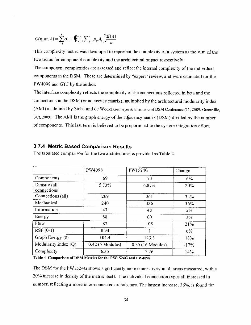
A comparison of the DSM's was made for the two engines to determine if there are aggregate
differences in the architecture that would highlight the impact of the architectural changes
between the two engines. The total number of connections of each type was tabulated and
additional network spectral analysis calculations were performed to highlight other features of
the two networks based on the spectral analysis work presented by de Weck and
Sinha(Intemational DSM Conference (11, 2009, Greenville, SC), Sinha, & O de Weck, 2009).
3.7.1 Graph Energy (G)The graph energy of the two matrices is computed as a means of the sum of the eigenvalues (C5)
of the adjacency matrix (DSM).
N
Energy of a graph, E(G) = 07,
i=1
The graph energy has been used in many fields to identify the total "energy" content of a system,
and is used here as a measure of the "energy" contained in the architecture. A higher energy
level represents a higher connectivity and architectural complexity.
3.7.2 Modularity Measurement (Q)The modularity measurement (Q) as introduced by Girvan and Newman(Newman & Girvan, 2004)
1Q = 1- 1 [A Ai; Pid 6(gi, g)
This provides a measure of the "modularity" of the architecture that can be computed from the
adjacency matrix and the proposed modularity groupings. The higher modularity score indicates
more cleanly defined "modules".
3.7.3 Complexity Measurement
The complexity measurement is performed as defined in DARPA complexitywork("Abstraction.pdf," n.d.)
33
C(n, m, A)= a, + /A, E(A)
This complexity metric was developed to represent the complexity of a system as the sum of the
two terms for component complexity and the architectural impact respectively.
The component complexities are assessed and reflect the internal complexity of the individual
components in the DSM. These are determined by "expert" review, and were estimated for the
PW4098 and GTF by the author.
The interface complexity reflects the complexity of the connections reflected in beta and the
connections in the DSM (or adjacency matrix), multiplied by the architectural modularity index
(AMI) as defined by Sinha and de Weck(Kreimeyer & International DSM Conference (11, 2009, Greenville,
SC), 2009). The AMI is the graph energy of the adjacency matrix (DSM) divided by the number
of components. This last term is believed to be proportional to the system integration effort.
3.7.4 Metric Based Comparison ResultsThe tabulated comparison for the two architectures is provided as Table 4.
PW4098 PW1524G Change
Components 69 73 6%
Density (all 5.73% 6.87% 20%connections)Connections (all) 269 361 34%
Mechanical 240 326 36%Information 47 48 2%
Energy 58 60 3%Flow 87 105 21%RSF (0-1) 0.94 1 6%Graph Energy (G) 104.4 123.3 18%Modularity Index (Q) 0.42 (5 Modules) 0.35 (16 Modules) -17%Complexity 6.35 7.26 14%
Table 4 Comparison of DSM Metrics for the PW1524G and PW4098
The DSM for the PWI 524G shows significantly more connectivity in all areas measured, with a
20% increase in density of the matrix itself The individual connection types all increased in
number, reflecting a more inter-connected architecture. The largest increase, 36%, is found for
34

the mechanical connections. This is not surprising given the emphasis on the fan drive gear
systems and the variable fan exhaust nozzle subsystem. This higher level of interconnectivity
would lead to the conclusion that the engine itself may have become slightly less "modular", and
this is reflected in the decrease in the modularity (Q) index, and increase in the number of
modules. The increase in graph energy (G), indicates that the system is more distributed than the
traditional turbofan architecture represented by the PW4098. This is also reflected in the
functional group connectivity analysis performed in section 4.3.4.
35

3.7.5 Modularity
The DSM can be reorganized to clarify the product structure, and also to examine different
potential module groupings which may inform the product architecture or the design and
development process. For a process based DSM, the steps in the process may be reordered to
reduce iterative design practices and better control the flow of the design process as described by
Eppinger et al (Eppinger, Whitney, Smith, & Gebala, 1994). The component based DSM's generated
for this work also can be organized to better manage the architecture and design process. Since
the DSM represents the physical coupling of the critical components in the engine, the
modularity analysis has two potential benefits. The first benefit is to highlight natural "modules"
in the engine architecture that are grouped based on interaction. The components comprising
these modules will have the greatest connectivity with each other, and would likely form a
strongly coupled set of components to be designed concurrently and by the same team. The
second benefit of the modularity is that it helps to highlight places in the design and development
process where the system integration has control points where there are relatively few
connections that require management. In designing a highly integrated product, managing the
workflow, inputs and outputs for each module can dramatically improve workflow and enable
parallel design of the subsystems, as discussed by Eppinger.
This view of modularity is potentially separate from physical modularity that may be designed
into the engine, in that it looks at the coupling of components through functional connections,
whereas physical modularity would be heavily influenced by the physical design of the
components. A highly functionally coupled design could still be made physically modular for
maintainability, as is done for aircraft engines where maintenance costs are a significant
influence on the marketability of an engine. Pratt & Whitney is expecting a 20% reduction in
maintenance costs(Wall, Kingsley-Jones, Norris, Mecham, & Warwick, 2010) for the PW1524G based on
the reduced part count enabled by the FDGS.
36

3.7.6 Modularity Analysis
To determine the modularity of the DSM, a top down or bottom up approach can be taken. In
the top down approach, the components are iteratively broken down into more and more
groupings (communities) and the modularity of the system is calculated. The total.
3.7.7 Modularity Analysis Results for PW4098
The modularity analysis for the PW4098 with all flow connections is presented as Figure 13.
BI-FI Duct.PC Bleed (4th Stage)
HPC Beed (8th Stage)HPC Bleed (12th Stage)ECS Switching Valve
ECS Cool er(Boeing Furnished)HPC Stabiliy Valve
-HCPCStartAir Valve
NacelleZone Ventillation ValveBuffer Air Coole CInner FairingLPC CaseLPC Inlet VanesLPC StatorsIntermediate Case
PC Case
HPCVariable Vanes (4)DiffuserFuel Nozzles
CombustorDiffuser/Cornbustor CaseHPT CaseHPTStators 0TC (TurbineCaseCooing)ValvTV0CA (turbinevarx blade coci
LPT TBV(ThrustBalance)LPTr CaweLPT StatorsoExhaust NozzlePMAGVSCF G enratorFuelBoost PumpMain Fuel PumrpFuel- 0Oiler(IDGOil Fuel)Fue Control(FMU)
Fuel Filter
Fue:.Flow SersorFue -Oil Cooler (Engine Oid)Fuel Distribution SystemHydraukicPumpIDGVsCF AirOsiCoolerIDG Air- Oil CoolerAccessory GearboxHPC Bleed (9th Stage ID)HPC Bleed (15th Stage ID)Giggle Tubes
#112BearingCompartmentAir- Ol CoolerLubrication Suppy andSc avengeF, n~ladlesFan RotorIntermediate Case StrutTozershaftHPRotorHPC StatorsHPT RotorFA DECNacelle Antike Valve
En gine Oil Tankut erFakringFEGV
Fana UThrust Reverser,4 Beating ComplartmrentLPC Rot.rLPE RotorLo. Shaft
o
. 00 0 0- 0- 0 0 0
0 0- 0 09: 00 0-0 00 0 00 0-0 0900 0- 0 00-0 00 0 0 0 00f0- 00- 0 00 0000 093 0 : f Eo
0393 0 000 0 00 0-00: 000 0 0 000 00- 0 0 00 0 0 -0 00 00o0 00 0 000
onl0 o-u, 0 0n0 i0n I E 00 0 t00m0 00 0 00 00-0 0100 00 0-00 0 00 0o o- 0- 0 0- 0 0 0 0 0 0 0 0 0 0 0 0 0 0 0 0 0- 0 0
S 00 0 0 0 0000 0 0 oooo 0nn000000000 00 60 0t00o 00 00
0 0 0 0 0 0 0 0 0 0 0 0 0 0 0 000 0a0f0 o o 0 ooof0 o000 0 0 0 0 0 0 0 0 0 0 0 0 ? 0 0 0 0 0 0 0 0
000 0a 000 6 0 0 - 0 a a a 0o 0 0 0 0 0 0 0 0 0 0 0 0 0 0 0
0 0 0 0 0 0 0 0 0 0 0 0 0 ,0 0 0 0 0 0 ao o 0 0 0 0 0 0 0 0 0 0 0 0 0 0 0 0 0 0 0 0 000 ) a 00 0 0 0 0 0 0 0 0 0 0 0 0 0 00 0 0 0 0 0 0 0 0a0 a 0 0 a0 0 0 0 a a o 0
. . 6 . .0 0 C, - -0 0
0 0 0 0 0 0 0 0 0 0 0 0 0 0 0 0 0 0 00 0 0 0 0 0 0 0 0 0 0 0 0 0 0 0- 0 0 0 0 0 0 0 0
0 0 0 a 0 0 0 0 0 9 o a0 0 0 0 0 0 0 0 a a a a
nj O 000000 0 a 0 0 0100 0 0 0 0 a,0 0 a= 0 0 a a 0 0 a 0 0 a a a aS 0 0 0 0 0 a 0 0K 0 0 0 D 0 0 0 0 0 ..
0 0 0 0 0 0 0 0 0 0 0: a 0 a 0 a -0 0 a- 0 0 00 a 0 a- 0 0 0 0 0 0 0 0 0 0 a 0- 0 0 0 a 0 0 0 00 0 0 0 0 0 0 0 0 0 0 0 0 0 0 0 a 0 0 0 0 0 ) 0 0
0 0 0 0 0 0 0 00 00000000 : 0 n 0 0H 00 0 0 000 0 0 0 0 0 0 0
o 0 0 0 0 0 0 00 0 0 0 0 0 00 : : 0 0 0
0 00000000 0 D 0 00 0 6 0 0 0 0 0
O 0 0 0 0 0 0 0
S0 0 0 0 0 0 0
Hon o 0 96 0 0
0 a 0 0 0 0 0 00 0 0 0 0 0 0
0 0 0 0 0 0 0 00 0 0 0 0 0 -Syste a 0 0 0 0 0S0 0 0 0 a 0 00 0 0 0 0 0 0 00 0 0 0 0 0 0 00 a 0 0 0 0 0 00 0 DO 0 0 0 00 0 0- 0- 0 D 0 am 0 60- 0 a 0 0:0 0 0 0 0 0 0. 0W0 0 0 G 0 0 00 0 0 0 0 0- 0 0-0 0 a' 0 0 0 0a 0, 0 6 0 0 0 0
0:0 0 0 0 0 0 00-0 q 0 0 0 0 00 0 0 .0 0 0- 0 0.0 0 0 0- 0 0 0 0
0 0 0 0 0 0 0 0 0 0 0 0 0 0 0 0 0 00 0 0 0 0 0 0 0 0 0 0 0 0 0 0 0 0 00 0 0 0 0 0 0 0 0 0 0 0 0 0 0 0 0 00 0 0 0 0 0 0 0 0 0 0 0 0 0 0 0 0 00 0 0 0 0 0 a 0 0 0 0 0 a 0 0 0 0 00 0 0 0 0 0 0 0 0 0 0 0 0 0 0 0 00 0 0 0 0 0 0 0 0 0 0 0 0 0 0 0 0 00 0 0 0 0 0 0 0 0 0 0 0 0 0 0 0 0 00 0 0 0 0 0 0 0 0 0 0 0 0 0 0 0 0 00 0 0 0 0 0 0 0 0 0 0 0 0 0 0 0 0 00 0 0 0 0 0 0 0 0 0 0 0 0 0 0 0 0 00 0 0 0 0 0 0 0 0 0 0 6 0 0 0 0 0 0a a a a a a a- a a a a a 0 0 a 0 0 a0 0 0 0 0 0 0 0 0 0 0 0 0 0 0 0 0 00 0 0 0 0 0 0 0 0 0 0 0 0 0 0 0 0 00 0 0 0 0 0 0 0 0 00D0 0 00 0 0 0 0. 0 0 0 0 0 0 G 0 0 0 0 0 00 0 o 0 00 0 0 0 0 0 0 0 0 9 00 0 0 0 0 0 0 0 0 0 0 0 0 0 0 0 00 0 a 0 0 0 0 0 0 0 0 0 0 0 0 0 0 0
0 0 0 0 0 0 0 0 0 0 0 0 0 0 0 0 00 o 0 0 0 0 0 0 0 0 0 0 0 0 0 0 0 0
0 0 0 afi 0 0 0 0 0 0 0 0 0 0 0 0 00 0 0 0 0 00 0 0 0 0 0 0 n,0 0 0 00 0 0 0 0 0 0 0 0 0 0 0 0 0 0 0 0 0a a : a a a a a a a a a a 0 o 0 0
00 0 0 Oi O' a a a a a 000 0 0 0 0 0 10 0 6 0,0 00 0 0 0 00 0 0 0 0 0 0 0 0 0 0 0 0 0 0 0 0 0o 0 0 0 0 0 0 0 q 0 q 0 0.0 0 0 0 00 0 0 0 0 0 0 0 0.0 0 0 0 0 0 0 0 000 0 0 0 0.0 0 0 0 0 0 0 0 0 0 00 a= 0 0 0 0 O 0 0 0 9 0 0 0 06 0 0 0 0 0 0 0 0 0 0 D 0 0 0 0 0 0a 0 a a a a 0:0 a 0 0 0 0 0 0 0 0 0O_ 0 0 N O_ 0 0. 0 0 0.0 0 0 0 0 0 00 a a a a 0.0 a (I a a a 0 am 0 0 0Sa a a a a 60 a a a a *a 0,0. a a a
00 0 000 E 0 Z0 0 0 0:0 0 0-0 000 0 00 00Io o 00-0 0.0000 0 000 000 0 0 00 00 0 0-00 000 0 00 0 00 0 0-00 6o 00 0 00 00 o 6 6 o 6oo 00a 0- 0 000 00000 000000 0000 0 000 0 0- 0 0 q 0 0 0 0 00 0 0 0 0 0 0 0 0 0 0 0 0 0 0 00 0 0 0 0 0 0 0 0 0 0 0 0 0 0 0 0
00 000 00 0 0 0 0 0000
0- 0 0 0 0 0 0 0 0 0 0 0 0 0 0 0 0o-o 0 0 0 0- 0 a 0 a 6 a 0 0- a a a - a 0 0 0 0 0000
0 0 0 0 0 0 0 0 0 0 0 0 0 0000 00 0 0 0 0 0 0 0 0 0 0 0 0 0 00 0 0 0 0 0 0 0 0 0 0 0 0 0 0 00 O 0 0 0 0 0 0 0 0 0 0 1 0 00 0 0 0 0 0 0 0 0 0 a 0 0 0
0 0 0 a a a 0 0 0 0 0 0 0 : 0 0 0
0 0 0 0 0 0 00 0 0 0 0 0 0
0 0: 0 0 0 0 0 0 0 0 00000
0 0 000 :0-0- 0 000000 0 0 0 0 0 0 00 0 0 0
00 0 0 0 0 0 0 0 0 0,0 0 000 0 0 0 0 0 0 0 0 0 0
0 0 0 0 0 0 0 0 0 0 0 0 0 0 0000 0 D 0 0 0 0 0 0 0- 0 0 0 0 0
0 0 0 0 0 0 0 0 0 oo oo 0 00 0 o 0 o O a n n o o o00 0 0 0 0 0 0 o0 0 0 0 0 0 0
0 0 0 0 6 0 D0 0 0 0 0 0 0 0 0
0 0 0 0 0 0 0 0 0 0 0 0 000 00,0 00 00 00 00a-0 00 0 0 0 0 0-
S 0 D . M 0 .0 0 0 0 0
S0 0 0 0 0 0 0 a OU 0 0 0 0 00
. 0 D 0 0 0 0 0 0 0 -'
0 0 0 0 0 0 0 0 0 0 0 0 0 00 0 0 0 0 0 0 0 0 0 0
0 0 00 a 00 0 00 0 00 0 00 0 00 0 00. 0 00 0 D0 0 0. 0 00. 0 0,0 0 0a 0 0a 0 0a 0 00 0 00 0 a0 0 06 a a0 0 00 0 00 0 DS o a:0 0 0
0 0 0 0 0 00 0 0 0 00a : 0 00 a 0 00 0 0 0 0 00 0. 0 0 0 00 0- 0 0. 0 00 0 0 0 0 00 0 0 90 0 a0 C 0 a 0 00 : 0 0 0S00 0 0 0
0 0 0 0 0 00, 0 0 0 D 00 0 0 0 0 aa 0 0 0 0 0a 0 0 0 0 00 a a 0 0 00 0 0 .0 00 0, 0 0 a 00 0 0 0 0 00 6 0 0 0 .0 0 0 0 0 00 0 0 . .. .0 0 0 0 0 0
0 00 0 00 0 0 0 010 0 0 0 00 0 0 0 00 0 0 0 00 0 0 0 00 0 0 0 00 0 0 0 00 0 0 0 00 0 0 0 00 0 0 0 00 0 0 0 00 0 0 0 0,0 0 0 0 00 0 0 0 0,0 0 0 0 00 0 0 0 00 0 0 0 0& 0 0 0 00 0 0 'a 00 0 0 0 00 0 0 0 00 0 0 0 00 0 0 0 00 0 0 0 0
EE
U -g
oog0 ( 0 0-0 0 000 o C 0 00 00
* 0 000 0l 0 0 0 0000 of n fl 0000 00 00 00 00 00- 0 0 0 0 o f l 0 0 0 0
o o 0 0- 0 0- 0 0 0 0 0 0 0 0 0 0 0 0 00 0 0 0 0 0 00 00 0 0 0 0 0 0 0 0 0 0 0 0 0 0 0 0 0 0 0 0 0 0
0 0 0 0 0 0 0 0 0 0 0 0 0 0 0 0 0 0- 0 0 0 0 0 0 0 00 0 0 0- 0 0- 0 0 0 0 0 0 0: 0 0 0 0 0 0 0 0 0 0 0 0 00 0 0 0 0 0 0 0 0 00 o 6660 0 0 0 0 6 0 00 0 0 0 0 0 0 0 0 0 0 0 0- 0 0 0 0 0 0 0 0- 0 0 0 0 00 0 0 0 0 0- 0 0* 0 0 0 0 0 0 0 0 0 0 0 0 0 0 0 0 00 000000000 noonnooo 60 0 0 6o no0 n oa 0 0 0 0 6 0 6 6 0 0 6 0 0 6 0 6 0 0 0 0 0 0 0 00 0 0 0 - 0 0 0 00 0 0 0 6 0 0o 6 oO 0 0 6 0 0 6 ofl 6 0 0 0 0 0 0 0 0 0- 0 6 0 6 6- 00 0 0 0 0 0 0 0 o 0 0: 0 0- 0 0 0 0 6 660 oflo: 60 0 0 f 0 0 0 0 f 0 01 0 0 0 0 0 0 0 0 0 0 0 0 0
0 0 0 0 0 0 0 0 0 0 0 0 0f 0 0 0 0 0 0 0 0 0 0 0 0O 0 0 0 0 0 0 0 0- 0 0 0 0: 0 0 0 0 0 0 0 0 0 0 0 0 00 0 0 0 0 0 0 0 0 0 0 0 o H 0 0 0 0 0 0: 0 0 0 0 0 000 0 0 0 0 0 0 - 0 0 0 0 0 0 0 0- 0 0 0 0 0 0 0 00 0-0 0 0 0 0 0 0 0 0-0 0 0 0 0-0 0 00 0 0 0 0 0 00 0 0 of 1 60- 0 0 666 6 6 0 6 0 0 0 0 0 0 0 00 0 0 0 0 0 0 0 0 0 0 0: 0 0 0 0 0 0 0 0 0 0 0 0 0S0 0 0 0 00 00 00 oflo 00 00 0 00 0-00 0 0 0 0 0 0 0 0 0 0 0 0 0 0 0 0 0 0 0 0 0 0- 0o 0 0 0 0 0- 0 0 0 0 0 0 0- 0- 0 0- 0 0 0 0 0 0 0 0 0 0
0 0 0 000 n 0 00 00 00 0 000 000-0 0 00660 0 6o oo0 0 o 0 0 0 0 0 0 0 0 no 6 0 0 0 of 60 0 0 0 0 0 0 0 0- 0 0 0 0~ 0 0 0 0 0 0 0- 0 0 0 0 0 0
0 0 0 0 0 0 0 0 0 0-0 0 00 0 00 0 010 0 0 0 0>00- 0 0- 0 0 0 0 0 0 0 0 0 6 0 0 0 o 0 0 0 0 0 0 0 00 0 01 0 0 0 0 0 0 0 0 0 0 0 0 0 0 0 0 0 0 0 0 0 0
0 0- 0 0 o 0 0 0 0 0 0 0 0- 0 0 0 0 0 0 0: 0 0 0 0 0 00 0 0 0 0 0 00 0 o o o ooo oo0 ooooo0 no-
0-0 0 0 0 0 0 0 0 0 0- 0 0 0 0 0 0 0 0 01 0 0 0 0 0 00 0 0 0- 0 0 0 0 0 0 6 0 0 0 0 0 0 0 0 0- 0 0 0 0 0 00 090 0 0 0 0-0 0 6 0 0 6 0 0 0-00 0 0-6 0 0 0 0 00 0 0 0 0 0 0 0 0 0 0 O0 0 0 0 0 0 0 0 0 0 0 0 0 0 0
0 0 6 0 0 0 0 0 0 0 0 0 0 0 0 0 0 0 0 0 0 0 0 0 00 0 0 0 0- 0 0 0 0 0 0 0- 0 0 0 0 0 0 0 0 0 0 0 0 0oo0 0 0 0 0 o oo0 0 0 0 0 0 0 0 0 0 0 0 0 0 6 0 0
0 0 0 0 0 0 0. 0 0 0 0 0 0 0 0 0 0 6 0 0 0 0 0 0 0 0
0 660- 6 0 F b0 0 0 0 0 0 0 0 0 0 0 00 0 000 00-0 00 0-0 0 000 0 00 00 00 00 0 ooooooo oo-om 0 oooooo 0oo000 0 00 0 0 0 0 0 0 00 000 00 00 0
S0 0 0 0 nOH...2 0 00 0 0 0 0 0 0 0 0 0 0 0 0 00 0 00 0 0 00 00 00 0:00 00 0 00 0
oo 00 0 3 0 00 ooooooo 0 0 00 0 0000 0 000 00 00 000 00 0-0
OOOO UOOUOO O 00 0- 00 00 00 00 00 000 a o0 000 0o 0 00 0000 00 0
0 000 00 0000 0 0 60 0 0 0oooooo 00 06:600666 00 0 0 00 00 0 00 00
S0 0-0 0060 00 0 0:0 000 00 0 00 00 O00-0-0 0 00 0 00 00 0 0 0 0 00 0
00 00 0-00 0 00 0 0 00 0 00 0-0 00onnooo6-0 0- ooo oo . 0 00 00 0-00 00 00 00 0010 000:0 00 0 00 00 0-0oooonofloflonn-oo0 0 00 000 00 0-0
000 00 0 00 00 0000 0 0 00 000 00 00600 00 00 00 0 0 0 00 0oooooooflon-ooooooooooo0 0 0 0 0-00 0 0 0 0 0 0 0 0 0 0 0 0 0 0 0 0 0 0 0 0 00ooofloooooooooonn 0 00 0 o o-o0 0 0
nnonooooo flonnono-non oo0 00 0 0
Figure 13 PW4098 DSM with Modularity Representing All ConnectionsUsing all of the connections, the algorithms decomposed the system into 5 modules, with one
very large module incorporating many of the cases and static hardware. The accessory gearbox,
accessories, and fuel system components became another module. The rotating components
37
- ^ ̂

associated with the high spool (rotors, and bearing compartments that support them) are another,
and then the two remaining modules are the low rotor components, and the components that
primarily connect to the fan case itself The very large first module is tied together with the
bifurcation duct, which is a conduit through which many of the connections to the control system
(on the fan case) flow. This connectivity may be over-emphasized in a practical sense, since the
duct is primarily a conduit through which plumbing and wiring harnesses pass. Inside of this
module, one can see there are potentially four smaller modules comprising the compressors, the
turbines, the combustor system and the secondary flow system.
3.7.8 Modularity Analysis Results for PW1524G
The modularity analysis for the PW4098 with all flow connections is presented as Figure 14.
38

E> -6 EE ,~
30 c0>. !I-~ . a 3 >~ 3 0 -~;
FADEC 0 0 0 3 0 C 0 0 ? 0 0 0 0 0 0 0 0- 0 0 0 0 0 O 0 0 A 0l 0 O 0 0HPCOIeod- 2.0(4thStg) 0 0 000 0 00 00 00 0 000 00 0.0 0 000 00 00 00 0 00 O000 00 0 000 0 00 00 00 00 0 00 00 0 000 00 0 00 0OPC 000d- 2.9(600hStage) 0-0 03.020 0 00 0 0 0 0 0 0 0 0 0 0 03 0 0 0 0 0 0 0 0 0 0 0 0 0 0 0 0 0 0 0 0 0 0 0 0 0 0 0 0 0 0 0 0 0 0 0 0 0 0 0 0 0 0 0 0 0 0 0 0 0
OPECECSOOO V SOV 0 0 3 0 0 0 o0 oo 0ooooooooooo ooooooooooooo oooo oo 0 oo o o 0o 0 o o oo o o oo o o oo o oPRECS 0004dSOV 0 0 00 00 0 0 0 0 0 0 0 0 00 0 0 0 0 0.&ufferAir Valv 0 0 0 0 0- 0 0 0 0 0 0 0 0 0 0 0 0 0 0 0. 0 0 0 0 0 02 0 0 0 0 0 0 0 0 0 0 0 0 02 0 0 0 0 0 0 0 0 0 0 0 0 0 0 0 0 0 0 0 0 0 0 0 0 0 0 0 3 0AnEtoocevatve 0 0 0 01 0 0 2 0 0 0 0 0 0 0 0 0 0 0 0 0 0 0 0 0 0 0: 0 0 0 0 0 0 0 0 0 0 0 0 0 0 0 0 0 0 0 0 0 0 0 0 0 0 0 0 0 0 0 0 0 0 0 0 0 0 0 0 0 0 0 0 0HPCOOOe(thStogotO) 0 0 00 00 00: 0 0-0 000 000000000000 0-0 O O O OO O O O 0 00 0-0 00 000 0 000 00 0 0 00 00 .OoooOOOO O o 0 0 0 -
G0ggle30000 0 000 00 0 0 0 0-0 0-0 0 000000000000 0 000 0 0 0 0 0 0 000 0 0 000 00 00 0 00 0 0 OOOO0 0 oo O OOOO 00 0 0 0 0002/3 0 0.0 0 0-0 0 0 0000 00000O O00000000 00.. 0 . O E O~o . . o~ o0 0 .00oooof lo o oooo oooooo 0 oo loooo ooo o0 o lo#4 0.020 0 00 0 0 0 00 00 0 00 0 00 0 0 0 00 0 00 0ooo 00 00 000 00 00 00 00 00 0 00.0 0000 00 00 00 0 00 0 0lntermdetOCasOStrt 3 o o b 020 0 0 0 0 0 0 0 00 00 00 0 00oo-ooooooooo 0 0o0 ooo i o f0 oooo o -0 o 0o oo-o - oooo 00 0 0 00 0To,.osh.f 0 00 0 00 0 00 0 0 0 0 0.0 0 03O0 0 0 0.Q-.9.P.P0..0:O.0 00 0 0 00 0 0 00 0.0 0 0 0 0 0 0 0 0 0 0 0 0 0 0-0 0 0 0 0 0 0HPCRtr 0. 0. 0 0 0 0 00 0 0 0 0 0 0 0 0-0 0 0 0 0 0 0 0 0 0 0 0 0. 0 0 080 00 o 0 0 0o0 0 o o o o o0 o 00,0
HsPCStotors 0 oooo00 ooo 0 0 0.0 0 00000 00000000000000000000000000000000000000000 0 000 03 o o0 o oo oo - oo o o o0 oo o oo o 0oo~ oHPT Rttr 00-000000 0 0 oo ooo000.0 .ooo 0 0 0oo 0 oooo oooooo -oo 0 0ooooooo 0 0o 0 o 0 o o 0 oo o o 0 oo o ooooDOPHM 0 000 0 0 0 00 0 0 0 0- 0 0 0 0 0 0 *0 0 0. 0 *0 0.03 0 0 0 0 03 0 0 0. 0 0 0 0 0 0 0 0 0 0 0 0 0 0 0. 0 0 0 0 0 0 0 0 0 0 0 0 0 0 0 0 0POAG 0 0 0 000 0 0 000 0 0 0 0 0 0 0 0 0 0 0 00 00 0 0 0 0 0 0 0 0 0 0 0 0 00 0 0 00 0 0 0 0 0 0 0 0.0 0 0 0 0 0 0 0 0 0 0 0 0 0 0 0 0-0a0nFuelPomp 0 0 0 0 0- 0 0 0-0 0 Q0 00 0 0 0 0 0 0 0 0 0 0 0 0 0 0200 0 0 0 0 0 0 0 0- 0 0 0. 0 0 0 0 0 00 0 0 0 0 0 0 0 0 0 0 0 0 0 0 0 030 00:0 0 0FV.ICotrV *0.00 0 00 0 00 0Ooo o . oo 0 0 0 0 0 00 o d 00 00 0 00 00 00 000 00 0 0 0000:0 00 0 0 0000 00 00 0FoelAstbutooSystem 0 00 000 00 00 0 00 00 00 0 0 0 0 00000000000000000000C 0000 000000000000000 0 oo o o o o o o o oo o o o o o oo o o o0io o
HPC~as 0 00 00 0 00 000 003 0 00 0 000000 0000 000000000 0 oooo o o oo o o o o 0 0 0 00 00 00 0 00 00 00 0 000 0Acesor~erbx 00 0 00 00 0 0030 030 00 0000 0000000 000000000 0 000000 oo o o~ o o o o o ~ ooo..p 0 00 00 00 00 00 0
#tOOanngCOWOartrnet ooooooOOO 00 00oooOOOOOOOO O0 0 0o 0 0 0 0 ooooooooooooflooooCoooooooooo30 00 0 0 000 00 00 0 00- 030VoonOblO~owValve 00 00 00 0 00 00 00 00 0 00 00 0 00 00 0-0 0 0 00 0 0 0 000 000 00 00 0 000 0 00 00 0 0 ooooo00 0ooooooo0
Fon~lodos . 0 p0 0 0 0 000 00 0 00 0- 00 00 00 0 00 0 0-0 0 00 0 000 00 0 00 0 0 0 0 0 0 0 0 0 0 0 0 0 *0 0 0 0 0 0 0 0 0 0 0 0 0 0 0 0 0 0Fanootor ooo o 0 00 0 00 00 00 00 0 0 000 0 0 0 00 00 0 000 00 0 000 0 00 00 00 0 0 000 00 00- 00 0 000 00 0 000 0FDGAgre
0ated 0.0 00 0.00 0 00 020.0 00 00 00 0000 ~ 0 0 00 00 000 00 0 00 00 020 00200 00 0 00 0 0000 0 00 000 0 00 0Midurin Far * 00 0 00 0 000 0U OO 0 oOOOO0O 00 0 O 0 0 0 0 0 00 0 00 00 00 00 0 00 000 0-00 0 0 0 000 0 00 0 00abetnupynwv ooooooooooo 0 oooooo 00 oo oo o 0 o 0 0 0 oooooooooo0 0 oooo 0oooof l ooooooo oo m
Engon.OIlTonk 00 00 00 0 000 00 00 0 00 00 0 0 000 0 00 0 0 0 0 00 00 0 00.0 000 00 00 00.0 0 00 000 000 0 00 0 00 000 0VETO.se 0.0 0 0 00 00 0 00 00 0 00 0 0 0 00 0 0 0 0 0 0-0 0 00 0 000 0 o o 0 0 o o o o 0 0 0 0 00 00 00VPT Stotor, 0 0 0 0 0 0 0.0 0 0 0 0 0 3 o 010 0 0 0 0 0 00 0 0 0 00 00 0 00 0 0 0 0. 0 0 0. 0 0 0 0 0 0 0 0 0 0 0 0 0 0 0 0 0 0 0 0 0 0 0TCCVaove 00 00 0 00<00 00 00 0 00 000 0 00 00 00 00 00 0 00 0 0 0 0 000 00 0 00 00 0 00 00 00 00 00 0 0 0 00 00 00 0
lnneFonng 00-0 00 00 0 0.000 00 0 00 000 00 030 00 00 0 000 0 0 0 0 0 0.000 00 00 00 00 000 00 00 000 00 00 0 0LPT Cat. inoooooooooooooooomoooooooooooo 00 00 0 0 0 0 00 0:0 00 00 0 0p00 0 000 0-00 00 00 00 00 0 0 0LPT Stator, 0O00 0 0 0 00 0 00 0 0 0 oooooooo-ooooo0 0 00 00 0 0 0 0 000 O0 0 00 00 0 0 000 0 0 0 0 0 0 0 0 0 0 0 0 0 0 0 0E0as oze0 000 0 0 00 0 0 00 00 000 0 000 00 0 00 0 00 0000 0 00 0 00 00 00 00 00 00 00 00 0 000 0 000 0 00 000 00 0Fo0I0ot Pump 00 0 0 0 00 00 00 00 00 00 0 00 o0 0 0 00 0 0 00 00 000 0 0 0 0 0 0 0 0 0 0 0 0 0 0 0 0 0 0 0 0 0 0 0 0 0 0 0 0 0 0 0 0MotiveFoelO.,p t 0 00 00 00 00 00 00 00 00000000000O000 0 0 000 0 00 00 00 00 00 0 000 00 00 00 00 0 00
ru,.-o-o oer ooo0 0* 00 o o oo o 0 00 0 o oo o 0 oo o o 0 l oo o 0 00 oooooooo ooooooooo 0 o o o oo f o oo oAor-OdCooler 30 0 00 00 000 00 00 00 00 00 00 0.0 0 000 000 00 00 0 0 0 00 0 00 00 0 00 0 00 00 030 00 00 00 0 00 0LPC Cooo 30 00000 00 030 00 00 000 0 0030300 0 003 oo 0 00 00 000 0 0 00 00 0 00 oooooooofloofloooo30 0LPOInlet Vonoo 00-0 0 000 0000 0 00 00 0 0 000 00 0 00 030 0 0 .ooooo oooooo 0 0 0 0 000 0-0 000 00 0 00 0 00 00 00 00 0LPCVOrVaVOVOane 3000 0 000 00 00 0 00 00 00 00 00 00 00 00 00 0 0-000 0 000 0 00 0 0 000 0 00 0-00 00 00 00 0C00 00 0 0LCSOators 00 000 00 0 00 0 000 000 00 0 00 00 00 0 00 000 0 000 00 00 0 00 0 0 oo-ooooooo0 0 ooooooooooooo0oo0 0
Otfuser 0 0-00 0 00 0.0 00 0 0 0 o K 0 0 0 p 0 00 00 0 00 0 0 00 P. 0 0 P P P 0 0 0 0 0 0 0 0 0 0 0 0 0 0 00 0 0 00 0 0 0 0 0 00 0 0 0.Fulo zl s0 0 0 0 0 0 0 0 0 0 0 0 0 0 0 0 0 0 0 0 0 0. 0 0 0 0 0 0 0 0 0 0 0 .P 0 0 0 0 P P 0 0 0 0 0 0 0 0 0 0 0 0 0 0 0 0 0 0 0 0 0 0 0 0 0. 0 0 0 0 0 0
C0mbust0r 0 0Ooo 00ooooo o oooo 0oooooooo0 0 ooooooo ooooooooooooooo 0 0 0 0 00 0 00 0000 0 00 00 00 0 000-Oosr/CToustrcaoto 0ooo *oooOO 0 00 oo 00ooooOOOOOOOOO ooooood 0 0 0o 0ooooooooooooo 0.0 - Oo o o oo o oo o o oo oHydrautic Pom 0.00 0 00 0 0-000 00 0.0 00 0 000000 000 00 0-0 00 00 0-00 00 00 0 000 00 00 0 0 0 00 000 0 000 00 00 00 0
VAN~ackupElec0-ncMOtor 000 O0 O O OO- 0000000 0 00 000 00 0 00 0 0 00 0 -OOOO .OOOO 0 o o o o 0 0 0 00 0-00 00 0 000 00 00 01r0st00 erOe .00 0 0.0 0 020 00 0 00 00 0 000 0 00 00 000 000 00 0-00 0.00 0 00 0 0 00 060 00 0 0.00 0 00 0 0 00 00 00 0
0s/6000ooOCopaOtmet .00 0 0 0 0 0 0 0 0 0 0- 0 0 0 0 0 0 0 0 0 0 0 0 0 0 0 0 0 0 0 0 0 0 0 0 0 0 0 0 0 0 0 . 0 0 0 . 0 0 0 0 0 0 0 0 00 00 00 0 0LPC ROtOr 0 0 0 0 0 0 0 0 0 0 0 0 0 0- 0 0 0 0 0 0 0 0 0 0 0 0 0 0 0 0 0 0 0 0 0 0 0 0 0 0 0 0 0 0 0 3 0 0 0 0 0 0 0. 0 0 0 0 0 0 0 0 0 0 0 0 0 0 0 0 0LPT Rotor 0 0 0 0 0.0 0 0000000000000000000 0000.0000000000000-0000 ooo oo0 oo0 oo 0oooo o - 0 0 0 00 0 00 0.0 00 000 00
LO~OtOOO OP-o ooo 00 0 oo 0 o0 00 0 0 0ooooo 0 0-0 0 00 0 0 0 0 .o0 ooooo ooooooo 0 0opoo 0 00- 00 0.00 00 0 00-VVriblFr0q.Genertor 00 0 0 0 000 00 00 O P O 0 0 00 000 000000 O -0 00 00 0 000 0 00 00 000 0 00 00 0 00p00 0P0 0 00 00 0 0
Oi-OCOOOe(VG-ngoin!30 0 0 0 0 0.. 00 0 0 0 0 P- 0 0 0- 0 0 0 0 0 0 0 0 0 C3 0 0 0 0 0 0 0 0 0 C 0 0 0 0 0 0- 0 0 0. 0 0 0 0 0 0 0 0 0 0 0 0 0 0 0 0 0VFGA-OilCooOer 0- 0 0 0 0 0 0 0 0 0 0 0 0 0 0 0 0 0 0 0 0 0 0 0 0 0 0 0 0 0 0 0 0 0 0 0 0 0 0 0 0 0 0 0 0 0 0 0 0 0 0 0 0 0 0 0.0 0- 0 0 0 0 0 0 0 0 00l.t0Er0rg 0 - 0 o 00 0 -ooodoooooooooooooooooooooooooooooo0o o o 0o o oo 0 0 o0 oo 0 00 0 0 0-0 00 0FGE 0-000. 000 00 000 0 000 00 00 0 00 00030 000 0 0003020 0 00 0030 00 0 000 0 000 00 00 00 0 0 0 00 00 0
ECFoo er 00 000 00 0 00- 0 - ooooooooooooooooooo0 000 000 00 00 00 000 000 0 0 00 0LPECLPS 0-0000000000000000000 -000000000000 OPP0 -0000000000 0 0000 0 o . oVPCferoirbl~oo (4) P00 00 00 00 00 0 0 0 0 0 0 0 00 00 00 00 0-0 00.0 0 0 0 000 00 0 00 0 000 00 000 00 00 000 0 0 0
Figure 14 PW1524G DSM with Modularity Representing All ConnectionsThe modularity of the PWI 524G is much more fractured than the PW4098, with 15 modules
represented. This increase in the number of modules reflects the more distributed architecture of
the engine, and will be shown to represent significant increases in functional design group
interaction in section 4.3.4.
3.7.9 Comparison of Modularity Analysis Results
The modularity analysis performed for both engine architectures using the total connectivity of
the DSM showed that there are many potential modules located in the architectures presented.
Some of the modules have relatively few components, because of their high relative internal
connectivity strength. These modules are likely good candidates to be worked by a single
39
organization or team, because of the tightly coupled dependencies. Some of the modules
highlighted using this technique are similar to groupings used in the industry, such as the
compressor module, combustor/diffuser module and secondary flow system. The Fan Drive
Gear System itself becomes a strong module with the components that it is most highly coupled
with, including the output shaft and fan. This close interaction between components traditionally
considered the domain of mechanical design (gears) and aerodynamics (fan) is the type of
connection that will later be shown to create novel connections between functional groups that
may not have interacted directly in the prior architectures (Section 4.3.7).
3.7.9.1 Modularity Impact to Design System.The modularity analysis of the DSM using both the mechanical and full connectivity provides
two different potential groupings of system components. The design system may not be best
influenced solely by the modularity analysis of the components, because of some of the social
interaction effects that will be shown in the functional group interactions in section 4.3.3.
Groupings based solely on the mechanical or total connectivity may attempt to aggregate
dissimilar functional groups, or may create additional connections across functional group
boundaries. The work of Rowles looked at a DSM of the design process itself, and the design
dependencies rather than the functional dependencies, and this would likely be more practical at
setting work group modules, in conjunction with the functional group analysis.
3.7.9.2 Modularity Impact to Other ProcessesThe modularity of the system taken with all connections shows some of the natural "breakpoints"
in the architecture with respect to system function and connectivity. These modules give insights
into components that are closely connected, and in a validation environment, may be best tested
together as a subsystem. A highly connected component will rely on other components for so
many interactions that testing it as an individual component will not reveal any emergent
behaviors of the system. The modularity analysis can be utilized to locate such components and
modules. In particular, the buffer air cooler, while a simple component in itself, is highly
connected and would likely be best tested in a full system evaluation once it's basic functionality
was assured through component test. Other natural modules are indicated as pieces of the
40

turbomachinery such as the compressors, which have been tested and developed as modules in
the gas turbine industry in the past.
4 Social Network
4.1 Importance of the Social LayerThe product physical architectural complexity is important from a number of standpoints in the
product domain, but the impact of complexity on the organization and the ability to successfully
develop and integrate the product is critical for the business. In particular, a complex system
such as a gas turbine engine involves the integration of multiple domains of expertise and
specialization of the individuals engaged in the design of that component. The knowledge is
created inside of that team (production), and then is used by other teams (consumption) to
integrate and define the more complex system(Malone, 1993). The transfer of this knowledge
during the design and development process must be adequately managed through boundary
objects(Paul R. Carlile, 2004). The role of the engineering organization is to couple the engineers in
different disciplines together to produce novelty(Black & P Carlile, n.d.). Examination of the
intersection of the organization and the product architecture through a Domain Mapping Matrix
(DMM)(Danilovic & Browning, 2007) will help to locate the boundaries between functional groups in
the organization (with domain specific knowledge) relative to the component boundaries.
4.2 Organizational Structure
The engineering organization at Pratt & Whitney is a matrix format, with functional disciplines
grouped together, and managed in projects for product development. As discussed by Allen
(Allen, 1984), this seeks to maximize the benefits of both the functional and project forms of the
organization, while minimizing the liabilities. This organization form does have it's own
liabilities as documented by Katz and Allen(Katz & Allen, 1985)due to the balance of pull from both
sides of the organization. The technical portions of the organization focusing on the technical
merits of the problem, and the project portions of the organization attempting to "get the product
out the door" at a reasonable development cost.
We expect that the project portion of the organization has influence over all of the components in
the functional DSM generated for this work. The analysis performed is then focused on the
technical interactions between the functional groups in the organization - which is ostensibly a
41

portion of the project organization's job. Pratt & Whitney has a dedicated organization (Systems
Design and Component Integration) which is intended to fulfill the technical portion of this role,
and is responsible for holding system level reviews and meetings. Successful management of the
project, integration of the multiple domains and the resulting product follows the trajectory of
locating and resolving latent problems in the design process identified by Black and Carlile(Black
& P Carlile, n.d.). Successful completion of this process requires adequate integration of the
different domains to minimize the gap between apparent and actual design knowledge at a given
point in the design cycle. In the Black and Carlile work, the case study demonstrated how
effectivity of boundary objects enabled the uncovering of latent issues during the design process,
and ineffective objects prevented the transfer of knowledge between functional groups. This
lack of actual communication of intent resulted in significant development challenges in the
study case. In the study of the GTF architecture, we seek to understand where the domain
boundaries are, and how the boundaries of the expertise align with the organizational and
functional boundaries on the product.
4.2.1 Discipline Boundaries in the DSM
Utilizing the discipline to CIPT map, and the component to CIPT map, this data can be applied
to the DSM to locate the boundaries between disciplines. Connections where there are cross
discipline boundaries sharing no common knowledge will more strongly require an effective
knowledge transfer mechanism than transfers within the same knowledge group. Pratt &
Whitney utilizes multiple types of processes to manage these connections, primarily in
Engineering Standard Work (Saxena et al., 2009). This system of documents is intended to provide
the practitioner guidance on inputs, outputs and design criteria for each task of designing a
particular component or module. While the contents of the system are proprietary, in order to
function as an adequate boundary object, multiple criteria need to be met. There is a need to
continually update ESW as the engine architectures change, because of new connections between
new disciplines driven by the architecture.
As an example of a new interface brought by architectural changes, we consider the primary
change in engine architecture between a classic turbofan and the geared turbofan. The transfer of
power from the turbine to the fan in a traditional turbofan is highly efficient given that it is a
single shaft, with a few sets of rolling element bearings to support the shaft and react against the
42

thrust load generated by the fan. Please do some simple power calculations to show how the
energy of the fuel is transferred to heat in the combustor, transferred to the shaft, fan, then thrust
etc.. Basically a zeroth order power flow calculation to show what is going on.
Figure 15 High Level Architecture of the Low Spool
In the geared fan architecture shown schematically in Figure 15, the addition of a gearbox adds
additional parasitic losses between the turbine and fan that need to be accounted for in
performance predictions and requirements coupling that must be added to the design process.
Given the prior coupling without a reduction gearbox, this efficiency was driven by
aerodynamics and cycle prediction tools - easily handled inside of one technical domain. With
the addition of the FDGS, there is power absorption between the two that needs to be accounted
for in the performance predictions, and this power absorption is in the mechanical engineering
(gear engineering) and tribology domain. The interface addition of mechanical and tribological
engineering into a system with direct coupling between aerodynamic performance is likely to
drive process challenges in the communication of performance and design information.
Uncovering these types of interactions during the conceptual design phase or even earlier will be
beneficial to ensuring that knowledge transfer is complete and without error throughout the
design and development effort, and this analysis is a critical tool for the successful management
of technical risk to ensure the fewest latent problems make it through the early design stages.
43

4.3 Analysis of the DSM and Organizational Mapping
Linkage of the DSM with the organizational linkage maps for the engines allows analysis,
measurement and then comparison of the architecture's impact on the organization and process.
The DSM representation of the architecture and functional connections of the machine provides
the opportunity to map the physical architecture onto the organization, both in a social
(interaction) and process context. Connectivity maps based on the Domain Mapping Matrix
(DMM) concept were developed based on the current organization's roles and responsibilities,
and the key technical disciplines represented.
The primary responsible functional group (CIPT) was associated with every component in the
DSM to provide a mapping of the hardware onto the organization itself. This is not a one-to-one
mapping as was assumed in earlier work, but it is a one to many mappings. I.e. a CIPT can be
responsible for multiple components but not the other way around. This provides the key
connectivity between components and people responsible for the design of those components.
This connectivity is shown on the Component-Functional group DMM. Each component may
have multiple groups that interact with it, requiring it as an input or output to their own design
process. However, the group with primary design responsibility for the component is the only
one currently utilized in the mapping, because it is assumed that the functional connectivity of
the DSM will contain all of the critical interactions with other groups.
4.3.1 DMM of the Organization and Components for the Engines
The component and functional group matrices below (Figure 16, Figure 17) show the linkage
between the components in the DSM and the CIPT's that were responsible for the design and
development of the GTF engine and for the PW4098. This assessment was made by the author
based on expert interviews, and will be verified with an upcoming survey. The assignment of the
components to owners for the PW4098 is based on the current organizational structure, because
the organization that was in place when that engine was designed was slightly different than that
used for the PW1524G, and would not have provided a good basis for comparison. In creating
the mapping of the CIPT's to the primary technical disciplines, the changes in organizational
44
responsibility that may have occurred in the years separating the design of the two architectures
is not considered. The changes made to the organization were not likely made to account for the
GTF architecture, as P&W is currently using the same organization to develop other non-geared
as well as geared turbofan engines currently. This analysis then is performed from the standpoint
of posing the question as follows: "If P&W were to design a new engine tomorrow, this is the
organization that would be responsible" - without consideration of the architectural role in
shaping the organization at this point.
The functional groups in the matrix represent the owners of either the component itself, or in
some cases, the major function of particular component. This analysis will reflect the major
design integration interactions in the engine. The connectivity is not "exhaustive", in that the
connections represented are aggregations similar to the aggregation represented with the
components, and connections will exist that are not shown in these matrices, but they are
believed to be of lower connectivity "strength" than those represented here. This lower
"strength" is represented by few interactions between groups, or interactions with lower impact
to the design integration of the engine. There are additional interactions between supporting
groups, and other groups who perform integration roles, but since they do not own components
or major functions they are not represented in the matrix. These groups represent
maintainability, systems integration, performance analysis and the validation organization. A
future analysis could be made with the additional inputs of organizations that interact in the
design process but do not have ownership of components or hardware, and this would provide
additional views of the interactions between functional groups from the perspective of groups
that have input into the process without component ownership.
45

Linkage of Component Design Owners ccwith Components for the GTF 0
(5 C 0 v ~ o
CC
o5 F 5 c P 2mu__ __ _ __ _ a 0 E , s Q-O W ij
FADECDPHM
Fuel Boost PumpMoiye Fuel PumpKbtin Fuel PumpFuel FilterFuel ControlFuel Distribution SystemHydraulic PumpVariable Freq. GeneratorLPC Bleed 2.45HPC Bleed - 2.8 4th StHPC Bleed - 2.9 6th Stage)HPC Bleed (7th Stage ID)Giggle TubesHPC Bleed (8th Stage)Nacelle Anti-ie ValveECS PrecoolerHP ECS Bleed SOVPR ECS Bleed SOVLPR ECS SOVTCC ValveBuffer Air ValveBuffer Air CoolerFuel-Oil CoolerAir-Oil CoolerOil-Oil Cooler (VFG-Engine Oil)VFG Air-Oil CoolerAnti-ice valve#1 Bearing Compartment#2/3tMd Turbine Frame#4#5/6 Bearing Com partmentLubrication Suppy and Scavenge SystemVariable Oil Flow ValveEngine Oil TankOuter FairingInner FaringVariable Area Fan NozzleVAN Backup Electric Mobtor
Fan BladesFEGVFan RotorFan CaseFDGSLPC CaseLPC Inlet VanesLPC Variable VanesLPC RotorLPC StatorsIntermediate CaseIntermediate Case StrutTowershaftHPC CaseHPC Variable Vanes 141HPC RotorHPC StatorsDiffuserFuel NozzlesCombustorDiffuser/Combustor CaseHPT CaseHPT RotorHPT StatorsLPT CaseLPT RotorLPT StatorsExhaust NozzleThrust ReverserAccessory GearboxLow Rotor
Figure 16 PW1524G Component to Functional Group Mapping
46

4.3.1.1 Mapping of PW4098 Components-CIPTS
0~ NC6 z
Linkage of Component Design Owners with 0
Components for the PW4098 -cE E EFE
a~ a~ Z!
Main w-_2 L u0WTI t> < <FADECBIt DuctPMLAGVSCF GeneratorFuel Boost PampMain Fuel PumpFuel FilterFuel Control (FKUJFuel Distribution SystemFuel Flow Sensor
draulic PumpIDGLPC Bleed (4th Stage)HPC Bleed (8th Stage)HPC Bleed 112th Stage)HPC Bleed 111th Stage IDGiggle TubesNacelle Anti-Ice ValveHPC Stability ValveHPC Start Air ValveNacelle Zone Ventillation Valve#3 Buffer Air CoolerVSCF Air Oil CoolerFuel-Oil CoolerAir-Oil CoolerFuel-Oil Cooler (IDG Oil - Fuel)IDG Air-Oil CoolerAnti-Ice valve#1/2 Bearing Compartment#3 Bearing Compartment#4 Bearing CompartmentLubrication Suppy and Scavenge SystemEngine Oil TankOuter FairingInner FairingFan BladesFEGVFan RotorFan CaseLPC CaseLPC Inlet VanesLPC RotorLPC StatorsIntermediate CaseIntermediate Case StrutTowershaftHPC CaseHPC Variable Vanes 14)HPC RotorHPC StatorsDiffuserFuel NozzlesCombustorDiffuser/Combustor CaseHPT CaseHPT RotorHPT StatorsTCC (Turbine Case Cooling) ValveTVBCA turbine vane blade cooling air) ValveLPT TBV (Thrust Balance)LPT CaseLPT RotorLPT StatorsExhaust NozzleThrust ReverserAccesso GearboxLow Shaft
Figure 17 PW4098 Component to Functional Group Mapping
47
In the DMM of functional groups and technical disciplines, each functional group (CIPT) was
also associated with a primary technical discipline. A component design team will likely consist
of multiple technical disciplines such as mechanical design, aerodynamics, structures, etc. In
this study, only the primary or core discipline is considered. For example, the group that works
with the low pressure turbine is assumed to be primarily an "aero-thermodynamic" group for the
purposes of the study, and does not reflect that the group will also very likely have dedicated
structural analysis, mechanical design, drafting and other support functions inside of the group.
This grouping assumes that the primary "language" spoken and understood by the members of
this group will be "aero-thermodynamic", and that their working environment is particularly
attuned to working in that domain. This assessment was made through expert interviews, and
will be verified at a later date with survey data. With the assumption that the same organization
will be responsible for the design and development of both engines, it is assumed that the
mapping of technical discipline to functional group remains the same for both engines.
48

4.3.1.2
4.3.1.3 Mapping of CIPT's to Technical Disciplines
0
ControlsHamilton Sundstrand
Q
a,0ca,0
a,
0~
0
V e a,
LU ci~
0 Ea, a, LUci -U, U,a, a, E
C')
aS
a, a
a, a, C')LU C,,711K ~IKIElLU
Air Systems Design and IntegrationSupport Equipment OrganizationExternaisThermal ManagementMechanical SystemsEn ine namics and LoadsNacelle/AeroFan/LPCCombustors, Au mentors and NozzlesEn ine CenterHPCHPTLPTValidationAirframe IntegrationAerodynamicsPropulsion System AnalysisProgram Management OfficePropulsion System Integration CenterSystem Design and Component Integration
Figure 18 Functional Group to Technical Discipline Mapping
4.3.1.4 Descriptions of the Functional Groups (CIPT's):
The functional groups in the matrix above represent the owners of either the component itself, or
in some cases, the major function of particular component. This analysis will reflect the major
design integration interactions in the engine. There are additional interactions between
supporting groups, and other groups who perform integration roles, but since they do not own
components or major functions, they are not represented in the matrix. A future analysis could
49
WWE

be made with the additional inputs of organizations that interact in the design process but do not
have ownership of components or hardware.
Controls - Responsible for development and certification of the engine control software and
control system integration.
Hamilton Sundstrand - Tier One supplier, responsible for the design or procurement of many
of the external engine components such as valves, pumps and heat exchangers
Air Systems Design and Integration - Responsible for the design and integration of the
"secondary" flows on the engine - air taken from the core or fan stream and used for cooling or
pressurizing components and systems
Support Equipment Organization - Responsible for the design and procurement of support
equipment for the building and maintenance of the engines.
Externals - Responsible for the placement of external components on the engine, and for
designing the plumbing network and wiring harnesses required to connect all of the pieces
external to the cases of the engine.
Thermal Management - Responsible for the heat management of the fuel and oil flows on the
engine, this group is responsible for ensuring that the head loads placed on the oil, fuel and by
the customer components all balance.
Mechanical Systems - Responsible for the design and procurement of the bearings, gears and
seals in the engine, as well as for the design of the lubrication system. Responsible for all oil-
wetted parts inside of the engine case.
Engine Dynamics and Loads - Responsible for the management of the engine dynamics
(vibration) and rotor dynamics of the engine shafts.
Nacelle/Aero - Responsible for the external aerodynamics of the engine and nacelle system
Fan/LPC - Responsible for the design and manufacture of the engine fan and low pressure
compressor.
Combustors, Augmentors and Nozzles - Responsible for the combustor and fuel nozzle
systems, as well as the exhaust nozzle for the engine core (hot exhaust stream)
Engine Center - Responsible for the assembly of the engines (both production and test engines)
HPC - Responsible for the design and manufacture of the high pressure compressor and related
components.
50

HPT - Responsible for the design and manufacture of the high pressure turbine and related
components.
LPT - Responsible for the design and manufacture of the low pressure turbine and related
components.
Validation - Responsible for the validation of the engine. Engine subsystem validation is often
handled by the design group responsible for the component or module.
Airframe Integration - Responsible for integration of the engine/nacelle system with the
airframe, including physical and functional interfaces and requirements.
Aerodynamics - Responsible for aerodynamic analysis of engine modules and subsystems,
including the engine inlet and thrust reverser.
Propulsion System Analysis - Responsible for the system level modeling and performance of
the engine.
Program Management Office - Responsible for the management of the engine program.
Allocates funding to the subgroups.
Propulsion System Integration Center - Responsible for integration of many of the engine
subsystems of the engine.
System Design and Component Integration - Responsible for managing interfaces between
functional groups. Leads design reviews and manages functional group performance targets for
weight, cost, performance, etc.
4.3.1.5 Descriptions of the Primary Technical Disciplines
To understand the interactions of the functional groups, a brief description of the general
knowledge base of a typical engineer working in the functional groups is noted below.
Information on the basic job functions was gathered and aggregated from job postings on the
Pratt & Whitney careers website("Pratt & Whitney Careers: Find Your NEXT Job Today!," n.d.).
Aero-Thermo Fluids - Focus on fluid flow and heat transfer. Primary user of 2D and 3D CFD
and thermal analysis. Degree in aerospace engineering or mechanical engineering with thermal
or flow focus.
51

Controls and Diagnostics - Focus on engine software and control systems. Modeling of control
logic and sensor systems. Degree in electrical or control systems.
Design - Focus on the physical layout of the engine hardware. Primary user of CAD systems.
Degree in Mechanical Engineering with focus on machine design.
Engine Performance and Operability - Focus on system operation. Primary user of one
dimensional system level analysis codes. Responsible for system level engine performance.
Degree in aerospace or mechanical engineering, with significant learning of proprietary tools and
methods on-the-job.
Manufacturing Engineering - Focus on manufacturing and manufacturability. Integrates with
manufacturers of hardware. Degree in manufacturing engineering with emphasis on machining
methods.
Materials and Processes -Focus on materials and material processing (such as heat treating,
coatings, special alloys, etc). Degree in Materials or chemistry.
Quality -Focus on inspection and measurement systems for hardware. Degree varies.
Structures - Focus on structural analysis of components (both static and rotating). Degree in
Mechanical Engineering with emphasis on structural analysis.
Systems Engineering - Focus on systems integration of the engine subsystems, mostly through
interfacing between existing component and module groups. Responsible for system level
engine metrics. Degree varies. May have worked in one of the other technical disciplines before
arriving at systems engineering.
Test Engineering - Focus on development and execution of validation and verification plans and
testing. Degree varies, but typically Mechanical Engineering.
4.3.2 Mapping Connections between Architecture, Functional Group and
Technical Discipline
Combination of the DSM, the functional group to component map, and the functional group to technicaltechnical discipline map then affords multiple views of the organization and engine architecture. The
52

The mapping space represented by these three documents is shown in
Figure 19.
4.3.2.1 Discipline-Functional Group-Component Mapping MethodA mapping between the components, functional groups and their technical disciplines isprovided as Figure 19.
Discipline A Discipline A
Functional Functional
Group AGroup A
Owner) utt
Discipline B Discipline B
Functional Functional
sMpping oup B CcomponnttoComponent is tuep DsinofteDC
DSM
Component-Functional Group Matrix Functional Discipline D
GroupcD l u(OiapM)
Discipline- Fun ctiona IGroup Matrix
Figure 19 Mapping of Technical Disciplines, Functional Groups and Components
The roles of the three matrices are:
" Mapping of component to component is the function of the DSM.
" Mapping of the Component to Functional Group is the Component -Functional Group
Matrix
" Mapping of the Functional Groups to their respective Technical Disciplines is the
Discipline-Functional Group Matrix.
53

4.3.3 Mapping of Functional Group Interactions
Utilizing the architecture data and organizational responsibility for the components in the DSM,
a new matrix was created to show the total number of connections between organizations. A
PERL program (see appendix) was written to combine the matrixes and output the organizational
interaction matrix for both engines studied. The two matrixes were then subtracted using two
methods to locate the changes in organizational connectivity. The matrix can be viewed as
directional information flow between organizations. The rows are the originating organizations,
and the columns are the receiving organizations. These flows and their directions are based on
the connection directionality in the DSM. The matrix is thus not necessarily symmetric. The
diagonal elements in the functional group mapping matrix are not necessarily empty because of
the existence of "self connections". A self connection arises when two components owned by
the same functional group connect to each other. A significant increase in self connections then
represents an increase in complexity of the subsystem of components owned by that functional
group alone.
To perform the analysis, maps of the functional group interactions based on the DSM and
functional group to component matrix are generated for both architectures. The map for the
PW1 524G is given as Figure 20, and the map for the PW4098 is given as Figure 21.
54

o
0)
*0
0 C
E EE E
E -- C=1 27 U
E E -- E -__ _ w LL T- r -j _ -
A__ ___ ___ ___ ____ _L _ _ _ _ __ _ __ _ _Air Systems Design and Integration 17 61 1 4 2 2 2 2Airframe Integration 1 2Combustors. Augmentos and Nozzles 12 1 1 2 1 1 1 1Controls 6 1 2 4 4 1 4 3 5 3 1Engine Dynamics ard Loads 1 2 1 2Fan/LPC 3 4 2 15 2 2 4 7 3HPC 5 3 5 1 4 2 3 3 1HPT 1 1 1 3 4 2 1Hamilton Sundstrand 2 61 4 2 3 8 6 3 2LPT 2 21 3 1 2 6 3 1 1Mechanical Systems 1 1 5 2 4 3 2 6 3 16 41Nacelle/Aero 1 3 5 1 1 31 6iThermal Management 2 2- 1 21 21 1 4 3 6
Figure 20 Functional Group Interaction Mapping for the GTF
0
N
0
~'2 E c EE
EEE) .0E E :
<~ E
Controls 1 2 1
Fan/LPC 10 2 12 2 19 5 15 8 34f-PC 5 2 4 21 1 1HIPT 1 1 1 1 4 2 1
1-tailtE SSdtrn 1 1w 0
Nacee/Aero 1 1 1 4 1 1 1 1Thermal Management 1 1 1 4 5 1 4
55
Figure 21 Functional Group Interaction Mapping for the PW4098

Once the functional group interaction mapping is completed for the two engines, comparison of
these results provides a map of the changes in organizational connectivity driven by the
architectural changes.
4.3.4 Aggregate Functional Group Connectivity Change AnalysisThe simplest method of comparison is to simply subtract the two matrixes from each other to get
the change (delta) of the number of functional group connections. Mathematically, if we
consider this is expressed as:
Delta(ij) = A(ij) - B(ij)
Where A and B are the functional group connection matrixes for the PW1 524G and PW4098
respectively. This shows the aggregate level of connectivity changes in the organizational
interactions, and is shown in Figure 22. From a business perspective, any increase in
connectivity will likely increase the amount of effort in person hours, communications, etc, and
so the increases are highlighted in red. A decrease in aggregate connectivity would imply fewer
interactions between functional groups for the given architecture.
56

4.3.4.1 Changes in Functional Ownership
C0
a)
a)
ED C:0
CD0
a)
E
NN0z
C
0
E
0)
Cl)
0
.0 C:00
~0CU0
CLU
Cca
UL0_
H0~I
T
Cl)
C
0
ED H0~-J
CD)
ECa
.E
CD
0
CU
CD
a)Ea)
CU
-C
Air Systems Design and Integration 12 0 -1 -1 0 -1i -2 1 2I..I..s -2 l -'1 1Airframe Integration 1_~t 0 1 1 01 -01_-i1 -x!1 01j1 -1~ 1Combustors Augmentors and NozzlesControls
0-1
0 0 0-1
01
Engine Dynamics and Loads C o CFan/LPC -1
0
-2
0 01 0 0 0
HPC 0 0 1 2HPT 1 01 0 CI Hamilton Sundstrand -1LPT -1 01 CMechanical Systems 0 1 CNacelle/Aero -1 C
IThermal Management 1 1
Net Change 10 -31 8 -51 4 7 61 41 -6 11 27 19 1Figure 22 Aggregate Number of Connectivity Changes Between Functional Groups and Self ConnectionsInside of a Functional Group
Provide some interpretation of the results shown in Fig 19. As much as the non-proprietarynature of the thesis will allow.
4.3.4.2 Aggregate Changes in Functional Group Connectivity Level ChangesThe analysis of the aggregate changes in functional group connectivity suggests that there is an
aggregate increase in functional group interconnections (an increase of 55, or 25%), as well as an
increase in self connections (an increase of 38 or 57%). This directly reflects the higher
connectivity of the DSM itself, but provides an organizational mapping of the increase in
changes. This aggregate level of connectivity change might be correlated with the overall effort
change required to successfully integrate the architecture through the design and development
process as a measure of the relative change in connectivity. To verify this, data for the total
57
a)
0a)z
-2
34
1612-61127
engineering effort for the design and development of several systems would be required, along
with the functional group connectivity for those systems. The development effort could then be
compared to the relative increase in connectivity to determine if there appears to be a correlation.
There are some particularly interesting results from this matrix analysis.
* There are only two groups with a net functional connectivity decrease. The Airframe
Integration decrease in connectivity reflects the change from the PW4098 airframe
mounted cooler being incorporated on the engine and being transferred to the Thermal
Management group. The Hamilton Sundstrand decrease reflects the move in Accessory
Gearbox ownership (a highly connected component) to Mechanical Systems. Both of
these changes tended to move integration from inter-functional group connections to
intra-functional group connections.
* The two groups with the most significant increases in connectivity are Air Systems
Design and Integration and Mechanical Systems. The increases were also on the
diagonal, reflecting the increase being in self connections. These changes are reflective
of the increase in architectural complexity of the secondary flow system (owned by
ASDI) and by the addition of components in supporting the FDGS (all owned by
Mechanical Systems).
4.3.5 Novel Functional Group Connectivity Discovery MethodThe delta matrix of Figure 22 showing the aggregate changes in connectivity in the organization
does not highlight what are most likely the important changes in connectivity based on the
concept of effective communications requiring adequate boundary objects or a common
language set. Highlighting of these changes is desirable for locating connections where
"novelty" communication as defined by Carlile may be challenged. For this purpose, a more
detailed analysis is helpful.
A significant impact to the effectivity of communications and the discovery of latent issues and
communication of novelty is the rise of connections between functional groups that do not have a
prior connection in the design and development process. In these instances, precedence or tools
for effective communication between groups may not be present. A revised method of matrix
subtraction was devised to highlight these changes.
The simple subtraction,
58

Delta(ij) = A(ij) - B(ij)
is now replaced with logic to determine if the connection is "new" or is "deleted".
To aide in visualization, "new" connectivity will be assigned a positive sign and "deleted"
connectivity a minus sign. The revised subtraction logic is now:
If A(ij) > 0 and B(I,j)= 0 or If B(ij) >0 and A(ij)= 0
Delta(ij) = A(ij) - B(ij)
Else
Delta(ij) = 0
This accomplishes two goals with respect to the connectivity of the functional groups. In cases
where the new architecture (A) has a connection between functional groups which was not
present in the old architecture (B), it returns the number of connections as a positive number. In
cases where the new architecture (A) has no connection where the old architecture (B) had a
connection, it returns the number of connections as a negative number. In cases where both
architectures have connectivity present, 0 is returned reflecting no change in organizational
connectivity architecture. In the case that both architectures required the connectivity, 0 is also
returned in order to highlight new connectivity changes between groups.
This could represent a continued connection or the continued lack of a connection.
The results of this revised functional group connectivity matrix analysis is presented as Figure
23.
59

0 N0
(U0D
U) 0(a 4- -o U
C ) C.2' 0 E(<) U) U)
E SE o C/) 0Fa, 0 <)>.CD (
E 3 2 0 -Cl) E E F5- 0 H E u 5~-
L. 0 0 C 20 M 0L (U 4) (U
<~ o.0GW LI- I I XJ _3.2 Z
Air Systems Design and Integration 1 2 -1Airframe Integration -I -1 -1 1 -1Combustors Augmentors and NozzlesControls -1 3 3,Engine Dynamics and Loads 1 2 1__ 2Fan/LPC -2 21HPC 3HPT -1 2Hamilton Sundstrand 2 -1 3 3LPT 3 - 2 3 1Mechanical Systems 1 1 2 1 2 3Nacelle/Aero -1 1 3 3 6 -1Thermal Management -1 1
00
52
2
_8012106
12
1
New Connections 21 0 7 4 2 3 2 8 9 8 121 1
Figure 23 Delta Matrix for Functional Group mapping highlighting new and deleted connections betweenfunctional groups
4.3.5.1 Novel Changes in Functional Group ConnectivityAs a whole, the increase in architectural connectivity has translated to a higher organizational
connectivity. As can be seen, in Figure 24, there is a 30% change overall in the total number of
functional group connections. This breaks down into two components. Self connections reflect
interactions between components owned by the same functional group. This 57% increase in
self connections reflects the increase in complexity of the engine sub-systems. There is also a
22% increase in functional group interconnections reflecting the more distributed architecture of
the PW1 524G over the more modular PW4098.
60
E
C:
cc
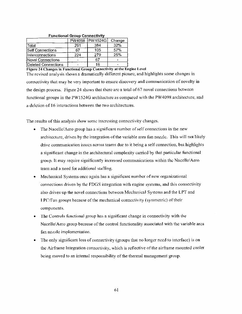
Functional Group ConnectivityPW4098 PW1524G Change
Total 291 384 32%Self Connections 67 105 57%Interconnections 224 279 25%Novel Connections - 67 -
Deleted Connections - 16 -
Figure 24 Changes in Functional Group Connectivity at the Engine Level
The revised analysis shows a dramatically different picture, and highlights some changes in
connectivity that may be very important to ensure discovery and communication of novelty in
the design process. Figure 24 shows that there are a total of 67 novel connections between
functional groups in the PWl 524G architecture as compared with the PW4098 architecture, and
a deletion of 16 interactions between the two architectures.
The results of this analysis show some interesting connectivity changes.
" The Nacelle/Aero group has a significant number of self connections in the new
architecture, driven by the integration of the variable area fan nozzle. This will not likely
drive communication issues across teams due to it being a self connection, but highlights
a significant change in the architectural complexity carried by that particular functional
group. It may require significantly increased communications within the Nacelle/Aero
team and a need for additional staffing.
* Mechanical Systems once again has a significant number of new organizational
connections driven by the FDGS integration with engine systems, and this connectivity
also drives up the novel connections between Mechanical Systems and the LPT and
LPC/Fan groups because of the mechanical connectivity (symmetric) of their
components.
* The Controls functional group has a significant change in connectivity with the
Nacelle/Aero group because of the control functionality associated with the variable area
fan nozzle implementation.
* The only significant loss of connectivity (groups that no longer need to interface) is on
the Airframe Integration connectivity, which is reflective of the airframe mounted cooler
being moved to an internal responsibility of the thermal management group.
61

4.3.5.2 Summary of Changes of Architectural Changes on OrganizationalConnectivity
The most significant changes in the organization by both the aggregate and novel connections
method are to connectivity with groups that do not hold the traditional "core" disciplines of the
gas turbine industry - the design of the engine "core" - but are with groups that perform a
supporting role to the primary value delivery of the engine. Air Systems Design and Integration
primarily provides cooling functionality to the engine components, and Mechanical Systems
provides the bearing compartments and subsystems necessary to support the rotors. This may
reflect a potential trend in advancements in engine technology and performance coming from
non-traditional areas of the supporting subsystems, and not directly from the traditional sources
of performance. It may be very difficult to get substantial gains from the core modules such as
LPC HPC etc.. because these have been optimized for many years. This limit in technological
gain from a given architecture has been well documented by Christiansen(Christensen, 1997) and
Utterback(Utterback, 1996), with the move to new architectures providing significant performance
gain, and being rewarded with significant gains in market share for the new product. The geared
turbofan architecture reflects a significant leap in engine performance with respect to fuel
efficiency and noise, and the most significant changes appear to be in subsystem integration. To
move a conventional architecture to similar performance, very significant changes in core engine
capability will need to be made(Wall et al., 2010).
4.3.5.3 Challenges with representation of organizational interaction throughthe DSM
The matrix for the PW4098 included the bifurcation duct that was a "conduit" that transferred
subsystem plumbing and wiring harnesses across the fan duct. This duct (the intermediate case
strut) is owned by the team working on the intermediate case, and is a contentious piece of real
estate in the design process because of the number of pieces of plumbing, ducting and wiring
harnesses that need to cross from the outside of the engine to the engine core. For this reason,
this duct was included in the DSM for the engine. This created a difficulty in mapping
organizational interaction when the social layer analysis was performed in that it effectively
decoupled the engine controller (FADEC) from the components that it was monitoring and
controlling because of the duct in-between the two. This was remedied by adding the controls
group as an "owner" of the bifurcation duct as well as the Fan/LPC group, which then corrected
62

the apparent connectivity gap. This does highlight a challenge of utilizing the DSM to map
connectivity in both the physical an information flow domains, because the information flow
domain may not depend on the connectivity between the endpoints as the information transfer
itself is valuable. In other words there is a distinction to be made between the physical way in
which the information travels (the equivalent of the physical layer on the internet, i.e. wires,
servers, TCP/IP, etc) and the application or logical layer that connects the producers and
consumers of information regardless of the way in which the information travels between them.
In the physical domain, there is particular value in the path taken by the connectivity. In
constructing the DSM, the purpose of the connectivity must be kept in mind. Another approach
for this could be to revise the methods for tracing the path independent connections (information
transfer) to include only the endpoints of the connectivity. This method would not be robust in a
system with loops, however, and would require user intervention to highlight the intended start
and end points of the information.
4.3.6 Aggregate Discipline Connectivity ChangesThe functional group connectivity mapped above was then mapped to the primary technical
disciplines represented by those functional groups. A similar analysis to calculate the change in
connectivity in the technical discipline area was performed and reflects the significant increase in
connectivity between functional groups. The aggregate changes are shown in Figure 25.
U)
U) 0
A 0 F-0) -)
System Enierig - -
Fae V-C U)
2 c c 2 cno ) U) ..-
Aero-Thermo Fluids 68. 12 11 0 -2Controls and Diagnostics 11 -12 2 0 -2Design 11 2. 12 2 1Structures -1 1 2 2 0S ystems Engineering -1 -2 1 0 0
Figure 25 Aggregate changes in Discipline Connectivity
63

4.3.7 Novel Changes in Discipline Connectivity
The analysis was then extended to determine where new or deleted connectivity exists in the new
engine architecture as shown in Figure 26 following the novel group connection method outlined
above.
U)
0
Lo
U)
0
C
C
U)
0
C).
a)0
U
2U)
a)
W
C
C
Aero-Thermo FluidsControls and DiagnosticsDesignStructuresSystems Engineering
Figure 26 New and Deleted Discipline
-22 1
1 22-2 1i
Connectivity
The new and deleted changes are far fewer than the aggregate changes, but do reflect a few new
connections. In particular, there is an increasing connectivity between the structural analysis
discipline and others - likely coming from the increased number of shafts and support structures
in the GTF architecture. The "Structures" discipline in this mapping owns a very limited number
of components, and is primarily concerned with the engine dynamics with respect to the shaft
dynamics. The increase in novel connectivity here reflects the increase in connectivity between
the rotor dynamics area of analysis on the engine and the traditional "Design" domain, which is
primarily responsible for the mechanical design of the FDGS. The insertion of this "Design"
domain component in between the fan and compressor (two "Aero-Thermal" owned
components) results in this new connectivity.
64

4.3.8 Particular Challenges in Representing Organizational Connectivity Via
the DSM
The "Externals" organization is challenging to represent in this architecture, as they are
responsible for the mounting and connection of all of the components on the outside cases of the
engine, but do not own the design of the components themselves. In effect, they actually own
many of the connections in the DSM, but not the elements connected themselves. This also
presents distinct challenges in the design process, in that their work is generally reactive by
necessity. This group is not represented in this work because of their connectivity and not
component ownership, and it is not expected that there are significant novel connections would
be present in their work because of the very distributed nature of their traditional role. On a
traditional turbofan engine, the Externals group needs to interface with almost every group, and
this will not change with this particular change in the architecture.
The "Air Systems Design Integration" (ASDI) organization is challenging to represent for
similar reasons to the "Externals" organization. The DSM was constructed around primary
physical components which represent functionality in the engine, but some of the secondary
flows utilize pathways that are not represented by dedicated physical components, such as
controlled gaps between otherwise existing components. Because of this issue, there is some
organizational connectivity that is challenging to represent in the DSM format.
A potential refinement that would assist in correcting this is the assignment of ownership to the
flows in the engine itself, instead of the components. This would then potentially allow for
ownership of the connections between components in the DSM, rather than just the components
themselves. Ownership could then be tagged to particular flow types, with ASDI owning the
secondary flows in the DSM, which are tagged independently in the current scheme. This would
require very careful tagging of flows in the DSM, and may lead to additional nomenclature
challenges as flows change ownership through various components. This is kept for future work.
4.3.9 Overall Impact of Architectural Change on the Organization
The analysis of the functional group connectivity as well as the technical discipline connectivity
highlights that there are some potentially significant new connections between groups and
individuals brought on by the architectural changes, and other research by Carlile demonstrates
65
that these interactions will need to be carefully managed to prevent latent design problems that
could adversely impact the cost and schedule of engine development.
4 .3.10Integration tools as Boundary Objects
The interfaces in the design and development process are managed through interactions and
communications between individuals and teams. These interactions produce and utilize artifacts
such as presentations, interface documents and prototypes for communication, all of which can
be considered to be "boundary objects" for the process. Boundary objects are documents, tools
or processes that enable the communication of knowledge between people or groups with
different implicit knowledge and terminology. The boundary object concept is taken from
sociology, and was proposed by Star and Griesemer (Star & Griesemer, 1989), and is prevalent in
many forms in the technical organization. Presentations of technical results by engineers to
management become a boundary object between the engineers and management, physical mock
ups can be boundary objects between engineering and manufacturing, and performance
predictions can be a boundary object between two different technical disciplines. People may
also function as boundary objects in an organization if they have the ability to translate between
different functional groups.
4.3.11 Critical Boundary Objects at Pratt & Whitney
The single most influential set of boundary objects in the current design system at Pratt &
Whitney is the suite of "Engineering Standard Work" documents. Engineering Standard Work
(ESW) is defined according to the patent as:
"A method and systemfor managing complex projects uses aframework having workflow maps
containing activity blocks that provide detailed, easily accessible information within the
framework about the project. The framework links functional groups, their associated activities,
and the dependences between activities. The detailed, prescriptive instructions provided at each
stage in the process creates in-process quality control, reducing the likelihood of costly mistakes
and turnbacks. Implementing the framework as a web-based application allows easy access to
the framework as well as data entered into the frameworkfor future analysis, making it easy to
identify improvement opportunities in the framework. "(Saxena et al., 2009)
66

The objective of the ESW implementation is to function as a connectivity roadmap and guide for
the design and integration of the propulsion system, ensuring all required calculations, tests and
verifications are done. As a boundary object, this provides a common language and core set of
instructions to manage the design and interface process. Given the analysis performed on the
novel connectivity, investigation should be performed to determine if additional ESW
documentation should be developed to guide the interchanges required in the novel connections
discovered through the functional group interaction mapping.
5 Summary and Future Work
The analysis performed developed a DSM to represent the architecture of a traditional turbofan
engine represented by the PW4098, and compared that with the DSM of a geared turbofan
architecture represented by the PW I524G. The analysis showed that there was a significant
increase in connectivity across the components that comprise the function of the machine, and
these components formed a more "distributed" architecture than the more traditional engine
layout. The five clearly defined modules for the PW4098 expanded to a much more
interconnected 15 modules for the PW1524G based on the Newman-Girvan modularity analysis.
The increase in connectivity of the architecture was also reflected in the organizational
interactions, and an analysis was performed to showed that this resulted in a 32% increase in
functional group connectivity overall, and most importantly, resulted in 67 novel connections
between functional groups that did not require interfacing on the older architecture. The increase
in architectural complexity is enabling a significant increase in predicted engine performance
metrics for noise and fuel consumption, and the architectural changes may represent a
"disruptive" type change in the large commercial engine market.
With the linkage between the DSM (architecture) and functional groups made, the potential
impact of the architecture on the organization and integration effort can be assessed. Future
work could continue to expand to combine functional analysis through MDO, with the
architectural complexity analysis, and the organizational impact. The MDO analysis could
potentially. be utilized to provide a relative strength of the architectural connections in the DSM,
which was represented uniformly in this work. An initial MDO analysis was performed using
publicly available data for the PW1 524G architecture, and demonstrated that the major system
67

trades presented by Sabnis(Sabnis, 2005) could be replicated without proprietary data.
Representative results from that analysis are shown in the Appendix 6.2 Open Literature MDO
Model Results.
From the business impact perspective, using the analysis performed in this work to calculate the
change in number of functional group interactions could potentially be evaluated through the
analysis of a number of similar products with different architectures, and may provide some
insight into the connections between architectural complexity and integration cost.
68

ReferencesAbstraction.pdf. (n.d.). . Retrieved from
http://www.darpa.mil/tto/programs/meta/pdf/Abstraction.pdf
ACI Aircraft Noise Rating Index (Update 2010). (n.d.). . Airports Council International.
Retrieved from
http://www.airports.org/aci/aci/file/ACI Priorities/Environment/201 0/ACIAircraftNois
eRating_Index_2010.pdf
Allen, T. J. (1984). Managing the Flow of Technology: Technology Transfer and the
Dissemination of Technological Information Within the R&D Organization (1 st ed.).
Cambridge, Mass: MIT Press.
Aviation Maintenance Magazine:: Geared Turbofan: Maintenance Simplified? (n.d.). . Retrieved
January 14, 2011, from http://www.aviationtoday.com/am/issue/productfocus/Geared-
Turbofan-Maintenance-Simplified_32283.html
Black, L., & Carlile, P. (n.d.). Apparent versus Actual Knowledge Integration in Cross-
Functional Reviews: Specifying a Knowledge Integration Capability by Confronting
Latent Problems. Unpublished.
Bowen, H., & Purrington, C. (2004, February 18). Pratt & Whitney: Engineering Standard Work.
Harvard Business Review Case Study, 24.
C Riegler, & Bichlmaier, C. (n.d.). THE GEARED TURBOFAN TECHNOLOGY -
OPPORTUNITIES, CHALLENGES AND READINESS STATUS. MTU Aero Engines
GmbH, Muchen, Germanyn.
Carlile, P. R. (2004). Transferring, Translating, and Transforming: An Integrative Framework for
Managing Knowledge Across Boundaries. ORGANIZATION SCIENCE, 15(5), 555-568.
69
doi: 10.1 287/orsc. 1040.0094
Christensen, C. M. (1997). The Innovator's Dilemma: When New Technologies Cause Great
Firms to Fail (1st ed.). Harvard Business Press.
Danilovic, M., & Browning, T. R. (2007). Managing complex product development projects with
design structure matrices and domain mapping matrices. International Journal ofProject
Management, 25(3), 300-314. doi:10.1016/j.ijproman.2006.11.003
Eppinger, S. D., Whitney, D. E., Smith, R. P., & Gebala, D. A. (1994). A model-based method
for organizing tasks in product development. Research in Engineering Design, 6(1), 1-13.
doi:10.1007/BFO1 588087
Hague, D. C., & System, D. A. M. P. (2001). Description ofa Turbofan Engine Product
Development Process.
International DSM Conference (11, 2009, Greenville, SC), Sinha, K., & de Weck, 0. (2009).
Spectral and Topological Features of 'Real-World' Product Structures. In M. Kreimeyer
(Ed.), Proceedings of 11th International DSM Conference. Presented at the 11T H
INTERNATIONAL DESIGN STRUCTURE MATRIX CONFERENCE, DSM'09,
Greenville, South Carolina: Hanser.
JT15D. (n.d.). .
Katz, R., & Allen, T. J. (1985). Project Performance and the Locus of Influence in the R&D
Matrix. The Academy of Management Journal, 28(1), 67-87. doi: 10.2307/256062
Kreimeyer, M., & International DSM Conference (11, 2009, Greenville, SC). (2009).
Proceedings of 11th International Structure Matrix : Greenville, SC, 12 and 13 October
2009 nchen: Hanser.
Malone, T. W. (1993). The Interdisciplinary Study of Coordination. Cambridge, Mass: Center
70

for Coordination Science, Alfred P. Sloan School of Management, Massachusetts
Institute of Technology.
Mascoli, G. J., System, D. A. M. P., & Sloan, S. 0. M. (1999). A Systems Engineering Approach
to Aero Engine Development in a Highly Distributed Engineering and Manufacturing
Environment.
Newman, M. E. J., & Girvan, M. (2004). Finding and evaluating community structure in
networks. Physical Review E, 69(2), 026113. doi:10.1 103/PhysRevE.69.026113
Next Generation Product Family Familiarization. (n.d.). . Retrieved January 15, 2011, from
http://wenku.baidu.com/view/0d35934733687e21af45a97e.html
Papalambros, P. Y. (2000). Principles of Optimal Design: Modeling and Computation (2nd ed.).
Cambridge: Cambridge University Press.
Pratt & Whitney Careers: Find Your NEXT Job Today! (n.d.). . Retrieved January 15, 2011,
from http://www.prattcareers.com/job-start.asp
PurePower® PW1000G Engine - Applications - CSeries. (n.d.). . Retrieved January 15, 2011,
from http://www.purepowerengine.com/CSeriesaircraftinformation.html
Rowles, C. M. (1999). System Integration Analysis ofa Large Commercial Aircraft Engine.
Sabnis, J. (2005, May 24). Emissions and Noise - Next Frontier for Aircraft Engine
Technologies. Presented at the AIAA/AAAF Aircraft Noise and Emissions Reduction
Symposium, Monterey, California. Retrieved from
http://www.google.com/url?sa=t&source=web&cd=1 &ved=0CBMQFjAA&url=http%3A
%2F%2Fwww.aiaa.org%2Fevents%2Faners%2FPresentations%2FANERS -
Sabnis.pdf&rct=j&q=EMISSIONS%20AND%20NOISE%20NEXT%20FRONTIER%20
FOR%20AIRCRAFT%20ENGINE%20TECHNOLOGIES&ei=C7YxTeuyLNDpgAe67
71
LCDCw&usg=AFQjCNFWwZUrft4IgGpLYQQCgi4s-nvPQ&sig2=AEMWxqQadk0Y
EyS-hQl qNQ&cad=rja
Saxena, V., Srinivasan, S., & Adams, J. (2009, February 24). Engineering standard work
framework method and system. Retrieved from
http://www.google.com/patents/about?id=iPezAAAAEBAJ&dq=engineering+standard+
work
Software Architecture, Software Quality, Impact Analysis, Dependency Management and DSM
Tools. (n.d.). . Retrieved January 15, 2011, from http://www.lattix.com/
Star, S. L., & Griesemer, J. R. (1989). Institutional Ecology, 'Translations' and Boundary
Objects: Amateurs and Professionals in Berkeley's Museum of Vertebrate Zoology, 1907-
39. Social Studies of Science, 19(3), 387420.
Suh, E. S., Furst, M. R., Mihalyov, K. J., & Weck, 0. D. (2009). Technology infusion for
complex systems: A framework and case study. Systems Engineering, n/a-n/a.
doi: 10.1002/sys.20142
Suh, E. S., Furst, M. R., Mihalyov, K. J., & de Weck, 0. L. (2008). Technology Infusion: An
Assessment Framework and Case Study. ASME Conference Proceedings, 2008(43284),
297-307. doi:10. 11 15/DETC2008-49860
Suh, E. S., de Weck, 0., & Furst, M. (2008, January). Estimating the Impact of Technology
Infusion. Xerox Corporation.
Utterback, J. M. (1996). Mastering the Dynamics ofInnovation (2nd ed.). Harvard Business
Press.
Wall, R., Kingsley-Jones, M., Norris, G., Mecham, M., & Warwick, G. (2010, December 6).
Leap of Faith. Aviation Week and Space Technology, 25-28.
72

de Weck, 0., & Wilcox, K. (2010, Spring).. MIT Course ESD.77J, Cambridge, MA.
de Weck, 0. (2010, April). PW-MIT-Geared Turbofan DSMIntro. Pratt & Whitney, East
Hartford, CT.
73

6 Appendix
6.1 DSM Manipulation Source Codes
The PERL scripts developed to enable manipulation of the DSM's between Excel (for DSMgeneration and presentation) and Matlab (numerical analysis) are included here.
The process flow (with example filenames) for using the attached scripts is:
. Develop Quad DSM in Excel (mydsm.xls) -> Save as a CSV file (mydsm.csv)
. Encode the DSM with all connections or with only the energy flow connections
dsm encode.prl mydsm.csv all
or
dsmencode.prl mydsm.csv 15
. Work on the DSM using matlab to perform any network or modularity analysis, etc
matlab dsm.m
. Create a new order for the components in the DSM by hand or with matlab(neworder.csv)
. Reorder the encoded DSM
dsmreorder.prl neworder.csv dsm out.csv
. Decode the encoded DSM back to the quad connection format for human consumption
dsm decode.prl dsm sorted.csv
. Open and admire your work in Excel (dsm sorted.csv). Some formatting will berequired to make it more "readable". A rudimentary VB script is provided that wasutilized for this work.
6.1.1 DSM Encoding Key1, mech,13, flow,37, info, 515, energy, 4
31,gaspath flow,3
63,bypass flow,3127,secondary flow,3
255,fuel flow,3
511,oil flow,3
74

1023, torque, 15
2047,electrical,15
4095, chemical, 158191,thermodynamic,15
16383,hydraulic,15
6.1.2 DSM Encoding Script#!/usr/bin/perl -w# This script takes a quad based un-encoded csv DSM and creates# the encoded, matlab friendly dsm# Form of call:# dsm encode.prl DSMFILE.csv CONNECTION# Where: DSMFILE.csv is the deWeck style four connection dsm in csv format# and CONNECTION is the encoded connection that you want to work with (i.e. 1 formechancial, 3 for flow, etc or "all" for everything)# Note that these matrices can be added in Matlab to get other combinations (i.e. flow + mech)
$htmloutfile="dsmout.html";$csvoutfile ="dsmout.csv";$matlabfile = "dsm.m";$delimiter = ",";
# The DSM encoding values# Read the encoding key from the encodingkey.txt file if it existsif(open(KEY,"encodingkey.txt")){
while (<KEY>){($flag,$tag) =split /$delimiter/, $;if($flag && $tag){
push (@values,$flag);push (@tags,$tag);
}}
}else{# else use the default encoding
@values = (1,3,7,15,31,63,127,255,511);@tags = ('mech','flow','info','energy','gaspath flow',bypass flow','secondary flow','fuel flow',
'oil flow');}
### This is where the output is controlled# Select which connection or "all" to output
75

#$connection = "all";#$connection = 3;if($ARGV[1]){
$connection = $ARGV[ 1];}else{
$connection = "all";}
# The input file from the user$file= $ARGV[0];open(FILE,$file) or die "Error $!\n";chomp(@file =<FILE>);close FILE;
####### Start here
# Load the DSM and prep for any other operations# break the dsm up# get the headersmy @dsm = ();$headers = splice @file, 0, 1;my @headers = split /$delimiter/, $headers;
# Note that we need to clean up the matrix now#get rid ofjunk entry in the upper left corner between the header rowssplice @headers, 0,1;
# Get the headers from the row going across the top.# MAKE SURE THAT THIS IS CORRECT IN THE CSV FILE!!!# Remove the odd numbered elements of the list to remove duplicate headers# Remember that in per], indicies start at 0!for($i=1;$i<=$#headers;$i++){
splice(@headers,$i,1);
}
# For each line in the remaining matrix, store the matrix valueforeach $line (@file){
# using the 'my' forces perl to create new instances each time# this is critical for the anon array
# note the -1 tells it to include trailing whitespacemy @line = split /$delimiter/, $line, -1;
# throw away the first element which is the label (we have the headers stored elsewhere)splice @line, 0, 1;# merge columns by summing
76

# trying "0"for($i=O;$i<$#1ine;$i++) {
$secondvalue = splice(@line,$i,1);if(!$second value){
$second-value = 0;
}if(!$line[$i]){
$line[$i]= 0;
}$line[$i]= $line[$i] + $secondvalue;
}# print "Element count on load = $#ine $line[O] $line[$#line]\n";
# Create an anonymous array of arrayspush @dsm, \@line;
}
my @newdsm 0;
for($i= 1;$i<=$#dsm;$i++){$firstlineref= $dsm[$i-1];
@firstline = @$firstilineref;$secondline ref= splice(@dsm,$i,I);
@secondline = @$secondline-ref;
my @new-();for($j=0;$j<=$#firstline;$j++) {
if(!$first line[$j]){$firstline[$j]=0;
iif(!$second line[$j]){
$second line[$j]=0;
I$new[$j]= $firstline[$j]+ $second line[$j];
}push @newdsm, \@new;
}
#@dsm 0;@dsm =@newdsm;
# Various operations follow here# Check for symmetry in mechanical connections&sym check(\@dsm);
77
## for a single dsmif($connection =-/[0-9]+/){
$newref = &single dsm($connection,\@dsm);@dsm = @$newref;
}## else&writedsm(\@dsm);&writematlab(\@dsm);
##&htmldsm(\@dsm);
# There is a bug in html dsm that corrupts the actual dsm matrix# needs to be fixed before multiple operations are possible# Always running html once and last will avoid the problem
### End of program flow - Subroutines Follow# Sub to check matrix for symmetrysub sym check (){
$dsmref= $_[O];my @dsm = @$dsmref;for ($row-O;$row<=$#dsm;$row++){
for ($col=O;$col<=$#dsm;$col++){# to avoid looking at things twice, only look where the column is > rowif($col>$row){
$encodedl $dsm[$row][$col];$decodedl &decode($encodedl);$encoded2 $dsm[$col][$row];$decoded2 &decode($encoded2);# Test for the mechanical connection flag
# if both pass, the result sums to 2, if neither has it they sum to zero# this is only a problem if they sum to one....
if(&test for flag( 1,$encoded I) + &test for flag( 1,$encoded2)== 1){
print "\nError!\n";print "$headers[$col] <-> $headers[$row]\n";print "Decoded: $decodedl <-> $decoded2\n";print "Encoded: $encodedl <-> $encoded2\n\n";
}}
}}
}
# sub to take the flag and return a text string of the decoded values
78

# used for symmetry check routine to provide english descriptionsub decode (
{$encoded = $_[O];
#decode the elements and return the string of connections$decoded= "";if($encoded && $encoded =-/[0-9]+/){
for($i=$#values;$i>=O;$i=$i-I){# for($i=$#values;$i>=O;$i=$i-1){
if($encoded - $values[$i]>=O){$decoded = $decoded.".".$tags[$i];$encoded = $encoded - $values[$i];
}else{
}}
} else{$decoded="";
}return $decoded;
}
sub write matlabO
{$dsmref $ [0];my @dsm = @$dsmref;
open MATLABFILE, ">", $matlabfile or die "Error $!\n";# Matlab cannot seem to handle text well, so only work with the matrix# in Matlab. The header code is commented out below# print the headers# #ensure that there are quotes around the headers# foreach $header (@headers){# if($header !/\"\'/){# $header = '\".$header.'V';# }#}# $headerstring =join(",",@headers);# print MATLABFILE 'headers={'.$headerstring.'};'."\n";
# print the matrix with the headers replaced by the original indiciesprint MATLABFILE 'dsm=[';foreach $element (@dsm) {
@line = @$element;$linestring = join(",",@line);
79

print MATLABFILE $linestring."\n";}
print MATLABFILE '];';
close MATLABFILE;
}
# sub to write DSM in memory back out to csv# currently dumps to the screensub writedsmO
{$dsmref= $_[O];my @dsm = @$dsmref;
open CSVFILE ,">", $csvoutfile or die "Error $!\n";
@headers copy = @headers;splice @headerscopy,0,0,"";splice @dsm,0,0,\@headers copy;$,=$delimiter;$i = 0;foreach $element (@dsm) {
@line = @$element;if($i>0) {
splice @line,0,0,$headers copy[$i];
Iprint CSVFILE @line,"\n";$i++;
}
# Sub to create an HTML version of the matrixsub html dsmO
{$matrixref = $_[0];my @matrix = @$matrixref;
# Write the HTML version of the matrix
open HTMLFILE ,">", $htmloutfile or die "Error $!\n";
# pad first line with junk
@headers copy = @headers;# splice @headerscopy,0,0,"";
# convert all of the numbers to image tagsfor($i=O;$i<=$ #matrix;$i++) {
80

for($j=O;$j<=$#matrix;$j++) {# Set blanks in the matrix to zeroif(!$matrix[$i][$j]) {
$matrix[$i][$j]=O;}$matrix[$i][$j =~s/\"//g;$matrix[$i][$j]= "<img src=\"".$matrix[$i][$j].".gif\" width=30>";
}}
print HTMLFILE "<html><table border-O cellspacing=O cellpadding-O >\n";foreach $element (@matrix){
print HTMLFILE "<tr>\n";print HTMLFILE "<td>";@line = @$element;splice @line,0,0,$headerscopy[$i];$,="</td><td>";
print HTMLFILE @line,"\n";$i++;
print HTMLFILE "</tr>\n";
print HTMLFILE "</table></html>";close HTMLFILE;return;
}
# Create a dsm with only a single attribute shownsub single dsmo
{# the first argument is the flag we are parsing for (i.e. 1, 3, 5, 11)my ($flag,$dsm) = @_;my @dsm = @$dsm;
for($row-O;$row<=$#dsm;$row++){for($col=O;$col<=$#dsm;$col++){
$encoded = $dsm[$row][$col];# determine which flags are in there
if(&test-for flag($flag,$encoded)){$dsm[$row][$col] = $flag;
}else{$dsm[$row][$col] = 0;
}}
81

}# return the parsed DSM as a reference...return \@dsm;
}
sub testforflago{my ($testflag, $encoded)$ans=O;if($encoded && $encoded =-/[0-9]+/){for($i=$#values;$i>=O;$i--) {
if($encoded - $values[$i]>=O) {$encoded = $encoded - $values[$i];if($testflag == $values[$i]){
$ans=1;
}
}}}else{
$ans=O;
}# print "Returning $ans from $testflag $encoded\n";
return $ans;
}
6.1.3 DSM Decoding Script#!/usr/bin/perl -w# This script takes an encoded dsm and creates the quad connection DSM# dsmencode.prl DSMFILE.csv# Where: DSMFILE.csv is the encoded DSM
$delimiter
# The DSM encoding values# Read the encoding key from the encoding_key.txt file if it existsif(open(KEY, "encodingkey.txt")) {
while (<KEY>) {($flag,$tag) =split /$delimiter/, $_;if($flag && $tag){
push (@values,$flag);push (@tags,$tag);print "Pushed $flag into $tag\n";
}
}else{
82

# else use the default encoding
@values= (1,3,7,15,31,63,127,255,511);@tags = ('mech','flow','info','energy','gaspath flow','bypass flow','secondary flow','fuel flow',
'oil flow');}
# The input file from the user is the encoded csv DSM$file= $ARGV[0];open(FILE,$file) or die "Error $!\n";chomp(@file = <FILE>);close FILE;
# Load the DSM and prep for any other operations# break the dsm up# get the headersmy @dsm = ();$headers = splice @file, 0, 1;
@headers = split /$delimiter/, $headers;
# Note that we need to clean up the matrix now#get rid ofjunk entry in the upper left corner between the header rowssplice @headers, 0,1;
for($i=0;$i<=$#file;$i++) {## get the line from the DSM (all encoded values)$line = $file[$i];# split the line up to get the individual coded connections
# note the -1 tells it to include trailing whitespacemy @line = split /$delimiter/, $line, -1;# An additional "component" with no connections was being created
# at the end of each row. I think that this is just because of the last","# on the line, and this can be fixed by popping off the last element
# pop the last element off, as it's spurious and created by the formatpop @line;# throw away the first element which is the label (we have the headers stored elsewhere)
splice @line, 0, 1;
# Create two new lines in the dsm for the entriesmy @dsml=();my @dsm2=();
foreach $connection (@line){# We are going to create four entries for each one encoded entryif($connection && $connection >0){
$mech = &decode($connection,1);
83
$flow=&decode($connection,3)+&decode($connection,3 1)+&decode($connection,63)+&decode($connection,127)+&decode($connection,255)+&decode($connection,5 11);
$info = &decode($connection,7);$energy = &decode($connection, 15);
}else{($mech,$flow,$info,$energy)= (0,0,0,0);
}push @dsm1,$mech,$flow;push @dsm2,$info,$ energy;
}
# Create an anonymous array of arrayspush @dsm, \@dsml, \@dsm2;
}
&write dsm(\@dsm);
# sub to take the flag and return a text string of the decoded values# used for symmetry check routine to provide english descriptionsub decode 0{
($encoded,$flag) @_# set up the return for zero unless the flag is found$ans=0;$notfound = 1;# decode the encoded flag and return the flag if it is in the encoded valueif($encoded){
for($j=$#values;$j>=0 && $notfound;$j=$j-1){if($encoded - $values[$j]>=0){
# this flag is valid thenif($flag == $values[$j]){
# this is the flag of interest so pass it back$ans = $flag;$notfound=0;
}$encoded = $encoded - $values[$j];
}}
return $ans;}
sub write-dsm()
{
84

my $i;open(OUT,">dsm quadconnection.csv");# print the headers, alternating with spacesprint OUT ","; # for the blank cell which starts things offfor($i=;$i<=$#headers;$i++) {
print OUT $headers[$i],',,';
}print OUT "\n";
for($i=0;$i<=$#dsm;$i=$i+2){$linerefl = $dsm[$i];
@linel = @$linerefl;$lineref2 = $dsm[$i+1];
@line2 = @$lineref2;
print OUT $headers[$i/2],@line ,"\n";print OUT "",@line2,"\n";
}close OUT;
}
6.1.4 DSM Reordering Script#!/usr/bin/perl -w# Reads in a list of elements for the new DSM order, and a csv based dsm# Then writes out a DSM with the order provided by the list# Both files should be of type CSV# Form of call:# dsm reorder.prl ORDERLIST DSMFILE($listfile,$dsmfile)= @ARGV;
# if the file isn't passed to the script, use the default name dsmout.csvif(!$dsmfile){
$dsmfile = "dsm out.csv";
}# The newly sorted DSM file based on the listfile passed to the script$newdsmfile="dsmsorted.csv";
# The delimiter for the data files$delimiter = ';
# Read the list for the desired new order of the componentsopen(MOUT,$listfile) or die "Error $!\n";chomp($neworder = <MOUT>);@neworder = split /$delimiter/, $neworder,-l;close MOUT;
85

# Shift the new order down by one to align with Perl list indicies
@neworder = map {$_-1} @neworder;
# Read the DSM from the original csv file
open(CSVOUT,$dsmfile) or die "Error $!\n";my @dsm;chomp(@dsm=<CSVOUT>);
# Get the header row off of the DSM# and create the header list$headerrow-splice @dsm,0,1;
@headers = split /$delimiter/, $headerrow, -1;# Throw out any blank headers
@headers = grep /[a-zA-ZO-9]/, @headers;
# Working with the rest of the DSM now,# get rid of the first element of each row (the headers)foreach $row (@dsm) {
my @line = split /$delimiter/, $row, -1;splice @line,0,1;# replace the string entry with a reference$row = \@line;
}
# make a copy to start with# Note that the []'s are required to make a *copy* of the list, rather than linking to itmy @dsmnew = [@dsm];
# loop through the matrix putting things in the new order$maxindex = $neworder; # use this instead of the DSM size so that we can use this to generatesub matricies# Shift the indicies by one...
for($row-$maxindex;$row>=O;$row--){for($col=$maxindex;$col>=O;$col--){
$newrow-$neworder[$row];$newcol=$neworder[$col];$dsmnew[$row] [$col]=$dsm[$newrow] [$newcol];
}}
# Copy the dsm back to dsm
@dsm = @dsmnew;
open(SORTED,">$newdsmfile") or die "Error $!\n";
86

print SORTED ",";
# print the headers in the new orderfor($col=O;$col<=$maxindex;$col++){
print SORTED $headers[$neworder[$col]],",";
}print SORTED "\n";for($row-O;$row<=$maxindex;$row++){
print SORTED $headers[$neworder[$row]],",";for($col=O;$col<=$maxindex;$col++) {
print SORTED $dsm[$row][$col],",";
}print SORTED "\n";
}close SORTED;
6.1.5 Visual Basic Script for Use in Excel to Format Quad ConnectionDSM's
Attribute VBName = "DSM Tools"
Sub colorDsm()' To format csv formatted DSM's
Dim dsmArea As Range, dsmCell As RangeDim iRows As Long, iCol As LongDim graycolor As IntegerDim matrixSize As Long 'size of the dsm for the coloringDim homecell As RangeDim index, componentNumber, home As LongDim yellow, red, black, blue, green As IntegerDim c As Range' Define the flow types
Dim mechanical, flow, info, energy, gaspathflow, bypassflow, secondaryflow,
fuelflow, oilflow As Integer
Dim fuelandoil, fuelandair As Integer
' the encoding scheme
mechanical = 1flow = 3info = 7
energy = 15
gaspathflow = 31
bypassflow 63secondaryflow = 127
fuelflow = 255
oilflow 511' Energy flow encoding
torque = 2 A 10 - 1 ' 1023electrical = 2 A 11 - 1 '2047chemical = 2 A 12 - 1 ' '4095
thermodynamic = 2 A 13 - 1 ' 8191hydraulic = 2 A 14 - 1 ' 16383
87
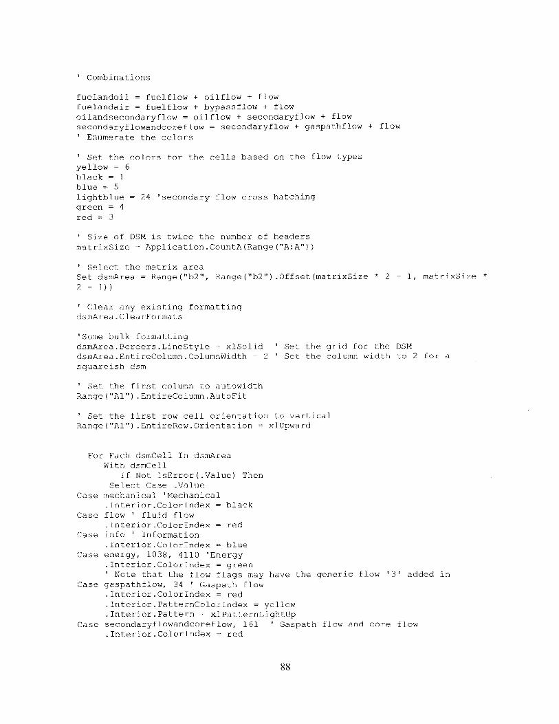
' Combinations
fuelandoil = fuelflow + oilflow + flowfuelandair = fuelflow + bypassflow + flow
oilandsecondaryflow = oilflow + secondaryflow + flow
secondaryflowandcoreflow = secondaryflow + gaspathflow + flow
Enumerate the colors
Set the colors for the cells based on the flow types
yellow = 6black = 1blue = 5lightblue = 24 'secondary flow cross hatching
green = 4
red = 3
' Size of DSM is twice the number of headers
matrixSize = Application.CountA(Range("A:A"))
' Select the matrix areaSet dsmArea = Range("b2", Range("b2").Offset(matrixSize * 2 - 1, matrixSize *
2 - 1))
' Clear any existing formatting
dsmArea.ClearFormats
'Some bulk formatting
dsmArea.Borders.LineStyle = xlSolid ' Set the grid for the DSM
dsmArea.EntireColumn.ColumnWidth = 2 ' Set the column width to 2 for a
squareish dsm
' Set the first column to autowidth
Range ("Al").EntireColumn.AutoFit
' Set the first row cell orientation to vertical
Range("Al").EntireRow.Orientation = xlUpward
For Each dsmCell In dsmArea
With dsmCell
If Not IsError(.Value) ThenSelect Case .Value
Case mechanical 'Mechanical
.Interior.ColorIndex = blackCase flow ' fluid flow
.Interior.ColorIndex = red
Case info ' Information
.Interior.ColorIndex = blueCase energy, 1038, 4110 'Energy
.Interior.ColorIndex = green' Note that the flow flags may have the generic flow '3' added in
Case gaspathflow, 34 ' Gaspath flow
.Interior.ColorIndex = red
.Interior.PatternColorIndex = yellow
.Interior.Pattern = xlPatternLightUpCase secondaryflowandcoreflow, 161 ' Gaspath flow and core flow
.Interior.ColorIndex = red
88

.Interior.PatternColorIndex = yellow
.Interior.Pattern = xlPatternLightUpCase bypassflow, 66 ' Bypass flow
.Interior.ColorIndex = red
.Interior.PatternColorIndex = blue
.Interior.Pattern = xlPatternLightDown
Case secondaryflow, 130 ' Secondary Flow.Interior.ColorIndex = red
.Interior.PatternColorIndex = lightblue.Interior.Pattern = xlPatternLightDown
Case fuelflow, 258 ' Fuel Flow.Interior.ColorIndex = red
Case oilflow, 514 ' Oil Flow.Interior.ColorIndex = red
Case fuelandoil, fuelandair ' Oil Flow + fuel flow, oil flow and bypass flow.Interior.ColorIndex = red
Case oilandsecondaryflow ' Oil flow and secondary flow.Interior.ColorIndex = red
Case chemical + energy, hydraulic + chemical + energy, thermodynamic +energy, thermal + energy, torque + energy, hydraulic + energy, electrical +energy
.Interior.ColorIndex = green
End Select
End If
End With
Next
Set the diagonal in the matrix to grayStart at b2, go over one and down one
graycolor = 48index = 0componentNumber = 0
While componentNumber < matrixSizehome = componentNumber * 2
Range ("B2") .Offset(home, home) .Interior.ColorIndex = graycolorRange ("B2") .Offset(home, home + 1) .Interior.ColorIndex = graycolorRange ("B2") .Offset (home + 1, home) .Interior.ColorIndex = graycolorRange ("B2") .Offset (home + 1, home + 1) .Interior.ColorIndex = graycolorcomponentNumber = componentNumber + 1Wend
End Sub
6.2 Open Literature MDO Model ResultsThe MDO model was built by Kaushik Sinha, Jeremy Agte and Denman James with dataavailable in the public domain, and assumed engine architecture based on studies of other knownsystem schematics for other engines.
The n-squared diagram of the MDO model generated represented the major functionalconnectivity of the engine.
89

Bypass aid Dw / Thrust
AOHEXSecondr airflow:
FDGS Core fow:TorqmFuel
FOHEX --on Exhaust
Coref+aTorque Exhaust
NozzleAir Fuel Thrust
ai 1W
Figure 27 N-squared diagram for the MDO model
The model design vector encompassed the critical design variables for the components modeled:
xi = 7 c, compressor pressure ratiox2 = TO, maximum turbine inlet total temperature [OR]X3= a, bypass ratioX4 = nsc, number of compressor stagesxs = gr, fan drive gear ratioX6= fan pressure ratio
The problem was run and an optimum configuration was determined for the given performance objectives. Thesensitivity of the TSFC at the optimum configuration reflect the importance of the bypass ratio in achieving theTSFC at the optimum value is provided in Figure 28.
fan pressure ratio -
gear ratio -
bypass ratio -
turbine inlet temp -
compressor pressure ratio - -
-0.12 -0.1 -0.08 -0.06 -0.04 -0.02 0 0.02 0.04Post Optimum Sensitivity of TSFC wrt Design Variables (normalized derivatives, dJ/dx*(xdJ,))
Figure 28 Design variable sensitivity study at the optimum configuration
A cost function was determined based on the relationship proposed by Raymer to be utilized asan objective function, and when combined with the performance modeling using the functionalmodel optimization, a clear linkage between the cost and specific thrust on the Pareto front canbe seen in Figure 29. The FDGS gear ratio is a clear driver to increase the specific thrust withlow impact to system cost, while additional gains in specific thrust through more conventionalmeans (compressor stages) increases the cost substantially.
90

Pareto Front m F-space
r of compressor stageslevel and gear ratio
My from A to 8
Is
C
Number of compressor stagesincreases to its upper eniitfrom E to C
*
at theAses
itB
19 20Specific Thrust Pbinbmts]
21 22 23
Figure 29 Pareto front showing cost and performance linkage for the GTF architecture
91
3.7
3,65 -
6
3.6
3.56
3.5
346
3.4
Numbo-minimsnomine
17
75.3