TNV TIER3 INTRODUCTION - autocd.biz 4TNV 98_Z_T3 training text 1.pdf · TNV TIER3 INTRODUCTION....
21
TNV TIER3 INTRODUCTION
-
Upload
trinhtuyen -
Category
Documents
-
view
239 -
download
0
Transcript of TNV TIER3 INTRODUCTION - autocd.biz 4TNV 98_Z_T3 training text 1.pdf · TNV TIER3 INTRODUCTION....

TNV TIER3 INTRODUCTION

Introduction program:Introduction program:TNV TIER3 TechnologyTNV TIER3 Technology (basic introduction)(basic introduction)
TNV ECO governorTNV ECO governor (practice & visualization)(practice & visualization)
n Engine model and technical update
n (DIS)advantages NEW technology
n ECO governor system operation
Yanmar service tool Yanmar service tool
n Yanmar Service tool explanation
n Diagnostics & troubleshooting

TNV Tier 3 TechnologyTNV Tier 3 Technology Engine model coding (new)
TNV Tier 3 TechnologyTNV Tier 3 Technology Engine model technical update
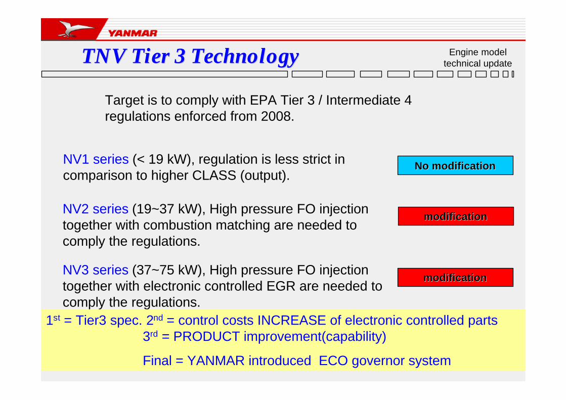
NV1 series (< 19 kW), regulation is less strict in comparison to higher CLASS (output).
Target is to comply with EPA Tier 3 / Intermediate 4 regulations enforced from 2008.
modificationmodificationNV2 series (19~37 kW), High pressure FO injection together with combustion matching are needed to comply the regulations.
No modificationNo modification
modificationmodificationNV3 series (37~75 kW), High pressure FO injection together with electronic controlled EGR are needed to comply the regulations.
1st = Tier3 spec. 2nd = control costs INCREASE of electronic controlled parts 3rd = PRODUCT improvement(capability)
Final = YANMAR introduced ECO governor system

TNV Tier 3 TechnologyTNV Tier 3 Technology Engine model technical update
DPF NOx Catalyzer
DPF
EPA-TierⅡ
EPA-TierⅢ
EPA-TierⅣ
EPA-TierⅡ EPA-TierⅣ
Under19kW
NVⅠ
75kW
37kW
19kW
56kW
NVⅡN
VⅢ
ML Pump + Mechanical Governor
MP PumpMP Pump
(ECO.Governor : Option)
MP Pump +ECO.Governor
+EGR
MP Pump+ECO.Governor +
EGR
Common Rail
※ECO.Governor = Electronic Control Governor
※MP Pump = Mono Plunger Pump※ML Pump = Mini in Line Pump

TNV Tier 3 TechnologyTNV Tier 3 Technology Engine model technical update
For 2008 Regulations (US.EPA-TierⅢ & EC-StageⅢA )
3719 56 75 1308
7.5
4.74.0
0.40.3N
Ox+
HC
g/k
Wh
PM
g/k
Wh
OutputkW
NO
x+H
C0.8
0.6
6.6PM
IDI DI
In-DirectInj. FuelPumpwith
MechanicalGovernor
Direct Inj. FuelPump withMechanicalGovernor
Optional ECOgovernor
Direct Inj. Fuel Pumpwith
Electric Governor+
Electric controlledEGR system YANMAR =MP= pump
for Direct inj.
NO M
ODI
FICA
TIO
N

TNV Tier 3 TechnologyTNV Tier 3 Technology Engine model technical update
3.0 4.00.5 1.0 1.5 2.0Displacement Litre
NV1NV1 NV2NV2 NV3NV3
NV2 (DI)NV2 (DI)Higher pressure of
fuel injection
(ECO Governor is option)
NV3 (DI)NV3 (DI)
Higher pressure of fuel injection
+Electronic control EGR
+ECO Governor
・MP pump with ECO governor
NV1 (IDI)NV1 (IDI)
Tier II technology is applied to Tier III
・ML Pump

TNV Tier 3 TechnologyTNV Tier 3 Technology Engine model technical update
MP pump (FO-injection) minor change(internal)
(1) Governor actuator (2) Speed sensor(5) Speed sensor gear
(4) Governor link
(3) Governor lever

TNV Tier 3 TechnologyTNV Tier 3 Technology Engine model technical update
YPDYPD--MP4MP4Higher pressure fuel deliveryDelivery valve (CPV)1. Opening press of delivery valve2. Seal length to be changed
Reduce noise and emission
ECO-governor
Standardized electric control
Reduce white smokeCSDStandardized electric control
prevent the cavitation
PlungerAdd a spill lead for sub-port on plunger

Basic dimension is same
as Tier 2 specification
Higher pressure fuel deliveryDelivery valve (CPV)1. To be changed opening press of delivery valve2. To prevent cavitation, seal length to be changed
Reduce noise and emission
ECO-governor
Standardized electric control
Reduce white smokeCSDStandardized electric control
Tier3 ; part to be changed
Tier2 ; part was applied
function
part name
structure
prevent the cavitation
PlungerAdd a spill lead for sub-port on plunger
Reduce LO transition
Pump housing
Additional drain hole etc..
Durable quality
PlungerAdditional groove on plunger
Structural description forStructural description for YPDYPD--MP4MP4
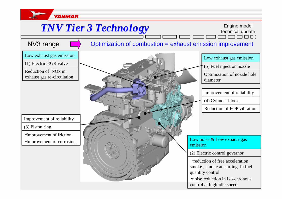
TNV Tier 3 TechnologyTNV Tier 3 TechnologyOptimization of combustion = exhaust emission improvementNV3 range
Optimization of nozzle hole diameter
(5) Fuel injection nozzle
Low exhaust gas emission
Reduction of NOx in exhaust gas re-circulation
(1) Electric EGR valve
Low exhaust gas emission
・Improvement of friction・Improvement of corrosion
(3) Piston ring
Improvement of reliability
・reduction of free acceleration smoke , smoke at starting in fuel quantity control・noise reduction in Iso-chronous control at high idle speed
(2) Electric control governor
Low noise & Low exhaust gas emission
Reduction of FOP vibration
(4) Cylinder block
Improvement of reliability
Engine model technical update

TNV Tier 3 TechnologyTNV Tier 3 Technology Engine model technical update
Principle of EGR system
2-ways to achieve this:
1. Retard (delay) ignition timing.
2. Reduce amount of oxygen in cylinder, to slow down combustion process.
GOOD for emission regulation
BAD for Engine performance & fuel economyCREATES soot and its reducing OIL change interval
Less oxygen drops cylinder and combustion process temperature.
This is done by re-circulating some exhaust gas back into the cylinder
*Temperature (The higher the temperature is, the more Nox generated.)
*Intake air (The more the quantity of intake air is, the more Nox generated.)
How to reduce NOx?
TNV Tier 3 TechnologyTNV Tier 3 Technology Engine model technical update
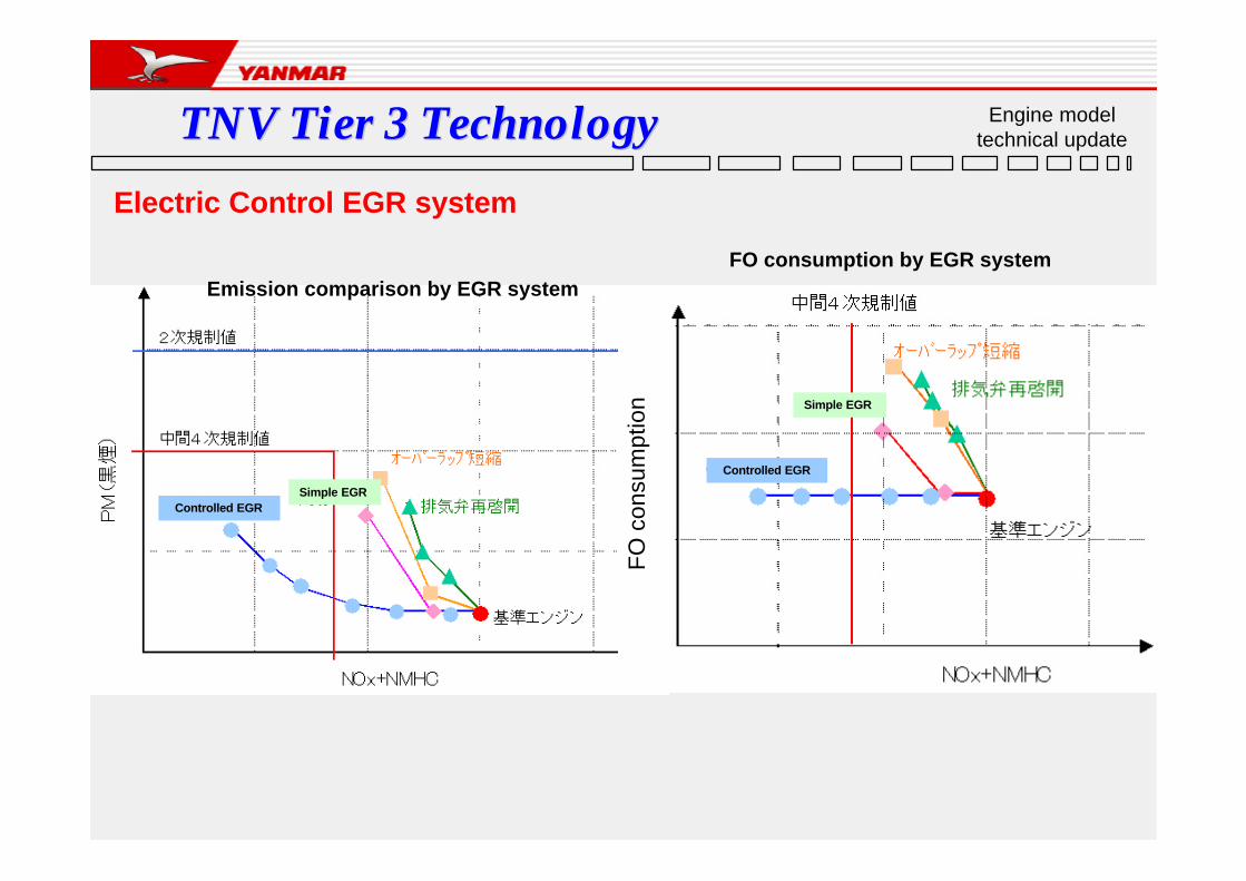
Electric Control EGR system
FO
con
sum
ptio
n
Emission comparison by EGR systemFO consumption by EGR system
Controlled EGRSimple EGR
Controlled EGR
Simple EGR

TNV Tier 3 TechnologyTNV Tier 3 Technology Engine model technical update
Intake Exhaust
ECU Speed , Load & Temp. ECU
EGR-Valve
Piston
Liner
Inj.N
ozz
le EGR-Valve
Combustion Temperature could be reduced.
Nox will be DecreaseNox will be Decrease
Re-circulation
Speed , Load & Temp.
Electric Control EGR system

TNV Tier 3 TechnologyTNV Tier 3 Technology (dis)advantages NEW technology
Advantages of ECO governor
ØControlled EGR valve by engine speed and load
ØOptimum fuel delivery rate at starting and acceleration
ØCombination control with ECU on machine side using CAN-bus correspondence
ØAvailable failure mode diagnosis and service tool
⇒Reduce NOx level for environmental friendly
⇒Reduce smoke level which is the weak point for diesel engine
⇒Adjustable engine speed and droop by machine condition
⇒Using personal computer

TNV Tier 3 TechnologyTNV Tier 3 Technology (dis)advantages NEW technology
Advantages of ECO governor
BIG feature is complete free control of engine speed versus FO amount. NO major restrictions. We can get best power output which matches the work performance of customers machine / application.
A. Droop control
B. Isochronous control
Torque matching LOW speed range
Engine performance @ partial load enhanced.
EG speed match acc. machine requirements
Idling (L&H) adjustment not needed
Establish EG output
Setting of EG speed
Optimization of FO consumption MOST effective EG performance (speed > noise reduction)
TOTAL is Torque curve control
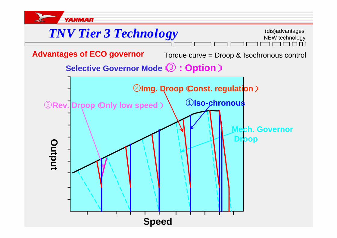
TNV Tier 3 TechnologyTNV Tier 3 Technology (dis)advantages NEW technology
Advantages of ECO governor Torque curve = Droop & Isochronous control
DroopMech. Governor
③Rev. Droop(Only low speed) ①Iso-chronous
②Img. Droop(Const. regulation)
Speed
Ou
tpu
t
Selective Governor Mode(③ : Option)

TNV Tier 3 TechnologyTNV Tier 3 Technology (dis)advantages NEW technology
C. Start control
D. Acceleration control
Advantages of ECO governor
Black smoke at starting and acceleration is reduced
Start Sd 1~2 > Sd 5~6 Acceleration Sd 2~3 > Sd ~1
FO injection control @ acceleration Fuel amount is optimized
Optimized rack position (= FO qty) @ EG start
Improved cold start performance Fuel injection timing is optimized

0 200 400 600 800 1000 1200 1400
TNV Tier 3 TechnologyTNV Tier 3 Technology (dis)advantages NEW technology
Advantages of ECO governor Start control Optimization of FO supply Black smoke at starting and
acceleration is reduced
Excessive Fuel0 200 400 600 800 1000 1200 1400
Fu
el In
ject
ion
Am
ou
nt
Engine Speed min-1
at Full - Throttle
Fuel Increase for Engine Start
Mech.Gov.
ECO Gov.
SMOKE at Starting and Acceleration
consequently
ECO-Governor NO SMOKE VISIBLENO SMOKE VISIBLE at Starting and Acceleration
TNV Tier 3 TechnologyTNV Tier 3 Technology (dis)advantages NEW technology
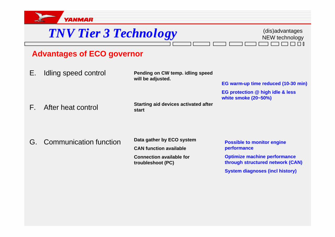
Advantages of ECO governor
E. Idling speed control
F. After heat control
G. Communication function
Pending on CW temp. idling speed will be adjusted.
EG warm-up time reduced (10-30 min)
EG protection @ high idle & less white smoke (20~50%)
Starting aid devices activated after start
Data gather by ECO system
CAN function available
Connection available for troubleshoot (PC)
Possible to monitor engine performance
Optimize machine performance through structured network (CAN)
System diagnoses (incl history)
TNV Tier 3 TechnologyTNV Tier 3 Technology (dis)advantages NEW technology
Disadvantages of ECO governor
A. Costs increase
B. New technology introduced
New advantaged technology / improved engine performance
Customer to be shown advantages
Current service system needs to be updated and trained

![[TNV] Doroga w Rosiju 1](https://static.fdocuments.net/doc/165x107/55cf94d7550346f57ba4c1ff/tnv-doroga-w-rosiju-1.jpg)