tnn oteton sstes o s esse onto n eseent sstes€¦ · man DVGW Code of Practise G 491 describes the...
37
Lightning protection systems for gas pressure control and measurement systems White Paper www.dehn-international.com Contents Risk analysis – Determination of the current state Risk analysis of the gas pres- sure control and measurement system Isolated external lightning pro- tection system Internal lightning protection – Lightning equipotential bonding – Surge protection
Transcript of tnn oteton sstes o s esse onto n eseent sstes€¦ · man DVGW Code of Practise G 491 describes the...
Lightning protection systems for gas pressure control and measurement systemsWhite Paper
www.dehn-international.com
Contents
Risk analysis – Determination of the current state
Risk analysis of the gas pres-sure control and measurement system
Isolated external lightning pro-tection system
Internal lightning protection – Lightning equipotential bonding – Surge protection
2
Lightning protection systems for gas pressure control and measurement systemsWhite Paper
WP033/E/0615 © Copyright 2015 DEHN + SÖHNE
The main functions of gas pressure control and measurement systems are to monitor and calculate gas volumes, automati-cally operate the stations by means of volume and condition-oriented connection and disconnection of measurement and control systems as well as volume control and monitoring of the gas transport between the distribution network opera-tors.
Certain functional units that are connected to the power supply system are subject to the stipulations of section 3 of the German Ordinance on Industrial Safety and Health (BetrSichV). The operator must ensure compliance with these stipulations which apply to e.g. systems in potentially ex-plosive atmospheres whose components are covered by the 94/9/EC directive, e.g. the installation of devices complying with the requirements of the 94/9/EC directive, their installa-tion according to the state of the art, inspection and testing prior to commissioning and recurrent testing by a competent expert under the responsibility of the company. The German Technical Rules on Operational Safety (TRBS) specify in greater detail the fundamental requirements of the German BetrSichV to be observed in this context. The Ger-man DVGW Code of Practise G 491 describes the require-ments for electrical and non-electrical explosion protection of gas pressure control and measurement systems, referring to the existing TRBS as a source of information.
Risk analysis – Determination of the current stateThe current state of the system must be determined in a site survey. To this end, the structural conditions, existing docu-ments and possible requirements of property insurers must be observed.
A risk analysis is performed in cooperation with the operator to define the protection measures required to prevent the destructive effects of lightning strikes and surges. To this end, designers use approved regulations that allow to design a complete protection concept.The IEC 62305 (EN 62305) standard is a reliable design basis for future-oriented lightning protection systems. This stand-ard is used to design, install, inspect and maintain lightning protection systems for structures.The risk of a lightning strike and the necessity of a lightning protection system for an object to be protected are determined according to IEC 62305-1 (EN 62305-1) and IEC 62305-2 (EN 62305-2). Technically and economically optimal pro-tection measures are selected depending on the risk. The IEC 62305-3 (EN 62305-3) and IEC 62305-4 (EN 62305-4) standards describe how to implement the protection meas-ures determined. Thus, the IEC 62305 (EN 62305) standard is a solid basis for operators and designers. This standard makes it easier to take further protection measures for wide-
spread power supply and information technology systems at lower costs. The IEC 62305-4 (EN 62305-4) standard de-scribes measures for protecting electronic systems.
Risk analysis of the gas pressure control and measurement systemThe protection of the structure and technical equipment against the effects of a lightning strike and personal protec-tion must be taken into account right from the design stage. For this reason, adequate protection goals are define togeth-er with the operator before performing a risk analysis.
In our example, the protection goals would be:
¨ Fire and explosion protection
¨ Personal protection
¨ Protection of the electronics of systems with high avail-ability
At first, the loss factors according to IEC 62305 (EN 62305), the required availability and the risk are determined. This leads to the following loss factors:
MEB
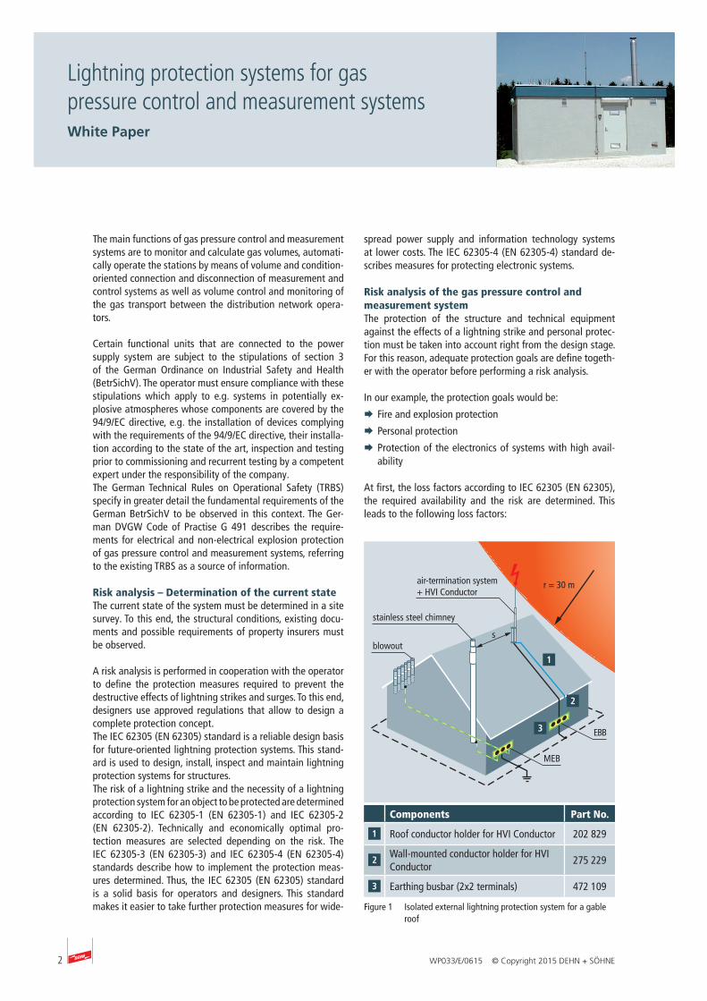
r = 30 m
EBB
sblowout
stainless steel chimney
air-termination system + HVI Conductor
Figure 1 Isolated external lightning protection system for a gable roof
Components Part No.
Roof conductor holder for HVI Conductor 202 829
Wall-mounted conductor holder for HVI Conductor
275 229
Earthing busbar (2x2 terminals) 472 109
3WP033/E/0615 © Copyright 2015 DEHN + SÖHNE
Lightning protection systems for gas pressure control and measurement systemsWhite Paper
¨ L1: Injury or death of persons (loss factor L1 includes the lightning-related ignition source specified in TRBS 2152 Part 3 with regard to explosion protection)
¨ L2: Loss of service to the public
¨ L4: Loss of economic value
The example described below was calculated based on IEC 62305-2 (EN 62305-2) by means of the DEHNsupport software. We expressively point out that the procedure shown is only an example. The solution in Figure 1 is not binding in any way and can be substituted by other equiva-
lent solutions. In the following, possible protection solutions based on LPL II and the most important characteristics of the example depending on the type of installation are described. A high-voltage-resistant, insulated down conductor (HVI Conductor I) can be installed on (Figure 2) or underneath (Figure 3) the roofing.
If conductors must be installed in Ex zone 1 or 2 due to lo-cal conditions, installation instructions No. 1501 must be ob-served. Figures 4 and 5 show an example of a flat-roofed gas pressure control and measurement system.
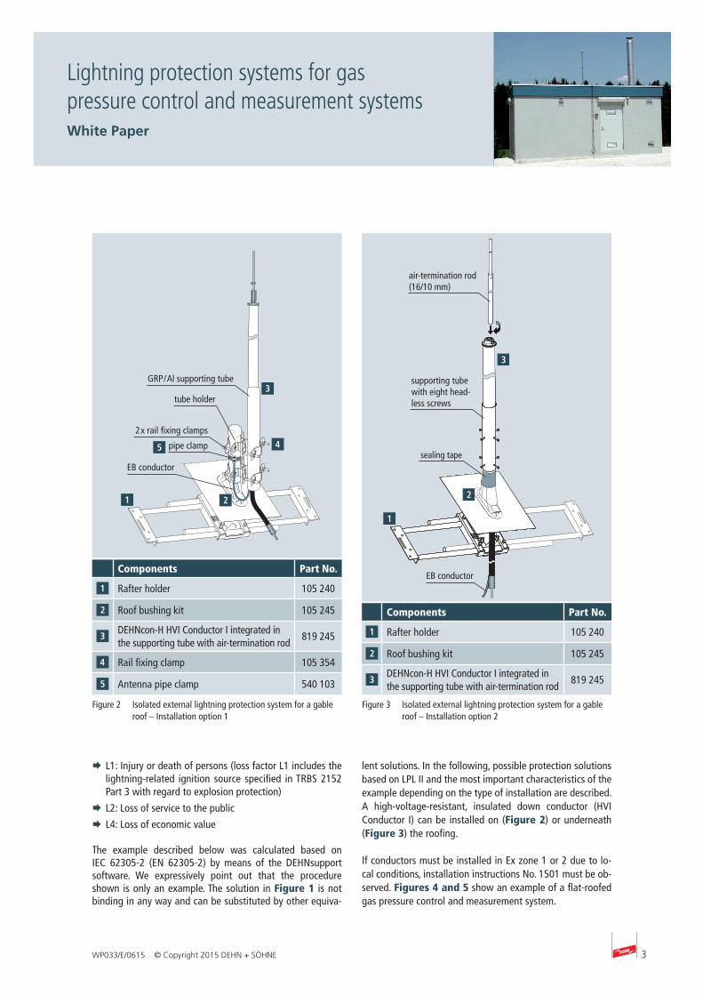
air-termination rod (16/10 mm)
supporting tube with eight head-less screws
EB conductor
sealing tape
Figure 3 Isolated external lightning protection system for a gable roof – Installation option 2
Components Part No.
Rafter holder 105 240
Roof bushing kit 105 245
DEHNcon-H HVI Conductor I integrated in the supporting tube with air-termination rod
819 245
Components Part No.
Rafter holder 105 240
Roof bushing kit 105 245
DEHNcon-H HVI Conductor I integrated in the supporting tube with air-termination rod
819 245
Rail fixing clamp 105 354
Antenna pipe clamp 540 103
GRP / Al supporting tube
pipe clamp
tube holder
EB conductor
2 x rail fixing clamps
Figure 2 Isolated external lightning protection system for a gable roof – Installation option 1
4
Lightning protection systems for gas pressure control and measurement systemsWhite Paper
WP033/E/0615 © Copyright 2015 DEHN + SÖHNE
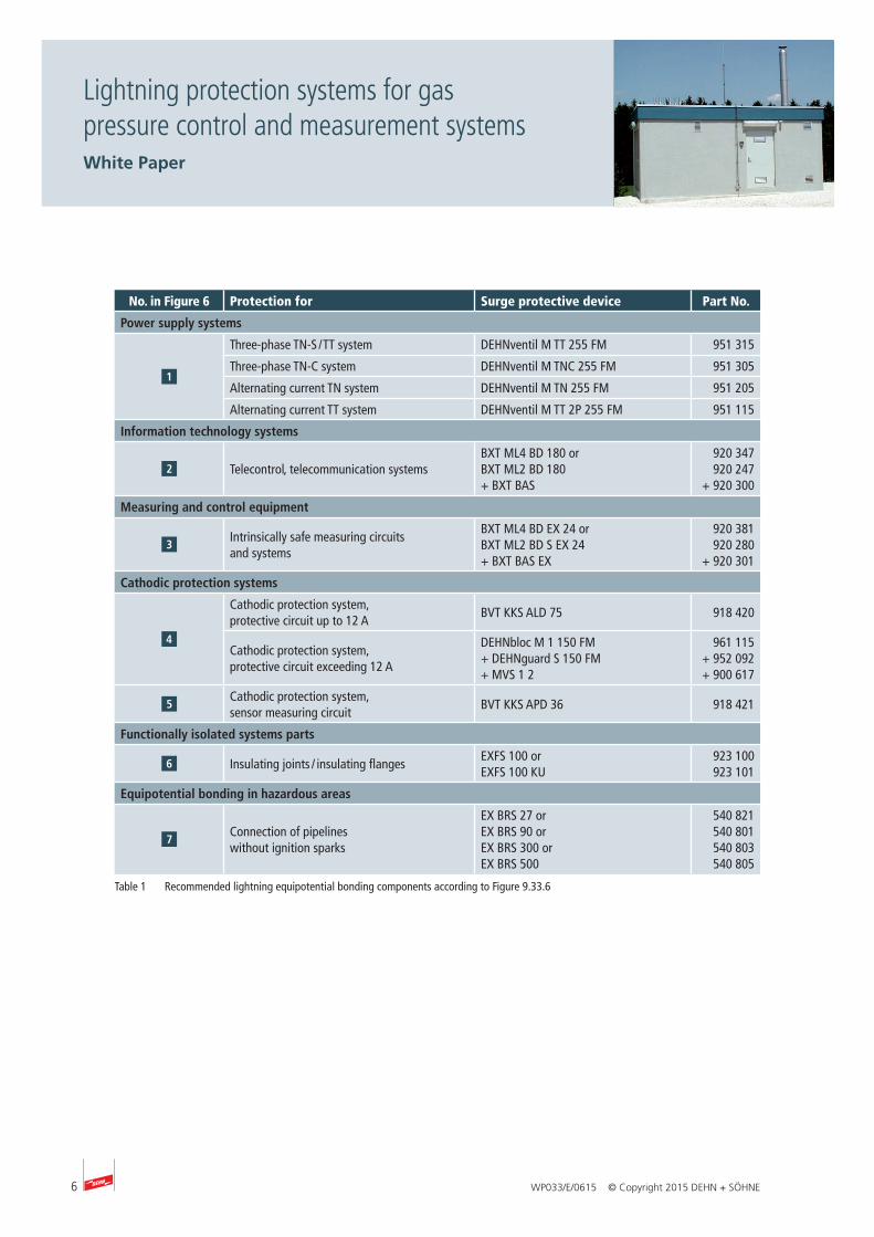
Internal lightning protection – Lightning equi- potential bonding – Surge protectionAll conductive systems entering the gas pressure control and measurement system from the outside must be integrated in the lightning equipotential bonding system (Figure 6). This is achieved by directly connecting all metal systems and indi-rectly connecting all live systems via surge protective devices. These surge protective devices must be capable of discharg-ing lightning currents (type 1 SPD: test wave form 10/350 µs). Lightning equipotential bonding should be established as close as possible to the entry point into the structure (zone transition from LPZ 0 to 1 or higher) to reduce high potential differences and dangerous sparkover in potentially explosive atmospheres and to prevent partial lightning currents from entering the structure.
Additional protection measures as per IEC 62305-4 (EN 62305-4) for increasing the availability of sensitive elec-trical systems may be required depending on the immunity level and installation environment of the systems. A com-bination of surge protection, shielding and supplementary equipotential bonding measures have proven their worth in practice.
r = 30 m
MEB
EBB
sblowout
stainless steel chimney
air-termination system + HVI Conductor
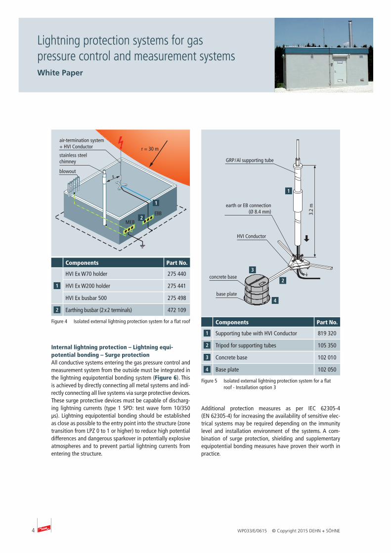
Figure 4 Isolated external lightning protection system for a flat roof Components Part No.
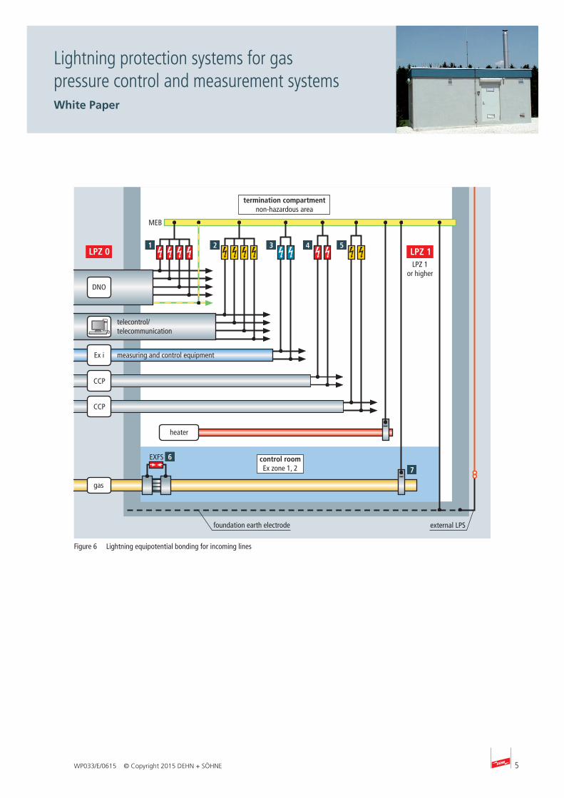
Supporting tube with HVI Conductor 819 320
Tripod for supporting tubes 105 350
Concrete base 102 010
Base plate 102 050
Components Part No.
HVI Ex W70 holder 275 440
HVI Ex W200 holder 275 441
HVI Ex busbar 500 275 498
Earthing busbar (2 x 2 terminals) 472 1093.
2 m
GRP / Al supporting tube
concrete base
base plate
HVI Conductor
earth or EB connection (Ø 8.4 mm)
Figure 5 Isolated external lightning protection system for a flat roof - Installation option 3
5WP033/E/0615 © Copyright 2015 DEHN + SÖHNE
Lightning protection systems for gas pressure control and measurement systemsWhite Paper
DNO
CCP
CCP
Ex i
MEB
termination compartment non-hazardous area
control roomEx zone 1, 2
heater
EXFS
gas
telecontrol/telecommunication
measuring and control equipment
external LPSfoundation earth electrode
LPZ 1or higher
Figure 6 Lightning equipotential bonding for incoming lines
6
Lightning protection systems for gas pressure control and measurement systemsWhite Paper
WP033/E/0615 © Copyright 2015 DEHN + SÖHNE
No. in Figure 6 Protection for Surge protective device Part No.
Power supply systems
Three-phase TN-S / TT system DEHNventil M TT 255 FM 951 315
Three-phase TN-C system DEHNventil M TNC 255 FM 951 305
Alternating current TN system DEHNventil M TN 255 FM 951 205
Alternating current TT system DEHNventil M TT 2P 255 FM 951 115
Information technology systems
Telecontrol, telecommunication systemsBXT ML4 BD 180 orBXT ML2 BD 180+ BXT BAS
920 347920 247
+ 920 300
Measuring and control equipment
Intrinsically safe measuring circuits and systems
BXT ML4 BD EX 24 orBXT ML2 BD S EX 24+ BXT BAS EX
920 381920 280
+ 920 301
Cathodic protection systems
Cathodic protection system, protective circuit up to 12 A
BVT KKS ALD 75 918 420
Cathodic protection system, protective circuit exceeding 12 A
DEHNbloc M 1 150 FM + DEHNguard S 150 FM + MVS 1 2
961 115+ 952 092+ 900 617
Cathodic protection system, sensor measuring circuit
BVT KKS APD 36 918 421
Functionally isolated systems parts
Insulating joints / insulating flangesEXFS 100 orEXFS 100 KU
923 100923 101
Equipotential bonding in hazardous areas
Connection of pipelines without ignition sparks
EX BRS 27 orEX BRS 90 orEX BRS 300 orEX BRS 500
540 821540 801540 803540 805
Table 1 Recommended lightning equipotential bonding components according to Figure 9.33.6
7WP033/E/0615 © Copyright 2015 DEHN + SÖHNE
White Paper: Lightning protection systems for gas pressure control and measurement systems
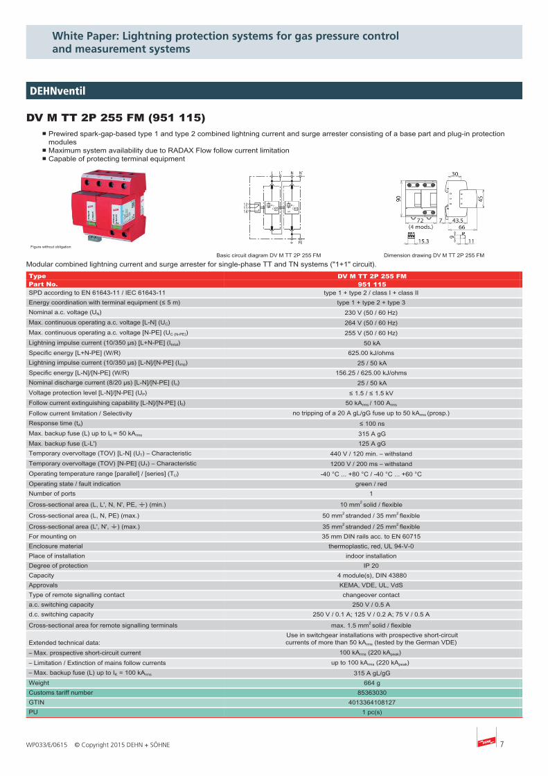
DV M TT 2P 255 FM (951 115)■ Prewired spark-gap-based type 1 and type 2 combined lightning current and surge arrester consisting of a base part and plug-in protection
modules■ Maximum system availability due to RADAX Flow follow current limitation■ Capable of protecting terminal equipment
Figure without obligation
Basic circuit diagram DV M TT 2P 255 FM Dimension drawing DV M TT 2P 255 FM
Modular combined lightning current and surge arrester for single-phase TT and TN systems ("1+1" circuit).Type DV M TT 2P 255 FMPart No. 951 115SPD according to EN 61643-11 / IEC 61643-11 type 1 + type 2 / class I + class II Energy coordination with terminal equipment (≤ 5 m) type 1 + type 2 + type 3 Nominal a.c. voltage (UN) 230 V (50 / 60 Hz) Max. continuous operating a.c. voltage [L-N] (UC) 264 V (50 / 60 Hz) Max. continuous operating a.c. voltage [N-PE] (UC (N-PE)) 255 V (50 / 60 Hz) Lightning impulse current (10/350 µs) [L+N-PE] (Itotal) 50 kASpecific energy [L+N-PE] (W/R) 625.00 kJ/ohms Lightning impulse current (10/350 µs) [L-N]/[N-PE] (Iimp) 25 / 50 kASpecific energy [L-N]/[N-PE] (W/R) 156.25 / 625.00 kJ/ohms Nominal discharge current (8/20 µs) [L-N]/[N-PE] (In) 25 / 50 kAVoltage protection level [L-N]/[N-PE] (UP) ≤ 1.5 / ≤ 1.5 kV Follow current extinguishing capability [L-N]/[N-PE] (Ifi) 50 kArms / 100 Arms Follow current limitation / Selectivity no tripping of a 20 A gL/gG fuse up to 50 kArms (prosp.) Response time (tA) ≤ 100 nsMax. backup fuse (L) up to IK = 50 kArms 315 A gGMax. backup fuse (L-L') 125 A gGTemporary overvoltage (TOV) [L-N] (UT) – Characteristic 440 V / 120 min. – withstand Temporary overvoltage (TOV) [N-PE] (UT) – Characteristic 1200 V / 200 ms – withstand Operating temperature range [parallel] / [series] (TU) -40 °C ... +80 °C / -40 °C ... +60 °C Operating state / fault indication green / red Number of ports 1
Cross-sectional area (L, L', N, N', PE, 9) (min.) 10 mm2 solid / flexible
Cross-sectional area (L, N, PE) (max.) 50 mm2 stranded / 35 mm2 flexible
Cross-sectional area (L', N', 9) (max.) 35 mm2 stranded / 25 mm2 flexible For mounting on 35 mm DIN rails acc. to EN 60715 Enclosure material thermoplastic, red, UL 94-V-0 Place of installation indoor installation Degree of protection IP 20 Capacity 4 module(s), DIN 43880Approvals KEMA, VDE, UL, VdS Type of remote signalling contact changeover contact a.c. switching capacity 250 V / 0.5 A d.c. switching capacity 250 V / 0.1 A; 125 V / 0.2 A; 75 V / 0.5 A
Cross-sectional area for remote signalling terminals max. 1.5 mm2 solid / flexible
Extended technical data:Use in switchgear installations with prospective short-circuitcurrents of more than 50 kArms (tested by the German VDE)
– Max. prospective short-circuit current 100 kArms (220 kApeak) – Limitation / Extinction of mains follow currents up to 100 kArms (220 kApeak) – Max. backup fuse (L) up to IK = 100 kArms 315 A gL/gGWeight 664 gCustoms tariff number 85363030GTIN 4013364108127PU 1 pc(s)
DEHNventil
8 WP033/E/0615 © Copyright 2015 DEHN + SÖHNE
White Paper: Lightning protection systems for gas pressure control and measurement systems
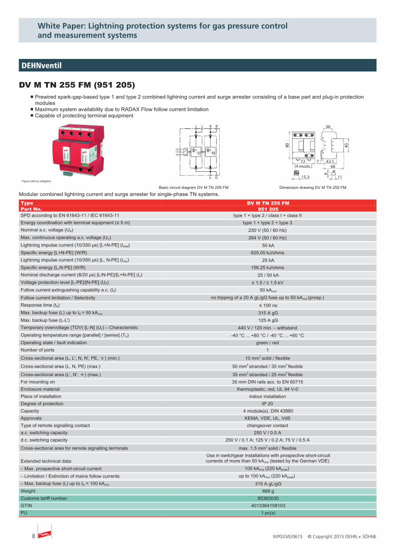
DV M TN 255 FM (951 205)■ Prewired spark-gap-based type 1 and type 2 combined lightning current and surge arrester consisting of a base part and plug-in protection
modules■ Maximum system availability due to RADAX Flow follow current limitation■ Capable of protecting terminal equipment
Figure without obligation
Basic circuit diagram DV M TN 255 FM Dimension drawing DV M TN 255 FM
Modular combined lightning current and surge arrester for single-phase TN systems.Type DV M TN 255 FMPart No. 951 205SPD according to EN 61643-11 / IEC 61643-11 type 1 + type 2 / class I + class II Energy coordination with terminal equipment (≤ 5 m) type 1 + type 2 + type 3 Nominal a.c. voltage (UN) 230 V (50 / 60 Hz) Max. continuous operating a.c. voltage (UC) 264 V (50 / 60 Hz) Lightning impulse current (10/350 µs) [L+N-PE] (Itotal) 50 kASpecific energy [L+N-PE] (W/R) 625.00 kJ/ohms Lightning impulse current (10/350 µs) [L, N-PE] (Iimp) 25 kASpecific energy [L,N-PE] (W/R) 156.25 kJ/ohms Nominal discharge current (8/20 µs) [L/N-PE]/[L+N-PE] (In) 25 / 50 kAVoltage protection level [L-PE]/[N-PE] (UP) ≤ 1.5 / ≤ 1.5 kV Follow current extinguishing capability a.c. (Ifi) 50 kArms
Follow current limitation / Selectivity no tripping of a 20 A gL/gG fuse up to 50 kArms (prosp.) Response time (tA) ≤ 100 nsMax. backup fuse (L) up to IK = 50 kArms 315 A gGMax. backup fuse (L-L') 125 A gGTemporary overvoltage (TOV) [L-N] (UT) – Characteristic 440 V / 120 min. – withstand Operating temperature range [parallel] / [series] (TU) -40 °C ... +80 °C / -40 °C ... +60 °C Operating state / fault indication green / red Number of ports 1
Cross-sectional area (L, L', N, N', PE, 9) (min.) 10 mm2 solid / flexible
Cross-sectional area (L, N, PE) (max.) 50 mm2 stranded / 35 mm2 flexible
Cross-sectional area (L', N', 9) (max.) 35 mm2 stranded / 25 mm2 flexible For mounting on 35 mm DIN rails acc. to EN 60715 Enclosure material thermoplastic, red, UL 94 V-0 Place of installation indoor installation Degree of protection IP 20 Capacity 4 module(s), DIN 43880Approvals KEMA, VDE, UL, VdS Type of remote signalling contact changeover contact a.c. switching capacity 250 V / 0.5 A d.c. switching capacity 250 V / 0.1 A; 125 V / 0.2 A; 75 V / 0.5 A
Cross-sectional area for remote signalling terminals max. 1.5 mm2 solid / flexible
Extended technical data:Use in switchgear installations with prospective short-circuitcurrents of more than 50 kArms (tested by the German VDE)
– Max. prospective short-circuit current 100 kArms (220 kApeak) – Limitation / Extinction of mains follow currents up to 100 kArms (220 kApeak) – Max. backup fuse (L) up to IK = 100 kArms 315 A gL/gGWeight 668 gCustoms tariff number 85363030GTIN 4013364108103PU 1 pc(s)
DEHNventil
9WP033/E/0615 © Copyright 2015 DEHN + SÖHNE
White Paper: Lightning protection systems for gas pressure control and measurement systems
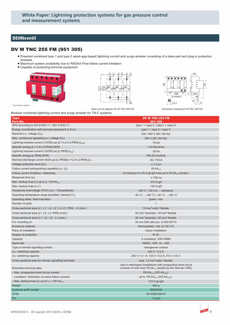
DV M TNC 255 FM (951 305)■ Prewired combined type 1 and type 2 spark-gap-based lightning current and surge arrester consisting of a base part and plug-in protection
modules■ Maximum system availability due to RADAX Flow follow current limitation■ Capable of protecting terminal equipment
Figure without obligation
Basic circuit diagram DV M TNC 255 FM Dimension drawing DV M TNC 255 FM
Modular combined lightning current and surge arrester for TN-C systems.Type DV M TNC 255 FM Part No. 951 305 SPD according to EN 61643-11 / IEC 61643-11 type 1 + type 2 / class I + class II Energy coordination with terminal equipment (≤ 5 m) type 1 + type 2 + type 3 Nominal a.c. voltage (UN) 230 / 400 V (50 / 60 Hz) Max. continuous operating a.c. voltage (UC) 264 V (50 / 60 Hz) Lightning impulse current (10/350 µs) [L1+L2+L3-PEN] (Itotal) 75 kA Specific energy [L1+L2+L3-PEN] (W/R) 1.40 MJ/ohms Lightning impulse current (10/350 µs) [L-PEN] (Iimp) 25 kA Specific energy [L-PEN] (W/R) 156.25 kJ/ohms Nominal discharge current (8/20 µs) [L-PEN]/[L1+L2+L3-PEN] (In) 25 / 75 kA Voltage protection level (UP) ≤ 1.5 kV Follow current extinguishing capability a.c. (Ifi) 50 kArms Follow current limitation / Selectivity no tripping of a 20 A gL/gG fuse up to 50 kArms (prosp.) Response time (tA) ≤ 100 ns Max. backup fuse (L) up to IK = 50 kArms 315 A gG Max. backup fuse (L-L') 125 A gG Temporary overvoltage (TOV) (UT) – Characteristic 440 V / 120 min. – withstand Operating temperature range [parallel] / [series] (TU) -40 °C ... +80 °C / -40 °C ... +60 °C Operating state / fault indication green / red Number of ports 1 Cross-sectional area (L1, L1', L2, L2', L3, L3', PEN, 9) (min.) 10 mm2 solid / flexible Cross-sectional area (L1, L2, L3, PEN) (max.) 50 mm2 stranded / 35 mm2 flexible Cross-sectional area (L1', L2', L3', 9) (max.) 35 mm2 stranded / 25 mm2 flexible For mounting on 35 mm DIN rails acc. to EN 60715 Enclosure material thermoplastic, red, UL 94 V-0 Place of installation indoor installation Degree of protection IP 20 Capacity 6 module(s), DIN 43880 Approvals KEMA, VDE, UL, VdS Type of remote signalling contact changeover contact a.c. switching capacity 250 V / 0.5 A d.c. switching capacity 250 V / 0.1 A; 125 V / 0.2 A; 75 V / 0.5 A Cross-sectional area for remote signalling terminals max. 1.5 mm2 solid / flexible
Extended technical data:Use in switchgear installations with prospective short-circuitcurrents of more than 50 kArms (tested by the German VDE)
– Max. prospective short-circuit current 100 kArms (220 kApeak) – Limitation / Extinction of mains follow currents up to 100 kArms (220 kApeak) – Max. backup fuse (L) up to IK = 100 kArms 315 A gL/gG Weight 962 g Customs tariff number 85363030 GTIN 4013364108141 PU 1 pc(s)
DEHNventil

10 WP033/E/0615 © Copyright 2015 DEHN + SÖHNE
White Paper: Lightning protection systems for gas pressure control and measurement systems
DV M TT 255 FM (951 315)■ Prewired spark-gap-based type 1 and type 2 combined lightning current and surge arrester consisting of a base part and plug-in protection
modules■ Maximum system availability due to RADAX Flow follow current limitation■ Capable of protecting terminal equipmen
Figure without obligation
Basic circuit diagram DV M TT 255 FM Dimension drawing DV M TT 255 FM
Modular combined lightning current and surge arrester for TT and TN-S systems ("3+1" circuit).Type DV M TT 255 FM Part No. 951 315 SPD according to EN 61643-11 / IEC 61643-11 type 1 + type 2 / class I + class II Energy coordination with terminal equipment (≤ 5 m) type 1 + type 2 + type 3 Nominal a.c. voltage (UN) 230 / 400 V (50 / 60 Hz) Max. continuous operating a.c. voltage [L-N] (UC) 264 V (50 / 60 Hz) Max. continuous operating a.c. voltage [N-PE] (UC (N-PE)) 255 V (50 / 60 Hz) Lightning impulse current (10/350 µs) [L1+L2+L3+N-PE] (Itotal) 100 kA Specific energy [L1+L2+L3+N-PE] (W/R) 2.50 MJ/ohms Lightning impulse current (10/350 µs) [L-N]/[N-PE] (Iimp) 25 / 100 kA Specific energy [L-N]/[N-PE] (W/R) 156.25 kJ/ohms / 2.50 MJ/ohms Nominal discharge current (8/20 µs) [L-N]/[N-PE] (In) 25 / 100 kA Voltage protection level [L-N]/[N-PE] (UP) ≤ 1.5 / ≤ 1.5 kV Follow current extinguishing capability [L-N]/[N-PE] (Ifi) 50 kArms / 100 Arms Follow current limitation / Selectivity no tripping of a 20 A gL/gG fuse up to 50 kArms (prosp.) Response time (tA) ≤ 100 ns Max. backup fuse (L) up to IK = 50 kArms 315 A gG Max. backup fuse (L-L') 125 A gG Temporary overvoltage (TOV) [L-N] (UT) – Characteristic 440 V / 120 min. – withstand Temporary overvoltage (TOV) [N-PE] (UT) – Characteristic 1200 V / 200 ms – withstand Operating temperature range [parallel] / [series] (TU) -40 °C ... +80 °C / -40 °C ... +60 °C Operating state / fault indication green / red Number of ports 1 Cross-sectional area (L1, L1', L2, L2', L3, L3', N, N', PE, 9) (min.) 10 mm2 solid / flexible Cross-sectional area (L1, L2, L3, N, PE) (max.) 50 mm2 stranded / 35 mm2 flexible Cross-sectional area (L1', L2', L3', N', 9) (max.) 35 mm2 stranded / 25 mm2 flexible For mounting on 35 mm DIN rails acc. to EN 60715 Enclosure material thermoplastic, red, UL 94 V-0 Place of installation indoor installation Degree of protection IP 20 Capacity 8 module(s), DIN 43880 Approvals KEMA, VDE, UL, VdS Type of remote signalling contact changeover contact a.c. switching capacity 250 V / 0.5 A d.c. switching capacity 250 V / 0.1 A; 125 V / 0.2 A; 75 V / 0.5 A Cross-sectional area for remote signalling terminals max. 1.5 mm2 solid / flexible
Extended technical data:Use in switchgear installations with prospective short-circuitcurrents of more than 50 kArms (tested by the German VDE)
– Max. prospective short-circuit current 100 kArms (220 kApeak) – Limitation / Extinction of mains follow currents up to 100 kArms (220 kApeak) – Max. backup fuse (L) up to IK = 100 kArms 315 A gL/gG Weight 1,28 kg Customs tariff number 85363030 GTIN 4013364108189 PU 1 pc(s)
DEHNventil
11WP033/E/0615 © Copyright 2015 DEHN + SÖHNE
White Paper: Lightning protection systems for gas pressure control and measurement systems
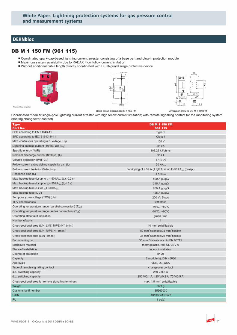
DB M 1 150 FM (961 115)■ Coordinated spark-gap-based lightning current arrester consisting of a base part and plug-in protection module■ Maximum system availability due to RADAX Flow follow current limitation■ Without additional cable length directly coordinated with DEHNguard surge protective device
Figure without obligation
Basic circuit diagram DB M 1 150 FM Dimension drawing DB M 1 150 FM
Coordinated modular single-pole lightning current arrester with high follow current limitation; with remote signalling contact for the monitoring system(floating changeover contact)Type DB M 1 150 FMPart No. 961 115SPD according to EN 61643-11 Type 1 SPD according to IEC 61643-1/-11 Class I Max. continuous operating a.c. voltage (UC) 150 VLightning impulse current (10/350 µs) (Iimp) 35 kASpecific energy (W/R) 306.25 kJ/ohms Nominal discharge current (8/20 µs) (In) 35 kAVoltage protection level (UP) ≤ 1.5 kVFollow current extinguishing capability a.c. (Ifi) 50 kArms
Follow current limitation/Selectivity no tripping of a 32 A gL/gG fuse up to 50 kArms (prosp.) Response time (tA) ≤ 100 nsMax. backup fuse (L) up to IK = 50 kArms (ta ≤ 0.2 s) 500 A gL/gGMax. backup fuse (L) up to IK = 50 kArms (ta ≤ 5 s) 315 A gL/gGMax. backup fuse (L) for IK > 50 kArms 200 A gL/gGMax. backup fuse (L-L') 125 A gL/gGTemporary overvoltage (TOV) (UT) 200 V / 5 sec.TOV characteristic withstand Operating temperature range (parallel connection) (TUP) -40°C...+80°C Operating temperature range (series connection) (TUS) -40°C...+60°C Operating state/fault indication green / red Number of ports 1
Cross-sectional area (L/N, L'/N', N/PE (N)) (min.) 10 mm2 solid/flexible
Cross-sectional area (L/N, N/PE(N)) (max.) 50 mm2 stranded/35 mm2 flexible
Cross-sectional area (L'/N') (max.) 35 mm2 stranded/25 mm2 flexible For mounting on 35 mm DIN rails acc. to EN 60715 Enclosure material thermoplastic, red, UL 94 V-0 Place of installation indoor installation Degree of protection IP 20 Capacity 2 module(s), DIN 43880Approvals VDE, UL, CSA Type of remote signalling contact changeover contact a.c. switching capacity 250 V/0.5 A d.c. switching capacity 250 V/0.1 A; 125 V/0.2 A; 75 V/0.5 A
Cross-sectional area for remote signalling terminals max. 1.5 mm2 solid/flexible Weight 321 gCustoms tariff number 85363030GTIN 4013364118577PU 1 pc(s)
DEHNbloc
12 WP033/E/0615 © Copyright 2015 DEHN + SÖHNE
White Paper: Lightning protection systems for gas pressure control and measurement systems
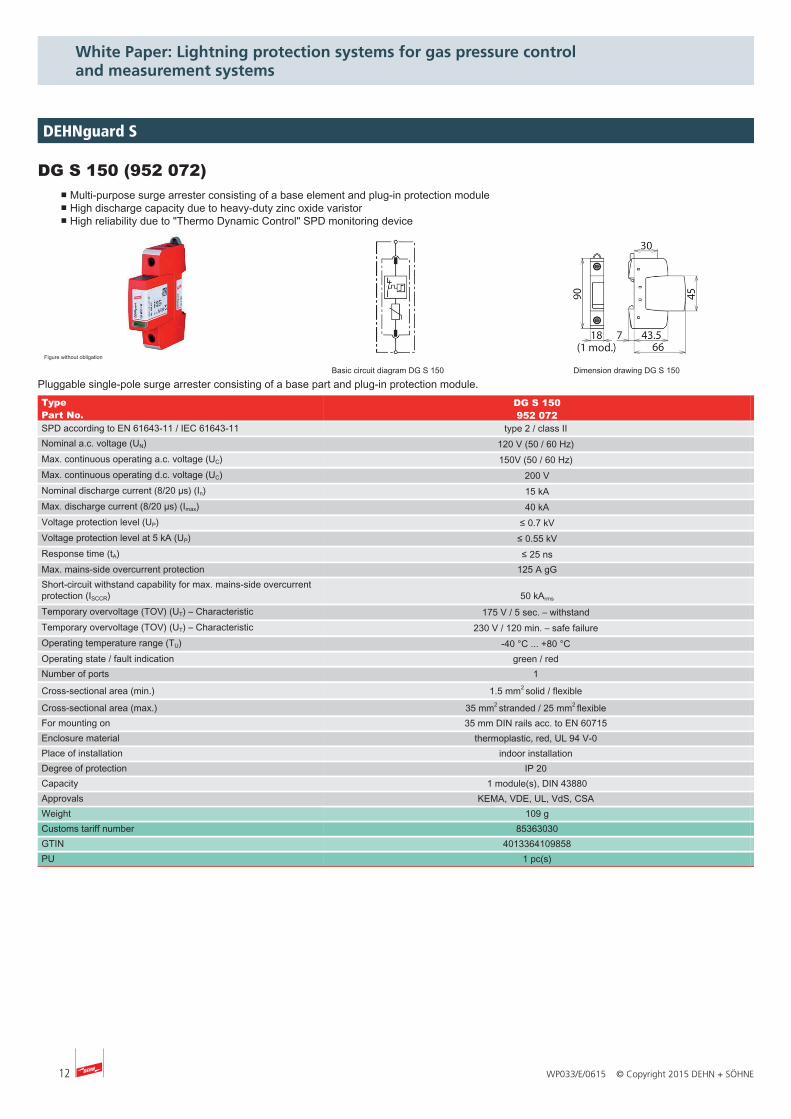
DG S 150 (952 072)■ Multi-purpose surge arrester consisting of a base element and plug-in protection module■ High discharge capacity due to heavy-duty zinc oxide varistor■ High reliability due to "Thermo Dynamic Control" SPD monitoring device
Figure without obligation
Basic circuit diagram DG S 150 Dimension drawing DG S 150
Pluggable single-pole surge arrester consisting of a base part and plug-in protection module.Type DG S 150Part No. 952 072SPD according to EN 61643-11 / IEC 61643-11 type 2 / class II Nominal a.c. voltage (UN) 120 V (50 / 60 Hz) Max. continuous operating a.c. voltage (UC) 150V (50 / 60 Hz) Max. continuous operating d.c. voltage (UC) 200 VNominal discharge current (8/20 µs) (In) 15 kAMax. discharge current (8/20 µs) (Imax) 40 kAVoltage protection level (UP) ≤ 0.7 kVVoltage protection level at 5 kA (UP) ≤ 0.55 kVResponse time (tA) ≤ 25 nsMax. mains-side overcurrent protection 125 A gGShort-circuit withstand capability for max. mains-side overcurrentprotection (ISCCR) 50 kArms
Temporary overvoltage (TOV) (UT) – Characteristic 175 V / 5 sec. – withstand Temporary overvoltage (TOV) (UT) – Characteristic 230 V / 120 min. – safe failure Operating temperature range (TU) -40 °C ... +80 °C Operating state / fault indication green / red Number of ports 1
Cross-sectional area (min.) 1.5 mm2 solid / flexible
Cross-sectional area (max.) 35 mm2 stranded / 25 mm2 flexible For mounting on 35 mm DIN rails acc. to EN 60715 Enclosure material thermoplastic, red, UL 94 V-0 Place of installation indoor installation Degree of protection IP 20 Capacity 1 module(s), DIN 43880Approvals KEMA, VDE, UL, VdS, CSA Weight 109 gCustoms tariff number 85363030GTIN 4013364109858PU 1 pc(s)
DEHNguard S
13WP033/E/0615 © Copyright 2015 DEHN + SÖHNE
White Paper: Lightning protection systems for gas pressure control and measurement systems
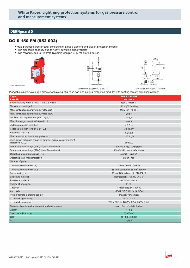
DG S 150 FM (952 092)■ Multi-purpose surge arrester consisting of a base element and plug-in protection module■ High discharge capacity due to heavy-duty zinc oxide varistor■ High reliability due to "Thermo Dynamic Control" SPD monitoring device
Figure without obligation
Basic circuit diagram DG S 150 FM Dimension drawing DG S 150 FM
Pluggable single-pole surge arrester consisting of a base part and plug-in protection module; with floating remote signalling contact.Type DG S 150 FMPart No. 952 092SPD according to EN 61643-11 / IEC 61643-11 type 2 / class II Nominal a.c. voltage (UN) 120 V (50 / 60 Hz) Max. continuous operating a.c. voltage (UC) 150V (50 / 60 Hz) Max. continuous operating d.c. voltage (UC) 200 VNominal discharge current (8/20 µs) (In) 15 kAMax. discharge current (8/20 µs) (Imax) 40 kAVoltage protection level (UP) ≤ 0.7 kVVoltage protection level at 5 kA (UP) ≤ 0.55 kVResponse time (tA) ≤ 25 nsMax. mains-side overcurrent protection 125 A gGShort-circuit withstand capability for max. mains-side overcurrentprotection (ISCCR) 50 kArms
Temporary overvoltage (TOV) (UT) – Characteristic 175 V / 5 sec. – withstand Temporary overvoltage (TOV) (UT) – Characteristic 230 V / 120 min. – safe failure Operating temperature range (TU) -40 °C ... +80 °C Operating state / fault indication green / red Number of ports 1
Cross-sectional area (min.) 1.5 mm2 solid / flexible
Cross-sectional area (max.) 35 mm2 stranded / 25 mm2 flexible For mounting on 35 mm DIN rails acc. to EN 60715 Enclosure material thermoplastic, red, UL 94 V-0 Place of installation indoor installation Degree of protection IP 20 Capacity 1 module(s), DIN 43880Approvals KEMA, VDE, UL, VdS, CSA Type of remote signalling contact changeover contact a.c. switching capacity 250 V / 0.5 A d.c. switching capacity 250 V / 0.1 A; 125 V / 0.2 A; 75 V / 0.5 A
Cross-sectional area for remote signalling terminals max. 1.5 mm2 solid / flexible Weight 113 gCustoms tariff number 85363030GTIN 4013364109865PU 1 pc(s)
DEHNguard S
14 WP033/E/0615 © Copyright 2015 DEHN + SÖHNE
White Paper: Lightning protection systems for gas pressure control and measurement systems
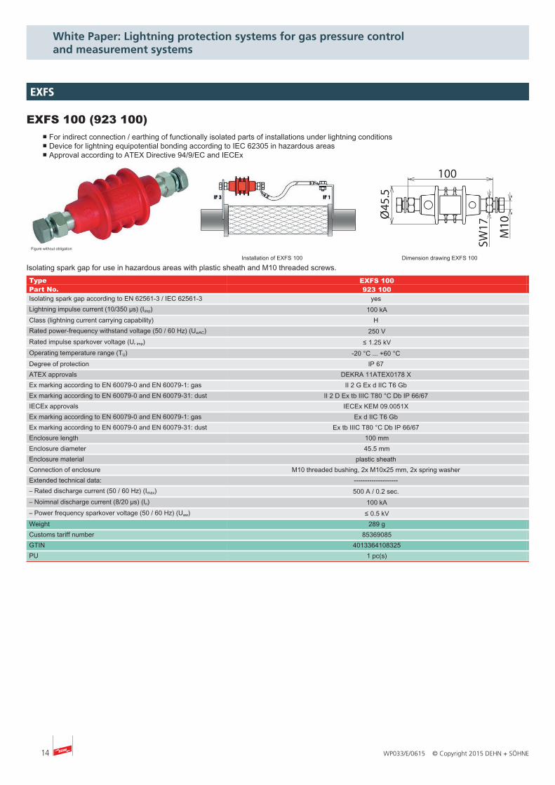
EXFS 100 (923 100)■ For indirect connection / earthing of functionally isolated parts of installations under lightning conditions■ Device for lightning equipotential bonding according to IEC 62305 in hazardous areas■ Approval according to ATEX Directive 94/9/EC and IECEx
Figure without obligation
Installation of EXFS 100 Dimension drawing EXFS 100
Isolating spark gap for use in hazardous areas with plastic sheath and M10 threaded screws.Type EXFS 100Part No. 923 100Isolating spark gap according to EN 62561-3 / IEC 62561-3 yes Lightning impulse current (10/350 µs) (Iimp) 100 kAClass (lightning current carrying capability) H Rated power-frequency withstand voltage (50 / 60 Hz) (UwAC) 250 VRated impulse sparkover voltage (Ur imp) ≤ 1.25 kVOperating temperature range (TU) -20 °C ... +60 °C Degree of protection IP 67 ATEX approvals DEKRA 11ATEX0178 X Ex marking according to EN 60079-0 and EN 60079-1: gas II 2 G Ex d IIC T6 Gb Ex marking according to EN 60079-0 and EN 60079-31: dust II 2 D Ex tb IIIC T80 °C Db IP 66/67 IECEx approvals IECEx KEM 09.0051X Ex marking according to EN 60079-0 and EN 60079-1: gas Ex d IIC T6 Gb Ex marking according to EN 60079-0 and EN 60079-31: dust Ex tb IIIC T80 °C Db IP 66/67 Enclosure length 100 mmEnclosure diameter 45.5 mmEnclosure material plastic sheath Connection of enclosure M10 threaded bushing, 2x M10x25 mm, 2x spring washer Extended technical data: -------------------- – Rated discharge current (50 / 60 Hz) (Imax) 500 A / 0.2 sec. – Noimnal discharge current (8/20 µs) (In) 100 kA– Power frequency sparkover voltage (50 / 60 Hz) (Uaw) ≤ 0.5 kVWeight 289 gCustoms tariff number 85369085GTIN 4013364108325PU 1 pc(s)
EXFS
15WP033/E/0615 © Copyright 2015 DEHN + SÖHNE
White Paper: Lightning protection systems for gas pressure control and measurement systems
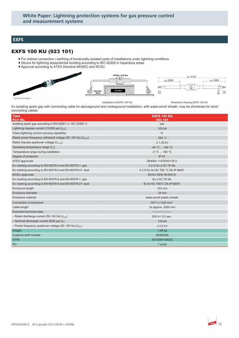
EXFS 100 KU (923 101)■ For indirect connection / earthing of functionally isolated parts of installations under lightning conditions■ Device for lightning equipotential bonding according to IEC 62305 in hazardous areas■ Approval according to ATEX Directive 94/9/EC and IECEx
Figure without obligation
Installation of EXFS 100 KU Dimension drawing EXFS 100 KU
Ex isolating spark gap with connecting cable for aboveground and underground installation; with water-proof sheath; may be shortened for shortconnecting cables.Type EXFS 100 KUPart No. 923 101Isolating spark gap according to EN 62561-3 / IEC 62561-3 yes Lightning impulse current (10/350 µs) (Iimp) 100 kAClass (lightning current carrying capability) H Rated power-frequency withstand voltage (50 / 60 Hz) (UwAC) 250 VRated impulse sparkover voltage (Ur imp) ≤ 1.25 kVOperating temperature range (TU) -40 °C ... +60 °C Temperature range during installation -5 °C ... +50 °C Degree of protection IP 67 ATEX approvals DEKRA 11ATEX0178 X Ex marking according to EN 60079-0 and EN 60079-1: gas II 2 G Ex d IIC T6 Gb Ex marking according to EN 60079-0 and EN 60079-31: dust II 2 D Ex tb IIIC T80 °C Db IP 66/67 IECEx approvals IECEx KEM 09.0051X Ex marking according to EN 60079-0 and EN 60079-1: gas Ex d IIC T6 Gb Ex marking according to EN 60079-0 and EN 60079-31: dust Ex tb IIIC T80°C Db IP 66/67 Enclosure length 123 mmEnclosure diameter 34 mmEnclosure material water-proof plastic sheath
Connection of enclosure NYY-J-1x25 mm2 Cable length 2x approx. 2000 mmExtended technical data: -------------------- – Rated discharge current (50 / 60 Hz) (Imax) 500 A / 0.2 sec. – Noimnal discharge current (8/20 µs) (In) 100 kA– Power frequency sparkover voltage (50 / 60 Hz) (Uaw) ≤ 0.5 kVWeight 1,98 kgCustoms tariff number 85369085GTIN 4013364108332PU 1 pc(s)
EXFS
16 WP033/E/0615 © Copyright 2015 DEHN + SÖHNE
White Paper: Lightning protection systems for gas pressure control and measurement systems
Modular wiring system
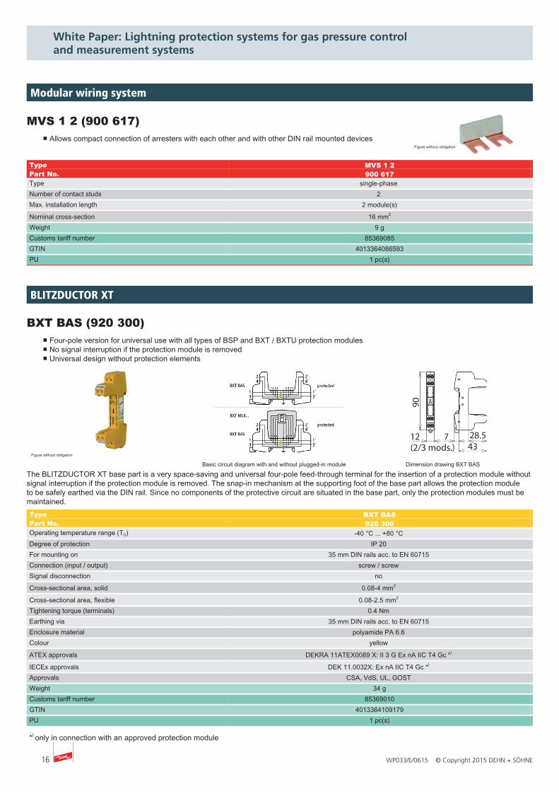
MVS 1 2 (900 617)■ Allows compact connection of arresters with each other and with other DIN rail mounted devices
Figure without obligation
Type MVS 1 2Part No. 900 617Type single-phase Number of contact studs 2 Max. installation length 2 module(s)
Nominal cross-section 16 mm2
Weight 9 gCustoms tariff number 85369085GTIN 4013364086593PU 1 pc(s)
BXT BAS (920 300)■ Four-pole version for universal use with all types of BSP and BXT / BXTU protection modules■ No signal interruption if the protection module is removed■ Universal design without protection elements
Figure without obligation
Basic circuit diagram with and without plugged-in module Dimension drawing BXT BAS
The BLITZDUCTOR XT base part is a very space-saving and universal four-pole feed-through terminal for the insertion of a protection module withoutsignal interruption if the protection module is removed. The snap-in mechanism at the supporting foot of the base part allows the protection moduleto be safely earthed via the DIN rail. Since no components of the protective circuit are situated in the base part, only the protection modules must bemaintained.Type BXT BAS Part No. 920 300 Operating temperature range (TU) -40 °C ... +80 °C Degree of protection IP 20 For mounting on 35 mm DIN rails acc. to EN 60715 Connection (input / output) screw / screw Signal disconnection no Cross-sectional area, solid 0.08-4 mm2 Cross-sectional area, flexible 0.08-2.5 mm2 Tightening torque (terminals) 0.4 Nm Earthing via 35 mm DIN rails acc. to EN 60715 Enclosure material polyamide PA 6.6 Colour yellow ATEX approvals DEKRA 11ATEX0089 X: II 3 G Ex nA IIC T4 Gc *) IECEx approvals DEK 11.0032X: Ex nA IIC T4 Gc *) Approvals CSA, VdS, UL, GOST Weight 34 g Customs tariff number 85369010 GTIN 4013364109179 PU 1 pc(s)
*) only in connection with an approved protection module
BLITZDUCTOR XT
MVS 1 2 (900 617)■ Allows compact connection of arresters with each other and with other DIN rail mounted devices
Figure without obligation
Type MVS 1 2Part No. 900 617Type single-phase Number of contact studs 2 Max. installation length 2 module(s)
Nominal cross-section 16 mm2
Weight 9 gCustoms tariff number 85369085GTIN 4013364086593PU 1 pc(s)
17WP033/E/0615 © Copyright 2015 DEHN + SÖHNE
White Paper: Lightning protection systems for gas pressure control and measurement systems
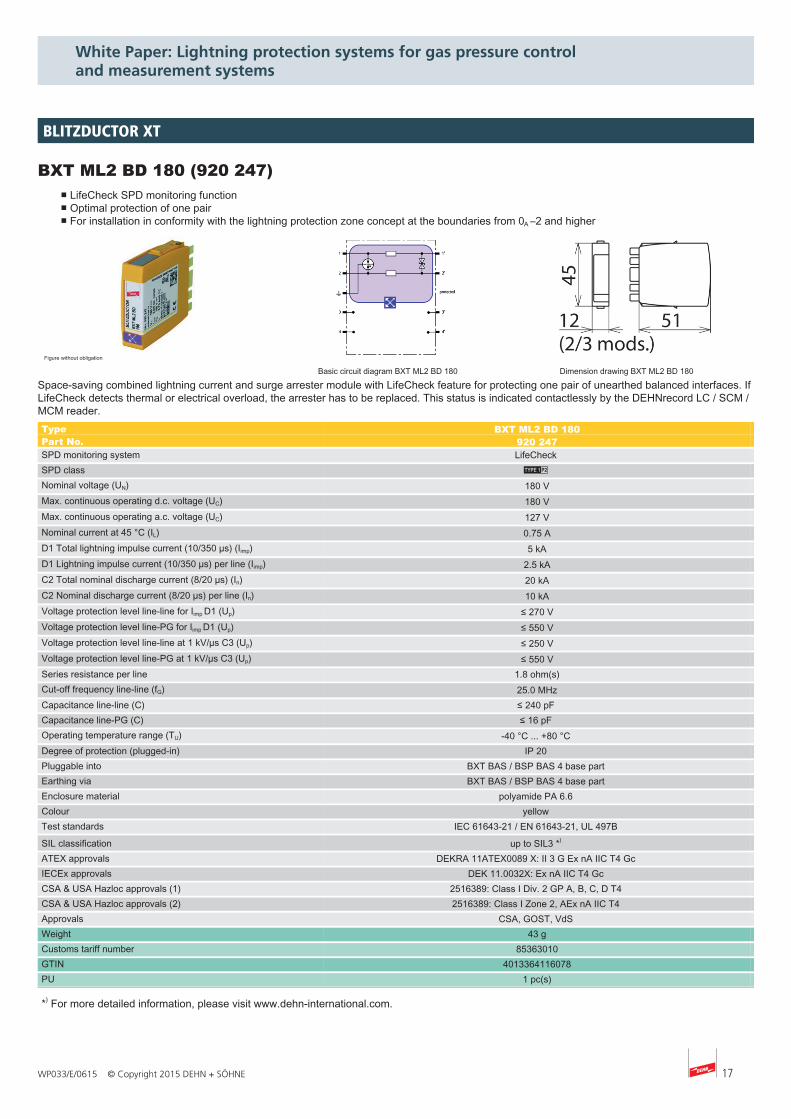
BXT ML2 BD 180 (920 247)■ LifeCheck SPD monitoring function■ Optimal protection of one pair■ For installation in conformity with the lightning protection zone concept at the boundaries from 0A –2 and higher
Figure without obligation
Basic circuit diagram BXT ML2 BD 180 Dimension drawing BXT ML2 BD 180
Space-saving combined lightning current and surge arrester module with LifeCheck feature for protecting one pair of unearthed balanced interfaces. IfLifeCheck detects thermal or electrical overload, the arrester has to be replaced. This status is indicated contactlessly by the DEHNrecord LC / SCM /MCM reader.Type BXT ML2 BD 180 Part No. 920 247 SPD monitoring system LifeCheck SPD class L Nominal voltage (UN) 180 V Max. continuous operating d.c. voltage (UC) 180 V Max. continuous operating a.c. voltage (UC) 127 V Nominal current at 45 °C (IL) 0.75 A D1 Total lightning impulse current (10/350 µs) (Iimp) 5 kA D1 Lightning impulse current (10/350 µs) per line (Iimp) 2.5 kA C2 Total nominal discharge current (8/20 µs) (In) 20 kA C2 Nominal discharge current (8/20 µs) per line (In) 10 kA Voltage protection level line-line for Iimp D1 (Up) ≤ 270 V Voltage protection level line-PG for Iimp D1 (Up) ≤ 550 V Voltage protection level line-line at 1 kV/µs C3 (Up) ≤ 250 V Voltage protection level line-PG at 1 kV/µs C3 (Up) ≤ 550 V Series resistance per line 1.8 ohm(s) Cut-off frequency line-line (fG) 25.0 MHz Capacitance line-line (C) ≤ 240 pF Capacitance line-PG (C) ≤ 16 pF Operating temperature range (TU) -40 °C ... +80 °C Degree of protection (plugged-in) IP 20 Pluggable into BXT BAS / BSP BAS 4 base part Earthing via BXT BAS / BSP BAS 4 base part Enclosure material polyamide PA 6.6 Colour yellow Test standards IEC 61643-21 / EN 61643-21, UL 497B SIL classification up to SIL3 *) ATEX approvals DEKRA 11ATEX0089 X: II 3 G Ex nA IIC T4 Gc IECEx approvals DEK 11.0032X: Ex nA IIC T4 Gc CSA & USA Hazloc approvals (1) 2516389: Class I Div. 2 GP A, B, C, D T4 CSA & USA Hazloc approvals (2) 2516389: Class I Zone 2, AEx nA IIC T4 Approvals CSA, GOST, VdS Weight 43 g Customs tariff number 85363010 GTIN 4013364116078 PU 1 pc(s)
*) For more detailed information, please visit www.dehn-international.com.
BLITZDUCTOR XT
18 WP033/E/0615 © Copyright 2015 DEHN + SÖHNE
White Paper: Lightning protection systems for gas pressure control and measurement systems
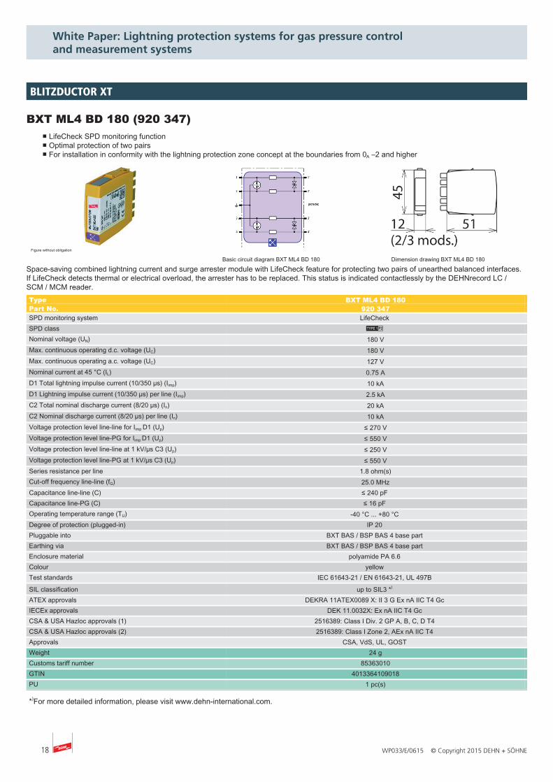
BXT ML4 BD 180 (920 347)■ LifeCheck SPD monitoring function■ Optimal protection of two pairs■ For installation in conformity with the lightning protection zone concept at the boundaries from 0A –2 and higher
Figure without obligation
Basic circuit diagram BXT ML4 BD 180 Dimension drawing BXT ML4 BD 180
Space-saving combined lightning current and surge arrester module with LifeCheck feature for protecting two pairs of unearthed balanced interfaces.If LifeCheck detects thermal or electrical overload, the arrester has to be replaced. This status is indicated contactlessly by the DEHNrecord LC /SCM / MCM reader.Type BXT ML4 BD 180 Part No. 920 347 SPD monitoring system LifeCheck SPD class L Nominal voltage (UN) 180 V Max. continuous operating d.c. voltage (UC) 180 V Max. continuous operating a.c. voltage (UC) 127 V Nominal current at 45 °C (IL) 0.75 A D1 Total lightning impulse current (10/350 µs) (Iimp) 10 kA D1 Lightning impulse current (10/350 µs) per line (Iimp) 2.5 kA C2 Total nominal discharge current (8/20 µs) (In) 20 kA C2 Nominal discharge current (8/20 µs) per line (In) 10 kA Voltage protection level line-line for Iimp D1 (Up) ≤ 270 V Voltage protection level line-PG for Iimp D1 (Up) ≤ 550 V Voltage protection level line-line at 1 kV/µs C3 (Up) ≤ 250 V Voltage protection level line-PG at 1 kV/µs C3 (Up) ≤ 550 V Series resistance per line 1.8 ohm(s) Cut-off frequency line-line (fG) 25.0 MHz Capacitance line-line (C) ≤ 240 pF Capacitance line-PG (C) ≤ 16 pF Operating temperature range (TU) -40 °C ... +80 °C Degree of protection (plugged-in) IP 20 Pluggable into BXT BAS / BSP BAS 4 base part Earthing via BXT BAS / BSP BAS 4 base part Enclosure material polyamide PA 6.6 Colour yellow Test standards IEC 61643-21 / EN 61643-21, UL 497B SIL classification up to SIL3 *) ATEX approvals DEKRA 11ATEX0089 X: II 3 G Ex nA IIC T4 Gc IECEx approvals DEK 11.0032X: Ex nA IIC T4 Gc CSA & USA Hazloc approvals (1) 2516389: Class I Div. 2 GP A, B, C, D T4 CSA & USA Hazloc approvals (2) 2516389: Class I Zone 2, AEx nA IIC T4 Approvals CSA, VdS, UL, GOST Weight 24 g Customs tariff number 85363010 GTIN 4013364109018 PU 1 pc(s)
*)For more detailed information, please visit www.dehn-international.com.
BLITZDUCTOR XT
19WP033/E/0615 © Copyright 2015 DEHN + SÖHNE
White Paper: Lightning protection systems for gas pressure control and measurement systems
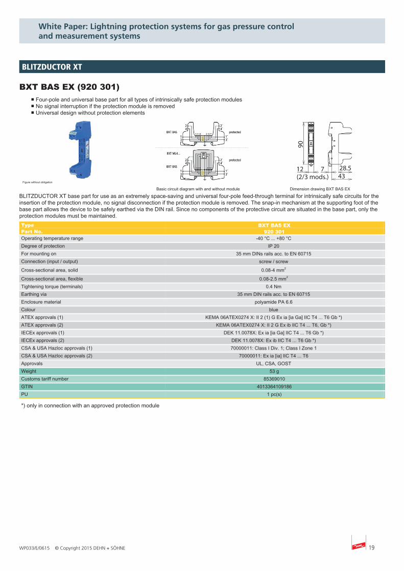
BXT BAS EX (920 301)■ Four-pole and universal base part for all types of intrinsically safe protection modules■ No signal interruption if the protection module is removed■ Universal design without protection elements
Figure without obligation
Basic circuit diagram with and without module Dimension drawing BXT BAS EX
BLITZDUCTOR XT base part for use as an extremely space-saving and universal four-pole feed-through terminal for intrinsically safe circuits for theinsertion of the protection module, no signal disconnection if the protection module is removed. The snap-in mechanism at the supporting foot of thebase part allows the device to be safely earthed via the DIN rail. Since no components of the protective circuit are situated in the base part, only theprotection modules must be maintained.Type BXT BAS EX Part No. 920 301 Operating temperature range -40 °C ... +80 °C Degree of protection IP 20 For mounting on 35 mm DINs rails acc. to EN 60715 Connection (input / output) screw / screw Cross-sectional area, solid 0.08-4 mm2 Cross-sectional area, flexible 0.08-2.5 mm2 Tightening torque (terminals) 0.4 Nm Earthing via 35 mm DIN rails acc. to EN 60715 Enclosure material polyamide PA 6.6 Colour blue ATEX approvals (1) KEMA 06ATEX0274 X: II 2 (1) G Ex ia [ia Ga] IIC T4 ... T6 Gb *) ATEX approvals (2) KEMA 06ATEX0274 X: II 2 G Ex ib IIC T4 ... T6, Gb *) IECEx approvals (1) DEK 11.0078X: Ex ia [ia Ga] IIC T4 ... T6 Gb *) IECEx approvals (2) DEK 11.0078X: Ex ib IIC T4 ... T6 Gb *) CSA & USA Hazloc approvals (1) 70000011: Class I Div. 1; Class I Zone 1 CSA & USA Hazloc approvals (2) 70000011: Ex ia [ia] IIC T4 ... T6 Approvals UL, CSA, GOST Weight 53 g Customs tariff number 85369010 GTIN 4013364109186 PU 1 pc(s)
*) only in connection with an approved protection module
BLITZDUCTOR XT
20 WP033/E/0615 © Copyright 2015 DEHN + SÖHNE
White Paper: Lightning protection systems for gas pressure control and measurement systems
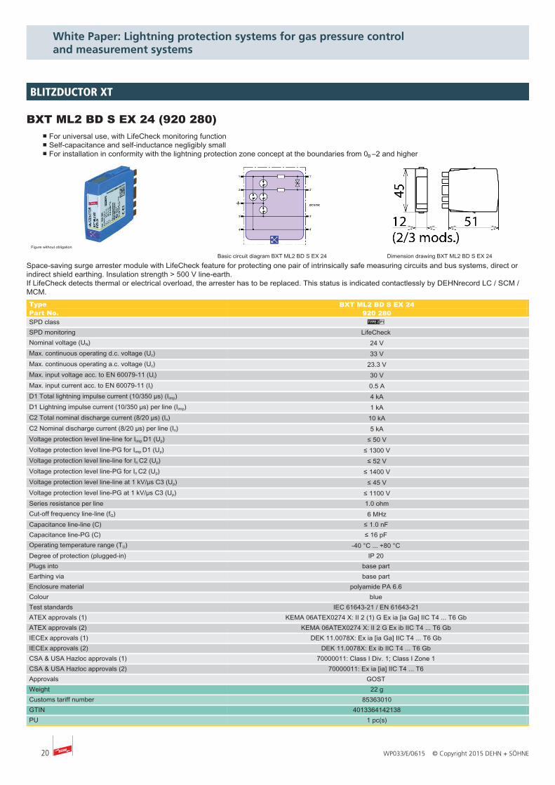
BXT ML2 BD S EX 24 (920 280)■ For universal use, with LifeCheck monitoring function■ Self-capacitance and self-inductance negligibly small■ For installation in conformity with the lightning protection zone concept at the boundaries from 0B –2 and higher
Figure without obligation
Basic circuit diagram BXT ML2 BD S EX 24 Dimension drawing BXT ML2 BD S EX 24
Space-saving surge arrester module with LifeCheck feature for protecting one pair of intrinsically safe measuring circuits and bus systems, direct orindirect shield earthing. Insulation strength > 500 V line-earth.If LifeCheck detects thermal or electrical overload, the arrester has to be replaced. This status is indicated contactlessly by DEHNrecord LC / SCM /MCM.Type BXT ML2 BD S EX 24 Part No. 920 280 SPD class T SPD monitoring LifeCheck Nominal voltage (UN) 24 V Max. continuous operating d.c. voltage (Uc) 33 V Max. continuous operating a.c. voltage (Uc) 23.3 V Max. input voltage acc. to EN 60079-11 (Ui) 30 V Max. input current acc. to EN 60079-11 (Ii) 0.5 A D1 Total lightning impulse current (10/350 µs) (Iimp) 4 kA D1 Lightning impulse current (10/350 µs) per line (Iimp) 1 kA C2 Total nominal discharge current (8/20 µs) (In) 10 kA C2 Nominal discharge current (8/20 µs) per line (In) 5 kA Voltage protection level line-line for Iimp D1 (Up) ≤ 50 V Voltage protection level line-PG for Iimp D1 (Up) ≤ 1300 V Voltage protection level line-line for In C2 (Up) ≤ 52 V Voltage protection level line-PG for In C2 (Up) ≤ 1400 V Voltage protection level line-line at 1 kV/µs C3 (Up) ≤ 45 V Voltage protection level line-PG at 1 kV/µs C3 (Up) ≤ 1100 V Series resistance per line 1.0 ohm Cut-off frequency line-line (fG) 6 MHz Capacitance line-line (C) ≤ 1.0 nF Capacitance line-PG (C) ≤ 16 pF Operating temperature range (TU) -40 °C ... +80 °C Degree of protection (plugged-in) IP 20 Plugs into base part Earthing via base part Enclosure material polyamide PA 6.6 Colour blue Test standards IEC 61643-21 / EN 61643-21 ATEX approvals (1) KEMA 06ATEX0274 X: II 2 (1) G Ex ia [ia Ga] IIC T4 ... T6 Gb ATEX approvals (2) KEMA 06ATEX0274 X: II 2 G Ex ib IIC T4 ... T6 Gb IECEx approvals (1) DEK 11.0078X: Ex ia [ia Ga] IIC T4 ... T6 Gb IECEx approvals (2) DEK 11.0078X: Ex ib IIC T4 ... T6 Gb CSA & USA Hazloc approvals (1) 70000011: Class I Div. 1; Class I Zone 1 CSA & USA Hazloc approvals (2) 70000011: Ex ia [ia] IIC T4 ... T6 Approvals GOST Weight 22 g Customs tariff number 85363010 GTIN 4013364142138 PU 1 pc(s)
BLITZDUCTOR XT
21WP033/E/0615 © Copyright 2015 DEHN + SÖHNE
White Paper: Lightning protection systems for gas pressure control and measurement systems
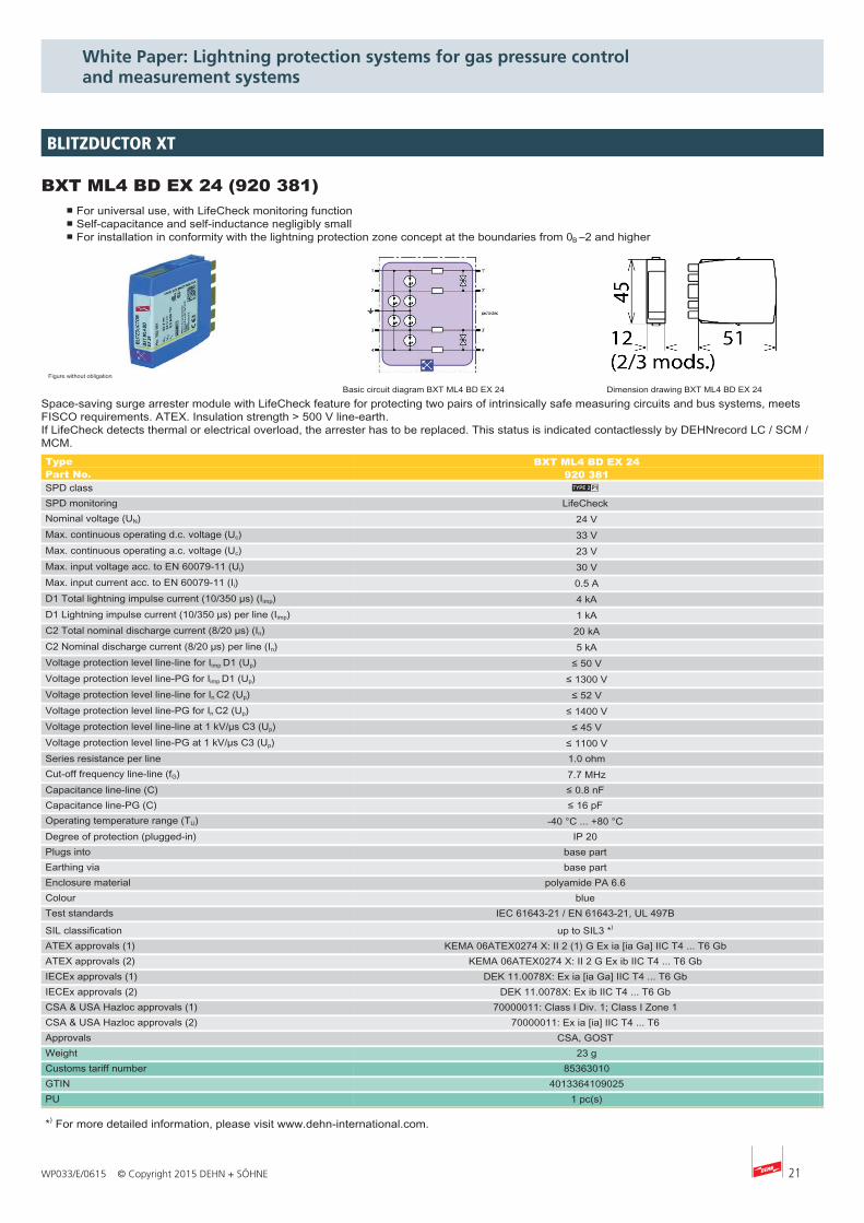
BXT ML4 BD EX 24 (920 381)■ For universal use, with LifeCheck monitoring function■ Self-capacitance and self-inductance negligibly small■ For installation in conformity with the lightning protection zone concept at the boundaries from 0B –2 and higher
Figure without obligation
Basic circuit diagram BXT ML4 BD EX 24 Dimension drawing BXT ML4 BD EX 24
Space-saving surge arrester module with LifeCheck feature for protecting two pairs of intrinsically safe measuring circuits and bus systems, meetsFISCO requirements. ATEX. Insulation strength > 500 V line-earth.If LifeCheck detects thermal or electrical overload, the arrester has to be replaced. This status is indicated contactlessly by DEHNrecord LC / SCM /MCM.Type BXT ML4 BD EX 24 Part No. 920 381 SPD class T SPD monitoring LifeCheck Nominal voltage (UN) 24 V Max. continuous operating d.c. voltage (Uc) 33 V Max. continuous operating a.c. voltage (Uc) 23 V Max. input voltage acc. to EN 60079-11 (Ui) 30 V Max. input current acc. to EN 60079-11 (Ii) 0.5 A D1 Total lightning impulse current (10/350 µs) (Iimp) 4 kA D1 Lightning impulse current (10/350 µs) per line (Iimp) 1 kA C2 Total nominal discharge current (8/20 µs) (In) 20 kA C2 Nominal discharge current (8/20 µs) per line (In) 5 kA Voltage protection level line-line for Iimp D1 (Up) ≤ 50 V Voltage protection level line-PG for Iimp D1 (Up) ≤ 1300 V Voltage protection level line-line for In C2 (Up) ≤ 52 V Voltage protection level line-PG for In C2 (Up) ≤ 1400 V Voltage protection level line-line at 1 kV/µs C3 (Up) ≤ 45 V Voltage protection level line-PG at 1 kV/µs C3 (Up) ≤ 1100 V Series resistance per line 1.0 ohm Cut-off frequency line-line (fG) 7.7 MHz Capacitance line-line (C) ≤ 0.8 nF Capacitance line-PG (C) ≤ 16 pF Operating temperature range (TU) -40 °C ... +80 °C Degree of protection (plugged-in) IP 20 Plugs into base part Earthing via base part Enclosure material polyamide PA 6.6 Colour blue Test standards IEC 61643-21 / EN 61643-21, UL 497B SIL classification up to SIL3 *) ATEX approvals (1) KEMA 06ATEX0274 X: II 2 (1) G Ex ia [ia Ga] IIC T4 ... T6 Gb ATEX approvals (2) KEMA 06ATEX0274 X: II 2 G Ex ib IIC T4 ... T6 Gb IECEx approvals (1) DEK 11.0078X: Ex ia [ia Ga] IIC T4 ... T6 Gb IECEx approvals (2) DEK 11.0078X: Ex ib IIC T4 ... T6 Gb CSA & USA Hazloc approvals (1) 70000011: Class I Div. 1; Class I Zone 1 CSA & USA Hazloc approvals (2) 70000011: Ex ia [ia] IIC T4 ... T6 Approvals CSA, GOST Weight 23 g Customs tariff number 85363010 GTIN 4013364109025 PU 1 pc(s)
*) For more detailed information, please visit www.dehn-international.com.
BLITZDUCTOR XT
22 WP033/E/0615 © Copyright 2015 DEHN + SÖHNE
White Paper: Lightning protection systems for gas pressure control and measurement systems
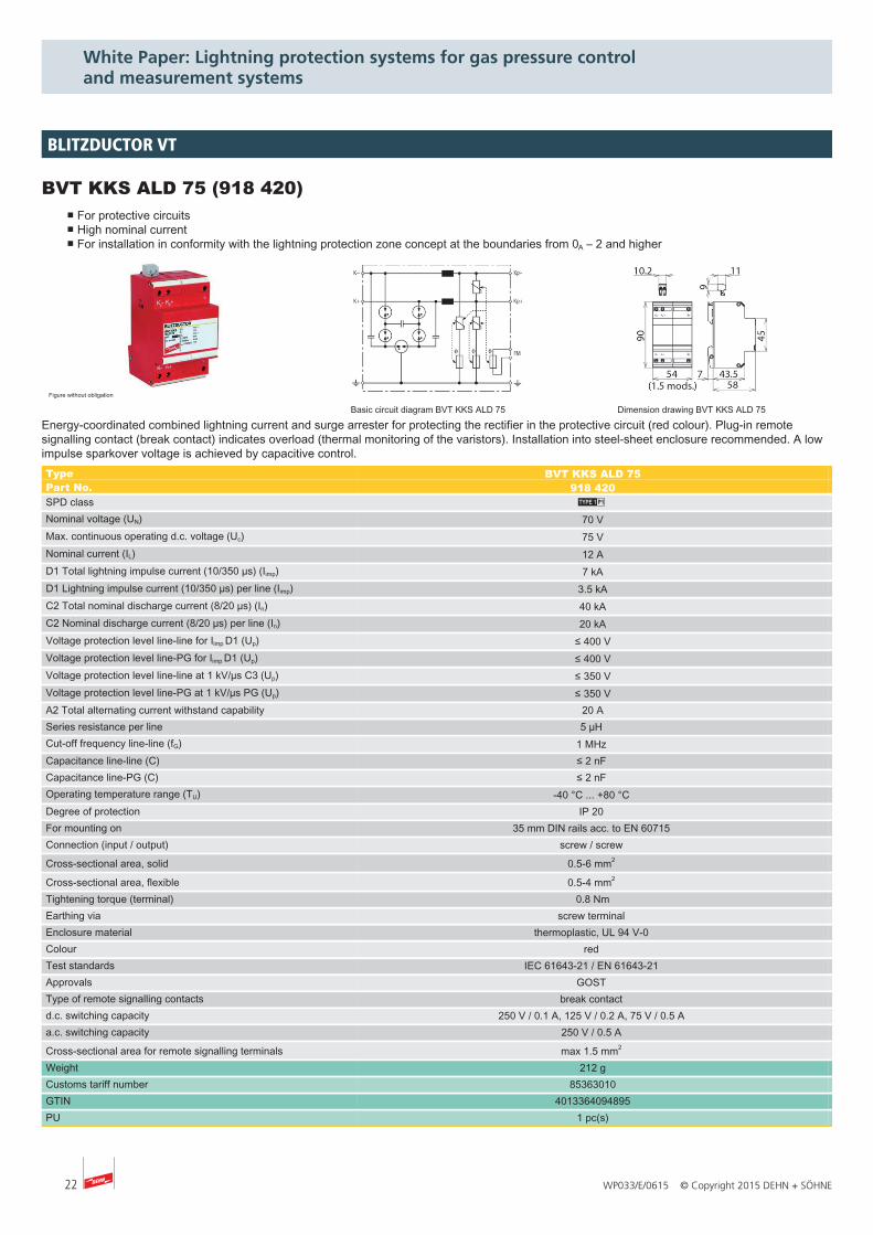
BVT KKS ALD 75 (918 420)■ For protective circuits■ High nominal current■ For installation in conformity with the lightning protection zone concept at the boundaries from 0A – 2 and higher
Figure without obligation
Basic circuit diagram BVT KKS ALD 75 Dimension drawing BVT KKS ALD 75
Energy-coordinated combined lightning current and surge arrester for protecting the rectifier in the protective circuit (red colour). Plug-in remotesignalling contact (break contact) indicates overload (thermal monitoring of the varistors). Installation into steel-sheet enclosure recommended. A lowimpulse sparkover voltage is achieved by capacitive control.Type BVT KKS ALD 75Part No. 918 420SPD class M Nominal voltage (UN) 70 VMax. continuous operating d.c. voltage (Uc) 75 VNominal current (IL) 12 AD1 Total lightning impulse current (10/350 µs) (Iimp) 7 kAD1 Lightning impulse current (10/350 µs) per line (Iimp) 3.5 kAC2 Total nominal discharge current (8/20 µs) (In) 40 kAC2 Nominal discharge current (8/20 µs) per line (In) 20 kAVoltage protection level line-line for Iimp D1 (Up) ≤ 400 VVoltage protection level line-PG for Iimp D1 (Up) ≤ 400 VVoltage protection level line-line at 1 kV/µs C3 (Up) ≤ 350 VVoltage protection level line-PG at 1 kV/µs PG (Up) ≤ 350 VA2 Total alternating current withstand capability 20 ASeries resistance per line 5 µH Cut-off frequency line-line (fG) 1 MHz Capacitance line-line (C) ≤ 2 nF Capacitance line-PG (C) ≤ 2 nF Operating temperature range (TU) -40 °C ... +80 °C Degree of protection IP 20 For mounting on 35 mm DIN rails acc. to EN 60715 Connection (input / output) screw / screw
Cross-sectional area, solid 0.5-6 mm2
Cross-sectional area, flexible 0.5-4 mm2 Tightening torque (terminal) 0.8 NmEarthing via screw terminal Enclosure material thermoplastic, UL 94 V-0 Colour red Test standards IEC 61643-21 / EN 61643-21 Approvals GOST Type of remote signalling contacts break contact d.c. switching capacity 250 V / 0.1 A, 125 V / 0.2 A, 75 V / 0.5 A a.c. switching capacity 250 V / 0.5 A
Cross-sectional area for remote signalling terminals max 1.5 mm2 Weight 212 gCustoms tariff number 85363010GTIN 4013364094895PU 1 pc(s)
BLITZDUCTOR VT
23WP033/E/0615 © Copyright 2015 DEHN + SÖHNE
White Paper: Lightning protection systems for gas pressure control and measurement systems
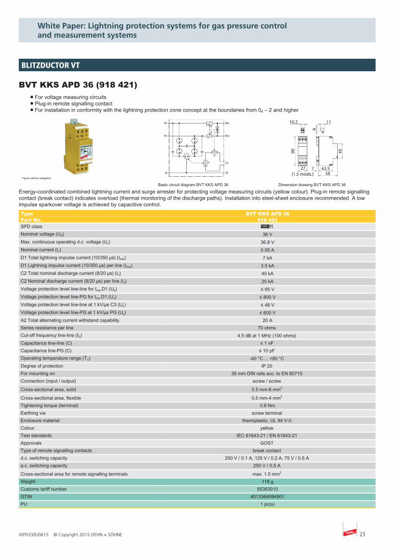
BVT KKS APD 36 (918 421)■ For voltage measuring circuits■ Plug-in remote signalling contact■ For installation in conformity with the lightning protection zone concept at the boundaries from 0A – 2 and higher
Figure without obligation
Basic circuit diagram BVT KKS APD 36 Dimension drawing BVT KKS APD 36
Energy-coordinated combined lightning current and surge arrester for protecting voltage measuring circuits (yellow colour). Plug-in remote signallingcontact (break contact) indicates overload (thermal monitoring of the discharge paths). Installation into steel-sheet enclosure recommended. A lowimpulse sparkover voltage is achieved by capacitive control.Type BVT KKS APD 36Part No. 918 421SPD class M Nominal voltage (UN) 36 VMax. continuous operating d.c. voltage (Uc) 36.8 VNominal current (IL) 0.05 AD1 Total lightning impulse current (10/350 µs) (Iimp) 7 kAD1 Lightning impulse current (10/350 µs) per line (Iimp) 3.5 kAC2 Total nominal discharge current (8/20 µs) (In) 40 kAC2 Nominal discharge current (8/20 µs) per line (In) 20 kAVoltage protection level line-line for Iimp D1 (Up) ≤ 65 VVoltage protection level line-PG for Iimp D1 (Up) ≤ 800 VVoltage protection level line-line at 1 kV/µs C3 (Up) ≤ 48 VVoltage protection level line-PG at 1 kV/µs PG (Up) ≤ 600 VA2 Total alternating current withstand capability 20 ASeries resistance per line 70 ohms Cut-off frequency line-line (fG) 4.5 dB at 1 MHz (100 ohms) Capacitance line-line (C) ≤ 1 nF Capacitance line-PG (C) ≤ 10 pF Operating temperature range (TU) -40 °C ... +80 °C Degree of protection IP 20 For mounting on 35 mm DIN rails acc. to EN 60715 Connection (input / output) screw / screw
Cross-sectional area, solid 0.5 mm-6 mm2
Cross-sectional area, flexible 0.5 mm-4 mm2 Tightening torque (terminal) 0.8 NmEarthing via screw terminal Enclosure material thermplastic, UL 94 V-0 Colour yellow Test standards IEC 61643-21 / EN 61643-21 Approvals GOST Type of remote signalling contacts break contact d.c. switching capacity 250 V / 0.1 A, 125 V / 0.2 A, 75 V / 0.5 A a.c. switching capacity 250 V / 0.5 A
Cross-sectional area for remote signalling terminals max. 1.5 mm2 Weight 118 gCustoms tariff number 85363010GTIN 4013364094901PU 1 pc(s)
BLITZDUCTOR VT
24 WP033/E/0615 © Copyright 2015 DEHN + SÖHNE
White Paper: Lightning protection systems for gas pressure control and measurement systems
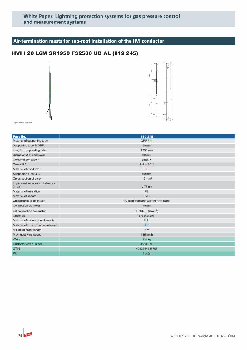
HVI I 20 L6M SR1950 FS2500 UD AL (819 245)
Figure without obligation
Part No. 819 245Material of supporting tube GRP / Al Supporting tube Ø GRP 50 mmLength of supporting tube 1950 mmDiameter Ø of conductor 20 mmColour of conductor black ● Coluor RAL similar 9011 Material of conductor Cu Supporting tube Ø Al 60 mmCross section of core 19 mm²Equivalent separation distance s(in air) ≤ 75 cmMaterial of insulation PE Material of sheath PVC Characteristics of sheath UV stabilised and weather resistant Connection diameter 10 mm
EB connection conductor H07RN-F (6 mm2) Cable lug 8-6 (Cu/Sn) Material of connection elements StSt Material of EB connection element StSt Minimum order length 6 mMax. gust wind speed 145 km/hWeight 7,4 kgCustoms tariff number 85389099GTIN 4013364135796PU 1 pc(s)
Air-termination masts for sub-roof installation of the HVI conductor
25WP033/E/0615 © Copyright 2015 DEHN + SÖHNE
White Paper: Lightning protection systems for gas pressure control and measurement systems
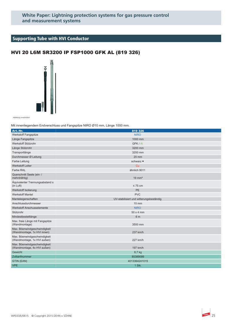
HVI 20 L6M SR3200 IP FSP1000 GFK AL (819 326)
Abbildung unverbindlich
Mit innenliegendem Endverschluss und Fangspitze NIRO Ø10 mm, Länge 1000 mm.Art.-Nr. 819 326Werkstoff Fangspitze NIRO Länge Fangspitze 1000 mmWerkstoff Stützrohr GFK / Al Länge Stützrohr 3200 mmTransportlänge 3200 mmDurchmesser Ø Leitung 20 mmFarbe Leitung schwarz ● Werkstoff Leiter Cu Farbe RAL ähnlich 9011 Querschnitt Seele (ein- /mehrdrähtig) 19 mm²Äquivalenter Trennungsabstand s(in Luft) ≤ 75 cmWerkstoff Isolierung PE Werkstoff Mantel PVC Manteleigenschaften UV-stabilisiert und witterungsbeständig Anschlussdurchmesser 10 mmWerkstoff Anschusselemente NIRO Stützrohr 50 x 4 mmMindestbestelllänge 6 mMax. freie Länge mit Fangspitze(Wandmontage) 3500 mmMax. Böenwindgeschwindigkeit(Wandmontage, 1x HVI innen) 237 km/hMax. Böenwindgeschwindigkeit(Wandmontage, 1x HVI außen) 227 km/hMax. Böenwindgeschwindigkeit(Wandmontage, 4x HVI außen) 197 km/hGewicht 8,7 kgZolltarifnummer 85389099GTIN (EAN) 4013364241015VPE 1 Stk.
Supporting Tube with HVI Conductor
26 WP033/E/0615 © Copyright 2015 DEHN + SÖHNE
White Paper: Lightning protection systems for gas pressure control and measurement systems
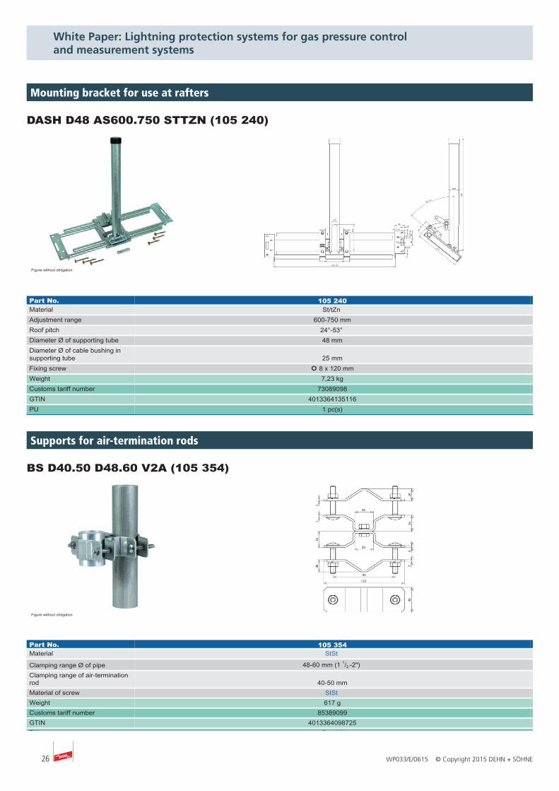
DASH D48 AS600.750 STTZN (105 240)
Figure without obligation
Part No. 105 240Material St/tZn Adjustment range 600-750 mmRoof pitch 24°-53° Diameter Ø of supporting tube 48 mmDiameter Ø of cable bushing insupporting tube 25 mmFixing screw l 8 x 120 mmWeight 7,23 kgCustoms tariff number 73089098GTIN 4013364135116PU 1 pc(s)
Mounting bracket for use at rafters
BS D40.50 D48.60 V2A (105 354)
Figure without obligation
Part No. 105 354Material StSt
Clamping range Ø of pipe 48-60 mm (1 1/2 -2") Clamping range of air-terminationrod 40-50 mmMaterial of screw StSt Weight 617 gCustoms tariff number 85389099GTIN 4013364098725PU 5 pc(s)
Supports for air-termination rods
27WP033/E/0615 © Copyright 2015 DEHN + SÖHNE
White Paper: Lightning protection systems for gas pressure control and measurement systems
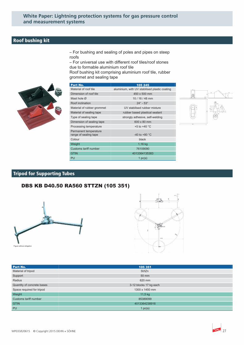
Roof Bushing Kit +
– For bushing and sealing of poles and pipes on steeproofs– For universal use with different roof tiles/roof stonesdue to formable aluminium roof tileRoof bushing kit comprising aluminium roof tile, rubbergrommet and sealing tape
Part No. 105 245 Material of roof tile aluminium, with UV stabilised plastic coating Dimension of roof tile 450 x 500 mm Mast hole Ø 10 / 16 / 48 mm Roof inclination 24° - 53° Material of rubber grommet UV stabilised rubber mixture Material of sealing tape rubber based plastical sealant Type of sealing tape strongly adhesive, self-welding Dimension of sealing tape 600 x 80 mm Processing temperature +5 to +40 °C Permanent temperaturerange of sealing tape -40 to +80 °C Colour black Weight 1,16 kg Customs tariff number 76109090 GTIN 4013364135383 PU 1 pc(s)
Roof bushing kit
+ DBS KB D40.50 RA560 STTZN (105 351)
Figure without obligation
Part No. 105 351Material of tripod St/tZn Support 50 mmRadius 620 mmQuantity of concrete bases 3-12 blocks 17 kg each Space required for tripod 1300 x 1450 mmWeight 11,5 kgCustoms tariff number 85389099GTIN 4013364238916PU 1 pc(s)
Tripod for Supporting Tubes
28 WP033/E/0615 © Copyright 2015 DEHN + SÖHNE
White Paper: Lightning protection systems for gas pressure control and measurement systems
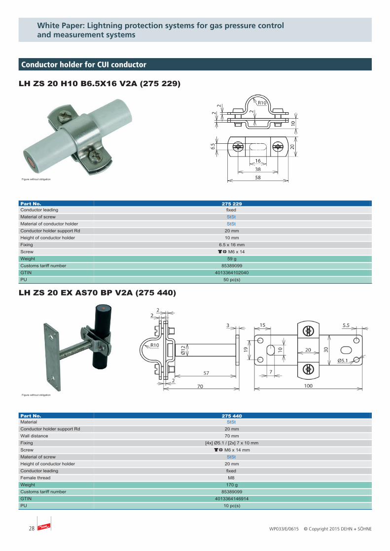
LH ZS 20 H10 B6.5X16 V2A (275 229)
Figure without obligation
Part No. 275 229Conductor leading fixed Material of screw StSt Material of conductor holder StSt Conductor holder support Rd 20 mmHeight of conductor holder 10 mmFixing 6.5 x 16 mmScrew dm M6 x 14 Weight 59 gCustoms tariff number 85389099GTIN 4013364102040PU 50 pc(s)
LH ZS 20 EX AS70 BP V2A (275 440)
Figure without obligation
Part No. 275 440Material StSt Conductor holder support Rd 20 mmWall distance 70 mmFixing [4x] Ø5.1 / [2x] 7 x 10 mmScrew dm M6 x 14 mmMaterial of screw StSt Height of conductor holder 20 mmConductor leading fixed Female thread M8 Weight 170 gCustoms tariff number 85389099GTIN 4013364146914PU 10 pc(s)
Conductor holder for CUI conductor
29WP033/E/0615 © Copyright 2015 DEHN + SÖHNE
White Paper: Lightning protection systems for gas pressure control and measurement systems
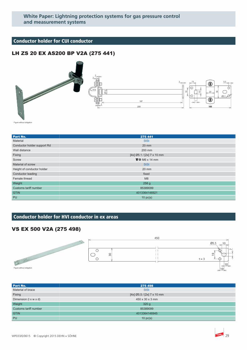
LH ZS 20 EX AS200 BP V2A (275 441)
Figure without obligation
Part No. 275 441Material StSt Conductor holder support Rd 20 mmWall distance 200 mmFixing [4x] Ø5.1 / [2x] 7 x 10 mmScrew dm M6 x 14 mmMaterial of screw StSt Height of conductor holder 20 mmConductor leading fixed Female thread M8 Weight 258 gCustoms tariff number 85389099GTIN 4013364146921PU 10 pc(s)
VS EX 500 V2A (275 498)
Figure without obligation
Part No. 275 498Material of brace StSt Fixing [4x] Ø5.5 / [2x] 7 x 10 mmDimension (l x w x d) 450 x 30 x 3 mmWeight 320 gCustoms tariff number 85389099GTIN 4013364146945PU 10 pc(s)
Conductor holder for CUI conductor
Conductor holder for HVI conductor in ex areas
30 WP033/E/0615 © Copyright 2015 DEHN + SÖHNE
White Paper: Lightning protection systems for gas pressure control and measurement systems
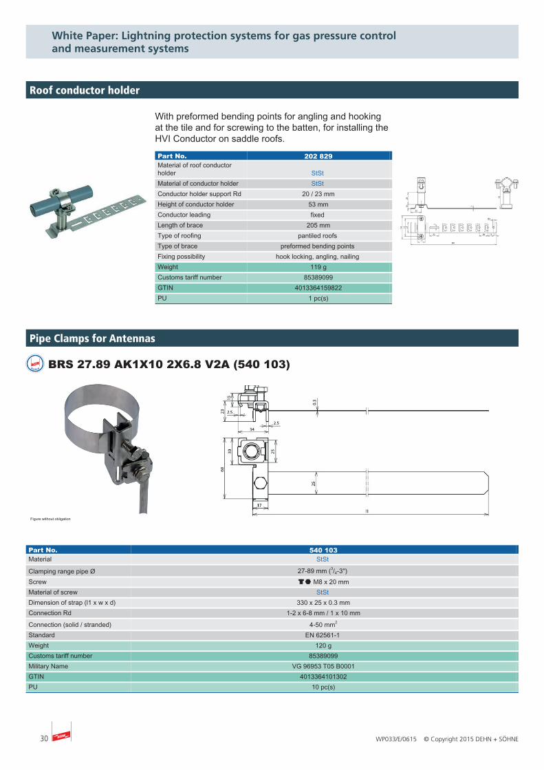
tested BRS 27.89 AK1X10 2X6.8 V2A (540 103)
Figure without obligation
Part No. 540 103Material StSt
Clamping range pipe Ø 27-89 mm (3/4-3'') Screw di M8 x 20 mmMaterial of screw StSt Dimension of strap (l1 x w x d) 330 x 25 x 0.3 mmConnection Rd 1-2 x 6-8 mm / 1 x 10 mm
Connection (solid / stranded) 4-50 mm2
Standard EN 62561-1 Weight 120 gCustoms tariff number 85389099Military Name VG 96953 T05 B0001GTIN 4013364101302PU 10 pc(s)
Pipe Clamps for Antennas
Roof Conductor Holder
With preformed bending points for angling and hookingat the tile and for screwing to the batten, for installing theHVI Conductor on saddle roofs.
Part No. 202 829 Material of roof conductorholder StSt Material of conductor holder StSt Conductor holder support Rd 20 / 23 mm Height of conductor holder 53 mm Conductor leading fixed Length of brace 205 mm Type of roofing pantiled roofs Type of brace preformed bending points Fixing possibility hook locking, angling, nailing Weight 119 g Customs tariff number 85389099 GTIN 4013364159822 PU 1 pc(s)
Roof conductor holder
31WP033/E/0615 © Copyright 2015 DEHN + SÖHNE
White Paper: Lightning protection systems for gas pressure control and measurement systems
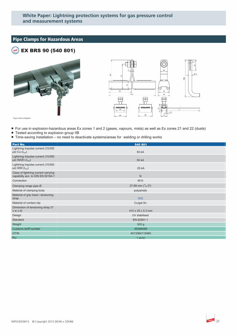
■ For use in explosion-hazardous areas Ex zones 1 and 2 (gases, vapours, mists) as well as Ex zones 21 and 22 (dusts)■ Tested according to explosion group IIB■ Time-saving installation – no need to deactivate systems/areas for welding or drilling works
tested EX BRS 90 (540 801)
Figure without obligation
Part No. 540 801Lightning impulse current (10/350µs) Cu (Iimp) 50 kA Lightning impulse current (10/350µs) St/tZn (Iimp) 50 kA Lightning impulse current (10/350µs) StSt (Iimp) 25 kAClass of lightning current carryingcapability acc. to DIN EN 50164-1 N Connection M10
Clamping range pipe Ø 27-89 mm (3/4-3") Material of clamping body polyamide Material of grip head / tensioningstrap StSt Material of contact clip Cu/gal Sn Dimension of tensioning strap (l1x w x d) 410 x 25 x 0.3 mmDesign UV stabilised Standard EN 62561-1 Weight 503 gCustoms tariff number 85389099GTIN 4013364115460PU 1 pc(s)
Pipe Clamps for Hazardous Areas
32 WP033/E/0615 © Copyright 2015 DEHN + SÖHNE
White Paper: Lightning protection systems for gas pressure control and measurement systems
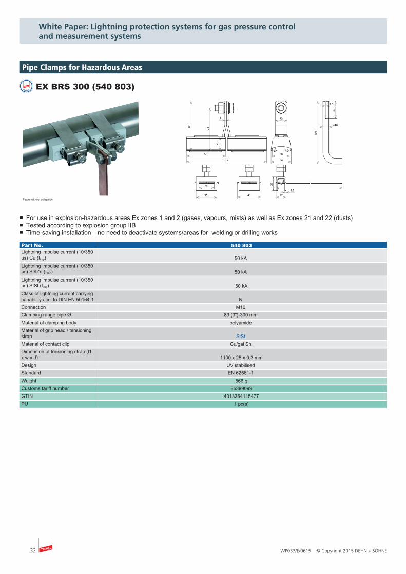
tested EX BRS 300 (540 803)
Figure without obligation
■ For use in explosion-hazardous areas Ex zones 1 and 2 (gases, vapours, mists) as well as Ex zones 21 and 22 (dusts)■ Tested according to explosion group IIB■ Time-saving installation – no need to deactivate systems/areas for welding or drilling works
Part No. 540 803Lightning impulse current (10/350µs) Cu (Iimp) 50 kA Lightning impulse current (10/350µs) St/tZn (Iimp) 50 kA Lightning impulse current (10/350µs) StSt (Iimp) 50 kAClass of lightning current carryingcapability acc. to DIN EN 50164-1 N Connection M10 Clamping range pipe Ø 89 (3")-300 mm Material of clamping body polyamide Material of grip head / tensioningstrap StSt Material of contact clip Cu/gal Sn Dimension of tensioning strap (l1x w x d) 1100 x 25 x 0.3 mmDesign UV stabilised Standard EN 62561-1 Weight 566 gCustoms tariff number 85389099GTIN 4013364115477PU 1 pc(s)
Pipe Clamps for Hazardous Areas
33WP033/E/0615 © Copyright 2015 DEHN + SÖHNE
White Paper: Lightning protection systems for gas pressure control and measurement systems
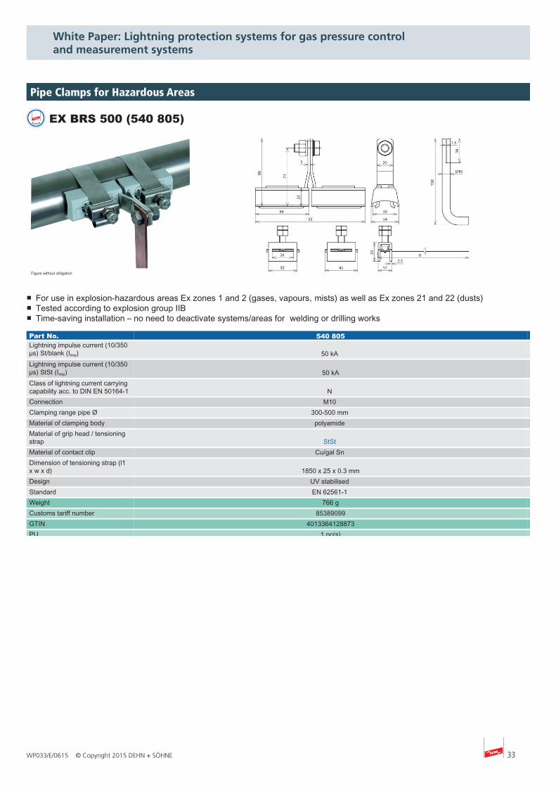
tested EX BRS 500 (540 805)
Figure without obligation
■ For use in explosion-hazardous areas Ex zones 1 and 2 (gases, vapours, mists) as well as Ex zones 21 and 22 (dusts)■ Tested according to explosion group IIB■ Time-saving installation – no need to deactivate systems/areas for welding or drilling works
Part No. 540 805Lightning impulse current (10/350µs) St/blank (Iimp) 50 kA Lightning impulse current (10/350µs) StSt (Iimp) 50 kAClass of lightning current carryingcapability acc. to DIN EN 50164-1 N Connection M10 Clamping range pipe Ø 300-500 mm Material of clamping body polyamide Material of grip head / tensioningstrap StSt Material of contact clip Cu/gal Sn Dimension of tensioning strap (l1x w x d) 1850 x 25 x 0.3 mmDesign UV stabilised Standard EN 62561-1 Weight 766 gCustoms tariff number 85389099GTIN 4013364128873PU 1 pc(s)
Pipe Clamps for Hazardous Areas
34 WP033/E/0615 © Copyright 2015 DEHN + SÖHNE
White Paper: Lightning protection systems for gas pressure control and measurement systems
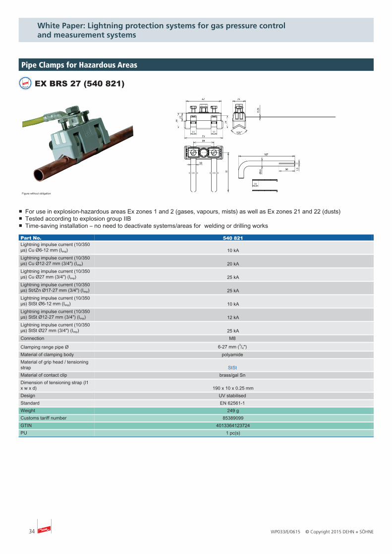
tested EX BRS 27 (540 821)
Figure without obligation
■ For use in explosion-hazardous areas Ex zones 1 and 2 (gases, vapours, mists) as well as Ex zones 21 and 22 (dusts)■ Tested according to explosion group IIB■ Time-saving installation – no need to deactivate systems/areas for welding or drilling works
Part No. 540 821Lightning impulse current (10/350µs) Cu Ø6-12 mm (Iimp) 10 kALightning impulse current (10/350µs) Cu Ø12-27 mm (3/4") (Iimp) 20 kALightning impulse current (10/350µs) Cu Ø27 mm (3/4") (Iimp) 25 kALightning impulse current (10/350µs) St/tZn Ø17-27 mm (3/4") (Iimp) 25 kALightning impulse current (10/350µs) StSt Ø6-12 mm (Iimp) 10 kALightning impulse current (10/350µs) StSt Ø12-27 mm (3/4") (Iimp) 12 kALightning impulse current (10/350µs) StSt Ø27 mm (3/4") (Iimp) 25 kAConnection M8
Clamping range pipe Ø 6-27 mm (3/4") Material of clamping body polyamide Material of grip head / tensioningstrap StSt Material of contact clip brass/gal Sn Dimension of tensioning strap (l1x w x d) 190 x 10 x 0.25 mmDesign UV stabilised Standard EN 62561-1 Weight 249 gCustoms tariff number 85389099GTIN 4013364123724PU 1 pc(s)
Pipe Clamps for Hazardous Areas
35WP033/E/0615 © Copyright 2015 DEHN + SÖHNE
White Paper: Lightning protection systems for gas pressure control and measurement systems
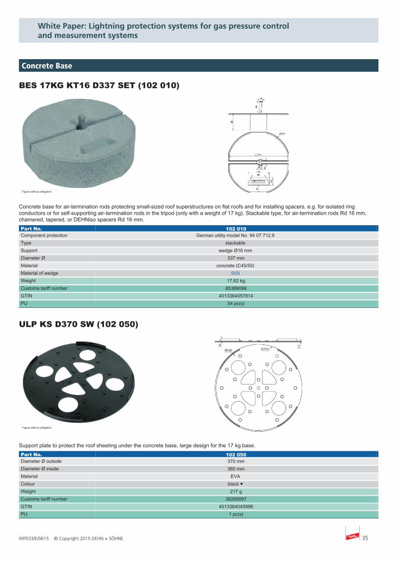
BES 17KG KT16 D337 SET (102 010)
Figure without obligation
Concrete base for air-termination rods protecting small-sized roof superstructures on flat roofs and for installing spacers, e.g. for isolated ringconductors or for self-supporting air-termination rods in the tripod (only with a weight of 17 kg). Stackable type, for air-termination rods Rd 16 mm,chamered, tapered, or DEHNiso spacers Rd 16 mm.Part No. 102 010Component protection German utility model No. 94 07 712.6 Type stackable Support wedge Ø16 mm Diameter Ø 337 mmMaterial concrete (C45/55) Material of wedge StSt Weight 17,62 kgCustoms tariff number 85389099GTIN 4013364057814PU 54 pc(s)
ULP KS D370 SW (102 050)
Figure without obligation
Support plate to protect the roof sheeting under the concrete base, large design for the 17 kg base.Part No. 102 050Diameter Ø outside 370 mmDiameter Ø inside 360 mmMaterial EVA Colour black ● Weight 217 gCustoms tariff number 39269097GTIN 4013364045996PU 1 pc(s)
Concrete Base
36 WP033/E/0615 © Copyright 2015 DEHN + SÖHNE
White Paper: Lightning protection systems for gas pressure control and measurement systems
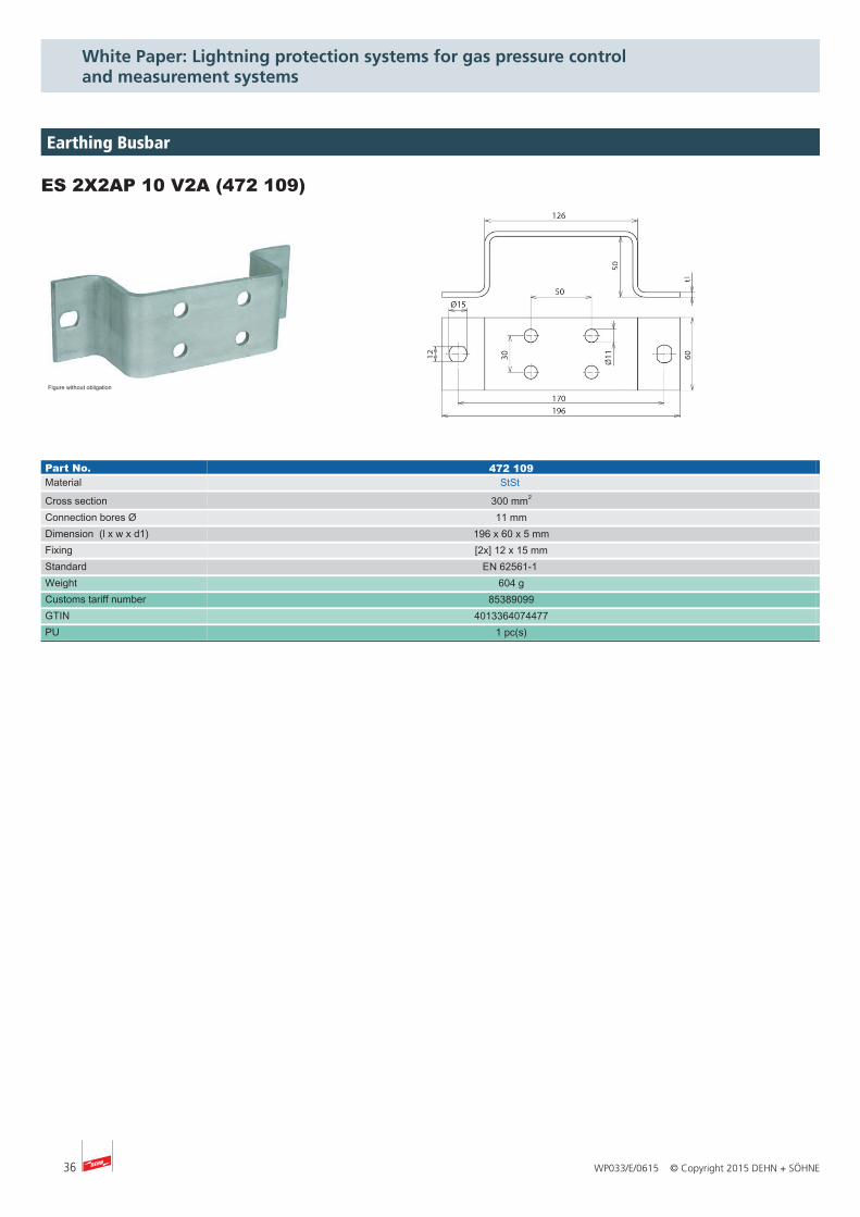
ES 2X2AP 10 V2A (472 109)
Figure without obligation
Part No. 472 109Material StSt
Cross section 300 mm2
Connection bores Ø 11 mmDimension (l x w x d1) 196 x 60 x 5 mmFixing [2x] 12 x 15 mmStandard EN 62561-1 Weight 604 gCustoms tariff number 85389099GTIN 4013364074477PU 1 pc(s)
Earthing Busbar
WP033/E/0615 © Copyright 2015 DEHN + SÖHNE
Type designations of products mentioned in the white paper being at the same time registered trademarks are not especially marked. So if there is no marking of ™ or ® this does not mean that the type designation is a free trade name. Neither it can be seen whether patents or utility models and other intellectual and industrial property rights are available. We reserve the right to introduce changes in performance, configuration and technology, dimensions, weights and materials in the course of technical progress. The figures are shown without obligation. Misprints, errors and modifications excepted. Reproduction in any form whatsoever is forbidden without our authorisation.
actiVsense, BLITZDUCTOR, BLITZPLANER, DEHN, DEHN Logo, DEHN schützt, DEHNbloc, DEHNfix, DEHNgrip, DEHNguard, DEHNport, DEHNQUICK, DEHNrapid, DEHNshield, DEHNsnap, DEHNventil, HVI, LifeCheck, Red/Line are protected by German Trade Mark, by Community Trade Mark (EU) and/or in other countries.
Surge Protection DEHN + SÖHNE Hans-Dehn-Str. 1 Tel. +49 9181 906-0Lightning Protection GmbH + Co.KG. Postfach 1640 Fax +49 9181 906-1100Safety Equipment 92306 Neumarkt [email protected] protects. Germany www.dehn-international.com
www.dehn-international.com/partners
www.dehn-international.com/partners