
TNEB Specification.pdf
408
TAMIL NADU TRANSMISSION CORPORATION LTD CHENNAI TAMIL NADU, INDIA Specification for Establishment of 230/33KV SF6 Gas Insulated Switch Gear Sub-Station under EPC contract at Mylapore, Chennai SPECIFICATION NO. T-1640 OFFICE OF THE CHIEF ENGINEER/TRANSMISSION 6 TH FLOOR, NPKRR MAALIGAI, 144, ANNA SALAI, CHENNAI - 600 002. Tamil Nadu, INDIA 1
Transcript of TNEB Specification.pdf

TAMIL NADU TRANSMISSION CORPORATION LTDCHENNAI
TAMIL NADU, INDIA
Specification for Establishment of 230/33KV SF6 Gas Insulated Switch Gear Sub-Station under EPC contract at Mylapore, Chennai
SPECIFICATION NO. T-1640
OFFICE OF THE CHIEF ENGINEER/TRANSMISSION 6TH FLOOR, NPKRR MAALIGAI,
144, ANNA SALAI, CHENNAI - 600 002.Tamil Nadu, INDIA
1
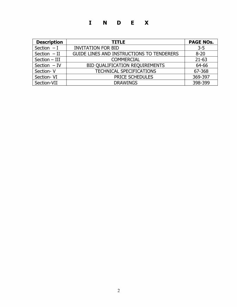
I N D E X
Description TITLE PAGE NOs.Section – I INVITATION FOR BID 3-5 Section – II GUIDE LINES AND INSTRUCTIONS TO TENDERERS 8-20 Section – III COMMERCIAL 21-63Section – IV BID QUALIFICATION REQUIREMENTS 64-66Section- V TECHNICAL SPECIFICATIONS 67-368Section- VI PRICE SCHEDULES 369-397Section-VII DRAWINGS 398-399
2

SECTION-I
INVITATION FOR GLOBAL BID
INTERNATIONAL COMPETITIVE BIDDING – INVITATION FOR BID.
Global Sealed Tenders in Duplicate “Two Part” Tender system are invited for
and on behalf of TAMIL NADU TRANSMISSION CORPORATION, hereinafter
referred to as PURCHASER, so as to reach on or before the due date prescribed.
1. SCOPE:
1) Establishment of 230/33 KV GIS Substation under EPC Contract with the following Equipments/Materials at Mylapore., Chennai
a) 3 Nos 230 KV GIS Feeder Bays and 2 Nos 230 KV GIS Transformer Bays.
b) 11 Nos 33 KV Feeder VCB bays and 4 Nos 33 KV Transformer VCB Bays with one Bus coupler.
c) 16 Nos 11 KV Feeder VCB bays and 3 Nos 11 KV Transformer VCB bays with 2 nos Bus coupler.
d) Supply and erection of 2 Nos 230/33 KV 100 MVA Power Transformers.
e) Dismantling of 2 nos 110/33 KV 50 MVA power Transformer and transporting to TNEB stores/TRB and erection of 2 Nos 110/11 KV 16 MVA Power Transformers after dismantling the power transformers from existing Substation in that vacant plinths.
f) Dismantling one number 33/11 KV 16 MVA Power Transformer from existing Substation and erection of same in new plinth in between 2 Nos 110/11 KV 16 MVA Power Transformers.
g) Other Substation equipments as per price schedule.
h) Construction of 230 KV GIS Room and 33 KV room and other civil works as per price schedule
j) Dismantling of existing 33 KV indoor VCB panels, transporting and devoluting to TNEB stores
k) 230 KV 1x1200 sqmm aluminium cable to connect the Power Transformer and GIS breaker will be supplied by TNEB
l) 11 KV 1x630 sqmm aluminum cable to connect the power transformer and 11 KV VCB will be supplied by TNEB.
3
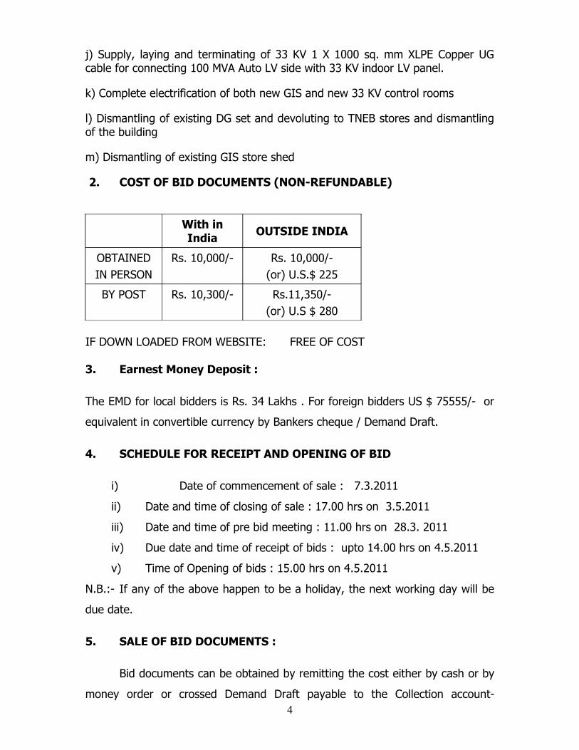
j) Supply, laying and terminating of 33 KV 1 X 1000 sq. mm XLPE Copper UG cable for connecting 100 MVA Auto LV side with 33 KV indoor LV panel.
k) Complete electrification of both new GIS and new 33 KV control rooms
l) Dismantling of existing DG set and devoluting to TNEB stores and dismantling of the building
m) Dismantling of existing GIS store shed
2. COST OF BID DOCUMENTS (NON-REFUNDABLE)
With in India OUTSIDE INDIA
OBTAINEDIN PERSON
Rs. 10,000/- Rs. 10,000/-(or) U.S.$ 225
BY POST Rs. 10,300/- Rs.11,350/-(or) U.S $ 280
IF DOWN LOADED FROM WEBSITE: FREE OF COST
3. Earnest Money Deposit :
The EMD for local bidders is Rs. 34 Lakhs . For foreign bidders US $ 75555/- or
equivalent in convertible currency by Bankers cheque / Demand Draft.
4. SCHEDULE FOR RECEIPT AND OPENING OF BID
i) Date of commencement of sale : 7.3.2011
ii) Date and time of closing of sale : 17.00 hrs on 3.5.2011
iii) Date and time of pre bid meeting : 11.00 hrs on 28.3. 2011
iv) Due date and time of receipt of bids : upto 14.00 hrs on 4.5.2011
v) Time of Opening of bids : 15.00 hrs on 4.5.2011
N.B.:- If any of the above happen to be a holiday, the next working day will be
due date.
5. SALE OF BID DOCUMENTS :
Bid documents can be obtained by remitting the cost either by cash or by
money order or crossed Demand Draft payable to the Collection account- 4

TANTRANSCO, VII Floor, N.P.K.R.R. Maaligai, Electricity Avenue, Anna Salai,
Chennai – 600 002, India noting the Specification number and sending the
receipt to the Superintending Engineer, Transmission-II, Tamil Nadu
Transmission Corporation, VI Floor, Western Wing, N.P.K.R.R Maaligai, 144,
Anna Salai, Chennai – 600 002. INDIA, with a requisition furnishing the
complete postal address. who shall authorize sale of document on all working
days from 10.30 a.m to 5.00 pm during the period of sale mentioned above,
Demand draft should be drawn in favour of “ TANTRANSCO Collection Account”.
Chennai.
Bid documents can also be downloaded from WEBSITE of TNEB www.tneb.in .
or from the WEBSITE of the Tamil Nadu Government www.tenders.tn.gov.in
at free of cost.
address for Communication. Chief Engineer/Transmission.
Tamil Nadu Transmission Corporation Ltd
6th Floor, Western Wing
144, Anna Salai, Chennai- 600 002.
INDIA- Fax No. 91 44 28555539.
6. Telex / Fax / Telegraphic bid will not be accepted and the Board is not
responsible for any postal delay in submission of bids.
7. GENERAL
The Purchaser will not be responsible for any costs or expenses incurred
by bidders in connection with the preparation or delivery of bids including the
costs and expenses resisted to site visits.
5
SECTION – II
GUIDE LINES AND INSTRUCTIONS TO TENDERERS
6

I N D E X
Sl.No TITLE PAGE NOs.1 Invitation for Bid 82 Transparency in Tenders Act 83 Submission of Tender Offer 84 Two parts Tender 8-125 Tender opening 126 Information Required and clarifications. 137 Evaluation and comparison of Tender Offers 148 Validity 149 Rights of the Board 1510 Deviations 1511 Appeal 1612 Clarifications 1613 Earnest Money Deposit 17-1914 Reimbursement of Duties and Taxes. 1915 Local Conditions 20
7

GUIDE LINES AND INSTRUCTIONS TO TENDERERS
1.0. Invitation for Bid
Sealed tenders in Two Part System (a) Technical Bid with Commercial
terms but without Price Bid and (b) Price Bid (both bids in duplicate) will
be received for and on behalf of TAMILNADU TRANSMISSION
CORPORATION LTD herein after referred as Board so as to reach on or
before the due date prescribed. All the tenders shall be prepared and
submitted strictly in accordance with the Instructions set forth herein.
THE TENDERERS WHO DO NOT FULFILL THE “BID QUALIFICATION
REQUIREMENTS“ NEED NOT PARTICIPATE IN THE TENDER. OFFERS
NOT SATISFYING THE "BID QUALIFICATION REQUIREMENTS” WILL NOT
BE CONSIDERED AND WILL BE SUMMARILY REJECTED.
2.0Tender Transparency Act
The Transparency in Tenders Act 1998 and the Transparency in Tender
Rules 2000 are applicable to this tender.
3.0SUBMISSION OF TENDER OFFER :
3.1 The Tenderer is expected to examine all instructions and Schedules
detailed in the Specification and submit the Schedule of prices and other
required particulars in the schedules and drawings called for in this
specification only as per the formats prescribed herein.
4.0TWO PARTS TENDER:
4.1 The Tenders shall be in Two Parts as detailed below each in a separate
sealed Envelope marked, " ENVELOPE - A " AND " ENVELOPE - B "
1. The first envelope, called “Envelope - A” shall contain:
(a) Un priced bid (i.e. Technical Bid with commercial terms except
price.)
8
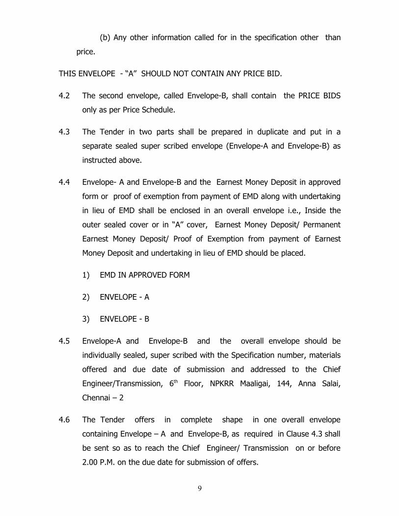
(b) Any other information called for in the specification other than
price.
THIS ENVELOPE - “A” SHOULD NOT CONTAIN ANY PRICE BID.
4.2 The second envelope, called Envelope-B, shall contain the PRICE BIDS
only as per Price Schedule.
4.3 The Tender in two parts shall be prepared in duplicate and put in a
separate sealed super scribed envelope (Envelope-A and Envelope-B) as
instructed above.
4.4 Envelope- A and Envelope-B and the Earnest Money Deposit in approved
form or proof of exemption from payment of EMD along with undertaking
in lieu of EMD shall be enclosed in an overall envelope i.e., Inside the
outer sealed cover or in “A” cover, Earnest Money Deposit/ Permanent
Earnest Money Deposit/ Proof of Exemption from payment of Earnest
Money Deposit and undertaking in lieu of EMD should be placed.
1) EMD IN APPROVED FORM
2) ENVELOPE - A
3) ENVELOPE - B
4.5 Envelope-A and Envelope-B and the overall envelope should be
individually sealed, super scribed with the Specification number, materials
offered and due date of submission and addressed to the Chief
Engineer/Transmission, 6th Floor, NPKRR Maaligai, 144, Anna Salai,
Chennai – 2
4.6 The Tender offers in complete shape in one overall envelope
containing Envelope – A and Envelope-B, as required in Clause 4.3 shall
be sent so as to reach the Chief Engineer/ Transmission on or before
2.00 P.M. on the due date for submission of offers.
9
4.7 The Tender documents shall be addressed to the Chief Engineer /
Transmission, 6th Floor, Western Wing, NPKRR Maaligai, 144, Anna
Salai, Chennai – 600 002.
4.8 At the time of opening the Tenders, any offer which does not satisfy the
Earnest Money Deposit Conditions shall not be readout. If any of the
Bidders indicate price in Envelope – A, the Bid will not be read out and
will be rejected.
4.9. Envelope “B” will not be opened at the time of opening Envelope “A”
but will be authenticated in the covers by officers authorized to open the
bids. Envelope “B” so authenticated will be kept under the safe
custody of the empowered officer to open the tender. Envelope “B”
Price Bid will be opened later, the date of which will be intimated to the
tenderer at a later date, after technical evaluation of the tender is
completed.
4.10 If the tenderer finds any ambiguity in any of the terms and
conditions stipulated in this specification, he shall get it clarified from the
Chief Engineer/ Transmission, 6th floor, Western Wing, NPKRR Maaligai,
Electricity Avenue, 144, Anna Salai, Chennai – 600 002. The clarification
to the tender documents if any asked for by any tenderer before 48 hours
of the opening of the tender will be replied to and copies of such
clarification will be communicated to all the tenderers. If this is not done
and subsequent to the opening of the tenders, it is found that the doubt,
about the meaning or, ambiguity in the interpretation, if any of the terms
and conditions stipulated in the specification are raised by the tenderer
either in this tender or by a separate letter, the interpretation or
clarification issued by the Chief Engineer / Transmission, Tamil Nadu
Electricity Board, Chennai – 2 on such of those terms and conditions of
the Tender Document as may be raised by the tenderer shall be final and
binding on the tenderer.
1

4.11 All tender offers shall be prepared by typing or printing in the formats
enclosed with the specifications. One original and one duplicate of the
original proposal which are identical shall be submitted by each tenderer.
4.12 All information in the tender offer shall be in ENGLISH only. It shall not
contain interlineations, erasures or over writings except as necessary to
correct errors made by the tenderer. Such erasures or other changes in
the tender document shall be attested by the person signing the tender
offer.
4.13 The tender offer shall contain full information asked for in the
accompanying schedules and elsewhere in the specification.
4.14 The tenderer has the option of sending the offer by Registered Post/
Courier or submitting the same in person so as to reach by the date and
time indicated.
4.15 In case of postal delivery, tenderers are advised to send them well in
advance so that they are delivered at the office of the Chief
Engineer / Transmission, Chennai-2 before the prescribed date and time.
4.16 The tenders delivered in person / courier shall be handed over to the
Executive Assistant to The Superintending Engineer / Transmission-II,
Chennai – 600 002 before 14.00 hrs. on the due date.
4.17 The Board will not be responsible for any postal or other transit loss
or delay in receipt of the tender offer.
4.18 Telex/Fax/E-Mail or telegraphic offers will not be entertained and will be
rejected.
4.19 Any offer received by the Purchaser after the due date and time specified
for submission of tender will be declared late, rejected and returned
unopened to the tenderer.
1

4.20 No tender offer shall be allowed to be modified Subsequent to the
deadline for submission of tender offers.
4.21 Tenderer shall bear all costs associated with the preparation and delivery
of the offers, and the PURCHASER will in no case be responsible or liable
for these costs.
4.22 No offer shall be withdrawn by the tenderer in the interval between the
deadline for submission and the expiry of the period of validity
specified/extended validity of the tender offer.
4.23 The Tenderers are requested to furnish the exact location of their
factories with detailed postal address, Pin Code, Telephone and Fax Nos.
etc., in their tender so as to arrange inspection by the Board if considered
necessary.
5. TENDER OPENING:
5.1 The Tender offers except price Bid will be opened at 15.00 Hrs.on the
date notified, at the Office of the Chief Engineer / Transmission, 6th Floor,
NPKRR Maaligai, Electricity Avenue, 144, Anna Salai, Chennai – 600 002
in the presence of tenderer’s authorised representatives who may wish to
be present on the date of opening.
5.2 If the last date set for submission of tender offers and opening date
happens to be a holiday, the tenders will be received and opened on the
succeeding working day, without any changes in the timings indicated.
5.3 The duly authorized representatives of the tenderers who are present
shall sign the tender opening register.
5.4 The Tenderer’s Name, prices, all discounts offered, and such other details
as the Board, at its discretion, may consider appropriate will be
announced and recorded at the time of tender opening.
1
6.0 INFORMATION REQUIRED AND CLARIFICATIONS:
6.1 To assist in the examination, evaluation and comparison if tender
offers, the Board may, at its discretion, ask the tenderer for a
clarification of his offers. All responses to requests for clarification shall
be in writing and to the point only. No change in the price or substance
of the offer shall be permitted.
6.2 The Board will examine the tender offers to determine whether they are
complete, whether any computational errors have been made, whether
required sureties have been furnished, whether the documents have
been properly signed and whether the offers are generally in order.
6.3 Prior to the detailed evaluation, the Board will determine the Substantial
responsiveness of each offer to the Bidding Documents.
6.4 A substantially responsive offer is one which conforms to all the terms
and conditions of the specification without any deviation.
6.5 The Tender offers shall be deemed to be under consideration immediately
after they are opened and until such time official intimation of
award/rejection is made by the Board to the tenderers. While the offers
are under consideration, tenderers, and / or their representatives or other
interested parties are advised to refrain from contacting by any means,
the Board and/or Board’s employees/representatives on matters related to
the offers under consideration.
6.6 Mere submission of any Tender offer connected with these documents
and Specification shall not constitute any agreement. The tenderer shall
have no cause of action or claim, against the Board for rejection of his
offer. The Board shall always be at liberty to reject or accept any offer or
offers at its sole discretion and any such action will not be called into
question and the tenderer shall have no claim in that regard against the
Board.
1
6.7 An attempt by any tenderer to bring to bear extraneous pressures on the
tender accepting authority shall be sufficient reason to disqualify the
tenderer.
7.0 EVALUATION AND COMPARISON OF TENDER OFFERS :
7.1 The tender offers received and accepted will be examined to determine
whether they are in complete shape, all data required have been
furnished, the tender offer is properly signed and the offers are
generally in order and the tender offer conforms to all the terms and
conditions of the Tender document without any deviation.
7.2.0 For the purpose of evaluation of the tender offers, the following factors
will be taken into account for arriving at the evaluated price.
7.2.1 The amount of Sales Tax and percentage of Sales Tax shall be indicated
in the offer.
7.2.2 The amount of Sales Tax under the Tamil Nadu General Sales Tax Act
1959 ( Tamil Nadu Act 1 of 1959) and Percentage shall be Indicated in the
offer.
7.2.3 The quoted price should be corrected for arithmetical errors.
7.2.4 In case of discrepancy between the price quoted in words and figures, the
lowest of the two shall be considered.
7.2.5 Adjustments to the price quoted shall be made for deviations in
commercial deviations such as the delivery schedules and minor variations
in the payment terms which are quantifiable.
7.2.6 Evaluation will be done for the entire package.
8.0 VALIDITY :
1

8.1 The tender offer shall be kept valid for acceptance for period of 180 days
from the date of opening of offers. The offers with lower validity
period are liable for rejection.
8.2 Further, the tenderer shall agree to extend the validity of the Bids
without altering the substance, and prices of their Bid for further periods,
if any, required by the Board.
9. 0 RIGHTS OF THE TANTRANSCO :
Not withstanding anything contained in this specification, the
TANTRANSCO reserves the right to :
(a) Accept the lowest tender.
(b) Revise the quantities at the time of placing orders.
(c) Reject any or all the tenders or cancel without assigning any reasons
therefore.
(d) To split the Tender Quantity and place orders on one or more than one
Firm to meet the delivery requirements.
(e) Relax or waive or amend any of the conditions stipulated in the tender
specification wherever deemed necessary in the best interest of the
Board.
(f) Recover losses if any sustained by Board, from the supplier who pleads
inability to supply, and backs out of his obligation after award of
contract. The Security Deposit paid shall be forfeited.
(g) To cancel the orders for not keeping up the delivery schedule.
10.0 DEVIATIONS :
10.1 The tenderer shall furnish, if there are any deviations in the commercial/
technical terms in the Schedule annexed. Deviations mentioned elsewhere
will not be considered. If no deviations are furnished, it will be construed
that the tenderer is accepting all terms specified in the specification.
1
Similarly if any deviations are furnished in the said schedules it will be
construed that these are the only deviations and the tenderer is accepting
all other terms of the specification and the offer will be taken for
evaluation accordingly.
10.2 THE OFFERS OF THE TENDERERS WITH DEVIATIONS IN COMMERCIAL
TERMS OF THE TENDER DOCUMENT WHICH COULD NOT BE ACCEPTED
WILL BE REJECTED.
10.3 NO ALTERNATE OFFER WILL BE ACCEPTED.
11.0 APPEAL:
Any tenderer aggrieved by the order Passed by the Tender accepting
Authority under section 10 of the Tamil Nadu Transparency in Tender Act 1998
may prefer an appeal to Government within 10 (Ten) days from the date of
receipt of order.
1.0 CLARIFICATIONS :
The tenderer is required to carefully examine the specifications and
documents and fully inform himself as to all the conditions and matters which
may in any way affects the supply or the cost thereof. If any tenderer finds
discrepancies or omissions in the specification and documents or is in doubt as to
the true meaning of any part, he shall at once request in writing for an
interpretation / clarification to the Superintending Engineer / Transmission-II.
Such a request for clarifications shall reach the PURCHASER not later than 30
days (Thirty) before the date of Bid closing. The Superintending Engineer, then
will issue interpretations / clarifications as he may think fit in writing to all
prospective tenderers. After receipt of such interpretations / clarifications form
the Board, the tenderer may submit his offer but within the time and date as
specified. All such interpretations / clarifications shall form a part of the
specification and documents and accompany the tenderers proposal. Verbal
clarification and information’s obtained by the tenderer shall not in any way be
binding on the Board. It will be the responsibility of each tenderer to fully inform
1
himself of all local conditions and factors which may have any effect on the
equipments / materials / execution of works covered under these specification
and documents.
It must be understood and agreed that such factors are properly
investigated and considered while submitting the proposals. No claim for
financial adjustment to any contract awarded under these specification and
document will be permitted by the PURCHASER.
Neither any change in the time schedule of the ‘Contract; nor any financial
adjustments arising thereof shall be permitted by the PURCHASER which are
based on the lack of such clear information or its effect on the cost of the Supply
to the tenderer.
2.0 EARNEST MONEY DEPOSIT :
Intending Tenderers should pay towards Earnest Money Deposit a sum of
US$ 75555 or equivalent amount in convertible currency. In the case of Foreign
Bidders the EMD in the form of Bankers cheque/ Demand Draft shall be
furnished.
In case of bidders from outside India the instruments of payment towards
EMD shall be payable at Chennai. Any collection charges if any incurred at the
time of crediting to the TRANSCO account by Bank the same will be adjusted
while refunding EMD or in adjusting against Security Deposit in the event of
successful bidder.
The EMD for Local Domestic Bidders is Rs.34 Lakhs. Or PEMD of Rs 20 lakhs.
The Earnest Money specified above should be deposited first either by
CASH and the receipt for the same may be obtained from the CHIEF FINANCIAL
CONTROLLER, Board Office, ACCOUNTS Branch, 7th Floor, N.P.K.R. Ramasamy
Maaligai, Electricity Avenue”, 144 Anna Salai, Chennai – 600 002.
A DEMAND DRAFT/PAY QRDER From any of the Nationalised / scheduled /
Foreign banks with branches in India for the above amount drawn in favour of
1
the “TANTRANSCO Collection Account”., NAKRR Maaligai, 7th Floor, Electricity
Avenue, 144, Anna Salai, Chennai – 600 002 and payable at Chennai.
The earnest money deposit made by the Tenderer will be forfeited if:-
(a) he withdraws his tender or backs out after acceptance of the
tender or fails to remit the Security Deposit.
(b) he withdraws his tender before the expiry of validity / rejection by
the Board / competent Authority.
(c) he revises any of the terms quoted during the validity period.
(d) he violates any of the provisions of these regulations contained
herein.
2.1 Cheques, Bank Guarantees, etc, other than Cash/Demand Drafts / Banker
cheque will not be accepted towards earnest money deposit and the
tenders will be rejected. (For local Bidders).
2.2 In the case of cash, it should be deposited with the Director/Finance,
Tamil Nadu Transmission Corporation Ltd, NPKRR Maaligai, 7th Floor, 144,
Anna Salai, Chennai – 600 002. and the receipt obtained thereon.
2.3 In the case of Demand Draft it should be either deposited with the
Director/Finance, Tamil Nadu Transmission Corporation Ltd , Chennai –
600 002 and the receipt obtained thereon should be enclosed or the
Demand Draft/Pay Order itself Should be enclosed with the tender cover
as specified.
13.4.1 If on opening the outer cover it is found that the Cash Receipt/ Demand
Draft/Pay Order has not been attached to the inner Tender cover then the
Tender will be summarily rejected.
13.4.2 Telegraphic quotation and Tenders accompanied by Part Earnest Money
Deposit will not be considered. This Earnest Money Deposit will be refunded to
the successful tenderer, only after receipt of materials at site in good condition
as per the order. The successful tenderer in whose favour the order is issued,
should on demand pay, in addition, the Security Deposit, if any called for by
1
the Board. If the successful tenderer either fails to execute the contract the
Earnest Money Deposit remitted by him will be forfeited.
13.4.3 In the case of unsuccessful tenderers except Permanent Earnest Money
Deposit the Earnest Money Deposit will be refunded by means of cheque to them
on application to the Superintending Engineer / Transmission after intimation is
sent to them conveying the rejection / non-acceptance of their tender.
13.4 The Earnest Money Deposit / Security Deposit paid by the Tenderers will
not carry any interest.
13.5 In respect of the successful tenderer, the EMD remitted by him will be
carried over as part of the Security Deposit payable by the tenderer. In
respect of permanent EMD holders, the Permanent EMD will not form part
of the Security Deposit payable by the tenderer and he will have to remit
the Security Deposit in full.
13.6 The Tenders will be opened at the office of the Superintending Engineer /
Transmission-II . 6th Floor, Western Wing, N.P.K.R. Ramasamy Maaligai,
“Electricity Avenue”, 144, Anna Salai, Chennai – 600 002. at 2.00 P.M on
the due date in the presence of such of those tenderers who may desire to
be present. If the due date for tender opening happens to be a holiday ,
the tenders will be opened on the succeeding working day.
13.7 The individuals attending the opening of tenders should be duly
authorized by the participated firms in the tender. Only tenderers who
had previous experience in manufacture and supply of equipments /
materials of the nature and description detailed in the specification shall
quote and such tenderer shall detail their experience and particulars of
their previous supplies.
3.0 Reimbursement of Duties and taxes.
In case where the Board has to reimburse the actual duties and taxes. It
is obligatory on the part of the supplier/concerned authorities in case the
1
assessment is found to be excessive in the opinion of the Board. The refund if
any obtained should be passed on to the Board. In case the supplier/contractor
himself has paid the taxes and duties under protest or has made only provisional
payment, it shall be clearly understood that payment made by the Board to the
supplier / contractor is subject to the condition that any refund passed on to the
Board.
15.0 LOCAL CONDITIONS
It will be imperative on each BIDDER to fully inform himself of all local
conditions and factors which may have any effect on the equipments / materials
/the execution of the Works covered under these specifications and documents.
In their own interest, the income Tax Act, 1961the Companies Act 1956 :
Customs Act, 1962 and other related acts and laws prevalent in India. It must be
understood and agreed that such factors have properly been investigated and
considered while submitting the proposals. No claim for financial adjustment to
any contract awarded under these specifications and documents will be
permitted by the PURCHASER. Neither any change in the time schedule of the
‘Contract’ nor any financial ‘PURCHASER’ which are based on the lack of such
clear information or its effect on the cost of the ‘Supply/Works’ to the BIDDER.
2

SECTION – III - COMMERCIAL
2
I N D E X
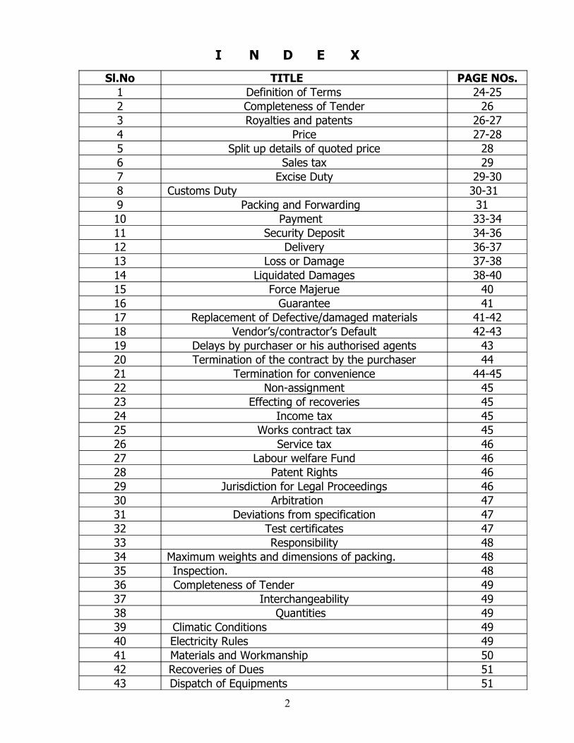
Sl.No TITLE PAGE NOs.1 Definition of Terms 24-252 Completeness of Tender 263 Royalties and patents 26-274 Price 27-285 Split up details of quoted price 286 Sales tax 297 Excise Duty 29-30 8 Customs Duty 30-31 9 Packing and Forwarding 31 10 Payment 33-3411 Security Deposit 34-3612 Delivery 36-3713 Loss or Damage 37-3814 Liquidated Damages 38-4015 Force Majerue 4016 Guarantee 4117 Replacement of Defective/damaged materials 41-4218 Vendor’s/contractor’s Default 42-43 19 Delays by purchaser or his authorised agents 4320 Termination of the contract by the purchaser 4421 Termination for convenience 44-4522 Non-assignment 4523 Effecting of recoveries 4524 Income tax 4525 Works contract tax 4526 Service tax 4627 Labour welfare Fund 4628 Patent Rights 4629 Jurisdiction for Legal Proceedings 4630 Arbitration 4731 Deviations from specification 4732 Test certificates 4733 Responsibility 4834 Maximum weights and dimensions of packing. 4835 Inspection. 4836 Completeness of Tender 4937 Interchangeability 4938 Quantities 4939 Climatic Conditions 4940 Electricity Rules 4941 Materials and Workmanship 5042 Recoveries of Dues 5143 Dispatch of Equipments 51
2

44 Past Performance 5145 Defective Supplies 5246 Special 52-5347 General Conditions 53-54
2
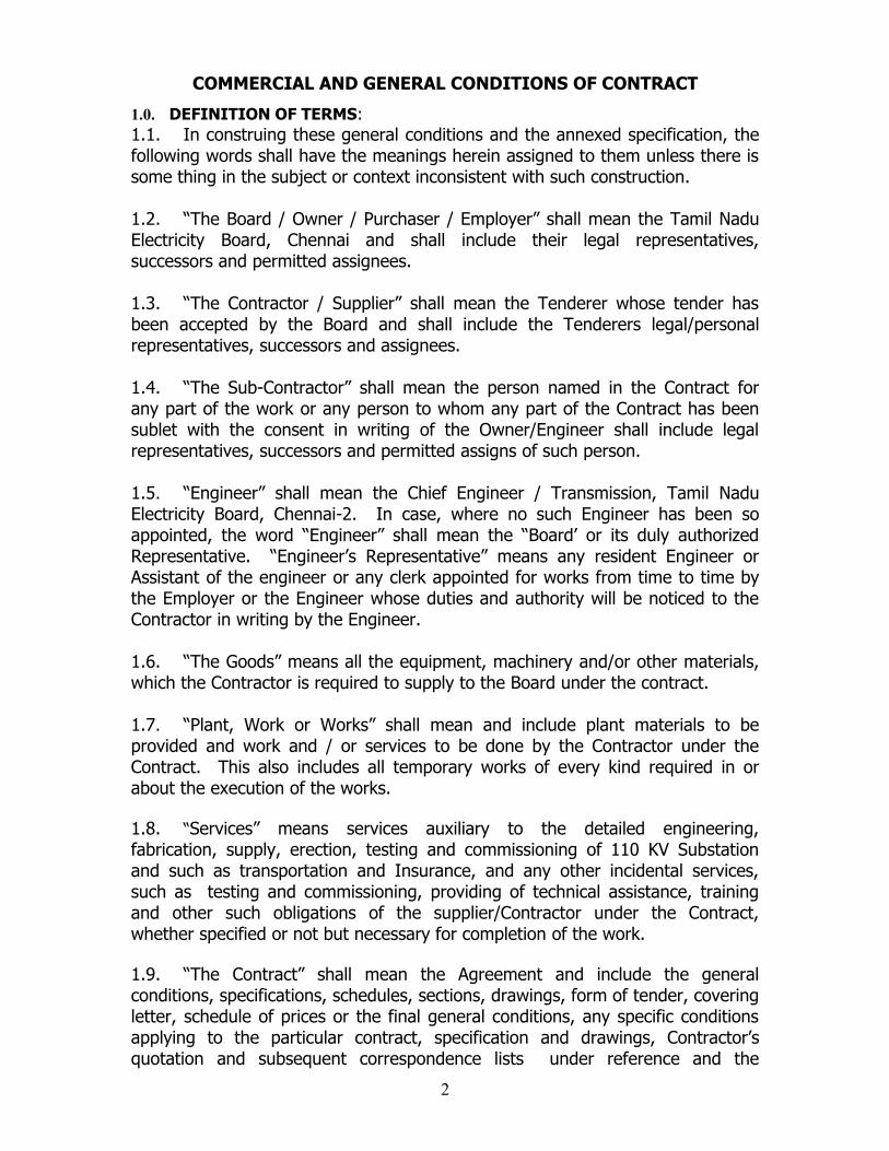
COMMERCIAL AND GENERAL CONDITIONS OF CONTRACT
1.0. DEFINITION OF TERMS:1.1. In construing these general conditions and the annexed specification, the following words shall have the meanings herein assigned to them unless there is some thing in the subject or context inconsistent with such construction.
1.2. “The Board / Owner / Purchaser / Employer” shall mean the Tamil Nadu Electricity Board, Chennai and shall include their legal representatives, successors and permitted assignees.
1.3. “The Contractor / Supplier” shall mean the Tenderer whose tender has been accepted by the Board and shall include the Tenderers legal/personal representatives, successors and assignees.
1.4. “The Sub-Contractor” shall mean the person named in the Contract for any part of the work or any person to whom any part of the Contract has been sublet with the consent in writing of the Owner/Engineer shall include legal representatives, successors and permitted assigns of such person.
1.5. “Engineer” shall mean the Chief Engineer / Transmission, Tamil Nadu Electricity Board, Chennai-2. In case, where no such Engineer has been so appointed, the word “Engineer” shall mean the “Board’ or its duly authorized Representative. “Engineer’s Representative” means any resident Engineer or Assistant of the engineer or any clerk appointed for works from time to time by the Employer or the Engineer whose duties and authority will be noticed to the Contractor in writing by the Engineer.
1.6. “The Goods” means all the equipment, machinery and/or other materials, which the Contractor is required to supply to the Board under the contract.
1.7. “Plant, Work or Works” shall mean and include plant materials to be provided and work and / or services to be done by the Contractor under the Contract. This also includes all temporary works of every kind required in or about the execution of the works.
1.8. “Services” means services auxiliary to the detailed engineering, fabrication, supply, erection, testing and commissioning of 110 KV Substation and such as transportation and Insurance, and any other incidental services, such as testing and commissioning, providing of technical assistance, training and other such obligations of the supplier/Contractor under the Contract, whether specified or not but necessary for completion of the work.
1.9. “The Contract” shall mean the Agreement and include the general conditions, specifications, schedules, sections, drawings, form of tender, covering letter, schedule of prices or the final general conditions, any specific conditions applying to the particular contract, specification and drawings, Contractor’s quotation and subsequent correspondence lists under reference and the
2
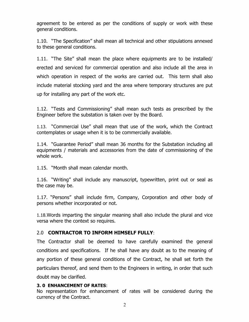
agreement to be entered as per the conditions of supply or work with these general conditions.
1.10. “The Specification” shall mean all technical and other stipulations annexed to these general conditions.
1.11. “The Site” shall mean the place where equipments are to be installed/
erected and serviced for commercial operation and also include all the area in
which operation in respect of the works are carried out. This term shall also
include material stocking yard and the area where temporary structures are put
up for installing any part of the work etc.
1.12. “Tests and Commissioning” shall mean such tests as prescribed by the Engineer before the substation is taken over by the Board.
1.13. “Commercial Use” shall mean that use of the work, which the Contract contemplates or usage when it is to be commercially available.
1.14. “Guarantee Period” shall mean 36 months for the Substation including all equipments / materials and accessories from the date of commissioning of the whole work.
1.15. “Month shall mean calendar month.
1.16. “Writing” shall include any manuscript, typewritten, print out or seal as the case may be.
1.17. “Persons” shall include firm, Company, Corporation and other body of persons whether incorporated or not.
1.18.Words imparting the singular meaning shall also include the plural and vice versa where the context so requires.
2.0 CONTRACTOR TO INFORM HIMSELF FULLY:
The Contractor shall be deemed to have carefully examined the general
conditions and specifications. If he shall have any doubt as to the meaning of
any portion of these general conditions of the Contract, he shall set forth the
particulars thereof, and send them to the Engineers in writing, in order that such
doubt may be clarified.
3. 0 ENHANCEMENT OF RATES:No representation for enhancement of rates will be considered during the currency of the Contract.
2
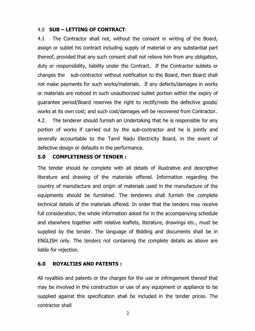
4.0 SUB – LETTING OF CONTRACT:
4.1 The Contractor shall not, without the consent in writing of the Board,
assign or sublet his contract including supply of material or any substantial part
thereof, provided that any such consent shall not relieve him from any obligation,
duty or responsibility, liability under the Contract. If the Contractor sublets or
changes the sub-contractor without notification to the Board, then Board shall
not make payments for such works/materials. If any defects/damages in works
or materials are noticed in such unauthorized sublet portion within the expiry of
guarantee period/Board reserves the right to rectify/redo the defective goods/
works at its own cost; and such cost/damages will be recovered from Contractor.
4.2. The tenderer should furnish an Undertaking that he is responsible for any
portion of works if carried out by the sub-contractor and he is jointly and
severally accountable to the Tamil Nadu Electricity Board, in the event of
defective design or defaults in the performance.
5.0 COMPLETENESS OF TENDER :
The tender should be complete with all details of illustrative and descriptive
literature and drawing of the materials offered. Information regarding the
country of manufacture and origin of materials used in the manufacture of the
equipments should be furnished. The tenderers shall furnish the complete
technical details of the materials offered. In order that the tenders may receive
full consideration, the whole information asked for in the accompanying schedule
and elsewhere together with relative leaflets, literature, drawings etc., must be
supplied by the tender. The language of Bidding and documents shall be in
ENGLISH only. The tenders not containing the complete details as above are
liable for rejection.
6.0 ROYALTIES AND PATENTS :
All royalties and patents or the charges for the use or infringement thereof that
may be involved in the construction or use of any equipment or appliance to be
supplied against this specification shall be included in the tender prices. The
contractor shall
2
protect the purchaser against any claims, actions, suits and proceedings for the
infringement or alleged either in the country of origin or in India by the use of
any equipment supplied by the contractor other than for the purpose indicated
by or reasonable to be inferred from the specification.
A quality plan will have to be furnished by the successful tenderer.
7.0 PRICE :
7.1 The Tenderers shall quote FIRM price and Fixed for the entire duration of
the contract. However the taxes , duties, other statutory levies, exchange rate
variation etc shall be payable by Board at actuals.
7.2 The prices should be for delivery F.O.R. (Destination) Stores in CHENNAI
inclusive of freight and insurance. In addition, the Ex-works/FOB price should
also be indicated separately. The ocean freight, FOB price, ocean insurance,
inland freight and insurance shall be separately shown in the currency of
payment. The prices should include all State and Central Taxes, Octroi and
Excise Duty and these elements should be indicated separately. The rates ruling
on the date of tender shall be specified. A format for price schedule is given in
the Specification.
7.3 It is the responsibility of the tenderer to inform himself of the correct
rates of duty leviable on the materials at the time of tendering. If the
rates assumed by the Tenderer are less than the current rates prevailing
at the time of tendering, the Board will not be responsible for the mistake
and only the lower rate quoted by the tenderer will be admitted, in cases
where such tenderer is successful in getting an order from the Board. If
the rates assumed are higher than current rates prevailing at the time of
tendering, the difference will be to the credit of the Board.
7.4 The tenderer should quote their rates taking into account the E.D. relief
available to them on account of duty paid for procurement of raw materials
under MODVAT scheme and this has to be confirmed by each tenderer. The
tenderer shall furnish a certificate to that effect that the Cenvat Credit to be 2
availed has been taken into account in the quoted price and passed on to the
Board.
7.5 Prices and rates quoted shall include cost of all materials, labour,
supervision/ payment to Corporation authorities for obtaining permission for
laying cables, all incidental charges thereon, crafts, tools, equipments, and plant
mobilizing and demobilising, fuels, lubricants, fixtures, setting and transport,
duty and taxes on raw materials / bought out items if any, royalties, octroi,
temporary and permanent works, local taxes, levies if any etc., and other costs
those are not specifically mentioned herein but will be incurred by the tenderers
for the satisfactory and timely completion of the works.
8.0 Split up details of the quoted prices.
The following splitup details shall be given
I) Ex-works price / FOB price
II) Packing and forwarding charges
III) Freight charges for delivery at site / stores.
IV) Transit insurance covering storage at site / store for 90 days from the date of receipt of materials / equipment at site / stores.
V) Excise duty as applicable payable on the ex-works price. Customs duty payable on FOB & CVD
VI) Value Added TAX if any as applicable payable on the ex-works plus excise duty.
VII) Other statutory levies such as work contract tax , service tax etc
VIII) Ocean Freight
IX) Marine insurance
Total of (i) to (ix)
Tenders with break up rates not furnished as above are liable for rejection.
Note : The break up for ED/CD/VAT etc., adopted in the Tender will form the
basis for regulating the variation in statutory levies after opening the tender.
2
9.0 SALES TAX
The Board has been registered as a dealer, under Central sales tax
Act 1956 under Registration No.32929/81-82 dated.18-1-1982. Appropriate
Central Sales Tax in accordance with the provisions of the Act in force shall be
included by the Tenderer in the price quoted.
The Commissioner of Commercial Taxes in their Lr.No.VAT Cell /
2952/2007 (VCC No.995) dt.6-8-2007 has clarified that exemption already
granted for registration of TNEB will continue as per Section 88 (3) (i) of the VAT
Act 2006. Hence TIN shall not be applicable to TNEB.
As per Sl.No.305 of Annexure to TN VAT Act, 2006 Sale of any
goods except Petrol, Diesel and Cement to TNEB for use in Generation,
Transmission and Distribution of Electrical energy will attract TNVAT @ 4% as
per G.O. Ms. No.31, Commercial Taxes, B.2, dt.27-3-2002.
The Commissioner of Commercial Taxes has confirmed in their Lr.No. VAT
Cell/2952/2007 (VCC No.995) dt.6-8-2007 that exemption is continued as per
Sec.88 (3) (i) of the TN VAT Act 2006.
Hence the tenderers are requested to quote appropriately TN VAT
@ 4% even if the items attract VAT @ 12.5% for the goods to be supplied to
TNEB used in Generation, Transmission and Distribution of Electrical energy
except Petrol, Diesel and cement. The necessary certificate as per G.O. shall be
furnished.
10.0 EXCISE DUTY
10.1. It is the responsibility of the tenderer to make sure about the correct
rates of duty leviable on the material at the time of tendering. If the rate
assumed by the Tenderer are less than the current rates prevailing at the time
of tendering, the Board will not be responsible for the mistake. If the rates
assumed by the tenderer are higher than the current rates prevailing at the
time of tendering, the Excise duty prevailing at the time of tendering will only
be paid.
2
10.2 Any Increase in Excise duty consequent to the supplier coming into
different duty slab during the execution of the contract shall be to the supplier’s
account No claim for increase in the above respect will be admitted. Any
variation in Excise Duty due to statutory variation within the contract delivery
date shall be considered.
10.3 In case of delayed delivery, the Excise duty prevailed on the date of actual
delivery or the Excise duty applicable on the contractual delivery period
whichever is less shall be admitted.
10.4 Authenticated Invoice containing the details viz. Central Excise, Registration
No., PLA No. etc. date and time of removal of goods, debit entry in PLA/RG 23
duly authenticated by authorised signatory shall be preferred by the supplier for
claim of ED.
10.5 The Tenderer who have quoted ED as NIL and in the event of placement of
order on such tenderer against this specification where the value of order is
above Rs.150 Lakhs, such tenderer shall furnish an undertaking to the effect that
the ED commitment on account of crossing the turnover slab will be discharged
to the ED authorities and that the Board shall not be responsible for any ED
evasion by the tenderer in respect of this transaction.
10.6 In the case of tenderer who has quoted ED as Nil and in the event of
placement of order against this specification and the proposed order value is less
than Rs.150 lakhs, the tenderer shall furnish an undertaking to the effect that he
has not obtained any other order in the same financial year and that the Board
shall not be responsible for ED evasion if any by the tenderer in respect of this
transaction.
11.0 CUSTOMS DUTY :
For equipments/materials of foreign origin and within the delivery
period the Customs duty to be paid on the port of entry shall be paid by the
supplier, which will be reimbursed at actuals on production of necessary
documentary evidences. (Bill of Entry).
3
For goods delivered beyond the delivery period, the customs duty
prevailing during the actual date of delivery or on the schedule date of
delivery whichever is less will be paid.
If the bidder is not the manufacturer of the imported materials /
equipments “High sea sales” shall be permitted. The necessary documentary
work shall be done by the bidder.
The concessional customs duty where ever applicable shall be availed
by the bidder. The bidder shall quote only concessional customs duty.
The purchaser will render all necessary assistance in availing the
concessional customs duty.
12.0 INSURANCE :
Contracting firms shall arrange insurance for the equipments and all its
accessories, being supplied by them, through any of the scheduled /
Nationalised Insurance Companies at their cost. The equipment shall be
insured to cover transport (from ware house) and 90 days storage risk at
site. The damages, if any, during transit will be reported within 30 days of
receipt of materials. It will be the responsibility of the supplier to replace
the defective / damaged materials and make good the shortages and other
losses in transit, free of cost and lodge and recover claim from Insurance,
Under-writers / Carriers.
13.0 PACKING AND FORWARDING :
The equipment and all its accessories shall be securely packed and
dispatched, freight paid, duly insured, at supplier’s risk and cost. The
packing may be in accordance with the manufacturer’s standard practice.
The contractor is responsible for ascertaining the facilities that exist for
Road Transport to site. Each package shall be clearly marked and contain
detailed packing list, such as gross weight, the nett weight etc., The
contractor is solely responsible for any loss or damage during transport and
3
safe delivery of the equipments at site in good conditions. The dispatch of
materials shall be only after the approval of test certification by the Board.
The scope of supply includes unloading the equipment at site / stores. Only
packages constructed out of sound materials and of dimensions
proportional to the site and weight of contents shall be used. Loose
materials eg. Bolts, nuts etc., shall be packed in gunny bags and sealed in
polythene bags with proper tagging. Components containing glass fragile
materials shall be carefully covered with shock absorbing protective
materials such as expanded polysterene (Thermocole).
All opening of the equipments shall be tightly covered, plugged or capped
to prevent foreign material from entering.
In the case of large and bulk equipment, the vendor shall be responsible for
ascertaining transport limitations and supply the equipments in the
minimum number of components or sub-assemblies with the frame work of
transport limitation.
Where necessary proper arrangements for attaching hinges for lifting shall
be provided. The contents of the packages shall be sealed in thick
polythene sheets and all the inside walls of the packages shall be lined with
waterproof paper to protect the equipment from damages due to dust or
moisture.
All equipment shall be protected for the entire period of dispatch, storage
and erection against corrosion, incidental damage due to vermin, sunlight,
rain, high temperature, humid atmosphere, rough handling in transit and
storage in the open including possible delays in transit. Silica gel or
approved equivalent moisture absorbing materials in small cotton bags shall
be placed and tied at various points on the equipment, wherever necessary.
Adequate provision of skids or pellets shall be made to keep the
packages above the collecting drainage. Crates and other large containers
shall have drain holes in the bottom to prevent collection of water within
3
the packing. Each crate or package shall contain a packing list, in a water
proof envelope. Copies of the packing list, in triplicate shall be clearly
marked for easy identification against the packing list.
All spare parts shall be packed and treated for long storage conditions at
Site. Any materials found short inside the intact pack up cases shall be supplied by the vendor at no extra cost to the purchaser. Including transportation up to the stores.
All packing cover and packing material shall become the property of the
PURCHASER.
All packages shall be clearly, legibly and durably marked with uniform block
letters (preferably with water proof paint) on atleast three sides with:-
a) Destination address as communicated
b) Purchase order reference
c) Dimensions
d) Nett and Gross weights
e) Sign showing Side-up
f) Sign showing fragile marks in case of delicate equipments
g) Sign showing slinging and slinging position.
h) Any handling and unpacking instructions, If considered necessary.
14.0 PAYMENT :
14.1 The foreign currency portion of the contract price will be made in the
currency of the bid. Where ever the payment could not be made in the currency
of bid as per Banker instructions, the payment will be made in U.S. Dollars as per
exchange rate prevailing then. This will be as per exchange rate prevailing as on
the date of payment so far as supplies are received as per delivery schedule. In
case the supply is delayed the payment will be restricted to the exchange rate
prevailing on the scheduled date of delivery or on the actual date of delivery
whichever is less.
3
14.2 Payments will not be made for materials damaged during transit. All
defective materials shall be replaced by the contractor free of charge. Payments
will not be made unless Test Certificates are approved by the Purchaser.
14.3 Payments for the suppliers will be made by cheque on any one of the
Nationalized / Scheduled Banks as may be decided by the Board from time to
time. Exchange commission for issue of Bank Drafts will be to the account of the
Tenderer. Subject to any deductions which the purchaser may be authorized to
make under the contract, the contractor shall on the certificates of the Engineer,
be entitled to payment as follows :
14.4 Letter of credit payment will be made for foreign currency payment
and also for the initial payment only. All balance payments will be
through direct payment procedure only. All charges for opening
and operation of L.C are to the account of the beneficiary. The
Letter of credit is to be opened 60 days prior to delivery.
The usuance letter of credit for a period of 45 days shall be opened.
The payment will be made on 45th date of receipt of documents at L/C openers
Bank or the date of issue of materials receipt certificate at site in good
condition/work executed certificate issued by the engineer whichever is earlier.
14.5 TERMS OF PAYMENT:
A. FOR SUPPLY PORTION
• 70% payment will be made for the materials/equipments received in
good condition at site and on physical verification by the purchaser.
• 20% after satisfactory completion of erection of the supplied
materials/ equipments.
• Balance 10% after completion of successful testing and
commissioning.
3
• In case of delay in supply portion of any equipment/material the
appropriate amount of Liquidated damages will be deducted from the
initial payment itself.
B. FOR ERECTION PORTION
• 80% progressive payment against the certification by the Board’s
Engineer/Board’s representative.
• 10% after satisfactory completion of erection.
• Balance 10% after successful testing and commissioning and hand
over the project in complete shape to the satisfaction of the Board.
• In the case of delay in the execution of any works, the appropriate
amount of Liquidated damages will be deducted from the initial
payment itself.
C. Civil Works:
The payment for civil works shall be as follows:
a) 10 % on completion of foundation upto ground level
b) 10% upto basement (plinth)
c) 20% ground floor upto floor slab
d) 20% first floor including roof slab
e) 20% Electrification control room & GIS Room
f) 10% finishing & others items and on handing over
g) Balance 10% on closure of order.
14.5.1 For the delayed payments, if any, the purchaser will not pay any interest
on any account.
14.6 The bills for payment will be passed only after the approval of the following:
a) Security Deposit Bank Guarantee for 5% value of the Orderb) Sales Tax Clearance Certificatec) Performance Bank Guarantee.d) Test Certificate for the respective materials/equipments.
3
14.7 The supplier should give a schedule of dispatches to suit the programme
of completion of the project and get the same approved by the purchaser
one month prior to the actual date of dispatch. The supplier should
dispatch each material/ equipment only after getting approval from the
consignee for such dispatches. The dispatch instruction will be issued by
the consignee Superintending Engineers.
If the supplier dispatches the materials without the prior approval, the
purchaser shall not be responsible of any damage or warefage or both
and only the supplier should bear any expenditure arising out of such
unapproved dispatches.
14.8 L.C. Payment will not be accepted in respect of indigenous
supply.
14.9 The supplier shall bear any expenditure arising out of unapproved
dispatches.
14.10 Offers agreeing to the above terms of payment will be preferred. Board
may reject the offer with other terms of payment.
14.11 For the supplies/works carried out beyond delivery schedule the exchange
rate prevailed on the scheduled date or actual date which ever is less shall
be admitted.
4.0 SECURITY DEPOSIT :
15.1 The successful tenderer will have to furnish Security Deposit for 5% of the
total accepted value of the contract inclusive of Earnest Money deposit paid if
any and balance by Bank Guarantee from any Nationalized / Scheduled Bank or
Foreign Banks with Branches in India valid upto the date of completion of supply.
15.2 The Security Deposit will be released to the Contractor only if the contract
is completed to the satisfaction of the purchaser. If the Purchaser incurs any loss
or damages on account of breach of any of the clauses mentioned above or any
3
other amount arising out of the contract becomes payable by the contractor to
the purchaser, then the purchaser will in addition to such other dues that they
shall be under the law, appropriate the whole or part of the security deposit and
such amount that is appropriated will not be refunded to the contractor.
16.0 DELIVERY :
The period of delivery for the supply , erection , testing and
commissioning and handing over of the Substation is 12 Months from the date
of receipt of LOI.
The Board is at liberty to alter the delivery dates on the lesser side to suit its
needs as and when necessity arises, during the pendency of the contract. The
acceptance of this clause should be specifically confirmed in the tender. The
successful bidder shall furnish a PERT Chart showing the plan of completion of all
the activities connected to the work and got approved by the Board. The chart
shall also indicate the date by which various materials & equipments for the work
will be required. The materials shall be dispatched as per the schedule and if any
of the materials/ equipments are supplied in advance than when it is required
the payment for the same will be made as per the schedule already agreed and
approved unless the purchaser himself seeks to advance the schedule.
17.0 LOSS OR DAMAGE :
17.1 External damages and / or shortages that are prime facie, the results of
rough handling in transit or due to defective packing will be intimated within one
month of the receipt of the materials at site. Internal defects, damages or
shortages of integral parts which cannot ordinarily be detected on a superficial
visual examination, though due to bad handling in transit or defective packing,
would be intimated within 2 months from the date of receipt of materials at
stores. In either case, the defective materials shall be replaced by the supplier,
free of cost to the board.
3
17.2 If during the period of supply, it is found that goods already supplied are
defective in material or workmanship or do not conform to specification or
unsuitable for the purpose for which they are purchased, then it will be open to
the purchaser either to reject the good or repudiate the entire contract and claim
such loss that the purchaser may suffer on that account or require the contractor
to replace the defective goods, free of cost.
17.3 Similarly, if during the thirty six months subsequent to the date of receipt of
the goods, any of the goods found to be defective in materials or workmanship or
do not conform to specification or unsuitable for the purpose for which they are
purchased, it will be open to the purchaser either to repudiate the entire contract
and claim damages or accept such parts of the goods that are satisfactory and
require the contractor to replace the balance or to claim compensation for the
entire loss sustained by the purchaser on that account.
17.4 In the event of supplies being received damaged or short at the destination
stations, the cost of materials with ED, Sales Tax (if payable) and other charges
payable thereof will be paid only proportionate to the value of materials received
in good condition, unless the damaged goods or short supplies are made good
free of cost by the suppliers.
17.5 For all legal purposes, the materials shall be deemed to pass into the
Board’s ownership at the destination stores, where they are delivered and
accepted.
18.0 LIQUIDATED DAMAGES :
18.1 The delivery period given in the clause DELIVERY should be guaranteed
by the contractor under the liquidated damage clause given below :
If the contractor fails to deliver the equipment / materials within the time
specified in the contract or any extension thereof, the purchaser shall recover
from the contractor as liquidated damages a sum of HALF PERCENT (0.5%) of
the contract price of the undelivered equipment / materials / unfinished portion
3
of works for each calendar week of delay. The total liquidated damages shall not
exceed TEN PERCENT of the contract price of the units / materials / works so
delayed. In respect of contracts where supply affected in part or works executed
in part, could not be beneficially used by the board due to such incomplete
supply / execution / liquidated damages should be worked out on the basis of
entire contract price only and not on the value of delayed portion.
The purchaser will not produce any definite proven commercial loss
incurred solely on account of the delayed delivery. L.D. will also be recovered
for the short supplies as is done for the belated supply. It is the responsibility of
the supplier to arrange for inspection, dispatch etc., in time to keep up the
delivery schedule. It should be noted that if a contract is placed on a higher
tenderer in preference to the lowest acceptable tender in consideration of the
offer of earlier delivery, the said contractor will be liable to pay the Board the
difference between the contract rate and that of the lowest acceptable tender in
case of failure to complete the delivery terms of such contract within the delivery
period specified in the tender and incorporated in the contract. This is without
prejudice to other rights under the terms of contract.
18.2 Equipment will be deemed to have been delivered only when all its
components parts are also delivered. If certain components are not delivered in
time the equipment will be considered as delayed unless the missing parts are
delivered.
18.3 If supplies to be tendered are made by the contractor beyond the period
of delivery and they are accepted by the Board, such acceptance is without
prejudice to Board’s right to levy liquidated damages for the delay in supply, If
there is delay in delivery, then claims for increase in statutory levies arising after
the delivery period specified in the contract will not be admitted even if the
materials are accepted.
18.4 If the ordered materials are not delivered, the purchaser shall recover
from the contractor, liquidated damages of a sum of 10% of the contract price of
3
the units/equipments undelivered in addition to forfeiture of EMD / SD and
recoveries as per 18.6 of this specification.
18.5 Tenderer not giving clear and specific acceptance to the above clauses are
liable to be rejected.
18.6 The suppliers are liable to pay the amount of loss sustained by the Board
in the event of non-execution of orders, if any placed on them either in full or
part to the satisfaction of the board under the terms of conditions of contract
and order will be placed for such quantities on some others at a higher price.
This is without prejudice to other rights under the terms of the contract.
18.7 The actual date of delivery at destination stores shall be reckoned for the
purpose of deciding “Liquidated Damages” for delay in supply. It should be the
suppliers responsibility to arrange for inspection, dispatch etc.,, in time to keep
up the delivery schedule.
19.0 FORCE MAJEURE :
19.1 If at any time, during the continuance of the contract, the performance in
whole or in part, in any obligation under this contract, shall be prevented or
delayed by reasons of any war, hostility, acts of public enemy, act of civil
commotion, strikes, lockouts, sabotages, fires floods, explosions epidemics
quarantine restrictions or other acts of God (therein after referred to as
eventualities) then, provided notice of the happening of any such eventually is
given by the tenderer to the Board within 15days from the date of occurrence
thereof neither party shall, by reasons of such eventuality, be entitled to
terminate this contract nor shall have any claim for damages against the other in
respect of such non-performance or delay in performance, and deliveries under
this contract, shall be resumed as soon as practicable after such eventually has
come to an end or ceased to exist.
19.2 Provided that if the performance in whole or part by the supplier on any
obligation under this contract is prevented or delayed by reasons of any
4
eventuality for a period exceeding 60 days, the Board may at its option terminate
this contract by a notice in writing. Power cut will not be considered under force
majeure condition. The period of extension shall be decided only by the authority
who placed the order, after verifying the evidence for the cause of delay.
19.3 It is hereby specifically agreed that time is the essence of the contract.
The termination of the contract as aforesaid shall not absolve the supplier /
contractor of his liability to pay damages to the Board for the breach of contract
to delivery the goods or complete the contract within the time fixed by the
P.O./Contract or extension thereof.
GUARANTEE :
20.1 The entire equipments should be guaranteed for satisfactory operation
atleast for a period of 36 months from the date of receipt of materials at site /
stores or 24 months from the date of commissioning whichever is later.
20.2 Any defects noticed during this period shall be rectified free of cost to the
Board within two months from the date of failure. Irrespective of number of
failures and repairs the Contractors are responsible for free replacement of the
defective materials till the same serves a continuous period of 12 months from
the date of first commissioning whichever date shall occur last.
20.3 The incidental expenses, transport and freight charges for the replacement
of defective materials within guarantee period may also be borne by the
Contractor till such time it serves continuous period of 24 months as said above.
20.4 The tenderer shall guarantee among other things, the following
i) Quality and strength of materials used.
ii) Safe electrical and mechanical stresses on all parts of the
equipments under all specified conditions.
iii) Performance figures given by the tenderer in the Schedule of
Guaranteed particulars.4
20.5 The successful tenderer should furnish a performance guarantee in the
form of a bank guarantee for a value of 5% contract value and shall be valid for
a period of 36 months from the date of receipt at site in good condition.
20.0 REPLACEMENT OF DEFECTIVE / DAMAGED MATERIALS :
21.1 Not withstanding anything contained in the above liquidated damage
clause when the whole or part of the materials supplied by the supplier are
found to be defective / damaged are not in conformity with the specification or
sample such defects or damages in materials supplied shall be rectified within
two months either at the point of destination or at the suppliers works, at the
cost of supplier, against proper security and acknowledgement. In the
alternative, the defective or damaged materials shall be replaced free of cost
within three months on receipt of the intimation from the purchaser of such
defects or damages. If the defects or damages are not rectified or replace within
this period, the supplier shall pay a sum towards liquidated damages as per
liquidated damages clause given above, for the delay from the date of receipt of
intimation of the defects or damages.
21.2 If even after such rectification or replacement of the damaged or defective
part, if the equipment ordered is not giving the satisfactory performance as per
the contract, then it will be open to the purchaser either to reject the goods or
repudiate the entire contract and claim such loss sustained by the Board.
22.0 VENDOR'S/CONTRACTOR'S DEFAULT
22.1 If the VENDOR/CONTRACTOR shall neglect to execute the supply/works
with due diligence and expedition or shall refuse or neglect to comply with any
reasonable orders given to him, in writing, by the PURCHASER in connection
with the supply/works or shall contravene the provisions of the 'Contract', the
PURCHASER may give notice in writing to the VENDOR to make good the
failure, neglect or contravention complained of. Should the VENDOR fail to
comply with the notice within thirty (30) days from the date of service thereof,
then and in such case, the PURCHASER shall be at liberty to place fresh orders
4
on other firms and get the equipments/materials required for the project,
without prejudice to any other right the PURCHASER may have under the
contract to delete "Works" wholly or in part out of the VENDOR's hands. If the
cost of completing the supply or executing a part thereof as aforesaid shall
exceed the balance due to the VENDOR, the VENDOR shall pay such excess.
Such payment of excess amount shall be independent of the liquidated damages
for delay which the VENDOR/CONTRACTOR shall have to pay if the completion
of supply/works is delayed.
In addition, such action by the OWNER/PURCHASER as aforesaid shall not
relieve the VENDOR/CONTRTACTOR of his liability to pay liquidated damages for
delay in completion of 'Supply/Works.
22.2 The termination of the 'Contract' under this clause shall not entitle the
VENDOR to reduce the value of the performance Guarantee nor the time
thereof. The performance Guarantee shall be valid for the full value and the full
period as originally stipulated in the 'Contract'.
23.0 DELAYS BY PURCHASER OR HIS AUTHORISED AGENTS
23.1 In case the Contractor's performance is delayed due to any act of omission
on the part of the Purchaser or his authorised agents, then the Contractor shall
be given due extension of time for the completion of the works, to the extent
such omission on the part of the Purchaser has caused delay in the Contractor's
performance of his work, for which no compensation will be payable for idle
labour, shift and machineries.
24.0 TERMINATI0N OF CONTRACT BY THE PURCHASER
24.1 The Purchaser reserves the right to terminate the Contract due to reasons
other than those mentioned under clause entitled "Contractors Default". The
Purchaser shall in such an event give fifteen (15) days notice in writing to the
Contractor of his decision to do so. The Contractor shall be paid by the
4
Purchaser for all work executed prior to the date of termination at the rates &
prices provided in the contract.
24.2 The Contractor upon receipt of such notice shall discontinue the work on
the date and to the extent specified in the notice, make all reasonable efforts to
obtain cancellation of all orders and contracts to the Purchaser, stop all further
sub-contracting or purchasing activity related to the work terminated, and assist
the Purchaser in maintenance, protection, and disposition of the works acquired
under the Contract by the Purchaser.
24.3 If the contract is terminated under the provisions of the above clause, the
Contractor shall with all reasonable diligence remove from the site all the
Contractor's equipment and shall give similar facilities to his sub-contractors to
do so.
24.4 If the contract is terminated as aforesaid, the Contractor shall be paid by
the Purchaser (in so far as such amounts or items shall not have already been
covered by on account payment made to the Contractor) for all work executed
and accepted by the Engineer prior to the date of termination at the rates and
prices provided in the Contract and in addition.
(a) The amount payable in respect of any preliminary items, so far as the work
or service comprised therein has been carried out or performed and an
appropriate portion as certified by the Engineer of any such items of the work or
service comprised therein which has been partially carried out or performed
(b) Any other expenses which the contractor has expended for performing the
works under the Contract subject to being duly certified by the Engineer, based
on documentary evidence for having incurred such expenses.
24.5 The contractor shall be further required to transfer the title and provide
the Purchaser with the following, in the manner and as directed by the
Purchaser.
(a) Any completed works
4
(b) Such partially completed works including drawings, information and contract
rights as the Contractor has specially performed, produced or acquired for the
performance of the Contract.
26.0 TERMINATION FOR CONVENIENCE
26.1 The Purchaser may, by written notice sent to the supplier, terminate the
Contract, in whole or in part, at any time for its convenience. The notice of
termination shall specify that termination is for the Purchaser's convenience, the
extent to which performance of work under the Contract is terminated and the
date upon which such termination becomes effective.
26.2 The Goods that are complete and ready for shipment within thirty (30)
days after the Supplier's receipt of notice of termination shall be purchased by
the Purchaser at the Contract prices and on the other Contract terms. For the
remaining Goods, the Purchaser may elect:
(a) to have any portion thereof completed and delivered at the Contract prices
and on the other Contract terms; and/or
(b) to cancel the remainder and pay to the Supplier an agreed amount for
partially completed Goods and for materials and parts previously procured by the
Supplier for the purpose of the Contract, together with a reasonable allowance
for overhead and profit.
27.0 NON-ASSIGNMENT:
The contractor shall not assign or transfer the contract or any part the
contract or any part there-of without the prior approval of the purchaser.
28.0 EFFECTING OF RECOVERIES :
Any loss, arising incident to non-fulfillment of this contract or any other
contract, will be recovered from the Security Deposit held and or any other
amount due to the contractor from the Board.
29.0 INCOME TAX :
4
The Tenderers shall furnish their Permanent Account Number in their
Offer.
30.0 SALES TAX CLEARANCE CERTIFICATE :
The tendered should enclose with the tender, a current Certificate of sales
tax clearance from the appropriate sales Tax Authorities.
31.0 WORKS CONTRACT TAX:
The works contract tax of 2% for civil works and 4% in case of other than
Civil works will be deducted from the contractors bill as per the conditions
stipulated in TNVAT Act 2006.
32.0 SERVICE TAX:
The tenderers shall quote the appropriate percentage and amount of Service Tax.
The Service Tax quoted will be included for the purpose of evaluation.
The Service tax claim in the offer shall be reimbursed on production of
documentary evidence.
The tenderer who have not quoted service tax shall provide an
undertaking to that effect that any service tax liability at a later date shall be
discharged from their account and Board shall not be responsible for any lapses
on this account.
33.0 LABOUR WELFARE FUND:
An amount of 0.3% towards manual labour welfare fund will be
recovered.
34.0 PATENT RIGHTS ETC :
4
The contractor shall indemnify the purchaser against all claims, actions,
suits and proceedings for the infringement or alleged infringement or alleged
infringement of an patent, design or copy right protected either in the country of
origin or in India by the use of any equipment supplied by the contractor other
than for the purpose indicated by or reasonably to be inferred from the
specification.
35.0 JURISDICTION FOR LEGAL PROCEEDINGS :
No suit or any proceedings in regards to any matter arising in any respect
under this contract shall be instituted in any court, save in the appropriate Civil
Court of Chennai or the court of small cause at Chennai. It is agreed that no
other court shall have jurisdiction to entertain any suit or proceedings, even
thought, part of the cause, any part of cause of action arises within the
jurisdiction of any of the courts in Tamil Nadu and not in the courts in Chennai
city, then it is agreed to between parties that such suits or proceedings shall be
instituted in court within Tamil Nadu and no other court outside Tamil Nadu shall
have jurisdiction, even though any part of the cause of action might arise within
the jurisdiction of such courts.
The successful tenderer shall furnish an undertaking in a non judicial stamp
paper of Rs.80/- agreeing to the above condition.
36.0 ARBITRATION :
The Board will not accept any arbitration in case of dispute arising in any respect
under this contract. Any dispute arising out of this contract shall not be subject
to arbitration under the provisions of Arbitration Act 1940 in the event of any
dispute between the parties.
37.0 DEVIATIONS FROM SPECIFICATION :
Should the tenderer wish to deviate from the provisions of this specification, he
shall list out such deviations only in the format enclosed and submit full
particulars and reasons there for, unless this is done, the equipment offered shall
4
be considered to comply, in every respect with the terms and conditions of this
specification.
38.0 TEST CERTIFICATES :
The test certificates in triplicate for the materials furnishing the results of the
tests as per latest issue of ISS shall be forwarded and got approved before the
materials are dispatched. In addition to the tests called for in the specification,
the purchaser reserves the right of having such tests as he desires carried out at
his own expenses to satisfy himself that the materials conform to the
requirements of this specification. The materials may be rejected if the test
results are not satisfactory. The type tests certificates (Photostat copies) as per
latest ISS/International Standard such as IEC shall be furnished with the tender
for inference.
39.0 RESPONSIBILITY:
The tenderer is responsible for safe delivery of the materials at the
destination stores, The tenderer should include and provide for packing and
secure protection of the materials so as to avoid damages or loss in transit.
40.0 MAXIMUM WEIGHTS AND DIMENSIONS OF PACKINGS:
The Contractor is responsible for informing himself of the facilities that
exist for Road and Sea transport to site the maximum packages which can be
conveyed by the railways and crane life available at the destination station. The
contractor is also responsible for any loss or damage during transport and
erection.
Each case or package should be clearly marked and should contain
detailed packing list.
41.0 Inspection:
41.1 The representatives of the purchaser shall have free access to the contractor
a or sub – contractor s works at any time during working hours for the purpose 4

of inspecting the manufacture of the materials and for testing the select samples
form the materials covered by this specification. The contractor or the sub-
contractor shall provide facilities for the above. A notice calling for inspection
shall be given at least 15 days in advance for arranging inspection. The
arrangement for inspection shall be made by the supplier in such a way that the
delivery schedule is kept up. The materials should not be dispatched without
instruction from the Board. If the inspection is offered other than the purchaser’s
country then at least 30 days notice shall be given for arranging inspection.
41.2 Tenderers are requested to furnish in their tenders the exact location of
their factory with address to enable inspection by Board if considered necessary.
42.0. COMPLETENESS OF TENDER:
The tender should be complete with all details of illustrative and
descriptive literature and drawings. The tenderers shall furnish the complete
technical details of the equipment information regarding the country of
manufacture or origin of materials used in the manufacture of the articles. The
tenders should include all minor accessories even though not specifically
mentioned in this specification but which are essential for the completeness of
the materials ordered. The tendered shall not be eligible for any extra charges in
respect of such minor accessories though not included in the tender.
43.0 INTERCHANGEABILITY:
All similar parts and removable parts of similar items shall be
interchangeable with each other.
44.0 QUANTITIES:
The purchaser reserves the right to revise the quantities at the time of
placing the order and ordering more materials. During the pendency of the order
at the accepted rates.
45.0 CLIMATIC CONDITIONS:
4

The materials are for use in Tamil Nadu and the materials should be
satisfactory for operation under tropical conditions in Tamil Nadu .
All electrical devices shall be given tropical and fungicidal treatment, Fog,
smoke and milked acids are also present in the atmosphere.
46.0. ELECTRICITY RULES:
All works shall be carried out in accordance with the latest provisions of
the Indian Electricity Act/Electricity (Supply) Act and the Indian Electricity Rules
there under unless modified by this specification.
47.0. MATERIALS AND WORKMANSHIP:
47.1 All materials, equipments and spare parts there of shall be new, unused
and originally coming from manufacturer’s plant to the destination stores. Those
including used, rebuilt or overhauled materials / equipments will not be
accepted.
47.2 All the materials shall be of best class and capable of satisfactory operation
in the tropics with humid atmospheric condition, Unless otherwise specified, they
shall conform to the requirements of appropriate Indian Standards. Where these
are not available, IEC and American / British Standards shall be followed.
47.3 The equipments should be designed to facilitate inspection and repairs and
to ensure satisfactory operation under atmospheric conditions prevailing at site
and under sudden variations of load and voltages as may be met with under
working conditions in the system including those due to faulty synchronizing and
short circuits within the rating of the apparatus.
47.4 The design shall incorporate every reasonable precautions and provisions
for the safety of all those concerned in the operation and maintenance of
equipment.
5
47.5 All the equipments should operate without undue vibration and with the
least practicable amount of noise.
47.6 The workmanship shall be of the highest grade and the entire construction
in accordance with the best modern practice.
47.7 The whole of the work shall be of the highest class throughout well
finished and approved make. The entire design and construction shall be capable
of withstanding the severest stresses likely to occur in actual service and
resisting rough handling during the transport.
48.0. RECOVERIES OF DUES ETC.:
The Board is empowered:
a. To recover any dues against this contract in any bills/Security
Deposit/Earnest Money Deposit due to the suppliers either in this contract or any
other contracts with Board.
b. To recover any dues against this contract of the suppliers with Board,
with the available amount due to the suppliers against this contract.
49.0. Raw materials
It is the responsibility of the tendered to make his own arrangement to procure
the necessary raw materials required for the manufacture.
50.0. DESPATCH OF EQUIPMENTS
It is the responsibility of the contractor to dispatch the materials /
equipments to the site. Materials can be brought to site by Road. The dispatch
intimation may however be given to Chief Engineer / Transmission VI th floor.
NPKRR Maaligai TNEB 144, Anna Salai, Chennai – 600 002.
All Materials should be dispatched only after getting dispatch clearance
from Superintending Engineer/Transmission-II /Chennai – 600 002.
51.0. PAST PERFORMANCE: 5
The intending Tenderers shall furnish the details of various supply
order/works contracts executed by them for the past Five years as on the date of
tenders in the performa enclosed to the Tender Specification. The details
furnished by the tenderer shall be complete in shape and if it is found that any
information is found omitted suppressed incomplete or incorrect the same will be
taken note of dealing with the Tender in future. Tender furnished by the
Tenderer without these accompanying details of their past performance are liable
for rejection.
52.0 Tender Form
The tenderers should furnish the Tender Form duly signed along with
their Tender Document.
53.0 DEFECTIVE SUPPLIES:
If during the period of supply it is found that goods already supplied are
defective in materials or workmanship or do not conform the speciation or are
unsuitable for the purpose for which they are purchased then it will be open to
the purchaser either to reject the goods and repudiate the entire contract and
claim such loss that the purchaser may suffer on that account or require the
contractor to replace the defective goods free of cost.
Similarly if during the guarantee period stipulated under guarantee clause
subsequent to the date of receipt of goods any of the goods found to be
defective in materials or workmanship or do not conform to the specification or
unsuitable for the purpose for which they are purchased then it will be open to
the purchaser either to repudiate the entire contract and claim damages or
accept such part of the goods that are satisfactory and require the contractor to
replace the balance or pay compensation to the extent of the loss sustained by
the purchaser on that account The tendered should with his tender dimensioned
general drawings for the equipments offered. Illustrated and descriptive
literature also should be enclosed. Any approval given to the detailed drawings
by the purchaser shall not relieve the Contractor of the responsibility for
5

drawings and in the execution of the work in accordance with the clauses of the
specification.
54.0. SPECIAL:
54.1 The Tenderer shall list out his experience, with documentary evidence along with the tender.
54.2 The tenderers should clearly indicate their acceptance or otherwise to the following terms and conditions.
1. Payment of security deposit bank guarantee for 5% of order Value.
2. Specific acceptance of Board’s terms of Payment.
3. Board’s terms of liquidated damages for delay in delivery.
4. Furnishing of performance guarantee backed by Bank Guarantee for the 5% of the contract.
54.3 In case of any contradiction between General conditions and Technical condition, the Technical condition shall prevail.
55.0. Exchange rate
For bid evaluation the exchange rate on the date of Technical bid opening
will be taken into account.
56.0 General conditions
56.1 The Tenderers are requested to procure the equipments/materials only
from reputed suppliers to SEB’s/Power Utilities for the equipments/materials
purchased within the India. Further the Suppliers equipments/Materials should
have been in satisfactory service for a minimum period of Two years. Necessary
documentary proof shall be furnished.
56.2 The Type Test for all the equipments/materials used for this project should
have been conducted in any approved Government/Govt. recognized laboratories
conforming to latest IS/IEC. The above type test certificates should accompany
the drawings of the materials/equipments, duly signed under seal by the
Institution, who have issued the type test certificate.
5
The above type test should have been conducted not earlier than five
(Five) years as on the date of Tender Opening.
The original type test certificates shall be furnished for verification on request.
The purchaser reserves the right to demand repetition of some or all the
type tests in the presence of purchaser’s representative at no extra cost.
56.3 All the intending Tenderers are informed that in the event of documents
furnished with the offer being found to be bogus or the documents containing
false particulars, the EMD paid by such tenderers will be forfeited in addition to
blacklisting them for future orders/contracts in Tamil Nadu Electricity Board.
56.4 The Tenderers should submit the drawings obtained from approved
suppliers of TNEB and should get approval for each equipment / materials.
56.5 Any other items not specifically mentioned in the specification but which are
required for erection, testing and commissioning and satisfactory operation of
the substation are deemed to be included in the scope of the specification unless
specifically excluded.
5
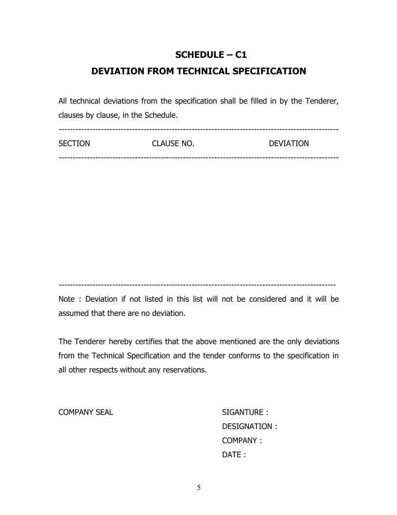
SCHEDULE – C1
DEVIATION FROM TECHNICAL SPECIFICATION
All technical deviations from the specification shall be filled in by the Tenderer,
clauses by clause, in the Schedule.
---------------------------------------------------------------------------------------------------
SECTION CLAUSE NO. DEVIATION
---------------------------------------------------------------------------------------------------
--------------------------------------------------------------------------------------------------
Note : Deviation if not listed in this list will not be considered and it will be
assumed that there are no deviation.
The Tenderer hereby certifies that the above mentioned are the only deviations
from the Technical Specification and the tender conforms to the specification in
all other respects without any reservations.
COMPANY SEAL SIGANTURE :
DESIGNATION :
COMPANY :
DATE :
5
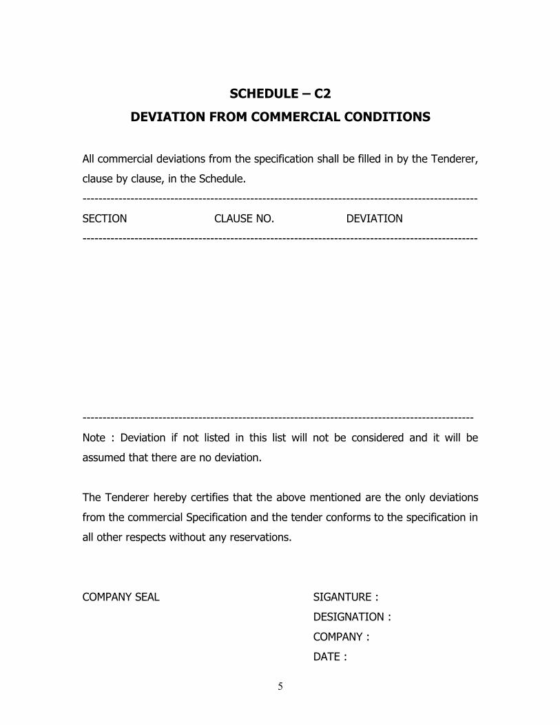
SCHEDULE – C2
DEVIATION FROM COMMERCIAL CONDITIONS
All commercial deviations from the specification shall be filled in by the Tenderer,
clause by clause, in the Schedule.
---------------------------------------------------------------------------------------------------
SECTION CLAUSE NO. DEVIATION
---------------------------------------------------------------------------------------------------
--------------------------------------------------------------------------------------------------
Note : Deviation if not listed in this list will not be considered and it will be
assumed that there are no deviation.
The Tenderer hereby certifies that the above mentioned are the only deviations
from the commercial Specification and the tender conforms to the specification in
all other respects without any reservations.
COMPANY SEAL SIGANTURE :
DESIGNATION :
COMPANY :
DATE :
5
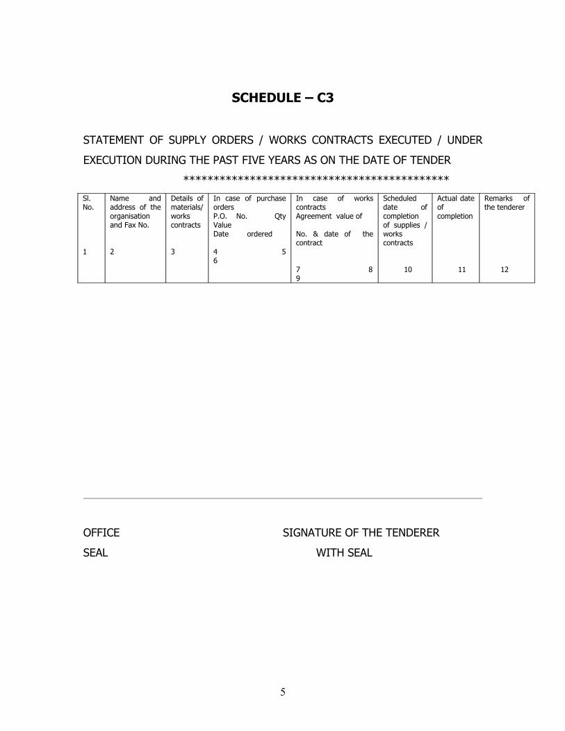
SCHEDULE – C3
STATEMENT OF SUPPLY ORDERS / WORKS CONTRACTS EXECUTED / UNDER
EXECUTION DURING THE PAST FIVE YEARS AS ON THE DATE OF TENDER
********************************************Sl. No.
1
Name and address of the organisation and Fax No.
2
Details of materials/ works contracts
3
In case of purchase ordersP.O. No. Qty Value Date ordered
4 5 6
In case of works contractsAgreement value of
No. & date of the contract
7 8 9
Scheduled date of completion of supplies / works contracts
10
Actual date of completion
11
Remarks of the tenderer
12
OFFICE SIGNATURE OF THE TENDERER
SEAL WITH SEAL
5
CONTRACT PERFORMANCE BANK GUARANTEE FORM
(TO BE ISSUED BY A SCHEDULED BANK ON NON – JUDICIAL STAMP PAPER OF
RS. 80.00)
ORDER NO.:
BANK GUARANTEE NO.:
DATE :
To
THE CHIEF ENGINEER / TRANSMISSION
Tamil Nadu Electricity Board,
6th Floor, NPKPR Maaligai.
144, Anna Salai, Chennai – 600 002.
TAMIL NADU, INDIA.
Dear Sir,
SUB : Your contract No…………………………………………
1. You have entered into a contract into a contract No. SE/TR2/GIS/ .......…
…………………… dated : ………………………………. With …………………………..
thereinafter referred to as the VENDOR for the ………………………… of ……
…………………………………………. (hereinafter referred to as the said
equipment / material) for the price and on the terms and conditions
contained in the said contract.
2. In accordance with the terms of payment of the said contract, the
VENDOR has agreed to furnish you with a Bank Guarantee in a form and
from a Bank acceptable to you as security for due performance by the
VENDOR of all his contractual obligation under the said contract in an
amount for the entire duration of the contract. For this purchase you have
agreed to accept the guarantee of our Bank.5
1. In consideration thereof, we ……………………………………..Bank address ……
……………………………………………………………………………… hereby irrevocably
and unconditionally guarantee, to pay to you on demand and without
demur such amount or amounts not exceeding the sum of Rs……………….
being 5% of the total value of the Contract on receipt of your intimating
that the VENDOR has committed a breach of any of his contractual
obligations
4. You shall have the right to file / make a claim on us under this guarantee
for a period of six months from the date of expiry.
5. This guarantee shall not be revoked without your express consent and
shall not be affected by your granting time or any other indulgence to the
VENDOR, which shall include but not limited to, postponement from time
to time of the exercise of any powers vested in you or any right which you
may have against the VENDOR and exercise the same in any manner at
any time and either to enforce or forbear to enforce any covenant
contained or implied in the said contract or any other course or remedy or
security available to you and our Bank shall not be released from its
obligations under this guarantee by your exercising any of your rights with
reference to matters aforesaid or any of them or by reason of any other
act or forbearance or other acts of omission or commission on your part
or any other indulgence shown by you or by any other matter or thing
whatsoever which under law, would, but for this provision, have the effect
of relieving our bank from its obligation under this guarantee.
6. We also agree that you shall be entitled at your option to enforce this
guarantee against our Bank as a principal debtor, in the first instance, not
withstanding any other security or guarantee that you may have in
relation to the VENDOR’s liabilities in respect of the premises.
5
7. Not withstanding anything herein contained, our liability under this
guarantee is restricted to Rs………………………….. and the guarantee will
remain in force upto and including………………. Day of …………………. 19 …
……………. And shall be extended from time to time for such period or
periods as may be desired by the VENDOR.
Dated…………………………………….this day of………………………… 19……..
SIGNATURE
PRINTED NAME
DESIGNATION
BANKER’S COMMON SEAL
WITNESS :
1.
2.
6

ANNEXURE
TENDER FORM
TAMIL NADU ELECTRICITY BOARD
To
THE CHIEF ENGINEER / TRANSMISSION,
Tamil Nadu Electricity Board,
6th Floor, Western wing,
NPKAR Maaligai, Electricity Avenue,
144, Anna Salai, Chennai – 600 002.
TAMIL NADU, INDIA.
Dear Sir,
Having examined the above specification together with the accompanying
schedule etc., and general conditions therein referred to, we hereby offer to
manufacture and supply the equipments / materials in general specification at
the rates entered in the attached contract schedule of prices.
1. We hereby undertake to have the equipment / materials delivered
in the times specified in your Tender.
1. We hereby guarantee the particulars entered in the schedules
attached to specification.
2. In accordance with Security Deposit, Clause – 15, Section-II, of the
Specification we agree to furnish security to the extent of 5% of
the value of the contract.
3. Our company is not a potentially Sick Industrial Company or a Sick
Industrial Company in terms of Section-23 of Section-15 of the Sick
Industrial Companies (Special Provisional Act, 1985)
Yours faithfully,
Place :
Date :
6
FORM OF CONSORTIUM/JOINT VENTURE AGREEMENT
(ON NON-JUDICIAL STAMP PAPER OF VALUE RS.100/- TO BE PURCHASED IN
ANY ONE NAME OF CONSORTIUM/JOINT VENTURE MEMBER)
PROFORMA OF CONSORTIUM/ JOINT VENTURE AGREEMENT BETWEEN ----------------------
FOR BID SPECIFICATION NO. - OF TAMIL NADU TRANSMISSION
CORPORATION LTD .
THIS Consortium/ Joint Venture agreement executed on this ----------------- day
of --------------Two Thousand and -------------------- between M/s
--------------------------------------a company incorporated under the laws of
---------------------------------------------
and having its registered office at ---------------------------------------------------------
( herein after called the “ Lead Company “ which expression shall include its
successors , executors and permitted assigns) , M/s ----------------------------------
a company incorporated under the laws of ------------------------------------and
having its registered office at -------------------------------(herein after called the
Constituent company which expression shall include its successors, executors
and permitted assigns) and M/s ------------------------a company incorporated
under the laws of ------------------------------------------------------- and having its
registered office at ---------------------------------------------(hereinafter called the
“Member ” which expression shall include its successors, executors and
permitted assigns) for the purpose of making a bid and entering into a contract”
(in case of award) against the Specification No. “ for the establishment of
230/33 KV GIS SS ” for the Tamil Nadu Transmission Corporation Ltd, having its
registered office at NPKRR Maaligai, 144, Anna Salai, Chennai-600 002, Tamil
Nadu (hereinafter called the “Owner”). The leader of the consortium/joint
venture shall abide by the general terms and conditions specified by the
purchaser.
6
WHEREAS the Owner invited bids as per the above mentioned Specification for
the design manufacture, supply and erection, testing and commissioning of
Equipment/Materials stipulated in the bidding documents under subject Package
for the establishment of 230/33 KV GIS
SS--------------------------------------------------------------------‘ under Specification
No. -------------
AND WHEREAS Section-IV (Bid Qualification Requirement) , forming part of the
bidding documents, stipulates that a consortium/ joint venture of firms meeting
the requirement of Section-Iv, applicable may bid, provided the consortium/
Joint Venture fulfills all other requirements of Specification and in such a case,
the BID shall be signed by the members so as to legally bind the members and
who will be jointly and severally liable to perform the Contract and all obligations
hereunder.
The above clause further states that the consortium/ joint venture agreement
shall be attached to the bid and the contract performance guarantee will be as
per the format enclosed with the bidding document without any restriction or
liability for either party.
AND WHEREAS the bid has been submitted to the Owner vide proposal
No.-----------------------dated ----------------------------by Lead Company based on
the Constituent agreement between all the consortium/joint venture partners
under these presents and the bid in accordance with the requirements of
Specification. (Qualification Requirements).
NOW THIS INDENTURE WITNESSETH AS UNDER:In consideration of the above premises and agreements all the Partners to this
joint venture members do hereby now agree as follows:
1) In consideration of the award of the Contract by the Owner to the joint
venture members, we, the members to the consortium/ joint venture
agreement do hereby agree that M/s-------------------------------------shall act as
Lead company and further declare and confirm that we shall jointly and severally 6

be bound unto the Owner for the successful performance of the Contract and
shall be fully responsible for the design, manufacture, supply and successful
performance of the equipments in accordance with the Contract.
2) In case of any breach of the said Contract by the Lead Company or other
Constituent of the consortium/joint venture agreement, the Lead Company do
hereby agree to be fully responsible for the successful performance of the
Contract and to carry out all the obligations and responsibilities under the
Contract in accordance with the requirements of the Contract.
3) Further, if the owner suffers any loss or damage on account of any breach
in the Contract or any shortfall in the performance of the equipment in meeting
the performance guaranteed as per the specification in terms of the Contract,
the Lead Company of these presents undertake to promptly make good such loss
or damages caused to the Owner, on its demand without any demur. It shall not
be necessary or obligatory for the Owner to proceed against Lead Partner to
these presents before proceeding against or dealing with the other Partner(s).
4) The financial liability of the members of this consortium/ joint venture
agreement to the Owner, with respect to any of the claims arising out of the
performance or non-performance of the obligations set forth in the said
consortium/ joint venture agreement, read in conjunction with the relevant
conditions of the Contract shall, however, not be limited in any way so as to
restrict or limit the liabilities of any of the members of the agreement.
5) It is expressly understood and agreed between the members to this
consortium/ joint venture agreement that the responsibilities and obligations of
each of the Partners shall be as delineated in Appendix-I (To be incorporated
suitably by the member to this agreement). It is further agreed by the member
that the above sharing of responsibilities and obligations shall not in any way be
a limitation of joint and several responsibilities of the members under this
contract.
6

6) This consortium/ joint venture agreement shall be construed and
interpreted in accordance with the laws of India and the courts of Chennai
shall have the exclusive jurisdiction in all matters arising there under.
7) In case of an award of a Contract, we the consortium/ joint venture
members do hereby agree that we shall be jointly and severally responsible for
the works respectively executed and Lead Company shall furnishing a contract
performance security from a bank in favour of the PURCHASER in the forms
acceptable to purchaser for value of 5% of the Contract Price in the
currency/currencies of the Contract.
8) It is further agreed that the consortium/ joint venture agreement shall be
irrevocable and shall form an integral part of the Contract, and shall continue to
be enforceable all the owner discharges the same. It shall be effective from the
date first mentioned above for all purposes and intents.
IN WITNESS WHEREOF the Partners to the consortium/joint venture agreement
have through their authorised representatives executed these presents and
affixed Common Seals of their companies, on the day, month and year first
mentioned above.
1. Common Seal of For Lead Company
has been affixed in my/our presence
pursuant to the Board of Director’s (Signature of authorised
resolution dated. Representative)
Signature Name
Name Designation
Designation Common Seal of the company
2. Common seal of For other Constituents6
has been affixed in my/our presence
pursuant to the Board of Director’s (Signature of authorised
resolution dated. Representative)
Signature--------------------------- Name-----------------------
Name ------------------------------- Designation----------------------
Designation------------------------ Common Seal of the company
WITNESSES:
1. --------------------------------- ------------------------------
(Signature) (Signature)
Name-------------------------- Name-----------------------
----------------------------------- --------------------------------
(Official address) (Official address)
6
FORM OF POWER OF ATTORNEY FOR CONSORTIUM/JOINT VENTURE(On Non-judicial Stamp Paper of value Rs.100/- to be purchased in any
one Name of Consortium/Joint venture member)
KNOW ALL MEN BY THESE PRESENTS THAT WE, the Consortium/ joint venture
members whose details are given hereunder (1)……………………… (2) ………………
………… 3) .…… ……………... have formed a joint venture under the laws of ………
……………………… and having our Registered Office(s)/Head Office (s) at …………
………………………..
(hereinafter called the Consortium/ joint venture which expression shall unless
repugnant to the context or meaning thereof, include its successors,
administrators and assigns) acting through M/s ……………………………………………
… being the company in charge do hereby constitute, nominate and appoint
M/s…………………………………………… a company incorporated under the laws of…
……………………………………and having its Registered/ Head Office at…………………
……………………….as our duly constituted lawful Attorney (hereinafter called
“Attorney” or “ Authorised Representative” or Partner in charge” ) to exercise
all or any of the powers for and on behalf of the consortium/ joint venture in
regard “for the establishment of 230/33 KV GIS SS,
------------------------------------------------------‘ for the Tamil Nadu Transmission
Corporation Ltd , NPKRR Maaligai, 144, Anna Salai, Chennai – 600 002
(hereinafter called the “ OWNER “ ) and the Bids for which have been invited by
the Owner, to undertake the following acts:
6
i) To submit proposal and participate in the aforesaid Bid Specification of the
Owner on behalf of the consortium/joint venture.
ii) To negotiate with the Owner in the terms and conditions for award of the
Contract pursuant to the aforesaid Bid to sign the Contract with the Owner for
and on behalf of the consortium/ joint venture.
iii) To do any other act or submit any document related to the above.
iv) To receive, accept and execute the Contract for and on behalf of the
consortium/ joint venture.
It is clearly understood that the Lead Company shall ensure performance of the
Contract (s) and if one or more Company fail to perform their respective portion
of the Contract (s), the same shall be deemed to be a default by the Lead
Company.
It is expressly understood that this Power Of Attorney shall remain valid binding
and irrevocable till completion of the Defect Liability Period in terms of the
Contract.
The consortium/joint venture hereby agrees and undertakes to ratify and confirm
all the whatsoever the said Attorney/ Authorised representative of the Lead
Company in charge quotes in the Bid, negotiates and signs the Contract with the
Owner and/or proposes to act on behalf of the joint venture by virtue of this
Power Of Attorney and the same shall bind the joint venture as if done by itself.
IN WITNESS THEREOF the Company constituting the joint venture as aforesaid
have executed these presents on this
--------------------------------------------------------
6
Day of ----------------------------------------------------------- under Common seal(s)
of their Companies.
For and on behalf of the Partners of consortium/ Joint Venture
--------------------------------------
-------------------------------------- --------------------------------------
The common Seal of the above Companies of the consortium/ Joint Venture:
The Common Seal has been affixed there unto in the presence of :
WITNESS
1.
Signature…………………………………. Name ………………………………………
Designation …………………………………
Occupation …………………………………
2.
Signature………………………………….
Name ……………………………………….
Designation …………………………………
Occupation …………………………………
6

SECTION – IV
BID QUALIFICATION REQUIREMENTS
I. The bidder should have supplied atleast 20 Nos of 110 KV class or above rating
GIS bays of which atleast 5 Nos shall be of 220 KV class during the last five years.
The end user certificate shall be furnished in support of the claim.
2. The bidder should have erected, tested & commissioned atleast Five Nos G.I.S
Substations of 110 KV or above rating of which atleast one number shall be with a
capacity of 220 KV or above rating. The substations shall be in satisfactory operation
for atleast two years. The end user certificate shall be furnished as proof of having
completed the works satisfactorily and for the satisfactory operation of the
Substation as above.
3. The financial turnover of the bidder shall be more than Rs.25 Crores or USD 5.55
Million in any one of the preceding three financial years, the copy of the Profit &
Loss account or turnover certificate issued by the chartered accountant shall be
furnished.
4 The bidder shall furnish a total back up guarantee for the GIS equipments offered
by them from the GIS manufacturer for successful operation for three years.
5. The bidder shall submit Type test reports as per the relevant IEC standards for
110 KV & 220KV or higher Voltage grade GIS obtained from any of the following
Laboratories.
a. KEMA, Holland
b. CESI, Italy
c. IPH, Germany
d. EDF, France
e. Keri, South Korea
f. CRIEPI, Japan.
g. CERDA, France
h. PHELA, Italy.
i. STRI, Sweden.
j. China national High Voltage apparatus Inspecting Centre, China
k. Xian High Voltage research institute, China

The type tests should have been conducted on the GIS manufactured at the same
source/unit from where the bidder is proposing to supply the tendered GIS.
The type tests should have been conducted within 5 years prior to the date of
opening of techno commercial bid.
In case the type test reports furnished is not for the quoted GIS but for the GIS with
higher voltage class , then type test reports shall be furnished for the quoted GIS
before offer of inspection of the GIS.
6. End user certificate is to be produced for the quantity of GIS claimed to have
been supplied and the number of GIS substations , erected, tested and
commissioned along with the corresponding copy of purchase order placed by the
end user, attested by the Indian High Commissioner / Ambassador of the respective
country where the manufacturing is done. In case of local manufacturers the same
should be got attested by Notary Public or Commissioner of Oaths. Before price bid
opening, such of the original Purchase orders and other documents will be referred
to the authority who had placed the order to get the genuineness of the claim made
by the bidder verified.
7.1 The Bidding is also open to consortium/joint venture (maximum of two
members) who shall meet the clauses 1 & 2 of qualifying requirements individually
or together subject to the following conditions.
7.2 The joint venture/consortium can be formed between bidder, supplier of GIS,
EPC Contractor in any combination.
7.3 No member can be a member in more than one consortium/ joint venture.
7.4 The bid and the contract agreement between PURCHASER and consortium/ joint
venture shall be signed by all members of the Joint venture.
7.5 The consortium/ Joint Venture agreement duly certified by a Notary Public in
case of Domestic Bidder and the Consulate General of India in Foreign country in
case of foreign bidder, confirming the intent of all the members to form the
consortium/joint venture should be submitted along with the Bid. It should also
distinctly show the financial participation of each member of the consortium/ joint
venture, scope of work and responsibilities of each member with regard to planning,
execution and performance of the work under the entire scope of contract between
Purchaser and consortium/joint venture.
7.6 The signatory of the consortium/ joint venture agreement shall be only those
holding valid power of attorney. A certified copy by the company secretary to the
respective members of the joint venture shall be attached as evidence for
authentication.
7.7 Any one member of the joint venture shall be nominated as leader of the
consortium/joint venture with proper authorization submitting a power of attorney
signed by legally authorised signatories of all the members of joint venture.
7.8 The leader of the consortium/joint venture shall abide by the general terms and
conditions specified by the purchaser or his authorised representatives.
7.9 The leader of the consortium/joint venture shall be the only one who will be
authorised to receive the instructions for and on behalf of the consortium/ joint
venture. The leader of the consortium/ joint venture is primarily responsible for the
total execution of the contract including all contractual obligations and receipt of the
payment due in accordance with the provision of the contract.
7.10 All the members of the consortium/joint venture shall be liable jointly and
severally for the execution of the contract in accordance with the terms and
conditions of the contract and a statement to this effect shall be included in the
consortium/ joint venture agreement as well as in the contract document.
7.11 There shall be no conditional offer in the consortium/ joint venture agreement
with regard to this Project.
7.12 The consortium/ joint venture formed for the purpose of this Project shall be
valid till completion of the performance guarantee period.
8. The bidder shall furnish copy of purchase order and performance certificate from
the end user in support of the above bid qualification requirements along with the
bid documents.
Bids not satisfying the above requirements will be summarily rejected.
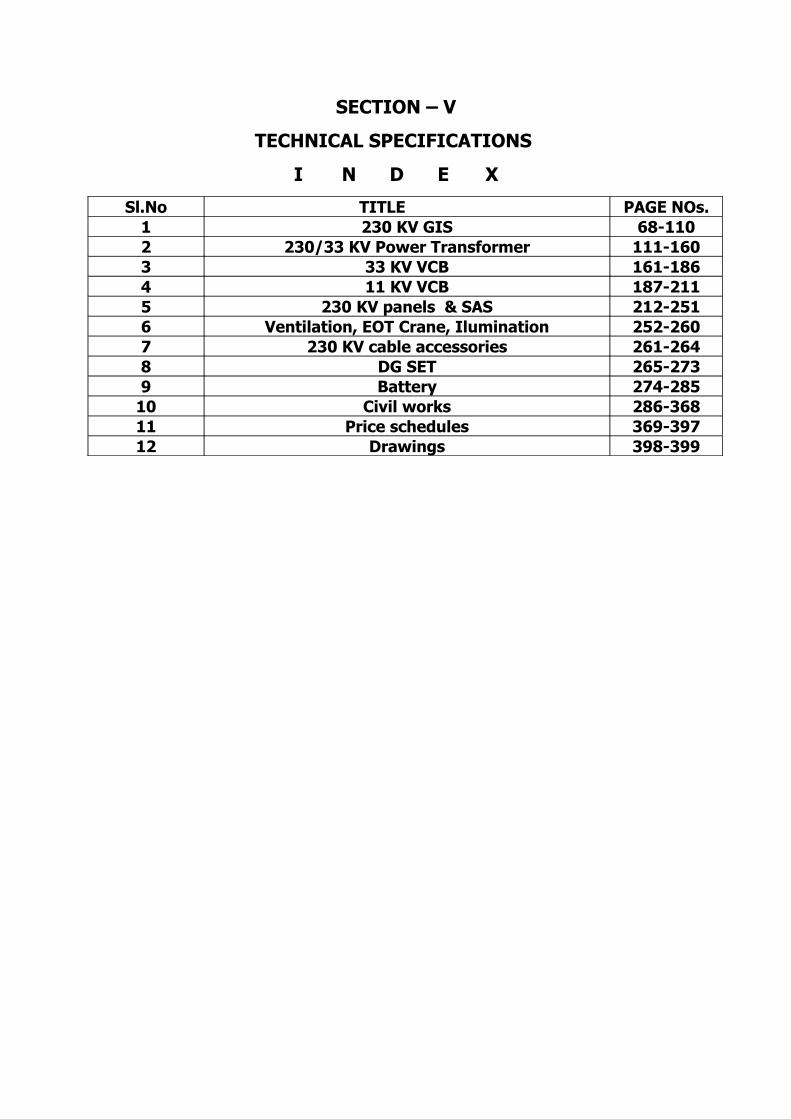
SECTION – V
TECHNICAL SPECIFICATIONS
I N D E X
Sl.No TITLE PAGE NOs.1 230 KV GIS 68-1102 230/33 KV Power Transformer 111-1603 33 KV VCB 161-1864 11 KV VCB 187-2115 230 KV panels & SAS 212-2516 Ventilation, EOT Crane, Ilumination 252-2607 230 KV cable accessories 261-2648 DG SET 265-2739 Battery 274-285
10 Civil works 286-36811 Price schedules 369-39712 Drawings 398-399
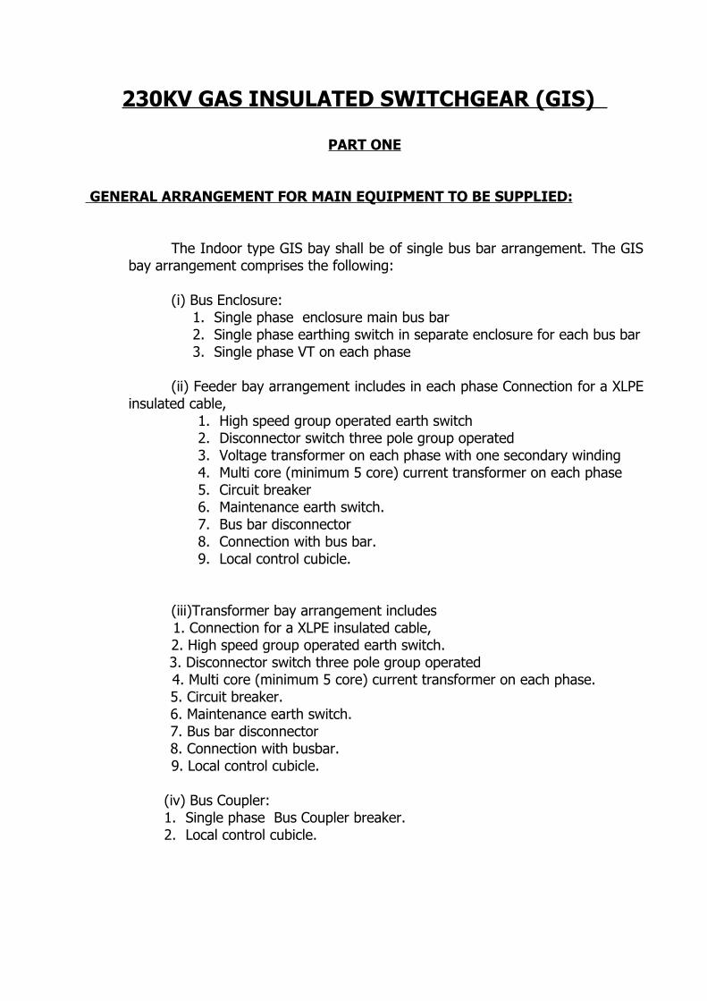
230KV GAS INSULATED SWITCHGEAR (GIS)
PART ONE
GENERAL ARRANGEMENT FOR MAIN EQUIPMENT TO BE SUPPLIED:
The Indoor type GIS bay shall be of single bus bar arrangement. The GIS bay arrangement comprises the following:
(i) Bus Enclosure:1. Single phase enclosure main bus bar2. Single phase earthing switch in separate enclosure for each bus bar3. Single phase VT on each phase
(ii) Feeder bay arrangement includes in each phase Connection for a XLPE insulated cable,
1. High speed group operated earth switch2. Disconnector switch three pole group operated3. Voltage transformer on each phase with one secondary winding4. Multi core (minimum 5 core) current transformer on each phase5. Circuit breaker6. Maintenance earth switch.7. Bus bar disconnector 8. Connection with bus bar.9. Local control cubicle.
(iii)Transformer bay arrangement includes
1. Connection for a XLPE insulated cable,2. High speed group operated earth switch.
3. Disconnector switch three pole group operated 4. Multi core (minimum 5 core) current transformer on each phase.
5. Circuit breaker. 6. Maintenance earth switch. 7. Bus bar disconnector 8. Connection with busbar.
9. Local control cubicle.
(iv) Bus Coupler:1. Single phase Bus Coupler breaker.2. Local control cubicle.
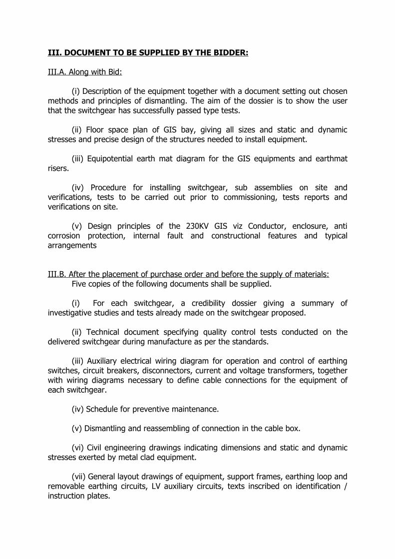
III. DOCUMENT TO BE SUPPLIED BY THE BIDDER:
III.A. Along with Bid:
(i) Description of the equipment together with a document setting out chosen methods and principles of dismantling. The aim of the dossier is to show the user that the switchgear has successfully passed type tests.
(ii) Floor space plan of GIS bay, giving all sizes and static and dynamic stresses and precise design of the structures needed to install equipment.
(iii) Equipotential earth mat diagram for the GIS equipments and earthmat risers.
(iv) Procedure for installing switchgear, sub assemblies on site and verifications, tests to be carried out prior to commissioning, tests reports and verifications on site.
(v) Design principles of the 230KV GIS viz Conductor, enclosure, anti corrosion protection, internal fault and constructional features and typical arrangements
III.B. After the placement of purchase order and before the supply of materials:Five copies of the following documents shall be supplied.
(i) For each switchgear, a credibility dossier giving a summary of investigative studies and tests already made on the switchgear proposed.
(ii) Technical document specifying quality control tests conducted on the delivered switchgear during manufacture as per the standards.
(iii) Auxiliary electrical wiring diagram for operation and control of earthing switches, circuit breakers, disconnectors, current and voltage transformers, together with wiring diagrams necessary to define cable connections for the equipment of each switchgear.
(iv) Schedule for preventive maintenance.
(v) Dismantling and reassembling of connection in the cable box.
(vi) Civil engineering drawings indicating dimensions and static and dynamic stresses exerted by metal clad equipment.
(vii) General layout drawings of equipment, support frames, earthing loop and removable earthing circuits, LV auxiliary circuits, texts inscribed on identification / instruction plates.
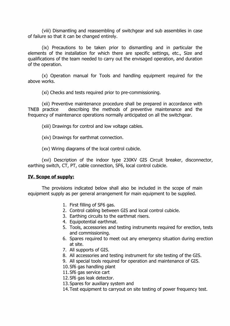
(viii) Dismantling and reassembling of switchgear and sub assemblies in case of failure so that it can be changed entirely.
(ix) Precautions to be taken prior to dismantling and in particular the elements of the installation for which there are specific settings, etc., Size and qualifications of the team needed to carry out the envisaged operation, and duration of the operation.
(x) Operation manual for Tools and handling equipment required for the above works.
(xi) Checks and tests required prior to pre-commissioning.
(xii) Preventive maintenance procedure shall be prepared in accordance with TNEB practice describing the methods of preventive maintenance and the frequency of maintenance operations normally anticipated on all the switchgear.
(xiii) Drawings for control and low voltage cables.
(xiv) Drawings for earthmat connection.
(xv) Wiring diagrams of the local control cubicle.
(xvi) Description of the indoor type 230KV GIS Circuit breaker, disconnector, earthing switch, CT, PT, cable connection, SF6, local control cubicle.
IV. Scope of supply:
The provisions indicated below shall also be included in the scope of main equipment supply as per general arrangement for main equipment to be supplied.
1. First filling of SF6 gas.2. Control cabling between GIS and local control cubicle.3. Earthing circuits to the earthmat risers.4. Equipotential earthmat.5. Tools, accessories and testing instruments required for erection, tests
and commissioning.6. Spares required to meet out any emergency situation during erection
at site.7. All supports of GIS.8. All accessories and testing instrument for site testing of the GIS.9. All special tools required for operation and maintenance of GIS.10.Sf6 gas handling plant 11.Sf6 gas service cart12.Sf6 gas leak detector.13.Spares for auxiliary system and14.Test equipment to carryout on site testing of power frequency test.

V .TRAINING
Training in maintenance for 2 Engineers for 4 weeks at manufacture’s site.
Training in operation for 4 Engineers for 4 weeks at site.
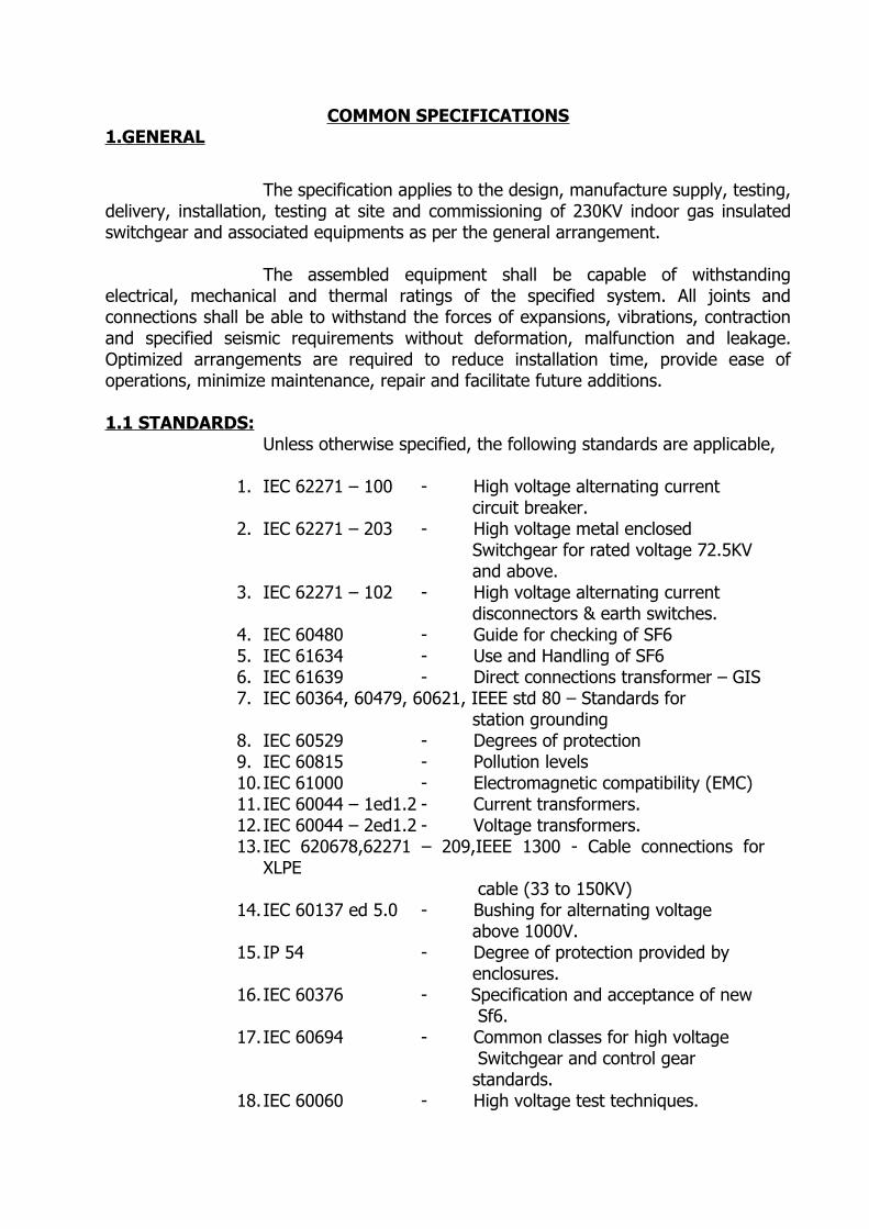
COMMON SPECIFICATIONS1.GENERAL
The specification applies to the design, manufacture supply, testing, delivery, installation, testing at site and commissioning of 230KV indoor gas insulated switchgear and associated equipments as per the general arrangement.
The assembled equipment shall be capable of withstanding electrical, mechanical and thermal ratings of the specified system. All joints and connections shall be able to withstand the forces of expansions, vibrations, contraction and specified seismic requirements without deformation, malfunction and leakage. Optimized arrangements are required to reduce installation time, provide ease of operations, minimize maintenance, repair and facilitate future additions.
1.1 STANDARDS:Unless otherwise specified, the following standards are applicable,
1. IEC 62271 – 100 - High voltage alternating current circuit breaker.2. IEC 62271 – 203 - High voltage metal enclosed Switchgear for rated voltage 72.5KV and above.3. IEC 62271 – 102 - High voltage alternating current disconnectors & earth switches.4. IEC 60480 - Guide for checking of SF65. IEC 61634 - Use and Handling of SF66. IEC 61639 - Direct connections transformer – GIS7. IEC 60364, 60479, 60621, IEEE std 80 – Standards for station grounding8. IEC 60529 - Degrees of protection9. IEC 60815 - Pollution levels10.IEC 61000 - Electromagnetic compatibility (EMC)11.IEC 60044 – 1ed1.2 - Current transformers.12.IEC 60044 – 2ed1.2 - Voltage transformers.13.IEC 620678,62271 – 209,IEEE 1300 - Cable connections for
XLPE cable (33 to 150KV)14.IEC 60137 ed 5.0 - Bushing for alternating voltage above 1000V.15.IP 54 - Degree of protection provided by enclosures.16.IEC 60376 - Specification and acceptance of new Sf6.17.IEC 60694 - Common classes for high voltage Switchgear and control gear standards.18.IEC 60060 - High voltage test techniques.
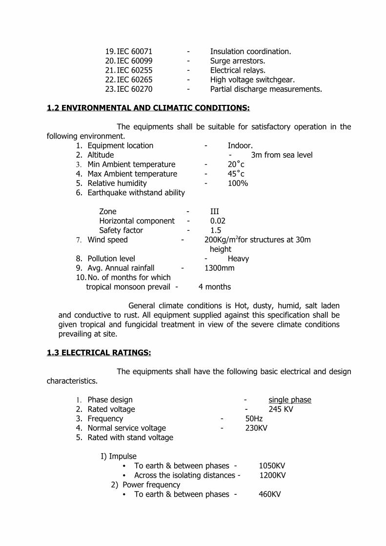
19.IEC 60071 - Insulation coordination.20.IEC 60099 - Surge arrestors.21.IEC 60255 - Electrical relays.22.IEC 60265 - High voltage switchgear.23.IEC 60270 - Partial discharge measurements.
1.2 ENVIRONMENTAL AND CLIMATIC CONDITIONS:
The equipments shall be suitable for satisfactory operation in the following environment.
1. Equipment location - Indoor.2. Altitude - 3m from sea level3. Min Ambient temperature - 20˚c4. Max Ambient temperature - 45˚c5. Relative humidity - 100%6. Earthquake withstand ability
Zone - IIIHorizontal component - 0.02Safety factor - 1.5
7. Wind speed - 200Kg/m2for structures at 30m height8. Pollution level - Heavy9. Avg. Annual rainfall - 1300mm10.No. of months for which
tropical monsoon prevail - 4 months
General climate conditions is Hot, dusty, humid, salt laden and conductive to rust. All equipment supplied against this specification shall be given tropical and fungicidal treatment in view of the severe climate conditions prevailing at site.
1.3 ELECTRICAL RATINGS:
The equipments shall have the following basic electrical and design characteristics.
1. Phase design - single phase2. Rated voltage - 245 KV 3. Frequency - 50Hz4. Normal service voltage - 230KV5. Rated with stand voltage
I) Impulse• To earth & between phases - 1050KV• Across the isolating distances - 1200KV
2) Power frequency• To earth & between phases - 460KV
• Across the isolating distances - 530kv1. Rated current - Busbar - 2000A Bays 1250A2. Rated short time current without burn through of enclosures -40KA for1 Sec3. Partial discharge level of complete bay - <10pc
At 1.5Uo4. Material
• Enclosures - Aluminium / Stainless steel• Conductors - Aluminium
The rated currents have to be guaranteed for maximum ambient temperature.
The rated withstand voltage have to be guaranteed for second low level of SF6 gas pressure.
The switchgear should withstand rated voltage for atleast 30min, when SF6 pressure reduced to atmospheric pressure.
2.EQUIPMENT SPECIFICATION:
2.1 GENERAL:The switchgear shall be completely metal clad with modular design,
all modules standardized and interchangeable. The GIS shall be designed so that normal service, inspection and maintenance operations, earthing of connected cables, locating of cable faults, voltage tests on connected cables or other apparatus and the elimination of dangerous electrostatic charges can be carried out safely, including the checking of phase sequence after installation.
The switchgear shall be made of Aluminium/Stainless steel enclosure with SF6 for insulation. It shall be of single phase encapsulation arrangement. The switchgear shall be modular design so that future extensions shall be easily accomplished for adding additional feeders without dismantling any major parts of the equipment. All the modules shall be standardized and interchangeable. It shall be compatible for IP54.
The switchgear shall be preassembled at the factory and installed at the site using bolts and sealed flange connections. Welding of enclosures at field is not acceptable. In order to ensure electrical continuity the metal clad enclosures shall be bonded together by metal to metal contact, straps across the different chamber for electrical continuity shall not be accepted.
The equipment should be pre designed in such a way that, the permitted movements of foundation, mechanical or thermal effects do not impair the assigned performance of the equipment. The SF6 pressure monitoring devices, optical indicators, emergency, mechanical operating deviee, locking and all other working devices shall be easily accessible from the floor to the extent possible.
In case of an internal fault in any one of the Bus bar sections, it shall be possible to remove and replace the faulty bus bar with out the necessasity of removing the healthy, energized Bus bar and Bus bar disconnectors from service. All components of the same rating and construction which may need to be replaced shall be interchangeable.
2.2. CONDUCTOR
Conductor shall be made of Aluminium suitable for the specified voltage and current rating. The electrical connections between the neighboring gas sections shall be made by multiple contact connectors (Plug in type) so that electrical connection is achieved automatically when one section is bolted to the other one. The surface of the connector fingers and conductor tubes on such connections shall be silver plated.
2.3. SUPPORT INSULATORS AND SECTION BARRIERS
Support insulators shall be used to maintain the conductors and enclosures in proper relation. The insulators shall be manufactured from high quality epoxy resin, free from all voids and designed to reduce the electrical stresses on the insulators. The insulator cones shall be embedded in full return current carrying metal fixing rings in order to avoid mechanical stress to the cast resin part and to impart full conductivity across the flange connections.
The mechanical strength must be sufficient to ensure the conductor’s space requirements and clearances when short circuit fault occurs. Barrier insulators are used to isolate the gas compartments and non-barrier insulators allow gas pressure to equalize. The gas barrier insulators sealing to the conductors and the enclosure wall shall be designed to withstand the maximum difference that could occur across the barrier i.e maximum operating pressure at one side and vacuum at the other side.
Tests shall be carried out during the manufacturing process to ensure all the insulators are free of partial discharge at a voltage at least 10% higher than the rated voltage.
2.4. SF6 GasThe GIS shall be filled with sufficient SF6 gas to pressurize the
complete system in sequential approach, one zone or compartment at a time to the rated normal density. It shall be possible to fill and evacuate the SF6 gas easily from the main circuit after earthing the circuit. The supplier/manufacturer shall specify rated density for each compartment and corresponding quantity of SF6 to be used. Also, necessary quantity and quality of Sf6 used for effective maintenance shall be intimated.
The SF6 gas supplied shall comply with the IEC 60376.
Handling of SF6 shall be in accordance with IEC 61634.
All apparatus necessary for filling and evacuating of SF6 gas to and from the switchgear shall be supplied with all necessary accessories. It shall be guaranteed that the pressure loss in each gas compartment will not be more than 1% per year under normal operating conditions.
The manufacturer shall provide information about the total amount of SF6 contained in the GIS equipments supplied.
Temperature compensated gas pressure monitoring devices shall be provided for each gas compartment. It shall provide continuous and automatic monitoring of the gas. It shall have two alarms,
I. Advanced warning can be given when the gas pressure is approaching a low level. It shall be indicated as
“REFILLING”II. This 2nd level requires immediate interventions. When the pressure reaches this
level, the circuit breaker shall be tripped automatically and further closing operation is blocked.
The manufacturer is responsible for choosing minimum functional pressure for insulation and operation. The rated filling pressure is related to the alarm pressure and the leakage rate in order to reach a sufficient period for refilling.
The time between alarm pressure and minimum functional should allow sufficient reaction time to permit actions. The tolerance of the gas monitoring device should be considered.
All gas seals shall be designed to ensure leakage rates kept to an absolute minimum, under normal pressure, temperature and electrical load conditions. All gas seals in the flanges of equipment shall be of O-ring type. Sub clause 5.15 of IEC 60694 is applicable with the following additions. Leakage losses and handling losses shall be considered separately. The objective is to achieve a total loss as low as possible. A value of less than 15% average in overall gas compartments for a service period of 25 Years.
2.5. Pressure relief:
Automatic external pressure relief devices shall be incorporated as a precaution against bursting of enclosure. The bursting pressure or abnormal pressure rise due to arcing shall be calculated and the pressure relief device shall be designed accordingly.
The arc faults shall be confined to the operating compartment and shall not spread to the other parts of the equipments so that no part of the enclosure or any loose part may fly off the switchgear.
Limitation of pressure rise due to internal are shall be in accordance with clause 5.105. 2 of IEC 62271-203
The internal arcing test reports for Aluminium enclosures having similar configuration and wall thickness shall be furnished. The effect of pressure rise and time to burn through shall also be incorporated while conducting such a testing on the relief device. The pressure relief device shall be positioned to ensure that personnel will not be affected. The pressure relief device shall be by means of metallic bursting disc system like Nickel alloy with a preset opening pressure. Bursting discs made of graphite or non metallic material shall be avoided for better gas tightness.
2.6 SWITCHGEAR ENCLOSURE :
The metal enclosure for the GIS equipment shall be of Aluminium/ stainless steel and tubular in construction. All flanges shall be directly bolted together for good metallic contact to make enclosures equipotential. Enclosures shall withstand normal as well as transient pressures in operation.
Enclosures shall be designed to withstand any burn through for a period long enough to enable the back up relay to clear the fault, i.e. the enclosure must withstand the short circuit current of >= 40KA (rms) as per clause 5.102.2 of IEC 62271 -203 without burn through.
All joint surfaces shall be machined, all castings shall be spot faced for all bolt heads, nuts and washers. All screws, bolts, studs and nuts shall confirm to metric system.
Each gas filled compartment shall be fitted with static filters to absorb water vapour. Design calculations or proof test report to demonstrate the strength of the enclosures at design pressure and temperature shall be furnished.
2.7 EXPANSION JOINTS AND FLEXIBLE CONNECTIONS:
Thermal expansion, contraction, vibration during making and braking operations and installation alignment shall be considered in the design of the bus and enclosure. In order to ensure the continuity of the equipment in service during thermal expansion, contraction and vibrations expansion joints with compensators for the enclosures and sliding plug in contacts for the bus shall be provided.
The total number and design of expansion joints and plug in contacts has to be determined by the manufacturer to ensure that the complete installation will not subject to expansion stresses which may lead to distortion or failure of GIS equipments, support structures or foundations.
Pressure tests on the partitions shall be conducted and reports submitted as per clause 6.103 of IEC 62271-203.
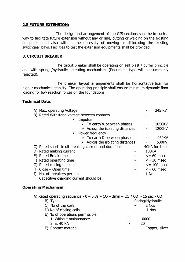
2.8 FUTURE EXTENSION:
The design and arrangement of the GIS sections shall be in such a way to facilitate future extension without any drilling, cutting or welding on the existing equipment and also without the necessity of moving or dislocating the existing switchgear bays. Facilities to test the extension equipments shall be provided.
3. CIRCUIT BREAKER
The circuit breaker shall be operating on self blast / puffer principle and with spring /hydraulic operating mechanism. (Pneumatic type will be summarily rejected).
The breaker layout arrangements shall be horizontal/vertical for higher mechanical stability. The operating principle shall ensure minimum dynamic floor loading for low reaction forces on the foundations.
Technical Data:
A) Max. operating Voltage - 245 KVB) Rated Withstand voltage between contacts -
• Impulse To earth & between phases - 1050KV Across the isolating distances - 1200KV
• Power frequency To earth & between phases - 460KV Across the isolating distances - 530KV
C) Rated short circuit breaking current and duration- 40KA for 1 sec D) Rated making current - 100KAE) Rated Break time - <= 60 msecF) Rated operating time - <= 30 msecG) Rated closing time - <= 100 msecH) Close – Open time - <= 60 msecI) No. of breakers per pole - 1 No
Capacitive charging current should be
Operating Mechanism:
A) Rated operating sequence - 0 – 0.3s – CO – 3min – CO / CO - 15 sec - CO B) Type - Spring/HydraulicC) No of trip coils - 2 NosD) No of closing coils - 1 NosE) No of operations permissible
1. Without maintenance - 10000 2. at 40 KA - 20
F) Contact material - Copper, silver
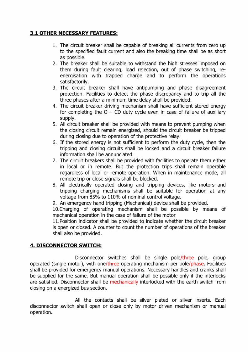
3.1 OTHER NECESSARY FEATURES:
1. The circuit breaker shall be capable of breaking all currents from zero up to the specified fault current and also the breaking time shall be as short as possible.
2. The breaker shall be suitable to withstand the high stresses imposed on them during fault clearing, load rejection, out of phase switching, re-energisation with trapped charge and to perform the operations satisfactorily.
3. The circuit breaker shall have antipumping and phase disagreement protection. Facilities to detect the phase discrepancy and to trip all the three phases after a minimum time delay shall be provided.
4. The circuit breaker driving mechanism shall have sufficient stored energy for completing the O – CD duty cycle even in case of failure of auxiliary supply.
5. All circuit breaker shall be provided with means to prevent pumping when the closing circuit remain energized, should the circuit breaker be tripped during closing due to operation of the protective relay.
6. If the stored energy is not sufficient to perform the duty cycle, then the tripping and closing circuits shall be locked and a circuit breaker failure information shall be annunciated.
7. The circuit breakers shall be provided with facilities to operate them either in local or in remote. But the protection trips shall remain operable regardless of local or remote operation. When in maintenance mode, all remote trip or close signals shall be blocked.
8. All electrically operated closing and tripping devices, like motors and tripping charging mechanisms shall be suitable for operation at any voltage from 85% to 110% of nominal control voltage.
9. An emergency hand tripping (Mechanical) device shall be provided. 10.Charging of operating mechanism shall be possible by means of mechanical operation in the case of failure of the motor 11.Position indicator shall be provided to indicate whether the circuit breaker is open or closed. A counter to count the number of operations of the breaker shall also be provided.
4. DISCONNECTOR SWITCH:
Disconnector switches shall be single pole/three pole, group operated (single motor), with one/three operating mechanism per pole/phase. Facilities shall be provided for emergency manual operations. Necessary handles and cranks shall be supplied for the same. But manual operation shall be possible only if the interlocks are satisfied. Disconnector shall be mechanically interlocked with the earth switch from closing on a energized bus section.
All the contacts shall be silver plated or silver inserts. Each disconnector switch shall open or close only by motor driven mechanism or manual operation.
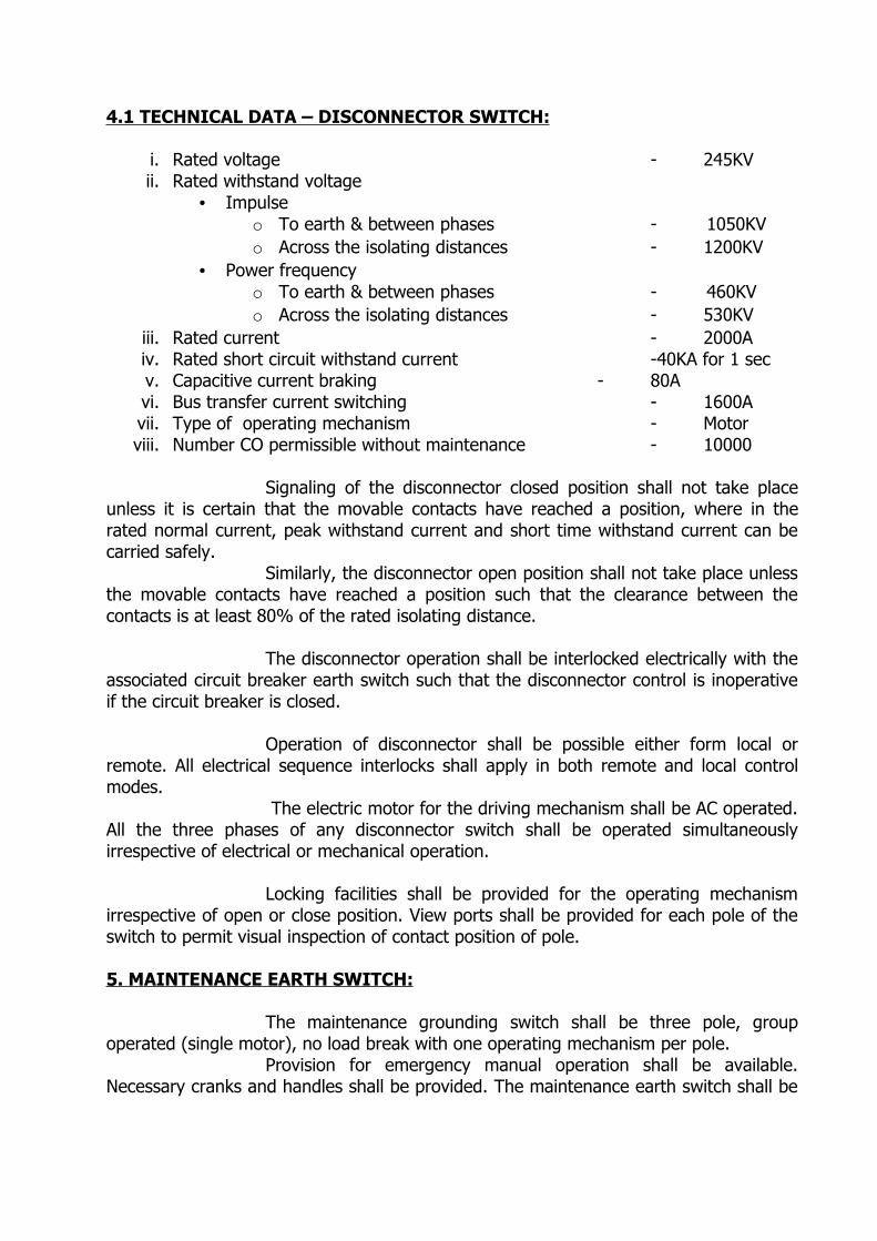
4.1 TECHNICAL DATA – DISCONNECTOR SWITCH:
i. Rated voltage - 245KVii. Rated withstand voltage
• Impulseo To earth & between phases - 1050KVo Across the isolating distances - 1200KV
• Power frequencyo To earth & between phases - 460KVo Across the isolating distances - 530KV
iii. Rated current - 2000A iv. Rated short circuit withstand current -40KA for 1 secv. Capacitive current braking - 80Avi. Bus transfer current switching - 1600Avii. Type of operating mechanism - Motorviii. Number CO permissible without maintenance - 10000
Signaling of the disconnector closed position shall not take place
unless it is certain that the movable contacts have reached a position, where in the rated normal current, peak withstand current and short time withstand current can be carried safely.
Similarly, the disconnector open position shall not take place unless the movable contacts have reached a position such that the clearance between the contacts is at least 80% of the rated isolating distance.
The disconnector operation shall be interlocked electrically with the associated circuit breaker earth switch such that the disconnector control is inoperative if the circuit breaker is closed.
Operation of disconnector shall be possible either form local or remote. All electrical sequence interlocks shall apply in both remote and local control modes.
The electric motor for the driving mechanism shall be AC operated. All the three phases of any disconnector switch shall be operated simultaneously irrespective of electrical or mechanical operation.
Locking facilities shall be provided for the operating mechanism irrespective of open or close position. View ports shall be provided for each pole of the switch to permit visual inspection of contact position of pole.
5. MAINTENANCE EARTH SWITCH:
The maintenance grounding switch shall be three pole, group operated (single motor), no load break with one operating mechanism per pole.
Provision for emergency manual operation shall be available. Necessary cranks and handles shall be provided. The maintenance earth switch shall be
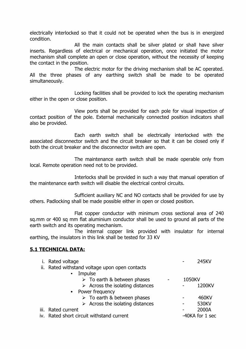
electrically interlocked so that it could not be operated when the bus is in energized condition.
All the main contacts shall be silver plated or shall have silver inserts. Regardless of electrical or mechanical operation, once initiated the motor mechanism shall complete an open or close operation, without the necessity of keeping the contact in the position.
The electric motor for the driving mechanism shall be AC operated. All the three phases of any earthing switch shall be made to be operated simultaneously.
Locking facilities shall be provided to lock the operating mechanism either in the open or close position.
View ports shall be provided for each pole for visual inspection of contact position of the pole. External mechanically connected position indicators shall also be provided.
Each earth switch shall be electrically interlocked with the associated disconnector switch and the circuit breaker so that it can be closed only if both the circuit breaker and the disconnector switch are open.
The maintenance earth switch shall be made operable only from local. Remote operation need not to be provided.
Interlocks shall be provided in such a way that manual operation of the maintenance earth switch will disable the electrical control circuits.
Sufficient auxiliary NC and NO contacts shall be provided for use by others. Padlocking shall be made possible either in open or closed position.
Flat copper conductor with minimum cross sectional area of 240 sq.mm or 400 sq mm flat aluminium conductor shall be used to ground all parts of the earth switch and its operating mechanism. The internal copper link provided with insulator for internal earthing, the insulators in this link shall be tested for 33 KV
5.1 TECHNICAL DATA:
i. Rated voltage - 245KVii. Rated withstand voltage upon open contacts
• Impulse To earth & between phases - 1050KV Across the isolating distances - 1200KV
• Power frequency To earth & between phases - 460KV Across the isolating distances - 530KV
iii. Rated current - 2000Aiv. Rated short circuit withstand current -40KA for 1 sec
v. Number CO permissible without maintenance -10000
6. HIGH SPEED EARTH SWITCH:
The high speed earth switches shall be provided at the bus bars and at all external connections like EHV cable, OH line or transformer connections. The switch shall be three pole operated with one driving mechanism per pole/phase. An emergency manual operation shall be provided with necessary cranks and handles. The high speed switch shall be eclectically interlocked to prevent from closing on an energized bus section. The high speed earth switches provided near the cable terminations shall be of isolated type, to enable to conduct the cable conductor resistance measurement.
All main contacts shall be silver plated or shall have silver inserts. Once, initiated motor mechanism shall complete an open or close operation with out requiring the initiating contact to be held closed.
The mechanism shall be arranged in such a way that all the three phases of any particular high speed earth switch can be operated simultaneously.
The motor shall be suitable for operating between 85% to 110% of the rated auxiliary voltage.
Each high speed switch shall be furnished with 8 (4 NO and 4 NC) potential free contacts.
View ports shall be provided to ensure visual inspection of each switch. Inspection of the main contacts shall be possible using an optical device which shall also provide lighting at contact zone.
These high speed earth switches shall be capable of interrupting the inductive, capacitive, currents and to withstand the transient voltages.
The switches shall be fitted with a stored energy closing system to provide fault making capability.
Both local and remote operation shall be made available.
Interlocks shall be provided so that insertion of manual operating device will disable the electrical control circuit. Pad locking facility shall be provided for the high speed earth switch either in open position and in closed position.
Flat copper conductor of 240 Sq.mm or 400 Sq mm flat aluminium
conductor size shall be used to ground all parts of the grounding switch and the operating mechanism.
6.1. TECHNICAL DATA
i. Rated voltage - 245KVii. Rated withstand voltage upon open contacts
• Impulse To earth & between phases -
1050KV Across the isolating distances -
1200KV• Power frequency
To earth & between phases - 460KV Across the isolating distances - 530KV
iii. Rated current - 2000Aiv. Rated short circuit withstand current -40KA for 1 secv. Inductive current switching capability - 80A,2KVvi. Capacitive current switching capability - 2A, 6KVvii. Closing time - 100 msecviii. Number permissible without maintenance - 10000ix. No. of short circuit making at 40KA - 2
7. CABLE CHAMBER:
Choice of materials
The choice of materials (metal parts, bolts etc.) must be made to avoid any risk of corrosion referring to the prescribed specifications on this subject for metal-cald substations.
Mechanical characteristics
The cable termination casing must withstand different electromechanical, thermomechancial and pressure constraints.
A sealed partition ensures the separation between the gas volumes contained in the cable termination casing and the adjacent compartments.
The two functions above, mechanical support and sealing may be ensured by one or several insulators.
Gas dielectric
The internal volume of the metal clad casing is filled with SF6 gas which ensures insulation. The rated pressure must be specified by the switchgear manufacturer. Sealing of the cable core
Sealing must be ensured in order to avoid gas leaks through the open strands of the core. Pressure surveillance
Pressure surveillance is ensured by one or more pressure monitoring devices balanced for temperature compensation and it shall have two stages:
.P1 : first level, not requiring rapid intervention.
.P2 : second level requiring rapid intervention.
These pressure monitoring are equipped with a device which allows their control without emptying the cable termination casing.
Rate of gas leakage
The minimal time interval between the filling pressure and supplementary filling up to the appearance of the first P1 level must not be less than three years.
7.1 SPECIFICATION FOR SF 6 GAS INSULATED METAL CLAD TERMINATION FOR XLPE CABLES: The following specification applies to single core XLPE insulated cable terminations connected to SF 6 gas insulated metal-clad substations (G.I.S.) for rated voltage of 245 KV, where the HV power cables are terminated directly in the metal clad switchgear using cable-sealing ends designed for use in SF6 gas and shall comply with IEC 62271-209 & IEEE 1300.
The arrangements and dimensions of the XLPE Cable termination for Gas Insulated Metal enclose Switchgear will be in accordance with IEC 62271-305 (i.e)Dry type A-inner cone type. The position, its entrance below or above, and the inclination angle in relation to the horizontal plane will be specified by the switchgear manufacturer.
The SF6 gas insulated metal clad termination for XLPE cable shall confirm to the following specification. They are meant for use with the following cables:
The following type of cables will be used.
230KV, 1x1200sq.mm, Aluminium, XLPE cable
The outer diameter and other details of the cables will be supplied by the cable manufacturer. The GIS feeder breaker shall have facility to test the connected power cable on site. Removable bolted links or similar arrangement will be accepted.
7.2. COMPONENTS
The cable termination is made generally up of the following elements
1. The enclosure is filled with SF 6 in which the cable termination has to be placed. This enclosure is closed by an insulating partitions on the “high voltage” side and by the flange and the cable gland on the “earth” side.
2. The connecting system allowing the electrical joining between the core of the cable and GIS should withstand the total dynamic forces generated during short circuit conditions and the axial forces due to temperature variations during service.
3. The mechanical connecting system shall be available between the cable gland and the GIS cable connection enclosure.
4. The flange providing completely even surfaces. Sealing joints are fixed in the flange of the metal enclosure and in the cable gland.
5. The metallic sheath of the cable must be electrically insulated from the GIS enclosure. In order to protect against over voltage at high voltage levels, three non-linear resistors (C.C.P.U.) must be connected between the metallic sheath of the cable and the metal-clad cable termination. The connections must be as short as possible, of the same length and be located at 120 degrees on the same circumference.
6. The cable gland can be linked either to the cable sheath and insulated from the GIS enclosure or linked to the GIS enclosure and insulated from the sheath of the cable
7. A free space is reserved under the cable end for the exclusive use of the cable supplier. This space is necessary for the passage of the cable termination on connection and can be used for the placing of the cable gland and the device which ensures insulation between the metallic sheath of the cable and the GIS enclosure.
7.3. LIMIT OF SUPPLIES AND SERVICES The cable manufacturer
The cable manufacturer supplies the following elements:
1. The cable connector. 2. The terminal end. 3. The sealing joints ensuring the sealing of the core, and those between cable gland and flange of the GIS enclosure. 4. The fixing device. 5. The earthing system of the cable sheath 6. Non-linear resistors(CCPU)
The required insulating ring, bolts, nuts, washers and insulating shield necessary for fixing the cable gland of the cable termination shall also be supplied. On testing, this assembly can be put through the same electrical tests on the inner sheath of the cable.
GIS manufacturer
The GIS manufacturer supplies the following elements:
1. The metal enclosure and flange. 2. The pressure monitoring device 3. The electrical contacts ensuring the continuity of the electrical circuit between the terminal end of the cable and the conductor of the metal-clad substation. 4. The mechanical blocking device of the terminal end. This shall be designed so as to support a strain, three times that of the maximum strain guaranteed by the cable supplier. 5. The parts ensuring the sealing of the different compartments between themselves and with the insulating flange up to the end of the enclosure 6. The grooves and joints necessary to ensure sealing between the cable gland and the flange. As this sealing is the responsibility of the cable supplier, the dimensions of the grooves and joints, the surface condition of the grooves and the quality of the joints shall be submitted to him for agreement. The filling with SF6 gas is ensured by the manufacturer of the metal enclosure.
8. CURRENT TRANSFORMER:
Ring core type CT is preferred.
Transformer bay
. Core 1: Transformer differential protection,. Core 2: Over current and local breaker back up protection,. Core 3: Spare. Core 4: Bus bar differential protection,. Core 5: Metering.
Feeder bay
. Core 1: Distance protection, . Core 2: Spare
. Core 3: Local breakers back up protection,
. Core 4: Bus bar differential protection,
. Core 5: Metering.The rating of the current transformers shall be as per the relevant standards in vogue.
For metering cores VA burden is indicated. For protection cores knee point voltage and resistance of CT secondary are indicated.
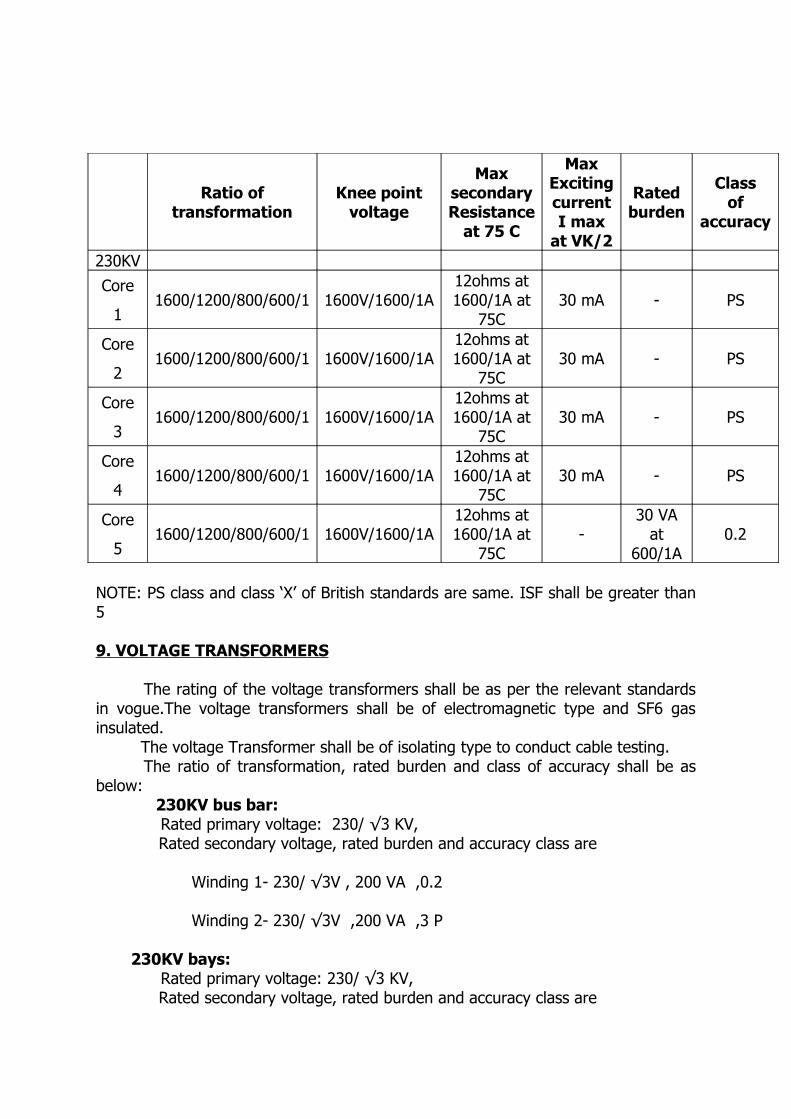
Ratio of transformation
Knee point voltage
MaxsecondaryResistance
at 75 C
MaxExciting currentI max
at VK/2
Rated burden
Classof
accuracy
230KVCore
11600/1200/800/600/1 1600V/1600/1A
12ohms at 1600/1A at
75C30 mA - PS
Core
21600/1200/800/600/1 1600V/1600/1A
12ohms at 1600/1A at
75C30 mA - PS
Core
31600/1200/800/600/1 1600V/1600/1A
12ohms at 1600/1A at
75C30 mA - PS
Core
41600/1200/800/600/1 1600V/1600/1A
12ohms at 1600/1A at
75C30 mA - PS
Core
51600/1200/800/600/1 1600V/1600/1A
12ohms at 1600/1A at
75C-
30 VA at
600/1A0.2
NOTE: PS class and class ‘X’ of British standards are same. ISF shall be greater than 5
9. VOLTAGE TRANSFORMERS
The rating of the voltage transformers shall be as per the relevant standards in vogue.The voltage transformers shall be of electromagnetic type and SF6 gas insulated. The voltage Transformer shall be of isolating type to conduct cable testing.
The ratio of transformation, rated burden and class of accuracy shall be as below: 230KV bus bar: Rated primary voltage: 230/ √3 KV,
Rated secondary voltage, rated burden and accuracy class are
Winding 1- 230/ √3V , 200 VA ,0.2
Winding 2- 230/ √3V ,200 VA ,3 P
230KV bays: Rated primary voltage: 230/ √3 KV,
Rated secondary voltage, rated burden and accuracy class are
230/ √3V, 200 VA , 0.2 The inductive voltage transformer shall be housed in a metal tank, which complies with the internal arcing requirement of IEC 62271-203. The tank shall have a suitable lifting facility.
The high voltage insulators (barriers) shall be suitable for withstanding the differential pressure i.e. the normal working pressure on one side and the vacuum on the other side. They shall be compatible with SF6 gas and its degradation products.
The pressure of the gas at normal temperature and the pressure shall be such that remains in its gaseous state when operating at the lowest temperatures stated in the schedules.
Facilities shall be provided for constant local monitoring of the SF6 gas pressure inside the tank, while topping up or sampling the gas.
Facilities shall be provided for isolating the voltage transformer during the injection testing of GIS equipment.
A bursting disc shall be fitted to the voltage transformer housing for safety reasons.
10.INTERLOCKS
Electrical interlock shall be provided between :
1. Circuit breakers and disconnector. 2. Disconnectors and earthing switches.
The principles of electrical interlocks are the following:
On each bay:
- The disconnector from the bus bar may not be closed if the associated circuit breaker is closed.The bus bar disconnector may not be closed if the earthing switch located between itself and the circuit breaker is closed.
- The earthing switch located between the bus bar disconnector and circuit breaker may not be closed if the bus bar disconnector is closed.
- The circuit breaker may not be closed if the ear thing switch of the associated section of bus bar is closed.
- The feeder disconnector may not be closed or opened if the associated circuit breaker is closed.
- The feeder disconnector may not be closed if the earthing switch is closed.
On the bus bar:
- cable disconnector can be opened and earthing switch can be closed only if the voltage transformer reads zero.- Cable earth switch can be closed only if cable disconnector is
opened.- Cable disconnector can be opened only if the associated circuit
breaker is opened.- The feeder disconnector cannot be closed if the switchgear is
closed and bus bar disconnector is closed.- The earthing switch of each bus bar may be closed only if all the
bus bar disconnections are opened.
11. LOCAL CONTROL CUBICLE:
A local control cubicle for each GIS breaker shall be supplied. It should enable local control, indication and interlocking operation of the devices associated with the GIS bay. The LCC shall be free standing or integrated with the GIS switchgear. Each local control cubicle will include principally:
A local / remote selector switch, An operation counter for circuit breaker, and a start up counter for motor pump, A mimic of single line diagram of the gas compartments clearly shown, Push buttons for local opening and closing operation of circuit breakers, Disconnectors and earth switches, The arrangement for the push button shall be as below: - Green “TO CLOSE”- Red “ TO OPEN”
All electrical closing and opening operations of circuit-breakers ,disconnectors and earth switches shall be connected to the terminal block in LCC. All relays contacts for operation of circuit breakers , disconnectors and earth switches shall be made available at the LCC.Terminals shall be available for the two trip coils of the circuit breaker which are to be connected to two different battery circuits. All cabling from control boxes of each switchgear will be connected to the relevant local control cubicle.
11.1 ARRANGEMENTS
Wiring
The wiring must be carried out with stranded copper conductors of at least 7 strands. The size of the conductors shall be suitable enough for the expected usage, but it must not be less than 1.5 sq.mm.
All precautions should be taken to minimize the inductive and capacity coupling between circuits of especially with the wiring of the AC and DC circuits.
The cable trays shall be designed in such a way that it has at least 20% space for future usage.
Terminal BlocksThe design of the terminal shall be as per the relevant standards in vogue.
The terminals permitting the direct control of SF 6 surveillance from pressure monitoring devices must be fitted with test point.
The outgoing terminal connection must be unique and comprises of 2 distinct parts: - an arrangement for auxiliary voltage supply (alternating or direct current) - an arrangement for control common.
Worker SafetyAll precautions must be taken to ensure an efficient protection against
accidental contact with the live elements.
Degree of protection The required level of protection shall be established for the enclosures of
boxes and cubicles as per the relevant standards in vogue. Frame work
The boxes and cubicles shall have metallic enclosures to ensure effective protection against radio interference. If these enclosures are of non-metallic materials, the screen shall be connected to the earth to ensure efficient protection.
Cable entrance Cable glands or grommets shall be provided for cable entry through the lower
side. These cable glands should avoid electrolytic corrosion at the lower side of the box.
Closing devicesA simple handle will be suffice at the door of the cubicles.The door must open at at least 120 deg.
Lighting and socket :Lighting facility at the cubicles shall be activated by opening the door. In each local control cubicle a single phase 3 pin socket with switch shall also
be provided.The lighting points and sockets should be connected by a circuit separate from other circuits.
Space heaters In each box and local control cubicle a space heater is required to prevent
condensation. It should be connected by the same separate A.C. circuit as above. Space heaters shall be of hygrostat with PTC heaters ( Positive thermal coefficient heaters)
The manufacturer shall indicate the electrical power of each heater. Earthing of boxes and cubicles
Depending upon the location of boxes and cubicles, the earthing terminal is either linked to the metal enclosure, or linked directly to the general earth mat by an earthing conductor of reduced cross – section.
Equipotential connections between boxes, cubicles and doors shall be provided to ensure that no movable part of the enclosure can, once it is in place, be isolated from the part to which the earthing terminal is connected.
Voltage transformerThe cable from voltage transformers shall be terminated in the cubicles with
removable fuses and shall be padlocked.The fuses are connected in such a way that the locking devices forbids access
to the cells corresponding to the conductors from the voltage transformers.The fuse units shall be of 25 amp rating with a 6amp fuse cartridge.
Boxes and cubicles. Other than stainless steel, all the boxes and cubicles shall be painted with a minimum one primer coat and one top coat.
Bolts, screws and nuts.In case of stainless steel a diameter of 16mm and above shall be provided.If the diameter is below 16mm hot galvanized will be allowed and in such case the thickness of zinc plating shall be 375 g /sq.m.All precautions shall be taken:
- to ensure that contacting materials do not cause electrolytic corrosion.- to avoid water stagnation.
The manufacturer shall specify the measures adopted to ensure the above conditions.
12. LOW VOLTAGE & CONTROL CABLES
12.1 415V/24OV A.C. AND 110V D.C. POWER CABLES :
These cables shall be 1100V Grade, single/multi-core, stranded, copper conductor, PVC insulated, aluminium wire armoured (for single core) and steel strip armoured (for multi-core) with extruded inner and outer sheaths made of Fire Retardent Low Smoke (FRLS) conforming to the following performance requirements:
i. The critical oxygen index value shall be minimum at 250C when tested for temperature index as per ASTM-D-2863-1974.
ii. The maximum acid gas generation as determined by titration shall be less than 15% by weight when tested as per IEC. 745-1.
iii. The smoke generation test shall pass the light transmission of minimum of 40% when tested as per ASTM-D-2843-77.
iv. The finished cable shall pass the flammability test as per IEC.332-1 and also as per Swedish Svensk Standard SS. 404-1475 (1978). The cable shall conform to IS.1554 (Part-I).
v. The cables shall be type tested for resistance to ultra violet rays as per DIN 533887 and ASTMG 53-77.
vi. The cables shall be type tested for hydrolytic resistance as per ASTM G 53-77.
vii. Water absorption outer sheath shall be subjected to tests for water absorption, both electrical and gravimetric as per Parts 28 and 33 of IS. 10810, respectively. The test sample shall pass the requirement of reference specification. Maximum value for water absorption by gravimetric method shall not exceed 1 mg/sq.cm. of the areas of sample tested.
viii. Test for rodent and termite repulsion :Vendor shall conduct type tests for proving the presence of rodent and termite repellant material in the outer sheath.
12.2 CONTROL CABLES :
12.2.1 The control cable shall be of 1100V Grade, stranded, tinned, annealed, high conductivity copper conductor of size 2.5 sq.mm. (except for C.T. circuits for which the size shall be 4 sq.mm.) steel strip armoured, extended inner and outer sheath made of FRLS PVC compound conforming to the performance requirements outlined above. Cables shall conform to IS.1554 (Part-I). Cables with up to 5 cores shall be colour coded. Cables with 6 cores and above shall have printed numbers.
12.2.2 In additions, the control cables shall have a copper screen over the inner sheath for protection against electromagnetic disturbances.
12.2.3 SPECIAL CABLES AND PANEL WIRES : Any other special cables being supplied as a part of this contract shall conform to the performance requirements, as per standards.
12.2.4 SCREEN CHARACTERISTICS :The screen consists of either a copper tube or a bare copper tape laid
longitudinally over the sheath. The screen is corrugated to improve the flexional strength. The length wise tape must overlap the screen edges by at least 5mm.
The DC electric resistance of the screen must be lower than 2 ohm/km at 20C. The measurement is made before and after the bending test.
12.2.5 TRANSFER IMPEDENCE MEASUREMENT
The transfer impedance is measured on the cable completed so as to check the degree of protection provided by the copper core. The transfer impedance must be measured and value must be between 1kHz and 1 MHz. The transfer impedance curve according to the frequency must be <2ohms and constantly fall from 100kHz.
12.3 CABLING`
The manufacturer shall carry out the erection of cables between the different phases of a same GIS module and the cubicles. Suitable marks on each cable between the different boxes and the cubicles shall be provided for easy identification. The control cables should occupy only up to 80% of the space in the cable trays initially. All cabling between boxes of switchgear and control cubicles shall be multicore cable and it shall be glanded with a suitable shield for protection against electromagnetic effects. It shall comply with the technical specification for low voltage cable.This shield shall be connected to the earthing at both ends by a braided conductor wire on a suitable copper flat within boxes and cubicles.
13. ACCESSORIES:
13.1 Sf6 gas service cart The SF6 gas service cart shall be adequate to:- refill each compartment between the first or second level of SF6 gas pressure to the rated pressure.- check the SF6 monitoring.
13.2 Sf6 handling plantThe SF6 handling plant shall contain compressors and vacuum pump necessary for recovering vacuum and filling SF6 gas. It shall be movable with wheels.
It shall allow the storage of SF6 in liquid state in a built – in tank having capacity sufficient to empty any three adjacent compartment of 245 KV GIS.
The capacity of compressors and vacuum pumps shall be selected in such a way for-filling a compartment to the rated pressure within one hour.-recovering SF6 gas from any compartment to the built in tank from the rated pressure to 50mb pressure within three hours.-evacuating a compartment from 50 mb pressure to less than 1 mb pressure within one hour.The cart shall have the following provisions:
-accessories for connections and operation (valves and coupling)
-dry type filters, dust and oil traps,-tools and spares for operation and Maintance,-hand-book for description, commissioning, operation, and Maintance.
13. 3 230KV SF 6 test bushings:
These bushings shall conform to IEC 60137 standard.The design shall meet the following requirements:- Minimum creep age distance : 31mm / KV for heavy pollution level according to the IEC60815 standard. -The terminal clamp shall be supplied by the GIS manufacturer
14. EARTHING
14.1 Earthing of the main circuits
In order to ensure security during maintenance work, it should be possible to earth all the parts of the main circuits by earthing switches. In addition, even after opening the enclosure, it must be possible to connect earthing devices while the work is in progress.
The earthing switches designed for busbars and feeders shall be supplemented by the following arrangements :
i) At each point where it may be necessary to have such an earthing for worker safety, an orifice with a cover permits the easy installation of a “removable earthing device” already connected to the earth mat of the substation.
ii) In cases where it is necessary to take out the earthing switch from service, either to carry out maintenance on it, or to take out a piece of apparatus in the compartment in which it is installed, provision shall be given in such a way that prior to taking the earthing switch out from service , “ a removable earthing device” (temporary earthing device) shall be given to the main circuit at where intervention is required.
iii) The possible connection points of the “removable earthing
devices” have to be indicated on the instructions. There shall be at least one connecting point on each
compartment of the busbar and on each cable box.
In order to reenergize a part of the main circuit, provision shall be given to refill the compartment in which the removable earthing device was installed, to its rated pressure of SF 6.
The manufacturer shall give the description of the “removable earthing device”.
14.2 EARTHING OF THE ENCLOSURES:
Generally the metal clad equipment are assembled, by bolting the structures, cover and partition which may be considered adequate as long as the electrical continuity has been maintained.
Consequently the metal enclosure of metal-clad substation are used as earth conductors and hence continuity has to be maintained. In the case of dismantling of any enclosure, the continuity of the earthing should be maintained by a temporary earthing arrangement.
In all cases where the enclosures do not ensure earthing continuity, the two neighboring enclosures must be linked to a same general earthing network by a conductor or by an equipotential link.
In order to ensure the continuity of the earthing circuit, it is essential that the enclosures are linked as directly as possible to the general earthing circuit of the substation by copper flat / Aluminium alloy flat of cross section sufficient to carry the rated short circuit current.
The earthing electrodes of the different pieces of equipment are therefore directly connected to the enclosures:
- either by copper flat / Aluminium alloy flat of a cross section equivalent to that of the general earthing circuit, so as to carry the short-circuit current .
These connections shall be supplied by the manufacturer.
14.3 Nature and size of connecting conductors :
In order to avoid electrolytic corrosion problems, these connections must be made by tinned copper flat or Aluminium Alloy flat because the enclosure are made of aluminum alloy . The minimum size of these earth conductors should carry the short circuit current shall be specified by the manufacturer and hence its size shall be specified accordingly.
Concerning the conductors which ensure earthing only, their cross sections shall be a minimum of 400 sq. mm for Aluminium of Aluminium alloy and 240 Sq.mm for copper
14.4 Bonding circuits
In case where the three phase of a feeder or of a bus bar are placed in separated enclosures, it is necessary to link the enclosures by “Bonding circuits”, of size suitable to carry a continuous current equal to the rated current of the feeder or of the bus bar. It is imperative that these bonding circuits are linked to the general earth mat of the substation by a circuit suitable to carry the rated short-circuit current.
14.5 Connection to the general earth mat.
All metal parts intended which does not belong to a main or an auxiliary circuit, shall be connected to earth.
The general copper earth circuit of the substation shall be formed by an uninterrupted loop which originates from the buried copper conductor of a cross section of 240sq.mm. These loops shall be fixed to the base of the chassis with the help of an earth riser connection bolted into a hole in the chassis or frame and situated at 0.30 m above the floor level of the switchgear.
The general earth mat design, the connection device and the bimetallic plate shall be supplied by the GIS manufacturer. The earth connection from earth pad of equipment to the general earth mat near shall be provided by the supplier.
The continuity of the earthing circuits shall be ensured taking into account the thermal and electrical stress by the current they may have to carry.
14.6 Equipotential Earthmat :When a fault current flows through the earthing connections into the soil, the enclosures, linked to the earthing circuits, will be at the same potential as the earthing mat conductors but this potential is generally different from that on the soil surface.
In order to ensure the security of personnel, it is necessary to install an equipotential mat linked to the general earthing mat in the zones where metal enclosures and fixed accessories are accessible from the floor.
It is also necessary to provide an equipotential earthing mat in the zones where an emergency mechanical operation or a locking system is accessible from the floor. It is therefore possible to extend the equipotential mat to allow the operator to carry out his maneuvers.
In order to ensure a good equipotential surface, each element of the equipotential mat must be connected to the general earthing network by the manufacturer.
This mat will be placed on the floor, all around the switchgears. It is not required in front of the control cubicles.
If it is an oxidizing material, it should be hot dip galvanized.
The manufacturer must design, specify, and provide this equipotential earth mat. The location of the equipotential mat should be defined by the supplier for all the GIS and at places where :
- the enclosures are accessible for the floor.
- Manual operation of apparatus or locking system is located.
Five copies of equipotential earth mat drawings along with design calculations may be submitted for approval by the successful Bidder.
15 TESTING & COMMISSIONING:
15.1 TYPE TEST:
Type tests shall be according to the IEC 62271-203 and other relevant IEC standards.
Copies of the type tests conducted shall be furnished along with the BID . These type tests should have been conducted in a Recognized independent institution / Laboratory.
15.2 ROUTINE TESTS
Routine tests shall be as per the IEC 62271-203 and other relevant standards.The manufacturer shall provide all the testing equipments required for the site tests.
15.3 COMMISSIONING TESTS/ON SITE TESTS AFTER ERECTION
After erection, and before putting into service, the gas-insulated metal enclosed Switchgear shall be tested for the correct operation and dielectric strength of the equipment.
These tests and verifications shall comprise:
15.3.1) Tests to be conducted on the circuit breaker at site
i) At all required operating sequences• Measurement of operating time
ii) Checking of wiring and connections and dielectric checksiii) Indications, alarms and interlocks, auxiliary contactsiv) Operation at minimum and maximum control supply voltage/pressurev) Operation of anti-pumping device.
15.3.2) Test to be conducted on the Disconnectors at site
i) Checking of wiring and connections and dielectric checksii) Indications, alarms and interlocks, auxiliary contactsiii) Operation at minimum and maximum control supply voltage/pressure
15.3.3) Other Tests at Site
- Dielectric tests on auxiliary circuits- Measurement of the resistance of the main circuit- Measurement of gas condition- Gas tightness tests- General verifications
15. 3.4) POWER FREQUENCY TEST:
15.3.4 A) ON SITE TESTING OF GIS
Power frequency tests for the completed GIS at site shall be possible without removing the voltage transformers. The power frequency test voltage at site shall be 80% of the factory test voltage for 1 min at 100Hz.
15.3.4 B) The Supplier is responsible to furnish the test equipment for conducting following performance tests at site.
• Voltage tests on main circuits at reduced voltage (80% p.f.) comprising:
- 50 Hz A.C. voltage test for 1 min
- Partial Discharge test shall be conducted and report submitted as per clause 6.2.9.101 of IEC 62271.203
The manufacturer shall provide :
-The test voltage source.
-All connections between the switchgear and the test voltage source.
The procedure to be implemented following a discharge during dielectric tests is as follows :
- if a disruptive discharge occurs at the first test while increasing of test voltage, a second test is performed.
- If a second disruptive discharge occurs in the same compartment before reaching the highest level, there are two possibilities :
- If the second disruptive discharge is higher than the first voltage again the voltage is immediately increased. If a new discharge occurs the value of which is again higher, a new test is carried out.
- If the second disruptive discharge is lower than or equal to the first, the test is stopped and the compartment dismantled.
The process is continued in order to reach the test voltage. If a disruptive discharge occurs at this voltage, there are two possibilities:
-if it is the first disruptive discharge in the compartment since the test was begun, voltage is again increased. If there is no other discharge, the test has been successful. The test is stopped and the compartment dismantled.
-if some discharge have previously occurred in this compartment during the increase in voltage, the test is stopped and the compartment dismantled.
16. NOISE: during the operation, the level of noise of noise emitted by the switchgear shall be in accordance with the clause 5.106 of IEC 62271.203
17. General Conditions for both 230 KV & 110 KV GIS The GIS Floor level shall be paved in such a way that the level difference shall not exceed +/- 2 mm.The GIS shall not be welded to the Floor beamThe view parts of the earth switch, disconnector switches and breakers shall be clearly visible.The cable trays shall be of Galvanized Iron.All bolts and nuts in the GIS shall be stainless steel.
18. Earthing:
As GIS earthing is unique, provision of earth mesh shall be provided in the basement before commencement of construction works.
SCHEDULE OF GUARANTEED PERFORMANCE AND OTHER
TECHNICAL PARTICULARS
FOR 245 KV SF6 INSULATED SWITCHGEAR
DESCRIPTION SPECIFICATION
REQUIREMENT
TO BE COMPLETED
BY BIDDERS
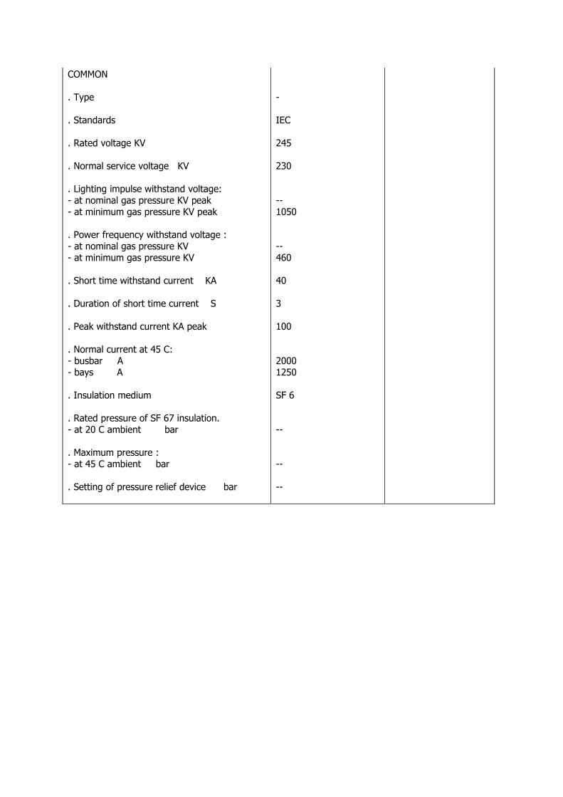
COMMON
. Type
. Standards
. Rated voltage KV
. Normal service voltage KV
. Lighting impulse withstand voltage:- at nominal gas pressure KV peak- at minimum gas pressure KV peak
. Power frequency withstand voltage :- at nominal gas pressure KV - at minimum gas pressure KV
. Short time withstand current KA
. Duration of short time current S
. Peak withstand current KA peak
. Normal current at 45 C:- busbar A- bays A
. Insulation medium
. Rated pressure of SF 67 insulation.- at 20 C ambient bar
. Maximum pressure :- at 45 C ambient bar
. Setting of pressure relief device bar
-
IEC
245
230
--1050
--460
40
3
100
20001250
SF 6
--
--
--
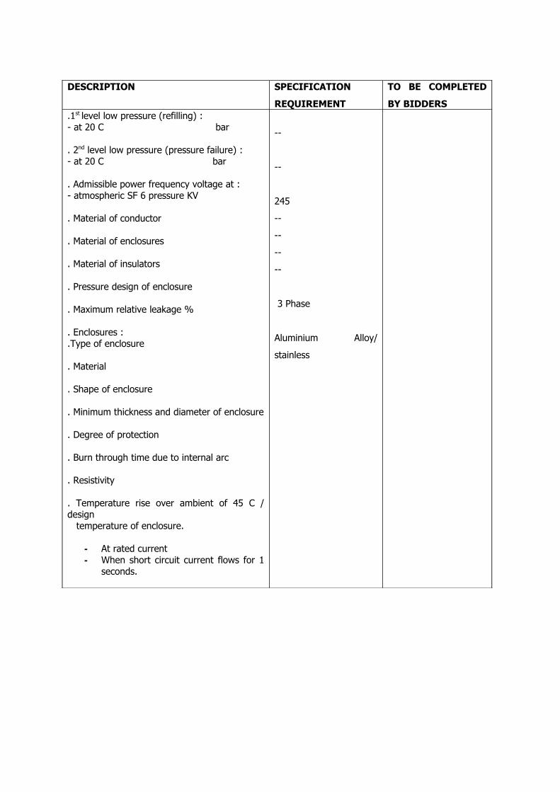
DESCRIPTION SPECIFICATION
REQUIREMENT
TO BE COMPLETED
BY BIDDERS.1st level low pressure (refilling) : - at 20 C bar
. 2nd level low pressure (pressure failure) :- at 20 C bar
. Admissible power frequency voltage at :- atmospheric SF 6 pressure KV
. Material of conductor
. Material of enclosures
. Material of insulators
. Pressure design of enclosure
. Maximum relative leakage %
. Enclosures :
.Type of enclosure
. Material
. Shape of enclosure
. Minimum thickness and diameter of enclosure
. Degree of protection
. Burn through time due to internal arc
. Resistivity
. Temperature rise over ambient of 45 C / design temperature of enclosure.
- At rated current- When short circuit current flows for 1
seconds.
--
--
245
--
--
--
--
3 Phase
Aluminium Alloy/
stainless
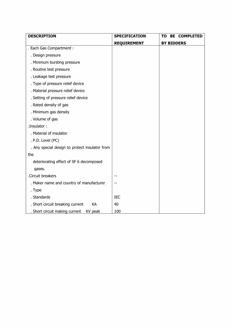
DESCRIPTION SPECIFICATION
REQUIREMENT
TO BE COMPLETED
BY BIDDERS. Each Gas Compartment :
. Design pressure
. Minimum bursting pressure
. Routine test pressure
. Leakage test pressure
. Type of pressure relief device
. Material pressure relief device
. Setting of pressure relief device
. Rated density of gas
. Minimum gas density
. Volume of gas
.Insulator :
. Material of insulator
. P.D. Level (PC)
. Any special design to protect insulator from
the
deteriorating effect of SF 6 decomposed
gases.
.Circuit breakers
. Maker name and country of manufacturer
. Type
. Standards
. Short circuit breaking current KA
. Short circuit making current KV peak
--
--
IEC
40
100
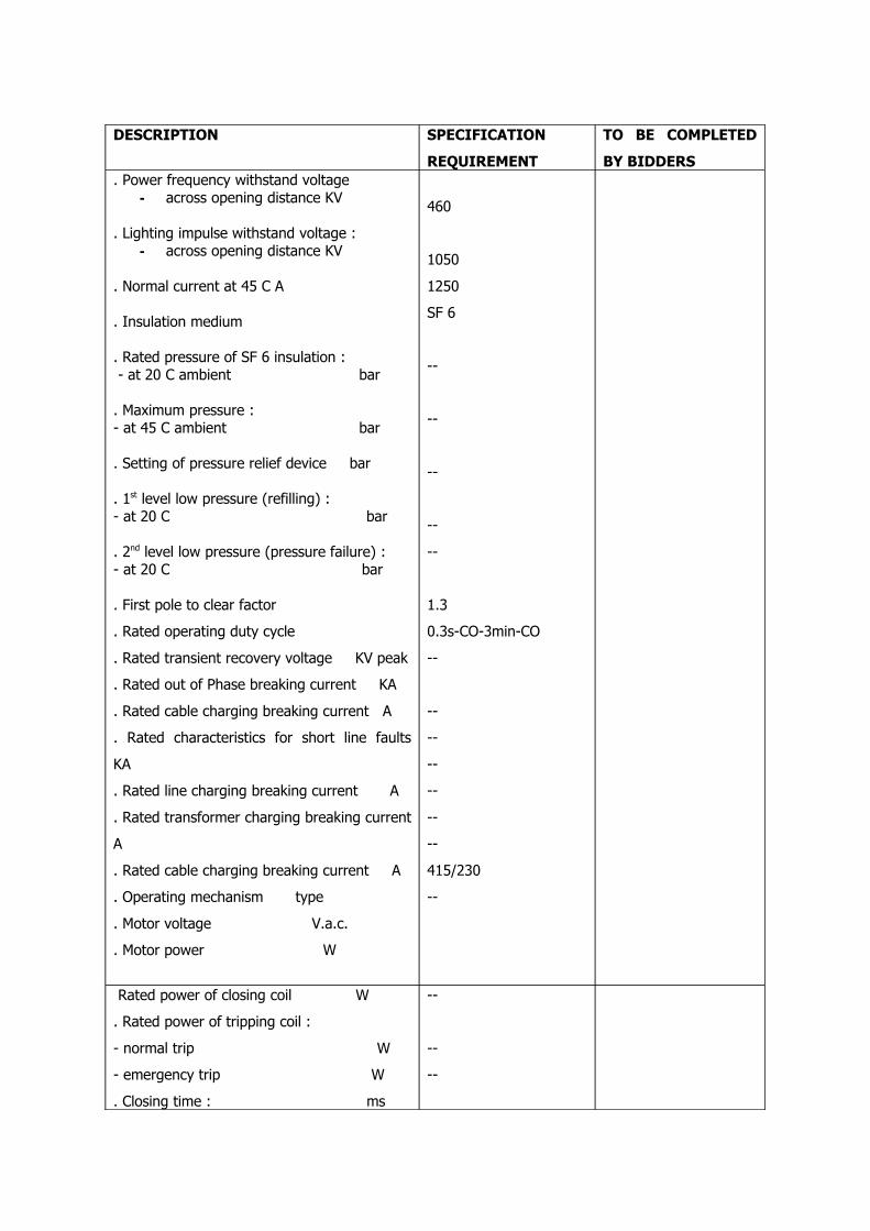
DESCRIPTION SPECIFICATION
REQUIREMENT
TO BE COMPLETED
BY BIDDERS. Power frequency withstand voltage
- across opening distance KV
. Lighting impulse withstand voltage :- across opening distance KV
. Normal current at 45 C A
. Insulation medium
. Rated pressure of SF 6 insulation : - at 20 C ambient bar
. Maximum pressure :- at 45 C ambient bar
. Setting of pressure relief device bar
. 1st level low pressure (refilling) :- at 20 C bar
. 2nd level low pressure (pressure failure) :- at 20 C bar
. First pole to clear factor
. Rated operating duty cycle
. Rated transient recovery voltage KV peak
. Rated out of Phase breaking current KA
. Rated cable charging breaking current A
. Rated characteristics for short line faults
KA
. Rated line charging breaking current A
. Rated transformer charging breaking current
A
. Rated cable charging breaking current A
. Operating mechanism type
. Motor voltage V.a.c.
. Motor power W
460
1050
1250
SF 6
--
--
--
--
--
1.3
0.3s-CO-3min-CO
--
--
--
--
--
--
--
415/230
--
Rated power of closing coil W
. Rated power of tripping coil :
- normal trip W
- emergency trip W
. Closing time : ms
--
--
--
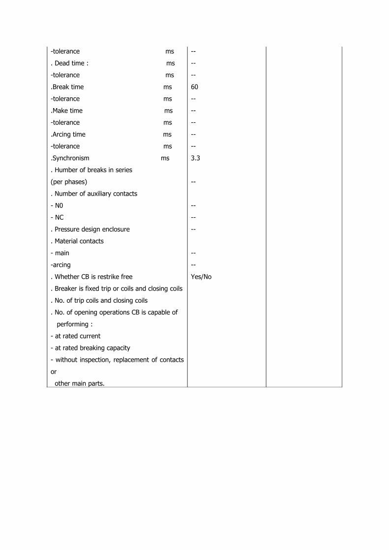
-tolerance ms
. Dead time : ms
-tolerance ms
.Break time ms
-tolerance ms
.Make time ms
-tolerance ms
.Arcing time ms
-tolerance ms
.Synchronism ms
. Humber of breaks in series
(per phases)
. Number of auxiliary contacts
- N0
- NC
. Pressure design enclosure
. Material contacts
- main
-arcing
. Whether CB is restrike free
. Breaker is fixed trip or coils and closing coils
. No. of trip coils and closing coils
. No. of opening operations CB is capable of
performing :
- at rated current
- at rated breaking capacity
- without inspection, replacement of contacts
or
other main parts.
--
--
--
60
--
--
--
--
--
3.3
--
--
--
--
--
--
Yes/No

DESCRIPTION SPECIFICATION
REQUIREMENT
TO BE COMPLETED
BY BIDDERS- Without replacing/reconditioning SF 6 gas
. No. of operations after which routine
inspection /
maintenance of CB is necessary.
. Maximum temperature rise over ambient
temperature of 45 C.
-Main current carrying part in SF 6 gas
- Operating coils
- Operating motor
. Thickness of Sliver plating for contacts.
. Overvoltage corresponding to (cable charging,
line charging, transformer charging, out of
phase current)
. Disconnectors
. Maker name and country of manufacturer
. Type
. Standards
. Characteristics
. Power frequency withstand voltage :
- across opening distance KV
. Lighting impulse withstand voltage :
- across opening distance KV peak
. Normal current at 45 C
- busbar A
- bays A
IEC
Live off-loadoperation
530
1050
2000
1250
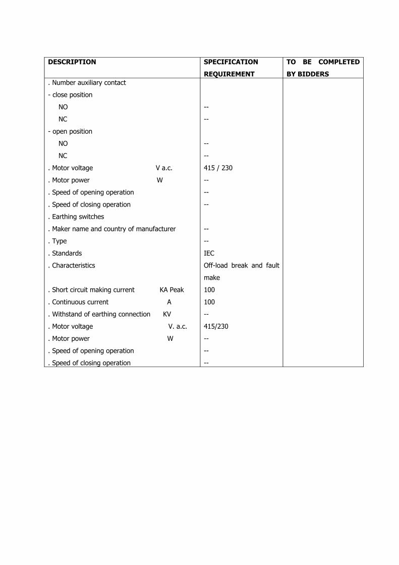
DESCRIPTION SPECIFICATION
REQUIREMENT
TO BE COMPLETED
BY BIDDERS. Number auxiliary contact
- close position
NO
NC
- open position
NO
NC
. Motor voltage V a.c.
. Motor power W
. Speed of opening operation
. Speed of closing operation
. Earthing switches
. Maker name and country of manufacturer
. Type
. Standards
. Characteristics
. Short circuit making current KA Peak
. Continuous current A
. Withstand of earthing connection KV
. Motor voltage V. a.c.
. Motor power W
. Speed of opening operation
. Speed of closing operation
--
--
--
--
415 / 230
--
--
--
--
--
IEC
Off-load break and fault
make
100
100
--
415/230
--
--
--
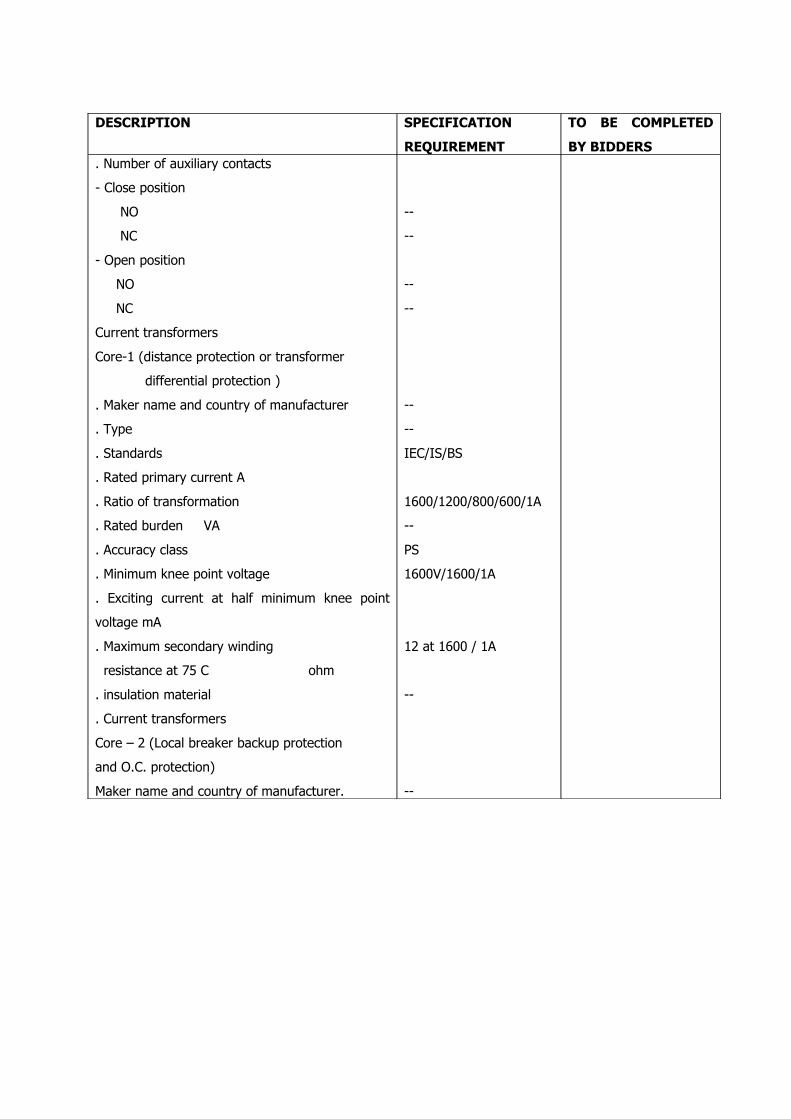
DESCRIPTION SPECIFICATION
REQUIREMENT
TO BE COMPLETED
BY BIDDERS. Number of auxiliary contacts
- Close position
NO
NC
- Open position
NO
NC
Current transformers
Core-1 (distance protection or transformer
differential protection )
. Maker name and country of manufacturer
. Type
. Standards
. Rated primary current A
. Ratio of transformation
. Rated burden VA
. Accuracy class
. Minimum knee point voltage
. Exciting current at half minimum knee point
voltage mA
. Maximum secondary winding
resistance at 75 C ohm
. insulation material
. Current transformers
Core – 2 (Local breaker backup protection
and O.C. protection)
Maker name and country of manufacturer.
--
--
--
--
--
--
IEC/IS/BS
1600/1200/800/600/1A
--
PS
1600V/1600/1A
12 at 1600 / 1A
--
--
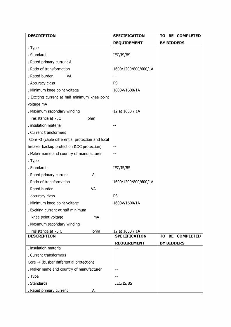
DESCRIPTION SPECIFICATION
REQUIREMENT
TO BE COMPLETED
BY BIDDERS. Type
. Standards
. Rated primary current A
. Ratio of transformation
. Rated burden VA
. Accuracy class
. Minimum knee point voltage
. Exciting current at half minimum knee point
voltage mA
. Maximum secondary winding
resistance at 75C ohm
. insulation material
. Current transformers
Core -3 (cable differential protection and local
breaker backup protection &OC protection)
. Maker name and country of manufacturer
. Type
. Standards
. Rated primary current A
. Ratio of transformation
. Rated burden VA
- accuracy class
. Minimum knee point voltage
. Exciting current at half minimum
knee point voltage mA
. Maximum secondary winding
resistance at 75 C ohm
--
IEC/IS/BS
1600/1200/800/600/1A
--
PS
1600V/1600/1A
12 at 1600 / 1A
--
--
--
IEC/IS/BS
1600/1200/800/600/1A
--
PS
1600V/1600/1A
12 at 1600 / 1ADESCRIPTION SPECIFICATION
REQUIREMENT
TO BE COMPLETED
BY BIDDERS. insulation material
. Current transformers
Core -4 (busbar differential protection)
. Maker name and country of manufacturer
. Type
. Standards
. Rated primary current A
--
--
--
IEC/IS/BS

. Ratio of transformation
. Rated burden VA
-accuracy class
. Minimum knee point voltage
. Exciting current at half minimum knee point voltage mA
. Maximum secondary winding
resistance at 75 C ohm
Core-5 (metering)
. Maker name and country of manufacturer
. Type
. Standards
. Rated primary current A
. Ratio of transformation
. Rated burden VA
. Accuracy class
. Minimum knee point voltage
. Exciting current at half minimum
knee point voltage mA.
. Secondary winding resistance at 75C ohm
. insulation material
1600/1200/800/600/1A
--
PS
1600V/1600/1A
12 at 1600 / 1A
--
--
IEC/IS/BS
1600/1200/800/600/1A30 at 600/1A
PS
1600V/1600/1A
1600V at 1600 / 1A
. Voltage transformers busbars
. Maker name and country of manufacturer
. Type
. Standards
. Rated primary voltage KV
. Winding 1 :
- Rated secondary voltage V
- Accuracy class
- Rated burden VA
IEC
230/√3
230/√3
0.2
200. Winding 2 :
- Rated secondary voltage V
- Accuracy class
- Rated burden VA
. insulation materials
. Rated voltage factor
- continuous
- for 30 seconds
. Whether VTs are capable of sustaining
capacitive discharge current of a de-
230/√3
3P
200
SF 6

energized cable feeder.
. Ratio error
- for metering cores
- for protection cores
- phase displacement error
. Power frequency withstand voltage of
secondary voltage
. Voltage transformers bays
. Maker name and country of manufacturer
. Type
. Standards
. Rated primary voltage kV
. Rated secondary voltage V
. Accuracy class
. Rated burden VA
. insulation material
. Control cubicle :
. Dimension
. Thickness of sheet used
. Cross sectional area of conductor for
control wiring (C.T. P.T. other circuits)
. Dimension
- width
- breadth
- Height
--
--
IEC
230/√3
230/√3
0.2
200
SF 6
230/33 KV Power TransformerTECHNICAL
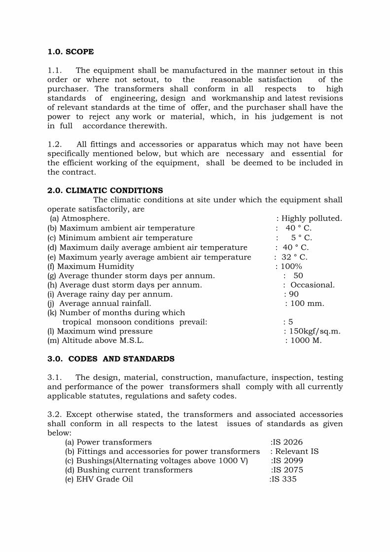
1.0. SCOPE 1.1. The equipment shall be manufactured in the manner setout in this order or where not setout, to the reasonable satisfaction of the purchaser. The transformers shall conform in all respects to high standards of engineering, design and workmanship and latest revisions of relevant standards at the time of offer, and the purchaser shall have the power to reject any work or material, which, in his judgement is not in full accordance therewith. 1.2. All fittings and accessories or apparatus which may not have been specifically mentioned below, but which are necessary and essential for the efficient working of the equipment, shall be deemed to be included in the contract. 2.0. CLIMATIC CONDITIONS The climatic conditions at site under which the equipment shall operate satisfactorily, are (a) Atmosphere. : Highly polluted. (b) Maximum ambient air temperature : 40 ° C. (c) Minimum ambient air temperature : 5 ° C. (d) Maximum daily average ambient air temperature : 40 ° C. (e) Maximum yearly average ambient air temperature : 32 ° C.(f) Maximum Humidity : 100% (g) Average thunder storm days per annum. : 50 (h) Average dust storm days per annum. : Occasional. (i) Average rainy day per annum. : 90 (j) Average annual rainfall. : 100 mm. (k) Number of months during which tropical monsoon conditions prevail: : 5 (l) Maximum wind pressure : 150kgf/sq.m. (m) Altitude above M.S.L. : 1000 M. 3.0. CODES AND STANDARDS 3.1. The design, material, construction, manufacture, inspection, testing and performance of the power transformers shall comply with all currently applicable statutes, regulations and safety codes.
3.2. Except otherwise stated, the transformers and associated accessories shall conform in all respects to the latest issues of standards as given below: (a) Power transformers :IS 2026 (b) Fittings and accessories for power transformers : Relevant IS (c) Bushings(Alternating voltages above 1000 V) :IS 2099 (d) Bushing current transformers :IS 2075 (e) EHV Grade Oil :IS 335
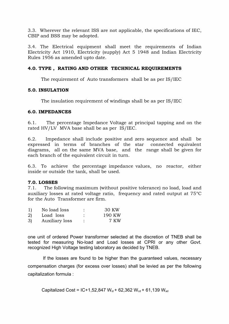
3.3. Wherever the relevant ISS are not applicable, the specifications of IEC, CBIP and BSS may be adopted.
3.4. The Electrical equipment shall meet the requirements of Indian Electricity Act 1910, Electricity (supply) Act 5 1948 and Indian Electricity Rules 1956 as amended upto date. 4.0. TYPE , RATING AND OTHER TECHNICAL REQUIREMENTS
The requirement of Auto transformers shall be as per IS/IEC
5.0. INSULATION The insulation requirement of windings shall be as per IS/IEC
6.0. IMPEDANCES
6.1. The percentage Impedance Voltage at principal tapping and on the rated HV/LV MVA base shall be as per IS/IEC.
6.2. Impedance shall include positive and zero sequence and shall be expressed in terms of branches of the star connected equivalent diagrams, all on the same MVA base, and the range shall be given for each branch of the equivalent circuit in turn.
6.3. To achieve the percentage impedance values, no reactor, either inside or outside the tank, shall be used. 7.0. LOSSES 7.1. The following maximum (without positive tolerance) no load, load and auxiliary losses at rated voltage ratio, frequency and rated output at 75°C for the Auto Transformer are firm.
1) No load loss : 30 KW 2) Load loss : 190 KW 3) Auxiliary loss : 7 KW
one unit of ordered Power transformer selected at the discretion of TNEB shall be tested for measuring No-load and Load losses at CPRI or any other Govt. recognized High Voltage testing laboratory as decided by TNEB. If the losses are found to be higher than the guaranteed values, necessary
compensation charges (for excess over losses) shall be levied as per the following
capitalization formula :
Capitalized Cost = IC+1,52,847 Wid + 62,362 Wcd + 61,139 Wad
Where IC = Quoted Ex-works price of the transformer Wid = Differential No load loss in KW (Maximum) Wcd= Differential Load loss in KW (Maximum) Wad = Differential Auxiliary loss in KW (Maximum)
The compensation shall also be applicable to the units supplied prior to the
selected unit by TNEB for which loss measurement test conducted at CPRI or Govt.
approved testing agency and to the subsequent units, even if all the test results are
within specified limits in respect of those units.
8.0. TEMPERATURE RISE
The transformer shall be capable of operating continuously at full rating without exceeding the temperature limits specified below, over and above the ambient temperature of 40o C. Permissible Temperature rise of top oil, measured by thermometer : 50o C. Permissible Temperature rise of winding, measured by resistance: 55o C. 9.0. DUTY REQUIREMENTS 9.1. The transformers would be used for Bi-directional flow of rated power. 9.2. The transformer and all its accessories like bushing CTs etc. shall be designed to withstand, without injury, the thermal and mechanical effects of any external short circuit to earth and of short circuits at the terminals of any winding for a period of 2 seconds. Transformer windings shall be capable of withstanding the thermal and mechanical stresses caused by symmetrical or asymmetrical faults. 9.3. The transformer shall be capable of being loaded in accordance with IS 6600. There shall be no limitation imposed by bushings, tap-changer etc. 9.4. The transformer shall be suitable for continuous operation with a frequency variation of ± 5% without exceeding the specified temperature rise. 9.5. The transformer shall be capable of being operated without danger on any tapping at the rated MVA with voltage variation of ± 10% corresponding to the voltage of that tapping and at the same time with a frequency of 5% below normal. 9.6.. Transformers of similar ratio, now in service in TNEB, shall operate satisfactorily in parallel with each other.
9.7. Radio interference and Noise Level i) The transformer shall be designed with particular attention to the suppression of harmonic voltages, especially the third and fifth to the maximum extent , so as to minimise interference with communication circuits. ii) The noise-level, when energised at normal voltage and frequency with fans running, shall be less than 81 decibles, the value specified by NEMA, when measured under standard conditions. 9.8. The maximum flux density in any part of the core and yoke at the rated MVA, frequency and 100% voltage and frequency shall not exceed 1.6 Tesla.
9.9. The maximum current density in any winding shall not exceed 300A/sq.cm.
9.10. Transformer shall be capable of operating under the natural cooled condition upto the specified load. The forced air cooling equipment shall come into operation by preset contact of the winding temperature indicator and transformer shall operate as a forced air cooled-unit initially upto the specified and rated load and than as ODAF. 9.11. Transformer shall be capable of remaining in operation at full load for 10 minutes after failure of the fans without the calculated winding hot-spot temperature exceeding 140°C. Also, stopping of one or two cooling fans should not have any effect on the cooling system. Transformers fitted with two coolers each capable of dissipating 50 % of the loss at continuous maximum rating shall be capable of remaining in operation for 20 minutes in the event of failure of fans associated with one cooler without the estimated winding hot-spot temperature exceeding 115°C. 9.12. Transformer shall accept, without injurious heating combined with voltage and frequency fluctuation, which produce the following overfluxing conditions. i) 125% for 1 minute. ii) 140% for 5 seconds. 10.0. CONSTRUCTIONAL FEATURES 10.1. The transformer and accessories shall be designed to facilitate operation, inspection, maintenance and repairs. 10.2. All materials used shall be of the best quality and of the class most suitable for working under the conditions specified and shall withstand the variations of temperature and atmospheric conditions, arising under working conditions, without undue distortion or deterioration or setting up

of undue stresses in any part and also without affecting the strength and suitability of the various parts for the work which they have to perform. 10.3. No patching, plugging, shimming or other such means of over-coming defects, discrepancies or errors will be accepted.
10.4. Corresponding parts liable for replacement shall be inter- changeable. 10.5. All outdoor apparatus, including bushing insulators with their mounting shall be designed so as to avoid pocket in which water can collect. 10.6. All mechanism shall, wherever necessary, be constructed of stainless steel, brass or gun-metal to prevent sticking due to rust or corrosion. 10.7. All taper pins used in any mechanism shall be of the split type. 10.8. Nuts, bolts and pins used inside the transformer and tap-changer compartment shall be provided with spring washers or locknuts, where gaskets are not used. Where galvanising specified shall be applied by the hot dipped process or by electro- galvanising process and for all parts, other than steel wires, shall consist of a thickness of zinc coating equivalent to not less than 610 gm of zinc per square metre of surface. The zinc coating shall be smooth, of uniform thickness and free from defects. 10.9. Surface, which are in contact with oil, shall not be galvanised or cadmium plated. 10.10. Labels or plates of non-corrosive material shall be provided for all apparatus such as relays, switches and fuses, contained in any cubicle or marshalling kiosks. 10.11. Steel bolts and nuts exposed to atmosphere shall be with suitable finishes like cadmium plated or zinc plated. 10.12. Painting 10.12.1. Before painting or filling with oil, all un galvanized parts shall be completely cleaned and freed from rust, scale and greases, and all external surface cavities on castings shall be filled by metal deposition. 10.12.2. The interior of transformer tank and other oil filled chambers and internal structural steel work shall be cleaned off all scale and rust by shot-blasting. These surfaces shall be painted with not less than two coats of, hot oil resisting varnish or paint. Un-exposed welds need not be painted.
10.12.3. Similarly the outer surface shall also be cleaned off all scale and rust by shot blasting, and then the primary coat shall be applied, immediately after cleaning. The second coat shall be of Aluminium paint. Before despatch, the transformer shall be given another final coat of Aluminium paint. Primer paint shall be, ready made zinc chrome as per IS : 2932. 10.12.4. All interior surfaces of mechanism chambers and kiosks, except those which have received anticorrosion treatment, shall receive three coats of paint, applied to the thoroughly cleaned metal surface. The final coat shall be of a light coloured anti- condensation mixture. 10.l2.5. Metal parts not accessible for painting shall be made of corrosion -resistant material. 10.12.6. Marshalling box and Drive mechanism box shall also be painted with Aluminium paint. The RTCC panel shall be painted with light grey as per shade-631 of IS-5.
11.0. CORE 11.1. The cores shall be constructed from high grade, cold rolled, non-ageing, high permeability, low loss, super grain oriented, silicon steel laminations, known as HI-BI steel trade name. The maximum flux density in the core shall not exceed 1.6 Tesla at rated MVA, voltage and frequency. Core assembly shall employ mitred-interleaved joints. 11.2. The oxide-silicate coating given on the core steel is adequate. However, laminations can be insulated at least on one side by hot resistant insulation, other than paper and varnish, is welcome. The insulation shall be inert to the action of hot transformer oil.
11.3. The design of the magnetic circuit shall be such as to avoid static discharges, development of short circuit paths within itself or to the earthed clamping structure and the production of flux components at right angles to the plane of the lamination which may cause local heating. 11.4. The insulation structure for the core to bolts and core clamp plates shall be such as to withstand a voltage of 2000V AC for one minute. The bolts and clamps, used in the assembly of the core, shall be suitably insulated with fibre glass tubes and the clamping structure shall be constructed so that eddy current will be minimum. 11.5. All steel sections, used for supporting the core, shall be thoroughly sand blasted or shot-blasted after cutting, drilling and welding. 11.6. Adequate lifting lugs shall be provided to enable the core and windings to be lifted.
11.7. Suitable projecting guides shall be provided on core assembly to facilitate removal of tank, in the case of Bell type tank construction, or the core assembly from the transformer tank.
11.8. Core and winding shall be capable of withstanding the shock to which they may be subjected during transport, installation and service. Adequate provision shall be made to prevent movement of the core and winding, relative to the tank, during these conditions. 11.9. The core and winding assembly shall be secured independently, with no connections to the tank cover. 11.10. The supporting frame work of the core shall be so designed, as to avoid the presence of pockets which would prevent complete emptying of the tank through the drain valve, or cause trapping of air during filling. 11.11. Oil ducts shall be provided, where necessary, to ensure adequate cooling. The winding structure and major insulation shall not obstruct the free flow of oil through such ducts. Where the magnetic circuit is divided into pockets by cooling ducts, parallel to the planes of the laminations or by insulating material above 0.25 mm thick, tinned copper strip bridging pieces shall be inserted to maintain electrical continuity between pockets. The frame work and clamping arrangements shall be earthed as specified separately, herein.
12.0. WINDINGS 12.1.1 The conductor shall be of electrolytic grade copper and windings shall be made in dust proof, conditioned atmosphere. The current density in any part of the winding shall not exceed 300 amps per sq. cm. 12.1.2 Coils of the windings of identical voltage and ratings shall be interchangeable. 12.1.3 The star connected winding shall have graded insulation. The neutral point shall be insulated for the voltages specified in IS:2026. 12.1.4 The windings shall be of interleaved continuous disc type designed to reduce the out-of-balance forces in the transformer to a minimum, at all voltage ratios. They shall withstand the impulse and power frequency test voltages as specified in this specification. 12.1.5 The insulation of transformer windings and connections shall be free from insulating compounds which are liable to soften, ooze out, shrink or collapse and be non-catalytic and chemically in-active in transformer oil during service.
12.1.6 Coil assembly and insulating spacers shall be so arranged as to ensure free circulation of oil and to reduce the hot spot temperature of the windings. 12.1.7 The stacks of windings shall receive adequate shrinkage treatment before final assembly. Adjustable devices shall be provided for taking up any possible shrinkage of coils in service. 12.1.8 Coils shall be supported at frequent intervals by means of wedge type insulation spacers permanently secured in place and arranged to ensure proper oil circulation. To ensure permanent tightness of winding assembly, the insulation spacers shall be dried and compressed at high pressure , before use. 12.1.9 The completed core and coil assembly shall be dried in vacuum , at not more than 0.5 mm of mercury absolute pressure and shall be immediately impregnated with oil after processing to ensure the elimination of air and moisture within the insulation. 12.1.10. All threaded connections shall be provided with locking facilities. All leads from the winding to terminal board and bushings shall be rigidly supported to prevent injury from vibration. Where applicable, guide tubes shall be used for the leads. 12.1.11. Adequate insulation and clearances between high voltage windings and low voltage windings shall be provided. All clearances of windings and other live parts shall be adequate for the normal voltage of operation plus 10%. 12.1.12. The conductors shall be transposed at sufficient intervals in order to minimise eddy current and equalise the distribution of currents and temperature along the windings. 12.1.13. The connections of all windings and winding segments shall be crimped; wherever crimping could not be done , they may be braced.
12.1.14.The strip conductor wound on edge shall not have a width exceeding six times its thickness. 12.1.15. The transformer shall be capable of withstanding the stresses due to short circuits on HV and LV terminals.
13.0. INSULATING OIL
13.1. The insulating oil, supplied with the transformer, shall be of EHV grade conforming to IS:335 of latest issue. No inhibitors shall be used in the oil. All the tests, specified in the standard, shall be carried out for confirmation of the quality on the oil samples, drawn at the following stages.
i) Prior to filling of the transformer
ii) Before carrying out the Heat-Run test iii) After carrying out the Heat-Run test iv) Before energising the transformer at site
13.2. The insulating oil shall be subjected to testing at the manufacture's works/reputed laboratory before supply, in the presence of Inspecting personnel.
13.3. Sufficient quantity of oil necessary for first filling of all tanks, coolers and radiators shall be supplied in sealed non returnable containers, suitable for out door storage.
13.4. The tenderer shall furnish the following information to enable the purchaser, to procure, if decided to go for separate procurement.
i) Recommended Technical parameters of the oil. ii) List of manufacturers of oil, who are preferred by the supplier for the transformers offered by them.
13.5. Where the supplier prefers to despatch the transformer without oil , due to limitations in the handling and transport facility, the transformer tank shall be filled with dry Nitrogen or equivalent inert gas. A gas cylinder, with suitable reducer connection and pressure gauge, shall be supplied to monitor the pressure of the gas in the tank during transit and storage at site, till completion of oil filling. These accessories shall become the property of the Purchaser.
14.0. TANK AND TANK ACCESSORIES
14.1. Tank Construction 14.1.1. The transformer tank shall be of Bell/Conventional type construction, with removable top cover. The transformer tank and cover shall be fabricated from good quality, low carbon steel, of adequate thickness and shall be designed to withstand a) lifting of the complete transformer with the tank completely filled
with oil, by crane or jacks and transportation, by road or rail, without overstraining any joints and without causing subsequent leakage of oil.
b) Mechanical shocks, during transportation c) Vacuum filling of oil d) Continuous internal pressure of 35 kN/sq.m, over normal hydrostatic pressure of oil. e) Short circuit forces 14.1.2. The base of each tank shall be so designed that it shall be possible to move the complete unit by skidding on metal plates or rails in any direction without injury.
14.1.3. The minimum thickness of the tank plate shall be as per ANNEXURE I Adequate stiffners shall be provided , wherever necessary, for general rigidity and these shall be designed to prevent retention of rain water. 14.1.4. Wherever possible the transformer tank and its accessories shall be designed without pockets wherein gas may collect. Where pockets can not be avoided, pipes shall be provided to vent the gas into the main expansion pipes. 14.1.5. Adequate space shall be provided at the bottom of the tank for collection of sediments. Suitable guides shall be provided for positioning the core & coil assembly and other various parts during assembly or dismantling. 14.1.6. Suitable shielding arrangement with a magnetic material of low permeability shall be provided inside the tank to shield off the leakage/stray magnetic fields, entering the tank and causing local heating/temperature rise at the joints. If required, impermeable shields shall be provided at the coil ends. Tank shield shall not resonate when excited at the natural frequency of the equipment. 14.1.7. All seam and joints, other than those which may have to be opened, shall be welded and wherever possible, double welded. After completion of construction of tank and before painting, dye penetration test shall be carried out on welded parts of jacking bosses, lifting lugs and all load bearing members.
14.2. Lifting and Haulage Facilities The tank shall be provided with: (a) Lifting lugs, suitable for lifting the transformer complete with oil. (b) Pulling eyes shall be provided to facilitate movement of the transformers and they shall be suitably braced in vertical direction, so that bending does not occur when the pull has vertical component. (c) Lashing lugs.
(d) Sufficient number of jacking pads at a height of about 500 mm from the bottom of the tank to enable the transformers, complete with oil, to be raised or lowered using hydraulic or screw jacks. 14.3. Tank Cover
14.3.1. The detachable top portion of the Bell cover shall be designed for adequate strength. It shall be sloped to prevent collection of water on any part . It must be separate from the core and coil and shall be capable of being lifted separately from the tank for inspecting the core and winding at site. It shall not distort, when lifted. 14.3.2. Inspection openings shall be provided, as necessary to give easy access to bushings, core and windings, OLTC, earth connection, etc. Each inspection opening shall be of ample size for the purpose for which it is provided and at least two openings one at each end of the tank, shall be provided. 14.3.3. The inspection covers shall be of box type to avert trapping of air during oil filling, or gas during incipient faults inside the transformers, from entering the Bucholtz relay. As an alternative the space under the cover shall be blanked with a solid insulating material, fitted to the cover itself.
14.3.4. The tank cover and inspection covers shall be provided with suitable lifting arrangements. Unless otherwise approved, inspection covers shall not weigh more than 25 kg, each. 14.3.5. The tank cover shall be provided with pockets for the probes/bulbs for oil temperature and winding temperature indicators. Metal sheath protection shall be provided to the capillary tubes of the temperature indicators. It shall be possible to remove these bulbs without lowering the oil in the tank. 14.3.6. The pockets for Temperature indicator shall be fitted with a captive screwed top to prevent ingress of water. 14.3.7. Bushing turrets, covers of inspection openings, thermometer pockets shall not permit ingress of water into or leakage of oil from the tank. 15.0. VALVES AND AIR RELEASE PLUGS 15.1. Each tank shall be fitted with the following valves.
i) Oil valves between cooler and tank. ii) One 100 mm drain valve with padlocking arrangement, located in the low voltage side of the transformer at the bottom most point, enabling complete draining of oil. iii) Two 50 mm filter valves, one on the top of the transformer and at a diagonally opposite end to that of drain valve and another at the bottom. The bottom valve shall be with padlocking arrangement. iv) Two sampling valves (size 25 mm) at top and bottom of the main tank, with provision for fixing PVC pipe. v) One 15 mm air release plug.
vi) Two plugged pipe outlets for applying vacuum.
15.2. All valves with opening to atmosphere, shall be fitted with blank flanges. 15.3. All valves shall be of gun metal or cast steel or may have cost iron bodies with gun metal fittings. 15.4. Valves shall be provided with flanges, having machined faces/ screw connection for external piping.
16.0. AXLES AND WHEELS 16.1. The transformers are to be provided with bi-directional flanged wheels and axles of suitable dimensions and so supported that under any service condition, they shall not deflect sufficiently to interfere with the movement of the transformer, complete with oil. Suitable locking arrangements shall be provided to prevent the accidental movement of the transformer. 16.2. All wheels should be detachable and shall be provided with suitable bearings which shall be rust and corrosion resistant. Fittings for lubrication shall also be provided. The flanged wheels shall be suitable for use on gauge track and shall be so placed that a pinch bar can be used to move the transformer. Track shall be of 1676 mm gauge between adjacent rails, (inner faces) both on longer and shorter axis. It is noted that rails along shorter axis will be provided. 16.3. The wheels shall be arranged so that they can be turned through an angle of 90 deg. (on both directions) when the tank is jacked up, clear of the rails or floor. Necessary jacking steps shall be provided . Bi-directional wheels only without locking facility and swivel movement shall be provided.
17.0. CONSERVATOR, TANK AND ITS ACCESSORIES
(i) Main conservator shall have air cell type constant oil pressure to prevent oxidation and contamination of oil due to contact with moisture and shall be fitted with magnetic oil level gauge with low oil level electrically insulated alarm contacts.
(ii) OLTC conservator shall have conventional type conservator with prismatic oil level gauge.
18.1. CONSERVATOR TANK 18.1.1. The conservator shall have adequate capacity between the highest and the lowest visible levels to meet the requirement of expansion of the total cold oil volume in the transformer and cooling equipment from the minimum ambient temperature to 100° C or 7.5% of the total volume of oil in the main tank whichever is higher.
18.1.2. One end of the conservator shall have bolted cover so that it can be removed for cleaning. 18.1.3. The conservator shall be bolted into position so that it can be removed for cleaning purpose. 18.1.4. The conservator shall be fitted in such a position, as not to obstruct the electrical connections to the transformer / lifting of the OLTC units. 18.1.5. The conservator shall be provided with one 50 mm flanged valve for oil filling and this should have box/canopy type cover, if fitted on the top.
18.1.6. The conservator shall be provided with one 50 mm flanged valve to completely drain the oil from the conservator.
18.1.7. The conservator shall have provision to receive one 80mm dia feed pipe from the main tank, fitted with Bucholtz relay with two shut off valves on either side of the Bucholtz relay. Of the two valves one shall be on the conservator side, beyond a length of 240mm (3 times the internal diameter of the pipe line) and another on the main tank side beyond a length of 400mm (5 times the internal diameter of the pipe line) from the Bucholtz relay. The feed pipe shall be free from sharp bends shall make an inclination of 3° to 7° to the horizontal.
18.1.8. The feed pipe shall extend inside the conservator for at least 25mm so as to form a sump inside the conservator.
18.2. Oil preservation equipment
The requirement of air cell type oil sealing system are given below:
18.2.1. Contact of oil with atmosphere is prohibited by using a flexible air cell of nitrile rubber reinforced with nylon cloth air cell.
18.2.2. The temperature of oil is likely to rise up to 100°C during operation. As such air cell used shall be suitable for operating continuously at 100°C.
18.2.3.Air cell of conservator shall be able to withstand the vacuum during installation/maintenance periods. Otherwise provision shall be kept to isolate the conservator from the main tank when the latter is under vacuum by providing a vacuum sealing valve or other suitable means in the pipe connecting main tank with the conservator.
18.2.4. The connection of air cell to the top of the reservoir is by air proof seal preventing entrance of air into the conservator.
18.2.5. A device shall be provided so that in the event of air enters into the conservator as a result of rupture of the air cell, an alarm sound.
18.3. Magnetic oil level gauge 183.1. The conservator shall be fitted with one magnetic oil level gauge having, i) Low oil level alarm contacts of 0.5 Amp. 110V D. C. rating ii) Dial with minimum, maximum and normal (at 30o C) oil level markings and a pointer.
18.4. Oil sealing system
18.4.1. The conservator shall be fitted with constant oil pressure (COP) Diaghram type or Air cell type oil sealing system to prevent oxidation and contamination of oil by the atmospheric oxygen/moisture. 2 nos. silicagel breathers in parallel, each one with a valve shall be provided. Breather pipe shall be made to protrude inside the oil conservator through its bottom instead having it connected to an opening on top of the conservator and running around the conservator. Wherever a single conservator for the main oil and OLTC oil is employed with a partition, inbetween, separate breathers shall be provided for the main & OLTC portions of the conservator. Design shall be such that (i) The passage of air is through silicagel, not less than 1 kg for every 3500 litres of oil in the tank. (ii) The silicagel is isolated from atmosphere by an oil seal. (iii) The moisture absorption, indicated by a change in colour of the tinted crystals, can be easily observed from distance.
18.4.2. The Breathers shall be mounted at an approximate height of 1,400 mm above ground level. 19.0. PRESSURE RELIEF DEVICE 19.1. Adequate number of pressure relief devices (at least two numbers, one on each end) of sufficient size shall be provided at suitable location for rapid release of any pressure that may be generated inside the tank and which may result in damage to the equipment. It shall be mounted directly on the tank. If mounted on the tank cover, it shall be away from the active parts of the transformer and the openings in the top cover shall be provided with a skirt, extending 25 mm inside the tank and holding a deflector plate, sufficiently away from the opening, so as to avert inadvertent trapping of gas during incipient fault inside the transformer. The device shall operate at a static pressure less than the hydraulic test pressure of transformer tank. Means shall be provided to prevent ingress of rain.
19.2. The pressure relief device shall be of safety valve type, capable of resealing after any pressure developed inside the tank is released. It shall be provided with switches for actuating trip contacts, when it acts. The switches shall be able to reset, once the pressure is released.
20.0. EARTHING ARRANGEMENTS 20.1. All metal parts of the transformer with exception of the individual core laminations, core bolts and associated individual clamping plates shall be maintained at some fixed potential.
20.2. Earthing of core clamping structure
Main core clamping structure at the top shall be connected to the tank body by a copper strap. The bottom clamping structure shall be earthed by one or more of the following methods.a) By connecting through vertical tie-rods to the top structure.b) By direct metal-to -metal contact with the tank base maintained by the weight of the core and winding.c) By connection to the top structure on the same side of the core as the main earth connection to the tank.
20.3. Earthing of magnetic circuit
a) The magnetic circuit shall be earthed to the clamping structure at one point only through a link placed in an accessible position beneath an inspection opening in the tank cover, the connection to the link shall be on the same side of the core as the main earth connection.
b) Magnetic circuits having an insulated sectional construction shall be provided with a separate link for each individual section. Where oil ducts insulating barriers parallel to the plane the laminations divide the magnetic circuit into two or more electrically separate parts the ducts or barriers shall be bridged and the magnetic circuit shall not be regarded as being of sectional construction.
20.4. Earthing of Coil clamping rings
Where coil clamping rings are of metal at earth potential, each ring shall be connected to the adjacent core clamping structure on the same side of transformer as the main earth connections so as to maintain at earth potential.
20.5. Size of earthing connection
All earthing connections with the exception of those from the individual coil clamping rings shall have a cross sectional area of not less
than 0.8 sq.cm. Connections inserted between laminations of different sections of core and shall have a cross sectional area of not less than 0.2 sq.cm.
20.6. Two earthing pads, at diagonally opposite external ends of the main tank, at its bottom, capable of carrying the short circuit current for 4 seconds without injurious heating, shall be provided with clamp type terminal for external connection.
21.0. RATING AND DIAGRAM PLATES 21.1. The following plates, suitable for outdoor use, shall be fixed to the transformer tank, at an average height of about 1750 mm above ground level. (a) A rating plate, of not less than 300 X 300 mm size , bearing the data specified in the appropriate clause of IS 2026.The details of the current transformers and normal operating pressure of PRV may also be indicated. (b) A diagram plate, showing the internal connections and also the voltage vector relationship of the several windings in accordance with IS 2026 and in addition a plan view of the transformer giving the correct physical relationship of the terminals. No-load voltage shall also be indicated for each tap. (c) A plate, showing the location and function of all valves and air release cocks or plugs. This plate shall also warn operators to refer to the maintenance instructions before applying the vacuum treatment for drying. (d) A plate showing the schematic wiring diagram of the respective cubicle may be provided in the cubicle. 21.2. The rating diagram and other plates shall be of brass or stainless steel.
22.0. JOINTS AND GASKETS 22.1. All bolted connections shall be fitted with weather proof, hot oil resistant gaskets in between, for complete oil tightness. Special attention shall be given to the oil tight joints between the tank and the cover and the bushing ,the turrets , covers of inspection openings, thermometer pockets etc and the other out- lets to prevent ingress of water into or leakage of oil even under hot condition from the tank. Suitable mechanical stoppers shall be provided, round the tank-flange, particularly in bell type tank construction so that the gasket between the top cover or bell cover, as the case may be, does not get compressed and loose its resilience.
22.2. One complete set of punched Neoprene gaskets shall be supplied with the transformer additionally, for all openings. 23.0. TERMINAL ARRANGEMENT
23.1. Bushings 23.1.1. HV leads shall be brought out of the tank through OIP condenser bushings. The LV and neutral leads shall be brought out of the tank through porcelain bushings. 23.1.2. The electrical & mechanical charateristics of bushings shall be as per IS 2099 of latest issue. The requirements of condenser bushings shall be as per IS 12576-1989. The dimensions of the bushings shall be as per IS 3347-1982 and as per the latest amendment. 23.1.3. The bushings for 230 KV shall be of the self contained, hermetically sealed type, condenser bushings with a lower porcelain cap for enclosing bushing oil, totally independent of the main tank oil for maintaining its insulation strength and potential gradation. Re-entrant type bushings are not acceptable. 23.1.4. Condenser type bushings shall be provided with (i)oil level gauge(ii)oil filling plug and drain valve if not hermetically sealed and(iii) tap for capacitance/tan-delta measurement with appropriate marking.
23.1.5. Stress shield for the bushings shall be considered as an integral part of the bushing assembly.
23.1.6. All bushings shall be equipped with suitable terminals and terminal clamps of approved type and size and all external current carrying contact surfaces shall be adequately silver plated. Main terminals shall be solderless. Flexible connectors shall be made from tinned copper sheets. Size of terminal/ conductor for which the clamp is suitable and the rated current shall be embossed/ punched. 23.1.7. Clamps and flanges shall not be re-entrant shape, which may trap air.
23.1.8. Each bushing shall be co-ordinated with the insulation class of the winding. 23.1.9. All porcelain, used in bushings, shall be homogeneous and free from cavities or other flaws. The glazing shall be uniform in colour and free from blisters, burns and other defects. The glaze shall be brown. 23.1.10. Bushing-turrets shall be provided with vent pipes which shall be connected to route the gas collection if any, through the Buchholtz
relay. The bushings shall be removable without disturbing the current transformers. 23.1.11. Specific requirements of bushings and their ratings etc are given in the Annexure - I.
23.2. TERMINAL CONNECTORS 23.2.1. Bushing terminals on HV side, shall be provided with clamping arrangement and suitable bi-metalic sleeves to receive 3" Aluminium bus bar. The clamp shall be such that the conductor takes off from the bushings vertically.
23.2.2. Bushing terminals on LV side shall be provided with clamping arrangement and suitable bi-metalic sleeves to receive "KUNDAH" conductor. 23.2.3. The connectors shall be designed for minimum 120% of the maximum current carrying capacity of the conductor and the temperature rise under any condition shall not be more than 50% of that in the main conductor.
23.2.4. All the terminal connectors shall conform to IS:5561 of latest issue. 23.2.5. All castings shall be free from blow holes, surface blisters, cracks and cavities. All sharp edges and corners shall be blurred and rounded off. 23.2.6. All ferrous parts shall be hot dip galvanised conforming to IS:2633. For bimetallic clamps copper alloy liner of minimum 2 mm thickness shall be cast integral with aluminium body. 23.2.7. Size of the terminal/conductor for which the clamp/connector is suitable shall be embossed/punched on each clamp/connector.
23.2.8. Neutral bushing terminal shall be suitable to receive 2 Nos. 50 x 10 mm G.I flats placed side by side on insulators up to ground level. Necessary outdoor type porcelain insulators ,GI flats and bi-metallic sleeves shall also be supplied.
24.0. BUSHING CURRENT TRANSFORMERS 24.1 Bushing current transformers of required ratio PS class may be provided in the bushing turrets of HV& LV and neutral ends of each phase for restricted earth fault protection.
24.2. The current transformers shall be of low resistance type, complying with IS 2705,Part-IV of latest issue. The current transformers on HV and LV sides shall have matching characteristics to the extent feasible to have differential protection scheme more effective. The bushing current transformers shall be housed in separate turrets and shall not be an in-built unit of the transformer. The housing of current transformers shall be so arranged that bushing can be removed, without disturbing the current transformers. The magnetisation characteristic curves, indicating the knee point voltage, excitation current and secondary resistance shall be furnished. 24.3. It shall be possible to remove the current transformers from the tank without removing the tank cover. Necessary precautions shall be taken to minimise the eddy currents and local heat generation in the turret. 24.4. All secondary leads shall be brought into a terminal box near each bushing. The terminals shall be wired up to marshalling box , using separate cables for each core.
25.0. VOLTAGE CONTROL EQUIPMENT ( ON LOAD TAP CHANGER) 25.1 The transformer shall be provided with reputed make voltage control equipment of the on-load tap changing type for varying its specified effective transformation ratio as furnished in Annexure I SL.NO.15, without producing phase displacement and suitable for remote control operation from switch board in the control room, in addition to being capable of local-manual as well as local-electrical operation. The design, manufacture and performance of the OLTC shall comply with the CBIP regulations, other statutes and safety codes and IS 8468 of latest issue. 25.2. The on-load tap changer shall include the following: a) An oil immersed divertor switch of transition resistor type. b) Motor driven mechanism for local as well as remote operation. c) Control and protective devices. d) Remote Tap Changer control panel. e) Annunciation schemes. f) Local - manual operating device. 25.3. The tap changing switches and mechanism shall be mounted in oil tanks or compartments mounted in an accessible position on the transformer tank. It shall not be possible for the oil in the divertor switch to mix with oil in the transformer tank. The OLTC oil shall be of the same EHV grade oil as used for the main transformer or of higher quality insulating oil and low viscosity is preferred. The oil in the OLTC compartment shall be maintained under conservator head by means of a pipe connection from the highest point of the chamber to the OLTC
conservator. This connection shall be controlled by a suitable valve, and shall be arranged so that any gas leaving the chamber will pass into the gas and oil actuated relay. This SURGE RELAY shall be of reputed make. 25.4. The OLTC chamber shall have oil filling valve, air release plug, pressure relief vent, tap position indicator, oil sampling valve and provision for circulation of oil in the divertor compartment and equalisation of divertor compartment and main tank during application of vacuum. Necessary pipes, valves, blanking plates etc for the above purpose shall form part of the accessories. 25.5. The tap changer shall be so mounted that top cover of the transformer can be lifted without removing the connections between the windings and the tap changer. 25.6. It is preferable that the contact be accessible for inspection without lowering oil level in the main tank and the contact tips shall be replaceable. Special tools and tackles if any, required for maintenance of OLTC gear shall be supplied. 25.7. The divertor switch or arcing switch shall be designed so as to ensure that its operation once commenced shall be completly independent of the operation of the control relays or switches, failure of auxiliary supply etc. 25.8. Drive mechanism chamber shall be mounted on to the transformer tank, in an accessible position. It shall be adequately ventilated and provided with anti-condensation metal clad heater. All contactors, relay coils or other parts shall be protected against corrosion or deterioration due to condensation, fungi, etc. 25.9. The whole of the drive mechanism shall be of robust design and capable of giving satisfactory service and shall not require frequent maintenance under the operating conditions met with, in service. 25.10. A permanently legible lubrication chart shall be fitted within the driving mechanism chamber. 25.11. The OLTC driving mechanism and its associated control equipment shall be mounted in an outdoor, weather-proof and vermin proof housing which shall include. a) Driving motor, operating on 3 phase 415V, 50HZ AC supply. b) Remote/local electrical and local manual selector switch. It shall control in the following manner. i) When the selector switch is in LOCAL position, it shall be possible to operate the RAISE/LOWER control switches. Remote control
of RAISE/LOWER functions shall be prevented.
ii) When the selector switch is in REMOTE, the RAISE/LOWER switches in the local control cubicle shall become inoperative. Remote control of the RAISE, LOWER functions shall be possible
from the remote control panel. The local REMOTE selector switch shall have at least two spare contacts per position which are closed in that position.
c) Motor starting contactor with thermal overload relay, isolating
switch and MCB to protect the motor from overloading. All relays, switches, MCBs etc shall be mounted in the drive mechanism chamber and shall be clearly marked for the purpose of identification.
d) Limit switch , to prevent motor over-travel in either direction. e) Counter (digital type) , to indicate the number of operations
completed. f) Electrically interlocked reversing contactors. g) Space heaters with switches. h) Master/follower selector switch. i) Cable termination glands for power and control cables. j) Interior lighting with door switch. k) Auxiliary relays. l) Mechanical tap- position indicator. m) Manual operating device. This cranking device for manual operation
shall be removable and suitable for operation by man at ground level. It shall have mechanical stops to prevent over cranking of the mechanism beyond the extreme tap positions. The mechanism shall have interlock with the motor to block motor-start-up during manual operation.
n) Necessary lamp indications and annunciation schemes of various operations of OLTC gear from RTCC panel.
o) RAISE-LOWER CONTROL SWITCH shall be spring loaded to return to the centre OFF position and shall require movement to the RIGHT, to raise the voltage of the transformer. Movement to LEFT shall lower the voltage of the transformer. This switch shall be operative only when the LOCAL/REMOTE SELECTOR switch is in LOCAL position.
25.12. 0. Tap changer control requirements 1) It shall not be possible for any two controls (ie. MANUAL,
LOCAL ELECTRICAL,REMOTE) to be in operation at the same time. 2) It shall be capable of permitting parallel operation with
transformers of the same ratio, say maximum four units.
3) Suitable selector switch shall be provided, so that , any one transformer of the group can at a time be selected as 'Master' 'Follower' or independent.
4) An out-of-step device with timer contacts shall be provided ,
which shall be arranged to prevent further tap-changing when transformers in a group , operating in 'Parallel control' ,are one tap out-of-step.
5) The equipment shall be suitable for supervisory control and
indication with a "Make before Break" multi-way switch, having one potential free contact for each tap position. This switch shall be provided in addition to any other switch/switches which may be required for the purpose of remote tap position indication. All other components of the supervisory gear, if required, shall be provided separately.
6) Operation from the local or remote control switch shall cause one
tap movement only, until the control switch is returned to the 'off' position between successive operations.
7) All electrical control switches and the local operating gear shall
be clearly labeled in a suitable manner to indicate the direction of tap-changing.
8) Limit switches to prevent motor 'over-travel' in either direction
may be located in the control circuit of the operating motor, provided with a mechanical declutching mechanism.
9) Necessary interlock, blocking the independent controls when the
units are in parallel, shall be provided. 10) A time delay relay for INCOMPLETE STEP alarm, consisting of a
normally open contact, which closes, if the tap changer fails to make a complete tap change. The alarm shall not operate momentarily for loss of auxiliary supply.
26.0. COOLING EQUIPMENTS 26.1. COOLER
26.1.1. The cooler shall be supplied with the requisite number of radiators. The wall thickness of radiator shall be not less than 1.2 mm.
26.1.2. Each radiator shall have its own shutoff valve, lifting lugs, air release plug, a drain valve and thermometer pockets fitted with captive screw cap on the inlet and outlet.
26.1.3. Each radiator shall be designed to withstand the pressure test. When assembled, they shall be accessible for cleaning and painting. Each radiator unit shall be provided with the following:
(a) An 100 mm shut-off valve at each point of connection to the header/transformer tank (b) Removable blanking plates to permit blanking-off the oil connection (c) A drain valve of size 25mm at the lowest point (d) Air release plug of 15 mm dia. at the highest point (e) Lifting lugs
26.1.4. The clearance between all pipe work and live parts shall be more than the clearance for live parts to earth.
26.1.5. The radiator bank shall be designed for same pressure and vacuum conditions as specified for main tank.
26.2.0. Oil piping and flanges
26.2.1. Necessary oil piping shall be provided for connecting each transformer to the coolers and oil pumps. The oil piping shall be with flanged gasketed joints. Cast iron pipes shall not be used.
26.2.2. A suitable expansion piece shall be provided, in each oil pipe connection, between the transformer and the separately mounted oil coolers.
26.2.3. Drain valves/plugs shall be provided in order that each sections of pipe work can be drained independently. Drain valves shall be provided with blanking plates.
26.2.4. The drilling of all pipe flanges shall comply with IS:3639.
26.3.0. Oil pumps
26.3.1. Each forced oil cooler shall be provided with two 100%, motor driven, oil pumps of the on-line type and of adequate capacity, out of which, one will be connected standby. The oil pump shall be of impeller type to permit oil circulation when the pump is idle.
26.3.2. It shall be possible to remove the pump and motor from the oil circuit without having to lower the level of oil in the transformers or coolers and without having to disturb the pump foundation fixing. Oil pump shall be capable of dealing with the maximum output of transformer and total head which may occur in service and with the varying head due to changes in the viscosity of the oil.
26.3.3. Each pump assembly shall be provided with an oil flow indicator with alarm contacts to indicate normal pump operation and oil flow.
26.3.4. Measures shall be taken to prevent mal-operation of Buchholz relay when all oil pumps are simultaneously put into service. Suitable baffles shall be provided inside the tank at oil inlet points when forced oil circulation is used.
26.4.0. Air blowers/fans
26.4.1. Adequate number of air blowers/fans, for use with oil coolers shall be provided. They shall be suitable for continuous outdoor operation; Two numbers connected – standby air-blowers, one in each cooler bank, shall also be provided additionally.
26.4.2. Air blowers/fans shall be capable of withstanding the stresses, imposed when brought up to speed by the direct application of full line voltage to the motor.
26.4.3. Air blowers/fans shall be complete with all necessary air-ducting and coolers shall be designed so that they operate with a minimum of noise or drumming. They shall not be mounted-on to the radiators and must be physically separate from the radiators. It shall be possible to remove the blower complete with motor, without disturbing or dismantling the cooler structure frame work.
26.4.4. If fans are mounted at a height less than 2.5 m, suitably painted wire-mesh guards with a mesh, not greater than 25 mm, shall be provided to prevent accident contact with the blades. Fans mounted at more than 2.5 m, height, shall be provided with outside guards against birdage. Fans shall be so mounted that hot air shall not get directed towards the transformer.
26.5.0. Motors
26.5.1. Motors shall be of the squirrel cage, totally enclosed, weather proof type and shall comply with IS:325. The motors shall be capable of operating at all loads without undue vibration and with a minimum noise. They shall be suitable for direct starting and for continuous running from 415-440 volts, three phase, 4 wire, 50 Hz supply.
26.5.2. Motors shall also be capable of continuous operation at 85 percent of the nominal voltage, at normal frequency, without injurious overheating. Motors shall be provided with thermal overload and short circuit protection.
26.6.0. Local cooler control cubicle
26.6.1. Each transformer shall be supplied with outdoor type, vermin and weather proof cooler control cubicle for accommodating the control gears of the cooling fans and pumps, besides cable termination from remote tap changer control panel and other transformer accessories.
26.6.2. The cooler control cubicle shall be provided with three pole, electrically operated, contactor and with control gears of suitable design, both for starting and stopping the individual pumps and groups of fans, cooling fans, manually and also automatically, from the contacts of the Winding Temperature Indicating device. These shall be accommodated in the local cooler control cubicle.
26.6.3. The local control panel shall have all necessary devices meant for cooler control viz.
a) MCBs of adequate capacity for main supply.b) Protection against over load.c) Protection against single phasing.
d) Selector switch for Manual/Automatic operation of individual pump & groups of cooling fans.
e) Selector switch for Local/Remote operation of individual pump groups of cooling fans.
f) Pump control ON/OFF/Test for each pump.g) Fan control ON/OFF/Test for each fan.
26.6.4. The following additional terminals shall be provided in the cooler control cubicle for remote indication.
a) Oil flow fail alarm.b) Cooling fan trip ( for each group of fans & stand-by)c) Cooling pump trip ( for pumps in service & stand-by) d) Cooler supply failure.e) Low oil level alarm.
26.6.5. The following initiating contact for lamp indicators shall be provided for local as well as remote indication.
a) Cooling system in on ‘Manual’ control.b) Cooling system is on ’Automatic control’c) Selector switch is in ‘Auto’ or ‘Manual’ or ‘Local’
d) Pump ‘ON’, pump ‘OFF’ for each pumpe) Fan ‘ON’/’OFF’ for each group of fan and each pump f) Oil flow failure.
27.0. GAS AND OIL ACTUATED RELAYS 27.1. Double float gas detector relay (Buchholz relay) conforming to IS 3637 shall be provided with the following: a) Two electrically independent ungrounded contacts to cause an alarm and tripping in the event of accumulation of gas and sudden changes in oil pressure.
b) Shut off valve of 80mm on either side of the relay and flange coupling, to permit easy removal , without lowering oil level in the main tank. c) A drain plug at the bottom most point of the relay-casing. d) A test cock suitable for a flexible pipe connection for checking its operation and taking gas sample e) A copper or stainless steel tube shall be connected from the gas collector to a valve located at about 1200 mm above ground level to facilitate sampling, with the transformer in service f) Locking arrangement during transport.27.2. The arrangement for mounting this relay, the associated pipe work and the cooling plant shall be such that all gas emitted from the transformer shall pass into the relay and mal-operation of the relays shall not take place under normal service conditions.
28.0. TEMPERATURE INDICATORS/CONTROLLERS 28.1. Oil temperature indicator (OTI)
The transformer shall be provided with one 150 mm dial type, oil-temperature indicator for top oil temperature. The indicator shall have adjustable, electrically independent ungrounded alarm & trip contacts with mercury switches, and maximum reading pointer. The temperature sensing element shall be suitably located in a pocket and shall be connected to the oil temperature indicator by means of capillary tubing. Accuracy class of the OTI shall be ±1.00 %.
28.2. Winding temperature indicator (WTI)
The transformer shall also be provided with a device for measuring the hot spot temperature of each winding (HV & LV). It shall comprise the following :a) Temperature sensing element suitably located on the top cover of the transformer.b) Image coilc) Auxiliary CTs, if required to match the image coil, shall be mounted in the cooler control cabinet.d) 150 mm dial, local indicating instrument with maximum reading pointer, mounted in the cooler control cabinet and two adjustable electrically independent, ungrounded contacts with mercury switches (besides that required for control of cooling equipment). The tripping contacts shall be adjustable to close between 60o C and 120 o C and alarm contacts to close between 50o C and 100o C and both shall re-open when the temperature has fallen by a desired amount between 5o C and 20 ° C. All contacts shall be adjustable on a scale. They shall be accessible on removal of the cover and it shall be possible to check the operation of the contacts and associated equipments. Connections from the contacts shall be brought down to the terminal BLOCK , placed inside the marshalling Box.
e) calibration device
29.0. MARSHALLING BOX Tank mounted, vermin and weather proof marshalling box, shall be provided with a controlled metal-clad heater to accommodate the following : (a) Temperature indicators/controllers. (b) Terminal blocks, made up of moulded, non inflammable plastic material with adequate size terminals, washers, binding screws/nuts for external wire connections, a white marking strip for circuit identification and a moulded plastic cover. (c) Suitable glands with gland plates for incoming and outgoing cables, meant for oil level alarm, Temperature alarm/Trip, Buchholtz alarm/trip, annunciation and indication provisions for RTCC panel etc.
30.0. AUXILIARY POWER SUPPLY CONTROL PANEL FOR OLTC AND COOLER CONTROL 30.1. Auxiliary power supply shall be provided by the purchaser at one place for OLTC control and cooler control.
30.2. Control cabinet for OLTC control and cooler control shall be of free standing, floor mounting type.
30.3. Control cabinet can be made out of 3mm thick sheet steel or 10mm thick aluminium plate / Aluminium casting. Hinged door shall be provided with padlocking arrangement. Sloping Rain-hood shall be provided to cover all sides. 15mm thick Neoprene or better type of gaskets shall be provided to ensure high degree of protection as per IS2147. The painting shall be as specified earlier.
30.4. Auxiliary electrical equipments to be supplied by the supplier shall be suitable for operation on the following supply system :
a. Power devices like drive motors rating 1 KW and above
415V, 3 phase 4 wire 50 Hz, neutral grounded AC supply
b. Lighting, space heaters and fractional KW motors
230V, single phase, 50 Hz neutral grounded AC supply
c. Alarm, control and protective devices
220/110V, 2 wire DC supply
30.5. All AC loads shall be fed by one of the two feeders through an electrically interlocked automatic transfer switch housed in any one of the local control cabinets. Design features of the transfer-switch shall include the following:
a) Selection of one of the feeders as normal source and other as stand by
b) Upon failure of normal source, automatic transfer of loads from normal source to the standby source after an adjustable time delay.
c) Indication for” failure of normal source” and for transfer to standby Source” and also for “failure to transfer” shall be provided locally and as well as in the remote tap changer control panel.
d) Automatic retransfer to normal source with an adjusted time delay, following re-energisation of the normal sourcese) The transfer and re-transfer shall not cause paralleling of the two source at any time.
30.6. Necessary isolating-switches, MCBs and other components for the above power supply transfer arrangement shall be in the scope of the supply of the supplier.
30.7. Bus bars. If used, shall be tinned copper of adequate cross section to carry the normal current without exceeding the permissible temperature rise over an ambient temperature of 40° C.
30.8. Isolating-switches shall be group operated units (3/4 pole for use on 3 phase supply system and 2 pole for single phase supply system), quick make and break type capable of breaking the rated current of the associated circuit safely. Switch handle shall have provision for locking in both fully opened and fully closed positions.
30.9. Push button shall be rated for not less than 6 Amps, 415V, AC or 2 Amps, 220V/110V DC and shall be flush mounted on the cabinet door and provided with appropriate name plates. Red, Green and Amber indicating lamps shall be flush mounted.
30.10. For motors up to 5 KW, contactors shall be direct-on-line, air break, single throw type and shall be suitable for making and breaking the stalled current of the associated motor which shall be assumed equal to 6.5 times the full load current of the motor at 0.2 p.f. For motors above 5 KW, automatic star-delta type starters shall be provided. 3 pole contactors shall be furnished for 3 phase motors and 2 pole contactors for single phase motors. Reversing contactors shall be provided with electrical interlocks between forward and reverse contactors. If possible, mechanical interlocks shall also be provided. Contactors shall be suitable for uninterrupted duty and shall be of duty category class AC4 as defined in IS:2959. The main contacts of the contactors shall be silver plated and the insulation class for the coils shall be class E or better. The dropout voltage of the contactors shall not exceed 70% of the rated voltage.
Contactors shall be provided with a three element, positive acting, ambient temperature compensated, time lagged, hand reset type thermal overload relay with adjustable setting, hand reset button shall be flush with the front door of the cabinet and suitable for resetting with starter compartment door closed.
30.11. Single phasing preventer relay shall be provided for 3 phase motors to provide positive protection against single phasing.
30.12. Mini starters shall be provided with No-volt coils wherever required.
30.13. Purchaser’s power cable will be 1100/650V grade stranded aluminium conductor, PVC insulated, PVC sheathed, steel wire armoured and PVC jacketed cable. All cable terminating accessories such as brass cable glands, lugs etc. shall be included in the scope of supply.
30.14. Separate Terminal-Blocks shall be provided for circuits of various voltage classes.
30.15. The terminal blocks shall be 1100 V grade and have 10 Amps continuous rating. They shall be fully enclosed with removable slip-on/clip-on covers and made of moulded non-inflammable plastic material with block and barrier moulded integrally. Such blocks shall have non-disconnecting stud type terminals, washers, nuts and lock nuts. All terminals shall be clearly marked with identification numbers or letters to facilitate connection to extent wiring. No live metal shall be exposed at the back of the terminal blocks.
30.16. In all terminal blocks at least 20% spare terminals shall be provided uniformly.
30.17. The terminal blocks meant for control circuits shall be suitable for connecting minimum of 2 numbers of 2.5 sq.mm. Copper cable, Terminals meant for CT circuits shall be capable of accommodating at least 2 numbers of 4 sq.mm. copper cable.
30.18. The terminal boards shall be mounted obliquely towards the rear doors to be easily accessed to termination and to enable ferrule numbers to be read without difficulty. The terminal boards shall be placed at least above a distance of 250mm from the cable gland so as to permit satisfactory arrangement of multi core cable tiles.
30.19. Terminal board rows should be spaced not less than 150mm apart to permit convenient access to wires and terminations.
30.20. Control cabinet shall be provided with an 230V incandescent lamp operated by a door switch.
30.21. The cabinet shall be provided with a 230V, single phase, 5 amps, 3 pin socket for hand lamp.
30.22. Strip heaters shall be provided inside the cabinet with thermostat (preferably differential type) to prevent moisture condensation. The heaters shall be controlled by suitably rated double pole miniature circuit breakers.
30.23. Signal lamps provided shall be of neon, screw type, with wire & resistors enclosed in bakelite body. Each signal lamp shall be provided with a fuse integrally mounted in the lamp body. If separate fuse units are used they shall be of the cartridge type. Fuses shall be labeled.
30.24. Electric measuring instruments shall be of moving iron type. Ammeters for measuring currents upto 30 amps shall be directly connected while those for measuring above 30 amps shall be connected through suitable CTs. Ammeter and Voltmeters shall be provided with selector switches.
31.0. REMOTE TAP-CHANGER CONTROL PANEL The Remote In-door Tap Changer control cubicle of height 2312 mm with sufficient inner working space for easy access to the instruments, wherever necessary ,shall house the following: 31.1. Controls a) Repeater dial of winding temperature indicator with selector switches. b) Push button switch to Raise/Lower the tap. c) Tap position indicator (digital type). d) Selector switch for Local/Remote operation. e) Four position Selector switch for Independent/OFF/Master/Follower. f) Control selector switches for the Fans and Pumps of the cooler. g) Emergency 'supply - off ' push button. h) Relays, Heater, illumination lamps, MCBs etc. 31.2. Lamp indications for the following (ON: Red indication;OFF:Green indication)
a) Cooling pump ON/OFF (group)b) Cooling fans ON/OFF (group)c) OLTC supply HEALTHY.d) Cooler control on AUTOMATIC/MANUAL.e) Tap change IN-PROGRESS.f) Selector switch on `AUTO' or `MANUAL' or `LOCAL' for each fan groups.
31.3. Facia type annunciation scheme for the following trip, non-trip & alarm INDICATIONS, suitable for 220V/110V DC operation. a) Bucholtz Relay - tripb) Tap Changer Surge Relay - tripc) Pressure Relief Device -tripd) Winding Temperature Indicator - Tripe) Tap Changer Drive Motor – tripf) Cooling Fan – trip (For each group of fans & standby)
g) Cooling Pump – trip (For each group of fans & standby)h) Bucholtz Relay – alarmi) Winding Temperature Indicator - alarmj) Oil Temperature Indicator - alarmk) Tap Changer Out of Step - alarml) Oil flow fail - alarmm) Low oil level - alarmn) Cooler Supply failure indicationo) Tap change delay - indicationp) Tap Change out of step – indicationq) Spare contacts-4 nos.
32.0. FITTINGS AND ACCESSORIES
The fittings and accessories, mentioned in this order, are only indicative and any other fittings which are generally required for satisfactory operation of the transformer are deemed to be included. 33.0. CENTRE OF GRAVITY The centre of gravity of the assembled transformer shall be low and as near the vertical centre line as possible. The transformer shall be stable with or without oil. If the centre of Gravity is eccentric, relative to track either with or without oil, its location shall be shown in the "Outline" drawing.
34.0. CONTROL WIRING, TERMINAL BOARDS, FUSES ETC 34.1. All wiring connections, terminal boards, fuses and links shall be suitable for tropical atmosphere. Any wiring liable to be in contact with oil shall have oil resisting insulation and the Board ends of stranded wire shall be sweated together to prevent creepage of oil along the wire. 34.2. There shall be no possibility of oil entering into the connection boxes, used for cables or wiring. 34.3. Panel connections shall be neatly and squarely fixed to the panel. All instruments and panel wiring shall be run in PVC or non-rusting metal cleats of the limited compression type. All wiring to a panel shall be taken from suitable terminal boards. 34.4. Where conduits are used, the runs shall be laid with suitable falls, and the lowest parts of the run shall be external to the boxes. All conduit runs shall be adequately drained and ventilated. Conduits shall not be run at or below ground level. 34.5. When 415 Volt connections are taken through junction boxes or marshalling boxes they shall be adequately screened and "415 volts
Danger" notices must be affixed to the outside of the junction boxes or marshalling boxes. 34.6. All box wiring shall be in accordance with relevant IS. All wiring shall be of stranded copper of 1100 grade and size not less than 4.00 sq.mm. for CT leads and not less than 2.5 sq.mm. for other connections. 34.7. All wires on panels and all multicore cables shall have ferrules which bear the same number at both ends. 34.8. At those points of interconnection between the wiring carried out by separate contractors, where a change of number cannot be avoided, double ferrule shall be shown on the appropriate diagram of the equipment. 34.9. The same ferrule numbers shall not be used on wires in different circuits on the same panels. 34.10. Ferrule shall be of yellow insulating material and shall be provided with glossy finish to prevent the adhesion of dirt. They shall be clearly and durably marked in black and shall not be affected by damp or oil. 34.11. Stranded wires shall be terminated with tinned Ross countney terminals, claw washers or crimped tubular lugs. Separate washers shall be used for each wire. The size of the washers shall be suitable to the size of the wire terminated. Wiring shall, in general, be accommodated on the sides of the box and the wires for each circuit shall be separately grouped. Back of panel wiring shall be arranged so that access to the connecting stems of relays and other apparatus is not impeded. 34.12. Wires shall not be jointed or tied between terminal points. 34.13. Wherever practicable, all circuits in which the voltage exceeds 125 Volts, shall be kept physically separated from the remaining wiring. The function of each circuit shall be marked on the associated terminal boards. 34.14. Where apparatus is mounted on panels, all metal cases shall be separately earthed by means of copper wire or strip having a cross section of not less than 2.0 sq.mm. where strip is used, the joint shall be sweated. 34.15. All wiring diagram for control and relay panel shall preferably be drawn as viewed from the back and shall show the terminal boards arranged as in service. All diagrams shall show, which view is employed. 34.16. Multicore cable tails shall be so bound that each wire may be traced without difficulty to its cable.
34.17. The screens or screen pairs of multicore cable shall be earthed at one end of the cable only. The position of earthing connections shall be shown clearly on the diagrams. 34.18. All terminal boards shall be mounted obliquely towards the rear doors to give easy access to terminations and to enable ferrule numbers to be read without difficulty. 34.19. Terminal board rows should be spaced adequately, not less than 100 mm apart, to permit convenient access to wires and terminations. 34.20. Terminal boards shall be so placed with respect to the cable gland (at a minimum distance of 200 mm), as to permit satisfactory arrangement of multicore cable tails. 34.21. Terminal boards shall have pairs of terminals of incoming and outgoing wires. Insulating barriers shall be provided between adjacent connections. The height of the barriers and the spacing between terminals shall be such as to give adequate protection while allowing easy access to terminals. The terminals shall be adequately protected with insulating dust-proof covers. 34.22. No live metal shall be exposed at the back of the terminal boards. 34.23. All fuses shall be of the cartridge type. 34.24. Fuses and links shall be labeled. 35.0. QUALITY PLAN AND INSPECTION 35.1. The supplier shall furnish the programme of manufacturing works well in advance.
35.2. The purchaser or the accredited representative of the purchaser shall have access to the contractor or sub-contractor's works at any time during working hours for the purpose of inspection of manufacture and selection of samples of the materials going into the equipment and testing. The contractor shall provide necessary facilities for such inspection or test. 35.3. Documents like invoice or receipted chalans, detailing the source of supply of raw materials and their specification, shall be shown by the supplier on demand either during the manufacturing process or at the time of inspection of the transformer . 35.4. The core and coil assembly, shall be offered for inspection and to verify the guaranteed technical parameters prior to connections and tanking. The readiness for such inspection shall be intimated at least 15 days in advance. Further process of manufacture of core and coil assembly, shall be taken up only after our approval in this regard.
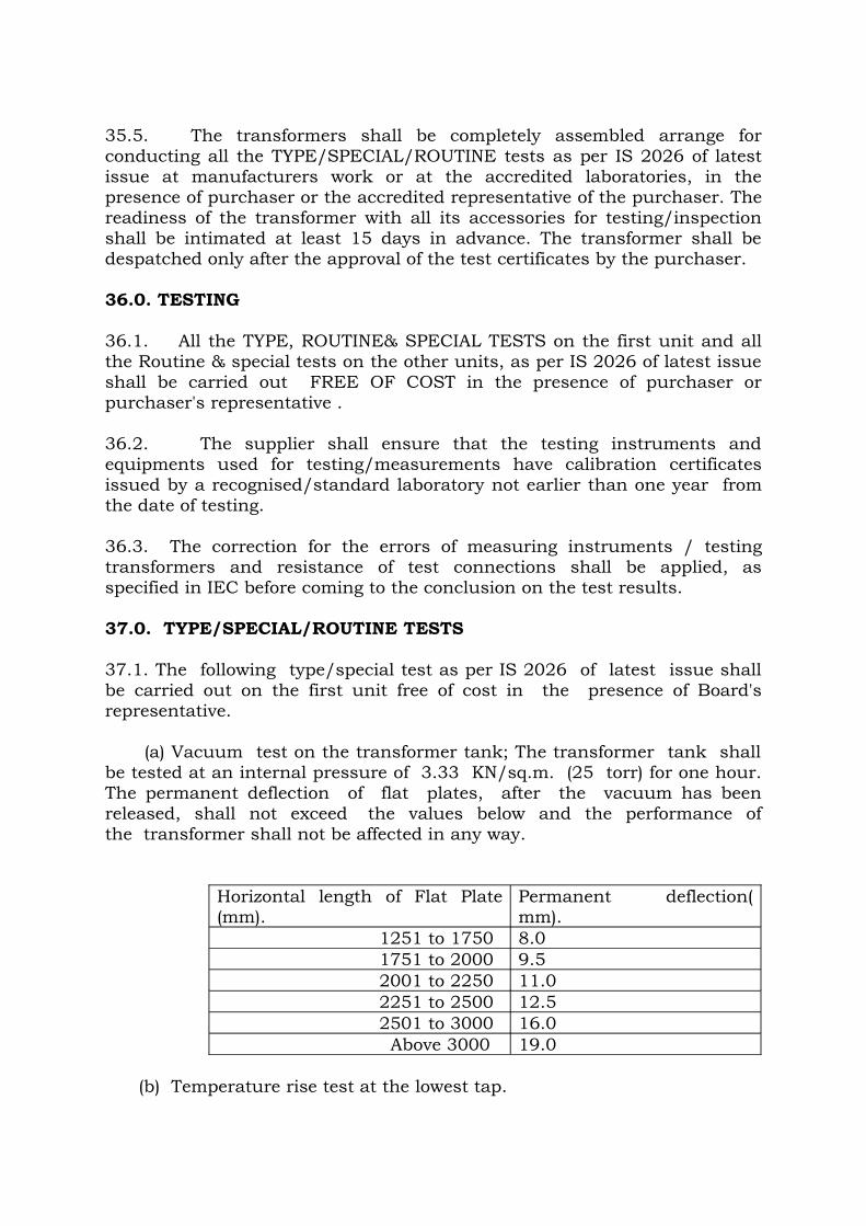
35.5. The transformers shall be completely assembled arrange for conducting all the TYPE/SPECIAL/ROUTINE tests as per IS 2026 of latest issue at manufacturers work or at the accredited laboratories, in the presence of purchaser or the accredited representative of the purchaser. The readiness of the transformer with all its accessories for testing/inspection shall be intimated at least 15 days in advance. The transformer shall be despatched only after the approval of the test certificates by the purchaser.
36.0. TESTING 36.1. All the TYPE, ROUTINE& SPECIAL TESTS on the first unit and all the Routine & special tests on the other units, as per IS 2026 of latest issue shall be carried out FREE OF COST in the presence of purchaser or purchaser's representative .
36.2. The supplier shall ensure that the testing instruments and equipments used for testing/measurements have calibration certificates issued by a recognised/standard laboratory not earlier than one year from the date of testing.
36.3. The correction for the errors of measuring instruments / testing transformers and resistance of test connections shall be applied, as specified in IEC before coming to the conclusion on the test results.
37.0. TYPE/SPECIAL/ROUTINE TESTS 37.1. The following type/special test as per IS 2026 of latest issue shall be carried out on the first unit free of cost in the presence of Board's representative. (a) Vacuum test on the transformer tank; The transformer tank shall be tested at an internal pressure of 3.33 KN/sq.m. (25 torr) for one hour. The permanent deflection of flat plates, after the vacuum has been released, shall not exceed the values below and the performance of the transformer shall not be affected in any way.
Horizontal length of Flat Plate (mm).
Permanent deflection( mm).
1251 to 1750 8.0 1751 to 2000 9.5 2001 to 2250 11.0 2251 to 2500 12.5 2501 to 3000 16.0 Above 3000 19.0
(b) Temperature rise test at the lowest tap.
(c) Full wave lightning Impulse voltage withstand test on all three phases including chopped impulses on principle tap and extreme taps. (This test shall precede power frequency high voltage tests). (d) Pressure test: The transformer tank with its radiators conservator vessel and other fittings shall be subjected to a pressure corresponding to twice the normal head of oil or to normal pressure plus 35 KN/sq.m. whichever is lower. The applied pressure shall be measured at the base of the tank and maintained for One hour. The permanent deflection of flat plates, after the excess pressure has been released, shall not exceed the value specified under the caption 'Vacuum test'. (e) Zero sequence impedance test. (f) Capacitance and Tan-delta measurement. (g) Noise Level Test. (h) Measurement of harmonic voltages
(i) Measurement of transformer oil required for first filling for entire transformer including radiators, coolers, conservator etc.
37.2. The following Routine tests as per IS 2026 of latest issue and special tests shall also be carried out on all the transformers, free of cost. (a) Measurement of winding resistance on all taps.(b) Measurement of voltage ratio on all taps and check of voltage vector relationship.(c) Measurement of impedance voltage/short circuit impedance, load-loss and spill current at principal and extreme taps. The test shall be repeated at 415 volts for comparison during pre-commissioning tests at site.(d) Measurement of No-load loss and current corresponding to normal and extreme taps at 100%, 90% and 110% of rated voltage.(e) Measurement of insulation resistance.(f) Dielectric Tests ( Short duration Power frequency withstand voltage test and Induced over voltage withstand test with line/leakage current measured).(g) Oil leakage test on transformer tank: The tank and oil filled compartments shall be tested for oil tightness by completely filling with air/oil of viscosity not greater than that of insulating oil, conforming to IS:335 1983/'87 at the ambient temperature and applying a pressure, equal to the normal pressure plus 35 KN/sq.m. measured at the base of the tank. This pressure shall be maintained for a period of not less than 12 Hours for oil and 1 Hour for air during which time no leakage shall occur.(h) Magnetic balance test.(i) Measurement of No-load current with 415 Volts supply.(j) Check of polarity and ratio, tests for knee point voltage, and magnetising current for Bushing current transformer.
37.3. The test sequence shall be :- Tests on transformer tank, Heat run test, Pressure test on the assembled transformer, Impulse test, Routine tests and Special tests.
37.4. FURTHER TESTS The purchaser reserves the right of having other reasonable tests carried out at his own expense either before transport or at site, to ensure that the transformer complies with the requirements of our specification. 37.5. TESTS AT SITE After erection at site, and prior to commissioning the transformer will be subjected to the following tests. (a) Insulation resistance test. (b) Ratio and polarity test on all taps. (c) All relevant test on oil. (d) Open circuit and short circuit test. (e) Operation test of OLTC. (f) Operation test of protection devices and interlocks. (g) Measurement of winding resistance at all taps. (h) Vector group verification. (i) Dissolved gas analysis on transformer.(This will be the base values for future guidance). 37.6. TEST CERTIFICATES 37.6.1. Six copies of the test certificates on the above type tests/ special tests/ routine tests with the endorsement of the inspecting officer shall be furnished to the Superintending Engineer/Transmission II/ 6th Floor, NPKRR Maaligai, 800, Anna Salai,Chennai -2. 37.6.2. The test report shall contain the following information. i) Complete identification data, including serial No. of the transformer. ii) Method of application where applied, duration, and interpretation of results in each test. iii) Details of Temperature rise corrected to 75 o C. 37.6.3. The equipment will be rejected if test results are not in conformity with the Guaranteed Technical particulars.
37.6.4. Besides the above test certificates, manufacturer's test certificates in respect of the following accessories shall also be furnished in sextuplicate. a) OLTC. b) Bushings (HV, LV & Neutral). c) Buchholtz relays and surge relay. d) Magnetic oil level gauge.
e) Winding Temperature Indicators. f) Oil Temperature Indicators.
g) Radiators.h) Cooling fans & pumpsi) Transformer oil(including dissolved Gas Analysis tests
37.6.5.The supplier shall also furnish test certificates to the effect that the withstand capability of the insulation between the core and all core bolts , side plates & structural frame has been tested with 2000 Volts AC for one minute after assembling the core and prior to the despatch of the transformer
38.0. DRAWING, TECHNICAL LITERATURE AND GUARANTEED TECHNICAL PARTICULARS. 38.1. The following detailed drawings shall be submitted within one month from the date of award of contract. (a) General out line drawing, showing front side elevations and plan views of the transformer and all accessories and external features with detailed dimensions, weights, crane lift for untanking and for erection/removal of bushings, size of lifting lugs and pulling eyes, HV and LV terminal clearances, live terminal to ground clearance, quantity of insulating oil, dimensional details for foundation etc. (b) List of fittings and accessories. (c) Assembly drawings of HV, LV and Neutral bushings. (d) Mounting arrangement for cooling pipes, radiators, fans etc. (e) Schematic control and wiring drawing and drawings showing temperature indicator/recorder circuits, and control system for cooling equipment. (f) Drawing, showing construction and mounting details of marshalling boxes. (g) Drawing, giving details of name plate, terminal marking and connection diagram. (h) Drawing on OLTC gear assembly. (i) Remote Tap Changer control panel. (j) Remote Tap Changer control circuit. (k) Drawing on Terminal Clamps. The responsibility rests with the supplier in case of any corrections or modification on scrutiny of the drawings.
38.2. Six complete sets of final drawings shall be supplied for the transformer, sufficiently before the actual despatch of the equipment. 38.3. Six copies of all bulletins, complete instruction manuals for the erection, operation and maintenance of the transformer are to be supplied, before they are despatched.
38.4. Any approval given to the detailed drawings by the purchaser shall not relieve the contractor of the responsibility for correctness of the design, completeness of the equipment supplied and in the execution of the works in accordance with the terms of specification.
39.0. REJECTION 39.1. The transformer may be rejected if during the tests or service on any of the following conditions arise. (a) No load losses exceed the guaranteed value. (b) Load losses exceed the guaranteed value. (c) Impedances exceed by the guaranteed values. (d) Oil or winding temperature rise exceeds the specified value. (e) Transformer fails on impulse test. (f) Transformer fails on power frequency voltage withstand test.
(g) If either of the test results conducted at factory and site (during pre-commissioning test) are not satisfactory.(h) Transformer manufactured not in accordance with the agreed
Specification and approved drawings.
TECHNICAL PARAMETERS
Sl No.
DESCRIPTION REQUIREMENT
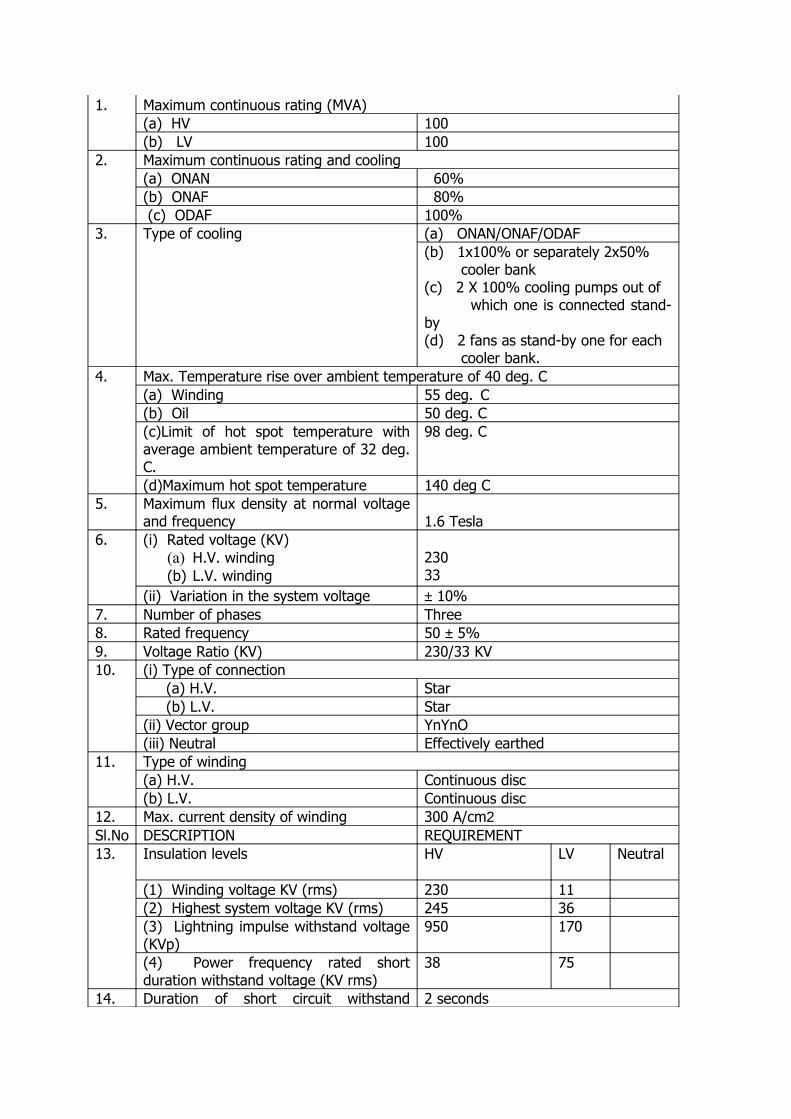
1. Maximum continuous rating (MVA)(a) HV 100(b) LV 100
2. Maximum continuous rating and cooling (a) ONAN 60%(b) ONAF 80% (c) ODAF 100%
3. Type of cooling (a) ONAN/ONAF/ODAF(b) 1x100% or separately 2x50% cooler bank(c) 2 X 100% cooling pumps out of which one is connected stand-by(d) 2 fans as stand-by one for each cooler bank.
4.
Max. Temperature rise over ambient temperature of 40 deg. C
(a) Winding 55 deg. C
(b) Oil 50 deg. C
(c)Limit of hot spot temperature with average ambient temperature of 32 deg. C.
98 deg. C
(d)Maximum hot spot temperature 140 deg C5. Maximum flux density at normal voltage
and frequency 1.6 Tesla6. (i) Rated voltage (KV)
(a) H.V. winding(b) L.V. winding
23033
(ii) Variation in the system voltage ± 10%7. Number of phases Three8. Rated frequency 50 ± 5%9. Voltage Ratio (KV) 230/33 KV10. (i) Type of connection
(a) H.V. Star (b) L.V. Star(ii) Vector group YnYnO(iii) Neutral Effectively earthed
11. Type of winding(a) H.V. Continuous disc(b) L.V. Continuous disc
12. Max. current density of winding 300 A/cm2Sl.No DESCRIPTION REQUIREMENT13. Insulation levels HV LV Neutral
(1) Winding voltage KV (rms) 230 11(2) Highest system voltage KV (rms) 245 36(3) Lightning impulse withstand voltage (KVp)
950 170
(4) Power frequency rated short duration withstand voltage (KV rms)
38 75
14. Duration of short circuit withstand 2 seconds
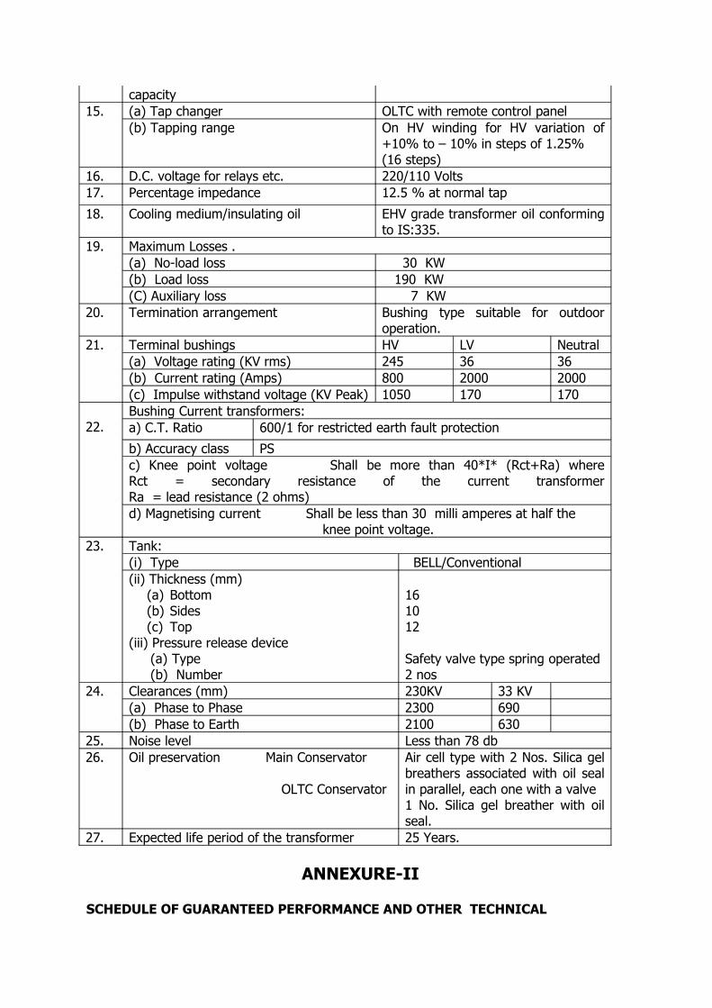
capacity15. (a) Tap changer OLTC with remote control panel
(b) Tapping range On HV winding for HV variation of +10% to – 10% in steps of 1.25%(16 steps)
16. D.C. voltage for relays etc. 220/110 Volts17. Percentage impedance 12.5 % at normal tap
18. Cooling medium/insulating oil EHV grade transformer oil conforming to IS:335.
19. Maximum Losses . (a) No-load loss 30 KW (b) Load loss 190 KW (C) Auxiliary loss 7 KW
20. Termination arrangement Bushing type suitable for outdoor operation.
21. Terminal bushings HV LV Neutral(a) Voltage rating (KV rms) 245 36 36(b) Current rating (Amps) 800 2000 2000(c) Impulse withstand voltage (KV Peak) 1050 170 170
22.Bushing Current transformers:a) C.T. Ratio 600/1 for restricted earth fault protection
b) Accuracy class PSc) Knee point voltage Shall be more than 40*I* (Rct+Ra) where Rct = secondary resistance of the current transformer Ra = lead resistance (2 ohms)d) Magnetising current Shall be less than 30 milli amperes at half the knee point voltage.
23. Tank:(i) Type BELL/Conventional(ii) Thickness (mm)
(a) Bottom(b) Sides(c) Top
(iii) Pressure release device(a) Type(b) Number
161012
Safety valve type spring operated2 nos
24. Clearances (mm) 230KV 33 KV(a) Phase to Phase 2300 690(b) Phase to Earth 2100 630
25. Noise level Less than 78 db26. Oil preservation Main Conservator
OLTC Conservator
Air cell type with 2 Nos. Silica gel breathers associated with oil seal in parallel, each one with a valve 1 No. Silica gel breather with oil seal.
27. Expected life period of the transformer 25 Years.
ANNEXURE-II
SCHEDULE OF GUARANTEED PERFORMANCE AND OTHER TECHNICAL
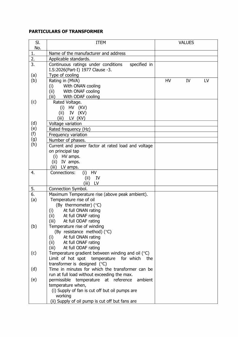
PARTICULARS OF TRANSFORMER
Sl.No.
ITEM VALUES
1. Name of the manufacturer and address2. Applicable standards.3.
(a)(b)
(c)
(d)(e)(f)(g)(h)
Continuous ratings under conditions specified in I.S:2026(Part-I) 1977 Clause -3. Type of cooling Rating in (MVA)(i) With ONAN cooling(ii) With ONAF cooling(iii) With ODAF cooling
HV IV LV
Rated Voltage. (i) HV (KV) (ii) IV (KV) (iii) LV (KV) Voltage variationRated frequency (Hz)Frequency variationNumber of phases.Current and power factor at rated load and voltage on principal tap (i) HV amps. (ii) IV amps. (iii) LV amps.
4. Connections: (i) HV
(ii) IV (iii) LV
5. Connection Symbol.6.(a)
(b)
(c)
(d)
(e)
Maximum Temperature rise (above peak ambient). Temperature rise of oil (By thermometer) (°C) (i) At full ONAN rating (ii) At full ONAF rating(iii) At full ODAF ratingTemperature rise of winding (By resistance method) (°C)(i) At full ONAN rating(ii) At full ONAF rating(iii) At full ODAF ratingTemperature gradient between winding and oil (°C) Limit of hot spot temperature for which the transformer is designed (°C) Time in minutes for which the transformer can be run at full load without exceeding the max. permissible temperature at reference ambient temperature when, (i) Supply of fan is cut off but oil pumps are working (ii) Supply of oil pump is cut off but fans are
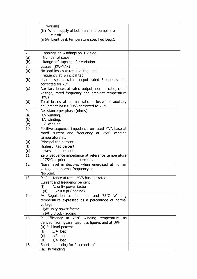
working(iii) When supply of both fans and pumps are cut off(iv)Ambient peak temperature specified Deg.C
7.(a)(b)
Tappings on windings on HV side. Number of steps Range of tappings for variation
8.(a)
(b)
(c)
(d)
Losses (KW-MAX)No-load losses at rated voltage andFrequency at principal tap.Load-losses at rated output rated Frequency and corrected for 75°CAuxiliary losses at rated output, normal ratio, rated voltage, rated frequency and ambient temperature (KW) Total losses at normal ratio inclusive of auxiliary equipment losses (KW) corrected to 75°C.
9.(a)(b)(c)
Resistance per phase (ohms)H.V.winding. I.V.winding.L.V. winding
10.
(a)(b)(c)
Positive sequence impedance on rated MVA base at rated current and frequency at 75°C winding temperature at,Principal tap percent.Highest tap percent.Lowest tap percent.
11. Zero Sequence impedance at reference temperature of 75°C at principal tap percent .
12. Noise level in decibles when energised at normal voltage and normal frequency at No-Load.
13. % Reactance at rated MVA base at ratedCurrent and frequency percent(i) At unity power factor (ii) At 0.8 pf (lagging)
14. % Regulation at full load and 75°C Winding temperature expressed as a percentage of normal voltage i)At unity power factor ii)At 0.8 p.f. (lagging)
15. % Efficiency at 75°C winding temperature as derived from guaranteed loss figures and at UPF(a) Full load percent(b) 3/4 load (c) 1/2 load (d) 1/4 load
16. Short time rating for 2 seconds of(a) HV winding
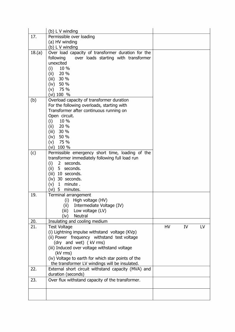
(b) L V winding 17. Permissible over loading
(a) HV winding (b) L V winding
18.(a) Over load capacity of transformer duration for the following over loads starting with transformer unexcited (i) 10 %(ii) 20 %(iii) 30 %(iv) 50 %(v) 75 %(vi) 100 %
(b) Overload capacity of transformer duration For the following overloads, starting with Transformer after continuous running on Open circuit. (i) 10 %(ii) 20 %(iii) 30 %(iv) 50 %(v) 75 %(vi) 100 %
(c) Permissible emergency short time, loading of the transformer immediately following full load run (i) 2 seconds.(ii) 5 seconds.(iii) 10 seconds.(iv) 30 seconds.(v) 1 minute .(vi) 5 minutes.
19. Terminal arrangement (i) High voltage (HV) (ii) Intermediate Voltage (IV) (iii) Low voltage (LV) (iv) Neutral
20. Insulating and cooling medium21. Test Voltage
(i) Lightning impulse withstand voltage (KVp)(ii) Power frequency withstand test voltage (dry and wet) ( kV rms)(iii) Induced over voltage withstand voltage (kV rms)(iv) Voltage to earth for which star points of the the transformer LV windings will be insulated.
HV IV LV
22. External short circuit withstand capacity (MVA) and duration (seconds)
23. Over flux withstand capacity of the transformer.
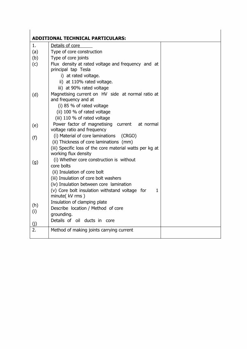
ADDITIONAL TECHNICAL PARTICULARS:1.(a)(b)(c)
(d)
(e)
(f)
(g)
(h)(i)
(j)
Details of core Type of core construction Type of core joints Flux density at rated voltage and frequency and at principal tap Tesla i) at rated voltage. ii) at 110% rated voltage. iii) at 90% rated voltage Magnetising current on HV side at normal ratio at and frequency and at (i) 85 % of rated voltage (ii) 100 % of rated voltage (iii) 110 % of rated voltage Power factor of magnetising current at normal voltage ratio and frequency (i) Material of core laminations (CRGO) (ii) Thickness of core laminations (mm) (iii) Specific loss of the core material watts per kg at working flux density (i) Whether core construction is without core bolts (ii) Insulation of core bolt (iii) Insulation of core bolt washers (iv) Insulation between core lamination (v) Core bolt insulation withstand voltage for 1 minute( kV rms )Insulation of clamping plateDescribe location / Method of core grounding. Details of oil ducts in core
2. Method of making joints carrying current
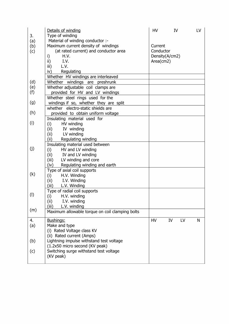
3.(a)(b)(c)
(d)(e)(f)
(g)
(h)
(i)
(j)
(k)
(l)
(m)
Details of windingType of winding Material of winding conductor :- Maximum current density of windings (at rated current) and conductor area i) H.V.ii) I.V.iii) L.V.iv) Regulating
HV IV LV
Current ConductorDensity(A/cm2) Area(cm2)
Whether HV windings are interleavedWhether windings are preshrunkWhether adjustable coil clamps are provided for HV and LV windingsWhether steel rings used for the windings if so, whether they are splitwhether electro-static shields are provided to obtain uniform voltageInsulating material used for (i) HV winding (ii) IV winding (ii) LV winding(ii) Regulating windingInsulating material used between(i) HV and LV winding(ii) IV and LV winding(iii) LV winding and core(iv) Regulating winding and earth
Type of axial coil supports(i) H.V. Winding(ii) I.V. Winding(iii) L.V. WindingType of radial coil supports(i) H.V. winding(ii) I.V. winding(iii) L.V. winding
Maximum allowable torque on coil clamping bolts
4.(a)
(b)
(c)
Bushings:Make and type(i) Rated Voltage class KV(ii) Rated current (Amps)Lightning impulse withstand test voltage(1.2x50 micro second (KV peak)Switching surge withstand test voltage (KV peak)
HV IV LV N
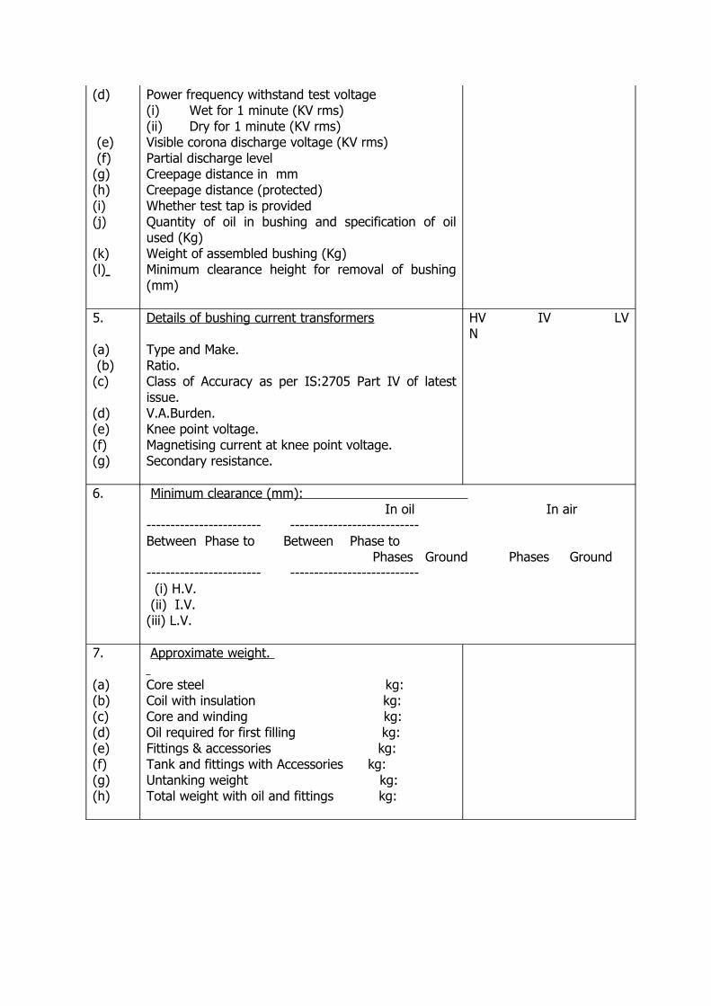
(d)
(e) (f)(g)(h)(i)(j)
(k)(l)
Power frequency withstand test voltage(i) Wet for 1 minute (KV rms)(ii) Dry for 1 minute (KV rms)Visible corona discharge voltage (KV rms)Partial discharge levelCreepage distance in mmCreepage distance (protected)Whether test tap is providedQuantity of oil in bushing and specification of oil used (Kg)Weight of assembled bushing (Kg)Minimum clearance height for removal of bushing (mm)
5.
(a) (b)(c)
(d)(e)(f)(g)
Details of bushing current transformers Type and Make.Ratio.Class of Accuracy as per IS:2705 Part IV of latest issue.V.A.Burden.Knee point voltage.Magnetising current at knee point voltage.Secondary resistance.
HV IV LV N
6. Minimum clearance (mm): In oil In air------------------------ ---------------------------Between Phase to Between Phase to Phases Ground Phases Ground------------------------ --------------------------- (i) H.V. (ii) I.V. (iii) L.V.
7.
(a)(b)(c)(d)(e)(f)(g)(h)
Approximate weight. Core steel kg:Coil with insulation kg:Core and winding kg:Oil required for first filling kg:Fittings & accessories kg:Tank and fittings with Accessories kg:Untanking weight kg:Total weight with oil and fittings kg:
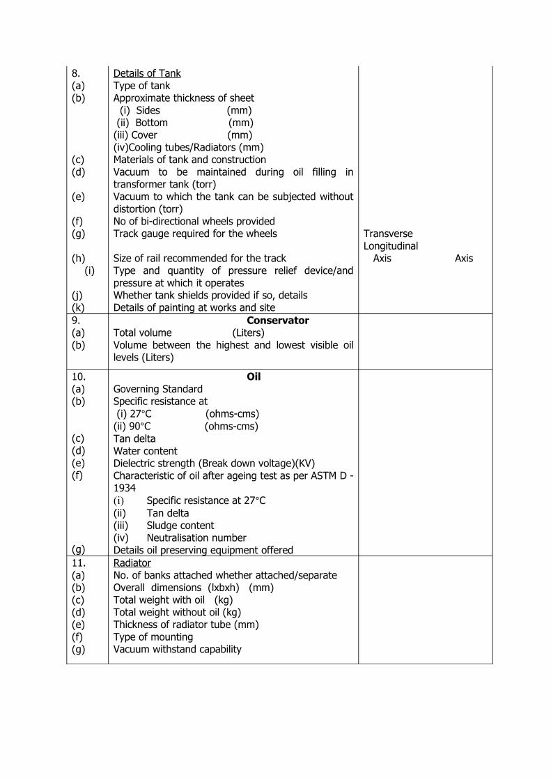
8.(a)(b)
(c)(d)
(e)
(f)(g) (h) (i)
(j)(k)
Details of TankType of tankApproximate thickness of sheet (i) Sides (mm) (ii) Bottom (mm)(iii) Cover (mm)(iv)Cooling tubes/Radiators (mm)Materials of tank and constructionVacuum to be maintained during oil filling in transformer tank (torr)Vacuum to which the tank can be subjected without distortion (torr)No of bi-directional wheels providedTrack gauge required for the wheels
Size of rail recommended for the trackType and quantity of pressure relief device/and pressure at which it operatesWhether tank shields provided if so, detailsDetails of painting at works and site
Transverse Longitudinal Axis Axis
9.(a)(b)
ConservatorTotal volume (Liters)Volume between the highest and lowest visible oil levels (Liters)
10.(a)(b)
(c)(d)(e)(f)
(g)
OilGoverning StandardSpecific resistance at (i) 27°C (ohms-cms)(ii) 90°C (ohms-cms)Tan deltaWater contentDielectric strength (Break down voltage)(KV)Characteristic of oil after ageing test as per ASTM D - 1934(i) Specific resistance at 27°C(ii) Tan delta(iii) Sludge content(iv) Neutralisation numberDetails oil preserving equipment offered
11.(a)(b)(c)(d)(e)(f)(g)
RadiatorNo. of banks attached whether attached/separateOverall dimensions (lxbxh) (mm)Total weight with oil (kg)Total weight without oil (kg)Thickness of radiator tube (mm)Type of mountingVacuum withstand capability
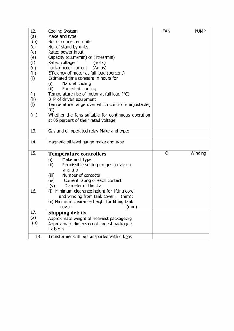
12.(a) (b)(c)(d)(e)(f)(g)(h)(i)
(j)(k)(l)
(m)
Cooling SystemMake and typeNo. of connected unitsNo. of stand by unitsRated power inputCapacity (cu.m/min) or (litres/min)Rated voltage (volts)Locked rotor current (Amps)Efficiency of motor at full load (percent)Estimated time constant in hours for (i) Natural cooling(ii) Forced air coolingTemperature rise of motor at full load (°C)BHP of driven equipmentTemperature range over which control is adjustable(°C)Whether the fans suitable for continuous operation at 85 percent of their rated voltage
FAN PUMP
13. Gas and oil operated relay Make and type:
14. Magnetic oil level gauge make and type
15. Temperature controllers(i) Make and Type(ii) Permissible setting ranges for alarm and trip(iii) Number of contacts(iv) Current rating of each contact (v) Diameter of the dial
Oil Winding
16. (i) Minimum clearance height for lifting core and winding from tank cover : (mm):(ii) Minimum clearance height for lifting tank cover: (mm):
17.(a) (b)
Shipping detailsApproximate weight of heaviest package:kgApproximate dimension of largest package : l x b x h
18. Transformer will be transported with oil/gas
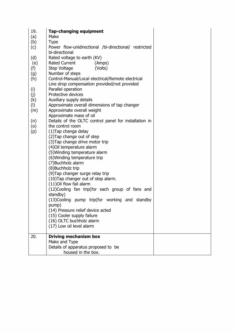
19.(a)(b)(c)
(d) (e)(f)(g)(h)
(i)(j)(k)(l)(m)
(n)(o)(p)
Tap-changing equipmentMake TypePower flow-unidirectional /bi-directional/ restricted bi-directionalRated voltage to earth (KV)Rated Current (Amps)Step Voltage (Volts)Number of stepsControl-Manual/Local electrical/Remote electricalLine drop compensation provided/not providedParallel operationProtective devicesAuxiliary supply detailsApproximate overall dimensions of tap changerApproximate overall weightApproximate mass of oilDetails of the OLTC control panel for installation in the control room(1)Tap change delay(2)Tap change out of step(3)Tap change drive motor trip(4)Oil temperature alarm(5)Winding temperature alarm(6)Winding temperature trip(7)Buchholz alarm(8)Buchholz trip(9)Tap changer surge relay trip(10)Tap changer out of step alarm.(11)Oil flow fail alarm(12)Cooling fan trip(for each group of fans and standby)(13)Cooling pump trip(for working and standby pump)(14) Pressure relief device acted(15) Cooler supply failure(16) OLTC buchholz alarm(17) Low oil level alarm
20. Driving mechanism boxMake and TypeDetails of apparatus proposed to be housed in the box.

21. Weight of copper used (kg) HV IV LV
22 Weight of core steel used (Kg)23. Quantity of transformer oil used (K.litres) (including
cooling system, OLTC & conservator)24. Type of gaskets used in the transformer25.(a)(b)(c)
Overall Dimensions.Length (mm)Breadth (mm)Height (mm)
26. Expected life of transformer
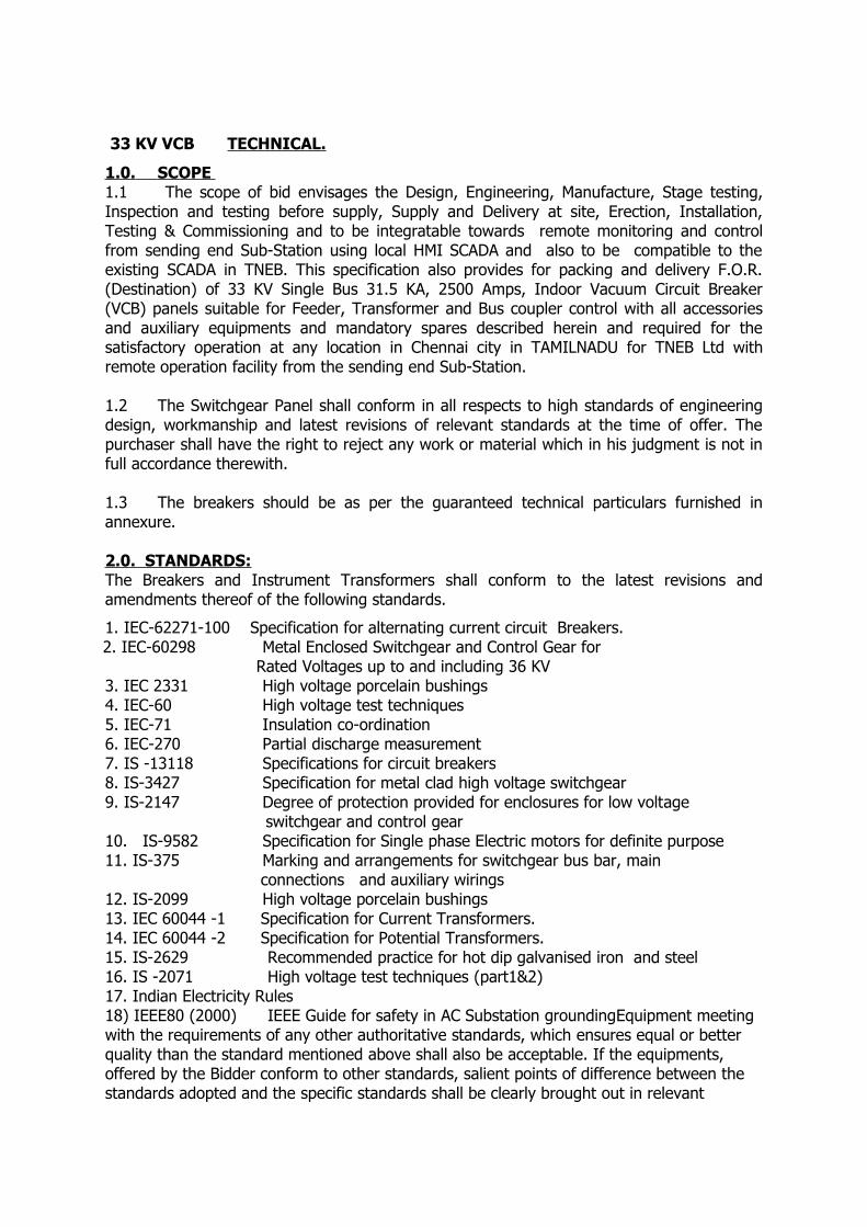
33 KV VCB TECHNICAL.
1.0. SCOPE 1.1 The scope of bid envisages the Design, Engineering, Manufacture, Stage testing, Inspection and testing before supply, Supply and Delivery at site, Erection, Installation, Testing & Commissioning and to be integratable towards remote monitoring and control from sending end Sub-Station using local HMI SCADA and also to be compatible to the existing SCADA in TNEB. This specification also provides for packing and delivery F.O.R. (Destination) of 33 KV Single Bus 31.5 KA, 2500 Amps, Indoor Vacuum Circuit Breaker (VCB) panels suitable for Feeder, Transformer and Bus coupler control with all accessories and auxiliary equipments and mandatory spares described herein and required for the satisfactory operation at any location in Chennai city in TAMILNADU for TNEB Ltd with remote operation facility from the sending end Sub-Station.
1.2 The Switchgear Panel shall conform in all respects to high standards of engineering design, workmanship and latest revisions of relevant standards at the time of offer. The purchaser shall have the right to reject any work or material which in his judgment is not in full accordance therewith.
1.3 The breakers should be as per the guaranteed technical particulars furnished in annexure.
2.0. STANDARDS:The Breakers and Instrument Transformers shall conform to the latest revisions and amendments thereof of the following standards.
1. IEC-62271-100 Specification for alternating current circuit Breakers. 2. IEC-60298 Metal Enclosed Switchgear and Control Gear for
Rated Voltages up to and including 36 KV3. IEC 2331 High voltage porcelain bushings4. IEC-60 High voltage test techniques5. IEC-71 Insulation co-ordination6. IEC-270 Partial discharge measurement7. IS -13118 Specifications for circuit breakers8. IS-3427 Specification for metal clad high voltage switchgear 9. IS-2147 Degree of protection provided for enclosures for low voltage switchgear and control gear 10. IS-9582 Specification for Single phase Electric motors for definite purpose11. IS-375 Marking and arrangements for switchgear bus bar, main connections and auxiliary wirings12. IS-2099 High voltage porcelain bushings13. IEC 60044 -1 Specification for Current Transformers.14. IEC 60044 -2 Specification for Potential Transformers.15. IS-2629 Recommended practice for hot dip galvanised iron and steel16. IS -2071 High voltage test techniques (part1&2)17. Indian Electricity Rules 18) IEEE80 (2000) IEEE Guide for safety in AC Substation groundingEquipment meeting with the requirements of any other authoritative standards, which ensures equal or better quality than the standard mentioned above shall also be acceptable. If the equipments, offered by the Bidder conform to other standards, salient points of difference between the standards adopted and the specific standards shall be clearly brought out in relevant
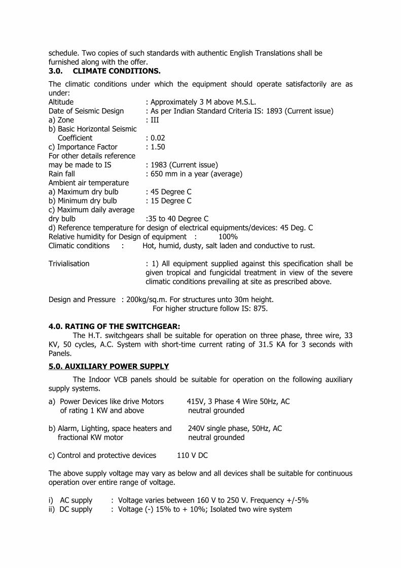
schedule. Two copies of such standards with authentic English Translations shall be furnished along with the offer.3.0. CLIMATE CONDITIONS.
The climatic conditions under which the equipment should operate satisfactorily are as under: Altitude : Approximately 3 M above M.S.L.Date of Seismic Design : As per Indian Standard Criteria IS: 1893 (Current issue)a) Zone : IIIb) Basic Horizontal Seismic Coefficient : 0.02 c) Importance Factor : 1.50For other details reference may be made to IS : 1983 (Current issue)Rain fall : 650 mm in a year (average)Ambient air temperaturea) Maximum dry bulb : 45 Degree Cb) Minimum dry bulb : 15 Degree Cc) Maximum daily average dry bulb :35 to 40 Degree Cd) Reference temperature for design of electrical equipments/devices: 45 Deg. CRelative humidity for Design of equipment : 100%Climatic conditions : Hot, humid, dusty, salt laden and conductive to rust.
Trivialisation : 1) All equipment supplied against this specification shall be given tropical and fungicidal treatment in view of the severe climatic conditions prevailing at site as prescribed above.
Design and Pressure : 200kg/sq.m. For structures unto 30m height. For higher structure follow IS: 875.
4.0. RATING OF THE SWITCHGEAR:The H.T. switchgears shall be suitable for operation on three phase, three wire, 33
KV, 50 cycles, A.C. System with short-time current rating of 31.5 KA for 3 seconds with Panels.
5.0. AUXILIARY POWER SUPPLY
The Indoor VCB panels should be suitable for operation on the following auxiliary supply systems.
a) Power Devices like drive Motors 415V, 3 Phase 4 Wire 50Hz, AC of rating 1 KW and above neutral grounded
b) Alarm, Lighting, space heaters and 240V single phase, 50Hz, AC fractional KW motor neutral grounded
c) Control and protective devices 110 V DC The above supply voltage may vary as below and all devices shall be suitable for continuous operation over entire range of voltage.
i) AC supply : Voltage varies between 160 V to 250 V. Frequency +/-5% ii) DC supply : Voltage (-) 15% to + 10%; Isolated two wire system

6.0. PRINCIPAL PARAMETERS:
SLNo
Item Requirement
1 Rated voltage 33 KV (rms) 2 Highest System Voltage 36 KV (rms) 3 Frequency 50(Hz.) 4 Neutral grounding solidly earthed 5 Continuous current rating for Bus 2500 A6 Continuous current rating for of Circuit
Breaker 2500 Amps for Incomer and Bus Coupler.1250 for Outgoing Feeders
7 Type of Switch Gear VCB8 Mounting Inside a steel cubicle of thickness not less
than 3.25 mm suitable for floor mounting and free standing
9 Number of Poles 310 Type of operation Gang Operated Poles11C Spacing between the Bus bars i.e. live
part to live part spacing300 (mm)Minimum
12 Spacing between the Bus bars and earth (i.e.) live part to earth
270 (mm)Minimum
13 Operating mechanism Universal motor operated spring charged – (Motor / Handle operation for spring charge)
14 Auto reclosing duty Three phase
15 Rated operating duty cycle O-0.3s-CO-3Min-CO
16 First pole to clear factor 1.5 17 Type of tripping Trip free
18 Maximum closing time ≤ 80 (ms)
19 Maximum total break time at rated breaking capacity
≤ 60 (ms)
20 1.2/50 microsecond impulse with- stand voltage (dry)
170 KV peak- to Earth195 KV peak -Across the open contacts with impulse on one terminal and power frequency voltage on opposite terminal.
21 One minute power frequency withstand voltage (dry)
70 KV( rms)
22 Rated breaking current capacity(Symmetrical)
25 KA
23 Rated Short circuit withstand current 31.5 K.A. for 3 Sec.
24 Peak short circuit making current capacity
62.5 KA(peak)
25 Rated cable charging breaking current 50 A (Test conforming to Class C1 as per IEC 62271-100)
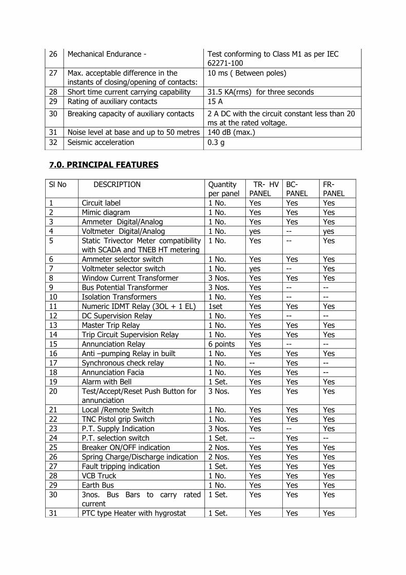
26 Mechanical Endurance - Test conforming to Class M1 as per IEC 62271-100
27 Max. acceptable difference in the instants of closing/opening of contacts:
10 ms ( Between poles)
28 Short time current carrying capability 31.5 KA(rms) for three seconds29 Rating of auxiliary contacts 15 A
30 Breaking capacity of auxiliary contacts 2 A DC with the circuit constant less than 20 ms at the rated voltage.
31 Noise level at base and up to 50 metres 140 dB (max.)32 Seismic acceleration 0.3 g
7 .0. PRINCIPAL FEATURES
Sl No DESCRIPTION Quantityper panel
TR- HV PANEL
BC-PANEL
FR-PANEL
1 Circuit label 1 No. Yes Yes Yes2 Mimic diagram 1 No. Yes Yes Yes3 Ammeter Digital/Analog 1 No. Yes Yes Yes4 Voltmeter Digital/Analog 1 No. yes -- yes5 Static Trivector Meter compatibility
with SCADA and TNEB HT metering1 No. Yes -- Yes
6 Ammeter selector switch 1 No. Yes Yes Yes7 Voltmeter selector switch 1 No. yes -- Yes 8 Window Current Transformer 3 Nos. Yes Yes Yes9 Bus Potential Transformer 3 Nos. Yes -- --10 Isolation Transformers 1 No. Yes -- --11 Numeric IDMT Relay (3OL + 1 EL) 1set Yes Yes Yes12 DC Supervision Relay 1 No. Yes -- --13 Master Trip Relay 1 No. Yes Yes Yes14 Trip Circuit Supervision Relay 1 No. Yes Yes Yes15 Annunciation Relay 6 points Yes -- --16 Anti –pumping Relay in built 1 No. Yes Yes Yes17 Synchronous check relay 1 No. -- Yes --18 Annunciation Facia 1 No. Yes Yes --19 Alarm with Bell 1 Set. Yes Yes Yes20 Test/Accept/Reset Push Button for
annunciation3 Nos. Yes Yes Yes
21 Local /Remote Switch 1 No. Yes Yes Yes22 TNC Pistol grip Switch 1 No. Yes Yes Yes23 P.T. Supply Indication 3 Nos. Yes -- Yes24 P.T. selection switch 1 Set. -- Yes --25 Breaker ON/OFF indication 2 Nos. Yes Yes Yes26 Spring Charge/Discharge indication 2 Nos. Yes Yes Yes27 Fault tripping indication 1 Set. Yes Yes Yes28 VCB Truck 1 No. Yes Yes Yes29 Earth Bus 1 No. Yes Yes Yes30 3nos. Bus Bars to carry rated
current1 Set. Yes Yes Yes
31 PTC type Heater with hygrostat 1 Set. Yes Yes Yes

32 Illumination Lamp with door switch 1 Set. Yes Yes Yes33 Interlock to defeat racking in when
the Control circuit Plug detached from the VCB Truck
1set Yes Yes Yes
34 Interlock-to defeat the movement of the Breaker when ON & in service position.
1set Yes Yes Yes
35 Stud type terminal block 1set Yes Yes Yes36 Disconnecting Link type terminal
block1set Yes Yes Yes
37 Cable termination kit 1set Yes -- YesCable gland plate of non magnetic material
1set Yes -- Yes
48.0 COMPATABILITY WITH SCADA SYSTEMS
The following features should be incorporated in the Indoor Vaccum Circuit Breaker panels so as to be compatiable with the SCADA system.
Sl.No. Feature Provision to be made available01. ON/OFF position of the
breaker2 NO – 2 NC contacts of the auxiliary switch wired upto the terminal block.
02. Local/Remote switch position Two separate No contacts – one for local and other for remote which be comes NC on selection of a particular position.
03. Spring charge discharge position One set of NO contact in the limit switch closes when the spring is in charged condition.
04. Fault tripping of the breaker One set of NO and one set of NC contacts of the Master/Tripping relay wired upto terminal block.
05. Voltage PT output.06. Current Voltage across the shunt resistance of the
ammeter.07. Transfer of data from the trivector
meter RS 485 port with MODBUS/DNP 3.0 / or IEC Protocol should have either an OPTO – Coupler or a Potential free contact to translate the Energy transmitted through the feeder to SCADA.
NOTE : There should be terminal blocks specifically marked for SCADA systems. Wiring should be made for the availability of the above datas in the terminal blocks.
49.0 DETAILS ON VARIOUS PANELS 49.1. TRANSFORMER PANELS:
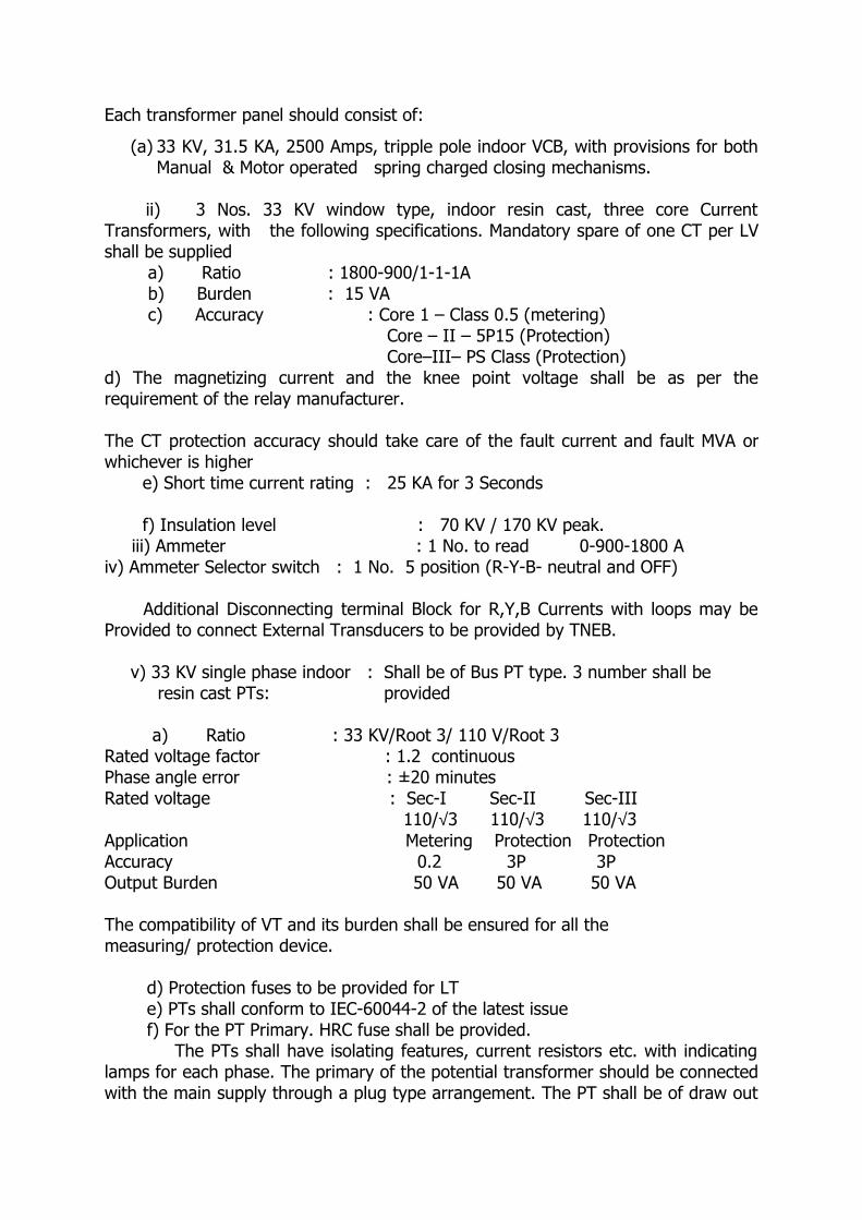
Each transformer panel should consist of:
(a) 33 KV, 31.5 KA, 2500 Amps, tripple pole indoor VCB, with provisions for both Manual & Motor operated spring charged closing mechanisms.
ii) 3 Nos. 33 KV window type, indoor resin cast, three core Current Transformers, with the following specifications. Mandatory spare of one CT per LV shall be supplied a) Ratio : 1800-900/1-1-1A b) Burden : 15 VA c) Accuracy : Core 1 – Class 0.5 (metering)
Core – II – 5P15 (Protection) Core–III– PS Class (Protection)
d) The magnetizing current and the knee point voltage shall be as per the requirement of the relay manufacturer.
The CT protection accuracy should take care of the fault current and fault MVA or whichever is higher e) Short time current rating : 25 KA for 3 Seconds f) Insulation level : 70 KV / 170 KV peak. iii) Ammeter : 1 No. to read 0-900-1800 A iv) Ammeter Selector switch : 1 No. 5 position (R-Y-B- neutral and OFF)
Additional Disconnecting terminal Block for R,Y,B Currents with loops may be Provided to connect External Transducers to be provided by TNEB.
v) 33 KV single phase indoor : Shall be of Bus PT type. 3 number shall be resin cast PTs: provided a) Ratio : 33 KV/Root 3/ 110 V/Root 3
Rated voltage factor : 1.2 continuous Phase angle error : ±20 minutes Rated voltage : Sec-I Sec-II Sec-III 110/√3 110/√3 110/√3 Application Metering Protection Protection Accuracy 0.2 3P 3P Output Burden 50 VA 50 VA 50 VA
The compatibility of VT and its burden shall be ensured for all the measuring/ protection device.
d) Protection fuses to be provided for LT e) PTs shall conform to IEC-60044-2 of the latest issue f) For the PT Primary. HRC fuse shall be provided.
The PTs shall have isolating features, current resistors etc. with indicating lamps for each phase. The primary of the potential transformer should be connected with the main supply through a plug type arrangement. The PT shall be of draw out
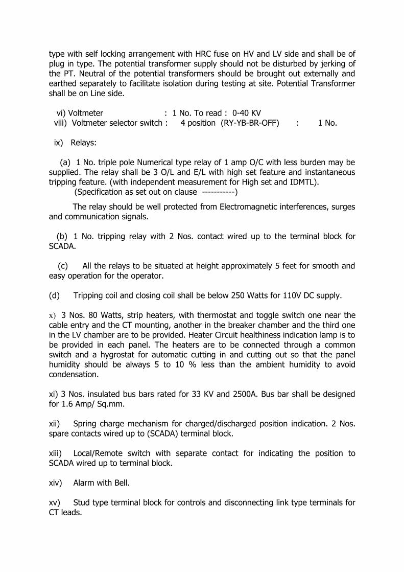
type with self locking arrangement with HRC fuse on HV and LV side and shall be of plug in type. The potential transformer supply should not be disturbed by jerking of the PT. Neutral of the potential transformers should be brought out externally and earthed separately to facilitate isolation during testing at site. Potential Transformer shall be on Line side.
vi) Voltmeter : 1 No. To read : 0-40 KV viii) Voltmeter selector switch : 4 position (RY-YB-BR-OFF) : 1 No.
ix) Relays:
(a) 1 No. triple pole Numerical type relay of 1 amp O/C with less burden may be supplied. The relay shall be 3 O/L and E/L with high set feature and instantaneous tripping feature. (with independent measurement for High set and IDMTL). (Specification as set out on clause -----------)
The relay should be well protected from Electromagnetic interferences, surges and communication signals.
(b) 1 No. tripping relay with 2 Nos. contact wired up to the terminal block for SCADA. (c) All the relays to be situated at height approximately 5 feet for smooth and easy operation for the operator.
(d) Tripping coil and closing coil shall be below 250 Watts for 110V DC supply.
x) 3 Nos. 80 Watts, strip heaters, with thermostat and toggle switch one near the cable entry and the CT mounting, another in the breaker chamber and the third one in the LV chamber are to be provided. Heater Circuit healthiness indication lamp is to be provided in each panel. The heaters are to be connected through a common switch and a hygrostat for automatic cutting in and cutting out so that the panel humidity should be always 5 to 10 % less than the ambient humidity to avoid condensation.
xi) 3 Nos. insulated bus bars rated for 33 KV and 2500A. Bus bar shall be designed for 1.6 Amp/ Sq.mm.
xii) Spring charge mechanism for charged/discharged position indication. 2 Nos. spare contacts wired up to (SCADA) terminal block.
xiii) Local/Remote switch with separate contact for indicating the position to SCADA wired up to terminal block.
xiv) Alarm with Bell.
xv) Stud type terminal block for controls and disconnecting link type terminals for CT leads.
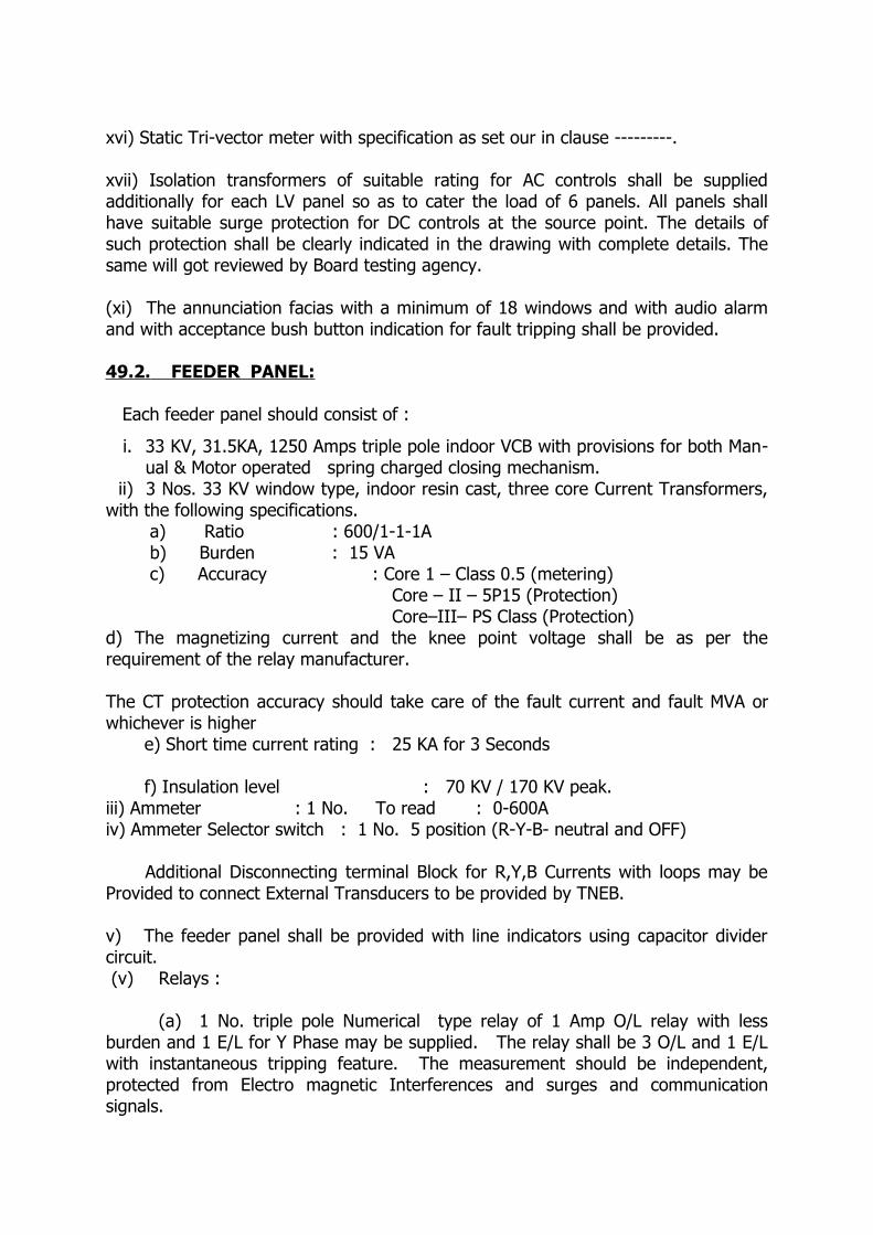
xvi) Static Tri-vector meter with specification as set our in clause ---------.
xvii) Isolation transformers of suitable rating for AC controls shall be supplied additionally for each LV panel so as to cater the load of 6 panels. All panels shall have suitable surge protection for DC controls at the source point. The details of such protection shall be clearly indicated in the drawing with complete details. The same will got reviewed by Board testing agency. (xi) The annunciation facias with a minimum of 18 windows and with audio alarm and with acceptance bush button indication for fault tripping shall be provided.
49.2. FEEDER PANEL:
Each feeder panel should consist of :
i. 33 KV, 31.5KA, 1250 Amps triple pole indoor VCB with provisions for both Man-ual & Motor operated spring charged closing mechanism.
ii) 3 Nos. 33 KV window type, indoor resin cast, three core Current Transformers, with the following specifications. a) Ratio : 600/1-1-1A b) Burden : 15 VA c) Accuracy : Core 1 – Class 0.5 (metering)
Core – II – 5P15 (Protection) Core–III– PS Class (Protection)
d) The magnetizing current and the knee point voltage shall be as per the requirement of the relay manufacturer.
The CT protection accuracy should take care of the fault current and fault MVA or whichever is higher e) Short time current rating : 25 KA for 3 Seconds f) Insulation level : 70 KV / 170 KV peak.iii) Ammeter : 1 No. To read : 0-600A iv) Ammeter Selector switch : 1 No. 5 position (R-Y-B- neutral and OFF)
Additional Disconnecting terminal Block for R,Y,B Currents with loops may be Provided to connect External Transducers to be provided by TNEB.
v) The feeder panel shall be provided with line indicators using capacitor divider circuit. (v) Relays :
(a) 1 No. triple pole Numerical type relay of 1 Amp O/L relay with less burden and 1 E/L for Y Phase may be supplied. The relay shall be 3 O/L and 1 E/L with instantaneous tripping feature. The measurement should be independent, protected from Electro magnetic Interferences and surges and communication signals.
(b) 1 No. tripping relay with 2 Nos. contact wired up to the terminal block for SCADA. (Specification as set our in clause 50.4)
(c) All the resetting flags to be situated at height of approximately 5 feet for smooth and easy operation for the operator.
(d) Tripping coil and closing coil shall be below 250 Watts for 110V DC supply.
(vi) 3 Nos. 80 Watts, strip heaters, with thermostat and toggle switch one near the cable entry and the CT mounting, another in the breaker chamber and the third one in the LV chamber are to be provided. Heater Circuit healthiness indication lamp is to be provided in each panel. The heaters are to be connected through a common switch and a hygrostat for automatic cutting in and cutting out so that the panel humidity should be always 5 to 10 % less than the ambient humidity to avoid condensation.
(xi) 3 Nos. insulated bus bars provided with heat shrinkable sleeves resin cast insulated bus bars rated for 33KV and 2500 A. Bus bars shall be designed for Current density of 1.6 Amp/Sq. mm.(xii) Spring charge mechanism ON/OFF indication (xiii) Local/Remote switch. (xiv) Indication for fault tripping linked to the common audio alarm and reset push button.(xv) Stud type terminal block for controls and disconnecting link type terminals for CT leads.(xvi) Static Tri-vector Meter with specification as set our in clause 50.5.
(xvii) Indication for fault tripping linked to the common audio alarm and reset push button.
(xviii) Upon TSR (trip circuit supervision relay) activation, there should be an alarm. The permissive command to close the breaker should be disabled (i.e) the breaker should not be closed either electrically or manually. Upon sensing loss of DC simultaneously in all the breakers, all the breakers should trip and should not be closed manually.
49.3 BUS COUPLER PANEL WITH SUITABLE ADAPTER:
The Bus coupler panel should consist of:
i) 33 KV, 31.5KA, 1250 Amps triple pole indoor VCB with provisions for both Manual & Motor operated spring charged closing mechanism.ii) 3 Nos. 33 KV window type, indoor resin cast, three core Current Transformers, with the following specifications. a) Ratio : 1800-900/1-1-1A b) Burden : 15 VA
c) Accuracy : Core 1 – Class 0.5 (metering) Core – II – 5P15 (Protection)
Core–III– PS Class (Protection)d) The magnetizing current and the knee point voltage shall be as per the requirement of the relay manufacturer.
The CT protection accuracy should take care of the fault current and fault MVA or whichever is higher e) Short time current rating : 25 KA for 3 Seconds f) Insulation level : 70 KV / 170 KV peak.iii) Ammeter : 1 No. To read : 0-900-1800A iv) Ammeter Selector switch : 1 No. 5 position (R-Y-B- neutral and OFF)
Additional Disconnecting terminal Block for R,Y,B Currents with loops may be Provided to connect External Transducers to be provided by TNEB.
v) Relays: (a) 1 No. triple pole Numerical type relay of 1 amp O/C with less burden may be supplied. The relay shall be 3 O/L and E/L with high set feature and instantaneous tripping feature. (with independent measurement for High set and IDMTL). (Specification as set out on clause -----------)
The relay should be well protected from Electromagnetic interferences, surges and communication signals.
(b) 1 No. tripping relay with 2 Nos. contact wired up to the terminal block for SCADA.
(c) Bus coupler shall be provided with one no synchronous check relay so that B/C can be closed only when the sequence of both the incomers are same, along with provision for checking phase sequence. PT selection switch for energy meter reading with phase sequence indication shall be provided.
(d) All the relays to be situated at height approximately 5 feet for smooth and easy operation for the operator.
(e) Tripping coil and closing coil shall be below 250 Watts for 110V DC supply.
vi) 3 Nos. 80 Watts, PTC (Positive Temperature co-efficient) heaters with Hygrostat shall be used. One near the cable entry and the CT mounting, another in the breaker chamber and the third one in the Bus bar chamber are to be provided. Heater circuit healthiness indication Lamp is to be provided in each panel. The heaters are to be connected through a common switch and a hygrostat for automatic cutting in and cutting out so that the panel humidity should be always less than the ambient humidity to avoid condensation. vii) 3 Nos. insulated bus bars rated for 33 KV and 2500A. Bus bar shall be designed for 1.6 Amp/ Sq.mm.
xviii) Spring charge mechanism for charged/discharged position indication. 2 Nos; spare contact wired upto (SCADA) terminal block.
ix) Local/Remote switch with separate contact for indicating the position to SCADA wired upto terminal block.
x) Alarm with Bell.
xi) Stud type terminal block for controls and disconnecting link type terminals for CT leads.
xii) Annunciation facia with a required windows.
(xii) Indication for fault tripping linked to the common audio alarm and reset push button.
(xiii) Upon TSR (trip circuit supervision relay) activation, there should be an alarm. The permissive command to close the breaker should be disabled (i.e) the breaker should not be closed either electrically or manually. Upon sensing loss of DC simultaneously in all the breakers, all the breakers should trip and should not be closed manually.
50.0. GENERAL50.1. SWITCHGEAR PANEL:
a) Each VCB Panel shall be housed in a fabricated housing made of sheet steel of thickness 10 SWG (3.25 mm) for all load bearing members and 12 SWG (2.5 mm) for all others with facility of lifting hooks of sufficient strength welded firmly at the top to lift the panel with VCB truck inside with a crane during transport and erection. The breaker shall be of floor mounted type ONLY.
b) Each VCB panels shall be supplied with resin cast insulated bus bars of single bus bar arrangement and provisions to join the same with adjacent panel of any model/make. Insulated bus bars should be of electrolytic copper and of sufficient size to carry the rated current of 2500 Amps, with temperature rise not exceeding the limit prescribed, in particular at joints. Bus bar shall be designed for a current density of 1.6 Amp/sq.mm. No tolerance shall be permitted. The bus bars are to be insulated with 33 KV class heat shrinkable sleeves housed in totally enclosed compartment without barriers between the adjacent panels. Specially designed cast resin insulators are to be used to support the insulated bus bars. The bus bar chamber is to be located on the back side of the circuit breaker chamber. 6 Nos Isolating plugs 3 Nos for the Buses and 3 Nos. for the line with necessary sockets along with automatic safety shutters, bus bar jumpers, etc. are to be provided in each panel. The bus bars shall be made up of of 99.9% electrolytic copper.
c) The flower contacts are to be provided on the truck side and free from atmospheric effects. The contacts shall be tested at CECRI for its current carrying capacity and resistance. Finger type contacts will not be accepted.d) Separate handles for manual operation of the circuit breaker for emergency operation.
e) The maximum temperature in any part of the equipment shall not exceed the permissible limits as stipulated in the relevant standards.
f) The L.V equipments like relay, meters, indication lamps and switches shall be mounted in the L.V. chamber at the panel front at a height of approximately 5 feet so that they can be operated easily without any steps.
g) The VCB shall be floor mounted type, with isolating main contacts for isolating
the VCB. The Circuit Breaker compartment shall be suitable for accommodating the VCB truck. The breaker compartment is to be separated from the bus bar and cable compartment by Fiber Glass reinforced epoxy plate / MS plate. The shutters are to be operated smoothly, automatically by the movement of truck and the shutters are of solid closing type that close automatically when the truck is withdrawn and the shutters cannot be pushed open inadvertently when the truck is removed. The breaker is to be operated both Manual/Motor spring charging mechanism. In case, the breaker truck is withdrawn, there shall be a cover supplied to make it vermin proof if doors are not provided.
h) 7NO + 7NC breaker auxiliary switch (2 NO + 2 NC to be wired up to control cubicle terminals for SCADA). 150 mm x 150 mm. gland plate for entry of SCADA and other control cables shall be provided at the back side of the panel.
Upon TSR (trip circuit supervision relay) activation, there should be an alarm. The permissive command to close the breaker should be disabled (i.e) the breaker should not be closed either electrically or manually. Upon sensing loss of DC simultaneously in all the breakers, all the breakers should trip and should not be closed manually. The above scheme shall be housed in the bus coupler.
All panels shall have suitable surge protection for DC controls at the source point. Provision shall be given to isolate the DC load of the SCADA system at a single point.
The individual compartments are to be provided with explosion vents at the top of panels to let out gases under pressure generated during unlikely event of fault inside the panel.
When the breaker is in service position, without closing the door the breaker should not be closed.
Window type CT shall be mounted such a way that while replacing the cable termination or terminating the cable there should not be any need to remove the CT and its associated wiring.

The Panel illumination with 14 W CFL is to be provided in the Bus bar and L.V.chamber compartment.
The offer should include provision for wiring of annunciation equipment like hooter, bell, reset push buttons for each Sub Station. The cable pan should have a maximum depth up to 400mm, to obtain trifurcation distance of about 800 mm between cable fixing and core connection.
Accessories required for fixing the panel such as foundation bolts and nuts shall be provided along with panel. For every 2 Nos. of breakers, breaker operating rod, door opening key, interlock key, spring charge rod shall be given. The control cable entry (open with cover) shall be provided in front side bottom of the cable chamber of Transformer and Feeder panels. Trip circuit healthiness indication and auto trip indication shall be in DC supply. All other indications shall be in AC supply.
Copper Bus bar joints should also be insulated either with 33 KV class HS sleeve or 33 KV class shrouds.
Cable pan shall have suitable MS channel for cable clamping arrangement for all Feeders and Transformer panels. Transformer panel shall have provision to connect 2 x 3 runs of 1 X 1000 sq. mm. XLPE copper UG cable and 3 runs of 1 X 630 sq. mm. XLPE aluminum UG cable for the feeder panel
In all the breakers, the reset push button shall be provided and the annunciation shall be extended from the common alarm.
Each VCB shall be housed in a fabricated sheet steel enclosure with the following:
(a) Vertical or horizontal isolation, horizontal draw out circuit Breaker truck with VCB, its mechanism, auxiliary contacts and interlocks.
(b) 33 KV, single phase, triple core, resin cast window type indoor CTs.
(c) 33 KV, single phase, cast resin, bus PT to be provided in Transformer panel.
(d) Air insulated Bus bar chamber, fixed main contacts, automatic safety shutters, bus bar, jumpers etc.
(e) Ammeter, Voltmeter, relay control and selector switches, cable termination kits suitable for 33 KV XLPE Copper/Aluminum cable with all accessories and with suitable heaters, indicating lamps and illuminating lamps etc.
(f) 1 No. fabricated housing made of steel sheet of minimum thickness of 2.50 mm with facility of lifting hooks at the top corners to lift the panel with VCB truck inside with a crane during transport and erection.
(g) One set of mechanical interlocks to prevent moving of the switch gear truck unless the circuit breaker is in the open position.
(h) One set of mechanical interlocks to prevent the movement of the breaker from service position of the Breaker, when the breaker is in service position and in closed condition.
(i) One set of mechanical/electrical interlocks to prevent the closing of the Breaker when the Breaker is in service position and the control cable plug is not inserted in the VCB truck
Upon TSR (trip circuit supervision relay) activation, there should be an alarm. The permissive command to close the breaker should be disabled (i.e) the breaker should not be closed either electrically or manually. Upon sensing loss of DC simultaneously in all the breakers, all the breakers should trip and should not be closed manually.
50.2. SWITCHGEAR TRUCK:
The breaker truck is to be horizontally drawn out and shall be floor mounted only. The service and test positions shall be distinctly marked. In the service position, the isolating contacts should fully engage each other. The breaker should lock out after the finger contacts have made full contact with the bus. The control wiring from the breaker to the control equipments on the L.V. Chamber shall be made through 24 way plug and socket arrangement. The plug is to be interlocked in such a way that the breaker truck cannot be pushed in service position until and unless the control plug is inserted in the correct place. The full isolated position is to be achieved in the test position by removal of the control plug. The inside operating or insulated fibre glass connecting rods wherever used shall be sturdy and shall not break during the entire life period of the breaker. The shunt close/ trip coils shall be fed from 110 Volts station battery for closing/ tripping purposes. The current taken by the coils shall be limited to 3 amps (maximum).
DUTY CYCLE O-0.3 s-CO-3Min.-CO as per latest IECAll the equipments should operate without undue vibration and with the least
practicable amount of noise. The breaker truck should be inter-changeable. This should be ensured. Two nos. operating handle & circuit breaker drawal handles are to be supplied along with the panels. All mating contacts (flower) shall be free from atmospheric effects. Contacts shall be tested at CECRI and designed to have adequate thermal and current carrying capacity for the duty specified and to have a life expectancy so that frequent replacements due to excessive burning will not be necessary. Provision shall be made for rapid dissipation of heat generated by the arc on opening. Breakers shall be so designed that when operated within their specified rating, the temperature of each part will be limited to values consistent with a long life of the materials used. The insulated fibre glass connecting rods wherever used shall be
sturdy and shall not break during the entire life period of the breaker. The temperature shall not exceed that indicated in latest IEC under specified ambient conditions.
Interchangeability of VCB truck should be ensured at the time of testing at the supplier’s premises and at site. If the above is not ensured at site, the breakers should be replaced by you, with the above facility.
If arcing contacts are used they shall be first to close and last to open. Tips of arcing contacts and main contacts shall be silver plated or made of superior material like graphite/tungsten copper /copper chromium
Any device provided for voltage grading to damp oscillations or to prevent restrike prior to the complete interruption of the circuit or to limit over-voltage on closing shall have a life expectancy comparable to that of the breaker as a whole.
Breakers shall be so designed that when operated within their specified rating, the temperature of each part will be limited to values consistent with a long life or the materials used. The temperature shall not exceed that indicated in the relevant standards under specified ambient conditions.
The inside operating or insulated fibre glass connecting rods whereverused shall be sturdy and shall not break during the entire life period of the breaker.
11.3 INTERLOCKS
11.3.1. Operation of the Bus selector switch should be defeated when the breaker is in service position and is in ON condition.
11.3.2. The movement of the switchgear truck should be defeated when Breaker is in service position and is in ON position.
11.3.3. The movement of the switchgear truck should be defeated when the door is in open position. Opening of door should be defeated when VCB is in service.
11.3.4. The process of racking in of the Switchgear truck should be defeated if the control plug is not plugged in on to the VCB truck and breaker should set tripped if the control plug is removed when the breaker is ON.
11.3.5. The closing of the breaker either electrically or mechanically should be defeated if the breaker is not locked in the service position fully.
11.3.6. Secondary Plug (Truck Plug) and socket interlock shall be provided.
11.3.7. Limit switch shall be given in such a way that after spring charging only the closing pulse can be given to the breaker.
11.3.8. One set of mechanical interlock to prevent moving of the switchgear truck unless the circuit breaker is in the open position.
11.3.9. One set of Electrical/Mechanical interlock to prevent the closing of the breaker when the breaker is in service position and the control cable plug is not inserted in the Vacuum Circuit Breaker truck.
11.3.10. Movement of the switchgear truck from service to test position shall be possible only when the breaker is in OFF position.
11.3.11. Front door of the switchgear compartment shall not be opened unless breaker is tripped and brought to test position.
12.3.12 Auxiliary plug and socket shall not be opened unless VCB is brought to test position
12.3.13. Rear cable chamber cover shall not be opened unless and otherwise the breaker if OFF and in test position. Further the movement of the switchgear truck should be defeated i) when the switchgear truck compartment is open and ii) the rear covers are not closed.
Detailed drawings on the operation of the above interlocks shall be provided along with the Technical offer.
50.4. NUMERICAL RELAY
i) The relay shall be of numerical type with true RMS measurement with provision for instantaneous tripping.
ii) Rated for CT secondary of 1 A and with burden less than 3 VA.
iii) Rated for auxiliary supply voltage 30 to 110 Volts DC.
iv) Shall have independent protection characteristics (IDMTL and Transient free High set) for each phase. The IDMTL characteristic of the relay shall be 1.3 secs at 10 times set value of the current with time set at unity.
v) The following characteristics should be able to be set at the site.IDMTL – 5% to 200% for OC. 2% to 80% for E/F. High Set – 50 % to 2000 % for OC 20 % to 800 % for E/F.
Selection of curve shall be 1.3 secs. Instantaneous setting for O/L shall be 20. For E/L it shall be 8.
vi) The Time Multiplier setting shall be 0 to unity continuously in steps of 0.01, variable for each phase and for both IDMTL and high set separately.
vii) Storage and display of last 7 (seven) fault data with time, date and current details.
vii) Alpha – Numeric LED display.
viii) HMI for programming the relay.
ix) Shall have self diagnostic features.
x) Shall have one set of NO and 1 set of NC potential free contacts.
xi) The relay should operate satisfactorily at ambient air temperature ranging from 10°C to 50°C.
(xii) The relay should have inbuilt characteristics of blocking unscrupulous tripping of upstream breakers.
(xiii) The relay should have communication port (RS 485) compatible for MOD BUS/IEC Protocol.
xiv) The relay should confirm to the latest IS/IEC.
xv) The relay shall be draw out type and suitable for both 30V and 110V DC.
Upon TSR (trip circuit supervision relay) activation, there should be an alarm. The permissive command to close the breaker should be disabled (i.e) the breaker should not be closed either electrically or manually. Upon sensing loss of DC simultaneously in all the breakers, all the breakers should trip and should not be closed manually.
Only Areva/Siemens/GE/ABB/Easun make relays shall be accepted. No equivalent shall be proposed. All relays shall be installed with Test block similar to Areva make MMLG/MMLB type to facilitate relay calibrating/testing/replacing without any interruption of power supply. The type of relay proposed by the vendors are to be got approved by Board testing agency if any other make of relay is proposed.
50.5. STATIC TRIVECTOR METER
3 Phase 4 wire 110V 1A 0.5 Accuracy class Static Trivector Meter with automatic and manual scrolling facility to read KWHr, RKVAHr, Voltage, Current, Power factor and instantaneous KW with optical port for downloading the load survey for 35 days and with MD reset push button and test block. (Link type
terminal block) preferably below the meters for isolation during testing. The meter should be compatible with the trivector meters used by TNEB for HT metering. Necessary software compatible with SANDS CMRI for the same also to be included in the scope of supply. Only Elster, Secure, L&T and Lyandis Gear make of the meter shall be accepted. Any other type of the meter intended to be used by the supplier shall have to be accepted by the MRT wing. RS 485 port compatible for MODBUS/IEC/D NP 3 protocol shall be provided. Opto coupler or one set potential free contact to translate the energy transmitted through the feeder to SCADA.
50.6. ANNUNCIATORS AND INDICATORS :
The annunciation fascias with a minimum of 18 windows shall be provided with auxiliary relays, flasher, hooter / bell for indicating tripping of the feeders and discontinuity of the trip circuits. All the panels shall have the inter connection for accepting / resetting the alarms from the respective panels. LEDs shall be utilised for various Indications to be provided
50.7. A.C AND D.C. DISTRIBUTION ARRANGEMENTS:
Each control and relay panel shall be provided with necessary arrangements for receiving, distributing, and isolating of A.C and D.C supplies for control ,signaling, lighting and heating purposes. The incoming and sub-circuits shall be separately provided with switch fuse units /MCBs . Fuses provided in the potential circuits shall protect metering.
All fuses shall be of HRC cartridge type confirming to IS2203 mounted on the plug in type fuse base. Fuses shall have fusing indication and the fuse base shall have imprints of fuse rating and voltage. All fuses and links shall be mounted with sufficient space between each row of fuses and rows upper or below and should have a minimum of 2cms. space between live terminal of the fuse / links and metal parts.Separate fuse control shall be given for close, trip and indication and annunciation in DC Circuit and for spring charging motor and heater for A.C.
50.8. PANEL WIRINGS:
The wiring should be of high standard and should be able to withstand the tropical weather conditions. All wiring shall be provided with 650 volt Grade single core multistrand copper conductor wires with P.V.C insulation and shall be flame retardant low smoke type. The minimum size of the stranded copper wire shall be 1.5 Sq.mm
The wiring shall be carried out using 4.0 Sq.mm. PVC insulated multi-strand FRLS copper wire of 1100V Grade for AC Power, DC Control, and CT circuits. Suitable coloured wires shall be used for phase identification and interlocking type ferrules shall be provided at both ends of the wires for wire identification. Terminal should be suitably protected to eliminate sulphating. Connections and terminal should be able to withstand vibrations. The terminal blocks should be stud type with suitable spring washer and lock nuts.
Flexible wires shall be used for wiring of devices on moving parts such as
swinging panels or panel doors. Panel wiring shall be securely supported, neatly arranged readily accessible and connected to equipment terminals, terminal blocks and wiring gutters. The cables shall be uniformly bunched and tied by means of PVC belts and carried in a PVC carrying trough. 32/24 Pintype socket shall be given in all the breakers in respective of the type of breaker with identical type of wiring for the purpose of interchangeability.
The position of PVC carrying trough and wires should not give any hindrance for fixing or removing relay casing, switches etc. Wire termination shall be made with solderless crimping type of tinned copper lugs. Core identification plastic ferrules marked to correspond with panel wiring diagram shall be fitted with both ends of each wire. Ferrules shall fit tightly on the wire when disconnected. The wire number shown on the wiring shall be in accordance with the IS.375.
All wires directly connected to trip circuits of breaker or devices shall be
distinguished by addition of a red color unlettered ferrule. Inter-connections to adjacent panels shall be brought out to a separate set of Terminal blocks located near the slots or holes to be provided at the top portion of the panel. Arrangements shall be made for easy connections to adjacent panels at site and wires for this purpose shall be provided and bunched inside the panel. The bus wire shall run at the top of the panel. Terminal block with isolating links should be provided for bus wire. Bus wire for voltage from the bus PT shall be provided with wiring diagram. At least 10% of total terminals shall be provided as spare for further connections. Wiring shall be done for all the contacts available in the relay and other equipment and brought out to the terminal blocks for spare contacts. Color code for wiring is preferable in the following colours.
PT supply Red, Yellow, Blue for phase and Black for neutral CT circuits Similar to the above DC circuits Grey for both positive and negative 240V AC circuits Black for both phase and neutral Earthing Green The wiring shall be in accordance to the wiring diagram for proper functioning of the connected equipment. Terminal blocks shall not be less than 1100V grade and shall be piece-molded type with insulation barriers. The terminal shall hold the wires in the tight position by bolts and nuts with lock washers. The terminal blocks shall be arranged in vertical formation at an inclined angle with sufficient space between terminal blocks for easy wiring. The lowest terminal shall be atleast 450mm above ground level. Steel plate shall be provided 150mm below the lowest terminal block to fix the cable glands. In all the breakers, the reset push button shall be provided and the annunciation shall be extended from the common alarm.
50.9. CABLE BOX:

Cable pan shall have suitable MS channel for cable clamping arrangement for all Feeders and Transformer panels. Each transformer panel and feeder panel has to be supplied with suitable 33 KV end termination kits of either push on or heat shrinkable type. The cable configuration shall be suitable for 1x1000 Sq.mm copper XLPE (3+3 runs) for Transformer panel and 1 X 630 sqmm aluminum XLPE (3 runs) for feeder panel. Cable Termination should be provided with support Insulators.
50.10. HEATERS:
3 Nos. 80 Watts, PTC (Positive Temperature co-efficient) heaters with Hygrostat shall be provided, with auto control, one near the cable entry and the CT mounting, another in the breaker chamber and the third one in the Bus bar chamber. The heaters are to be connected through a common switch and a hygrostat for automatic cutting in and cutting out so that the panel temperature should be always higher than the ambient temperature to avoid condensation. Indication for healthiness of Heater circuit has to be provided in each panel.
50.11. EARTHING
All panels shall be equipped with an earth bus securely fixed along the base of the panels. When several panels are mounted adjoining to each other, the earth bus shall be made continuous and necessary connectors and clamps for this purpose shall be included in the scope of supply. The size of the earth bus shall be made of 25mm x 6mm tinned copper flat. Provision shall be made on end panels for connecting the earth bus to the earth grid. Necessary terminal clamps and connectors shall be included in the scope of supply.
All metallic cases of the relays, instruments and other panel mounted equipment’s shall be connected to the earth bus by independent copper wires of size not less than 4.0 sq.mm. The color code of earthing wire shall be green. Earthing wires shall be connected on the terminals with suitable clamp connectors and soldering shall not be permitted. 50.12. LABELS
All fronts mounted equipment as well as equipment mounted inside the anels shall be provided with individual labels with equipment designation engraved. Labels shall be made of non-rusting metal or 3 ply lanced. Labels shall have white letters on black or dark batch ground. The size of the labels shall be width- 1.5cms. length- as per the length of the inscription and the letter size shall be 0.75cm.
51.0. TESTS:
51.1. ACCEPTANCE AND ROUTINE TESTS:
All acceptance and routine tests as stipulated in the latest IEC- shall be carried out by the supplier in the presence of purchaser’s representative. A team of Board
engineers not less than three, one each from CDC, MRT and Inspection wing shall inspect the breaker. Only on getting the inspection report to the effect that the inspection was carried out satisfactorily, dispatch clearance shall be issued. The supplier shall give minimum15 days advance intimation to the board to enable them to depute their representatives for witnessing the tests.
51.2. ADDITIONAL TESTS:
The purchaser reserves the right for carrying out any other tests of a reasonable nature at the works of the supplier/laboratory or at any other recognised laboratory/research institute in addition to the above mentioned type, acceptance and routine tests at the cost of the purchaser to satisfy that the material complies with the intent of this Purchase order.
52.0. INSPECTION:
The inspection may be carried out by the purchaser at any stage of manufacture. The supplier shall grant free access to purchaser’s representative at a reasonable time when the work is in progress. Inspection and acceptance of any equipment under this purchase order by the purchaser shall not relieve the supplier of his obligation of furnishing equipment in accordance with the purchase order and shall not prevent subsequent rejection if the equipment is found to be defective.
The supplier shall keep the purchaser informed in advance, about the manufacturing programme so that arrangement can be made for inspection.The purchaser reserves the right to insist for witnessing the acceptance/routine testing of the bought out items. No material shall be despatched from its point of manufacture unless the material has been satisfactorily inspected and tested / unless the same is waived by the purchaser in writing.
No material shall be despatched from its point of manufacture unless the material has been satisfactorily inspected and tested / unless the same is waived by the Board in writing.
53.0. DOCUMENTATION: All drawings shall conform to relevant international standards Organisation (ISO) Specification. All drawings shall be in ink and suitable for micro filming.
54.0. TYPE TEST:
Following Type tests as per latest IEC must have been performed and the reports enclosed along with technical bid.1) Basic short circuit test duties 1-5 2) Single phase breaking capacity test 3) Short time withstand test for 31.5 KA for 3 secs. 4) Temperature rise test at 2500 A & milli volt drop test. 5) Lightning impulse withstand test 6) Power frequency withstand test (dry)
7) Cable charging switching test duty 8) Mechanical endurance (M2 class) 9) Internal arc fault withstand test on cable, main bus and breaker chambers.
The same shall be scrutinized and accepted by the Board before opening up of price bid.
55.0. DRAWINGS :
Supplier has to furnish the drawings for
(i) Principal dimensions of the 33 KV switchgear, (ii) GA for 18 panels (13 feeders, 2 LV, 2 HV & 1 Bus coupler with adaptor) including its foundation details, (iii) Drawing clearly showing the interlock arrangement provisions specified in the specification, (iv) Schematic drawings of control, metering, protection and SCADA circuits in respect of feeders, LV & Bus coupler with detailed write up. The schematic shall include wiring details of individual components and terminal arrangements with ferrule details, (v) Drawing showing height and arrangement of 33 KV bus bars including design calculations & loading data for its support insulators, (vi) Name plate drawing along with the technical offer.
The drawings shall have to be accepted by any of the MRT wing before opening of the price bid.
Further the supplier shall submit illustrative and descriptive literature for various items of switchgear, etc. including. i) Instruction manuals
ii) Catalogues of spares recommended with drawing to indicate each items of spares
iii) List of spares and special tools recommended by the supplier. iv) Type Test Certificates as per ISS
The following should be supplied to each consignee circle along with the initial supply of the equipments ordered.
5 copies of printed and bound volumes of operation, maintenance and erection manuals in English along with the copies of approved drawings and type test reports etc.
3 sets of the manuals detailed as above shall have to be supplied to the SE/Transmission-II within one week from the date of approval of drawings. The spares for the breakers ordered under scope of the contract should also be supplied to the consignee circles along with the initial supply of breakers. It should be noted that if the above conditions are not full filled the initial payment will not be released.
56.0. NAME PLATE :
Each circuit breaker shall be provided with a name plate legible and indelibly marked with at least the following information.a) Name of manufacturerb) Type, design and serial numberc) Rated voltage and currentd) Rated frequencye) Rated symmetrical breaking capacityf) Rated making capacityg) Rated short time current and its durationh) Purchaser Order number and datei) Month and Year of supplyj) Rated lighting impulse withstand voltagek) D.C. component of current.
NOTE: 1) The word rated need not appear on the name plate. Recognised abbreviations may be used to express the above particulars. 2) Whether the circuit breaker is fitted with closing/tipping devices necessitating an auxiliary supply shall be stated either on the circuit breaker name plate or any other acceptable position.
57.0. MATERIALS AND WORKMANSHIP:
All the materials shall be of the best class and capable of satisfactory operation in the tropics with humid atmosphere conditions. Unless otherwise specified, they shall conform to the requirements of the appropriate ISS/IEC.
NOTE: The Over Current and earth leakage relays shall be of numerical version.
The workmanship shall be of the best grade and the entire construction in accordance with the best modern practice.
The equipment shall be designed to facilitate inspection and repairs and to ensure satisfactory operation under atmosphere condition prevailing at site and under such sudden variation of load and voltage as may be met with under working conditions in the system including those due to faulty synchronizing and short circuit within the rating of the apparatus.
The design shall incorporate every reasonable precaution and provision for the safety of all those concerned in the operation and maintenance of the equipment.
All the equipments should operate without undue vibration and with the least practicable amount of noise.
The breaker truck should be inter-changeable. This should be ensured.
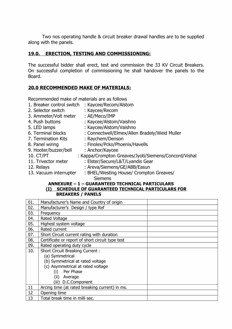
Two nos operating handle & circuit breaker drawal handles are to be supplied along with the panels.
19.0. ERECTION, TESTING AND COMMISSIONING:
The successful bidder shall erect, test and commission the 33 KV Circuit Breakers. On successful completion of commissioning he shall handover the panels to the Board.
20.0 RECOMMENDED MAKE OF MATERIALS:
Recommended make of materials are as follows1. Breaker control switch : Kaycee/Recom/Alstom2. Selector switch : Kaycee/Recom3. Ammeter/Volt meter : AE/Meco/IMP4. Push buttons : Kaycee/Alstom/Vaishno5. LED lamps : Kaycee/Alstom/Vaishno6. Terminal blocks : Connectwell/Elmex/Allen Bradely/Weid Muller7. Termination Kits : Raychem/Denson8. Panel wiring : Finolex/Pcko/Phoenix/Havells9. Hooter/buzzer/bell : Anchor/Kaycee10. CT/PT : Kappa/Crompton Greaves/Jyoti/Siemens/Concord/Vishal11. Trivector meter : Elster/Secure/L&T/Lyandis Gear12. Relays : Areva/Siemens/GE/ABB/Easun13. Vacuum interrupter : BHEL/Westing House/ Crompton Greaves/ Siemens ANNEXURE – 1 – GUARANTEED TECHNICAL PARTICULARS
(I) SCHEDULE OF GUARANTEED TECHNICAL PARTICULARS FORBREAKERS / PANELS
01. Manufacturer’s Name and Country of origin02. Manufacturer’s Design / type Ref03. Frequency04. Rated Voltage05. Highest system voltage06. Rated current07. Short Circuit current rating with duration08. Certificate or report of short circuit type test09. Rated operating duty cycle10. Short Circuit Breaking Current :
(a) Symmetrical(b) Symmetrical at rated voltage(c) Asymmetrical at rated voltage
(i) Per Phase (ii) Average
(iii) D.C.Component 11 Arcing time (at rated breaking current) in ms.12 Opening time13 Total break time in milli sec.

(a) At 10% rated interrupting capacity (b) At rated interrupting capacity
14. (a) Peak short circuit making current capacity(b) Rated cable charging breaking current(c )Rated kilometric fault level(d) Rated capacitor breaking current
15 Make time in ms.16. Maximum temperature rise over ambient
(a) Main contacts (b) Terminals
17. Rated restriking voltage at 100% and 50% rated capacity
(a) Amplitude factor(b) Phase factor(c) Natural frequency
(d) R.R.R.V. (Volts/Micro Sec.)18. Dry 1 minute power frequency withstand test voltage
(a) Between line terminal and Earth KV rms(b) Between terminals with breaker contacts open
19. 1.2/50 full wave impulse withstand test voltage (a) Between line terminal and Earth KV p (b) Between terminals with breaker contacts
open KVp20 Spacing between Bus bars (Live part to live part)21 Spacing between Live part to Earth22 Vacuum Interrupter Make23 Contact separation Distance24 Type of main contacts (Flower contact only)25 Contact pressure26 Contact Resistance27 Life of the Interrupter (In no of operations)
(i) Tripping at Rated current (ii) Tripping at maximum fault current (Allowable maximum erosion 3mm) (iii) Mechanical operations
28 Details of main contacts making contact with the Breaker truck with the panel
29 Control Circuit Voltage AC / DC30 Power required for Closing Coil at 110 V31 Power required for Tripping Coil at 110V32 Whether Trip free or not33 Whether all the interlocks provided34 Overall dimensions35 Gauge of the MS sheet used for the fabrication of the
cubicle. Size and type of stiffeners used36 Total weight of one complete Breaker
(II) SCHEDULE OF GUARANTEED TECHNICAL PARTICULARS FOR
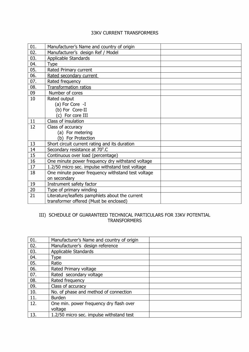
33KV CURRENT TRANSFORMERS
01. Manufacturer’s Name and country of origin02. Manufacturer’s design Ref / Model03. Applicable Standards04. Type05. Rated Primary current06. Rated secondary current 07. Rated frequency08. Transformation ratios09 Number of cores10 Rated output
(a) For Core -I (b) For Core-II
(c) For core III11 Class of insulation12 Class of accuracy
(a) For metering (b) For Protection
13 Short circuit current rating and its duration14 Secondary resistance at 700.C15 Continuous over load (percentage)16 One minute power frequency dry withstand voltage17 1.2/50 micro sec. impulse withstand test voltage18 One minute power frequency withstand test voltage
on secondary19 Instrument safety factor20 Type of primary winding21 Literature/leaflets pamphlets about the current
transformer offered (Must be enclosed)
III) SCHEDULE OF GUARANTEED TECHNICAL PARTICULARS FOR 33KV POTENTIAL TRANSFORMERS
01. Manufacturer’s Name and country of origin02. Manufacturer’s design reference 03. Applicable Standards04. Type05. Ratio06. Rated Primary voltage07. Rated secondary voltage08. Rated frequency09. Class of accuracy 10. No. of phase and method of connection11. Burden12. One min. power frequency dry flash over
voltage13. 1.2/50 micro sec. impulse withstand test
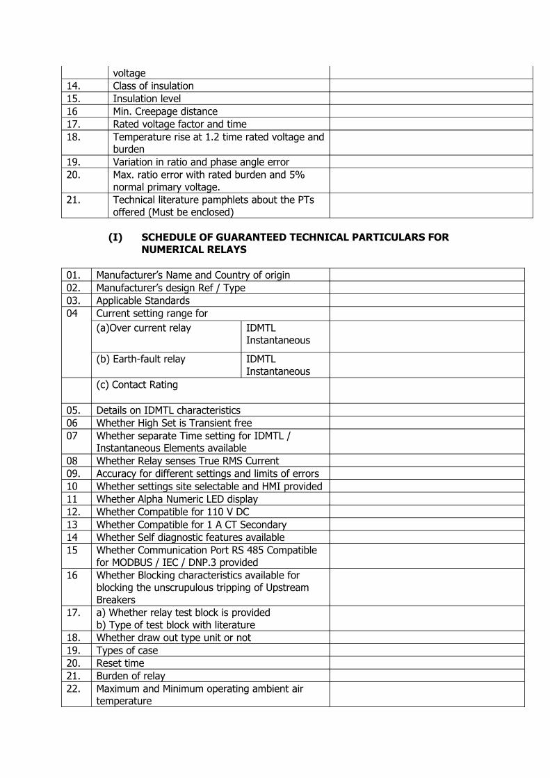
voltage14. Class of insulation15. Insulation level16 Min. Creepage distance17. Rated voltage factor and time18. Temperature rise at 1.2 time rated voltage and
burden19. Variation in ratio and phase angle error 20. Max. ratio error with rated burden and 5%
normal primary voltage. 21. Technical literature pamphlets about the PTs
offered (Must be enclosed)
01. Manufacturer’s Name and Country of origin02. Manufacturer’s design Ref / Type03. Applicable Standards 04 Current setting range for
(a)Over current relay IDMTLInstantaneous
(b) Earth-fault relay IDMTLInstantaneous
(c) Contact Rating
05. Details on IDMTL characteristics 06 Whether High Set is Transient free07 Whether separate Time setting for IDMTL /
Instantaneous Elements available08 Whether Relay senses True RMS Current09. Accuracy for different settings and limits of errors10 Whether settings site selectable and HMI provided11 Whether Alpha Numeric LED display12. Whether Compatible for 110 V DC13 Whether Compatible for 1 A CT Secondary14 Whether Self diagnostic features available15 Whether Communication Port RS 485 Compatible
for MODBUS / IEC / DNP.3 provided16 Whether Blocking characteristics available for
blocking the unscrupulous tripping of Upstream Breakers
17. a) Whether relay test block is providedb) Type of test block with literature
18. Whether draw out type unit or not19. Types of case20. Reset time21. Burden of relay22. Maximum and Minimum operating ambient air
temperature
(I) SCHEDULE OF GUARANTEED TECHNICAL PARTICULARS FOR NUMERICAL RELAYS
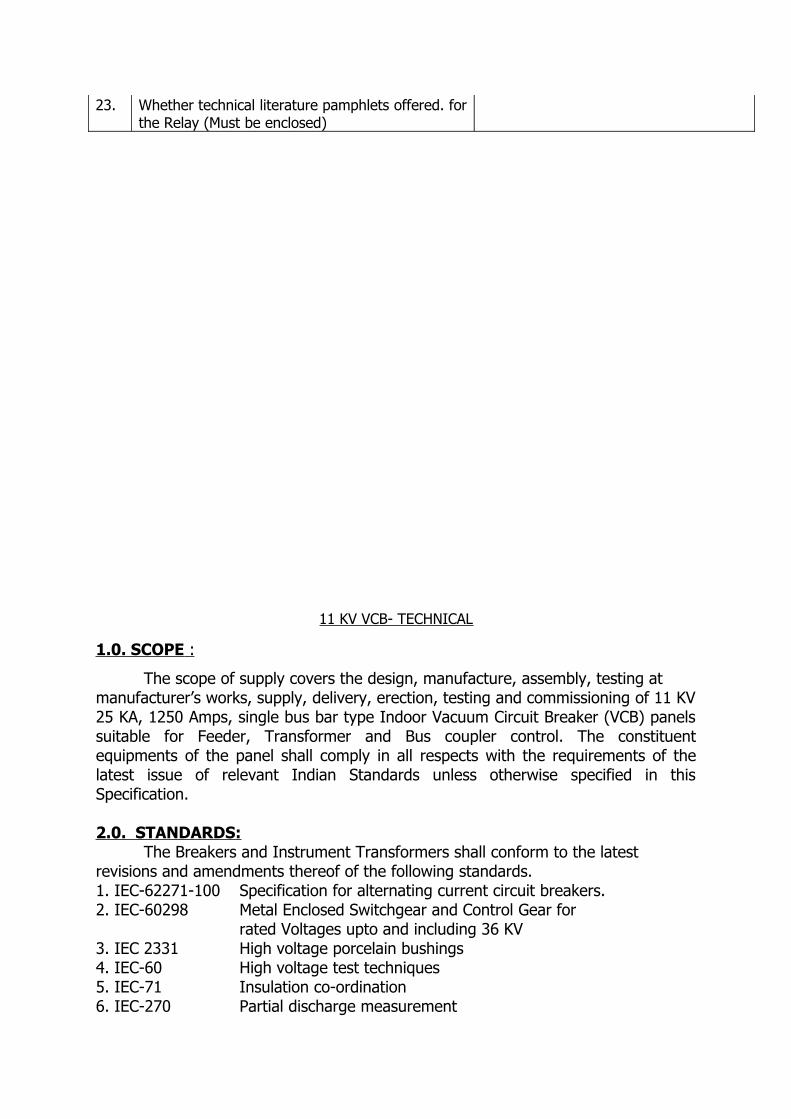
23. Whether technical literature pamphlets offered. for the Relay (Must be enclosed)
11 KV VCB- TECHNICAL
1.0. SCOPE :
The scope of supply covers the design, manufacture, assembly, testing atmanufacturer’s works, supply, delivery, erection, testing and commissioning of 11 KV 25 KA, 1250 Amps, single bus bar type Indoor Vacuum Circuit Breaker (VCB) panels suitable for Feeder, Transformer and Bus coupler control. The constituent equipments of the panel shall comply in all respects with the requirements of the latest issue of relevant Indian Standards unless otherwise specified in this Specification.
2.0. STANDARDS:The Breakers and Instrument Transformers shall conform to the latest
revisions and amendments thereof of the following standards.1. IEC-62271-100 Specification for alternating current circuit breakers.2. IEC-60298 Metal Enclosed Switchgear and Control Gear for rated Voltages upto and including 36 KV3. IEC 2331 High voltage porcelain bushings4. IEC-60 High voltage test techniques5. IEC-71 Insulation co-ordination6. IEC-270 Partial discharge measurement
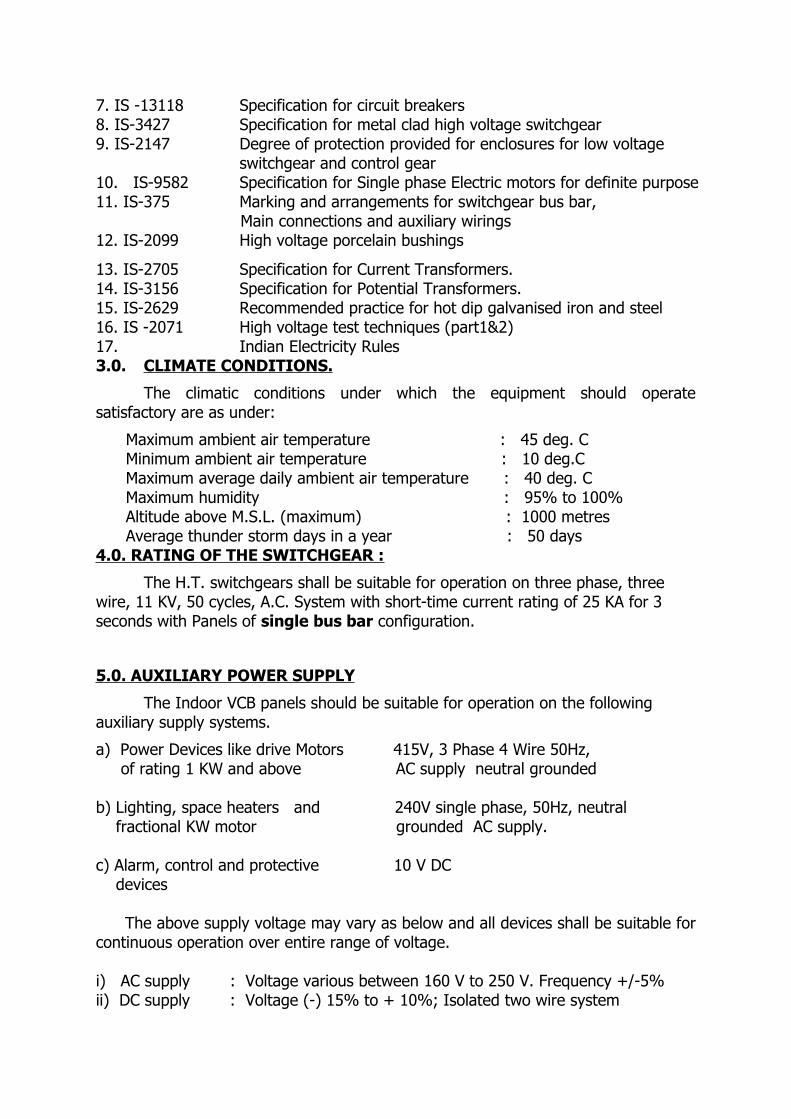
7. IS -13118 Specification for circuit breakers8. IS-3427 Specification for metal clad high voltage switchgear 9. IS-2147 Degree of protection provided for enclosures for low voltage
switchgear and control gear 10. IS-9582 Specification for Single phase Electric motors for definite purpose11. IS-375 Marking and arrangements for switchgear bus bar, Main connections and auxiliary wirings12. IS-2099 High voltage porcelain bushings
13. IS-2705 Specification for Current Transformers.14. IS-3156 Specification for Potential Transformers.15. IS-2629 Recommended practice for hot dip galvanised iron and steel16. IS -2071 High voltage test techniques (part1&2)17. Indian Electricity Rules 3.0. CLIMATE CONDITIONS.
The climatic conditions under which the equipment should operate satisfactory are as under:
Maximum ambient air temperature : 45 deg. C Minimum ambient air temperature : 10 deg.C Maximum average daily ambient air temperature : 40 deg. C Maximum humidity : 95% to 100% Altitude above M.S.L. (maximum) : 1000 metres Average thunder storm days in a year : 50 days 4.0. RATING OF THE SWITCHGEAR :
The H.T. switchgears shall be suitable for operation on three phase, three wire, 11 KV, 50 cycles, A.C. System with short-time current rating of 25 KA for 3 seconds with Panels of single bus bar configuration.
5.0. AUXILIARY POWER SUPPLY
The Indoor VCB panels should be suitable for operation on the following auxiliary supply systems.
a) Power Devices like drive Motors 415V, 3 Phase 4 Wire 50Hz, of rating 1 KW and above AC supply neutral grounded
b) Lighting, space heaters and 240V single phase, 50Hz, neutral fractional KW motor grounded AC supply.
c) Alarm, control and protective 10 V DC devices
The above supply voltage may vary as below and all devices shall be suitable for continuous operation over entire range of voltage.
i) AC supply : Voltage various between 160 V to 250 V. Frequency +/-5% ii) DC supply : Voltage (-) 15% to + 10%; Isolated two wire system
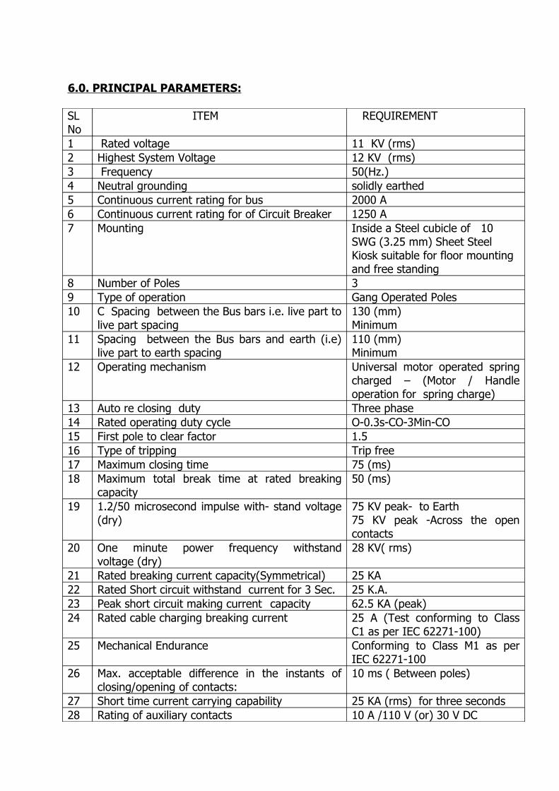
6.0. PRINCIPAL PARAMETERS:
SLNo
ITEM REQUIREMENT
1 Rated voltage 11 KV (rms) 2 Highest System Voltage 12 KV (rms) 3 Frequency 50(Hz.) 4 Neutral grounding solidly earthed 5 Continuous current rating for bus 2000 A6 Continuous current rating for of Circuit Breaker 1250 A 7 Mounting Inside a Steel cubicle of 10
SWG (3.25 mm) Sheet Steel Kiosk suitable for floor mounting and free standing
8 Number of Poles 39 Type of operation Gang Operated Poles10 C Spacing between the Bus bars i.e. live part to
live part spacing130 (mm)Minimum
11 Spacing between the Bus bars and earth (i.e) live part to earth spacing
110 (mm)Minimum
12 Operating mechanism Universal motor operated spring charged – (Motor / Handle operation for spring charge)
13 Auto re closing duty Three phase14 Rated operating duty cycle O-0.3s-CO-3Min-CO 15 First pole to clear factor 1.5 16 Type of tripping Trip free17 Maximum closing time 75 (ms) 18 Maximum total break time at rated breaking
capacity50 (ms)
19 1.2/50 microsecond impulse with- stand voltage (dry)
75 KV peak- to Earth75 KV peak -Across the open contacts
20 One minute power frequency withstand voltage (dry)
28 KV( rms)
21 Rated breaking current capacity(Symmetrical) 25 KA22 Rated Short circuit withstand current for 3 Sec. 25 K.A. 23 Peak short circuit making current capacity 62.5 KA (peak)24 Rated cable charging breaking current 25 A (Test conforming to Class
C1 as per IEC 62271-100) 25 Mechanical Endurance Conforming to Class M1 as per
IEC 62271-10026 Max. acceptable difference in the instants of
closing/opening of contacts: 10 ms ( Between poles)
27 Short time current carrying capability 25 KA (rms) for three seconds28 Rating of auxiliary contacts 10 A /110 V (or) 30 V DC
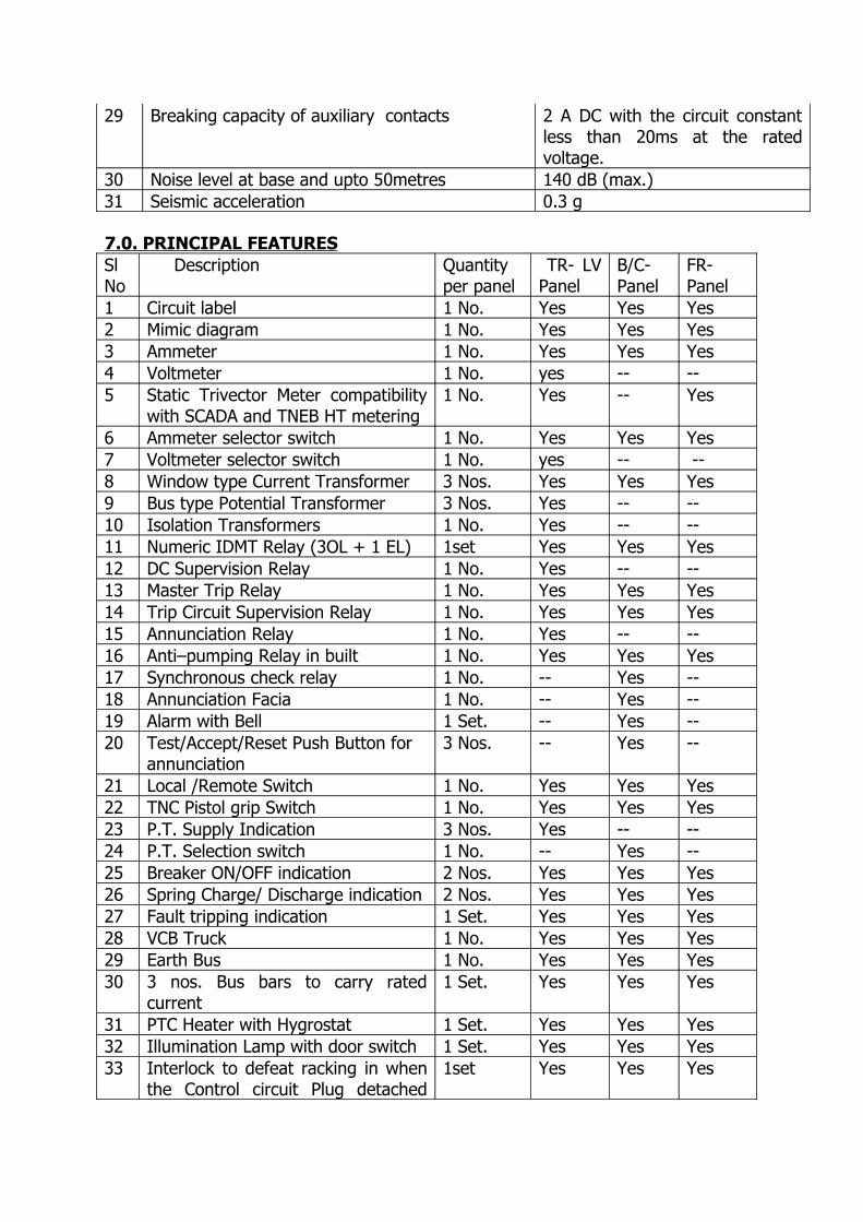
29 Breaking capacity of auxiliary contacts 2 A DC with the circuit constant less than 20ms at the rated voltage.
30 Noise level at base and upto 50metres 140 dB (max.)31 Seismic acceleration 0.3 g
7.0. PRINCIPAL FEATURESSl No
Description Quantityper panel
TR- LV Panel
B/C-Panel
FR-Panel
1 Circuit label 1 No. Yes Yes Yes2 Mimic diagram 1 No. Yes Yes Yes3 Ammeter 1 No. Yes Yes Yes4 Voltmeter 1 No. yes -- --5 Static Trivector Meter compatibility
with SCADA and TNEB HT metering1 No. Yes -- Yes
6 Ammeter selector switch 1 No. Yes Yes Yes7 Voltmeter selector switch 1 No. yes -- --8 Window type Current Transformer 3 Nos. Yes Yes Yes9 Bus type Potential Transformer 3 Nos. Yes -- --10 Isolation Transformers 1 No. Yes -- --11 Numeric IDMT Relay (3OL + 1 EL) 1set Yes Yes Yes12 DC Supervision Relay 1 No. Yes -- --13 Master Trip Relay 1 No. Yes Yes Yes14 Trip Circuit Supervision Relay 1 No. Yes Yes Yes15 Annunciation Relay 1 No. Yes -- --16 Anti–pumping Relay in built 1 No. Yes Yes Yes17 Synchronous check relay 1 No. -- Yes --18 Annunciation Facia 1 No. -- Yes --19 Alarm with Bell 1 Set. -- Yes --20 Test/Accept/Reset Push Button for
annunciation3 Nos. -- Yes --
21 Local /Remote Switch 1 No. Yes Yes Yes22 TNC Pistol grip Switch 1 No. Yes Yes Yes23 P.T. Supply Indication 3 Nos. Yes -- --24 P.T. Selection switch 1 No. -- Yes --25 Breaker ON/OFF indication 2 Nos. Yes Yes Yes26 Spring Charge/ Discharge indication 2 Nos. Yes Yes Yes27 Fault tripping indication 1 Set. Yes Yes Yes28 VCB Truck 1 No. Yes Yes Yes29 Earth Bus 1 No. Yes Yes Yes30 3 nos. Bus bars to carry rated
current1 Set. Yes Yes Yes
31 PTC Heater with Hygrostat 1 Set. Yes Yes Yes32 Illumination Lamp with door switch 1 Set. Yes Yes Yes33 Interlock to defeat racking in when
the Control circuit Plug detached 1set Yes Yes Yes
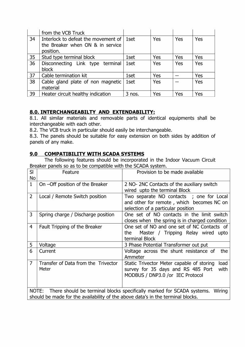
from the VCB Truck34 Interlock to defeat the movement of
the Breaker when ON & in service position.
1set Yes Yes Yes
35 Stud type terminal block 1set Yes Yes Yes36 Disconnecting Link type terminal
block1set Yes Yes Yes
37 Cable termination kit 1set Yes -- Yes38 Cable gland plate of non magnetic
material1set Yes -- Yes
39 Heater circuit healthy indication 3 nos. Yes Yes Yes
8.0. INTERCHANGEABILTY AND EXTENDABILITY:8.1. All similar materials and removable parts of identical equipments shall be interchangeable with each other.8.2. The VCB truck in particular should easily be interchangeable.8.3. The panels should be suitable for easy extension on both sides by addition of panels of any make.
9.0 COMPATIBILITY WITH SCADA SYSTEMS The following features should be incorporated in the Indoor Vacuum Circuit
Breaker panels so as to be compatible with the SCADA system. Sl No
Feature Provision to be made available
1 On –Off position of the Breaker 2 NO- 2NC Contacts of the auxiliary switch wired upto the terminal Block
2 Local / Remote Switch position Two separate NO contacts ; one for Local and other for remote , which becomes NC on selection of a particular position
3 Spring charge / Discharge position One set of NO contacts in the limit switch closes when the spring is in charged condition
4 Fault Tripping of the Breaker One set of NO and one set of NC Contacts of the Master / Tripping Relay wired upto terminal Block
5 Voltage 3 Phase Potential Transformer out put6 Current Voltage across the shunt resistance of the
Ammeter7 Transfer of Data from the Trivector
MeterStatic Trivector Meter capable of storing load survey for 35 days and RS 485 Port with MODBUS / DNP3.0 /or IEC Protocol
NOTE: There should be terminal blocks specifically marked for SCADA systems. Wiring should be made for the availability of the above data’s in the terminal blocks.
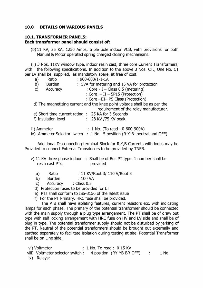
10.0 DETAILS ON VARIOUS PANELS
10.1. TRANSFORMER PANELS:Each transformer panel should consist of:
(b) 11 KV, 25 KA, 1250 Amps, triple pole indoor VCB, with provisions for both Manual & Motor operated spring charged closing mechanisms.
(ii) 3 Nos. 11KV window type, indoor resin cast, three core Current Transformers, with the following specifications. In addition to the above 3 Nos. CT., One No. CT per LV shall be supplied, as mandatory spare, at free of cost. a) Ratio : 900-600/1-1-1A b) Burden : 5VA for metering and 15 VA for protection c) Accuracy : Core - I – Class 0.5 (metering)
: Core – II – 5P15 (Protection) : Core –III– PS Class (Protection)
d) The magnetizing current and the knee point voltage shall be as per the requirement of the relay manufacturer. e) Short time current rating : 25 KA for 3 Seconds f) Insulation level : 28 KV /75 KV peak.
iii) Ammeter : 1 No. (To read : 0-600-900A) iv) Ammeter Selector switch : 1 No. 5 position (R-Y-B- neutral and OFF)
Additional Disconnecting terminal Block for R,Y,B Currents with loops may be Provided to connect External Transducers to be provided by TNEB.
v) 11 KV three phase indoor : Shall be of Bus PT type. 1 number shall be resin cast PTs: provided a) Ratio : 11 KV/Root 3/ 110 V/Root 3 b) Burden : 100 VA c) Accuracy : Class 0.5 d) Protection fuses to be provided for LT e) PTs shall conform to ISS-3156 of the latest issue f) For the PT Primary. HRC fuse shall be provided.
The PTs shall have isolating features, current resistors etc. with indicating lamps for each phase. The primary of the potential transformer should be connected with the main supply through a plug type arrangement. The PT shall be of draw out type with self locking arrangement with HRC fuse on HV and LV side and shall be of plug in type. The potential transformer supply should not be disturbed by jerking of the PT. Neutral of the potential transformers should be brought out externally and earthed separately to facilitate isolation during testing at site. Potential Transformer shall be on Line side.
vi) Voltmeter : 1 No. To read : 0-15 KV viii) Voltmeter selector switch : 4 position (RY-YB-BR-OFF) : 1 No. ix) Relays:
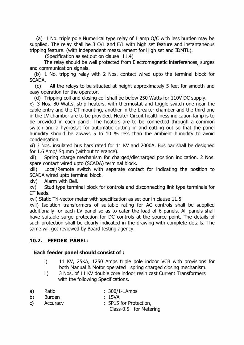
(a) 1 No. triple pole Numerical type relay of 1 amp O/C with less burden may be supplied. The relay shall be 3 O/L and E/L with high set feature and instantaneous tripping feature. (with independent measurement for High set and IDMTL). (Specification as set out on clause 11.4) The relay should be well protected from Electromagnetic interferences, surges and communication signals. (b) 1 No. tripping relay with 2 Nos. contact wired upto the terminal block for SCADA. (c) All the relays to be situated at height approximately 5 feet for smooth and easy operation for the operator. (d) Tripping coil and closing coil shall be below 250 Watts for 110V DC supply.x) 3 Nos. 80 Watts, strip heaters, with thermostat and toggle switch one near the cable entry and the CT mounting, another in the breaker chamber and the third one in the LV chamber are to be provided. Heater Circuit healthiness indication lamp is to be provided in each panel. The heaters are to be connected through a common switch and a hygrostat for automatic cutting in and cutting out so that the panel humidity should be always 5 to 10 % less than the ambient humidity to avoid condensation. xi) 3 Nos. insulated bus bars rated for 11 KV and 2000A. Bus bar shall be designed for 1.6 Amp/ Sq.mm (without tolerance).xii) Spring charge mechanism for charged/discharged position indication. 2 Nos. spare contact wired upto (SCADA) terminal block.xiii) Local/Remote switch with separate contact for indicating the position to SCADA wired upto terminal block.xiv) Alarm with Bell.xv) Stud type terminal block for controls and disconnecting link type terminals for CT leads.xvi) Static Tri-vector meter with specification as set our in clause 11.5.xvii) Isolation transformers of suitable rating for AC controls shall be supplied additionally for each LV panel so as to cater the load of 6 panels. All panels shall have suitable surge protection for DC controls at the source point. The details of such protection shall be clearly indicated in the drawing with complete details. The same will got reviewed by Board testing agency.
10.2. FEEDER PANEL:
Each feeder panel should consist of :
i) 11 KV, 25KA, 1250 Amps triple pole indoor VCB with provisions for both Manual & Motor operated spring charged closing mechanism.
ii) 3 Nos. of 11 KV double core indoor resin cast Current Transformers with the following Specifications.
a) Ratio : 300/1-1Ampsb) Burden : 15VAc) Accuracy : 5P15 for Protection, Class-0.5 for Metering

d) Short time current rating : 25 KA for 3 Secondse) Insulation level : 28 KV/75 KV Peakiii) Ammeter : 1 No. To Read 0-300 A iv) Ammeter Selector switch : 1 No. (5 position) (R-Y-B- Neutral-and OFF.)
Additional Disconnecting terminal Block for R,Y,B Currents with loops may be Provided to connect External Transducers to be provided by TNEB.v) The feeder panel shall be provided with line indicators using capacitor divider circuit along with provision for checking phase sequence. PT selection switch for energy meter reading with phase sequence indication shall be provided. (Shall be provided in Bus Coupler)
vi) Relays: (a) 1 No. triple pole Numerical type relay of 1 amp O/C with less burden may be supplied. The relay shall be 3 O/L and E/L with high set feature and instantaneous tripping feature. (with independent measurement for High set and IDMTL).(Specification as set out on clause 11.4) The relay should be well protected from Electromagnetic interferences, surges and communication signals. (b) 1 No. tripping relay with 2 Nos. contact wired upto the terminal block for SCADA. (c) All the relays to be situated at height approximately 5 feet for smooth and easy operation for the operator. (d) 3 Nos. 80 Watts, strip heaters, with thermostat and toggle switch one near the cable entry and the CT mounting, another in the breaker chamber and the third one in the LV chamber are to be provided. Heater Circuit healthiness indication lamp is to be provided in each panel. The heaters are to be connected through a common switch and a hygrostat for automatic cutting in and cutting out so that the panel humidity should be always 5 to 10 % less than the ambient humidity to avoid condensation.
viii) 3 Nos. insulated bus bars rated for 11 KV and 2000A. Bus bar shall be designed for 1.6 Amp/ Sq.mm (without tolerance).ix) Spring charge mechanism for charged/discharged position indication. 2 Nos. spare contact wired upto (SCADA) terminal block.x) Local/Remote switch with separate contact for indicating the position to SCADA wired upto terminal block.xi) Indication for fault tripping linked to common audio alarm and reset push button.xii) Alarm with Bell.xiii) Stud type terminal block for controls and disconnecting link type terminals for CT leads.xiv) Static Tri-vector meter with specification as set our in clause 11.5.
10.3 BUS COUPLER PANEL WITH SUITABLE ADAPTER:The Bus coupler panel should consist of:
i) 1 No. 11 KV, 25KA, 1250 Amps triple pole, VCB breaker panel with provision for both manual operation and motor spring closing mechanism with suitable adaptor for separating different feeders and transformers.

ii) 3 Nos. 11KV window type, indoor resin cast, three core Current Transformers, with the following specifications. a) Ratio : 900-600/1-1-1A b) Burden : 5VA for metering and 15 VA for protection c) Accuracy : Core - I – Class 0.5 (metering)
: Core – II – 5P15 (Protection) : Core –III– PS Class (Protection)
d) The magnetizing current and the knee point voltage shall be as per the requirement of the relay manufacturer. e) Short time current rating : 25 KA for 3 Seconds f) Insulation level : 28 KV /75 KV peak.
iii) Ammeter : 1 No. To read : 0-600-900A iv) Ammeter Selector switch : 1 No. 5 position (R-Y-B- neutral and OFF) Additional Disconnecting terminal Block for R,Y,B Currents with loops may be Provided to connect External Transducers to be provided by TNEB. v) Relays: (a) 1 No. triple pole Numerical type relay of 1 amp O/C with less burden may be supplied. The relay shall be 3 O/L and E/L with high set feature and instantaneous tripping feature. (with independent measurement for High set and IDMTL). (Specification as set out on clause 11.4) The relay should be well protected from Electromagnetic interferences, surges and communication signals.
(b) 1 No. tripping relay with 2 Nos. contact wired upto the terminal block for SCADA. (c) Bus coupler shall have synchronous check relay provision so that B/C can be closed only when the sequence of both the incomers are same. (d) All the relays to be situated at height approximately 5 feet for smooth and easy operation for the operator. (e) 3 Nos. 80 Watts, strip heaters, with thermostat and toggle switch one near the cable entry and the CT mounting, another in the breaker chamber and the third one in the LV chamber are to be provided. Heater Circuit healthiness indication lamp is to be provided in each panel. The heaters are to be connected through a common switch and a hygrostat for automatic cutting in and cutting out so that the panel humidity should be always 5 to 10 % less than the ambient humidity to avoid condensation. vii) 3 Nos. insulated bus bars rated for 11 KV and 2000A. Bus bar shall be designed for 1.6 Amp/ Sq.mm (without tolerance).viii) Spring charge mechanism for charged/discharged position indication. 2 Nos; spare contact wired upto (SCADA) terminal block.ix) Local/Remote switch with separate contact for indicating the position to SCADA wired upto terminal block.x) Alarm with Bell.xi) Stud type terminal block for controls and disconnecting link type terminals for CT leads.xii) Annunciation facia with a required windows.(xiii) Indication for fault tripping linked to the common audio alarm and reset push button.
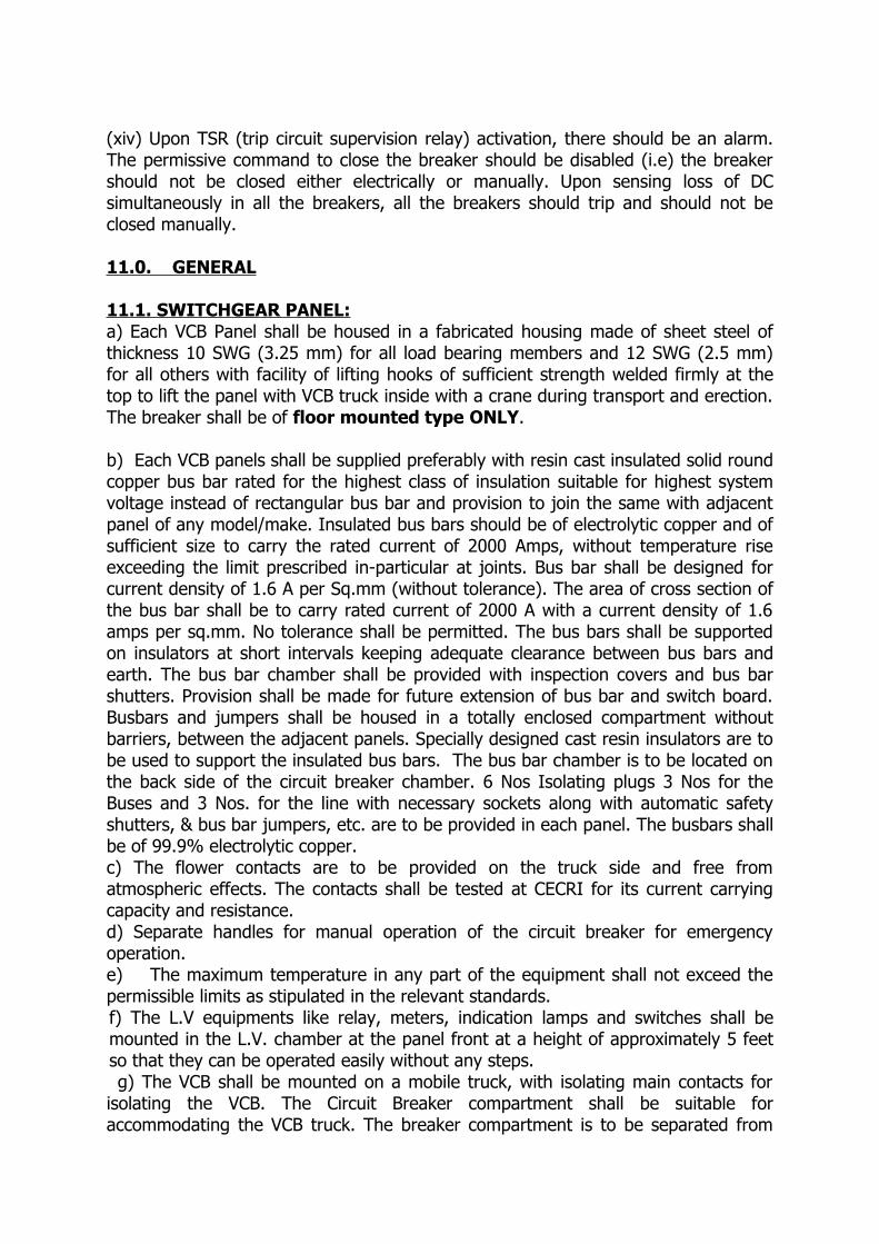
(xiv) Upon TSR (trip circuit supervision relay) activation, there should be an alarm. The permissive command to close the breaker should be disabled (i.e) the breaker should not be closed either electrically or manually. Upon sensing loss of DC simultaneously in all the breakers, all the breakers should trip and should not be closed manually.
11.0. GENERAL
11.1. SWITCHGEAR PANEL:a) Each VCB Panel shall be housed in a fabricated housing made of sheet steel of thickness 10 SWG (3.25 mm) for all load bearing members and 12 SWG (2.5 mm) for all others with facility of lifting hooks of sufficient strength welded firmly at the top to lift the panel with VCB truck inside with a crane during transport and erection. The breaker shall be of floor mounted type ONLY.
b) Each VCB panels shall be supplied preferably with resin cast insulated solid round copper bus bar rated for the highest class of insulation suitable for highest system voltage instead of rectangular bus bar and provision to join the same with adjacent panel of any model/make. Insulated bus bars should be of electrolytic copper and of sufficient size to carry the rated current of 2000 Amps, without temperature rise exceeding the limit prescribed in-particular at joints. Bus bar shall be designed for current density of 1.6 A per Sq.mm (without tolerance). The area of cross section of the bus bar shall be to carry rated current of 2000 A with a current density of 1.6 amps per sq.mm. No tolerance shall be permitted. The bus bars shall be supported on insulators at short intervals keeping adequate clearance between bus bars and earth. The bus bar chamber shall be provided with inspection covers and bus bar shutters. Provision shall be made for future extension of bus bar and switch board. Busbars and jumpers shall be housed in a totally enclosed compartment without barriers, between the adjacent panels. Specially designed cast resin insulators are to be used to support the insulated bus bars. The bus bar chamber is to be located on the back side of the circuit breaker chamber. 6 Nos Isolating plugs 3 Nos for the Buses and 3 Nos. for the line with necessary sockets along with automatic safety shutters, & bus bar jumpers, etc. are to be provided in each panel. The busbars shall be of 99.9% electrolytic copper. c) The flower contacts are to be provided on the truck side and free from atmospheric effects. The contacts shall be tested at CECRI for its current carrying capacity and resistance.d) Separate handles for manual operation of the circuit breaker for emergency operation.e) The maximum temperature in any part of the equipment shall not exceed the permissible limits as stipulated in the relevant standards.f) The L.V equipments like relay, meters, indication lamps and switches shall be mounted in the L.V. chamber at the panel front at a height of approximately 5 feet so that they can be operated easily without any steps.
g) The VCB shall be mounted on a mobile truck, with isolating main contacts for isolating the VCB. The Circuit Breaker compartment shall be suitable for accommodating the VCB truck. The breaker compartment is to be separated from
the bus bar and cable compartment by Fiber Glass reinforced epoxy plate / MS plate. The shutters are to be operated smoothly, automatically by the movement of truck and the shutters are of solid closing type which close automatically when the truck is withdrawn and the shutters cannot be pushed open inadvertently when the truck is removed. The breaker is to be operated both Manual/Motor spring charging mechanism. In case, the breaker truck is withdrawn, there shall be a cover supplied to make it vermin proof if doors are not provided.h) 7NO + 7NC breaker auxiliary switch (2 NO + 2 NC to be wired up to control cubicle terminals for SCADA). 150 mm x 150 mm. gland plate for entry of SCADA and other control cables shall be provided at the back side of the panel.Upon TSR (trip circuit supervision relay) activation, there should be an alarm. The permissive command to close the breaker should be disabled (i.e) the breaker should not be closed either electrically or manually. Upon sensing loss of DC simultaneously in all the breakers, all the breakers should trip and should not be closed manually. The above scheme shall be housed in the bus coupler.All panels shall have suitable surge protection for DC controls at the source point. Provision shall be given to isolate the DC load of the SCADA system at a single point. The individual compartments are to be provided with explosion vents at the top of panels to let out gases under pressure generated during unlikely event of fault inside the panel.
When the breaker is in service position, without closing the door the breaker should not be closed.
Window type CT shall be mounted such a way that while replacing the cable termination or terminating the cable there should not be any need to remove the CT and its associated wiring. LV and Bus coupler the ratio shall be 900-600/1-1-1A.
The Panel illumination with 14 W CFL is to be provided in the Bus bar and L.V.chamber compartment.
The offer should include provision for wiring of annunciation equipment like hooter, bell, and reset push buttons for each Sub Station. The cable pan should have a maximum depth up to 400mm, to obtain trifurcation distance of about 800mm between cable fixing and core connection.
Accessories required for fixing the panel such as foundation bolts and nuts shall be provided along with panel. For every 2 Nos. of breakers, breaker operating rod, door opening key, interlock key, spring charge rod shall be given.
The control cable entry (open with cover) shall be provided in rear side bottom of the cable chamber of Transformer and Feeder panels and shall be separated from the power cable entry.
Trip circuit healthiness indication and auto trip indication shall be in DC supply. All other indications shall be in AC supply.
Copper Bus bar joints should also be insulated.Cable pan shall have suitable MS channel for cable clamping arrangement for
all Feeders and Transformer panels. Transformer panel shall have provision to connect 6 runs of 1 X 630 sq. mm. aluminum UG cable and 3 X 300 sq. mm. cable for the feeder panel.
In all the breakers, the reset push button shall be provided and the annunciation shall be extended from the common alarm. Each VCB shall be housed in a fabricated sheet steel enclosure with the following:
(a) Vertical or horizontal isolation, horizontal draw out circuit Breaker truck with VCB its mechanism, auxiliary contacts and interlocks.(b) 11 KV, single phase, twin core/triple core, resin cast window type indoor CTs.(c) 11KV, single phase, cast resin, bus PT to be provided for Transformer panel.(d) Air insulated Bus bar chamber fixed main contacts, automatic safety shutters, bus bar, jumpers etc.(e) Ammeter, Voltmeter, relay control and selector switches, cable termination kits Suitable for 11 KV XLPE Aluminum cable with all accessories and with suitable heaters, indicating lamps and illuminating lamps etc.(f) 1 No. fabricated housing made of steel not less than 10 SWG (3.25 mm) sheet with facility of lifting hooks at the top corners to lift the panel with a crane during transport and erection.
(g) One set of mechanical interlocks to prevent moving of the switch gear truck unless the circuit breaker is in the open position.(h) One set of mechanical interlocks to prevent the movement of the breaker from service position of the Breaker, when the breaker is in service position and in closed condition.(i) One set of mechanical/electrical interlocks to prevent the closing of the Breaker when the Breaker is in service position and the control cable plug is not inserted in the VCB truck
11.2. SWITCHGEAR TRUCK:
The breaker truck is to be horizontally drawn out and of floor mounted type only. The service and test positions shall be distinctly marked. In the service position, the isolating contacts should fully engage each other. The breaker should lock out after the flower contacts have made full contact with the bus. The control wiring from the breaker to the control equipments on the L.V. Chamber shall be made through 24 way plug and socket arrangement. The plug is to be interlocked in such a way that the breaker truck cannot be pushed in service position until and unless the control plug is inserted in the correct place. The full isolated position is to be achieved in the test position by removal of the control plug. The inside operating or insulated fibre glass connecting rods wherever used shall be sturdy and shall not break during the entire life period of the breaker. The shunt close/ trip coils shall be fed from 110 Volts station battery for closing/ tripping purposes. The current taken by the coils shall be limited to 3 amps (maximum).
DUTY CYCLE O-0.3 s-CO-3Min.-CO as per latest IECAll the equipments should operate without undue vibration and with the least practicable amount of noise. The breaker truck should be inter-changeable. This should be ensured. Operating handle, circuit breaker drawal handles are to be supplied at the rate of two per sub-station where the breaker panels are intended to be used. All mating contacts (flower) shall be free from atmospheric effects. Contacts shall be tested at CECRI and designed to have adequate thermal and current carrying capacity for the duty specified and to have a life expectancy so that frequent replacements due to excessive burning will not be necessary. Provision shall be made for rapid dissipation of heat generated by the arc on opening.
Breakers shall be so designed that when operated within their specified rating, the temperature of each part will be limited to values consistent with a long life of the materials used. The insulated fibre glass connecting rods wherever used shall be sturdy and shall not break during the entire life period of the breaker. The temperature shall not exceed that indicated in latest IEC under specified ambient conditions.
Interchangeability of VCB truck should be ensured at the time of testing at the supplier’s premises and at site. If the above is not ensured at site, the breakers should be replaced by you, with the above facility.
If arcing contacts are used they shall be first to close and last to open. Tips of arcing contacts and main contacts shall be silver plated or made of superior material like graphite/tungsten copper /copper chromium
Any device provided for voltage grading to damp oscillations or to prevent restrike prior to the complete interruption of the circuit or to limit over-voltage on closing shall have a life expectancy comparable to that of the breaker as a whole.
11.3 INTERLOCKS11.3.1. Operation of the Bus selector switch should be defeated when the breaker is in service position and is in ON condition.
11.3.2. The movement of the switchgear truck should be defeated when Breaker is in service position and is in ON position.
11.3.3. The movement of the switchgear truck should be defeated when the door is in open position. Opening of door should be defeated when VCB is in service.
11.3.4. The process of racking in of the Switchgear truck should be defeated if the control plug is not plugged in on to the VCB truck and breaker should set tripped if the control plug is removed when the breaker is ON.
11.3.5. The closing of the breaker either electrically or mechanically should be defeated if the breaker is not locked in the service position fully.
11.3.6. Secondary Plug (Truck Plug) and socket interlock shall be provided.
11.3.7. Limit switch shall be given in such a way that after spring charging only the closing pulse can be given to the breaker.
11.3.8. One set of mechanical interlock to prevent moving of the switchgear truck unless the circuit breaker is in the open position.
11.3.9. One set of Electrical/Mechanical interlock to prevent the closing of the breaker when the breaker is in service position and the control cable plug is not inserted in the Vacuum Circuit Breaker truck.

11.3.10. Movement of the switchgear truck from service to test position shall be possible only when the breaker is in OFF position.
11.3.11. Front door of the switchgear compartment shall not be opened unless breaker is tripped and brought to test position.
12.3.12 Auxiliary plug and socket shall not be opened unless VCB is brought to test position
12.3.13. Rear cable chamber cover shall not be opened unless and otherwise the breaker if OFF and in test position. Further the movement of the switchgear truck should be defeated i) when the switchgear truck compartment is open and ii) the rear covers are not closed.
Detailed drawings on the operation of the above interlocks shall be provided along with the Technical offer. 11.4. NUMERICAL RELAY:
i) The relay shall be of numerical type with true RMS measurement with provision for instantaneous tripping.
ii) Rated for CT secondary of 1 A and with burden less than 3 VA.
iii) Rated for auxiliary supply voltage 30 to 110 Volts DC.
iv) Shall have independent protection characteristics (IDMTL and Transient free High set) for each phase. The IDMTL characteristic of the relay shall be 1.3 secs at 10 times set value of the current with time set at unity.
v) The following characteristics should be able to be set at the site.IDMTL – 5% to 200% for OC. 2% to 80% for E/F. High Set – 50 % to 2000 % for OC 20 % to 800 % for E/F.
Selection of curve shall be 1.3 secs. Instantaneous setting for O/L shall be 20. For E/L it shall be 8.
vi) The Time Multiplier setting shall be 0 to unity continuously in steps of 0.01, variable for each phase and for both IDMTL and high set separately.
vii) Storage and display of last 7 (seven) fault data with time, date and current details.
vii) Alpha – Numeric LED display.
viii) HMI for programming the relay.
ix) Shall have self diagnostic features.
x) Shall have one set of NO and 1 set of NC potential free contacts.
xi) The relay should operate satisfactorily at ambient air temperature ranging from 10°C to 50°C.
(xii) The relay should have inbuilt characteristics of blocking unscrupulous tripping of upstream breakers.
(xiii) The relay should have communication port (RS 485) compatible for MOD BUS/IEC Protocol.
xiv) The relay should confirm to the latest IS/IEC.
xv) The relay shall be draw out type and suitable for both 30V and 110V DC.
Upon TSR (trip circuit supervision relay) activation, there should be an alarm. The permissive command to close the breaker should be disabled (i.e) the breaker should not be closed either electrically or manually. Upon sensing loss of DC simultaneously in all the breakers, all the breakers should trip and should not be closed manually.
Only Areva/Siemens/GE/ABB/Easun make relays shall be accepted. No equivalent shall be proposed. All relays shall be installed with Test block similar to Areva make MMLG/MMLB type to facilitate relay calibrating/testing/replacing without any interruption of power supply. The type of relay proposed by the vendors are to be got approved by Board testing agency if any other make of relay is proposed. 11.5. STATIC TRIVECTOR METER 3 Phase 4 wire 110V 1A 0.5 Accuracy class Static Trivector Meter with automatic and manual scrolling facility to read KWHr, RKVAHr, Voltage, Current, Power factor and instantaneous KW with optical port for downloading the load survey for 35 days and with MD reset push button and test block. (Link type terminal block) preferably below the meters for isolation during testing. The meter should be compatible with the trivector meters used by TNEB for HT metering. Necessary software compatible with SANDS CMRI for the same also to be included in the scope of supply. Only Elster, Secure, L&T and Lyandis Gear make of the meter shall be accepted. Any other type of the meter intended to be used by the supplier shall have to be accepted by the MRT wing. RS 485 port compatible for MODBUS/IEC/D NP 3 protocol shall be provided. Opto coupler or one set potential free contact to translate the energy transmitted through the feeder to SCADA.
11.6. ANNUNCIATORS AND INDICATORS :
The annunciation fascias with a minimum of 24 windows shall be provided with auxiliary relays, flasher, hooter / bell for indicating tripping of the feeders and discontinuity of the trip circuits. All the panels shall have the inter connection for
accepting / resetting the alarms from the respective panels. LEDs shall be utilised for various Indications to be provided. All indication lamps shall be of LED cluster type. Lamps must be replaced from the front end instead of the rear end.
11.7. A.C AND D.C. DISTRIBUTION ARRANGEMENTS:
Each control and relay panel shall be provided with necessary arrangements for receiving, distributing and isolating of A.C and D.C supplies for control, signaling, lighting and heating purposes. The incoming and sub-circuits shall be separately provided with switch fuse units/MCBs. Fuses provided in the potential circuits shall protect metering.
All fuses shall be of HRC cartridge type confirming to IS2203 mounted on the plug in type fuse base. Fuses shall have fusing indication and the fuse base shall have imprints of fuse rating and voltage. All fuses and links shall be mounted with sufficient space between each row of fuses and rows upper or below and should have a minimum of 2cms. space between live terminal of the fuse/links and metal parts. Separate fuse control shall be given for close, trip and indication and annunciation in DC Circuit and for spring charging motor and heater for A.C.
1 1.8. PANEL WIRINGS:
The wiring should be of high standard and should be able to withstand the tropical weather conditions. All wiring shall be provided with 1100 volt Grade single core multistranded copper conductor wires with P.V.C insulation and shall be flame retardant low smoke type. The minimum size of the stranded copper wire shall be 1.5 Sq.mm
The wiring shall be carried out using 4.0 Sq.mm. PVC insulated multi-strand FRLS copper wire of 1100V Grade for entire CT circuits, 2.5 Sq.mm. PVC insulated multi-strand FRLS copper wire of 1100V Grade for entire AC Power &, DC Control. Suitable coloured wires shall be used for phase identification and interlocking type ferrules shall be provided at both ends of the wires for wire identification. Terminal should be suitably protected to eliminate sulphating. Connections and terminal should be able to withstand vibrations. The terminal blocks should be stud type with suitable spring washer and lock nuts.
Flexible wires shall be used for wiring of devices on moving parts such as swinging panels or panel doors. Panel wiring shall be securely supported, neatly arranged readily accessible and connected to equipment terminals, terminal blocks and wiring gutters. The cables shall be uniformly bunched and tied by means of PVC belts and carried in a PVC carrying trough.
24 Pin type socket shall be given in all the breakers in respective of the type of breaker with identical type of wiring for the purpose of interchangeability.The position of PVC carrying trough and wires should not give any hindrance for fixing or removing relay casing, switches etc., Wire termination shall be made with solder less crimping type of tinned copper lugs. Core identification plastic ferrules marked to correspond with panel wiring diagram shall be fitted with both ends of each wire. Ferrules shall fit tightly on the wire when disconnected. The wire number shown on the wiring shall be in accordance with the IS.375.
All wires directly connected to trip circuits of breaker or devices shall be distinguished by addition of a red color unlettered ferrule. Inter-connections to adjacent panels shall be brought out to a separate set of Terminal blocks located near the slots or holes to be provided at the top portion of the panel.
Arrangements shall be made for easy connections to adjacent panels at site and wires for this purpose shall be provided and bunched inside the panel. The bus wire shall run at the top of the panel.
Terminal block with isolating links should be provided for bus wire. Bus wire for voltage from the bus PT shall be provided with wiring diagram. At least 10% of total terminals shall be provided as spare for further connections. Wiring shall be done for all the contacts available in the relay and other equipment and brought out to the terminal blocks for spare contacts. Color code for wiring is preferable in the following colours. PT supply Red, Yellow, Blue for phase and Black for neutral CT circuits Similar to the above DC circuits Grey for both positive and negative 250V AC circuits Black for both phase and neutral Earthing Green
The wiring shall be strictly in accordance to the wiring diagram for proper functioning of the connected equipment. Not more than two wires must be connected to one terminal. Terminal blocks shall not be less than 1100V grade and shall be piece-molded type with insulation barriers. The terminal shall hold the wires in the tight position by bolts and nuts with lock washers. The terminal blocks shall be arranged in vertical formation at an inclined angle with sufficient space between terminal blocks for easy wiring. The lowest terminal shall be atleast 450 mm above ground level. Steel plate shall be provided 150 mm below the lowest terminal block to fix the cable glands. 11.9. CABLE BOX:
Cable pan shall have suitable MS channel for cable clamping arrangement for all Feeders and Transformer panels. Each transformer panel and feeder panel has to be supplied with suitable 11 KV end termination kits of either push on or heat shrinkable type. The cable configuration for transformer panel shall be 1x630 Sq.mm aluminum XLPE (3+3 runs) and 3 X 300 sq. mm aluminum XLPE for feeder panel. Cable Termination should be provided with support Insulators.
11.10. HEATERS: 3 Nos. 80 Watts, PTC (Positive Temperature co-efficient) heaters with
Hygrostat shall be provided, with auto control, one near the cable entry and the CT mounting, another in the breaker chamber and the third one in the Bus bar chamber. The heaters are to be connected through a common switch and a hygrostat for automatic cutting in and cutting out so that the panel humidity should be always lower than the ambient humidity to avoid condensation. Indication for healthiness of Heater circuit has to be provided in each panel.11.11. EARTHING
All panels shall be equipped with an earth bus securely fixed along the base of the panels. When several panels are mounted adjoining to each other, the earth bus shall be made continuous and necessary connectors and clamps for this purpose shall be included in the scope of supply. The main earth bus shall be made of 25 mm x 6 mm tinned copper flat and others shall be of 25 mm X 3 mm size. Provision shall be made on the end panel for connecting the earth bus to the earth grid. Necessary terminal clamps and connectors shall be included in the scope of supply.All metallic cases of the relays, instruments and other panel mountedequipment’s shall be connected to the earth bus by independent copper wires of size not less than 4.0 sq.mm. The color code of earthing wire shall be green. Earthing wires shall be connected on the terminals with suitable clamp connectors and soldering shall not be permitted. 11.12. LABELS
All fronts mounted equipments as well as equipments mounted inside the panels shall be provided with individual labels with equipment designation engraved. Labels shall be made of non-rusting metal or 3 ply lanced. Labels shall have white letters on black or dark batch ground. The size of the labels shall be width - 1.5 cms. length - as per the length of the inscription and the letter size shall be 0.75 cm.
12 .0. DOCUMENTATION: All drawings shall conform to relevant international standards Organisation (ISO) Specification. All drawings shall be in ink and suitable for micro filming.
13.0. NAME PLATE :
Each circuit breaker shall be provided with a name plate legible and indelibly marked with at least the following information.a) Name of manufacturerb) Type, design and serial numberc) Rated voltage and currentd) Rated frequencye) Rated symmetrical breaking capacityf) Rated making capacityg) Rated short time current and its durationh) Purchaser Order number and datei) Month and Year of supplyj) Rated lighting impulse withstand voltagek) D.C. component of current.
The drawings shall have to be accepted by any of the MRT wing before opening of the price bid.
NOTE: 1) The word rated need not appear on the name plate. Recognised abbreviations may be used to express the above particulars.

2) Whether the circuit breaker is fitted with closing/tipping devices necessitating an auxiliary supply shall be stated either on the circuit breaker name plate or any other acceptable position.
14.0. MATERIALS AND WORKMANSHIP:
All the materials shall be of the best class and capable of satisfactory operation in the tropics with humid atmosphere conditions. Unless otherwise specified, they shall conform to the requirements of the appropriate ISS/IEC.
NOTE: The Over Current and earth leakage relays shall be of numerical version.
The workmanship shall be of the best grade and the entire construction in accordance with the best modern practice.
The equipment shall be designed to facilitate inspection and repairs and to ensure satisfactory operation under atmosphere condition prevailing at site and under such sudden variation of load and voltage as may be met with under working conditions in the system including those due to faulty synchronizing and short circuit within the rating of the apparatus.
The design shall incorporate every reasonable precaution and provision for the safety of all those concerned in the operation and maintenance of the equipment.
All the equipments should operate without undue vibration and with the least practicable amount of noise.
The breaker truck should be inter-changeable. This should be ensured.
Operating handle, circuit breaker draw out handles are to be supplied at the rate of two per sub-station for the sub-stations where the breaker panels are intended to be used.
15.0. DRAWINGS :
Supplier has to furnish the drawings for
(i) Principal dimensions of the 11 KV switchgear, (ii) GA for 11 panels (8 feeders, 2 LV & 1 Bus coupler with adaptor) including its foundation details, (iii) Drawing clearly showing the interlock arrangement provisions specified in the specification, (iv) Schematic drawings of control, metering, protection and SCADA circuits in respect of feeders, LV & Bus coupler with detailed write up. The schematic shall
include wiring details of individual components and terminal arrangements with ferrule details, (v) Drawing showing height and arrangement of 11 KV bus bars including design calculations & loading data for its support insulators, and (vi) Name plate drawing along with the technical offer.
Further the supplier shall submit illustrative and descriptive literature for various items of switchgear, etc. including. i) Instruction manuals
ii) Catalogues of spares recommended with drawing to indicate each items of spares
iii) List of spares and special tools recommended by the supplier. iv) Type Test Certificates as per ISS
The following should be supplied to each consignee circle along with the initial supply of the equipments ordered.
5 copies of printed and bound volumes of operation, maintenance and erection manuals in English along with the copies of approved drawings and type test reports etc.
3 sets of the manuals detailed as above shall have to be supplied to the SE/Transmission-II within one week from the date of approval of drawings. The spares for the breakers ordered under scope of the contract should also be supplied to the consignee circles along with the initial supply of breakers. It should be noted that if the above conditions are not full filled the initial payment will not be released.16.0. TESTS:
16.1. TYPE TEST:
Following Type tests as per latest IEC must have been performed and the reports enclosed along with technical bid.1) Basic short circuit test duties 1-5 2) Single phase breaking capacity test 3) Short time withstand test for 25 KA for 3 secs. 4) Temperature rise test at 2000 A & milli volt drop test. 5) Lightning impulse withstand test 6) Power frequency withstand test (dry) 7) Cable charging switching test duty 8) Mechanical endurance (M2 class) 9) Internal arc fault withstand test on cable, main bus and breaker chambers.
The same shall be scrutinized and accepted by the Board before opening up of price bid.16.2. ACCEPTANCE AND ROUTINE TESTS:
All acceptance and routine tests as stipulated in the latest IEC- shall be carried out by the supplier in the presence of purchaser’s representative. A team of Board engineers not less than three, one each from CDC, MRT and Inspection wing shall inspect the breaker. Only on getting the inspection report to the effect that the inspection was carried out satisfactorily dispatch clearance shall be issued. The supplier shall give atleast 10 days advance intimation to the board to enable them to depute their representatives for witnessing the tests.
16.3. ADDITIONAL TESTS:
The purchaser reserves the right for carrying out any other tests of a reasonable nature at the works of the supplier/laboratory or at any other recognised laboratory/research institute in addition to the above mentioned type, acceptance and routine tests at the cost of the purchaser to satisfy that the material complies with the intent of this Purchase order.
17.0. INSPECTION:
The inspection may be carried out by the purchaser at any stage of manufacture. The supplier shall grant free access to purchaser’s representative at a reasonable time when the work is in progress. Inspection and acceptance of any equipment under this purchase order by the purchaser shall not relieve the supplier of his obligation of furnishing equipment in accordance with the purchase order and shall not prevent subsequent rejection if the equipment is found to be defective.
The supplier shall keep the purchaser informed in advance, about the manufacturing programme so that arrangement can be made for inspection. The purchaser reserves the right to insist for witnessing the acceptance/routine testing of the bought out items. No material shall be despatched from its point of manufacture unless the material has been satisfactorily inspected and tested / unless the same is waived by the purchaser in writing.
Two nos operating handle & circuit breaker drawal handles are to be supplied along with the panels.
19.0. ERECTION, TESTING AND COMMISSIONING:
The successful bidder shall erect, test and commission the 33 KV Circuit Breakers. On successful completion of commissioning he shall handover the panels to the Board.
18.0. MAKE OF MATERIALS
1. Breaker control switch : Kaycee/Recom/Alstom2. Selector switch : Kaycee/Recom3. Ammeter/Volt meter : AE/Meco/IMP4. Push buttons : Kaycee/Alstom/Vaishno5. LED lamps : Kaycee/Alstom/Vaishno6. Terminal blocks : Connectwell/Elmex/Allen Bradely/Weid muller

7. Termination Kits : Rachem/Denson8. Panel wiring : Finolex/Pcko/Phoenix/Havells9. Hooter/buzzer/bell : Anchor/Kaycee10. CT/PT :Kappa/Crompton Greaves/Jyoti/Siemens/Concord/Vishal11. Trivector meter : Elster/Secure/L&T/Lyandis Gear12. Relays : Areva/Siemens/GE/ABB/Easun13. Vacuum interrupter : BEL/Westing House/ Crompton Greaves/ Siemens
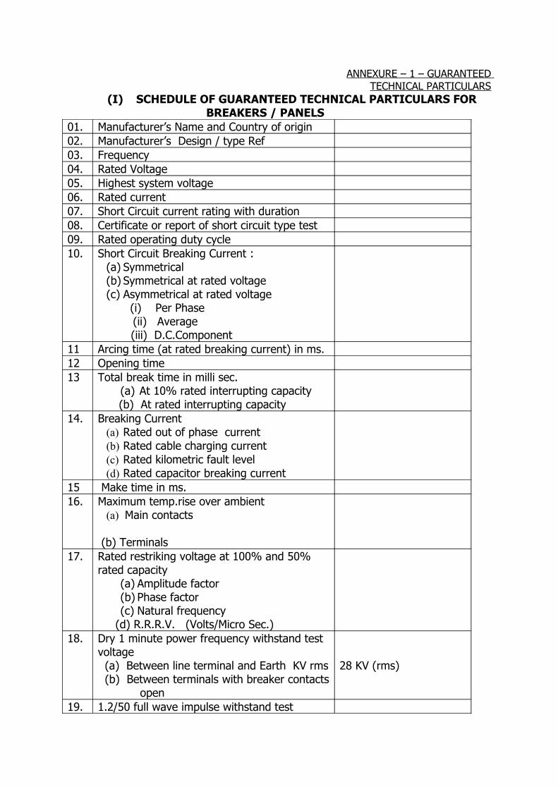
ANNEXURE – 1 – GUARANTEED TECHNICAL PARTICULARS
(I) SCHEDULE OF GUARANTEED TECHNICAL PARTICULARS FOR BREAKERS / PANELS01. Manufacturer’s Name and Country of origin02. Manufacturer’s Design / type Ref03. Frequency04. Rated Voltage05. Highest system voltage06. Rated current07. Short Circuit current rating with duration08. Certificate or report of short circuit type test09. Rated operating duty cycle10. Short Circuit Breaking Current :
(a) Symmetrical(b) Symmetrical at rated voltage(c) Asymmetrical at rated voltage
(i) Per Phase (ii) Average
(iii) D.C.Component 11 Arcing time (at rated breaking current) in ms.12 Opening time13 Total break time in milli sec.
(a) At 10% rated interrupting capacity (b) At rated interrupting capacity
14. Breaking Current (a) Rated out of phase current (b) Rated cable charging current (c) Rated kilometric fault level (d) Rated capacitor breaking current
15 Make time in ms.16. Maximum temp.rise over ambient
(a) Main contacts (b) Terminals
17. Rated restriking voltage at 100% and 50% rated capacity
(a) Amplitude factor(b) Phase factor(c) Natural frequency
(d) R.R.R.V. (Volts/Micro Sec.)18. Dry 1 minute power frequency withstand test
voltage (a) Between line terminal and Earth KV rms (b) Between terminals with breaker contacts open
28 KV (rms)
19. 1.2/50 full wave impulse withstand test
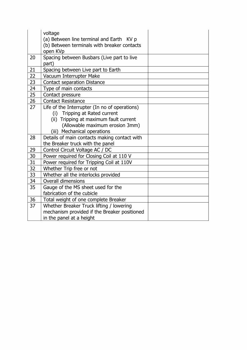
voltage(a) Between line terminal and Earth KV p(b) Between terminals with breaker contacts open KVp
20 Spacing between Busbars (Live part to live part)
21 Spacing between Live part to Earth22 Vacuum Interrupter Make23 Contact separation Distance24 Type of main contacts25 Contact pressure26 Contact Resistance27 Life of the Interrupter (In no of operations)
(i) Tripping at Rated current (ii) Tripping at maximum fault current (Allowable maximum erosion 3mm) (iii) Mechanical operations
28 Details of main contacts making contact with the Breaker truck with the panel
29 Control Circuit Voltage AC / DC30 Power required for Closing Coil at 110 V31 Power required for Tripping Coil at 110V32 Whether Trip free or not33 Whether all the interlocks provided34 Overall dimensions35 Gauge of the MS sheet used for the
fabrication of the cubicle36 Total weight of one complete Breaker37 Whether Breaker Truck lifting / lowering
mechanism provided if the Breaker positioned in the panel at a height
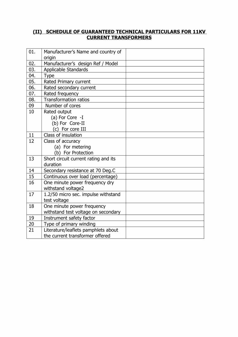
(II) SCHEDULE OF GUARANTEED TECHNICAL PARTICULARS FOR 11KV CURRENT TRANSFORMERS
01. Manufacturer’s Name and country of origin
02. Manufacturer’s design Ref / Model03. Applicable Standards04. Type05. Rated Primary current06. Rated secondary current07. Rated frequency08. Transformation ratios09 Number of cores10 Rated output
(a) For Core -I (b) For Core-II
(c) For core III11 Class of insulation12 Class of accuracy
(a) For metering (b) For Protection
13 Short circuit current rating and its duration
14 Secondary resistance at 70 Deg.C15 Continuous over load (percentage)16 One minute power frequency dry
withstand voltage217 1.2/50 micro sec. impulse withstand
test voltage18 One minute power frequency
withstand test voltage on secondary19 Instrument safety factor20 Type of primary winding21 Literature/leaflets pamphlets about
the current transformer offered
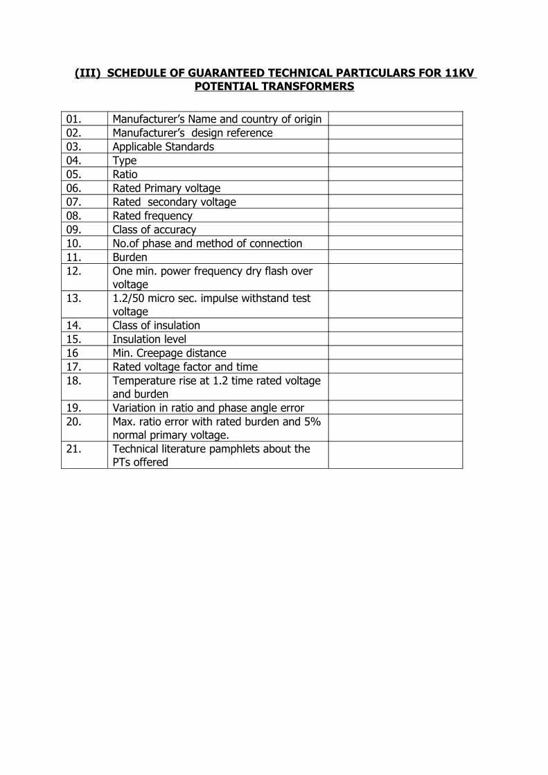
(III) SCHEDULE OF GUARANTEED TECHNICAL PARTICULARS FOR 11KV POTENTIAL TRANSFORMERS
01. Manufacturer’s Name and country of origin02. Manufacturer’s design reference 03. Applicable Standards04. Type05. Ratio06. Rated Primary voltage07. Rated secondary voltage08. Rated frequency09. Class of accuracy 10. No.of phase and method of connection11. Burden12. One min. power frequency dry flash over
voltage13. 1.2/50 micro sec. impulse withstand test
voltage14. Class of insulation15. Insulation level16 Min. Creepage distance17. Rated voltage factor and time18. Temperature rise at 1.2 time rated voltage
and burden19. Variation in ratio and phase angle error 20. Max. ratio error with rated burden and 5%
normal primary voltage. 21. Technical literature pamphlets about the
PTs offered
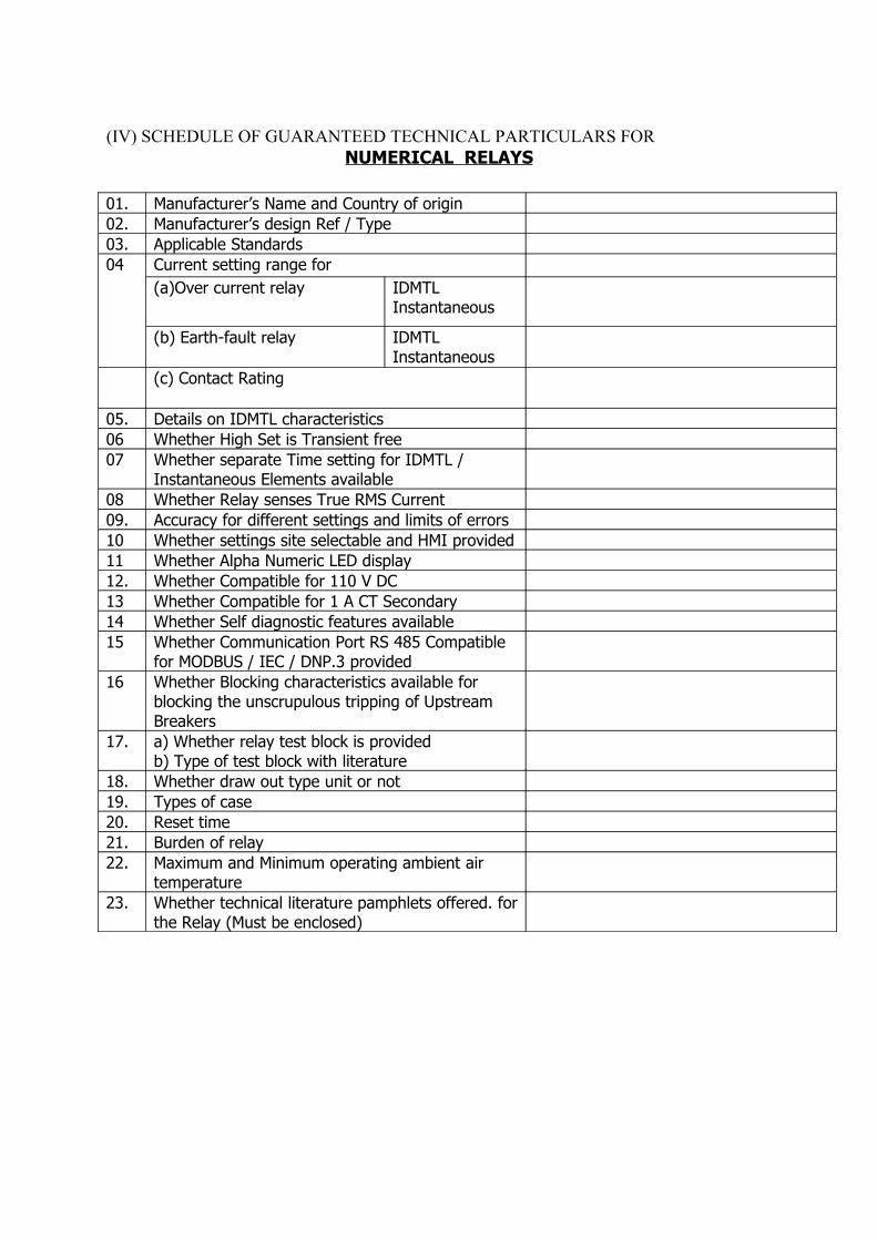
(IV) SCHEDULE OF GUARANTEED TECHNICAL PARTICULARS FOR NUMERICAL RELAYS
01. Manufacturer’s Name and Country of origin02. Manufacturer’s design Ref / Type03. Applicable Standards 04 Current setting range for
(a)Over current relay IDMTLInstantaneous
(b) Earth-fault relay IDMTLInstantaneous
(c) Contact Rating
05. Details on IDMTL characteristics 06 Whether High Set is Transient free07 Whether separate Time setting for IDMTL /
Instantaneous Elements available08 Whether Relay senses True RMS Current09. Accuracy for different settings and limits of errors10 Whether settings site selectable and HMI provided11 Whether Alpha Numeric LED display12. Whether Compatible for 110 V DC13 Whether Compatible for 1 A CT Secondary14 Whether Self diagnostic features available15 Whether Communication Port RS 485 Compatible
for MODBUS / IEC / DNP.3 provided16 Whether Blocking characteristics available for
blocking the unscrupulous tripping of Upstream Breakers
17. a) Whether relay test block is providedb) Type of test block with literature
18. Whether draw out type unit or not19. Types of case20. Reset time21. Burden of relay22. Maximum and Minimum operating ambient air
temperature23. Whether technical literature pamphlets offered. for
the Relay (Must be enclosed)
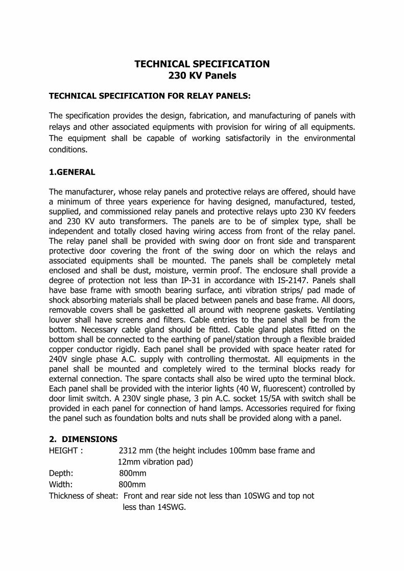
TECHNICAL SPECIFICATION230 KV Panels
TECHNICAL SPECIFICATION FOR RELAY PANELS:
The specification provides the design, fabrication, and manufacturing of panels with relays and other associated equipments with provision for wiring of all equipments. The equipment shall be capable of working satisfactorily in the environmental conditions.
1.GENERAL
The manufacturer, whose relay panels and protective relays are offered, should have a minimum of three years experience for having designed, manufactured, tested, supplied, and commissioned relay panels and protective relays upto 230 KV feeders and 230 KV auto transformers. The panels are to be of simplex type, shall be independent and totally closed having wiring access from front of the relay panel. The relay panel shall be provided with swing door on front side and transparent protective door covering the front of the swing door on which the relays and associated equipments shall be mounted. The panels shall be completely metal enclosed and shall be dust, moisture, vermin proof. The enclosure shall provide a degree of protection not less than IP-31 in accordance with IS-2147. Panels shall have base frame with smooth bearing surface, anti vibration strips/ pad made of shock absorbing materials shall be placed between panels and base frame. All doors, removable covers shall be gasketted all around with neoprene gaskets. Ventilating louver shall have screens and filters. Cable entries to the panel shall be from the bottom. Necessary cable gland should be fitted. Cable gland plates fitted on the bottom shall be connected to the earthing of panel/station through a flexible braided copper conductor rigidly. Each panel shall be provided with space heater rated for 240V single phase A.C. supply with controlling thermostat. All equipments in the panel shall be mounted and completely wired to the terminal blocks ready for external connection. The spare contacts shall also be wired upto the terminal block. Each panel shall be provided with the interior lights (40 W, fluorescent) controlled by door limit switch. A 230V single phase, 3 pin A.C. socket 15/5A with switch shall be provided in each panel for connection of hand lamps. Accessories required for fixing the panel such as foundation bolts and nuts shall be provided along with a panel.
2. DIMENSIONSHEIGHT : 2312 mm (the height includes 100mm base frame and 12mm vibration pad)Depth: 800mmWidth: 800mmThickness of sheat: Front and rear side not less than 10SWG and top not less than 14SWG.

DC voltage of the panels:- 220V DC3. NAME PLATE, LABELS AND MARKINGS:
All the equipment mounted on front as well as those mounted inside the panel shall be provided with individual name labels with equipment designation engraved. Also on the top of each panel on front, large and bold name plates shall be provided for circuit/ feeder designation. Name plate and labels shall be made of non rusting metal or 3 ply lamicoid. Name plate shall be black with white engraving lettering. All relays and other devices shall be clearly marked. Each switch /push button /indication lamp shall bear clear inscription identifying its function. The size of the label shall be ; width- 1.5cm; length – as per the length of the inscription; the letter size – 0.75cm.
4.PAINTING:
i) All sheet steel work shall be phosphated in accordance with IS-6005
ii) Oil, grease, dirt, swart, rust and scale shall be removed by adopting proper cleansing procedure.
iii) After phosphating and thorough rinsing, the phosphate coating shall be sealed with application of two coats of ready mixed stoved type zinc chromate primer. The first coat shall be flash dried while the second coat shall be stoved.
iv) After application of primer, two coats of finishing synthetic enamel paint shall be applied, each coat followed by stoving
v) The colour of the panel shall match with the existing panel colour of subject station and normally of following choice for new station.
Exterior - stoved enamel greyInterior - stoved enamel whiteBus frame - stoved enamel blackFinish - glossy surface treatment shall be done as per BIS.
5.ENERGY METERS:
Electronic tri-vector meters shall be with facility for separate registering of KWH, KVAH and KVARH consumption and also to record export/import and demands and their input quantities. The accuracy of the meter shall be 0.5 class. The meter shall have communication facility with open protocol. It shall record and indicate the measured parameters for a frequency variation of +/- 5 % and for A.C auxiliary
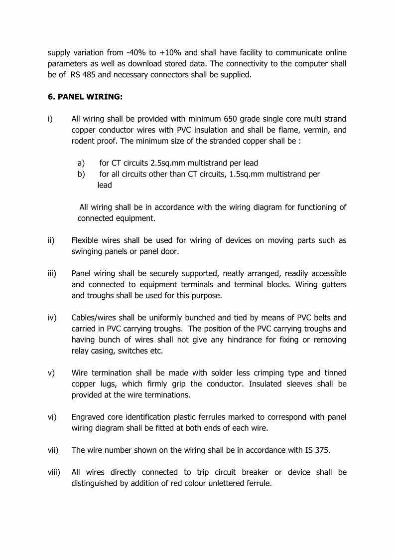
supply variation from -40% to +10% and shall have facility to communicate online parameters as well as download stored data. The connectivity to the computer shall be of RS 485 and necessary connectors shall be supplied.
6. PANEL WIRING:
i) All wiring shall be provided with minimum 650 grade single core multi strand copper conductor wires with PVC insulation and shall be flame, vermin, and rodent proof. The minimum size of the stranded copper shall be :
a) for CT circuits 2.5sq.mm multistrand per leadb) for all circuits other than CT circuits, 1.5sq.mm multistrand per lead
All wiring shall be in accordance with the wiring diagram for functioning of connected equipment.
ii) Flexible wires shall be used for wiring of devices on moving parts such as
swinging panels or panel door.
iii) Panel wiring shall be securely supported, neatly arranged, readily accessible and connected to equipment terminals and terminal blocks. Wiring gutters and troughs shall be used for this purpose.
iv) Cables/wires shall be uniformly bunched and tied by means of PVC belts and carried in PVC carrying troughs. The position of the PVC carrying troughs and having bunch of wires shall not give any hindrance for fixing or removing relay casing, switches etc.
v) Wire termination shall be made with solder less crimping type and tinned copper lugs, which firmly grip the conductor. Insulated sleeves shall be provided at the wire terminations.
vi) Engraved core identification plastic ferrules marked to correspond with panel wiring diagram shall be fitted at both ends of each wire.
vii) The wire number shown on the wiring shall be in accordance with IS 375.
viii) All wires directly connected to trip circuit breaker or device shall be distinguished by addition of red colour unlettered ferrule.
ix) Interconnection to adjacent panels shall be brought to a separate set of terminal blocks located near to the slots or holes to be provided at the top of the panel. Arrangements shall be made for easy connections to adjacent panels at site and wires for this purpose shall be provided and bunched inside the panel.
x) Bus wires shall run at the top the panels. The terminal blocks for the wires shall be with isolating links.
xi) The terminal blocks used shall be minimum 650V grade and have 10A continuous rating, moulded piece, complete with insulated barriers, stud type terminals washers nuts and lock nuts suitable for operation with a tubular box spanner or screw driver.
xii) Terminal blocks shall be arranged in vertical formation at an inclined angle with sufficient space between terminal blocks with minimum of 150mm for easy wiring.
xiii) Terminal blocks shall include a white fibre marking stripe with clear plastic, slip on/clip on terminal covers. Marking on terminal strips shall correspond to wire number and terminal number on the wiring diagrams.
xiv) There shall be minimum clearance of 250mm between the first row of terminal blocks and the associated cable and plate or panel side wall.
xv) At least 20% of total terminal shall be provided as spare for further connections and these spare terminals shall be uniformly distributed on all terminal blocks.
xvi) Wiring is preferable with the following colour code. PT supply : Red, yellow, blue for phase and black for neutral. CT circuits : Similar to above. DC circuit : Gray for both positive and negative. 230V AC circuits : Black for both phase and neutral. Earthing : Green.
7. EARTHING:
i) All panels shall be equipped with bus securely fixed along the inside base of the panels. When several panels are mounted adjoining to each other, the
earth bus shall be made continuous and necessary connectors and clamps for this purpose shall be included in the scope of supply.
ii) The size of the earth bus shall be made of 25mmx6mm tinned copper flat.
iii) The earth of the substation will be 40mm diameter MS rods, provision shall be made on the earth bus bars of the end panels for connecting to the earth grid. Necessary terminal clamps and connectors shall be included in the scope of supply.
iv) All metal case of the relays, instruments and other panel mounted equipments shall be connected to the earth bus by independent copper wires of size not less than 2.5 sq.mm. The colour code of the earthing wire shall be green. Earthing wire shall be connected on the terminals with suitable clamp connectors and soldering shall not be permitted.
8. CIRCUIT DISTRIBUTION AND ISOLATION:
i) Each relay panel shall be provided with necessary arrangements for receiving, isolating and fusing of AC and DC supplies for various control of signaling, lighting and space heaters.
ii) The incoming and sub circuit shall be separately provided with switch fuse units, selection main and sub circuit fuse rating shall be such as to ensure selective clearance of sub circuit faults.
iii) Potential circuit for metering and relaying shall be protected by fuses.
iv) All fuses shall be of HRC cartridge type conforming to IS2203 mounted on plug in type fuse bases. All accessible live connection of fuse base shall be adequately shrouded.
v) Fuse shall have operation indications for indicating blown fuse condition.
vi) Fuse carrier shall have imprints of fuse rating and voltage.
vii) Removable links should be provided at the output of each relay for trip output and reclose output. Adequate space shall be left between fuse units when arranged adjacently.
9. RELAYS:i) All protective relays should be of 61850 protocol.
ii) All relays shall conform to IS: 8686 and or other relevant standards in vogue.iii) Descriptive details of relays are furnished and specified in separate heads.iv) Testing facility provided on the relay shall be detailed.v) Necessary test plugs, test blocks and switches shall be provided.vi) Unless or otherwise specified all auxiliary relays and timers shall be supplied
in non-draw out cases / plug in type modular Cases. vii) Relays shall have the rating for 110V VT secondaries and 1 Amp CT
secondaries. Auxiliary relays and timers shall be designed for the DC voltage specified.
viii) Provision shall be made for isolation of trip circuits of each relay for the purpose of testing and maintenance.
ix) Test jack and Test blocks should be provided by the tenderers free of cost. Inter bay connections between BCUs and relays shall be of fibre optic cables. Since relays with RJ 45 is also acceptable the communication from relays/BCU to Ethernet switch may be on copper cable and the ring may be on FO cable.
x) All relay/wiring shall withstand a test voltage of 2.5KV, 50Hz rms voltage for 1 minute.
xi) The relays shall be able to be tested with universally acceptable testing kit.xii) All relays offered shall have to be type tested. xiii) For each type of numerical relay offered in the tender, necessary software
capable of interacting with relay for performing following complete functions:
1. Input/output relay assignment2. LED configuration 3. Setting and modification of relay parameters4. Analysis of disturbance recording Tools to download details of relay shall
be supplied
xiv) One number lap top of latest configuration alongwith software and cables exclusively for the purpose of testing and configuration of relays and downloading of disturbance records.
xv) One number Computerized Numerical Relay Testing kit alongwith software compatible with IEC 61850 protocol. Necessary Test report of the Testing kit obtained from a recognized lab should be enclosed.
10 RELEVANT REFERENCE STANDARDS: IS – 3231 electrical relays for power system protectionIS – 8686 static protective relaysIS – 2147 degree of protection of cubiclesIS – 1248 & IS – 2419 indicating instrumentsIS – 4237 general requirements for switches and control gear for
voltages not exceeding 1KVIS – 0722 energy meters, control switches (LV switching devices for control and auxiliary circuits) IS – 0337,0337-1 -do-IS – 0297(part 1-3)dimensions for the mechanical structures of the 482.6mm(19”)seriesIS – 0375 marking and arrangement for switch gear, busbars, main connection and auxiliary wiringIS – 6875 control switches (LV switching devices for control and aux.circuits)IS – 0005 colour for ready mix paintsIS – 1554(part –I) PVC insulated cables upto and including 1000 voltsIS –3842(part I-VII) application guide for protectionIS –9224(part-II) HRC cartridge fuse linksIS –6005 code of practice for phospating iron and steelIES –2555-1-0 electrical relays –all-or-nothing elec. relays.ICE – 255-3,5,6,7,8,10,11,12,13,16 electrical relays for various specificationsICE – 255-21-2,3ICE – 255-22-1,2,3,4 electrical relays – vibration and disturbance etc. ICE – 255-23 electrical relays – contact performance
I. 230KV LINE PROTECTION:
MAIN-I & MAIN –II DISTANCE PROTECTION:
The schemes shall
1. be of Numerical type relays of same version suitable for rated voltage of 110V phase to phase and 63.5V phase to ground ; rated for 1A, DC: 110V/220V
2. Have continuous current rating of 2 times the rated current and have high short time current of atleast 70 times rated current for a period of 1sec
3. Have a minimum of 3 forward and 1 forward / reverse selectable distance protection zones
4. Have six independent loop measurements system to cater phase to phase and phase to ground faults
5. Have MHO/polygonal characteristics for phase to phase fault and polygonal characteristics for phase to earth fault. In case of polygonal characteristics X and R should be independently settable.
6. the maximum operating time of the numerical distance protection relays shall be as follows:
a) source impedance ratio 4 15
b) relay settings – ohms 10 2 c) fault location % 60 60 d) fault resistance – ohms 0 0 e) maximum operating time 45 for 45 for 3 in milli secs. including trip all fault phase and relays with CVT 60 for all other faults 7. have an impedance setting range of 0.25 – 120 ohm8. have a requisite independent continuously variable time setting with range 0-3
sec9. Have a resetting time of less than 40 millisec.10. have facility for zero-sequence compensation for earth fault on all measuring
element 11. be suitable for single and three phase tripping12. have switch-on-to-fault feature.13. have LBB protection and synchro check function.14. Have cross polarization, assure 100% directional sensitivity for unbalance fault
and memory for balanced faults.15. Have programmable communication scheme for inter trip selectable for
permissive under reach, over reach, blocking and acceleration scheme.16. comply with weak-end in feed logic and current reversal logic.17. Have feature to detect open conductor.18. Have feature to detect VT (or CVT) fuse failure. It should detect single phase,
two phase and all three phase fuse failure condition both at relay panels and fuses in the yard and take necessary precaution in measurement to block the distance protection. However, during blocking period the relay shall have over current protection facility for fault detection.
19. Have power swing blocking protection. The power swing shall be detected by rate of change of impedance with suitable characteristics. The blocking shall have continuously adjustable time delay with setting range of not less than 2sec or shall have feature to block the tripping as long as it exists. The relay shall have feature to unblock during fault. It shall be explained how blocking is effected during power swing for phase to earth fault, phase to phase faults and three phase faults. In each case the relay shall have feature to unblock during fault and with facility to block each distance zone independently.
20. Include built-in high speed auto re-close relay for single shot, single phase re-close with adjustable dead time setting of 0.1sec to 1sec, and with adjustable reclaim time of 1 to 250sec.
21. Auto re-close relay shall be provided in both Main I and Main 2 as a built in feature.

22. Have built in IDMT directional earth fault relay with adjustable setting range of 10 to 80% with characteristic curve for normal inverse, very inverse and extremely inverse of both IEC and IEEE curves.
23. Have an adjustable characteristic angle setting range 35 to 75 degrees.24. Have built in disturbance recorder unit with minimum 8 analog and 12 digital
inputs and with minimum memory capacity to store at least 8 disturbance records with each record of minimum 10 cycles. The sampling of analog inputs shall be at least 16 per cycle. Shall have features to adjust pre fault and post fault time. (The DIs specified includes 4Nos. DIs for triggering disturbance records).
25. Have programmable 12 nos. of opto input (minimum) 20 nos. output (minimum) and opto voltage are field programmable.
26. Event recorder shall be able to store at least 80 time tagged events. The resolution of event recorder shall be at least 1 millisecond.
27. Have built in fault recorder with following features.a) Shall display the fault location either in percentage of line length or in actual
distance in kilometer based on reactance setting.b) Shall have an accuracy of +/-3% or better and watch dog output.28. Have self diagnostic feature and watch dog output.29. The contact of the relay shall have the following minimum rating
Make and carry continuously : 5AMake and carry for minimum 1 sec : 30ABreaking capacity for DC when L/R is 40m sec. :30W
30. Have front or back RS232 port for connecting laptop (suitable connecting cards /converter to be supplied) and rear RJ 45 or fibre optic port for local and remote communications. However for uniformity all the relays shall be provided either with RJ45 port or fibre optic port at the rear. The communication shall be through IEC 61850 protocols.
31. Have time synchronizing facility with IRIGB / DCF77 /SNTP whichever is compatible to IEC 61850.
32. Have metering function of class 1.0 accuracy or better and user programmable display.
33. Necessary latest version communication software should be supplied for configuration, setting modification, event analysis, SCADA communication.
34. Binary Input and output contacts of BCU may be used for Trip circuit supervision function.
35. LEDs in Main I & Main II protection relays may be used for carrier healthy indication.
36. Integral function of protection relays may be used for A/R ON/OFF operation and carrier cut in/cut off operation.
III. BUS-BAR PROTECTION:
Bus-Bar protection scheme shall
1. be of low impedance numerical type and may be of centralized/ decentralized type.
2. have operating time of 15millisec at 5times setting value for all type of fault.3. operate selectively for each busbar.4. be stable for through fault condition upto 40KA fault level.5. incorporate check feature and clear zone indication.6. shall include one overall check zone protection in addition to single/double
zone specified.7. incorporate continuous supervision of CT secondaries against any possible
open circuit and if it occurs, shall render the relevant zone of protection inoperative after a time delay and initiate an alarm.
8. be phase segregated type and provide independent zone of protection. If bus section is provided, then each side of the bus section shall have separate set of bus bar protection scheme.
9. be transient-free in operation.10. includes continuous DC supply supervision.11. include provision for protection IN/OUT for each zone and check zone.12. be rated for 1Amps.13. suitable for aux. supply 110V/220V DC.14. the relay must have rejection and shall not operate on second and third
harmonics. Second harmonic rejection ratio 2:1 minimum, third harmonic rejection ratio 40 :1 minimum.
15. the high speed tripping relays (96) for tripping each feeders on actuation of bus bar protection shall be on respective feeder relay panels and necessary provision for running the tripping bus wires to actuate these relays shall be made.
16. should have provision for connecting three numbers of additional feeders as spare.(for 230KV side)
17. the communication protocol shall be IEC61850.
IV. TRANSFORMER PROTECTION:Α. BIAS DIFFRENTIAL PROTECTION RELAY FOR TWO WINDING TRANSFORMER PROTECTION:1. Shall be of Numerical type.2. three phase with faulty phase identification.
3. shall have continuous self monitoring and diagnostic feature.4. shall have instantaneous high set feature with facility to adjust 5 to 20 times
normal current.5. shall have second harmonic restraint feature with second harmonic content in
the range of 15 t0 25% .6. the disturbance recording functions should be integrated in the relay module.
The disturbance recorder shall have facility to record at least 4 numbers of digital signals apart from digital signal from the relay and currents in HV&LV winding.
7. Facility to set transformer vector group and CT ratio selection/ correction through software.
8. Rated current of 1 amp.9. Thermal withstand current continuous 2 amps and for 1 sec 70 amps.10. Rated voltage: 110V/220V DC.11. Basic bias setting 20 to 40% in steps 10% or 15 to 45% in steps of 15%.12. Operating current setting range 15 to 30%.13. have operating time not greater than 35ms at 3 times normal current.14. Maximum operating time for instantaneous operation: 25ms +/-4% of set
value.15. Recording memory capacity: 5secs.16. Shall have inbuilt restricted earth fault protection inbuilt over fluxing
protection and inbuilt LBB protection. The Backup impedance function may be an inbuilt function of the offered differential relay.
17. Shall have impedance protection. If the same is not a inbuilt feature of the differential protection relay then the same may be provided separately.
18. have front or back RS232 port for connecting Lap Top (suitable connecting cards/converter to be supplied) and rear RJ45or fibre optic port for local and remote communication. However for uniformity all the relays shall be provided either with RJ45 port or fibre optic port at the rear. The communication shall be through IEC 61850 protocols.
19. Have time synchronizing facility with IRIGB / DCF77 / SNTP whichever is compatible to IEC 61850.
IV.B. BACKUP NON-DIRECTIONAL OVER CURRENT PROTECTION WITH HIGH SET INSTANTANEOUS FOR HV:
1. Shall be of Numerical type.2. IDMT Characteristics with NI/EI/VI/definite characteristics with a variable
setting range of 50 to 200% of rated current of one ampere in steps of 10%. Time multiplier range 0.05 – 1.0 in steps of 0.05.
3. Provided with Hand reset flags/LED indicators4. High set feature 500-2000% of rated current5. Have front or back RS232 port for connecting Laptop (Suitable connecting
cards/convertor to be supplied) and rear RJ45 port or Fibre optic port for local & remote communications. However for uniformity, all the relays shall be provided either with RJ 45 port or Fibre Optic Port at the rear.
6. The communication shall be through IEC 61850 protocol.
IV.C. BACKUP NON-DIRECTIONAL OVER CURRENT RELAY FOR LV:
1. Shall be of Numerical type.2. IDMT Characteristics with NI/EI/VI/definite characteristics with variable
setting range of 50 to 200% of rated current of one ampere in steps of 10%. Time multiplier range 0.05 – 1.0 in steps of 0.05.
3. Provided with Hand reset flags/LED indicators4. High set feature 500-2000% of rated current5. Have front or back RS232 port for connecting Laptop (Suitable connecting
cards/convertor to be supplied) and rear RJ45 port or Fibre optic port for local & remote communications. However for uniformity, all the relays shall be provided either with RJ 45 port or Fibre Optic Port at the rear.
6. The communication shall be through IEC 61850 protocol.NOTE : The back up protection relays IVB & IVC are separately required even if it is a inbuilt feature of the main relay/BCU.
V. MISCELLANEOUS PROTECTION1) D.C. Supply Supervision Relay.
The relay shall monitor continuously D.C. Supply to Protection System. The de-energization of this relay will indicate the DC Supply failure. Auxiliary supply for the relay is 110V/220V DC. The relay shall have a time delay on drop off of not less than 100 milli second. The relay shall be provided with operation indicators (Reverse flag) self reset. Sufficient number of contacts potential free may be provided. Separate relays for dual source are to be provided.
2) Trip Circuit Supervision Relays.
The relays shall supervise the healthiness of trip circuit continuously (Both pre-closing and post-closing conditions of the circuit breakers). The relay shall be capable of monitoring the healthiness of each phase trip coil and associated circuits of the circuit breaker during “ ON and OFF ” conditions. The relay shall work on 110V/220V dc with allowable margin as the case may
be. The relay shall have adequate contacts for providing connection to alarm and event logger, self reset. The relay shall have a “ time delay on drop off of not less than 200 milli seconds ” and provided with Operation indicators. The short circuiting of any series resistance provided in this relay or short circuiting the coil of the relay should not energize the trip coil of the breaker.
3) Tripping (Master) Relay :
- For tripping of feeder / transformer breakers in a station on operation of protective relays and for interlock purposes. The relay shall be voltage rated for 110V/220V dc with allowable margin of variation, be instantaneous (Operating time not exceed 10 milli seconds).
- Reset within 20 milli seconds.
- Have adequate contacts to meet the requirement of scheme, other functions like autoreclose relay, LBB relay as well as to cater to associated equipments like SER, DR etc., to be provided with operation element/ coil.
4. Under Frequency Relay :
The relay shall be highly reliable and immune to transient and surges. The relay shall be of Numeric design. The relay shall have a discrete (digital) selection unit with built in timer and tripping relay to activate tripping. The relay shall have two elements for frequency supervision alternatively for under or over frequency detection with independent separate adjustable timer. The relay shall have time setting ranges of 0-5 sec. in steps of 0.02 sec. The relay shall have two elements atleast for supervision of frequency gradient df/dt (rate of change of frequency). The relay shall be suitable for 110V AC and Auxiliary DC voltage of 110V/220V. The programmable frequency range shall be 45 Hertz to 55 Hertz in very minimum possible steps of 0.1 Hz. with operation accuracy of approximately + 50 milli Hz. The protective function can be assigned individually to the output relays. Necessary LED indications for operation, parameter selection etc., need be provided. df/dt setting range selectable between 0.2 to 0.5 Hz./sec. in steps of 0.1 Hz./sec. with operation accuracy of approximately 5 milli Hz./sec. Under frequency relay should be independent even if it is a built in feature of other protective relays. The Communication protocol shall be IEC 61850.
5. Check Synchronizing relay:-Synchro check function should be part of the main relay.

SUBSTATION AUTOMATION SYSTEM (SAS) :
1) GENERAL :This specification provides for complete Design, Manufacture, Inspection, Testing at the manufacturer’s works and at site packing, shipment, insurance, transport and delivery to site, installation, commissioning substation automation system as described in the following sections to control and monitor the 230 KV and equipments at 230/33 KV substations through HMI (Keyboard, Mouse, LCD). The details of equipments to be controlled are given in the single line diagram.
The substation automation system shall be installed to control and monitor all the substation equipments from Local Control room and Gateway shall be provided for remote SCADA.
The substation Automation System shall be of decentralized architecture with combination of Numerical Relays and Bay Control Units . The typical configuration of the proposed SAS is as given in figure enclosed. - Numerical Relays, BCUs and Electronic Energy Meters to communicate
with HMI.- HMI for operation and Engineering/DR work station with LAN connectivity. - Communication with the remote control centers State Sub-load Dispatch
Centre through Gateway on IEC 60870 – 5 – 101 of SCADA/EMS system commissioned under ULDC Scheme of GE Harris make XA 21 software through PLCC Modem or fibre optic communication. This interface shall support communication to the remote control centre on IEC 60870 – 5 – 101. ULDC SCADA Engineers have to be co-coordinated for integration. The data should be made available for the polling schedule of XA21 software in the ULDC SCADA system. Any support required for completing the task shall be in bidders scope. PLCC modem at both ends to be supplied by the bidder.
- The PLCC system will be erected by TNEB- Supply of PLCC modem is in Bidders scope.- Data transfer from substation through PLCC modem to ULDC is to be
made available at 101 protocol is in bidders scope. Linking and mopping with GE Harris system is in TNEB scope.
- Necessary hardware and software requested for convention from IEC 61850 protocol to 101 protocol is in bidders scope.
- The communication will be through PLCC/FO cable/Microwave.2) FUNCTIONAL REQUIREMENTS :
a) Control of all equipments mentioned in the Single Line diagram.b) Supervisory function (i.e.) Data Acquisition, Processing, Monitoring, Analysis and
Diagnostic,c) Data Exchanged) Report Generation and Printing.
3) CONTROL:
Basic Functions :
a) To execute commands from both operator work stations HMI.b) Select before execute commands. c) Operation of all 230 KV Circuit breakers and all 230 KV motorized Isolators
through output contacts of corresponding BCUs.d) Operation of On load Tap Changer: Manual Operation from HMIs through BCU is
envisaged. e) Provide interlocking of different switchgear/isolators for their correct and safe
operation. f) Monitoring of Circuit breakers, Isolators and Earth Switch contacts (status)
4) OTHER FUNCTIONS:
a) Switching sequences.b) Time synchronizing through GPS.c) Monitoring of DC system.d) Monitoring of fire-protection system.e) Monitoring of DG operation.f) Changing relay settings of all numerical relays from Engg./DR works station with
suitable software.g) Storage of data.h) Collection of disturbance record files from various relays and analysis of the same
from Engg/DR works station with suitable software.i) Auto re closure selection and monitoring.j) Bus PT change-over.k) Carrier IN/OUT selection.l) Synchro check provision.
5) INTERLOCKING:
The interlocking function provision through logic gates prevents unsafe operation of equipments such as breakers, isolators and earthing switches for all switching operation within a bay or station. An override function at Bay level shall be provided, which can be enabled to by-pass the interlocking function via a key/password, in cases of maintenance or emergency situations. This over ride function should be accessed with higher level pass word security. Over ride function at Bay level is acceptable.
6) SUPERVISORY FUNCTION: DATA ACQUISITION, PROCESSING MONITORING, ANALYSIS AND DIAGNOSTICS.The status of each switchgear, e.g., circuit breaker, isolator, transformer tap changer etc., shall be continuously acquired through polling sequences. ie., - Polling on request - Automatic Polling (Every 5sec, 10sec,….)- Polling by exception (change of digital status)Every detected change of position shall be immediately visible on the screen in the single-line diagram, recorded in the event list, Alarms shall be initiated in cases when spontaneous position changes have taken place.Each position of an apparatus shall be indicated by two binary auxiliary switches which are opposite each other in normally closed (NC) and normally opened (NO) position. An alarm shall be initiated if these position indication indicate an excessive running time of the operating mechanism to change position through watchdog timers.
7) DATA ACQUISITION, PROCESSING AND MONITORING:Conventional interlock through hardware wiring is to be provided in addition to the software interlock. The BCU shall be located in the relay panel itself. The main and redundant HMI will be located in the operator table. The distance between the BCU and the HMI will vary according to site conditions during execution and shall not exceed 15 Mtrs. Bay control shall be provided to each bay and the number of bays to be provided in each substation as per SLD is furnished in the bill of materials.The SA system shall acquire data (analog and digital inputs) from 1) Numerical relays Electronic Energy meters (to be made available in all the feeders, transformers both HV & LV sides). 2) OLTC, Battery charger etc.,. Data for the system shall be acquired as hard wired input for all station equipments stated in the single line diagram.
(Field wiring of all equipments upto control room shall be in TNEB’s scope. Necessary contact multipliers shall be provided by the bidder).
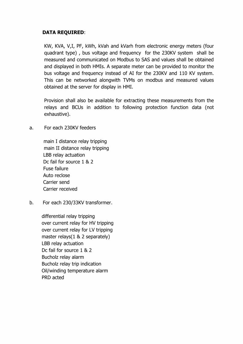
DATA REQUIRED:
KW, KVA, V,I, PF, kWh, kVah and kVarh from electronic energy meters (four quadrant type) , bus voltage and frequency for the 230KV system shall be measured and communicated on Modbus to SAS and values shall be obtained and displayed in both HMIs. A separate meter can be provided to monitor the bus voltage and frequency instead of AI for the 230KV and 110 KV system. This can be networked alongwith TVMs on modbus and measured values obtained at the server for display in HMI.
Provision shall also be available for extracting these measurements from the relays and BCUs in addition to following protection function data (not exhaustive).
a. For each 230KV feeders main I distance relay tripping
main II distance relay tripping LBB relay actuation Dc fail for source 1 & 2 Fuse failure Auto reclose Carrier send Carrier received
b. For each 230/33KV transformer. differential relay tripping over current relay for HV tripping over current relay for LV tripping master relays(1 & 2 separately) LBB relay actuation Dc fail for source 1 & 2 Bucholz relay alarm Bucholz relay trip indication Oil/winding temperature alarm PRD acted
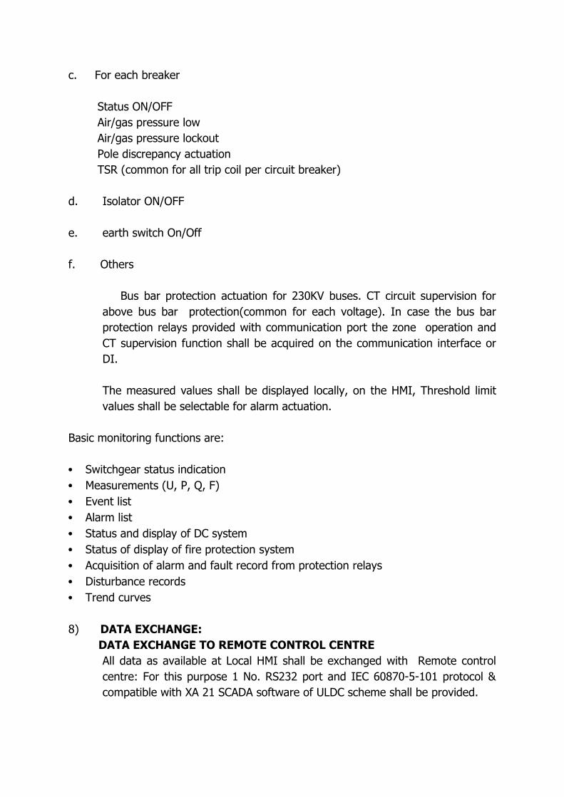
c. For each breaker
Status ON/OFF Air/gas pressure low Air/gas pressure lockout Pole discrepancy actuation TSR (common for all trip coil per circuit breaker)
d. Isolator ON/OFF
e. earth switch On/Off
f. Others
Bus bar protection actuation for 230KV buses. CT circuit supervision for above bus bar protection(common for each voltage). In case the bus bar protection relays provided with communication port the zone operation and CT supervision function shall be acquired on the communication interface or DI.
The measured values shall be displayed locally, on the HMI, Threshold limit values shall be selectable for alarm actuation.
Basic monitoring functions are:
• Switchgear status indication• Measurements (U, P, Q, F)• Event list• Alarm list• Status and display of DC system• Status of display of fire protection system• Acquisition of alarm and fault record from protection relays• Disturbance records• Trend curves
8) DATA EXCHANGE: DATA EXCHANGE TO REMOTE CONTROL CENTRE
All data as available at Local HMI shall be exchanged with Remote control centre: For this purpose 1 No. RS232 port and IEC 60870-5-101 protocol & compatible with XA 21 SCADA software of ULDC scheme shall be provided.
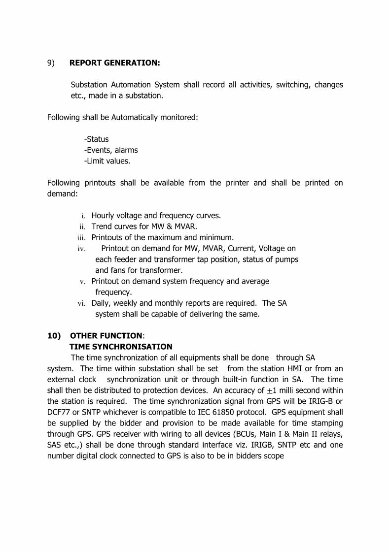
9) REPORT GENERATION: Substation Automation System shall record all activities, switching, changes
etc., made in a substation.
Following shall be Automatically monitored: -Status -Events, alarms -Limit values.
Following printouts shall be available from the printer and shall be printed on demand:
i. Hourly voltage and frequency curves.ii. Trend curves for MW & MVAR.
iii. Printouts of the maximum and minimum.iv. Printout on demand for MW, MVAR, Current, Voltage on
each feeder and transformer tap position, status of pumps and fans for transformer.
v. Printout on demand system frequency and average frequency.
vi. Daily, weekly and monthly reports are required. The SA system shall be capable of delivering the same.
10) OTHER FUNCTION: TIME SYNCHRONISATION
The time synchronization of all equipments shall be done through SA system. The time within substation shall be set from the station HMI or from an external clock synchronization unit or through built-in function in SA. The time shall then be distributed to protection devices. An accuracy of +1 milli second within the station is required. The time synchronization signal from GPS will be IRIG-B or DCF77 or SNTP whichever is compatible to IEC 61850 protocol. GPS equipment shall be supplied by the bidder and provision to be made available for time stamping through GPS. GPS receiver with wiring to all devices (BCUs, Main I & Main II relays, SAS etc.,) shall be done through standard interface viz. IRIGB, SNTP etc and one number digital clock connected to GPS is also to be in bidders scope
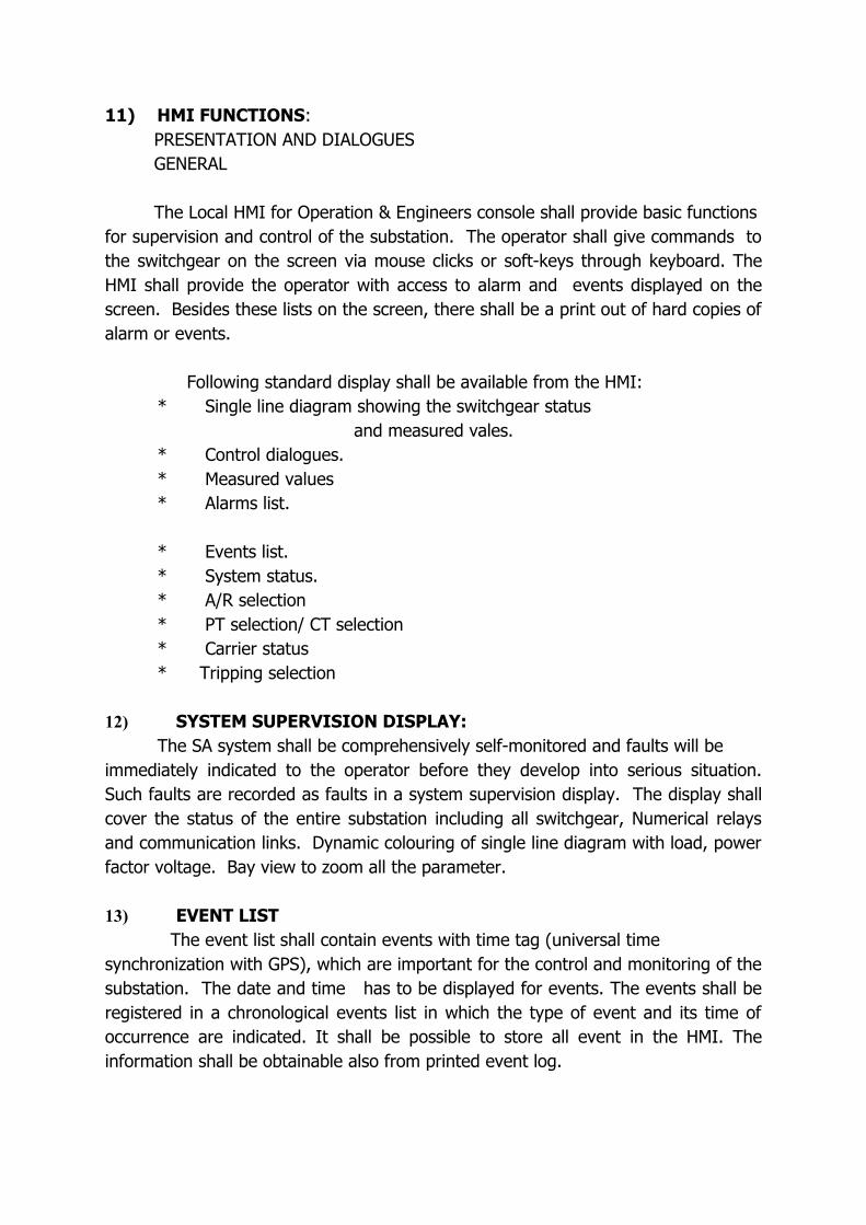
11) HMI FUNCTIONS: PRESENTATION AND DIALOGUES GENERAL The Local HMI for Operation & Engineers console shall provide basic functions for supervision and control of the substation. The operator shall give commands to the switchgear on the screen via mouse clicks or soft-keys through keyboard. The HMI shall provide the operator with access to alarm and events displayed on the screen. Besides these lists on the screen, there shall be a print out of hard copies of alarm or events.
Following standard display shall be available from the HMI:* Single line diagram showing the switchgear status and measured vales.* Control dialogues.* Measured values* Alarms list.
* Events list.* System status.* A/R selection* PT selection/ CT selection * Carrier status* Tripping selection
12) SYSTEM SUPERVISION DISPLAY:The SA system shall be comprehensively self-monitored and faults will be
immediately indicated to the operator before they develop into serious situation. Such faults are recorded as faults in a system supervision display. The display shall cover the status of the entire substation including all switchgear, Numerical relays and communication links. Dynamic colouring of single line diagram with load, power factor voltage. Bay view to zoom all the parameter.
13) EVENT LIST The event list shall contain events with time tag (universal time synchronization with GPS), which are important for the control and monitoring of the substation. The date and time has to be displayed for events. The events shall be registered in a chronological events list in which the type of event and its time of occurrence are indicated. It shall be possible to store all event in the HMI. The information shall be obtainable also from printed event log.
14) ALARM LIST:Fault and error occurring in the substation shall be listed in an alarm list and
shall be immediately transmitted to the control centre. The alarm list shall substitute a conventional alarm table, and shall constitute an evaluation of all station alarm however alarm and visual must be provided on receiving alarm. It shall contain unacknowledged alarms and persisting faults. Date and time of occurrence shall be indicated. Historical data sizing for storing Data for 35 days shall be available in the SA system. The capacity of the server is to be designed accordingly. Also necessary hardware and software to copy and store data from server should be provided. The data collected shall not be lost due to overflow. Whenever overflow is likely to occur, the date shall be archived into storage media like CD so that there is no change of losing historical data.
15) RIGHTS:1. local HMI: shall be able to get data from all the equipments
for monitoring and control. Engineering/DR work station: shall have the facility for relay setting and
analysis of faults by acquiring disturbance recorder data from Numerical relays.The alarm list consists of a summary display of the present alarm situation. Each alarm shall be reported on one line that contain.
• The alarm date and time.• The name of device in alarming state.• A descriptive text.• The acknowledgement state. The operator shall be able to acknowledge alarms, which shall be either
audible or only displayed on the monitor. Acknowledged alarms shall be marked at the list. Filters for selection of a certain type or group of alarm shall be available as for events.
16) SYSTEM TESTING:The supplier shall submit a test specification for factory acceptance test (FAT)
and commissioning tests of the station automation system for approval. If the complete system consists of parts from various suppliers or some parts are already installed on the site, the FAT shall be sub-system tests. In such a case, the complete system test shall be performed on site together with the site acceptance test (SAT).
17) EXTENDABILITY IN FUTURE:
Offered substation automation system shall be suitable for extension in future for additional bays. During such requirement, all the drawings and configurations, alarm/event list etc. displayed shall be designed in the such a manner that its extension shall be easily performed by the Engineers authorized. During such event, normal operation of the existing substation shall be unaffected and system shall not require a complete shutdown.
18) RELIABILITY AND AVAILABILITY:
The SA system shall be designed to satisfy the very high demands for reliability and availability concerning.
a. Solid mechanical and electrical designb. Security against electrical interference (EMI).c. High quality components and boards.d. Modular, well-tested hardware.e. Thoroughly developed and tested modular software.f. Easy-to-understand programming language for application
programming.g. Detailed graphical documentation and application software.h. Built-in supervision and diagnostic function.i. Panel design appropriate to the harsh electrical environment and
ambient conditions.j. Panel grounding immune against transient ground potential rise.
19) Documentation:The following documentation to be provided for the system in the course of the project shall be consistent, CAD supported, and of similar look/feel:
a. List of Drawings. b. Substation automation system architecture.c. Block Diagram.d. Guaranteed technical parameters, e. List of Signal-Analogue/Digital.f. Schematic diagrams.g. List of Apparatus.h. List of Labels.i. Logic Diagram.j. Test schedule and reports of FAT/SATk. Product Manuals’
l. Operator’s Manual.m. Listing of software and loadable in CD ROM.
3 sets of CD ROM containing all the as built documents/drawing shall be provided.
20) SERVER:DESIGN STANDARDSThe server provided should be highly reliable. It should employ an Embedded operating system. The Server should also be suitable for fan less operation.
21) COMMUNICATION INTERFACES:* Dedicated serial ports for communication with Multifunction energy meters with RS485 Modbus RTU protocol. The meters should be multidropped and will be as slave to the Server.* Dedicated ports for communication to Numerical Relay and BCUs on IEC 61850 protocol.
22) CAPACITY:The system should be capable of handling upto 100 IEDs and 10,000 data points.
23) SEQUENCY OF EVENTS (SOE) FEATURE: To analyze the chronology or sequence of events occurring in the power
system, time tagging of data is required which should be achieved through SOE feature of SA. The server should have an internal clock with adequate stability. The Server time should be set from time synchronization messages received from GPS equipment to be supplied by bidder. The Server should maintain a clock and should time-stamp the digital status data. Any digital status input data point in the Server should be assignable as an SOE point. Each time a SOE status indication point changes the state, the Server should time-tag the change and store in SOE buffer within it. SOE shall be transferable to the Remote Control Centre through the IEC 60870-5-101 gateway. The time resolution for SOE should be 1 ms at point of acquisition.
24) ETHERNET SWITCHES:
The Ethernet switches used for creating the LAN network should meet the specification as laid down in the IEC 61850 standard.
***
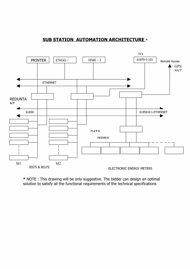
SUB STATION AUTOMATION ARCHITECTURE *
* NOTE : This drawing will be only suggestive. The bidder can design an optimal solution to satisfy all the functional requirements of the technical specifications
Remote Access PRINTER
IED’S & BCU’S ELECTRONIC ENERGY METERS
MODBUS
ENGG / HMI – I 61870-5-101
REDUNTANT
M1 M2
DATA
61850-8-1-ETHERNET
GPSSNT
ETHERNET
TO
61850
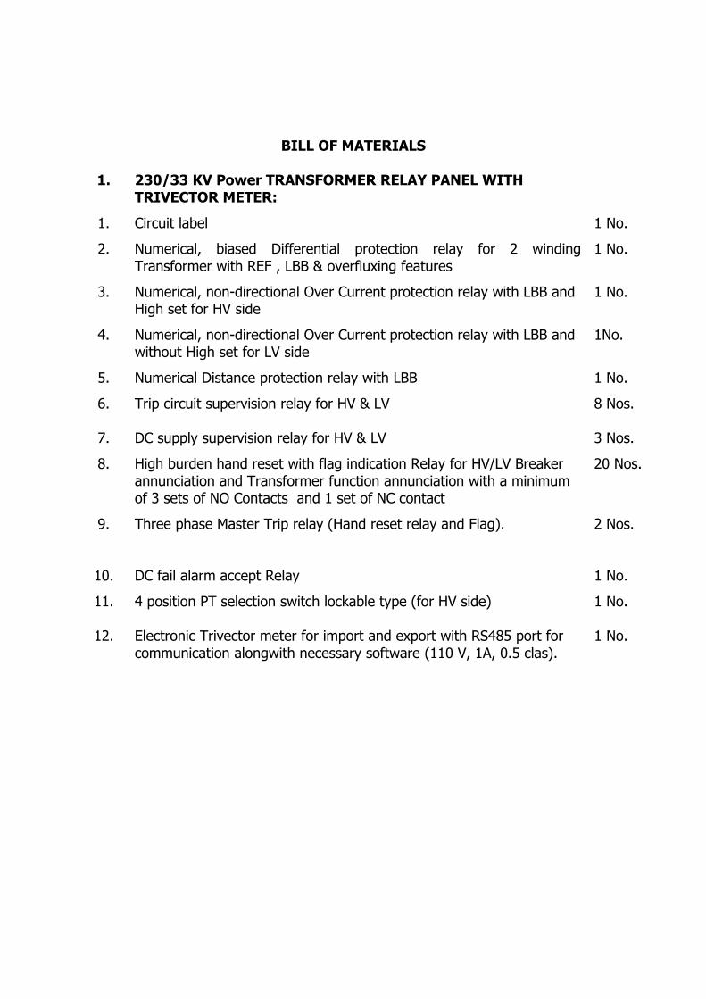
BILL OF MATERIALS
1. 230/33 KV Power TRANSFORMER RELAY PANEL WITH TRIVECTOR METER:
1. Circuit label 1 No.
2. Numerical, biased Differential protection relay for 2 winding Transformer with REF , LBB & overfluxing features
1 No.
3. Numerical, non-directional Over Current protection relay with LBB and High set for HV side
1 No.
4. Numerical, non-directional Over Current protection relay with LBB and without High set for LV side
1No.
5. Numerical Distance protection relay with LBB 1 No.
6. Trip circuit supervision relay for HV & LV 8 Nos.
7. DC supply supervision relay for HV & LV 3 Nos.
8. High burden hand reset with flag indication Relay for HV/LV Breaker annunciation and Transformer function annunciation with a minimum of 3 sets of NO Contacts and 1 set of NC contact
20 Nos.
9. Three phase Master Trip relay (Hand reset relay and Flag). 2 Nos.
10. DC fail alarm accept Relay 1 No.
11. 4 position PT selection switch lockable type (for HV side) 1 No.
12. Electronic Trivector meter for import and export with RS485 port for communication alongwith necessary software (110 V, 1A, 0.5 clas).
1 No.
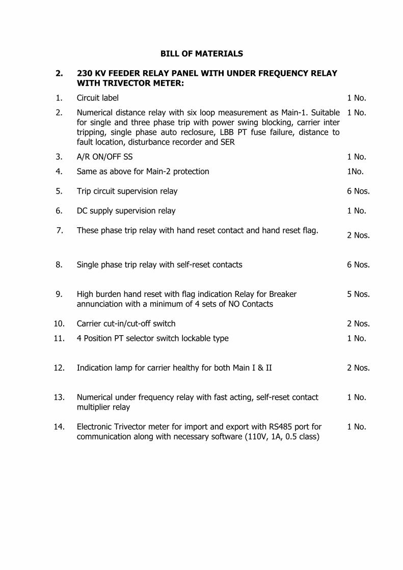
BILL OF MATERIALS
2. 230 KV FEEDER RELAY PANEL WITH UNDER FREQUENCY RELAY WITH TRIVECTOR METER:
1. Circuit label 1 No.
2. Numerical distance relay with six loop measurement as Main-1. Suitable for single and three phase trip with power swing blocking, carrier inter tripping, single phase auto reclosure, LBB PT fuse failure, distance to fault location, disturbance recorder and SER
1 No.
3. A/R ON/OFF SS 1 No.
4. Same as above for Main-2 protection 1No.
5. Trip circuit supervision relay 6 Nos.
6.
7.
DC supply supervision relay
These phase trip relay with hand reset contact and hand reset flag.
1 No.
2 Nos.
8. Single phase trip relay with self-reset contacts 6 Nos.
9. High burden hand reset with flag indication Relay for Breaker annunciation with a minimum of 4 sets of NO Contacts
5 Nos.
10. Carrier cut-in/cut-off switch 2 Nos.
11. 4 Position PT selector switch lockable type 1 No.
12. Indication lamp for carrier healthy for both Main I & II 2 Nos.
13. Numerical under frequency relay with fast acting, self-reset contact multiplier relay
1 No.
14. Electronic Trivector meter for import and export with RS485 port for communication along with necessary software (110V, 1A, 0.5 class)
1 No.
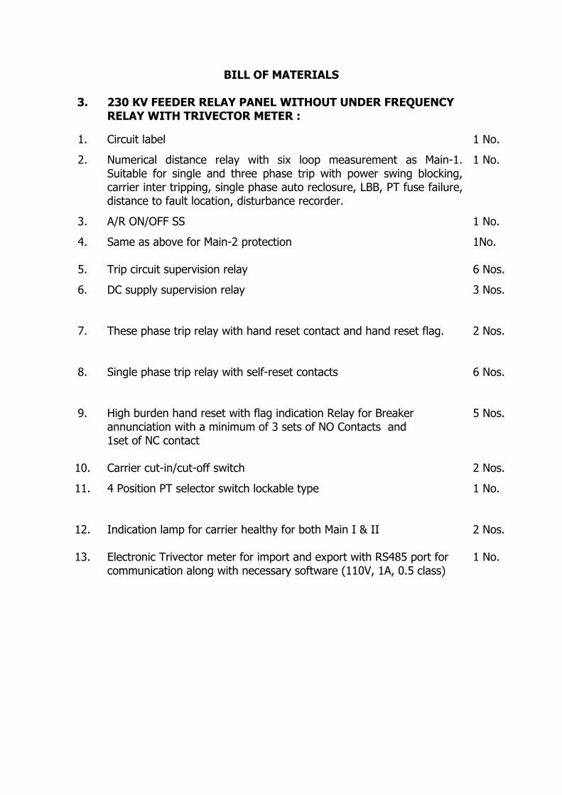
BILL OF MATERIALS
3. 230 KV FEEDER RELAY PANEL WITHOUT UNDER FREQUENCY RELAY WITH TRIVECTOR METER :
1. Circuit label 1 No.
2. Numerical distance relay with six loop measurement as Main-1. Suitable for single and three phase trip with power swing blocking, carrier inter tripping, single phase auto reclosure, LBB, PT fuse failure, distance to fault location, disturbance recorder.
1 No.
3. A/R ON/OFF SS 1 No.
4. Same as above for Main-2 protection 1No.
5. Trip circuit supervision relay 6 Nos.
6. DC supply supervision relay 3 Nos.
7. These phase trip relay with hand reset contact and hand reset flag. 2 Nos.
8. Single phase trip relay with self-reset contacts 6 Nos.
9. High burden hand reset with flag indication Relay for Breaker annunciation with a minimum of 3 sets of NO Contacts and 1set of NC contact
5 Nos.
10. Carrier cut-in/cut-off switch 2 Nos.
11. 4 Position PT selector switch lockable type 1 No.
12. Indication lamp for carrier healthy for both Main I & II 2 Nos.
13. Electronic Trivector meter for import and export with RS485 port for communication along with necessary software (110V, 1A, 0.5 class)
1 No.
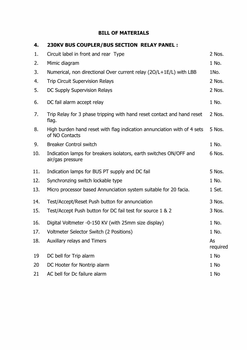
BILL OF MATERIALS
4. 230KV BUS COUPLER/BUS SECTION RELAY PANEL :
1. Circuit label in front and rear Type 2 Nos.
2. Mimic diagram 1 No.
3. Numerical, non directional Over current relay (2O/L+1E/L) with LBB 1No.
4. Trip Circuit Supervision Relays 2 Nos.
5. DC Supply Supervision Relays 2 Nos.
6. DC fail alarm accept relay 1 No.
7. Trip Relay for 3 phase tripping with hand reset contact and hand reset flag.
2 Nos.
8. High burden hand reset with flag indication annunciation with of 4 sets of NO Contacts
5 Nos.
9. Breaker Control switch 1 No.
10. Indication lamps for breakers isolators, earth switches ON/OFF and air/gas pressure
6 Nos.
11. Indication lamps for BUS PT supply and DC fail 5 Nos.
12. Synchronzing switch lockable type 1 No.
13. Micro processor based Annunciation system suitable for 20 facia. 1 Set.
14. Test/Accept/Reset Push button for annunciation 3 Nos.
15. Test/Accept Push button for DC fail test for source 1 & 2 3 Nos.
16. Digital Voltmeter -0-150 KV (with 25mm size display) 1 No.
17. Voltmeter Selector Switch (2 Positions) 1 No.
18. Auxillary relays and Timers As required
19 DC bell for Trip alarm 1 No
20 DC Hooter for Nontrip alarm 1 No
21 AC bell for Dc failure alarm 1 No
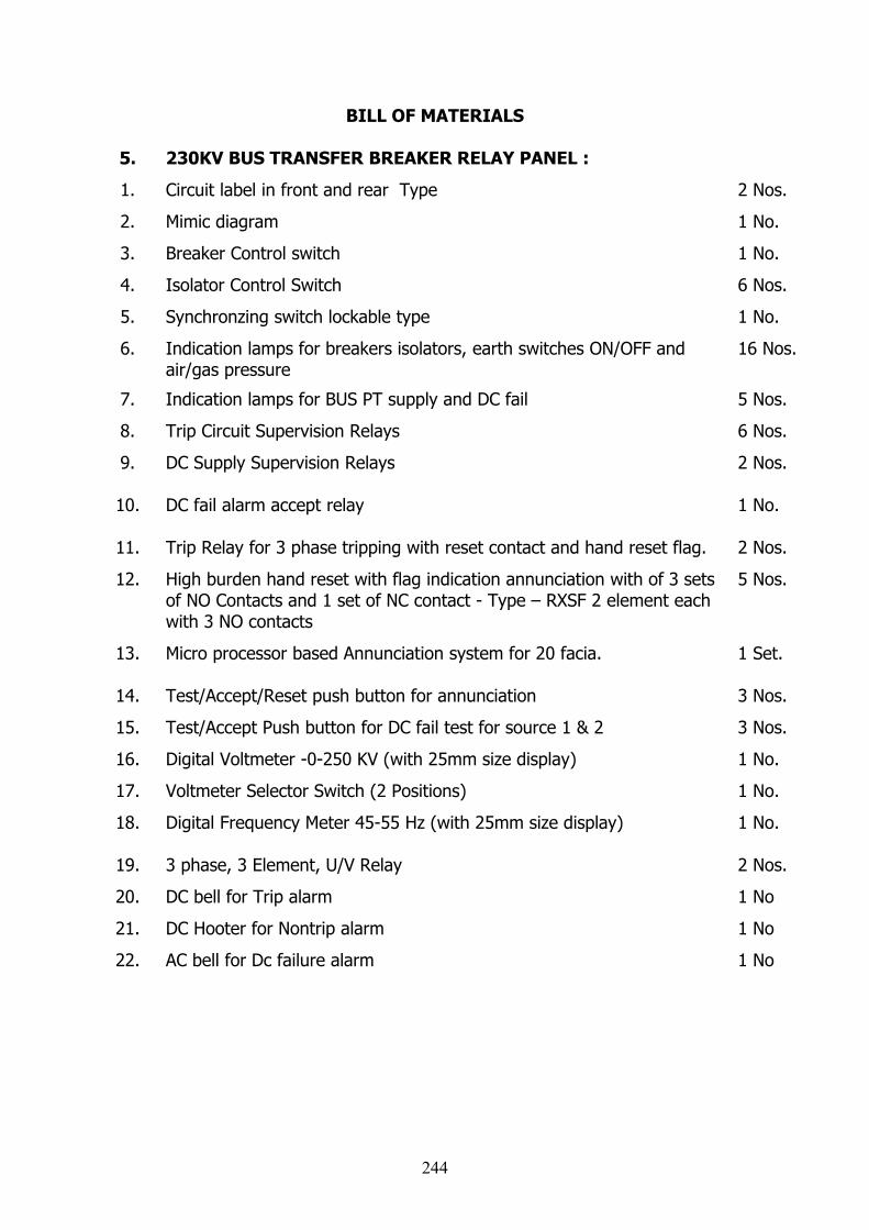
BILL OF MATERIALS
5. 230KV BUS TRANSFER BREAKER RELAY PANEL :
1. Circuit label in front and rear Type 2 Nos.
2. Mimic diagram 1 No.
3. Breaker Control switch 1 No.
4. Isolator Control Switch 6 Nos.
5. Synchronzing switch lockable type 1 No.
6. Indication lamps for breakers isolators, earth switches ON/OFF and air/gas pressure
16 Nos.
7. Indication lamps for BUS PT supply and DC fail 5 Nos.
8. Trip Circuit Supervision Relays 6 Nos.
9. DC Supply Supervision Relays 2 Nos.
10. DC fail alarm accept relay 1 No.
11. Trip Relay for 3 phase tripping with reset contact and hand reset flag. 2 Nos.
12. High burden hand reset with flag indication annunciation with of 3 sets of NO Contacts and 1 set of NC contact - Type – RXSF 2 element each with 3 NO contacts
5 Nos.
13. Micro processor based Annunciation system for 20 facia. 1 Set.
14. Test/Accept/Reset push button for annunciation 3 Nos.
15. Test/Accept Push button for DC fail test for source 1 & 2 3 Nos.
16. Digital Voltmeter -0-250 KV (with 25mm size display) 1 No.
17. Voltmeter Selector Switch (2 Positions) 1 No.
18. Digital Frequency Meter 45-55 Hz (with 25mm size display) 1 No.
19. 3 phase, 3 Element, U/V Relay 2 Nos.
20. DC bell for Trip alarm 1 No
21. DC Hooter for Nontrip alarm 1 No
22. AC bell for Dc failure alarm 1 No
244
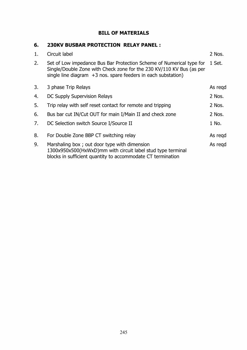
BILL OF MATERIALS
6. 230KV BUSBAR PROTECTION RELAY PANEL :
1. Circuit label 2 Nos.
2. Set of Low impedance Bus Bar Protection Scheme of Numerical type for Single/Double Zone with Check zone for the 230 KV/110 KV Bus (as per single line diagram +3 nos. spare feeders in each substation)
1 Set.
3. 3 phase Trip Relays As reqd
4. DC Supply Supervision Relays 2 Nos.
5. Trip relay with self reset contact for remote and tripping 2 Nos.
6. Bus bar cut IN/Cut OUT for main I/Main II and check zone 2 Nos.
7. DC Selection switch Source I/Source II 1 No.
8. For Double Zone BBP CT switching relay As reqd
9. Marshaling box ; out door type with dimension 1300x950x500(HxWxD)mm with circuit label stud type terminal blocks in sufficient quantity to accommodate CT termination
As reqd
245
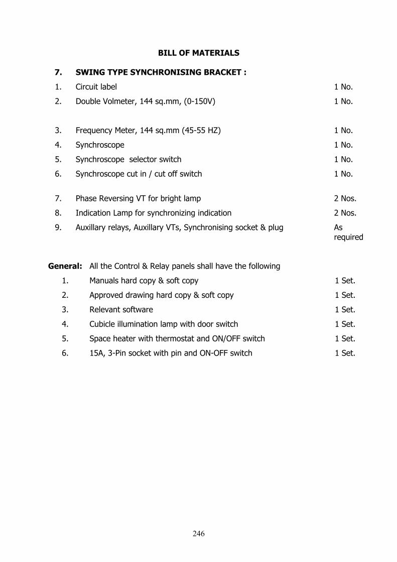
BILL OF MATERIALS
7. SWING TYPE SYNCHRONISING BRACKET :
1. Circuit label 1 No.
2. Double Volmeter, 144 sq.mm, (0-150V) 1 No.
3. Frequency Meter, 144 sq.mm (45-55 HZ) 1 No.
4. Synchroscope 1 No.
5. Synchroscope selector switch 1 No.
6. Synchroscope cut in / cut off switch 1 No.
7. Phase Reversing VT for bright lamp 2 Nos.
8. Indication Lamp for synchronizing indication 2 Nos.
9. Auxillary relays, Auxillary VTs, Synchronising socket & plug As required
General: All the Control & Relay panels shall have the following
1. Manuals hard copy & soft copy 1 Set.
2. Approved drawing hard copy & soft copy 1 Set.
3. Relevant software 1 Set.
4. Cubicle illumination lamp with door switch 1 Set.
5. Space heater with thermostat and ON/OFF switch 1 Set.
6. 15A, 3-Pin socket with pin and ON-OFF switch 1 Set.
246
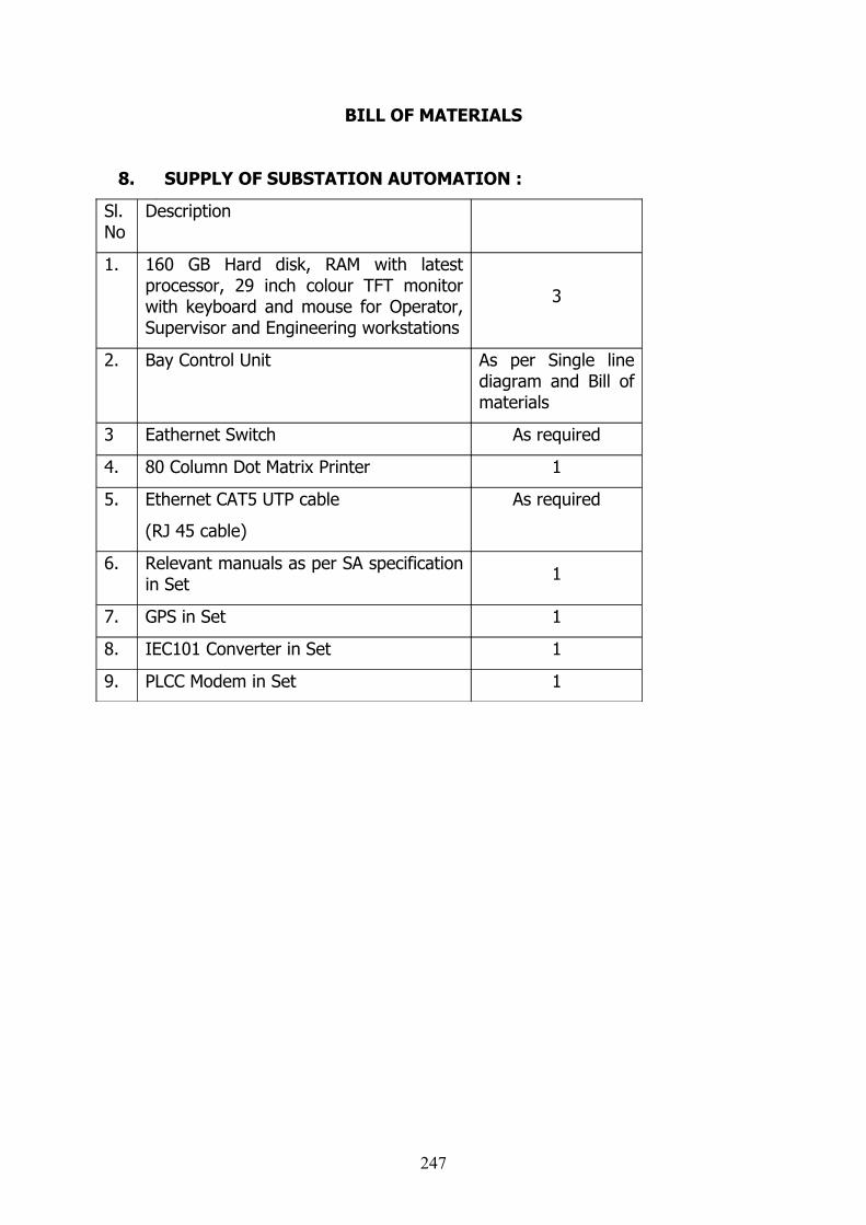
BILL OF MATERIALS
8. SUPPLY OF SUBSTATION AUTOMATION :
Sl. No
Description
1. 160 GB Hard disk, RAM with latest processor, 29 inch colour TFT monitor with keyboard and mouse for Operator, Supervisor and Engineering workstations
3
2. Bay Control Unit As per Single line diagram and Bill of materials
3 Eathernet Switch As required
4. 80 Column Dot Matrix Printer 1
5. Ethernet CAT5 UTP cable
(RJ 45 cable)
As required
6. Relevant manuals as per SA specification in Set 1
7. GPS in Set 1
8. IEC101 Converter in Set 1
9. PLCC Modem in Set 1
247
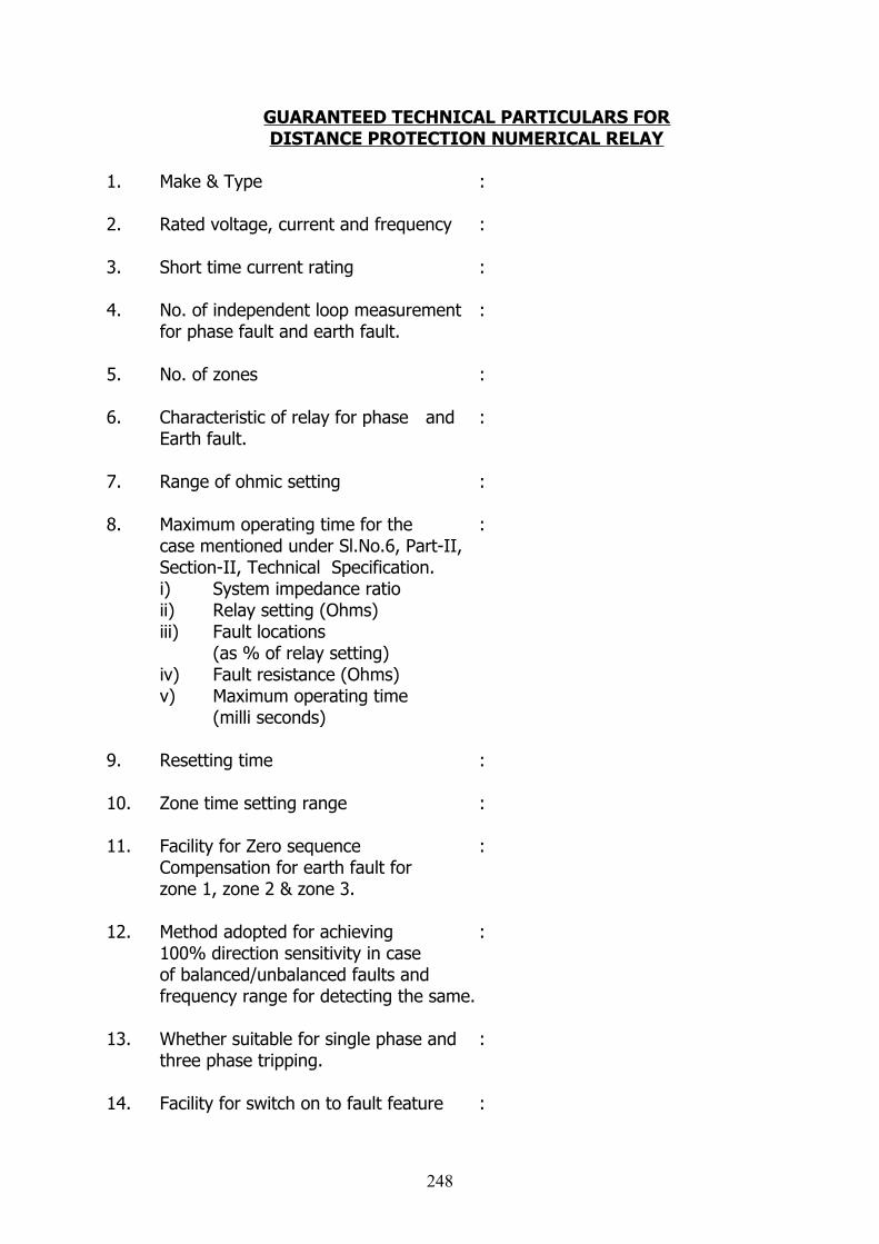
GUARANTEED TECHNICAL PARTICULARS FORDISTANCE PROTECTION NUMERICAL RELAY
1. Make & Type :
2. Rated voltage, current and frequency :
3. Short time current rating :
4. No. of independent loop measurement :for phase fault and earth fault.
5. No. of zones :
6. Characteristic of relay for phase and :Earth fault.
7. Range of ohmic setting :
8. Maximum operating time for the :case mentioned under Sl.No.6, Part-II,Section-II, Technical Specification.i) System impedance ratioii) Relay setting (Ohms)iii) Fault locations
(as % of relay setting)iv) Fault resistance (Ohms)v) Maximum operating time
(milli seconds)
9. Resetting time :
10. Zone time setting range :
11. Facility for Zero sequence :Compensation for earth fault for zone 1, zone 2 & zone 3.
12. Method adopted for achieving :100% direction sensitivity in caseof balanced/unbalanced faults and frequency range for detecting the same.
13. Whether suitable for single phase and :three phase tripping.
14. Facility for switch on to fault feature :
248

15. Facility for carrier aided tripping :
16. Facility for weak end in feed :logic and current reversal logic.
17. VT fuse failure detection:
a) Whether detects single phase :two phase, three phase PT fusefailure at Control room and yard.
b) Method of detection :
c) Whether block distance :protection in case of condition (a).
d) Whether distance protection :is allowed for tripping in case of fault when there is PT fuse failure.
18. Power swing blockinga) Detection method :b) Blocking time :c) Details of combination of Zones :
that can be blocked.
19. a) Details of trip contacts :b) Details of additional contacts :
provided.
20. Details of Auto reclose relay:a) Dead time setting :b) Reclaim time setting :c) Synchro check facility :d) Facility to initiate from main-2 :
21. Details of IDMT directional earth :fault relay.a) Setting range :b) Characteristic curve at 10 :
times of set value.
22. Characteristic angle range of distance :relay.
23. Details of Disturbance recorder :
a) No. of Analog input :
249
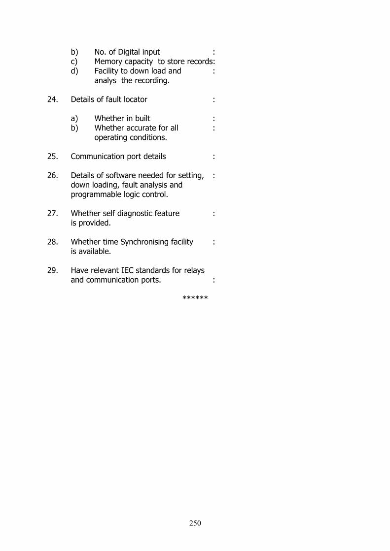
b) No. of Digital input :c) Memory capacity to store records:d) Facility to down load and :
analys the recording.
24. Details of fault locator :
a) Whether in built :b) Whether accurate for all :
operating conditions.
25. Communication port details :
26. Details of software needed for setting, :down loading, fault analysis and programmable logic control.
27. Whether self diagnostic feature : is provided.
28. Whether time Synchronising facility :is available.
29. Have relevant IEC standards for relays and communication ports. :
******
250

GUARANTEED TECHNICAL PARTICULARS
1. Transformer Biased Differential Relay:
Make & Type :Numerical :Rated DC Voltage :Current Rated :Continuous :For 1 Sec. :Two Winding Relay :Operating time at 3 times normal current:Operating time for instantaneous operation:Bias setting range with steps :Availability of faulty phase identification :Availability of instantaneous High setfeature with current setting range :Range of second harmonic restrain feature available. :Availability of continuous self monitoring and diagnostic features. :Transformer vector group and CT ratioselection/corrections through software.
Disturbance recorder:
a) No. of external digital signal that can be recorded. :
b) Facility to record currents in HV & LV Winding.
:Memory Capacity of D.R:
Fault records :No. of fault records that can be stored :
Details of ports available with protocol :
251
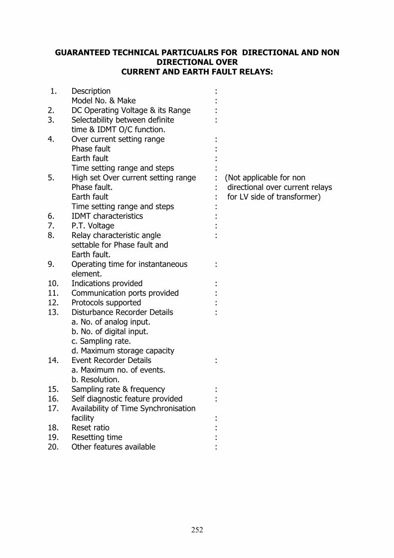
GUARANTEED TECHNICAL PARTICUALRS FOR DIRECTIONAL AND NON DIRECTIONAL OVER
CURRENT AND EARTH FAULT RELAYS:
1. Description : Model No. & Make :2. DC Operating Voltage & its Range :3. Selectability between definite : time & IDMT O/C function.4. Over current setting range :
Phase fault :Earth fault :Time setting range and steps :
5. High set Over current setting range : (Not applicable for non Phase fault. : directional over current relays Earth fault : for LV side of transformer)Time setting range and steps :
6. IDMT characteristics :7. P.T. Voltage :8. Relay characteristic angle : settable for Phase fault and Earth fault. 9. Operating time for instantaneous : element.10. Indications provided :11. Communication ports provided :12. Protocols supported :13. Disturbance Recorder Details : a. No. of analog input. b. No. of digital input. c. Sampling rate. d. Maximum storage capacity 14. Event Recorder Details :
a. Maximum no. of events. b. Resolution. 15. Sampling rate & frequency :16. Self diagnostic feature provided :17. Availability of Time Synchronisation
facility :18. Reset ratio :19. Resetting time :20. Other features available :
252
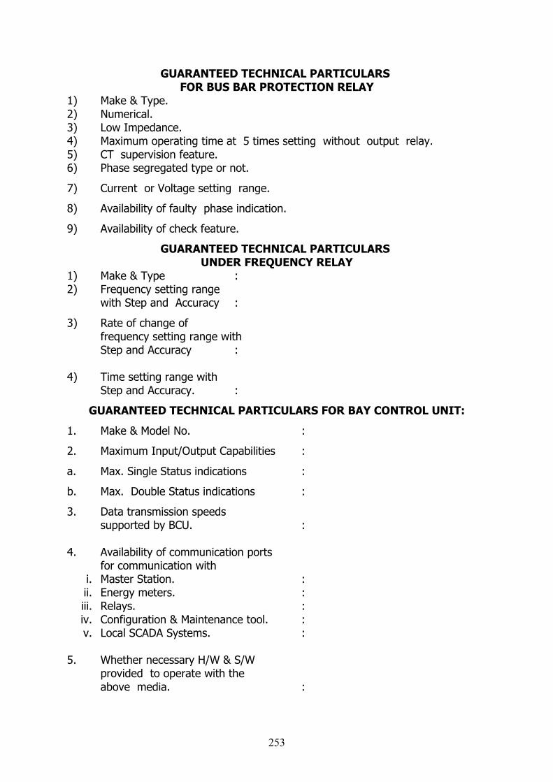
GUARANTEED TECHNICAL PARTICULARS FOR BUS BAR PROTECTION RELAY
1) Make & Type.2) Numerical.3) Low Impedance.4) Maximum operating time at 5 times setting without output relay.5) CT supervision feature.6) Phase segregated type or not.
7) Current or Voltage setting range.
8) Availability of faulty phase indication.
9) Availability of check feature.
GUARANTEED TECHNICAL PARTICULARS UNDER FREQUENCY RELAY
1) Make & Type :2) Frequency setting range
with Step and Accuracy :
3) Rate of change offrequency setting range withStep and Accuracy :
4) Time setting range with Step and Accuracy. :
GUARANTEED TECHNICAL PARTICULARS FOR BAY CONTROL UNIT:
1. Make & Model No. :
2. Maximum Input/Output Capabilities :
a. Max. Single Status indications :
b. Max. Double Status indications :
3. Data transmission speeds supported by BCU. :
4. Availability of communication ports for communication with
i. Master Station. :ii. Energy meters. :iii. Relays. :iv. Configuration & Maintenance tool. :v. Local SCADA Systems. :
5. Whether necessary H/W & S/Wprovided to operate with theabove media. :
253
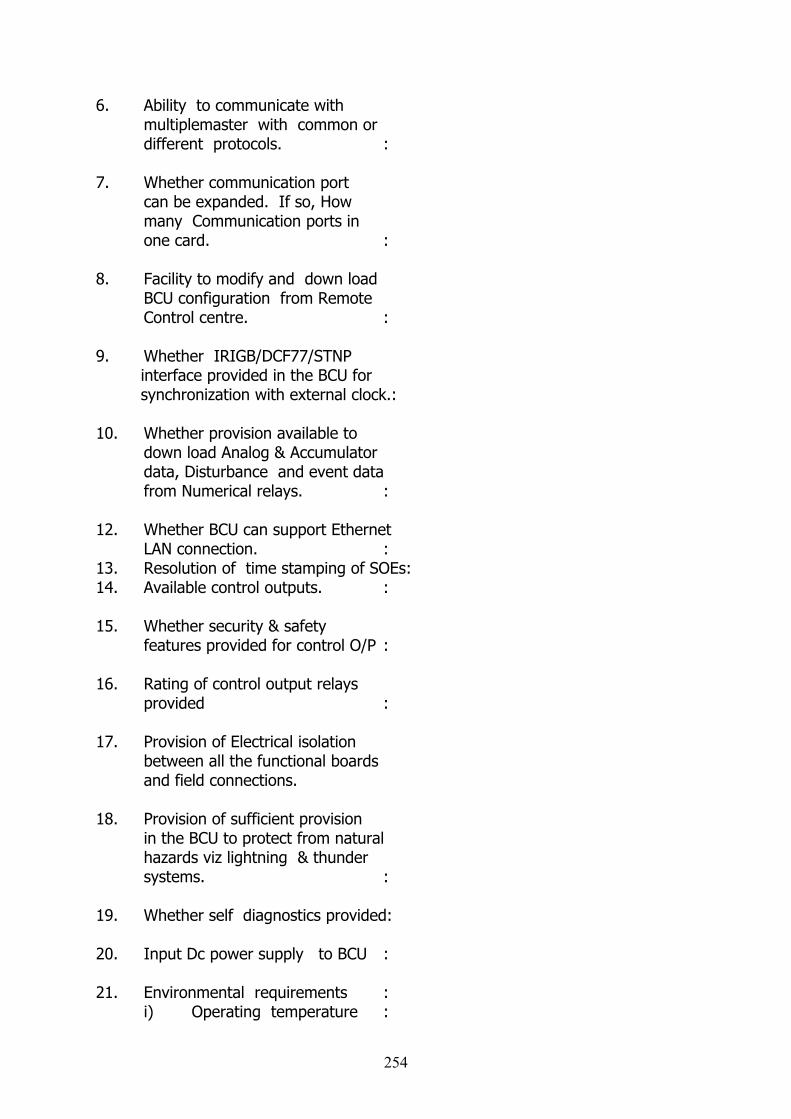
6. Ability to communicate with multiplemaster with common or different protocols. :
7. Whether communication port can be expanded. If so, Howmany Communication ports in one card. :
8. Facility to modify and down loadBCU configuration from RemoteControl centre. :
9. Whether IRIGB/DCF77/STNP interface provided in the BCU for synchronization with external clock.:
10. Whether provision available to down load Analog & Accumulator data, Disturbance and event data from Numerical relays. :
12. Whether BCU can support Ethernet LAN connection. :
13. Resolution of time stamping of SOEs:14. Available control outputs. :
15. Whether security & safety features provided for control O/P :
16. Rating of control output relays
provided :
17. Provision of Electrical isolation between all the functional boards and field connections.
18. Provision of sufficient provision in the BCU to protect from naturalhazards viz lightning & thunder systems. :
19. Whether self diagnostics provided:
20. Input Dc power supply to BCU :
21. Environmental requirements :i) Operating temperature :
254

ii) Relative humidity :iii) Whether type tested for :
continuous operation at 55°C for 48 hours followed by continuous operation at normal ambient temperature for 240 hours.
22. Software requirements :1. Operating System :
2. Automatic restart of the BCU upon power restoration, memory parity errors, hardware failures and upon manual request. :
3. Diagnostic software for checkingthe hardware errors and other functions of the BCU. :
4. Whether diagnostic software is user interactive . :
5. Whether configuration and maintenance : tool with all required hardwares (other than Laptop PC) and software.
255
1. Ventilation
(a) The type of ventilation systems for non-air conditioned areas shall be as under:- 33 kv switchgear rooms, GIS Bay and cable gallery : Ventilation ducts
- Other part of the building : Mechanical ventilation system with Exhaust fans
(b)Industrial Exhaust fan of suitable capacity (min 5 Hp) should be provided in the GIS bay to bail out any SF 6 gas leak from the equipments. The ducts shall be of galvanized steel .Full guarantee for 24 months for all parts and services after commissioning shall be given.
(c) All the required materials, labour, tools, staging materials and consumables for completing the work shall be supplied.
(d)Ventilation duct shall be perforated polythene tubing system consisting of one or more inflatable polythene ducts suspended overhead from steel wires or clamped on the wall sides. Rows of small holes in the sides of the ducts shall produce jets of air, with enough throw to create continuous gentle air movement throughout the building. Unnecessary elbows, ‘tee-pieces’, ‘y-pieces’, splitters etc. shall be avoided.
While designing the ducts, the number and size of the holes (Perforation) most suitable for the duct diameter and airflow shall be calculated and provided. Minimum Perforation Diameter shall be 2 inches.
(e)Ventilation duct shall consist of a fan suspended in the roof space at one end of the building which draws fresh air in from outside. Ventilation ducting is connected to the fan and runs down the length of the building. Holes cut into the sides of the ventilation ducting distribute the fresh air in a series of high pressure jets.
(f) The fan shall be chosen so that it produces the required air flow at the optimum static pressure. Minimum static pressure - 75pa (6mm water gauge)
Optimum static pressure - 125pa (12mm water gauge)
Maximum static pressure - 150pa (14mm water gauge)
The fan size should be chosen as follows:
Propeller fan diameter = duct diameter x 0.8
Axial fan diameter = duct diameter
Centrifugal fan area = duct area
256
Where an exact match is not available a reducer to the fan outlet, and next smallest duct size can be used in such a way that the airflow shall be within the required range. The use of fan speed control should be avoided. Large fans can also be replaced with more smaller fans each with there own ducts wherever possible. Provision shall be available to switch them in steps.
(g) Air temperature inside inflatable duct systems shall be maintained Maximum air temperature - 150 degrees Fahrenheit (65 degrees centigrade)Minimum air temperature - 41 degrees Fahrenheit ( 5 degrees centigrade)An air straighteners and air filters shall be fitted on the upstream of the fan and after elbows or ‘tee-pieces’ to reduces air turbulence inside the duct, improving air distribution and reducing duct fatigue caused by flapping.
(h) The ventilation system shall be of reputed make and it shall be got approved along with design calculations for total capacity, air flow and no of the units required. The quantities mentioned in the schedule are tentative. 36 months of full guarantee for all parts and services after commissioning shall be given. (i) The fire resistive performance of a ventilation duct assembly shall be in accordance with the requirements of ISO 6944-1985, "Fire Resistance Tests - Ventilation Ducts."
2. Electric overhead traveling (EOT) crane and mono rail crane
2.1 GENERAL
(a) The cranes shall comply with the requirements and standards of latest versions of relevant IS / IEC standards. The span of the crane shall be fixed in such a way that the travel and lift of the main and auxiliary hooks of the crane as well as the hook limits shall be adequate for the assembly and disassembly of the main equipment. The lift above the service bay (upper limit) shall be adequate to hoist and carry the equipments to assemble and disassemble. The lift below the service bay (lower limit) shall be fixed in such a way as necessary for assembly and disassembly of the equipments.
(b) The hook and wire rope capacity shall be taken as 10% more than the maximum weight to be lifted inclusive of the weight of the lifting beam.
(c) The provision of radio remote control and variable voltage variable frequency (VVVF) drive for various crane motions for the purpose of precision speed control shall be made available for the cranes.
(d) The radio remote control equipment, wherever provided shall conform to all applicable Government rules and regulations. The frequency of operation shall be in the requisite frequency band as per relevant standards.
257
(e)Codes and standards:
IS 807 : 2006 - Design, Erection and testing (Structural Portion) of Cranes and Hoists - Code of Practice (Second Revision)
IS 3177 : 1999 - Code of Practice for Electric Overhead Traveling Cranes and Gantry Cranes other than Steel Work Cranes (Second Revision) This code covers mechanical, electrical, inspection and testing requirements relating to the design, manufacturing and erection of electric overhead traveling cranes, portal and semi - portal cranes, single girder, double girder or mono-box type.
IS 13834 : Part 1 : 1994 - Cranes - Classification Part 1 General IS 13870 : Part 1 : 1993 - Cranes and lifting appliances - Selection of wire ropes Part 1 General
(f) Full guarantee of 24 months for all parts and services after commissioning shall be given. Any defects arising during the guarantee period shall be rectified free of cost.
(g) 5 sets of layout drawing and maintenance manual of the crane shall be given after commissioning.
(h) All the required materials, labour, tools, staging materials and consumables for completing the work shall be supplied
(i)Cables & Wiring: The cables laid from control panel to girder end junction box, DSL to Main switch to Protection panel shall be 1100V grade armored PVC copper cables confirming to IS 1554 with latest amendments. The trailing cables laid on Coburn track(Cross conductor system with Coburn track) shall suitably rated for 1100v grade bare copper flexible cables confirming to relevant IS standards. The end termination of all cables shall be with copper lugs, , pins, glands etc. and shall be ferruled with numbers. The details including cable size calculations, make of the cables, lay out drawings etc. shall be submitted for prior approval. Separate control panel shall be provided for protective circuit, Hoist, LT & CT
(j)The motors shall be of reputed make like ABB, Siemens, AEI, and GEC only. Confirming to appropriate code of standard. The crane to shall be of reputed make and it shall be got approved.
2.2 Electric overhead traveling (EOT) craneREQUIREMENTSDESIGN :- Compact dimensions, low weight, easy to operate and easy to maintain with Coburn track wiring.
MOTORS :- Motors shall preferably be heavy duty squirrel cage induction motors for hoists and cranes .Slip ring induction motors will also be acceptable if heavy duty cranes are required as per design requirement.
258
GEAR BOXES :- Precision flat helical / spur gear units in light alloy housings with case-hardened gears, high-grade surface treatment and permanent oil / grease lubrication. All the couplings shall be of spring grid / Gear type couplings
BRAKES :- Single / Dual-disc electromagnetic DC brakes featuring automatic braking on power failure Or Electro hydraulic thruster operated type.
LIMIT SWITCHES :- Shall be provided to prevent over hoisting & over lowering of hook.
PUSH BUTTON STATIONS :- Extra light, handy, easy to operate, aluminum, fabricated from extruded section.
SOFT STARTS :- Electric / Electronic soft start modules electrically coupled to the long travel drives to achieve jerk free, cushioned & smooth starts.
MAINTENANCE PLATFORM WITH HAND RAILING: - Easy, simple & safe maintenance of the Crane extended partially or totally along the girder.
Normal speed creep speed:
(i) Main hoist 1m / min (Normal speed) 0.2m / min(Creep speed)(ii) Cross travel 12m / min(iii) Bridge long travel 25m / min
A ladder shall be provided to attend any defects in the crane in case of emergency situation.
2.3 UNDERSLUNG CRANES (With Electric Hoist):-REQUIREMENTS
DESIGN :- Compact dimensions, low weight, easy to operate and easy to maintain as per IS 3938 Class II duty operations and use.
MOTORS :- Sturdy cylindrical / conical rotor pole-changing motors with continuous cast aluminum sections, integrated safety brakes insulation protection confirming to IS 325.
GEAR BOXES :- Precision flat helical / spur gear units in light alloy housings with case-hardened gears and anti friction bearings on both sides, high-grade surface treatment and permanent oil / grease lubrication.
BRAKES :- Single / Dual-disc electromagnetic DC brakes featuring automatic braking on power failure.
LIMIT SWITCHES :- Shall be provided to prevent over hoisting & over lowering of hook.
259

PUSH BUTTON STATIONS :- Extra light, handy, easy to operate, aluminum, fabricated from extruded section.
SOFT STARTS :- Electric / Electronic soft start modules electrically coupled to the long travel drives to achieve jerk free, cushioned & smooth starts.
4. Fire detection, alarm, protection and Fighting system
4.1Fire detection and alarm
(a) A comprehensive fire detection, alarm as well as fire protection system shall be installed for the Station in conformity with relevant IS. In addition, all buildings shall conform to National Building Code. Fire protection system shall be designed as per the guidelines of Tariff Advisory Committee (TAC) established under Insurance Act 1938 and /or NFPA.
(b) Automatic fire detection and alarm system shall be intelligent and addressable type and shall be provided to facilitate detection of fire at the incipient stage and give warning to the staff.
(c) Major equipment to be used for fire detection and protection system shall be in accordance with Indian Standards or UL (Underwriters Laboratories, USA) or FM (Factory Mutuals, USA)
4.2 Fire protection system
All major and minor fire risks in the Station shall be protected against fire by suitable automatic fire protection systems. Following systems shall be generally adopted for various fire risks:
(i) Passive fire protection measures such as fire barriers for cable galleries etc., fire retardant coatings, fire resistant penetration sealing for all openings in floors, ceilings, walls etc., fire proof doors etc. shall be provided to prevent spreading and for containment of fire.
(ii) Automatic medium velocity water spray system, complying with TAC guidelines, shall be provided for the cable galleries, cable vaults, cable spreader rooms, cable risers, etc.
4.3 Fire Fighting System
(1) Proper attention shall be given to isolation, limiting and extinguishing of fire so as to prevent damage to costly equipments, reduce chances of serious interruption of power supply and ensure safety of personnel. The layout of the sub- station itself shall be such that the fire shall not spread from one to other equipment and areas as far as possible.
260
(2) Fire hydrant, carbon dioxide (CO2) type fire extinguisher or dry chemical powder type fire extinguisher conforming to relevant IS shall be provided at various locations to cover the entire Station.
(3) Adequate Number and quantity complying with TAC guidelines, shall be provided
(4) Dedicated fire water storage and pumping facilities shall be provided for the fire fighting system as per TAC guidelines. Main fire water pumps shall be electrically driven and standby pumps shall be diesel engine driven.
(5) Portable fire extinguishers as per TAC guidelines shall be provided for each room/area of sub- station in addition to fixed fire protection system to extinguish fire in its early phase to prevent its spread.
5. Earthing system
5.1 GeneralAC system: Solidly earthedDC system: Unearthed
The earthing system shall be designed for a life expectancy of at least forty (40) years and for maximum system fault current or 40kA for 1.0 sec, whichever is higher.
The minimum rate of corrosion of COPPER used for earthing conductor shall be considered as 1% per year while determining the conductor size.Grounding and lightning protection for the entire Station shall be designed and provided in accordance with relevant IEEE Standards.The soil resistivity at the substation is Combined earth resistance shall be >/= 0.1 ohms
5.2 Earth electrode Grounding protection for the entire Station shall be provided with earth electrode made of copper rod of cross section 240 sq mm and 15 mts length. At least 2 no earth electrode shall be provided for the sub station building diagonally opposite. The electrode shall be embedded in 150 mm din hole driven by auguring and filled with bentonite and carbon powder mixture. Similarly at least 1 no earth electrode shall be driven for each Transformer. All the earth electrodes shall be submerged 1 mt below the basement floor level
Resistance of each earth electrodes shall be measured and recorded.
5.3 Earth electrode inter-connection
The earth electrodes provided for the sub station building shall be inter- connected with each other by providing 240 sq mm stranded bare copper conductor
261
and copper clamps. The copper conductor loop shall cover entire perimeter of the substation
Similarly the earth electrodes provided for the Transformers shall be inter- connected with each other by providing 240 sq mm stranded bare copper conductor and copper clamps. The copper conductor loop shall cover entire perimeter of the Transformers plinth.
Both the loops shall be inter- connected at least at 2 locations with each other by providing 240 sq mm stranded bare copper conductor and copper clamps.
Combined earth resistance shall be measured and recorded. The value shall be less than 0.1Ώ more earth electrodes can be added, if it is necessary to achieve the required combined resistance.
5.4 Earth mat risers
Earth mat risers shall be of copper flats with cross section area of 240 sq mm connected at 5mts interval to the copper conductor loop below the basement floor level by copper clamps. These risers shall be brought up from the floors, through 140 mm PVC pipe filled with fire proof insulating compound.
5.5 Earth mat layout
These earth mat risers shall be looped or inter-connected through out the inner periphery of each room by providing 240 sq mm copper flats by brazing or fastening stainless steel bolt and nuts, 300 mm above floor level and secured to the wall by copper cleats. Forming earthmat layout. At the entrance of any room it should be fixed below the floor level. All the earthing connections required for any equipment, and equi-potential earth mat in any particular room shall be taken only from this copper flat earth mat layout in that particular room, by providing 240 sq mm copper flat 100 mm below the floor level . Similarly for connecting the transformers and power cables, 240 sq mm copper flat earth mat risers shall be connected to the copper conductor loop, where ever earthing connection is required for the equipments.
ILLUMINATION
STANDARDS:
The electrical installations shall be carried out as per IS.732.
LIGHTING LEVELS:
A general distribution and protection panel has to be provided in the building.
LIGHTING:
262
The power and number of ceiling-mounted lighting fixtures are determined to
provide the following intensities of illumination or adequate illumination.
Corridors : 200 lux
Cable floor-basement : 100 lux
Toilets : 100 lux
Control room : 100 lux
Offices : 250 lux
110KV compartment room : 250 lux
Battery room : 100 lux
Rectifier room : 100 lux
Basement : 100 lux
Air-conditioning : 250 lux
Stairs : 100 lux
Stores : 250 lux
Spares & tools : 250 lux
Provision of Socket:220V single phase + earth (16A or 20A) corridor
Offices : 2
Basement : 1
Stores : 1
Spares tools : 1
Conference room : 1
Rectifier room : 1
110 and 33KV compartment room : 4
Control room : 2
LIGHTING MATERIALS:
All the room must be equipped of adequate fluorescent electric lamps. These
ones must be sealed in the incandescent reflector or in any other way. These fittings
shall be dust-proof. These ones must be agreed by the purchaser.
A special connector must be installed at the entrance of the sub-station. This
switch will extinguish all the lighting of the building.
263

The security lighting shall be performed by automatic emergency exit light
and shall be on when the power is down.
The handling emergency light must be located in specified areas on each level
of the building in the drawings.
In specified area the contractor must use adequate lighting such as explosion
proof light or equivalent type fluorescent lamp, emergency lamp, emergency exit
lamp, filament lamp, tight double lamp, handling emergency lamp.
All the different units used on the site must fit the Indian standards and must
be agreed by the purchaser. The height of the lamps must be agreed by the
purchaser.
264
230KV CABLE ACCESSORIES
1.0. CHARACTERISTICS OF THE ACCESSORIES
All accessories (sealing ends and joints) shall be supplied along with cable. The electrical stress in the accessories shall be controlled by a silicon rubber/EPDM rubber Premoulded block (slip on type) consisting of insulating and semi-conducting layers.
Type tests shall have been performed atleast on two outdoor sealing ends, one 230KV cable straight through joint and one sheath sectionalising joint of the same model which is proposed for CHENNAI application, unless the test have been done already for which the certificate of proof shall be submitted.
For GIS connection, either test certificates or electrical field calculation sheets shall be provided so as to demonstrate that the internal electrical stress along the cable termination (stress cone) remains within the limits which have been experienced for the outdoor applications.
Supply and installation of the insulated cables required for sheath earthing and their connections to the general earthing system(s) at terminations and joint locations (Wherever necessary) are part of the contract. The specification of the cables used for the sheath bonding and their connecting diagrams shall be submitted to Purchaser’s Agreement.
Any special tools required for installation of accessories should be supplied free of cost.
The Vendor should not offer more than two makes of accessories in the bid and one make will be decided by the Purchaser.
2 SEALING ENDS
2.1 OUTDOOR SEALING ENDS
For terminating the cables , pre-molded sealing ends suitable for heavily industrial and saline polluted atmospheric conditions as per relevant IEC shall be supplied along with the cables. The sealing ends shall conform to the latest International Standards apart from the specification for the cable mentioned above.
The internal electric stress in the sealing end shall be controlled by the Silicon rubber /EPDM rubber Premoulded cone arrangement. The outside bushing shall be weather – proof and of good quality, suitable for use in locations of severe coastal pollution. The creep-age shall be 31 mm/kv (Pollution Level IV).
Each outdoor type sealing end shall be supplied complete with mounting plate insulators to insulate the Sealing End from the supporting structures and to control the cable sheath current.
Phase to Phase clearance of sealing end should match with other terminal equipment.
265
The required BI-metallic Terminal connectors shall be supplied free of cost along with the Sealing Ends to suit the jumper conductor. Size of jumper conductor will be furnished to the successful bidder.
The vendor shall supply the galvanised steel structures with necessary civil foundation design for the outdoor termination structures.. In the terminal structures one side is to be provided with stainless steel cross bars to break the circulating current effect.
2.2 INDOOR SEALING ENDS
The connection of the cables shall be made through SF6 filled cable connection enclosures. General arrangement/dimensions of the compartment is enclosed in Appendix `B’.
The following are part of the supply:-
the cable termination including the pre-moulded stress cone and the connector
the cable gland with insulating arrangement from earth (insulating flange etc.) including stainless steel bolts.
the sealing of the conductor to prevent the SF6 from penetrating inside the conductor.
the sealing at the cable gland for SF6 tightness.
The insulating arrangement of the gland shall be designed to withstand the following:
Lightning impulse : 35 KV (Peak value)
Power frequency : 8 KV (r.m.s. value) for 15 min.
For impulse withstand test, the wave shall have a virtual front time between 1 and 5 microseconds and a nominal time to half the peak value between 40 microseconds and 60 microseconds.
The arrangement shall withstand 10 impulses in positive polarity followed by 10 impulses in negative polarity.
During a series of 10 impulses a maximum of one or two flashovers can occur in the air, for which 5 additional impulses are applied.
No breakdown of the insulating arrangement shall occur; the number of flashover shall not be more than two.
To protect the cable gland insulation, against over voltages, three voltage limiters (CCPU) shall be provided and connected between the metallic sheath of the cable and the GIS cable enclosure.
266
To be effective, the connections shall be as short as possible, of the same length and regularly distributed at 120° on the same circumference; the connections of the CCPU shall be bolted (diameter : 14 mm).
Routine tests which are conducted in the factory for testing the insulating arrangement of the gland shall be indicated by the vendor.
Characteristics of the surge limiters (CCPU) shall be submitted to Purchaser. for agreement.
3. SHEATH BONDING CONNECTION
Each sealing end shall be provided with two terminals, diametrically opposite each, suitable for bolting (14mm diameter) the sheath bonding cables.All sheath bonding and insulated connections to the link boxes shall be designed for the fault current conditions which are stipulated in clauses-2.1.
4. LINK BOXES
4.1. LINK BOXES FOR SHEATH EARTHING
The sheath connections shall be of bolted type the connecting bar and disconnecting link shall be of copper. The arrangement shall be installed in a water tight box.
Detailed description and drawing shall be provided by the vendor along with the tender.
4.2. LINK BOXES FOR SHEATH SECTIONALISING ( Three phase type)
The provision for sectionalising sheath circuit shall be made in link boxes where the cable is earthed enroute.
The connecting, disconnecting and earthing links shall be made of copper. The arrangement shall be installed in a watertight box.
Detailed description and drawing shall be provided by the vendor along with the tender. Installation recommendations shall also be provided with particular reference to protection from explosion risk. Arrangements for erection of link boxes above ground level inside an all – weather proof pillar box shall be made by the Vendor.
5.0. EARTHING SYSTEM
Bare copper wires, electrodes and connection for the joint chamber earthing systems, wherever necessary shall be in the scope of supply, he installation will be done by Vendor as per the instructions of the T.N.E.B.
267
6.0 ACCESSORIES:
All jointing and termination works shall be carried out by the vendor on turn key basis with their own best supervision in the presence of purchaser.
Dust and humidity free enclosures, complete with air conditioners and material handling equipment shall be used by the vendor.
All special tools including a set of jointer’s hand-tools, that are necessary to complete the joint/termination works shall be arranged by the vendor. The facilities available with purchaser can be availed of by the vendor.
Necessary power supply for jointing and termination works shall be arranged by the VENDOR. Alternatively the power supply will be provided by purchaser wherever feasible at the tariff rates prevailing on the day of utilisation, at vendors specific request.
The cost of consumables which are essential for satisfactory erection and commissioning shall be included. No extra cost will be paid towards the cost of consumables.
Adequate quantity of consumables shall be supplied for completing the entire cable laying and jointing works. The list of such consumables shall be furnished..
268
TECHNICAL SPECIFICATION FOR SUPPLY OF 50 KVA DIESEL GENERATOR SET
1.0 CODES AND STANDARDS: 2.1 BSS-5514 - Diesel Engines for general purposes2.2 BSS. 2613 - Electrical performance of rotating electrical machines2.3 ISS-4722 - Rotating Electrical machines2.4 IS-8623 - Specification for factory built, assembly of switchgear
and control gear for voltages upto and including 1000V/1200V A.C.
2.5 IS-4237 - General requirements for switchgear and control gear for voltages not exceeding 1000V.
2.6 IS-2147 - Degree of protection provided by enclosures for LV switchgear
2.7 IS-3072 - Code of practice for installation and maintenance of switchgear
2.8 IS-2075 - Current Transformer2.9 IS-2516 - A.C. Circuit Breaker (Part-II, II etc.,)2.10 IEC-408/72 - Short time withstand test2.11 IS-6005 - Surface treatment for M.S. Sheets2.12 IS-2203 - HRC Cartridge type fuses2.13 IS-722 - Energy Meter
2.0 PERFORMANCE REQUIREMENTS: The Diesel Generator set and accessories shall be so designed as to meet the following requirements:(i) The unit shall be capable of starting from cold conditions, reaching
synchronous speed and taking up load without undue wear and stresses on equipments.
(ii) The unit shall be capable of delivering continuously at the generator terminals the nett output specified, with invisible exhaust.
(iii) The unit shall be capable of delivering a peak output of 10%. In excess over the rated output for a period of one hour out of total of twelve consecutive hours of operation without exceeding permissible temperature limits and with a very little visible exhaust. The unit shall be continuously rated to supply power for long periods.
(iv) The unit shall be capable of meeting the specified performance when using diesel oil as recommended by the supplier.
(v) The unit shall operate up to 110% of the rated speed over the entire range of output without undue vibration and noise.
3.0 QUALITY OF MATERIALS All materials used in the construction of the work shall be of the best quality obtainable of their respective kinds and comply in all respect with the standards and tests laid down in the appropriate British Standard specification. Where a British Standard Specification covering a material is not published, the standards and tests adopted by American Society for testing materials shall be adopted.
269
4.0 WORKMANSHIP All workmanship must be first class in every respect and in accordance with the best modern practice. Working surfaces must be accurately and finely finished. All working parts of the machines and their connections shall be finished in the best possible manner and with the utmost precision.
All electrical machinery shall be designed to work without undue noise and special precautions must be taken to provide machine that will run quietly without any vibration.
5.0 DIESEL ENGINE: 1. The diesel engine shall be vertical, single acting, mechanical
injection type. The horse power rating required, auxiliaries, guarantee of fuel consumption, parallel operation, governor performance and torsional vibration shall be in accordance with BS-5514 or approved equivalent.
2. The diesel engine of suitable capacity (not less than a nett output of 32bhp at 1500 rpm for 25KVA sets and 91 bhp at 1500 rpm for 75KVA sets) cold start, air/water cooled 4 stroke cycle compression engine with complete standard accessories and fittings.
3. The fuel consumption at no-load and fuel consumption at rated output and 50% shall be furnished.
4. The percentage of overload that can be permitted and the duration shall be furnished.
6.1 ELECTRICAL STARTING SYSTEM:Starting system shall be suitable for manual electrical starting. The starting system offered shall be complete with starter motor, batteries, battery charger, other required instruments, accessories, control switches and interconnecting cable.
6.2 GOVERNOR SYSTEM The type of governor shall be indicated. The governor shall conform to BS-5514 or approved equivalent. The governor characteristic shall comply with requirements of “Class-A Governing” of BS-5514 (latest amendment) or approved equivalent.
The governor shall have the following features;
(i) An over speed trip mechanism shall be provided automatically shutoff fuel in case the set speed reaches above 110% of rated speed. The engine speed at which the mechanism trips the engine shall be adjustable.
(ii) An emergency stop push button shall be provided, which when operated will trip the engine.
270
6.0 GENERATOR (a) The generator shall have Class-H insulation for stator and rotor.(b) The live and needful ends of each phase winding of the generator
shall be brought out and suitably terminated. Supplier shall provide suitable clamping arrangements for connecting the cables to the machine terminals. The terminals shall be suitably enclosed to prevent short circuits by rodents etc., suitable cable glands shall be provided on the enclosures to facilitate entry of the above cables.
(c) All parts of generator and accessories shall be designed to withstand all electrical, mechanical and other stresses which may be experienced during operation, including short circuit and over speed conditions.
(d) The generator shall be provided with two (2) grounding terminals with clamps for connection to purchaser’s gruonding grid.
7.1 EXCITATION SYSTEM(a) The excitation system shall be so designed or protected, that
harmful over voltages cannot occur at the main exciter commutator due to combined effect of maximum exciter field current and machine over speed.
(b) The exciter shall be provided with two (2) diametrically opposite ground terminals with clamps suitable for connection to purchaser’s grounding grid.
7.2 VOLTAGE REGULATORS
(a) The generator shall be capable of operation over a range of +/-5% if the rated voltage.
(b) The voltage drop from no-load to full load shall not exceed 3%.
7.3 CONTROL SYSTEM FOR DIESEL GENERATOR (a) All the sequence involved in the complete startup of the diesel engine set and
bringing upto the rated speed and voltage shall take place automatically. Vendor shall provide all the necessary accessories required for this purpose.
(b) It should also be possible to start the engine manually. Please note that except for the starting impulse which is manual, all other starting operations shall be automatic.
(c) A tripping push button shall be made available in the Control schematic to relieve the set from its load when the set is running irrespective of the mode of operation.
7.4 TRIPPING CONDITIONS The Diesel Generator shall be tripped under the following conditions:-
(a) Over speed above 110% of the rated speed of the diesel generator set.(b) Low lubricating oil pressure after the engine has attained 90% of its rated
speed.
271
(c) Cylinder Head Temperature high.(d) Generator faults.
All sending devices and required contractors are included in the scope of supply. These devices shall be suitable for operation on ungrounded D.C. system.
7.0 CONTROL AND ANNUNCIATOR PANEL The panel shall be free standing, floor mounting sheet steel clad indoor type with front hinged, rear removable, undrilled and removable bottom. The sheet steel used shall be of 12SWG.
The control panel shall have the following instruments, switches, relays, fuses, etc.,
(i) A.C. Voltmeter of range 0-600V to read the generated voltage (phase to phase and phase to neutral).
(ii) A.C. Ammeter suitable for 25KVA and 75KVA, 415V (0 to 100A) to read the load current.
(iii) Selector switches for the above voltmeters and ammeters.(iv) Frequency meter of range 45 – 50-55 Hz to read the frequency of the
generated voltage.(v) 3 Phase, 4 Wire Kilowatt Hour meter to measure the energy generated.(vi) Service hour meter to record the time of operation of DG set.(vii) D.C. Voltmeter of suitable range to read the battery voltage.(viii) D.C. Ammeter of suitable range to read the battery charger current and
load current (i.e) centre zero ammeter.(ix) Solenoid relays for starting and stopping DG set.(x) Overload relay to protect the generator from overload as well as to give
annunciation.(xi) Earth fault relay to trip the generator as well as to give annunciation.(xii) Current Transformers of suitable ratio for metering and protection
purposes.(xiii) H.R.C. Fuses for power circuits and control circuits for protection for both
A.C. and D.C.(xiv) Indicating lamps and hooter for visual and audible indication.(xv) Push buttons for control purpose and acknowledging the annunciation.(xvi) Four pole double throw change over switch of suitable capacity to change
the load from main to DG set.
NOTE : ALL INSTRUMENTS/RELAYS/SWITCHES/FUSES SHALL POSITIVELY BEAR ISI CERTIFICATION MARK.
The control and annunciation panel shall be wired with suitable engraved designation labels. The panel shall have provision for receiving incoming and outgoing cables through undrilled gland places at the bottom. All instruments/relays/switches shall be of flush mounting type.
The window type annunciators shall give visual and audible indication for the following conditions:-
272
1. Cylinder Head Temperature high2. Lubricating oil pressure low.3. Engine over speed4. Generator over load5. Ground fault on the system6. Spare windows – 2 Nos.
The Annunciation system shall be provided with:-
a. One flasher relayb. One push button for acknowledging the audible alarm while the visual indication shall persist till normalcy it restored to the systemc. Auto Reset facility andd. One push button for testing the indicating lamps.
On occurrence of a fault the audible alarm shall sound and the appropriate window shall blink. The audible alarm will be silenced and visual indication shall be in steady glow condition if fault persists while pressing the acknowledge the push button. The visual indication shall, however persist till the relevant fault contracts reset.
After acknowledgement of one fault by the acknowledge push button, the alarm circuit shall be ready to operate for another fault.
Control circuits shall work on the D.C. of the Engine Battery.
Supplier shall provide all necessary sensing devices to detect the abnormal conditions and necessary associated relays and accessories to initiate appropriate protective action and annunciation. These shall be suitable for operation on ungrounded D.C. system.
Additional contacts shall be made available on the sensing relays, annunciator relays for remote annunciation.
A detailed schematic shall be furnished with wiring details, write-ups and pamphlets.
8.0 BEARING, LUBRICATION & FOUNDATION BOLTS:
9.1 Each bearing shall be provided with a system of continuous lubrication, either by split oil rings or any other approved method with an oil reservoir, a sight feed fitted with gauge glass to show the amount of oil in the bearing and draw-off cock at the bottom. Each bearing shall be provided with dust proof, fault lined self-closing cover with grease packed grooves in the cover to prevent dust from reaching the oil. Where oil cups, grease cups or similar lubricators are employed, they shall be attached and connected so as to be
273
accessible for inspection and adjustment during the operation of the machinery.
9.2 Each machine shall be provided with a complete set of foundation bolts, nuts, washers, iron tubes etc.,
9.3 Anti-vibration mountings should also be provided to limit vibrations to the safe level as per the Standards.
9.0 TOOLS AND SPARE PARTS:10.1 One complete set of tools spanners and special tools necessary for
assembling and dismantling the plant shall be supplied along each with DG SET. A set of spares for each 25KVA DG set & 75KVA DG set shall be supplied FREE of cost as per Annexure.
10.2 SERVICE TOOLS:A suitable tool board complete with all necessary tools required for servicing the diesel generator set shall also be supplied with relevant instruction booklets.
10.0 NAME PLATE All machines shall have metal plates fixed in approved positions, with the name of the makers and full particulars of the rating clearly marked thereon.
The year of manufacture of Diesel Engine, alternator, control & annunciation panel and other switch gears and purchase order details shall positively be furnished in the name plates.
11.0 DRAWINGS The supplier shall submit the following drawings for approval since the Board has to determine the design and layout of the installations:-
a. General layout and assembly drawings of the equipment and the auxiliaries, showing clearance and grouting details.
b. Layout of control gear, control boards, etc., with wiring drawings and cable schedule.
c. Arrangement of terminal equipment.d. Schematic diagram of control circuits and control and annunciation
panel circuit (wiring diagram).e. Drawings showing the critical dimensions of Diesel Engine, alternator,
control and annunciation panel etc., and respective individual weights, vibration pads, lifting hook positions etc.,
12.0 TESTS AND CERTIFICATES:
a. TYPE TESTS The tenderers are requested to enclose with their tender, a copy of the type test certificates for all the equipments offered in full shape
274
conforming to latest issue of IS obtained from a Government/ Government recognised lab. The above type test certificates should accompany the drawings for the equipments duly signed under seal by the institution who has issued the type test certificate. The above type test should have been conducted not earlier than 5 years on the date of tender opening.
Type tests on base Diesel Engine shall conform to IS-10002 and Type tests on Alternator shall conform to IS-4722:1968 Clause 20.3.2.1 or their latest equivalents.
b. ROUTINE TESTS i. On base Diesel Engine : (to be carried out in the presence of Board’s Engineer free of cost to the Board at the works of the Diesel Engine Manufacturer).
4. Rating Test as per IS:10000-Part-VIII5. Fuel Consumption Test as per IS:10000-Part-VIII6. Governing Test as per IS:10000-Part-VI
ii. On Alternator : (to be carried out in the presence of Board’s Engineer free of cost to the Board at the works of the alternator manufacturer).
38 Measurement of resistance of windings39 Measurement of insulation Resistance of windings.40 High voltage Tests41 Open circuit characteristics42 Short circuit characteristics43 Voltage Regulation Tests44 Full load temperature rise test on any one alternator by resistance
method using Kelvin’s Double Bridge.
All these tests shall conform to IS:4722-1968 Clause-20.3.2.2 and IS:7132 or their latest equivalents.
c. TESTS ON ASSEMBLED SET BEFORE DELIVERY
The following tests shall be conducted as per IS:10000 series on the fully assembled diesel generator sets before delivery in the presence of Board’s Engineer free of cost to the Board.
I. One hour run upto full load at unity power factor.II. One hour at full load at unity power factor allowed by one hour
at 110% of rated load at unity power factor continuously.III. Voltage regulation test.IV. Functional checks of control and protection circuits.
The supplier shall furnish copies of test certificates of the tests conducted on the equipments and shall despatch the diesel generator sets only after
275
approval of these test reports by the Superintending Engineer/Transmission.
13.0 PERFORMANCE GUARANTEE
The following items of performance shall be guaranteed by the supplier in respect of the diesel generator set and its auxiliaries when operating under the specified site conditions:
44.2Fuel consumption at full load.44.3Lubricating oil consumption at full load.44.410% over load for one hour without overheating or showing
signs of undue stress and within specified frequency variation.44.5Freedom from vibration and noise.44.6Generator efficiency at quarter, half, three-quarter and full
load.44.7Voltage regulation response.44.8Governor response, overspeed trip and overspeed capability.44.9Nett electrical output.
In addition to the above, the supplier shall guarantee the following:-a. Quality and strength of materials used.b. Adequate factors of safety for all parts of equipments to
withstand the mechanical and electrical stresses developed therein.
c. Satisfactory commissioning of the generator set at site.
14.0 PAINTING
A. Machined and finished surfaces shall be protected against information of rust and corrosion by application of suitable rust inhibitors.
B. All steel surfaces which are to be painted shall be thoroughly degreased, cleaned and given one shop coat of primer before assembly.
C. All castings shall be sand blasted, degreased and cleaned before painting.
D. The finishing coat must be finished off with 3 coats of standard enamel paint.
Also, the shaft, the stator cores, rotor, bed plates and other metallicsurfaces of the diesel generator set shall be able to withstand corrosiondue to surface moisture during transport and prolonged shutdown.
15.0 ERECTION AND COMMISSIONING The following tests are to be conducted at site while commissioning:I. Rating test as done before delivery.II. High voltage test at 75% of initial test voltage.III. Winding resistance test.
276
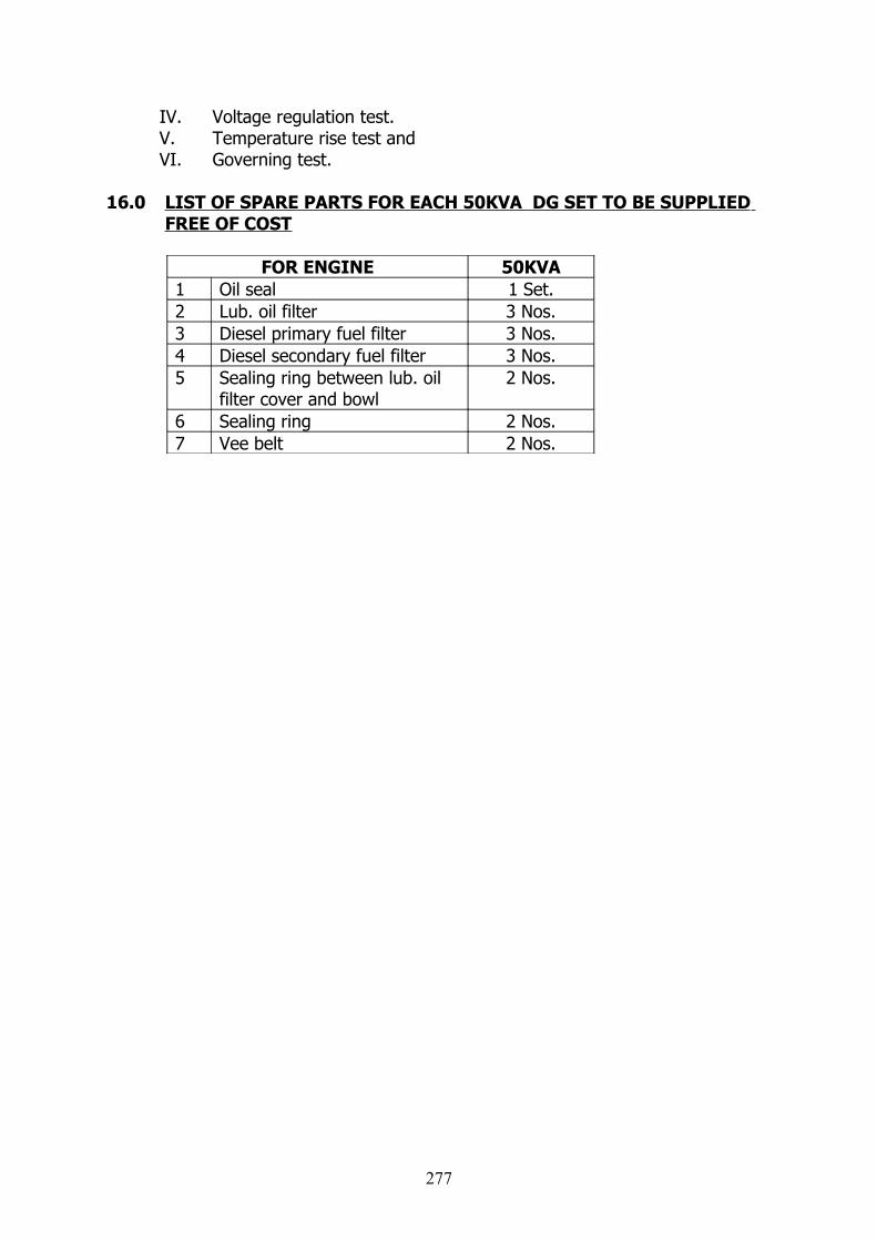
IV. Voltage regulation test.V. Temperature rise test andVI. Governing test.
16.0 LIST OF SPARE PARTS FOR EACH 50KVA DG SET TO BE SUPPLIED FREE OF COST
FOR ENGINE 50KVA1 Oil seal 1 Set.2 Lub. oil filter 3 Nos.3 Diesel primary fuel filter 3 Nos.4 Diesel secondary fuel filter 3 Nos.5 Sealing ring between lub. oil
filter cover and bowl2 Nos.
6 Sealing ring 2 Nos.7 Vee belt 2 Nos.
277
TECHNICAL SPECIFICATION FOR LEAD ACID BATTERIES
1.0 The specification provides for the manufacture, testing before despatch and delivery F.O.R.(Destination) of 110V/300Ah Tubular type lead-acid stationary batteries in Transparent (SAN) container along with accessories as detailed below:
2.0 Supervision of Erection and commissioning of the battery bank at the sub-stations shall have to be undertaken on mutual acceptance of terms and conditions for the same, if required and rates for the same shall be indicated along with the offer. The offers with out this information are liable for rejection.
3.0 APPLICABLE STANDARDS (LATEST REVISION)3.01 IS-1885: Electrical vocabulary, secondary cells and batteries
IS-1651: Lead acid batteries with Tubular positive plates.IS-1069: Water for storage batteriesIS-266: Sulphuric acid for storage batteriesIS-8320: General requirements for methods of tests for
lead-acid Storage batteries.IS-6071: Synthetic separator for lead acid batteries.IEEE-485: IEEE Recommended practice for sizing of large
lead acid Storage batteries for generating stations and substations.
IEEE-484: Recommended practice for design and installation of Storage batteries.
IEC 896-1: Stationary Lead – acid Batteries.
4.0 DESIGN AND CONSTRUCTIONAL FEATURES OF BATTERY.4.01 Type The battery shall be lead acid Tubular type in Transparent SAN container. Sealed Maintenance Free VRLA type/ Nickel Cadmium type batteries are not acceptable.4.02 Positive Plates: The plates shall be of first class material and workmanship and shall be free from blow-holes, cracks and other imperfections. The tubular positive plates shall consist of a suitable bar with spines cast of suitably alloyed lead to give adequate mechanical strength and minimum electrical resistance. The tubular spines shall be cast of an alloy of Pb and Antimony with Antimony content not greater than 3% by weight. The casting shall be done using proper controlled procedure preferably using high pressure casting machine with an operating pressure not less than 90-100 Bars. Low antimony alloy (not greater than 3%) will ensure low water loss and a guaranteed topping up frequency of not more than once in 6 months. High pressure cast spines will ensure a long life and trouble-free operation.
Porous, acid resistant and oxidation resistant tubes shall be inserted one over each spine. After insertion, the tube shall be adequately filled and packed with active
278
material (preferable through a rotary shaking machine) before their lower ends are closed by common plastic bar. The construction and material of tube shall be such as to reduce the loss of active material and shall be able to withstand normal internal stresses developed during service.4.03 Negative Plates:
The negative plates shall be of flat pasted type. The pasting shall be done on an automated machine for better control of process parameters. It should have adequate mechanical strength and would be so designed that active material is maintained in intimate contact with the grid under normal working conditions throughout the life of the battery. Lead antimony alloy grid with maximum 3% antimony content or lead calcium alloy grid shall be used.4.04 Separators:(i) The separators shall be microporous polyethylene envelope type to avoid direct as well as side shorts. It should be acid resistant, chemically inert and should have excellent oxidation resistance and high degree of porosity to ensure minimum internal resistance. The average pore size shall be less than 1 micron. It should not exhibit any tendency to swell or shrink at temperature encountered during operation. Microporous synthetic separators shall conform to latest IS:6071. The internal resistance factor of the separators shall assure high discharge characteristics under all operating conditions. Proper arrangement to keep end plates in position shall be furnished by the bidder alongwith his offer.Buffers/spring: Suitable buffers / springs shall be provided in the cells to keep the end plates in position. These shall have adequate length and strength.4.05 Containers: Containers shall preferably be made of transparent SAN ( styrene acrylonitrile) copolymer giving excellent clarity, outstanding chemical resistance, rigidity and toughness with very high insulating qualities which eliminate the need for separate cell insulators. It shall have adequate mechanical strength to prevent bulging, cracking etc, during the life span of battery when operating under expected temperature range and due to action of static and dynamic loads and the action of electrolyte. These containers should enable the electrolyte level and the cell condition to be monitored at a glance. The containers shall conform to latest edition of applicable standards. A copy of the such standard in english shall be enclosed along with the offer.
Battery containers shall be subjected to type, Routine and Acceptance Tests as per the requirements of applicable standards. The containers of the label attached firmly to the containers shall be marked with the information as per requirements of the above standard. The supplier’s manufacturer’s test certificates shall be submitted by the tenderer for the scrutiny of the purchaser.
4.06 Cell Lids:It should be moulded from opaque SAN and sealed to the container. It
should be easily removable if the need arises Terminal post shall be suitably sealed at the lid to prevent escape of acid spray, by means of rubber grommets, sealing compound or other suitable device. The positive and negative terminal posts shall be clearly and indelibly marked for easy identification.
279

4.07 Microporous Ceramic Vent Plugs: The vent plugs should be specially designed incorporating a microporous ceramic filter which effectively returns all acid spray to the cell, but allow free exit of oxygen and hydrogen which is generated at the end of boost charging. On removal, the plugs shall permit drawing of the electrolyte sample for servicing and of checking of the electrolyte level. The vent plug should preferably be flame retardant type to prevent any fire hazard in the battery room.
4.08 Connectors: Connectors shall be of lead plated copper. The lead coating shall be
adequate and tenacious. Minimum thickness of lead coating shall be 50 microns. Connectors should be adequately designed to carry maximum duty cycle as specified and shall offer minimum resistance. The current density for copper connectors shall not be more than 1.5 Amps/ Sq.mm. While considering the terminal voltage of the cell at the time of testing for discharge, the voltage drop due to inter-row and inter-cell connectors shall be considered. Connectors shall be adequately designed to withstand various stresses due to temperature changes, attack of acid and dynamic forces that could occur during the operation of the battery.
Necessary transparent shrouds to cover all the inter row, inter cell and terminal connectors shall be provided.
The cross section of cell connectors should not less than 75 sqmm for 110V and 220V. Double link plates may be provided for 110V/300Ah Batteries .
4.09 Fasteners :
Fasteners shall be of high tensile steel with lead coatings should be provided. 4.10 Electrolyte:
The electrolyte shall be battery grade sulphuric acid conforming to latest edition of relevant IS 266. The strength of the electrolyte in the cell during operation shall conform to the governing IS specification for the cell. Required quantity of electrolyte for the initial filling with 10% extra quantity shall be supplied in no-returnable non-degradable acid resistant strong plastic containers.4.11 Water:
Water used in preparation of electrolyte and also to bring the level of electrolyte to the correct position during the course of operation or testing shall conform to the latest edition of IS-10694.12 Terminal Post:
Positive and negative terminal posts of the cells shall be clearly and unmistakably identifiable. Terminal posts shall be designed to accommodate external bolted connections conveniently and positively. All metal parts of the terminals shall be of lead coated type. Bolts, heads and nuts, except seal nuts, shall be hexagonal and shall be lead coated. Terminal posts shall be adequately fixed or removed. The junction between terminal posts and cover and between the cover and container shall be adequately sealed to prevent any seepage of the electrolyte. All terminals shall be provided with insulated covers.
The pole terminal should be of lead with a brass core insert, which shall increase the conductivity. The pole should have a double layered protection against crevice corrosion. The lead lining of the terminal should be protected against any
280
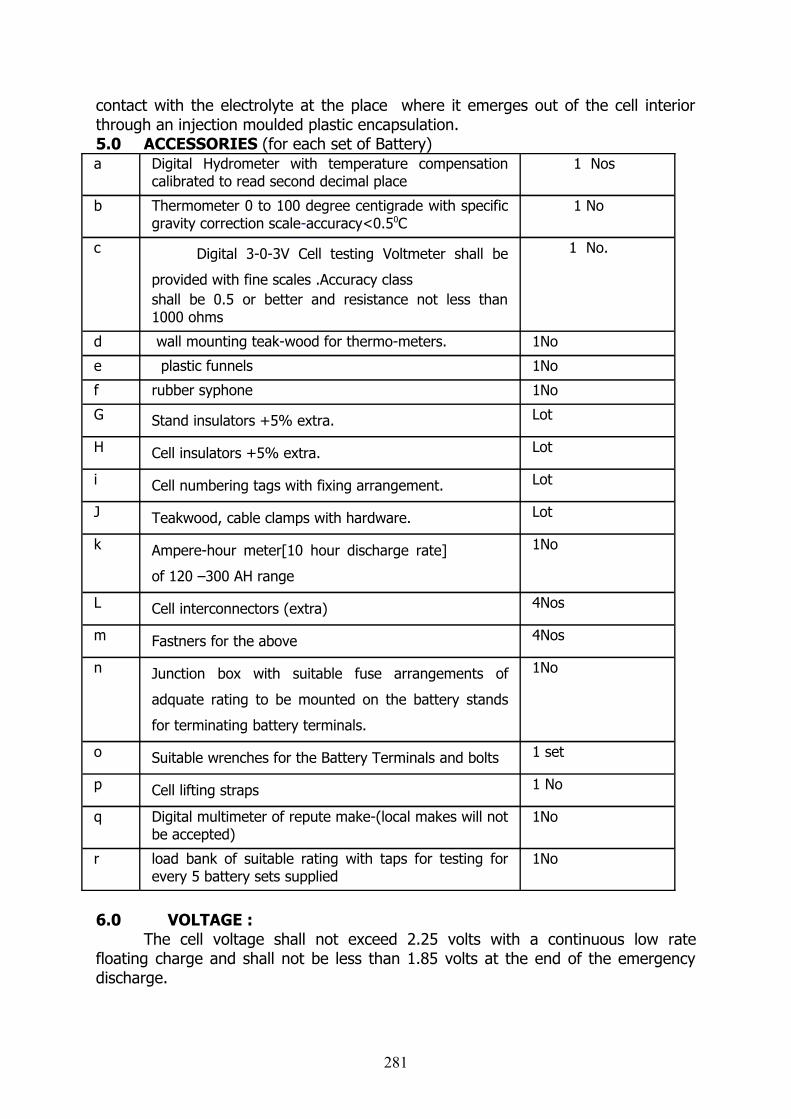
contact with the electrolyte at the place where it emerges out of the cell interior through an injection moulded plastic encapsulation.5.0 ACCESSORIES (for each set of Battery)a Digital Hydrometer with temperature compensation
calibrated to read second decimal place 1 Nos
b Thermometer 0 to 100 degree centigrade with specific gravity correction scale-accuracy<0.50C
1 No
c Digital 3-0-3V Cell testing Voltmeter shall be
provided with fine scales .Accuracy classshall be 0.5 or better and resistance not less than 1000 ohms
1 No.
d wall mounting teak-wood for thermo-meters. 1No
e plastic funnels 1No
f rubber syphone 1No
G Stand insulators +5% extra. Lot
H Cell insulators +5% extra. Lot
i Cell numbering tags with fixing arrangement. Lot
J Teakwood, cable clamps with hardware. Lot
k Ampere-hour meter[10 hour discharge rate]
of 120 –300 AH range
1No
L Cell interconnectors (extra) 4Nos
m Fastners for the above 4Nos
n Junction box with suitable fuse arrangements of
adquate rating to be mounted on the battery stands
for terminating battery terminals.
1No
o Suitable wrenches for the Battery Terminals and bolts 1 set
p Cell lifting straps 1 No
q Digital multimeter of repute make-(local makes will not be accepted)
1No
r load bank of suitable rating with taps for testing for every 5 battery sets supplied
1No
6.0 VOLTAGE :The cell voltage shall not exceed 2.25 volts with a continuous low rate
floating charge and shall not be less than 1.85 volts at the end of the emergency discharge.
281
7.0 OPERATION:The D.C Battery shall be operated without an intentional ground. For
indicating the incidence and degree of a ground fault on the D.C control circuitry, the mid point of the battery shall be earthed through an ammeter of high resistance. The high resistance shall be so proportional that the current flowing under the worst earth fault shall not exceed 250 mA. It should be noted that, the 220V batteries are to be accommodated in the
Battery Room and should operate satisfactorily over the entire range of ambient
temperature of 00 C to 500 C and relative humidity of 95%.
8.0 General Requirements for TestsSpecific Gravity of Electrolyte:
The specific gravity of a fully charged cells shall be adjusted to 1.200+/- 0.005 at 27 deg. C as per the requirement of IS 1651 (latest revision)
Temperature Correction:The capacity of the cell shall be corrected to 27 deg. C using the
proper temperature correction factor pertaining to the type of the cell and the rate of discharge. The temperature correction should be made using factors supplied by the manufacturer but shall generally conform to some national or international standard for the similar type of cell.
Observations:The observations, during any test shall be performed as
specified in IS 1651 (latest revision)
8.1 Test for Capacity:The cell shall be tested for its rated capacity output. The
fundamental requirement shall be a discharge for 10 hours whilst discharge at other rates, may also be performed.
The capacity output, at the first discharge, corrected to 27 deg. C shall not be less than 85% of the rated capacity of the cell. The cell shall reach 100% of its rated capacity within 5 charge – discharge cycles.
8.2 Test for Charging Efficiency:Since the cells are expected to operate at various state of
charge (SOC), the charging efficiencies at various depth for discharge needs to be measured and standardized for this application.
The cell appropriate for this application should have the following charging efficiencies:
80% SOC 80%10% SOC 90%
8.3 Water loss:
282
The cell/ battery after being fully charged shall be kept on a float charge of 2.4 volts per cell at a temperature of 40 deg. C for 21 days at a stretch. The loss of water due to evaporation and self discharge shall not be more than 0.65 grams per Ah.
The battery shall reach an equilibrium state of charge within 72 hours of such charging. This shall be indicated by the float current after 72 hours of constant float. The float current shall not be more than 3 mA per Ah.
9.0 WOODEN STANDS:The stand shall be double row double tier for 220V/300Ah. The stand
shall be made of seasoned teakwood as per approval of the drawing. The proposed drawing for double row double tier for 220V/300Ah battery and may be enclosed along with the tender offer. The successful tenderer will be required to supply sufficient quantity of paint in separate containers for applying 3 coats for each stand with Cell No. Plates-1 to 55 for110 V/120Ah,110V/300Ah batteries and 110 cells for 220V/535Ah, 220V/300 Ah battery. 9.1 Marking:
Each cell shall be marked to meet the requirements of relevant Indian standards. In addition, each cell shall be legibly numbered serially to identify the cell during manufacture, testing, installation and operation of battery to identify after having assembled into battery bank in battery racks. Following marking however, shall be provided.
[i] Manufacturer’s name, type and trade mark.
[ii] Nominal voltage.
[iii] AH capacity at 10 hours rate with specified end cell
voltage.
[iv] Cell number.
[v] Upper and lower electrolyte level.
[vi] Type of positive plate.
[vii] Type of container.
[viii] Date of manufacture [ month and year] or [week and
year].A set of loose stickers shall be provided to mark the cells
position in the assembled battery bank at site so that a cell removed for maintenance can be put back in original position.
10.0 TYPE TEST CERTIFICATE: The type test certificates for 220V/300Ah battery (Attested xerox copies) as
per latest ISS shall be furnished by the tenderer. The initial payment for the materials will be released only after approval of type test certificate from this office. The bidder shall submit the test reports along with his offer for the
283
following type tests, conducted on the offered samples as per relevant National
Standard[s] within five years from the date of opening of the bid and test witnessed
by any Government Department / Government undertaking, failing which the offer is
liable for rejection.
aVerification of constructional requirements.
bVerification of dimensions.
cTest for capacity.
dTest for retention of charge.
eEndurance Test.
fAmpere-hour and watt-hour efficiency test.
gTest for voltage during discharge.
If the type test report [s] does/do not meet the requirements
as per this specification,TNEB at its discretion may ask the supplier to conduct the
above type tests [s] at the supplier’s cost in the presence of TNEB’s representative
without any financial liability to TNEB.
Special Tests :
The bidder shall submit the test reports alongwith his offer for the
following special tests, conducted on the offered samples as per relevant National
Standard[s] within five years from the date of opening of the bid and test witnessed
by any Government Department / Government undertaking, failing which the offer is
liable for rejection.
11.0. DRAWINGS TO BE SUPPLIED ALONG WITH TENDER: Tenderer shall submit along with the tender the following:
i) General arrangement of cells and battery assembly. ii) General arrangement showing the inter-connections. iii) Graphics showing the performance of materialiv) Drawing for the wooden stand.v) Instruction manuals for initial charging and subsequent
charging.vi) Pamphlets and technical literature giving detailed information of the batteries offered.vii) The following characteristic curves, to be furnished alongwith the tender.
a.Battery discharge curves at various rates between one minute and 10 hour rate. b.Curves showing the relation between the specific gravity and amount of charge in the battery for both charging and discharging conditions.c.Curve of internal resistance at the end of various discharge rates .
284
d.Curves showing the relation between cell voltage and charging current when charged at Finishing rate, High starting rate & Two step charging by starting and finishing rate.
(No block diagrams are acceptable. Tenders are liable for rejection if details schematic drawings are not submitted).
The successful tenderers shall forward within 10 days of issue of purchase order four sets of the drawings for the purchaser’s approval. Drawings which are satisfactory for approval on the first submission will be approved and one copy of the approved prints will be returned. The drawing not satisfactory for approval on the first submission will be returned to the supplier for re-submission. The print with such addition shall not be interpreted by the supplier to be approved as noted, unless specifically so noted above on approving signatures.
a) Drawing showing cell dimension and assembly,b) General arrangement showing the inter connections,c) Drawing for the wooden stand,
Any shop work done prior to the approval of drawings shall be at the supplier’s risk. Supplier shall make any change in the design which are considered necessary to make the equipment conform to the provisions and indent of the purchase order without any additional cost to the purchaser.
The supplier shall supply the purchaser within 15 days of receiving an approved print, one reproducible master print plus two prints of each of the approved drawings. In case the supplier resubmit a revision or change for approval, such resubmission shall be by four prints.
All drawings, part lists, assembly procedures etc., shall bear a readily identifiable number, drawing number etc., and each subsequent revision or addition to the drawing shall be identified by a revision number.
Checking and approval of the above documents by the purchaser is for the benefit of the purchaser and shall not relieve the supplier from full responsibility for ensuring correct interpretation of design, drawings and specifications or for the completeness and accuracy of the shop drawings and relevant specification.
Supplier shall record all deviations, corrections, omissions, changes, etc., occuring throughout the manufacturing, assembly and testing phases.
The Bidder shall also furnish one copy of bound manual along with each set of battery covering erection, commissioning, operation and maintenance instructions in English Language and all relevant information and drawings pertaining to the main equipment as well as auxiliary devices.
Approval of drawings by the Purchaser shall not relieve the supplier of any of his responsibility and liability for ensuring correctness and correct interpretation of the drawings for meeting the requirements of the latest revision of the applicable standards, rules and codes of practices.
The equipment shall conform in all respects to high standards of engineering, design, workmanship and latest revisions of relevant standards at the time of supply and Purchaser shall have the power to reject any material which, in his judgment, is not in full accordance therewith.
285

All drawings shall be in English Language and in Meteric System of units.The supplier shall also submit three sets of instruction
manuals/leaflets/photographs.
286
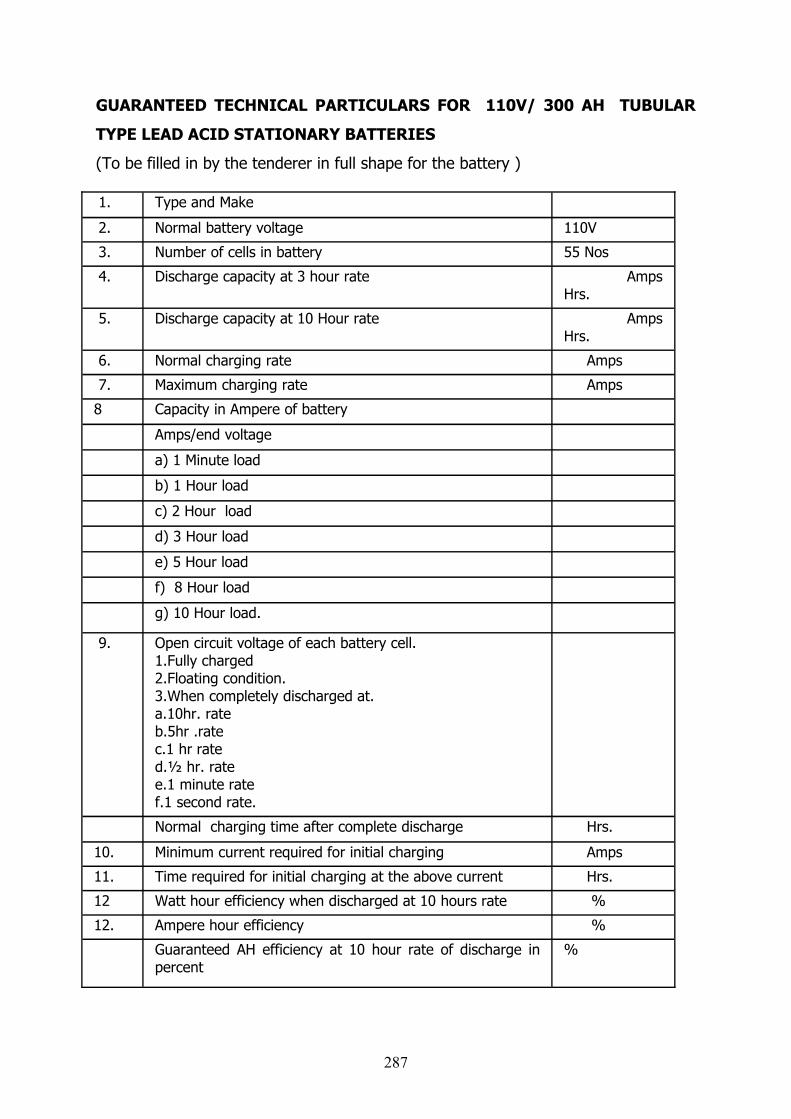
GUARANTEED TECHNICAL PARTICULARS FOR 110V/ 300 AH TUBULAR
TYPE LEAD ACID STATIONARY BATTERIES
(To be filled in by the tenderer in full shape for the battery )
1. Type and Make
2. Normal battery voltage 110V
3. Number of cells in battery 55 Nos
4. Discharge capacity at 3 hour rate Amps Hrs.
5. Discharge capacity at 10 Hour rate Amps Hrs.
6. Normal charging rate Amps
7. Maximum charging rate Amps
8 Capacity in Ampere of battery
Amps/end voltage
a) 1 Minute load
b) 1 Hour load
c) 2 Hour load
d) 3 Hour load
e) 5 Hour load
f) 8 Hour load
g) 10 Hour load.
9. Open circuit voltage of each battery cell.1.Fully charged2.Floating condition.3.When completely discharged at.a.10hr. rateb.5hr .ratec.1 hr rated.½ hr. ratee.1 minute ratef.1 second rate.
Normal charging time after complete discharge Hrs.
10. Minimum current required for initial charging Amps
11. Time required for initial charging at the above current Hrs.
12 Watt hour efficiency when discharged at 10 hours rate %
12. Ampere hour efficiency %
Guaranteed AH efficiency at 10 hour rate of discharge in percent
%
287
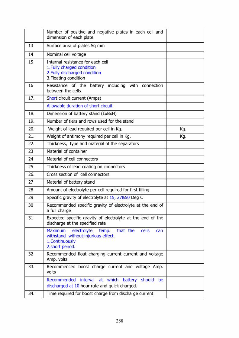
Number of positive and negative plates in each cell and dimension of each plate
13 Surface area of plates Sq mm
14 Nominal cell voltage
15 Internal resistance for each cell1.Fully charged condition2.Fully discharged condition3.Floating condition
16 Resistance of the battery including with connection between the cells
17. Short circuit current (Amps)
Allowable duration of short circuit
18. Dimension of battery stand (LxBxH)
19. Number of tiers and rows used for the stand
20. Weight of lead required per cell in Kg. Kg.
21. Weight of antimony required per cell in Kg. Kg.
22. Thickness, type and material of the separators
23 Material of container
24 Material of cell connectors
25 Thickness of lead coating on connectors
26. Cross section of cell connectors
27 Material of battery stand
28 Amount of electrolyte per cell required for first filling
29 Specific gravity of electrolyte at 15, 27&50 Deg C
30 Recommended specific gravity of electrolyte at the end of a full charge
31 Expected specific gravity of electrolyte at the end of the discharge at the specified rate
Maximum electrolyte temp. that the cells can withstand without injurious effect.1.Continuously2.short period.
32 Recommended float charging current current and voltage Amp. volts
33. Recommenced boost charge current and voltage Amp. volts
Recommended interval at which battery should be discharged at 10 hour rate and quick charged.
34. Time required for boost charge from discharge current
288

35. Recommended trickle charging rate for different type of working
36. Overall dimensions of each cell/battery
37 Distance between the centres of cells when erected
38 Weight of cell/battery complete with acid
39 Recommended maximum period of storage
Guaranteed life of battery in years
Estimated life of battery in years
289
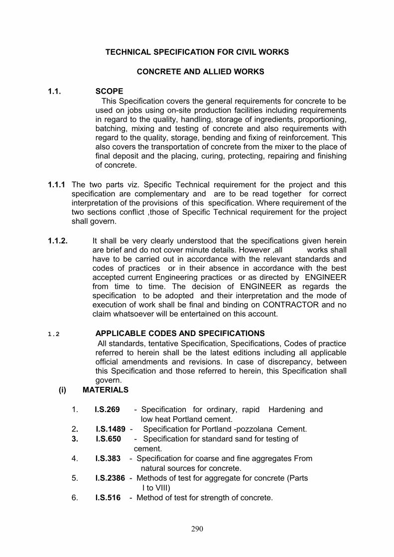
TECHNICAL SPECIFICATION FOR CIVIL WORKS
CONCRETE AND ALLIED WORKS
1.1. SCOPE This Specification covers the general requirements for concrete to be
used on jobs using on-site production facilities including requirements in regard to the quality, handling, storage of ingredients, proportioning, batching, mixing and testing of concrete and also requirements with regard to the quality, storage, bending and fixing of reinforcement. This also covers the transportation of concrete from the mixer to the place of final deposit and the placing, curing, protecting, repairing and finishing of concrete.
1.1.1 The two parts viz. Specific Technical requirement for the project and this specification are complementary and are to be read together for correct interpretation of the provisions of this specification. Where requirement of the two sections conflict ,those of Specific Technical requirement for the project shall govern.
1.1.2. It shall be very clearly understood that the specifications given herein are brief and do not cover minute details. However ,all works shall have to be carried out in accordance with the relevant standards and codes of practices or in their absence in accordance with the best accepted current Engineering practices or as directed by ENGINEER from time to time. The decision of ENGINEER as regards the specification to be adopted and their interpretation and the mode of execution of work shall be final and binding on CONTRACTOR and no claim whatsoever will be entertained on this account.
1.2 APPLICABLE CODES AND SPECIFICATIONS All standards, tentative Specification, Specifications, Codes of practice
referred to herein shall be the latest editions including all applicable official amendments and revisions. In case of discrepancy, between this Specification and those referred to herein, this Specification shall govern.
(i) MATERIALS
1. I.S.269 - Specification for ordinary, rapid Hardening and low heat Portland cement.
2. I.S.1489 - Specification for Portland -pozzolana Cement.3. I.S.650 - Specification for standard sand for testing of
cement.4. I.S.383 - Specification for coarse and fine aggregates From
natural sources for concrete.5. I.S.2386 - Methods of test for aggregate for concrete (Parts I to VIII) 6. I.S.516 - Method of test for strength of concrete.
290
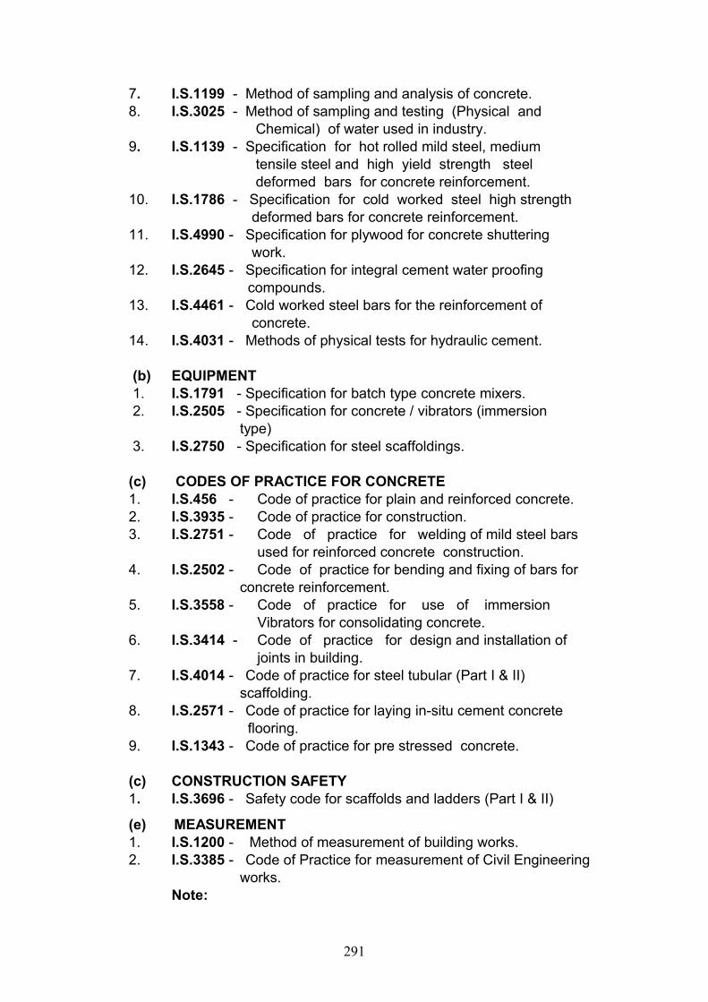
7. I.S.1199 - Method of sampling and analysis of concrete.8. I.S.3025 - Method of sampling and testing (Physical and Chemical) of water used in industry.9. I.S.1139 - Specification for hot rolled mild steel, medium tensile steel and high yield strength steel deformed bars for concrete reinforcement. 10. I.S.1786 - Specification for cold worked steel high strength deformed bars for concrete reinforcement.11. I.S.4990 - Specification for plywood for concrete shuttering work.12. I.S.2645 - Specification for integral cement water proofing compounds.13. I.S.4461 - Cold worked steel bars for the reinforcement of concrete.14. I.S.4031 - Methods of physical tests for hydraulic cement.
(b) EQUIPMENT 1. I.S.1791 - Specification for batch type concrete mixers. 2. I.S.2505 - Specification for concrete / vibrators (immersion type) 3. I.S.2750 - Specification for steel scaffoldings.
(c) CODES OF PRACTICE FOR CONCRETE 1. I.S.456 - Code of practice for plain and reinforced concrete. 2. I.S.3935 - Code of practice for construction.3. I.S.2751 - Code of practice for welding of mild steel bars used for reinforced concrete construction.4. I.S.2502 - Code of practice for bending and fixing of bars for concrete reinforcement.5. I.S.3558 - Code of practice for use of immersion Vibrators for consolidating concrete.6. I.S.3414 - Code of practice for design and installation of joints in building.7. I.S.4014 - Code of practice for steel tubular (Part I & II) scaffolding. 8. I.S.2571 - Code of practice for laying in-situ cement concrete flooring.9. I.S.1343 - Code of practice for pre stressed concrete. (c) CONSTRUCTION SAFETY1. I.S.3696 - Safety code for scaffolds and ladders (Part I & II)
(e) MEASUREMENT1. I.S.1200 - Method of measurement of building works.2. I.S.3385 - Code of Practice for measurement of Civil Engineering works.
Note:
291
In the event that state, city or other Government bodies have requirements more stringent than those set forth in this Specification, such requirements shall be considered part of this specification and shall supersede this Specification where applicable.
1.3. MATERIALS FOR CONCRETEThe ingredients to be used in the manufacture of standard concrete shall consist solely of a standard type Portland cement, clean sand, natural coarse aggregate, clean water, and admixtures, if specially called for on drawings or specifications.
The quality of materials, method, control, manufacture and transportation of all concrete irrespective of mix, whether reinforced or otherwise, shall conform to the applicable portion of this specification.ENGINEER shall have the right to inspect the sources of materials, the layout and operation of procurement and storage of materials, the concrete batching and mixing equipment, and take quality control systems such an inspection shall be arranged of concrete work.
1. CEMENT
a) Unless otherwise specified in Section C or called for by ENGINEER/ OWNERS, cement shall be ordinary Portland cement conforming to not less than Grade 43 of relevant I.S. and in 50-kg bags. The use of bulk cement will be permitted only with the approval of ENGINEER. Changing of brands on type of cement within the same structure will not be permitted without approval of ENGINEER.
a) While purchasing cement or before commencing the work for every batch of cement consignments, the CONTRACTOR should satisfy himself about the quality of cement by conducting initial test on concrete cubes in the presence of the representative of the PURCHASER and only after establishing the suitability, the cement should be used on work. To have quick evaluation results, the above specimens should be cured by steam curing and tested immediately at CONTRACTOR’s cost at an approved laboratory.
CONTRACTOR shall not be entitled to any claim of any nature on this account.
1.3.2. AGGREGATES a) `Aggregate’ in general designates both fine and coarse inert materials
used in the manufacture of concrete. `Fine Aggregate’ is aggregate most of which passes through 4.75mm IS sieve. `Coarse Aggregate’ is aggregate most of which is retained on 4.75mm IS sieve.
b) All fine and coarse aggregates proposed for the use in the work shall be subject to ENGINEER's approval and after specific materials have been accepted, the source of supply of such materials shall not be changed without prior approval of ENGINEER.
292
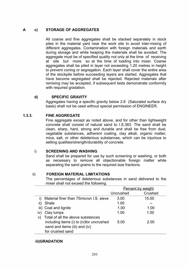
A c) STORAGE OF AGGREGATES
All coarse and fine aggregates shall be stacked separately in stock piles in the material yard near the work site to avoid inter-mixing of different aggregates. Contamination with foreign materials and earth during storage and while heaping the materials shall be avoided. The aggregate must be of specified quality not only at the time of receiving at site but more so at the time of loading into mixer. Coarse aggregates shall be piled in layer not exceeding 1.20 metres in height to prevent coning or segregation. Each layer shall cover the entire area of the stockpile before succeeding layers are started. Aggregates that have become segregated shall be rejected. Rejected materials after remixing may be accepted, if subsequent tests demonstrate conformity with required gradation.
d) SPECIFIC GRAVITYAggregates having a specific gravity below 2.6 (Saturated surface dry basis) shall not be used without special permission of ENGINEER.
1.3.3. FINE AGGREGATEFine aggregate except as noted above, and for other than lightweight concrete shall consist of natural sand to I.S.383. The sand shall be clean, sharp, hard, strong and durable and shall be free from dust, vegetable substances, adherent coating, clay alkali, organic matter, mica, salt, or other deleterious substances, which can be injurious to setting qualities/strength/durability of concrete.
i) SCREENING AND WASHINGSand shall be prepared for use by such screening or washing, or both as necessary to remove all objectionable foreign matter while separating the sand grains to the required size fractions.
ii) FOREIGN MATERIAL LIMITATIONS The percentages of deleterious substances in sand delivered to the mixer shall not exceed the following.
Percent by weight Uncrushed Crushed
i) Material finer than 75micron I.S. sieve 3.00 15.00 ii) Shale 1.00 -- iii) Coal and lignite 1.00 1.00 iv) Clay lumps 1.00 1.00
v) Total of all the above substances including items (i) to (iv)for uncrushed 5.00 2.00 sand and items (iii) and (iv)
for crushed sand
iii)GRADATION
293
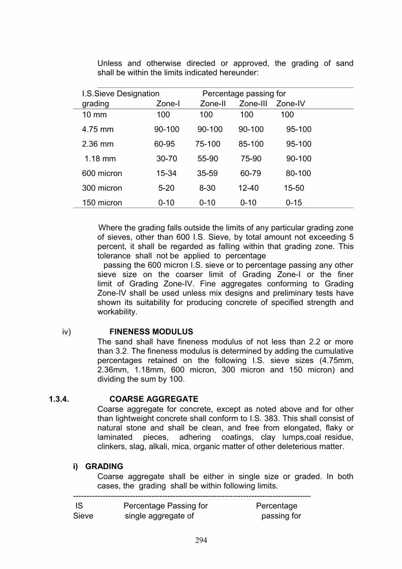
Unless and otherwise directed or approved, the grading of sand shall be within the limits indicated hereunder:
I.S.Sieve Designation Percentage passing for grading Zone-I Zone-II Zone-III Zone-IV 10 mm 100 100 100 100
4.75 mm 90-100 90-100 90-100 95-100
2.36 mm 60-95 75-100 85-100 95-100
1.18 mm 30-70 55-90 75-90 90-100
600 micron 15-34 35-59 60-79 80-100
300 micron 5-20 8-30 12-40 15-50
150 micron 0-10 0-10 0-10 0-15
Where the grading falls outside the limits of any particular grading zone
of sieves, other than 600 I.S. Sieve, by total amount not exceeding 5 percent, it shall be regarded as falling within that grading zone. This tolerance shall not be applied to percentage
passing the 600 micron I.S. sieve or to percentage passing any other sieve size on the coarser limit of Grading Zone-I or the finer limit of Grading Zone-IV. Fine aggregates conforming to Grading Zone-IV shall be used unless mix designs and preliminary tests have shown its suitability for producing concrete of specified strength and workability.
iv) FINENESS MODULUSThe sand shall have fineness modulus of not less than 2.2 or more than 3.2. The fineness modulus is determined by adding the cumulative percentages retained on the following I.S. sieve sizes (4.75mm, 2.36mm, 1.18mm, 600 micron, 300 micron and 150 micron) and dividing the sum by 100.
1.3.4. COARSE AGGREGATECoarse aggregate for concrete, except as noted above and for other than lightweight concrete shall conform to I.S. 383. This shall consist of natural stone and shall be clean, and free from elongated, flaky or laminated pieces, adhering coatings, clay lumps,coal residue, clinkers, slag, alkali, mica, organic matter of other deleterious matter.
i) GRADINGCoarse aggregate shall be either in single size or graded. In both cases, the grading shall be within following limits.
---------------------------------------------------------------------------------------- IS Percentage Passing for Percentage Sieve single aggregate of passing for
294
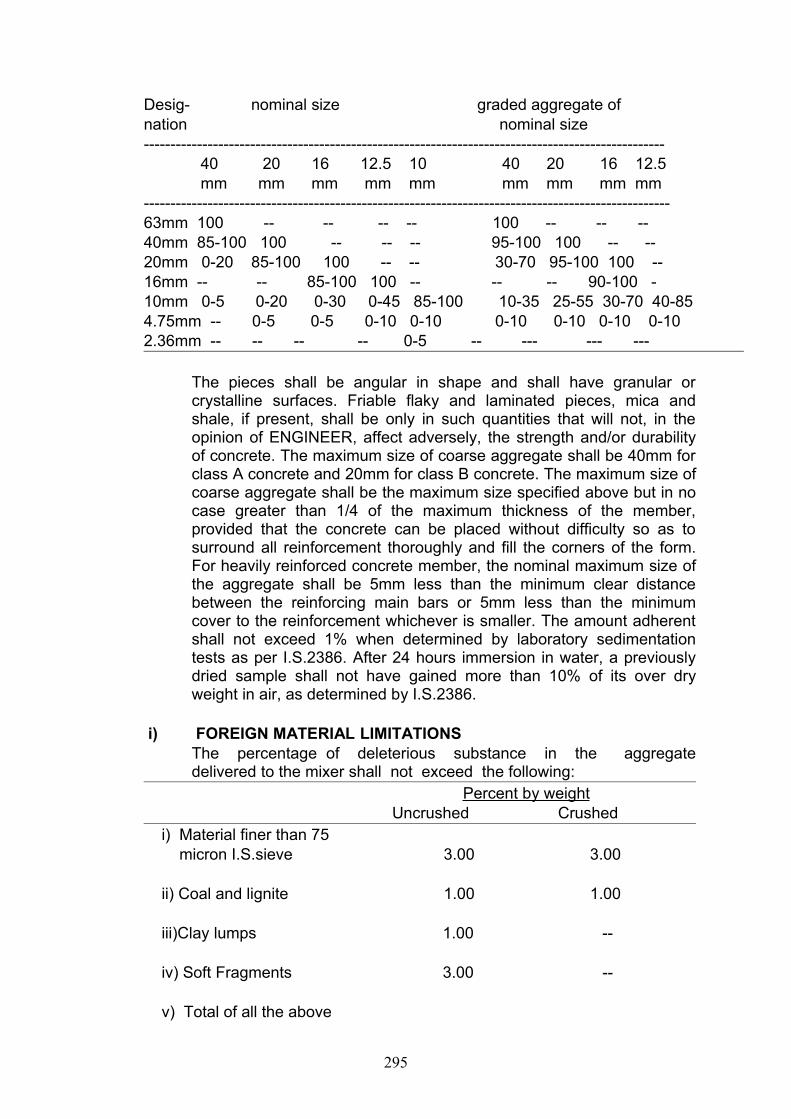
Desig- nominal size graded aggregate of nation nominal size--------------------------------------------------------------------------------------------------
40 20 16 12.5 10 40 20 16 12.5 mm mm mm mm mm mm mm mm mm
---------------------------------------------------------------------------------------------------63mm 100 -- -- -- -- 100 -- -- --40mm 85-100 100 -- -- -- 95-100 100 -- --20mm 0-20 85-100 100 -- -- 30-70 95-100 100 --16mm -- -- 85-100 100 -- -- -- 90-100 -10mm 0-5 0-20 0-30 0-45 85-100 10-35 25-55 30-70 40-854.75mm -- 0-5 0-5 0-10 0-10 0-10 0-10 0-10 0-102.36mm -- -- -- -- 0-5 -- --- --- ---
The pieces shall be angular in shape and shall have granular or crystalline surfaces. Friable flaky and laminated pieces, mica and shale, if present, shall be only in such quantities that will not, in the opinion of ENGINEER, affect adversely, the strength and/or durability of concrete. The maximum size of coarse aggregate shall be 40mm for class A concrete and 20mm for class B concrete. The maximum size of coarse aggregate shall be the maximum size specified above but in no case greater than 1/4 of the maximum thickness of the member, provided that the concrete can be placed without difficulty so as to surround all reinforcement thoroughly and fill the corners of the form. For heavily reinforced concrete member, the nominal maximum size of the aggregate shall be 5mm less than the minimum clear distance between the reinforcing main bars or 5mm less than the minimum cover to the reinforcement whichever is smaller. The amount adherent shall not exceed 1% when determined by laboratory sedimentation tests as per I.S.2386. After 24 hours immersion in water, a previously dried sample shall not have gained more than 10% of its over dry weight in air, as determined by I.S.2386.
i) FOREIGN MATERIAL LIMITATIONSThe percentage of deleterious substance in the aggregate delivered to the mixer shall not exceed the following:
Percent by weight Uncrushed Crushed i) Material finer than 75 micron I.S.sieve 3.00 3.00
ii) Coal and lignite 1.00 1.00
iii)Clay lumps 1.00 --
iv) Soft Fragments 3.00 --
v) Total of all the above
295
substances 5.00 --
1.4. WATER
a) Water used for both mixing of mortar / concrete and curing shall be free from injurious amounts of deleterious materials. Potable water is generally satisfactory for mixing of mortar / concrete and curing concrete. The relevant essential Water tests pertaining to access the suitability for construction standards shall have to be done before commencement of work.
b) The suitability of water for making concrete shall be ascertained by the
compressive strength and initial setting time test specified in I.S.456. The sample of water taken for testing shall be typical of the water proposed to be used for concreting, due account being paid to seasonal variation. The sample shall not receive any treatment before testing other than that envisaged in the regular supply of water proposed for use in concrete. The sample shall be stored in a clean container previously rinsed out with similar water.
c) Average 28 days compressive strength of atleast three 150mm concrete cubes prepared with water proposed to be used shall not be less than 90% of the average strength of three similar concrete cubes prepared with distilled water.
d) The initial setting time of test block made with the appropriate test cement and the water proposed to be used shall not be less than 30minutes and shall not differ by more than 30 minutes from the initial setting time of control test block prepared with the appropriate test cement and distilled water. The test blocks shall be prepared and tested in accordance with the requirements of I.S.4031.
e) Where water can be shown to contain an excess of acid, alkali, sugar or salt, ENGINEER may refuse to permit its use. As a guide, the following concentrations represent the maximum permissible values.
(i) To neutralise 100 ml sample of water, using phenolphthalein as indicator, it should not require more than 5 ml. of 0.02 Normal NaOH. The details of test shall be as given in IS.3025.
(ii) To neutralise 200ml sample of water using methyl orange as an indicator, it should not require more than 10ml of 0.1. Normal HCL. The details of test shall be as given in IS.3025.
(iii) Presence of solids, when tested in accordance with the method indicated below, shall not exceed the following :
Percent Method of Test (Ref. to Clause No. in
S.3025/60)
296

Organic 0.02 10 & 11 (Organic Solids Total solids minus Ignited Residue)
InorganicSulphates (as SO4) 0.30 11 (Ignited residue)Alkali 0.05 20
Chlorides (as Cl) 0.20 24
1.5. REINFORCEMENT
i) SUPPLYThe supply of steel shall be arranged by the contractor himself. Reinforcement if supplies are arranged by CONTRACTOR shall be either plain round mild bars Grade – 1 as per IS.432 (Part – 1) or medium tensile steel bars as per IS.432 (Part – 1)and deformed bars of Fe 415 grade as per IS:1786. Wire mesh or fabric shall be in accordance with IS 1566. Substitution of reinforcement will not be permitted except upon written approval from ENGINEER.
No advance amounts shall be paid to the contractor towards purchase of steel.
NoteThe tenderer, in his tender, shall give details of Fe 415 grade. viz. sizes (diameter) available, necessary test reports and manufacturers certificate on the every consignment of steel that are brought to site shall be furnished to the Engineer then and there and approval of Engineer shall be obtained before proceeding the works.
ii) STORAGE
a) The reinforcement shall not be kept in direct contact with the ground but stacked on top of an arrangement of timber sleepers or the like.
b) If the reinforcing rods have to be stored for long duration, they shall be coated with cement wash before stacking and/or be kept under cover or stored as directed by ENGINEER.
c) Fabricated reinforcement shall be carefully stored to prevent damage, distortion, corrosion and deterioration.
iii) QUALITY
a) All steel shall be of Grade-I quality unless specifically permitted by ENGINEER. No re-rolled material will be accepted. If demanded by ENGINEER, CONTRACTOR shall submit the manufacturers test certificate for steel. Random tests on steel supplied by CONTRACTOR may be performed by OWNER as per relevant Indian Standards. All costs
297
incidental to such tests shall be at "CONTRACTOR's” expense. Steel not conforming to Specifications shall be rejected.
b) All reinforcement shall be clean, free from grease, oil, and paint, dirt loose mill scale, loose rust, dust bituminous material or any other substances that will destroy or reduce the bond. All rods shall be thoroughly cleaned before being fabricated. Pitted and defective rods shall not be used. All bars shall be rigidly held in position before concreting. No welding of rods to obtain continuity shall be allowed unless approved by ENGINEER. If welding is approved, the work shall be carried out as per I.S.2751 according to best modern practices and as directed by ENGINEER. In all cases of important connections, tests shall be made to prove that the joints are of the full strength of bars welded. Special precautions, as specified by ENGINEER, shall be taken in the welding of cold worked reinforcing bars and bars other than mild steel.
iv) LAPSLaps and splices for reinforcement shall be as shown on the drawings. Splices in adjacent bars shall be staggered and the locations of all splices, except those specified on the drawings, shall be approved by ENGINEER. The bars shall not be lapped unless the length required exceeds the maximum available lengths of bars at site.
v) BENDING
a) Reinforcing bars supplied bent or in coils, shall be straightened before they are cut to size. Straightening of bars shall be done in cold and without damaging the bars. This is considered as a part of reinforcement bending fabrication work.
b) All bars shall be accurately bent according to the sizes and shapes shown on the detailed working drawings/ bar bending schedules. They shall be bent gradually by machine or other approved means. Reinforcing bars shall not be straightened and re-bent in a manner that will injure the material. Bars containing cracks or splits shall be rejected. They shall be bent cold, except bars of over 25mm in diameter which may be bent hot if specifically approved by ENGINEER, Bars which depend for their strength on cold working, shall not be bent hot, shall not be heated beyond cherry red colour (not exceeding 845°C) and after bending shall be allowed to cool slowly without quenching. Bars incorrectly bent shall be used only if the means used for straightening and re-bending be such as shall not, in the opinion of ENGINEER, injure the material. No reinforcement shall be bent when in position in the work without approval, whether or not it is partially embedded in hardened concrete. Bars having kinks or bends other than those required by design shall not be used.
vi) FIXING
298
Reinforcement shall be accurately fixed by any approved means and maintained in the correct position shown in the drawings by the use of blocks, spacers and chairs as per IS.2503 to prevent displacement during placing and compaction of concrete. Bars intended to be in contact at crossing points shall be securely bound together at all such points with number 16 gauge annealed soft iron wire. The vertical distances required between successive layers of bar in beams or similar members shall be maintained by the provision of mild steel spacer bars at such intervals that the main bars do not perceptibly sag between adjacent spacer bars.
vii) COVER
The cover to reinforcement shall be in accordance with clause 26.4 of IS 456-2000. Unless indicated otherwise on the drawings, clear concrete cover for reinforcement (exclusive of plaster or other decorative finish) shall be as follows:
a) At each end of reinforcing bar, not less than 25mm or less than twice the diameter of the bar.
b) For a longitudinal reinforcing bar in a column, not less than 40mm, not less than the diameter of the bar. In case of columns, of minimum dimension of 200mm or under with reinforcing bars of 12mm and less in diameter, a cover of 25mm may be used.
c) For longitudinal reinforcing bars in a beam, not less than 25mm, nor less than the diameter of the bar.
d) For tensile, compressive, shear or other reinforcement in a slab or wall not less than 15mm nor less than diameter of such reinforcement.
e) For any other reinforcement not less than 15mm nor less than the diameter of such reinforcement.
f) For footings and other principal structural members in which the concrete is deposited directly against the ground, cover to the bottom reinforcement shall be 75mm. If concrete is poured on layer of lean concrete the bottom cover may be reduced to 50mm.
g) For concrete surface exposed to the weather / the ground after removal of forms, such as retaining walls, grade beams, footing sides and top etc., not less than 50mm for bars larger than 16mm dia nor less than 40mm for bars 16mm dia or smaller.
2 Increased cover thickness shall be provided as indicated on the drawings, for surfaces exposed to the action of harmful chemicals (or exposed to earth contaminated by such chemical), acid, alkali, saline atmosphere, sulphurous smoke etc.
i) For reinforced concrete members, totally or periodically immersed in sea water or subject to sea water spray, the cover of concrete shall be 50mm more than specified in (a) to (e) above.
j) For liquid retaining structures, the minimum cover to all steel shall be 40mm or the diameter of the main bar, whichever is greater. Inthe presence of sea water and soils and water of a corrosive character the cover shall be increased by 10mm.
299

k) Protection to reinforcement in case of concrete exposed to harmful surroundings may also be given by providing dense impermeable concrete with approved protective coatings, as specified on the drawings. In such a case, the extra cover mentioned in (h) and (i) above, may be reduced by ENGINEER to those shown on the drawings.
l) The correct cover shall be maintained by cement mortar cubes or other approved means. Reinforcement for footings, grade beams and slabs on subgrade shall be supported on precast concrete blocks as approved by ENGINEER. The use of pebbles or stones shall not be permitted .
m) The 28 days crushing strength of cement mortar cubes precast concrete cover blocks shall be atleast equal to the specified strength of concrete in which these cubes blocks are embedded.
1.0. The minimum clear distance between reinforcing bars shall be in accordance with IS.456 or as shown in drawings.
viii) INSPECTION Erected and secured reinforcement shall be inspected and approved
by ENGINEER prior to placement of concrete.
1.6. CONSISTENCY AND SLUMP a) The concrete mix proportions chosen should be such that the concrete
is of adequate workability for the placing conditions of the concrete and can properly be compacted with the means available. Suggested ranges of workability of concrete measured in accordance with IS 1199 are given below:
Placing Conditions Degree of Workability
Slump (mm)
Blinding concrete; Shallow sections;Pavements using pavers
Very low See5.6.b below
Mass concrete; Lightly reinforced Sections in slabs, Beams, walls, columns; Floors; Hand placed pavements; Canal lining; Strip footings.
Low 25-75
Heavily reinforced sections in slabs, beams, walls, columns, slip formwork, Pumped concrete.
Medium 50-10075-100
Trench fill, In situ piling. High 100-150Tremie concrete Very
highSee 5.6.c below
300
NOTE: For most of the placing conditions, internal vibrators (needle vibrators) are suitable. The diameter of the needle shall be determined based on the density and spacing of reinforcement bars and thickness of sections. For tremie concrete, vibrators are not required to be used.
b) In the 'very low" category of workability where strict control is necessary, for example pavement quality concrete, measurement of workability by determination of compacting factor will be more appropriate than slump (see. IS 1199) and a value of compacting factor of 0.75 to 0.80 is suggested.
c) In the 'very high' category of workability, measurement of workability by determination of flow will be appropriate (see IS 9103)
1.7. TESTING OF CUBES Arrangement shall be made by CONTRACTOR to have the cubes
tested in an approved laboratory at his expense, with the prior consent of the ENGINEER.
i) SAMPLING FOR STRENGTH OF CONCRETEAt least 6 test cubes of each class of concrete shall be made for every 15 cu.m. concrete or part thereof. At least one sample shall be taken from each shift. Such samples shall be drawn on each day for each type of concrete. Of each set of 6 cubes, three shall be tested at 7 days age and three at 28 days age. The laboratory test results shall be tabulated and furnished to ENGINEER. ENGINEER will pass the concrete if the acceptance criteria as per clause 16 of IS: 456-2000 are met with.
ii) NOMINAL / DESIGN MIX CONCRETEConcrete grade shall be designated on drawings. Concrete in the works shall be "DESIGN MIX CONCRETE” or "NOMINAL MIX CONCRETE.” Design mix is preferred to nominal mix. If design mix concrete can not be used for any reason on the work for Grades M20 or lower, nominal mixes may be used with permission from Engineer. CONCRETE grade M20 and above shall be DESIGN MIX CONCRETE.
a) DESIGN MIX CONCRETE For Design Mix Concrete, the mix shall be designed according to
IS: 10262 and SP: 23 to provide the grade of concrete having the required workability and characteristic strength not less than appropriate values given in IS: 456. The design mix shall in addition be such that it is cohesive and does not segregate and should result in dense and durable concrete and also capable of giving the finish as specified. For liquid retaining structures, the mix shall also result in water tight concrete. The CONTRACTOR shall exercise great care
301
while designing the concrete mix and executing the works to achieve the desired result. The minimum cement content for different grades of Concrete for RCC / P.C.C works shall be as per IS 456-2000 or as specified in the drawings/schedule.
It shall be CONTRACTOR's sole responsibility to carry out the mix designs in a reputed Institution / Research Institute at his own cost. He shall furnish to ENGINEER at least 30 days before concreting operations, a statement of proportions proposed to be used for the various concrete mixes and the strength results obtained. The strength requirements of the concrete mixes ascertained on 150mm cubes as per IS: 516 shall comply with the requirements of IS: 456.
(ii) CONSISTENCY
Slump tests shall be carried out as often as demanded by ENGINEER and invariably from the same batch of concrete from which the test cubes are made. Slump tests shall be done immediately after sampling.
13.3. ADMIXTURES
Admixtures may be used in concrete only with the approval of ENGINEER based upon evidence that, with the passage of time, neither the compressive strength nor its durability reduced. Calcium chloride shall not be used for accelerating setting of the cement for any concrete containing reinforcement, or embedded steel parts. When calcium chloride is permitted to be used, such as in mass concrete works, it shall be dissolved in water and added to mixing water in an amount not to exceed 1½ percent of the weight of the cement in each batch of concrete. When admixtures are used, the designed concrete mix shall be corrected accordingly. Admixtures shall be used as per manufacturer’s instructions and in the manner and with the control specified by ENGINEER. No extra cost will be paid for admixtures .
Water Proofing AgentWhere specified and approved by ENGINEER, water proofing agent conforming to IS.2645, shall be added in quantity specified by Engineer.
1.9. TESTSa) Engineer if he so desires may order tests to be carried out on cement,
sand, coarse aggregate, water in accordance with the relevant Indian Standards.
Tests on cement shall include i) fineness test ii) test for normal consistency iii) test for setting time
302
iv) test for soundness v) test for tensile strength vi) test for compressive strengthvii) test for heat of hydration (by experiment and by calculations) in
accordance with IS: 269.
Tests on sand shall include. i) Sieve testii) test for organic impurities. iii) Decantation test for determining clay and silt contentiv) specific gravity test v) test for unit weight and bulkage factor vi) test for sieve analysis and fineness modulus.
Tests on coarse aggregate shall include. i) Sieve analysis ii) specific gravity and unit weight of dry, loose and clodded aggregate. iii) Soundness and alkali aggregate reactivity. iv) Petrographic examination.v) Deleterious materials and organic impurities. vi) Test for aggregate crushing value.vii) Any or all these tests would normally be ordered to be carried out only
if ENGINEER feels the materials are not in accordance with the specifications or if the specified concrete strengths are not obtained and shall be performed by CONTRACTOR or at an approved test laboratory
b) If the test cubes of the work do not give the stipulated strengths, ENGINEER reserves the right to ask CONTRACTOR to dismantle such portions of the work, which in his opinion are unacceptable and re-do the work to the standard stipulated at CONTRACTOR’s cost. The unit rate for concrete shall be all-inclusive, including making preliminary mix design and test cubes, works-cubes, testing them as per Specification, slump tests, optional tests, etc. complete.
c) LOAD TEST ON MEMBERS OR ANY OTHER TESTS:In the event of any work being suspected of faulty materials or workmanship or both, ENGINEER requiring its removal and reconstruction may order, or CONTRACTOR may request that it should be load tested in accordance with the following provisions.
i) The test load shall be 125 percent of the maximum superimposed load for which the structure was designed. Such test load shall not be applied before 56 days after the effective hardening of concrete. During the test, struts strong enough to take the whole load shall be placed in position leaving a gap under the members. The test load shall be maintained for 24 hours before removal.
303

ii) If within 24 hours of the removal of the load, the structure does not show a recovery of at least 75 percent of the maximum deflection shown during the 24hours under load, the test loading shall be repeated after a lapse of at least 72hours. The structure shall be considered to have failed to pass the test if the recovery after the second test is not at least 75 percent of the maximum deflection shown during the second test. If the structure is certified as failed by the ENGINEER, the cost of the load test shall be borne by the CONTRACTOR.
iii) Any other tests, e.g. taking out in an approved manner concrete cores, examination and tests on such cores removed from such parts of the structure as directed by ENGINEER, sonic testing etc. shall be carried out by CONTRACTOR if so directed.
UNSATISFACTORY TESTS
Should the results of any test prove unsatisfactory, or the structure shows signs of weakness, undue deflection or faulty construction CONTRACTOR shall remove and rebuild the member or members involved or carry out such other remedial measures as may be required by ENGINEER/ OWNER. CONTRACTOR shall bear the cost of redoing, unless the failure of the member or members to fulfil the test conditions is proved to be solely due to faulty design.
1.10. PREPARATION PRIOR TO CONCRETE PLACEMENT, FINAL INSPECTION AND APPROVAL
a) Before the concrete is actually placed in position, the inside of the formwork shall be inspected to see that they have been cleaned and oiled. Temporary openings shall be provided to facilitate inspection, especially at bottom of columns and wall forms, to permit removal of saw dust, wood shavings, binding wire, rubbish, dirt etc. Openings shall be placed or holes drilled so that these
materials and water can be removed easily. Such openings/ holes shall be later suitably plugged.
(b) The various trades shall be permitted ample time to install drainage and plumbing lines, floor and trench drains, conduits, hangers, anchors, inserts, sleeves, bolts, frames, and other miscellaneous embedment to be cast in the concrete as indicated on the drawings or as is necessary for the proper execution of the work. CONTRACTOR shall co-operate fully with all such agencies, and shall permit the use of scaffolding, formwork etc. by other trades at no extra cost.
(c) All embedded parts, inserts etc. supplied by OWNER or CONTRACTOR shall be correctly positioned and securely held in the forms to prevent displacement during depositing and vibrating of concrete.
304
(d) All anchor bolts shall be positioned and kept in place with the help of properly manufactured templates unless specifically waived in writing by ENGINEER. The use of all such templates, fixtures etc. shall be deemed to be included in the rates.
(d) Slots, openings, holes, pockets etc. shall be provided in the concrete work in the positions indicated in the drawings or as directed by ENGINEER.
(f) Reinforcement and other items to be cast in concrete shall have clean surfaces that will not impair bond.
(g) Prior to concrete placement all work shall be inspected and approved by ENGINEER and if found unsatisfactory, concrete shall not be poured until after all defects have been corrected at CONTRACTOR’s cost.
(h) Approval by ENGINEER of any and all materials and work as required herein shall not relieve CONTRACTOR from his obligation to produce finished concrete in accordance with the drawings and Specifications.
(i) RAIN OR WASH WATERNo concrete shall be placed in wet or on a water-covered surface. Any concrete that has been washed by heavy rains shall be entirely removed, if there is any sign of cement and sand having been washed away from the concrete mixture. To guard against damage, which may be caused by rains, the works shall be covered with tarpaulins immediately after the concrete has been placed and compacted before leaving the work unattended. Any water accumulating on the surface of the newly placed concrete shall be removed by approved means and no further concrete shall be placed thereon until such water is removed. To avoid flow of water over/ all-round freshly placed concrete, suitable drains and sumps shall be provided.
(i) BONDING MORTARImmediately before concrete placement begins, prepared surfaces except formwork, which will come in contact with the concrete to be placed shall be covered with a bonding mortar.
1.11. TRANSPORTATIONa) All buckets, containers, or conveyer used for transporting concrete
shall be mortar-tight. Irrespective of the method of transportation adopted, concrete shall be delivered with the required consistency and plasticity without segregation or loss of slump. However, chutes shall not be used for transport of concrete without the written permission of Engineer and concrete shall not be re-handled before placing.
b) RETEMPERED OR CONTAMINATED CONCRETE
305
Concrete must be placed in the final position before it becomes too stiff to work. On no account water shall be added after the initial mixing. Concrete, which has become stiff or has been contaminated with foreign materials shall be rejected and disposed off as directed by ENGINEER.
c) CLEANING OF EQUIPMENT All equipment used for mixing, transporting and placing of concrete
shall be maintained in clean condition. All pans, buckets, hoppers, chutes, pipelines and other equipment shall be thoroughly cleaned after each period of placement.
1.12 PROCEDURE FOR PLACING OF CONCRETE: ENGINEER’S APPROVAL OF EQUIPMENT & METHODS a) Before any concrete is placed, the entire placing programme,
consisting of equipment, layout, proposed procedures and methods shall be submitted to ENGINEER for approval if so demanded by ENGINEER and no concrete shall be placed until ENGINEER's approval has been received. Equipment for conveying concrete shall be of such size and design as to ensure a practically continuous flow of concrete during depositing without segregation of materials considering the size of the job and placement location.
b) TIME INTERVAL BETWEEN MIXING AND PLACINGConcrete shall be placed in its final position before the cement reaches its initial set and concrete shall normally be compacted in its final position within thirty minutes of leaving the mixer, and once compacted it shall not be disturbed.
c) AVOIDING SEGREGATIONConcrete shall, in all cases, be deposited as nearly as practicable directly in its final position, and shall not be re-handled or caused to flow in a manner which will cause segregation, loss of materials, displacement of reinforcement, shuttering or embedded inserts or impair its strength. For locations where direct placement is not possible, and in narrow forms, contractor shall provide suitable drop and "Elephant Trunks” to confine the movement of concrete. Special care shall be taken when concrete is dropped from a height, especially if reinforcement is in the way, particularly in columns and thin walls.
d ) PLACING BY MANUAL LABOUR Except when otherwise approved by Engineer, concrete shall be
placed in the shuttering by shovels of other approved implements and shall not be dropped from a height more than 1.0metre or handled in a manner, which will cause segregation.
e) PLACING BY MECHANICAL EQUIPMENT
306
i) The following specification shall apply when placing of concrete by use of mechanical equipment is specifically called for while inviting bids or is warranted considering the nature of work involved. The control of placing shall begin at the mixer discharge. Concrete shall be discharged by a vertical drop into the middle of the bucket or hopper and this principle of vertical discharge of concrete shall be adhered to throughout all stages of delivery until the concrete comes to rest in its final position.
ii) TYPE OF BUCKETS Central-bottom-dump buckets of a type that provides for positive
regulation of the amount and rate of deposition of concrete in all dumping position, shall be employed.
iii) OPERATION OF BUCKET In placing concrete in large open area, the bucket shall be spotted
directly over the position designated and then lowered for dumping. The open bucket shall clear the concrete already in place and the height of drop shall not exceed 1.00m. The bucket shall be opened slowly to avoid high vertical bounce. Dumping of buckets on theswing in any manner, which results in separation of ingredients or disturbance of previously placed concrete, will not be permitted.
f) PLACEMENT IN RESTRICTED FORMS Concrete placed in restricted form by barrow, buggies, cars, short
chutes or hand shovelling shall be subject to the requirements for vertical delivery of limited height to avoid segregation and shall be deposited as nearly as practicable in its final position.
1.13. CHUTINGWhere it is necessary to use transfer chutes ,specific approval of Engineer must be obtained to type ,length, slopes ,baffles, vertical terminals and timing of operations . These shall be so arranged that an almost continuous flow of concrete is obtained at the discharge and without segregation .To allow for the loss of mortar against the sides of the chutes, the first mixes shall have less coarse aggregate. During cleaning of chutes ,the waste water shall be kept clear of the forms. Concrete shall not be permitted to fall from the end of the chutes by more than 1m.Chutes when approved for use shall have slopes not flatter than 1vertical :3 horizontal and not steeper than 1vertical :2 horizontal. Chutes shall be of metal or metal lined and of rounded cross section .The slopes of all chute sections shall be approximately the same .The discharge end of the chutes shall be maintained above the surface concrete in the forms.
1.14 PLACING CONCRETE IN LAYERS Concreting, once started, shall be continuous until the pour is
completed. Concrete shall be placed in successive horizontal layers of uniform thickness ranging from 150 to 900 mm as directed by
307
Engineer. These shall be placed as rapidly as practicable to prevent the formation of cold joints or planes of weakness between each succeeding layer within the pour. The thickness of each layer shall be such that it can be deposited before the previous layer has stiffened. The bucket leads or other units of Deposit shall be spotted progressively along the face of the layer with such overlap as will facilitate spreading the layer to uniform depth and texture with a minimum of shovelling. Any tendency to segregation shall be corrected by shovelling stones into mortar rather than mortar on to stones. Such a condition shall be corrected by redesign of mix or other means, as directed by Engineer.
1.15. BEDDING OF LAYERS
The top surface of each pour and bedding planes shall be approximately horizontal unless otherwise instructed.
1.16. COMPACTIONConcrete shall be compacted during placing, with approved vibrating equipment until the concrete has been consolidated to the maximum, practicable density, is free of pockets of coarse aggregate and fits rightly against all form surfaces, reinforcement and embedded fixtures. Particular care shall be taken to ensure that all concrete placed against the form faces and into corners of forms or against hardened concrete at joints is free from voids or cavities. The use of vibrators shall be consistent with the concrete mix and caution exercised not to over vibrate the concrete to the pointing that segregation result.
i) TYPE OF VIBRATORS Vibrators shall conform to IS specifications. Type of vibrator to be used
shall depend on the structure where concrete is to be placed. Shutter vibrators to be effective, shall be firmly secured to the formwork which must be sufficiently rigid to transmit the vibration and strong enough not to be damaged by it. Immersion vibrators shall have "no load” frequency, amplitude and acceleration as per I.S.2505 depending on the size of the vibrator. Immersion vibrators in sufficient numbers and each of adequate size shall be used to properly consolidating all concrete. Tapping of external vibrating of forms by hand tools or immersion vibrators will not be permitted.
ii) USE OF VIBRATORSThe exact manner of application and the most suitable machines for the purpose must be carefully considered and operated by experienced men. Immersion vibrators shall be inserted vertically at joints not more than 450mm apart and withdrawn when air bubbles cease to come to the surface. Immersion vibrators shall be withdrawn very slowly. In no
308
case shall immersion vibrators be used to transport concrete inside the vibration at the top of a lift e.g. in column or wall.
iii) MOULDING SUCCESSIVE BATCHESWhen placing concrete in layer, which are advancing horizontally as the work progress, great care shall be exercised to ensure adequate vibration, blending and moulding of the concrete between the succeeding layers.
iv) PENETRATION OF VIBRATOR The immersion vibrator shall penetrate the layer being placed and also
penetrate the layer below while the under layer is still plastic to ensure good bond and homogeneity between the two layers and prevent the formation of cold joints.
v) VIBRATING AGAINST REINFORCEMENT Care shall be taken to prevent contact of immersion vibrators against
reinforcement steel. Immersion vibrators shall not be allowed to come in contact with reinforcement steel after start of initial set. They shall also not be allowed to come in contact with forms or finished surfaces.
vi) USE OF FORM ATTACHED VIBRATORS Form attached vibrators shall be used only with specific authorisation of
ENGINEER.
vii) USE OF SURFACE VIBRATORS The use of surface vibrators will not be permitted under normal
conditions. However, for thin slabs, such as highways, runways and similar construction, surface vibration by specially designed vibrators may be permitted, upon approval of ENGINEER.
1.17. STONE POCKETS AND MORTAR PONDAGES The formation of stone pockets or mortar pondages in corners and
against faces of forms shall not be permitted. Should these occur, they shall be dug out, reformed and refilled to sufficient depth and shape for thorough bonding, as directed by ENGINEER.
1.18. PLACEMENT INTERVAL Except when placing with slip forms, each placement of concrete in
multiple lift work, shall be allowed to set for at least 24 hours after the final set of concrete and before the start of a subsequent placement.
1.19. SPECIAL PROVISION IN PLACING When placing concrete in walls with openings, in floors, of integral slab
and beam construction and other similar conditions, the placing shall stop when the concrete reaches the top of the opening in walls or bottom horizontal surface of the slab, as the case may be. Placing shall
309
be resumed before the concrete in place takes initial set, but not until it has had time to settle as determined by ENGINEER.
3.0. PLACING CONCRETE THROUGH REINFORCING STEEL
When placing concrete through reinforcing steel, care shall be taken to prevent segregation of the coarse aggregate. Where the congestion of steel make placing difficult it may be necessary to temporarily move the top steel aside to get proper placement and restore reinforcing steel to design position.
1.21. BLEEDING Bleeding or free water on top of concrete being deposited into the
forms shall be a cause to stop the concrete pour and the conditions causing this defect corrected before any further concreting is resumed.
1.22. CONSTRUCTION JOINTS AND KEYS a) Concrete shall be placed without interruption until completion of the
part of the work between predetermined construction joints, as specified herein after. Time lapse between the pouring of adjoining units shall be as specified on the drawing or as directed by ENGINEER.
b) If stopping of concreting becomes unavoidable anywhere, a properly formed construction joint shall be made where the work is stopped. Joints shall be either vertical or horizontal, unless shown otherwise on drawings. In case of an inclined or curved member, the joints shall be at right angles to the axis of the member. Vertical joints in walls shall be kept to a minimum. Vertical joints shall be formed against a stop board: horizontal joints shall be level and wherever possible arranged so that the joint lines coincide with the architectural features of the finished work. Battens shall be nailed to the formwork to ensure a horizontal line and if directed, shall also be used to form a grooved joint. For tank walls and similar work, joints shall be formed as per I.S.3370.
Concrete that is in the process of setting shall not be disturbed or shaken by traffic either on the concrete itself or upon the shuttering. Horizontal and vertical construction joints and shear keys shall be located and shall conform in detail to the requirements of the plans unless otherwise directed by ENGINEER. Where not described, the joint shall be in accordance with the following.
1.23. COLUMN JOINTIn a column, the joint shall be formed 75mm below the lowest soffit of the beams including haunches if any. In flat slab construction, the joint shall be 75mm below the soffit of column capital. At least 2 hours shall
310
elapse after depositing concrete in columns, piers or walls, before depositing in beams, girders or slabs supported thereon.
1.24 BEAM AND SLAB JOINTS Concrete in a beam shall be placed throughout without a joint but if the
provision of a joint is unavoidable the joint shall be vertical and at the centre or within the middle third of the span unless or otherwise shown on drawings. Where a beam intersects a girder, the joints in the girder shall offset a distance equal to twice the width of the beam and additional reinforcement provided for shear. The joints shall be vertical throughout the full thickness of the concrete member. All joints in a slab shall be vertical and parallel to the principal reinforcement. Where it is unavoidably at right angles to the principal reinforcement, the joint shall be vertical and at the middle of the span.
1.25. JOINT IN LIQUID RETAINING STRUCTURES Vertical construction joints in watertight construction will not be
permitted unless indicated on the drawings. Where a horizontal construction joint is required to resist water pressure, special care shall be taken in all phases of its construction to ensure maximum water tightness.
1.26. DOWELS Dowels for concrete work, not likely to be taken up in the near future,
shall be wrapped in tar paper and burlap.
1.27. MASS FOUNDATIONSMass foundations shall be poured in lifts not exceeding 1.5m in height unless otherwise indicated on the drawings or approved by Engineer.
1.28. TREATMENT OF CONSTRUCTION JOINTS ON RESUMING CONCRETING
A drier mix shall be used for the top lift of horizontal pours to avoid laitance. All laitance and loose stones shall be thoroughly and carefully removed by wire brushing/backing and surface washed.
Just before concreting is resumed, the roughened joint surface shall be thoroughly cleaned and loose matter removed and then treated with a thin layer of cement grout of proportion specified by Engineer and worked well into the surface. The new concrete shall be well worked against the prepared face before the grout mortar sets. Special care shall be taken to obtain thorough compaction and to avoid segregation of the concrete along the joint plane.
1.29 CURING, PROTECTING, REPAIRING AND FINISHING CURING
3 All concrete shall be cured by keeping it continuously damp for the period of time required for complete hydration and hardening to take place.
311
Preference shall be given to the use of continuous sprays, or ponded water, continuously saturated coverings of sacking, canvas, hessian or other absorbent materials, or approved
effective curing compounds applied with spraying equipment capable of producing a smooth, even textured coat. Extra precautions shall be exercised in curing concrete during cold and hot weather as outlined herein after. The quality of curing water shall be the same as that used for mixing concrete.
ii) Certain types of finish or preparation for overlaying concrete must be done at certain stages of the curing process and special treatment may be required for specific concrete surface finish.
iii) CURING WITH WATER Fresh concrete shall be kept continuously wet for a minimum period of
10 days of placing of concrete, following a lapse of 12 to 14hours after laying concrete. The curing of horizontal surfaces executed during winds shall however begin immediately the concrete has hardened. Water shall be applied to unformed concrete surfaces, within 1hour after concrete has set. Water shall be applied to formed surfaces immediately upon removal of forms. Quantity of water applied shall be controlled so as to prevent erosion of freshly placed concrete.
iv) CONTINUOUS SPRAYING Curing shall be assured by use of ample water supply under pressure
in pipes, with all necessary appliances of hose, sprinklers and spraying devices. Continuous fine mist spraying or sprinkling shall be used unless otherwise specified or approved by ENGINEER.
v) ALTERNATIVE CURING METHODS Wherever in the judgement of ENGINEER, it may be necessary to omit
the continuous spray method, covering of clean sand or other approved means such as wet gunny bags which will prevent loss of moisture from the concrete, may be used. No type of covering will be approved which would stain or damage the concrete during or after the curing period. Covering shall be kept continuously wet during the curing period.
vi) CURING EQUIPMENTAll equipment and materials required for curing shall be on hand and ready for use before concrete is placed.
vii) PROTECTING FRESH CONCRETE Fresh concrete shall be protected from the elements, from
defacements and damage due to construction operations by leaving forms in place for an ample period as specified later in this
312
specification. Newly placed concrete shall be protected by approved means such as tarpaulins from rain, sun and winds. Steps as approved by Engineer shall also be taken to protect immature concrete from damage by debris, excessive loading vibration, abrasion or contact with other materials etc. that may impair the strength and or durability of the concrete. Workman shall be warned against and prevented from disturbing green concrete during its setting period. If it is necessary that workmen enter the area of freshly placed concrete, ENGINEER may require that bridges be placed over the area.
viii) REPAIR AND REPLACEMENT OF UNSATISFACTORY CONCRETE
a) Immediately after the shuttering is removed, the surface of concrete shall be very carefully gone over and all defective areas called to the attention of ENGINEER who may permit patching of the defective areas or also reject the concrete unit either partially or in its entirety. Rejected concrete shall be removed and replaced by CONTRACTOR at no additional expense to owner. Holes left by form bolts etc. shall be filled up and made good with mortar composed of one part of cement to one and half parts of sand passing 2.36 mm IS sieve after removing any loose stones adhering to the concrete. Mortar filling shall be struck off flush at the face of the concrete. Concrete surfaces are finished as described under the particular items of work.
b) Superficial honey combed surface and rough patches shall be similarly made good immediately after removal of shuttering, in the presence of ENGINEER and superficial water and air holes shall be filled in. The mortar shall be well worked into the surface with a wooden float. Excess water shall be avoided. Unless instructed otherwise by ENGINEER, the surface of the exposed, concrete placed against shuttering shall be rubbed down immediately on removal of shuttering to remove fine or other irregularities, care being taken to avoid damaging the surface. Surface irregularities shall be removed by grinding.
c) If reinforcement is exposed or the honey combing occurs at vulnerable position e.g. ends of beams and columns it may be necessary to cut out the member completely or in part and reconstruct. The decision of Engineer shall be final in this regard. If only patching is necessary, the defective concrete shall be cut out till solid concrete is reached (or to a minimum depth of 25mm) the edges being cut perpendicular to the affected surface or with a small under cut if possible. Anchors, tees or dovetail slots shall be provided whenever necessary to attach the new concrete securely in place. An area extending several centimetres beyond the edge and the edges and the surfaces of the prepared voids shall be saturated with water for 24 hours immediately before the patching material is placed.
313
d) USE OF EPOXY The use of epoxy for bonding fresh concrete used for repairs will be
permitted upon written approval of ENGINEER. Epoxies shall be applied in strict accordance with the instructions of the manufacturer.
e) METHOD OF REPAIR Small size holes having surface dimension about equal to the depth of
the hole, holes left after removal of form bolts, grout insert holes and slots cut for repair of cracks shall be repaired as follows. The holes to be patched shall be roughened and thoroughly soaked with clean water until absorption stops. A 5mm layer of grout of equal parts of cement and sand shall be well brushed into the surface to be patched, followed immediately by the patching concrete, which shall be well consolidated with a wooden float and left slightly proud of the surrounding surface. The concrete patch shall be built upon weather conditions, it shall be worked off flush with a wooden float and a smooth finish obtained by wiping with Hessian, a steel trowel shall be used for this purpose. The mix of patching shall be of the same materials and in the same proportions as that used in the concrete being repaired, although some reducing in the maximum size of the coarse aggregates may be necessary and the mix shall be kept as dry as possible. Mortar filling by air pressure (guniting) shall be used for repair of areas to large and/or too shallow for patching with mortar. Patched surfaces shall be given a final treatment to match the colour and texture of the surrounding concrete. White cement shall be substituted for ordinary cement, if so directed by ENGINEER to match the shade of the patch with the original concrete.
f) CURING OF PATCHED WORK The patched areas shall be covered immediately with an approved non
staining, water-saturated material such as gunny bags, which shall be kept continuously, wet and protected against sun and wind for a period of 24 hours. Thereafter, the patched area shall be kept wet continuously by a final spray of sprinkling for not less than 10days.
g) APPROVAL BY ENGINEER All materials, procedures, and operations used in the repair of concrete
and also the finished repair work shall be subject to the approval of ENGINEER. All fillings shall be tightly bonded to the concrete and shall be sound, free from shrinkage cracks after the fillings have been cured and dried.
ix) FINISHINGa) This specification is intended to cover the treatment of concrete surface
of all structures. Areas requiring special finish not covered by this specification shall be clearly indicated on the drawings and special specifications shall be furnished.
b) FINISH FOR FORMED SURFACES
314
The type of finish for formed concrete surfaces shall be as follows, unless otherwise specified by the ENGINEER.
For surface against which backfill or concrete is to be placed, no treatment is required except repair of defective areas.
For surface below grade which will receive water proofing treatment the concrete shall be free of surface irregularities, which would interfere with proper application of the waterproofing materials which is specified for use.
Unless specified, surface which will be exposed when the structure is in service shall receive no special finish, except repair of damaged or defective concrete, removal of fins, and abrupt irregularities, filling of holes left by form ties and rods and clean up of adhering debris.
c) Surfaces which will be exposed to the weather and which would normally level shall be sloped for drainage, unless the drawing specifies a horizontal surface or shows the slope required, the tops of narrow surfaces show the slope required, the tops of narrow surfaces such as stair treads, walls, curbs, and parapets shall be sloped across the width approximately 1 in 3. Broader surfaces such as walkways, road, parking areas and platforms shall be sloped about 1 in 50. Surfaces that will be covered by backfill or concrete, subfolders to be covered by backfill or concrete, sub-floors to be covered with concrete topping, terrazzo or quarry tile, and similar surfaces shall be smooth screeded and levelled to produce even surfaces.
d) STANDARD FINISH FOR EXPOSED CONCRETE Exposed concrete shall mean any concrete, other than floors or
slabs, exposed to view upon completion of the job. Unless otherwise specified on the drawings, the standard finish for exposed concrete shall be smooth finish. A smooth finish shall beobtained with the use of lined or plywood forms having smoothed and even surfaces and edges. Panels and form linings shall be of uniform size and be as large as practicable and installed withclosed joint. Upon removal of form the joint marks shall be smoothed off
and all blemishes, projections etc. removed leaving the surfaces reasonably smooth and unmarred.
e) INTEGRAL CEMENT CONCRETE FINISH When specified on the drawings an integral cement concrete finish of
specified thickness for floors and slabs shall be applied either monolithic or bonded, as specified on the drawings, as per IS 2571. The surfaces shall be compacted and then floated with a wooden float or power floating machine. The surface shall be tested with a straight edge and any high and low spots eliminated. Floating or trowelling of the finish shall be permitted only after all surface water has evaporated. Dry cement or mixture of dry cement and sand shall not be sprinkled
315
directly on the surface of the cement finish to absorb moisture or to stiffen the mix.
f) RUBBED FINISH A rubbed finish shall be provided only on exposed concrete surfaces as
specified on the drawings. Upon removal of forms, all fins and other projections in the surfaces shall be carefully removed, offsets levelled and voids and/or damaged sections immediately saturated with water and repaired by filling with concrete or mortar of the same composition as was used in the surface. The surfaces shall then be thoroughly wetted and rubbed with carborundum or other abrasive. Cement mortar may be used in the rubbing, but the finished surfaces shall not be brush coated with either cement or grout after rubbing. The finished surfaces shall present a uniform and smooth appearance.
g) PROTECTIONAll concrete shall be protected against damage until final acceptance by ENGINEER/OWNER.
5 1.30. FORM WORK i) The formwork shall consist of shores, bracing, sides or beams
and columns bottom of slabs, etc., including ties, anchors, hangers, inserts etc. complete which shall be properly designed and planned for the work. False work shall be so constructed that vertical adjustments can be made to compensate for take up and settlements. Wedges may be used at the top or bottom of timer shores, but not at both ends, to facilitate vertical adjustment or dismantling of a formwork. Only steel scaffolding and steel centering materials should be used for all RCC works.
ii) DESIGN OF FORMWORK The design and engineering of the formwork as well as its
construction shall be the responsibility of CONTRACTOR. If so instructed, the drawings and/or calculations for the design of the form work shall be submitted to ENGINEER's approval and thereon. Such approval shall not however relieve contractor of the full responsibility for the design and construction of the form work. The design shall take into account all the loads vertical as well as lateral that the forms will be carrying including live and vibration loadings.
iii) TOLERANCES Tolerance is a specified permissible variation from lines, grade or
dimension given in drawings. No tolerances specified for horizontal or vertical building lines or footings shall be construed to permit encroachment beyond the legal boundaries. Unless otherwise specified, the tolerances on the shapes, lines and dimensions will be permitted as per I.S. 456:2000.
iv) TYPE OF FORM WORK
316
Form work may be of timber, plywood, metal, plastic or concrete. For special finishes the formwork may be lined with plywood, steel sheets, oil tempered hard board, etc. Sliding forms and slip forms may be used with the approval of ENGINEER.
v) FORMWORK REQUIRERMENTS a) Forms shall conform to the shapes, lines, grades and dimensions
including camber of the concrete as called for on the drawings. Ample studs, walers, braces, ties, straps, shores, etc. shall be used to hold the forms in proper position without any distortion whatsoever until the concrete has set sufficiently to permit removal of forms. Forms shall be strong enough to permit the use of immersion vibrators. In special cases, form vibrators may also be used. The shuttering shall be close boarded. Timber shall be well seasoned, free from sap, shakes, loose, knots, worm holes, warps or other surface defects in contact with concrete. Faces coming in contact with the concrete shall be free from adhering grout, plaster, paint, projecting nails, split, or other defects, joints shall be sufficiently tight to prevent loss of water and fine materials from concrete.
b) Plywood shall be used for Exposed Concrete surfaces. Where called for, Sawn and wrought timer may be used for unexposed surfaces. Inside faces of forms for concrete surfaces, which are to be rubbed, finish shall be planed to remove irregularities or unevenness in the face. Formwork with linings will be permitted.
c) All new and used form timber shall be maintained in a good condition with respect to shape, strength, rigidity, water tightness, smoothness and cleanliness of surfaces. Form timber unsatisfactory in any respect shall not be used and if rejected by ENGINEER shall be removed from the site.
d) Shores supporting successive storeys shall be placed directly over those below or be so designed and placed that the load will be transmitted directly to them. Trussed supports shall be provided for shores that cannot be secured on adequate foundations.
e) Formwork, during any stage of construction showing signs of distortion or distorted to such a degree that the intended concrete work will not conform to the exact contours indicated on the drawings shall be repositioned and strengthened. Poured concrete affected by the faulty formwork, shall be removed entirely and the formwork corrected prior to placing new concrete.
f) Excessive construction camber to compensate for shrinkage, settlement etc. that may impair the structural strength of members will not be permitted.
317
g) Forms for substructure concrete may be omitted when in the opinion of ENGINEER the open excavation is firm enough to act as the form. Such excavations shall be slightly larger than required by the drawings to compensate for irregularities in excavation and to ensure the design requirements.
h) Forms shall be so designed and constructed that their removal will not damage the concrete. Face formwork shall provide true vertical and horizontal joints conforming to the architectural features of the structure as to location of joints and be as directed by ENGINEER.
i) Where exposed smooth or rubbed concrete finishes are required the
form shall be constructed with special care so that resulting concrete surfaces require a minimum finish.
vi) BRACINGS, STRUTS AND PROPSShuttering shall be braced, strutted, propped and so supported that it shall not deform under weight and pressure of the concrete and also due to the movement of men and other materials. Bamboo shall not be used as props or cross bearers. The shuttering for beams and slabs shall be so erected that the shuttering on the sides of the beams and under the soffit of slabs can be removed without disturbing the beam bottoms. Re-propping of beams shall not be done except when props have to be reinstated to take care of construction loads anticipated to be in excess of the design load. Vertical props shall be supported on wedges or other measures shall be taken where by the props can be gently lowered vertically while striking the shuttering. If the shuttering for column is erected for the full height of the column, one side shall be left open and built up in sections as placing of concrete proceeds or windows may be left for pouring concrete from the sides to limit the drop of concrete to 1.0m or as directed by ENGINEER.
vii) MOULD OIL Care shall be taken to see that the faces of formwork coming in
contract with concrete are perfectly cleaned and two coats of mould oil or any other approved materials applied before fixing reinforcement and placing concrete such coating shall be insoluble in water, non-staining and not injurious to the concrete. It shall not become flaky or be removed by rain or wash water. Reinforcement and/or other items to be cast in the concrete shall not be placed until coating of the forms is complete. Adjoining concrete surfaces shall also be protected against contamination from the coating material.
viii) CHAMFERS AND FILLETS All corners and angles exposed in the finished structure shall be
formed with mouldings to form chamfers or fillets on the finished concrete. The standard dimensions of chamfers and fillets, unless otherwise specified, shall be 20mm x 20mm. Care shall be exercised
318
to ensure accurate mouldings. The diagonal face of the moulding shall be planed or surfaced to the same texture as the forms to which it is attached.
ix) VERTICAL CONSTRUCTION JOINT CHAMFERS Vertical construction joints on faces, which will be exposed at the
completion of the work, shall be chamfered as above except where not permitted by ENGINEER for structural or hydraulic reasons.
x) WALL TIES Wire ties passing through the walls shall not be allowed. In their
place bolts passing through sleeves shall be used.
xi) REUSE OF FORMS Before reuse, all forms shall be thoroughly scrapped, cleaned, nails
removed, holes that may leak suitably plugged and joints examined and when necessary, repaired and the inside retreated to prevent adhesion, to the satisfaction of ENGINEER. Warped timber shall be resized. CONTRACTOR shall equip himself with enough shuttering to complete the job in the stipulated time.
a) REMOVAL OF FORMSThe stripping time for forms shall be in accordance with clause 11.3 of IS 456-2000.
CONTRACTOR shall record on the drawing or a special register the date upon which the concrete is placed in each part of the work and the date on which the shuttering is removed there from.
In no circumstances shall forms struck until the concrete reaches a strength of at least twice the stress due to self weight and any construction/erection loading to which the concrete may be subjected at the time of striking formwork.
In normal circumstances (generally where temperatures are above 20oC) forms may be struck after expiry of the following periods:
------------------------------------------------------------------------------------ Type of Form work Minimum Period Before Striking
Form work. ----------------------------------------------------------------------------------- a) Vertical formwork to columns, walls, 16-24 hours
beams. b) Soffit formwork to slabs 3 days (Props to be refixed immediately
after removal of formwork)
319
c) Soffit formwork to beams 7 days (Props to be refixed immediately after removal of formwork)
d) Props to slabs: 1) Spanning up to 4.5m 7 days 2) Spanning over 4.5m 14 days
e) Props to beams and arches: 1) Spanning up to 6m 14 days
2) Spanning over 6m 21 days ------------------------------------------------------------------------------------
Striking shall be done slowly with utmost care to avoid damage to raises and projections and without shock or vibration by gently easing the wedges. If after removing the form work, it is found that timber has been embedded in the concrete, it shall be removed and made good as specified earlier.
Reinforced temporary opening shall be provided, as directed by ENGINEER to facilitate removal of formwork which otherwise may be in accessible.
Tie rods, clamps, form bolts, etc. which must be entirely removed from walls or similar structures shall be loosened not sooner than 24 hours nor later than 48 hours after the concrete has been deposited. Ties, except those required to hold forms in place, may be removed at the same time. Ties withdrawn from walls and grade beams shall be pulled towards the inside face. Cutting ties back from the faces of walls and grade beams will not be permitted.
For liquid retaining structures no sleeves for through bolts shall be used nor shall through bolts be removed. The bolts, in this case, shall cut at 25mm depth from the surface and then the hole shall be made good by sand cement mortar of the same proportions as the concrete just after striking the form work.
1.31. FOUNDATION BEDDING, BONDING AND JOINING i) All surfaces upon or against which concrete will be placed shall
suitably prepared by thoroughly cleaning, washing, dewatering,as may be indicated in the plans or directed by ENGINEER, to meetthe various situations encountered in the work.
ii) Prior to construction of form work for any item where soil will act as bottom form, approval shall be obtained form ENGINEER as to the suitability of the soil.
iii) PREPARATION OF EARTH STRATA OF FOUNDATIONS All earth surfaces upon which or against which concrete is to be placed shall be well compacted and free form standing water, mud or debris. Soft yielding soil shall be removed and replaced with suitable earth well compacted as directed by ENGINEER where
320
specified, lean concrete shall be provided on the earth stratum for receiving concrete. The surface of absorptive soils against which concrete is to be placed shall be made moisture thoroughly so that no moisture will be drawn from the freshly placed concrete and later shall help to cure the concrete.
iv) PREPARATION OF CONCRETE SURFACES The preparation of concrete surfaces upon which additional concrete is
to be placed later, shall preferably be done by scarifying and cleaning while the concrete is between its initial and final set. This method shall be used wherever practicable and shall consist of cutting the surface with picks and stiff brooms and by use of an approved combination of air and water jet as directed by ENGINEER. Great care shall be taken in performing this work to avoid removal of too much mortar and the weakening of the surface by loosening of aggregate. When it is not practicable to follow the above method, it will be necessary to employ air tools to remove laitance and roughen the surface. The final required result should be a pitted surface from which all dirt, unsound concrete laitance and glazed mortar have been removed.
v) BONDING TREATMENT (MORTAR) a) After rock or concrete surfaces upon which new concrete is to be
placed have been scarified, cleaned, and wetted as specified herein, they shall receive, a bonding treatment, immediately before placement of the concrete.
b) The bonding medium shall be a coat of cement-sand mortar. The mortar shall have the same cement- sand proportions as the concrete, which shall be placed on it. The water-cement ratio shall be determined by placing conditions and as approved by ENGINEER.
c) Bonding mortar shall be placed in sufficient quantity to completely cover the surface about 10mm thick for rock surface and about 5mm thick for concrete surfaces. It shall be brushed or broomed over the surface and worked thoroughly into all cracks, crevices and depressions. Accumulations or puddles of mortar shall not be allowed to settle in depressions and shall be brushed out to a satisfactory degree, as determined by ENGINEER.
d) Mortar shall be placed at such a rate that it can be brushed over the surface just in advance of placement of concrete. Only such area shall be covered with concrete before initial set in mortar taken place. The amount of mortar that will be permitted to place to any one time, or the area, which it is to cover, shall be in accordance with ENGINEER's directions.
vi) CLEANING AND BONDING FORMED CONSTRUCTION JOINTS
321
Vertical construction joints shall be cleaned as specified above or by other methods approved by ENGINEER. In placing concrete against formed construction joints, the surfaces of the joints, where accessible, shall be coated thoroughly with the specified bed joint bonding mortar immediately before they are covered with concrete or by scrubbing with wire brooms dipped into the fresh concrete. Where it is impracticable to apply such a mortar coating, special precautions shall be taken to ensure that the new concrete is
brought into intimate contact with the surface of the joint by careful puddling and spading with aid of vibrators and suitable tools.
vii) EXPANSION AND CONTRACTION JOINTSProvision shall be made for expansion and contraction in concrete by use of special type joint located as shown on the drawing. Contraction by joint surfaces shall be treated as directed by the specification on the drawing or as directed by ENGINEER.
1.32. HOT WEATHER REQUIREMENT a) All concrete work performed in hot weather shall be in accordance with
I.S: 456 except as herein modified.
b) Admixture may be used only when approved by ENGINEER.
c) Adequate provisions shall be made to lower concrete temperatures by cool ingredient, eliminating excessive mixing, preventing exposure of mixers and conveyors to direct sunlight and the use of reflective paint on mixers etc. The temperature of the freshly placed concrete shall not be permitted to exceed 38 °C.
d) Consideration shall be given to shading aggregate stockpiles from direct rays of the sun and sprayings stockpiles with water, use of cold water when available, and burying insulating shading and/or painting white the pipe lines and water storage tanks and conveyance.
e) In order to reduce loss of mixing water the aggregates, wooden forms, sub-grade, adjacent concrete and other moisture absorbing surfaces shall be well wetted prior to concreting placement and finishing shall be done as quickly as possible.
f) Extra precautions shall be taken for the protection and curing of concrete. Consideration shall be given to continuous water curing and protection against high temperatures and drying hot winds for a period of at least 7days immediately after concrete has set and after which normal curing procedures may be resumed.
1.33. PLACING CONCRETE UNDER WATER
322
i) Under all ordinary conditions all foundations shall be completely dewatered and concrete placed in the dry. However, when concrete placement under water is necessary, all work shall conform to IS.456 and the procedure shall be as follows:
ii) METHOD OF PLACEMENTConcrete shall be deposited under water by means of tremies, or drop bottom buckets of approved type.
iii) DIRECTION, INSPECTION AND APPROVAL All works requiring placement of concrete under water shall be
designed, directed and inspected with due regard to local circumstance and purposes. All under water concrete shall be placed according to the plans or specifications and as directed and approved by ENGINEER.
1.34. PRECAST CONCRETE i) Pre-cast units shall comply with I.S: 456 and with the following
requirements:All pre-cast units shall be cast on a suitable bed or platform with firm foundation and free from wind. CONTRACTOR shall be responsible for the accuracy of the level or shape of the bed or platform. A suitable serial number and the date of casting shall be impressed or painted on each unit.
ii) STRIKING FORMSSide shutters shall not be struck in less than 24 hours after depositing concrete and no pre-cast unit shall be lifted until the concrete reaches strength of at least twice the stress to which the concrete may be subjected to at the time of lifting.
iii) PRECAST UNITS The lifting and removal of precast units, that shall be undertaken
without causing shock, vibration or undue bending stresses to or in the units. Before lifting and removal takes place, CONTRACTOR shall satisfy ENGINEER or his representative that the methods he proposes to adopt for these operations will not over stress or otherwise affect seriously the strength of the precast units. The reinforced side of the units shall be distinctly marked.
iv) CURINGAll precast work shall be protected from the direct rays of the sun for at least 7 days after casting and during that period each unit shall be kept constantly watered or preferably be completely immersed in water if the size of the unit so permits. Otherwise curing practice as given in clause D 1.29 shall be followed.
323
1.35. SLOTS OPENING ETC.Slots, openings, or holes, pockets etc. shall be provided in the concrete work in the positions indicated in the drawings or as directed by ENGINEER. Any deviation from the approved drawingsshall be made good by CONTRACTOR at his own expense without damaging any other work. Sleeves, bolts, inserts etc. shall also be provided in concrete work where so specified.
1.36. INSPECTION i) All materials workmanship and finished construction shall be subject to
the continuous inspection and approval of ENGINEER. ii) All materials supplied by CONTRACTOR and all work or construction
performed by CONTRACTOR rejected as not in conformity with the specifications and drawings shall be immediately replaced at no additional expense to the OWNER.
iii) Approvals of any preliminary materials or phase work shall in no way relieve the CONTRACTOR from the responsibility of supplying concrete and or producing finished concrete in accordance with the specifications and drawings.
iv) All concrete shall be protected against damage until final acceptance by OWNER or his representative.
v) CLEAN-UP a) Upon the completion of concrete work, all forms, equipment
construction tools, protective covering and any debris resulting from the work shall be removed from the premises.
b) All debris i.e., empty containers, scrap wood etc. shall be removed to "Dump" daily or as directed by ENGINEER.
c) The finished concrete surfaces shall be left in a clean condition satisfactory to ENGINEER.
1.37. ACCEPTABLE CRITERIA Any concrete work shall satisfy the requirements given below individually and collectively for it to be acceptable.
a) Properties of constituent materialsb) Characteristic compressive strength c) Specified mix proportionsd) Minimum cement content e) Maximum free –water /cement ratiof) Workabilityg) Temperatureh) Density of fully compacted concrete i) Curing j) Tolerances in dimensions
324

k) Tolerances in levelsl) Durability
m) Surface finishes n) Special requirements such as i) Water tightness ii) Resistance to aggressive chemicals iii) Resistance to freezing and thawing iv) Improved fire resistance v) Wear resistance vi) Resistance to early thermal cracking
The ENGINEER ‘s decision as to the acceptability or otherwise of any concrete work shall be final and binding on the CONTRACTOR.
For work not accepted, the ENGINEER may review and decide whether remedial measures are feasible so as to render the work acceptable. The ENGINEER shall in that case direct the CONTRACTOR to undertake and execute the remedial measures. These shall be expeditiously and effectively implemented by the CONTRACTOR. Nothing extra shall become payable to the CONTRACTOR by the OWNER for executing the remedial measures.
1.38MODE OF MEASUREMENT AND PAYMENT i) The unit rate for concrete work under various categories shall be all
inclusive and no claims for extra payment on account of such items as leaving holes, embedding inserts, etc. shall be entertained unless separately provided for in the schedule of quantities. No extra claim shall also be entertained due to change in the number, position and/or dimensions of holes, slots or openings, sleeves, inserts or on account of any increased lift or scaffolding etc. All these factors should be taken into consideration while quoting the unit rates. Unless consideration while quoting the unit rates. Unless provided for in the schedule of quantities the rates shall also include fixing inserts in all concrete works, whenever required.
ii) Payments of concrete will be made on the basis of unit rates quoted for the respective items in the schedule of quantities. No deduction in the concrete quantity will be made for the reinforcement, inserts etc. and opening less than 1/20 of a sq.m. in area where concrete is measured in sq.m and 1/150 cu.m. Where concrete is measure in cu, Metres. Where no such deduction for concrete is made, payment for shuttering work provided for such holes, pockets etc. will not be made. Similarly the unit rates for concrete work shall be inclusive or exclusive of shuttering as provided for in the schedule of quantities.
Where formwork is paid for separately, it shall be very clearly understood that payment for formwork is inclusive of form work, shuttering, shoring, propping, scaffolding etc. complete.Payment for beams will be made for the quantity placed on the depth being reckoned from the underside of the slabs and length measured as
325

the clear distance between supports. Payments for columns shall be made for the quantity based on height reckoned upto the underside of slabs.
The unit rate for precast concrete members shall include form work, mouldings, finishing, hoisting and setting in position including setting mortar, provision of lifting arrangement etc. complete. Only if reinforcement is used it shall be measured and paid for separately under item rate.
D.2 SPECIFICATION FOR GENERAL BUILDING WORKS2.1. SCOPE:
This specification covers the general requirement for brick masonry, plastering, flooring, doors, windows, ventilators, wood work, water proofing, false ceiling, painting and such other related work forming a part of this job which may be required to be carried out though not specifically mentioned above. The work under this specification shall consist of furnishing of all tools, plants, labour, materials, any and everything necessary for carrying out the work.
2.2.0 APPLICABLE CODES AND SPECIFICATIONS : 2.2.1 This specification covers standards and specifications and are made a part of
this specification. All standards, tentative specifications, specifications, codes of practices referred to herein shall be the latest edition including all applicable official amendments and revisions.
In case of discrepancy between this specification and those referred to herein, this specification shall govern:
IS.1077 - Common burnt clay building bricks. IS.3102 - Classification of burnt clay solid bricks IS.2180 - Burnt clay building bricks, heavy duty IS.3495 - Method of tests for burnt clay building bricks IS.2691 - Burnt clay facing bricks
IS.2212 - Code of practice for brick work. IS.2645 - Integral cement water – proofing compounds
IS.1443 - Code of practice for laying and finishing of cement concrete flooring tiles
IS.2114 - Code of practice for laying in situ Terrazzo floor Finish
IS.777 - Glazed Earthenware tiles. IS.4021 - Timber door, window and ventilator frames IS.2202 - Wooden flush shutters (solid, core type) Part – II IS.1003 - Timber panelled and glazed shutters(Part-I& II) IS.4020 - Methods of tests for wooden flush doors: Type tests. IS.1761 - Transparent sheet glass for glazing and
framing purposes. IS.4351 - Steel door frames. IS.1038 - Steel doors, windows and ventilators. IS.1081 - Code of practice for fixing and glazing of metal
326
(steel and aluminium) doors, windows and ventilators.
IS.5807 Method of test or clear finishes for wooden Furniture (Part-I to III)
IS.1477 - Code of practice for painting of ferrous metals in buildings and allied finishes (Part I & II)
IS.2338 - Code of practice for finishing of wood and wood-based materials (Part-I).
IS.427 - Distemper, dry, colour as required. IS.428 - Distemper, oil emulsion, colour as required.
IS.2395 - Code of practice for painting concrete, masonryand plaster surfaces.
IS.3384 - Bitumen primer for use in water – proofing and damp – proofing.
IS.1580 - Bituminous compound for water-proofing and caulking purposes. IS.1322 - Bitumen felts for water-proofing and damp –
proofing. IS.1346 - Code of practice for water-proofing of roofs with Bitumen
felts.2.3.0. BRICKWORK:2.3.1 Bricks used in works shall conform to the relevant Indian Standards. They
shall be sound, hard, homogenous in texture well burnt in kiln without being vitrified, table moulded, deep red, cherry or copper coloured, of regular shape and size and shall have sharp and square edges and parallel faces. The bricks shall be free from pores chics, flaws of humps of any kind, bricks containing unground particles and/or which absorb water more than 1/6th of their weight when soaked in water for twenty-four hours shall be rejected. Over-burnt or under-burnt bricks shall be liable to rejection. The bricks shall give a clear ringing sound when struck and shall have a minimum crushing strength of 50 Kg./Sq.cm. unless otherwise noted in drawings. The classes and quality requirements of bricks shall be as laid down in IS.3102.
1. The size of the brick shall be 22.86 x 11.43 x 7.62 cm. Unless and otherwise specified, but tolerance upto +/- 3mm in each direction shall be permitted. However bricks conforming in size to IS 1077 could be used. Bricks shall be provided with frogs. Only full size bricks shall be used for masonry work. Brick bats shall be used only with the permission of the ENGINEER to make up required wall length or for bonding. Sample bricks shall be submitted to the ENGINEER for approval and bricks supplied shall confirm to approved samples. If demanded by ENGINEER, brick sample shall be got tested as per IS 3495 by CONTRACTOR at no extra cost to OWNER. Bricks rejected by ENGINEER shall be removed from the site of works within 24 hours.
2.3.3.0 MORTAR2.3.3.1. Mortar for brick masonry shall be prepared as per IS : 2250. Mix for cement
mortar shall be as specified in the respective items of work. Gauge boxes for sand shall be of such dimensions that one completed bag of
cement containing 50kgs of cement forms one unit. The sand shall be free from clay, shale, loam, alkali, organic matter and shall be of sound, hard, clean and durable particles. Sand shall be approved by ENGINEER. If so directed by the ENGINEER, sand shall be thoroughly washed till it is free of any contamination.
2.3.3.2 For preparing cement mortar, the ingredients shall first be mixed thoroughly in dry condition. Water shall then be added and mixing continued to give a uniform mix of required
327
consistency. Cement mortar shall preferably be machine mixed, though hand mixing in a thorough manner may be allowed. The mortar so mixed shall be used within twenty five (25) minutes of mixing. The mortar left unused in the specified period shall be rejected.
2.3.3.3 The CONTRACTOR shall arrange for test on mortar samples if so directed by the Engineer. Re-tempering of mortar shall not be permitted.
2.3.4. WORKMANSHIP2.3.4.1 All bricks shall be thoroughly soaked in clean water for at least one hour
immediately before being laid. The cement mortar for brick masonry work shall be as specified in the respective item of work. Brick work 230mm thick and over shall be laid in English Bond unless otherwise specified. 115mm thick wall shall be laid with stretchers. For laying bricks a layer of mortar shall be spread over the full width of suitable length of the lower course. Each brick shall be pressed into the mortar and shoved into final position so as to embed the brick fully in mortar. Bricks shall be laid with frogs upper-most.
2.3.4.2 All brick work shall be plumb, square and true to dimensions shown. Vertical joints in alternate courses shall come directly one over the other and be in line. Horizontal course shall be levelled. The thickness of brick courses shall be kept uniform. For walls of thickness greater than 230mm both faces shall be kept in vertical planes. All interconnected brickwork shall be carried out at nearly one level (so that there is uniform distribution of pressure on the supporting structure) and no portion of the work shall be left more than one course lower than the adjacent work. Where this is not possible, the work shall be raked back according to bond (and not saw toothed) at an angle not exceeding 45 Degree. But in no case the level difference between adjoining walls shall exceed 1.25m. Workmanship shall conform to IS : 2212.
2.3.4.3 Bricks shall be so laid that all joints are well filled with mortar. The thickness of joints shall not be less than 6mm and not more than 10mm. The face joints shall be raked to a minimum depth of 12mm by raking tools daily during the progress of work when the mortar is still green, so as to provide a proper key for the plaster or pointing to be done. When plastering or pointing is not required to be done, the joints shall be uniform in thickness and be struck flush and finished at the time of laying. Face of brickwork shall be cleaned daily and all mortar droppings removed. The surface of each course shall be thoroughly cleaned of all dirt before another course is laid on top. If the mortar in the lower course has begun to set, the joints shall be raked out to a depth of 12mm before another course is laid.
2.3.4.4 All brick work shall be built tightly against columns, floor slabs or other structural members.
2.3.4.5 Where drawings indicate that structural steel columns are to be fire proofed with brick work, the brick shall be built closely against all flanges and webs with all spaces between the steel and brick work filled solid with mortar. Steel members partly embedded in brick work and not indicated to be fire proofed with concrete, shall be covered with not less than 12mm thick mortar unless directed otherwise by Engineer.
2.3.5 Miscellaneous inserts in masonry, e.g sleeves, wall ties, anchors, conduits, structural steel, steel lintels etc shall be installed by the CONTRACTOR at no extra cost to the OWNER. Furnishing of any of these inserts by the CONTRACTOR, will be paid for separately. Openings, arches, etc. shall be
328
provided as on the drawings. Chases, pockets etc. shall be provided as shown in the drawings to receive windows, louvers, doors, frames etc. Wall ties and flashings shall be built into the brickwork in accordance with the drawings and specifications. It shall be clearly understood that the rates quoted by the CONTRACTOR include for fixing of inserts, leaving openings, cutting chases in brickwork for various trades etc.
2.3.6. FACING BRICK WORK :2.3.6.1. Facing bricks of the type specified shall be laid in the positions indicated on
the drawings and all facing brickwork shall be well bonded to the backing bricks. No facing brickwork shall at any time be more than 600mm above the backing brickwork.
2.3.6.2. All facing brickwork shall be pointed as the work proceeds and internal faces of the brickwork shall be pointed with neat flush joint to give a fair face.
2.3.6.3. Faced work shall be kept clean and free from damage, discolouration etc. at all time. The CONTRACTOR shall fill carefully all holes with bricks similar to the surrounding brickwork and point brick as required.
2.3.6.4. For facing brickwork, double scaffolding shall be used. No holes in brickwork for scaffolding shall be permitted.
2.3.7. The green work shall be protected from rain by suitable covering. Bricks shall be kept constantly moist on all faces for a minimum period of ten days. Brick work shall not be raised more than one metre per day.
2.3.8. The rates quoted by the CONTRACTOR are exclusive of transoms and mullions. CONTRACTOR shall provide the same as shown or indicated in the drawings. These shall be generally provided only in half and full brick walls. Dimensions of the transoms and mullions shall conform to the thickness of the wall. Concrete work for transoms and mullions shall conform to the specifications for concrete and shall be of grade M20.
2.3.9. Where shown on the structural drawings bricks for partition walls shall be stacked adjacent to the structural member to pre-deflect the structural member before the wall is built.
2.4.0. All joints in masonry shall be raked to a depth of 12mm with a hooked tool made for the purpose when the mortar is still green and in any case within 48 hours of its laying. The surface to be rendered shall be washed with fresh, clean, water free from all dirt, loose material, grease, etc .and thoroughly wetted for 6 hours before plastering work is commenced. Concrete surfaces to be rendered will however be kept dry. The wall should not be too wet but only damp at the time of plastering. The damping shall be uniform to get uniform bond between the plaster and the wall.
2.4.1. The proportion of the mortar shall be as specified under the respective items of work. Cement shall be mixed thoroughly in dry condition and then just enough water added to obtain a workable consistency. The quality of water, sand and cement shall be as per I.S. Standards. The mortar thus mixed shall be used immediately and in no case shall the mortar be allowed to stand for more than 25minutes after mixing with water.
329
2.4.2. Curing of plaster shall be started as soon as the applied plaster has hardened enough so as not to be damaged. The decision as to when the plaster has hardened, will be given by the ENGINEER. Curing shall be done by continuously applying water in a fine spray and shall be carried out for at least 7 days.
2.4.3. Whenever the specification or the item of work calls for water proofing, the CONTRACTOR shall provide the percentage of water-proofing compound as specified in the items of work.
2.4.4. Where lath plaster is specified, it shall be paid for at the same rate as for plaster work without metal lath except that separate payment for metal lath will be made.
2.4.5. Ceiling plaster shall be done before wall plaster and wall plaster shall commence at top and work downwards.
2.4.6. Interior and Exterior plaster – This plaster shall be laid in a single coat of 12mm thickness. The mortar shall be dashed on the prepared surface with a trowel and finished smooth by trowelling on the surface with neeru (lime cream). Neeru shall be properly slaked fat lime. The standard of finish expected is high and shall conform to IS:2394. Interior plaster shall be carried out on jambs, lintel and sill faces, top and undersides, etc. as shown in the drawing or as directed by the ENGINEER. Rate quoted for plaster work shall be deemed to include plastering of all those surfaces. However, if the item of work includes plaster finish, no separate payment would be made under ‘Plastering work’.
2.5.0. WATERPROOFING ADMIXTUREIf directed by the ENGINEER, the CONTRACTOR shall use approved water
proofing admixtures made by reputed manufacturer in the mortar for plaster work. The quantity to be used etc, shall be in accordance with the manufacturer’s instructions subject however to the approval of the ENGINEER. These admixtures shall not contain calcium chloride unless specifically allowed by Engineer and shall conform to IS : 2645. Payment shall be made for actual quantity of such admixture used unless it is already covered in the rates for the work concerned.
2.6.0. CERAMIC TILED WORK IN FLOORING
The type, quality, size, thickness, colour, etc. of the tiles for flooring and skirting work shall be of test quality approved by the ENGINEER. For this purpose, the CONTRACTOR shall provide the ENGINEER with necessary samples for his selection.
2.6.1. Before the tiling work is commenced, the sub-surface shall be thoroughly cleaned and washed of all loose materials, dirt, and scum or laitance and then well wetted without forming water pools on the surface.
2.6.2 The tiles shall be laid on mortar bedding of about 20mm thick. The proportion of mortar shall be one part of cement and 3 parts of sand. The tiles shall be fixed on this bed one after another, each tile being gently tapped with a wooden mallet till it is properly bedded and in level with the adjoining tiles. The joints shall be perfectly straight and uniform in thickness. The tiles shall be laid perfectly in level unless otherwise specified or required or desired by
330
the ENGINEER. After laying the tiles the joints shall be finished with white cement or cement of approved colour.
2.6.3. For lime mortar, lime from burnt stone shall be used. It shall be free from ash and impurities and be in the form of lumps and not powder when brought to site. Lime which is damaged due to rain, soaking, moisture or air slaking will be rejected.
2.6.4. Floor tiles laid adjoining the wall project 12mm under the plaster, skirting or dado as may be required by the ENGINEER. Half tiles and pieces shall be avoided as far as possible. After laying, the flooring shall be allowed to cure undisturbed for seven days. Design traffic shall not be allowed on the floor at least 14 days after laying the tiles.
2.6.5. About a week after laying the tiles, each and every tile shall be lightly tapped with a small wooden mallet to find out if it gives a hollow sound. If it does, such tiles along with any other cracked or broken tiles shall be removed and replaced with a new tile to proper line and level. The same procedure shall be followed again after the tiles are finally laid. For the purpose of ensuring that such replaced tiles match with those earlier laid, it is necessary that the contractor order enough extra tiles from the factory to meet this contingency.
2.6.6. For dado and skirting work, the vertical surface shall be thoroughly cleaned and wetted. Thereafter it shall be evenly and uniformly covered with about 12mm thick cement mortar. For this work the tiles as obtained from the factory shall be of the size required and practically fully polished. The back of each tile to be fixed shall be covered with a thin layer of neat cement paste and the tile shall then be gently tapped, against the wall with a wooden mallet. This shall be done from the bottom of the surface upwards. The joints shall be as close as possible and the work shall be truly vertical and flush.
After the work has set, hand polishing with carborandum stones shall be done so that the surface attains a high glossy finish corners and junctions shall be finished true. True workmanship shall conform to IS:1443.
2.6.7. The work is subject to the approval of the ENGINEER. If any portion of the work is rejected by the ENGINEER, the same shall be removed and redone by the CONTRACTOR to the satisfaction of the ENGINEER at no extra cost to the OWNER.
2.7.0. GLAZED TILE WORK :The glazed tiles in paving and dado shall be of the best available first class quality approved by the ENGINEER and they should be laid on a base of 12mm thick cement mortar.The tiles shall be of standard size without warp and with straight edges true and even in shape and size and of uniform colour. They shall be laid truly vertical on walls and truly horizontal on floors or to slopes as directed. The joint shall be very thin, uniform and perfectly straight. The joint shall be floated with white cement as approved by the ENGINEER. At the top of dado work, a coloured glazed tile border 75mm deep shall be provided as approved by ENGINEER. The rate quoted for paving and dado work shall be inclusive of angles, corner pieces and approved colour border on top. Glazed tiles shall conform to IS:771.
6.3. INTEGRAL CEMENT FINISH ON CONCRETE FLOOR :
331
In all case where integral cement finish on a concrete floor has been specified, the top layer of concrete shall be screeded off to proper level and tamped with tamper having conical projections so that the aggregate shall be forced below the surface. The surface shall be finished with a wooden float and a trowel with pressure. The finish shall be continued till the concrete reaches its initial set. No cement or cement mortar finish shall be provided on the surface. Where specified, a floor hardener as approved by the ENGINEER shall be supplied and used as recommended by the manufacturer.
2.9 WOOD WORK IN DOORS, WINDOWS, PARTITIONS, LOUVERS, RAILINGS ETC :
2.9.1 Wood used for all work shall be the best of the respective class specified and properly seasoned by at least 6 months air drying, suitable for joiner’s work, should be of natural growth, uniform in texture, straight grained, free from sapwood, dead knots, open shakes, boreholes, rot, decay and any and all other defects and blemishes.
2.9.2 The thickness specified for joiner’s wrought timbers are unless otherwise specified, prior to planning and 3mm will be allowed from the thickness stated for each wrought faces.
2.9.3 All joining shall be wrought on all faces and finished off by hand with sand paper, with slightly rounded arises.
2.9.4 The joints shall be pinned with hard wood pins and put together with white lead. Jointing shall be by means of mortice and tennon or dovetailed joints as approved.
2.9.5 Any joiner’s work which shall split, fracture, shrink, or show flaws or other defects due to unsoundness, inadequate seasoning or bad workmanship, shall be removed and replaced with sound material at the CONTRACTOR’s expense.
2.9.6 Doors, windows, and ventilator frames, transoms and mullions shall be rebated. All dimensions shall be as per drawings. The top framing member of doors and top and bottom framing of windows and ventilators shall project about 150mm in brickwork. The verticals of door frames shall project about 50mm below finished floor. Surface coming in contact with brick work shall be painted with bitumen as directed by the ENGINEER. Each of the door and window frames shall be provided with 3 Nos. M.S.230 x 50 x 5mm flat split hold-fasts on each side. These hold fasts shall be embedded in masonry or concrete work. The work shall conform to IS:4021.
2.9.7 The doors shall be panelled or solid flush doors as described in the item of work. All flush doors shall be supplied with approved fittings such as hinges, lock of approved make with handles on both sides, anodised aluminium tower bolts, aldrop and latch arrangements, door stoppers etc. and as detailed in schedule. Panelled doors shall
have the same fittings except lock, shall be provided. Each door leaf shall have two 200mm tower bolts, two anodised aluminium or oxidised brass handles, rubber bush and one door stopper mounted near the bottom of door. External flush doors shall be made of weather-proof plywood. Flush doors shall conform to IS:2202 (Part-I)
332
2.9.8. Doors will generally have no sills but if a few have to be provided, the CONTRACTOR shall do so at no extra cost to the OWNER.
2.9.9. The type of window shall be as specified. Each shutter shall have minimum one pair of hinges, two tower bolts, one handle and peg stay. Ventilators shall have two M.S. hold fasts and hinges, one handle at each and one small tower bolt in the centre, where so directed by the ENGINEER.
2.9.10. The workmanship of all door and window shutters shall conform to the requirements of IS:1003 (Part I & II) and IS:2203 (Part I). If required, flush door panels shall be got tested as per IS: 4020.
2.9.11. Cupboards, almirahs and shelves shall be provided as shown in drawings.
2.9.12. The finish expected is of a very high order and the work shall be all inclusive whether or not all detailed specifications have been spelt out and the work
shall be free from blemish.
2.9.13. Iron bars or grills are proposed to be provided in the windows or ventilators. Glass louvered ventilators where specified shall be provided.
2.9.14. Glazed windows, louvers, ventilators and doors shall be provided with either clear or pin headed glass 4mm thick which shall be free from all blemishes and shall conform to IS:1761. It should be clearly understood that glass which does not have uniform refractive index or which is wavy, will be rejected.
2.9.15 Wood work shall not be painted, oiled or otherwise treated before it has been approved by the ENGINEER.
2.10 ALUMINIUM DOORS, WINDOWS AND FITTINGSThe aluminium doors, windows and fittings shall conform to IS:1948-1961.
2.11. PAINTING/POLISHING WOOD WORK AND IRON WORK.2.11.1. Paint / Polish to be used for various items of work shall be of best quality and
shall be obtained ready mixed in sealed containers from approved manufacturer. The CONTRACTOR shall obtain the ENGINEER’s approval for the make and colour of the paint he proposed to use. If required, polish for wood work shall be tested as per IS:5807 (PART I & III)
2.11.2 All surfaces shall be thoroughly cleaned of all dirt, loose particles and rust and approved, prior to application of paint. For wood surfaces, a priming coat without colouring matter shall be first applied after which all holes, cracks, etc. shall be made good with putty and all knots properly filled with quicklime. Workmanship shall conform to IS:1477 (Part I & II) and 2330 (Part I)
2.11.3. Specified number of coats shall be applied and at least 24 hours shall elapse between the application of successive coats. No painting shall be carried out on exterior work in wet weather or on surfaces which are not entirely dry.
2.11.4. Painting / polishing rate shall include all necessary scaffolding, cradles and plant. Measurements will be on the basis of sq.m for doors and windows, only the projected area will be measured. If such painting / polishing is not already a part of the item, without deducting for the glazed portions though not painted. The CONTRACTOR’s rate should take this into account.
333
2.12. DISTEMPERING, WHITE, COLOUR WASHING AND PAINTING OF WALLS.
2.12.1. DISTEMPERING
The surface to be treated shall be thoroughly cleaned of all dirt and loose particles etc. Inequalities and holes shall be filled with gypsum, which should be allowed to set hard before distemper is applied.
Distemper shall be of well known brands of approved make. It shall be applied by a board stiff brush in two coats over a coat of primer. The first and second coat shall be applied only after the primer coat has thoroughly dried. The first coat shall be of a lighter tint. The shade of the distemper shall be got approved by the ENGINEER. Water bound and oil bound distemper shall conform to the requirements of IS:427 and 428 respectively.
2.12.2. WHITE WASHWalls to be thoroughly cleaned before white wash is applied. White wash shall be of ordinary fat lime and of good quality. It shall be slaked with an excess of water to the consistency of a cream and allowed to remain under water for 2 days. It shall then be strained through a cloth and 2kg of clean gum added for every cubic metre of lime ready for white washing.
Each coat is to be applied with a brush. It shall be laid with a stroke of the brush from the top, downwards, another from bottom upwards over the first stroke and similarly, one stroke from the right and another from the left over the first brush before it dries. Three such coats shall be applied.
2.12.3. COLOUR WASH Colour wash shall be applied the same way as white wash. Necessary and approved colouring matter shall be added to the white wash which has been strained. Only wash sufficient for the day’s work shall be prepared each morning. If the finished surface is powdery and comes off easily or the general appearance is streaky, the work shall be rejected.
2.12.4. PAINTINGPaint to be used for the various items of work should be of approved make and colour. It is imperative that the CONTRACTOR should obtain ENGINEER’s permission in regard to the make and colour of paint that he proposes to use for the various items of work. The painting work shall be carried out as directed by the ENGINEER, keeping however, in view the recommendations of the manufacturers.
Where painting with plastic emulsion is specified all uneven surfaces shall be made up by use of putty of appropriate quality, after the surface has been thoroughly cleaned of all dust, dirt and sand papered. One primer coat and two coats of emulsion paint shall be applied. Workmanship shall conform to the requirements of IS:2395.
2.13.0 EXPANSION JOINTS, WATER STOPS, PREMOULDED JOINT FILLERS, FLASHINGS2.13.1 EXPANSION JOINTS
Expansion joints shall be provided with 20gauge copper strips/mild steel hot dip galvanised strips of 250mm width at locations shown on drawings or as
334
approved by ENGINEER. The strips shall be bent to the shape indicated on the drawing and embedded properly in masonry. The joint width shall be uniform throughout and special care shall be taken to ensure proper bending at expansion joints. Expansion joints shall be continuous and where two or more strips meet, they shall be lapped to the extent of 75mm and joints properly soldered. The expansion joints shall be filled with premoulded joint fillers and sealed with mastic compound. For purposes of measurement, the laps provided will be neglected. Wherever an expansion joint between the existing part and new part is proposed the rate quoted shall be inclusive of making necessary connections with existing part.
2.13.2 WATER STOPPERS :
Water stops shall be of rubber or PVC Bars of approved make. These shall be provided at locations indicated on drawings. Water stops shall be lapped 100mm and heat sealed to obtain continuity. Water stops shall be cleaned thoroughly of all concrete and mortar coating as directed before resuming concrete work. Water stops shall be in long lengths to avoid joints as far as possible.
2.13.3 JOINT FILLER :
Premoulded joint fillers shall be of a non-deteriorating and resilient type. A sample of material shall be approved by the ENGINEER before being brought to site. Installation shall be carried out properly and as directed.
2.13.4 FLASHINGS :Metal or tar felt flashings shall be fixed as directed by the ENGINEER. Metal flashings where provided shall be welded / soldered to obtain continuity. Tar felt flashings shall be lapped for a minimum length of 150mm. Flashings shall be measured and paid for in linear metres for the specified width disregarding laps or joints.
2.14.0. WATER PROOFING WORK :All surfaces to be water proofed shall be dry, clean, smooth and free from dust and loose particles.
2.14.1. TAR FELT TYPE :
For a five layer treatment, bitumen primer conforming to IS:3394 shall be applied. Over this primer coat, hot bitumen conforming to IS:1580 shall be applied at the rate of 1.2 kg./Sq.m. Hessian based felt type-3 Grade-2 conforming to IS:1322 shall be spread and embedded in the previously laid bitumen while hot. Hot bitumen will again be applied over the felt at the rate of 1.2 Kg./Sq.m. Pea size gravel or grit shall be uniformly spread at the rate of 0.008cu.m./sq.m. The end and side laps of each sheet shall not be less than 100 and 175mm respectively and shall be firmly bonded with bitumen. The extreme ends shall be taken up about 100 – 150mm along parapet wall and embedded in chases made in the wall and brick masonry and made good in plaster. The standard of water proofing shall comply with IS:1346. For seven layer treatment, one additional layer of bitumen shall be laid before gravel layer in a manner described above for five layer treatment.
D.3. SPECIFICATION FOR WATER SUPPLY AND SANITARY WORKS3.1.0. SCOPE :
335
This specification covers the general requirements for supplying and laying of water supply pipe line with necessary fittings and fixtures for buildings / structures tapping off from potable water supply distribution system, supplying and laying sewage pipe line with disposal works including provision of all fittings and fixtures of sanitary works and such other related items of work forming a part of the job, which may be required to be carried out though not specifically mentioned above. The work under this specification shall consist of furnishing of all tools, plants, labour, materials and any and everything necessary for satisfactorily carrying out the work.
3.2.0 APPLICABLE CODES :3.2.1. The following standards and codes are made part of this specification.
All standards, codes of practice referred to herein shall be the latest editions including all official amendments and revisions.
a. IS.458 - Concrete Pipes (with and without reinforcements).b. IS.554 - Dimensions for pipe threads where
pressure tight joints are required on the threads.
c. IS.651 - Salt glazed stoneware pipes and fittings.d. IS.774 - Flushing cisterns for water closets
and urinals (valve-less siphonic type).e. IS.775 - Cast iron brackets and supports
for wash basins and sinks.f. IS.781 - Sand cast brass screw-down bib
taps and stop taps for water services.g. IS.783 - Code of practice for laying of
concrete pipes.h. IS.1068 - Electroplated coatings of nickel
and chromium on iron and steel.i. IS.1239 -Mild steel tubes (Part-I) and Mild
steel tubulars and other wrought steel pipe fittings (Part-II)
j. IS.1536 - Centrifugally cast (Spun) iron pressure pipes for water, gas and sewage.
k. IS.1626 - Asbestos cement building pipes, guttersand fittings (spigot and socket types).
l. IS.1703 - Ball valves (horizontal plunger type)including floats for water supply purposes.
m. IS.1726 - Cast iron manhole covers and frames.n. IS1729- Sand cast iron spigot and socket soil,
waste and ventilating pipes, fittings, and accessories.
o. IS.1742 - Code of practice for building drainage.p. IS.2326 - Automatic flushing cisterns for urinals.q. IS.2470 - Code of practice for design and
construction of septic tanks.r. IS.2556 - Vitreous sanitary appliances
(Part-I to Part-XV)s. IS.2963 - Non-ferrous waste fittings for wash
basins and sinks.t. IS.3311 - Waste plug and its accessories for
sinks and wash basins.
336
u. IS.5329 - Code of practice for sanitary pipe work above ground for buildings
v. IS.5434 - Non-ferrous alloy bottle traps for marine use.
3.3.0 DRAWINGS
3.3.1. Drawings released for construction showing locations of sanitary and water supply fixtures will be furnished to the CONTRACTOR and all drawings so furnished shall form a part of this specification. Drawing will also furnish the details of one/or more supply points outside the building for the water supply system and disposal points/schemes for sanitary works. The CONTRACTOR shall refer to these drawings for all information contained therein which pertains to as required for this work. CONTRACTOR shall submit to OWNER/ENGINEER for his approval, detailed working drawings showing layout of water supply and sanitary works with necessary fittings and fixtures before the actual construction is undertaken.
4.4.1. All Civil works will be measured and paid under respective items of work.
3.4.0. SANITARY INSTALLATION :
3.4.1. The work shall be carried out complying in all respect with any specific requirements of the Local Body in whose jurisdiction the work is situated and as approved by the OWNER/ENGINEER.
3.4.2. Any damage caused to the building, or to installations therein, either due to negligence on the part of the CONTRACTOR or due to actual requirements of the work, shall be made good and the building or the installation shall be restored to its original condition by the CONTRACTOR. No extra payments shall be made for such works except
when there is an item specifically included for such work in the schedule.
3.4.3. All sanitary and plumbing work shall be carried out by licensed plumbers.
3.4.4. On completion of the work, the site shall be cleaned and all rubbish disposed off as directed by the ENGINEER.
3.4.5. All sanitary appliances including sanitary fittings, fixtures, toilet requisites shall be of size and design as specified in the item of work and as per sample approved by the ENGINEER.
3.4.6. All sanitary fittings and fixtures shall be acceptable to the ENGINEER/ OWNER and if there are any variations, they shall satisfy the permissible tolerances in dimensions/slope/contour as specified in relevant IS Codes /Standards.
3.4.7. All white glazed porcelain fixtures, such as wash basin sink, drain board, water closet pan, urinal ‘P’ trap etc., shall have hard durable white glazed finish. They shall be free from cracks, indentations or other glazing defects. No chipped porcelain fixtures shall be used. Joints between iron and earthenware pipes shall be made perfectly air and water tight by chaulking with near cement mortar.
337
3.4.8. INDIAN TYPE WATER CLOSET (I.W.C)This shall be the long pan pattern with separate foot-rests made of white glazed earthenware, white glazed vitreous china or white glazed fire clay. The general requirements shall conform to IS:2556 (Part – III and Part-X). Each pan shall have an integral flushing rim of suitable type. It shall also have an inlet or supply horn for connecting the flush pipe. The flushing rim and inlet shall be of self-draining type. It shall have a weep hole at the flushing inlet to the pan. The flushing inlet shall be in the front unless otherwise specified or ordered by the ENGINEER. The inside of the bottom of the pan shall have sufficient slope from the front towards the outlet and the surface shall be uniform and smooth to enable easy and quick disposal while flushing. The exterior surface shall be unglazed and sufficiently rough or grooved at right angle to the axis of the outlet. Pans shall be provided with a trap ‘P’ or ‘S’ type with a minimum 50mm water seal and 50mm diameter vent horn. Pan shall be laid at the correct location and level over a bed of lime concrete using brick aggregates (1 part lime mortar to 2 parts brick bats with lime mortar of 1 part lime to 2 parts of sand) or cement – sand admixture as specified in the drawings.
3.4.9 WASH BASINS
1. Wash basins shall be of Hi-lites colour glazed earthenware, Hi-lites colour glazed vitreous China or Hi-lites colour glazed fire clay as specified and conforming to IS:2556 (Part – IV).
TYPE SIZE Corner wash basin 400 x 400mmFlat Back 550 x 400mm
37.2.1.1 Wash basin shall be of one piece construction, including as combined overflow. All internal angles shall be designed so as to facilitate cleaning. Each basin shall have a rim sloping inside towards the bowl on all sides except sides in contact with the walls and shall have skirting at the back. Basins shall be provided with single or double tap holes as specified. The tap holes shall be square. A suitable tap hole button shall be supplied if one tap hole is not required in installations. Each basin shall have a circular waste hole to which the interior of basin shall drain. The waste hole shall be either rebated or levelled internally with diameter of 65mm at top and a depth of 10mm to suit a waste plug having 64mm diameter. Each basin shall be provided with a non-ferrous 32mm waste fitting. Stud slots to receive the brackets on the underside of the wash basins shall be suitable for a bracket with stud not exceeding 13mm diameter, 5mm high and 305mm from the back of basin to the centre of the stud. The stud slots shall be of depth sufficient to take 5mm stud. Every basin shall have an integral soap holder recess or recesses which shall fully drain into the bowl. The position of the chain stay-hole shall not be lower than the over flow slot. A slot type of overflow having an area of not less than 5sq.cm shall be provided and shall be so designed as to facilitate cleaning of the overflow. The specifications for waste plug, chain and stay shall be the same as given for sinks.
3.4.9.3. All the waste fittings shall be chromium plated. Bottle trap shall conform to IS:5434. The chromium plating shall be of service grade No.2 conforming to IS:1068.
3.5.0 CAST IRON SOIL WASTE AND VENT PIPES AND FITTINGS :
338
3.5.1. All cast iron pipes and fittings shall be of uniform thickness with strong and deep socket, free from flaws, air-holes, cracks, sand-holes and other defects and conform to IS:1536. The diameter specified shall be internal diameter of pipe. The pipes and fittings shall be true to shape, smooth and cylindrical and shall ring clearly when struck over with a light hand hammer. All pipes and fittings shall be properly cleaned of all foreign material before being fixed.
i. All plug bends of drainage pipes shall be provided with inspection and cleaning caps, covers which shall be fixed with nuts and screws. Pipes shall be fixed to the wall by C.I. or MS holder bat clamps, unless projecting ears with fixing holes are provided at socket end of pipe. The pipes shall be installed, truly vertical or to the lines and slopes as indicated. The clamps shall be fixed to the walls by embedding their hooks in cement concrete blocks (1:2:4) 10cm x 10cm by making necessary holes in the walls at proper places. All holes and breakages shall be made good. The clamps shall be kept 25mm clear of the finished face of the walls to facilitate cleaning and painting of pipes.
3.5.3. The annular space between the socket and spigot shall be filled with a gasket of hemp or spun yarn soaked in neat cement slurry. The joint shall then be filled with stiff cement mortar 1:2 (1 cement : 2 find sand) well pressed with caulking tool and finished smooth on top at an angle of 450 . The joint shall be kept wet for not less than 7days by tying a piece of gunny bag kept moist. Joints shall be perfectly air and water tight.
3.5.4. C.I. Pipes and fittings which are exposed shall be first cleaned and then painted with a coat of red lead primer. Remaining two coats of paint shall be white zinc base and approved colour.
3.5.5. The thickness of fittings and their socket and spigot dimensions shall conform to the thickness and dimensions specified for the corresponding sizes of straight pipes.
10.7.4 The connection between the main pipe and branch pipes shall be made by using branches and bends with access for cleaning. Floor traps shall be provided with 25mm dia. puff pipe where the length of the waste is more than 1800mm or the floor trap is connected to a waste stack through bends.
10.7.5 C.I. Pipe shall be measured along the centre lines of pipes including fittings such as branches, plug bends, etc.
10.7.6 All cast iron pipes and fittings including joints shall be tested by a smoke test to the satisfaction of the ENGINEEER and left in working condition after completion. The smoke test shall be carried out as stated under. Smoke shall be pumped into the pipe at the lowest end from a smoke machine which consists of bellows and burner. The materials usually burnt is greasy cotton waste which gives out a clear pungent smoke which is easily detectable by sight as well as smell if there is a leak at any point of the pipe line.
10.7.7 Water test and air test shall be conducted as stipulated in IS:5329.
3.6.0 ASBESTOS CEMENT PIPES AND FITTINGS :3.6.1 All A.C. soil waste vent pipes and fittings shall conform to IS:1626.
The pipes shall have spigot and socket ends. These shall be composed of an inert aggregate consisting of clean asbestos fibre cemented together by ordinary Portland cement conforming to IS:269 or Portland blast furnace slag
339
cement conforming to IS:455. No organic materials shall be added to the composition.
3.6.2 The pipes shall be straight and the ends of the pipes and fittings shall be finished square to their axes. The finished pipes and fittings shall be true and smooth, their inner and outer surfaces being as nearly as procurable, concentric. They shall be in all respects, homogenous and free from impurities or other imperfections.
3.6.3. The permissible tolerances on the thickness and external dimensions of pipes and fittings including hydraulic test pressure of the pipes and fittings shall conform to IS:1626.
3.6.4. All A.C. pipes and fittings shall be of approved make and with necessary accessories, wherever required. The diameter wherever specified for pipes and fittings shall be clear internal diameter. All gaps between pipes and fittings and walls shall be filled with cement mortar 1:3 neatly finished for which no extra payment will be made. All pipes and fittings shall be supported with standard fixing brackets.
7.1.1. The annular space between the socket and spigot shall be filled with a gasket of hemp or spun yarn soaked in tar. The joint shall then be filled with stiff cement mortar 1:2 (1 cement : 2 fine sand) well pressed with caulking tool and finished smooth on top with neat cement paste at an angle of 450. The joint shall be kept wet for not less than 7days by tying a piece of gunny bag kept moist. Joints shall be perfectly air and water tight.
3.6.6 A.C. Pipes shall be measured along with centre lines of pipes including fittings such as junctions, bends, etc.
3.6.7 Pipes and fittings shall be tested with a smoke test as specified in Clause – 7.5.8
3.7.0 STONEWARE PIPES AND FITTINGS :
3.7.1 All pipes with spigot and socket ends shall conform to IS: 651 and shall be of Grade ‘A’ as specified. These shall be sound, free from visible defects such as fine cracks or hair cracks. The glaze of the pipes shall be free from crazing. The pipes shall give a sharp clear note, when struck with a light hammer. There shall be no broken blisters. The pipe shall be handled with sufficient care to avoid damage to them.
3.7.2. Pipes shall be laid to the correct grade and alignment shown in the plan / sections with their sockets up the gradient. Laying and jointing shall conform to the general requirements specified in IS:651.
3.7.3. Stoneware pipe used for sewers shall be subjected to a test pressure of 1.5m head of water at the highest point of the section under test. The test shall be carried out suitably by plugging the low end of the drain and the ends of the connection if any and filling the system with water. A buckle bend shall be temporarily joined in at the top end and sufficient length of vertical pipe joined to it so as to provide the required test head or the top may be plugged with a connection to a hose ending in a funnel which could be raised or lowered till the required head is obtained and fixed suitably for observation.
340
Where leakage will be visible, the defective part of the work shall be removed and made good.
3.7.4. In measuring the length of sewer pipes, laid length between faces of manholes shall only be measured omitting lengths of channels between inside faces of walls of manholes or chambers.
3.8.0 P.V.C. PIPES AND FITTINGS :
3.8.1 All pipes with spigot and socket ends shall conform to IS:651 and shall be of grade ‘A’ as specified. These shall be sound, free from visible defects such as fine cracks or hair cracks. The glaze of the pipes shall be free from crazing. There shall be no broken blisters. The pipe shall be handled with sufficient care to avoid damage to them.
3.8.2. Pipe shall be laid to the correct grade and alignment shown in the plan/sections with their sockets up the gradient. Laying and jointing shall conform to the general requirements specified in IS.
3.8.3 P.V.C. pipes used for sewers shall be subjected to a test pressure of 40m head of water at the highest point of the section under test. The test shall be carried out suitably by plugging the low end of the drain and the ends of the connections if any and filling the system with water. A buckle bend shall be temporarily joined in at the top and a sufficient length of vertical pipe joined to it so as to provide with a connection to a hose ending in a funnel which could be raised or lowered till the required head is obtained and fixed suitably for observation. Where leakage is visible, the defective part of the work shall be removed and made good.
3.8.4. In measuring the length of sewer pipes, laid length between faces of manholes shall only be measured omitting lengths of channels between inside faces of walls of manholes or chambers.
3.9.0 STOP COCK AND BIB COCK :3.9.1. A Bib cock (Bib tap) is a draw-off tap with a horizontal inlet and free outlet and
stop cock (stop tap) is a valve with a suitable means of connections for insertions in a pipe line for controlling of stopping the flow. They shall be of specified size and shall be of the screw down type. The closing device should work by means of a disc carrying a renewable non-metallic washer, which shuts against water pressure on a seating at right angles to the axis of the threaded spindle. The cocks shall open in anti-clockwise direction. When the bib cocks and stop cocks are required to be chromium plated, the chromium plating shall be of service Grade No.2 conforming to IS:1068. In finish and appearance, the plated articles shall be free from plating defects such as blisters, pits, roughness and shall not be stained or discoloured.
3.9.2. These fittings shall be of brass heavy class, chromium plated (C.P.) and of approved manufacture and pattern with screwed or flanged ends as specified. The fittings shall in all respects comply with the requirements of IS:781. The standard size of brass fittings shall be designed by the nominal bore of the pipe to which fittings are attached. A sample of each kind and all supplies made according to the approved samples.
3.9.3. All cast fittings shall be sound and free from laps, blow-holes and fittings. Both internal and external surfaces shall be clean, smooth, etc. Boring, plugging, stopping or patching of the casting shall not be permitted. The
341
bodies, bonnets, spindles and other parts shall be axial, parallel, and cylindrical with surfaces smoothly finished. The area of the water way of the fittings shall not be less than the area of the nominal bore.
3.9.4. The fittings shall be fully examined and cleared of all foreign matter before being fixed. The fittings shall be fitted in the pipe line in a workman-like manner. The joint between fittings and pipes shall be made leak-proof. The joints and fittings shall be leak proof when subjected to a pressure test specified by the ENGINEER and the defective fittings and joints shall be replaced or redone.
3.10.0 GUARANTEE FOR WATER SUPPLY, SOIL VENT SYSTEM :
3.10.1 The CONTRACTOR shall deliver to the OWNER / ENGINEER upon completion of his work under this CONTRACT, a written GUARANTEE.
i. That for a period of five (5) years after acceptance by the ENGINEER, plumbing and drainage work shall be free from defective material and workmanship.
ii. That for a period of five (5) years after acceptance by the ENGINEER, the CONTRACTOR shall be responsible for the water / air tightness of all joints.
iii. That he will, at his own expense, repair, replace all such defective work and all other works damaged thereby, during the terms of GUARANTEE.
3.10.2 After completion of the work, the CONTRACTOR shall obtain and hand over to the ENGINEER necessary certificates.
D.4.TECHNICAL SPECIFICATION - SPECIFIC REQUIREMENTS
CementIS : 269 - Specification for 43 grade ordinary Portland cement.
Material StorageIS:4082 -Recommendations on stacking and storing of Construction materials at site.
Construction Safety IS:7969 - Safety code for handling and storage of building materials.
Concrete Mix Design : IS:10262 - Recommended guidelines for concrete mix deSP:23 (S&T)- Handbook on concrete mixes.
MeasurementIS : 3385 - Code of practice for measurement of Civil Engineering works
4.1. STORING OF MATERIALSAll materials shall be stored in a manner so as to prevent its deterioration and contamination which would preclude its use in the works. Requirement of IS:4082 shall be complied with.
342
CONTRACTOR will have to make his own arrangements for cement and the storage of adequate quantity of cement. If such cement is not stored properly and has deteriorated, the material shall be rejected. Cement bags shall be stored in dry weather proof shed with a raised floor, well away from the outer walls and insulated from the floor to avoid moisture from ground. Not more than 15 bags shall be stacked in any tier. Storage arrangement shall be approved by ENGINEER. Storage under tarpaulin shall not be permitted. Each consignment of cement shall be stored separately and consumed in its order of receipt.
Each size of coarse and fine aggregate shall be stacked separately and shall be protected from leaves and contamination with foreign material. The stacks shall be on hard, clear, free draining bases, draining away from the concrete mixing area.
CONTRACTOR shall make his own arrangements for water at site for construction.
The reinforcement shall be stacked on top of timber sleepers to avoid contact with ground/water. Each type and size shall be stacked separately.
4.2 CONCRETE11.6.1. General
Concrete grade shall be designated on drawings. In concrete grade M20, the number represents the specified characteristic compressive strength of 150mm cube at 28 days, expressed in N/Sq.mm as per IS: 456. Concrete in the works shall be ‘DESIGN MIX CONCRETE’ or “NOMINAL MIX CONCRETE”. All plain cement concrete works shall be nominal mix concrete and reinforced cement concrete works of M20 grade and above of Design mix concrete.
4.2.2 DESIGN MIX CONCRETE :Mix Design & Testing :For Design Mix concrete, the mix shall be designed according to IS:10262 and SP:23 to provide the grade of concrete having the required workability and characteristic strength not less than appropriate values given in IS:456. The design mix shall in addition be such that it is cohesive and does not segregate and should result in a dense and durable concrete and also capable of giving the finish as specified. For liquid retaining structures, the mix shall also result in water tight concrete. The CONTRACTOR shall exercise great care while designing the concrete mix and executing the works to achieve the designed result.
The minimum cement content for Design Mix Concrete shall be as given below. Grade of concrete Minimum Cement Content in
Kg/cu.m of concreteM 20 360 & 315M 25 400
The minimum cement content stipulated above shall be adopted irrespective of whether the contractor achieves the desired strength with less quantity OF CEMENT. The CONTRACTOR’s quoted rates for concrete shall provide for the above eventuality and nothing extra shall become payable to the CONTRACTOR in this account. Even in the case where the quantity of cement required is higher than that specified above to achieve desired
343
strength based on an approved mix design, nothing extra shall become payable to the CONTRACTOR.
It shall be CONTRACTOR’s sole responsibility to carry out the mix designs at his own cost. He shall furnish to ENGINEER at least 30days before concrete operations, a statement of proportions proposed to be used for the various concrete mixes and the strength results obtained. The strength requirements of the concrete mixes ascertained on 150mm cubes as per IS:516 shall comply with the requirements of IS:456.
1. Superstructure :Brick work in CM 1:6 of chamber burnt II class bricks of size 9” x 41/2” x 3” of bearing walls plastered with CM 1:5, 12mm thick inside and outside shall be provided. All main walls shall be 230mm (1Brick) thick. The partition walls will be in brick work in CM 1:4, 115 mm thick will have to be provided with reinforcement bars as indicated in the drawing.
1. RCC lintels :
A continuous RCC lintel in M20 mix of 150mm thick using 20mm graded hard granite stone shall be provided for the entire building except for the portion of grill in service verandah. Necessary reinforcement for the drop in service verandah shall be taken from the roof slab. The lintel beam shall be for full width of the walls even on partition walls.
4.3.2. RCC Sunshade :
RCC sunshade in M20 mix using 20mm graded HBG stone shall be 600mm wide and shall be cast along with the continuous lintel beam as
per drawing.
4.4. ROOFING AND FLOORING :
The roof slab shall be of RCC M20 mix using 20mm graded hard machine broken granite stone, 125 mm thick and reinforcement as shown in drawing. The top of the roof slab will be provided with weathering course consisting of one course of pressed tiles of size 200 x 200 x 20mm embedded in CM 1:3 mixed with crude oil as specified in Tamil Nadu Building Practice of Tamil Nadu Public Works department and pointed at top with CM 1:3 mixed with crude oil, over a bed of brick jelly concrete in lime (proportion being 32:12.5 of 80 mm average thickness). The underside of the roof shall be plastered with cement mortar 1:3, 12mm thick.
Ceramic tiled floorings shall be provided in the rooms detailed in clause 4.6 of this section. The floor level of the above rooms should be suitably depressed to allow for laying of tiles and mortar. The floor level of all rooms shall be maintained uniform on completion of flooring works.
Flooring for bath and F.O.L. shall be anti-skid ceramic tile of size 200mmx200mm with C.M 1:3,20mm thick immediately after the concrete is laid. Necessary water proofing compound should be added for all flooring in F.O.L. and Bath.
The floor level in bath room and F.O.L. in all floors should be depressed by 50mm below the level of the general floor area.
344
The sunken portion of slab, if needed, below floor level in toilet rooms to receive Indian type water closets (orissa pan type) shall be plastered with CM 1:3, 12mm thick with admixture of approved water proofing compound and painted with two coats of asphaltic paint.
4.5 M.S. sheets for centering for RCC slab works to be adopted instead of wooden planks.
The entire centering arrangements for the RCC slabs and beams should be checked and approved by the Board’s Engineer before concrete is laid. All centering and props shall be properly braced and cross braced in two directions and well stayed or strutted on all sides enough to resist storm or sudden high winds or any other unforeseen impact during execution. All RCC concrete shall be vibrated with suitable vibrators depending on depth/ thickness of concrete .
The concrete for the entire building should be mixed only by using diesel or electricity operated concrete mixers. Hand mixing by manual labour is not permitted.
Necessary hooks for fixing fan may be provided at suitable locations in floor / roof slabs while concreting for which no extra payment will be made. PVC conduits, junction boxes and accessories should be laid before concreting wherever necessary for concealed wiring.
4.6 FLOORING : CERAMIC TILED FLOORING:
Ceramic tiled flooring using rectified tile of size400mmx400mm in CM 1:3, 20mm thick bedding shall be provided in the room. Pointing to be done with the same colour cement. Necessary samples of tile shall be provided by the contractor for approval of the Engineer. The floor level should be suitably depressed to allow for laying tiles and mortar so as to maintain uniform level for all rooms.
4.7. DOORS, WINDOWS & VENTILATORS :All doors except toilet doors shall be of CW hollow core flush door with frame of size 100x65mm and shutter using 75x30mm CW scantlings for frame work and fixing 4mm thick commercial plywood on both sides, TW lipping on edges, fixing 1mm thick lamination of approved quality & design on both sides, Brass butt hinges, Brass
parallel bolt, Brass handles on both sides, Brass door stopper etc and as per the specification and sizes mentioned in the drawing and painted with two coats of approved brand enamel paint over a coat of primer. The fixtures to be provided as per the schedule of items for all doors. Toilet doors shall be of PVC door with frame, Forex or equivalent, the frame made out of hollow core door frame of size 50x47mm with a wall thickness of 5mm rigid foam sheet, mitre cut at two corners and joined with 2Nos of 150mm long brackets of 15x15mm MS square tube & reinforced with 19x19mm MS square tube of 19G and fixed to thr wall by drilling 100mm long MS screws using PVC fasteners and PVC shutter made out of 30mm thick PVC rigid foam panel door and PVC shutter made out of 30mm thick PVC rigid foam panel door and shutter made from MS tubular frame of 19 G of size 19x19mm for styles and 15x15mm for top & bottom rails and covered with
345
5mm thick heat moulded PVC 'C' channel of size 50x30mm for styles with 5mm thick PVC sheet [width 75mm for lock rail, bottom rail, top rail on either side]. The inner panelling should be inserted with 5mm thick PVC sheet sealed with solvent cement adhesive to the styles and rails with 5x25mm PVC sheet beading on either side and as per the specification and sizes mentioned in the drawing .All windows shall be of aluminium glazed windows with 5mm thick plain glass and as per the specification & of sizes noted in the drawing. The fittings and furniture shall be provided as per the specification MS grills for windows using MS flats 25x5mm painted with one coat red oxide primer and of design approved by the Engineer at site shall be provided inside.
All Ventilators are of Anodized aluminum fixed type ventilator, Zig-Zag type, using Aluminium Box section 63x38xmmx0.85kg/m, 4mm thick machine frosted glass, aluminium mesh fixed with aluminium beading clip 17.15x17.27x0.178kg/m, fixing rubber lining etc.
4.8 PLASTERING WITH CEMENT MORTAR :
Plastering with CM 1:5, 12 mm thick to be laid for the interior and exterior faces of walls. Plastering with CM 1:3, 12 mm thick as shown in the drawing to be provided. Plastering specification laid down in IS:1661-1972 shall apply. For external rendered finishes, the specification laid down in IS:2402-1963 shall apply.
4.8.1 PROPORTIONING :The material used in the preparations of plastering mixer may be measured by volume using gauge boxes.
4.8.2 QUANTITY OF WATER :
For general cement plaster work, the quantity of water required is about 70% by weight of cement. IS:2250 – 1965 may be followed.
4.8.3 MIXING :Cement and sand IS:1543-1960 shall be mixed only in the required proportion to obtain a uniform colour. Water shall then be added to get the required consistency for the plaster.
Mixing may be done either manually or mechanically. Hand mixing shall be carried out on a clean, water tight platform. During mixing, the mortar shall be heed back and forth for 10 to 15minutes, after the water is added. In machine mixing, the mixer shall run atleast 5minutes after placing all the ingredients in the drum.
The thickness of plaster work for single coat, both internal and external shall 12mm. For single coat plaster, the fineness modulus of sand should be as far as possible, 1.5 and confirming to grading zone IV of IS:383-1970. Where only fine sand is available, the fineness modulus of sand may be improved by mixing the required percentage of coarse sand. The strength of plaster mix gets reduced with the reduction in the fineness modulus of sand.
346
Should mortar crack or perish through neglect of watering or other fault of the contractor, the work shall be removed and redone at the contractor’s expense or should the contractor fail to water the work to the satisfaction of the Engineer-in-charge of the work, the later may supply the requisite men to water the work properly and charge the cost to the contractor.
4.9 COLOUR WASHING :The outside of the walls and the entire building to be colour washed with two coats using supercem pigments over a coat of primer. The inside of the walls to be colour washed with two coats using Oil Bound Distemper over a coat of primer
4.10 PAINTING :All the wood work and M.S. grills to be painted with two coats of approved brand/ colour enamel paint. Painting has to be carried out as per the specification.
4.11 STAIR CASESThe stair-case shall be with RCC M20 mix waist slabs with flat intermediate landing. The steps will be with brick work in cement mortar 1:5. MS hand Rails for staircase using MS square 20x20mm and MS Pipe 40mm dia, painted with one coat red oxide primer as per approved design and as directed by Engineer at site, painted with one coat red oxide primer The width of flight should be as indicated in the drawing.
4.12 DRAINS :
Suitable down-fall pipes 100mm dia of P.V.C. pipes (6kg/sq.cm) with necessary clamps of plastic with screws of brass shall be provided and taken outside the building up to basement level and finally connected to the outside drain.
4.13 SANITARY FITTINGS :
Lavatory shall be provided with Indian water closet of Orissa pan type and European water closet in the places shown in the drawing. The pan of Indian water closet set shall be of Hi-lites colour of 580x420mm size.
In order to clean the portion between the trap in the flush out latrine, and pipe, suitable specials with eye should be provided. The cleaning of the section will be done when necessary arises through this eye.
The plumbing shall be of best workmanship and the whole apparatus shall be handed over in good condition after testing them to the satisfaction of the Engineer.
The sewer connections shall be taken to the outside sewer line or to a distance of 3metre from the outer face of the building, if the outside main sewer is not within 3metre.
The quantities given in schedule and for drainage and sewage arrangements are only tentative. These items of work have to be executed as per the decision and direction of the Engineer at site according to site condition.
4.14 WATER SUPPLY :
347
The bath room, lavatory and the kitchen should be fitted with a 15mm C.P. brass screw down bib cock tap connected to the PVC distribution main including necessary bib-cock, collars, reducers, bends, elbows, connecting special pipe. The rates quoted should be for the complete work including the labour for cutting, and should be done to the entire satisfaction of the Engineer at site. The exact size of distribution main valves and bib cock will however be decided by the Engineer at site to suit site conditions. The quantities indicated in the schedule for water supply items are tentative and are for tender comparison purposes All PVC used for water supply should be of heavy duty and approved make with necessary specials conforming to relevant I.S.S. 4985/1988 or latest editions with working pressure 15kgf/cm2 .
In all bathrooms, C.P. showers with shower arm 300mm ,necessary pipe line with suitable wheel valve shall be provided.
Necessary RCC brackets have to be provided in the bathroom. Necessary floor trap using 150mm dia brass grating to be provided as instructed by the Engineer at site.
4.15 STEPS
Steps shall be of brickwork in CM 1:6 shall be provided wherever necessary. ENDURA step/landing Tiles of approved colour/ design for steps set in CM 1:3,20mm thick with contrast colour shall be provided. The tread and rise of each step shall be as indicated in the drawing.
4.16 FINISH OF THE BUILDING :
The building is to be finished to the high standard and neat in all respects as directed by the Engineer at site.
4.17 SAMPLES FOR APPROVAL
Samples of all sanitary fittings, water supply fittings, such as bib-cocks, valves, etc. shall be provided for the approval of the Engineer-in-charge before installation. Sample of all furniture fittings for doors, windows, aluminium sections for windows and joinery fittings in ventilator, cupboard, country wood shutters shall be produced for the approval of the Engineer-in-charge before fixing.
4.18 GENERAL
The buildings shall be executed generally as per the approved drawings and specification.
5. BORED CAST-IN-SITU CONCRETE PILES
5.1. SCOPE
5.1.1. This specification covers the furnishing of all materials, plant, labour,
equipment, tools and services for the complete and proper installation
of vertical concrete piles, as shown on the drawings or specified,
348
including all surveying and setting out necessary for correct location of
piles, furnishing everything necessary for forming working piles, test
piles and anchor piles (if required), excavations for pile cut-off of all
piles to a true plane at the elevation specified, load test of single pile
and/or pile groups designated for that purpose or as directed during the
progress of the work (unless otherwise specified) and clean-up of the
working area. Contractor shall also exhume test piles, before/after load
tests, as directed by Engineer, if so specified, for checking the quality
of the pile shaft in case of cast-in-situ piles. Contractor shall provide
everything requisite and necessary exhume the pile as instructed.
5.1.2. Access to the work areas be kept unobstructed and clear at all times so as not to hamper the work of other trades.
5.1.3. Contractor shall, prior to submitting a proposal, acquaint himself fully in regard to the scope of the work in accordance with the intent and meaning of the borings and soil investigation report, where such bore hole data and soil investigation report, are available, and drawings and specifications, examine the premises sufficiently to compare them with the drawings and specifications and satisfy himself as to the condition of the site, obstructions, accessibility, etc. required in connection with the work. Failure to comply with this requirement shall in no way relieve Contractor of his responsibility to completely perform the work in accordance with the specification.
5.1.4. Contractor shall on award of the contract, install test piles as directed by Engineer and load test the same as per this specification and as directed by Engineer. In the case of cast-in-situ piles, Engineer may direct contractor to completely exhume some or all test piles, before or before load testing, to examine the quality of the pile shaft. This shall be done either by excavating around the pile or by pulling out or by a combination of both methods.
5.1.5. If the quality of the pile shaft does not satisfy the requirements of this specification and / or if the pile fails to attain the specified safe pile capacity and if this can be attributed to defective workmanship and / or negligence on the part of Contractor, all costs of mobilization, Installation and testing of test piles, exhuming or test piles and any other work in connection with the test piles shall be to the cost of Contractor.
5.1.6. In the event of test piles not satisfying the requirements of this specification, Owner reserves the right to terminate the contract and to award the contract to other parties.
349
5.1.7. The information given in the bore logs and soil investigation report, where such bore logs and soil investigation report are available, is given to Bidders / Contractor in good faith and Owner / Engineer will not be responsible for any inaccuracies or discrepancies therein and shall not entertain any claim whatsoever from Bidders / Contractor on this account.
5.1.8. Nothing contained in the contract documents shall relieve Contractor from the responsibility of obtaining approval from Engineer for all pile installation criteria.
5.1.9. Scope of this Specification covers bored cast in situ piles of circular cross section. These piles shall be formed by boring to the specified depth as shown and called for on the drawings or as directed by Engineer. Execution on pile bore shall be any one of the methods outlined below.
a) Using percussion type of boring technique and bentonite slurry to stabilise the hole, with temporary guide casing through unstable strata only upto a maximum of 5m below working ground level.
b) Using Direct Mud Circulation or Reverse Mud Circulation method with bentonite slurry as drilling mud and appropriate equipment and with temporary guide casing through unstable strata, only upto a maximum of 5m below working ground level.
c) Using permanent rigid liners of steel or any other material approved by the ENGINEER.
Temporary casings of length exceeding 5m below working ground level shall not be used for forming the pile bores. Concrete piles formed shall be free of any necking and excessive bulging. Contractor shall not proceed with the work before obtaining instruction / clarification from the Owner / Engineer.
5.2. APPLICABLE CODES AND SPECIFICATIONS
5.2.1. All applicable documents, including standards, codes, rules, laws, regulations of regulatory bodies referred to herein shall be of latest issue or edition and shall be considered part of this specification, except as may otherwise be stated herein.
5.2.2. Unless otherwise stated herein and in specific technical requirements. the design, materials and workmanship shall conform to the following standards:
IS : 2911 : Code of practice for design and construction of pile foundations.
a) Part – I : Part – I concrete piles, Section-2 (SEC.2-1979) Bored cast in situ piles.
350
b) Part -4-1985 : Part 4 Load test on piles
IS : 2131 – 1981 : Method of standard penetration test for soils
IS : 456 – 2000 : Code of practice for plain and reinforced concrete.
IS : 455 : Portland slag cement
IS : 269 – 1989 : Specification for ordinary, Rapid hardening and low heat Portland cement
IS: 1489 – 1991 : Portland Pozzolana cement
IS:8112 – 1989 : High Strength ordinary Portlandcement
IS : 383 – 1970 : Specifications for coarse and fine aggregates from Natural sources for concrete
IS : 2386 – 1963 : Methods of Test for aggregates for concrete
IS : 432 – 1982 : Specification for Mild steel and medium Tensile steel bars and hand drawn steel wire for concrete reinforcement
IS : 1786 – 1985 : Specification for cold twisted steel bars for concrete reinforcement
IS : 3764 – 1992 : Safety code for excavation work
IS : 1200 – 1988 : Method of measurement of building works – Part-XXIII
5.3. MATERIALS
5.3.1. CONCRETE
351
5.3.1.1. All concrete work shall conform to IS 456 unless otherwise stated
herein. All aspects of concrete work including materials specifications,
preliminary mix designs, workability, inspection, testing etc. shall be as
specified Section D of this specification.
5.3.1.2. Cement used shall be ordinary port land cement of not less than 43 grade conforming to I.S. 269. Where port land Pozzolana Cement is specified to be used, only such cement which does not contain fly ash as Pozzolans, shall be approved.
5.3.1.3. In case of piles where concrete is to be placed through tremie pipe, coarse aggregates, as per I.S. 383, are preferable to crushed aggregates for better workability.
5.3.1.4. Maximum size coarse aggregate shall be 20mm.
5.3.1.5 Concrete shall be M25 grade as per specification for concrete work unless otherwise called for. Concrete, for piles in alkali soil/ alkaline water, shall have a minimum 28 days 15cm works cube compressive strength of 250 kg/cm2 (25 N/mm2 ) and shall not contain less than 400kgs. of cement per cum. of concrete in piles.
5.3.1.6. Concrete, for piles formed in-situ, shall have sufficient slump (125 to 175m) to drop into place properly. The water-cement ratio including the water contained in the aggregates, shall be limited to 0.5, unless otherwise stipulated. Special plasticizing admixtures, if approved by Engineer, shall be added to the concrete as per manufacturer’s instructions to improve the slump, without impairing the specified strength.
5.3.1.7. Atleast one test shall be made for every 25 piles cast and not less than one test shall be made for any one day’s concreting operation. Each test shall consist of three works test cubes field cured. One cube shall be tested at 7 days and the other two at 28 days. Records of all cube test results shall be communicated to Engineer.
5.3.1.8. Owner reserves the right to reject piles of deficient concrete General Body Meeting of the Society on 28.9.06 at 5.30 PM. strength. Such rejected piles (installed or to be installed) shall be replaced by Contractor, by new or additional piles and the cost of such replacement shall be wholly borne by Contractor.
5.3.1.9. Engineer reserve the right to order a change in the mix or in the water-cement ratio to obtain the specified strength and / or workability.
5.3.2. REINFORCEMENT
352

5.3.2.1. All reinforcement for use within the pile shaft, shall be as per drawings and be associated and tied and or welded together and made up into cages sufficiently rigid to withstand handling without damage and distortion.
5.3.2.2. Joints in longitudinal bars, if unavoidable, shall be made by lapping and the laps shall be tack-welded to prevent distortion of the reinforcing cages except for driven precast piles where they shall be butt-welded.
5.3.2.3. The projecting lengths of the longitudinal bars beyond the pile cut-off level shall be equal to a minimum of 50 times bar diameter or such other length as shown on drawings.
5.3.2.4. For precast driven piles, all the longitudinal bars shall be of the same length and be fitted into the pile shoe. Shorter bars, to resist local bending moments near the middle point of the pile or any other location, may be added but shall be carefully arranged as sudden discontinuity of bars may lead to cracks under heavy driving.
5.3.2.5. The lateral links / helix shall fit tightly against the longitudinal bars and be fixed to them by welding or soft annealed 16 gauge black iron wire, the free ends of which shall be turned into the interior of the pile.
5.3.2.6. The spacing of lateral reinforcement shall be such as to permit free flow of concrete around it. For precast driven piles, the transition between closer spacing and maximum spacing, shall be gradual over a length of three times the diameter / side.
5.3.2.7. Concrete cover over all reinforcement including lateral links or helix, shall be 50mm unless other wise shown on drawing. Care shall be taken to preserve the correct over and alignment of reinforcement free from any twist, throughout the whole operation of placing the reinforcing cage into the bore hole and concreting the pile. The inside the dimension of the reinforcing cage shall be adequate for operation of the tremie pipe when used.
5.3.3. STEEL CASING5.3.3.1. Temporary steel castings, used for driven cast-in-situ piles and for bored
piles using casings, shall be straight and shall have sufficient wall thickness and strength to withstand without damage, distortion, etc. the handling stresses and driving stresses set up in obtaining the specified depth and set (in the cast of the former piles)and to resist harmful distortion of buckling due to soil pressures developed during installation of pile or adjacent piles. Joints shall be welded or lock seamed. Screwed joints shall be permitted for casings for bored piles. Casings and their joints shall be sufficiently water - tight.
5.3.3.2 Casings shall be of such diameter as to give the specified nominal diameter of the pile. Casing lengths shall be the maximum consistent with standard practice, transport, handling and driving facilities.
353
5.3.3.3 Detachable shoes used with the temporary steel casings for driven cast-in-situ piles shall be of cast iron and for requisite strength of the standard sizes used with the respective steel castings and the shoe shall be coaxial with the steel casing.
5.3.3.4. Casings distorted from true and uniform shape, whether caused by driving or earth and water pressure, resulting in a reduction of the cross –sectional area of the pile in excess of 10%, shall not be used on the work.
5.4. PILE CAPACITY, QUALITY AND TOLERANCES5.4.1. Piles individually and in groups, installed in place, shall safely sustain
the load specified on the drawings. The capacity of the piles in place, shall be tested by conducting routine tests as decided by Engineer on one or more working piles. The safe load i.e pile capacity shall be assessed as defined under “Routine Tests on Working Piles” herein after.
5.4.2. In the case of cast-in-situ piles, Contractor shall guarantee 90% of full cross sectional area of the pile and also guarantee against occurrence of necking or wasting, bulging, spelling of pile shaft concrete, exposure of pile shaft reinforcement, honey combed/porous pile shaft concrete and similar defects which will impair the strength and durability of the pile.
5.5. SETTING OUT
5.5.1. The CONTRACTOR will be furnished with one reference benchmark and with two mutually perpendicular reference axes. The CONTRACTOR shall locate accurately the position of piles and install stakes as directed or as required by drawings with reference to the reference bench mark and axes furnished. The CONTRACTOR shall make good to the satisfaction of the ENGINEER, defective or in fructuous work arising out of error in field layout, notwithstanding that such layout and staking may have been checked and approved by the ENGINEER.
5.5.2. The CONTRACTOR shall check the co-ordinates of initial guide casing or permanent liner position for each pile during and mmediately after placing the casing on the ground prior to its
driving and confirm the same with the co-ordinates of that pile as shown on the drawing.
5.6. CONTINUITY OF CONSTRUCTION
5.6.1. Any pile that is taken up for execution from boring to final concreting shall be executed at a continuous stretch without interruption, stoppage of work in between shifts will be permitted only during boring stage of the pile execution if further boring is pending. Thereafter right from
354

boring or chiseling of the final portion of the length of the pile, through subsequent activities of flushing, lowering of reinforcement cage, lowering of tremie, preconcrete flushing and upto concreting, no halt whatsoever in the execution of the pile will be permitted.
5.6.2. In case there is a halt of work during any of these activities except concreting the CONTRACTOR shall take steps to bore an extended length of further 300mm or as decided by the ENGINEER, or adopt any other measure as decided by the ENGINEER.
5.6.3. If there is any stoppage of work during concreting, this pile shall be abandoned altogether.
5.6.4. Cost of remedial measures and their consequences shall be borne by the CONTRACTOR’s act of commission or omission.
5.7. BENTONITE DRILLING MUD
5.7.1. The bentonite powder shall be mixed thoroughly with clean, potable water to make a suspension of density as specified. The temperature of the water used and that of the bentonite fluid supplied to the pile bore shall not be lower than 5C. where saline or chemically contaminated ground water occurs, special precautions shall be taken as approved by the ENGINEER to modify the bentonite suspension or pre-hydrate the bentonite with fresh, potable water so as to render the fluid suitable for construction of piles. The PH of the fluid shall range from 9.5 to 12. The density freshly prepared bentonite suspension should be between 1.03 to 1.1gm/ml. The density of the bentonite suspension after mixing with deleterious material in the bore hole may go upto 1.25gm/ml. The marsh viscosity when tested by a marsh cone shall be between 30 to 60 second. The differential free swell shall be more than 540%. The bentonite suspension fluid shall be continuously circulated and agitated using circulating pumps to prevent deposition of suspension and coagulation.
5.7.2. The suspension fluid shall be regularly tested to ensure its suitability for use as drilling mud. The frequency of testing the fluid and the method of sampling shall be proposed by the CONTRACTOR for approval prior to the commencement of the work. The frequency may subsequently be varied as deemed necessary by the ENGINEER. These tests shall ensure consistency of the fluid properties, after the mixing process, blending of freshly mixed bentonite suspension and previously used betonite suspension and any pricess which may be adopted to remove impurities from previously used bentonite suspension.
5.8. PILE BORING:
5.8.1. Formation of pile bores:
5.8.1.1. Pile bores for bored cast in situ concrete piles shall be executed upto a minimum depth specified in the Drawings or as modified by the
355
ENGINEER in writing during progress of boring. The pile shall achieve its required capacity to take downward and upward force and horizontal forces in combination as specified.
5.8.1.2. Pile bores shall be executed by any of the following methods:
a) using the Direct Mud Circulation or Reverse Mud Circulation Methods with bentonite slurry as drilling Mud and appropriate equipment.
b) Using percussion type of drilling and bentonite slurry to stabilize the hole.
c) Using permanent rigid liners of steel or any other material approved by the ENGINEER and boring through the liners
The BIDDER shall indicate along with his Bid which of the above methods he proposes to adopt for this work. However the decision of the ENGINEER regarding the method to be adopted for executing the bores shall be binding on the CONTRACTOR.
5.8.1.3. Use of temporary guide casings through unstable strata is permitted only upto a maximum of 5 m below ground level.
5.8.1.4. The CONTRACTOR shall ensure that bores formed are true to a cylindrical shape to the extent possible and over cutting is
minimized. The CONTRACTOR shall also ensure that water cavities behind temporary casings are altogether avoided so as to ensure quality concrete for the pile shaft.
5.8.1.5. Boring shall not be carried out within a distance of five times the diameter of the pile from a pile which has been freshly concreted within the past forty-eight hours.
5.8.2. Direct mud circulation method:5.8.2.1. The initial boring of about 1.5 m shall be done by bailer and the guide
casing shall then be lowered into the bore hole. The bore shall be filled with bentonite slurry fed from bentonite installation.
5.8.2.2. The centre-line of the guide casing shall be checked with respect to the reference points before proceeding with further boring. Further boring shall proceed with the use of direct mud circulation chisel upto the founding strata.
5.8.2.3. The chisel used to bore the hole, shall be of diameter appropriate for the specified nominal diameter of the hole to be bored. The chisel shall be connected to API rods of adequate diameter and thickness through which bentonite slurry shall be pumped.
356
5.8.2.4. Bentonite slurry shall be pumped through the chisel rods by means of high pressure pumps. The chisel shall have suitable ports for the bentonite slurry to flow out at high pressure. The bentonite slurry and the cuttings, which are carried to the surface by the rising flow of slurry shall pass through a setting tank of adequate size to remove the cuttings and spoils from the slurry before the slurry is re-circulated to the pile bore. A suitable bentonite slurry mixing and re-circulation plant shall be designed and installed.
5.8.3. Reverse mud circulation method
5.8.3.1. The CONTRACTOR shall adopt Reverse Mud circulation Method only where strata encountered are such that there is no danger of loosening of the sub-soil during the boring operations and the subsoil gradually becomes denser and more compact with progressive depth, or where bedrock is being penetrated at shallow depths. This methods shall be adopted only if approved by the ENGINEER
5.8.3.2. The Method is essentially the same as the Direct Mud Circulation Method except that the bentonite slurry shall be sucked through the chisel instead of being pumped through it. Except for this, the specifications for Direct Mud Circulation Method apply here also.
5.8.4. Bailer boring using bentonite slurry.5.8.4.1. This process is essentially the same as the Mud Circulation Method
except that all boring shall be done by flap value bailer or flap valve bailer and chisel upto the founding stratum, using bentonite slurry. Bentonite slurry shall be allowed to flow into the guide casing through pipes or channels, so that the guide casing is always kept filled with bentonite. The material extracted by the bailer shall be left alongside the boring if so directed by ENGINEER. Fresh bentonite slurry shall be allowed to flow into the casing so that the top level of the bentonite is kept the same at all times.
5.8.4.2. Except as modified herein above, the specification for Direct Mud Circulation Method shall apply to Bailer Boring also.
5.8.4.3. Loss of drilling mud while boring:In the event of a rapid loss of drilling mud in a pile bore, the CONTRACTOR shall immediately draw the attention of the ENGINEER and take necessary action as approved by the ENGINEER.
8.1.1. Auger boringAugers are used cohesive and other soft soils above water table. Hand augers are used for depths upto about 6 metres. Mechanically operated augers are used for greater depths and they can also be used is gravelly soils. Samples recovered from the soil brought up by auguers are badly disturbed and are useful for identification purpose only.
357
5.8.5.1. Auger and shell boring
Cylindrical auguers and shells with cutting edge on teeth at the lower end can be used for making deep borings. Hand operated rings are used for depths upto 25m and the mechanical rigs upto 50m . Auguers suitable for soft to stiff clays, shells for very stiff and hard clay and shells or sand pumps for sandy soils, small boulders thin soft strata or rock, or cemented gravel can be broken by chisel bits attached to drill rods. The hole usually requires a casing.
5.8.5.2 Percussion boring
In this methods, soil and rock formation are broken by repeated blows of heavy chisel or bit suspended by a cable or drill rod. Water is added to the hole during boring if not already present, and the slurry of pulverised material is bailed out at intervals.
5.8.6. Final post-bore flushing and cleaning:On completion of the total length of the pile bore, the bore shall be thoroughly cleaned and flushed.
5.8.6.1. If the pile bore has been executed by either of the mud circulation methods, fresh bentonite slurry shall be pumped through the chisel resting at the base of the bore to completely remove all currings and other loose material from the base. During the flushing, the speed of
the bentonite circulation pump shall be raised to maintain high pressure. Such flushing shall be continued for at least 20 minutes while occasionally agitating the chisel. Flushing shall be continued beyond 20 minutes if the return slurry indicates presence of cuttings still within the bore.
5.8.6.2. In case the pile bore has been executed by Bailer Boring with Bentonite Slurry the bore shall be initially cleaned of loose material by light tampering of the flap-valve bailer. Thereafter the bailer shall be withdrawn and a string of AP1 rods shall be lowered up to the base of the bore and bentonite slurry shall be pumped through under high pressures in the case of the Mud Circulation Method. Agitation shall be effected by circular movement of the string of rods around the pile bore. Flushing shall be thus continued for at least 20 minutes. Flushing shall continue beyond 20 minutes till the return wash indicates that the bore is clean to the satisfaction of the ENGINEER.
7.1.1.1 Where permanent liners have been used, the bore shall be filled with water that has been certified for concreting and a flap valve
bailer shall be used to remove the loose material light tamping. The bailer shall then be withdrawn and a string of API rods shall belowered down to the base of the bore. The certified water shall
then be pumped through the string of rods at high speed for atleast 20 minutes. Agitation shall simultaneously be effected by a gentle vertical movement and vigorous circular movement to the rods.
358
Flushing shall continue thus beyond 20 minutes till the return wash indicates that the bore is clean to the satisfaction of the ENGINEER.
The water from within may be pumped out with approval of the Engineer. However no pumping out shall be done if the ground water table is above the bottom of the pile bore and/or if the subsoil around the bottom of the pile bore is likely to be disturbed by pumping out the water.
5.9. PLACEMENT OF REINFORCEMENT CAGE:5.9.1. Immediately after successful completion of final post-bore flushing and
cleaning, the reinforcement cage shall be lowered into the pile bore. All care shall be taken during transporting, lifting and lowering of the cage that the cage does not twist or distort out of alignment.
5.9.2. The cage shall be lowered into the pile – bore by gravity and shall not be forced linto the bore. Care shall be exercised that no collapse of any portion of the unlined bore occurs while lowering. In case the total length of the pile is such that handling of the entire length of the cage becomes unwieldy, the cage shall be fabricated in two lengths. The location of such jointing shall however be got approved by the ENGINEER in writing. After the first section of the cage is lowered and held with the top of the bars adequately outside the bore, the upper cage section shall be lifted, held vertical and gradually lowered over the lower cage section so that the main longitudinal reinforcement bars of the two cage sections are aligned bar for bar. Jointing of the respective bars of the two cages shall be effected as per Clause – 5.3.2 above. The internal cage shall then be lowered into the pile bore and into final position and held in place by slings or suitable devices approved by the ENGINEER.
5.9.3. Longitudinal reinforcement above the ground level shall not be arbitrarily bent for seating the concrete tremie hopper. If the reinforcement cage has been fabricated longer than that required on the Drawing (in view of a shorter pile bore than that envisaged earlier), the excess lengths shall be cut. Outward flaying of the main reinforcement bars of the cage shall not exceed 5 degrees with the vertical to avoid breaking of the bars while rebending the reinforcement back into position after the concreting. In any case, the internal radius of the bend shall not be less than five times the bar diameter. While flaying the reinforcement cage outwards, it shall be ensured that the cover to reinforcement within the pile bore to be concreted is maintained.
5.10 FINAL PRE-CONCRETING FLUSHING:
5.10.1 Immediately after the reinforcement cage is positioned, the concrete tremie pipe shall be lowered into the pile bore concentrically within the reinforcement cage, with the bottom of the tremie pipe just above the bottom of the bore. The top of the tremie pipe shall be connected to a high speed bentonite pump and flushing with bentonite slurry shall be
359
resumed. If concreting of the pile bore is to be done by concrete pump, flushing shall be done through a string of API rods lowered into the pile bore concentrically within the reinforcement cage with the bottom of the string of rods just above the bottom of the pile bore.
5.10.2 The procedure for flushing shall be the same as that indicated in clause 5.8.6 above. At the end of such flushing the CONTRACTOR shall ensure that heavy contaminated bentonie suspension, which could impair free flow of the concrete from the tremic pipe or concrete pump trunk has not accumulated in the bottom of the pile bore. The suspension shall be sampled from the pile bore bottom by a suitable device approved by the ENGINEER and the density of the suspension checked by a calibrated hydrometer. The density of the sampled suspension shall not exceed 1.2gm/cc. In case this value is exceeded, flushing shall be resumed as per Clause 5.8.6 till the suspension is within the desired density range.
5.11. PILE CONCRETING
5.11.1. GENERAL5.11.1.1. Concreting of pile bores shall be executed only through a tremle
system of concrete pump over the entire length of the pile. Tipping in of concrete from ground level or above into the pile bore is prohibited even if the pile bore is dry (as may perhaps be the case for pile bores with permanent liners).
5.11.1.2. Only freshly mixed concrete shall be used. Placement of the concrete shall be a continuous operation. The CONTRACTOR shall ensure that concrete mixers of adequate capacity are provided at the site with standby. If concrete pump is to be used for concreting a standby pump shall be provided. The pile shall be abandoned if concreting operations are suspended due to any reason by more than 20 minutes. It shall also be ensured that there are no air pockets created within the concrete shaft.
5.11.2. TREMIE CONCRETING SYSTEM
5.11.2.1. Tremie pipe concreting shall be done as per IS.456 and IS:2911 (Part I/Sec.2). The minimum diameter of the tremie pips shall be 200mm. The steel hopper at the top of the tremie pipe shall have a volume in excess of the total volume of the tremie pipe below. The neck of the hopper shall be fitted with a steel plate covering the entire opening. Suitable arrangements shall be made to remove the steel plate and uncover the hopper neck aperture when the hopper is full of concrete. The hopper and the entire length of the tremie pipe shall be thoroughly clean and free of any encrusted concrete or internal protrusions such a sleeves, collars etc. or any soil or debris. The entire tremie pipe-hopper system shall be water tight.
360
5.11.2.2. After the final pre-concreting flushing has been successfully executed, the tremie pipe shall not be extracted but shall continue to remain upto the bottom of the pile bore. Suitable ramps or staging shall be provided to facilitate easy and smooth feeding of the hopper with concrete either manually or by mechanised means, The ramps of staging shall be flexible enough to allow concrete feeding if the hopper is raised during concreting.
5.11.2.3 A sliding plug of polystyrene for similar material lighter than water and approved by the ENGINEER shall be placed in the tremie pipe to prevent direct contact between the first charge of concrete in the tremie and the bentonite slurry. At the commencement of
concreting, the steel plate shall first cover the hopper neck while the hopper iscompletely filled with concrete. The steel plate shall then be removed and the concrete in the hopper allowed to flow into the tremie pipe. Subsequent charges of concrete shall be maintained as continuous as possible until the pile bore is concreted as specified in Clause 5.11.5 below. The tremie pipe shall at all times penetrate the concrete by minimum two meters after placing of the concrete has commenced and shall not be withdrawn from within the concrete until completion of concreting. Care shall be exercised when vertical movement is imparted on the tremie pipe to force the concrete down the tremie pipe. Such movements shall be limited. The CONTRACTOR shall note that the pile shall be abandoned if in the opinion of the ENGINEER, the tremie pipe bottom has been raised above the concrete level within the pile bore. While raising the tremie pipe, care shall be exercised that the reinforcement cage is not disturbed from its position.
5.11.3. Concrete pump :5.11.3.1. If the concrete pump is used to feed the hopper of a tremie concreting
system Clause –5.11.2 shall apply.
5.11.3.2. If the concrete pump is used for placing concrete directly into the pile bore, the trunk of the pump shall be placed upto the bottom of the pile bore immediately after the string of AP1 rods used for final pre-concreting flushing have been removed after successful flushing. The trunk shall at all times penetrate the concrete after commencement of concreting by at least two metres and shall not be withdrawn from within the concrete until the completion of concreting. The CONTRACTOR shall note that the pile shall be abandoned if in the opinion of the ENGINEER, the trunk has been raised above the concrete level within the pile bore. While raising the trunk, care shall be exercised that the reinforcement cage is not disturbed from its position.
5.11.4. Lifting of temporary casing :5.11.4.1. The temporary casing shall be carefully withdrawn only after the
concrete surface in the pile bore has risen to not less than three metres above the bottom of the casing or not less than one metre above the
361
level of ground water whichever is higher. The casing shall be lifted only to the extent that there is minimum one metre of concrete above the casing bottom. The level of concrete shall be checked vis a vis the casing bottom and ground water level by suitable methods as approved by the ENGINEER.
1. While withdrawing the temporary casing, care shall be exercised that the reinforcement cage is not pulled out along with the casing. It
shall also be ensured that no voids or ground water pockets are formed around the pile shaft during withdrawal. Adequate precautions shall be exercised to ensure that the concrete is not lifted up along with the casing and that no necking or waisting
occurs in the pile shaft. Special care shall be exercised when the ground water level is high. During withdrawal, the movement of
the temporary casing shall be maintained in an axial direction relative to the pile.
5.11.5. Completion of concreting:Irrespective of the specified pile cut-off level, concrete shall be poured into the pile bore until all the contaminated concrete at the top of the bore overflows the top of the pile bore and beat concrete appears continuously as overflow. Concreting shall then be terminated after permission of the ENGINEER.
5.11 PILE CUT – OFF AND EXTENSION :
5.12.1. Excavation for pile cut-off shall be done by the CONTRACTOR unless indicated otherwise in Data Sheet A. The extent of excavation shall not exceed the minimum necessary for the required pile cut-off. The CONTRACTOR shall provide adequate side slopes / shoring at no extra cost to the OWNER. In order to provide safe working space for pile cut-off, Excavated material shall not be stacked near the edge of any excavation. The material shall be stacked at spots designated by the OWNER near the excavation within the plant limits at no extra cost to the OWNER. Dewatering if required, will not be paid separately.
3.4.1 Pile cut-off to specified levels shown on the Drawing shall be done by the CONTRACTOR for all piles at no extra cost. The CONTRACTOR shall station an adequate work force at site for the
same.
5.12.3. When cutting off and trimming piles to the specified cut-off level, the contractor shall take care to avoid shattering or otherwise damaging the rest of the pile. Any cracked or defective concrete shall be cut away and the pile repaired in an approved manner to provide a full and sound section at the cut-off level.
5.12.4. Minimum chipping of the pile shall be 600 mm or till sound concrete is met with or specified cut-off level, whichever is greater. While chipping the concrete, care shall be taken to ensure that the reinforcement is not
362
damaged in any way. If the reinforcement is damaged while chipping or bending back, the CONTRACTOR shall rectify the same as directed by the ENGINEER at no extra cost to the OWNER. If the specified cut-off level is less than 600 mm below the ground level (which is the concrete overflow level after all temporary casings are withdrawn) or if the cutoff level is above the ground level, the concrete shaft shall be chipped by minimum 600mm or till sound concrete is met with, whichever is greater. Thereafter, if found necessary, additional reinforcement shall be jointed as specified earlier in Clause 5.3.2 above. The pile shall then built up to the specified cut-off level using suitable circular formwork & concrete of grade specified for the pile shaft.
5.12.5 If due to any defective concreting, honey-combing, exposure of reinforcement, snapping of reinforcement bars etc., stripping of pile concrete is required to be done to a level lower than the specified cut-off level to obtain dense and sound concrete, the pile shall be built up with the good concrete of specified grade for the pile shaft upto the specified cut off level by the CONTRACTOR at no extra cost to the OWNER. Such building up including excavation, concreting, form work and compacted backfiring shall be at CONTRACTOR’s cost.
5.12.6. On completing pile cut-off for any pile, all exposed reinforcement surface shall be coated with cement wash at no extra cost to the OWNER.
5.12.7. The CONTRACTOR shall backfill all excavation done by him for pile cut-off to levels specified by the ENGINEER or as shown on the Drawing, These levels shall be lower that or at least equal to the original working level.
5.12.8. Any over-excavation and backfilling of the same with consolidation shall be at no extra cost to the OWNER.
5.13. TOLERANCES;
5.13.1. Positional:
5.13.1.1. For a pile cut off at or above ground level, the maximum permitted deviation of the pile centre from the centre-point shown on the Drawing shall be 75 mm in any direction. An additional tolerance for the pile head, cut off below ground level will be permitted as below.
5.13.2. Vertical:Tolerance of verticality shall be with in 1 in 75 for the completed pile shaft.
5.13.3. Rake:
363
The equipment governing alignment of the inclined permanent casing and boring tool shall be set to give the correct alignment of the pile to within a tolerance of 1 in 50.
The maximum deviation of the finished pile from the specified rake shall be 1 in 25 for piles raking up to 1:6 and 1 in 15 for piles raking more than 1:6.
5.13.4. Corrective measures:
5.13.4.1. No forcible corrections to piles to overcome errors of position or alignment shall be attempted.
5.13.4.2 If after excavation for pile cut off, any pile or piles are found to exceed the specified positional and/or alignment tolerances, these shall be replaced or supplemented by the CONTRACTOR by additional pile(s) as directed by the ENGINEER at no extra cost to the
OWNER. Also if as a result of pile(s) exceeding the specified permissible positional deviations, and/or the consequent addition of any replacement pile(s), any pile cap is required to be enlarged, the
extra cost of such pile cap enlargement shall be to the CONTRACTOR’s account.
5.14 ABANDONED PILE BORES AND REJECTED PILES :
5.14.1 Abandoned pile bores shall be filled with sand which constitutes fine aggregate used for making concrete. If a permanent liner has already been driven, the same shall be withdrawn progressively as the sand is poured in. However no attempts shall be made to extract the liner if, in the opinion of the ENGINEER, this can damage or set out of alignment any other pile in the vicinity.
5.14.2. No attempt shall be made to forcibly extract a rejected pile shaft. Rejected piles shall be cut off as directed by the ENGINEER. The CONTRACTOR shall install replacement pile or piles in lieu of rejected piles as directed by the ENGINEER.
5.14.3. Piles / casing / borings that are defective or exceed the tolerance specified, shall be left in place or pulled out as directed by the Engineer, without adversely affecting the performance of adjacent piles. In case piles/casings can not be extracted, that shall be cut off as directed by the Engineer.
5.14.4. The CONTRACTOR shall not be paid any additional amount for filling up abandoned pile bores or cutting off rejected piles, provision of extra piles, enlargement of pile cap etc., necessitated due to faulty work of the CONRACTOR, filling of voids, etc.
5.15. PILE CAPACITIES :
364
5.15.1. Safe structural capacity of the pile shall be taken as the load calculated on the basis of permissible concrete stresses and permissible steel stresses as per IS : 456.
5.15.2. The total load carrying capacity shall be determined by conducting initial load tests on piles installed to full length.
5.15.3. Pile load tests on both initial piles as well as working piles shall be
carried out to establish and prove these capacities.
5.16. PILE LOAD TESTS :
5.16.1. General :
5.16.1.1 Any number of test piles and working piles as specified in the schedule of items or at the discretion of the ENGINEER shall be subjected to load tests. The CONTRACTOR shall provide everything, necessary including equipment, measuring devices, jacks, structural framework, kentledges etc. This includes installation of test piles also and concreting of pile cap either temporary or permanent over single or group of piles for testing the piles. The pile cap concreting will not be paid for separately.
5.16.1.2 Load tests shall in general be carried out as per IS : 2911 (Part-4) except as modified herein or directed otherwsie by the ENGINEER.
5.16.1.3. Piles to be load tested shall either be so designated on the Drawings or specified / selected by ENGINEER in the field.
5.16.1.4. Test load shall be applied to the piles by any suitable means preferably by a properly calibrated hydraulic jack with a remote control pump. Test load applied to the piles shall be such that a constant load is maintained under increasing settlement.
5.16.1.5. The required reaction may be derived from either a loaded platform or anchor piles. Anchor piles shall not be closer than 6 times the pile diameter on either side. Working piles shall not be used anchor piles. Anchor piles, if provided, shall be at CONTRACTOR’S cost.
5.16.1.6. Load tests shall in general be carried out not earlier than 28 days from the time of casting the pile and may be performed concurrently with the pile installation operations if permitted by the ENGINEER.
5.16.1.7. The design and arrangement of application of loading etc. for all types of load tests, shall be submitted by the CONTRACTOR to the ENGINEER for his approval.
5.16.1.8. All load tests shall be conducted under the supervision of the ENGINEER. All responsibilities for conducting the tests safely and properly shall rest with the CONTRACTOR.
365
5.16.1.9. Arrangements shall be made to cast the test piles and conduct initial load test on the same. On conformation of load test results, further testing of piles shall be done.
5.16.1.10 Calibration of equipment
The CONTRACTOR shall ensure, that all the equipment / instruments are properly calibrated, at the start of the tests, to reflect the correct values. If so demanded by the ENGINEER, the CONTRACTOR shall have all or such specific instruments tests at an approved testing laboratory at the CONTRACTOR’S cost and the test report shall be submitted to the ENGINEER. If the ENGINEER desires to witness / inspect such tests, the CONTRACTOR shall arrange for this and also provide such access and facilities for inspection as are required.
5.16.2 Initial load tests 5.16.2.1 Immediately on mobilisation to site, the CONTRACTOR shall prepare to
install piles for conducting initial vertical load (downward and pull-out) tests.
5.16.2.2 In case the cut off is below ground level, a suitable excavation shall be made to provide access to the level after breaking off the unsound concrete as specified earlier in Clause – 5.12.
5.16.2.3 For the compression type of test, the pile head shall be cut off level and capped by a R.C. cap to provide a horizontal plane bearing surface upon which a steel plate shall be placed. Earth from under the pile cap shall be scooped out so that pile cap has no soil support. Thereafter, the kentledge and all other accessories outside the pit pertaining to and necessary for conducting the test shall be set up. An easy access to the pile test head shall be provided.
5.16.2.4 If the pile test head is below the ground water level, the CONTRACTOR shall provide suitable sumps and dewater the pit so as to render the pit dry enough to enable conducting the test. Any dewatering will be considered as part of the test and the CONTRACTOR shall not be separately paid for the same.
5.16.2.5 The test load shall be so applied that it reaches the pile in a static manner. The loading may be applied directly by kentledge or jacking against a reaction system provided by means of kentledge, tension piles or ground anchors. Where kentledge is used it shall be supported on a properly designed frame or gantry such that there is no possibility of the load tilting or collapsing. The foundations of this frame or gantry should be sufficiently far way from the test pile so as not to affect its behaviour to any significant extent. Where tension piles or ground anchors are used, they shall be located a minimum distance of three times the test pile size from the centre of the test pile to the centre of the pile / anchor.
366
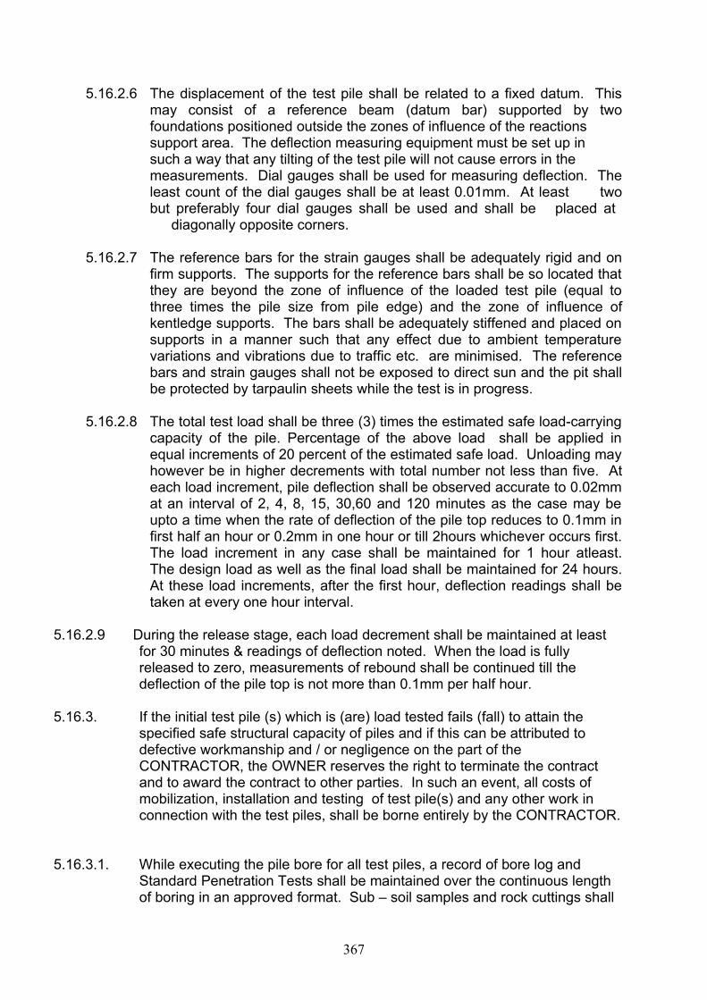
5.16.2.6 The displacement of the test pile shall be related to a fixed datum. This may consist of a reference beam (datum bar) supported by two foundations positioned outside the zones of influence of the reactions support area. The deflection measuring equipment must be set up in such a way that any tilting of the test pile will not cause errors in the measurements. Dial gauges shall be used for measuring deflection. The least count of the dial gauges shall be at least 0.01mm. At least two but preferably four dial gauges shall be used and shall be placed at
diagonally opposite corners.
5.16.2.7 The reference bars for the strain gauges shall be adequately rigid and on firm supports. The supports for the reference bars shall be so located that they are beyond the zone of influence of the loaded test pile (equal to three times the pile size from pile edge) and the zone of influence of kentledge supports. The bars shall be adequately stiffened and placed on supports in a manner such that any effect due to ambient temperature variations and vibrations due to traffic etc. are minimised. The reference bars and strain gauges shall not be exposed to direct sun and the pit shall be protected by tarpaulin sheets while the test is in progress.
5.16.2.8 The total test load shall be three (3) times the estimated safe load-carrying capacity of the pile. Percentage of the above load shall be applied in equal increments of 20 percent of the estimated safe load. Unloading may however be in higher decrements with total number not less than five. At each load increment, pile deflection shall be observed accurate to 0.02mm at an interval of 2, 4, 8, 15, 30,60 and 120 minutes as the case may be upto a time when the rate of deflection of the pile top reduces to 0.1mm in first half an hour or 0.2mm in one hour or till 2hours whichever occurs first. The load increment in any case shall be maintained for 1 hour atleast. The design load as well as the final load shall be maintained for 24 hours. At these load increments, after the first hour, deflection readings shall be taken at every one hour interval.
5.16.2.9 During the release stage, each load decrement shall be maintained at least for 30 minutes & readings of deflection noted. When the load is fully released to zero, measurements of rebound shall be continued till the deflection of the pile top is not more than 0.1mm per half hour.
5.16.3. If the initial test pile (s) which is (are) load tested fails (fall) to attain the specified safe structural capacity of piles and if this can be attributed to defective workmanship and / or negligence on the part of the CONTRACTOR, the OWNER reserves the right to terminate the contract and to award the contract to other parties. In such an event, all costs of mobilization, installation and testing of test pile(s) and any other work in connection with the test piles, shall be borne entirely by the CONTRACTOR.
5.16.3.1. While executing the pile bore for all test piles, a record of bore log and Standard Penetration Tests shall be maintained over the continuous length of boring in an approved format. Sub – soil samples and rock cuttings shall
367

be collected and systematically preserved. A complete log of the sub surface profile shall be maintained during execution of boring for each and every pile shaft and a copy of such log shall be maintained to the owner for scrutiny prior to commencement of lowering of reinforcement cage
5.17. Load tests on working piles :
5.17.1. These tests shall be carried out on poles selected by the ENGINEER after they have been cast. Tests to be carried out on working piles shall essentially be ordinary compression type. The test will be similar to that conducted on initial test piles, except that the capacity of the pile shall be limited to 1.5 times the safe pile capacity, the maximum settlement during test loading not exceeding 12mm.
5.17.2 The working pile shall be considered to have stood the test satisfactorily if total settlement under final test load is not more than 12 mm and as stated in IS 2911 Part IV.
5.17.3. If the pile does not satisfy these requirements and if this can be attributed to defective workmanship or negligence on the part of CONTRACTOR, all costs of the load test, the cost of providing and installing additional piles, cost of additional or enlarged pile caps and other work necessitated because of the defective pile, shall be at the cost of CONTRACTOR.
5.17.4 Records of load test results:
Within 48 hours of completion of each test, the CONTRACTOR shall furnish a copy of all recorded test data to the ENGINEER. Upon
completion of pile load tests, the CONTRACTOR shall furnish the ENGINEER at no extra cost with a pile test report in triplicate and this
shall include the following information where applicable.
(a) Identification of working pile/test as per Drawing.
(b) Co-ordinate axes of pile, elevation of bottom of pile, cut-offLevel of pile, type of pile, pile size.
(c) Pile Bore log Records.
(d) SPT Results
(e) Deviation from designated location / alignment.
(f) Jack gauge calibration curves from approved Test House.
(g) Tabulation of loads and settlement readings during the loading and unloading of the pile.
368

(h) Graphic representations of the test results in the form of time-load-settlement curves.
(i) Graphic analysis of Initial Cyclic test results to separate skin friction and end bearing as set out in IS : 2911 (Part-IV)
(j) Remarks concerning any unusual occurrences during installation or test loading of the working piles / test piles.
5.18 INDIRECT INTEGRITY TESTS FOR PILES :
The ENGINEER may desire to get bored cast in situ piles subject to integrity tests by indirect methods through another agency. The
CONTRACTOR shall give all cooperation in getting such tests conducted. The ENGINEER reserves the right to give due weightage
and consideration to results of these tests which will affect the integrity of the installed piles.
5.19. INSTALLATION RECORDS :
5.19.1. The CONTRACTOR shall submit each working day, detailed pile installation records in duplicate for each pile installed in the enclosed formats. The ENGINEER’S piling plans will show all piles serially numbered as per the piling layout plans. The cost of all labour, materials and services called for herein shall be included in the CONTRACTOR’s unit rates.
5.19.2 The details of the record shall include but not be limited to the list below :
PILE INSTALLATION RECORD :A. Basic data :
1. Piling Layout Drawing No.
2. Pile Number
3. Location Co-ordinates
4. System / Structure
5. Pile Location vis-a – vis Pile Group (Draw dimensioned sketch with reference axes and shade the pile)
6. Pile Type : Vertical / Raker
7. Pile Nominal Diameter
8. Pile Tip Elevation
369

9. Pile Cut-off Elevation
10. Ground Level at Pile Location.
11. Grade of Concrete Specified
12. Reinforcement Details (Draw sketch if complex)
13. Safe Capacity of Pile Specified.
B. Pile bore data :
1. Date and Time of Start
2. Date and Time of Completion
3. Method of Boring
4. Inner Nominal Diameter of Temporary Casing / Permanent Liner
5. Length of Temporary Casing / Permanent Liner
6. Material of Permanent Liner.
7. Method of Jointing Temporary Casing / Permanent Liner
8. Treatment to Permanent Liner
9. Length Bored in Soil
10. Length Bored in Rock
11. Bore Log (Draw sketch or refer to separate sheet)
12. Details of Standard Penetration Test
13. Number of Subsoil Samples / Rock cuttings collected.
14. Ground Water Elevation
15. Any Artesian Conditions
16. Any Bore Collapse and Details
17. Any Loss of Drilling Mud and Details
18. Any other Details or Phenomena Observed.
C. Flushing Record :
370
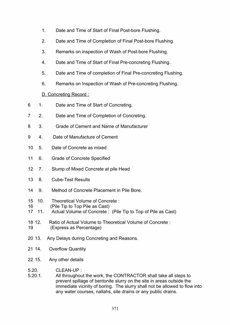
1. Date and Time of Start of Final Post-bore Flushing.
2. Date and Time of Completion of Final Post-bore Flushing.
3. Remarks on inspection of Wash of Post-bore Flushing.
4. Date and Time of Start of Final Pre-concreting Flushing.
5. Date and Time of completion of Final Pre-concreting Flushing.
6. Remarks on Inspection of Wash of Pre-concreting Flushing.
D. Concreting Record :
6 1. Date and Time of Start of Concreting.
7 2. Date and Time of Completion of Concreting.
8 3. Grade of Cement and Name of Manufacturer
9 4. Date of Manufacture of Cement
10 5. Date of Concrete as mixed
11 6. Grade of Concrete Specified
12 7. Slump of Mixed Concrete at pile Head
13 8. Cube-Test Results
14 9. Method of Concrete Placement in Pile Bore.
15 10. Theoretical Volume of Concrete :16 (Pile Tip to Top Pile as Cast)17 11. Actual Volume of Concrete : (Pile Tip to Top of Pile as Cast)
18 12. Ratio of Actual Volume to Theoretical Volume of Concrete :19 (Express as Percentage)
20 13. Any Delays during Concreting and Reasons.
21 14. Overflow Quantity
22 15. Any other details
5.20. CLEAN-UP :5.20.1. All throughout the work, the CONTRACTOR shall take all steps to
prevent spillage of bentonite slurry on the site in areas outside the immediate vicinity of boring. The slurry shall not be allowed to flow into any water courses, nallahs, site drains or any public drains.
371

5.20.2. Any discarded and / or used bentonite shall be removed from the site without any undue delay.
5.20.3. Upon completion of piling work, all casings, equipment, construction tools, protective coverings and any debris resulting from the work shall be removed from the premises.
5.20.4. All debris, empty containers, scrap timber etc. shall be removed as directed by the ENGINEER / OWNER.
5.20.5. Exposed and finished concrete and dowel surfaces shall be left in a clean condition satisfactory to the ENGINEER.
***
SPECIFIC TECHNICAL REQUIREMENT
1. General Description: The total quantity of Bored cast-in-situ pile foundation required for the quarters
is 78 locations. The work shall be executed as per the drawings enclosed and detailed in Section D and subsequent construction drawings furnished during the execution.
2. Materials used in the work.Cement :. The cement shall be OPC of not less than 43 grade. RCC M25 with the minimum cement content of 400 kg/m2 and maximum water cement ration of 0.5 shall be adopted.
Steel : Steel reinforcement to be used for RCC work shall be of Fe415 grade conforming to IS 1786 manufactured by standard companies.
3. The following are the details of works to be carried out by the contractor.
a) Setting up of piling / boring rigs equipment with all accessories, mobilisation & demobilisation from location to location.
b) Boring and concreting of bored cast-in-situ piles 450mm dia up to 15 m length in all kind of soil, using Bentonite slurry for boring with pile augurs/rigs, concreting with M25 grade concrete with 20mm HBS metal with minimum cement content of 400 kg/m3 and maximum water cement ratio of 0.5 using tremie pipe for concreting.
c) Mud circulation method shall be used for boring. The minimum cut off level shall be 600mm below Ground level to meet sound concrete in the pile and clearing the dismantled debris from pile location.
d) Carrying out initial load test on single vertical test pile in one location to a load of 100 MTl as per specification.
e) Carrying out routine load test on single vertical working pile to a load of 100 Tonnes all as per specification on one pile.
****************
372

SECTION VI
PRICE SCHEDULES
373

ABSTRACT OF PRICE SCHEDULE
Sl.No.
Description Amount
1 Supply of materials/Equipments from offshore – Schedule A1
In convertible currency/ Indian Rupees
2. Supply of materials/equipmentsSchedule from within the Purchaser country – A2
In Indian Rupees
3. Erection, Testing and Commissioning -Schedule - A3
In Indian Rupees
4 Civil works- schedule A4 In Indian rupeesTOTAL COST OF THE PROJECT A1to A4 In Indian Rupees and in
convertible currency
( In words )
SIGNATURE OF CONTRACTOR WITH COMPANY SEAL
374
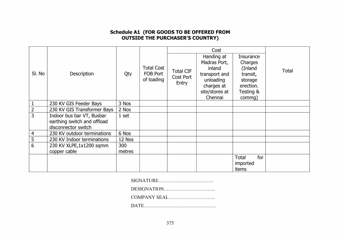
Schedule A1 (FOR GOODS TO BE OFFERED FROMOUTSIDE THE PURCHASER’S COUNTRY)
Sl. No Description QtyTotal Cost FOB Port of loading
Cost
Total CIF Cost Port
Entry
Handing at Madras Port,
inland transport and
unloading charges at
site/stores at Chennai
Insurance Charges (Inland transit, storage erection. Testing & commg)
Total
1 230 KV GIS Feeder Bays 3 Nos2 230 KV GIS Transformer Bays 2 Nos3 Indoor bus bar VT, Busbar
earthing switch and offload disconnector switch
1 set
4 230 KV outdoor terminations 6 Nos5 230 KV Indoor terminations 12 Nos6 230 KV XLPE,1x1200 sqmm
copper cable300 metres
Total for imported items
SIGNATURE…………………………….
DESIGNATION…………………………..
COMPANY SEAL………………………..
DATE………………………………………
375

SCHEDULE – A2
PRICE SCHEDULE FOR EQUIPMENTS/MATERIALS
Sl.No
Description Qty. Unit Ex-works Price (Firm)
Unit excise Duty and Cess on E.D. in % and amount
Unit Sales Tax/VAT in % and amount
Unit Freight & Insuranc charges (Firm)
Unit FOR (D) All inclusivePrice.
Total All inclusive F.O.R. (D) Price inclusive of E.D. Cess on E.D., S.T./VAT & F&I Charges
01
100 MVA 230/33 KV Power transformer
2 Nos.
02 33 KV 1x1000 sqmm copper XLPE cable
1500mts
03 33 KV indoor VCB for outgoing Feeders
11Nos
04 33 KV VCB for Transformer bays(2 LV & 2 HV)
4Nos
05 33 KV VCB for Bus Cpupler with adaptor
1 No
06 33 KV indoor Terminations suitable for 1x1000 sq mm copper XLPE cable
12Nos
376
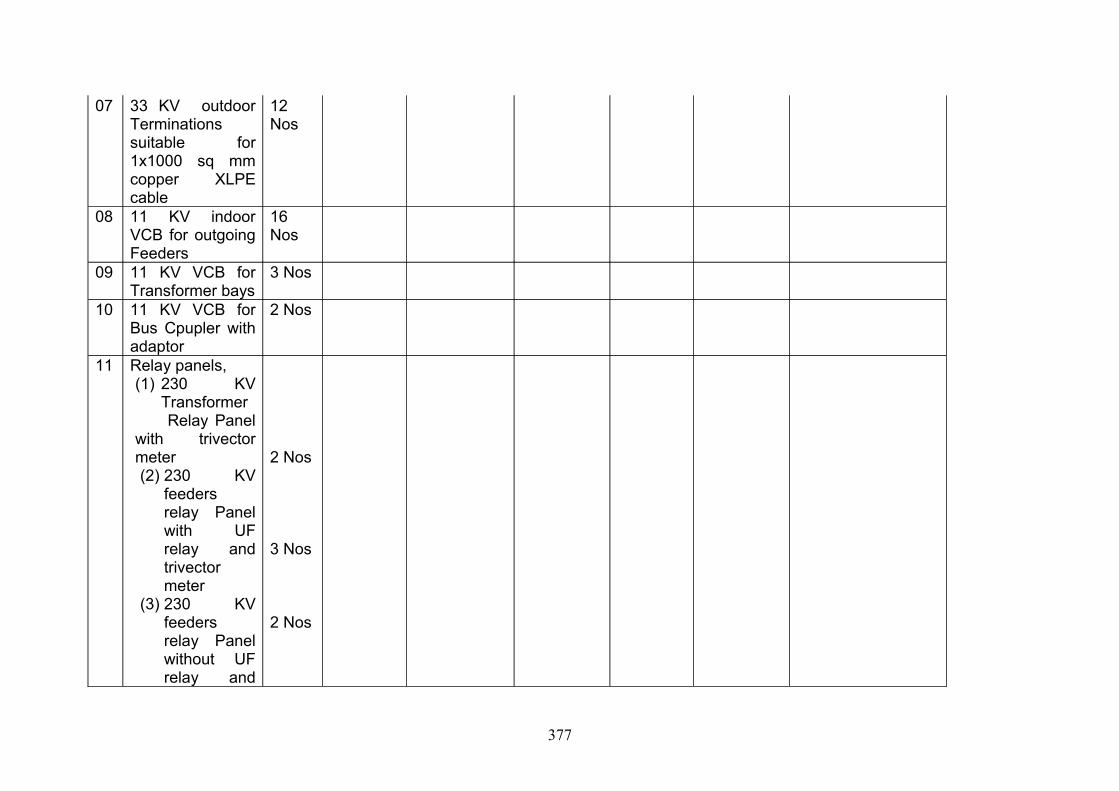
07 33 KV outdoor Terminations suitable for 1x1000 sq mm copper XLPE cable
12Nos
08 11 KV indoor VCB for outgoing Feeders
16Nos
09 11 KV VCB for Transformer bays
3 Nos
10 11 KV VCB for Bus Cpupler with adaptor
2 Nos
11 Relay panels,(1) 230 KV
Transformer Relay Panel with trivector meter(2) 230 KV
feeders relay Panel with UF relay and trivector meter
(3) 230 KV feeders relay Panel without UF relay and
2 Nos
3 Nos
2 Nos
377
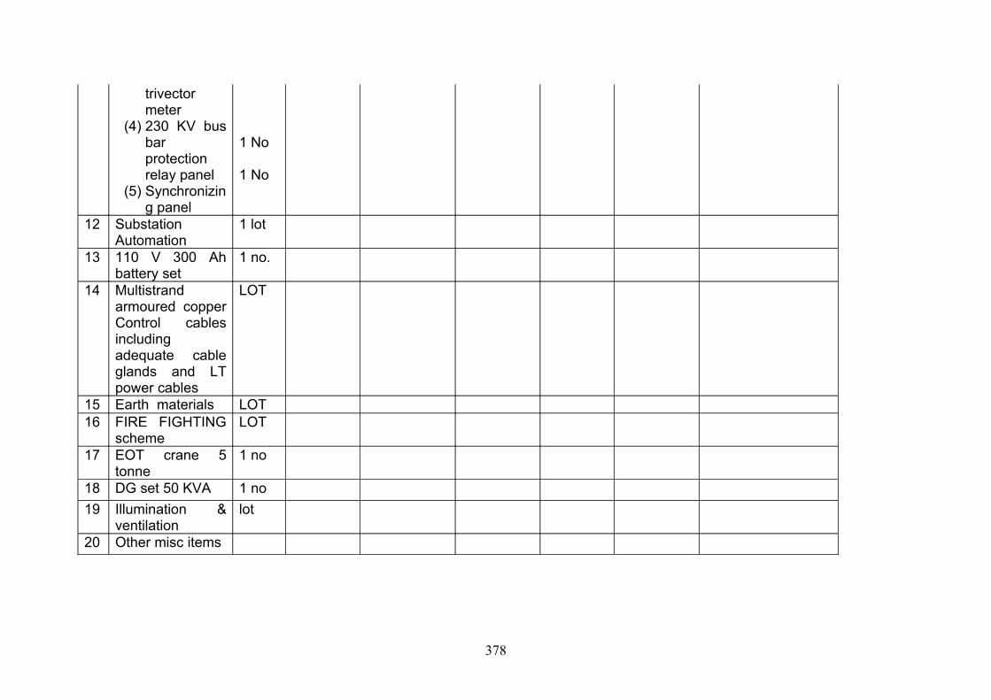
trivector meter
(4) 230 KV bus bar protection relay panel
(5) Synchronizing panel
1 No
1 No
12 Substation Automation
1 lot
13 110 V 300 Ah battery set
1 no.
14 Multistrand armoured copper Control cables including adequate cable glands and LT power cables
LOT
15 Earth materials LOT16 FIRE FIGHTING
scheme LOT
17 EOT crane 5 tonne
1 no
18 DG set 50 KVA 1 no19 Illumination &
ventilationlot
20 Other misc items
378
Note: The above materials shall be procured only from reputed suppliers to TNEB/other SEB’s/Power Utilities. Further the equipment/material should have been in successful operation for a minimum period of Two years within a period of Five years from the date of Tender opening. The enduser certificate should be furnished.
SIGNATURE OF CONTRACTOR WITH COMPANY SEAL
379
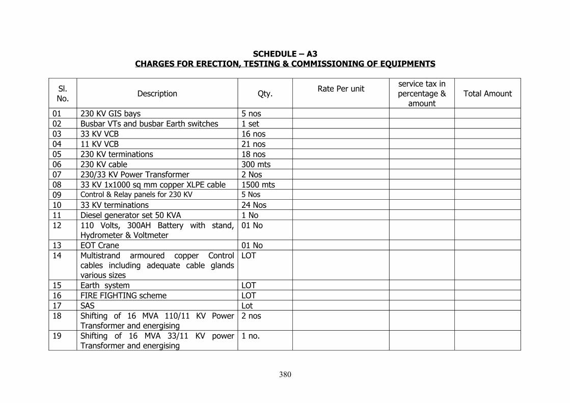
SCHEDULE – A3CHARGES FOR ERECTION, TESTING & COMMISSIONING OF EQUIPMENTS
Sl. No. Description Qty. Rate Per unit service tax in
percentage & amount
Total Amount
01 230 KV GIS bays 5 nos 02 Busbar VTs and busbar Earth switches 1 set03 33 KV VCB 16 nos04 11 KV VCB 21 nos05 230 KV terminations 18 nos06 230 KV cable 300 mts07 230/33 KV Power Transformer 2 Nos08 33 KV 1x1000 sq mm copper XLPE cable 1500 mts09 Control & Relay panels for 230 KV 5 Nos10 33 KV terminations 24 Nos11 Diesel generator set 50 KVA 1 No12 110 Volts, 300AH Battery with stand,
Hydrometer & Voltmeter01 No
13 EOT Crane 01 No14 Multistrand armoured copper Control
cables including adequate cable glands various sizes
LOT
15 Earth system LOT16 FIRE FIGHTING scheme LOT17 SAS Lot18 Shifting of 16 MVA 110/11 KV Power
Transformer and energising2 nos
19 Shifting of 16 MVA 33/11 KV power Transformer and energising
1 no.
380
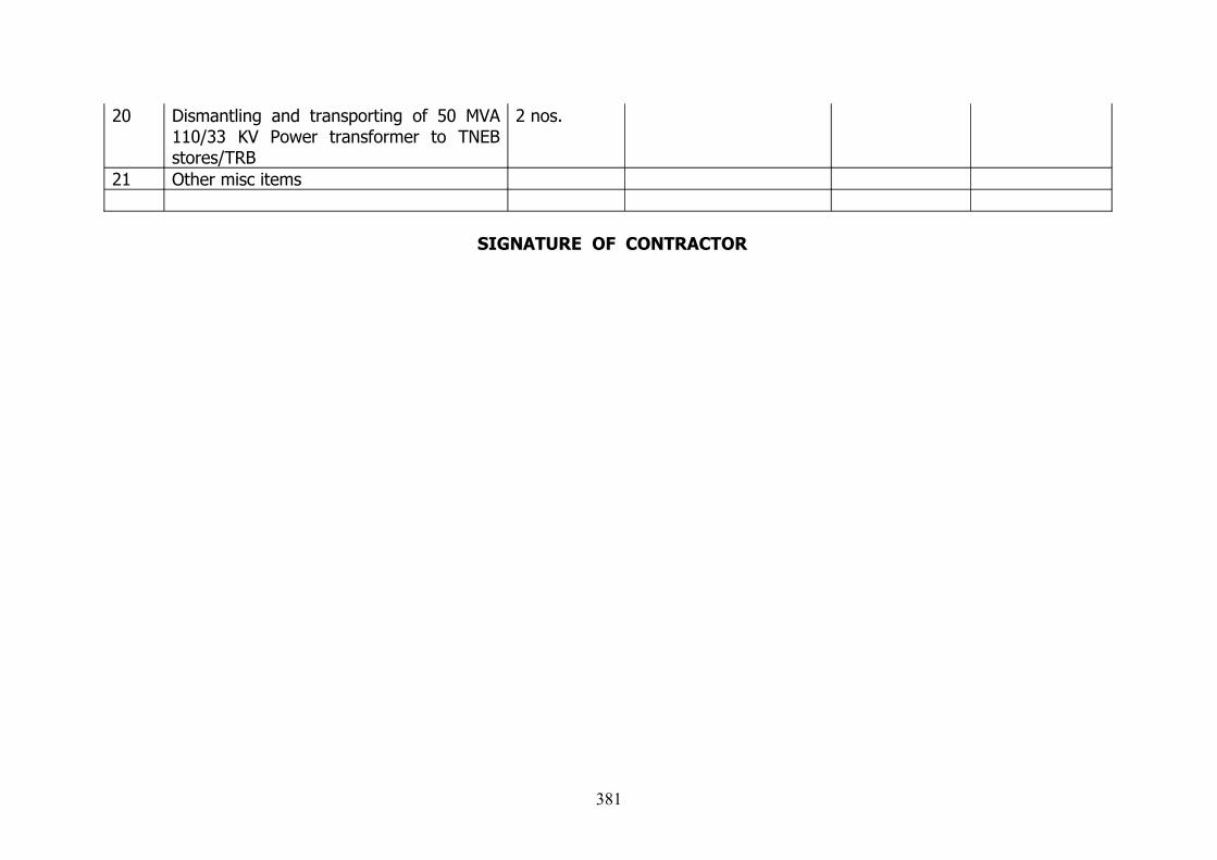
20 Dismantling and transporting of 50 MVA 110/33 KV Power transformer to TNEB stores/TRB
2 nos.
21 Other misc items
SIGNATURE OF CONTRACTOR
381

382

383
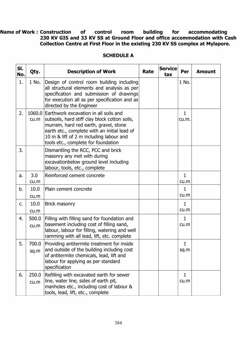
Name of Work : Construction of control room building for accommodating 230 KV GIS and 33 KV SS at Ground Floor and office accommodation with Cash Collection Centre at First Floor in the existing 230 KV SS complex at Mylapore.
SCHEDULE A
Sl. No. Qty. Description of Work Rate Service
tax Per Amount
1. 1 No. Design of control room building including all structural elements and analysis as per specification and submission of drawings for execution all as per specification and as directed by the Engineer
1 No.
2. 1060.0 cu.m
Earthwork excavation in all soils and subsoils, hard stiff clay block cotton soils, murram, hard red earth, gravel, stone earth etc., complete with an initial lead of 10 m & lift of 2 m including labour and tools etc., complete for foundation
1 cu.m.
3. Dismantling the RCC, PCC and brick masonry any met with during excavationbelow ground level including labour, tools, etc., complete
a. 3.0 cu.m
Reinforced cement concrete 1 cu.m
b. 10.0cu.m
Plain cement concrete 1 cu.m
c. 10.0cu.m
Brick masonry 1 cu.m
4. 500.0cu.m
Filling with filling sand for foundation and basement including cost of filling sand, labour, labour for filling, watering and well ramming with all lead, lift, etc. complete
1 cu.m
5. 700.0sq.m
Providing antitermite treatment for inside and outside of the building including cost of antitermite chemicals, lead, lift and labour for applying as per standard specification
1 sq.m
6. 250.0cu.m
Refilling with excavated earth for sewer line, water line, sides of earth pit, manholes etc., including cost of labour & tools, lead, lift, etc., complete
1 cu.m
384

Sl. No. Qty. Description of Work Rate Service
tax Per Amount
7. 800.0cu.m
Transporting the balance excavated earth for a lead of upto 10 km including loading and unloading and transporting and filling in low level places of SS complex as directed by the Engineer including all lead, lift, etc., complete
1 cu.m
8. 150.0 cu.m
Laying plain cement concrete 1:4:8 using 40 mm HBG metal for foundation and basement including cost of all materials, lead, lift, labour for laying concrete etc., complete
1 cu.m
9. Laying reinforced cement concrete M25 using 12 mm to 20 mm HBG metal and 300 kg of minimum cement content for various types of work including necessary strutting, form work lead, lift, labour, etc., complete but excluding cost of reinforcement
I. Foundation and basementa. 400.0
cu.mRaft 1
cu.m
b. 18.0cu.m
Column upto basement 1 cu.m
c. 60.0cu.m
Grade beam 1 cu.m
d. 45.0cu.m
Plinth beam 1 cu.m
e. 65.0cu.m
Basement Slab 1 cu.m
f. 80.0cu.m
RCC slide walls 1 cu.m
g. 10.0cu.m
Pre-cast slab 1 cu.m
II. Ground Floora. 25.0
cu.mColumn 1
cu.m
b. 35.0cu.m
Beams in Ground Floor 1 cu.m
c. 10.0cu.m
Lintel 1 cu.m
385
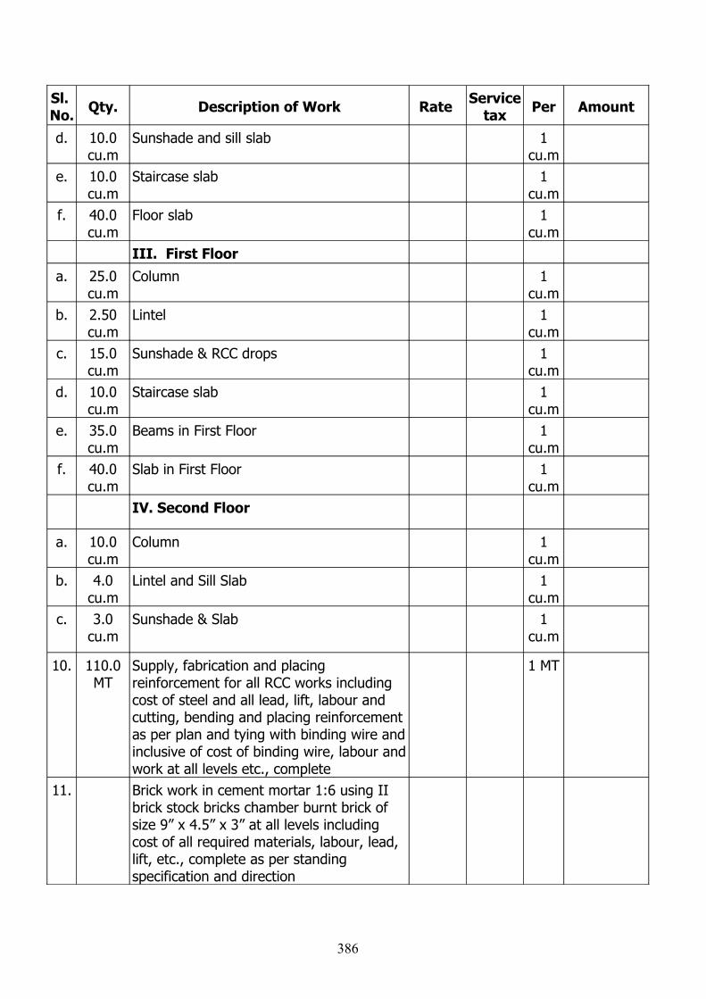
Sl. No. Qty. Description of Work Rate Service
tax Per Amount
d. 10.0cu.m
Sunshade and sill slab 1 cu.m
e. 10.0cu.m
Staircase slab 1 cu.m
f. 40.0cu.m
Floor slab 1 cu.m
III. First Floora. 25.0
cu.mColumn 1
cu.mb. 2.50
cu.mLintel 1
cu.mc. 15.0
cu.mSunshade & RCC drops 1
cu.md. 10.0
cu.mStaircase slab 1
cu.me. 35.0
cu.mBeams in First Floor 1
cu.mf. 40.0
cu.mSlab in First Floor 1
cu.mIV. Second Floor
a. 10.0 cu.m
Column 1 cu.m
b. 4.0cu.m
Lintel and Sill Slab 1 cu.m
c. 3.0cu.m
Sunshade & Slab 1 cu.m
10. 110.0 MT
Supply, fabrication and placing reinforcement for all RCC works including cost of steel and all lead, lift, labour and cutting, bending and placing reinforcement as per plan and tying with binding wire and inclusive of cost of binding wire, labour and work at all levels etc., complete
1 MT
11. Brick work in cement mortar 1:6 using II brick stock bricks chamber burnt brick of size 9” x 4.5” x 3” at all levels including cost of all required materials, labour, lead, lift, etc., complete as per standing specification and direction
386
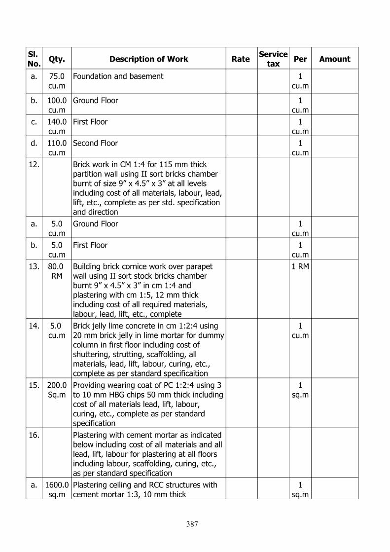
Sl. No. Qty. Description of Work Rate Service
tax Per Amount
a. 75.0 cu.m
Foundation and basement 1 cu.m
b. 100.0 cu.m
Ground Floor 1 cu.m
c. 140.0 cu.m
First Floor 1 cu.m
d. 110.0 cu.m
Second Floor 1 cu.m
12. Brick work in CM 1:4 for 115 mm thick partition wall using II sort bricks chamber burnt of size 9” x 4.5” x 3” at all levels including cost of all materials, labour, lead, lift, etc., complete as per std. specification and direction
a. 5.0cu.m
Ground Floor 1 cu.m
b. 5.0cu.m
First Floor 1 cu.m
13. 80.0 RM
Building brick cornice work over parapet wall using II sort stock bricks chamber burnt 9” x 4.5” x 3” in cm 1:4 and plastering with cm 1:5, 12 mm thick including cost of all required materials, labour, lead, lift, etc., complete
1 RM
14. 5.0 cu.m
Brick jelly lime concrete in cm 1:2:4 using 20 mm brick jelly in lime mortar for dummy column in first floor including cost of shuttering, strutting, scaffolding, all materials, lead, lift, labour, curing, etc., complete as per standard specificaition
1 cu.m
15. 200.0 Sq.m
Providing wearing coat of PC 1:2:4 using 3 to 10 mm HBG chips 50 mm thick including cost of all materials lead, lift, labour, curing, etc., complete as per standard specification
1 sq.m
16. Plastering with cement mortar as indicated below including cost of all materials and all lead, lift, labour for plastering at all floors including labour, scaffolding, curing, etc., as per standard specification
a. 1600.0 sq.m
Plastering ceiling and RCC structures with cement mortar 1:3, 10 mm thick
1 sq.m
387
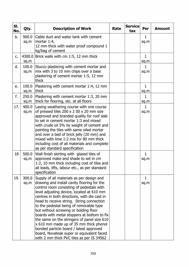
Sl. No. Qty. Description of Work Rate Service
tax Per Amount
b. 900.0 sq.m
Cable duct and water tank with cement mortar 1:4, 12 mm thick with water proof compound 1 kg/bag of cement
1 sq.m
c. 4300.0 sq.m
Brick walls with cm 1:5, 12 mm thick 1 sq.m
d. 100.0 sq.m
Stucco plastering with cement mortar and mix with 3 to 10 mm chips over a base plastering of cement mortar 1:5, 12 mm thick
1 sq.m
e. 100.0 sq.m
Plastering with cement mortar 1:4, 12 mm thick
1 sq.m
f. 250.0 sq.m
Plastering with cement mortar 1:3, 20 mm thick for flooring, etc. at all floors
1 sq.m
17. 400.0 sq.m
Laying weathering course with one course of pressed tiles 200 x 2 00 x 20 mm size approved and branded quality for roof slab to set in cement mortar 1:3 and mixed with crude oil 5% by weight of cement and pointing the tiles with same oiled mortar and over a bed of brick jelly (20 mm) and mixed with lime 1:2 mix for 80 mm thick including cost of all materials and complete as per standard specification
1 sq.m
18 500.0 sq.m
Wall finish skirting with glazed tiles of approved make and shade to set in cm 1:2, 10 mm thick including cost of tiles and all leads, lifts, labour etc., as per standard specification
1 sq.m
19. 300.0 sq.m
Supply of all materials as per design and drawing and install cavity flooring for the control room consisting of pedestals with level adjusting device, located at 610 mm centres in both directions, with die cast in head to receive string. String connection to the pedestal being of removable type but without screwing or bolding floor boards with metal stoppers at bottom to fix the same on the stringers of panel size 610 x 610 mm made up of 35 mm thick phenol bonded particle board / latest approved board, Novateak super or equivalent faced with 2 mm thick PVC tiles as per IS 34562
1 sq.m
388
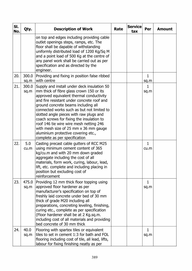
Sl. No. Qty. Description of Work Rate Service
tax Per Amount
on top and edges including providing cable outlet openings steps, ramps, etc. The floor shall be dapable of withstanding uniformly distributed load of 1200 Kg/Sq M and a point load of 500 Kg at the centre of any panel work shall be carried out as per specification and as directed by the engineer.
20. 300.0 sq.m
Providing and fixing in position false ribbed with centre
1 sq.m
21. 300.0 sq.m
Supply and install under deck insulation 50 mm thick of fibre glass crown 150 or its approved equivalent thermal conductivity and fire resistant under concrete roof and ground concrete beams including all connected works such as but not limited to slotted angle pieces with raw plugs and coach screws for fixing the insulation to roof 146 tie wire wire mesh netting 246 with mesh size of 25 mm x 36 mm gauge aluminium protective covering etc., complete as per specification
1 sq.m
22. 5.0cu.m
Casting precast cable gutters of RCC M25 using minimum cement content of 365 kg/cu.m and with 20 mm down graded aggregate including the cost of all materials, form work, curing, labour, lead, lift, etc. complete and including placing in position but excluding cost of reinforcement
1 cu.m
23. 475.0 sq.m
Providing 12 mm thick floor topping using approved floor hardener as per manufacturer’s specification on top of freshly laid concrete under bed of 30 mm thick of grade M20 including all preparations, concreting leveling, finishing, curing etc., complete as per specification (Floor hardener shall be at 2 Kg.sq.m. including cost of all materials and providing bed concrete of 30 mm thick
1 sq.m
24. 40.0 sq.m
Flooring with spartex tiles or equivalent tiles to set in cement 1:3 for bath and FOL flooring including cost of tile, all lead, lifts, labour for fixing finishing neatly as per
1 sq.m
389
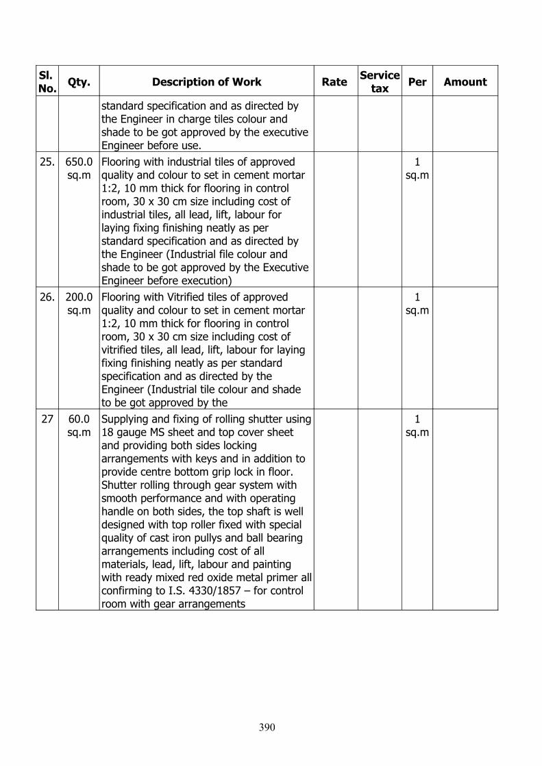
Sl. No. Qty. Description of Work Rate Service
tax Per Amount
standard specification and as directed by the Engineer in charge tiles colour and shade to be got approved by the executive Engineer before use.
25. 650.0 sq.m
Flooring with industrial tiles of approved quality and colour to set in cement mortar 1:2, 10 mm thick for flooring in control room, 30 x 30 cm size including cost of industrial tiles, all lead, lift, labour for laying fixing finishing neatly as per standard specification and as directed by the Engineer (Industrial file colour and shade to be got approved by the Executive Engineer before execution)
1 sq.m
26. 200.0 sq.m
Flooring with Vitrified tiles of approved quality and colour to set in cement mortar 1:2, 10 mm thick for flooring in control room, 30 x 30 cm size including cost of vitrified tiles, all lead, lift, labour for laying fixing finishing neatly as per standard specification and as directed by the Engineer (Industrial tile colour and shade to be got approved by the
1 sq.m
27 60.0sq.m
Supplying and fixing of rolling shutter using 18 gauge MS sheet and top cover sheet and providing both sides locking arrangements with keys and in addition to provide centre bottom grip lock in floor. Shutter rolling through gear system with smooth performance and with operating handle on both sides, the top shaft is well designed with top roller fixed with special quality of cast iron pullys and ball bearing arrangements including cost of all materials, lead, lift, labour and painting with ready mixed red oxide metal primer all confirming to I.S. 4330/1857 – for control room with gear arrangements
1 sq.m
390
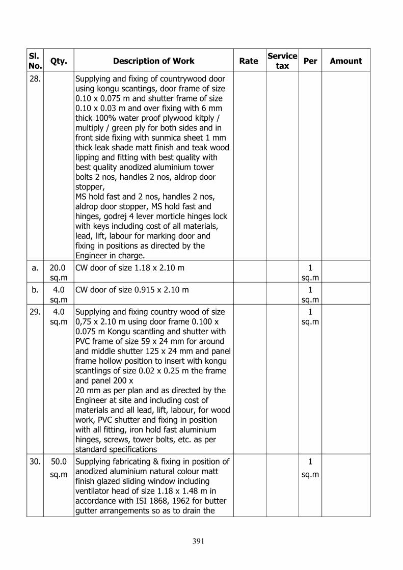
Sl. No. Qty. Description of Work Rate Service
tax Per Amount
28. Supplying and fixing of countrywood door using kongu scantings, door frame of size 0.10 x 0.075 m and shutter frame of size 0.10 x 0.03 m and over fixing with 6 mm thick 100% water proof plywood kitply / multiply / green ply for both sides and in front side fixing with sunmica sheet 1 mm thick leak shade matt finish and teak wood lipping and fitting with best quality with best quality anodized aluminium tower bolts 2 nos, handles 2 nos, aldrop door stopper, MS hold fast and 2 nos, handles 2 nos, aldrop door stopper, MS hold fast and hinges, godrej 4 lever morticle hinges lock with keys including cost of all materials, lead, lift, labour for marking door and fixing in positions as directed by the Engineer in charge.
a. 20.0 sq.m
CW door of size 1.18 x 2.10 m 1 sq.m
b. 4.0sq.m
CW door of size 0.915 x 2.10 m 1 sq.m
29. 4.0sq.m
Supplying and fixing country wood of size 0,75 x 2.10 m using door frame 0.100 x 0.075 m Kongu scantling and shutter with PVC frame of size 59 x 24 mm for around and middle shutter 125 x 24 mm and panel frame hollow position to insert with kongu scantlings of size 0.02 x 0.25 m the frame and panel 200 x 20 mm as per plan and as directed by the Engineer at site and including cost of materials and all lead, lift, labour, for wood work, PVC shutter and fixing in position with all fitting, iron hold fast aluminium hinges, screws, tower bolts, etc. as per standard specifications
1 sq.m
30. 50.0
sq.m
Supplying fabricating & fixing in position of anodized aluminium natural colour matt finish glazed sliding window including ventilator head of size 1.18 x 1.48 m in accordance with ISI 1868, 1962 for butter gutter arrangements so as to drain the
1
sq.m
391
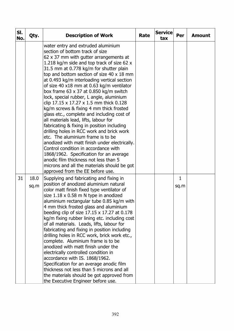
Sl. No. Qty. Description of Work Rate Service
tax Per Amount
water entry and extruded aluminium section of bottom track of size 62 x 37 mm with gutter arrangements at 1.218 kg/m side and top track of size 62 x 31.5 mm at 0.778 kg/m for shutter plain top and bottom section of size 40 x 18 mm at 0.493 kg/m interloading vertical section of size 40 x18 mm at 0.63 kg/m ventilator box frame 63 x 37 at 0.850 kg/m switch lock, special rubber, L angle, aluminium clip 17.15 x 17.27 x 1.5 mm thick 0.128 kg/m screws & fixing 4 mm thick frosted glass etc., complete and including cost of all materials lead, lifts, labour for fabricating & fixing in position including drilling holes in RCC work and brick work etc. The aluminium frame is to be anodized with matt finish under electrically. Control condition in accordance with 1868/1962. Specification for an average anodic film thickness not less than 5 microns and all the materials should be got approved from the EE before use.
31 18.0
sq.m
Supplying and fabricating and fixing in position of anodized aluminium natural color matt finish fixed type ventilator of size 1.18 x 0.58 m N type in anodized aluminium rectangular tube 0.85 kg/m with 4 mm thick frosted glass and aluminium beeding clip of size 17.15 x 17.27 at 0.178 kg/m fixing rubber lining etc. including cost of all materials. Leads, lifts, labour for fabricating and fixing in position including drilling holes in RCC work, brick work etc., complete. Aluminium frame is to be anodized with matt finish under the electrically controlled condition in accordance with IS. 1868/1962. Specification for an average anodic film thickness not less than 5 microns and all the materials should be got approved from the Executive Engineer before use.
1
sq.m
392
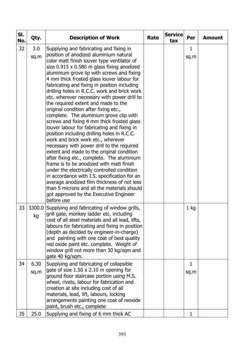
Sl. No. Qty. Description of Work Rate Service
tax Per Amount
32 3.0
sq.m
Supplying and fabricating and fixing in position of anodized aluminium natural color matt finish louver type ventilator of size 0.915 x 0.580 m glass fixing anodized aluminium grove lip with screws and fixing 4 mm thick frosted glass louver labour for fabricating and fixing in position including drilling holes in R.C.C. work and brick work etc. wherever necessary with power drill to the required extent and made to the original condition after fixing etc., complete. The aluminium grove clip with screws and fixing 4 mm thick frosted glass louver labour for fabricating and fixing in position including drilling holes in R.C.C. work and brick work etc., wherever necessary with power drill to the required extent and made to the original condition after fixing etc., complete. The aluminium frame is to be anodized with matt finish under the electrically controlled condition in accordance with I.S. specification for an average anodized film thickness of not less than 5 microns and all the materials should got approved by the Executive Engineer before use
1
sq.m
33 3300.0
kg
Supplying and fabricating of window grills, grill gate, monkey ladder etc. including cost of all steel materials and all lead, lifts, labours for fabricating and fixing in position (depth as decided by engineer-in-charge) and painting with one coat of best quality red oxide paint etc. complete. Weight of window grill not more than 30 kg/sqm and gate 40 kg/sqm.
1 kg
34 6.30
sq.m
Supplying and fabricating of collapsible gate of size 1.50 x 2.10 m opening for ground floor staircase portion using M.S. wheel, rivets, labour for fabrication and creation at site including cost of all materials, lead, lift, labours, locking arrangements painting one coat of reoxide paint, brush etc., complete
1
sq.m
35 25.0 Supplying and fixing of 6 mm thick AC 1
393
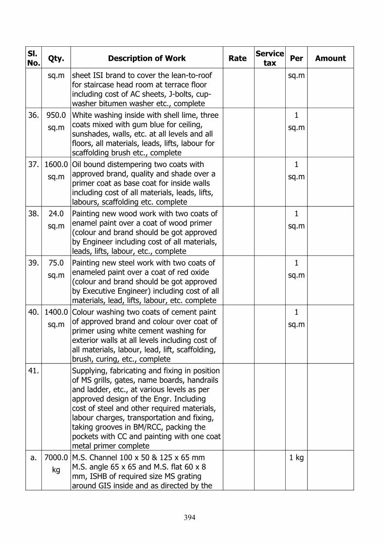
Sl. No. Qty. Description of Work Rate Service
tax Per Amount
sq.m sheet ISI brand to cover the lean-to-roof for staircase head room at terrace floor including cost of AC sheets, J-bolts, cup-washer bitumen washer etc., complete
sq.m
36. 950.0
sq.m
White washing inside with shell lime, three coats mixed with gum blue for ceiling, sunshades, walls, etc. at all levels and all floors, all materials, leads, lifts, labour for scaffolding brush etc., complete
1
sq.m
37. 1600.0
sq.m
Oil bound distempering two coats with approved brand, quality and shade over a primer coat as base coat for inside walls including cost of all materials, leads, lifts, labours, scaffolding etc. complete
1
sq.m
38. 24.0
sq.m
Painting new wood work with two coats of enamel paint over a coat of wood primer (colour and brand should be got approved by Engineer including cost of all materials, leads, lifts, labour, etc., complete
1
sq.m
39. 75.0
sq.m
Painting new steel work with two coats of enameled paint over a coat of red oxide (colour and brand should be got approved by Executive Engineer) including cost of all materials, lead, lifts, labour, etc. complete
1
sq.m
40. 1400.0
sq.m
Colour washing two coats of cement paint of approved brand and colour over coat of primer using white cement washing for exterior walls at all levels including cost of all materials, labour, lead, lift, scaffolding, brush, curing, etc., complete
1
sq.m
41. Supplying, fabricating and fixing in position of MS grills, gates, name boards, handrails and ladder, etc., at various levels as per approved design of the Engr. Including cost of steel and other required materials, labour charges, transportation and fixing, taking grooves in BM/RCC, packing the pockets with CC and painting with one coat metal primer complete
a. 7000.0
kg
M.S. Channel 100 x 50 & 125 x 65 mm M.S. angle 65 x 65 and M.S. flat 60 x 8 mm, ISHB of required size MS grating around GIS inside and as directed by the
1 kg
394
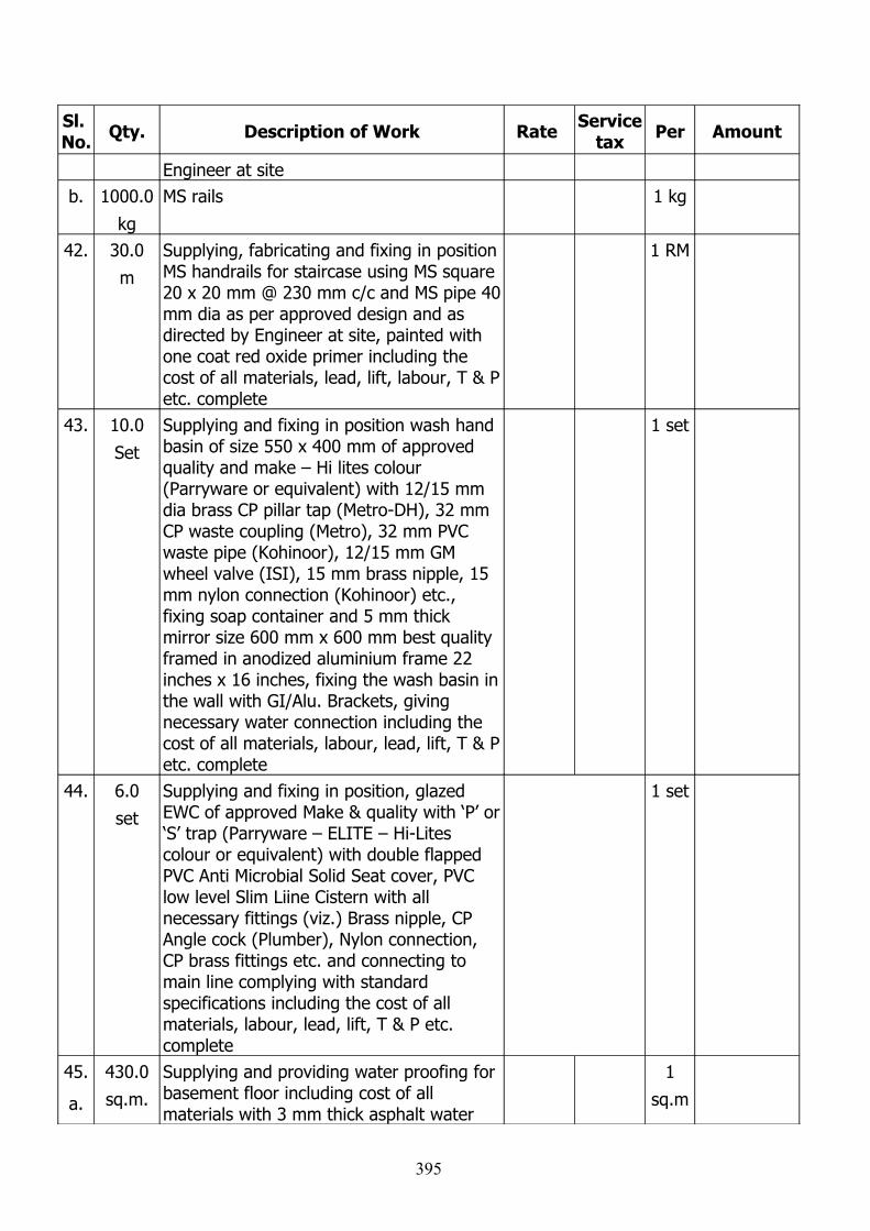
Sl. No. Qty. Description of Work Rate Service
tax Per Amount
Engineer at siteb. 1000.0
kg
MS rails 1 kg
42. 30.0
m
Supplying, fabricating and fixing in position MS handrails for staircase using MS square 20 x 20 mm @ 230 mm c/c and MS pipe 40 mm dia as per approved design and as directed by Engineer at site, painted with one coat red oxide primer including the cost of all materials, lead, lift, labour, T & P etc. complete
1 RM
43. 10.0
Set
Supplying and fixing in position wash hand basin of size 550 x 400 mm of approved quality and make – Hi lites colour (Parryware or equivalent) with 12/15 mm dia brass CP pillar tap (Metro-DH), 32 mm CP waste coupling (Metro), 32 mm PVC waste pipe (Kohinoor), 12/15 mm GM wheel valve (ISI), 15 mm brass nipple, 15 mm nylon connection (Kohinoor) etc., fixing soap container and 5 mm thick mirror size 600 mm x 600 mm best quality framed in anodized aluminium frame 22 inches x 16 inches, fixing the wash basin in the wall with GI/Alu. Brackets, giving necessary water connection including the cost of all materials, labour, lead, lift, T & P etc. complete
1 set
44. 6.0
set
Supplying and fixing in position, glazed EWC of approved Make & quality with ‘P’ or ‘S’ trap (Parryware – ELITE – Hi-Lites colour or equivalent) with double flapped PVC Anti Microbial Solid Seat cover, PVC low level Slim Liine Cistern with all necessary fittings (viz.) Brass nipple, CP Angle cock (Plumber), Nylon connection, CP brass fittings etc. and connecting to main line complying with standard specifications including the cost of all materials, labour, lead, lift, T & P etc. complete
1 set
45.
a.
430.0
sq.m.
Supplying and providing water proofing for basement floor including cost of all materials with 3 mm thick asphalt water
1
sq.m
395
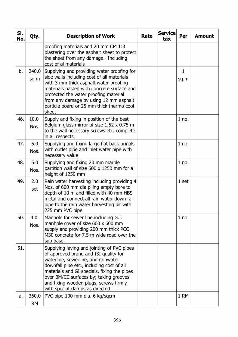
Sl. No. Qty. Description of Work Rate Service
tax Per Amount
proofing materials and 20 mm CM 1:3 plastering over the asphalt sheet to protect the sheet from any damage. Including cost of al materials
b. 240.0
sq.m
Supplying and providing water proofing for side walls including cost of all materials with 3 mm thick asphalt water proofing materials pasted with concrete surface and protected the water proofing material from any damage by using 12 mm asphalt particle board or 25 mm thick thermo cool sheet
1
sq.m
46. 10.0
Nos.
Supply and fixing in position of the best Belgium glass mirror of size 1.52 x 0.75 m to the wall necessary screws etc. complete in all respects
1 no.
47. 5.0
Nos.
Supplying and fixing large flat back urinals with outlet pipe and inlet water pipe with necessary value
1 no.
48. 5.0
Nos.
Supplying and fixing 20 mm marble partition wall of size 600 x 1250 mm for a height of 1250 mm
1 no.
49. 2.0
set
Rain water harvesting including providing 4 Nos. of 600 mm dia piling empty bore to depth of 10 m and filled with 40 mm HBS metal and connect all rain water down fall pipe to the rain water harvesting pit with 225 mm PVC pipe
1 set
50. 4.0
Nos.
Manhole for sewer line including G.I. manhole cover of size 600 x 600 mm supply and providing 200 mm thick PCC M30 concrete for 7.5 m wide road over the sub base
1 no.
51. Supplying laying and jointing of PVC pipes of approved brand and ISI quality for waterline, sewerline, and rainwater downfall pipe etc., including cost of all materials and GI specials, fixing the pipes over BM/CC surfaces by; taking grooves and fixing wooden plugs, screws firmly with special clamps as directed
a. 360.0
RM
PVC pipe 100 mm dia. 6 kg/sqcm 1 RM
396
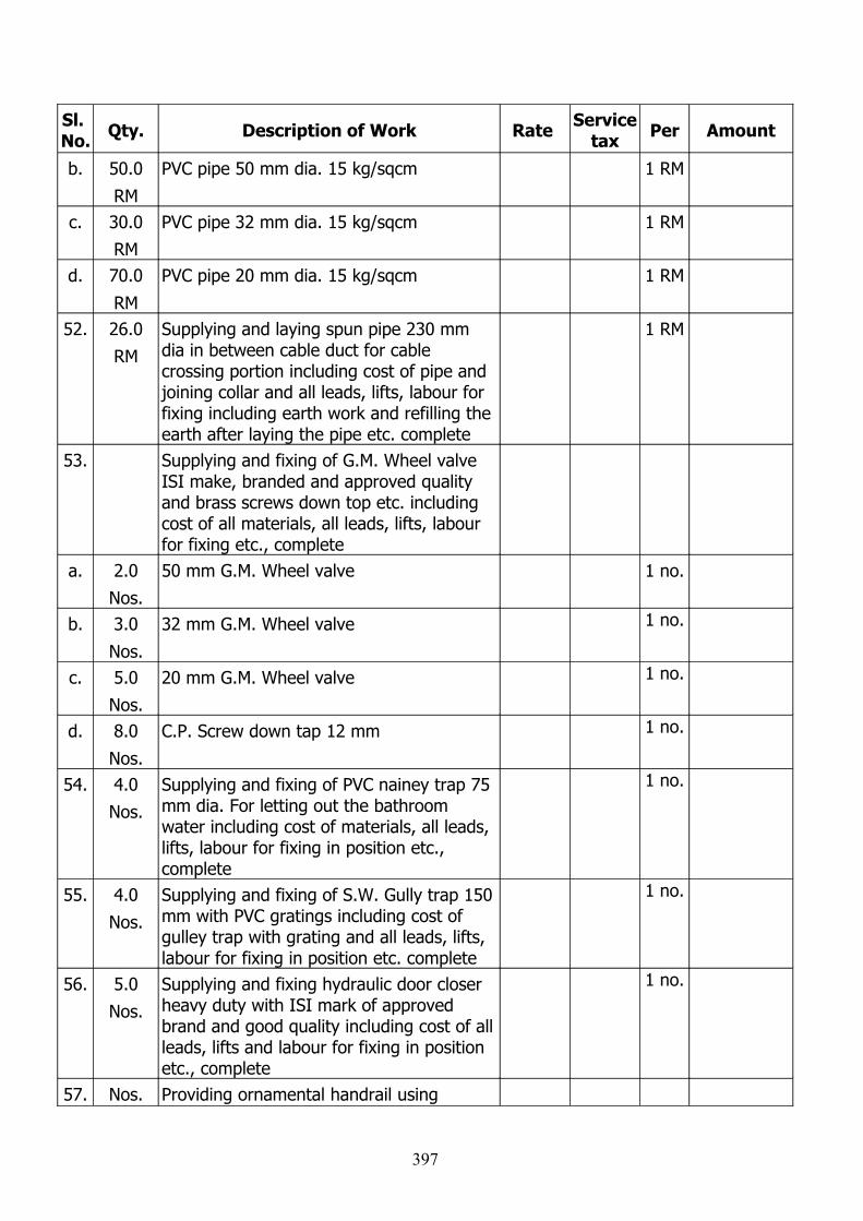
Sl. No. Qty. Description of Work Rate Service
tax Per Amount
b. 50.0
RM
PVC pipe 50 mm dia. 15 kg/sqcm 1 RM
c. 30.0
RM
PVC pipe 32 mm dia. 15 kg/sqcm 1 RM
d. 70.0
RM
PVC pipe 20 mm dia. 15 kg/sqcm 1 RM
52. 26.0
RM
Supplying and laying spun pipe 230 mm dia in between cable duct for cable crossing portion including cost of pipe and joining collar and all leads, lifts, labour for fixing including earth work and refilling the earth after laying the pipe etc. complete
1 RM
53. Supplying and fixing of G.M. Wheel valve ISI make, branded and approved quality and brass screws down top etc. including cost of all materials, all leads, lifts, labour for fixing etc., complete
a. 2.0
Nos.
50 mm G.M. Wheel valve 1 no.
b. 3.0
Nos.
32 mm G.M. Wheel valve 1 no.
c. 5.0
Nos.
20 mm G.M. Wheel valve 1 no.
d. 8.0
Nos.
C.P. Screw down tap 12 mm 1 no.
54. 4.0
Nos.
Supplying and fixing of PVC nainey trap 75 mm dia. For letting out the bathroom water including cost of materials, all leads, lifts, labour for fixing in position etc., complete
1 no.
55. 4.0
Nos.
Supplying and fixing of S.W. Gully trap 150 mm with PVC gratings including cost of gulley trap with grating and all leads, lifts, labour for fixing in position etc. complete
1 no.
56. 5.0
Nos.
Supplying and fixing hydraulic door closer heavy duty with ISI mark of approved brand and good quality including cost of all leads, lifts and labour for fixing in position etc., complete
1 no.
57. Nos. Providing ornamental handrail using
397
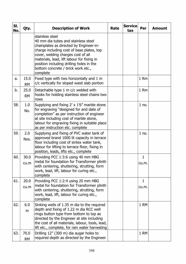
Sl. No. Qty. Description of Work Rate Service
tax Per Amount
stainless steel 40 mm dia tubes and stainless steel chainplates as directed by Engineer-in-charge including cost of base plates, top cover, welding charges cost of all materials, lead, lift labour for fixing in position including drilling holes in the bottom concrete / brick work etc., complete
a. 15.0
RM
Fixed type with two horizontally and 1 m c/c vertically for sloped waist slab portion
1 Rm
b. 25.0
RM
Detachable type 1 m c/c welded with hooks for holding stainless steel chains two rows
1 Rm
58. 1.0
No.
Supplying and fixing 2’ x 1’6” marble stone for engraving “designed for and date of completion” as per instruction of engineer at site including cost of marble stone, labour for engraving fixing in suitable place as per instruction etc. complete
1 no.
59. 2.0
Nos.
Supplying and fixing of PVC water tank of approved brand 1000 lit capacity in terrace floor including cost of sintex water tank, labour for lifting to terrace floor, fixing in position, leads, lifts etc., complete
1 no.
60. 30.0
cu.m
Providing PCC 1:3:6 using 40 mm HBG metal for foundation for Transformer plinth with centering, shuttering, strutting, form work, lead, lift, labour for curing etc., complete
1
cu.m.
61. 20.0
cu.m
Providing PCC 1:2:4 using 20 mm HBG metal for foundation for Transformer plinth with centering, shuttering, strutting, form work, lead, lift, labour for curing etc., complete
1
cu.m.
62. 6.0
m
Sinking wells of 1.35 m dia to the required depth and fixing of 1.22 m dia RCC well rings button type from bottom to top as directed by the Engineer at site including the cost of all materials, labour, tools, lead, lift etc., complete, for rain water harvesting
1 RM
63. 70.0
RM
Drilling 12” (300 m) dia augar holes to required depth as directed by the Engineer
1 RM
398
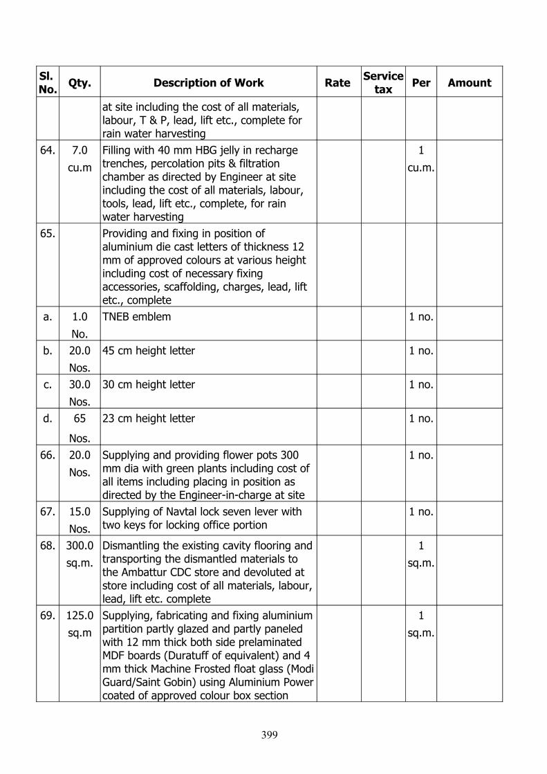
Sl. No. Qty. Description of Work Rate Service
tax Per Amount
at site including the cost of all materials, labour, T & P, lead, lift etc., complete for rain water harvesting
64. 7.0
cu.m
Filling with 40 mm HBG jelly in recharge trenches, percolation pits & filtration chamber as directed by Engineer at site including the cost of all materials, labour, tools, lead, lift etc., complete, for rain water harvesting
1
cu.m.
65. Providing and fixing in position of aluminium die cast letters of thickness 12 mm of approved colours at various height including cost of necessary fixing accessories, scaffolding, charges, lead, lift etc., complete
a. 1.0
No.
TNEB emblem 1 no.
b. 20.0
Nos.
45 cm height letter 1 no.
c. 30.0
Nos.
30 cm height letter 1 no.
d. 65
Nos.
23 cm height letter 1 no.
66. 20.0
Nos.
Supplying and providing flower pots 300 mm dia with green plants including cost of all items including placing in position as directed by the Engineer-in-charge at site
1 no.
67. 15.0
Nos.
Supplying of Navtal lock seven lever with two keys for locking office portion
1 no.
68. 300.0
sq.m.
Dismantling the existing cavity flooring and transporting the dismantled materials to the Ambattur CDC store and devoluted at store including cost of all materials, labour, lead, lift etc. complete
1
sq.m.
69. 125.0
sq.m
Supplying, fabricating and fixing aluminium partition partly glazed and partly paneled with 12 mm thick both side prelaminated MDF boards (Duratuff of equivalent) and 4 mm thick Machine Frosted float glass (Modi Guard/Saint Gobin) using Aluminium Power coated of approved colour box section
1
sq.m.
399
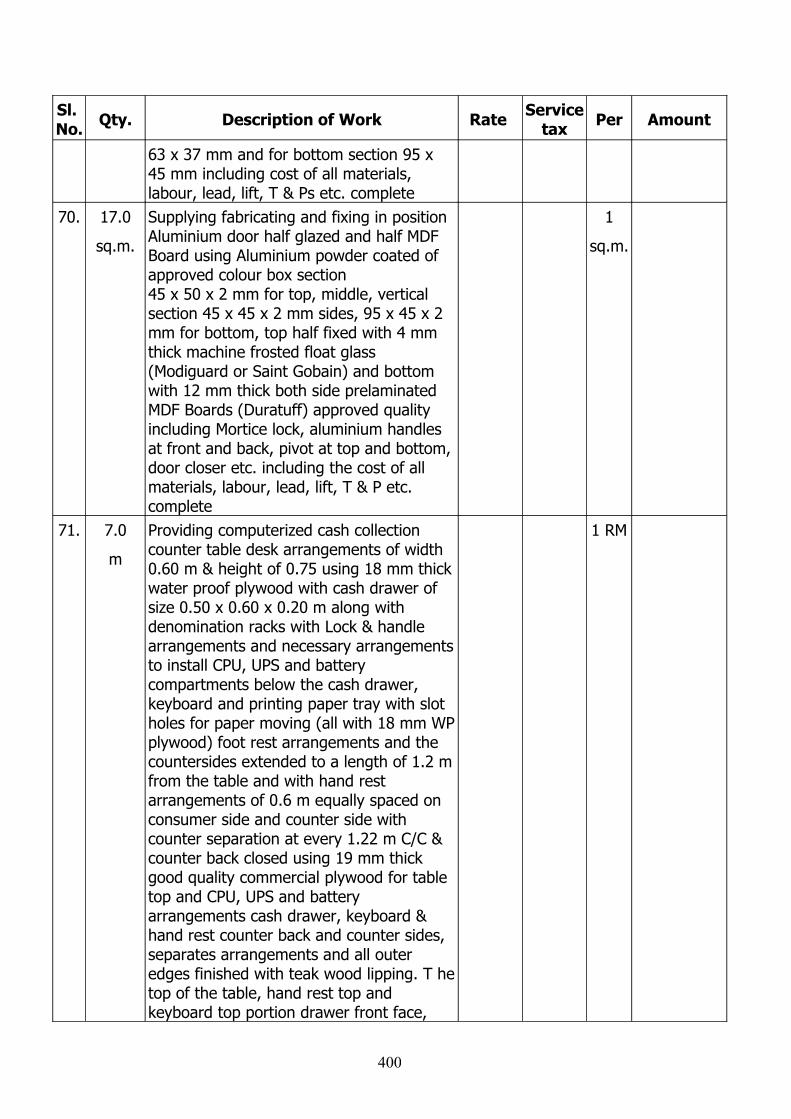
Sl. No. Qty. Description of Work Rate Service
tax Per Amount
63 x 37 mm and for bottom section 95 x 45 mm including cost of all materials, labour, lead, lift, T & Ps etc. complete
70. 17.0
sq.m.
Supplying fabricating and fixing in position Aluminium door half glazed and half MDF Board using Aluminium powder coated of approved colour box section 45 x 50 x 2 mm for top, middle, vertical section 45 x 45 x 2 mm sides, 95 x 45 x 2 mm for bottom, top half fixed with 4 mm thick machine frosted float glass (Modiguard or Saint Gobain) and bottom with 12 mm thick both side prelaminated MDF Boards (Duratuff) approved quality including Mortice lock, aluminium handles at front and back, pivot at top and bottom, door closer etc. including the cost of all materials, labour, lead, lift, T & P etc. complete
1
sq.m.
71. 7.0
m
Providing computerized cash collection counter table desk arrangements of width 0.60 m & height of 0.75 using 18 mm thick water proof plywood with cash drawer of size 0.50 x 0.60 x 0.20 m along with denomination racks with Lock & handle arrangements and necessary arrangements to install CPU, UPS and battery compartments below the cash drawer, keyboard and printing paper tray with slot holes for paper moving (all with 18 mm WP plywood) foot rest arrangements and the countersides extended to a length of 1.2 m from the table and with hand rest arrangements of 0.6 m equally spaced on consumer side and counter side with counter separation at every 1.22 m C/C & counter back closed using 19 mm thick good quality commercial plywood for table top and CPU, UPS and battery arrangements cash drawer, keyboard & hand rest counter back and counter sides, separates arrangements and all outer edges finished with teak wood lipping. T he top of the table, hand rest top and keyboard top portion drawer front face,
1 RM
400
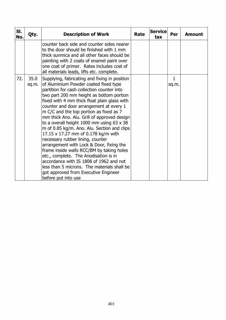
Sl. No. Qty. Description of Work Rate Service
tax Per Amount
counter back side and counter sides nearer to the door should be finished with 1 mm thick sunmica and all other faces should be painting with 2 coats of enamel paint over one coat of primer. Rates includes cost of all materials leads, lifts etc. complete.
72. 35.0sq.m.
Supplying, fabricating and fixing in position of Aluminium Powder coated fixed type partition for cash collection counter into two part 200 mm height as bottom portion fixed with 4 mm thick float plain glass with counter and door arrangement at every 1 m C/C and the top portion as fixed as 7 mm thick Ano. Alu. Grill of approved design to a overall height 1000 mm using 63 x 38 m of 0.85 kg/m. Ano. Alu. Section and clips 17.15 x 17.27 mm of 0.178 kg/m with necessary rubber lining, counter arrangement with Lock & Door, fixing the frame inside walls RCC/BM by taking holes etc., complete. The Anodisation is in accordance with IS 1808 of 1962 and not less than 5 microns. The materials shall be got approved from Executive Engineer before put into use
1 sq.m.
401

402