TNC 640 - · PDF fileHEIDENHAIN touch probe. The TNC 640 offers you powerful functions that...
59
TNC 640 Contouring Control for Machining Centers and Milling-Turning Machines 02/2018
Transcript of TNC 640 - · PDF fileHEIDENHAIN touch probe. The TNC 640 offers you powerful functions that...

TNC 640Contouring Control for Machining Centers and Milling-Turning Machines
02/2018
2
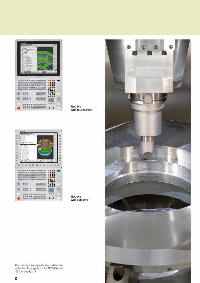
The functions and specifi cations described in this brochure apply for the TNC 640 with NC SW 34059x-08
TNC 640
With touchscreen
TNC 640
With soft keys

Contents
The TNC 640...
Where can it be used? Versatile– The TNC contouring control for milling and milling-turning machines
4
What does it look like? Well designed and user friendly– Modern multitouch operation– The functional user interface
6
What can it do? Multi-operation machining– Milling and turning on the same machine
10
Quick and reliable machining with high contour accuracy– Dynamic Precision– The TNC 640 permits optimum tool movement– Machining and measuring 3-D contours
12
Machining with fi ve axes– Guided tool tip– Swivel head and rotary table controlled by the TNC 640
17
Intelligent machining– Dynamic collision monitoring (DCM)– Dynamic Effi ciency– Active chatter control (ACC)– Adaptive feed control (AFC)– Machining any contour slots with trochoidal milling– Global program settings (option)
20
Automated machining– The TNC 640 measures, manages and communicates– Pallet management and multiple machining– Tool management and workspace monitoring
27
Minimize setup times– The TNC 640 makes setup easy
30
How is it programmed? Programming, editing, testing– The TNC 640 opens endless possibilities– Graphic support in any situation
32
Programming in the workshop– Straightforward function keys for complex contours– Programming contours unconventionally– Field-proven cycles for recurring operations– Field-proven turning cycles– Reusing programmed contour elements– Fast availability of all information
34
Open for communication– The TNC 640 understands CAD fi les– Uniformly digital order management with Connected Machining– The TNC 640 programming station
42
Are there any accessories? Workpiece measurement– Setup, presetting and measuring with touch trigger probes
47
Tool measurement– Measuring length, radius and wear directly in the machine
48
Inspecting and optimizing machine accuracy– Calibrating rotary axes simply with KinematicsOpt (option)
49
Positioning with the electronic handwheel– Delicate axis traverse
50
... At a glance Overview– User functions, accessories, options, specifi cations, comparison of controls
51

4
Versatile
– The TNC contouring control for milling and milling-turning machines
For more than 35 years, TNC controls from HEIDENHAIN have been proving themselves in daily use on milling, drilling and boring machines, as well as machining centers. During this period the controls have been continuously developed with the needs of the machine operator always placed foremost.
Multi-touch operation
The TNC 640 is available in the conventional version with screen and keyboard as well as with touch screen and keyboard. Whether zooming with two fi ngers, rotating or moving, you operate the TNC 640 quickly and easily by fi ngertip.
Shop-oriented programming
You program conventional milling and drilling operations, and with the TNC 640 also turning operations, yourself at the machine, in a Klartext plain-language dialog—the workshop-oriented programming language from HEIDENHAIN. The TNC 640 provides you with optimum support with practical prompts, questions and expressive graphical aids—for turning operations, too.
Standard operations and even complex applications are on call as a large variety of real-world machining cycles or coordinate transformations.
Easy to operate
For simple work, such as face milling or face turning, you need not write a program on the TNC 640. It is just as easy to operate the machine manually by pressing the axis keys or—for maximum sensitivity—using the electronic handwheel.
Offl ine program creation
The TNC 640 can be programmed remotely just as well. Its Ethernet interface guarantees very short transfer times, even of long programs.
5
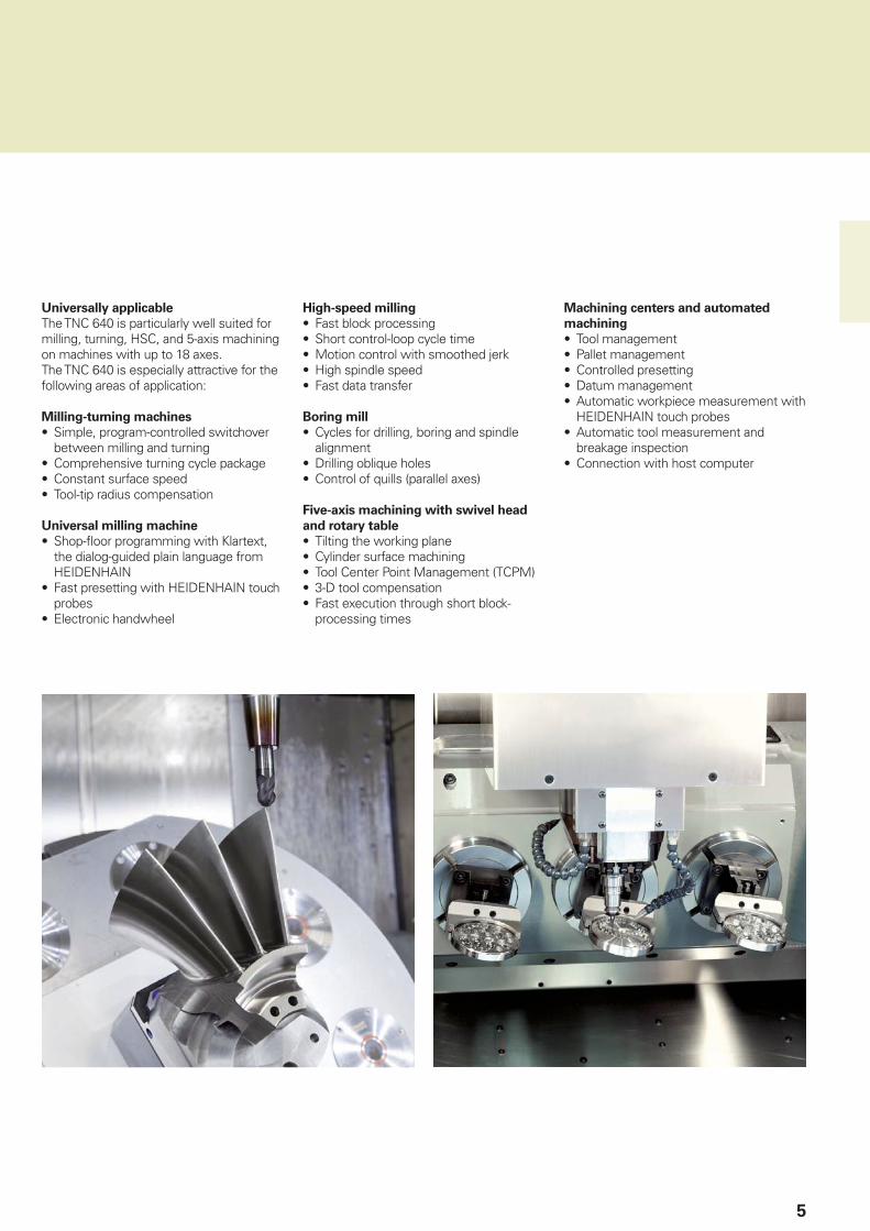
Universally applicable
The TNC 640 is particularly well suited for milling, turning, HSC, and 5-axis machining on machines with up to 18 axes.The TNC 640 is especially attractive for the following areas of application:
Milling-turning machines
• Simple, program-controlled switchover between milling and turning
• Comprehensive turning cycle package• Constant surface speed• Tool-tip radius compensation
Universal milling machine
• Shop-fl oor programming with Klartext, the dialog-guided plain language from HEIDENHAIN
• Fast presetting with HEIDENHAIN touch probes
• Electronic handwheel
High-speed milling
• Fast block processing• Short control-loop cycle time• Motion control with smoothed jerk• High spindle speed• Fast data transfer
Boring mill
• Cycles for drilling, boring and spindle alignment
• Drilling oblique holes• Control of quills (parallel axes)
Five-axis machining with swivel head
and rotary table
• Tilting the working plane• Cylinder surface machining• Tool Center Point Management (TCPM)• 3-D tool compensation• Fast execution through short block-
processing times
Machining centers and automated
machining
• Tool management• Pallet management• Controlled presetting• Datum management• Automatic workpiece measurement with
HEIDENHAIN touch probes• Automatic tool measurement and
breakage inspection• Connection with host computer
6
Well designed and user friendly
– Modern multitouch operation
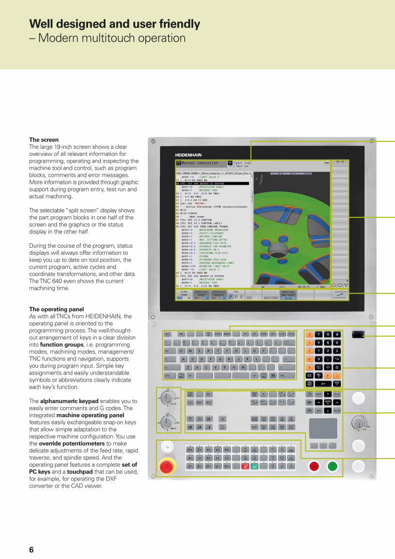
The screen
The large 19-inch screen shows a clear overview of all relevant information for programming, operating and inspecting the machine tool and control, such as program blocks, comments and error messages. More information is provided through graphic support during program entry, test run and actual machining.
The selectable “split screen” display shows the part program blocks in one half of the screen and the graphics or the status display in the other half.
During the course of the program, status displays will always offer information to keep you up to date on tool position, the current program, active cycles and coordinate transformations, and other data. The TNC 640 even shows the current machining time.
The operating panel
As with all TNCs from HEIDENHAIN, the operating panel is oriented to the programming process. The well-thought-out arrangement of keys in a clear division into function groups, i.e. programming modes, machining modes, management/TNC functions and navigation, supports you during program input. Simple key assignments and easily understandable symbols or abbreviations clearly indicate each key’s function.
The alphanumeric keypad enables you to easily enter comments and G codes. The integrated machine operating panel features easily exchangeable snap-on keys that allow simple adaptation to the respective machine confi guration. You use the override potentiometers to make delicate adjustments of the feed rate, rapid traverse, and spindle speed. And the operating panel features a complete set of
PC keys and a touchpad that can be used, for example, for operating the DXF converter or the CAD viewer.

7
The screen content includes two operating modes, the program, graphics, and the machine status
PLC soft keys for machine functions
Self-explanatory soft keys for NC programming
Alphanumeric keyboard for comments or G codes and a set of PC keys for controlling the operating system functions
USB port for additional data storage or pointing devices
Axis-selection keys and numeric keypad
Function keys for programming modes, machine modes, TNC functions, management and navigation
Override potentiometers for feed rate, rapid traverse and spindle speed
Machine operating panel with snap-on keys and LEDs
Symbol Gesture
Tap
Double tap
Long press
Swipe
Drag
Two-fi nger drag
Spread
Pinch
Gestures for multitouch operation
The screen of the TNC 640 can be operated with gestures as commonly used on your smartphone or tablet. For example, you can zoom in or out with two fi ngers. By swiping, you can very quickly navigate in soft key rows, programs, or menus.
Ergonomic and sturdy design
The optimized stainless steel design of the TNC 640 features a special protection coating and is therefore highly resistant to soiling and wear. The inscriptions of the ergonomically formed keys withstand extreme workshop conditions. With the handy control knobs you can delicately adjust the feed rate, rapid traverse, and spindle speed.
Clear-cut touchscreen operation
The operation of the TNC has proven itself over many years. Operators around the world use their TNC with dialog keys, navigation keys and soft-keys.In a touch-screen version, the TNC 640 now supports you with a particularly innovative and user-friendly operating interface. It combines the proven advantages of the HEIDENHAIN controls with a new type of operation by tapping, wiping and pulling.
Practical touchscreen
The touchscreen was conceived for harsh workshop conditions. It is splash-proof, scratch-resistant and certifi ed for IP54 protection. If you want to clean your screen, you can simply select “Touchscreen Cleaning” mode. This locks the screen to prevent unintended operation.

8
Well designed and user friendly
– The functional user interface
The combination of the straightforward and ergonomically designed keyboard and the well-designed screen layout are the essence of reliable and fatigue-free operation—principles that HEIDENHAIN has always represented. However, the TNC 640 also offers a number of features that make working with the control even easier and user-friendlier than ever.
Attractive view
The user interface of the TNC 640 has a modern appearance, with slightly rounded forms, color gradients and a homogeneously designed font. The individual screen areas are clearly distinguished and the operating modes are also indicated by their respective symbols.
To better distinguish between the priority of error messages, the TNC 640 displays them in color-coded categories. A color-coded warning triangle is also displayed.
Fast function overview
With smartSelect you enjoy dialog guidance for quick and easy selection of functions that up to now were accessible only through the soft-key structure. As soon as you open smartSelect, it displays a tree structure with all subordinate functions that can be defi ned in the control’s current condition. Moreover, in the right part of the smartSelect window, the TNC displays the integrated help. With the cursor or a mouse click, you immediately access detailed information on the respective function. Also, smartSelect enables you to defi ne fi xed cycles, touch probe cycles, and special functions (SPEC FCT), and quickly access the parameter programming.

9
Color-structured programs
The content of a program line can be quite comprehensive: line number, program function, input values, comment. To help you always fi nd your way even in complex programs, the individual program elements on the TNC 640 are shown in different colors. The color syntax highlighting improves your overview when editing NC programs. It enables you to see at a glance, for example, where the editable input values are.
Uniform table editor
Regardless of which table you are editing—whether the tool table, datum table or pallet table—the appearance, function, and operation of the table editor are always the same.
Info line
In the info line, the TNC 640 shows the respective submode condition and helps you to orient yourself.
MOD function
The additional mode MOD offers a myriad of possible settings in a standardized layout regardless of the operating mode.
Easy to operate
The TNC 640 can also be conveniently operated through a connected mouse. In the workshop, however, it's sometimes hard to fi nd an adequate running surface for a mouse. With a touchscreen, you do not need an additional workspace for input devices. In addition, operating the control is even easier: wiping, direct selection of controls, and navigation in menus make daily work on your TNC 640 easier. The CAD importing is especially convenient with the touch screen. In drawings, you can zoom, move or select quickly and easily by gesture.

10
Does your workpiece, after complex milling operations, also need to be set up on a lathe for several working steps? Do you have to plan for machine capacity, make tools, set up and fi x the workpiece, and measure the fi nished part? The TNC 640 helps you to save time: on a milling-turning machine with TNC 640, you machine the complete cast workpiece on one machine—milling, turning, milling, in whatever sequence. After performing all operations on this one machine, you measure the fi nished workpiece with a HEIDENHAIN touch probe.
The TNC 640 offers you powerful functions that enable you to switch the NC program as desired between turning and milling under program control. This enables you to decide with complete freedom how and when you want to combine the two machining methods. And of course, the operations switch back and forth regardless of the machine and its axis confi guration. During switchover, the TNC 640 assumes all necessary internal changes, such as switching to diameter display, setting the datum in the center of the rotary table, and even machine-dependent functions such as clamping the tool spindle.*
Cycles for milling and turning
HEIDENHAIN controls have always been known for their comprehensive and technologically sophisticated package of cycles. Frequently recurring operations that comprise several steps are also stored in the TNC 640 as cycles. You program them under conversational guidance and are supported by enlightening help graphics that clearly illustrate the required input parameters. Besides the well known TNC milling and drilling cycles, the TNC 640 also offers a wide variety of turning cycles, for example for roughing, fi nishing, recessing, thread turning and recess turning. The fi eld-
Multi-operation machining
– Milling and turning on the same machine (option)
Programming as accustomed
You can program the turning operations—as always—conveniently under dialog guidance in HEIDENHAIN plain language. Besides the standard path functions you can also use FK free contour programming to easily create contour elements not dimensioned for NC. Beyond this, you also have the contour elements recessing and undercutting for turning operations, which are supported by expressive help illustrations.
If the contour exists as a CAD fi le, you can easily import it with the aid of the CAD importer (option).
* The machine must be prepared by the machine tool builder for this function.
11
proven HEIDENHAIN lathe controls provide the software basis for the turning functions. They enable you to program even demanding turning operations very easily at the machine.
In the more sophisticated contour turning cycles, the TNC 640 uses the same techniques as are used for milling. Here, too, there is no need for the TNC programmer to learn new ways of programming—he can continue to rely on what he already knows and quickly fi nd his way into the world of turning on a milling machine.
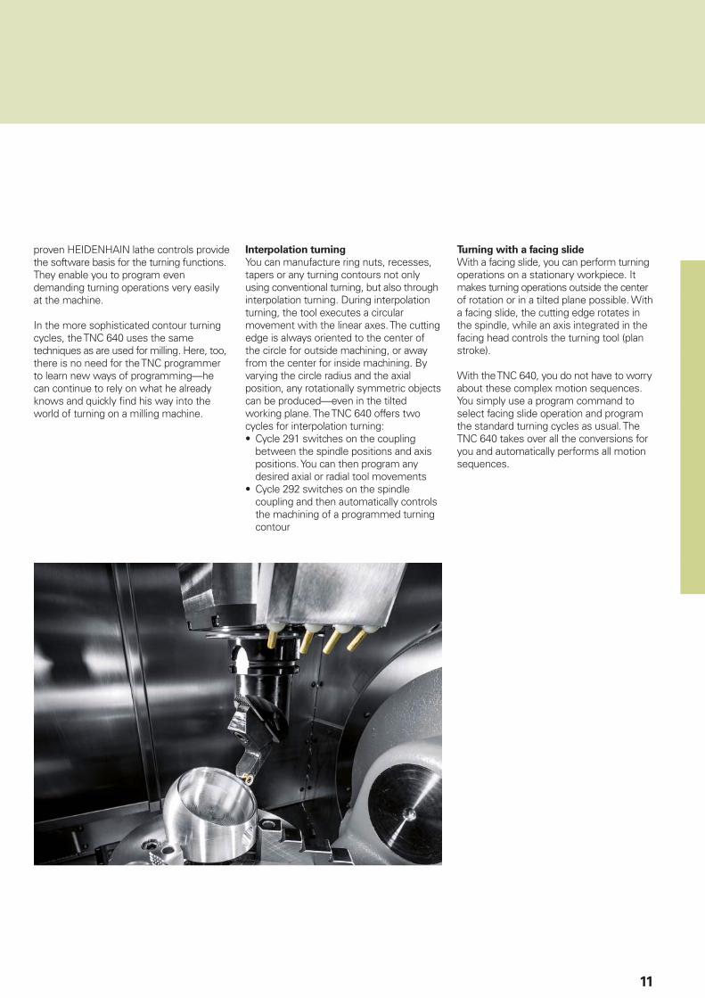
Interpolation turning
You can manufacture ring nuts, recesses, tapers or any turning contours not only using conventional turning, but also through interpolation turning. During interpolation turning, the tool executes a circular movement with the linear axes. The cutting edge is always oriented to the center of the circle for outside machining, or away from the center for inside machining. By varying the circle radius and the axial position, any rotationally symmetric objects can be produced—even in the tilted working plane. The TNC 640 offers two cycles for interpolation turning:• Cycle 291 switches on the coupling
between the spindle positions and axis positions. You can then program any desired axial or radial tool movements
• Cycle 292 switches on the spindle coupling and then automatically controls the machining of a programmed turning contour
Turning with a facing slide
With a facing slide, you can perform turning operations on a stationary workpiece. It makes turning operations outside the center of rotation or in a tilted plane possible. With a facing slide, the cutting edge rotates in the spindle, while an axis integrated in the facing head controls the turning tool (plan stroke).
With the TNC 640, you do not have to worry about these complex motion sequences. You simply use a program command to select facing slide operation and program the standard turning cycles as usual. The TNC 640 takes over all the conversions for you and automatically performs all motion sequences.

12
Quick and reliable machining with high contour fi delity
– Dynamic Precision
All these infl uences are together responsible for dimensional inaccuracies and faults in the workpiece surface. They therefore have a decisive infl uence on quality and, when poor-quality parts are scrapped, also on productivity. Dynamic Precision counteracts these problems with intelligent control technology to enable designers to further improve the quality and dynamic performance of machine tools. That saves time and money in production.
The control design of the TNC 640 guaran-tees not just very high accuracy and surface quality, but high machining speeds as well—regardless of whether you are milling or turning. These are made possible by differing technologies, cycles and functions. Individually or in combination, they ensure optimized motion control, effective jerk limiting, and dynamic contour look-ahead, and therefore perfect surfaces with very short machining times.
The hypernym Dynamic Precision stands for a number of HEIDENHAIN solutions for metal cutting that can dramatically improve the dynamic accuracy of a machine tool. It is the result of a new perspective on the competing demand for accuracy, high surface quality and short machining times. The dynamic accuracy of machine tools manifests itself in deviations at the tool center point (TCP). These deviations depend on kinetic quantities such as velocity and acceleration (also jerk), and are caused, in part, by vibrations of machine components.

13
With AVD, visibly superior surface quality is achievedVibrations can signifi cantly impair surface quality
Dynamic Precision includes the following functions:• CTC – Compensation of acceleration-
dependent position errors at the TCP• AVD – active damping of drive train and
machine setup vibrations• PAC – Position-dependent adaptation of
controller parameters• – Load-dependent adaptation of
control parameters and maximum
axis acceleration
• MAC – Motion-dependent adaptation of control parameters
The machine tool builder can use the options comprised by Dynamic Precision either individually or in combination. The advantages of functions at a glance:• CTC: Higher accuracy in acceleration
phases• AVD: Better surfaces• CTC+AVD: Faster and more precise
machining• PAC: Greater contour accuracy• LAC: Higher accuracy regardless of the
load• MAC: Less vibration, higher maximum
acceleration during rapid traverse

14
Quick and reliable machining with high contour accuracy
– The TNC 640 permits optimum tool movement
High contour fi delity and surface
defi nition
TNC controls from HEIDENHAIN are known for their jerk-smoothed as well as
velocity- and acceleration-optimized
motion control. In this way they ensure optimized surface quality and workpiece accuracy. With the TNC 640 you can exploit state-of-the-art developments. The TNC 640 looks ahead, thinks along with you, and can calculate the contour dynamically before machining. Special fi lters specifi cally and additionally suppress machine-specifi c natural vibration.
With look-ahead, the TNC 640 recognizes directional changes beforehand and adapts the traversing speed to the course of the contour and the surface to be machined. You simply program the maximum machining velocity as feed rate and, in Cycle 32
TOLERANCE, enter in the control the maximum permissible deviations from the ideal contour. The TNC 640 automatically adapts the machining to the tolerance that you defi ne. No contour damage occurs with this method.
Advanced Dynamic Prediction (ADP) expands the previous advance calculation of the permissible maximum feed rate profi le. ADP compensates differences in feed rate profi les resulting from point distribution on neighboring paths, especially in NC programs from CAM systems. This provides, among other things, a particularly symmetric feed rate behavior on the back-and-forth path during bidirectional fi nish milling, as well as very smooth feed rate curves on parallel milling paths.

15
Fast machining and computing
processes
The fast block-processing time of at most 0.5 ms enables the TNC 640 to run fast advance calculations in order to optimally use the dynamic parameters of the machine. In this way, functions like ADP and look-ahead not only provide very high contour accuracy and surface defi nition—they also optimize the machining time.
One of the reasons for the TNC 640’s high speed is its uniformly digital control
design. It consists on the one hand of the integrated digital drive technology from HEIDENHAIN, and on the other hand all control components are interconnected with digital interfaces—the control components via HSCI (HEIDENHAIN Serial Controller Interface), and the encoders via EnDat 2.2. This makes it possible to realize very high feed rates. And the TNC 640 interpolates simultaneously in up to fi ve axes. To attain the required cutting speeds, the TNC 640 digitally controls spindle speeds up to 100 000 rpm.
The TNC 640’s powerful 5-axis machining enables you to manufacture even complex 3-D contours economically. The required programs are usually created on external CAM systems and comprise a large number of very short line segments that are transferred to the control. With its short block-processing time, the TNC 640 quickly executes even complex NC programs. Thanks to its computing power, however, it can also transfer complex advance calculations to simpler NC programs. This makes it unimportant what data volume the NC programs from their CAD systems have: with the TNC 640, the fi nished workpiece will be a virtually perfect refl ection of the generated program.

16
�
�
���������
��������
– Machining and measuring 3-D contours
Compensating tool form error
Option 92, 3D-ToolComp, is a powerful option for three-dimensional tool radius compensation. A compensation-value table is used to defi ne angle-dependent delta values that describe the tool deviation from the ideal circular form (see graphic).
The TNC 640 then corrects the radius value defi ned for the tool’s current point of contact with the workpiece. In order to determine the point of contact exactly, the NC program must be created with surface-normal blocks (LN blocks) by a CAM system. The surface-normal blocks specify the theoretical center point of the tool, and in some cases also the tool orientation relative to the workpiece surface.
Ideally, the compensation-value table is generated fully automatically by way of a special cycle that uses a laser system to measure the form of the tool so that the TNC 640 can use this table directly. If the form errors of the tool used are available as a calibration chart from the tool manufacturer, then you can create the compensation-value table manually.
Measuring 3-D geometries
With Cycle 444, 3-D probing, you can measure points on 3-D geometries. You enter the respective measured point with its coordinates and the associated normal vectors into the cycle. After probing, the TNC automatically calculates whether the measured points are within a preset tolerance. You can interrogate the result through the system parameters in order, for example, to initiate program-controlled reworking. Moreover, you can trigger a program stop and a message. After measurement the cycle automatically generates an easy-to-read measuring log in HTML format.
To obtain even more accurate results, you can perform a 3-D calibration of the touch probe before running Cycle 444. Then the cycle compensates the touch probe’s individual triggering behavior in any direction. Option 92 is required for 3-D calibration.
17
With TCPM you can defi ne the behavior of the tilting and compensating movements automatically calculated by the TNC 640.
TCPM defi nes the interpolation between
the start and end positions:
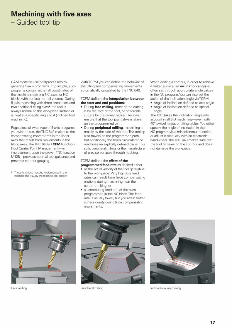
• During face milling, most of the cutting is by the face of the tool, or on toroidal cutters by the corner radius. The axes ensure that the tool point always stays on the programmed path.
• During peripheral milling, machining is mainly by the side of the tool. The tool tip also travels on the programmed path, but additionally the tool’s circumference machines an explicitly defi ned plane. This suits peripheral milling for the manufacture of precise surfaces through hobbing.
TCPM defi nes the effect of the
programmed feed rate as desired either• as the actual velocity of the tool tip relative
to the workpiece. Very high axis feed rates can result from large compensating motions during machining near the center of tilting, or
• as contouring feed rate of the axes programmed in the NC block. The feed rate is usually lower, but you attain better surface quality during large compensating movements.
When editing a contour, in order to achieve a better surface, an inclination angle is often set through appropriate angle values in the NC program. You can also set the action of the inclination angle via TCPM:• Angle of inclination defi ned as axis angle• Angle of inclination defi ned as spatial
angleThe TNC takes the inclination angle into account in all 3-D machining—even with 45° swivel heads or tilting tables. You either specify the angle of inclination in the NC program via a miscellaneous function, or adjust it manually with an electronic handwheel. The TNC 640 makes sure that the tool remains on the contour and does not damage the workpiece.
CAM systems use postprocessors to generate 5-axis programs. In principle, such programs contain either all coordinates of the machine’s existing NC axes, or NC blocks with surface normal vectors. During 5-axis machining with three linear axes and two additional tilting axes* the tool is always normal to the workpiece surface or is kept at a specifi c angle to it (inclined tool machining).
Regardless of what type of 5-axis programs you wish to run, the TNC 640 makes all the compensating movements in the linear axes that result from movements in the tilting axes. The TNC 640’s TCPM function (Tool Center Point Management)—an improvement upon the proven TNC function M128—provides optimal tool guidance and prevents contour gouging.
* These functions must be implemented in the machine and TNC by the machine tool builder.
Machining with fi ve axes
– Guided tool tip
Face milling Peripheral milling Inclined-tool machining

18
Machining with fi ve axes
– Swivel head and rotary table controlled by the TNC
Many 5-axis operations that at fi rst glance may seem very complex can be reduced to conventional 2-D movements that are simply tilted about one or more rotary axes or wrapped onto a cylindrical surface. The TNC supports you with application-oriented functions to help you write and edit such programs quickly and simply without a CAM system.
Tilting the working plane*
Programs for contours and holes on inclined surfaces are often very complex and require time-consuming computing and programming work. Here the TNC 640 helps you to save a great deal of programming time.
You program the machining operation as usual in a plane, for example in X/Y. However, the machine will then execute machining in the tilted working plane.
The PLANE feature makes it easy to defi ne a tilted working plane: you can specify tilted working planes in seven different ways, depending on the information on the workpiece drawing. Clearly arranged support graphics assist you during input.
You can also use the PLANE function to defi ne the positioning behavior for tilting so that there are no unpleasant surprises when the program is run. The settings for defi ning the positioning behavior are identical for all PLANE functions, making everything that much easier.
* These functions must be implemented in the machine and TNC by the machine tool builder.

19
Manual axis motion in the tool direction
on 5-axis machines
The safe retraction of a tool is very important with fi ve-axis machining. The “Virtual Tool Axis” function is of assistance here. You can use it to traverse the tool in the current direction of the tool axis through an external direction key or the handwheel. This function is especially useful if you want to• retract the tool in the direction of the tool
axis during interruption of a 5-axis machining program,
• use the handwheel or external direction keys to perform an operation in Manual mode with an inclined tool,
• move the tool with the handwheel in the active tool axis direction during machining.
Cylinder surface machining*
With the TNC 640 it is quite easy to program contours (consisting of straight lines and arcs) on cylindrical surfaces using rotary and tilting tables: You simply program the contour in a plane as if the cylinder surface were unrolled. You enter a contour in two dimensions—as if in a plane—and the TNC 640 then calculates and machines the corresponding cylindrical contour.
The TNC 640 features four cycles for cylindrical surface machining:• Slot milling (the slot width is the same as
the tool diameter)• Guide-groove milling (the slot width is
greater than the tool diameter)• Ridge milling• Mill outside of contour
* These functions must be implemented in the machine and TNC by the machine tool builder.
Feed rate for rotary axes and tables
in mm/min*
By default, the feed rate of rotary axes is programmed in degrees/minutes. However, the TNC 640 can interpret this feed rate in mm/min as well. The feed rate at the contour is then independent of the distance of the tool center from the center of the rotary axis.

20
Intelligent machining
– Dynamic Collision Monitoring option (DCM)
The complex motions and the normally high traversing speeds of 5-axis machining make axis movements diffi cult to foresee. This makes collision monitoring a valuable function that relieves the machine operator and protects the machine from damage.
NC programs from CAM systems may avoid collisions of the tool or tool holder with the workpiece, but unless you invest in expensive offl ine machine simulation software, they ignore the machine components located within the work envelope. And even then it cannot be guaranteed that machine conditions, such as the fi xture position, will be identical to those of the simulation. In the worst case, a collision will remain undetected until the damage is done.
In cases such as these, the machine operator is supported by the dynamic
collision monitoring (DCM)* feature of the TNC 640. The control interrupts machining whenever a collision is imminent, thereby increasing the safety for the machine and its operator. This helps to prevent machine damage, which can result in costly downtimes. Unattended shifts become safer and more reliable.
However, DCM works not only in automatic
mode. It is also active in manual operation. If, for example, during setup the machine operator takes a collision course, the TNC 640 detects it, stops axis movement, and issues an error message.
* These functions must be implemented in the machine and TNC by the machine tool builder.
21
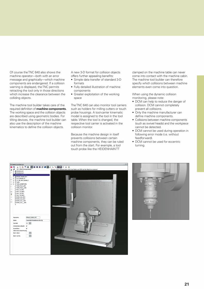
Of course the TNC 640 also shows the machine operator—both with an error message and graphically—which machine components are endangered. If a collision warning is displayed, the TNC permits retracting the tool only in those directions which increase the clearance between the colliding objects.
The machine tool builder takes care of the required defi nition of machine components. The working space and the collision objects are described using geometric bodies. For tilting devices, the machine tool builder can also use the description of the machine kinematics to defi ne the collision objects.
A new 3-D format for collision objects offers further appealing benefi ts:• Simple data transfer of standard 3-D
formats• Fully detailed illustration of machine
components• Greater exploitation of the working
space
The TNC 640 can also monitor tool carriers such as holders for milling cutters or touch probe housings. A tool-carrier kinematic model is assigned to the tool in the tool table. When the tool is changed, the respective tool carrier is activated in the collision monitor.
Because the machine design in itself prevents collisions between certain machine components, they can be ruled out from the start. For example, a tool touch probe like the HEIDENHAIN TT
clamped on the machine table can never come into contact with the machine cabin. The machine tool builder can therefore specify which collisions between machine elements even come into question.
When using the dynamic collision monitoring, please note:• DCM can help to reduce the danger of
collision. DCM cannot completely prevent all collisions.
• Only the machine manufacturer can defi ne machine components.
• Collisions between machine components (such as swivel heads) and the workpiece cannot be detected.
• DCM cannot be used during operation in following error mode (i.e. without feedforward).
• DCM cannot be used for eccentric turning.

22
Intelligent machining
– Dynamic Effi ciency
With the concept of Dynamic Effi ciency, HEIDENHAIN offers innovative TNC functions that help the user to make heavy machining and roughing more effi cient while also enhancing its process reliability. The software functions support the machine operator but also make the manufacturing process itself faster, more stable and more predictable—in short, more effi cient. Dynamic Effi ciency permits higher removal rates and therefore increases productivity without making the user resort to special tools. At the same time, it prevents any tool overloading and the concomitant premature cutter wear. All of this means that with Dynamic Effi ciency you can manufacture more economically while increasing process reliability.
Dynamic Effi ciency comprises three software TNC functions:• Active Chatter Control (ACC) – The
ACC option reduces chatter tendencies and permits greater infeeds
• Adaptive Feed Control (AFC) – The AFC option controls the feed rate depending on the machining situation
• Trochoidal milling – A function for the roughing of slots and pockets that eases the load on the tool and the machine
Each solution in itself offers decisive advantages in the machining process. But the combination of these TNC features, in particular, exploits the potential of the machine and tool and at the same time reduces the mechanical load. Changing machining conditions, such as interrupted cuts, various material plunging procedures, or simple clear-out also show that these features pay for themselves. In practice, removal rate increases of 20 to 25 percent are possible.
23
– Active Chatter Control option (ACC)
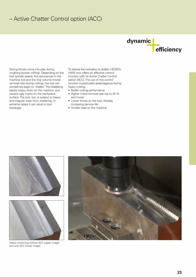
Strong forces come into play during roughing (power milling). Depending on the tool spindle speed, the resonances in the machine tool and the chip volume (metal-removal rate during milling), the tool can sometimes begin to “chatter.” This chattering places heavy strain on the machine, and causes ugly marks on the workpiece surface. The tool, too, is subject to heavy and irregular wear from chattering. In extreme cases it can result in tool breakage.
To reduce the inclination to chatter, HEIDEN-HAIN now offers an effective control function with its Active Chatter Control option (ACC). The use of this control function is particularly advantageous during heavy cutting:• Better cutting performance• Higher metal removal rate (up to 25 %
and more)• Lower forces on the tool, thereby
increasing service life• Smaller load on the machine
Heavy machining without ACC (upper image) and with ACC (lower image)

24
Intelligent machining
– Adaptive Feed Control option (AFC)
Besides the feed rate for each block or cycle, HEIDENHAIN controls have always allowed the programmer to enter a manual compensation through the override potentiometer to adjust for the actual machining situation. But this always depends on the experience and, of course, the presence of the operator.
Adaptive Feed Control (AFC) automatically regulates the feed rate of the TNC, taking into consideration the respective spindle power and other process data. In a teach-in cut, the TNC records the maximum spindle power. Then, before actual machining, you defi ne in a table the respective limit values between which the TNC can infl uence the feed rate in the “control” mode. Of course, various overload reactions can be provided for, which can also be defi ned by your machine tool builder.
Adaptive feed rate control offers various advantages:
Process reliability
Roughing with high metal removal rates requires strong cutting forces. In practice this often causes tool defects. If the user doesn’t react quickly enough, for example because he is responsible for several machine simultaneously, or if the shift is unattended, this can result in serious subsequent damage and high costs:• Costly rework on the workpiece• Irreparable workpiece damage• Damage to the tool holder• Machine downtime due to spindle
damage
An increase in spindle power consumption due to tool wear or defective inserts is detected by continuous monitoring, and a sister tool can be automatically inserted.*
In this way, AFC effectively avoids possible damage from tool wear and therefore increases process safety and reliability.
Reduction of machining time
AFC regulates the feed rate of the TNC, taking into consideration the respective spindle power. In zones with less material removal, the feed rate is increased accordingly. This can signifi cantly reduce the machining time.
Protection of the machine mechanics
Reducing the feed rate down to the reference value whenever the learned maximum permissible spindle power is exceeded also reduces the strain and wear on the machine. It effectively protects the spindle from overload.
* The machine must be prepared by the machine tool builder for this function.
Workpiece with damage resulting from a broken indexable insert Fully machined workpiece protected by AFC

25
– Machining any contour slots with trochoidal milling
The benefi t of trochoidal milling is its ultra-effi cient machining of slots of all kinds. The roughing process is a circular motion superimposed on a forward linear motion. This procedure is referred to as trochoidal milling. It is used particularly for milling high-strength or hardened materials, where the high loads placed on the tool and machine usually only permit small infeeds.
With trochoidal milling, on the other hand, large cutting depths are possible since the prevailing cutting conditions do not increase the wear and tear on the tool. On the contrary, the entire length of a hob’s cutting edges can be used. This enables you to achieve a greater chip volume per tooth. Circular plunging into the material places less radial force on the tool. This reduces the mechanical load on the machine and prevents vibration. Enormous time savings can be realized by combining this milling method with the integrated Adaptive Feed Control (AFC) option.
The slot to be machined is described in a contour subprogram as a contour train. You defi ne the dimensions of the slot and the cutting data in a separate cycle. Any residual material remaining can then easily be removed with a subsequent fi nishing cut.
The benefi ts include:• Engagement of the entire cutter length• Higher metal removal rates• Relieves mechanical load on the machine• Less vibration• Integrated fi nishing of the side wall• Better chip removal
26
Intelligent machining
– Global program settings (option)
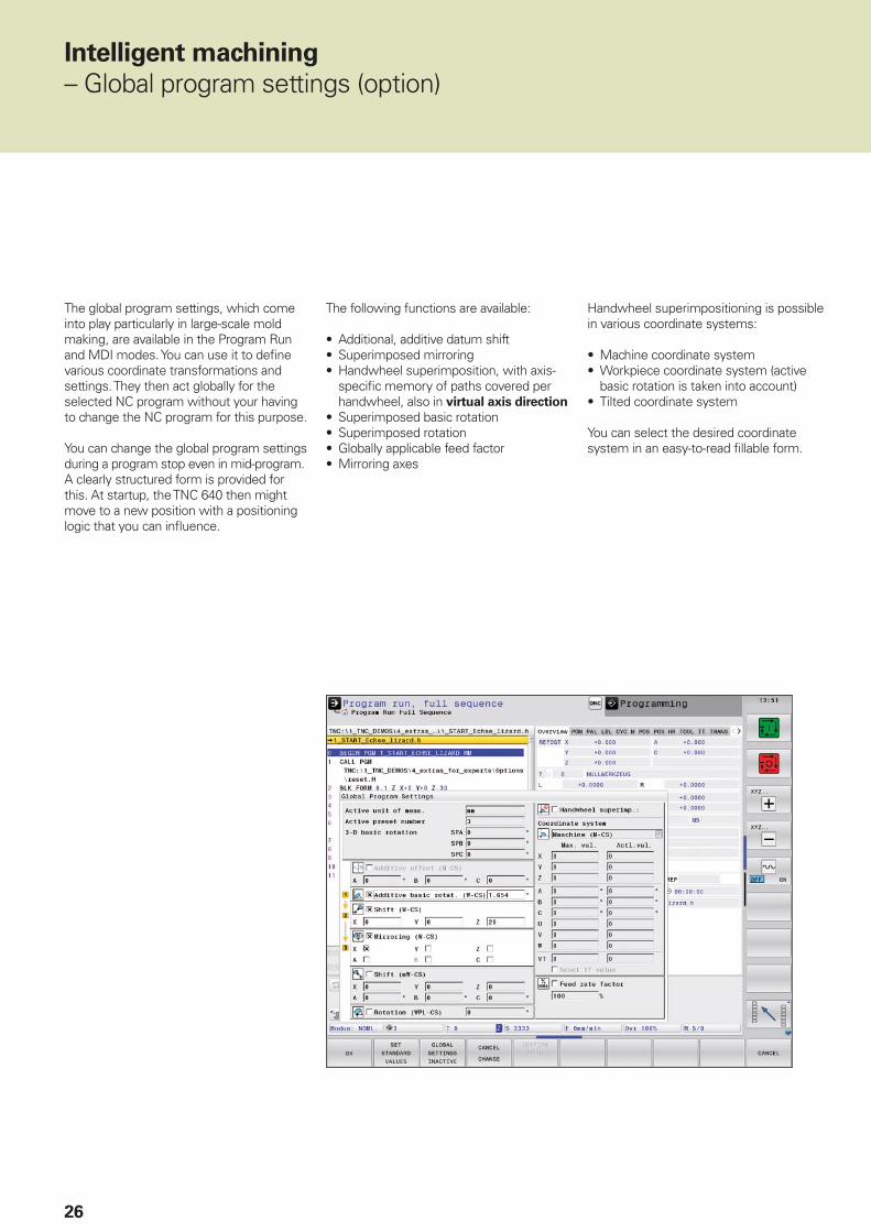
The global program settings, which come into play particularly in large-scale mold making, are available in the Program Run and MDI modes. You can use it to defi ne various coordinate transformations and settings. They then act globally for the selected NC program without your having to change the NC program for this purpose.
You can change the global program settings during a program stop even in mid-program. A clearly structured form is provided for this. At startup, the TNC 640 then might move to a new position with a positioning logic that you can infl uence.
The following functions are available:
• Additional, additive datum shift• Superimposed mirroring• Handwheel superimposition, with axis-
specifi c memory of paths covered per handwheel, also in virtual axis direction
• Superimposed basic rotation• Superimposed rotation• Globally applicable feed factor• Mirroring axes
Handwheel superimpositioning is possible in various coordinate systems:
• Machine coordinate system• Workpiece coordinate system (active
basic rotation is taken into account)• Tilted coordinate system
You can select the desired coordinate system in an easy-to-read fi llable form.

27
Inspecting workpieces for proper
machining and dimensional accuracy
The TNC 640 features a number of measuring cycles for checking the geometry of the machined workpieces. This requires the insertion of a touch probe from HEIDENHAIN (see page 47) instead of the tool in the spindle. This enables you to• recognize a workpiece and call the
appropriate part program,• check whether all machining operations
were conducted correctly,• determine infeeds for fi nishing,• detect and compensate tool wear,• check the workpiece geometry and sort
the parts,• log measured data,• ascertain the machining error trend.
Automated machining
– The TNC 640 measures, manages and communicates
The difference in requirements placed on the classical machine for tool and mold-making and machining centers is becoming ever less distinct. Of course, the TNC 640 is capable of controlling automated manufacturing processes. It masters the range of functions needed to start the proper machining operations on individual workpieces in any setup, and even in interlinked machining.
Milling cutter measurement and
automatic compensation of tool data
Together with the TT and TL tool touch probe (see page 48), the TNC 640 offers the possibility of automatically measuring milling tools in the machine. The TNC 640 saves the ascertained values of tool length and radius in the central tool file. By inspecting the tool during machining you can quickly and directly measure wear or breakage to prevent scrap or rework. If the measured deviations lie outside the tolerances, or if the monitored life of the tool is exceeded, the TNC 640 locks the tool and automatically inserts a replacement tool.

28
– Pallet management and multiple machining
Pallet management
With pallet management, you can machine workpieces in any order automatically. When replacing the pallet, the associated machining program and the workpiece preset are automatically selected. Of course, you can also use coordinate conversions and measuring cycles in the machining programs.
Batch process manager (option)
The batch process manager is a powerful function for pallet machining and series production. With the clear-cut user interface, you plan your production process and receive important information about the upcoming operations.
Tool-oriented machining
In tool-oriented machining, one machining step is performed on all workpieces on a pallet before the next machining step. This reduces the number of tool changes to a necessary minimum and the machining time is signifi cantly shorter.
The TNC 640 supports you with convenient fi llable forms that allow you to assign a tool-oriented operation to a pallet with multiple workpieces. You can write the program, however, in the familiar workpiece-oriented sequence.
You can also use this function even if your machine does not support pallet management. In the pallet fi le you then simply defi ne the positions of the workpieces on your machining table.
Batch process manager automatically checks for missing tools, downtime, or manual insertion of tools. The result of the check is displayed in the status overview.
In the batch process manager, the following information is already displayed in advance:• Sequence of operations• Time of next manual intervention
(option 93 required)• Program duration and run time
(option 93 required) • Status information (option 93 required):
preset, tool and program

29
Tool management
For machining centers with automatic tool changers, the TNC 640 offers a central tool memory for any number of milling and turning tools. The tool memory is a freely confi gurable fi le and can therefore be optimally fi tted to your needs. You can even have the TNC 640 manage your tool names. The control prepares the next tool change while the current tool is still cutting. This signifi cantly reduces the non-cutting time required for changing tools.
With the optionally available expanded tool management you can also graphically prepare and display any data.*
* The machine must be prepared by the machine tool builder for this function.
Monitoring of the working space
With the Visual Setup Control option (VSC), the TNC can automatically monitor the current setup or machining situation during program run. With this option, reference photos are taken by a camera system for the fi rst parts of a series, which are then compared with the photos of the subsequent parts.
User-friendly cycles enable you to specify several places in the NC program at which the control conducts an optical comparison of the actual with the desired condition. If an error is detected, the TNC reacts as previously chosen by the user.
VSC not only helps you to avoid expensive damage to the tool, workpiece and machine, you can also use it to document setup situations by saving photos. You can also identify missing machining operations or document recurring fi xturing situations.
– Tool management and workspace monitoring
30
Minimize setup times
– The TNC 640 makes setup easy
Before you can begin machining, you must fi rst clamp the workpiece and set up the machine, fi nd the position and orientation of the workpiece on the machine, and set the workpiece reference point. This is a time-consuming but indispensable procedure. After all, any error directly reduces the machining accuracy. Particularly in small and medium-sized production runs, as well as for very large workpieces, setup times become quite a signifi cant factor.
The TNC 640 features application-oriented, real-world setup functions. They support the user, help to reduce non-productive time, and make overnight, unattended production possible. Together with the touch probes, the TNC 640 offers numerous probing cycles for automatic alignment of the workpieces, presetting, and measurement of the workpiece and the tool.
Delicate manual traverse
For setup, you can use the direction keys to move the machine axes manually or in incremental jog. A simpler and more reliable way, however, is to use the elec-tronic handwheels from HEIDENHAIN (see page 50). With the handwheels you are always close to the action, enjoy a close-up view of the setup process, and can control the infeed responsively and precisely.
Adapting the probing velocity
Frequently, the workpiece has to be probed at hidden locations or in cramped spaces. In this case, the standard probing feed rate is usually too fast. In such situations you can use the override knob to change the feed rate during probing. What is special about this option is that it does not infl uence accuracy.
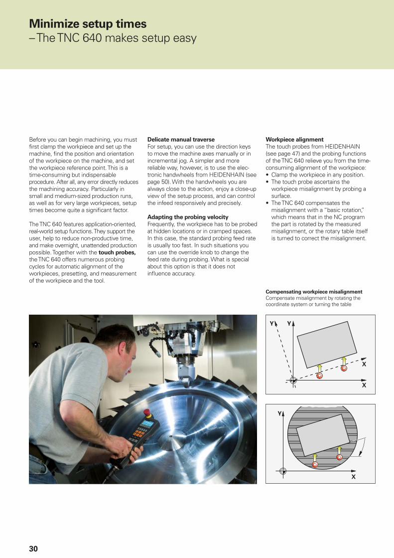
Workpiece alignment
The touch probes from HEIDENHAIN (see page 47) and the probing functions of the TNC 640 relieve you from the time-consuming alignment of the workpiece:• Clamp the workpiece in any position.• The touch probe ascertains the
workpiece misalignment by probing a surface.
• The TNC 640 compensates the misalignment with a “basic rotation,” which means that in the NC program the part is rotated by the measured misalignment, or the rotary table itself is turned to correct the misalignment.
Compensating workpiece misalignment
Compensate misalignment by rotating the coordinate system or turning the table

31
Setting a reference point
At a corner, for example, or in the center of a circular stud
Preset management with the preset
table
The preset manager makes fl exible machining, shorter setup times and increased productivity possible. In other words, it makes it much easier to set up the machine.
In the preset manager you can save any
number of presets and assign an individual basic rotation to each one. To permanently save fi xed presets in the machine working space, you can also write-protect individual lines.
There are three ways to save presets rapidly in the preset manager:• In the Manual mode by soft key• By using the probing functions• With the automatic probing cycles
Setting presets
You can use a preset to assign a defi ned value in the TNC display to any workpiece position. Finding this point quickly and reliably reduces nonproductive time and increases machining accuracy.
The TNC 640 features probing cycles for automatic setting of presets. Once found, you can save these points• in the preset manager,• in a datum table, or• by directly setting the displayed value.
Saving datums
In datum tables, you can save positions or values given or measured with respect to the workpiece. Datums are always relative to the active reference point.

32
Programming, editing, testing
– The TNC 640 opens endless possibilities
The TNC 640 is just as universal in applica-tion as it is fl exible in machining and programming.
Positioning with Manual Data Input
You can start working with the TNC 640 even before writing a complete part program. Simply machine a part step by step—switching as you want between manual operation and automatic positioning.
Programming at the machine
HEIDENHAIN controls are workshop oriented, which means that they were conceived for programming right at the machine. With Klartext conversational programming you can forget about memorizing G codes. Instead you use dedicated keys and soft keys to program line segments, circular arcs and cycles. You initiate a HEIDENHAIN Klartext dialog with a keystroke and the TNC immediately begins to support you actively in your work. Unambiguous questions and prompts help you enter all the required information.
Whether Klartext prompts, dialog guidance, programming steps, or soft keys, all texts are available in numerous languages.
Even if you are used to G-code
programming, however, the TNC is still the right control—you can enter G-code commands over soft keys or directly through the alphanumeric keyboard.
Creating programs offl ine
The TNC 640 is also well equipped for offl ine programming. Through its interfaces it can be integrated into networks and connected with programming stations or other data storage devices.

33
Programming graphics
The two-dimensional programming graphics give you additional security: while you are programming, the TNC 640 draws every entered traverse command on the screen. You can select among plan view, side view, and front view. Also, tool paths and rapid-traverse movements can be hidden and the view can be scaled.
Test graphics
To play it safe before running a program, the TNC 640 can simulate the machining of the workpiece, and can show this with high-resolution graphics. The TNC 640 can present different views of the simulation:• As a plan view with different shades of
depth• In three projections• As a solid model, 3-D view
– Graphic support in any situation
You can adjust the type and quality of the image. Details can be displayed in magnifi cation. In addition, the TNC 640 indicates the calculated machining time in hours, minutes and seconds.
In the 3-D view, you can display the programmed tool-center path in three dimensions. With the powerful zoom function you can also see the fi nest details. You should especially use the 3-D line graphics to inspect programs created offl ine for irregularities before machining, in order to avoid undesirable traces of the machining process on the workpiece, e.g. when points are output incorrectly by the postprocessor. The TNC also features a measuring function in the 3-D view. You can position the mouse pointer anywhere in the graphic to see the coordinates.
Program-run graphics
The program-run graphics display the workpiece in real time to show you the current stage of machining. Direct workpiece observation is usually impossible due to the coolant and the safety enclosure. During workpiece machining, you can switch at any time between various operating modes, for example to create programs. You then use free moments for a keystroke to take a glance at the progress of workpiece machining.

34
��
���
��
���
���
Programming in the workshop
– Straightforward function keys for complex contours
Programming 2-D contours
Two-dimensional contours are the bread and butter of the modern machine shop. The TNC 640 offers a variety of possibilities here. And—regardless of whether you are programming a milling or turning contour—you always use the same tools. For you this means that you do not have to relearn, just continue to program as usual.
Programming with path function keys
If contours are dimensioned for NC, which means that the end points are specifi ed in Cartesian or polar coordinates, then you can program them directly with the path function keys.
Straight and circular contour elements
To program a line segment, for example, simply press the key for linear traverse. The TNC 640 asks in Klartext format for all infor-mation required for a complete programming block, such as target coordinates, feed rate, tool compensation, and machine functions. Appropriate path function keys for circular movement, chamfers, and corner rounding simplify your programming. To avoid surface blemishes during approach or departure from the contour, movement has to be smooth—that is, tangential.
You simply specify the starting or end point of the contour and the approaching or departing radius of the cutter edge—the control does the rest for you.
The TNC 640 can look ahead over a radius-compensated contour for up to 99 blocks to watch for back cutting and avoid contour damage such as can occur when roughing a contour with a large tool.
Circular path with smooth
(tangential) connection with the preceding contour element, defi ned by end point
Circular path defi ned by its
radius, end point and rotational direction
Circular path
defi ned by its center, end point, and rotational direction
Corner rounding: circular path
with smooth (tangential) connection on both sides, defi ned by radius and corner point
Straight line defi ned by its
end point
Chamfer defi ned by
the corner point and chamfer length

35
FK free contour programming
Not all workpieces are dimensioned for conventional NC programming. Thanks to FK, the control’s free contour programming feature, in such cases you simply type in the known data—without fi rst having to convert or calculate it! It does not matter if individual contour elements are not com-pletely defi ned as long as the complete contour has been. If the given data result in more than one mathematical solution, the helpful TNC 640 programming graphics show you the possible variants for your selection.
– Programming contours unconventionally
Lathe-specifi c contour elements
(option)
The TNC 640 provides special contour elements to enable you to defi ne recesses and undercuts. Axial or radial recesses can be defi ned over the GRV (groove) function. With the aid of dialog guidance and help graphics, you use the proper parameters to defi ne the desired recess.
Undercuts can be defi ned using the UDC function. Here the forms E, F, H, K and U are available as well as thread undercuts.

36
Programming in the workshop
– Field-proven cycles for recurring operations
Comprehensive fi xed cycles for
milling, drilling and boring
Frequently recurring operations that comprise several working steps are stored in the TNC 640 memory as standard cycles. You program them under conversational guidance and are supported by graphics that clearly illustrate the required input parameters.
Standard cycles
Besides the fi xed cycles for drilling and tapping (with or without fl oating tap holder), there are optional cycles for thread milling, reaming, engraving, and boring, as well as for hole patterns, for clearing plane surfaces, and for roughing and fi nishing pockets, slots and studs.
Cycles for complex contours
The Subcontour List cycles (SL) are particularly helpful for clearing pockets with combined contours. This term is used to identify machining cycles for pilot drilling, roughing and fi nishing when the contour or subcontours are specifi ed in subprograms. In this way, one contour description can be used for more than one operation using different tools.
Up to twelve subcontours can be superimposed for machining. The control automatically calculates the resulting contour and the tool paths for roughing or clearing the surfaces. Subcontours can be pockets or islands. Different components are combined to form a single pocket in which the tool avoids the islands.
The TNC 640 maintains a fi nishing
allowance on the wall and fl oor surfaces during roughing. When roughing with different tools, the control identifi es material remaining in inside corners so that it can be cleared later with smaller tools. A separate cycle is used for milling to the fi nished dimension.
OEM cycles
As original equipment manufacturers (OEMs), machine-tool builders can contribute their special manufacturing know-how by designing additional fi xed cycles and saving them in the TNC 640. However, the end user can write his own cycles as well. HEIDENHAIN makes this possible with its PC program CycleDesign. This enables you to organize the input parameters and soft-key structure of the TNC 640 to suit your own needs.

37
Simple and fl exible programming of
machining patterns
Machining positions are often arranged in patterns on the workpiece. With the TNC 640, you can program very diverse machining patterns simply and extremely fl exibly—of course with graphic support. You can defi ne as many point patterns as desired with various numbers of points. Then you can execute all points at once or each point individually.
3-D machining with parametric
programming
With parameter functions you can program simple 3-D geometric fi gures that can easily be described mathematically. Here you can use the basic arithmetical operations, trigonometric functions, roots, powers, logarithmic functions, parentheses, and logical comparisons with conditional jump instructions. Parametric programming also offers you a simple method of realizing 3-D operations. Of course, parametric programming is also suited for 2-D contours that cannot be described with line segments or circular arcs, but rather through mathematical functions.
Hobbing of external teeth*
With Cycle 880 Gear Hobbing you can machine external cylindrical gears or helical gears with any angles. During hobbing, the rotation of the tool spindle and that of the rotary table are synchronized. In addition, the gear hob moves along the workpiece in axial direction. The new Cycle 880 automatically controls these complex movements and enables you to enter all relevant values easily and practically. You can use the tooth parameters directly from your drawing—the cycle calculates from them the course of fi ve-axis movement.
* Software options 50 and 131 required

38
Programming in the workshop
– Field-proven turning cycles (option)
In the area of milling cycles, too, the TNC 640 offers a comprehensive and technologically ambitious package. They are equivalent to the proven and fully developed core functions of the HEIDENHAIN lathe controls. The user interface, however, is inspired in its look and functionality by the familiar and proven Klartext plain-language format. Cycle parameters that come into use both for milling and turning are, of course, used with the same number. For turning operations, as well, you are supported during programming as accustomed with explanatory graphics.
Machining simple contours
Various cycles are available for machining simple contours in longitudinal and transverse direction. The surface to be machined might also be inclined and can require a plunging movement. Naturally, the TNC 640 fully automatically takes the angle of the turning tool into account.
Machining any desired contours
If the contours to be machined become more complex and can no longer be defi ned with simple cycle parameters, you can describe them using contour subprograms. The process is completely identical to the procedure when using SL cycles in milling: with Cycle 14 you defi ne the subprogram in which the fi nished contour is described, and in the respective turning cycle you specify the technological parameters.
During contour description, too, you use exactly the same Klartext functions as when defi ning a milling contour, which of course includes FK free contour programming. Moreover, the turning-specifi c contours elements recess and undercut are available, which you can insert between contour elements like chamfers and rounding arcs. Besides radial and axis recesses, undercuts of the forms E, F, H, K, U are available, as are thread undercuts.
Depending on the cycle, the TNC 640 machines parallel to the axis or the contour. You defi ne the machining operations (roughing, fi nishing) or oversize under dialog guidance through the corresponding parameters.

39
Recessing
In this area, as well, the TNC 640 distinguishes itself with ample fl exibility and functionality. Simple recessing operations in longitudinal and transverse direction are just as possible as contour recessing, in which the cycle is machined along any desired contour. You can work particularly effectively during recess turning. Because infeed and cutting alternate directly, air cuts are hardly necessary. Here, too, the TNC considers the technological constraints (width of recessing tool from the tool table) and executes the operations quickly and reliably.
Thread machining
Simple and expanded cycles are available for longitudinal and transverse machining of cylindrical or tapered threads. You can use cycle parameters to defi ne the manner in which the thread is produced. This enables you to machine a wide variety of materials.
Blank form update
Another highlight of the TNC 640 is the blank form update feature. If you defi ne the workpiece blank at the beginning of your program, the control then computes the new blank for each following step. The machining cycles always adapt to the current workpiece blank. The blank form update feature helps you to avoid air cuts and optimize approach paths.
Orientation of the turning tool
On milling-turning machines it can be necessary to incline the tool during turning or change the side from which the part is to be machined. With the aid of a cycle, the TNC can change the tool's angle of incidence or use an outside turning tool as an inside tool without having to adjust the tool tip and/or the angle of orientation in the tool table.
Eccentric turning (option)With the eccentric turning function you can perform turning operations even when the workpiece axis, due to the setup situation, is not aligned with the axis of rotation. During machining, the TNC 640 compensates any eccentricity with opposing movements of the linear axis coupled with the rotating spindle.

40
Coordinate transformation
If you should need a contour that has already been programmed at another position or in a different size, the TNC 640 offers you a simple solution: coordinate transformation.
Depending on the operation, you can shift
the datum (milling and turning) and rotate the coordinate system (milling) as well as mirror the contour (milling). With a scaling
factor (milling) you can enlarge or reduce contours to respect shrinkage or oversizes.
Programming in the workshop
– Reusing programmed contour elements
Program section repeats and
subprograms
Many machining operations repeat themselves either on the same workpiece or on different workpieces. Once you have programmed a detail, there is no reason to have to program it again. With its subpro-gramming feature, the TNC can save you a great deal of programming time.
In program section repeats, you label a section of the program and during program run the TNC repeats the section succes-sively as many times as required.
You can mark a program section as a subprogram and then call it at any point in the program and as often as you want.
With the program call function you can even use a completely separate program at any place in your current program. This gives you convenient access to pre-programmed, frequently needed working steps or contours.
Of course you can also combine these programming techniques as often as desired.

41
– Fast availability of all information
Do you have questions on a programming step but your User’s Manual is not at hand? No problem: Both the TNC 640 and the TNC 640 programming station feature TNCguide, a convenient help system that can display the user documentation in a separate window.
You can activate TNCguide by simply pressing the help key on the TNC keyboard or by clicking any soft key when the mouse pointer has a question mark. You switch the cursor by simply clicking the help symbol that is always visible on the TNC screen.
TNCguide integrated in the control, e.g. on the TNC 640 ... … or at the programming station.
TNCguide usually displays the information in the immediate context of the element in question (context-sensitive help). This means that you immediately receive the relevant information. This function is particularly helpful with the soft keys. The method and effect of operation are explained in detail.
You can download the documentation in the desired language free of charge from the HEIDENHAIN homepage into the corresponding language directory on the TNC hard disk.
The following manuals are available in the help system:• User’s manual for Klartext conversational
programming• User’s manual for cycle programming• User's manual for ISO programming• User’s manual for the TNC 640
programming station (installed only with the programming station)

42
Open for communication
– The TNC 640 understands CAD fi les
CAD viewer
The CAD viewer (standard feature) enables you to open 3-D CAD models and drawings directly on the TNC 640.
Various view options as well as rotation and zoom capabilities allow detailed visual control and analysis of your CAD data. You can also use the viewer to determine posi-tion values from a 3-D model. You simply select an arbitrary reference point in your drawing and select the desired contour elements. The CAD viewer then displays the coordinates of the elements in a window. The CAD viewer can depict the following fi le formats:• STEP fi les (.STP and .STEP)• IGES fi les (.IGS and .IGES)• DXF fi les (.DXF)
CAD import (option)
Why program complex contours if you already have the drawing in DXF, STEP or IGES format? You can extract contours or machining positions from these CAD fi les. This not only saves time otherwise spent on programming and testing, you can also be sure that the fi nished contour is exactly according to the design engineer’s specifi cations.
Extracting machining information directly from CAD data offers additional possibilities, in particular for creating NC programs with a tilted machining plane. You can also defi ne the preset with a 3-D base rotation on the 3-D model. Plus, you can place a datum with the appropriate 3-D rotation on the desired working plane.
You can easily save the working plane in the clipboard and transfer it to the NC program with the appropriate transformation and the associated PLANE command. On the defi ned working plane, you can extract contours and machining positions and apply them to the NC program.
Selecting the contour is particularly convenient. You select any element by clicking it with the mouse. As soon as you select a second element, the TNC detects your desired direction of machining, and starts the automatic contour detection. The TNC automatically selects all clearly identifi able contour elements until the contour closes or branches out. It enables you to defi ne extensive contours with just a few mouse clicks. The you can simply copy the selected contour to an existing conversational program via the clipboard.

43
Part program on the basis of the imported DXF fi le Display of a 3-D model in the CAD viewer
But you can also select machining
positions and save them as point fi les, particularly in order to use drilling positions or starting points for pocket machining. This can be done very easily: Using the mouse, simply select the desired area. In a pop-up window with a fi lter function, the TNC displays all hole diameters that are within the area you have selected. To select the desired hole diameters and restrict the number of hole positions, simply click the corresponding fi lter symbol to change the fi lter limits. A zoom function and various setting possibilities complement the functionality of the CAD import.
In addition, you can defi ne the resolution of the contour program to be output in case you want to use it on older TNC controls, or a transition tolerance if occasionally the elements do not quite adjoin.
You can defi ne the following locations as reference point:
• The beginning, end or mid-point of a line• The beginning, end or center point of a
circular arc• Quadrant transitions or center point of a
circle• Intersection of two lines, regardless of
whether it is located inside or outside the programmed segments
• Intersection of a line and a circular arc• Intersection of a line and a circle
If multiple intersections can result between two elements (e.g., between a straight line and a circle), you can select the correct intersection with a mouse click.

44
Open for communication
– Uniformly digital order management with Connected Machining
The well functioning transfer of knowledge contributes decisively to the success of any company. To transfer knowledge quickly and without loss, effective communication via e-mail is just as much a matter of course as the universal availability of electronic production documents or the transfer of data to merchandise management systems and production activity control systems. The tools and raw materials in stock, tool data, fi xture setups, CAD data, NC programs, and inspection instructions must be available to machine operators across all shifts. Economic manufacturing therefore demands an effi ciently working process chain and a numeric control connected to this network.
The TNC 640, with its Connected
Machining package of functions, integrates itself fl exibly into your process chain and helps you to optimize the transfer of
Company network
Programming
system
TNC 320
Ethernet interface
TNC 640
Ethernet interface
iTNC 530
Ethernet interface
knowledge within your company. So also grant your workshop all the information available in your company. Connected
Machining makes uniformly digital order management possible in networked manufacturing. You thus profi t from:• Easy data usage• Time-saving procedures• Transparent processes
The networked TNC 640
By integrating the TNC 640 with its Connected Machining functions in your company network, the control connects the workshop with PCs, programming stations, and other data storage devices in other areas of your company:• Design• Programming• Simulation• Production planning• Production
The TNC 640 in its basic version is already equipped with a Gigabit Ethernet data interface of the latest generation. The TNC 640 communicates with NFS servers and Windows networks in TCP/IP protocol without needing additional software. The fast data transfer at rates of up to 1000 Mbps guarantees very short transfer times. The TNC 640 offers the best technological conditions for Connected Machining, the networking of the control in the workshop with all areas of your company that accompany production.

45
Standard performance range
In order to be able to use the data that you have transmitted to the control via the standard network connections, the TNC 640 offers you several interesting applications, even as part of the standard scope of functions. A CAD viewer, PDF viewer or the web browser Mozilla Firefox make the simplest form of Connected Machining possible: access to manufacturing process data right at the control.
The operation of web-based documentation software or ERP systems is just as possible here as is access to your e-mail inbox. The following fi le formats can also be opened directly on the TNC:• Text fi les ending with .txt or .ini• Graphic fi les ending with .gif, .bmp, .jpg,
or .png• Table fi les ending with .xls or .csv• HTML fi les
Data transfer with Connected Machining
An additional solution for uniformly digital order management as part of Connected
Machining is the free TNCremo software for PCs. With it, and even over the Ethernet interface, you can• transfer remotely stored part programs
and tool or pallet tables in both directions, and
• start the machine.With the powerful TNCremoPlus software for PCs you can also transfer the screen contents of the control to your PC using the live-screen function.
Using order-related data on the control
With the REMOTE DESKTOP MANAGER (option 133) you operate a Windows PC directly from the TNC 640. You can access IT systems of the process chain directly from the control, and you also profi t from much more effi cient setup procedures by eliminating tedious journeys between the machine and the offi ce. Technical drawings, CAD data, NC programs, tool data, work instructions, parts lists and warehouse information are digitally available at the machine. E-mails can be sent and received very easily. With a simple keystroke on the machine operating panel you can switch between the control screen and the screen of the Windows PC. It can be a computer in the local network or an industrial PC in the machine’s electrical cabinet.
Detailed data for an optimal organization
of the production process
HEIDENHAIN DNC* has several functions, including the connection of TNC controls to merchandise management systems and production activity control systems. For example, this interface can be used for the confi guration of automatic feedback messages about active production processes.
* The machine must be prepared by the machine tool builder for this function.
With its Connected Machining feature, the PC software StateMonitor* gives you access to the status of current machining. You can use the software with any device that has a web browser. This allows you to use StateMonitor not only on your control or a PC, but also on your smartphone or tablet. In a clear-cut overview, you can quickly get an overview of the current machine status or see whether any machine messages are pending. This enables you to react immediately and take action. You can also easily confi gure the StateMonitor to send you an e-mail for specifi c events, such as at the end of a program, for a machine stop, or for a service message.
* Option 18 required; recommended as of NC-SW 34059x-07 SP2
46
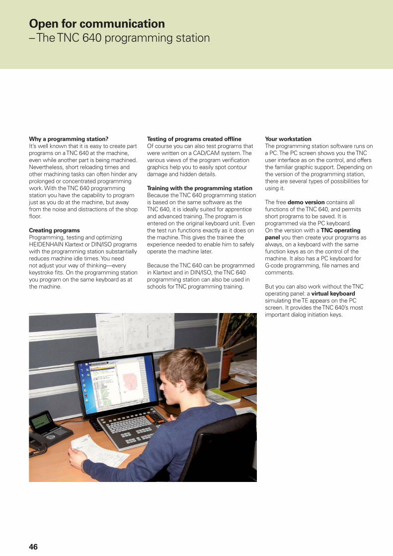
Why a programming station?
It’s well known that it is easy to create part programs on a TNC 640 at the machine, even while another part is being machined. Nevertheless, short reloading times and other machining tasks can often hinder any prolonged or concentrated programming work. With the TNC 640 programming station you have the capability to program just as you do at the machine, but away from the noise and distractions of the shop fl oor.
Creating programs
Programming, testing and optimizing HEIDENHAIN Klartext or DIN/ISO programs with the programming station substantially reduces machine idle times. You need not adjust your way of thinking—every keystroke fi ts. On the programming station you program on the same keyboard as at the machine.
Your workstation
The programming station software runs on a PC. The PC screen shows you the TNC user interface as on the control, and offers the familiar graphic support. Depending on the version of the programming station, there are several types of possibilities for using it.
The free demo version contains all functions of the TNC 640, and permits short programs to be saved. It is programmed via the PC keyboard.On the version with a TNC operating
panel you then create your programs as always, on a keyboard with the same function keys as on the control of the machine. It also has a PC keyboard for G-code programming, fi le names and comments.
But you can also work without the TNC operating panel: a virtual keyboard simulating the TE appears on the PC screen. It provides the TNC 640’s most important dialog initiation keys.
Open for communication
– The TNC 640 programming station
Testing of programs created offl ine
Of course you can also test programs that were written on a CAD/CAM system. The various views of the program verifi cation graphics help you to easily spot contour damage and hidden details.
Training with the programming station
Because the TNC 640 programming station is based on the same software as the TNC 640, it is ideally suited for apprentice and advanced training. The program is entered on the original keyboard unit. Even the test run functions exactly as it does on the machine. This gives the trainee the experience needed to enable him to safely operate the machine later.
Because the TNC 640 can be programmed in Klartext and in DIN/ISO, the TNC 640 programming station can also be used in schools for TNC programming training.

47
SE 660
TS 460
Workpiece measurement
– Setup, presetting and measuring with touch trigger probes
Workpiece touch probes* from HEIDEN-HAIN help you to reduce costs in the workshop and in series production: Together with the TNC 640, touch probes can automatically perform setup, measuring and inspection functions.
The stylus of a TS touch trigger probe is defl ected upon contact with a workpiece surface. At that moment the TS generates a trigger signal that, depending on the model, is transmitted either by cable or over an infrared beam to the control.
The touch probe* is inserted directly into the machine tool spindle. It can be equipped with various shanks depending on the machine. The ruby ball tips are available in several diameters, and the styli in different lengths.
* Machine and TNC must be specially adapted by the machine tool builder.
Touch probes with cable connection for
signal transmission for machines with manual tool change and for grinding machines and lathes:
TS 260 – New generation, axial or radial cable
Touch probe with radio or infrared signal
transmission for machines with automatic tool change:
TS 460 – New-generation standard touch probe for radio and infrared transmission with compact dimensions, energy-saving mode, optional collision protection and thermal decouplingTS 444 – Battery-free voltage supply through integrated air turbine generator from compressed air, for infrared transmission, with compact dimensionsTS 740 – High probing accuracy and repeatability, low probing force, with infrared transmission
TS 460 with collision protection
For more information:
Comprehensive descriptions of workpiece touch probes are available on the Internet at www.tastsysteme.de or in the Touch Probes brochure.

48
TL Micro
TT 460
Tool measurement
– Measuring length, radius and wear directly in the machine
The tool is of course a decisive factor in ensuring a consistently high level of production quality. This means that an exact measurement of the tool dimensions and periodic inspection of the tool for wear and breakage, as well as the shape of each tooth, are necessary. HEIDENHAIN offers the TT trigger tool touch probes as well as the non-contacting TL Nano and TL Micro laser systems for tool measurement.
The systems are installed directly in the machine’s workspace, where they permit tool measurement either before machining or during interruptions.
The TT tool touch probes measure the tool length and radius. When probing the rotating or stationary tool, e.g. during individual tooth measurement, the contact plate is defl ected and a trigger signal is transmitted directly to the TNC 640.
The TT 160 uses signal transmission by cable, whereas the TT 460 operates with wireless signal transmission over radio or an infrared beam. It is therefore particularly suitable for use on rotary and tilting tables.
The TL Nano and TL Micro laser systems are available for various maximum tool diameters. Using a laser beam, they probe the tool without contact, and can detect form errors of individual teeth along with the tool length and radius.
For more information:
Comprehensive descriptions of tool touch probes are available on the Internet at www.tastsysteme.de or in the Touch Probes brochure.
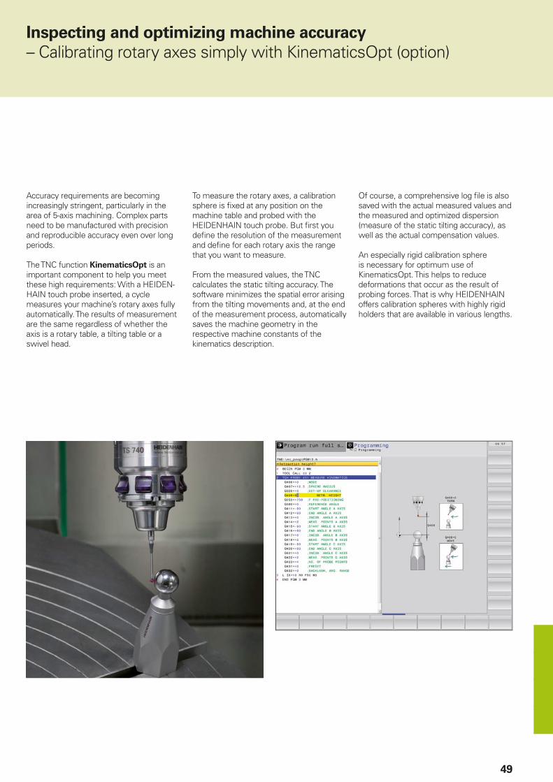
49
Accuracy requirements are becoming increasingly stringent, particularly in the area of 5-axis machining. Complex parts need to be manufactured with precision and reproducible accuracy even over long periods.
The TNC function KinematicsOpt is an important component to help you meet these high requirements: With a HEIDEN-HAIN touch probe inserted, a cycle measures your machine’s rotary axes fully automatically. The results of measurement are the same regardless of whether the axis is a rotary table, a tilting table or a swivel head.
Inspecting and optimizing machine accuracy
– Calibrating rotary axes simply with KinematicsOpt (option)
To measure the rotary axes, a calibration sphere is fi xed at any position on the machine table and probed with the HEIDENHAIN touch probe. But fi rst you defi ne the resolution of the measurement and defi ne for each rotary axis the range that you want to measure.
From the measured values, the TNC calculates the static tilting accuracy. The software minimizes the spatial error arising from the tilting movements and, at the end of the measurement process, automatically saves the machine geometry in the respective machine constants of the kinematics description.
Of course, a comprehensive log fi le is also saved with the actual measured values and the measured and optimized dispersion (measure of the static tilting accuracy), as well as the actual compensation values.
An especially rigid calibration sphere is necessary for optimum use of KinematicsOpt. This helps to reduce deformations that occur as the result of probing forces. That is why HEIDENHAIN offers calibration spheres with highly rigid holders that are available in various lengths.

50
HR 550
Positioning with the electronic handwheel
– Delicate axis traverse
To set up the workpiece, you can use the direction keys to move the machine axes manually. A simpler and more sensitive way, however, is to use the electronic handwheels from HEIDENHAIN.
You can move the axis slide through the feed motors in direct relation to the rotation of the handwheel. For delicate operations you can set the transmission ratio to certain preset distances per handwheel revolution.
HR 130 and HR 150 panel-mounted
handwheels
The panel-mounted handwheels from HEIDENHAIN can be integrated in the machine operating panel or mounted at another location on the machine. An adapter permits connection of up to three HR 150 electronic handwheels.
Expanded feature content of HR 520 and
HR 550
• Traverse distance per revolution can be set
• Display for operating mode, actual position value, programmed feed rate and spindle speed, error messages
• Override potentiometer for feed rate and spindle speed
• Selection of axes via keys or soft keys• Keys for continuous traverse of the axes• Emergency stop button• Actual position capture• NC start/stop• Spindle on/off• Soft keys for machine functions defi ned
by the machine tool builder
HR 510, HR 520 and HR 550 portable
handwheels
The HR 510, HR 520 and HR 550 are particularly helpful for when you have to work close to the machine’s working space. The axis keys and certain functional keys are integrated in the housing. In this way you can switch axes and set up the machine at any time—regardless of where you happen to be standing. As a wireless handwheel, the HR 550 is ideal for use on large machine tools. If you no longer need the handwheel, just attach it to the machine somewhere by its built-in magnets.

51
Overview
– User functions
User functions
Defa
ult
Op
tio
n
Short description •
•
0-77778
Basic version: 3 axes plus spindle4th NC axis plus auxiliary axisor
24 control loops, including up to 4 spindles
Digital current and speed control
Program entry ••
42
HEIDENHAIN Klartext conversational languageDIN/ISO programmingDirect loading of contours or machining positions from CAD fi les (STP, IGS, DXF) and saving as
Klartext conversational language contouring program or point table
Position entry •••
Nominal positions for lines and arcs in Cartesian coordinates or polar coordinatesIncremental or absolute dimensionsDisplay and entry in mm or inches
Tool compensation ••
9
Tool radius in the working plane and tool lengthRadius-compensated contour look-ahead for up to 99 blocks (M120)Three-dimensional tool-radius compensation for changing tool data without having to recalculate
an existing program
Tool tables • Multiple tool tables with any number of tools
Cutting data • Automatic calculation of spindle speed, cutting speed, feed per tooth and feed per revolution
Constant contour speed ••
Relative to the path of the tool centerRelative to the tool’s cutting edge
Parallel operation • Creating a program with graphical support while another program is being run
3-D machining •99
999
Motion control with highly smoothed jerk3-D tool compensation through surface normal vectorsUsing the electronic handwheel to change the angle of the swivel head during program run
without affecting the position of the tool point (TCPM = Tool Center Point Management)Keeping the tool normal to the contourTool radius compensation normal to the tool directionManual traverse in the active tool-axis system
Machining with a rotary
table
88
Programming of cylindrical contours as if in two axesFeed rate in distance per minute
Turning 50505050505050505050
Program-controlled switchover between milling and turningConstant surface speedTool-tip radius compensationCycles for roughing, fi nishing, recessing, thread turning and recess turningBlank form updated in contour cyclesTurning-specifi c contour elements for recesses and undercutsOrientation of the turning tool for outside or inside machiningInclined turningSpeed limitingEccentric turning (additionally required: option 135)

52
User functions
Defa
ult
Op
tio
nContour elements •
••••••
5050
Straight lineChamferCircular pathCircle centerCircle radiusTangentially connecting circular arcCorner roundingRecessUndercut
Approaching and
departing the contour
••
Via straight line: tangential or perpendicularVia circular arc
Adaptive feed control 45 Adaptive feed control (AFC) adjusts the contouring feed rate to the current spindle power
Collision monitoring 404040
Dynamic Collision Monitoring (DCM)Graphic depiction of the active collision objectsTool carrier monitoring
FK free contour
programming
• FK free contour programming in HEIDENHAIN conversational format with graphic support for workpiece drawings not dimensioned for NC
Program jumps •••
SubprogramsProgram section repeatsCalling any program as a subprogram
Fixed cycles ••
•
••••••••
505050
5050+13196
Drilling, conventional and rigid tapping, rectangular and circular pocketsPeck drilling, reaming, boring, counterboring, centeringArea clearance cycles, longitudinal and transverse, paraxial and contour parallelRecessing cycles, radial/axialRadial/axial recess turning cycles (combined recessing and roughing motion)Milling internal and external threadsTurning internal and external threadsHobbing
Interpolation turningClearing level and oblique surfacesMulti-operation machining of rectangular and circular pockets, rectangular and circular studsMulti-operation machining of straight and circular slotsCartesian and polar point patternsContour train, contour pocketContour slot with trochoidal millingEngraving cycle: Engrave text or numbers in a straight line or on an arcOEM cycles (special cycles developed by the machine tool builder) can be integrated
Coordinate conversions •844
Shifting, rotating, mirroring, scaling (axis-specifi c)Tilting the working plane, PLANE functionGlobal program settings make it possible to manually defi ne shifts, rotations, and handwheel
superimpositioning
Q parameters
Programming with variables•
•••
••
Mathematical functions =, +, –, *, /, sin , cos , tan , arc sin, arc cos, arc tan, an, en, In, log, a, a2 + b2
Logical operations (=, = /, <, >)Calculating with parenthesesAbsolute value of a number, constant , negation, truncation of digits before or after the decimal
pointFunctions for calculation of circlesFunctions for text processing
Overview
– User functions (continued)

53
User functions
Defa
ult
Op
tio
n
Programming aids ••••••
CalculatorComplete list of all current error messagesContext-sensitive help function for error messagesTNCguide: The integrated help system. User information available directly on the TNC 640Graphic support for programming cyclesComment and structure blocks in the NC program
Teach-In • Actual positions can be transferred directly into the NC program
Test graphics
Display modes•••
Graphic simulation before milling operations, even while another program is runningPlan view / projection in 3 planes / 3-D view, also in tilted working plane/3-D line graphicsDetail zoom
Programming graphics • In the Programming and Editing mode, the contours of the NC blocks are drawn on screen while they are being entered (2-D pencil-trace graphics), even while another program is running
Program-run graphics
Display modes••
Real-time graphic simulation during execution of the milling programPlan view / projection in three planes / 3-D view
Machining time ••
Calculation of machining time in the Test Run operating modeDisplay of the current machining time in the Program Run operating modes
Returning to the contour •
•
Mid-program startup in any block in the program, returning the tool to the calculated nominal position to continue machining
Program interruption, contour departure and return
Reference-point
management
• One table for storing any reference points
Datum tables • Multiple datum tables for storing workpiece-specifi c datums
Pallet tables •
154
Workpiece-oriented execution of pallet tables with any number of entries for selection of pallets, NC programs and datums
Planning the production process with the batch process manager
Touch probe cycles ••••
48
Calibrating the touch probeCompensation of workpiece misalignment, manual or automaticPresetting, manual or automaticAutomatic tool and workpiece measurementKinematicsOpt: Automatic measurement and optimization of machine kinematics
Parallel secondary axes ••
•
Compensating movement in the secondary axes U, V, W through the principal axes X, Y, ZIncluding movements of the parallel axis in the position display of the associated principal axis
(sum display)Defi ning the principal and secondary axes in the NC program makes it possible to run programs
on different machine confi gurations
Conversational languages • English, German, Czech, French, Italian, Spanish, Portuguese, Swedish, Danish, Finnish, Dutch, Polish, Hungarian, Russian (Cyrillic), Chinese (traditional, simplifi ed), Slovenian, Slovak, Norwegian, Korean, Turkish, Romanian
CAD viewer • Display CAD models on the TNC

54
– Accessories
Accessories
Electronic handwheels • One HR 510 portable handwheel or• One HR 520 portable handwheel or• One HR 550 portable wireless handwheel or• One HR 130 panel-mounted handwheel or• Up to three HR 150 panel-mounted handwheels through an HRA 110 handwheel adapter
Workpiece measurement • TS 260: 3-D touch trigger probe with cable connection or• TS 460: 3-D touch trigger probe with infrared transmission or• TS 444: 3-D touch trigger probe with infrared transmission or• TS 640: 3-D touch trigger probe with infrared transmission or• TS 740: 3-D touch trigger probe with infrared transmission
Tool measurement • TT 160: 3-D touch trigger probe, or• TS 460: 3-D touch trigger probe with infrared transmission• TL Nano: laser system for contact-free tool measurement or• TL Micro: laser system for contact-free tool measurement
Programming station Control software for PCs for programming, archiving, and training• Single-station license with original control keyboard• Single-station license with virtual keyboard• Network license with virtual keyboard• Demo version (operated with PC keyboard—free of charge)
Software for PCs • TeleService: Software for remote diagnosis, monitoring, and operation• CycleDesign: Software for creating your own cycle structure• TNCremo: Data transmission software—free of charge• TNCremoPlus: Software for data transfer with live-screen function

55
Option
number
Option As of NC
software
340 59x-
ID Remark
0
1
2
3
4
5
6
7
Additional axis 01 354540-01353904-01353905-01367867-01367868-01370291-01370292-01370293-01
Additional control loops 1 to 8
8 Advanced function set 1
01 617920-01 Machining with a rotary table
• Programming of cylindrical contours as if in two axes• Feed rate in distance per minuteInterpolation: Circular in 3 axes with tilted working planeCoordinate transformation: Tilting the working plane, PLANE function
9 Advanced function set 2
01 617921-01 Interpolation: Linear in 5 axes3-D machining
• 3-D tool compensation through surface normal vectors• Using the electronic handwheel to change the angle of the swivel
head during program run without affecting the position of the tool point (TCPM = Tool Center Point Management)
• Keeping the tool normal to the contour• Tool radius compensation normal to the tool direction• Manual traverse in the active tool-axis system
18 HEIDENHAIN DNC 01 526451-01 Communication with external Windows applications over COM component
23 Display step 01 632986-01 Display step to 0.01 µm or 0.000 01°
40 DCM collision 02 526452-01 Dynamic Collision Monitoring (DCM)
42 CAD import 02 526450-01 Importing contours from 3-D models
44 Global PGM settings 08 576057-01 Global program settings
45 Adaptive Feed Control (AFC)
02 579648-01 Adaptive feed control
46 Python OEM process 01 579650-01 Python application on the TNC
48 KinematicsOpt 01 630916-01 Touch-probe cycles for automatic measurement of rotary axes
50 Turning 01 634608-01 Turning functions:• Tool management for turning• Tool-tip radius compensation• Switching between milling and turning modes of operation• Lathe-specifi c contour elements• Package of turning cycles• Hobbing
52 KinematicsComp 05 661879-01 Compensate spatial error in rotary and linear axes
77 4 additional axes 01 634613-01 4 additional control loops
78 8 additional axes 01 634614-01 8 additional control loops
92 3D-Tool Comp 07 679678-01 3-D radius compensation depending on the tool’s contact angle
Overview
– Options

56
Option
number
Option As of NC
software
340 59x-
ID Remark
93 Extended tool management
01 676938-01 Extended tool management
96 Advanced spindle interpolation
05 751653-01 Cycles for interpolation turning
131 Spindle synchronism 05 806270-01 Speeds of two or more spindles can be synchronized at equal angles, with a transmission ratio, and/or with a defi ned offset
133 Remote desktop manager
01 894423-01 Display and remote operation of external computer units (e.g. a Windows PC)
135 Synchronizing functions
04 1085731-01 RTC: Real-Time Coupling function for synchronizing axes and spindles
136 Visual setup control 06 1099457-01 VSC: Camera-based monitoring of the setup situation
141 Cross Talk Comp. 02 800542-01 CTC: Compensation of axis couplings
142 Pos. Adapt. Control 02 800544-01 PAC: Position-dependent adaptation of the control parameters
143 Load Adapt. Control 02 800545-01 LAC: Load-dependent adaptation of the control parameters
144 Motion Adapt. Control 02 800546-01 MAC: Motion-dependent adaptation of control parameters
145 Active Chatter Control 02 800547-01 ACC: Active suppression of chatter
146 Active Vibration Damping
04 800548-01 AVD: Active suppression of vibration
154 Batch process manager
08 121952-01 Easy-to-read presentation of the pallet management
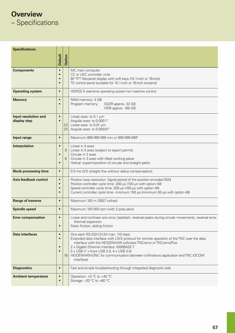
57
Specifi cations
Defa
ult
Op
tio
n
Components •
•
•
•
MC main computerCC or UEC controller unitsBF TFT fl at-panel display with soft keys (15.1-inch or 19-inch)TE control panel (suitable for 15.1-inch or 19-inch screens)
Operating system • HEROS 5 real-time operating system for machine control
Memory •
•
RAM memory: 4 GBProgram memory: SSDR approx. 32 GB HDR approx. 160 GB
Input resolution and
display step
•
•
2323
Linear axes: to 0.1 µmAngular axes: to 0.000 1°Linear axes: to 0.01 µmAngular axes: to 0.000 01°
Input range • Maximum 999 999 999 mm or 999 999 999°
Interpolation •
•
•
9
8
Linear in 4 axesLinear in 5 axes (subject to export permit)Circular in 2 axesCircular in 3 axes with tilted working planeHelical: superimposition of circular and straight paths
Block processing time • 0.5 ms (3-D straight line without radius compensation)
Axis feedback control •
•
•
•
Position loop resolution: Signal period of the position encoder/1024Position controller cycle time: 200 µs (100 µs with option 49)Speed controller cycle time: 200 µs (100 µs with option 49)Current controller cycle time: minimum 100 µs (minimum 50 µs with option 49)
Range of traverse • Maximum 100 m (3937 inches)
Spindle speed • Maximum 100 000 rpm (with 2 pole pairs)
Error compensation •
•
Linear and nonlinear axis error, backlash, reversal peaks during circular movements, reversal error, thermal expansion
Static friction, sliding friction
Data interfaces •
•
•
•
18
One each RS-232-C/V.24 max. 115 kbpsExtended data interface with LSV2 protocol for remote operation of the TNC over the data
interface with the HEIDENHAIN software TNCremo or TNCremoPlus2 x Gigabit Ethernet interface 1000BASE-T5 x USB (1 x front USB 2.0, 4 x USB 3.0)HEIDENHAIN-DNC for communication between a Windows application and TNC (DCOM
interface)
Diagnostics • Fast and simple troubleshooting through integrated diagnostic aids
Ambient temperature •
•
Operation: +5 °C to +40 °CStorage: –20 °C to +60 °C
Overview
– Specifi cations

58
– Comparison of controls
Comparison of controls TNC 620NC-SW 81760x-05
TNC 640NC-SW 34059x-08
iTNC 530NC SW 60642x-04
Area of application Standard milling High-end
milling-turning
High-end milling
• Simple machining centers (up to 5 control loops + spindle)
• Machine tools/machining centers (up to 24 control loops, max. 4 of which are spindles)
–
• Milling/turning operations (up to 18 control loops + 2 spindles) – Option –
Program entry
• HEIDENHAIN Klartext conversational
• According to ISO
• CAD import Option Option Option
• CAD viewer Option
• FK free contour programming Option
• Extended milling and drilling cycles Option
• Turning cycles – Option –
NC program memory 1.8 GB > 21 GB > 21 GB
5-axis and high-speed machining Option Option Option
Block processing time 1.5 ms 0.5 ms 0.5 ms
Input resolution and display step (standard/option) 0.1 µm/0.01 µm 0.1 µm/0.01 µm 0.1 µm/–
New design of the screen and keyboard 15-inch screen 15/19-inch screen 15/19-inch screen
Touchscreen –
Adaptive Feed Control (AFC) – Option Option
Active Chatter Control (ACC) Option Option Option
Dynamic Collision Monitoring (DCM) – Option Option
KinematicsOpt Option Option Option
KinematicsComp – Option Option
Touch probe cycles Option
Pallet editor Option
Parallel axis function –
Standard– Not available

PH MACHINEBANKS' CORPORATIONQuezon City, Philippines 1113E-mail: [email protected]
PL APS02-384 Warszawa, Polandwww.heidenhain.pl
PT FARRESA ELECTRÓNICA, LDA.4470 - 177 Maia, Portugalwww.farresa.pt
RO HEIDENHAIN Reprezentanta RomaniaBrasov, 500407, Romaniawww.heidenhain.ro
RS Serbia BG
RU OOO HEIDENHAIN115172 Moscow, Russiawww.heidenhain.ru
SE HEIDENHAIN Scandinavia AB12739 Skärholmen, Swedenwww.heidenhain.se
SG HEIDENHAIN PACIFIC PTE LTDSingapore 408593www.heidenhain.com.sg
SK KOPRETINA TN s.r.o.91101 Trencin, Slovakiawww.kopretina.sk
SL NAVO d.o.o.2000 Maribor, Sloveniawww.heidenhain.si
TH HEIDENHAIN (THAILAND) LTDBangkok 10250, Thailandwww.heidenhain.co.th
TR T&M Mühendislik San. ve Tic. LTD. STI·.
34775 Y. Dudullu – Ümraniye-Istanbul, Turkeywww.heidenhain.com.tr
TW HEIDENHAIN Co., Ltd.Taichung 40768, Taiwan R.O.C.www.heidenhain.com.tw
UA Gertner Service GmbH Büro Kiev 02094 Kiev, Ukrainewww.heidenhain.ua
US HEIDENHAIN CORPORATIONSchaumburg, IL 60173-5337, USAwww.heidenhain.com
VE Maquinaria Diekmann S.A. Caracas, 1040-A, VenezuelaE-mail: [email protected]
VN AMS Co. LtdHCM City, VietnamE-mail: [email protected]
ZA MAFEMA SALES SERVICES C.C.Midrand 1685, South Africawww.heidenhain.co.za
ES FARRESA ELECTRONICA S.A.08028 Barcelona, Spainwww.farresa.es
FI HEIDENHAIN Scandinavia AB01740 Vantaa, Finlandwww.heidenhain.fi
FR HEIDENHAIN FRANCE sarl92310 Sèvres, Francewww.heidenhain.fr
GB HEIDENHAIN (G.B.) LimitedBurgess Hill RH15 9RD, United Kingdomwww.heidenhain.co.uk
GR MB Milionis Vassilis17341 Athens, Greecewww.heidenhain.gr
HK HEIDENHAIN LTDKowloon, Hong KongE-mail: [email protected]
HR Croatia SL
HU HEIDENHAIN Kereskedelmi Képviselet1239 Budapest, Hungarywww.heidenhain.hu
ID PT Servitama Era ToolsindoJakarta 13930, IndonesiaE-mail: [email protected]
IL NEUMO VARGUS MARKETING LTD.Holon, 58859, IsraelE-mail: [email protected]
IN HEIDENHAIN Optics & ElectronicsIndia Private LimitedChetpet, Chennai 600 031, Indiawww.heidenhain.in
IT HEIDENHAIN ITALIANA S.r.l.20128 Milano, Italywww.heidenhain.it
JP HEIDENHAIN K.K.Tokyo 102-0083, Japanwww.heidenhain.co.jp
KR HEIDENHAIN Korea LTD.Gasan-Dong, Seoul, Korea 153-782www.heidenhain.co.kr
MX HEIDENHAIN CORPORATION MEXICO20290 Aguascalientes, AGS., MexicoE-mail: [email protected]
MY ISOSERVE SDN. BHD.43200 Balakong, SelangorE-mail: [email protected]
NL HEIDENHAIN NEDERLAND B.V.6716 BM Ede, Netherlandswww.heidenhain.nl
NO HEIDENHAIN Scandinavia AB7300 Orkanger, Norwaywww.heidenhain.no
NZ Llama ENGINEERING Ltd5012 Wellington, New ZealandE-mail: [email protected]
AR NAKASE SRL.B1653AOX Villa Ballester, Argentinawww.heidenhain.com.ar
AT HEIDENHAIN Techn. Büro Österreich83301 Traunreut, Germanywww.heidenhain.de
AU FCR MOTION TECHNOLOGY PTY LTDLaverton North Victoria 3026, AustraliaE-mail: [email protected]
BE HEIDENHAIN NV/SA1760 Roosdaal, Belgiumwww.heidenhain.be
BG ESD Bulgaria Ltd.Sofi a 1172, Bulgariawww.esd.bg
BR HEIDENHAIN Brasil Ltda.04763-070 – São Paulo – SP, Brazilwww.heidenhain.com.br
BY GERTNER Service GmbH220026 Minsk, Belaruswww.heidenhain.by
CA HEIDENHAIN CORPORATIONMississauga, OntarioL5T2N2, Canadawww.heidenhain.com
CH HEIDENHAIN (SCHWEIZ) AG8603 Schwerzenbach, Switzerlandwww.heidenhain.ch
CN DR. JOHANNES HEIDENHAIN (CHINA) Co., Ltd.Beijing 101312, Chinawww.heidenhain.com.cn
CZ HEIDENHAIN s.r.o.102 00 Praha 10, Czech Republicwww.heidenhain.cz
DK TP TEKNIK A/S2670 Greve, Denmarkwww.tp-gruppen.dk
DE HEIDENHAIN Vertrieb Deutschland83301 Traunreut, Deutschland 08669 31-3132 08669 32-3132E-Mail: [email protected]
HEIDENHAIN Technisches Büro Nord12681 Berlin, Deutschland 030 54705-240
HEIDENHAIN Technisches Büro Mitte07751 Jena, Deutschland 03641 4728-250
HEIDENHAIN Technisches Büro West44379 Dortmund, Deutschland 0231 618083-0
HEIDENHAIN Technisches Büro Südwest70771 Leinfelden-Echterdingen, Deutschland 0711 993395-0
HEIDENHAIN Technisches Büro Südost83301 Traunreut, Deutschland 08669 31-1345
Vollständige und weitere Adressen siehe www.heidenhain.deFor complete and further addresses see www.heidenhain.de
������������ ��� ��������������� ��������������������������������������� �������������� �������������������� !��"�#����������
������ !���� ��!�
892916-28 · 10 · 2/2018 · CD · Printed in Germany


![· PDF fileHeidenhain iTNC 530, [Heidenhain TNC 640], [Siemens 840 D sl] Heidenhain TNC 640 [Siemens 840 D sl] [Option] ... E-Mail: info@alzmetall.com Internet:](https://static.fdocuments.net/doc/165x107/5abcf7527f8b9a297f8eb5f2/itnc-530-heidenhain-tnc-640-siemens-840-d-sl-heidenhain-tnc-640-siemens-840.jpg)