TN 2014 Catalog HR - Turbonetics Performance wide range of compressor wheel sizes, trim blade...
53
Transcript of TN 2014 Catalog HR - Turbonetics Performance wide range of compressor wheel sizes, trim blade...

Phone: (805) 581-0333 • Fax: (805) 584-19132
Since 1978, Turbonetics has been a leader in designing andmanufacturing turbochargers, intercoolers, turbo systems, pressurecontrol valves and forced induction components. Turbonetics productsare boosting engines that run on all kinds of fuel, and in all sorts ofenvironments including performance, racing, industrial and militaryapplications. Our commitment to quality and innovation and our abilityto design and deliver customized solutions within days makesTurbonetics products the number one choice for daily drivenperformance vehicles as well as extreme race-only applications fromas little as 250 to over 2000 horsepower on a single turbo.
But with a Turbonetics product you get more than just performance,you get peace of mind that what you install has been made to the
highest quality standards, with years of experience in designing andproducing forced induction parts. And if something goes wrong ourlegendary no fault no hassle warranty has you covered - we are hereto help to get you back behind the wheel quickly.
Our range of Turbonetics’ turbos comes with a mind-boggling choice of compressor wheels, turbine wheels and end housingconfigurations. We listed as much as possible, but if you cannot findwhat you are looking for, contact us for an even more customizedturbocharger or intercooler. And as we are constantly adding newproducts and options to our portfolio, make sure to checkwww.turboneticsinc.com for the latest innovations as well astechnical information.
I NTR O D U CT I O N

t u r b o n e t i c s i n c . c o m3
TAB LE O F C O NTE NTS
INTRODUCTION 2
TABLE OF CONTENTS 3
BALL BEARING TECHNOLOGY 4
WARRANTY AND BENEFITS 5
TURBOCHARGER BALANCING 6
COMPRESSOR AND TURBINE WHEELS 7
HOW TO CHOOSE A TURBO 8
A/R RATIO AND TWIN TURBO 9
HOW TO READ A COMPRESSOR MAP 10-11
INDUSTRIAL SOLUTIONS 12
MILITARY SOLUTIONS 13
UNMANNED SOLUTIONS 14
GT-K BILLET TURBOCHARGERS 15
GT-K TURBOCHARGERS 16
HURRICANE SERIES TURBOCHARGER 17
T3 TURBOCHARGERS 18
T3/T4 TURBOCHARGERS 19
T04B & T04E TURBOCHARGERS 20
60-SERIES TURBOCHARGERS 21
T-SERIES TURBOCHARGERS 22
SUPER T TURBOCHARGERS 23
MID-FRAME TURBOCHARGERS 24
Y2K / SUPER THUMPER TURBOCHARGERS 25
TURBINE WHEELS AND HOUSINGS 26-27
COMPRESSOR WHEELS AND HOUSINGS 28-29
TURBINE HOUSING FLANGES AND GASKETS 30
TURBINE HOUSING HEATSHIELDS AND V-BANDS 31
FLUID LINES & FITTINGS 32
OIL SUPPLY - GASKETS AND FLANGES 33
PARTS & ACCESSORIES 34
EXTERNAL WASTEGATES 35-36
BYPASS VALVES AND BOOST CONTROLLERS 37
SILICONE CONNECTIONS AND T-BOLT CLAMPS 38
INTERCOOLER SELECTION GUIDE/SPEARCO 39
AIR TO AIR INTERCOOLER CORES 40-42
LIQUID TO AIR INTERCOOLER CORES 43-45
MITSUBISHI EVOLUTION X INTERCOOLER KIT 46
SUBARU WRX / STI INTERCOOLER KIT 47
FORD MUSTANG SYSTEM 48
CHEVROLET CAMARO TURBO SYSTEMS 49
GM DURAMAX DIESEL UPGRADES 50
FORD POWERSTROKE DIESEL UPGRADES 51
DODGE CUMMINS DIESEL UPGRADES 52
TERMS & CONDITIONS / RMA INSTRUCTIONS 53

Phone: (805) 581-0333 • Fax: (805) 584-1913
CERAMIC BALL BEARINGS
4
Every Turbonetics turbocharger from T3 to SuperT comes pre-installed with a special in-line oilfilter to prolong your custom turbos life andprotect it from oil debris damage. See page 53for complete warranty details.
WHAT MAKES THE TURBONETICS BALL BEARING SPECIAL?Turbonetics offers a patented Angular-Contact Ceramic Ball Bearing design. ThisTurbonetics exclusive design is made with almost indestructible silicone-nitrideceramic balls. A conventional unit has a capacity of 60-80 lbs. of dynamic thrustload. The patented Turbonetics Angular-Contact Ceramic Ball Bearing canwithstand anywhere from 1000 to 2200 lbs. of loading. The “angular-contact” featureoffers extreme strength because it is used as the loading surface. This results inquicker transient response and ultra-fast spooling of the turbo. With TurboneticsAngular-Contact Ceramic Ball Bearing units, you will build boost faster at the line,reach boost sooner in the RPM band and maintain higher boost in between shifts.
TURBONETICS BALL BEARING SERVICEABILITYWhile most of our turbos never need any repairs, many of our customers love to havepeace of mind when it comes to serviceability. Our unique design allows all genuineTurbonetics Ball Bearing units to be rebuilt for less than the cost of a new unit. Contactyour dealer or call us if you need to service your unit.
WITH PATENTED
TECHNOLOGY
• MORE THAN 13X GREATER THRUST CAPACITY• 25% FASTER SPOOL UP• RE-BUILDABLE• PATENTED CERAMIC BALL BEARINGS
BA LL B EAR I N G TE C H N O LO GY

t u r b o n e t i c s i n c . c o m5
COMPANY WARRANTY POLICY
COMPANY /SERVICE FEATURE
THE “NO FAULT/NO HASSLE” WARRANTYWe at Turbonetics stand behind our products. And our “No Fault/NoHassle” warranty program shows this commitment.
We will repair or replace any Turbonetics product that fails, includingproducts used in racing or competition applications, for a period ofone year from the original date of purchase. Any defect in material or
workmanship is covered - no questions asked. This truly exceptionalwarranty program offers peace-of-mind that when you get aTurbonetics product, you get our commitment to quality andperformance. See page 53 for exclusions and details on how tosubmit a claim.
ENGINEERING• In-depth aerodynamic and turbocharger
engineering expertise
• Custom aerodynamic matching application
• CAD expertise to turn ideas into products quickly
RESEARCH & DEVELOPMENT• Expert tuning capability
• Skillful custom fabrication
• Dynamometers on site
• Gas stand performance testing
SALES & TECH SUPPORT• Friendly sales staff
• Excellent tech support
• Dedicated customer service
MANUFACTURING• In house machining and assembly
• Component and VSR assembly balancing
• Fully trained & certified technicians
QUALITY• Disciplined quality management system
• Caterpillar SQEP gold certified
SHIPPING• FedEx, UPS, DHL and freight forwarding
• Competitive rates
• Same day shipping for in stock items
Call Turbonetics Customer Service
Department at 805-581-0333.
PLEASE PROVIDE: - Warranty Registration Number
- RGA (Returned Goods Authorization)number supplied by Turboneticsclearly marked on outside of box
- Description regarding failure ordamage to the component
- Mileage
- Point of purchase
WAR R ANTY AN D B E N E F ITS

Phone: (805) 581-0333 • Fax: (805) 584-1913
COMPONENT & ASSEMBLY BALANCING
6
Balance angle
Clock indicatingrequired balance
position
Oil flow throughturbocharger
Speed at cursor position and maximum speed attained
Vibration signal
Cursor is moved along rev scale.Clock indicating imbalance position
Operating speed
VSR HIGH SPEED BALANCING PROCESS
Turbochargers can spin at speeds of well over 100,000 rpm. Thetiniest imbalance can cause vibration, leading to noisy operation,oiling issues and ultimately bearing failure. Just like the wheels on acar, the wheels on a turbocharger have to be balanced to ensureoptimal performance.
There are two ways on how a turbocharger can be balanced:Component balancing and VSR or "Assembly" balancing. While manyturbocharger manufacturers choose one or the other method, atTurbonetics we believe that the perfect turbocharger has to beperfectly balanced. And this can only be achieved by using bothmethods - on every turbocharger possible.
STEP 1: COMPONENT BALANCINGWhen using a component balancer, both the turbine wheel and thecompressor wheel are balanced individually - before they areassembled into the turbocharger. The wheels are run at relatively lowspeeds, just like new tires at a tire shop. But unlike tires, where weightis added to achieve balance, tiny amounts of metal are removed fromturbocharger wheels through precision milling and grinding to achievethe perfect balance.
STEP 2: VSR OR "ASSEMBLY" BALANCINGThe second method is called VSR (Vibration Sorting Rig) balancing.This machine detects imbalance of the complete unit after assembly.As turbos are assembled, there are still tiny imperfections in thrustcollars, nose nuts, wheels and shafts. While each one is adequatelybalanced by itself, once assembled together the sum of all theimbalances can become significant. Using the VSR process, acompleted CHRA (Center Housing & Rotating Assembly - basically a turbocharger without end housings) is driven by compressed air in aVSR balancer, and accelerometers determine:
• THE AMOUNT OF IMBALANCE
• THE POSITION OF THE IMBALANCE
• SHAFT ROTATING SPEED
• OIL FLOW VOLUME THROUGH ASSEMBLY
A certified technician then removes even tinier parts of metal, ensuringthe perfect balance of the entire unit. The result is a perfectly balancedTurbonetics turbocharger that will run smoothly, perform better andlive longer.
TU R B O C HAR G E R BALAN C I N G
Example of an out of balance turbocharger.

t u r b o n e t i c s i n c . c o m7
COMPRESSOR WHEEL DESIGN
TURBINE WHEEL
Compressor wheels deliver pressurized air to the engine.Turbonetics compressor wheels are manufactured from one of threedifferent materials: cast 354 aluminum that is heat treated andHipped, A-2618 forged aluminum and Titanium depending on theapplication requirements. Computer aided design (CAD) allows fornew blade designs to create maximum airflow efficiency and
pressure. Racers and enthusiasts continue to strive for greaterpower and Turbonetics compressor wheel designs are constantlyevolving to meet the demands and deliver higher boost pressures.
Our wide range of compressor wheel sizes, trim blade configurationsand blade shapes can be categorized into three groups:
Turbine wheels harness the hot exhaust gas energy for theturbocharger. All Turbonetics turbine wheels are made from 713CInconel, a nickel-based super alloy. This material is much strongerand can withstand higher temperatures than most other turbine wheelmaterials. Turbonetics exclusive F1-series turbine wheels feature a10-blade design and tall tip height configuration to maximize theexhaust gas energy and keep backpressures low. Backpressure isthe opposite of boost pressure. It is the pressure of the exhaust gastrying to get past the turbine wheel. High backpressure can preventoptimum flow through the engine, limit theturbocharger from making boost andreduce potential horsepower. Unlikeconventional T style turbine wheels,our F1-series design minimizesbackpressure to allow the mosthorsepower possible for a givenwheel size.
T-SERIES BASED WHEELS: Known for their outstanding durabilityand solid air flow characteristics, this category includes well establishedcast wheels such as T3, 60-1, 62-1, T04B, T04E.
HP (HIGH PRESSURE) WHEELS: To meet the need for higher boostpressures and efficiency, Turbonetics developed the HP- Serieswheels with new blade shapes providing optimized air flow. Primarilycast components and under more stress than T-series based wheels,these wheels go through a process called Hot Isostatic Processing(HIP). This process removes any air bubbles that could be trapped inthe castings. Imperfections in the castings can cause wheel bursts,and we are not prepared to compromise on durability.
HPC WHEELS: The "C" stands for "Competition". A furtherdevelopment over the HP wheels, these Turbonetics billet wheelsprovide even greater efficiency and airflow. To withstand the extremepressures, HPC compressor wheels are machined from forged blanksinstead of standard bar stock. Wheels machined from forged blankshave stronger blades and wheel hubs and allow maximizing airflowwhile minimizing rotating mass.
New aerodynamics and improvements in blade design andmaterials are always in the works at Turbonetics.
Check our website for the latest updates and learn moreabout wheel diameters and trim at
w w w. t u r b o n e t i c s i n c . c o m
F1 turbine wheel provides unequaled exhaust
flow while keeping backpressures low.
HP Compressor WheelHPC Billet Compressor Wheel
F1-SERIES TURBINE WHEELS*FAMILY WHEEL HORSEPOWER
T3 F1-49 325T3 F1-54 400T3 F1-57 475T3 or T4 F1-62 550T3 or T4 F1-65 750T3 or T4 F1-68 1000T4 F1-75 1150 NEW
MID-FRAME F1-75 1200MID-FRAME (coming soon) F1-82 1250+ NEW
Y2K F1-89 1200Y2K F1-101 1250THUMPER F1-96 1850THUMPER F1-106 1900THUMPER F1-112 2000
*Wheel names also denotes turbine exducer diameter in mm.
COMPRESSOR AND TURBINE WHEELS

Phone: (805) 581-0333 • Fax: (805) 584-1913
CHOOSING THE RIGHT TURBO FOR YOU
8
HOW TO CHOOSE A TURBOThere are many variables to consider when choosing the perfect turbo for your engine. This section will help narrow down your choice. Check www.turboneticsinc.com for more detailed information. Here are some things to consider.
ESTABLISH YOUR GOALS:POWER: HOW MUCH HORSEPOWER DO YOU WANT TO MAKE?
• Think in horsepower. The horsepower output is the single most important factor to size a turbo.• Don't think in boost pressure. Boost is just a number that you will have to run on your
engine to make a certain horsepower.• Can your vehicle (not just the engine, but the entire setup) handle your
power target? Think of pistons, connecting rods, head studs, etc.
• Translate your targeted wheel HP into a crankshaft HP. Rule of thumb:add 20%
INTENDED USAGE• What are you using the vehicle for? Are you targeting peak
horsepower or fast boost response?• The way that you will be using the vehicle dramatically changes
the sizing of the turbocharger and intercooler needs.
• Your choice of transmission type and gearing will greatly affectthe performance and characteristics of the turbocharger.
PACKAGING• Will the turbocharger(s) fit in your vehicle’s space constraints?• Consider using differently sized compressor housings to more easily fit a given location.
Here are 3 steps to select the turbine wheel and housing combinationfor a typical street application, where boost response is important:
1. Ignore the compressor side for a moment: Start with theturbine side.
2. Turbine wheel: Choose the smallest wheel diameter that meetsthe target engine horsepower level. Turbine wheel HP limitsare located on page 7. If you choose a larger wheel, you willjeopardize boost response.
3. Turbine housing: Fine tune the turbine side by choosing anappropriate housing. Boost response/spool-up time isaffected by both turbine wheel diameter and turbine housingA/R. The A/R sizing can be used as a tool to fine tune theresponse range in the RPM band. The smaller the A/R, thefaster the turbocharger will be able to spool up. Similarly,choose a larger housing and the setup will respond moreslowly to throttle changes, but make more top power.
This is the most important and most discussed question whenconfiguring your turbocharger. The basic dilemma is: Do you want tomaximize the horsepower output of the engine at a very small rpmrange and accept a slower boost response at lower rpms, or do youneed immediate throttle response throughout the rpm range and arenot too concerned with the maximum horsepower number?
In street/autocross/drift applications, a faster response is generallypreferred, and a smaller turbocharger achieves exactly that.Conversely, dedicated drag racers for example need peak power, notboost response. Therefore larger frame turbochargers are used tomaximize horsepower.
BOOST RESPONSE OR MAXIMUM HORSEPOWER?
H OW TO C H O O S E A TU R B O

t u r b o n e t i c s i n c . c o m9
A/R RATIO
The A/R number you normally see cast into a turbine housing isbasically a description for how "big" a turbine housing is. The largerthe number, the bigger the housing. As the volume decreases in thevolute of the housing, the exhaust gas is able to maintain velocity anda high energy level therefore increasing turbine wheel speed. But if theturbine housing A/R is too small, it can become a choke point, limitingthe efficiency of the system by increasing backpressure and preventingtotal horsepower capability.
For racing applications it is often critical to maximize the turbinehousing A/R as much as possible to keep backpressure low andefficiency high while still providing the necessary response time, but
some backpressure can be a good thing for street driving use as thepressure differential helps with turbine wheel speed and transientboost response.
While turbine housing A/Rs have a huge impact on the overallturbocharger efficiency, compressor housings do not have the sameeffect. That is why compressor housings hardly ever come with a rangeof different A/Rs.
We carry a wide range of different A/R ratio turbine housings for allTurbonetics turbos, making it easy to fine tune your turbo setup bysimply changing the turbine housing.
TWIN TURBO OR SINGLE TURBO?In general, a big single turbo is going to work better than two smallerturbos because bigger are usually more efficient than smaller ones. Ona small V-engine, the exhaust manifolding can be tricky. If a single turbocan be packaged neatly without any serious compromises, then thatis the way to go. Only one set of oil lines, only one air inlet and exhaustoutlet routing required...
However, there are times when twins have an advantage. Becausetwins will be smaller, they may package better in certain engine bays(especially V-engines) with shorter exhaust manifold piping. Someengine configurations (like an inline 6) lend themselves to a twin setup due to the firing order and even exhaust pulses. The downsides arethe multiple oil lines, inlet plumbing, exhaust plumbing, and the cost oftwo turbos and wastegates.
Notice how tight the throat of the volute is on the right turbine housing. The smaller A/R dramatically improves turbine response time.
A / R R AT I O AN D TW I N TU R B O

Phone: (805) 581-0333 • Fax: (805) 584-1913
HOW TO READ A COMPRESSOR MAP
10
MAP: MANIFOLD PRESSURE IN ABSOLUTE (subtract 14.7 to get to the actual pressure)W: Airflow (lb/min), this is determined by your horsepower goal
R: Gas constant. 639.6
T: Intake Manifold Pressure in F. Ranges from ~100-130F forintercooled setups
VE: Volumetric efficiency; use 0.95-0.99 for peak efficiency formodern 4 valve engines
N: Engine RPM
V: Engine displacement in cubic inches. Multiply liters by 61.02 toget to cubic inches
Let's calculate the manifold pressure for an intercooled 2 literengine, max RPM 6000, goal 380HP.
W: 380/10 = 38lbs/min
T: Assume a very efficient Spearco intercooler, 100 degrees F
VE: Assume 0.98
N: 6000
V: 2l * 61.02 = 122.04 cubic inches
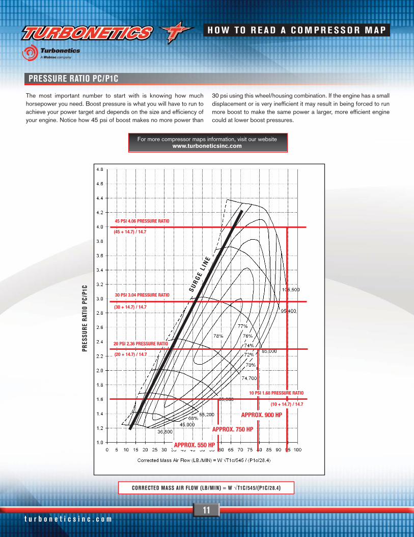
One of the most important aspects to a well designed turbo systemis choosing the right compressor and turbine wheel correctly. Whenthe right wheels are selected you can be confident that theturbocharger is going to perform exactly as it should withoutcomplications from surge, excessive lag or overspeed. We havealready discussed turbine wheel selection in the previous section.Let's look at the compressor wheel next. Using a gasoline engineexample, let's look at how to read compressor maps.
Power produced by any gasoline-fueled engine is a function of howmuch air flows into the engine, regardless of whether it is naturallyaspirated, supercharged or turbocharged. Air flow is shown on the x-axis marked as "Corrected Mass Air Flow" and is measured in lb/min.It takes approximately 1 lb of air per minute to make 10 HP. If anengine makes 500 HP then it flows 50 lbs of air per minute.
Now let's look at the pressure ratio, the y-axis on the compressor mapmarked as "Pressure Ratio" on the left hand side. Pressure ratio isdefined as absolute compressor discharge pressure P2, divided by theabsolute inlet (ambient) pressure. The term "absolute" means that youhave to account for the ambient pressure of 14.7 psi. So let's say youare running at 15 psi of boost: (15 psi + 14.7 psi ) / 14.7 psi= 2.02pressure ratio.
But how do you know where on the compressor map your engineoperates? Well, for that you have to know a little more and do somemath. While this can get complicated quickly, we will try to explain ona simplified example how to use compressor maps to find out whereyour engine is at.
Plugged into the above formula results in MAP = 24.39 psi. Adjust forambient pressure (subtract 14.7 psi) results in 9.69 psi of requiredboost or a pressure ratio of 1.66. Note that for this calculation we aremaking a lot of assumption, including no loss from the intake, operatingat sea level, no interaction with the turbine side and so on. So yourreal manifold pressure will be somewhat different from this number.
In practice, you would most likely calculate the maximum the enginewill be able to make, so a basic compressor choice could be madebased on this single point alone. To get it perfect, you have to calculatea lot of points throughout the entire RPM range and change theparameters for each point accordingly. Remember, our calculationhere is a very simplified example. To make sure you do choose theright turbo, contact your Turbonetics dealer.
Any operating point can be calculated using the following formula:
PR
ES
SU
RE
RA
TIO
Pc
/P1
c
MAP =W x R x (460+T)
VE x 0.5 + N + V
You can find more maps, technical info and locate a dealer on our website
www.turboneticsinc.com
H OW TO R EAD A C O M PR E SS O R MAP
Corrected Mass Air Flow (LB/MIN) = W √T1c/545/(P1c/28.4)
t u r b o n e t i c s i n c . c o m11
PRESSURE RATIO PC/P1C
The most important number to start with is knowing how muchhorsepower you need. Boost pressure is what you will have to run toachieve your power target and depends on the size and efficiency ofyour engine. Notice how 45 psi of boost makes no more power than
30 psi using this wheel/housing combination. If the engine has a smalldisplacement or is very inefficient it may result in being forced to runmore boost to make the same power a larger, more efficient enginecould at lower boost pressures.
PRES
SURE
RAT
IO P
C/P1
C
30 PSI 3.04 PRESSURE RATIO
(30 + 14.7) / 14.7
20 PSI 2.36 PRESSURE RATIO
(20 + 14.7) / 14.7
45 PSI 4.06 PRESSURE RATIO
(45 + 14.7) / 14.7
SU
RG
E L I
NE
10 PSI 1.68 PRESSURE RATIO
(10 + 14.7) / 14.7
APPROX. 550 HP
APPROX. 900 HP
APPROX. 750 HP
For more compressor maps information, visit our website www.turboneticsinc.com
H OW TO R EAD A C O M PR E SS O R MAP
CORRECTED MASS AIR FLOW (LB/MIN) = W √T1C/545/(P1C/28.4)

Phone: (805) 581-0333 • Fax: (805) 584-1913
INDUSTRIAL / MILITARY / UNMANNED SOLUTIONS
12
TURBOSForged from the extreme conditions of racing environments and usedin some of the most demanding industrial/military environments on theplanet, our patented bearing technology has revolutionized turbochargerstandards of durability and performance. Turbonetics offers a patentedAngular-Contact Ceramic Ball Bearing design. This Turboneticsexclusive design is made with almost indestructible silicone-nitrideceramic balls. A conventional unit has a capacity of 60-80 lbs. of dynamicthrust load. The patented Turbonetics’ design can withstand anywherefrom 1000 to 2500 lbs. of loading depending on the frame size.
The “angular-contact” feature offers extreme strength because it is usedas the loading surface instead of softer, weaker parts in standard units.What does this mean? It means the turbocharger is exceptionallydurable in high-pressure ratios, is not susceptible to thrust failurescommon with standard bearing turbos, and will provide fantastictransient response.
Turbonetics’ patented High Pressure Ratio/High Efficiency aerodynamicsallows for reliability and performance regardless of your boost pressurerequirements. Our high-pressure ratio turbo designs are being utilizedtoday for unmanned aircraft in extremely demanding applications. Inalternative fuel industrial applications this advanced technology allowsfor greater efficiency and therefore better emissions compliance.
Along with our full engineering staff ready to help you match turbochargersfor your specific requirements, Turbonetics utilizes compressor and turbinecomponent balancing as well as multiple high-speed VSR (VibrationSorting Rig) Core Balancing Machines. “Core balancing” ensures aturbocharger rotor assembly is balanced in its final assembled condition,at close to normal operational speeds. This process minimizes bearingloads and vibration, producing a quiet and reliable turbocharger with along service life. Turbonetics can address your specific application needswith a wide variety of standard product or ground up custom designs.Please call our sales staff to discuss how we can help you today.
INDUSTRIAL /MILITARY / UNMANNED SOLUTIONS

t u r b o n e t i c s i n c . c o m13
INDUSTRIAL / MILITARY / UNMANNED SOLUTIONS
HEAT EXCHANGERS Conventional intercooler cores are thin-walled, extruded aluminumtubes that are not designed to handle extreme boost pressures andlimit cooling performance because of their narrow width. Turbonetics’W.A.V.E. Technology Cores (Wide Area Vane Effectiveness) utilize thelatest design advances in strength and durability and maximize coolingeffectiveness through a greater surface area. In addition to ourselection of cast-aluminum manifolds which are used on a variety ofcores, it is also possible to fabricate special manifolds from sheet andv-channel aluminum for special applications to fit all intercoolerinstallation requirements and aid you in initial fit and function.
Turbonetics can also fabricate complete assemblies to our customer'sspecifications or sketches as well as offering complete engineeringassistance for intercooler design and applications. Specializing in bothair-to-air and air-to-liquid type heat exchangers, our engineering staffis ready to provide solutions to cool your forced induction applications.Whether you need a stronger core design to withstand higher boost
pressures, an intercooler assembly to increase fuel efficiency,water/radiator solutions, engine/transmission oil cooler or a uniquehigh performance application focusing on horsepower capabilities,Turbonetics has what you are looking for.
• W.A.V.E. Technology cores provide greater efficiency. Bar & Platedesign for rugged conditions and high boost pressures
• Core construction process withstands high pressures (100+ psi)
• Increase fuel economy by providing a denser air intake charge
• Air to air and air to liquid internal and external vane designs help to lower inlet temperatures
INDUSTRIAL /MILITARY / UNMANNED SOLUTIONS

Phone: (805) 581-0333 • Fax: (805) 584-191314
INDUSTRIAL / MILITARY / UNMANNED SOLUTIONS
CONTROLS & VALVESAll of Turbonetics’ high performance wastegates and valves aredesigned and tested to control boost and flow large volumes of exhaustgases. Turbonetics’ wastegates feature investment cast stainless steelbases, precision machined parts, high temperature resistantdiaphragms, computer modeled and flow tested inconel valve designsand v-band connections. These wastegates perform under pressureand handle high EGTs (Exhaust Gas Temperatures) to protect yourengine from over boosting while efficiently evacuating hot gases tolower back pressure when running under wide open throttle.
All of our by-pass valves are engineered to efficiently alleviate boostpressure contained within the induction system by venting or re-routingair pressure to prevent surging and unnecessary wear on theturbocharger. Our wastegate and by-pass valve lineup is able to be appliedon low displacement (< 1 liter), low boost (< 5 psi) applications all the wayup to large 10+ liter engines running 100+ psi in compound boost setups.
From automotive gasoline to natural gas powered stationary engines,Turbonetics has your boost control needs covered. Turboneticsindustrial products are built to last. Offered as original equipment onlarge displacement natural gas and diesel power plants, our regulatorsendure extreme hours and conditions to control boost year after year.Made in a variety of different configurations for numerous types ofindustrial applications, these valves use the latest technology andmaterial specifications to deliver on strict OEM requirements.
• Multiple configurations available for a wide variety of engine typesand sizes, including diesel and natural gas
• Computer aided designs allow maximum flow and precise boost control
• Patented valve designs aid in reducing backpressure to optimizehorsepower capabilities
• High strength components allow extreme use and long life
TORQUEMASTER KITKIT PN 11232-1
INDUSTRIAL /MILITARY / UNMANNED SOLUTIONS

t u r b o n e t i c s i n c . c o m15
TURBONETICS HPC BILLET GT-K TURBOCHARGERS
B I L L E TB I L L E TB I L L E T
Aerodynamics is what separates the GT-Kturbo line from the competition.
GT-K 600 600 C-61 60 Series 3.5" / 2.0" F1-62 T3 .65 A/R 4-bolt/3" V-band 11587 11588
GT-K 700 700 C-64 60 Series 3.5" / 2.0" F1-65 T3 .65 A/R 4-bolt/3" V-band 11589 11590
GT-K 750 750 C-69 T Series 3.5" / 2.0" F1-68 T4 .81 A/R 4-bolt/4" V-band 11591 11592
GT-K 850 850 C-72 T Series 4.0" / 2.5" F1-68 T4 .81 A/R 4-bolt/4" V-band 11585 11586
GT-K 1050 1050 C-75 T Series 4.0" / 2.5" F1-68 T4 .96 A/R 4-bolt/4" V-band 11593 11594
HP COMPRESSOR COMPRESSOR COMP. HOUSING TURBINE TURBINE HOUSING TURBINE HOUSING TURBO W/AIR COOLED TURBO W/WATER COOLEDTURBO RATING WHEEL HOUSING STYLE INLET/OUTLET WHEEL STYLE INLET/OUTLET CENTER HOUSING CENTER HOUSING
*Description name also denotes turbo crankshaft horsepower rating.
Following the previous successful GT-K turbos is our latest revisionto this line of turbos. Our engineers have been hard at work for thelast few years trying to make our popular GT-K line of turbos evenbetter. The new Billet GT-K line of turbos features all new BilletCompressor wheels which will flow more air than any of our previousGT-K models.
The GT-K series, Turbonetics’ premium turbochargers covering the325 to 1050 horsepower range, is expanding its lineup with HPCforged billet aluminum compressor wheels in the newly developed GT-K 600, 700, 750, 850 and 1050 turbochargers. A furtherdevelopment over the HPC compressor wheels, the HPC (HighPressure Competition) compressor wheels provide even greaterefficiency and airflow. To withstand the extreme pressures, HPCcompressor wheels are machined from forged blanks instead ofstandard bar stock. Wheels machined from forged blanks havestronger blades and wheel hubs, allowing maximum airflow whileminimizing rotating mass.
In addition to Turbonetics’ HPC forged billet compressor wheels, the newlydeveloped GT-K 600, 700, 750, 850 and 1050 turbochargers featurebrushed satin finish on the compressor housing and black ceramic coatedturbine housing which not only helps with heat containment, but providesa distinguished look. The brushed satin finish is an extremely durable finishthat is scratch and chip resistant. The black ceramic coating on the turbinehousing further differentiates the Billet GT-K series from the lineup.
As with previous GT-K turbochargers, the patented ceramic ball bearingcenter housing rotating assembly (CHRA) is standard on all GT-Kturbochargers. Turbonetics’ ceramic ball bearing design offers 50 timesgreater thrust capacity and is more resilient under high temperatureshut-downs than conventional journal bearing design. The patented“angular-contact” design offers extreme strength because it is used asthe thrust-loading surface. This exclusive technology allows ultra fasttransient response and extremely quick spooling of the turbocharger.With Turbonetics’ GT-K turbochargers, you will build boost faster at theline and reach targeted boost pressure sooner in the RPM band.
H PC B I L LE T GT-K TU R B O C HAR G E R S

16
TURBONETICS GT-K TURBOCHARGERS
Aerodynamics is what separates the GT-K turbo line from the competition.
*Description name also denotes turbo crankshaft horsepower rating.
Phone: (805) 581-0333 • Fax: (805) 584-1913
The GT-K turbocharger series, our top of the line turbos covering the325 to 1000 horsepower range, has everything a turbo can have:
• State-of-the-art wheels with the latest aerodynamics - F1 turbines, HP compressors.
• Ceramic coated turbine housing to keep heat in and protect from corrosion.
• Black Chrome finish compressor housing with MapEnhancement Porting.
• Water cooled center housing options.
Our Map Enhancement Porting is the latest in ported shroud design.Ported shrouds widen the compressor map and move the surge linefurther to the left, enabling more aggressive setups and avoidingdamaging compressor surge. The porting is designed to reduce surgewhile optimizing the intake airflow. All features come as standard onthe GT-K series. The only decision you have to make is whether to getyour GT-K with an air cooled or water cooled center housing.
Our Map Enhancement Porting is the latest in ported shroud design.
GT-K TU R B O C HAR G E R S
GT-K 325 325 HP E-46 T04E 3.5" / 2.0" F1-54 T3 .48 A/R 4-bolt/4-bolt 11257 11475
GT-K 650 650 HP-66 T-Series 4.0" / 2.5" F1-65 T4 .68 A/R 4-bolt/3" V-band 11262 11480
GT-K 850 850 HP-72 T-Series 4.0" / 2.5" F1-68 T4 .81 A/R 4-bolt/4" V-band 11263 11481
GT-K 1000 1000 HP-76 T-Series 4.0" / 2.5" F1-68 T4 .96 A/R 4-bolt/4" V-band 11264 11482
HP COMPRESSOR COMPRESSOR COMP. HOUSING TURBINE TURBINE HOUSING TURBINE HOUSING TURBO W/AIR COOLED TURBO W/WATER COOLEDTURBO RATING WHEEL HOUSING STYLE INLET/OUTLET WHEEL STYLE INLET/OUTLET CENTER HOUSING CENTER HOUSING
HURRICANE SERIES TURBOCHARGERS
17
Hurricane 6662 500-600 HP-66 60 series 4.0"/2.5" Ported Shroud F1-62 T3 .82 4-bolt/4-bolt 11531 11531-BB
"Erin"
Hurricane 6665-3 500-600 HP-66 60 series 4.0"/2.5" Ported Shroud F1-65 T3 .82 4-bolt/4-bolt 11532 11532-BB
"Ashley"
Hurricane 6665-4 500-600 HP-66 60 series 4.0"/2.5" Ported Shroud F1-65 T4 .81 4-bolt/3" V-band 11226 11226-BB
"Lety"
Hurricane 7268-3 600-700 HP-72 T-series 4.0"/2.5" Ported Shroud F1-68 T3 .84 4-bolt/4" V-band 11521 11521-BB
"Christina"
Hurricane 7268-4 600-700 HP-72 60 series 4.0"/2.5" Ported Shroud F1-68 T4 .81 4-bolt/3" V-band 11533 11533-BB
"Sylvia"
Hurricane 7668 650-750 HP-76 60 series 4.0"/2.5" F1-68 T4 .96 4-bolt/3" V-band 11534 11534-BB
"Vanessa"
Hurricane 7868 650-800 HP-78 60 series 4.0"/2.5" F1-68 T4 .96 4-bolt/3" V-band 11535 11535-BB
"Benita"
HP COMPRESSOR COMPRESSOR COMP. HOUSING TURBINE TURBINE HOUSING TURBO HOUSING JOURNAL BEARING BALL BEARINGTURBO RATING WHEEL HOUSING STYLE INLET/OUTLET WHEEL STYLE INLET/OUTLET PART NUMBER PART NUMBER
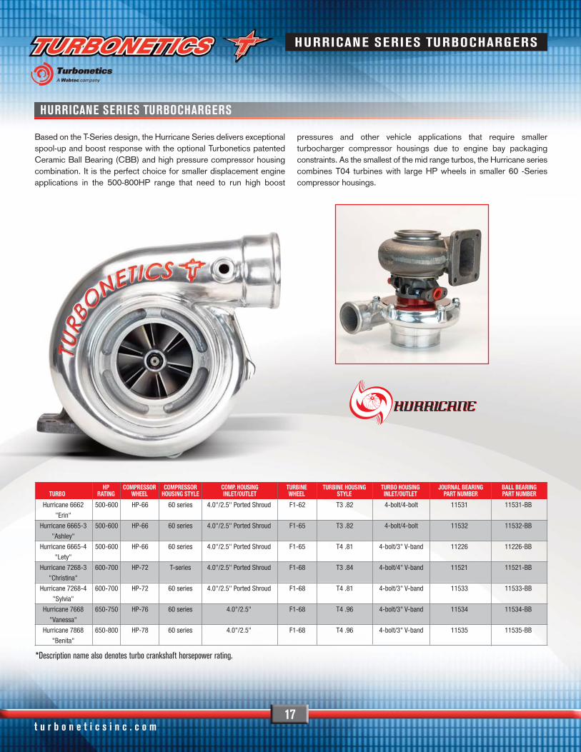
Based on the T-Series design, the Hurricane Series delivers exceptionalspool-up and boost response with the optional Turbonetics patentedCeramic Ball Bearing (CBB) and high pressure compressor housingcombination. It is the perfect choice for smaller displacement engineapplications in the 500-800HP range that need to run high boost
pressures and other vehicle applications that require smallerturbocharger compressor housings due to engine bay packagingconstraints. As the smallest of the mid range turbos, the Hurricane seriescombines T04 turbines with large HP wheels in smaller 60 -Seriescompressor housings.
*Description name also denotes turbo crankshaft horsepower rating.
t u r b o n e t i c s i n c . c o m
HURRICANE SERIES TURBOCHARGERS

t u r b o n e t i c s i n c . c o m18
T3 TURBOCHARGERS
Perfectly sized for applications under 2 liters, the T3 line-up starts withthe 150 HP 35 trim wheel and goes up to the 325 HP Super 60. T3compressor wheels are efficient up to 22 psi. With a huge selection ofwheels and end housings, this frame size can be customized to makethe perfect match to any small displacement engine. The T3-Seriesgives you the choice of liquid or air cooled bearing housing with journalor ceramic ball bearings. All T3 turbos feature our 5/16" "Big Shaft"for added durability in day to day use.
T3 5 BOLT SWING VALVES PNSwing Valve 30298
3 Bolt Swing Valve Discharge Flange 20368
Single port actuator 3-10 psi 30314
Dual port actuator 3-10 psi 30326
Swing valve for the 5 bolt turbine housing options are available to addinternal wastegates to all T3 and T3/T4 turbos.
TURBINE WHEEL TURBINE HOUSINGDESCRIPTION PN (NON-BB) OUTLET STYLE A/R PN
F1-49 21480 4-bolt .48 21581-494-bolt .63 21582-494-bolt .65 21589-494-bolt .85 21590-495-bolt .48 21578-495-bolt .63 21579-495-bolt .82 21580-49V-band 2.5" .65 21603-49V-band 2.5" .85 21604-49
F1-54 21481 4-bolt .48 21581-544-bolt .63 21582-544-bolt .65 21589-544-bolt .85 21590-545-bolt .48 21578-545-bolt .63 21579-545-bolt .82 21580-54V-band IN/OUT .64 22155-54V-band 2.5" .65 21603-54V-band IN/OUT .82 22156-54V-band 2.5" .85 21604-54
F1-57 21482 4-bolt .48 21581-574-bolt .63 21582-574-bolt .65 21589-574-bolt .85 21590-57V-band *** .64 22155-57V-band 2.5" .65 21603-57V-band *** .82 27156-57V-band 2.5" .85 21604-57V-band 3.0" .65 22054-57V-band 3.0" .85 22055-575-bolt .48 21578-575-bolt .63 21579-575-bolt .82 21580-57Grand National .63 21584-57Grand National .82 21585-57
F1-62 21483 4-bolt .48 21581-624-bolt .63 21582-624-bolt .65 21589-624-bolt .85 21590-625-bolt .48 21578-625-bolt .63 21579-625-bolt .82 21580-62V-band *** .64 22155-62V-band 2.5" .65 21603-62V-band *** .82 22156-62V-band 2.5" .85 21604-62V-band 3.0" .65 22054-62
F1-62 V-band 3.0" .85 22055-62(Cont) 21483 Grand National .63 21584-62
Grand National .82 21585-62
TURBINE WHEEL TURBINE HOUSINGDESCRIPTION PN (NON-BB) OUTLET STYLE A/R PN
*Description names also denotes turbine exducer diameter in mm.
F1-65 21484 4-bolt .65 21589-654-bolt .85 21590-65V-band 3.0" .65 22054-65V-band 3.0" .85 22055-65
F1-68 21486 V-band 3.0" .65 22054-68V-band 3.0" .82 22156-68V-band 3.0" .85 22055-68
COMPRESSOR WHEEL HOUSING - polished, 2" outlet
DESCRIPTION TYPE PN INLET SIZE PN
50 Trim T3 20268T 3.00" 20374-3
60 Trim T3 20272T 3.00" 20375-3
Super 60 T3 20324T 2.35" 20376
Super 60 T3 20324T 3.00" 20376-3
T3 TU R B O C HAR G E R S

T3/T4 HYBRID TURBOCHARGERS
19
The T3/T4 Hybrid turbochargers connects a T3 turbine section, witha T4 compressor section. This combination offers the low inertia andfast boost response of the lightweight T3 turbine wheel with the high-airflow characteristics of the T4 compressor family. The result is avirtually lag-free turbocharger, perfect for applications where drivabilityis key, while delivering impressive power.
A well established classic, but by no means outdated. Since itscreation, we have continuously improved the design. From replacingthe original T3 wheels with the modern F1 design, to making ourpatented Ceramic Ball-Bearing option available. The result is a T3/T4Hybrid series that spools up faster and withstands the high pressuresmodern performance engines need.
All T3/T4 Turbonetics turbos are covered by our exclusive 1 year NoFault/No Hassle warranty.
COMPRESSOR WHEEL HOUSING - polished, 2" outlet
DESCRIPTION TYPE PN INLET SIZE PNSuper-S T04B 20394T 2.75" 20202Super-V T04B 20364T 2.75" 20203Super-H T04B 20288T 2.75" 2019250 Trim T04E 30375T 3.00" 3049160 Trim T04E 30378T 3.00" 3043250 Trim T04E Super 20576T 3.00" 3049160 Trim T04E Super 20579T 3.00" 30432
TURBINE WHEEL TURBINE HOUSINGDESCRIPTION PN (NON-BB) OUTLET STYLE A/R PN
F1-49 21480 4-bolt .48 21581-494-bolt .63 21582-494-bolt .65 21589-494-bolt .85 21590-495-bolt .48 21578-495-bolt .63 21579-495-bolt .82 21580-49V-band 2.5" .65 21603-49V-band 2.5" .85 21604-49
F1-54 21481 4-bolt .48 21581-544-bolt .63 21582-544-bolt .65 21589-544-bolt .85 21590-545-bolt .48 21578-545-bolt .63 21579-545-bolt .82 21580-54V-band IN/OUT .64 22155-54V-band 2.5" .65 21603-54V-band IN/OUT .82 22156-54V-band 2.5" .85 21604-54
F1-57 21482 4-bolt .48 21581-574-bolt .63 21582-574-bolt .65 21589-574-bolt .85 21590-57V-band *** .64 22155-57V-band 2.5" .65 21603-57V-band *** .82 27156-57V-band 2.5" .85 21604-57V-band 3.0" .65 22054-57V-band 3.0" .85 22055-575-bolt .48 21578-575-bolt .63 21579-575-bolt .82 21580-57Grand National .63 21584-57Grand National .82 21585-57
F1-62 21483 4-bolt .48 21581-624-bolt .63 21582-624-bolt .65 21589-624-bolt .85 21590-625-bolt .48 21578-625-bolt .63 21579-625-bolt .82 21580-62V-band *** .64 22155-62V-band 2.5" .65 21603-62V-band *** .82 22156-62V-band 2.5" .85 21604-62V-band 3.0" .65 22054-62V-band 3.0" .85 22055-62Grand National .63 21584-62Grand National .82 21585-62
TURBINE WHEEL TURBINE HOUSINGDESCRIPTION PN (NON-BB) OUTLET STYLE A/R PN
*Description names also denotes turbine exducer diameter in mm.
F1-65 21484 4-bolt .65 21589-654-bolt .85 21590-65V-band 3.0" .65 22054-65V-band 3.0" .85 22055-65
F1-68 21486 V-band 3.0" .65 22054-68V-band 3.0" .82 22156-68V-band 3.0" .85 22055-68
T3 /T4 HYB R I D TU R B O C HAR G E R S
Phone: (805) 581-0333 • Fax: (805) 584-1913

t u r b o n e t i c s i n c . c o m20
TO4B & TO4E TURBOCHARGERS
All Turbonetics journal bearing turbochargers feature a 360° bronzethrust bearing instead of a weaker 270° bearing. Our 360° bearingsare able to withstand higher boost pressures and axial loads thanconventional units.
TO4BThe T04B series turbochargers are one of the most versatile unitsavailable to the performance aftermarket. High compressor efficiency,strict quality standards, Turbonetics’ exclusive “blueprinted” assemblyprocess and competitive pricing makes the T04B the obvious choicefor many applications. Available in a wide range of compressor andturbine combinations, the T04B series can support power levels from300-500 HP. The compact T04B housing with 2.75” inlet (comparedto T04E’s 3.00” inlet) makes it extremely attractive for twin turboapplications and where space is limited.
TO4ELike the versatility of the T04B, but need a little bit more power?The tried-and-true combination of T04E series allows you toachieve more power without taking up much more space than aT04B or changing your exhaust setup. Turbonetics T04Ecompressor wheels are extremely effective on high pressureapplications. Match it with Turbonetics Patented Ceramic BallBearing and you get a monster result! With its larger compressorhousing (compared to T04B) and 3” compressor inlet, and sameimpressive selection of matching turbine housings as the T04B,there is a combination for every application.
COMPRESSOR WHEEL HOUSING - polished, 2" outlet
DESCRIPTION TYPE PN INLET SIZE PN
Super-S T04B 20394T 2.75" 20202
Super-V T04B 20364T 2.75" 20203
Super-H T04B 20288T 2.75" 20192
50 Trim T04E 30375T 3.00" 30491
60 Trim T04E 30378T 3.00" 30432
50 Trim T04E Super 20576T 3.00" 30491
HPC-54 Billet T04E 22374 3.00" 22375-2
HPC-58 Billet T04E 22365 3.00" 22366-2
HPC-61 Billet T04E 22355 4.00" 22358-2
HPC-64 Billet T04E 22090 3.00" 22166
TURBINE WHEEL TURBINE HOUSINGDESCRIPTION PN OUTLET STYLE A/R PN
F1-62 21483 3" V-band .58 21592-623" V-band .68 21593-623" V-band, divided .58 21596-623" V-band, divided .70 21597-623" V-band, divided .84 21598-624 bolt, on center .58 21605-624 bolt, on center .69 21606-624 bolt, on center .81 21607-62
F1 -65 21484 3" V-band .58 21592-653" V-band .68 21593-653" V-band .81 21594-653" V-band .96 21595-653" V-band, divided .58 21596-653" V-band, divided .70 21597-653" V-band, divided .84 21598-653" V-band, divided 1.0 21599-653" V-band, divided 1.15 21600-654 bolt, on center .58 21605-654 bolt, on center .69 21606-654 bolt, on center .81 21607-654 bolt, on center .96 21608-654 bolt, on center 1.30 21609-65
F1-68 21486 3" V-band .58 21592-683" V-band .68 21593-683" V-band .81 21594-683" V-band .96 21595-683" V-band, divided .58 21596-683" V-band, divided .70 21597-683" V-band, divided .84 21598-683" V-band, divided 1.00 21599-683" V-band, divided 1.15 21600-684 bolt, on center .58 21605-684 bolt, on center .69 21606-684 bolt, on center .81 21607-684 bolt, on center .96 21608-684 bolt, on center 1.30 21609-68
BIG SHAFT STANDARD ON ALL T04B, T04E & 60 SERIES TURBOS
*Description names also denotes turbine exducer diameter in mm.
TO4B & TO4E TU R B O C HAR G E R S

Phone: (805) 581-0333 • Fax: (805) 584-1913
60-SERIES TURBOCHARGERS
21
OIL FILTER
Supporting the highest possible airflow in the T04 range, the 60-Series matches T04 turbine side options with larger compressoroptions. Originally designed with the 60-1 and the 62-1 (below22psi, 425-625HP), we added 2 wheel options for added versatility:
The HP61 wheel introduces modern aerodynamics into this class.The 60-1 HiFi flows approximately 90% of a standard 60-1, butresides in a compact compressor housing featuring a 2.75" inlet and2" discharge.
Every Turbonetics Turbocharger from T3 through Super T comes pre-installed with a special in-line oil filter to prolong your custom turbo’slife and protect it from oil debris damage.
CENTER HOUSING OPTIONS:AIR COOLED OR WATER COOLED
JOURNAL BEARING OR BALL BEARING
CUTAWAY VIEW
*Description names also denotes turbine exducer diameter in mm.
20754
COMPRESSOR WHEEL HOUSING- polished, 2.5" outlet
DESCRIPTION TYPE PN INLET SIZE PN
Compact 60-1 HiFi 20230T 2.75" 20210
Standard 60-1 20177T 4.00" 20190
HP HP-61 21634 4.00" 21735
Large Trim 62-1 20255T 4.00" 20249
HPC Billet HPC-61 22355 4.00" 22357-2
HPC Billet HPC-64 22333 4.00" 22335-2
TURBINE WHEEL TURBINE HOUSINGDESCRIPTION PN OUTLET STYLE A/R PN
F1-62 21483 3" V-band .58 21592-623" V-band .68 21593-623" V-band, divided .58 21596-623" V-band, divided .70 21597-623" V-band, divided .84 21598-624 bolt, on center .58 21605-624 bolt, on center .69 21606-624 bolt, on center .81 21607-62
F1-65 21484 3" V-band .58 21592-653" V-band .68 21593-653" V-band .81 21594-653" V-band .96 21595-653" V-band, divided .58 21596-653" V-band, divided .70 21597-653" V-band, divided .84 21598-653" V-band, divided 1.00 21599-653" V-band, divided 1.15 21600-654 bolt, on center .58 21605-654 bolt, on center .69 21606-654 bolt, on center .81 21607-654 bolt, on center .96 21608-654 bolt, on center 1.30 21609-65
F1-68 21486 3" V-band .58 21592-683" V-band .68 21593-683" V-band .81 21594-683" V-band .96 21595-683" V-band, divided .58 21596-683" V-band, divided .70 21597-683" V-band, divided .84 21598-683" V-band, divided 1.00 21599-683" V-band, divided 1.15 21600-684 bolt, on center .58 21605-684 bolt, on center .69 21606-684 bolt, on center .81 21607-684 bolt, on center .96 21608-684 bolt, on center 1.30 21609-68
F1-75 22323-BB 3" V-band .96 22325-0963" V-band 1.15 22325-115
6 0-S E R I E S TU R B O C HAR G E R S

22
T-SERIES TURBOCHARGERS
T-Series turbos are the true mid range choice for applications from500 to 950 horsepower. The compressor side consists of a choice ofHP wheels (58, 61, 64, 66, 70, 72, 76 and 78mm) that are combinedwith T-Series housings, nicely matched with one of the many turbine
options. Also available in this turbo family are forged billet wheeloptions (HP-C compressor wheels), that flow even more than cast HPwheels. Check out our website for our latest HP-C options, we areconstantly expanding our forged billet wheel selection.
*Description names also denotes turbine exducer diameter in mm.
CENTER HOUSING OPTIONS:AIR COOLED OR WATER COOLED
JOURNAL BEARING OR BALL BEARING
(High Pressure) compressor wheel, specificallydesigned for max power at over 30psi.
TURBINE WHEEL TURBINE HOUSINGDESCRIPTION PN OUTLET STYLE A/R PN
F1-62 21483 3" V-band .58 21592-623" V-band .68 21593-623" V-band, divided .58 21596-623" V-band, divided .70 21597-623" V-band, divided .84 21598-624 bolt, on center .58 21605-624 bolt, on center .69 21606-624 bolt, on center .81 21607-62
F1-65 21484 3" V-band .58 21592-653" V-band .68 21593-653" V-band .81 21594-653" V-band .96 21595-653" V-band, divided .58 21596-653" V-band, divided .70 21597-653" V-band, divided .84 21598-653" V-band, divided 1.00 21599-653" V-band, divided 1.15 21600-654 bolt, on center .58 21605-654 bolt, on center .69 21606-654 bolt, on center .81 21607-654 bolt, on center .96 21608-654 bolt, on center 1.30 21609-65
F1-68 21486 3" V-band .58 21592-683" V-band .68 21593-683" V-band .81 21594-683" V-band .96 21595-683" V-band, divided .58 21596-683" V-band, divided .70 21597-683" V-band, divided .84 21598-683" V-band, divided 1.00 21599-683" V-band, divided 1.15 21600-684 bolt, on center .58 21605-684 bolt, on center .69 21606-684 bolt, on center .81 21607-684 bolt, on center .96 21608-684 bolt, on center 1.30 21609-68
F1-75 22323-BB 3" V-band .96 22325-0963" V-band 1.15 22325-115
Phone: (805) 581-0333 • Fax: (805) 584-1913
COMPRESSOR WHEEL COMPRESSOR HOUSING - polished, 3" outlet
DESCRIPTION PN INLET SIZE PN
HP-58 30335 4.00" 20450
HP-61 21346 4.00" 21386
HP-66 21348 4.00" 21388
HP-70 21351 4.00" 21391
HP-72 30336 4.00" 21392
HP-76 21257 4.00" 21393
HP-78 21354 4.00" 21394
HPC-61 22355 4.00" 22358-2
HPC-64 22333 4.00" 22356-2
HPC-69 22361 4.00" 22363
HPC-72 22347 4.00" 22350-2
HPC-75 22339 4.00" 21393
T-S E R I E S TU R B O C HAR G E R S

SUPER T TURBOCHARGERS
F1 TURBINE WHEEL
23
Our Super T combines a T04 turbine side with the next size up midframe compressors. Think of it as a hybrid for high horsepower. Theconcept is similar to a T3/T4 hybrid: Take a small turbine side, add alarge compressor and you have a turbo that can be spooled up bysmaller displacement engines but support a lot of power very efficiently.
Same concept with the Super T-Series - just in the next size up. In fact,the Super T-Series provides the most horsepower T04 turbines cansupport, up to 1000HP. Since these are perfect for smaller engine raceapplications, these housings are available with Turbonetics' signatureASME Bell inlet included (see page 34).
COMPRESSOR WHEEL COMPRESSOR HOUSING - polished, 3" outlet
DESCRIPTION PN INLET SIZE PN
HP-72 30336 4.50" 21401
HP-76 21257 4.50" 21402
HP-78 21354 4.50" 21395
HPC-72 22347 4.50" 22351-2
HPC-75 22339 4.50" 22343-2
TURBINE WHEEL TURBINE HOUSINGDESCRIPTION PN (NON-BB) OUTLET STYLE A/R PN
F1-62 21483 3" V-band .58 21592-623" V-band .68 21593-623" V-band, divided .58 21596-623" V-band, divided .70 21597-623" V-band, divided .84 21598-624 bolt, on center .58 21605-624 bolt, on center .69 21606-624 bolt, on center .81 21607-62
F1 -65 21484 3" V-band .58 21592-653" V-band .68 21593-653" V-band .81 21594-653" V-band .96 21595-653" V-band, divided .58 21596-653" V-band, divided .70 21597-653" V-band, divided .84 21598-653" V-band, divided 1.00 21599-653" V-band, divided 1.15 21600-654 bolt, on center .58 21605-654 bolt, on center .69 21606-654 bolt, on center .81 21607-654 bolt, on center .96 21608-654 bolt, on center 1.30 21609-65
F1-68 21486 3" V-band .58 21592-683" V-band .68 21593-683" V-band .81 21594-683" V-band .96 21595-683" V-band, divided .58 21596-683" V-band, divided .70 21597-683" V-band, divided .84 21598-683" V-band, divided 1.00 21599-683" V-band, divided 1.15 21600-684 bolt, on center .58 21605-684 bolt, on center .69 21606-684 bolt, on center .81 21607-684 bolt, on center .96 21608-684 bolt, on center 1.30 21609-68
F1-75 22323-BB 3" V-band .96 22325-0963" V-band 1.15 22325-115
CENTER HOUSING OPTIONS:
Made from 713C Inconel, a nickel based super alloy, these 10 bladed, tall tip, turbine wheelswithstand extremely high temperatures while flowing large amounts of exhaust gas.
AIR COOLED OR WATER COOLEDBALL BEARING
*Description names also denotes turbine exducer diameter in mm.
t u r b o n e t i c s i n c . c o m
S U PE R T TU R B O C HAR G E R S

24
MID-FRAME TURBOCHARGERS
The largest series within the mid range turbochargers, the mid framecompressor side is designed for 72, 76 and 78mm HP wheels andbillet HP-C compressor wheels. The turbine side is one size up fromthe T04, using F1-75 turbine wheels. For ease of installation and tointegrate the Mid-Frame turbo with existing hardware, we maintained
the T04 inlet flange and use a 4" outlet on the turbine housing. Thiscombination supports 900 up to 1500 horsepower, the most you canget from a T04 flange, and features Turbonetics’ Ceramic Ball Bearingsystem as standard.
TURBINE WHEEL TURBINE HOUSINGDESCRIPTION STYLE A/R PN
F1-75 Mid-Frame 1.00 21404Mid-Frame 1.14 21365Mid-Frame 1.27 21366
F1-82 Mid-Frame 1.00 COMING SOONMid-Frame 1.14 COMING SOONMid-Frame 1.27 COMING SOON
*Description names also denotes turbine exducer diameter in mm.
HPC billet compressor wheel optionsfor high airflow applications
All Mid Frame turbos run on Turbonetics’ patentedCeramic Ball Bearing design.
*Comes Standard with Turbo SpeedSensor ports on bearing housing
Phone: (805) 581-0333 • Fax: (805) 584-1913
COMPRESSOR WHEEL COMPRESSOR HOUSING - polished, 3" outlet
DESCRIPTION PN INLET SIZE PN
HP-72 21849 4.50" 21401
HP-76 21419 4.50" 21411
HP-78 21355 4.50" 21395
HPC-72 22348 4.50" 22351-2
HPC-75 22340 4.50" 22343-2
Y2K88 21970 4.50 21829-1
M I D-FR AM E TU R B O C HAR G E R S

Y2K / SUPER THUMPER TURBOCHARGERS
25
As the largest Turbocharger series, the Y2K / THUMPER Seriesincludes everything with 80mm and larger compressor wheels forapplications between 900 and 2400 HP. With large gains in efficiencyand air flow in this size range, we strongly recommend using forgedbillet HPC wheels for all serious race engines. Y2K / THUMPER
turbos come standard with Ceramic Ball Bearing systems, ASME bellcompressor inlet and 4.5" V-band turbine outlet, these turbos are readyto deliver huge horsepower and big boost – exactly what extreme raceapplications need.
For those still needing more, our Thumper with 115mm forged billetcompressor wheels can deliver 2500+ horsepower. To withstandthese extreme conditions, Turbonetics’ engineers came up with amonster of a turbo:
• Hex-Lock compressor wheel to prevent wheel slippage
• Oversized Ceramic Ball Bearing system capable of 2600+lbs of thrust
• 4.5" F1 blade design turbine wheel options
• Custom matched, designed and built for your application- Contact us for more information
*Description names also denotes turbine exducer diameter in mm.
t u r b o n e t i c s i n c . c o m
*Comes Standard with Turbo SpeedSensor ports on bearing housing
TURBINE WHEEL TURBINE HOUSINGDESCRIPTION STYLE A/R PN
F1-89 Y2K 0.96 217841.08 217851.23 217861.39 21787
F1-101 Y2K 1.23 218561.39 21857
F1-106 Thumper 1.00 218631.14 218641.32 218651.50 21866
F1-112 Thumper 1.00 218671.14 218701.32 218681.50 21869
COMPRESSOR WHEEL COMPRESSOR HOUSING - polished, 3" outlet
DESCRIPTION PN INLET SIZE PN
HP-80 21356 4.50" 21396
HP-88 22329 4.50" 21399
HP-91 21361 4.50" 21403
HP-91 30721 5.50" 20735
HP-94 21997 5.50" 21998
HP-98 30895 5.50" 21006
HP-101 30728 5.50" 20738
HP-106 30649 5.50" 20737
HPC-88 22169 4.50" 22327-2
HPC-91 22171 5.50" 20735
HPC-115 21513 5.50" 21514
Y2K/SUPER THUMPER TURBOCHARGERS

26
TURBINE OPTIONS
T3 4-bolt flange
T3 with 3” V-band
T3 V-Band Inlet/Outlet
T3 V-Band Discharge
DESCRIPTION PN INLET OUTLET A/R PNDESCRIPTION PN INLET OUTLET A/R PNF1-49 21840 T3 4-bolt T3 4-bolt discharge .48 21581-49
T3 4-bolt T3 4-bolt discharge .63 21582-49
T3 4-bolt T3 4-bolt discharge .65 21589-49
T3 4-bolt T3 4-bolt discharge .85 21590-49
T3 4-bolt T3 5-bolt discharge .48 21578-49
T3 4-bolt T3 5-bolt discharge .63 21579-49
T3 4-bolt T3 5-bolt discharge .82 21580-49
T3 4-bolt V-band 2.5" .65 21603-49
T3 4-bolt V-band 2.5" .85 21604-49
F1-54 21481 T3 4-bolt T3 4-bolt discharge .48 21581-54
T3 4-bolt T3 4-bolt discharge .63 21582-54
T3 4-bolt T3 4-bolt discharge .65 21589-54
T3 4-bolt T3 4-bolt discharge .85 21590-54
T3 4-bolt T3 5-bolt discharge .48 21578-54
T3 4-bolt T3 5-bolt discharge .63 21579-54
T3 4-bolt T3 5-bolt discharge .82 21580-54
T3 4-bolt V-band 2.5" .65 21603-54
T3 4-bolt V-band 2.5" .85 21604-54
V-band 2.75" V-band 3.625" .64 22155-54
V-band 2.75" V-band 3.625" .82 22156-54
F1-57 21482 T3 4-bolt T3 4-bolt discharge .48 21581-57
T3 4-bolt T3 4-bolt discharge .63 21582-57
T3 4-bolt T3 4-bolt discharge .65 21589-57
T3 4-bolt T3 4-bolt discharge .85 21590-57
T3 4-bolt V-band 2.5" .65 21603-57
T3 4-bolt V-band 2.5" .85 21604-57
T3 4-bolt V-band 3.0" .65 22054-57
T3 4-bolt V-band 3.0" .85 22055-57
T3 4-bolt T3 5-bolt discharge .48 21578-57
T3 4-bolt T3 5-bolt discharge .63 21579-57
T3 4-bolt T3 5-bolt discharge .82 21580-57
V-band 2.75" V-band 3.625" .64 22155-57
V-band 2.75" V-band 3.625" .82 22156-57
GN Grand National .63 21584-57
GN Grand National .82 21585-57
F1-62 21483 T3 4-bolt T3 4-bolt discharge .48 21581-62
T3 4-bolt T3 4-bolt discharge .63 21582-62
T3 4-bolt T3 4-bolt discharge .65 21589-62
T3 4-bolt T3 4-bolt discharge .85 21590-62
T3 4-bolt T3 5-bolt discharge .48 21578-62
T3 4-bolt T3 5-bolt discharge .63 21579-62
T3 4-bolt T3 5-bolt discharge .82 21580-62
T3 4-bolt V-band 2.5" .65 21603-62V
T3 4-bolt V-band 2.5" .85 21604-62
T3 4-bolt V-band 3.0" .65 22054-62
T3 4-bolt V-band 3.0" .85 22055-62
V-band 2.75" V-band 3.625" .64 22155-62
V-band 2.75" V-band 3.625" .82 22156-62
GN Grand National .63 21584-62
GN Grand National .82 21585-62
T4 4-bolt T4 3" V-band .58 21592-62
T4 4-bolt Counterbore outlet .58 21712-62
T4 4-bolt T4 3" V-band .68 21593-62
T4 4-bolt Counterbore outlet .68 21713-62
T4 4-bolt T4 3" V-band, divided .58 21596-62
T4 4-bolt Counterbore outlet .58 21716-62
T4 4-bolt T4 3" V-band, divided .70 21597-62
T4 4-bolt Counterbore outlet .70 21717-62
T4 4-bolt T4 3" V-band, divided .84 21598-62
T4 4-bolt Counterbore outlet .84 21718-62
T4 4-bolt T4 on center .58 21605-62
T4 4-bolt T4 on center .69 21606-62
T4 4-bolt T4 on center .81 21607-62
F1 -65 21484 T3 4-bolt T3 4-bolt discharge .65 21589-65
T3 4-bolt T3 5-bolt discharge .82 21580-65
T3 4-bolt T3 4-bolt discharge .85 21590-65
T3 4-bolt V-band 3.0" .65 22054-65
T3 4-bolt V-band 3.0" .85 22055-65
V-band 2.75" V-band 3.625" .82 22156-65
T4 4-bolt T4 3" V-band .58 21592-65
T3 4-bolt flange
Phone: (805) 581-0333 • Fax: (805) 584-1913
TURBINE WHEELS AND HOUSINGS
TURBINE OPTIONS
27
DESCRIPTION PN INLET OUTLET A/R PNDESCRIPTION PN INLET OUTLET A/R PN
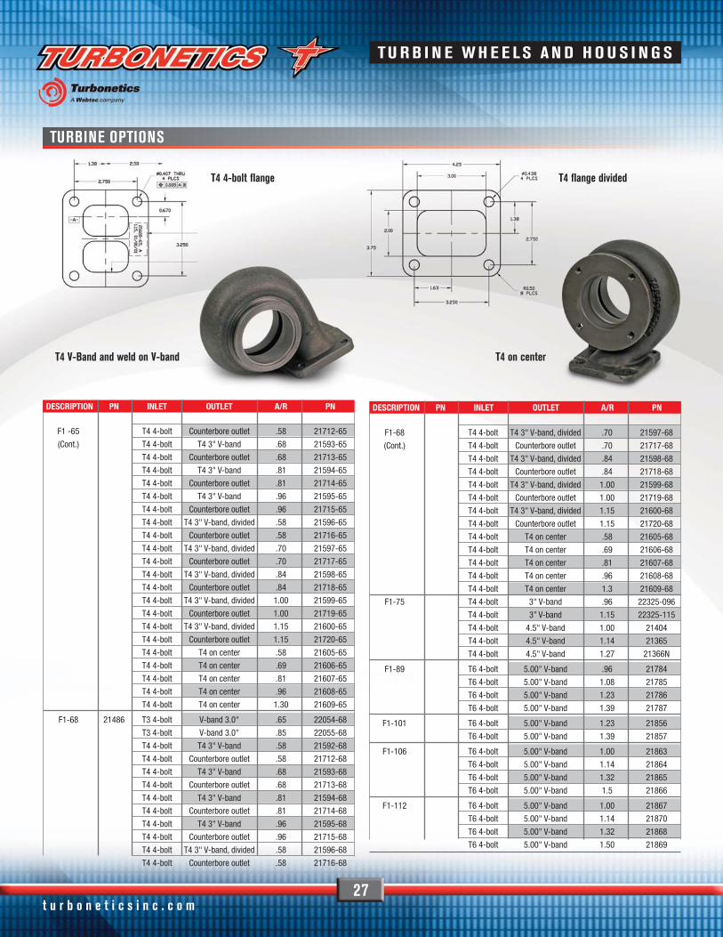
T4 4-bolt flange
T4 V-Band and weld on V-band
T4 flange divided
T4 on center
F1 -65 T4 4-bolt Counterbore outlet .58 21712-65
(Cont.) T4 4-bolt T4 3" V-band .68 21593-65
T4 4-bolt Counterbore outlet .68 21713-65
T4 4-bolt T4 3" V-band .81 21594-65
T4 4-bolt Counterbore outlet .81 21714-65
T4 4-bolt T4 3" V-band .96 21595-65
T4 4-bolt Counterbore outlet .96 21715-65
T4 4-bolt T4 3" V-band, divided .58 21596-65
T4 4-bolt Counterbore outlet .58 21716-65
T4 4-bolt T4 3" V-band, divided .70 21597-65
T4 4-bolt Counterbore outlet .70 21717-65
T4 4-bolt T4 3" V-band, divided .84 21598-65
T4 4-bolt Counterbore outlet .84 21718-65
T4 4-bolt T4 3" V-band, divided 1.00 21599-65
T4 4-bolt Counterbore outlet 1.00 21719-65
T4 4-bolt T4 3" V-band, divided 1.15 21600-65
T4 4-bolt Counterbore outlet 1.15 21720-65
T4 4-bolt T4 on center .58 21605-65
T4 4-bolt T4 on center .69 21606-65
T4 4-bolt T4 on center .81 21607-65
T4 4-bolt T4 on center .96 21608-65
T4 4-bolt T4 on center 1.30 21609-65
F1-68 21486 T3 4-bolt V-band 3.0" .65 22054-68
T3 4-bolt V-band 3.0" .85 22055-68
T4 4-bolt T4 3" V-band .58 21592-68
T4 4-bolt Counterbore outlet .58 21712-68
T4 4-bolt T4 3" V-band .68 21593-68
T4 4-bolt Counterbore outlet .68 21713-68
T4 4-bolt T4 3" V-band .81 21594-68
T4 4-bolt Counterbore outlet .81 21714-68
T4 4-bolt T4 3" V-band .96 21595-68
T4 4-bolt Counterbore outlet .96 21715-68
T4 4-bolt T4 3" V-band, divided .58 21596-68
T4 4-bolt Counterbore outlet .58 21716-68
F1-68 T4 4-bolt T4 3" V-band, divided .70 21597-68
(Cont.) T4 4-bolt Counterbore outlet .70 21717-68
T4 4-bolt T4 3" V-band, divided .84 21598-68
T4 4-bolt Counterbore outlet .84 21718-68
T4 4-bolt T4 3" V-band, divided 1.00 21599-68
T4 4-bolt Counterbore outlet 1.00 21719-68
T4 4-bolt T4 3" V-band, divided 1.15 21600-68
T4 4-bolt Counterbore outlet 1.15 21720-68
T4 4-bolt T4 on center .58 21605-68
T4 4-bolt T4 on center .69 21606-68
T4 4-bolt T4 on center .81 21607-68
T4 4-bolt T4 on center .96 21608-68
T4 4-bolt T4 on center 1.3 21609-68
F1-75 T4 4-bolt 3" V-band .96 22325-096
T4 4-bolt 3” V-band 1.15 22325-115
T4 4-bolt 4.5" V-band 1.00 21404
T4 4-bolt 4.5" V-band 1.14 21365
T4 4-bolt 4.5" V-band 1.27 21366N
F1-89 T6 4-bolt 5.00" V-band .96 21784
T6 4-bolt 5.00" V-band 1.08 21785
T6 4-bolt 5.00" V-band 1.23 21786
T6 4-bolt 5.00" V-band 1.39 21787
F1-101 T6 4-bolt 5.00" V-band 1.23 21856
T6 4-bolt 5.00" V-band 1.39 21857
F1-106 T6 4-bolt 5.00" V-band 1.00 21863
T6 4-bolt 5.00" V-band 1.14 21864
T6 4-bolt 5.00" V-band 1.32 21865
T6 4-bolt 5.00" V-band 1.5 21866
F1-112 T6 4-bolt 5.00" V-band 1.00 21867
T6 4-bolt 5.00" V-band 1.14 21870
T6 4-bolt 5.00" V-band 1.32 21868
T6 4-bolt 5.00" V-band 1.50 21869
t u r b o n e t i c s i n c . c o m
TU R B I N E WH E E LS AN D H O U S I N G S
28
TRIM PN INDUCER (INCH) MAJOR (INCH) INLET SIZE (INCH) OUTLET (INCH) PN MODEL
T3-50 CAST 20268T 1.674 2.367 3" 2.00" 20374-3 T3T3-60 CAST 20272T 1.830 2.367 3" 2.00" 20375-3 T3
Super 60 CAST 20324T 1.900 2.367 2.35" 2.00" 20376 T3Super 60 CAST 20324T 1.900 2.367 3" 2.00" 20376-3 T3Super-S CAST 20394T 1.904 3.000 2.75" 2.00" 20202 T3T4, T04BT4-50 CAST 30375T 2.112 3.000 3" 2.00" 30491 T3T4, T04ET4-50 CAST 20576T 2.112 3.200 3" 2.00" 30491 T3T4, T04E
Super-V CAST 20364T 2.180 3.000 2.75" 2.00" 20203 T3T4, T04BT4-60 CAST 30378T 2.285 3.000 3" 2.00" 30432 T3T4, T04ET4-60 CAST 20579T 2.285 3.200 3" 2.00" 30432 T3T4, T04EHP-58 CAST 22339 2.293 3.304 4" 2.50" 20240 T-Series
Super-H CAST 20288T 2.300 3.000 2.75" 2.00" 20192 T3T4, T04B60-1- Hi Fi CAST 20230T 2.324 3.000 2.75" 2.50" 20210 60 Series
60-1 CAST 20177T 2.324 3.000 4" 2.50" 20190 60 SeriesHP-61 CAST 21634 2.418 3.228 4" 2.50" 21735 60 SeriesHP-61 CAST 22339 2.418 3.228 4" 2.50" 21386 T-Series62-1 CAST 20255T 2.441 3.000 4" 2.50" 20249 60 Series
HP-66 CAST 22339 2.580 3.584 4" 2.50" 21388 T-SeriesHP-70 CAST 22339 2.733 4.030 4" 3.00" 21391 T-SeriesHP-72 CAST 22339 2.840 4.030 4" 2.50" 21392 T-SeriesHP-72 CAST 22339 2.840 4.030 4.50" 3.00" 21401 Super THP-72 CAST 21849 2.840 4.030 4.50" 3.00" 21401 Mid FrameHP-76 CAST 22339 2.941 4.030 4" 2.50" 22343-2 T-SeriesHP-76 CAST 22339 2.941 4.030 4.50" 3.00" 21402 Super THP-76 CAST 21419 2.941 4.030 4.50" 3.00" 21411 Mid FrameHP-78 CAST 22339 3.070 4.030 4" 2.50" 21394 T-SeriesHP-78 CAST 22339 3.070 4.030 4.50" 3.00" 21395 Super THP-78 CAST 21355 3.070 4.030 4.50" 3.00" 21395 Mid FrameHP-80 CAST 21356 3.150 4.628 4.50" 3.00" 21396 Y2KHP-88 CAST 21359 3.463 4.628 4.50" 3.00" 21399 Y2KHP-91 CAST 21361 3.582 4.628 4.50" 3.00" 21403 Y2KHP-91 CAST 30721 3.582 4.628 5.50" 3.00" 20735 ThumperHP-94 CAST 21997 3.688 5.565 5.50" 3.00" 21998 ThumperHP-98 CAST 30895 3.852 5.565 5.50" 3.00" 21006 ThumperHP-101 CAST 30728 3.976 5.565 5.50" 3.00" 20738 ThumperHP-106 CAST 30649 4.161 5.560 5.50" 3.00" 20737 ThumperHPC-54 BILLET 22374 2.121 2.818 3" 2.00" 22375-2 T04EHPC-58 BILLET 22365 2.285 2.995 3" 2.00" 22366-2 T04EHPC-61 BILLET 22355 2.401 3.219 3" 2.00" 22356-2 T04EHPC-61 BILLET 22355 2.401 3.219 4." 2.50" 22357-2 60 SERIESHPC-61 BILLET 22355 2.401 3.219 4" 2.50" 22358-2 T-SERIESHPC-64 BILLET 22333 2.52 3.230 3" 2.00" 22334-2 T04EHPC-64 BILLET 22333 2.52 3.230 4" 2.50" 22335-2 60 SERIESHPC-64 BILLET 22333 2.52 3.230 4" 2.50" 22336-2 T-SERIESHPC-69 BILLET 22361 2.717 3.489 4." 2.50" 22363 T-SERIESHPC-72 BILLET 22347 2.849 3.711 4" 2.50" 22350-2 T-SERIESHPC-72 BILLET 22347 2.849 3.711 4.50" 3.00" 22351-2 SUPER THPC-72 BILLET 22348 2.849 3.711 4.50" 3.00" 22351-2 MIDFRAMEHPC-75 BILLET 22339 2.941 3.930 4" 2.50" 22342-2 T-SERIESHPC-75 BILLET 22339 2.941 3.930 4.50" 3.00" 22343-2 SUPER THPC-75 BILLET 22340 2.941 3.930 4.50" 3.00" 22343-2 MIDFRAMEHPC-88 BILLET 22329 3.464 4.471 4.50" 3.00" 22327-2 Y2KHPC-91 BILLET 22171 3.605 5.560 5.50" 3.00" 20735 ThumperHPC-115 BILLET 21513 4.528 6.000 5.50" 3.00" 21514 Thumper
Phone: (805) 581-0333 • Fax: (805) 584-1913
COMPRESSOR WHEEL COMPRESSOR HOUSING TURBOCHARGER
COMPRESSOR WHEELS AND HOUSINGS

29
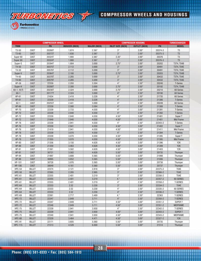
WHEEL DIMENSIONS AND TRIM
The most important dimensions when choosing a turbocharger are thecompressor wheel inducer and the turbine wheel exducer diameters. In addition, the ratio of the compressor wheel inducer to major diameteralso affects the turbocharger performance drastically. The ratio of theinducer area divided by the major area is often called “trim”. Generally,a higher trim number wheel means more airflow, while a smaller trimresults in faster spoolup.
T3 TO4B TO4E 60 SERIES
T-SERIES THUMPER 91-115SUPER T, MID FRAME & Y2K 80-88Ported shroud shown
t u r b o n e t i c s i n c . c o m
COMPRESSOR WHEELS AND HOUSINGS

30
TURBINE HOUSING FLANGES AND GASKETS
Turbonetics turbo accessories make turbo installation a breeze. We have a wide selection of standard andstainless steel flanges, that fit a wide range of industry-standard connection types and turbochargers.
T3 TURBINE HOUSING FLANGESSIZE DRILLED STAINLESS STEEL TRAPPED M10 STAINLESS STEEL GASKET
T3 inlet 4bolt 20365S 30263
T3 inlet 5bolt 20367
T3 discharge 4bolt 21418
T4 TURBINE HOUSING FLANGESSIZE DRILLED STAINLESS STEEL TRAPPED M10 STAINLESS STEEL GASKET
T4 inlet flange, 4bolt 21102 21103 30143
T4 inlet flange, 4bolt, divided n/a n/a n/a 30143-DIV
T4 inlet flange, 4 bolt, 2.25" hole use 30143
T4 discharge flange, 4 bolt, 2.25" hole 30142S
T4 discharge flange, 4 bolt, 3" hole 30142S
T6 Y2K 80 through Thumper 115 inlet included in 10794 kit
T3 Gasket30263
T4 Flange21102
T3 5 Bolt Flange20367
T4 Gasket30143
T3 Flange20365
Phone: (805) 581-0333 • Fax: (805) 584-1913
T3 V - Band IN / OUTDESCRIPTION IN/OUT PN
OUTLET 31356
INLET 31355
OUTLET 30242
INLET 30624
FLANGES
CLAMPS
TURBINE HOUSING FLANGES & GASKETS

V-BAND CLAMPS AND V-BAND FLANGES
31
Improve performance and protect components in your engine bay atthe same time with Turbonetics’ heatshields. Made from aerospacegrade material, and installing in minutes, these heat shields keep theexhaust gas heat where it belongs: Inside the turbine housing.
The more energy you can keep directed at the turbine wheel thebetter the performance of the turbo. We use ceramic fiber wrappedwith corrugated aluminum foil to keep the inside of your turbo hot,and the outside cool.
PN: 20163
PN: 31040 T35-Bolt Discharge
PN: 30149On-Center
PN: 30228 T4 Tangential
PN: 31172T4 Fabric
PN: 31171T3 Fabric
SIZE TURBINE HOUSING TUBE WELD TUBE WELD FLANGE V-BAND CLAMP USE ON TURBINE HOUSINGWELD FLANGE FLANGE STAINLESS STEEL
2.5" 30230 30231 30231-S 30232 T3
3" 20244 30241 30241-S 30242 T3, T4, GT-K, Hurricance, TN
4" 20533 30409 30409-S 30410 T-series
Y2K / Thumper N/A 30409 30409-S 30410 Mid Frame Y2K / Thumper
3.5" 20534 30407 30407-S 30408 Mid Frame
V-bands are quickly becoming the number one choice in making turbine housing connections.For good reasons: They allow fast and easy turbo installation and removal, do not require agasket, and can be oriented in any rotation.
ADAPTORS:PN DESCRIPTION
20760 V-band adapter - 3" to 3.5"
20761 V-band adapter - 3" to 4"
t u r b o n e t i c s i n c . c o m
T3 V - Band IN / OUTDESCRIPTION IN/OUT PN
OUTLET 31356
INLET 31355
OUTLET 30242
INLET 30624
ADAPTERSFLANGES
CLAMPS
HEATSHIELDSPN DESCRIPTION
31171 Heatshield - T3 turbine housing, fabric
31040 Heatshield - T3 5 bolt turbine housing, flexible
31172 Heatshield - T4 tangential turbine housing, fabric
30149 Heatshield - T4 on center housings, hard shell
30228 Heatshield - T4 tangential turbine housing, hard shell
20163 Heatshield sheet - 6" x 14"
TURBINE HOUSING HEATSHIELDS AND V-BANDS
TURBINE HOUSING HEATSHIELDS & V-BANDS

32
FLUID LINES & FITTINGS
OIL LINE FITTINGSOIL LINE FITTINGS ORIENTATION FITS CENTER HOUSINGS
1/8" NPT x -3AN, short straight T3, T3T4, T04B&E, 60series, T series, Super T
1/8" NPT x -3AN, medium straight T3, T3T4, T04B&E, 60series, T series, Super T
1/8" NPT x -4AN, short straight T3, T3T4, T04B&E, 60series, T series, Super T
1/4" NPT x -4AN straight Mid-Frame and Y2K / Thumper
1/8" NPT x -4AN 45° T3, T3T4, T04B&E, 60series, T series, Super T
1/4" NPT x -4AN 45° Mid-Frame and Y2K / Thumper
1/8" NPT x -3AN, short 90° T3, T3T4, T04B&E, 60series, T series, Super T
1/8" NPT x -3AN, medium 90° T3, T3T4, T04B&E, 60series, T series, Super T
1/8" NPT x 4AN 90° T3, T3T4, T04B&E, 60series, T series, Super T
1/4" NPT x 4AN 90° Mid-Frame and Y2K / Thumper
UNIVERSAL TEFLON® STAINLESS STEEL BRAIDED LINES
Delivering fresh oil for lubrication and cooling of your Turbonetics’ turbois critical to ensure optimal performance and avoid costly repairs. To cover the wide range of turbos and engine setups, Turbonetics
carries a wide range of oil and water lines, flanges, gaskets and fittings– everything you need to make sure your turbo gets the vital fluids itneeds to provide boost for many miles.
OIL LINE ADAPTORSOIL LINE ADAPTORS ORIENTATION PN FITS CENTER HOUSINGS
1/8" MPT x 1/4" FPT M10x1.00x-3 straight universal
1/8" NPT MxFxF straight universal
Oil filter replacement 20754 T3, T3T4, T04B&E, 60series, T series, Super T
PN: 30244 PN: 30816
PN: 30245
PN: 10721
Phone: (805) 581-0333 • Fax: (805) 584-1913
CONNECTION LENGTH PN-4AN female swivel ends 24" 31013
-4AN female swivel ends 36" 10724
-4AN female swivel ends 48" 10725
F LU I D L I N E S & F IT T I N G S

OIL SUPPLY
33
OIL FLANGESDESCRIPTION PN FITS TURBO FAMILIES GASKET
Oil drain flange 20259 T3, T3/T4 30141
Oil drain flange, billet 20258 T3, T3/T4 30141
Oil drain flange 21521 Mid Frame, Y2K / Thumper
Oil inlet flange 30500 T3, T3/T4 30238
Oil inlet flange Mid Frame, Y2K / Thumper
Gasket kit (oil inlet & drain, turbine inlet) 10794 TNX91 through Y2K / Thumper
OIL GASKETSFITTINGS ORIENTATION PN FITS
3/8" NPT x 5/8" hose straight watercooled center housings with 3/8NPT fitting
1/2" NPT x 5/8" hose straight 30244 oil drain, all turbos
1/2" NPT x 5/8" hose 45° oil drain, all turbos
1/2" NPT x 5/8" hose 90° oil drain, all turbos
1/8" NPT x 5/32" hose straight 30306 Vacuum hose 30542-BK
1/8" NPT x 5/32" hose 90° Vacuum hose 30542-BK
1/8" NPT x 1/4" hose 90° Vacuum hose 30543-BK
PN: 30141
PN: 20259
PN: 21521
PN: 30500PN: 10794
Complete a clean and durable installation withgenuine Turbonetics oil line gaskets and flanges
t u r b o n e t i c s i n c . c o m
OIL SUPPLY - GASKETS & FLANGES

34
ASME COMPRESSOR INLET KITS
PLENUMS
Designed to ASME specifications, the compressor Inlet kit allows youto maximize airflow velocity and air volume at the compressor inlet.Manufactured from spun aluminum, the kit comes complete withpolished bellow, silicone hose and T-clamps. Adds 2.5" to 3" to thelength of the turbo inlet. See page 28 for compressor housing inlet sizes.
PN DESCRIPTION
10766 3" Inlet Kit10767 4" Inlet Kit
20817P 4.5" Inlet Bell20816P 5.5" Inlet Bell
Turbonetics pressure plenum features a ball-burnished finish. This low-profile design is great for low clearance hood applications.
Pressure Plenums will fit the standard 5-1/8'' carburetor inlet or can bemodified to fit 4 barrel EFI throttle bodies.
PN PLENUMS
10351 3" side entry
PN 10351
Phone: (805) 581-0333 • Fax: (805) 584-1913
PARTS & AC C E SS O R I E S

EXTERNAL WASTEGATES
35
All of Turbonetics’ high performance wastegates are designed andengineered to control boost and flow large amounts of gas volumes,allowing the complete turbo system to be balanced perfectly. All ofour wastegates are made from stainless steel bases and high
temperature resistant diaphragms to withstand extreme EGTs(Exhaust Gas Temperatures). All external wastegate kits comecomplete with flanges and clamps, and with an adjustable set screwto fine-tune the valve’s response.
WATEGATE KITSDESCRIPTION SIZE HP RATING PN
Evolution kit 35mm up to 500HP 10780
RG-45 kit 45mm up to 750HP 11240
Newgen kit 51mm up to 1000HP 10733
Newgen HP kit 51mm up to 1500HP 11105
RG-45 KitKIT PN 11240
RG-45 45MM WASTEGATEANCILIARY PARTS FOR RG-45 45MM WASTEGATE PN
Spring Purple 15 PSI 31151-15
Spring Black 11 PSI 31151-11
Spring Green 8 PSI 31151-8
Spring Brown 5 PSI 31151-5
Diaphragm 21648
Weld Flange 21910
Weld Flange Outlet 21911
Valve Seat Clamp In or Out 30626
t u r b o n e t i c s i n c . c o m
EXTE R NAL WASTE GATE S

36
EXTERNAL WASTEGATES
EVOLUTION KITKIT PN 10780
NEWGEN HPKIT PN 11105
NEWGEN KITKIT PN 10733
NEWGEN 51MM WASTEGATE ANCILIARY PARTS FOR NEWGEN 51MM WASTEGATE PN
Spring Pink 15 PSI 30693-15
Spring Red 11 PSI 30693-11
Spring Orange 8 PSI 30693-8
Spring Yellow 5 PSI 30693-5
Diaphragm 20644
V-Band Weld Flange Inlet 20650
V-Band Clamp 30643
Discharge Weld Flange 21658
NEWGEN HP 51MM WASTEGATEANCILIARY PARTS FOR NEWGEN HP 51MM WASTEGATE PN
Spring Red 20 PSI 31047-20
Spring Orange 15 PSI 31047-15
Spring Yellow 10 PSI 31047-10
Diaphragm 20113
V-Band Clamp 30643
V-Band Weld Flange Inlet 20650
Discharger Weld Flange 21688
Phone: (805) 581-0333 • Fax: (805) 584-1913
EVOLUTION 35MM WASTEGATE ANCILIARY PARTS FOR EVOLUTION 35MM WASTEGATE PN
Flange, drilled 20260
Flange, drilled, stainless steel 20260S
Flange, tapped, 5/16" - 18 20261
Flange, tapped, 5/15" - 18, stainless steel 20261S
Flange, tapped, M8 20981
Replacement Gasket 20142
Spring 9PSI 30778-9
Spring 7PSI 30778-7
Spring 5PSI 30778-5
Diaphragm 20644
Valve Seat 20763
EXTE R NAL WASTE GATE S

BLOW OFF VALVES AND BOOST CONTROLLERS
BOOST CONTROLLERS
37
The use of a blow off valve is essential on engines where the throttle iscontrolled by a butterfly inside the throttle body (basically all enginesexcept diesels). As the throttle is lifted the inertia of the turbo is stillproducing boost. But with the butterfly closed, the pressured air hasnowhere to go and the result is a sudden increase in pressure upstream
of the butterfly. This can cause damage to the turbo, intercooler, andultimately the engine very quickly. A blow off valve releases this pressurespike into the atmosphere before damage is done. A bypass valve isbasically the same as a blow off valve. But instead of venting pressureto the outside, the air is routed back into the turbocharger inlet.
Boost controllers allow modifying boost levels without physically changing yourwastegate setting. Turbonetics offers the classic VBC kit for three different boostratings. All of our kits come with a wide selection of fittings and all necessary hardware.
BLOW OFF VALVE KITS PN
Godzilla kit 10765
BOOST CONTROLLER KITS
BOOST CONTROLLER KITS PSI RANGE PN COMPATIBLE WITH:
Classic VBC 0 to 10 10402-10 all external wastegate, dual port actuators
Classic VBC 0 to 25 10402-25 all external wastegate, dual port actuators
Classic VBC 0 to 50 10402-50 all external wastegate, dual port actuators
CLASSIC VBC KITEXTERNAL WASTEGATE AND DUAL
PORT ACTUATORS ONLY
“GODZILLA” VALVE ASSEMBLY
DESCRIPTION PN
Valve body assembly N/A
V-band clamp assembly 30422
Valve body O-ring 30467
Base flange fastener 30471
Base flange 20491
Base flange O-ring 30468
Weld flange, steel 20507S
Weld flange, aluminum 20507A
Discharge gasket 20510
Discharge hose adapter 20495
Discharge horn assembly 10692
Discharge fastener 30470
Diaphragm Godzilla 20502
t u r b o n e t i c s i n c . c o m
BYPASS VALVES & BOOST CONTROLLERS
GODZILLAKIT PN 10765
38
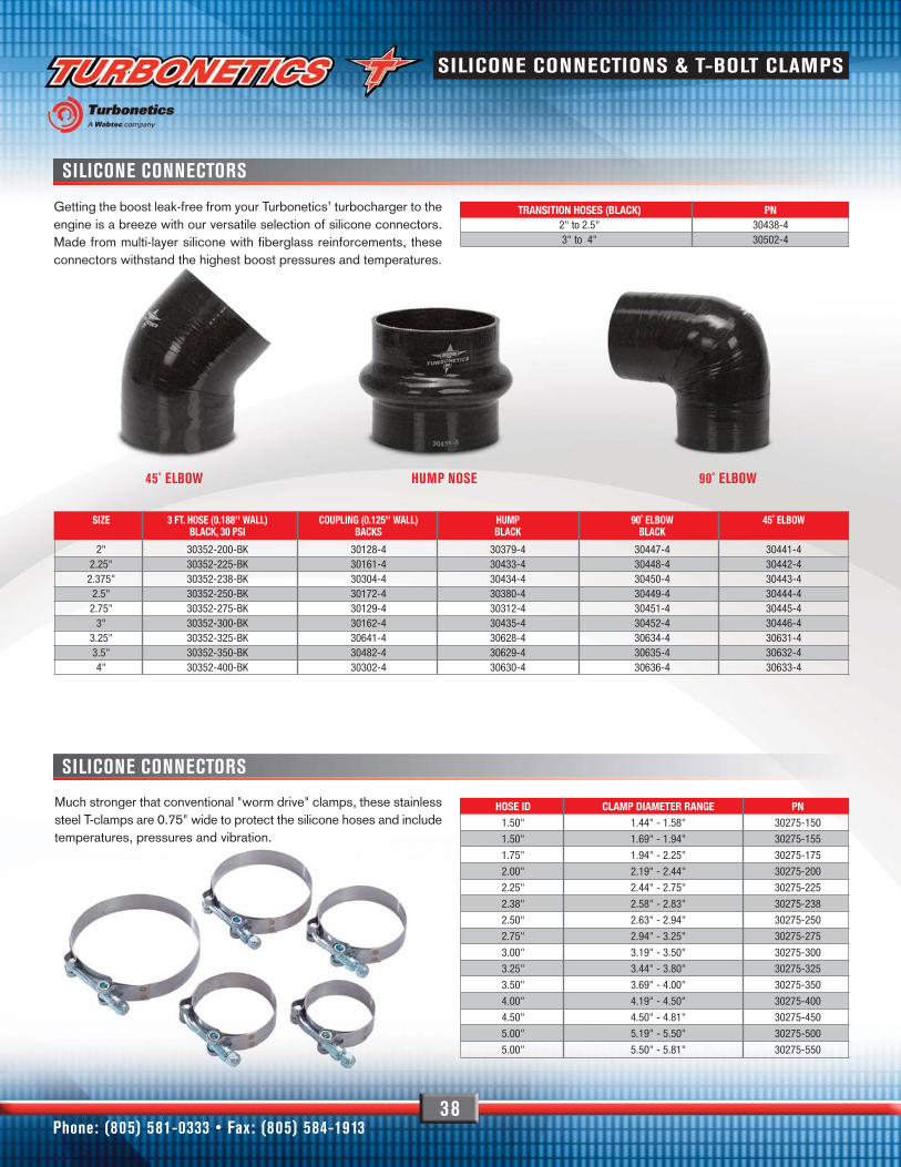
SILICONE CONNECTORS
Getting the boost leak-free from your Turbonetics’ turbocharger to theengine is a breeze with our versatile selection of silicone connectors.Made from multi-layer silicone with fiberglass reinforcements, theseconnectors withstand the highest boost pressures and temperatures.
Much stronger that conventional "worm drive" clamps, these stainlesssteel T-clamps are 0.75" wide to protect the silicone hoses and includetemperatures, pressures and vibration.
TRANSITION HOSES (BLACK) PN2" to 2.5" 30438-43" to 4" 30502-4
SIZE 3 FT. HOSE (0.188'' WALL) COUPLING (0.125'' WALL) HUMP 90˚ ELBOW 45˚ ELBOWBLACK, 30 PSI BACKS BLACK BLACK
2" 30352-200-BK 30128-4 30379-4 30447-4 30441-42.25" 30352-225-BK 30161-4 30433-4 30448-4 30442-42.375" 30352-238-BK 30304-4 30434-4 30450-4 30443-42.5" 30352-250-BK 30172-4 30380-4 30449-4 30444-42.75" 30352-275-BK 30129-4 30312-4 30451-4 30445-4
3" 30352-300-BK 30162-4 30435-4 30452-4 30446-43.25" 30352-325-BK 30641-4 30628-4 30634-4 30631-43.5" 30352-350-BK 30482-4 30629-4 30635-4 30632-44" 30352-400-BK 30302-4 30630-4 30636-4 30633-4
HOSE ID CLAMP DIAMETER RANGE PN1.50" 1.44" - 1.58" 30275-150
1.50" 1.69" - 1.94" 30275-155
1.75" 1.94" - 2.25" 30275-175
2.00" 2.19" - 2.44" 30275-200
2.25" 2.44" - 2.75" 30275-225
2.38" 2.58" - 2.83" 30275-238
2.50" 2.63" - 2.94" 30275-250
2.75" 2.94" - 3.25" 30275-275
3.00" 3.19" - 3.50" 30275-300
3.25" 3.44" - 3.80" 30275-325
3.50" 3.69" - 4.00" 30275-350
4.00" 4.19" - 4.50" 30275-400
4.50" 4.50" - 4.81" 30275-450
5.00" 5.19" - 5.50" 30275-500
5.00" 5.50" - 5.81" 30275-550
45˚ ELBOW HUMP NOSE 90˚ ELBOW
SILICONE CONNECTORS
Phone: (805) 581-0333 • Fax: (805) 584-1913
SILICONE CONNECTIONS & T-BOLT CLAMPS

TURBONETICS SPEARCO BRAND INTERCOOLERS
AIR TO AIR CORE SELECTION GUIDE
39
The Spearco brand name has been well known for unbeatable qualityand performance heat exchangers for over 35 years. Whether the designis an air-to-air, liquid-to-air or liquid-to-liquid, all Spearco heat exchangersare designed and manufactured using a Bar and Plate style construction,which is superior in performance and durability to older style Tube andFin designs. Spearco’s W.A.V.E (Wide Area Vane Effectiveness)technology is the ultimate in strength and efficiency, withstanding peakpressures in excess of 200 psi. With several fin designs to choose fromwe are able to achieve maximum cooling effectiveness within a smallerpackage than traditional types of heat exchangers.
We offer a wide range of universal intercoolers with both cast andfabricated manifolds. If you cannot find what you are looking for,contact us. We will help you choose the intercooler that is right foryou, or make a customized intercooler to your specifications.
CORE PN THICKNESS HEIGHT LENGTH FLOW RATE IN HP RATINGCUBIC FEET/MIN
2-195 3.50" 9.40" 8.375" 500 350
2-110 3.50" 9.24" 6.00" 540 380
2-113 3.50" 6.80" 11.75" 320 235
2-172 3.50" 10.40" 10.50" 575 405
2-161 3.50" 7.90" 12.88" 700 490
2-120 3.50" 7.90" 24.00" 740 520
2-203 3.50" 6.52" 24.00" 740 520
2-178 3.50" 7.80" 20.00" 760 530
2-180 3.50" 13.00" 17.25" 760 530
2-127 6.00" 5.875" 22.00" 855 600
2-216 3.50" 10.50" 28.00" 860 600
2-179 4.50" 19.70" 20.75" 1000 700
2-174 4.50" 16.40" 8.75" 1050 735
2-177 4.50" 18.50" 6.50" 1080 760
2-102 3.00" 17.00" 36.00" 1400 980
2-125 3.00" 21.20" 33.00" 1400 980
2-205 3.50" 13.04" 24.00" 1400 980
70062 5.10" 12.72" 27.80" 1820 1400
KEYA = THICKNESSB = HEIGHTC = LENGTH/WIDTH
A
B
C
We recommend picking a core that is rated slightly above your targethorsepower to compensate for pressure drops in the air intakeplumbing. Using the chart below, showing our most popular air to airintercooler cores, we produce custom intercooler assemblies with
1.75”, 2.00”, 2.25”, 2.50”, 2.75” 3.00” and 4.00” tube connections.Manifolds can be straight or tapered, and manifold orientations can bevaried to fit your application. Check out www.turboneticsinc.com, orcontact us with your specifications.
t u r b o n e t i c s i n c . c o m
INTERCOOLER SELECTION GUIDE/SPEARCO

40
CORE #2-110 ASSEMBLY #2-220 CORE #2-113 ASSEMBLY #2-222
CORE #2-167 ASSEMBLY #2-226CORE #2-116 ASSEMBLY #2-223 CORE #2-161 ASSEMBLY #2-225
CORE #2-172 ASSEMBLY #2-245 CORE #2-173 ASSEMBLY #2-257 CORE #2-174 ASSEMBLY #2-237
CORE #2-178 ASSEMBLY #2-247CORE #2-175 ASSEMBLY #2-239 CORE #2-176 ASSEMBLY #2-233
CORE #2-179 ASSEMBLY #2-277 CORE #2-101 ASSEMBLY #2-246
CORE #2-194 ASSEMBLY #2-243CORE #2-102 ASSEMBLY #2-248 CORE #2-192 ASSEMBLY #2-242
CORE #2-195 ASSEMBLY #2-249 CORE #2-196 ASSEMBLY #2-250 CORE #2-197 ASSEMBLY #2-234
CORE #2-115 ASSEMBLY #2-221
CORE #2-180 ASSEMBLY #2-235
VISIT WWW.TURBONETICSINC.COM FOR ALL INTERCOOLER CORE DIMENSIONS AND FULL SIZE DRAWINGS.
AIR TO AIR INTERCOOLER CORES
Phone: (805) 581-0333 • Fax: (805) 584-1913
A I R TO A I R I NTE R C O O LE R C O R E S

AIR TO AIR INTERCOOLER CORES
41
CORE #2-212 ASSEMBLY #2-263 CORE #2-216 ASSEMBLY #2-272 CORE #2-217 ASSEMBLY #2-279
CORE #2-210 ASSEMBLY #2-274 CORE #2-120 ASSEMBLY #2-238 CORE #2-112 ASSEMBLY #2-300
CORE #2-110 ASSEMBLY #2-228 CORE #2-203 ASSEMBLY #2-255 CORE #2-205 ASSEMBLY #2-256
CORE #2-207 ASSEMBLY #2-266 CORE #2-208 ASSEMBLY #2-258 CORE #2-209 ASSEMBLY #2-262
CORE #2-210 ASSEMBLY #2-267 CORE #2-211 ASSEMBLY #2-268
VISIT WWW.TURBONETICSINC.COM FOR ALL INTERCOOLER CORE DIMENSIONS AND FULL SIZE DRAWINGS.
t u r b o n e t i c s i n c . c o m
A I R TO A I R I NTE R C O O LE R C O R E S

42
UNIVERSAL SPEARCO AIR TO AIR INTERCOOLERS
HP RATING CORE THICKNESS CORE HEIGHT CORE WIDTH HOSE CONECTION PN450 3.50" 7.90" 20.00" 2.50" OD 5-377
450 3.50" 7.90" 20.00" 2.50" OD 5-374
500 3.50" 7.90" 28.00" 2.50" OD 2-379
550 3.50" 7.90" 24.00" 3.00" OD 5-383
650 3.50" 10.50" 28.00" 3.00" OD 5-364
760 3.50" 9.00" 18.48" 2.50" OD 2-221A-3C
PN 5-364 PN 2-221A-3C
PN 2-379 PN 5-377
PN 5-374PN 5-383
While the sheer amount of Turbonetics air to air intercooler versions canbe overwhelming, below you can find a quick selection of our mostpopular complete intercoolers, in stock and ready to ship. For more coreand manifold options, go to www.turboneticsinc.com or contact us.
Phone: (805) 581-0333 • Fax: (805) 584-1913
AIR TO AIR UNIVERSAL INTERCOOLERS

LIQUID TO AIR INTERCOOLERS
43
Spearco liquid to air intercoolers are best suited for racing and highboost applications, or where the engine setup does not allow for aconventional air to air unit. While installation is more involved than anair to air intercooler, liquid to air intercoolers offer superior coolingefficiency. Remarkable increases in air density and power are theresult. Turbonetics offers five standard core sizes that can becombined to create customized units.
CORE PN THICKNESS HEIGHT LENGTH FLOW RATE IN HP RATINGCUBIC FT/MIN
2-213 3.00" 4.25" 8.63" 575 405
2-206 2.25" 4.65" 7.00" 575 405
2-171 4.50" 4.50" 10.125" 570 400
2-170 4.50" 9.00" 10.125" 1000 700
2-202 6.00" 13.51" 12" 1800 1260
PN 2-260
t u r b o n e t i c s i n c . c o m
LIQUID TO AIR INTERCOOLER SELECTION GUIDE

t u r b o n e t i c s i n c . c o m44
PART NO. 2-270
PART NO. 2-265
PART NO. 2-271 PART NO. 2-279
PART NO. 2-278
PART NO. 2-252Effective on engines up to 2.6L (160 CID) or 450 CFM.Available in configurations A or B.
PART NO. 2-269
Effective on engines up to 4.2L (260 CID) or 700 CFM.Available in configurations A or B shown below. Air manifoldoutlet 3" OD.
PART NO. 2-231
HORSEPOWER300
HORSEPOWER
HORSEPOWER
HORSEPOWER HORSEPOWER
HORSEPOWER
HORSEPOWER
HORSEPOWER400
400400
700 600
800600
LIQUID TO AIR UNIVERSAL INTERCOOLERS

Phone: (805) 581-0333 • Fax: (805) 584-191345
For high horsepower racing engines up to 2500hp. Available as shown or it can be fabricated to suit your dual supercharger or turbocharger applications.
For high horsepower racing engines up to 2500hp. Availableas shown or it can be fabricated to suit your dualsupercharger or turbocharger applications.
Effective on engines up to 7.4L (454 CID) or 1500 CFM.Available in configurations A, B, or C shown below. Air manifold outlet 3" OD. Core only:
For high horsepower racing engines up to 2500hp. Available as shown or it can be fabricated to suit.
PART NO. 2-275
PART NO. 2-276
PART NO. 2-260 PART NO. 2-280
This configuration is arranged so it can be mounted on top of the intake manifold on highperformance V-8 racing engineswith centrifugal superchargers,custom fabricated with or with-out mounting flanges in 2, 3, or4 core arrangement. This set-upgives excellent results usingcirculated ice water withextremely low pressure drop.
PART NO. 2-254
PART NO. 2-259
PART NO. 2-261
PART NO. 2-230
HORSEPOWER
HORSEPOWER
HORSEPOWER
HORSEPOWER HORSEPOWER
HORSEPOWER
HORSEPOWER
HORSEPOWER1400700
900 1400
1500900
1200 2500
LIQUID TO AIR UNIVERSAL INTERCOOLERS

46
MITSUBISHI EVOLUTION X INTERCOOLER KIT
This direct bolt-on high performance intercooler upgrade features thesame W.A.V.E. Technology as used in all the other high horsepower racecars. This intercooler is also the largest intercooler you can fit withoutany modification or cutting to the vehicle. All factory mounting bracketsare retained. Computer modeled end tank design, center air inlet and
outlets provide maximum boost pressurve distribution, increasing coolingefficiency and dramatically reducing pressure drop. The W.A.V.E.Technology core is capable of dropping temps by as much as 220º F.Kit includes all heavy duty T-bolt clamps and silicone hose needed forinstallation. Approximate install time 1-2 hours.
*Core measures 3.5” Thick x 11.74” Tall x 20.00” Wide**Measurement does not include end tanks
PN 11647
Phone: (805) 581-0333 • Fax: (805) 584-1913
MITSUBISHI EVOLUTION X INTERCOOLER KIT

SUBARU WRX/ STI INTERCOOLER KIT
47
Spearco's WRX intercooler kits feature the largest air-to-air, top-mountintercooler in the market. Utilizing the factory mounting points, themassive 4.5 in. thick unit bolts on easily without any modifications tothe vehicle. Factory turbo piping and blow-off valves can be bolted oneasily with standard hand tools. The massive 1,000 cfm intercooleroffers a very low pressure drop and extremely low chargetemperatures. Dyno results have shown performance improvementsof up to 15 hp when compared to the stock intercooler. The kits comecomplete with clamps and silicone hose. Boost pressure can now beincreased without the horsepower-robbing effects of the extremecharge temperatures normally associated with compressed intake air.
Spearco’s WRX intercooler kit for 2008 NON-STI models features thelargest air-to-air top-mount intercooler on the market. Utilizing the factorymounting points, the massive 3.5"-thick unit bolts on with minormodifications to the vehicle. Includes aluminum hood splitter, all mountinghardware, clamps and silicone hoses. Approximate install time of 1-2 hours.
*Core measures 3.5” Thick x 7.80” Tall x 20.00” Wide**NON-STI models ONLY
t u r b o n e t i c s i n c . c o m
Subaru WRX NON-STI 2001-2007 2-450 Subaru WRX STI 2004-2007 70071
PN 11651
SUBARU WRX / STI INTERCOOLER KIT

48
2005 TO 2009 MUSTANG GT 4.6L V8 TURBO SYSTEM (MANUAL TRANSMISSION ONLY)
STOCK CRANKSHAFT HP 300 HP
TURBOCHARGED HP: 540 HP (475ft/lb) @ 8.5 PSI OF BOOST
INSTALLATION:
• Installs in one day
• No modifications to chassis required - no cutting or splicing of electrical components
50 STATESMOG LEGAL
SYSTEM INCLUDES:MAJOR COMPONENTS:
• Turbonetics 60 series ceramic ball bearing turbocharger
• T304 stainless TIG welded exhaust plumbing from stock cat converters to turbocharger, from turbocharger back to stock exhaust system
• Aluminum plumbing from turbocharger to intercooler, from intercooler to throttle body
• Turbonetics Evolution 35mm external wastegate
• Spearco front mount intercooler
• Bosch by-pass valve
• Eight 39lb/hr fuel injectors
• Fuel pump controller (MSD boost referenced)
• 8 Spark plugs 1 heat range colder than stock
• High flow air filter, stock replacement
• Diablo hand help ECU programmer loaded with Turbonetics CARB legal program
• De-gas reservoir
• Hardware kits (fastener, gaskets, clamps, hoses, EO# D-99-5 certification label)
Phone: (805) 581-0333 • Fax: (805) 584-1913
15168-1 - Mustang V-8 Complete Turbo System
Mustang V-8 Turbo Tuner system is intended for off road applications only.Same as complete system, but without spark plugs, fuel pump controller,tuner, injectors and air filter. Perfect for more extreme, custom race trackapplications. Check www.turboneticsinc.com for more info.
FO R D M U STAN G SYSTE M

2010-2013 CAMARO SS LS3 / L99 V8 TURBO SYSTEM
49
STOCK RWHP 364 HP
TURBOCHARGED HP: 511 RWHP @ 6.8 PSI OF BOOST
INSTALLATION:• Installs in one day• No modifications to chassis required - no cutting or
splicing of electrical components
50 STATESMOG LEGAL
SYSTEM INCLUDES:MAJOR COMPONENTS:
• Turbonetics T76 Ceramic Ball Bearing Turbocharger
• Massive Spearco Front Mount Intercooler with 4.5 x 26 x 11” core
• Two Turbonetics Evolution 35mm wastegates
• Turbonetics Duo 35 by-pass valve
• T304 stainless steel TIG welded exhaust plumbing
• Aluminum intercooler and air intake plumbing
• 8 x 630cc/min fuel injectors
• 8 x NGK TR6 spark plugs
• Diablo handheld programmer with CARB legal Tune (For LS3 Manual Transmission cars)
• SCT hand held programmer with CARB Legal Tune (For L99 Automatic Transmission cars)
• Coolant/window wash fluid reservoirs
• Hardware kit (fasteners, gaskets, clamps, instructions, EO label, etc.)
t u r b o n e t i c s i n c . c o m
15192 - Camaro V-8 Complete Turbo System15194 - Camaro V-8 Tuner Turbo System15193 - Camaro V8 Complete Turbo System L99
Automatic Transmission15195 - Camaro V8 Tuner Turbo System L99
Automatic TransmissionCamaro V-8 Turbo Tuner system is intended for off road applications only. Same ascomplete system, but without spark plugs, fuel pump controller, tuner, injectors andair filter. Perfect for more extreme, custom race track applications. Checkwww.turboneticsinc.com for more info.
C H EVR O LET CAMAR O SYSTE M
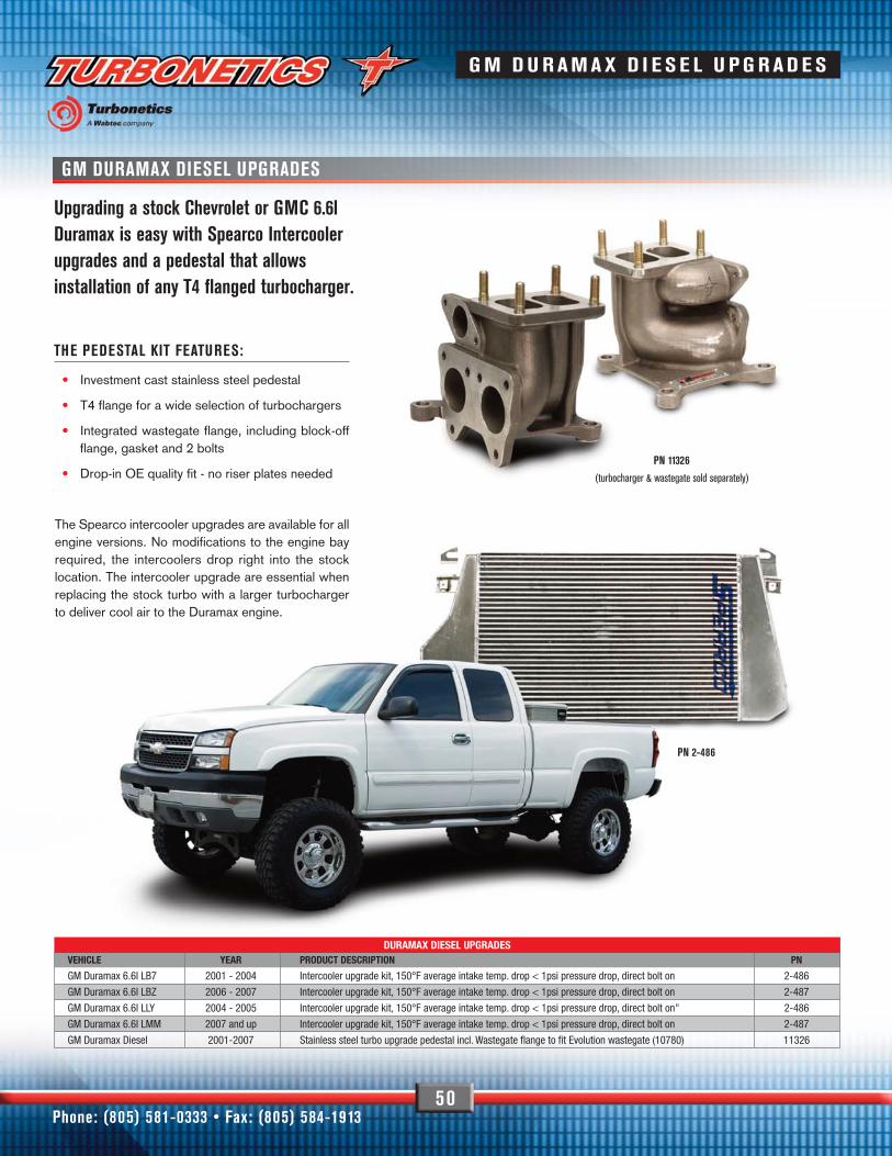
50
GM DURAMAX DIESEL UPGRADES
Upgrading a stock Chevrolet or GMC 6.6lDuramax is easy with Spearco Intercoolerupgrades and a pedestal that allowsinstallation of any T4 flanged turbocharger.
THE PEDESTAL KIT FEATURES:
• Investment cast stainless steel pedestal
• T4 flange for a wide selection of turbochargers
• Integrated wastegate flange, including block-offflange, gasket and 2 bolts
• Drop-in OE quality fit - no riser plates needed
The Spearco intercooler upgrades are available for allengine versions. No modifications to the engine bayrequired, the intercoolers drop right into the stocklocation. The intercooler upgrade are essential whenreplacing the stock turbo with a larger turbochargerto deliver cool air to the Duramax engine.
DURAMAX DIESEL UPGRADESVEHICLE YEAR PRODUCT DESCRIPTION PN
GM Duramax 6.6l LB7 2001 - 2004 Intercooler upgrade kit, 150°F average intake temp. drop < 1psi pressure drop, direct bolt on 2-486
GM Duramax 6.6l LBZ 2006 - 2007 Intercooler upgrade kit, 150°F average intake temp. drop < 1psi pressure drop, direct bolt on 2-487
GM Duramax 6.6l LLY 2004 - 2005 Intercooler upgrade kit, 150°F average intake temp. drop < 1psi pressure drop, direct bolt on" 2-486
GM Duramax 6.6l LMM 2007 and up Intercooler upgrade kit, 150°F average intake temp. drop < 1psi pressure drop, direct bolt on 2-487
GM Duramax Diesel 2001-2007 Stainless steel turbo upgrade pedestal incl. Wastegate flange to fit Evolution wastegate (10780) 11326
PN 11326
(turbocharger & wastegate sold separately)
PN 2-486
Phone: (805) 581-0333 • Fax: (805) 584-1913
G M D U R AMAX D I E S E L U PG R AD E S

FORD POWERSTROKE DIESEL UPGRADES
51
The Ford family of engines see fantastic gains from bolting on theseturbo and intercooler upgrades. Turbonetics offers both intercooler andturbo upgrades the 7,3 and 6.0, and an intercooler upgrade for the 6.4.
Perfectly designed for towing, the Stage 1 turbo and intercooler bringboth the 6.0L and 7.3L to life. Our high powered Stage 2 and Stage3 are available for extreme upgrades.
FOR POWERSTROKE DIESEL UPGRADESVEHICLE YEAR PRODUCT DESCRIPTION PN
Ford 6.0L Powerstroke Diesel 2003 - 2007 Turbo upgrade pedestal only, stainless steel 21653
Ford 6.0L Powerstroke Diesel 2003 - 2007 Turbo upgrade pedestal kit includes all hardware to install any T4 flange turbocharger and connect to stock V-band exhaust. 11313
Ford 6.0L Powerstroke Diesel 2003 - 2007 Turbo upgrade kit Stage I Pedestal, hardware and ball bearing turbo (11470-BB T6168, 0.58 A/R, 3.5"" V-band) Capable of 500HP, 700 ft/lb, 40psi boost. Programmer/tune not included. 15180
Ford 6.0l Powerstroke Diesel 2003-2007 Intercooler upgrade kit, 150°F average intake temp. drop < 1psi pressure drop, direct bolt on 70057
Ford 6.4l Powerstroke Diesel 2007 and up Intercooler upgrade kit, 150°F average intake temp. drop < 1psi pressure drop, direct bolt on 2-488
Ford 7.3l Powerstroke 1999.5 - 2003 Intercooler upgrade kit, 150°F average intake temp. drop < 1psi pressure drop, direct bolt on 70058
6.0 & 7.3 Ford Intercooler
You can now fit a massive 24x23.5x3.5" (core size) intercooler in either the 6.0and the 7.3l Fords. Both are available in complete bolt on kits and come withcast end tanks for added strength.
t u r b o n e t i c s i n c . c o m
6.0L FORD TURBO UPGRADE
FORD POWERSTROKE DIESEL UPGRADES

52
CERAMIC BALL BEARINGSDODGE CUMMINS DIESEL UPGRADES
FOR POWERSTROKE DIESEL UPGRADESVEHICLE YEAR PRODUCT DESCRIPTION PN
Dodge Cummins 12V Diesel 1994 - 1998 Intercooler upgrade kit, 150°F average intake temp. drop < 1psi pressure drop, direct bolt on 2-479
Dodge Cummins 24V Diesel 1998.5 - 2002 Intercooler upgrade kit, 150°F average intake temp. drop < 1psi pressure drop, direct bolt on 2-479
Dodge Cummins 24V CRD 2003 - 2006 Intercooler upgrade kit,150°F average intake temp. drop < 1psi pressure drop, direct bolt on 2-477
Dodge Cummins 24V CRD 2003 - 2006 Turbo Stage I upgrade, T5868, 0.84 A/R, div. ball bearing turbo 450HP, 1100 ft/lbs, 45psi boost, Perfect for towing 11280
Dodge Cummins 24V CRD 2007 Intercooler upgrade kit, 150°F average intake temp. drop < 1psi pressure drop, direct bolt on 2-477
Get the maximum out of your Dodge Cummins 5.9l with a selection ofcarefully designed intercooler and turbo upgrades. With several kitsavailable for towing, street performance or extreme power, you canchoose your perfect fit. All intercooler and turbo upgrades bolt-ondirectly to the factory engine.
Phone: (805) 581-0333 • Fax: (805) 584-1913
DODGE CUMMINS DIESEL UPGRADES

53
TERMS AND CONDITIONSThe following Terms and Conditions are effective November 1, 2006 and aresubject to change without notice.
PAYMENT METHODVisa, MasterCard, American Express, cashier’s check, and money order areaccepted. Company checks are accepted only upon approval.
HEAT EXCHANGER ORDERSAll heat exchanger products are subject to customer-approved drawings and a 50%deposit prior to acceptance of the order. No returns or exchanges on customer-approved heat exchanger products will be accepted.
SHIPPINGAll shipments are Moorpark, California, USA Shipping charges includeinsurance for full value of the product unless prohibited by the shipping agency.
FINAL SHIPMENT HOUROrders received no later than 2:00PM(14:00) will be shipped that day, inventorylevels permitting.
AUTOMATIC ORDER CANCELLATIONUnless told otherwise, Turbonetics will automatically cancel open orders(backorders) after 60 days from the order entry date.
CLAIMSA claim for damage in transit must be made by the customer directly to theshipping agency as soon as the damage is discovered. Turbonetics is not liablefor the condition of merchandise as handled by the shipper once the shipperhas accepted delivery from Turbonetics.
RETURNED GOODS AUTHORIZATION TRACKING NUMBERTurbonetics will only accept product returns, repair orders/upgrades, andwarranty requests that have been approved and are returned with acorresponding Returned Goods Authorization (RGA) tracking number. ContactTurbonetics for approval and the RGA number. Write the RGA number clearlyon the outside of the package and include it inside the package. This is veryimportant in allowing us to properly identify and process your request. Failure tocomply with this requirement will result in the delay of processing or the productbeing returned to you.
RETURN POLICYOnly unused and complete merchandise may be accepted for return subject toinspection and acceptance by Turbonetics. No goods will be accepted withoutprior return authorization from Turbonetics. Call for approval and RGA (ReturnedGoods Authorization) tracking number. • No returns will be accepted without an RGA tracking number. No
returns will be accepted after ninety (90) days from the original shipping datefrom Turbonetics unless approved. All approved returns are subject to a 15%restocking charge NO EXCEPTIONS.
• The original invoice must accompany the return. • Approved returns will be issued credit only.
REPAIR ORDERS/PERFORMANCE UPGRADESContact a Sales and Technical Support Representative for information onturbocharger and related product repairs and performance upgrades. Availableoptions, estimated pricing, shipment method, and RGA (Returned GoodsAuthorization) tracking number will be communicated at the time of the call.After receipt of the product, we will contact you with our visual inspectionevaluation and final pricing. Any reman left at Turbonetics beyond 60 days willbecome property of Turbonetics/will be scrapped or discarded.
REFUSED SHIPMENTSSending a shipment back to Turbonetics does not automatically constitute theright to a refund or credit. Turbonetics may, at its discretion, require differentpayment means for any reshipped refused shipments. It is the customer’sresponsibility to make all arrangements with Turbonetics for disposition of therefused shipment. Customer is responsible for all outgoing and return shippingand handling charges regardless of disposition of refused shipment. Accountsthat refuse a COD-Cashier’s Check/Money Order shipment will require a newpayment method prior to acceptance of future orders.
RETURNED CHECKSAny customer checks returned to Turbonetics for insufficient funds from anyinstitution will incur a $25.00 USD processing charge. Any customer whosubmits an invalid check will be refused further shipments until such time asany outstanding debt is cleared. Customers submitting invalid checks aresubject to cancellation of their buying status and / or their payment terms.Turbonetics will prosecute any fraudulent payments to the full extent of the law.
WARRANTY-"NO-FAULT/NO-HASSLE" WARRANTY PROGRAMTurbonetics will repair or replace, at our expense, any new Turbonetics /Spearcoproducts that fail, including products used in racing or competition applications,for a period of one year from the original date of purchase. All turbocharger andcartridge assemblies (except Midframe, Y2K and Thumper) have a factory installedinline oil filtration device. This filter device must remain in place if any warranty isto be considered under the No-Fault / No-Hassle program. Warranty is limited toTurbonetics products and does not include progressive or subsequential damageand does not cover removal or installation labor or associated parts.Remanufactured units, upgraded units, and O.E.M. replacement units are coveredby a 90-day warranty or the O.E. warranty period. Warranty is non-transferableand must be processed via the original purchaser from Turbonetics. ContactTurbonetics for return approval, RGA (Returned Goods Authorization) trackingnumber, and shipping method PRIOR to sending the product to Turbonetics. OurCustomer Service Representative will provide packaging and shippinginstructions. Please include your invoice with the shipment. Turbonetics productsare manufactured to strict quality standards using all the latest and highest gradematerials. All turbochargers are professionally assembled and VSR tested ascomplete assemblies to assure proper balance, oil flow and long life with troublefree performance. Turbonetics highly recommends that the installation ofmechanical or electrical parts be performed by trained professionals. Improperlyinstalled products may lead to unsafe and unreliable conditions.
14399 PRINCETON AVE, MOORPARK, CA 93021TEL : (805) 581- 0333/FAX:(805) 584-1913
Call the Turbonetics Customer Service Department @ (805) 581-0333. Beprepared to provide the representative with the Warranty Registration Number.The Customer Service Representative will provide you with a RGA (ReturnedGoods Authorization) number, packing and shipping instruction. The RGAnumber must be clearly marked on the outside of the box and all accompanyingdocumentation. Information regarding the failure or damage must alsoaccompany the components, i.e., mileage, description of defect, point ofpurchase, etc. Any warranty requests sent to Turbonetics without a RGAnumber will be refused. The Customer (MWD/WD/End-user) is responsible forall freight charges. Please allow 10-15 business days for turn-around.
Note: Turbochargers that are sent in to Turbonetics under the warranty claimand under inspection the unit is found to have zero manufacturer defects, thecustomer will be subject to standard repair fees and shipping charges. Actualproducts may vary from pictorial representations in catalog.
t u r b o n e t i c s i n c . c o m
TERMS & CONDITIONS/RMA INSTRUCTIONS