ORDIN Nr. 3769/2015 din 23 decembrie 2015 privind declararea ...

�������������� ����������� ����
Programmer’sGuide
1997 Digital Signal Processing Solutions

Printed in U.S.A., January 1997D418019-9761 revision *
SPRU178


TMS320C8xSoftware Development Board
Programmer’s Guide
Literature Number: SPRU178Manufacturing Part Number: D418019-9761 revision *
January 1997
Printed on Recycled Paper

Running Title—Attribute Reference
ii
IMPORTANT NOTICE
Texas Instruments (TI) reserves the right to make changes to its products or to discontinue anysemiconductor product or service without notice, and advises its customers to obtain the latestversion of relevant information to verify, before placing orders, that the information being reliedon is current.
TI warrants performance of its semiconductor products and related software to the specificationsapplicable at the time of sale in accordance with TI’s standard warranty. Testing and other qualitycontrol techniques are utilized to the extent TI deems necessary to support this warranty.Specific testing of all parameters of each device is not necessarily performed, except thosemandated by government requirements.
Certain applications using semiconductor products may involve potential risks of death,personal injury, or severe property or environmental damage (“Critical Applications”).
TI SEMICONDUCTOR PRODUCTS ARE NOT DESIGNED, INTENDED, AUTHORIZED, ORWARRANTED TO BE SUITABLE FOR USE IN LIFE-SUPPORT APPLICATIONS, DEVICESOR SYSTEMS OR OTHER CRITICAL APPLICATIONS.
Inclusion of TI products in such applications is understood to be fully at the risk of the customer.Use of TI products in such applications requires the written approval of an appropriate TI officer.Questions concerning potential risk applications should be directed to TI through a local SCsales office.
In order to minimize risks associated with the customer’s applications, adequate design andoperating safeguards should be provided by the customer to minimize inherent or proceduralhazards.
TI assumes no liability for applications assistance, customer product design, softwareperformance, or infringement of patents or services described herein. Nor does TI warrant orrepresent that any license, either express or implied, is granted under any patent right, copyright,mask work right, or other intellectual property right of TI covering or relating to any combination,machine, or process in which such semiconductor products or services might be or are used.
Copyright 1997, Texas Instruments Incorporated

iii
Preface
Read This First
About This Manual
This programmer’s guide for the TMS320C8x (’C8x) software developmentboard (SDB) provides application programming interface (API) references,descriptions of hardware functions of the SDB, theory of operation, andexample code to help you develop custom applications with the SDB.
This manual assumes you are familiar with working in a Windows NT�environment and understand general and technical PC� and multimediaprocesses and terminology.
How to Use This Manual
This book is divided into three distinct sections:
� Introductory information , consisting of Chapters 1 and 2. Chapter 1provides an overview of the TMS320C8x SDB, its components, and theorganization of this book. Chapter 2 discusses the theory of hardwareoperation of the SDB.
� Topical material , consisting of Chapters 3–6, provides descriptions ofhardware functions and a complete API reference for each of the followingtopics:
� Audio capture and playback� Video display� Video capture� Host communications
� Reference material , consisting of Appendixes A, B, C, and D, providesexample code, a listing of the shared data types and macros, a referencelisting of all API functions, and a glossary.

Notational Conventions / Information About Cautions
iv
Notational Conventions
This document uses the following conventions.
� Program listings, program examples, and interactive displays are shownin a special typeface . Examples use a bold version of thespecial typeface for emphasis, such as in the following listing:
long DisplaySemaId;ULONG Buff;
DisplaySemaId = TaskOpenSema(–1,0);
Display_Init();Display_InstallSema(DisplaySemaId);Display_SetMode(640,480,60,DISPLAY_T555,DISPLAY_VIDEO);Display_Enable();
while (1) {Display_ToggleBuffers();TaskWaitSema(DisplaySemaId);Buff = Display_GetBuffer(DISPLAY_INACTIVE);
/* do some processing here */}
� Device pins and register bits often are represented in groups. Differentnotation distinguishes between device pins and register bits.
� Device pin group notation consists of the pin name followed bybrackets containing the range of pins included in the group. A colonseparates the numbers in the range. For example, D[63:0] representsthe 64 data pins (D63 through D0) on a device.
� Register bit group notation consists of the register name or the bit fieldname followed by parentheses containing the range of bits included inthe group. A colon separates the numbers in the range. For example,CDCIDX(7:0) represents the eight bits of the audio codec’s indexaddress register, and IXA(4:0) represents the five IXA bits (IXA4through IXA0) of the CDCIDX register.
Information About Cautions
This book contains cautions.
This is an example of a caution statement.
A caution statement describes a situation that could potentiallydamage your software or equipment.
The information in a caution is provided for your protection. Please read eachcaution carefully.

Related Documentation From Texas Instruments
v Read This First
Related Documentation From Texas Instruments
The following books describe the TMS320C8x software development boardand related support tools. To obtain a copy of any of these TI documents, callthe Texas Instruments Literature Response Center at (800) 477–8924. Whenordering, please identify the book by its title and literature number.
TMS320C8x Software Development Board Installation Guide (literaturenumber SPRU150B) provides information about how to install and usethe SDB.
TMS320C80 Digital Signal Processor Data Sheet (literature numberSPRS023) describes the features of the TMS320C80 and providespinouts, electrical specifications, and timings for the device.
TMS320C80 (MVP) C Source Debugger User’s Guide (literature numberSPRU107) describes the ’C8x master processor and parallel processorC source debuggers. This manual provides information about thefeatures and operation of the debuggers and the parallel debugmanager; it also includes basic information about C expressions and adescription of progress and error messages.
TMS320C80 (MVP) Code Generation Tools User’s Guide (literaturenumber SPRU108) provides information about the features andoperation of the linker and the master processor (MP) and parallelprocessor (PP) C compilers and assemblers. It also includes adescription of the common object file format (COFF) and shows you howto link MP and PP code.
TMS320C8x Master Processor User’s Guide (literature number SPRU109)provides information about the master processor (MP) features,architecture, operation, and assembly language instruction set; it alsoincludes sample applications that illustrate various MP operations.
TMS320C8x Multitasking Executive User’s Guide (literature numberSPRU112) provides information about the multitasking executivesoftware features, operation, and interprocessor communications; it alsoincludes a list of task error codes.
TMS320C8x Parallel Processor User’s Guide (literature number SPRU110)provides information about the parallel processor (PP) features,architecture, operation, and assembly language instruction set; it alsoincludes software applications and optimizations.
TMS320C8x System-Level Synopsis (literature number SPRU113)describes the ’C8x features, development environment, architecture,memory organization, and communication network (the crossbar).

Related Documentation From Texas Instruments / FCC Warning / Trademarks
vi
TMS320C80 Transfer Controller User’s Guide (literature numberSPRU105) provides information about the transfer controller (TC)features, functional blocks, and operation; it also includes examples ofblock write operations for big- and little-endian modes.
TMS320C80 Video Controller User’s Guide (literature number SPRU111)provides information about the video controller (VC) features,architecture, and operation; it also includes procedures and examplesfor programming the serial register transfer (SRT) controller and theframe timer registers.
TVP3020 Video Interface Palette Data Manual (literature number SLAS080)provides information about the TVP3020 video interface palettefeatures, register set, operation, and characteristics.
FCC Warning
This equipment is intended for use in a laboratory test environment only. Itgenerates, uses, and can radiate radio frequency energy and has not beentested for compliance with the limits of computing devices pursuant to subpartJ of part 15 of FCC rules, which are designed to provide reasonable protectionagainst radio frequency interference. Operation of this equipment in otherenvironments may cause interference with radio communications, in whichcase the user at his own expense will be required to take whatever measuresmay be required to correct this interference.
Trademarks
IBM and PC are trademarks of International Business Machines Corporation.
MS, Windows, and Windows NT are registered trademarks of MicrosoftCorporation.

If You Need Assistance
vii Read This First
If You Need Assistance. . .
� World-Wide Web SitesTI Online http://www.ti.comSemiconductor Product Information Center (PIC) http://www.ti.com/sc/docs/pic/home.htmDSP Solutions http://www.ti.com/dsps320 Hotline On-line� http://www.ti.com/sc/docs/dsps/support.html
� North America, South America, Central AmericaProduct Information Center (PIC) (972) 644-5580TI Literature Response Center U.S.A. (800) 477-8924Software Registration/Upgrades (214) 638-0333 Fax: (214) 638-7742U.S.A. Factory Repair/Hardware Upgrades (281) 274-2285U.S. Technical Training Organization (972) 644-5580DSP Hotline (281) 274-2320 Fax: (281) 274-2324 Email: [email protected] Modem BBS (281) 274-2323DSP Internet BBS via anonymous ftp to ftp://ftp.ti.com/mirrors/tms320bbs
� Europe, Middle East, AfricaEuropean Product Information Center (EPIC) Hotlines:
Multi-Language Support +33 1 30 70 11 69 Fax: +33 1 30 70 10 32 Email: [email protected] +49 8161 80 33 11 or +33 1 30 70 11 68English +33 1 30 70 11 65Francais +33 1 30 70 11 64Italiano +33 1 30 70 11 67
EPIC Modem BBS +33 1 30 70 11 99European Factory Repair +33 4 93 22 25 40Europe Customer Training Helpline Fax: +49 81 61 80 40 10
� Asia-PacificLiterature Response Center +852 2 956 7288 Fax: +852 2 956 2200Hong Kong DSP Hotline +852 2 956 7268 Fax: +852 2 956 1002Korea DSP Hotline +82 2 551 2804 Fax: +82 2 551 2828Korea DSP Modem BBS +82 2 551 2914Singapore DSP Hotline Fax: +65 390 7179Taiwan DSP Hotline +886 2 377 1450 Fax: +886 2 377 2718Taiwan DSP Modem BBS +886 2 376 2592Taiwan DSP Internet BBS via anonymous ftp to ftp://dsp.ee.tit.edu.tw/pub/TI/
� JapanProduct Information Center +0120-81-0026 (in Japan) Fax: +0120-81-0036 (in Japan)
+03-3457-0972 or (INTL) 813-3457-0972 Fax: +03-3457-1259 or (INTL) 813-3457-1259DSP Hotline +03-3769-8735 or (INTL) 813-3769-8735 Fax: +03-3457-7071 or (INTL) 813-3457-7071DSP BBS via Nifty-Serve Type “Go TIASP”
� DocumentationWhen making suggestions or reporting errors in documentation, please include the following information that is on the titlepage: the full title of the book, the publication date, and the literature number.
Mail: Texas Instruments Incorporated Email: [email protected] Documentation Services, MS 702P.O. Box 1443Houston, Texas 77251-1443
Note: When calling a Literature Response Center to order documentation, please specify the literature number of thebook.

viii

Contents
ix
Contents
1 Introduction 1-1. . . . . . . . . . . . . . . . . . . . . . . . . . . . . . . . . . . . . . . . . . . . . . . . . . . . . . . . . . . . . . . . . . . . . Describes the TMS320C8x software development board (SDB) and introduces you to thetopics of this book.
1.1 TMS320C8x Digital Signal Processor 1-2. . . . . . . . . . . . . . . . . . . . . . . . . . . . . . . . . . . . . . . . . 1.2 TMS320C8x SDB Contents and Components 1-2. . . . . . . . . . . . . . . . . . . . . . . . . . . . . . . . . . 1.3 TMS320C8x SDB Hardware Functions 1-4. . . . . . . . . . . . . . . . . . . . . . . . . . . . . . . . . . . . . . . . 1.4 TMS320C8x SDB Peripheral Driver Libraries 1-4. . . . . . . . . . . . . . . . . . . . . . . . . . . . . . . . . . .
2 SDB Hardware 2-1. . . . . . . . . . . . . . . . . . . . . . . . . . . . . . . . . . . . . . . . . . . . . . . . . . . . . . . . . . . . . . . . . . . Discusses the theory of hardware operation for the SDB.
2.1 System-Level Overview 2-2. . . . . . . . . . . . . . . . . . . . . . . . . . . . . . . . . . . . . . . . . . . . . . . . . . . . . 2.1.1 SDB Hardware Modules 2-2. . . . . . . . . . . . . . . . . . . . . . . . . . . . . . . . . . . . . . . . . . . . . . 2.1.2 Data Buses 2-5. . . . . . . . . . . . . . . . . . . . . . . . . . . . . . . . . . . . . . . . . . . . . . . . . . . . . . . . .
2.2 TMS320C80 2-6. . . . . . . . . . . . . . . . . . . . . . . . . . . . . . . . . . . . . . . . . . . . . . . . . . . . . . . . . . . . . . . 2.3 Audio 2-7. . . . . . . . . . . . . . . . . . . . . . . . . . . . . . . . . . . . . . . . . . . . . . . . . . . . . . . . . . . . . . . . . . . . .
2.3.1 Memory-Mapped Audio Registers 2-8. . . . . . . . . . . . . . . . . . . . . . . . . . . . . . . . . . . . . 2.3.2 Audio Codec 2-13. . . . . . . . . . . . . . . . . . . . . . . . . . . . . . . . . . . . . . . . . . . . . . . . . . . . . . . 2.3.3 IDT72520 Bidirectional Bus-Matching FIFO 2-14. . . . . . . . . . . . . . . . . . . . . . . . . . . .
2.4 Video Display 2-19. . . . . . . . . . . . . . . . . . . . . . . . . . . . . . . . . . . . . . . . . . . . . . . . . . . . . . . . . . . . . 2.4.1 Memory-Mapped Video Display Registers 2-21. . . . . . . . . . . . . . . . . . . . . . . . . . . . . 2.4.2 ICS1574 Pixel Clock Generator 2-30. . . . . . . . . . . . . . . . . . . . . . . . . . . . . . . . . . . . . . 2.4.3 Supported Resolutions 2-31. . . . . . . . . . . . . . . . . . . . . . . . . . . . . . . . . . . . . . . . . . . . . . 2.4.4 Video Overlay Feature (Mixed Mode) 2-33. . . . . . . . . . . . . . . . . . . . . . . . . . . . . . . . .
2.5 Video Capture 2-35. . . . . . . . . . . . . . . . . . . . . . . . . . . . . . . . . . . . . . . . . . . . . . . . . . . . . . . . . . . . . 2.5.1 Video Capture FIFO 2-35. . . . . . . . . . . . . . . . . . . . . . . . . . . . . . . . . . . . . . . . . . . . . . . . 2.5.2 Memory-Mapped Video Capture Registers 2-37. . . . . . . . . . . . . . . . . . . . . . . . . . . . . 2.5.3 SAA7196 Video Decoder/Scaler (DESC) 2-44. . . . . . . . . . . . . . . . . . . . . . . . . . . . . . 2.5.4 PCF8584 I2C Bus Controller 2-44. . . . . . . . . . . . . . . . . . . . . . . . . . . . . . . . . . . . . . . . .
2.6 Memory Controller 2-45. . . . . . . . . . . . . . . . . . . . . . . . . . . . . . . . . . . . . . . . . . . . . . . . . . . . . . . . . 2.6.1 DRAM 2-45. . . . . . . . . . . . . . . . . . . . . . . . . . . . . . . . . . . . . . . . . . . . . . . . . . . . . . . . . . . . 2.6.2 VRAM 2-46. . . . . . . . . . . . . . . . . . . . . . . . . . . . . . . . . . . . . . . . . . . . . . . . . . . . . . . . . . . . 2.6.3 I/O Bus 2-46. . . . . . . . . . . . . . . . . . . . . . . . . . . . . . . . . . . . . . . . . . . . . . . . . . . . . . . . . . . . 2.6.4 Video Capture FIFO 2-46. . . . . . . . . . . . . . . . . . . . . . . . . . . . . . . . . . . . . . . . . . . . . . . . 2.6.5 PCI Bus 2-47. . . . . . . . . . . . . . . . . . . . . . . . . . . . . . . . . . . . . . . . . . . . . . . . . . . . . . . . . . .

Running Title—Attribute Reference
x
2.7 Interrupt Controller 2-48. . . . . . . . . . . . . . . . . . . . . . . . . . . . . . . . . . . . . . . . . . . . . . . . . . . . . . . . . 2.7.1 Memory-Mapped Interrupt Controller Registers 2-51. . . . . . . . . . . . . . . . . . . . . . . . .
2.8 PCI Interface 2-58. . . . . . . . . . . . . . . . . . . . . . . . . . . . . . . . . . . . . . . . . . . . . . . . . . . . . . . . . . . . . . 2.8.1 PCI Status Register 2-59. . . . . . . . . . . . . . . . . . . . . . . . . . . . . . . . . . . . . . . . . . . . . . . . . 2.8.2 PCI FIFO 2-62. . . . . . . . . . . . . . . . . . . . . . . . . . . . . . . . . . . . . . . . . . . . . . . . . . . . . . . . . . 2.8.3 TMS320C80 Access to the PCI FIFO 2-64. . . . . . . . . . . . . . . . . . . . . . . . . . . . . . . . . 2.8.4 PCI Plug and Play 2-64. . . . . . . . . . . . . . . . . . . . . . . . . . . . . . . . . . . . . . . . . . . . . . . . . . 2.8.5 Host Address Space 2-66. . . . . . . . . . . . . . . . . . . . . . . . . . . . . . . . . . . . . . . . . . . . . . . . 2.8.6 PCI Bus Mastering 2-68. . . . . . . . . . . . . . . . . . . . . . . . . . . . . . . . . . . . . . . . . . . . . . . . . . 2.8.7 Bootstrapping 2-70. . . . . . . . . . . . . . . . . . . . . . . . . . . . . . . . . . . . . . . . . . . . . . . . . . . . . .
3 Audio Capture and Playback API 3-1. . . . . . . . . . . . . . . . . . . . . . . . . . . . . . . . . . . . . . . . . . . . . . . . . Discusses the shared data types and macros and lists alphabetically the API functionsassociated with the audio capture and playback drivers for the SDB.
3.1 Audio Capture and Playback API Macros and Data Types 3-2. . . . . . . . . . . . . . . . . . . . . . . . 3.1.1 AUDIO_PTR Data Type 3-4. . . . . . . . . . . . . . . . . . . . . . . . . . . . . . . . . . . . . . . . . . . . . . 3.1.2 Audio Metric Parameters 3-4. . . . . . . . . . . . . . . . . . . . . . . . . . . . . . . . . . . . . . . . . . . . .
3.2 Audio Buffering 3-5. . . . . . . . . . . . . . . . . . . . . . . . . . . . . . . . . . . . . . . . . . . . . . . . . . . . . . . . . . . . . 3.2.1 Individual Queue 3-7. . . . . . . . . . . . . . . . . . . . . . . . . . . . . . . . . . . . . . . . . . . . . . . . . . . . 3.2.2 Individual Buffer 3-8. . . . . . . . . . . . . . . . . . . . . . . . . . . . . . . . . . . . . . . . . . . . . . . . . . . . . 3.2.3 Individual Subblock 3-8. . . . . . . . . . . . . . . . . . . . . . . . . . . . . . . . . . . . . . . . . . . . . . . . . .
3.3 Audio Capture and Playback API Functions 3-9. . . . . . . . . . . . . . . . . . . . . . . . . . . . . . . . . . . .
4 Video Display API 4-1. . . . . . . . . . . . . . . . . . . . . . . . . . . . . . . . . . . . . . . . . . . . . . . . . . . . . . . . . . . . . . . Discusses the video display data types and macros and lists alphabetically the API functionsassociated with the video display driver for the SDB.
4.1 Video Display API Macros and Data Types 4-2. . . . . . . . . . . . . . . . . . . . . . . . . . . . . . . . . . . . . 4.1.1 Color Modes 4-5. . . . . . . . . . . . . . . . . . . . . . . . . . . . . . . . . . . . . . . . . . . . . . . . . . . . . . . . 4.1.2 Monitor Timing Parameters 4-5. . . . . . . . . . . . . . . . . . . . . . . . . . . . . . . . . . . . . . . . . . . 4.1.3 Metric Parameters 4-8. . . . . . . . . . . . . . . . . . . . . . . . . . . . . . . . . . . . . . . . . . . . . . . . . . .
4.2 Video Overlay 4-8. . . . . . . . . . . . . . . . . . . . . . . . . . . . . . . . . . . . . . . . . . . . . . . . . . . . . . . . . . . . . . 4.3 Video Display Window 4-9. . . . . . . . . . . . . . . . . . . . . . . . . . . . . . . . . . . . . . . . . . . . . . . . . . . . . . . 4.4 Video Display API Functions 4-10. . . . . . . . . . . . . . . . . . . . . . . . . . . . . . . . . . . . . . . . . . . . . . . .
5 Video Capture API 5-1. . . . . . . . . . . . . . . . . . . . . . . . . . . . . . . . . . . . . . . . . . . . . . . . . . . . . . . . . . . . . . . Discusses the data types and macros and lists alphabetically the API functions associated withthe video capture driver for the SDB.
5.1 Video Capture API Macros and Data Types 5-2. . . . . . . . . . . . . . . . . . . . . . . . . . . . . . . . . . . . 5.1.1 Supported Scaling Resolutions 5-4. . . . . . . . . . . . . . . . . . . . . . . . . . . . . . . . . . . . . . . . 5.1.2 Video Capture Metric Parameters 5-4. . . . . . . . . . . . . . . . . . . . . . . . . . . . . . . . . . . . . .
5.2 Video Capture Buffering 5-5. . . . . . . . . . . . . . . . . . . . . . . . . . . . . . . . . . . . . . . . . . . . . . . . . . . . . 5.3 Video Capture API Functions 5-8. . . . . . . . . . . . . . . . . . . . . . . . . . . . . . . . . . . . . . . . . . . . . . . . .

Contents
xi Contents
6 Host Communications API 6-1. . . . . . . . . . . . . . . . . . . . . . . . . . . . . . . . . . . . . . . . . . . . . . . . . . . . . . . Discusses the data types and macros and lists alphabetically the API functions associated withthe host communications driver for the SDB.
6.1 Host Communications API Macros and Data Types 6-2. . . . . . . . . . . . . . . . . . . . . . . . . . . . . 6.2 Interaction Between the Client API and the Server API 6-6. . . . . . . . . . . . . . . . . . . . . . . . . .
6.2.1 Client/Server Synchronization 6-6. . . . . . . . . . . . . . . . . . . . . . . . . . . . . . . . . . . . . . . . . 6.2.2 Client to Server Protocol 6-8. . . . . . . . . . . . . . . . . . . . . . . . . . . . . . . . . . . . . . . . . . . . . .
6.3 Bootstrapping the SDB from the Host 6-10. . . . . . . . . . . . . . . . . . . . . . . . . . . . . . . . . . . . . . . . 6.4 Host Communications API Functions 6-11. . . . . . . . . . . . . . . . . . . . . . . . . . . . . . . . . . . . . . . . .
A Example Code A-1. . . . . . . . . . . . . . . . . . . . . . . . . . . . . . . . . . . . . . . . . . . . . . . . . . . . . . . . . . . . . . . . . . . Lists example code to illustrate the effective use of the API libraries. Some examples may begood starting points for developing your own applications.
A.1 Video Capture-Process-Display Example A-2. . . . . . . . . . . . . . . . . . . . . . . . . . . . . . . . . . . . . . A.2 Audio DMA Capture Example A-8. . . . . . . . . . . . . . . . . . . . . . . . . . . . . . . . . . . . . . . . . . . . . . . . A.3 Audio DMA Playback Example A-12. . . . . . . . . . . . . . . . . . . . . . . . . . . . . . . . . . . . . . . . . . . . . . A.4 Audio Block Capture/Playback Example A-17. . . . . . . . . . . . . . . . . . . . . . . . . . . . . . . . . . . . . . A.5 Audio Programmed I/O Example A-21. . . . . . . . . . . . . . . . . . . . . . . . . . . . . . . . . . . . . . . . . . . . . A.6 Video Capture Scaling Example A-24. . . . . . . . . . . . . . . . . . . . . . . . . . . . . . . . . . . . . . . . . . . . . A.7 Video Display Test Example A-30. . . . . . . . . . . . . . . . . . . . . . . . . . . . . . . . . . . . . . . . . . . . . . . . .
B Shared Data Types and Macros B-1. . . . . . . . . . . . . . . . . . . . . . . . . . . . . . . . . . . . . . . . . . . . . . . . . . . Describes the data types and macros that are shared by the audio capture and playback, videodisplay, video capture, and host communications drivers for the SDB.
B.1 TMS320C80 API Library Header File <sdbdrvs.h> B-2. . . . . . . . . . . . . . . . . . . . . . . . . . . . . . B.2 Host API Library Header File <hsdbdrvs.h> B-4. . . . . . . . . . . . . . . . . . . . . . . . . . . . . . . . . . . .
C API Functions With Arguments and Return Types C-1. . . . . . . . . . . . . . . . . . . . . . . . . . . . . . . . . . Lists all the API functions in alphabetical order by function name and includes their argumentsand return types. Use this list as a function protocol list and as a reminder of argument order.
D Glossary D-1. . . . . . . . . . . . . . . . . . . . . . . . . . . . . . . . . . . . . . . . . . . . . . . . . . . . . . . . . . . . . . . . . . . . . . . . Defines acronyms and key terms used in this book.

Figures
xii
Figures
1–1. TMS320C8x SDB Components 1-3. . . . . . . . . . . . . . . . . . . . . . . . . . . . . . . . . . . . . . . . . . . . . . . . . 2–1. System Block Diagram 2-3. . . . . . . . . . . . . . . . . . . . . . . . . . . . . . . . . . . . . . . . . . . . . . . . . . . . . . . . . 2–2. Audio Block Diagram 2-7. . . . . . . . . . . . . . . . . . . . . . . . . . . . . . . . . . . . . . . . . . . . . . . . . . . . . . . . . . 2–3. Audio FIFO Block Diagram 2-9. . . . . . . . . . . . . . . . . . . . . . . . . . . . . . . . . . . . . . . . . . . . . . . . . . . . . 2–4. Video Display Block Diagram 2-20. . . . . . . . . . . . . . . . . . . . . . . . . . . . . . . . . . . . . . . . . . . . . . . . . . 2–5. Display EPLD Block Diagram 2-27. . . . . . . . . . . . . . . . . . . . . . . . . . . . . . . . . . . . . . . . . . . . . . . . . . 2–6. Display I/O Block Diagram 2-34. . . . . . . . . . . . . . . . . . . . . . . . . . . . . . . . . . . . . . . . . . . . . . . . . . . . 2–7. Video Capture Block Diagram 2-36. . . . . . . . . . . . . . . . . . . . . . . . . . . . . . . . . . . . . . . . . . . . . . . . . 2–8. Video Digitizer Block Diagram 2-39. . . . . . . . . . . . . . . . . . . . . . . . . . . . . . . . . . . . . . . . . . . . . . . . . 2–9. PCI Interface Block Diagram 2-58. . . . . . . . . . . . . . . . . . . . . . . . . . . . . . . . . . . . . . . . . . . . . . . . . . . 2–10. PCI FIFO Block Diagram 2-63. . . . . . . . . . . . . . . . . . . . . . . . . . . . . . . . . . . . . . . . . . . . . . . . . . . . . . 2–11. Host Address Space 2-66. . . . . . . . . . . . . . . . . . . . . . . . . . . . . . . . . . . . . . . . . . . . . . . . . . . . . . . . . . 3–1. Audio API Data Types 3-3. . . . . . . . . . . . . . . . . . . . . . . . . . . . . . . . . . . . . . . . . . . . . . . . . . . . . . . . . 3–2. Internal Audio Buffer Structure 3-5. . . . . . . . . . . . . . . . . . . . . . . . . . . . . . . . . . . . . . . . . . . . . . . . . . 3–3. Buffering Queue Structure 3-6. . . . . . . . . . . . . . . . . . . . . . . . . . . . . . . . . . . . . . . . . . . . . . . . . . . . . . 4–1. Video Display API Data Types 4-4. . . . . . . . . . . . . . . . . . . . . . . . . . . . . . . . . . . . . . . . . . . . . . . . . . 4–2. Relationship Between the Display Resolution and the Video Frame 4-5. . . . . . . . . . . . . . . . . . 4–3. Horizontal Sync and Porch Times of the Video Frame 4-6. . . . . . . . . . . . . . . . . . . . . . . . . . . . . . 4–4. Video Display Driver Window Feature 4-9. . . . . . . . . . . . . . . . . . . . . . . . . . . . . . . . . . . . . . . . . . . . 5–1. Video Capture API Data Type (Metrics Parameter Structure CAPTURE_MET) 5-3. . . . . . . . 5–2. Video Capture Double Buffering Logic 5-7. . . . . . . . . . . . . . . . . . . . . . . . . . . . . . . . . . . . . . . . . . . 6–1. Host Communications API Data Type (CLIENT_STAT) 6-5. . . . . . . . . . . . . . . . . . . . . . . . . . . . . 6–2. Client/Server Synchronization 6-7. . . . . . . . . . . . . . . . . . . . . . . . . . . . . . . . . . . . . . . . . . . . . . . . . . 6–3. Client/Server Command Flow 6-9. . . . . . . . . . . . . . . . . . . . . . . . . . . . . . . . . . . . . . . . . . . . . . . . . . .

Tables
xiii Contents
Tables
2–1. Audio Registers Summary 2-8. . . . . . . . . . . . . . . . . . . . . . . . . . . . . . . . . . . . . . . . . . . . . . . . . . . . . 2–2. Commands Supported by the IDT72520 2-15. . . . . . . . . . . . . . . . . . . . . . . . . . . . . . . . . . . . . . . . 2–3. IDT72520 Internal Configuration Registers 2-16. . . . . . . . . . . . . . . . . . . . . . . . . . . . . . . . . . . . . . 2–4. FIFO Flag Pin Configurations 2-17. . . . . . . . . . . . . . . . . . . . . . . . . . . . . . . . . . . . . . . . . . . . . . . . . . 2–5. Truth Table for FIFO Flag Assignments 2-18. . . . . . . . . . . . . . . . . . . . . . . . . . . . . . . . . . . . . . . . . 2–6. Video Display Registers Summary 2-21. . . . . . . . . . . . . . . . . . . . . . . . . . . . . . . . . . . . . . . . . . . . . 2–7. Standard Resolutions Supported by the API 2-32. . . . . . . . . . . . . . . . . . . . . . . . . . . . . . . . . . . . . 2–8. Video Capture Registers Summary 2-37. . . . . . . . . . . . . . . . . . . . . . . . . . . . . . . . . . . . . . . . . . . . . 2–9. Category-1 Events 2-49. . . . . . . . . . . . . . . . . . . . . . . . . . . . . . . . . . . . . . . . . . . . . . . . . . . . . . . . . . . 2–10. Category-2 Events 2-50. . . . . . . . . . . . . . . . . . . . . . . . . . . . . . . . . . . . . . . . . . . . . . . . . . . . . . . . . . . 2–11. Interrupt Controller Registers Summary 2-51. . . . . . . . . . . . . . . . . . . . . . . . . . . . . . . . . . . . . . . . 2–12. Parts of the FIFO Device Accessed by Host/SDB Transfers 2-63. . . . . . . . . . . . . . . . . . . . . . . . 2–13. PCI Bus Mastering Registers Summary 2-69. . . . . . . . . . . . . . . . . . . . . . . . . . . . . . . . . . . . . . . . 3–1. Audio API Macros 3-2. . . . . . . . . . . . . . . . . . . . . . . . . . . . . . . . . . . . . . . . . . . . . . . . . . . . . . . . . . . . . 4–1. Video Display API Macros 4-2. . . . . . . . . . . . . . . . . . . . . . . . . . . . . . . . . . . . . . . . . . . . . . . . . . . . . . 5–1. Video Capture API Macros 5-2. . . . . . . . . . . . . . . . . . . . . . . . . . . . . . . . . . . . . . . . . . . . . . . . . . . . . 6–1. Host Communications API Macros 6-2. . . . . . . . . . . . . . . . . . . . . . . . . . . . . . . . . . . . . . . . . . . . . .
Examples
xiv
Examples
2–1. Sample C Code to Reset the Audio FIFO 2-15. . . . . . . . . . . . . . . . . . . . . . . . . . . . . . . . . . . . . . . . 2–2. Accessing Internal Configuration Register 4 2-16. . . . . . . . . . . . . . . . . . . . . . . . . . . . . . . . . . . . . 2–3. Write Three RGB Triples to the Color Palette RAM 2-22. . . . . . . . . . . . . . . . . . . . . . . . . . . . . . . 2–4. Read Three RGB Triples from the Color Palette RAM 2-23. . . . . . . . . . . . . . . . . . . . . . . . . . . . . 2–5. Usage of TVPIDX and TVPDAT Registers 2-24. . . . . . . . . . . . . . . . . . . . . . . . . . . . . . . . . . . . . . . 2–6. Sample Code for Programming the ICS1574 2-30. . . . . . . . . . . . . . . . . . . . . . . . . . . . . . . . . . . . . 2–7. Programming CAP to Be Triggered by an Odd-to-Even Field Transition 2-42. . . . . . . . . . . . . 2–8. Setting the CAP Enable Bits 2-52. . . . . . . . . . . . . . . . . . . . . . . . . . . . . . . . . . . . . . . . . . . . . . . . . . . 2–9. Setting/Clearing Category-2 Events 2-53. . . . . . . . . . . . . . . . . . . . . . . . . . . . . . . . . . . . . . . . . . . . 2–10. Clearing an Event 2-56. . . . . . . . . . . . . . . . . . . . . . . . . . . . . . . . . . . . . . . . . . . . . . . . . . . . . . . . . . . . 4–1. Sample MT Table of Custom Timing Parameters 4-8. . . . . . . . . . . . . . . . . . . . . . . . . . . . . . . . . . A–1. video A-2. . . . . . . . . . . . . . . . . . . . . . . . . . . . . . . . . . . . . . . . . . . . . . . . . . . . . . . . . . . . . . . . . . . . . . . . A–2. audcapt A-8. . . . . . . . . . . . . . . . . . . . . . . . . . . . . . . . . . . . . . . . . . . . . . . . . . . . . . . . . . . . . . . . . . . . . . A–3. audplay A-12. . . . . . . . . . . . . . . . . . . . . . . . . . . . . . . . . . . . . . . . . . . . . . . . . . . . . . . . . . . . . . . . . . . . . A–4. audtest A-17. . . . . . . . . . . . . . . . . . . . . . . . . . . . . . . . . . . . . . . . . . . . . . . . . . . . . . . . . . . . . . . . . . . . . A–5. piotest A-21. . . . . . . . . . . . . . . . . . . . . . . . . . . . . . . . . . . . . . . . . . . . . . . . . . . . . . . . . . . . . . . . . . . . . . A–6. capttest A-24. . . . . . . . . . . . . . . . . . . . . . . . . . . . . . . . . . . . . . . . . . . . . . . . . . . . . . . . . . . . . . . . . . . . . A–7. disptest A-30. . . . . . . . . . . . . . . . . . . . . . . . . . . . . . . . . . . . . . . . . . . . . . . . . . . . . . . . . . . . . . . . . . . . .

1-1
Introduction
The software development board (SDB) is a peripheral component intercon-nect (PCI) plug-in card. The SDB helps you evaluate characteristics of theTMS320C8x digital signal processor (DSP) to determine how it will meet therequirements of your given application. You can also use the SDB as a devel-opment tool to create software applications for the ’C8x on a PC. The SDB isdesigned for use on PCI PC-based computers with Windows NT.
This chapter briefly describes the items that are delivered as part of the SDBand introduces you to the topics of this book.
Topic Page
1.1 TMS320C8x Digital Signal Processor 1-2. . . . . . . . . . . . . . . . . . . . . . . . . . .
1.2 TMS320C8x SDB Contents and Components 1.2. . . . . . . . . . . . . . . . . . . .
1.3 TMS320C8x SDB Hardware Functions 1-4. . . . . . . . . . . . . . . . . . . . . . . . . .
1.4 TMS320C8x SDB Peripheral Driver Libraries 1-4. . . . . . . . . . . . . . . . . . . .
Chapter 1

TMS320C8x Digital Signal Processor
1-2
1.1 TMS320C8x Digital Signal Processor
The ’C8x is TI’s first generation of single-chip multiprocessor DSP devices. Asingle ’C8x contains up to five powerful, fully programmable processors: amaster processor (MP) and up to four parallel processors (PPs). The MP is a32-bit reduced instruction set computer (RISC) processor with an integral,high-performance IEEE-754 floating-point unit. Each PP is a 64-bit advancedDSP that combines capabilities similar to those of conventional DSPs with ad-vanced features to accelerate operation on a variety of data types.
The ’C8x supports a variety of parallel-processing configurations, which facilitatea wide range of DSP applications that require high processing speeds. Applica-tions include medical and industrial image processing, three-dimensional graph-ics, virtual reality, digital audio and video compression, and telecommunications.
1.2 TMS320C8x SDB Contents and Components
The ’C8x SDB kit contains the following items:
� ’C8x SDB PCI plug-in card� Three peripheral cables� ’C8x SDB system software� ’C8x C source debugger software� User documentation
The ’C8x PCI plug-in card is the main component of the ’C8x SDB. The boardis a printed-circuit assembly (PCA) that plugs into a PCI expansion slot on yourcomputer’s motherboard.
The ’C8x SDB PCI plug-in card includes the following components (seeFigure 1–1):
� 40-MHz TMS320C80 DSP
� 8M bytes of dynamic random-access memory (DRAM)
� 2M bytes of video random-access memory (VRAM) for high-resolutiondisplay
� Audio codec for the capture and playback of audio signals at sample ratesof up to 48 kHz in 16-bit stereo
� Video capture circuitry, consisting of a complete video front end for captur-ing National Television Standards Committee (NTSC) or phase alternationline (PAL) video signals in a composite video (CVBS) or super VHS(S-VHS) component format
TMS320C8x Digital Signal Processor / TMS320C8x SDB Contents and Components
TMS320C8x SDB Contents and Components
1-3Introduction
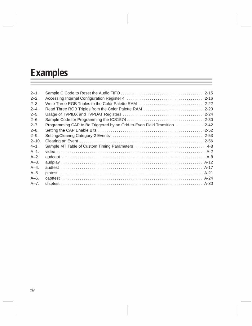
� Video display circuitry, consisting of a video interface palette (VIP) thatdrives monitor resolutions up to 1600 × 1200 at 8 BPP (bits per pixel) witha 60-Hz refresh rate
� PCI interface
� Memory controller
The SDB card also contains IEEE 1149.1-standard emulation support, and thecard’s retaining bracket has cable connectors that connect optional peripher-als to the SDB.
Figure 1–1. TMS320C8x SDB Components
TMS320C80 DSP
PCI bus
64 16
32
I/O bus
PCIinterface
32
16
16
64
64
64
16
64
32
16
64
16
DRAM
VRAM
Memorycontroller
Audiocodec
Videodisplay
Videocapture

TMS320C8x SDB Hardware Functions
1-4
1.3 TMS320C8x SDB Hardware Functions
The ’C8x SDB is a complete ’C8x development platform. The board containsthe following hardware functions:
Audio capture and playback The board contains hardware for the cap-ture and playback of audio signals at sam-ple rates of up to 48 kHz in 16-bit stereo.
Video display A video RAMDAC coupled with 2M bytes ofVRAM gives the board complete video dis-play capabilities at resolutions of up to1600 × 1200 pixels at 8 BPP (bits per pixel).
Video capture On a daughter card mounted on the mainboard is a complete video front end for cap-turing NTSC or PAL video signals in eitherS-VHS or CVBS component form.
Host communications Also on board is in-circuit emulation hard-ware controlled by C source debuggers.These debuggers allow real-time, multiple-processor debugging of ’C8x code.
1.4 TMS320C8x SDB Peripheral Driver Libraries
The SDB gives you a platform for ’C8x performance evaluation, code bench-marking, and code production prior to building your own system. The ability todevelop and successfully run code on a ’C8x during the early stages of applica-tion design greatly reduces your time to market. Therefore, it is not ideal to pro-gram all of the peripherals on the board before working on applications.
TI provides a set of ’C8x libraries that you can call through applicationprogramming interface (API) functions to set up the various hardware peripher-als on the SDB. Using this set of libraries, you can start writing application codewithout having to program the hardware. However, TI understands that knowl-edge of the low-level activities happening on the board is useful if not necessary.Therefore, TI supplies all source code to these libraries for reference.
TMS320C8x SDB Hardware Functions / TMS320C8x SDB Peripheral Driver Libraries
2-1
SDB Hardware
This chapter discusses the theory of operation for the TMS320C8x softwaredevelopment board (SDB).
Topic Page
2.1 System-Level Overview 2-2. . . . . . . . . . . . . . . . . . . . . . . . . . . . . . . . . . . . . . . .
2.2 TMS320C80 2-6. . . . . . . . . . . . . . . . . . . . . . . . . . . . . . . . . . . . . . . . . . . . . . . . . . .
2.3 Audio 2-7. . . . . . . . . . . . . . . . . . . . . . . . . . . . . . . . . . . . . . . . . . . . . . . . . . . . . . . .
2.4 Video Display 2-19. . . . . . . . . . . . . . . . . . . . . . . . . . . . . . . . . . . . . . . . . . . . . . . .
2.5 Video Capture 2-35. . . . . . . . . . . . . . . . . . . . . . . . . . . . . . . . . . . . . . . . . . . . . . .
2.6 Memory Controller 2-45. . . . . . . . . . . . . . . . . . . . . . . . . . . . . . . . . . . . . . . . . . .
2.7 Interrupt Controller 2-48. . . . . . . . . . . . . . . . . . . . . . . . . . . . . . . . . . . . . . . . . . .
2.8 PCI Interface 2-58. . . . . . . . . . . . . . . . . . . . . . . . . . . . . . . . . . . . . . . . . . . . . . . . .
Chapter 2

System-Level Overview
2-2
2.1 System-Level Overview
Looking at the ’C8x SDB as a whole, it consists of the eight modules depictedin Figure 2–1. Each of these modules is discussed individually later in thechapter. This section describes the overall features of the hardware modulesand the interaction between them.
Note:
The SDB operates in big-endian mode.
2.1.1 SDB Hardware Modules
The ’C8x SDB contains the following hardware modules:
� ’C80: TI’s TMS320C80 digital signal processor (DSP) is the single-chip,multiprocessor device responsible for program execution and input/outputmanagement. For more information about the ’C80 multiprocessor DSP,see Section 2.2, TMS320C80.
� Audio : The on-board hardware for sampling and playing back audio datafeatures:
� Codec� Stereo� Sampling rate of up to 48 kHz� FIFO (first in, first out logic) interface
For more information about the audio hardware, see Section 2.3, Audio.
� Video display : The on-board video display hardware features:
� TI’s TVP3020 random-access memory digital-to-analog converter(RAMDAC)
� Resolution support from 640 × 480 at 32 BPP to 1600 × 1200 at 8 BPP
� Programmable pixel clock generator
� Standard 15-pin D-sub RGB (red-green-blue) output
� Multiplexing capability with analog VGA input
For more information about the video display hardware, see Section 2.4,Video Display.

System-Level Overview
2-3SDB Hardware
Figure 2–1. System Block Diagram
Memoryand
interruptcontroller
Audio
Videodisplay
VRAM
Videocapture
DRAM
’C80
Á
Á
ÁÁ
ÁÁ
Á
Á
ÁÁ
ÁÁ
Á
Á
ÁÁ Á
ÁÁPCI bus 32
32
16
16
64
64
16
16
64
64
16
32
PCIinterface
ÁÁÁÁ
64
64
I/O b
us
’C80
bus
System-Level Overview
2-4
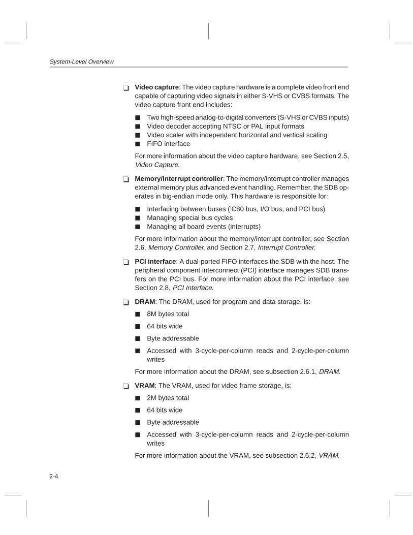
� Video capture : The video capture hardware is a complete video front endcapable of capturing video signals in either S-VHS or CVBS formats. Thevideo capture front end includes:
� Two high-speed analog-to-digital converters (S-VHS or CVBS inputs)� Video decoder accepting NTSC or PAL input formats� Video scaler with independent horizontal and vertical scaling� FIFO interface
For more information about the video capture hardware, see Section 2.5,Video Capture.
� Memory/interrupt controller : The memory/interrupt controller managesexternal memory plus advanced event handling. Remember, the SDB op-erates in big-endian mode only. This hardware is responsible for:
� Interfacing between buses (’C80 bus, I/O bus, and PCI bus)� Managing special bus cycles� Managing all board events (interrupts)
For more information about the memory/interrupt controller, see Section2.6, Memory Controller, and Section 2.7, Interrupt Controller.
� PCI interface : A dual-ported FIFO interfaces the SDB with the host. Theperipheral component interconnect (PCI) interface manages SDB trans-fers on the PCI bus. For more information about the PCI interface, seeSection 2.8, PCI Interface.
� DRAM: The DRAM, used for program and data storage, is:
� 8M bytes total
� 64 bits wide
� Byte addressable
� Accessed with 3-cycle-per-column reads and 2-cycle-per-columnwrites
For more information about the DRAM, see subsection 2.6.1, DRAM.
� VRAM: The VRAM, used for video frame storage, is:
� 2M bytes total
� 64 bits wide
� Byte addressable
� Accessed with 3-cycle-per-column reads and 2-cycle-per-columnwrites
For more information about the VRAM, see subsection 2.6.2, VRAM.

System-Level Overview
2-5SDB Hardware
2.1.2 Data Buses
Figure 2–1 shows the data paths between the hardware modules on the ’C8xSDB. There are three main data buses:
� ’C80 bus� Input/output (I/O) bus� PCI bus
The ’C80 bus is the 64-bit-wide data bus of the ’C80. All transfers to and fromthe ’C80 happen on this bus. The ’C80 bus interfaces to the system DRAM,VRAM, and the video capture FIFO. The ’C80 bus also is used by the memory/interrupt controller to route data to and from the other two buses.
The I/O bus is designed as a general-purpose peripheral bus. In fact, all pe-ripherals on the board interface to this bus to give access to internal peripheralregisters. The peripherals interfaced to the I/O bus include the audio codec,display RAMDAC, video capture chipset, and register sets in the electricallyprogrammable logic devices (EPLDs).
The PCI bus is an integral part of the host in that all transfers to and from thehost happen over this bus. The SDB occupies a certain address range in thePCI address space as dictated by the PCI BIOS.

TMS320C80
2-6
2.2 TMS320C80
The ’C80 DSP is the heart of the SDB. The ’C80 offers the following features:
� Capable of over two billion RISC-like operations per second
� 40-MHz clock speed
� 32-bit RISC master processor (MP) with an integrated IEEE-754 floating-point unit and an architecture tuned for efficient compilation of C programs
� Four 32-bit fixed-point, advanced DSP parallel processors (PPs) in a mul-tiple-instruction, multiple-data (MIMD) configuration
� Byte-addressable machine with big-endian and little-endian byte orderingsupport (however, the SDB operates in big-endian mode only)
� 50K bytes of on-chip SRAM (static random-access memory)
� On-chip crossbar that allows five instruction fetches and ten parallel dataaccesses during each cycle to support high transfer rates:
� 1.8G bytes/s transferring instructions� 2.4G bytes/s transferring data
� On-chip video controller (VC) containing dual frame timers for simulta-neous image capture and display
� 64-bit direct memory access (DMA) transfer controller (TC) capable of upto 400M bytes/s on- and off-chip memory transfers
� Dynamic sizing of bus width for 64, 32, 16, or 8 bits� Access to 64-bit VRAM/RAM/SRAM memory
� 4G-byte memory address space
� Synchronous DRAM support
� Four external interrupts, edge- and level-triggered
� Built-in emulation features accessed via an IEEE 1149.1-compliant testport
� Full-scan design (plus boundary scan), accessed via an IEEE1149.1-compliant test port
� 3.3-V power supply requirement
� TI EPIC� 0.5/0.6-µm CMOS technology
� Approximately 4 million transistors
� 305-pin ceramic PGA package

Audio
2-7SDB Hardware
2.3 Audio
The audio hardware on the SDB provides everything you need to capture andplay back audio data (see Figure 2–2). There are two modes of operation: PIO(programmed input/output) and DMA (direct memory access). In PIO mode,the audio codec’s PIO register is accessed to read and write sample data ona sample-by-sample basis. PIO mode does not use the audio FIFO. In DMAmode, samples are transferred (using the DMA controller) between the codecand the audio FIFO. This method of transfer allows audio data to be accessedin chunks rather than sample by sample. DMA is allowed only in one directionat a time, which means full-duplex DMA is not possible.
Most commonly, the audio is set up for DMA operation. For DMA playback, thecodec reads data from the FIFO; eventually, the audio FIFO becomes almostempty and asserts one of its flags. This flag generates a ’C80 interrupt in whichthe interrupt service routine (ISR) issues a packet transfer to write audio datato the FIFO. For DMA capture, the codec writes data to the FIFO; eventually,the FIFO becomes almost full and asserts a flag. This flag triggers a ’C80 inter-rupt. The ISR then issues a packet transfer to read the audio data from theFIFO.
Figure 2–2. Audio Block Diagram
ÁÁ
ÁÁÁÁ
ÁÁ
ÁÁ
I/O bus 16
64
64
’C80
bus
Á64
ÁÁ Á3 3
D[63:0]
XPT[2:0] EINT[3:1]
Audiocodec
ÁÁ
Á8
16 16
ÁÁÁÁÁÁ
CD0
CD1
CE0
CE1
ÁÁ LÁÁÁÁÁÁÁÁÁÁÁ
TMS320C80 AD1848
IDT72520
R
LRLR
AUX1 in
Line in
Line out
Memoryand
interruptcontroller
Port B
Port A
FLAGAFLAGB
FLAGC
FLAGD
Á
FIFO

Audio
2-8
2.3.1 Memory-Mapped Audio Registers
The audio hardware has seven registers accessible on the I/O bus. They areaccessed using 16-bit reads or writes. You should use direct external ac-cesses (DEAs) to bypass the MP’s data cache. Table 2–1 lists the memory-mapped audio registers. Following the table are diagrams of the register for-mats and descriptions of the registers and their fields.
Table 2–1. Audio Registers Summary
RegisterName Access
’C80 Address
Host Address
Size (Bits) Description
AFIFODAT Read/write 0xE0000200 0x2400 16 Audio FIFO data register
CDCIDX Read/write 0xE0000208 0x2410 8 Codec index address register
CDCDAT Read/write 0xE000020A 0x2414 8 Codec index data register
CDCSTAT Read/write 0xE000020C 0x2418 8 Codec status register
CDCPIO Read/write 0xE000020E 0x241C 8 Codec PIO data register
AFIFOCFG Read/write 0xE0000210 0x2420 16 Audio FIFO configuration register
AFIFOCMD Read/write 0xE0000218 0x2430 16 Audio FIFO command/status register

Audio
2-9SDB Hardware
AFIFODAT register’C80 / host addresses: 0xE0000200 0x2400
15 14 13 12 11 10 9 8 7 6 5 4 3 2 1 0
Audio FIFO data register
AFIFODAT is the gateway to the audio FIFO. Reads of this register read a16-bit word from the B-to-A FIFO; writes to this register write a 16-bit word tothe A-to-B FIFO (see Figure 2–3). Normally, packet transfer tables are set upto transfer data to or from this location in blocks. When setting up packet trans-fer tables, remember that this is a single location and not a range. For example,to transfer 32 16-bit words to the audio FIFO using a packet transfer, you wouldprogram the destination parameters of the packet transfer table as follows:
Parameter Value Meaning
Destination Address = 0xE0000200 This register
Destination A Count = 2 2 bytes, 16-bit register
Destination B Count = 32 32 words to transfer
Destination C Count = 0 1-dimensional data
Destination B Pitch = 0 No change to destination address
Destination C Pitch = 0 1-dimensional data
A similar setup should be used when performing packet transfer reads fromthe audio FIFO.
Figure 2–3. Audio FIFO Block Diagram
Á
Á
8
IDT72520
ÁÁ
Á
ÁÁÁÁÁÁ
88
8 16
88
16
16
Port A
Port B
Codec
I/O bus
Bypasspath
A-to-BFIFO
2048 × 8
1024 × 16
B-to-AFIFO
2048 × 8
1024 × 16

Audio
2-10
CDCIDX register
’C80 / host addresses: 0xE0000208 0x2410
7 6 5 4 3 2 1 0
INIT MCE TRD IXA
CDCIDX is the audio codec’s index address register. Whenever an internalregister of the codec needs to be accessed, its internal register address mustfirst be written to this register. Then, a read or a write to the codec index dataregister (CDCDAT) reads or writes to that internal register. This register alsohas three other bits of information.
INIT Initialization bit . This read-only bit is set whenever thecodec cannot respond to parallel bus cycles and duringcodec autocalibration.
INIT = 0 Codec can respond
INIT = 1 Codec cannot respond
MCE Mode change enable . This bit must be set whenever thecurrent functional mode of the codec changes.
MCE = 0 Mode change disabled
MCE = 1 Mode change enabled
TRD Transfer request disable . This bit is used to stop DMAtransfers when the interrupt status (INT) bit is set. TRDshould be cleared to 0 because the codec interrupt pin isnot used.
IXA(4:0) Index address bits . These bits make up the 5-bitaddress of the internal register accessed via CDCDAT.
CDCDAT register
’C80 / host addresses: 0xE000020A 0x2414
7 6 5 4 3 2 1 0
Codec index data register
CDCDAT is the audio codec’s index data register. Whenever an internal regis-ter of the codec needs to be accessed, its internal register address must firstbe written to the index register (CDCIDX). Then, a read or a write to CDCDATreads or writes to the desired internal codec register. All codec internal regis-ters are 8-bit registers.

Audio
2-11SDB Hardware
CDCSTAT register
’C80 / host addresses: 0xE000020C 0x2418
7 6 5 4 3 2 1 0
CU/L CL/R CRDY SOUR PU/L PL/R PRDY INT
CDCSTAT is the audio codec’s status register.
CU/L Capture upper/lower . This bit indicates whether the cap-ture PIO port has the upper or lower byte of a sample.
CU/L = 0 Lower byte ready
CU/L = 1 Upper byte ready or any 8-bit mode
CL/R Capture left/right sample . This bit indicates whether thecapture PIO port has the left- or right-channel data.
CL/R = 0 Right channel
CL/R = 1 Left channel or mono
CRDY Capture ready . This bit is set to 1 when the codec has acapture sample ready and is valid only when the codec isset up for PIO capture.
CRDY = 0 Do not read from PIO port
CRDY = 1 Capture ready; PIO port has data
SOUR Sample overrun/underrun . This bit indicates that themost recent sample was not serviced in time.
SOUR = 0 No error
SOUR = 1 Overrun or underrun occurred
PU/L Playback upper/lower . This bit indicates whether theplayback PIO port is ready for the upper or lower byte ofa sample.
PU/L = 0 Lower byte needed
PU/L = 1 Upper byte needed or any 8-bit mode
PL/R Playback left/right sample . This bit indicates whetherthe playback PIO port is ready for left- or right-channeldata.
PL/R = 0 Right channel needed
PL/R = 1 Left channel or mono
Audio
2-12
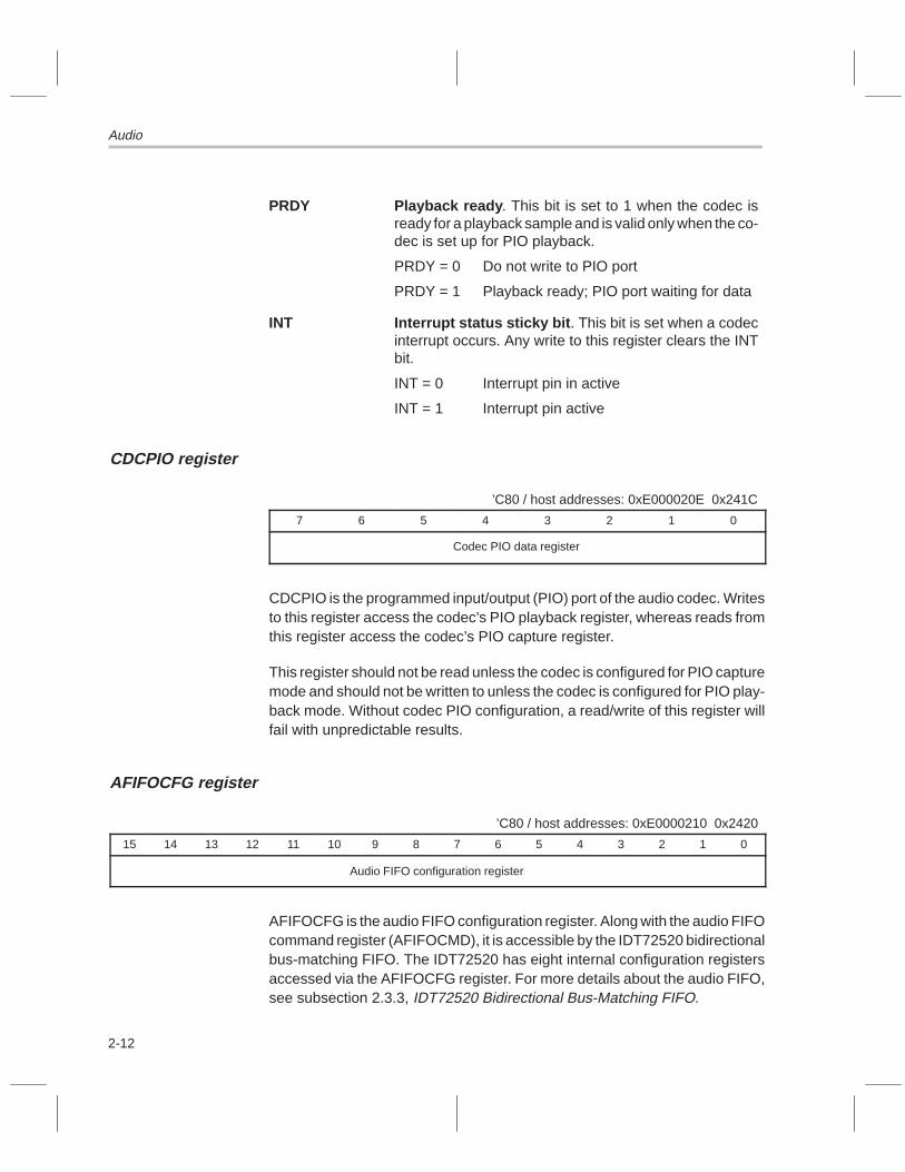
PRDY Playback ready . This bit is set to 1 when the codec isready for a playback sample and is valid only when the co-dec is set up for PIO playback.
PRDY = 0 Do not write to PIO port
PRDY = 1 Playback ready; PIO port waiting for data
INT Interrupt status sticky bit . This bit is set when a codecinterrupt occurs. Any write to this register clears the INTbit.
INT = 0 Interrupt pin in active
INT = 1 Interrupt pin active
CDCPIO register
’C80 / host addresses: 0xE000020E 0x241C
7 6 5 4 3 2 1 0
Codec PIO data register
CDCPIO is the programmed input/output (PIO) port of the audio codec. Writesto this register access the codec’s PIO playback register, whereas reads fromthis register access the codec’s PIO capture register.
This register should not be read unless the codec is configured for PIO capturemode and should not be written to unless the codec is configured for PIO play-back mode. Without codec PIO configuration, a read/write of this register willfail with unpredictable results.
AFIFOCFG register
’C80 / host addresses: 0xE0000210 0x2420
15 14 13 12 11 10 9 8 7 6 5 4 3 2 1 0
Audio FIFO configuration register
AFIFOCFG is the audio FIFO configuration register. Along with the audio FIFOcommand register (AFIFOCMD), it is accessible by the IDT72520 bidirectionalbus-matching FIFO. The IDT72520 has eight internal configuration registersaccessed via the AFIFOCFG register. For more details about the audio FIFO,see subsection 2.3.3, IDT72520 Bidirectional Bus-Matching FIFO.

Audio
2-13SDB Hardware
AFIFOCMD register
’C80 / host addresses: 0xE0000218 0x2430
15 14 13 12 11 10 9 8 7 6 5 4 3 2 1 0
opcode operand
AFIFOCMD is the audio FIFO command register. Along with the audio FIFOconfiguration register (AFIFOCFG), it is accessible by the IDT72520 bidirec-tional bus-matching FIFO. The IDT72520 is configured by writing commandsto this register. The command word has a 4-bit opcode and a 3-bit operand.For more details about the audio FIFO, see subsection 2.3.3, IDT72520 Bi-directional Bus-Matching FIFO.
2.3.2 Audio Codec
The audio codec used on the SDB is Analog Devices AD1848. Although thecodec has a complete set of internal registers, they are accessible only indi-rectly. This is accomplished using the four registers that are accessible:CDCIDX, CDCDAT, CDCSTAT, and CDCPIO. The codec operates in eitherstereo or mono mode.
The audio codec supports the following sampling rates (in kHz):
5.5125 22.0500
6.6150 27.4286
8.0000 32.0000
9.6000 33.0750
11.025 37.8000
16.0000 44.1000
18.9000 48.0000
The audio codec data formats are:
� 8-bit unsigned pulse code modulation (PCM)� 8-bit µ-law companded� 8-bit A-law companded� 16-bit twos-complement PCM

Audio
2-14
2.3.3 IDT72520 Bidirectional Bus-Matching FIFO
The audio FIFO is the IDT72520 bidirectional bus-matching FIFO. It is2048 × 8 on the codec side (port B) and 1024 × 16 on the I/O bus side (portA). The FIFO has two accessible registers: AFIFOCMD and AFIFOCFG. ThisFIFO has a DMA interface to the audio codec, so transfers between the FIFOand the codec require no ’C80 resources. The DMA interface is one-way; thatis, the interface either happens for audio capture or audio playback, but not forboth at the same time.
The FIFO has four flags: FLAGA, FLAGB, FLAGC, and FLAGD. These flagsare independently configurable to assert upon the introduction of any of theFIFO states (empty, almost empty, full, and almost full). The four FIFO flagsare tied to event inputs of the SDB’s interrupt controller as follows:
� FLAGA – CD0� FLAGB – CD1� FLAGC – CE0� FLAGD – CE1
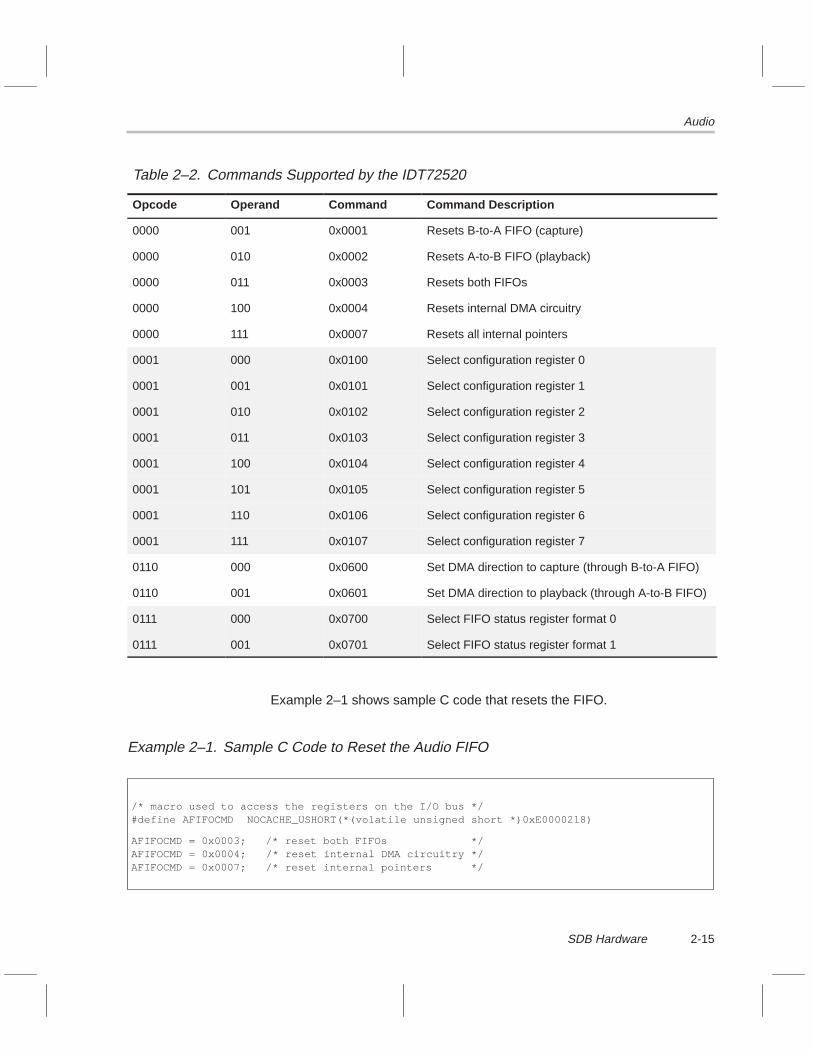
The IDT72520 is configured by writing commands to the audio FIFO commandregister (AFIFOCMD). The command word has a 4-bit opcode and a 3-bitoperand (as shown in the AFIFOCMD register diagram on page 2-13).Table 2–2 lists each command the IDT72520 supports.
Audio
2-15SDB Hardware
Table 2–2. Commands Supported by the IDT72520
Opcode Operand Command Command Description
0000 001 0x0001 Resets B-to-A FIFO (capture)
0000 010 0x0002 Resets A-to-B FIFO (playback)
0000 011 0x0003 Resets both FIFOs
0000 100 0x0004 Resets internal DMA circuitry
0000 111 0x0007 Resets all internal pointers
0001 000 0x0100 Select configuration register 0
0001 001 0x0101 Select configuration register 1
0001 010 0x0102 Select configuration register 2
0001 011 0x0103 Select configuration register 3
0001 100 0x0104 Select configuration register 4
0001 101 0x0105 Select configuration register 5
0001 110 0x0106 Select configuration register 6
0001 111 0x0107 Select configuration register 7
0110 000 0x0600 Set DMA direction to capture (through B-to-A FIFO)
0110 001 0x0601 Set DMA direction to playback (through A-to-B FIFO)
0111 000 0x0700 Select FIFO status register format 0
0111 001 0x0701 Select FIFO status register format 1
Example 2–1 shows sample C code that resets the FIFO.
Example 2–1. Sample C Code to Reset the Audio FIFO
/* macro used to access the registers on the I/O bus */#define AFIFOCMD NOCACHE_USHORT(*(volatile unsigned short *)0xE0000218)
AFIFOCMD = 0x0003; /* reset both FIFOs */AFIFOCMD = 0x0004; /* reset internal DMA circuitry */AFIFOCMD = 0x0007; /* reset internal pointers */

Audio
2-16
The IDT72520 has eight internal configuration registers accessed via the au-dio FIFO configuration register (AFIFOCFG). To access one of the internalconfiguration registers, you must first issue a command to the device withopcode = 0001 and the operand equal to the configuration register number.The read of AFIFOCFG reads that internal register, whereas a write toAFIFOCFG writes to that configuration register. To read the device’s internalconfiguration register number 3, you write 0x0103 to the command register(AFIFOCMD), and then read the configuration register (AFIFOCFG).Example 2–2 shows the C code to read configuration register 4, mask off thelower four bits, and then write it back. See Table 2–3 for a listing of eachIDT72520 internal configuration register.
Example 2–2. Accessing Internal Configuration Register 4
/* macros used to access the registers on the I/O bus */#define AFIFOCFG NOCACHE_USHORT(*(volatile unsigned short *)0xE0000210)#define AFIFOCMD NOCACHE_USHORT(*(volatile unsigned short *)0xE0000218)
USHORT Val;
AFIFOCMD = 0x0104; /* select configuration register 4 */Val = AFIFOCFG; /* read configuration register 4 */Val = Val & 0xFFF0; /* mask off lower 4 bits */AFIFOCFG = Val; /* write back to configuration register 4 */
Table 2–3. IDT72520 Internal Configuration Registers
RegisterNo. Description
0 A-to-B FIFO almost empty offset (playback) [valid 0x0000 to 0x03FF]
1 A-to-B FIFO almost full offset (playback) [valid 0x0000 to 0x03FF]
2 B-to-A FIFO almost empty offset (capture) [valid 0x0000 to 0x03FF]
3 B-to-A FIFO almost full offset (capture) [valid 0x0000 to 0x03FF]
4 Flag pin assignments
5 Hardware interface register; should be set to 0x0780
6 Reserved; do not read or write to this register
7 Reserved; should be initialized to 0x0000

Audio
2-17SDB Hardware
The flag pin assignment register (configuration register 4) specifies whichFIFO conditions assert the four FIFO flag pins (FLAGA, FLAGB, FLAGC, andFLAGD). Each FIFO flag pin can be configured to any of the FIFO conditionslisted in Table 2–4. Active low means that the flag pin goes low when asserted.The active-high pins should be used for the SDB because a low-to-high transi-tion on the pin triggers the event on the interrupt controller.
Table 2–4. FIFO Flag Pin Configurations
Bits FIFO Condition Polarity
0000 A to B (playback) Not empty Active low
0001 A to B (playback) Almost empty Active low
0010 A to B (playback) Full Active low
0011 A to B (playback) Almost full Active low
0100 B to A (capture) Empty Active low
0101 B to A (capture) Almost empty Active low
0110 B to A (capture) Full Active low
0111 B to A (capture) Almost full Active low
1000 A to B (playback) Not empty Active high
1001 A to B (playback) Almost empty Active high
1010 A to B (playback) Full Active high
1011 A to B (playback) Almost full Active high
1100 B to A (capture) Empty Active high
1101 B to A (capture) Almost empty Active high
1110 B to A (capture) Full Active high
1111 B to A (capture) Almost full Active high
For example, you could program the flag pin assignments as follows:
FLAGA – (1001) playback FIFO almost empty, active high
FLAGB – (1111) capture FIFO almost full, active high
FLAGC – (1010) playback FIFO full, active high
FLAGD – (1110) capture FIFO empty, active high

Audio
2-18
The flag pin assignment register value then becomes:
[ddddccccbbbbaaaa] = [1110101011111001] = 0xEAF9
The flag offsets are set to determine when the flags assert. Table 2–5 containsthe truth table of the flags.
Table 2–5. Truth Table for FIFO Flag Assignments
Number of Words in FIFO FIFO Flag Condition
From To Empty Almost Empty Almost Full Full
0 0 Asserted Asserted Not asserted Not asserted
1 n Not asserted Asserted Not asserted Not asserted
n + 1 D – (m + 1) Not asserted Not asserted Not asserted Not asserted
D – m D – 1 Not asserted Not asserted Asserted Not asserted
D D Not asserted Not asserted Asserted Asserted
Legend: D FIFO depth (1024)m almost-full flag offsetn almost-empty flag offset

Video Display
2-19SDB Hardware
2.4 Video Display
The video display hardware on the SDB provides everything you need to dis-play video and graphics on a standard VGA monitor (see Figure 2–4). It fea-tures TI’s TVP3020 RAMDAC, ICS1574 programmable pixel clock generator,and analog multiplexing circuitry for video overlay. This is all coupled with 2Mbytes of VRAM to support resolutions up to 1600 × 1200 at 8 BPP, noninter-laced. These features’ descriptions use the following terms:
Active area The area of a display frame that is not in blanking
Pixel One picture element (pel)
Pixel resolution Dimensions of the active area of the display in number ofpixels
Dot Measurement of time equal to the time required for thedisplay hardware to draw one pixel
Dot rate The reciprocal of dot. If it takes 40 ns to display one pixel,then the dot rate is 1/40 ns = 25 MHz. The dot rate is alsoknown as the dot clock frequency (Fd) or the pixel clockfrequency.
Refresh rate The number of times a display frame is drawn in one se-cond. A common refresh rate for VGA displays is 60frames per second. The refresh rate is also known as thevertical frequency (Fv).
Pixel depth The number of bits needed to store a pixel in VRAM

Video Display
2-20
Figure 2–4. Video Display Block Diagram
CLK0
DisplayEPLDÁ
Á
6
64VRAM
D[7:0]
CLK1CLK2CLK2
8/6SENSE
PCLK HOLDDATA
DATCLKPCLKEN
ÁÁ
ÁÁ
ICSHOLDICSDATAICSCLKPCLKEN
ÁÁÁÁ
ÁÁ
PAL86SENSECAREA1VSYNC1HSYNC1
VGAIHSVGAIVS
VGAOHSVGAOVSVGASEL
ÁÁÁÁÁ
ÁÁ
RCLKLCLK
D[5:0]
HSYNC1VSYNC1CAREA1
CBLNK1FCLK1SCLK1ÁÁÁ
Á
ÁOVS
PSEL
ÁÁÁ
SYSBLVCLKSCLK
ÁÁSerialclockPixel bus ’C80 bus
ÁÁ Á
VGASELVGAIHSVGAIVS
VGAOHSVGAOVS
IORIOGIOB
IORIOGIOB
ÁÁÁÁÁ
ÁÁÁÁÁÁÁÁ
SYSHSSYSVS
P[63:0]
VRAM
Display I/O
TMS320C80
ÁÁ
64
ÁÁÁÁ
8ÁÁ Á16
I/O bus
ICS1574
TVP3020
Pixel clock generator
ÁÁÁ
RAMDAC

Video Display
2-21SDB Hardware
2.4.1 Memory-Mapped Video Display Registers
The video display hardware has nine registers accessible on the I/O bus. Theyare accessed using 16-bit reads or writes. You should use direct external ac-cesses (DEAs) to bypass the MP’s data cache. Table 2–6 lists the memory-mapped video display registers. Following the table are diagrams of the regis-ter formats and descriptions of the registers and their fields.
Table 2–6. Video Display Registers Summary
RegisterName Access
’C80 Address
Host Address
Size(Bits) Description
PALADWR Read/write 0xE0000400 0x2800 8 Palette write address register
PALHOLD Read/write 0xE0000402 0x2804 8 Palette holding register
PELMASK Read/write 0xE0000404 0x2808 8 Pixel read-mask register
PALADRD Read/write 0xE0000406 0x280C 8 Palette read address register
TVPIDX Read/write 0xE000040C 0x2818 8 TVP3020 index register
TVPDAT Read/write 0xE000040E 0x281C 8 TVP3020 data register
DIS0CON Read/write 0xE0000410 0x2820 6 Display control register 0
DIS1CON Read/write 0xE0000412 0x2824 6 Display control register 1
DIS2CON Read/write 0xE0000414 0x2828 2 Display control register 2
PALADWR register
’C80 / host addresses: 0xE0000400 0x2800
7 6 5 4 3 2 1 0
Palette write address register
PALADWR is used to set the write address of the TVP3020 color palette. Afterthis register is set, writes to the palette data holding register (PALHOLD) gointo the color palette memory at that address. This register is autoincrement-ing, so sequential writes to PALHOLD are possible.

Video Display
2-22
PALHOLD register
’C80 / host addresses: 0xE0000402 0x2804
7 6 5 4 3 2 1 0
Palette holding register
PALHOLD is the TVP3020’s palette holding register. Reads of this register per-form a read of the color palette RAM, and writes to this register perform a writeto the color palette RAM. The color palette RAM must be read or written in tri-ples, that is, in three successive reads or writes. The three reads or writes area byte of red, a byte of green, and a byte of blue in that order (this is called anRGB triple). Upon reading the third byte from this register, the palette read ad-dress register (PALADRD) increments by 1. Writing a triple to this register in-crements the palette write address register (PALADWR) by 1. This allows RGBtriples to be read to or written from the palette in sequence, without updatingthe read or write register each time. Example 2–3 shows the writing of threeRGB triples to the color palette RAM starting at RAM address 0x20, andExample 2–4 shows the reading of three RGB triples to the color palette RAMstarting at RAM address 0x40.
Example 2–3. Write Three RGB Triples to the Color Palette RAM
/* macros used to access the registers on the I/O bus */#define PALADRD NOCACHE_USHORT(*(volatile unsigned short *)0xE0000406)#define PALADWR NOCACHE_USHORT(*(volatile unsigned short *)0xE0000400)#define PALHOLD NOCACHE_USHORT(*(volatile unsigned short *)0xE0000402)
/* set color palette RAM address for writes to 0x20 */PALADWR = 0x20;
/* remember that all I/O bus accesses must be 16 bit, so the upper 8 bits areset to zero when writing to 8-bit registers */
/* write first triple (red = 0, green = 0, blue = 0) */PALHOLD = 0x0000; PALHOLD = 0x0000; PALHOLD = 0x0000;
/* write second triple (red = 0, green = 0, blue = 0) */PALHOLD = 0x0000; PALHOLD = 0x0000; PALHOLD = 0x0000;
/* write third triple (red = 0, green = 0, blue = 0) */PALHOLD = 0x0000; PALHOLD = 0x0000; PALHOLD = 0x0000;

Video Display
2-23SDB Hardware
Example 2–4. Read Three RGB Triples from the Color Palette RAM
/* macros used to access the registers on the I/O bus */#define PALADRD NOCACHE_USHORT(*(volatile unsigned short *)0xE0000406)#define PALADWR NOCACHE_USHORT(*(volatile unsigned short *)0xE0000400)#define PALHOLD NOCACHE_USHORT(*(volatile unsigned short *)0xE0000402)
/* declare some variables to store RGB triples */unsigned short R1,G1,B1;unsigned short R2,G2,B2;unsigned short R3,G3,B3;
/* set color palette RAM address for reads to 0x40*/PALADRD = 0x40;
/* remember that I/O bus accesses are 16 bit, so the upper 8 bits need to bemasked off */
/* read first triple */R1 = PALHOLD & 0x00FF; G1 = PALHOLD & 0x00FF; B1 = PALHOLD & 0x00FF;
/* read second triple */R2 = PALHOLD & 0x00FF; G2 = PALHOLD & 0x00FF; B2 = PALHOLD & 0x00FF;
/* read third triple */R3 = PALHOLD & 0x00FF; G3 = PALHOLD & 0x00FF; B3 = PALHOLD & 0x00FF;
PELMASK register
’C80 / host addresses: 0xE0000404 0x2808
7 6 5 4 3 2 1 0
Pixel read-mask register
PELMASK is the pixel read-mask register. This 8-bit register is used to enableor disable a bit plane from addressing the color palette RAM in the pseudocolormodes. Each palette address bit is logically ANDed with the corresponding bitfrom the read-mask register before going to the palette-page register and ad-dressing the palette RAM.

Video Display
2-24
PALADRD register
’C80 / host addresses: 0xE0000406 0x280C
7 6 5 4 3 2 1 0
Palette read address register
PALADRD is used to set the read address of the TVP3020 color palette. Afterthis register is set, reads from the palette holding register (PALHOLD) comefrom the color palette memory at that address. This register is autoincrement-ing, so sequential reads from PALHOLD are possible.
TVPIDX register
’C80 / host addresses: 0xE000040C 0x2818
7 6 5 4 3 2 1 0
TVP3020 index register
TVPIDX is the index register to the TVP3020 internal registers. Set this registerto access one of the TVP3020 internal registers. For instance, If you want toread the TVP3020 internal register 0x1B, you write 0x1B to TVPIDX and thenread from TVPDAT (see Example 2–5).
TVPDAT register
’C80 / host addresses: 0xE000040E 0x281C
7 6 5 4 3 2 1 0
TVP3020 data register
TVPDAT is the data port register to the TVP3020 internal registers. Set the in-ternal register address in TVPIDX and then read or write to register TVPDAT,which performs a read or write to the internal register (see Example 2–5).
Example 2–5. Usage of TVPIDX and TVPDAT Registers
/* macros used to access the registers on the I/O bus */#define TVPIDX NOCACHE_USHORT(*(volatile unsigned short *)0xE000040C)#define TVPDAT NOCACHE_USHORT(*(volatile unsigned short *)0xE000040E)
unsigned short Val;
/* set bit zero of TVP3020 register 0x1B */TVPIDX = 0x1B;Val = (TVPDAT & 0x00FF) | 0x0001;TVPDAT = Val;

Video Display
2-25SDB Hardware
DIS0CON register
’C80 / host addresses: 0xE0000410 0x2820
5 4 3 2 1 0
MEN WIN IVS IHS ICE VGA
DIS0CON is one of three display control registers on the SDB located in anEPLD (electrically programmable logic device). This register contains bits tocontrol the video overlay feature of the board. A complete description of thevideo overlay feature is provided in subsection 2.4.4, Video Overlay Feature(Mixed Mode). The display EPLD block diagram depicted in Figure 2–5 showsthe logical relationship between the display control registers and the displaysignals.
MEN Mix enable . This bit enables mixed (overlay) mode inwhich the input from the VGA pass-through cable ismixed in the analog domain with the output of theTVP3020 RAMDAC; that is, VGA is mixed with palettegraphics.
MEN = 0 Disable mixed mode
MEN = 1 Enable mixed mode
WIN Window mode . When the display is in mixed mode(VGA = 1 and MEN = 1), this bit determines which videosignal is in the window and which signal is in the back-ground.
WIN = 0 Palette graphics window over VGA background
WIN = 1 VGA window over palette graphics background
IVS Invert vertical sync . Setting this bit to 1 inverts the verti-cal sync (VS) signal going to the display output connector.
IVS = 0 Normal VS
IVS = 1 Invert VS
IHS Invert horizontal sync . Setting this bit to 1 inverts thehorizontal sync (HS) signal going to the display outputconnector.
IHS = 0 Normal HS
IHS = 1 Invert HS

Video Display
2-26
ICE Invert pixel clock enable . Setting this bit inverts the en-able signal (PCLKEN) to the pixel clock generator chip(ICS1574). When the VGA bit is 1, the PCLKEN signal isdriven by the horizontal sync signal from the VGA pass-through input (VGAIHS). When the VGA bit is 0, thePCLKEN signal is held high (pixel clock always enabled).
ICE = 0 Normal ICS1574 enable
ICE = 1 Invert ICS1574 enable
VGA VGA/mix enable . When this bit is cleared to 0, the videooutput of the SDB is palette graphics (that is, the outputof the TVP3020 RAMDAC). When this bit is set to 1, eitherthe VGA input from the VGA pass-through cable or a mix-ture of that and palette graphics is displayed, dependingon the MEN (mix enable) bit.
VGA = 0 Palette graphics only
VGA = 1 VGA or VGA/palette graphics mix enabled

Video Display
2-27SDB Hardware
Figure 2–5. Display EPLD Block Diagram
ÁÁÁÁ DIS1CON[0]
DIS1CON[1]DIS1CON[2]DIS1CON[3]DIS1CON[4]
PAL86ICSDATAICSHOLD
ICSCLKSENSE
MEN WIN IVS IHS ICE VGA
5 4 3 2 1 0
Res. SEN ICSC ICSH IISD PAL86
5 4 3 2 1 0
IVS1 IHS1
1 0
DIS0CON
DIS1CON
DIS2CON
Display
control
registers
ÁÁÁ
DIS0CON[4] DIS0CON[5] DIS0CON[0]
VGASEL
DIS0CON[1] DIS0CON[0]
PCLKEN
ÁÁÁÁ
ÁÁ Á
Á
Á
ÁÁ
Á
Á
Á
ÁÁVGAOHS
VGAIHS
HSYNC1
DIS2CON[0] DIS0CON[1] DIS0CON[0]
ÁÁÁÁ
ÁÁ
Á
Á
ÁÁVGAOVS
VGAIVS
VSYNC1
DIS2CON[1] DIS0CON[3] DIS0CON[0]

Video Display
2-28
DIS1CON register
’C80 / host addresses: 0xE0000412 0x2824
5 4 3 2 1 0
Reserved SEN ICSC ICSH ICSD PAL86
DIS1CON is one of three display control registers on the SDB located in anEPLD (electrically programmable logic device). This register programs theICS1574 pixel clock generator chip. The display EPLD block diagram depictedin Figure 2–5 shows the logical relationship between the display control regis-ters and the display signals.
Reserved This bit is not used.
SEN SENSE from TVP3020 . This bit is read only and returnsthe state of the TVP3020’s SENSE line.
ICSC ICS1574 clock . This bit is tied directly to the DATCLK pinof the ICS1574 pixel clock generator chip and is used forserial communication to the ICS1574 device. See sub-section 2.4.2, ICS1574 Pixel Clock Generator, for moredetails.
ICSH ICS1574 hold . This bit is tied directly to the HOLD pin ofthe ICS1574 pixel clock generator chip and is used for se-rial communication to the ICS1574 device. See subsec-tion 2.4.2, ICS1574 Pixel Clock Generator, for more de-tails.
ICSD ICS1574 data . This bit is tied directly to the DATA pin ofthe ICS1574 pixel clock generator chip and is used for se-rial communication to the ICS1574 device. See subsec-tion 2.4.2, ICS1574 Pixel Clock Generator, for more de-tails.
PAL86 TVP3020 palette 8/6 mode . This bit is only for backwardcompatibility with earlier graphics systems and is normal-ly not used. It should always be set to 1.
PAL86 = 0 6-bit component palette graphics
PAL86 = 1 8-bit component palette graphics

Video Display
2-29SDB Hardware
DIS2CON register
’C80 / host addresses: 0xE0000414 0x2828
1 0
IVS1 IHS1
DIS2CON is one of three display control registers on the SDB located in anEPLD (electrically programmable logic device). This register is used to invertthe sync signal inputs of the ’C80 when the video display is set for mixed mode.The display EPLD block diagram depicted in Figure 2–5 shows the logicalrelationship between the display control registers and the display signals.
IVS1 VSYNC1 invert . When the display is set for mixed mode,setting this bit inverts the vertical sync input to the ’C80.
IVS1 = 0 Normal VSYNC1 input to ’C80
IVS1 = 1 Invert VSYNC1 input to ’C80
IHS1 HSYNC1 invert . When the display is set for mixed mode,setting this bit inverts the horizontal sync input to the ’C80.
IHS1 = 0 Normal HSYNC1 input to ’C80
IHS1 = 1 Invert HSYNC1 input to ’C80

Video Display
2-30
2.4.2 ICS1574 Pixel Clock Generator
The SDB uses the ICS1574 programmable pixel clock generator chipmanufactured by Integrated Systems, Inc. This device is fully programmableto output a clock frequency up to 400 MHz. It contains a crystal oscillator, aphase-frequency detector, a prescaler, and a postscaler. The device has oneinternal 56-bit register, which is written serially using its DATA, HOLD, andDATCLK pins. These three pins are tied to the ICSD, ICSH, and ICSC bits, re-spectively, of the DIS1CON register. Actually a 56-bit shift register accepts theserial input and, when all serial bits are shifted in, the shift register contentsare written to the internal register and take effect.
To program the ICS1574, the ICSH bit should go low and remain low until thelast bit is written. When ICSH goes high, the data in the shift register is trans-ferred to the internal register. The serial data bit (ICSD) is shifted into theICS1574 upon the 0-to-1 transition of the DATCLK bit. Four operations areneeded to program the device:
1) Serially write a 1 bit.2) Serially write a 0 bit.3) Serially write a 1 bit as the last bit.4) Serially write a 0 bit as the last bit.
Example 2–6 shows sample code to do each operation.
Example 2–6. Sample Code for Programming the ICS1574
/* macros used to access the registers on the I/O bus */#define DIS1CON NOCACHE_USHORT(*(volatile unsigned short *)0xE0000412)
/* in each case, the PAL86 bit is set to 1, which has nothing to do with *//* programming the ICS1574 but is the desired setting */
/* write a 1 bit */DIS1CON = 0x03; /* ICSC = 0, ICSH = 0, ICSD = 1, PAL86 = 1 */DIS1CON = 0x0B; /* ICSC = 1, ICSH = 0, ICSD = 1, PAL86 = 1 */
/* write a 0 bit */DIS1CON = 0x01; /* ICSC = 0, ICSH = 0, ICSD = 0, PAL86 = 1 */DIS1CON = 0x09; /* ICSC = 1, ICSH = 0, ICSD = 0, PAL86 = 1 */
/* write a 1 bit as the last bit */DIS1CON = 0x07; /* ICSC = 0, ICSH = 1, ICSD = 1, PAL86 = 1 */DIS1CON = 0x0F; /* ICSC = 1, ICSH = 1, ICSD = 1, PAL86 = 1 */
/* write a 0 bit as the last bit */DIS1CON = 0x05; /* ICSC = 0, ICSH = 1, ICSD = 0, PAL86 = 1 */DIS1CON = 0x0D; /* ICSC = 1, ICSH = 1, ICSD = 0, PAL86 = 1 */

Video Display
2-31SDB Hardware
The display application programming interface (API) has functionality thattranslates a frequency into the 56 bits and then writes them out to the device.If you wish to program the ICS1574, you must determine all 56 bits and thenwrite them to the device using the previously described methods.
2.4.3 Supported Resolutions
Two factors govern available pixel resolution:
� Amount of VRAM� Refresh rate
The pixel resolution is bound by the amount of VRAM because each pixel hasto be stored there. The refresh rate is a limiting factor because the maximumdot rate available on the SDB is 170 MHz, and the dot rate depends on therefresh rate.
The amount of VRAM is determined by pixel resolution and pixel depth. So,for a pixel resolution of 1600 × 1200 with a pixel depth of 8 BPP, 1.92 millionbytes of VRAM are needed (see the calculation that follows). The SDB has 2Mbytes (2 097 152 bytes) of VRAM, which means there is more than enoughstorage for a 1600 × 1200 at 8 BPP display.
Calculation for 1600 × 1200 at 8 BPP:
1600 pixels1 line
�1200 lines
1 frame�
8 bits1 pixel
�1 byte8 bits
�1.92 million bytes
1 frame
To determine an approximate dot rate, apply two general rules:
� Approximately 76% of the total horizontal frame width is active, whileabout 24% is in blanking.
� Approximately 96% of the total vertical frame height is active, while about4% is in blanking.
Pixels are displayed only in the active area. Thus, for a 1600 ×1200 pixel reso-lution, the active area is 1600 × 1200, whereas the entire frame is about2105 × 1250 (1600/.76 = 2105, 1200/.96 = 1250). Because a dot is the amountof time it takes to display a pixel, there are 2105 × 1250 dots in the entire framefor this example. Multiply the number of pixels per frame (dots) by the numberof frames per second (refresh rate); the result is the number of pixels per se-cond. Pixels per second is the dot rate. So, for a pixel resolution of 1600 × 1200and a refresh rate of 60 frames per second, a dot rate of 157.9 MHz is needed(as shown in the calculation that follows). The board can handle up to 170MHz.

Video Display
2-32
Calculation for 1600 × 1200 at 60 frames per second:
1600 pixels1 line
�1
0.76�
1200 lines1 frame
�1
0.96�
60 frames1 s
�157.9 million pixe
1 s
Apply these calculations to another example, and the result becomes margin-al: 1600 × 1280 at 8 BPP and 60 frames per second. There is enough VRAM(2 048 000 bytes), but the dot clock approaches 170 MHz. This dot rate isclose to the maximum and could cause slight instability or noise. For this rea-son, the maximum resolution specified is 1600 × 1200 at 8 BPP with a 60-Hzrefresh rate. Table 2–7 specifies the standard resolutions supported by theAPI.
Table 2–7. Standard Resolutions Supported by the API
HorizontalResolution(Pixels)
Vertical Resolution(Pixels)
Refresh Rate(Hz)
Pixel Depth(BPP)
RequiredVRAM (Bytes)
Approximate Required Dot
Rate (MHz)
640 480 60 8 307 200 25.26
640 480 60 16 614 400 25.26
640 480 60 32 1 228 800 25.26
640 480 72 8 307 200 30.32
640 480 72 16 614 400 30.32
640 480 72 32 1 228 800 30.32
800 600 60 8 480 000 39.47
800 600 60 16 960 000 39.47
800 600 60 32 1 920 000 39.47
1024 768 60 8 786 430 64.67
1024 768 60 16 1 572 864 64.67
1024 768 70 8 786 430 75.45
1024 768 70 16 1 572 864 75.45
1280 1024 60 8 1 310 720 107.79
1600 1200 60 8 1 920 000 157.89

Video Display
2-33SDB Hardware
It is clear from Table 2–7 that the display resolution is dependent on theamount of VRAM available. There must be enough VRAM to store the pixelsthat fill the active area of the display. One feature the API supports is the abilityto set up a display window. A display window is nothing more than the wideningof the blanking area to shrink the active area of the display. Reducing the activearea size reduces the number of pixels in the active area, thus reducing theVRAM storage requirements.
When the API sets up a display window, the monitor timing parameters are cal-culated for a full resolution window. The active area then is shrunk to the win-dow size and position. One might set up a display resolution of 1024 × 768 andthen specify a window of 512 × 512. The dot clock and sync signal parametersare calculated for a 1024 ×768 resolution to allow the monitor to sync up. Thenthe blanking signals are programmed such that an active area of 512 × 512 isproduced. By setting up a display window, you can achieve higher resolutionsfor a given pixel size. For instance, the SDB does not support 1024 × 768 at32 BPP, but you could set up a 640 × 480 at 32 BPP window in a 1024 × 768display. This method is useful when using the video overlay feature.
2.4.4 Video Overlay Feature (Mixed Mode)
The SDB supports analog video overlay (mixed mode) by multiplexing be-tween palette graphics (TVP3020 RAMDAC output) and VGA graphics (inputfrom VGA pass-through cable) using an analog multiplexer. This is illustratedin Figure 2–6. One signal, VGASEL, determines which signal (palette or VGA)is sent to the graphics output of the SDB. Overlay is made possible by the factthat VGASEL can be switched in real time on a pixel-by-pixel basis.
You could, for instance, overlay palette graphics on top of VGA graphics. Themultiplexer normally switches to pass VGA graphics to the output, but whenthe pixel location is within the overlay window, the multiplexer switches, pass-ing palette graphics to the output. Then, as the scan line continues, it reachesthe end of the window and the multiplexer switches back to VGA graphics. The’C80’s CAREA1 signal is used to control the multiplexer.
It is important for the pixel clock frequency of the RAMDAC to match the pixelclock frequency of the VGA input. The pixel clock frequency of the VGA inputis considered an unknown, so trial and error must be used to match it. The gen-eral rules described in subsection 2.4.3, Supported Resolutions, to calculatethe pixel clock frequency usually yield a close match, but some adjustmentsneed to be applied. The display API provides tweak functions for adjusting thevideo overlay parameters.

Video Display
2-34
Figure 2–6. Display I/O Block Diagram
5 4 3 2 19 8 7
15 14 13 12 11
432
IORIOGIOB ÁÁ
Graphicsoutput connector
ÁÁÁÁ
8 7 6
5 4 3
2 1
5
6
ÁÁ
ÁÁÁÁÁÁÁÁ
ÁÁÁÁÁÁÁÁÁÁ
Á
VGAOHSVGAOVS
VGASEL
ÁÁÁÁ
ÁÁÁÁ
IORIOGIOB
VGAOREDVGAOGRNVGAOBLU
ÁÁÁÁÁÁÁÁ
VGAOREDVGAOGRNVGAOBLU
VGAIREDVGAIGRNVGAIBLU
S=0
S=1
VGApass-through
connector
Analogmultiplexer
QS3257
TVP3020RAMDAC
Á
VGAgraphics
card
ÁÁÁ
ÁÁ
ÁÁÁÁVGASEL
0 = RAMDAC1 = VGA
ÉÉÉÉ
Overlay window
VGAgraphics
Palettegraphics
VGAIHS
VGAIVS 10 6
ÁÁ
IORIOGIOB
VGAIREDVGAIGRNVGAIBLU
VGAOREDVGAOGRNVGAOBLU
S
ÁÁ

Video Capture
2-35SDB Hardware
2.5 Video Capture
The video capture front end on the SDB, as depicted in Figure 2–7, resides ona daughter card mounted on the main board. The front end is capable of cap-turing NTSC or PAL video in CVBS or S-VHS formats. The chipset decodesand then scales the digitized video data. The output of the scaler is configur-able to several pixel formats in both YUV and RGB color space. The scaler out-put is a 32-bit interface to a 1024 × 32 FIFO. The other end of this FIFO (512× 64) is tied to the ’C80’s data bus and supports peripheral data packet trans-fers to DRAM or VRAM. The scaler performs scaling by pixel dropping andline dropping but has built-in filters to lessen the effects that pixel and line drop-ping have.
The video capture front end supplies three events for the interrupt controller:FRM, ROW, and CAP. The FRM event occurs at the end of each frame for non-interlaced and at the end of each field for interlaced video. The ROW eventoccurs at the end of each line of video. CAP is a programmable event that canbe triggered by one of eight video capture conditions. Section 2.7, InterruptController, provides more detailed information about interrupt controllerevents and triggers.
2.5.1 Video Capture FIFO
The 512 × 64 video capture FIFO, tied directly to the ’C80 data bus (64 bit),allows the ’C80’s transfer controller (TC) to packet transfer video data out ofthe FIFO one whole line at a time. The FIFO is read only but can act as a pe-ripheral to support peripheral data packet transfers to DRAM or VRAM. Thevideo capture FIFO has the following address range:
0xC0400000 to 0xC07FFFFF

Video Capture
2-36
Figure 2–7. Video Capture Block Diagram
3 4
4 3
2
ÁÁÁÁ
Video digitizer
1
VID1 VID2
CVBS[7:0]
CHR[7:0]
VR[31:0]
FIFO
512 × 64
1024 × 32
ODD/EVENINCADDRHFL
IS1 IS0
ODD/EVENINCADDR
HFL
HSYNC0VSYNC0CSYNC0
HSVS
SCLSDA
SCLSDA
D[7:0]D[7:0]
ROWFRMCAP
ROWFRMCAPÁ
ÁÁÁÁÁÁÁÁ
ÁÁÁÁ
ÁÁÁÁ
CSYNC0HSYNC0VSYNC0
ÁÁÁ
ÁÁÁI2C
ÁÁ
Á Á
ÁÁÁÁ
SAA7196
Capture EPLD
PCF8584
64
64
32
88
ÁÁÁÁ8
8
ÁÁ’C80 bus
I/O bus 16
To interruptcontroller
S-VHS input connector
VID1
VID2
CVBS[7:0]
CHR[7:0]
IS1 IS0
Á

Video Capture
2-37SDB Hardware
2.5.2 Memory-Mapped Video Capture Registers
The video capture hardware has 14 registers accessible on the I/O bus. Theymust be accessed using 16-bit reads or writes. You should use direct externalaccesses (DEAs) to bypass the MP’s data cache. Table 2–8 lists the memory-mapped video capture registers. Following the table are diagrams of the regis-ter formats and descriptions of the registers and their fields.
Table 2–8. Video Capture Registers Summary
RegisterName Access
’C80 Address
Host Address
Size(Bits) Description
CFIFORST Write only 0xE0000600 0x2C00 8 Reset video capture FIFO register
ISRC Read only 0xE0000602 0x2C04 2 Read input source setting register
SVHS Write only 0xE0000608 0x2C10 8 Set input to S-VHS register
CVBS1 Write only 0xE000060A 0x2C14 8 Set input to CVBS1 register
CVBS2 Write only 0xE000060C 0x2C18 8 Set input to CVBS2 register
CAPID Read only 0xE000060E 0x2C1C 8 Capture card ID register
INTREG Read only 0xE0000610 0x2C20 8 Interrupt flag register
INTEN Write only 0xE0000618 0x2C24 8 Interrupt enable register
INTSRC Write only 0xE0000614 0x2C28 3 Interrupt source register
I2CDAT Read/write 0xE0000620 0x2C40 8 PCF8584 I2C data register
I2CCTRL Write only 0xE0000622 0x2C44 8 PCF8584 I2C control register
I2CSTAT Read only 0xE0000626 0x2C4C 8 PCF8584 I2C status register
CAPRST Write only 0xE000063C 0x2C78 8 Reset video capture EPLD register
I2CRST Write only 0xE000063C 0x2C7C 8 Reset PCF8584 I2C controller
CFIFORST register
’C80 / host addresses: 0xE0000600 0x2C00
7 6 5 4 3 2 1 0
Pseudobits
CFIFORST is a write-only pseudoregister; that is, a write to this addresscauses an action to occur, but no data is stored here. Writing any value to thisregister location resets the video capture FIFO.

Video Capture
2-38
ISRC register
’C80 / host addresses: 0xE0000602 0x2C04
1 0
Input source
ISRC is a read-only register that returns the current video input configuration.The input configuration is set by writing to the SVHS, CVBS1, or CVBS2 regis-ter locations.
ISRC = 00 S-VHS input
ISRC = 01 CVBS1 input
ISRC = 11 CVBS2 input
SVHS register
’C80 / host addresses: 0xE0000608 0x2C10
7 6 5 4 3 2 1 0
Pseudobits
SVHS is a write-only pseudoregister; that is, a write to this address causes anaction to occur, but no data is stored here. Writing any value to this registerlocation sets up the video capture input for S-VHS. When the setting is S-VHSmode, the luminance is digitized from video input 1, whereas chrominance isdigitized from video input 2 (see Figure 2–8).
CVBS1 register
’C80 / host addresses: 0xE000060A 0x2C14
7 6 5 4 3 2 1 0
Pseudobits
CVBS1 is a write-only pseudoregister; that is, a write to this address causesan action to occur, but no data is stored here. Writing any value to this registerlocation sets up the video capture input for CVBS1. When the setting is CVBS1mode, the composite video signal at video input 1 is digitized (see Figure 2–8).

Video Capture
2-39SDB Hardware
Figure 2–8. Video Digitizer Block Diagram
8ÁÁ
TDA8708
Á
Á
Á
Á
Á
ÁÁ
Á
CVBS[7:0]
8ÁÁÁÁ
Á
CHR[7:0]
ÁÁ
IS1
IS0
VID1
VID2
TDA8709
Analog switch
S-VHS
CVBS1
N/A
CVBS2
0
0
1
1
0
1
0
1
MODE IS1 IS0 CVBS CHR
VID1
VID1
Z
VID2
VID2
Z
VID2
Z
D[7:0]
I1I0
VIN0VIN1VIN2
D[7:0]
I1I0
VIN0VIN1VIN2
CVBS2 register
’C80 / host addresses: 0xE000060C 0x2C18
7 6 5 4 3 2 1 0
Pseudobits
CVBS2 is a write-only pseudoregister; that is, a write to this address causesan action to occur, but no data is stored here. Writing any value to this registerlocation sets up the video capture input for CVBS2. When the setting is CVBS2mode, the composite video signal at video input 2 is digitized (see Figure 2–8).

Video Capture
2-40
CAPID register
’C80 / host addresses: 0xE000060E 0x2C1C
7 6 5 4 3 2 1 0
Capture card ID x x x x
CAPID is a read-only register that detects the video capture card ID. If readingthis register returns 1010 (0xA) in bits 7:4 (the capture card ID), the video cap-ture card is present. Bits 3:0 are ignored.
INTREG register
’C80 / host addresses: 0xE0000610 0x2C20
7 6 5 4 3 2 1 0
i7 i6 i5 i4 i3 i2 i1 i0
INTREG is a read-only register that returns the video capture interrupt flag bits.Reading this register clears all of its bits. Any of eight video capture conditionscan cause an interrupt; each of these conditions has a corresponding bit inINTREG. When one of these conditions occurs, its bit is set in INTREG,assuming the corresponding bit in the interrupt enable register (INTEN) is set.
i7 Capture FIFO empty flag interrupt flag
i6 TFRAME interrupt flag
i5 TROW interrupt flag
i4 Odd-to-even field transition interrupt flag
i3 Even-to-odd field transition interrupt flag
i2 VSYNC0 falling edge interrupt flag
i1 HSYNC0 falling edge interrupt flag
i0 Capture FIFO full flag interrupt flag
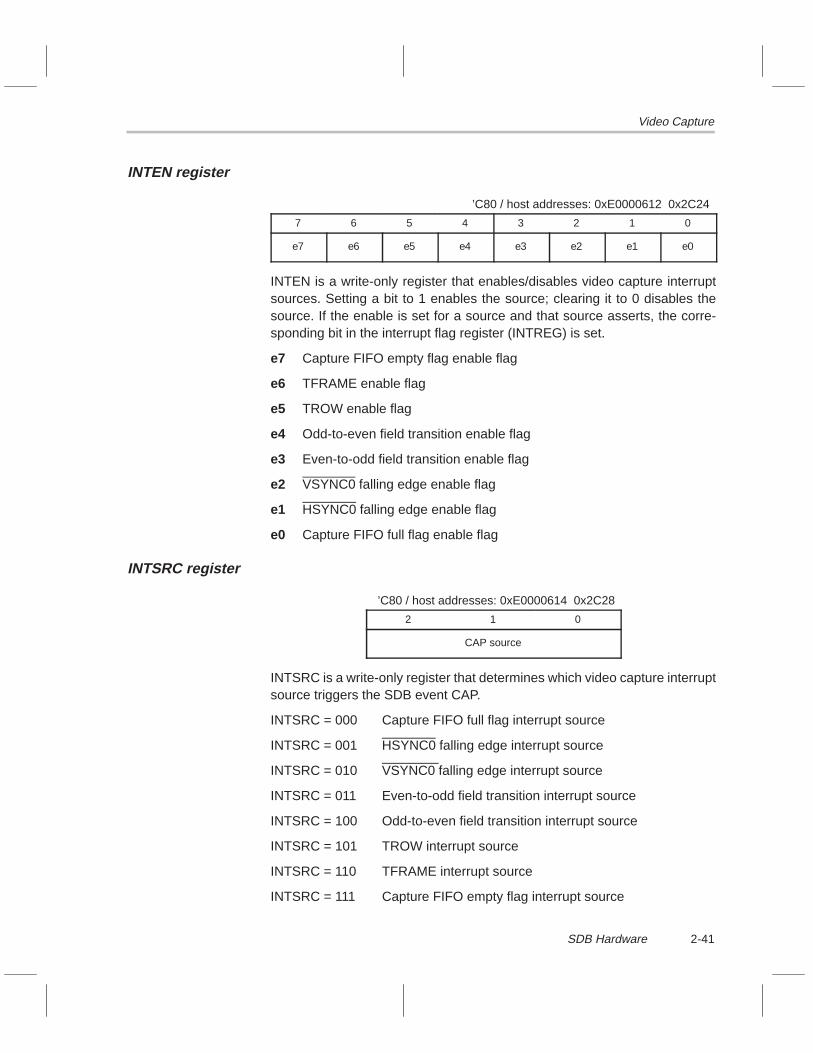
Video Capture
2-41SDB Hardware
INTEN register
’C80 / host addresses: 0xE0000612 0x2C24
7 6 5 4 3 2 1 0
e7 e6 e5 e4 e3 e2 e1 e0
INTEN is a write-only register that enables/disables video capture interruptsources. Setting a bit to 1 enables the source; clearing it to 0 disables thesource. If the enable is set for a source and that source asserts, the corre-sponding bit in the interrupt flag register (INTREG) is set.
e7 Capture FIFO empty flag enable flag
e6 TFRAME enable flag
e5 TROW enable flag
e4 Odd-to-even field transition enable flag
e3 Even-to-odd field transition enable flag
e2 VSYNC0 falling edge enable flag
e1 HSYNC0 falling edge enable flag
e0 Capture FIFO full flag enable flag
INTSRC register
’C80 / host addresses: 0xE0000614 0x2C28
2 1 0
CAP source
INTSRC is a write-only register that determines which video capture interruptsource triggers the SDB event CAP.
INTSRC = 000 Capture FIFO full flag interrupt source
INTSRC = 001 HSYNC0 falling edge interrupt source
INTSRC = 010 VSYNC0 falling edge interrupt source
INTSRC = 011 Even-to-odd field transition interrupt source
INTSRC = 100 Odd-to-even field transition interrupt source
INTSRC = 101 TROW interrupt source
INTSRC = 110 TFRAME interrupt source
INTSRC = 111 Capture FIFO empty flag interrupt source

Video Capture
2-42
Example 2–7 shows how to program CAP to be triggered by an odd-to-evenfield transition.
Example 2–7. Programming CAP to Be Triggered by an Odd-to-Even Field Transition
/* macros used to access the registers on the I/O bus */#define INTREG NOCACHE_USHORT(*(volatile unsigned short *)0xE0000610)#define INTEN NOCACHE_USHORT(*(volatile unsigned short *)0xE0000612)#define INTSRC NOCACHE_USHORT(*(volatile unsigned short *)0xE0000614)
USHORT Junk;
/* read the INTREG register, which clears it */Junk = INTREG;
/* bind CAP with odd to even field transition */INTSRC = 0x0004;
/* enable odd to even field transition interrupt condition */INTEN = 0x0010;
I2CDAT register
’C80 / host addresses: 0xE0000620 0x2C40
7 6 5 4 3 2 1 0
PCF8584 I2C data register
I2CDAT, the data register of the PCF8584 I2C controller chip, writes data to theI2C bus. For more details about the PCF8584 I2C controller, see subsection2.5.4, PCF8584 I2C Bus Controller.
I2CCTRL register
’C80 / host addresses: 0xE0000622 0x2C44
7 6 5 4 3 2 1 0
PCF8584 I2C control register
I2CCTRL, the PCF8584 I2C control register, controls the operation of thePCF8584 I2C controller chip. For more details about the PCF8584 I2C control-ler, see subsection 2.5.4, PCF8584 I2C Bus Controller.

Video Capture
2-43SDB Hardware
I2CSTAT register
’C80 / host addresses: 0xE0000626 0x2C4C
7 6 5 4 3 2 1 0
PCF8584 I2C status register
I2CSTAT is the status register of the PCF8584 I2C controller chip. Reading thisregister returns status information about the PCF8584 I2C controller chip. Formore details about the PCF8584 I2C controller, see subsection 2.5.4,PCF8584 I2C Bus Controller.
CAPRST register
’C80 / host addresses: 0xE000063C 0x2C78
7 6 5 4 3 2 1 0
Pseudobits
CAPRST is a write-only pseudoregister; that is, a write to this address causesan action to occur, but no data is stored here. Writing any value to this registerlocation resets the video capture EPLD (electrically programmable logic de-vice).
I2CRST register
’C80 / host addresses: 0xE000063E 0x2C7C
7 6 5 4 3 2 1 0
Pseudobits
I2CRST is a write-only pseudoregister; that is, a write to this address causesan action to occur, but no data is stored here. Writing any value to this registerlocation resets the PCF8584 I2C controller. For more details about thePCF8584 I2C controller, see subsection 2.5.4, PCF8584 I2C Bus Controller.
Video Capture
2-44
2.5.3 SAA7196 Video Decoder/Scaler (DESC)
The video capture front end uses a Philips chipset for digitizing, decoding, andscaling video input. (See Figure 2–7 and Figure 2–8.) Analog video is digitizedand then goes into the SAA7196. The SAA7196 is where the digitized videois decoded and then scaled. Next, the scaled output of the SAA7196 is writteninto the video capture FIFO, where the ’C80 has access to it. All register ac-cesses to the SAA7196 occur via the PCF8584 I2C controller.
2.5.4 PCF8584 I2C Bus Controller
The PCF8584 I2C controller writes to the register space of the SAA7196 videodecoder/scaler. Three registers, I2CDAT, I2CCTRL, and I2CSTAT, control thePCF8584 I2C device. The API handles all I2C bus communications, so thestrict protocols used to communicate over the bus are a concern for an applica-tion only in rare instances.

Memory Controller
2-45SDB Hardware
2.6 Memory Controller
A memory controller on the SDB manages transfers between the ’C80 bus, I/Obus, and the PCI bus. The system DRAM and VRAM are connected to the’C80 bus. The video capture FIFO also ties to the memory controller.
Integrated with the memory controller is the interrupt controller, which is de-scribed in Section 2.7, Interrupt Controller.
Note:
The SDB operates in big-endian mode only.
2.6.1 DRAM
The SDB has 8M bytes of 64-bit-wide, byte-addressable DRAM (dynamicRAM), which is used for program and data storage. The DRAM is accessedin page mode at two cycles per column for writes and three cycles per columnfor reads. For a 40-MHz ’C80, this gives a peak transfer rate of 160M bytes/sfor writes and 106.66M bytes/s for reads. The DRAM is on two 4M-byte DIMMmodules. DIMM rather than SIMM modules were used to save space. Thememory controller is hardwired for 8M bytes of DRAM, so it is not upgradable.The DRAM interface supports peripheral data packet transfers (PDPTs) fromthe video capture FIFO. To use PDPTs to transfer data from the video captureFIFO to DRAM, the 28th bit of the DRAM address must be set. The DRAM hasthe following address range:
Normal access 0x80000000 to 0x807FFFFF
PDPT access 0x90000000 to 0x907FFFFF

Memory Controller
2-46
2.6.2 VRAM
The SDB has 2M bytes of 64-bit-wide, byte-addressable VRAM (video RAM),which is used for video frame storage. The VRAM is accessed in page modeat two cycles per column for writes and three cycles per column for reads. Fora 40-MHz ’C80, this gives a peak transfer rate of 160M bytes/s for writes and106.66M bytes/s for reads. Because the VRAM is surface mounted on theboard, it is not upgradable. The VRAM, by nature, is dual ported, having botha 64-bit processor port and a 64-bit serial port. The serial port supports a peakdisplay rate of 340M bytes/s. The VRAM interface supports PDPTs from thevideo capture FIFO. To use PDPTs to transfer data from the video captureFIFO to VRAM, the 28th bit of the VRAM address must be set. The VRAMmemory is composed of four 4M-bit VRAM devices. Each VRAM device is or-ganized as 512 ×512 ×16 with 256 words of serial access memory (SAM). TheVRAM has the following address range:
Normal access 0xC0000000 to 0xC01FFFFF
PDPT access 0xD0000000 to 0xD01FFFFF
2.6.3 I/O Bus
All peripheral devices are tied to the I/O bus. The I/O bus is 16 bits wide, is non-byte-addressable, and does not operate in page mode. All I/O bus accessesmust be 16 bits. If a register of less than 16 bits is read from the I/O bus, theupper bits of the read value should be ignored. When writing to a register ofless than 16 bits on the I/O bus, you should set the upper bits to 0. You shouldaccess the I/O bus using DEAs to bypass the MP’s data cache. To be compat-ible with all devices on the bus, each access has six wait states added, whichamounts to nine column cycles per access (reads and writes). The audio FIFOis connected to the I/O bus, which means all audio data transfers occur at I/Obus rates. The I/O bus has the following address range:
0xE0000000 to 0xEFFFFFFF
2.6.4 Video Capture FIFO
The 512 × 64 video capture FIFO, tied directly to the ’C80 data bus (64 bit),allows the ’C80’s transfer controller (TC) to packet transfer video data out ofthe FIFO one whole line at a time. The FIFO is read only but can act as a pe-ripheral to support peripheral data packet transfers to DRAM or VRAM. Thevideo capture FIFO has the following address range:
0xC0400000 to 0xC07FFFFF

Memory Controller
2-47SDB Hardware
2.6.5 PCI Bus
The memory controller manages all accesses to and from the PCI bus throughthe PCI FIFO. All PCI FIFO accesses are 32 bits wide and require two cycles.This nets an 80M bytes/s peak transfer rate. For a complete description of thePCI bus interface, see Section 2.8, PCI Interface.

Interrupt Controller
2-48
2.7 Interrupt Controller
The interrupt controller is integrated with the memory controller. It detects ex-ternal event signals and then takes the appropriate action. The following ter-minology is used in describing the interrupt controller.
Event An occurrence in hardware that requires attention.For example, a FIFO becoming empty, thus requir-ing more data, is an event. The SDB interrupt con-troller handles 22 events. Each event is given amnemonic name; for instance, ROW is an eventthat occurs when the video capture hardware hascaptured a row of video and needs it to be readfrom the video capture FIFO.
Event signal The means by which the interrupt controller is noti-fied that an event has occurred. For instance, theFLAGA pin of the audio FIFO is tied to one of theinterrupt controller inputs. When the interrupt con-troller detects a rising edge on this input, it is saidto be signaled.
Triggering an event When the interrupt controller detects an event sig-nal, the corresponding event is said to be triggered.
Event source Device, condition, or action that signals or triggersan event. For instance, the FLAGA pin of the audioFIFO is an event source because it signals the in-terrupt controller that an event has occurred.
Event destination Once an event has been triggered, action must betaken by some device. This device is the event des-tination. There are three event destinations on theSDB: ’C80 EINT, ’C80 XPT, and host interrupt. Forexample, a host interrupt is the event destination ofthe CE0 event. That is, when the CE0 event is trig-gered, it causes a host interrupt.

Interrupt Controller
2-49SDB Hardware
Category-1 event An event whose event destination is configurable.CD0 is a category-1 event because its event des-tination can be configured to C80 EINT, C80 XPT,or host interrupt. There are 11 category-1 events(see Table 2–9).
Category-2 event An event that has one fixed event destination. CE0is a category-2 event because it only causes hostinterrupts when it is triggered. All category-2events have the host interrupt as their event des-tination. That is, category-2 events can only causehost interrupts. There are 11 category-2 events(see Table 2–10).
Table 2–9. Category-1 Events
Event Description
CD0 Audio codec event 0 . Triggered by audio FIFO FLAGA.
CD1 Audio codec event 1 . Triggered by audio FIFO FLAGB.
CAP General-purpose video capture event . Triggered by CAP from the videocapture front end.
ROW Video capture row event . Triggered by ROW from the video capture frontend. ROW events happen at the end of each captured row of video.
FRM Video capture frame event . Triggered by FRM from the video capturefront end. FRM events happen at the end of each captured field of video.
PCI PCI event . General-purpose event, which is usually triggered by the hostwriting to the PCI bit in STFLAG0.
BRD Block transfer (blt) read event . Triggered by setting the BLR bit in the PCIstatus register.
BWR Block transfer (blt) write event . Triggered by setting the BLW bit in thePCI status register.
EF2 FIFO2 empty flag event . Triggered by SDB-to-host FIFO becomingempty.
AE2 FIFO2 almost empty flag event . Triggered by SDB-to-host FIFO becom-ing almost empty.
AF1 FIFO1 almost full flag event . Triggered by host-to-SDB FIFO becomingalmost full.
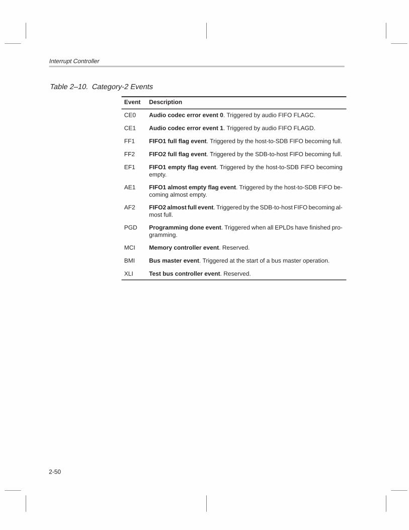
Interrupt Controller
2-50
Table 2–10. Category-2 Events
Event Description
CE0 Audio codec error event 0 . Triggered by audio FIFO FLAGC.
CE1 Audio codec error event 1 . Triggered by audio FIFO FLAGD.
FF1 FIFO1 full flag event . Triggered by the host-to-SDB FIFO becoming full.
FF2 FIFO2 full flag event . Triggered by the SDB-to-host FIFO becoming full.
EF1 FIFO1 empty flag event . Triggered by the host-to-SDB FIFO becomingempty.
AE1 FIFO1 almost empty flag event . Triggered by the host-to-SDB FIFO be-coming almost empty.
AF2 FIFO2 almost full event . Triggered by the SDB-to-host FIFO becoming al-most full.
PGD Programming done event . Triggered when all EPLDs have finished pro-gramming.
MCI Memory controller event . Reserved.
BMI Bus master event . Triggered at the start of a bus master operation.
XLI Test bus controller event . Reserved.

Interrupt Controller
2-51SDB Hardware
2.7.1 Memory-Mapped Interrupt Controller Registers
To manipulate SDB events, the interrupt controller has 12 registers accessibleon the I/O bus. They are accessed using 16-bit reads or writes. You should usedirect external accesses (DEAs) to bypass the MP’s data cache. Following thetable are diagrams of the register formats and descriptions of the registers andtheir fields.
Table 2–11. Interrupt Controller Registers Summary
RegisterName Access
’C80 Address
Host Address
Size(Bits) Description
ENABLE0 Read/write 0xE0000180 0x2300 16 Event enable register 0
ENABLE1 Read/write 0xE0000182 0x2304 16 Event enable register 1
ENABLE2 Read/write 0xE0000184 0x2308 16 Event enable register 2
EVSTATE Read only 0xE0000186 0x230C 16 Event state register
CLFLAG0 Write only 0xE0000188 0x2310 16 Clear flag register 0
RDFLAG0 Read only 0xE0000188 0x2310 16 Read flag register 0
STFLAG0 Write only 0xE000018A 0x2314 16 Set flag register 0
CNFLAG0 Read only 0xE000018A 0x2314 16 Condition flag register 0
CLFLAG1 Write only 0xE000018C 0x2318 16 Clear flag register 1
RDFLAG1 Read only 0xE000018C 0x2318 16 Read flag register 1
STFLAG1 Write only 0xE000018E 0x231C 16 Set flag register 1
CNFLAG1 Read only 0xE000018E 0x231C 16 Condition flag register 1

Interrupt Controller
2-52
ENABLE0 register
’C80 / host addresses: 0xE0000180 0x2300
15 14 13 12 11 10 9 8 7 6 5 4 3 2 1 0
0 0 0 0 PCI(1:0) FRM(1:0) ROW(1:0) CAP(1:0) CD1(1:0) CD0(1:0)
00 disabled01 XPT510 EINT311 N/A
00 disabled01 XPT410 EINT111 N/A
00 disabled01 XPT310 EINT211 N/A
00 disabled01 N/A10 EINT311 Host
00 disabled01 XPT210 EINT111 Host
00 disabled01 XPT110 EINT211 Host
ENABLE1 register
’C80 / host addresses: 0xE0000182 0x2304
15 14 13 12 11 10 9 8 7 6 5 4 3 2 1 0
0 0 AF1(1:0) AE2(1:0) EF2(1:0) BWR(1:0) BRD(1:0) 0 0 0 0
00 disabled01 XPT510 EINT211 N/A
00 disabled01 XPT410 EINT311 N/A
00 disabled01 XPT310 EINT111 N/A
00 disabled01 XPT210 EINT211 N/A
00 disabled01 XPT110 EINT311 N/A
The ENABLE0 and ENABLE1 registers contain the enable bits for allcategory-1 events (see Table 2–9). Each event has two enable bits that config-ure the event destination. For example, writing 0x0090 to ENABLE1 sets theBWR event to cause EINT2, and it sets the BRD event to cause XPT1. Thatis, EINT2 is the event destination of the BWR event, and XPT1 is the eventdestination of the BRD event. Clearing the enable bits to 00 disables the event.Normally, when you set the enable bits of an event, you leave all other bitsalone. Example 2–8 shows how to set the CAP enable bits.
Example 2–8. Setting the CAP Enable Bits
#define ENABLE0 NOCACHE_USHORT(*(volatile unsigned short*)0xE0000180)
/* enable CAP to EINT3 */ENABLE0 = (ENABLE0 & 0xFFCF) | 0x0020;

Interrupt Controller
2-53SDB Hardware
ENABLE2 register
’C80 / host addresses: 0xE0000184 0x2308
15 14 13 12 11 10 9 8 7 6 5 4 3 2 1 0
0 0 0 0 0 XLI BMI MCI PGD AF2 AE1 EF1 FF2 FF1 CE1 CE0
The ENABLE2 register contains the enable bits for all category-2 events (seeTable 2–10). Setting a bit to 1 enables the event; clearing it to 0 disables theevent. All category-2 events cause a host interrupt when the event is enabledand triggered. Normally, when you set the enable bits of an event, you leaveall other bits alone. Example 2–9 provides sample code to set/clear the bits.
Example 2–9. Setting/Clearing Category-2 Events
#define ENABLE2 NOCACHE_USHORT(*(volatile unsigned short*)0xE0000184)
/* enable CE1 */ENABLE2 = (ENABLE2 & 0xFFFD) | 0x0002;
/* disable AF2 */ENABLE2 = ENABLE2 & 0xFFBF;

Interrupt Controller
2-54
EVSTATE register
’C80 / host addresses: 0xE0000186 0x230C
15 14 13 12 11 10 9 8 7 6 5 4 3 2 1 0
LINT EINT(3:1) XPT(2:0) 0 0 0 0 0 0 0 0 0
EVSTATE is the event state register. The bits in this register provide a real-time(synchronous) image of the ’C80 event pins. The EVSTATE register is readonly.
LINT State of the ’C80 LINT4 pin . This pin is an active-low,level-sensitive interrupt pin.
LINT = 0 LINT4 is asserted (active)
LINT = 1 LINT4 is not asserted (not active)
EINT(3:1) State of the ’C80 EINT [3:1] pins . A 0 in one of the bitpositions means the corresponding EINT (external inter-rupt) pin on the ’C80 is low. ’C80 EINTs are triggered onthe rising edge of the EINT pin.
XPT(2:0) State of the ’C80 XPT [2:0] pins . All zeros means that noXPTs (external packet transfers) are being requested.
XPT = 000 no XPTs are being requested
XPT = 001 XPT1 is being requested
XPT = 010 XPT2 is being requested
XPT = 011 XPT3 is being requested
XPT = 100 XPT4 is being requested
XPT = 101 XPT5 is being requested
XPT = 110 XPT6 is being requested
XPT = 111 XPT7 is being requested

Interrupt Controller
2-55SDB Hardware
CLFLAG0 (write) / RDFLAG0 (read) register
’C80 / host addresses: 0xE0000188 0x2310
15 14 13 12 11 10 9 8 7 6 5 4 3 2 1 0
0 0 0 AF1 AE2 EF2 BWR BRD 0 0 PCI FRM ROW CAP CD1 CD0
CLFLAG0 / RDFLAG0 is a dual-purpose register. Writes to this register ac-cess CLFLAG0; reads from it access RDFLAG0. CLFLAG0 and RDFLAG0are located at the same address.
The RDFLAG0 register contains event sticky bits or flags. When a category-1event is triggered, its corresponding sticky bit in this register is set and remainsset until cleared by software. (See Table 2–9 for a list of category-1 events.)The one exception to the bit remaining set is when an event is enabled to causean XPT. If the enabled event causes an XPT, the corresponding sticky bit iscleared automatically when the ’C80 begins the XPT cycle. The flags in thisregister get set whether the corresponding event is enabled or not.
For example, assume that the CD0 enable bits in ENABLE0 are set to 0 (dis-abled), and then the CD0 event is triggered. In this case, the CD0 flag bit inRDFLAG0 gets set, but nothing else occurs. In other words, no EINTs, XPTs,or host interrupts are caused. Also, once a sticky bit is set, no further eventshappen until the sticky bit is cleared. For instance, assume CD0 is enabled tocause EINT2. CD0 is then triggered, which sets the CD0 sticky bit inRDFLAG0, causing EINT2 to occur on the ’C80. If another CD0 event happensbefore the sticky bit is cleared, another ’C80 EINT2 is not caused. For this rea-son, the sticky bit must be cleared in the ISR.
The CLFLAG0 register clears the sticky bits in the RDFLAG0 register. Writinga 1 to a bit has no effect; writing a 0 to a bit clears that bit.

Interrupt Controller
2-56
Example 2–10. Clearing an Event
#define CLFLAG0 NOCACHE_USHORT(*(volatile unsigned short*)0xE0000188)#define RDFLAG0 NOCACHE_USHORT(*(volatile unsigned short*)0xE0000188)
unsigned short flags;
/* read the event flags */flags = RDFLAG0;
/* does nothing */CLFLAG0 = 0xFFFF;
/* clear the ROW flag */CLFLAG0 = 0xFFF7;
/* clear all flags in RDFLAG0 */CLFLAG0 = 0x0000;
STFLAG0 (write) / CNFLAG0 (read) register
’C80 / host addresses: 0xE000018A 0x2314
15 14 13 12 11 10 9 8 7 6 5 4 3 2 1 0
0 0 0 AF1 AE2 EF2 BWR BRD 0 0 PCI FRM ROW CAP CD1 CD0
STFLAG0 / CNFLAG0 is a dual-purpose register. Writes to this register ac-cess STFLAG0; reads from it access CNFLAG0. STFLAG0 and CNFLAG0are located at the same address.
The STFLAG0 register is used to trigger a category-1 event (see Table 2–9).Writing a 1 to one of the bits in this register triggers the corresponding eventjust as if that event had actually happened. This capability allows the softwareto simulate event occurrences.
The CNFLAG0 register returns the state of the event signals coming into theinterrupt controller. For instance, the CD0 bit reflects the current state of theaudio FIFO FLAGA pin.
CLFLAG1 (write) / RDFLAG1 (read) register
’C80 / host addresses: 0xE000018C 0x2318
15 14 13 12 11 10 9 8 7 6 5 4 3 2 1 0
0 0 0 0 0 XLI BMI MCI PGD AF2 AE1 EF1 FF2 FF1 CE1 CE0
CLFLAG1 / RDFLAG1 operates in the same way as the CLFLAG0 /RDFLAG0 register, except the sticky bits (or flags) in this register correspondto category-2 events (see Table 2–10).
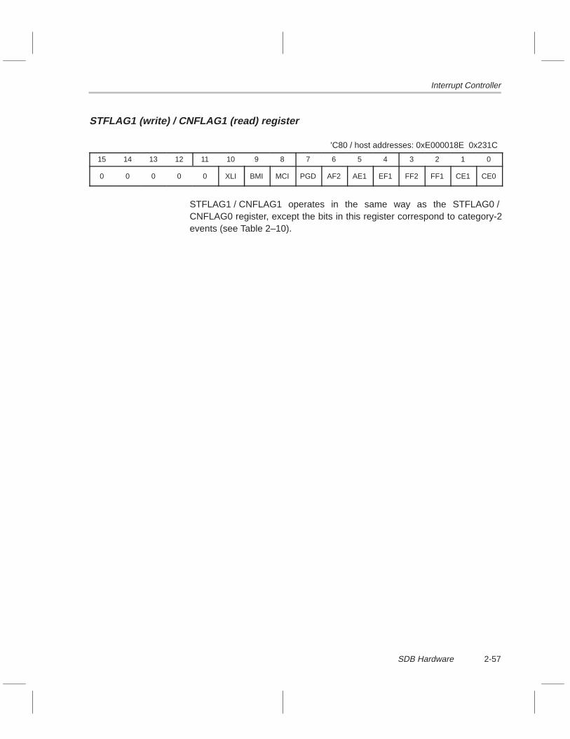
Interrupt Controller
2-57SDB Hardware
STFLAG1 (write) / CNFLAG1 (read) register
’C80 / host addresses: 0xE000018E 0x231C
15 14 13 12 11 10 9 8 7 6 5 4 3 2 1 0
0 0 0 0 0 XLI BMI MCI PGD AF2 AE1 EF1 FF2 FF1 CE1 CE0
STFLAG1 / CNFLAG1 operates in the same way as the STFLAG0 /CNFLAG0 register, except the bits in this register correspond to category-2events (see Table 2–10).

PCI Interface
2-58
2.8 PCI Interface
The interface between the SDB and the host is a dual-ported FIFO mappedinto both ’C80 and host address space. The host side of the FIFO connectsdirectly to the PCI bus through a 32-bit bus transceiver. Bus control logic is con-tained in EPLDs, which manage all transfers to and from the PCI bus. TheSDB side of the FIFO connects to the SDB’s memory controller via a 32-bitdata path. The memory controller routes FIFO data to or from either the SDB’sI/O bus or the ’C80’s data bus. Figure 2–9 illustrates this process. The inter-face logic also generates control signals for the PCI bus itself.
Figure 2–9. PCI Interface Block Diagram
ÁPCI bus
ÁÁ
Memoryand
interruptcontroller
ÁÁ
ÁÁ
Port B
ÁÁ32
32
Port A
PCI FIFO
FIFO
ÁÁ
ÁÁ
32
Interfacelogic
’C80
bus
ÁÁ
ÁÁ16
Á
Á64
16
I/O b
us
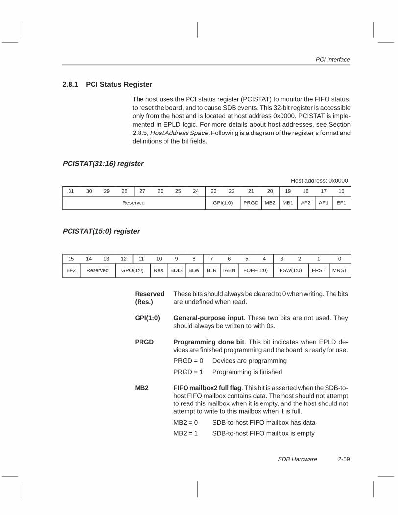
PCI Interface
2-59SDB Hardware
2.8.1 PCI Status Register
The host uses the PCI status register (PCISTAT) to monitor the FIFO status,to reset the board, and to cause SDB events. This 32-bit register is accessibleonly from the host and is located at host address 0x0000. PCISTAT is imple-mented in EPLD logic. For more details about host addresses, see Section2.8.5, Host Address Space. Following is a diagram of the register’s format anddefinitions of the bit fields.
PCISTAT(31:16) register
Host address: 0x0000
31 30 29 28 27 26 25 24 23 22 21 20 19 18 17 16
Reserved GPI(1:0) PRGD MB2 MB1 AF2 AF1 EF1
PCISTAT(15:0) register
15 14 13 12 11 10 9 8 7 6 5 4 3 2 1 0
EF2 Reserved GPO(1:0) Res. BDIS BLW BLR IAEN FOFF(1:0) FSW(1:0) FRST MRST
Reserved(Res.)
These bits should always be cleared to 0 when writing. The bitsare undefined when read.
GPI(1:0) General-purpose input . These two bits are not used. Theyshould always be written to with 0s.
PRGD Programming done bit . This bit indicates when EPLD de-vices are finished programming and the board is ready for use.
PRGD = 0 Devices are programming
PRGD = 1 Programming is finished
MB2 FIFO mailbox2 full flag . This bit is asserted when the SDB-to-host FIFO mailbox contains data. The host should not attemptto read this mailbox when it is empty, and the host should notattempt to write to this mailbox when it is full.
MB2 = 0 SDB-to-host FIFO mailbox has data
MB2 = 1 SDB-to-host FIFO mailbox is empty

PCI Interface
2-60
MB1 FIFO mailbox1 full flag . This bit is asserted when there is datain the host-to-SDB FIFO mailbox. The ’C80 should not attemptto read this mailbox when it is empty, and the ’C80 should notattempt to write to this mailbox when it is full.
MB1 = 0 Host-to-SDB FIFO mailbox has data
MB1 = 1 Host-to-SDB FIFO mailbox is empty
AF2 FIFO2 almost full flag . This bit asserts when the SDB-to-hostFIFO becomes almost full. The ’C80 should not attempt to writeto this FIFO when it is almost full.
AF2 = 0 SDB-to-host FIFO is almost full
AF2 = 1 SDB-to-host FIFO is not almost full
AF1 FIFO1 almost full flag . This bit asserts when the host-to-SDBFIFO becomes almost full. The host should not attempt to writeto this FIFO when it is almost full.
AF1 = 0 Host-to-SDB FIFO is almost full
AF1 = 1 Host-to-SDB FIFO is not almost full
EF1 FIFO1 empty flag . This bit asserts when the host-to-SDBFIFO becomes empty. The ’C80 should not attempt to read thisFIFO when it is empty.
EF1 = 0 Host-to-SDB FIFO is empty
EF1 = 1 Host-to-SDB FIFO is not empty
EF2 FIFO2 empty flag . This bit asserts when the SDB-to-hostFIFO becomes empty. The host should not attempt to read thisFIFO when it is empty.
EF2 = 0 SDB-to-host FIFO is empty
EF2 = 1 SDB-to-host FIFO is not empty

PCI Interface
2-61SDB Hardware
GPO(1:0) General-purpose output . These two bits are general-purpose output bits that can be written to by the host, wherethey can then be used by the SDB. Currently, GPO1 is notused, but GPO0 is used to trigger the PCI event on the SDB’sinterrupt controller. A 0-to-1 transition of the GPO0 bit triggersthe PCI event. The ’C80 code handles the event. Generally,this event is used to cause EINT3 on the ’C80 for messagepassing to the SDB from the host.
GPO0 0 to 1 transition triggers PCI event
GPO1 Not used
BDIS Burst disable . Setting this bit disables all burst transfersbetween the SDB and PCI bus.
BDIS = 0 Burst transfers enabled
BDIS = 1 Burst transfers disabled
BLW Block transfer (blt) write event trigger bit . A 0-to-1 transitionof the bit triggers the BWR event on the SDB’s interrupt control-ler. Because block transfers between the SDB and host arecommon, this feature has been added as an efficient way totrigger an event on the SDB. The ’C80 code handles the BWRevent.
BLR Block transfer (blt) read event trigger bit . A 0-to-1 transitionof the bit triggers the BRD event on the SDB’s interrupt control-ler. Because block transfers between the SDB and host arecommon, this feature has been added as an efficient way totrigger an event on the SDB. The ’C80 code handles the BRDevent.
IAEN PCI interrupt A enable . Setting this bit to 1 enables host inter-rupts.
IAEN = 0 Host interrupts disabled
IAEN = 1 Host interrupts enabled

PCI Interface
2-62
FOFF(1:0) PCI FIFO offset . These bits determine the PCI FIFO offset thatgoverns when the FIFO flags assert/deassert. The suggestedsetting for the offset is 12 32-bit words.
FOFF = 00 4-word offset
FOFF = 01 8-word offset
FOFF = 10 12-word offset
FOFF = 11 16-word offset
FSW(1:0) FIFO swap setting bits . The PCI FIFO logic has functionalityto swap bytes on transfers through the FIFO. When a FIFOswap setting change occurs, any data currently in the FIFOgets the new swap setting. This feature is useful for transfer-ring little-endian data from the host to a big-endian format forthe SDB. The swapping does not affect the FIFO mailboxes.
FSW = 00 No swapping 0x12345678 → 0x12345678
FSW = 01 Byte swapping 0x12345678 → 0x78563412
FSW = 10 Word swapping 0x12345678 → 0x56781234
FSW = 11 Byte-word 0x12345678 → 0x34127856swapping
FRST PCI FIFO reset . Writing a 0 to this bit resets the PCI interfaceFIFO.
FRST = 0 FIFO reset asserted
FRST = 1 FIFO reset not asserted
MRST Master reset . Writing a 0 to this bit pulls the C80’s RESET pinlow. Other devices on the board are also tied to this reset sig-nal.
MRST = 0 Master reset asserted
MRST = 1 Master reset not asserted
2.8.2 PCI FIFO
The PCI FIFO is depicted in Figure 2–10. The FIFO device has two data FIFOsand two mailboxes. The mailboxes act as single-word FIFOs, meaning that themailboxes are full after one write and then are empty after one read. The mail-boxes can be accessed without disrupting the data in the data FIFOs.Table 2–12 lists the parts of the FIFO device accessed by different host/SDBtransfers. All FIFO accesses must be 32-bit accesses.

PCI Interface
2-63SDB Hardware
Figure 2–10. PCI FIFO Block Diagram
ÁÁ
Á
ÁÁ
Á
32
32
32
Port A
Port B
SDB side
Host side
ÁÁ
Á32 32
1 × 32Mailbox2
3232 32 32
32
FIFO1
64 × 32
FIFO21 × 32
Mailbox1
64 × 32
Table 2–12. Parts of the FIFO Device Accessed by Host/SDB Transfers
Type of Access Part of FIFO Device Accessed
’C80 reads from data FIFO FIFO1 Host-to-SDB FIFO
’C80 writes to data FIFO FIFO2 SDB-to-host FIFO
’C80 reads from mailbox Mailbox1 Host-to-SDB mailbox
’C80 writes to mailbox Mailbox2 SDB-to-host mailbox
Host reads from data FIFO FIFO2 SDB-to-host FIFO
Host writes to data FIFO FIFO1 Host-to-SDB FIFO
Host reads from mailbox Mailbox2 SDB-to-host mailbox
Host writes to mailbox Mailbox1 Host-to-SDB mailbox
PCI Interface
2-64
2.8.3 TMS320C80 Access to the PCI FIFO
The ’C80 can access the PCI data FIFOs and the PCI FIFO mailboxes. All ac-cesses must be 32-bit accesses. When the ’C80 performs a read from theFIFO data address range, a read is done from the host-to-SDB data FIFO(FIFO1). When the ’C80 performs a write to this range, a write is done to theSDB-to-host data FIFO (FIFO2). The ’C80 should not attempt a read from anempty FIFO or attempt a write to an almost full or full FIFO. When the ’C80 per-forms a read from the FIFO mailbox address range, a read is done from thehost-to-SDB mailbox (mailbox1). When the ’C80 performs a write to this range,a write is done to the SDB-to-host mailbox (mailbox2). The ’C80 should not at-tempt to read an empty mailbox or attempt to write to a full mailbox.
’C80 FIFO mailbox address range:
0xF8000000 to 0xFBFFFFFF
’C80 FIFO data address range:
0xFC000000 to 0xFFFFFFFF
2.8.4 PCI Plug and Play
The SDB is a PCI plug-and-play device, meaning the host PCI BIOS dynami-cally configures the board at system boot time. The purpose of plug and playis to dynamically allocate resources to devices so that no two devices use thesame resource. These resources include memory address space, I/O addressspace, interrupts, and DMA channels. Each plug-and-play device requestsneeded resources during autoconfiguration. The BIOS assigns those re-sources to the device. Each device has a standard set of PCI configuration reg-isters that the BIOS sets to reflect assigned resources. For the most part, thisis all transparent to the user.
The SDB requests 64K bytes of memory address space and one interrupt.During autoconfiguration at boot time, the PCI BIOS detects the SDB request.The PCI BIOS then finds an unused 64K byte chunk of address space andassigns it to the SDB. Next, the PCI assigns an unused interrupt resource tothe SDB.
The memory address assigned to the SDB is its physical location on the PCIbus. Generally, an application cannot access this physical address space di-rectly, so a device driver is needed. Because the SDB has 64K bytes of ad-dress space, only 16 bits of address are needed to locate any position in that64K, given the starting address. The device driver locates the starting or physi-cal address by taking a 16-bit address and adding the physical base address.The device driver knows where the physical base address is from the PCI con-figuration space on the board.

PCI Interface
2-65SDB Hardware
This method of allocating resources allows application code running on thehost to locate the board using only a 16-bit address, which the device drivertranslates to the correct physical address (no matter where PCI assigned theboard in its address space). Thus, the 16-bit address remains static since it isjust an offset into the 64K address window of PCI address space. This 16-bitoffset is referred to as the host address in this guide. For example, assume thePCI BIOS located the SDB at the PCI address of 0xFFBF0000. The devicedriver translates a 16-bit host address of 0x1234 to a physical location of0xFFBF1234 on the PCI bus.

PCI Interface
2-66
2.8.5 Host Address Space
The host address space of the SDB is a 64K byte window into the PCI addressspace. All host addresses to the SDB are specified as 16-bit offsets into thiswindow; the host device driver takes care of the translation (see subsection2.8.4, PCI Plug and Play). The 64K address space of the SDB is partitionedinto several areas as depicted in Figure 2–11. Following the diagram is a de-scription of each partition.
Figure 2–11. Host Address Space
Á
64K-bytewindowinto PCIaddressspace
0x0000Host address
0x1FFF
FIFOheader2K × 32
I/Ospace
FIFOboot
2K × 32
0x2000
0x3FFF0x4000
0x5FFF0x6000
0x7FFF0x8000
0xFFFF
FIFOdata
8K × 32
Á
0x1800MAIL

PCI Interface
2-67SDB Hardware
0x0000 PCISTAT. This location is the PCI status registerand is visible only to the host. (See Section 2.8.1,PCI Status Register, for more information.)
0x1800 MAIL . This 32-bit location is the port into the FIFOmailboxes and is visible only from the host. Read-ing this location reads the SDB-to-host mailbox(mailbox2), whereas writes to this location write tothe host-to-SDB mailbox (mailbox1). The hostshould never attempt to read this location when theSDB-to-host mailbox is empty, and the host shouldnever attempt to write to this location when thehost-to-SDB mailbox is full. You can determinethese conditions by checking the MB1 and MB2bits in the PCISTAT register.
0x2000 – 0x3FFF I/O space . The entire I/O bus on the SDB is acces-sible in this address range. Special state machinesare implemented that use the FIFO mailboxes tocomplete I/O bus accesses. The host cannot ac-cess the SDB’s I/O bus unless both FIFO mail-boxes are empty. The transfer is actually a 2-stepprocess handled by the host device driver.
0x4000 – 0x5FFF FIFO header (2K × 32). This range of addressesmaps to the PCI data FIFOs. This range is write-only. A host write to anywhere in this range per-forms a write to the host-to-SDB data FIFO. Thehost should not attempt to write to an almost full orfull FIFO. The intention of this range is to have aseparate FIFO header space to write commandserver header information. Host reads from thisrange return the PCI status register (PCISTAT)contents.

PCI Interface
2-68
0x6000 – 0x7FFF FIFO boot (2K × 32). This range of addressesmaps to the PCI data FIFOs. This range is write-only. A host write to anywhere in this range per-forms a write to the host-to-SDB data FIFO. Thehost should not attempt to write to an almost full orfull FIFO. This range provides a separate FIFOboot space to supply boot code to the ’C80. Hostreads from this range return the PCI status register(PCISTAT) contents.
0x8000 – 0xFFFF FIFO data (8K × 32). This range of addressesmaps to the PCI data FIFOs. A host read from any-where in this range performs a read from the SDB-to-host data FIFO; a host write to anywhere in thisrange performs a write to the host-to-SDB dataFIFO. The host should not attempt to read anempty FIFO or attempt to write to an almost full orfull FIFO. This range provides space for normalFIFO data transfers.
2.8.6 PCI Bus Mastering
The SDB supports bus master writes to the PCI bus. This means that the SDBhas the ability to take control of the PCI bus (master) and write to devices(slaves) on the bus. The destination address of the bus master write is a physi-cal address on the PCI bus. This physical address differs from logical address-es used in PC operating systems such as Windows NT. Translation of a logicaladdress into a physical address and vice versa is beyond the scope of thisguide.
Three registers are used to perform bus mastering:
� Bus master address low (BMAL)� Bus master address high (BMAH)� Bus master control (BMCTRL)
The application should place the host physical address into BMAL and BMAH(the lower 16 bits into BMAL and the upper 16 bits into BMAH). Once the ad-dress registers are configured, setting the BMEN bit of the BMCTRL registerstarts the bus master transfer. The address registers are autoincrementingduring the transfer, but you can disable this feature by setting the incrementdisable (IDIS) bit of the BMCTRL register.

PCI Interface
2-69SDB Hardware
The bus mastering registers are accessible on the I/O bus. They are accessedusing 16-bit reads or writes. You should use direct external accesses (DEAs)to bypass the MP’s data cache. Table 2–13 lists the PCI bus mastering regis-ters. Following the table are diagrams of the register formats and descriptionsof the registers and their fields.
Table 2–13. PCI Bus Mastering Registers Summary
RegisterName Access
’C80 Address
Host Address
Size(Bits) Description
BMAL Read/write 0xE0000A00 0x3400 16 Bus master address low register
BMAH Read/write 0xE0000A02 0x3404 16 Bus master address high register
BMCTRL Read/write 0xE0000104 0x2208 8 Bus master control register
BMAL register
’C80 / host addresses: 0xE0000A00 0x3400
15 14 13 12 11 10 9 8 7 6 5 4 3 2 1 0
Bus master address low register
BMAL is the bus master address low register. This register is loaded with thelower 16 bits of the physical PCI address of the target of the bus master opera-tion.
BMAH register
’C80 / host addresses: 0xE0000A02 0x3404
15 14 13 12 11 10 9 8 7 6 5 4 3 2 1 0
Bus master address high register
BMAH is the bus master address high register. This register is loaded with theupper 16 bits of the physical PCI address of the target of the bus master opera-tion.

PCI Interface
2-70
BMCTRL register
’C80 / host addresses: 0xE0000104 0x2208
7 6 5 4 3 2 1 0
Reserved BMEN IDIS b0
BMCTRL controls the bus mastering feature of the SDB.
Reserved Each of these bits should always be cleared to 0.
BMEN Bus mastering enable . This bit enables bus mastering. Whenset, the SDB begins transferring data from the SDB-to-hostFIFO to the PCI physical address contained in BMAL andBMAH. The transfer operation continues until this bit (BMEN)is cleared. If the FIFO becomes empty, the SDB relinquishesmaster control of the PCI bus until the ’C80 puts more data intothe FIFO, at which point the SDB becomes master again andtransfers the data. It is important that you do not clear this bitto complete the bus master operation until all of the data in theFIFO has been transferred.
BMEN = 0 Bus mastering disabled
BMEN = 1 Bus mastering enabled
IDIS Increment disable . This bit disables the address auto-increment feature of the bus mastering hardware.
IDIS = 0 Address autoincrement enabled
IDIS = 1 Address autoincrement disabled
b0 Bit 0 . The bus master hardware requires this bit to be set.
2.8.7 Bootstrapping
The term bootstrapping refers to the process of resetting the board and provid-ing it some code to run. The SDB is bootstrapped from the host via the PCIFIFO. The ’C80 can be reset by writing a 0 then a 1 to the MRST bit of thePCISTAT register. After it is reset, the ’C80 is halted because the HREQ pinon the SDB is tied high. To unhalt the ’C80 at this point, the EINT3 signal onthe ’C80 must be asserted. The host asserts EINT3 by setting up the interruptcontroller and then triggering EINT3 (remember that the host can access theI/O bus without intervention from the ’C80).

PCI Interface
2-71SDB Hardware
When the ’C80 unhalts, it first executes the instruction at 0xFFFFFFF8. Sincethe MP’s instruction cache is empty, however, the ’C80 must first do an i-cachesubblock fill beginning at address 0xFFFFFFC0 (a subblock is 64 bytes). Thisaddress falls into the address space of the PCI FIFO; therefore, 64 bytes ofMP code must be in the FIFO. This means that the host has to put the data inthe FIFO from the host side. The MP code then finishes the boot process.

2-72

3-1Audio Capture and Playback API
Audio Capture and Playback API
This chapter discusses the audio macros and data types. It also describes, inalphabetical order, the application programming interface (API) functionsassociated with the audio capture and playback drivers for the TMS320C8xsoftware development board (SDB).
Topic Page
3.1 Audio Capture and Playback API Macros and Data Types 3-2. . . . . . . .
3.2 Audio Buffering 3-5. . . . . . . . . . . . . . . . . . . . . . . . . . . . . . . . . . . . . . . . . . . . . . .
3.3 Audio Capture and Playback API Functions 3-9. . . . . . . . . . . . . . . . . . . . .
Chapter 3

Audio Capture and Playback API Macros and Data Types
3-2
3.1 Audio Capture and Playback API Macros and Data Types
Table 3–1 describes the macros used by the audio API and lists the API func-tions that use each macro. Figure 3–1 provides definitions for the audio APIdata types. These macros and data types, as well as the API function proto-types, are defined in <audio.h>. The object code resides in sdbdrvs.lib.
Table 3–1. Audio API Macros
(a) Audio operation mode
Macro Value Description
#define AUDIO_CAPTURE 0x02 DMA capture mode
#define AUDIO_PLAYBACK 0x03 DMA playback mode
#define AUDIO_PIO 0x04 Programmed I/O mode
Note: These macros are used by the function Audio_Install( ).
(b) Audio stereo mode
Macro Value Description
#define AUDIO_MONO FALSE Mono mode
#define AUDIO_STEREO TRUE Stereo mode
Note: These macros are used by the function Audio_Install( ).
(c) Audio data coding format
Macro Value Description
#define AUDIO_PCM16 0x21 16-bit pulse code modulation (signed)
#define AUDIO_PCM8 0x12 8-bit pulse code modulation (unsigned)
#define AUDIO_ALAW8 0x13 8-bit A-Law
#define AUDIO_ULAW8 0x14 8-bit µ-Law
Note: These macros are used by the function Audio_Install().
(d) Audio analog input source
Macro Value Description
#define AUDIO_LINE 0x00 Line input
#define AUDIO_AUX1 0x01 Auxiliary 1 input
#define AUDIO_MIXED 0x03 Line input with post-DAC mixing
Note: These macros are used by the function Audio_ProgramInputs( ).

Audio Capture and Playback API Macros and Data Types
3-3Audio Capture and Playback API
Table 3–1. Audio API Macros (Continued)
(e) Boolean mute flags for the audio codec
Macro Value Description
#define AUDIO_UNMUTE FALSE Unmute channel
#define AUDIO_MUTE TRUE Mute channel
Note: These macros are used by the following functions:Audio_ProgramAux1()Audio_ProgramDacs()
Figure 3–1. Audio API Data Types
(a) Stereo buffer-pointer structure definition
typedef struct {
void *L; /* pointer to left buffer */void *R; /* pointer to right buffer */
} AUDIO_PTR;
(b) Audio metrics structure definition
typedef struct {
BYTE Mode; /* audio mode */BYTE Stereo; /* stereo flag */BYTE Format; /* data format */float Fs; /* sample rate */BYTE Bps; /* bytes per sample */BYTE BlockCt; /* number of subblocks in a buffer */BYTE BlockSz; /* number of samples in a subblock */BYTE BuffCt; /* number of buffers in a queue */ULONG BuffSz; /* size of buffer in samples */ULONG ByteSz; /* size of buffer in bytes */
} AUDIO_MET;

Audio Capture and Playback API Macros and Data Types
3-4
3.1.1 AUDIO_PTR Data Type
By encapsulating left and right buffer pointers into one data structure, theAUDIO_PTR data type simplifies argument passing to audio API functions.The two members of AUDIO_PTR are L and R, which are both void pointers.Because they are void pointers, the members can point to 8- or 16-bit data buff-ers. The audio API internally performs the correct type casting of the void point-ers to match the buffer data size.
3.1.2 Audio Metric Parameters
The type definition for AUDIO_MET defines metric parameters of the currentaudio state. Define a variable of this type, then pass a pointer to it as an argu-ment to Audio_GetMetrics(). Audio_GetMetrics() fills in the structure mem-bers.

Audio Buffering
3-5Audio Capture and Playback API
3.2 Audio Buffering
This section describes the structure and operation of the internal buffering thatis managed by the audio driver. An internal variable of type BUFFS, which islocal to the audio API module, manages the actual buffers. Figure 3–2 showsthe BUFFS data type. An application does not have scope into this data type,but it may be important for you to understand the internal workings of the buff-ering.
Figure 3–2. Internal Audio Buffer Structure
typedef struct {
BYTE Mode; /* current audio mode */ BYTE Format; /* current audio format */ float Fs; /* current audio sample rate */ BYTE BlockSz; /* size of each buffer subblock in number of samples */ BYTE BlockCt; /* number of subblocks in each buffer */ BYTE BuffCt; /* number of buffers in each queue */ ULONG ByteSz; /* size of each buffer in bytes */ ULONG BuffSz; /* size of each buffer in samples */ BYTE Bps; /* bytes per sample (1=8-bit, 2=16-bit) */ BOOL Stereo; /* stereo flag (FALSE=mono, TRUE=stereo) */ BYTE Capp; /* applications buffer index into the capture queue */ BYTE Cisr; /* ISRs buffer index into the capture queue */ BYTE Papp; /* applications buffer index into the playback queue */ BYTE Pisr; /* ISRs buffer index into the playback queue */ BYTE Cidx; /* capture subblock index */ BYTE Pidx; /* playback subblock index */ ULONG SubSize; /* size of one subblock in bytes */ ULONG Coffset; /* subblock offset into capture buffer in bytes */ ULONG Poffset; /* subblock offset into playback buffer in bytes */ void **CL; /* pointer to left capture queue */ void **CR; /* pointer to right capture queue */ void **PL; /* pointer to left playback queue */ void **PR; /* pointer to right playback queue */
} BUFFS;
The audio buffering structure is created dynamically on the system heap whenthe application calls Audio_Install( ) and remains intact until the applicationcalls Audio_UnInstall( ). Audio_UnInstall( ) destroys the queue structurecreated by Audio_Install( ) and frees up all relative heap storage.

Audio Buffering
3-6
Figure 3–3 illustrates the buffering structure. The main component of the en-tire buffering mechanism is the queue structure. Individual queues are createdfor left capture (CL), right capture (CR), left playback (PL), and right playback(PR), depending on the mode (stereo or mono, capture or playback). All point-ers within a queue are void pointers that allow 8-bit or 16-bit sample data. Thedriver takes care of correct type casting of these pointers. Each queue is ac-cessed using one of the void ** members of the BUFFS structure. The left cap-ture queue is accessed using CL. Figure 3–3 illustrates the left capture queueonly, but the other queues (CR, PL, and PR) have the same structure. The fol-lowing subsections provide details about the individual queue, individual buff-er, and individual subblock depicted in Figure 3–3.
Figure 3–3. Buffering Queue Structure
ÁÁÁÁÁÁÁÁ
ÁÁÁÁÁÁÁÁ
ÁÁÁÁ
ÁÁÁÁÁÁÁÁ
ÁÁÁÁÁÁÁÁ
ÁÁÁÁ
ÁÁÁÁÁÁÁÁÁÁÁÁÁÁÁÁÁÁÁÁÁÁÁÁ
(a) Individual queue
SubSz (bytes)BlockSz (samples)
Sample
(b) Individual buffer
Bps
BlockCt
Coffset
CidxblockSub-
(c) Individual subblock
Buffer
ByteSz (bytes)BuffSz (samples)
CL
CisrCapp
BuffCt

Audio Buffering
3-7Audio Capture and Playback API
3.2.1 Individual Queue
Figure 3–3(a) shows an individual queue structure, the left capture queue. TheCL member of BUFFS points to an array of void pointers, each of which pointto a data buffer. BuffCt indicates the number of such buffers. Each buffer hasa size of BuffSz (in number of samples) and ByteSz (in number of bytes). If theaudio data is 8 bit (one byte), then the BuffSz is equal to ByteSz.
The Capp and Cisr members of BUFFS are queue indexes into the array ofbuffer pointers, which range from 0 to BuffCt – 1. These indexes continuouslyadvance when audio is running (enabled). When the audio ISR has completedfilling a buffer, it advances the Cisr index. If the index overflows (>= BuffCt),it wraps back to 0. The application advances the Capp index each timeAudio_GetCaptureBuffs() is called. The ISR fills the buffer indexed by Cisr; thebuffer returned to the application through a call to Audio_GetCaptureBuffs()is indexed by Capp. The Capp buffer is locked from the ISR, which gives theapplication exclusive access to it. When the application callsAudio_GetCaptureBuffs(), the Capp index is advanced, then a pointer to theindexed buffer is returned.
The Capp and Cisr indexes cannot be equal; that is, the application cannothave access to the same buffer as the ISR. If the application and the ISR wereto both have access to the same buffer, the application would read from thebuffer as it is being filled by the ISR. This condition introduces the possibilityof an index collision. If the ISR tries to advance the Cisr index onto the Cappindex, the advance does not take place and the ISR fills the same buffer again.The result is that one buffer of captured audio is skipped. If the application triesto advance the Capp index onto the Cisr index through a call to Audio_GetCap-tureBuffs(), the advance does not take place and the same buffer pointer isreturned as the last call. As a result, the application receives the same buffertwice in a row. The only way to prevent index collisions is to have the applica-tion advance the Capp index at the same rate (on average) that the ISRadvances the Cisr index.
The capture operation described here also applies, in general, to playback op-eration. The ISR advances Pisr while the application advances Papp throughcalls to Audio_GetPlaybackBuffs(). Collisions are handled in a similar fashion.

Audio Buffering
3-8
3.2.2 Individual Buffer
Figure 3–3(b) shows the structure of an individual buffer. Bps, or bytes persample, is the width of the buffer in number of bytes. This value is 1 for 8-bitsamples and 2 for 16-bit samples. The application only deals with completebuffers, but the ISR must operate on partitioned buffers. Each partition is calleda subblock, and there are BlockCt of them in one buffer.
The ISR manages the index Cidx, which is the subblock index into the currentcapture buffer. Audio data is packet transferred from the audio FIFO into theaudio buffer in chunks equal in size to the subblock. When the audio FIFO be-comes almost full (captured audio from the codec), it triggers an interrupt thatis handled by the audio capture ISR. This ISR advances the Cidx index, thentransfers the new FIFO data into the capture buffer starting at the new sub-block offset (Coffset). When the Cidx index overflows, it wraps back to 0 andthe next buffer is obtained (Cisr is advanced). The Coffset member is just abyte offset into the buffer used to calculate the destination address of the pack-et transfer. Each time Cidx is advanced, Coffset is computed. An overview isthat the ISR fills up the buffer in chunks and, when it is full, the next one is ob-tained.
3.2.3 Individual Subblock
Figure 3–3(c) depicts the individual subblock. Its size is BlockSz (in numberof samples) and SubSz (in number of bytes). Data is transferred from the audioFIFO in chunks equal in size to the subblock size.
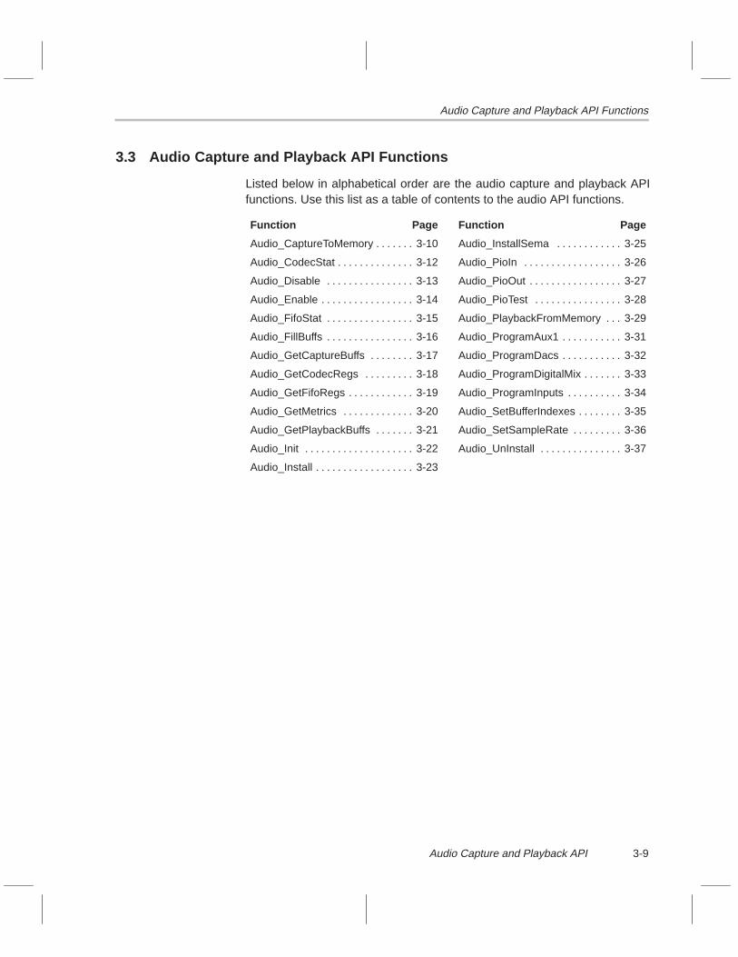
Audio Capture and Playback API Functions
3-9Audio Capture and Playback API
3.3 Audio Capture and Playback API Functions
Listed below in alphabetical order are the audio capture and playback APIfunctions. Use this list as a table of contents to the audio API functions.
Function Page Function Page
Audio_CaptureToMemory 3-10. . . . . . . Audio_InstallSema 3-25. . . . . . . . . . . .
Audio_CodecStat 3-12. . . . . . . . . . . . . . Audio_PioIn 3-26. . . . . . . . . . . . . . . . . .
Audio_Disable 3-13. . . . . . . . . . . . . . . . Audio_PioOut 3-27. . . . . . . . . . . . . . . . .
Audio_Enable 3-14. . . . . . . . . . . . . . . . . Audio_PioTest 3-28. . . . . . . . . . . . . . . .
Audio_FifoStat 3-15. . . . . . . . . . . . . . . . Audio_PlaybackFromMemory 3-29. . .
Audio_FillBuffs 3-16. . . . . . . . . . . . . . . . Audio_ProgramAux1 3-31. . . . . . . . . . .
Audio_GetCaptureBuffs 3-17. . . . . . . . Audio_ProgramDacs 3-32. . . . . . . . . . .
Audio_GetCodecRegs 3-18. . . . . . . . . Audio_ProgramDigitalMix 3-33. . . . . . .
Audio_GetFifoRegs 3-19. . . . . . . . . . . . Audio_ProgramInputs 3-34. . . . . . . . . .
Audio_GetMetrics 3-20. . . . . . . . . . . . . Audio_SetBufferIndexes 3-35. . . . . . . .
Audio_GetPlaybackBuffs 3-21. . . . . . . Audio_SetSampleRate 3-36. . . . . . . . .
Audio_Init 3-22. . . . . . . . . . . . . . . . . . . . Audio_UnInstall 3-37. . . . . . . . . . . . . . .
Audio_Install 3-23. . . . . . . . . . . . . . . . . .

Audio_CaptureToMemory
3-10
Function Name Audio_CaptureToMemory
Syntax void Audio_CaptureToMemory(AUDIO_PTR *P, ULONG NumBuffs);
Arguments AUDIO_PTR *P Pointer to a buffer pointer structure whose elementspoint to preallocated buffers of memory in which thecaptured audio is stored
ULONG NumBuffs Amount of audio to capture; value specified as an inte-gral number of DMA buffers as set up by Audio_Install( )
Return Value None
Description This function captures a specified amount of audio data into buffers pointedto by the members of P. Before calling Audio_CaptureToMemory(), you mustfirst call Audio_Install( ) to set up the audio hardware for DMA capture. TheNumBuffs argument specifies how much audio to capture in number of buffers.The buffer size is determined when you call Audio_Install( ). If the audio is setup for mono mode, the L member of P is ignored.
Notes:
1) Do not call Audio_CaptureToMemory() while audio is enabled.
2) Audio_CaptureToMemory() must be called from a task other than the de-fault task because it waits on a semaphore.
Example void AudioTask(void *P) {AUDIO_PTR Cptr;AUDIO_MET AM;BYTE Format = AUDIO_PCM16;BOOL Stereo = AUDIO_STEREO;float Fs = 48.0;BYTE BlockCt = 20;BYTE BlockSz = 50;BYTE BuffCt = 8;ULONG NumBuffs = Fs*10;
/* dummy install to set audio metrics */Audio_Install(AUDIO_CAPTURE, Format, Stereo, Fs, BlockCt,
BlockSz, BuffCt);
/* get the metrics of the new settings */Audio_GetMetrics(&AM);
/* allocate some DRAM storage for captured audio */Cptr.L = (void*)memalign(64,AM.ByteSz*NumBuffs);if (Stereo)
Cptr.R = (void*)memalign(64,AM.ByteSz*NumBuffs);
/* capture some audio into the allocated buffers */Audio_CaptureToMemory(&Cptr, NumBuffs);

Audio_CaptureToMemory
3-11Audio Capture and Playback API
/* uninstall the audio settings */ Audio_UnInstall();
/* process the captured audio here */
/* free up the buffer storage */free((void*)Cptr.L);
if (Stereo)free((void*)Cptr.R);
}
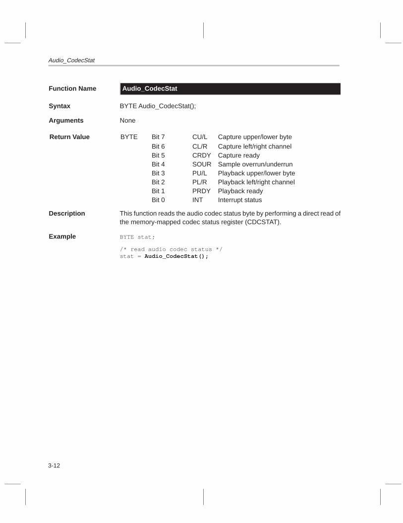
Audio_CodecStat
3-12
Function Name Audio_CodecStat
Syntax BYTE Audio_CodecStat();
Arguments None
Return Value BYTE Bit 7 CU/L Capture upper/lower byte
Bit 6 CL/R Capture left/right channelBit 5 CRDY Capture readyBit 4 SOUR Sample overrun/underrunBit 3 PU/L Playback upper/lower byteBit 2 PL/R Playback left/right channelBit 1 PRDY Playback readyBit 0 INT Interrupt status
Description This function reads the audio codec status byte by performing a direct read ofthe memory-mapped codec status register (CDCSTAT).
Example BYTE stat;
/* read audio codec status */stat = Audio_CodecStat();

Audio_Disable
3-13Audio Capture and Playback API
Function Name Audio_Disable
Syntax void Audio_Disable();
Arguments None
Return Value None
Description This function disables the audio subsystem by disabling the audio codec anddisabling any associated events.
Example Audio_Install(AUDIO_PLAYBACK, AUDIO_PCM16, AUDIO_STEREO, 48, 16, 64, 4);
Audio_Enable();
/* do some audio processing here */
Audio_Disable();Audio_UnInstall();

Audio_Enable
3-14
Function Name Audio_Enable
Syntax void Audio_Enable();
Arguments None
Return Value None
Description This function enables the audio subsystem by enabling the audio codec andenabling any associated events.
Example Audio_Install(AUDIO_PLAYBACK, AUDIO_PCM16, AUDIO_STEREO, 48,
16, 64, 4);
Audio_Enable();
/* do some audio processing here */
Audio_Disable();Audio_UnInstall();

Audio_FifoStat
3-15Audio Capture and Playback API
Function Name Audio_FifoStat
Syntax USHORT Audio_FifoStat();
Arguments None
Return Value USHORT Bit 15 Capture almost empty flag (AEF)
Bit 14 Capture FIFO empty flag (FEF)Bit 13 Playback almost full flag (AFF)Bit 12 Playback FIFO full flag (FFF)Bit 11 Status register format (1)Bit 10 Read parity errorBit 9 Write parity errorBit 8 Odd byte valid bitBit 7 Capture AFFBit 6 Capture FFFBit 5 Playback AEFBit 4 Playback FEFBit 3 DMA direction (0 = capture)Bit 2 ReservedBit 1 ReservedBit 0 Reserved
Description This function returns the status of the audio FIFO by performing a direct readof the memory-mapped audio FIFO command register (AFIFOCMD).
Note:
Bits 8 and 11 are not used by the software but do occupy bit positions in thestatus word.
Example USHORT stat;
/* read audio FIFO status */stat = Audio_FifoStat();

Audio_FillBuffs
3-16
Function Name Audio_FillBuffs
Syntax void Audio_FillBuffs(USHORT val);
Arguments USHORT val This specifies the fill value. For 8-bit buffers, this valuewill be cast into a byte.
Return Value None
Description This function fills the internal audio buffers created by Audio_Install( ) with thevalue specified.
Note:
Do not call Audio_FillBuffs() while audio is enabled.
Example Audio_Install(AUDIO_PLAYBACK, AUDIO_PCM16, AUDIO_MONO, 8.0, 16, 64, 8);
Audio_FillBuffs(0x0000);Audio_Enable();
/* do audio processing here */
Audio_Disable();

Audio_GetCaptureBuffs
3-17Audio Capture and Playback API
Function Name Audio_GetCaptureBuffs
Syntax BOOL Audio_GetCaptureBuffs(AUDIO_PTR *P);
Arguments AUDIO_PTR *P Pointer to buffer pointer structure that will be filled in bythis function with pointers to the captured audio buffers
Return Value BOOL TRUEFALSE
Internal buffers advancedInternal buffers did not advance
Description For DMA audio capture, this function is used to get pointers to buffers of cap-tured audio. This function first advances the application index into the capturebuffer queue(s), then returns pointers to the newest capture buffers (left andright). If the audio is in mono mode, the R member of P is assigned NULL. Ifthe buffers cannot advance because the ISR is using the next buffers in thequeue, this function returns FALSE and pointers to the buffers before advance-ment are returned. For DMA capture mode, this function must be called, onaverage, at the same rate the ISR is capturing buffers.
Example AUDIO_PTR Cptr;
Audio_Install(AUDIO_CAPTURE, AUDIO_PCM16, AUDIO_STEREO, 8.0, 16, 64, 8);
Audio_FillBuffs(0x0000);Audio_Enable();
/* loop forever */while (1) {
TaskWaitSema(AudioSemaId);Audio_GetCaptureBuffs(&Cptr) ;
/* Cptr.L now points to left captured audio DMA buffer *//* Cptr.R now points to right captured audio DMA buffer */
/* do audio processing here */}

Audio_GetCodecRegs
3-18
Function Name Audio_GetCodecRegs
Syntax void Audio_GetCodecRegs(BYTE *CodecRegs);
Arguments BYTE *CodecRegs Pointer to a preallocated array of 16 bytes (un-signed characters) that will be filled with the codecregister values
Return Value None
Description This function reads the internal audio codec registers and stores these valuesinto the array pointed to by the CodecRegs argument. The pointer must pointto 16 bytes of preallocated memory (16-byte array). The index into the arraycorresponds to the codec internal register number. None of the internal codecregisters are changed. The following list describes the indexes into the codec:
Index: [0x00] Left input control[0x01] Right input control[0x02] Left auxiliary 1 input control[0x03] Right auxiliary 1 input control[0x04] Left auxiliary 2 input control[0x05] Right auxiliary 2 input control[0x06] Left DAC control[0x07] Right DAC control[0x08] Clock and data format register[0x09] Interface configuration register[0x0A] Pin control register[0x0B] Test and initialization register[0x0C] Miscellaneous control register[0x0D] Digital mix control register[0x0E] Upper base count register[0x0F] Lower base count register
Note:
Use this function for debugging purposes.
Example 1 BYTE Cregs[16];
Audio_GetCodecRegs(Cregs);
Example 2 BYTE *Cregs = (BYTE *)malloc(16 * sizeof(BYTE));
Audio_GetCodecRegs(Cregs);

Audio_GetFifoRegs
3-19Audio Capture and Playback API
Function Name Audio_GetFifoRegs
Syntax void Audio_GetFifoRegs(USHORT *FifoRegs);
Arguments USHORT *FifoRegs Pointer to a preallocated array of 6 USHORTS(unsigned shorts) that will be filled with the FIFOconfiguration register values
Return Value None
Description This function reads the internal audio FIFO configuration registers and storesthese values into the array pointed to by the FifoRegs argument. The pointermust point to preallocated memory (6 USHORT array). The index into the arraycorresponds to the FIFO configuration register number. None of the FIFO con-figuration registers are changed. The following list describes the indexes intothe FIFO:
Index: [0x00] Playback FIFO almost empty flag (AEF) offset[0x01] Playback FIFO almost full flag (AFF) offset[0x02] Capture FIFO AEF offset[0x03] Capture FIFO AFF offset[0x04] FIFO flag pin assignment register[0x05] FIFO interface configuration register
Note:
Use this function for debugging purposes.
Example 1 USHORT Fregs[6];
Audio_GetFifoRegs(Fregs);
Example 2 USHORT *Fregs = (USHORT *)malloc(6 * sizeof(USHORT));
Audio_GetFifoRegs(Fregs);

Audio_GetMetrics
3-20
Function Name Audio_GetMetrics
Syntax void Audio_GetMetrics(AUDIO_MET *M);
Arguments AUDIO_MET *M Pointer to AUDIO_MET structure that will be filled in bythis function
AUDIO_MET consists of the following members:BYTE Mode; /* audio mode */
BYTE Stereo; /* stereo flag */
FBYTE Formats; /* data format */
float Fs; /* sample rate */
BYTE Bps; /* bytes per sample */
BYTE BlockCt; /* number of subblocks in a buffer */
BYTE BlockSz; /* number of samples in a subblock */
BYTE BuffCt; /* number of buffers in a queue */
ULONG BuffSz; /* size of buffer in samples */
ULONG ByteSz; /* size of buffer in bytes */
Return Value None
Description This function returns the current operating metrics of the audio subsystem.The AUDIO_MET structure pointed to by M is filled in with the metrics values.
Note:
You can call Audio_GetMetrics() whether audio is enabled or not.
Example AUDIO_MET M;
Audio_GetMetrics(&M);

Audio_GetPlaybackBuffs
3-21Audio Capture and Playback API
Function Name Audio_GetPlaybackBuffs
Syntax BOOL Audio_GetPlaybackBuffs(AUDIO_PTR *P);
Arguments AUDIO_PTR *P Pointer to buffer pointer structure whose members (L andR) will be assigned pointers to buffers that need to be filledwith audio playback data
Return Value BOOL TRUEFALSE
Internal buffers advancedInternal buffers did not advance
Description For DMA audio playback, this function is used to get buffers for audio playback.This function first advances the application index into the playback bufferqueue(s), then returns pointers to the playback buffers (left and right). If theaudio is in mono mode, the R member of P is assigned NULL. If the bufferscannot advance because the ISR is using the next buffers in the queue, thisfunction returns FALSE and pointers to the buffers before advancement arereturned. For DMA playback mode, this function must be called, on average,at the same rate the ISR is playing buffers.
Example AUDIO_PTR Pptr;
Audio_Install(AUDIO_PLAYBACK, AUDIO_PCM16, AUDIO_STEREO, 8.0, 16, 64, 8);
Audio_FillBuffs(0x0000);Audio_Enable();
/* loop forever */while (1) {
TaskWaitSema(AudioSemaId);Audio_GetPlaybackBuffs(&Pptr);
/* Pptr.L now points to the left playback audio buffer *//* Pptr.R now points to the right playback audio buffer */
/* do audio processing here */}

Audio_Init
3-22
Function Name Audio_Init
Syntax BOOL Audio_Init();
Arguments None
Return Value BOOL TRUEFALSE
Initialization succeededInitialization failed
Description This function initializes the audio codec and audio FIFO to a default state byresetting the FIFO circuitry. Upon reset, all previous codec and FIFO settingsare lost. The codec will go through autocalibration twice during this call, whichcould require up to 800 sample periods.
Default codec values:
data format 16-bit, PCM (pulse code modulation), monosampling rate 8.0 kHzinterface Single-channel DMAautocalibration oncapture PIO, disabledplayback PIO, disabledleft input LINE, +4.5 dB gainright input LINE, +4.5 dB gainAUX1 left input 0.0 dB attenuation, mute onAUX1 right input 0.0 dB attenuation, mute onAUX2 left input 0.0 dB attenuation, mute onAUX2 right input 0.0 dB attenuation, mute onleft DAC output 0.0 dB attenuation, mute offright DAC output 0.0 dB attenuation, mute offinterrupt control Interrupt disableddigital mix control 0.0 dB attenuation, disabledbase count 0x0000
Default FIFO values:
DMA direction Capturecapture AEF offset 0x0200capture AFF offset 0x0200playback AEF offset 0x0200playback AFF offset 0x0200flag pin A (CdcInt0) 0x0D → capture almost empty flag (AEF)flag pin B (CdcInt1) 0x0F → capture almost full flag (AFF)flag pin C (CdcErr0) 0x09 → playback AEFflag pin D (CdcErr1) 0x0B → playback AFF
Example /* initialize audio hardware */
Audio_Init();

Audio_Install
3-23Audio Capture and Playback API
Function Name Audio_Install
Syntax BOOL Audio_Install(BYTE Mode, BYTE Format, BOOL Stereo, float Fs,BYTE BlockCt, BYTE BlockSz, BYTE BuffCt);
Arguments BYTE Mode AUDIO_CAPTUREAUDIO_PLAYBACKAUDIO_PIO
Installs DMA capture modeInstalls DMA playback modeInstalls PIO mode
BYTE Format AUDIO_PCM16AUDIO_PCM8AUDIO_ALAW8AUDIO_ULAW8
16-bit PCM (signed)8-bit PCM (unsigned)8-bit A-Law compression8-bit �-Law compression
BOOL Stereo TRUEFALSE
Set up stereo modeSet up mono mode
float Fs Sampling frequency (kHz):5.51256.61508.00009.600011.025016.000018.9000
22.050027.428632.000033.075037.800044.100048.0000
BYTE BlockCt Number of subblocks in a bufferBYTE BlockSz Number of samples in a subblockBYTE BuffCt Number of buffers in a queue
Return Value BOOL TRUEFALSE
Function succeededFunction failed (check heap size)
Description This function is used to install audio subsystem settings for a particular mode.This function does not enable the audio. When the mode is set to AUDIO_PIO,no DMA FIFO transfers or events are set up. The last three arguments,BlockCt, BlockSz, and BuffCt, are used to create the buffer queues asdescribed in Section 3.2. Because these buffer queues are created on the sys-tem heap, it is possible to run out of heap space, in which case the functionreturns FALSE. If this happens, check the heap size setting in the linker com-mand file.
This function performs the following actions:
� Disables audio� Creates internal buffer queues� Programs audio FIFO� Programs audio codec� Sets up events

Audio_Install
3-24
Example BOOL success;
success = Audio_Install(AUDIO_CAPTURE, AUDIO_PCM16, AUDIO_STEREO, 48.0, 8, 64, 4);
if (success) {/* do audio stuff */
}

Audio_InstallSema
3-25Audio Capture and Playback API
Function Name Audio_InstallSema
Syntax long Audio_InstallSema(long SemaId);
Arguments long SemaId ID of semaphore to install returned by TaskOpenSema()
Return Value long Old semaphore ID
Description This function installs a semaphore into the audio subsystem. The applicationmust open the semaphore by calling TaskOpenSema(). OnlyAUDIO_CAPTURE and AUDIO_PLAYBACK modes use the semaphore.These modes use DMA and the audio FIFO that triggers an event. The ISRfor this event manages the buffers and, when a new buffer is captured orplayed back, the semaphore is signaled. The semaphore allows an applicationto synchronize with the audio ISR.
Example void AudioTask(void *p) {BOOL success;long AudioSemaId;AUDIO_PTR P;
AudioSemaId = TaskOpenSema(–1,0);Audio_InstallSema(AudioSemaId);success = Audio_Install(AUDIO_CAPTURE, AUDIO_PCM16,
AUDIO_STEREO, 48.0, 8, 64, 4);
if (success) {Audio_Enable();while (1) {
TaskWaitSema(AudioSemaId);Audio_GetCaptureBuffs(&P);/* process captured audio here */
}}
}

Audio_PioIn
3-26
Function Name Audio_PioIn
Syntax void Audio_PioIn(void *left, void *right);
Arguments void *left Pointer to left sample storage
void *right Pointer to right sample storage
Return Value None
Description This function performs the following actions:
� Inputs samples from the audio codec when the codec is programmed forprogrammed input/output (PIO) capture mode
� Automatically detects the data format (8- or 16-bit, stereo or mono)
� Waits until the codec is ready with samples before reading them
If the codec is in mono mode, only the left sample is captured. If the codeccapture mode is not PIO or if capture is not enabled, the function returnsimmediately without waiting or reading from the codec.
Example USHORT l,r;
/* ... other processing ... */
/* capture sample in PIO mode */Audio_PioIn((void*)&l, (void*)&r);
/* ... other processing ... */

Audio_PioOut
3-27Audio Capture and Playback API
Function Name Audio_PioOut
Syntax void Audio_PioOut(void *left, void *right);
Arguments void *left Pointer to left sample storage
void *right Pointer to right sample storage
Return Value None
Description This function performs the following actions:
� Outputs samples from the audio codec when the codec is programmed forprogrammed input/output (PIO) playback mode
� Automatically detects the data format (8- or 16-bit, stereo or mono)
� Waits until the codec is ready for samples before writing them out
If the codec is in mono mode, only the left sample is used. If the codec playbackmode is not PIO or if playback is not enabled, the function returns immediatelywithout waiting or writing to the codec. This function does not modify thesample values.
Example USHORT l,r;
/* ... other processing ... */
/* playback sample in PIO mode */Audio_PioOut((void*)&l, (void*)&r);
/* ... other processing ... */

Audio_PioTest
3-28
Function Name Audio_PioTest
Syntax void Audio_PioTest(BYTE Format, BOOL Stereo, float Fs, ULONG Ct);
Arguments BYTE Format AUDIO_PCM16AUDIO_PCM8AUDIO_ALAW8AUDIO_ULAW8
16-bit PCM (signed)8-bit PCM (unsigned)8-bit A-Law compression8-bit µ-Law compression
BOOL Stereo TRUEFALSE
Set up stereo modeSet up mono mode
float Fs Sampling frequency (kHz):5.51256.61508.00009.600011.025016.000018.9000
22.050027.428632.000033.075037.800044.100048.0000
ULONG Ct Number of loopback samples to run through
Return Value None
Description This function tests the audio subsystem by running in full-duplex loopbackAUDIO_PIO mode for Ct samples. If audio has already been installed usingAudio_Install(), it should be uninstalled using Audio_UnInstall( ) before callingthis function. Audio should not be enabled when this function is called.
Example /* loopback 60 seconds of audio */
Audio_PioTest(AUDIO_PCM16, AUDIO_STEREO, 48.0, 48000*60);

Audio_PlaybackFromMemory
3-29Audio Capture and Playback API
Function Name Audio_PlaybackFromMemory
Syntax void Audio_PlaybackFromMemory(AUDIO_PTR *P, ULONG NumBuffs);
Arguments AUDIO_PTR *P Pointer to a buffer pointer structure whose elementspoint to preallocated buffers of memory that are filled withaudio playback data
ULONG NumBuffs Amount of audio to play back; value specified as an inte-gral number of DMA buffers as set up by Audio_Install()
Return Value None
Description This function plays back a specified amount of audio data from buffers pointedto by the members of P. Before calling Audio_PlaybackFromMemory(), youmust first call Audio_Install( ) to set up the audio hardware for DMA playback.The NumBuffs argument specifies how much audio to play in number of buff-ers. The buffer size is determined when you call Audio_Install( ). If the audiois set up for mono mode, the L member of P is ignored.
Note:
1) Do not call Audio_PlaybackFromMemory() while audio is enabled.
2) Audio_PlaybackFromMemory() must be called from a task other thanthe default task because it waits on a semaphore.
Example void AudioTask(void *P) {AUDIO_PTR Pptr;AUDIO_MET AM;BYTE Format = AUDIO_PCM16;BOOL Stereo = AUDIO_STEREO;float Fs = 48.0;BYTE BlockCt = 20;BYTE BlockSz = 50;BYTE BuffCt = 8;ULONG NumBuffs = Fs*10;
/* dummy install to set audio metrics */Audio_Install(AUDIO_PLAYBACK, Format, Stereo, Fs, BlockCt,
BlockSz, BuffCt);
/* get the metrics of the new settings */Audio_GetMetrics(&AM);
/* allocate some DRAM storage for the playback audio */Pptr.L = (void*)memalign(64,AM.ByteSz*NumBuffs);if (Stereo)
Pptr.R = (void*)memalign(64,AM.ByteSz*NumBuffs);
/* fill up the allocated playback buffers here */
/* playback some audio from the allocated buffers */Audio_PlaybackFromMemory(&Pptr, NumBuffs);

Audio_PlaybackFromMemory
3-30
/* uninstall the audio settings */Audio_UnInstall();
/* free up the buffer storage */free((void*)Pptr.L);if (Stereo)
free((void*)Pptr.R);}

Audio_ProgramAux1
3-31Audio Capture and Playback API
Function Name Audio_ProgramAux1
Syntax void Audio_ProgramAux1(BOOL lmute, BOOL rmute, float lg, float rg);
Arguments BOOL lmute AUDIO_MUTEAUDIO_UNMUTE
Left auxiliary 1 mute onLeft auxiliary 1 mute off
BOOL rmute AUDIO_MUTEAUDIO_UNMUTE
Right auxiliary 1 mute onRight auxiliary 1 mute off
float lg Left auxiliary 1 gain in dB–34.5 dB <= lg <= +12.0 dB (in 1.5 dB steps)
float rg Right auxiliary 1 gain in dB–34.5 dB <= rg <= +12.0 dB (in 1.5 dB steps)
Return Value None
Description This function sets up auxiliary 1 analog mixing. The aux1 inputs are mixed inthe analog domain with the outputs of the digital-to-analog converters (DACs).These mixed signals appear on the codec analog outputs. If mute is turned on,no mixing takes place. Otherwise, the aux1 inputs are run through a gain stageand then mixed. The codec does not go through autocalibration.
Note:
This function does not affect the aux1 inputs to the analog-to-digital convert-ers (ADCs). You must program the input gains to the ADCs by usingAudio_ProgramInputs().
Example /* unmute aux1 inputs and set +3.0 dB gain */
Audio_ProgramAux1(AUDIO_UNMUTE, AUDIO_UNMUTE, +3.0, +3.0);
/* unmute aux1 inputs and set -3.0 dB gain *//* which is +3.0 dB attenuation */Audio_ProgramAux1(AUDIO_UNMUTE, AUDIO_UNMUTE, -3.0, -3.0);

Audio_ProgramDacs
3-32
Function Name Audio_ProgramDacs
Syntax void Audio_ProgramDacs(BOOL lmute, BOOL rmute, float lg, float rg);
Arguments BOOL lmute AUDIO_MUTEAUDIO_UNMUTE
Left DAC mute onLeft DAC mute off
BOOL rmute AUDIO_MUTEAUDIO_UNMUTE
Right DAC mute onRight DAC mute off
float lg Left DAC gain in dB–94.5 dB <= lg <= 0.0 dB (in 1.5 dB steps)
float rg Right DAC gain in dB–94.5 dB <= rg <= 0.0 dB (in 1.5 dB steps)
Return Value None
Description This function sets up the digital-to-analog converter (DAC) outputs of the audiocodec. The codec does not go through autocalibration.
Example /* unmute both codec DACs and set 0 dB gain */
Audio_ProgramDacs(AUDIO_UNMUTE, AUDIO_UNMUTE, 0.0, 0.0);
/* unmute both codec DACs and set -9.0 dB gain *//* which is +9.0 dB attenuation */Audio_ProgramDacs(AUDIO_UNMUTE, AUDIO_UNMUTE, -9.0, -9.0);

Audio_ProgramDigitalMix
3-33Audio Capture and Playback API
Function Name Audio_ProgramDigitalMix
Syntax void Audio_ProgramDigitalMix(BOOL enable, float gain);
Arguments BOOL enable TRUEFALSE
Digital mix enabledDigital mix disabled
float gain ADC gain to DAC in dB-94.5 dB <= gain <= 0.0 dB (in 1.5 dB steps)
Return Value None
Description This function sets up the digital mix capabilities of the audio codec. With digitalmixing enabled, the output of the analog-to-digital converters (ADCs) is runthrough a gain stage and then digitally mixed with the input to the digital-to-analog converters (DACs). The codec does not go through autocalibration.
Example /* enable digital mixing and set -6.0 dB gain */
Audio_ProgramDigitalMix(TRUE, -6.0);

Audio_ProgramInputs
3-34
Function Name Audio_ProgramInputs
Syntax void Audio_ProgramInputs(BYTE lsrc, BYTE rsrc, float lg, float rg);
Arguments BYTE lsrc Selects which input source to use for the left input to theaudio codec:
AUDIO_LINEAUDIO_AUX1AUDIO_MIXED
Select line inputSelect auxiliary 1 inputSelect line input with post-mixed DAC
BYTE rsrc Selects which input source to use for the right input to theaudio codec:
AUDIO_LINEAUDIO_AUX1AUDIO_MIXED
Select line inputSelect auxiliary 1 inputSelect line input with post-mixed DAC
float lg Sets the audio codec’s left input gain in decibels0.00 dB <= lg <= +22.5 dB (+1.5 dB steps)
float rg Sets the audio codec’s right input gain in decibels0.00 dB <= rg <= +22.5 dB (+1.5 dB steps)
Return Value None
Description This function programs the inputs to the audio codec.
Example /* program both inputs to LINE with +4.5 dB gain */
Audio_ProgramInputs(AUDIO_LINE, AUDIO_LINE, 4.5, 4.5);

Audio_SetBufferIndexes
3-35Audio Capture and Playback API
Function Name Audio_SetBufferIndexes
Syntax BOOL Audio_SetBufferIndexes(BYTE Capp, BYTE Cisr, BYTE Papp, BYTE Pisr);
Arguments BYTE Capp Application index into capture buffer queue(s)BYTE Cisr ISR index into capture buffer queue(s)BYTE Papp Application index into playback buffer queue(s)BYTE Pisr ISR index into playback buffer queue(s)
Return Value BOOL TRUEFALSE
SuccessFailure, indexes are invalid
Description This function sets the internal indexes into the buffer queue(s) and allows theapplication to specify custom starting points for the indexes. Before calling thisfunction, you must first call Audio_Install( ). Remember that Cisr cannot equalCapp, and Pisr cannot equal Papp; if these indexes are equal, this function re-turns FALSE. Also, none of the indexes can exceed or equal the number ofbuffers in the queue as specified in the call to Audio_Install( ). All four indexesmust be specified, even though only one set (either capture or playback) isused. See Section 3.2, Audio Buffering, for more information regarding thebuffering structure.
Note:
1) Do not call Audio_SetBufferIndexes() while audio is enabled.
2) This function normally is not needed unless the application requires cus-tom settings.
Example Audio_Install(AUDIO_PLAYBACK, AUDIO_PCM8, AUDIO_MONO, 16.0, 8,
100, 6);
Audio_SetBufferIndexes(1,5,1,5);

Audio_SetSampleRate
3-36
Function Name Audio_SetSampleRate
Syntax void Audio_SetSampleRate(float Fs);
Arguments float Fs Desired sampling rate in kHz:
5.51256.6158.09.611.02516.018.9
22.0527.428632.033.07537.844.148.0
Return Value None
Description This function sets the sample rate of the audio codec. The codec must gothrough autocalibration when the sample rate is changed, which could take upto 400 sample periods.
Example /* set 8.0kHz sampling rate */
Audio_SetSampleRate(8.0);

Audio_UnInstall
3-37Audio Capture and Playback API
Function Name Audio_UnInstall
Syntax void Audio_UnInstall();
Arguments None
Return Value None
Description This functions performs the following actions:
� Uninstalls settings set up by Audio_Install( )� Disables audio� Frees up buffer queue storage� Disables all audio events� Disables audio codec
Example Audio_UnInstall();

3-38

4-1
Video Display API
This chapter discusses the video display macros and data types. It alsodescribes, in alphabetical order, the application programming interface (API)functions associated with the video display driver for the TMS320C8x softwaredevelopment board (SDB).
Topic Page
4.1 Video Display API Macros and Data Types 4-2. . . . . . . . . . . . . . . . . . . . . .
4.2 Video Overlay 4-8. . . . . . . . . . . . . . . . . . . . . . . . . . . . . . . . . . . . . . . . . . . . . . . . .
4.3 Video Display Window 4-9. . . . . . . . . . . . . . . . . . . . . . . . . . . . . . . . . . . . . . . . .
4.4 Video Display API Functions 4-10. . . . . . . . . . . . . . . . . . . . . . . . . . . . . . . . . .
Chapter 4

Video Display API Macros and Data Types
4-2
4.1 Video Display API Macros and Data Types
Table 2–1 describes the macros used by the video display API and lists the APIfunctions that use each macro. Figure 4–1 provides definitions for the videodisplay API data types. These macros and data types, as well as the API func-tion prototypes, are defined in <display.h>. The object code resides insdbdrvs.lib.
Table 4–1. Video Display API Macros
(a) SDB pixel formats
Macro NameLookupKey Description of Pixel Bits
DataBits
OverlayBits
#define DISPLAY_P8 s19 8-bit pseudocolor:dddddddd
8 0
#define DISPLAY_DXRGB d2 32-bit direct color graphics with overlay field:xxxxxxxxrrrrrrrrggggggggbbbbbbbb
24 8
#define DISPLAY_DBGRX d4 32-bit direct color graphics with overlay field:bbbbbbbbggggggggrrrrrrrrxxxxxxxx
24 8
#define DISPLAY_D565 d7 16-bit direct color graphics:rrrrrggggggbbbbb
16 0
#define DISPLAY_D555 d10 16-bit direct color graphics:xrrrrrgggggbbbbb
15 1
#define DISPLAY_D664 d13 16-bit direct color graphics:rrrrrrggggggbbbb
16 0
#define DISPLAY_D444 d16 16-bit direct color graphics with overlay field:rrrrggggbbbbxxxx
12 4
#define DISPLAY_TXRGB t2 32-bit true color graphics:xxxxxxxxrrrrrrrrggggggggbbbbbbbb
24 0
#define DISPLAY_TBGRX t4 32-bit true color graphics:bbbbbbbbggggggggrrrrrrrrxxxxxxxx
24 0
#define DISPLAY_T565 t7 16-bit true color graphics:rrrrrggggggbbbbb
16 0
#define DISPLAY_T555 t10 16-bit true color graphics:xrrrrrgggggbbbbb
15 0
#define DISPLAY_T664 t13 16-bit true color graphics:rrrrrrggggggbbbb
16 0
#define DISPLAY_T444 t16 16-bit true color graphics:rrrrggggbbbbxxxx
12 0
Legend: d data bits b bits of blue fieldg bits of green field x bits of do not care fieldr bits of red field
Note: These macros are used by the function Display_SetMode().
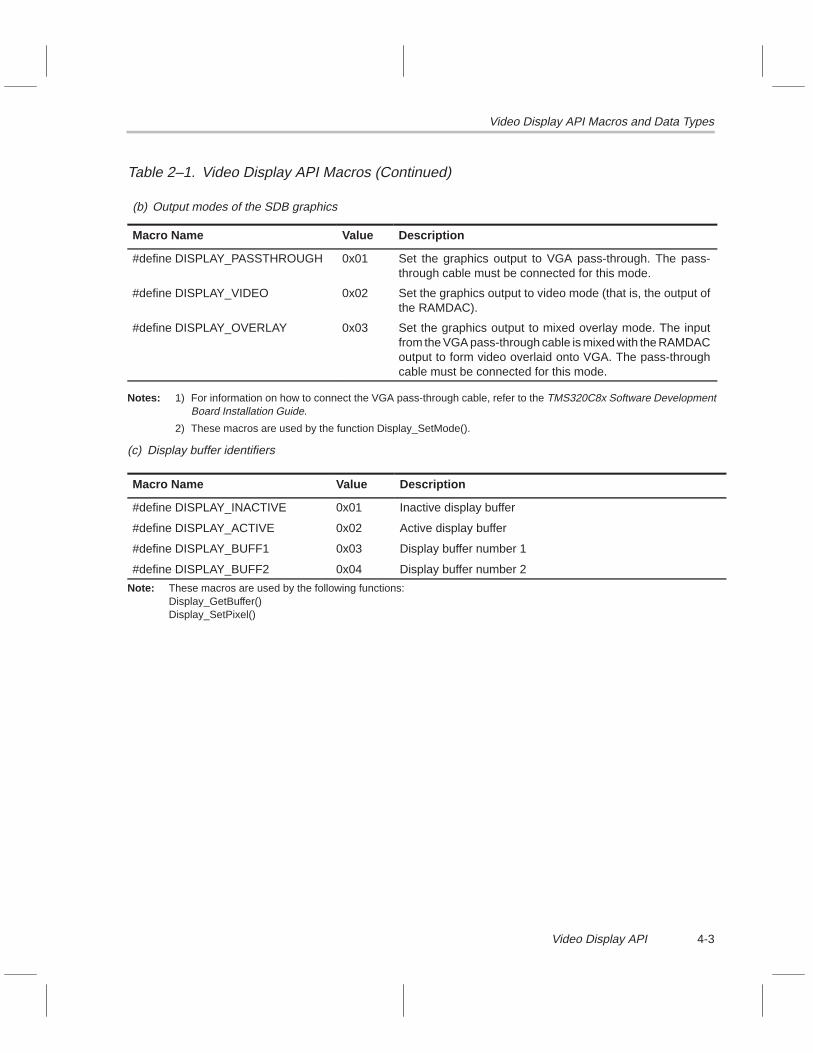
Video Display API Macros and Data Types
4-3Video Display API
Table 2–1. Video Display API Macros (Continued)
(b) Output modes of the SDB graphics
Macro Name Value Description
#define DISPLAY_PASSTHROUGH 0x01 Set the graphics output to VGA pass-through. The pass-through cable must be connected for this mode.
#define DISPLAY_VIDEO 0x02 Set the graphics output to video mode (that is, the output ofthe RAMDAC).
#define DISPLAY_OVERLAY 0x03 Set the graphics output to mixed overlay mode. The inputfrom the VGA pass-through cable is mixed with the RAMDACoutput to form video overlaid onto VGA. The pass-throughcable must be connected for this mode.
Notes: 1) For information on how to connect the VGA pass-through cable, refer to the TMS320C8x Software DevelopmentBoard Installation Guide.
2) These macros are used by the function Display_SetMode().
(c) Display buffer identifiers
Macro Name Value Description
#define DISPLAY_INACTIVE 0x01 Inactive display buffer
#define DISPLAY_ACTIVE 0x02 Active display buffer
#define DISPLAY_BUFF1 0x03 Display buffer number 1
#define DISPLAY_BUFF2 0x04 Display buffer number 2
Note: These macros are used by the following functions:Display_GetBuffer()Display_SetPixel()

Video Display API Macros and Data Types
4-4
Figure 4–1. Video Display API Data Types
(a) Monitor timing parameters for the ’C80 frame timer controller
typedef struct {
char active; /* Active: 0=don’t use, 1=can use, –1=end of table */USHORT Rh; /* Horizontal resolution (in pixels) */USHORT Rv; /* Vertical resolution (in pixels) */float Fv; /* Vertical frequency, refresh rate (in Hz) */float Fh; /* Horizontal frequency, line rate (in kHz) */float Fd; /* Pixel frequency, dot clock (in MHz) */float Ths; /* Horizontal sync interval (in µs) */float Thbp; /* Horizontal back porch interval (in µs) */float Tvs; /* Vertical sync interval (in µs) */float Tvbp; /* Vertical back porch interval (in µs) */BYTE Sh; /* Horizontal sync polarity: 0=–, 1=+ */BYTE Sv; /* Vertical sync polarity: 0=–, 1=+ */
} DISPLAY_MT;
(b) Type definition of DISPLAY_MET
typedef struct {
BYTE FtNumber; /* ’C80 frame timer used: 0 or 1 */BYTE FclkRatio; /* DCLK/FCLK ratio (default = 8) */BYTE RclkRatio; /* DCLK/RCLK ratio */BYTE BPP; /* Bits per pixel: 8, 16, or 32 */USHORT Rh; /* Horizontal resolution (in pixels) */USHORT Rv; /* Vertical resolution (in pixels) */ULONG Vram; /* Address of the start of VRAM */ULONG VramLen; /* Length of VRAM (in bytes) */ULONG Buff1; /* Frame buffer 1 address */ULONG Buff2; /* Frame buffer 2 address */ULONG Pitch; /* Frame buffer pitch (in bytes) */ULONG CurBuff; /* Current frame buffer address */USHORT x; /* X-coordinate of display window (in pixels) */USHORT y; /* Y-coordinate of display window (in pixels) */USHORT dx; /* Width of display window (in pixels) */USHORT dy; /* Height of display window (in pixels) */float Fv; /* Vertical frequency, refresh rate (in Hz) */float Fh; /* Horizontal frequency, line rate (in kHz) */float Fd; /* Pixel frequency, dot clock (in MHz) */float Ths; /* Horizontal sync interval (in µs) */float Thbp; /* Horizontal back porch interval (in µs) */float Tvs; /* Vertical sync interval (in µs) */float Tvbp; /* Vertical back porch interval (in µs) */
} DISPLAY_MET;
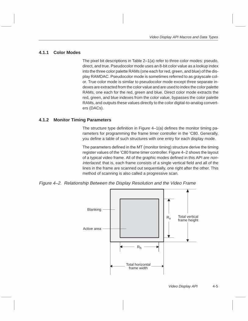
Video Display API Macros and Data Types
4-5Video Display API
4.1.1 Color Modes
The pixel bit descriptions in Table 2–1(a) refer to three color modes: pseudo,direct, and true. Pseudocolor mode uses an 8-bit color value as a lookup indexinto the three color palette RAMs (one each for red, green, and blue) of the dis-play RAMDAC. Pseudocolor mode is sometimes referred to as grayscale col-or. True color mode is similar to pseudocolor mode except three separate in-dexes are extracted from the color value and are used to index the color paletteRAMs, one each for the red, green and blue. Direct color mode extracts thered, green, and blue indexes from the color value, bypasses the color paletteRAMs, and outputs these values directly to the color digital-to-analog convert-ers (DACs).
4.1.2 Monitor Timing Parameters
The structure type definition in Figure 4–1(a) defines the monitor timing pa-rameters for programming the frame timer controller in the ’C80. Generally,you define a table of such structures with one entry for each display mode.
The parameters defined in the MT (monitor timing) structure derive the timingregister values of the ’C80 frame timer controller. Figure 4–2 shows the layoutof a typical video frame. All of the graphic modes defined in this API are non-interlaced; that is, each frame consists of a single vertical field and all of thelines in the frame are scanned out sequentially, one right after the other. Thismethod of scanning is also called a progressive scan.
Figure 4–2. Relationship Between the Display Resolution and the Video Frame
Blanking
Active area
Total verticalframe height
Total horizontalframe width
Rh
Rv

Video Display API Macros and Data Types
4-6
A typical value of Rh is 640 pixels and a typical value of Rv is 480 pixels.Generally, the horizontal active area is about 76% of the total horizontal framewidth, and the vertical active area is about 94% of the total vertical frameheight.
Because the MT structure does not define the total frame size, you must deriveit by calculating pixels per line for the total horizontal frame width and lines perframe for the total vertical frame height. These calculations assume MHzfrequencies:
Total horizontal frame width �Fd (million pixels�s)Fh (million lines�s)
�Fd
Fh(pixels�line)
Total vertical frame height �Fh (million pixels�s)Fv (million frames�s)
�Fh
Fv(lines�frame)
Figure 4–3 illustrates the horizontal sync and porch times in relation to theframe. The intervals ths and thbp correspond to the sync and back porch inter-vals of the horizontal sync and blanking signals. Similarly, tvs and tvbp have thesame relationship to the vertical sync and blanking signals. For more detailson the video timing signals, refer to the TMS320C80 (MVP) Video ControllerUser’s Guide.
Figure 4–3. Horizontal Sync and Porch Times of the Video Frame
Horizontalblanking
signal
Horizontalsync signal
Activearea
Back porchSyncFrontporch
Start of line
ths
thbp

Video Display API Macros and Data Types
4-7Video Display API
The frame timer registers derived from the data in the MT structure for bothhorizontal and vertical signals are:
� HESYNC (horizontal end sync)� HEBLNK (horizontal end blank)� HSBLNK (horizontal start blank)� VESYNC (vertical end sync)� VEBLNK (vertical end blank)� VSBLNK (vertical start blank)
The following calculations are generalized. In the actual code, rounding isdone and the horizontal registers are adjusted for the FCLK (frame clock) ratio.These calculations assume MHz frequencies and time intervals in µs times:
HESYNC = ths * Fd (pixels)HEBLNK = (ths + thbp) * Fd (pixels)HSBLNK = (ths + thbp) * Fd + Rh (pixels)VESYNC = tvs + Fh (lines)VEBLNK = (tvs + tvbp) * Fh (lines)VSBLNK = (tvs + tvbp) * Fh + Rv (lines)
Remember that you use a table of MT structures to obtain the monitor timingparameters. You supply Rh, Rv, and Fv; then the software uses these valuesto find a match in the table. Once a match is found, Fh, Fd, ths, thbp, tvs, and tvbpare read from the table.
To create a custom table, copy the default table to your own code, modify it asneeded, and pass a pointer to it to the Display_InstallTimingTable() function.Then all timing parameters will be read from this custom table. Example 4–1illustrates an MT table of custom timing parameters. The values shown inExample 4–1 are the default values, but the structure array MyTimingTable isa separate entity from the default table. Once you create your custom table,you modify the default values.

Video Overlay
4-8
Example 4–1. Sample MT Table of Custom Timing Parameters
static DISPLAY_MT MyTimingTable[] = {
/* A Rh Rv Fv Fh Fd Ths Thbp Tvs Tvbp Sh Sv *//* pels pels Hz kHz MHz µs µs µs µs */
{ 1, 640, 480, 60.0, 31.4, 25.2, 1.00, 2.00, 100.0, 600.0, 0, 0},{ 1, 640, 480, 72.0, 37.7, 31.2, 1.00, 3.00, 100.0, 600.0, 0, 0},{ 1, 800, 600, 60.0, 37.8, 40.0, 1.00, 2.00, 100.0, 400.0, 0, 0},{ 1, 1024, 768, 60.0, 48.3, 65.0, 1.00, 2.75, 100.0, 350.0, 0, 0},{ 1, 1024, 768, 70.0, 56.4, 75.0, 1.00, 2.00, 100.0, 350.0, 0, 0},{ 1, 1280, 1024, 60.0, 63.9, 114.0, 1.00, 2.40, 100.0, 400.0, 0, 0},{ 1, 1600, 1200, 60.0, 76.2, 156.0, 1.00, 2.00, 100.0, 600.0, 0, 0},{ –1, 0000, 0000, 00.0, 00.0, 000.0, 0.00, 0.00, 000.0, 000.0, 0, 0}
};
In the application code, call Display_InstallTimingTable(MyTimingTable) to de-fine your custom table.
4.1.3 Metric Parameters
The type definition for DISPLAY_MET in Figure 4–1(b) defines metric parame-ters of the current display state. Define a variable of this type, then pass apointer to it as an argument to Display_GetMetrics(). Display_GetMetrics() fillsin the structure members.
4.2 Video Overlay
Use the Display_SetOverlayParams() function to set up the video overlay fea-ture of the SDB. Because of the way video overlay is achieved on the SDB, itis important that the ‘C80-RAMDAC timing match with the timing of the VGApass-through input. Generally, the VGA input is the VGA output of the graphicscard that is currently installed in your PC. The timing of one VGA card differsfrom another VGA card, so you must adjust the overlay timing for each cardthat you use. Some trial and error may be necessary to get the right settings.
Video Display API Macros and Data Types / Video Overlay
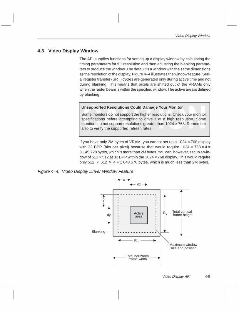
Video Display Window
4-9Video Display API
4.3 Video Display Window
The API supplies functions for setting up a display window by calculating thetiming parameters for full resolution and then adjusting the blanking parame-ters to produce the window. The default is a window with the same dimensionsas the resolution of the display. Figure 4–4 illustrates the window feature. Seri-al register transfer (SRT) cycles are generated only during active time and notduring blanking. This means that pixels are shifted out of the VRAMs onlywhen the raster beam is within the specified window. The active area is definedby blanking.
Unsupported Resolutions Could Damage Your Monitor
Some monitors do not support the higher resolutions. Check your monitorspecifications before attempting to drive it at a high resolution. Somemonitors do not support resolutions greater than 1024 × 768. Rememberalso to verify the supported refresh rates.
If you have only 2M bytes of VRAM, you cannot set up a 1024 × 768 displaywith 32 BPP (bits per pixel) because that would require 1024 × 768 × 4 =3 145 728 bytes, which is more than 2M bytes. You can, however, set up a win-dow of 512 × 512 at 32 BPP within the 1024 × 768 display. This would requireonly 512 × 512 × 4 = 1 048 576 bytes, which is much less than 2M bytes.
Figure 4–4. Video Display Driver Window Feature
Blanking
xdx
y
dy Activearea
Maximum windowsize and position
frame height
Total horizontalframe width
Total verticalRv
Rh

Video Display API Functions
4-10
4.4 Video Display API Functions
Listed below in alphabetical order are the video display API functions. Use thislist as a table of contents to the video display API functions.
Function Page Function Page
Display_Disable 4-11. . . . . . . . . . . . . . . Display_SetMode 4-25. . . . . . . . . . .
Display_Enable 4-12. . . . . . . . . . . . . . . Display_SetOverlayParams 4-27. . .
Display_FillBuffs 4-13. . . . . . . . . . . . . . Display_SetPaletteAddress 4-29. . .
Display_GetBuffer 4-14. . . . . . . . . . . . . Display_SetPitch 4-30. . . . . . . . . . . .
Display_GetMetrics 4-15. . . . . . . . . . . . Display_SetPixel 4-31. . . . . . . . . . . .
Display_GetTvpRegs 4-16. . . . . . . . . . Display_SetSyncPolarities 4-32. . . .
Display_Init 4-17. . . . . . . . . . . . . . . . . . . Display_SetVgaPalette 4-33. . . . . . .
Display_InstallSema 4-18. . . . . . . . . . . Display_SetWindow 4-34. . . . . . . . .
Display_InstallTimingTable 4-19. . . . . . Display_ToggleBuffers 4-35. . . . . . .
Display_MoveWindow 4-20. . . . . . . . . Display_TvpRegIn 4-36. . . . . . . . . . .
Display_ReadPalette 4-21. . . . . . . . . . Display_TvpRegOut 4-37. . . . . . . . .
Display_SetBufferAddresses 4-22. . . . Display_WaitEndOfFrame 4-38. . . .
Display_SetDotClock 4-23. . . . . . . . . . Display_WritePalette 4-39. . . . . . . . .
Display_SetGreyScalePalette 4-24. . .

Display_Disable
4-11Video Display API
Function Name Display_Disable
Syntax void Display_Disable();
Arguments None
Return Value None
Description This function disables the display hardware by turning off the frame timer con-troller and the serial-data clock inputs to the ’C80.
Example BOOL success;
Display_Init();
success = Display_SetMode(640, 480, 60, Display_P8, DISPLAY_VIDEO);
if (success) {Display_Enable();/* ... do main programming ... */
}
Display_Disable();

Display_Enable
4-12
Function Name Display_Enable
Syntax void Display_Enable();
Arguments None
Return Value None
Description This function enables the display hardware by turning on the frame timer con-troller and the serial-data clock inputs to the ’C80.
When you call Display_SetMode(), the display hardware is disabled, so youmust call Display_Enable() after Display_SetMode() to enable the displayhardware. This allows you to make other display adjustments after callingDisplay_SetMode() and before enabling the display. Making adjustmentswhile the display is disabled eliminates flicker. For example, you would callDisplay_SetWindow() after calling Display_SetMode() but before callingDisplay_Enable().
Example BOOL success;
Display_Init();
success = Display_SetMode(640, 480, 60, DISPLAY_P8, DISPLAY_VIDEO);
if (success) {Display_Enable();/* ... do main programming ... */
}
Display_Disable();

Display_FillBuffs
4-13Video Display API
Function Name Display_FillBuffs
Syntax void Display_FillBuffs(ULONG val);
Arguments ULONG val Value to fill display buffers with
Return Value None
Description This function fills both display buffers with the value specified. The unit of stor-age is a ULONG. Therefore, if the display is 16 BPP, the val argument musthave the fill value in both the upper and lower 16 bits.
Example Display_SetMode(640,480,60,DISPLAY_T555,DISPLAY_VIDEO);Display_FillBuffs(0x001F001F); /* fill with blue */

Display_GetBuffer
4-14
Function Name Display_GetBuffer
Syntax ULONG Display_GetBuffer(BYTE buffid);
Arguments BYTE buffid DISPLAY_INACTIVE Return address of inactive display buffer
DISPLAY_ACTIVE Return address of active display buffer
DISPLAY_BUFF1 Return address of display buffer number 1
DISPLAY_BUFF2 Return address of display buffer number 2
Return Value ULONG Address of the specified buffer
Description This function returns the address of one of the display buffers. The display driv-er manages two display buffers, Buff1 and Buff2. When double buffering is inuse, one of these buffers is active and the other is inactive. A call toDisplay_ToggleBuffers() reverses the buffers. The active buffer is the one thatthe RAMDAC is receiving pixels from. An application should avoid writing tothe active buffer because this may cause unwanted visual effects. Generally,an application calls Display_ToggleBuffers(), then immediately calls this func-tion.
Example ULONG InActiveBuff;
Display_SetMode(640,480,60,DISPLAY_T555,DISPLAY_VIDEO);
InActiveBuff = Display_GetBuffer(DISPLAY_INACTIVE);

Display_GetMetrics
4-15Video Display API
Function Name Display_GetMetrics
Syntax void Display_GetMetrics(DISPLAY_MET *M);
Arguments DISPLAY_MET *M Pointer to the DISPLAY_MET structure of metric param-eters
DISPLAY_MET consists of the following members:
BYTE FtNumber /* ’C80 frame timer used: 0 or 1 */BYTE FclkRatio /* DCLK/FCLK ratio (default = 8) */BYTE RclkRatio /* DCLK/RCLK ratio */BYTE Bpp /* Bits per pixel: 8, 16, or 32 */USHORT Rh /* Horizontal resolution (in pixels) */USHORT Rv /* Vertical resolution (in pixels) */ULONG Vram /* Address of the start of VRAM */ULONG VramLen /* Length of VRAM (in bytes) */ULONG Buff1 /* Frame buffer 1 address */ULONG Buff2 /* Frame buffer 2 address */ULONG Pitch /* Frame buffer pitch (in bytes) */ULONG CurBuff /* Current frame buffer address */USHORT x /* X-coord of display window (in pixels) */USHORT y /* Y-coord of display window (in pixels) */USHORT dx /* Width of display window (in pixels) */USHORT dy /* Height of display window (in pixels) */float Fv /* Vertical frequency, refresh rate (in Hz) */float Fh /* Horizontal frequency, line rate (in kHz) */float Fd /* Pixel frequency, dot clock (in MHz) */float Ths /* Horizontal sync interval (in µs) */float Thbp /* Horizontal back porch interval (in µs) */float Tvs /* Vertical sync interval (in µs) */float Tvbp /* Vertical back porch interval (in µs) */
Return Value None
Description This function fills in the DISPLAY_MET structure pointed to by M with the cur-rent display state metrics.
Example BOOL success;ULONG Pitch;DISPLAY_MET M;
Display_Init();
success = Display_SetMode(640, 480, 60, DISPLAY_P8, DISPLAY_VIDEO);
if (success) {Display_GetMetrics(&M);Pitch = M.Pitch;Display_Enable();/* ... do main programming ... */
}
Display_Disable();

Display_GetTvpRegs
4-16
Function Name Display_GetTvpRegs
Syntax void Display_GetTvpRegs(BYTE *R);
Arguments BYTE *R Pointer to a preallocated array of 64 bytes
Return Value None
Description This function reads the 64 internal RAMDAC registers and stores them into thearray pointed to by R. The R argument must point to 64 bytes of preallocatedmemory. This function does not alter any of the registers. Refer to theTVP3020 Video Interface Palette Data Manual for register descriptions.
Example BYTE TvpRegs[64];
/* ... other setup ... */
Display_GetTvpRegs(R);
/* ... other processing ... */
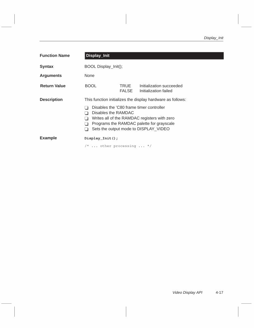
Display_Init
4-17Video Display API
Function Name Display_Init
Syntax BOOL Display_Init();
Arguments None
Return Value BOOL TRUEFALSE
Initialization succeededInitialization failed
Description This function initializes the display hardware as follows:
� Disables the ’C80 frame timer controller� Disables the RAMDAC� Writes all of the RAMDAC registers with zero� Programs the RAMDAC palette for grayscale� Sets the output mode to DISPLAY_VIDEO
Example Display_Init();
/* ... other processing ... */

Display_InstallSema
4-18
Function Name Display_InstallSema
Syntax long Display_InstallSema(long SemaId);
Arguments long SemaId ID of an open semaphore as returned by TaskOpenSema()
Return Value long Previous semaphore ID
Description This function installs a semaphore into the display driver. The semaphore sig-nals the application when a display buffer toggle request has completed. Tog-gling display buffers is only suitable during vertical blanking. Therefore, whenthe application calls Display_ToggleBuffers(), the toggle does not occur rightaway; rather, the toggle occurs at the next vertical blanking period. When thetoggle occurs, the semaphore is signaled. This protocol allows the applicationto request a buffer toggle via Display_ToggleBuffers(), then wait until thetoggle actually happens via TaskWaitSema(SemaId).
Note:
The application must open the semaphore before calling this function. Thesemaphore is signaled only when the display is enabled.
Example long DisplaySemaId;ULONG Buff;
DisplaySemaId = TaskOpenSema(–1,0);
Display_Init();Display_InstallSema(DisplaySemaId);Display_SetMode(640,480,60,DISPLAY_T555,DISPLAY_VIDEO);Display_Enable();
while (1) {Display_ToggleBuffers();TaskWaitSema(DisplaySemaId);Buff = Display_GetBuffer(DISPLAY_INACTIVE);
/* do some processing here */}

Display_InstallTimingTable
4-19Video Display API
Function Name Display_InstallTimingTable
Syntax void Display_InstallTimingTable(DISPLAY_MT *Table);
Arguments DISPLAY_MT *Table Pointer to a table of monitor timing structures.
Return Value None
Description This function installs a custom monitor timing table. If you wish to install a cus-tom table into the driver, call this function before calling Display_SetMode().Care must be taken when driving monitors with custom timing settings. Youcould copy the default table from the display driver module into an applicationand then modify it.
Example DISPLAY_MT MyTimingTable[] = {
{ ... table data ... },
{ ... table data ... },
{ ... table data ... },
};
Display_Init();Display_InstallTimingTable(MyTimingTable);Display_SetMode(640,480,60,DISPLAY_T555,DISPLAY_VIDEO);Display_Enable();
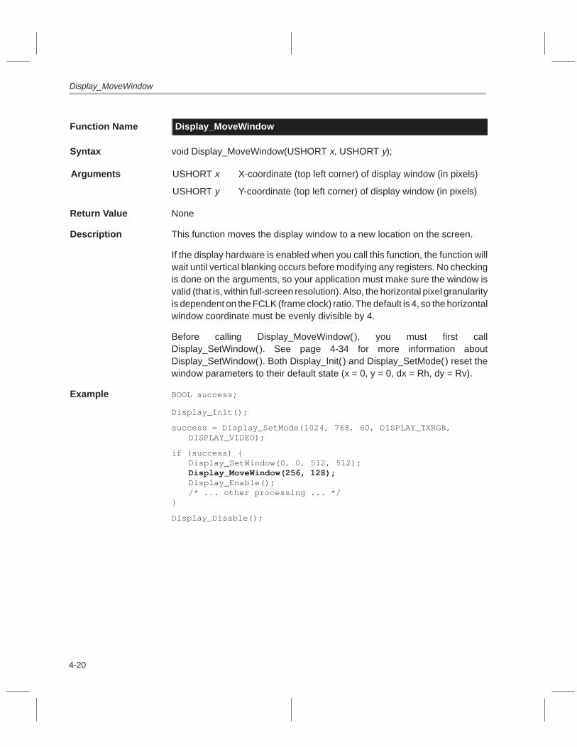
Display_MoveWindow
4-20
Function Name Display_MoveWindow
Syntax void Display_MoveWindow(USHORT x, USHORT y);
Arguments USHORT x X-coordinate (top left corner) of display window (in pixels)
USHORT y Y-coordinate (top left corner) of display window (in pixels)
Return Value None
Description This function moves the display window to a new location on the screen.
If the display hardware is enabled when you call this function, the function willwait until vertical blanking occurs before modifying any registers. No checkingis done on the arguments, so your application must make sure the window isvalid (that is, within full-screen resolution). Also, the horizontal pixel granularityis dependent on the FCLK (frame clock) ratio. The default is 4, so the horizontalwindow coordinate must be evenly divisible by 4.
Before calling Display_MoveWindow(), you must first callDisplay_SetWindow(). See page 4-34 for more information aboutDisplay_SetWindow(). Both Display_Init( ) and Display_SetMode() reset thewindow parameters to their default state (x = 0, y = 0, dx = Rh, dy = Rv).
Example BOOL success;
Display_Init();
success = Display_SetMode(1024, 768, 60, DISPLAY_TXRGB, DISPLAY_VIDEO);
if (success) {Display_SetWindow(0, 0, 512, 512);Display_MoveWindow(256, 128);Display_Enable();/* ... other processing ... */
}
Display_Disable();

Display_ReadPalette
4-21Video Display API
Function Name Display_ReadPalette
Syntax void Display_ReadPalette(BYTE *R, BYTE *G, BYTE *B);
Arguments BYTE *R Pointer to the variable that will receive a red value
BYTE *G Pointer to the variable that will receive a green value
BYTE *B Pointer to the variable that will receive a blue value
Return Value None
Description This function reads an RGB triple (that is, three successive bytes of RGB data)from the current palette address in the RAMDAC. After each call, the paletteaddress increments automatically. Normally, you should callDisplay_SetPaletteAddress() and then call Display_ReadPalette()repeatedly to read out the RAMDAC palette RAM. See page 4-29 for moreinformation on Display_SetPaletteAddress(). You do not have to enable thedisplay hardware in order to use Display_ReadPalette().
Note:
See page 4-33 for a listing of the RAMDAC palette RAM values for VGA col-ors (in RGB triples).
Example BYTE R,G,B;
Display_SetPaletteAddress(0x00);
/* auto-address increment */Display_ReadPalette(&R, &G, &B);Display_ReadPalette(&R, &G, &B);Display_ReadPalette(&R, &G, &B);
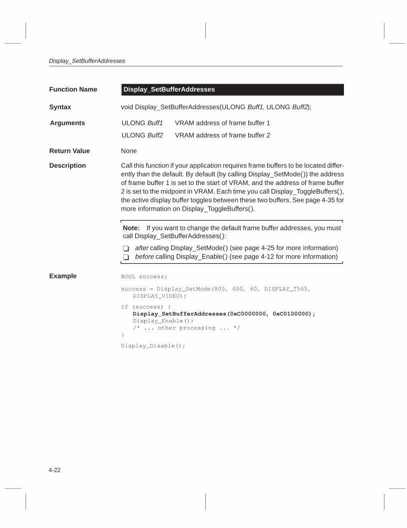
Display_SetBufferAddresses
4-22
Function Name Display_SetBufferAddresses
Syntax void Display_SetBufferAddresses(ULONG Buff1, ULONG Buff2);
Arguments ULONG Buff1 VRAM address of frame buffer 1
ULONG Buff2 VRAM address of frame buffer 2
Return Value None
Description Call this function if your application requires frame buffers to be located differ-ently than the default. By default (by calling Display_SetMode()) the addressof frame buffer 1 is set to the start of VRAM, and the address of frame buffer2 is set to the midpoint in VRAM. Each time you call Display_ToggleBuffers(),the active display buffer toggles between these two buffers. See page 4-35 formore information on Display_ToggleBuffers().
Note: If you want to change the default frame buffer addresses, you mustcall Display_SetBufferAddresses():
� after calling Display_SetMode() (see page 4-25 for more information)� before calling Display_Enable() (see page 4-12 for more information)
Example BOOL success;
success = Display_SetMode(800, 600, 60, DISPLAY_T565, DISPLAY_VIDEO);
if (success) {Display_SetBufferAddresses(0xC0000000, 0xC0100000);Display_Enable();/* ... other processing ... */
}
Display_Disable();

Display_SetDotClock
4-23Video Display API
Function Name Display_SetDotClock
Syntax float Display_SetDotClock(float Fd);
Arguments float Fd The desired dot clock frequency:10 MHz <= Fd <= 170 MHz
Return Value float The actual dot clock frequency setting (in MHz)
Description This function programs the pixel clock generator for the desired frequency (Fd).Because the clock generator operates at quantum levels, the actual frequencymay differ slightly from the desired frequency. Generally, this difference is in-significant. The clock doubling input of the RAMDAC is used so the dot clockis actually programmed to half of that specified, then doubled. You should ig-nore this clock doubling and treat both the dot clock argument and return valueas the true dot clock frequency.
For example, if you require a dot clock of 64 MHz, you should call Display_Set-DotClock(64.0). In this case, the function programs the pixel clock generatorfor 32.0 MHz so that the frequency is doubled in the RAMDAC to 64.0 MHz.The return value of this function would then be 64.0 MHz ± quantization error.
Notes:
1) Generally, you should not call Display_SetDotClock() because it iscalled by Display_SetMode(). See page 4-25 for more information onDisplay_SetMode().
2) Call Display_SetDotClock() only for custom displays.
Example float ActualFrequency;
/* Program the dot clock to 63.7 MHz */ActualFrequency = Display_SetDotClock(63.7);

Display_SetGreyScalePalette
4-24
Function Name Display_SetGreyScalePalette
Syntax void DisplaySetGreyScalePalette();
Arguments None
Return Value None
Description This function programs the RAMDAC palette RAM for grayscale by settingeach color cell in the palette array to its offset in the array. For instance, thecell at offset 0x7F is set to 0x7F. This is done for all three RAM arrays: red,green, and blue. The grayscale palette is the default.
Notes:
1) This function is called by Display_Init() and Display_SetMode().
2) The display does not have to be enabled to call this function, but youmust call Display_SetMode() first. See page 4-25 for more informationon Display_SetMode().
Refer to the following API functions for customizing the color palette:
Function See Page
Display_ReadPalette() 4-21
Display_SetPaletteAddress() 4-29
Display_WritePalette() 4-39
Example BOOL success;
success = Display_SetMode(800, 600, 60, DISPLAY_T565, DISPLAY_VIDEO);
if (success) {Display_SetGreyScalePalette();Display_Enable();/* ... other processing ... */
}
Display_Disable();

Display_SetMode
4-25Video Display API
Function Name Display_SetMode
Syntax BOOL Display_SetMode(USHORT Rh, USHORT Rv, float Fv, char *PixFmt,BYTE Output);
Arguments USHORT Rh Horizontal resolution (in pixels)
USHORT Rv Vertical resolution (in pixels)
float Fv Vertical frequency refresh rate (in Hz)
char *PixFmt Pixel format designator (see Table 2–1 on page 2-8 formore detailed descriptions):
DISPLAY_P8 8 BPPDISPLAY DXRGB 32 BPPDISPLAY_DXRGB 32 BPPDISPLAY_DBGRX 32 BPPDISPLAY D565 16 BPPDISPLAY_D565 16 BPPDISPLAY_D555 16 BPP_DISPLAY_D664 16 BPPDISPLAY D444 16 BPPDISPLAY_D444 16 BPPDISPLAY_TXRGB 32 BPPDISPLAY TBGRX 32 BPPDISPLAY_TBGRX 32 BPPDISPLAY_T565 16 BPPDISPLAY_T555 16 BPPDISPLAY T664 16 BPPDISPLAY_T664 16 BPPDISPLAY_T444 16 BPP
BYTE Output Display output mode:
DISPLAY_PASSTHROUGH Select VGA pass-throughDISPLAY_VIDEO Select RAMDAC outputDISPLAY_OVERLAY Select overlaid video output
Return Value BOOL TRUEFALSE
Mode is supported by monitor timing table.Mode is not supported by monitor timing table.
Description This function sets up a particular display mode. It is the most important functionin the display API. For most applications, you need to use only the followingfunctions to set up your display.
� Display_Init()� Display_SetMode()� Display_Enable()� Display_Disable()
Note:
Because Display_SetMode() disables the display hardware, you must callDisplay_Enable() after Display_SetMode() to reenable the display hard-ware.

Display_SetMode
4-26
Remember that a table of MT structures is used to obtain the monitor timingparameters. You supply Rh, Rv, and Fv; then the software uses these valuesto find a match in the table.
No argument checking is done to ensure that the parameters are valid. There-fore, your application must supply valid parameters.
Unsupported Resolutions Could Damage Your Monitor
Some monitors do not support the higher resolutions. Check your monitorspecifications before attempting to drive it at a high resolution. Somemonitors do not support resolutions greater than 1024 × 768. Rememberalso to verify the supported refresh rates.
If you have only 2M bytes of VRAM, you cannot set up a 1024 × 768 displaywith 32 BPP (bits per pixel) because that would require 1024 × 768 × 4 =3 145 728 bytes, which is more than 2M bytes. You can, however, set up win-dow of 512 × 512 at 32 BPP within the 1024 × 768 display. This would requireonly 512 × 512 × 4 = 1 048 576 bytes, which is much less than 2M bytes.
Example BOOL success;
success = Display_SetMode(640, 480, 60, DISPLAY_T565, DISPLAY_VIDEO);
if (success) {Display_Enable();/* ... other processing ... */
}
Display_Disable();

Display_SetOverlayParams
4-27Video Display API
Function Name Display_SetOverlayParams
Syntax void Display_SetOverlayParams(short adx, short ady, short bdx, short bdy, float dThbp, float dTvbp, float Fd, float dFd);
Arguments short adx Signed offset to HSAREA (in pixels)
short ady Signed offset to VSAREA (in pixels)
short bdx Signed offset to HEBLNK (in pixels)
short bdy Signed offset to VEBLNK (in pixels)
float dThbp Signed offset to thbp (in µs)
float dTvbp Signed offset to tvbp (in µs)
float Fd Replacement dot clock (in MHz)
float dFd Signed offset to the dot clock (in MHz)
Return Value None
Description This function sets the video overlay parameters used whenDISPLAY_OVERLAY mode is specified in a call to Display_SetMode(). Thedriver sets up the display like normal, then adjusts certain parameters to ac-count for timing differences between the RAMDAC graphics and the VGAgraphics input from the VGA pass-through cable. The AREA and BLNK signalsare adjusted according to adx, ady, bdx, and bdy. The back porch timing pa-rameters are adjusted according to dThbp and dTvbp. The Fd argument isspecial in that, if it is zero, the default dot clock is used. If Fd is nonzero, theFd parameter is used instead of the default dot clock. Generally, the default dotclock is close to that of the VGA input from the PC graphics card, so Fd canbe set to zero. The dFd parameter is a signed offset to the dot clock whetherit is the default dot clock or the dot clock defined by the Fd parameter. A displaywindow must be used when the display hardware is in overlay mode. The dis-play resolution specified in Display_SetMode() should be the same as theVGA graphics card input.

Display_SetOverlayParams
4-28
Example /* set up an overlay window onto a 640x480 display *//* adx = –16 pixels *//* ady = 0 pixels *//* bdx = 0 pixels *//* bdy = 12 pixels *//* dThbp = 1.0 µs *//* dTvbp = –0.5 µs *//* Fd = 0.0 MHz (use default dot clock) *//* dFd = 1.051 MHz */
Display_Init();Display_SetOverlayParams(–16, 0, 0, 12, 1.0, –0.5, 0.0,
1.051);Display_SetMode(640,480,60,DISPLAY_T555,DISPLAY_OVERLAY);Display_SetWindow(96,96,128,64);Display_Enable();
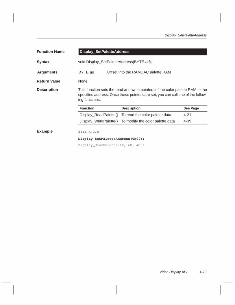
Display_SetPaletteAddress
4-29Video Display API
Function Name Display_SetPaletteAddress
Syntax void Display_SetPaletteAddress(BYTE ad);
Arguments BYTE ad Offset into the RAMDAC palette RAM
Return Value None
Description This function sets the read and write pointers of the color palette RAM to thespecified address. Once these pointers are set, you can call one of the follow-ing functions:
Function Description See Page
Display_ReadPalette() To read the color palette data 4-21
Display_WritePalette() To modify the color palette data 4-39
Example BYTE R,G,B;
Display_SetPaletteAddress(0x00);
Display_ReadPalette(&R, &G, &B);

Display_SetPitch
4-30
Function Name Display_SetPitch
Syntax void Display_SetPitch(ULONG pitch);
Arguments ULONG pitch Desired frame buffer pitch (in bytes)
Return Value None
Description This function sets the pitch of the display frame buffer. The pitch is the numberof bytes from the start of one line to the start of the next line. By default, thepitch is set to the line width in bytes. For instance, if you call Display_Set-Mode(1024, 768, 60, DISPLAY_T565, DISPLAY_VIDEO), then the pitch is1024 pixels × 2 bytes/pixel = 2048 bytes, or 0x0800 by default.
Make sure that you do not try to set a pitch that is less than the line width (inbytes). Setting a pitch that is less than the line width may result insemiomnipresent pixels on the screen; that is, a particular pixel will appear tobe at two locations on the screen at once. The number of lines in the activeframe times the pitch is the amount of VRAM needed for a single frame buffer.For example, 1024 × 2048 = 2 097 152 bytes = 2M bytes.
Example BOOL success;
success = Display_SetMode(1024, 768, 60, DISPLAY_T565, DISPLAY_VIDEO);
if (success) {Display_SetPitch(0x0800);Display_Enable();/* ... other processing ... */
}
Display_Disable();

Display_SetPixel
4-31Video Display API
Function Name Display_SetPixel
Syntax void Display_SetPixel(USHORT x, USHORT y, ULONG val, BYTE buffid);
Arguments USHORT x x (horizontal) position of pixel to set
USHORT y y (vertical) position of pixel to set
ULONG val Value to store at pixel location
BYTE buffid Which display buffer to store value into:
DISPLAY_INACTIVE Inactive display buffer
DISPLAY_ACTIVE Active display buffer
DISPLAY_BUFF1 Display buffer number 1
DISPLAY_BUFF2 Display buffer number 2
Return Value None
Description This function is a utility used to set a single pixel in one of the display buffers.The function detects whether the display is set up for 8, 16, or 32 BPP and usesonly that part of the val argument. This function is inefficient and should beused only for a test.
Example USHORT x,y;
Display_SetMode(640,480,60,DISPLAY_T555,DISPLAY_VIDEO);Display_Enable();
/* fill entire active buffer with blue pixels one pixel at *//* a time */for (x=0; x<640; x++) {
for (y=0; y<480; y++) {Display_SetPixel(x, y ,0x001F, DISPLAY_ACTIVE);
}}

Display_SetSyncPolarities
4-32
Function Name Display_SetSyncPolarities
Syntax void Display_SetSyncPolarities(BYTE Sh, BYTE Sv, BYTE Pen);
Arguments BYTE Sh Horizontal sync polarity: 0 = –, 1 = +
BYTE Sv Vertical sync polarity: 0 = –, 1 = +
BYTE Pen Pixel clock enable polarity: 0=–, 1=+
Return Value None
Description This function sets the polarities of the horizontal and vertical sync signals. Bydefault, the sync polarities are set according to the parameters in the monitortiming (MT) table. (See Figure 4–1(a) on page 4-4 for the definition of the MTdata structure.) Set an argument to 0 to invert the sync signal (negative sync)or set it to 1 for positive sync. The Pen argument is used to invert the pixel clockgenerator enable signal.
Example BOOL success;
success = Display_SetMode(640, 480, 60, DISPLAY_T565, DISPLAY_VIDEO);
if (success) {Display_SetSyncPolarities(0,1,0);Display_Enable();/* ... other processing ... */
}
Display_Disable();
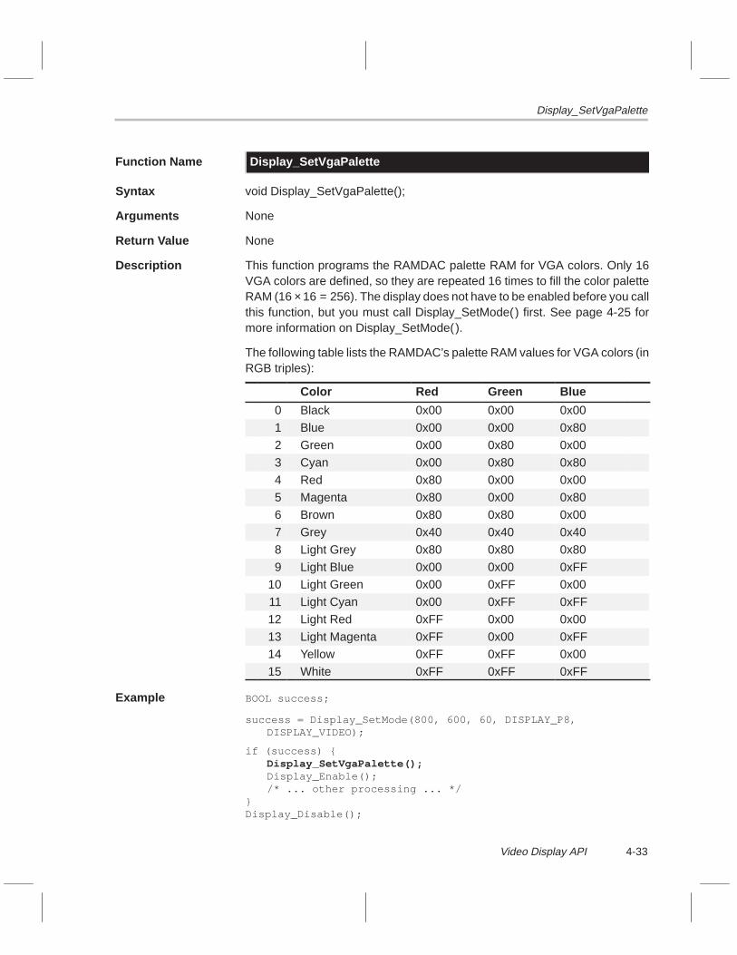
Display_SetVgaPalette
4-33Video Display API
Function Name Display_SetVgaPalette
Syntax void Display_SetVgaPalette();
Arguments None
Return Value None
Description This function programs the RAMDAC palette RAM for VGA colors. Only 16VGA colors are defined, so they are repeated 16 times to fill the color paletteRAM (16 × 16 = 256). The display does not have to be enabled before you callthis function, but you must call Display_SetMode() first. See page 4-25 formore information on Display_SetMode().
The following table lists the RAMDAC’s palette RAM values for VGA colors (inRGB triples):
Color Red Green Blue
0 Black 0x00 0x00 0x00
1 Blue 0x00 0x00 0x80
2 Green 0x00 0x80 0x00
3 Cyan 0x00 0x80 0x80
4 Red 0x80 0x00 0x005 Magenta 0x80 0x00 0x80
6 Brown 0x80 0x80 0x00
7 Grey 0x40 0x40 0x40
8 Light Grey 0x80 0x80 0x80
9 Light Blue 0x00 0x00 0xFF10 Light Green 0x00 0xFF 0x00
11 Light Cyan 0x00 0xFF 0xFF
12 Light Red 0xFF 0x00 0x00
13 Light Magenta 0xFF 0x00 0xFF14 Yellow 0xFF 0xFF 0x00
15 White 0xFF 0xFF 0xFF
Example BOOL success;
success = Display_SetMode(800, 600, 60, DISPLAY_P8, DISPLAY_VIDEO);
if (success) {Display_SetVgaPalette();Display_Enable();/* ... other processing ... */
}Display_Disable();

Display_SetWindow
4-34
Function Name Display_SetWindow
Syntax void Display_SetWindow(USHORT x, USHORT y, USHORT dx, USHORT dy);
Arguments USHORT x X-coordinate (top left corner) of the display window (in pixels)
USHORT y Y-coordinate (top left corner) of the display window (in pixels)
USHORT dx Width of window (in pixels)
USHORT dy Height of window (in pixels)
Return Value None
Description This function sets the display window. If the display hardware is enabled whenyou call this function, the function waits until vertical blanking occurs beforemodifying any registers. No checking is done on the arguments, so you mustmake sure the window is valid. Both Display_Init( ) and Display_SetMode() re-set the window parameters to their default state (x = 0, y = 0, dx = Rh,dy = Rv).
Note:
The horizontal pixel granularity is dependent on the FCLK (frame clock) ratio.The default is 4, so the horizontal window coordinate must be evenly divisibleby 4.
Example BOOL success;
Display_Init();
success = Display_SetMode(1024, 768, 60, DISPLAY_TXRGB, DISPLAY_VIDEO);
if (success) {Display_SetWindow(0, 0, 512, 512);Display_MoveWindow(256, 128);/* ... other processing ... */
}
Display_Disable();

Display_ToggleBuffers
4-35Video Display API
Function Name Display_ToggleBuffers
Syntax void Display_ToggleBuffers();
Arguments None
Return Value None
Description This function tells the display driver to toggle the active display buffer at thenext vertical blanking period. When the toggle takes place, the driver signalsthe display semaphore. The display driver manages two display buffers, Buff1and Buff2. When double buffering is in use, one of these buffers is active andthe other is inactive. A call to Display_ToggleBuffers() reverses the buffers.The active buffer is the one that the RAMDAC is receiving pixels from. An ap-plication should avoid writing to the active buffer because this may cause un-wanted visual effects. Generally, an application calls Display_ToggleBuffers(),then waits on the display semaphore before calling Display_GetBuffer( ) to getthe new inactive buffer.
Example long DisplaySemaId;
ULONG Buff;
DisplaySemaId = TaskOpenSema(–1,0);Display_Init();Display_InstallSema(DisplaySemaId);Display_SetMode(640,480,60,DISPLAY_T555,DISPLAY_VIDEO);Display_Enable();
while (1) {Display_ToggleBuffers();TaskWaitSema(DisplaySemaId);Buff = Display_GetBuffer(DISPLAY_INACTIVE);
/* do some processing here */}

Display_TvpRegIn
4-36
Function Name Display_TvpRegIn
Syntax BYTE Display_TvpRegIn(BYTE reg);
Arguments BYTE reg Palette internal register number
Return Value BYTE Value of register
Description This function reads a value from one of the RAMDAC internal registers. Referto the TVP3020 Video Interface Palette Data Manual for a listing of the regis-ters.
Example BYTE val;
val = Display_TvpRegIn(0x1B);
Display_TvpRegOut(0x1B, val | 0x80);

Display_TvpRegOut
4-37Video Display API
Function Name Display_TvpRegOut
Syntax void Display_TvpRegOut(BYTE reg, BYTE val);
Arguments BYTE reg Palette internal register number
BYTE val Value of register
Return Value None
Description This function writes a value to one of the RAMDAC internal registers. Refer tothe TVP3020 Video Interface Palette Data Manual for a listing of the registers.
Example BYTE val;
val = Display_TvpRegIn(0x1B);
Display_TvpRegOut(0x1B, val | 0x80);

Display_WaitEndOfFrame
4-38
Function Name Display_WaitEndOfFrame
Syntax void Display_WaitEndOfFrame();
Arguments None
Return Value None
Description This function waits until vertical blanking occurs and then returns.Display_WaitEndOfFrame() first clears the frame timer interrupt pending bitand then polls it until the bit is set. If the display hardware is disabled, this func-tion returns without waiting.
Example BOOL success;
Display_Init();
success = Display_SetMode(1024, 768, 60, DISPLAY_TXRGB, DISPLAY_VIDEO);
if (success) {Display_Enable();/* ... other processing ... */Display_WaitEndOfFrame(); /* ... other processing ... */
}
Display_Disable();

Display_WritePalette
4-39Video Display API
Function Name Display_WritePalette
Syntax void Display_WritePalette(BYTE R, BYTE G, BYTE B);
Arguments BYTE R Red value
BYTE G Green value
BYTE B Blue value
Return Value None
Description This function writes an RGB triple to the current palette address in theRAMDAC. After each call, the palette address automatically increments. Nor-mally, you would call Display_SetPaletteAddress() and then callDisplay_WritePalette() repeatedly to fill the palette RAM. See page 4-29 formore information on Display_SetPaletteAddress().
Note:
The display hardware does not have to be enabled before you use this func-tion.
Example Display_SetPaletteAddress(0x50);
Display_WritePalette(0x20, 0x10, 0x80);
Display_WritePalette(0x40, 0x20, 0x40);

4-40

5-1
Video Capture API
This chapter discusses the video capture macros and data type. It alsodescribes, in alphabetical order, the application programming interface (API)functions associated with the video capture driver for the TMS320C8x soft-ware development board (SDB).
Topic Page
5.1 Video Capture API Macros and Data Types 5-2. . . . . . . . . . . . . . . . . . . . . .
5.2 Video Capture Buffering 5-5. . . . . . . . . . . . . . . . . . . . . . . . . . . . . . . . . . . . . . .
5.3 Video Capture API Functions 5-8. . . . . . . . . . . . . . . . . . . . . . . . . . . . . . . . . .
Chapter 5

Video Capture API Macros and Data Types
5-2
5.1 Video Capture API Macros and Data Types
Table 5–1 describes the macros used by the video capture API and lists theAPI functions that use each macro. Figure 5–1 provides the definition for thevideo capture API data type. These macros and the data type, as well the APIfunction prototypes, are defined in <capture.h>. The object code resides insdbdrvs.lib.
Table 5–1. Video Capture API Macros
(a) Input source constants
Macro Name Value Description
#define CAPTURE_SVHS 0x00 S-VHS input source
#define CAPTURE_VID1 0x01 CVBS input source 1
#define CAPTURE_VID2 0x03 CVBS input source 2
Note: These macros are used by the function Capture_SetInputSource( ).
(b) Input format constants
Macro Name Value Description
#define CAPTURE_NTSC 0x01 Select NTSC setting
#define CAPTURE_PAL 0x02 Select PAL setting
Note: These macros are used by the function Capture_Install( ).
(c) Scaling constants
Macro Name Value Description
#define CAPTURE_640x480 0x01 640 × 480 interlaced
#define CAPTURE_512x512 0x02 512 × 512 interlaced
#define CAPTURE_CIF 0x03 352 × 288 interlaced
#define CAPTURE_CIFK 0x04 352 × 240 even fields only
#define CAPTURE_QCIF 0x05 176 × 144 even fields only
#define CAPTURE_SQCIF 0x06 128 × 96 even fields only
Note: These macros are used by the function Capture_Install( ).

Video Capture API Macros and Data Types
5-3Video Capture API
Table 5–1. Video Capture API Macros (Continued)
(d) Output format constants
Macro Name Value Description
#define CAPTURE_YUV422 0x01 Multiplexed YUV 4:2:2 format:YUYVYUYV ...
#define CAPTURE_RGB888 0x02 RGB 8,8,8,X format: RGBXRGBX ...
#define CAPTURE_RGB555 0x03 RGB α,5,5,5 format: αRGBαRGB ...
#define CAPTURE_MONO8 0x04 8-bit monochrome (luminance only)format: YYYYYYY ...
Note: These macros are used by the function Capture_Install( ).
Figure 5–1. Video Capture API Data Type (Metrics Parameter Structure CAPTURE_MET)
typedef struct {
BYTE Fps; /* frames per second */ULONG Size; /* buffer size in bytes */USHORT Rh; /* horizontal capture resolution in pixels */USHORT Rv; /* vertical resolution in lines */BYTE Bpp; /* bits per pixel */ULONG Pitch; /* buffer pitch, number of bytes from one line to next*/BOOL Interlace; /* interlaced flag (TRUE = interlaced) */
} CAPTURE_MET;

Video Capture API Macros and Data Types
5-4
5.1.1 Supported Scaling Resolutions
The six API-supported video capture scaling resolutions are listed inTable 5–1(c). Two of these resolutions have special limitations:CAPTURE_512x512 (which has a pixel resolution of 512 × 512) andCAPTURE_CIFK (which has a pixel resolution of 352 × 288). The video cap-ture hardware captures video at a resolution of 640 × 480 pixels in interlacedmode. The hardware scaler does not have the ability to upscale the image; itcan only downscale. Because of this upscaling limitation, 512 lines of video,as needed by CAPTURE_512x512, cannot be created from 480 lines. Howev-er, because 512 × 512 is a common video resolution, the API simulates it bycapturing 512 × 480 into a 512 × 512 buffer. Thus, the application gets a512 × 512 buffer, but only the first 480 lines contain video—the other 32 linesare undefined. You can clear out the entire buffer via Capture_FillBuffs(), thenthe 32 lines at the bottom of the buffer will remain cleared unless the applica-tion modifies them.
The 352 × 288 resolution faces the same limitation for noninterlaced mode,which uses only half of the captured image (a maximum of 480 lines / 2 or 240lines). The same method used to overcome the 512 × 512 limitation is also ap-plied to the 352 × 288 resolution. The API creates buffers that are 352 × 288but only captures 352 × 240 noninterlaced video into the buffers.
5.1.2 Video Capture Metric Parameters
To get information about the current video capture subsystem, callCapture_GetMetrics() to get a pointer to a CAPTURE_MET structure.Figure 5–1 gives the type definition for CAPTURE_MET. Refer to page 5-16for more information on Capture_GetMetrics().

Video Capture Buffering
5-5Video Capture API
5.2 Video Capture Buffering
The video capture driver manages a double buffering scheme internal to thedriver. When the application calls Capture_Install( ), the driver creates an inter-nal buffering structure that contains two storage buffers: Buff1 and Buff2.These two buffers are dynamically allocated on the heap and are used to storethe captured video as it comes in one line at a time. At any given time, one ofthese buffers is the active buffer and the other one is the inactive buffer. Theactive buffer is the one currently receiving new lines of video. The applicationcannot access the active buffer.
The video capture hardware generates an interrupt every time a new frame isdetected by an odd-to-even field transition of the video input. The interrupt ser-vice routine (ISR) toggles the active and inactive buffers; that is, the active buff-er becomes inactive and the inactive buffer becomes active. This behavior iseffectively a ping-pong action in which the buffers are toggled each frame. Asa result, the active buffer always receives incoming video, and the inactivebuffer has the most recent frame of video. This behavior continues, free-run-ning, until the application interferes by requesting a buffer.
When the application needs a frame of newly captured video, it callsCapture_GetBuffer( ), which returns the address of the inactive buffer. Thisinterferes with the ISR ping-ponging because the application cannot use abuffer at the same time that the ISR uses it. For this reason, the driver managesthe InUse flag, which is set when the application calls Capture_GetBuffer( ).The ISR does not toggle the buffers when the InUse flag is set. The result isthe active buffer does not change and all new frames of incoming video getstored into the same buffer (the active one). Ping-ponging then stops. The ap-plication has effectively locked the inactive buffer. The locking of the inactivebuffer allows the application to modify the contents of the buffer as necessary.When the application is finished with the buffer, the buffer operation needs tobe put back to normal. The application must return the buffer acquired fromGetCaptureBuffer() to the ISR by calling Capture_FreeBuffer(). TheCapture_FreeBuffer() function clears the InUse flag and ISR ping-ponging re-sumes.

Video Capture Buffering
5-6
The buffering mechanism just described has a hazard that occurs when theapplication performs the following sequence of events:
1) Calls Capture_GetBuffer( ), which returns the inactive buffer
2) Modifies the contents of the inactive buffer
3) Calls Capture_FreeBuffer( ), which returns the buffer to the ISR
4) Calls Capture_GetBuffer( ) again before a new frame has arrived since thecall to Capture_FreeBuffer( )
After this sequence of events, the buffer obtained by calling Capture_GetBuf-fer() in step 4 contains corrupted data that was modified in step 2. This hap-pens because the Capture_GetBuffer() function was called in step 4 before anactual new frame of video was captured by the hardware. Because modifyingthe buffer contents is a common practice (color space conversion, for exam-ple), a mechanism has been built into the API to avoid corrupted buffers beingpassed to the application. The built-in fix causes the Capture_GetBuffer()function, as called in step 4, to stall until a new frame arrives.
The driver manages a second flag, Requested. Whenever the ISR toggles thebuffers, it clears the Requested flag. The Capture_GetBuffer( ) function spinsuntil the Requested flag is cleared by the ISR. Then, the function sets theRequested flag. As a result, a call to Capture_GetBuffer( ) will wait until a newbuffer is ready before obtaining the inactive buffer. The only time this waitoccurs is when the application is trying to obtain buffers faster than they areavailable.
Figure 5–2 better illustrates the double buffering using flow charts. These flowcharts show the general flow and program logic; the actual variable names andidentifiers may differ in the driver code. Also, nonrelated parts of the code arenot shown.

Video Capture Buffering
5-7Video Capture API
Figure 5–2. Video Capture Double Buffering Logic
IsrCAP
Capture_GetBuffer
Capture_FreeBuffer
bufferinactiveReturn
Requested?
interruptsDisable
InUse=TRUE
TRUERequested=
Enableinterrupts
Yes
No
No
Yes
semaphoreSignal
Makeactivebuffer
inactive
activebuffer
inactiveMake
Requested=FALSE
?useIn
Enableinterrupts
InUse=FALSE
interruptsDisable

Video Capture API Functions
5-8
5.3 Video Capture API Functions
Listed below in alphabetical order are the video capture API functions. Use thislist as a table of contents to the video capture API functions.
Function Page
Capture_CardPresent 5-9. . . . . . . . . . .
Capture_Disable 5-10. . . . . . . . . . . . . .
Capture_Enable 5-11. . . . . . . . . . . . . . .
Capture_FillBuffs 5-12. . . . . . . . . . . . . .
Capture_FreeBuffer 5-13. . . . . . . . . . . .
Capture_GetBuffer 5-14. . . . . . . . . . . .
Capture_GetDecoderRegs 5-15. . . . . .
Capture_GetMetrics 5-16. . . . . . . . . . .
Capture_GetScalerRegs 5-17. . . . . . .
Capture_Init 5-18. . . . . . . . . . . . . . . . . .
Capture_Install 5-19. . . . . . . . . . . . . . . .
Capture_InstallSema 5-21. . . . . . . . . .
Capture_SetInputSource 5-22. . . . . . .
Capture_SetScaling 5-23. . . . . . . . . . .
Capture_UnInstall 5-24. . . . . . . . . . . . .

Capture_CardPresent
5-9Video Capture API
Function Name Capture_CardPresent
Syntax BOOL Capture_CardPresent();
Arguments None
Return Value BOOL TRUEFALSE
Video capture card detectedVideo capture card not detected
Description This function reads the video capture card ID register (CAPID) and returnsTRUE if it is present; otherwise, it returns FALSE.
Example Capture_Init();
if ( Capture_CardPresent() ) {Capture_Install( arguments );
Capture_Enable();
/*...do main programming...*/
Capture_Disable();
Capture_UnInstall();
}
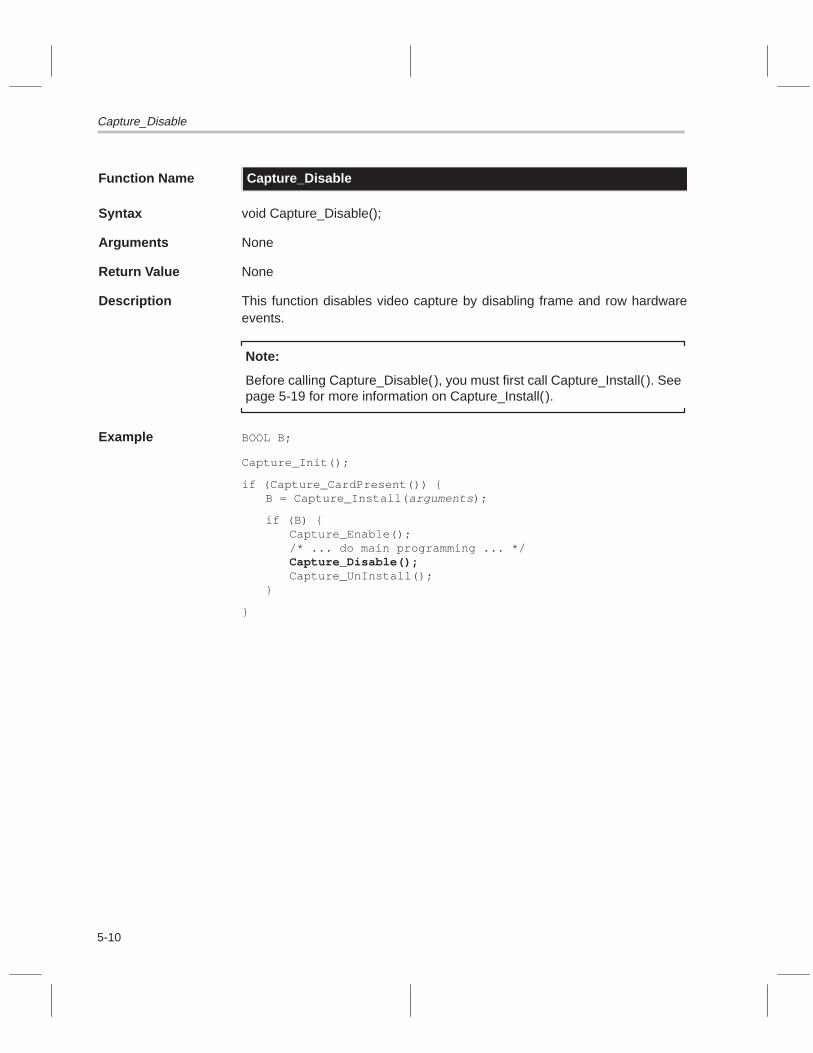
Capture_Disable
5-10
Function Name Capture_Disable
Syntax void Capture_Disable();
Arguments None
Return Value None
Description This function disables video capture by disabling frame and row hardwareevents.
Note:
Before calling Capture_Disable(), you must first call Capture_Install( ). Seepage 5-19 for more information on Capture_Install( ).
Example BOOL B;
Capture_Init();
if (Capture_CardPresent()) {B = Capture_Install( arguments );
if (B) {Capture_Enable();/* ... do main programming ... */Capture_Disable();Capture_UnInstall();
}
}

Capture_Enable
5-11Video Capture API
Function Name Capture_Enable
Syntax void Capture_Enable();
Arguments None
Return Value None
Description This function enables video capture by enabling frame and row hardwareevents.
Note:
Before calling Capture_Enable(), you must first call Capture_Install( ). Seepage 5-19 for more information on Capture_Install( ).
Example BOOL B;
Capture_Init();
if (Capture_CardPresent()) {B = Capture_Install( arguments );
if (B) {Capture_Enable();/* ... do main programming ... */Capture_Disable();Capture_UnInstall();
}
}

Capture_FillBuffs
5-12
Function Name Capture_FillBuffs
Syntax void Capture_FillBuffs(ULONG val);
Arguments ULONG val 32-bit value used to fill the buffers
Return Value None
Description This function fills the two internal capture buffers (active and inactive) with thevalue specified.
Note:
Do not call Capture_FillBuffs() while video capture is enabled.
Example Capture_Install(CAPTURE_NTSC, CAPTURE_YUV422, CAPTURE_QCIF);
Capture_FillBuffs(0x00000000);
Capture_Enable();
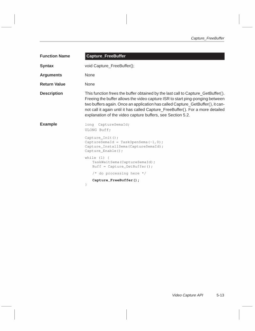
Capture_FreeBuffer
5-13Video Capture API
Function Name Capture_FreeBuffer
Syntax void Capture_FreeBuffer();
Arguments None
Return Value None
Description This function frees the buffer obtained by the last call to Capture_GetBuffer( ).Freeing the buffer allows the video capture ISR to start ping-ponging betweentwo buffers again. Once an application has called Capture_GetBuffer( ), it can-not call it again until it has called Capture_FreeBuffer( ). For a more detailedexplanation of the video capture buffers, see Section 5.2.
Example long CaptureSemaId;
ULONG Buff;
Capture_Init();CaptureSemaId = TaskOpenSema(–1,0);Capture_InstallSema(CaptureSemaId);Capture_Enable();
while (1) {TaskWaitSema(CaptureSemaId);Buff = Capture_GetBuffer();
/* do processing here */
Capture_FreeBuffer();}

Capture_GetBuffer
5-14
Function Name Capture_GetBuffer
Syntax ULONG Capture_GetBuffer();
Arguments None
Return Value ULONG Address of inactive buffer
Description This function returns the address of the inactive video capture buffer and locksthe buffer for exclusive use by the application. The application can modify thecontents of the buffer. When the application is finished using the buffer, it mustcall Capture_FreeBuffer( ) to return the buffer to the driver. For a more detailedexplanation of the video capture buffers, see Section 5.2.
Example long CaptureSemaId;
ULONG Buff;
Capture_Init();Capture_Install(CAPTURE_NTSC,CAPTURE_RGB888,CAPTURE_640x480);CaptureSemaId = TaskOpenSema(–1,0);Capture_InstallSema(CaptureSemaId);Capture_Enable();
while (1) {TaskWaitSema(CaptureSemaId);Buff = Capture_GetBuffer();
/* do processing here */
Capture_FreeBuffer();}

Capture_GetDecoderRegs
5-15Video Capture API
Function Name Capture_GetDecoderRegs
Syntax void Capture_GetDecoderRegs(BYTE *DR);
Arguments BYTE *DR Pointer to a preallocated array of 25 bytes that will be filledin with video decoder register values
Return Value None
Description This function fills in the array of bytes pointed to by DR with the current videodecoder register settings. Because there are a total of 25 decoder registers,DR must point to 25 bytes of preallocated memory. Although the decoder reg-isters cannot be read directly, the hardware layer of the software keeps trackof register writes and maintains a registry of the current register values.
Notes:
1) Use this function for reference and debugging purposes.
2) Before calling Capture_GetDecoderRegs(), you must first callCapture_Init( ). See page 5-18 for more information on Capture_Init( ).
Example BYTE Dregs[25];
BYTE *buff;
BOOL B;
Capture_Init();
if (Capture_CardPresent()) {B = Capture_Install( arguments );
if (B) {Capture_GetDecoderRegs(Dregs);Capture_Enable();/* ... do main programming ... */Capture_Disable();Capture_UnInstall();
}
}

Capture_GetMetrics
5-16
Function Name Capture_GetMetrics
Syntax void Capture_GetMetrics(CAPTURE_MET *M);
Arguments CAPTURE_MET *M Pointer to the CAPTURE_MET structure of videocapture metric parameters
CAPTURE_MET consists of the following members :
BYTE Fps; /* frames per second */ULONG Size; /* buffer size in bytes */USHORT Rh; /* horizontal capture resolution in pixels*/USHORT Rv; /* vertical resolution in lines */BYTE Bpp; /* bits per pixel */ULONG Pitch; /* buffer pitch, number of bytes from one
line to next */BOOL Interlace; /* interlaced flag (TRUE = interlaced) */
Return Value None
Description This function fills in the CAPTURE_MET structure that is pointed to by M withthe current capture state metrics.
Note:
Before calling Capture_GetMetrics(), you must first call Capture_Install( ).See page 5-19 for more information on Capture_Install( ).
Example CAPTURE_MET cmet;
BOOL B;
Capture_Init();
if (Capture_CardPresent()) {B = Capture_Install( arguments );
if (B) {Capture_GetMetrics(&cmet);Capture_Enable();/* ... do main programming ... */Capture_Disable();Capture_UnInstall();
}
}

Capture_GetScalerRegs
5-17Video Capture API
Function Name Capture_GetScalerRegs
Syntax void Capture_GetScalerRegs(BYTE *SR);
Arguments BYTE *SR Pointer to a preallocated array of 17 bytes (unsigned char-acters) that will be filled in with scaler register values
Return Value None
Description This function fills in the array of bytes that is pointed to by SR with the currentvideo scaler register settings. Because there are a total of 17 scaler registers,SR must point to 17 bytes of preallocated memory. Although the scaler regis-ters cannot be read directly, the hardware layer of the software keeps track ofregister writes and maintains a registry of the current register values.
Notes:
1) Use this function for reference and debugging purposes.
2) Before calling Capture_GetScalerRegs(), you must first callCapture_Init( ). See page 5-18 for more information on Capture_Init( ).
Example BYTE Sregs[25];
BYTE *buff;
BOOL B;
Capture_Init();
if (Capture_CardPresent()) {B = Capture_Install( arguments );
if (B) {Capture_GetScalerRegs(Sregs);Capture_Enable();/* ... do main programming ... */Capture_Disable();Capture_UnInstall();
}
}

Capture_Init
5-18
Function Name Capture_Init
Syntax BOOL Capture_Init();
Arguments None
Return Value BOOL TRUEFALSE
Initialization succeededInitialization failed
Description This function initializes the video capture hardware to a known state. General-ly, this function should be called only once—at the beginning of a program.
Note:
You must call Capture_Init( ) before calling any other video capture functionlisted in this API.
Example BOOL B;
Capture_Init();
if (Capture_CardPresent()) {B = Capture_Install( arguments );Capture_Enable();/* ... do main programming ... */Capture_Disable();Capture_UnInstall();
}
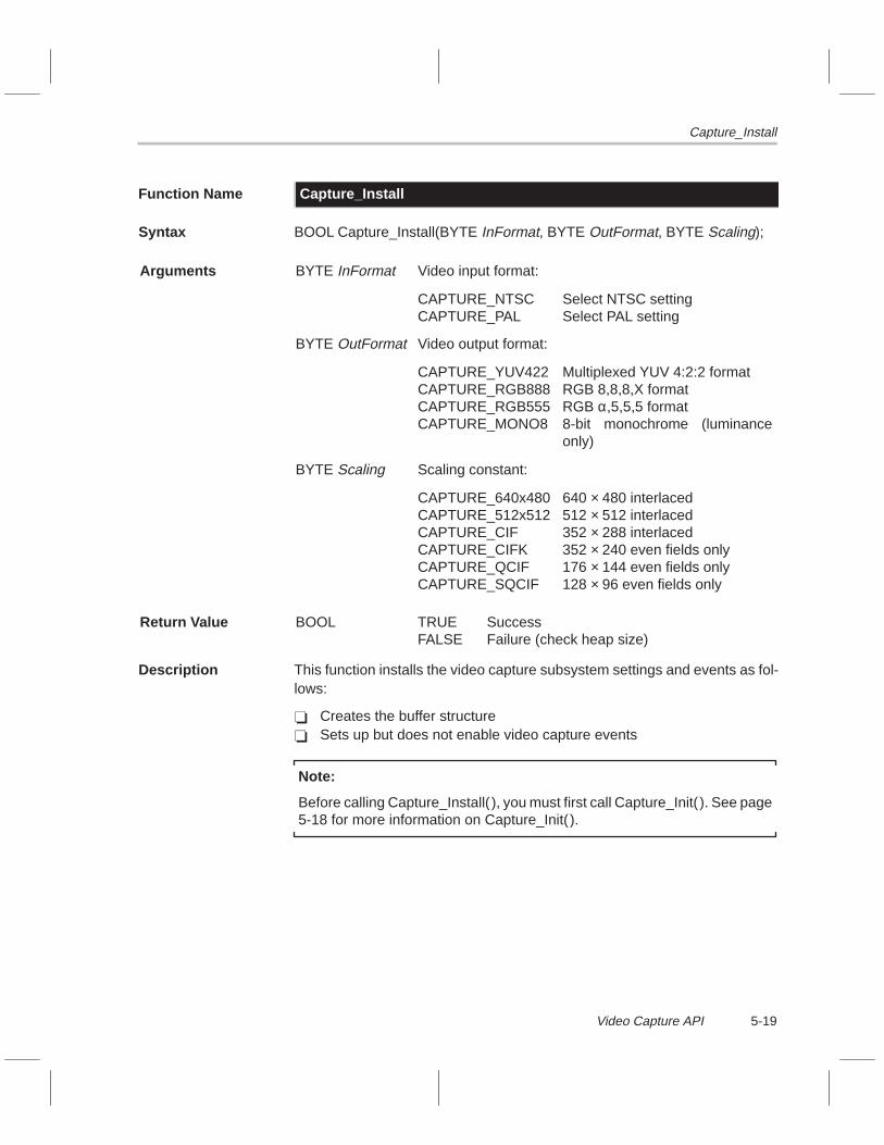
Capture_Install
5-19Video Capture API
Function Name Capture_Install
Syntax BOOL Capture_Install(BYTE InFormat, BYTE OutFormat, BYTE Scaling);
Arguments BYTE InFormat Video input format:
CAPTURE_NTSCCAPTURE_PAL
Select NTSC settingSelect PAL setting
BYTE OutFormat Video output format:
CAPTURE_YUV422CAPTURE_RGB888CAPTURE_RGB555CAPTURE_MONO8
Multiplexed YUV 4:2:2 formatRGB 8,8,8,X formatRGB α,5,5,5 format8-bit monochrome (luminanceonly)
BYTE Scaling Scaling constant:
CAPTURE_640x480CAPTURE_512x512CAPTURE_CIFCAPTURE_CIFKCAPTURE_QCIFCAPTURE_SQCIF
640 × 480 interlaced512 × 512 interlaced352 × 288 interlaced352 × 240 even fields only176 × 144 even fields only128 × 96 even fields only
Return Value BOOL TRUEFALSE
SuccessFailure (check heap size)
Description This function installs the video capture subsystem settings and events as fol-lows:
� Creates the buffer structure� Sets up but does not enable video capture events
Note:
Before calling Capture_Install( ), you must first call Capture_Init( ). See page5-18 for more information on Capture_Init( ).

Capture_Install
5-20
Example BOOL B;
Capture_Init();
if (Capture_CardPresent()) {B = Capture_Install(CAPTURE_NTSC, CAPTURE_YUV422,
CAPTURE_CIF);
if (B) {Capture_Enable();/* ... do main programming ... */Capture_Disable();Capture_UnInstall();
}
}

Capture_InstallSema
5-21Video Capture API
Function Name Capture_InstallSema
Syntax long Capture_InstallSema(long SemaId);
Arguments long SemaId ID of an opened semaphore (TaskOpenSema())
Return Value long Old semaphore value
Description This function installs the video capture semaphore. The semaphore ID argu-ment must be obtained from calling TaskOpenSema(). The video capture ISRsignals this semaphore whenever a new frame of video is ready.
Example long CaptureSemaId;
ULONG Buff;
Capture_Init();Capture_Install(CAPTURE_NTSC,CAPTURE_RGB888,CAPTURE_640x480);CaptureSemaId = TaskOpenSema(–1,0);Capture_InstallSema(CaptureSemaId);Capture_Enable();
while (1) {TaskWaitSema(CaptureSemaId);Buff = Capture_GetBuffer();
/* do processing here */
Capture_FreeBuffer();}

Capture_SetInputSource
5-22
Function Name Capture_SetInputSource
Syntax void Capture_SetInputSource(BYTE InSrc);
Arguments BYTE InSrc Input source:
CAPTURE_SVHS
CAPTURE_VID1CAPTURE_VID2
Decode SVHS input from VID1 and VID2inputsDecode CVBS input from VID1 inputDecode CVBS input from VID2 input
Return Value None
Description This function selects the input source to the video decoder. There are two RCAinput jacks labeled VID1 and VID2. A composite input source can be con-nected to either one of these, or both of them may be used for an S-VHS input.An on-board analog multiplexer takes care of routing, and glue logic (that is,intermediate interface logic) takes care of multiplexing on the high-speed ana-log-to-digital converters (ADCs).
Note:
Before calling Capture_SetInputSource(), you must first call Capture_Init( ).See page 5-18 for more information on Capture_Init( ).
Example BOOL B;
Capture_Init();
if (Capture_CardPresent()) {B = Capture_Install(CAPTURE_NTSC,CAPTURE_YUV422,CAP-
TURE_CIF);
if (B) {Capture_SetInputSource(CAPTURE_VID1);Capture_Enable();/* ... do main programming ... */Capture_Disable();Capture_UnInstall();
}
}

Capture_SetScaling
5-23Video Capture API
Function Name Capture_SetScaling
Syntax BOOL Capture_SetScaling(BYTE Scaling);
Arguments BYTE Scaling New scaling value, one of the following:
CAPTURE_640x480CAPTURE_512x512CAPTURE_CIFCAPTURE_CIFKCAPTURE_QCIFCAPTURE_SQCIF
640 × 480 interlaced512 × 512 interlaced352 × 288 interlaced352 × 240 even fields only176 × 144 even fields only128 × 96 even fields only
Return Value BOOL TRUEFALSE
SuccessFailure (check heap size)
Description This function sets the video capture scaling. When you first callCapture_Install( ), you specify a scaling constant. However, if there is a needto change the scaling size dynamically, use this function. This function mustnot be called when video capture is enabled. This function first frees any buffermemory allocated from the previous settings. New buffers are allocated fromthe heap to match the new scaling size. An application can callCapture_GetMetrics() after calling this function to get the dimensions and buff-er sizes.
Example long CaptureSemaId;
ULONG Buff;
Capture_Init();Capture_Install(CAPTURE_NTSC,CAPTURE_RGB888,CAPTURE_640x480);CaptureSemaId = TaskOpenSema(–1,0);Capture_InstallSema(CaptureSemaId);Capture_Enable();
while (1) {TaskWaitSema(CaptureSemaId);Buff = Capture_GetBuffer();
/* do processing here */
Capture_FreeBuffer();
if ( some condition ) {Capture_Disable();Capture_SetScaling(CAPTURE_SQCIF);Capture_Enable();
}}

Capture_UnInstall
5-24
Function Name Capture_UnInstall
Syntax void Capture_UnInstall();
Arguments None
Return Value None
Description This function performs the following actions:
� Disables video capture� Uninstalls all video capture events that were set up by Capture_Install( )� Frees any memory allocated for buffer storage
Example BOOL B;
Capture_Init();
if (Capture_CardPresent()) {B = Capture_Install(CAPTURE_NTSC, CAPTURE_YUV422,
CAPTURE_CIF);
if (B) {Capture_SetInputSource(CAPTURE_VID1);Capture_Enable();/* ... do main programming ... */Capture_Disable();Capture_UnInstall();
}
}
6-1
Host Communications API
This chapter discusses the host communications data types and macros. Italso describes, in alphabetical order, the application programming interface(API) functions associated with the host communications drivers for theTMS320C8x software development board (SDB).
Two host communications driver libraries exist: one links into a host applica-tion and the other links into an SDB application. The host library contains acomplete set of primitives used to communicate to the board plus a set of clientmanagement functions. The SDB driver contains a set of server managementfunctions. Together, with the host acting as the client and the SDB acting asthe server, the two libraries allow a host application to send commands to anSDB application. The libraries do not define the context of the com-mands—they just provide the means to transmit them and synchronize the twoapplications. This guide refers to the host library as the client library and thecorresponding SDB library as the server library.
Topic Page
6.1 Host Communications API Macros and Data Types 6-2. . . . . . . . . . . . . .
6.2 Interaction Between the Client API and the Server API 6-6. . . . . . . . . . .
6.3 Bootstrapping the SDB from the Host 6-10. . . . . . . . . . . . . . . . . . . . . . . . .
6.4 Host Communications API Functions 6-11. . . . . . . . . . . . . . . . . . . . . . . . . .
Chapter 6

Host Communications API Macros and Data Types
6-2
6.1 Host Communications API Macros and Data Types
Table 6–1 describes the macros used by the host communications API andlists the API functions that use each macro. Figure 6–1 provides the definitionfor the host communications API data type. The macros, data type, and func-tion prototypes for the client API are defined in <hclient.h>. The client API ob-ject code resides in hsdbdrvs.lib. The macros and the function prototypes forthe server API are defined in <sserver.h>. The server API object code residesin sdbdrvs.lib.
Table 6–1. Host Communications API Macros
(a) Client status bits
Macro Name Value Description
#define CLIENT_STATOK 0x0000 Status okay
#define CLIENT_TIMEOUT 0x0001 Time-out occurred
#define CLIENT_DEAD 0x0002 Device did not respond
#define CLIENT_MAILBOXFULL 0x0004 FIFO mailbox was full
#define CLIENT_MAILBOXEMPTY 0x0008 FIFO mailbox was empty
#define CLIENT_FIFOALMOSTFULL 0x0010 FIFO was almost full
#define CLIENT_FIFOEMPTY 0x0020 FIFO was empty
#define CLIENT_CLOSED 0x0040 Device was not opened
#define CLIENT_BITSET 0x0080 Bit test result
#define CLIENT_BOOTFILE 0x0100 Could not open boot file
#define CLIENT_COFFFILE 0x0200 Could not open COFF file
#define CLIENT_BINFILE 0x0400 Could not open bin file
Note: These macros are used by all client API functions except Client_Init( ).
(b) PCI status bits
Macro Name ValueBitPosition Description
#define CLIENT_MRST 0x00000001 [00] Master reset (active low)
#define CLIENT_FRST 0x00000002 [01] FIFO reset (active low)
#define CLIENT_FSW0 0x00000004 [02] Byte swapping 0
#define CLIENT_FSW1 0x00000008 [03] Byte swapping 1
#define CLIENT_FOFF0 0x00000010 [04] FIFO flag offset 0
#define CLIENT_FOFF1 0x00000020 [05] FIFO flag offset 1
#define CLIENT_IAEN 0x00000040 [06] Host interrupt enable
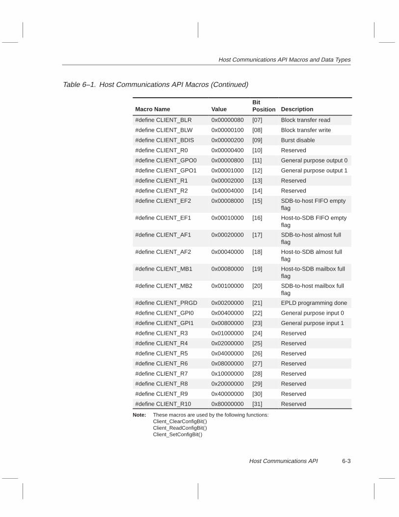
Host Communications API Macros and Data Types
6-3Host Communications API
Table 6–1. Host Communications API Macros (Continued)
Macro Name ValueBitPosition Description
#define CLIENT_BLR 0x00000080 [07] Block transfer read
#define CLIENT_BLW 0x00000100 [08] Block transfer write
#define CLIENT_BDIS 0x00000200 [09] Burst disable
#define CLIENT_R0 0x00000400 [10] Reserved
#define CLIENT_GPO0 0x00000800 [11] General purpose output 0
#define CLIENT_GPO1 0x00001000 [12] General purpose output 1
#define CLIENT_R1 0x00002000 [13] Reserved
#define CLIENT_R2 0x00004000 [14] Reserved
#define CLIENT_EF2 0x00008000 [15] SDB-to-host FIFO emptyflag
#define CLIENT_EF1 0x00010000 [16] Host-to-SDB FIFO emptyflag
#define CLIENT_AF1 0x00020000 [17] SDB-to-host almost fullflag
#define CLIENT_AF2 0x00040000 [18] Host-to-SDB almost fullflag
#define CLIENT_MB1 0x00080000 [19] Host-to-SDB mailbox fullflag
#define CLIENT_MB2 0x00100000 [20] SDB-to-host mailbox fullflag
#define CLIENT_PRGD 0x00200000 [21] EPLD programming done
#define CLIENT_GPI0 0x00400000 [22] General purpose input 0
#define CLIENT_GPI1 0x00800000 [23] General purpose input 1
#define CLIENT_R3 0x01000000 [24] Reserved
#define CLIENT_R4 0x02000000 [25] Reserved
#define CLIENT_R5 0x04000000 [26] Reserved
#define CLIENT_R6 0x08000000 [27] Reserved
#define CLIENT_R7 0x10000000 [28] Reserved
#define CLIENT_R8 0x20000000 [29] Reserved
#define CLIENT_R9 0x40000000 [30] Reserved
#define CLIENT_R10 0x80000000 [31] Reserved
Note: These macros are used by the following functions:Client_ClearConfigBit()Client_ReadConfigBit()Client_SetConfigBit()

Host Communications API Macros and Data Types
6-4
Table 6–1. Host Communications API Macros (Continued)
(c) Boot and reset bits
Macro Name Value Description
#define CLIENT_RUN 0x0001 Do not run COFF file†
#define CLIENT_LOAD 0x0002 Do not load COFF file†
#define CLIENT_EPOINT 0x0004 Custom entry point specified†
#define CLIENT_TBCOFF 0x0008 Disable TBC emulator chip‡
#define CLIENT_EMURST 0x0010 Execute emurst.exe‡
#define CLIENT_VERBOSE 0x0020 Display messages§
† Macros used by the function Client_Reset( )‡ Macros used by the function Client_Boot( )§ Macro used by the functions Client_Reset( ) and Client_Boot( )
(d) FIFO data swapping constants
Macro Name Value Description of Data Swap
#define CLIENT_NOSWAP 0x0000 0×12345678 → 0×12345678
#define CLIENT_BYTESWAP 0x0004 0×12345678 → 0×78563412
#define CLIENT_WORDSWAP 0x0008 0×12345678 → 0×56781234
#define CLIENT_BYTEWORD-SWAP
0x000C 0×12345678 → 0×34127856
Note: These macros are used by the function Client_SetSwapping( ).
(e) Client command size
Macro Name Value Description
#define CLIENT_CMNDSIZE 0x0010 Number of 32-bit words in a com-mand
Note: This value is used internal to the API and must match SERVER_CMNDSIZE.
(f) Server command size
Macro Name Value Description
#define SERVER_CMNDSIZE 0x0010 Number of 32-bit words in a com-mand
Note: This value is used internal to the API and must match CLIENT_CMNDSIZE.

Host Communications API Macros and Data Types
6-5Host Communications API
Figure 6–1. Host Communications API Data Type (CLIENT_STAT)
typedef USHORT CLIENT_STAT;
/* CLIENT_STAT returns status information to the application: */
/* Bit *//* Position Bit Name Description *//* [00] CLIENT_STATOK No errors occurred. *//* [01] CLIENT_TIMEOUT The access timed out. *//* [02] CLIENT_DEAD The SDB did not respond. *//* [03] CLIENT_MAILBOXFULL The time-out was caused by attempting *//* write to a full mailbox. *//* [04] CLIENT_MAILBOXEMPTY The time-out was caused by attempting *//* read from an empty mailbox. *//* [05] CLIENT_FIFOALMOSTFULL The time-out was caused by attempting *//* write to an almost full FIFO *//* [06] CLIENT_FIFOEMPTY The time-out was caused by attempting *//* read from an empty FIFO. *//* [07] CLIENT_CLOSED Function could not complete because *//* the device has not been opened. *//* [08] CLIENT_BITSET The configuration bit tested was set. *//* [09] CLIENT_BOOTFILE The sdbboot.out file could not be *//* opened. *//* [10] CLIENT_COFFFILE The COFF file to be loaded could not *//* be opened. *//* [11] CLIENT_BINFILE The .bin file could not be opened. *//* [12] reserved This bit is reserved for future use. *//* [13] reserved This bit is reserved for future use. *//* [14] reserved This bit is reserved for future use. *//* [15] reserved This bit is reserved for future use. */

Interaction Between the Client API and the Server API
6-6
6.2 Interaction Between the Client API and the Server API
The client API provides functions for communicating with the SDB via the SDBdevice driver for Windows. These functions include simple primitives for read-ing to and writing from the SDB’s I/O space and the PCI interface FIFO. Alsoincluded in the API is client/server command passing functionality. For theclient/server protocol to work, the host has to be running the client API, andthe SDB must be running the server API. When the client/server software isrunning, the host can pass application-defined commands to the SDB.
The API does not define the context of commands, but it does define the struc-ture. A command is nothing more than a sequence of 32-bit words. The num-ber of 32-bit words that make up a command is defined byCLIENT_CMNDSIZE for the client API and by SERVER_CMNDSIZE for theserver API. These two values are the same and, if you alter them, they mustalways be equal. The first 32-bit word in the command is defined to be the com-mand ID. The remaining 32-bit words may be used however the applicationwishes. The command size is set by TI to 16. This size provides fifteen 32-bitwords for applications to use for argument passing in a command, plus oneapplication-defined command ID. The ’C80 server is an interrupt service rou-tine (ISR) that, when triggered by the host, accepts the command, and thensignals the ’C80 application.
6.2.1 Client/Server Synchronization
One important aspect of the client/server operation is synchronization. Boththe client and server APIs have a synchronization function that ensures eventsoccur when they are supposed to. These synchronization functions are:
� Client_Sync() in the client API for the host� Server_Sync() in the server API for the SDB
When the Client_Sync() function is called, it does not return to the host ap-plication until the SDB application calls Server_Sync(). When the Serv-er_Sync() function is called, it does not return to the SDB application until thehost application calls Client_Sync(). The result is the Client_Sync() functionreturns to the host application at virtually the same time that the Server_Sync()function returns to the SDB application. This mechanism synchronizes the twoapplications.
Figure 6–2 illustrates, in generic terms, how the Client_Sync() function inter-acts with the Server_Sync() function. FLAG is a bit visible to both the host andSDB.

Interaction Between the Client API and the Server API
6-7Host Communications API
Figure 6–2. Client/Server Synchronization
ClientSync ServerSync
Set FLAG
Yes
NoIs
FLAGcleared
?
Yes
NoIs
FLAGset?
Clear FLAG

Interaction Between the Client API and the Server API
6-8
6.2.2 Client to Server Protocol
Figure 6–3 illustrates the flow of the host client sending a command to the SDBserver. Keep in mind that the host and the SDB applications are both runningat the same time. The host issues a command that interrupts the SDB. TheSDB ISR signals a semaphore, which is received by the SDB application. TheSDB application gets the command and acts on it. As seen in the flow charts,synchronization functions have been placed at strategic locations to ensureboth applications work in harmony.

Interaction Between the Client API and the Server API
6-9Host Communications API
Figure 6–3. Client/Server Command Flow
Server_Sync1
semaphoreserverSignal
Server ISR
Server_GetCmnd
Readcommand
out of FIFO
2
Server_Sync
3
Server_Sync
Server_Done
Server_GetCmnd
semaphoreserver
Wait on
SDB application (server)
Do thecommand
Client_Sync
2
into FIFOcommand
Write
Client_IssueCmnd
TriggerSDB
interrupt
1
Client_Sync
Client_Sync
3
IssueCmndClient_
Host application (client)

Bootstrapping the SDB from the Host
6-10
6.3 Bootstrapping the SDB from the Host
A required and fundamental aspect of the SDB is the ability to bootstrap it fromthe host. Bootstrapping is the process of bringing the ’C80 out of reset and thenproviding it some code to run. The host can reset the SDB by writing a 0 thena 1 into the CLIENT_MRST (master reset) bit position of the PCI status register(PCISTAT). The ’C80 and other hardware on the board are reset, but the ’C80comes out of reset halted. The ’C80 must be unhalted by asserting its EINT3pin, which can be done by the host. Once unhalted after reset, the ’C80 im-mediately begins executing the instruction located at address 0xFFFFFFF8 inthe ’C80’s address space. Because the ’C80 just came out of reset, its instruc-tion cache is empty, so it must do an instruction cache subblock fill to fetch itsfirst instruction. Therefore, the ’C80 must load 64 bytes into cache. Becauseall cache subblocks are 64-byte aligned, 64 bytes will be loaded starting at ad-dress 0xFFFFFFC0. This address falls in the range of the PCI interface FIFO,implying 64 bytes of instructions must be in the FIFO for the ’C80 to completeits instruction cache fill. The host is responsible for putting this data into theFIFO.
Two methods of bootstrapping the SDB are implemented. The first methodloads two ’C80 programs stored in binary format: miniboot.bin andbootserv.bin. The miniboot program is bootstrapped to the ’C80, whichexecutes and loads the bootserv program. These are default programs thatreset the board. The host API function Client_Reset() as well as the board re-set utility sdbrst.exe loads these two programs.
The second method of bootstrapping the SDB involves loading a boot serverprogram, which then loads a user-specified common object file format (COFF)file for execution. The host API function Client_Boot() resets the board, loadsa specified COFF file, and executes it. In other words, Client_Boot() loads andruns a ’C80 program from the host.
Included with the API libraries is a ’C80 application named sdbboot.out (inCOFF format). The Client_Boot() function bootstraps this file to the ’C80,which runs entirely from MP cache. The sdbboot.out file is responsible foraccepting a COFF file from the host, storing it in memory on the board, andthen executing it. The boot program (sdbboot.out) is written to fit precisely intoseven MP instruction cache subblocks. This is accomplished by forcing the’C80 to do seven instruction cache subblock fills in the same order that the hostwrites the subblocks into the PCI interface FIFO. The source for sdbboot.outis included with the SDB software so that you can customize it.

Host Communications API Functions
6-11Host Communications API
6.4 Host Communications API Functions
Listed below in alphabetical order are the host communications API functions.Use this list as a table of contents to the host communications API functions.
Function Page Function Page
Client_Boot 6-12. . . . . . . . . . . . . . . . . . . Client_Sync 6-26. . . . . . . . . . . . . . . .
Client_ClearConfigBit 6-13. . . . . . . . . . Client_WriteConfig 6-27. . . . . . . . . . .
Client_Close 6-14. . . . . . . . . . . . . . . . . . Client_WriteDataFifo 6-28. . . . . . . . .
Client_Init 6-15. . . . . . . . . . . . . . . . . . . . Client_WriteIo 6-29. . . . . . . . . . . . . . .
Client_IssueCmnd 6-16. . . . . . . . . . . . . Client_WriteMailbox 6-30. . . . . . . . .
Client_Open 6-17. . . . . . . . . . . . . . . . . . Server_Done 6-31. . . . . . . . . . . . . . .
Client_ReadConfig 6-18. . . . . . . . . . . . Server_GetCmnd 6-32. . . . . . . . . . . .
Client_ReadConfigBit 6-19. . . . . . . . . . Server_Init 6-33. . . . . . . . . . . . . . . . .
Client_ReadDataFifo 6-20. . . . . . . . . . . Server_Install 6-34. . . . . . . . . . . . . . .
Client_ReadIo 6-21. . . . . . . . . . . . . . . . Server_InstallSema 6-35. . . . . . . . . .
Client_ReadMailbox 6-22. . . . . . . . . . . Server_ReadDataFifo 6-36. . . . . . . .
Client_Reset 6-23. . . . . . . . . . . . . . . . . . Server_Sync 6-37. . . . . . . . . . . . . . . .
Client_SetConfigBit 6-24. . . . . . . . . . . . Server_UnInstall 6-38. . . . . . . . . . . .
Client_SetSwapping 6-25. . . . . . . . . . . Server_WriteDataFifo 6-39. . . . . . . .

Client_Boot
6-12
Function Name Client_Boot
Syntax CLIENT_STAT Client_Boot(char *coffname, ULONG EntryPoint, USHORT Flags, FILE *Output);
Arguments char *coffname COFF filename (may include path information)
ULONG EntryPoint Alternative program entry point
USHORT Flags CLIENT_VERBOSECLIENT_EPOINT
CLIENT_LOADCLIENT_RUN
Send messages to OutputAddress of alternative entrypointDo the COFF loadExecute the COFF file
FILE *Output Opened text stream, such as stdout
Return Value CLIENT_STAT Status information
Description This function bootstraps the SDB by resetting the board, loading the specifiedCOFF file, and then executing it. Basically, this function loads and runs a ’C80program. The function looks in the current directory for the COFF file. If anentry point is specified, program execution begins at that point rather than thedefault address in the COFF file.
Four flags can be set to alter the functionality. Setting the CLIENT_VERBOSEflag instructs the function to output text messages to the stream pointed to bythe Output argument. If you set the CLIENT_EPOINT flag, the EntryPoint ar-gument is used; otherwise, the argument is ignored. Setting CLIENT_LOADinstructs the function to load the COFF file. Setting CLIENT_RUN instructs thefunction to execute the COFF file.
Sometimes it may be desirable to load a COFF file but execute it at a later time.To do this, first call this function with the load flag set but the run flag cleared.Then, call this function later with the run flag set and the load flag cleared. Thisworks fine as long as the SDB is not disrupted between calls (from a reset, forinstance). If the sdbboot.out file cannot be opened, the CLIENT_BOOTFILEflag is set in the return status. If the COFF file cannot be opened, theCLIENT_COFFFILE flag is set in the return status.
Example CLIENT_STAT St;
St = Client_Boot(“myprog.out”, NULL, CLIENT_RUN|CLIENT_LOAD|CLIENT_VERBOSE, stdout);
if (St == CLIENT_STATOK) {/* boot went okay */
}

Client_ClearConfigBit
6-13Host Communications API
Function Name Client_ClearConfigBit
Syntax CLIENT_STAT Client_ClearConfigBit(ULONG bit);
Arguments ULONG bit Bit position constant:
CLIENT_MRSTCLIENT_FRSTCLIENT_FSW0CLIENT_FSW1CLIENT_FOFF0CLIENT_FOFF1CLIENT_IAENCLIENT_BLRCLIENT_BLWCLIENT_BDISCLIENT_R0CLIENT_GPO0CLIENT_GPO1CLIENT_R1CLIENT_R2CLIENT_EF2CLIENT_EF1CLIENT_AF1CLIENT_AF2CLIENT_MB1CLIENT_MB2CLIENT_PRGDCLIENT_GPI0CLIENT_GPI1CLIENT_R3CLIENT_R4CLIENT_R5CLIENT_R6CLIENT_R7CLIENT_R8CLIENT_R9CLIENT_R10
[00][01][02][03][04][05][06][07][08][09][10][11][12][13][14][15][16][17][18][19][20][21][22][23][24][25][26][27][28][29][30][31]
Master reset (active low)FIFO reset (active low)Byte swapping 0Byte swapping 1FIFO flag offset 0FIFO flag offset 1Host Interrupt enableBlock transfer readBlock transfer writeBurst disableReservedGeneral purpose output 0General purpose output 1ReservedReservedSDB-to-host FIFO empty flagHost-to-SDB FIFO empty flagSDB-to-host almost full flagHost-to-SDB almost full flagHost-to-SDB mailbox full flagSDB-to-host mailbox full flagEPLD programming doneGeneral purpose input 0General purpose input 1ReservedReservedReservedReservedReservedReservedReservedReserved
Return Value CLIENT_STAT Status information
Description This function clears a bit in the PCI status register (PCISTAT).
Example CLIENT_STAT St;
St = Client_ClearConfigBit(CLIENT_FSW0);
if (St == CLIENT_STATOK) {/* ... okay ... */
}

Client_Close
6-14
Function Name Client_Close
Syntax CLIENT_STAT Client_Close();
Arguments None
Return Value CLIENT_STAT Status information
Description This function closes the SDB device. Once it is closed, no other accesses canoccur on the SDB until it is reopened via Client_Open().
Example CLIENT_STAT st;
st = Client_Open();
if (st) {/* ... do some processing ... */Client_Close();
}

Client_Init
6-15Host Communications API
Function Name Client_Init
Syntax BOOL Client_Init();
Arguments None
Return Value BOOL TRUEFALSE
Initialization succeededInitialization failed
Description This function initializes the host API. It returns TRUE if the initializationsucceeded.
Notes:
1) You must call Client_Init() before calling any other host API function.2) You must call this function only once in an application.
Example BOOL ok;
ok = Client_Init();
if (ok) {/* ... do some processing ... */
}

Client_IssueCmnd
6-16
Function Name Client_IssueCmnd
Syntax CLIENT_STAT Client_IssueCmnd(ULONG *Cmnd, long TimeOut);
Arguments ULONG *Cmnd Pointer to command; must point to CLIENT_CMNDSIZE32-bit words of preallocated memory
long TimeOut Number of attempts before timing out
Return Value CLIENT_STAT Status information
Description This function is the host command client responsible for sending a commandto the SDB. Success requires the ’C80 command server to be running also.The context of the command is application defined.
Example #define MY_CMND_ID 0x80120001
void MyClientFunc() {
ULONG Cmnd[CLIENT_CMNDSIZE];Cmnd[0] = MY_CMND_ID;Cmnd[1] = argument1 ;Cmnd[2] = argument2 ;/* ... etc ... */Client_IssueCmnd(1000);Client_Sync(100);/* ... finish up command ... */
}

Client_Open
6-17Host Communications API
Function Name Client_Open
Syntax CLIENT_STAT Client_Open();
Arguments None
Return Value CLIENT_STAT Status information
Description This function opens the SDB device. Before accesses to the SDB can occur,it must be opened. If the SDB device opens successfully, the return statusequals CLIENT_STATOK.
Note: You must call Client_Open():
� after calling Client_Init( ) (see page 6-15 for more information)� before calling any other host API functions
Example CLIENT_STAT st;
if (Client_Init()) {
st = Client_Open();
if (st == CLIENT_STATOK) {/* ... do some processing ... */Client_Close();
}
}

Client_ReadConfig
6-18
Function Name Client_ReadConfig
Syntax CLIENT_STAT Client_ReadConfig(ULONG *Val);
Arguments ULONG *Val Pointer to ULONG, which receives the PCI status registercontents
Return Value CLIENT_STAT Status information
Description This function reads the PCI status register (PCISTAT) and stores it into theULONG pointed to by Val.
Example ULONG PciStat;
Client_ReadConfig(&PciStat);

Client_ReadConfigBit
6-19Host Communications API
Function Name Client_ReadConfigBit
Syntax CLIENT_STAT Client_ReadConfigBit(ULONG bit);
Arguments ULONG bit Bit position constant:
CLIENT_MRSTCLIENT_FRSTCLIENT_FSW0CLIENT_FSW1CLIENT_FOFF0CLIENT_FOFF1CLIENT_IAENCLIENT_BLRCLIENT_BLWCLIENT_BDISCLIENT_R0CLIENT_GPO0CLIENT_GPO1CLIENT_R1CLIENT_R2CLIENT_EF2CLIENT_EF1CLIENT_AF1CLIENT_AF2CLIENT_MB1CLIENT_MB2CLIENT_PRGDCLIENT_GPI0CLIENT_GPI1CLIENT_R3CLIENT_R4CLIENT_R5CLIENT_R6CLIENT_R7CLIENT_R8CLIENT_R9CLIENT_R10
[00][01][02][03][04][05][06][07][08][09][10][11][12][13][14][15][16][17][18][19][20][21][22][23][24][25][26][27][28][29][30][31]
Master reset (active low)FIFO reset (active low)Byte swapping 0Byte swapping 1FIFO flag offset 0FIFO flag offset 1Host interrupt enableBlock transfer readBlock transfer writeBurst disableReservedGeneral purpose output 0General purpose output 1ReservedReservedSDB-to-host FIFO empty flagHost-to-SDB FIFO empty flagSDB-to-host almost full flagHost-to-SDB almost full flagHost-to-SDB mailbox full flagSDB-to-host mailbox full flagEPLD programming doneGeneral purpose input 0General purpose input 1ReservedReservedReservedReservedReservedReservedReservedReserved
Return Value CLIENT_STAT Status information
Description This function reads the PCI status register (PCISTAT) and tests the specifiedbit. The CLIENT_BITSET flag in the return status indicates whether the testedbit is set or not. CLIENT_BITSET is set if the tested bit is set.
Example CLIENT_STAT st;
st = Client_ReadConfigBit(CLIENT_P2H_FEF);
if (st & CLIENT_BITSET) {/* ... bit was set ... */
}

Client_ReadDataFifo
6-20
Function Name Client_ReadDataFifo
Syntax CLIENT_STAT Client_ReadDataFifo(ULONG *Block, ULONG ct,long timeout);
Arguments ULONG *Block Pointer to a block of 32-bit words
ULONG ct Number of words in a block (0 � ct � 8192)
long timeout Number of attempts before timing out
Return Value CLIENT_STAT Status information
Description This function reads a block of 32-bit words from the PCI interface FIFO. To pre-vent reading an empty FIFO, a software watchdog timer is implemented. Thisfunction checks the FIFO empty flag and, if it is not set, reads ct 32-bit wordsand stores them into *Block. If the flag is set, indicating the FIFO is empty, thefunction loops and tries again. If the function fails timeout times, it returns with-out reading data and the CLIENT_TIMEOUT flag plus theCLIENT_FIFOEMPTY flag is set in the return status.
Note:
Client_ReadDataFifo() only checks the FIFO empty flag initially. If the blocksize is larger than the FIFO size, the ’C80 must write the entire block to theFIFO for this function to read out. If this function tries to read more data outof the FIFO than the ’C80 writes, the PCI bus will try to read it out forever,literally.
Example ULONG Data[20];
Client_ReadDataFifo(Data,20,100);

Client_ReadIo
6-21Host Communications API
Function Name Client_ReadIo
Syntax CLIENT_STAT Client_ReadIo(USHORT Address, ULONG *Val);
Arguments USHORT Address Host-relative I/O address
ULONG *Val Pointer to ULONG, which receives the PCI status reg-ister contents
Return Value CLIENT_STAT Status information
Description This function reads a value from the SDB’s I/O bus. The address is relative tothe host address window into the SDB device. For instance, the MASKEN0register of the SDB’s interrupt controller has a host-relative address of 0x2300.The I/O bus on the SDB is 16 bits wide, but all PCI accesses must be 32-bitaccesses. For this reason, the application should mask off the unneeded bits,which contain unpredictable values.
Note:
This function performs an I/O access that requires the use of both PCI inter-face FIFO mailboxes. If either or both mailboxes are full, the access will failand the PCI status register (PCISTAT) is returned.
Example ULONG MaskEn0;
Client_ReadIo(0x2300, &MaskEn0);
MaskEn0 &= 0x0000FFFF;

Client_ReadMailbox
6-22
Function Name Client_ReadMailbox
Syntax CLIENT_STAT Client_ReadMailbox(ULONG *Val, long timeout);
Arguments ULONG *Val Pointer to ULONG, which receives the PCI status register(PCISTAT) contents
long timeout Number of attempts before timing out
Return Value CLIENT_STAT Status information
Description This function reads the 32-bit word from the PCI interface FIFO mailbox. Toprevent reading an empty mailbox, a software watchdog timer is implemented.This function checks the mailbox full flag and, if it is set, reads a 32-bit wordand stores it in *Val. If the flag is not set, indicating the mailbox is empty, thefunction loops and tries again. If the function fails timeout times, it returns with-out reading data, 0×00000000 is written to *Val, and the CLIENT_TIMEOUTflag plus the CLIENT_MAILBOXEMPTY flag is set in the return status.
Example ULONG Data;
Client_ReadMailbox(&Data, 100);

Client_Reset
6-23Host Communications API
Function Name Client_Reset
Syntax CLIENT_STAT Client_Reset(USHORT Flags, FILE *Output);
Arguments USHORT Flags CLIENT_VERBOSECLIENT_TBCOFF
CLIENT_EMURST
Send messages to OutputDisable test bus controller (TBC)emulator chipExecute emurst.exe
FILE *Output Opened text stream, such as stdout
Return Value CLIENT_STAT Status information
Description This function bootstraps the SDB by resetting the board, loading miniboot.bin,and then loading and running bootserv.bin. The files miniboot.bin and boot-serv.bin are the default bootstrapping files and are located in the system32directory of the host operating system.
Three flags can be passed to this function:
� CLIENT_VERBOSE� CLIENT_TBCOFF� CLIENT_EMURST
Setting CLIENT_VERBOSE causes this function to output text messages tothe Output stream. Setting CLIENT_TBCOFF causes the on-board TBC emu-lator chip to be disabled. Disabling this chip allows debugging using the JTAGconnector on the board and an XDS510 emulator. Setting CLIENT_EMURSTcauses this function to execute the emurst.exe utility before resetting. Thisonly applies if you have an XDS510 installed in your PC. By performing anemurst, you can reset the XDS510 and the SDB. The emurst.exe program isnot spawned, but rather it is called out as a system command, so the programonly needs to be in the system path.
Example CLIENT_STAT St;
St = Client_Reset(CLIENT_VERBOSE, stdout);
if (St == CLIENT_STATOK) {/* reset went okay */
}

Client_SetConfigBit
6-24
Function Name Client_SetConfigBit
Syntax CLIENT_STAT Client_SetConfigBit(ULONG bit);
Arguments ULONG bit Bit position constant:
CLIENT_MRSTCLIENT_FRSTCLIENT_FSW0CLIENT_FSW1CLIENT_FOFF0CLIENT_FOFF1CLIENT_IAENCLIENT_BLRCLIENT_BLWCLIENT_BDISCLIENT_R0CLIENT_GPO0CLIENT_GPO1CLIENT_R1CLIENT_R2CLIENT_EF2CLIENT_EF1CLIENT_AF1CLIENT_AF2CLIENT_MB1CLIENT_MB2CLIENT_PRGDCLIENT_GPI0CLIENT_GPI1CLIENT_R3CLIENT_R4CLIENT_R5CLIENT_R6CLIENT_R7CLIENT_R8CLIENT_R9CLIENT_R10
[00][01][02][03][04][05][06][07][08][09][10][11][12][13][14][15][16][17][18][19][20][21][22][23][24][25][26][27][28][29][30][31]
Master reset (active low)FIFO reset (active low)Byte swapping 0Byte swapping 1FIFO flag offset 0FIFO flag offset 1Host interrupt enableBlock transfer readBlock transfer writeBurst disableReservedGeneral purpose output 0General purpose output 1ReservedReservedSDB-to-host FIFO empty flagHost-to-SDB FIFO empty flagSDB-to-host almost full flagHost-to-SDB almost full flagHost-to-SDB mailbox full flagSDB-to-host mailbox full flagEPLD programming doneGeneral purpose input 0General purpose input 1ReservedReservedReservedReservedReservedReservedReservedReserved
Return Value CLIENT_STAT Status information
Description This function sets a bit in the PCI status register (PCISTAT).
Example CLIENT_STAT St;
St = Client_SetConfigBit(CLIENT_FSW0);
if (St == CLIENT_STATOK) {/* status = okay */
}

Client_SetSwapping
6-25Host Communications API
Function Name Client_SetSwapping
Syntax CLIENT_STAT Client_SetSwapping(USHORT sw);
Arguments USHORT sw CLIENT_NOSWAPCLIENT_BYTESWAPCLIENT_WORDSWAPCLIENT_BYTEWORD-SWAP
0x12345678 → 0x123456780x12345678 → 0x785634120x12345678 → 0x567812340x12345678 → 0x34127856
Return Value CLIENT_STAT Status information
Description This function configures the PCI interface FIFO byte swapping logic. The byteswapping logic of the FIFO interface rearranges each 32-bit value that passesthrough the data FIFO. The swapping logic affects the host-to-SDB FIFO andthe SDB-to-host FIFO. It does not affect the FIFO mailboxes (therefore I/O ac-cesses are not affected by swapping).
Note:
If you change the FIFO swapping logic (to do a transfer, for instance), makesure you restore it to CLIENT_NOSWAPPING because the client/server rou-tines require it this way.
Example CLIENT_STAT St;
St = Client_SetSwapping(CLIENT_NOSWAP);

Client_Sync
6-26
Function Name Client_Sync
Syntax CLIENT_STAT Client_Sync(long timeout);
Arguments long timeout Number of attempts before timing out
Return Value CLIENT_STAT Status information
Description When you call this function, it waits until the ’C80 executes Server_Sync() be-fore returning. This synchronizes the host client with the ’C80 server.
Example #define MY_CMND_ID 0x80120001
void MyClientFunc() {
ULONG Cmnd[CLIENT_CMNDSIZE];Cmnd[0] = MY_CMND_ID;Cmnd[1] = argument1 ;Cmnd[2] = argument2 ;/* ... etc ... */Client_IssueCmnd(1000);Client_Sync(100);/* ... finish up command ... */
}

Client_WriteConfig
6-27Host Communications API
Function Name Client_WriteConfig
Syntax CLIENT_STAT Client_WriteConfig(ULONG Val);
Arguments ULONG Val ULONG value to be written to the PCI status register
Return Value CLIENT_STAT Status information
Description This function writes Val to the PCI status register (PCISTAT).
Example ULONG PciStat = 0x00000023;
Client_WriteConfig(PciStat);

Client_WriteDataFifo
6-28
Function Name Client_WriteDataFifo
Syntax CLIENT_STAT Client_WriteDataFifo(ULONG *Block, ULONG ct,long timeout);
Arguments ULONG *Block Pointer to a block of 32-bit words
ULONG ct Number of words in a block (0 � ct � 8192)
long timeout Number of attempts before timing out
Return Value CLIENT_STAT Status information
Description This function writes a block of 32-bit words to the PCI interface FIFO. To pre-vent writing to a full FIFO, a software watchdog timer is implemented. Thisfunction checks the FIFO almost full flag and, if it is not set, writes ct 32-bitwords from *Block into the FIFO. If the flag is set, indicating the FIFO is almostfull, the function loops and tries again. If the function fails timeout times, it re-turns without writing any data and the CLIENT_TIMEOUT flag plus theCLIENT_FIFOALMOSTFULL flag is set in the return status.
Note:
Client_WriteDataFifo() only checks the FIFO almost full flag initially. If theblock size is larger than the FIFO size, the ’C80 must read the entire blockout of the FIFO. If this function tries to write out more data than the ’C80reads, the FIFO will become full and the PCI bus will try to write to it forever,literally.
Example ULONG Data[20];
Client_WriteDataFifo(Data,20,100);

Client_WriteIo
6-29Host Communications API
Function Name Client_WriteIo
Syntax CLIENT_STAT Client_WriteIo(USHORT Address, ULONG Val);
Arguments ULONG Address Host-relative I/O address
ULONG Val Value to write to I/O bus
Return Value CLIENT_STAT Status information
Description This function writes a value to the SDB’s I/O bus. The address is relative to thehost address window into the SDB device. For instance, the MASKEN0 regis-ter of the SDB’s interrupt controller has a host-relative address of 0x2300. TheI/O bus on the SDB is 16 bits wide, but all PCI accesses must be 32-bitaccesses. Only the lower 16 bits are used.
Note:
This function performs an I/O access that requires the use of both PCI inter-face FIFO mailboxes. If either or both mailboxes are full, the access will fail.
Example Client_WriteIo(0x2300, 0x0800);

Client_WriteMailbox
6-30
Function Name Client_WriteMailbox
Syntax CLIENT_STAT Client_WriteMailbox(ULONG Val, long timeout);
Arguments ULONG Val Value to be written to the FIFO mailbox
long timeout Number of attempts before timing out
Return Value CLIENT_STAT Status information
Description This function writes a single 32-bit word to the PCI interface mailbox. To pre-vent writing to a full mailbox, a software watchdog timer is implemented. Thisfunction checks the mailbox full flag and, if it is not set, writes Val to the mailbox.If the flag is set, indicating the mailbox is full, the function loops and tries again.If the function fails timeout times, it returns without writing data and theCLIENT_TIMEOUT flag plus the CLIENT_MAILBOXFULL flag is set in the re-turn status.
Example Client_WriteMailbox(0x12345678,100);

Server_Done
6-31Host Communications API
Function Name Server_Done
Syntax void Server_Done();
Arguments None
Return Value None
Description This function notifies the SDB server that the application has finished servicingthe command. Once the server receives a command from the host client, itdoes not accept any more commands until this function is called. Also, afterthis function is called, the ’C80 application cannot call Server_GetCmnd() untilthe server receives a new command.
Example Server_Done();

Server_GetCmnd
6-32
Function Name Server_GetCmnd
Syntax void Server_GetCmnd(ULONG *Cmnd);
Arguments ULONG *Cmnd Pointer to a series of 32-bit words whose count is the val-ue of SERVER_CMNDSIZE
Return Value None
Description This function copies the command read by the ’C80 command server into thecommand pointed to by Cmnd. The Cmnd argument must point to a series of32-bit words of preallocated memory whose count is the value ofSERVER_CMNDSIZE. The server command is copied only if the server hasone waiting and the application has not yet called Server_Done() for that com-mand. Otherwise, *Cmnd is filled with zeros.
Example ULONG Cmnd[SERVER_CMNDSIZE];
Server_GetCmnd(Cmnd);
Server_Sync();
/* ... complete command ... */
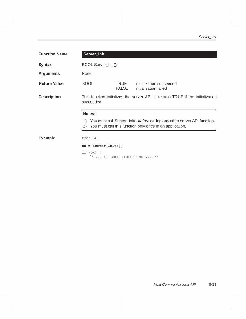
Server_Init
6-33Host Communications API
Function Name Server_Init
Syntax BOOL Server_Init();
Arguments None
Return Value BOOL TRUEFALSE
Initialization succeededInitialization failed
Description This function initializes the server API. It returns TRUE if the initializationsucceeded.
Notes:
1) You must call Server_Init() before calling any other server API function.2) You must call this function only once in an application.
Example BOOL ok;
ok = Server_Init();
if (ok) {/* ... do some processing ... */
}

Server_Install
6-34
Function Name Server_Install
Syntax void Server_Install();
Arguments None
Return Value None
Description This function installs the server ISR. Server_Install() must be called before thehost (client) can send down any commands. Calling Server_UnInstall()reverses the actions of this function.
Example Server_Init();
Server_Install();

Server_InstallSema
6-35Host Communications API
Function Name Server_InstallSema
Syntax long Server_InstallSema(long SemaId);
Arguments long SemaId ID of an opened semaphore
Return Value long Old semaphore value
Description This function installs a semaphore into the server driver. Whenever the SDBreceives a new command from the host (client), it signals this semaphore. Theapplication must open the semaphore before installing it.
Example long ServerSemaId;
ServerSemaId = TaskOpenSema(–1,0);Server_InstallSema(ServerSemaId);
.
.
.
TaskWaitSema(ServerSemaId);
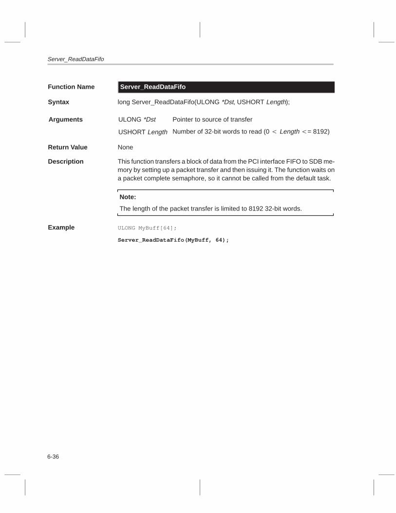
Server_ReadDataFifo
6-36
Function Name Server_ReadDataFifo
Syntax long Server_ReadDataFifo(ULONG *Dst, USHORT Length);
Arguments ULONG *Dst Pointer to source of transfer
USHORT Length Number of 32-bit words to read (0 � Length �= 8192)
Return Value None
Description This function transfers a block of data from the PCI interface FIFO to SDB me-mory by setting up a packet transfer and then issuing it. The function waits ona packet complete semaphore, so it cannot be called from the default task.
Note:
The length of the packet transfer is limited to 8192 32-bit words.
Example ULONG MyBuff[64];
Server_ReadDataFifo(MyBuff, 64);

Server_Sync
6-37Host Communications API
Function Name Server_Sync
Syntax void Server_Sync();
Arguments None
Return Value None
Description When you call this function, it waits until the host executes Client_Sync() be-fore returning. This synchronizes the ’C80 server with the host client.
Example Server_Sync();

Server_UnInstall
6-38
Function Name Server_UnInstall
Syntax void Server_UnInstall();
Arguments None
Return Value None
Description This function performs the following actions:
� Uninstalls the server that was installed by calling Server_Install()� Disables the server interrupt
Example Server_UnInstall();

Server_WriteDataFifo
6-39Host Communications API
Function Name Server_WriteDataFifo
Syntax void Server_WriteDataFifo(ULONG *Src, USHORT Length);
Arguments ULONG *Src Pointer to source of transfer
USHORT Length Number of 32-bit words to read (0 � Length �= 8192)
Return Value None
Description This function transfers a block of data from SDB memory to the PCI interfaceby setting up a packet transfer and then issuing it. The function waits on a pack-et complete semaphore, so it cannot be called from the default task.
Note:
The length of the packet transfer is limited to 8192 32-bit words.
Example ULONG MyBuff[64];
/* write the contents of the buffer to the FIFO */Server_WriteDataFifo(MyBuff, 64);

6-40

A-1
Appendix A
Example Code
This appendix lists several examples of code that illustrate the effective useof the API libraries that come with the SDB. Some of these examples may begood starting points for developing your own applications.
The complete coding examples illustrate how to use the driver APIs. Each ex-ample includes the following files:
� C source file for the example� Linker command file� Batch file for building the project
The project files are located on the TMS320C8x SDB System Software CDROM under the samples directory. The projects on the CD have already beenbuilt into a .out file and are ready to execute. If you want to rebuild the projects,the TMS320C8x code generations tools must be installed on your system.
Topic Page
A.1 Video Capture-Process-Display Example A-2. . . . . . . . . . . . . . . . . . . . . . . .
A.2 Audio DMA Capture Example A-8. . . . . . . . . . . . . . . . . . . . . . . . . . . . . . . . . .
A.3 Audio DMA Playback Example A-12. . . . . . . . . . . . . . . . . . . . . . . . . . . . . . . .
A.4 Audio Block Capture/Playback Example A-17. . . . . . . . . . . . . . . . . . . . . . .
A.5 Audio Programmed I/O Example A-21. . . . . . . . . . . . . . . . . . . . . . . . . . . . . .
A.6 Video Capture Scaling Example A-24. . . . . . . . . . . . . . . . . . . . . . . . . . . . . . .
A.7 Video Display Test Example A-30. . . . . . . . . . . . . . . . . . . . . . . . . . . . . . . . . . .
Appendix A

Video Capture-Process-Display Example
A-2
A.1 Video Capture-Process-Display Example
This example provides a skeleton application that performs double-bufferedvideo capture and double-buffered video display. You can start with this exam-ple and add to it by providing processing on the captured video.
Example A–1. video
(a) video.c/****************************************************************************\* Copyright (C) 1995–1996 Texas Instruments Incorporated.* All Rights Reserved*––––––––––––––––––––––––––––––––––––––––––––––––––––––––––––––––––––––––––––** video.c –– TMS320C8x MP ’C’ Source Code** This is the C file for the video example program.*\****************************************************************************/#include <sdbdrvs.h>
/****************************************************************************\* Data Types, Global Variables, Constants\****************************************************************************/
/* executive variables */long VideoTaskId;long CaptureSemaId;long DisplaySemaId;long PtSemaId;
/* packet transfer table (PT is defined in sdbdrvs.h) */PT *PtTable;
/* metrics variables */CAPTURE_MET CM;DISPLAY_MET DM;
/****************************************************************************\* Function Prototypes\****************************************************************************/void VideoTask(void *p);void ProcessVideo(ULONG Buff);void InitVideo(USHORT sx, USHORT sy, BYTE scale);void InitPtTable();

Video Capture-Process-Display Example
A-3Example Code
/****************************************************************************\* Functions\****************************************************************************/void main() {
/* these register settings are mandatory */ REFCNTL = 0xFFFF0100; PTMIN = 0x00000100; PTMAX = 0x00010000;
/* initialize the executive */ TaskInitTasking(); PtReqInit();
/* initialize the drivers */ Capture_Init(); Display_Init();
/* create the task and semaphores */ VideoTaskId = TaskCreate(–1, VideoTask, (void *)NULL, 20, 1024); CaptureSemaId = TaskOpenSema(–1,0); DisplaySemaId = TaskOpenSema(–1,0);
/* install driver semaphores */ Capture_InstallSema(CaptureSemaId); Display_InstallSema(DisplaySemaId);
/* set up packet transfer table and semaphore */ PtSemaId = TaskOpenSema(–1,0); PtTable = (PT *)PtReqAlloc();
/* start the video task */ TaskResume(VideoTaskId);
while (1);}
/*––––––––––––––––––––––––––––––––––––––––––––––––––––––––––––––––––––––––––*/void VideoTask(void *p) {
int SemaCt = 0; ULONG CaptureBuff; ULONG DisplayBuff;
/* initialize the video settings */ if (0) InitVideo(1024, 768, CAPTURE_640x480); if (1) InitVideo( 640, 480, CAPTURE_640x480); if (0) InitVideo(1024, 768, CAPTURE_512x512); if (0) InitVideo( 640, 480, CAPTURE_CIF); if (0) InitVideo( 640, 480, CAPTURE_CIFK); if (0) InitVideo( 640, 480, CAPTURE_QCIF); if (0) InitVideo( 640, 480, CAPTURE_SQCIF); if (0) InitVideo(1024, 768, CAPTURE_SQCIF);

Video Capture-Process-Display Example
A-4
/* turn on the video */ Display_Enable(); Capture_Enable();
/* video capture–process–display loop */ while (1) {
/* wait for new captured frame */ TaskWaitSema(CaptureSemaId);
/* selectively process frame */ if (SemaCt++ > 0) { SemaCt = 0;
/* get buffer of most recently captured frame */ CaptureBuff = Capture_GetBuffer();
/* tell display driver to toggle buffers next display frame event */ Display_ToggleBuffers();
/* do some processing on captured buffer */ if (0) ProcessVideo(CaptureBuff);
/* wait until display driver has toggled display buffers */ TaskWaitSema(DisplaySemaId);
/* get the in–active display buffer */ DisplayBuff = Display_GetBuffer(DISPLAY_INACTIVE);
/* transfer the processed capture buffer to the */ /* in–active display buffer */ PtTable–>SrcStart = CaptureBuff; PtTable–>DstStart = DisplayBuff; PtReqIssue((void *)PtTable,PtSemaId); TaskWaitSema(PtSemaId);
/* unlock the capture buffer obtained from Capture_GetBuffer() */ Capture_FreeBuffer(); } }}
/*––––––––––––––––––––––––––––––––––––––––––––––––––––––––––––––––––––––––––*/void ProcessVideo(ULONG Buff) {
USHORT x,y; ULONG addr;
/* this processing is not practical but has a good visual effect */

Video Capture-Process-Display Example
A-5Example Code
/* for each 16–bit pixel in the captured buffer */ for (x=0; x<CM.Rh; x++) { for (y=0; y<CM.Rv; y++) { addr = Buff + CM.Bpp/8*x + CM.Pitch*y; /* invert the pixel */ NOCACHE_USHORT(*(volatile USHORT*)addr) = (0xFFFF – NOCACHE_USHORT(*(volatile USHORT*)addr)); } }}/*––––––––––––––––––––––––––––––––––––––––––––––––––––––––––––––––––––––––––*/void InitVideo(USHORT sx, USHORT sy, BYTE scale) { USHORT x,y,dx,dy;
/* set up the video capture */ Capture_Install(CAPTURE_NTSC,CAPTURE_RGB555,scale); Capture_FillBuffs(0x00000000); Capture_GetMetrics(&CM);
/* calculate the display window */ dx = CM.Rh; dy = CM.Rv; x = (sx–dx)/2; y = (sy–dy)/2;
/* set up the display */ Display_SetMode(sx,sy,60,DISPLAY_T555,DISPLAY_VIDEO); Display_SetWindow(x,y,dx,dy); Display_SetPitch(CM.Pitch); Display_GetMetrics(&DM);
/* initialize the packet transfer table */ InitPtTable();}
/*––––––––––––––––––––––––––––––––––––––––––––––––––––––––––––––––––––––––––*/void InitPtTable() {
/* Setup packet transfer table used to transfer the capture buffer to */ /* the display buffer. The two metrics variables CM and DM must already */ /* be set before calling this function. */ PtTable–>Next = (ULONG)PtTable; PtTable–>Options = 0x80000000; PtTable–>SrcStart = 0x00000000; PtTable–>DstStart = 0x00000000; PtTable–>SrcBCnt = CM.Rv–1; PtTable–>SrcACnt = CM.Rh*CM.Bpp/8; PtTable–>DstBCnt = CM.Rv–1; PtTable–>DstACnt = CM.Rh*CM.Bpp/8; PtTable–>SrcCCnt = 0; PtTable–>DstCCnt = 0; PtTable–>SrcBPitch = CM.Pitch; PtTable–>DstBPitch = DM.Pitch;

Video Capture-Process-Display Example
A-6
PtTable–>SrcCPitch = 0; PtTable–>DstCPitch = 0; PtTable–>Trans0 = 0; PtTable–>Trans1 = 0; PtTable–>Junk1 = 0; PtTable–>Junk2 = 0;}
/****************************************************************************\* End of ’video.c’\****************************************************************************/
(b) video.lnk/****************************************************************************\* Copyright (C) 1995–1996 Texas Instruments Incorporated.* All Rights Reserved*––––––––––––––––––––––––––––––––––––––––––––––––––––––––––––––––––––––––––––** video.lnk –– TMS320C8x MP Linker Command File*\****************************************************************************/
–c–x–heap 0x00400000–stack 0x00010000–l mp_rts.lib–l mp_task.lib–l mp_int.lib–l mp_ptreq.lib–l sdbdrvs.lib
MEMORY{ PROGMEM : origin=0x80000000 length=0x00800000}
SECTIONS{ .text :> PROGMEM .ptext :> PROGMEM .cinit :> PROGMEM .const :> PROGMEM .switch :> PROGMEM .data :> PROGMEM .bss :> PROGMEM .sysmem :> PROGMEM}
/****************************************************************************\* End of ’video.lnk’\****************************************************************************/

Video Capture-Process-Display Example
A-7Example Code
(c) video.bat@rem #************************************************************************\@rem # Copyright (C) 1995–1996 Texas Instruments Incorporated.@rem # All Rights Reserved@rem #––––––––––––––––––––––––––––––––––––––––––––––––––––––––––––––––––––––––@rem #@rem # video.bat –– batch file to build project@rem #@rem #************************************************************************/
@mpcl –gq video.c
@mvplnk –m video.map –o video.out video.obj video.lnk
@rem #************************************************************************\@rem # End of ’video.bat’@rem #************************************************************************/

Audio DMA Capture Example
A-8
A.2 Audio DMA Capture Example
This example shows how to use buffered DMA audio capture in real time. Theonly processing done on the audio is displaying each sample on the displayin an oscilloscope fashion. When you run this example in the debugger, do nothalt the debugger. The audio FIFO generates an interrupt when it is almost full.The ISR then issues a packet transfer to read the data out of the FIFO. If youhalt the debugger, the ISR never executes, and the FIFO is never serviced.When this happens, the FIFO becomes full and overflows. No more events aretriggered and, therefore, audio stops.
Example A–2. audcapt
(a) audcapt.c/****************************************************************************\* Copyright (C) 1995–1996 Texas Instruments Incorporated.* All Rights Reserved*––––––––––––––––––––––––––––––––––––––––––––––––––––––––––––––––––––––––––––** audcapt.c –– TMS320C8x MP ’C’ Source Code** This is the C file for the audcapt example.*\****************************************************************************/#include <sdbdrvs.h>
/****************************************************************************\* Data Types, Global Variables, Constants\****************************************************************************/long AudioTaskId;long AudioSemaId;
AUDIO_MET AM;DISPLAY_MET DM;
#define BG_COLOR 0x0000#define FG_COLOR 0x03E0
/****************************************************************************\* Function Prototypes\****************************************************************************/void AudioTask(void *p);void ProcessAudio(AUDIO_PTR *Cptr);
/****************************************************************************\* Functions\****************************************************************************/void main() {
/* these register settings are mandatory */ REFCNTL = 0xFFFF0100;

Audio DMA Capture Example
A-9Example Code
PTMIN = 0x00000100; PTMAX = 0x00010000;
/* initialize executive */ TaskInitTasking(); PtReqInit();
/* initialize drivers */ Audio_Init(); Display_Init();
/* set up display */ Display_SetMode(1024,768,60,DISPLAY_T555,DISPLAY_VIDEO); Display_FillBuffs(BG_COLOR); Display_GetMetrics(&DM); Display_Enable();
/* executive stuff */ AudioSemaId = TaskOpenSema(–1,0); AudioTaskId = TaskCreate(–1, AudioTask, (void *)NULL, 20, 1024); Audio_InstallSema(AudioSemaId);
/* start the audio task */ TaskResume(AudioTaskId);
while (1);}
/*––––––––––––––––––––––––––––––––––––––––––––––––––––––––––––––––––––––––––*/void AudioTask(void *p) {
AUDIO_PTR Cptr;
/* set up the audio */ Audio_ProgramInputs(AUDIO_LINE,AUDIO_LINE,15,15); Audio_Install(AUDIO_CAPTURE,AUDIO_PCM16,AUDIO_STEREO,48.0,8,128,4); Audio_FillBuffs(0x00000000); Audio_GetMetrics(&AM); Audio_Enable();
/* audio capture loop */ while (1) { TaskWaitSema(AudioSemaId); Audio_GetCaptureBuffs(&Cptr); ProcessAudio(&Cptr); }}
/*––––––––––––––––––––––––––––––––––––––––––––––––––––––––––––––––––––––––––*/void ProcessAudio(AUDIO_PTR *Cptr) {
USHORT x,y,n; static BOOL init = FALSE;

Audio DMA Capture Example
A-10
static short L0[2048]; static short R0[2048];
n = AM.BlockSz * AM.BlockCt;
if (init) { for (x=0; x<n; x++) { Display_SetPixel(x,L0[x]+768/3,BG_COLOR,DISPLAY_ACTIVE); L0[x] = ((short*)(Cptr–>L))[x]>>8; Display_SetPixel(x,768/3,0x3C00,DISPLAY_ACTIVE); Display_SetPixel(x,L0[x]+768/3,FG_COLOR,DISPLAY_ACTIVE); if (AM.Stereo) { Display_SetPixel(x,R0[x]+2*768/3,BG_COLOR,DISPLAY_ACTIVE); R0[x] = ((short*)(Cptr–>R))[x]>>8; Display_SetPixel(x,2*768/3,0x3C00,DISPLAY_ACTIVE); Display_SetPixel(x,R0[x]+2*768/3,FG_COLOR,DISPLAY_ACTIVE); } } } else { init=TRUE; for (x=0; x<n; x++) { L0[x] = R0[x] = 0; } }}
/****************************************************************************\* End of ’audcapt.c’\****************************************************************************/
(b) audcapt.lnk/****************************************************************************\* Copyright (C) 1995–1996 Texas Instruments Incorporated.* All Rights Reserved*––––––––––––––––––––––––––––––––––––––––––––––––––––––––––––––––––––––––––––** audcapt.lnk –– TMS320C8x MP Linker Command File*\****************************************************************************/
–c–x–heap 0x00100000–stack 0x00010000–l mp_rts.lib–l mp_task.lib–l mp_int.lib–l mp_ptreq.lib–l sdbdrvs.lib

Audio DMA Capture Example
A-11Example Code
MEMORY{ PROGMEM : origin=0x80000000 length=0x00800000}
SECTIONS{ .text :> PROGMEM .ptext :> PROGMEM .cinit :> PROGMEM .const :> PROGMEM .switch :> PROGMEM .data :> PROGMEM .bss :> PROGMEM .sysmem :> PROGMEM}/****************************************************************************\* End of ’audcapt.lnk’\****************************************************************************/
(c) audcapt.bat@rem #************************************************************************\@rem # Copyright (C) 1995–1996 Texas Instruments Incorporated.@rem # All Rights Reserved@rem #––––––––––––––––––––––––––––––––––––––––––––––––––––––––––––––––––––––––@rem #@rem # audcapt.bat –– batch file to build project@rem #@rem #************************************************************************/
mpcl –gq audcapt.c
mvplnk –m audcapt.map –o audcapt.out audcapt.obj audcapt.lnk
@rem #************************************************************************\@rem # End of ’audcapt.bat’@rem #************************************************************************/
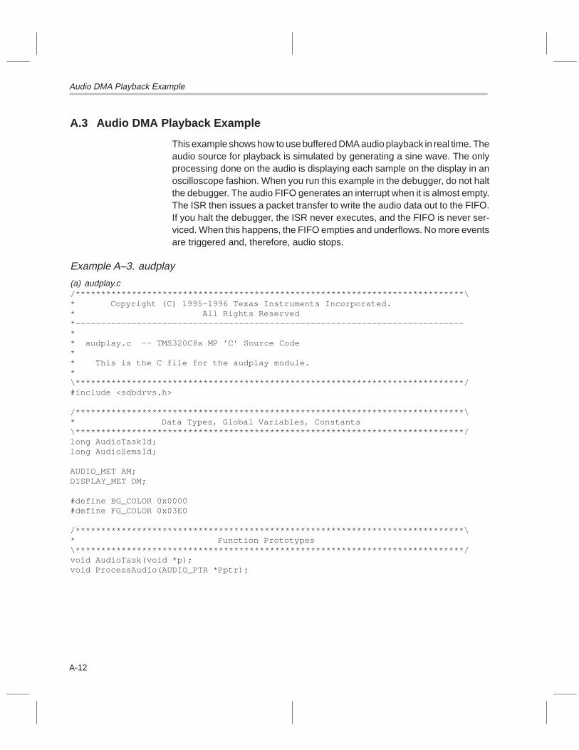
Audio DMA Playback Example
A-12
A.3 Audio DMA Playback Example
This example shows how to use buffered DMA audio playback in real time. Theaudio source for playback is simulated by generating a sine wave. The onlyprocessing done on the audio is displaying each sample on the display in anoscilloscope fashion. When you run this example in the debugger, do not haltthe debugger. The audio FIFO generates an interrupt when it is almost empty.The ISR then issues a packet transfer to write the audio data out to the FIFO.If you halt the debugger, the ISR never executes, and the FIFO is never ser-viced. When this happens, the FIFO empties and underflows. No more eventsare triggered and, therefore, audio stops.
Example A–3. audplay
(a) audplay.c/****************************************************************************\* Copyright (C) 1995–1996 Texas Instruments Incorporated.* All Rights Reserved*––––––––––––––––––––––––––––––––––––––––––––––––––––––––––––––––––––––––––––** audplay.c –– TMS320C8x MP ’C’ Source Code** This is the C file for the audplay module.*\****************************************************************************/#include <sdbdrvs.h>
/****************************************************************************\* Data Types, Global Variables, Constants\****************************************************************************/long AudioTaskId;long AudioSemaId;
AUDIO_MET AM;DISPLAY_MET DM;
#define BG_COLOR 0x0000#define FG_COLOR 0x03E0
/****************************************************************************\* Function Prototypes\****************************************************************************/void AudioTask(void *p);void ProcessAudio(AUDIO_PTR *Pptr);

Audio DMA Playback Example
A-13Example Code
/****************************************************************************\* Functions\****************************************************************************/void main() {
/* these register settings are mandatory */ REFCNTL = 0xFFFF0100; PTMIN = 0x00000100; PTMAX = 0x00010000;
/* initialize executive */ TaskInitTasking(); PtReqInit();
/* initialize drivers */ Audio_Init(); Display_Init();
/* set up display */ Display_SetMode(1024,768,60,DISPLAY_T555,DISPLAY_VIDEO); Display_FillBuffs(BG_COLOR); Display_GetMetrics(&DM); Display_Enable();
/* executive stuff */ AudioSemaId = TaskOpenSema(–1,0); AudioTaskId = TaskCreate(–1, AudioTask, (void *)NULL, 20, 1024); Audio_InstallSema(AudioSemaId);
/* start the audio task */ TaskResume(AudioTaskId);
while (1);}
/*––––––––––––––––––––––––––––––––––––––––––––––––––––––––––––––––––––––––––*/void AudioTask(void *p) {
AUDIO_PTR Pptr;
/* set up the audio */ Audio_ProgramInputs(AUDIO_LINE,AUDIO_LINE,15,15); Audio_Install(AUDIO_PLAYBACK,AUDIO_PCM16,AUDIO_STEREO,48.0,8,128,4); Audio_FillBuffs(0x00000000); Audio_GetMetrics(&AM); Audio_Enable();
/* audio capture loop */ while (1) { TaskWaitSema(AudioSemaId);

Audio DMA Playback Example
A-14
Audio_GetPlaybackBuffs(&Pptr); ProcessAudio(&Pptr); }}
/*––––––––––––––––––––––––––––––––––––––––––––––––––––––––––––––––––––––––––*/void ProcessAudio(AUDIO_PTR *Pptr) {
USHORT x,y,n; static BOOL init = FALSE; static short L0[2048]; static short R0[2048]; static float theta = 0.0; static float pi; float z;
pi = 4.0*atan(1.0); n = AM.BlockCt * AM.BlockSz;
/* erase old plot */ if (init) { for (x=0; x<n; x++) { Display_SetPixel(x,L0[x]+768/3,BG_COLOR,DISPLAY_ACTIVE); if (AM.Stereo) Display_SetPixel(x,R0[x]+2*768/3,BG_COLOR,DISPLAY_ACTIVE); } }
init=TRUE;
/*theta = 0.0;*/ /* draw new plot */ for (x=0; x<n; x++) { z = 16384*sin(theta); L0[x] = (short)z>>8; NOCACHE_SHORT(*(volatile short *)((short*)(Pptr–>L)+x)) = (short)z; Display_SetPixel(x,768/3,0x3C00,DISPLAY_ACTIVE); Display_SetPixel(x,L0[x]+768/3,FG_COLOR,DISPLAY_ACTIVE); if (AM.Stereo) { z = 16384*sin(4*theta+pi); R0[x] = (short)z>>8; NOCACHE_SHORT(*(volatile short *)((short*)(Pptr–>R)+x)) = (short)z; Display_SetPixel(x,2*768/3,0x3C00,DISPLAY_ACTIVE); Display_SetPixel(x,R0[x]+2*768/3,FG_COLOR,DISPLAY_ACTIVE); } theta = theta + 4.0*2.0*pi/n; }}
/****************************************************************************\* End of ’audplay.c’\****************************************************************************/

Audio DMA Playback Example
A-15Example Code
(b) audplay.lnk/****************************************************************************\* Copyright (C) 1995–1996 Texas Instruments Incorporated.* All Rights Reserved*––––––––––––––––––––––––––––––––––––––––––––––––––––––––––––––––––––––––––––** audplay.lnk –– TMS320C8x MP Linker Command File*\****************************************************************************/
–c–x–heap 0x00100000–stack 0x00010000–l mp_rts.lib–l mp_task.lib–l mp_int.lib–l mp_ptreq.lib–l sdbdrvs.lib
MEMORY{ PROGMEM : origin=0x80000000 length=0x00800000}
SECTIONS{ .text :> PROGMEM .ptext :> PROGMEM .cinit :> PROGMEM .const :> PROGMEM .switch :> PROGMEM .data :> PROGMEM .bss :> PROGMEM .sysmem :> PROGMEM}
/****************************************************************************\* End of ’audplay.lnk’\****************************************************************************/
(c) audplay.bat@rem #************************************************************************\@rem # Copyright (C) 1995–1996 Texas Instruments Incorporated.@rem # All Rights Reserved@rem #––––––––––––––––––––––––––––––––––––––––––––––––––––––––––––––––––––––––@rem #@rem # audplay.bat –– batch file to build project@rem #@rem #************************************************************************/
mpcl –gq audplay.c

Audio DMA Playback Example
A-16
mvplnk –m audplay.map –o audplay.out audplay.obj audplay.lnk
@rem #************************************************************************\@rem # End of ’audplay.bat’@rem #************************************************************************/

Audio Block Capture/Playback Example
A-17Example Code
A.4 Audio Block Capture/Playback Example
This example shows how to use the audio block processing functions, Au-dio_CaptureToMemory() and Audio_PlaybackFromMemory(). The programcaptures 10 seconds of audio, and then plays it back. You can insert process-ing between the capture and playback.
Example A–4. audtest
(a) audtest.c/****************************************************************************\* Copyright (C) 1995–1996 Texas Instruments Incorporated.* All Rights Reserved*––––––––––––––––––––––––––––––––––––––––––––––––––––––––––––––––––––––––––––** audtest.c –– TMS320C8x MP ’C’ Source Code** This is the C file for the audtest module.*\****************************************************************************/#include <sdbdrvs.h>#include <stdlib.h>
/****************************************************************************\* Data Types, Global Variables, Constants\****************************************************************************/
/* executive stuff */long AudioTaskId;long AudioSemaId;
/* metrics variables */AUDIO_MET AM;
/****************************************************************************\* Function Prototypes\****************************************************************************/void AudioTask(void *p);void ProcessAudio(AUDIO_PTR *Cptr, ULONG NumBuffs);
/****************************************************************************\* Functions\****************************************************************************/void main() {
/* these register settings are mandatory */ REFCNTL = 0xFFFF0100; PTMIN = 0x00000100; PTMAX = 0x00010000;
/* initialize executive */ TaskInitTasking();

Audio Block Capture/Playback Example
A-18
PtReqInit();
/* initialize drivers */ Audio_Init();
/* executive stuff */ AudioSemaId = TaskOpenSema(–1,0); AudioTaskId = TaskCreate(–1, AudioTask, (void *)NULL, 20, 1024); Audio_InstallSema(AudioSemaId);
/* start the audio task */ TaskResume(AudioTaskId);
while (1);}
/*––––––––––––––––––––––––––––––––––––––––––––––––––––––––––––––––––––––––––*/void AudioTask(void *p) {
AUDIO_PTR Cptr; BYTE Format = AUDIO_PCM16; BOOL Stereo = AUDIO_STEREO; float Fs = 48.0; BYTE BlockCt = 20; BYTE BlockSz = 50; BYTE BuffCt = 8; ULONG NumBuffs = Fs*10; /* 10 seconds worth (watch out for heap size) */
/* dummy install to set audio metrics */ Audio_Install(AUDIO_CAPTURE,Format,Stereo,Fs,BlockCt,BlockSz,BuffCt); Audio_GetMetrics(&AM); Audio_UnInstall();
/* allocate some DRAM storage for captured audio */ Cptr.L = (void*)memalign(64,AM.ByteSz*NumBuffs); Cptr.R = (void*)memalign(64,AM.ByteSz*NumBuffs);
/* set the input gain */ Audio_ProgramInputs(AUDIO_LINE,AUDIO_LINE,9,9);
while (1) { /* capture audio into memory */ Audio_Install(AUDIO_CAPTURE,Format,Stereo,Fs,BlockCt,BlockSz,BuffCt); Audio_CaptureToMemory(&Cptr, NumBuffs); Audio_UnInstall();
/* process the captured audio */ ProcessAudio(&Cptr,NumBuffs);
/* playback the processed audio */ Audio_Install(AUDIO_PLAYBACK,Format,Stereo,Fs,BlockCt,BlockSz,BuffCt);

Audio Block Capture/Playback Example
A-19Example Code
Audio_PlaybackFromMemory(&Cptr, NumBuffs); Audio_UnInstall(); }
/* if loop exited, free up the allocated memory */ free((void*)Cptr.L); free((void*)Cptr.R);}
/*––––––––––––––––––––––––––––––––––––––––––––––––––––––––––––––––––––––––––*/void ProcessAudio(AUDIO_PTR *Cptr, ULONG NumBuffs) {
ULONG i; short *L,*R;
L = (short*)(Cptr–>L); R = (short*)(Cptr–>R);
/* do some dummy processing */ /* watch out for data cache coherency */ for (i=0; i<AM.BuffSz*NumBuffs; i++) { L[i] = –L[i]; R[i] = R[i]/2; }}
/****************************************************************************\* End of ’audtest.c’\****************************************************************************/
(b) audtest.lnk/****************************************************************************\* Copyright (C) 1995–1996 Texas Instruments Incorporated.* All Rights Reserved*––––––––––––––––––––––––––––––––––––––––––––––––––––––––––––––––––––––––––––** audtest.lnk –– TMS320C8x MP Linker Command File*\****************************************************************************/
–c–x–heap 0x00400000–stack 0x00010000–l mp_ptreq.lib–l mp_rts.lib–l mp_task.lib–l mp_int.lib–l sdbdrvs.lib
MEMORY{

Audio Block Capture/Playback Example
A-20
PROGMEM : origin=0x80000000 length=0x00800000}
SECTIONS{ .text :> PROGMEM .stack :> PROGMEM .ptext :> PROGMEM .cinit :> PROGMEM .const :> PROGMEM .switch :> PROGMEM .data :> PROGMEM .bss :> PROGMEM .sysmem :> PROGMEM}
/****************************************************************************\* End of ’audtest.lnk’\****************************************************************************/
(c) audtest.bat@rem #************************************************************************\@rem # Copyright (C) 1995–1996 Texas Instruments Incorporated.@rem # All Rights Reserved@rem #––––––––––––––––––––––––––––––––––––––––––––––––––––––––––––––––––––––––@rem #@rem # audtest.bat –– batch file to build project@rem #@rem #************************************************************************/
mpcl –qg audtest.c
mvplnk –m audtest.map –o audtest.out audtest.obj audtest.lnk
@rem #************************************************************************\@rem # End of ’audtest.bat’@rem #************************************************************************/

Audio Programmed I/O Example
A-21Example Code
A.5 Audio Programmed I/O Example
This example shows how to use the PIO (programmed I/O) mode of the audiocodec to perform full-duplex audio. Two methods are used:
� The program creates its own PIO loop.� The program calls the built-in driver function Audio_PioTest().
This example tests many different audio formats.
Example A–5. piotest
(a) piotest.c/****************************************************************************\* Copyright (C) 1995–1996 Texas Instruments Incorporated.* All Rights Reserved*––––––––––––––––––––––––––––––––––––––––––––––––––––––––––––––––––––––––––––** piotest.c –– TMS320C8x MP ’C’ Source Code** This is the C file for the piotest example.*\****************************************************************************/#include <sdbdrvs.h>
/****************************************************************************\* Functions\****************************************************************************/void main() {
short L,R; ULONG ct = 48000*10; ULONG x; /* these register settings are mandatory */ REFCNTL = 0xFFFF0100; PTMIN = 0x00000100; PTMAX = 0x00010000;
/* initialize the executive */ TaskInitTasking(); PtReqInit();
/* initialize the audio driver */ Audio_Init();
/* setup PIO mode */ Audio_Install(AUDIO_PIO, AUDIO_PCM16, AUDIO_STEREO, 48.0, 0,0,0); Audio_ProgramInputs(AUDIO_LINE, AUDIO_LINE, 9.0, 9.0); Audio_Enable();

Audio Programmed I/O Example
A-22
/* do loopback for ct samples */ for (x=0; x<ct; x++) { Audio_PioIn(&L,&R); Audio_PioOut(&L,&R); }
/* now use the driver built in PIO test routine */ Audio_PioTest(AUDIO_PCM16, AUDIO_STEREO, 48.0, 48000*60);
Audio_PioTest(AUDIO_PCM16, AUDIO_STEREO, 48.0, 48000*5); Audio_PioTest(AUDIO_PCM16, AUDIO_MONO, 48.0, 48000*5); Audio_PioTest(AUDIO_PCM16, AUDIO_STEREO, 8.0, 8000*5); Audio_PioTest(AUDIO_PCM16, AUDIO_MONO, 8.0, 8000*5);
Audio_PioTest(AUDIO_PCM8, AUDIO_STEREO, 48.0, 48000*5); Audio_PioTest(AUDIO_PCM8, AUDIO_MONO, 48.0, 48000*5); Audio_PioTest(AUDIO_PCM8, AUDIO_STEREO, 8.0, 8000*5); Audio_PioTest(AUDIO_PCM8, AUDIO_MONO, 8.0, 8000*5);
Audio_PioTest(AUDIO_ALAW8, AUDIO_STEREO, 48.0, 48000*5); Audio_PioTest(AUDIO_ALAW8, AUDIO_MONO, 48.0, 48000*5); Audio_PioTest(AUDIO_ALAW8, AUDIO_STEREO, 8.0, 8000*5); Audio_PioTest(AUDIO_ALAW8, AUDIO_MONO, 8.0, 8000*5);
Audio_PioTest(AUDIO_ULAW8, AUDIO_STEREO, 48.0, 48000*5); Audio_PioTest(AUDIO_ULAW8, AUDIO_MONO, 48.0, 48000*5); Audio_PioTest(AUDIO_ULAW8, AUDIO_STEREO, 8.0, 8000*5); Audio_PioTest(AUDIO_ULAW8, AUDIO_MONO, 8.0, 8000*5);
Audio_PioTest(AUDIO_PCM16, AUDIO_STEREO, 48.0, –1);
while (1);}
/****************************************************************************\* End of ’piotest.c’\****************************************************************************/
(b) piotest.lnk/****************************************************************************\* Copyright (C) 1995–1996 Texas Instruments Incorporated.* All Rights Reserved*––––––––––––––––––––––––––––––––––––––––––––––––––––––––––––––––––––––––––––** piotest.lnk –– TMS320C8x MP Linker Command File*\****************************************************************************/
–c–x–heap 0x00100000–stack 0x00010000

Audio Programmed I/O Example
A-23Example Code
–l mp_rts.lib–l mp_task.lib–l mp_int.lib–l mp_ptreq.lib–l sdbdrvs.lib
MEMORY{ PROGMEM : origin=0x80000000 length=0x00800000}
SECTIONS{ .text :> PROGMEM .ptext :> PROGMEM .cinit :> PROGMEM .const :> PROGMEM .switch :> PROGMEM .data :> PROGMEM .bss :> PROGMEM .sysmem :> PROGMEM}
/****************************************************************************\* End of ’piotest.lnk’\****************************************************************************/
(c) piotest.bat@rem #************************************************************************\@rem # Copyright (C) 1995–1996 Texas Instruments Incorporated.@rem # All Rights Reserved@rem #––––––––––––––––––––––––––––––––––––––––––––––––––––––––––––––––––––––––@rem #@rem # piotest.bat –– batch file to build project@rem #@rem #************************************************************************/
@mpcl –gq piotest.c
@mvplnk –m piotest.map –o piotest.out piotest.obj piotest.lnk
@rem #************************************************************************\@rem # End of ’piotest.bat’@rem #************************************************************************/

Video Capture Scaling Example
A-24
A.6 Video Capture Scaling Example
This example shows how to set up video capture and then change the scaling.It displays each scaling setting in its own box on the display. For additional in-formation about video capture scaling, see subsection 5.1.1, Supported Scal-ing Resolutions, on page 5-4.
Example A–6. capttest(a) capttest.c/****************************************************************************\* Copyright (C) 1995–1996 Texas Instruments Incorporated.* All Rights Reserved*––––––––––––––––––––––––––––––––––––––––––––––––––––––––––––––––––––––––––––** capttest.c –– TMS320C8x MP ’C’ Source Code** This is the C file for the capttest example.*\****************************************************************************/#include <sdbdrvs.h>
/****************************************************************************\* Data Types, Global Variables, Constants\****************************************************************************/
/* executive variables */long VideoTaskId;long CaptureSemaId;long DisplaySemaId;long PtSemaId;
/* packet transfer table (PT is defined in sdbdrvs.h) */PT *PtTable;
/* metrics variables */CAPTURE_MET CM;DISPLAY_MET DM;
/****************************************************************************\* Function Prototypes\****************************************************************************/void VideoTask(void *p);void DoCapture(ULONG frames, BYTE scale);void InitPtTable();void DrawScreen();void DrawBox(USHORT dx, USHORT dy, ULONG color);
/****************************************************************************\* Functions\****************************************************************************/void main() {

Video Capture Scaling Example
A-25Example Code
/* these register settings are mandatory */ REFCNTL = 0xFFFF0100; PTMIN = 0x00000100; PTMAX = 0x00010000;
/* initialize the executive */ TaskInitTasking(); PtReqInit();
/* initialize the drivers */ Capture_Init(); Display_Init();
/* create the task and semaphores */ VideoTaskId = TaskCreate(–1, VideoTask, (void *)NULL, 20, 1024); CaptureSemaId = TaskOpenSema(–1,0); DisplaySemaId = TaskOpenSema(–1,0);
/* install driver semaphores */ Capture_InstallSema(CaptureSemaId); Display_InstallSema(DisplaySemaId);
/* set up packet transfer table and semaphore */ PtSemaId = TaskOpenSema(–1,0); PtTable = (PT *)PtReqAlloc();
/* start the video task */ TaskResume(VideoTaskId);
while (1);}
/*––––––––––––––––––––––––––––––––––––––––––––––––––––––––––––––––––––––––––*/void VideoTask(void *p) {
/* number of seconds run each capture setting */ USHORT frames = 30*5; /* 5 seconds */
/* set up the video capture */ Capture_Install(CAPTURE_NTSC,CAPTURE_RGB555,CAPTURE_SQCIF); Capture_FillBuffs(0x00000000); Capture_GetMetrics(&CM);
/* set up the display */ Display_SetMode(1024,768,60,DISPLAY_T555,DISPLAY_VIDEO); Display_GetMetrics(&DM); Display_SetBufferAddresses(0xC0000000,0xC0000000); DrawScreen(); Display_Enable();

Video Capture Scaling Example
A-26
/* try out different capture settings */ while (1) { DoCapture(frames,CAPTURE_640x480); DoCapture(frames,CAPTURE_512x512); DoCapture(frames,CAPTURE_CIF); DoCapture(frames,CAPTURE_CIFK); DoCapture(frames,CAPTURE_QCIF); DoCapture(frames,CAPTURE_SQCIF); DoCapture(frames,CAPTURE_QCIF); DoCapture(frames,CAPTURE_CIFK); DoCapture(frames,CAPTURE_CIF); DoCapture(frames,CAPTURE_512x512); }}
/*––––––––––––––––––––––––––––––––––––––––––––––––––––––––––––––––––––––––––*/void DoCapture(ULONG frames, BYTE scale) {
int SemaCt = 0; ULONG CaptureBuff; ULONG DisplayBuff; ULONG dx,dy; ULONG fct;
/* set the scaling of the capture */ Capture_SetScaling(scale); Capture_FillBuffs(0x00000000); Capture_GetMetrics(&CM);
/* initialize the packet transfer table */ InitPtTable();
/* draw the display background */ DrawScreen(); /* turn on the video */ Capture_Enable();
/* video capture–process–display loop */ for (fct=0; fct<frames; fct++) {
/* wait for new captured frame */ TaskWaitSema(CaptureSemaId);
/* get buffer of most recently captured frame */ CaptureBuff = Capture_GetBuffer();
/* tell display driver to toggle buffers next display frame event */ Display_ToggleBuffers();
/* wait until display driver has toggled display buffers */ TaskWaitSema(DisplaySemaId);

Video Capture Scaling Example
A-27Example Code
/* get the in–active display buffer */ DisplayBuff = Display_GetBuffer(DISPLAY_INACTIVE); dx = (DM.dx–CM.Rh)/2*DM.bpp/8; dy = (DM.dy–CM.Rv)/2*DM.Pitch;
/* transfer the processed capture buffer to the */ /* in–active display buffer */ PtTable–>SrcStart = CaptureBuff; PtTable–>DstStart = DisplayBuff+dx+dy; PtReqIssue((void *)PtTable,PtSemaId); TaskWaitSema(PtSemaId);
/* unlock the capture buffer obtained from Capture_GetBuffer() */ Capture_FreeBuffer(); } Capture_Disable();}
/*––––––––––––––––––––––––––––––––––––––––––––––––––––––––––––––––––––––––––*/void InitPtTable() {
/* Setup packet transfer table used to transfer the capture buffer to */ /* the display buffer. The two metrics variables CM and DM must already */ /* be set before calling this function. */ PtTable–>Next = (ULONG)PtTable; PtTable–>Options = 0x80000000; PtTable–>SrcStart = 0x00000000; PtTable–>DstStart = 0x00000000; PtTable–>SrcBCnt = CM.Rv–1; PtTable–>SrcACnt = CM.Rh*CM.Bpp/8; PtTable–>DstBCnt = CM.Rv–1; PtTable–>DstACnt = CM.Rh*CM.Bpp/8; PtTable–>SrcCCnt = 0; PtTable–>DstCCnt = 0; PtTable–>SrcBPitch = CM.Pitch; PtTable–>DstBPitch = DM.Pitch; PtTable–>SrcCPitch = 0; PtTable–>DstCPitch = 0; PtTable–>Trans0 = 0; PtTable–>Trans1 = 0; PtTable–>Junk1 = 0; PtTable–>Junk2 = 0;}
/*––––––––––––––––––––––––––––––––––––––––––––––––––––––––––––––––––––––––––*/void DrawScreen() {
USHORT x,y; ULONG A; USHORT color = 0x00007C00;
Display_FillBuffs(0x0007);

Video Capture Scaling Example
A-28
/* draw full frame */ for(x=0; x<DM.dx; x++) { Display_SetPixel(x,0,color,DISPLAY_INACTIVE); Display_SetPixel(x,DM.dy–1,color,DISPLAY_INACTIVE); } for (y=0; y<DM.dy; y++) { Display_SetPixel(0,y,color,DISPLAY_INACTIVE); Display_SetPixel(DM.dx–1,y,color,DISPLAY_INACTIVE); }
/* draw scaling boxes */ DrawBox(640,480,color); DrawBox(512,512,color); DrawBox(352,288,color); DrawBox(176,144,color); DrawBox(128,96,color); }
/*––––––––––––––––––––––––––––––––––––––––––––––––––––––––––––––––––––––––––*/void DrawBox(USHORT dx, USHORT dy, ULONG color) {
USHORT x,y;
/* draw box frame */ for(x=(DM.dx–dx)/2–1; x<(DM.dx–dx)/2+dx; x++) { Display_SetPixel(x,(DM.dy–dy)/2–1,color,DISPLAY_INACTIVE); Display_SetPixel(x,(DM.dy–dy)/2+dy,color,DISPLAY_INACTIVE); } for (y=(DM.dy–dy)/2–1; y<(DM.dy–dy)/2+dy; y++) { Display_SetPixel((DM.dx–dx)/2–1,y,color,DISPLAY_INACTIVE); Display_SetPixel((DM.dx–dx)/2+dx,y,color,DISPLAY_INACTIVE); }}
/****************************************************************************\* End of ’capttest.c’\****************************************************************************/
(b) capttest.lnk/****************************************************************************\* Copyright (C) 1995–1996 Texas Instruments Incorporated.* All Rights Reserved*––––––––––––––––––––––––––––––––––––––––––––––––––––––––––––––––––––––––––––** capttest.lnk –– TMS320C8x MP Linker Command File*\****************************************************************************/
–c–x–heap 0x00400000

Video Capture Scaling Example
A-29Example Code
–stack 0x00010000–l mp_rts.lib–l mp_task.lib–l mp_int.lib–l mp_ptreq.lib–l sdbdrvs.lib
MEMORY{ PROGMEM : origin=0x80000000 length=0x00800000}
SECTIONS{ .text :> PROGMEM .ptext :> PROGMEM .cinit :> PROGMEM .const :> PROGMEM .switch :> PROGMEM .data :> PROGMEM .bss :> PROGMEM .sysmem :> PROGMEM}
/****************************************************************************\* End of ’capttest.lnk’\****************************************************************************/
(c) capttest.bat@rem #************************************************************************\@rem # Copyright (C) 1995–1996 Texas Instruments Incorporated.@rem # All Rights Reserved@rem #––––––––––––––––––––––––––––––––––––––––––––––––––––––––––––––––––––––––@rem #@rem # capttest.bat –– batch file to build project@rem #@rem #************************************************************************/
@mpcl –gq capttest.c
@mvplnk –m capttest.map –o capttest.out capttest.obj capttest.lnk
@rem #************************************************************************\@rem # End of ’capttest.bat’@rem #************************************************************************/

Video Display Test Example
A-30
A.7 Video Display Test Example
This example tests almost all aspects of the display hardware. You should runthis example from a debugger so you can single-step through it.
Example A–7. disptest
(a) disptest.c/****************************************************************************\* Copyright (C) 1995–1996 Texas Instruments Incorporated.* All Rights Reserved*––––––––––––––––––––––––––––––––––––––––––––––––––––––––––––––––––––––––––––** disptest.c –– TMS320C8x MP ’C’ Source Code** This is the C file for the disptest module.** !!!NOTE!!!* Some monitors do not support the higher resolutions. Check your monitor* specifications before attempting to drive it at a high resolution. Some* monitors do not support resolutions greater than 1024x768. Remember* also to verify the supported refresh rates.\****************************************************************************/#include <sdbdrvs.h>
/****************************************************************************\* Function Prototypes\****************************************************************************/void BasicTest();void ColorTest();void WindowTest();void _640x480Test();void _800x600Test();void _1024x768Test();void _1280x1024Test();void TableTest();void Fill(ULONG val);void Delay(ULONG d);
/****************************************************************************\* Functions\****************************************************************************/void main() {
/* these register settings are mandatory */ REFCNTL = 0xFFFF0100; PTMIN = 0x00000100; PTMAX = 0x00010000;
TaskInitTasking(); /* initialize the multitasking executive */ PtReqInit(); /* needed to allow drivers to use PtReqAlloc() */

Video Display Test Example
A-31Example Code
Display_Init(); /* called before any other display functions */
if (1) BasicTest(); /* setup simple display mode */ if (1) ColorTest(); /* test all of the color modes */ if (1) _640x480Test(); /* test 640x480 resolution modes */ if (1) _800x600Test(); /* test 800x600 resolution modes */ if (1) _1024x768Test(); /* test 1024x768 resolution modes */
/* !!! only enable the below test when sure monitor can handle it !!! */ if (0) _1280x1024Test(); /* test 1280x1024 resolution modes */ if (1) TableTest(); /* test with custom monitor timing table */ if (1) WindowTest(); /* do some fancy display window programming */
while (1);}
/*––––––––––––––––––––––––––––––––––––––––––––––––––––––––––––––––––––––––––*/void BasicTest() {
/* Fill up display VRAM with 0x000000FF which is blue in */ /* XRGB format. Set display mode to 640x480 pixels @ 60Hz */ /* refresh rate. True color XRGB 32bpp format. Video output */ /* mode. */ Fill(0x000000FF); Display_SetMode(640,480,60,DISPLAY_TXRGB,DISPLAY_VIDEO); Display_Enable();}
/*––––––––––––––––––––––––––––––––––––––––––––––––––––––––––––––––––––––––––*/void ColorTest() {
Display_SetMode(640,480,60, DISPLAY_P8, DISPLAY_VIDEO); Display_SetVgaPalette(); Display_Enable(); Fill(0x00000000); /* palette offset 0x00 color */ Fill(0x01010101); /* palette offset 0x01 color */ Fill(0x02020202); /* palette offset 0x02 color */ Fill(0x03030303); /* palette offset 0x03 color */ Fill(0x04040404); /* palette offset 0x04 color */ Fill(0x05050505); /* palette offset 0x05 color */ Fill(0x06060606); /* palette offset 0x06 color */ Fill(0x07070707); /* palette offset 0x07 color */ Fill(0x08080808); /* palette offset 0x08 color */ Fill(0x09090909); /* palette offset 0x09 color */ Fill(0x0A0A0A0A); /* palette offset 0x0A color */ Fill(0x0B0B0B0B); /* palette offset 0x0B color */ Fill(0x0C0C0C0C); /* palette offset 0x0C color */ Fill(0x0D0D0D0D); /* palette offset 0x0D color */ Fill(0x0E0E0E0E); /* palette offset 0x0E color */ Fill(0x0F0F0F0F); /* palette offset 0x0F color */ Display_SetGreyScalePalette();

Video Display Test Example
A-32
Display_SetMode(640,480,60, DISPLAY_DXRGB, DISPLAY_VIDEO); Display_Enable(); Fill(0x00000000); /* BLACK */ Fill(0x000000FF); /* BLUE */ Fill(0x0000FF00); /* GREEN */ Fill(0x0000FFFF); /* CYAN */ Fill(0x00FF0000); /* RED */ Fill(0x00FF00FF); /* MAGENTA */ Fill(0x00FFFF00); /* YELLOW */ Fill(0x00FFFFFF); /* WHITE */ Display_SetMode(640,480,60, DISPLAY_TXRGB, DISPLAY_VIDEO); Display_Enable(); Fill(0x00000000); /* BLACK */ Fill(0x000000FF); /* BLUE */ Fill(0x0000FF00); /* GREEN */ Fill(0x0000FFFF); /* CYAN */ Fill(0x00FF0000); /* RED */ Fill(0x00FF00FF); /* MAGENTA */ Fill(0x00FFFF00); /* YELLOW */ Fill(0x00FFFFFF); /* WHITE */ Display_SetMode(640,480,60, DISPLAY_DBGRX, DISPLAY_VIDEO); Display_Enable(); Fill(0x00000000); /* BLACK */ Fill(0xFF000000); /* BLUE */ Fill(0x00FF0000); /* GREEN */ Fill(0xFFFF0000); /* CYAN */ Fill(0x0000FF00); /* RED */ Fill(0xFF00FF00); /* MAGENTA */ Fill(0x00FFFF00); /* YELLOW */ Fill(0xFFFFFF00); /* WHITE */ Display_SetMode(640,480,60, DISPLAY_TBGRX, DISPLAY_VIDEO); Display_Enable(); Fill(0x00000000); /* BLACK */ Fill(0xFF000000); /* BLUE */ Fill(0x00FF0000); /* GREEN */ Fill(0xFFFF0000); /* CYAN */ Fill(0x0000FF00); /* RED */ Fill(0xFF00FF00); /* MAGENTA */ Fill(0x00FFFF00); /* YELLOW */ Fill(0xFFFFFF00); /* WHITE */ Display_SetMode(640,480,60, DISPLAY_D565, DISPLAY_VIDEO); Display_Enable(); Fill(0x00000000); /* BLACK */ Fill(0x001F001F); /* BLUE */ Fill(0x07E007E0); /* GREEN */ Fill(0x07FF07FF); /* CYAN */ Fill(0xF100F100); /* RED */ Fill(0xF11FF11F); /* MAGENTA */

Video Display Test Example
A-33Example Code
Fill(0xFFE0FFE0); /* YELLOW */ Fill(0xFFFFFFFF); /* WHITE */ Display_SetMode(640,480,60, DISPLAY_T565, DISPLAY_VIDEO); Display_Enable(); Fill(0x00000000); /* BLACK */ Fill(0x001F001F); /* BLUE */ Fill(0x07E007E0); /* GREEN */ Fill(0x07FF07FF); /* CYAN */ Fill(0xF100F100); /* RED */ Fill(0xF11FF11F); /* MAGENTA */ Fill(0xFFE0FFE0); /* YELLOW */ Fill(0xFFFFFFFF); /* WHITE */ Display_SetMode(640,480,60, DISPLAY_D555, DISPLAY_VIDEO); Display_Enable(); Fill(0x00000000); /* BLACK */ Fill(0x001F001F); /* BLUE */ Fill(0x03E003E0); /* GREEN */ Fill(0x03FF03FF); /* CYAN */ Fill(0x7C007C00); /* RED */ Fill(0x7C1F7C1F); /* MAGENTA */ Fill(0x7FE07FE0); /* YELLOW */ Fill(0x7FFF7FFF); /* WHITE */ Display_SetMode(640,480,60, DISPLAY_T555, DISPLAY_VIDEO); Display_Enable(); Fill(0x00000000); /* BLACK */ Fill(0x001F001F); /* BLUE */ Fill(0x03E003E0); /* GREEN */ Fill(0x03FF03FF); /* CYAN */ Fill(0x7C007C00); /* RED */ Fill(0x7C1F7C1F); /* MAGENTA */ Fill(0x7FE07FE0); /* YELLOW */ Fill(0x7FFF7FFF); /* WHITE */ Display_SetMode(640,480,60, DISPLAY_D664, DISPLAY_VIDEO); Display_Enable(); Fill(0x00000000); /* BLACK */ Fill(0x000F000F); /* BLUE */ Fill(0x03F003F0); /* GREEN */ Fill(0x03FF03FF); /* CYAN */ Fill(0xFC00FC00); /* RED */ Fill(0xFC0FFC0F); /* MAGENTA */ Fill(0xFFF0FFF0); /* YELLOW */ Fill(0xFFFFFFFF); /* WHITE */ Display_SetMode(640,480,60,DISPLAY_T664, DISPLAY_VIDEO); Display_Enable(); Fill(0x00000000); /* BLACK */ Fill(0x000F000F); /* BLUE */ Fill(0x03F003F0); /* GREEN */ Fill(0x03FF03FF); /* CYAN */

Video Display Test Example
A-34
Fill(0xFC00FC00); /* RED */ Fill(0xFC0FFC0F); /* MAGENTA */ Fill(0xFFF0FFF0); /* YELLOW */ Fill(0xFFFFFFFF); /* WHITE */ Display_SetMode(640,480,60, DISPLAY_D444, DISPLAY_VIDEO); Display_Enable(); Fill(0x00000000); /* BLACK */ Fill(0x00F000F0); /* BLUE */ Fill(0x0F000F00); /* GREEN */ Fill(0x0FF00FF0); /* CYAN */ Fill(0xF000F000); /* RED */ Fill(0xF0F0F0F0); /* MAGENTA */ Fill(0xFF00FF00); /* YELLOW */ Fill(0xFFF0FFF0); /* WHITE */ Display_SetMode(640,480,60, DISPLAY_T444, DISPLAY_VIDEO); Display_Enable(); Fill(0x00000000); /* BLACK */ Fill(0x00F000F0); /* BLUE */ Fill(0x0F000F00); /* GREEN */ Fill(0x0FF00FF0); /* CYAN */ Fill(0xF000F000); /* RED */ Fill(0xF0F0F0F0); /* MAGENTA */ Fill(0xFF00FF00); /* YELLOW */ Fill(0xFFF0FFF0); /* WHITE */}
/*––––––––––––––––––––––––––––––––––––––––––––––––––––––––––––––––––––––––––*/void WindowTest() {
USHORT Rh = 640; USHORT Rv = 480; USHORT W = 128; float Xr = Rh/2; /* Rh/2; */ float Yr = 0; /* Rv/3; */ float Xg = 0; /* Rh/3; */ float Yg = Rv; /* 2*Rv/3; */ float Xb = Rh; /* 2*Rh/3; */ float Yb = Rv; /* 2*Rv/3; */ ULONG pitch = 4*Rh; BYTE R,G,B; float x,y,Rn,Rr,Rg,Rb; ULONG A,C; /* zero out VRAM for visual effect */ Fill(0x00000000);
/* set display mode */ Display_SetMode(Rh,Rv,60, DISPLAY_TXRGB, DISPLAY_VIDEO); Display_Enable();
/* fill display with fancy colors */

Video Display Test Example
A-35Example Code
Rn = sqrt(Rh*Rh + Rv*Rv); for (y=0.0; y<Rv; y+=1.0) { for (x=0.0; x<Rh; x+=1.0) { Rr = sqrt((x–Xr)*(x–Xr)+(y–Yr)*(y–Yr))/Rn; Rg = sqrt((x–Xg)*(x–Xg)+(y–Yg)*(y–Yg))/Rn; Rb = sqrt((x–Xb)*(x–Xb)+(y–Yb)*(y–Yb))/Rn;
R = (BYTE)((1.0–Rr)*255.0); G = (BYTE)((1.0–Rg)*255.0); B = (BYTE)((1.0–Rb)*255.0);
C = (R<<16)|(G<<8)|(B); A = 0xC0000000+(ULONG)(pitch*y+4*x);
NOCACHE_ULONG(*(volatile ULONG *)A) = C; } }
x = 0.0; y = 0.0;
/* wait about a second */ Delay(1000);
/* set display window */ Display_SetWindow(0,0,W,W); /* move the window around on the screen */ for (y=0; y<Rv–W; y+=8) { Display_MoveWindow(0,y); }
for (x=0; x<Rh–W; x+=8) { Display_MoveWindow(x,Rv–W); }
for (y=Rv–W; y>=0; y–=8) { Display_MoveWindow(Rh–W,y); }
for (x=Rh–W; x>=0; x–=8) { Display_MoveWindow(x,0); }
/* animate window back to full size */ for (x=W; x<=Rh; x+=8) Display_SetWindow(0,0,x,W);
for (y=W; y<=Rv; y+=8) Display_SetWindow(0,0,Rh,y);
/* wait about a second */

Video Display Test Example
A-36
Delay(1000);}
/*––––––––––––––––––––––––––––––––––––––––––––––––––––––––––––––––––––––––––*/void _640x480Test() {
Fill(0xFFFFFFFF);
Display_SetMode(640,480,60, DISPLAY_P8, DISPLAY_VIDEO); Display_Enable(); Display_SetMode(640,480,60, DISPLAY_DXRGB,DISPLAY_VIDEO); Display_Enable(); Display_SetMode(640,480,60, DISPLAY_DBGRX,DISPLAY_VIDEO); Display_Enable(); Display_SetMode(640,480,60, DISPLAY_D565, DISPLAY_VIDEO); Display_Enable(); Display_SetMode(640,480,60, DISPLAY_D555, DISPLAY_VIDEO); Display_Enable(); Display_SetMode(640,480,60, DISPLAY_D664, DISPLAY_VIDEO); Display_Enable(); Display_SetMode(640,480,60, DISPLAY_D444, DISPLAY_VIDEO); Display_Enable(); Display_SetMode(640,480,60, DISPLAY_TXRGB,DISPLAY_VIDEO); Display_Enable(); Display_SetMode(640,480,60, DISPLAY_TBGRX,DISPLAY_VIDEO); Display_Enable(); Display_SetMode(640,480,60, DISPLAY_T565, DISPLAY_VIDEO); Display_Enable(); Display_SetMode(640,480,60, DISPLAY_T555, DISPLAY_VIDEO); Display_Enable(); Display_SetMode(640,480,60, DISPLAY_T664, DISPLAY_VIDEO); Display_Enable(); Display_SetMode(640,480,60, DISPLAY_T444, DISPLAY_VIDEO); Display_Enable();
Display_SetMode(640,480,72, DISPLAY_P8, DISPLAY_VIDEO); Display_Enable(); Display_SetMode(640,480,72, DISPLAY_DXRGB,DISPLAY_VIDEO); Display_Enable(); Display_SetMode(640,480,72, DISPLAY_DBGRX,DISPLAY_VIDEO); Display_Enable(); Display_SetMode(640,480,72, DISPLAY_D565, DISPLAY_VIDEO); Display_Enable(); Display_SetMode(640,480,72, DISPLAY_D555, DISPLAY_VIDEO); Display_Enable(); Display_SetMode(640,480,72, DISPLAY_D664, DISPLAY_VIDEO); Display_Enable(); Display_SetMode(640,480,72, DISPLAY_D444, DISPLAY_VIDEO); Display_Enable(); Display_SetMode(640,480,72, DISPLAY_TXRGB,DISPLAY_VIDEO); Display_Enable(); Display_SetMode(640,480,72, DISPLAY_TBGRX,DISPLAY_VIDEO); Display_Enable(); Display_SetMode(640,480,72, DISPLAY_T565, DISPLAY_VIDEO); Display_Enable(); Display_SetMode(640,480,72, DISPLAY_T555, DISPLAY_VIDEO); Display_Enable(); Display_SetMode(640,480,72, DISPLAY_T664, DISPLAY_VIDEO); Display_Enable(); Display_SetMode(640,480,72, DISPLAY_T444, DISPLAY_VIDEO); Display_Enable();}
/*––––––––––––––––––––––––––––––––––––––––––––––––––––––––––––––––––––––––––*/void _800x600Test() {
Fill(0xFFFFFFFF);
Display_SetMode(800,600,60, DISPLAY_P8, DISPLAY_VIDEO); Display_Enable(); Display_SetMode(800,600,60, DISPLAY_DXRGB,DISPLAY_VIDEO); Display_Enable(); Display_SetMode(800,600,60, DISPLAY_DBGRX,DISPLAY_VIDEO); Display_Enable(); Display_SetMode(800,600,60, DISPLAY_D565, DISPLAY_VIDEO); Display_Enable(); Display_SetMode(800,600,60, DISPLAY_D555, DISPLAY_VIDEO); Display_Enable(); Display_SetMode(800,600,60, DISPLAY_D664, DISPLAY_VIDEO); Display_Enable(); Display_SetMode(800,600,60, DISPLAY_D444, DISPLAY_VIDEO); Display_Enable(); Display_SetMode(800,600,60, DISPLAY_TXRGB,DISPLAY_VIDEO); Display_Enable(); Display_SetMode(800,600,60, DISPLAY_TBGRX,DISPLAY_VIDEO); Display_Enable(); Display_SetMode(800,600,60, DISPLAY_T565, DISPLAY_VIDEO); Display_Enable(); Display_SetMode(800,600,60, DISPLAY_T555, DISPLAY_VIDEO); Display_Enable();

Video Display Test Example
A-37Example Code
Display_SetMode(800,600,60, DISPLAY_T664, DISPLAY_VIDEO); Display_Enable(); Display_SetMode(800,600,60, DISPLAY_T444, DISPLAY_VIDEO); Display_Enable();}
/*––––––––––––––––––––––––––––––––––––––––––––––––––––––––––––––––––––––––––*/void _1024x768Test() {
Fill(0xFFFFFFFF);
Display_SetMode(1024,768,60, DISPLAY_P8, DISPLAY_VIDEO); Display_Enable(); Display_SetMode(1024,768,60, DISPLAY_D565,DISPLAY_VIDEO); Display_Enable(); Display_SetMode(1024,768,60, DISPLAY_D555,DISPLAY_VIDEO); Display_Enable(); Display_SetMode(1024,768,60, DISPLAY_D664,DISPLAY_VIDEO); Display_Enable(); Display_SetMode(1024,768,60, DISPLAY_D444,DISPLAY_VIDEO); Display_Enable(); Display_SetMode(1024,768,60, DISPLAY_T565,DISPLAY_VIDEO); Display_Enable(); Display_SetMode(1024,768,60, DISPLAY_T555,DISPLAY_VIDEO); Display_Enable(); Display_SetMode(1024,768,60, DISPLAY_T664,DISPLAY_VIDEO); Display_Enable(); Display_SetMode(1024,768,60, DISPLAY_T444,DISPLAY_VIDEO); Display_Enable();
Display_SetMode(1024,768,70, DISPLAY_P8, DISPLAY_VIDEO); Display_Enable(); Display_SetMode(1024,768,70, DISPLAY_D565,DISPLAY_VIDEO); Display_Enable(); Display_SetMode(1024,768,70, DISPLAY_D555,DISPLAY_VIDEO); Display_Enable(); Display_SetMode(1024,768,70, DISPLAY_D664,DISPLAY_VIDEO); Display_Enable(); Display_SetMode(1024,768,70, DISPLAY_D444,DISPLAY_VIDEO); Display_Enable(); Display_SetMode(1024,768,70, DISPLAY_T565,DISPLAY_VIDEO); Display_Enable(); Display_SetMode(1024,768,70, DISPLAY_T555,DISPLAY_VIDEO); Display_Enable(); Display_SetMode(1024,768,70, DISPLAY_T664,DISPLAY_VIDEO); Display_Enable(); Display_SetMode(1024,768,70, DISPLAY_T444,DISPLAY_VIDEO); Display_Enable();}
/*––––––––––––––––––––––––––––––––––––––––––––––––––––––––––––––––––––––––––*/void _1280x1024Test() {
Fill(0xFFFFFFFF);
Display_SetMode(1280,1024,60, DISPLAY_P8, DISPLAY_VIDEO); Display_Enable();}
/*––––––––––––––––––––––––––––––––––––––––––––––––––––––––––––––––––––––––––*/
/* custom monitor timing table */DISPLAY_MT CustomTable[] = {/* A Rh Rv Fv Fh Fd Ths Thbp Tvs Tvbp Sh Sv *//* pels pels Hz kHz MHz usec usec usec usec */ { 1, 640, 480, 60.0, 31.4, 25.2, 1.00, 2.00, 100.0, 600.0, 0, 0}, { 1, 800, 600, 60.0, 37.8, 40.0, 1.00, 2.00, 100.0, 400.0, 0, 0}, { 1, 1024, 768, 60.0, 48.3, 65.0, 1.00, 2.75, 100.0, 350.0, 0, 0}, { 1, 1152, 864, 60.0, 54.9, 82.0, 1.00, 2.30, 100.0, 500.0, 0, 0}, {–1, 0000, 0000, 00.0, 00.0, 000.0, 0.00, 0.00, 000.0, 000.0, 0, 0}};
/* 1152x864 is a custom display mode */

Video Display Test Example
A-38
void TableTest() {
Fill(0x001F001F); /* blue for T555 */
/* install the new timing table */ Display_InstallTimingTable(CustomTable);
/* Display_SetMode() will use the new timing table for now on */ Display_SetMode(1152,864,60, DISPLAY_T555, DISPLAY_VIDEO); Display_Enable();
/* wait about 5 seconds */ Delay(5000);}
/*––––––––––––––––––––––––––––––––––––––––––––––––––––––––––––––––––––––––––*/void Fill(ULONG val) {
ULONG A;
/* Fills all of VRAM with val */ for (A=0xC0000000; A<0xC0200000; A+=4) NOCACHE_ULONG(*(ULONG *)A) = val;}
/*––––––––––––––––––––––––––––––––––––––––––––––––––––––––––––––––––––––––––*/void Delay(ULONG d) {
ULONG i;
/* about 1ms per d */ for (i=d*4500; i>0; i––);}
/****************************************************************************\* End of ’disptest.c’\****************************************************************************/
(b) disptest.lnk/****************************************************************************\* Copyright (C) 1995–1996 Texas Instruments Incorporated.* All Rights Reserved*––––––––––––––––––––––––––––––––––––––––––––––––––––––––––––––––––––––––––––** disptest.lnk –– TMS320C8x MP Linker Command File*\****************************************************************************/
–c–x–heap 0x00100000–stack 0x00010000

Video Display Test Example
A-39Example Code
–l mp_rts.lib–l mp_task.lib–l mp_int.lib–l mp_ptreq.lib–l sdbdrvs.lib
MEMORY{ PROGMEM : origin=0x80000000 length=0x00800000}SECTIONS{ .text :> PROGMEM .ptext :> PROGMEM .cinit :> PROGMEM .const :> PROGMEM .switch :> PROGMEM .data :> PROGMEM .bss :> PROGMEM .sysmem :> PROGMEM}
/****************************************************************************\* End of ’disptest.lnk’\****************************************************************************/
(c) disptest.bat@rem #************************************************************************\@rem # Copyright (C) 1995–1996 Texas Instruments Incorporated.@rem # All Rights Reserved@rem #––––––––––––––––––––––––––––––––––––––––––––––––––––––––––––––––––––––––@rem #@rem # disptest.bat –– batch file to build project@rem #@rem #************************************************************************/
@mpcl –gq disptest.c
@mvplnk –m disptest.map –o disptest.out disptest.obj disptest.lnk
@rem #************************************************************************\@rem # End of ’disptest.bat’@rem #************************************************************************/

A-40

B-1
Appendix A
Shared Data Types and Macros
This chapter contains two header files, <sdbdrvs.h> and <hsdbdrvs.h>, whichdefine shared data types and macros used among the driver modules. The’C80 driver modules all share the data types and macros defined in<sdbdrvs.h>; the host communications driver modules share the data typesand macros defined in <hsdbdrvs.h>.
Topic Page
B.1 TMS320C80 API Library Header File <sdbdrvs.h> B-2. . . . . . . . . . . . . . . .
B.2 Host API Library Header File <hsdbdrvs.h> B-4. . . . . . . . . . . . . . . . . . . . .
Appendix B

TMS320C80 API Library Header File <sdbdrvs.h>
B-2
B.1 TMS320C80 API Library Header File <sdbdrvs.h>
The data types and macros shared among the ’C80 driver modules, audio, dis-play, capture, and server, are defined in sdbdrvs.h. Following is the contentsof this header file. A ’C80 application only needs to include sdbdrvs.h to useany of the driver modules.
/****************************************************************************\* Copyright (C) 1996 Texas Instruments Incorporated.* All Rights Reserved*––––––––––––––––––––––––––––––––––––––––––––––––––––––––––––––––––––––––––––** sdbdrvs.h –– TMS320C8x MP ’C’ Header File** This is the header file for the entire sdb C80 driver library.*\****************************************************************************/#ifndef _SDBDRVS_H#define _SDBDRVS_H
/* include commonly used header files */#include <mvp.h>#include <mvp_hw.h>#include <task.h>#include <mp_ptreq.h>#include <stdlib.h>#include <math.h>
/* makes for shorter and neater code */typedef unsigned char BYTE;typedef unsigned short USHORT;typedef unsigned long ULONG;typedef unsigned char BOOL;
/* simple DIM to DIM packet transfer table structure */typedef struct { ULONG Next; ULONG Options; ULONG SrcStart; ULONG DstStart; short SrcBCnt; short SrcACnt; short DstBCnt; short DstACnt; long SrcCCnt; long DstCCnt; long SrcBPitch; long DstBPitch; long SrcCPitch; long DstCPitch; ULONG Trans0; ULONG Trans1;

TMS320C80 API Library Header File <sdbdrvs.h>
B-3Shared Data Types and Macros
ULONG Junk1; ULONG Junk2;} PT;
#ifndef TRUE #define TRUE 1#endif
#ifndef FALSE #define FALSE 0#endif
#ifndef NULL #define NULL 0#endif
/* include the driver header files *//* note that _SDBAPI_ is only defined from within a driver module */#if !defined _SDBAPI_ #include <audio.h> #include <display.h> #include <capture.h> #include <sserver.h>#endif
#endif /* _SDBDRVS_H *//****************************************************************************\* End of ’sdbdrvs.h’\****************************************************************************/

Host API Library Header File <hsdbdrvs.h>
B-4
B.2 Host API Library Header File <hsdbdrvs.h>
The data types and macros shared among the host client module and its sub-modules are defined in hsdbdrvs.h. Following is the contents of this header file.A host application only needs to include hsdbdrvs.h to use the driver module.
/****************************************************************************\* Copyright (C) 1996 Texas Instruments Incorporated.* All Rights Reserved*––––––––––––––––––––––––––––––––––––––––––––––––––––––––––––––––––––––––––––** hsdbdrvs.h –– PC ’C’ Header File** This is the header file for the entire host library.*\****************************************************************************/#ifndef _HSDBDRVS_H#define _HSDBDRVS_H
/* include some commonly used header files */#include <windows.h>#include <stdio.h>
/* makes for shorter and neater code */typedef unsigned char BYTE;typedef unsigned short USHORT;typedef unsigned long ULONG;typedef int BOOL; /* BOOL is an ’int’ in ”windef.h” */
#ifndef TRUE #define TRUE 1#endif
#ifndef FALSE #define FALSE 0#endif
#ifndef NULL #define NULL 0#endif
/* include the driver header file */#if !defined _HOSTAPI_ #include <hclient.h>#endif
#endif /* _HSDBDRVS_H *//****************************************************************************\* End of ’hsdbdrvs.h’\****************************************************************************/

C-1
Appendix A
API Functions With Arguments and Return Types
This appendix lists all the API functions in alphabetical order by function name,including their arguments and return types. Use this list as a function protocollist and as a reminder of argument order.
Appendix C

API Functions With Arguments and Return Types
C-2
Function Page
void Audio_CaptureToMemory (AUDIO_PTR *P, ULONG NumBuffs); 3-10. . . . . . . . . . . . . . . . . . . . . . .
BYTE Audio_CodecStat (); 3-12. . . . . . . . . . . . . . . . . . . . . . . . . . . . . . . . . . . . . . . . . . . . . . . . . . . . . . . . . . . . . . . .
void Audio_Disable (); 3-13. . . . . . . . . . . . . . . . . . . . . . . . . . . . . . . . . . . . . . . . . . . . . . . . . . . . . . . . . . . . . . . . . .
void Audio_Enable (); 3-14. . . . . . . . . . . . . . . . . . . . . . . . . . . . . . . . . . . . . . . . . . . . . . . . . . . . . . . . . . . . . . . . . . .
USHORT Audio_FifoStat (); 3-15. . . . . . . . . . . . . . . . . . . . . . . . . . . . . . . . . . . . . . . . . . . . . . . . . . . . . . . . . . . . . .
void Audio_FillBuffs (USHORT val); 3-16. . . . . . . . . . . . . . . . . . . . . . . . . . . . . . . . . . . . . . . . . . . . . . . . . . . .
BOOL Audio_GetCaptureBuffs (AUDIO_PTR *P); 3-17. . . . . . . . . . . . . . . . . . . . . . . . . . . . . . . . . . . . . . . . . .
void Audio_GetCodecRegs (BYTE *CodecRegs); 3-18. . . . . . . . . . . . . . . . . . . . . . . . . . . . . . . . . . . . . . . . . .
void Audio_GetFifoRegs (USHORT *FifoRegs); 3-19. . . . . . . . . . . . . . . . . . . . . . . . . . . . . . . . . . . . . . . . . .
void Audio_GetMetrics (AUDIO_MET *M); 3-20. . . . . . . . . . . . . . . . . . . . . . . . . . . . . . . . . . . . . . . . . . . . . . . .
BOOL Audio_GetPlaybackBuffs (AUDIO_PTR *P); 3-21. . . . . . . . . . . . . . . . . . . . . . . . . . . . . . . . . . . . . . . . .
BOOL Audio_Init (); 3-22. . . . . . . . . . . . . . . . . . . . . . . . . . . . . . . . . . . . . . . . . . . . . . . . . . . . . . . . . . . . . . . . . . . . . .
BOOL Audio_Install (BYTE Mode, BYTE Format, BOOL Stereo, float Fs, BYTE BlockCt, BYTE BlockSz, BYTE BuffCt); 3-23. . . . . . . . . . . . . . . . . . . . . . . . . . . . . . . . . . . . . . .
long Audio_InstallSema (long SemaId); 3-25. . . . . . . . . . . . . . . . . . . . . . . . . . . . . . . . . . . . . . . . . . . . . . . .
void Audio_PioIn (void *left, void *right); 3-26. . . . . . . . . . . . . . . . . . . . . . . . . . . . . . . . . . . . . . . . .
void Audio_PioOut (void *left, void *right); 3-27. . . . . . . . . . . . . . . . . . . . . . . . . . . . . . . . . . . . . . . .
void Audio_PioTest (BYTE Format, BOOL Stereo, float Fs,ULONG Ct); 3-28. . . . . . . . . . . . . . .
void Audio_PlaybackFromMemory (AUDIO_PTR *P, ULONG NumBuffs); 3-29. . . . . . . . . . . . . . . . . . . .
void Audio_ProgramAux1 (BOOL lmute, BOOL rmute, float lg, float rg); 3-31. . . . . . . . . . .
void Audio_ProgramDacs (BOOL lmute, BOOL rmute, float lg, float rg); 3-32. . . . . . . . . . .
void Audio_ProgramDigitalMix (BOOL enable, float gain); 3-33. . . . . . . . . . . . . . . . . . . . . . . . . . .
void Audio_ProgramInputs (BYTE lsrc, BYTE rsrc, float lg, float rg); 3-34 . . . . . . . . . . .
BOOL Audio_SetBufferIndexes (BYTE Capp, BYTE Cisr, BYTE Papp, BYPE Pisr); 3-35. . . . .
void Audio_SetSampleRate (float Fs); 3-36. . . . . . . . . . . . . . . . . . . . . . . . . . . . . . . . . . . . . . . . . . . . . . . . .
void Audio_UnInstall (); 3-37. . . . . . . . . . . . . . . . . . . . . . . . . . . . . . . . . . . . . . . . . . . . . . . . . . . . . . . . . . . . . . . .
BOOL Capture_CardPresent (); 5-9. . . . . . . . . . . . . . . . . . . . . . . . . . . . . . . . . . . . . . . . . . . . . . . . . . . . . . . . . . . .
void Capture_Disable (); 5-10. . . . . . . . . . . . . . . . . . . . . . . . . . . . . . . . . . . . . . . . . . . . . . . . . . . . . . . . . . . . . . . .
void Capture_Enable (); 5-11. . . . . . . . . . . . . . . . . . . . . . . . . . . . . . . . . . . . . . . . . . . . . . . . . . . . . . . . . . . . . . . . .
void Capture_FillBuffs (ULONG val); 5-12. . . . . . . . . . . . . . . . . . . . . . . . . . . . . . . . . . . . . . . . . . . . . . . . . . .
void Capture_FreeBuffer (); 5-13. . . . . . . . . . . . . . . . . . . . . . . . . . . . . . . . . . . . . . . . . . . . . . . . . . . . . . . . . . . .
ULONG Capture_GetBuffer (); 5-14. . . . . . . . . . . . . . . . . . . . . . . . . . . . . . . . . . . . . . . . . . . . . . . . . . . . . . . . . . . .
void Capture_GetDecoderRegs (BYTE *DR); 5-15. . . . . . . . . . . . . . . . . . . . . . . . . . . . . . . . . . . . . . . . . . . . . .
void Capture_GetMetrics (CAPTURE_MET *M); 5-16. . . . . . . . . . . . . . . . . . . . . . . . . . . . . . . . . . . . . . . . . . .
void Capture_GetScalerRegs (BYTE *SR); 5-17. . . . . . . . . . . . . . . . . . . . . . . . . . . . . . . . . . . . . . . . . . . . . . .

API Functions With Arguments and Return Types
C-3API Functions With Arguments and Return Types
Function Page
BOOL Capture_Init (); 5-18. . . . . . . . . . . . . . . . . . . . . . . . . . . . . . . . . . . . . . . . . . . . . . . . . . . . . . . . . . . . . . . . . . .
BOOL Capture_Install (BYTE InFormat, BYTE OutFormat, BYTE Scaling); 5-19. . . . . . . . . . . . .
long Capture_InstallSema (long SemaId); 5-21. . . . . . . . . . . . . . . . . . . . . . . . . . . . . . . . . . . . . . . . . . . . . .
void Capture_SetInputSource (BYTE InSrc); 5-22. . . . . . . . . . . . . . . . . . . . . . . . . . . . . . . . . . . . . . . . . . .
BOOL Capture_SetScaling (BYTE Scaling); 5-23. . . . . . . . . . . . . . . . . . . . . . . . . . . . . . . . . . . . . . . . . . . . . .
void Capture_UnInstall (); 5-24. . . . . . . . . . . . . . . . . . . . . . . . . . . . . . . . . . . . . . . . . . . . . . . . . . . . . . . . . . . . .
CLIENT_STAT Client_Boot (char *coffname, ULONG EntryPoint, USHORT Flags, FILE *Output); 6-12. . . . . . . . . . . . . . . . . . . . . . . . . . . . . . . . . . . . . . . . . . . . . . . . . . . . . . . . . . . . . . . . . . . . . . .
CLIENT_STAT Client_ClearConfigBit (ULONG bit); 6-13. . . . . . . . . . . . . . . . . . . . . . . . . . . . . . . . . . . . . .
CLIENT_STAT Client_Close (); 6-14. . . . . . . . . . . . . . . . . . . . . . . . . . . . . . . . . . . . . . . . . . . . . . . . . . . . . . . . . . .
BOOL Client_Init (); 6-15. . . . . . . . . . . . . . . . . . . . . . . . . . . . . . . . . . . . . . . . . . . . . . . . . . . . . . . . . . . . . . . . . . . .
CLIENT_STAT Client_IssueCmnd (ULONG *Cmnd, long TimeOut); 6-16. . . . . . . . . . . . . . . . . . . . . . . .
CLIENT_STAT Client_Open (); 6-17. . . . . . . . . . . . . . . . . . . . . . . . . . . . . . . . . . . . . . . . . . . . . . . . . . . . . . . . . . . .
CLIENT_STAT Client_ReadConfig (ULONG *Val); 6-18. . . . . . . . . . . . . . . . . . . . . . . . . . . . . . . . . . . . . . . . .
CLIENT_STAT Client_ReadConfigBit (ULONG bit); 6-19. . . . . . . . . . . . . . . . . . . . . . . . . . . . . . . . . . . . . . .
CLIENT_STAT Client_ReadDataFifo (ULONG *Block, ULONG ct, long timeout); 6-20. . . . . . . .
CLIENT_STAT Client_ReadIo (USHORT Address, ULONG *Val); 6-21. . . . . . . . . . . . . . . . . . . . . . . . . . .
CLIENT_STAT Client_ReadMailbox (ULONG *Val, long timeout); 6-22. . . . . . . . . . . . . . . . . . . . . . .
CLIENT_STAT Client_Reset (USHORT Flags, FILE *Output); 6-23. . . . . . . . . . . . . . . . . . . . . . . . . . . .
CLIENT_STAT Client_SetConfigBit (ULONG bit); 6-24. . . . . . . . . . . . . . . . . . . . . . . . . . . . . . . . . . . . . . . .
CLIENT_STAT Client_SetSwapping (USHORT sw); 6-25. . . . . . . . . . . . . . . . . . . . . . . . . . . . . . . . . . . . . . . . .
CLIENT_STAT Client_Sync (long timeout); 6-26. . . . . . . . . . . . . . . . . . . . . . . . . . . . . . . . . . . . . . . . . . . . . .
CLIENT_STAT Client_WriteConfig (ULONG Val); 6-27. . . . . . . . . . . . . . . . . . . . . . . . . . . . . . . . . . . . . . . . .
CLIENT_STAT Client_WriteDataFifo (ULONG *Block, ULONG ct, long timeout); 6-28. . . . . . .
CLIENT_STAT Client_WriteIo (USHORT Address, ULONG Val); 6-29. . . . . . . . . . . . . . . . . . . . . . . . . . .
CLIENT_STAT Client_WriteMailbox (ULONG Val, long timeout); 6-30. . . . . . . . . . . . . . . . . . . . . . .
void Display_Disable (); 4-11. . . . . . . . . . . . . . . . . . . . . . . . . . . . . . . . . . . . . . . . . . . . . . . . . . . . . . . . . . . . . . . .
void Display_Enable (); 4-12. . . . . . . . . . . . . . . . . . . . . . . . . . . . . . . . . . . . . . . . . . . . . . . . . . . . . . . . . . . . . . . . .
void Display_FillBuffs (ULONG val); 4-13. . . . . . . . . . . . . . . . . . . . . . . . . . . . . . . . . . . . . . . . . . . . . . . . . . .
ULONG Display_GetBuffer (BYTE buffid); 4-14. . . . . . . . . . . . . . . . . . . . . . . . . . . . . . . . . . . . . . . . . . . . . . .
void Display_GetMetrics (DISPLAY_MET *M); 4-15. . . . . . . . . . . . . . . . . . . . . . . . . . . . . . . . . . . . . . . . . . .
void Display_GetTvpRegs (BYTE *R); 4-16. . . . . . . . . . . . . . . . . . . . . . . . . . . . . . . . . . . . . . . . . . . . . . . . . . . .
BOOL Display_Init (); 4-17. . . . . . . . . . . . . . . . . . . . . . . . . . . . . . . . . . . . . . . . . . . . . . . . . . . . . . . . . . . . . . . . . . .
long Display_InstallSema (long SemaId); 4-18. . . . . . . . . . . . . . . . . . . . . . . . . . . . . . . . . . . . . . . . . . . . . .
void Display_InstallTimingTable (DISPLAY_MT *Table); 4-19. . . . . . . . . . . . . . . . . . . . . . . . . . . . . .
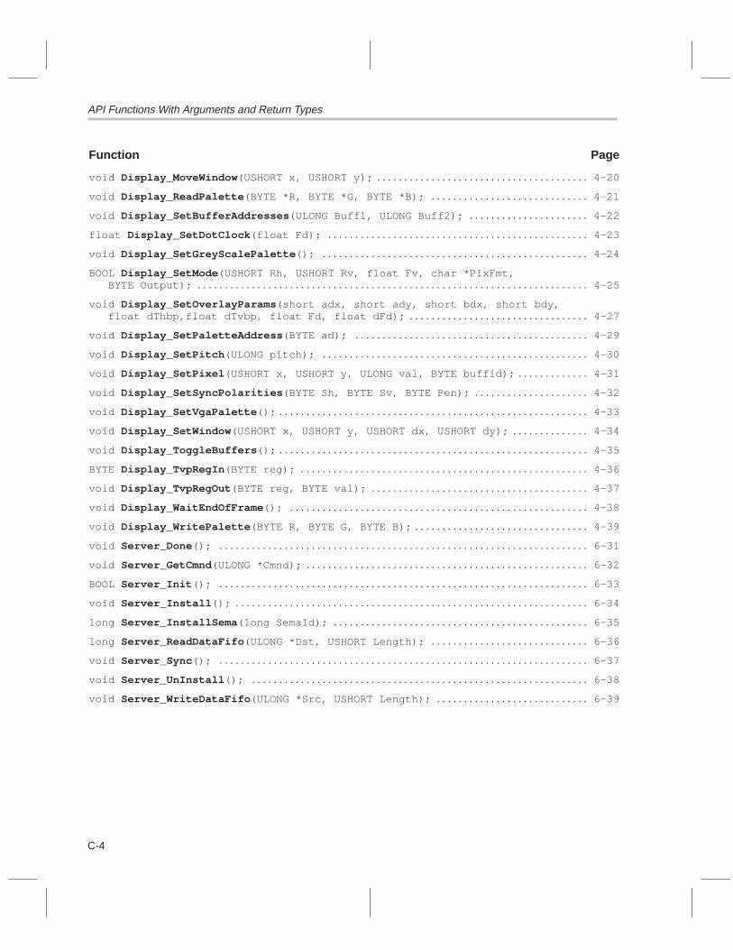
API Functions With Arguments and Return Types
C-4
Function Page
void Display_MoveWindow (USHORT x, USHORT y); 4-20. . . . . . . . . . . . . . . . . . . . . . . . . . . . . . . . . . . . . . .
void Display_ReadPalette (BYTE *R, BYTE *G, BYTE *B); 4-21. . . . . . . . . . . . . . . . . . . . . . . . . . . . .
void Display_SetBufferAddresses (ULONG Buff1, ULONG Buff2); 4-22. . . . . . . . . . . . . . . . . . . . . .
float Display_SetDotClock (float Fd); 4-23. . . . . . . . . . . . . . . . . . . . . . . . . . . . . . . . . . . . . . . . . . . . . . . .
void Display_SetGreyScalePalette (); 4-24. . . . . . . . . . . . . . . . . . . . . . . . . . . . . . . . . . . . . . . . . . . . . . . . .
BOOL Display_SetMode (USHORT Rh, USHORT Rv, float Fv, char *PixFmt, BYTE Output); 4-25. . . . . . . . . . . . . . . . . . . . . . . . . . . . . . . . . . . . . . . . . . . . . . . . . . . . . . . . . . . . . . . . . . . . . . . .
void Display_SetOverlayParams (short adx, short ady, short bdx, short bdy, float dThbp,float dTvbp, float Fd, float dFd); 4-27. . . . . . . . . . . . . . . . . . . . . . . . . . . . . . . . .
void Display_SetPaletteAddress (BYTE ad); 4-29. . . . . . . . . . . . . . . . . . . . . . . . . . . . . . . . . . . . . . . . . . .
void Display_SetPitch (ULONG pitch); 4-30. . . . . . . . . . . . . . . . . . . . . . . . . . . . . . . . . . . . . . . . . . . . . . . . .
void Display_SetPixel (USHORT x, USHORT y, ULONG val, BYTE buffid); 4-31. . . . . . . . . . . . .
void Display_SetSyncPolarities (BYTE Sh, BYTE Sv, BYTE Pen); 4-32. . . . . . . . . . . . . . . . . . . . .
void Display_SetVgaPalette (); 4-33. . . . . . . . . . . . . . . . . . . . . . . . . . . . . . . . . . . . . . . . . . . . . . . . . . . . . . . . .
void Display_SetWindow (USHORT x, USHORT y, USHORT dx, USHORT dy); 4-34. . . . . . . . . . . . . .
void Display_ToggleBuffers (); 4-35. . . . . . . . . . . . . . . . . . . . . . . . . . . . . . . . . . . . . . . . . . . . . . . . . . . . . . . . .
BYTE Display_TvpRegIn (BYTE reg); 4-36. . . . . . . . . . . . . . . . . . . . . . . . . . . . . . . . . . . . . . . . . . . . . . . . . . . . .
void Display_TvpRegOut (BYTE reg, BYTE val); 4-37. . . . . . . . . . . . . . . . . . . . . . . . . . . . . . . . . . . . . . . .
void Display_WaitEndOfFrame (); 4-38. . . . . . . . . . . . . . . . . . . . . . . . . . . . . . . . . . . . . . . . . . . . . . . . . . . . . . .
void Display_WritePalette (BYTE R, BYTE G, BYTE B); 4-39. . . . . . . . . . . . . . . . . . . . . . . . . . . . . . . .
void Server_Done (); 6-31. . . . . . . . . . . . . . . . . . . . . . . . . . . . . . . . . . . . . . . . . . . . . . . . . . . . . . . . . . . . . . . . . . . .
void Server_GetCmnd (ULONG *Cmnd); 6-32. . . . . . . . . . . . . . . . . . . . . . . . . . . . . . . . . . . . . . . . . . . . . . . . . . . .
BOOL Server_Init (); 6-33. . . . . . . . . . . . . . . . . . . . . . . . . . . . . . . . . . . . . . . . . . . . . . . . . . . . . . . . . . . . . . . . . . . .
void Server_Install (); 6-34. . . . . . . . . . . . . . . . . . . . . . . . . . . . . . . . . . . . . . . . . . . . . . . . . . . . . . . . . . . . . . . . .
long Server_InstallSema (long SemaId); 6-35. . . . . . . . . . . . . . . . . . . . . . . . . . . . . . . . . . . . . . . . . . . . . . .
long Server_ReadDataFifo (ULONG *Dst, USHORT Length); 6-36. . . . . . . . . . . . . . . . . . . . . . . . . . . . .
void Server_Sync (); 6-37. . . . . . . . . . . . . . . . . . . . . . . . . . . . . . . . . . . . . . . . . . . . . . . . . . . . . . . . . . . . . . . . . . . .
void Server_UnInstall (); 6-38. . . . . . . . . . . . . . . . . . . . . . . . . . . . . . . . . . . . . . . . . . . . . . . . . . . . . . . . . . . . . .
void Server_WriteDataFifo (ULONG *Src, USHORT Length); 6-39. . . . . . . . . . . . . . . . . . . . . . . . . . . .

D-1
Appendix A
Glossary
A
A-Law companding: See companded.
active time: (vs. blanking) The time intervals of a display frame that are notin blanking. The time intervals in which pixels are displayed.
ADC: Analog-to-digital converter. A device that converts a continuously va-rying signal (analog) to a signal represented by a series of numbers (digi-tal).
analog mixing: The mixing together of two analog signals. The multiplexingof two analog signals into one.
API: Application programming interface. Used for proprietary applicationprograms to interact with communications software or to conform to pro-tocols from another vendor’s product.
assert: To make a digital logic device pin active. If the pin is active low, thena low voltage on the pin asserts it. If the pin is active high, then a highvoltage asserts it.
autocalibration: Automatic adjustment of a device so that the output is with-in a specific range for particular values of the input.
B
back porch: The interval of the video waveform between the end of syn-chronization and the corresponding blanking pulse. The horizontal backporch is specified as an integral number of FCLK periods; the verticalback porch is specified as an integral number of lines (halflines for inter-laced mode). See also front porch.
bit plane: A bit storage array (plane) used to store a particular bit of eachpixel of an image. The 0th bit of each pixel is stored in bit plane 0, the firstbit of each pixel is stored in bit plane 1, and so on.
Appendix D
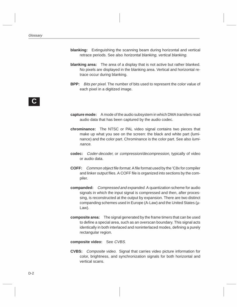
Glossary
D-2
blanking: Extinguishing the scanning beam during horizontal and verticalretrace periods. See also horizontal blanking, vertical blanking.
blanking area: The area of a display that is not active but rather blanked.No pixels are displayed in the blanking area. Vertical and horizontal re-trace occur during blanking.
BPP: Bits per pixel. The number of bits used to represent the color value ofeach pixel in a digitized image.
C
capture mode: A mode of the audio subsystem in which DMA transfers readaudio data that has been captured by the audio codec.
chrominance: The NTSC or PAL video signal contains two pieces thatmake up what you see on the screen: the black and white part (lumi-nance) and the color part. Chrominance is the color part. See also lumi-nance.
codec: Coder-decoder, or compression/decompression, typically of videoor audio data.
COFF: Common object file format. A file format used by the ’C8x for compilerand linker output files. A COFF file is organized into sections by the com-piler.
companded: Compressed and expanded. A quantization scheme for audiosignals in which the input signal is compressed and then, after proces-sing, is reconstructed at the output by expansion. There are two distinctcompanding schemes used in Europe (A-Law) and the United States (µ-Law).
composite area: The signal generated by the frame timers that can be usedto define a special area, such as an overscan boundary. This signal actsidentically in both interlaced and noninterlaced modes, defining a purelyrectangular region.
composite video: See CVBS.
CVBS: Composite video. Signal that carries video picture information forcolor, brightness, and synchronization signals for both horizontal andvertical scans.

Glossary
D-3Glossary
DDAC: Digital-to-analog converter. A device that converts a signal repre-
sented by a series of numbers (digital) to a continuously varying signal(analog).
deassert: To make a digital logic device pin inactive. If the pin is active low,then a high voltage on the pin deasserts it. If the pin is active high, thena low voltage deasserts it.
debugger: A window-oriented software interface that helps you to detectand fix errors in programs running on a ’C8x.
digital mixing: The mixing together of two digital signals into one. The alge-braic sum of two digital signals.
digital signal processor: See DSP.
digitizer: The part of the video capture front end that converts the analogvideo signal into a digital signal to be decoded.
display mode: The mode in which pixels are shown on a display device andalso the resolution of a display.
display window: Reducing the active area of a display creates a displaywindow.
DMA mode: Direct memory access mode. A mode of the audio subsystemin which DMA transfers read audio data that has been captured by theaudio codec or in which DMA transfers supply audio data for playback.DMA capture and playback are not possible simultaneously.
dot clock: The clock that cycles the rate at which video data is output to adisplay monitor.
DRAM: Dynamic random-access memory. Memory typically used for exter-nal memory. A special memory circuit that is dynamic in nature; it re-quires each bit of information to be refreshed, or restored to its pro-grammed state, on a periodic basis to maintain valid data.
DSP: Digital signal processor. A processor used for high speed data manip-ulations of audio, video, graphical, or image information.
Eevent pin: A pin on the SDB’s interrupt controller that triggers an event when
asserted.
externally initiated packet transfer: See XPT.

Glossary
D-4
F
FCLK: Frame clock. The clock that controls the internal video logic of the vid-eo controller’s frame timers.
FIFO: First in, first out. A queue; a data structure or hardware buffer fromwhich items are taken out in the same order they were put in. A FIFO isuseful for buffering a stream of data between a sender and receiverwhich are not synchronized; that is, are not sending and receiving at ex-actly the same rate. If the rates differ by too much in one direction for toolong, the FIFO will become either full (blocking the sender) or empty(blocking the receiver).
FIFO flag: Indicator that gets set or cleared depending on the state of theFIFO.
FIFO status register: A register located within a FIFO device used to storestatus information regarding the device.
flag: A variable or quantity that can take on one of two values. A bit, particu-larly one that is used to indicate one of two outcomes or is used to controlwhich of two things is to be done.
flag offsets: The offset into a FIFO memory device that determines whenFIFO flags get set or cleared.
frame: The screen image output during a single vertical sweep.
frame timer: In the video controller (VC), a timer that provides video timingcontrol and indicates to the serial register transfer (SRT) controller whenan SRT is necessary.
front porch: The interval of a video waveform between the start of blankingand the corresponding sync pulse. The horizontal front porch is specifiedas an integral number of FCLK periods; the vertical front porch is speci-fied as an integral number of lines (halflines for interlaced mode). Seealso back porch.

Glossary
D-5Glossary
Ggain stage: That portion of a circuit which imposes a gain onto a signal. Also
that portion of an algorithm that imposes a gain onto a digital signal.
grayscale: Or greyscale. A range of accurately known shades of grayprinted out for use in calibrating those shades on a display or printer. Ingraphics, composed of discrete shades of gray. For displays, a color for-mat in which each pixel is determined by an 8-bit value. This value mapsto RGB space with the red, green, and blue components all taking on the8-bit value. The result is pixels which can range from black, to gray, topure white.
Hhorizontal blanking: A bidirectional timing signal that enables or disables
pixel capture and display. Horizontal blanking occurs once per line andits pulse width is defined as an integral number of FCLK periods. Seealso blanking.
horizontal sync: The portion of the composite video signal that tells the re-ceiver where to place the image in the left-to-right dimension. The hori-zontal sync pulse tells the receiving system where the beginning of thenew scan line is. See also vertical sync.
IIEEE standard 1149.1-1990: See JTAG.
IEEE-754 floating point unit: The floating point math unit contained in thecore of the TMS320C8x’s master RISC processor.
interlaced mode: A video mode in which each frame consists of two verticalfields. One field displays odd horizontal lines, and the other field displayseven horizontal lines. In effect, the number of transmitted pictures isdoubled, thus reducing flicker.
interrupt: A signal sent by hardware or software to a processor requestingattention. An interrupt tells the processor to suspend its current opera-tion, save the current task status, and perform a particular set of instruc-tions. Interrupts communicate with the operating system and prioritizetasks to be performed.
interrupt service routine: See ISR.
ISR: Interrupt service routine. A module of code that is executed in responseto a hardware or software interrupt.

Glossary
D-6
JJPEG standard: Joint Photographic Experts Group standard. A standard
used for compressed still-picture data.
JTAG: Joint Test Action Group. The Joint Test Action Group was formed in1985 to develop economical test methodologies for systems designedaround complex integrated circuits and assembled with surface-mounttechnologies. The group drafted a standard that was subsequentlyadopted by IEEE as IEEE Standard 1149.1-1990, “IEEE Standard TestAccess Port and Boundary-Scan Architecture”.
KkHz: Kilohertz.
Lline dropping: The process of eliminating lines of video from an image to
downscale the image vertically.
look-up table: A table, used during scan conversions of a digital image, thatconverts color-map addresses into the actual color values displayed.
luminance: The NTSC or PAL video signal contains two pieces that makeup what you see on the screen: the black and white part and the color part(chrominance). The black and white part is called the luminance. Seealso chrominance.
Mµ-Law companding: See companded.
master processor: See MP.
member: An element or variable of a structure, union, or enumeration.
merge mode: A serial register transfer (SRT) mode for the video controller(VC) during which an image is capture and stored in memory. Memorylocations not corresponding to the captured image are preserved. Seealso capture mode, display mode.
metric parameters: A set of parameters that define state dimensions andattributes for the audio subsystem, display subsystem, or video capturesubsystem.

Glossary
D-7Glossary
MHz: Megahertz.
monitor timing (parameters): Parameters that the display API uses to de-termine what signal rates are needed to drive a monitor.
mono mode: A mode of the audio codec in which only one channel of audioexists.
MP: Master processor. A general-purpose RISC processor that coordinatesthe activity of the other processors on the ’C8x. The ’C8x includes anIEEE1-754 floating-point hardware unit.
MPEG standard: Moving Picture Experts Group standard. A proposed stan-dard for compressed video data.
multiplexing: A process of transmitting more than one set of signals at atime over a single wire or communications link.
multisync monitor: A monitor that adjusts itself to the horizontal and verti-cal synchronization rate of the video signal. A multisync monitor can beused with a variety of video adapters.
mutual exclusion: A collection of techniques for sharing resources so thatdifferent uses do not conflict and cause unwanted interactions. One ofthe most commonly used techniques for mutual exclusion is the sema-phore. See also semaphore.
N
noninterlaced graphics mode: A mode for the video controller (VC) inwhich each frame consists of a single vertical field. A method of scanningout a video display where all of the lines in the frame are scanned out se-quentially, one right after the other. Also called progressive scan.
NTSC: National Television Standards Committee. A color television broad-cast standard wherein the image consists of a format that has 525 scanlines; a field frequency of 60 Hz; a broadcast bandwidth of 4 MHz; a linefrequency of 15.75 kHz; a frame frequency of one–thirtieth of a second;and a color subcarrier frequency of 3.58 MHz. See also PAL.
O
overlay mode: Mixed video mode. The input from the VGA pass-throughcable is mixed with the RAMDAC output to form video overlaid onto VGA.

Glossary
D-8
P
PAL: Phase alternation line. A European deviation of the standard U.S. tele-vision NTSC signal; the format is 625 lines and a 50-Hz frequency. Seealso NTSC.
parallel processor: See PP.
PCA: Printed-circuit assembly. A printed-circuit board on which separatelymanufactured component parts have been installed in an electrical cir-cuit that performs a defined function.
PCI: Peripheral component interconnect. High-speed local bus that sup-ports data-transfer speeds of up to 132M bytes per second at 33 MHz.
PCM: Pulse code modulation.
PIO mode: Programmed input/output mode. A mode of the audio codec inwhich DMA is not use; rather, samples are directly read from or writtento the PIO port.
pitch: The number of bytes between the start of one line to the start of thenext line in a frame of video.
pixel: One picture element (pel).
pixel dropping: The process of removing pixels from a line of video to down-scale that line.
playback mode: A mode of the audio subsystem in which DMA transferssupply audio data for playback.
porch: The portion of a video display signal that corresponds to the blankinginterval on either side of a horizontal or vertical sync pulse. The termsfront porch and back porch refer to the blanking intervals that precedeand follow, respectively, the sync pulse. See also back porch, front porch.
PP: Parallel processor. The ’C8x’s advanced digital signal processor that isused for video compression/demcompression (P×64 or MPEG), still-image compression/decompression (JPEG), 2-D and 3-D graphic func-tions such as line draw, trapezoid fill, antialiasing, and a variety of high-speed integer operations on image data. A ’C8x single-chip multiproces-sor device may contain from one to eight PPs, depending on the deviceversion.
progressive scan: See noninterlaced graphics mode.

Glossary
D-9Glossary
Q
quantization error: The error resulting from converting an analog signalinto a digital signal due to the fact that a digital signal can only have dis-crete values whereas an analog signal may take on any value within dy-namic range of the signal.
quantum levels: When a signal can only take on certain discrete values,these values are referred to as quantum levels.
R
RAMDAC: Random-access memory digital-to-analog converter. Used toconvert digital RGB (red-green-blue) information to analog signals thatdrive a display.
raster: The series of scan lines that comprise a television picture or a com-puter’s display. A raster line is the same as a scan line, which is an indi-vidual sweep across the face of the display by the electron beam thatmakes the picture.
refresh rate: The speed with which a video source redisplays the screen.
RISC: Reduced instruction set computer. A computer whose instruction setand related decode mechanism are much simpler than those of micro-programmed complex instruction set computers. The result is a higherinstruction throughput and a faster real-time interrupt service responsefrom a smaller, cost-effective chip.
S
sample rate: The rate at which the audio codec samples audio data. Usuallyspecified in hertz (samples per second).
SDB: TMS320C8x software development board.
semaphore: A classic method for restricting access to shared resources (forexample, storage) in a multiprocessing environment. A semaphore is aprotected variable (or abstract data type) that can be accessed only bycertain operations for testing and incrementing the value of the variable.
semiomnipresent pixel: A pixel that appears to be at two locations on thescreen at once in a video display.

Glossary
D-10
serial register transfer: See SRT controller.
skew: Time differences in multiple clock signals based on physical dis-tances between the origin of the signals and their destinations. Switchingdelays caused by gates in the logic.
S-VHS: Super VHS (vertical helical scan). Similar to the VHS video record-ing standard, except that the chrominance and luminance data aretreated as components that provide higher quality video.
SRT controller: Serial register transfer controller. Hardware that schedulesrequests to the transfer controller to move data into and out of VRAMframe memories.
status bit: A bit in a status word or register that contains a single piece ofstatus information.
sync: A synchronization signal that tells the display where to put the picture.See also horizontal sync and vertical sync.
T
triple: A row in a table consisting of three columns. For example, an RGBtriple contains the red, green, and blue values which define a particularcolor.
V
VC: Video controller. The portion of the ’C8x responsible for the video inter-face.
vertical blanking: Bidirectional vertical timing signals that occur once perframe (once per field for interlaced systems) and have a pulse width de-fined as an integral number of lines (halflines for an interlaced system).Can be used to disable pixel capture and display during vertical retrace.See also blanking.
vertical sync: A bidirectional vertical timing signal occurring once per framewith a pulse width defined as an integral number of lines (halflines for in-terlaced mode). The portion of the composite video signal that tells thereceiver where the top of the picture is. See also horizontal sync.
video controller: See VC.
VIP: Video interface palette. See RAMDAC.

Glossary
D-11Glossary
VRAM: Video random access memory. A portion of the microprocessor’smemory address space reserved for the temporary storage of video databefore it is sent to the display monitor. A type of dynamic read accessmemory that lets the video circuitry serially access the memory bit by bit.VRAM has separate pins for the processor and video circuitry, is used inhigh-speed video applications, and is easily interfaced to a video display.
W
window: A defined rectangular area of virtual space on the display.
X
XPT: Externally initiated packet transfer. A packet transfer initiated by an ex-ternal device through the ’C8x’s XPT [2:0] inputs.
Y
YUV: A color space standard in which the luminance (Y) and chrominance(U and V) values are separate components.

D-12

Index
Index-1
Index
#define. See individual macro entry
Aaccessing internal configuration registers in
FIFO 2-16
active area 2-19, 2-31, 2-33
AD1848. See audio codec
AE1 bitsin CLFAG1/RDFLAG1 register 2-56in ENABLE2 register 2-53in STFLAG1/CNFLAG1 register 2-57
AE1 event 2-50
AE2 bitsin CLFLAG0/RDFLAG0 register 2-55in ENABLE1 register 2-52in STFLAG0/CNFLAG0 register 2-56
AE2 event 2-49
AF1 bitsin CLFLAG0/RDFLAG0 register 2-55in ENABLE1 register 2-52in PCISTAT register 2-59, 2-60in STFLAG0/CNFLAG0 register 2-56
AF1 event 2-49
AF2 bitsin CLFLAG1/RDFLAG1 register 2-56in ENABLE2 register 2-53in PCISTAT register 2-59, 2-60in STFLAG1/CNFLAG1 register 2-57
AF2 event 2-50, 2-53
AFIFOCFG register 2-8, 2-12, 2-14 to 2-18
AFIFOCMD register 2-8, 2-13, 2-14 to 2-18, 3-15
AFIFODAT register 2-8, 2-9
assistance from TI vii
audcapt.bat file A-11 to A-12
audcapt.c file A-8 to A-10
audcapt.lnk file A-10 to A-11audio block capture/playback exam-
ple A-17 to A-20audio buffering 3-5 to 3-8audio capture and playback API
data types 3-3functions, listing 3-9macros 3-2 to 3-3
audio codecdata formats 2-13example of PIO mode A-21in components diagram 1-3sample rates supported 2-13
audio codec error event 0 2-50audio codec error event 1 2-50audio codec event 0 2-49audio codec event 1 2-49audio codec registers
index address (CDCIDX) 2-8, 2-10index data (CDCDAT) 2-8, 2-10programmed input/output (CDCPIO) 2-8, 2-12status (CDCSTAT) 2-8, 2-11 to 2-12
audio DMA capture example A-8 to A-11audio DMA playback example A-12 to A-16audio FIFO
accessing internal configuration registers 2-16and the audio buffering structure 3-8block diagram 2-9commands supported 2-15description 2-14 to 2-18example of reset code 2-15flag pin configurations 2-17flag truth table 2-18in audio block diagram 2-7internal configuration registers 2-16
audio FIFO registerscommand/status (AFIFOCMD) 2-8, 2-13,
2-14 to 2-18

Index
Index-2
audio FIFO registers (continued)configuration (AFIFOCFG) 2-8, 2-12,
2-14 to 2-18data (AFIFODAT) 2-8, 2-9
audio FIFO registers, command/status (AFI-FOCMD) 3-15
audio hardwareblock diagram 2-7description 2-7features 2-2 to 2-4FIFO. See audio FIFOregisters summary 2-8
audio programmed I/O (PIO) exam-ple A-21 to A-23
audio.h file 3-2
AUDIO_ALAW8 macro 3-2AUDIO_AUX1 macro 3-2
AUDIO_CAPTURE macro 3-2Audio_CaptureToMemory function 3-10 to 3-11,
A-17Audio_CodecStat function 3-12
Audio_Disable function 3-13
Audio_Enable function 3-14Audio_FifoStat function 3-15
Audio_FillBuffs function 3-16Audio_GetCaptureBuffs function 3-7, 3-17
Audio_GetCodecRegs function 3-18
Audio_GetFifoRegs function 3-19Audio_GetMetrics function 3-4, 3-20
Audio_GetPlaybackBuffs function 3-7, 3-21Audio_Init function 3-22
Audio_Install functiondescription 3-23 to 3-24macros used by 3-2
Audio_InstallSema function 3-25
AUDIO_LINE macro 3-2
AUDIO_MET data type 3-3, 3-4, 3-10, 3-20, 3-29AUDIO_MIXED macro 3-2
AUDIO_MONO macro 3-2AUDIO_MUTE macro 3-3
AUDIO_PCM16 macro 3-2
AUDIO_PCM8 macro 3-2AUDIO_PIO macro 3-2
Audio_PioIn function 3-26Audio_PioOut function 3-27
Audio_PioTest function 3-28, A-21AUDIO_PLAYBACK macro 3-2Audio_PlaybackFromMemory func-
tion 3-29 to 3-30, A-17Audio_ProgramAux1 function
description 3-31macros used by 3-3
Audio_ProgramDacs functiondescription 3-32macros used by 3-3
Audio_ProgramDigitalMix function 3-33Audio_ProgramInputs function
description 3-34macros used by 3-2
AUDIO_PTR data type 3-3 to 3-4, 3-10, 3-17,3-21, 3-29
Audio_SetBufferIndexes function 3-35Audio_SetSampleRate function 3-36AUDIO_STEREO macro 3-2AUDIO_ULAW8 macro 3-2Audio_UnInstall function 3-5, 3-37AUDIO_UNMUTE macro 3-3audplay.bat file A-15 to A-17audplay.c file A-12audplay.lnk file A-15audtest.bat file A-20 to A-21audtest.c file A-17 to A-19audtest.lnk file A-19 to A-20autoconfiguration 2-64
Bb0 bit 2-70BDIS bit 2-59, 2-61big-endian mode 2-2, 2-4, 2-45bit notation ivblock diagram, system 2-3block transfer (blt)
read event 2-49read event trigger bit (BLR) 2-61write event 2-49write event trigger bit (BLW) 2-61
BLR bit 2-59, 2-61BLW bit 2-59, 2-61BMAH bits 2-68BMAH register 2-68, 2-69, 2-70

Index
Index-3
BMAL bits 2-68BMAL register 2-68, 2-69, 2-70BMCTRL register 2-68, 2-69, 2-70BMEN bit 2-68, 2-70BMI bits
in CLFLAG1/RDFLAG1 register 2-56in ENABLE2 register 2-53in STFLAG1/CNFLAG1 register 2-57
BMI event 2-50bootserv.bin file 6-10bootstrapping 2-70 to 2-71, 6-10BRD bits
in CLFLAG0/RDFLAG0 register 2-55in ENABLE1 register 2-52in STFLAG0/CNFLAG0 register 2-56
BRD event 2-49, 2-52, 2-61buffering
audio 3-5video capture 5-5 to 5-7
buffering queue structure 3-6BUFFS data type 3-5, 3-6, 3-7burst disable bit (BDIS) 2-61bus controller 2-44bus master address high register (BMAH) 2-69bus master address low register (BMAL) 2-69bus master control register (BMCTRL) 2-69, 2-70bus master event 2-50bus mastering 2-68 to 2-70bus mastering enable bit (BMEN) 2-70BWR bits
in CLFLAG0/RDFLAG0 register 2-55in ENABLE1 register 2-52in STFLAG0/CNFLAG0 register 2-56
BWR event 2-49, 2-52, 2-61
CC source debugger 1-2, 1-4, A-8, A-12, A-30’C80 bus
and the memory controller 2-45and video capture FIFO 2-35description 2-5in audio block diagram 2-7in PCI interface block diagram 2-58in video capture block diagram 2-36in video display block diagram 2-20
’C8x DSP device 1-2, 2-2, 2-6’C8x SDB components 1-2 to 1-3CAP bits
example of setting 2-52in CLFLAG0/RDFLAG0 register 2-55in ENABLE0 register 2-52in STFLAG0/CNFLAG0 register 2-56
CAP event 2-35, 2-41, 2-49CAPID register 2-37, 2-40, 5-9CAPRST register 2-37, 2-43capttest.bat file A-29 to A-30capttest.c file A-24 to A-28capttest.lnk file A-28 to A-29capture card ID register (CAPID) 2-37, 2-40, 5-9capture FIFO empty flag
enable flag bit 2-41interrupt flag bit 2-40interrupt source bit 2-41
capture FIFO full flagenable flag bit 2-41interrupt flag bit 2-40interrupt source bit 2-41
capture left/right sample bit (CL/R) 2-11capture ready bit (CRDY) 2-11capture upper/lower bit (CU/L) 2-11capture.h file 5-2CAPTURE_512x512 macro 5-2CAPTURE_640x480 macro 5-2Capture_CardPresent function 5-9CAPTURE_CIF macro 5-2CAPTURE_CIFK macro 5-2Capture_Disable function 5-10Capture_Enable function 5-11Capture_FillBuffs function 5-4, 5-12Capture_FreeBuffer function 5-5, 5-6, 5-7, 5-13Capture_GetBuffer function 5-5, 5-6, 5-7, 5-14Capture_GetDecoderRegs function 5-15Capture_GetMetrics function 5-4, 5-16Capture_GetScalerRegs function 5-17Capture_Init function 5-18Capture_Install function
description 5-19 to 5-20macros used by 5-2, 5-3
Capture_InstallSema function 5-21CAPTURE_MET data type 5-3, 5-4, 5-16

Index
Index-4
CAPTURE_MONO8 macro 5-3
CAPTURE_NTSC macro 5-2CAPTURE_PAL macro 5-2CAPTURE_QCIF macro 5-2CAPTURE_RGB555 macro 5-3CAPTURE_RGB888 macro 5-3Capture_SetInputSource function
description 5-22macros used by 5-2
Capture_SetScaling function 5-23CAPTURE_SQCIF macro 5-2CAPTURE_SVHS macro 5-2Capture_UnInstall function 5-24
CAPTURE_VID1 macro 5-2CAPTURE_VID2 macro 5-2CAPTURE_YUV422 macro 5-3category-1 events
definition 2-49enable bits 2-52listing 2-49
category-2 eventsdefinition 2-49enable bits 2-53setting/clearing example 2-53listing 2-50
caution, damage to monitor from unsupported reso-lutions 4-9, 4-26
CD0 bitsin CLFLAG0/RDFLAG0 register 2-55in ENABLE0 register 2-52in STFLAG0/CNFLAG0 register 2-56
CD0 event 2-14, 2-49, 2-55CD1 bits
in CLFLAG0/RDFLAG0 register 2-55in ENABLE0 register 2-52in STFLAG0/CNFLAG0 register 2-56
CD1 event 2-14, 2-49CDCDAT register 2-8, 2-10CDCIDX register 2-8, 2-10CDCPIO register 2-12CDCPIO register 2-8CDCSTAT register 2-8, 2-11 to 2-12, 3-12CE0 bits
in CLFLAG1/RDFLAG1 register 2-56in ENABLE2 register 2-53in STFLAG1/CNFLAG1 register 2-57
CE0 event 2-14, 2-48, 2-49, 2-50CE1 bits
in CLFLAG1/RDFLAG1 register 2-56in ENABLE2 register 2-53in STFLAG1/CNFLAG1 register 2-57
CE1 event 2-14, 2-50, 2-53CFIFORST register 2-37CL/R bit 2-11clear flag register 0 (CLFLAG0) 2-51, 2-55 to 2-56clear flag register 1 (CLFLAG1) 2-51, 2-56client library (host library) 6-1client to server protocol 6-8client/server command flow diagram 6-9CLIENT_AF1 macro 6-3CLIENT_AF2 macro 6-3CLIENT_BDIS macro 6-3CLIENT_BINFILE macro 6-2CLIENT_BITSET macro 6-2CLIENT_BLR macro 6-3CLIENT_BLW macro 6-3Client_Boot function
and bootstrapping 6-10description 6-12macros used by 6-4
CLIENT_BOOTFILE macro 6-2CLIENT_BYTESWAP macro 6-4CLIENT_BYTEWORDSWAP macro 6-4Client_ClearConfigBit function
description 6-13macros used by 6-2, 6-3
Client_Close functiondescription 6-14macros used by 6-2
CLIENT_CLOSED macro 6-2CLIENT_CMNDSIZE macro 6-4CLIENT_COFFFILE macro 6-2CLIENT_DEAD macro 6-2CLIENT_EF1 macro 6-3CLIENT_EF2 macro 6-3CLIENT_EMURST macro 6-4CLIENT_EPOINT macro 6-4CLIENT_FIFOALMOSTFULL macro 6-2CLIENT_FIFOEMPTY macro 6-2CLIENT_FOFF0 macro 6-2CLIENT_FOFF1 macro 6-2CLIENT_FRST macro 6-2

Index
Index-5
CLIENT_FSW0 macro 6-2CLIENT_FSW1 macro 6-2CLIENT_GPI0 macro 6-3CLIENT_GPI1 macro 6-3CLIENT_GPO0 macro 6-3CLIENT_GPO1 macro 6-3CLIENT_IAEN macro 6-2Client_Init function 6-15Client_IssueCmnd function
description 6-16macros used by 6-2
CLIENT_LOAD macro 6-4CLIENT_MAILBOXEMPTY macro 6-2CLIENT_MAILBOXFULL macro 6-2CLIENT_MB1 macro 6-3CLIENT_MB2 macro 6-3CLIENT_MRST macro 6-2CLIENT_NOSWAP macro 6-4Client_Open function
description 6-17macros used by 6-2
CLIENT_PRGD macro 6-3CLIENT_R0 macro 6-3CLIENT_R1 macro 6-3CLIENT_R10 macro 6-3CLIENT_R2 macro 6-3CLIENT_R3 macro 6-3CLIENT_R4 macro 6-3CLIENT_R5 macro 6-3CLIENT_R6 macro 6-3CLIENT_R7 macro 6-3CLIENT_R8 macro 6-3CLIENT_R9 macro 6-3Client_ReadConfig function
description 6-18macros used by 6-2
Client_ReadConfigBit functiondescription 6-19macros used by 6-2, 6-3
Client_ReadDataFifo functiondescription 6-20macros used by 6-2
Client_ReadIo functiondescription 6-21macros used by 6-2
Client_ReadMailbox functiondescription 6-22macros used by 6-2
Client_Reset functionand bootstrapping 6-10description 6-23macros used by 6-2, 6-4
CLIENT_RUN macro 6-4Client_SetConfigBit function
description 6-24macros used by 6-2, 6-3
Client_SetSwapping functiondescription 6-25macros used by 6-2, 6-4
CLIENT_STATOK macro 6-2Client_Sync function
description 6-26macros used by 6-2
CLIENT_TBCOFF macro 6-4CLIENT_TIMEOUT macro 6-2CLIENT_VERBOSE macro 6-4CLIENT_WORDSWAP macro 6-4Client_WriteConfig function
description 6-27macros used by 6-2
Client_WriteDataFifo functiondescription 6-28macros used by 6-2
Client_WriteIo functiondescription 6-29macros used by 6-2
Client_WriteMailbox functiondescription 6-30macros used by 6-2
CNFLAG0 register 2-51, 2-56CNFLAG1 register 2-51, 2-57codec index address register (CDCIDX) 2-8, 2-10codec index data register (CDCDAT) 2-8, 2-10codec PIO data register (CDCPIO) 2-8, 2-12codec status register (CDCSTAT) 2-8,
2-11 to 2-12, 3-12color modes
defined 4-5direct 4-2, 4-5pseudocolor 4-2, 4-5true 4-2, 4-5
color palette RAM 2-22, 2-23

Index
Index-6
composite video 1-2, 2-38, 2-39See also CVBS video
condition flag register 0 (CNFLAG0) 2-51, 2-56condition flag register 1 (CNFLAG1) 2-51, 2-57CRDY bit 2-11CU/L bit 2-11CVBS video 1-2, 1-4, 2-4, 2-35CVBS1 mode 2-38, 2-39CVBS1 register 2-37, 2-38CVBS2 mode 2-39CVBS2 register 2-37, 2-38, 2-39
Ddamage to monitor from unsupported resolu-
tions 4-9, 4-26data buses 2-5data types
audio capture and playback API 3-3host communications API 6-5video capture API 5-3video display API 4-4
DATCLK bit 2-30DESC. See SAA7196 video decoder/scalerdevice pin notation ivdirect color mode 4-2, 4-5direct memory access (DMA) mode 2-7display control registers
DIS0CON register 2-21, 2-25DIS1CON register 2-21, 2-28, 2-30DIS2CON register 2-21, 2-29
display EPLD block diagram 2-27display I/O 2-20, 2-34display timing parameters 2-33, 4-5display window 2-33display.h file 4-2DISPLAY_ACTIVE macro 4-3DISPLAY_BUFF1 macro 4-3DISPLAY_BUFF2 macro 4-3DISPLAY_D444 macro 4-2DISPLAY_D555 macro 4-2DISPLAY_D565 macro 4-2DISPLAY_D664 macro 4-2DISPLAY_DBGRX macro 4-2Display_Disable function 4-11
DISPLAY_DXRGB macro 4-2Display_Enable function 4-12Display_FillBuffs function 4-13Display_GetBuffer function
description 4-14macros used by 4-3
Display_GetMetrics function 4-8, 4-15Display_GetTvpRegs function 4-16DISPLAY_INACTIVE macro 4-3Display_Init function 4-17Display_InstallSema function 4-18Display_InstallTimingTable function 4-7, 4-8, 4-19DISPLAY_MET data type 4-4, 4-8, 4-15Display_MoveWindow function 4-20DISPLAY_MT data type 4-4, 4-5 to 4-8, 4-19DISPLAY_OVERLAY macro 4-3DISPLAY_P8 macro 4-2DISPLAY_PASSTHROUGH macro 4-3Display_ReadPalette register 4-21Display_SetBufferAddresses function 4-22Display_SetDotClock function 4-23Display_SetMode function
description 4-25 to 4-26macros used by 4-2, 4-3
Display_SetOverlayParams function 4-8,4-27 to 4-28
Display_SetPaletteAddress function, 4-29Display_SetPitch function 4-30Display_SetPixel function
description 4-31macros used by 4-3
Display_SetSyncPolarities function 4-32Display_SetVgaPalette function 4-33Display_SetWindow function 4-34DISPLAY_T444 macro 4-2DISPLAY_T555 macro 4-2DISPLAY_T565 macro 4-2DISPLAY_T664 macro 4-2DISPLAY_TBGRX macro 4-2Display_ToggleBuffers function 4-35Display_TvpRegOut function 4-37DISPLAY_TXRGB macro 4-2DISPLAY_VIDEO macro 4-3Display_WaitEndOfFrame function 4-38Display_WritePalette function 4-39
Index
Index-7
DisplaySetGreyScalePalette function 4-24disptest.bat file A-39 to A-40disptest.c file A-30 to A-38disptest.lnk file A-38 to A-39DMA (direct memory access) mode 2-7dot 2-19, 2-31dot clock 2-32, 2-33dot clock frequency (Fd). See dot ratedot rate 2-19, 2-31, 2-32DRAM
and memory controller 2-45features 2-4in components diagram 1-3
dynamic random-access memory. See DRAM
Ee0–e7 bits 2-41EF1 bits
in CLFLAG1/RDFLAG1 register 2-56in ENABLE2 register 2-53in PCISTAT register 2-59, 2-60in STFLAG1/CNFLAG1 register 2-57
EF1 event 2-50EF2 bits
in CLFLAG0/RDFLAG0 register 2-55in ENABLE1 register 2-52in PCISTAT register 2-59, 2-60in STFLAG0/CNFLAG0 register 2-56
EF2 event 2-49EINT bits 2-54emurst.exe file 6-4, 6-23ENABLE0 register 2-51, 2-52ENABLE1 register 2-51, 2-52ENABLE2 register 2-51, 2-53event
category-1 table 2-49category-2 table 2-50clearing, example 2-56definition 2-48setting/clearing category-2, example 2-53triggering 2-48
event destination 2-48event enable register 0 (ENABLE0) 2-51, 2-52event enable register 1 (ENABLE1) 2-51, 2-52event enable register 2 (ENABLE2) 2-51, 2-53
event signal 2-48event source 2-48event state register (EVSTATE) 2-51, 2-54event trigger 2-61
definition 2-48example 2-42
even-to-odd field transition enable flag bit 2-41even-to-odd field transition interrupt flag bit 2-40even-to-odd field transition interrupt source
bit 2-41EVSTATE register 2-51, 2-54
FFd (dot clock frequency). See dot rateFF1 bits
in CLFLAG1/RDFLAG1 register 2-56in ENABLE2 register 2-53in STFLAG1/CNFLAG1 register 2-57
FF1 event 2-50FF2 bits
in CLFLAG1/RDFLAG1 register 2-56in ENABLE2 register 2-53in STFLAG1/CNFLAG1 register 2-57
FF2 event 2-50FIFO boot location 2-68FIFO data location 2-68FIFO flag pin configurations 2-17FIFO flag truth table 2-18FIFO header location 2-67FIFO mailbox1 full flag bit (MB1) 2-60FIFO mailbox2 full flag bit (MB2) 2-59FIFO swap setting bits (FSW) 2-62FIFO1 almost empty flag event 2-50FIFO1 almost full flag bit (AF1) 2-60FIFO1 almost full flag event 2-49FIFO1 empty flag bit (EF1) 2-60FIFO1 empty flag event 2-50FIFO1 full flag event 2-50FIFO2 almost empty flag event 2-49FIFO2 almost full event 2-50FIFO2 almost full flag bit (AF2) 2-60FIFO2 empty flag bit (EF2) 2-60FIFO2 empty flag event 2-49FIFO2 full flag event 2-50FOFF bits 2-59, 2-62

Index
Index-8
frame timer registers 4-7
FRM bitsin CLFLAG0/RDFLAG0 register 2-55in ENABLE0 register 2-52in STFLAG0/CNFLAG0 register 2-56
FRM event 2-35, 2-49
FRST bit 2-59, 2-62
FSW bits 2-59, 2-62
functions, listingaudio capture and playback API 3-9host communications API 6-11video capture API 5-8video display API 4-10
Fv (vertical frequency). See refresh rate
Ggeneral-purpose input bits (GPI) 2-59
general-purpose output bits (GPO) 2-61
general-purpose video capture event 2-49
GPI bits 2-59
GPO bits 2-59, 2-61
Hhardware functions list 1-4
hardware modules 2-2
hclient.h file 6-2
horizontal sync times 4-6
host communications APIdata type 6-5functions, listing 6-11macros 6-2 to 6-4
host library (client library) 6-1
hsdbdrvs.h file B-1, B-4
hsdbdrvs.lib file 6-2
HSYNC0 falling edge enable flag bit 2-41
HSYNC0 falling edge interrupt flag bit 2-40
HSYNC0 falling edge interrupt source bit 2-41
HSYNC1 invert bit (IHS1) 2-29
II/O bus
and IDT72520 FIFO 2-14and the memory controller 2-46audio registers accessible by 2-8bus mastering registers accessible by 2-69description 2-5in audio block diagram 2-7in host address space 2-67in PCI interface block diagram 2-58in video capture block diagram 2-36in video display block diagram 2-20interrupt controller registers accessible by 2-51video capture registers accessible by 2-37video display registers accessible by 2-21
I/O space, host 2-67i0–i7 bits 2-40I2CCTRL bits 2-42I2CCTRL register 2-37, 2-42, 2-44I2CDAT bits 2-42I2CDAT register 2-37, 2-42, 2-44I2CRST register 2-37, 2-43I2CSTAT bits 2-43I2CSTAT register 2-37, 2-43, 2-44IAEN bit 2-59, 2-61ICE bit 2-25, 2-26ICS1574. See pixel clock generatorICS1574 clock bit (ICSC) 2-28ICS1574 data bit (ICSD) 2-28, 2-30ICS1574 hold bit (ICSH) 2-28ICSC bit 2-28, 2-30ICSD bit 2-28, 2-30ICSH bit 2-28, 2-30IDIS bit 2-68, 2-70IDT72520. See audio FIFOIEEE 1149.1 emulation support 1-3IEEE 1149.1 standard 1-3IHS bit 2-25IHS1 bit 2-29increment disable bit (IDIS) 2-70index address bits (IXA) 2-10individual buffer structure 3-8individual queue buffer structure 3-7initialization bit (INIT) 2-10INT bit 2-10, 2-11, 2-12

Index
Index-9
INTEN register 2-37, 2-41, 2-42
interaction between client and server APIs 6-6
interrupt controller (memory/interrupt controller)See also memory controllerand bootstrapping 2-70and bus-matching FIFO 2-14, 2-17description 2-48 to 2-57events from video capture 2-35features 2-4in audio block diagram 2-7in PCI interface block diagram 2-58in video capture block diagram 2-36registers summary 2-51
interrupt enable register (INTEN) 2-37, 2-41
interrupt flag register (INTREG) 2-37, 2-40
interrupt source register (INTSRC) 2-37,2-41 to 2-42
interrupt status sticky bit (INT) 2-10, 2-12
INTREG register 2-37, 2-40, 2-42
INTSRC bits 2-41
INTSRC register 2-37, 2-41 to 2-42
invert horizontal sync bit (IHS) 2-25
invert pixel clock enable bit (ICE) 2-26
invert vertical sync bit (IVS) 2-25
ISRC bits 2-38
ISRC register 2-37, 2-38
IVS bit 2-25
IVS1 bit 2-29
IXA bits 2-10
Kkit contents 1-2
LLINT bit 2-54
Mmacros
audio capture and playback API 3-2 to 3-3host communications API 6-2 to 6-4video capture API 5-2 to 5-3video display API 4-2 to 4-3
MAIL location 2-67
MASKEN0 register 6-29
master processor (MP) 1-2
master reset bit (MRST) 2-62, 2-70
MB1 bit 2-59, 2-60, 2-67
MB2 bit 2-59, 2-67
MCE bit 2-10
MCI bitsin CLFLAG1/RDFLAG1 register 2-56in ENABLE2 register 2-53in STFLAG1/CNFLAG1 register 2-57
MCI event 2-50
memoryDRAM 2-4, 2-45RAM 2-6, 2-22, 2-23SAM 2-46SRAM 2-6VRAM
and memory controller 2-46and pixel resolution 2-31 to 2-33features 2-4in video display hardware 2-19 to 2-20
memory controller (memory/interrupt controller)See also interrupt controllerdescription 2-45 to 2-47features 2-4in audio block diagram 2-7in components diagram 1-3in PCI interface block diagram 2-58
memory controller event 2-50
MEN bit 2-25
metric parametersdisplay 4-8video capture 5-4
miniboot.bin file 6-10
mix enable bit (MEN) 2-25, 2-26
mixed mode 2-25, 2-29, 2-33, 4-3
mode change enable bit (MCE) 2-10
monitor timing parameters 4-4, 4-5
mono mode 2-13
MRST bit 2-59, 2-62, 2-70
Nnoninterlaced video 4-5
notational conventions iv

Index
Index-10
NTSCdefinition D-7video 1-2, 2-4, 2-35
Oodd-to-even field transition enable flag bit 2-41
odd-to-even field transition interrupt flag bit 2-40
odd-to-even field transition interrupt sourcebit 2-41
opcode bits 2-13, 2-14, 2-15, 2-16
operand bits 2-13, 2-14, 2-15, 2-16
overlay mode 4-3, 4-25, 4-27See also mixed mode
overlay, video 2-25, 2-33 to 2-34, 4-3, 4-8, 4-25,4-27
Ppacket transfer 2-7, 2-9, 2-35, 2-46, 2-54, A-8
See also PDPT (peripheral data packet transfer)
page mode 2-45, 2-46
PALdefinition D-8video 1-2, 2-4, 2-35
PAL86 bit 2-28, 2-30
PALADRD register 2-21, 2-22, 2-24
PALADWR register 2-21, 2-22
palette graphics output 2-25, 2-26, 2-33
palette holding register (PALHOLD) 2-21, 2-22,2-24
palette read address register (PALADRD) 2-21,2-22, 2-24
palette write address register (PALADWR) 2-21,2-22
PALHOLD register 2-21, 2-22, 2-24
parallel processor (PP) 1-2
PCF8584 I2C control register (I2CCTRL) 2-37,2-42
PCF8584 I2C controller chip 2-36, 2-42, 2-43, 2-44
PCF8584 I2C data register (I2CDAT) 2-37, 2-42
PCF8584 I2C status register (I2CSTAT) 2-37, 2-43
PCI bitsin CLFLAG0/RDFLAG0 register 2-55in ENABLE0 register 2-52in STFLAG0/CNFLAG0 register 2-56
PCI busand bus master writes 2-68and the memory controller 2-47description 2-5in PCI interface block diagram 2-58
PCI bus mastering, registers summary 2-69
PCI event 2-49, 2-61
PCI FIFOaccess by ’C80 2-63 to 2-64block diagram 2-63description 2-58, 2-62 to 2-63host-to-SDB (FIFO1) 2-49, 2-50, 2-60, 2-63,
2-64, 2-67, 2-68in host address space 2-66 to 2-68mailbox
host-to-SDB (mailbox1) 2-60, 2-63, 2-64,2-67
SDB-to-host (mailbox2) 2-59, 2-63, 2-64,2-67
mailboxes 2-62, 2-64, 2-67resetting 2-62SDB-to-host (FIFO2) 2-49, 2-50, 2-60, 2-63,
2-64, 2-68, 2-70
PCI FIFO offset bit (FOFF) 2-62
PCI FIFO reset bit (FRST) 2-62
PCI interfaceSee also PCI FIFOblock diagram 2-58description 2-58 to 2-71in components diagram 1-3registers
bus mastering, listing 2-69PCI status register (PCISTAT) 2-59
PCI interrupt A enable bit (IAEN) 2-61
PCI status register (PCISTAT)and bootstrapping 2-70 to 2-71, 6-10and Client_ClearConfigBit function 6-13and Client_ReadConfig function 6-18and Client_ReadConfigBit function 6-19and Client_ReadIo function 6-21and Client_ReadMailbox function 6-22and Client_SetConfigBit function 6-24and Client_WriteConfig function 6-27and host reads 2-67, 2-68bits and fields 2-59 to 2-62

Index
Index-11
PCI status register (PCISTAT) (continued)description 2-59 to 2-62location in host address space 2-67
PDPT (peripheral data packet transfer) 2-35, 2-45,2-46See also package transfer
PELMASK register 2-21, 2-23peripheral data packet transfer (PDPT) 2-35, 2-45,
2-46See also packet transfer
peripheral driver libraries 1-4PGD bits
in CLFLAG1/RDFLAG1 register 2-56in ENABLE2 register 2-53in STFLAG1/CNFLAG1 register 2-57
PGD event 2-50pin notation ivPIO (programmed input/output) mode 2-7, 2-12,
A-21piotest.bat file A-23 to A-24piotest.c file A-21 to A-22piotest.lnk file A-22 to A-23pixel
defined 2-19resolution 2-19, 2-31 to 2-33
pixel clock frequency 2-19, 2-33See also dot rate
pixel clock generatorand DIS1CON register 2-28description 2-30 to 2-31in video display block diagram 2-20sample program 2-30
pixel depth 2-19, 2-31, 2-32pixel read-mask register (PELMASK) 2-21, 2-23pixel resolution 1-3, 1-4playback left/right sample bit (PL/R) 2-11playback ready bit (PRDY) 2-12playback upper/lower bit (PU/L) 2-11plug and play 2-64 to 2-65plug-in card 1-2porch times 4-6PRDY bit 2-11, 2-12PRGD bit 2-59programmed input/output (PIO) mode 2-7, 2-12,
A-21programming done bit (PRGD) 2-59
programming done event 2-50progressive scan (noninterlaced video) 4-5protocol, client to server 6-8pseudocolor mode 2-23, 4-2, 4-5PU/L bit 2-11
Rr1 bit 2-70RAM 2-6, 2-22, 2-23read flag register 0 (RDFLAG0) 2-51, 2-55 to 2-56read flag register 1 (RDFLAG1) 2-51, 2-56read input source setting register (ISRC) 2-37,
2-38reduced instruction set computer (RISC) 1-2refresh rate 1-3, 2-19, 2-31, 2-32register bit notation ivregisters
audio hardware, listing 2-8interrupt controller, listing 2-51PCI bus mastering, listing 2-69PCI interface 2-59video capture hardware, listing 2-37video display hardware, listing 2-21
related documentation v to vireset PCF8584 I2C controller register
(I2CRST) 2-37, 2-43reset video capture EPLD register
(CAPRST) 2-37, 2-43reset video capture FIFO register (CFI-
FORST) 2-37ROW bits
in CLFLAG0/RDFLAG0 register 2-55in ENABLE0 register 2-52in STFLAG0/CNFLAG0 register 2-56
ROW event 2-35, 2-48, 2-49
SSAA7196 video decoder/scaler (DESC) 2-36, 2-44sample overrun/underrun bit (SOUR) 2-11samples directory A-1scaling resolutions supported, video capture 5-4scaling example, video capture A-24 to A-29sdbboot.out file 6-10sdbdrvs.h file B-1, B-2

Index
Index-12
sdbdrvs.lib 3-2
sdbdrvs.lib file 4-2, 5-2, 6-2
sdbrst.exe file 6-10
SEN bit 2-28
SENSE from TVP3020 bit (SEN) 2-28
serial access memory. See SAM
serial access memory (SAM) 2-46
server library (SDB library) 6-1
SERVER_CMNDSIZE macro 6-4
Server_Done function 6-31
Server_GetCmnd function 6-32
Server_Init function 6-33
Server_Install function 6-34
Server_InstallSema function 6-35
Server_ReadDataFifo function 6-36
Server_Sync function 6-37
Server_UnInstall function 6-38
Server_WriteDataFifo function 6-39
set flag register 0 (STFLAG0) 2-51, 2-56
set flag register 1 (STFLAG1) 2-51, 2-57
set input to CVBS1 register (CVBS1) 2-37, 2-38
set input to CVBS2 register (CVBS2) 2-37, 2-39
set input to S-VHS register (SVHS) 2-37, 2-38
software development board (SDB)description 1-1hardware
audio 2-2, 2-7 to 2-18block diagram 2-3data buses 2-5DRAM 2-4, 2-45functions 1-4interrupt controller 2-4, 2-48 to 2-57memory controller 2-4, 2-45 to 2-47overview 2-2 to 2-5PCI interface 2-4, 2-58 to 2-71TMS320C80 2-2, 2-6, 2-45, 2-46video capture 2-4, 2-35 to 2-44video display 2-2, 2-19 to 2-34VRAM 2-4, 2-31 to 2-33, 2-46
illustration 1-3kit, contents 1-2memory address assigned 2-64PCI plug-in card, components 1-2peripheral driver libraries 1-4plug and play 2-64
SOUR bit 2-11
SRAM 2-6sserver.h file 6-2state of the ’C80 EINT[3:1] pins bits (EINT) 2-54state of the ’C80 LINT4 pin bit (LINT) 2-54state of the ’C80 XPT[2:0] pins bits (XPT) 2-54static random-access memory. See SRAMstereo mode 2-13STFLAG0 register 2-51, 2-56STFLAG1 register 2-51, 2-57S-VHS mode 2-38, 2-39S-VHS video 1-2, 1-4, 2-4, 2-35, 2-36, 2-38SVHS register 2-37, 2-38synchronization of client and server
APIs 6-6 to 6-7system block diagram 2-3system-level overview 2-2 to 2-5
TTC (transfer controller) 2-6technical support viitest bus controller event 2-50TFRAME enable flag bit 2-41TFRAME interrupt flag bit 2-40TFRAME interrupt source bit 2-41TMS320C8x digital signal processor (DSP). See
’C8x DSP devicetransfer controller (TC) 2-6, 2-35, 2-46transfer request disable bit (TRD) 2-10trigger an event 2-61triggering an event
definition 2-48example 2-42
TROW enable flag bit 2-41TROW interrupt flag bit 2-40TROW interrupt source bit 2-41true color mode 4-2, 4-5TVP3020 data register (TVPDAT) 2-21, 2-24TVP3020 index register (TVPIDX) 2-21, 2-24TVP3020 palette 8/6 mode bit (PAL86) 2-28TVP3020 RAMDAC
and the DIS0CON register 2-25, 2-26and the PALADRD register 2-24and the PALADWR register 2-21and the PALHOLD register 2-22

Index
Index-13
TVP3020 RAMDAC (continued)and the TVPDAT register 2-24and the TVPIDX register 2-24and video overlay (mixed mode) 2-33in display I/O block diagram 2-34in video display block diagram 2-20
TVPDAT register 2-21, 2-24TVPIDX register 2-21, 2-24
VVC (video controller) 2-6
vertical frequency (Fv) 2-19See also refresh rate
VGA bit 2-25, 2-26
VGA pass-through mode 2-26, 2-33, 4-3, 4-25VGA/mix enable bit (VGA) 2-26
video capture APIbuffering 5-5 to 5-7data type 5-3functions, listing 5-8macros 5-2 to 5-3metric parameters 5-4scaling resolutions supported 5-4
video capture condition 2-35, 2-40
video capture FIFOdescription 2-35, 2-46in video capture block diagram 2-36resetting 2-37
video capture frame event 2-49
video capture hardwareblock diagram 2-36description 2-35features 2-4FIFO 2-35registers, listing 2-37
video capture row event 2-49
video capture scaling example A-24 to A-29video capture-process-display example A-2 to A-7video controller (VC) 2-6
video digitizer 1-2, 2-39
video display APIdata types 4-4functions, listing 4-10macros 4-2 to 4-3
video display hardwareblock diagram 2-20description 2-19features 2-2registers summary 2-21
video display modes, overlay (mixed) 2-29video display test example A-30 to A-40video interface palette (VIP) 1-3video mode 4-3, 4-17, 4-25video overlay 2-33 to 2-34, 4-3, 4-8, 4-25, 4-27video random-access memory. See VRAMvideo.bat file A-7 to A-8video.c file A-2 to A-6video.lnk file A-6VRAM
and memory controller 2-46and pixel resolution 2-31 to 2-33features 2-4in components diagram 1-3in video display hardware 2-19 to 2-20
VSYNC0 falling edge enable flag bit 2-41VSYNC0 falling edge interrupt flag bit 2-40VSYNC0 falling edge interrupt source bit 2-41VSYNC1 invert bit (IVS1) 2-29
Wwindow mode bit (WIN) 2-25
XXLI bits
in CLFLAG1/RDFLAG1 register 2-56in ENABLE2 register 2-53in STFLAG1/CNFLAG1 register 2-57
XLI event 2-50XPT bits 2-54

Index-14


![[3769]-101 - unipune.ac.in](https://static.fdocuments.net/doc/165x107/61bd1d7761276e740b0f81a7/3769-101-.jpg)