TMO 18553 WCDMA d2U d4U Distributed NodeB Integration in an Existing UTRAN _ 14w29.pdf
84
All Rights Reserved © Alcatel-Lucent 2006 9326 d2U /9926 BBU 2U/4U Distributed Node B Integration Course Reference: TMO 18553 GPEC July 2014
-
Upload
wilfried-yao-yao -
Category
Documents
-
view
229 -
download
0
Transcript of TMO 18553 WCDMA d2U d4U Distributed NodeB Integration in an Existing UTRAN _ 14w29.pdf
8/17/2019 TMO 18553 WCDMA d2U d4U Distributed NodeB Integration in an Existing UTRAN _ 14w29.pdf
http://slidepdf.com/reader/full/tmo-18553-wcdma-d2u-d4u-distributed-nodeb-integration-in-an-existing-utran 1/84
All Rights Reserved © Alcatel-Lucent 2006
9326 d2U /9926 BBU 2U/4U
Distributed Node B
Integration
Course Reference: TMO 18553
GPEC
July 2014
8/17/2019 TMO 18553 WCDMA d2U d4U Distributed NodeB Integration in an Existing UTRAN _ 14w29.pdf
http://slidepdf.com/reader/full/tmo-18553-wcdma-d2u-d4u-distributed-nodeb-integration-in-an-existing-utran 2/84
All Rights Reserved © Alcatel-Lucent 2006
Agenda
Distributed NodeB Integration in an Existing UTRAN
Distributed NodeB Integration Testing
Distributed NodeB Integration Additional NSP GUI
Work order creation
NodeB integration to WMS / NSP GUI
Basics Tests
2 | Distributed Node B Integration | July 2014

8/17/2019 TMO 18553 WCDMA d2U d4U Distributed NodeB Integration in an Existing UTRAN _ 14w29.pdf
http://slidepdf.com/reader/full/tmo-18553-wcdma-d2u-d4u-distributed-nodeb-integration-in-an-existing-utran 3/84
All Rights Reserved © Alcatel-Lucent 2006
Distributed Node B Integration
in an Existing UTRAN
8/17/2019 TMO 18553 WCDMA d2U d4U Distributed NodeB Integration in an Existing UTRAN _ 14w29.pdf
http://slidepdf.com/reader/full/tmo-18553-wcdma-d2u-d4u-distributed-nodeb-integration-in-an-existing-utran 4/84
All Rights Reserved © Alcatel-Lucent 2006
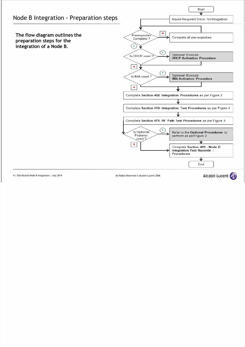
Node B Integration - Preparation steps
The flow diagram outlines the
preparation steps for theintegration of a Node B.
4 | Distributed Node B Integration | July 2014
8/17/2019 TMO 18553 WCDMA d2U d4U Distributed NodeB Integration in an Existing UTRAN _ 14w29.pdf
http://slidepdf.com/reader/full/tmo-18553-wcdma-d2u-d4u-distributed-nodeb-integration-in-an-existing-utran 5/84
All Rights Reserved © Alcatel-Lucent 2006
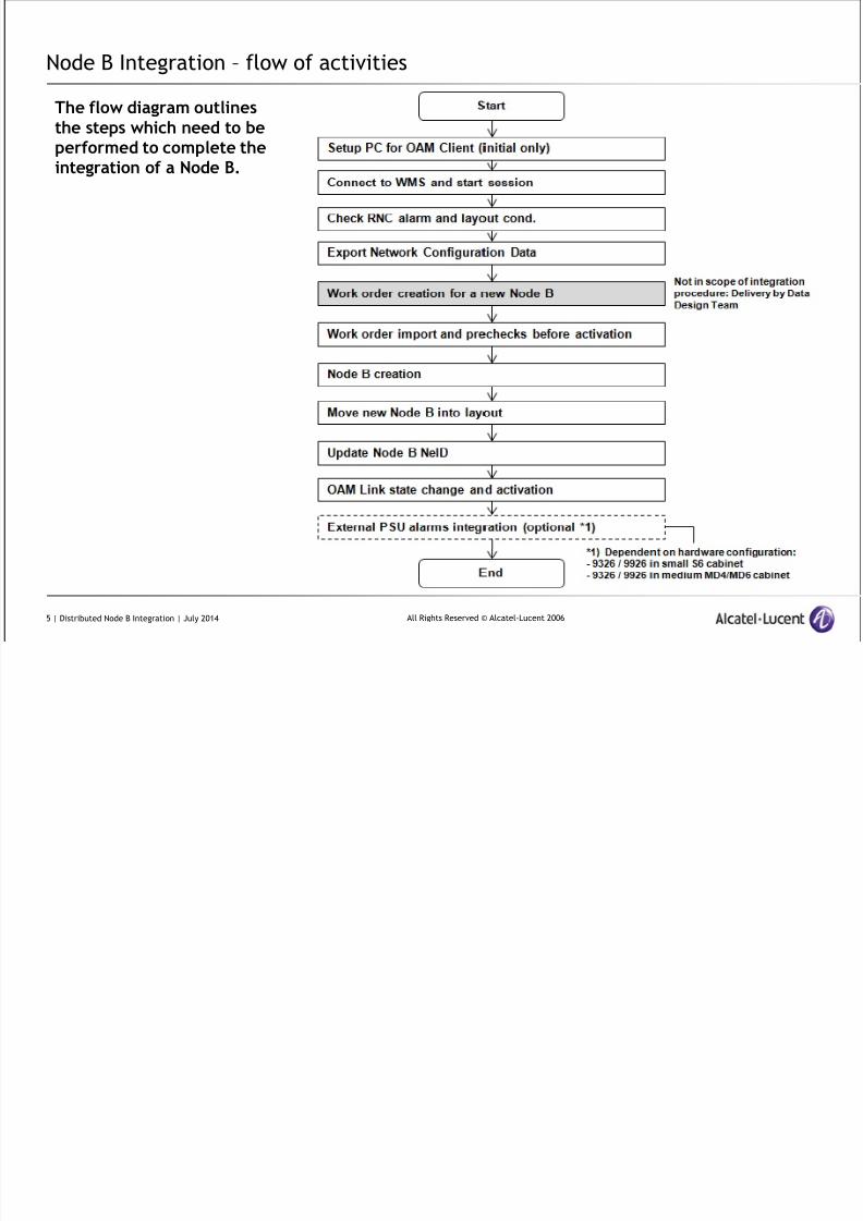
Node B Integration – flow of activities
The flow diagram outlinesthe steps which need to be
performed to complete theintegration of a Node B.
5 | Distributed Node B Integration | July 2014
8/17/2019 TMO 18553 WCDMA d2U d4U Distributed NodeB Integration in an Existing UTRAN _ 14w29.pdf
http://slidepdf.com/reader/full/tmo-18553-wcdma-d2u-d4u-distributed-nodeb-integration-in-an-existing-utran 6/84
All Rights Reserved © Alcatel-Lucent 2006
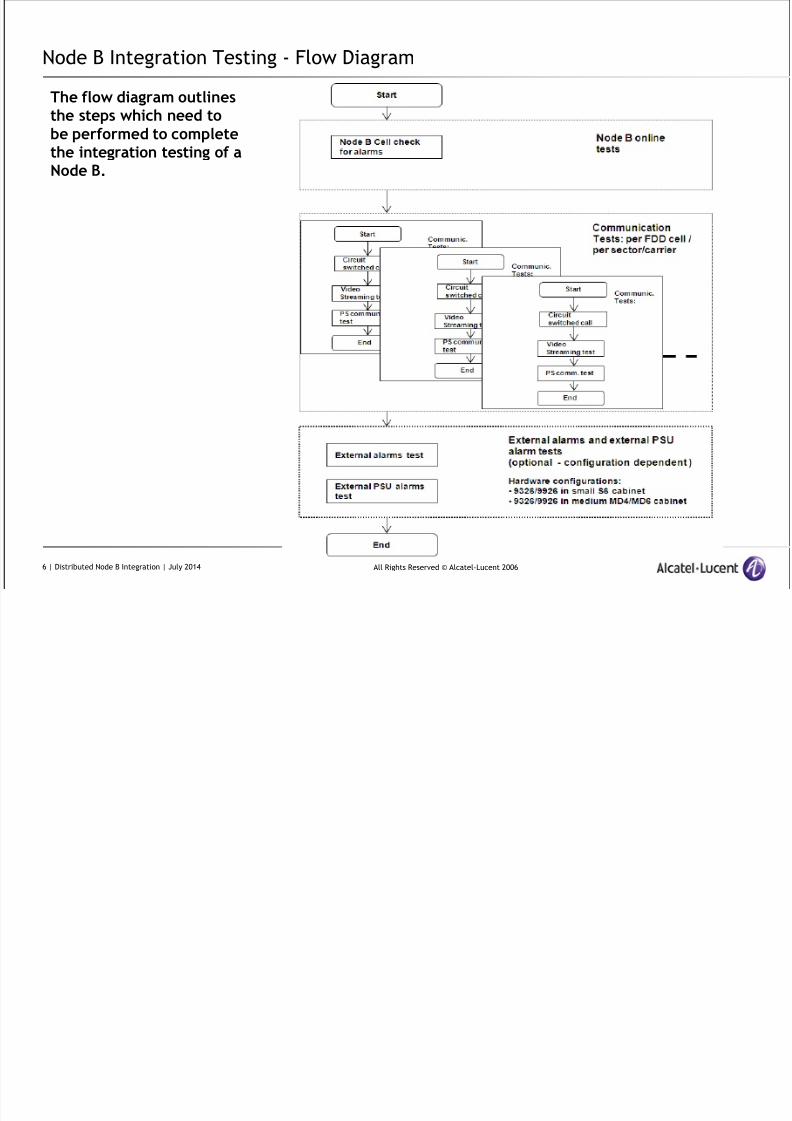
Node B Integration Testing - Flow Diagram
The flow diagram outlinesthe steps which need to
be performed to completethe integration testing of aNode B.
6 | Distributed Node B Integration | July 2014
8/17/2019 TMO 18553 WCDMA d2U d4U Distributed NodeB Integration in an Existing UTRAN _ 14w29.pdf
http://slidepdf.com/reader/full/tmo-18553-wcdma-d2u-d4u-distributed-nodeb-integration-in-an-existing-utran 7/84
All Rights Reserved © Alcatel-Lucent 2006
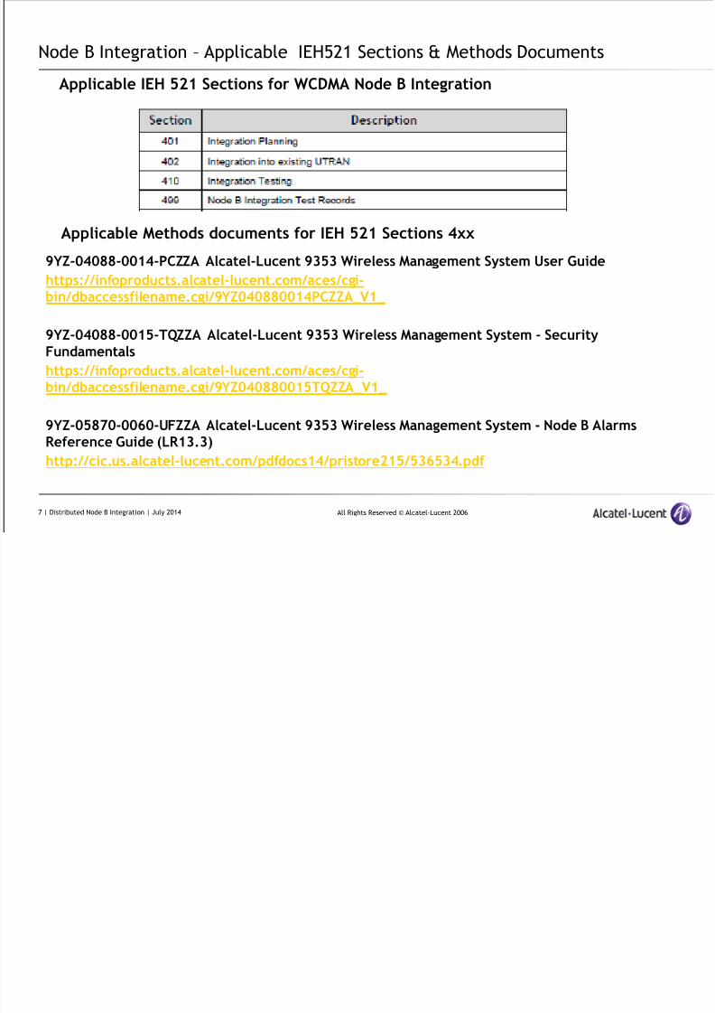
Node B Integration – Applicable IEH521 Sections & Methods Documents
9YZ-04088-0014-PCZZA Alcatel-Lucent 9353 Wireless Management System User Guide
https://infoproducts.alcatel-lucent.com/aces/cgi-bin/dbaccessfilename.cgi/9YZ040880014PCZZA_V1_
9YZ-04088-0015-TQZZA Alcatel-Lucent 9353 Wireless Management System - SecurityFundamentals
https://infoproducts.alcatel-lucent.com/aces/cgi-bin/dbaccessfilename.cgi/9YZ040880015TQZZA_V1_
9YZ-05870-0060-UFZZA Alcatel-Lucent 9353 Wireless Management System - Node B AlarmsReference Guide (LR13.3)
http://cic.us.alcatel-lucent.com/pdfdocs14/pristore215/536534.pdf
Applicable IEH 521 Sections for WCDMA Node B Integration
Applicable Methods documents for IEH 521 Sections 4xx
7 | Distributed Node B Integration | July 2014
8/17/2019 TMO 18553 WCDMA d2U d4U Distributed NodeB Integration in an Existing UTRAN _ 14w29.pdf
http://slidepdf.com/reader/full/tmo-18553-wcdma-d2u-d4u-distributed-nodeb-integration-in-an-existing-utran 8/84
All Rights Reserved © Alcatel-Lucent 2006
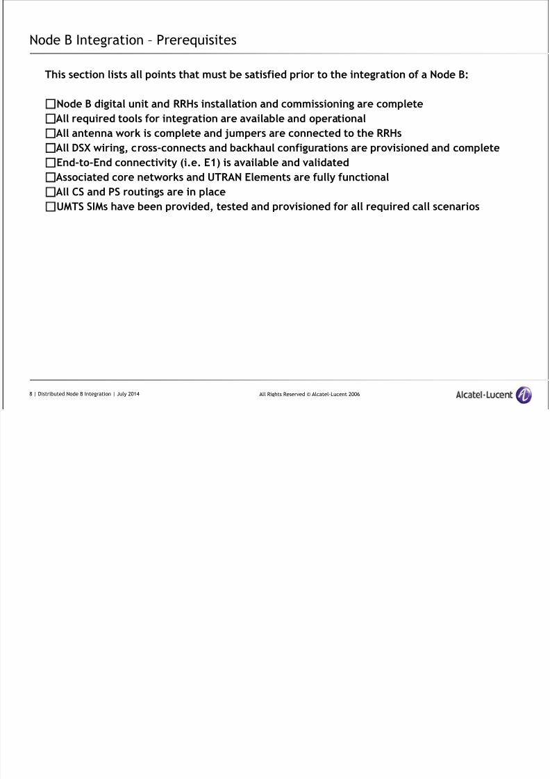
Node B Integration – Prerequisites
This section lists all points that must be satisfied prior to the integration of a Node B:
Node B digital unit and RRHs installation and commissioning are complete
All required tools for integration are available and operational
All antenna work is complete and jumpers are connected to the RRHs
All DSX wiring, cross-connects and backhaul configurations are provisioned and complete
End-to-End connectivity (i.e. E1) is available and validated
Associated core networks and UTRAN Elements are fully functional
All CS and PS routings are in placeUMTS SIMs have been provided, tested and provisioned for all required call scenarios
8 | Distributed Node B Integration | July 2014
8/17/2019 TMO 18553 WCDMA d2U d4U Distributed NodeB Integration in an Existing UTRAN _ 14w29.pdf
http://slidepdf.com/reader/full/tmo-18553-wcdma-d2u-d4u-distributed-nodeb-integration-in-an-existing-utran 9/84
All Rights Reserved © Alcatel-Lucent 2006
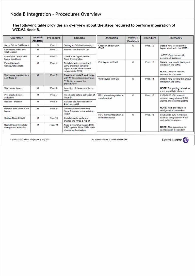
Node B Integration – Procedures Overview
The following table provides an overview about the steps required to perform integration ofWCDMA Node B.
9 | Distributed Node B Integration | July 2014
8/17/2019 TMO 18553 WCDMA d2U d4U Distributed NodeB Integration in an Existing UTRAN _ 14w29.pdf
http://slidepdf.com/reader/full/tmo-18553-wcdma-d2u-d4u-distributed-nodeb-integration-in-an-existing-utran 10/84
All Rights Reserved © Alcatel-Lucent 2006
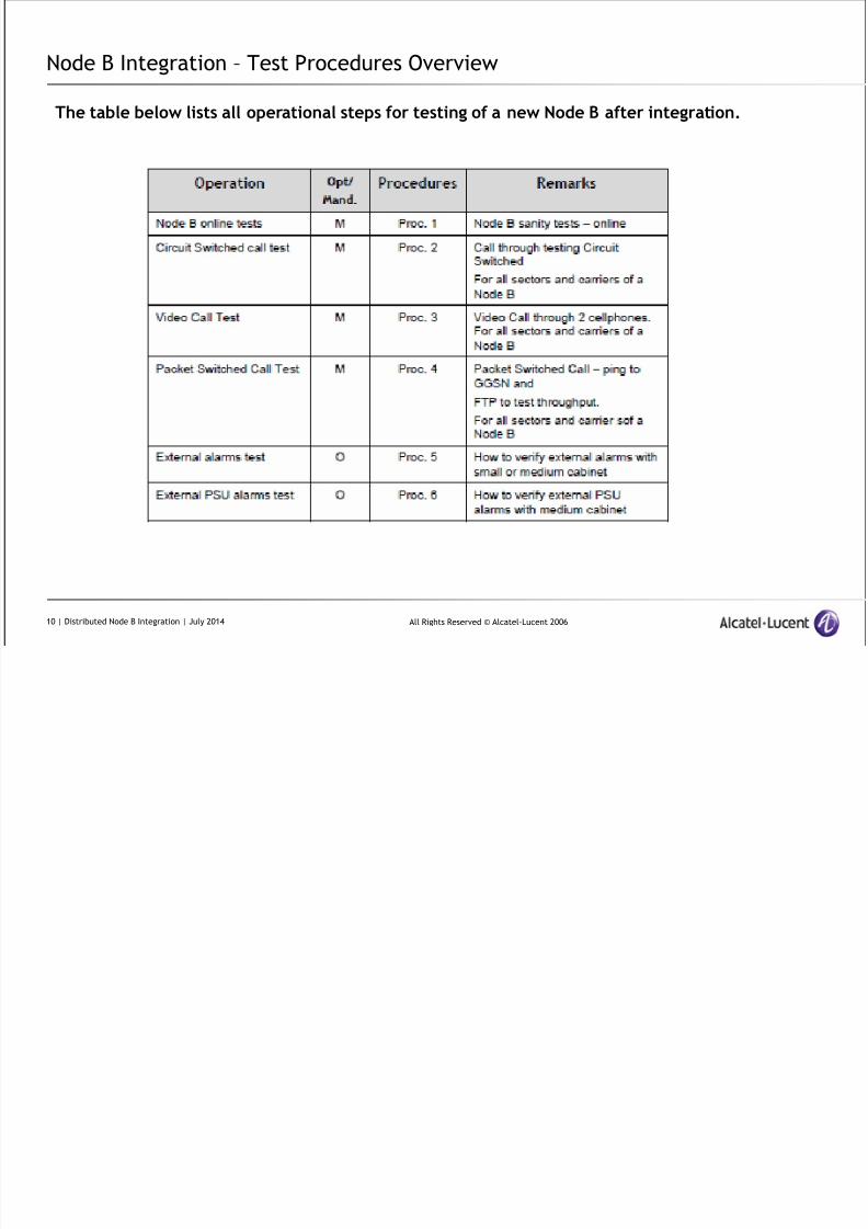
Node B Integration – Test Procedures Overview
The table below lists all operational steps for testing of a new Node B after integration.
10 | Distributed Node B Integration | July 2014
8/17/2019 TMO 18553 WCDMA d2U d4U Distributed NodeB Integration in an Existing UTRAN _ 14w29.pdf
http://slidepdf.com/reader/full/tmo-18553-wcdma-d2u-d4u-distributed-nodeb-integration-in-an-existing-utran 11/84
All Rights Reserved © Alcatel-Lucent 2006
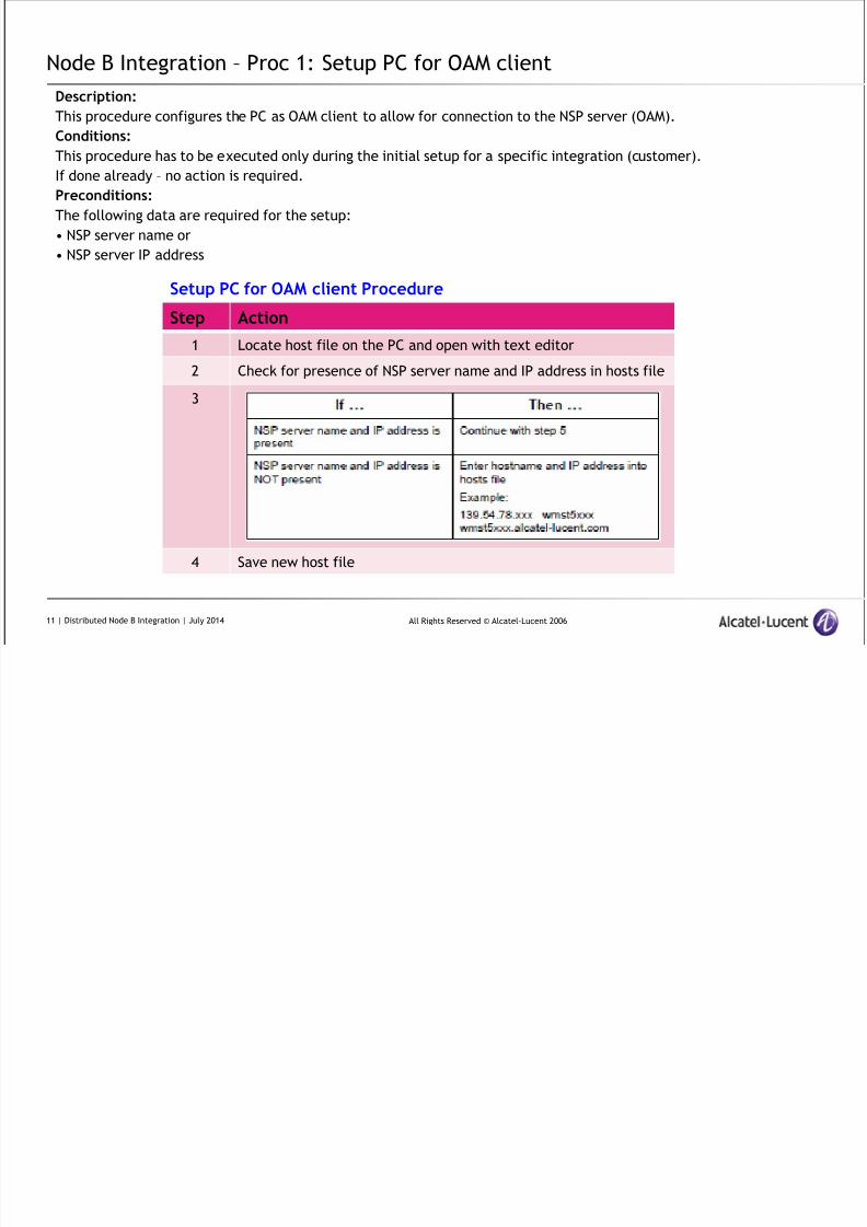
Node B Integration – Proc 1: Setup PC for OAM client
Description:
This procedure configures the PC as OAM client to allow for connection to the NSP server (OAM).
Conditions:
This procedure has to be executed only during the initial setup for a specific integration (customer).
If done already – no action is required.
Preconditions:
The following data are required for the setup:
• NSP server name or
• NSP server IP address
Step Action
1 Locate host file on the PC and open with text editor
2 Check for presence of NSP server name and IP address in hosts file
3
4 Save new host file
Setup PC for OAM client Procedure
11 | Distributed Node B Integration | July 2014
8/17/2019 TMO 18553 WCDMA d2U d4U Distributed NodeB Integration in an Existing UTRAN _ 14w29.pdf
http://slidepdf.com/reader/full/tmo-18553-wcdma-d2u-d4u-distributed-nodeb-integration-in-an-existing-utran 12/84
All Rights Reserved © Alcatel-Lucent 2006
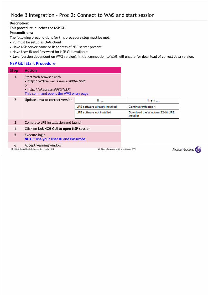
Node B Integration – Proc 2: Connect to WMS and start session
Description:
This procedure launches the NSP GUI.
Preconditions:
The following preconditions for this procedure step must be met:
• PC must be setup as OAM client
• Have NSP server name or IP address of NSP server present
• Have User ID and Password for NSP GUI available
• Java (version dependent on WMS version). Initial connection to WMS will enable for download of correct Java version.
Step Action
1 Start Web browser with
• http://NSPser ver ' s name: 808 0/ NSP/
or
• http://IPadress:8080/NSP/This command opens the WMS entry page.
2 Update Java to correct version
3 Complete JRE installation and launch
4 Click on LAUNCH GUI to open NSP session
5 Execute login
NOTE: Use your User ID and Password.
6 Accept warning window
NSP GUI Start Procedure
12 | Distributed Node B Integration | July 2014
8/17/2019 TMO 18553 WCDMA d2U d4U Distributed NodeB Integration in an Existing UTRAN _ 14w29.pdf
http://slidepdf.com/reader/full/tmo-18553-wcdma-d2u-d4u-distributed-nodeb-integration-in-an-existing-utran 13/84
All Rights Reserved © Alcatel-Lucent 2006
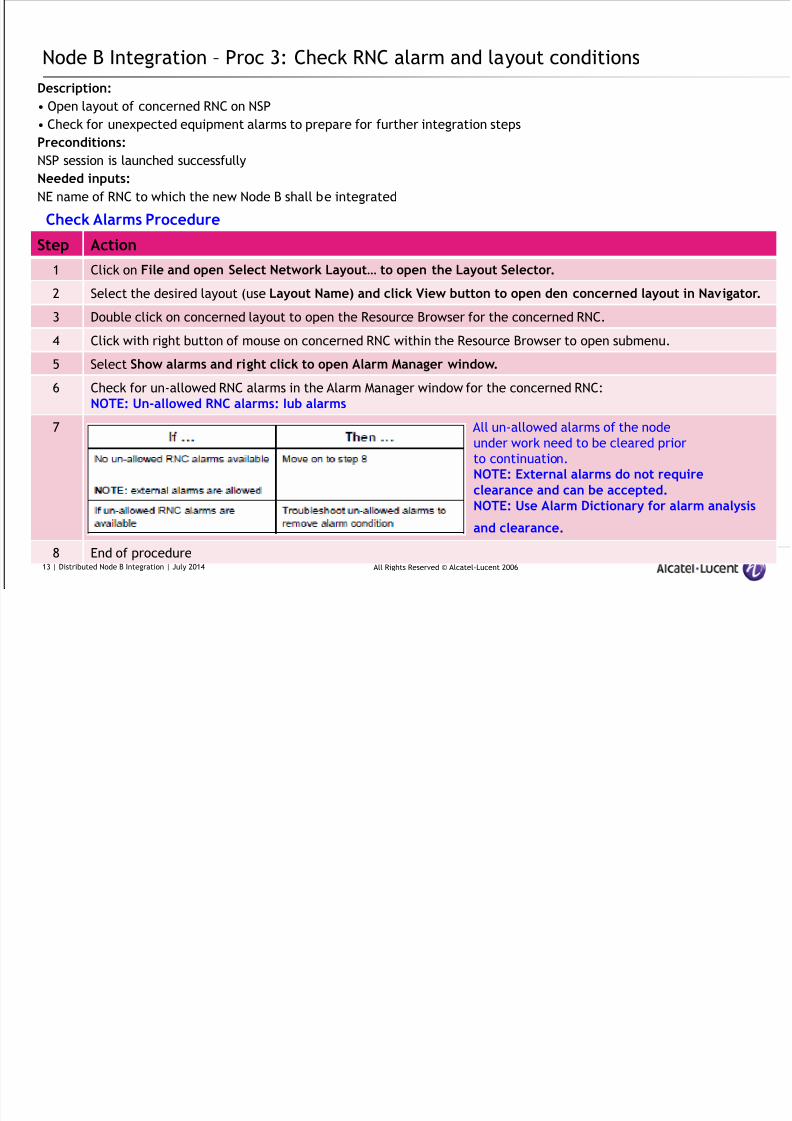
Node B Integration – Proc 3: Check RNC alarm and layout conditions
Description:
• Open layout of concerned RNC on NSP
• Check for unexpected equipment alarms to prepare for further integration steps
Preconditions:NSP session is launched successfully
Needed inputs:
NE name of RNC to which the new Node B shall be integrated
Step Action
1 Click on File and open Select Network Layout… to open the Layout Selector.
2 Select the desired layout (use Layout Name) and click View button to open den concerned layout in Navigator.
3 Double click on concerned layout to open the Resource Browser for the concerned RNC.
4 Click with right button of mouse on concerned RNC within the Resource Browser to open submenu.
5 Select Show alarms and right click to open Alarm Manager window.
6 Check for un-allowed RNC alarms in the Alarm Manager window for the concerned RNC:
NOTE: Un-allowed RNC alarms: Iub alarms
7 All un-allowed alarms of the node
under work need to be cleared prior
to continuation.NOTE: External alarms do not requireclearance and can be accepted.NOTE: Use Alarm Dictionary for alarm analysis
and clearance.
8 End of procedure
Check Alarms Procedure
13 | Distributed Node B Integration | July 2014

8/17/2019 TMO 18553 WCDMA d2U d4U Distributed NodeB Integration in an Existing UTRAN _ 14w29.pdf
http://slidepdf.com/reader/full/tmo-18553-wcdma-d2u-d4u-distributed-nodeb-integration-in-an-existing-utran 14/84
All Rights Reserved © Alcatel-Lucent 2006
Node B Integration – Proc 4: Export Network Configuration Data
Description:
This procedure describes how to export a snapshot of the network configuration data into WPS work space.
Preconditions:
• NSP session is launched successfully• WPS on local computer and operational
• RNC name for Node B integration
Work order data:
IMPORTANT: The design team (data filler) always requires the snapshot of the network data (latest version) for creation of
the Node B integration work order.
Step Action1 Open Resource Browser GUI on NSP.
2 Select target RNC for Node B integration and select Configuration | CM XML | Export NE Grouping
Export Network Configuration Data Procedure
14 | Distributed Node B Integration | July 2014
8/17/2019 TMO 18553 WCDMA d2U d4U Distributed NodeB Integration in an Existing UTRAN _ 14w29.pdf
http://slidepdf.com/reader/full/tmo-18553-wcdma-d2u-d4u-distributed-nodeb-integration-in-an-existing-utran 15/84
All Rights Reserved © Alcatel-Lucent 2006
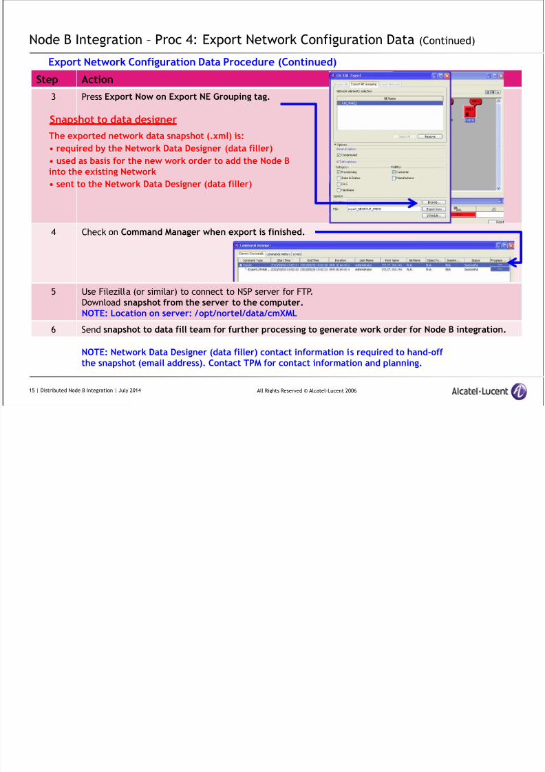
Node B Integration – Proc 4: Export Network Configuration Data (Continued)
Step Action
3 Press Export Now on Export NE Grouping tag.
4 Check on Command Manager when export is finished.
5 Use Filezilla (or similar) to connect to NSP server for FTP.
Download snapshot from the server to the computer.NOTE: Location on server: /opt/nortel/data/cmXML
6 Send snapshot to data fill team for further processing to generate work order for Node B integration.
Export Network Configuration Data Procedure (Continued)
Snapshot to data designer
The exported network data snapshot (.xml) is:
• required by the Network Data Designer (data filler)
• used as basis for the new work order to add the Node Binto the existing Network
• sent to the Network Data Designer (data filler)
NOTE: Network Data Designer (data filler) contact information is required to hand-offthe snapshot (email address). Contact TPM for contact information and planning.
15 | Distributed Node B Integration | July 2014
8/17/2019 TMO 18553 WCDMA d2U d4U Distributed NodeB Integration in an Existing UTRAN _ 14w29.pdf
http://slidepdf.com/reader/full/tmo-18553-wcdma-d2u-d4u-distributed-nodeb-integration-in-an-existing-utran 16/84
All Rights Reserved © Alcatel-Lucent 2006
Node B Integration – Proc 5: Work order creation for a new Node B
Description:
This process step details the actions to allow for creation of new work order(s) for Node B integration.
Submission of snapshotThe exported network data snapshot (.xml file) must be sent to the network data design team (data filler) for further
processing.
Work order generation
Network Data Design team generates the new Node B / Node B parenting work order based on:
• provided network data snapshot (.xml)
• customer data (CIQ based)
• configuration data
Reception of work order
Network Data Design team provides new Node B / Node B parenting work order to integrator for further use during the
integration.
Delivery method of work order
Email from data filler
16 | Distributed Node B Integration | July 2014

8/17/2019 TMO 18553 WCDMA d2U d4U Distributed NodeB Integration in an Existing UTRAN _ 14w29.pdf
http://slidepdf.com/reader/full/tmo-18553-wcdma-d2u-d4u-distributed-nodeb-integration-in-an-existing-utran 17/84
All Rights Reserved © Alcatel-Lucent 2006
Node B Integration – Proc 6: Work order import
Description:
This procedure imports the pre-defined work order to the Main Server directory on the WMS
Prerequisites:
The Node B integration work order is available in .xwo format from data filler for transfer to the WMS Main server.File transfer software (e.g. Filezilla) is available for file transfer of .xwo - work order to WMS.
Step Action
1 Load work order (.xwo) into PC in preparation of file transfer
2 Execute file import of work order into WMS main server by use of file transfer software (e.g. filezilla) tomain server directory:/opt/nortel/data/cmXML
3 Verify that the work order has been successfully transferred into the WMS main server under/opt/nortel/data/cmXML
Work order import Procedure
17 | Distributed Node B Integration | July 2014
8/17/2019 TMO 18553 WCDMA d2U d4U Distributed NodeB Integration in an Existing UTRAN _ 14w29.pdf
http://slidepdf.com/reader/full/tmo-18553-wcdma-d2u-d4u-distributed-nodeb-integration-in-an-existing-utran 18/84
All Rights Reserved © Alcatel-Lucent 2006
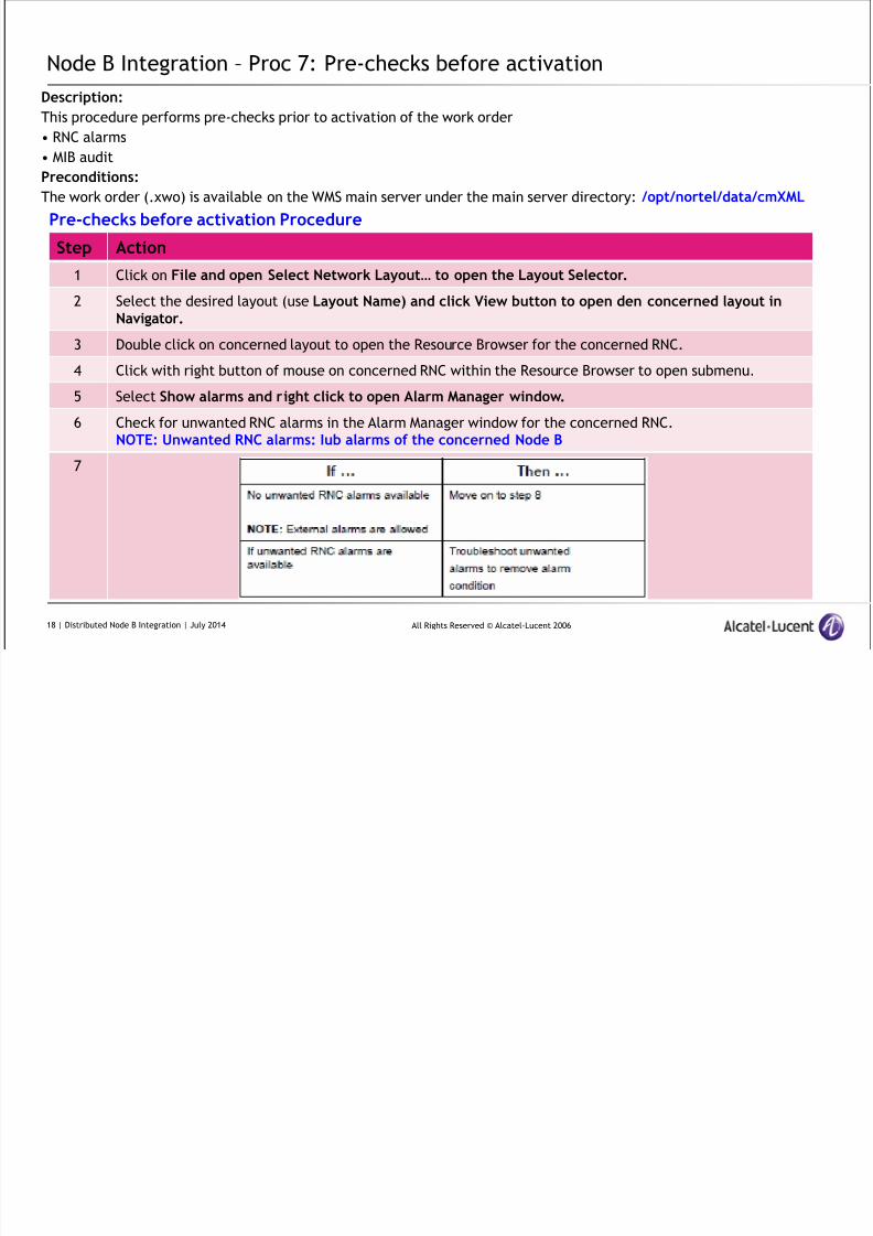
Node B Integration – Proc 7: Pre-checks before activation
Description:
This procedure performs pre-checks prior to activation of the work order
• RNC alarms
• MIB auditPreconditions:
The work order (.xwo) is available on the WMS main server under the main server directory: /opt/nortel/data/cmXML
Step Action
1 Click on File and open Select Network Layout… to open the Layout Selector.
2 Select the desired layout (use Layout Name) and click View button to open den concerned layout inNavigator.
3 Double click on concerned layout to open the Resource Browser for the concerned RNC.
4 Click with right button of mouse on concerned RNC within the Resource Browser to open submenu.
5 Select Show alarms and right click to open Alarm Manager window.
6 Check for unwanted RNC alarms in the Alarm Manager window for the concerned RNC.NOTE: Unwanted RNC alarms: Iub alarms of the concerned Node B
7
Pre-checks before activation Procedure
18 | Distributed Node B Integration | July 2014
8/17/2019 TMO 18553 WCDMA d2U d4U Distributed NodeB Integration in an Existing UTRAN _ 14w29.pdf
http://slidepdf.com/reader/full/tmo-18553-wcdma-d2u-d4u-distributed-nodeb-integration-in-an-existing-utran 19/84
All Rights Reserved © Alcatel-Lucent 2006
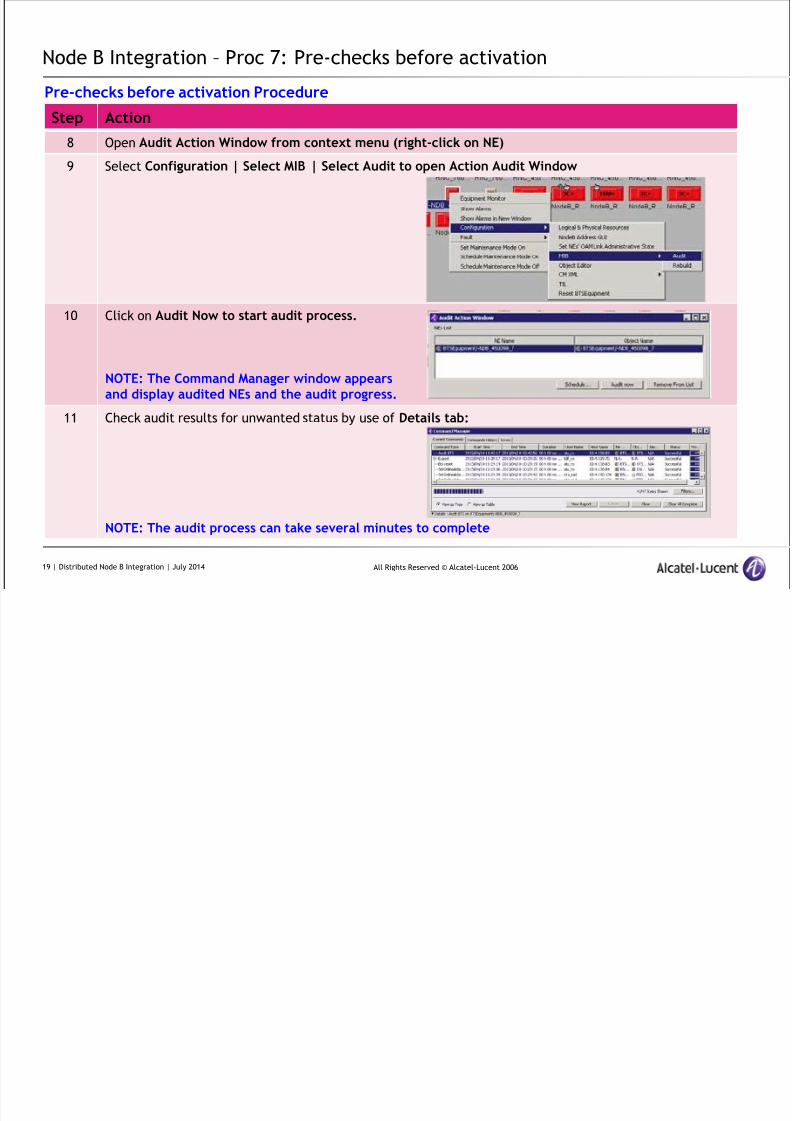
Node B Integration – Proc 7: Pre-checks before activation
Step Action
8 Open Audit Action Window from context menu (right-click on NE)
9 Select Configuration | Select MIB | Select Audit to open Action Audit Window
10 Click on Audit Now to start audit process.
NOTE: The Command Manager window appearsand display audited NEs and the audit progress.
11 Check audit results for unwanted status by use of Details tab:
NOTE: The audit process can take several minutes to complete
Pre-checks before activation Procedure
19 | Distributed Node B Integration | July 2014
8/17/2019 TMO 18553 WCDMA d2U d4U Distributed NodeB Integration in an Existing UTRAN _ 14w29.pdf
http://slidepdf.com/reader/full/tmo-18553-wcdma-d2u-d4u-distributed-nodeb-integration-in-an-existing-utran 20/84
All Rights Reserved © Alcatel-Lucent 2006
Node B Integration – Proc 7: Pre-checks before activation
Step Action
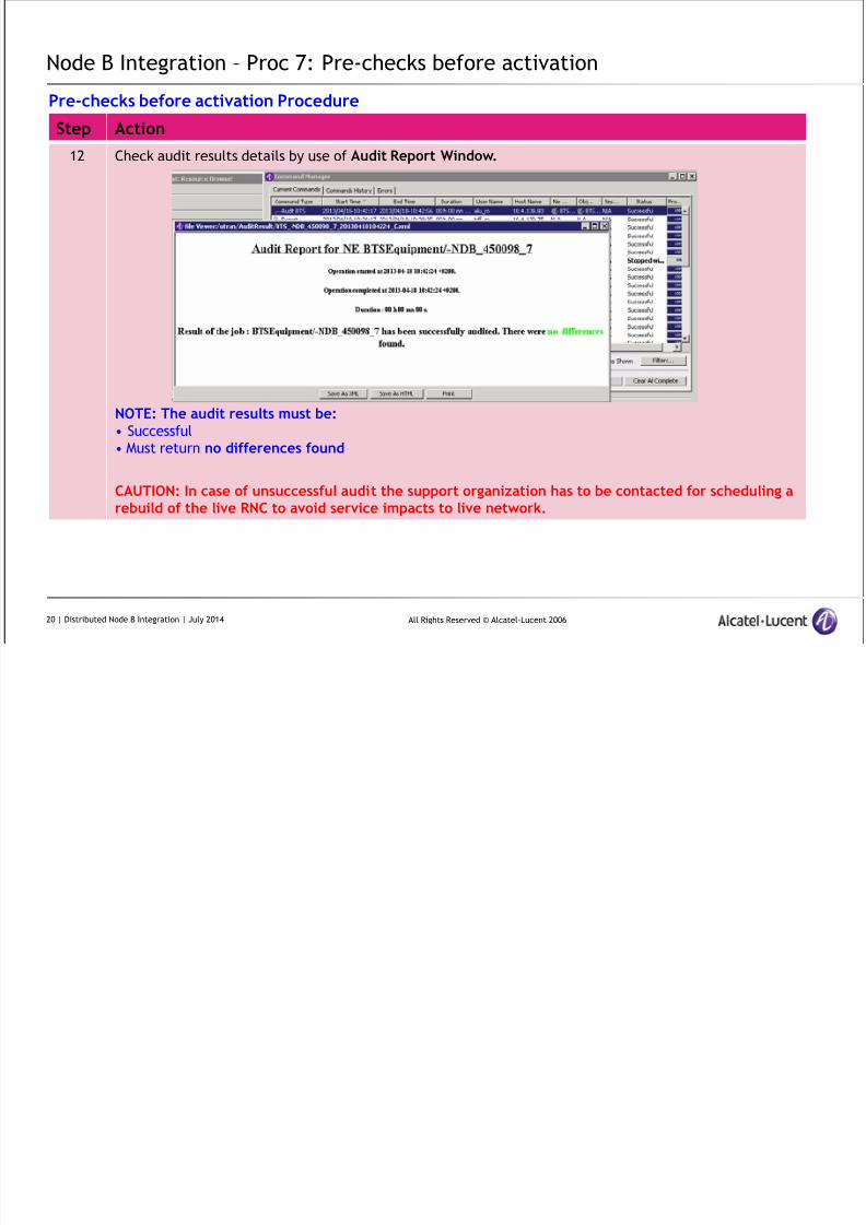
12 Check audit results details by use of Audit Report Window.
NOTE: The audit results must be:• Successful
• Must return no differences found
CAUTION: In case of unsuccessful audit the support organization has to be contacted for scheduling arebuild of the live RNC to avoid service impacts to live network.
Pre-checks before activation Procedure
20 | Distributed Node B Integration | July 2014
8/17/2019 TMO 18553 WCDMA d2U d4U Distributed NodeB Integration in an Existing UTRAN _ 14w29.pdf
http://slidepdf.com/reader/full/tmo-18553-wcdma-d2u-d4u-distributed-nodeb-integration-in-an-existing-utran 21/84
All Rights Reserved © Alcatel-Lucent 2006
Node B Integration – Proc 8: Node B – creation
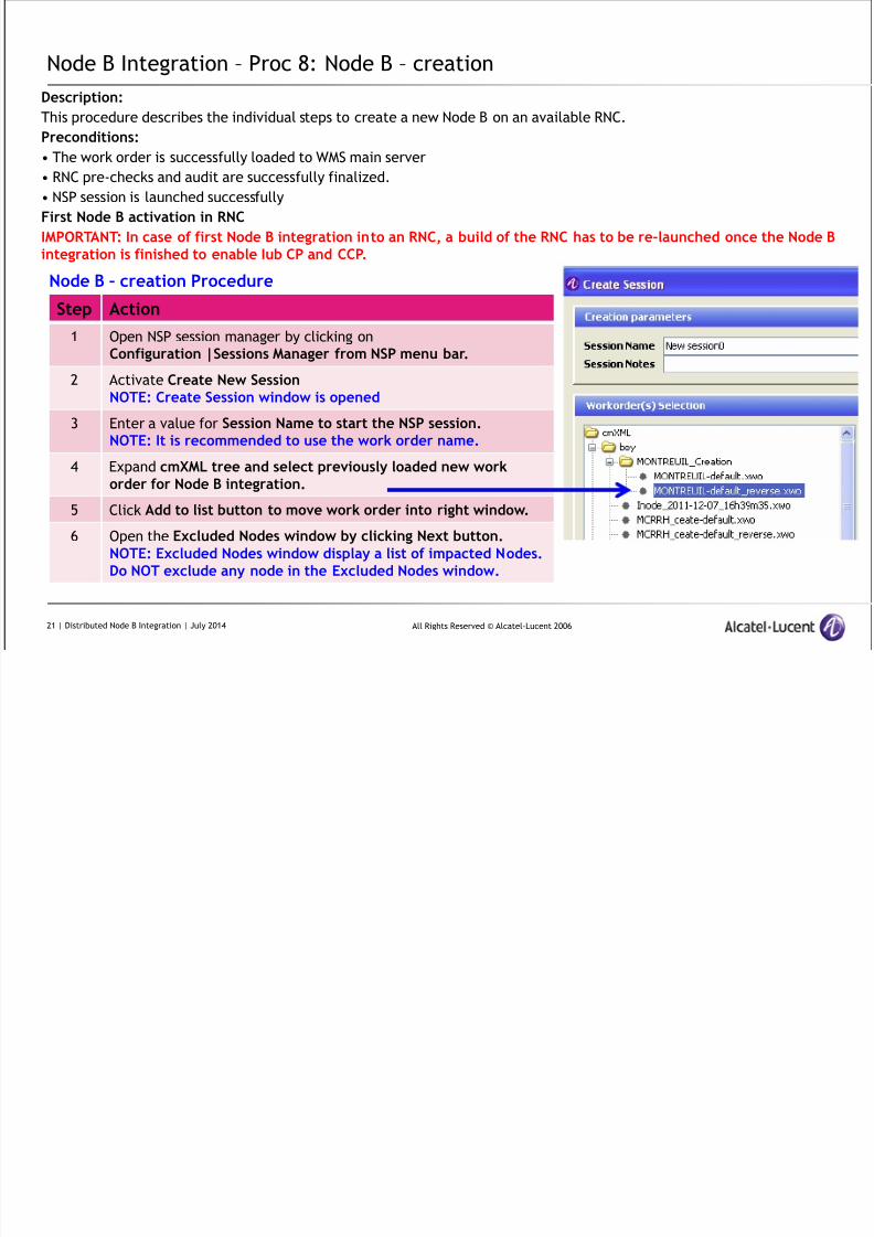
Description:
This procedure describes the individual steps to create a new Node B on an available RNC.
Preconditions:
• The work order is successfully loaded to WMS main server• RNC pre-checks and audit are successfully finalized.
• NSP session is launched successfully
First Node B activation in RNC
IMPORTANT: In case of first Node B integration into an RNC, a build of the RNC has to be re-launched once the Node Bintegration is finished to enable Iub CP and CCP.
Step Action
1 Open NSP session manager by clicking onConfiguration |Sessions Manager from NSP menu bar.
2 Activate Create New SessionNOTE: Create Session window is opened
3 Enter a value for Session Name to start the NSP session.NOTE: It is recommended to use the work order name.
4 Expand cmXML tree and select previously loaded new workorder for Node B integration.
5 Click Add to list button to move work order into right window.
6 Open the Excluded Nodes window by clicking Next button.NOTE: Excluded Nodes window display a list of impacted Nodes.Do NOT exclude any node in the Excluded Nodes window.
Node B – creation Procedure
21 | Distributed Node B Integration | July 2014
8/17/2019 TMO 18553 WCDMA d2U d4U Distributed NodeB Integration in an Existing UTRAN _ 14w29.pdf
http://slidepdf.com/reader/full/tmo-18553-wcdma-d2u-d4u-distributed-nodeb-integration-in-an-existing-utran 22/84
All Rights Reserved © Alcatel-Lucent 2006
Node B Integration – Proc 8: Node B – creation (continued)
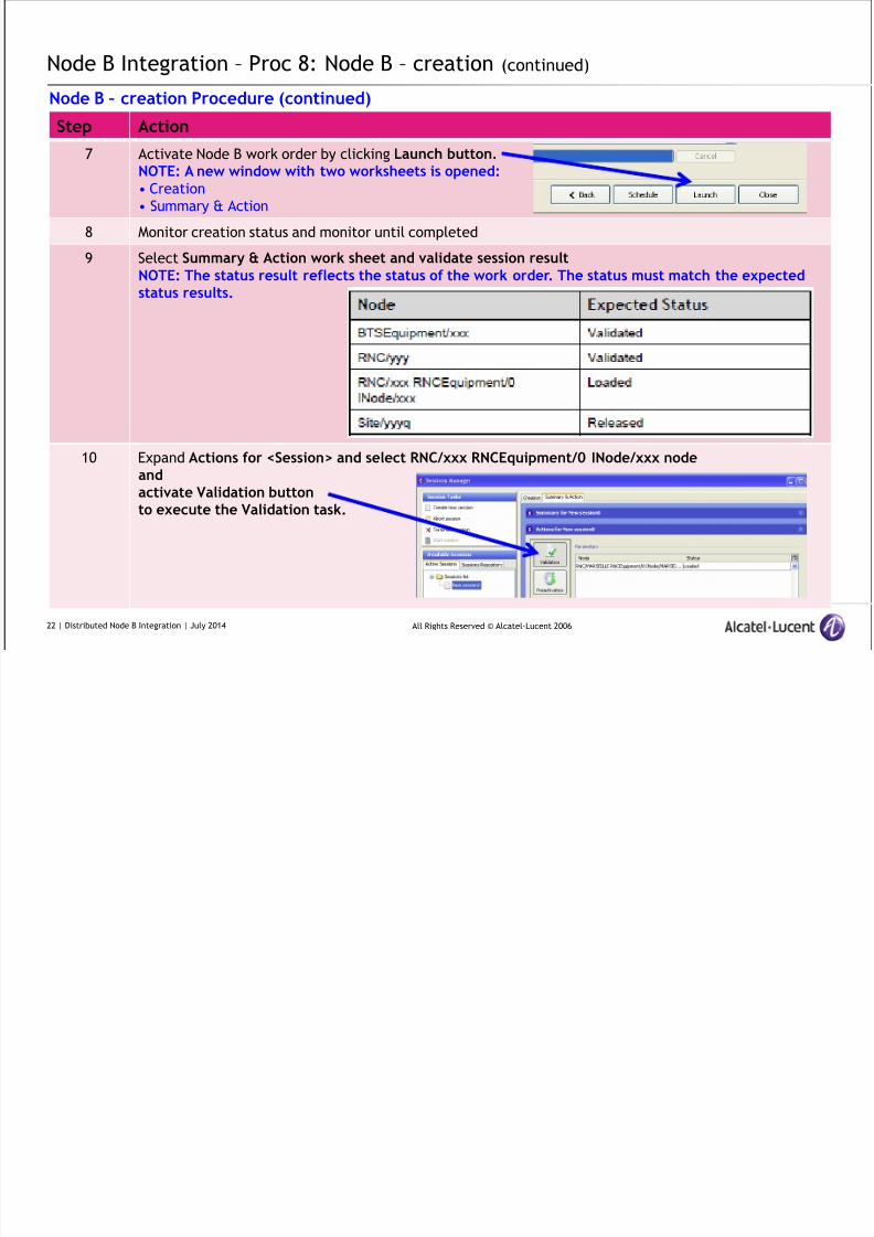
Step Action
7 Activate Node B work order by clicking Launch button.NOTE: A new window with two worksheets is opened:• Creation
• Summary & Action
8 Monitor creation status and monitor until completed
9 Select Summary & Action work sheet and validate session resultNOTE: The status result reflects the status of the work order. The status must match the expectedstatus results.
10 Expand Actions for <Session> and select RNC/xxx RNCEquipment/0 INode/xxx nodeandactivate Validation buttonto execute the Validation task.
Node B – creation Procedure (continued)
22 | Distributed Node B Integration | July 2014
8/17/2019 TMO 18553 WCDMA d2U d4U Distributed NodeB Integration in an Existing UTRAN _ 14w29.pdf
http://slidepdf.com/reader/full/tmo-18553-wcdma-d2u-d4u-distributed-nodeb-integration-in-an-existing-utran 23/84
All Rights Reserved © Alcatel-Lucent 2006
Node B Integration – Proc 8: Node B – creation (continued)
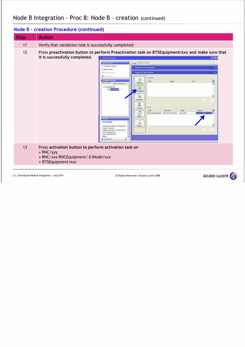
Step Action
11 Verify that validation task is successfully completed:
12 Press preactivation button to perform Preactivation task on BTSEquipment/xxx and make sure thatit is successfully completed.
13 Press activation button to perform activation task on• RNC/yyy
• RNC/xxx RNCEquipment/ 0 INode/xxx
• BTSEquipment/xxx
Node B – creation Procedure (continued)
23 | Distributed Node B Integration | July 2014
8/17/2019 TMO 18553 WCDMA d2U d4U Distributed NodeB Integration in an Existing UTRAN _ 14w29.pdf
http://slidepdf.com/reader/full/tmo-18553-wcdma-d2u-d4u-distributed-nodeb-integration-in-an-existing-utran 24/84
All Rights Reserved © Alcatel-Lucent 2006
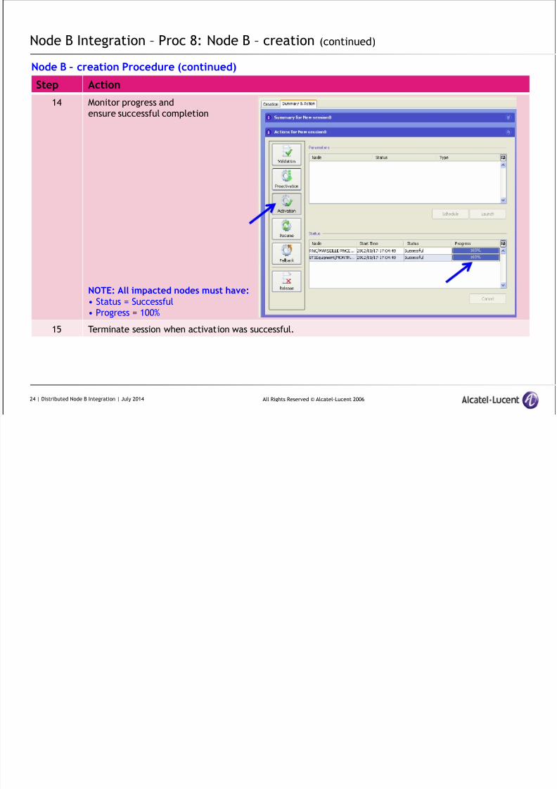
Node B Integration – Proc 8: Node B – creation (continued)
Step Action
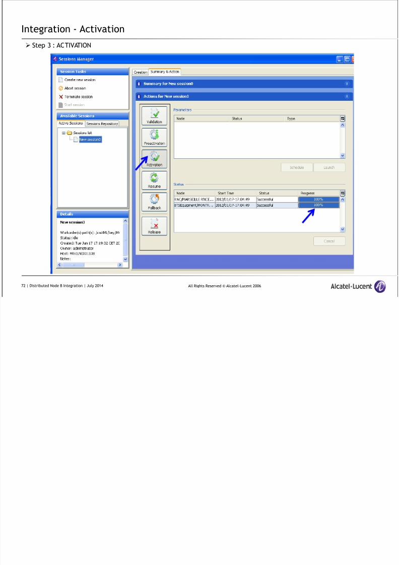
14 Monitor progress andensure successful completion
NOTE: All impacted nodes must have:• Status = Successful
• Progress = 100%
15 Terminate session when activation was successful.
Node B – creation Procedure (continued)
24 | Distributed Node B Integration | July 2014
8/17/2019 TMO 18553 WCDMA d2U d4U Distributed NodeB Integration in an Existing UTRAN _ 14w29.pdf
http://slidepdf.com/reader/full/tmo-18553-wcdma-d2u-d4u-distributed-nodeb-integration-in-an-existing-utran 25/84
All Rights Reserved © Alcatel-Lucent 2006
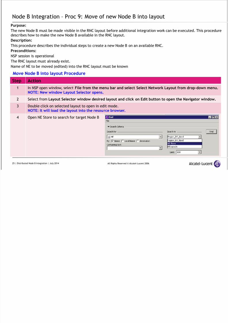
Node B Integration – Proc 9: Move of new Node B into layout
Purpose:
The new Node B must be made visible in the RNC layout before additional integration work can be executed. This procedure
describes how to make the new Node B available in the RNC layout.
Description:This procedure describes the individual steps to create a new Node B on an available RNC.
Preconditions:
NSP session is operational
The RNC layout must already exist.
Name of NE to be moved (edited) into the RNC layout must be known
Step Action1 In NSP open window, select File from the menu bar and select Select Network Layout from drop-down menu.
NOTE: New window Layout Selector opens.
2 Select from Layout Selector window desired layout and click on Edit button to open the Navigator window.
3 Double click on selected layout to open in edit mode.NOTE: It will load the layout into the resource browser.
4 Open NE Store to search for target Node B
Move Node B into layout Procedure
25 | Distributed Node B Integration | July 2014
8/17/2019 TMO 18553 WCDMA d2U d4U Distributed NodeB Integration in an Existing UTRAN _ 14w29.pdf
http://slidepdf.com/reader/full/tmo-18553-wcdma-d2u-d4u-distributed-nodeb-integration-in-an-existing-utran 26/84
All Rights Reserved © Alcatel-Lucent 2006
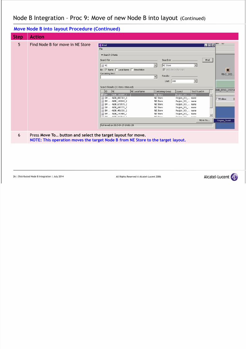
Node B Integration – Proc 9: Move of new Node B into layout (Continued)
Step Action
5 Find Node B for move in NE Store
6 Press Move To… button and select the target layout for move.NOTE: This operation moves the target Node B from NE Store to the target layout.
Move Node B into layout Procedure (Continued)
26 | Distributed Node B Integration | July 2014
8/17/2019 TMO 18553 WCDMA d2U d4U Distributed NodeB Integration in an Existing UTRAN _ 14w29.pdf
http://slidepdf.com/reader/full/tmo-18553-wcdma-d2u-d4u-distributed-nodeb-integration-in-an-existing-utran 27/84
All Rights Reserved © Alcatel-Lucent 2006
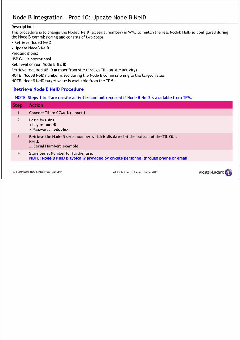
Node B Integration – Proc 10: Update Node B NeID
Description:
This procedure is to change the NodeB NeID (ex serial number) in WMS to match the real NodeB NeID as configured during
the Node B commissioning and consists of two steps:
• Retrieve NodeB NeID• Update NodeB NeID
Preconditions:
NSP GUI is operational
Retrieval of real Node B NE ID
Retrieve required NE ID number from site through TIL (on-site activity)
NOTE: NodeB NeID number is set during the Node B commissioning to the target value.
NOTE: NodeB NeID target value is available from the TPM.
Step Action
1 Connect TIL to CCM(-U) – port 1
2 Login by using:
• Login: nodeB• Password: nodeblnx
3 Retrieve the Node B serial number which is displayed at the bottom of the TIL GUI:
Read:
….Serial Number: example
4 Store Serial Number for further use.
NOTE: Node B NeID is typically provided by on-site personnel through phone or email.
Retrieve Node B NeID Procedure
NOTE: Steps 1 to 4 are on-site activities and not required if Node B NeID is available from TPM.
27 | Distributed Node B Integration | July 2014

8/17/2019 TMO 18553 WCDMA d2U d4U Distributed NodeB Integration in an Existing UTRAN _ 14w29.pdf
http://slidepdf.com/reader/full/tmo-18553-wcdma-d2u-d4u-distributed-nodeb-integration-in-an-existing-utran 28/84
All Rights Reserved © Alcatel-Lucent 2006
Node B Integration – Proc 10: Update Node B NeID (Continued)
Step Action
1 Select new Node B icon in NSP Resource Browser
2 Use right click to open menu bars and select Configuration
3 A new under menu opens – select Object Editor
4 Select line with attributeneid in open Object Editor window
5 Enter correct (previously retrieved from site)
NeID number
6 Apply new value by clicking
Set and Apply all changes
Update Node B NeID Procedure (continued)
28 | Distributed Node B Integration | July 2014
8/17/2019 TMO 18553 WCDMA d2U d4U Distributed NodeB Integration in an Existing UTRAN _ 14w29.pdf
http://slidepdf.com/reader/full/tmo-18553-wcdma-d2u-d4u-distributed-nodeb-integration-in-an-existing-utran 29/84
All Rights Reserved © Alcatel-Lucent 2006
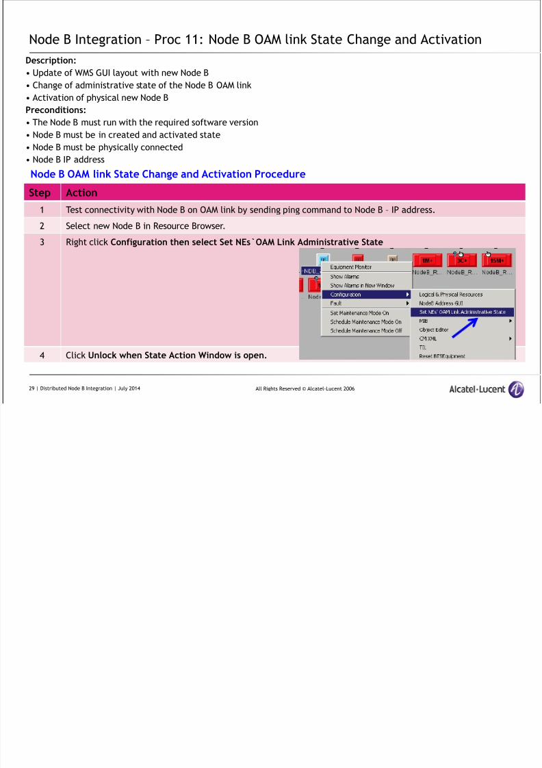
Node B Integration – Proc 11: Node B OAM link State Change and Activation
Description:
• Update of WMS GUI layout with new Node B
• Change of administrative state of the Node B OAM link
• Activation of physical new Node BPreconditions:
• The Node B must run with the required software version
• Node B must be in created and activated state
• Node B must be physically connected
• Node B IP address
Step Action1 Test connectivity with Node B on OAM link by sending ping command to Node B – IP address.
2 Select new Node B in Resource Browser.
3 Right click Configuration then select Set NEs`OAM Link Administrative State
4 Click Unlock when State Action Window is open.
Node B OAM link State Change and Activation Procedure
29 | Distributed Node B Integration | July 2014
8/17/2019 TMO 18553 WCDMA d2U d4U Distributed NodeB Integration in an Existing UTRAN _ 14w29.pdf
http://slidepdf.com/reader/full/tmo-18553-wcdma-d2u-d4u-distributed-nodeb-integration-in-an-existing-utran 30/84
All Rights Reserved © Alcatel-Lucent 2006
Node B Integration – Proc 11: Node B OAM link State Change & Activation (continued)
Step Action
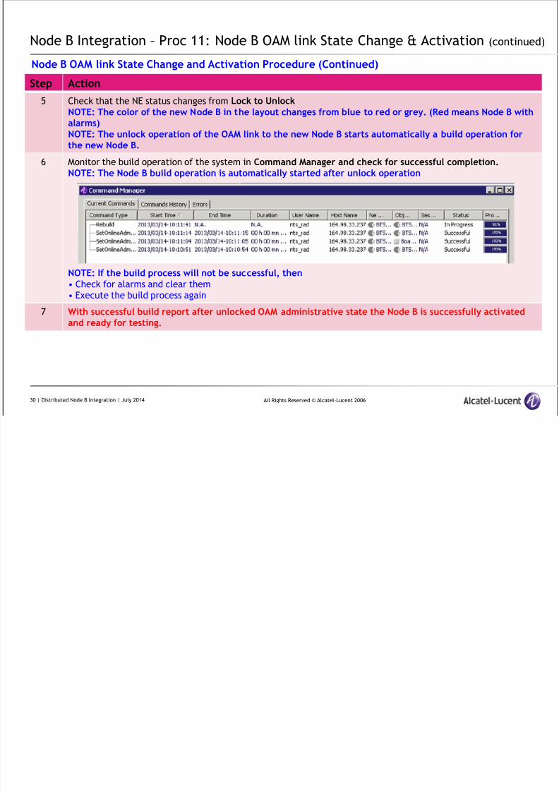
5 Check that the NE status changes from Lock to UnlockNOTE: The color of the new Node B in the layout changes from blue to red or grey. (Red means Node B withalarms)NOTE: The unlock operation of the OAM link to the new Node B starts automatically a build operation forthe new Node B.
6 Monitor the build operation of the system in Command Manager and check for successful completion.NOTE: The Node B build operation is automatically started after unlock operation
NOTE: If the build process will not be successful, then• Check for alarms and clear them
• Execute the build process again
7 With successful build report after unlocked OAM administrative state the Node B is successfully activatedand ready for testing.
Node B OAM link State Change and Activation Procedure (Continued)
30 | Distributed Node B Integration | July 2014
8/17/2019 TMO 18553 WCDMA d2U d4U Distributed NodeB Integration in an Existing UTRAN _ 14w29.pdf
http://slidepdf.com/reader/full/tmo-18553-wcdma-d2u-d4u-distributed-nodeb-integration-in-an-existing-utran 31/84
All Rights Reserved © Alcatel-Lucent 2006
Node B Integration – Proc 12: Creation of layout in WMS (optional)
Description:
This procedure allows creation of a new layout on the WMS.
This procedure has to be executed if required (e.g. by customer).
Purpose :A new layout may be used to place new / migrated NEs in a specific layout for a period of observation.
Preconditions:
• The creation of a new layout in WMS is determined by customer needs and created based upon customer request.
• The following information is required: Layout name
• NSP session is established
Step Action1 In NSP open window, select File from the menu bar and select Select Network Layout to open Layout
Selector.
2 Click on Layout Management and then New to open new Window to enter new layout name.
3 Enter name for new layout NEW Layout and pr ess OK but t on
NOTE: The new layout name appears in the Layout Selector window.
Creation of New layout in WMS Procedure
31 | Distributed Node B Integration | July 2014
8/17/2019 TMO 18553 WCDMA d2U d4U Distributed NodeB Integration in an Existing UTRAN _ 14w29.pdf
http://slidepdf.com/reader/full/tmo-18553-wcdma-d2u-d4u-distributed-nodeb-integration-in-an-existing-utran 32/84
All Rights Reserved © Alcatel-Lucent 2006
Node B Integration – Proc 13: Edit of layout in WMS (optional)
Description:
This operation is used to move a NE (new Node B under integration) into an already existing layout.
Purpose :
New NEs under integration may be assembled under a specific layout for extended period for observation.Preconditions:
• The layout must already exist.
• Name of NE to be edited into layout must be known
Step Action1 In NSP open window, select File from the menu bar and select Select Network Layout to open Layout
Selector.
2 Select from Layout Selector window desired layout and click on Edit button to open the Navigator window.
3 Double click on selected layout to open in edit mode.NOTE: It will load the selected layout into the resource browser.
Edit layout Procedure
32 | Distributed Node B Integration | July 2014
8/17/2019 TMO 18553 WCDMA d2U d4U Distributed NodeB Integration in an Existing UTRAN _ 14w29.pdf
http://slidepdf.com/reader/full/tmo-18553-wcdma-d2u-d4u-distributed-nodeb-integration-in-an-existing-utran 33/84
All Rights Reserved © Alcatel-Lucent 2006
Node B Integration – Proc 14: View layout in WMS (optional)
Description:
This operation details how to open the layout in view mode.
Supporting Procedure for integration :
Opening of Layout is used for many different reasons during the operation of a network.In the context of this IEH521 the layout on WMS open in view mode is required to perform necessary actions during the
integration procedure.
Entry Criteria:
NSP GUI operational
Step Action1 Select File from menu bar and click on Select Network Layout to open Layout Selector window.
2 Select desired Layout and click on View t o open Navigat or wi ndow
3 Load layout applications by double clicking on desired Layout
NOTE: The desired layout is now open for further operations.
View layout Procedure
33 | Distributed Node B Integration | July 2014

8/17/2019 TMO 18553 WCDMA d2U d4U Distributed NodeB Integration in an Existing UTRAN _ 14w29.pdf
http://slidepdf.com/reader/full/tmo-18553-wcdma-d2u-d4u-distributed-nodeb-integration-in-an-existing-utran 34/84
All Rights Reserved © Alcatel-Lucent 2006
Node B Integration – Proc 15: PSU alarm integration in small cabinet (optional)
Description:
Integration and setting of cabinet alarms and PSU alarms for a very specific configuration (in small cabinet)
When to use this procedure :
Outdoor cabinet from Eltek: Small S6 Includes: 9326 d2U V2 or 9926 d2U V3DC/DC power supply configuration:
DO NOT use this procedure to integrate alarms of an external DC/DC power supply.
Preconditions:
The Node B is already fully integrated
On site work: Rearrangement of external alarms
IMPORTANT: In case of usage of more than 8 external alarm pairs by customer some re-arrangements need to be made.This re-arrangement is required to be completed prior to the setting and integration of the PSU alarms and are part of
physical installation.
Step Action
1 Open layout in WMS with Node B for integration of power supply alarms
2 Right click on concerned Node B and select Equipment Monitor to open Equipment Monitor.
3 Open External Alarm Mapping Table and select ExternalAlarms/0
External PSU alarm integration in small cabinet Procedure
34 | Distributed Node B Integration | July 2014
8/17/2019 TMO 18553 WCDMA d2U d4U Distributed NodeB Integration in an Existing UTRAN _ 14w29.pdf
http://slidepdf.com/reader/full/tmo-18553-wcdma-d2u-d4u-distributed-nodeb-integration-in-an-existing-utran 35/84
All Rights Reserved © Alcatel-Lucent 2006
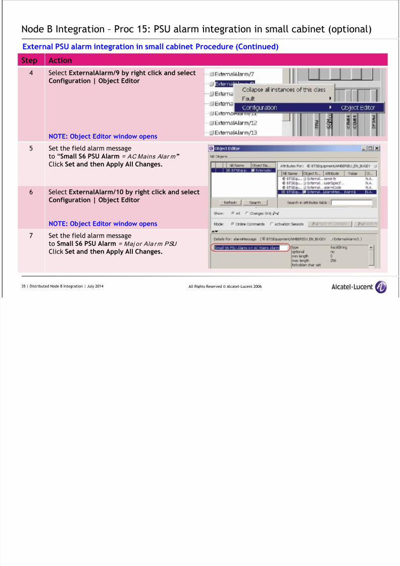
Node B Integration – Proc 15: PSU alarm integration in small cabinet (optional)
Step Action
4 Select ExternalAlarm/9 by right click and selectConfiguration | Object Editor
NOTE: Object Editor window opens
5 Set the field alarm message
to “Small S6 PSU Alarm = AC Mains Alar m”
Click Set and then Apply All Changes.
6 Select ExternalAlarm/10 by right click and selectConfiguration | Object Editor
NOTE: Object Editor window opens
7 Set the field alarm message
to Small S6 PSU Alarm = Maj or Ala rm PSU
Click Set and then Apply All Changes.
External PSU alarm integration in small cabinet Procedure (Continued)
35 | Distributed Node B Integration | July 2014
8/17/2019 TMO 18553 WCDMA d2U d4U Distributed NodeB Integration in an Existing UTRAN _ 14w29.pdf
http://slidepdf.com/reader/full/tmo-18553-wcdma-d2u-d4u-distributed-nodeb-integration-in-an-existing-utran 36/84
All Rights Reserved © Alcatel-Lucent 2006
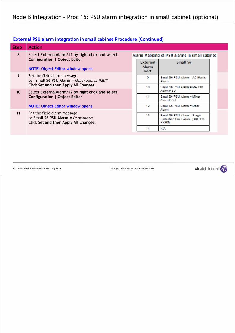
Node B Integration – Proc 15: PSU alarm integration in small cabinet (optional)
Step Action
8 Select ExternalAlarm/11 by right click and selectConfiguration | Object Editor
NOTE: Object Editor window opens
9 Set the field alarm message
to “Small S6 PSU Alarm = Minor Alar m PSU”
Click Set and then Apply All Changes.
10 Select ExternalAlarm/12 by right click and selectConfiguration | Object Editor
NOTE: Object Editor window opens
11 Set the field alarm message
to Small S6 PSU Alarm = Door Alar m
Click Set and then Apply All Changes.
External PSU alarm integration in small cabinet Procedure (Continued)
36 | Distributed Node B Integration | July 2014
8/17/2019 TMO 18553 WCDMA d2U d4U Distributed NodeB Integration in an Existing UTRAN _ 14w29.pdf
http://slidepdf.com/reader/full/tmo-18553-wcdma-d2u-d4u-distributed-nodeb-integration-in-an-existing-utran 37/84
All Rights Reserved © Alcatel-Lucent 2006
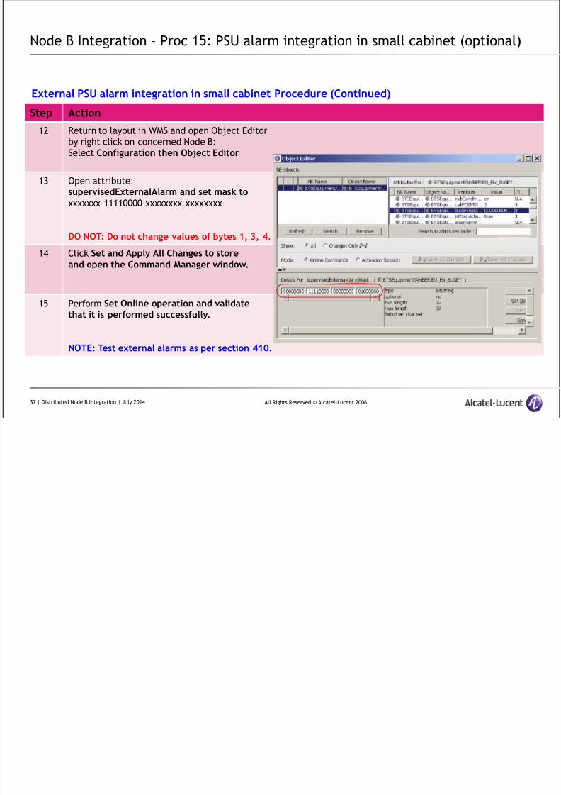
Node B Integration – Proc 15: PSU alarm integration in small cabinet (optional)
Step Action
12 Return to layout in WMS and open Object Editor
by right click on concerned Node B:
Select Configuration then Object Editor
13 Open attribute:supervisedExternalAlarm and set mask to
xxxxxxx 11110000 xxxxxxxx xxxxxxxx
DO NOT: Do not change values of bytes 1, 3, 4.
14 Click Set and Apply All Changes to storeand open the Command Manager window.
15 Perform Set Online operation and validatethat it is performed successfully.
NOTE: Test external alarms as per section 410.
External PSU alarm integration in small cabinet Procedure (Continued)
37 | Distributed Node B Integration | July 2014
8/17/2019 TMO 18553 WCDMA d2U d4U Distributed NodeB Integration in an Existing UTRAN _ 14w29.pdf
http://slidepdf.com/reader/full/tmo-18553-wcdma-d2u-d4u-distributed-nodeb-integration-in-an-existing-utran 38/84
All Rights Reserved © Alcatel-Lucent 2006
Node B Integration – Proc 15: PSU alarm integration in small cabinet (optional)
Step Action
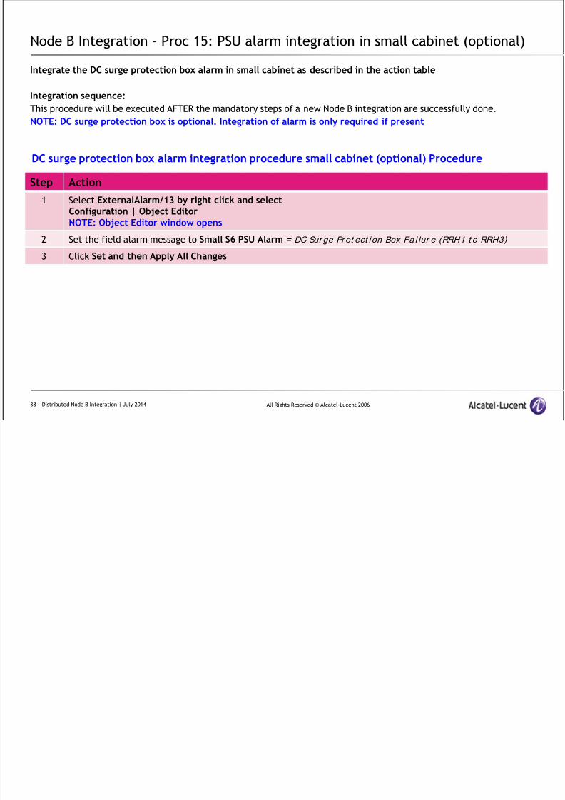
1 Select ExternalAlarm/13 by right click and selectConfiguration | Object EditorNOTE: Object Editor window opens
2 Set the field alarm message to Small S6 PSU Alarm = DC Sur ge Pr ot ect i on Box Fa i lur e (RRH1 t o RRH3)
3 Click Set and then Apply All Changes
DC surge protection box alarm integration procedure small cabinet (optional) Procedure
Integrate the DC surge protection box alarm in small cabinet as described in the action table
Integration sequence:
This procedure will be executed AFTER the mandatory steps of a new Node B integration are successfully done.
NOTE: DC surge protection box is optional. Integration of alarm is only required if present
38 | Distributed Node B Integration | July 2014
Node B Integration Proc 16: PSU alarm integration in medium cabinet
8/17/2019 TMO 18553 WCDMA d2U d4U Distributed NodeB Integration in an Existing UTRAN _ 14w29.pdf
http://slidepdf.com/reader/full/tmo-18553-wcdma-d2u-d4u-distributed-nodeb-integration-in-an-existing-utran 39/84
All Rights Reserved © Alcatel-Lucent 2006
Node B Integration – Proc 16: PSU alarm integration in medium cabinet
(optional)
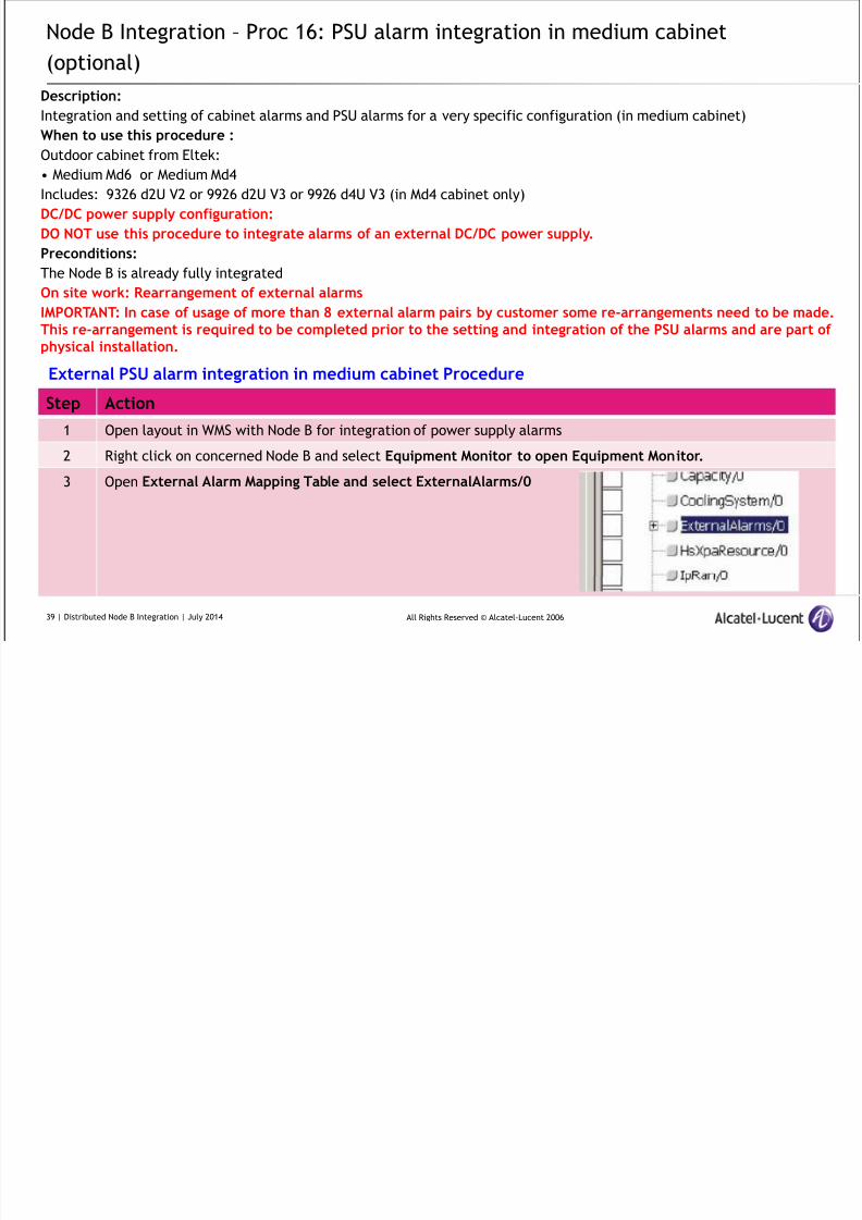
Description:
Integration and setting of cabinet alarms and PSU alarms for a very specific configuration (in medium cabinet)
When to use this procedure :
Outdoor cabinet from Eltek:• Medium Md6 or Medium Md4
Includes: 9326 d2U V2 or 9926 d2U V3 or 9926 d4U V3 (in Md4 cabinet only)
DC/DC power supply configuration:
DO NOT use this procedure to integrate alarms of an external DC/DC power supply.
Preconditions:
The Node B is already fully integrated
On site work: Rearrangement of external alarms
IMPORTANT: In case of usage of more than 8 external alarm pairs by customer some re-arrangements need to be made.This re-arrangement is required to be completed prior to the setting and integration of the PSU alarms and are part ofphysical installation.
Step Action
1 Open layout in WMS with Node B for integration of power supply alarms
2 Right click on concerned Node B and select Equipment Monitor to open Equipment Monitor.
3 Open External Alarm Mapping Table and select ExternalAlarms/0
External PSU alarm integration in medium cabinet Procedure
39 | Distributed Node B Integration | July 2014
Node B Integration Proc 16: PSU alarm integration in medium cabinet

8/17/2019 TMO 18553 WCDMA d2U d4U Distributed NodeB Integration in an Existing UTRAN _ 14w29.pdf
http://slidepdf.com/reader/full/tmo-18553-wcdma-d2u-d4u-distributed-nodeb-integration-in-an-existing-utran 40/84
All Rights Reserved © Alcatel-Lucent 2006
Node B Integration – Proc 16: PSU alarm integration in medium cabinet
(optional)
Step Action
4 Select ExternalAlarm/9 by right click and selectConfiguration | Object Editor
NOTE: Object Editor window opens
5 Set the field alarm message
to “Medium PSU Alarm = AC Mains Alar m”
Click Set and then Apply All Changes.
6 Select ExternalAlarm/10 by right click and selectConfiguration | Object Editor
NOTE: Object Editor window opens
7 Set the field alarm message
to Medium PSU Alarm = Maj or Alarm PSU
Click Set and then Apply All Changes.
External PSU alarm integration in medium cabinet Procedure (Continued)
40 | Distributed Node B Integration | July 2014
Node B Integration Proc 16: PSU alarm integration in medium cabinet

8/17/2019 TMO 18553 WCDMA d2U d4U Distributed NodeB Integration in an Existing UTRAN _ 14w29.pdf
http://slidepdf.com/reader/full/tmo-18553-wcdma-d2u-d4u-distributed-nodeb-integration-in-an-existing-utran 41/84
All Rights Reserved © Alcatel-Lucent 2006
Node B Integration – Proc 16: PSU alarm integration in medium cabinet
(optional)
Step Action
8 Select ExternalAlarm/11 by right click and selectConfiguration | Object Editor
NOTE: Object Editor window opens
9 Set the field alarm message
to “Medium PSU Alarm = Minor Alarm PSU”
Click Set and then Apply All Changes.
10 Select ExternalAlarm/12 by right click and selectConfiguration | Object Editor
NOTE: Object Editor window opens
11 Set the field alarm message
to Medium PSU Alarm = Door Alar m
Click Set and then Apply All Changes.
External PSU alarm integration in medium cabinet Procedure (Continued)
41 | Distributed Node B Integration | July 2014
Node B Integration Proc 16: PSU alarm integration in medium cabinet
8/17/2019 TMO 18553 WCDMA d2U d4U Distributed NodeB Integration in an Existing UTRAN _ 14w29.pdf
http://slidepdf.com/reader/full/tmo-18553-wcdma-d2u-d4u-distributed-nodeb-integration-in-an-existing-utran 42/84
All Rights Reserved © Alcatel-Lucent 2006
Node B Integration – Proc 16: PSU alarm integration in medium cabinet
(optional)
Step Action
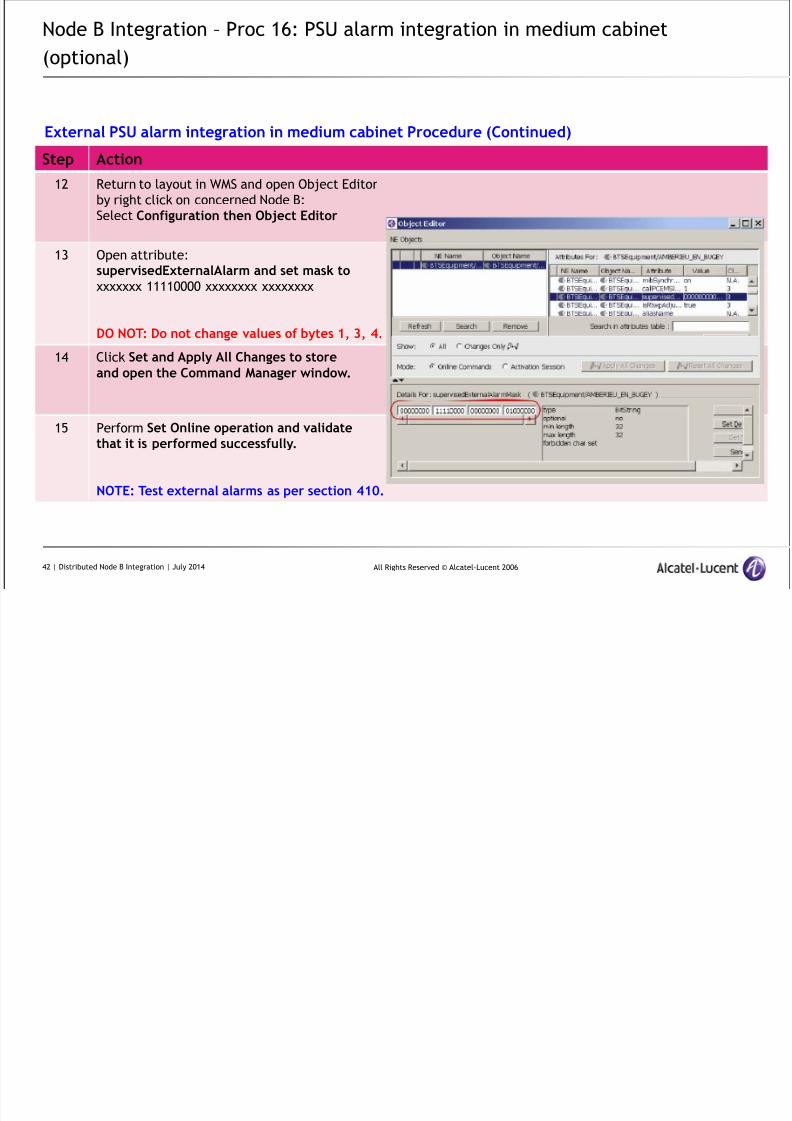
12 Return to layout in WMS and open Object Editor
by right click on concerned Node B:
Select Configuration then Object Editor
13 Open attribute:supervisedExternalAlarm and set mask to
xxxxxxx 11110000 xxxxxxxx xxxxxxxx
DO NOT: Do not change values of bytes 1, 3, 4.
14 Click Set and Apply All Changes to storeand open the Command Manager window.
15 Perform Set Online operation and validatethat it is performed successfully.
NOTE: Test external alarms as per section 410.
External PSU alarm integration in medium cabinet Procedure (Continued)
42 | Distributed Node B Integration | July 2014
Node B Integration Proc 16: PSU alarm integration in medium cabinet
8/17/2019 TMO 18553 WCDMA d2U d4U Distributed NodeB Integration in an Existing UTRAN _ 14w29.pdf
http://slidepdf.com/reader/full/tmo-18553-wcdma-d2u-d4u-distributed-nodeb-integration-in-an-existing-utran 43/84
All Rights Reserved © Alcatel-Lucent 2006
Node B Integration – Proc 16: PSU alarm integration in medium cabinet
(optional)
Step Action
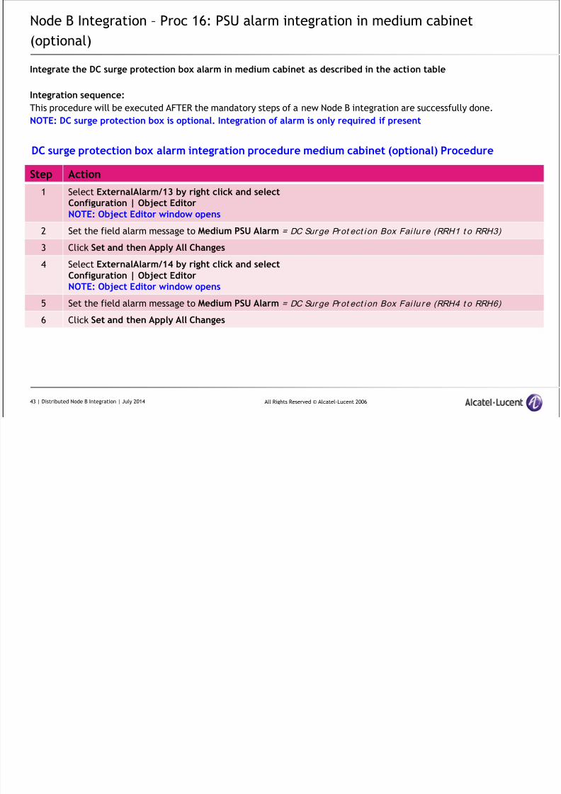
1 Select ExternalAlarm/13 by right click and select
Configuration | Object EditorNOTE: Object Editor window opens
2 Set the field alarm message to Medium PSU Alarm = DC Sur ge Pr ot ect i on Box Fai lu r e (RRH1 t o RRH3)
3 Click Set and then Apply All Changes
4 Select ExternalAlarm/14 by right click and selectConfiguration | Object EditorNOTE: Object Editor window opens
5 Set the field alarm message to Medium PSU Alarm = DC Sur ge Pr ot ect i on Box Fai lu r e (RRH4 t o RRH6)
6 Click Set and then Apply All Changes
DC surge protection box alarm integration procedure medium cabinet (optional) Procedure
Integrate the DC surge protection box alarm in medium cabinet as described in the action table
Integration sequence:
This procedure will be executed AFTER the mandatory steps of a new Node B integration are successfully done.
NOTE: DC surge protection box is optional. Integration of alarm is only required if present
43 | Distributed Node B Integration | July 2014

8/17/2019 TMO 18553 WCDMA d2U d4U Distributed NodeB Integration in an Existing UTRAN _ 14w29.pdf
http://slidepdf.com/reader/full/tmo-18553-wcdma-d2u-d4u-distributed-nodeb-integration-in-an-existing-utran 44/84
All Rights Reserved © Alcatel-Lucent 2006
Distributed Node B
Integration Testing
8/17/2019 TMO 18553 WCDMA d2U d4U Distributed NodeB Integration in an Existing UTRAN _ 14w29.pdf
http://slidepdf.com/reader/full/tmo-18553-wcdma-d2u-d4u-distributed-nodeb-integration-in-an-existing-utran 45/84
All Rights Reserved © Alcatel-Lucent 2006
Node B Integration Testing - Tools Required
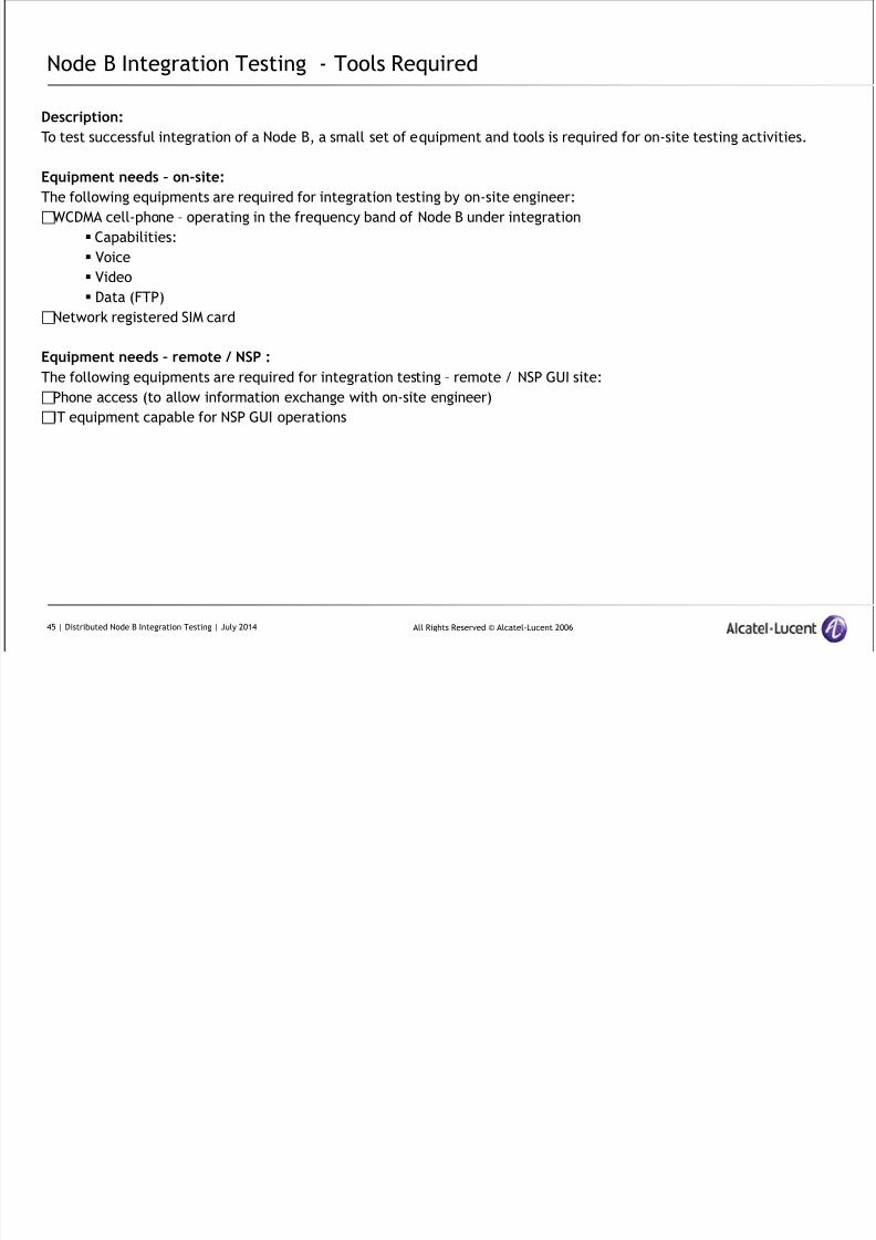
Description:
To test successful integration of a Node B, a small set of equipment and tools is required for on-site testing activities.
Equipment needs – on-site:
The following equipments are required for integration testing by on-site engineer:
WCDMA cell-phone – operating in the frequency band of Node B under integration
Capabilities:
Voice
Video
Data (FTP)
Network registered SIM card
Equipment needs – remote / NSP :
The following equipments are required for integration testing – remote / NSP GUI site:
Phone access (to allow information exchange with on-site engineer)
IT equipment capable for NSP GUI operations
45 | Distributed Node B Integration Testing | July 2014
8/17/2019 TMO 18553 WCDMA d2U d4U Distributed NodeB Integration in an Existing UTRAN _ 14w29.pdf
http://slidepdf.com/reader/full/tmo-18553-wcdma-d2u-d4u-distributed-nodeb-integration-in-an-existing-utran 46/84
All Rights Reserved © Alcatel-Lucent 2006
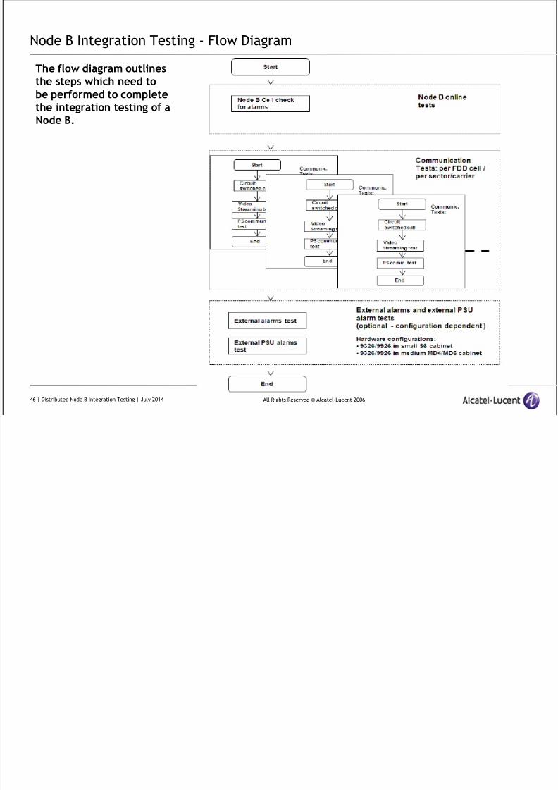
Node B Integration Testing - Flow Diagram
The flow diagram outlinesthe steps which need tobe performed to completethe integration testing of aNode B.
46 | Distributed Node B Integration Testing | July 2014

8/17/2019 TMO 18553 WCDMA d2U d4U Distributed NodeB Integration in an Existing UTRAN _ 14w29.pdf
http://slidepdf.com/reader/full/tmo-18553-wcdma-d2u-d4u-distributed-nodeb-integration-in-an-existing-utran 47/84
All Rights Reserved © Alcatel-Lucent 2006
Node B Integration Testing - Proc 1: Node B online tests
Description:
This procedure is used to check that there is no problem/unexpected alarm on the FDD cells of the Node B.
Preconditions:
Node B must be integrated (IEH 521-402)All cells must be unlocked / enabled
NSP session established
Inputs: Node B – NeID and RNC number of Node B under check
Step Action
1 Open layout view on WMS (NSP)
2 Set cursor on the RNC NE and click on the right mouse button to open pull-down menu
3 Select Show Alarms to open Alarm manager Window
4 Check that no FDD cells of the integrated Node B are in the alarm manager window and display anunexpected Node B alarm.NOTE: Use Node B NeID to identify Node B alarms of Node B under integration.
Node B online tests Procedure
If FDD cell alarms occur :
Analyze alarms by using the document External UTRAN Alarms Dictionary
Perform trouble shooting to clear unexpected FDD cell alarms before moving to next step of Integration testing
47 | Distributed Node B Integration Testing | July 2014
8/17/2019 TMO 18553 WCDMA d2U d4U Distributed NodeB Integration in an Existing UTRAN _ 14w29.pdf
http://slidepdf.com/reader/full/tmo-18553-wcdma-d2u-d4u-distributed-nodeb-integration-in-an-existing-utran 48/84
All Rights Reserved © Alcatel-Lucent 2006
Node B Integration Testing - Proc 1: Node B online tests: Communication Tests
Content of communication tests: The communication tests do consist of:
CS call test (voice)
Video Test (streaming video)
PS call test (FTP).Description: The full set of communication tests has to be performed on:
Every carrier (frequency) of the integrated Node B
Every sector of the integrated Node B.
Customer specific deviations
Customer specific requirements for testing may result in modifications of the call testing. Customer specific requests should
not change the generic flow of call tests operation and shall be reflected in performing / not performing individual call
tests (e.g. only on subset of FDD cells per Node B or reducing/increasing the number of call tests)
Customer specific requirements must be documented in the call testing sheet.Selection of sector and frequency for call tests
Lock all FDD cells of the integrated Node B which are NOT subject to call test of the required sector and frequency.
IMPORTANT:
Typically only ONE FDD cell (which is the cell dedicated for call testing) is unlocked. This will force the mobile phoneto use the desired cell for the call tests.
Change of selection of sector and frequency for call tests
A new FDD cell is made available for
call testing by change the locking status of FDD cells.
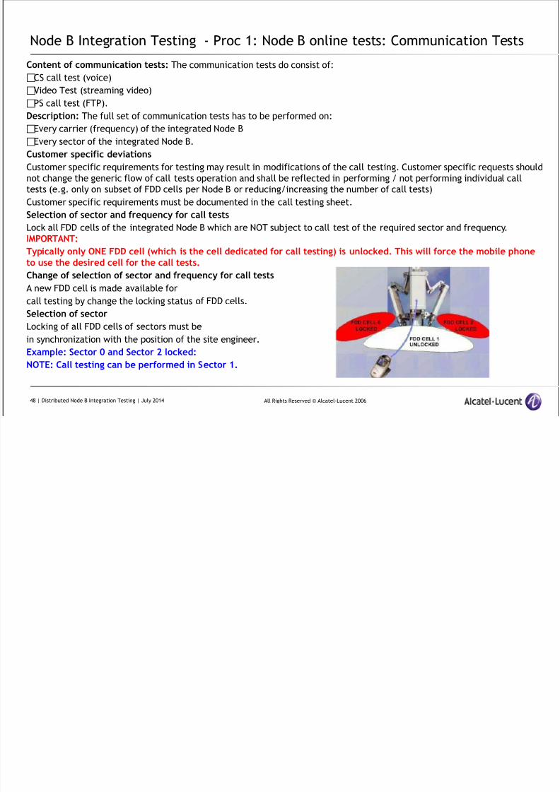
Selection of sector
Locking of all FDD cells of sectors must be
in synchronization with the position of the site engineer.
Example: Sector 0 and Sector 2 locked:
NOTE: Call testing can be performed in Sector 1.
48 | Distributed Node B Integration Testing | July 2014
8/17/2019 TMO 18553 WCDMA d2U d4U Distributed NodeB Integration in an Existing UTRAN _ 14w29.pdf
http://slidepdf.com/reader/full/tmo-18553-wcdma-d2u-d4u-distributed-nodeb-integration-in-an-existing-utran 49/84
All Rights Reserved © Alcatel-Lucent 2006
Node B Integration Testing - Flow Diagram of Call Tests Operation
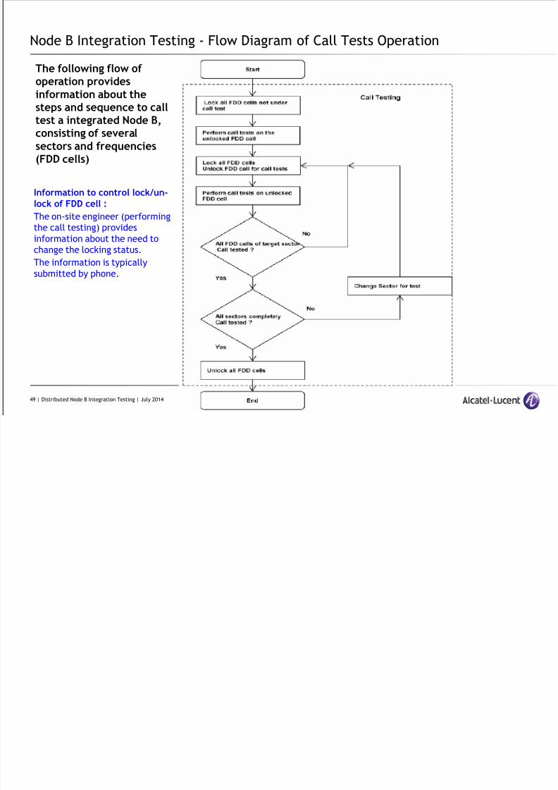
The following flow ofoperation providesinformation about thesteps and sequence to calltest a integrated Node B,consisting of severalsectors and frequencies(FDD cells)
Information to control lock/un-
lock of FDD cell :
The on-site engineer (performing
the call testing) provides
information about the need to
change the locking status.
The information is typically
submitted by phone.
49 | Distributed Node B Integration Testing | July 2014
Node B Integration Testing - Proc 2: Change Locking/Un-locking status of FDD
8/17/2019 TMO 18553 WCDMA d2U d4U Distributed NodeB Integration in an Existing UTRAN _ 14w29.pdf
http://slidepdf.com/reader/full/tmo-18553-wcdma-d2u-d4u-distributed-nodeb-integration-in-an-existing-utran 50/84
All Rights Reserved © Alcatel-Lucent 2006
Node B Integration Testing Proc 2: Change Locking/Un locking status of FDD
cells
Description:
This procedure allows to lock / unlock FDD cells of a dedicated Node B.
Preconditions:
NSP GUI operationalNode B under call test must be known
Information from on – site engineer
Use Case
Procedure 2 (Change Locking / Un-locking status of FDD cells) need to be used to establish the correct test environment for
communication tests as part of integration testing.
Each procedure has to be executed for each FDD cell.
50 | Distributed Node B Integration Testing | July 2014
Node B Integration Testing - Proc 2: Change Locking/Un-locking status of FDD

8/17/2019 TMO 18553 WCDMA d2U d4U Distributed NodeB Integration in an Existing UTRAN _ 14w29.pdf
http://slidepdf.com/reader/full/tmo-18553-wcdma-d2u-d4u-distributed-nodeb-integration-in-an-existing-utran 51/84
All Rights Reserved © Alcatel-Lucent 2006
Node B Integration Testing Proc 2: Change Locking/Un locking status of FDD
cells (Continued)
Locking of FDD cells Procedure
Step Action
1 Right click in Layout on concerned RNC (Node B under test is connected there) to open sub-menu
2 Click on Equipment Monitor to open Equipment Monitor window
3 Select FDD cell of Node B under integration test
targeted to lock.
Then pressConfiguration|Set Administrative State.
RESULT: The Set Administrative State Action Window opens for selected FDD cell.
4 Click on Lock button to start execution of lock command.
5 Monitor successful execution of Lock command in Command Manager window by selecting logsRESULT: Selected FDD cell is locked (and therefore no call can be made through this cell)
6 Repeat steps 1 to 5 for every FDD cell to be locked.
51 | Distributed Node B Integration Testing | July 2014
Node B Integration Testing - Proc 2: Change Locking/Un-locking status of FDD
8/17/2019 TMO 18553 WCDMA d2U d4U Distributed NodeB Integration in an Existing UTRAN _ 14w29.pdf
http://slidepdf.com/reader/full/tmo-18553-wcdma-d2u-d4u-distributed-nodeb-integration-in-an-existing-utran 52/84
All Rights Reserved © Alcatel-Lucent 2006
g g g g g
cells (Continued)
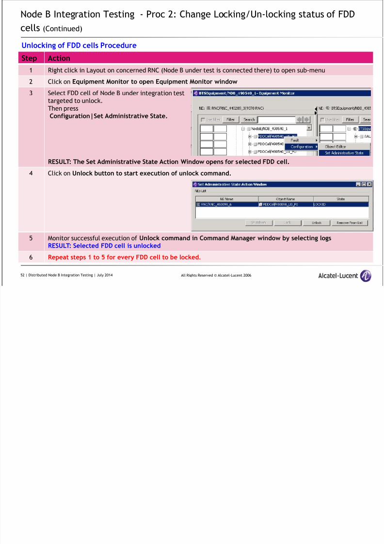
Unlocking of FDD cells Procedure
Step Action
1 Right click in Layout on concerned RNC (Node B under test is connected there) to open sub-menu
2 Click on Equipment Monitor to open Equipment Monitor window
3 Select FDD cell of Node B under integration test
targeted to unlock.
Then pressConfiguration|Set Administrative State.
RESULT: The Set Administrative State Action Window opens for selected FDD cell.
4 Click on Unlock button to start execution of unlock command.
5 Monitor successful execution of Unlock command in Command Manager window by selecting logsRESULT: Selected FDD cell is unlocked
6 Repeat steps 1 to 5 for every FDD cell to be locked.
52 | Distributed Node B Integration Testing | July 2014

8/17/2019 TMO 18553 WCDMA d2U d4U Distributed NodeB Integration in an Existing UTRAN _ 14w29.pdf
http://slidepdf.com/reader/full/tmo-18553-wcdma-d2u-d4u-distributed-nodeb-integration-in-an-existing-utran 53/84
All Rights Reserved © Alcatel-Lucent 2006
Node B Integration Testing - Proc 3: Circuit Switched Call Test
Description:
Perform circuit switched communication tests (audio) to proof successful integration of the new Node B
Preconditions:Fully integrated Node B into existing UTRAN (unlocked enabled)
No impacting Alarms on Node B or RNC
Specific Cell phone with network registered SIM
Telephone number for test (PSTN)
FDD cells not under test must be locked.
Call tester (on-site engineer) must be in correct position within sector under test
Communication with integratorIMPORTANT: For all communication tests, collaboration of on-site personnel and integration tester is required. Usetelephone connection to exchange necessary information.
Call testing position
IMPORTANT: On site engineer´s position during communication testing must be:
in the area, covered by the FDD cell under test (sector)
at least 100m away from the antenna position
CS call - test definition
Circuit Switched Call on FDD cell of a Node B.
Recommended call duration: ~ 2 mins
Success criteria
Connection to predefined subscriber is established. Understandable audio conversation (uplink and downlink).
53 | Distributed Node B Integration Testing | July 2014
8/17/2019 TMO 18553 WCDMA d2U d4U Distributed NodeB Integration in an Existing UTRAN _ 14w29.pdf
http://slidepdf.com/reader/full/tmo-18553-wcdma-d2u-d4u-distributed-nodeb-integration-in-an-existing-utran 54/84
All Rights Reserved © Alcatel-Lucent 2006
Node B Integration Testing - Proc 3: Circuit Switched Call Test (Continued)
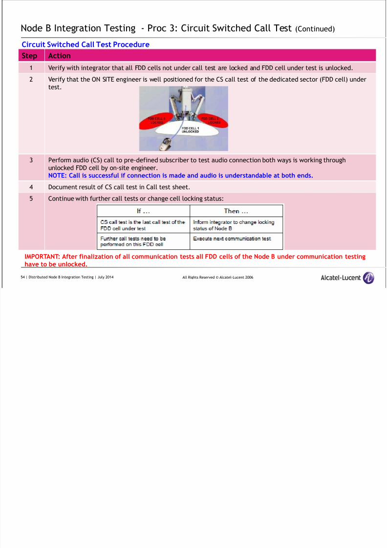
Circuit Switched Call Test Procedure
Step Action
1 Verify with integrator that all FDD cells not under call test are locked and FDD cell under test is unlocked.
2 Verify that the ON SITE engineer is well positioned for the CS call test of the dedicated sector (FDD cell) under
test.
3 Perform audio (CS) call to pre-defined subscriber to test audio connection both ways is working through
unlocked FDD cell by on-site engineer.NOTE: Call is successful if connection is made and audio is understandable at both ends.
4 Document result of CS call test in Call test sheet.
5 Continue with further call tests or change cell locking status:
IMPORTANT: After finalization of all communication tests all FDD cells of the Node B under communication testinghave to be unlocked.
54 | Distributed Node B Integration Testing | July 2014
8/17/2019 TMO 18553 WCDMA d2U d4U Distributed NodeB Integration in an Existing UTRAN _ 14w29.pdf
http://slidepdf.com/reader/full/tmo-18553-wcdma-d2u-d4u-distributed-nodeb-integration-in-an-existing-utran 55/84
All Rights Reserved © Alcatel-Lucent 2006
Node B Integration Testing - Proc 4: Video Call Test
Description:
A video call is performed to proof video capabilities of the integrated FDD cell work (UL/DL)
Preconditions:Fully integrated Node B into existing UTRAN (unlocked enabled)
No impacting Alarms on Node B or RNC
Specific Cell phone (video call capable) with network registered SIM
Telephone number for test (Video call capable)
FDD cells not under test must be locked.
Call tester (on-site engineer) must be in correct position within sector under test
Communication with integratorIMPORTANT: For all communication tests, collaboration of on-site personnel and integration tester is required. Usetelephone connection to exchange necessary information.
Call testing position
IMPORTANT: On site engineer´s position during communication testing must be:
in the area, covered by the FDD cell under test (sector)
at least 100m away from the antenna position
Video call - test definition
Video Call on FDD cell under test of a Node B.
Recommended call duration: ~ 1 min
NOTE: If no video capable partner for testing is available using streaming video test (e.g. www.youtube.com) wouldalternatively be possible as backup solution for test.
55 | Distributed Node B Integration Testing | July 2014
8/17/2019 TMO 18553 WCDMA d2U d4U Distributed NodeB Integration in an Existing UTRAN _ 14w29.pdf
http://slidepdf.com/reader/full/tmo-18553-wcdma-d2u-d4u-distributed-nodeb-integration-in-an-existing-utran 56/84
All Rights Reserved © Alcatel-Lucent 2006
Node B Integration Testing - Proc 4: Video Call Test (Continued)
Video Call Test Procedure
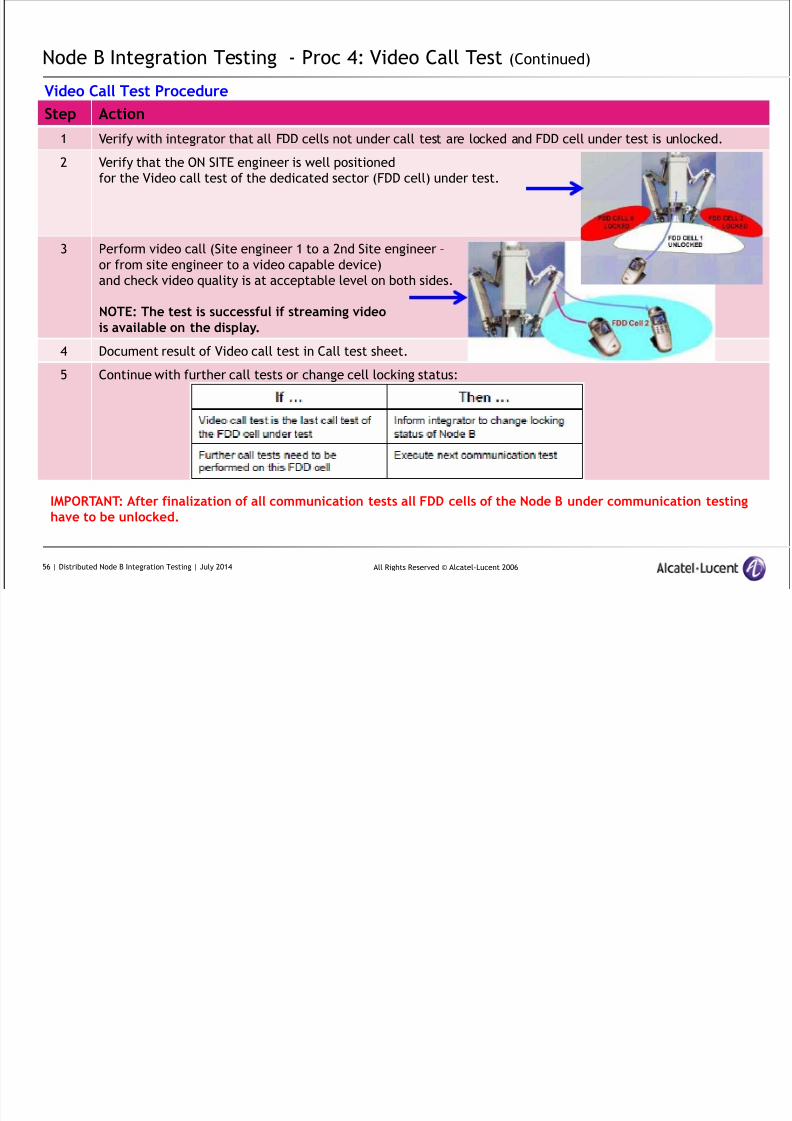
Step Action
1 Verify with integrator that all FDD cells not under call test are locked and FDD cell under test is unlocked.
2 Verify that the ON SITE engineer is well positioned
for the Video call test of the dedicated sector (FDD cell) under test.
3 Perform video call (Site engineer 1 to a 2nd Site engineer –
or from site engineer to a video capable device)
and check video quality is at acceptable level on both sides.
NOTE: The test is successful if streaming videois available on the display.
4 Document result of Video call test in Call test sheet.
5 Continue with further call tests or change cell locking status:
IMPORTANT: After finalization of all communication tests all FDD cells of the Node B under communication testinghave to be unlocked.
56 | Distributed Node B Integration Testing | July 2014
8/17/2019 TMO 18553 WCDMA d2U d4U Distributed NodeB Integration in an Existing UTRAN _ 14w29.pdf
http://slidepdf.com/reader/full/tmo-18553-wcdma-d2u-d4u-distributed-nodeb-integration-in-an-existing-utran 57/84
All Rights Reserved © Alcatel-Lucent 2006
Node B Integration Testing - Proc 5: Packet Switched Call Test
Description:
Validate PS network connectivity end-to-end – including Node B, RNC and GGSN by performing
Web browser test (open web page) for PS connectivity
FTP test to verify the throughput
Preconditions:
Fully integrated Node B into existing UTRAN (unlocked enabled)
No impacting Alarms on Node B or RNC
Specific Cell phone (PS call capable) with network registered SIM - with Laptop connected
FTP server address and target file for download
Test website (http://www.alcatel-lucent.com/)
FDD cells not under test must be locked.
Call tester (on-site engineer) must be in correct position within sector under testTarget throughput values for DL and UL are available for checking (from network design team)
Communication with integrator
IMPORTANT: For all communication tests, collaboration of on-site personnel and integration tester is required. Use telephoneconnection to exchange necessary information.
Call testing position
IMPORTANT: On site engineer´s position during communication testing must be:in the area, covered by the FDD cell under test (sector)
at least 100m away from the antenna position
PS call - test definition
Packet Switched call to available website on FDD cell of a Node B
File transfer to and from FTP server
57 | Distributed Node B Integration Testing | July 2014
8/17/2019 TMO 18553 WCDMA d2U d4U Distributed NodeB Integration in an Existing UTRAN _ 14w29.pdf
http://slidepdf.com/reader/full/tmo-18553-wcdma-d2u-d4u-distributed-nodeb-integration-in-an-existing-utran 58/84
All Rights Reserved © Alcatel-Lucent 2006
Node B Integration Testing - Proc 5: Packet Switched Call Test (Continued)
Packet Switched Call Test Procedure
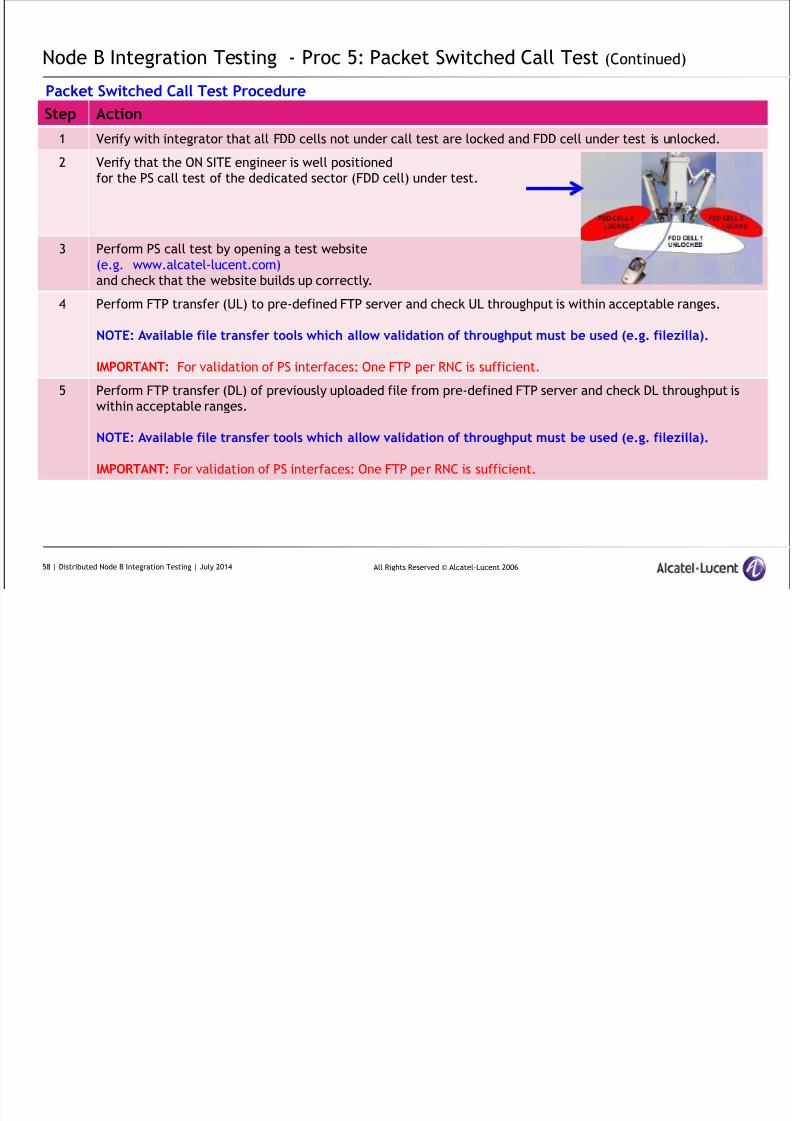
Step Action
1 Verify with integrator that all FDD cells not under call test are locked and FDD cell under test is unlocked.
2 Verify that the ON SITE engineer is well positioned
for the PS call test of the dedicated sector (FDD cell) under test.
3 Perform PS call test by opening a test website
(e.g. www.alcatel-lucent.com)
and check that the website builds up correctly.4 Perform FTP transfer (UL) to pre-defined FTP server and check UL throughput is within acceptable ranges.
NOTE: Available file transfer tools which allow validation of throughput must be used (e.g. filezilla).
IMPORTANT: For validation of PS interfaces: One FTP per RNC is sufficient.
5 Perform FTP transfer (DL) of previously uploaded file from pre-defined FTP server and check DL throughput is
within acceptable ranges.
NOTE: Available file transfer tools which allow validation of throughput must be used (e.g. filezilla).
IMPORTANT: For validation of PS interfaces: One FTP per RNC is sufficient.
58 | Distributed Node B Integration Testing | July 2014
8/17/2019 TMO 18553 WCDMA d2U d4U Distributed NodeB Integration in an Existing UTRAN _ 14w29.pdf
http://slidepdf.com/reader/full/tmo-18553-wcdma-d2u-d4u-distributed-nodeb-integration-in-an-existing-utran 59/84
All Rights Reserved © Alcatel-Lucent 2006
Node B Integration Testing - Proc 5: Packet Switched Call Test (Continued)
Packet Switched Call Test Procedure
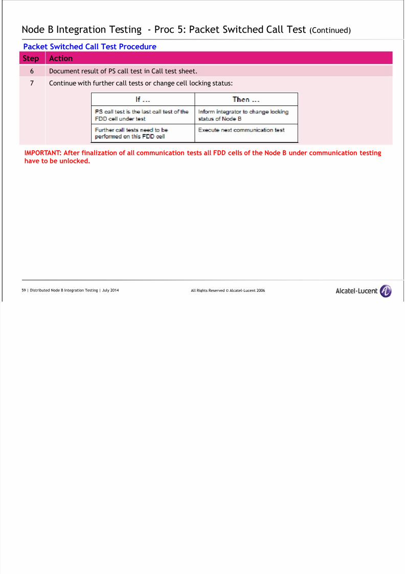
Step Action
6 Document result of PS call test in Call test sheet.
7 Continue with further call tests or change cell locking status:
IMPORTANT: After finalization of all communication tests all FDD cells of the Node B under communication testinghave to be unlocked.
59 | Distributed Node B Integration Testing | July 2014
Node B Integration Testing - Proc 6: External alarms test – small/medium

8/17/2019 TMO 18553 WCDMA d2U d4U Distributed NodeB Integration in an Existing UTRAN _ 14w29.pdf
http://slidepdf.com/reader/full/tmo-18553-wcdma-d2u-d4u-distributed-nodeb-integration-in-an-existing-utran 60/84
All Rights Reserved © Alcatel-Lucent 2006
cabinet (Optional)
Description:
This test is the validation that external PSU alarms are displayed at the OMC when they occur.
Tested Configuration
IMPORTANT: This test has only to be performed in case of d2U or d4U inside the
Small Outdoor cabinet (S6)
Medium Outdoor cabinet (Md4 or Md6)
Preconditions:
Integrated Node B:
Small Outdoor cabinet (S6)
Medium Outdoor cabinet (Md4 or Md6)
Integration of external PSU alarms have been doneSite engineer at Node B site to trigger alarms
Test Sample
It is economically not feasible to test all external alarms. Simple and quick validation can be done by checking the door alarm
60 | Distributed Node B Integration Testing | July 2014
Node B Integration Testing - Proc 6: External alarms test – small/medium
8/17/2019 TMO 18553 WCDMA d2U d4U Distributed NodeB Integration in an Existing UTRAN _ 14w29.pdf
http://slidepdf.com/reader/full/tmo-18553-wcdma-d2u-d4u-distributed-nodeb-integration-in-an-existing-utran 61/84
All Rights Reserved © Alcatel-Lucent 2006
cabinet (Optional) (Continued)
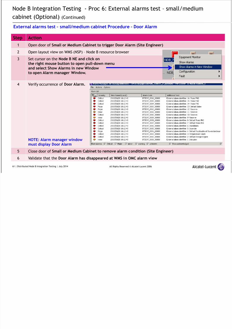
External alarms test – small/medium cabinet Procedure – Door Alarm
Step Action
1 Open door of Small or Medium Cabinet to trigger Door Alarm (Site Engineer)
2 Open layout view on WMS (NSP) – Node B resource browser
3 Set cursor on the Node B NE and click onthe right mouse button to open pull-down menuand select Show Alarms in new Windowto open Alarm manager Window.
4 Verify occurrence of Door Alarm.
NOTE: Alarm manager windowmust display Door Alarm
5 Close door of Small or Medium Cabinet to remove alarm condition (Site Engineer)
6 Validate that the Door Alarm has disappeared at WMS in OMC alarm view
61 | Distributed Node B Integration Testing | July 2014
Node B Integration Testing - Proc 7: External PSU alarms test – medium cabinet

8/17/2019 TMO 18553 WCDMA d2U d4U Distributed NodeB Integration in an Existing UTRAN _ 14w29.pdf
http://slidepdf.com/reader/full/tmo-18553-wcdma-d2u-d4u-distributed-nodeb-integration-in-an-existing-utran 62/84
All Rights Reserved © Alcatel-Lucent 2006
(Optional)
Description:
This test is the validation that an external PSU alarm of the medium cabinet is displayed at the OMC when they occur
Tested Configuration
IMPORTANT: This test has only to be performed in case of d2U or d4U inside the Medium Outdoor cabinet (Md4 or Md6)
Preconditions:
Integrated Node B: Medium Outdoor cabinet (Md4 or Md6)
Integration of external PSU alarms have been done
Site engineer at Node B site to trigger alarms
Test Sample
It is economically not feasible to test all power alarms. Simplest and quick validation can be done by checking the AC mains Alarm
IMPORTANT: This test can only to be performed in case of charged backup batteries are present.
62 | Distributed Node B Integration Testing | July 2014
Node B Integration Testing - Proc 7: External PSU alarms test – medium cabinet

8/17/2019 TMO 18553 WCDMA d2U d4U Distributed NodeB Integration in an Existing UTRAN _ 14w29.pdf
http://slidepdf.com/reader/full/tmo-18553-wcdma-d2u-d4u-distributed-nodeb-integration-in-an-existing-utran 63/84
All Rights Reserved © Alcatel-Lucent 2006
cabinet (Optional) (Continued)
External PSU alarms test – medium cabinet Procedure – AC Mains Alarm
Step Action
1 Switch off the AC customer breaker (which supplies the Small or Medium Cabinet) to trigger Medium PSUALARM = AC Mains Alarm PSU (Site Engineer)IMPORTANT: Do not leave AC customer breaker open for longer than 10 min (max) to avoid full discharge ofbatteries
2 Open layout view on WMS (NSP) – Node B resource browser
3 Set cursor on the Node B NE and click onthe right mouse button to open pull-down menuand select Show Alarms in new Window
to open Alarm manager Window.
4 Verify occurrence of
Medium PSU ALARM = AC Mains Alarm PSU.
NOTE: Alarm manager window must displayMedium PSU ALARM = AC Mains Alarm PSU.
5 Switch on the AC customer breaker (which supplies the Small or Medium Cabinet) to remove alarm condition
(Site Engineer)
6 Validate that the Medium PSU ALARM = AC Mains Alarm PSU has disappeared at WMS in OMC alarm view.
63 | Distributed Node B Integration Testing | July 2014
8/17/2019 TMO 18553 WCDMA d2U d4U Distributed NodeB Integration in an Existing UTRAN _ 14w29.pdf
http://slidepdf.com/reader/full/tmo-18553-wcdma-d2u-d4u-distributed-nodeb-integration-in-an-existing-utran 64/84
All Rights Reserved © Alcatel-Lucent 2006
Distributed Node B
Integration
Additional NSP GUI
8/17/2019 TMO 18553 WCDMA d2U d4U Distributed NodeB Integration in an Existing UTRAN _ 14w29.pdf
http://slidepdf.com/reader/full/tmo-18553-wcdma-d2u-d4u-distributed-nodeb-integration-in-an-existing-utran 65/84
All Rights Reserved © Alcatel-Lucent 2006
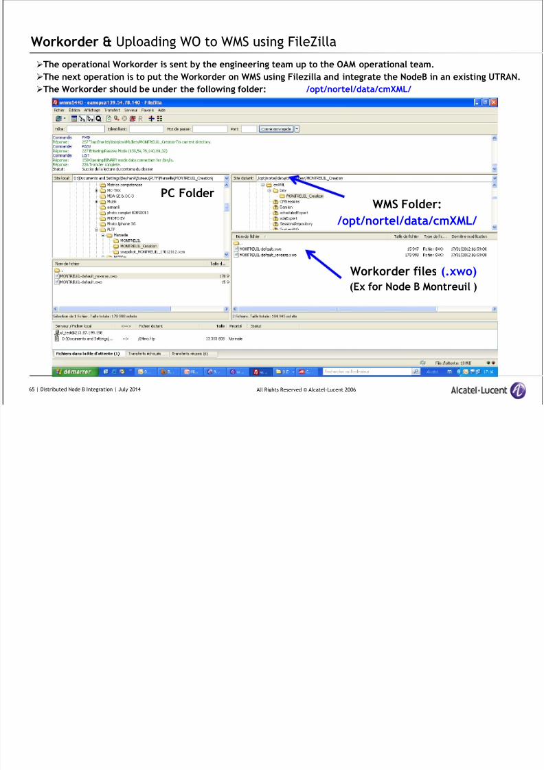
Workorder & Uploading WO to WMS using FileZilla
The operational Workorder is sent by the engineering team up to the OAM operational team.
The next operation is to put the Workorder on WMS using Filezilla and integrate the NodeB in an existing UTRAN.
The Workorder should be under the following folder: /opt/nortel/data/cmXML/
WMS Folder:
/opt/nortel/data/cmXML/
Workorder files (.xwo)
(Ex for Node B Montreuil )
PC Folder
65 | Distributed Node B Integration | July 2014

8/17/2019 TMO 18553 WCDMA d2U d4U Distributed NodeB Integration in an Existing UTRAN _ 14w29.pdf
http://slidepdf.com/reader/full/tmo-18553-wcdma-d2u-d4u-distributed-nodeb-integration-in-an-existing-utran 66/84
All Rights Reserved © Alcatel-Lucent 2006
Layout without NodeB MONTREUIL
Launch NSP and open the layout where the NodeB will be integrated
66 | Distributed Node B Integration | July 2014
8/17/2019 TMO 18553 WCDMA d2U d4U Distributed NodeB Integration in an Existing UTRAN _ 14w29.pdf
http://slidepdf.com/reader/full/tmo-18553-wcdma-d2u-d4u-distributed-nodeb-integration-in-an-existing-utran 67/84
All Rights Reserved © Alcatel-Lucent 2006
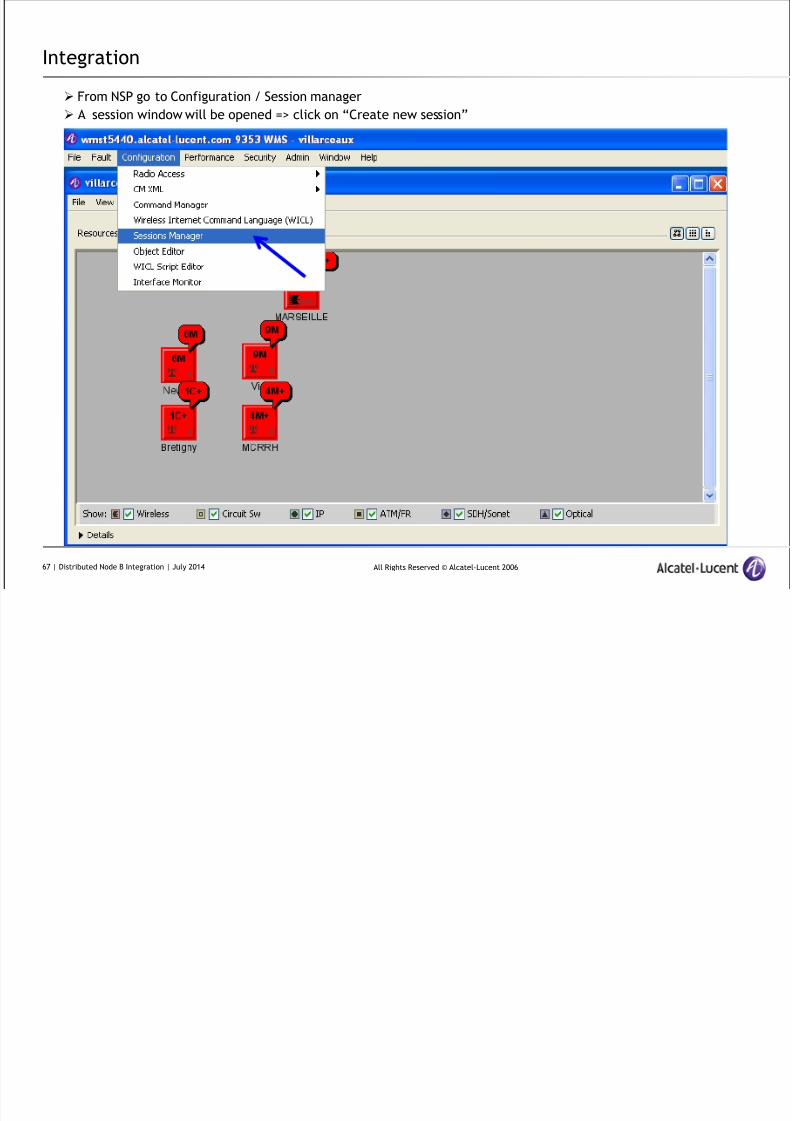
Integration
From NSP go to Configuration / Session manager
A session window will be opened => click on “Create new session”
67 | Distributed Node B Integration | July 2014
8/17/2019 TMO 18553 WCDMA d2U d4U Distributed NodeB Integration in an Existing UTRAN _ 14w29.pdf
http://slidepdf.com/reader/full/tmo-18553-wcdma-d2u-d4u-distributed-nodeb-integration-in-an-existing-utran 68/84
All Rights Reserved © Alcatel-Lucent 2006
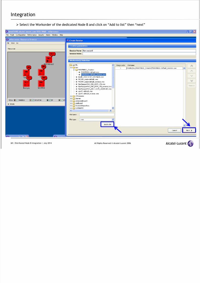
Integration
Select the Workorder of the dedicated Node B and click on “Add to list” then “next”
68 | Distributed Node B Integration | July 2014
8/17/2019 TMO 18553 WCDMA d2U d4U Distributed NodeB Integration in an Existing UTRAN _ 14w29.pdf
http://slidepdf.com/reader/full/tmo-18553-wcdma-d2u-d4u-distributed-nodeb-integration-in-an-existing-utran 69/84
All Rights Reserved © Alcatel-Lucent 2006
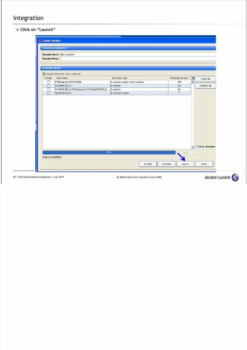
Integration
Click on “Launch”
69 | Distributed Node B Integration | July 2014
l d
8/17/2019 TMO 18553 WCDMA d2U d4U Distributed NodeB Integration in an Existing UTRAN _ 14w29.pdf
http://slidepdf.com/reader/full/tmo-18553-wcdma-d2u-d4u-distributed-nodeb-integration-in-an-existing-utran 70/84
All Rights Reserved © Alcatel-Lucent 2006
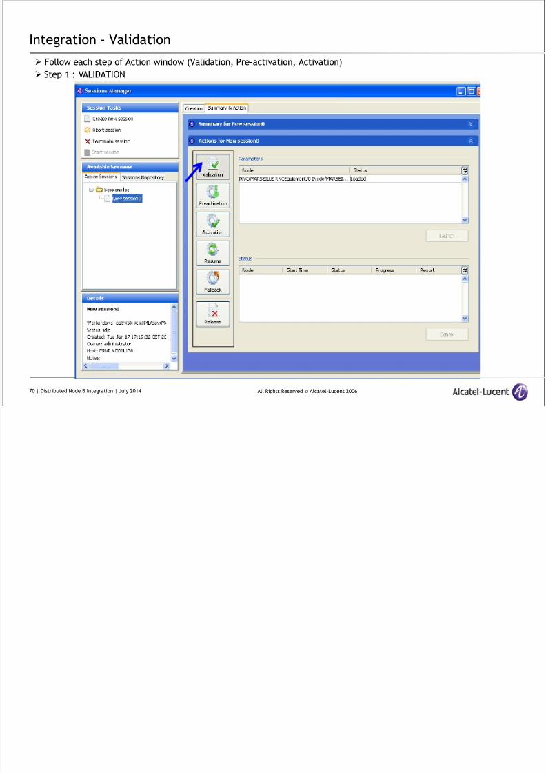
Integration - Validation
Follow each step of Action window (Validation, Pre-activation, Activation)
Step 1 : VALIDATION
70 | Distributed Node B Integration | July 2014
I i P i i
8/17/2019 TMO 18553 WCDMA d2U d4U Distributed NodeB Integration in an Existing UTRAN _ 14w29.pdf
http://slidepdf.com/reader/full/tmo-18553-wcdma-d2u-d4u-distributed-nodeb-integration-in-an-existing-utran 71/84
All Rights Reserved © Alcatel-Lucent 2006
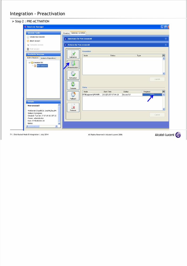
Integration - Preactivation
Step 2 : PRE-ACTIVATION
71 | Distributed Node B Integration | July 2014
I t ti A ti ti
8/17/2019 TMO 18553 WCDMA d2U d4U Distributed NodeB Integration in an Existing UTRAN _ 14w29.pdf
http://slidepdf.com/reader/full/tmo-18553-wcdma-d2u-d4u-distributed-nodeb-integration-in-an-existing-utran 72/84
All Rights Reserved © Alcatel-Lucent 2006
Integration - Activation
Step 3 : ACTIVATION
72 | Distributed Node B Integration | July 2014
I t ti T i t i

8/17/2019 TMO 18553 WCDMA d2U d4U Distributed NodeB Integration in an Existing UTRAN _ 14w29.pdf
http://slidepdf.com/reader/full/tmo-18553-wcdma-d2u-d4u-distributed-nodeb-integration-in-an-existing-utran 73/84
All Rights Reserved © Alcatel-Lucent 2006
Integration – Terminate session
Step 4 : TERMINATE SESSION / YES
73 | Distributed Node B Integration | July 2014
I t ti NE t
8/17/2019 TMO 18553 WCDMA d2U d4U Distributed NodeB Integration in an Existing UTRAN _ 14w29.pdf
http://slidepdf.com/reader/full/tmo-18553-wcdma-d2u-d4u-distributed-nodeb-integration-in-an-existing-utran 74/84
All Rights Reserved © Alcatel-Lucent 2006
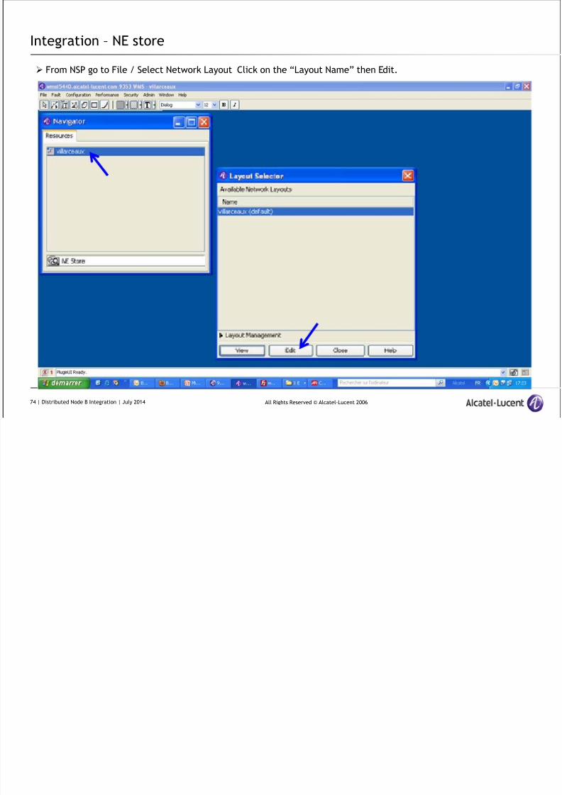
Integration – NE store
From NSP go to File / Select Network Layout Click on the “Layout Name” then Edit.
74 | Distributed Node B Integration | July 2014
I t g ti NE St
8/17/2019 TMO 18553 WCDMA d2U d4U Distributed NodeB Integration in an Existing UTRAN _ 14w29.pdf
http://slidepdf.com/reader/full/tmo-18553-wcdma-d2u-d4u-distributed-nodeb-integration-in-an-existing-utran 75/84
All Rights Reserved © Alcatel-Lucent 2006
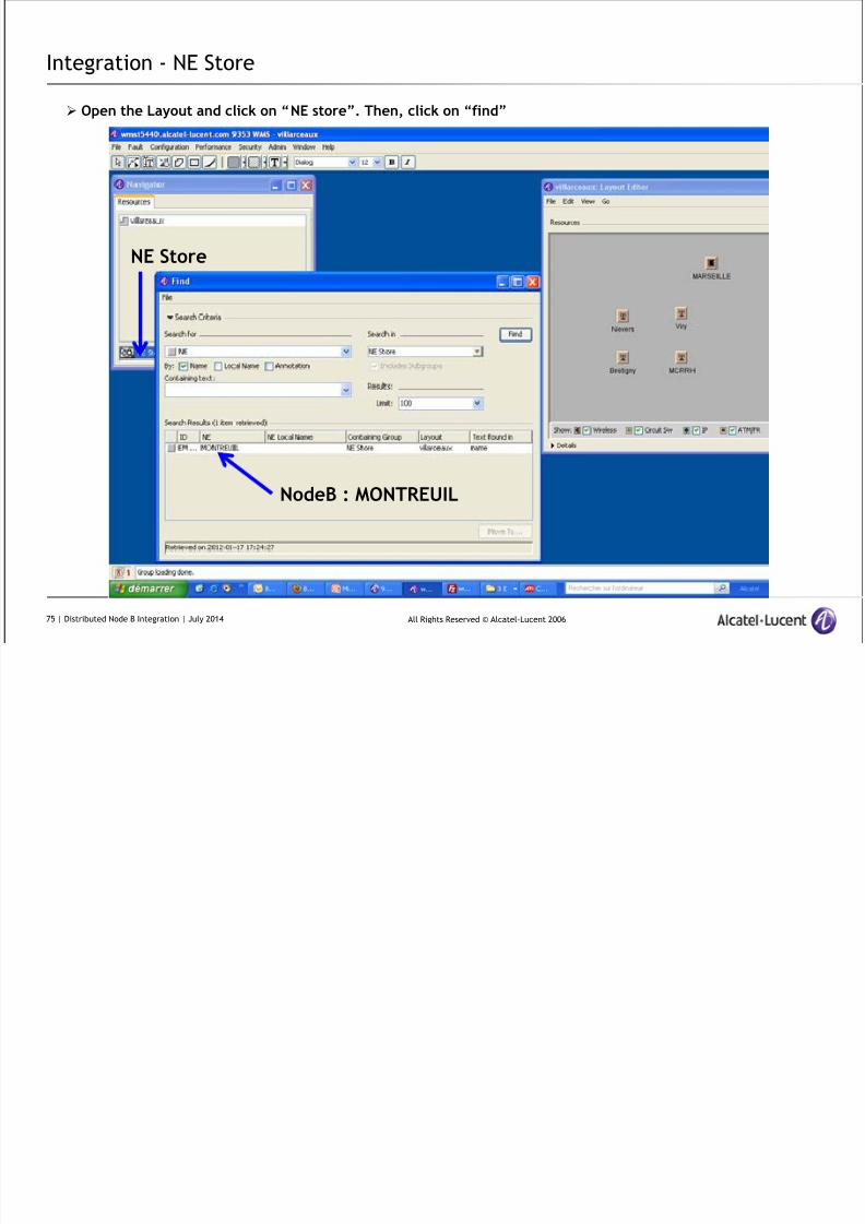
Integration - NE Store
Open the Layout and click on “NE store”. Then, click on “find”
NE Store
NodeB : MONTREUIL
75 | Distributed Node B Integration | July 2014
Inrtegration NE Store

8/17/2019 TMO 18553 WCDMA d2U d4U Distributed NodeB Integration in an Existing UTRAN _ 14w29.pdf
http://slidepdf.com/reader/full/tmo-18553-wcdma-d2u-d4u-distributed-nodeb-integration-in-an-existing-utran 76/84
All Rights Reserved © Alcatel-Lucent 2006
Inrtegration – NE Store
Select the NE (NodeB MONTREUIL) from the list and click on “Move to” and select the Layout
76 | Distributed Node B Integration | July 2014
Integration NE Store
8/17/2019 TMO 18553 WCDMA d2U d4U Distributed NodeB Integration in an Existing UTRAN _ 14w29.pdf
http://slidepdf.com/reader/full/tmo-18553-wcdma-d2u-d4u-distributed-nodeb-integration-in-an-existing-utran 77/84
All Rights Reserved © Alcatel-Lucent 2006
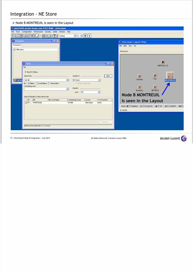
Integration - NE Store
Node B MONTREUIL
Is seen in the Layout
Node B MONTREUIL is seen in the Layout
77 | Distributed Node B Integration | July 2014
Integration
8/17/2019 TMO 18553 WCDMA d2U d4U Distributed NodeB Integration in an Existing UTRAN _ 14w29.pdf
http://slidepdf.com/reader/full/tmo-18553-wcdma-d2u-d4u-distributed-nodeb-integration-in-an-existing-utran 78/84
All Rights Reserved © Alcatel-Lucent 2006
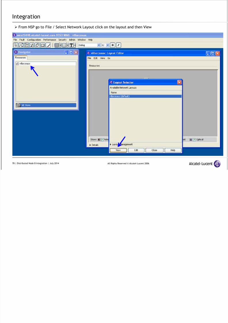
Integration
From NSP go to File / Select Network Layout click on the layout and then View
78 | Distributed Node B Integration | July 2014
Integration Neid

8/17/2019 TMO 18553 WCDMA d2U d4U Distributed NodeB Integration in an Existing UTRAN _ 14w29.pdf
http://slidepdf.com/reader/full/tmo-18553-wcdma-d2u-d4u-distributed-nodeb-integration-in-an-existing-utran 79/84
All Rights Reserved © Alcatel-Lucent 2006
Integration - Neid
From NSP open the layout. Select the NodeB, right click / configuration / Object editor
79 | Distributed Node B Integration | July 2014
Integration Neid
8/17/2019 TMO 18553 WCDMA d2U d4U Distributed NodeB Integration in an Existing UTRAN _ 14w29.pdf
http://slidepdf.com/reader/full/tmo-18553-wcdma-d2u-d4u-distributed-nodeb-integration-in-an-existing-utran 80/84
All Rights Reserved © Alcatel-Lucent 2006
Integration - Neid
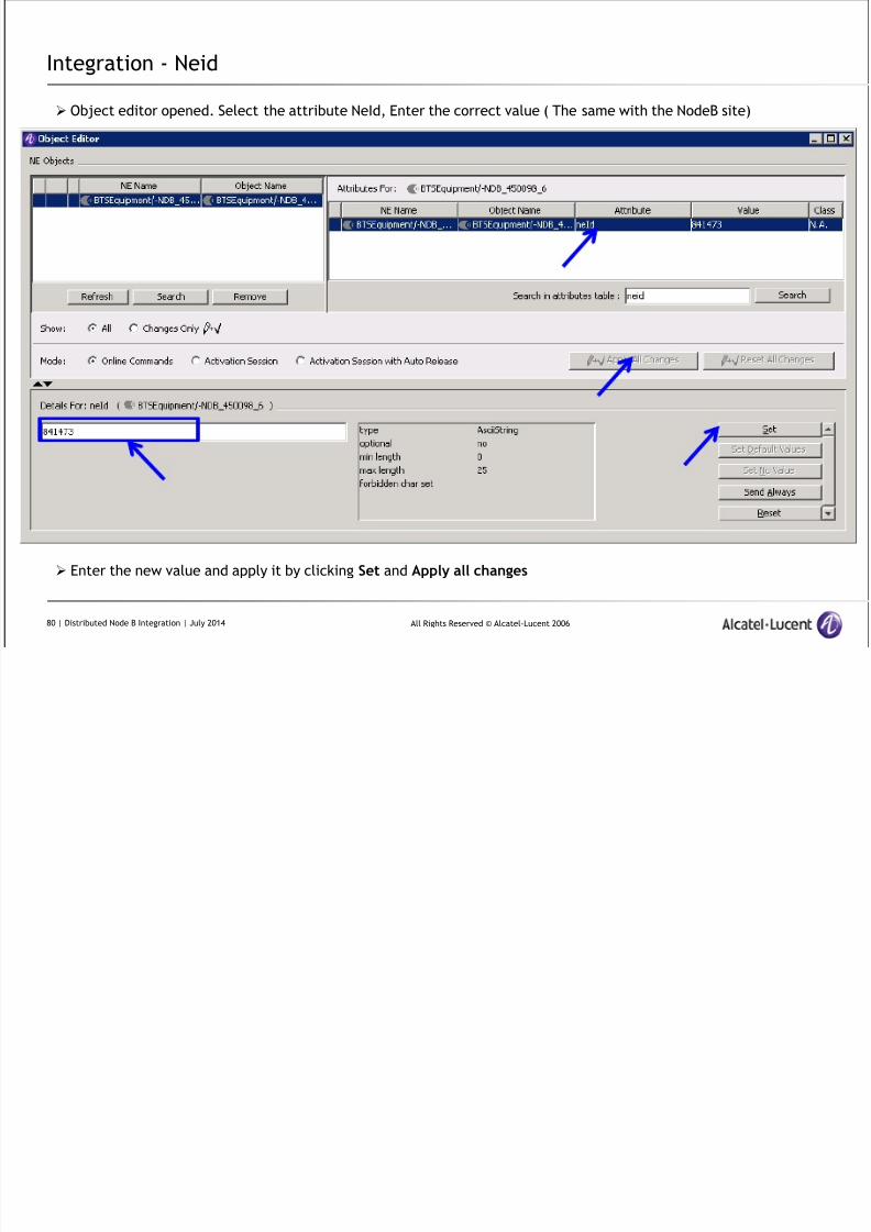
Object editor opened. Select the attribute NeId, Enter the correct value ( The same with the NodeB site)
Enter the new value and apply it by clicking Set and Apply all changes
80 | Distributed Node B Integration | July 2014
Integration
8/17/2019 TMO 18553 WCDMA d2U d4U Distributed NodeB Integration in an Existing UTRAN _ 14w29.pdf
http://slidepdf.com/reader/full/tmo-18553-wcdma-d2u-d4u-distributed-nodeb-integration-in-an-existing-utran 81/84
All Rights Reserved © Alcatel-Lucent 2006
Integration
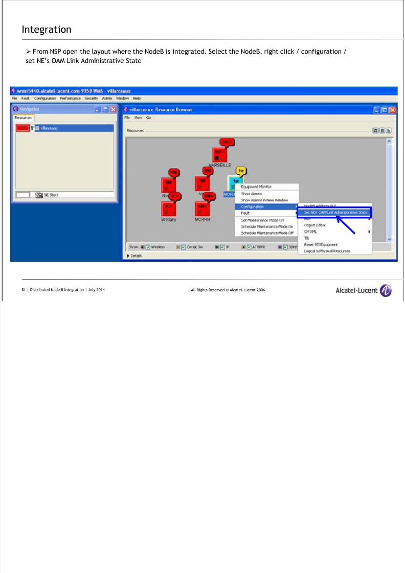
From NSP open the layout where the NodeB is integrated. Select the NodeB, right click / configuration /
set NE’s OAM Link Administrative State
81 | Distributed Node B Integration | July 2014
Integration
8/17/2019 TMO 18553 WCDMA d2U d4U Distributed NodeB Integration in an Existing UTRAN _ 14w29.pdf
http://slidepdf.com/reader/full/tmo-18553-wcdma-d2u-d4u-distributed-nodeb-integration-in-an-existing-utran 82/84
All Rights Reserved © Alcatel-Lucent 2006
Integration
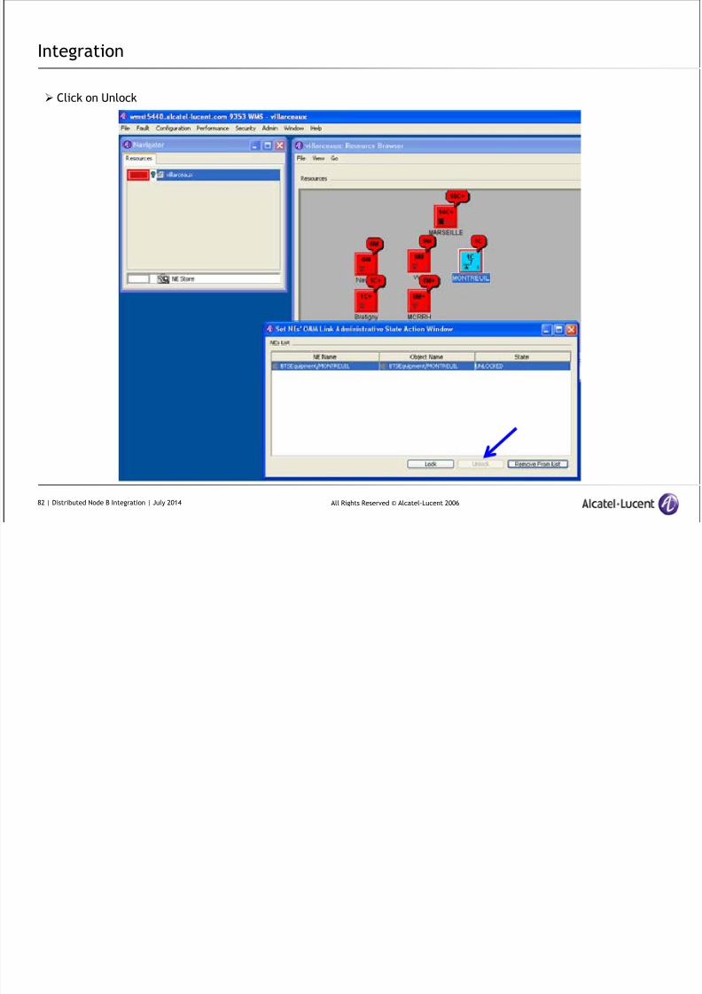
Click on Unlock
82 | Distributed Node B Integration | July 2014
Integration
8/17/2019 TMO 18553 WCDMA d2U d4U Distributed NodeB Integration in an Existing UTRAN _ 14w29.pdf
http://slidepdf.com/reader/full/tmo-18553-wcdma-d2u-d4u-distributed-nodeb-integration-in-an-existing-utran 83/84
All Rights Reserved © Alcatel-Lucent 2006
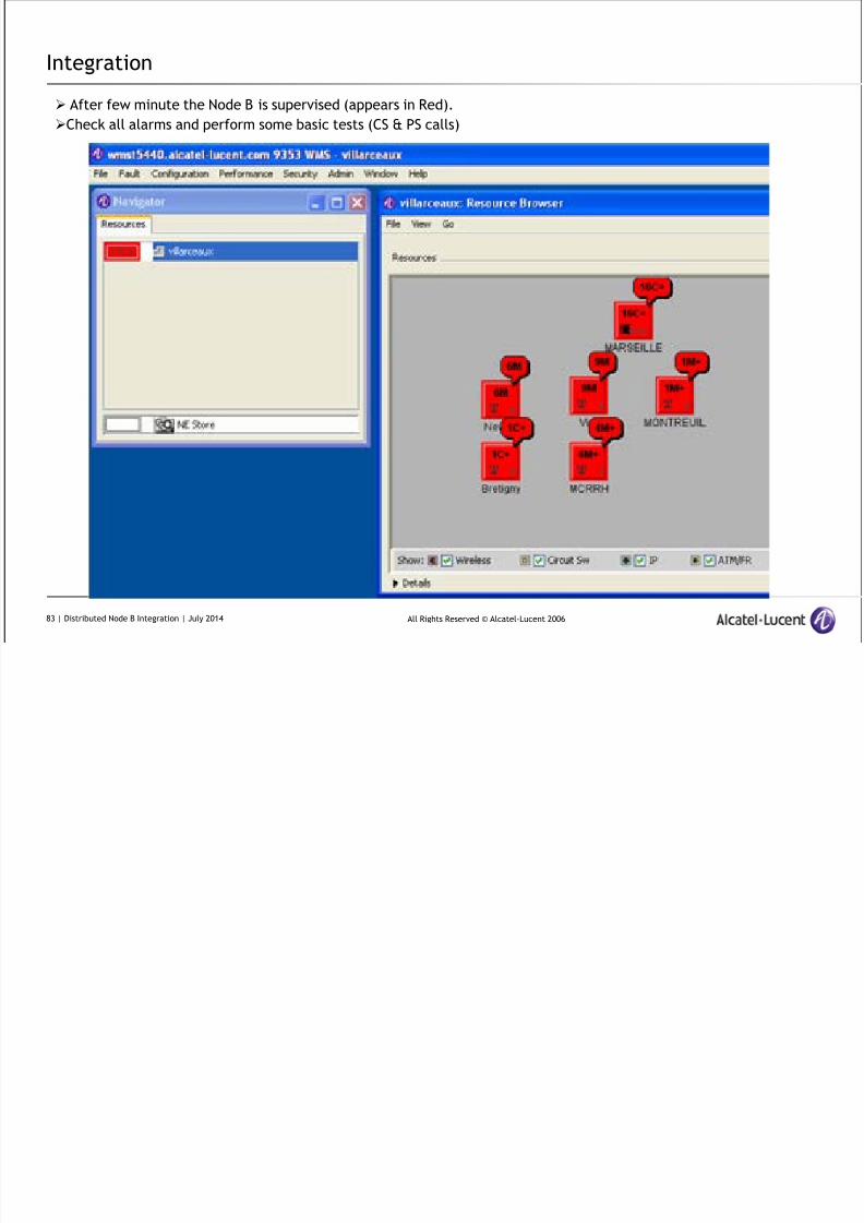
Integration
After few minute the Node B is supervised (appears in Red).
Check all alarms and perform some basic tests (CS & PS calls)
83 | Distributed Node B Integration | July 2014

8/17/2019 TMO 18553 WCDMA d2U d4U Distributed NodeB Integration in an Existing UTRAN _ 14w29.pdf
http://slidepdf.com/reader/full/tmo-18553-wcdma-d2u-d4u-distributed-nodeb-integration-in-an-existing-utran 84/84
www.alcatel-lucent.com