TMK, TMKW and TMK FL Orbital MotorTechnical Information TMK, TMKW and TMK FL Orbital Motors Versions...
40
MAKING MODERN LIVING POSSIBLE Technical Information Orbital Motor TMK, TMKW and TMK FL powersolutions.danfoss.com
Transcript of TMK, TMKW and TMK FL Orbital MotorTechnical Information TMK, TMKW and TMK FL Orbital Motors Versions...
MAKING MODERN LIVING POSSIBLE
Technical Information
Orbital MotorTMK, TMKW and TMK FL
powersolutions.danfoss.com

Revision History Table of Revisions
Date Changed Rev
Feb 2014 Converted to Danoss layout - DITA CMS FA
Apr 2006 EA
Technical Information TMK, TMKW and TMK FL Orbital Motors
2 520L0479 • Rev FA • Feb 2014
A wide range of Orbital MotorsCharacteristic, features and application areas of Orbital Motors....................................................................................5
Characteristic features of Danfoss Orbital Motors.......................................................................................................... 5Technical features of Danfoss Orbital Motor.....................................................................................................................5The Danfoss Orbital Motors are used in the following application areas:..............................................................6
Survey of literature with technical data on Danfoss Orbital Motors..............................................................................6
Data surveySpeed and torque ............................................................................................................................................................................7
VersionsVersion..................................................................................................................................................................................................8Features available (options)..........................................................................................................................................................8
Technical data
Technical dataTechnical data for parking brake motor TMK FL.................................................................................................................10
Schematic diagramSchematic diagram........................................................................................................................................................................11
Shaft sealMax. permissible shaft seal pressure.......................................................................................................................................12
TMK, TMKW and TMK FL with use of drain connection ............................................................................................. 12TMK with check valves and without use of drain connection..................................................................................12TMKW / TMK FL without check valves and without use of drain connection.....................................................12
Pressure dropPressure drop in motor................................................................................................................................................................ 13
Oil flowOil flow in drain line...................................................................................................................................................................... 14Direction of shaft rotation...........................................................................................................................................................14
Shaft loadPermissible shaft load for TMKW..............................................................................................................................................15
Mounting flange: Magneto, SAE-C ....................................................................................................................................15Mounting flange: Wheel ........................................................................................................................................................15Permissible radial shaft load.................................................................................................................................................15Permissible radial shaft load.................................................................................................................................................16
Function diagramsFunction diagrams.........................................................................................................................................................................17
TMK 160 function diagram....................................................................................................................................................17TMK 200 function diagram....................................................................................................................................................18TMK 250 function diagram....................................................................................................................................................18TMK 315 function diagram....................................................................................................................................................19TMK 400 function diagram....................................................................................................................................................19TMK 470 function diagram....................................................................................................................................................20
ShaftShaft Versions .................................................................................................................................................................................21
PortPort thread versions......................................................................................................................................................................23
Dimensions, US version, TMK with Magneto flangeTMK with Magneto flange.......................................................................................................................................................... 24
Dimensions................................................................................................................................................................................. 25
Dimensions, US version, TMK with SAE-C flangeTMK with SAE-C flange.................................................................................................................................................................26
Dimensions................................................................................................................................................................................. 26
Technical Information TMK, TMKW and TMK FL Orbital Motors
Contents
520L0479 • Rev FA • Feb 2014 3

Dimension, US version TMKW with side portTMKW with side port and drain connection........................................................................................................................ 28
Dimensions................................................................................................................................................................................. 29
Dimension, US version, TMKW with end portTMKW with end port and drain connection.........................................................................................................................30
Dimensions................................................................................................................................................................................. 31
Dimension, US version, TMK FL with side portTMK FL with side port and drain connection.......................................................................................................................32
Dimensions................................................................................................................................................................................. 33
Dimension, US version, TMK FL with end portTMK FL with end port and drain connection....................................................................................................................... 34
Dimensions................................................................................................................................................................................. 35
WeightWeight of Oribtal Motors............................................................................................................................................................ 36
Technical Information TMK, TMKW and TMK FL Orbital Motors
Contents
4 520L0479 • Rev FA • Feb 2014
Characteristic, features and application areas of Orbital Motors
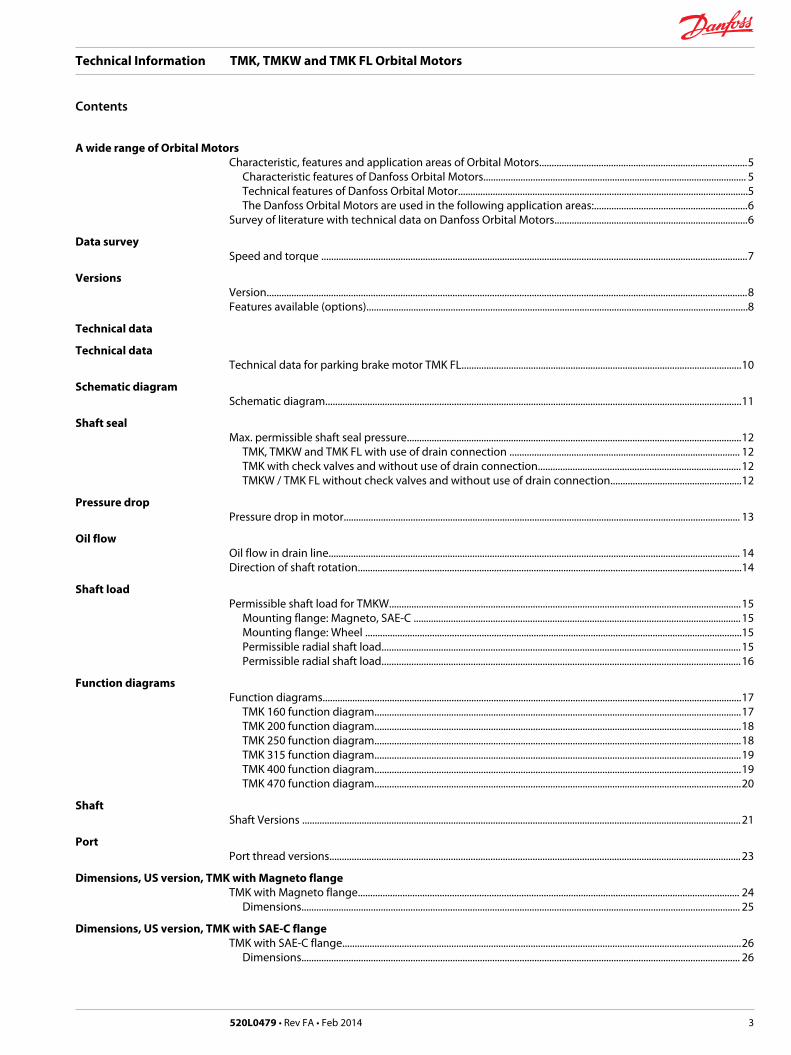
Danfoss is a world leader within production of low speed orbital motors with high torque. We can offermore than 3000 different orbital motors, categorised in types, variants and sizes (incl. different shaftversions).
The motors vary in size (rated displacement) from 8 cm³ [0.50 in³] to 800 cm³ [48.9 in³] per revolution.
Speeds range up to approx. 2500 min-1 (rpm) for the smallest type and up to approx. 600 min-1 (rpm) forthe largest type.
Maximum operating torques vary from 13 N•m [115 lbf•in] to 2700 N•m [24.000 lbf•in] (peak) andmaximum outputs are from 2.0 kW [2.7 hp] to 70 kW [95 hp].
Characteristic features of Danfoss Orbital Motors
• Smooth running over the entire speed range
• Constant operating torque over a wide speed range
• High starting torque
• High return pressure without the use of drain line (High pressure shaft seal)
• High efficiency
• Long life under extreme operating conditions
• Robust and compact design
• High radial and axial bearing capacity
• For applications in both open and closed loop hydraulic systems
• Suitable for a wide variety of hydraulics fluids
Technical features of Danfoss Orbital Motor
The programme is characterised by technical features appealing to a large number of applications and apart of the programme is characterised by motors that can be adapted to a given application. Adaptionscomprise the following variants among others:
Technical Information TMK, TMKW and TMK FL Orbital Motors
A wide range of Orbital Motors
520L0479 • Rev FA • Feb 2014 5

• Motors with corrosion resistant parts
• Wheel motors with recessed mounting flange
• OMP, OMR- motors with needle bearing
• OMR motor in low leakage version
• OMR motors in a super low leakage version
• Short motors without bearings
• Ultra short motors
• Motors with integrated positive holding brake
• Motors with integrated negative holding brake
• Motors with integrated flushing valve
• Motors with speed sensor
• Motors with tacho connection
• All motors are available with black finish paint
The Danfoss Orbital Motors are used in the following application areas:
• Construction equipment
• Agricultural equipment
• Material handling & Lifting equipment
• Forestry equipment
• Lawn and turf equipment
• Special purpose
• Machine tools and stationary equipment
• Marine equipment
Survey of literature with technical data on Danfoss Orbital Motors
Detailed data on all Danfoss Orbital Motors can be found in our motor catalogue, which is divided intomore individual subcatalogues:
• General information on Danfoss Orbital Motors: function, use, selection of orbital motor, hydraulicsystems, etc.
• Technical data on small motors: OML and OMM
• Technical data on medium sized motors: OMP, OMR, OMH
• Technical data on medium sized motors: DH and DS
• Technical data on medium sized motors: OMEW
• Technical data on medium sized motors: VMP
• Technical data on medium sized motors: VMR
• Technical data on large motors: OMS, OMT and OMV
• Technical data on large motors: TMT
• Technical data on large motors: TMV
A general survey brochure on Danfoss Orbital Motors gives a quick motor reference based on power,torque, speed and capabilities.
Technical Information TMK, TMKW and TMK FL Orbital Motors
A wide range of Orbital Motors
6 520L0479 • Rev FA • Feb 2014

Speed and torque
Max. speed / Max. torque
[light] Intermittent values
[dark] Continuous values
The bar diagrams above are useful for a quick selection of relevant motor size for the application. Thefinal motor size can be determined by using the function diagram for each motor size.
• TMK can be found under Function diagrams.
The function diagrams are based on actual tests on a representative number of motors from ourproduction. The diagrams apply to a return pressure between 5 and 10 bar [75 and 150 psi] when usingmineral based hydraulic oil with a viscosity of 35 mm²/s [165 SUS] and a temperature of 50°C [120°F]. Forfurther explanation concerning how to read and use the function diagrams, please consult the paragraph"Selection of motor size" in the technical information "General" DHMH.PK.100.G2.02 520L0232.
Technical Information TMK, TMKW and TMK FL Orbital Motors
Data survey
520L0479 • Rev FA • Feb 2014 7

Version
Orbit motors US-versions, standard shaft seals, drain connections and painted black
Mount.flange
Spigot diameterfront /rear end
Bolt circlediameter (BC)
Shaft Port size Side portversion
End portversion
Checkvalve
Main typedesign
Config.-code
Magneto Ø 3.25 in Ø 4.187 in Cyl. 1.25 in 1 1/16-12 UN x x TMK 1
Spl. 1.25 in 1 1/16-12 UN x x TMK 2
Tap. 1.25 in 1 1/16-12 UN x x TMK 3
SAE-C Ø 5 in Ø 6.375 in Cyl. 1.25 in 1 1/16-12 UN x x TMK 4
Spl. 1.25 in 1 1/16-12 UN x x TMK 5
Tap. 1.25 in 1 1/16-12 UN x x TMK 6
Tap. 1.5 in 1 1/16-12 UN x x TMK 7
Tap. 1.625 in 1 1/16-12 UN x x TMK 8
Wheel Ø 4.25 in Ø 5 in(rear)
Ø 5.8 in Tap. 1.5 in 1 1/16-12 UN x TMKW 9
7/8-14 UNF x TMKW 10
Brake std. Ø 5.5 in (onlyrear)
Ø 6.375 in Tap. 1.5 in 1 1/16-12 UN x TMK-FL 11
7/8-14 UNF x TMK-FL 12
Configuration code and code numbers
Config.- code Code number - displacement (cm³)
160 200 250 315 400 470
1 151F6060 151F6061 151F6062 151F6063 151F6064 151F6065
2 151F6050 151F6051 151F6052 151F6053 151F6054 151F6055
3 151F6070 151F6071 151F6072 151F6073 151F6074 151F6075
4 151F6130 151F6131 151F6132 151F6133 151F6134 151F6135
5 151F6120 151F6121 151F6122 151F6123 151F6124 151F6125
6 151F6140 151F6141 151F6142 151F6143 151F6144 151F6145
7 151F6090 151F6091 151F6092 151F6093 151F6094 151F6095
8 151F6080 151F6081 151F6082 151F6083 151F6084 151F6085
9 151F6010 151F6011 151F6012 151F6013 151F6014 151F6015
10 151F6030 151F6031 151F6032 151F6033 151F6034 151F6035
11 11008903 11008904 11008905 11008906 11008907 11008908
12 11008909 11008910 11008911 11008912 11008913 11008914
Features available (options)
Shaft options:
• Splined 1.5 in shaft
• Cyl. 40 mm shaft (not brake version)
Port option:
• Side port G 3/4
• End port G 1/2
Check valves
Flushing valves with different flushing flow
Motors are painted black
Technical Information TMK, TMKW and TMK FL Orbital Motors
Versions
8 520L0479 • Rev FA • Feb 2014

Type TMKTMKWTMK FL
TMKTMKWTMK FL
TMKTMKWTMK FL
TMKTMKWTMK FL
TMKTMKWTMK FL
TMKTMKWTMK FL
Motor size 160 200 250 315 400 470
Geometricdisplacement
cm³[in³]
158.0[9.64]
201.5[12.30]
252.2[15.39]
315.3[19.23]
397.2[24.24]
471.1[28.75]
Max. speed min-1
[rpm]cont. 505 400 320 255 200 170
int. 1) 630 500 400 315 250 210
Max. torque* cont. 570 [5045] 720 [6370] 910 [8055] 1050 [9295] 1070 [9470] 1080 [9560]
int. 1) 725 [6415] 920 [8140] 1070 [9470] 1310 [11595] 1400 [12390] 1350 [11950]
Max. output kW[hp]
cont. 22.0 [29.5] 22.0 [29.5] 21.0 [28] 20.0 [27] 17.5 [23.5] 13.0 [17.4]
int. 1) 27.0 [36] 27.0 [36] 25.0 [33.5] 23.5 [31.5] 22.0 [29.5] 17.0 [22.8]
Max. pressuredrop*
bar[psi]
cont. 250 [3625] 250 [3625] 250 [3625] 250 [3625] 200 [2900] 160 [2320]
int. 1) 325 [4715] 325 [4715] 300 [4350] 300 [4350] 250 [3625] 200 [2900]
Max. oil flow l/min[US gal/min]
cont. 80 [21.1] 80 [21.1] 80 [21.1] 80 [21.1] 80 [21.1] 80 [21.1]
int. 1) 100 [26.4] 100 [26.4] 100 [26.4] 100 [26.4] 100 [26.4] 100 [26.4]
Max. startingpressure withunloaded shaft
bar[psi]
8 [100] 8 [100] 7 [100] 7 [100] 7 [100] 7 [100]
Min. startingtorque
Nm[lbf•in]
at max. press.drop cont.:
430 [3805] 540 [4780] 680 [6020] 790 [6990] 800 [7080] 830 [7350]
at max. press.drop int.1):
545 [4825] 690 [6105] 800 [7080] 985 [8720] 1050 [9290] 1050 [9290]
Type Max. inlet pressure Max. return pressure with drain line
TMK 160 - 470 bar[psi]
cont. 250 [3625] cont. 140 [2030]
max. 350 [5075] int. 1) 175 [2540]
- - peak 2) 210 [3045]
*Max. torque for shaft type Tap. 1.25 in Splined 1.25 in Cyl. 1.25 in
Nm [lbf•in] 900 [8000] 900 [8000] 900 [8000]
Max. values apply for applications were there is no external radial load. If radial load is present, please contact Danfoss for evaluation.
1) Intermittent operation: the permissible values may occur for max. 10% of every minute2) Peak load: the permissible values may occur for max. 1% of every minute.
For max. permissible combination of flow and pressure, see function diagram for actual motor.
Technical Information TMK, TMKW and TMK FL Orbital Motors
Technical data
520L0479 • Rev FA • Feb 2014 9

Technical data for parking brake motor TMK FL
Technical data for brake motor TMK FL
Holding torque1) Nm [lbf•in] 1050 [9295]
Min. release pressure2) bar [psi] 15 [215]
Max. pressure in drain/brake line bar [psi] 30 [435]
1) This brake is to be used only as a passive parking brake. It may not be used for dynamic braking.
When release pressure2) is greater than zero, the holding torque depends inversely proportional on theactual release pressure.
At 0 bar - holding torque = 1050 Nm [9295 lbf•in]
At 15 bar [215 psi] or more - holding torque = 0 Nm2) The release pressure is the difference between the pressure in the drain/brake release line and thepressure in the vent line. The vent port must always be connected to tank.
The brake will be fully released at 15 bar [215 psi].
151-2009.11
vent line
drain/brakerelease line
Technical Information TMK, TMKW and TMK FL Orbital Motors
Technical data
10 520L0479 • Rev FA • Feb 2014

Schematic diagram
A: Motor
C: Charge pressure relief valve
(setting min 15 bar [215 psi])
D: Charge pump
M: Brake release valve
R: Drain and brake release port
V: Vent line
The drain/release port on the TMK FL motor must never remain plugged or be connected to the system Aor B pressures, since the brake is a low pressure device. A common solution for controlling the brake is touse a two position valve to connect the drain port to hydrostatic charge pressure (brake released), or toreservoir pressure (brake holding).
The vent port must always be connected to tank.
See the above schematic for details.
Technical Information TMK, TMKW and TMK FL Orbital Motors
Schematic diagram
520L0479 • Rev FA • Feb 2014 11

Max. permissible shaft seal pressure
TMK, TMKW and TMK FL with use of drain connection
The shaft seal pressure equals the pressure in the drain line.
151-320.10
TMK with check valves and without use of drain connection
The pressure on the shaft seal never exceeds the pressure in the return line.
TMKW / TMK FL without check valves and without use of drain connection
The shaft seal pressure equals the average of input pressure and return pressure.
TMK FL must always have a drainline.
151-1855.10
Max. pressure on shaft seal
151-1674.10
0 100 200 300 400 500 600 700 800 max.
1500
1200
900
600
300
0
100
90
80
70
60
50
40
30
20
10
0
psi bar
P P
min-1
(rpm)
Technical Information TMK, TMKW and TMK FL Orbital Motors
Shaft seal
12 520L0479 • Rev FA • Feb 2014

Pressure drop in motor
The curve applies to an unloaded motor shaft and an oil viscosity of 35 mm²/s [165 SUS]
Technical Information TMK, TMKW and TMK FL Orbital Motors
Pressure drop
520L0479 • Rev FA • Feb 2014 13

Oil flow in drain line
The table below shows the max. oil flow in the drain line at a return pressure less than 5-10 bar [75-150psi].
Pressure dropbar [psi]
Viscositymm²/s [SUS]
Oil flow in drain linel/min [US gal/min]
160 [2320] 20 [100] 1.7 [0.45]
35 [165] 1.2 [0.32]
325 [4713] 20 [100] 3.5 [0.92]
35 [165] 2.5 [0.66]
Direction of shaft rotation
151-2008.11
B BA A
X X X X
X-X X-X
151-2006.11
B BA A
Technical Information TMK, TMKW and TMK FL Orbital Motors
Oil flow
14 520L0479 • Rev FA • Feb 2014
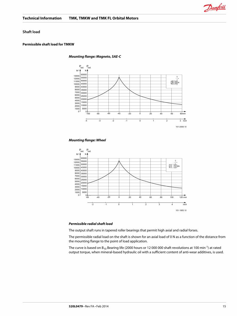
Permissible shaft load for TMKW
Mounting flange: Magneto, SAE-C
Mounting flange: Wheel
Permissible radial shaft load
The output shaft runs in tapered roller bearings that permit high axial and radial forses.
The permissible radial load on the shaft is shown for an axial load of 0 N as a function of the distance fromthe mounting flange to the point of load application.
The curve is based on B10 Bearing life (2000 hours or 12 000 000 shaft revolutions at 100 min-1) at ratedoutput torque, when mineral-based hydraulic oil with a sufficient content of anti-wear additives, is used.
Technical Information TMK, TMKW and TMK FL Orbital Motors
Shaft load
520L0479 • Rev FA • Feb 2014 15

Permissible radial shaft load
The output shaft runs in tapered roller bearings that permit high axial and radial forses.
The permissible radial load on the shaft is shown for an axial load of 0 N as a function of the distance fromthe mounting flange to the point of load application.
The curve is based on B10 Bearing life (2000 hours or 12 000 000 shaft revolutions at 100 min-1) at ratedoutput torque, when mineral-based hydraulic oil with a sufficient content of anti-wear additives, is used.
Technical Information TMK, TMKW and TMK FL Orbital Motors
Shaft load
16 520L0479 • Rev FA • Feb 2014

Function diagrams
Explanation of function diagram use, basis and conditions can be found under Speed and torque on page7 Speed and torque
[blue] Continuous range
[pink] Intermittent range (max. 10% operation every minute)
Intermittent pressure drop and oil flow must not occur simultaneously.
TMK 160 function diagram
Technical Information TMK, TMKW and TMK FL Orbital Motors
Function diagrams
520L0479 • Rev FA • Feb 2014 17
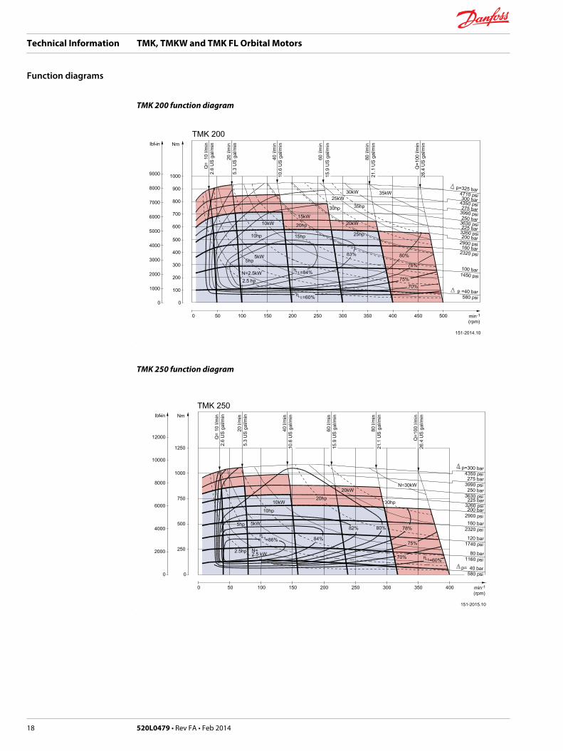
TMK 200 function diagram
TMK 250 function diagram
Technical Information TMK, TMKW and TMK FL Orbital Motors
Function diagrams
18 520L0479 • Rev FA • Feb 2014

TMK 315 function diagram
TMK 400 function diagram
Technical Information TMK, TMKW and TMK FL Orbital Motors
Function diagrams
520L0479 • Rev FA • Feb 2014 19

TMK 470 function diagram
Technical Information TMK, TMKW and TMK FL Orbital Motors
Function diagrams
20 520L0479 • Rev FA • Feb 2014

Shaft Versions
A: Cylindrical shaft 1. 25 in
F: Parallel key
5/16 x 5/16 x 1 1/4 in
SAE J744
P301 682
A
Ø45
[1.7
7]
53.1[2.091]53.5[2.106]
min.21[0.83]
A -16 UNC3-8
A
50.1[1.972]50.5[1.988]
Ø31
.70[
1.24
8]Ø
31.7
4[1.
250]
R1.75[0.069]R1.25[0.049]
4[0.16]
32.0[1.260]
10.1[0.398]7.5[0.295]
31.5[1.240]
35.1
[1.3
82]
F
A-A
35.3
[1.3
90]
7.90[0.311]7.95[0.313]
B: Involute splined shaft
ANS B92.1 - 1970 standard
Flat root side fit
Pitch 12/24
Teeth 14
Major diameter: 1.25 in
Pressure angle 30°
P301 683
B
A 8-3 -16 UNC
24.3[0.957]R1.75[0.069]
R2[0.08]
49.2[1.937]
Ø45
[1.7
7]
48.8[1.921]min.21[0.83]
A
24.7[0.972]4[0.16]
Ø31
.750
[1.2
50]
Ø31
.725
[1.2
49]
R1.25[0.049]
A-AØ
25.3
[0.9
96]
Ø25
.5[1
.004
]
C: Tapered shaft 1. 25 in
G: Cone 1 : 8
SAE J501
H: 1 - 20 UNEF
Across flats: 1 7/16 in
Tightening torque:
450 ± 10 Nm [3980 ± 85lbf•in]
I: Parallel key
5/16 x 5/16 x 3/4 in
SAE J501P301 684
R1.75[0.069]
Ø45
[1.7
7]
R1.25[0.049]
C
A
A
53.2[2.094]
56.3[2.217]56.7[2.232]
53.8[2.118]
35.6[1.402]34.4[1.354]
Ø31
.775
[1.2
51]
Ø31
.725
[1.2
49]
1-20
UN
EF-2
A
19.3[0.760]18.8[0.740]
4.5[0.177]7.963[0.3135]7.937[0.3125]
3.94
9[0.
1555
]
3.82
3[0.
1501
]
A-A
IH
G
2xØ4[0.16]
12.7[0.500]
2xØ
4[0.
16]
Technical Information TMK, TMKW and TMK FL Orbital Motors
Shaft
520L0479 • Rev FA • Feb 2014 21

D: Tapered shaft 1. 5 in
J: Cone 1 : 8
SAE J501
K: 1 - 20 UNEF
Across flats: 1 7/16 in
Tightening torque:
450 ± 10 Nm [3980 ± 85lbf•in]
L: Parallel key 3/8 x 3/8 x 1 in
B.S. 46P301 685
A
A
D
A-A
46.9[1.846]48.1[1.894]
65.7[2.587]66.3[2.610]
69.2[2.724]68.8[2.709]
25.2[0.992]25.8[1.016]
Ø45
[1.7
7]
K
J
1-20
UN
EF
Ø38
.075
[1.4
99]
Ø38
.125
[1.5
01]
4[0.16]
2xØ
4[0.
16]
4.71
5[0.
1856
]
4.59
5[0.
1809
]
9.525[0.375]9.545[0.376]
L
12.7[0.500]R1.25[0.049]R1.75[0.069]
E: Tapered shaft 1. 625 in
M: Cone 1 : 8
SAE J501
N: 1 1/4- 18 UNEF
Across flats: 2 3/16 in
Tightening torque:
500 ± 10 Nm [4425 ± 85lbf•in]
O: Parallel key
7/16 x 7/16 x 1 1/4 in
B.S. 46P301 686
A M
32.1[1.264]
31.5[1.240]
A
16[0.63]
5.49
9[0.
2165
]
5.37
9[0.
2118
]
11.133[0.4383]11.113[0.4375]
O
A-A
E
Ø45
[1.7
7]
4[0.16]
2xØ
4[0.
16]
1 -1
8UN
EF-2
A-1 4 Ø41
.30[
1.62
6]Ø
41.2
6[1.
624]
N
53.4[2.102]54.6[2.150]
75.2[2.961]75.8[2.984]
78.7[3.098]78.3[3.083]
R1.75[0.069]R1.25[0.049]
Technical Information TMK, TMKW and TMK FL Orbital Motors
Shaft
22 520L0479 • Rev FA • Feb 2014
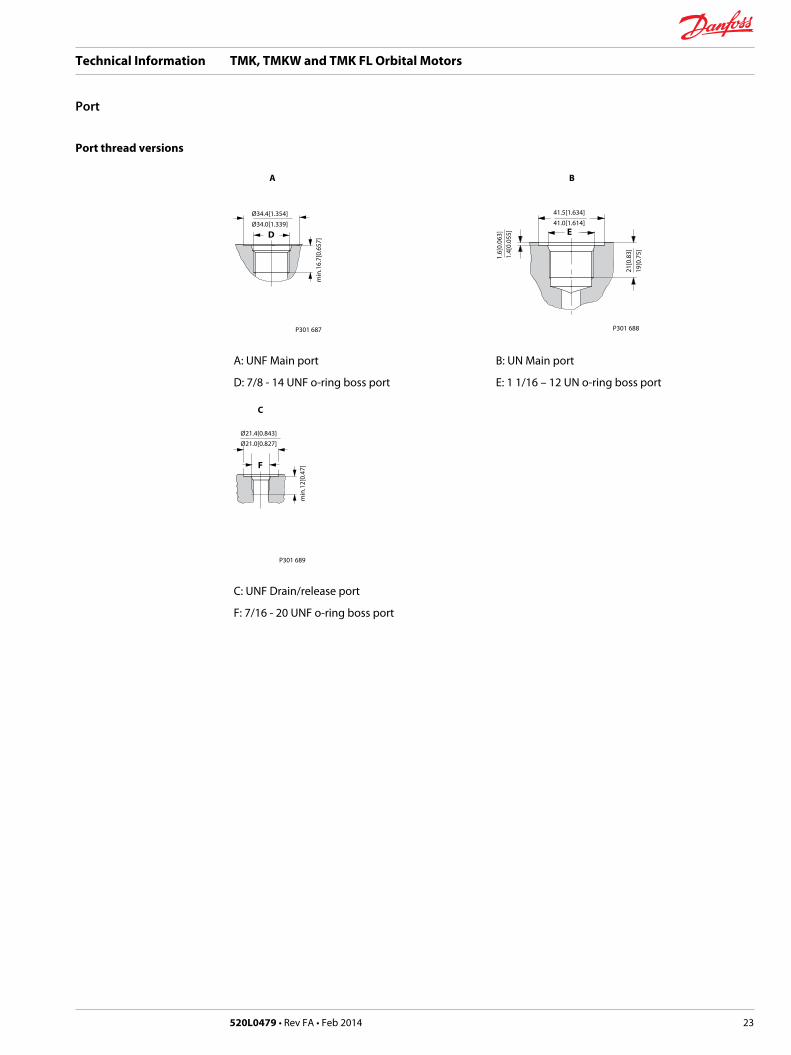
Port thread versions
P301 687
A
D
min
.16.
7[0.
657]
Ø34.4[1.354]
Ø34.0[1.339]
P301 688
19[0
.75]
21[0
.83]
E
1.4[
0.05
5]
B
1.6[
0.06
3]
41.5[1.634]
41.0[1.614]
A: UNF Main port
D: 7/8 - 14 UNF o-ring boss port
B: UN Main port
E: 1 1/16 – 12 UN o-ring boss port
P301 689
F
Ø21.4[0.843]
Ø21.0[0.827]
min
.12[
0.47
]
C
C: UNF Drain/release port
F: 7/16 - 20 UNF o-ring boss port
Technical Information TMK, TMKW and TMK FL Orbital Motors
Port
520L0479 • Rev FA • Feb 2014 23

TMK with Magneto flange
C: Drain connection 7/16 - 20 UNF
D: 2 x 1 1/16 - 12 UN
---------Not Painted
Technical Information TMK, TMKW and TMK FL Orbital Motors
Dimensions, US version, TMK with Magneto flange
24 520L0479 • Rev FA • Feb 2014

Dimensions
Type L1 mm [in] L2 mm [in] L3 mm [in] L4 mm [in]
TMK 160 204.6 [8.06] 179.6 [7.07] 160.8 [6.33] 151.4 [5.96]
TMK 200 210.6 [8.29] 185.6 [7.31] 166.8 [6.57] 157.4 [6.20]
TMK 250 217.6 [8.57] 192.6 [7.58] 176.8 [6.84] 164.4 [6.47]
TMK 315 226.3 [8.91] 201.3 [7.93] 182.5 [7.19] 173.1 [6.81]
TMK 400 237.6 [9.35] 212.6 [8.37] 193.8 [7.63] 184.4 [7.26]
TMK 470 247.8 [9.76] 222.8 [8.77] 204.0 [8.03] 194.6 [7.66]
Output shaft L5 mm [in]
Cyl. 1.25 in 58.8 [2.31]
Spl. 1.25 in 56.0 [2.20]
Tap. 1.25 in 62.0 [2.44]
The stated dimensions are without paint.
Technical Information TMK, TMKW and TMK FL Orbital Motors
Dimensions, US version, TMK with Magneto flange
520L0479 • Rev FA • Feb 2014 25
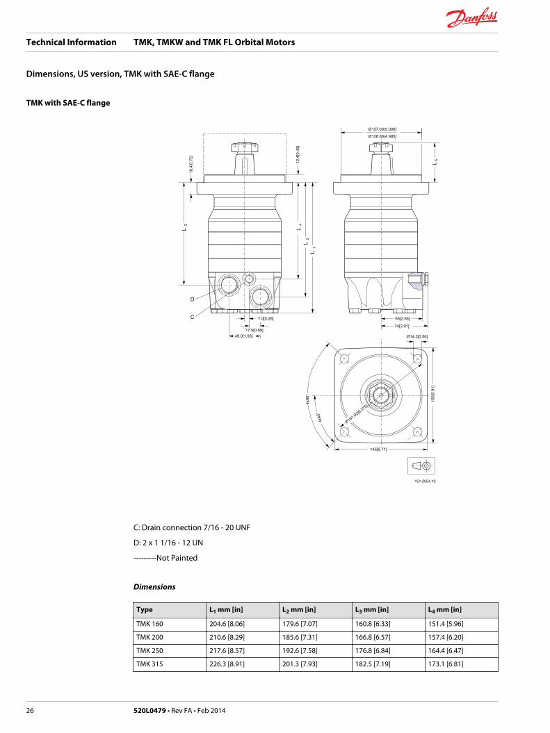
TMK with SAE-C flange
C: Drain connection 7/16 - 20 UNF
D: 2 x 1 1/16 - 12 UN
---------Not Painted
Dimensions
Type L1 mm [in] L2 mm [in] L3 mm [in] L4 mm [in]
TMK 160 204.6 [8.06] 179.6 [7.07] 160.8 [6.33] 151.4 [5.96]
TMK 200 210.6 [8.29] 185.6 [7.31] 166.8 [6.57] 157.4 [6.20]
TMK 250 217.6 [8.57] 192.6 [7.58] 176.8 [6.84] 164.4 [6.47]
TMK 315 226.3 [8.91] 201.3 [7.93] 182.5 [7.19] 173.1 [6.81]
Technical Information TMK, TMKW and TMK FL Orbital Motors
Dimensions, US version, TMK with SAE-C flange
26 520L0479 • Rev FA • Feb 2014
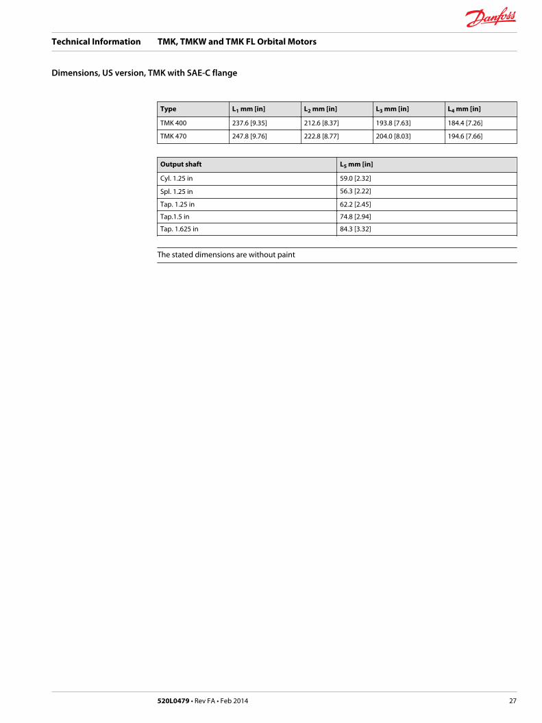
Type L1 mm [in] L2 mm [in] L3 mm [in] L4 mm [in]
TMK 400 237.6 [9.35] 212.6 [8.37] 193.8 [7.63] 184.4 [7.26]
TMK 470 247.8 [9.76] 222.8 [8.77] 204.0 [8.03] 194.6 [7.66]
Output shaft L5 mm [in]
Cyl. 1.25 in 59.0 [2.32]
Spl. 1.25 in 56.3 [2.22]
Tap. 1.25 in 62.2 [2.45]
Tap.1.5 in 74.8 [2.94]
Tap. 1.625 in 84.3 [3.32]
The stated dimensions are without paint
Technical Information TMK, TMKW and TMK FL Orbital Motors
Dimensions, US version, TMK with SAE-C flange
520L0479 • Rev FA • Feb 2014 27

TMKW with side port and drain connection
C: Drain connection 7/16 - 20 UNF
D: 2 x 1 1/16 - 12 UN
---------Not Painted
Technical Information TMK, TMKW and TMK FL Orbital Motors
Dimension, US version TMKW with side port
28 520L0479 • Rev FA • Feb 2014

Dimensions
Type L1 mm [in] L2 mm [in] L3 mm [in] L4 mm [in]
TMKW 160 164.7 [6.48] 139.3 [5.48] 120.3 [4.74] 110.8 [4.36]
TMKW 200 170.7 [6.72] 145.3 [5.72] 126.3 [4.97] 116.8 [4.60]
TMKW 250 177.7 [7.00] 152.3 [6.00] 133.3 [5.25] 123.8 [4.87]
TMKW 315 186.4 [7.34] 161.0 [6.34] 142.0 [5.59] 132.5 [5.22]
TMKW 400 197.7 [7.78] 172.3 [6.78] 153.3 [6.00] 143.8 [5.66]
TMKW 470 207.9 [8.19] 182.5 [7.19] 163.5 [6.44] 154.0 [6.06]
The stated dimensions are without paint
Technical Information TMK, TMKW and TMK FL Orbital Motors
Dimension, US version TMKW with side port
520L0479 • Rev FA • Feb 2014 29

TMKW with end port and drain connection
D C
13.8
[0.5
43]
24.4
[0.9
61]
19.5
[0.7
68]
5.6[0.220]
21.8[0.858] 23[0.91]
L
Ø107.95[4.250]
Ø107.81[4.244]
70[2
.76]
6.4[
0.25
2]
117.
4[4.
622]
Ø126.97(4.999]Ø126.83(4.993]
46.5
[1.8
31]
133[5.24]
133[
5.24
]
Ø147.6[5.811]
Ø13.6[0.535] 45°
151-1992.11
C: Drain connection
7/16 - 20 UNF
D: 2 x 7/8 - 14 UNF
---------Not Painted
Technical Information TMK, TMKW and TMK FL Orbital Motors
Dimension, US version, TMKW with end port
30 520L0479 • Rev FA • Feb 2014

Dimensions
Type Lmm [in]
TMKW 160 183.5 [7.2]
TMKW 200 189.5 [7.46]
TMKW 250 196.5 [7.74]
TMKW 315 205.2 [8.08]
TMKW 400 216.5 [8.52]
TMKW 470 226.7 [8.93]
The stated dimensions are without paint
Technical Information TMK, TMKW and TMK FL Orbital Motors
Dimension, US version, TMKW with end port
520L0479 • Rev FA • Feb 2014 31

TMK FL with side port and drain connection
C: Drain connection and brake release port 7/16 - 20 UNF
D: 2 x 1 1/16 - 12 UN
V: Vent port 7/16 - 20 UNF
---------Not Painted
Technical Information TMK, TMKW and TMK FL Orbital Motors
Dimension, US version, TMK FL with side port
32 520L0479 • Rev FA • Feb 2014

Dimensions
Type L1mm [in]
L2mm [in]
L3mm [in]
L4mm [in]
TMK FL 160 125.2 [4.18] 100.2 [3.43] 81.2 [3.06] 71.2 [4.93]
TMK FL 200 131.2 [5.17] 106.2 [4.18] 87.2 [3.43] 77.7 [3.06]
TMK FL 250 138.2 [5.44] 113.2 [4.46] 94.2 [3.70] 84.7 [33.3]
TMK FL 315 146.9 [5.78] 121.9 [4.80] 102.9 [4.05] 93.4 [3.68]
TMK FL 400 158.2 [6.23] 133.2 [5.24] 114.2 [4.50] 104.7 [4.12]
TMK FL 470 168.4 [6.63] 143.4 [5.65] 124.4 [4.90] 114.9 [4.52]
The stated dimensions are without paint.
Technical Information TMK, TMKW and TMK FL Orbital Motors
Dimension, US version, TMK FL with side port
520L0479 • Rev FA • Feb 2014 33

TMK FL with end port and drain connection
D C
5.6[0.220]
23[0.91]21.8[0.858]
13.8
[0.5
43]
24.4
[0.9
61]
19.5
[0.7
68]
L70
[2.7
6]
∅139.63[5.497]∅139.77[5.503]
11[0
.43]
184.
5[7.
264]
114.
5[4.
508]
159[6.26]
45°Ø14.4[0.567]
159[
6.26
]
Ø161.9[6.374]
151-1991.12
V
C: Drain connection and brake release port 7/16 - 20 UNF
D: 2 x 7/8 - 14 UNF
V: Vent port 7/16 - 20 UNF
---------Not Painted
Technical Information TMK, TMKW and TMK FL Orbital Motors
Dimension, US version, TMK FL with end port
34 520L0479 • Rev FA • Feb 2014
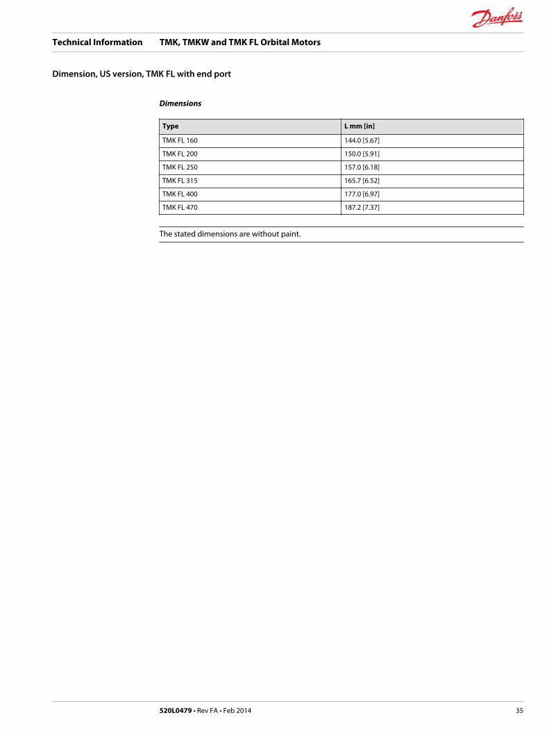
Dimensions
Type L mm [in]
TMK FL 160 144.0 [5.67]
TMK FL 200 150.0 [5.91]
TMK FL 250 157.0 [6.18]
TMK FL 315 165.7 [6.52]
TMK FL 400 177.0 [6.97]
TMK FL 470 187.2 [7.37]
The stated dimensions are without paint.
Technical Information TMK, TMKW and TMK FL Orbital Motors
Dimension, US version, TMK FL with end port
520L0479 • Rev FA • Feb 2014 35

Weight of Oribtal Motors
Code no Weightkg [lb]
Code no Weightkg [lb]
151F6010 16.0 [35.3] 151F6090 16.9 [37.2]
151F6011 16.5 [36.4] 151F6091 17.4 [38.3]
151F6012 17.0 [37.5] 151F6092 17.9 [39.4]
151F6013 17.5 [38.6] 151F6093 18.4 [40.5]
151F6014 18.0 [39.7] 151F6094 18.9 [41.6]
151F6015 18.5 [40.8] 151F6095 19.4 [42.7]
151F6030 16.0 [35.3] 151F6120 16.5 [36.5]
151F6031 16.5 [36.4] 151F6121 17.0 [37.6]
151F6032 17.0 [37.5] 151F6122 17.5 [38.7]
151F6033 17.5 [38.6] 151F6123 18.0 [39.8]
151F6034 18.0 [39.7] 151F6124 18.5 [40.9]
151F6035 18.5 [40.8] 151F6125 19.0 [42.0]
151F6050 14.0 [30.9] 151F6130 16.7 [36.7]
151F6051 14.5 [32.0] 151F6131 17.2 [37.8]
151F6052 15.0 [33.1] 151F6132 17.7 [38.9]
151F6053 15.5 [34.2] 151F6133 18.2 [40.0]
151F6054 16.0 [35.3] 151F6134 18.7 [41.1]
151F6055 16.5 [36.4] 151F6135 19.2 [42.2]
151F6060 14.1 [31.2] 151F6140 16.7 [36.8]
151F6061 14.6 [32.3] 151F6141 17.2 [37.9]
151F6062 15.1 [33.4] 151F6142 17.7 [39.0]
151F6063 15.6 [34.5] 151F6143 18.2 [40.1]
151F6064 16.1 [35.6] 151F6144 18.7 [41.2]
151F6065 16.6 [36.7] 151F6145 19.2 [42.3]
151F6070 14.2 [31.2] 11008903 19.5 [43.0]
151F6071 14.7 [32.3] 11008904 20.0 [44.1]
151F6072 15.2 [33.3] 11008905 20.5 [45.2]
151F6073 15.7 [34.5] 11008906 21.0 [46.3]
151F6074 16.2 [35.6] 11008907 21.5 [47.4]
151F6075 16.7 [36.7] 11008908 22.0 [48.5]
151F6080 17.2 [37.9] 11008909 19.5 [43.0]
151F6081 17.7 [39.0] 11008910 20.0 [44.1]
151F6082 18.2 [40.1] 11008911 20.5 [45.2]
151F6083 18.7 [41.2] 11008912 21.0 [46.3]
151F6084 19.2 [42.3] 11008913 21.5 [47.4]
151F6085 19.7 [43.4] 11008914 22.0 [48.5]
Technical Information TMK, TMKW and TMK FL Orbital Motors
Weight
36 520L0479 • Rev FA • Feb 2014

Technical Information TMK, TMKW and TMK FL Orbital Motors
520L0479 • Rev FA • Feb 2014 37

Technical Information TMK, TMKW and TMK FL Orbital Motors
38 520L0479 • Rev FA • Feb 2014

Technical Information TMK, TMKW and TMK FL Orbital Motors
520L0479 • Rev FA • Feb 2014 39
Danfoss Power Solutions is a global manufacturer and supplier of high-quality hydraulic andelectronic components. We specialize in providing state-of-the-art technology and solutions thatexcel in the harsh operating conditions of the mobile off -highway market. Building on our extensive applications expertise, we work closely with our customers to ensure exceptional performance for a broad range of off -highway vehicles.
We help OEMs around the world speed up system development, reduce costs and bring vehicles tomarket faster.Danfoss – Your Strongest Partner in Mobile Hydraulics.
Go to www.powersolutions.danfoss.com for further product information.
Wherever off -highway vehicles are at work, so is Danfoss.
We off er expert worldwide support for our customers, ensuring the best possible solutions for outstanding performance. And with an extensive network of Global Service Partners, we also provide comprehensive global service for all of our components.
Please contact the Danfoss Power Solution representative nearest you.
Local address:
Danfoss Power Solutions GmbH & Co. OHGKrokamp 35D-24539 Neumünster, GermanyPhone: +49 4321 871 0
Danfoss Power Solutions ApSNordborgvej 81DK-6430 Nordborg, DenmarkPhone: +45 7488 2222
Danfoss Power Solutions US Company2800 East 13th StreetAmes, IA 50010, USAPhone: +1 515 239 6000
Danfoss Power Solutions(Shanghai) Co. Ltd.Building #22, No. 1000 Jin Hai RdJin Qiao, Pudong New DistrictShanghai, China 201206Phone: +86 21 3418 5200
Danfoss can accept no responsibility for possible errors in catalogues, brochures and other printed material. Danfoss reserves the right to alter its products without notice. This also applies toproducts already on order provided that such alterations can be made without subsequential changes being necessary in specifications already agreed.All trademarks in this material are property of the respective companies. Danfoss and the Danfoss logotype are trademarks of Danfoss A/S. All rights reserved.
520L0479 • Rev FA • Feb 2014 www.danfoss.com © Danfoss A/S, 2014
Products we off er:
• Bent Axis Motors
• Closed Circuit Axial Piston Pumps and Motors
• Displays
• Electrohydraulic Power Steering
• Electrohydraulics
• Hydraulic Power Steering
• Integrated Systems
• Joysticks and Control Handles
• Microcontrollers and Software
• Open Circuit Axial Piston Pumps
• Orbital Motors
• PLUS+1® GUIDE
• Proportional Valves
• Sensors
• Steering
• Transit Mixer Drives
Comatrolwww.comatrol.com
Schwarzmüller-Inverterwww.schwarzmueller-inverter.com
Turolla www.turollaocg.com
Valmovawww.valmova.com
Hydro-Gearwww.hydro-gear.com
Daikin-Sauer-Danfosswww.daikin-sauer-danfoss.com