TM8 On-Line Gas Chromatography DGA Monitor Installation ... · The TM8 On-Line Gas Chromatography...
35
TMx Installation Guide 810-1644-04 Rev C www.serveron.com TM8 On-Line Gas Chromatography DGA Monitor Installation Guide TMx Series June, 2017 810-1644-04 Rev C
Transcript of TM8 On-Line Gas Chromatography DGA Monitor Installation ... · The TM8 On-Line Gas Chromatography...
TMx Installation Guide 810-1644-04 Rev C
www.serveron.com
TM8 On-Line Gas Chromatography DGA Monitor Installation Guide TMx Series June, 2017 810-1644-04 Rev C
Legal
2
Information in this document is subject to change without notice. This document is provided to purchasers of Serveron® products for use in the installation, operation and servicing of such products. No other use, nor any reproduction, distribution or the making of any derivatives of this document is authorized, without the express prior written permission of Serveron® Corporation.
Serveron® endeavors to ensure the accuracy and quality of its published materials; however, no warranty, expressed or implied, is provided. Serveron® disclaims any responsibility or liability for any direct or indirect damages resulting from the use of the information in this manual or products described in it. Mention of any product or brand does not constitute an endorsement by Serveron® of that product or brand.
This document was originally composed in English and was subsequently translated into other languages. The fidelity of subsequent translations cannot be guaranteed. In case of conflict between the English version and another language version, the English version takes precedence.
© 2017 Serveron® Corporation. All rights reserved. Information subject to change without notice.
QUALITROL is a registered trademark of Qualitrol Company LLC. Serveron, LOADGUIDE, and TRUEGAS are registered trademarks and TM1, TM3 and TM8 are trademarks of
Serveron® Corporation. All trademarks are properties of their respective companies, as noted herein. 810-1644-04 Rev C.

810-1644-04 Rev C TMx Installation Guide
3
Contents Product Overview ............................................................................................ 5
Product Symbols ............................................................................................. 6
Environmental Conditions .............................................................................. 7
Warranty ........................................................................................................... 7
Items Needed for Installation ......................................................................... 8
Optional Accessories ............................................................................................... 9
Preparatory Tasks for Installation ............................................................... 10
Monitor Installation Overview ...................................................................... 11
Mounting and Assembly ............................................................................... 12
Mounting the Pedestal ........................................................................................... 12
Assembling the Stand (Standard Installation) ..................................................... 13
Optional Oil Cooler ................................................................................................. 14
Mounting the DGA Monitor ........................................................................... 15
Mounting to the Pedestal Stand ............................................................................ 15
Transformer or Wall Mounting ..................................................................... 16
Tank / Wall Mount Assembly ................................................................................. 16
With Optional Oil Cooler ........................................................................................ 16
Without Optional Oil Cooler .................................................................................. 17
Oil Connections ............................................................................................. 18
Oil Tubing................................................................................................................ 18
In-Line Oil Filter ...................................................................................................... 19

810-1644-04 Rev C TMx Installation Guide
4
Oil Supply and Return Valves ............................................................................... 19
Manual Sample Valve (optional) / Secondary Shut-off Valve ............................. 20
Oil Moisture and Temperature (optional) .................................................... 21
Vaisala Oil Moisture / Temperature Probe............................................................ 21
E+E Elektronik Oil Moisture / Temperature Probe ............................................... 23
Gas Connections ........................................................................................... 24
Helium Cylinder / Regulator Installation............................................................... 24
Verification Gas Cylinder Installation ................................................................... 25
TMx Electrical Interface ................................................................................ 26
Power Input ............................................................................................................. 26
Wire Termination / Grounding / Shielding ............................................................ 26
Ferrite Installation .................................................................................................. 26
External Sensors ........................................................................................... 28
Oil Moisture and Temperature Connections (optional) ....................................... 28
LoadGuide® (optional) ........................................................................................... 29
Relays ...................................................................................................................... 29
Aux Inputs ............................................................................................................... 30
Pedestal Assembly Drawing ......................................................................... 31
Pedestal Parts List ................................................................................................. 32
Tank-Mount Assembly Drawing ............................................................................ 33
Installation Completion Checklist ................................................................ 34
810-1644-04 Rev C TMx Installation Guide
5
Product Overview The TM8 On-Line Gas Chromatography DGA Monitor from Serveron Corp. is a remotely-deployed laboratory-grade gas chromatograph which can be safely installed onto an energized or non-energized transformer. The monitor is designed to detect and measure fault gases found in an electrical power transformer‘s insulating oil. It is designed and constructed to resist environmental conditions relevant to a transformer substation.
Serveron offers two versions of the TMx product. The TM8 measures eight IEEE-recommended fault gases: hydrogen (H2), oxygen (O2), carbon dioxide (CO2), carbon monoxide (CO), methane (CH4), ethylene (C2H4), ethane (C2H6), and acetylene (C2H2). The TM3 measures the three Duval Triangle fault gases: methane (CH4), ethylene (C2H4), and acetylene (C2H2). The monitor may be used on conservator or nitrogen-blanketed transformers. The sample of gas is extracted directly from the oil within the transformer.
Oil is circulated from transformer, to the monitor and then returned to the transformer through ¼-inch O.D. stainless-steel tubing. Stainless-steel tubing is used in conjunction with compression fittings to minimize the risk of leaks. The monitor is equipped with an internal gas extraction system which removes dissolved gases from the circulating transformer oil. Helium is used as a carrier gas to help transport the extracted sample gases through the gas chromatograph.
Data is collected in the monitor each time a gas chromatograph (GC) analysis is completed. The GC analysis takes approximately 45 minutes. Once an analysis has been completed, the TM View software can be used to view the monitor’s data. The monitor is set up to perform a sample analysis once every four hours by default. All data captured during an analysis is stored on compact flash memory within the monitor. The compact flash memory holds approximately (2) years of data. The TM View software will allow the end user to track the gas ppm levels over time and monitor the gas levels against user defined caution and alarm settings.
Optional LoadGuide® and Oil Moisture and Temperature sensors are available, along with 4-20mA inputs for use with other external devices. External sensor information can be correlated with fault gas information to allow a complete diagnostic overview of the transformer’s condition.

810-1644-04 Rev C TMx Installation Guide
6
Product Symbols The following symbols are used throughout the monitor or accessories. They are defined by the International Electrotechnical Commission, IEC 878 and IEC 417A. It is important for safety reasons to have an understanding of their representation.
Voltage Output
Voltage Input
Fuse
High Voltage
Caution: Refer to On-Line Transformer Monitor Installation Guide and accompanying documentation.
Protective Earth (ground)
V~ Alternating Current and Voltage H Connect to mains live conductor (brown) L Connect to mains neutral conductor (blue)
__I__ O
The I position indicates the power switch is ON The O position indicates the power switch is OFF
Table 1: Product Symbols
WARNING statements in this manual identify conditions or practices that could result in personal injury.
CAUTION statements in this manual identify conditions or practices that could result in damage to the equipment or other property.
NOTE statements provide additional important information.

810-1644-04 Rev C TMx Installation Guide
7
Environmental Conditions The TMx series is designed to operate within the following outdoor conditions:
Altitude 4572 m
Humidity Range 5% to 95%
Temperature Range -50C to 55C
Installation Category II
Please note that the altitude, humidity and temperature ranges indicated are considered extended environmental conditions from the minimum ranges required by UL 61010-1, Clause 1.4.1.
Warranty Serveron warrants its Goods to be free from latent defects in materials or workmanship for 12 months from the date of shipment. Serveron will repair or replace, at Serveron’s option and without cost to Buyer, any Goods furnished hereunder that are found to contain defects in materials or workmanship during that period. Serveron uses new and reconditioned parts in performing warranty repairs and building replacements. Serveron owns all Goods it has replaced and all parts removed from repaired Goods. It is Buyer’s responsibility to return the Goods to Serveron for warranty coverage. This warranty does not cover items damaged in shipment or damages resulting from misuse, neglect, abuse, acts of war or acts of God. Serveron recommends only using the provided shipping material and packing inserts for transportation. The TMx is designed for pedestal or tank mount in normal transformer operation. It is not designed to be mounted or affixed to the transformer or any other device during transportation. Doing so is subject to void all and any warranties. Prior to returning any item (whether during the warranty period or out of warranty), Buyer must obtain a Return Material Authorization (RMA) number from Serveron Corporation by calling (800) 880-2552 Monday through Friday, 8 am to 5 pm, Pacific Time or by email at [email protected]. Serveron makes no warranties, expressed or implied, other than the warranties expressly stated in this paragraph. All other warranties, expressed or implied, arising by law or otherwise, including, but not limited to, the implied warranties of title, merchantability, non-infringement and fitness for a particular purpose, are expressly disclaimed.
Serveron’s product operation manuals and product installation guides describe approved accessories, options, operating materials and installation methods. Use of accessories, options, operating materials and installation methods not as described will void the warranty.

810-1644-04 Rev C TMx Installation Guide
8
Items Needed for Installation NOTE: As each transformer is different, some items may need to be provided by the installer.
Upon receipt of your monitor, it is important to verify the contents of the shipping carton with the packing list. After inspection of the contents, please notify Serveron directly if there are any signs of damage that may have occurred in transit. (XX = current revision supplied).
Table 2: Items shipped
Part # Description
250-0130-XX (1) In-line Oil Filter, 1/4” SS Swagelok
250-0144-XX (2) Nut and Ferrule Set, 1/4” OD, SS
250-0238-XX (1) Valve, Secondary Shut-off
250-0189-XX (1) Bleed Fixture
250-0190-XX (1) Plug, Black Iron, 2” NPT
250-0191-XX (1) Tee, Black Iron, 2” NPT
250-0192-XX (1) Nipple, Brass, ½” NPT
252-0013-XX (3) 10-32 Nut
253-0066-XX (2) 10-32x3/8” Screw
290-0024-XX (1) Verification Gas Cylinder (ships separately from monitor)
292-0026-XX (1) Helium Regulator, Dual Stage
385-0038-XX (5) Ferrite Core, 0.40” ID x 0.735” OD
456-0022-XX (1) Valve, Oil Return Assy.
456-0026-XX (1) Oil Supply Port Assy.
610-0268-XX (1) Mini USB Communication Cable
610-0185-XX (1) Cable Adapter, Fiber Optic, ST-to-MTRJ
750-0089-XX (1) 120” Helium Supply Line
900-0057-XX 900-0138-XX
(1) Pedestal Mount OR (1) Transformer Tank Mount
910-0018-XX (1) TM View DGA Monitor Software CD
810-1644-04 Rev C TMx Installation Guide
9
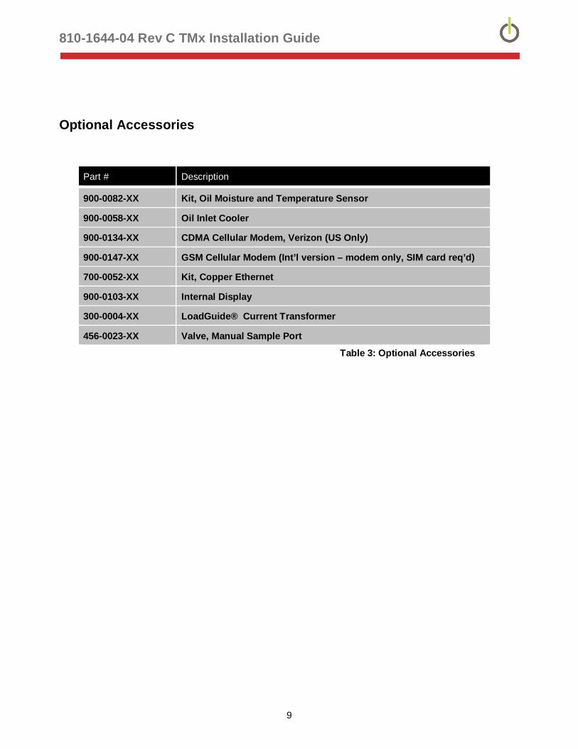
Optional Accessories
Part # Description
900-0082-XX Kit, Oil Moisture and Temperature Sensor
900-0058-XX Oil Inlet Cooler
900-0134-XX CDMA Cellular Modem, Verizon (US Only)
900-0147-XX GSM Cellular Modem (Int’l version – modem only, SIM card req’d)
700-0052-XX Kit, Copper Ethernet
900-0103-XX Internal Display
300-0004-XX LoadGuide® Current Transformer
456-0023-XX Valve, Manual Sample Port
Table 3: Optional Accessories
810-1644-04 Rev C TMx Installation Guide
10
Preparatory Tasks for Installation CAUTION: Do not attempt to install your Serveron monitor until you have read and fully understand the procedures outlined in this document.
There are certain tasks that must be completed prior to the installation of the monitor. These tasks are outlined in the Site Preparation Guide (810-1647-02) that was sent to you upon acceptance of your order. Additionally, a copy of the guide can be downloaded from www.qualitrolcorp.com. Please review the Site Preparation Guide and ensure all items on the Site Preparation checklist below have been completed.
Site Preparation Checklist The following is a checklist that will help ensure that all the proper steps have been completed.
Customer Information form filled out and returned to Serveron A location for mounting the monitor has been identified The transformer oil supply valve (oil supply port) and the transformer oil return valve (oil
return port) have been selected
NOTE: Serveron recommends a minimum size of ½” for the oil supply valve
Power is available at the installation site for the monitor Transformer is oil-filled Communication is available to the monitor (if required) A cylinder of chromatographic grade helium (>99.9995% pure with < 0.5 ppm of H2O)
is onsite A 0 to 5 Amp CT has been identified for the optional LoadGuide sensor (if required) All shipped items and optional accessories have been located Electrical conduit and enclosures have been installed (as required) Stainless steel tubing (316SS, ¼” OD, 0.035 wall thickness), enough for each tubing
run is onsite

810-1644-04 Rev C TMx Installation Guide
11
Monitor Installation Overview Installation consists of the following steps:
Pedestal Assembly and Mounting and or Tank-Mount Assembly Mounting the Monitor Gas Connections Wiring Connections Oil Connections External Sensors
G
E
N
A
B
CD
SERVERONO nline T ra nsformer Monitor
Model TMx
F
H
I
J
K
L
M
A Existing Xfmer valveB Customer Supplied - 2" NPT NippleC Serveron Oil Supply Valve AssyD Serveron Optional Moisture / Temperature SensorE Customer Supplied - ¼" SS /316 Tubing, .035 wallF Serveron Secondary Shut -off / Manual Sample ValveG Serveron Oil Return Assy
H Serveron Bleed Fixture AssyI Serveron In-line Oil filterJ Existing Xfmer valveK Customer Supplied - Helium Cylinder, 99.9995%, L Customer Supplied - 120/230 VAC, 6A/3AM Serveron Pedestal Mounting StandN Serveron Helium Regulator
Figure 1: Installation Schematic
810-1644-04 Rev C TMx Installation Guide
12
Mounting and Assembly There are two mounting options for the TMx monitor, pedestal mount or transformer tank-mount. The monitor should be located in a position where it will not interfere with transformer maintenance or access requirements. The front of the monitor must be accessible for commissioning and maintenance. There should be adequate room around the monitor to access the junction box and helium cylinder. The mounting location should also be chosen to minimize the length of supply and return tubing runs.
Items to consider when choosing a location for the monitor are:
Location of oil supply and oil return ports Location of power supply Transformer maintenance points Access to the monitor Available concrete or grating (for pedestal mount)
NOTE: The monitor must be mounted and operated in an upright position. Failure to do so will void the warranty.
Mounting the Pedestal 1. Remove the pedestal stand from the shipping container.
2. Position the stand on the transformer pad or the dedicated monitor pad. The mounting location should have been determined after reviewing the Site Preparation Guide (810-1547-XX).
3. Use the stand as a template and mark the four mounting holes onto the pad. Orientation of the four mounting holes is not important.
4. Temporarily move the stand. Using a hammer drill, drill a 3/8-in x 2-in (5 cm) deep hole at each of the marked locations.
5. Insert the four 3/8-in concrete anchors supplied with the stand.
6. Reposition the stand over the four anchors and install a flat-washer, split-washer and 3/8-in nut onto each of the four anchors and tighten evenly.
7. Using a level, verify the stand-post is within ± 5˚ of plumb in all directions. Use 3/8-in stainless steel washers as spacers under the four corners if leveling is required.

810-1644-04 Rev C TMx Installation Guide
13
Assembling the Stand (Standard Installation) 1. Locate the hardware and assemble the pedestal, following the steps below and
referring to the Pedestal Assembly drawing in the back of this guide.
2. Attach (1) unistrut (item 5) using (1) U-bolt assembly (item 4) with (2) lock washers (item 9) to the stand approx. 3-in (7.6 cm) from the top. Using a 9/16-in deep socket and a level, secure the items to the stand with (2) 3/8 nuts (item 7) without over-tightening and ensure the channel is ± 5˚ of plumb. (Note: over-tightening will crush the aluminum post.)
3. On the back side of the stand, mark from the top of the U-bolt assembly 20-in down and attach the second unistrut (item 5) using (1) U-bolt assembly (item 4) with (2) lock washers (item 9) and (2) 3/8 nuts (item 7) to post. (Note: If the optional Oil Cooler will be installed, fully tighten the lower U-bolt nuts to the stand at this time. Otherwise, wait until the monitor is installed and secured before tightening the nuts.)
4. Insert (2) spring nuts (item 2) in the top unistrut channel using (2) fully-threaded bolts (item 3) from the rear of channel.
5. Insert (2) spring nuts (item 2) in the bottom unistrut channel.
6. Attach helium tank support bracket and strap to the back of the lower unistrut (items 11 and 12) using (2) bolts, (2) washers and (2) nuts (items 20, 7 and 9).
7. If the optional oil cooler was purchased, proceed to the “Optional Oil Cooler” section.
8. If the oil cooler was not purchased, continue to the section, Mounting the DGA Monitor.
810-1644-04 Rev C TMx Installation Guide
14
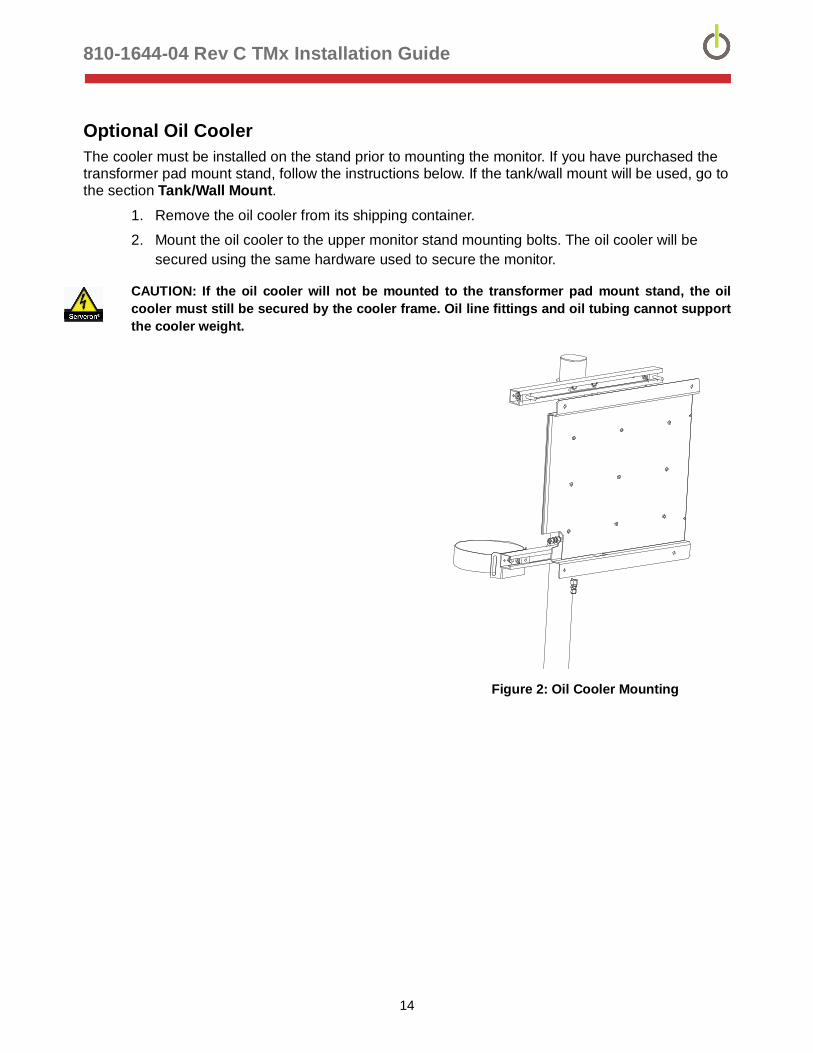
Optional Oil Cooler The cooler must be installed on the stand prior to mounting the monitor. If you have purchased the transformer pad mount stand, follow the instructions below. If the tank/wall mount will be used, go to the section Tank/Wall Mount.
1. Remove the oil cooler from its shipping container.
2. Mount the oil cooler to the upper monitor stand mounting bolts. The oil cooler will be secured using the same hardware used to secure the monitor.
CAUTION: If the oil cooler will not be mounted to the transformer pad mount stand, the oil cooler must still be secured by the cooler frame. Oil line fittings and oil tubing cannot support the cooler weight.
Figure 2: Oil Cooler Mounting

810-1644-04 Rev C TMx Installation Guide
15
Mounting the DGA Monitor CAUTION: The monitor must be mounted and operated in an upright position. Failure to do so will VOID the warranty.
WARNING: The weight of the monitor is approximately 90 lbs (41kgs). Ensure there are adequate resources to lift the monitor during installation.
Mounting to the Pedestal Stand 1. Remove the monitor from the shipping container, taking care not to damage the
ambient temperature sensor or cable glands protruding from the bottom of the monitor enclosure. Refer to the Pedestal Assembly drawing at the end of this guide.
2. Attach the monitor to the upper unistrut using the (2) mounting bolts (item 3) and secure with (2) strut washers (item 21 – only if oil cooler will NOT be used), (2) flat washers, (2) lock washers and (2) nuts (items 8, 9 and 7) provided with the stand hardware.
3. Position the spring nuts in the lower unistrut so they are in line with the lower monitor mounting tabs. Loosely secure the monitor using (2) strut washers (item 21 – only if oil cooler will NOT be used), (2) bolts, (2) lock washers and (2) flat washers (items 6, 8 and 9) to the spring nuts.
4. Using a 9/16-in deep socket, tighten the lower channel on the post if not already done. (Note: Over-tightening will crush the aluminum post.)
5. Verify monitor is plumb and level, within ± 5˚ and all mounting hardware is tight.
Figure 3: Transformer Monitor Mounting

810-1644-04 Rev C TMx Installation Guide
16
Transformer or Wall Mounting The transformer mounting kit includes the necessary hardware to mount the monitor and helium cylinder to 1 5/8” deep-channel unistrut (optional) or to mounting tabs located directly on the transformer tank.
Tank / Wall Mount Assembly 1. If unistrut is required, mount (2) 4ft pieces approx. 40“ from the ground or pad level
(depending on where the helium cylinder will sit) as shown in the figure below:
Figure 4: Unistrut Mounting
With Optional Oil Cooler
Locate (2) 3/8” unistrut spring nuts (item 1) (refer to the Tank/Wall Mount Assembly drawing” in the back of this guide). Install one on each unistrut rung approximately 2” from the left end.
Locate and unpack the oil cooler. Position the cooler over the unistrut, aligning the mounting holes on the left with the spring nuts previously installed and mark the mounting hole positions on the right side. Set the cooler aside.
2. Install the other (2) 3/8” spring nuts in the locations identified in step 3.
3. Locate (4) 3/8” lock washers, (4) vibration dampers and the grounding strap (items 11, 12 and 14). Align the oil cooler over all (4) installed spring nuts. Insert a vibration damper (item 12) into each of the top cooler mounting holes to loosely hold it in place. Position one end of the grounding strap (item 14) over the lower-left mounting hole between the spring nut and the oil cooler, placing a lock washer (item 11) in front of, and behind the strap (fig 6). Use the other two vibration dampers to attach the bottom of the cooler to the unistrut. Ensure that all 4 vibration dampers are tight against the oil cooler.
810-1644-04 Rev C TMx Installation Guide
17
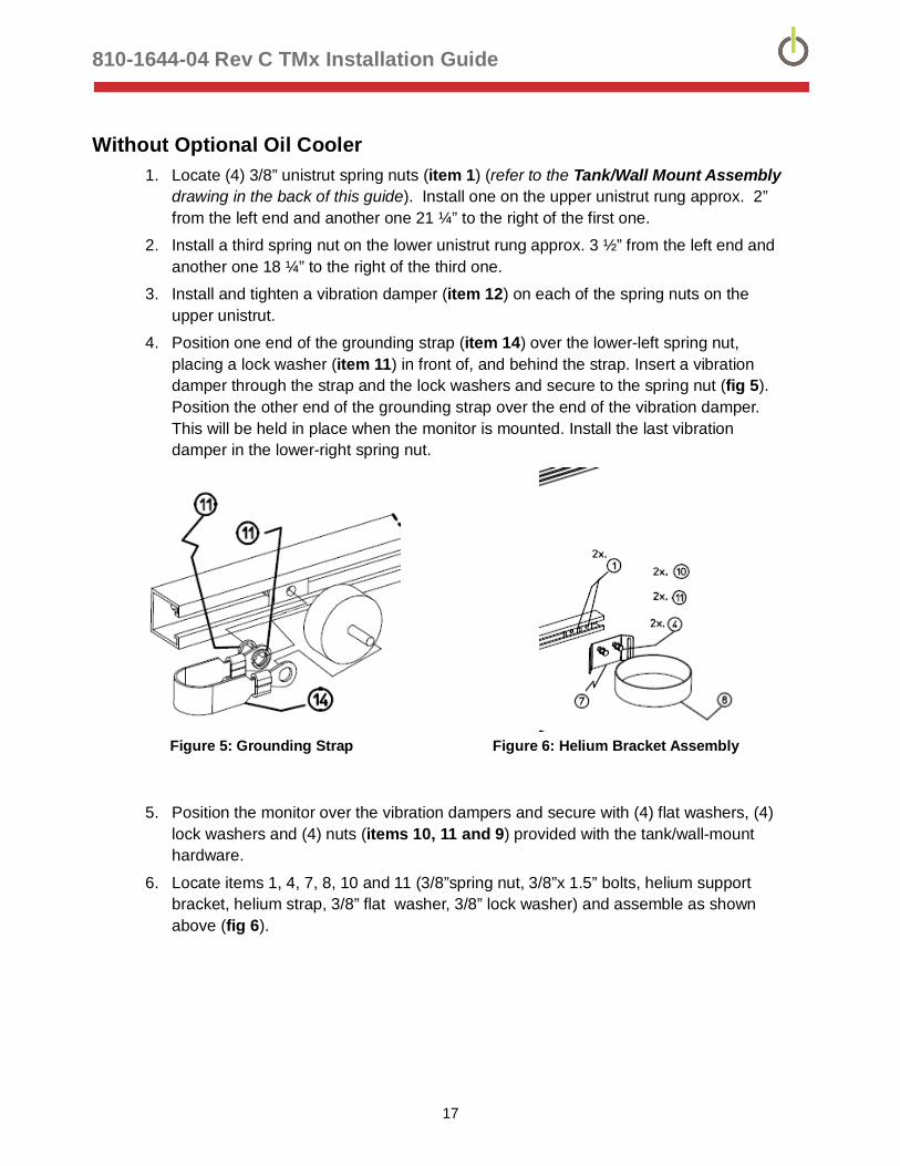
Without Optional Oil Cooler 1. Locate (4) 3/8” unistrut spring nuts (item 1) (refer to the Tank/Wall Mount Assembly
drawing in the back of this guide). Install one on the upper unistrut rung approx. 2” from the left end and another one 21 ¼” to the right of the first one.
2. Install a third spring nut on the lower unistrut rung approx. 3 ½” from the left end and another one 18 ¼” to the right of the third one.
3. Install and tighten a vibration damper (item 12) on each of the spring nuts on the upper unistrut.
4. Position one end of the grounding strap (item 14) over the lower-left spring nut, placing a lock washer (item 11) in front of, and behind the strap. Insert a vibration damper through the strap and the lock washers and secure to the spring nut (fig 5). Position the other end of the grounding strap over the end of the vibration damper. This will be held in place when the monitor is mounted. Install the last vibration damper in the lower-right spring nut.
Figure 5: Grounding Strap Figure 6: Helium Bracket Assembly
5. Position the monitor over the vibration dampers and secure with (4) flat washers, (4) lock washers and (4) nuts (items 10, 11 and 9) provided with the tank/wall-mount hardware.
6. Locate items 1, 4, 7, 8, 10 and 11 (3/8”spring nut, 3/8”x 1.5” bolts, helium support bracket, helium strap, 3/8” flat washer, 3/8” lock washer) and assemble as shown above (fig 6).

810-1644-04 Rev C TMx Installation Guide
18
Oil Connections There are several steps that must be followed specifically when connecting the oil supply and return lines. The monitor must be connected to the transformer’s main tank in two locations. The first connection supplies oil from the transformer to the monitor (Oil Supply Port). The second connection returns oil from the monitor back to the transformer (Oil Return Port). Refer to the Site Preparation Guide (810-1647-02) for recommended transformer oil connection locations.
To guard against oil leaks, Extra High Density, (1.0 SG or higher) Teflon® tape (PTFE) or Teflon paste should be applied to all pipe-thread connections prior to assembly.
CAUTION: The monitor must be mounted and operated in an upright position. Failure to do so will VOID the warranty.
CAUTION: Maximum oil inlet pressure is 45 psi (3 bar).
Oil Tubing
Mineral oil
Serveron recommends oil line installations are performed with Swagelok ¼” OD, 0.035” wall thickness rigid tubing for all runs less than 40ft. For oil runs greater than 40ft, 3/8”OD, 0.035” wall thickness tubing should be used. Depending on the environmental conditions, heat-traced tubing may be required for the oil supply line. Flexible stainless oil lines are acceptable if the correct length is used. The inner core should be stainless steel and not Teflon.
NOTE: Rigid tubing is generally available in 20ft (6m) lengths. If the tubing is ordered through Serveron, 10ft (3m) lengths will be shipped. The installer is required to provide the necessary unions for the installation.
FR3 Oil
Serveron recommends that installations using this oil type are performed with Swagelok 3/8” OD, 0.035” wall thickness rigid tubing for all runs less than 30ft. Oil runs greater than 30ft are not recommended. Depending on the environmental conditions, heat-traced tubing may be required for the oil supply and oil return lines.
The tubing runs are connected to the Oil Supply valve (yellow handle) and the Oil Return valve (black handle) at the transformer and to the Oil In and Oil Out bulkhead fittings on the monitor enclosure. Ensure that all cut tubing ends are reamed-out and that the tubing runs are routed so they are out of the way and do not restrict access to the monitor or the transformer.
810-1644-04 Rev C TMx Installation Guide
19
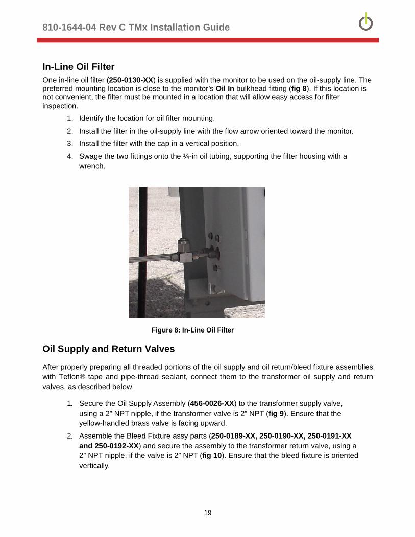
In-Line Oil Filter One in-line oil filter (250-0130-XX) is supplied with the monitor to be used on the oil-supply line. The preferred mounting location is close to the monitor’s Oil In bulkhead fitting (fig 8). If this location is not convenient, the filter must be mounted in a location that will allow easy access for filter inspection.
1. Identify the location for oil filter mounting.
2. Install the filter in the oil-supply line with the flow arrow oriented toward the monitor.
3. Install the filter with the cap in a vertical position.
4. Swage the two fittings onto the ¼-in oil tubing, supporting the filter housing with a wrench.
Figure 8: In-Line Oil Filter
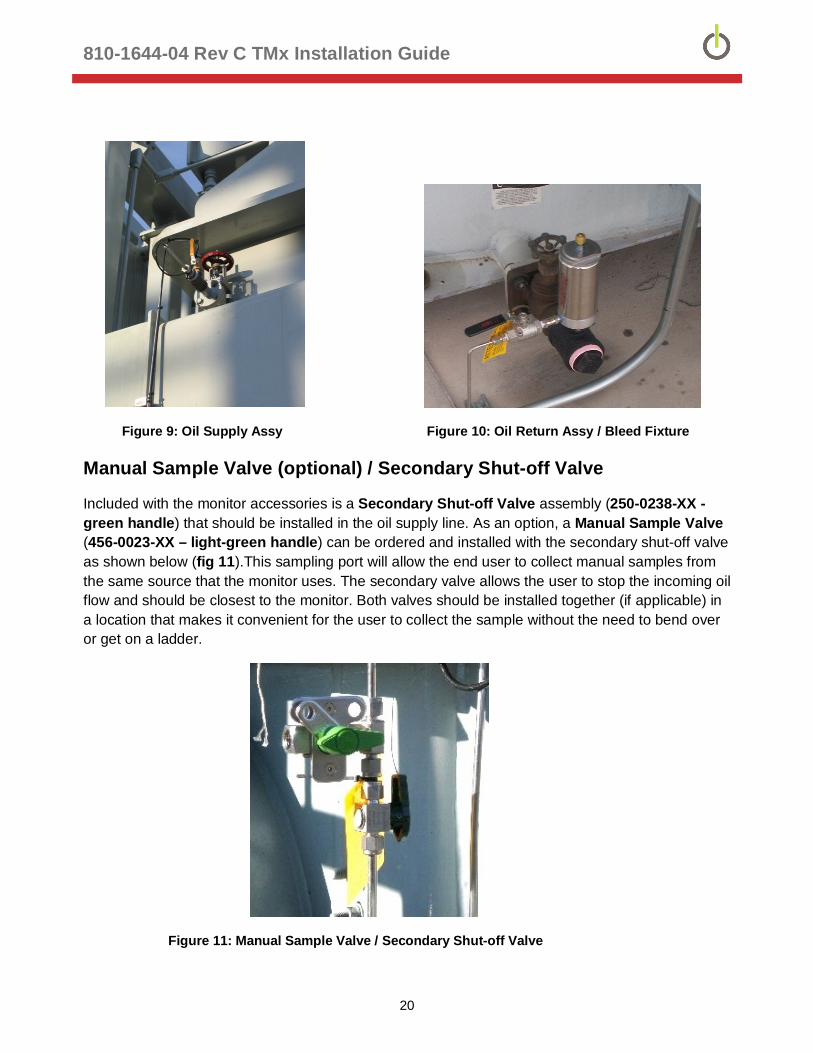
Oil Supply and Return Valves
After properly preparing all threaded portions of the oil supply and oil return/bleed fixture assemblies with Teflon® tape and pipe-thread sealant, connect them to the transformer oil supply and return valves, as described below.
1. Secure the Oil Supply Assembly (456-0026-XX) to the transformer supply valve, using a 2” NPT nipple, if the transformer valve is 2” NPT (fig 9). Ensure that the yellow-handled brass valve is facing upward.
2. Assemble the Bleed Fixture assy parts (250-0189-XX, 250-0190-XX, 250-0191-XX and 250-0192-XX) and secure the assembly to the transformer return valve, using a 2” NPT nipple, if the valve is 2” NPT (fig 10). Ensure that the bleed fixture is oriented vertically.
810-1644-04 Rev C TMx Installation Guide
20
Figure 9: Oil Supply Assy Figure 10: Oil Return Assy / Bleed Fixture
Manual Sample Valve (optional) / Secondary Shut-off Valve
Included with the monitor accessories is a Secondary Shut-off Valve assembly (250-0238-XX -green handle) that should be installed in the oil supply line. As an option, a Manual Sample Valve (456-0023-XX – light-green handle) can be ordered and installed with the secondary shut-off valve as shown below (fig 11).This sampling port will allow the end user to collect manual samples from the same source that the monitor uses. The secondary valve allows the user to stop the incoming oil flow and should be closest to the monitor. Both valves should be installed together (if applicable) in a location that makes it convenient for the user to collect the sample without the need to bend over or get on a ladder.
Figure 11: Manual Sample Valve / Secondary Shut-off Valve

810-1644-04 Rev C TMx Installation Guide
21
Oil Moisture and Temperature (optional) An optional sensor is available to provide measured oil moisture in percent relative saturation (%RS) and calculated moisture in parts per million (ppm), as well as oil temperature in °C. There are two versions of the oil moisture / temp sensor available, but the sensor should always be installed in the oil supply valve, wherever that valve is located on the transformer. Since there are differences in the installation and wiring for both versions, follow the instructions for the version included with your monitor.
Vaisala Oil Moisture / Temperature Probe
This sensor assembly includes:
Adjustable-length probe with 5m cable attached Transmitter unit and mounting plate Rain Shield Interface cable (20m)
Install the moisture probe as follows: 1. After installing the male nipple and the Oil Supply Assy on the transformer valve in the
orientation shown below (fig 12), install the provided 2” NPT x ½” NPT reducing bushing packaged with the moisture kit, using Teflon® tape and pipe-thread sealant. If the oil supply tee is not 2” NPT, then a suitable reducing bushing must be supplied to accommodate the 1/2” NPT moisture probe fitting.
2. Install the stainless fitting into the bushing, after preparing the threads. 3. Set the proper depth of the probe by sliding it through its fitting so that the perforated end
aligns with the vertical port of the tee fitting (fig 12). Once adjusted, insert into the end of the stainless fitting and secure with the nut.
A
B
C
D
A Existing Xfmer valveB Customer Supplied - 2" NPT NippleC Serveron Oil Supply Valve AssyD Serveron Optional Moisture/Temperature Sensor
Figure 12 Moisture Probe Installation - Vaisala
NOTE: All fittings must be stainless steel, brass or black iron. If black iron is being used, it may
be beneficial to paint the valve assemblies after installation to prevent any corrosion / rust.

810-1644-04 Rev C TMx Installation Guide
22
The location of the transmitter unit will depend on the relative location of the oil supply valve. It should be located as close to the monitor installation (pedestal or tank-mount) as possible. The transmitter unit is secured with two 3-mm hex screws to the mounting base (fig 13). If the transmitter is installed in an unprotected outside environment, the rain shield must be installed. The base and rain shield are mounted together, then the transmitter is secured to the base. The cable between the probe and transmitter is usually secured to the stainless tubing. Once the transmitter is secured, the 20m interface cable is connected to the other port on the transmitter (fig 14) and is cut to length before terminating in the junction box. The wiring connections will be discussed later in this guide (TMx Electrical Interface).
Figure 13 Vaisala Transmitter Unit Figure 14 Installed Rain Shield
Connect cable here
810-1644-04 Rev C TMx Installation Guide
23
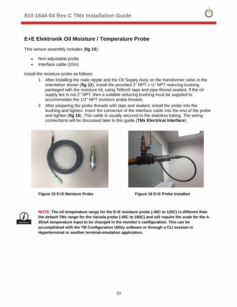
E+E Elektronik Oil Moisture / Temperature Probe
This sensor assembly includes (fig 15):
Non-adjustable probe Interface cable (10m)
Install the moisture probe as follows: 1. After installing the male nipple and the Oil Supply Assy on the transformer valve in the
orientation shown (fig 12), install the provided 2” NPT x ½” NPT reducing bushing packaged with the moisture kit, using Teflon® tape and pipe-thread sealant. If the oil supply tee is not 2” NPT, then a suitable reducing bushing must be supplied to accommodate the 1/2” NPT moisture probe threads.
2. After preparing the probe threads with tape and sealant, install the probe into the bushing and tighten. Insert the connector of the interface cable into the end of the probe and tighten (fig 16). This cable is usually secured to the stainless tubing. The wiring connections will be discussed later in this guide (TMx Electrical Interface).
Figure 15 E+E Moisture Probe Figure 16 E+E Probe Installed
NOTE: The oil temperature range for the E+E moisture probe (-40C to 120C) is different than the default TMx range for the Vaisala probe (-40C to 180C) and will require the scale for the 4-20mA temperature input to be changed in the monitor’s configuration. This can be accomplished with the TM Configuration Utility software or through a CLI session in Hyperterminal or another terminal-emulation application.

810-1644-04 Rev C TMx Installation Guide
24
Gas Connections CAUTION: The use of helium with purity less than 99.9995% or H2O content greater than 0.5-ppm will affect monitor performance and may VOID the monitor warranty.
WARNING: The helium gas cylinder is pressurized to greater than 2000psi (138 bar) and is regulated to 80 psi (5.5 bar), nominal, before entering the monitor. Always follow Compressed Gas Association (CGA) guidelines when handling and transporting compressed gases.
Helium Cylinder / Regulator Installation
WARNING: Do not leave any helium inputs exposed to the atmosphere for extended periods.
NOTE: The leak-check is very important, as even the smallest leak can substantially reduce the life of the helium cylinder.
The helium cylinder must be securely mounted. The monitor installation kit includes a cylinder mounting bracket and strap that meets all Compressed Gas Association (CGA) cylinder restraining requirements.
A 10-ft (305 cm) section of 1/8-in O.D. stainless-steel tubing is provided to connect the helium regulator to the monitor.
1. Install the helium regulator onto the helium cylinder. Do not use Teflon tape or pipe dope.
2. Orient the gauge vertically and tighten the regulator fitting to the cylinder valve.
3. Orient the helium cylinder so that the gauges on the regulator can be clearly seen.
Figure 17: Helium Regulator
4. Install one end of the 10-ft stainless steel tubing onto the regulator. Do not over-tighten the 7/16-in. nut on the regulator. Install the other end to the helium input fitting on the right side of the monitor.
5. Verify the helium regulator shut-off valve (black knob) is closed and slowly turn the valve on top of the helium cylinder fully counterclockwise (open).
6. Open the helium regulator shutoff valve counter-clockwise.
7. Confirm all helium connections are leak-tight by applying a leak-check solution to the fittings.

810-1644-04 Rev C TMx Installation Guide
25
Verification Gas Cylinder Installation
WARNING: The verification gas cylinder is pressurized to greater than 500psi (34 bar) and is regulated to 8 psi (0.5 bar) before entering the monitor. Always follow Compressed Gas Association (CGA) guidelines when handling and transporting compressed gases.
NOTE: The leak check is very important, as even the smallest leak can substantially reduce the life of the Verification Gas cylinder.
The Verification Gas cylinder is used to automatically calibrate the monitor. The cylinder contains a certified, NIST-traceable concentration of the eight transformer fault-gases measured by the monitor.
1. Open the analyzer door and locate the Verification cylinder mounting bracket and regulator.
2. Install the Verification cylinder into the mounting bracket and secure using the Velcro strap.
3. Connect the cylinder to the regulator union and tighten.
Figure 18: Installed Verification Cylinder
4. Turn the knob on the top of the Verification cylinder counterclockwise until it is fully open.
5. Confirm that the entire Verification Gas regulator and gas line connection to the manifold is leak-tight by applying a leak-check solution to the fitting. Wipe away any excess leak-check solution. Since the delivery pressure is low, it may take a few minutes to notice any foaming develop from a leak with this gas.
810-1644-04 Rev C TMx Installation Guide
26
TMx Electrical Interface The TMx enclosure includes an integrated junction box design that provides a larger terminal strip with dedicated positions for the various termination options (fig 19). This design eliminates the need for a separate junction box, with separate wiring harnesses, simplifying the installation.
Power Input
The monitor has an auto-switching power supply capable of receiving input of 115VAC or 230VAC ±15%, 50/60 Hz. Current draw is 6A max at 115VAC and 3A max at 230VAC. There are two 4A/250V type 3AG (T) fuses installed for the power supply (line and neutral) and two 2.5A/250V type GMD fuses for the monitor’s enclosure heater (line and neutral).
Serveron recommends installing a properly-rated and marked switch or circuit breaker in close proximity as a mains voltage disconnect device.
Wire Termination / Grounding / Shielding
Figure 19 specifies terminal block number and function. All possible wiring options are pre-terminated on the monitor-side (right-side) of the terminal strip. Not all terminations will be utilized on the end-user side (left-side). Terminate only the connections that are required for your particular application.
Terminals accommodate wire size AWG #10 - #24. Metallic conduit is bonded to enclosure case. Conduit fitting openings are ¾ “ Earth ground conductor is bonded to enclosure case. Shielded cable drain wire is grounded to case.
Ferrite Installation
Install Ferrite Shields as shown (fig 19)
Power conductors, wrap 1 turn around dedicated ferrite. Unshielded conductors (relay channels and LoadGuide®) may share a common
ferrite shield. Shielded cables (moisture Sensor and serial communications) may share a common
ferrite shield.
NOTE: The integrated junction box is supplied with openings that will accommodate ¾” conduit fittings (not included).

810-1644-04 Rev C TMx Installation Guide
27
TMx Enclosure
System Brd
Fiber Eternet Option
Copper Eternet Option
RJ-45
Integrated Junction Box
1
2
3
4
5
6
7
8
9
10
11
12
13
14
15
16
17
18
19
20
21
22
23
24
25
26
27
28
29
30
31
32
33
34
35
36
37
38
39
40
41
Brn
Blu
Steward 28B0735-000
Steward 28B0735- 000
Oil M
oist
ure
Sen
sor
Pwr Rtn
V+ Pwr
RH
Temp
Data -
Data+
SigGnd
RJ-45
IP Modem OptionSerial Modem Option
¾” Metal Conduit to Utility Cabinet
Relay ChannelsLoad Guide
GN
D
RS48
5 ½
Dup
lex
23 NC
22 NC
21 NC
20 He Sw Ret ( Ignd )
19 He Sw
18 Modem Tip
17 Modem Ring
16 485 Ref Gnd
15 485 Tx B
14 485 Rcv B
13 485 Tx A
12 485 Rcv A
11 232 Sig Gnd
10 232 DTR
9 232 RI
8 232 DSR
7 232 DCD
6 232 CTS
5 232 RTS
4 232 RXD
3 232 TXD
2 +12VI Ret ( Ignd )
1 +12VI
41 Earth Gnd
40 Neutral
39 Line
38 Pwr Rly NO
37 Pwr Rly NC
36 Pwr Rly Com
35 Cust Rly NO
34 Cust Rly NC
33 Cust Rly Com
32 LD Guide Ret
31 LD Guide
30 4-20mA Ch3
29 +24V Ch3
28 4-20mA Ch1
27 +24V Ch1
26 4-20mA Ch2
25 +24V Ch2
24 Sys Gnd
Steward 28B0735 -000
Rela
y C
hann
els
Load
Gui
de
Serial CommunicationMIO Sensor
Line Power
RS2
32 F
ull D
uple
x
Wireless Comm Options
3/8" NPT CableGland Fitting
S hielded Multi -Cond Cable
Cu Ethernet Option
Brn
Blu
Earth Gnd Bonded to Case
Metallic Conduit Bonded to CaseAll Cable Shields
Grounded to Case
Power toAnalyzer P/S
Sensor ChanelsTo Analyzer J100
CommunicationsTo Analyzer J101
Fiber Ethernet Option
S hielded Multi -Cond Cable
Unshielded Tw-P r Cable
Unshielded Tw-P r Cable(s )
ANT
Steward 28B0735 -000
Steward 28B0735 - 000
Line Conductors:1 Loop on Ferrite
GND GNDGnd
Radio Antenna
¾” NPT Hole Plug ¾” NPT Hole Plug
Conduit
¾” Fitting
Conduit
¾” Fitting
Wire Termination Diagram – Fig 19
¾” NPT Hole Plug
810-1644-04 Rev C TMx Installation Guide
28
External Sensors
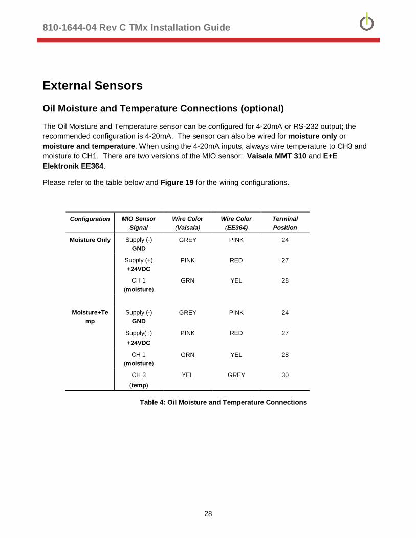
Oil Moisture and Temperature Connections (optional)
The Oil Moisture and Temperature sensor can be configured for 4-20mA or RS-232 output; the recommended configuration is 4-20mA. The sensor can also be wired for moisture only or moisture and temperature. When using the 4-20mA inputs, always wire temperature to CH3 and moisture to CH1. There are two versions of the MIO sensor: Vaisala MMT 310 and E+E Elektronik EE364.
Please refer to the table below and Figure 19 for the wiring configurations.
Configuration MIO Sensor Signal
Wire Color (Vaisala)
Wire Color (EE364)
Terminal Position
Moisture Only Supply (-) GND
GREY PINK 24
Supply (+) +24VDC
PINK RED 27
CH 1 (moisture)
GRN YEL 28
Moisture+Temp
Supply (-) GND
GREY PINK 24
Supply(+) +24VDC
PINK RED 27
CH 1 (moisture)
GRN YEL 28
CH 3 (temp)
YEL GREY 30
Table 4: Oil Moisture and Temperature Connections
810-1644-04 Rev C TMx Installation Guide
29
LoadGuide® (optional)
If the optional LoadGuide will be used, install according to the instructions below.
WARNING: High voltage can be induced by the LoadGuide sensor. Do not clamp the LoadGuide around the transformer CT winding until its wires have been terminated in the junction box.
1. Locate the desired 0A to 5A CT winding identified within the transformer control panel.
2. Pull the LoadGuide leads from the transformer panel to the monitor junction box. A wire size of 22 AWG or larger can be used to extend the length of the leads.
3. Connect the black and white wires of the LoadGuide to terminal positions 31 and 32 (fig 19). Polarity is not significant.
4. Unscrew the white screws from the LoadGuide and remove the back plate from the device.
5. Place the clamp around the 0A to 5A tap.
6. Reinstall back plate and finger-tighten the screws.
Relays
There are two dry-contact relays (Programmable and Power). Both relays can be wired and configured for normally-open (NO) or normally-closed (NC) operation.
Programmable Relay - typically configured for critical events such as high gas alarms, but can also be programmed for: gas caution alarms, service-required conditions and aux sensor alarms (Fig 19 - terminal positions 33 and 34 or 35)
Power Relay - will always report loss of AC power, if wired. It can also be configured for non-critical events such as: gas caution alarms, service-required conditions and aux sensor alarms (Fig 19 - terminal positions 36 and 37 or 38)
The relay contact ratings for resistive loads are:
Max switched Power 100W or 600VA
Max switched Current 3A
Max switched Voltage 150VDC or 300VAC

810-1644-04 Rev C TMx Installation Guide
30
Aux Inputs
The TMx has three 4-20mA, self-powered (24VDC) auxiliary inputs (AUX1, AUX2 and AUX3) with a common power/signal return and Sys Gnd. The inputs are scalable and can be labeled for name and units. If the moisture and temperature sensor is installed, only one spare input is available (AUX2). The AUX inputs can be configured using either the TM Configuration Utility or through Command Line Interface (CLI), in Hyperterminal or a similar application
AUX Connections (Fig 19)
AUX1: +24V Ch1 (terminal position 27) / 4-20mA Ch1 (terminal position 28) AUX2: +24V Ch2 (terminal position 25) / 4-20mA Ch2 (terminal position 26) AUX3: +24V Ch3 (terminal position 29) / 4-20mA Ch3 (terminal position 30)

810-1644-04 Rev C TMx Installation Guide
31
Pedestal Assembly Drawing
Figure 20 Monitor Pedestal Assembly

810-1644-04 Rev C TMx Installation Guide
32
Pedestal Parts List
Item Part Number Item Description QTY UoM
1 140-0190-00 CMP, Stand Post 1 EA
2 291-0011-00 Clamping Nut w/Spring, 3/8" - 16, ZPS 4 EA
3 253-0144-00 Screw, 3/8"-16, 3"L, Fully Threaded 2 EA
4 291-0010-00 U-bolt, 3" w/ mounting plate, Zinc 2 EA
5 291-0009-00 Strut Channel, Aluminum, 1 5/8" x 2 ft, 12 Gauge
2 EA
6 253-0071-00 Screw, HHG5, 3/8"-16, 1 1/2"L, ZPS 2 EA
7 252-0014-00 Nut, 3/8"-16, hex, ZPS 4 EA
8 254-0070-00 Washer, Flat, ZPS, 3/8", 7/16"ID, 1"OD, 5/64" Thick
4 EA
9 254-0071-00 Washer, SL, ZPS, 3/8", 0.385"ID, 0.680"OD, 0.094" Thick
10 EA
10 253-0076-00 Screw, AW, 3/8"D, 3"L, 18-8 SS 4 EA
11 140-0062-00 CMP, TG, Mounting Bracket for Helium Tank
1 EA
12 190-0001-00 Strap, Nylon Webbing, 3 Ft, 2"w 1 EA
15 254-0023-00 #10 Lock washer 8 EA
16 253-0070-00 10-32 x ½” Screw 8 EA
18 140-0203-00 CMP, Bulkhead Bracket 1 EA
19 253-0148-00 Screw, #10-16 x 3/4" Pan Pozi, Self Drilling
2 EA
20 253-0151-00 Screw, HHC, 3/8"-16 by 7/8"L, 18-8, SS
2 EA
21 254-0094-00 Washer, Grip Style, 3/8", Galvanized Steel
4 EA
Table 5: Pedestal Parts List
810-1644-04 Rev C TMx Installation Guide
33
NOTE: Your pedestal kit may include additional hardware that is not referenced or required for the monitor installation, and may be discarded.
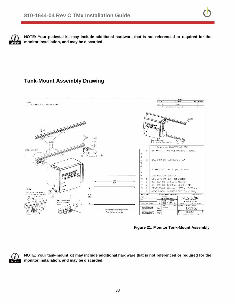
Tank-Mount Assembly Drawing
Figure 21: Monitor Tank-Mount Assembly
NOTE: Your tank-mount kit may include additional hardware that is not referenced or required for the monitor installation, and may be discarded.
810-1644-04 Rev C TMx Installation Guide
34
Installation Completion Checklist
The following steps should be completed prior to monitor commissioning:
Monitor securely mounted on pedestal or tank-mount (with or without optional oil cooler)
Helium cylinder securely mounted
Helium regulator installed
Helium system leak-checked
Verification cylinder securely mounted
Verification cylinder system leak-checked
All oil tubing installed, valve assemblies installed and closed
All compression fittings securely tightened and leak-checked
All cabling securely routed and safely out of the way
Any additional electrical conduit and or enclosures installed, and grounded
Sensor connections (oil moisture / temp) installed, if required
Communication interfaces installed, if required
Power connections established (power is OFF in the analyzer)
CAUTION: DO NOT apply power to the analyzer! Power will be applied as part of the commissioning procedure.
810-1644-04 Rev C TMx Installation Guide
35
Serveron® Field Services
Serveron provides on-site commissioning, start-up and comprehensive maintenance contracts to all customers worldwide. To further improve reliability, an extended warranty is available on selected products commissioned by Serveron.
Serveron® Educational Services
Serveron professional training (designed to achieve hands-on performance based objectives) prepares operations, maintenance, and engineering personnel to install, test, configure, operate and maintain Serveron products.
Serveron® Accelerated Delivery
Serveron provides accelerated delivery on many products and services including replacements, spare parts and repairs.
About Serveron®
Serveron transformer condition assessment and management tools are critical to utilities in improving grid reliability while optimizing the management and economics of their asset base. We are a leader in on-line DGA monitoring of power transformers with solutions across the entire power transformer fleet. Serveron is a QUALITROL Company. © 2017 Serveron® Corporation. All rights reserved. Information subject to change without notice.
QUALITROL is a registered trademark of Qualitrol Company LLC. Serveron, LOADGUIDE, and TRUEGAS are registered trademarks and TM1, TM3 and TM8 are trademarks of Serveron® Corporation.
All trademarks are properties of their respective companies, as noted herein. 810-1644-04 Rev C