TM-9-4931-355-14
47
TM 9-4931-355-14 DEPARTMENT OF THE ARMY TECHNICAL MANUAL OPERATOR'S, ORGANIZATIONAL, DIRECT SUPPORT, AND GENERAL SUPPORT MAINTENANCE MANUAL FOR TEST SET, LASER RANGE FINDER TS-3375/VVG-1 (4931-00-150-1558) HEADQUARTERS, DEPARTMENT OF THE ARMY JUNE 1975
-
Upload
costas-moraitis -
Category
Documents
-
view
212 -
download
0
Transcript of TM-9-4931-355-14

TM 9-4931-355-14
DEPARTMENT OF THE ARMY TECHNICAL MANUAL
OPERATOR'S, ORGANIZATIONAL,
DIRECT SUPPORT, AND GENERAL SUPPORT
MAINTENANCE MANUAL
FOR
TEST SET,
LASER RANGE FINDER
TS-3375/VVG-1
(4931-00-150-1558)
HEADQUARTERS, DEPARTMENT OF THE ARMYJUNE 1975

WARNING
The R/T tester is used to test the receiver-transmitter unit of the laser range finder. The laser beam emitted from thereceiver-transmitter unit is dangerous and can cause blindness if it enters the eye either directly or reflected from a shinysurface. When using the R/T tester in a checkout area, ensure that the gasket on the R/T tester is making contact withthe front of the receiver-transmitter unit before setting the RESET-FIRE switch on the R/T tester to FIRE. Laser lightleakage due to improper mounting may cause injury to eyes. Ensure that the light seal on the tester adapter and R/Ttester are correctly mated and that the screws are secured. This procedure will prevent light leakage between theinterface of the R/T tester, the receiver-transmitter unit, and the tester adapter. Post warning signs "WARNING - LASERLIGHT" and use a countdown procedure if the laser is fired without being covered by the tester as in optical alinement.
The pulse forming network (PFN) may retain high-voltage charges from the 1200 volts developed in the PFN chargepower supply if the dump relay fails.Before working within the transmitter area of the receiver-transmitter unit, allow 20 seconds after turn-off, thenmomentarily ground the terminal of the high voltage lead to the housing with a shorting bar having an insulated handle.If the PFN charge POWER supply extender cable is used, ground the COIL terminal of the PFN.
Personnel routinely performing maintenance at the GS and depot level are required to receive eye examinations inaccordance with AR 40-46.

WARNING
DANGEROUS CHEMICALS
Toluol solvent is toxic and flammable. Use only in a well-ventilated area.Avoid prolonged or repeated breathing of the vapor. Avoid prolonged or repeated contact withthe skin.
Isopropyl alcohol is flammable. Keep all flammable cleaning material away from open flames.Failure to do so could result in injury or death.
Paints and primers are toxic and flammable. Keep all flammable material away from openflames. Use only in a well-ventilated area. Avoid prolonged or repeated contact with the skin.
Methyl ethyl ketone is toxic and flammable. Use only in a well-ventilated area. Avoidprolonged or repeated breathing of vapor. Avoid prolonged or repeated contact with the skin.Keep away from heat or open flames.

TM 9-4931-355-14
TECHNICAL MANUAL HEADQUARTERSDEPARTMENT OF THE ARMY
No. 9-4931-355-14 WASHINGTON, D. C., 13 June 1975
OPERATOR'S, ORGANIZATIONAL, DIRECT SUPPORT, AND
GENERAL SUPPORT MAINTENANCE MANUAL
FOR
TEST SET, LASER RANGE FINDER
TS-3375/VVG-1
(4931-00-150-1558)
PageLIST OF ILLUSTRATIONS ....................................................................................................ivLIST OF TABLES ..................................................................................................................iv
CHAPTER 1. INTRODUCTION ................................................................................................................ 1-1Section I. General .............................................................................................................................. 1-1
1-1 Scope........................................................................................................................ 1-11-2 Forms and records. ................................................................................................... 1-11-3 Reporting of errors .................................................................................................... 1-1
II. Description and data ........................................................................................................... 1-11-4. Description . ............................................................................................................. 1-11-5. Functional description................................................................................................ 1-91-6. Tabulated data .........................................................................................................1-10
CHAPTER 2. OPERATING INSTRUCTIONS........................................................................................... 2-12-1. General ..................................................................................................................... 2-12-2. Controls and indicators ............................................................................................. 2-12-3. Operation procedures .............................................................................................. .2-3
CHAPTER 3. DIRECT SUPPORT AND GENERAL SUPPORT MAINTENANCE INSTRUCTIONS ......... 3-1Section I. Service upon receipt of materiel ......................................................................................... 3-1
3-1. General ..................................................................................................................... 3-13-2. Modification work orders............................................................................................ 3-13-3. Receiving inspection ................................................................................................. 3-13-4. Services for deficiencies on receipt ........................................................................... 3-1
II. Repair parts, special tools, and equipment.......................................................................... 3-13-5. Repair parts . ............................................................................................................ 3-13-6. Special tools and equipment...................................................................................... 3-1
III. Preventive maintenance checks and services .................................................................... 3-23-7 General ..................................................................................................................... 3-23-8. General cleaning instructions .................................................................................... 3-23-9. Inspection ................................................................................................................. 3-23-10. General painting instructions ..................................................................................... 3-33-11. R /T tester purging and charging procedure ............................................................... 3-43-12. R/T tester calibration ................................................................................................. 3-5
IV. Troubleshooting .................................................................................................................. 3-53-13. Troubleshooting the test set....................................................................................... 3-5
CHAPTER 4. REPAIR INSTRUCTIONS................................................................................................... 4-1Section I. General .............................................................................................................................. 4-1
4-1. Scope. ...................................................................................................................... 4-1II. Repair of receiver-transmitter tester.................................................................................... 4-1
4-2. General ..................................................................................................................... 4-14-3. Repair ....................................................................................................................... 4-14-4. Inspection.................................................................................................................. 4-1
III. Repair of tester adapter ...................................................................................................... 4-14-5. General ..................................................................................................................... 4-14-6. Repair . .................................................................................................................... 4-1
ii

TM 9-4931-355-14
PageIV. Repair of extender cards..................................................................................................... 4-2
4-7. General ...................................................................................................................... 4-24-8. Repair......................................................................................................................... 4-24-9 . Inspection ................................................................................................................... 4-2
V. Repair of cables. ................................................................................................................ 4-24-10. General................................................................................................................... . 4-24-11. Repair ....................................................................................................................... 4-24-12. Inspection .................................................................................................................. 4-6
VI. Repair of alinement lens assembly ..................................................................................... 4-64-13. General..................................................................................................................... 4-64-14. Repair....................................................................................................................... 4-7
CHAPTER 5. FINAL INSPECTION ......................................................................................................... 5-15-1. General ................................................................................................................... . 5-15-2. Visual inspection ........................................................................................................ 5-15-3. Final inspection standards ......................................................................................... 5-1
CHAPTER 6. ADMINISTRATIVE STORAGE ........................................................................................... 6-16-1. General ...................................................................................................................... 6-1
APPENDIX A. REFERENCES .................................................................................................................. A-1APPENDIX B. BASIC ISSUE ITEMS LIST, ITEMS TROOP INSTALLED OR AUTHORIZED LIST, AND
REPAIR PARTS AND SPECIAL TOOLS LIST. .................................................................. B-1APPENDIX C. MAINTENANCE ALLOCATION CHART ............................................................................C-1
Section I. Introduction.........................................................................................................................C-1C-1. General ......................................................................................................................C-1C-2. Maintenance Functions ...............................................................................................C-1C-3. Explanation of Format.................................................................................................C-1
II. Maintenance allocation chart . ...........................................................................................C-2
iii

TM 9-4931-355-14
LIST OF ILLUSTRATIONS
Number Title Page1-1 Direct support common special tools and test equipment (10559658)........................................... 1-31-2 Direct support unique special tools and test equipment (11738864).............................................. 1-31-3 R/T holding fixture (11738862) .................................................................................................... .1-41-4 General support special tools and test equipment-alinement kit (11738863)................................. 1-51-5 Fire Control Laser Range Finder AN/VVG-1 units ........................................................................ 1-61-6 R/T tester block diagram .......................................................................................................... FO-12-1 R/T tester controls and indicators ................................................................................................. 2-12-2 PFN charge ammeter control and indicator .................................................................................. 2-33-1 Cables schematic diagram ........................................................................................................ FO-24-1 Repair of test cable W50. ............................................................................................................ 4-24-2 Repair of test cables W51, W52, W54, and tester cable A7/A77 ................................................. 4-34-3 Repair of test cable A75/A76 . ..................................................................................................... 4-34-4 Repair of branched cable ........................................................................................................... .4-44-5 Repair of test cable W53............................................................................................................. .4-44-6 Repair of PFN charge power supply extender cable ................................................................... .4-54-7 Repair of PFN charge ammeter cable ......................................................................................... .4-6
LIST OF TABLES
Number Title Page1-1 Direct Support Common Special Tools and Test Equipment (10559658) ..................................... 1-71-2 Direct Support Unique Special Tools and Test Equipment (11738864) ....................................... .1-81-3 General Support Special Tools and Test Equipment-Alinement Kit (11738863). ......................... .1-91-4 Test Sets and Alinement Kit Shipping Data ................................................................................1-101-5 R/T Tester Performance Characteristics......................................................................................1-102-1 R/T Tester Controls and Indicators .............................................................................................. 2-22-2 PFN Charge Ammeter Controls and Indicators ............................................................................ 2-33-1 Special Tools and Equipment ...................................................................................................... 3-13-2 Preventive Maintenance Checks and Services....................................................................... 3-2,3-33-3 Materials Needed for Cleaning and Touch-up Painting ................................................................ 3-43-4 Test Set Troubleshooting ............................................................................................................. 3-53-5 Extender Cards Wire Lists . ......................................................................................................... 3-63-6 Branched Cable Wire List . .......................................................................................................... 3-7
iv
TM 9-4931-355-14
CHAPTER 1INTRODUCTION
Section I. GENERAL
1-1. Scopea. This manual is for use in operating and
maintaining the Laser Range Finder Test Sets and theAlinement Kit.
b. Instructions for operating and maintaining theLaser Range Finder Units, which are issued as testequipment, are in the TM 9-2350-230-10-23 and TM 9-1240-369-34.
1-2. Equipment Maintenance Forms.
Equipment maintenance forms and proceduresfor their use are prescribed in TM 38-750.
1-3. Reporting of Errors.Report of errors, omissions, and
recommendations for improving this publication by theindividual user is encouraged. Reports should besubmitted on DA Form 2028 Recommended Changes toPublications, and forwarded directly to Commander,Frankford Arsenal, ATTN: SARFA-MA, Philadelphia,PA 19137. A reply will be furnished to you.
Section II. DESCRIPTION AND DATA
1-4. Description.a. The TS-3375/VVG-1 laser range finder test set
consists of special tools and equipment for performingdirect support (DS) and general support (GS)maintenance of the AN/VVG-1 laser range finder. Thetest set provides a means for limited system testing ofthe AN/VVG-1 laser range finder and for testing andreplacement of unit modules or parts. The special toolsand test equipment, with the exception of the R/Tholding fixture, are contained in three carrying cases.The first carrying case 10559658 is for direct supportcommon special tools and test equipment (fig. 1-1), withparts are listed in table 1-1. The second carrying case11738864 is for direct support unique special tools andtest equipment (fig. 1-2) with parts are listed in table 1-2.
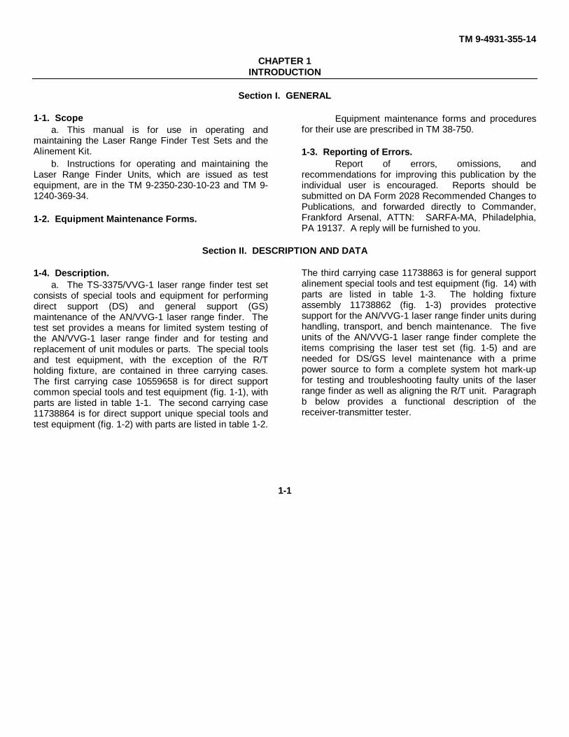
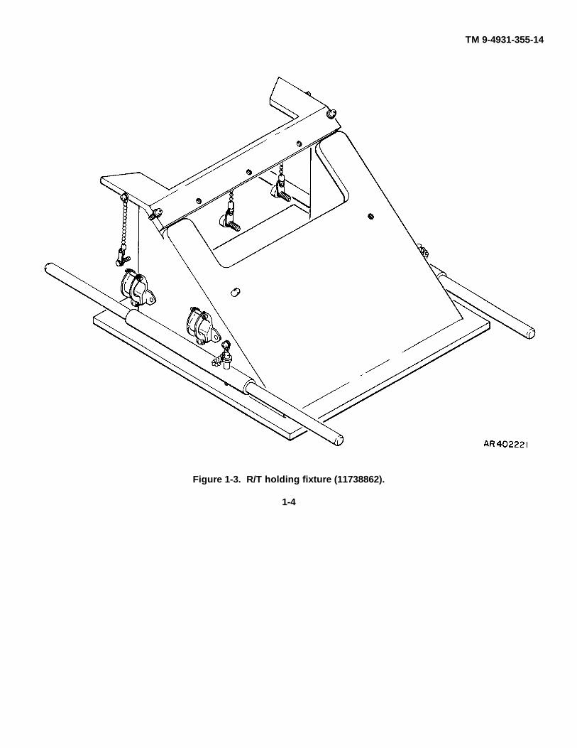
The third carrying case 11738863 is for general supportalinement special tools and test equipment (fig. 14) withparts are listed in table 1-3. The holding fixtureassembly 11738862 (fig. 1-3) provides protectivesupport for the AN/VVG-1 laser range finder units duringhandling, transport, and bench maintenance. The fiveunits of the AN/VVG-1 laser range finder complete theitems comprising the laser test set (fig. 1-5) and areneeded for DS/GS level maintenance with a primepower source to form a complete system hot mark-upfor testing and troubleshooting faulty units of the laserrange finder as well as aligning the R/T unit. Paragraphb below provides a functional description of thereceiver-transmitter tester.
1-1

TM 9-4931-355-14
Figure 1-1. Direct support common special tools and test equipment (10559658).1-2

TM 9-4931-355-14
Figure 1-2. Direct support unique special tool and test equipment (11738864).1-3
TM 9-4931-355-14
Figure 1-3. R/T holding fixture (11738862).
1-4
TM 9-4931-355-14
Figure 1-4. General support special tools and test equipment-alinement kit (11738863).
1-5

TM 9-4931-355-14
Figure 1-5. Fire control laser range finder AN/VVG-1 units.
1-6

TM 9-4931-355-14
Key to fig. 1-5:1. R/T Control C-8728/VVG-1 (A75)2. Laser Receiver-Transmitter RT-1021/VVG-1 (A76)3. Battery Power Supply PP-6607/VVG-1 (A78)4. Laser Ranging Commander's Control C-9134/VVG-1 (A79)5. Laser Power Supply Control C-9135/VVG-1 (A77)
Table 1-1. Direct Support Common Special Tools and Test Equipment (10559658)
Reference
Item NSN or Fig. Item Function
No. Item reference No. No. No.
1 Tester, R/T 4931-00-169-0114 1-1 6 To measure receiver sensitivity and(10559600) transmitter output energy of the
receiver-transmitter unit ZA76).2 Cable, extender-PFN charge 4931-00-234-3322 1-1 5
power supply (10559664)3 Extender card, counters 4931-00-491-6998 1-1 4 To provide test points for designated
(10559508) circuit card assemblies located in4 Extender card, reply gating 4931-00-191-1384 1-1 3 the power supply control unit (A77)
(10559516) and battery power supply unit5 Extender card, select logic 4931-00-493-9239 1-1 1 (A78) during troubleshooting.
(10559518)6 Extender card, -1600 power supply 4931-00-493-9237 1-1 2
(10559517)7 Puller, circuit card 4931-00-628-1336 1-1 14 To remove circuit card assemblies
(11737838) from power supply control unit8 Key, Socket Head Screw 5120-00-628-1454 1-1 19 (A77) housing.
(11737812-1)9 Key, Socket Head Screw 5120-00-628-1759 1-1 18
(11737812-2) Used to loosen and tighten various10 Key, Socket Head Screw 5120-00-628-1457 1-1 17 socket head capscrews during repair
(11737812-3) of unit.11 Key, Socket Head Screw 5120-00-628-1762 1-1 16
(11737812-4)12 Key, Socket Head Screw 5120-00-628-1781 1-1 15
(11737812-5)13 Wrench, socket (0.875) 5120-00-628-1784 1-1 7
(11737480-5)14 Wrench, socket (1.062) 5120-00-851-8683 1-1 9
(11737480-8)15 Wrench, socket (1.187) 5120-00-901-1573 1-1 11
(11737480-10) Used to loosen and tighten various16 Wrench, socket (1.312) 5120-00-967-3058 1-1 13 connector nuts during repair of
(11737480-12) units.17 Wrench, socket (1.437) 11737480-14 1-1 818 Wrench, socket (1.562) 5120-00-967-3059 1-1 10
(11737480-16)19 Wrench, socket (1.687) 5120-00-926-7123 1-1 12
(11737480-18)20 Case, carrying 11745643 1-1 20 To carry and store special tools and
test equipment for the laser rangefinder.
21 Insert, lower 11745642 1-1 2122 Insert, upper 11745640-1 1-1 22 To retain items within the case.
1-7

TM 9-4931-355-14
Table 1-2. Direct Support Unique Special Tools and Test Equipment (11738864)
Reference
Item NSN or Fig. Item Function
No. Item reference No. No. No.
1 Adapter, assembly 11737814 1-2 25 To mount R/T tester to receiver-transmitter unit (A76).
2 Ammeter, PFN charge 4931-00-628-1820 1-2 2 To determine the PFN current setting(11737824) after adjustment using the R/T
tester.3 Cable, ammeter PFN charge 4931-00-628-1808 1-2 16 To interconnect PFN charge ammeter
(11745327) to power supply control unit (A77).4 Cable, tester A7/A77 4931-00-628-1341 1-2 17 To interconnect the R/T tester to the
(11737815) power supply control unit (A77).5 Cable, test A75/A79 (W50) 4931-00-628-1692 1-2 18
(11737821)6 Cable, test A76/A77 (W51) 4931-00-628-1343 1-2 19
(11737817) To interconnect the designated units7 Cable, test A76/A77 (W52) 4931-00-628-1580 1-2 20 during troubleshooting.
(11737818)8 Cable, test A76/A77 (W53) 4931-00-628-1671 1-2 21
(11737819)9 Cable, test A77/A78 (W54) 4931-00-628-1342 1-2 22
(11737816) To interconnect the designated units10 Cable, test A75/A76 11737820 1-2 23 J during troubleshooting.11 Extender card, interface 4931-00-628-1340 1-2 12
(11737822)12 Extender card, low voltage power 4931-00-493-9236 1-2 13
supply (10559515) To provide test points for designated13 Extender card, battery charge sensor 4931-00-628-1544 1-2 9 circuit card assemblies located in
(11737823) the power supply control unit (A77)14 Extender card, charge control 4931-00-628-1542 1-2 10 and battery power supply unit (A781
(11737845) during troubleshooting.15 Extender card, power control 4931-00-628-1519 1-2 11
(11737851)16 Eyebolt (2 each) 5305-00-113-3767 1-2 4 To facilitate use of receiver-
(NAS1053-05-17) transmitter handles with amechanical hoist or similar device.
17 Gage. depth-connector, cov- 4931-00-628-1520 1-2 14 To determine clearance on connectorser/housing (11737471) W1J3 and WIJ5 of receiver-
transmitter unit A7C6.18 Handle assembly, ballistic cover 4931-00-628-1541 1-2 3 To facilitate handling of the ballistic
(11741606) cover.19 Handle, receiver-transmitter (2 each) 11737942 1-2 120 Tie rod assembly, handle-receiver- 11737945 1-2 15 To facilitate handling of the receiver-
transmitter transmitter unit (A76).21 Tool, removal-boot 11737451 1-2 7 To remove switch boots (switch lens
seals) from R/T control unit (A75)and commander's control unit(A79).
22 Wrench, spanner nut 11745619-1 1-2 5 To remove spanner nuts from23 Wrench, spanner nut 11745619-2 1-2 6 switches on the R/T control unit24 Wrench, spanner switch 11737810 1-2 8 (A75) and commander's control
unit (A79).25 Manual, technical TM 9-4931-355-14 1-2 24 To inform operator, organizational.
direct support and general supportmaintenance personnel how tomaintain the laser range finderspecial tools and test equipment.
26 Case, carrying 11737835 1-2 26 To carry and store special tools andtest equipment for the laser rangefinder.
27 Insert, lower 11737837 1-2 27 To retain items within the case.28 Insert, upper 11745640-3 1-2 28
1-8
TM 9-4931-355-14
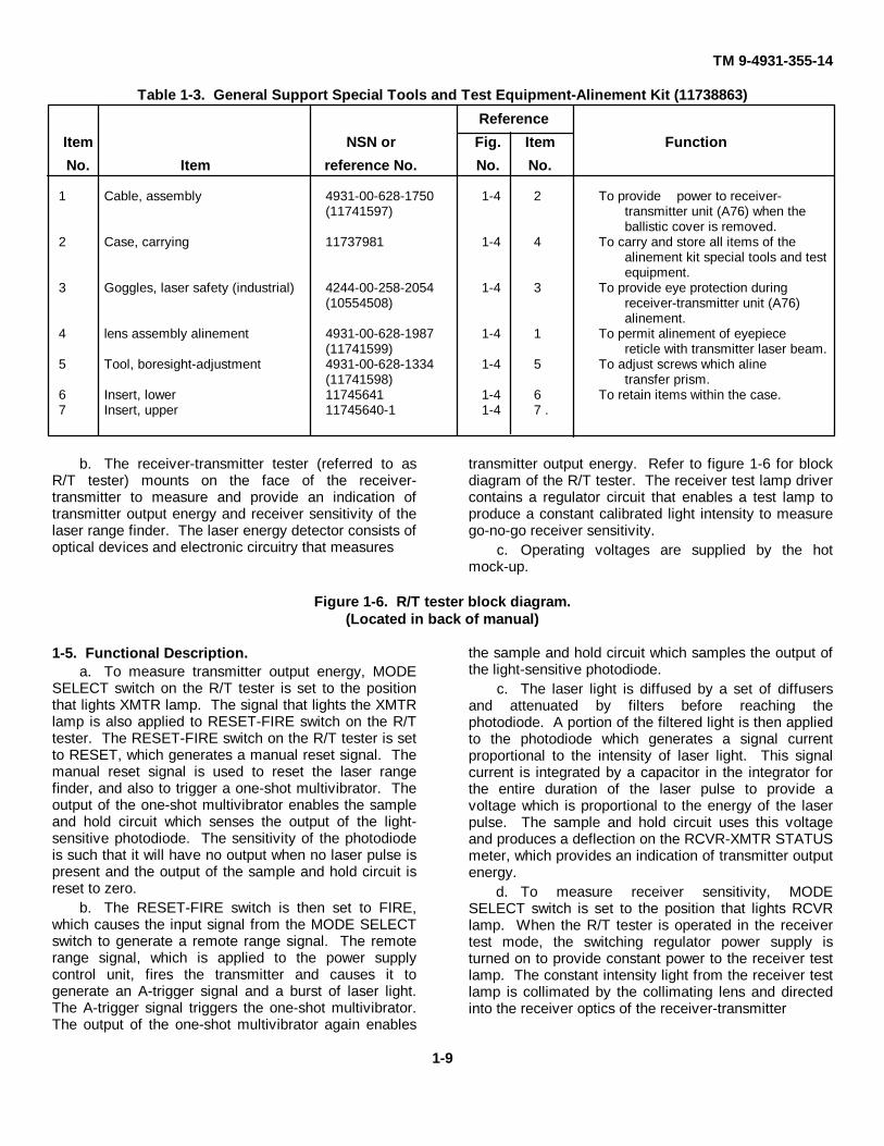
Table 1-3. General Support Special Tools and Test Equipment-Alinement Kit (11738863)
Reference
Item NSN or Fig. Item Function
No. Item reference No. No. No.
1 Cable, assembly 4931-00-628-1750 1-4 2 To provide power to receiver-(11741597) transmitter unit (A76) when the
ballistic cover is removed.2 Case, carrying 11737981 1-4 4 To carry and store all items of the
alinement kit special tools and testequipment.
3 Goggles, laser safety (industrial) 4244-00-258-2054 1-4 3 To provide eye protection during(10554508) receiver-transmitter unit (A76)
alinement.4 lens assembly alinement 4931-00-628-1987 1-4 1 To permit alinement of eyepiece
(11741599) reticle with transmitter laser beam.5 Tool, boresight-adjustment 4931-00-628-1334 1-4 5 To adjust screws which aline
(11741598) transfer prism.6 Insert, lower 11745641 1-4 6 To retain items within the case.7 Insert, upper 11745640-1 1-4 7 .
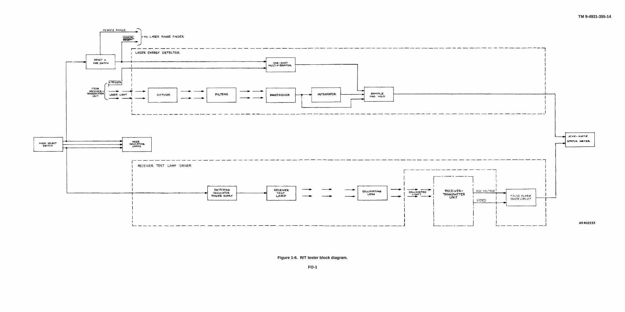
b. The receiver-transmitter tester (referred to asR/T tester) mounts on the face of the receiver-transmitter to measure and provide an indication oftransmitter output energy and receiver sensitivity of thelaser range finder. The laser energy detector consists ofoptical devices and electronic circuitry that measures
transmitter output energy. Refer to figure 1-6 for blockdiagram of the R/T tester. The receiver test lamp drivercontains a regulator circuit that enables a test lamp toproduce a constant calibrated light intensity to measurego-no-go receiver sensitivity.
c. Operating voltages are supplied by the hotmock-up.
Figure 1-6. R/T tester block diagram.(Located in back of manual)
1-5. Functional Description.a. To measure transmitter output energy, MODE
SELECT switch on the R/T tester is set to the positionthat lights XMTR lamp. The signal that lights the XMTRlamp is also applied to RESET-FIRE switch on the R/Ttester. The RESET-FIRE switch on the R/T tester is setto RESET, which generates a manual reset signal. Themanual reset signal is used to reset the laser rangefinder, and also to trigger a one-shot multivibrator. Theoutput of the one-shot multivibrator enables the sampleand hold circuit which senses the output of the light-sensitive photodiode. The sensitivity of the photodiodeis such that it will have no output when no laser pulse ispresent and the output of the sample and hold circuit isreset to zero.
b. The RESET-FIRE switch is then set to FIRE,which causes the input signal from the MODE SELECTswitch to generate a remote range signal. The remoterange signal, which is applied to the power supplycontrol unit, fires the transmitter and causes it togenerate an A-trigger signal and a burst of laser light.The A-trigger signal triggers the one-shot multivibrator.The output of the one-shot multivibrator again enables
the sample and hold circuit which samples the output ofthe light-sensitive photodiode.
c. The laser light is diffused by a set of diffusersand attenuated by filters before reaching thephotodiode. A portion of the filtered light is then appliedto the photodiode which generates a signal currentproportional to the intensity of laser light. This signalcurrent is integrated by a capacitor in the integrator forthe entire duration of the laser pulse to provide avoltage which is proportional to the energy of the laserpulse. The sample and hold circuit uses this voltageand produces a deflection on the RCVR-XMTR STATUSmeter, which provides an indication of transmitter outputenergy.
d. To measure receiver sensitivity, MODESELECT switch is set to the position that lights RCVRlamp. When the R/T tester is operated in the receivertest mode, the switching regulator power supply isturned on to provide constant power to the receiver testlamp. The constant intensity light from the receiver testlamp is collimated by the collimating lens and directedinto the receiver optics of the receiver-transmitter
1-9

TM 9-4931-355-14
unit. The receiver responds to the light from the testlamp as if it were background light from a target. Thereceiver than develops an automatic gain control (agc)voltage which is used by the receiver to maintain thenoise count rate at a constant value. The video signal isused to trigger a one-shot multivibrator which developsan output voltage in conjunction with the agc voltage.This voltage is applied to the RCVR-XMTR STATUSmeter, which provides an indication of go-no-go receiversensitivity.
e. The face of RCVR-XMTR STATUS meter hastwo scales: one for the transmitter mode and one for thereceiver mode. Each scale consists of a color-codedband bracketed by a black region. During thetransmitter mode of test, a deflection of the meterneedle into the red band indicates that the transmitteroutput energy is within tolerance. During the receiver
mode of test, an acceptable receiver sensitivity isindicated by a deflection in the white band. In eachcase, the color of the acceptable band corresponds tothe color of the mode indicator lamp that is illuminated.In either test, a deflection into either of the black regionsindicates an out-of-tolerance condition.
1-6. Tabulated Data.a. Shipping Information and Physical
Characteristics. The physical characteristics of thecarrying cases for the test sets and alinement kit arelisted in table 1-4.
b. R/T Tester Performance Characteristics.Performance characteristics of the R/T tester aresummarized in table 1-5. Refer to TM 9-1240-36934 fordata on the laser range finder units.
Table 1-4. Test Sets and Alinement Kit Shipping DataLength Width Height Volume
(in.) (in.) (in.) (cu. ft.)Item approx approx approx approx
Test set (10559658) 19 23 15 3.8Test set (11738864) 29 40 18 12.1Alinement kit (11738863) 13 17 15 1.9R/T holding fixture (11738862) 29 19.75 12
Table 1-5. R/T Tester Performance CharacteristicsPower Requirements
Voltage(supplied by hot mock-up)
Current Receiver test mode: 2 amperes (maximum)Transmitter test mode: 150 milliamperes
(maximum)Operation
Optimum operating temperature 75±10° FOperating temperature 70±30° FAltitude 10,000 feet
OtherStorage temperature: -65 to +160°F
1-10

TM 9-4931-355-14
CHAPTER 2
OPERATING INSTRUCTIONS
2-1. General.This chapter describes the various controls and
indicators of the R/T tester and PFN charge ammeter.
2-2. Controls and Indicators.The controls and indicators for the R/T tester
are shown in figure 2-1. A functional description of the
controls and indicators for the R/T tester are listed intable 2-1. The control and indicator for the PFN chargeammeter are shown in figure 2-2. A functionaldescription for the control and indicator for the PFNcharge ammeter are listed in table 2-2.
'
1. Nitrogen charging valve 11739027 5. RESET-FIRE switch MS24659-27N2. RCVR lamp 11737364-10 6. MODE SELECT switch 117389993. OFF lamp 11737364-11 7. Nitrogen exhaust port 11737540-14. XMTH lamp 11737364-9 8. RCVR-XMTR STATUS meter 10559645
Figure 2-1. R/T tester controls and indicators.
2-1

TM 9-4931-355-14
Table 2-1. R/T Tester Controls and Indicators
KEY Control orNO. Indicator Type Function
1 Nitrogen charging valve Provides connection for purging andcharging tester.
2 RCVR lamp Lamp Lights when receiver test mode isselected with MODE SELECTswitch.
3 OFF lamp Lamp Lights when the MODE SELECTswitch is set to the off position.
4 XMTR lamp Lamp Lights when transmitter test mode isselected with MODE SELECTswitch.
5 RESET-FIRE switch Spring-loaded toggle, pulls out and up to FIRE
RESET position Resets laser range finder and R/Ttester.
FIRE position Fires receiver-transmitter unit.6 MODE SELECT switch Three-position rotary Selects the mode of test.7 Nitrogen exhaust port Exhaust for nitrogen while purging.8 RCVR-XMTR STATUS meter Indicating Indicates receiver-transmitter unit
test status.
2-2
TM 9-4931-355-14
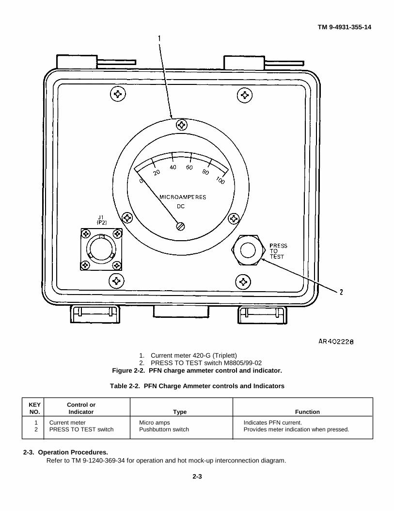
1. Current meter 420-G (Triplett)2. PRESS TO TEST switch M8805/99-02
Figure 2-2. PFN charge ammeter control and indicator.
Table 2-2. PFN Charge Ammeter controls and Indicators
KEY Control orNO. Indicator Type Function
1 Current meter Micro amps Indicates PFN current.2 PRESS TO TEST switch Pushbuttorn switch Provides meter indication when pressed.
2-3. Operation Procedures.Refer to TM 9-1240-369-34 for operation and hot mock-up interconnection diagram.
2-3

TM 9-4931-355-14
CHAPTER 3
DIRECT SUPPORT AND GENERAL SUPPORTMAINTENANCE INSTRUCTIONS
Section I. SERVICE UPON RECEIPT OF MATERIEL
3-1. General.a. When new or reconditioned Laser Test Sets or
Alignment Kit are received by the using organization,check that all items are present, in good condition,clean, and properly stored. Purge and charge the tester,if necessary.
3-2. Modification Work Orders.All pertinent modification work orders must have
been applied. Check DA Pamphlet 310-7. If applicable,check on the application of all authorized modificationsto see that no unauthorized alteration has been made,or that no work beyond the authorized scope of the unitis being attempted.
3-3. Receiving Inspection.a. General Requirements.
(1) The external case and cover must beclean and in good condition.
(2) All switches, lamps, and connectors onapplicable test equipment must be intact.
(3) All switches must function normally.(4) All panel markings, and other essential
markings must be legible.(5) Cables and extender card connectors and
other accessory equipment must be in good condition.There must be no brittle or frayed insulation.
(6) The special tools and test equipment mustbe examined for evidence of abuse.
b. Specific Requirement. Test Sets and AlignmentKit components should conform to the configurationdepicted in figures 1-1 through 1-4.The R/T tester and PFN charge ammeter should be ingood operating condition.
3-4. Services for Deficiencies on Receipt.Any deficiencies discovered by the inspection
described in paragraph 3-3 will be corrected.
Section II. REPAIR PARTS, SPECIAL TOOLS, AND EQUIPMENT
3-5. Repair Parts.Repair parts, special tools, and equipment for
the test set at direct and general support maintenancelevels are contained in TM 9-4931355-24P.
3-6. Special Tools and Equipment.Refer to table 3-1.
Table 3-1. Special Tools and Equipment
Reference
NSN or Fig. Para Use
Item reference No. No. No.
Kit. Purging Fire Control 4931-00-065-1110 3-11 To purge and charge tester.Nitrogen, Technical Tank 6830-00-782-2641 3-11 Used with Kit, Purging 4931-00-065-
(BB-N-411} 1110.
3-1
TM 9-4931-355-14
Section III. PREVENTIVE MAINTENANCE CHECKS AND SERVICES
3-7. General.Preventive maintenance services include
cleaning, inspection, and paint touch-up procedures.Such maintenance is performed at regular orunscheduled intervals to detect and correct conditionswhich might cause the equipment to deteriorate anddegrade field performance or cause a field failure. Thefollowing subparagraph and table 3-2 containsprocedures and instructions necessary to performorganizational preventive maintenance checks andservices.
3-8. General Cleaning Instructions.The test set should always be kept clean. Otherwiseperformance may be degraded and obvious defect thatwould be noticed in a visual inspection may be hiddenby dust or other foreign matter.
WARNINGToluol solvent is toxic andflammable. Use only in a well-ventilated area. Avoid prolonged orrepeated breathing of vapor. Avoidprolonged or repeated contact withthe skin.Isopropyl alcohol is flammable.Keep all flammable cleaningmaterials away from open flames.Failure to do so could result in injuryor death.
a. Metal Parts. Use dry, cotton wiping cloths toremove dust, dirt, grease, moisture, or other foreignmatter. If the foreign matter cannot be removed usingdry wiping cloths, dampen a cloth with isopropyl alcoholor solvent and gently wipe the area.
b. Rubber Parts. Clean rubber parts using a milddetergent and warm water. Dry the parts using a clean,absorbent wiping cloth.
c. Glass.CAUTION
Do not clean the glass surfaces onfront of the R/T tester or alinementlens assembly with cloths or othermaterials that might scratch thesurface.
Use a camel hair brush to remove loose particles of dustand lint from the glass surface. Then wipe the surfacein a circular motion using lens tissue (either dry ormoistened with isopropyl alcohol).If dirt, lint, or smears remain on the glass, wrap a pieceof lens tissue around the end of an orange stick (orequivalent) to form a swab. Beginning at the center ofthe surface, swab with a circular motion while applying alight downward pressure.Gradually increase the radius of the area being cleaneduntil the entire surface has been covered.If necessary, use a rubber syringe to remove anyremaining dust or lint.
3-9. Inspection.Conduct a visual inspection of the test set as
indicated in table 3-2 to make sure that all items are ingood condition. Replacement items should besubstituted for those found to be damaged or worn nearor beyond serviceable limits. Dirt, grease, and foreignmatter should be removed from all inspected surfaces.Preservatives and foreign matter should be removedfrom electrical connectors. Areas where the paint isscratched, chipped, or worn should be repainted.
Table 3-2. Preventive Maintenance Checks and Services
Sequence Item to be Corrective action and/orNO. inspected Procedure paragraph reference
1 General Appearance Check for accumulations of dirt, oil, Clean.grease, or other foreign matter.
Check for breaks, cracks, distortions, Replace item.or other evidence of damage.
Check interfaces for serviceability and Replace item.for evidence of damage or wear.bent or broken connector pins.
Check for rust or corrosion and Clean and spot (para 3-10. table 3-3).missing, chipped or blistered paint.
(check for missing parts. Replace item.2 Equipment markings Inspect for legibility. Replace item.3 Adapter, test Check adapter for cleanliness and Clean (table 3-31 and replace if
damage. damaged.Check for damaged inserts. Replace inserts (para 4-6a)Check for missing. chipped or Clean and spot paint (para 3-10, table 3-3).
blistered paint.
3-2

TM 9-4931-355-14Table 3-2. Preventive Maintenance Checks and Services -Continued
Sequence Item to be Corrective action and/orNO. inspected Procedure paragraph reference
3 Adapter test-Continued Check light seal for cleanliness and Clean (para 3-8b, table 3-3) anddamage. replaced if damaged
4 Tool, removal-boot Check tool for cleanliness and Clean (para 3-8a, table 3-3) anddamage. replace if damaged
5 Cables Check connectors. and cables for Clean (table 3-3) and replace ifcleanliness and damage. damaged
Check connectors for bent or broken Replace cablepins.
6 Extender cards Check for worn or damaged surfaces, Replace extender card.or broken -copper paths and bent orbroken connectors and,/or pins.
Check pins for cleanliness. Clean as required (table 3-3)Check for- broken or loose wires. Replace or resolder wires.Check connector for missing Replace as required (para 4-8).
polarizing keys.7 Handles, and tie rod assembly Check handles for cleanliness and Clean (para 3-8a) and
receiver- transmitter excessive wear and/or damage. replace if damaged.Check tie rod assembly for damaged Replace assembly
cables.Check tie rod assembly, for damaged Replace assembly
or missing pins.8 Handle assembly, ballistic cover Check handles for cleanliness and Clean (para 3-8a, table 3-3) and
excessive wear and/or damage. replaced if damagedCheck screws for excessive binding. Replace handle assembly.
9 Ammeter, PFN charge Check ammeter for cleanliness and Clean (para 3-8, table 3-3) and replacedamage. if damaged.
Check for missing, chipped or Clean and spot paint (para 3-10, table 3-3).blistered paint.
10 Gage, depth connector Check gage for cleanliness and Clean (para 3-8a, table 3-3) andcover/housing damage. replace if damaged.
11 Eyebolt Check eyebolt for cleanliness and Clean (para 3-8a, table 3-3) anddamage replace if damaged
12 Cases, carrying Check for cleanliness and damage. Clean (para 3-8 a table 3-3) andreplace if damaged.
Check for missing, chipped or Clean and spot paint (para 3-10, table 3-3).blistered paint.
13 Wrenches Check for damage. Replace if damaged.14 Tester, R/T Check glass surface for cleanliness Clean (para 3-8c, table 3-3) and
and damage. Replace if damaged..Check for missing, chipped, or Clean and spot paint (para 3-10, table 3-3).
blistered paint.Check for damage. Replace if damaged.Check for cracked or missing MODE Replace knob (para 4-3).
SELECT switch knob.Check for damaged or missing Replace connector cover (para 4-3).connector cover.
15 Puller, circuit card Check puller fir damaged knobs. Replace puller.Check puller for damage. Replace Puller
16 Lens, assembly, alinement Check glass surfaces for cleanliness Clean (para 3-8c, table 3-3) andand damage. Replace if damaged.
Check for damaged or missing cord Replace cord assembly (para 4-14).assembly.
17 Tool boresight-adjustment Check tool Cleanliness. Clean para 3-8a, table 3-3Check for missing setscrews. Replace setscrews.Check for damage Replace tool.
3-10. General Painting Instructions.Visually inspect the special tools and test
equipment items for rust or corrosion and missing,chipped or blistered paint. Small areas of damagedpaint are touched up as part of user maintenance.
Apply paint as issued or with not more than 5 percent byvolume of thinner. See table 3-3 for requirements andmaterials needed for cleaning and touch-up painting.
a. Smooth surface and feather edges of affectedareas with fine abrasive paper.
3-3

TM 9-4931-355-14
WARNINGToluol solvent is toxic andflammable. Use only in a well-ventilated area. Avoid prolonged orrepeated breathing of the vapor.Avoid prolonged or repeated contactwith the skin.
b. Clean area with a wiping cloth dampened withtoluol solvent.
c. Apply primer and paint to the affected area pertable 3-3 and instructions cited on the paint containers.Air dry primer for a minimum of 1/2 hour. Within twohours after application of primer, apply one coat of paintper table 3-3.3-11. R/T Tester Purging and Charging Procedure .
The R/T tester is a sealed unit which is purgedwith dry nitrogen at 90-day intervals. The unit is purgedto prevent condensation of moisture which may hinderthe operation of the unit. A purging adapter kit which issupplied for organizational maintenance of the Sheridanvehicle is connected to a nitrogen cylinder and to the fillvalve of the R/T tester. The fill valve is color codedgray and the escape port is color coded yellow. Thefollowing procedure shall be used to purge the R/Ttester.
a. Remove fill valve cap from the R/T tester fillvalve (1, fig. 2-1).
b. Remove screw plug from the R/T tester exhaustport (7, fig. 2-1).
c. Attach one end of the purging adapter kit to thenitrogen cylinder and the other end to the R/T tester fillvalve.
Table 3-3. Materials Needed For Cleaning and Touch-up Painting
Item Name Specification FSC
WARNINGIsopropyl alcohol is flammable. When using it for cleaning, keep it and all flammable cleaningmaterials away from open flames.Toluol solvent is toxic and flammable. Use only in well-ventilated area. Avoid prolonged orrepeated breathing of the vapor. Avoid prolonged or repeated contact with the skin.
Adhesive RTV-8262 (General Electric Co.) 8030Cotton, Flannel, (wiping rag) CCC-C-458 8305Filler, Engraving TT-F-325, type II 8010Flux, Soldering, Liquid (Rosin Base) MIL-F-14256 3439Identification Marking of U. S. Military Property MIL-STD-130 MISCIsopropyl Alcohol Grade I TT-I-735 6810Methyl Ethyl Ketone Technical) TT-M-261 6810Paint, Olive, Drab X240)87 FED-STD-595 8010Paper, Lens Tissue NNN-P-40 6640Primer Coating, Zinc Chromate MIL-P-6808 8010Primer, Fluorescent, Pink SS4004 (General Electric Co.) 8030Solder, Tin Allov Sn 60 QQ-S-571 type WRMAP-2 3439Toluol. ('leaning, Solvent T324 6810Waxed Cord 11737916
d. Turn the tank valve on the nitrogen cylindercounterclockwise to open the valve.
e. Set the pressure regulator for 14±1.0 psig.f. Turn the control valve on the purging adapter kit
counterclockwise to open the valve.g. Allow the R/T tester to purge for a minimum of
one minute.h. Turn the control valve on the purging adapter kit
clockwise to close the valve.i. Allow the R/T tester to depressurize to ambient
pressure.j. Repeat f through i above four times and
continue with paragraph k below.k. Turn the control valve on the purging adapter kit
counterclockwise to open the valve.
l. Allow the R/T tester to purge for at least 20minutes at the 14±1.0 psig pressure.
m. Reduce the pressure to less than three psig.n. Install the plug screw in the R/T tester exhaust
port.o. Repressurize to a pressure of 10±1.0 psig.p. Turn the control valve on the purging adapter kit
clockwise to close the valve.q. Remove the purging adapter kit from the R/T
tester fill valve.r. Install the fill valve cap on the R/T tester fill
valve.s. Close the valve on the nitrogen tank and relieve
the pressure in the purging adapter kit.
3-4

TM 9-4931-355-14
3-12. R/T Tester Calibration.Calibration of the R/T tester must be performed atdepot.
Section IV. TROUBLESHOOTING
3-13. Troubleshooting the Test Set.Troubleshooting of the test set is limited to
continuity checks of the test cables and extender cardsand to visual inspection of the special tools and testequipment. If continual faulty indications are observedon the RCVR-XMTR STATUS meter of the R/T tester oron the PFN charge ammeter, a known good R/T testeror PFN charge ammeter, receiver-transmitter unit,power supply control unit or test cable should be
substituted to localize the trouble to one of the fouritems. Table 3-4 summarizes the troubleshootingrequired for the test set. Figure 3-1 provides theschematic diagrams of the test cables and table 3-5provides the wire list for the extender cards. Table 3-6provides the wire list for the branched cable. Refer toTM 9-1240-369-34 for troubleshooting of laser rangefinder units.
Figure 3-1. Cables schematic diagram.(Located in back of manual)
Table 3-4. Test Set Troubleshooting
Sequence Item to be Corrective action and/orNO. inspected Procedure paragraph reference
1 All of the mode lamps do not light Tester cable, or R/T tester. Check continuity of tester cable. Ifon R/T tester. proper continuity exists, return
R/T tester to depot for repair. Ifproper- continuity does not exist,repair tester cable (para 4-11 ).
2 One or more or more of the mode lamps R/T tester. Return R/T tester to depot do for repair.not light on R/T tester.
3 No indication on the R/T tester R/T tester. Return R/T tester to. depot forRCVR-XMTR STATUS meter repair.during receiver sensitivity check ortransmitter output energy check.
4 PFN charge ammeter does not PFN charge ammeter or PRESS Return PFN charge, ammeter depotindicate during transmitter output TO TEST switch. for repair.energy check.
5 Various circuit card assemblies or Extender card/extender cable. Perform maintenance checks asmodules do not function properly described in table 3-1 and repairwhen installed in extender card extender card (para 4-8) or extenderconnectors or extender cable cable (para 4-11).connectors.
6 Laser range finder does not function Branched cable. Perform maintenance checks asproperly during receiver to described in table 3-1 and repairtransmitter alinement. (para 4-11).
3-5

TM 9-4931-355-14
Table 3-5. Extender Cards Wire ListsInterface Card Low Voltage Power -1600V Power Counters Card Reply Gating Card Select Logic Card Power Control Card Battery Charge Battery Charge
Wire List Supply Card Wire List Supply Card Wire List Wire List Wire List Wire List Wire list Sensor ControlCard Wire List Card Wire List
From To From To From To From To From To From To From To From To From To
J1-A1 Pad-A1 J1-A1 Pad-A1 J1-A1 Pad-A1 J1-A1 Pad-A1 J1-A1 Pad-A1 J1-A1 Pad-A1 P1-7 Pad-A7 P1-1 Pad-A1 P1-4 Pad-A4J1-B2 Pad-B2 J1 B2 Pad-B2 J1-B2 Pad-B2 J1-B2 Pad-B2 J1-B2 Pad-B2 J1-B2 Pad-B2 P1-8 Pad-A8 P1-2 Pad-A2 P1-5 Pad-A5J1-A3 Pad-A3 J1-A3 Pad-A3 J1-A3 Pad-A3 J1-A3 Pad-A3 J1-A3 Pad-A3 J1-A3 Pad-A3 P1-9 Pad-A9 P1-4 Pad-A4 P1-6 Pad-A6J1-B4 Pad-B4 J1-B4 Pad-B4 J1-B4 Pad-B4 J1-B4 Pad-B4 J1-B4 Pad-B4 J1-B4 Pad-B4 P1-10 Pad-A10 P1-5 Pad-A5 P1-7 Pad-A7J1-A5 Pad-A5 J1-A5 Pad-A5 J1-A5 Pad-A5 J1-A5 Pad-A5 J1-A5 Pad-A5 J1-A5 Pad-A5 P1-11 Pad-A11 P1-6 Pad-A6 P1-8 Pad-ASJ1-B6 Pad-B6 J1-B6 Pad-B6 J1-B6 Pad-B6 J1-B6 Pad-B6 J1-B6 Pad-B6 J1-B6 Pad-B6 P1-12 Pad-A12 P1-7 Pad-A7 P1-10 Pad-A10J1-A7 Pad-A7 J1-A7 Pad-A7 J1-A7 Pad-A7 J1-A7 Pad-A7 J1-A7 Pad-A7 J1-A7 Pad-A7 P1-13 Pad-A13 P1-8 Pad-A8 P1-11 Pad-A11J1-B8 Pad-B8 J1-B8 Pad-B8 J1-B8 Pad-B8 J1-B8 Pad-B8 J1-B8 Pad-B8 J1-B8 Pad-B8 P1-14 Pad-A14 P1-10 Pad-A10 P1-12 Pad-A12J1-A9 Pad-A9 J1-A9 Pad-A9 J1-A9 Pad-A9 J1-A9 Pad-A9 J1-A9 Pad-A9 J1-A9 Pad-A9 P1-15 Pad-A15 P1-11 Pad-A11 P1-15 Pad-A15J1-B10 Pad-B10 J1-B10 Pad-B10 J1-B10 Pad-B10 J1-B10 Pad-B10 J1-B10 Pad-B10 J1-B10 Pad-B10 P1-16 Pad-A16 P1-12 Pad-A12 P1-16 Pad-A16J1-A11 Pad-A11 J1-A11 Pad-A11 J1-A11 Pad-A11 J11-A11 Pad-A11 J1-A11 Pad-A11 J1-A11 Pad-A11 P1-17 Pad-A17 P1-14 Pad-A14 P1-24 P1-A24J1-B12 Pad-B12 J1-B12 Pad-B12 J1-B12 Pad-B12 J1-B12 Pad-B12 J1-B12 Pad-B12 J1-B12 Pad-B12 P1-18 Pad-A18 P1-15 Pad-A15 P2-4 Pad-B24J1-A13 Pad-A13 J1-A13 Pad-A13 J1-A13 Pad-A13 J1-A13 Pad-A13 J1-A13 Pad-A13 J1-B14 Pad-B14 P1-20 Pad-A20 P1-17 Pad-A17 P2-5 Pad-B5J1-B14 Pad-B14 J1-B14 Pad-B14 J1-B14 Pad-B14 J1-B14 Pad-B14 J1-B14 Pad-B14 J1-A15 Pad-A15 P1-21 Pad-A21 P1-18 Pad-A18 P2-6 Pad-B6J1-A15 Pad-A15 J1-A15 Pad-A15 J1-A15 Pad-A15 J1-A15 Pad-A15 J1-A15 Pad-A15 J1-B16 Pad-B16 P1-22 Pad-A22 P1-20 Pad-A20 P2-7 Pad-B7J1-B16 Pad-B16 J1-B16 Pad-B16 J1-B16 Pad-B16 J1-B16 Pad-B16 J1-B16 Pad-B16 J1-A17 Pad-A17 P1-24 Pad-A24 P1-22 Pad-A22 P2-8 Pad-B8J1-A17 Pad-A17 J1-A17 Pad-A17 J1-A17 Pad-A17 J1-A17 Pad-A17 J1-A17 Pad-A17 J1-B18 Pad-B18 P1-25 Pad-A25 P2-1 Pad-B1 P2-10 Pad-B10J1-A19 Pad-A19 J1-B18 Pad-B18 J1-B18 Pad-B18 J1-B18 Pad-B18 J1-B18 Pad-B18 J1-A19 Pad-A19 P2-7 Pad-B7 P2-2 Pad-B2 P2-11 Pad-B11J1-B20 Pad-B20 J1-A19 Pad-A19 J1-A19 Pad-A19 J1-A19 Pad-A19 J1-A19 Pad-A19 J1-B20 Pad-B20 P2-8 Pad-B8 P2-4 Pad-B4 P2-12 Pad-B12J1-A21 Pad-A21 J1-B20 Pad-B20 J1-B20 Pad-B20 J1-B20 Pad-B20 J1-A21 Pad-A21 J1-A21 Pad-A21 P2-9 Pad-B9 P2-5 Pad-B5 P2-15 Pad-B15J1-B22 Pad-B22 J1-A21 Pad-A21 J1-A21 Pad-A21 J1-A21 Pad-A21 J1-B22 Pad-B22 J1-B22 Pad-B22 P2-10 Pad-B10 P2-6 Pad-B6 P2-16 Pad-B16J1-A23 Pad-A23 J1-B22 Pad-B22 J1-A23 Pad-A23 J1-B22 Pad-B22 J1-A23 Pad-A23 J1-A23 Pad-A23 P2-11 Pad-B11 P2-7 Pad-B7 P2-24 Pad-B24J1-B24 Pad-B24 J1-A23 Pad-A23 J1-B24 Pad-B24 J1-A23 Pad-A23 J1-B24 Pad-B24 J1-B24 Pad-B24 P2-12 Pad-B12 P2-8 Pad-B8J1-A25 Pad-A25 J1-B24 Pad-B24 J1-A25 Pad-A25 J1-B24 Pad-B24 J1-A25 Pad-A25 J1-A25 Pad-A25 P2-13 Pad-B13 P2-10 Pad-B10J1-B26 Pad-B26 J1-A25 Pad-A25 J1-B26 Pad-B26 J1-A25 Pad-A25 J1-B26 Pad-B26 J1-B26 Pad-B26 P2-14 Pad-B14 P2-11 Pad-B11J1-A27 Pad-A27 J1-A27 Pad-A27 J1-A29 Pad-A29 J1-B26 Pad-B26 J1-A27 Pad-A27 J1-A27 Pad-A27 P2-15 Pad-B15 P2-12 Pad-B12J1-B28 Pad-B28 J1-B28 Pad-B28 J1-B32 Pad-B32 J1-A27 Pad-A27 J1-B28 Pad-B28 J1-B28 Pad-B28 P2-16 Pad-B16 P2-14 Pad-B14J1-A29 Pad-A29 J1-A29 Pad-A29 J1-A33 Pad-A33 J1-B28 Pad-B28 J1-A29 Pad-A29 J1-A29 Pad-A29 P2-17 Pad-B17 P2-15 Pad-B15J1-B30 Pad-B30 J1-B30 Pad-B30 J1-B34 Pad-B34 J1-A29 Pad-A29 J1-B30 Pad-B30 J1-B30 Pad-B30 P2-18 Pad-B18 P2-17 Pad-B17J1-A31 Pad-A31 J1-A31 Pad-A31 J1-A35 Pad-A35 J1-B30 Pad-B30 J1-A31 Pad-A31 J1-A31 Pad-A31 P2-20 Pad-B20 P2-18 Pad-B18J1-B32 Pad-B32 J1-B32 Pad-B32 J1-B36 Pad-B36 J1-A31 Pad-A31 J1-B32 Pad-B32 J1-B32 Pad-B32 P2-21 Pad-B21 P2-20 Pad-B20J1-A33 Pad-A33 J1-A33 Pad-A33 J1-B32 Pad-B32 J1-A33 Pad-A33 J1-A33 Pad-A33 P2-22 Pad-B22 P2-22 Pad-B22J1-B34 Pad-B34 J1-B34 Pad-B34 J1-A33 Pad-A33 J1-B34 Pad-B34 J1-B34 Pad-B34 P2-24 Pad-B24J1-A35 Pad-A35 J1-A35 Pad-A35 J1-B34 Pad-B34 J1-A35 Pad-A35 J1-A35 Pad-A35 P2-25 Pad-B25J1-B36 Pad-B36 J1-B36 Pad-B36 J1-B36 Pad-B36 J1-B36 Pad-B36 J1-B36 Pad-B36
3-6

TM 9-4931-355-14
Table 3-6. Branched Cable Wire ListFrom To From To From To
P1-A1 Not used P1-46 J2-k P2-44 Not usedP1-1 J1-e P2-A1 J2-Z P2-45 Not usedP1-2 J1-f P2-1 J2-J P2-46 Not usedP1-2 SHLD P1-3 SHLD P2-2 J2-K J2-A Not usedP1-3 J1-g P2-16 J2-1 J2-B Not usedP1-4 J1-h P2-17 J2-M J2-C Not usedP1-4 SHLD P1-16 P2-17 SHLD P2-3 J2-D Not usedP1-5 J1-H P2-4 Not used J2-F Not usedP1-6 J1-J P2-5 J2-e J2-F Not usedP1-7 J1-K P2-5 SHLD P2-7 SHLD J2-G Not usedP1-8 J1-L P2-6 J2-i J2-H Not usedP1-9 J1-M P2-7 J2-f J2-x Not usedP1-10 J1-N P2-7 SHLD P2-11 J2-y Not usedP1-11 J1-P P2-8 J2-h J2-a Not usedP1-12 J1-R P2-9 J2-d J2-M SHLD J2-NP1-13 J1-S P2-9 SHLD P2-5 SHLD J2-d SHLD J2-8 SHLDP1-14 J1-T P2-10 J2-j J2-e SHLD J2-f SHLDP1-15 J1-E P2-12 J2-n J2-f SHLD J2-gP1-17 J1-j P2-13 Not used J2-b SHLD J2-d SHLDP1-18 J1-k P2-14 Not used J2-m Not usedP1-18 SHLD P1-19 SHLD P2-15 Not used J1-A Not usedP1-19 J1-z P2-18 J2-T J1-B Not usedP1-20 J1-AA P2-19 J2-V J1-C Not usedP1-20 SHLD P1-33 P2-30 J2-P J1-D Not usedP1-21 J1-U P2-31 J2-R J1-f SHLD J1-g SHLDP1-22 J1-V P2-32 J2-S J1-h SHLD J1-iP1-23 J1-W P2-33 J2-U J1-k SHLD J1-z SHLDP1-24 J1-X P2-34 J2-W J1-AA SHLD J1-yP1-25 J1-Y P2-20 J1-8P1-26 J1-Z P2-21 J1-rP1-27 J1-a P2-22 J1-sP1-28 J1-b P2-23 J1-uP1-29 J1-c P2-24 J2-pP1-30 J1-d P2-25 J2-qP1-31 J1-BB P2-26 J2-rP1-32 J1-CC P2-27 Not usedP1-34 J1-m P2-28 Not usedP1-35 J1-n P2-29 Not usedP1-36 J1-p P2-35 J2-bP1-37 J1-t P2-36 J2-cP1-38 J1-F P2-35 SHLD P2-9 SHLDP1-39 J1-G P2-37 J1-vP1-40 J1-DD P2-38 J1-wP1-41 J1-EE P2-39 J1-xP1-42 J1-FF P2-40 J2-sP1-43 J1-GG P2-41 J2-tP1-44 J1-HH P2-42 Not usedP1-45 Not used P2-43 Not used
3-7
TM 9-4931-355-14
CHAPTER 4REPAIR INSTRUCTIONS
Section I. GENERAL
4-1. ScopeThis chapter contains instructions for the repair
of the test set. Also any inspection or test requiredduring the process of repair will be discussed or
referenced to the applicable section. Refer to TM 9-1240-369-34 for repair instructions for laser range finderunits.
Section II. REPAIR OF RECEIVER-TRANSMITTER TESTER
4-2. General.Repair of the R/T tester is limited to
replacement of MODE SELECT switch knob, connectorcover for connector 6A7J1, and touch up or replacementof illegible equipment markings.4-3. Repair.
No special instructions are necessary forreplacement of the knob or connector cover. Touch upor replace illegible equipment markings in accordancewith MIL Standard 130 using white paste engravingfiller.4-4. Inspection.
Refer to chapter 5 for final inspection criteria.
Section III. REPAIR OF TESTER ADAPTER
4-5. General.Repair of the tester adapter is limited to
replacement of four inserts, the outer window gaskets,and touch-up painting of illegible markings.4-6. Repair.
a. Replacement of Inserts. Replace damagedinserts with four inserts MS124695. No specialinstructions are necessary for replacement.
b. Replacement of Outer Window Gasket.(1) Remove damaged outer window gasket
from tester adapter.WARNING
Methyl ethyl ketone used in thefollowing step is toxic andflammable. Use only in a well-ventilated area. Avoid prolonged orrepeated breathing of the vapor.Avoid prolonged or repeated contactwith the skin. Keep away from heatand open flames.
(2) Clean mating surface of tester adapterwith a wiping rag, CCC-C-458, dampened with methylethyl ketone, TT-M-261.
(3) Coat mating surface of tester adapter withprimer SS4004 Allow to dry at room temperature for aminimum of 30 minutes.
(4) Prepare replacement outer window gasketby rubbing adhesive RTV-8262, catalyzed with fourtimes the amount of catalyst normally used, into matingsurface Remove excess adhesive with a dry tissue.
(5) Prepare adhesive by mixing adhesive withcatalyst in a clean, nonabsorbent container. Coat themating surfaces of both the outer window gasket and theadapter with adhesive.
(6) Install the outer window gasket to thetester adapter.
c. Repair of Markings Touch up or replace illegiblemarkings in accordance with MIL Standard 130 usingwhite paste engraving filler.
4-1
TM 9-4931-355-14
Section IV. REPAIR OF EXTENDER CARDS
4-7. General.The repair of the extender cards is limited to
replacement of defective or missing polarizing keys11738976 and replacement of loose or broken wires.4-8. Repair.
No special instructions are required for replacingthe polarizing keys in the extender cards. Thereplacement polarizing key 11738976, is inserted intoconnector at pin location as indicated below.
Extender card assembly Connector locationCounters 35Low voltage power supply 26Reply gating 20- 1600V power supply 22Select logic 13Interface circuit 18
Soldered all wires using solder Sn 60, QQ-S-571. Referto table 3-5 for the wire list of each extender card.4-9. Inspection.
Refer to chapter 5 for final inspection criteria.
Section V. REPAIR OF CABLES
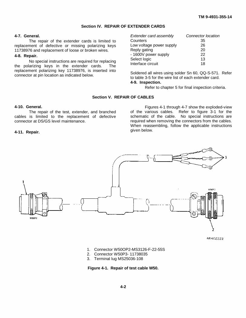
4-10. General.The repair of the test, extender, and branched
cables is limited to the replacement of defectiveconnector at DS/GS level maintenance.
4-11. Repair.
Figures 4-1 through 4-7 show the exploded-viewof the various cables. Refer to figure 3-1 for theschematic of the cable. No special instructions arerequired when removing the connectors from the cables.When reassembling, follow the applicable instructionsgiven below.
1. Connector W50OP2-MS3126-F-22-55S2. Connector W50P3- 117380353. Terminal lug MS25036-108
Figure 4-1. Repair of test cable W50.
4-2

TM 9-4931-355-14
Test cable W51 Tester cable A7/A771. Connector W51P1-MS3126F-22-55SW 1. Connector P1-MS3126F-14-19-SW2. Connector W51P2-MS3126F-55SX 2. Connector P2-MS3126F-20-41PTest cable W54 Test cable W521. Connector W54P1-MS3126F-16-26SY 3. Connector W52P1-117380342. Connector W54P2-MS3126F-16-26PW 4. Connector W5P2-11738033
Figure 4-2. Repair of test cables W51, W52, W54, and tester cable A7/A77.
1. Connector P2-M24308/3-5 5 Washer NAS620C42. Clamp 11738042 6. Lockwasher MS35338-1353. Connector P1-M24308/1-5 7. Nut NAS671C44. Screw, NAS1635-04-4
Figure 4-3. Repair of test cable A75/A76.4-3
TM 9-4931-355-14
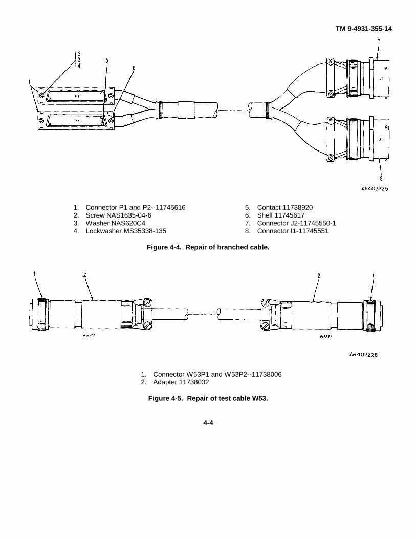
1. Connector P1 and P2--11745616 5. Contact 117389202. Screw NAS1635-04-6 6. Shell 117456173. Washer NAS620C4 7. Connector J2-11745550-14. Lockwasher MS35338-135 8. Connector I1-11745551
Figure 4-4. Repair of branched cable.
1. Connector W53P1 and W53P2--117380062. Adapter 11738032
Figure 4-5. Repair of test cable W53.
4-4
TM 9-4931-355-14
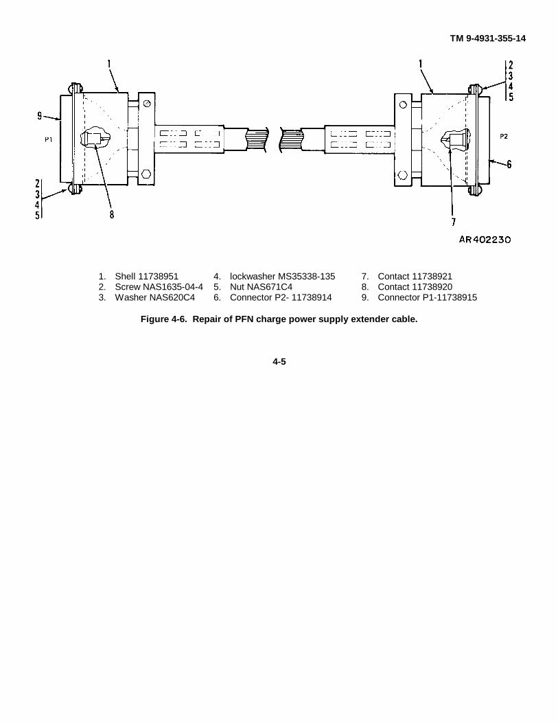
1. Shell 11738951 4. lockwasher MS35338-135 7. Contact 117389212. Screw NAS1635-04-4 5. Nut NAS671C4 8. Contact 117389203. Washer NAS620C4 6. Connector P2- 11738914 9. Connector P1-11738915
Figure 4-6. Repair of PFN charge power supply extender cable.
4-5
TM 9-4931-355-14
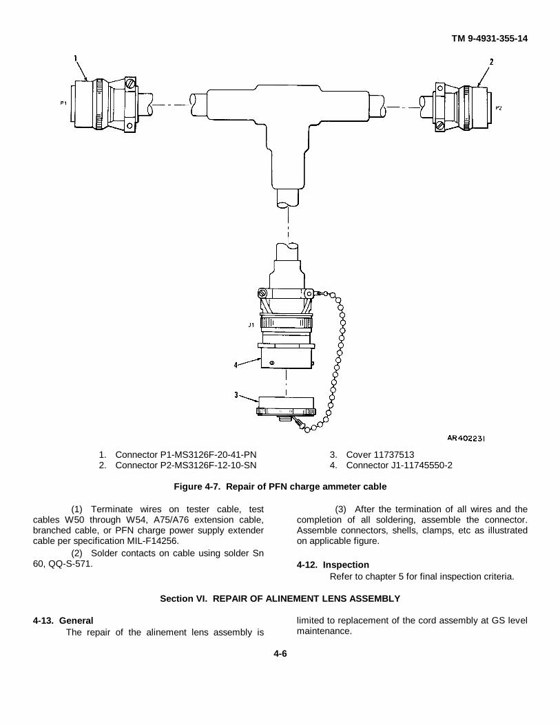
1. Connector P1-MS3126F-20-41-PN 3. Cover 117375132. Connector P2-MS3126F-12-10-SN 4. Connector J1-11745550-2
Figure 4-7. Repair of PFN charge ammeter cable
(1) Terminate wires on tester cable, testcables W50 through W54, A75/A76 extension cable,branched cable, or PFN charge power supply extendercable per specification MIL-F14256.
(2) Solder contacts on cable using solder Sn60, QQ-S-571.
(3) After the termination of all wires and thecompletion of all soldering, assemble the connector.Assemble connectors, shells, clamps, etc as illustratedon applicable figure.
4-12. InspectionRefer to chapter 5 for final inspection criteria.
Section VI. REPAIR OF ALINEMENT LENS ASSEMBLY
4-13. GeneralThe repair of the alinement lens assembly is
limited to replacement of the cord assembly at GS levelmaintenance.
4-6

TM 9-4931-355-14
4-14. Repaira. Replacement of Cord Assembly.
(1) Remove screw holding terminal lug toalinement lens assembly.
(2) Remove cord tip and retain.(3) Cut waxed cord 11737916 to a length
such that the overall length of the cord assembly fromthe cord tip to the center of the terminal lug hole is 71inches.
(4) Insert one end of waxed cord into terminallug MS25036-108 and crimp.
(5) Insert other end of waxed cord throughcord tip and make a one-knot tie.
(6) Secure terminal lug to alinement lensassembly.
4-7

TM 9-4931-355-14
CHAPTER 5FINAL INSPECTION
5-1. General.This chapter provides visual inspection and final
inspection standards to ensure the serviceability of thecomplete test set. The items requiring final inspectionare the R/T tester, the cables, and the extender cards.Final inspection is performed after repair has beencompleted to ensure serviceability of the test setaccording to established standards. Any itemscontaining defects disclosed by the final inspection willbe returned to the maintenance shop for repair. Refer toTM 9-1240-369-34 for final inspection procedures of thelaser range finder units.
5-2. Visual Inspection.The following procedure provides visual
inspection techniques for the test set.a. Inspect each item to ensure that it is complete.b. Inspect each item for appearance and quality of
workmanship. Check workmanship for soldering, wiring,riveting, painting, and mechanical assemblies. Ensurethat all corners and edges are smooth.
5-3. Final Inspection Standards.
a. R/T Tester The following procedures establishesinspection criteria for the R/T tester.
(1) Connect laser range finder units in the hotmock-up configuration as described in TM 91240-369-34.
(2) Perform receiver sensitivity andtransmitter output energy checks as described in PFNadjustment procedure in TM 9-1240-369-34.
b. Cables. Cables should be inspected for bent orbroken pins, broken insulation, and frayed or brokenwires. All connectors should be checked for faultysolder connections. The only test required for the cableassemblies is a continuity check. Before making acontinuity check perform visual inspection describedabove.
c. Extender Cards. Extender cards should bevisually inspected for broken or cracked board anddamaged printed circuit wiring. The extender cardconnector should be checked for faulty solderconnections. The only test required for the extendercards is a continuity check. Before making a continuitycheck perform the visual inspection described above.
5-1

TM 9-4931-355-14
CHAPTER 6ADMINISTRATIVE STORAGE
6-1. General.Refer to TM 740-90-1 for administrative storage
procedures for the special tools and test equipment.
6-1

TM 9-4931-355-14
APPENDIX AREFERENCES
A-1. Safety.Control of Hazards from Laser Radiation ................................................................................... TB MED 279Control of Health Hazards from Lasers and Other High Intensity Optical Sources ...................... AR 40-46A-2. Supply Catalogs.The following Department of the Army Supply Catalogs pertain to repair of this
materiel:Brushes, Paints, Sealers, and Adhesives .................................................................................. C8000-IL-AFire Control Maintenance and Repair Shop Specialized Equipment Tool Set, DS,
GS, and Depot Maintenance: General Purpose Tools (4931-574-6433) ........................ SC 4931-95-CL-J51Fire Control Maintenance and Repair Shop Specialized Equipment Wrench Set,
Spanner DS, GS, and Depot Maintenance: Tuba, Dble-End Concave InsertedBlade: Set of 76 Wrenches (4931-580-0012) ................................................................ SC 4931-95-CL-J52
Miscellaneous Hardware ............................................................................................................ C5340-IL-A vols 123Oils and Greases: Cutting, Lubricating, and Hydraulic ................................................................ C9100-ILSets, Kits, and Outfits Component List Purging Kit, Fire Control Organization,
Direct and General Support Maintenance (NSN 4931-00-065-1110) .............................. SC 4931-95-CL-J54Shop Set, Instrument and Fire Control, Field Maintenance: Basic (4931-754-0740).................... SC 4931-95-CL-A07Tool Kit, Fire Control Instrument Repairman (4931-947-8243).................................................... SC 4931-95-CL-A09A-3. Other Publications.
a. General.Accident Reporting and Records ................................................................................................ AR 385-40First Aid for Soldiers................................................................................................................... FM 21-11Recommended Changes to Publications ................................................................................... DAFORM 2028The Army Maintenance Management Systems (TAMMS) ......................................................... TM 38-750
b. Maintenance.Direct Support and General Support Maintenance Manual for Range Finder, Fire
Control (Laser) AN/VVG-1 (1240-00-470-2156) ............................................................. TM 9-1240-369-34General Maintenance Procedures for Fire Control Material ........................................................ TM 9-254Operator and Organizational Maintenance Manual Armored
Reconnaissance/Airborne Assault Vehicle Full-Tracked, 152-MM, M551 (2350-873-5408) and M551A1 (2350-140-5151).............................................................................. TM 9-2350-230-12
Operator's Manual (Turret Operation) AR/AAV M551A1 (Sheridian) (w/LaserRange Finder) (2350-140-5151)..................................................................................... TM 9-2350-230-10/2-3
c. Operations.Northern Operations................................................................................................................... FM 31-71Operation and Maintenance of Army Materiel in Extreme Cold Weather 0° to
-65°F ............................................................................................................................ TM 9-207d. Shipment and Storage.
Administrative Storage of Equipment ......................................................................................... TM 740-90-1Paper Lens Tissue Anti-Tarnish Wrapping ................................................................................. MIL-P-13988Part Equipment and Tools for Army Material, Packaging of........................................................ MIL-P-14232Preservation Methods of ........................................................................................................... MIL-P-116Preservation Packaging and Packing ......................................................................................... AR 700-15
Not applicable
A-1

TM 9-4931-355-14
APPENDIX BBASIC ISSUE ITEMS LIST, ITEMS TROOP INSTALLED
OR AUTHORIZED LIST, ANDREPAIR PARTS AND SPECIAL TOOLS LIST
Not applicable.
B-1
TM 9-4931-355-14
APPENDIX CMAINTENANCE ALLOCATION CHART
Section I. INTRODUCTION
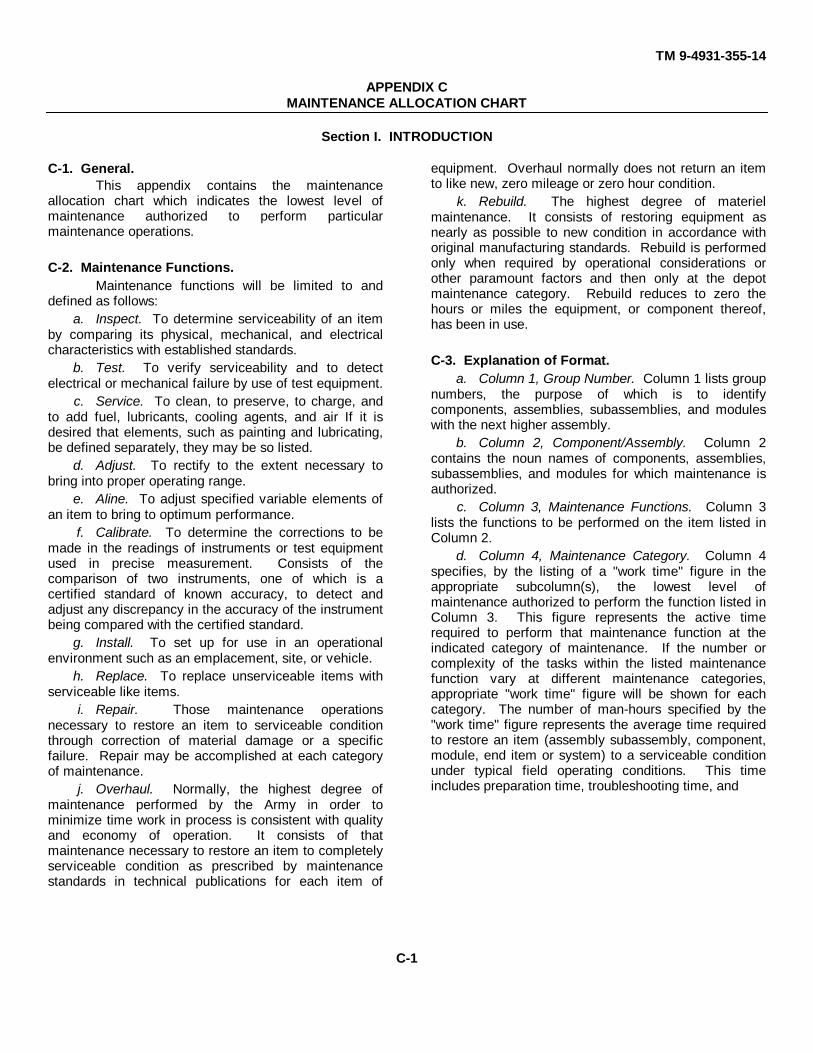
C-1. General.This appendix contains the maintenance
allocation chart which indicates the lowest level ofmaintenance authorized to perform particularmaintenance operations.
C-2. Maintenance Functions.Maintenance functions will be limited to and
defined as follows:a. Inspect. To determine serviceability of an item
by comparing its physical, mechanical, and electricalcharacteristics with established standards.
b. Test. To verify serviceability and to detectelectrical or mechanical failure by use of test equipment.
c. Service. To clean, to preserve, to charge, andto add fuel, lubricants, cooling agents, and air If it isdesired that elements, such as painting and lubricating,be defined separately, they may be so listed.
d. Adjust. To rectify to the extent necessary tobring into proper operating range.
e. Aline. To adjust specified variable elements ofan item to bring to optimum performance.
f. Calibrate. To determine the corrections to bemade in the readings of instruments or test equipmentused in precise measurement. Consists of thecomparison of two instruments, one of which is acertified standard of known accuracy, to detect andadjust any discrepancy in the accuracy of the instrumentbeing compared with the certified standard.
g. Install. To set up for use in an operationalenvironment such as an emplacement, site, or vehicle.
h. Replace. To replace unserviceable items withserviceable like items.
i. Repair. Those maintenance operationsnecessary to restore an item to serviceable conditionthrough correction of material damage or a specificfailure. Repair may be accomplished at each categoryof maintenance.
j. Overhaul. Normally, the highest degree ofmaintenance performed by the Army in order tominimize time work in process is consistent with qualityand economy of operation. It consists of thatmaintenance necessary to restore an item to completelyserviceable condition as prescribed by maintenancestandards in technical publications for each item of
equipment. Overhaul normally does not return an itemto like new, zero mileage or zero hour condition.
k. Rebuild. The highest degree of materielmaintenance. It consists of restoring equipment asnearly as possible to new condition in accordance withoriginal manufacturing standards. Rebuild is performedonly when required by operational considerations orother paramount factors and then only at the depotmaintenance category. Rebuild reduces to zero thehours or miles the equipment, or component thereof,has been in use.
C-3. Explanation of Format.a. Column 1, Group Number. Column 1 lists group
numbers, the purpose of which is to identifycomponents, assemblies, subassemblies, and moduleswith the next higher assembly.
b. Column 2, Component/Assembly. Column 2contains the noun names of components, assemblies,subassemblies, and modules for which maintenance isauthorized.
c. Column 3, Maintenance Functions. Column 3lists the functions to be performed on the item listed inColumn 2.
d. Column 4, Maintenance Category. Column 4specifies, by the listing of a "work time" figure in theappropriate subcolumn(s), the lowest level ofmaintenance authorized to perform the function listed inColumn 3. This figure represents the active timerequired to perform that maintenance function at theindicated category of maintenance. If the number orcomplexity of the tasks within the listed maintenancefunction vary at different maintenance categories,appropriate "work time" figure will be shown for eachcategory. The number of man-hours specified by the"work time" figure represents the average time requiredto restore an item (assembly subassembly, component,module, end item or system) to a serviceable conditionunder typical field operating conditions. This timeincludes preparation time, troubleshooting time, and
C-1
TM 9-4931-355-14
quality assurance/quality control time in addition to thetime required to perform the specific tasks identified forthe maintenance functions authorized in themaintenance allocation chart.
e. Column 5, Tools and Equipment. Column 5specifies by code, those common tool sets and specialtools, test, and support equipment required to performthe designated function.
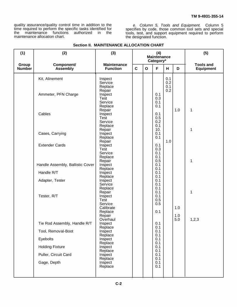
Section II. MAINTENANCE ALLOCATION CHART
(1) (2) (3) (4) (5)MaintenanceCategory*
Group Component/ Maintenance Tools andNumber Assembly Function C O F H D Equipment
Kit, Alinement Inspect 0.1Service 0.2Replace 0.1Repair 0.2
Ammeter, PFN Charge Inspect 0.1Test 0.3Service 0.1Replace 0.1Repair 1.0 1
Cables Inspect 0.1Test 0.5Service 0.2Replace 0.1Repair 10. 1
Cases, Carrying Inspect 0.1Replace 0.1Repair 1.0
Extender Cards Inspect 0.1Test 0.3Service 0.1Replace 0.1Repair 0.5 1
Handle Assembly, Ballistic Cover Inspect 0.1Replace 0.1
Handle R/T Inspect 0.1Replace 0.1
Adapter, Tester Inspect 0.1Service 0.1Replace 0.1Repair 0.1 1
Tester, R/T Inspect 0.1Test 0.5Service 0.5Calibrate 1.0Replace 0.1Repair 1.0Overhaul 5.0 1,2,3
Tie Rod Assembly, Handle R/T Inspect 0.1Replace 0.1
Tool, Removal-Boot Inspect 0.1Replace 0.1
Eyebolts Inspect 0.1Replace 0.1
Holding Fixture Inspect 0.1Replace 0.1
Puller, Circuit Card Inspect 0.1Replace 0.1
Gage, Depth Inspect 0.1Replace 0.1
C-2
TM 9-4931-355-14
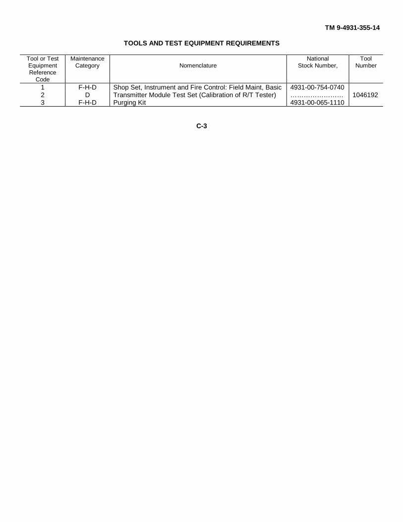
TOOLS AND TEST EQUIPMENT REQUIREMENTS
Tool or Test Maintenance National ToolEquipment Category Nomenclature Stock Number, NumberReference
Code1 F-H-D Shop Set, Instrument and Fire Control: Field Maint, Basic 4931-00-754-07402 D Transmitter Module Test Set (Calibration of R/T Tester) … … … … … … … … 10461923 F-H-D Purging Kit 4931-00-065-1110
C-3
TM 9-4931-355-14
By Order of the Secretary of the Army:
FRED C. WEYANDGeneral, United States Army,
Official: Chief of StaffVERNE L. BOWERSMajor General, United States Army,The Adjutant General
Distribution:To be distributed in accordance with DA Form 12-41, (qty rqr block No 186) Direct and General Support
maintenance requirements for Range Finder, Fire Control Laser AN/VVG-1.
U.S. GOVERNMENT PRINTING OFFICE: 1986 0 - 491-421 (40001)
TM 9-4931-355-14
Figure 1-6. R/T tester block diagram.
FO-1

TM 9-4931-355-14
Figure 3-1. Cables schematic diagram.
FO-2
The Metric System and Equivalents
Linear Measure Liquid Measure
1 centiliter = 10 milliters = .34 fl. ounce1 centimeter = 10 millimeters = .39 inch 1 deciliter = 10 centiliters = 3.38 fl. ounces1 decimeter = 10 centimeters = 3.94 inches 1 liter = 10 deciliters = 33.81 fl. ounces1 meter = 10 decimeters = 39.37 inches 1 dekaliter = 10 liters = 2.64 gallons1 dekameter = 10 meters = 32.8 feet 1 hectoliter = 10 dekaliters = 26.42 gallons1 hectometer = 10 dekameters = 328.08 feet 1 kiloliter = 10 hectoliters = 264.18 gallons1 kilometer = 10 hectometers = 3,280.8 feet
Square MeasureWeights
1 sq. centimeter = 100 sq. millimeters = .155 sq. inch1 centigram = 10 milligrams = .15 grain 1 sq. decimeter = 100 sq. centimeters = 15.5 sq. inches1 decigram = 10 centigrams = 1.54 grains 1 sq. meter (centare) = 100 sq. decimeters = 10.76 sq. feet1 gram = 10 decigram = .035 ounce 1 sq. dekameter (are) = 100 sq. meters = 1,076.4 sq. feet1 decagram = 10 grams = .35 ounce 1 sq. hectometer (hectare) = 100 sq. dekameters = 2.47 acres1 hectogram = 10 decagrams = 3.52 ounces 1 sq. kilometer = 100 sq. hectometers = .386 sq. mile1 kilogram = 10 hectograms = 2.2 pounds1 quintal = 100 kilograms = 220.46 pounds Cubic Measure1 metric ton = 10 quintals = 1.1 short tons
1 cu. centimeter = 1000 cu. millimeters = .06 cu. inch1 cu. decimeter = 1000 cu. centimeters = 61.02 cu. inches1 cu. meter = 1000 cu. decimeters = 35.31 cu. feet
Approximate Conversion Factors
To change To Multiply by To change To Multiply by
inches centimeters 2.540 ounce-inches Newton-meters .007062feet meters .305 centimeters inches .394yards meters .914 meters feet 3.280miles kilometers 1.609 meters yards 1.094square inches square centimeters 6.451 kilometers miles .621square feet square meters .093 square centimeters square inches .155square yards square meters .836 square meters square feet 10.764square miles square kilometers 2.590 square meters square yards 1.196acres square hectometers .405 square kilometers square miles .386cubic feet cubic meters .028 square hectometers acres 2.471cubic yards cubic meters .765 cubic meters cubic feet 35.315fluid ounces milliliters 29,573 cubic meters cubic yards 1.308pints liters .473 milliliters fluid ounces .034quarts liters .946 liters pints 2.113gallons liters 3.785 liters quarts 1.057ounces grams 28.349 liters gallons .264pounds kilograms .454 grams ounces .035short tons metric tons .907 kilograms pounds 2.205pound-feet Newton-meters 1.356 metric tons short tons 1.102pound-inches Newton-meters .11296
Temperature (Exact)
°F Fahrenheit 5/9 (after Celsius °Ctemperature subtracting 32) temperature

PIN: 008566

This fine document...
Was brought to you by me:
Liberated Manuals -- free army and government manuals
Why do I do it? I am tired of sleazy CD-ROM sellers, who take publicly available information, slap “watermarks” and other junk on it, and sell it. Those masters of search engine manipulation make sure that their sites that sell free information, come up first in search engines. They did not create it... They did not even scan it... Why should they get your money? Why are not letting you give those free manuals to your friends?
I am setting this document FREE. This document was made by the US Government and is NOT protected by Copyright. Feel free to share, republish, sell and so on.
I am not asking you for donations, fees or handouts. If you can, please provide a link to liberatedmanuals.com, so that free manuals come up first in search engines:
<A HREF=http://www.liberatedmanuals.com/>Free Military and Government Manuals</A>
– SincerelyIgor Chudovhttp://igor.chudov.com/
![[C?;?TM 5:G ]LOGT êoD;=QLH O:DKM:DM PO= nTGKHKODTHH;TM … · jjj](https://static.fdocuments.net/doc/165x107/5f0f46787e708231d4435a35/ctm-5g-logt-odqlh-odkmdm-po-ntgkhkodthhtm-jjj-.jpg)