
TM 9-3417-215-14P TECHNICAL MANUAL OPERATOR’S ...vintagemachinery.org/pubs/132/5821.pdf ·...
23
TM 9-3417-215-14&P TECHNICAL MANUAL OPERATOR’S, ORGANIZATIONAL, DIRECT SUPPORT AND GENERAL SUPPORT MAINTENANCE MANUAL (INCLUDING REPAIR PARTS UST) FOR MILLING MACHINE MODEL NO. 4 (BURKE DIVISION POWERMATIC/HOUDAILLE, INC.) (NSN 3417-00-357-1948) This publication is a courtesy quick copy from the UNITED STATES ARMY PUBLICATIONS CENTER, ST. LOUIS, MISSOURI, to meet your needs while we are replenishing our regular stock. HEADQUARTERS, DEPARTMENT OF THE ARMY JULY 1981
Transcript of TM 9-3417-215-14P TECHNICAL MANUAL OPERATOR’S ...vintagemachinery.org/pubs/132/5821.pdf ·...
TM 9-3417-215-14&P
TECHNICAL MANUAL
OPERATOR’S, ORGANIZATIONAL, DIRECT SUPPORTAND GENERAL SUPPORT MAINTENANCE MANUAL
(INCLUDING REPAIR PARTS UST)
FOR
MILLING MACHINEMODEL NO. 4
(BURKE DIVISION POWERMATIC/HOUDAILLE, INC.)(NSN 3417-00-357-1948)
This publication is a courtesy quick copy fromthe UNITED STATES ARMY PUBLICATIONSCENTER, ST. LOUIS, MISSOURI, to meet yourneeds while we are replenishing our regularstock.
HEADQUARTERS, DEPARTMENT OF THE ARMYJULY 1981
TM 9-3417-215-14&P
Technical Manual HEADQUARTERSDEPARTMENT OF THE ARMY
No. 9-3417-215-14&P Washington, DC, 15 July 1981
OPERATOR’S, ORGANIZATIONAL, DIRECT SUPPORTAND GENERAL SUPPORT MAINTENANCE MANUAL
(INCLUDING
FOR
MILLING MACHINEMODEL NO. 4
(NSN 3417-00-357-1948)
REPORTING ERRORS AND RECOMMENDING IMPROVEMENTS
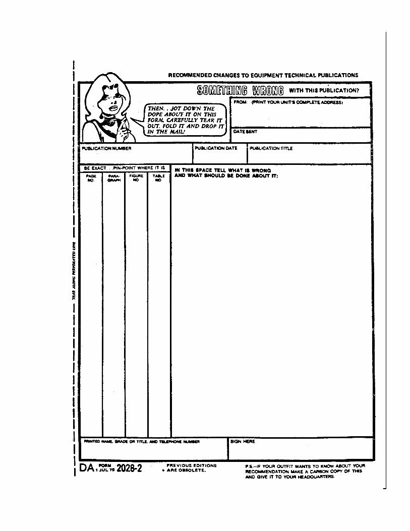
You can help improve this manual. If you find any mistakes or if you know of a wayto Improve the procedures, please let us know. Mail your letter, DA Form 2028(Recommended Changes to Publications and Blank Forms), or DA Form 2028-2,located in the back of this manual direct to: Commander, US Army ArmamentMateriel Readiness Command, ATTN: DRSAR-MAS, Rock Island, IL 61299. A replywill be furnished direct to you.
NOTE
This manual is published for the purpose of identifying an authorized commercial manual for theuse of the personnel to whom this milling machine is issued.
Manufactured by: Burke Division Powermatic/Houdaille, Inc.38 Brotherton RoadCincinnati, OH 45227
Procured under Contract No. DAAA09-78-C-5160
This technical manual is an authentication of the manufacturers’ commercialliterature and does not conform with the format and content specified in AR 310-3,Military Publications. This technical manual does, however, contain availableinformation that is essential to the operation and maintenance of the equipment.
i
TM 9-3417-215-14&P
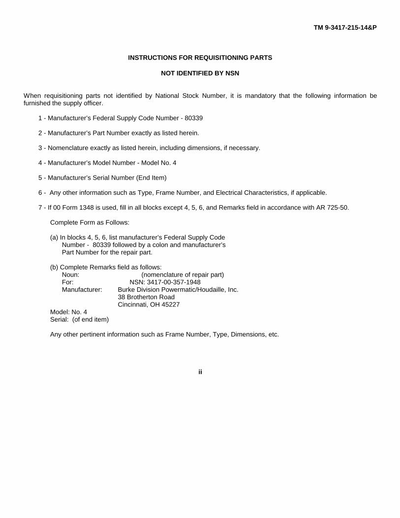
INSTRUCTIONS FOR REQUISITIONING PARTS
NOT IDENTIFIED BY NSN
When requisitioning parts not identified by National Stock Number, it is mandatory that the following information befurnished the supply officer.
1 - Manufacturer’s Federal Supply Code Number - 80339
2 - Manufacturer’s Part Number exactly as listed herein.
3 - Nomenclature exactly as listed herein, including dimensions, if necessary.
4 - Manufacturer’s Model Number - Model No. 4
5 - Manufacturer’s Serial Number (End Item)
6 - Any other information such as Type, Frame Number, and Electrical Characteristics, if applicable.
7 - If 00 Form 1348 is used, fill in all blocks except 4, 5, 6, and Remarks field in accordance with AR 725-50.
Complete Form as Follows:
(a) In blocks 4, 5, 6, list manufacturer’s Federal Supply CodeNumber - 80339 followed by a colon and manufacturer’sPart Number for the repair part.
(b) Complete Remarks field as follows:Noun: (nomenclature of repair part)For: NSN: 3417-00-357-1948Manufacturer: Burke Division Powermatic/Houdaille, Inc.
38 Brotherton RoadCincinnati, OH 45227
Model: No. 4Serial: (of end item)
Any other pertinent information such as Frame Number, Type, Dimensions, etc.
ii
TM 9-3417-215-14&P
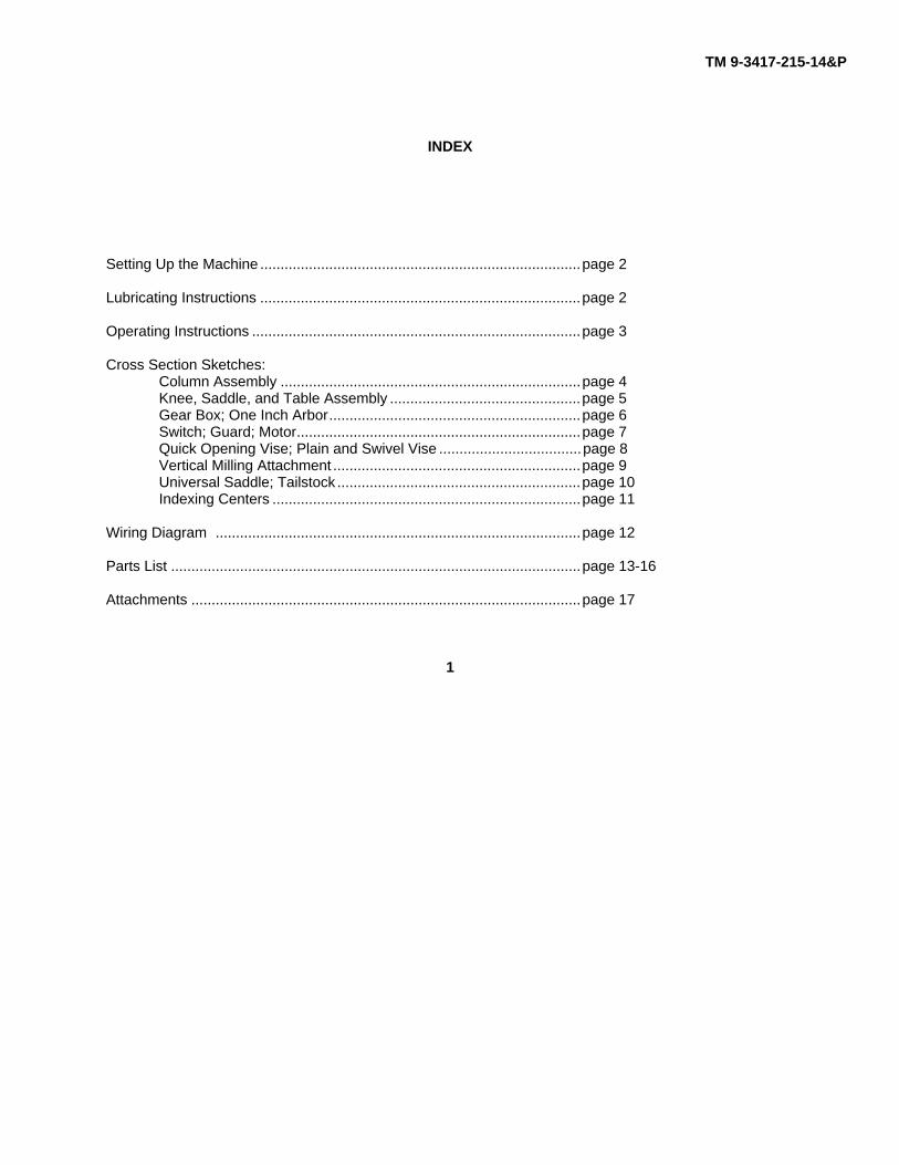
INDEX
Setting Up the Machine ...............................................................................page 2
Lubricating Instructions ...............................................................................page 2
Operating Instructions .................................................................................page 3
Cross Section Sketches:Column Assembly ..........................................................................page 4Knee, Saddle, and Table Assembly ...............................................page 5Gear Box; One Inch Arbor..............................................................page 6Switch; Guard; Motor......................................................................page 7Quick Opening Vise; Plain and Swivel Vise ...................................page 8Vertical Milling Attachment .............................................................page 9Universal Saddle; Tailstock ............................................................page 10Indexing Centers ............................................................................page 11
Wiring Diagram ..........................................................................................page 12
Parts List .....................................................................................................page 13-16
Attachments ................................................................................................page 17
1
TM 9317-215-14&P
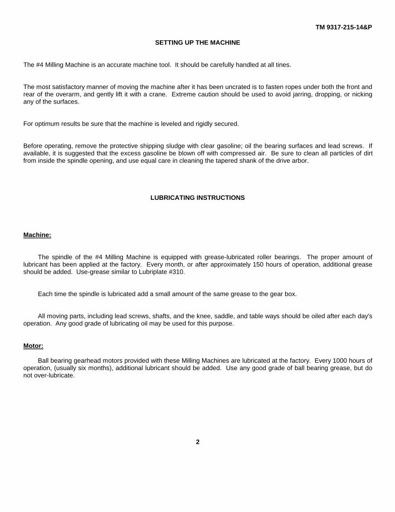
SETTING UP THE MACHINE
The #4 Milling Machine is an accurate machine tool. It should be carefully handled at all tines.
The most satisfactory manner of moving the machine after it has been uncrated is to fasten ropes under both the front andrear of the overarm, and gently lift it with a crane. Extreme caution should be used to avoid jarring, dropping, or nickingany of the surfaces.
For optimum results be sure that the machine is leveled and rigidly secured.
Before operating, remove the protective shipping sludge with clear gasoline; oil the bearing surfaces and lead screws. Ifavailable, it is suggested that the excess gasoline be blown off with compressed air. Be sure to clean all particles of dirtfrom inside the spindle opening, and use equal care in cleaning the tapered shank of the drive arbor.
LUBRICATING INSTRUCTIONS
Machine:
The spindle of the #4 Milling Machine is equipped with grease-lubricated roller bearings. The proper amount oflubricant has been applied at the factory. Every month, or after approximately 150 hours of operation, additional greaseshould be added. Use-grease similar to Lubriplate #310.
Each time the spindle is lubricated add a small amount of the same grease to the gear box.
All moving parts, including lead screws, shafts, and the knee, saddle, and table ways should be oiled after each day’soperation. Any good grade of lubricating oil may be used for this purpose.
Motor:
Ball bearing gearhead motors provided with these Milling Machines are lubricated at the factory. Every 1000 hours ofoperation, (usually six months), additional lubricant should be added. Use any good grade of ball bearing grease, but donot over-lubricate.
2
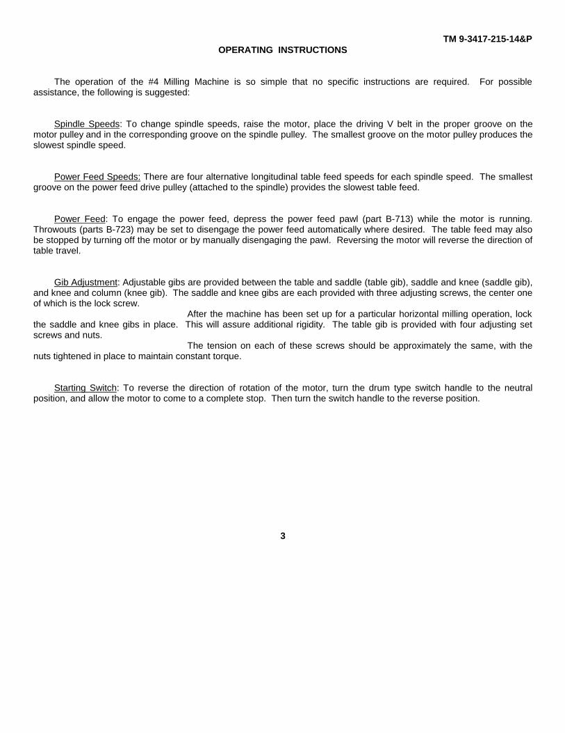
TM 9-3417-215-14&POPERATING INSTRUCTIONS
The operation of the #4 Milling Machine is so simple that no specific instructions are required. For possibleassistance, the following is suggested:
Spindle Speeds: To change spindle speeds, raise the motor, place the driving V belt in the proper groove on themotor pulley and in the corresponding groove on the spindle pulley. The smallest groove on the motor pulley produces theslowest spindle speed.
Power Feed Speeds: There are four alternative longitudinal table feed speeds for each spindle speed. The smallestgroove on the power feed drive pulley (attached to the spindle) provides the slowest table feed.
Power Feed: To engage the power feed, depress the power feed pawl (part B-713) while the motor is running.Throwouts (parts B-723) may be set to disengage the power feed automatically where desired. The table feed may alsobe stopped by turning off the motor or by manually disengaging the pawl. Reversing the motor will reverse the direction oftable travel.
Gib Adjustment: Adjustable gibs are provided between the table and saddle (table gib), saddle and knee (saddle gib),and knee and column (knee gib). The saddle and knee gibs are each provided with three adjusting screws, the center oneof which is the lock screw.
After the machine has been set up for a particular horizontal milling operation, lockthe saddle and knee gibs in place. This will assure additional rigidity. The table gib is provided with four adjusting setscrews and nuts.
The tension on each of these screws should be approximately the same, with thenuts tightened in place to maintain constant torque.
Starting Switch: To reverse the direction of rotation of the motor, turn the drum type switch handle to the neutralposition, and allow the motor to come to a complete stop. Then turn the switch handle to the reverse position.
3
TM 9-3417-215-14&P
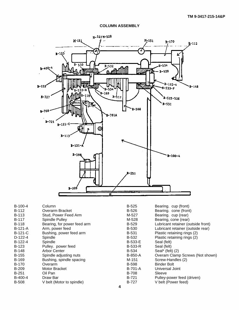
COLUMN ASSEMBLY
B-100-4 Column B-525 Bearing. cup (front)B-112 Overarm Bracket B-526 Bearing. cone (front)B-113 Stud, Power Feed Arm M-527 Bearing. cup (rear)B-117 Spindle Pulley M-528 Bearing, cone (rear)B-118 Bearing, for power feed arm B-529 Lubricant retainer (outside front)B-121-A Arm, power feed B-530 Lubricant retainer (outside rear)B-121-C Bushing, power feed arm B-531 Plastic retaining rings (2)D-122-4 Spindle B-532 Plastic retaining rings (2)B-122-4 Spindle B-533-E Seal (felt)B-123 Pulley. power feed B-533-R Seal (felt)B-148 Arbor Center B-534 Seal* (felt) (2)B-155 Spindle adjusting nuts B-850-A Overam Clamp Screws (Not shown)B-169 Bushing, spindle spacing M-151 Screw-Handles (2)B-170 Overarm B-598 Binder BoltB-209 Motor Bracket B-701-A Universal JointB-251 Oil Pan B-708 SleeveB-400-4 Draw Bar B-721 Pulley-power feed (driven)B-508 V belt (Motor to spindle) B-727 V belt (Power feed)
4
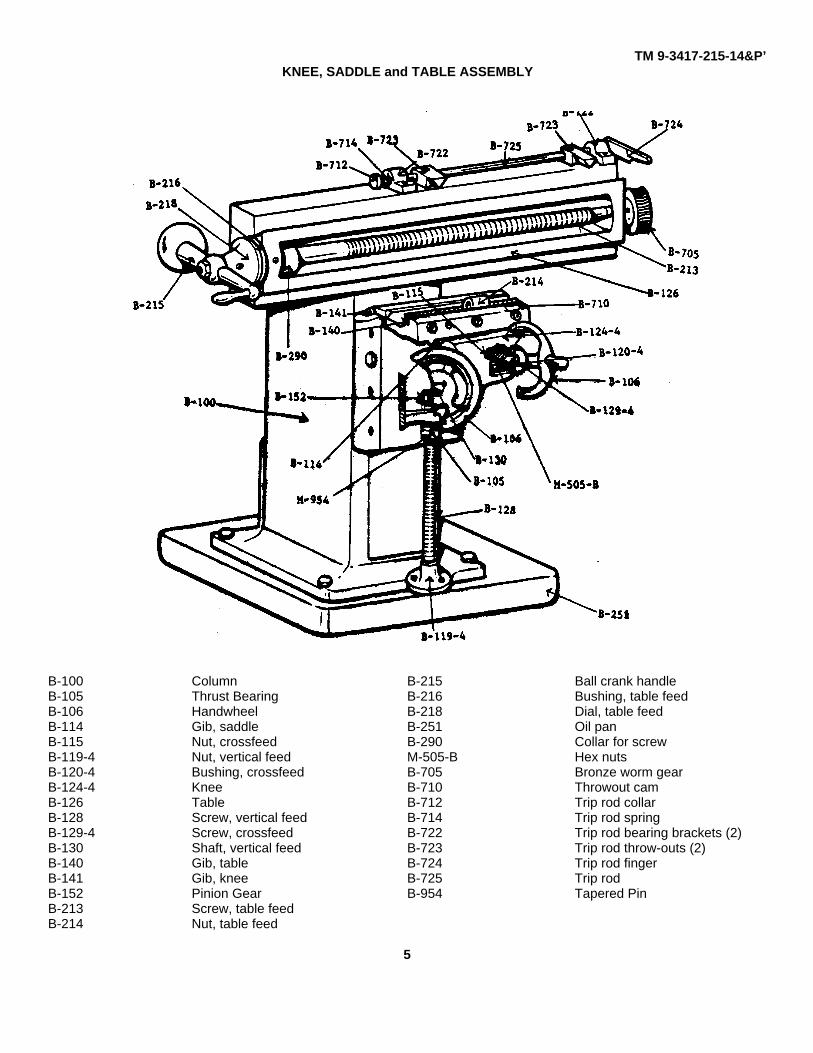
TM 9-3417-215-14&P’KNEE, SADDLE and TABLE ASSEMBLY
B-100 Column B-215 Ball crank handleB-105 Thrust Bearing B-216 Bushing, table feedB-106 Handwheel B-218 Dial, table feedB-114 Gib, saddle B-251 Oil panB-115 Nut, crossfeed B-290 Collar for screwB-119-4 Nut, vertical feed M-505-B Hex nutsB-120-4 Bushing, crossfeed B-705 Bronze worm gearB-124-4 Knee B-710 Throwout camB-126 Table B-712 Trip rod collarB-128 Screw, vertical feed B-714 Trip rod springB-129-4 Screw, crossfeed B-722 Trip rod bearing brackets (2)B-130 Shaft, vertical feed B-723 Trip rod throw-outs (2)B-140 Gib, table B-724 Trip rod fingerB-141 Gib, knee B-725 Trip rodB-152 Pinion Gear B-954 Tapered PinB-213 Screw, table feedB-214 Nut, table feed
5

TM 9-3417-215-14&P
GEAR BOX - POWER FEED
Gear Box Power Feed
B-113 Stud, power feed arm B-707 Telescope tubeB-121-A Arm, power feed B-709 Telescope shaftB-701 Universal joint B-713 Pawl, power feedB-701-A Universal joint B-713-P Plate, power feed pawlB-702 Yoke, Gear Box B-715 Spring, gear boxB-704 Steel Worm B-718 Stud, yokeB-706 Gear Box B-719 Worm ShaftB-706-C Gear Box Cover B-800 Oiler
ONE INCH ARBOR
One Inch Arbor
B-102-C One Inch arborM-200 Arbor nutM-226 2 inch spacer collarM-227 1 inch spacer collarM-228 1/2 inch spacer collar
6
TM 9-3417-215-14&P
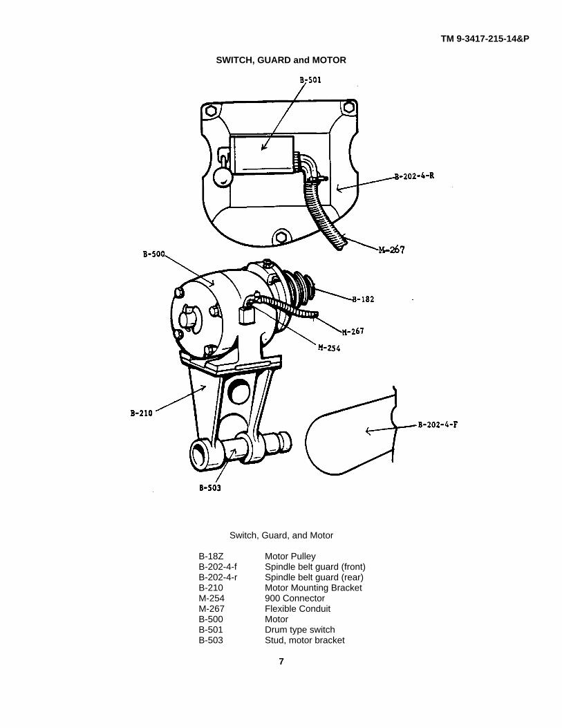
SWITCH, GUARD and MOTOR
Switch, Guard, and Motor
B-18Z Motor PulleyB-202-4-f Spindle belt guard (front)B-202-4-r Spindle belt guard (rear)B-210 Motor Mounting BracketM-254 900 ConnectorM-267 Flexible ConduitB-500 MotorB-501 Drum type switchB-503 Stud, motor bracket
7
TM 9-3417-215-14&P
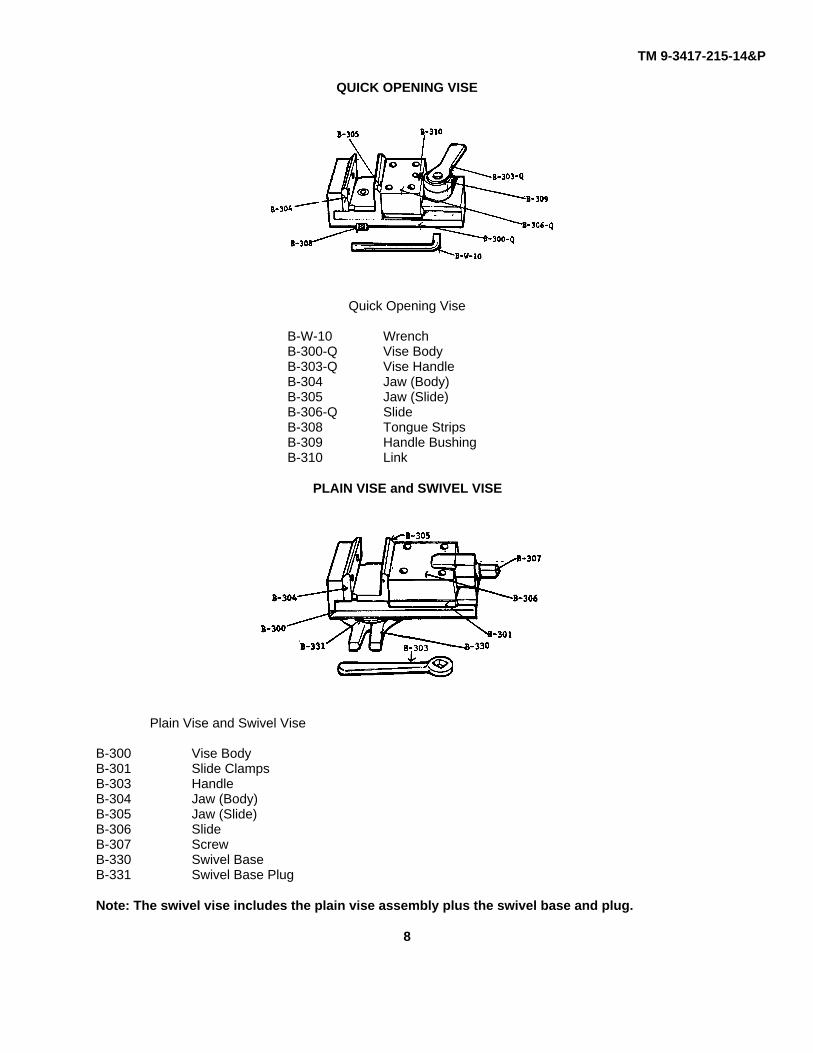
QUICK OPENING VISE
Quick Opening Vise
B-W-10 WrenchB-300-Q Vise BodyB-303-Q Vise HandleB-304 Jaw (Body)B-305 Jaw (Slide)B-306-Q SlideB-308 Tongue StripsB-309 Handle BushingB-310 Link
PLAIN VISE and SWIVEL VISE
Plain Vise and Swivel Vise
B-300 Vise BodyB-301 Slide ClampsB-303 HandleB-304 Jaw (Body)B-305 Jaw (Slide)B-306 SlideB-307 ScrewB-330 Swivel BaseB-331 Swivel Base Plug
Note: The swivel vise includes the plain vise assembly plus the swivel base and plug.
8
TM 9-3417-215-14&P
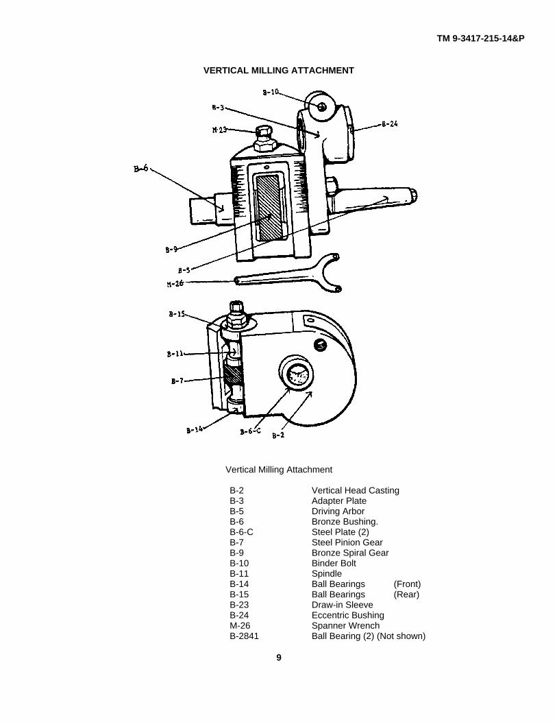
VERTICAL MILLING ATTACHMENT
Vertical Milling Attachment
B-2 Vertical Head CastingB-3 Adapter PlateB-5 Driving ArborB-6 Bronze Bushing.B-6-C Steel Plate (2)B-7 Steel Pinion GearB-9 Bronze Spiral GearB-10 Binder BoltB-11 SpindleB-14 Ball Bearings (Front)B-15 Ball Bearings (Rear)B-23 Draw-in SleeveB-24 Eccentric BushingM-26 Spanner WrenchB-2841 Ball Bearing (2) (Not shown)
9
TM 9-3417-215-14&P
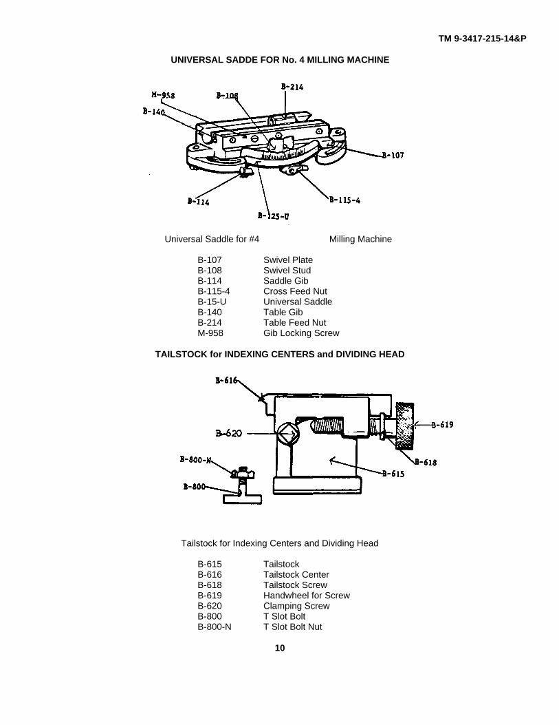
UNIVERSAL SADDE FOR No. 4 MILLING MACHINE
Universal Saddle for #4 Milling Machine
B-107 Swivel PlateB-108 Swivel StudB-114 Saddle GibB-115-4 Cross Feed NutB-15-U Universal SaddleB-140 Table GibB-214 Table Feed NutM-958 Gib Locking Screw
TAILSTOCK for INDEXING CENTERS and DIVIDING HEAD
Tailstock for Indexing Centers and Dividing Head
B-615 TailstockB-616 Tailstock CenterB-618 Tailstock ScrewB-619 Handwheel for ScrewB-620 Clamping ScrewB-800 T Slot BoltB-800-N T Slot Bolt Nut
10
TM 9-3417-215-14&P
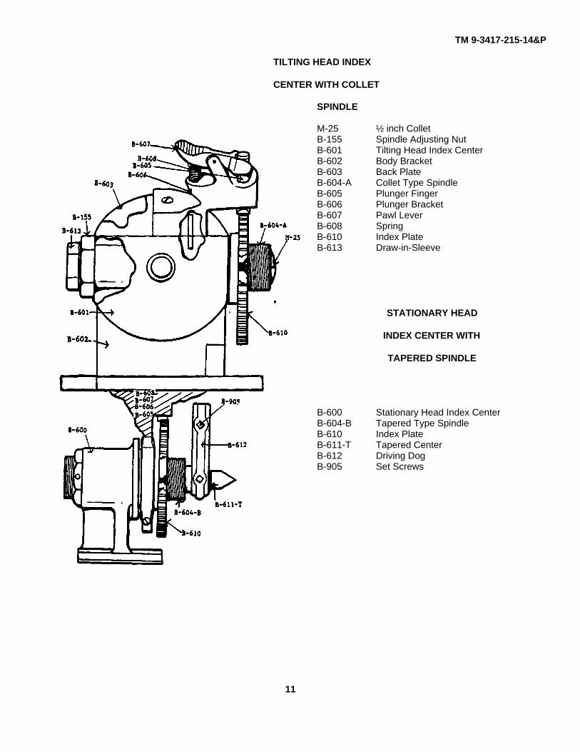
TILTING HEAD INDEX
CENTER WITH COLLET
SPINDLE
M-25 ½ inch ColletB-155 Spindle Adjusting NutB-601 Tilting Head Index CenterB-602 Body BracketB-603 Back PlateB-604-A Collet Type SpindleB-605 Plunger FingerB-606 Plunger BracketB-607 Pawl LeverB-608 SpringB-610 Index PlateB-613 Draw-in-Sleeve
STATIONARY HEAD
INDEX CENTER WITH
TAPERED SPINDLE
B-600 Stationary Head Index CenterB-604-B Tapered Type SpindleB-610 Index PlateB-611-T Tapered CenterB-612 Driving DogB-905 Set Screws
11
TM 9-3417-215-14&P
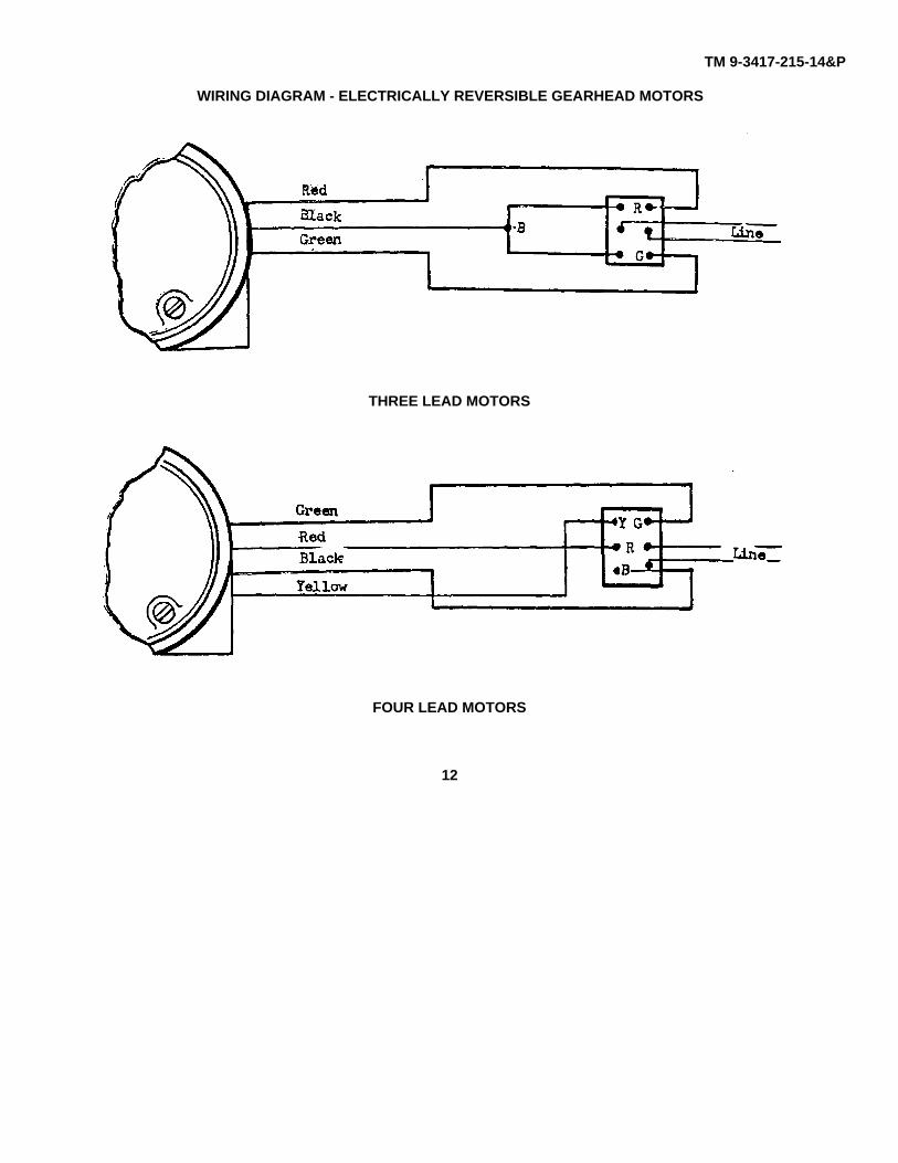
WIRING DIAGRAM - ELECTRICALLY REVERSIBLE GEARHEAD MOTORS
THREE LEAD MOTORS
FOUR LEAD MOTORS
12
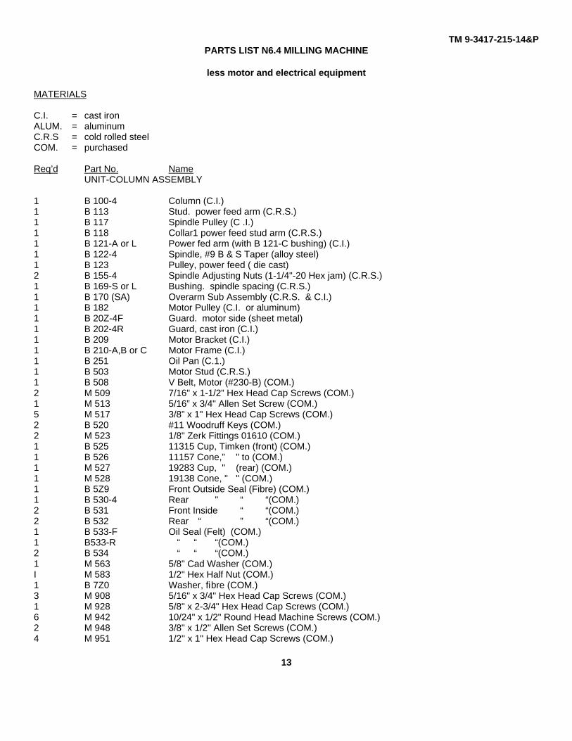
TM 9-3417-215-14&PPARTS LIST N6.4 MILLING MACHINE
less motor and electrical equipment
MATERIALS
C.I. = cast ironALUM. = aluminumC.R.S = cold rolled steelCOM. = purchased
Req’d Part No. NameUNIT-COLUMN ASSEMBLY
1 B 100-4 Column (C.I.)1 B 113 Stud. power feed arm (C.R.S.)1 B 117 Spindle Pulley (C .I.)1 B 118 Collar1 power feed stud arm (C.R.S.)1 B 121-A or L Power fed arm (with B 121-C bushing) (C.I.)1 B 122-4 Spindle, #9 B & S Taper (alloy steel)1 B 123 Pulley, power feed ( die cast)2 B 155-4 Spindle Adjusting Nuts (1-1/4"-20 Hex jam) (C.R.S.)1 B 169-S or L Bushing. spindle spacing (C.R.S.)1 B 170 (SA) Overarm Sub Assembly (C.R.S. & C.I.)1 B 182 Motor Pulley (C.I. or aluminum)1 B 20Z-4F Guard. motor side (sheet metal)1 B 202-4R Guard, cast iron (C.I.)1 B 209 Motor Bracket (C.I.)1 B 210-A,B or C Motor Frame (C.I.)1 B 251 Oil Pan (C.1.)1 B 503 Motor Stud (C.R.S.)1 B 508 V Belt, Motor (#230-B) (COM.)2 M 509 7/16" x 1-1/2” Hex Head Cap Screws (COM.)1 M 513 5/16” x 3/4" Allen Set Screw (COM.)5 M 517 3/8” x 1" Hex Head Cap Screws (COM.)2 B 520 #11 Woodruff Keys (COM.)2 M 523 1/8" Zerk Fittings 01610 (COM.)1 B 525 11315 Cup, Timken (front) (COM.)1 B 526 11157 Cone,” " to (COM.)1 M 527 19283 Cup, " (rear) (COM.)1 M 528 19138 Cone, " " (COM.)1 B 5Z9 Front Outside Seal (Fibre) (COM.)1 B 530-4 Rear " “ “(COM.)2 B 531 Front Inside “ “(COM.)2 B 532 Rear “ ” “(COM.)1 B 533-F Oil Seal (Felt) (COM.)1 B533-R “ “ “(COM.)2 B 534 “ “ “(COM.)1 M 563 5/8" Cad Washer (COM.)I M 583 1/2" Hex Half Nut (COM.)1 B 7Z0 Washer, fibre (COM.)3 M 908 5/16" x 3/4" Hex Head Cap Screws (COM.)1 M 928 5/8" x 2-3/4" Hex Head Cap Screws (COM.)6 M 942 10/24" x 1/2" Round Head Machine Screws (COM.)2 M 948 3/8" x 1/2" Allen Set Screws (COM.)4 M 951 1/2'' x 1" Hex Head Cap Screws (COM.)
13
TM 9-3417-215-14&P
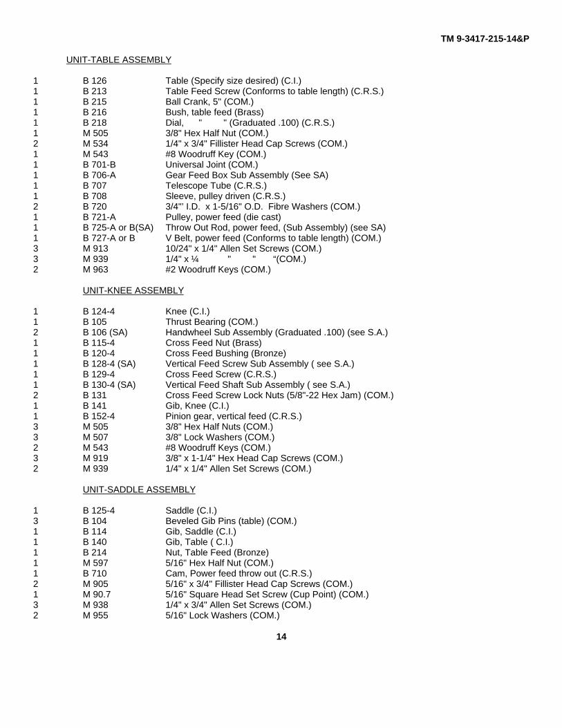
UNIT-TABLE ASSEMBLY
1 B 126 Table (Specify size desired) (C.I.)1 B 213 Table Feed Screw (Conforms to table length) (C.R.S.)1 B 215 Ball Crank, 5" (COM.)1 B 216 Bush, table feed (Brass)1 B 218 Dial, " " (Graduated .100) (C.R.S.)1 M 505 3/8" Hex Half Nut (COM.)2 M 534 1/4" x 3/4" Fillister Head Cap Screws (COM.)1 M 543 #8 Woodruff Key (COM.)1 B 701-B Universal Joint (COM.)1 B 706-A Gear Feed Box Sub Assembly (See SA)1 B 707 Telescope Tube (C.R.S.)1 B 708 Sleeve, pulley driven (C.R.S.)2 B 720 3/4"’ I.D. x 1-5/16" O.D. Fibre Washers (COM.)1 B 721-A Pulley, power feed (die cast)1 B 725-A or B(SA) Throw Out Rod, power feed, (Sub Assembly) (see SA)1 B 727-A or B V Belt, power feed (Conforms to table length) (COM.)3 M 913 10/24" x 1/4" Allen Set Screws (COM.)3 M 939 1/4" x ¼ " " “(COM.)2 M 963 #2 Woodruff Keys (COM.)
UNIT-KNEE ASSEMBLY
1 B 124-4 Knee (C.I.)1 B 105 Thrust Bearing (COM.)2 B 106 (SA) Handwheel Sub Assembly (Graduated .100) (see S.A.)1 B 115-4 Cross Feed Nut (Brass)1 B 120-4 Cross Feed Bushing (Bronze)1 B 128-4 (SA) Vertical Feed Screw Sub Assembly ( see S.A.)1 B 129-4 Cross Feed Screw (C.R.S.)1 B 130-4 (SA) Vertical Feed Shaft Sub Assembly ( see S.A.)2 B 131 Cross Feed Screw Lock Nuts (5/8"-22 Hex Jam) (COM.)1 B 141 Gib, Knee (C.I.)1 B 152-4 Pinion gear, vertical feed (C.R.S.)3 M 505 3/8" Hex Half Nuts (COM.)3 M 507 3/8" Lock Washers (COM.)2 M 543 #8 Woodruff Keys (COM.)3 M 919 3/8" x 1-1/4" Hex Head Cap Screws (COM.)2 M 939 1/4" x 1/4" Allen Set Screws (COM.)
UNIT-SADDLE ASSEMBLY
1 B 125-4 Saddle (C.I.)3 B 104 Beveled Gib Pins (table) (COM.)1 B 114 Gib, Saddle (C.I.)1 B 140 Gib, Table ( C.I.)1 B 214 Nut, Table Feed (Bronze)1 M 597 5/16" Hex Half Nut (COM.)1 B 710 Cam, Power feed throw out (C.R.S.)2 M 905 5/16" x 3/4" Fillister Head Cap Screws (COM.)1 M 90.7 5/16" Square Head Set Screw (Cup Point) (COM.)3 M 938 1/4" x 3/4" Allen Set Screws (COM.)2 M 955 5/16" Lock Washers (COM.)
14
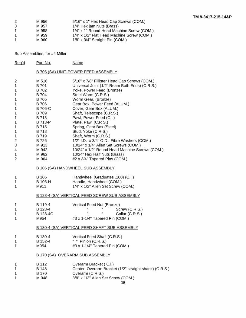
TM 9-3417-215-14&P2 M 956 5/16" x 1" Hex Head Cap Screws (COM.)3 M 957 1/4" Hex jam Nuts (Brass)1 M 958. 1/4" x 1" Round Head Machine Screw (COM.)1 M 959 1/4" x 1/2" Flat Head Machine Screw (COM.)1 M 960 1/8" x 3/4" Straight Pin (COM.)
Sub Assemblies, for #4 Miller
Req’d Part No. Name
B 706 (SA) UNIT-POWER FEED ASSEMBLY
2 M 516 5/16" x 7/8" Fillister Head Cap Screws (COM.)1 B 701 Universal Joint (1/2" Ream Both Ends) (C.R.S.)1 B 702 Yoke, Power Feed (Bronze)1 B 704 Steel Worm (C.R.S.)1 B 705 Worm Gear, (Bronze)1 B 706 Gear Box, Power Feed (ALUM.)1 B 706-C Cover, Gear Box (ALUM.)1 B 709 Shaft, Telescope (C.R.S.)1 B 713 Pawl, Power Feed (C.l.)1 B 713-P Plate, Pawl (C.R S.)1 B 715 Spring, Gear Box (Steel)1 B 718 Stud, Yoke (C.R.S.)1 B 719 Shaft, Worm (C.R.S.)2 B 726 1/2" I.D. x 3/4" O.D. Fibre Washers (COM.)3 M 913 10/24" x 1/4" Allen Set Screws (COM.)4 M 942 10/24" x 1/2" Round Head Machine Screws (COM.)1 M 962 10/24" Hex Half Nuts (Brass)2 M 964 #2 x 3/4" Tapered Pins (COM.)
B 106 (SA) HANDWHEEL SUB ASSEMBLY
1 B 106 Handwheel (Graduates .100) (C.I.)1 B 106-H Handle, Handwheel (COM.)1 M911 1/4" x 1/2" Allen Set Screw (COM.)
B 128-4 (SA) VERTICAL FEED SCREW SUB ASSEMBLY
1 B 119-4 Vertical Feed Nut (Bronze)1 B 128-4 “ " Screw (C.R.S.)1 B 128-4C " “ Collar (C.R.S.)1 M954 #3 x 1-1/4" Tapered Pin (COM.)
B 130-4 (SA) VERTICAL FEED SHAFT SUB ASSEMBLY
1 B 130-4 Vertical Feed Shaft (C.R.S.)1 B 152-4 " " Pinion (C.R.S.)1 M954 #3 x 1-1/4" Tapered Pin (COM.)
B 170 (SA) OVERARM SUB ASSEMBLY
1 B 112 Overarm Bracket ( C.l.)1 B 148 Center, Overarm Bracket (1/2" straight shank) (C.R.S.)1 B 170 Overarm (C.R.S.)1 M 948 3/8" x 1/2" Allen Set Screw (COM.)
15
TM 9-3417-215-14&P
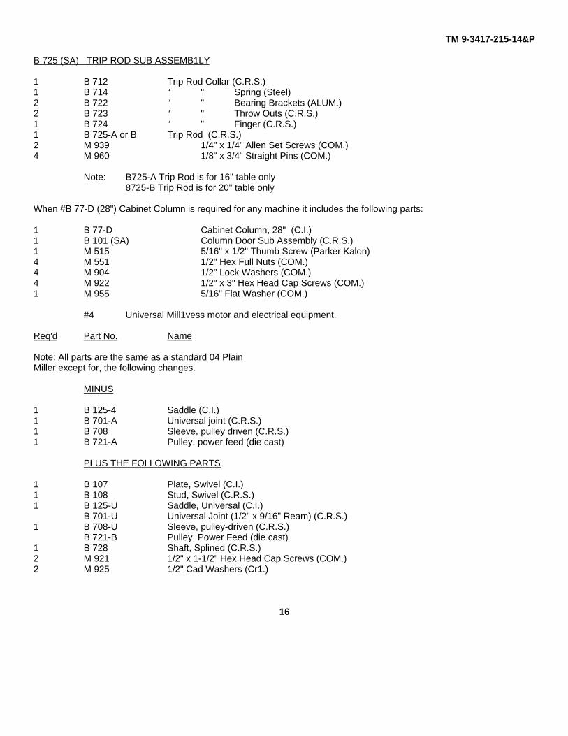
B 725 (SA) TRIP ROD SUB ASSEMB1LY
1 B 712 Trip Rod Collar (C.R.S.)1 B 714 “ " Spring (Steel)2 B 722 “ " Bearing Brackets (ALUM.)2 B 723 “ " Throw Outs (C.R.S.)1 B 724 “ " Finger (C.R.S.)1 B 725-A or B Trip Rod (C.R.S.)2 M 939 1/4" x 1/4" Allen Set Screws (COM.)4 M 960 1/8" x 3/4" Straight Pins (COM.)
Note: B725-A Trip Rod is for 16" table only8725-B Trip Rod is for 20" table only
When #B 77-D (28") Cabinet Column is required for any machine it includes the following parts:
1 B 77-D Cabinet Column, 28" (C.I.)1 B 101 (SA) Column Door Sub Assembly (C.R.S.)1 M 515 5/16" x 1/2" Thumb Screw (Parker Kalon)4 M 551 1/2" Hex Full Nuts (COM.)4 M 904 1/2" Lock Washers (COM.)4 M 922 1/2" x 3" Hex Head Cap Screws (COM.)1 M 955 5/16" Flat Washer (COM.)
#4 Universal Mill1vess motor and electrical equipment.
Req'd Part No. Name
Note: All parts are the same as a standard 04 PlainMiller except for, the following changes.
MINUS
1 B 125-4 Saddle (C.I.)1 B 701-A Universal joint (C.R.S.)1 B 708 Sleeve, pulley driven (C.R.S.)1 B 721-A Pulley, power feed (die cast)
PLUS THE FOLLOWING PARTS
1 B 107 Plate, Swivel (C.I.)1 B 108 Stud, Swivel (C.R.S.)1 B 125-U Saddle, Universal (C.I.)
B 701-U Universal Joint (1/2" x 9/16" Ream) (C.R.S.)1 B 708-U Sleeve, pulley-driven (C.R.S.)
B 721-B Pulley, Power Feed (die cast)1 B 728 Shaft, Splined (C.R.S.)2 M 921 1/2" x 1-1/2" Hex Head Cap Screws (COM.)2 M 925 1/2" Cad Washers (Cr1.)
16

TM 9-3417-215-14&P
Attachments for MILLERS and other small Machine Tools
17/(18 blank)
TM 9-3417-215-14&P
By Order of the Secretary of the Army:
E. C. MEYERGeneral, United States Army
Official: Chief of Staff
ROBERT M. JOYCEBrigadier General, United States Army
The Adjutant General

PIN: 049450-000


