TM 10-4320-324-14 TECHNICAL MANUAL … 10-4320-324-14 c 2 change headquarters department of the army...
413
TECHNICAL MANUAL OPERATOR’S, UNIT, DIRECT SUPPORT, AND GENERAL SUPPORT MAINTENANCE FOR PUMPING ASSEMBLY, FLAMMABLE LIQUID, BULK TRANSFER, DIESEL ENGINE DRIVEN, WHEEL MTD, 350 GPM, 275 FT. HEAD, P/N LC350AGPM (36024) (FUEL USE ONLY) NSN 4320-01-337-7538 PUMP UNIT, CENTRIFUGAL, DIESEL ENGINE DRIVEN, WHEEL MTD, 350 GPM, 275 FT. HEAD P/N LC350BGPM (36024) (WATER USE ONLY) NSN 4320-01-335-9671 TM 10-4320-324-14 HEADQUARTERS, DEPARTMENT OF THE ARMY SEPTEMBER 1991 INTRODUCTION 1-1 OPERATING INSTRUCTIONS 2-1 OPERATOR’S MAINTENANCE INSTRUCTIONS 3-1 UNIT MAINTENANCE INSTRUCTIONS 4-1 DIRECT SUPPORT MAINTENANCE INSTRUCTIONS 5-1 GENERAL SUPPORT MAINTENANCE INSTRUCTIONS 6-1 REFERENCES A-1 MAINTENANCE ALLOCATION CHART B-1 COMPONENTS OF END ITEM AND BASIC ISSUE ITEMS LISTS C-1 ADDITIONAL AUTHORIZATION LIST D-1 EXPENDABLE/DURABLE SUPPLIES AND MATERIALS LIST E-1 TORQUE LIMITS F-1 DISTRIBUTION STATEMENT A: Approved for public release; distribution Is unlimited.
Transcript of TM 10-4320-324-14 TECHNICAL MANUAL … 10-4320-324-14 c 2 change headquarters department of the army...

TECHNICAL MANUAL
OPERATOR’S, UNIT, DIRECT SUPPORT, ANDGENERAL SUPPORT MAINTENANCE
FOR
PUMPING ASSEMBLY, FLAMMABLE LIQUID,BULK TRANSFER, DIESEL ENGINE DRIVEN,
WHEEL MTD, 350 GPM, 275 FT. HEAD,P/N LC350AGPM (36024)
(FUEL USE ONLY)NSN 4320-01-337-7538
PUMP UNIT, CENTRIFUGAL,DIESEL ENGINE DRIVEN, WHEEL MTD,
350 GPM, 275 FT. HEADP/N LC350BGPM (36024)
(WATER USE ONLY)NSN 4320-01-335-9671
TM 10-4320-324-14
HEADQUARTERS, DEPARTMENT OF THE ARMY
SEPTEMBER 1991
INTRODUCTION 1-1
OPERATING INSTRUCTIONS 2-1
OPERATOR’SMAINTENANCE INSTRUCTIONS 3-1
UNIT MAINTENANCEINSTRUCTIONS 4-1
DIRECT SUPPORTMAINTENANCE INSTRUCTIONS 5-1
GENERAL SUPPORTMAINTENANCE INSTRUCTIONS 6-1
REFERENCES A-1
MAINTENANCEALLOCATION CHART B-1
COMPONENTS OF END ITEMAND BASIC ISSUE ITEMS LISTS C-1
ADDITIONALAUTHORIZATION LIST D-1
EXPENDABLE/DURABLE SUPPLIESAND MATERIALS LIST E-1
TORQUE LIMITS F-1
DISTRIBUTION STATEMENT A: Approved for public release; distribution Is unlimited.


TM 10-4320-324-14
Change 2 Warning a/b blank
DEATH or severe injury to personnel may result if personnel fail to observe precautions.
To prevent pumping assembly from rolling or sliding, securely chock both wheels.
Pumping assembly Model LC350AGPM (36024) must be grounded prior to operation when fuel is pumped, orspark could ignite fuel causing possible injury to personnel.
Do not operate pumping assembly in an enclosed area unless exhaust gases are piped to outside and adequateventilation is provided.
To prevent serious burns, take necessary precautions when filling battery with electrolyte. Do not allowelectrolyte to come in contact with skin or eyes. Use rubber gloves and protective clothing.
Do not puncture or mishandle quick start kit container. Container contains ether-based mixture that is extremelycombustible.
Do not smoke or use an open flame in the vicinity when filling fuel tank.
Use care during testing of injection pump. Fuel is under high pressure and spray may cut through skin.
Use care during testing of fuel injector nozzles. Fuel is under high pressure and spray may cut through skin.
Contact with Skysol 100 cleaning solvent may cause skin irritation. Use chemical resistant gloves. In case ofskin contact, remove any contaminated clothing and wash skin thoroughly with soap and water. Washcontaminated clothing before reuse. Eye contact may cause irritation, tearing or blurring of vision. Use faceshield or goggles when eye contact may occur. In case of eye contact, flush eyes with large amounts of waterfor at least fifteen (15) minutes or until irritation subsides. Inhalation may cause irritation to upper respiratorypassages. DO NOT have food or drink in the vicinity. Failure to comply may result in injury or death topersonnel.
Accidental or intentional introduction of liquid contaminants into the environment is in violation of state,federal,and military regulation. Refer to Army POL for information concerning storage, use, and disposal of theseliquids. Failure to comply may result in damage to environment and health of personnel.
Do not use a fuel transfer pump to transfer water.
Do not use a water transfer pump to transfer fuel.
Hearing protection must be worn by all personnel within working distance of pump during pump operation.Failure to comply may result in permanent hearing loss to personnel.
Lifting frame is heavy. Ensure two personnel handle lifting frame, or injury to personnel may result.
WARNING


TM 10-4320-324-14
C 2
CHANGE HEADQUARTERSDEPARTMENT OF THE ARMY
NO. 2 WASHINGTON, D.C., 30 SEPTEMBER 2005
OPERATOR’S, UNIT DIRECT SUPPORT AND GENERAL SUPPORT MAINTENANCE MANUAL
FORPUMPING ASSEMBLY, FLAMMABLE LIQUID,BULK TRANSFER, DIESEL ENGINE DRIVEN,
WHEEL MTD, 350 GPM, 275 FT. HEAD,P/N LC350AGPM (36024)
(FUEL USE ONLY)NSN 4320-01-337-7538
PUMP UNIT, CENTRIFUGAL, DIESEL ENGINE DRIVEN,WHEEL MTD, 350 GPM, 275 FT. HEAD,
P/N LC350BGPM (36024)(WATER USE ONLY)
NSN 4320-01-335-9671
DISTRIBUTION STATEMENT A: Approved for public release; distribution is unlimited.
TM 10-4320-324-14, 30 September 1991, is changes as follows:
1. Remove and insert pages as indicated below. New or changed text and illustrations are indicated by a verticalbar in the margin.
Remove pages Insert pagesWarning a/b blank Warning a/b blankA and B A and Bi and ii i and ii1-1 through 1-10 1-1 through 1-102-3 through 2-22 2-3 through 2-223-5 and 3-6 3-5 and 3-63-9 through 3-14 3-9 through 3-144-1 and 4-2 4-1 and 4-24-5 and 4-6 4-5 and 4-64-19 through 4-104 4-19 through 4-1044-107 through 4-110 4-107 through 4-1104-113 through 4-132 4-113 through 4-1324-135 through 4-152 4-135 through 4-1524-155 through 4-170 4-155 through 4-1704-177 and 4-178 4-177 and 4-1784-187 through 4-194 4-187 through 4-1945-1 and 5-2 5-1 and 5-25-5 and 5-6 5-5 and 5-65-17 through 5-38 5-17 through 5-385-41 through 5-60 5-41 through 5-605-63 through 5-68 5-63 through 5-685-73 through 5-78 5-73 through 5-785-83 and 5-84 5-83 and 5-845-91 and 5-92 5-91 and 5-925-95 through 5-98 5-95 through 5-98
i

6-7 and 6-8 6-7 and 6-86-17 and 6-18 6-17 and 6-186-33 through 6-36 6-33 through 6-366-41 through 6-44 6-41 through 6-44B-3 through B-6 B-3 through B-6C-3 and C-4 blank C-3 and C-4 blankE-1 and E-2 E-1 and E-2I-1 through I-4 I-1 through I-4None DA FORM 2028 (Sample)DA FORM 2028-2 DA FORM 2028
2. Retain this sheet in front of manual for reference purposes.
Remove pages Insert pages
By Order of the Secretary of the Army:
SANDRA R. RILEYAdministrative Assistant to the
Secretary of the Army0505601
PETER J. SCHOOMAKER General, United States Army
Chief of Staff
Official:
Distribution:
To be distributed in accordance with the initial distribution number (IDN) 253572, requirements for TM 10-4320-324-14

TM 10-4320-324-14
C 1
CHANGE HEADQUARTERSDEPARTMENT OF THE ARMY
NO. 1 WASHINGTON, D.C., 30 AUGUST 1996
OPERATOR’S, UNIT DIRECT SUPPORT AND
GENERAL SUPPORT MAINTENANCE MANUAL
PUMPING ASSEMBLY, FLAMMABLE LIQUID,
BULK TRANSFER, DIESEL ENGINE DRIVEN,
WHEEL MTD, 350 GPM, 275 FT. HEAD,
MODEL 13229E8400 (97403)
(FUEL USE ONLY)
PUMP UNIT, CENTRIFUGAL, DIESEL ENGINE DRIVEN,
WHEEL MTD, 350 GPM, 275 FT. HEAD,
MODEL 13229E8401 (97403)
(WATER USE ONLY)
DISTRIBUTION STATEMENT A: Approved for public release; distribution is unlimited
TM 10-4320-324-14, 30 September 1991, is changed as follows:
1. Remove and insert pages as indicated below. New or changed text material is indicated by a vertical bar in the margin. Anillustration change is indicated by a miniature pointing hand.
Remove pages Insert pages
i and ii i and ii1-3 and 1-4 1-3 and 1-41-9 and 1-10 1-9 and 1-10
2. Retain this sheet in front of manual for reference purposes.

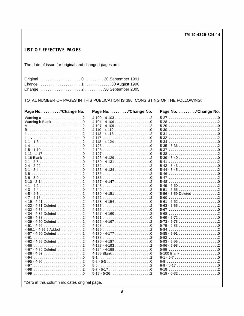
LIST OF EFFECTIVE PAGES
The date of issue for original and changed pages are:
Original . . . . . . . . . . . . . . . . . . 0 . . . . . . . . 30 September 1991Change . . . . . . . . . . . . . . . . . . . . . 1 . . . . . . . . . . . . . 30 August 1996Change . . . . . . . . . . . . . . . . . . 2 . . . . . . . . . 30 September 2005
TE: The portion of the text affected by the changes is indicated by a vertical line in the outer margins of the page. TOTAL NUMBER OF PAGES IN THIS PUBLICATION IS 390, CONSISTING OF THE FOLLOWING:
*Zero in this column indicates original page.
TM 10-4320-324-14
A
Warning a . . . . . . . . . . . . . . . . . . . .2Warning b Blank . . . . . . . . . . . . . . .0A . . . . . . . . . . . . . . . . . . . . . . . . . . .2B . . . . . . . . . . . . . . . . . . . . . . . . . . .2i . . . . . . . . . . . . . . . . . . . . . . . . . . . .2ii - iv . . . . . . . . . . . . . . . . . . . . . . . . .01-1 - 1-3 . . . . . . . . . . . . . . . . . . . . . .21-4 . . . . . . . . . . . . . . . . . . . . . . . . . .01-5 - 1-10 . . . . . . . . . . . . . . . . . . . . .21-11 - 1-17 . . . . . . . . . . . . . . . . . . . .01-18 Blank . . . . . . . . . . . . . . . . . . . .02-1 - 2-3 . . . . . . . . . . . . . . . . . . . . . .02-4 - 2-22 . . . . . . . . . . . . . . . . . . . . .23-1 - 3-4 . . . . . . . . . . . . . . . . . . . . . .03-5 . . . . . . . . . . . . . . . . . . . . . . . . . .23-6 - 3-9 . . . . . . . . . . . . . . . . . . . . . .03-10 - 3-14 . . . . . . . . . . . . . . . . . . . .24-1 - 4-2 . . . . . . . . . . . . . . . . . . . . . .24-3 - 4-4 . . . . . . . . . . . . . . . . . . . . . .04-5 - 4-6 . . . . . . . . . . . . . . . . . . . . . .24-7 - 4-18 . . . . . . . . . . . . . . . . . . . . .04-19 - 4-21 . . . . . . . . . . . . . . . . . . . .24-22 - 4-31 Deleted . . . . . . . . . . . . .24-32 - 4-33 . . . . . . . . . . . . . . . . . . . .24-34 - 4-35 Deleted . . . . . . . . . . . . .24-36 - 4-38 . . . . . . . . . . . . . . . . . . . .24-39 - 4-50 Deleted . . . . . . . . . . . . .24-51 - 4-56 . . . . . . . . . . . . . . . . . . . .24-56.1 - 4-56.2 Added . . . . . . . . . . .24-57 - 4-60 Deleted . . . . . . . . . . . . .24-61 . . . . . . . . . . . . . . . . . . . . . . . . .24-62 - 4-65 Deleted . . . . . . . . . . . . .24-66 . . . . . . . . . . . . . . . . . . . . . . . . .24-67 - 4-85 Deleted . . . . . . . . . . . . .24-86 - 4-93 . . . . . . . . . . . . . . . . . . . .24-94 . . . . . . . . . . . . . . . . . . . . . . . . .04-95 - 4-96 . . . . . . . . . . . . . . . . . . . .24-97 . . . . . . . . . . . . . . . . . . . . . . . . .04-98 . . . . . . . . . . . . . . . . . . . . . . . . .24-99 . . . . . . . . . . . . . . . . . . . . . . . . .0
4-100 - 4-103 . . . . . . . . . . . . . . . . . .24-104 - 4-106 . . . . . . . . . . . . . . . . . .04-107 - 4-109 . . . . . . . . . . . . . . . . . .24-110 - 4-112 . . . . . . . . . . . . . . . . . .04-113 - 4-116 . . . . . . . . . . . . . . . . . .24-117 . . . . . . . . . . . . . . . . . . . . . . . .04-118 - 4-124 . . . . . . . . . . . . . . . . . .24-125 . . . . . . . . . . . . . . . . . . . . . . . .04-126 . . . . . . . . . . . . . . . . . . . . . . . .24-127 . . . . . . . . . . . . . . . . . . . . . . . .04-128 - 4-129 . . . . . . . . . . . . . . . . . .24-130 - 4-131 . . . . . . . . . . . . . . . . . .04-132 . . . . . . . . . . . . . . . . . . . . . . . .24-133 - 4-134 . . . . . . . . . . . . . . . . . .04-135 . . . . . . . . . . . . . . . . . . . . . . . .24-136 . . . . . . . . . . . . . . . . . . . . . . . .04-137 - 4-147 . . . . . . . . . . . . . . . . . .24-148 . . . . . . . . . . . . . . . . . . . . . . . .04-149 . . . . . . . . . . . . . . . . . . . . . . . .24-150 - 4-151 . . . . . . . . . . . . . . . . . .04-152 . . . . . . . . . . . . . . . . . . . . . . . .24-153 - 4-154 . . . . . . . . . . . . . . . . . .04-155 . . . . . . . . . . . . . . . . . . . . . . . .24-156 . . . . . . . . . . . . . . . . . . . . . . . .04-157 - 4-160 . . . . . . . . . . . . . . . . . .24-161 . . . . . . . . . . . . . . . . . . . . . . . .04-162 - 4-167 . . . . . . . . . . . . . . . . . .24-168 . . . . . . . . . . . . . . . . . . . . . . . .04-169 . . . . . . . . . . . . . . . . . . . . . . . .24-170 - 4-177 . . . . . . . . . . . . . . . . . .04-178 . . . . . . . . . . . . . . . . . . . . . . . .24-179 - 4-187 . . . . . . . . . . . . . . . . . .04-188 - 4-193 . . . . . . . . . . . . . . . . . .24-194 - 4-198 . . . . . . . . . . . . . . . . . .04-199 Blank . . . . . . . . . . . . . . . . . . .05-1 . . . . . . . . . . . . . . . . . . . . . . . . . .25-2 - 5-5 . . . . . . . . . . . . . . . . . . . . . .05-6 . . . . . . . . . . . . . . . . . . . . . . . . . .25-7 - 5-17 . . . . . . . . . . . . . . . . . . . . .05-18 - 5-26 . . . . . . . . . . . . . . . . . . . .2
5-27 . . . . . . . . . . . . . . . . . . . . . . . . .05-28 . . . . . . . . . . . . . . . . . . . . . . . . .25-29 . . . . . . . . . . . . . . . . . . . . . . . . .05-30 . . . . . . . . . . . . . . . . . . . . . . . . .25-31 . . . . . . . . . . . . . . . . . . . . . . . . .05-32 . . . . . . . . . . . . . . . . . . . . . . . . .25-34 . . . . . . . . . . . . . . . . . . . . . . . . .05-35 - 5-36 . . . . . . . . . . . . . . . . . . . .25-37 . . . . . . . . . . . . . . . . . . . . . . . . .05-38 . . . . . . . . . . . . . . . . . . . . . . . . .25-39 - 5-40 . . . . . . . . . . . . . . . . . . . .05-41 . . . . . . . . . . . . . . . . . . . . . . . . .25-42 - 5-43 . . . . . . . . . . . . . . . . . . . .05-44 - 5-45 . . . . . . . . . . . . . . . . . . . .25-46 . . . . . . . . . . . . . . . . . . . . . . . . .05-47 . . . . . . . . . . . . . . . . . . . . . . . . .25-48 . . . . . . . . . . . . . . . . . . . . . . . . .05-49 - 5-50 . . . . . . . . . . . . . . . . . . . .25-51 - 5-55 . . . . . . . . . . . . . . . . . . . .25-56 - 5-59 Deleted . . . . . . . . . . . . .25-60 . . . . . . . . . . . . . . . . . . . . . . . . .25-61 - 5-62 . . . . . . . . . . . . . . . . . . . .05-63 - 5-66 . . . . . . . . . . . . . . . . . . . .25-67 . . . . . . . . . . . . . . . . . . . . . . . . .05-68 . . . . . . . . . . . . . . . . . . . . . . . . .25-69 - 5-72 . . . . . . . . . . . . . . . . . . . .05-73 - 5-78 . . . . . . . . . . . . . . . . . . . .25-79 - 5-83 . . . . . . . . . . . . . . . . . . . .05-84 . . . . . . . . . . . . . . . . . . . . . . . . .25-85 - 5-91 . . . . . . . . . . . . . . . . . . . .05-92 . . . . . . . . . . . . . . . . . . . . . . . . .25-93 - 5-95 . . . . . . . . . . . . . . . . . . . .05-96 - 5-98 . . . . . . . . . . . . . . . . . . . .25-99 . . . . . . . . . . . . . . . . . . . . . . . . .05-100 Blank . . . . . . . . . . . . . . . . . . .06-1 - 6-7 . . . . . . . . . . . . . . . . . . . . . .06-8 . . . . . . . . . . . . . . . . . . . . . . . . . .26-9 - 6-17 . . . . . . . . . . . . . . . . . . . . .06-18 . . . . . . . . . . . . . . . . . . . . . . . . .26-19 - 6-32 . . . . . . . . . . . . . . . . . . . .0
Page No. . . . . . . . .*Change No. Page No. . . . . . . . .*Change No. Page No. . . . . . . . .*Change No.
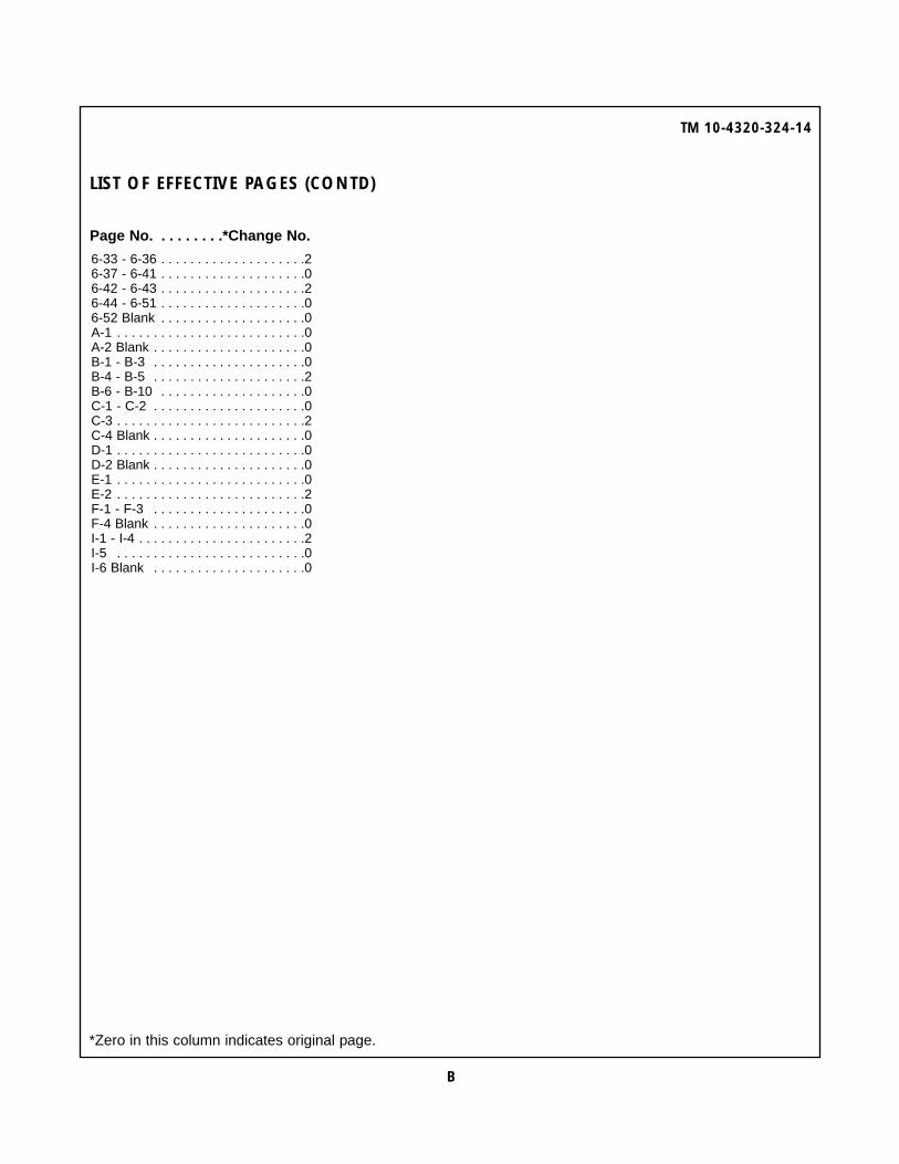
LIST OF EFFECTIVE PAGES (CONTD)
*Zero in this column indicates original page.
TM 10-4320-324-14
6-33 - 6-36 . . . . . . . . . . . . . . . . . . . .26-37 - 6-41 . . . . . . . . . . . . . . . . . . . .06-42 - 6-43 . . . . . . . . . . . . . . . . . . . .26-44 - 6-51 . . . . . . . . . . . . . . . . . . . .06-52 Blank . . . . . . . . . . . . . . . . . . . .0A-1 . . . . . . . . . . . . . . . . . . . . . . . . . .0A-2 Blank . . . . . . . . . . . . . . . . . . . . .0B-1 - B-3 . . . . . . . . . . . . . . . . . . . . .0B-4 - B-5 . . . . . . . . . . . . . . . . . . . . .2B-6 - B-10 . . . . . . . . . . . . . . . . . . . .0C-1 - C-2 . . . . . . . . . . . . . . . . . . . . .0C-3 . . . . . . . . . . . . . . . . . . . . . . . . . .2C-4 Blank . . . . . . . . . . . . . . . . . . . . .0D-1 . . . . . . . . . . . . . . . . . . . . . . . . . .0D-2 Blank . . . . . . . . . . . . . . . . . . . . .0E-1 . . . . . . . . . . . . . . . . . . . . . . . . . .0E-2 . . . . . . . . . . . . . . . . . . . . . . . . . .2F-1 - F-3 . . . . . . . . . . . . . . . . . . . . .0F-4 Blank . . . . . . . . . . . . . . . . . . . . .0I-1 - I-4 . . . . . . . . . . . . . . . . . . . . . . .2I-5 . . . . . . . . . . . . . . . . . . . . . . . . . .0I-6 Blank . . . . . . . . . . . . . . . . . . . . .0
Page No. . . . . . . . .*Change No. Page No. . . . . . . . .*Change No. Page No. . . . . . . . .*Change No.
B

TM 10-4320-324-14
Change 2 i
TECHNICAL MANUAL
No. 10-4320-324-14
HEADQUARTERSDEPARTMENT OF THE ARMY
WASHINGTON, D.C., 30 SEPTEMBER 1991
DISTRIBUTION STATEMENT: Approved for public release; distribution is unlimited.
TABLE OF CONTENTSHow to Use This Manual . . . . . . . . . . . . . . . . . . . . . . . . . . . . . . . . . . . . . . . . . . . . . . . . . . . . . . . . . . . . . . . . . . . . . . . . . . . . . . . . . ivCHAPTER 1 INTRODUCTION . . . . . . . . . . . . . . . . . . . . . . . . . . . . . . . . . . . . . . . . . . . . . . . . . . . . . . . . . . . . . . . . . . . . . . . . . . . 1-1
Section I General Information . . . . . . . . . . . . . . . . . . . . . . . . . . . . . . . . . . . . . . . . . . . . . . . . . . . . . . . . . . . . . . . . . . . . . . . . . 1-1Section II Equipment Description . . . . . . . . . . . . . . . . . . . . . . . . . . . . . . . . . . . . . . . . . . . . . . . . . . . . . . . . . . . . . . . . . . . . . . 1-4Section III Technical Principles of Operation . . . . . . . . . . . . . . . . . . . . . . . . . . . . . . . . . . . . . . . . . . . . . . . . . . . . . . . . . . . . . . 1-12
CHAPTER 2 OPERATING INSTRUCTIONS . . . . . . . . . . . . . . . . . . . . . . . . . . . . . . . . . . . . . . . . . . . . . . . . . . . . . . . . . . . . . . . . 2-1Section I Description and Use of Operator's Controls and Indicators . . . . . . . . . . . . . . . . . . . . . . . . . . . . . . . . . . . . . . . . . . 2-1Section II Preventive Maintenance Checks and Services . . . . . . . . . . . . . . . . . . . . . . . . . . . . . . . . . . . . . . . . . . . . . . . . . . . . 2-2Section III Operation Under Usual Conditions . . . . . . . . . . . . . . . . . . . . . . . . . . . . . . . . . . . . . . . . . . . . . . . . . . . . . . . . . . . . . 2-9Section IV Operation Under Unusual Conditions . . . . . . . . . . . . . . . . . . . . . . . . . . . . . . . . . . . . . . . . . . . . . . . . . . . . . . . . . . . 2-19
CHAPTER 3 OPERATOR’S MAINTENANCE INSTRUCTIONS . . . . . . . . . . . . . . . . . . . . . . . . . . . . . . . . . . . . . . . . . . . . . . . . . 3-1Section I Lubrication Instructions . . . . . . . . . . . . . . . . . . . . . . . . . . . . . . . . . . . . . . . . . . . . . . . . . . . . . . . . . . . . . . . . . . . . . . 3-1Section II Troubleshooting Procedures . . . . . . . . . . . . . . . . . . . . . . . . . . . . . . . . . . . . . . . . . . . . . . . . . . . . . . . . . . . . . . . . . . 3-1Section III Operator Maintenance Procedures . . . . . . . . . . . . . . . . . . . . . . . . . . . . . . . . . . . . . . . . . . . . . . . . . . . . . . . . . . . . . 3-9
OPERATOR'S, UNIT, DIRECT SUPPORT ANDGENERAL SUPPORT MAINTENANCE MANUAL
FOR
PUMPING ASSEMBLY, FLAMMABLE LIQUID,BULK TRANSFER, DIESEL ENGINE DRIVEN,
WHEEL MTD, 350 GPM, 275 FT. HEAD,P/N LC350AGPM (36024)
(FUEL USE ONLY)NSN 4320-01-337-7538
PUMP UNIT, CENTRIFUGAL, DIESEL ENGINE DRIVENWHEEL MTD, 350 GPM, 275 FT. HEAD
P/N LC350BGPM (36024)(WATER USE ONLY)
NSN 4320-01-335-9671
REPORTING ERRORS AND RECOMMENDING IMPROVEMENTSYou can help improve this publication. If you find any mistakes or if you know of a way to improve theprocedures, please let us know. Submit your DA Form 2028 (Recommended Changes to Publications andBlank Forms), through the Internet, on the Army Electronic Product Support (AEPS) website. TheInternet address is http://aeps.ria.army.mil. If you need a password, scroll down and click on “ACCESSREQUEST FORM”. The DA Form 2028 is located in the ONLINE FORMS PROCESSING section of theAEPS. Fill out the form and click on SUBMIT. Using this form on the AEPS will enable us to respond quickerto your comments and better manage the DA Form 2028 program. You may also mail, fax or E-mail yourletter or DA Form 2028 direct to: AMSTA-LC-CI Tech Pubs, TACOM-RI, 1 Rock Island Arsenal, RockIsland, IL 61299-7630. The E-mail address is [email protected]. The fax number is DSN793-0726 or Commercial (309) 782-0726.

TM 10-4320-324-14
ii
TABLE OF CONTENTS (Contd)
CHAPTER 4 UNIT MAINTENANCE INSTRUCTIONS . . . . . . . . . . . . . . . . . . . . . . . . . . . . . . . . . . . . . . . . . . . . . . . . . . . . . . . . . . 4-1Section I Repair Parts, Special Tools, TMDE, and Support Equipment . . . . . . . . . . . . . . . . . . . . . . . . . . . . . . . . . . . . . . . . . 4-2Section II Service Upon Receipt . . . . . . . . . . . . . . . . . . . . . . . . . . . . . . . . . . . . . . . . . . . . . . . . . . . . . . . . . . . . . . . . . . . . . . . 4-3Section III Preventive Maintenance Checks and Services (PMCS) . . . . . . . . . . . . . . . . . . . . . . . . . . . . . . . . . . . . . . . . . . . . . 4-4Section IV Troubleshooting . . . . . . . . . . . . . . . . . . . . . . . . . . . . . . . . . . . . . . . . . . . . . . . . . . . . . . . . . . . . . . . . . . . . . . . . . . . . 4-9Section V Maintenance Procedures . . . . . . . . . . . . . . . . . . . . . . . . . . . . . . . . . . . . . . . . . . . . . . . . . . . . . . . . . . . . . . . . . . . . . 4-19Section VI Preparation for Storage or Shipment . . . . . . . . . . . . . . . . . . . . . . . . . . . . . . . . . . . . . . . . . . . . . . . . . . . . . . . . . . . . . 4-196
CHAPTER 5 DIRECT SUPPORT MAINTENANCE INSTRUCTIONS . . . . . . . . . . . . . . . . . . . . . . . . . . . . . . . . . . . . . . . . . . . . . 5-1Section I General Information . . . . . . . . . . . . . . . . . . . . . . . . . . . . . . . . . . . . . . . . . . . . . . . . . . . . . . . . . . . . . . . . . . . . . . . . . 5-1Section II Troubleshooting . . . . . . . . . . . . . . . . . . . . . . . . . . . . . . . . . . . . . . . . . . . . . . . . . . . . . . . . . . . . . . . . . . . . . . . . . . . . 5-2Section III Maintenance Procedures . . . . . . . . . . . . . . . . . . . . . . . . . . . . . . . . . . . . . . . . . . . . . . . . . . . . . . . . . . . . . . . . . . . . . 5-6
CHAPTER 6 GENERAL SUPPORT MAINTENANCE INSTRUCTIONS . . . . . . . . . . . . . . . . . . . . . . . . . . . . . . . . . . . . . . . . . . . 6-1Section I General Information . . . . . . . . . . . . . . . . . . . . . . . . . . . . . . . . . . . . . . . . . . . . . . . . . . . . . . . . . . . . . . . . . . . . . . . . 6-1Section II Maintenance Procedures . . . . . . . . . . . . . . . . . . . . . . . . . . . . . . . . . . . . . . . . . . . . . . . . . . . . . . . . . . . . . . . . . . . . . 6-8
APPENDIX A REFERENCES . . . . . . . . . . . . . . . . . . . . . . . . . . . . . . . . . . . . . . . . . . . . . . . . . . . . . . . . . . . . . . . . . . . . . . . . . . . . A-1
APPENDIX B MAINTENANCE ALLOCATION CHART . . . . . . . . . . . . . . . . . . . . . . . . . . . . . . . . . . . . . . . . . . . . . . . . . . . . . . . . . B-1
APPENDIX C COMPONENTS OF END ITEM AND BASIC ISSUE ITEMS LISTS . . . . . . . . . . . . . . . . . . . . . . . . . . . . . . . . . . . . C-1
APPENDIX D ADDITIONAL AUTHORIZATION LIST . . . . . . . . . . . . . . . . . . . . . . . . . . . . . . . . . . . . . . . . . . . . . . . . . . . . . . . . . . D-1
APPENDIX E EXPENDABLE/DURABLE SUPPLIES AND MATERIALS . . . . . . . . . . . . . . . . . . . . . . . . . . . . . . . . . . . . . . . . . . . E-1
APPENDIX F TORQUE LIMITS . . . . . . . . . . . . . . . . . . . . . . . . . . . . . . . . . . . . . . . . . . . . . . . . . . . . . . . . . . . . . . . . . . . . . . . . . . F-1

TM 10-4320-324-14
LIST OF ILLUSTRATIONS
Number Title Page
1-1 Pumping Assembly ............................................................................................................................... 1-21-2 Major Components ................................................................................................................................ 1-51-3 Major Components ................................................................................................................................ 1-61-4 Major Components ................................................................................................................................ 1-71-5 Major Components ................................................................................................................................ 1-81-6 Major Components ................................................................................................................................ 1-91-7 Fuel System Function Diagram ............................................................................................................. 1-121-8 Lubrication System Functional Diagram ................................................................................................ 1-131-9 Cold Start System Functional Diagram .................................................................................................. 1-141-10 Electrical Schematic .............................................................................................................................. 1-161-11 Pumping System Functional Diagram .................................................................................................... 1-172-1 PMCS Locations (Left Side View) ........................................................................................................... 2-42-2 PMCS Locations (Right Side View) ........................................................................................................ 2-54-1 PMCS Locations (Left Side View) .......................................................................................................... 4-54-2 PMCS Locations (Right Side View) ........................................................................................................ 4-6
LIST OF TABLES
Number Title Page
1-1 Equipment Data .................................................................................................................................... 1-101-2 Significant Hazards ............................................................................................................................... 1-112-1 Operator/Crew Preventive Maintenance Checks and Services (PMCS) .................................................. 2-62-2 Performance Data ................................................................................................................................. 2-143-1 Troubleshooting .................................................................................................................................... 3-24-1 Preventive Maintenance Checks and Services ....................................................................................... 4-74-2 Troubles hooting ................................................................................................................................... 4-1504-3 Valve Clearance (Engine Cold) .............................................................................................................. 5-25-1 Troubleshooting .................................................................................................................................... 5-155-2 Starter No-Load Test Specifications ....................................................................................................... 5-156-1 Wear Limits, Fits, and Tolerances .......................................................................................................... 6-2
iii

TM 10-4320-324-14
HOW TO USE THIS MANUAL
This manual is designed to help operate and maintain the 350 GPM Pumping Assembly. Listed below are some of the specialfeatures that have been included to help locate and use the needed information.
A front cover Table of Contents is provided for quick reference to chapters and sections that will be used often.
Warning, caution and note headings, subject headings, and certain other essential information are printed in bold type to make themeasier to see.
The maintenance tasks describe what must be done to the pumping assembly before starting the task, and what must be done toreturn the pumping assembly to operating condition after the task is finished.
In addition to text, there are exploded-view illustrations showing you how to take the part off and to put it on. Cleaning and inspectionprocedures are also included, when required.
Chapters 1 and 2 of this manual are directed at the crew/operator of the pumping assembly. These chapters include an overalldescription of the pumping assembly and discuss the controls and indicators, their location and use, and the instructions foroperation of the pumping assembly under different circumstances.
Chapter 3 of this manual covers crew/operator lubrication, preventive maintenance checks and services and basic troubleshooting.Crew/operator maintenance is also covered in this chapter.
Chapter 4 of this manual covers unit maintenance including preventive maintenance checks and services, troubleshooting andmaintenance procedures.
Chapter 5 of this manual covers direct support maintenance including troubleshooting and maintenance procedures.
Chapter 6 of this manual covers general support maintenance.
The appendixes are located at the end of the manual. They contain a reference guide to other manuals, guidelines to reading theMaintenance Allocation Chart (MAC), a list of expendable supplies and materials, and other material for maintaining the pumpingassembly.
FOLLOW THESE GUIDELINES WHEN USING THIS MANUAL
The operator must read through this manual and become familiar with the contents before attempting to operate the pumpingassembly.
Read all WARNINGS and CAUTIONS before performing any procedure.
iv

TM 10-4320-324-14
Change 2 1-1
CHAPTER 1
INTRODUCTIONPara Contents Page1-8 Calibration . . . . . . . . . . . . . . . . . . . . . . . . . . . . . . . . . . . . . . . . . . . . . . . . . . . . . . . . . . . . . . . . . . . . . . . . . . . . . 1-31-20 Cold Start System . . . . . . . . . . . . . . . . . . . . . . . . . . . . . . . . . . . . . . . . . . . . . . . . . . . . . . . . . . . . . . . . . . . . . . . 1-141-9 Destruction of Army Material to Prevent Enemy Use . . . . . . . . . . . . . . . . . . . . . . . . . . . . . . . . . . . . . . . . . . . . 1-41-15 Difference in Models . . . . . . . . . . . . . . . . . . . . . . . . . . . . . . . . . . . . . . . . . . . . . . . . . . . . . . . . . . . . . . . . . . . . . 1-101-21 Electrical System . . . . . . . . . . . . . . . . . . . . . . . . . . . . . . . . . . . . . . . . . . . . . . . . . . . . . . . . . . . . . . . . . . . . . . . . 1-151-12 Equipment Characteristics, Capabilities, and Features . . . . . . . . . . . . . . . . . . . . . . . . . . . . . . . . . . . . . . . . . . . 1-41-14 Equipment Configuration . . . . . . . . . . . . . . . . . . . . . . . . . . . . . . . . . . . . . . . . . . . . . . . . . . . . . . . . . . . . . . . . . . 1-41-16 Equipment Data . . . . . . . . . . . . . . . . . . . . . . . . . . . . . . . . . . . . . . . . . . . . . . . . . . . . . . . . . . . . . . . . . . . . . . . . . 1-101-18 Fuel System . . . . . . . . . . . . . . . . . . . . . . . . . . . . . . . . . . . . . . . . . . . . . . . . . . . . . . . . . . . . . . . . . . . . . . . . . . . . 1-121-3 Hand Receipt (-HR) Manuals . . . . . . . . . . . . . . . . . . . . . . . . . . . . . . . . . . . . . . . . . . . . . . . . . . . . . . . . . . . . . . . 1-11-7 List of Abbreviations . . . . . . . . . . . . . . . . . . . . . . . . . . . . . . . . . . . . . . . . . . . . . . . . . . . . . . . . . . . . . . . . . . . . . . 1-31-13 Location and Description of Major Components . . . . . . . . . . . . . . . . . . . . . . . . . . . . . . . . . . . . . . . . . . . . . . . . 1-41-19 Lubrication System . . . . . . . . . . . . . . . . . . . . . . . . . . . . . . . . . . . . . . . . . . . . . . . . . . . . . . . . . . . . . . . . . . . . . . 1-131-2 Maintenance Form and Records . . . . . . . . . . . . . . . . . . . . . . . . . . . . . . . . . . . . . . . . . . . . . . . . . . . . . . . . . . . . 1-11-6 Nomenclature Cross-Reference List . . . . . . . . . . . . . . . . . . . . . . . . . . . . . . . . . . . . . . . . . . . . . . . . . . . . . . . . . 1-31-10 Preparation for Storage or Shipment . . . . . . . . . . . . . . . . . . . . . . . . . . . . . . . . . . . . . . . . . . . . . . . . . . . . . . . . . 1-41-22 Pumping System . . . . . . . . . . . . . . . . . . . . . . . . . . . . . . . . . . . . . . . . . . . . . . . . . . . . . . . . . . . . . . . . . . . . . . . . 1-171-11 Quality Assurance/Quality Control (QA/QC) . . . . . . . . . . . . . . . . . . . . . . . . . . . . . . . . . . . . . . . . . . . . . . . . . . . 1-41-4 Reporting Equipment Improvement Recommendations (EIRs) . . . . . . . . . . . . . . . . . . . . . . . . . . . . . . . . . . . . . 1-31-17 Safety, Care, and Handling . . . . . . . . . . . . . . . . . . . . . . . . . . . . . . . . . . . . . . . . . . . . . . . . . . . . . . . . . . . . . . . . 1-111-1 Scope . . . . . . . . . . . . . . . . . . . . . . . . . . . . . . . . . . . . . . . . . . . . . . . . . . . . . . . . . . . . . . . . . . . . . . . . . . . . . . . . . 1-11-5 Warranty Information . . . . . . . . . . . . . . . . . . . . . . . . . . . . . . . . . . . . . . . . . . . . . . . . . . . . . . . . . . . . . . . . . . . . . 1-3
SECTION I. GENERAL INFORMATION
1-1. Scope.
a. This manual contains operational and maintenance instructions for the operator, unit, direct and general supportmaintenance for pumping assemblies.
b. This manual covers the LC350AGPM Bulk Transfer, Flammable Liquid Pumping Assembly and the LC350BGPMCentrifugal Pump Unit (Figure 1-1), hereafter called the pumping assembly.
c. The purpose of the pumping assembly is to transfer gasoline, jet fuels, light liquid petroleum fuels, and water. Onemodel has been designated for fuel transfer only and one model designated for water transfer only.
1-2. Maintenance Form and Records.
Department of the Army forms and procedures used for equipment maintenance will be those prescribed in DA PAM738-750, The Army Maintenance Management System (TAMMS).
1-3. Hand Receipt (-HR) Manuals.
This paragraph is not applicable.

TM 10-4320-324-14
1-2 Change 2
Figure 1-1. Pumping Assembly.

TM 10-4320-324-14
Change 2 1-3
1-4. Reporting Equipment Improvement Recommendations (EIRs).
“If your pumping assembly needs improvement, let us know. Send us an EIR You, the user, are the only one who can tellus what you don’t like about your equipment. Let us know why you don’t like the design or performance. If you haveInternet access, the easiest and fastest way to report problems or suggestions is to go tohttp://aeps.ria.army.mil/aepspublic.cfm (scroll down and choose the “Submit Quality Deficiency Report” bar). The Internetform lets you choose to submit an equipment Improvement Recommendation (EIR), a Product Quality Deficiency Report(PQDR) or a Warranty Claim Action (WCA). You may also submit your information using an SF 368 (Product QualityDeficiency Report). You can send your SF 368 via e-mail, regular mail, or facsimile using the addresses/ facsimile numbersspecified in DA PAM 738-750. Functional Users Manual for The Army Maintenance Management System (TAMMS). Wewill send you a reply.”
1-5. Warranty Information.
These two pumping assemblies are not warranted.
1-6. Nomenclature Cross-Reference List.
The following nomenclature is used instead of the official nomenclature in this manual.
Common Name Official Nomenclature
Pumping assembly Pumping Assembly, Flammable Liquid, Bulk TransferPumping assembly Pump Unit, Centrifugal
1-7. List of Abbreviations.
Abbreviations used in this manual are as follows:
Abbreviation Nomenclature
m . . . . . . . . . . . . . . . . . . . . .metermm . . . . . . . . . . . . . . . . . . .millimeterscm . . . . . . . . . . . . . . . . . . . .centimetersTDC . . . . . . . . . . . . . . . . . . .top dead centerBDC . . . . . . . . . . . . . . . . . .bottom dead centerN m . . . . . . . . . . . . . . . . . . .Newton metersRPM . . . . . . . . . . . . . . . . . .revolutions per minuteamp . . . . . . . . . . . . . . . . . . .amperedc . . . . . . . . . . . . . . . . . . . .direct currentpsi . . . . . . . . . . . . . . . . . . .per square inchpsig . . . . . . . . . . . . . . . . . . .pounds per square inch gage“Hg” . . . . . . . . . . . . . . . . . . .inches of mercuryKg . . . . . . . . . . . . . . . . . . . .kilogramshp . . . . . . . . . . . . . . . . . . . .horsepowermph . . . . . . . . . . . . . . . . . . .miles per hourVDC . . . . . . . . . . . . . . . . . .volts direct current
1-8. Calibration.
All calibration procedures are included in the maintenance procedure where they are accomplished.

TM 10-4320-324-14
1-4
1-9. Destruction of Army Material to Prevent Enemy Use.
Refer to TM 750-244-3 for instructions on destruction of Army material to prevent enemy use.
1-10. Preparation for Storage or Shipment.
a. Contact unit maintenance for preparation of the pumping assembly for storage or shipment.
b. Placement of equipment in administrative storage should be short periods of time when a shortage ofmaintenance effort exists. Items should be in mission readiness within 24 hours or within the time factors asdetermined by the directing authority. During the storage period appropriate maintenance records will be kept.
c. Before placing equipment in administrative storage, current maintenance services should be completed,shortcomings and deficiencies should be corrected, and all modification work orders (MWO's) should be applied.
d. Storage site selection. Inside storage is preferred for items selected for administrative storage. If inside storage isnot available, trucks, vans, conex containers and other containers may be used.
e. Refer to AR 750-1, Administrative Storage of Equipment, for detailed information on Administrative Storage.
1-11. Quality Assurance/Quality Control (QA/QC).
All quality assurance/quality control procedures are included in the maintenance procedure where they are accomplished.
SECTION II. EQUIPMENT DESCRIPTION
1-12. Equipment Characteristics, Capabilities, and Features.
a. Characteristics. The pumping assembly is designed specifically to transfer gasoline, jet fuels, light liquidpetroleum fuels, and water.
b. Capabilities and Features. The unit can be field transported by means of a towing vehicle. It consists of an aircooled, three cylinder diesel engine and a self-priming centrifugal pump mounted on a two wheel frameassembly. The pumping assembly incorporates its own control panel and suction and discharge valves. Thesecomponents are mounted on the frame assembly. An internal fuel tank supplies fuel to the diesel engine, therebymaking the unit a complete self supporting pumping assembly.
1-13. Location and Description of Major Components.
Figures 1-2 thru 1-6 show the location of the pumping assembly major components and a description of thesecomponents.
1-14. Equipment Configuration.
The pumping assemblies are configured the same.

TM 10-4320-324-14
Change 2 1-5
KEY COMPONENT DESCRIPTION
1
2
3
4
Discharge Valve
Control Panel
Suction Valve
Centrifugal Pump
Gate valve, manually operated, provides positive means of pump flowshutoff. When opened, allows liquids to be discharged throughcentrifugal pump.
Contains the start/stop switch, start switch, oil pressure bypass switch,oil pressure gauge, tachometer/hourmeter, ammeter gauge, suction anddischarge pressure gauges.
Gate valve, manually operated, provides positive means of pump flowshutoff. When opened, allows liquids to be brought up through thecentrifugal pump.
Pumps liquids through the suction valve and out through the dischargevalve.
Figure 1-2. Major Components.
~
~
1
2
3
4
TM 10-4320-324-14
1-6 Change 2
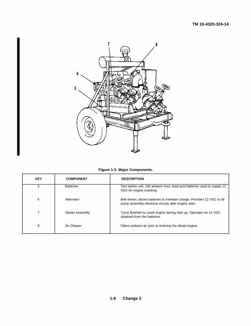
KEY COMPONENT DESCRIPTION
5
6
7
8
Batteries
Alternator
Starter Assembly
Air Cleaner
Two twelve volt, 100 ampere hour, lead-acid batteries used to supply 12VDC for engine cranking.
Belt driven; allows batteries to maintain charge. Provides 12 VDC to allpump assembly electrical circuits after engine start.
Turns flywheel to crank engine during start up. Operates on 12 VDCobtained from the batteries.
Filters ambient air prior to entering the diesel engine.
Figure 1-3. Major Components.
~
5
6
7 8

TM 10-4320-324-14
Change 2 1-7
KEY COMPONENT DESCRIPTION
9
10
11
12
13
Engine Assembly
Frame Assembly
Filter/Separator
Speed RegulatingThrottle Control
Fuel Shutdown Solenoid
An air cooled, three cylinder diesel engine that drives the centrifugalpump.
Provides mounting of engine assembly, pump, and components.Contains axle assembly, wheels and tires, and towbar to enable pumpingassembly to be field transported.
Attached to frame assembly. A throw-away element removes nearly 100percent of water and solid contaminants down to one micron in size.
Operates engine speed
A two position 12 VDC rack type solenoid. Attached to Solenoid fuelinjection pump cut-off lever. Shuts off fuel supply to engine when either alow oil pressure condition exists, or a drive belt breaks.
Figure 1-4. Major Components.
~
12
9
1011
13

TM 10-4320-324-14
1-8 Change 2
KEY COMPONENT DESCRIPTION
14
15
16
17
18
Fuel Feed Pump
Fuel Injection Pump
Fuel Filter
Oil Filter
Low Oil Pressure Switch
Pumps fuel from internal fuel tank to injection pump. A diaphragm typepump actuated by cam in fuel injection pump. Cleanable inlet screen.Provides positive head of pressure to injection pump.
Meters high pressure fuel to injector nozzles. A high Pump pressure fueldelivery pump driven by gear in engine timing cover. Main shaft in coverhas cams which operate plunger pumping fuel to injection nozzle.
A throw-away element which filters fuel from internal fuel tank prior toentering fuel pump.
A throw-away element which filters oil from oil sump prior to enteringengine.
Relays a signal to fuel shutdown solenoid upon a drop in switch oilpressure. Set to automatically shut down engine when oil pressure dropsbelow 4 psi (0.28 kg/cm2).
Figure 1-5. Major Components.
16 18
17
15
14
~

TM 10-4320-324-14
Change 2 1-9
KEY COMPONENT DESCRIPTION
19
20
Fuel Tank
Starting Aid Handpump
Contains fuel supply for operation of diesel engine. Retained by holddown straps to frame assembly. Has 19 gallon (17.9 liters) capacity, andincorporates a fuel level gauge, fuel selector valves, filler cap, drain plug,and overflow return fitting.
Supplies ether to engine air intake for starting in cold weather.
Figure 1-6. Major Components.
~
19
20

TM 10-4320-324-14
Change 2 1-10
1-15. Difference in Models.
a. Model LC350AGPM (36024). This model is used to transfer fuel only and does not have a regulator. It ismanually controlled and includes a grounding device.
b. Model LC350BGPM (36024). This model is used to transfer water only and does not have a regulator. It ismanually controlled and does not have grounding devices.
1-16. Equipment Data.
Table 1-1 is a list of data for the pumping assembly.
TABLE 1-1. EQUIPMENT DATA
Dimensions and WeightsLength
Towbar extended . . . . . . . . . . . . . . . . . . . . . . . . . . . . . . . . . . . . . . . . . . . . . . . . . . . . . . . . . . .131 inches (3327 mm)Towbar retracted . . . . . . . . . . . . . . . . . . . . . . . . . . . . . . . . . . . . . . . . . . . . . . . . . . . . . . . . . . . .87 inches (2210 mm)
Width . . . . . . . . . . . . . . . . . . . . . . . . . . . . . . . . . . . . . . . . . . . . . . . . . . . . . . . . . . . . . . . . . . . . . . .70 inches (1778 mm)Height . . . . . . . . . . . . . . . . . . . . . . . . . . . . . . . . . . . . . . . . . . . . . . . . . . . . . . . . . . . . . . . . . . . . . . .77 inches (1956 mm)Weight (overall) (dry) . . . . . . . . . . . . . . . . . . . . . . . . . . . . . . . . . . . . . . . . . . . . . . . . . . . . . . . . .2170 pounds (984.3 kg)Maximum towing speed
Hard surface . . . . . . . . . . . . . . . . . . . . . . . . . . . . . . . . . . . . . . . . . . . . . . . . . . . . . . . . . . . . . . . . . . . .20 mph (32 km)Gravel road . . . . . . . . . . . . . . . . . . . . . . . . . . . . . . . . . . . . . . . . . . . . . . . . . . . . . . . . . . . . . . . . . . . . .10 mph (16 km)Rough cross country . . . . . . . . . . . . . . . . . . . . . . . . . . . . . . . . . . . . . . . . . . . . . . . . . . . . . . . . . . . . .8 mph (12.8 km)
Tire pressure . . . . . . . . . . . . . . . . . . . . . . . . . . . . . . . . . . . . . . . . . . . . . . . . . . . . . . . . . . . . . . . . . . .40 psi (2.8 kg/cm2)Voltage . . . . . . . . . . . . . . . . . . . . . . . . . . . . . . . . . . . . . . . . . . . . . . . . . . . . . . . . . . . . . . . . . . . . . . . . . . . . . . . . .12 VDC
Engine SpecificationsNumber of cylinders . . . . . . . . . . . . . . . . . . . . . . . . . . . . . . . . . . . . . . . . . . . . . . . . . . . . . . . . . . . . . . . . . . . . . . . . . . . .3Bore (inch) . . . . . . . . . . . . . . . . . . . . . . . . . . . . . . . . . . . . . . . . . . . . . . . . . . . . . . . . . . . . . . . . . .3-15/16 inch (100 mm)Stroke (inch) . . . . . . . . . . . . . . . . . . . . . . . . . . . . . . . . . . . . . . . . . . . . . . . . . . . . . . . . . . . . .4-23/32 inch (105/120 mm)Piston displacement (entire inch) . . . . . . . . . . . . . . . . . . . . . . . . . . . . . . . . . . . . . . . . . . .172.45 cubic inch (2826 cm3)Direction of rotation (facing flywheel) . . . . . . . . . . . . . . . . . . . . . . . . . . . . . . . . . . . . . . . . . . . . . . . . .CounterclockwiseWorking principle . . . . . . . . . . . . . . . . . . . . . . . . . . . . . . . . . . . . . . . . . . . . . . . . Four-stroke diesel with direct injectionWeight (less starter and alternator) (pounds) . . . . . . . . . . . . . . . . . . . . . . . . . . . . . . . . . . . . . .595.25 pounds (270 kg)Power input . . . . . . . . . . . . . . . . . . . . . . . . . . . . . . . . . . . . . . . . . . . . . . . . . . . . . . . . . . . . . . . . . . . .44 hp at 2500 RPMSpeed . . . . . . . . . . . . . . . . . . . . . . . . . . . . . . . . . . . . . . . . . . . . . . . . . . . . . . . . . . . . . . . . . . . . . . . . . . . . . . .3000 RPMOil pump speed . . . . . . . . . . . . . . . . . . . . . . . . . . . . . . . . . . . . . . . . . . . . . . . . . . . . . . . . . . . . . . . . . . . . . . . .3140 RPMFuel . . . . . . . . . . . . . . . . . . . . . . . . . . . . . . . . . . . . . . . . . . . . . . . . . . . . . . . . . . . . . . . . . . . . . . . . . . . . . . . . . . . .DieselLubrication system . . . . . . . . . . . . . . . . . . . . . . . . . . . . . . . . . . . . . . . . . . . . . . . . . . . . . . . . . . . . . . .Forced lubricationValve clearance (engine cold) . . . . . . . . . . . . . . . . . . . . . . . . . . . . . . . . . . . . . . . . . . . . . . . . . . . . .0.006 in. (0.15 mm)
Inlet valves open . . . . . . . . . . . . . . . . . . . . . . . . . . . . . . . . . . . . . . . . . . . . . . . . . . . . . . . . . . . . . . . . .32° before TDCInlet valves close . . . . . . . . . . . . . . . . . . . . . . . . . . . . . . . . . . . . . . . . . . . . . . . . . . . . . . . . . . . . . . . . . . .60 after BDCExhaust valves open At above valve . . . . . . . . . . . . . . . . . . . . . . . . . . . . . . . . . . . . . . . . . . . . . . . . .70° before BDCExhaust valves close clearance . . . . . . . . . . . . . . . . . . . . . . . . . . . . . . . . . . . . . . . . . . . . . . . . . . . . . . .32° after TDC

TM 10-4320-324-14
Table 1-1. Equipment Data - CONT.
Piston crown clearance (measured with lead wire) ........................................................ 0.040 to 0.047 in. (1.0-1.2 mm)Injection release pressure . ......................................................................................................... 2489.1 psi (175+8 bar)Firing order .......................................................................................................................................................... 1-2-3Compression ratio . .................................................................................................................................................17:1
Pump SpecificationsType ..............................................................................................Single stage, centrifugal flow, variable displacementOutput volume .........................................................................................................................350 GPM at 250 ft. headDesigned working pressure ............................................................................................................125 psi (8.7 kg cm2)Designed suction pressure ...............................................................................................................20 psi (1.4 kg cm2)Type lube system .............................................................................................................. ."0" pressure, self-containedSuction and discharge size . ............................................................................................................. 4 inches (101 mm)
CapacitiesFuel tank . ......................................................................................................................................19 gallons (72 liters)Crankcase ....................................................................................................................................... 8.5 quarts (8 liters)Pump oil ...............................................................................................................................8 ounces (226.792 grams)
1-17. Safety, Care, and Handling.
Table 1-2 lists some of the hazards associated with working with the pumping assembly.
Table 1-2. Significant Hazards
OperatingHazard Safety Recommendation Condition
Carbon monoxide Do not operate pumping assembly in an enclosed area Normal(exhaust gas) unless exhaust gases are piped to the outside and
adequate ventilation is provided.
Fuel spills when using No smoking, flames, or sparks within 50 ft (15.2 m) Normalpumping assemblymodel 13229E8400.
Fuel spills when refilling No smoking, flames, or sparks within 50 ft (15.2 m) Normalthe fuel tanks.
Connecting towing device Chock both wheels to prevent pumping assembly from Normalrolling.
1-11

TM 10-4320-324-14
Section III. TECHNICAL PRICIPLES OF OPERATION
1-18. Fuel System.
Figure 1-7. Fuel System Function Diagram
a. Fuel Tank. Retained by hold down straps to trailer frame. Has 19 gallon (72 liters) capacity. Has fuel level gauge, fuelsource selector valve, filler cap, drain plug, and overflow return fitting.
b. Filter/Separator. Attached to trailer frame. A throw-away element remove nearly 100% of water and solid contaminantsdown to one micron in size.
c. Fuel Feed Pump. A diaphragm type pump actuated by cam in fuel injection pump. Cleanable inlet screen. Providespositive head of pressure to injection pump.
d. Fuel Injector Pump. A high pressure fuel delivery pump driven by gear in engine timing cover. Main shaft in pump hascams which operate plungers pumping fuel to injector nozzles. Controlled mechanically.
e. Fuel Filter. A throw-away element removing contaminants from fuel on way to injection pump.
f. Injector Nozzles. Single inlet, four outlet, high pressure injectors. Spray fuel directly into cylinders.
g. Overflow Lines. Carry excess fuel not needed for combustion to fuel tank and injection pump.
1-12

TM 10-4320-324-14
1-19. Lubrication System.
Figure 1-8. Lubrication System Functional Diagram
a. Oil Sump. Has 8.5 qt. (8 liter) capacity.
b. Oil Pump. Gear type element driven by gear in engine front cover.
c. Oil Cooler. Cools and directs oil to filter by engine cooling blower.
d. Oil Filter. A throw-away element which removes contaminants from oil.
e. Low Oil Pressure Switch. Located at oil filter housing discharge. Set to automatically shut down engine when oilpressure drops below 4 PSI (0.28 kg/cm2).
f. Metering Plugs. Oil jets within engine block. Spray oil to various components.
g. Fuel Injection Pump Lube Supply. Line on one side of lube oil filter housing directs oil to injection pump spills into timingcover.
1-13

TM 10-4320-324-14
1-20. Cold Start System.
Figure 1-9. Cold Start System Functional Diagram
NOTE
The cold start system serves as an aid for starting engine at low ambient temperatures.
a. Handpump. Pressurizes reservoir forcing starting fuel (Ether) through system.
b. Reservoir. Has liquid level sight line --MAXI-- to ensure full servicing.
c. Nozzle. Screwed into engine air intake manifold. Directs fluid spray toward upstream end of manifold.
1-14

TM 10-4320-324-14
1-21. Electrical System.
a. Batteries. Two 12 volt, 100 ampere hour, lead acid batteries. Supply power to all pumping assembly electrical circuits.
b. Emergency Stop Switch (S1). Two position PUSH-PULL switch. PULL position provides normal operation. PUSHposition cuts off power and shuts down assembly. Provides rapid engine shut down in event of emergency.
c. K2 Relay. A normally open relay, actuated by the By-Pass switch during start. Held closed when oil pressure reaches 4to 7 psi and K1 relay is closed. K2 provides power to actuate fuel shutdown solenoid.
d. Fuel Shutdown Solenoid. A two position 12 VDC rack type solenoid. Attached to governor cut-off lever, it providespositive fuel cut-off to shutdown engine. When fully retracted (fuel open), auxiliary tap (A) actuates K1 relay.
e. K1 Relay. A normally open relay, actuated by auxiliary tap (A) of fuel shutdown solenoid. One contact of relay whenclosed, provides path for current flow from start switch to starter solenoid. Second contact of relay provides current flowthrough V-belt contact switch and low oil pressure switch to K2 relay coil.
f. Oil Pressure By-Pass Switch (S3). A spring loaded off push button switch. Used only during engine start. Whendepressed, switch by passes low oil pressure switch. K2 relay then energizes to allow fuel shutdown solenoid to retract(fuel open) and K1 relay coil to energize.
g. Start Switch (S2). Spring loaded. When depressed (simultaneously with oil pressure bypass switch), directs currentthrough K1 relay contact to starter solenoid coil K3.
h. Starter Solenoid. A normally open 12 VDC coil. When energized, engages starter drive with engine flywheel and allowsbattery power to rotate starter motor. Solenoid deenergized when start button released. Starter then disengages fromengine.
i. V-Belt Contact Switch (S4). A normally closed switch. Provides current path in series with low oil pressure switch andK1 relay contact keeping K2 relay coil energized. If cooling blower V-belts breaks, switch will open deenergizing K2 relaycoil. When K2 opens, fuel shutdown solenoid extends (fuel closed) and engine shuts down.
j. Low Oil Pressure Switch. A normally open switch. Closes when oil pressure reaches 4 to 7 psi while starting. As long asoil pressure remains above close point, switch provides current path in series with V-belt contact switch and K1 relaycontact keeping K2 relay coil energized. If oil pressure drops below 4-7 psi, pressure switch opens deenergizing K2 relaycoil. When K2 opens, fuel shutdown solenoid extends (fuel closed) and engine shuts down.
1-15

TM 10-4320-324-14
Figure 1-10. Electrical Schematic.
1-16

TM 10-4320-324-14
1-22. Pumping System.
Figure 1-11. Pump System Functional Diagram
a. Impeller Shaft. The impeller shaft is the direct link between the engine and pump. The faster the engine runs, the fasterthe impeller shaft turns the impeller, raising pump pressure.
b. Impeller. The impeller, powered by the engine, through the impeller shaft, uses centrifugal force to pull the liquid into thepump housing through the suction valve and diverted it to the discharge valve.
c. Suction Valve. The suction valve is a manually operated gate valve which provides pump flow shutoff. When opened,the suction valve allows liquids to be brought through the centrifugal pump.
d. Centrifugal Pump. The centrifugal pump uses energy provided by the engine to move fluids from one place to another.
e. Discharge Valve. The discharge valve is a manually operated gate valve which provides pump flow shutoff. Whenopened, the discharge valve allows liquid to be discharged through the centrifugal pump.
1-17/(1-18 blank)


TM 10-4320-324-14
CHAPTER 2
OPERATING INSTRUCTIONS
Para Contents Page
2-5 Assembly and Preparation for Use ........................................................................................................ 2-92-2 Controls and Indicators ......................................................................................................................... 2-12-12 Emergency Procedures ......................................................................................................................... 2-222-11 Fording or Swimming ............................................................................................................................ 2-222-6 Initial Adjustments and Daily Checks ..................................................................................................... 2-122-1 Introduction (Controls and Indicators) .................................................................................................... 2-12-3 Introduction (PMCS) .............................................................................................................................. 2-22-9 Nuclear, Biological, and Chemical (NBC) Decontamination ................................................................... 2-192-7 Operating Procedures ........................................................................................................................... 2-122-10 Operation in Unusual Weather .............................................................................................................. 2-202-4 PMCS Procedures ................................................................................................................................. 2-62-8 Preparation for Movement ..................................................................................................................... 2-19
Section I. DESCRIPTION AND USE OF OPERATOR'S CONTROLS AND INDICATORS
2-1. Introduction.
This section describes the different controls and indicators used to operate the pumping assembly.
2-2. Controls and Indicators.
NOTE
The control panel is located on the forward left side of thepumping assembly.
a. Start/Stop. This switch (1) is a push-pull type switch and is markedEMERGENCY STOP, PULL TO START, PUSH TO STOP. Theswitch is pulled out during engine start cycle and remains pulled outwhile engine is operating. It is pushed in to shut down engine.
b. Start Switch. This switch (2) is a pushbutton type switch and ismarked START. This switch is pushed in and held during enginestart to activate K3 start relay. The switch is released upon ignition.
c. Oil Pressure Bypass Switch. This switch (3) is a pushbutton typeswitch and is marked OIL PRESSURE BYPASS. The switch must bepushed in simultaneously with start switch during engine start. Theoil pressure bypass switch is released upon ignition and buildup of oilpressure to 10 PSI.
2-1

TM 10-4320-324-14
2-2. Controls and Indicators (CONT).
d. Oil Pressure Gauge. The oil pressure gauge (4) indicates engine oil pressure by pounds per square inch (PSI). Thisgauge is graduated in 10 pound increments from 0 to 80 PSI.
e. Tachometer/Hourmeter. The tachometer/hourmeter (5) indicates engine speed inrevolutions per minute (RPM). This gauge is graduated in 100 RPM increments from 0to 3000 RPM. The center portion of the gauge indicates the total number of hours theengine has been operated.
f. Ammeter Gauge. The ammeter gauge (6) indicates alternator amperage output. Thisgauge is graduated in 30 amp increments from 0 to +60 AMPS and from 0 to -60 AMPS.
g. Suction Gauge. This gauge (7) is marked SUCTION and indicates pump suctionpressure and vacuum per square inch (PSI). This gauge is graduated in one unitincrements from 0 to 30 PSI for both vacuum and pressure with numerals at five unitintervals on the pressure side and at 10 unit intervals on the vacuum side.
h. Discharge Gauge. This gauge (8) is marked DISCHARGE and indicates pump dischargepressure in pounds per square inch (PSI). This gauge is graduated in 5 pound increments from 0 to 160 PSI withnumerals at 20 PSI intervals.
i. Engine Throttle. The engine throttle (9) provides manual speed selection. Turning throttle control counterclockwiseincreases engine speed. Clockwise rotation decreases engine speed.
j. Handpump. The handpump (10) is used to pressurize the cold start reservoir. If the outside air temperature is below
+40° F (+5° C) the cold start system may be used to assist in starting engine.
Section II. PREVENTIVE MAINTENANCE CHECKS AND SERVICES
2-3. Introduction.
a. General. Preventive maintenance checks and services are performed before, during, and after operating the equipment.
(1) Before Operating. Review all CAUTIONS and WARNINGS applicable to the pumping assembly. Perform thebefore (B) PMCS in accordance with Table 2-1.
(2) While Operating. Pay special attention to any CAUTIONS and WARNINGS applicable to the pumping assembly.Perform the during (D) PMCS in accordance with Table 2-1.
(3) After Operating. Be sure to perform the after (A) PMCS in accordance with Table 2-1.
(4) If equipment fails to operate refer to Table 3-1 and troubleshoot using proper equipment. Use the proper forms toreport any deficiencies, see DA PAM 735-750.
2-2

TM 10-4320-324-14
2-3
WARNINGAny leakage of fuel renders unit not mission capable.
b. Special Instructions. Leakage definitions for the operator/crew PMCS are defined as: Class I Seepage of fluid (asindicated by wetness or discoloration) not great enough to form drops Class II Leakage of fluid great enough toform drops but not enough to cause drops to drip from item being checked/inspected Class III Leakage of fluidgreat enough to form drops that fall from the item being checked/inspected
CAUTIONEquipment operation is allowed with minor leakage (Class I or II). Ofcourse, you must consider the fluid capacity of the item/system beingchecked/inspected. When in doubt, notify your supervisor.
(1) When operating with Class I or Class II leaks, continue to check fluid levels as required in your PMCS.
(2) Class III leaks should be reported to your supervisor or unit maintenance.
c. PMCS Column Explanation.
(1) Item Number Column. This column lists, in logical order of performance, the checks and services that are tobe performed.
(2) Interval Column. This column contains the time frame for which a required check or service is to beperformed. A dot (.) is placed in appropriate sub-column(s) that contains a symbol identifying the time framefor which designated checks or services are to be performed. The symbol designations for the various timeframes are as follows: B -Before; D -During; A -After; W -Weekly; M -Monthly.
(3) Item to be Inspected. This column lists the part or group of parts to be checked and serviced. These parts areidentified in figures 2-2 and 2-3.
(4) Procedures Check For and Have Repaired or Adjusted Column. This column contains a brief description ofthe procedure by which the check is to be performed.
(5) Equipment Is Not Ready/Available If Column. This column contains the criteria that will cause the equipmentto be classified as not ready/available because of inability to perform its primary combat mission. The terms“ready/available” and “mission capable” refer to the same status -Equipment is on hand and is able to performits combat missions (see DA PAM 738-750). Entries in this column will be keyed specifically to checks listed inthe Procedure column. An entry in this column will:
(a) Identify conditions that make the equipment not ready/available for readiness reporting.
(b) Deny use of the equipment until corrective maintenance has been performed.

TM 10-4320-324-14
2-4 Change 2
Figure 2-1. PMCS Locations (Left Side View).
1
10
7
8
13
5
6
1720
16
15

TM 10-4320-324-14
Change 2 2-5
Figure 2-2. PMCS Locations (Right Side View).
~
~~
11
14
2
12
2
18
39
19
4

TM 10-4320-324-14
2-6 Change 2
2-4. PMCS Procedures.
The pumping assembly PMCS procedures are listed in Table 2-1. When filling out the "Item Number" column on DA Form2404, Equipment Inspection and Maintenance Worksheet, use the number taken from Item No. column in Table 2-1 torecord results of the checks and services. Item number also refers to index numbers on figures 2-2 and 2-3.
NOTEIf the equipment must be kept in continuous operation, check and serviceonly those items that can be checked and serviced without disturbingoperation. Make the complete checks and services when the equipmentcan be shut down.
Within designated interval, these checks are to be performed in the order listed. Perform weekly PMCS as well as beforeoperations PMCS if:
(1) assigned to the operator and the item has not been operated since the last weekly PMCS.
(2) operating the item for the first time.
Table 2-1. Operator/Crew Preventive Maintenance Checks and Services (PMCS)
B–Before D–During A–After W–Weekly M–Monthly
ITEMNO
INTERVAL ITEM TO BEINSPECTED
PROCEDURES CHECK FOR AND HAVE REPAIRED OR ADJUST AS NECESSARY
EQUIPMENT ISNOT READY/
AVAILABLE IF:B D A W M
1
2
3
4
•
•
•
•
•
•
•
•
•
Control box access door
Suction and DischargeValves
Centrifugal Pump
Battery Box Cover
Visually inspect for missing or looseattaching parts, broken or loose doorlatches and door hinges.
Check that valve turns on and off freely.Check for leaks around attachmentpoints.
a. Check for signs of leakage.
b. Drain water if ambient temperature isexpected to fall to 32°F (0°C) orbelow.
* Inspect for corrosion. Check to ensurebox cover has not been damaged.
Valve does not turn on andoff. If any class III waterleaks or any fuel leaks arepresent.
a. If any class III water leaksor any fuel leaks arepresent.
b. Bearing housingmounting hardware isloose or excessive noiseis present.
*Applicable to Model LC350BGPM (36024)

TM 10-4320-324-14
Change 2 2-7
Table 2-1. Operator/Crew Preventive Maintenance Checks and Service (PMCS - CONT)
NOTEWithin designated interval, these checks are to be performed in the orderlisted.
B–Before D–During A–After W–Weekly M–Monthly
ITEMNO
INTERVAL ITEM TO BEINSPECTED
PROCEDURES CHECK FOR AND HAVE REPAIRED OR ADJUST AS NECESSARY
EQUIPMENT ISNOT READY/
AVAILABLE IF:B D A W M
5
6
7
8
9
10
11
•
•
•
••
•
•
•
•
•
•
•
•
••
•
Engine Oil Dipstick
V-Belts
Fuel Lines and Hoses
Oil Lines
Fuel Tank, Fittings, andGauge
Air Cleaner
Alternator
Check oil level after every 10 hours ofoperation. If engine oil level is on orbelow the lower mark, add oil. Changeoil as required.
Check for loose v-belt. Check for cracksor otherwise damaged v-belt. Checkwarning device for correct function afterat least every 100 hours of operation.
Visually inspect unit for fuel leaks,breaks, cracks and loose fittings.
Visually inspect unit for oil leaks.
Check fuel tank fitting, lines, drain plugand all tank surfaces for leaks or anyother damage. Check tank retainingstraps for security. Check fuel levelgauge for damage. Check for cloggedstrainer, clean as required.
Check service indicator before and aftereach operation for red signal indicatingthat elements require replacement. Ifsignal shows, replace elements inaccordance with paragraph 3-5. Inspectfor bent, cracked, or damaged aircleaner.
Check that alternator and all electricalconnections are secure and no brokenwires are present.
If any class III oil leaks arepresent.
Leaks are present.
Class III leaks are present.
Leaks are present.
Evidence of arcingoverheating, binding, orcracking and alternator lightstays on at start-up orduring operations.

TM 10-4320-324-14
2-8 Change 2
Table 2-1. Operator/Crew Preventive Maintenance Checks and Service (PMCS - CONT)
NOTEWithin designated interval, these checks are to be performed in the orderlisted.
B–Before D–During A–After W–Weekly M–Monthly
ITEMNO
INTERVAL ITEM TO BEINSPECTED
PROCEDURES CHECK FOR AND HAVE REPAIRED OR ADJUST AS NECESSARY
EQUIPMENT ISNOT READY/
AVAILABLE IF:B D A W M
12
13
14
15
16
17
*18
19
20
•
•
•
•
•
•
•
•
•
•
•
•
•
•
•
•
•
•
Control Panel,Instruments, andSwitches
Throttle Control
Main Wiring Harness
Tires
Wheel
Frame Assembly
Ground Rods
Batteries and Cables
Filter/Separator
Inspect for damage, secure mountingand proper operations of controls andinstruments. Check to ensure allinstruments are working properly.
Inspect for bent, loose, or damagedcontrol mechanism.
Inspect for frayed or worn spots inwiring harness. Check for looseconnections.
Check for proper inflation, 40 PSI (2.8 kg/cm2). Check tires for properwear; no less than 1/8 in. tread. Be suretires are not excessively worn. Checkfor cuts, cracks, uneven wear.
Check for damaged wheels. Check thatlug nuts on wheels are securelytightened. Check that bearing caps areproperly seated and tight.
Visually inspect all structural parts forexcessive wear, corrosion, brokenwelds, security, cracks, damagedlanding leg assemblies, and damagedtowbar.
Inspect for missing or damaged rodsand brackets.
Check electrolyte level. Check forcorrosion buildup at post.
Drain water if ambient temperature isexpected to fall to 32°F (0°C) or below.Check for leaks.
Damage to indicators andinternal components.Switches are loose, ordamaged. Gauges cannotbe read.
Throttle control inoperative.
If wiring excessively frayed,worn, or deteriorated.
Rods are missing.
Battery is too weak to crankengine.
Class III leak is present.
*Applicable to Model LC350AGPM (36024)

TM 10-4320-324-14
Change 2 2-9
a. Upon reaching the operating area where pumping assembly is to be used, prepare the equipment for use asfollows:
(1) Position pumping assembly in such a manner that connections of where liquid is to be pumped from willconnect with fittings on suction valve. Locate pumping assembly as close as possible to liquid source. Keepsuction lift as low as possible.
(2) Be sure site is as nearly level as possible; clean site of rocks and vegetation. Be sure surface is firm enoughto support pumping assembly. If it is necessary to place the unit on soft ground, arrange a foundation ofplanking, logs, or any other suitable material.
(3) Be sure all sides of pumping assembly, and all fittings and controls are easily accessible.
(4) Remove pins (1 and 2) to extend trailer support legs (3) as far as possible.
(5) Reinstall pins (1 and 2) to secure trailer support legs (3).
(6) Release pintle (4) and disconnect pumping assembly from towing vehicle (5).
(7) Position pumping assembly such that frame support legs (3) support forward section of pumping assembly.
2-5. Assembly and Preparation for Use.
5
4
12
3

TM 10-4320-324-14
2-10 Change 2
WARNINGTo prevent pumping assembly from rolling or sliding, securely chock bothwheels or serious injury to personnel could result.
(8) Place chocks (6) under wheels (7).
WARNINGPumping assembly Model LC350AGPM (36024), must be grounded priorto operation when fuel is pumped or spark could ignite fuel causingpossible injury to personnel.
(9) Remove a ground rod (8) from frame assembly, except Model LC350BGPM (36024), and drive into groundapproximately four feet. Remove grounding cable (9) from tool box and clamp one end to the rod and theother to the frame grounding lug (10).
(10) Ensure the two fuel selector valves (11) are positioned correctly. Valve handles must have pointer in the“FUEL TANK” position when fuel is supplied from the pump tank.
(11) Perform preventive maintenance checks and services (Table 2-1).
2-5. Assembly and Preparation for Use.
9
7
6 8
11
10

TM 10-4320-324-14
Change 2 2-11
CAUTIONUse of petrolatum preservative (Type 14, MIL-C-10382C) can causeirreversible damage to water pump membranes. Pumps that have beenpreserved must be thoroughly rinsed prior to being used in conjunctionwith ROWUPs to prevent damage.
NOTEWhen installing suction and discharge lines, keep lines as straight aspossible to keep friction losses at a minimum. Fittings in pipe linesincrease friction losses considerably. When necessary to use elbows, uselong-radius type to minimize friction loss.
(1) Disconnect and remove coupling half (1) from suction valve (2).
(2) Connect suction hose (3) to suction valve (2).
(3) Disconnect and remove coupling half (4) from discharge valve (6).
(4) Connect discharge hose (5) to discharge valve (6).
(5) Connect suction hose (3) to component from which liquid is to be pumped.
(6) Connect discharge hose (5) to component to which liquid is to be transferred to.
b. Once pumping assembly has been positioned and secured, connect suction and discharge hoses as follows:
5
6
2
314

TM 10-4320-324-14
2-12 Change 2
WARNINGFailure to replace priming port cap and lock securely will result in a twoinch (5.08 cm) stream of liquid at high pressure. Keep hands and faceaway or personal injury may result.
(3) Install priming port cap (4) and place camlock levers in locked position.
2-6. Initial Adjustments and Daily Checks.
a. Perform all daily PMCS procedures.
b. Make sure fuel tank is full before starting to pump site.
2-7. Operating Procedures.
a. Startup.
WARNINGHearing protection must be worn by all personnel within working distanceof pump during pump operation. Failure to comply may result inpermanent hearing loss to personnel.
CAUTIONNever operate pump unless pump housing is filled with liquid. The pumpwill not pump when dry. Extended operation of a dry pump will destroy theseal assembly.
(1) Open vent valve (1) and ensure that all suction valves (2), and discharge valves (3) are closed.
(2) Check pump fluid level by carefully opening camlock levers on priming port cap (4) and raising port capslightly to see if liquid is discharged from priming port. If liquid is discharged, quickly install priming port capand place cam-lock levers in locked position. If fluid is not discharged, remove port cap and add clean liquidof the type to be pumped, until the liquid level reaches the top of the priming port.
1
4
2
3

(4) Push and raise throttle control (5) from detentlatch, releasing it to the idle position.
NOTEIf outside temperature is below + 10°F (-12°C) refer toparagraph 2-9a for operation of cold start system. Referto Table 2-2 for performance data.
(5) Pull out EMERGENCY STOP switch (6).
CAUTIONDo not operate starter motor for more than 10 seconds;damage to starter can result.
(6) Push in start switch (7) and oil pressure bypassswitch (8) simultaneously.
(7) Upon engine start, release start switch (7).
NOTEThe engine will shut down when oil pressure bypassswitch is released if oil pressure is not 8 PSI or above.
(8) Release oil pressure bypass switch (8) when 10PSI is exceeded on gauge (9).
(9) Allow engine to idle approximately two minutes, then smoothly push throttle control (5) into detent.
(10) Turn throttle control counterclockwise to increase or clockwise to decrease engine speed to approximately2400 RPM as indicated on gauge (10).
(11) Open suction valve (2) that is connected to suction line.
CAUTIONEnsure discharge valve is open. Pump can overheat if discharge valve isclosed for long periods of time. A vapor-locked condition may result. If thisoccurs, shut down engine and allow pump to cool before filling housingwith liquid.
(12) Slowly open discharge valve (3) that is connected to discharge line.
(13) Observe the end of vent line (11) for liquid flowing from it. Once liquid begins to flow from line, close ventvalve (1).
TM 10-4320-324-14
Change 2 2-13
4
11
1
6
9
8 7
10
5
2
3

TM 10-4320-324-14
2-14
CAUTIONAs pump begins to pump, reduce engine speed and reduce dischargevalve opening to prevent hydraulic shock to system when line is filled toofast, causing hose rupture and fitting failure.
NOTE• When pump picks up prime, a change in engine RPM will be noted.
• Depending on pumping conditions, pump may not take suctionimmediately; it may be necessary to fill suction line with liquid before thepump takes suction. If after a reasonable time pump fails to take suction,shut down engine and check suction line for leaks, then repeat steps (1)through (13).
(14) Readjust pump speed to desired level (Table 2-2).
(15) Check all control panel gauges for indications of malfunctions. If a malfunction is indicated, shut down pumpimmediately.
2-7. Operating Procedures (Contd).
Table 2-2. Performance Data

(16) Perform during operation PMCS (Table 2-1).
CAUTIONEnsure discharge valve is open. Pump can overheatif discharge valve is closed for long periods of time. Avapor-locked condition may result. If this occurs, shutdown engine and allow pump to cool before fillinghousing with liquid.
b. Run. During normal operation the pump assemblyshould run without further intervention. Make periodicchecks of all valves, gauges and indicators. If amalfunction is indicated, shut down pump at once.
c. Shutdown.
CAUTIONDo not shut engine down suddenly from full speedunless an emergency exists. Allow engine to stabilizeat idle before shutdown.
(1) Push and raise throttle control (5) from detent toset engine speed to idle.
(2) After approximately two minutes, close dischargevalve (3) and suction valve (2).
(3) Push in EMERGENCY STOP switch (6).
(4) Perform after operation PMCS (Table 2-1).
TM 10-4320-324-14
Change 2 2-15
2
3
6
95

TM 10-4320-324-14
2-16 Change 2
2-7. Operating Procedures (Contd).
d. Operating Instructions on Decals and Instruction Plates. A list of Instruction plates and Decals with their location isillustrated below.
1 2
3
4
56
7
KEY NAME
1 Information Vent (Stencil)
2 Information Emergency Stop Plate
3 Information Throttle Plate
4 Information Valve Plate (2 ea.)
5 Pump Priming Port (Stencil)
6 Caution Sign (2 ea.)
7 Caution Sign (2 ea.)

TM 10-4320-324-14
Change 2 2-17
89
10
11
12
13
14
KEY NAME
8 Information Lift Plate
9 Information Operation Plate
10 Information Fuel Performance Plate
11 Information Tiedown Plate (2 ea.)
12 Instruction Fuel Plate (2 ea.)
13 Information Battery Plate
14 Information Valve Plate (2 ea.)
2-7. Operating Procedures (Contd).

TM 10-4320-324-14
2-18 Change 2
1516
17
18
19
20
21
22
KEY NAME
15 Instruction Cold Start Plate
16 Information Engine Temperature Plate
17 Information Fuel Filter Plate
18 Information Oil Plate
19 Information Tiedown Plate (2 ea.)
20 Information Water Separator Plate
21 Identification Pumping Assembly Plate
22 Engine Coupling Oil Level Plate
2-7. Operating Procedures (Contd).

TM 10-4320-324-14
Change 2 2-19
a. Perform shutdown procedure on pumping assembly (para 2-7c).
b. Ensure fuel selector valves (11) are in the off position.
c. Loosen terminal stud nut (10), disconnect grounding cable (9), and stow cable (9) and attaching hardware in toolbox. Stow ground rod (8) on frame assembly. This is not required for Model LC350BGPM (36024).
d. Attach pumping assembly drawbar to towing vehicle (5) using pintle (4).
e. Stow trailer support legs (3) in frame using pins (1 and 2).
f. Remove chocks (6) from under wheels (7) and stow.
Section IV. OPERATION UNDER UNUSUAL CONDITIONS
2-9. Nuclear, Biological, and Chemical (NBC) Decontamination.a. If attack is known or suspected, mask at once and continue mission. If inside, stay there if possible.
b. If outside, brush fallout from skin, clothing, and equipment with available brushes and rags before going inside.Wash skin and have a radiation check made as soon as tactical situation permits.
c. Do not unmask until told to do so.
d. Detailed DECON procedures can be found in FM 3-3, FM 3-4, and FM 3-5.
109
4
511
7
6
12
3
2-8. Preparation for Movement.
8

TM 10-4320-324-14
2-20 Change 2
2-10. Operation In Unusual Weather.
a. Extreme Cold Weather.
(1) Keep batteries fully charged.
(2) Keep fuel tank full at all times to prevent ice crystalformation.
(3) Do not disturb electrical leads or wiring unless repair isneeded.
(4) Use cold start system and allow the engine to warm upa full five minutes before accelerating to full speedRPM.
NOTEThe cold start system may be used to assist instarting engine when air temperature is below + 10°F(-12°C).
(a) Open cover (1).
WARNINGDo not puncture or mishandle quick start servicingcan. This can contains an ether base mixture that ishighly combustible.
(b) Force servicing can (2) into nipple (3) on reservoir(4) so fluid flows from can into reservoir.
CAUTIONDo not continue pumping after engine starts.
(c) Remove can when reservoir level reaches “MAX”line, then close cover.
(d) Pump hand pump (5) immediately when depressingstart button (6) on control panel.

TM 10-4320-324-14
Change 2 2-21
NOTEIf engine speed decreases, start pumping; engine speed should increase.
(e) Stop pumping when engine starts.
b. Extreme Hot Weather.
(1) Keep cylinder and cylinder head cooling fins clean.
(2) Inspect cooling blower inlet often for any obstructions. Remove obstructions from fan shroud cover.
c. Dusty or Sandy Areas.
(1) Keep crankcase oil fill cap tight and dipstick seated to prevent contamination.
(2) Keep cylinder and cylinder heat cooling fins clean.
(3) Wipe spilled lubricants from assembly to avoid collecting dust and sand.
(4) Use care when servicing fuel tank to prevent sand and dirt from entering the fuel system. Ensure that fill capis kept tight.
(5) Pay particular attention to the air cleaner service indicator. Replace elements as required.
d. Extreme Wet (fresh water) Areas. Except for modifying PMCS time intervals and ensuring that surface under unitis firm enough to support pumping assembly, no special instructions are required for operation of pumpingassembly in damp or muddy areas.
e. Salt Water Areas. When it is necessary to operate the pumping assembly near salt water, the followingprecautions should be observed to provide maximum protection to the unit and to assure efficient operation.
(1) Keep all electrical components clean, dry, and free of corrosion.
(4) Wash unit frequently with fresh, clean water. Dry thoroughly.
(3) Keep fuel filler cap tight.
(4) Check all gauges for loose or broken lenses which might permit entry of moisture.
f. High Altitude Areas. Power output and temperature level of a diesel engine are governed by careful matching ofcombustion air and fuel injection volumes, and since the density of the combustion air taken in varies with theatmospheric pressure and the ambient temperature, full rated power is obtained only at 985 feet (300 m) abovesea level and 68° F (20° C). Where engines are operated at greater altitudes and/or higher ambient temperature,they must be de-rated (reduced fuel injection and hence engine loading). Therefore, never run the diesel engine in“thin air” under heavy-duty conditions unless the engine has been de-rated, otherwise the engine's lifespan,reliability, and exhaust emissions may be affected, especially at altitudes above 3280 feet (1000 m) and/ortemperatures above 68°F (20° C).

TM 10-4320-324-14
2-22 Change 2
2-11. Fording or Swimming.
a. Before Fording or Swimming.
NOTEThe pumping assembly is transportable through abody of water up to 30 inches (762 mm) deep.
(1) Secure tool box cover latch.
(2) Secure control panel cover.
(3) Ensure that battery cover retaining bar is secure.
NOTEFuel tank incorporates a vent valve. Valve must beclosed before fording to prevent water entry. Duringnormal operation, vent valve must be open. Noteinstructions on cap (1).
(4) Remove cap (1) from tank, turn cap over, and restcap on tank neck.
(5) Rotate vent valve selector to CLOSED position (2).
(6) Reinstall cap and secure.
b. After Fording or Swimming.
(1) Remove fuel tank filler cap and turn cap over.
(2) Rotate vent valve selector to OPEN position (3).
(3) Reinstall cap and secure.
2-12. Emergency Procedures.
General. Anytime an emergency arises while operating thepumping assembly which calls for an immediate engine shutdown,push the START/STOP switch.
1
23

TM 10-4320-324-14
CHAPTER 3
OPERATOR'S MAINTENANCE INSTRUCTIONS
Para Contents Page
3-1 General Lubrication Information....................................................................................... 3-13-2 Introduction (Troubleshooting Procedures)....................................................................... 3-13-4 Introduction (Operator Maintenance Procedures) .............................................................3-93-5 Service Air Cleaner .......................................................................................................... 3-103-6 Service Batteries .............................................................................................................. 3-113-8 Service Engine Assembly................................................................................................. 3-133-7 Service Fuel Tank ............................................................................................................ 3-123-9 Service Pump Assembly .................................................................................................. 3-143-3 Troubleshooting Table...................................................................................................... 3-2
Section I. LUBRICATION INSTRUCTIONS
3-1. General Lubrication Information.
CAUTION
Use only the type lubricants specified on current lubrication order and do not over lubricate. Overlubrication may cause equipment failure or damage to working parts.
a. Refer to LO 10-4320-324-12.
b. Keep all lubricants in closed containers and store in a clean dry area away from excessive heat. Do not allowdust, dirt, or other foreign matter to mix with the lubricants. Keep the lubrication equipment clean and ready for use.Before lubricating the equipment wipe all lubrication points to remove dirt and grease. After lubricating, clean alllubrication points of any spilled or excessively applied lubricant to prevent accumulation of dirt and foreign matter. Keepall external surfaces and parts not requiring lubrication free of lubricants. Inspect all oil lines, fitting and filters for leaksimmediately after lubrication and during operation.
Section II. TROUBLESHOOTING PROCEDURES
3-2. Introduction.
a. Table 3-1 lists the common malfunctions which you may find during the operation or maintenance of thepumping assembly or its components. You should perform the tests/inspections and corrective actions in the order listed.
3-1

TM 10-4320-324-14
3-2. Introduction (CONT).
b. This manual cannot list all malfunctions that may occur, nor all tests or inspections and corrective actions. If amalfunction is not listed or is not corrected by listed corrective actions, notify your supervisor.
3-3. Troubleshooting Table.
Table 3-1 contains troubleshooting information for the pumping assembly and components.
Table 3-1. Troubleshooting
MALFUNCTION
TEST OR INSPECTION
CORRECTIVE ACTION
ENGINE
1. ENGINE WILL NOT CRANK.
Step 1. Inspect electrolyte in batteries.
Refer to paragraph 3-6 and, if fluid is low, refill with water.
Notify unit maintenance.
Step 2. Check for loose or corroded connections at battery and starter.
Notify unit maintenance.
Step 3. Check for broken or frayed cables at battery and starter.
Notify unit maintenance.
Step 4. Check for broken or frayed wires between alternator and voltage regulator.
Notify unit maintenance.
Step 5. Visually inspect wiring harness for corroded or dirty connections, broken, frayed, or damagedwires.
Notify unit maintenance.
Step 6. Check V-belt tension.
Notify unit maintenance.
Step 7. Inspect for proper starter operation.
Notify unit maintenance.
3-2

TM 10-4320-324-14
Table 3-1. Troubleshooting-CONT.
MALFUNCTION
TEST OR INSPECTION
CORRECTIVE ACTION
ENGINE-CONT
Step 8. Inspect emergency stop switch and start switch for damage.
Notify unit maintenance.
Step 9. Notify unit maintenance to test battery.
2. ENGINE CRANKS BUT WILL NOT RUN.
Step 1. Check fuel supply in fuel tank.
Fill with fuel if empty or low (refer to paragraph 3-7).
If tank is empty, notify unit maintenance to bleed fuel system.
Step 2. Check for closed shut-off valve.
Open shut-off valve.
Notify unit maintenance.
Step 3. Inspect for broken fuel lines or hoses and loose fittings.
Notify unit maintenance.
Step 4. Inspect for leaks at fuel tank.
Notify unit maintenance.
Step 5. Check for loose, broken, frayed or damaged wires between fuel shutdown solenoid, low oil pressureswitch and V-belt contact switch.
Notify unit maintenance.
Step 6. Notify unit maintenance to test shutdown solenoid, low oil pressure switch and V-belt contactswitch.
Step 7. Inspect oil pressure bypass switch for damage.
Notify unit maintenance.
Step 8. If operating during winter, check for fuel clouding.
Notify unit maintenance.
3-3

TM 10-4320-324-14
Table 3-1. Troubleshooting - CONT.
MALFUNCTION
TEST OR INSPECTION
CORRECTIVE ACTION
ENGINE - CONT
2. ENGINE CRANKS BUT WILL NOT RUN (CONT).
Step 9. Check grade of oil for proper viscosity.
Notify unit maintenance.
3. COLD START SYSTEM FAILS TO ASSIST CRANKING OF ENGINE DURING COLD START.
Step 1. Check reservoir for ether supply.
Notify unit maintenance.
Step 2. Inspect pumping action of pump.
Notify unit maintenance.
4. CANNOT ADJUST ENGINE SPEED.
Step 1. Check for bent, broken, or damaged throttle control arm.
Notify unit maintenance.
Step 2. Check for frozen fuel control lever at injection pump.
Notify unit maintenance.
5. STARTS OR RUNS ROUGHLY AFTER WARMUP. DOES NOT DEVELOP FULL POWER OR MAKES
EXCESSIVE EXHAUST SMOKE.
Step 1. Visually inspect air cleaner restriction indicator for dirty cartridge.
Refer to paragraph 3-5 and replace both cartridges.
Notify unit maintenance.
Step 2. Check fuel supply in fuel tank.
Refer to paragraph 3-7 and fill with fuel if tank is empty or low.
Step 3. Check for partially closed shut-off-valve.
Open shut-off-valve fully.
Notify unit maintenance.
3-4

TM 10-4320-324-14
Change 2 3-5
Table 3-1. Troubleshooting (Contd)
MALFUNCTIONTEST OR INSPECTION
CORRECTIVE ACTION
ENGINE (Contd)
5. STARTS OR RUNS ROUGHLY AFTER WARMUP. DOES NOT DEVELOP FULL POWER OR MAKESEXCESSIVE EXHAUST SMOKE (CONT).
Step 4. Refer to paragraph 3-9 and check engine oil level.
If overfilled, notify unit maintenance to drain off oil to proper level.
6. ENGINE OVERHEATS.
Step 1. Refer to paragraph 3-9 and check engine oil level.
Add oil as required (see LO 10-4320-324-12).
Step 2. Inspect cooling fins on cylinders and cylinder heads for dirt.
Clean as required.
Step 3. Check for blockage of cooling air input to blower at fan shroud cover.
Ensure free cooling air flow.
Step 4. Inspect for broken or missing V-belt.
Notify unit maintenance.
Step 5. Check operation of cooling fan.
Notify unit maintenance.
Step 6. Refer to LO 10-4320-324-12 and check for use of proper grade of oil for operating temperature.
Notify unit maintenance.
7. ENGINE OR EXHAUST NOISY.
Step 1. Check for loose connections allowing exhaust leaks.
Notify unit maintenance.
Step 2. Check for holes in muffler.
Notify unit maintenance.

TM 10-4320-324-14
3-6
Table 3-1. Troubleshooting (Contd)
MALFUNCTIONTEST OR INSPECTION
CORRECTIVE ACTION
ENGINE (Contd)
7. ENGINE OR EXHAUST NOISY (CONT).
Step 3. Check for loose connections allowing exhaust pipe to move.
Notify unit maintenance.
Step 4. Check for burned out exhaust pipe.
Notify unit maintenance.
8. OIL PRESSURE GAUGE READING TOO LOW.
Step 1. Refer to paragraph 3-9 and check engine oil level.
Add oil as required (see LO 10-4320-324-12).
Step 2. Inspect for leaks in lube oil system.
Notify unit maintenance.
Step 3. Check electrical connection at oil pressure sending unit.
Notify unit maintenance.
9. AMMETER READING TOO LOW.
Step 1. Check V-belt tension, causing alternator to operate at low output.
Notify unit maintenance.
Step 2. Check for loose connections at alternator, causing insufficient charging of the batteries.
Notify unit maintenance.
PUMP ASSEMBLY
1. NO SUCTION OR DISCHARGE PRESSURE.
Step 1. Check for leaks in valves, connections and suction line.
Correct leak.

TM 10-4320-324-14
Table 3-1. Troubleshooting - CONT.
MALFUNCTION
TEST OR INSPECTION
CORRECTIVE ACTION
PUMP ASSEMBLY - CONT
1. NO SUCTION OR DISCHARGE PRESSURE (CONT).
Step 2. Check for clogged suction strainer.
Clean suction strainer.
Step 3. Check for collapsed suction hose.
Replace suction hose.
Step 4. Check for foreign matter in discharge valves.
Notify unit maintenance.
Step 5. Check for high suction lift or discharge head.
Notify unit maintenance.
Step 6. Check for damaged gauges.
Notify unit maintenance.
Step 7. Check that drain valve is tightly closed.
Close drain valve.
Step 8. Check for pump prime.
Refer to paragraph 2-7 or 2-8 and prime pump.
2. PUMP STOPS OR FAILS TO DELIVER RATED FLOW OR PRESSURE.
Step 1. Check for air leak in suction line.
Correct leak.
Step 2. Check for clogged suction strainer.
Clean suction strainer.
Step 3. Check to verify suction intake is fully submerged.
Submerge suction intake.
3-7

TM 10-4320-324-14
Table 3-1. Troubleshooting - CONT.
MALFUNCTION
TEST OR INSPECTION
CORRECTIVE ACTION
PUMP ASSEMBLY - CONT
2. PUMP STOPS OR FAILS TO DELIVER RATED FLOW OR PRESSURE (CONT).
Step 4. Check for collapsed suction hose.
Replace suction hose.
Step 5. Check that pump is not driven too slow.
Check engine speed.
Step 6. Check for high suction lift or discharge head.
Notify unit maintenance.
3. PUMP NOISY.
Refer to paragraph 3-9 and check oil level.
Add oil as required (See LO 10-4320-324-12).
4. SUCTION OR DISCHARGE VALVES WILL NOT OPERATE.
Check to see if valves will turn on and off.
Notify unit maintenance.
FRAME ASSEMBLY
1. UNIT DOES NOT TRACK STRAIGHT.
Step 1. Inspect for damaged towbar.
Notify unit maintenance.
Step 2. Inspect for bent, broken or damaged frame.
Notify unit maintenance.
Step 3. Inspect for bent, broken or damaged axle.
Notify unit maintenance.
3-8

TM 10-4320-324-14
Table 3-1. Troubleshooting - CONT.
MALFUNCTION
TEST OR INSPECTION
CORRECTIVE ACTION
FRAME ASSEMBLY - CONT
2. WHEELS NOISY DURING TOWING OPERATIONS.
Inspect for loose or missing lug nuts.
Notify unit maintenance.
3. TIRES.
Check tires for proper inflation pressure (40 psi (28 kg/cm2)).
If low, fill to proper inflation pressure.
If flat, notify unit maintenance.
Section III. OPERATOR MAINTENANCE PROCEDURES
3-4. Introduction.
This section contains maintenance procedures to be performed by the operator of the pumping assembly as authorizedby the Maintenance Allocation Chart (MAC).
3-9

TM 10-4320-324-14
3-10 Change 2
CAUTIONDust in combustion air can cause premature wear of engine. Maintenanceof air cleaner is therefore essential to ensure long life. The air cleanermust be replaced when indicator keeps displaying red warning signalwhen engine is shut down. Another indication that cartridge needsreplacing is a smoking exhaust and decreasing engine output.
NOTEThe safety cartridge is not to be cleaned. If dirty, it is to be replaced.
a. Replacing elements.
(1) Unscrew captive wingnut (1) and air cleaner cover (2).
(2) Remove wing nut (3) and pull secondary filter element (4) from air cleaner housing (7).
(3) Remove wing nut (5) and primary filter element (6). Insert end of new element (6) into air cleaner housing andsecure with wing nut (5).
(4) Install new secondary filter element (4) on air cleaner housing (7) with wing nut (3).
(5) Install air cleaner housing cover (2) and tighten captive wing nut (1).
3-5. Service Air Cleaner.
AIR INDICATOR
7
65
4
32
1

TM 10-4320-324-14
Change 2 3-11
3-6. Service Batteries.
CAUTIONTo prevent short circuits, never rest toolson battery.
a. Servicing Battery. Prior to operating the unit,check electrolyte level in each cell as follows:
(1) Remove two wing nuts (1), two washers(2), strap (3), and two covers (4).
(2) Remove caps (5).
WARNINGTo prevent serious burns, take thenecessary precautions when filling batterywith electrolyte. Do not allow electrolyte tocome in contact with skin or eyes. Userubber gloves and protective clothing.
(3) Visually check the electrolyte level of allcells.
(4) Electrolyte level must cover lead plates (6)and be to a level at the lower portion of thefill hole.
(5) If electrolyte level is low, add water only.
(6) Replace caps (5).
(7) Install covers (4) and strap (3) withwashers (2) and wings nuts (1).

TM 10-4320-324-14
3-12 Change 2
WARNINGDo not smoke or use an open flame in the vicinity when filling fuel tank.
CAUTIONEnsure that fuel tank does not run dry, otherwise fuel filter and injectionlines will require bleeding of air from fuel system.
NOTEObserve strict cleanliness during replenishing of fuel tank. At low ambienttemperatures, use winter grade fuel only.
a. Check fuel level gauge (1). If low replenish promptly. Fill tank to (F) mark on quantity indicator.
b. Remove tank filler cap (2) and inspect gasket (3) for damage.
c. Ensure that vent valve is open (para 2-10).
d. Check filter screen (4) for debris.
e. Install filler cap (2).
3-7. Service Fuel Tank.

TM 10-4320-324-14
Change 2 3-13
3-8. Service Engine Assembly.
NOTENormally, new engines have a higher oilconsumption. During the breaking-in period,approximately 200 operating hours, it is essential tocheck oil level more frequently. One check issufficient after the breaking-in period.
a. Ensure engine is in a level position.
b. Pull out dipstick (1), and wipe it clean with a nonfrayingrag.
c. Replace dipstick (1) pushing it in as far as it will go; then,withdraw it again.
d. Check oil film left on dipstick. It should extend to uppermark (2).
e. If level only reaches to lower level (3), remove filler cap(4), refer to Lubrication Order, LO 10-4320-324-12 and fillto proper level.

TM 10-4320-324-14
3-14 Change 2
3-9. Service Pump Assembly.
The operator must periodically check oil level of pump assembly. To do so, perform the following:a. Look into sight gauge (1) to verify oil level.
b. Oil level should be even with oil level line (2).
c. If oil is below oil level line (2), notify unit maintenance to fill to proper level.

TM 10-4320-324-14
CHAPTER 4
UNIT MAINTENANCE INSTRUCTIONSPara Contents Page4-66 Administrative Storage . . . . . . . . . . . . . . . . . . . . . . . . . . . . . . . . . . . . . . . . . . . . . . . . . . . . . . . . . . . . . . . . . . . . 4-1994-25 Air Cleaner Assembly Replacement . . . . . . . . . . . . . . . . . . . . . . . . . . . . . . . . . . . . . . . . . . . . . . . . . . . . . . . . . 4-864-33 Alternator Belt Replacement . . . . . . . . . . . . . . . . . . . . . . . . . . . . . . . . . . . . . . . . . . . . . . . . . . . . . . . . . . . . . . . 4-1044-35 Alternator Replacement . . . . . . . . . . . . . . . . . . . . . . . . . . . . . . . . . . . . . . . . . . . . . . . . . . . . . . . . . . . . . . . . . . . 4-1064-30 Batteries and Cables Replacement . . . . . . . . . . . . . . . . . . . . . . . . . . . . . . . . . . . . . . . . . . . . . . . . . . . . . . . . . . 4-964-29 Battery Box and Cover Replacement . . . . . . . . . . . . . . . . . . . . . . . . . . . . . . . . . . . . . . . . . . . . . . . . . . . . . . . . 4-944-32 Blower Extension Replacement . . . . . . . . . . . . . . . . . . . . . . . . . . . . . . . . . . . . . . . . . . . . . . . . . . . . . . . . . . . . . 4-1024-1 Common Tools and Equipment . . . . . . . . . . . . . . . . . . . . . . . . . . . . . . . . . . . . . . . . . . . . . . . . . . . . . . . . . . . . . 4-24-16 Control Box Panels Repair/Replacement . . . . . . . . . . . . . . . . . . . . . . . . . . . . . . . . . . . . . . . . . . . . . . . . . . . . . 4-514-59 Control Panel Assembly Repair/Replacement . . . . . . . . . . . . . . . . . . . . . . . . . . . . . . . . . . . . . . . . . . . . . . . . . . 4-1784-34 Cooling Blower Belt Replacement . . . . . . . . . . . . . . . . . . . . . . . . . . . . . . . . . . . . . . . . . . . . . . . . . . . . . . . . . . . 4-1054-50 Crankshaft Pulley Seal Replacement . . . . . . . . . . . . . . . . . . . . . . . . . . . . . . . . . . . . . . . . . . . . . . . . . . . . . . . . 4-1524-65 Crating . . . . . . . . . . . . . . . . . . . . . . . . . . . . . . . . . . . . . . . . . . . . . . . . . . . . . . . . . . . . . . . . . . . . . . . . . . . . . . . . 4-1994-27 Exhaust Pipe Replacement . . . . . . . . . . . . . . . . . . . . . . . . . . . . . . . . . . . . . . . . . . . . . . . . . . . . . . . . . . . . . . . . 4-914-7 Explanation of Columns in PMCS Table . . . . . . . . . . . . . . . . . . . . . . . . . . . . . . . . . . . . . . . . . . . . . . . . . . . . . . 4-44-44 Fuel Feed Pump Repair/Replacement . . . . . . . . . . . . . . . . . . . . . . . . . . . . . . . . . . . . . . . . . . . . . . . . . . . . . . . 4-1414-43 Fuel Filter Replacement . . . . . . . . . . . . . . . . . . . . . . . . . . . . . . . . . . . . . . . . . . . . . . . . . . . . . . . . . . . . . . . . . . . 4-1404-42 Fuel Filter/Separator Repair/Replacement . . . . . . . . . . . . . . . . . . . . . . . . . . . . . . . . . . . . . . . . . . . . . . . . . . . . 4-1374-41 Fuel Lines, Hoses, and Fittings Replacement . . . . . . . . . . . . . . . . . . . . . . . . . . . . . . . . . . . . . . . . . . . . . . . . . . 4-1284-45 Fuel System Bleeding . . . . . . . . . . . . . . . . . . . . . . . . . . . . . . . . . . . . . . . . . . . . . . . . . . . . . . . . . . . . . . . . . . . . 4-1444-5 General (PMCS) . . . . . . . . . . . . . . . . . . . . . . . . . . . . . . . . . . . . . . . . . . . . . . . . . . . . . . . . . . . . . . . . . . . . . . . . 4-44-8 General (Troubleshooting) . . . . . . . . . . . . . . . . . . . . . . . . . . . . . . . . . . . . . . . . . . . . . . . . . . . . . . . . . . . . . . . . . 4-94-18 Ground Rod Brackets Replacement . . . . . . . . . . . . . . . . . . . . . . . . . . . . . . . . . . . . . . . . . . . . . . . . . . . . . . . . . 4-614-63 Hub Assembly Repair . . . . . . . . . . . . . . . . . . . . . . . . . . . . . . . . . . . . . . . . . . . . . . . . . . . . . . . . . . . . . . . . . . . . 4-1934-10 Identification Plates and Reflectors Replacement . . . . . . . . . . . . . . . . . . . . . . . . . . . . . . . . . . . . . . . . . . . . . . . 4-194-51 Idler Pulley Assembly Repair . . . . . . . . . . . . . . . . . . . . . . . . . . . . . . . . . . . . . . . . . . . . . . . . . . . . . . . . . . . . . . . 4-1544-13 Lifting Frame Replacement . . . . . . . . . . . . . . . . . . . . . . . . . . . . . . . . . . . . . . . . . . . . . . . . . . . . . . . . . . . . . . . . 4-324-54 Low Oil Pressure Cut-out Switch Replacement . . . . . . . . . . . . . . . . . . . . . . . . . . . . . . . . . . . . . . . . . . . . . . . . . 4-1614-38 Main Wiring Harness Repair/Replacement . . . . . . . . . . . . . . . . . . . . . . . . . . . . . . . . . . . . . . . . . . . . . . . . . . . . 4-1134-28 Muffler Replacement . . . . . . . . . . . . . . . . . . . . . . . . . . . . . . . . . . . . . . . . . . . . . . . . . . . . . . . . . . . . . . . . . . . . . 4-924-48 Nozzle and Ether Tube Replacement . . . . . . . . . . . . . . . . . . . . . . . . . . . . . . . . . . . . . . . . . . . . . . . . . . . . . . . . 4-1474-53 Oil Drain Hose Replacement . . . . . . . . . . . . . . . . . . . . . . . . . . . . . . . . . . . . . . . . . . . . . . . . . . . . . . . . . . . . . . . 4-1594-52 Oil Filter Replacement . . . . . . . . . . . . . . . . . . . . . . . . . . . . . . . . . . . . . . . . . . . . . . . . . . . . . . . . . . . . . . . . . . . . 4-1584-56 Oil Line Replacement . . . . . . . . . . . . . . . . . . . . . . . . . . . . . . . . . . . . . . . . . . . . . . . . . . . . . . . . . . . . . . . . . . . . . 4-1654-55 Oil Sending Unit Replacement . . . . . . . . . . . . . . . . . . . . . . . . . . . . . . . . . . . . . . . . . . . . . . . . . . . . . . . . . . . . . . 4-1634-6 PMCS Procedures . . . . . . . . . . . . . . . . . . . . . . . . . . . . . . . . . . . . . . . . . . . . . . . . . . . . . . . . . . . . . . . . . . . . . . . 4-44-64 Preservation Procedures for Storage or Shipment . . . . . . . . . . . . . . . . . . . . . . . . . . . . . . . . . . . . . . . . . . . . . . 4-1964-3 Repair Parts . . . . . . . . . . . . . . . . . . . . . . . . . . . . . . . . . . . . . . . . . . . . . . . . . . . . . . . . . . . . . . . . . . . . . . . . . . . . 4-24-47 Reservoir Replacement . . . . . . . . . . . . . . . . . . . . . . . . . . . . . . . . . . . . . . . . . . . . . . . . . . . . . . . . . . . . . . . . . . . 4-1464-40 Shutdown Solenoid Replacement . . . . . . . . . . . . . . . . . . . . . . . . . . . . . . . . . . . . . . . . . . . . . . . . . . . . . . . . . . . 4-1244-26 Spark Arrestor Repair/Replacement . . . . . . . . . . . . . . . . . . . . . . . . . . . . . . . . . . . . . . . . . . . . . . . . . . . . . . . . . 4-894-2 Special Tools, TMDE, and Support Equipment . . . . . . . . . . . . . . . . . . . . . . . . . . . . . . . . . . . . . . . . . . . . . . . . . 4-24-36 Starter Replacement . . . . . . . . . . . . . . . . . . . . . . . . . . . . . . . . . . . . . . . . . . . . . . . . . . . . . . . . . . . . . . . . . . . . . 4-1094-46 Starting Aid Pump Replacement . . . . . . . . . . . . . . . . . . . . . . . . . . . . . . . . . . . . . . . . . . . . . . . . . . . . . . . . . . . . 4-1454-60 Support Legs Replacement . . . . . . . . . . . . . . . . . . . . . . . . . . . . . . . . . . . . . . . . . . . . . . . . . . . . . . . . . . . . . . . . 4-1894-39 Throttle Control Replacement . . . . . . . . . . . . . . . . . . . . . . . . . . . . . . . . . . . . . . . . . . . . . . . . . . . . . . . . . . . . . . 4-122
Change 2 4-1
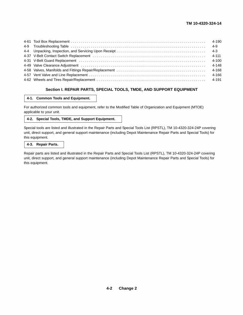
TM 10-4320-324-14
4-2 Change 2
4-61 Tool Box Replacement . . . . . . . . . . . . . . . . . . . . . . . . . . . . . . . . . . . . . . . . . . . . . . . . . . . . . . . . . . . . . . . . . . . . 4-1904-9 Troubleshooting Table . . . . . . . . . . . . . . . . . . . . . . . . . . . . . . . . . . . . . . . . . . . . . . . . . . . . . . . . . . . . . . . . . . . . 4-94-4 Unpacking, Inspection, and Servicing Upon Receipt . . . . . . . . . . . . . . . . . . . . . . . . . . . . . . . . . . . . . . . . . . . . . 4-34-37 V-Belt Contact Switch Replacement . . . . . . . . . . . . . . . . . . . . . . . . . . . . . . . . . . . . . . . . . . . . . . . . . . . . . . . . . 4-1114-31 V-Belt Guard Replacement . . . . . . . . . . . . . . . . . . . . . . . . . . . . . . . . . . . . . . . . . . . . . . . . . . . . . . . . . . . . . . . . 4-1004-49 Valve Clearance Adjustment . . . . . . . . . . . . . . . . . . . . . . . . . . . . . . . . . . . . . . . . . . . . . . . . . . . . . . . . . . . . . . . 4-1484-58 Valves, Manifolds and Fittings Repair/Replacement . . . . . . . . . . . . . . . . . . . . . . . . . . . . . . . . . . . . . . . . . . . . . 4-1684-57 Vent Valve and Line Replacement . . . . . . . . . . . . . . . . . . . . . . . . . . . . . . . . . . . . . . . . . . . . . . . . . . . . . . . . . . . 4-1664-62 Wheels and Tires Repair/Replacement . . . . . . . . . . . . . . . . . . . . . . . . . . . . . . . . . . . . . . . . . . . . . . . . . . . . . . . 4-191
Section I. REPAIR PARTS, SPECIAL TOOLS, TMDE, AND SUPPORT EQUIPMENT
For authorized common tools and equipment, refer to the Modified Table of Organization and Equipment (MTOE)applicable to your unit.
Special tools are listed and illustrated in the Repair Parts and Special Tools List (RPSTL), TM 10-4320-324-24P coveringunit, direct support, and general support maintenance (including Depot Maintenance Repair Parts and Special Tools) forthis equipment.
Repair parts are listed and illustrated in the Repair Parts and Special Tools List (RPSTL), TM 10-4320-324-24P coveringunit, direct support, and general support maintenance (including Depot Maintenance Repair Parts and Special Tools) forthis equipment.
4-3. Repair Parts.
4-2. Special Tools, TMDE, and Support Equipment.
4-1. Common Tools and Equipment.

TM 10-4320-324-14
Section II. SERVICE UPON RECEIPT
4-4. Unpacking, Inspection, and Servicing Upon Receipt.
a. Unpacking.
(1) Break steel bands securing packing crate to frame assembly and remove crate.
(2) Store crate for reuse.
(3) Remove sealing tape from air filter intake, dust ejector, cooling air intake, exhaust spark arrestor, dipstick, fillercap, breather tube, and pump oil sump filler.
(4) Refer to paragraph 4-34 and install blower drive belt.
(5) Refer to paragraph 4-33 and install alternator drive belt.
(6) Check front area of engine for loose nuts, bolts, screws, and electrical connections.
b. Inspection.
(1) Inspect pump manifolds and gate valves for loose bolts, nuts, and attaching hardware.
(2) Inspect all pump flanges for loose bolts, nuts, and attaching hardware.
(3) Inspect pump suction, discharge pressure and vent line fittings and connections for condition and security.
(4) Inspect engine for any loose nuts, bolts, and screws.
(5) Inspect all controls and instruments for damage and loose mounting.
(6) Inspect all fluid lines and hoses for dents, loose connections, and cuts.
(7) Inspect all air cowlings for cracks, security, and deformations.
(8) Inspect engine and pump mounts for security.
(9) Inspect tires for cuts, bulges, cracks, and deterioration. Ensure that lug nuts are tight.
(10) Remove all foreign matter from assembly.
(11) Wipe assembly clean.
c. Servicing.
NOTE
Crankcase is filled to operating level with preservative oil, MIL-P-21260. Engine lubricating preservationoil does not have to be drained from crankcase until first scheduled oil change.
(1) Check engine crankcase oil level. Service as required (refer to Lubrication Order, LO 10-4320-324-12).
(2) Check oil quantity level of pump. Drain off excess until sight gauge indicates proper operating level.
(3) Fill fuel tank with proper fuel grade.
(4) Place fuel filler cap vent valve to OPEN position.4-3

TM 10-4320-324-14
4-4. Unpacking, Inspection, and Servicing Upon Receipt (CONT).
WARNING
To prevent serious burns, take necessary precautions when filling battery with electrolyte. Do not allow electrolyte tocome in contact with skin or eyes. Use rubber gloves and protective clothing.
(5) If batteries were shipped dry, remove and fill with electrolyte to a level 3/8 inch (9.5 mm) above cell plates (refer to para 3-6).
(6) Install batteries, attach cables, covers, and hold-down bar.
(7) Service tires to 40 PSI (2.8 kg/cm2).
(8) Perform before operation preventive maintenance checks and services (PMCS), listed in Section III of this chapter.
Section III. PREVENTIVE MAINTENANCE CHECKS AND SERVICES (PMCS)
4-5. General.
The necessary preventive maintenance checks and services to be performed at the unit level on a monthly, quarterly,and semiannually schedule are listed and described in Table 4-1.
4-6. PMCS Procedures.
The PMCS procedures are arranged in a logical sequence as indicated by the item numbers. These numbers shall beused as a source of item numbers for the TM Number Column on DA Form 2404, Equipment Inspection andMaintenance Worksheet, in recording results of the checks and services.
4-7. Explanation of Columns in PMCS Table.
a. Item Number Column. This column list, in logical order of performance, the checks and services that are to beperformed.
b. Interval Column. This column contains the time frame for which a required check or service is to be performed.
A dot (•) is placed in appropriate subcolumn(s) that contain a symbol identifying the time frame for whichdesignated checks or services are to be performed. The symbol designations for the various time frames are asfollows:
H - HourlyM - MonthlyQ - QuarterlyS - Semiannually
c. Items to be Inspected Column. This column lists the part or group of parts to be checked and serviced. Theseparts are identified in figures 4-1 and 4-2.
d. Procedures Column. This column contains a brief description of the procedure by which the check is to beperformed.
4-4

TM 10-4320-324-14
Change 2 4-5
Figure 4-1. PMCS Locations (Left Side View).
11
10
14
18
209
21
7
1517
12
16
6
8

TM 10-4320-324-14
4-6 Change 2
Figure 4-2. PMCS Locations (Right Side View).
4
26
22
2 19
24
13
235
25
13

TM 10-4320-324-14
Table 4-1. Preventive Maintenance Checks and Service
4-7

TM 10-4320-324-14
Table 4-1. Preventive Maintenance Checks and Service
4-8
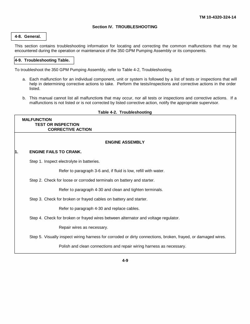
TM 10-4320-324-14
Section IV. TROUBLESHOOTING
4-8. General.
This section contains troubleshooting information for locating and correcting the common malfunctions that may beencountered during the operation or maintenance of the 350 GPM Pumping Assembly or its components.
4-9. Troubleshooting Table.
To troubleshoot the 350 GPM Pumping Assembly, refer to Table 4-2, Troubleshooting.
a. Each malfunction for an individual component, unit or system is followed by a list of tests or inspections that willhelp in determining corrective actions to take. Perform the tests/inspections and corrective actions in the orderlisted.
b. This manual cannot list all malfunctions that may occur, nor all tests or inspections and corrective actions. If amalfunctions is not listed or is not corrected by listed corrective action, notify the appropriate supervisor.
Table 4-2. Troubleshooting
MALFUNCTION
TEST OR INSPECTION
CORRECTIVE ACTION
ENGINE ASSEMBLY
1. ENGINE FAILS TO CRANK.
Step 1. Inspect electrolyte in batteries.
Refer to paragraph 3-6 and, if fluid is low, refill with water.
Step 2. Check for loose or corroded terminals on battery and starter.
Refer to paragraph 4-30 and clean and tighten terminals.
Step 3. Check for broken or frayed cables on battery and starter.
Refer to paragraph 4-30 and replace cables.
Step 4. Check for broken or frayed wires between alternator and voltage regulator.
Repair wires as necessary.
Step 5. Visually inspect wiring harness for corroded or dirty connections, broken, frayed, or damaged wires.
Polish and clean connections and repair wiring harness as necessary.
4-9
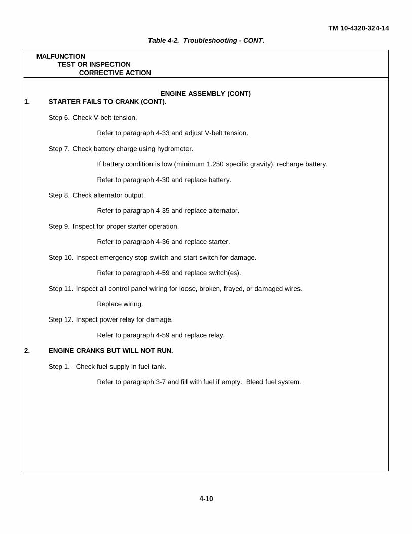
TM 10-4320-324-14
Table 4-2. Troubleshooting - CONT.
MALFUNCTION
TEST OR INSPECTION
CORRECTIVE ACTION
ENGINE ASSEMBLY (CONT)
1. STARTER FAILS TO CRANK (CONT).
Step 6. Check V-belt tension.
Refer to paragraph 4-33 and adjust V-belt tension.
Step 7. Check battery charge using hydrometer.
If battery condition is low (minimum 1.250 specific gravity), recharge battery.
Refer to paragraph 4-30 and replace battery.
Step 8. Check alternator output.
Refer to paragraph 4-35 and replace alternator.
Step 9. Inspect for proper starter operation.
Refer to paragraph 4-36 and replace starter.
Step 10. Inspect emergency stop switch and start switch for damage.
Refer to paragraph 4-59 and replace switch(es).
Step 11. Inspect all control panel wiring for loose, broken, frayed, or damaged wires.
Replace wiring.
Step 12. Inspect power relay for damage.
Refer to paragraph 4-59 and replace relay.
2. ENGINE CRANKS BUT WILL NOT RUN.
Step 1. Check fuel supply in fuel tank.
Refer to paragraph 3-7 and fill with fuel if empty. Bleed fuel system.
4-10
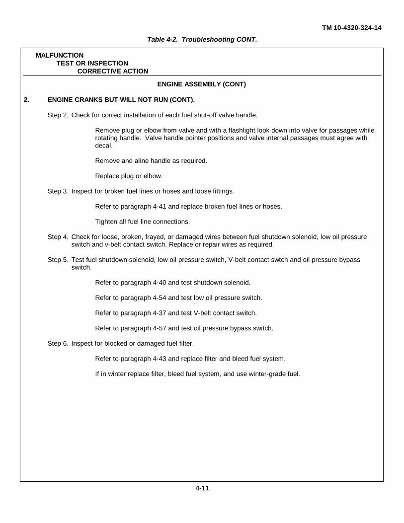
TM 10-4320-324-14
Table 4-2. Troubleshooting CONT.
MALFUNCTION
TEST OR INSPECTION
CORRECTIVE ACTION
ENGINE ASSEMBLY (CONT)
2. ENGINE CRANKS BUT WILL NOT RUN (CONT).
Step 2. Check for correct installation of each fuel shut-off valve handle.
Remove plug or elbow from valve and with a flashlight look down into valve for passages while rotating handle. Valve handle pointer positions and valve internal passages must agree with decal.
Remove and aline handle as required.
Replace plug or elbow.
Step 3. Inspect for broken fuel lines or hoses and loose fittings.
Refer to paragraph 4-41 and replace broken fuel lines or hoses.
Tighten all fuel line connections.
Step 4. Check for loose, broken, frayed, or damaged wires between fuel shutdown solenoid, low oil pressure switch and v-belt contact switch. Replace or repair wires as required.
Step 5. Test fuel shutdown solenoid, low oil pressure switch, V-belt contact switch and oil pressure bypass switch.
Refer to paragraph 4-40 and test shutdown solenoid.
Refer to paragraph 4-54 and test low oil pressure switch.
Refer to paragraph 4-37 and test V-belt contact switch.
Refer to paragraph 4-57 and test oil pressure bypass switch.
Step 6. Inspect for blocked or damaged fuel filter.
Refer to paragraph 4-43 and replace filter and bleed fuel system.
If in winter replace filter, bleed fuel system, and use winter-grade fuel.
4-11

TM 10-4320-324-14
Table 4-2. Troubleshooting CONT.
MALFUNCTION
TEST OR INSPECTION
CORRECTIVE ACTION
ENGINE ASSEMBLY (CONT)
2. ENGINE CRANKS BUT WILL NOT RUN (CONT).
Step 7. Check for blocked strainer in fuel feed pump; verify pump operates properly.
Refer to paragraph 4-44 and wash strainer.
Refer to paragraph 4-44 and replace fuel feed pump.
Refer to paragraph 4-45 and bleed fuel system.
Step 8. Inspect for leaks at fuel tank.
Notify direct support maintenance.
Step 9. Check for air in fuel lines.
Locate point of air entrance; tighten if loose connection and bleed fuel system.
Step 10. If operating during winter, check for fuel clouding.
Refer to paragraph 4-43, replace filter, bleed fuel system, and use winter-grade fuel.
Step 11. Check injection pump for proper operation.
Notify direct support maintenance.
Step 12. Refer to LO 10-4320-324-12 and check oil for proper viscosity.
Refer to paragraph 4-52 and replace oil filter and oil with oil of proper viscosity.
Step 13. Check for operation of GP relay in control panel.
Refer to paragraph 4-59 and replace GP relay.
3. COLD START SYSTEM FAILS TO ASSIST CRANKING OF ENGINE DURING COLD START.
Step 1. Check reservoir for ether supply.
Fill reservoir.
Step 2. Inspect pumping action of pump.
Refer to paragraph 4-46 and replace pump.
4-12

TM 10-4320-324-14
Table 4-2. Troubleshooting CONT.
MALFUNCTION
TEST OR INSPECTION
CORRECTIVE ACTION
ENGINE ASSEMBLY (CONT)
3. COLD START SYSTEM FAILS TO ASSIST CRANKING OF ENGINE DURING COLD START (CONT).
Step 3. Check for clogged injector nozzle.
Clean or replace injector nozzle.
4. CANNOT ADJUST ENGINE SPEED.
Step 1. Check for bent, broken, or damaged control arm.
Refer to paragraph 4-39 and replace throttle control.
Step 2. Check for frozen fuel control lever at injection pump.
Free fuel control lever.
Notify direct support maintenances.
5. ENGINE OVERHEATS.
Step 1. Inspect cooling fins on cylinders and cylinder heads for dirt.
Clean cooling fins.
Step 2. Check for blockage of cooling air input to blower.
Ensure free cooling air flow.
Step 3. Inspect for broken or missing v-belt.
Refer to paragraph 4-34 and replace v-belt.
Step 4. Check condition and operation of cooling fan.
Notify direct support maintenance.
Step 5. Refer to paragraph 3-9 and check engine oil level.
Add oil as required (see LO 10-4320-324-12).
Step 6. Refer to LO 10-4320-324-12 and check oil for proper viscosity.
Refer to paragraph 4-52 and replace oil filter and oil with oil of proper viscosity.
4-13

TM 10-4320-324-14
Table 4-2. Troubleshooting CONT.
MALFUNCTION
TEST OR INSPECTION
CORRECTIVE ACTION
ENGINE ASSEMBLY (CONT)
6. ENGINE RUNS ROUGH, DOES NOT DEVELOP FULL POWER, OR SMOKES EXCESSIVELY.
Step 1. Check for sufficient supply of fuel.
Refer to paragraph 4-44 and clean strainer in fuel feed pump.
Tighten all fuel line connections.
Replace fuel filter, refer to paragraph 4-42 and bleed fuel system.
Step 2. Visually inspect air cleaner restriction indicator for dirty cartridges.
Refer to paragraph 3-5 and replace both cartridges.
Step 3. Check for overfilled oil sump.
Refer to paragraph 3-1 and drain off until level reaches top mark on dipstick.
Step 4. Check for inefficient compression due to sticking or broken compression rings or incorrect valve clearance.
Refer to paragraph 4-49 and readjust valve clearance.
Notify direct support maintenance.
7. ENGINE OR EXHAUST NOISY.
Step 1. Check for loose connections allowing exhaust leak.
Tighten any loose connections.
Step 2. Check for holes in muffler.
Refer to paragraph 4-28 and replace muffler.
Step 3. Check for loose connections allowing exhaust pipe to move.
Tighten any loose connections.
Step 4. Check for holes in exhaust pipe.
Refer to paragraph 4-27 and replace exhaust pipe.
4-14

TM 10-4320-324-14
Table 4-2. Troubleshooting CONT.
MALFUNCTION
TEST OR INSPECTION
CORRECTIVE ACTION
ENGINE ASSEMBLY (CONT)
8. OIL PRESSURE GAUGE READING TOO LOW.
Step 1. Refer to paragraph 3-9 and check engine oil level.
Add oil as required (see LO 10-4320-324-12).
Step 2. Inspect for leaks in lube oil system.
Tighten all connections on pumps, lines, filter, pressure gauge, and cooler.
Notify direct support maintenance to check for excessive play on main bearing.
Step 3. Improper operation of low oil pressure switch.
Refer to paragraph 4-54 and replace switch.
Step 4. Improper operation of oil pressure sending unit.
Refer to paragraph 4-55 and replace oil pressure sending unit.
Step 5. Improper operation of oil pressure gauge.
Refer to paragraph 4-59 and replace gauge.
Step 6. Oil pump malfunction.
Notify direct support maintenance.
9. AMMETER READING TOO LOW.
Step 1. Check v-belt tension, causing alternator to operate at low output.
Refer to paragraph 4-33 and tighten v-belt.
Step 2. Check for loose connections at alternator, causing insufficient charging of the batteries.
Tighten wiring connections at alternator.
Step 3. Check for defective alternator, causing insufficient charging of the batteries.
Refer to paragraph 4-35 and replace alternator.
4-15

TM 10-4320-324-14
Table 4-2. Troubleshooting CONT.
MALFUNCTION
TEST OR INSPECTION
CORRECTIVE ACTION
PUMP ASSEMBLY
1. NO SUCTION OR DISCHARGE PRESSURE.
Step 1. Check for foreign matter in discharge valves.
Remove foreign matter.
Step 2. Inspect valves for leak.
Refer to paragraph 4-58 and replace valve.
Step 3. Inspect all connections and suction lines for leaks.
Tighten all connections.
Step 4. Check for damaged gauges.
Refer to paragraph 4-59 and replace gauges.
Step 5. Inspect for faulty seal or pump gasket.
Notify direct support maintenance.
2. PUMP STOPS OR FAILS TO DELIVER RATED FLOW OR PRESSURE.
Step 1. Inspect for faulty seal or pump gasket.
Notify direct support maintenance.
Step 2. Check for clogged impeller.
Notify direct support maintenance.
Step 3. Inspect for broken impeller or wear plate.
Notify direct support maintenance.
Step 4. Check that pump is not driven too slowly.
Notify direct support maintenance.
3. PUMP NOISY.
Step 1. Check for proper bearing lubrication.
Notify direct support maintenance.
4-16

TM 10-4320-324-14
Table 4-2. Troubleshooting CONT.
MALFUNCTION
TEST OR INSPECTION
CORRECTIVE ACTION
PUMP ASSEMBLY (CONT)
3. PUMP NOISY (CONT).
Step 2. Check for bent impeller shaft.
Notify direct support maintenance.
Step 3. Inspect for worn bearings.
Notify direct support maintenance.
Step 4. Check for binding, broken, or loose rotating parts.
Notify direct support maintenance.
Step 5. Check for cavitation.
Notify direct support maintenance.
4. SUCTION OR DISCHARGE VALVES WILL NOT OPERATE.
Step 1. Check to see if valves will turn on and off.
Free valve.
Refer to paragraph 4-58 and replace valve.
FRAME ASSEMBLY
1. UNIT DOES NOT TRACK STRAIGHT.
Step 1. Inspect for damaged towbar.
Replace towbar.
Step 2. Inspect for bent, broken, or damaged frame.
Notify direct support maintenance.
Step 3. Inspect for bent, broken, or damaged axle.
Notify direct support maintenance.
4-17

TM 10-4320-324-14
Table 4-2. Troubleshooting CONT.
MALFUNCTION
TEST OR INSPECTION
CORRECTIVE ACTION
FRAME ASSEMBLY (CONT)
2. WHEELS NOISY DURING TOWING OPERATIONS.
Step 1. Inspect for loose or missing lug nuts.
Install new lug nuts and tighten all lug nuts.
Step 2. Inspect for dry or damaged bearings.
Grease bearings in accordance with Lubrication Order, LO 10-4320-324-12.
Refer to paragraph 4-63 and replace bearings.
3. FLAT TIRE.
Step 1. Inspect tire for damage or excessive wear.
Repair tire.
Refer to paragraph 4-62 and repair or replace tire.
4-18

TM 10-4320-324-14
Change 2 4-19
a. Removal.
(1) Using drill, remove two rivets (4) and two caution signs (5) from top of lifting frame (1). Discard rivets (4).
(2) Remove four nuts (6), lockwashers (7), and screws (9), and lift information plate (8) from lifting frame (1).Discard lockswashers (7).
(3) Remove throttle information plate (11) from throttle rod bracket (10) by carefully prying. Remove remainingadhesive from mating surfaces.
(4) Remove four nuts (12), lockwashers (13), screws (15), and two front reflectors (14) from trailer frame (3).Discard lockwashers (13).
(5) Remove two tiedown information plates (16) from front of trailer frame (3) by carefully prying. Removeremaining adhesive from mating surfaces.
(6) Using drill, remove ten rivets (18), operation information plate (17), and performance information plate (19)from control box door (2). Discard rivets (18).
4-10. Identification Plates and Reflectors Replacement.
This task covers:a. Removal b. Inspection c. Installation
INITIAL SETUP:Tools Equipment ConditionTool kit, general mechanics: automotive, item 32, Engine shut down (para 2-7).section III, appendix BDrill, electric, item 33, section III, appendix B General Safety Instructions
Wear eye protection when drilling outold rivets or installing new rivets.
Materials/PartsRivet, Blind (12) MS24243/1-G402Lockwasher (8) MS35338-44Adhesive, sealant, item 1.1, appendix ERiv-nut (2) Marson 47150 or Grainger 5JK83Rivet, Blind (10) AD48A
Section V. MAINTENANCE PROCEDURES
~
2
175
4 1
67
8
9 10
11
12 1314
15
16
2
319 18

TM 10-4320-324-14
4-20 Change 2
(7) Remove cold start instruction plate (4) from side of control box (1) by carefully prying. Remove remainingadhesive from mating surfaces.
(8) Using drill, remove eight rivets (6) and two caution signs (5) from left and right sides of lifting frame (2).Discard rivets (6).
(9) Remove two screws (10), lockwashers (9), and rear reflector (8) from riv-nuts (7) on right side of trailerframe (3). Discard lockwashers (9).
(10) Remove two nuts (12), lockwashers (9), screws (11), and rear reflector (8) from left side of trailer frame (3).Discard lockwashers (9).
(11) Remove two tiedown information plates (13) from back of trailer frame (3) by carefully prying. Removeremaining adhesive from mating surfaces.
(12) Remove pump assembly information plate (14) from left side of trailer frame (3) by carefully prying. Removeremaining adhesive from mating surfaces.
(13) Remove four screws (15) and water separator information plate (16) from lifting frame (2).
b. Cleaning/Inspection.
(1) Inspect identification plates, instruction plates, and caution signs for illegible print or other obvious damage.Replace if damaged.
(2) Inspect reflectors for breakage or other obvious damage. Replace if damaged.
c. Installation.
(1) Install water separator information plate (16) on lifting frame (3) with four screws (15).
(2) Install pump assembly information plate (14) on left side of trailer frame (3) with adhesive.
(3) Install two tiedown information plates (13) on back of trailer frame (3) with adhesive.
(4) Install rear reflector (8) on left side of trailer frame (3) with two screws (11), new lockwashers (9), and nuts(12).
(5) Install rear reflector (8) on riv-nuts (7) at right side of trailer frame (3) with two screws (10) and newlockwashers (9).
(6) Install caution sign (5) on left and right side of lifting frame (2) with eight new rivets (6).
(7) Install cold start instruction plate (4) on side of control box (1) with adhesive.
(8) Install performance information plate (27) and operation information plate (28) on control box door (17) withtwelve new rivets (26).
(9) Install two tiedown information plates (13) on front of trailer frame (3) with adhesive.
(10) Install two front reflectors (25) on trailer frame (3) with four screws (11), new lockwashers (20), and nuts (19).
(11) Install throttle information plate (24) on throttle rod bracket (23) with adhesive.
(12) Install lift information plate (21) on lifting frame (2) with four screws (22), new lockwashers (20), and nuts(19).
(13) Install two caution signs (18) on top of lifting frame (2) with two new rivets (6).
4-10. Identification Plates and Reflectors Replacement (CONT).
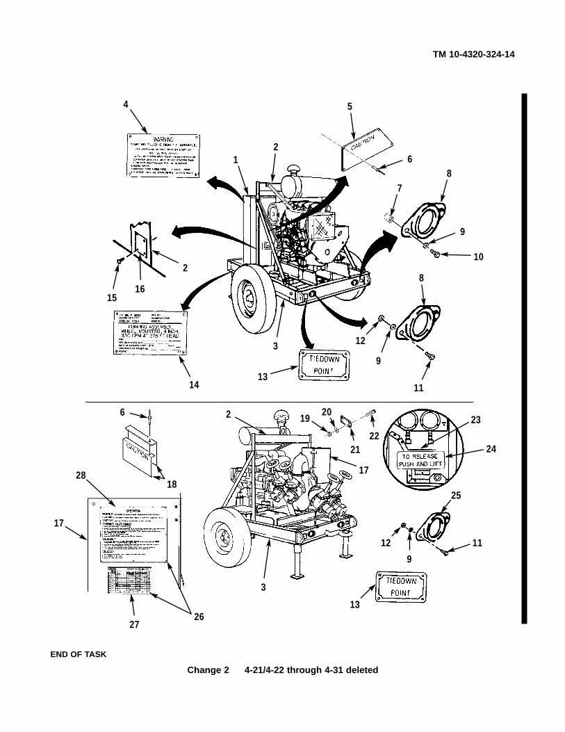
TM 10-4320-324-14
Change 2 4-21/4-22 through 4-31 deleted
4
12
5
6
78
9
10
8
12
9
1113
14
1516
2
17
28
6
18
2 1920
2122
23
24
11
25
9
12
13
3
2627
17
3
END OF TASK

TM 10-4320-324-14
4-32 Change 2
a. Removal.
(1) Remove self-locking nut (7), two washers (5), and screw (6) from brace (2) and lifting frame (1). Discardself-locking nut (7).
(2) Remove self-locking nut (8), two washers (5), and screw (6) from support bracket (4), brace (2), and liftingframe (1). Discard self-locking nut (8).
(3) Remove two self-locking nuts (7), four washers (5), two screws (6), and braces (2) from trailer frame (3).Discard self-locking nuts (7).
(4) Remove screw (10), lockwasher (11), washer (12), and support bracket (4) from engine bell housing (9).Discard lockwasher (11).
Lifting frame is heavy. Ensure two personnel handle lifting frame, orinjury to personnel may result.
NOTEAssistant will steady and help remove lifting frame in step 5 below.
(5) Remove two self-locking nuts (7), four washers (5), two screws (6), and lifting frame (1) from trailer frame(3). Discard self-locking nuts (7).
WARNING
4-13. Lifting Frame Replacement.
This task covers:a. Removal b. Installation c. Follow-on Maintenance
INITIAL SETUP:Tools Personnel RequiredTool kit, general mechanics: automotive Twosection III, item 32, appendix B
Materials/Parts Equipment ConditionSelf-locking nut (5) – M45913/1-10CG5C Muffler removed (para 4-28).Lockwasher (1) – 91169A214 Battery boxes removed (para 4-29)Self-locking nut (1) – 90566A035 Vent valve removed (para 4-57).
General Safety InstructionsLift frame and roof panel assembly are heavy.Get help to lift or carry either component.

TM 10-4320-324-14
Change 2 4-33/4-34 and 4-35 deleted
7
5 2
1
5
6
8
5 4
1
5
62
10
11
124
9
7
5
13
5
6
6
32
75
5
2
3
4
1
2

TM 10-4320-324-14
4-36 Change 2
b. Installation.
NOTEThe two lifting frame braces must be installed facing the inside of the liftingframe and trailer frame.
(1) Install two braces (2) on trailer frame (3) with two screws (6), four washers (5), and two new self-locking nuts (7). Do not tighten at this time.
Lifting frame is heavy. Ensure two personnel handle lifting frame, or injuryto personnel may result.
NOTEAssistant will help lift and position lifting frame in step 2 below.
(2) Position lifting frame (1) on trailer frame (3), and install two screws (6), four washers (5), and two new self-locking nuts (7). Do not tighten at this time.
NOTEA thinner self-locking nut is used to secure the brace and support bracketat left-hand side of lifting bracket.
(3) Install support bracket (4) and brace (2) on left-hand side of lifting frame (1) with screw (6), two washers (5),and new self-locking nut (8). Do not tighten at this time.
(4) Install screw (6), two washers (5), brace (2), and new self-locking nut (7) on right side of lifting bracket (1).
(5) Install screw (10), new lockwasher (11), and washer (12) on support bracket (4) and engine bell housing (9).Tighten screw (10) to 45 lb-ft (61 N•m).
(6) Tighten self-locking nut (8) and five self-locking nuts (7) to 65 lb-ft (88 N•m).
WARNING
4-13. Lifting Frame Replacement (CONT).

TM 10-4320-324-14
Change 2 4-37
7
5 2
1
5
6
8
5 4
1
5
62
10
11
124
9
7
5
13
5
6
6
32
75
5
2
3
4
1
2

TM 10-4320-324-14
4-38/4-39 through 4-50 deleted Change 2
f. Follow-on Maintenance.
(1) Install vent valve (para 4-57).
(2) Install battery boxes (par 4-29).
(3) Install muffler (para 4-28).
END OF TASK
4-13. Lifting Frame Replacement (CONT).

TM 10-4320-324-14
Change 2 4-51
a. Removal.
(1) Remove seven nuts (6), lockwashers (5), fourteen washers (3), and seven screws (2) from control box panel(8) and post (4). Discard lockwashers (5).
(2) Remove two screws (2), lockwashers (5), and washers (3) from riv-nuts (7), and remove control box top (1)from panel (8) and post (4). Discard lockwashers (5).
(3) If damages, drill out two riv-nuts from control box panel (8) and post (4). Discard riv-nuts (7).
4-16. Control Box Panels Repair/Replacement.
This task covers:a. Removal c. Installationb. Cleaning/Inspection d. Follow-on Maintenance
INITIAL SETUP:Tools Equipment ConditionTool kit, general mechanics: automotive Control panel wiring harness disconnectedsection III, item 32, appendix B (para 4-59).Drill, electric, item 33, section III, appendix B Control panel removed (para 4-59).
Throttle control rod removed (para 4-39).Materials/Parts Starting aid pump and bracket removed (para 4-46).
Self-locking nut (14) - MS17829-4CRiv-nut (2) - MS27130-S45Lockwasher (5) - MS35338-44Seal - 13229E8478Lockwasher (41) - MS35338-45Lockwasher (1) - MS35338-46
12
3
4
3
5
6
7
8
7

TM 10-4320-324-14
4-52 Change 2
(4) Remove three nuts (15), three lockwashers (14), six washers (16), three screws (18), bracket (19), seal (17),and bracket (11) from post (8). Discard lockwashers (14).
(5) Remove screw (13) and latch (12).
(6) Remove two nuts (27), two lockwashers (26), four washers (4), and two screws (3) from panel (6). Discardlockwashers (26).
(7) Remove two self-locking nuts (2), four washers (5) and (24), two spacers (23), two screws (21), two rubberwashers (22), and bracket (20) from panel (6). Discard self-locking nuts (2).
(8) Remove four self-locking nuts (25), eight flat washers (9), four screws (10), and bracket (1) from panel (6).Discard self-locking nuts (25).
(9) If damaged, remove two cage nuts (7) from bracket (1).
4-16. Control Box Panels Repair/Replacement (CONT).
12
3 4 56 7
8
910
11 12
13
14
15
16
17
18
19
16
20272621
224
2324
925

TM 10-4320-324-14
Change 2 4-53
(10) Remove eight self-locking nuts (41), washers (40), screws (39), two hinges (38), and door (37) from panel (6)and panel (42). Discard self-locking nuts (41).
(11) If necessary, remove two retainers (35) and latches (36) from door (37), and remove two receptacles (30) frompost (8).
(12) Remove four nuts (31), lockwashers (32), eight washers (33), four screws (34), and panel (42) from panel (6).Discard lockwashers (32).
(13) Remove eleven nuts (31), lockwashers (32) twenty-two washers (33), and screws (34), from panel (6) and post (8). Discard lockwashers (32).
(14) Remove two plugs (29) and grommets (28) from panel (6).
4-16. Control Box Panels Repair/Replacement (CONT).
6
2829
8
30
31
32
33
34
36
3537
38
39
4041
42

TM 10-4320-324-14
Change 2 4-54
(15) Remove nut (12), lockwasher (13), two washers (14), and screw (20) from brace (11), post (21) and panel (1).Discard lockwasher (13).
(16) Remove nut (10), lockwasher (9), washer (8), and brace (11) from pump housing stud (7). Discard lockwasher (9).
(17) Remove two nuts (12), lockwashers (13), four washers (14), and two screws (20) from post (21). Discardlockwashers (13).
(18) Remove two nuts (18), lockwashers (17), twelve washers (16), two screws (15), and post (21) from trailerframe (19). Discard lockwashers (17).
(19) Remove two nuts (5), two lockwashers (6), four flat washers (3), two screws (2), and bracket (4) from panel (1). Discard lockwashers (6).
b. Cleaning/Inspection
(1) Inspect two control box door latches for proper operation. Replace if defective.
(2) Inspect brackets for obvious damage. Replace if damaged.
(3) Inspect throttle rod seal for tears, or other obvious damage. Replace if damaged.
(4) Inspect all sheet metal for holes, deformation, or other obvious damage. Replace if defective.
c. Installation.
(1) Install bracket (4) on panel (1) with two screws (2), four washers (3), two new lockwashers (6) and nuts (5).
(2) Position post (21) on trailer frame (19), and install two screws (15), twelve washers (16), two new lockwashers(17), and nuts (18) on post (21) and trailer frame (19).
(3) Install two screws (20), four washers (14), two new lockwashers (13), and nuts (12) on post (21).
(4) Install brace (11) on pump housing stud (7) with washer (8), new lockwasher (9), and nut (10).
(5) Position and align panel (1) with post (21), and install screw (20), two washers (14), new lockwasher (13), andnut (12) on panel (1), post (21), and brace (11).
4-16. Control Box Panels Repair/Replacement (CONT).

TM 10-4320-324-14
Change 2 4-55
1
2
3
45
6
3
8
9
10
11
1213
14
15
16
16
17
18
1914
20
2114
1312
14
20
7

TM 10-4320-324-14
4-56 Change 2
(6) Install two grommets (2) and plugs (3) on panel (1).
(7) Install panel (17) on panel (1) with four screws (9), eight washers (8), four new lockwashers (7), and nuts (6).
(8) Install eleven screws (9), twenty-two washers (8), eleven new lockwashers (7), and nuts (6) on post (4) and panel (1).
(9) Install door (12) on panels (1) and (17) with two hinges (13), eight screws (14), washers (15), and new self-locking nuts (16).
(10) If removed, install two latches (11) on door (12) with two retainers (10), and install two receptacles (5) on post (4).
4-16. Control Box Panels Repair/Replacement (CONT).
1
2 3 4
5
6
7
8
10
11
12
13
14
1516
17
9

TM 10-4320-324-14
Change 2 4-56.1
(11) If removed, install two cage nuts (21) on bracket (38).
(12) Install bracket (38) on panel (1) and post (4) with four screws (23), eight washers (22), and four new self-locking nuts (37).
(13) Install bracket (42) and two rubber washers (34) on panel (1) with two screws (33), four washers (36) and (20), twospacers (35), and new self-locking nuts (39).
(14) Install two screws (18), four washers (19), two new lockwashers (40), and nuts (41) on bracket (42).
(15) Install latch (25) on bracket (24) with screw (26).
(16) Install bracket (24), new seal (30), and bracket (32) on post (4) with three screws (31), six washers (29), newlockwashers (27) and nuts (28).
4-16. Control Box Panels Repair/Replacement (CONT).
121
4
2322 24
25 26
27
2829
30
2931
32
423334
40 41
19
3536
22 37
39
38
2019
18

(18) If removed, install two new riv-nuts (7) on control box post (4) and panel (8).
(19) Position control box top (1) on post (4) and panel (8), and install two screws (2), new lockwashers (5), andwashers (3) on riv-nuts (7) and top (1).
(20) Install seven screws (2), fourteen washers (3), seven new lockwashers (5), and nuts (6) on top (1), panel(8), and post (4).
12
3
4
3
5
6
7
8
7
4-16. Control Box Panels Repair/Replacement (CONT).
TM 10-4320-324-14
4-56.2/4-57 through 4-60 deleted Change 2
d. Follow-on Maintenance.
(1) Deleted.
(2) Install starting aid bracket and pump (para 4-46).
(3) Install throttle control rod (para 4-39).
(4) Install control panel (para 4-59).
(5) Connect control panel wiring harness (para 4-59).
END OF TASK

TM 10-4320-324-14
Change 2 4-61/4-62 through 4-65 deleted
a. Removal.
(1) Remove two ground rods (8) from brackets (1), (9), and (6).
(2) Remove six nuts (5), lockwashers (4), thirty flat washers (3), six screws (7), and ground rod brackets (1), (9),and (6) from trailer frame (2). Discard lockwashers (4).
(3) Remove two nuts (12), lockwashers (11) and terminal studs (10) from trailer frame (2). Discard lockwashers (11).
4-18. Ground Rod Brackets Replacement.
This task covers:a. Removal b. Installation
INITIAL SETUP:ToolsTool kit, general mechanics: automotive,item 32, section III, appendix B.
Materials/PartsSelf-locking nut (4) - MS17829-4CLockwasher (6) - MS35338-44Lockwasher (6) - MS35333-75
10
2
11
12
1
2
3
4
5
3637
8
9

TM 10-4320-324-14
4-66/4-67 through 4-85 deleted Change 2
b. Installation.
(1) Install two terminal studs (10) on trailer frame (2) with two new lockwashers (11) and nuts (12).
(2) Install ground rod brackets (6), (9), and (1) with six screws (7), thirty washers (3), six new lockwashers (4),and nuts (5).
(3) Install two ground rods (8) on brackets (6), (9), and (1).
4-18. Ground Rod Brackets Replacement (CONT).
10
2
11
12
1
2
3
4
5
3637
8
9
END OF TASK


TM 10-4320-324-14
4-86 Change 2
a. Removal.
(1) Loosen six hose clamps (2), and remove three 90° elbows (1) and air intake tubes (20) and (21) frommanifold extension tube (3) and air cleaner (24).
(2) Remove four screws (18), lockwashers (17), washers (16), and mounting plate (12) from engine flywheelhousing (15). Discard lockwashers (17).
(3) Remove four nuts (14), lockwashers (13), eight washers (11), four screws (10), and two clamps (8) frommounting plate (12). Discard lockwashers (13).
(4) Loosen two screws (9), and remove two clamps (8) from air cleaner (24).
(5) Remove air restriction indicator (22) from air cleaner (24).
(6) Remove wing nut (5), cover (7), filter element (6), wing nut (5), and filter element (4) from air cleaner (24).
(7) Remove vacuator valve (19) and air inlet hood (23) from air cleaner (24).
4-25. Air Cleaner Assembly Replacement.
This task covers:a. Removal b. Cleaning/Inspection c. Installation
INITIAL SETUP:Tools Materials/PartsTool kit, general mechanics: automotive, item 32, Lockwasher (4) MS35338-45section III, appendix B Lockwasher (4) MS35338-46

TM 10-4320-324-14
Change 2 4-87
b. Cleaning/Inspection.
(1) Inspect housing for cracks, dents or other damage.
(2) Inspect clamps and brackets for thread bareness, cracks, or other damage.
(3) Inspect inlet hood and valve vacuator for holes or other damage.
(4) Inspect service indicator and extension. If worn, repair by replacement.
(5) Replace all parts failing inspection.
c. Installation.
(1) Install air linlet hood (23) and vacuator valve (19) on air cleaner (24).
(2) Install filter element (4), wing nut (5), filter element (6), cover (7), and wing nut (5) on air cleaner (24).
(3) Install air restriction indicator (22) on air cleaner (24).
(4) Install two clamps (8) on air cleaner (24). Do not tighten clamps (8) at this time.
1 2 3
4
5
6 7
5
10
118
23 24
12
11
13
14
15
16
17
18
1
220
2
1
2 21 22
19
9
9
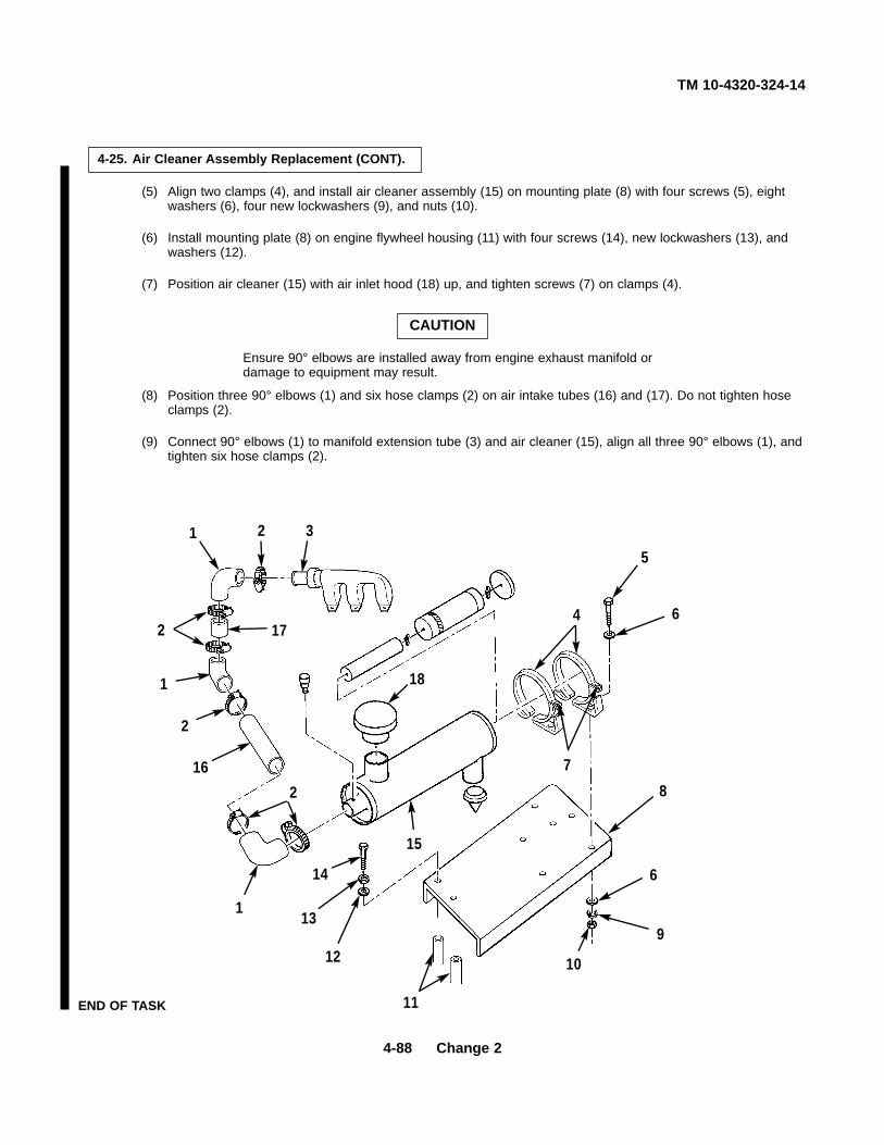
TM 10-4320-324-14
4-88 Change 2
(5) Align two clamps (4), and install air cleaner assembly (15) on mounting plate (8) with four screws (5), eightwashers (6), four new lockwashers (9), and nuts (10).
(6) Install mounting plate (8) on engine flywheel housing (11) with four screws (14), new lockwashers (13), andwashers (12).
(7) Position air cleaner (15) with air inlet hood (18) up, and tighten screws (7) on clamps (4).
Ensure 90° elbows are installed away from engine exhaust manifold ordamage to equipment may result.
(8) Position three 90° elbows (1) and six hose clamps (2) on air intake tubes (16) and (17). Do not tighten hoseclamps (2).
(9) Connect 90° elbows (1) to manifold extension tube (3) and air cleaner (15), align all three 90° elbows (1), andtighten six hose clamps (2).
CAUTION
4-25. Air Cleaner Assembly Replacement (CONT).
1 2 3
5
64
7
8
6
9
10
11
12
13
14
1
216
2
1
2 17
15
18
END OF TASK

TM 10-4320-324-14
Change 2 4-89
a. Removal.
(1) Remove two nuts (1), clamp base (2), and u-bolt (3).
(2) Remove spark arrestor assembly (4).
b. Disassembly.
Remove nut (5), flat washer (6), cap (7), plate (8), and baffles (9) from base (10).
4-26. Spark Arrestor Repair/Replacement.
This task covers:a. Removal c. Cleaning/Inspection e. Installationb. Disassembly d. Assembly f. Follow-on Maintenance
INITIAL SETUP:Tools Equipment ConditionTool kit, general mechanics: automotive, item 32, Engine shut down (para 2-7).section III, appendix BBrush, wire, item 33, section III, appendix B General Safety Instructions
Spark arrestor may be exteremely hot after operation.Materials/Parts Let engine cool before performaing the following Solvent, dry cleaning, item 15, appendix E procedure.
Wear personal protective equipment when usingcleaning solvent.
4——
56
78
910
31
2

TM 10-4320-324-14
4-90 Change 2
c. Cleaning/Inspection.
Dry cleaning solvent P-D-680 is toxic and flammable. Wear protectivegoggles and gloves and use only in a well ventilated area. Avoid contactwith skin, eyes, and clothes and don't breathe vapor. Do not use nearopen flame or excessive heat. The flash point is 100°F-138°F (38°-50°C).If you become dizzy while using cleaning solvent, get fresh air immediatelyand get medical aid. If contact with eyes is made, wash your eyes withwater and get medical aid immediately.
(1) Clean all parts with dry cleaning solvent P-D-680 and wire brush.
(2) Inspect all parts for cracks and holes.
(3) Replace damaged parts.
d. Assembly.
(1) Install and aline baffles (9) and plate (8) on base (10).
(2) Install cap (7), flat washer (6), and nut (5).
e. Installation. Install spark arrestor assembly (4) with u-bolt (3), clamp base (2), and two nuts (1).
f. Follow-on Maintenance. Install exhaust screen (para 4-11).
WARNING
4-26. Spark Arrestor Repair/Replacement (CONT).
4——
56
78
910
31
2
END OF TASK

TM 10-4320-324-14
Change 2 4-91
a. Removal. Remove three locking nuts (1),exhaust pipe (2), three bolts (3), and gasket (4).Discard locking nuts (1) and gasket (4).
b. Installation.
(1) Install new gasket (4), three bolts (3),exhaust pipe (2), and three new locking nuts (1).
(2) Tighten three locking nuts (1) to preload of15 lb-ft (20 N•m).
(3) Tighten three locking nuts (1) to first stagetorque of 26 lb-ft (35 N•m).
(4) Tighten three locking nuts (1) to a finaltorque of 37 Ib-ft (50 N•m).
c. Follow-on Maintenance. Install muffler
END OF TASK
4-27. Exhaust Pipe Replacement.
This task covers:a. Removal b. Installation c. Follow-on Maintenance
INITIAL SETUP:Tools Equipment ConditionTool kit, general mechanics: automotive, item 32, Muffler removed (para 4-28).section III, appendix BWrench, torque, item 33, section III, appendix B General Safety Instruction
Exhaust pipe retains extreme heat. Letengine cool before performing removal.
Materials/PartsGranular gasket - 334 8038Nut, locking (3) - 113 7394
1
2
4
3

TM 10-4320-324-14
4-92 Change 2
a. Removal.
(1) Losen clamp (1), two clamps (3), and remove muffler (2) from exhaust pipe and support (11).
(2) Loosen clamp (5), and remove spark arrestor (4) from muffler (2).
(3) Remove two nuts (12), lockwashers (13), four washers (14), two screws (21), and support (11) from brace(20). Discard lockwashers (13).
(4) Remove two nuts (10), lockwashers (9), four washers (7), and two screws (6) from brace (20) and blowerextension (8). Discard lockwashers (16).
(5) Remove two nuts (15), lockwashers (16), four washers (17), two screws (19), and brace (20) from lifting frame(18). Discard lockwashers (16).
4-28. Muffler Replacement.
This task covers:a. Removal b. Installation
b. Cleaning/Inspection
INITIAL SETUP:Tools Equipment ConditionTool kit, general mechanics: automotive, item 32, Engine shut down (para 2-7).section III, appendix B
Materials/Parts General Safety InstructionsLockwasher (2) - MS35338-44 Muffler retains extreme heat in operation.Lockwasher (2) - MS35338-46 Wait for engine to cool before performing procedure.

TM 10-4320-324-14
Change 2 4-93
b. Cleaning/Inspection.
(1) Inspect muffler for holes or cracks.
(2) Inspect muffler support for thread bareness or otherdamage.
(3) Replace all parts failing inspection.
c. Installation.
(1) Install brace (20) on lifting frame (18) with twoscrews (19), four washers (17), two newlockwashers (16), and nuts (15).
(2) Install two screws (6), four washers (7), two newlockwashers (9), and nuts (10) on brace (20) andblower extension (8).
(3) Install support (11) on brace (20) with two screws(21), four washers (14), two new lockwashers (13),and nuts (12).
(4) Install spark arrestor (4) and clamp (5) on muffler(2), and tighten clamp (5).
(5) Install muffler (2) and clamp (1) on exhaust pipeand support (11) with two clamps (3). Tightenclamp (1) and two clamps (3).
END OF TASK
1
2 34
5
6
20 14
7
8
7
9
10
111213
14
1516
17
18
1719
21

TM 10-4320-324-14
4-94
a. Removal.
WARNING• Remove rings, bracelets, wristwatches, neck chains, and any other
jewelry before working around vehicle. Jewelry can catch on equipmentand cause injury, or may short across an electrical circuit and causesevere burns or electrical shock.
• Be careful not to short out battery terminals. Do not smoke or use openflame near batteries. Batteries may explode from a spark. Battery acid isharmful to skin and eyes.
(1) Remove two wing nuts (1), two flat washers (2), strap (3), and two covers (4).
(2) If damaged, remove two cotter pins (5), two straight pins (6), and two bolts (7).
CAUTIONRemove negative (-) battery cable first to prevent possible electrical arc.Failure to comply may result in damage to batteries and/or cables.
(3) Loosen four battery terminals (8) and remove two cables.
(4) Remove two batteries (9).
(5) Remove eight nuts (10), eight lockwashers (11), eight flat washers (12), and eight screws (13).
(6) Remove two boxes (14).
4-30. Batteries and Cables Replacement.
This task covers:a. Removal b. Installation
INITIAL SETUP:Tools General Safety InstructionsTool kit, general mechanics: automotive, item 32, Wear safety goggles and rubber gloves whilesection III, appendix B performing maintenance.
Materials/Parts Do not wear any jewelry while performingwhen using cleaning solvent. maintenance. Jewelry can catch on equipmentGrease, automotive and artillery, item 5, causing injury or can short out causing burns orappendix E starting a fire.Lockwasher - MS35338-44Pins, cotter (2) - MS24665-151
Do not short out battery terminals whileperforming maintenance. Sparks can start afire.

TM 10-4320-324-14
Change 2 4-95
b. Installation.
(1) Install two boxes (14) with eight screws (13),eight flat washers (12), eight lockwashers (11),and eight nuts (10).
(2) Install two batteries (9).
Connect negative (-) battery cable last to preventpossible electrical arc. Failure to comply mayresult in damage to batteries and/or cables.
(3) Install two cables with four battery terminals (8).Tighten terminals and coat with grease.
(4) Install two bolts (7), two straight pins (6), and twocotter pins (5).
(5) Install covers (4) and strap (3) on boxes (14).
(6) Install two flat washers (2) and two wing nuts (1).
END TASK
CAUTION 3
4
8
9
5
1
2
76
1312
11
10
14

TM 10-4320-324-14
4-96 Change 2
a. Removal.
• Remove rings, bracelets, wristwatches, neck chains, and any otherjewelry before working around vehicle. Jewelry can catch on equipmentand cause injury, or may short across an electrical circuit and causesevere burns or electrical shock.
• Be careful not to short out battery terminals. Do not smoke or use openflame near batteries. Batteries may explode from a spark. Battery acid isharmful to skin and eyes.
Remove negative (-) battery cable first to prevent possible electrical arc.Failure to comply may result in damage to batteries and/or cables.
NOTETag all wires before removing.
CAUTION
WARNING
4-30. Batteries and Cables Replacement.
This task covers:a. Removal c. Testing e. Follow-on Maintenance
b. Cleaning/Inspection d. Installation
INITIAL SETUP:Tools General Safety InstructionsTool kit, general mechanics: automotive, item 32, Wear safety goggles and rubber gloves whilesection III, appendix B performing maintenance.
Materials/Parts Wear personal protective equipmentCloth, lint free, item 3, appendix E when using cleaning solvent.Grease, automotive and artillery, item 5,appendix E Do not wear any jewelry while performingCleaning solvent compound, item 2.1, appendix E maintenance. Jewelry can catch on equipmentStarwasher - MS35333-110 causing injury or can short out causing burns orLockwasher - 1102800 starting a fire.Lockwasher (3) - MS35333-110
Do not short out battery terminals whileEquipment Condition performing maintenance. Sparks can start a
fire.Battery covers removed (para 4-29).

TM 10-4320-324-14
(1) Remove four nuts (1), two lead wires (2),four bolts (3), and two cables (4).
(2) Loosen four nuts (5) and remove fourbattery terminals (6).
(3) Remove two batteries (7).
(4) Remove nut (8), lockwasher (9), positivecable (10), and two positive wires (11). Tagall wires.
(5) Remove nut (12), lockwasher (13), andnegative wire (14). Tag wire.
(6) Remove bolt (15), lockwasher (16),starwasher (17), negative wire (18), andnegative cable (19). Tag cable.
4-97

TM 10-4320-324-14
4-98 Change 2
b. Cleaning/Inspection.
Skysol 100 solvent is combustible. Use mechanical ventilation wheneverproduct is used in a confined space, is heated above ambienttemperatures, or is agitated. DO NOT use or store near heat, sparks,flame, or other ignition sources. Keep container sealed when not in use.
Contact with Skysol 100 cleaning solvent may cause skin irritation. Usechemical resistant gloves. In case of skin contact, remove anycontaminated clothing and wash skin thoroughly with soap and water.Wash contaminated clothing before reuse. Eye contact may causeirritation, tearing or blurring of vision. Use face shield or goggles when eyecontact may occur. In case of eye contact, flush eyes with large amountsof water for at least fifteen (15) minutes or until irritation subsides.Inhalation may cause irritation to upper respiratory passages. DO NOThave food or drink in the vicinity.
(1) Clean all wires, cables, battery posts, and terminals to remove corrosion buildup.
(2) Inspect cables and jumpers for any broken or frayed wires.
(3) Inspect terminals for any damaged nuts or bolts.
(4) Replace any defective components.
c. Testing.
(1) Check lead wires and cables for continuity. If continuity is not indicated, replace.
(2) Check electrolyte level in batteries.
d. Installation.
(1) Install negative cable (19), negative wire (18),starwasher (17), lockwasher (16), and bolt (15).
(2) Install negative wire (14), lockwasher (13), andnut (12).
(3) Install two positive wires (11), positive cable(10), lockwasher (9), and nut (8).
WARNING
4-30. Batteries and Cables Replacement (CONT).

TM 10-4320-324-14
CAUTION
System is 12-volt. Batteries must be connectedin parallel to prevent supplying 24-volts tosystem. Failure to do so will result in damage tounit.
(4) Install two batteries (7).
(5) Install four terminals (6) and tighten fournuts (5). Coat terminals and battery postswith grease.
CAUTION
Connect negative (-) battery cable last toprevent possible electrical arc. Failure tocomply may result in damage to batteriesand/or cables.
(6) Install two cables (4), four bolts (3), two leadwires (2) and four nuts (1).
e. Follow-on Maintenance. Install battery covers(para 4-29).
END OF TASK
4-99

TM 10-4320-324-14
4-100 Change 2
a. Removal.
(1) Remove eight nuts (22), lockwashers (20), washers (21), screws (18), and fan shroud cover (19) from blowerextension (17). Discard lockwashers (20).
(2) Remove bolt (1), four flat washers (2 and 3), and spacer (4).
(3) Remove screw (5), two flat washers (6 and 7), and spacer (8).
(4) Remove bolt (9), lockwasher (10), and flat washer (11). Discard lockwashers (10).
(5) Remove two screws (12), four flat washers (13 and 14), two lockwashers (15), and two nuts (16). Discardlockwashers (15).
(6) Remove belt guard (17).
4-31. V-Belt Guard Replacement.
This task covers:a. Removal b. Installation
INITIAL SETUP:Tools Materials/PartsTool kit, general mechanics: automotive, item 32, Lockwashers (2) - MS35338-44.section III, appendix B Lockwashers (8) - MS35338-45

TM 10-4320-324-14
Change 2 4-101
b. Installation.
(1) Install belt guard (17) with two nuts (16), two new lockwashers (15), four flat washers (14 and 13), and two screws (12).
(2) Install flat washer (11), new lockwasher (10), and bolt (9).
(3) Install spacer (8), two flat washers (7 and 6), and screw (5).
(4) Install spacer (4), two flat washers (3 and 2), and bolt (1).
(5) Install fan shroud cover (19) on blower extension (17) with eight screws (18), washers (21), new lockwashers(20) and nuts (22).
END OF TASK
22
20
21
17
4
3
2
1
91011
56
16
1514
17
78
1312
19
18

TM 10-4320-324-14
4-102 Change 2
a. Removal.
(1) Remove eight nuts (15), lockwashers (14), washers (13), screws (12), and fan shroud cover (11) from blowerextension (10). Discard lockwashers (14).
(2) Remove nut (1), lockwasher (2), two flat washers (3 and 5), and screw (4).
(3) Remove six self locking nuts (6), 12 flat washers (7 and 9), and six screws (8).
(4) Remove blower extension (10).
4-32. Blower Extension Replacement.
This task covers:a. Removal b. Inspection c. Installation
INITIAL SETUP:Tools Materials/PartsTool kit, general mechanics: automotive, item 32, Lockwashers (8) - MS35338-45section III, appendix B Lockwashers (6) - MS35338-44
Lockwasher - 110-2802Nuts, self-locking (6) - MS17829-8L
6
7
10
98
11
12
1314
15
3
1
2 4 5

TM 10-4320-324-14
Change 2 4-103
(5) Remove three nuts (11), three flat washers (12),three bolts (13), and air feeder (14).
(6) Remove three bolts (15), three flat washers (16),and three clamps (17).
(7) Remove sealing brush (18) and sealing section(19).
b. Installation.
(1) Install sealing section (19), sealing brush (18),three clamps (17), three flat washers (16), andthree bolts (15).
(2) Install air feeder (14) with three bolts (13), threeflat washers (12), and three nuts (11).
(3) Install blower extension (10) with six flat washers(9), six screws (8), six flat washers (7), and sixself locking nuts (6).
(4) Install two flat washers (5), two screws (4), twoflat washers (3), two lockwashers (2), and twonuts (1).
(5) Install fan shroud cover (11) on blower extension(10) with eight screws (12), washers (13), newlockwashers (14), and nuts (15).
END OF TASK
11
12
1819
14
13
15
16
17

TM 10-4320-324-14
4-33. Alternator Belt Replacement.
This task covers:
a. Removal b. Installation c. Follow-on Maintenance
INITIAL SETUP:
Tools Equipment ConditionTool kit, general mechanics: automotive, item 32, Belt guard removed (para 4-31).section III, appendix BWrench, torque, item 33, section III, appendix B
a. Removal.
(1) Loosen two screws (1 and 2).
(2) Push alternator (3) towards engine andremove belt (4) from alternator andcrankshaft pulley (5).
b. Installation.
(1) Install belt (4) on alternator (3) andcrankshaft pulley (5).
(2) Measure and adjust belt deflection to 1/4 in.(6 mm).
(3) Torque two bolts (1 and 2) according toappendix F.
c. Follow-on Maintenance. Install belt guard (para4-31).
END OF TASK
4-104

TM 10-4320-324-14
4-34. Cooling Blower Belt Replacement.
This task covers:
a. Removal b. Installation d. Follow-on Maintenance
INITIAL SETUP:
Tools Equipment ConditionTool kit, general mechanics: automotive, item 32, Blower extension removed (para 4-32).section III, appendix B Alternator belt removed (para 4-33).
a. Removal. Apply pressure with hand to idlerpulley (1) and remove belt (2) from idler pulley,cooling blower (3), and crankshaft pulley (4).
b. Installation. Apply pressure with hand to idlerpulley (1) and install belt (2) on idler pulley,cooling blower (3), and crankshaft pulley (4).
c. Follow-on Maintenance.
(1) Install alternator belt (para 4-33).
(2) Install blower extension (para 4-32).
END OF TASK
4-105

TM 10-4320-324-14
4-35. Alternator Replacement
This task covers:
a. Testing c. Installation
b. Removal d. Follow-on Maintenance
INITIAL SETUP:
Tools Equipment ConditionTool kit, general mechanics: automotive, item 32, Unit shut down (para 2-7).section III, appendix B Alternator belt removed (para 4-33).Multimeter, section III, item 33, appendix B Negative battery cable disconnected (para 4-
30).
Materials/PartsTags, identification: item 17, appendix ELockwasher - MS35338-45Lockwasher - 20-111
a. Testing.
(1) Connect multimeter as shown.(2) Start unit (para 2-7).(3) Operate unit at 2400 RPM.(4) Check voltage at terminal A. Voltage should read between 13.8 to 14.8 volts.(5) If voltage reading not within range, remove and replace alternator.
4-106

TM 10-4320-324-14
Change 2 4-107
b. Removal.
NOTETag wires before removing from alternator.
(1) Tag and remove quick connect wire (1).
(2) Tag and remove nut (2) and wire (3).
(3) Tag and remove nut (4), lockwasher (5), andwire (6).
(4) Remove screw (7), lockwasher (8), and flatwasher (9).
(5) Remove screw (10), lockwasher (11), flatwasher (12), and alternator (13).

TM 10-4320-324-14
4-108 Change 2
c. Installation.
NOTEWhen installing screws (10 and 7), do nottighten completely.
(1) Install alternator (13) with flat washer (12),lockwasher (11), and screw (10).
(2) Install flat washer (9), lockwasher (8), and screw (7).
4-35. Alternator Replacement (CONT).
END OF TASK
(3) Install wire (6), lockwasher (5), and nut (4).
(4) Install wire (3), nut (2), and quick connect wire (1).
d. Follow-on Maintenance.
(1) Install alternator belt (para 4-33).
(2) Connect negative battery cable (para 4-30).

TM 10-4320-324-14
Change 2 4-109
a. Removal.
NOTETag all wires before removing.
(1) Tag and remove nut (1), lockwasher (2), andnegative wire (3).
(2) Tag and remove nut (4), lockwasher (5),positive cable (6), and two positive wires (7).
(3) Tag and remove three bolts (8), threelockwashers (9), starwasher (10), negative wire(11), and negative cable (12).
(4) Remove starter (13).
b. Installation.
(1) Install starter (13). Ensure that drive gearmates with teeth on flywheel.
NOTERefer to tags to correctly install wires.
(2) Install negative cable (12), negative wire (11),starwasher (10), three lockwashers (9), andthree bolts (8).
(3) Install two positive wires (7), positive cable (6),lockwasher (5), and nut (4).
(4) Install negative wire (3), lockwasher (2), andnut (1).
4-36. Starter Replacement.
This task covers:a. Removal b. Installation d. Follow-on Maintenance
INITIAL SETUP:Tools Equipment ConditionTool kit, general mechanics: automotive, item 32, Battery covers removed (para 4-29).section III, appendix B Negative battery cable disconnected (para 4-30).
Materials/PartsLockwasher (2) - 1102800Lockwasher (3) - MS35333-110Starwasher - 2985062

TM 10-4320-324-14
c. Follow-on Maintenance.
(1) Connect negative battery cable (para 4-30).
(2) Install battery covers (para 4-29).
END OF TASK
4-110

TM 10-4320-324-14
4-37. V-Belt Contact Switch Replacement.
This task covers:
a. Removal c. Installation
b. Testing d. Follow-on Maint enance
INITIAL SETUP:
Tools Equipment ConditionTool kit, general mechanics: automotive, item 32, V-belt guard removed (para 4-31).section III, appendix B
Materials/PartsTags, identification, item 17, appendix E
a. Removal.NOTE
Tag all wires prior to removal.
(1) Remove two wires (1) from switch (3). Tag wires.
(2) Remove nut (2) and switch (3).
4-111
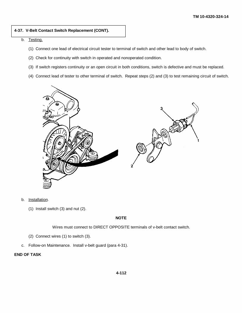
TM 10-4320-324-14
4-37. V-Belt Contact Switch Replacement (CONT).
b. Testing.
(1) Connect one lead of electrical circuit tester to terminal of switch and other lead to body of switch.
(2) Check for continuity with switch in operated and nonoperated condition.
(3) If switch registers continuity or an open circuit in both conditions, switch is defective and must be replaced.
(4) Connect lead of tester to other terminal of switch. Repeat steps (2) and (3) to test remaining circuit of switch.
b. Installation.
(1) Install switch (3) and nut (2).
NOTE
Wires must connect to DIRECT OPPOSITE terminals of v-belt contact switch.
(2) Connect wires (1) to switch (3).
c. Follow-on Maintenance. Install v-belt guard (para 4-31).
END OF TASK
4-112

TM 10-4320-324-14
Change 2 4-113
a. Removal.
NOTE• Tag all wires before removal.
• Remove wires from terminal board that go toengine components only.
(1) Remove screws (1) and wires (2) from wireharness (3). Tag wires.
4-38. Main Wiring Harness Repair/Replacement.
This task covers:a. Removal c. Testing e. Installation
b. Cleaning/Inspection d. Repair f. Follow-on Maintenance
INITIAL SETUP:Tools Equipment ConditionTool kit, general mechanics: automotive, item 32, Negative battery cable disconnected (para 4-30).section III, appendix B V-belt guard removed (para 4-31).
Materials/PartsTags, identification, item 17, appendix ELockwasher - 20-111Lockwasher - 1102800
1
2
3

TM 10-4320-324-14
4-114 Change 2
(2) Remove two screws (4) and two wires (5) fromshutdown solenoid (6). Tag wires.
(3) Remove nut (7), flat washer (8), and wire (9)from oil sending unit (10). Tag wire.
NOTEIf it is not possible to remove wires, remove lowoil pressure cut-out switch and oil pressuresending unit as an assembly (para 4-56 and 4-57).
(4) Remove two screws (11) and three wires (12)from oil pressure switch (13). Tag wires.
4
5
65
4
7
8
13
109
1211
4-38. Main Wiring Harness Repair/Replacement (CONT).

TM 10-4320-324-14
Change 2 4-115
(5) Remove two wires (14) from v-belt contact switch(15). Tag wires.
(6) Remove quick connect wire (16), two nuts (17and 20), lockwasher (18), and two wires (19 and21) from alternator (22).
(6) Remove quick connect wire (16), two nuts (17and 20), lockwasher (18), and two wires (19 and21) from alternator (22).
1514
2021
171819
16
22

TM 10-4320-324-14
4-116 Change 2
(7) Remove nut (23), lockwasher (24), wire (25),nut (26), lockwasher (27), cable (28), and twowires (29) from starter (30). Tag wires.
b. Cleaning/Inspection.
(1) Inspect harness for cracks, cuts, abrasions, andloose ends. Replace if damaged.
(2) Check individual wires for loose solderconnections at connectors. Repair solderconnections and replace connectors ifdamaged.
28
2726
29
23 24 2530
4-38. Main Wiring Harness Repair/Replacement (CONT).

TM 10-4320-324-14
c. Testing. Using wiring diagram, check individual wires for continuity. If continuity is not indicated, check solderconnections, replace all damaged wires and connectors.
d. Repair. When repairing solder joints, wire connections must be made mechanically sound before they aresoldered. solder alone does not provide sufficient strength to prevent breakage. Surfaces of connections to besoldered must be clean and bright. Solder shall be a lead-tin solder conforming to Specification QQ-S-571E.Wires should always be heated to the point at which the solder will melt completely and flow into all parts of thejoint. Excessive buildup or solder globs on the joint should be avoided or removed.
4-117

TM 10-4320-324-14
4-118 Change 2
e. Installation.
(1) Install two wires (29), cable (28), lockwasher (27),nut (26), wire (25), lockwasher (24), and nut (23)on starter (30).
4-38. Main Wiring Harness Repair/Replacement (CONT).
25242330
27
26
29
28

TM 10-4320-324-14
Change 2 4-119
(2) Install wire (21), nut (20), wire (19), lockwasher(18), nut (17), and quick connect wire (16) onalternator (22).
(3) Install two wires (14) on v-belt contact switch (15).
15
14
2021
17
18
19
22
16
(3) Install two wires (14) on v-belt contact switch (15).

TM 10-4320-324-14
4-120 Change 2
(4) Install three wires (12) and two screws (11) on oilpressure switch (13).
(5) Install wire (9), flat washer (8), and nut (7) on oilsending unit (10). Install low oil pressure cut-outswitch and oil pressure sending unit as anassembly if removed (para 4-56 and 4-57).
(6) Install two wires (5) and two screws (4) onshutdown solenoid (6).
4
5
65
4
7
8
13
109
1211
4-38. Main Wiring Harness Repair/Replacement (CONT).

TM 10-4320-324-14
Change 2 4-121
(7) Install wires (2) and screws (1) on wireharness (3).
f. Follow-on Maintenance.
(1) Install v-belt guard (para 4-31).
(2) Install negative battery cable (para 4-30).
END OF TASK
3
1
2

TM 10-4320-324-14
4-122 Change 2
a. Disassembly
Remove studs (2 and 12) only if necessary. Thread locking compound isused to secure studs. Studs will be damaged when removed.
(1) Remove knob (1) from inside of control box.
(2) Remove clamp (3) and bellows (4).
(3) Remove set screw (5), cotter pin (6), straight pin (7), spacer (8), sleeve nut (9), and clip (10).
CAUTION
4-39. Throttle Control Replacement.
This task covers:a. Disassembly b. Cleaning/Inspection c. Assembly
INITIAL SETUP:Tools Materials/PartsTool kit, general mechanics: automotive, item 32, Compound, thread locking, item 4, section IIIsection III, appendix B appendix B
1
2
14
15
13
1211
10
7
8 9
5
6 34

TM 10-4320-324-14
Change 2 4-123
Only remove nut (11) when replacing nut or stud (12). Thread lockingcompound is used to secure studs. Studs will be damaged when removed.
(5) Remove extension (13), throttle rod (14), and two set scrrews (15).
b. Cleaning/Inspection
(1) Inspect and clean all parts.
(2) Replace defective parts
c. Assembly
(1) Assemble throttle rod (14) and extension (13). Install two set screws (15).
(2) Install clip (10), sleeve nut (9), spacer (8), straight pin (7), cotter pin (6), and set screw (5).
(3) Install bellows (3) and clamp (4).
(4) Install knob (1) inside of control box.
CAUTION
END OF TASK

TM 10-4320-324-14
4-124 Change 2
a. Testing.
(1) Connect 12-volt test lamp to auxiliary terminal (1)and ground terminal (2).
Release oil pressure bypass switch within 30seconds if voltage is not indicated (by illuminationof light) at the auxiliary terminal. Oil pressuresending unit may burn out.
(2) Depress oil pressure bypass switch and monitorsolenoid rod retraction and test lamp illumination.
(3) If the solenoid rod does not retract or test lampdoes not illuminate, replace shutdown solenoid.
CAUTION
4-40. Shutdown Solenoid Replacement.
This task covers:a. Testing c. Cleaning/Inspection c. Follow-on Maintenance
b. Removal d. Installation
INITIAL SETUP:Tools Equipment ConditionTool kit, general mechanics: automotive, item 32, Engine shut down (para 2-7).section III, appendix B Fuel line from feed pump and injection pumpMultimeter, item 33, section III, appendix B removed (para 4-41).
Fuel filter removed (para 4-43).Materials/Parts Oil filter removed (para 4-52).Cloth, lint free, item 3, appendix E Oil line removed (para 4-56).Cleaning solvent compound, item 2.1,appendix E General Safety InstructionsLockwasher (5) SE-2366 Wear personal protective equipment
when using cleaning solvent.
2
1

TM 10-4320-324-14
b. Removal.
CAUTION
Solenoid linkage is factory set. Do not adjust at field level.
(1) Remove two screws (1), two flat washers (2), and filter support (3).
NOTE
Tag wires before removal.
(2) Disconnect three lead wires (4).
(3) Remove pin (5).
(4) Remove nut (6), lockwasher (7), and washer (8).
(5) Remove two mounting bolts (9), two lockwashers (10), two flat washers (11), and shutdown solenoid (12).
4-125

TM 10-4320-324-14
4-126 Change 2
Skysol 100 cleaning solvent is combustible. Use mechanical ventilationwhenever product is used in a confined space, is heated above ambienttemperatures, or is agitated. DO NOT use or store near heat, sparks,flame, or other ignition sources. Keep container sealed when not in use.
Contact with Skysol 100 cleaning solvent may cause skin irritation. Usechemical resistant gloves. In case of skin contact, remove anycontaminated clothing and wash skin thoroughly with soap and water.Wash contaminated clothing before reuse. Eye contact may causeirritation, tearing or blurring of vision. Use face shield or goggles when eyecontact may occur. In case of eye contact, flush eyes with large amountsof water for at least fifteen (15) minutes or until irritation subsides.Inhalation may cause irritation to upper respiratory passages. DO NOThave food or drink in the vicinity.
(1) Clean all metal surfaces with cloth and solvent.
(2) Wipe rubber boot (13) with clean cloth.
(3) Inspect electrical terminals for cracks, corrosion, and looseness.
(4) Inspect solenoid housing and linkage for cracks or any other damage.
(5) Repair by replacing defective parts.
WARNING

TM 10-4320-324-14
d. Installation.
(1) Install shutdown solenoid assembly (12) with two flat washers, (11), two lockwashers (10), and two mounting bolts(9).
(2) Install washer (8), lockwasher (7), nut (6), and pin (5).
CAUTION
Ensure that positive (+) terminal is connected to ground.
(3) Refer to tags and install three wires (4).
(4) Install filter support (3) with two flat washers (2) and two screws (1).
e. Follow-on Maintenance.
(1) Install oil line (para 4-56).
(2) Install oil filter (para 4-52).
(3) Install fuel filter (para 4-43).
(4) Install fuel line from feed pump and injection pump (para 4-41).
(5) Bleed fuel lines (para 4-45).
END OF TASK
4-127
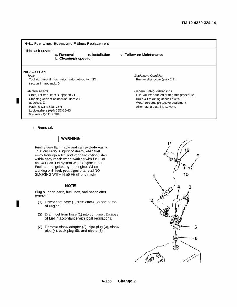
TM 10-4320-324-14
4-128 Change 2
a. Removal.
Fuel is very flammable and can explode easily.To avoid serious injury or death, keep fuelaway from open fire and keep fire extinguisherwithin easy reach when working with fuel. Donot work on fuel system when engine is hot.Fuel can be ignited by hot engine. Whenworking with fuel, post signs that read NOSMOKING WITHIN 50 FEET of vehicle.
NOTEPlug all open ports, fuel lines, and hoses afterremoval.
(1) Disconnect hose (1) from elbow (2) and at topof engine.
(2) Drain fuel from hose (1) into container. Disposeof fuel in accordance with local regulations.
(3) Remove elbow adapter (2), pipe plug (3), elbowpipe (4), cock plug (5), and nipple (6).
WARNING
4-41. Fuel Lines, Hoses, and Fittings Replacement
This task covers:a. Removal c. Installation d. Follow-on Maintenanceb. Cleaning/Inspection
INITIAL SETUP:Tools Equipment ConditionTool kit, general mechanics: automotive, item 32, Engine shut down (para 2-7).section III, appendix B
Materials/Parts General Safety InstructionsCloth, lint free, item 3, appendix E Fuel will be handled during this procedureCleaning solvent compound, item 2.1, Keep a fire extinguisher on site.appendix E Wear personal protective equipmentPacking (2)-MS28778-4 when using cleaning solvent.Lockwashers (6)-MS35338-43Gaskets (2)-111 8688

TM 10-4320-324-14
Change 2 4-129
(4) Disconnect hose (7) from left hand side.
(5) Drain fuel from hose (7) into container. Disposeof fuel in accordance with local regulations.
(6) Remove straight adapter (8), pipe plug (3),elbow pipe (4), cock plug (5), and nipple (6).
NOTEClamps are located in various places on unit.
(7) Remove three screws (9), three lockwashers(10), three nuts (11), and three clamps (12).Discard lockwashers (10).
(8) Remove line (7), straight adapter (13), andpacking (14) from filter/separator (19).
(9) Remove line (15), elbow adapter (16), nut (17),and packing (18).
3
4
8
11
12
9
107
6
5
1413
7
16
15
1718
19
11
12
9
10

TM 10-4320-324-14
4-41. Fuel Lines, Hoses, and Fittings Replacement (CONT).
NOTE
Bolts used in connecting the fuel lines are banjobolts and cannot be replaced by standard bolts.
(10) Remove line (15), elbow adapter (20), banjo bolt(21), two gaskets (22 and 24), and connector(23).
(11) Remove banjo bolt (25), two washers (26 and28), and hose (27) from fuel feed pump (29).
(12) Remove banjo bolt (30), two washers (31 and 32), and hose (27).
(13) Remove banjo bolt (33), two washers (34 and 36), and hose (35) from fuel filter (37).
(14) Remove banjo bolt (38), two washers (39 and 40), and hose (35) from injection pump (41).
4-130

TM 10-4320-324-14
(15) Remove three injector lines (42, 43, and 44)from injection pump (41).
(16) Remove banjo bolt (45), two washers (46 and48), and back leakage return line (47).
(17) Unlock two latches (49) and remove cover (50).
(18) Remove three injector lines (42, 43, and 44).
4-131

TM 10-4320-324-14
4-132 Change 2
(19) Remove two banjo bolts (51), three washers (52), back leakage return line (47), bolt (53), washer (54), overflow line (55), and three washers (56).
(20) Remove line (2), straight adapter (57), banjo bolt (58), washer (59), and fitting (60).
4-41. Fuel Lines, Hoses, and Fittings Replacement (CONT).
b. Cleaning and Inspection.
Skysol 100 cleaning solvent is combustible. Use mechanical ventilationwhenever product is used in a confined space, is heated above ambienttemperatures, or is agitated. DO NOT use or store near heat, sparks,flame, or other ignition sources. Keep container sealed when not in use.
Contact with Skysol 100 cleaning solvent may cause skin irritation. Usechemical resistant gloves. In case of skin contact, remove anycontaminated clothing and wash skin thoroughly with soap and water.Wash contaminated clothing before reuse. Eye contact may causeirritation, tearing or blurring of vision. Use face shield or goggles when eyecontact may occur. In case of eye contact, flush eyes with large amountsof water for at least fifteen (15) minutes or until irritation subsides.Inhalation may cause irritation to upper respiratory passages. DO NOThave food or drink in the vicinity.
(1) Clean all fittings and lines (exterior) with clean cloth moistened with dry cleaning solvent compound Skysol 100.
(2) Induce 25 to 30 psi (1.7 to 2.1 kg/cm2) of dry air into lines to clear any foreign matter.
(3) Inspect lines for cracks, chafing, and defective connectors. Replace if defective.
(4) Inspect fittings for cracks and thread distortions. Replace if defective.
WARNING

TM 10-4320-324-14
c. Installation.
NOTE
Prior to installation of fuel lines, hoses,or fittings, remove plugs and capsinstalled to prevent contamination.
(1) Install fitting (60), sealing ring (59),banjo bolt (58), straight adapter (57),and line (2).
(2) Install three sealing rings (56), backleakage line (55), washer (54), banjobolt (53), back leakage return line (47),three washers (52), and two banjo bolts(51).
(3) Install three injector lines (44, 43, and 42).
(4) Install cover (50) and lock latches (49).
4-133

TM 10-4320-324-14
4-41. Fuel Lines, Hoses, and Fittings Replacement (CONT).
(5) Install washer (48), back leakage return line(47), washer (46), and banjo bolt (45).
(6) Install three injector lines (44, 43, and 42) oninjection pump (41).
(7) Install washer (40), hose (35), washer (39), and banjo bolt (38) on injection pump (41).
(8) Install washer (36), hose (35), washer (34), and banjo bolt (33).
(9) Install washer (32), hose (27), washer (31), and banjo bolt (30) on fuel filter (37).
4-134

TM 10-4320-324-14
Change 2 4-135
(10) Install washer (28), hose (27), washer (26),and banjo bolt (25).
(11) Install gasket (24), connector (23), gasket(22), banjo bolt (21), elbow adapter (20), andline (15) on fuel pump (29).
(12) Install packing (18), nut (17), elbow adapter(16), and line (15).
(13) Install packing (14), straight adapter (13), andline (7) on filter/separator (19).
NOTEClamps are located in various places on unit.
(14) Install three clamps (12), three nuts (11), threelockwashers (10), and three screws (9).
1413
7
16
15
1718
19
11
12
9
10

TM 10-4320-324-14
4-41. Fuel Lines, Hoses, and Fittings Replacement (CONT).
(15) Install nipple (6), cock plug (5), elbow pipe (4), pipe plug (3), and straight adapter (8).
(16) Install hose (7).
(17) Install elbow adapter (2), pipe plug (3), elbow pipe (4), cock plug (5), and nipple (6). (18) Install hose (1).
g. Follow-on Maintenance. Bleed fuel lines (para 4-45).
END OF TASK
4-136

TM 10-4320-324-14
Change 2 4-137
a. Removal.
Fuel is very flammable and can explode easily. Toavoid serious injury or death, keep fuel awayfrom open fire and keep fire extinguisher withineasy reach when working with fuel. Do not workon fuel system when engine is hot. Fuel can beignited by hot engine. When working with fuel,post signs that read NO SMOKING WITHIN 50FEET of vehicle.
The fuel filter/separator must be drained afteroperation if the ambient temperature is expectedto fall below 32°F (0°C).
(1) Place suitable container under fuel filter separatordrain plug (1).
(2) Open drain valve (1) to drain fuel filter/separator.
(3) Remove two nuts (2), two lockwashers (3) twobolts (4), two washers (5), and filter/separator (6).Discard lockwashers (3).
CAUTION
WARNING
4-42. Fuel Filter/Separator Repair/Replacement.
This task covers:a. Removal b. Cleaning/Inspection e. Installationb. Disassembly d. Assembly f. Follow-on Maintenance
INITIAL SETUP:Tools Equipment ConditionTool kit, general mechanics: automotive, item 32, Engine shut down (para 2-7).section III, appendix B Filter/separator fuel lines removed (para 4-41).Drill, electric, item 33, section III, appendix B
Materials/Parts General Safety InstructionsFilter element-2000SM Fuel will be handled during this procedure.Gasket-12013 Keep a fire extinguisher on site.Gasket- 12014Lockwasher (2)-MS35338-45 Wear personal protective equipmentCleaning solvent compound, item 2.1, appendix E when using cleaning solvent.
4
5
6
3 2
1

TM 10-4320-324-14
4-138 Change 2
b. Disassembly.
(1) Remove retaining clamp (1), lid (2), gasket (3),filter element (4), and gasket (5). Discard filterelement (4) and gaskets (3 and 5).
(2) Remove four screws (6) and disassemble base (7)and (8).
(3) Remove gasket (9), flow director (10), andbowl/bracket (11).
(4) Remove drain valve (12) from base (8).
c. Cleaning/Inspection.
Skysol 100 cleaning solvent is combustible. Usemechanical ventilation whenever product is usedin a confined space, is heated above ambienttemperatures, or is agitated. DO NOT use or storenear heat, sparks, flame, or other ignition sources.Keep container sealed when not in use.
Contact with Skysol 100 cleaning solvent maycause skin irritation. Use chemical resistantgloves. In case of skin contact, remove anycontaminated clothing and wash skin thoroughlywith soap and water. Wash contaminated clothingbefore reuse. Eye contact may cause irritation,tearing or blurring of vision. Use face shield orgoggles when eye contact may occur. In case ofeye contact, flush eyes with large amounts ofwater for at least fifteen (15) minutes or untilirritation subsides. Inhalation may cause irritationto upper respiratory passages. DO NOT havefood or drink in the vicinity.
(1) Clean all parts with cleaning solvent compoundSkysol 100.
(2) Inspect bowl for cracks and leaks. Replace bowl ifdefective.
(3) Inspect base, lid, and retaining clamp for cracks,breaks and any other defects.
WARNING
4-42. Fuel Filter/Separator Repair/Replacement (CONT).2
1
3
4
5
7
9
10
11
8
126

TM 10-4320-324-14
Change 2 4-139
d. Assembly.
(1) Install bowl/bracket (11), flow director (10), and newgasket (9).
(2) Assemble base (8 and 7) and install four screws(6).
(3) Install new gasket (5), new filter element (4), andnew gasket (3).
(4) Install lid (2) and retaining clamp (1).
(5) Install drain valve (12) on base (8).
e. Installation.
(1) Install filter/separator (14) with two washers (15),two bolts (13), two new lockwashers (17), and twonuts (16).
(2) Close drain valve (12).
f. Follow-on Maintenance.
(1) Install fuel lines to filter/separator (para 4-41).
(2) Bleed fuel system (para 4-45).
13
15
14
17 16
12

TM 10-4320-324-14
4-140 Change 2
a. Removal.
Fuel is very flammable and can explode easily. Toavoid serious injury or death, keep fuel away fromopen fire and keep fire extinguisher within easyreach when working with fuel. Do not work on fuelsystem when engine is hot. Fuel can be ignited byhot engine. When working with fuel, post signs thatread NO SMOKING WITHIN 50 FEET of vehicle.
(1) Remove and discard cartridge (1).
(2) Wipe off seat (2) with a clean cloth.
b. Installation.
(1) Lubricate rubber seal (3) with oil.
(2) Install new cartridge (1).
c. Follow-on Maintenance.
Bleed fuel system (para 4-45).
WARNING
4-43. Fuel Filter Replacement.
This task covers:a. Removal b. Installation c. Follow-on Maintenance
INITIAL SETUP:Tools Equipment ConditionTool kit, general mechanics: automotive, item 32, Engine shut down (para 2-7).section III, appendix B
Materials/PartsCloth, lint free, item 3, appendix ELubricating oil, internal, item 7, appendix E
1
3
2

TM 10-4320-324-14
Change 2 4-141
Fuel is very flammable and can explode easily. To avoid serious injury ordeath, keep fuel away from open fire and keep fire extinguisher withineasy reach when working with fuel. Do not work on fuel system whenengine is hot. Fuel can be ignited by hot engine. When working with fuel,post signs that read NO SMOKING WITHIN 50 FEET of vehicle.
a. Removal.
Remove three nuts (1), three lockwashers (2), pump assembly (3), and preformed packing (4). Discardlockwashers (2) and preformed packing (4).
WARNING
4-44. Fuel Feed Pump Repair/Replacement.
This task covers:a. Removal c. Cleaning/Inspection e. Installationb. Disassembly d. Assembly f. Follow-on Maintenance
INITIAL SETUP:Tools Equipment ConditionTool kit, general mechanics: automotive, item 32, Engine shut down (para 2-7).section III, appendix B Fuel lines to feed pump removed (para 4-41).
Materials/Parts General Safety InstructionsLockwasher (3)-110 2797 Keep a fire extinguisher close at hand whenGasket-415 7603 working with fuel.Preformed packing-116 2695Cleaning solvent compound, item 2.1, appendix E Wear personal protective equipment
when using cleaning solvent.
3
1 2
4

TM 10-4320-324-14
4-142 Change 2
b. Disassembly.
(1) Remove bolt (5), washer (6), and lid (7).
(2) Remove gasket (8), screen (9), and diaphragm (10)from pump base (11). Discard gasket (8).
c. Cleaning/Inspection.
Skysol 100 cleaning solvent is combustible. Usemechanical ventilation whenever product is used ina confined space, is heated above ambienttemperatures, or is agitated. DO NOT use or storenear heat, sparks, flame, or other ignition sources.Keep container sealed when not in use.
Contact with Skysol 100 cleaning solvent maycause skin irritation. Use chemical resistant gloves.In case of skin contact, remove any contaminatedclothing and wash skin thoroughly with soap andwater. Wash contaminated clothing before reuse.Eye contact may cause irritation, tearing or blurringof vision. Use face shield or goggles when eyecontact may occur. In case of eye contact, flusheyes with large amounts of water for at least fifteen(15) minutes or until irritation subsides. Inhalationmay cause irritation to upper respiratory passages.DO NOT have food or drink in the vicinity.
(1) Clean all parts with cleaning solvent compoundSkysol 100.
(2) Inspect diaphragm and screen for defects. Replace ifdiaphragm or screen is defective.
d. Assembly.
(1) Install diaphragm (10) and screen (9) in pump base(11).
(2) Install new gasket (8), lid (7), washer (6), and bolt(5).
WARNING
4-44. Fuel Feed Pump Repair/Replacement (CONT).

TM 10-4320-324-14
Change 2 4-143
f. Follow-on Maintenance.
(1) Install fuel lines to feed pump (para 4-41).
(2) Bleed fuel system (para 4-45).
e. Installation.
(1) Install new preformed packing (4).
(2) Install pump assembly (3) with three new lockwashers (2) and three nuts (1).
3
1 2
4
END OF TASK

TM 10-4320-324-14
4-144 Change 2
Fuel is very flammable and can explode easily. Toavoid serious injury or death, keep fuel awayfrom open fire and keep fire extinguisher withineasy reach when working with fuel. Do not workon fuel system when engine is hot. Fuel can beignited by hot engine. When working with fuel,post signs that read NO SMOKING WITHIN 50FEET of vehicle.
a. Bleed fuel lines as follows:
(1) Place a suitable container under fuel feed pump.
(2) Loosen overflow valve (1).
(3) Operate fuel pump lever (2) until fuel is free of airbubbles and emerges at overflow valve (1).
NOTEThe fuel pump will work if injector pump camshaftis in such position that diaphragm of fuel pump isnot lifted. When operating priming lever, the liftingmovement of diaphragm must occur in firstquarter of travel. If not, turn engine over by hand.
(3) Tighten overflow valve (1).
(4) Start engine and check for leaks.
WARNING
4-45. Fuel System Bleeding.
This task covers:Bleeding
INITIAL SETUP:ToolsTool kit, general mechanics: automotive, item 32,section III, appendix B
END OF TASK
1
2

TM 10-4320-324-14
Change 2 4-145
a. Removal.
Ether is extremely flammable. Do not removetube while smoking or near open flames. Failurein doing so may result in damage to unit andinjury to personnel.
(1) Remove ether tube (1).
(2) Turn knob (2) counterclockwise and remove.
(3) Remove nut (3) and pump (4).
b. Installation.
(1) Install pump (4) with tube connection at twelveo’clock position.
(2) Install nut (3).
(3) Install knob (2) With pump shaft pulled out andnut on end of shaft held with wrench.
(4) Connect ether tube (1) to pump (4).
WARNING
4-46. Starting Aid Pump Replacement.
This task covers:a. Removal b. Installation
INITIAL SETUP:ToolsTool kit, general mechanics: automotive, item 32,section III, appendix B
END OF TASK
1
4
3
2

TM 10-4320-324-14
4-146 Change 2
a. Removal.
Ether is extremely flammable. Do not removetubes while smoking or near open flames. Failurein doing so may result in damage to unit and injuryto personnel.
(1) Disconnect two ether tubes (6) and (7).
(2) Remove two nuts (5), two starwashers (4), andreservoir (9). Discard starwashers (4).
(3) Remove two nuts (11), lockwashers (10), fourwashers (2), two screws (3), and bracket (8) fromcontrol box post (1). Discard lockwashers (10).
b. Installation.
(1) Install bracket (8) on control box post (1) with twoscrews (3) four washers (2), and new lockwashers(10), and nuts (11).
(2) Install reservoir (9) on bracket with fill cap locatedat twelve o’clock position.
(3) Install two new starwashers (4) and two nuts (5).
(4) Connect two ether tubes (7) and (6) to reservoir (9).
WARNING
4-47. Reservoir Replacement.
This task covers:a. Removal b. Installation
INITIAL SETUP:Tools Materials/PartsTool kit, general mechanics: automotive, item 32, Starwasher (2)-MS35333-110section III, appendix B Lockwasher (2) MS35338-45
END OF TASK
1 2
3
4 56
75
4
89
210
11

TM 10-4320-324-14
Change 2 4-147
a. Removal.
Ether is extremely flammable. Do notremove tube while smoking or near openflames. Failure in doing so may result indamage to unit and injury to personnel.
(1) Remove four straps (1), and remove ether tube (2) from nozzle and hand pumpreservoir (8). Discard tiedown straps (1).
(2) Remove nut (3) and nozzle (4) from intakemanifold (5).
b. Installation.
NOTEEnsure that arrow on nozzle pointstowards muffler.
(1) Install nozzle (4) and nut (3) on intakemanifold (5).
(2) Install ether tube (2) on nozzle (4) andhand pump reservoir (8).
(3) Secure ether tube (2) to fuel lines (6) and (7) with four new tiedown straps (1).
WARNING
4-48. Nozzle and Either Tube Replacement.
This task covers:a. Removal b. Installation
INITIAL SETUP:Tools Materials/PartsTool kit, general mechanics: automotive, item 32, Starwasher (2)-MS35333-110section III, appendix B Lockwasher (2) MS35338-45
Tiedown strap (4) MS3367-1-9
END OF TASK
8
76
5
43
21

TM10-4320-324-14
4-49. Valve Clearance Adjustment.
This task covers:
a. Disassembly c. Assembly
b. Adjustment d. Follow-on Maintenance
INITIAL SETUP:
Tools Equipment ConditionTool kit, general mechanics: automotive, item 32, Belt guard removed (4-31). section III, appendix B
Materials/PartsCloth, lint free, item 3, appendix EAdhesive, item 1, appendix EGasket (3)-337 1692Washer (3)-121-6307
4-148

TM 10-4320-324-14
Change 2 4-149
NOTEEngine must be cold to perform this procedure.
a. Disassembly.
(1) Raise cooling air compartment.
NOTE• Be sure to remove all of the old gasket from
cylinder head.
• All covers are removed the same way.
(2) Remove screw (1), flat washers (2 and 3), cover(4) and gasket (5) from cylinder head (6). Discardflat washers (3) and gasket (5).
1
2
3
1
2
31
2
3
4
54
5
4
6

TM 10-4320-324-14
4-49. Valve Clearance Adjustment (CONT).
b. Adjustment.
(1) Rotate crankshaft (1) to close valves ofcylinder to be adjusted.
(2) Turn crankshaft (1) in clockwise direction untilvalves overlap.
(3) Mark position on pulley (2), then rotatecrankshaft (1) one revolution (360°).
(4) Loosen nut (3) on rocker arm (4), then turnscrew (5) to adjust rocker arm to valve stemclearance. Refer to Table 4-3.
(5) Hold screw (5) and tighten nut (3).
(6) Check clearance and adjust, if required.
Table 4-3. Valve Clearance (Engine Cold)
Clearance 0.006 in. (0.15 mm)Inlet Valves Open 32° before T.D.C.Inlet Valves Close 60° after B.D.C.
(At above valve clearance)Exhaust Valves Open 70° before B.D.C.Exhaust Valves Close 32° after T.D.C.
4-150

TM 10-4320-324-14
Change 2 4-151
a. Assembly.
(1) Apply adhesive to new gasket (5).
(2) Position gasket (5) on cylinder head (6).
(3) Install cover (4) and aline holes.
(4) Thread screw (1), with flat washers (2) and new flat washer (3) installed, into cylinder head (6) and tighten.
d. Follow-on Maintenance. Install belt and pulley guard(para 4-31).
1
2
3
1
2
31
2
3
4
54
5
4
6
END OF TASK
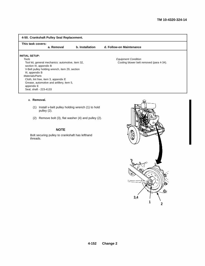
TM 10-4320-324-14
4-152 Change 2
a. Removal.
(1) Install v-belt pulley holding wrench (1) to holdpulley (2).
(2) Remove bolt (3), flat washer (4) and pulley (2).
NOTEBolt securing pulley to crankshaft has lefthandthreads.
4-50. Crankshaft Pulley Seal Replacement.
This task covers:a. Removal b. Installation d. Follow-on Maintenance
INITIAL SETUP:Tools Equipment ConditionTool kit, general mechanics: automotive, item 32, Cooling blower belt removed (para 4-34).section III, appendix BV-Belt pulley holding wrench, item 29, sectionIII, appendix B
Materials/PartsCloth, lint free, item 3, appendix EGrease, automotive and artillery, item 5,appendix ESeal, shaft - 223-4133
3,41 2

TM 10-4320-324-14
(3) Install bolt (3) and remove seal (5).
(4) Remove bolt (3).
b. Installation.
(1) Lubricate lip of seal (1) with grease.
(2) Position seal (1) in cover (2) with lip inward andinstall seal.
(3) Check that edge of seal (1) is flush with outeredge of cover (2).
(4) Aline hole in pulley (3) with pin in crankshaftgear wheel, then slide pulley into position.
(5) Install flat washer (4), then thread bolt (5) intocrankshaft.
(8) Install v-belt pulley holding wrench (6). Refer toTable 6-1 for correct torque for bolt (5).
NOTE
Bolt securing pulley to crankshaft haslefthand threads.
c. Follow-on-Maintenance. Install cooling blowerbelt (para 4-34).
END OF TASK
4-153

TM 10-4320-324-14
4-51. Idler Pulley Assembly Repair.
This task covers:
a. Removal c. Inspection e. Installation
b. Disassembly d. Assembly f. Follow-on Maintenance
INITIAL SETUP:
Tools Equipment ConditionTool kit, general mechanics: automotive, item 32, Cooling blower belt removed (para 4-34).section 111, appendix B Batteries disconnected (para 4-30).
Materials/PartsCloth, lint free item 3, appendix EOil, engine, item 8, appendix EO-Seal- 116-6110Gasket - 213-6434
4-154

TM 10-4320-324-14
Change 2 4-155
a. Removal.
Disconnect negative (-) cables from batteries.
(1) Tag and disconnect switch wires (1).
(2) Loosen spacer (2).
(3) Hold pulley (3), then loosen bolt (4) until bracket (5)can be moved to disengage lever (6). Releasepulley (3).
(4) Remove bolt (7), flat washer (8), spacer (2), nut (9),flat washer (10), and idler pulley assembly (11).
CAUTION
HOLD PULLEY HERE WHEN
3
89
10 9
5
6
4
11
1
2

TM 10-4320-324-14
4-51. Idler Pulley Assembly Repair (CONT).
b. Disassembly.
(1) Remove o-seal (1) from body (14).
(2) Remove three screws (2), cover (3) and gasket(4) from pulley (13).
(3) Remove nut (5), flat washers (6, 7 and 8), screw(9) and pulley (13) from body (14).
(4) Remove ring (10), bushing (11) and bearing (12)from pulley (13).
c. Inspection.
(1) Inspect all parts for cracks, distortion ordamage.
(2) Replace defective parts as necessary.
d. Assembly.
(1) Lubricate bearing (12) with engine oil.
(2) Install bearing (12) and bushing (11) in pulley (13).
(3) Insert screw (9) through bushing (11), then install ring (10) and flat washers (8 and 7) on end of bolt (9).
(4) Position pulley (13) on body (14), then install flat washer (6) on end of bolt (9).
(5) Thread nut (5) on to bolt (9) and tighten.
(6) Position gasket (3) and cover (2) on pulley (13), then thread three screws (2) into pulley (13) and tighten.
(7) Lubricate o-seal (1) with engine oil and install in groove of body (14).
4-156

TM 10-4320-324-14
Change 2 4-157
e. Installation.
(1) Position idler pulley assembly (11) on engine andaline holes.
(2) Install flat washers (10 and 8), nut (9) and screw(7), then tighten.
(3) Install screw (4), and spacer (2). Do not tighten.
(4) Raise pulley (3) and engage bracket (5) with lever(6), then tighten screw (4) and spacer (2).
(5) Connect switch wires (1).
f. Follow-on Maintenance.
(1) Install blower outlet extension (para 4-32).
(2) Install v-belt and pulley guard (para 4-31).
(3) Connect batteries (para 4-30).
HOLD PULLEY HERE WHEN
3
89
10 9
5
6
4
11
1
2
END OF TASK

TM 10-4320-324-14
4-158 Change 2
a. Removal.
WARNINGDo not remove filter while engine is hot. Engineoil is extremely hot and severe injury topersonnel may result.
(1) Remove and discard filter (1).
(2) Wipe off seat (2) with a clean cloth.
b. Installation.
(1) Lubricate rubber seal (3) with oil.
(2) Install new filter (1).
4-52. Oil Filter Replacement.
This task covers:a. Removal b. Installation
INITIAL SETUP:ToolsWrench, oil filter, item 33, section III, appendix B
Materials/Parts old rivets or installing new rivets.Lubricating oil, internal: item 8, appendix ECloth, lint free, item 3, appendix EOil filter - 1173481
END OF TASK
1
3
2

TM 10-4320-324-14
Change 2 4-159
a. Removal.
WARNINGEngine oil is extremely hot when engine is inoperation. Allowing hot oil to contact your skinwill result in burns.
(1) Remove cap (1) and drain oil in a suitablecontainer.
(2) Remove oil hose (2), copper washer (3), locknut(4), and nipple (5).
4-53. Oil Drain Hose Replacement.
This task covers:a. Removal b. Cleaning/Inspection c. Installation
INITIAL SETUP:Tools ReferencesTool kit, general mechanics: automotive, item 32, LO 10-4320-324-12section III, appendix B
Equipment ConditionMaterials/Parts Engine shut down (para 2-7).Copper washer - 13229E8486Locknut - MS51860-58 General Safety InstructionsCleaning solvent compound, item 2.1, appendix E Wear personal protective equipmentOil, engine, item 8, appendix E when draining hot engine oil or whenusing cleaning solvent.
1 54
2
3

TM 10-4320-324-14
4-160 Change 2
Skysol 100 cleaning solvent is combustible. Usemechanical ventilation whenever product is usedin a confined space, is heated above ambienttemperatures, or is agitated. DO NOT use orstore near heat, sparks, flame, or other ignitionsources. Keep container sealed when not in use.
Contact with Skysol 100 cleaning solvent maycause skin irritation. Use chemical resistantgloves. In case of skin contact, remove anycontaminated clothing and wash skin thoroughlywith soap and water. Wash contaminated clothingbefore reuse. Eye contact may cause irritation,tearing or blurring of vision. Use face shield orgoggles when eye contact may occur. In case ofeye contact, flush eyes with large amounts ofwater for at least fifteen (15) minutes or untilirritation subsides. Inhalation may cause irritationto upper respiratory passages. DO NOT havefood or drink in the vicinity.
(1) Clean all metal parts with cleaning solvent Skysol100.
(2) Inspect all parts for damage. Replace defectiveparts.
c. Installation.
(1) Install copper washer (3), oil hose (2), nipple (5),locknut (4), and cap (1).
(2) Fill engine with oil (LO 10-4320-324-12).
WARNING
1 54
2
3
4-43. Oil Drain Hose Replacement (CONT).
END OF TASK

TM 10-4320-324-14
4-54. Low Oil Pressure Cut-out Switch Replacement.
This task covers:
a. Testing b. Removal
c. Installation d. Follow-on Maintenance
INITIAL SETUP:
Tools Equipment ConditionTool kit, general mechanics: automotive, item 32, Negative battery cable disconnected (para 4-section III, appendix B 30).
General Safety InstructionsMaterials/Parts Engine oil is extremely hot when engine is
Tags, identification, item 17, appendix E operating. Severe burns may result from contact with hot oil.
Gasket - 111-8659Lockwasher - 111-7861
a. Testing.
(1) Connect leads of electrical circuit tester to each terminal of switch.
(2) Tester should indicate an open circuit.
(3) With tester still connected, press OIL PRESSURE BYPASS switch on control panel. Tester should now indicatecontinuity.
(4) If low oil pressure cut-out switch fails test, remove and replace switch.
NOTE
Refer to tags to install wires properly.
If oil pressure switch is defective, skip to step b.
(5) If oil pressure switch is not defective, connect wires to switch.
4-161

TM 10-4320-324-14
4-162 Change 2
b. Removal.
Do not remove low oil pressure switch while engine is hot. Oil is extremelyhot and severe injury topersonnel may result.
(1) Remove banjo bolt (3) and gasket (4). Discard gasket (4).
(2) Remove oil pressure switch (5), pipe tee (6), oil sending unit (7) as an assembly. Remove lockwasher (8).Discard lockwasher (8).
(3) Remove three screws (1) and three wires (2).
(4) Remove low oil pressure switch (5).
c. Installation.
(1) Install low oil pressure switch (5).
NOTERefer to tags to install wires properly.
(2) Install three wires (2) and three screws (1). Remove all tags.
(3) Install new lockwasher (8), sending unit (7), pipe tee (6), and oil pressure switch (5) as an assembly.
(4) Install new gasket (4), and banjo bolt (3).
d. Follow-on Maintenance.
Connect negative battery terminal (para 4-30).
WARNING
4-54. Low Oil Pressure Cut-out Switch Replacement (CONT).
8
7
64
3
5
12
END OF TASK

TM 10-4320-324-14
Change 2 4-163
a. Testing.
(1) Remove nut (1), flat washer (2) and wire (3).
(2) Connect one lead of multimeter to terminal of oil sending unit (4) and other lead to body of oil sending unit.
(3) Measure resistance. Reading should be between 229 to 243 ohms. If reading does not fall within this range,replace unit.
NOTEIf oil sending unit is defective, skip to step b.
(4) If oil sending unit is not defective, connect wire (3) with flat washer (2) and nut (1).
4-55. Oil Sending Unit Replacement.
This task covers:a. Removal b. Inspectionc. Installation d Follow-on Maintenance
INITIAL SETUP:Tools Equipment ConditionTool kit, general mechanics: automotive, item 32, Engine shut down (para 2-7).section III, appendix B Negative battery cable disconnected (para 4-30).Multimeter, item 33, section III, appendix B
Materials/Parts General Safety InstructionsGasket - 111-8659 Engine oil is extremely hot when engine is operatingLockwasher - 111-7861 Severe burns may result from contact with hot oi.
3 21

TM 10-4320-324-14
4-164 Change 2
b. Removal.
WARNINGDo not remove oil sending unit while engine is hot. Engine oil is extremelyhot and severe injury to personnel may result.
(1) Remove banjo bolt (1) and gasket (2). Discard gasket (2).
(2) Remove oil pressure switch (3), pipe tee (4), oil sending unit (5) as an assembly. Remove lockwasher (6).Discard lockwasher (6).
(3) Remove oil sending unit (5).
c. Installation.
(1) Install oil sending unit (5) to pipe tee (4).
(2) Install flat washer (9), wire (8), and nut (7).
(3) Install new lockwasher (6).
(4) Install oil sending unit (5), pipe tee (4), and oil pressure switch (3) as an assembly.
(5) Install new gasket (2) and banjo bolt (1).
d. Follow-on Maintenance.
9 8
7
5
6 4
1
23
END OF TASK

TM 10-4320-324-14
Change 2 4-165
a. Removal.
Do not remove oil line while engine is hot. Engine oil is extremely hot andsevere injury to personnel may result.
(1) Remove banjo bolt (1), two gaskets (2) and (5), assembly (3), and lockwasher (4). Discard gaskets (2) and (5)and lockwasher (4).
(2) Remove banjo bolt (6) two gaskets (7) and (9), and oil line (8). Discard gaskets (7) and (9).
b. Installation.
NOTEReplace lockwasher and gaskets.
(1) Install new gasket (9), oil line (8), new gasket (7), and banjo bolt (6).
(2) Install new gasket (5), oil line (8), new lockwasher (4), assembly (3), new gasket (2), and banjo bolt (4).
WARNING
4-56. Oil Line Replacement.
This task covers:a. Removal b. Installation
INITIAL SETUP:Tools Equipment ConditionTool kit, general mechanics: automotive, item 32, Engine shut down (para 2-7).section III, appendix B
Materials/Parts old rivets or installing new rivets.Gasket (4) - 111-8659Lockwasher - 111-7861
2
3
5
4
19
7
6
8
END OF TASK
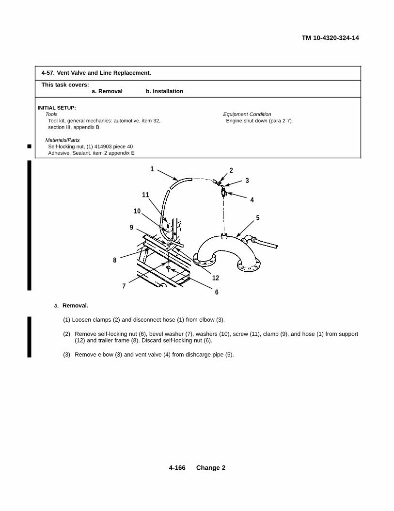
TM 10-4320-324-14
4-166 Change 2
a. Removal.
(1) Loosen clamps (2) and disconnect hose (1) from elbow (3).
(2) Remove self-locking nut (6), bevel washer (7), washers (10), screw (11), clamp (9), and hose (1) from support(12) and trailer frame (8). Discard self-locking nut (6).
(3) Remove elbow (3) and vent valve (4) from dishcarge pipe (5).
4-57. Vent Valve and Line Replacement.
This task covers:a. Removal b. Installation
INITIAL SETUP:Tools Equipment ConditionTool kit, general mechanics: automotive, item 32, Engine shut down (para 2-7).section III, appendix B
Materials/PartsSelf-locking nut, (1) 414903 piece 40Adhesive, Sealant, item 2 appendix E
1 23
4
5
67
8
9
10
11
12

TM 10-4320-324-14
Change 2 4-167
b. Installation.
(1) Apply sealant adhesive to threads of vent valve (4) and elbow (3).
(2) Install vent valve (4) and elbow (3) on discharge pipe (5).
(3) Connect hose (1) to elbow (3), and tighten clamp (2).
(4) Secure hose (1) to trailer frame (8) and support (12) with clamp (9), screw (11), washer (10), bevel washer(7), and new self-locking nut (6).
END OF TASK

TM 10-4320-324-14
4-58. Valves, Manifolds and Fittings Repair/Replacement.
This task covers:
a. Removal c. Assembly e. Follow-on Mainten ance
b. Disassembly d. Installation
INITIAL SETUP:
Tools Equipment ConditionTool kit, general mechanics: automotive, item 32, Roof panels removed (para 4-13).section III, appendix B Front panels removed (para 4-18).
Materials/Parts General Safety InstructionsCloth, lint free, item 3, appendix E Petroleum solvent, which is toxic and Solvent, TT-T-548, item 16, appendix E flammable, is used during this procedure. Take Gasket (11) - 13220E1069-1 (total) necessary safety precautions.Gasket (1) - MS27030-9 (each coupling half)Spring - 70171-N (each gate valve)Packing - 65107-K (each gate valve)Lockwasher (92) - MS35338-46
4-168

TM 10-4320-324-14
Change 2 4-169
NOTEDrain any remaining liquid from the valvesinto a suitable container before startingremoval procedures.
a. Removal.
(1) Removal of four coupling halves (4).
(a) Remove eight nuts (1), eight lockwashers(2), and eight screws (3). Discardlockwashers (2).
(b) Remove coupling half (4) and gasket (5).Discard gasket (5).
(c) Remove nut (6), lockwasher (7), twowashers (8), bevel washer (9), screw(10), and bracket (11). Discardlockwasher (7).
FRAME
GATEVALVE
1
211
10
8
9
8
7
6
3
4
5

TM 10-4320-324-14
4-58. Valves, Manifolds and Fittings Repair/Replacement (CONT).
(2) Removal of four gate valves (12).
(a) Match mark gate valve (12) to manifold.
(b) Remove eight nuts (13), eightlockwashers (14), gate valve (12), andgasket (15).
(3) Removal of suction manifold.
(a) Refer to steps 1 and 2 to remove couplinghalves and gate valves.
(b) Disconnect suction hose (16) and elbow(17) from suction manifold (18).
(c) Match mark suction manifold (18) topump assembly.
(d) Remove eight nuts (19), eightlockwashers (20), suction manifold (18),and gasket (21).
4-170

TM 10-4320-324-14
(4) Removal of discharge manifold andconnection.
(a) Refer to steps 1 and 2 to remove couplinghalves and gate valves.
(b) Remove pressure line and elbow (17).
(c) Match mark manifold (22) to connection(23).
(d) Remove eight nuts (24), eightlockwashers (25), eight screws (26),manifold (22), and gasket (27).
(e) Match mark connection (23) to pumpassembly.
(f) Remove eight nuts (28), eightlockwashers (29), eight washers (30),connection (23), and gasket (31).
(g) Remove plate (32) from connection (23) ifdamaged.
b. Disassembly.
(1) Disassembly of suction coupling half.
(a) Remove chain (1) from chain hook (2).
(b) Remove chain hook (2) from dust plug(3).
(c) Pull arms of body away from body (4).
(d) Remove plug (3) and gasket (5) frombody (4).
4-171

TM 10-4320-324-14
4-58. Valves, Manifolds and Fittings Repair/Replacement (CONT).
(2) Disassembly of discharge coupling half.
(a) Remove chain (6) from chain hook (7).
(b) Remove three chain hooks (7) from cap(8).
(c) Pull arms of dust cap (8) away from cap.
(d) Remove cap (8) and gasket (9) from body(10).
NOTE
The following procedure is forreplacement of packing and spring only.
(3) Remove threaded nut (11), plate (12),handwheel (13), nut (14), spring (15), retainer(16), and packing (17) from stem.
4-172

TM 10-4320-324-14
c. Assembly.
(1) Assembly of suction coupling half.
(a) Place gasket (5) and dust plug (3) in body(4).
(b) Pull arms of body (4) toward body.
(c) Attach chain hook (2) to plug (3).
(d) Attach chain (1) to chain hook (2).
(2) Assembly of discharge coupling half.
(a) Place gasket (9) and dust cap (8) on body(10).
(b) Pull arms of cap (8) toward body (10).
(c) Attach three chain hooks (7) to cap (8).
(d) Attach chain (6) to chain hook (7).
4-173

TM 10-4320-324-14
4-58. Valves, Manifolds and Fittings Repair/Replacement (CONT).
NOTE
Tighten all nuts and screws on gatevalves to 44-48 ft-lb.
(3) Assembly of gate valve.
(a) Install packing (17), retainer (16) andspring (15) on stem.
(b) Thread nut (14) on to body and tighten.
(c) Install handwheel (13), plate (12), thenthread nut (11) on to stem and tighten.
d. Installation.
(1) Installation of discharge manifold andconnection.
(a) Place gasket (31) on pump.
(b) Aline match marks, then positionconnection (23) on pump assembly.
(c) Install eight washers (30) and eight lock-washers (29), then thread eight nuts (28)on to pump assembly studs and tighten.
(d) Install gasket (27) on connection (23).
(e) Aline match marks, then position manifold(22) against connection (23).
(f) Insert eight screws (26) throughconnection (23) and manifold (22).
4-174

TM 10-4320-324-14
(g) Install eight lockwashers (25), then thread nuts (24) on to screws (26) and tighten.
WARNING
Potential health hazards result from inhalation of petroleum solvent vapors and from contact of solvent with skin.
Use rubber gloves and hand cream for protection, and work with adequate ventilation.
Petroleum solvents are highly flammable. Keep solvent container lids closed when not in use, and avoid all
possible risks of igniting solvent vapors, keep away from open flame and excessive heat. Flash point of solventis 100 to 138 degrees F (38 to 59 degrees C).
(h) Wipe mounting pad on connection (23) with a lint free cloth dampened in cleaning solvent. Allow to airdry.
(i) Install plate (32) on connection (23).
(j) Install pressure line and elbow (17).
(k) Refer to steps 3 and 4 to install coupling halves and gate valves.
(2) Installation of suction manifold.
(a) Install gasket (21) on pump assembly.
(b) Aline match marks, then position suctionmanifold (18) against pump assembly.
(c) Install eight lockwashers (20), then threadeight nuts (19) on to pump assemblystuds and tighten.
(d) Install suction hose (16) and elbow (17) atsuction manifold (17).
4-175

TM 10-4320-324-14
4-58. Valves, Manifolds and Fittings Repair/Replacement (CONT).
(3) Installation of gate valve.
(a) Install gasket (15) on manifold.
(b) Aline match marks, then position gatevalve (12) against manifold.
(c) Install eight lockwashers (14), then threadeight nuts (13) on to manifold studs andtighten.
(4) Installation of four coupling halves (4).
(a) Position bracket (11) on frame.
(b) Insert screw (10), with one washer (8)installed, through bracket (11) and frame.
(c) Install washer (8) and lockwasher (7), thenthread nut (6) on to screw (10) andtighten.
(d) Install gasket (5) on gate valve.
(e) Position coupling half (4) against gatevalve and aline holes.
NOTE
Longest screw must go through hole and bracket.
(f) Insert eight screws (3) through gate valveand coupling half (4).
NOTE
Be sure to attach coupling half chain toone screw before installing lockwashersand nuts.
(g) Install eight lockwashers (2), then threadnuts (1) on to screws (3) and tighten.
4-176

TM 10-4320-324-14
e. Follow-on Maintenance.
(1) Install front panels (para 4-18).
(2) Install roof panels (para 4-13).
END OF TASK
4-177

TM 10-4320-324-14
4-178 Change 2
a. Removal.
(1) Remove two lines (1 and 2), four screws (3),four washers (4), four lockwashers (5), andtwo cage nuts (6). Discard lockwashers (5).
(2) Lower control panel (7) and remove twoscrews (8), two lockwashers (9), and terminalboard (10). Discard lockwashers (9).
4-59. Control Panel Assembly Repair/Replacement.
This task covers:a. Removal c. Assembly e. Follow-on Maintenanceb. Disassembly d. Installation
INITIAL SETUP:Tools Equipment ConditionTool kit, general mechanics: automotive, item 32, Negative battery cables disconnected (para 4-30).section III, appendix B
Materials/PartsCompound, thread locking, item 4, appendix ETags, ID, item 17, appendix ELockwasher (12) - MS35338-43Lockwasher (4) - MS35338-107Lockwasher (22) - MS35338-45
6
89 10
72
1
3 4 5

TM 10-4320-324-14
NOTE
Tag all wires before removing from terminal
board.
Remove wires on terminal board that are from
control panel only.
(3) Remove screws (11) and wires (12). Tag wires.
(4) Remove control panel (7).
b. Disassembly.
NOTE
Tag all wires before removal.
(1) Remove wires from control panel as follows:
(a) Remove two screws (1) and two wires (2) from starter switch (3).
(b) Remove two screws (4) and two wires (5) from oil bypass switch (6).
4-179

TM 10-4320-324-14
4-59. Control Panel Assembly Repair/Replacement (CONT).
(c) Remove four screws (7) and seven wires (8) from emergency stop switch (9).
(d) Remove two nuts (10), two wires (11), and two flat washers (12), and two lockwashers (13) from ammeter(14).
(e) Remove three nuts (15), six wires (16), and three lockwashers (17) from tachometer (18).
(f) Remove three nuts (19), five wires (20), and three lockwashers (21) from oil pressure gauge (22).
(g) Remove two screws (23) and five wires (24) from rheostat (25).
(h) Remove six screws (26) and eight wires (27) from relay (28).
4-180
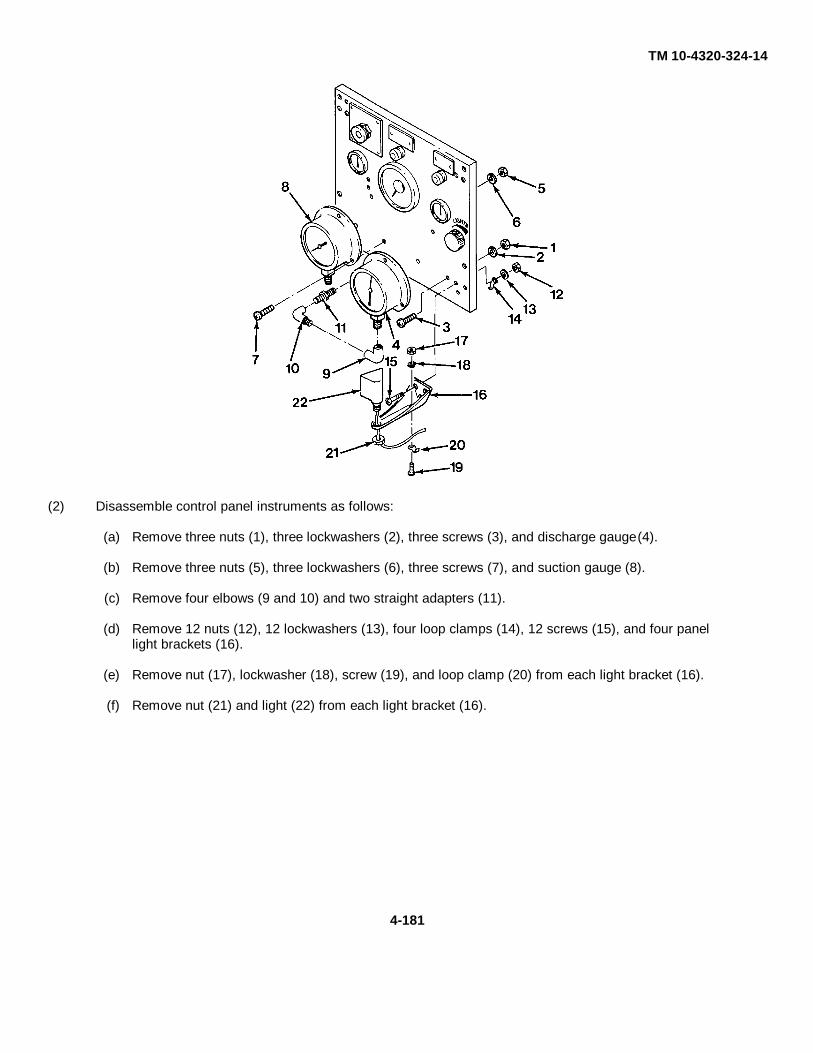
TM 10-4320-324-14
(2) Disassemble control panel instruments as follows:
(a) Remove three nuts (1), three lockwashers (2), three screws (3), and discharge gauge (4).
(b) Remove three nuts (5), three lockwashers (6), three screws (7), and suction gauge (8).
(c) Remove four elbows (9 and 10) and two straight adapters (11).
(d) Remove 12 nuts (12), 12 lockwashers (13), four loop clamps (14), 12 screws (15), and four panellight brackets (16).
(e) Remove nut (17), lockwasher (18), screw (19), and loop clamp (20) from each light bracket (16).
(f) Remove nut (21) and light (22) from each light bracket (16).
4-181

TM 10-4320-324-14
4-59. Control Panel Assembly Repair/Replacement (CONT).
(g) Remove two nuts (23), two lockwashers (24), hold spring and spacers (25), two screws (26), relay (27),and relay socket (28).
(h) Remove two nuts (29), plastic spacer (30), bracket (31) and ammeter (32).
(i) Remove two nuts (33), two star washers (34), bracket (35), and tachometer (36).
(j) Remove two nuts (37), two lockwashers (38), bracket (39) and oil pressure gauge (40).
4-182
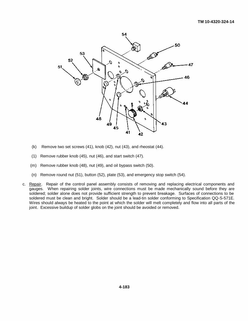
TM 10-4320-324-14
(k) Remove two set screws (41), knob (42), nut (43), and rheostat (44).
(1) Remove rubber knob (45), nut (46), and start switch (47).
(m) Remove rubber knob (48), nut (49), and oil bypass switch (50).
(n) Remove round nut (51), button (52), plate (53), and emergency stop switch (54).
c. Repair. Repair of the control panel assembly consists of removing and replacing electrical components andgauges. When repairing solder joints, wire connections must be made mechanically sound before they aresoldered; solder alone does not provide sufficient strength to prevent breakage. Surfaces of connections to besoldered must be clean and bright. Solder should be a lead-tin solder conforming to Specification QQ-S-571E.Wires should always be heated to the point at which the solder will melt completely and flow into all parts of thejoint. Excessive buildup of solder globs on the joint should be avoided or removed.
4-183

TM 10-4320-324-14
4-59. Control Panel Assembly Repair/Replacement (CONT).
d. Assembly.
(1) Assemble control panel instruments as follows:
(a) Install emergency stop switch (54), plate (53), button (52), and round nut (51).
(b) Install oil bypass switch (50), nut (49), and rubber knob (48).
(c) Install start switch (47), nut (46), and rubber knob (45).
(d) Install rheostat (44), nut (43), knob (42), and two set screws (41).
4-184

TM 10-4320-324-14
(e) Install oil pressure gauge (40) bracket (39), two lockwashers (38), and two nuts (37).
(f) Install tachometer (36), bracket (35), two star washers (34), and two nuts (33).
(g) Install ammeter (32), bracket (31), plastic spacer (30), and two nuts (29).
(h) Install relay socket (28), relay (27), two screws (26), hold spring and spacers (25), two lockwashers(24), and two nuts (23).
4-185

TM 10-4320-324-14
4-59. Control Panel Assembly Repair/Replacement (CONT).
(i) Install light (22) on light bracket (16) with nut (21).
(j) Install loop clamp (20), screw (19), lockwasher (18), and nut (17) on each light bracket (16).
(k) Install four panel light brackets (16) with 12 screws (15), four loop clamps (14), 12 lockwashers (13), and12 nuts (12).
(i) Apply sealing compound to threads of four elbows (9 and 10) and two straight adapters (11).
(m) Install four elbows (9 and 10) and two straight adapters (11).
(n) Install suction gauge (8), three screws (7), three lockwashers (6), and three nuts (5).
(o) Install discharge gauge (4), three screws (3), three lockwashers (2), and three nuts (1).
4-186

TM 10-4320-324-14
(2) Install wires on control panel as follows:
(a) Install eight wires (27) and six screws (26) on relay (28).
(b) Install five wires (24) and two screws (23) on rheostat (25).
(c) Install three lockwashers (21), five wires (20), and three nuts (19) on oil pressure gauge (22).
(d) Install three lockwashers (17), six wires (16), and three nuts (15) on tachometer (18).
(e) Install flat washer (12), lockwasher (13), two wires (11), and two nuts (10) on ammeter (14).
(f) Install seven wires (8) and four screws (7) on emergency stop switch (9).
(g) Install two wires (5) and two screws (4) on oil bypass switch (6).
(h) Install two wires (2) and two screws (1) on starter switch (3).
4-187

TM 10-4320-324-14
4-188 Change 2
e. Installation.
(1) Install all wires (12) with screws (11) from control panel (7).
(2) Install terminal board (10) with new two lockwashers (9), and two screws (8).
(3) Install control panel (7) with two cage nuts (6), four new lockwashers (5), four washers (4), four screws (3),and two lines (2) and (1).
f. Follow-on Maintenance.
Connect negative battery cables (para 4-30).
4-59. Control Panel Assembly Repair/Replacement (CONT).
6
89
10
72
1
3 4 5
END OF TASK

TM 10-4320-324-14
Change 2 4-189
a. Removal.
(1) Place jack stands under towbar and rear of unit.
(2) Place chocks at front and rear of wheels. Tilt entire assembly until enough clearance is attained for removal ofsupport legs (1).
(3) Remove two retaining pins (2), two anchor pins (3), and two support legs (1).
(4) Remove retaining ring (5), chains (4) and (7), and two pins (2) and (3) from each side of trailer frame (6).
b. Installation.
(1) Install two pins (3) and (2), chains (7) and (4), and retaining ring (5) on trailer frame (6).
(2) Install two retaining pins (2), two anchor pins (3), and two support legs (1).
(3) Remove chocks at front and rear of wheels.
(4) Remove jack stands under towbar and rear of trailer frame (6).
4-60. Support Legs Replacement.
This task covers:a. Removal b. Installation
INITIAL SETUP:Tools Equipment ConditionTool kit, general mechanics: automotive, item 32, Engine shut down (para 2-7).section III, appendix B
1
3
2
2
4
5
67
3

TM 10-4320-324-14
4-190 Change 2
a. Removal.
(1) Remove three nuts (12), three lockwashers (11), six washers (10), three screws (17), and tool box (1) frombracket (4). Discard lockwashers (11).
(2) Remove two nuts (9), lockwashers (8), four washers (6), two bevel washers (7), from bracket (16). Discardlockwashers (8).
(3) Remove self-locking nut (13), bevel washer (7), washer (6), screw (5), and bracket (4) from clamp (15) andtrailer frame (14). Discard self-locking nut (13).
(4) If damaged, drill out and remove four rivets (3) and catch (2) from tool box (1). Discard rivets (3).
b. Installation.
(1) If removed, install catch (2) on tool box (1) with four new rivets (3).
(2) Install bracket (4) on frame (14) with four washers (6), three screws (5), bevel washers (7), new lockwashers(8), and nuts (9).
(3) Install clamp (15), screw (5), washer (6), bevel washer (7) and new self-locking nut (13) on bracket (16) andtrailer frame (14).
(4) Install tool box (1) on bracket (16) with three screws (17), six washers (10), three new lockwashers (11), andnuts (12).
4-61. Tool Box Replacement.
This task covers:a. Removal b. Installation
INITIAL SETUP:Tools Materials/PartsTool kit, general mechanics: automotive, item 32, Lockwasher (2) - MS25228-45.section III, appendix B Lockwasher (3) - MS35338-44
Self-locking nut (1) - 414903 PIECE 40Rivet (4) - MS20613-4P5
~
12
3
45
6
7
6
8
9
10
1112
7
13
1415
6
51610
17
END OF TASK

TM 10-4320-324-14
Change 2 4-191
a. Removal.
(1) Chock wheel opposite the one to be removed.
(2) Secure the leg on side opposite tire being removed in the up position.
(3) Secure the leg on the same side as the tire being removed in the down position.
(4) Loosen five nuts (1).
(5) Remove plug buttons (2) over jack holes.
(6) Position a jack under the rear corner.
(7) Raise tire (3) clear of ground using floor jack on frame (7).
(8) Remove five nuts (1).
(9) Remove tire (3) and wheel (4).
b. Disassembly.
(1) Place tire (3) flat on floor with valve (5) facing upward.
(2) Remove tire bead (8) from wheel (4).
(3) Remove inner tube (6).
(4) Remove tire (3) from wheel (4).
4-62. Wheels and Tires Repair/Replacement.
This task covers:a. Removal c. Cleaning/Inspection e. Installationb. Disassembly d. Assembly
INITIAL SETUP:Tools Equipment ConditionTool kit, general mechanics: automotive, item 32, Engine shut down (para 2-7).section III, appendix BTire iron, item 33, section III, appendix B General Safety InstructionsJack, hydraulic, item 33, section III, appendix B Ensure that pumping unit is on level groundBrush, wire, item 33, section III, appendsix B before lifting. Chock wheel(s) before removal.
1
4
3
78
65 HYDRAULIC JACK

TM 10-4320-324-14
4-192 Change 2
c. Cleaning/Inspection.
(1) Use wire brush to remove all dirt and corrosion from rim.
(2) Inspect wheel for cracks, deep pitting or dents. Replace if significant damage is found.
(3) Measure center tread of tire. If less than 1/16 in. replace tire.
(4) Inspect inner tube for leaks. Replace if leaks are found.
d. Assembly.
(1) Place wheel (4) on flat surface with valve hole up and install tire (3).
(2) Install inner tube (6) in tire (3) and place valve stem (5) through hole on wheel (4).
(3) Install tire bead (8) on wheel (4).
(4) Inflate tire (3) to 40 psi (275 kPa).
e. Installation.
(1) Install wheel (4) and tire (3).
(2) Install five nuts (1). Tighten snugly.
(3) Lower frame (7) and remove jack.
(4) Secure leg on side opposite of tire being removed in down position.
(5) Install plug buttons (2) in jack holes.
(6) Tighten five nuts (1) to 40 lb-ft (54 N•m) according to pattern shown.
(7) Remove chocks from wheel.
4-62. Wheels and Tires Repair/Replacement (CONT).
1
4
3
78
65 HYDRAULIC JACK
TIGHTENING SEQUENCE
END OF TASK
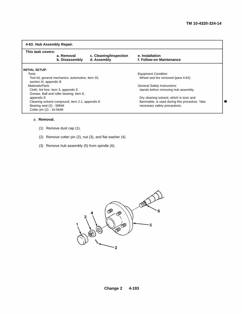
TM 10-4320-324-14
Change 2 4-193
a. Removal.
(1) Remove dust cap (1).
(2) Remove cotter pin (2), nut (3), and flat washer (4).
(3) Remove hub assembly (5) from spindle (6).
4-63. Hub Assembly Repair.
This task covers:a. Removal c. Cleaning/Inspection e. Installationb. Disassembly d. Assembly f. Follow-on Maintenance
INITIAL SETUP:Tools Equipment ConditionTool kit, general mechanics: automotive, item 32, Wheel and tire removed (para 4-62).section III, appendix B
Materials/Parts General Safety InstructionsCloth, lint free: item 3, appendix E stands before removing hub assembly.Grease, Ball and roller bearing: item 6,appendix E Dry cleaning solvent, which is toxic andCleaning solvent compound, item 2.1, appendix E flammable, is used during this procedure. TakeBearing seal (2) - 58846 necessary safety precautions.Cotter pin (2) - 16-5648

TM 10-4320-324-14
4-194 Change 2
b. Disassembly.
(1) Remove outer bearing (7) and outer race (8).
(2) Remove seal (9), inner bearing (10), and inner race (11).
c. Cleaning/Inspection.
Skysol 100 cleaning solvent is combustible. Use mechanical ventilationwhenever product is used in a confined space, is heated above ambienttemperatures, or is agitated. DO NOT use or store near heat, sparks,flame, or other ignition sources. Keep container sealed when not in use.
Contact with Skysol 100 cleaning solvent may cause skin irritation. Usechemical resistant gloves. In case of skin contact, remove anycontaminated clothing and wash skin thoroughly with soap and water.Wash contaminated clothing before reuse. Eye contact may causeirritation, tearing or blurring of vision. Use face shield or goggles wheneye contact may occur. In case of eye contact, flush eyes with largeamounts of water for at least fifteen (15) minutes or until irritationsubsides. Inhalation may cause irritation to upper respiratory passages.DO NOT have food or drink in the vicinity.
• Do not DRY SPIN bearings with compressed air. Bearings may fly apartcausing injury to personnel and damage to bearings.
(1) Remove and clean grease in hub and on spindle. Inspect hub for cracks.
(2) Clean all metal parts with cleaning solvent compound Skysol 100 and dry with cloth.
(3) Check bearings for pitting, rusting, and wear.
(4) Check races for grooves.
(5) Check studs for thread damage.
(6) Replace all parts failing inspection.
WARNING

TM 10-4320-324-14d. Assembly.
(1) Pack two bearings (7 and 10) with grease.
(2) Apply grease and install inner race (11) bearing (10), and seal (9).
(3) Apply grease and install inner race (8) and bearing (7).
e. Installation.
(1) Coat spindle (6) with grease and install hub assembly (5).
(2) Install washer (4). Tighten nut (3) and rotate hub (5) in forward and backward direction. Adjust nut untilhub turns freely.
(3) Install cotter pin (2) and dust cap (1).
f. Follow-on Maintenance. Install tire and wheel (para 4-61).
END OF TASK
4-195

TM 10-4320-324-14
Section VI. PREPARATION FOR STORAGE OR SHIPMENT
4-64. Preservation Procedures for Storage or Shipment.
a. Crankcase.
(1) Remove oil drain cap and drain engine oil. Install cap.
(2) Remove and replace oil filter.
(3) Fill crankcase to operating level with Type II, grade 30, of MIL-L-21260 preservation oil.
b. Fuel System.
(1) Disconnect fuel line at fuel tank source selector valve and replace fuel filter.
(2) Fill a portable container with Type P-9 preservative oil (VV-L-800).
(3) Remove fuel return hose and place in an empty recovery container.
(4) Start and operate engine at approximately 1500 RPM (para 2-7).
(5) Continue to operate engine at 1500 RPM until undiluted preservation oil is flowing into recovery container.
(6) Shut down engine (para 2-7).
(7) Turn both fuel tank valves to "OFF' position.
(8) Connect lines.
(9) Drain excess fuel/preservation mixture into the recovery container and install 1/4-in. NPT pipe plugs infuel tank valves. Discard fuel/preservation mixture in recovery container.
c. Fuel Tank.
(1) Remove tank drain plug and drain tank.
(2) Thoroughly spray interior of tank with oil, Type I or II, grade 30, of MIL-L-21260 preservative lubricating oil.
(3) When drainage flow ceases, coat drain plug with same preservation oil and install.
(4) Remove fuel tank filler cap and rotate vent valve selector to CLOSED position.
(5) Install cap.
d. Pump.
(1) Remove pump drain plug, suction and discharge caps.
(2) Open suction and discharge valves.
(3) Thoroughly drain pump, manifolds, and valves. Blow out with compressed air.
4-196

TM 10-4320-324-14
WARNING I
Drinking water transfer pump internal components must not be sprayed with preservative oil specified forthe fuel transfer pumps. Failure to heed this warning can result in severe illness or death.
(4) Thoroughly spray interior of drinking water transfer pump, through suction and discharge connections andpriming connection, with petrolatum preservative, Type 14, MIL-C-10382C, in accordance with MIL-P10603D.
(5) Thoroughly spray interior of fuel transfer pump, through suction and discharge connections and primingconnection with preservative oil, MIL-P-52144D, paragraph 5.2.1.3.
(6) Install all caps and plugs.
(7) Close suction and discharge valves.
(8) Seal intermediate bracket shields with tape (PP-T-60).
NOTE
No special preservative oil is required for pump intermediate bracket.
(9) Remove vent/filler fitting at top of pump intermediate bracket and fill bracket with lubricating oil OE/HDO30.
e. Engine Combustion Chambers, Valves, Air Cleaner, Cooling Air System.
NOTE
Do not allow engine to fire during this operation.
(1) Remove air cleaner cover and cartridges.
(2) Remove air cowling.
(3) Spray inside of air cowling, elements covered by cowling, and air cleaner interior with preservative oil MIL-L-21260.
(4) Install air cowling.
(5) Install air filter cartridges and cover.
(6) Disconnect air intake hose from intake manifold.
(7) Seal air intake hose from intake manifold.
(8) While rotating engine by hand, through at least twelve complete revolutions, spray approximately twoounces of preservative oil, MIL-L-21260, into the intake manifold, allowing oil to coat valves andcombustion chamber.
4-197

TM 10-4320-324-14
NOTEDo not rotate engine after this operation is complete.
(9) Remove engine air intake and exhaust manifolds.
(10) Expose area to black (ultraviolet) light. Areas that have been coated with treated oil will fluoresce whenexposed to the black light, giving an indication of preservative coating.
(11) Install air intake and exhaust manifolds.
(12) Seal engine dipstick, filler cap and breather with tape (PP-T-60).
f. Rocker Arm Assemblies, Injection Pump, and Push Rods Preservation.
(1) Coat rocker arm and injection pump assemblies with preservative oil, MIL-L-21260.
(2) Spray a small amount of preservative oil, MIL-L-21260, over exposed push rod assemblies.
g. Drive Belts and Pulleys.
(1) Remove v-belt guard and blower extension.
(2) Remove cooling blower drive v-belt from blower pulley.
(3) Relieve tension from alternator v-belt.
(4) Coat unpainted surfaces of pulleys with a thin film of primer (TT-P-664).
(5) Install v-belt guard.
(6) Hang tag (UU-T-81) on cooling air inlet indicating "DRIVE BELTS TENSION RELIEVED -ADJUST PRIORTO STARTING ENGINE."
h. Exhaust System.
(1) Remove spark arrestor.
(2) Spray interior of tail pipe and spark arrestor with preservative oil, MIL-L-21260.
(3) Install spark arrestor.
(4) Seal spark arrestor with tape (PP-T-60).
i. Tool Box.
(1) Store all required components, e.g., ground cables, operator's manual, in tool box.
(2) Seal tool box latch with tape (PP-T-60).
4-198

TM 10-4320-324-14
j. Ground Connections.
(1) Cover ground connectors with tape (PP-T-60).
(2) Wipe a thin film of preservative oil, MIL-L-21260, on ground rods.
k. Batteries and Cables.
(1) Disconnect battery cables from batteries.
(2) Place a small amount of Torque Seal, or similar material on juncture between battery caps and case.
(3) Coil battery cables and straps, and place in battery box on top of batteries.
(4) Install cover.
(5) Seal battery filler openings with tape (PP-T-60).
l. Tires. Inflate tires to 40 psi (3.5 kg/cm2).
4-65. Crating.
a. Carefully place wooden crate over pumping assembly and set on frame.
b. Wrap and secure steel bands around crate and frame.
c. Use a minimum of two bands lengthwise and two across the width.
4-66. Administrative Storage.
a. Store equipment so as to provide maximum protection from the elements and to provide access for inspection,maintenance and servicing. Anticipate removal or deployment problems, and take suitable precautions.
b. Take into account environmental conditions, such as, extreme cold or heat, high humidity, blowing snow,earthquakes, or combinations thereof, and take adequate precautions.
c. Placement of equipment in administrative storage should be for short periods of time when a shortage ofmaintenance effort exists. Items should be in mission readiness within 24 hours or within the time factors asdetermined by the directing authority. During the storage period appropriate maintenance records will be kept.
d. Before placing equipment in administrative storage, current maintenance services and equipment serviceablecriteria (ESC) evaluations should be completed, shortcomings and deficiencies should be corrected, and allmodification work orders (MWO's) should be applied.
e. Establish a fire plan, and provide for adequate precautions.
4-199/(4-200 blank)


TM 10-4320-324-14
CHAPTER 5DIRECT SUPPORT MAINTENANCE INSTRUCTIONS
Para Contents Page5-7 Alternator Assembly Testing . . . . . . . . . . . . . . . . . . . . . . . . . . . . . . . . . . . . . . . . . . . . . . . . . . . . . . . . . . . . . . . . 5-75-8 Alternator Assembly Repair . . . . . . . . . . . . . . . . . . . . . . . . . . . . . . . . . . . . . . . . . . . . . . . . . . . . . . . . . . . . . . . . 5-105-27 Axle Replacement . . . . . . . . . . . . . . . . . . . . . . . . . . . . . . . . . . . . . . . . . . . . . . . . . . . . . . . . . . . . . . . . . . . . . . . 5-965-1 Common Tools and Equipment . . . . . . . . . . . . . . . . . . . . . . . . . . . . . . . . . . . . . . . . . . . . . . . . . . . . . . . . . . . . . 5-15-21 Cooling Coil Replacement . . . . . . . . . . . . . . . . . . . . . . . . . . . . . . . . . . . . . . . . . . . . . . . . . . . . . . . . . . . . . . . . . 5-665-20 Cooling Fan Repair/Replacement . . . . . . . . . . . . . . . . . . . . . . . . . . . . . . . . . . . . . . . . . . . . . . . . . . . . . . . . . . . 5-635-25 Coupling Flange Replacement . . . . . . . . . . . . . . . . . . . . . . . . . . . . . . . . . . . . . . . . . . . . . . . . . . . . . . . . . . . . . 5-925-22 Cylinder Head Assembly Replacement . . . . . . . . . . . . . . . . . . . . . . . . . . . . . . . . . . . . . . . . . . . . . . . . . . . . . . . 5-685-17 Engine Assembly Replacement . . . . . . . . . . . . . . . . . . . . . . . . . . . . . . . . . . . . . . . . . . . . . . . . . . . . . . . . . . . . . 5-495-16 Engine Compression Check . . . . . . . . . . . . . . . . . . . . . . . . . . . . . . . . . . . . . . . . . . . . . . . . . . . . . . . . . . . . . . . 5-435-19 Engine Cowlings . . . . . . . . . . . . . . . . . . . . . . . . . . . . . . . . . . . . . . . . . . . . . . . . . . . . . . . . . . . . . . . . . . . . . . . . 5-615-28 Frame Assembly Repair/Replacement . . . . . . . . . . . . . . . . . . . . . . . . . . . . . . . . . . . . . . . . . . . . . . . . . . . . . . . 5-985-11 Fuel Tank Repair . . . . . . . . . . . . . . . . . . . . . . . . . . . . . . . . . . . . . . . . . . . . . . . . . . . . . . . . . . . . . . . . . . . . . . . . 5-185-26 Gate Valve Repair . . . . . . . . . . . . . . . . . . . . . . . . . . . . . . . . . . . . . . . . . . . . . . . . . . . . . . . . . . . . . . . . . . . . . . . 5-935-4 General . . . . . . . . . . . . . . . . . . . . . . . . . . . . . . . . . . . . . . . . . . . . . . . . . . . . . . . . . . . . . . . . . . . . . . . . . . . . . . . 5-25-12 Idler Lever Assembly Repair . . . . . . . . . . . . . . . . . . . . . . . . . . . . . . . . . . . . . . . . . . . . . . . . . . . . . . . . . . . . . . . 5-255-15 Injection Nozzle Repair/Replacement . . . . . . . . . . . . . . . . . . . . . . . . . . . . . . . . . . . . . . . . . . . . . . . . . . . . . . . . 5-385-14 Injection Pump Replacement . . . . . . . . . . . . . . . . . . . . . . . . . . . . . . . . . . . . . . . . . . . . . . . . . . . . . . . . . . . . . . . 5-295-13 Injection Pump Testing . . . . . . . . . . . . . . . . . . . . . . . . . . . . . . . . . . . . . . . . . . . . . . . . . . . . . . . . . . . . . . . . . . . . 5-265-18 Intake and Exhaust Manifolds Replacement . . . . . . . . . . . . . . . . . . . . . . . . . . . . . . . . . . . . . . . . . . . . . . . . . . . 5-555-24 Pump Assembly Repair . . . . . . . . . . . . . . . . . . . . . . . . . . . . . . . . . . . . . . . . . . . . . . . . . . . . . . . . . . . . . . . . . . . 5-785-23 Pump Assembly Replacement . . . . . . . . . . . . . . . . . . . . . . . . . . . . . . . . . . . . . . . . . . . . . . . . . . . . . . . . . . . . . . 5-745-3 Repair Parts . . . . . . . . . . . . . . . . . . . . . . . . . . . . . . . . . . . . . . . . . . . . . . . . . . . . . . . . . . . . . . . . . . . . . . . . . . . . 5-25-2 Special Tools, TMDE, and Support Equipment . . . . . . . . . . . . . . . . . . . . . . . . . . . . . . . . . . . . . . . . . . . . . . . . . 5-15-10 Starter Assembly Repair . . . . . . . . . . . . . . . . . . . . . . . . . . . . . . . . . . . . . . . . . . . . . . . . . . . . . . . . . . . . . . . . . . 5-165-9 Starter Assembly Testing . . . . . . . . . . . . . . . . . . . . . . . . . . . . . . . . . . . . . . . . . . . . . . . . . . . . . . . . . . . . . . . . . . 5-135-5 Troubleshooting . . . . . . . . . . . . . . . . . . . . . . . . . . . . . . . . . . . . . . . . . . . . . . . . . . . . . . . . . . . . . . . . . . . . . . . . . 5-2
Section I. GENERAL INFORMATION
5-1. Common Tools and Equipment.
For authorized common tools and equipment, refer to the Modified Table of Organization and Equipment (MTOE) applicableto your unit.
5-2. Special Tools, TMDE, and Support Equipment.
Special Tools are listed and illustrated in the Repair Parts and Special Tools List (RPSTL), TM 10-4320-324-24P, coveringunit, direct support, and general support maintenance (including Depot Maintenance Repair Parts and Special Tools) for thisequipment.
Change 2 5-1

TM 10-4320-324-14
5-2
5-3. Repair Parts.
Repair parts are listed and illustrated in the Repair Parts and Special Tools List (RPSTL), TM 10-4320-324-24P, coveringunit, direct support, and general support maintenance (including Depot Maintenance Repair Parts and Special Tools) forthis equipment.
Section II. TROUBLESHOOTING
5-4. General.
This section contains troubleshooting information for locating and correcting the common malfunctions which may beencountered during the operation or maintenance of the 350 GPM Pumping Assembly or its components.
5-5. Troubleshooting. I
To troubleshoot the 350 GPM Pumping Assembly, refer to Table 5-1, Troubleshooting.a. Each malfunction for an individual component, unit or system is followed by a list of tests or inspections which will
help in determining corrective actions to take. Perform the tests/inspections and corrective actions in the orderlisted.
b. This manual cannot list all malfunctions that may occur, nor all tests or inspections and corrective actions. If amalfunction is not listed or is not corrected by listed corrective actions, notify the appropriate supervisor.
Table 5-1. Troubleshooting
MALFUNCTIONTEST OR INSPECTION
CORRECTIVE ACTION1 ENGINE ASSEMBLY 1. ENGINE FAILS TO START.
Step 1. Check for loose, broken, frayed or damaged wires between fuel shutdown solenoid, low oil pressureswitch and V-belt switch.
Replace or repair wires as required.
Step 2. Check for broken or frayed wires between alternator and voltage regulator.
Replace or repair wires as required.

TM 10-4320-324-14
Table 5-1. Troubleshooting - CONT.
MALFUNCTION
TEST OR INSPECTION
CORRECTIVE ACTION
ENGINE ASSEMBLY (CONT)
1. ENGINE FAILS TO START (CONT).
Step 3. Check for closed shut-off valve.
Open shut-off valve and bleed fuel system (para 4-45), if necessary.
Step 4. Inspect for leaks at fuel tank.
Refer to paragraph 5-11 and repair as required.
Step 5. Refer to paragraphs 4-35 and 5-7 and test alternator.
Refer to paragraph 5-8 and repair alternator.
Refer to paragraph 4-35 and replace alternator.
Step 6. Refer to paragraph 5-13 and test injection pump.
Refer to paragraph 5-14 and replace injection pump.
Step 7. Test for proper starter operation.
Refer to paragraph 5-10 and repair starter.
Refer to paragraph 4-36 and replace starter.
Step 8. Inspect for burned GP relay.
Replace relay.
Step 9. Inspect for burned power relay.
Replace relay.
2. CANNOT ADJUST ENGINE SPEED.
Check for stuck fuel control lever at injection pump.
Free fuel control lever.
Refer to paragraph 5-14 and replace injection pump.
5-3

TM 10-4320-324-14
Table 5-1. Troubleshooting - CONT.
MALFUNCTION
TEST OR INSPECTION
CORRECTIVE ACTION
ENGINE ASSEMBLY (CONT)
3. ENGINE PERFORMANCE IS POOR.
Check for broken valve spring.
Refer to paragraph 5-17 and replace engine.
4. EXHAUST SMOKE IS WHITE AND EXCESSIVE.
Check for inefficient compression due to sticking or broken compression rings or incorrect valve clearance.
Refer to paragraph 5-17 and replace engine.
5. LOW ENGINE OIL PRESSURE.
Check for excessive play on main bearing.
Refer to paragraph 5-17 and replace engine.
6. AMMETER READING TOO LOW.
Check for defective alternator, causing insufficient charging of the batteries.
Refer to paragraph 5-8 and repair alternator.
7. ENGINE OVERHEATS.
Check condition and operation of cooling fan.
Refer to paragraph 5-20 and repair or replace cooling fan.
PUMP ASSEMBLY
1. NO SUCTION OR DISCHARGE PRESSURE.
Inspect for faulty seal or pump gasket.
Refer to paragraph 5-24 and replace seal.
5-4

TM 10-4320-324-14
Table 5-1. Troubleshooting - CONT.
MALFUNCTION
TEST OR INSPECTION
CORRECTIVE ACTION
PUMP ASSEMBLY (CONT)
2. PUMP STOPS OR FAILS TO DELIVER RATED FLOW OR PRESSURE.
Step 1. Inspect for faulty seal or pump gasket.
Refer to paragraph 5-24 and replace seal.
Step 2. Check for clogged impeller.
Refer to paragraph 5-24 and free impeller.
Step 3. Inspect for broken impeller or wear plate.
Refer to paragraph 5-24 and replace impeller or wear plate.
Step 4. Check that pump is not driven too slowly.
Check engine speed.
3. PUMP NOISY.
Step 1. Check for proper bearing lubrication.
Refer to paragraph 5-24 and replace bearings.
Step 2. Check for bent impeller shaft.
Refer to paragraph 5-24 and replace impeller shaft.
Step 3. Inspect for worn bearings.
Refer to paragraph 5-24 and replace bearings.
Step 4. Check for binding, broken, or loose rotating parts.
Refer to paragraph 5-24 and replace parts as required.
Step 5. Check for cavitation.
Refer to paragraph 5-24 and replace parts causing cavitation.
5-5

TM 10-4320-324-14
5-6 Change 2
Table 5-1. Troubleshooting (Contd).
MALFUNCTIONTEST OR INSPECTION
CORRECTIVE ACTION
FRAME ASSEMBLY
1. UNIT DOES NOT TRACK STRAIGHT.
Step 1. Inspect for damaged towbar.
Replace towbar.
Step 2. Inspect for bent, broken, or damaged frame.
Refer to paragraph 5-28 and repair as required.
Refer to paragraph 5-28 and replace frame assembly.
Step 3. Inspect for bent, broken, or damaged axle.
Notify general support maintenance.
TM 10-4320-324-14
5-7. Alternator Assembly Testing.
This task covers:
a. Testing b. Follow-on Maintenance
INITIAL SETUP:
Test Equipment Equipment ConditionVoltmeter, item 40, section III, appendix B Alternator removed (para 4-35).Tachometer, item 43, section III, appendix B
ToolsTool kit, general mechanics, item 35, section 11,appendix B
CAUTION
• Do not, under any circumstances, short field terminal of alternator to ground. Permanent damage toregulator may occur.
• Do not disconnect voltage regulator while alternator is operating. Large voltage transient may occur anddamage regulator.
• Do not disconnect alternator output lead from alternator while alternator is operating, as damping effect ofbattery will be lost. The voltage will rise to an extreme value and permanent damage to regulator mayoccur.
• Do not remove alternator from engine without first disconnecting ground battery cable. Permanentdamage to regulator may result.
NOTE
• Battery used in electrical testing must be of correct voltage and must be in good condition and fullycharged.
5-7

TM 10-4320-324-14
5-7 Alternator Assembly Testing (CONT).
a. Testing.
(1) Regulator test (open).
NOTEAlternator should be mounted in vise, shaft rotating at 3000 RPM, with jumper wire installed between Band the field terminal.
(a) Measure voltage at terminal A. Meter should read approximately 14 volts.
(b) Increase RPM to 4000. (Clockwise as viewed facing the fan.)
(c) Measure voltage at terminal A. Voltage should increase to 15 to 16 volts.
(d) Readings other than these indicate the alternator is open and should be replaced.
5-8

TM 10-4320-324-14
(2) Regulator test (shorted).
NOTEMount alternator on test stand, shaft rotating at 3000 RPM to perform this test.
(a) Measure voltage at terminal A. The meter should indicate approximately 14 volts.
(b) Increase RPM to 4000. If voltage at A increases beyond 15 volts, regulator is shorted. Replaceregulator.
b. Follow-on Maintenance.
Install alternator (para 4-35).
END OF TASK
5-9

TM 10-4320-324-14
5-8. Aternator Assembly Repair.
This task covers:a. Disassembly c. Assemblyb. Cleaning/Inspection d. Follow-on Maintenance
INITIAL SETUP:
Tools Materials/PartsTool kit, general mechanics, item 35, section III, Lockwashers (2) - MS35338-44appendix BMultimeter, item 34, section III, appendix B Equipment Condition
Alternator removed (para 4-35).
a. Disassembly.
(1) Remove three screws (1).
(2) Pull regulator back and disconnect green electrical lead (2) from the brush assembly.
(3) Remove two nuts (4), two lockwashers (5) and remove the electrical leads (6 and 7).
5-10

TM 10-4320-324-14
(4) Remove two screws (8), cover (9), and brush assembly (3).
b. Cleaning/Inspection.
(1) Inspect brush assembly for excessive wear. Replace brush if 3/16 in. or less extends beyond bottom of holder.
(2) Inspect for foreign material, oil or dirt.
NOTE
• Correct tension to move brush against spring to 4 to 6 ounces.
• Resistance should not vary when brush and connecting wire is moved around.
(3) Inspect brush for correct spring tension.
NOTEUse a 12 volt test lamp or ohmmeter for thefollowing procedures.
(4) Insulation test. Test point A to point D.
(5) No circuit indicates no short circuit -assembly is correct.
(6) Continuity test. Test point A to point c and point D topoint E.
(7) A continuous circuit indicates no open connectionassembly is correct.
5-11

TM 10-4320-324-14
5-8. Alternator Assembly Repair (CONT).
c. Installation.
(1) Install electrical leads (6 and 7) and secure with two lockwashers (5) and two nuts (4).
(2) Connect electrical lead (2) to brush assembly (3).
(3) Install three screws (1).
d. Follow-on Maintenance.
Install alternator (para 4-35).
END OF TASK
5-12

TM10-4320-324-14
5-9. Starter Assembly Testing.
This task covers:a. Testing b. Follow-on Maintenance
INITIAL SETUP:
Test Equipment Equipment ConditionAmmeter, item 41, section III, appendix B Starter removed (para 4-36).Voltmeter, item 40, section III, appendix BTachometer, item 43, section IlI, appendix B General Safety InstructionsCarbon Pile, item 42, section III, Be sure switch is open when connecting power toappendix B test setup. You could be shocked or burned.
ToolsTool kit, general mechanics, item 35, section III,appendix B
a. Testing.
(1) Rotate pinion (1) by hand. If pinion does not rotate freely, repair per para 5-10.
(2) Using a screwdriver (2), pry the pinion upward and rotate with your free hand. If pinion does not rotate freely,repair per para 5-10.
5-13

TM 10-4320-324-14
5-9. Starter Assembly Testing (CONT).
(3) If pinion rotates freely, perform the following no-load test prior to disassembly.
(a) Connect a voltmeter from starter motor terminal to starter motor frame. Connect negative battery cable tostarter motor frame.
(b) Mount tachometer to measure armature speed.
WARNINGEnsure switch is open prior to connecting to starter solenoid. Electrical shock or physical injury may resultif starter is energized while making final battery connection.
(c) Connect switch to solenoid battery terminal and solenoid switch terminal.
(d) Connect ammeter in series between the positive side of the battery and battery terminal on the startersolenoid.
(e) Connect carbon pile between positive and negative battery terminals.
(f) Close switch and adjust carbon pile until voltmeter indicates 11 VDC.
(g) Write down ammeter and tachometer readings.
(h) Open switch and de-energize starter.
(i) Refer to table 5-1 for current and rpm performance specifications.
5-14

TM 10-4320-324-14
Table 5-2. Starter No-Load Test Specifications
No-Load Test (Includes Solenoid Current)
Volts Min Amps Max Amps Min RPM Max RPM
11 120 210 9000 13400
(j) Remove test equipment from starter assembly. If measured performance is above or below performancespecifications remove and test solenoid assembly per paragraph 5-10.
b. Follow-on Maintenance . Install starter (para 4-36).
END OF TASK
5-15
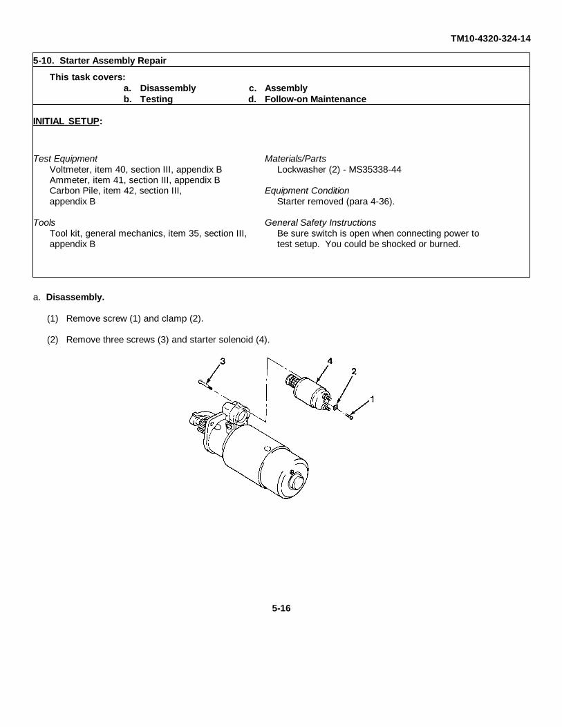
TM10-4320-324-14
5-10. Starter Assembly Repair
This task covers:
a. Disassembly c. Assembly
b. Testing d. Follow-on Maintenance
INITIAL SETUP:
Test Equipment Materials/PartsVoltmeter, item 40, section III, appendix B Lockwasher (2) - MS35338-44Ammeter, item 41, section III, appendix BCarbon Pile, item 42, section III, Equipment Conditionappendix B Starter removed (para 4-36).
Tools General Safety InstructionsTool kit, general mechanics, item 35, section III, Be sure switch is open when connecting power toappendix B test setup. You could be shocked or burned.
a. Disassembly.
(1) Remove screw (1) and clamp (2).
(2) Remove three screws (3) and starter solenoid (4).
5-16

TM 10-4320-324-14
b. Testing.
(1) Perform starter solenoid ammeter test.
(a) Connect positive battery cable to one side of theammeter and the negative battery cable to solenoidground.
WARNINGEnsure switch is open prior to connecting to startersolenoid. Electrical shock may result solenoid isenergized while making final battery connection.
(b) Connect switch leads to ammeter and solenoid switchterminal (S).
(c) Connect voltmeter leads to solenoid ground andsolenoid switch terminal (S).
(d) Connect carbon pile across positive and negativebattery terminals.
(e) Close switch and adjust carbon pile until voltmeterindicates 11 VDC.
(f) Observe ammeter reading. If reading is below or above 120 to 210 amps, replace starter solenoid. Ifsolenoid is good, install new starter assembly per paragraph 4-36.
c. Assembly.
(1) Attach starter solenoid (4) with three screws (3).
(2) Install clamp (2) and screw (1).
d. Follow-on Maintenance.
Install starter assembly (para 4-36).
END OF TASK
5-17

TM 10-4320-324-14
5-18 Change 2
4-10. Fuel Tank Repair.
This task covers:a. Removal c. Inspection e. Installationb. Disassembly d. Repair f. Installation
INITIAL SETUP:
Tools Personnel RequiredTool kit, general mechanics, item 35, section III, Twoappendix B
Equipment ConditionMaterials/Parts Engine assembly removed (para 5-17).Adhesive, MM-A-122, item 1, appendix E Pump assembly removed (para 5-23).Cleaning solvent compound, item 2.1,appendix E General Safety Instructions
Lockwashers (4) - MS35338 Keep fuel from sources of heat or open flames.Wear personal protective equipmentwhen using cleaning solvent.

TM 10-4320-324-14
Change 2 5-19
a. Removal.
WARNINGFuel is very flammable and can explode easily. To avoid serious injury ordeath, keep fuel away from open fire and keep fire extinguisher withineasy reach when working with fuel. Do not work on fuel system whenengine is hot. Fuel can be ignited by hot engine. When working with fuel,post signs that read NO SMOKING WITHIN 50 FEET of vehicle.
(1) Drain fuel in a suitable container by removing drain plug (1). Install drain plug (1).
(2) Disconnect and plug open ends of hose fittings (2). Clean up any spilled fuel prior to proceeding to the nextstep.
2
1
2

TM 10-4320-324-14
5-20 Change 2
5-11. Fuel Tank Repair (Contd).
(3) Remove drain plug (2) from fuel tank bulkhead (1).
(4) Remove two three-way fuel selector valves (3).
(5) Remove four nuts (4), lockwashers (5), flat washers (6), screws (8), and flat washers (7). Discardlockwashers (5).
(6) Remove two top straps (9), rubber washer (10), and fuel tank (11).
(7) Remove two bottom straps (12).
b. Disassembly.
(1) Remove filler cap, (13) gasket (14), and strainer (15).
(2) Remove fuel gauge (16) by rotating counterclockwise.
16
3
133
8
7
6
7
4
11
21
12
6
5
4
10
7
8
14
15
10
TM 10-4320-324-14
Change 2 5-21
WARNINGSkysol 100 cleaning solvent is combustible. Use mechanical ventilationwhenever product is used in a confined space, is heated above ambienttemperatures, or is agitated. DO NOT use or store near heat, sparks,flame, or other ignition sources. Keep container sealed when not in use.
Contact with Skysol 100 cleaning solvent may cause skin irritation. Usechemical resistant gloves. In case of skin contact, remove anycontaminated clothing and wash skin thoroughly with soap and water.Wash contaminated clothing before reuse. Eye contact may causeirritation, tearing or blurring of vision. Use face shield or goggles wheneye contact may occur. In case of eye contact, flush eyes with largeamounts of water for at least fifteen (15) minutes or until irritationsubsides. Inhalation may cause irritation to upper respiratory passages.DO NOT have food or drink in the vicinity.
(1) Clean exterior and interior of fuel tank with cleaning solvent, compound Skysol 100.
(2) Flush fuel tank with continuous flow of clean water.
(3) Perform fuel tank pressure check.
(a) Connect air fitting to fuel inlet opening. Plug remaining fuel tank openings.
WARNINGCompressed air used for cleaning purposes will not exceed 30 psi. Useonly with effective chip guarding and personal protective equipment(goggles/shield, gloves, etc).
(b) Attach air hose to air fitting on fuel tank.
(c) Adjust air regulator to provide between 4 to 5 psi.
(d) Open air valve and pressurize tank between 4 to 5 psi (0.28 - 0.35 kg/cm2) for five minutes. Check forsigns of leakage or permanent deformation.
(e) Close air valve and bleed off air pressure from fuel tank.
(f) Disconnect air hose and remove plugs and air fitting from fuel tank.
(4) Inspect tank straps for cracks, breaks, and torn or separated rubber.
(5) Inspect condition of filler cap gasket and fording vent valve.
(6) Inspect fuel indicator for broken or cracked face glass. Inspect glass frame screws for looseness.

TM 10-4320-324-14
5-22 Change 2
d. Repair.
(1) Weld tank in accordance with TM 9-237 for Plain Carbon Steel.
(2) Replace filler cap (12) if fording vent valve contains defects.
(3) Replace strainer (14) if defective.
(4) Replace damaged rubber on tank straps using adhesive MM-A-122 or equivalent.
(5) Replace filler cap gasket (13) if defective.
(6) Replace fuel indicator (15) if defects are found.
e. Assembly.
(1) Install and tighten fuel indicator (15) by rotating clockwise.
(2) Install strainer (14), gasket (13), and filler cap (12).
5-11. Fuel Tank Repair (Contd).
16 3
13
3
8
7
1498
7
54
11
456
15
12
10
6
10
21

TM 10-4320-324-14
Change 2 5-23
f. Installation.
(1) Install two lower tank straps (12) aligning frame and strap screw holes.
(2) Install four screws (8) through two lower straps (12) and frame to prevent straps from moving while installingfuel tank.
(3) Install and align fuel tank (11) on top straps (9).
(4) Remove four screws (8).
(5) Install two rubber washers (9), two top straps (10) and align screw holes with two lower straps (12).
(6) Install four screws (8), four washers (7), four washers (6), four new lockwashers (5), and four nuts (4).
(7) Install two three-way selector valves (3).
(8) Install drain plug (2) on fuel tank bulkhead (1).

TM 10-4320-324-14
5-24 Change 2
(9) Remove pipe plugs from two hose fittings (2), and install on two three-way selection valves (3).
(10) Tighten drain plug (1).
g. Follow-on Maintenance.
(1) Install pump (para 5-23).
(2) Install engine assembly (para 5-17).
END OF TASK
5-11. Fuel Tank Repair (Contd).
2
23
1
3

TM 10-4320-324-14
Change 2 5-25
a. Disassembly.
(1) Remove spring (1), flat washer (2), and bearing sleeve (3) from cover (4). Discard spring (1) and bearingsleeve (3).
(2) Remove dowel sleeve (5), shaft (6), lever (7), seal (8), and bearing sleeve (9). Discard seal (8) and bearingsleeve (9).
b. Cleaning/inspection. Inspect all parts for wear.
c. Repair. Replace all defective parts.
d. Assembly.
(1) Install new bearing sleeve (9), new seal (8), lever (7), shaft (6), and dowel sleeve (5).
(2) Install new bearing sleeve (3), flat washer (2), and new spring (1) in cover (4).
e. Follow-on Maintenance. Install idler pulley assembly (para 4-51).
END OF TASK
5-12 Idler Lever Assembly Repair
This task covers:
a. Disassembly c. Repair e. Follow-on Maintenanceb. Cleaning/Inspection d. Assembly
INITIAL SETUP:Tools Equipment ConditionTool kit, general mechanics, item 35, section III, Idler pulley assembly removed (para 4-51)appendix B
Materials/PartsSpring - 223 4345 Bearing sleeve - 223 0851Seal - 116 6110
6
9
43
1 2
8
75

TM 10-4320-324-14
5-26 Change 2
5-13. Injection Pump Testing.
This task covers:a. Testing b. Follow-on Maintenance
INITIAL SETUP:
Tools Equipment ConditionTool kit, general mechanics, item 35, section III Rocker cover removed (para 5-22).appendix B V-belt guard removed (para 4-31).Tester gauge, item 31, section III, appendix B Roof panels removed (para 4-13).
Materials/PartsRetaining rings (2) - 1320784Gasket- 1309117
3
2
10
97
654
8
1
BLEED VALVELOCATION

TM 10-4320-324-14
Change 2 5-27
a. Testing.
WARNINGFuel is under high pressure during this test. Pressure is sufficient topenetrate skin and cause severe injury to personnel.
(1) Rotate and secure injection input lever (1) clockwise (towards dipstick), to full run position.
CAUTIONDo not bend injection lines more than 5° from original shape or lines maybreak.
(2) Loosen three injection lines (2).
NOTEThe following steps apply to each of the three elements.
(3) Disconnect an injection line (2) from element to be tested.
(4) Refer to paragraph 4-45 and evacuate air from injection pump.
(5) Connect injection pump test gauge (3) to the element to be tested.
(6) Open bleeder valve (10) on back of test gauge (3).
(7) Remove two hex socket screws (4), two retaining rings (5), cover (6), and gasket (7).
(8) Manually rotate crankshaft (8) clockwise until injection pump element to be tested is at the bottom of itsstroke.
NOTEThe lever bar should apply pressure under head of element adjustmentscrew. Use care in inserting lever
bar in order not to dislodge plunger spring keeper.
(9) Insert lever bar (9) under injection pump plunger element adjustment screw head, and carefully applydownward pressure on lever bar to evacuate air from gauge. When escaping fuel is free of bubbles, closebleeder valve (10) on test gauge (3).
(10) While holding shut off solenoid up in open position, pump lever bar (9) until test gauge reads 2175 psi (150bar). Observe reading for 60 seconds. Replace pump if measured pressure is below 145 psi (10 bar).
(11) While holding shut off solenoid up in open position, pump lever bar (9, approximately five strokes) until testgauge reads 5075 psi (350 bar). Replace pump if 5075 psi cannot be obtained.
(12) Repeat the above steps (4) through (12) for the other two elements.
(13) Install gasket (7) and injection cover (6) with two retaining rings (5) and screws (4).

TM 10-4320-324-14
5-28 Change 2
(14) Remove test gauge (3) and install three lines (2).
(15) Refer to paragraph 4-45 and bleed injection lines and tighten fittings on three lines (2).
(16) Return injection pump lever (1) to shutdown position.
b. Follow-on Maintenance.
(1) Install rocker cover (para 5-22).
(2) Install v-belt guard (para 4-31).
(3) Install roof panels (para 4-13).
END OF TASK
3
2
10
97
654
8
1
BLEED VALVELOCATION
5-13. Injection Pump Testing (Contd).

TM 10-4320-324-14
Change 2 5-29
5-14. Injection Pump Replacement.
This task covers:a. Timing c. Installationb. Removal d. Follow-on Maintenance
INITIAL SETUP:Tools Tool kit, general mechanics, item 35, section III, appendix BAdjusting device, item 1, section III, appendix BDial gauge, item 2, section III, appendix BPointer, item 3, section III, appendix B Injection timing pump, item 23, section III, appendix B
Materials/PartsGasket - 213 6717Washers (3) - 111 8693Sealing ring - 121 6306Cloth, lint free, Item 3, Section III, Appendix E
Equipment ConditionShutdown solenoid removed (para 4-40).Throttle control rod removed (para 4-39).Fuel feed pump removed (para 4-44).Idler pulley removed (para 4-51).
General Safety InstructionsMaintenance shall be performed away fromsources of heat and open flame.

TM 10-4320-324-14
5-30 Change 2
a. Timing.
(1) Determine Top Dead Center (TDC) and FuelInjection (FI) point on cylinder number 1.
(a) Rotate crankshaft clockwise until valvesoverlap (until exhaust valves about to closeand intake valve about to open) and thenrotate crank another 1/2 turn.
(b) Install adjusting tool by setting rocker armbetween 5 to 6 mm using screw press (1).
(c) Install pre-tension dial gauge (2).
(d) Slowly rotate crankshaft clockwise until pistonpushes valve up and dial gauge (2) pointerchanges direction. Adjust dial gauge to zero(0).
(e) Rotate crankshaft counterclockwise onerevolution of dial gauge (2).
(f) Rotate crankshaft clockwise until dial gauge
(2) pointer indicates 0.1 mm (10 graduations) from"0" position.
(g) Install pointer (3) in dowel sleeve (4).
(h) Scribe mark on pulley to align with pointer (3).
(i) Rotate crankshaft clockwise until dial gauge(2) pointer completes one revolution. Slowlyrotate crankshaft counterclockwise until dialgauge pointer reads 0.1 mm (10) graduations)from "0" position.
(j) Scribe mark on pulley to align with pointer (3).
5-14. Injection Pump Replacement (Contd).
43
1
2

TM 10-4320-324-14
(k) Measure and mark the halfway position (3) between the two marks (1 and 2). This indicates the Top DeadCenter (TDC) of the number one cylinder.
(l) Measure 2-13/32 in. (61.12 mm) clockwise from Top Dead Center (4) to determine fuel injection point (5).
(m) Remove pointer, dial gauge, and adjusting tool.
5-31

TM 10-4320-324-14
5-32 Change 2
b. Removal.
NOTECap or plug all fuel lines, hoses, fittings, and open fuel ports to prevent contamination of fuel system.
(1) Remove banjo bolt (1), two washers (2), and banjo fitting (3). Discard washers (2).
(2) Remove overflow valve bolt (4), washer (5), banjo fitting (6), and sealing ring (7). Discard sealing ring (7)and washer (5).
(3) Remove three fuel injection lines (8), (9), and (10).
(4) Manually rotate engine clockwise until No. 1 injection pump element (element closest to governor end ofpump) is in upper position and crankshaft pulley is located on TDC mark.
1
2 3
28
910
7
6
54
5-14. Injection Pump Replacement (Contd).

TM 10-4320-324-14
Change 2 5-33
CAUTIONDo not drop capscrews or washers into timing cover. A clean shop clothplaced inside case will catch tools or hardware.
(5) Remove three capscrews (11), three lockwashers (12), and three washers (13). Discard lockwashers (12).
(6) Remove four nuts (14) and four washers (15).
(7) Holding injection pump drive gear (16) in mesh, carefully remove injection pump (17) and gasket (18).Discard gasket (18).
NOTEDo not rotate crankshaft; leave engine in No. 1 TDC position.
(8) Remove nut (19) from pump shaft.
(9) Use standard puller and remove hub (20).
(10) If damaged, remove four studs (21).
17
2218
16
20
19 11
121321
1514
NUMBER 1INJECTION PUMPELEMENT

TM 10-4320-324-14
5-34 Change 2
c. Installation.
(1) Ensure key (22) is installed on pump shaft.
(2) If removed, install four studs (21).
(3) Install hub (20) on camshaft of injection pump.
(4) Install nut (19) and tighten in accordance with torque instructions shown in Appendix F.
(5) Position new gasket (18), over studs (21) at pump mounting flange.
(6) Hold gear (16) in mesh (through belt tightener opening) with the right hand, while using the left hand to installinjection pump (17) onto mounting studs (21), centering the elongated holes of injection pump mounting.
(7) Install four washers (15) and four nuts (14).
(8) While keeping injection pump drive gear in mesh, rotate injection pump flange nut (19) clockwise until No. 1injection pump plunger is to top of stroke.
(9) Loosely install three washers (13), three new lockwashers (12), and three bolts (11).
NOTERemove shop cloth from timing gear case.
(10 Remove plugs and caps from all bores and lines.
5-14. Injection Pump Replacement (Contd).
NUMBER 1INJECTIONPUMP ELEMENT
17
2218
16
20
121311
19
211514

TM 10-4320-324-14
Change 2 5-35
NOTENo. 1 injection pump outlet is located at governor end on injection pump.
(11) Install special overflow pipe (23) and catch container (24) onto No. 1 injection pump outlet, and looselyinstall two remaining injection lines (9) and (10).
(12) Rotate governor input lever (27) clockwise (towards dipstick), to full run position, and secure lever inposition.
(13) Install plug (25) in overflow port.
(14) Install high pressure hand pump (26) on inlet port with two new washers (2) and banjo bolt (1).
(15) Adjust start of fuel injection as follows:
(a) Turn crankshaft counterclockwise, through 90 degrees from point of fuel mark (FI). Rotate V-belt pulleyclockwise until FI mark registers with timing indicator.
(b) Pump hand-pump (26) until fuel flows from overflow tube (23).
8
239
10
45
6
7
25
11
1924
3
2
126

TM 10-4320-324-14
5-36 Change 2
CAUTIONDo not drop capscrews or washers into timing cover. Aclean shop cloth placed inside case will catch tools orhardware.
(c) Turn injection pump nut (19) until one drop every 5 to 8 secondsappears at the end of the overflow tube, with timing pointer (28)aligned with fuel injection point mark.
(d) Hold injection pump shaft in this position and tighten screws (11).
(e) Recheck fuel beginning point by repeating steps (a) through (d).
(16) Remove overflow pipe (23) and catch container (24).
(17) Install and tighten fuel line (7).
(18) Remove hand pump (26), and install inlet fuel line (3) with two new washers (2) and banjo bolt (1).
(19) Remove plug (25) from overflow port.
(20) Install new sealing ring (7) and fuel overflow line (6) with new washer (5), and banjo bolt (4).
5-14. Injection Pump Replacement (Contd).
4
109
23
8
28
243
126
1119
25
5
6
7
2

TM 10-4320-324-14
d. Follow-on Maintenance .
(1) Install idler pulley (para 4-51).
(2) Install fuel feed pump (para 4-44).
(3) Install shutdown solenoid (para 4-40).
(4) Install throttle control rod (para 4-39).
END OF TASK
5-37

TM 10-4320-324-14
5-38 Change 2
a. Removal.
(1) Remove nut (1) and nozzle retainer (2).
5-15. Injection Nozzle Repair/Replacement
This task covers:a. Removal d. Cleaning/Inspection f. Installationb. Testing e. Assembly g. Follow-on Maintenancec. Disassembly
INITIAL SETUP:
Tools Tool kit, general mechanics, item 35, section III,appendix BPuller, item 5, section III, appendix B Puller, item 6, section III, appendix B Gasket extractor, item 17, section III, appendix BSlide hammer, item 19, section III, appendix B Injection seal remover, item 24, section III, appendix B
Materials/PartsCleaning solvent compound, item 2.1, appendix EPacking (3) - 337-2164
Equipment ConditionInjector fuel lines removed (para 4-41).
General Safety InstructionsWear personal protective equipment whenusing cleaning solvent and compressed air.During testing, fuel under very high pressurecoming out of the injector can severely cut you.
1
2

TM 10-4320-324-14
(2) Install thread adapter and extractor (2) to injector (1).
(3) Install slide hammer (3) on extractor (2) and removeinjector (1).
(4) Remove packing (5) from injector nozzleport with gasket extractor (4).
5-39

TM 10-4320-324-14
5-15. Injection Nozzle Repair/Replacement (CONT).
b. Testing.
WARNINGKeep hands away from spray. Spray is under high pressureand can cut through skin.
(1) Connect injector (1) to tester (2).
(2) With pressure gauge cut in, press tester pump lever several times.
(3) Read opening pressure and inspect spray pattern.
NOTEReadings should be 2537-2653 psi (175-183 bar) for used nozzle. Readings should be 2610-2726 psi(180-188 bar) for new nozzle, or new spring in nozzle. The jet pattern must be solid without surroundingmist.
(4) Reduce pressure to 362.5-435 pounds (25-30 bar) below specified opening pressure, check that no fuel dribblesfrom nozzle.
(6) Adjust nozzle opening pressure by adding or removing shims (7), as directed in paragraph e.
c. Disassembly.
(1) Using a suitable clamping device, remove union nut (1), nozzle (2), needle (3), and intermediate piece (4).
(2) Remove plunger (5), spring (6), and shims (7), from holder (8).
5-40

TM 10-4320-324-14
Change 2 5-41
WARNING• Skysol 100 cleaning solvent is combustible. Use mechanical ventilation
whenever product is used in a confined space, is heated aboveambient temperatures, or is agitated. DO NOT use or store near heat,sparks, flame, or other ignition sources. Keep container sealed whennot in use.
• Contact with Skysol 100 cleaning solvent may cause skin irritation. Usechemical resistant gloves. In case of skin contact, remove anycontaminated clothing and wash skin thoroughly with soap and water.Wash contaminated clothing before reuse. Eye contact may causeirritation, tearing or blurring of vision. Use face shield or goggles wheneye contact may occur. In case of eye contact, flush eyes with largeamounts of water for at least fifteen (15) minutes or until irritationsubsides. Inhalation may cause irritation to upper respiratory passages.DO NOT have food or drink in the vicinity.
• Compressed air used for cleaning purposes will not exceed 30 psi. Useonly with effective chip guarding and personal protective equipment(goggles/shield, gloves, etc).
(1) Wash all parts in clean cleaning solvent compound Skysol 100 and blow out with compressed air.
e. Assembly.
(1) Install shims (7) and spring (6) in holder (8) and plunger (5) with shoulder next to spring.
(2) Insert intermediate piece (4) with guide pins into holes in holder. Insert needle (3) in nozzle (2). Align bodyholes with guide pins in intermediate piece (4) and insert guide pins, then install union nut (1).
(3) Test injection nozzle in accordance paragraph b.

TM 10-4320-324-14
f. Installation.
(1) Install packing (4) on injector (3).
(2) Install injector (3).
(3) Install nozzle retainer (2) with nut (1).
g. Follow-on Maintenance.
(1) Install injector fuel lines (para 4-41).
(2) Install roof panels (para 4-13).
END OF TASK
5-42

TM10-4320-324-14
5-16. Engine Compression Check.
This task covers:
a. Disassembly b. Testing
c. Assembly d. Follow-on Maintenance
INITIAL SETUP:
Test Equipment Materials/PartsCompression gauge assembly, item 20, Cloth, lint free, item 3, appendix Eappendix B Packing (6) - 337 2164Compression gauge adapter, item 21, appendix B
Equipment ConditionsTools Roof panels removed Para 4-13).
Tool kit, general mechanics: automotive, item 32, section III, appendix BPuller, nozzle (003-0463), item 5, appendix BPuller, washer (003-0422), item 6, appendix B
5-43

TM 10-4320-324-14
5-44 Change 2
a. Disassembly.
(1) Run engine at medium speed for oneminute to coat cylinders with an oil film.
(2) Refer to paragraph 5-14 to remove fuelinjection.
CAUTIONHandle fuel injection nozzles with careto prevent damage. Cap inlet port andplug overflow port to prevent entry offoreign matter.
NOTENozzle puller may be required toremove injection nozzle.
(3) Remove nut (1) nozzle retainer (2),injector (3) and packing (4) fromcylinder head (5).
NOTEIf packing did not come out of cylinderhead, remove using puller.
(4) Remove bushing (6) from injector (3).
5-16. Engine Compression Check (Contd).
1
2
6
3
4
5

TM 10-4320-324-14
Change 2 5-45
(5) Disconnect shutdown lever (7) as follows:
(a) Remove pin (8) and rod (9) from shutdown lever (7).
(b) Place shutdown lever (7) in full shutdown position and wire it into place.
7
9
8
SHUTDOWNSOLENOID
NOTE: THIS VIEWROTATED 180°FOR CLARITY.THIS VIEW SHOWSBACK SIDE OFGOVERNOR ORSIDE NEXT TOENGINE BLOCK.

TM 10-4320-324-14
5-16. Engine Compression Check (CONT).
b. Testing.
(1) Install new packing (1), metal surface down,compression gauge adapter (2) and nozzle retainer(3).
(2) Thread nut (4) on to cylinder head (5) stud andtighten.
(3) Attach compression gauge (6) to compression gaugeadapter (2). Ensure all connections are tight.
(4) Place RUN switch to ON, then depress oil pressureby-pass switch and start switch at same time. Holdfor about three seconds.
(5) Record reading on compression gauge. Readingshould be between 290-406 psi (20-28 bar). Ifcompression reading is low, refer to Table 5-1,Troubleshooting.
(6) Release start switch and oil pressure by-pass switch,then place RUN switch to OFF.
(7) Remove compression gauge (6) from compressiongauge adapter (2).
5-46

TM 10-4320-324-14
Change 2 5-47
(8) Remove nut (4), nozzle retainer (3),compression gauge adapter (2) and washer(1) from cylinder head (5). Discard washer (1).
c. Assembly.
(1) Connect shutdown lever (7) as follows:
(a) Remove wire from shutdown lever (7).
(b) Insert rod (9) through lever (7).
(c) Install pin (8) in rod (9).
7
9
8
SHUTDOWNSOLENOID

TM 10-4320-324-14
5-16. Engine Compression Check (CONT).
(2) If removed, install bushing (6) on injector (3).
(3) Install new washer (4), metal side down, and nozzle (3) in cylinder head (5).
(4) Hold nozzle (3) and install nozzle retainer (2) on end of injector (3) and cylinder head (5) stud.
(5) Thread nut (1) on to cylinder head (5) stud and tighten.
END OF TASK
5-48

TM 10-4320-324-14
Change 2 5-49
5-17. Engine Assembly Replacement.
This task covers:a. Removal b. Cleaning/Inspectionc. Installation d. Follow-on Maintenance
INITIAL SETUP:
ToolsTool kit, general mechanics, item 35, section III, appendix B Lifting device (1000 lb capacity)Lifting eyes (2)
Materials/PartsLockwashers (12) - 21171-511Self-locking nuts (6) - MS21044 N10
Personnel RequiredTwo
Equipment ConditionTool box removed (para 4-61).Engine wiring harness disconnected (para 4-38).Engine fuel lines disconnected (para 4-41).Muffler removed (para 4-28).Air cleaner removed (para 4-25).

TM 10-4320-324-14
5-50 Change 2
a. Removal.
(1) Remove clamp (1) and disconnect hose (2) from engine.
(2) Remove 12 screws (3), 12 lockwashers (4), and two pump shields (5) from intermediate bracket (6).
6
4
5
3
1
2
5-17. Engine Assembly Replacement (Contd).

TM 10-4320-324-14
Change 2 5-51
(4) Remove two self-locking nuts (7), four washers (8), two beveled washer (9), and two screws (10).
(5) Remove four self-locking nuts (11), eight washers (12), four beveled washers (13), and screws (14).
(6) Install two lifting eyes (15) in top of engine crankcase.
WARNINGEnsure lifting device has a minimum capacity of 1000 lbs. (454 Kg) ordamage to equipment and possible injury or death to personnel may result.
(7) Attach hoist capable of lifting at least 1000 pounds to lifting eyes (15).
(8) Slowly raise hoist until weight of engine assembly is on straps and lifting device clears mounts.
(9) Carefully pull engine assembly back, away from pump, until flexible coupling disengages from connection ring.
(10) Pull engine assembly completely clear of intermediate bracket.
(11) Carefully raise engine assembly clear of frame and place on adequate stand.
b. Cleaning/Inspection.
(1) Inspect all sheet metal parts for excessive rust, holes, or other obvious damage.
(2) Replace all damaged parts.
15 15
10
1413
8
98
7
1112
13

TM 10-4320-324-14
5-52 Change 2
c. Installation
(1) Install two engine lifting eyes (15).
(2) Carefully raise engine assembly clear of stand and position on frame.
(3) Slowly lower engine assembly and position in intermediate bracket, alining flexible coupling with pumpconnecting ring. This will require slow movement of engine assembly.
(4) When coupling and ring are alined, push engine assembly forward until coupling completely engages.Ensure studs of intermediate bracket aline with holes on engine assembly.
(5) Install four screws (14), four beveled washers (13), eight washers (12), and four self-locking nuts (11).
(6) Install two screws (10), four washers (8), two beveled washers (9), and two self-locking nuts (8).
15 15
10
1413
8
98
7
1112
13
5-17. Engine Assembly Replacement (Contd).

TM 10-4320-324-14
Change 2 5-53
(7) Install two pump shields (5), 12 lockwashers (4) and 12 screws (3) to intermediate bracket (6).
(8) Connect hose (2) to engine and install clamp (1).
6
4
5
3
1
2

TM 10-4320-324-14
5-54 Change 2
e. Follow-on Maintenance.
(1) Connect fuel lines (para 4-41).
(2) Connect engine wiring harness (para 4-38).
(3) Install tool box (para 4-61).
(4) Install air cleaner (para 4-25).
(5) Install muffler (para 4-28).
END OF TASK
5-17. Engine Assembly Replacement (Contd).

TM 10-4320-324-14
Change 2 5-55/5-56 through 5-59 deleted
5-18. Intake and Exhaust Manifolds Replacement.
This task covers:` a. Removal b. Installation c. Follow-on Maintenance
INITIAL SETUP:
Tools Tool set, general mechanics, item 35, section III, appendix B
Materials/PartsGaskets (3)- 415-7248Gaskets (6)- 337 1689Spacers (3)- 337 2324Lockwashers (13)- 110 2797Lockwashers (14)- MS35338-44Lockwasher - 110 2799
Equipment ConditionNegative battery cable disconnected (para 4-30).Nozzle removed (para 4-48).Exhaust pipe removed (para 4-27).
321
8
7
6 5 4
8
49
510
1112
11
13
a. Removal.
(1) Loosen clamp (2), and disconnect manifold extension tube (1) from intake manifold (3).
(2) Remove the nuts (4) and (10) washers (5), intake manifold (3), and three gaskets (6) from studs (7) andcylinder heads (8). Discard gaskets (3).
(3) If damaged, remove six studs (7) from cylinder heads (8).
(4) Remove six nuts (10), exhaust manifold (9), six gaskets (11), and three spacers (12) from studs (13) andcylinder heads (8). Discard gaskets (11) and spacers (12).
(5) If damaged, remove six studs (13) from cylinder heads (8).

TM 10-4320-324-14
5-60 Change 2
b. Installation
(1) If removed, install six studs (13) and (7) on cylinder heads (8).
(2) Install exhaust manifold (9) on cylinder head (8) and studs (13) with three new spacers (12), six new gaskets(11), and nuts (4).
(3) If removed, install six studs (7) on cylinder heads (8).
(4) Install intake manifold (3) on cylinder heads (8) and studs (7) with three new gaskets (6), six washers (5),and three nuts (10) and (4).
(5) Connect manifold extension tube (1) to intake manifold (3), and tighten clamp (2).
c. Follow-on Maintenance.
(1) Install nozzle (para 4-48).
(2) Install exhaust pipe (para 4-27).
(3) Connect negative battery cable (para 4-30).
END OF TASK
321
8
7
6 5 4
8
49
510
1112
11
13
5-18. Intake and Exhaust Manifolds Replacement (Contd).

TM10-4320-324-14
5-19. Engine Cowlings.
This task covers:
a. Removal b. Cleaning/Inspection
c. Installation d. Follow-on Maintenance
INITIAL SETUP:
Tools Equipment ConditionTool kit, general mechanics, item 35, section III, Cooling fan removed (para 5-20).appendix B Fuel lines disconnected (para 4-41).
Materials/PartsLockwasher (11)- 110 2797Lockwasher (2)- 110 2799Lockwasher (1)- 110-7283
a. Removal
(1) Unlatch and remove duct part (1).
(2) Remove two bolts (2), two lockwashers (3), and two flat washers (4) from plate (5).
(3) Remove three bolts (6), three lockwashers (7), three flatwashers (8), and plate (5) from engine.
(4) Remove nut (9), bolt (10) lockwasher (11), flatwasher (12), and securing plate (5) from air cowling base(14).
(9) If necessary, remove grommet (13) from plate (5).
(10) Remove oil cooling coil (para 5-21).
(11) Remove two bolts (14), two lockwashers
(15) two flatwashers (16), air cowling base
(17) and rubber seal (18).
(12) Remove six bolts (19), six lockwashers (20), and guide rail (21).
(13) If necessary, remove grommets (22 and 23), from guide rail (21).
b. Inspection Inspect engine cowlings for obvious damage.Replace damaged cowlings.
5-61

TM 10-4320-324-14
5-19. Engine Cowlings (CONT).
c. Installation
(1) If removed, install grommets (22 and 23) inguide rail (21).
(2) Place guide rail (21) on engine and securewith six bolts (19) and six lockwashers (20).
(3) Position rubber seal (18) and air cowling base(17) and install two flatwashers (16), twolockwashers (15), and two bolts (14).
(4) Install oil cooling coil (para 4-21).
(5) If removed, install grommets (13) in plate (5).
(6) Position plate (5) in place and secure to aircowling base (17) with bolt (10), lockwasher(11), and nut (9).
(7) Install three bolts (6), lockwashers (7),flatwashers (8), and plate (5) to engine.
(8) Install two bolts (2), two lockwashers (3), andtwo flatwashers (4) in plate (5).
(9) Install duct part (1) and latch in position.
d. Follow on maintenance
(1) Connect fuel lines (para 4-41).
(2) Install cooling fan (para 5-20).
END OF TASK
5-62

TM 10-4320-324-14
Change 2 5-63
a. Removal.
(1) Remove three bolts (1) and three flat washers (2).
(2) Remove nut (3), bolt (4), flat washer (5), andcooling fan (6).
5-20. Cooling Fan Repair/Replacement.
This task covers:a. Removal b. Disassembly c. Cleaning/Inspectiond. Assembly e. Installation f. Follow-on Maintenance
INITIAL SETUP:ToolsTool kit, general mechanics, item 35, section III,appendix B
Materials/PartsCloth, lint free, item 3, appendix E Cleaning solvent compound, item 2.1, appendix E
Equipment ConditionBlower extension removed (para 4-32).
General Safety InstructionsWear personal protective equipmentwhen using cleaning solvent.
6
21
45
3

TM 10-4320-324-14
5-64 Change 2
b. Disassembly.
(1) Remove nut (1), bolt (2), pulley (3), roller (4), and shaft (5).
(2) Remove ring (6), two bearings (7 and 8), and bushing (9) from jacket (10).
c. Cleaning/Inspection.
WARNINGSkysol 100 cleaning solvent is combustible. Use mechanical ventilationwhenever product is used in a confined space, is heated above ambienttemperatures, or is agitated. DO NOT use or store near heat, sparks,flame, or other ignition sources. Keep container sealed when not in use.
Contact with Skysol 100 cleaning solvent may cause skin irritation. Usechemical resistant gloves. In case of skin contact, remove anycontaminated clothing and wash skin thoroughly with soap and water.Wash contaminated clothing before reuse. Eye contact may causeirritation, tearing or blurring of vision. Use face shield or goggles wheneye contact may occur. In case of eye contact, flush eyes with largeamounts of water for at least fifteen (15) minutes or until irritationsubsides. Inhalation may cause irritation to upper respiratory passages.DO NOT have food or drink in the vicinity.
(1) Clean all parts with cleaning solvent compound Skysol 100 and wipe clean with cloth.
(2) Inspect roller and jacket for cracks. If cracks are found replace defective part.
(3) Check inside of jacket for signs of wear, indicating worn bearings. If signs are present, replace defectivebearing.
d. Assembly.
(1) Fill bearings (7 and 8) with grease and install one bearing into jacket (10) with enclosed side to front.
(4) Install shaft (5) in bearing (7) and bushing (9) on shaft.
(5) Fill space between bushing (9) and jacket (10) with grease.
(6) Install bearing (8) into jacket (10) so that closed side seats against bushing (9).
(7) Install ring (6) into groove.
5-20. Cooling Fan Repair/Replacement (Contd).

TM 10-4320-324-14
Change 2 5-65
(8) Install roller (4) with wide flange facing upwards.
(9) Install pulley (3), bolt (2), and tighten nut (1) in accordance to Appendix F.
e. Installation.
(1) Install flatwasher (5), bolts (4), and nuts (3) oncooling fan (6).
(2) Install three flatwashers (2) and three bolts (1).
f. Follow-on Maintenance.
Install blower extension (para 4-32).
END OF TASK

TM 10-4320-324-14
5-66 Change 2
a. Removal.
(1) Remove two nuts (1).
(2) Remove two plates (2).
(3) Remove rubber section (3).
(4) Loosen tube (4) and pull away from rubber section(5).
(5) Remove rubber section (5) and strip (6) from twobolts (7).
(6) Loosen two nuts (8) and remove cooling coil (9).
b. Cleaning/Inspection.
WARNINGCompressed air used for cleaning purposes willnot exceed 30 psi. Use only with effective chipguarding and personal protective equipment(goggles/shield, gloves, etc).
(1) Blow clean, compressed air through coils toremove any obstructions and across all coilsurfaces.
5-21. Cooling Coil Replacement.
This task covers:a. Removal c. Cleaning/Inspectionb. Installation d. Follow-on Maintenance
INITIAL SETUP:ToolsTool kit, general mechanics, item 35, section III, appendix B Cooling fan removed (para 5-20).
Materials/PartsCloth, lint free, item 3, appendix E Sleeve (2)- 121-6511Nut (2)- 223-2381Sleeve, rubber (4)- 121-6795
Equipment ConditionInjector lines removed (para 4-41).Engine cowlings removed (para 5-19).
General Safety InstructionsWear personal protective equipmentwhen using compressed air for cleaning.
9
8
7
6
5
4
3
2
1

TM 10-4320-324-14
(2) Inspect cooler connectors for thread damage and deep scratches across sleeve mating surfaces. Replaceif defective.
(3) Inspect sleeves for deep scratches across mating surfaces. Replace if defective.
(4) Inspect coils for dents or evidence of leakage. Replace if defective.
c. Installation.
(1) Install cooling coil (9)and tighten two nuts (8).
(2) Thread two bolts (7)through strip (6)and rubber section (5).
(3) Arrange two tubes (4)and install rubber section (3).
(4) Install two plates (2)using two nuts (1).
d. Follow-on Maintenance.
(1) Install cooling fan (para 5-20).
(2) Install engine cowlings (para 5-19).
(3) Install injector lines (para 4-41).
END OF TASK
5-67

TM 10-4320-324-14
5-68 Change 2
a. Removal.
(1) Raise cooling air compartment.
(1) Remove bolt (1) and two flat washers(2 and 3).
(2) Remove rocker cover (4) and gasket (5).
(3) Remove three nuts (6), and rocker armassembly (7).
(4) Remove two screw plugs (8) and two flatwashers (9), and two pushrods (10).
5-22. Cylinder Head Assembly Replacement.
This task covers:a. Removal b. Cleaning/Inspectionc. Installation d. Follow-on Maintenance
INITIAL SETUP:
ToolsTool kit, general mechanics, item 35, section III,appendix BTorque wrench, item 34, section III, appendix BSocket spanner, item 7, section III, appendix BSocket spanner, item 8, section III, appendix BSpring compressor, item 26, section III,appendix B
Materials/PartsGasket - 415 7234Intermediate ring - 223-0216Solder, item 14, appendix E
Equipment ConditionMuffler removed (para 4-28).Injection nozzle removed (para 5-15).Exhaust and intake manifold removed(para 5-18).Engine cowlings removed (para 5-19).V-belt guard removed (para 4-31).
General Safety InstructionsPushrod tube springs are under compressiontension and can act as projectiles whentension is released. Injury to personnelcan result.
1
2
34
6
10 5
8
9
13
7

TM 10-4320-324-14
(5) Remove four head bolts (11) and four flatwashers(12).
Remove cylinder head slowly to preventdamage to pushrod tube assemblies.
(6) Remove cylinder head (13) and intermediate ring (14).
(7) Remove two pushrod tubes (15).
(8) Remove four flatwashers (16 and 17), twocaps (18), and two springs (19).
5-69

TM 10-4320-324-14
5-22. Cylinder Head Assembly Replacement (CONT).
b. Cleaning/Inspection.
(1) Inspect rocker cover and cylinder head for cracks andwarpage.
(2) Inspect length of head bolts. Bolts must be between 8.440 to8.480 in. (211 to 212 mm). Replace bolts that havestretched beyond these limits.
(3) Inspect piston crown clearance.
a. Install resin core solder on piston crown (1).
b. Replace cylinder head (see step (3(c)) of b. Cleaning/Inspection)and rotate crankshaft 360°
c. Remove cylinder head and inspect thickness of resin core solderon cylinder head. Thickness must be between 0.0040 to 0.048 in.(1.0 to 1.2 mm). To adjust to correct clearance, replace shims at base of cylinder.
5-70

TM 10-4320-324-14
c. Installation.
(1) Install new intermediate ring (14) and cylinder head (13) aligning inlet and exhaust flanges with astraight edge.
NOTE
Use care in order not disturb alinement of cylinders.
(2) Install four flat washers (12) and four head bolts (11). Tighten in sequence shown in upper left corner.Torque bolts in accordance to Appendix F.
5-71

TM 10-4320-324-14
5-22. Cylinder Head Assembly Replacement (CONT).
NOTE
Place all wide-end of pushrod tube washers facing outward.
Check that upper and lower washers are properly seated when installed.
(3) Assemble two pushrod tubes (15) four flatwashers (16 and 17), two springs (19), and two caps (18).
WARNING
Use care when installing springs. Springs are under compression tension and can act as projectiles whenreleased and could cause severe eye injury.
(4) Install two springs (19) using spring compressor.
(5) Install two caps (18) and two flatwashers (17).
(6) Install two flatwashers (16).
(7) Install two pushrod tubes (15) by inserting spring end in crankcase and cone in cylinder head (13).
5-72

TM 10-4320-324-14
Change 2 5-73
(8) Install two pushrods (10) with cup ends up.
(9) Install two flat washers (9), two screw plugs (8), rocker arm assembly (7), and three nuts (6).
NOTEEnsure that old gasket material is removed from cylinder head androcker cover.
(9) Install new gasket (5).
(10) Install rocker cover (4), two flat washers (3 and 2), and bolt (1).
d. Follow-on Maintenance.
(1) Install V-belt guard (para 4-31).
(2) Install engine cowlings (para 5-19).
(3) Install intake and exhaust manifold (para 5-18).
(4) Install fuel injection nozzle (para 5-15).
(5) Adjust valve clearance (paragraph 4-49).
(6) Install muffler (para 4-28).
(7) Check for leaks and proper operation.
END OF TASK
1
2
34
6
10 5
8
9
13
7

TM 10-4320-324-14
5-74 Change 2
5-23. Pump Assembly Replacement.
This task covers:a. Removal b. Installation c.Follow-on Maintenance
INITIAL SETUP:
ToolsTool kit, general mechanics, item 35, section III,appendix BDevice, lifting [minimum capacity - 1000 lbs (454 kg)]
Materials/Parts Antiseizing tape, item 18,appendix EWashers, bevel (2) - 13206E4482-3Nut, self locking (2) - MS21044N10
Personnel RequiredTwo
Equipment ConditionValves, manifolds, and fittings removed(para 4-58).Engine removed (para 5-17).
General Safety InstructionsPump assembly is very heavy. Use a liftingdevice with minimum capacity of 1000 lbs(454 kg) to move pump.

TM 10-4320-324-14
Change 2 5-75
a. Removal.
(1) Place a suitable container under hose (1) and drain liquid. Dispose of oil according to local regulations.
(2) Loosen clamp (2) and remove hose (1) and clamp and valve assembly (3) from pump (5).
WARNINGAttach suitable lifting device to pump prior to removal or installation toprevent possible injury to personnel.
(3) Place suitable lifting device around intermediate bracket (4) and pump housing.
5
4
3
2
1

TM 10-4320-324-14
5-76 Change 2
(4) Remove two self locking nuts (6), two bevel washers (7), two flat washers (8), and two screws (9).
(5) With weight of pump (5) on lifting device, slowly and carefully pull pump assembly straight up from frameand place on an adequate and clean stand.
(6) Remove two spacers (10) from frame.
CAUTION• Use an adjustable spanner wrench with smooth jaws to remove brass
coupling half or damage to fitting will result.
• To ensure nothing falls into opening in pump housing in the interim,plug priming port after removal of coupling assembly or damage toequipment may result.
(7) Remove coupling assembly (10) from pump (5).
b. Installation.
(1) Aline two spacers (10) on pump mounting holes inframe.
(2) Lift pump (5) and position on frame.
(3) Install two screws (9), two flat washers (8), two bevelwashers (7), and two self locking nuts (6).
CAUTIONUse an adjustable spanner wrench with smooth jaws totighten brass coupling half or damage to fitting will result.
NOTEEnsure pipe threads in pump priming port are clean prior toinstallation of coupling half.
(4) Apply antiseizing tape to threads of couplingassembly (10), and install coupling assembly (10) onpump (5).
5-23. Pump Assembly Replacement (Contd).
10 59
8
1076

TM 10-4320-324-14
Change 2 5-77
(4) Remove lifting device and install valve assembly (3), and hose (1) with clamp (2).
c. Follow-on Maintenance.
(1) Install pump valves, manifolds, and fittings (para 4-58).
(2) Install engine (para 5-17).
(3) Refer to LO 10-4320-324-12 and add oil.
END OF TASK
5
4
3
2
1

TM 10-4320-324-14
5-78 Change 2
5-24. Pump Assembly Repair.
This task covers:a. Removal c. Cleaning/lnspection e. Installationb. Disassembly d. Assembly f. Follow-on Maintenance
INITIAL SETUP:Tools Tool kit, general mechanics, item 35, section III,appendix BTire irons, item 34, section III, appendix BDevice, lifting [minimum capacity - 100 lbs(46 kg)] only.
Materials/PartsGasket - 3768G1210Lockwashers (12) - MS33538-48Lockwashers (12) - MS33538-46Wear ring - 3765Lockwashers (6) 29391-010Shims - 37-J-1709-1Spacers (6) -24391-004Gasket - 38683-207Lockwashers (3) - 24391-009Cleaning solvent compound, item 2.1, appendix ECloth, lint free, item 3, appendix EOil, lubricating, item 8, appendix E
Personnel RequiredTwo
Special Environmental ConditionsRemove impeller in a clean and dust free area
Equipment ConditionPump assembly removed (para 5-23).
General Safety InstructionsDrive end assembly is heavy and cumbersome.Use lifting device with minimum capacity of 100 Ibs (46 kg) to move drive end assembly.Wear personal protective equipmentwhen using cleaning solvent.

TM 10-4320-324-14
a. Removal.
(1) Place container with minimum of 10 oz. (296 cu. cm) capacity under oil drain plug (1). Remove plug anddrain oil. Dispose of oil according to local regulations.
WARNING
Drive end assembly weighs approximately 100 lbs (46 kg). Attach suitable lifting device prior to removalor installation to prevent possible injury to personnel.
(2) Remove 12 nuts (2), 12 lockwashers (3), and drive end assembly (4) from pump end assembly (10).
(3) Remove and discard gasket (5).
(4) Remove wear ring (6) from pump end assembly (10).
NOTE
Remove screws and lockwashers from clamping ring not from taper lock hub. Bolts threaded in hub wouldbe too small of a diameter to aid removal of drive end assembly.
(5) Remove two screws (7) and two lockwashers (8), diagonally opposite, from clamping ring (11).
5-79

TM 10-4320-324-14
5-24. Pump Assembly Repair (CONT).
b. Disassembly
(1) Install two 3 inch (76.2 mm) long screws (1) in clamping ring (2).
(2) Place tire iron between two screws (1).
(3) Place a second tire iron into impeller (3).
CAUTION
Impeller is made of brass. Bar must be held rigid when struck with hammer to prevent damage to impellervane.
(4) While holding bar at clamping ring (2) securely in position, and bar at impeller (3), firmly strike bar atimpeller end in a counterclockwise direction while facing impeller until impeller breaks loose.
(5) Remove two bars and impeller (3).
(6) Remove two screws (1) from clamping ring (2). Retain screws for use at assembly.
5-80

TM 10-4320-324-14
NOTE
Record quantity and thickness of shims to aid assembly.
(7) Remove shims (4), spring seat (5), and spring (6).
(8) Remove eight nuts (7), eight lockwashers (8), and seal plate (9).
(9) Remove seal rotating assembly (10) and sleeve shaft (11) from seal plate (9).
5-81

TM 10-4320-324-14
5-24. Pump Assembly Repair (CONT).
(10) Remove remaining four screws (12), four lockwashers (13), and clamping ring (14).
(11) Measure and note location of flexible coupling (15) on shaft (29).
(12) Remove three screws (16) and three lockwashers (17).
(13) Remove flexible coupling (15), spacers (18), and taper lock hub (19).
(14) Matchmark taper bushing (21) to shaft (29). Remove setscrew (20) and taper bushing.
5-82

TM 10-4320-324-14
(15) Remove four screws (22) and four lockwashers (23).
(16) Remove bearing cap (24), oil seal (25), and gasket (26).
(17) Remove key (27) from shaft (29).
(18) Remove retaining ring (28).
(19) Remove shaft (29) with a rubber mallet.
(20) Remove two bearings (30) and (31) using arbor press.
(21) Tap oil seal (32) out of intermediate bracket (33).
5-83
TM 10-4320-324-14
5-84 Change 2
c. Cleaning/Inspection.
WARNINGSkysol 100 cleaning solvent is combustible. Use mechanical ventilationwhenever product is used in a confined space, is heated above ambienttemperatures, or is agitated. DO NOT use or store near heat, sparks,flame, or other ignition sources. Keep container sealed when not in use.
Contact with Skysol 100 cleaning solvent may cause skin irritation. Usechemical resistant gloves. In case of skin contact, remove anycontaminated clothing and wash skin thoroughly with soap and water.Wash contaminated clothing before reuse. Eye contact may causeirritation, tearing or blurring of vision. Use face shield or goggles wheneye contact may occur. In case of eye contact, flush eyes with largeamounts of water for at least fifteen (15) minutes or until irritationsubsides. Inhalation may cause irritation to upper respiratory passages.DO NOT have food or drink in the vicinity.
If personnel become dizzy while using cleaning solvent, immediately getfresh air and medical help. If solvent contacts skin or clothes, flush withcold water. If solvent contacts eyes, immediately flush eyes with waterand get immediate medical attention.
(1) Clean all parts and assembled units with cleaning solvent compound Skysol 100.
(2) Wrap all internal components such as bearings and seals in a clean lint free cloth after cleaning.
(3) Inspect bearings. If rough, gritty, or loose replace bearings.
(4) Inspect shaft for deformation of bearing journals or other evidence of damage. Replace shaft only if bearingshave seized causing deformation of bearing journals or if shaft is damaged though mishandling.
(5) Inspect impeller vane tip for slight deformation which may have occurred from use of steel bar duringremoval. If so, use a file to remove burrs. Ensure that no filings fall into impeller.
5-24. Pump Assembly Repair (Contd).

TM 10-4320-324-14
d. Assembly.
(1) Lightly oil shaft (29) with lubricating oil.
NOTE
Rear bearing contains eight balls. Ensure correct assembly.
(2) Install bearing (31) on shaft (29) from key end. Press on with pressure applied to inner race only, andensure that inner race seats against shaft shoulder.
CAUTION
Front bearings must be installed with "THRUST HERE" marking on outer race facing upward towardthreaded (impeller) end of shaft. Damage can result to unit if installed improperly.
NOTE
Front bearing contains 12 balls. Ensure correct assembly.
(3) Install bearing (30) on shaft (29) from threaded end applying pressure to inner race only. Ensure thatinner race seats against shaft shoulder with "THRUST HERE" marking facing toward threaded (impeller)end of shaft.
(4) Lightly oil both bearing (30) and (31) outer races with lubricating oil.
(5) Install retaining ring (28) into groove of shaft (26).
5-85

TM 10-4320-324-14
5-24. Pump Assembly Repair (CONT).
CAUTION
Ensure that intermediate bracket bearing cavity remains free from dirt, dust, or other contaminates.Damage can result to unit and contaminate liquids pumped.
(6) Install new oil seal (32) with narrow lip of seal facing inward. Tape seal into place.
(7) Install shaft (29) assembly (coupling end) into intermediate bracket (33) from impeller end using rubbermallet.
CAUTION
Ensure that rear bearing is fully seated in intermediate bracket and shaft is not cocked. Damage canresult to unit.
NOTE
Ensure that seal is flush with bearing cap face when installed.
(8) Install new oil seal (25) into flat side of bearing cap (24) with narrow lip of seal facing inward.
(9) Aline new gasket (26) with bearing cap (24) and install to intermediate bracket (33).
(10) Install four lockwashers (23) and tighten four screws (22) to 21 lb-ft (28 N.m).
(11) Install key (27) in shaft (29). Key should protrude 1/4 in. (6.35 mm).
5-86

TM 10-4320-324-14
(12) Install set screw (20) in taper bushing (21). Install taper bushing to matchmark applied at removal.
(13) Tap key (27) until it can be seen through setscrew hole. Tighten setscrew (20) to 12 lb-ft (16 N.m).
(14) Install taper lock hub (19) to taper bushing (21) with three lockwashers (17) and three screws (16).
(15) Install six spacers (18) and align flexible coupling (15) on taper lock hub (19).
NOTE
Leave two threaded holes, diametrically opposite, open to aid installation of impeller later during assemblyprocedure.
(16) Install clamping ring (14) with four lockwashers (13), and four screws (12).
5-87

TM 10-4320-324-14
5-24. Pump Assembly Repair (CONT).
(17) Lubricate base and seat of seal plate (9) with lubricating oil.
CAUTION
Ensure that seal back face seats in bottom of base, otherwise seal will leak and damage unit. Also ensurethat seal does not fall out of place on seal rotating assembly. Damage to unit can result.
(18) Install seal plate (9) with eight lockwashers (8) and eight nuts (7). Tighten nuts to 21 lb-ft (28 N.m).
(19) Lubricate outer surface of shaft sleeve (11) and inner base of seal rotating assembly (10) withlubricating oil.
(20) Install shaft sleeve (11) into seal rotating assembly (10).
(21) Install seal rotating assembly (10) onto shaft (29).
(22) Install spring (6) and spring seat (5).
NOTE
Install same quantity and thickness of shims as recorded during removal.
(23) Install shims (4).
5-88

TM 10-4320-324-14
CAUTION
When installing impeller, ensure that spring remains centered on spring seat. Damage can result to unit.
(24) Install two 3.0 inch (76.2 mm) long screws (1) in clamping ring (2).
(25) Place tire iron between two screws (1).
(26) Place second tire iron into impeller (3).
(27) Install impeller (3) by rotating impeller clockwise. Torquing not necessary. Impeller will tighten duringpump operation.
(28) Determine installed location of impeller as follows:
(a) Measure distance (A) from volute flange, with gasket, to center of volute discharge opening with adepth gauge.
(b) Measure distance (B) from front flange of seal plate to center of impeller opening.
(c) Dimension B must be within 1/32 in. 0.794 mm) of dimension A. If B dimension is greater than Adimension A, remove shims as needed. If B dimension is less than A dimension, add shims asneeded.
5-89

TM 10-4320-324-14
5-90

TM 10-4320-324-14
e. Installation.
(1) Install new wear ring (6). Widest face toward pump end assembly (10) outlet.
(2) Install new gasket (5) on pump end assembly (10).
(3) Install drive end assembly (4).
CAUTION
Make certain that housing to seal plate alinement is correct or damage to unit will result.
(5) Install 12 lockwashers (3) and tighten 12 nuts (2) to 40 - 42 lb-ft (54 - 57 N.m).
(6) Install oil drain plug (1).
f. Follow-on Maintenance.
(1) Install pump assembly (para 5-23).
(2) Remove vent cap (12) and pour 8 ounces (240 ml) of lubrication oil into drive end assembly (3).Replace vent cap. Refer to LO 10-4320-324-12.
END OF TASK
5-91

TM 10-4320-324-14
5-92 Change 2
a. Removal. Remove six screws (1), six lockwashers (2), and coupling flange (3).
b. Cleaning/Inspection. Inspect for obvious damage and excessive wear. Replace defective coupling flange.
c. Installation. Install coupling flange (3), six lockwashers (2), and six screws (1).
d. Follow-on Maintenance. Install pump assembly (5-23).
5-25. Coupling Flange Replacement.
This task covers:a. Removal c. Installationb. Cleaning/lnspection d. Follow-on Maintenance
INITIAL SETUP:ToolsTool kit, general mechanics, item 35, section III,appendix B
Materials/PartsLockwashers (6) - 21171-511
Equipment ConditionPump assembly removed (para 5-23).
3
12
END OF TASK

TM10-4320-324-14
5-26. Gate Valve Repair.
This task covers:
a. Disassembly c. Assembly
b. Cleaning/lnspection d. Follow-on Maintenance
INITIAL SETUP:
Tools Equipment ConditionTool kit, general mechanics, item 35, section III, Front valve covers removed (para 4-17).appendix B
Materials/PartsGasket - 66173-NLockwashers (8) - MS35338-46Packing - 65107-K
5-93

TM 10-4320-324-14
5-26. Gate Valve Repair (CONT).
a. Disassembly
NOTE
Valves may differ slightly.
(1) Place valve in closed position.
(2) Remove wheel nut (1), information plate (2), andhandwheel (3).
(3) Remove packing nut (4), spring (5), packing retainer (6).
(4) Remove eight nuts (8), eight lockwashers (9), and eightscrews (10).
(5) Place valve in open position and remove bonnet (11) frombody (17).
(6) Remove and discard gasket (12).
(7) Unthread stem (14) out of body (17).
(8) Remove two screws (15), pull nut (13), and disc assembly(13).
(9) Remove and discard packing (7).
b. Cleaning/Inspection.
(1) Clean bonnet (11) and body (17) of gasket material.
(2) Inspect for defective or worn parts.
(3) Replace all parts that fail inspection.
c. Assembly.
(1) Install pull nut (13) in disc assembly (16) with two screws(15).
(2) Install disc assembly (16) into valve body (17).
(3) Thread stem (14) into valve body (17) and install newgasket (12).
5-94

TM 10-4320-324-14
NOTE
Check to ensure gasket is properly aligned before installing bonnet.
(4) Place valve in open position and install bonnet (11) with eight screws (10), eight lockwashers, and eightnuts (9). Tighten nuts to 44 - 48 lb-ft (60 - 65 N.m).
(5) Install packing (7), packing retainer (6), spring (5), and packing nut (4).
(6) Install handwheel (3), information plate (2), and wheel nut (1). Tighten nut 44 - 48 lb-ft (60 - 65 N.m).
d. Follow-on Maintenance. Install front valve covers (para 4-17).
END OF TASK
5-95

TM 10-4320-324-14
5-96 Change 2
a. Removal.
WARNINGAxle assembly is heavy. Place jackstands under assembly to
prevent injury to personnel or damage to axle.
(1) Place jackstands under axle assembly (7).
WARNINGCoil springs under high tension. Never remove bolts (8) securing top bracketto base bracket.
(2) Remove four nuts (1), four lockwashers (2), four flat washers (3), fourscrews (4), four flat washers (5), and four bevel washers (6).
(3) Remove axle assembly (7) from jackstands and frame.
b. Installation.
(1) Place jackstands under axle assembly (7) and position under frame.
(2) Install four bevel washers (6), four flat washers (5), four screws (4),four washers (3), four lockwashers
5-27. Axle Replacement.
This task covers:a. Removal b. Installation c. Follow-on Maintenance
INITIAL SETUP:Tools Tool kit, general mechanics, item 35, section III, appendix B Jackstands, item 34, section III, appendix B
Materials/Parts Lockwashers (4) - MS 35338-48Cloth, lint free, item 3, appendix E Washers, bevel (4) - 13206E4482-2
Equipment ConditionTires and wheels removed (para 4-62).
General Safety InstructionsAxle is heavy and if allowed to fall awayfrom frame, personal injury may result.Axle coil springs are under extreme tension andcan act as projectiles when tension is releasedat once. Injury to personnel may result.

TM 10-4320-324-14
Change 2 5-97
c. Follow-on Maintenance.
Install wheels and tires (para 4-62).
END OF TASK

TM 10-4320-324-14
5-98 Change 2
a. Cleaning/Inspection.
WARNINGSkysol 100 cleaning solvent is combustible. Use mechanical ventilationwhenever product is used in a confined space, is heated above ambienttemperatures, or is agitated. DO NOT use or store near heat, sparks,flame, or other ignition sources. Keep container sealed when not in use.
Contact with Skysol 100 cleaning solvent may cause skin irritation. Usechemical resistant gloves. In case of skin contact, remove anycontaminated clothing and wash skin thoroughly with soap and water.Wash contaminated clothing before reuse. Eye contact may causeirritation, tearing or blurring of vision. Use face shield or goggles wheneye contact may occur. In case of eye contact, flush eyes with largeamounts of water for at least fifteen (15) minutes or until irritationsubsides. Inhalation may cause irritation to upper respiratory passages.DO NOT have food or drink in the vicinity.
(1) Clean frame and braces with cloth and cleaning solvent compound Skysol 100. Dry thoroughly.
(2) Inspect all welds for cracks.
5-28. Frame Assembly Repair/Replacement.
This task covers:a. Cleaning/lnspection b. Repair c. Follow-on Maintenance
INITIAL SETUP:ToolsTool kit, general mechanics, item 35, section III, appendix B
Materials/PartsCleaning solvent compound, item 2.1,appendix E
ReferencesTM 9-237
Equipment ConditionPump removed (para 5-23).Axle removed (para 5-27).Fuel tank removed (para 5-11).
NOTEOnly remove components in the area whichrequires repair.
General Safety InstructionsWear personal protective equipmentwhen using cleaning solvent.

TM 10-4320-324-14
b. Repair.
(1) Straighten all bent, twisted or dented frame components using conventional repair methods.
(2) Reweld cracks in frame (1) in accordance with TM 9-237 for Plain Carbon Steel, Class 1, Type 4.
c. Follow-on Maintenance.
(1) Install axle (para 5-27).
(2) Install fuel tank (para 5-11).
(3) Install pump (para 5-23).
END OF TASK
5-99/(5-100 blank)

TM 10-4320-324-14
CHAPTER 6
GENERAL SUPPORT MAINTENANCE INSTRUCTIONS
Para Contents Page
6-2 Common Tools and Equipment............................................................................6-16-11 Crankcase Repair.................................................................................................6-466-9 Cylinder Head Repair ...........................................................................................6-356-7 Engine Assembly Repair ......................................................................................6-86-1 Introduction..........................................................................................................6-16-10 Piston and Connecting Rod Repair.......................................................................6-426-4 Repair Parts.........................................................................................................6-16-8 Rocker Arm Assembly Repair ..............................................................................6-336-3 Special Tools, TMDE, and Support Equipment.....................................................6-16-5 Torquing Instructions............................................................................................6-16-6 Wear Limits, Fits, and Tolerances........................................................................6-2
Section I. GENERAL INFORMATION
6-1. Introduction.
This chapter contains maintenance instructions for removing, repairing, and installing the engine at the general supportmaintenance level.
6-2. Common Tools and Equipment.
For authorized common tools and equipment, refer to the Modified Table of Organization and Equipment (MTOE)applicable to your unit.
6-3. Special Tools, TMDE, and Support Equipment.
Special tools are listed and illustrated in the Repair Parts and Special Tools List (RPSTL), TM 5-4320-324-24P, coveringunit, direct support, and general support maintenance (including Depot Maintenance Repair Part and Special Tools) forthis equipment.
6-4. Repair Parts.
Repair parts are listed and illustrated in the Repair Parts and Special Tools List (RPSTL), TM 5-4320-324-24P,covering unit, direct support, and general support maintenance (including Depot Maintenance Repair Parts andSpecial Tools) for this equipment.
6-5. Torquing Instructions.
Torquing instructions are located in Appendix F.
6-1

TM 10-4320-324-14
6-6. Wear Limits, Fits, and Tolerances.
Refer to Table 6-1 for wear limits, fits, and tolerances for use throughout Section II.
Table 6-1. Wear Limits, Fits, and Tolerances
Component Minimum Maximum
Intake Valves:
Head Diameter 1.6890 in. 1.6969 in.(42.90 mm) 43.10 mm)
Stem Diameter 0.3128 in. 0.3134 in.(7.945 mm) (7.960 mm)
Stem-to-guide normal clearance 0.0016 in. 0.0028 in.(0.04 mm) (0.07 mm)
Stem-to-guide maximum clearance 0.0059 in.(0.15 mm)
Seat bore diameter in head-nominal 1.7913 in. 1.7923 in.(45.50 mm) (45.525 mm)
Seat outside diameter 1.7969 in. 1.7976 in.(45.64 mm) (45.66 mm)
Valve seat width 0.0591 in. 0.0787 in.(1.50 mm) (2.0 mm)
Seat angle 45
Valve rim thickness 0.0197 in. 0.0394 in.(0.50 mm) (1.00 mm)
Valve recessed below cylinder head deck 0.1999 in. 0.2205 in.(5.080 mm) (5.600 mm)
Exhaust Valves:
Head diameter 1.4527 in. 1.4606 in.(36.90 mm) (37.10 mm)
Stem diameter 0.3118 in. 0.3125 in.(7.920 mm) (7.940 mm)
Stem-to-guide normal clearance 0.0023 in. 0.0037 in.(0.06 mm) (0.095 mm)
Stem-to-guide maximum clearance 0.0079 in.(0.20 mm)
6-2

TM 10-4320-324-14
Table 6-1. Wear Limits, Fits, and Tolerances - CONT.
Component Minimum Maximum
Exhaust Valves - continued:
Seat bore diameter in head-nominal 1.5748 in. 1.5757 in.(40.0 mm) (40.025 mm)
Seat outside diameter 1.5803 in. 1.5811 in.(40.14 mm) (40.16 mm)
Valve seat width 0.0591 in. 0.0787 in.(1.50 mm) (2.0 mm)
Seat angle 45
Valve rim thickness 0.0197 in. 0.0591 in.(0.50 mm) (1.50 mm)
Valve recessed below cylinder head deck 0.1999 in. 0.2205 in.(5.080 mm) (5.600 mm)
Valve guides:
Outside diameter - nominal 0.5923 in. 0.597 in.(15.045 mm) (15.056 mm)
Bore in cylinder head diameter 0.5905 in. 0.5909 in.(15.00 mm) (15.011 mm)
Pressed in inside diameter 0.3149 in. 0.3155 in.(8.00 mm) (8.015 mm)
Valve springs:
Total coils 7
Normal length 2.323 in. 2.23976 in.(59.0 mm) (60.9 mm)
Minimum length 2.2047 in.(56.0 mm)
Cylinder head:
Distance between cylinder head bottom and 0.2323 in. 0.2519 in.cylinder head joint w/o shim bolts. (5.9 mm) (6.4 mm)
Stud nominal length 8.287 in. 8.326 in.(210.50 mm) (211.5 mm)
6-3

TM 10-4320-324-14
6-6. Wear Limits, Fits, and Tolerances (CONT).
Table 6-1. Wear Limits, Fits, and Tolerances - CONT.
Component Minimum Maximum
Cylinder head - continued:
Stud maximum length 8.3661 in.(212.5 mm)
Cylinders:
Bore diameter - normal 3.937 in. 3.9378 in.(100.00 mm) (100.022 mm)
Bore wear - maximum 0.0004 in.(0.1 mm)
Pistons:
Diameter - normal 3.9331 in. 3.9338 in.(99.901 mm) (99.919 mm)
Diameter of bore for connecting rod pin 1.3779 in. 1.3781 in.(35.0 mm) (35.006 mm)
Connecting rod pin diameter 1.3777 in. 1.3779 in.(34.994 mm) (35.0 mm)
2nd and 3rd ring groove widths 0.0984 in. 0.1020 in.(2.50 mm) (2.59 mm)
4th ring groove width 0.1969 in. 0.1980 in.(5.00 mm) (5.03 mm)
Piston Rings:
2nd ring clearance in groove 0.0039 in. 0.0051 in.(0.10 mm) (0.132 mm)
2nd ring maximum clearance in groove 0.0118 in.(0.30 mm)
3rd ring clearance in groove 0.0039 in. 0.0051 in.(0.10 mm) (0.0132 mm)
3rd ring maximum clearance in groove 0.118 in.(0.30 mm)
6-4

TM 10-4320-324-14
Table 6-1. Wear Limits, Fits, and Tolerances - CONT.
Component Minimum Maximum
Piston Rings - continued:
4th ring clearance in groove 0.0015 in. 0.0028 in.(0.04 mm) (0.072 mm)
4th ring maximum clearance in groove 0.0059 in.(0.15 mm)
Gap: 1st ring - normal 0.0137 in. 0.0216 in.(0.350 mm) (0.550 mm)
Gap: 2nd ring - normal 0.0079 in. 0.0177 in.(0.20 mm) (0.45 mm)
Gap: 3rd ring - normal 0.0098 in. 0.0197 in.(0.25 mm) (0.50 mm)
Gap: 4th ring - normal 0.0098 in. 0.0157 in.(0.250 mm) (0.40 mm)
Gap: 1st, 2nd, 3rd and 4th rings - maximum 0.0315 in.(0.80 mm)
Connecting Rods:
Hole for connecting rod pin bushing 1.496 in. 1.4966 in.(38.0 mm) (38.016 mm)
Rod bearing bore diameter, less bearing 2.5196 in. 2.5204 in.(64.0 mm) (64.019 mm)
Rod bearing inside diameter 2.3622 in. 2.3637 in.(60.00 mm) (60.039 mm)
Rod pin bushing outside diameter 1.498 in. 1.4992 in.(38.050 mm) (38.080 mm)
Rod pin bushing inside diameter - pressed in 1.3795 in. 1.3813 in.(35.040 mm) (35.086 mm)
Rod pin-to-bushing clearance 0.0015 in. 0.0035 in.(0.040 mm) (0.091 mm)
Rod pin-to-bushing maximum clearance 0.0059 in.(0.150 mm)
Rod bearing width 0.9763 in. 0.9842 in.(24.80 mm) (25.00 mm)
6-5

TM 10-4320-324-14
6-6. Wear Limits, Fits, and Tolerances (CONT).
Table 6-1. Wear Limits, Fits, and Tolerances - CONT.
Component Minimum Maximum
Connecting Rods - continued:
Rod width 1.3172 in. 1.3228 in.(33.458 mm) (33.600 mm)
Rod bearing-to-crankshaft clearance 0.0015 in. 0.0038 in.(0.040 mm) (0.098 mm)
Rod bearing-to-crankshaft maximum clearance 0.0059 in.(0.150 mm)
Idler Gear and Journal:
Bearing bushing internal diameter - pressed in 1.5748 in. 1.5757 in.(40.00 mm) (40.025 mm)
Journal diameter 1.5744 in. 1.5748 in.(39.991 mm) (40.00 mm)
Journal clearance in bushing 0.0013 in. 0.0026 in.(0.034 mm) (0.066 mm)
Journal-to-bushing maximum clearance 0.0039 in.(0.10 mm)
Camshaft:
Camshaft-to-bushing maximum clearance 0.0079 in.(0.20 mm)
Camshaft bushing inside diameter - nominal 1.889 in. 1.8911 in.(47.980 mm) (48.034 mm)
Crankshaft:
Connecting rod journal diameter - nominal 2.3606 in. 2.3610 in.(59.960 mm) (59.970 mm)
Connecting rod journal out-of-round maximum 0.0004 in.(0.01 mm)
Main bearing journal diameter - normal 2.7555 in. 2.7556 in.(69.99 mm) (70.00 mm)
6-6

TM 10-4320-324-14
Table 61. Wear Limits, Fits, and Tolerances - CONT.
Component Minimum Maximum
Crankshaft - continued:
Main bearing journal out-of-round 0.001 in.(0.02 mm)
Main bearing journal width 1.4567 in. 1.4606 in.(37.00 mm) (37.10 mm)
Main bearings, numbers 2, 3, and 4:
Main bearing bore diameter - less bearings 2.933 in. 2.9334 in.(74.50 mm) (74.508 mm)
Main bearing inside diameter - normal 2.7574 in. 2.7582 in.(70.04 mm) (70.060 mm)
Main bearing inside diameter - minimum 2.6984 in. 2.7001 in.(68.54 mm) (68.583 mm)
Main bearing to crankshaft journal clearance - normal 0.0019 in. 0.0043 in.(0.05 mm) (0.11 mm)
Main bearing to crankshaft journal clearance - maximum 0.0059 in.(0.15 mm)
Thrust bearings with stop rings
Outside distance of stop rings - nominal 1.4453 in. 1.4508 in(36.711 mm) (36.850 mm)
Outside distance of stop rings - maximum 1.5241 in. 1.5295 in.(38.711 mm) (38.85 mm)
Thrust bearing-to-journal - normal clearance 0.0059 in. 0.0123 in.(0.15 mm) (0.314 mm)
Thrust bearing-to-journal - maximum clearance 0.0157 in.(0.4 mm)
6-7

TM 10-4320-324-14
6-8 Change 2
6-7. Engine Assembly Repair.
This task covers:
a. Disassembly c. Assemblyb. Cleaning/Inspection d. Follow-on Maintenance
Section II. MAINTENANCE PROCEDURES
INITIAL SETUP:
ToolsDepth gauge, item 34, section III, appendix B Micrometer, item 34, section III, appendix B Dial gauge, item 2, section III, appendix B Retainer, item 36, section III, appendix B Press-in device, item 37, section III, appendix B Tool kit, general mechanic's, item 35, section III, appendix B
Materials/PartsLockwasher - 110 2800 Lockwasher - 110 2799 Lockwasher - 110 2802 Lockwasher (2) - 111 7863 Lockwasher (2) - 110 2799Grease, automotive and artillery, item 5, appendix E Oil, lubricating, item 8, appendix E Adhesive, silicone sealant, item 2, appendix ECleaning solvent compound, PD-680, item 2.1, appendix ECloth, lint-free, item 3, appendix E
Equipment ConditionEngine removed (para 5-17).Starter assembly removed (para 4-36).Alternator assembly removed (para 4-35).Fuel lines, hoses and fittings removed (para 4-41).Idler pulley assembly removed (para 4-51).Injection pump removed (para 5-14).Cylinder head removed (para 5-22).
General Safety InstructionsSome springs are under tension and can act asprojectiles when tension is released. Injury topersonnel can result.
Wear personal protective equipment whencleaning components with cleaning solventand compressed air.
a. Disassembly.
(1) Ensure engine oil has been drained.
(2) Place engine assembly in swiveling mounting stand.
(3) Install retainer (1) on V-belt pulley and socket on nut.

TM 10-4320-324-14
CAUTION
Bolt securing v-belt pulley has left-hand threads.
(4) Remove bolt (2), flat washer (3), and V-beltpulley (4) from front cover (5).
(5) Remove four screws (6), four flat washers (7),motor mount (8), and four flat washers (9).
CAUTION
Use care in removing front cover to preventdamage to injection pump gear which couldfall when front cover is removed.
(6) Remove two bolts (10), two flat washers (11),four bolts (12), four lockwashers (13), one bolt(14), lockwasher (15), bolt (16), lockwasher (17),three bolts (18), and three flat washers (19).Discard lockwashers.
(7) Remove front cover (5) from crankcase (20).Discard gasket.
6-9

TM 10-4320-324-14
6-7. Engine Assembly Repair (CONT).
WARNING
Spring is under tension and can act as aprojectile when tension is suddenly released.Injury to personnel can result.
(8) Remove plug (21), spacer (22), cap (23) andspring (24) from front cover (5).
(9) Remove plug (25), plug (26), and preformedpacking (27). Discard preformed packing.
(10) Remove three bolts (28), three flat washers(29), one cover (30), and preformed packing(31). Discard preformed packing.
(11) Remove dowel sleeve (32).
(12) Press out shaft seal (33).
(13) Remove bolt (34) and flat washer (35).
(14) Carefully rotate engine over on injection pumpside.
(15) Remove three long bolts (36), eleven shortbolts (37), eleven lockwashers (38), andhousing adapter (39) from crankcase (20).Discard lockwasher.
6-10

TM 10-4320-324-14
(16) Remove 10 bolts (40) and flywheel (41). If ringgear (42) needs to be replaced, cut through itwith a hard chisel and remove.
(17) Remove three bolts (43), 16 bolts (44), 19 flatwashers (45), oil sump (46), retaining plate (47)and breather tube (48) from crankcase (20).
6-11

TM 10-4320-324-14
6-7. Engine Assembly Repair (CONT).
(18) Remove eight bolts (49), eight flat washers(50), and rear end cover (51).
(19) Press seal (52) out of rear end cover (51).
(20) Remove two nuts (53), two tooth lockwashers(54), and two bolts (55) from crankcase (20).Discard lockwashers.
(21) Remove suction pipe (56).
(22) Remove two bolts (57), two flat washers (58),shield (59), and oil pump (60).
(23) Remove two screws (61), two flat washers (62)and two brackets (63).
6-12

TM 10-4320-324-14
(24) Remove capscrew (64), bracket (65), and idler gear (66) from crankcase (20).
(25) Remove tube (67) and seal (68) from bracket (65).
(26) Remove bushing (69) from idler gear (66).
(27) Remove journal (70) and bushing (71).
(28) Remove dipstick (72).
(29) Remove cover (73), screw (74), and sealing ring (75).
6-13

TM 10-4320-324-14
6-7. Engine Assembly Repair (CONT).
NOTE
Mark connecting rod caps and correspondingconnecting rods.
(30) Remove connecting rod bolts (76) andconnecting rod caps (77).
(31) Remove connecting rods and pistons (78)from crankcase (20).
6-14

TM 10-4320-324-14
(32) Remove cylinders (79) and shims (80).
(33) Carefully remove camshaft (81), flat washer (82), and valve tappets (83).
(34) Remove flat washer (82) from camshaft (81).
6-15

TM 10-4320-324-14
6-7. Engine Assembly Repair (CONT).
NOTE
Matchmark main bearing caps for location.
(35) Matchmark bearing caps and block. Remove eight bolts (84), eight flat washers (85), one bearing cap (86)and three bearing caps (87).
(36) Remove eight dowel bushings (88).
NOTE
Mark bearing halves on back corresponding with crankshaft and bearing caps.
(37) Remove crankshaft (89), four bearing halves (90), and stop rings (91 and 92).
6-16

TM 10-4320-324-14
(38) Remove two plugs (93) and two flat washers (94), one plug (95), flat washer (96), plug (97), nozzle (98), flat washer (99) and plug (100) from crankcase (20).
(39) Remove sleeve bearing (101), deflector plate (102), and notched nail (103).
6-17

TM 10-4320-324-14
6-18 Change 2
b. Cleaning/Inspection
Skysol 100 cleaning solvent is combustible. Use mechanical ventilationwhenever product is used in a confined space, is heated above ambienttemperatures, or is agitated. DO NOT use or store near heat, sparks,flame, or other ignition sources. Keep container sealed when not in use.
Contact with Skysol 100 cleaning solvent may cause skin irritation. Usechemical resistant gloves. In case of skin contact, remove anycontaminated clothing and wash skin thoroughly with soap and water.Wash contaminated clothing before reuse. Eye contact may causeirritation, tearing or blurring of vision. Use face shield or goggles wheneye contact may occur. In case of eye contact, flush eyes with largeamounts of water for at least fifteen (15) minutes or until irritationsubsides. Inhalation may cause irritation to upper respiratory passages.DO NOT have food or drink in the vicinity.
Compressed air used for cleaning purposes will not exceed 30 psi. Useonly with effective chip guarding and personal protective equipment(goggles/shield, gloves, etc).
(1) Clean all metal parts in cleaning solvent compound Skysol 100. Dry thoroughly.
(2) Blow clean compressed air through oil nozzle and bushing oil holes.
(3) Clean all tapped holes in crankcase by running down a tap. A greased tap should be used for blind holes.
(4) Clean all plastic and rubber parts with a dry, lint free cloth.
(5) Discard all fasteners that are loaded such as lockwashers.
(6) Discard all used gaskets.
(7) Inspect bushings for galling or excessive wear. Replace if defective.
(8) Inspect studs for damage. Replace if defective.
(9) Inspect stop rings for defects. Replace if defective.
(10) Check valve tappets (83) for excessive wear (contacting face must be convex) and oil hole is not obstructed.
(11) Inspect cylinder head parts for obvious defects. Replace defective parts.
(12) Measure valve springs length. Minimum length is 2.204 inch (56 mm). Replace if less than minimum length.
WARNING
6-7. Engine Assembly Repair (CONT).

TM 10-4320-324-14
(13) Inspect valves for cracks and pits. Replace asrequired. Reface valves if required and inspectto the tolerances specified in Appendix F,Table F-1.
(14) Inspect cylinder head for external damage orcracks. Replace cylinder head if damaged orcracked.
(15) Check cylinder head seating surface. It mustbe flat and square. Slight damage to seatingsurface can be removed by grinding cylinderhead on cylinder with fine abrasive paste.
(16) If cylinder head seating surface is moreseverely damaged, recut with plate mill.
(17) After reworking, measure clearance betweencylinder head bottom and cylinder head seatingsurface. The measured value may not belower than 0.23 in. (5.8 mm).
(18) Insert valve seat and measure distance fromcrown of valve to cylinder head seatingsurface. If distance exceeds specifications oneither valve (Table 6-1), seat must bereplaced.
(19) Check clearance of valve stems in guides ofboth valves. If it exceeds 0.0016 in. (0.04mm) inlet valve, or 0.0024 in. (0.06 mm)exhaust valve, replace guides.
(20) Inspect cylinder liner as follows. If necessary,replace complete with piston.
(a) Set dial gauge to 3.937 inches (100 mm).
(b) Measure cylinder bore at levels 1 to 4 of engine center line "a" as well as crossline "b".
(c) Compare readings with above dimensions.If not within plus 0.0079 inch (0.2 mm),replace parts concerned.
6-19

TM 10-4320-324-14
6-7. Engine Assembly Repair (CONT).
(21) Check that cylinder top and bottom joint faces are flat. Replace cylinders as needed.
(22) Measure diameter of piston pin and gauge bore of piston pin bushing with a micrometer and an internal dialgauge. The reading should be between 0.0015 inch (0.04 mm) and 0.0035 inch (0.091 mm). If clearance is onthe high side, replace piston pin bushing.
(23) Inspect piston for damage or visible wear, including bosses.
(24) Using standard measuring tools, ensure axial piston ring clearance (Table 6-1).
(25) Using trapezoidal groove wear gauge, measure piston ring grooves (Table 6-1).
(26) Using magnaflux penetrant, check crankshaft for cracks. Replace crankshaft if cracked.
(27) Measure crankshaft as follows:
(a) Remove gearwheel (104) from crankshaft.
(b) Support crankshaft at outer main journalson prism-shaped blocks.
(c) Measure outside diameter of each bearingjournal at points "1" and "2," in the verticaland horizontal, as indicated by "a" and "b".
(d) Measure width "C" for a locating bearing.
(e) Note measurements and compare with the following:
(1) Crankshaft bearing diameter: 2.75 inches (70 mm) maximum.
(2) Crankshaft center locating bearing: 2.75 inches (70 mm).
(3) Length of journal: 1.46 inches (37 mm) minimum.
(f) Wear limit for ovality is 0.0008 inch (0.01 mm).
6-20

TM 10-4320-324-14
(g) Using a micrometer, check other journals for out-of-round. Refer to Table 6-1 for tolerances.
(h) Check working surface of radial packing ring on flywheel flange. Replace crankshaft if it is defective.
(27) Inspect camshaft for cracks and scores using the magnetic particle method. Replace if defective.
(28) Measure camshaft bearing journal outside diameter. Record journal diameter.
(29) Measure inside diameter of bearing. Subtract journal diameter from its bearing inside diameter. Replacebearing if difference (clearance) is more than 0.0079 inch (0.20 mm).
(30) Inspect crankcase for cracks. Replace cracked crankcase.
(31) Check bearing housing for alinement as follows:
(a) Coat the main crankshaft journalslightly with marking ink.
(b) Install crankshaft and bearing caps incrankcase. Refer to Appendix F, TableF-1 and torque bolts.
(c) Rotate crankshaft and then remove it.If bearing bores are in alinement therewill be an even pattern on all bearingbores.
CAUTION
The main bearings are of thin-shell type. Their proper installation requires that webs in crankcase be inalinement and for bearing bores to be preloaded. No attempt should be made to adjust or reconditionbearing shells. Severe engine damage may result.
(32) Check preloading of bearing bores as follows:
(a) Position bearing caps, making sure that their identification numbers match with those stamped incrankcase. Torque bolts in accordance instructions given in Table 6-1.
(b) Using a micrometer frame and precision gauge, set gauge to 2.93 inches (74.5 mm).
6-21

TM 10-4320-324-14
6-7. Engine Assembly Repair (CONT).
(c) Measure each main bearing bore at points 1 and2 in plane "a," then in the same manner in plane"b" offset by 90 degrees.
(d) If the recorded value is between 2.933 inches(74.5 mm) and 2.934 inches (74.519 mm), therespective bearing is in acceptable conditionand the required preload will be obtained whenbearing halves are installed.
(e) If the recorded bearing bore diameters differonly slightly from the specified values givenabove, repeat the measurements with newbearing halves installed.
(f) Insert new bearings.
(g) Position bearing cap, then preload and torqueaccording to instructions given in Appendix Fand Table F-1.
(h) Using a micrometer, adjust internal dial gaugeset to nominal inside diameter of crankshaftmain bearing bore, 2.757 inches (70.04 mm).
(i) Gauge each bore at points 1 and 2 in thevertical and horizontal positions "a" and "b".
(j) If recordings show that bearing tolerances areup to 0.0015 inch (0.043 mm) maximum abovevalue specified above, crankcase is acceptablefor further use.
6-22

TM 10-4320-324-14
c. Assembly.
(1) Install deflector plate (102) using notched nail (103) on crankcase (20).
(2) Install sleeve bearing (101).
(3) Install nozzle (98) and flat washer (99)in crankcase (20).
(4) Install plug (97), flat washer (96)and plug (95) in crankcase (20).
(5) Install two flat washers (94) andtwo plugs (93) in crankcase (20).
(6) Install plug (100) in crankcase (20).Plug may require a pressing device.
6-23

TM 10-4320-324-14
6-7. Engine Assembly Repair (CONT).
(7) Check locating pin in crankshaft gearwheel. It should project 0.67 inch (17 mm) from side opposite that bearingidentification mark. If necessary, install a new locating pin.
(8) Install crankshaft gearwheel (104) with face bearing identification mark directed away from crankshaft.
(9) Install bearing halves (90) in crankcase (20) and bearing caps (86 and 87), making sure that identification marksare correct.
(10) Coat ring stop (91 and 92) halves with grease and stick them by their smooth faces to first bearing web and firstbearing cap.
(11) Install eight dowel bushings (88).
(12) Using oil, lubricate crankshaft journals and install crankshaft (89) with crankshaft gear match mark positioned.
(13) Ensure bearing shells are seated in main bearing caps and bearing webs.
NOTE
Start by tightening middle bearing cap and those on either side, finish with bearing caps at ends. Thecrankshaft must be able to rotate freely.
(14) Install bearing caps (86 and 87), with their identification number corresponding to and in same direction as that
stamped on crankcase (20). Install flat washers (85) and bolts (84). Preload bolts (84) to 22 lb-ft (30 N•m).Stage 1 angle is 60°. Stage 2 angle is 45°. Total is 105°.
6-24

TM 10-4320-324-14
(15) Press seal (52) into rear end cover (51).
(16) Apply silicone sealer and install rear end cover(51) using eight flat washers (50) and bolts(49).
(17) If ring gear (42) has been removed, heat it to atemperature of 248°F (120°C). Position ringgear (42), beveled edge against flywheel, onflywheel (41) and tap it into position so it seatsagainst shoulder.
(18) Install flywheel (41) with 10 bolts (40). Preload
bolts (77) to 22 lb-ft (30 N•m). Stage 1 angle is
30°. Stage 2 angle is 30°. Total is 60°.
6-25

TM 10-4320-324-14
6-7. Engine Assembly Repair (CONT).
(19) Using oil, lubricate valve tappets (83) and install them in crankcase (20).
(20) Install flat washer (82) on camshaft (81).
(21) Using oil, lubricate camshaft journals (105) and install camshaft (81) with camshaft gear positioned as shown.
(22) Check camshaft gear lineup carefully. Dots and characters must match illustration.
6-26

TM 10-4320-324-14
(23) Using oil, lubricate working surface of cylinderand piston (79). Apply grease to shim surfaceand place at least one shim (80) (0.0079 inch(0.2 mm)) thick on cylinder liner. Installcylinders.
NOTE
Long side of connecting rod goes toward the camshaft.
(24) Using a ring compression sleeve installconnecting rods and pistons (78) so arrow onpiston points to side of cylinder recessed forpush rod tubes.
(25) Install connecting rod caps (77) using bolts
(76). Preload bolts (71) to 22 lb-ft (30 N•m).Stage 1 angle is 60°. Stage 2 angle is 300.Total is 90°.
6-27

TM 10-4320-324-14
6-7. Engine Assembly Repair (CONT).
(26) Install bushing (71) and journal (70).
(27) Install bushing (69) in idler gear (66).
(28) Install seal (68) and tube (67) in bracket (65).
(29) Install bracket (65) on capscrew (64).
(30) Install idler gear (66) using capscrew (64) with bracket (65) and match marks. Preload capscrew (64) to 22 lb-ft
(30 N•m). Stage 1 angle is 45°. Total is 45°.
(31) Install cover (73) using flat washer (75) and screw (74). Cover may need a pressing device.
(32) Install dipstick (72).
6-28

TM 10-4320-324-14
(33) Install oil pump (60) and shield (59) using twolockwashers (58) and two bolts (57).
(34) Install suction pipe (56).
(35) Install bolt (55), lockwasher (54), and nut (53).
Torque bolt to 26 lb-ft (35 N•m).
(36) Install two screws (61), flat washers (62), andbrackets (62).
(37) Install oil sump (46), retaining plate (47) andbreather tube (48) using three bolts (43), 16bolts (44) and 19 flat washers (45) in crankcase(20).
6-29

TM 10-4320-324-14
6-7. Engine Assembly Repair (CONT).
(38) Install flat washer (35) and bolt (34) in frontcover (5).
(39) Seat shaft seal (33) in front cover (5).
(40) Install dowel sleeve (32) in front cover (5).
(41) Coat preformed packing (31) with packingcompound. Install preformed packing (31),cover (30) using three lockwashers (29) andbolts (28) in front cover (5).
(42) Install preformed packing (27) and plug (26) infront cover (5).
(43) Install plug (25) in front cover (5).
(44) Install spring (24), cap (23), spacer (22) andplug (21) in front cover (5).
(45) Before installing front cover check gear positions one more time.
46) Position idler gear with matchmarks as shown.
6-30

TM 10-4320-324-14
(47) Apply silicone sealer to inside of front cover(5) and install front cover (5) on crankcase(20) using three flat washers (19), bolts (18),one lockwasher (17), bolt (16), lockwasher(15), bolt (14), four lockwashers (13), bolts(12), two flat washer (11), and bolts (10).
(48) Install four washers (9), one motor mount (8),four washers (7), and screws (6).
NOTE
Bolt securing v-belt pulley has left-hand threads.
(49) Install v-belt pulley (4) using flat washer (3)and bolt (2). Preload bolt to 36.9 lb-ft (50N.m). Stage 1 angle is 210°. Total is 210°.
6-31
TM10-4320-324-14
6-7. Engine Assembly Repair (CONT).
d. Follow-on Maintenance.
(1) Install cylinder head (para 5-22).
(2) Install injector pump (para 5-14).(3) Install idler pulley assembly (para 4-51).
(4) Install fuel lines, hoses, and fittings (para 4-41).
(5) Install alternator assembly (para 4-35).
(6) Install starter assembly (para 4-36).
(7) Install engine (para 5-17).
END OF TASK
6-32

TM 10-4320-324-14
Change 2 6-33
6-8. Rocker Arm Assembly Repair.
This task covers:
a. Disassembly c. Assemblyb. Cleaning/Inspection d. Follow-on Maintenance
INITIAL SETUP:
ToolsTool set, general mechanics, item 35, section III, appendix B Torque wrench, item 34, section III, appendix B
Materials/PartsBushing - 223 0851 Thrust Pad - 213 9600 Bushing - 337 1866 Cleaning solvent compound, item 2.1, appendix ECloth, lint-free, item 3, appendix E
Equipment ConditionCylinder head cover removed (para 5-22).
General Safety InstructionsWear personal protective equipment whenusing cleaning solvement or compressed air for cleaningpurposes.
a. Disassembly.
(1) Remove two nuts (1), flat washers (2), and rocker arms (3).
(2) Remove two bushings (4) and press bushing (5) out of rocker arms (3).
(3) Remove two locknuts (6) and studs (7).
(4) Remove two thrust pads (8), nuts (9), and oil nozzles (10).
(5) Remove two studs (11) from rocker bracket (12).

TM 10-4320-324-14
6-34 Change 2
b. Cleaning/Inspection
Skysol 100 cleaning solvent is combustible. Use mechanical ventilationwhenever product is used in a confined space, is heated above ambienttemperatures, or is agitated. DO NOT use or store near heat, sparks,flame, or other ignition sources. Keep container sealed when not in use.
Contact with Skysol 100 cleaning solvent may cause skin irritation. Usechemical resistant gloves. In case of skin contact, remove anycontaminated clothing and wash skin thoroughly with soap and water.Wash contaminated clothing before reuse. Eye contact may causeirritation, tearing or blurring of vision. Use face shield or goggles wheneye contact may occur. In case of eye contact, flush eyes with largeamounts of water for at least fifteen (15) minutes or until irritationsubsides. Inhalation may cause irritation to upper respiratory passages.DO NOT have food or drink in the vicinity.
Compressed air used for cleaning purposes will not exceed 30 psi. Useonly with effective chip guarding and personal protective equipment(goggles/shield, gloves, etc).
(1) Clean parts in cleaning solvent compound Skysol 100. Dry all parts using a clean shop rag.
(2) Clean all oil nozzle and bushing oil holes with compressed air.
(3) Inspect bushings for galling or excessive wear. Replace if defective.
(4) Inspect studs for damage. Replace if defective.
(5) Inspect thrust pads for defects. Replace if defective.
c. Assembly.
(1) Install two studs (11) in rocker bracket (12).
(2) Install two oil nozzles (10) with dot stamped on screw head facing groove on rocker arm and top of screwnearly flush with two nuts (9).
(3) Install two thrust pads (8).
(4) Install two studs (7) and nuts (6).
NOTE
Oil holes in bushing must align with oil holes in rocker arm.
(5) Press two bushings (5) in rocker arms (3).
(6) Install two bushings (4), rocker arms (3), flat washers (2), and nuts (1).
d. Follow-on Maintenance. Install rocker cover (para 5-22).
END OF TASK
WARNING
6-8. Rocker Arm Assembly Repair (CONT).

TM 10-4320-324-14
Change 2 6-35
6-9. Cylinder Head Repair.
This task covers:
a. Disassembly c. Repairb. Cleaning/Inspection d. Assembly
INITIAL SETUP:
ToolsPilot pin, item 9, section III, appendix B Cutter, item 10, section III, appendix B Mandrel, item 11, section III, appendix BReamer, item 12, section III, appendix B Mandrel (intake), item 13, section III, appendix B Mandrel (exhaust), item 14, section III, appendix B Cutting device, item 15, section III, appendix B Valve spring compressor, item 25, section III, appendix B Micrometer, item 34, section III, appendix B Depth gauge, item 34, section III, appendix BArbor press, item 34, section III, appendix B Drill, item 34, section III, appendix B Clamping stand, item 38, section III, appendix B Plate, item 39, section III, appendix BTool set, general mechanics, item 35, section III, appendix B
Materials/PartsWasher - 111 8760Washer - 111 8760Cleaning solvent compound, item 2.1, appendix ECloth, lint-free, item 3, appendix E
Equipment ConditionCylinder head assembly removed (para 5-22).
General Safety InstructionsWear personal protective equipment when usingcleaning solvent or compressed air for cleaningpurposes.
Heating of head to install components isrequired. Do not touch hot parts without heavygloves. Severe burns can result.
a. Disassembly.
(1) Install cylinder head (1) in clamping stand.

TM 10-4320-324-14
6-36 Change 2
b. Cleaning/Inspection
Skysol 100 cleaning solvent is combustible. Use mechanical ventilationwhenever product is used in a confined space, is heated above ambienttemperatures, or is agitated. DO NOT use or store near heat, sparks,flame, or other ignition sources. Keep container sealed when not in use.
Contact with Skysol 100 cleaning solvent may cause skin irritation. Usechemical resistant gloves. In case of skin contact, remove anycontaminated clothing and wash skin thoroughly with soap and water.Wash contaminated clothing before reuse. Eye contact may causeirritation, tearing or blurring of vision. Use face shield or goggles wheneye contact may occur. In case of eye contact, flush eyes with largeamounts of water for at least fifteen (15) minutes or until irritationsubsides. Inhalation may cause irritation to upper respiratory passages.DO NOT have food or drink in the vicinity.
Compressed air used for cleaning purposes will not exceed 30 psi. Useonly with effective chip guarding and personal protective equipment(goggles/shield, gloves, etc).
(1) Clean parts in cleaning solvent compound Skysol 100. Dry all parts using a clean shop rag.
WARNING
6-9. Cylinder Head Repair (CONT).
NOTE
Inlet valve has valve rotor. Exhaust valve has springseat. (2) Using valve spring compressor, removetapered valve spring keeper (2), two spring caps (3),springs (4), one valve rotor or spring seat (5), andvalves (6 and 7) from cylinder head (1).

TM 10-4320-324-14
(2) Inspect cylinder head for external damage orcracks. Replace cylinder head if damaged orcracked.
(3) Inspect cylinder head parts for obviousdefects. Replace defective parts.
(4) Check cylinder head seating surface. It mustbe flat and square. Slight damage to seatingsurface can be removed by grinding cylinderhead on cylinder with fine abrasive paste. Ifcylinder head seating surface is moreseverely damaged, re-cut with cutting device.
NOTE
Measurement must be made with intermediatering inserted.
(5) After refacing cylinder head seating surface, measure clearance between cylinder head bottom and cylinderhead seating surface. The measured value may not be lower than 0.23 in. (5.8 mm).
(6) Using a micrometer, measure valve springs (4) length. Minimum length is 2.204 inch (56 mm). Replace ifless than minimum length.
(7) Inspect valve rotor and spring seat (5) for damage. Replace if damaged.
(8) Inspect valves (6 and 7) for cracks and pits. Replace as required. Reface valves if required and inspect tothe tolerances specified in Table 6-1.
6-37

TM 10-4320-324-14
6-9. Cylinder Head Repair (CONT).
(9) Inspect intermediate ring (8). Replace ifdamaged.
NOTE
Perform all inspections before beginning repairs. Do notreheat cylinder head. Too much heating may warphead.
(10) Inspect valve seats (9). Measure distancefrom crown of valve to cylinder head seatingsurface. If the measured distance is notbetween 0.1999 in. (5.080 mm) to 0.2205 in.(5.600 mm), seat must be replaced. Refer toRepair.
(11) Check clearance of valve stems in guides ofboth valves. If it exceeds 0.0016 in. (0.04mm) inlet valve, or 0.0024 in. (0.06 mm)exhaust valve, replace guides (10) Refer toRepair.
6-38

TM 10-4320-324-14
c. Repair. Use the following procedure to replacevalve seats and valve guides.
NOTE
Mandrels come in two sizes; one to fit exhaust valveseat and the other to fit intake valve seat.
(1) Place mandrel (1) on valve seat and insertguide through mandrel into valve stem.Tighten guide so that mandrel is firmly inplace.
CAUTION
Do not drill into cylinder head.
(2) Insert drill (2) into mandrel (1) and drill throughvalve seat at two positions 180 degrees apart.
(3) Remove guide and mandrel.
(4) Carefully remove drilled seat.
(5) Measure diameter of valve seat bore in cylinderhead.
NOTE
Intake valve seats have larger outside diameter than exhaust val ve seats.
(6) Measure outside diameter of new valve seat. Subtract the diameter of bore from diameter of seat. Difference must not be less than 0.003 inch (0.076 mm).
(7) If needed repeat steps (1) through (6) for remaining valve seat.
CAUTION
Heating cylinder head for longer than 30 minutes or at a higher temperature than 430° F (220°C) may cause head to warp.
(8) Heat cylinder head in oven uniformly to a temperature of 430° F (220°C). Do not heat for more than 30 minutes.
6-39

TM 10-4320-324-14
6-9. Cylinder Head Repair (CONT).
WARNING
Exercise care when working around hot cylinder head.Wear gloves. Severe burns can result if protectivemeasures are not taken. (9) Remove head from oven.
NOTE
Replace valve guides in need of replacement at thistime.
(10) Insert arbor (3) into chamber side of valve guideand drive guide out of cylinder head (4).
(11) Place new valve seat (5) on drift with chamferedside up and drive seat into recess of cylinder head.Ensure that seal is fully inserted.
6-40

TM 10-4320-324-14
(12) Place new locating ring on valve guide anddrive longer end of guide into bore from therocker arm side. Drive in until locating ringseats in guide bore.
(13) After head cools, ream valve guides usingspecial 8.0 mm (0.3149 in.) reamer (6).
d. Assembly.
(1) Install intermediate ring.
(2) Reseat valve seats and install valves (6 and 7).
(3) Inspect valve rotators (5) for free rotation andinstall over valve guide (8).
(4) Using spring compressor, install spring (4), withclose coils on rotator (5).
(5) Install spring caps (3) and tapered spring keeper(2) in cylinder head (1).
e. Follow-on Maintenance. Install cylinder head (para5-22).
END OF TASK
6-41

TM 10-4320-324-14
6-42 Change 2
6-10. Piston and Connecting Rod Assembly Repair.
This task covers:
a. Disassembly c. Assemblyb. Cleaning/Inspection d. Follow-on Maintenance
INITIAL SETUP:
ToolsTools Outside micrometer, item 34, section III, appendix BInside micrometer, item 34, section III, appendix B Tool kit, general mechanics, item 35, section III, appendix B
Materials/Parts Cloth, lint-free, item 3, appendix E Cleaning solvent compound, item 2.1, appendix E
Equipment ConditionEngine disassembled (para 6-7).
General Safety InstructionsWear personal protective equipment when usingcleaning solvent or compressed air for cleaningpurposes.
Heating of piston to install components may berequired. Do not touch hot parts without heavygloves. Severe burns can result.
a. Disassembly.
(1) If necessary, remove locating pin (1). Remove two bearing sleeves (2).
(2) Remove connecting rod (3) and piston (4) as an assembly.
(3) Remove two circlips (5) and pin (6).
(4) Remove piston (4) from connecting rod (3).
(5) Remove trapezoidal ring (7), taper-faced ring (8), and oil control ring (9).
(6) Remove sleeve bushing (10).

TM 10-4320-324-14
Change 2 6-43
b. Cleaning/Inspection
Skysol 100 cleaning solvent is combustible. Use mechanical ventilationwhenever product is used in a confined space, is heated above ambienttemperatures, or is agitated. DO NOT use or store near heat, sparks,flame, or other ignition sources. Keep container sealed when not in use.
Contact with Skysol 100 cleaning solvent may cause skin irritation. Usechemical resistant gloves. In case of skin contact, remove anycontaminated clothing and wash skin thoroughly with soap and water.Wash contaminated clothing before reuse. Eye contact may causeirritation, tearing or blurring of vision. Use face shield or goggles wheneye contact may occur. In case of eye contact, flush eyes with largeamounts of water for at least fifteen (15) minutes or until irritationsubsides. Inhalation may cause irritation to upper respiratory passages.DO NOT have food or drink in the vicinity.
Compressed air used for cleaning purposes will not exceed 30 psi. Useonly with effective chip guarding and personal protective equipment(goggles/shield, gloves, etc).
(1) Clean parts in cleaning solvent compound Skysol 100. Dry all parts using a clean shop rag.
NOTE
All measurements are according to Table 6-1.
(1) Inspect piston (1) for damage or visible wear, includingbosses. Measure diameter of piston at position ANormal diameter is between 3.9331 in. (99.901 mm) to 3.9338 in. (99.919 mm). If not in range, replacepiston.
(2) Measure outside diameter of pin (2) at position B.Normal diameter is between 0.0015 in. (0.04 mm) to 0.0035 in. (0.091 mm). If not in range, replace pin.
(3) Measure ring grooves on piston (Table 6-1).
(4) Measure trapezoidal ring (3), taper-faced ring (4), andoil control ring (5) at position C (Table 6-1). Insert eachpiston ring (one at a time) into cylinder and press downwith piston to a distance of 30 mm from cylinder headcontacting surface. Measure gap of piston ring andcompare with gap clearance in Table 6-1. Ifmeasurement is wrong, replace ring.
(5) Make all necessary measurements of piston (1) andconnecting rod (6) assemblies according to table 6-1.
WARNING
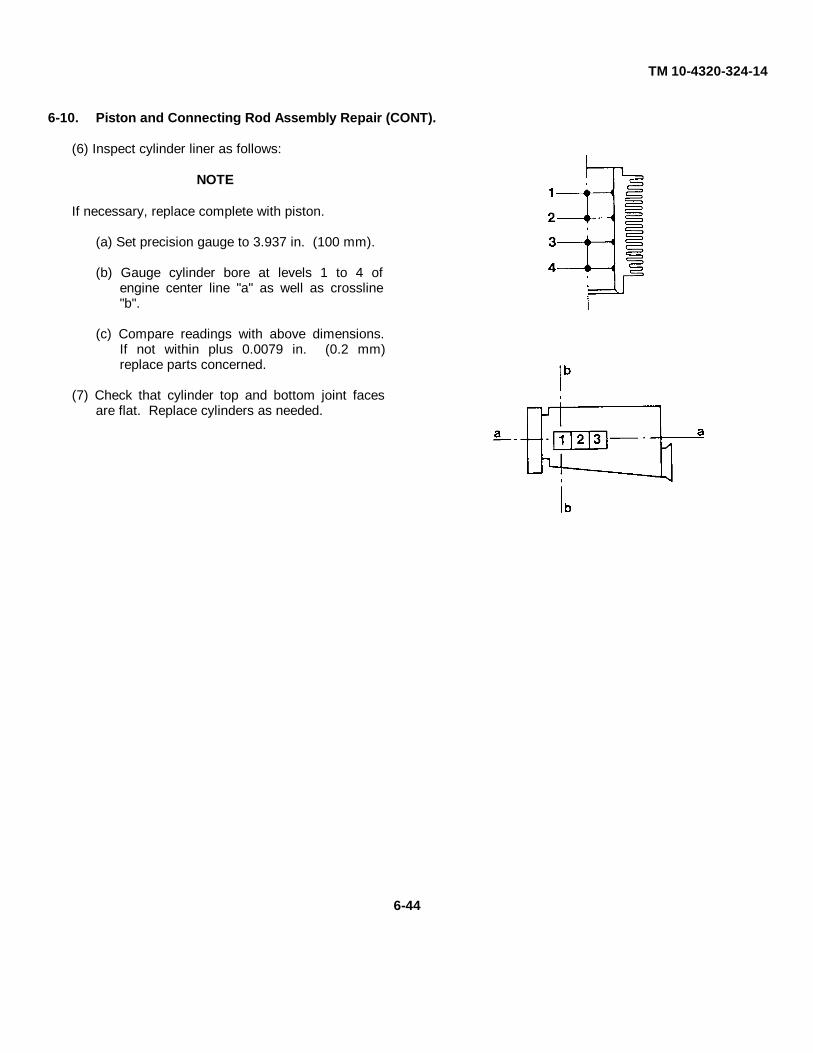
TM 10-4320-324-14
6-10. Piston and Connecting Rod Assembly Repair (CONT).
(6) Inspect cylinder liner as follows:
NOTE
If necessary, replace complete with piston.
(a) Set precision gauge to 3.937 in. (100 mm).
(b) Gauge cylinder bore at levels 1 to 4 ofengine center line "a" as well as crossline"b".
(c) Compare readings with above dimensions.If not within plus 0.0079 in. (0.2 mm)replace parts concerned.
(7) Check that cylinder top and bottom joint facesare flat. Replace cylinders as needed.
6-44

TM 10-4320-324-14
c. Assembly.
(1) Install sleeve bushing (10).
(2) Install piston rings as follows:
(a) Install oil control ring (9).
(c) Install taper-faced ring (8) with face marked"top" upwards.
(d) Install trapezoidal ring (7) with face marked"top" upwards.
(3) Install one circlip (5) into boss of piston (4).
WARNINGWear gloves to protect against burns.
(4) If necessary, heat piston to a temperature ofapproximately 176° F (80° C).
(5) Apply light coat of oil to pin (6) and sleevebushing (10).
(6) Place piston (4) on small end of connecting rod(3) so that exhaust air side of piston (marked onpiston crown) is in same direction as open sideof connecting rod bearing.
(7) Install piston pin (6) into piston (4) andconnecting rod (3).
(8) Install second circlip (5).
(9) Install locating pin (1) if pin was removed.
(10) Install two bearing sleeves (2).
d. Follow-on Maintenance. Assemble engine (para 6-7).
END OF TASK
6-45

TM10-4320-324-14
6-11. Crankcase Repair.
This task covers:
a. Cleaning/Inspection b. Repair c. Follow-on Maintenance
INITIAL SETUP
Tools Materials/PartsMicrometer, item 34, section III, appendix B Bearing shells (4) - 03362379123456Tightening fixture, item 34, section III,appendix B Equipment ConditionPrecision gauge, item 34, section III, appendix B Engine disassembled (para 6-7).Taps, thread (2), item 34, section III, appendix BDial indicator, item 34, section III, appendix B General Safety InstructionsTorque wrench, item 34, section III, appendix B Wear personal protective equipment when usingRefacing device, item 18, section III, appendix B cleaning solvent or compressed air for cleaningTool kit, general mechanics, item 35, section III, purposes.appendix B
a. Cleaning/Inspection.
WARNING
• Potential health hazards result from inhalation of petroleum solvent vapors and form contact of solvent with skin.Use rubber gloves and hand cream for protection, an work with adequate ventilation.
• Compressed air used for cleaning purposes will not exceed 30 psi. Use only with effective chip guarding and
personal protective equipment (goggles/shield, gloves, etc).
• Petroleum solvents are highly flammable. Keep solvent container lids closed when not in use, and avoid all
possible risks of igniting solvent vapors, keep away from open flame and excessive heat. Flash point of solventis 100 to 138 degrees F (38 to 59 degrees C).
1) Clean all parts with solvent. Thoroughly wash out oil ways. Dry with compressed air.
(2) Clean tapped holes for lifting eyes and cylinder head bolts in crankcase by running down a tap. A greased tapshould be used for blind holes.
(3) Inspect crankcase for cracks. Replace cracked crankcase.
6-46

TM 10-4320-324-14
NOTE
The main bearings are of thin-shell type. Their properinstallation requires that webs in crankcase be inalinement and for bearing bores to be preloaded. Noattempt should be made to adjust or recondition bearingshells.
(4) Check preloading of bearing bores as follows:
(a) Position bearing caps, making sure that theiridentification numbers match with thosestamped in crankcase. Torque bolts usingtightening fixture (1) and turning device (2) inaccordance instructions given in Appendix F,Table F-1.
(b) Using a micrometer frame and precision gauge,set gauge to 2.93 inches (74.5 mm).
(c) Measure each main bearing bore at points 1 and2 in plane "a," then in the same manner in plane"b" offset by 90 degrees, to determine anycontraction, out-of-roundness or conicity.
(d) If the recorded value is between 2.933 inches(74.5 mm) and 2.934 inches (74.519 mm), therespective bearing is in acceptable conditionand the required preload will be obtained whenbearing halves are installed.
(e) If the recorded bearing bore diameters differ onlyslightly from the specified values given above,repeat the measurements with new bearinghalves installed.
NOTE
Main bearings are made in two halves. No attempt may be made to recondition bearings.
(f) Insert new bearings.
(g) Position bearing cap, then preload and torque according to instructions given in Table F-1.
(h) Using a micrometer, adjust internal dial gauge set to nominal inside diameter of crankshaft main bearing bore,2.7574 inches (70.04 mm).
6-47

TM 10-4320-324-14
6-11. Crankcase Repair (CONT).
(i) Measure each bore at points 1 and 2 in the vertical and horizontal positions "a" and "b".
(j) If recordings show that bearing tolerances are up to 0.001 inch (0.020 mm) maximum above value specifiedabove, crankcase is acceptable for further use as is.
(5) Check bearing housing for alinement as follows:
(a) Coat main crankshaft journals with marking ink.
(b) Place crankshaft in crankcase and install bearingcaps according to the numbering. Torque boltsaccording to Appendix F, Table F-1.
NOTE
• If all bearings have a uniform contact pattern,bearings are in alinement.
• Do not bore out individual bearings.
(c) Rotate crankshaft and then remove it. If bearingbores are in alinement there will be an evenpattern of marking by crankshaft in all bearingbores. If bearing bores require alinement, thebores must be line-bored at a machine shop.
(6) Check cylinder liner seating on crankcase Touch thesurface and feel for any evidence of roughness.Seating surface must be level and free fromgrooves. If cylinder liner seat must be reworked,refer to Repair.
(7) Measure camshaft bearing bores of crankcase usingan inside dial indicator. Bore should be 1.889-1.8911 in. (47.980-48.034 mm). If bores areexcessive, replace bearings using the procedure inRepair.
6-48

TM 10-4320-324-14
b. Repair.
(1) Rework cylinder liner seating on crankcase asfollows:
(a) Clean seating area and remove paintresidues.
(b) Place support brackets (1) in position, mountturning fixture (2), and tighten retaining bolts(3) in such a manner that turning fixture isstill movable.
(c) Center refacing device and tighten bolts (3).
(d) Withdraw centering finger and slide toolholder (4) out to diameter of cylinder seatingface.
CAUTION
• DO NOT turn spindle counterclockwise whenreworking surface or refacing device will be broken.
• Adjust feed carefully. A full turn (3600) of the
knurled nut feeds the tool holder inch (1.5 mm).
(e) By means of knurled nut (5), turn spindle ofturning device clockwise and adjust toolholder (4) to face to be reworked.
(f) Move the tool holder (4) towards the middleof the bore.
(g) Using knurled nut (5) set the tool over andslightly beyond distance "a" to permitsatisfactory refacing.
6-49

TM 10-4320-324-14
6-11. Crankcase Repair (CONT).
(h) After adjusting, tighten setscrew (6).
NOTE
The selected cutting depth should not exceed inch (0.2mm). This feed corresponds to a 1/8th turn (45°) ofknurled nut. The smaller the feed, the smaller the depthof roughness of the reworked surface.
(i) Turn spindle (7) to rework seating area untilsmooth and/or flush with top of crankcasesurface.
(j) Set back tool holder and remove refacing device.
(k) Clean crankcase thoroughly.
(2) Replace camshaft bearing bushing as follows:
(a) Install shorter, small-diameter thrust piece, partof removing and installing tool, on front end ofcamshaft bore.
6-50
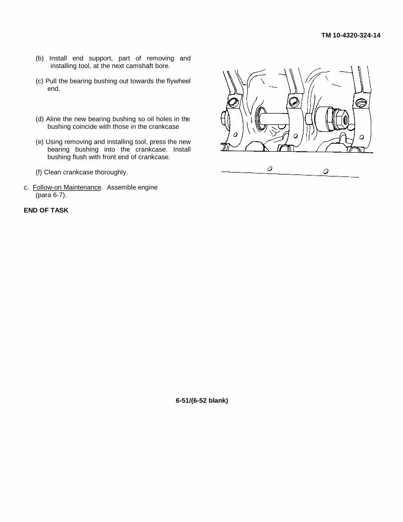
TM 10-4320-324-14
(b) Install end support, part of removing andinstalling tool, at the next camshaft bore.
(c) Pull the bearing bushing out towards the flywheelend.
(d) Aline the new bearing bushing so oil holes in thebushing coincide with those in the crankcase
(e) Using removing and installing tool, press the newbearing bushing into the crankcase. Installbushing flush with front end of crankcase.
(f) Clean crankcase thoroughly.
c. Follow-on Maintenance. Assemble engine(para 6-7).
END OF TASK
6-51/(6-52 blank)


TM 10-4320-324-14
APPENDIX A
REFERENCES
A-1. Scope.
Indexes should be consulted frequently for latest changes or revisions of references given in this appendix and for newpublications relating to material covered in this publication.
Military Publication Indexes.
Consolidated Index of Army Publications and Forms ....................................................... DA PAM 25-30
A-2. Forms.
Refer to DA PAM 738-750, the Army Maintenance Management System (TAMMS), for instructions on the use ofmaintenance forms pertaining to the pumping assembly.
A-3. Field Manuals.
The following publications contain information pertinent to the pumping assembly material.
Camouflage .................................................................................................................. F-M 5-20Basic Cold Weather Manual ......................................................................................... FM 31-70Manual for Wheel Vehicle Driver ................................................................................... FM 21-305Army Motor Transport Units and Operations.................................................................. FM 55-30Northern Operations ..................................................................................................... FM 31-71Operation and Maintenance of Ordnance Materiel in Cold Weather 0°F to -65°F .......... FM 9-207Nuclear, Biological, and Chemical (NBC) Defense ........................................................ FM 3-87 (HTF)Nuclear, Biological, and Chemical Contamination Avoidance ....................................... FM 3-3Nuclear, Biological, and Chemical (NBC) Protection .................................................... FM 3-4
A-4. Technical Manuals.
Administrative Storage of Equipment ............................................................................... TMCare, Maintenance and Repair of Pneumatic Tires and Inner Tubes ............................... TM 9-2610-200-24Inspection, Care, and Maintenance of Antifriction Bearings ............................................. TM 9-214Materials Used for Cleaning, Preserving, Abrading, and CementingOrdnance Materiel and Related Materials Including Chemicals ........................................ TM 9-247Operator's Manual for Welding Theory and Application ................................................... TM 9-237
A-5. Miscellaneous Publications.
Description, Use, Bonding Techniques, and Properties of Adhesives .............................. TB ORD1032
A-1/(A-2 blank)


TM 10-4320-324-14
APPENDIX B
MAINTENANCE ALLOCATION CHART
Section I. INTRODUCTION
B-1. General.
a. This section provides a general explanation of all maintenance and repair functions authorized at variousmaintenance categories.
b. The Maintenance Allocation Chart (MAC) in Section II designates overall authority and responsibility for theperformance of maintenance functions on the identified end item or component. The application of the maintenancefunctions to the end item or component will be consistent with the capacities and capabilities of the designatedmaintenance categories.
c. Section III lists the tools and test equipment (both special tools and common tool sets) required for eachmaintenance function as referenced from Section II.
d. Section IV contains supplemental instructions and explanatory notes for a particular maintenance function.
B-2. Maintenance Functions.
Maintenance functions will be limited to and defined as follows:
a. Inspect. To determine the serviceability of an item by comparing its physical, mechanical, and/or electricalcharacteristics with established standards through examination (e.g., by sight, sound, or feel).
b. Test. To verify serviceability by measuring the mechanical, pneumatic, hydraulic, or electrical characteristics ofan item and comparing those characteristics with prescribed standards.
c. Service. Operations required periodically to keep an item in proper operating condition, i.e., to clean (includesdecontaminate, when required), to preserve, to drain, to paint, or to replenish fuel, lubricants, chemical fluids, or gases.
d. Adjust. To maintain or regulate, within prescribed limits, by bringing into proper or exact position, or by setting theoperating characteristics to specified parameters.
e. Aline. To adjust specified variable elements of an item to bring about optimum or desired performance.
f. Calibrate. To determine and cause corrections to be made or to be adjusted on instruments or test, measuring,and diagnostic equipment used in precision measurement. Consists of comparisons of two instruments, one of which is acertified standard of known accuracy, to detect and adjust any discrepancy in the accuracy of the instrument beingcompared.
g. Remove/Install. To remove and install the same item when required to perform service or other maintenancefunctions. Install may be the act of emplacing, seating, or fixing into position a spare, repair part, or module (componentor assembly) in a manner to allow the proper functioning of an equipment or system.
h. Replace. To remove an unserviceable item and install a serviceable counterpart in its place. "Replace" isauthorized by the MAC and is shown as the 3d position code of the SMR code.
B-1

TM 10-4320-324-14
i. Repair. The application of maintenance services, including fault location/troubleshooting2, removal/installation,and disassembly/assembly3 procedures, and maintenance actions4 to identify troubles and restore serviceability to anitem by correcting specific damage, fault, malfunction, or failure in a part, subassembly, module (component orassembly), end item, or system.
j. Overhaul. That maintenance effort (service/action) prescribed to restore an item to a completelyserviceable/operational condition as required by maintenance standards in appropriate technical publications (i.e.,DMWR). Overhaul is normally the highest degree of maintenance performed by the Army. Overhaul does not normallyreturn an item to like new condition.
k. Rebuild. Consists of those services/actions necessary for the restoration of unserviceable equipment to a likenew condition in accordance with original manufacturing standards. Rebuild is the highest degree of materielmaintenance applied to Army equipment. The rebuild operation includes the act of returning to zero those agemeasurements (hours/miles, etc.) considered in classifying Army Equipment/Components.
B-3. Explanation of Columns in the MAC, Section II. I
a. Column 1, Group Number. Column 1 lists functional group code numbers, the purpose of which is to identifymaintenance significant components, assemblies, sub-assemblies, and modules with the next higher assembly.
b. Column 2, Component/Assembly. Column 2 contains the names of components, assemblies, subassemblies, andmodules for which maintenance is authorized.
c. Column 3, Maintenance Function. Column 3 lists the functions to be performed on the item listed in Column 2.(For detailed explanation of these functions, see paragraph B-2.)
d. Column 4, Maintenance Category. Column 4 specifies, by the listing of a work time figure in the appropriatesubcolumns(s), the category of maintenance authorized to perform the function listed in Column 3. This figurerepresents the active time required to perform that maintenance function at the indicated category of maintenance. If thenumber or complexity of the tasks within the listed maintenance function vary at different maintenance categories,appropriate work time figures will be shown for each category. The work time figure represents the average timerequired to restore an item (assembly, subassembly, component, module, end item, or system) to a serviceable conditionunder typical field operating conditions. This time includes preparation time (including any necessarydisassembly/assembly time), troubleshooting/fault location time, and quality assurance/quality control time in addition tothe time required to perform the specific tasks identified for the maintenance functions authorized in the maintenanceallocation chart. The symbol designations for the various maintenance categories are as follows:
C.......................................................... Operator or crewO ......................................................... Unit MaintenanceF .......................................................... Direct Support MaintenanceH.......................................................... General Support MaintenanceD.......................................................... Depot Maintenance
e. Column 5, Tools and Equipment. Column 5 specifies, by code, those common tool sets (not individual tools) andspecial tools, TMDE, and support equipment required to perform the designated function.
1Services - inspect, test, service, adjust, aline, calibrate, and/or replace.
2 Fault locate/troubleshooting - The process of investigating and detecting the cause of equipment malfunctioning; the act of
isolating a fault within a system or unit under test (UUT).3 Disassemble/assemble - encompasses the step-by-step taking apart (or breakdown) of a spare/functional group coded item to
the level of its least competency identified as maintenance significant (i.e., assigned an SMR code) for the category of maintenanceunder consideration.
4 Actions - welding, grinding, riveting, straightening, facing, remachine, and/or resurfacing.
B-2

TM 10-4320-324-14
f. Column 6, Remarks. This column shall, when applicable, contain a letter code, in alphabetic order, which shall bekeyed to the remarks contained in Section IV.
B-4. Explanation of Columns in Tools and Test Equipment Requirements, Section III.
a. Column 1, Reference Code. The tool and test equipment reference code correlates with a code used in the MAC,Section II, Column 5.
b. Column 2. Maintenance Category. The lowest category of maintenance authorized to use the tool or testequipment.
c. Column 3, Nomenclature. Name or identification of the tool or test equipment.
d. Column 4, National Stock Number. The national stock number of the tool or test equipment.
e. Column 5, Tool Number. The manufacturer's part number.
B-5. Explanation of Columns in Remarks, Section IV.
a. Column 1, Reference Code. The code recorded in column 6, Section II.
b. Column 2, Remarks. This column lists information pertinent to the maintenance function being performed asindicated in the MAC, Section II.
B-3

TM 10-4320-324-14
B-4 Change 2
SECTION II. MAINTENANCE ALLOCATION CHART
0101 Air DischargeCompartment Inspect 0.1
Repair 0.3 0.3 33 B-GReplace 0.5 32
0105 Control PanelAssembly Inspect 0.4
Repair 4.0 32, 33 GReplace 4.0 32, 33
0106 Control BoxPanels Inspect 0.1
Repair 0.4 0.3 33 B-GReplace 0.2 32

TM 10-4320-324-14
Change 2 B-5
02 Air CleanerAssembly Inspect 0.1
Service 0.2 32 AReplace 0.5
03 Exhaust System
0301 Spark Arrestor Inspect 0.1 32 CRepair 0.3 32 GReplace 0.2 32 G
0302 Exhaust Pipe Inspect 0.1Replace 1.2 32, 33 G
0303 Muffler Inspect 0.1Replace 1.4 32, 33 G
04 ElectricalSystem
0401 Battery Boxand Cover Inspect 0.1
Replace 0.2 32 G
0402 Batteriesand Cables Inspect 0.1
Test 0.2 33 DService 0.1 0.2 32Replace 1.0 32 G
0403 AccessoryDrive (Belts) Inspect 0.1
Adjust 0.4 32 EReplace 0.7 32 G
0404 AlternatorAssembly Inspect 0.1
Replace 1.0 32Test 1.0 34, 40, 43 F, LRepair 2.0 34, 35 G
0405 StarterAssembly Inspect 0.1
Replace 0.5 32Test 0.8 34, 40, 41, 42, 43 HRepair 2.0 34, 35, 40, 41, 42 G
0406 V-Belt ContactSwitch Inspect 0.1
Test 0.2 33 I, K, LReplace 0.5 32 G

TM 10-4320-324-14
(1) (2) (3) (4) (5) (6)
GROUP COMPONENT/ MAINTENANCE MAINTENANCE LEVEL TOOLS AND
NUMBER ASSEMBLY FUNCTION C O F H D EQUIPMENT REMARKS
0407 Main WiringHarness Inspect 0.2 33 I
Repair 1.0 32, 33 JReplace 1.0 32, 33
05 Fuel System
0501 Throttle Control Inspect 0.1Replace 0.5 32
0502 Shut-DownSolenoid Inspect 0.1
Test 0.2 33 K, LReplace 0.8 32
0503 Fuel Tank Inspect 0.2Service 0.2 32Repair 1.5 34, 35 BReplace 1.5 32, 33
0504 Fuel Lines, Hosesand Fittings Inspect 0.1
Replace 0.2 32 G
0505 FuelFilter/Separator Inspect 0.1
Service 0.2 32 AReplace 1.0 32
0506 Fuel Feed Pump Inspect 0.1Service 0.2 32 MRepair 0.8 32 NReplace 1.0 32
0507 Fuel Filter Inspect 0.1Replace 0.5 32 A
0508 Injection Pump Inspect 0.1Service 0.2 32Test 2.0 1,2,3, 23, O
30,31,34 OReplace 1.5 34, 35
0509 Injection Nozzles Inspect 0.1Test 1.0 OReplace 1.0 5, 6, 17, 19, 24Repair 1.0 34, 35 G
0510 Starting AidPump Inspect 0.1
Replace 0.4 32 G
B-6

TM 10-4320-324-14
(1) (2) (3) (4) (5) (6)
GROUP COMPONENT/ MAINTENANCE MAINTENANCE LEVEL TOOLS AND
NUMBER ASSEMBLY FUNCTION C O F H D EQUIPMENT REMARKS
0511 Reservoir Inspect 0.1 GReplace 0.4
0512 Nozzle Inspect 0.1Replace 0.2 32 G
06 Engine Assembly Inspect 0.4 5, 6, 17, 19, 20, K21, 24 K
Service 0.1 0.5Repair 6.0 29, 34, 35, 36, 37Replace 8.0 34, 35
0601 Lubrication System
Oil Filter Inspect 0.1Replace 0.2 33 A
Low Oil PressureCut-out Inspect 0.1Switch Test 0.4 33 G
Replace 0.5 32
Sending Unit, Oil Inspect 0.1Test 0.3 33 GReplace 0.5 32
Oil Linesand Fittings Inspect 0.1
Replace 0.3 32, 33 G
Oil Pump Inspect 0.2 34 GReplace 4.0 34, 35
0602 Cooling Fan Inspect 0.1Repair 2.0 34, 35 GReplace 2.0 34, 35
0603 Cylinder Headand Valves Inspect 0.1
Replace 4.0 34, 35Repair 6.0 7,8,9, 10, 11, P
12, 13, 14, 15, 22, P25,34,35,38,39 P
Crankcase Block Inspect 0.5Repair 20.0 18, 26, 27, 28 G
34, 35 GReplace 6.0 34, 35
B-7

TM 10-4320-324-14
(1) (2) (3) (4) (5) (6)
GROUP COMPONENT/ MAINTENANCE MAINTENANCE LEVEL TOOLS AND
NUMBER ASSEMBLY FUNCTION C O F H D EQUIPMENT REMARKS
0604 Gears, Camshaftand Inspect 0.2 2.0Timing Repair 10.0 34,35 G, Q
Replace 10.0 34, 35
0605 Rods, Piston Inspect 1.0and Connecting Repair 6.0 34, 35 R
Replace 6.0 34,35
0606 Crankshaft, Inspect 3.0and Flywheel Replace 15.0 4, 16, 34, 35 S
0607 Bearings Inspect 0.5Replace 5.0 4, 16, 34, 35 G
07 Pump Assembly Inspect 0.2Service 0.2 32Repair 8.0 32, 33, 34, 35 GReplace 10.0 34, 35
0701 Valves, Manifolds Inspect 0.1and Fittings Repair 1.0 34 T
Replace 2.0 32
08 Wheel Mounted Inspect 0.2Frame Assembly Repair 8.0 34, 35 B
Replace 2.0 2.0 34, 35
0801 Axle, Wheels, Inspect 0.2Tires Service 1.0 32, 33 U
Repair 1.0 32, 34, 35 GReplace 1.0 3.0 32, 35
B-8

TM 10-4320-324-14
SECTION III. TOOL AND TEST EQUIPMENT REQUIREMENTS
Tool or Test
Equipment Maintenance National/NATO Tool
Ref Code Level Nomenclature CAGE Stock Number Number
1 F Adjusting Device 36719 5120-01-204-5067 003-04982 F,H Dial Gauge 36719 5120-01-204-5068 003-05433 F Pointer 36719 5120-01-206-6502 003-06784 H Bolt Degree Gauge 36719 5120-01-204-5071 003-11025 O,F Puller 36719 5330-00-202-2042 003-04636 O,F Puller 36719 4730-01-152-1147 003-04227 F Socket Spanner 36719 5120-01-204-5072 003-05128 F Socket Spanner 36719 5120-01-208-6997 003-05119 H Pilot Pin 36719 3460-01-204-5069 003-0650
10 H Cutter 36719 5110-01-204-5070 003-065211 H Mandrel 36719 5120-01-204-5073 003-045312 H Reamer 36719 5120-01-203-7945 003-045213 H Mandrel (Intake) 36719 3460-01-203-7947 003-062014 H Mandrel (Exhaust) 36719 3460-01-203-7946 003-044115 H Cutting Device 36719 5120-01-203-7948 003-042616 H Spanner 36719 5120-01-203-7949 003-057217 F Gasket Extractor 36719 5120-01-203-7950 003-073318 H Refacing Device 36719 5120-01-203-7951 003-113319 F Slide Hammer 36719 003-053620 F Compression Gauge Assy. 25341 4910-01-189-7948 J-3333621 F Compression Gauge Adapter 25341 4910-01-198-8719 J-3333722 F Angle Torque Meter 25341 5120-01-208-6996 J-3333923 F Injection Timing Pump 25341 5120-01-208-7000 J-3334224 F Injection Seal Remover 25341 5120-01-191-5897 J-3334425 H Valve Spring Compressor 25341 5120-01-208-7036 J-3334526 F Push Rod Tube Spring Compressor 25341 5120-01-208-6892 J-3334627 O Crankshaft Seal Installer 25341 5120-01-208-6998 J-3334728 O Crankshaft Seal Installer 25341 5120-01-208-6995 J-3334829 O "V" Belt Pulley Holding Wrench 25341 5120-01-208-6999 J-3334930 F Timing Mark and Bolt Scale 25341 5120-01-208-6994 J-3314631 F Injection Pump Tester Gauge 25341 5120-01-202-0227 J-3400632 O Tool Kit, General Mechanics 5180-00-177-7033
Automotive33 O Shop Equipment, Automotive 4910-00-754-0654
Maintenance and RepairCommon No. 1
34 F,H Shop Set, Automotive Repair 4910-00-754-0705Field Maintenance Basic
35 F,H Tool Kit, General Mechanics 5180-00-699-527336 H Retainer for V-belt Pulley 36719 003-044637 H Press-in Device 36719 003-044838 H Clamping Stand for Cylinder Head 36719 003-056239 H Clamping Plate 36719 003-079440 F Voltmeter 6625-00229-045741 F Ammeter42 F Carbon Pile43 F Tachometer 6680-00-171-4584
B-9

TM 10-4320-324-14
Section IV. REMARKS
Reference
Code Remarks
A Replace element(s)B WeldC Repair by replacing discsD Check specific gravityE Adjust belt tensionF Insulation breakdown and continuity testG Repair by replacing defective componentsH Test for opens, grounds and shortsI Continuity testJ Repair by replacing defective wireK Operational testL Test for known voltageM Service by cleaning filterN Repair by replacing defective diaphragmO Test timing and pressure outputP Includes replacing valve seats, guidesQ Includes replacing bearing and gearsR Includes replacing rings and rod bearingsS Includes crankshaft grindingT Replace gate valve sealsU Pack wheel bearings
B-10

TM 10-4320-324-14
APPENDIX C
COMPONENTS OF END ITEMS AND BASIC ISSUE ITEMS LISTS
Section I. INTRODUCTION
C-1. Scope.
This appendix lists components of end item and basic issue items for the Pumping Assembly to help inventory itemsrequired for safe and efficient operation.
C-2. General.
The Components of End Item and Basic Issue Item are divided into the following sections:
a. Section II. Components of End Item. This listing is for informational purposes only and is not authority torequisition replacements. These items are part of the end item, but are removed and separately packaged fortransportation or shipment. As part of the end item, these items must be with the end item whenever it is issued ortransferred between property accounts. Illustrations are furnished to assist you in identifying the items.
b. Section IlI. Basic Issue Items. These are the minimum essential items required to place the pumping assemblyin operation, to operate it, and to perform emergency repairs. Although shipped separately packaged, BII must be withthe pumping assembly during operation and whenever it is transferred between property accounts. The illustrations willassist you with hard-to-identify items. This manual is your authority to request/requisition replacement BII, based onTOE/MTDE authorization of the end item.
C-3. Explanation of Columns.
The following provides an explanation of columns found in the tabular listings:
a. Column (1) - Illustration Number (Illus Number). This column indicates the number of the illustration in which theitem is shown.
b. Column (2) - National Stock Number. Indicates the National Stock Number assigned to the item and will be usedfor requisitioning purposes.
c. Column (3) - Description. Indicates the Federal Item name and, if required, a minimum description to identifyand locate the item. The last line for each item indicates the FSCM (in parentheses) followed by the part number.
d. Column (4) - Unit of Measure (U/M). Indicates the measure used in performing the actualoperational/maintenance function. This measure is expressed by a two-character alphabetical abbreviation (e.g., ea, in,pr).
e. Column (5) - Quantity required (Qty rqr). Indicates the quantity of the item authorized to be used with/on theequipment.
C-1

TM 10-4320-324-14
Section II. COMPONENTS OF END ITEM
Illus National Stock Description Usable Qty
Number Number FSCM & Part No. On Code U/M rqr
1 6150-01-197-6335 Cable, Grounding (58541), 13220E1127 EYA EA 2
2 Rod, Grounding (97403) 13220E1137 EYA EA. 2
C-2

TM 10-4320-324-14
Change 2 C-3/(C-4 blank)
Section III. BASIC ISSUE ITEMS
Illus National Stock Description Usable Qty
Number Number FSCM & Part No. On Code U/M rqr
1 Technical Manual, TM 10-4320-324-14 EYA, EYB EA. 1
TECHNICAL MANUAL
OPERATOR’S, UNIT, DIRECT SUPPORT, AND
GENERAL SUPPORT MAINTENANCE
FOR
PUMPING ASSEMBLY, FLAMMABLE LIQUID,
BULK TRANSFER, DIESEL ENGINE DRIVEN,
WHEEL MTD, 350 GPM, 275 FT. HEAD,
P/N LC350AGPM (36024)
(FUEL USE ONLY)
NSN 4320-01-337-7538
PUMP UNIT, CENTRIFUGAL,
DIESEL ENGINE DRIVEN, WHEEL MTD,
350 GPM, 275 FT. HEAD
P/N LC350BGPM (36024)
(WATER USE ONLY)
NSN 4320-01-335-9671
TM 10-4320-324-14
HEADQUARTERS, DEPARTMENT OF THE ARMY
30 SEPTEMBER 1991 CHANGE 2–08 APRIL 2005
INTRODUCTION 1-1
OPERATING INSTRUCTIONS 2-1
OPERATOR’SMAINTENANCE INSTRUCTIONS 3-1
UNIT MAINTENANCEINSTRUCTIONS 4-1
DIRECT SUPPORTMAINTENANCE INSTRUCTIONS 5-1
GENERAL SUPPORTMAINTENANCE INSTRUCTIONS 6-1
REFERENCES A-1
MAINTENANCEALLOCATION CHART B-1
COMPONENTS OF END ITEMAND BASIC ISSUE ITEMS LISTS C-1
ADDITIONALAUTHORIZATION LIST D-1
EXPENDABLE/DURABLE SUPPLIESAND MATERIALS LIST E-1
TORQUE LIMITS F-1
DISTRIBUTION STATEMENT A: Approved for public release; distribution Is unlimited.


TM 10-4320-324-14
APPENDIX D
ADDITIONAL AUTHORIZATION LIST
There are no additional items authorized for the support of the Pumping Assembly.
D-1/(D-2 blank)

TM 10-4320-324-14
APPENDIX E
EXPENDABLE/DURABLE SUPPLIES AND MATERIALS
Section I. INTRODUCTION
E-1. Scope.
This appendix lists expendable/durable supplies and materials you will need to operate and maintain the PumpingAssembly. This listing is for informational purposes only and is not authority to requisition the listed items. These itemsare authorized to you by CTA 50-970, Expendable/Durable Items (Except Medical, Class V, Repair Parts, and Heraldic;Items), or CTA 8-100, Army Medical Department Expendable/Durable Items.
E-2. Explanation of Columns.
a. Column (1) -Item Number. This number is assigned to the entry in the listing and is referenced in the narrativeinstructions to identify the material (e. g. , "Use cleaning compound, item 5. , Appendix E").
b. Column (2) -Level. This column identifies the lowest level of maintenance that requires the listed item.
C - Operator/CrewO - Organizational MaintenanceF - Direct Support MaintenanceH - General Support Maintenance
c. Column (3) National Stock Number. This is the National Stock Number assigned to the item; use it to request orrequisition the item.
d. Column (4) Description. Indicates the Federal item name, and, if required, a description to identify the item. Thelast line for each item indicates the part number followed by Commercial And Government Entity (CAGE) Code inparentheses.
e. Column (5) Unit of Measure (U/M). Indicates the measure used in performing the actual maintenance function.This measure is expressed by two-character alphabetical abbreviations (e.g. , ea, in, pr). If the unit of measure differsfrom the unit of issue, requisition the lowest unit of issue that will satisfy your requirements.
E-1

TM 10-4320-324-14
E-2 Change 2
1 F Adhesive, MM-A-122
1.1 O 8040-00-225-4548 Adhesive, Sealant, RTV732 oz
2 O,H 8040-00-995-0590 Adhesive, Sealant, Silicone, RTV, General Purpose, MIL-A-46106A, 108
2.1 O,F,H 6850-01-381-4423 Cleaning Solvent Compound (OK209) Skysol 100, 5-gallon can gl
3 O,F,H 5330-01-083-0081 Cloth, Lint free
4 O,F,H Compound, Thread Locking, MIL-S-22473
5 C,H 9150-00-190-0907 Grease, Automotive and Artillery, MIL-L-10924 gl
6 O 9150-00-754-2595 Grease, Ball and Roller Bearing, MIL-G-18709 lb
7 C 9150-00-189-6727 Lubricating Oil, Internal combustion engine, tactical service, MIL-L-2104C (OE/HDO 10) gl
8 C,F,H 9150-00-186-6681 Lubricating Oil, Internal combustion engine, tactical service, MIL-L-2104C (OE/HDO 30) qt
9 O Oil, Preservation, Grade 30, Type II, MIL-L-21260 gl
10 O Oil, Preservative, MIL-L-52144 gl
11 O Oil, Preservative, Type P-9, W-L-800 gl
12 O Preservative, Petrolatum, Type 14, MIL-C-10382C gl
13 O Primer, Paint, TT-P-664 qt
14 F Solder, Resin Flux Core, ASTM B 284-79
15 Deleted
16 O Solvent, 1TT-T-548
17 O Tags, identification, UU-T-81
18 O 8030-00-809-3535 Tape, Antiseizing ea
19 O Tape, Masking, PP-T-60

TM 10-4320-324-14
APPENDIX F
TORQUE LIMITS
Section I. INTRODUCTION
F-1. Scope.
This appendix lists torque specifications and torquing instructions for specific engine nuts and bolts.
F-2. General.
Preloading and angle torques are applied.
Section II. TORQUE SPECIFICATIONS
F-3. Torque Specifications.
The application, preloading, and torque angles in degrees are listed in Table F-1.
F-4. Torquing Instructions.
Preloading is applied with a torque wrench that iscalibrated in foot pounds (ft. lbs) or newton meters
(N•m). Preloading is applied before angle torques. Allangle torques listed in Table F-1 are accomplished byturning the bolt/nut a specific number of degrees from azero reference point as shown. The tightening angle isobtained by turning the handle of the wrench being usedto the desired angle selected from a clock face youmentally superimpose over the bolt head. Torquing oftwo or more bolts securing one assembly should beaccomplished in an alternating fashion to ensureassembly seating and equal load distribution. Forexample, if angle torque specified is 30° initial then 30°final, proceed as follows:
a. Coat bolt and surface under bolt head with engineoil MIL-L-2104.
b. Set bolts squarely to ensure assembly seating.
c. Apply specified preload with torque wrench.
d. Using angle torque meter (Appendix B, SectionIII, Item 22) and socket wrench, apply 30° initial torque tobolt 1.
F-1

TM 10-4320-324-14
e. Apply 30° initial torque to bolt 2.
f. Apply 30° final torque to bolt 1.
g. Apply 30°final torque to bolt 2.
Table F-I. Torque Specifications
Preloading Angle In Degrees or Total
Torque Values
Application Ib-ft Nom Stage 1 Stage2 Stage 3 Stage 4 Degree Ib-ft N•m
Cylinder head 29.5 40 45° 45° 45° 30° 165° - -Cylinder head screw - - - - - - - 59-66 80-90
plugRocker arm bracket - - - - - - - 21 28nutRocker chamber - - - - - - - 7 10
cover bolt - (+4; -2) (+5; -3)Connecting rod 22 30 60° 30° - - 90° - -
Bearing cap 22 30 60° 45° - - 105° - -
Idler gear 22 30 60° - - - 60° - -
Flywheel bolts 22 30 30° 30° - - 60° - -
Balance weight 22 30 30° 30° - - 60° - -
Flywheel nuts 37 50 90° 90° - - 180° - -
Injection nozzle - - - - - - - 18.5-22 25-30Fuel injection pump - - - - - - - 44-52 60-70
drive nutFuel injector cap nut - - - - - - - 44-59 60-80V-belt pulley 37 50 210° - - - 210° - -
Cooling blower 22 30 90° - - - 90° - -
Filter carrier 18.5 25 30° 60° 60° - 150° - -
Oil pump retaining - - - - - - - 26 35bolt
Oil connecting pipe 80 - - - - - 59 (+15) 80 (+20)union screw
Alternator 22 30 180° - - - 180° - -
Idler pulley 22 30 45° - - - 45° - -
Engine suspension 22 30 45° 60° - - 105°Pump stud nuts 3/8-16 - - - - - - - 17-19 23-26Pump stud nuts 1/2-13 - - - - - - 40-42 54-57Discharge and suction - - - - - - - 44-48 60-65
valve fastenersImpeller bearing - - - - - - - 21 28
cap screws
F-2

TM 10-4320-324-14
Table F-2. Torque Specifications (Cont)
Preloading Angle In Degrees or Total
Torque Values
Application Ib-ft Nom Stage 1 Stage2 Stage 3 Stage 4 Degree Ib-ft N•m
Impeller shaft bushing - - - - - - - 12 16set screwIntermediate bracket - - - - - - - 21 28seal plate nutsExhaust pipe locking 15 20 26 lb-ft 37 lb-ft- - - - 37 50nuts (35 N•m) (50 N•m)
F-3/(F-4 blank)


TM 10-4320-324-14
Change 2 I-1
INDEXSUBJECT Page
A
Administrative Storage.........................................................................................................................................................4-199Air Cleaner Assembly Replacement ......................................................................................................................................4-86Alternator
Belt Replacement ..........................................................................................................................................................4-104Repair ..............................................................................................................................................................................5-10Replacement..................................................................................................................................................................4-106Testing ...............................................................................................................................................................................5-7
Assembly and Preparation for Use..........................................................................................................................................2-9Axle Replacement..................................................................................................................................................................5-96
B
Batteries and Cables Replacement .......................................................................................................................................4-96Battery Box and Cover Replacement ....................................................................................................................................4-94Blower Extension Replacement...........................................................................................................................................4-102
C
Calibration................................................................................................................................................................................1-3Cold Start System ..................................................................................................................................................................1-14Control Box Panels Repair/Replacement ..............................................................................................................................4-51Control Panel Assembly Repair/Replacement.....................................................................................................................4-178Controls and Indicators............................................................................................................................................................2-1Cooling Blower Belt Replacement .......................................................................................................................................4-105Cooling Coil Replacement .....................................................................................................................................................5-66Cooling Fan Repair/Replacement..........................................................................................................................................5-63Coupling Flange Replacement ..............................................................................................................................................5-92Crankcase
Repair ..............................................................................................................................................................................6-46Pulley Seal Replacement ..............................................................................................................................................4-152
Crating .................................................................................................................................................................................4-199Cylinder Head
Repair ..............................................................................................................................................................................6-35Replacement....................................................................................................................................................................5-68
D
Destruction of Army Material to Prevent Enemy Use ..............................................................................................................1-4Difference in Models ..............................................................................................................................................................1-10

TM 10-4320-324-14
I-2 Change 2
INDEX (cont)SUBJECT Page
E
Electrical System ...................................................................................................................................................................1-15Emergency Procedures .........................................................................................................................................................2-22Engine
Repair ................................................................................................................................................................................6-8Replacement....................................................................................................................................................................5-49Compression Check ........................................................................................................................................................5-43Cowlings ..........................................................................................................................................................................5-61
EquipmentCharacteristics, Capabilities, and Features .......................................................................................................................1-4Configuration .....................................................................................................................................................................1-4Data .................................................................................................................................................................................1-10
Ether Tube Replacement .....................................................................................................................................................4-147Exhaust Pipe Replacement ...................................................................................................................................................4-91Explanation of Columns in PMCS Table..................................................................................................................................4-4
F
Fording or Swimming.............................................................................................................................................................2-22Frame Assembly Repair/Replacement ..................................................................................................................................5-98Fuel Feed Pump Repair/Replacement ................................................................................................................................4-141Fuel Filter Replacement.......................................................................................................................................................4-140Fuel Filter/Separator Repair/Replacement ..........................................................................................................................4-137Fuel Lines, Hoses, and Fittings Replacement .....................................................................................................................4-128Fuel System
Bleeding.........................................................................................................................................................................4-144Overview..........................................................................................................................................................................1-12Fuel Tank Repair..............................................................................................................................................................5-18
G
Gate Valve Repair..................................................................................................................................................................5-93General Lubrication Information ..............................................................................................................................................3-1Ground Rod Brackets Replacement ......................................................................................................................................4-61
H
Hand Receipt (-HR) Manuals...................................................................................................................................................1-1Hub Assembly Repair ..........................................................................................................................................................4-193
I
Identification Plates and Reflectors Replacement .................................................................................................................4-19Idler Lever Assembly Repair..................................................................................................................................................5-25Idler Pulley Assembly Repair ...............................................................................................................................................4-154Initial Adjustments and Daily ..............................................................................................................................................C 2-12Injection Nozzle Repair/Replacement....................................................................................................................................5-38Injection Pump
Replacement....................................................................................................................................................................5-29Testing .............................................................................................................................................................................5-26
Intake and Exhaust Manifolds Replacement .........................................................................................................................5-55

TM 10-4320-324-14
Change 2 I-3
INDEX (cont)SUBJECT Page
LLifting Frame Replacement....................................................................................................................................................4-32List of Abbreviations.................................................................................................................................................................1-3Location and Description of Major Components......................................................................................................................1-4Low Oil Pressure Cut-out Switch Replacement...................................................................................................................4-161Lubrication System ................................................................................................................................................................1-13
M
Main Wiring Harness Repair/Replacement..........................................................................................................................4-113Maintenance Form and Records .............................................................................................................................................1-1Muffler Replacement..............................................................................................................................................................4-92
N
Nomenclature Cross-Reference List........................................................................................................................................1-3Nozzle Replacement............................................................................................................................................................4-147Nuclear, Biological, and Chemical (NBC) Decontamination ..................................................................................................2-19
O
Oil Drain Hose Replacement ...............................................................................................................................................4-159Oil Filter Replacement .........................................................................................................................................................4-158Oil Line Replacement ..........................................................................................................................................................4-165Oil Sending Unit Replacement.............................................................................................................................................4-163Operating Procedures............................................................................................................................................................2-12Operation in Unusual Weather ..............................................................................................................................................2-20
P
Piston and Connecting Rod Repair .......................................................................................................................................6-42PMCS Procedures
Operator.............................................................................................................................................................................2-6Unit ....................................................................................................................................................................................4-4
Preparation for Movement .....................................................................................................................................................2-19Preparation for Storage or Shipment .......................................................................................................................................1-4Preservation Procedures for Storage or Shipment ..............................................................................................................4-196Pump Assembly
Repair ..............................................................................................................................................................................5-78Replacement....................................................................................................................................................................5-74
Pumping System....................................................................................................................................................................1-17
Q
Quality Assurance/Quality Control (QA/QC) ............................................................................................................................1-4

TM 10-4320-324-14
I-4 Change 2
INDEX (cont)SUBJECT Page
R
Reporting Equipment Improvement Recommendations (EIRs)...............................................................................................1-3Reservoir Replacement .......................................................................................................................................................4-146Rocker Arm Assembly Repair ................................................................................................................................................6-33
S
Safety, Care, and Handling ....................................................................................................................................................1-11Scope.......................................................................................................................................................................................1-1Service Air Cleaner ................................................................................................................................................................3-10Service Batteries ....................................................................................................................................................................3-11Service Engine Assembly ......................................................................................................................................................3-13Service Fuel Tank ..................................................................................................................................................................3-12Service Pump Assembly ........................................................................................................................................................3-14Shutdown Solenoid Replacement........................................................................................................................................4-124Spark Arrestor Repair/Replacement ......................................................................................................................................4-89Starter Assembly Repair ........................................................................................................................................................5-16Starter Assembly Testing........................................................................................................................................................5-13Starter Replacement ............................................................................................................................................................4-109Starting Aid Pump Replacement ..........................................................................................................................................4-145Support Legs Replacement .................................................................................................................................................4-189
T
Throttle Control Replacement..............................................................................................................................................4-122Tool Box Replacement.........................................................................................................................................................4-190Torquing Instructions................................................................................................................................................................6-1Troubleshooting
Direct Support....................................................................................................................................................................5-2Operator.............................................................................................................................................................................3-2Unit ....................................................................................................................................................................................4-9
U
Unpacking, Inspection, and Servicing Upon Receipt...............................................................................................................4-3
V
V-Belt Contact Switch Replacement.....................................................................................................................................4-111V-Belt Guard Replacement ..................................................................................................................................................4-100Valve Clearance Adjustment ................................................................................................................................................4-148Valve Covers and Front Skirt Repair/Replacement ...............................................................................................................4-56Valves, Manifolds and Fittings Repair/Replacement ...........................................................................................................4-168Vent Valve and Line Replacement.......................................................................................................................................4-166

TM 10-4320-324-14
INDEX (cont)SUBJECT Page
W
Warranty Information .................................................................................................................................................... 1-3Wear Limits, Fits, and Tolerances................................................................................................................................. 6-2Wheels and Tires Repair/Replacement ..................................................................................................................... 4-191
I-5/(I-6 blank)


TM 10-4320-324-14
By Order of the Secretary of the Army:
GORDON R. SULLIVANGeneral, United States Army
Chief of Staff
Official:
PATRICIA P. HICKERSONBrigadier General, United States Army
The Adjutant General
DISTRIBUTION:To be distributed in accordance with DA Form 12-25E, (qty rqr block no. 1430),
(DA Form 12-25A, qty rqr block no. 1429, 1430 and 1431).
*U.S. GOVERNMENT PRINTING OFFICE: 1992-654-028/60003


TM 10-4320-324-14
These are the instructions for sending an electronic 2028
The following format must be used if submitting an electronic 2028. The subject line must be exactly the same and allfields must be included; however only the following fields are mandatory: 1, 3, 4, 5, 6, 7, 8, 9,10, 13, 15, 16, 17, and 27.
From: "Whomever" <[email protected]>To: mpmtYoavma288st-louis-emh7.army.mil
Subject: DA Form 20281. From: Joe Smith2. Unit: home3. Address: 4300 Park
4. City: Hometown
5. St: MO
6. Zip: 77777
7. Date Sent: 19-OCT-93
8. Pub no: 55-2840-229-23
9. Pub Title: TM
10. Publication Date: 04-JUL-8511. Change Number: 712. Submitter Rank: MSG13. Submitter FName: Joe14. Submitter MName: T15. Submitter LName: Smith
16. Submitter Phone: 123-123-1234
17. Problem: 118. Page: 219. Paragraph: 320. Line: 421. NSN: 522. Reference: 623. Figure: 724. Table: 825. Item: 926. Total: 12327. Text:This is the text for the problem below line 27.
*U. S. GOVERNMENT PRINTING OFFICE: 1996 - 755-025/40199

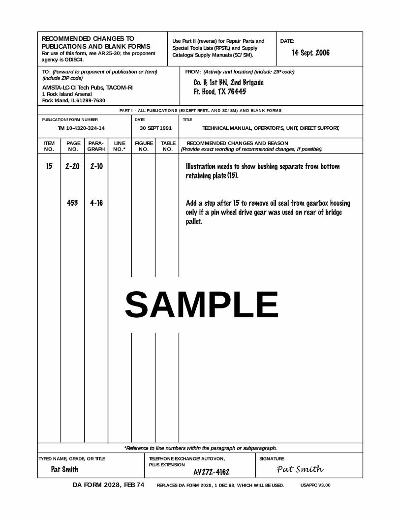
TYPED NAME, GRADE, OR TITLE
Pat Smith
TELEPHONE EXCHANGE/AUTOVON, PLUS EXTENSION
AV272-4162
SIGNATURE
Pat Smith
DATE:
ITEM PAGE PARA- LINE FIGURE TABLE RECOMMENDED CHANGES AND REASONNO. NO. GRAPH NO.* NO. NO. (Provide exact wording of recommended changes, if possible).
USAPPC V3.00DA FORM 2028, FEB 74 REPLACES DA FORM 2028, 1 DEC 68, WHICH WILL BE USED.
RECOMMENDED CHANGES TO PUBLICATIONS AND BLANK FORMSFor use of this form, see AR 25-30; the proponentagency is ODISC4.
Use Part II (reverse) for Repair Parts andSpecial Tools Lists (RPSTL) and SupplyCatalogs/Supply Manuals (SC/SM).
TO: (Forward to proponent of publication or form)(include ZIP code)
AMSTA-LC-CI Tech Pubs, TACOM-RI1 Rock Island ArsenalRock Island, IL 61299-7630
PUBLICATION/FORM NUMBER
TM 10-4320-324-14
DATE
30 SEPT 1991
TITLE
TECHNICAL MANUAL, OPERATOR’S, UNIT, DIRECT SUPPORT,
FROM: (Activity and location) (include ZIP code)
PART I - ALL PUBL ICAT IONS (EXCEPT RPSTL AND SC/SM) AND BLANK FORMS
*Reference to line numbers within the paragraph or subparagraph.
15 2-20 2-10 Illustration needs to show bushing separate from bottom retaining plate (15).
453 4-16 Add a step after 15 to remove oil seal from gearbox housingonly if a pin wheel drive gear was used on rear of bridge pallet.
SAMPLE
14 Sept. 2006
Co. B, 1st BN, 2nd BrigadeFt. Hood, TX 76445

TYPED NAME, GRADE, OR TITLE TELEPHONE EXCHANGE/AUTOVON, PLUS EXTENSION
SIGNATURE
DATE:
TOTAL NO.OF MAJOR
PAGE COLM LINE NATIONAL REFERENCE FIGURE ITEM ITEMS RECOMMENDEDNO. NO. NO. STOCK NUMBER NO. NO. NO. SUPPORTED ACTION
USAPPC V3.00
TO: (Forward direct to addressee listed in publication)
AMSTA-LC-CI Tech Pubs, TACOM-RI1 Rock Island ArsenalRock Island, IL 61299-7630
FROM: (Activity and location) (include ZIP code)
PUBLICATION/FORM NUMBER DATE TITLE
PART I I - REPAIR PARTS AND SPECIAL TOOLS L ISTS AND SUPPLY CATALOGS/SUPPLY MANUALS
PART I I I - REMARKS (Any general remarks or recommendations, or suggestions for improvement of publications and blank forms. Additional blank sheets may be used if more space is needed.)
SAMPLE
TYPED NAME, GRADE, OR TITLE TELEPHONE EXCHANGE/AUTOVON, PLUS EXTENSION
SIGNATURE
DATE:
ITEM PAGE PARA- LINE FIGURE TABLE RECOMMENDED CHANGES AND REASONNO. NO. GRAPH NO.* NO. NO. (Provide exact wording of recommended changes, if possible).
USAPPC V3.00DA FORM 2028, FEB 74 REPLACES DA FORM 2028, 1 DEC 68, WHICH WILL BE USED.
RECOMMENDED CHANGES TO PUBLICATIONS AND BLANK FORMSFor use of this form, see AR 25-30; the proponentagency is ODISC4.
Use Part II (reverse) for Repair Parts andSpecial Tools Lists (RPSTL) and SupplyCatalogs/Supply Manuals (SC/SM).
TO: (Forward to proponent of publication or form)(include ZIP code)
AMSTA-LC-CI Tech Pubs, TACOM-RI1 Rock Island ArsenalRock Island, IL 61299-7630
PUBLICATION/FORM NUMBER
TM 10-4320-324-14
DATE
30 SEPT 1991
TITLE
TECHNICAL MANUAL, OPERATOR’S UNIT, DIRECT SUPPORT, AND GENERAL SUPPORT
FROM: (Activity and location) (include ZIP code)
PART I - ALL PUBL ICAT IONS (EXCEPT RPSTL AND SC/SM) AND BLANK FORMS
*Reference to line numbers within the paragraph or subparagraph.

TYPED NAME, GRADE, OR TITLE TELEPHONE EXCHANGE/AUTOVON, PLUS EXTENSION
SIGNATURE
DATE:
TOTAL NO.OF MAJOR
PAGE COLM LINE NATIONAL REFERENCE FIGURE ITEM ITEMS RECOMMENDEDNO. NO. NO. STOCK NUMBER NO. NO. NO. SUPPORTED ACTION
USAPPC V3.00
TO: (Forward direct to addressee listed in publication)
AMSTA-LC-CI Tech Pubs, TACOM-RI1 Rock Island ArsenalRock Island, IL 61299-7630
FROM: (Activity and location) (include ZIP code)
PUBLICATION/FORM NUMBER DATE
1985
TITLE
PART I I - REPAIR PARTS AND SPECIAL TOOLS L ISTS AND SUPPLY CATALOGS/SUPPLY MANUALS
PART I I I - REMARKS (Any general remarks or recommendations, or suggestions for improvement of publications and blank forms. Additional blank sheets may be used if more space is needed.)

TYPED NAME, GRADE, OR TITLE TELEPHONE EXCHANGE/AUTOVON, PLUS EXTENSION
SIGNATURE
DATE:
ITEM PAGE PARA- LINE FIGURE TABLE RECOMMENDED CHANGES AND REASONNO. NO. GRAPH NO.* NO. NO. (Provide exact wording of recommended changes, if possible).
USAPPC V3.00DA FORM 2028, FEB 74 REPLACES DA FORM 2028, 1 DEC 68, WHICH WILL BE USED.
RECOMMENDED CHANGES TO PUBLICATIONS AND BLANK FORMSFor use of this form, see AR 25-30; the proponentagency is ODISC4.
Use Part II (reverse) for Repair Parts andSpecial Tools Lists (RPSTL) and SupplyCatalogs/Supply Manuals (SC/SM).
TO: (Forward to proponent of publication or form)(include ZIP code)
AMSTA-LC-CI Tech Pubs, TACOM-RI1 Rock Island ArsenalRock Island, IL 61299-7630
PUBLICATION/FORM NUMBER
TM 10-4320-324-14
DATE
30 SEPT 1991
TITLE
TECHNICAL MANUAL, OPERATOR’S UNIT, DIRECT SUPPORT, AND GENERAL SUPPORT
FROM: (Activity and location) (include ZIP code)
PART I - ALL PUBL ICAT IONS (EXCEPT RPSTL AND SC/SM) AND BLANK FORMS
*Reference to line numbers within the paragraph or subparagraph.

TYPED NAME, GRADE, OR TITLE TELEPHONE EXCHANGE/AUTOVON, PLUS EXTENSION
SIGNATURE
DATE:
TOTAL NO.OF MAJOR
PAGE COLM LINE NATIONAL REFERENCE FIGURE ITEM ITEMS RECOMMENDEDNO. NO. NO. STOCK NUMBER NO. NO. NO. SUPPORTED ACTION
USAPPC V3.00
TO: (Forward direct to addressee listed in publication)
AMSTA-LC-CI Tech Pubs, TACOM-RI1 Rock Island ArsenalRock Island, IL 61299-7630
FROM: (Activity and location) (include ZIP code)
PUBLICATION/FORM NUMBER DATE
1985
TITLE
PART I I - REPAIR PARTS AND SPECIAL TOOLS L ISTS AND SUPPLY CATALOGS/SUPPLY MANUALS
PART I I I - REMARKS (Any general remarks or recommendations, or suggestions for improvement of publications and blank forms. Additional blank sheets may be used if more space is needed.)


PIN 069050-000

This fine document...
Was brought to you by me:
Liberated Manuals -- free army and government manuals
Why do I do it? I am tired of sleazy CD-ROM sellers, who take publicly available information, slap “watermarks” and other junk on it, and sell it. Those masters of search engine manipulation make sure that their sites that sell free information, come up first in search engines. They did not create it... They did not even scan it... Why should they get your money? Why are not letting you give those free manuals to your friends?
I am setting this document FREE. This document was made by the US Government and is NOT protected by Copyright. Feel free to share, republish, sell and so on.
I am not asking you for donations, fees or handouts. If you can, please provide a link to liberatedmanuals.com, so that free manuals come up first in search engines:
<A HREF=http://www.liberatedmanuals.com/>Free Military and Government Manuals</A>
– SincerelyIgor Chudovhttp://igor.chudov.com/
– Chicago Machinery Movers