TLS in Determining Geometry of a Tall Structure - unizg.hr · PDF fileTLS in Determining...
12
TS 3 – Engineering Geodesy for Construction Works, Industry and Research 279 TLS in Determining Geometry of a Tall Structure Jelena Pandžić 1 , Marko Pejić 1 , Branko Božić 1 , Verica Erić 1 1 Faculty of Civil Engineering, University of Belgrade, Bulevar kralja Aleksandra 73, Belgrade, Serbia, [email protected], [email protected], [email protected], [email protected] Abstract. Although total stations and levels still hold primacy when it comes to determining geometry of various man-made structures, terrestrial laser scanners tend to emerge as at least equally efficient instruments for these purposes. This was one of the main motives for employing the method of terrestrial laser scanning for determining geometry of the tower of the St. Anthony of Padua Church in Belgrade. Unlike the church that was built in the early 1930s, the bell tower leaning against it was not completed until 1962. By the end of its construction, the longitudinal axis of the cylinder-shaped tower inclined from the vertical axis. Over the following years, the tower rehabilitation was done which was supposed to prevent the tower from further leaning. However, one epoch of terrestrial laser scanning performed in April 2015 revealed that the horizontal displacement of the tower top centre from the tower ground floor centre reached the value of 1.2 m, which requests an immediate start of the tower stability monitoring in order to prevent a potential tower collapse. The magnitude of the displacement was determined based on the cylinder fitted to the obtained point cloud of the tower. Moreover, the distances of the individual points from the cylinder (residuals) were calculated and their magnitudes suggest that the tower does not act as a rigid body. Keywords: cylinder, determining geometry, inclination, residuals, tall structure, terrestrial laser scanning (TLS). 1. Introduction Determining geometry of a tall structure is a specific engineering task that usually features unfavourable working conditions, e.g. very limited area around the structure suitable for setting up an instrument, different obstacles in the form of vegetation, other structures, etc. Total stations and levels have traditionally been used for solving these tasks, yet terrestrial laser scanning (TLS) as a method for mass data acquisition has recently been introduced to this field. Although nowadays numerous examples of using TLS for inspecting geometry of various man-made structures exist, [Pejić et al. 2013, Pandžić et al. 2014] just to mention a few, examples of employing TLS for determining geometry of a tall structure are still quite rare. Most of them deal with medieval bell towers
Transcript of TLS in Determining Geometry of a Tall Structure - unizg.hr · PDF fileTLS in Determining...

TS 3 – Engineering Geodesy for Construction Works, Industry and Research
279
TLS in Determining Geometry of a Tall Structure Jelena Pandžić1, Marko Pejić1, Branko Božić1, Verica Erić1
1 Faculty of Civil Engineering, University of Belgrade, Bulevar kralja Aleksandra 73, Belgrade, Serbia, [email protected], [email protected], [email protected], [email protected]
Abstract. Although total stations and levels still hold primacy when it comes to determining geometry of various man-made structures, terrestrial laser scanners tend to emerge as at least equally efficient instruments for these purposes. This was one of the main motives for employing the method of terrestrial laser scanning for determining geometry of the tower of the St. Anthony of Padua Church in Belgrade. Unlike the church that was built in the early 1930s, the bell tower leaning against it was not completed until 1962. By the end of its construction, the longitudinal axis of the cylinder-shaped tower inclined from the vertical axis. Over the following years, the tower rehabilitation was done which was supposed to prevent the tower from further leaning. However, one epoch of terrestrial laser scanning performed in April 2015 revealed that the horizontal displacement of the tower top centre from the tower ground floor centre reached the value of 1.2 m, which requests an immediate start of the tower stability monitoring in order to prevent a potential tower collapse. The magnitude of the displacement was determined based on the cylinder fitted to the obtained point cloud of the tower. Moreover, the distances of the individual points from the cylinder (residuals) were calculated and their magnitudes suggest that the tower does not act as a rigid body.
Keywords: cylinder, determining geometry, inclination, residuals, tall structure, terrestrial laser scanning (TLS).
1. Introduction
Determining geometry of a tall structure is a specific engineering task that usually features unfavourable working conditions, e.g. very limited area around the structure suitable for setting up an instrument, different obstacles in the form of vegetation, other structures, etc. Total stations and levels have traditionally been used for solving these tasks, yet terrestrial laser scanning (TLS) as a method for mass data acquisition has recently been introduced to this field.
Although nowadays numerous examples of using TLS for inspecting geometry of various man-made structures exist, [Pejić et al. 2013, Pandžić et al. 2014] just to mention a few, examples of employing TLS for determining geometry of a tall structure are still quite rare. Most of them deal with medieval bell towers

SIG 2016 – International Symposium on Engineering Geodesy, 20–22 May 2016, Varaždin, Croatia
280
throughout Italy. [Bertacchini et al. 2010] employed TLS for surveying and monitoring three medieval towers in the Emilia Romagna region. The inclination angle of each of these cuboid-shaped towers was determined based on the line connecting centres of mass of a number of tower cross sections (along the tower longitudinal axis). The famous Two Towers of Bologna were the subject of interest for [Pesci et al. 2011]. Since both towers are cuboid-shaped, their leaning was determined based on plane fitting (vertical and best-fit) to the tower point clouds. [Teza & Pesci 2013] used TLS for determining the leaning angle of the cylinder-shaped medieval bell tower of Caorle (the Province of Venice). They employed the moving cylinder approach for fitting a cylinder to the tower point cloud. [Pellegrinelli et al. 2014] and [Teza et al. 2015] investigated the possibility of employing TLS for surveying and monitoring tall structures in areas that are earthquake prone. Following the earthquake, the cuboid-shaped bell tower of San Benedetto Church in Ferrara was scanned and the tower inclination angle was determined and presented by [Pellegrinelli et al. 2014]. A digital level was also used for determining settlement of the tower foundations. It was shown that TLS and levelling complement each other very well when it comes to determining the geometry of a tall structure. [Teza et al. 2015] characterized geometry of the Leaning Tower of Ficarolo (the Province of Rovigo) after the 2012 earthquake by using several complementing methods, among which there were TLS and infrared thermography. Planes were fitted to the point clouds of this cuboid-shaped tower and consequently the tower leaning angle determined.
Bell towers are not the only tall structures that have been scanned in order to determine their inclination angle, but industrial chimneys have also undergone this process. [Kregar et al. 2015] theoretically described and practically tested the efficiency of two different surveying methods on the example of two chimneys in the Brestanica thermal power plant in Slovenia. The traditional surveying method using a total station was compared to TLS. The chimney inclination angle in each case was determined based on the method of least squares fitting of a cylinder to a point cloud.
In this paper we presented the results of determining geometry of the cylinder-shaped bell tower of the St. Anthony of Padua Church in Belgrade. The data used for quantifying the tower inclination angle were collected in April 2015 using the terrestrial laser scanner Leica ScanStation P20.
2. St. Anthony of Padua Church in Belgrade
The St. Anthony of Padua Church is located in Bregalnička Street, near the very centre of Belgrade. It was built in the period of 1929-1932 based on the idea of the famous Slovenian architect Josip (Jože) Plečnik. Being 25 m high and built in a rotunda form, its ground plan reminds of the statue of St. Anthony with the baby Jesus in his arms [URL 1].
During the construction of the church, the first part of the 52 m high cylinder-shaped bell tower leaning against it was built on the same foundations. Since the terrain and the surroundings were constantly changing and the tower

TS 3 – Engineering Geodesy for Construction Works, Industry and Research
281
became heavier with its completion in 1962, the longitudinal axis of the tower inclined from the vertical axis [Figure 2.1]. As Father Rafael Lipovac who served in this church said in 2007, at the moment of the tower completion this inclination corresponded to the horizontal displacement of ca. 45 cm of the tower top centre from the tower ground floor centre. Over the following years, the tower rehabilitation was done and the tower foundation was separated from the church and additionally strengthened. This was supposed to ensure the stability of the tower, in spite of a potential terrain subsidence [URL 3]. However, one epoch of terrestrial laser scanning performed in April 2015 revealed that the tower leaned even more towards one newly built structure.
Figure 2.1 St. Anthony of Padua Church in Belgrade with its bell tower [URL 2]
3. Determining geometry of the tower using terrestrial laser scanning
Geometry of tall structures has traditionally been determined using total stations. Field work in this case is often exhausting, very time-consuming and results in a dataset of a modest size, i.e. a structure is usually discretized with several tens or hundreds of points at most. On the other hand, terrestrial laser scanning, as a method that has been rapidly developing over the past decade, enables millions of points to be gathered within minutes. TLS requires less field work in comparison with traditional surveying methods, but one should be aware of its limitations, especially when it comes to the employing of this method for some challenging tasks, like determining geometry of a tall structure. Our intention here was to try to employ the method of terrestrial laser scanning exactly for such task – determining geometry of the bell tower of the St. Anthony of Padua Church in Belgrade. The tower was scanned in April 2015 using the terrestrial laser scanner Leica ScanStation P20 [Figure 3.1].

SIG 2016 – International Symposium on Engineering Geodesy, 20–22 May 2016, Varaždin, Croatia
282
Figure 3.1 Leica ScanStation P20 in action
3.1. Scanning process
The preparation for the scanning process involved, first of all, placing the targets, both on the surface of the tower and throughout the scanning location. A total of 30 black&white (B&W) targets (circular, with a diameter of 6") printed on a self-adhesive paper were placed on the windows of the tower [Figure 3.2] in the manner that they cover the entire extents of the tower. The only area lacking the targets was the backside (the north-western side) of the tower and this was due to its inaccessibility. Three original Leica tilt&turn 6" circular planar B&W targets were placed at the top of the tower (on the terrace fence, not on the very roof, to be precise). Eight more targets were placed nearby the tower, some of them were self-adhesive targets placed on the neighbouring buildings, others were 15 cm x 15 cm square-shaped B&W targets placed on tripods. The reason for introducing the unusually large number of targets in the field was another experiment dealing with optimization of the target number and their disposition, but this is not within the scope of this paper. A certain number of the aforementioned targets were later on used in the process of scan registration.
Figure 3.2 Target placed on one of the tower windows
TS 3 – Engineering Geodesy for Construction Works, Industry and Research
283
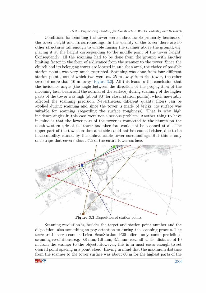
Conditions for scanning the tower were unfavourable primarily because of the tower height and its surroundings. In the vicinity of the tower there are no other structures tall enough to enable raising the scanner above the ground, e.g. placing it at the height corresponding to the middle point of the tower height. Consequently, all the scanning had to be done from the ground with another limiting factor in the form of a distance from the scanner to the tower. Since the church and its belonging tower are located in an urban area, the choice of possible station points was very much restricted. Scanning was done from four different station points, out of which two were ca. 25 m away from the tower, the other two not more than 10 m away [Figure 3.3]. All this leads to the conclusion that the incidence angle (the angle between the direction of the propagation of the incoming laser beam and the normal of the surface) during scanning of the higher parts of the tower was high (about 80° for closer station points), which inevitably affected the scanning precision. Nevertheless, different quality filters can be applied during scanning and since the tower is made of bricks, its surface was suitable for scanning (regarding the surface roughness). That is why high incidence angles in this case were not a serious problem. Another thing to have in mind is that the lower part of the tower is connected to the church on the north-western side of the tower and therefore could not be scanned at all. The upper part of the tower on the same side could not be scanned either, due to its inaccessibility caused by the unfavourable tower surroundings. But this is only one stripe that covers about 5% of the entire tower surface.
Figure 3.3 Disposition of station points
Scanning resolution is, besides the target and station point number and the disposition, also something to pay attention to during the scanning process. The terrestrial laser scanner Leica ScanStation P20 offers only some predefined scanning resolutions, e.g. 0.8 mm, 1.6 mm, 3.1 mm, etc., all at the distance of 10 m from the scanner to the object. However, this is in most cases enough to set desired point spacing in a point cloud. Having in mind that the maximum distance from the scanner to the tower surface was about 60 m for the highest parts of the

SIG 2016 – International Symposium on Engineering Geodesy, 20–22 May 2016, Varaždin, Croatia
284
tower, setting a scanning resolution of 3.1 mm at the distance of 10 m enabled us to have point spacing of about 1.5 cm for the highest parts of the tower. The lower parts of the tower featured point spacing of ca. 0.5 cm to 1 cm, depending on the station point in question.
3.2. Scan registration and point cloud cleaning
At each station point all visible targets were scanned prior to scanning the tower itself. As far as Leica ScanStation P20 is concerned, target scanning resolution cannot be chosen, at least not when built-in target acquisition process is employed in the field. A total of four scans obtained from four different station points were imported into Leica Cyclone 9.0 software for further data processing. First of all, scan registration was done constrained by identical targets identified in multiple scans, aided by cloud-to-cloud constraints for the higher parts of the tower. Namely, due to the unfavourable scanning conditions many of the targets, especially on the upper half of the tower, could not be scanned at all. Introducing cloud-to-cloud constraints helped to improve the quality of registration, particularly in the area lacking targets. Scan registration resulted in the point clouds aligned with respect to the point cloud obtained from the station point 1 (it was set as a reference scan). This means that the point clouds were not georeferenced, but rather they stayed in the scanner coordinate system. The mean absolute error of scan registration was 2 mm. Registration in this case involved 4-parameter similarity transformation: three translation parameters (one for each coordinate system axis) and one rotation parameter (about Z-axis) were determined for each pair of scans. The parameters corresponding to the rotation about X- and Y-axis were not determined since the terrestrial laser scanner is equipped with a dual-axis compensator that enables the scanner to be levelled in the sense that XY-plane of its coordinate system coincides with the horizon. The scale parameter was also considered to be unchanged.
Figure 3.4 Vegetation and surrounding buildings in the point cloud

TS 3 – Engineering Geodesy for Construction Works, Industry and Research
285
Figure 3.5 Tower windows deviating from the tower surface
Point cloud cleaning meant deleting millions of points that were of no interest for this experiment. The scanner field-of-view was not limited to a big extent during scanning in order to capture targets in the tower surroundings, so that they could be obtained directly from the point cloud if necessary. Inevitably, great amount of unnecessary data was collected [Figure 3.4]. Deleting irrelevant details like vegetation, pathways, parts of the church, etc. was done in Leica Cyclone 9.0. The tower windows had also been deleted because they deviate from the rest of the tower surface [Figure 3.5] and would have otherwise biased modelling of the tower.
3.3. Determining geometry of the tower
Scan registration resulted in mutually aligned, but still separate point clouds. In order to combine four distinctive point clouds of different parts of the tower into one comprehensive point cloud, the point cloud unification had to be done. This unification process led to a non-uniform point cloud, with largely varying point spacing. Therefore, the point cloud was resampled to point spacing of 3 cm. This unified and resampled point cloud was later on used for some analysis.
Nowadays many different software packages for point cloud processing and object modelling are available on the market, Leica Cyclone, Geomagic Studio (now replaced with Geomagic Design X and Geomagic Wrap), 3DReshaper, Rhino, just to mention a few. There are also numerous free and open-source software packages like GOM Inspect, CloudCompare, Point Cloud Library (PCL), etc. Of course, not all of these are equally suitable for the cylinder-shaped tower modelling which was needed in this experiment. In this case we used two different software packages for fitting a cylinder to the tower point cloud. A few cylinders were fitted in both software packages, using point clouds with different point spacing. In one case a unified point cloud with 3 cm point spacing was used, in another one point spacing was 5 cm, later on 50 cm. The fact is that this fitting algorithm conducted in commercial software is so-called “black-box”, meaning that

SIG 2016 – International Symposium on Engineering Geodesy, 20–22 May 2016, Varaždin, Croatia
286
the user does not have the insight in the background of the algorithm. Nevertheless, in all of the aforementioned cases pretty much the same fitting results were observed, so we decided to adopt one cylinder fitted in Leica Cyclone 9.0 as the final solution. The cylinder was fitted to the four mutually aligned point clouds, i.e. to the original separate point clouds after registration and cleaning, and prior to their unification and resampling. This helped to preserve as much original data as possible during cylinder fitting. At the same time, a huge amount of data did not obstruct the fitting process thanks to the software capabilities and the characteristics of the computer used in this case.
Prior to quantifying tower leaning, one extra step had to be done. Namely, the tower itself consists of two main cylinder-shaped distinctive parts. The bottom (greater) part of the tower features a bigger diameter and on top of it there is another cylinder-shaped part with a smaller diameter. Yet, these two parts of the tower share the same longitudinal axis. The cylinder was fitted to the point clouds of the greater (wider) part of the tower. Since some points at the top of the tower upper (narrower) part were gathered during scanning, extrapolation of the fitted cylinder height could be done. Based on the height difference between points on top of the upper and lower parts of the tower, coordinates of the centre point of the tower upper part top base (the tower top centre) were determined. The coordinates of the centre point of the tower lower part bottom base were acquired during the cylinder fitting process. The tower leaning was quantified by a horizontal distance between the two aforementioned points, i.e. a horizontal displacement of the tower top centre from the tower ground floor centre. The magnitude of this horizontal displacement was calculated to be ca. 1.2 m which is about three times bigger than what it was believed to be. Consequently, an immediate start of the tower stability monitoring is needed in order to prevent a potential tower collapse.
After cylinder fitting and determining the tower leaning, another analysis of the tower geometry was conducted. Firstly, the cylinder fitted to the tower point cloud in Leica Cyclone 9.0 was exported in a parametric form and in this form imported into Rhino. The cylinder in Rhino was transformed into a mesh with a parameter maximum distance, edge to surface set to 0.1 mm. This mesh was imported into CloudCompare afterwards, together with the unified and resampled (3 cm point spacing) point cloud of the tower. The step involving Rhino was needed because CloudCompare does not support importing a cylinder in a parametric form. For each point in the imported point cloud the shortest distance to the cylinder (mesh) was calculated. Inspection of these residuals, i.e. their magnitudes and disposition, revealed that the tower does not act as a rigid body. Nevertheless, most of the residuals are in the range of [-0.02, 0.02] m [Figure 3.6].
At this point, it is important to state that the tower is made of bricks. During scanning not only the surface of the bricks was obtained, but grout lines as well. The depth of the grout lines with respect to the surface of the bricks which is about 1 cm inevitably affected the tower modelling. Nevertheless, grout line points were greatly outnumbered by brick points in the tower point cloud. As a consequence, modelling of the tower was not significantly biased.

TS 3 – Engineering Geodesy for Construction Works, Industry and Research
287
Figure 3.6 Point to mesh distances
4. Conclusion
As far as surveying is concerned, until a couple of years ago total stations and levels were predominantly used instruments in determining geometry of various man-made structures, including tall structures like bell towers, chimneys, etc. Terrestrial laser scanning as a rapidly developing method for mass data acquisition is now more and more used for these specific engineering tasks. Although an application of close-range photogrammetry also results in a great amount of data, this method unlike TLS requires determining a scale parameter and materializing the Z-axis of a data coordinate system. That is why TLS is often a more suitable method for determining geometry of various man-made structures than photogrammetry is.
In this paper we described the procedure of determining geometry of a tall structure using the method of terrestrial laser scanning. The test field was the cylinder-shaped bell tower of the St. Anthony of Padua Church in Belgrade. The tower itself is more than 50 metres high and its longitudinal axis has been inclined
SIG 2016 – International Symposium on Engineering Geodesy, 20–22 May 2016, Varaždin, Croatia
288
from the vertical axis since the tower completion in the 1960s. It was believed that this inclination angle corresponded to the horizontal displacement of the tower top centre from the tower ground floor centre of ca. 45 cm. Despite the tower rehabilitation conducted in order to prevent further leaning of the tower, the tower inclination angle increased over years. One epoch of terrestrial laser scanning performed in April 2015 revealed that the aforementioned horizontal displacement reached the value of 1.2 m. In addition to quantifying the tower leaning, distances of individual points from the cylinder fitted to the tower point cloud were calculated and their magnitudes suggest that the tower does not act as a rigid body. Consequently, permanent monitoring of the tower stability is planned in order to prevent a potential tower collapse.
Acknowledgement
This paper is financially supported by the Ministry of Education, Science and Technological Development of the Republic of Serbia through Contract No. TR 36009.
References
Bertacchini, E.; Boni, E.; Capra, A.; Castagnetti, C.; Dubbini, M. (2010). Terrestrial Laser Scanner for Surveying and Monitoring Middle Age Towers. FIG Congress 2010, Facing the Challenges – Building the Capacity, Sydney, Australia, 11-16 April 2010.
Kregar, K.; Ambrožič, T.; Kogoj, D.; Vezočnik, R.; Marjetič, A. (2015). Determining the inclination of tall chimneys using the TPS and TLS approach, Measurement, 75, pp. 354-363.
Pandžić, J.; Erić, V.; Božić, B.; Pejić, M. (2014). The Accuracy Analysis of Leica ScanStation P20 Data by Means of Point Cloud Fitting Algorithm, Proceedings of the 6th International Conference on Engineering Surveying INGEO 2014, Prague, Czech Republic, April 3-4.
Pejić, M.; Božić, B.; Abolmasov, B.; Gospavić, Z. (2013). Design and optimization of laser scanning for tunnels geometry inspection, Tunnelling and Underground Space Technology, 37, pp. 199-206.
Pellegrinelli, A.; Furini, A.; Russo, P. (2014). Earthquakes and ancient leaning towers: Geodetic monitoring of the bell tower of San Benedetto Church in Ferrara (Italy), Journal of Cultural Heritage, 15(6), pp. 687-691.
Pesci, A.; Casula, G.; Boschi, E. (2011). Laser scanning the Garisenda and Asinelli towers in Bologna (Italy): Detailed deformation patterns of two ancient leaning buildings, Journal of Cultural Heritage, 12(2), pp. 117-127.
Teza, G.; Pesci, A. (2013). Geometric characterization of a cylinder-shaped structure from laser scanner data: Development of an analysis tool and its use on a leaning bell tower, Journal of Cultural Heritage, 14(5), pp. 411-423.

TS 3 – Engineering Geodesy for Construction Works, Industry and Research
289
Teza, G.; Pesci, A.; Trevisani, S. (2015). Multisensor surveys of tall historical buildings in high seismic hazard areas before and during a seismic sequence, Journal of Cultural Heritage, 16(3), pp. 255-266.
URL 1: Beogradska nadbiskupija (Belgrade Archbishopric), www.kc.org.rs/dekanat.php?recordID=2, (2. 2. 2016).
URL 2: Dizajn Zona, www.dizajnzona.com/forums/index.php?showtopic=91211, (2. 2. 2016).
URL 3: eKapija, www.ekapija.com/website/sr/page/105444/Evropa-Gde-se-nalazi-Krivi-toranj-u-Beogradu, (2. 2. 2016).

SIG 2016 – International Symposium on Engineering Geodesy, 20–22 May 2016, Varaždin, Croatia
290
TLS za potrebe određivanja geometrije visokih građevina Sažetak. Iako mjerne stanice i niveliri i dalje drže primat u određivanju geometrije raznih građevina, terestrički laserski skeneri se pokazuju kao barem jednako učinkoviti za navedeni zadatak. Navedeno je bilo motiv za određivanje geometrije tornja crkve sv. Antuna Padovanskoga u Beogradu pomoću terestričkoga laserskog skeniranja. Iako je sama crkva sagrađena u ranim 1930-im godinama, sam toranj, koji se naslanja na crkvu, je završen tek 1962. Do kraja gradnje, uzdužna os tornja se otklonila u odnosu na vertikalnu os. Tijekom idućih godina toranj je obnovljen u svrhu prevencije daljnjeg naginjanja tornja. Unatoč tome, tijekom jedne epohe terestričkoga laserskog skeniranja iz travnja 2015. godine, otkriven je pomak centra vrha tornja u odnosu na centar dna tornja u iznosu od 1.2 m, što zahtjeva monitoring stabilnosti tornja kako bi se spriječilo potencijalno urušavanje tornja. Veličina pomaka određena je na temelju modeliranja plohe valjka na izmjereni oblak točaka. Povrh toga, određene su udaljenosti pojedinih točaka od plohe valjka (popravke), te njihove vrijednosti ukazuju da se toranj ne ponaša kao kruto tijelo.
Ključne riječi: nagib, određivanje geometrije, popravke, terestričko lasersko skeniranje (TLS), valjak, visoke građevine.
*professional paper