The Alamo Analysis of two Armies The commanders Why the Alamo? The Siege of the Alamo.
Upload
truongkhanhCategory
view
217download
0
TK530 Terrain King
© 2003 Alamo Group Inc.
COMPLETE PARTSLISTING
ALAMO INDUSTRIAL1502 E. WalnutSeguin, Texas 78155830-372-3551
2003 Edition
Archive ManualPart No. 02980262
ARCHIVE BOOK
15 ' Flex Wing3 Gearbox Model
S/N TK 530-07195 (May 1968) to
S/N TK 530-21446 (Nov. 1973)

Alamo Industrial (Terrain King)15 foot Flex Wing Mowers
Model - 3 Gearbox 15 ft. / Flex Wing Mowers
Production Date Serial NumberStart.........to....End Start s/n...............to.... End s/n
530............ May 1968........ Nov. 1973* TK530-07195............... TK530-21446*
CP180....... Dec. 1973........ Mar. 1976* CP180-31188............... CP180-34724*
X-3............ Apr. 1975......... Apr. 1978* X-3-33388..................... X-3-36782*
TK15.......... May 1978......... Sep. 1982* TK15-36783.................. TK15-39979*
TK15HD... Oct. 1982......... May 1987* TK15HD-39980............ TK15HD-46051*
A315...... Mar. 1990........ Sep. 1990* A315-01001............. A315-10080*
* End of Production for this Model
Model - 4 Gearbox 15 ft. Flex Wing Mowers
Production Date Serial NumberStart.........to....End Start s/n...............to... End s/n
TK15-IV.... Mar. 1985........ May. 1987* TK15-IV-42840............. TK15-IV-46051*
AG15-IV.... Jun. 1987........ Mar. 2002* AG15-IV-01001............. AG15-IV-04643*
A415...... Jun. 1990........ Dec. 2002* A415-01001............. A415-14000*
ST15........ Jan 2002........ Current ST15-C31500564205.. ST15-Current
* End of Production for this Model
Archive Manual Part Numbers
TK530........................ 02980262 TK15-IV....................... 00761652
CP180........................ 02980263 AG15-IV...................... 00761652
X-3.............................. 02980264 A315........................... 02980317
TK15.......................... 02980265 A415........................... 02980316
TK 15HD.....................02980265 ST15........................... 02980337

Index - 3TK 530 (Archive Book) 08/03
© 2002 Alamo Group Inc.
ITEM PAGE NO.
AXLE ARMCenter Axle Single Wheel
TK530-07195 (May. 1968) to TK530-21446 (Nov. 1973).................. 15, 56Wing Axle Single Wheel Only
TK530-07195 (May. 1968) to TK530-21446 (Nov. 1973).................. 15
BLADE CARRIERS & BLADESCenter Section
TK530-07195 (May. 1968) to TK530-21446 (Nov. 1973)..................28,29Wing Section
TK530-07195 (May. 1968) to TK530-21446 (Nov. 1973)..................28,29
CHAIN GUARDSTK530-07195 (May. 1968) to TK530-21446 (Nov. 1973).................. N/A
COUNTER WEIGHT (10 foot Model)TK530-07195 (May. 1968) to TK530-21446 (Nov. 1973).................. N/A
CONTROL / LEVEL LIFT RODTK530-07195 (May. 1968) to TK530-21446 (Nov. 1973).................. 17
DECK COMPONENT OVERALLTK530-07195 (May. 1968) to TK530-21446 (Nov. 1973).................. 14,15,16
DRIVELINEPTODriveline w/o Jack Shaft
TK530-07195 (May. 1968) to TK530-21446 (Nov. 1973)..................31 thru 35Driveline w/ Jack Shaft
TK530-07195 (May. 1968) to TK530-21446 (Nov. 1973)..................36 thru 43
JACK SHAFTStandard Driveline
TK530-07195 (May. 1968) to TK530-21446 (Nov. 1973).................. 36 thru 43
WING, RH & LHStandard Driveline
TK530-07195 (May. 1968) to TK530-21446 (Nov. 1973).................. 44 thru 49
CLUTCHESStandard Driveline
TK530-07195 (May. 1968) to TK530-21446 (Nov. 1973).................. 26
INDEX - TK 530
Continued Next Page

TK 530 (Archive Book) 08/03
© 2002 Alamo Group Inc.
Index - 4
INDEX - TK 530ITEM PAGE NO.
GEARBOX ASSEMBLYDivider Gearbox
TK530-07195 (May. 1968) to TK530-21446 (Nov. 1973).................. 20,21,24
Wing GearboxTK530-07195 (May. 1968) to TK530-21446 (Nov. 1973).................. 22,23,25
GEARBOX SHIELDSDivider Gearbox
TK530-07195 (May. 1968) to TK530-21446 (Nov. 1973)..................37 thru 40Wing Gearbox
TK530-07195 (May. 1968) to TK530-21446 (Nov. 1973).................. N/A
HYDRAULIC SYSTEMSchematic
TK530-07195 (May. 1968) to TK530-21446 (Nov. 1973).................. 50,51Tongue Lift Cylinder
TK530-07195 (May. 1968) to TK530-21446 (Nov. 1973).................. 52Wing Lift and Fold Cylinders
TK530-07195 (May. 1968) to TK530-21446 (Nov. 1973).................. 53,54Hydraulic Hose & Connections
TK530-07195 (May. 1968) to TK530-21446 (Nov. 1973).................. 50 thru 55Hydraulic Cylinder Stand
TK530-07195 (May. 1968) to TK530-21446 (Nov. 1973).................. 54
INDEX / INTRODUCTIONIndex................................................................................................... 3 thru 6
Introduction......................................................................................... 13
SAFETY SECTIONSafety Information.............................................................................. 7 thru 12
TONGUE ASSEMBLYTK530-07195 (May. 1968) to TK530-21446 (Nov. 1973).................. 18,19
TIRE & WHEELAll Models......................................................................................... 58,59
WINCH & STANDWinch Assembly................................................................................ 14, 15Winch Stand......................................................................................
WHEEL HUBTK530-07195 (May. 1968) to TK530-21446 (Nov. 1973).................. 57
Index - 5TK 530 (Archive Book) 08/03
© 2002 Alamo Group Inc.
NOTES

TK 530 (Archive Book) 08/03
© 2002 Alamo Group Inc.
Index - 6
The TK 530 Archive Book is a complete listing of Parts from the first Unit to the Present.The Production Dates, Serial Numbers, Special Notes and Descriptions are furnished tohelp find Replacement Parts. Dimension (if listed) are for Identification of Parts and MAYNOT be to Manufacturing Specification, Your measurements may vary some fromdimensions listed. Some Parts may be changed and be different than parts listed. SomeModification may be required when replacing older parts. Match S/N's listed in this Bookwith theS/N's listed at the top of each Parts Page.
May 1968to
Nov. 1973
S/N TK530 -07195to
S/N TK530-21446
FRAMEASSEMBLY
Beginning Production Date
Ending Production Date Componets Listed This Page
PAGE EXAMPLE
For ordering parts the following instructions offered to help eliminate delay
1. The purchase order must include the Name, Address (Ship to Street Address) of thePerson / Organization ordering the parts. Who / How Parts should be Billed. Nameand Phone Number of a Contact Person at your end.
2. The Purchase Order must list clearly the correct Part Number of Part. Quantity of each Part wanted, Complete and correct Description of each Part. All Parts will be shipped as requested depending on availability and/or reasonability of requestcarrier / method.
3. Alamo Industrial reserves the right to substitute parts where applicable and changeprices Without prior notice. Alamo Industrial also reserves the right to Ship Parts themost Reasonable way as determined by Alamo Industrial.
4. Some Parts are unlisted items, which are special production items not normally stocked or built for a limited / special use, These parts may be subject to specialhandling or cannot be priced till ordered. Always Request a quotation for such Partsbefore sending a purchase order.
INTRODUCTION
TK 530ARCHIVE BOOK
Beginning S/N
Ending S/N

SAFETYSECTION
Safety Section - 7© 2003 Alamo Group Inc.

Safety Section - 8
SAFETY
© 2003 Alamo Group Inc.
Read these assembly instructions through completely and understand thembefore proceeding with the assembly of the equipement.
A safe and careful operator is the best operator. Safety is of primary importance to the manufac-turer and should be to the owner/operator. Most accidents can be avoided by being aware ofyour equipment, your surroundings, and observing certain precautions. The first section of thismanual includes a list of Safety Messages that, if followed, will help protect the operator andbystanders from injury or death. Read and understand these Safety Messages before assem-bling, operating or servicing this Implement. This equipment should only be operated by thosepersons who have read the Manual, who are responsible and trained, and who know how to do
so safely and responsibly.
The Safety Alert Symbol combined with a Signal Word, as seen below, is used throughout thismanual and on decals which are attached to the equipment. The Safety Alert Symbol means:“ATTENTION! BECOME ALERT! YOUR SAFETY IS INVOLVED!” The Symbol and SignalWord are intended to warn the owner/operator of impending hazards and the degree of possibleinjury faced when operating this equipment..
CAUTION! The lowest level of Safety Message; warns of possible injury. Decals located on the Equipment with this Signal Word are Black and Yellow.
WARNING! Serious injury or possible death! Decals are Black and Orange.
DANGER! Imminent death/critical injury. Decals are Red and White. (SG-1)
Practice all usual and customary safe working precautions andabove all---remember safety is up to YOU. Only YOU can preventserious injury or death from unsafe practices.
Safety Section - 9
SAFETY
© 2003Alamo Group Inc.
Si no lee Ingles, pida ayuda a alguien que si lo lea para que letraduzca las medidas de seguridad. (SG-3)
PELIGRO!
!LEA EL INSTRUCTIVO!
READ, UNDERSTAND, and FOLLOW the following SafetyMessages. Serious injury or death may occur unless care istaken to follow the warnings and instructions stated in the SafetyMessages. Always use good common sense to avoid hazards.
(SG-2)
!Si no lee Ingles, pida ayuda a alguien quesi lo lea para que le traduzca las medidasde seguridad. (SG-3)
PELIGRO! LEA ELINSTRUCTIVO!
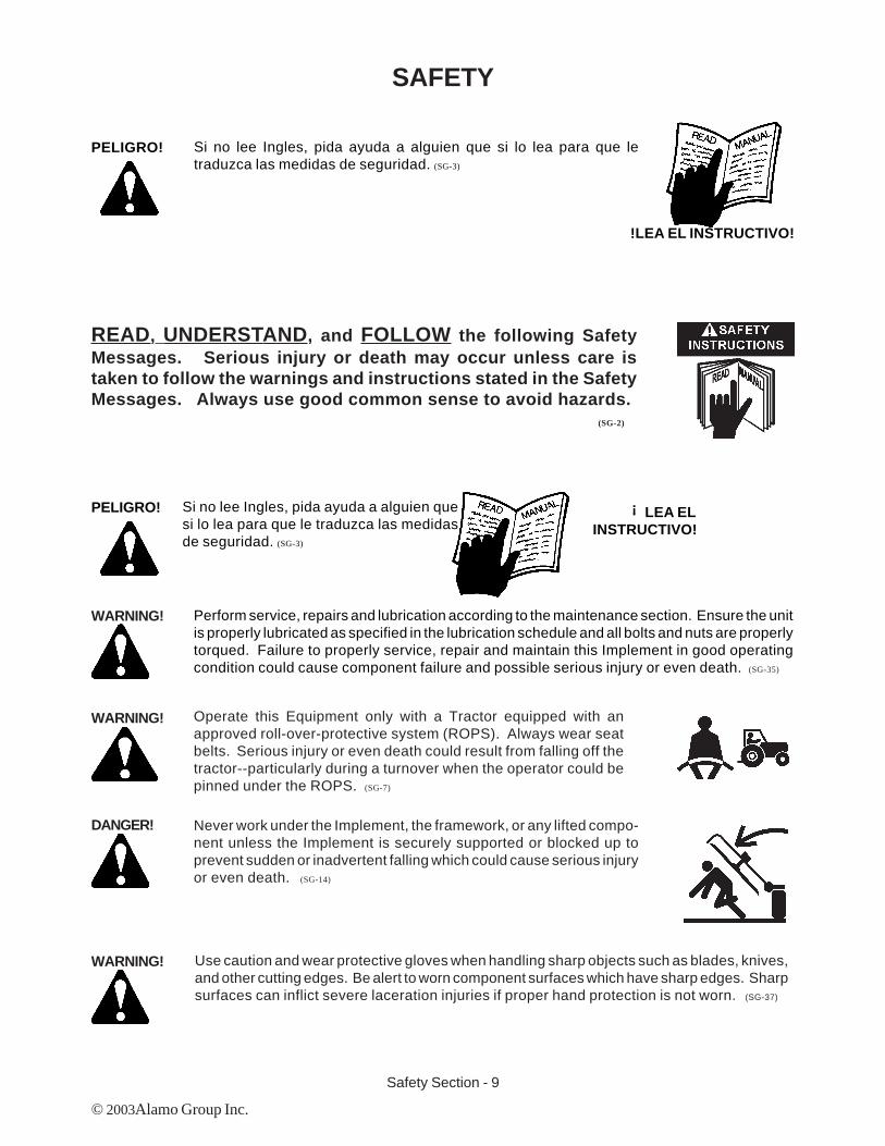
WARNING! Perform service, repairs and lubrication according to the maintenance section. Ensure the unitis properly lubricated as specified in the lubrication schedule and all bolts and nuts are properlytorqued. Failure to properly service, repair and maintain this Implement in good operatingcondition could cause component failure and possible serious injury or even death. (SG-35)
WARNING! Operate this Equipment only with a Tractor equipped with anapproved roll-over-protective system (ROPS). Always wear seatbelts. Serious injury or even death could result from falling off thetractor--particularly during a turnover when the operator could bepinned under the ROPS. (SG-7)
DANGER! Never work under the Implement, the framework, or any lifted compo-nent unless the Implement is securely supported or blocked up toprevent sudden or inadvertent falling which could cause serious injuryor even death. (SG-14)
WARNING! Use caution and wear protective gloves when handling sharp objects such as blades, knives,and other cutting edges. Be alert to worn component surfaces which have sharp edges. Sharpsurfaces can inflict severe laceration injuries if proper hand protection is not worn. (SG-37)

Safety Section - 10
SAFETY
© 2003 Alamo Group Inc.
Many of the parts are heavy and require lifting assistance. Do not try tolift the heavy parts by yourself. Get help from another employee or froman overhead crane.
WARNING! The operator and all support personnel should wear hard hats,safety shoes, safety glasses, and proper hearing protection at alltimes for protection from injury including injury from items thrown bythe equipment. (SG-16)
Always wear safety shoes with steel toes when working on this equipment.It is recommended that the safety shoes have metatarsal guards.
When welding use Welding hood with the appropriate OSHA requiredprotective lens, welding apron, and welding gloves.
DANGER! Always disconnect the wire leads from the mower valve solenoid beforeperforming service on the Tractor or Mower. Use caution when workingon the Tractor or Mower. Tractor engine must be stopped beforeworking on Mower or Tractor. The Mower Blades could inadvertently beturned on without warning and cause immediate dismemberment, injuryor death. (SBM-12)
DANGER! Never run the tractor engine in a closed building or without adequateventilation. The exhaust fumes can be hazardous to your health.
(SG-23)
WARNING!
WARNING!
WARNING!

Safety Section - 11
SAFETY
© 2003Alamo Group Inc.
Before starting the mower make sure the area is clear and the floor hasbeen swept. The mower blade can throw objects several hundred feet.Thrown objects could damge property or cause severe bodily injuries evendeath.
WARNING! Make certain that the “Slow Moving Vehicle” (SMV) sign is installed insuch a way as to be clearly visible and legible. When transporting theEquipment use the Tractor flashing warning lights and follow all local trafficregulations. (SG-6)
DANGER! Start tractor only when properly seated in the Tractor seat. Starting atractor in gear can result in injury or death. Read the Tractor operatorsmanual for proper starting instructions. (SG-13)
DANGER! Do not operate this Equipment with hydraulic oil leaking. Oil isexpensive and its presence could present a hazard. Do not check forleaks with your hand! Use a piece of heavy paper or cardboard. High-pressure oil streams from breaks in the line could penetrate the skinand cause tissue damage including gangrene. If oil does penetrate theskin, have the injury treated immediately by a physician knowledge-able and skilled in this procedure. (SG-15)
WARNING! Always read carefully and comply fully with the manufacturers instruc-tions when handling oil, solvents, cleansers, and any other chemicalagent. (SG-22)
DANGER! All Safety Shields, Guards and Safety devices including(but not limited to) - the Deflectors, Chain Guards, SteelGuards, Gearbox Shields, PTO integral shields , andRetractable Door Shields should be used and main-tained in good working condition. All safety devicesshould be inspected carefully at least daily for missingor broken components. Missing, broken, or worn itemsmust be replaced at once to reduce the possibility ofinjury or death from thrown objects, entanglement, orblade contact. (SGM-3)
DANGER!

Safety Section - 12
SAFETY
© 2003 Alamo Group Inc.
DANGER! NEVER use drugs or alcohol immediately before or while operating theTractor and Implement. Drugs and alcohol will affect an operator’salertness and coordination and therefore affect the operator’s ability tooperate the equipment safely. Before operating the Tractor or Imple-ment, an operator on prescription or over-the-counter medication mustconsult a medical professional regarding any side effects of the medi-cation that would hinder their ability to operate the Equipment safely.NEVER knowingly allow anyone to operate this equipment when theiralertness or coordination is impaired. Serious injury or death to theoperator or others could result if the operator is under the influence ofdrugs or alcohol. (SG-27)
DANGER! Operate the Tractor and/or Implement controls only while properly seatedin the Tractor seat with the seat belt securely fastened around you.Inadvertent movement of the Tractor or Implement may cause seriousinjury or death. (SG-29)
WARNING! Engine Exhaust, some of its constituents, and certain vehiclecomponents contain or emit chemicals known to the state ofCalifornia to cause cancer and birth defects or otherreproductive harm. (SG-30)
WARNING! Battery posts, terminals and related accessories contain leadand lead compounds, chemicals known to the state of Califor-nia to cause cancer and birth defects or other reproductiveharm. Wash Hands after handling. (SG-31)
WARNING! Use extreme caution when getting onto the Implement to perform repairs, maintenance andwhen removing accumulated material. Only stand on solid flat surfaces to ensure good footing.Use a ladder or raised stand to access high spots which cannot be reached from gound level.Slipping and falling can cause serious injury or death. (SG-33)
WARNING! Avoid contact with hot surfaces including hydraulic oil tanks, pumps, motors, valves and hoseconnections. Relieve hydraulic pressure before performing maintenance or repairs. Usegloves and eye protection when servicing hot components. Contact with a hot surface or fluidcan cause serious injury from burns or scalding. (SG-34)
WARNING! Avoid contact with hot surfaces of the engine or muffler. Use gloves and eye protection whenservicing hot components. Contact with a hot surface or fluid can cause serious injury fromburns or scalding. (SG-38)

Parts Section 13TK530 (Archive Book) 08/03
© 2003 Alamo Group Inc.
TK530 Archive Book: This is a complete listing of Parts from the first Unit to the Present. TheProduction Dates, Serial Numbers, Special Notes and Descriptions are furnished to help findReplacement Parts. Dimension (if listed) are for Identification of Parts and MAY NOT be toManufacturing Specification, Your measurements may vary some from dimensions listed.Some Parts may be changed and be different than parts listed. Some Modification may berequired when replacing older parts. Match S/N' and Ship Dates if avaialble.
TK 530 (May 1968 to Nov. 1973 ) The TK 530 was built from May 1968 (s/n TK530-07195)to Nov. 1973 (s/n TK530-21446) then the Model was changed to CP180 which used some ofthe same parts as the TK 530 But most parts were different and will not interchange. The TK530-10 was the same as the TK530 with one Wing removed to make it a 10 foot model.
Gearboxes: The best way to ID the TK 530 is by the Gearboxes, They have Bolt on Top Covers,And Input Shaft Option, Square Shaft, Shear Pin Shaft or Slip Clutch Shaft.
Tongue: The Tongue is made with Round Pipe, The Tongue has a Floating Tongue as Standardans a Hydraulic Level Lift as Optional
Standard Drivelines: The Standard Drivelines were a 35R Series standard and a 44R Option.Only available as a 540 RPM Only . The Wing used a single telescoping Shaft and Tube Asy.with a Double Telescoping Option, The Wings were available as a 35 R or a 14R Driveline option.The Drivelines had an option of Clutches, Shear Bolt System or a standard Square Shaft atgearbox. Driveliens must be ordered to match the type Gearbox Input Shaft.Side Skirt X-3 Option: There is no listing of a Side Skirt & Counter Weight asy for the X-3
Chain Guard Option: There are no listings of Chain Guards.
Hose Quick Disconnect Kit Option: The hose quick disconnect kit was offered as an option,there were 3 each of part # 00275400 per unit on TK 530 and 2 each on 10' model.
Dual Wheel Option: There is NO Listing for Dual Wheel option offered for the center section.
Weight: The Shipping Weight of the TK 530 is approx 2700 lbs. This will vary with some optionsinstalled or removed.
TK 530 Flex Wing RotaryARCHIVE BOOK

Parts Section 14TK530 (Archive Book) 08/03© 2003 Alamo Group Inc.
NOTE: Deck Weldments are Listed for Reference Only, SomeMAY NOT be available as a replacement part, ALWAYS
Check Price & Availabilty BEFORE ORDERING Deck Sec-tions or any Replacement Parts.
DECK COMPONENTSTK 530
29
26,27,28
23,24,25
20,22
2,3,4
1
56
7
13,14,15
1
1
19
18
17
1211
98 10
May 1968to
Nov. 1973
TK 530-07195to
TK 530-21446

Parts Section 15TK530 (Archive Book) 08/03
© 2003 Alamo Group Inc.
Item Part No. Qty Description
1. 00391100 4 Height Adjustment Asy.2. 00423500 2 Outside Retaining Arm3. 00162001 2 Retaining Arm Pin (Not Shown)4. 00162002 4 Retaining Arm Washer (Not Shown)5. 00000801 1 Winch Cable Asy Complete
00000800 1 Winch Cable Only00000900 1 Cable Thimble00001000 1 Cable Clip
6. 00214300 1 Tongue Asy. (Floating Spring)00716000 a/r Tongue Asy, Hyd Level Lift (optional)
7. ------------- 1 PTO Driveline8. 00008900 2 Retaining Pin9. 00148700 1 Crank10. 00256000 1 Winch Asy.11. 00285001 1 Jack Asy.12. ------------- 2 Gearbox Asy, Wing Section
00442100 2 Blade Hub Asy, Wing13. ------------- a/r Pneumatic Tires & Wheels
00025200 a/r Sectional Tire & Wheel, 6 X 9.0014. 00008700 a/r Pneumatic Wheel Only, 15 X 5.00
00019200 a/r Pneumatic Wheel Only, 14 X 5.0015. 00264600 a/r Wheel Hub and Bearing Asy.17. 00283600 1 Inspection Cover, Center Opening18. ------------- a/r Driveline, Wing Single Telescoping
------------- a/r Driveline, Wing Double Telescoping19. ------------- 1 Gerbox Asy, Center Section20. 00303200 2 Hinge Pin22. 00164600 38 Hinge (Weld on Parts)
00775765 1 Hinge Weld Instructions Sheet23. 00001102 12 Bolt24. 00001200 12 Nut (Not Shown)25. 00001300 12 Lockwasher (Not Shown)26. 00019300 14 Bolt27. 00019400 14 Nut (Not Shown)28. 00001300 14 Lockwasher29. 00284000 2 Cover, Wing Openings30. 00026600 1 Blade Wrench (Not Shown)31. 00533800 1 Shield Asy, (Used w/ jack Shaft models Only)32. ------------ 2 Center Section Axle Arms
DECK COMPONENTSTK 530
May 1968to
Nov. 1973
TK 530-07195to
TK 530-21446

Parts Section 16TK530 (Archive Book) 08/03© 2003 Alamo Group Inc.
LEVEL LIFT SYSTEMCenter Section
TK 530
Item Part No. Qty. Description
1. 00714500 1 Center Section Frame2. 00391101 2 Wheel Support & Height Adjust Asy.3. 00008700 a/r Wheel, Pneumatic 15"4. 00019200 a/r Wheel, Pneumatic 14"5. 00025200 a/r Wheel & Sectional Tire (Notat) 6 X 96. 00715400 2 Rear Swivel Bracket7. 00716700 2 Rear Swivel Bracket Pin8. 00021900 4 Cotter Pin9. 00162802 10 Clip Washer10. 00162809 2 Rear Link Rod Pin11. 00717200 2 Link Rod Weldment12. 00059500 2 Link Rod Nut13. 00732800 2 Link Rod Turnbuckle14. 00162805 2 Tongue Pin15. 00716000 1 Tongue Asy.16. 00749300 2 Hydraulic Cylinder, Tongue17. 00748767 2 Turnbuckle Pin18. 02022300 4 Cotter Pin
15 17,18
9,14
16
13 12 1
119,10
7,8
63,4,5
2
May 1968to
Nov. 1973
TK 530-07195to
TK 530-21446

Parts Section 17TK530 (Archive Book) 08/03
© 2003 Alamo Group Inc.
Item Part No. Qty. Description
1. 00732800 2 Link Rod Turnbuckle Asy.3. 00059500 2 Nut4. 00717200 2 Link Rod Weldment5. 00748767 2 Front Link Rod Pin6. 00162809 2 Rear Link Rod Pin7. 02022300 4 Cotter Pin8. 00162802 4 Clip Washer
Note: Qty Shown for 1 Control Rod, 2 Control Rods used on Mower.
LINK ROD ASYLevel Lift Rod
TK 530
13 4 6, 85, 7
May 1968to
Nov. 1973
TK 530-07195to
TK 530-21446

Parts Section 18TK530 (Archive Book) 08/03© 2003 Alamo Group Inc.
TONGUE ASYFloating Tongue Standard
TK 530
Item Part No. Qty Description
00214300 1 Floating Tongue Asy (Items 1 thru 18)00210200 2 Spring and Clevis Asy (items 1 thru 13)
1. 00600000 ref Grease Fitting2. 00012400 2 Set Screw3. 00147600 2 Collar4. 00210700 2 Clevis Asy5. 00132002 2 Spring6. 00210100 4 Bushing7. 00012000 4 Bolt8. 00002700 8 Washer9. 00001200 4 Nut10. 00210600 2 Height Adjusting Nut Asy11. 00210400 2 Height Adjusting Screw12. 00162003 2 Pin, Adjusting Screw13. 00162002 4 Retainer14. 00162805 2 Pin, Tongue Pivot15. 00162802 4 Retaining Washer16. 00165106 ref Tongue Support17. 00165104 ref Tongue Clevis18. 00180700 1 Tongue
1618
14,15
17
2
3
4 5
67
8910
11
12,13
1
May 1968to
Nov. 1973
TK 530-07195to
TK 530-21446

Parts Section 19TK530 (Archive Book) 08/03
© 2003 Alamo Group Inc.
TONGUE ASYHydraulic Tongue Option
TK 530
Item Part No. Qty Description
00165100 1 Tongue and Cylinder Asy (items 1 thru 10)1. 00180700 1 Tongue Wledment2. 00162805 2 Pin, Tongue pivot3. 00162802 4 Retaining Washer4. 00488100 2 Hydraulic Cylinder, Tongue lift5. 00012000 4 Bolt6. 00002700 8 Washer7. 00001200 4 Nut8. 00162003 2 Pin, Cylinder Pivot9. 00162002 4 Retainer10. 00210100 4 Bushing11. 00331100 2 Tie Down Chain Asy, (Optional Order Item)
12,3
4
5
6
7
8,9
10
6
11
Chain & Retaining Clips (Added Accesso-ries) are shown in transport position. Theymay also be used to limit Cylinder Movementfor storage or when mowing to a fixed height.
May 1968to
Nov. 1973
TK 530-07195to
TK 530-21446

Parts Section 20TK530 (Archive Book) 08/03© 2003 Alamo Group Inc.
GEARBOX ASY. CENTERTK 530
Side View
Top View
To LH WingTo RH Wing
FromTractor
PTO
39,40
4443
38
37
45,46
51
46,48
39,404
14,16
52
54,55
4
41
42
46,48
312
52
14,164
51
Center Gearbox w/ Shear PinShaft & Flange
Center Gearbox w/ Slip ClutchShaft
43
65
64
67
66
1143
25
11
3 68 49
50
47
5658
455960
20,21
123,24
2526,27,28
45,46
TK 530-07195to
TK 530-21446
May 1968to
Nov. 1973

Parts Section 21TK530 (Archive Book) 08/03
© 2003 Alamo Group Inc.
Item Part No. Qty Description
1. 00142800 1 Seal Protector3. 00001900 20 Bolt4. 00006000 5 Bearing11. 00009600 4 Setscrew12. 00128013 1 Bearing Cap14. 00013100 2 Nut16. 00013000 2 Lockwasher20 00020600 2 Bearing Cup21. 00020700 2 Bearing Cone23. 00020800 1 Seal24. 00243400 1 Seal Race25. 00139701 1 Key26. 00020900 1 Blade Hub Nut27. 00001600 1 Cotter Pin28. 00242900 1 Blade Hub Washer37. 00001700 1 Filler Plug38. 00138400 1 Main Housing39. 00012101 18 Lockwasher40. 00011400 18 Bolt41. 00006100 1 Bearing42. 00128003 1 Bearing Cap43. 00128001 a/r Main Shaft, Square
00178400 a/r Shear Pin Shaft00410700 a/r Slip Clutch Shaft
44. 00128002 1 Seal45. 00183200 2 Key46. 00131502 3 Gear, Upper47. 00021100 1 Lockwasher48. 00183100 2 Key49. 00138600 1 G/B Cover, Top50. 00021000 1 Stake Nut51. 00168200 2 Bearing Housing52. 00168300 2 Output Shaft54. 00128008 2 Seal55. 00128009 2 Seal Race56. 00242000 1 Output Shaft58. 00131501 1 Gear59. 00243100 1 Bearing Shield60. 00243200 1 Support Ring
GEARBOX ASY. CENTERTK 530
00128000 a/r Gearbox Asy, Standard Square Input Shaft00211800 a/r Gearbox Asy, Optional Shear Pin Shaft00495500 a/r Gearbox Asy, Optional Slip Clutch Shaft
Item Part No. Qty Description
64. 00219701 1 Drive Plate Asy.65. 00011700 2 Lockwasher66. 00027100 2 Bolt67. 00177000 1 Washer68. 00001701 1 Breather Plug69. 00033900 1 Cotter Pin
Notes:Gearbox Timing: (Shear Pin Gearboxes)Turn the Drive screw Hole in the horizontalShafts (# 43 and #52) straight up and down,Point the Key in the Vertical Shaft (#56) towardthe end of the Horizontal input Shaft (#43) asshown in drawingShear Pin or Slip Clutch:Gearboxes w/ Shear Pin must be timed soBlades don't hit between center section andWing section. When using Slip Clutches a differ-ent Blade carrier was used that made bladesshorter. Do Not mix these.Stakenut:The Stake Nut (# 50) on the Output Shaft mustbe staked solidly with a punch after assembly /adjustment is complete.Setscrew:The Setscrews (#11) must be cleaned & in-stalled with Lock Tite.Input Shafts:The input Shafts (#43, #62 & #63)must be in-stalled with the type to match the type Drivelineconnection you haveSerial Numbers:The early models had the S/N stamped into theGearbox, these serial numbers were for thedeck and all components. Match any numbersstamped in Gearbox Housing with Serial num-bers listed on pages above.
May 1968to
Nov. 1973
TK 530-07195to
TK 530-21446

Parts Section 22TK530 (Archive Book) 08/03© 2003 Alamo Group Inc.
GEARBOX ASY. WINGTK 530
Wing Gearbox w/ SlipClutch Shaft
Wing Gearbox w/ ShearPin Shaft & Flange
13
1134
3313
5
43
2
9,30
20,21
1
13
14,16
26
25
27
28 17
23,24
15
18
19
4
12
3
3
9,10(CCW)3 87 6
CW CCW
9,10(CW)
May 1968to
Nov. 1973
TK 530-07195to
TK 530-21446

Parts Section 23TK530 (Archive Book) 08/03
© 2003 Alamo Group Inc.
GEARBOX ASY. WINGTK 530
00127000 a/r Gearbox Asy, (w/ Standard Square Input Shaft, CCW Rotation)00127001 a/r Gearbox Asy, (w/ Standard Square Input Shaft CW Rotation)00456200 a/r Gearbox Asy, (w/ Optional Shear Pin Input Shaft CW Rotation)00456300 a/r Gearbox Asy, (w/ Optional Shear Pin Input Shaft CCW Rotation)00482300 a/r Gearbox Asy, (w/ Optional Slip Clutch Input Shaft CCW Rotation)00482400 a/r Gearbox Asy, (w/ Optional Slip Clutch Input Shaft CW Rotation)
(CCW = Gear is located in Back & CW = Gear is located in Front as Shown) Whenusing Shear Pins the Gearbox must be timed with the center Gearbox so Blades don't Hit
Item Part No. Qty Description
1. 00142800 1 Seal Protector2. 00127005 1 Bearing Cap3. 00001900 20 Bolt4. 00006000 2 Bearing5. 00127007 1 Seal6. 00001701 1 Breather Plug7. 00033900 1 Cotter Pin8. 00138500 1 Lid, Top Cover9. 00131400 2 Gear10. 00182900 1 Key11. 00009600 2 Setscrew12. 00128013 1 Bearing Cap13. 00127008 a/r Input Shaft, Square
00477300 a/r Input Shaft, Slip Clutch00336601 a/r Input Shaft, Shear Pin
14. 00013100 1 Nut15. 00138200 1 Main Housing16. 00013000 1 Lockwasher17. 00244100 1 Output Shaft18. 00243800 1 Support Ring19. 00243900 1 Bearing Shield20. 00020600 2 Bearing Cup21. 00020700 2 Bearing Cone23. 00020800 1 Seal24. 00243400 1 Seal Race25. 00139701 1 Key26. 00020900 1 Blade Hub Nut27. 00001600 1 Cotter Pin28. 00242900 1 Blade Hub Washer29. 00001700 1 Filler Plug (Not Shown)30. 00244000 1 Key33. 00254300 1 Key34. 00455900 a/r Shear Pin Flange
Notes:Stakenut:
The Stake Nut (# 50) on the Output Shaft
must be staked solidly with a punch after
assembly / adjustment is complete.
Setscrew:
The Setscrews (#11) must be cleaned &
installed with Lock Tite.
Input Shafts:
The input Shafts (#13) must be installed with
the type to match the type Driveline connec-
tion you have
Location Input Gear:
The Input gear (#9) must be installed in the
front or Rear of the Input Shaft, CCW Rota-
tion install Gear in Back as shown in drawing,
CW Rotation install gear in the front.
Vent Plug:
The Vent Plug (#6) must be installed in Lid
Top Civer (#8) and top Cover must be in-
stalled where Breather Plug is not over top of
gear, if it is the gear will throw Oil into plug and
cause oil to be forced out of it.Serial Numbers:The early models had the S/N stamped intothe Gearbox, these serial numbers were forthe deck and all components. Match anynumbers stamped in Gearbox Housing withSerial numbers listed on pages above.
May 1968to
Nov. 1973
TK 530-07195to
TK 530-21446

Parts Section 24TK530 (Archive Book) 08/03© 2003 Alamo Group Inc.
SHEAR PIN KITCENTER GEARBOX
TK 530
Item Part No. Qty Description
00220601 1 Shear Pin Kit, f/ Center Gearbox1. 00178400 1 Input Shaft (Shear Pin Gearbox)2. 00219701 1 Driven Plate Asy (w/ item # 3)3. 00219900 3 Shear Bushing4. 00220000 1 Yoke Asy. (w/ item # 7 & # 13)5. 00033900 1 Cotter Pin6. 00220200 7 Shear Pin7. 00220300 1 Bushing (f/ Yoke item # 4)8. 00177000 1 Washer (special 2 hole washer)9. 00027100 2 Bolt10. 00011700 2 Lockwahser11. 00009600 1 Setscrew12. 00139701 1 Key13. 00003500 1 Grease Fitting (f/ Yoke item # 4)
Note: Item # 3 Bushing is welded into Driven Plate item # 2, if this bushing has to be replacedit will have to be hardened after welding it in. To Harden Bushing after welding heat eachbushing with a torch to dull red color, cool in water and this will harden bushing.
1 2,12
5,64
7
8,9,1011 13
3Driveline
When using Shear Pins Gear-boxes must be timed so Bladesdon't hit each other
May 1968to
Nov. 1973
TK 530-07195to
TK 530-21446
Parts Section 25TK530 (Archive Book) 08/03
© 2003 Alamo Group Inc.
SHEAR PIN KITWING GEARBOX
TK 530
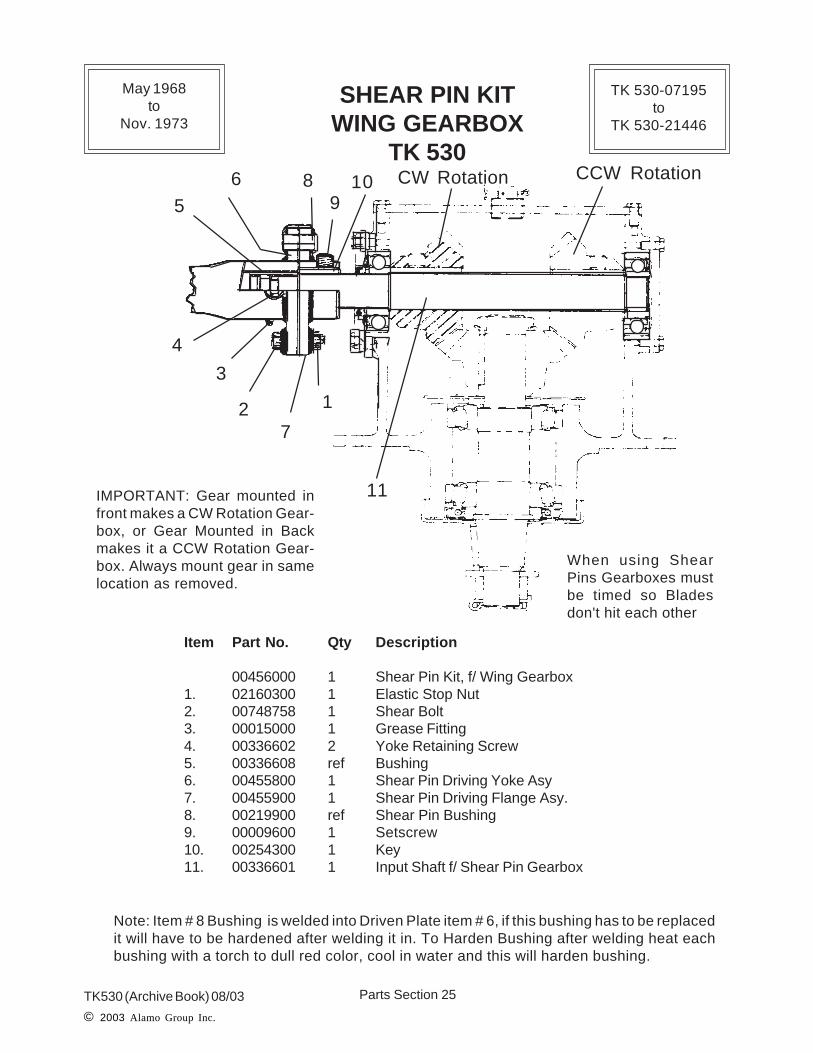
Item Part No. Qty Description
00456000 1 Shear Pin Kit, f/ Wing Gearbox1. 02160300 1 Elastic Stop Nut2. 00748758 1 Shear Bolt3. 00015000 1 Grease Fitting4. 00336602 2 Yoke Retaining Screw5. 00336608 ref Bushing6. 00455800 1 Shear Pin Driving Yoke Asy7. 00455900 1 Shear Pin Driving Flange Asy.8. 00219900 ref Shear Pin Bushing9. 00009600 1 Setscrew10. 00254300 1 Key11. 00336601 1 Input Shaft f/ Shear Pin Gearbox
Note: Item # 8 Bushing is welded into Driven Plate item # 6, if this bushing has to be replacedit will have to be hardened after welding it in. To Harden Bushing after welding heat eachbushing with a torch to dull red color, cool in water and this will harden bushing.
IMPORTANT: Gear mounted infront makes a CW Rotation Gear-box, or Gear Mounted in Backmakes it a CCW Rotation Gear-box. Always mount gear in samelocation as removed.
12
3
4
5
6
7
89
10
11
CW Rotation CCW Rotation
When using ShearPins Gearboxes mustbe timed so Bladesdon't hit each other
May 1968to
Nov. 1973
TK 530-07195to
TK 530-21446

Parts Section 26TK530 (Archive Book) 08/03© 2003 Alamo Group Inc.
SLIP CLUTCHCENTER GEARBOX
TK 530
Item Part No. Qty Description
00584700 1 Slip Clutch Asy.1. 00585200 1 Back Plate (Use # 00748834)2. 00585300 2 Friction Disc (Use # 00748833)3. 00585100 1 Hub4. 00585400 1 Nut (Obsolete)5. 00585500 2 Bellville Spring (Use # 00748831)6. 00585600 1 Pressure Plate (Obsolte)7. 00585700 1 Drive Plate (Obsolete)
NOTE: Some parts listed above are obsolete and no longer available and are listedas reference only. Check Part numbers and availability before ordering.
1
2
7
6
54
3
2
1-3/8" BoreNOTE: Shear Pin or SlipClutch:Gearboxes w/ Shear Pinmust be timed so Bladesdon't hit between Center sec-tion and Wing section. Whenusing Slip Clutches a differ-ent Blade carrier was usedthat made blades shorter. DoNot mix these or installClutches on unit with ShearPins unless Blade Carriersare changed also.
May 1968to
Nov. 1973
TK 530-07195to
TK 530-21446

Parts Section 27TK530 (Archive Book) 08/03
© 2003 Alamo Group Inc.
NOTES

Parts Section 28TK530 (Archive Book) 08/03© 2003 Alamo Group Inc.
Item Part No. Qty Description
00442100 3 Blade Carrier Asy, Center or Wing Section (w/ Flat Blades)1. 00000400 12 Cotter Pin2. 00017200 12 Nut, Slotted3. 00137200 18 Washer, Special (Hardened & Large OD)4. 00167700 6 Bolt, Special w/ Hole5. 00127029 6 Spacer6. 00139700 3 Blade Hub7. 00127600 6 Swivel Busing8. 00442000 6 * Inside Blade Section, 19-5/8" end to end / 15-3/8" ctr hole to ctr hole
00167100 6 * Inside Blade Section, 18" end to end / 13-3/4" ctr hole to ctr hole9. 00127700 6 Swivel Bolt10. 00127028 6 Blade, Flat CW or CCW Rotation Center or Wing
00419900 6 Blade, Updraft CCW Rotation Center or RH Wing Only00419800 6 Blade, Updraft CW Rotation LH Wing Only
11. 00020900 3 Nut, Slotted (Hub Retaining Not Shown)12. 00242900 3 Washer, Blade Hub (Hub Retaining Not Shown)13. 00001600 3 Cotter Pin (Hub Retaining Not Shown)
BLADE BAR CARRIER ASYDOUBLE SWING
CENTER or WING SECTIONTK 530
NOTE: Flat Blades were standard and Updraft (Fan Blades) were Special order option. TheBar carrier was only used on the Shear Pin Model gearboxes where the Gearboxes had to betimed to prevent the Blades form Hittingbetween Center and Wing Blades.
* Item 8, Inside Blade Section, there were two different lengths used, you will have tomeasure to see which one you have before ordereing a replacement. Units were built witheither length and a combination of lengths depending on original options. Do not get theseinside blade sections mixed up, if you do the blades could hit each other.
123
3
45
6
7
8
9
103
1
4
53
72 1
Use one carrier persection, Qty shownbelow is for 3 BladeCarriers
May 1968to
Nov. 1973
TK 530-07195to
TK 530-21446
Parts Section 29TK530 (Archive Book) 08/03
© 2003 Alamo Group Inc.
BLADE PAN CARRIER ASYCENTER or WING SECTION
TK 530
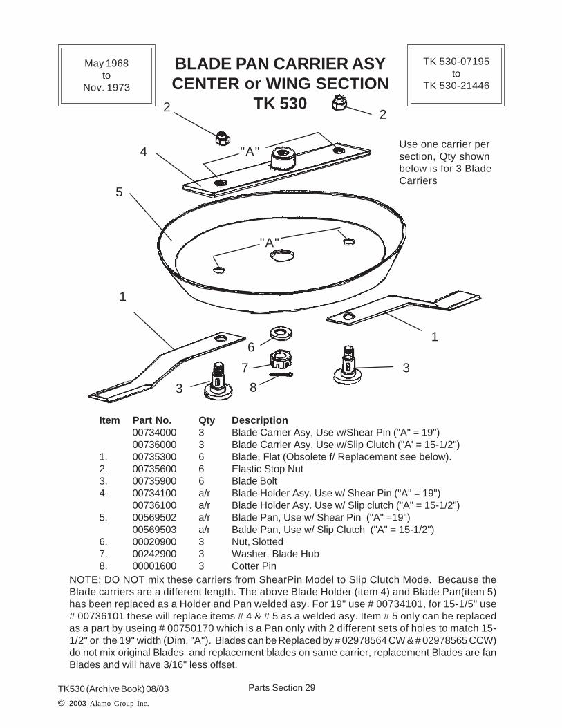
Item Part No. Qty Description00734000 3 Blade Carrier Asy, Use w/Shear Pin ("A" = 19")00736000 3 Blade Carrier Asy, Use w/Slip Clutch ("A' = 15-1/2")
1. 00735300 6 Blade, Flat (Obsolete f/ Replacement see below).2. 00735600 6 Elastic Stop Nut3. 00735900 6 Blade Bolt4. 00734100 a/r Blade Holder Asy. Use w/ Shear Pin ("A" = 19")
00736100 a/r Blade Holder Asy. Use w/ Slip clutch ("A" = 15-1/2")5. 00569502 a/r Blade Pan, Use w/ Shear Pin ("A" =19")
00569503 a/r Balde Pan, Use w/ Slip Clutch ("A" = 15-1/2")6. 00020900 3 Nut, Slotted7. 00242900 3 Washer, Blade Hub8. 00001600 3 Cotter Pin
NOTE: DO NOT mix these carriers from ShearPin Model to Slip Clutch Mode. Because theBlade carriers are a different length. The above Blade Holder (item 4) and Blade Pan(item 5)has been replaced as a Holder and Pan welded asy. For 19" use # 00734101, for 15-1/5" use# 00736101 these will replace items # 4 & # 5 as a welded asy. Item # 5 only can be replacedas a part by useing # 00750170 which is a Pan only with 2 different sets of holes to match 15-1/2" or the 19" width (Dim. "A"). Blades can be Replaced by # 02978564 CW & # 02978565 CCW)do not mix original Blades and replacement blades on same carrier, replacement Blades are fanBlades and will have 3/16" less offset.
1
1
2 2
3
3
4
5
6
7
8
"A"
"A"Use one carrier persection, Qty shownbelow is for 3 BladeCarriers
May 1968to
Nov. 1973
TK 530-07195to
TK 530-21446
Parts Section 30TK530 (Archive Book) 08/03© 2003 Alamo Group Inc.
1. PTO Drivelines used without Pillow Block Bearings or Jack Shafts (2 PieceDrivelines)
2. PTO Drivelines used with Pillow Block Bearings & Jack Shafts (3 PieceDrivelines)
3. PTO Drivelines a 35R series or a 44R Series Universal joints optional.4. PTO Drivelines with Plain (Square Hole) Yokes, Shear Pin Yoke, Slip Clutch
Yoke where an option and Drivelines must match the Input Shaft that is installed into the Gearbox or Driveline will not connect to Gearbox. Check this beforeordering Parts.
5. Drivelines used with Shields and without shields.6. PTO Drivelines have codes at the bottom of the Page (Code Example = 530
Model with S/P - J/S - 35R) When ordering part from PTO Driveline pages lookat the bottom of the page, these codes should match.
7. Wing Drivelines used Single Telescoping Drivelines or Double TelescopingDriveline as Option.
8. Wing Drivelines were option 14R or 35R Series universal joint.9. Wing Drivelines had Square Shaft Yoke, Shear Pin Yoke or Slip Clutch Yoke
Option. Drivelines must match the Gearbox Input Shaft or they will not fit.
DRIVELINEASSEMBLYOPTIONS

Parts Section 31TK530 (Archive Book) 08/03
© 2003 Alamo Group Inc.
Used without Jack Shaft means Drivelines connecteddirectly to the Center Gearbox. If Driveline connect toStub shaft of Jack Shaft at Pillow Block Bearing seePTO Drivelines used with Jack Shaft & Pillow Block
Bearings.
PTODRIVELINES
USEDWITHOUT
JACKSHAFTOR
PILLOW BLOCKBEARING

Parts Section 32TK530 (Archive Book) 08/03© 2003 Alamo Group Inc.
12 118,9,10 17 6
4
1,2,3
20,21 19 1817 16 15
13 14
8,9,10
22
23
PTO DRIVELINE ASY35R SERIES
TK 530Used w/o Jack shaft
IMPORTANT NOTES:1. The above driveline connected direct to the Center Gearbox
and DID NOT USE Jack Shaft & Pillow Block Bearing
2. The driveline options were in the Gearbox connection, Checkwhich Driveline was connected which way before orderingparts.
NOTE: To ID 44R driveline from the 35R driveline, Look at the Universal Joint CapRetaining Clips. The clips on the 44R are on the inside of the cap in grooves that aremachined ionto the cap. The 35R has retaining clips that are on the outside of the cap andgo into grooves machined into the Yoke Ear. (44R drivelines offered as option on TK530)
(530 Model with S/P - no J/S - 35R)
PTODriveline
End
CenterGearbox
End
May 1968to
Nov. 1973
TK 530-07195to
TK 530-21446

Parts Section 33TK530 (Archive Book) 08/03
© 2003 Alamo Group Inc.
Item Part No. Qty Description
00220500 a/r Driveline Asy, (w/ 1-3/8" X 6 Spline & Shear Pin Yoke)
00264800 a/r Driveline Asy, (w/ 1-3/8" X 21 Spline & Shear Pin Yoke)
00409000 a/r Driveline Asy, (w/ 1-3/8" X 6 Spline & Slip Clutch Yoke)
00414000 a/r Driveline Asy, (w/ 1-3/8" X 21 Spline & Slip Clutch Yoke)
00180800 a/r Driveline Asy, (w/ 1-3/8" X 6 & Square Yoke)
00239000 a/r Driveline Asy, (w/ 1-3/8" X 21 & Square Yoke)
1. 00180100 1 "X" Washer
2. 00180200 1 Spring
3. 00180300 1 Locking Pin
4. 00191900 a/r Yoke Asy, 1-3/8" 6 Spline (w/ items 1, 2 & 3)
00228000 a/r Yoke Asy, 1-3/8" 21 Spline (w/ items 1, 2 & 3)
6. 00189700 2 Universal Joint, (X-Kit)
8. 00310800 2 Shield Snap Ring
9. 00310700 2 Thrust Washer
10. 00183700 2 Shield Bearing
11. 00186200 1 Driving Round Tube (Welds to item 12 & 14)
12. 00185700 1 Driving Sleeve Asy. (Welds to item 11 & 14)
13. 00311000 1 Outer Shield & Bell Asy.
14. 00192300 1 Weld Yoke, Round Tube (Welds to item 11 & 12)
15. 00183900 1 Square Shaft & Rivit Asy. (connects to item 18)
16. 00310600 1 Inner Shield and Bell Asy.
17. 00310900 1 Shield Bell, (Part of Shield & Bell Asy)
18. 00192700 1 Yoke, f/ Square Shaft (connects to item 15)
19. 00185100 1 Plain Yoke, Square Hole. (Shown)
00220000 a/r Shear Pin Yoke (Not Shown)
00409200 a/r Slip Clutch Yoke (Not Shown)
20. 00132900 2 Locking Screw (f/ Square Yoke)
21. 00012100 2 Locking Washer (f/ Square Yoke)
22. 00184000 a/r PTO Half Asy w/ 1-3/8" X 6 Spline
00248200 a/r PTO Half Asy w/ 1-3/8" X 21 Spline
23. 00186100 a/r Impl Half Asy w/ Square yoke
00264700 a/r Impl Half Asy w/ Shear Pin Yoke
PTO DRIVELINE ASY35R SERIES
TK 530Used w/o Jack shaft
(530 Model with S/P - no J/S - 35R)
May 1968to
Nov. 1973
TK 530-07195to
TK 530-21446

Parts Section 34TK530 (Archive Book) 08/03© 2003 Alamo Group Inc.
PTO DRIVELINE ASY44R SERIES
TK 530Used w/o Jack shaft
NOTE: To ID 44R driveline from the 35R driveline, Look at the Universal Joint CapRetaining Clips. The clips on the 44R are on the inside of the cap in grooves that aremachined ionto the cap. The 35R has retaining clips that are on the outside of the cap andgo into grooves machined into the Yoke Ear. (44R drivelines offered as option on TK530)
1
1A
2
2B
3
45
6
7B8
9
5
6A6B6C
6D
7A
7
8
9
7
(530 Model with S/P - no J/S - 44R)
PTODriveline
End
CenterGearbox
End
May 1968to
Nov. 1973
TK 530-07195to
TK 530-21446

Parts Section 35TK530 (Archive Book) 08/03
© 2003 Alamo Group Inc.
Item Part No. Qty Description
00697100 a/r Driveline Asy w/o Shields (items 1A & 2B)
00696100 a/r Driveline Asy w/ Shields (items 1 & 2)
1. 00697800 1 Driveline Half Asy w/ Shields, Tractor End (44R)
1A 00697400 ref Driveline Half Asy w/ o Shields, Tractor End (44R)
2. 00697900 1 Driveline Half Asy w/ Shields Mower End
2B. 00697500 ref Driveline Half Asy w/o Shields Mower End
3. 00698000 1 Bell & Outer Shield Asy
4. 00698100 1 Bell & Inner Shield Asy
5. 00669200 4 Nylon Bearing, 2 ea. Iinner & Outer Shield
6. 00697700 1 Yoke, Tube & Sleeve Weldment (items
6A. 00670200 ref Square Sleeve only (Welded in Part)
6B. 00697200 ref Tube Only (Weld in Part)
6C. 00670000 ref Tube Yoke (Weld in Part)
6D. 00693400 ref Grease Fitting
7. 00697600 1 Yoke & Shaft Weldment
7A. 00697300 ref Square Shaft (Weld in Part)
7B. 00670400 ref Square Hole Weld Yoke (Weld in Part)
8. 00669000 1 QD Yoke, 1-3/8" X 6 Spline (Use # W 821A)
9. 00697000 1 Shear Pin Yoke
10. 00669100 2 Universal Joint (Use # W840)
PTO DRIVELINE ASY44R SERIES
TK 530Used w/o Jack shaft
NOTE: This driveline used with the Shear Pin Gearbox Model.
(530 Model with S/P - no J/S - 44R)
IMPORTANT NOTES:1. The above driveline connected direct to the Center Gearbox
and DID NOT USE Jack Shaft & Pillow Block Bearing
2. The driveline options were in the Gearbox connection, Checkwhich Driveline was connected which way before orderingparts.
May 1968to
Nov. 1973
TK 530-07195to
TK 530-21446

Parts Section 36TK530 (Archive Book) 08/03© 2003 Alamo Group Inc.
PTODRIVELINES
USEDWITH
JACKSHAFT&
PILLOW BLOCKBEARING
Used with Jack Shaft means Drivelines connected tothe Stub Shaft of the Jack Shaft at Pillow Block Bear-ing. If Driveline connect directly to Center Gearbox
see PTO Drivelines used without Jack Shaft & PillowBlock Bearings in previous pages.

Parts Section 37TK530 (Archive Book) 08/03
© 2003 Alamo Group Inc.
PTO DRIVELINE ASY35R SERIES STANDARD
TK 530Used w/ Jack shaft
Item Part No. Qty Description
1. 00546900 1 Jack Shaft Asy. Shear Pin Drivel line (35R)
2. 00533800 1 Jack Shaft Shield Asy.
3. 00477900 1 DriveShaft Asy (35R
1 2
3
SEE NEXT 2 PAGES FOR PARTSBREAK DOWN OF THIS DRIVELINE
(530 Model with S/P - J/S - 35R)
May 1968to
Nov. 1973
TK 530-07195to
TK 530-21446

Parts Section 38TK530 (Archive Book) 08/03© 2003 Alamo Group Inc.
Item Part No. Qty Description
00477900 -- Driveline Asy, Complete Shaft & Tube Asy1. 00180100 1 "X" Washer2. 00180200 1 Spring3. 00180300 1 Locking Pin4. 00191900 a/r Yoke Asy, 1-3/8" 6 Spline (w/ items 1, 2 & 3)6. 00189700 2 Universal Joint, (X-Kit)8. 00310800 2 Shield Snap Ring9. 00310700 2 Thrust Washer10. 00183700 2 Shield Bearing11. 00512800 1 Driving Round Tube (Welds to item 12 & 14)12. 00185700 1 Driving Sleeve Asy. (Welds to item 11 & 14)13. 00512600 1 Outer Shield & Bell Asy.14. 00192300 1 Weld Yoke, Round Tube (Welds to item 11 & 12)15. 00512900 1 Square Shaft & Rivit Asy. (connects to item 18)16. 00512700 1 Inner Shield and Bell Asy.17. 00310900 1 Shield Bell (Part of Shield & Bell Asy18. 00192700 1 Yoke, f/ Square Shaft (connects to item 15)19. 00185100 1 Plain Yoke, Square Hole. (Shown)20. 00132900 2 Locking Screw (f/ Square Yoke)21. 00012100 2 Locking Washer (f/ Square Yoke)
PTO DRIVELINE ASY35R SERIES STANDARD
TK 530Used w/ Jack shaft # 00546900
(530 Model with S/P - J/S - 35R)
12 118,9,10 17 6
4
1,2,3
20,21 19 1817 16 15
13 14
8,9,10
TractorPTOEnd
JackShaftEnd
May 1968to
Nov. 1973
TK 530-07195to
TK 530-21446

Parts Section 39TK530 (Archive Book) 08/03
© 2003 Alamo Group Inc.
PTO JACK SHAFT ASY35R SERIES STANDARD
TK 530SHEAR PIN MODEL
Used w/ PTO Shaft Asy # 00477900
Item Part No. Qty Description
00546900 -- Jack Shaft Asy, Complete w/ Pillow Block Bearing1. 00013300 2 Bolt2. 00001200 2 Nut3. 00001300 2 Lockwasher4. 00477700 1 Pillow Block Bearing Support Stand5. 00034000 1 Pillow Block Asy (Use # 00751272 & # 00752176)6. 00546800 1 Jack Shaft, (Shaft Only)7. 00012100 2 Lockwasher8. 00132900 2 Bolt, Retaining Bolt9. 00185100 1 Yoke, Plain (35R)10. 00189700 1 Universal Joint11. 00220000 1 Driving Yoke (Shear Pin)12. 00027100 2 Bolt13. 00177000 1 Washer14. 00009600 1 Setscrew15. 00139701 1 Key17. 00003500 1 Grease Fitting18. 00219701 ref Driven Plate Asy.19. 00033900 1 Cotter Pin20. 00220200 1 Shear Pin21. 00220300 1 Bushing22. 00011700 2 Lockwasher
14,15,18
19,2017,21
12,13,22
11 10
9
7,8
6
1,2,3
4
5
(530 Model with S/P - J/S - 35R)
PTODriveline
End
CenterGearbox
End
May 1968to
Nov. 1973
TK 530-07195to
TK 530-21446

Parts Section 40TK530 (Archive Book) 08/03© 2003 Alamo Group Inc.
PTO DRIVELINE ASY44R SERIES OPTION
TK 530Used w/ Jack shaft
Shear Pin or Slip Clutch Model Option
Item Part No. Qty Description
1. 00728500 a/r Jack Shaft Asy. Shear Pin Drivel line (44R)
00702700 a/r Jack Shaft Asy, Slip Clutch Driveline (44R)
2. 00533800 1 Jack Shaft Shield Asy.
3. 00615900 1 DriveShaft Asy (44R)
1 2
3
SEE NEXT PAGES FOR PARTSBREAK DOWN OF THIS DRIVELINE
(530 Model with S/P or S/C - J/S - 44R)
May 1968to
Nov. 1973
TK 530-07195to
TK 530-21446

Parts Section 41TK530 (Archive Book) 08/03
© 2003 Alamo Group Inc.
PTO DRIVELINE ASY44R SERIES OPTION
TK 530Used w/ Jack shaft # 00728500 or # 00702700
1,2,34
14,15
5
6 6
78
9
10
111213
5
16
Item Part No. Qty Description
00615900 -- Driveline Asy, Complete Shaft & Tube Asy (44R)00682600 1 Driveline Half Asy, Shaft End / Tractor End00682700 1 Driveline Half Asy, Tube End / Jack Shaft End
1. 00180100 1 "X" Washer2. 00180200 1 Spring3. 00180300 1 Locking Pin4. 00669000 a/r Yoke Asy, 1-3/8" 6 Spline (w/ items 1, 2 & 3)5. 00669100 2 Universal Joint, (X-Kit) Use # W8406. 00669200 4 Nylon Shield Bearing7. 00682800 1 Outer Shield & Bell Asy.8. 00682900 1 Inner Shield & Bell Asy.9. 00669700 1 Plain Yoke10. 00682100 1 Square Shaft & Rivit Asy.11. 00682000 1 Repair Tube12. 00670200 1 Sleeve13. 00670400 1 Weld Yoke, f/ Square Shaft14. 00012100 2 Lockwasher15. 00132900 2 Locking Screw16. 00670000 1 Wled Yoke, f/ Tube
(530 Model with S/P or S/C - J/S - 44R)
TractorPTOEnd
JackShaftEnd
May 1968to
Nov. 1973
TK 530-07195to
TK 530-21446

Parts Section 42TK530 (Archive Book) 08/03© 2003 Alamo Group Inc.
PTO JACK SHAFT ASY44R SERIES
TK 530SHEAR PIN MODEL OPTION
Used w/ PTO Shaft Asy # 00615900
Item Part No. Qty Description
00728500 -- Jack Shaft Asy, Complete w/ Pillow Block Bearing1. 00013300 2 Bolt2. 00001200 2 Nut3. 00001300 2 Lockwasher4. 00477700 1 Pillow Block Bearing Support Stand5. 00034000 1 Pillow Block Asy (Use # 00751272 & # 00752176)6. 00546800 1 Jack Shaft, (Shaft Only)7. 00012100 2 Lockwasher8. 00132900 2 Bolt, Retaining Bolt9. 00669700 1 Yoke, Plain (44R)10. 00669100 1 Universal Joint (use # W840)11. 00697000 1 Driving Yoke (Shear Pin)12. 00027100 2 Bolt13. 00177000 1 Washer14. 00009600 1 Setscrew15. 00139701 1 Key17. 00003500 1 Grease Fitting18. 00219701 ref Driven Plate Asy.19. 00033900 1 Cotter Pin20. 00220200 1 Shear Pin21. 00220300 1 Bushing22. 00011700 2 Lockwasher
14,15,18
19,2017,21
12,13,22
11 10
9
7,8
6
1,2,3
4
5
(530 Model with S/P - J/S - 44R)
PTODriveline
End
CenterGearbox
End
May 1968to
Nov. 1973
TK 530-07195to
TK 530-21446

Parts Section 43TK530 (Archive Book) 08/03
© 2003 Alamo Group Inc.
PTO JACK SHAFT ASY44R SERIES
TK 530SLIP CLUTCH MODEL OPTION
Used w/ PTO Shaft Asy # 00615900
Item Part No. Qty Description
00702700 -- Jack Shaft Asy, Complete w/ Pillow Block Bearing1. 00584700 1 Slip Clutch2. 00411100 1 Key3. 00021900 4 Bolt4. 00021800 4 Nut5. 00011700 8 Lockwasher6. 00034100 1 Snap Ring7. 00658900 1 Slip Clutch Yoke (44R)8. 00669100 1 Universal Joint (Use # W840)9. 00669700 1 Plain Yoke, (44R)10. 00021700 1 Bolt11. 00557100 1 Jack Shaft (21-1/2" Long)12. 00034000 1 Pillow Block Bearing13. 00477700 1 Pillow Block Support14. 00001300 2 Lockwasher15. 00001200 2 Nut16. 00013300 2 Bolt17. 00410700 ref Input Shaft f/ Slip Clutch, Center Gearbox
14,15,16
17
21 3,4,5
7
86
5,10
5,1012
13
11
(530 Model with S/C - J/S - 44R)
PTODriveline
End
CenterGearbox
End
May 1968to
Nov. 1973
TK 530-07195to
TK 530-21446

Parts Section 44TK530 (Archive Book) 08/03© 2003 Alamo Group Inc.
WINGDRIVELINES
Single or DoubleTelescoping
&Square Shaft, Shear Pin
or Slip Clutch
Options
The Wing Drivelines had Single or Double Telescop-ing Options. Plain Square Yoke, Shear Pin Yoke or Slip
Clutch Yoke Options

Parts Section 45TK530 (Archive Book) 08/03
© 2003 Alamo Group Inc.
WING DRIVELINE ASY14R SERIES
TK 530Single Telescoping
Square Hole & Shear Pin Option
Item Part No. Qty Description
1. 00179500 1 Driveline Half Asy , Divider Gearbox End (14R)2. 00179500 a/r Driveline Half Asy w/ Square Yoke, Wing Gearbox End
00456700 a/r Driveline Half Asy w/ Shear Pin Yoke, Wing Gearbox End3. 00180600 1 Driveing Sleeve, Square Hole4. 00019500 1 Grease Fitting5. 00372400 1 Driving Tube6. 00173800 1 Weld Yoke7. 00179600 2 Universal Joint (X-Kit)8. 00180000 2 Plain Yoke9. 00132900 4 Locking Screw10. 00012100 4 Lockwasher11. 00184100 1 Square Shaft & Rivit Asy.12. 00174900 1 Yoke, Square Hole13. 00455800 1 Shear Pin Yoke
3
4 5 6 7
6
9,10
9,10
8
7 12 11
13
1
2
DividerGearbox
End
WingGearbox
End
May 1968to
Nov. 1973
TK 530-07195to
TK 530-21446

Parts Section 46TK530 (Archive Book) 08/03© 2003 Alamo Group Inc.
WING DRIVELINE ASY14R SERIES STANDARD
TK 530Double Telescoping w/ Shear Pin
Option
Item Part No. Qty Description
00451700 a/r Driveline Asy, w/ Square Yoke Both Ends (item 1)00456800 a/r Driveline Asy, w/ Shear Pin Yoke One End (item 12)
1. 00180000 2 Plain Yoke (2 on # 00451700 or 1 on # 00456800)2. 00012100 4 Lockwasher3. 00132900 4 Locking Screw4. 00175700 1 Yoke5. 00364503 1 Shaft6. 00364504 1 Intermeadiate Drive Tube7. 00364505 1 Large Drive Tube8. 00015000 1 Grease Fitting9. 00015100 1 Rivet10. 00175800 1 Yoke11. 00179600 2 Universal Joint12. 00455800 1 Shear Pin Yoke (1 on # 00456800)13. 00037000 1 Rivet
11,2,3 4
5 6 7
89
10
1111
1213
WingGearbox
End
DividerGearbox
End
May 1968to
Nov. 1973
TK 530-07195to
TK 530-21446

Parts Section 47TK530 (Archive Book) 08/03
© 2003 Alamo Group Inc.
11,2 4
5 6 7
89
10
1111
123
WING DRIVELINE ASY35R SERIES OPTION
TK 530Double Telescoping w/ Shear Pin
Option
Item Part No. Qty Description
00598000 a/r Driveline Asy, w/ Square Yoke Both Ends (item 1)00598600 a/r Driveline Asy, w/ Shear Pin Yoke One End (item 12)
1. 00598500 2 Plain Yoke (2 on # 00598000 or 1 on # 00598600)2. 00038700 2 Nut (only 1 used on # 00598600)
00011700 2 Lockwasher (only 1 used on # 00598600)00748200 2 Bolt (only 1 used on # 00598600)
3. 00037000 1 Rivet4. 00185101 1 Yoke5. 00598100 1 Shaft6. 00657201 1 Intermeadiate Drive Tube7. 00364506 1 Large Drive Tube8. 00015000 1 Grease Fitting9. 00015100 1 Rivet10. 00598400 1 Yoke11. 00189700 2 Universal Joint (X-Kit)12. 00597900 1 Shear Pin Yoke (1 on # 00598600)
DividerGearbox
End
WingGearbox
End
May 1968to
Nov. 1973
TK 530-07195to
TK 530-21446

Parts Section 48TK530 (Archive Book) 08/03© 2003 Alamo Group Inc.
WING DRIVELINE ASY14R SERIES OPTION
TK 530Double Telescoping w/ Slip Clutch
OptionDivider
GearboxEnd
WingGearbox
End
12
4
5 6 7 8 9
10
11
1
2,311
Item Part No. Qty Description
00481300 1 Driveline Asy, w/ Slip Clutch Yoke1. 00598500 1 Plain Yoke2. 00012100 2 Lockwasher3. 00132900 2 Locking Screw4. 00175700 1 Yoke5. 00481303 1 Shaft6. 00165504 1 Intermediate Tube Asy.7. 00165505 1 Outer Large Tube Asy.8. 00015000 1 Grease Fitting9. 00037000 1 Rivet10. 00175800 1 Yoke11. 00179600 2 Universal Joint (14R)12. 00409300 1 Slip Clutch Yoke13. 00015101 1 Pin, 2-1/4" long
May 1968to
Nov. 1973
TK 530-07195to
TK 530-21446

Parts Section 49TK530 (Archive Book) 08/03
© 2003 Alamo Group Inc.
WING DRIVELINEDouble Telescoping Asy
InstructionsTK 530
Disassembling and Assembling of the Double Telescoping Driveline Shaft forrepair or replacement. All Double Telescoping Drivelines.
1. Remove Rivets on Both ends, thsi will require that the rivets be destroyed toremove them.
2. Remove the Yokes, Both Ends. The Tube Yoke is pressed into the Large Tubeand may be difficult to rermove. The Sqaure Sahft Yoke can be driven off.
3. With the Yokes removed push the Square Shaft from Left to the Right andthrough the Intermediate Tube, then push the Intermediate Tube through theLarge Tube. Note the stops welded to the Shaft and tubes which will allow themto be pushed in from one direction only.
4. To replace the Shaft and Tubes insert them as shown, the Square shaft into theIntermediate Tube and the intermediate tube into the Large Tube.
5. Before the Yokes are installed the Rivet holes in Yokes and Tubes must bealigned. Install the Tube Yoke into the Large Tube and the Shaft Yoke on to theShaft. The Tube Yoke and the Shaft Yoke may need to be pressed into tube.
6. The Rivets must be Bent Down on the end to prevent them from coming out.
Rivet
Square Shaft
Intermediate Shaft
Rivet
Large Tube
Square Shaft
Intermediate ShaftLarge Tube
Square Shaft Yoke Tube Yoke
Left Right
RightLeft
May 1968to
Nov. 1973
TK 530-07195to
TK 530-21446
Parts Section 50TK530 (Archive Book) 08/03© 2003 Alamo Group Inc.
1
2
3
4
3 6 7
1
2
3
4
5
36
8
5
9
12123
121212
1212
12341234
1212
10
11
12
13
12
To Valve End
To Hose End
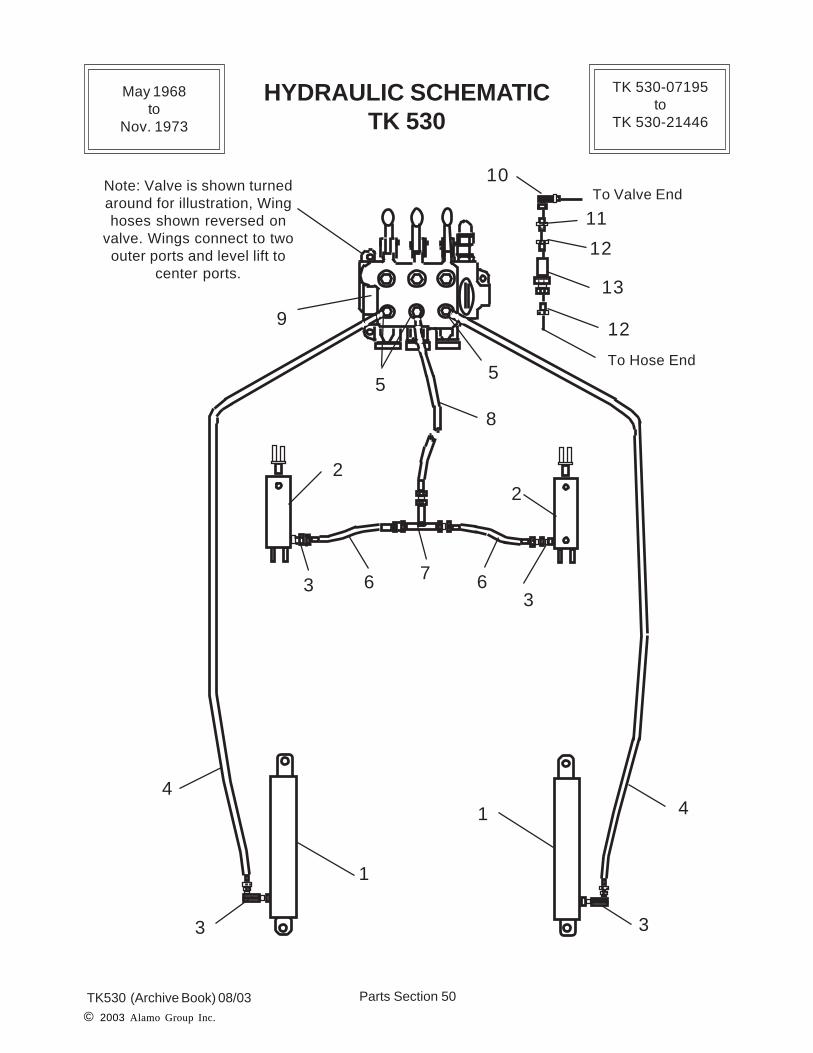
Note: Valve is shown turnedaround for illustration, Winghoses shown reversed on
valve. Wings connect to twoouter ports and level lift to
center ports.
HYDRAULIC SCHEMATICTK 530
May 1968to
Nov. 1973
TK 530-07195to
TK 530-21446

Parts Section 51TK530 (Archive Book) 08/03
© 2003 Alamo Group Inc.
Item Part No. Qty. Description
1. 00212701 2 Wing Lift Cyl. Asy. RH or LH
2. 00488100 2 Level Lift Cyl Asy. Tongue Cyl.
3. 00035400 4 Elbow, Swivel
4 00410300 2 Hose, 206" Long
5. 00703000 3 Elbow, Swivel
6. 00410200 2 Hose, 26" Long
7. 00493900 1 Tee
8. 00407300 1 Hose, 137" Long
9. 00380200 a/r * 3 Spool Valve, Open Center (Optional)
00750382 a/r * 3 Spool Valve, Closed Center (Optional)
10. 00703000 3 Elbow Swivel (Optional QD Coupler)
11. 00702900 3 Nipple, (Optional QD Coupler)
12. 00494800 6 Bushing, (Optional QD Coupler)
13. 00275400 3 QD Coupler Asy, Inner & Outer (Optional)
14. 00612100 1 Hose Kit, Valve to Tractor (Not Shown)
NOTE: Item 9 listed as a replacement Valve and was not always purchased with unit. Somewere supplied by dealers / customers. Shown and listed as Item 9 only as a reference. TheValve on the unit at the time of Purchase may have been a Cross Valve or a ? and will not bethe same as the one listed above. Some of the old Valves used during this period are nolonger available as parts. The Valve listed above will replace the old valve as an assembly.
HYDRAULIC SCHEMATICTK 530
May 1968to
Nov. 1973
TK 530-07195to
TK 530-21446

Parts Section 52TK530 (Archive Book) 08/03© 2003 Alamo Group Inc.
CYLINDER ASYTongue Lift & Level
TK 530
Item Part No. Qty Description
00488100 -- Tongue Cylinder Asy.1. 00651700 1 Locknut2. 00651800 1 Piston3. 00651600 1 * Piston Seal4. 00651500 2 * Back-up Ring5. 00651400 1 * Rod Static Seal6. 00488300 1 Barrel Asy.7. 00652000 1 Rod8. 00652100 1 Gland9. 00651200 1 * Snap Ring10. 00651300 1 * Rod Wiper11. 00035400 1 Fitting, Elbow Swivel12. 00651000 ref Seal Kit
*Seal Kit Consist of items 3,4,5,9 & 10, plus Gland Static Seal and RodSeal
11
1
2 3 4
5
6
7
8
10
9
May 1968to
Nov. 1973
TK 530-07195to
TK 530-21446
Parts Section 53TK530 (Archive Book) 08/03
© 2003 Alamo Group Inc.
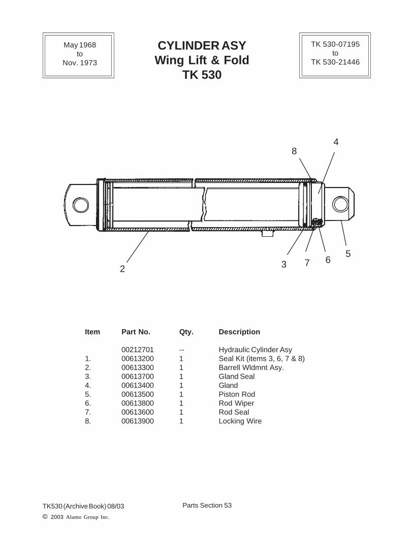
Item Part No. Qty. Description
00212701 -- Hydraulic Cylinder Asy1. 00613200 1 Seal Kit (items 3, 6, 7 & 8)2. 00613300 1 Barrell Wldmnt Asy.3. 00613700 1 Gland Seal4. 00613400 1 Gland5. 00613500 1 Piston Rod6. 00613800 1 Rod Wiper7. 00613600 1 Rod Seal8. 00613900 1 Locking Wire
CYLINDER ASYWing Lift & Fold
TK 530
2 3
4
567
8
May 1968to
Nov. 1973
TK 530-07195to
TK 530-21446
Parts Section 54TK530 (Archive Book) 08/03© 2003 Alamo Group Inc.
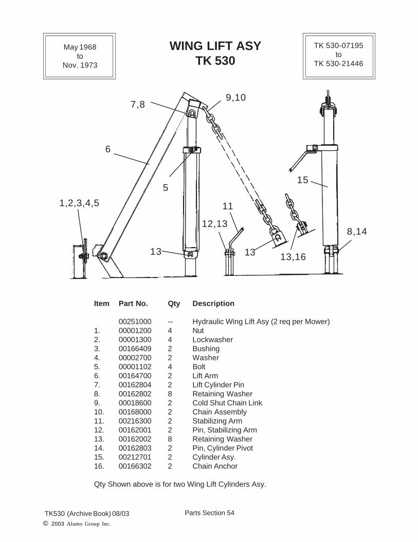
WING LIFT ASYTK 530
Item Part No. Qty Description
00251000 -- Hydraulic Wing Lift Asy (2 req per Mower)1. 00001200 4 Nut2. 00001300 4 Lockwasher3. 00166409 2 Bushing4. 00002700 2 Washer5. 00001102 4 Bolt6. 00164700 2 Lift Arm7. 00162804 2 Lift Cylinder Pin8. 00162802 8 Retaining Washer9. 00018600 2 Cold Shut Chain Link10. 00168000 2 Chain Assembly11. 00216300 2 Stabilizing Arm12. 00162001 2 Pin, Stabilizing Arm13. 00162002 8 Retaining Washer14. 00162803 2 Pin, Cylinder Pivot15. 00212701 2 Cylinder Asy.16. 00166302 2 Chain Anchor
Qty Shown above is for two Wing Lift Cylinders Asy.
1,2,3,4,5
7,8
6
9,10
5
13
12,13
11
13 13,16
8,14
15
May 1968to
Nov. 1973
TK 530-07195to
TK 530-21446

Parts Section 55TK530 (Archive Book) 08/03
© 2003 Alamo Group Inc.
HOSE KITVALVE TO TRACTOR
TK 530
Item Part No. Qty Description
00612100 1 Hose kit, Valve to Tractor (items 2 & 3)1. ------------- ref 3 Spool Valve Asy2. 02049100 2 Elbow, 90 deg.3. 00424200 2 Hose, 60 " Long4. ------------- 2 Hose Fitting (optional)
OutletSide
InletSide
2
3
1
2
3
4
TractorPressure
Line
TractorReturn
Line
May 1968to
Nov. 1973
TK 530-07195to
TK 530-21446

Parts Section 56TK530 (Archive Book) 08/03© 2003 Alamo Group Inc.
Item Part No. Qty Description
00391100 2 Wheel Support & Height Adjust Asy1. 00142400 ref Spindle , Single Wheel Weld in Part2. 00391600 2 Wheel Support Casting (w/ items #1, #17 & #18)3. 00162002 4 Retaining Washer4. 00162003 2 Pin5. 00390900 2 Height Adjusting Screw7. 00390700 2 Height Adjusting Locknut8. 00390800 2 Height Adjusting Nut & Tube Asy.9. 00132002 2 Spring10. 00129701 ref Height Adjusting Swivel11. 00171700 ref Swivel Block Support12. 00147600 1 Collar13. 00012400 1 Set Screw14. 00600000 ref Grease Fitting15. 00162802 2 Retaining Washer16. 00162801 1 Pin17. 00017200 ref Nut (Not Shown)18. 00000400 ref Cotter Pin (Not Shown)
Qty Shown is for two Axle Arms and Spring Assembly
WHEEL SUPPORT &HEIGHT ADJUSTMENT ASY.
TK 530
1,17,18
2
3,4 57
14
89
10 11 12
13
15,16
May 1968to
Nov. 1973
TK 530-07195to
TK 530-21446

Parts Section 57TK530 (Archive Book) 08/03
© 2003 Alamo Group Inc.
WHEEL HUB ASY.TK 530
Item Part No. Qty Description
00264600 a/r Wheel Hub Asy1. 00006500 1 Bearing Cone2. 00006700 1 Seal3. 00016900 1 Bearing Cup4. 00019800 5 Stud Bolt5. 00018500 5 Lug Nut6. 00009000 a/r Hub Asy (w/ items # 3, # 4, # 5 & # 7)7. 00016800 1 Bearing Cup8. 00006400 1 Bearing Cone9. 00007100 1 Washer10 00017200 1 Nut11. 00006900 1 Dust Cap12. 00000400 1 Cotter Pin13. 00142400 ref Spindle , Single Wheel Weld in Part
Wheel Hub #00264600 and # 00009000 are replaced by a later style Hub andwhen orderd the later hub with components will be shipped. The later style Hubwill fit the spindle but parts may not interchange with the earlier style Hub.
1,3
2
4
5
6
7,89
10
11
12
13
May 1968to
Nov. 1973
TK 530-07195to
TK 530-21446

Parts Section 58TK530 (Archive Book) 08/03© 2003 Alamo Group Inc.
WHEEL AND TIRE ASYTK 530
May 1968to
Nov. 1973
TK 530-07195to
TK 530-21446
2
3
4, 5
1 wheel only
Install Flat Side of LugNut Against Wheel as
Shown
Laminated Tire orFoam Filled Tire
Wheel BoltsLugnuts
Ribbed Implement Tire
Place Conical Side ofLugnut against Wheel
See Side of Tire forMaximum Pressure
Wheel Bolts
Lugnuts
Maximum InflationPressure 50 PSI Also
See Decal # 00762608
Airplane Tire
Parts Section 59TK530 (Archive Book) 08/03
© 2003 Alamo Group Inc.
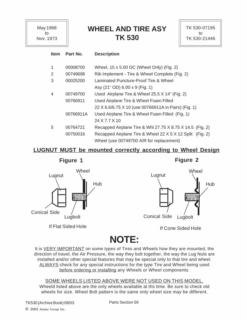
WHEEL AND TIRE ASYTK 530
Item Part No. Description
1 00008700 Wheel, 15 x 5.00 DC (Wheel Only) (Fig. 2)
2 00749698 Rib Implement - Tire & Wheel Complete (Fig. 2)
3 00025200 Laminated Puncture-Proof Tire & Wheel
Asy (21" OD) 6.00 x 9 (Fig. 1)
4 00749700 Used Airplane Tire & Wheel 25.5 X 14" (Fig. 2)
00766911 Used Airplane Tire & Wheel Foam Filled
22 X 6.6/6.75 X 10 (use 00766911A in Pairs) (Fig. 1)
00766911A Used Airplane Tire & Wheel Foam Filled (Fig. 1)
24 X 7.7 X 10
5 00764721 Recapped Airplane Tire & Whl 27.75 X 8.75 X 14.5 (Fig. 2)
00750016 Recapped Airplane Tire & Wheel 22 X 5 X 12 Split (Fig. 2)
Wheel (use 00749700 A/R for replacement)
NOTE:It is VERY IMPORTANT on some types of Tires and Wheels how they are mounted, thedirection of travel, the Air Pressure, the way they bolt together, the way the Lug Nuts are
installed and/or other special features that may be special only to that tire and wheel.ALWAYS check for any special instructions for the type Tire and Wheel being used
before ordering or installing any Wheels or Wheel components.
SOME WHEELS LISTED ABOVE WERE NOT USED ON THIS MODEL.Wheeld listed above are the only wheels available at ths time. Be sure to check oldwheels for size. Wheel Bolt pattern is the same only wheel size may be different.
LUGNUT MUST be mounted correctly according to Wheel Design
Lugnut
Conical SideLugbolt
Wheel
Hub
Figure 1
Lugbolt
Wheel
Hub
Figure 2
Lugnut
Conical Side
If Flat Sided Hole If Cone Sided Hole
May 1968to
Nov. 1973
TK 530-07195to
TK 530-21446


TK530 Archive Manual 08/03
© 2003 Alamo Group Inc.
TK 530 (Terrain King) Archive ManualProduction
May 1968 (Start) S/N TK 530-07195to Nov. 1973 (End) TK530-21446
Manual P/N 02980262
TK530 {