
Title: STRUCTURED CABLING SPECIFICATIONS … Services/Cabling Projects...19 Communications Labeling...
81
Information Technology Cabling Standard Structured Cabling Specifications Standard Page i Title: STRUCTURED CABLING SPECIFICATIONS STANDARD Issuing Department: Facilities Department Issued By: John Sclare, Construction Manager Last Review Date: January 20, 2017 Next Review Date: June 30, 2017 Table of Contents 1 Purpose .................................................................................................................................................. 5 2 Scope...................................................................................................................................................... 5 2.1 Exclusions .................................................................................................................................... 5 3 Responsibilities..................................................................................................................................... 6 3.1 Implementation ............................................................................................................................. 6 4 Safety...................................................................................................................................................... 7 5 Environmental Statement ..................................................................................................................... 7 6 Regulatory Compliance ........................................................................................................................ 7 6.1 General ......................................................................................................................................... 7 6.2 Applicable Regulatory References ............................................................................................... 8 6.2.1 ANSI/TIA: ............................................................................................................................. 8 6.2.2 ISO/IEC................................................................................................................................ 11 6.2.3 National Electric Codes ....................................................................................................... 11 6.2.4 OSHA Standards and Regulations – all applicable ............................................................. 12 6.2.5 Local Codes and Standards – all applicable ....................................................................... 12 6.2.6 BICSI ................................................................................................................................... 12 7 General Guidelines ............................................................................................................................... 13 7.1 Maintenance of Patch Fields ........................................................................................................ 13 7.2 Cable Pulling and Termination ..................................................................................................... 14 8 Work Area .............................................................................................................................................. 15 8.1 General ......................................................................................................................................... 15 8.2 Outlets and Surface Mount Boxes ............................................................................................... 16
Transcript of Title: STRUCTURED CABLING SPECIFICATIONS … Services/Cabling Projects...19 Communications Labeling...

Information Technology Cabling Standard
Structured Cabling Specifications Standard Page i
Title: STRUCTURED CABLING SPECIFICATIONS STANDARD
Issuing Department: Facilities Department Issued By: John Sclare, Construction Manager Last Review Date: January 20, 2017 Next Review Date: June 30, 2017
Table of Contents
1 Purpose .................................................................................................................................................. 5
2 Scope...................................................................................................................................................... 5
2.1 Exclusions .................................................................................................................................... 5
3 Responsibilities ..................................................................................................................................... 6
3.1 Implementation ............................................................................................................................. 6
4 Safety...................................................................................................................................................... 7
5 Environmental Statement ..................................................................................................................... 7
6 Regulatory Compliance ........................................................................................................................ 7
6.1 General ......................................................................................................................................... 7
6.2 Applicable Regulatory References ............................................................................................... 8
6.2.1 ANSI/TIA: ............................................................................................................................. 8
6.2.2 ISO/IEC ................................................................................................................................ 11
6.2.3 National Electric Codes ....................................................................................................... 11
6.2.4 OSHA Standards and Regulations – all applicable ............................................................. 12
6.2.5 Local Codes and Standards – all applicable ....................................................................... 12
6.2.6 BICSI ................................................................................................................................... 12
7 General Guidelines ............................................................................................................................... 13
7.1 Maintenance of Patch Fields ........................................................................................................ 13
7.2 Cable Pulling and Termination ..................................................................................................... 14
8 Work Area .............................................................................................................................................. 15
8.1 General ......................................................................................................................................... 15
8.2 Outlets and Surface Mount Boxes ............................................................................................... 16

Information Technology Cabling Standard
Structured Cabling Specifications Standard Page ii
8.3 Outlet Jack Assignments .............................................................................................................. 17
8.4 Outlet Example Diagrams ............................................................................................................ 17
9 Copper Cat.6 & Cat.6A Copper Cable and RJ-45 Jack Modules ...................................................... 19
9.1 Panduit UTP Category 6 4 Pair Cable …………………………………………19
9.2 Panduit UTP Category 6A 4 Pair Cable…………………………………………..……….19 9.3 PanduitCat.6A UTP Jack Module…………………………………………………………..20 9.4 Panduit Cat.6 UTP Jack Module……………………………………………………………20
10 Wireless Access Points ........................................................................................................................ 21
11 Fiber Backbone Cabling ....................................................................................................................... 21
11.1 General……………….………………………………………………………………….……21 11.2 Fiber Cable Types ........................................................................................................................ 21
11.3 Backbone Cabling - Intrabuilding ................................................................................................. 22
11.4 Backbone Cabling - Inter-building ................................................................................................ 22
11.5 Fiber Terminations ....................................................................................................................... 23
11.6 INSINTECH LC OM4 and Singlemode Fiber Connectors ............................................................ 23
12 Telecommunications Rooms ............................................................................................................... 24
12.1 General ......................................................................................................................................... 24
12.2 Entrance Facilities ........................................................................................................................ 24
12.3 Equipment Rooms ........................................................................................................................ 25
12.4 Horizontal Telecommunications Rooms ...................................................................................... 26
13 Racks, Cabinets and Cable Managers ................................................................................................ 28
13.1 General ......................................................................................................................................... 28
13.1.1 Normal or non-space restricted horizontal TRs ................................................................... 29
13.1.2 Typical Rack Configuration For Edge Switches .................................................................. 29
13.2 Cable Managers .................................................................................................................. 33
13.2.1 General ................................................................................................................................ 33
13.2.2 Horizontal Cable Managers ................................................................................................. 34
13.2.3 Vertical Cable Management ................................................................................................ 34
13.3 Wall Mount Cabinets ........................................................................................................... 35
13.3.1 General ................................................................................................................................ 35
13.3.2 Wall Mount Cabinets ........................................................................................................... 35
14 Copper Patch Panels and Cords ......................................................................................................... 36
14.1 General ......................................................................................................................................... 36
Information Technology Cabling Standard
Structured Cabling Specifications Standard Page iii
14.2 Patch Cord Details ....................................................................................................................... 37
14.4.1 Patch Cord Color Standards................................................................................................ 37
15 Fiber Patching and Fiber Jumpers ...................................................................................................... 37
15.1 Fiber Enclosures .......................................................................................................................... 37
15.2 Multi-mode Fiber Adapter Panels ........................................................................................ 38
15.3 Singlemode Fiber Adapter Panels ....................................................................................... 38
15.4 Fiber Patch Cords ................................................................................................................ 38
16 Cable Pathways ..................................................................................................................................... 38
16.1 Overhead Ladder Rack Systems ................................................................................................. 38
16.2 Overhead Fiber Pathways ............................................................................................................ 39
16.3 Surface Raceway…………………………………………………………………………….40 17 Substitution Policy ................................................................................................................................ 44
17.1 General ......................................................................................................................................... 44
18 Communications Structured Grounding ............................................................................................ 45
18.1 General ......................................................................................................................................... 45
18.2 Details .......................................................................................................................................... 45
19 Communications Labeling ................................................................................................................... 49
19.1 General ......................................................................................................................................... 49
19.2 Universal Guidelines .................................................................................................................... 50
20 Testing and Documentation ................................................................................................................. 50
20.1 General ......................................................................................................................................... 50
20.2 Copper Testing .................................................................................................................... 50
20.3 Fiber Testing ........................................................................................................................ 51
20.4 Documentation ............................................................................................................................. 52
20.5 Final Inspection and Acceptance ................................................................................................. 53
21 PanGen System Performance Warranty……………………………………………………53
21.1 Contractor Warranty Commitments .............................................................................................. 53
22 Contractor Qualifications ..................................................................................................................... 54
22.1 General ......................................................................................................................................... 54
23 Bid Guidelines ....................................................................................................................................... 57
23.1 General ......................................................................................................................................... 57
23.2 Labor ............................................................................................................................................ 57
23.3 Prevailing Wage ........................................................................................................................... 57

Information Technology Cabling Standard
Structured Cabling Specifications Standard Page iv
24.4 Material ......................................................................................................................................... 59
Materials Lists ...................................................................................................................... 59
Appendix B. Definitions of Terms………………………………………………………….60 Labeling a Copper Backbone Cable .................................................................................... 66
Labeling a Patch Panel for Copper Backbone Cabling ....................................................... 67
Labeling a Horizontal Cable ................................................................................................ 68
Labeling a Patch Panel for Horizontal Cabling .................................................................... 69
Labeling a Copper Patch Cord ............................................................................................ 70
Labeling a Fiber Optic Patch Cord ...................................................................................... 71
Structured Cabling Specifications Standard Page 5
1 Purpose
The purpose of this document is to provide a standard defining the structured communications cabling systems to be installed within CHICO USD telecommunications facilities. The goal is to accomplish this in the most economic and systematic fashion possible, and in a manner compliant with the latest codes, cabling standards and industry best practices.
Such standardization will maximize system reliability by ensuring that critical operational and legal requirements are met, while enhancing safety to personnel and the public.
Note that while many portions of this document are addressed to "The Contractor", the contents herein apply equally to anyone doing the work. Whether employees internal to CHICO USD, or outside contractors employed on specific projects the expectation of CHICO USD is that all work be carried out and executed as prescribed in this document.
2 Scope
This specification addresses the requirements and materials in the following structured cabling subsystems:
Work Area (Equipment Outlets)
Copper Horizontal Cabling
Wireless Access Points
Fiber Backbone Cabling
Telecommunications and Equipment Rooms
Pathways
Cable Bundling and Dressing Accessories
Communications Structured Grounding
Communications Labeling
2.1 Exclusions
The information contained in this document is based on our experience to date and is believed to be reliable. It is intended as a guide for use by persons having technical skill and is to be used with their own discretion and risk. This document is not to be used to negate good engineering principles, design practices or common sense.
This specification is meant to be a part of the overall Cabling Infrastructure standards and provide a background of consistency to project-specific requirements. There may be application specific standards released after the writing of this document that may provide more detailed information on some of the areas covered. Wherever requirements of this document are in conflict with existing cabling standards or state or local codes, the most stringent will apply.
Dimensions contained herein are for reference purposes only. For specific dimensional requirements of a cabling component, consult the manufacturer or distributor of that

Structured Cabling Specifications Standard Page 6
component, or the document specific to that project. For questions of architectural or structural dimensions, consult the project documentation or submit the question to the Facilities Department for resolution.
This publication is not to be taken as a license to operate under, or a recommendation to infringe any existing patents. This supersedes and voids all previous literature, etc.
3 Responsibilities
The Construction Manager
Responsible for approving, revising and distributing this standard.
Responsible for ensuring that contractors and employees are aware of, and accountable for, consistent and uniform compliance with the area specific requirements of this standard when involved with the installation, maintenance, repairing, removal, or restoration of equipment.
Responsible for the safe, efficient and timely performance of the necessary work to ensure compliance with this standard.
Responsible for ensuring that contractors and employees that will be involved with installing, maintaining, repairing, removing and replacing equipment are trained, knowledgeable and qualified to perform the assigned tasks.
All Employees
Employees assigned the task of installing, maintaining, repairing, removing, or replacing equipment are responsible for safely, effectively, and efficiently performing their assignments.
Responsible for their own safety and that of the general public.
Responsible for only performing tasks for which they are trained, knowledgeable and qualified.
Responsible to notify their supervisors of whenever additional training, equipment, or resources needed to safely, effectively, and efficiently perform their assigned tasks.
3.1 Implementation
In implementation, this document applies particularly to the following:
IT Field Engineers
IT Design Engineers
Network Specialists
Network Architects/Planners- Enterprise Architecture Network Services
Project Managers
Cabling Contractors and Vendors

Structured Cabling Specifications Standard Page 7
4 Safety
The following are general safety requirements that should be followed:
Always perform a pre-task safety assessment of the planned work activities to ensure proper resources have been assembled.
Confined spaces safety procedures must be followed if applicable.
IT personnel must coordinate their work with the appropriate departments, must be trained as appropriate, and must be accompanied by a qualified worker as appropriate. Contractors must always be accompanied by a qualified CHICO USD employee while working inside CHICO USD facilities, where deemed applicable. Often contractors are able to work unescorted.
Safety and Health Program Standard and the Code of Safe Practices shall be followed at all times.
5 Environmental Statement
This standard supports CHICO USD’s values of protecting the environment and reducing environmental impacts by:
Reducing the amount of materials required for infrastructure by utilizing new products that optimize rack and equipment space, investing in new technologies that reduce the need for traditional cabling schemes, and limiting the amount of un-utilized copper cables being installed in work spaces.
Seeking vendors that have an established environmental policy and minimize environmental impacts by deploying manufacturing strategies and processes including Restriction of the use of Hazardous Substances (RoHS), Waste Electrical and Electronic Equipment (WEEE), and ISO 14001, reducing packaging materials, and promoting product and process efficiencies and energy conservation.
Removing all old, unused cables as required by TIA and NEC Article 800.
Implementing proper cable management strategies that improve air flow and air conditioning/cooling efficiencies.
Recycling obsolete and unused copper cables as areas are re-stacked or upgraded.
6 Regulatory Compliance
6.1 General
All installations should be in compliance with the requirements of the National Electric Code, UBC, the local Building Code, local OSHA rules, the FCC as well as the recommendations and guidelines of BICSI and the TIA Standards.

Structured Cabling Specifications Standard Page 8
In cases where listed Standards and Codes have been updated, the most recent revisions, including all relevant changes or addenda at the time of installation should be used.
Anywhere cabling Standards conflict with electrical or safety Codes, installer should defer to NEC and any applicable local codes or ordinances, or default to the most stringent requirements listed by either.
Contractors are required to be familiar with all applicable codes and standards. Knowledge and execution of applicable codes is the sole responsibility of the installer.
All active equipment installed should comply with the minimum requirements of NEMA, IEEE, ASTM, ANSI and Underwriters’ Laboratories, as applicable.
Should any change in plans or specifications be required to comply with governmental regulations, the Contractor is to notify the General Contractor/Engineer at the time of submittal.
6.2 Applicable Regulatory References
6.2.1 ANSI:
ANSI/TIA-526-7-A (July 2015) Measurement of Optical Power Loss of Installed Single-Mode Fiber Cable Plant
TIA-526.2-A (July 2015) Effective Transmitter Output Power Coupled into Single-Mode Fiber Optic Cable - Adoption of IEC 61280-1-1 ed. 2 Part 1-1: Test Procedures for General Communication Subsystems – Transmitter Output Optical Power Measurement for Single-Mode Optical Fibre Cable
ANSI/TIA-4994 (March 2015) Standard for Sustainable Information Communications Technology
ANSI/TIA-526-14-C (April 2015) Optical Power Loss Measurements of Installed Multimode Fiber Cable Plant
ANSI/TIA-568.0-D (September 2015) Generic Telecommunications Cabling for Customer Premises (supersedes TIA-568-C.0 and TIA-568-C-1)
ANSI/TIA-568-C.2 (August 2009) Balance Twisted Pair Communications and Components Standards
TIA-568-C.2-1 (July 2016) Balanced Twisted-Pair Telecommunications Cabling and Components Standard, Addendum 1: Specifications for 100 Next Generation Cabling
TIA-568-C.2-2 (November 2014) Balanced Twisted-Pair Telecommunications Cabling and Components Standard, Addendum 2: Additional Considerations for Category 6A Patch Cord Testing
TIA-568-C.3 (June 2008) Optical Fiber Cabling Components Standard (will be superseded by ANSI/TIA-568.3-D after default ballot)
TIA-568-C.3-1 (October 2011) Optical Fiber Cabling Component Standard-

Structured Cabling Specifications Standard Page 9
Addendum 1, Addition of OM4 Cabled Optical Fiber and array connectors (will be superseded by ANSI/TIA-568.3-D after default ballot)
ANSI/TIA-568-C.4 (July 2011) Broadband Coaxial Cabling Components Standard
ANSI/TIA-568.1-D (September 2015) Commercial Building Telecommunications Infrastructure Standard (supersedes ANSI/TIA-C.1)
ANSI/TIA-569-D (April 2015) Telecommunications Pathways and Spaces
ANSI/TIA-598-D (July 2014) Optical Fiber Cable Color Coding
ANSI/TIA-570-C (August 2012) Residential Telecommunications Infrastructure Standard
ANSI/TIA-606-B (June 2012) Administration Standard for Telecommunications Infrastructure
ANSI/TIA-606-B-1 (December 2015) Administration Standard for Telecommunications Infrastructure Addendum 1 - Automated Infrastructure Management Systems - Addendum to ANSI/TIA-606-B
ANSI/TIA-607-C (November 2015) Generic Telecommunications Bonding and Grounding (Earthing) for Customer Premises
ANSI/TIA-758-B (March 2012) Customer-Owned Outside Plant Telecommunication Infrastructure Standard
ANSI/TIA-862-B (February 2016) Structured Cabling Infrastructure Standard for Intelligent Building Systems
ANSI/TIA-942-A (March 2014) Telecommunications Infrastructure Standard for Data Centers (will be superseded by ANSI/TIA-942-B after balloting)
ANSI/TIA-942-A-1 (March 2013) Telecommunications Infrastructure Standard for Data Centers, Addendum 1 - Cabling Guidelines for Data Center Fabrics (will be superseded by ANSI/TIA-942-B after balloting)
ANSI/TIA-1005-A (May 2012) Telecommunications Infrastructure Standard For Industrial Premises
ANSI/TIA-1005-A-1 (January 2015) Telecommunications Infrastructure Standard For Industrial Premises, Addendum 1- M12-8 X-Coding Connector - Addendum to TIA-1005-A
ANSI/TIA-1183 (August 2012) Measurement Methods and Test Fixtures for Balum-Less Measurements of Balanced Components and Systems
ANSI/TIA-1183-1 (January 2016) Measurement Methods and Test Fixtures for Balun-Less Measurements of Balanced Components and Systems, Extending Frequency Capabilities to 2 GHz - Addendum to TIA-1183
ANSI/TIA-1152 (September 2009) Requirements for Field Test Instruments and Measurements for Balanced Twisted-Pair Cabling

Structured Cabling Specifications Standard Page 10
ANSI/TIA-1179 (July 2010) Healthcare Facility Telecommunications Infrastructure Standard
ANSI/TIA-4966 (May 2014) Telecommunications Infrastructure Standard for Educational Facilities
TIA-455-104-B (February 2016) FOTP 104- Fiber Optic Cable Cyclic Flexing Test (supersedes TIA-455-104-A)
TIA/EIA-455-25-D (February 2016) FOTP-25 Impact Testing of Optical Fiber Cables
TIA-604-18 (November 2015) FOCIS 18 Fiber Optic Connector Intermateability Standard – Type MPO-16
TIA-604-5-E (November 2015) FOCIS 5 Fiber Optic Connector Intermateability Standard- Type MPO
TIA-5017 (March 2016) Telecommunications Physical Network Security Standard
TIA-TSB-155-A (Reaffirmed 10-6-2014) Guidelines for the Assessment and Mitigation of Installed Category 6 Cabling to Support 10GBASE-T
TSB-184 (July 2009) Guidelines for Supporting Power Delivery Over Balanced Twisted-Pair Cabling
TSB-4979 (August 2013) Practical Considerations for Implementation of Multimode Launch Conditions in the Field
TSB-190 (June 2011) Guidelines on Shared Pathways and Shared Sheaths
TIA-TSB-162-A (November 2013) Telecommunications Cabling Guidelines for Wireless Access Points
TSB-5018 (July 2016) Structured Cabling Infrastructure Guidelines to support Distributed Antenna Systems
TIA-492AAAE (June 2016) Detail Specification for 50-µm Core Diameter/125-µm Cladding Diameter Class 1a Graded-Index Multimode Optical Fibers with Laser-Optimized Bandwidth Characteristics Specified for Wavelength Division Multiplexing
TIA-492AAAB-A (November 2009) Detail specification for 50-µm core diameter/125-µm cladding diameter class Ia graded-index multimode optical fibers
TIA-455-243 (March 2010) FOTP-243 Polarization-mode Dispersion Measurement for Installed Single-mode Optical Fibers by Wavelength-scanning OTDR and States-of-Polarization Analysis
TSB-172-A (February 2013) Higher Data Rate Multimode Fiber Transmission Techniques

Structured Cabling Specifications Standard Page 11
6.2.2 ISO/IEC
ISO/IEC TR 11801-99-01 Information technology – Generic cabling for customer premises: Guidance for balanced cabling in support of at least 40 GBit/s data transmission: Parts 1 and 2
ISO/IEC TR 29106 AMD 1 Information technology -- Generic cabling -- Introduction to the MICE environmental classification
ISO/IEC 14763-3 Ed 2.0 Information technology -- Implementation and operation of customer premises cabling -- Part 3: Testing of optical fibre cabling
ISO/IEC 24764 AMD 1 Information technology – Generic cabling for data centres
ISO/IEC 11801 AMD 1 AMD 2 Information technology – Generic cabling for customer premises
ISO/IEC 15018 AMD 1 Information technology – Generic cabling for homes
ISO/IEC 24702 AMD 1 Information technology – Generic cabling – Industrial premises
ISO/IEC 14763-1 AMD 1 Information technology – Implementation and operation of customer premises cabling – Part 1: Administration
ISO/IEC 14763-2 Information technology – Implementation and operation of customer premises cabling – Part 2: Planning and installation
ISO/IEC 14763-2-1 Information technology – Implementation and operation of customer premises cabling – Part 2-1: Planning and installation – Identifiers within administration systems
ISO/IEC TR 24704 Information technology – Customer premises cabling for wireless access points
ISO/IEC TR 24750 Information technology – Assessment and mitigation of installed balanced cabling channels in order to support 10GBASE-T
ISO/IEC TR 29125 IT Telecommunications cabling requirements for remote powering of terminal equipment
6.2.3 NATIONAL ELECTRIC CODES
National Electrical Safety Code (NESC) (IEEE C2-2012)
NFPA 70-2016, National Electrical Code© (NEC©)
ANSI/IEEE C2-207, National Electrical Safety Code®
National Electrical Code (NEC) (NFPA 70)
NFPA 72 National Fire Alarm and Signaling Code

Structured Cabling Specifications Standard Page 12
6.2.4 OSHA STANDARDS AND REGULATIONS – ALL APPLICABLE
6.2.5 LOCAL CODES AND STANDARDS – ALL APPLICABLE
6.2.6 BICSI
1. BICSI – Building Industry Consultative Services International – Published Standards
ANSI/BICSI 001-2009, Information Transport Systems Design Standard for K-12 Educational Institutions
ANSI/BICSI 002-2014, Data Center Design and Implementation Best Practices
ANSI/BICSI-003-2014 Building Information Modeling (BIM) Practices for Information Technology Systems
BICSI 004-2012, Information Technology Division Systems Design and Implementation Best Practices for Healthcare Institutions and Facilities
ANSI/BICSI 005-2016, Electronic Safety and Security (ESS) System Design and Implementation Best Practices
BICSI 006-2015 Distributed Antenna System (DAS) Design and Implementation Best Practices
ANSI/NECA/BICSI 568-2006, Standard for Installing Commercial Building Telecommunications Cabling
NECA/BICSI 607-2011, Standard for Telecommunications Bonding and Grounding Planning and Installation Methods for Commercial Buildings
Telecommunications Distribution Methods Manual, 13th Edition
BICSI – Building Industry Consultative Services International – Manuals
Telecommunications Distribution Methods Manual, 13th Edition
Information Transport Systems Installation Methods Manual (ITSIMM), 6th Edition
Outside Plant Design Reference Manual, 5th Edition
BICSI's ICT Terminology Handbook, Version 1.0
Telecommunications Project Management Manual (TPMM), 1st edition
Telecommunications Project Management Reference Document (TPMRD), 2nd Edition
BICSI's Special ICT Design Considerations, Version 1.0
Essentials of Bonding and Grounding, Version 1.0

Structured Cabling Specifications Standard Page 13
Information Transport Systems Installation Methods Manual (ITSIMM), 6th Edition
ANSI/BICSI 002-2011, Data Center Design and Implementation Best Practices
ANSI/NECA/BICSI 568-2006, Standard for Installing Commercial Building Telecommunications Cabling
NECA/BICSI 607-2011, Standard for Telecommunications Bonding and Grounding Planning and Installation Methods for Commercial Buildings
AV Design Reference Manual, 1st Edition
Network Design Reference Manual, 7th Edition
Outside Plant Design Reference Manual, 5th Edition
Wireless Design Reference Manual, 3rd Edition
7 General Guidelines
7.1 Maintenance of Patch Fields
Any persons with Contractor or CHICO USD adding or moving copper or fiber optic patch (equipment) cords should do so in a neat, workmanlike fashion in keeping with the original system concept and according to all industry best practices as outlined in cabling standards and applicable BICSI publications referenced in this document.
Persons performing such moves, adds, or changes (MACs), should further adhere to the following:
Contactor should use existing cabling management pathways and take care to place cable like with like, maintaining original segregation strategies for separating fiber and copper cables as well as any separation necessary between different types of copper cables.
Cables should be dressed neatly within patch management pathways with care taken to maintain minimum bend radius of not less than 4 times the cord outer diameter for copper and not less than a 2" bend radius for fiber jumpers as per ANSI/TIA 568-C.0.
All patch cords used should be of same copper Category or fiber OM/OS designation or higher than the media used in the permanent links.
Patch cords shall not be run across fan blades such that it will prohibit the maintenance of the switch.
Patching in all cases should be done using factory terminated cords manufactured for that purpose. Hand terminated patch cords will not be accepted.
All patch cords or jumpers must be completely contained within supplied cable management paths. Cables draped across the front cabinets or racks will not be accepted.

Structured Cabling Specifications Standard Page 14
Any persons moving fiber optic patch cords for any reason will clean the connector with lint-free wipes and 99% or higher isopropyl alcohol before replacing the connector in a port.
Any persons with CHICO USD or Installing Contractors performing moves, adds or changes within patch field will label additions to the system according to the labeling guidelines outlined in this document.
Any persons with CHICO USD or Installing Contractors performing moves, adds or changes within patch field will record the move according to documentation guidelines outlined in this document.
7.2 Cable Pulling and Termination
The cable should be restricted to a single four-pair cable construction to support a broad range of applications.
Keep all permanent cable runs to a maximum of 295 feet / 90 meters for each run. CAT 6 & 6A Channel has a max distance of 328 feet / 100 meters with patch cords, and CAT 6 Permanent Link has a max distance of 295’ or 90 meters.
Be conscious of conduit fill guidelines. No pathway, including conduits should have greater than a 35% fill per TIA and BICSI fill charts. Contractor is responsible for bringing to the attention of CHICO USD project manager any insufficiently sized conduit in project documentation.
Keep CAT 6 & 6A cables as far away from potential sources of EMI (electrical cables, transformers, light fixtures, etc.) as required in cited TIA Standards.
Use low to moderate force when pulling cable. Maximum tensile load may not 25 lbs. maximum pulling force per 4 pair cable.
Always use grommets to protect the cable when passing through metal studs or anything that can possibly cause damage to the cable.
Do not deform the jacket of the cable. The jacket should be continuous, free from pinholes, splits, blisters, burn holes or other imperfections.
Install proper cable supports, spaced less than 5 feet apart and no more than 49 cables and/or 25 lbs. max per support.
Leave a pull string to the end of each conduit run. Replace pull string if it was used for a cable pull.
All copper horizontal cabling should have slack service loops no less than 12” at the work area (equipment outlet) and not less than 3 feet in the telecommunications room. Slack at the work area may be stored in the ceiling and in the telecommunications room may be wall mounted or contained in pathways or racking systems if done in a neat, workmanlike fashion.
Note service loops may not touch the ceiling assembly and if so must be remedied at the Contractor expense.
Always label every termination point within 6 in. of the end. Use a unique number for each cable segment as required by the documentation for that project.

Structured Cabling Specifications Standard Page 15
Dress the cables neatly with hook and loop cable ties (“Velcro”), not plastic cable ties. Use low to moderate pressure.
Maintain the twists of the pairs all the way to the point of termination, or no more than 0.5" (one half inch) untwisted.
All UTP patching should be accomplished using CAT 6 & 6A rated modular patch panels as indicated elsewhere in this document.
Contractor must remove all abandoned cable per Article 800 of the National Electrical Code and per TIA and BICSI standards. This is mandatory; Contractors must consider this when placing bids.
8 Work Area
8.1 General
A model of one computer and one IP phone per cable has been established with wireless networking available as a secondary option for connectivity as the technology matures and the resources are deployed. Case-by-case exceptions can be made depending upon business justifications or type of work area where network cable is to be installed such as a bull room, storm room, conference room, etc.
The Work Area should consist of the connectivity equipment used to connect the horizontal cabling subsystem and the equipment in the work area. Both copper and fiber media should be supported. The connectivity equipment should include the following options:
UTP Cable
Outlets and surface mount boxes
Surface raceway and outlet poles
Patch Cords and Modular Connectors
The use of “mini-hubs” is not allowed since they cannot be seen or managed when connected to CHICO USD network.
The PANDUIT Mini-Com Network Cabling System or CHICO USD approved equivalent should be used for the Work Area subsystem, including all modular connectors. The network cabling system should be comprised of modular connectors in support of high-speed networks and applications designed for implementation on copper cabling. All outlets should utilize fully interchangeable and individual connector modules that mount side-by-side to facilitate quick and easy moves, adds, and changes.
Cables are to be installed and tested per the Testing and Acceptance section of this document.
The telecommunications Room end of the cables will be installed in to a patch panel per illustrations in the Telecommunications Room section of this document.
The work area terminations and appliances should be installed per the illustrations in this section.
.

Structured Cabling Specifications Standard Page 16
Cables are to be installed and tested per the Testing and Acceptance section of this document.
The telecommunications Room end of the cables will be installed in to a patch panel per illustrations in the Telecommunications Room section of this document.
The work area terminations and appliances should be installed per the illustrations in this section.
Additional cables may be installed to a work area if there is a business need for extra outlets. Examples of this would be a conference room or a storm room where there would be a large demand for network connections.
Cables are to be tested as outlined in the "Testing and Acceptance" section of this document.
Contractor must keep approximately 12 inches of cable in a service-loop in the ceiling for ease of possibly re-terminating the cable at a future time.) This service loop must be properly supported and should in no instance touch the drop ceiling.
Service loops must not go below minimum bend radius requirements.
Any service loops making contact with drop ceiling structures should be remedied at the Contractor's expense.
The work area end of the cables will be installed on a Panduit RJ45 Mini-Com jack. See "Appendix A - Materials" at the end of this document for product details.
8.2 Outlets and Surface Mount Boxes
Work area outlets will generally be one of three types.
Modular Furniture Faceplate
Surface Mount Box
Wall Face Plate
The outlets and surface mount boxes should support the network system by providing high-density in-wall, surface mount or modular office furniture cabling applications. The outlets consist of faceplates for flush and recessed in-wall mounting as well as mounting to the modular office furniture systems. The surface mount boxes can be mounted where in-wall applications are not possible or to support applications where surface mount is the best option.

Structured Cabling Specifications Standard Page 17
All outlets should utilize the interchangeable, individual Mini-Com connector modules that mount side by side to facilitate quick and easy moves, adds and changes. All outlets should be manufactured from high-impact thermoplastic material with a U.L. flammability rating of 94 HB or better.
The standard color for outlets and surface mount boxes is Panduit Off White (IW). Other colors may be used to match a pre-existing color scheme.
.
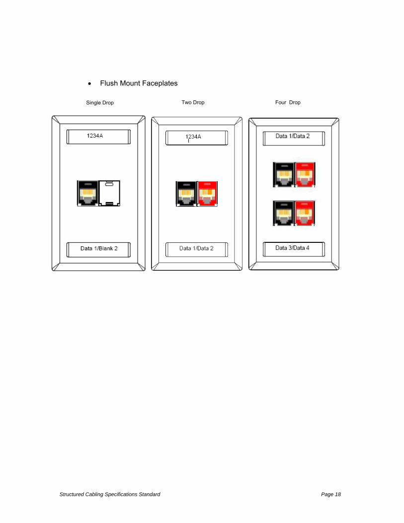
8.3 Outlet Jack Assignments
Cat.5e = Blue Jack
Cat.6 = Black Jack
Cat.6A = Red Jack
8.4 Outlet Example Diagrams
Surface Mount Boxes.
**If more drops are needed in a surface box, Contractor may need to install 4-hole surface box. Consult project documentation for details.
Surface box requiring one Cat.6 drop. (Good example is WAP connection).
Surface box requiring a Cat.6 & Cat.6A data drop
Structured Cabling Specifications Standard Page 18
Flush Mount Faceplates
Single Drop Two Drop Four Drop

Structured Cabling Specifications Standard Page 19
9 Copper Cat.6 & Cat.6A Cable & RJ-45 Modules
9.1 COPPER CABLE CAT.6E: PANDUIT CORP. PUP6004BU-W
• Superior performance exceeds all TIA/EIA-568-B.2-1 Category 6 and ISO 11801 Edition 2.0 for Class E cable requirements • ETL tested and verified for Category 6 component performance • Conductors are twisted in pairs with four pairs contained in a flame retardant PVC jacket separated by a spline • Performance tested to 650 MHz • Plenum (CMP) and non-plenum/riser (CMR) flame rated • Maximum installation tension of 25 lbs (110 N) • Installation temperature range: 32°F to 140°F (0°C to 60°C) • Operating temperature range: 14°F to 140°F (–10°C to 60°C) • Cable diameter: Riser – 0.260"; Plenum – 0.250" • Easy payout, reel-in-a-box and descending length markings on cable speed installation • Supports the following applications: Ethernet 10BASE-T, 100BASE-T (Fast Ethernet) and 1000BASE-T (Gigabit Ethernet); 1.2Gb/s ATM; Token Ring 4/16; digital video; and broadband/baseband analog video
9.2 COPPER CABLE CAT.6A: PANDUIT CORP. GENSPEED 10 UTP See GenSpeed Spec at end of this Document
All cable shall conform to the requirements for communications circuits defined by the National Electrical Code (Article 800) and the Canadian Building Code. Cable listed to NEC Article 800-51(a) will be used for “Plenum” installations. Cable listed to NEC Article 800-51(b) shall be installed in vertical runs penetrating more than one floor.
9.3 UTP CAT.6A JACK MODULES
MINI-COM® TX6A™ 10GIG™ UTP Jack Modules shall be Category 6A modules featuring MaTriX Technology. The eight position modules shall terminate unshielded twisted 4 pair, 22 – 26 AWG, 100 ohm cable and shall not require the use of a punchdown tool. Jack module shall use Enhanced Giga-TX™ Technology with forward motion termination to optimize performance by maintaining cable pair geometry and eliminating conductor untwist. The

Structured Cabling Specifications Standard Page 20
termination cap shall provide strain relief on the cable jacket, ensure cable twists are maintained to within 1/8” (3.18 mm) and include a wiring scheme label. The blue module base shall signify Category 6A performance and shall include a universal label representing T568A and T568B wiring schemes. The MINI-COM®
TX6A™ Jack Modules include MaTriX Tape on the external portion of the jack module, which assists in suppressing alien crosstalk. The jack modules shall be universal in design, including complying with the intermateability standard IEC 60603-7 for backward compatibility. Category 6A jack modules shall be UL and CSA approved and RoHS compliant.
The jack modules shall be ETL verified to ANSI/TIA/EIA Category 6A and IEC/ISO 11801Class EA channel performance. They shall be universal in design, accepting 2, 3, or 4 pair modular plugs without damage to the outer jack contacts. The jack modules shall be able to be re-terminated a minimum of 20 times and be available in 11 standard colors for color-coding purposes. The jack module shall snap into all MINI-COM® outlets, patch panels and surface mount boxes. The MINI-COM® TX6A™ 10GIG™ Jack Module must be installed as part of a complete TX6A™ 10GIG™ Copper Cabling System with MaTriX Technology in order to achieve 10GBASE-Tcertified performance.
Part number Style Category Colors CJ6X88TG** RJ-45 6A 11
**To designate a color, add suffix IW (Off White), EI (Electric Ivory), IG (Int'l Gray), WH (White), BL (Black), OR (Orange), RD (Red), BU (Blue), GR (Green), YL (Yellow) or VL
9.4 UTP CAT.6 JACK MODULES
MINI-COM® TX-6™ TG MODULES SHALL BE CATEGORY 6 MODULES FEATURING GIGA-TX™
TECHNOLOGY. THE EIGHT POSITION MODULES SHALL BE USED IN ALL WORK AREAS AND
SHALL EXCEED THE CONNECTOR REQUIREMENTS OF THE TIA/EIA CATEGORY 6 STANDARD. TERMINATION SHALL BE ACCOMPLISHED BY USE OF A FORWARD MOTION TERMINATION CAP
AND SHALL NOT REQUIRE THE USE OF A PUNCH DOWN TOOL. THE TERMINATION CAP SHALL
PROVIDE STRAIN RELIEF ON THE CABLE JACKET, ENSURE CABLE TWISTS ARE MAINTAINED TO
WITHIN 1/8” (3.18 MM) AND INCLUDE A WIRING SCHEME LABEL. THE WIRING SCHEME LABEL
SHALL BE AVAILABLE WITH BOTH T568A AND T568B WIRING SCHEMES. ALL TERMINATIONS
FOR THIS PROJECT SHALL USE THE T568B (B) WIRING SCHEME. THE MODULES SHALL
TERMINATE 4 PAIR 23 100-OHM SOLID UNSHIELDED TWISTED PAIR CABLE. THE MODULES
SHALL BE UNIVERSAL IN DESIGN, INCLUDING COMPLYING WITH THE INTERMATEABILITY
STANDARD IEC 60603-7 FOR BACKWARD COMPATIBILITY. CATEGORY 6 MODULES SHALL
HAVE UL AND CSA APPROVAL. THE MODULES SHALL HAVE ETL VERIFIED CATEGORY 6
PERFORMANCE AND ISO CLASS E PERFORMANCE (AS DEFINED IN ISO/IEC 11801) IN BOTH
THE BASIC AND CHANNEL LINKS. THEY SHALL BE UNIVERSAL IN DESIGN, ACCEPTING 2, 3, OR 4
PAIR MODULAR PLUGS WITHOUT DAMAGE TO THE OUTER JACK CONTACTS. THE MODULES
SHALL BE ABLE TO BE RE-TERMINATED A MINIMUM OF 10 TIMES AND BE AVAILABLE IN 11
STANDARD COLORS FOR COLOR-CODING PURPOSES. THE JACK SHALL SNAP INTO ALL MINI-COM OUTLETS AND PATCH PANELS. THE MODULE SHALL INCLUDE A BLACK BASE TO SIGNIFY

Structured Cabling Specifications Standard Page 21
CATEGORY 6 400 MHZ PERFORMANCE.
Part number Style Category Colors CJ688TG** RJ-45 6 11
**To designate a color, add suffix IW (Off White), EI (Electric Ivory), IG (Int'l Gray), WH (White), BL (Black), OR (Orange), RD (Red), BU (Blue), GR (Green), YL (Yellow) or VL
All copper Category 6 & 6A terminations should be the T568B pin-out.
Refer to the "Appendix A - Materials" for specific cable part numbers.
10 Wireless Access Points
For information regarding the design and installation of Wireless Access Points, please refer to the CUSD Construction Manager and IT Staff.
11 Fiber Backbone Cabling
11.1 General
Installation of fiber in legacy installations must match the installed base both mechanically (core size, cable type, terminations) and in performance rating.
For new installations CHICO USD has standardized on General Cable brand plenum rated indoor/outdoor, tight-buffered, armored cable to be used both between telecommunications room within buildings, and in campus backbone connections between buildings.
The connections within buildings (intrabuilding) are to be OM4 as distance requires for the transmission of 10GBase-SR 10 gigabit ethernet.
Distances beyond 550 M should be singlemode. The connections between buildings (inter-building) are to be various strand counts of singlemode cable in all cases unless the project documentation calls out multi-mode.
Confirmation of the glass type used per distance traveled is the responsibility of the Engineer.
11.2 Fiber Cable Types
CHICO USD made the decision to standardize on plenum rated indoor/outdoor, tight-buffered, armored cable to simplify optical distribution design and implementation. In particular this decision had the following advantages:
Reduced part numbers and simplified design

Structured Cabling Specifications Standard Page 22
Outside plant fiber may skip the transition to inside type fiber since it is already inside rated.
Using only plenum rated fiber cable allows the cable to be routed anywhere in the building, including air return spaces.
The corrugated armor eliminates the needs to contain in conduit or innerduct within buildings.
11.3 Backbone Cabling - Intrabuilding
All fiber backbone connections should be made with General Cable OM4, 50 micron, indoor/outdoor, plenum-rated, tight-buffered cable with a corrugated armor.
These intrabuilding fiber backbones should be installed in the following strand counts:
12, 24 and 48 strand.
See "Appendix A - Materials" for approved cable part numbers. Consult project documentation for strand counts on specific jobs.
General Cable Part Number Description
BL0121ANU.BK 12F 50 OM4 MM TB OFNP IN/OUT DIST
BL0241ANU.BK 24F 50 OM4 MM TB OFNP IN/OUT DIST
BL0481ANU.BK 48F 50 OM4 MM TB OFNP IN/OUT DIST
8.5 Backbone Cabling - Inter-building
All fiber connections between buildings should be made using General Cable singlemode, plenum rated, indoor/outdoor tight-buffered cable with corrugated armor jacket unless project documentation calls out multimode between buildings.
These inter-building fiber backbones should be installed in the following strand counts:
12, 24, 48 strand.
See "Appendix A - Materials" for approved cable part numbers. Consult project documentation for strand counts on specific jobs.
General Cable Part Number Description
AP0121ANR.BK 12F SM TB OFNR I/O DIST
AP0241ANR.BK 24F SM TB OFNR I/O DIST
AP0481ANR.BK 48F SM TB OFNR I/O DIST
11.5 Fiber Terminations
Backbone fiber terminations should be done with ILSINTESCH “Splice On” fiber connectors. 50 micron OM4 factory pre-polished connectors should be used to terminate multimode and ILSINTECH “Splice On” fiber connectors OS2 for singlemode backbone terminations. These connectors must have the following properties:

Structured Cabling Specifications Standard Page 23
11.6 INSINTECH” LC” OM4 AND SINGLEMODE FIBER CONNECTORS
CHICO USD fiber terminations and connectors should meet the following requirements:
. The termination processes shall utilize an all-in-one tooling method A. Cable stripping--thermal process B. Cleave process--shard containment C. Clean fiber--alcohol reservoir D. Fuse--splices and connectors E. Sleeve--heat activated system 1. Metal strength reinforced splice sleeve F. Tensile test--each splice/termination G. Insertion loss estimate--save statistics 3. FSOC (Fusion Spliced on Connector) termination systems shall be as manufactured by America Ilsintech A. KF4A to utilize active v-groove alignment 4. The FOSC splice and connector terminations shall meet the following requirements: A. Tensile Strength
1. Splice -- >11.8 newtons 2. Connector -- >60 newtons B. Return Loss 1. Splice -- >60db 2. Connector -- MM >30db, SM UPC >50db, SM APC >60db C. Insertion Loss 1. Splice -- average <.02db (maximum <.03db) 2. Connector --average <.20db (maximum <.30db) 3. MPO MM connector -- average <.15db (maximum >.50db) ILSINTECH “LC” OM4 MM splice on fiber connector part number LCS-OM4-UPC-09 Splice On Connector, LC Simplex, OM4, 900 micron buffer ILSINTECH “LC” OS2 SM splice on fiber connector part number LCS-SM-UPC-09 Splice On Connector, LC Simplex, SM, UPC, 900 micron buffer

Structured Cabling Specifications Standard Page 24
12 Telecommunications Rooms
12.1 General
All telecommunications rooms should be designed and constructed per all TIA guidelines:
Entrance Facilities - per guidelines contained in TIA 569-C, including all additions, addenda and revisions at the time of installation.
Equipment Rooms - per guidelines contained in TIA 569-C, including all additions, addenda and revisions at the time of installation.
Horizontal Telecommunications Rooms - per guidelines contained in TIA 569-C, including all additions, addenda and revisions at the time of installation.
Details of mandatory attributes of telecommunications spaces (rooms) follow.
12.2 Entrance Facilities
The Entrance Facility is the location where outside communications services enter the building and are transitioned to CHICO USD owned cabling.
Contractor should follow all guidelines contained with TIA 569-C, Contractor should pay particular attention to the following details on all TRs and related Telecommunications Spaces:
Locate the entrance facility in a dry area as close as practicable to the building entrance point and next to the electrical service room in order to reduce the length of bonding conductor to the electrical grounding system.
Size the Entrance Facility according to present and expected future equipment requirements.
Cover one wall with 3/4" A-C plywood that is 8' high, fire retardant and kiln dried to a maximum moisture content of 15%. Plywood should be painted with two coats white fire-retardant paint. Any penetrations through IDF fire-rated walls should use ETI easy path.
Minimum ceiling height is 8' with 10' preferred.
The floor, walls, and ceiling should be sealed to reduce dust. Finishes should be light in color to enhance room lighting. Floors should have anti-static properties.
Lighting should be powered by separate circuits than the communications equipment and provide brightness not less than 500 lx (50 foot-candles) as measured 3 ft. above the finished floor.
Entrance door should be lockable, not less than 36' wide and should be without a doorsill.

Structured Cabling Specifications Standard Page 25
Power should provide a minimum of two dedicated 120 V nominal, non-switch, ac duplex electrical receptacles, each on a separate branch circuit receptacles. Outlets should be rated at 20 A and be connected to 20 A branch circuit. Consult project documentation for specific power requirements.
All equipment and infrastructure should be grounded according to the grounding section of this document.
For server room design, refer to TIA 942A, section 6.4.4.4 Lighting.
12.3 Equipment Rooms
An Equipment Room may serve any or all of the functions of a telecommunications room or entrance facility, and is distinguished by the presence of active networking equipment. An Equipment Room's contents should be restricted to only that which pertains directly to the telecommunications equipment and support features. The Equipment Room should further meet the following requirements:
Location for an Equipment room should avoid locations restricted by building/architectural components or places holding equipment that generates large amount of electro-magnetic interference.
Thorough-fare areas used to provide access to other part of the building should be avoided so the Equipment Room is secure and accessed only by authorized personnel.
Locate the Equipment Room to have ready access to the main HVAC system.
The following is a general guideline for sizing Equipment Rooms according to the number of work areas served:
Consult project documentation for details of room sizing for that project.
Power systems up to 100 kVA may be located within the equipment room. Power systems above 100 kVA should be located in a separate room.
Cover one wall with 3/4" A-C plywood that is 8' high, fire retardant and kiln dried to a maximum moisture content of 15%. Plywood should be painted with two coats white fire-retardant paint.
Minimum ceiling height is 8' with 10' preferred.

Structured Cabling Specifications Standard Page 26
The floor, walls, and ceiling should be sealed to reduce dust. Finishes should be light in color to enhance room lighting. Floors should have anti-static properties.
Lighting should be powered by separate circuits than the communications equipment and provide brightness not less than 500 lx (50 foot-candles) as measured 3 ft. above the finished floor.
Doors should be lockable, not less than 36" wide 80" high, without doorsill and hinged to open outward if local codes permit. Doors could also slide side-to-side, or be removable.
An ideal door solution is double doors with a removable center-post.
The equipment room should be designed for a minimum distributed floor load rating of at least 4.8 kPa (100 lbf/ft2) and a minimum concentrated load rating of at least 8.8 kPa (182 lbf/ft2). If unusually heavy equipment is expected, the floor specifications should be increased to accommodate.
HVAC should be continuously available 24/7, 365 days a year.
HVAC should be outfitted with a standby power source.
Temperature ranges should be 64 to 75 degrees F with a relative humidity of 30% to 55%.
The Equipment Room should be powered by a separate circuit terminated in its own electrical panel. Required electrical provisioning is dependent upon equipment and supporting facilities. Consult project documentation for exact power needs.
All equipment and infrastructure should be grounded according to the grounding section of this document.
12.4 Horizontal Telecommunications Rooms
Horizontal Telecommunications Rooms are located minimally one per floor and are the areas where backbone cable and horizontal cables are terminated and administered. Modern Telecommunications Rooms necessarily also contain a considerable amount of active equipment and in such cases also qualify as an "Equipment Room" and must be designed accordingly.
Telecommunications Rooms must meet the following requirements:
Locate the TR (Telecommunications Room) as close as possible to the horizontal area to be served.
Size the TR according to the following table.

Structured Cabling Specifications Standard Page 27
Cover one wall with 3/4" A-C plywood that is 8' high, fire retardant and kiln dried to a maximum moisture content of 15%. Plywood should be painted with two coats white fire-retardant paint.
Lighting should be powered by separate circuits than the communications equipment and provide brightness not less than 500 lx (50 foot-candles) as measured 3 ft. above the finished floor.
For maximum flexibility TRs should not have a drop ceiling.
Minimum floor loading should be minimally 2.4 kPa (50 lbf/ft2). If unusually heavy equipment is expected, floor loading requirements may need to be increased accordingly.
HVAC should be provided and maintain the same temperatures as adjacent office areas.
HVAC should be provides 24/7, 365 days a year, even if this means an HVAC system exclusively provided to the TR. If there is a standby power source available, the TR HVAC will be connected to it.
A positive pressure should be maintained with a minimum of one air change per hour, or as required by applicable code.
A minimum of two dedicated 120 V nominal, non-switched, ac duplex electrical receptacles, each on a separate branch circuit, should be provided for equipment power.
These receptacles should be rated at 20 A and be connected to a 20 A branch circuit.
Identified and marked "convenience" fourdex outlets should be placed at 6' intervals around the perimeter walls, at a height of 6" above the floor.
Specific outlets for equipment and convenience along with their locations should be coordinated with the telecommunications system designers. See project documentation for details.
All equipment and infrastructure should be grounded according to the grounding section of this document.

Structured Cabling Specifications Standard Page 28
TIA 569 Common Telecommunications Room – Example 1
TIA 569 Common Telecommunications Room – Example 2
13 Racks, Cabinets and Cable Managers
13.1 General
In new installations, all data and voice (VoIP) traffic should utilize Category 6 / 6A cabling and terminations.
Cables are to be terminated one cable per device. Splitting out pairs from one cable to multiple devices is not allowed and will not be accepted.
TRs where Category 6 horizontal cable is terminated fall into two types according to

Structured Cabling Specifications Standard Page 29
available space:
13.1.1 NORMAL OR NON-SPACE RESTRICTED HORIZONTAL TRS
Where space allows all modular Cat 6 / 6A panels will be angled to save space and eliminate horizontal managers.
In such telecommunications rooms, racks should be standard 19", black aluminum with high capacity Panduit PatchRunner vertical managers on both sides. R2P
PatchRunner high-capacity vertical managers should be sized to be no more than 35% upon installation according to manufacturer's calculations (fill charts).
Racks should have interbay routing paths available at the top, middle and bottom of 19" racks to provide a shortest path between any two points when TR racks are ganged together.
See illustration below for properly configured 19" rack in a "normal" (non-space restricted TR:
Typical Rack Configuration
13.1.2 TYPICAL RACK CONFIGURATION FOR EDGE SWITCHES
CAT 6 / 6A Horizontal UTP cable shall be terminated on flat Cat 6 /6A modular panels as prescribed in the elevations provided in this section.
All patching shall be done using the “One-To-One” patching methodology demonstrated below and at: http://www.panduit.com/heiler/ProductBulletins/D-COCB20--WW-ENG-OneToOneSwitchPatchn-W.pdf. Horizontal cable managers are NOT used in this design.

Structured Cabling Specifications Standard Page 30
All patch cords shall be Panduit UTP28X8INRD (28 Gauge) for CAT 6A, (UTP28X8INBK for CAT 6) using One to One patching.
Full size racks in space restricted TRs shall have integrated vertical managers on one side only. See illustrations below for another comparison of rack configurations for normal-sized and space-restricted telecommunications rooms.

Structured Cabling Specifications Standard Page 31
Typical Rack Elevation For Edge Switch Using One-To-One Patching

Structured Cabling Specifications Standard Page 32
Vertical Cable
Management Door Panduit
PRD6
PDUPDU
RESET
1/1
1/2
1/3 1/5 1/7 1/9 1/11 1/13 1/15 1/17
1/18
1/19
1/20
1/21
1/22
1/23
1/24
1/25
1/26
1/27
1/28
1/29
1/30
1/31
1/32
1/33
1/34
1/35
1/36
1/37
1/38
1/39
1/40
1/41
1/42
1/43
1/44
1/45
1/46
1/47
1/481/4 1/6 1/8 1/10 1/12 1/14 1/16
XL2/1 XL2/3 XL2/5
T M BROCADEICX 7750-48C
IOIOI
STACK ID
PSU2
DIAG
RNDT
PSU1
MS
HA
XL2/2 XL2/4 XL2/6
Vertical Cable Management Panduit PRV6
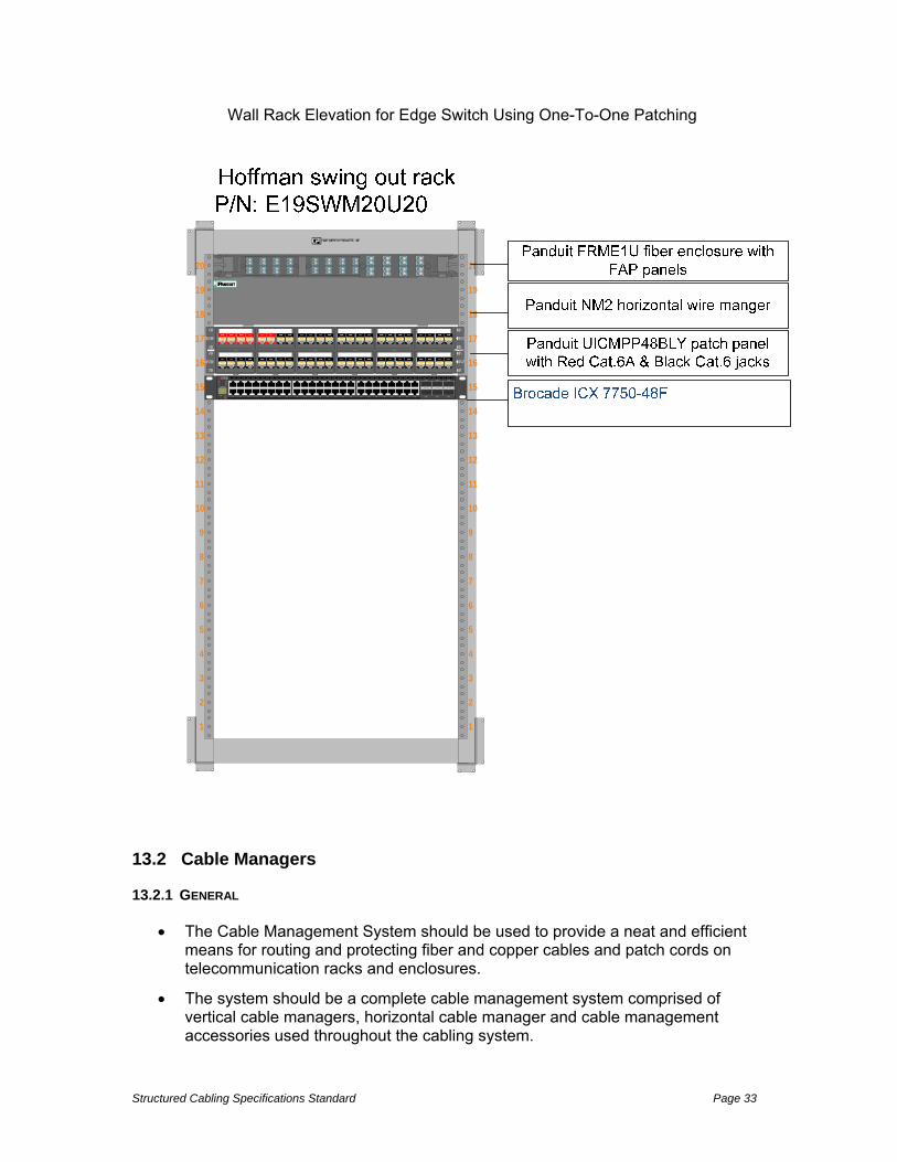
Brocade ICX 7750-48F
Panduit UICMPP48BLY patch panel
Panduit NM2 wire manager
Panduit FRME2U fiber enclosure with FAP panels
Rack Panduit R2P
Structured Cabling Specifications Standard Page 33
Wall Rack Elevation for Edge Switch Using One-To-One Patching
1 1
2 2
3 3
4 4
5 5
6 6
7 7
8 8
9 9
10 10
11 11
12 12
13 13
14 14
15 15
16 16
17 17
18 18
19 19
20 20
RESET
1/1
1/2
1/3 1/5 1/7 1/9 1/11 1/13 1/15 1/17
1/18
1/19
1/20
1/21
1/22
1/23
1/24
1/25
1/26
1/27
1/28
1/29
1/30
1/31
1/32
1/33
1/34
1/35
1/36
1/37
1/38
1/39
1/40
1/41
1/42
1/43
1/44
1/45
1/46
1/47
1/481/4 1/6 1/8 1/10 1/12 1/14 1/16
XL2/1 XL2/3 XL2/5
TM
BROCADEICX 7750-48C
IOIOI
STACK ID
PSU2
DIAG
RNDT
PS U1
MS
HA
XL2/2 XL2/4 XL2/6
13.2 Cable Managers
13.2.1 GENERAL
The Cable Management System should be used to provide a neat and efficient means for routing and protecting fiber and copper cables and patch cords on telecommunication racks and enclosures.
The system should be a complete cable management system comprised of vertical cable managers, horizontal cable manager and cable management accessories used throughout the cabling system.

Structured Cabling Specifications Standard Page 34
The system should protect network investment by maintaining system performance, controlling cable bend radius and providing cable strain relief.
Cable managers size should be selected according to projected port density when the rack is fully loaded and should not in any case exceed a 35% fill per manufacturers calculations (fill charts) upon installation.
13.2.2 HORIZONTAL CABLE MANAGERS
The horizontal cable managers are needed only in space restrictive TRs where there is not sufficient room to use angled patch panels. If horizontal managers are needed, they should meet the following criteria:
Adjustable depth for pathway utilization or fan avoidance.
Manage cables on switches with vertical cards.
Can be used to create cable pathways for routing cable between bays.
Have steel hinged covers to provide easy access to the pathway.
Panduit part number PEHF2, 3 and 4 (last number corresponds with rack units). .
13.2.3 VERTICAL CABLE MANAGEMENT
CHICO USD approved vertical cable managers are Panduit PatchRunner High Capacity type and should have the following properties:
The Vertical cable managers should include components that aid in routing, managing and organizing cable to and from patch panels and/or equipment.
Managers should protect network equipment by controlling cable bend radius and providing cable strain relief.
Managers should be a universal design mounting to EIA racks. The manager should be constructed with a base that possesses pass through holes and molded cable management fingers.
The fingers should incorporate integral bend radius control and be spaced so that the gaps between them align with the EIA rack spaces.
The vertical manager should have a dual hinged cover that can be opened to the left or right to allow easy access to the pathway speeding moves, adds and changes.
High density minimizes area required for network layout, freeing up valuable floor space.
Allows mounting of many standard EIA 19" accessories, such as patch panels, vertically in the manager.
Ventilated side walls provide maximum airflow for equipment cooling.
Snap on finger sections can be removed to improve airflow, and break away fingers allow routing of large cable bundles.
Large finger spacing accommodates up to 48 Cat 6 / 6A cables.

Structured Cabling Specifications Standard Page 35
Optional "sure close" dual hinged metal doors provide easy access to vertical pathway and provide visual and audible feedback on closure.
Available in 7 foot version.
13.3 Wall Mount Cabinets
13.3.1 GENERAL
In classrooms areas requiring lockable equipment mounting, CHICO USD should use Hoffman Access Plus II wall mount communications cabinets to house critical network equipment.
13.3.2 WALL MOUNT CABINETS
CHICO USD approved wall mount cabinets are Hoffman Access Plus II and should have the following properties:
Double-hinged for easy equipment access; center section provides 19-in. rack mounting per EIA universal spacing and is accessed through the front door or swing the center section away from the wall section for rear access • Round corners; no sharp edges • Front door has either a solid steel or hardened, tinted safetyglass window door for superior scratch resistance • Center section easily removed from rear section; tool-less oneperson installation possible • Self-grounding, plated steel rack angles fully adjustable within center section • Wall section provides cable entry and cable management with knockouts or gland plates • Gland plate model provides easy retrofit and fast installation and allows for pre-terminated cables or pre-wired patch panels; no need to re-terminate and test • Self-locking center-to-wall section latches in two locations • Front access to all latches (no exposed side latches); cabinet can be installed tightly in corners • Vented sides provide cross flow ventilation to improve heat dissipation • Vertical cable manager included in 28-in.-wide models
• A full line of accessories is available
SPECIFICATIONS Front Door (window or solid steel) • Composite frame (injection molded top and bottom with extruded composite sides) • 140-degree opening door • Field-reversible (left or right) hinge • Quarter-turn key lock, two keys included • Window door is scratch-resistant 1/4-in. tinted safety glass • Solid door has 16 gauge steel insert with matching black finish Center Section

Structured Cabling Specifications Standard Page 36
• Welded 14 gauge steel • Solid top of center sections provides protection against falling debris • Ventilated sides (to which fans can be added) • Self-latching closure connects center section to wall section • Self-alignment ramp supports center section to wall section • Heavy duty center-to-rear section hinge with quick-release selfretained hinge pin eases wall installation Rack-Mounting Angles • 12 gauge, plated steel • EIA universal spaced 19-in. rack-mounting holes • RU marked from bottom to top • Tapped 10-32 holes, 20 mounting screws included Rear Wall Section • Welded 14 gauge steel • Radius corners; no sharp edges • Available with knockouts or gland plates • Raised pads for accessory mounting • Cable tie-down points for cable management • Keyhole mounting holes allow wall section to be mounted over fasteners and eases installation • Three cable-entry grommets FINISH Pretreated steel coated with RAL 9005 black light-textured, lowgloss polyester powder paint. Standard Product: Hoffman Access Plus II Wall Mount part numbersnits Additional Rack Angles ( EWMW242425 23.62 x 23.62 x 25.09 EWMW362425 36.02 x 23.62 x 25.09 EWMW482425 48.03 x 23.62 x 25.09
14 Copper Patch Panels and Cords
14.1 General Mini-Com® Modular Patch Panels should be designed with snap in four position
and six position molded faceplate frames.
The patch panels shall be modular accepting all Mini-Com® modules.
The faceplate frames should be releasable from the front to provide access to the modules and terminated cable. Modules should be mounted to the patch panel using Mini-Com® mounting features for added strength.
Patch panels should be available with and without labels.
Angled patch panels that allow cable to flow to each side of the rack eliminating the need for horizontal cable managers should be used on all CHICO USD telecommunications rooms having the depth to mount them.
Structured Cabling Specifications Standard Page 37
All patch panels should allow for a labeling scheme and port identification to be visible at all times.
Refer to Appendix A - Materials at the end of this document for part numbers.
14.2 Patch Cord Details
Modular patch cords should be Panduit Category 6 / 6A.
Patch cords should be Panduit factory terminated with modular plugs featuring a tangle-free latch design and clear strain-relief boots to support easy moves, adds and changes.
Each Panduit patch cord should be 100% performance tested at the factory to the appropriate ANSI/TIA 568 C.2 cable standard.
The Panduit patch cords should come in standard lengths of 3’, 5’, 7’, 10’, 14’, and 20’.
Panduit patch cords should be labeled according to the labeling section in this document.
14.2.1 PANDUIT CORD COLOR STANDARDS
CHICO USD patch cord color coding is as follows:
Cat.5e - Blue
Cat.6 - Black
Cat.6A- Red
*For patch cord part numbers see Appendix A - Materials at the end of this document.
**Check project documentation for other color conventions that may be used on that installation.
15 Fiber Patching and Fiber Jumpers
15.1 Fiber Enclosures
CHICO USD approved fiber enclosures are Panduit FRME type. All fiber terminations should be contained in these rack mount enclosures built to that purpose and having the following properties:
Mount to standard 19" or 23" EIA rack or cabinet • Hold QuickNet ™ or Opticom ®
Fiber Adapter Panels.
Have front and rear access on all models via durable molded-hinge doors.
Have integral bend radius control and cable management for fiber patch cords.
Have multiple trunk cable entry locations.
Include fiber optic cable routing kit (grommets, cable ties, saddle clips, strain relief bracket, and ID/caution labels) for various cable management solutions.

Structured Cabling Specifications Standard Page 38
15.2 MULTI-MODE FIBER ADAPTER PANELS
OM3 multi-mode fiber adapter panels should be LC with 12 duplex fiber ports per FAP and meeting the following:
LC 10Gig™ FAP loaded with 12 LC 10Gig™ Duplex Multimode Fiber Optic Adapters (Aqua).
Have zirconia ceramic split sleeves.
Panduit part number (FAP12WAQDLCZ)
15.3 SINGLEMODE FIBER ADAPTER PANELS
Singlemode fiber adapter panels should be LC with 12 duplex ports per FAP and meet the following:
LC FAP loaded with 12 LC duplex singlemode fiber optic adapters (Blue).
Have zirconia ceramic split sleeves.
Panduit Part number FAP12WBUDLCZ .
15.4 FIBER PATCH CORDS
Multimode and Single-mode fiber patch cords should be manufactured by Panduit and meet the following conditions:
Be terminated in duplex LC connections.
Be available in both singlemode and OM4 multimode.
Available in riser (OFNR) or plenum (OFNP) flame ratings.
Be 100% pre-tested for insertion and return loss.
Support speeds up to 10 Gb/s for link lengths up to 300 (OM4) meters with an 850nm source per IEEE 802.3ae 10 GbE standard.
Pass all TIA/EIA-568-B.3 performance requirements.
LC and SC connector housing and boot colors follow TIA/EIA-568-C.3 suggested color identification scheme.
Insertion loss per connection: 0.10dB typical; 0.30dB maximum for OM3.
Typical insertion loss per connection: 0.25dB for singlemode.
See Appendix A - Materials for fiber jumper part numbers.
16 Cable Pathways
16.1 Overhead Ladder Rack Pathways
The Ladder Rack System conveniently routes cables via a modular pathway through unused space on the floor, wall or ceiling while

Structured Cabling Specifications Standard Page 39
keeping cables accessible for easy maintenance. A variety of straight and curved sections are highly adaptable and can accommodate virtually any room layout. Features •• Section cross members welded on 9-in. (229-mm) centers •• Accessory adjustable cross members •• Butt-splice kits and junction-splice kits •• Each model is boxed or bagged Specifications •• Straight and curved sections made of 1-1/2-in. steel •• Sections available in 6-, 12-, 18- and 24-in. (152-, 305-, 457- and 610- mm) widths •• Steel connecting and mounting hardware Finish Available in three finishes: •• ANSI 61 gray polyester powder paint •• RAL 9005 black polyester powder paint •• Plated The Ladder Rack System conveniently routes cables via a modular pathway through unused space on the floor, wall or ceiling while keeping cables accessible for easy maintenance. A variety of straight and curved sections are highly adaptable and can accommodate virtually any room layout. Features •• Section cross members welded on 9-in. (229-mm) centers •• Accessory adjustable cross members •• Butt-splice kits and junction-splice kits •• Each model is boxed or bagged Specifications •• Straight and curved sections made of 1-1/2-in. steel •• Sections available in 6-, 12-, 18- and 24-in. (152-, 305-, 457- and 610- mm) widths •• Steel connecting and mounting hardware Finish Available in three finishes: •• ANSI 61 gray polyester powder paint •• RAL 9005 black polyester powder paint •• Plated Accessories Touch-up
16.2 Overhead Fiber Pathways
Overhead non-metallic fiber pathways should be Panduit FiberRunner and have the following properties:
Be comprised of fittings, channel, couplers and brackets designed to segregate, route, and protect fiber optic and high performance copper cabling.
Be available in sizes 24x4, 12x4, 6x4, 4x4, and 2x2.
Have hinged channel cover and split fitting covers for 12x4, 6x4, and 4x4 systems protect cabling and provide easy access for future cabling revisions and additions.

Structured Cabling Specifications Standard Page 40
Feature QuikLock ™ assembly features that have built-in bend radius control and that eliminates or minimizes the need for tools to assemble the system.
QuikLock ™ Couplers and Brackets require less than
Have available multiple spillout options to provide versatility in making transitions to various equipment and rack configurations.
Be part of an integrated system compatible with Panduit ® Fiber-Duct ™ 4x4 and 2x2 Routing Systems, CabRunner®, and Wyr-Grid ® Overhead Routing Systems, cable management and racks.
16.3 Surface Raceway Surface raceway refers to a surface raceway system used for branch circuit wiring and/or data network, voice, video and other low-voltage cabling. Surface raceway shall be used in solid wall applications or for applications where moves, adds and changes are very typical to the workflow. The raceway system shall consist of raceway, appropriate fittings and accessories to complete installation per electrical and/or data drawings.
Non-metallic surface raceway is to be utilized in dry interior locations only as covered in Article 388of the NEC, as adopted by the NFPA and as approved by the ANSI.
Multi-Channel
T-70 (4.07” by 1.77”) Raceway The raceway shall be a two-piece design with a base and snap-on cover. The raceway shall maintain complete separation of the power and data channels. Raceway dimensions shall be 4.07”wide by 1.77” deep with an approximate wall thickness of .10”. The base (T70B) shall have a 70mm opening, its own 70mm cover and features for mounting device brackets, hanging boxes, wire retainers and snap on faceplates. Divider walls, which snap onto the base to form additional wiring channels, must be available. The base shall be manufactured of rigid PVC compound. The base shall have a smooth texture, and be available in three colors: off white, electrical ivory, and white with international gray being offered in 8’ lengths. The cover (T70C) shall have flanges for snapping onto the base. The cover shall be manufactured of a rigid PVC compound. The cover shall be available in three colors: off white, electrical ivory, and white with international gray being offered in 8’ lengths. The cover shall match the finish and the color of the base. The divider wall (T70DW) shall have flanges, which snap onto the T-70 base. The divider shall be manufactured of a rigid PVC compound. The divider shall have a smooth texture and be international gray in color. Fittings A full complement of fittings (T-70 series) must be available including but not limited to flat, internal, and external elbows, tee with insert to separate power and data cabling, entrance fitting, cover coupler, base coupler, and end cap. A transition fitting shall be available to adapt to PANDUIT ® T45, LDPH10, LDPH5 and LDPH3 series raceways. The fittings shall provide a means for connecting to the raceway base and shall be

Structured Cabling Specifications Standard Page 41
capable of maintaining a 1” minimum cable bend radius. The fittings shall be manufactured from a rigid PVC (or ABS/PC) compound. The fittings shall have a matte texture, on the top surfaces, and be available in three colors: off white, electrical ivory and white to match the base and cover. They shall overlap the cover and base to hide uneven cuts. All fittings shall be supplied with a base where applicable to eliminate mitering. Accessories Device brackets and hanging boxes shall be available for mounting standard devices in-line within the raceway. An offset two-piece termination box shall be available for positioning power devices adjacent to inline data terminations. Faceplates may be a PAN-WAY ™ Snap-On faceplate to match and fit flush with the device bracket, or any NEMA standard 70mm faceplate. Data faceplates may accommodate up to six jacks and shall be modular in design to accept UTP, Coax, ST, SC, FC and Fiber Jack type of connectors. They shall be available in off white, electrical ivory, and white to match the raceway base and cover. Material The raceway and all system components must be UL Listed and CSA Certified up to 600Vand exhibit nonflammable self-extinguishing characteristics, tested to comparable specifications of UL94V-0. The raceway base, cover, and divider shall be available in 8’ and 10’ lengths.
Part Number Description Bend Radius
Control Size T70B** T-70 Base (8' or 10' Long) - 8' & 10' T70C** Cover (8' or 10' Long) - 8' & 10' T70DW** Divider Wall (8' or 10' Long) - 8' & 10' T70IC** Inside Corner (Base and Cover) Yes - T70OC** Outside Corner (Base and Cover) Yes - T70RA** Right Angle (Base and Cover) Yes - T70TR** Transition Fitting (Base and Cover) Yes - T70TRC** Transition Fitting (Cover Only) Yes - T70T** Tee Fitting (Base and Cover) Yes - T70TD Tee Divider Yes - T70TDB Tee Divided Insert (Bottom) Yes - T70EC** End Cap - - T70EE** Entrance End Yes - T70WM40TRIW Wiremold ® to T70 Transition Fitting - - T70BC**X Base Coupler - T70CC**-X Cover Coupler - - T70DB-X Device Bracket - - T70SDB-X Snap-on Device Bracket - - T70BF** Backfeed Fitting Yes - T70BFI Backfeed Fitting Insert Yes - T70WR-X Wire Retainer - - T70PC** Pre-Cut Snap-On Cover Modular
Furniture - -
T70S-X Surface Mount Box Spacer Plate - - T70HB3GFCI-X GFCI Three-sided Hanging Box - T70HB-X Hanging Box - - T70HB3-X 3 Sided Hanging Box - - T70WC** WORKSTATION OUTLET CENTER
™ Screw-On faceplate - -

Structured Cabling Specifications Standard Page 42
T70WC2** WORKSTATION OUTLET CENTER ™ Snap-On faceplate
- -
T70FSB Fiber Spool Bracket - - T70P** 106 Duplex Snap-On Faceplate - - T70PG** Rectangular Snap-On Faceplate - - CP106** 106 Duplex Screw-On Faceplate - - CPG** Rectangular Screw-On Faceplate - -
** Designates color option
Multi-Channel
Twin-70 (7.23” by 1.77”) Raceway The raceway shall be a three-piece design with a base, and two snap-on covers, which provide access to each channel independently. The raceway shall maintain complete separation of the power and data channels. Raceway dimensions shall be 7.23” wide by 1.77” deep with an approximate wall thickness of .10”. The base (T702B) shall have two wiring channels separated by an integral barrier, and features in both channels for mounting device brackets. Each channel shall have a 70mm opening and its own 70mm cover. Divider walls, which snap onto the base to form additional wiring channels, must be available. The base shall be manufactured of rigid PVC compound. The base shall have a smooth texture, and be available in three colors: off white, electrical ivory, and white. The covers (T70C) shall have flanges for snapping onto the base. The cover shall be manufactured of a rigid PVC compound. The cover shall be available in three colors: off white, electrical ivory, and white. The cover shall match the finish and the color of the base. Additional divider walls (T70DW) shall have flanges, which snap onto the Twin-70 base and shall be removable. The divider shall be manufactured of a rigid PVC compound. The divider shall have a smooth texture and be international gray. Fittings A full complement of fittings (Twin-70 series) must be available including but not limited to flat, internal and external elbows, tee with insert, entrance fittings, cover coupler, base coupler, and end cap. A transition fitting shall be available to adapt to PANDUIT ® LDPH10, LDPH5, LDPH3, T-70, and LD2P10 series raceways. The fittings shall provide a means for connecting to the raceway base and shall be capable of maintaining a 1” minimum cable bend radius. The fittings shall have two separate covers in order to maintain complete separation of power and data channels; exceptions would be the tee and entrance end fittings. The fittings shall be manufactured from a rigid PVC (or ABS/PC) compound. The fittings shall have a matte texture, on top surfaces, and be available in three colors: off white, electrical ivory, and white to match the base and cover. They shall overlap the cover and base to hide uneven cuts. All fittings shall be supplied with a base where applicable to eliminate mitering. Accessories Device brackets shall be available for mounting standard devices in-line within the raceway. Faceplates may be a PAN-WAY ™ Snap-On faceplate to match and fit flush with the device bracket, or any NEMA standard 70mm faceplate. Data faceplates may accommodate up to six jacks and shall be modular in design to accept UTP, Coax, ST,

Structured Cabling Specifications Standard Page 43
SC, FC and Fiber-Jack type of connectors. They shall be available in off-white, electrical ivory, white, and international gray to match the raceway base and cover. Materials The raceway and all system components must be UL Listed and CSA Certified up to 600Vand exhibit nonflammable self-extinguishing characteristics, tested to comparable specifications of UL94V-0. The raceway base, cover, and divider shall be available in 8’ and 10’ lengths.
Part Number Description Bend Radius
Control Size T702B** Twin-70 Base (8' or 10' Long) - 8' & 10' T70C** Cover (8' or 10' Long) - 8' & 10' T70DW** Divider Wall (8' or 10' Long) - 8' & 10' T702IC** Inside Corner (Base and Cover) Yes - T702OC** Outside Corner (Base and Cover) Yes - T702RA** Right Angle (Base and Cover) Yes - T702TR** Transition to T-70 (Base and Cover) Yes - T702TRL** Transition to LD profile raceway
(Base and Cover) Yes -
T702TRI Transition Divided Insert Yes - T702EC** End Cap - - T702T** Divided Tee (Base, Cover and Insert) Yes - T702EE** Entrance End Yes - T702BC**-X Base Coupler - - T70CC**-X Cover Coupler - - T70DB-X Device Bracket - - T70SDB-X Snap-on Devise Bracket - - T70WR-X Wire Retainer - - T70S-X Surface Mount Box Spacer Plate - - T70FSB Fiber Spool Bracket Yes -
** Designates color option
Single Channel
LD3, 5 & 10 Raceway The PANDUIT ® PAN-WAY ™ LDH Single Channel Surface Raceway shall be a one-piece design. Raceway dimensions shall be: 0.77" wide x 0.46" deep for LD3, 1.00" wide x 0.6" deep for LD5 and 1.51” wide x 0.86” deep for LD10 with an approximate wall thickness of 0.055”. The raceway shall be available in 6', 8’ and 10’ lengths. The raceway (LD) shall have a tamper resistant hinge attaching the cover to the base. The raceway shall have tamper resistant non-slip cover design. The raceway shall be manufactured of rigid PVC compound. The raceway shall have a smooth texture, and be available in four colors: off white, electrical ivory, white and international gray. Fittings A full complement of fittings (LD series) must be available including but not limited to flat, internal and external elbows, divided tees and entrance fittings, couplers, and end caps. The fittings shall provide a means for connecting to the raceway and shall be capable of maintaining a 1” minimum cable bend radius. Applicable fittings shall be of

Structured Cabling Specifications Standard Page 44
cover only design (for low voltage cabling only), or base and cover design in order to maintain complete enclosure, maintain separation of power and data channels, and to eliminate mitering. The fittings shall be manufactured from a rigid PVC (or ABS/PC) compound. The fittings shall have a matte texture and be available in four colors: off white, electrical ivory, white and international gray to match the raceway. They shall overlap the raceway to hide uneven cuts. Accessories Junction boxes and faceplates shall be available for mounting standard devices. The junction boxes shall be available in standard, intermediate and deep versions. The faceplates shall allow for terminating of standard electrical devices, both duplex and rectangular styles, and accept PANDUIT ® inserts for data terminations. The faceplates may accommodate up to six jacks and shall be modular in design to accept UTP, Coax, ST, SC, FC and Fiber Jack type of connectors. They shall be available in off white, electrical ivory, white and international gray to match the raceway. Materials The raceway and all system components must be UL Listed and CSA certified up to 600V and exhibit nonflammable, self-extinguishing characteristics, tested to comparable specifications of UL94V-0 and FT-4.
Part Number Description Bend Radius
Control Size LD10**6-A LDP10 Raceway - 6' L LD10**8-A LDP10 Raceway - 8' L LD10**10-A LDP10 Raceway - 10' L CFX10** Coupler Fitting - - ICFX10** Inside Corner Fitting Yes - OCFX10** Outside Corner Fitting Yes - RAFX10** Right Angle Fitting Yes - ECFX10** End Cap Fitting - - TFX10** Tee Fitting Yes - DCEFX**X Drop Ceiling Entrance End Fitting Yes - RAEFX** Right Angle Entrance End Fitting Yes -
** Designates color option 10 - substitute 3 for LD3 or 5 for LD5 raceway
17 Substitution Policy
17.1 General
Any Contractor wishing to offer structured cabling products or associated hardware other than those specified should submit a request for product substitution in writing no less than one week in advance of bid.
Written requests for substitution should be accompanied by all drawings, specification sheets and engineering documents, as well as third party laboratory

Structured Cabling Specifications Standard Page 45
performance test results proving equivalency in transmission performance and mechanical function.
This written documentation should be accompanied by three (3) each samples of the substitution product being offered for evaluation by CHICO USD.
Equal product acceptance must be received from CHICO USD in writing.
Contractor shall be responsible for and assume all costs for removal and replacement of any substituted product installed without prior written approval. Such costs should include but not be limited to labor, materials as well as any penalties, fees or costs incurred for late completion.
All requests for substitution must be submitted in writing and approved by John Sclare, CHICO USD 2455 Carmichael, Chico, CA 95928 [email protected].
18 Communications Structured Grounding
18.1 General
Contractor is responsible for bonding to ground all newly placed equipment and installed racks or cabinets per the TIA 607-B Standard.
18.2 Details
All newly installed racks and cabinets should have installed a vertical busbar mounted along one equipment rail to serve as a clean, low-resistance bonding place for any equipment not equipped with a designated grounding pad.
Smaller equipment without an integrated grounding pad should be bonded to the vertical busbar through the use of a thread-forming grounding screw that is anodized green and includes serrations under the head to cut through oxidation or paint on the equipment flange.
Larger equipment (chassis switches) with a designated grounding terminal should be bonded to the vertical busbar with and EBC (equipment bonding conductor) kit built to that purpose.
Contractor should take care to clean (wire brush, scotchbrite pads) any metallic surface to be bonded down to bare metal and apply a film of anti-oxidation paste to the surfaces prior to effecting the bond.
All bonding lugs on racks and busbars should be of two-hole irreversible compression type. Mechanical lugs and single-hole lugs will not be accepted and should be removed and replaced at Contractor's expense.
Every rack or cabinet should have an individual bonding conductor into the grounding network, serially connecting (daisy-chaining) of racks is expressly forbidden and will not be accepted.
Rack Bonding Conductors (RBC) may tap into an overhead or underfloor aisle ground, or may run to the wall-mounted grounding busbar in smaller Telecommunications rooms containing 5 racks or less.

Structured Cabling Specifications Standard Page 46
A minimum of every other rack or cabinet should be outfitted with a properly installed and bonded ESD (electro-static discharge) port along with a wrist strap and lead to be used by any technicians servicing network equipment. On four post racks and cabinets these ESC ports and straps should be provided on front and back to be accessible and able to reach any active equipment needing servicing.
Armored cables should be properly bonded to the earthing system with a kit built to that purpose.
For examples of rack and cabinet grounding refer to the illustrations below:
Properly Bonded Cabinet

Structured Cabling Specifications Standard Page 47
Rack Ground Strip (not used in retrofit application)
Basic equipment cabinet with the doors and side panels removed for clarity
Front to Back Rail Jumper
Common Bonding Network Jumper
Mesh Common Bonding Network
Equipment Jumper
Grounding Busbar (can be mounted to bottom or top of cabinet)
Electrostatic Discharge (ESD) Port
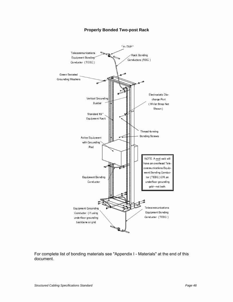
Structured Cabling Specifications Standard Page 48
Properly Bonded Two-post Rack
For complete list of bonding materials see "Appendix I - Materials" at the end of this document.

Structured Cabling Specifications Standard Page 49
19 Communications Labeling
19.1 General
Within CHICO USD, each location has adopted local naming conventions for communications circuit designation and labeling. For exact instructions of how one project will be designated, consult the attached project specifications for that job.
19.2 Universal Guidelines
The following are general labeling guidelines that will apply to all facilities:
When making additions to legacy (brownfield) systems, Contractor should adopt the circuit designation and labeling strategy of the existing systems unless instructed otherwise in project documentation.
In new installations (greenfield), Contractor should develop and submit for approval a labeling strategy based on the TIA 606-B Circuit Designation and Labeling Standard.
This labeling scheme should, at a minimum, clearly identify all components of the system: racks, cables, panels and outlets, grounding, pathways and spaces like telecommunications rooms.
The labeling system should designate the cable origin and destination with a unique identifier for the cable within the system.
Racks and patch panels should be labeled to identify the location within the cable system infrastructure.
All labeling information should be recorded on the as-built drawings and all test documents should reflect the appropriate labeling scheme.
All label printing will be machine generated by either hand-held labeling systems or computer generated using programs and materials built specifically for communications labeling.
Hand written labels will not be accepted and must be remedied at Contractors expense.
Such labels should utilize materials designed to outlast the cabling elements to which they attach. Office quality labels will not be accepted.
Cable labels should be self-laminating, appropriately sized to the outside diameter of the cable and placed within view at the termination point on each end.
Outlet, patch panel and wiring block labels should be installed on, or in, the space provided on the device.
Machine-generated labels should be installed behind the clear lens or cover on any device that provides such an option.

Structured Cabling Specifications Standard Page 50
All Bays should be labeled with Bay Designation at the end of Bay on side of cabinet.
All cabinets should be labeled on outside door and on the inside so identification can be made when door is open.
Labeling information will be supplied to the Communications Contractor by the CHICO USD Telecommunications Engineer in the project documentation.
All labels will be permanently affixed to cables, patch panels, racks, cabinets, and enclosures.
Labels should be legible and placed in a position that insures ease or visibility. Label type must be as listed in Appendix A - Materials.
Conduit should be marked indicating the identification of the cable within.
Backbone cabling should be labeled on each end designating the cable identification, FROM (origin), and TO (destination).
For a complete listing of communications labeling products see Appendix A – Materials.
20 Testing and Documentation
20.1 General
Contractor should test all cables and termination hardware for defects in installation and to verify cabling system performance prior to system acceptance.
Testing should be done in accordance with this document, the ANSI/TIA Standards, the Pan/Gen Certification Plus System Warranty guidelines and best industry practice.
If any of these are in conflict, the Contractor should bring any discrepancies to the attention of CHICO USD Project Manager for clarification and resolution.
Any defect in the cabling system performance or installation including but not limited to cable, connectors, feed through couplers, patch panels, and connector blocks should be repaired or replaced in order to ensure 100% useable conductors or fibers in all cables installed.
Contractor is responsible for supplying all of the required test equipment used to conduct acceptance tests.
CHICO USD reserves the right to be present during any or all of testing.
All cabling not tested strictly in accordance with these procedures should be re-tested at no cost to CHICO USD.
20.2 COPPER TESTING
All twisted-pair copper cable links should be tested in compliance to the requirements in ANSI/TIA 1152 and ANSI/TIA 568-C.2 for Category 6 & 6A compliance using a test unit meeting a minimum IEC level of accuracy.

Structured Cabling Specifications Standard Page 51
All testers used must have been factory calibrated by the manufacturer within one year of use or according to factory calibration recommendations, whichever is the more stringent.
Contractor should set references according to manufacturer’s recommendation prior to each day’s testing and reset references anytime tester is left unused for more than two hours.
20.3 FIBER TESTING
All installed fiber should be tested for link-loss in accordance with ANSI/TIA 568-C.0 and should be within limits specified within ANSI/TIA 568-C.3
For horizontal cabling system using multimode optical fiber, attenuation should be measured in one direction at either 850 nanometer (nm) or 1300 nm using a light source and power meter.
Backbone multimode fiber cabling should be tested at both 850 nm and 1300 nm (or 1310 and 1550 nm for single mode) in both directions.
Test set-up and performance should be conducted in accordance with ANSI/568-C.0 Standard, Method B.
Attenuation testing should be performed with a stable launch condition using two-meter reference grade fiber test leads (jumpers) to attach the test equipment to the cable plant.
The light source should be left in place after calibration and the power meter moved to the far end to take measurements.
Contractor should use reference grade fiber test leads built and sold specifically for fiber testing. Testing performed with standard fiber jumpers will not be accepted.
Where links are combined to complete a circuit between devices, the Contractor should test each link from end to end to ensure the performance of the system. Only basic link loss testing is required.
The values for calculating acceptable loss should be those defined in the ANSI/TIA 568-C.3 Standard.
CHICO USD reserves the right to conduct, using Communications Contractor equipment and labor, a random re-test of up to five (5) percent of the cable plant to confirm documented results.
Random re-testing, if performed, should be at the expense of CHICO USD, using standard labor rates. Any failing cabling should be re-tested and restored to a passing condition.
In the event more than two (2) percent of the cable plant fails during a re-test, the entire cable plant should be re-tested and restored to a passing condition at no additional cost to CHICO USD.

Structured Cabling Specifications Standard Page 52
20.2 Documentation
Test reports may be submitted in hardcopy or electronic format. Hand-written test reports are not acceptable.
Invoice will not be paid until final test results and as-built drawing(s) are received.
Hardcopy reports are to be submitted in labeled 3 ring binders and signed off by the Communications Contractor’s Project Manager, verifying passing execution of all tests. For large installations electronic reports with hardcopy summaries are preferred.
Hardcopy summary reports should contain the following information on each row of the report: circuit ID, test specification used, length, date of test, and pass/fail result.
Electronic documentation should be submitted in tester native format (not Excel). This is inclusive of all test results and draft as-built drawings.
Draft drawings may include annotations done by hand. Machine generated (final) copies of all drawings should be submitted within 30 working days of the completion of each testing phase.
At the request of CHICO USD, the telecommunications Contractor should provide additional copies of the original test results.
The all report media should be clearly marked on the outside front cover with the words “Project Test Documentation”, the project name, and the date of completion (month and year).
Test results should include the date of testing, a record of test frequencies (or wavelengths), cable type, conductor pair (or fiber strand if fiber) and cable (or outlet) I.D., measurement direction, reference setup, and crew member name(s).
The test equipment name, manufacturer, model number, serial number, software version and last calibration date should also be provided at the end of the document.
Unless the manufacturer specifies a more frequent calibration cycle, an annual calibration cycle is anticipated on all test equipment used for this installation.
The test document should further detail the test method used and the specific settings of the equipment during the test.
When repairs and re-tests are performed, the problem found and corrective action taken should be noted, and both the failed and passed test data should be documented.
The As-Built drawings are to include cable routes and outlet locations. Their sequential number as defined elsewhere in this document should identify outlet locations.
Numbering, icons, and drawing conventions used should be consistent throughout all documentation provided. CHICO USD will provide floor plans in paper and electronic (DWG, AutoCAD) formats to which as-built construction information can be added.

Structured Cabling Specifications Standard Page 53
The Contractor should annotate the base drawings and return a hard copy (same plot size as originals) and electronic (AutoCAD) form
20.3 Final Inspection and Acceptance
Final project walk-though will occur within 7 working days of testing completion. The Contractor will have up to 7 days to correct any “punch item” issues identified during the walk down.
Once all work has been completed, test documentation has been submitted, and the CHICO USD Project Manager is satisfied that all work is in accordance with the Scope of Work documents, CHICO USD should notify the Communications Contractor in writing of formal acceptance of the system.
Following completion and/or compliance with the requirements listed above, CHICO USD will issue a Notice of Completion confirming that the project is complete. A 45 day Acceptance Period will begin immediately following the issuance of the Notice of Completion.
21 Panduit ® CERTIFICATION PLUS™ System Warranty
A CERTIFICATION PLUS System Warranty shall provide a complete system warranty to guarantee end-to-end high performance cabling systems that meet application requirements. The guarantee shall include cable and connectivity components and have one point of contact for all cabling system issues. The system shall be warranted for a period of 25 years.
The Certification Plus Warranty may be applied only if the cabling channel links are comprised of Panduit connectivity and cable.
Upon acceptance of Warranty, Panduit will mail a notification letter to the installer and a notification letter and warranty certificate to CHICO USD.
21.1 Contractor Warranty Commitments
Installation firm must be a current certified Panduit ONE Partner in good standing and should include a copy of the company Panduit ONE Partner certification with the bid.
Contractor should name a supervisor to serve on site as a liaison responsible to inspect and assure all terminations are compliant to factory methods taught in Panduit Technician Certification Training and according to all Standards cited in the Regulatory References section of this document.
Contractor liaison should have a current, up-to-date Panduit ONE Partner Certified Technician (PCT) certificate in both copper and fiber. Copies of the

Structured Cabling Specifications Standard Page 54
copper and fiber certificates of the Panduit liaison should be submitted with the bid.
Contractor agrees all components comprising active links should be of the same copper Category or fiber OM designation as the system being installed. Contractor should under no circumstances mix different Categories or OM classes of cable or termination devices (connectors) within the same link or system.
Contractor should install all racking and support structures according to cited TIA Standards in such fashion as to maintain both Standards and Manufacturer recommendations for uniform support and protection, segregation of different cable types, maintenance of maximum pulling tensions, minimum bend radius, approved termination methods as well as adhering to industry accepted practices of good workmanship.
Contractor is responsible for understanding and submitting to Panduit all documents required prior to project start to apply for this warranty. These include but are not limited to the project information form and SCS warranty agreement.
Contractor is responsible for understanding and submitting to Panduit all documents required at project end. These include completed warranty forms, passing test reports and drawings of floor plans showing locations of links tested.
Test results should be delivered in the tester native format (not Excel) and represent the full test report. Summaries should not be accepted. Contact Panduit for a current list of approved testers, test leads and latest operating systems.
The Communications Contractor will correct any problems and malfunctions that are warranty-related issues without additional charge to CHICO USD for the entire warranty period. The warranty period should commence following the acceptance of the project by CHICO USD and written confirmation of Warranty from Panduit.
22 Contractor Qualifications
The following guidelines must be adhered to when work is bid to outside Contractors.
22.1 General
Contactor should be a current Panduit Certified Installer. A copy of corporate certificate must be included with quote.
At least 30 percent of the technicians on the job must have a current Panduit Certified Copper Technicians certificate to install Panduit Copper Distribution Systems.
At least 30 percent of the technicians installing any Fiber Distribution Systems must have a current Panduit Certified Fiber Technicians certificate to install Fiber Distribution Systems.

Structured Cabling Specifications Standard Page 55
Contractor should employ at least one BICSI Registered Communication Distribution Designer (RCDD). A copy of the RCDD certificate must be attached to the proposal.
Contractor should design and provide all materials in order to install a complete structure cabling solution supporting voice and data. Only one Contractor (no subs) should be responsible for providing a complete and functional infrastructure including the procurement of products, installation of cabling infrastructure, pathways and spaces, bonding and grounding, fire stopping, verification of performance, and documentation.
Contractor must possess a valid C-7 California State Contractor’s license. This license must have been issued 5-years prior to the date of the bid.
Contactor must have been in telecommunications business for a period of at least 2 years. Contractor must submit at least 3 project references (of similar size and scope to this project).
This installation must provide a 25-year extended warranty on the UTP cabling solutions by Panduit and General Cable. The extended warranty should include (but not limited to), product, performance, and application guarantees.
Contractor should visit the work site before their proposal will be accepted. No allowances should be made to the Contractor for any extra expense, due to failure or neglect to discover unforeseen conditions affecting the work.
Contractor employees should act in a professional manner, and be dressed appropriately for the task. No person should bring alcoholic beverages, controlled substances, firearms, or animals to the job site.
Contractor should clear the work area every evening. If available space exists, Contractor equipment and materials may be stored at the facility with approval of CHICO USD. All packing material should be disposed of at the end of each day. CHICO USD will not be responsible for the loss, theft, or damage of any equipment or material.
Contractor should follow the security policies and procedures defined by CHICO USD. This may include providing key access, creating access badges, and escorts for restricted areas.
Contractor should take all precautions necessary to protect existing structures and furniture. Any items that are damaged during the course of the work should be repaired or replaced by the Contractor at no cost to CHICO USD.
CHICO USD will provide the Contractor with reasonable access to the job site Monday-Friday 8-5 (Federal / State holidays excluded). CHICO USD must approve any work that requires access outside of these parameters.
Contractor will provide a high-level project plan. This project plan should identify the tasks, timelines, and a completion date. Any changes to the schedule will be emailed to CHICO USD weekly. Attached files can be formatted in Adobe Acrobat.

Structured Cabling Specifications Standard Page 56
Contractor should assign a Project Manager. The Project Manager should email a weekly update status report to the project team members. A central off-hours emergency contact number should also be available for evenings and weekends.
Contractor should take special precautions to ensure a safe work environment for the employees, contractors, and visitors.
Contractor will make a reasonable effort to not be disruptive to other Contractors, or working staff at the job site.
Contractor will install only material that is new and undamaged. Refurbished or used material is not acceptable.
Contractor will dispose of all removed copper cable at a licensed Recycling Service facility.
CHICO USD expects the workmanship to be of high quality. All equipment should be plumb and true with the structure. All materials should be firmly secured in place, adequately supported, and permanent.
Install and coordinate this work in cooperation with other trades installing interrelated work. Before installation, make proper provisions to avoid interferences in a manner accepted by the General Contractor/Engineer.
All repairs or changes required in the work of the Contractor, caused by his/her neglect, should be made by the Contractor at his own expense.
The locations of ladder racks and other equipment indicated on the drawings or the specification are approximately correct and are understood to be subject to such revision as may be found necessary or desirable at the time the work is installed. Detailed information is to be discussed and agreed upon by the Contractor, or Contractor’s representative, and CHICO USD Engineer and/or Project Manager.
Exercise particular caution with respect to the location of cable termination frames, and have precise and definite locations accepted by CHICO USD/Engineer before proceeding with the installation.
Keep all items protected before and after installation. Clean up all debris daily
If in the event the Contractor and CHICO USD disagree technically during the execution of this project, both parties agree to be bound by the decision of a 3rd
party. This person should be an RCDD in good standing with BICSI. He/she should be retained by CHICO USD, and should not be an employee. A decision will be provided within 2-business days.
CHICO USD will consider the project complete when all work has been completed when all stipulations in the Testing and Acceptance section of this document have been satisfied and signed-off on.
Contractor agrees to replace or repair within 2 business days, any defective work or materials identified by CHICO USD within 12 months of final payment.

Structured Cabling Specifications Standard Page 57
23 Bid Guidelines
23.1 General
The bid specification will allow for up to a +/- 10% variance to the total cable counts before a change order and/or scope revision is required.
23.2 Labor
Labor costs to install, terminate and test all vertical and/or horizontal cabling specified by the project scope document.
23.3 Prevailing Wage
Contractor will pay wages to the Contractor employees which meets or exceed prevailing wages. Prevailing wages should be as defined by California Labor Code Part 7, Chapter 1, Article 2 Section 1770, 1773, and 1773.1.
23.4 Material
Contractor will provide unit cost details, including materials list, for the project including an addendum for changes or additions to the original job scope.
Total project cost with the following cost breakdowns:
i. Total material costs with detailed material list with all parts and estimated quantities identified
ii. Total labor costs with estimated man-hours for project completion
iii. Cost per additional station with one Cat6 cable pulled to the station 100 feet from the communications room.

Structured Cabling Specifications Standard Page 58
Materials Lists COPPER CONNECTIVITY
Part Number Description
PUP6004BU-W TX6000™ Enhanced Category 6 U/UTP Copper Cable, CMP, Blue
PUP6AM04BU-UG TX6A™ 10Gig™ UTP Copper Cable with Advanced MaTriX Technology,CMP, Blue
CJ6X88TGxx Mini-Com TX6A UTP Jack Module
CJ688TGxx Mini-Com TX6 UTP Jack Module
DPA246X88TGY 24-port, angled, Category 6A, patch panel with 24 RJ45, 8-position, 8-wire ports
DPA486X88TGY 48-port, angled, Category 6A, patch panel with 48 RJ45, 8-position, 8-wire ports
DPA24688TGY 24-port, angled, Category 6, patch panel with 24 RJ45, 8-position, 8-wire ports
DPA48688TGY 48-port, angled, Category 6, patch panel with 48 RJ45, 8-position, 8-wire ports
DP12688TGY
12-port, Category 6, patch panel with twelve RJ45, 8-position, 8-wire ports. Mounts to 89D wall mount bracket.
DP246X88TGY 24-port, Category 6A, patch panel with 24 RJ45, 8-position, 8-wire ports
DP486X88TGY 48-port, Category 6A, patch panel with 48 RJ45, 8-position, 8-wire ports
DP24688TGY 24-port, Category 6, patch panel with 24 RJ45, 8-position, 8-wire ports
DP48688TGY 48-port, Category 6, patch panel with 48 RJ45, 8-position, 8-wire ports
UTP28X*xx Category 6A/Class E, UTP, small diameter patch cords should be constructed of 28 AWG, unshielded, twisted pair, stranded copper cable with high performance modular plugs. * = length xx = color
UTP28SP*xx Category 6/Class E, UTP, small diameter patch cords should be constructed of 28 AWG, unshielded, twisted pair, stranded copper cable with high performance modular plugs. * = length xx = color
CJS6X88TGY Category 6A, RJ45, 8-position, 8-wire universal shielded module with integral shield
CJS688TGY Category 6, RJ45, 8-position, 8-wire universal shielded module with integral shield
UICMPPA24BLY 24-port angled patch panel with six UICPPL4BL Mini-Com® Ultimate ID® Faceplates
UICMPPA48BLY 48-port angled patch panel with six UICPPL4BL Mini-Com® Ultimate ID® Faceplates
UICMPP24BLY 24-port patch panel with six UICPPL4BL Mini-Com®Ultimate ID® Faceplates
UICMPP24BLY
UICMPP48BLY 48-port patch panel with twelve UICPPL4BL Mini-Com® Ultimate ID® Faceplates
SRBWCY Strain relief bar with integrated adjustable clips; supports, manages, and provides proper bend radius protection for up to 24 cables.
CFPL4IWxxY 4 Port Single gang, vertical faceplate accepts four Mini-Com® Modules
CBXJ2IW-A Mini-Com® 2-port surface mount box accepts up to two Mini-Com® Modules. Includes built-in removable blank to add a second module.

Structured Cabling Specifications Standard Page 59
CBXC4IW-A Mini-Com® surface mount box accepts four Mini-Com® Modules
CMBxx-X Mini-Com® 1-port blank module, reserves space for future use xx = color
* *For lengths 1 to 20 feet (increments of one foot), and 25, 30, 35, 40, 45, 50 feet, change the length designation in the part number to the desired length.
xx To designate color, add suffix IW (Off White), replace IW suffix with EI (Electric Ivory), IG (International Gray), AW (Arctic White), BL (Black), BU (Blue), RD (Red),YL(Yellow), GR (Green), OR (Orange), or VL (Violet). BL (Black), BU (Blue),RD (Red), YL (Yellow), GR (Green), or OR (Orange
FIBER CONNECTIVITY
Part Number Description
BL0121ANU.BK General Cable Indoor / Outdoor 12 strand tight buffer Multimode 50/125um / OM4 distribution interlock armored plenum cable.
BL0241ANU.BK General Cable Indoor / Outdoor 24 strand tight buffer Multimode 50/125um / OM4 distribution interlock armored plenum cable.
BL0481ANU.BK General Cable Indoor / Outdoor 48 strand tight buffer Multimode 50/125um / OM4 distribution interlock armored plenum cable.
AP0121ANR.BK General Cable Singlemode 9/125um Indoor / Outdoor 12 strand tight buffer distribution interlock armored plenum cable.
AP0241ANR.BK General Cable Singlemode 9/125um Indoor / Outdoor 24 strand tight buffer distribution interlock armored plenum cable.
AP0481ANR.BK General Cable Singlemode 9/125um Indoor / Outdoor 48 strand tight buffer distribution interlock armored plenum cable.
FRME1U Rack Mount Enclosure 1 RU, Holds up to three FAP or FMP adapter panels or FOSM splice modules. Bidirectional sliding drawers provides front and rear access to fibers. Dimensions: 1.74"H x 17.00"W x 14.20"D (44.0mm x 432.0mm x 361.0mm)
FRME2U Rack Mount Fiber Enclosure 2 RU, Holds up to six FAP or FMP adapter panels or FOSM splice modules. Bidirectional sliding drawers provides front and rear access to fibers. Dimensions: 3.48"H x 17.00"W x 14.20"D (88.0mm x 432.0mm x 361.0mm)
FWME4 Opticom Wall Mount Fiber Enclosure. Good for containing Fan-out transitions from outdoor loose-tube cable to indoor-type tight-buffered cable. Holds up to four QuickNet™ Cassettes, FAP, or FMP panels. Dimensions: 16.11"W x 12.25"H x 3.52"D. (409.2mm x 311.0mm x 89.4mm). For sizes holding 2 or 8 adapter panel, replace "4" in part number with 2 or 8.
FAPB Blank fiber adapter panel for filling space in fiber enclosures for future use.
FWME4 Opti-com wall mount fiber enclosure. Holds up to four QuickNet™ Cassettes, FAP, or FMP panels. Dimensions: 16.11"W x 12.25"H x 3.52"D (409.2mm x 311.0mm x 89.4mm). For containing outdoor/indoor fiber fan-out transitions in entrance facilities.
FAP12WAQDLC LC 10Gig™ FAP loaded with 12 LC 10Gig™ Duplex Multimode Fiber Optic Adapters (Aqua) with phosphor bronze split sleeves.
FAP12WBUDDCZ LC FAP loaded with 12 LC duplex singlemode fiber optic adapters (Blue) with zirconia ceramic split sleeves.
FZ2ERLNLNSNMxxx LC to LC multimode duplex patch cord, 1.6mm jacketed cable (two duplex LC connectors on each end) – 10Gig™ 50/125μm. 1 meter length. Patch cords are available in 1 – 10 meter lengths in 1 meter increments, and 15, 20, 25 and 30 meter lengths. For other lengths, replace the "1" in part number with

Structured Cabling Specifications Standard Page 60
desired length. M = 001 – 003 meters
F92ERLNLNSNMxxx LC to LC singlemode duplex patch cord, 1.6mm jacketed cable (one duplex LC connector on each end) – 9/125μm. 1 meter length. Patch cords are available in 1 – 10 meter lengths in 1 meter increments, and 15, 20, 25 and 30 meter lengths. For other lengths, replace the "1" in part number with desired length. M = 001 – 003 meters
RACKS, CABINETS AND CABLE MANAGERS
Part Number Description
R2P 19" EIA rack, aluminum. Dimensions: 84.0"H x 20.3"W x 3.0"D (2134mm x 514mm x 76mm).
PRV8
Vertical cable manager, includes four PRSP7 slack spools. Dimensions: 83.9"H x 8.0"W x 16.4"D (2131mm x 203mm x 417mm)
PRD8 Vertical Dual Hinge, 8" wide Door
R2PPEVWF Waterfall Trough for 2 Post Rack and PatchRunner ™ High Capacity Vertical Cable Managers. Use on top each 2 post rack for high interbay pathway.
CMUT19 Cable Management Cable Trough. Placed at bottom of racks for lower interbay pathway. Not needed end of row.
NMF4 Horizontal Cable Manager High Capacity Front Only 4 Rack Units. Place in middle of racks for mid-level interbay pathway. Not needed on end of row unless shown on elevations.
NM2 Horizontal Cable Manager High Capacity Front and Rear 2 rack spaces.
EWMW242825 Hoffman 24” High AcessPlus II Double-Hinge Wall Mount Cabinet with Window Door / 12 Rack Units
EWMW362825 Hoffman 36” High AcessPlus II Double-Hinge Wall Mount Cabinet with Window Door / 19Rack Units
EWMW482825 Hoffman 48” High AcessPlus II Double-Hinge Wall Mount Cabinet with Window Door / 29 Rack Units
E19SWM12U20 Hoffman 25” High Swing-Out Wall Mount Rack / 12 Rack Units
E19SWM20U20 Hoffman 40” High Swing-Out Wall Mount Rack / 20 Rack Units
E19SWM25U20 Hoffman 48” High Swing-Out Wall Mount Rack / 25 Rack Units
E19SWM32U20 Hoffman 60” High Swing-Out Wall Mount Rack / 32 Rack Units
PATHWAYS AND CABLE
Part Number Description
Fiber Runner Panduit 4X4" and 6X4"FiberRunner fiber channel. Mounts alongside ladder rack. See Panduit website or catalog for fittings and mounting hardware.
LD5EI8-A LD5 Raceway - 8 foot sections - for surface mounting work area cable where concealed routing not possible only.
LD10EI8-A LD10 Raceway - 8 foot sections - for surface mounting work area cable where concealed routing not possible only.
PLT2S-C702Y Red (Maroon) plenum cable ties for use in ceiling spaces - 7.4"
PLT3S-C702Y Red (Maroon) plenum cable ties for use in ceiling spaces - 11.6"
HLS-75R6 75 foot continuous roll blue hook and loop ties - to be used on cable bundles in telecom rooms

Structured Cabling Specifications Standard Page 61
EZ Path Series 22 Low cable volumes
EZ Path Series 33 Moderate cable
EZ Path Series 44+ High cable volume
BONDING AND GROUNDING
Part Number Description
LCC series Panduit two-hole compressing lugs for code conductors in BICSI hole spacing.
HTCT series Panduit HTAPs. Must be selected according AWG size of run and tap conductors.
CLRCVR series Panduit clear covers for HTAPs. Must be selected according to HTAP being covered.
RGS134-1Y Grounding strip (vertical busbar) for newly installed racks or cabinets with screw rails. 78.65" (2m) length; .67" (17mm) width; .05" (1.27mm)thickness; provided with .16 oz. (5cc) of antioxidant, one grounding sticker and three each #12-24 x 1/2" and M6 x 12mm thread-forming screws.
RGS134B-1 Grounding strip for newly installed racks or cabinets with cage nut rails: 78.70" (2m) length; .67" (17mm) width; .05" (1.27mm) thickness; provided with .16 oz. (5cc) of antioxidant, one grounding sticker, three cage nut bonding studs, eight #12-24 bonding nuts and three strip clips.
RGCBNJ660P22 Jumper kit for bonding individual racks or cabinets into grounding backbone. #6 AWG (16mm²) jumper; 60" (1.52m) length; 45° bent lug on grounding strip side; provided with .16 oz. (5cc) of antioxidant, two each #12-24 x 1/2", M6 x 12mm, #10-32 x 1/2" and M5 x 12mm thread forming screws and a copper compression HTAP* for connecting to a #6 to #2 awg sized bonding backbone.
RGCBNJ660PY Jumper kit for bonding individual racks or cabinets into grounding backbone. #6 AWG (16mm²) jumper; 60" (1.52m) length; 45° bent lug on grounding strip side; provided with .16 oz. (5cc) of antioxidant, two each #12-24 x 1/2", M6 x 12mm, #10-32 x 1/2" and M5 x 12mm thread forming screws and a copper compression HTAP* for connecting to a #2 awg to 250 kcmil bonding backbone.
GJ672UH Rack jumper (and cabinet) kits for smaller TR (5 bays or less) to bond individual rack or cabinet directly back to wall mounted busbar. One 72" length #6 AWG green wire with yellow horizontal stripe. Jumper is pre-terminated on one end with LCC6-14JAWH-L and the other end with LCC6-14JAW-L. This rack grounding jumper is 72" long. For other lengths replace the "72" in the part number. Available lengths are 72, 96, 120, 144, 168, 192, 216, 240, 264 and 288 inches.
RGESD2-1 Two-hole ESD port with 5/8" hole spacing; provided with an ESD protection sticker, .16 oz. (5cc) of antioxidant, and two each #12-24 x 1/2" and M6 x 12mm thread-forming screws.
RGESDWS Adjustable fabric ESD wrist strap with 6' coil cord, banana plug, 1 megaohm resistor and 4mm snap.
RGTBSG-C Green thread-forming bonding screws for use to mount equipment that does not have a built-in grounding pad (terminal).
CNB4K Green bonding cage nut, includes 4 #12-24 bonding cage nuts (.06 – .11 thick panel) and 4 #12-24 x 1/2" bonding screws with #2 Phillips/slotted combo hex head (use 5/16" or 8mm socket). Ideal for patch panel applications and bonding smaller equipment not equipped with a built-in grounding terminal.
CNBK Green bonding cage nut, includes 50 #12-24 bonding cage nuts (.06 – .11

Structured Cabling Specifications Standard Page 62
thick panel) and 50 #12-24 x 1/2" bonding screws with #2 Phillips/slotted combo hex head (use 5/16" or 8mm socket).
RGW-100-1Y 100 paint piercing bonding washers for 3/8" (M8) stud size; .875" (22.2mm) O.D.; provided with .16 oz. (5cc) of antioxidant. NOTE: Panduit racks come supplied with these. This is needed to construct non-Panduit racks.
RGEJ1024PHY 24" long pre-terminated equipment grounding jumper#10 AWG (6mm²) jumper; bent lug on grounding strip side to straight lug on equipment; provided with .16 oz. (5cc) of antioxidant and two each #12-24 x 1/2", M6 x 12mm, #10-32 x 1/2" and M5 x 12mm thread-forming screws.
RGEJ1036PFY 36" long pre-terminated equipment grounding jumper#10 AWG (6mm²) jumper; bent lug on grounding strip side to straight lug on equipment; provided with .16 oz. (5cc) of antioxidant and two each #12-24 x 1/2", M6 x 12mm, #10-32 x 1/2" and M5 x 12mm thread-forming screws.
GB2B0514TPI-1 Wall mounted telecommunications busbar suitable for small telecom room. Pre-assembled with BICSI/TIA-607-B hole spacing. Bar is 1/4" x 2" x 24" in size.
GB4B1028TPI-1 Wall mounted telecommunications busbar suitable for larger telecom room. Pre-assembled with BICSI/TIA-607-B hole spacing. Bar is 1/4" x 4" x 24" in size.
ACGK Armored cable grounding kit. Contains one grounding terminal for #6 AWG grounding conductor, and one #10 mechanical clamp for cable diameters in 9/16" – 1 1/16" diameter range.
ACG24K-500 #6 AWG (16mm2) jumper for armored cable diameter 0.85" (21.3mm) to 1.03" (26.2mm); 24" (609.6mm) length; factory terminated on one end with LCC6 two-hole copper compression lug and the other end with grounding terminal; provided with two each #12-24 and M6 thread-forming screws and a black polypropylene terminal cover.
ACG24K #6 AWG (16mm2) jumper for armored cable diameter up to 0.84" (21.3mm); 24" (609.6mm) length; factory terminated on one end with LCC6 two-hole copper compression lug and the other end with grounding terminal; provided with two each #12-24 and M6 thread-forming screws and a black polypropylene terminal cover.
LTYK Wall mounted busbar label kit. Label kit includes printed tag and one flame retardant cable tie.
LABELS & LABELING EQUPIMENT
Part Number Description
PROG-EM2GO Easy-Mark Labeling Software for PC, supplied on USB Flash Drive.
LS8EQ-KIT-ACS Panduit PanTher hand-held label printing system in kit. Includes LS8EQ printer with QWERTY keypad, one cassette of S100X150VAC self-laminating labels, six AA alkaline batteries, LS8E-ACS, LS8-CASE, LS8-PCKIT, LS8-IB, LS8-WS, quick reference card and operator’s manual.
C195X040Y1J Faceplate label for use with Easy-Mark labeling software and laser printer.
C261X035Y1J Faceplate label for use with Easy-Mark labeling software and laser printer - horizontal sloped faceplates.
C195X040Y1C Faceplate label for use with PanTher LS8E hand-held printer
C261X035Y1J Component Labels for Mini-Com® Modular Faceplate Patch Panels for use with Easy-Mark software and laser printer.
C261X035Y1C Component Labels for Mini-Com® Modular Faceplate Patch Panels for use with PanTher LS8E hand-held printer.
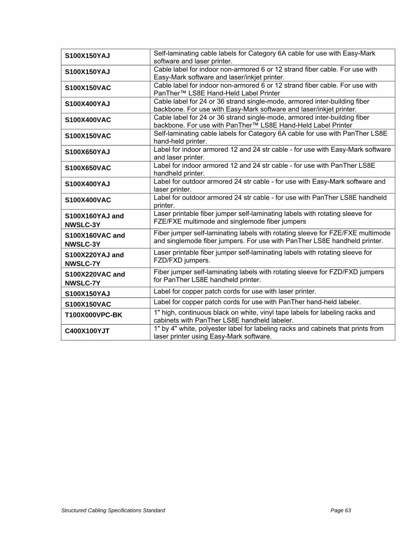
Structured Cabling Specifications Standard Page 63
S100X150YAJ Self-laminating cable labels for Category 6A cable for use with Easy-Mark software and laser printer.
S100X150YAJ Cable label for indoor non-armored 6 or 12 strand fiber cable. For use with Easy-Mark software and laser/inkjet printer.
S100X150VAC Cable label for indoor non-armored 6 or 12 strand fiber cable. For use with PanTher™ LS8E Hand-Held Label Printer
S100X400YAJ Cable label for 24 or 36 strand single-mode, armored inter-building fiber backbone. For use with Easy-Mark software and laser/inkjet printer.
S100X400VAC Cable label for 24 or 36 strand single-mode, armored inter-building fiber backbone. For use with PanTher™ LS8E Hand-Held Label Printer
S100X150VAC Self-laminating cable labels for Category 6A cable for use with PanTher LS8E hand-held printer.
S100X650YAJ Label for indoor armored 12 and 24 str cable - for use with Easy-Mark software and laser printer.
S100X650VAC Label for indoor armored 12 and 24 str cable - for use with PanTher LS8E handheld printer.
S100X400YAJ Label for outdoor armored 24 str cable - for use with Easy-Mark software and laser printer.
S100X400VAC Label for outdoor armored 24 str cable - for use with PanTher LS8E handheld printer.
S100X160YAJ and NWSLC-3Y
Laser printable fiber jumper self-laminating labels with rotating sleeve for FZE/FXE multimode and singlemode fiber jumpers
S100X160VAC and NWSLC-3Y
Fiber jumper self-laminating labels with rotating sleeve for FZE/FXE multimode and singlemode fiber jumpers. For use with PanTher LS8E handheld printer.
S100X220YAJ and NWSLC-7Y
Laser printable fiber jumper self-laminating labels with rotating sleeve for FZD/FXD jumpers.
S100X220VAC and NWSLC-7Y
Fiber jumper self-laminating labels with rotating sleeve for FZD/FXD jumpers for PanTher LS8E handheld printer.
S100X150YAJ Label for copper patch cords for use with laser printer.
S100X150VAC Label for copper patch cords for use with PanTher hand-held labeler.
T100X000VPC-BK 1" high, continuous black on white, vinyl tape labels for labeling racks and cabinets with PanTher LS8E handheld labeler.
C400X100YJT 1" by 4" white, polyester label for labeling racks and cabinets that prints from laser printer using Easy-Mark software.

Structured Cabling Specifications Standard Page 64

Structured Cabling Specifications Standard Page 65
Definitions of Terms Word or Phrase Meaning
°C degrees Celsius °F degrees Fahrenheit A Ampere AC Alternating Current Access floor A system consisting of completely removable and interchangeable
floor panels that are supported on adjustable pedestals or stringers (or both) to allow access to the area beneath.
Access provider The operator of any facility that is used to convey telecommunications signals to and from a customer premises.
ANSI American National Standards Institute AP Access Provider ASTM American Society for Testing and Materials ATIS Alliance for Telecommunications Industry Solutions AWG American Wire Gauge Backbone A facility (e.g., pathway, cable or conductors) between any of the
following spaces: telecommunications rooms, telecommunications enclosures, common telecommunications rooms, floor serving terminals, entrance facilities, equipment rooms, and common equipment rooms.
Backbone cable See backbone. BICSI Building Industry Consulting Service International Blended floor system A combination of cellular floor units with raceway capability and other
floor units with raceway capability, systematically arranged in a modular pattern.
BOCA Building Officials and Code Administrators BOMA Building CHICO USDs Managers Association Buried cable A cable installed under the surface of the ground in such a manner
that it cannot be removed without disturbing the soil. Cabinet A container that may enclose connection devices, terminations,
apparatus, wiring, and equipment. Campus The buildings and grounds having legal contiguous interconnection. CCITT International Telegraph and Telephone Consultative Committee Cell A single raceway of a cellular or under floor duct system. CER common equipment room Common telecommunications room
An enclosed space used for backbone interconnections for more than one tenant in a building, which may also house equipment.
Conduit (1) A raceway of circular cross-section. (2) A structure containing one or more ducts. Editorial note - For the purposes of this Standard, the term conduit includes electrical metallic tubing (EMT) or electrical non-metallic tubing (ENT)
Consolidation point A location for interconnection between horizontal cables extending from building pathways and horizontal cables extending into furniture pathways.
CTR common telecommunications room Customer premises equipment (CPE)
Telecommunications equipment located on the customer's premises.
dB decibel Demarcation point A point where the operational control or ownership changes. Direct-buried cable A telecommunications cable designed to be installed under the
surface of the earth, in direct contact with the soil.

Structured Cabling Specifications Standard Page 66
Distribution duct A raceway of rectangular cross-section placed within or just below the finished floor and used to extend the wires or cables to a specific work area.
Duct (1) A single enclosed raceway for conductors or cables. See also conduit, raceway. (2) A single enclosed raceway for wires or cables usually used in soil or concrete. (3) An enclosure in which air is moved. Generally part of the HVAC system of a building.
EF entrance facility Elastomeric firestop A firestopping material resembling rubber (See also firestopping). Electromagnetic interference
Radiated or conducted electromagnetic energy that has an undesirable effect on electronic equipment or signal transmissions.
Embedded duct A duct fully enclosed inside a floor or a wall. EMT electrical metallic tubing Enclosure, telecommunications
A case or housing for telecommunications equipment, cable terminations, and cross-connect cabling.
End user CHICO USD or user of the premises cabling system. ENT electrical nonmetallic tubing
Entrance facility (telecommunications)
An entrance to a building for both public and private network service cables (including wireless) including the entrance point of the building and continuing to the entrance room or space.
Entrance point (telecommunications)
The point of emergence for telecommunications cabling through an exterior wall, a floor, or from a conduit.
Entrance room or space (telecommunications)
A space in which the joining of inter or intra building telecommunications backbone facilities takes place. Editorial note - An entrance room may also serve as an equipment room.
EP entrance point
Equipment room (telecommunications)
An environmentally controlled centralized space for telecommunications equipment that usually houses a main or intermediate cross-connect.
False ceiling See suspended ceiling. FCC Federal Communications Commission Firestop system A specific construction consisting of the material(s) (firestop
penetration seals) that fill the opening in the wall or floor assembly and any items that penetrate the wall or floor, such as cables, cable trays, conduit, ducts, pipes, and any termination devices, such as electrical outlet boxes, along with their means of support.
Firestop A fire-rated material, device, or assembly of parts installed in a penetration of a fire-rated barrier.
Floor slab That part of a reinforced concrete floor which is carried on beams below.
ft. feet, foot Furniture cluster A contiguous group of work areas, typically including space divisions,
work surfaces, storage, and seating. g gram grounding The act of creating a ground. Horizontal cabling 1) The cabling between and including the telecommunications
outlet/connector and the horizontal cross-connect. 2) The cabling between and including the building automation system outlet or the first mechanical termination of the horizontal connection point and the horizontal cross-connect. 3) in a data center, horizontal cabling is the cabling from the horizontal cross-connect (in the main distribution area or horizontal distribution area) to the outlet in the equipment

Structured Cabling Specifications Standard Page 67
distribution area or zone distribution area. Horizontal connection point
A location for connections between horizontal cables that extend from building pathways and horizontal cables that extend to building automation systems devices and equipment.
HVAC heating, ventilation and air conditioning IDF Intermediate Distribution Frame IEEE The Institute of Electrical and Electronics Engineers in inch Infrastructure (telecommunications)
A collection of those telecommunications components, excluding equipment, which provide the basic support for the distribution of all information within a building or campus.
innerduct A nonmetallic raceway, usually circular, placed within a larger raceway.
ISO International Organization for Standardization junction box A location in the pathway system that allows transition of pathways
and access to cables. kg kilogram km kilometer m meter Multi-user telecommunications outlet assembly
A grouping in one location of several telecommunications outlet/connectors.
MUTOA multi-user telecommunications outlet assembly N Newton NEC National Electrical Code NEMA National Electrical Manufacturers Association NESC National Electrical Safety Code NFPA National Fire Protection Association NIST National Institute for Standards and Technologies Plenum cable A cable with flammability and smoke characteristics that meets the
safety requirements of the National Electrical Code® (NEC®) allowing it to be routed in a plenum area without being enclosed in a conduit.
Plenum A designated area used for transport of environmental air as part of the air distribution system. Because it is part of the air distribution system, cables installed in this space require a higher fire rating.
Power Over Ethernet (PoE)
Power Over Ethernet. Usually referring to the IEEE 802.3af standard that provides a means to supply low voltage power to end equipment using network cable and devices.
Power Sum Attenuation-to-Crosstalk Ratio (PSACR)
The difference between attenuation and power sum crosstalk measured in dB at a given frequency. This difference is critical to ensure that the signal sent down the twisted-pair cable is stronger at the receiving end of the cable than any interference signals (crosstalk) from other cable pairs.
Power Sum Equal Level Far-End Crosstalk (PSELFEXT) Loss
A computation of the unwanted signal coupling from multiple transmitters at the near end into a pair measured at the far end and normalized to the received signal level.
Power Sum Near-End Crosstalk (PSNEXT) Loss
A computation of the unwanted signal coupling from multiple transmitters at the near end into a pair measured at the near end.
ppm parts per million Propagation delay The time interval required for a signal to be transmitted from one end
of the circuit to the other. pull box A housing located in a pathway run used to facilitate the placing of
wire or cables.

Structured Cabling Specifications Standard Page 68
PVC polyvinyl chloride Raceway Any enclosed channel designed for holding wires or cables. RoHS Restriction of Hazardous Substances. This directive was adopted by
the European Union in an effort to restrict hazardous materials in the manufacture of various types of electronic and electrical equipment.
RoIP Radio over IP Return loss A ratio of the power of the outgoing signal to the power of the
reflected signal, expressed in dB. RF radio frequency Riser Term applied to vertical sections of cable, such as changing from
underground or direct-buried plant to aerial plant. Term also applies to the space used for cable access between floors.
Service entrance See entrance facility (telecommunications). Service provider The operator of any service that furnishes telecommunications
content (transmissions) delivered over access provider facilities. Signal-to-Noise Ratio (SNR)
The ratio between the detected signal power and noise in a receiver, expressed in dB. The prime determining factor in bit error rate. See Bit Error Rate.
Sleeve An opening, usually circular, through the wall, ceiling, or floor to allow the passage of cables.
Slot An opening through a wall, floor, or ceiling, usually rectangular, to allow the passage of cables.
SP service provider Splice box A box, located in a pathway run, intended to house a cable splice. Splice closure A device used to protect a splice Structural Return loss A measure of reflected energy of a transmitted signal due to
impedance variations along the length of the cable, expressed in dB. Suspended ceiling A ceiling that creates an area or space between the ceiling material
and the structure above. TE telecommunications enclosure Telecommunications room
An enclosed architectural space for housing telecommunications equipment, cable terminations, and cross-connect cabling.
TIA Telecommunications Industry Association TLA Three Letter Acronym TR telecommunications room TS telecommunications space UL Underwriters Laboratories Inc. Underfloor raceway A pathway placed within the floor and from which wires and cables
emerge to a specific floor area. Uninterruptible power supply
A buffer between utility power or other power source and a load that requires continuous precise power.
UPS uninterruptible power supply V volt Vac volts alternating current Vdc volts direct current Velocity of propagation The speed of transmission along a cable relative to the speed of light
in a vacuum. Voice over IP (VoIP) A term used in IP telephony for voice delivered using the Internet
Protocol. YABA Yet Another Bloody Acronym WEEE Waste Electrical and Electronic Equipment Directive. A European
Union directive that set collection, recycling and recovery targets for all types of electrical goods.
WiFi WiFi is the trade name for the popular wireless technology used in

Structured Cabling Specifications Standard Page 69
home networks, mobile phones, video games and other electronic devices that require some form of wireless networking capability. In particular, it covers the various IEEE 802.11 technologies (including 802.11n, 802.11b, 802.11g, and 802.11a).
Wireless The use of radiated electromagnetic energy (e.g., radio frequency and microwave signals, light) traveling through space to convey information.
Work area A building space where the occupants interact with telecommunications terminal equipment.
Zone box An enclosure used to house one or more of the following; a) a consolidation point, b) a horizontal connection point, c) building automation system outlets.

Structured Cabling Specifications Standard Page 70

Structured Cabling Specifications Standard Page 71
Appendix C. Labeling a Copper Backbone Cable
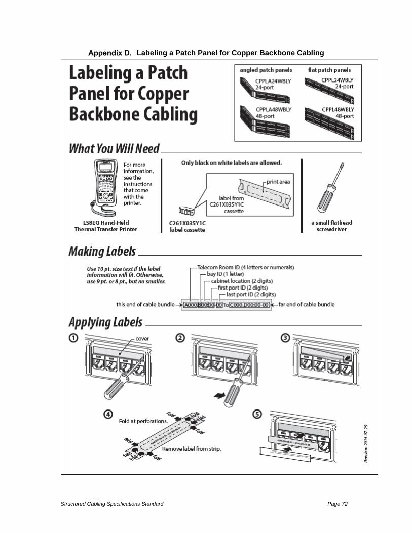
Structured Cabling Specifications Standard Page 72
Labeling a Patch Panel for Copper Backbone Cabling

Structured Cabling Specifications Standard Page 73
Labeling a Horizontal Cable

Structured Cabling Specifications Standard Page 74
Labeling a Patch Panel for Horizontal Cabling
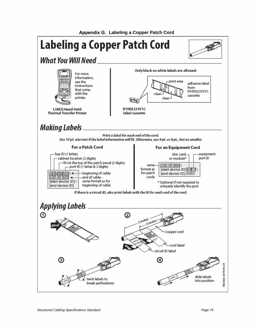
Structured Cabling Specifications Standard Page 75
Labeling a Copper Patch Cord

Structured Cabling Specifications Standard Page 76
Labeling a Fiber Optic Patch Cord

Structured Cabling Specifications Standard Page 77

Structured Cabling Specifications Standard Page 78

Structured Cabling Specifications Standard Page 79

Conductors• 23 AWG solid bare annealed copper
Insulation• Plenum: Fluoropolymer
Color Code• Pair 1: Blue-White• Pair 2: Orange-White• Pair 3: Green-White• Pair 4: Brown-White
Separator• Engineered Cross-Web
Jacket• Plenum: Low-Smoke,
Flame-Retardant PVC
ANEXT Protection• Encapsulated Isolation Wrap
Features and Benefits • Innovative design provides guaranteed
performance using the industry’s smallest 6A cable.
• Smaller cable diameter allows for greater cable density, reducing cable management costs.
• Simplified design and improved bend radius make it easier to strip, terminate and route, reducing installation time and expense.
• 90°C jacket rating provides consistent performance in a wide range of operating environments.
• Certified performance for high power PoE applications.
• Innovative cross-web separator with patented design provides superior internal electrical characteristics by locking the pairs into a systematic orientation within the cable.
• Streamlined design allows for 36 reels per pallet, improving distribution and warehousing efficiency.
• TRU-MARK® print legend contains footage markings from 1000’ to 0’.
• All GenSPEED products are Made in the U.S.A.
Applications• IEEE 802.3: 10G BASE-T, 1000 BASE-T,
100 BASE-TX, 10 BASE-T, PoE, PoE+• ANSI/TIA 854: 1000 BASE-TX• Digital Video • Broadband and Baseband Analog Video • CDDI, Token Ring, ATM
Standard Compliances• ANSI/TIA 568-C.2• NEC/CEC Type CMP (NFPA 262) for Plenum• UL Listed CMP-LP• UL 444• RoHS Compliant Directive 2011/65/EU• ANSI/TIA 862 (Building Automation) • ICEA S-116-732• ISO/IEC 11801 Ed. 2.0 (Class EA)
CONSTRUCTION
PHYSICAL DATA
CMP (Plenum)
Nominal Cable Diameter (in) 0.250
Nominal Cable Weight (lbs/1000 ft) 32
Minimum Bend Radius (in) 1
Maximum Pulling Force (lbs) 40
Temperature Rating (˚C)
Installation: 0 to +60
Operation: -20 to +90
PART NUMBERSStandard packaging: 1000' Spool
Spool*
Jacket Color CMP (Plenum)
Blue 7141819White 7141820Yellow 7141822Gray 7141821Red 7141824Orange 7141826Green 7141823Black 7141828Pink 7141827Purple 7141825
*Note: Spool Pac available upon request. Non-stock items may be subject to minimum order quantities.
GenSPEED ® 10 UTP Category 6A CableReliable Performance in the Industry’s Smallest Full Channel 6A Cable
GenSPEED® Category 6A Cables Datacom

Data subject to change without notice.
CROSS-SECTION ELECTRICAL CHARACTERISTICS
Max. Nom.
DC ResistanceOhms/100 m (328 ft) @ 20˚C 9.38 7.50
DC Resistance UnbalanceIndividual Pair % 4.00 < 1
Delay Skewns/100 m 45ns/100m
Nom. Velocity of Propagation% Speed of Light 70
Characteristic Impedance Frequency (f): 1-500 MHz
Ohms100 ± 15
OUTER JACKET
ENCAPSULATED ISOLATION WRAP
SEPARATOR
INSULATION
23 AWG CONDUCTOR
ELECTRICAL PERFORMANCE
FrequencyMHz
PSACR**(min)
ACR**(min)
Insertion Loss (min)
PSNEXT(min)
NEXT(min)
PSACRF(min)
ACRF(min)
Return Loss(min)
TCL(min)
PSANEXT(min)
PSAACRF(min)
TIA / GC Guaranteed
TIA / GC Guaranteed
TIA / GC Guaranteed
TIA / GC Guaranteed
TIA / GC Guaranteed
TIA / GC Guaranteed
TIA / GC Guaranteed
TIA / GC Guaranteed
TIA / GC Guaranteed TIA GC
Guaranteed TIA GC Guaranteed
1 70.2 72.2 2.1 72.3 74.3 64.8 67.8 20.0 40.0 67.0 69.0 67.0 69.0
4 59.5 61.5 3.8 63.3 65.3 52.8 55.8 23.0 40.0 67.0 69.0 66.2 68.2
10 51.4 53.4 5.9 57.3 59.3 44.8 47.8 25.0 40.0 67.0 69.0 58.2 60.2
16 46.8 48.8 7.5 54.2 56.2 40.7 43.7 25.0 38.0 67.0 69.0 54.1 56.1
20 44.4 46.4 8.4 52.8 54.8 38.8 41.8 25.0 37.0 67.0 69.0 52.2 54.2
31.25 39.4 41.4 10.5 49.9 51.9 34.9 37.9 23.6 35.1 67.0 69.0 48.3 50.3
62.5 30.4 32.4 15.0 45.4 47.4 28.9 31.9 21.5 32.0 65.6 67.6 42.3 44.3
100 23.2 25.2 19.1 42.3 44.3 24.8 27.8 20.1 30.0 62.5 64.5 38.2 40.2
150 16.0 18.0 23.7 39.7 41.7 21.3 24.3 18.9 28.2 59.9 61.9 34.7 36.7
200 10.2 12.2 27.6 37.8 39.8 18.8 21.8 18.0 27.0 58.0 60.0 32.2 34.2
250 5.2 7.2 31.1 36.3 38.3 16.8 19.8 17.3 26.0 56.5 58.5 30.2 32.2
300 0.9 2.9 34.3 35.1 37.1 15.3 18.3 16.8 25.2 55.3 57.3 28.7 30.7
400 — — 40.1 33.3 35.3 12.8 15.8 15.9 24.0 53.5 55.5 26.2 28.2
500 — — 45.3 31.8 33.8 10.8 13.8 15.2 23.0 52.0 54.0 24.2 26.2
600* — — 50.1* 30.6* 32.6* 9.2* 12.2* 14.7* 22.2* — 50.8* — 22.6*
700* — — 54.5* 29.6* 31.6* 7.9* 10.9* 14.2* 21.5* — 49.8* — 21.3*
750* — — 56.7* 29.2* 31.2* 7.3* 10.3* 14.0* 21.2* — 49.4* — 20.7*Note: Values are expressed in dB per 100 m (328 ft.) length @ 20˚C.*Values are for reference only.**PSACR & ACR not specified in ANSI/TIA 568-C.2