Title Licensee Conditions of use This is a licensed ... 404… · Licensed to LUU MINH LUAN on 26...
282
Title Licensee Conditions of use This is a licensed electronic copy of a document where copyright is owned or managed by Standards Australia International. Your licence is a single user licence and the document may not be stored, transferred or otherwise distributed on a network. You may also make one paper copy of this document if required. Web Check-up
-
Upload
phungkhanh -
Category
Documents
-
view
217 -
download
1
Transcript of Title Licensee Conditions of use This is a licensed ... 404… · Licensed to LUU MINH LUAN on 26...

Title
Licensee
Conditions of use This is a licensed electronic copy of a document where copyright is owned or managed by Standards Australia International. Your licence is a single user licence and the document may not be stored, transferred or otherwise distributed on a network. You may also make one paper copy of this document if required.
Web Check-up

AS 4041—1998(Incorporating Amendment No. 1)
Australian Standard™
Pressure piping
AS 4041
Lice
nsed
to L
UU
MIN
H L
UA
N o
n 26
Feb
200
2. S
ingl
e us
er li
cenc
e on
ly. S
tora
ge, d
istr
ibut
ion
or u
se o
n ne
twor
k pr
ohib
ited.

This Australian Standard was prepared by Committee ME/1, Pressure Equipment. Itwas approved on behalf of the Council of Standards Australia on 13 March 1998and published on 5 July 1998.
The following interests are represented on Committee ME/1:A.C.T. WorkCoverAustralasian Corrosion AssociationAustralasian Institute of Engineering InspectionAustralian Aluminium CouncilAustralian Building Codes BoardAustralian Chamber of Commerce and IndustryAustralian Institute of EnergyAustralian Institute of PetroleumAustralian Liquefied Petroleum Gas AssociationBoiler and Pressure Vessel Manufacturers Association of AustraliaBureau of Steel Manufacturers of AustraliaDepartment for Administrative and Information Services, S.A.Department of Labour, New ZealandDepartment of Training and Industrial Relations, QldElectricity Corporation of New ZealandElectricity Supply Association of AustraliaInstitute of Metals and Materials, AustralasiaInstitution of Engineers, AustraliaInstitution of Professional Engineers, New ZealandMetal Trades Industry Association of AustraliaNational Association of Testing Authorities, AustraliaNew Zealand Engineering FederationNew Zealand Heavy Engineering Research AssociationNew Zealand Institute of WeldingNew Zealand Petrochemical Users GroupNew Zealand Timber Industry FederationVictorian WorkCover AuthorityWelding Technology Institute of AustraliaWorkCover N.S.W.Work Health Authority, N.T.Workplace Standards Authority, Tas.WorkSafe Western Australia
Keeping Standards up-to-dateStandards are living documents which reflect progress in science, technology and systems Tomaintain their currency, all Standards are periodically reviewed, and new editions arepublished. Between editions, amendments may be issued. Standards may also be withdrawn.It is important that readers assure themselves they are using a current Standard, which shouldinclude any amendments which may have been published since the Standard was purchased.Detailed information about Standards can be found by visiting the Standards Australia website at www.standards.com.au and looking up the relevant Standard in the on-line catalogue.Alternatively, the printed Catalogue provides information current at 1 January each year, andthe monthly magazine, The Australian Standard, has a full listing of revisions andamendments published each month.We also welcome suggestions for the improvement in our Standards, and especiallyencourage readers to notify us immediately of any apparent inaccuracies or ambiguities.Contact us via email at [email protected], or write to the Chief Executive, StandardsAustralia International Ltd, GPO Box 5420, Sydney, NSW 2001.
This Standard was issued in draft form for comment as DR 97114.
Lice
nsed
to L
UU
MIN
H L
UA
N o
n 26
Feb
200
2. S
ingl
e us
er li
cenc
e on
ly. S
tora
ge, d
istr
ibut
ion
or u
se o
n ne
twor
k pr
ohib
ited.

AS 4041—1998(Incorporating Amendment No. 1)
Australian Standard™
Pressure piping
Originated in part as part of AS CB15—1959.Previous edition AS 4041—1992.Second edition 1998.Reissued incorporating Amendment No. 1 (April 2001).
COPYRIGHT© Standards Australia International
All rights are reserved. No part of this work may be reproduced or copied in any form orby any means, electronic or mechanical, including photocopying, without the writtenpermission of the publisher.
Published by Standards Australia International LtdGPO Box 5420, Sydney, NSW 2001, Australia
ISBN 0 7337 1934 1
Lice
nsed
to L
UU
MIN
H L
UA
N o
n 26
Feb
200
2. S
ingl
e us
er li
cenc
e on
ly. S
tora
ge, d
istr
ibut
ion
or u
se o
n ne
twor
k pr
ohib
ited.

AS 4041 — 1998 2
PREFACE
This Standard was prepared by the Joint Standards Australia/Standards New ZealandCommittee ME/1, Pressure Equipment, to supersede AS 4041—1992, Pressure piping.
This Standard incorporates Amendment No. 1 (April 2001). The changes arising from theAmendment are indicated in the text by a marginal bar and amendment number againstthe clause, note, table, figure, or part thereof affected.
This Standard is the result of a consensus among representatives on the Joint Committeeto produce it as an Australian Standard. Consensus means general agreement by allinterested parties. Consensus includes an attempt to remove all objection and impliesmuch more than the concept of a simple majority, but not necessarily unanimity. It isconsistent with this meaning that a member may be included in the Committee list and yetnot be in full agreement with all clauses of this Standard.
This Standard makes use of current American and British Standards such asANSI/ASME B31.3, Process piping, and BS 806, Specification for the design andconstruction of ferrous piping installations for and in connection with land boilers, aswell as Australian Standards. This has been done where practicable to align withinternational practices to provide flexibility in design and to enable current provencomputer programs for either of the above Standards to be used to satisfy the designrequirements of this Standard (see Clause 1.6).
Comparison of this Standard with ANSI/ASME B31.1, Power piping andANSI/ASME B31.3 shows that for the same pressure and application, piping to thisStandard may be thinner than piping to the two American Standards at low to mediumtemperatures. These two American Standards have been consulted as a major source ofmaterial, but preference has been given to BS 806 for ferrous materials. Certain subjectmatter either unique to BS 806 or too complex to modify has been copied direct and thesource acknowledged.
The extension of scope in this edition to embrace room-temperature-safe fluids brings intocontrast three different traditions of steel pipe engineering which exist side by side inAustralia. All are successful in their particular scope of application.
The first tradition is that of power and process piping using steam and other hazardousfluids. This tradition is noted for higher safety factors, thick pipe, and the greater use ofpre- and post-weld heat treatment and sophisticated quality assurance.
Another tradition is the non-code tradition for room temperature safe fluids. This is moreinfluenced by the third tradition than by the first. It uses thick or thin pipe and rarelyapplies postweld heat treatment and only uses limited quality assurance.
The third pipe tradition is that of petroleum and natural gas pipelines. This tradition useslower safety factors, thin pipe, rarely applies preheat and rarely uses postweld heattreatment but has adequate quality assurance.
The extension of scope that joined tradition 1 and 2 (and possibly tradition 3 in specialcases) presented the Committee with a difficulty in preventing unnecessary increases incosts for the present non-code piping systems in Australian while maintaining safety. Themore conservative requirements of tradition 1, represented by BS 806 andANSI/ASME B31.3 are not appropriate for applying these features to room-temperaturesafe fluids in modern low carbon equivalent pipe steels. Hence a four-tier pipeclassification system is introduced to ensure adequate safety, performance and economy ofpiping systems for the wider range of industrial applications from critical pipe used inpower stations to low hazard piping found in small industrial plant. In summary thisedition will generally permit thinner steel pipe to be used for a given pressure thanpreviously. Also there is a change to some of its pressure testing equations for steel pipe.A1The traditional value of 1.5P applies for steam and water piping for steam boilers only.Li
cens
ed to
LU
U M
INH
LU
AN
on
26 F
eb 2
002.
Sin
gle
user
lice
nce
only
. Sto
rage
, dis
trib
utio
n or
use
on
netw
ork
proh
ibite
d.

3 AS 4041 — 1998
This Standard is arranged similarly to AS 1210,Pressure Vessels, includingSupplement 1,Unfired Pressure Vessels—Advance design and construction (Supplementto AS 1210—1997), and its class system parallels that of these Standards. Withoutinferring equality of the safety factor, the alignment of classes is approximately asfollows:
AS 4041Class
AS 1210Class
12A2P
3
1H2H—
3
Australian, American, and British material and component Standards which are used to aconsiderable extent in Australia have been listed. This Standard now provides for a widerrange of materials than previously covered. A basis for specifying non-metallic pressurepiping is given by reference to ANSI/ASME B31.3 but with provision for substitution ofequivalent Australian Standards.
The Standard follows in principle other Standards forming part of AS/NZS 1200,Pressureequipment, in providing guidance for owners, designers, manufacturers, inspection bodiesand users in the form of minimum engineering requirements for the safe design,fabrication, installation, testing, and commissioning of pressure piping based onworld-wide advances and experience. It also provides basic requirements and referencesfor welding qualification, non-destructive testing, operation, maintenance and in-serviceinspection.
The principle objective of this Standard is clear uniform national requirements which willresult in reasonably certain protection of the general public, persons installing andoperating the piping, and of adjacent property and environment, which give economicpiping, and which show where a margin for deterioration may be necessary to giveadequate and safe service life. Additional requirements may be necessary to preventdamage from unusual conditions, third parties and abnormal forces.
The Standard provides an authoritative source of important principles, data, and practicalguidelines to be used by responsible and competent persons. It is not practicable norindeed desirable for the Standard to specify every aspect of piping design and fabrication.It is neither an instruction manual nor a complete design or construction specification.The Standard does not replace the need for appropriate experience, competent engineeringjudgement, and the application of fundamental engineering principles.
Users of this Standard are reminded that it has no intrinsic legal authority, but mayacquire legal standing in one or more of the following circumstances:
(a) Adoption by a government or other authority having jurisdiction.
(b) Adoption by a purchaser as the required standard of construction when placing acontract.
(c) Adoption where a manufacturer states that piping is in accordance with thisStandard.
Acknowledgment is gratefully made to the American Society of Mechanical Engineers andthe British Standards Institution for the considerable assistance provided by the abovereferenced national Standards.
Statements expressed in mandatory terms in notes to tables and figures are deemed to berequirements of this Standard.
The term ‘normative’ has been used in this Standard to define the application of theappendix to which it applies. A‘normative’ appendix is an integral part of a Standard.Li
cens
ed to
LU
U M
INH
LU
AN
on
26 F
eb 2
002.
Sin
gle
user
lice
nce
only
. Sto
rage
, dis
trib
utio
n or
use
on
netw
ork
proh
ibite
d.

AS 4041 — 1998 4
CONTENTS
PageSECTION 1 SCOPE AND GENERAL
1.1 SCOPE. . . . . . . . . . . . . . . . . . . . . . . . . . . . . . . . . . . . . . . . . . . . . . . . . 71.2 RESPONSIBILITIES . . . . . . . . . . . . . . . . . . . . . . . . . . . . . . . . . . . . . . . 81.3 CLASSIFICATION OF PIPING. . . . . . . . . . . . . . . . . . . . . . . . . . . . . . . . 81.4 CLASSIFICATION OF FLUIDS . . . . . . . . . . . . . . . . . . . . . . . . . . . . . . . 81.5 SELECTION OF PIPING CLASS. . . . . . . . . . . . . . . . . . . . . . . . . . . . . . 121.6 ALTERNATIVE STANDARDS . . . . . . . . . . . . . . . . . . . . . . . . . . . . . . . . 141.7 DEFINITIONS . . . . . . . . . . . . . . . . . . . . . . . . . . . . . . . . . . . . . . . . . . . . 141.8 NOTATION . . . . . . . . . . . . . . . . . . . . . . . . . . . . . . . . . . . . . . . . . . . . . 171.9 NON-SI UNITS . . . . . . . . . . . . . . . . . . . . . . . . . . . . . . . . . . . . . . . . . . . 181.10 REFERENCED DOCUMENTS. . . . . . . . . . . . . . . . . . . . . . . . . . . . . . . . 181.11 REPORTS AND CERTIFICATES. . . . . . . . . . . . . . . . . . . . . . . . . . . . . . 181.12 NOT ALLOCATED . . . . . . . . . . . . . . . . . . . . . . . . . . . . . . . . . . . . . . . . 181.13 NOT ALLOCATED . . . . . . . . . . . . . . . . . . . . . . . . . . . . . . . . . . . . . . . . 181.14 NON-METALLIC PIPING . . . . . . . . . . . . . . . . . . . . . . . . . . . . . . . . . . . 181.15 INTERPRETATION OF STANDARDS. . . . . . . . . . . . . . . . . . . . . . . . . . 181.16 NEW DESIGNS, MATERIALS AND FABRICATION METHODS. . . . . . . 181.17 DIMENSIONAL AND MASS TOLERANCES . . . . . . . . . . . . . . . . . . . . . 191.18 ALTERNATIVE DESIGN OF ACCESSORIES. . . . . . . . . . . . . . . . . . . . . 19
SECTION 2 MATERIALS AND COMPONENTS2.1 GENERAL . . . . . . . . . . . . . . . . . . . . . . . . . . . . . . . . . . . . . . . . . . . . . . 202.2 QUALIFICATION OF MATERIALS AND COMPONENTS. . . . . . . . . . . . 202.3 LIMITATIONS ON MATERIALS AND COMPONENTS. . . . . . . . . . . . . . 242.4 PROPERTIES OF MATERIALS. . . . . . . . . . . . . . . . . . . . . . . . . . . . . . . 242.5 IDENTIFICATION OF MATERIALS AND COMPONENTS . . . . . . . . . . . 252.6 LIMITATIONS ON APPLICATION . . . . . . . . . . . . . . . . . . . . . . . . . . . . 252.7 MATERIALS AND COMPONENTS FOR CORROSIVE SERVICE. . . . . . 282.8 DISSIMILAR MATERIALS . . . . . . . . . . . . . . . . . . . . . . . . . . . . . . . . . . 292.9 BACKING RINGS AND FUSIBLE INSERTS. . . . . . . . . . . . . . . . . . . . . . 292.10 BRAZING MATERIALS . . . . . . . . . . . . . . . . . . . . . . . . . . . . . . . . . . . . 292.11 MATERIALS FOR LOW TEMPERATURE SERVICE. . . . . . . . . . . . . . . . 29
SECTION 3 DESIGN3.1 GENERAL . . . . . . . . . . . . . . . . . . . . . . . . . . . . . . . . . . . . . . . . . . . . . . 503.2 DESIGN PRESSURE. . . . . . . . . . . . . . . . . . . . . . . . . . . . . . . . . . . . . . . 503.3 DESIGN TEMPERATURE. . . . . . . . . . . . . . . . . . . . . . . . . . . . . . . . . . . 503.4 DESIGN LIFE . . . . . . . . . . . . . . . . . . . . . . . . . . . . . . . . . . . . . . . . . . . . 513.5 STATIC AND DYNAMIC LOADS AND FORCES . . . . . . . . . . . . . . . . . . 513.6 RISK ANALYSIS . . . . . . . . . . . . . . . . . . . . . . . . . . . . . . . . . . . . . . . . . 523.7 THERMAL EFFECTS . . . . . . . . . . . . . . . . . . . . . . . . . . . . . . . . . . . . . . 523.8 EFFECTS OF MOVEMENT AT SUPPORTS, ANCHORS AND
TERMINALS . . . . . . . . . . . . . . . . . . . . . . . . . . . . . . . . . . . . . . . . . . . . 523.9 DESIGN PRESSURE AND TEMPERATURE FOR PIPING ASSOCIATED
WITH STEAM BOILERS . . . . . . . . . . . . . . . . . . . . . . . . . . . . . . . . . . . . 523.10 DESIGN CRITERIA. . . . . . . . . . . . . . . . . . . . . . . . . . . . . . . . . . . . . . . . 563.11 DESIGN STRENGTH. . . . . . . . . . . . . . . . . . . . . . . . . . . . . . . . . . . . . . . 573.12 DESIGN FACTORS. . . . . . . . . . . . . . . . . . . . . . . . . . . . . . . . . . . . . . . . 603.13 ALLOWANCES. . . . . . . . . . . . . . . . . . . . . . . . . . . . . . . . . . . . . . . . . . . 613.14 WALL THICKNESS OF STRAIGHT PIPE. . . . . . . . . . . . . . . . . . . . . . . . 62
Lice
nsed
to L
UU
MIN
H L
UA
N o
n 26
Feb
200
2. S
ingl
e us
er li
cenc
e on
ly. S
tora
ge, d
istr
ibut
ion
or u
se o
n ne
twor
k pr
ohib
ited.

5 AS 4041 — 1998
Page
3.15 PIPE BENDS. . . . . . . . . . . . . . . . . . . . . . . . . . . . . . . . . . . . . . . . . . . . . 643.16 REDUCERS . . . . . . . . . . . . . . . . . . . . . . . . . . . . . . . . . . . . . . . . . . . . . 693.17 BIFURCATIONS, SPECIAL FITTINGS AND CONNECTIONS. . . . . . . . . 703.18 EXPANSION FITTINGS AND FLEXIBLE HOSE ASSEMBLIES . . . . . . . 703.19 BRANCH CONNECTIONS AND OPENINGS. . . . . . . . . . . . . . . . . . . . . 713.20 WELDED BRANCH CONNECTIONS. . . . . . . . . . . . . . . . . . . . . . . . . . . 863.21 DESIGN OF CLOSURES FOR PIPE ENDS AND BRANCHES. . . . . . . . . 863.22 DESIGN OF OTHER PRESSURE-RETAINING COMPONENTS. . . . . . . . 863.23 ATTACHMENTS . . . . . . . . . . . . . . . . . . . . . . . . . . . . . . . . . . . . . . . . . . 873.24 PIPING JOINTS . . . . . . . . . . . . . . . . . . . . . . . . . . . . . . . . . . . . . . . . . . 893.25 DESIGN REQUIREMENTS PERTAINING TO SPECIFIC PIPING. . . . . . . 1073.26 NOT ALLOCATED . . . . . . . . . . . . . . . . . . . . . . . . . . . . . . . . . . . . . . . . 1103.27 FLEXIBILITY, STRESS ANALYSIS AND SUPPORT DESIGN. . . . . . . . . 1103.28 PIPE SUPPORTS. . . . . . . . . . . . . . . . . . . . . . . . . . . . . . . . . . . . . . . . . . 1223.29 INFORMATION TO BE SUPPLIED . . . . . . . . . . . . . . . . . . . . . . . . . . . . 1263.30 INFORMATION TO BE SUPPLIED BY THE OWNER. . . . . . . . . . . . . . . 126
SECTION 4 FABRICATION AND INSTALLATION4.1 SCOPE. . . . . . . . . . . . . . . . . . . . . . . . . . . . . . . . . . . . . . . . . . . . . . . . . 1274.2 FABRICATION . . . . . . . . . . . . . . . . . . . . . . . . . . . . . . . . . . . . . . . . . . . 1274.3 INSTALLATION . . . . . . . . . . . . . . . . . . . . . . . . . . . . . . . . . . . . . . . . . . 1274.4 THERMAL INSULATION . . . . . . . . . . . . . . . . . . . . . . . . . . . . . . . . . . . 1284.5 IDENTIFICATION . . . . . . . . . . . . . . . . . . . . . . . . . . . . . . . . . . . . . . . . . 128
SECTION 5 WELDING AND ALLIED JOINING PROCESSES. . . . . . . . . . . . . . . 129
SECTION 6 EXAMINATION AND TESTING6.1 SCOPE. . . . . . . . . . . . . . . . . . . . . . . . . . . . . . . . . . . . . . . . . . . . . . . . . 1306.2 RESPONSIBILITY. . . . . . . . . . . . . . . . . . . . . . . . . . . . . . . . . . . . . . . . . 1306.3 QUALIFICATION OF WELDING PROCEDURES AND WELDERS. . . . . 1306.4 NON-DESTRUCTIVE EXAMINATION . . . . . . . . . . . . . . . . . . . . . . . . . . 1306.5 ALTERNATIVES TO NON-DESTRUCTIVE TESTING . . . . . . . . . . . . . . 1316.6 PRESSURE TESTS. . . . . . . . . . . . . . . . . . . . . . . . . . . . . . . . . . . . . . . . 1326.7 HYDROSTATIC TEST. . . . . . . . . . . . . . . . . . . . . . . . . . . . . . . . . . . . . . 1326.8 ALTERNATIVE TO HYDROSTATIC TEST . . . . . . . . . . . . . . . . . . . . . . 1336.8A INITIAL SERVICE LEAK TEST . . . . . . . . . . . . . . . . . . . . . . . . . . . . . . . 1346.9 TESTING PRESSURE-LIMITING DEVICES, RELIEF VALVES,
PRESSURE REGULATORS, AND CONTROL EQUIPMENT. . . . . . . . . . 1356.10 REPORT. . . . . . . . . . . . . . . . . . . . . . . . . . . . . . . . . . . . . . . . . . . . . . . . 135
SECTION 7 PROTECTIVE SYSTEMS AND DEVICES7.1 GENERAL . . . . . . . . . . . . . . . . . . . . . . . . . . . . . . . . . . . . . . . . . . . . . . 1367.2 PRESSURE AND TEMPERATURE CONTROL SYSTEMS. . . . . . . . . . . . 1367.3 PRESSURE RELIEF SYSTEMS. . . . . . . . . . . . . . . . . . . . . . . . . . . . . . . 1367.4 CORROSION PROTECTION. . . . . . . . . . . . . . . . . . . . . . . . . . . . . . . . . 1377.5 FIRE PROTECTION . . . . . . . . . . . . . . . . . . . . . . . . . . . . . . . . . . . . . . . 1377.6 EARTHING . . . . . . . . . . . . . . . . . . . . . . . . . . . . . . . . . . . . . . . . . . . . . . 1377.7 PROTECTION FROM IMPACT . . . . . . . . . . . . . . . . . . . . . . . . . . . . . . . 1377.8 LIGHTNING PROTECTION. . . . . . . . . . . . . . . . . . . . . . . . . . . . . . . . . . 1387.9 HUMAN CONTACT PROTECTION . . . . . . . . . . . . . . . . . . . . . . . . . . . . 1387.10 NOISE CONTROL. . . . . . . . . . . . . . . . . . . . . . . . . . . . . . . . . . . . . . . . . 1387.11 ISOLATION PROTECTION (FOR INTERCONNECTED PIPING). . . . . . . 1387.12 NOT ALLOCATED . . . . . . . . . . . . . . . . . . . . . . . . . . . . . . . . . . . . . . . . 138
Lice
nsed
to L
UU
MIN
H L
UA
N o
n 26
Feb
200
2. S
ingl
e us
er li
cenc
e on
ly. S
tora
ge, d
istr
ibut
ion
or u
se o
n ne
twor
k pr
ohib
ited.

AS 4041 — 1998 6
Page
7.13 PROTECTION AGAINST INTERFERENCE. . . . . . . . . . . . . . . . . . . . . . 138
SECTION 8 QUALITY ASSURANCE AND INSPECTION8.1 GENERAL . . . . . . . . . . . . . . . . . . . . . . . . . . . . . . . . . . . . . . . . . . . . . . 1398.2 REVIEW OF DESIGN . . . . . . . . . . . . . . . . . . . . . . . . . . . . . . . . . . . . . . 1408.3 MATERIAL AND COMPONENT INSPECTION . . . . . . . . . . . . . . . . . . . 1408.4 GENERAL INSPECTION OF FABRICATION. . . . . . . . . . . . . . . . . . . . . 140
SECTION 9 COMMISSIONING AND OPERATION9.1 COMMISSIONING . . . . . . . . . . . . . . . . . . . . . . . . . . . . . . . . . . . . . . . . 1419.2 OPERATION. . . . . . . . . . . . . . . . . . . . . . . . . . . . . . . . . . . . . . . . . . . . . 141
APPENDICESA LIST OF REFERENCED DOCUMENTS. . . . . . . . . . . . . . . . . . . . . . . . . . . 142B NOMINAL SIZES AND OUTSIDE DIAMETERS OF PIPE . . . . . . . . . . . . . 153C NOT ALLOCATED . . . . . . . . . . . . . . . . . . . . . . . . . . . . . . . . . . . . . . . . . 156D MATERIAL PROPERTIES, DESIGN PARAMETERS AND
TENSILE STRENGTHS . . . . . . . . . . . . . . . . . . . . . . . . . . . . . . . . . . . . . . 157E LINEAR EXPANSION . . . . . . . . . . . . . . . . . . . . . . . . . . . . . . . . . . . . . . . 182F YOUNG MODULUS . . . . . . . . . . . . . . . . . . . . . . . . . . . . . . . . . . . . . . . . . 184G DESIGN TENSILE STRENGTH FOR FLANGE BOLTING. . . . . . . . . . . . . 186H LODMAT ISOTHERMS . . . . . . . . . . . . . . . . . . . . . . . . . . . . . . . . . . . . . . 190I DETERMINATION OF DESIGN STRENGTH. . . . . . . . . . . . . . . . . . . . . . . 191J DESIGN PRESSURE FOR SAFETY VALVE DISCHARGE PIPING. . . . . . . 195K TYPICAL FORGED BRANCH FITTINGS . . . . . . . . . . . . . . . . . . . . . . . . . 199L REINFORCEMENT OF A BRANCH AND AN OPENING . . . . . . . . . . . . . . 200M TYPICAL BRANCH WELDS . . . . . . . . . . . . . . . . . . . . . . . . . . . . . . . . . . 210N WELD DETAILS . . . . . . . . . . . . . . . . . . . . . . . . . . . . . . . . . . . . . . . . . . . 218O FILLET-WELDED SOCKETS . . . . . . . . . . . . . . . . . . . . . . . . . . . . . . . . . . 226P SLEEVE JOINT . . . . . . . . . . . . . . . . . . . . . . . . . . . . . . . . . . . . . . . . . . . . 227Q NOTES ON PIPING STRESS ANALYSIS. . . . . . . . . . . . . . . . . . . . . . . . . . 228R METHOD OF ASSESSING FLEXIBILITY . . . . . . . . . . . . . . . . . . . . . . . . . 231S EXAMPLE OF STRESS CALCULATION IN A SECTIONALIZED PIPING
SYSTEM . . . . . . . . . . . . . . . . . . . . . . . . . . . . . . . . . . . . . . . . . . . . . . . . . 253T STANDARD PIPING DESIGN. . . . . . . . . . . . . . . . . . . . . . . . . . . . . . . . . . 263U HYDROSTATIC TEST PRESSURE. . . . . . . . . . . . . . . . . . . . . . . . . . . . . . 267
INDEX . . . . . . . . . . . . . . . . . . . . . . . . . . . . . . . . . . . . . . . . . . . . . . . . . . . . . . . . 272
Lice
nsed
to L
UU
MIN
H L
UA
N o
n 26
Feb
200
2. S
ingl
e us
er li
cenc
e on
ly. S
tora
ge, d
istr
ibut
ion
or u
se o
n ne
twor
k pr
ohib
ited.

7 AS 4041 — 1998
STANDARDS AUSTRALIA
Australian Standard
Pressure piping
S E C T I O N 1 S C O P E A N D G E N E R A L
1.1 SCOPE This Standard sets out minimum requirements for the materials, design,fabrication, testing, inspection, reports and pre-commissioning of piping subject tointernal pressure or external pressure or both. Specific requirements are given for pipingconstructed of carbon, carbon-manganese, low alloy and high alloy steels, ductile and castiron, copper, aluminium, nickel, titanium and alloys of these materials. Generalrequirements and reference to Standards for non-metallic piping are included.
A1 The Standard makes extensive use of AS/NZS 3992, AS 4037 and AS 4458.Piping complying with BS 806, ANSI/ASME B31.1, ANSI/ASME B31.3 andANSI/ASME B31.5 are deemed to meet the requirements of this Standard (seeClause 1.6).
This Standard applies specifically to pressure piping, i.e. piping which may present asignificant risk of injury to people, property or the environment owing to hazards arisingfrom—
(a) the effects of pressure, either as a result of internal pressure causing an explosion orprojectile, or as a result of external pressure causing buckling and collapse;
(b) release of contents which are lethal, toxic, harmful to human tissue (e.g. hot, cold,corrosive) flammable, combustible or are otherwise hazardous; or
(c) release of contents which directly or indirectly result in injury or damage e.g. pipingfor pollutants, fire-fighting purposes or cooling purposes.
This Standard is intended to apply to the following piping except when varied by therelevant Standard:
(i) Piping for land steam boilers, prime-movers, refrigerant and other industrial plantexcept where the piping forms an integral part of a boiler or pressure vessel and therequirements of AS 1210 or AS 1228 apply.
(ii) Hydraulic piping, water piping (including feed water piping), process piping, hotwater piping exceeding 99°C and water piping forming part of a fire protectionsystem (see AS 3689 and AS 4118). See also Items (A) to (G) of this Clause.
(iii) Piping within boundaries of chemical manufacturing or processing installations,petroleum refineries, petrochemical plant, gas process plant, refinery tank farms,terminals and bulk handling plants.
(iv) Oil fuel piping within the scope of AS 1375, AS 1692 and AS 1940.
(v) Liquefied petroleum gas piping within the scope of AS 1596.
(vi) Anhydrous ammonia within the scope of AS 2022.
(vii) Low-temperature and refrigeration piping within the scope of AS 1677.
(viii) Piping for road tank vehicles within the scope of AS 2809.
(ix) Compressed air piping, the design pressure of which exceeds 70 kPa (internal) or32 kPa (external).
(x) Piping for low pressure gas systems complying with AG 601.
(xi) Other piping covered by Standards Australia Standards which require compliancewith this Standard.
www.standards.com.au © Standards Australia
Lice
nsed
to L
UU
MIN
H L
UA
N o
n 26
Feb
200
2. S
ingl
e us
er li
cenc
e on
ly. S
tora
ge, d
istr
ibut
ion
or u
se o
n ne
twor
k pr
ohib
ited.

AS 4041 — 1998 8
This Standard may be applied beyond the limits of application of Items (i) to (xi) wherespecified by the purchaser. Unless suitably referenced this Standard is not intended toapply to the following:
(A) Gas and liquid petroleum pipelines covered by AS 2885.
(B) Gas distribution pipelines covered by AS 1697 for Australia or NZS 5258 forNew Zealand.
(C) Liquid hydrocarbon pipelines with operating pressure less than 2 MPa which arecovered by AS 2018.
(D) Piping on shipping and aircraft.
(E) Piping used for roof or floor drains, plumbing services, sewers, domestic water andgas reticulation, and low pressure ventilation ducting.
(F) Mineral slurry pipelines which are covered by ANSI/ASME B31.11.
(G) Nuclear piping.
1.2 RESPONSIBILITIES This Standard assumes the basic responsibilities of thoseparties normally involved with pressure piping to be as follows:
(a) The owner . . . . . . . . theoverall responsibility for compliance with this Standard,and for the establishment of the requirements for design, manufacture, examination,inspection, testing, operation, and maintenance of the piping.
(b) The designer. . . . . . . . . . . . . . . . . . . .responsible to the owner for assurance thatthe engineering design of piping is in compliance with this Standard and with anyadditional requirements specified by the owner.
(c) The manufacturer and fabricator. . . . . . . . . . . . . . . . . . .responsible to the ownerfor assurance that materials, components, workmanship, examination, and testingare in compliance with this Standard and the engineering design. See alsoClause 6.2.
(d) The owner’s inspector . . . . . . . . . . responsible to the owner for ensuring that therequirements of Section 8, and any additional responsibilities specified by the ownerare met.
(e) The inspection body. . . . . . . . . . . . . . . . . .responsible to the owner for carryingA1 out inspections for piping to hazard level A and B to AS 4343 piping, and required
certification.
1.3 CLASSIFICATION OF PIPING Metallic piping specified in this Standard isclassified according to the material, design, welding, examination and testing andinspection criteria given in Table 1.3. Non-metallic piping is not classified. Class 2 issubdivided into subclasses 2A and 2P. Where the text refers to Class 2, Class 2A and 2Pare included.
1.4 CLASSIFICATION OF FLUIDS Fluids are classified in Table 1.4.
© Standards Australia www.standards.com.au
Lice
nsed
to L
UU
MIN
H L
UA
N o
n 26
Feb
200
2. S
ingl
e us
er li
cenc
e on
ly. S
tora
ge, d
istr
ibut
ion
or u
se o
n ne
twor
k pr
ohib
ited.

9 AS 4041 — 1998
TABLE 1.3
PIPING CLASSIFICATION (See Notes 1 and 2)A1
Item No. Description andClause reference
Limit or requirement
Class 1piping
Class 2piping Class 3
piping2A 2P
1 MATERIAL - (See Section 2)1.1 Steels designated for pressure
purposesAny C,
C-Mnaustenitic and ferritic-
austenitic stainless steel,3½% Ni,1Cr-½Mo
C,C-Mn
C,C-Mn,
austenitic andferritic-austenitic
stainless steelDuctile iron (Clauses 2.3.2,2.6.3.4) See Table 2.6.3.4Non-ferrous metals(Clauses 2.6.3.5 to 2.6.3.8) Any Any Not permitted AnyStructural pipe and structuralsteel (Clause 2.2.4) Not permitted Not permitted Any with
appropriate tests1.2 Seamless, hot finished (HFS),
or cold finished (CPS) Both permitted1.3 Continuous welded (CW)
(In America this is called BW)(Clause 2.6.10)(Weld Joint FactorTable 3.12.2)
Not permitted Permitted to 260°C (seeClause 2.6.10) Permitted Permitted
1.4 Electric resistance welded (ERW)Cold-drawn electric-resistance-welded (CEW)
Permitted with weld joint factor listed in Table 3.12.2
1.5 Welds with filler metal added Permitted with weld joint factor listed in Table 3.12.22 DESIGN (See Section 3)2.1 Design temperature (excluding
material limitations)°C:(a) Maximum None 400°C 99°C 180°C(b) Minimum (MDMT see
Clause 2.11) ≥ MDMT ≥ MDMT 0°C ≥ MDMT + 20°C;and≥ − 100°C
Determination (Clauses 3.3, 3.9.4,3.9.5, 3.9.7, 3.9.8.3, 3.9.9)
2.2 Design pressure (excludingmaterial limitations)
Pressure limits across classes depends upon the fluid type (see Table 1.4)Determination of design pressure (see Clauses 3.2, 3.9.1, 3.9.2, 3.9.3, 3.9.5, 3.9.6, 3.9.8.1)
2.3 Design strength at roomtemperature for C and C-Mnsteels (See Note 5)(Clause 3.11)
Lower of:
Re
1.5or
Rm
2.35
Lower of:
Re
1.5or
Rm
2.35
0.72 Re20Lower of:
Re
1.5or
Rm
2.35
2.4 Design factorsClass design factor, (M) 1 1 0.7 (see Item 7 in
this Table)0.6 min. (See
Clause 3.14.3(a))Weld joint factor, (e)(Clause 3.12)
1.0 min. 0.6 min.
2.5 Flexibility assessment(Clauses 3.4 to 3.8 and 3.27.2.2)Analysis (Clause 3.11 and 3.27)
Required
If required
Required
If required2.6 Fatigue assessment (Clauses 3.4
to 3.8)Analysis (Clauses 3.11.7, 3.11.8)
Required
If required
Required
If requiredNot required
(See end of Table for Notes) (continued)
www.standards.com.au © Standards Australia
Lice
nsed
to L
UU
MIN
H L
UA
N o
n 26
Feb
200
2. S
ingl
e us
er li
cenc
e on
ly. S
tora
ge, d
istr
ibut
ion
or u
se o
n ne
twor
k pr
ohib
ited.

10 AS 4041 — 1998
A1
TABLE 1.3 (continued)
Item No. Description andClause reference
Limit or requirement
Class 1piping
Class 2piping Class 3
piping2A 2P
2.7 Welded branch connection (Clauses 3.19, 3.20)Minimum included angle(Clause 3.19.1)
60° (or 45° whenagreed) 45°
External non-integralreinforcement(Clause 3.19.8.1, 3.20.3)
Not permitted withoutdetailed analysis Permitted
Partial penetration or fillet weld(Clause 3.20.3.2)
Not permitted withoutdetailed analysis
Not permitted withoutdetailed analysis
Permitted byagreement Permitted
2.8 Pipe joint (See Note 6) (Clause 3.24)Butt weld (Clause 3.24.2.1) PermittedPartial penetration butt welds(Clause 3.24.2.6) Not permitted Not permitted PermittedSocket weld (Clause 3.24.2.3) Permitted below DN 65 PermittedSleeve weld (Clause 3.24.2.4) Not permitted PermittedBell and spigot (Clause 3.24.2.5) Not permitted Permitted
Threaded joints (Clause 3.24.3)Permitted T ≤495°C
Permitted byagreement T >495°C
Permitted
Flanged (Clause 3.24.4) PermittedFlared, flareless and compressionfittings (Clause 3.24.5) Permitted when used within manufacturer’ s recommendations, DN 25 practical upper limitCaulked (Clause 3.24.6) Not permitted PermittedSoldered (Clause 3.24.7) Not permitted Permitted below 75°C Not permitted Permitted below
75°CBrazed (Clause 3.24.8) Permitted up to 200°C
2.9 Bend (Clause 3.15)Mitre (Clause 3.15.4) Permitted cut ≤15° PermittedCut and shut (Clause 3.15.5) Not permitted PermittedWrinkle (Clause 3.15.3) Not permitted PermittedOvality (Clause 3.15.2.3) ≤10% ≤12%
2.10 Non-pressure attachment (Clause 3.23)
Partial penetration or fillet weldNot permitted without
detailed analysisT >250°C
Permitted by agreementT >250°C Permitted
3 WELDING (Includes brazing, see AS 4458, AS/NZS 3992 and Note 3)3.1 Personnel requirements Option 1 or Option 2 Option 1 or Option 2
Welder certification (AS 1796) Required Not required Not required RequiredWelder qualification(Clause 6.3) Required Required Required Not requiredWelding supervisor (AS 1796) Not required Required Not required Not required
3.2 Welding procedure qualification(Clause 6.3) Required (except as provided for in Item 3.3)
3.3 Prequalified welding procedure Permitted but be subject to partial re-qualificatione.g. welder qualification
3.4 Permanent backing ring(Clauses 2.9.1, 3.20.3.4, 3.24.2.1) Not permitted Permitted
3.5 Fit-up (AS 4458) Close limits Medium limits Wide limits3.6 Criteria for weld quality Very high High Reduced3.7 Dissimilar joints Permitted
(continued)
© Standards Australia www.standards.com.au
Lice
nsed
to L
UU
MIN
H L
UA
N o
n 26
Feb
200
2. S
ingl
e us
er li
cenc
e on
ly. S
tora
ge, d
istr
ibut
ion
or u
se o
n ne
twor
k pr
ohib
ited.
11 AS 4041 — 1998
A1
TABLE 1.3 (continued)
Item No. Description andClause reference
Limit or requirement
Class 1piping
Class 2piping Class 3
piping2A 2P
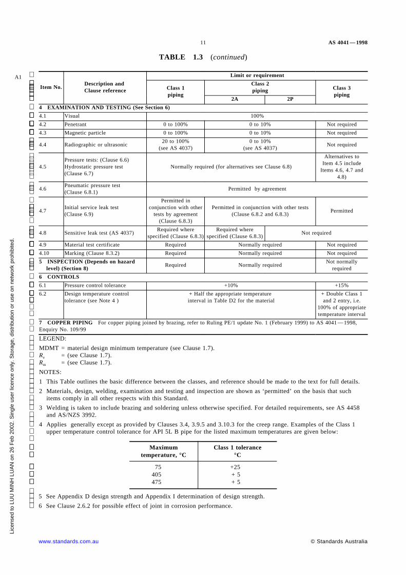
4 EXAMINATION AND TESTING (See Section 6)4.1 Visual 100%4.2 Penetrant 0 to 100% 0 to 10% Not required4.3 Magnetic particle 0 to 100% 0 to 10% Not required4.4 Radiographic or ultrasonic 20 to 100%
(see AS 4037)0 to 10%
(see AS 4037) Not required
4.5Pressure tests: (Clause 6.6)Hydrostatic pressure test(Clause 6.7)
Normally required (for alternatives see Clause 6.8)Alternatives to
Item 4.5 includeItems 4.6, 4.7 and
4.8)4.6 Pneumatic pressure test
(Clause 6.8.1) Permitted by agreement
4.7 Initial service leak test(Clause 6.9)
Permitted inconjunction with other
tests by agreement(Clause 6.8.3)
Permitted in conjunction with other tests(Clause 6.8.2 and 6.8.3) Permitted
4.8 Sensitive leak test (AS 4037) Required wherespecified (Clause 6.8.3)
Required wherespecified (Clause 6.8.3) Not required
4.9 Material test certificate Required Normally required Not required4.10 Marking (Clause 8.3.2) Required Normally required Not required5 INSPECTION (Depends on hazard
level) (Section 8) Required Normally required Not normallyrequired
6 CONTROLS6.1 Pressure control tolerance +10% +15%6.2 Design temperature control
tolerance (see Note 4 )+ Half the appropriate temperatureinterval in Table D2 for the material
+ Double Class 1and 2 entry, i.e.
100% of appropriatetemperature interval
7 COPPER PIPING For copper piping joined by brazing, refer to Ruling PE/1 update No. 1 (February 1999) to AS 4041 — 1998,Enquiry No. 109/99LEGEND:MDMT = material design minimum temperature (see Clause 1.7).Re = (see Clause 1.7).Rm = (see Clause 1.7).NOTES:1 This Table outlines the basic difference between the classes, and reference should be made to the text for full details.2 Materials, design, welding, examination and testing and inspection are shown as ‘ permitted’ on the basis that such
items comply in all other respects with this Standard.3 Welding is taken to include brazing and soldering unless otherwise specified. For detailed requirements, see AS 4458
and AS/NZS 3992.4 Applies generally except as provided by Clauses 3.4, 3.9.5 and 3.10.3 for the creep range. Examples of the Class 1
upper temperature control tolerance for API 5L B pipe for the listed maximum temperatures are given below:
Maximumtemperature, °C
Class 1 tolerance°C
75405475
+25+ 5+ 5
5 See Appendix D design strength and Appendix I determination of design strength.6 See Clause 2.6.2 for possible effect of joint in corrosion performance.
www.standards.com.au © Standards Australia
Lice
nsed
to L
UU
MIN
H L
UA
N o
n 26
Feb
200
2. S
ingl
e us
er li
cenc
e on
ly. S
tora
ge, d
istr
ibut
ion
or u
se o
n ne
twor
k pr
ohib
ited.

AS 4041 — 1998 12
TABLE 1.4
APPLICATION OF PIPING CLASSES FOR SERVICE CONDITIONSA1
Service conditions (see AS 4343)Service limits for following classes
Class 1 Class 2A Class 2P Class 3(see Note 1)
Designpressurefor fluidtype (seeNote 2
andClause3.2)
1 LethalGas No service
limit ProhibitedLiquid
2Veryharmful
Gas No servicelimit
10 MPa max. Prohibited 2 MPa max.Liquid 10 MPa max.
3 HarmfulGas No service
limit10 MPa max. Prohibited 4 MPa max.
Liquid No service limit No service limit
4 Non-harmfulGas
No servicelimit
No service limitProhibited
No service limit
Liquid No servicelimit
No service limit
Design temperature(see Clause 3.3)
Maximum No servicelimit 400°C 99°C 180°C
Minimum No servicelimit (seeItem 2.1
Table 1.3)
No service limit (seeItem 2.1 Table 1.3) 0°C −100°C (see Item 2.1 of
Table 1.3)
Nominal size(see Clause 1.7.21) All material No service
limit No service limit No servicelimit
No service limit exceptDN 150 max. for Type 2
fluid
Nominal wallthickness (seeClause 3.14.2)
Max.
Carbon steelLow alloysteelHigh alloysteelNon-ferrousmetal
No servicelimit See Table 3.14.2
Min.
Carbon steelLow alloysteelHigh alloysteelNon-ferrousmetal
See Clause3.14.2(a) See Clause 3.14.2(b)
Ductile &cast iron Prohibited No service limit
NOTES:1 See Clause 3.24.2.6 for relaxation for low hazard service.2 As an example, steam above 90°C is fluid No. 3.
1.5 SELECTION OF PIPING CLASS
1.5.1 Basic requirements The class of metallic piping selected for a particularapplication shall be determined in accordance with Table 1.4.
The requirements of Table 1.4 are intended to give a high level of assurance of reliableperformance and of adequate protection to life and property for the service conditionslisted. However, it is not practicable to include all details of the various service
© Standards Australia www.standards.com.au
Lice
nsed
to L
UU
MIN
H L
UA
N o
n 26
Feb
200
2. S
ingl
e us
er li
cenc
e on
ly. S
tora
ge, d
istr
ibut
ion
or u
se o
n ne
twor
k pr
ohib
ited.

13 AS 4041 — 1998
applications. Therefore in selection of the class of piping, the following shall be takeninto account:
(a) The possibility of piping failure under expected service conditions.
(b) Consequence of failure of piping on human life, property and the environment.
(c) Proximity of the piping to members of the general public and workers.
(d) Properties of any released contents including temperature, corrosiveness,flammability, and toxicity and radioactive properties.
(e) Pressure energy (pressure times volume) of the contents.
(f) Service conditions.
(g) Design life.
(h) Adequacy of materials (e.g. weldability, corrosive resistance) adequacy of design,fabrication, installation, examination, testing, inspection, protection, operation,and maintenance.
(i) Economics of carrying out repairs and replacements.
(j) Minimization of the number of classes of piping for the same conditions in anyone plant or for any one product.
(k) Where there is doubt about a precise classification, the classification is a matterof agreement by the parties concerned.
1.5.2 Mixing classes Designers should nominate the class of pipe early in the designprocess. Classes may be mixed. Welds and components at the interface between differentclasses shall comply with the higher class.
A total piping system may be divided arbitrarily and the divisions given a different classnumber in accordance with Table 1.4 of this Standard and at the designer’ s discretion.
1.5.3 Fast-track selection of class of piping Prepare a list of the proposed fluiddescription, the pressure, the temperature and the nominal size and consult Table 1.4 toselect one or two trial classes. Then consult Table 1.3 for details of the testing requiredfor the chosen classes and then select the class most applicable. However, the designermay select a higher class for all or part of the piping (observing the prohibitions ofTable 1.4) at the designer’ s discretion. For this Clause, Class 1 is a higher class than 2A,which is a higher class than 2P, which is a higher class than 3.
Class 1 may be used for all conditions, fluids and services. Class 1 requires compulsorynon-destructive examination, fatigue assessment, flexibility assessment and moreextensive records and there are limitations on materials. See also Clauses 1.11 and 6.10on records.
Class 2 offers reduced levels of non-destructive examination in step with current practicein other fields. The text gives other concessions and exclusions.
Class 2A limits the design strength and uses the same thickness as Class 1. Class 2P maybe used for steel piping for room temperature application with a reduced thicknessdetermined from a design strength of 72 percent yield stress at room temperature.
Class 3 gives concessions on non-destructive examination and other matters but uses67 percent extra design thickness above Class 1. This may not be a significant extra forsteel pipe under DN 150 where the actual thickness is usually in excess of the calculatedthickness.
Clause 2.11.4.1 requires piping for lethal fluids to be treated as low-temperature pipe andonly materials having an MDMT of 0°C or lower may be used.
www.standards.com.au © Standards Australia
Lice
nsed
to L
UU
MIN
H L
UA
N o
n 26
Feb
200
2. S
ingl
e us
er li
cenc
e on
ly. S
tora
ge, d
istr
ibut
ion
or u
se o
n ne
twor
k pr
ohib
ited.

AS 4041 — 1998 14
1.6 ALTERNATIVE STANDARDS Piping complying with the following alternativeStandards is deemed to comply with this Standard, according to their particular scope,provided that any requirement of this Standard nominated by the owner is complied with:
(a) Piping for power plant . . . . . . . . . . . . . . . . . . . BS 806 or ANSI/ASME B31.1.
(b) Piping for chemical plant . . . . . . . . . . . . . . . . . . . . . . . . . ANSI/ASME B31.3.
(c) Piping for refrigeration plant . . . . . . . . . . . . . . . . . . . . . . ANSI/ASME B31.5.
Mixing the content of application Standards is not permitted except where agreed by theparties concerned. The materials, design, construction, testing and inspection of thealternative specification shall be used in full unless otherwise agreed.
1.7 DEFINITIONS For the purpose of this Standard, and unless stated otherwise, thedefinitions below shall apply.
1.7.1 Accessory—a component of a piping system, other than a pipe, valve, or fitting,but including a relief device, pressure-containing item, pipe support, and any other itemnecessary to make the piping operative whether or not these items are specified in theStandard.
1.7.2 Agreed and agreement—agreed by or agreement between the parties concerned.
1.7.3 Cold spring— the forcing into position of a component that has been fabricated toa length shorter or longer than its nominal length, so that it is stressed in the installedcondition, with the intention of compensating for the change in length produced by anincrease or decrease in temperature. (Also called ‘ cold pull’ or ‘ cold push’ ).
1.7.4 Component—a part of a piping system, including a pipe, valve, fitting, and anaccessory.
1.7.5 Corrosion— the wastage of a metal, because of a reaction with its environment,including oxidation, scaling, mechanical abrasion, erosion, and all other forms of wastage.
1.7.6 Design—drawings, calculations, specifications, models, and all other informationnecessary for the complete description of the fabrication and installation of the piping.
1.7.7 Designer— the person or organization responsible to the owner for the assurancethat the engineering design complies with this Standard and any additional requirementsspecified by the owner.
1.7.8 Design strength— the maximum stress specified for material and which is to beused in equations in this Standard. (Quantity symbol: f.)
1.7.9 Extruded outlet—an outlet in a pipe or piping component where a lip has beenformed at the outlet so that the lip height above the surface of the main pipe is not lessthan the radius of curvature of the external contoured portion of the outlet, i.e. ho ≥ ro (seeFigure 3.19.9.2).
1.7.10 Fabrication— the forming and joining of piping components which includescutting, bending, threading, welding, and any other operation on these components whichis not part of installation.
NOTE: Fabrication may be carried out in the workshop or on site.
1.7.11 Fitting—a component, including a bend, a tee, a flange, a bolt, or a gasket, usedto join pipes, to change the direction or diameter of a pipe, provide a branch, or terminatea pipe.
A11.7.12 Fluid—any vapour, liquid, gas, or mixture thereof or fluidized solid, e.g. slurryand powdered material. (See AS 4343 for fluid classification.)
© Standards Australia www.standards.com.au
Lice
nsed
to L
UU
MIN
H L
UA
N o
n 26
Feb
200
2. S
ingl
e us
er li
cenc
e on
ly. S
tora
ge, d
istr
ibut
ion
or u
se o
n ne
twor
k pr
ohib
ited.

15 AS 4041 — 1998
1.7.13 Hydrostatic test—a pressure test that exerts a pressure uniformly with a liquidfor a specified period, and is used to prove the integrity and the leaktightness of thepiping.
1.7.14 Inspection— the examination and verification, carried out by the owner or theinspection body, of materials, design, fabrication, installation, examinations, tests,certificates, documents and records to determine compliance with this Standard.
1.7.15 Inspection body—a body corporate or firm responsible for the inspection ofpressure equipment and certification of inspection results.
1.7.16 Installation— the complete installation of a piping system in the locations and onthe supports given by the engineering design including any field assembly, fabrication,examination, and testing of the system as specified in this Standard.
1.7.17 May— indicates the existence of an option.
1.7.18 Mitre bend—a bend consisting of one or more mitre joints.
1.7.19 Mitre joint—a joint formed by two straight sections of pipe that are matchedand joined by welding on a plane bisecting the angle of junction so that the change indirection exceeds three degrees.
1.7.20 Nominal pressure—a numerical designation which is a convenient roundednumber for reference purposes. All equipment of the same nominal size (DN) anddesignated by the same PN number should have compatible mating dimensions.
NOTES:
1 The maximum allowable pressure depends on material, design and temperature and shouldbe selected from the tables of pressure/temperature ratings given in the appropriateStandard. Steel pipe Standards commonly do not have tables of nominal pressure.
2 Nominal pressure is designated ‘ PN’ followed by an appropriate number and unit.
1.7.21 Nominal size—a numerical designation of size which is common to allcomponents in a piping system other than components designated by outside diameters orby thread size. It is a convenient round number for reference purpose and is only looselyrelated to manufacturing dimensions (see Appendix B).
NOTES:
1 Nominal size is designated ‘ DN’ followed by an appropriate number.
2 The nominal size cannot be subjected to measurement, tolerances or used for purposes ofcalculation and has no units.
3 Not all components are designated by nominal size, e.g. steel tubes are designated byoutside diameter and thickness.
1.7.22 Owner— the person or organization having the overall responsibility forcompliance with this Standard and the engineering design, and for the establishment ofthe requirements for design, construction, examination, inspection, testing, operation andmaintenance which will govern the entire fluid handling or process system of whichpiping is a part.
NOTE: For the purpose of this Standard, the term ‘ owner’ includes the purchaser or hirer.
1.7.23 Parties concerned— the purchaser, designer, fabricator, manufacturer, designverifier, inspection body, supplier, installer and owner as appropriate.
1.7.24 Pipe—a pressure-tight cylinder used to convey a fluid or to transmit a fluidpressure, ordinarily designated ‘ pipe’ in the applicable material specification.
NOTE: For the purpose of this Standard, the term ‘ pipe’ is synonymous with ‘ tube’ exceptwhere otherwise noted.
www.standards.com.au © Standards Australia
Lice
nsed
to L
UU
MIN
H L
UA
N o
n 26
Feb
200
2. S
ingl
e us
er li
cenc
e on
ly. S
tora
ge, d
istr
ibut
ion
or u
se o
n ne
twor
k pr
ohib
ited.

AS 4041 — 1998 16
1.7.25 Pipe support—an accessory consisting of fixtures and attachments as follows:
(a) Fixtures which transfer the load from the pipe or structural attachment to thesupporting structure or equipment. They include fixtures of the hanging type, suchas hanger rods, spring hangers, sway braces, counterweights, turnbuckles, struts,chains, guides and anchors, and fixtures of the bearing type, such as saddles, bases,rollers, brackets, and sliding supports.
(b) Attachments which are welded, bolted, or clamped to the pipe. These include clips,lugs, rings, clamps, clevises, straps, skirts, and anchor attachments.
1.7.26 Pressure piping—an assembly of pipes, pipe fittings, valves and pipe accessoriessubject to internal pressure and used to contain or convey fluid or to transmit fluidpressure. It includes distribution headers, bolting, gaskets, pipe supports and pressure-retaining accessories.
1.7.26.1 Control piping—piping used to convey pneumatic or hydraulic pressure tocontrolling apparatus and between instrument transmitters and receivers.
1.7.26.2 Instrument piping—piping used to connect instruments to main piping, to otherinstruments and apparatus, or to measuring equipment.
1.7.26.3 Sampling piping—piping used for the collection of samples from the contentsof the main piping.
1.7.27 Pressure, design— the pressure used to determine the wall thickness of apressure containing component, being that pressure at the most severe condition oftemperature and coincident internal or external pressure expected during normal operatingconditions. (Quantity symbol: p.)
NOTE: Unless otherwise stated, pressure is expressed in kilopascals or megapascals aboveatmospheric pressure, i.e. gauge pressure.
1.7.28 Proprietary components—components made or marketed by a company havingthe right to manufacture and sell them. Technical data and experience may also beproprietary, i.e. not in the public domain.
1.7.29 Service conditions— the range of pressure, temperature and other conditions towhich the piping is subject during its design life.
1.7.30 Shall— indicates that a statement is mandatory.
1.7.31 Should— indicates a recommendation.
1.7.32 Socket welded joint— that joint formed from the end of a pipe entering thesocket end of a socket-welding fitting and the pipe and socket being joined by means of afillet weld.
1.7.33 Strength
1.7.33.1 Specified minimum tensile strength— the minimum tensile strength specified inthe Standard to which the material or component is made. (Quantity symbol: Rm.) It maybe qualified by the test temperature.
1.7.33.2 Specified minimum yield strength— the minimum yield strength specified in theStandard to which the material or component is made. (Quantity symbol: Re.) It isqualified by the test temperature.
1.7.34 Temperature
1.7.34.1 Temperature design— the metal temperature at the coincident design pressure,used to select the design strength and to determine the dimensions of the part underconsideration (see Clause 3.3).
© Standards Australia www.standards.com.au
Lice
nsed
to L
UU
MIN
H L
UA
N o
n 26
Feb
200
2. S
ingl
e us
er li
cenc
e on
ly. S
tora
ge, d
istr
ibut
ion
or u
se o
n ne
twor
k pr
ohib
ited.

17 AS 4041 — 1998
1.7.34.2 Material design minimum temperature (MDMT)—a characteristic minimumtemperature of a material. It is used in design to select material with sufficient notchtoughness to avoid brittle fracture and to select the temperature at which the material canbe used at full design strength (see Clause 2.11.2.2).
1.7.34.3 Maximum operating temperature— the highest metal temperature to which thepiping under consideration is subjected under normal operation. It is determined by thetechnical requirements of the process. (To avoid confusion with the following definition itis never reduced to an acronym.)
1.7.34.4 Minimum operating temperature (MOT)— the lowest mean metal temperaturethrough the thickness to which the piping under consideration is subjected under normaloperation. It is determined by the technical requirements of the process, or lowertemperature where specified by the purchaser.
1.7.35 Testing— the assessment of the properties of materials or components by the useof mechanical methods, pressure testing or other destructive or potentially destructivemethods to ensure compliance with specified requirements.
1.7.36 Thickness
1.7.36.1 Actual thickness— the actual wall thickness of the material or a component usedin the piping, which is the measured thickness or, when the material is not measured, thenominal thickness less the greatest negative tolerance specified in the Standard to whichthe material or component was made.
1.7.36.2 Pressure design thickness— the wall thickness calculated according to theequations to resist pressure, but which does not include an allowance for loss of thicknessdue to corrosion, forming, threading, grooving, and other action.
1.7.36.3 Required thickness— the sum of the pressure design thickness and theallowance for corrosion, forming, threading, grooving, and other actions.
1.7.36.4 Nominal thickness— the wall thickness nominated on the purchase order and towhich the manufacturer’ s tolerances on wall thickness are applicable.
1.7.37 Verification—confirmation by examination and provision of evidence thatspecified requirements have been met.
1.7.38 Weld joint factor—an arbitrary quality ratio of the allowable stress across alongitudinal or spiral welded joint to that allowed in the adjacent parent material.
A1 1.7.39 Assemblies—a collection of individual components joined together.
1.7.40 Gas—a substance which is completely gaseous at 20°C and 101.3 kPa absoluteor at 50°C has a vapour pressure greater than 300 kPa.
For this Standard, gas also includes:
(a) Compressed gas which is entirely gaseous at 20°C and 101.3 kPa absolute.
(b) Liquefied gas which is partially liquid at 20°C.
(c) Refrigerated liquefied gas which is partially liquid because of its low temperature.
(d) Gas in solution which is a compressed gas dissolved in a solvent.
(e) Any liquid when it is above its atmospheric pressure boiling point, e.g. pressurized
high-temperature water which flashes to steam on release of pressure.
(f) Fluidized solids in compressed air or other gas.
1.7.41 Liquid—any substance below its atmospheric pressure boiling point, e.g. water<100°C. Liquid also includes solids fluidized in liquids, e.g. slurries.1.8 NOTATION Symbols used in equations in this Standard are defined in relation tothe particular equations in which they occur.
www.standards.com.au © Standards Australia
Lice
nsed
to L
UU
MIN
H L
UA
N o
n 26
Feb
200
2. S
ingl
e us
er li
cenc
e on
ly. S
tora
ge, d
istr
ibut
ion
or u
se o
n ne
twor
k pr
ohib
ited.
AS 4041 — 1998 18
1.9 NON-SI UNITS Where units other than SI units are used in nominated Standards,the conversion to SI units shall be made in accordance with AS 1376.
1.10 REFERENCED DOCUMENTS The documents referred to in this Standard arelisted, with titles, in Appendix A.
1.11 REPORTS AND CERTIFICATES
1.11.1 Manufacturer’s data report After the piping has been completed, tested andinspected, the fabricator shall complete a manufacturer’ s data report for hazard level Aand B piping and where specified by the owner, the report shall briefly identify thepiping, and certify that the piping has been designed, fabricated, installed and tested inpartial or complete compliance with the requirements of this Standard.
A1 Where the design of piping to hazard level A and B of AS 4343 piping has not beencarried out by the fabricator, the designer shall provide a report certifying partial orcomplete compliance of the design with the Standard.
In most cases, this is adequate certification but, when requested, the following documentsmay be included in the manufacturer’ s data report:
(a) Materials test certificates.
(b) Welding procedure and welder qualification test results.
(c) Heat treatment reports.
(d) Non-destructive examination reports.
(e) Other testing reports.
1.11.2 Copies Reports complying with Clause 1.11.1 shall be given to —
(a) the owner when required by the design (and hence at the owner’ s option);
(b) the inspection body, if requested; and
(c) ‘ to whom it may concern’ , if required by law or regulation.
1.12 NOT ALLOCATED
1.13 NOT ALLOCATED
1.14 NON-METALLIC PIPING Non-metallic piping and piping lined with anon-metallic material shall—
(a) comply with requirements of ANSI/ASME B31.3 or an equivalent NationalStandard;
NOTE: Equivalent Australian Standards may be applied in lieu of material Standardsreferred to in ANSI/ASME B31.3 e.g. AS 1460, AS/NZS 4129(Int) and AS/NZS 4130.
(b) comply with the engineering design; and
(c) be agreed by the parties concerned.
1.15 INTERPRETATION OF STANDARDS See AS/NZS 1200 for interpretation ofStandards.
1.16 NEW DESIGNS, MATERIALS AND FABRICATION METHODS ThisStandard does not prohibit the use of materials or methods of design or constructionwhich are not specifically referred to herein. (See AS/NZS 1200 for guidance).
© Standards Australia www.standards.com.au
Lice
nsed
to L
UU
MIN
H L
UA
N o
n 26
Feb
200
2. S
ingl
e us
er li
cenc
e on
ly. S
tora
ge, d
istr
ibut
ion
or u
se o
n ne
twor
k pr
ohib
ited.

19 AS 4041 — 1998
A1 1.17 DIMENSIONAL AND MASS TOLERANCES Dimensional and mass tolerancesfor pipe, components and assemblies shall comply with the tolerances—
(a) provided with the material component specification;
(b) according to AS 1210 for assemblies;
(c) specified in engineering drawings; or
(d) as otherwise agreed by the parties concerned.
1.18 ALTERNATIVE DESIGN OF ACCESSORIES Any accessory (see Clause 1.7)in a piping system may be made from standard pipe and standard fittings at the designer’ soption. Such an accessory is deemed to be piping and may be designed as either piping oras a pressure vessel.
www.standards.com.au © Standards Australia
Lice
nsed
to L
UU
MIN
H L
UA
N o
n 26
Feb
200
2. S
ingl
e us
er li
cenc
e on
ly. S
tora
ge, d
istr
ibut
ion
or u
se o
n ne
twor
k pr
ohib
ited.

AS 4041 — 1998 20
S E C T I O N 2 M A T E R I A L S A N D C O M P O N E N T S
2.1 GENERAL Materials and components which are to be used for piping shall be—
(a) suitable and safe for fabrication and the service conditions under which they areused; and
(b) qualified for the conditions of their use by compliance with the nominated Standards(Clause 2.2.1) and any additional requirements of this Standard.
2.2 QUALIFICATION OF MATERIALS AND COMPONENTS
2.2.1 Materials and components complying with nominated Standards Materialsand components which comply with the following Standards may be used for appropriateapplications, as specified and limited by this Standard (for limits of materials seeAppendix D), without further qualification. Material and components permitted byAS 1210, BS 806, ANSI/ASME B31.1 and ANSI/ASME B31.3 are permitted by thisStandard. Item (a) to (m) cover metallic materials and Item (n) covers plastic and non-metallic materials.
For limitation on use of materials listed in this Clause 2.2.1, reference should be made toother relevant Clauses in this Standard, e.g. Clauses 2.2.4 and 2.6.10.
(a) Pipes
AS 1074AS 1432AS 1569AS 1572AS 1579AS 1751
AS/NZS 1866AS/NZS 1867AS/NZS 1571AS/NZS 2280
ASTM A 53ASTM A 106ASTM A 135ASTM A 178ASTM A 179ASTM A 199ASTM A 209ASTM A 210ASTM A 213
ASTM A 249ASTM A 250ASTM A 268ASTM A 269ASTM A 312ASTM A 333ASTM A 334ASTM A 335ASTM A 358ASTM A 369ASTM A 376ASTM A 423ASTM A 430ASTM A 452ASTM A 524ASTM A 587ASTM A 672ASTM A 688ASTM A 691ASTM A 789ASTM A 790
ASTM B 42ASTM B 75ASTM B 88ASTM B 111ASTM B 161ASTM B 163ASTM B 165ASTM B 167ASTM B 210ASTM B 221ASTM B 241ASTM B 315ASTM B 337ASTM B 338ASTM B 395ASTM B 407ASTM B 423ASTM B 444ASTM B 514ASTM B 515ASTM B 516
ASTM B 517ASTM B 535ASTM B 619ASTM B 622ASTM B 626
BS 1387BS 1471BS 1474BS 2871BS 3059BS 3601BS 3602BS 3603BS 3604BS 3605
API 5L
ISO 9329ISO 9330
A1 Pipes fabricated in accordance with AS 1210 or equivalent Standard.
(b) Plates
AS 1548AS 1566
AS/NZS 1594AS/NZS 1734AS/NZS 3678
ASTM A 203ASTM A 204
ASTM A 240ASTM A 302ASTM A 353ASTM A 387ASTM A 516ASTM A 517
ASTM B 96ASTM B 127
ASTM B 162ASTM B171ASTM B 333ASTM B 409ASTM B 424ASTM B 434ASTM B 435ASTM B 443ASTM B 575
BS 1501, Part 3
© Standards Australia www.standards.com.au
Lice
nsed
to L
UU
MIN
H L
UA
N o
n 26
Feb
200
2. S
ingl
e us
er li
cenc
e on
ly. S
tora
ge, d
istr
ibut
ion
or u
se o
n ne
twor
k pr
ohib
ited.

21 AS 4041 — 1998
(c) Rods, bars and sections
AS/NZS 1567AS/NZS 1865AS/NZS 1866AS/NZS 3679
ASTM A 479ASTM B 160ASTM B 164ASTM B 166
ASTM B 211ASTM B 408ASTM B 425ASTM B 446
BS 1502
(d) Castings
AS 1565AS 1830AS 1831AS 1832
AS 1833AS 1874
ASTM A 216
ASTM A 217ASTM A 276ASTM A 351ASTM A 352
BS 1490BS 3071
(e) Forgings
AS 1448
ASTM A 105
ASTM A 181ASTM A 182ASTM A 336
ASTM A 350
ASTM B 381
ASTM B 564
BS 1503
(f) Fittings
AS 3672AS 3673AS 3688
AS/NZS 2280AS/NZS 2544
ANSI/ASMEB16.9
ASTM A 182ASTM A 234ASTM A 403
ASTM A 420
BS 143BS 1640BS 1740BS 3799
MSS SP 97
A1 Fittings fabricated in accordance with AS 1210 or equivalent Standard.
(g) Pressure gauges
AS 1349
(h) Valves
AS 1271AS 1628
ASTM A 182
API STD 600API STD 602API STD 603
API STD 606
ANSI/ASME B16.10ANSI/ASME B16.34
BS 1414BS 1868BS 1873
BS 1963BS 5150BS 5151BS 5152BS 5153BS 5154BS 5155BS 5156
BS 5157BS 5158BS 5159BS 5160BS 5352BS 5353BS 6759
(i) Flanges
AS 2129AS 4087
AS/NZS 4331
ANSI/ASME B16.5ANSI/ASME B16.47
BS 1560BS 3293
MSS SP-44
(j) Bolting and gaskets
AS 2528
AS/NZS 1111AS/NZS 1112
ANSI/ASME B16.20ANSI/ASME B16.21
ASTM A 108ASTM A 193
ASTM A 194ASTM A 307ASTM A 320ASTM A 325ASTM A 449
BS 4882
(k) Welding consumables Any welding consumables complying with AS/NZS 3992.
www.standards.com.au © Standards Australia
Lice
nsed
to L
UU
MIN
H L
UA
N o
n 26
Feb
200
2. S
ingl
e us
er li
cenc
e on
ly. S
tora
ge, d
istr
ibut
ion
or u
se o
n ne
twor
k pr
ohib
ited.

AS 4041 — 1998 22
(l) Any valve of fitting complying with Standards acceptable to ANSI/ASME B31.1and B31.3 and BS 806.
(m) Refrigeration system components
Valves, fittings and controls acceptable to ANSI/ASME B31.5.
(n) Plastic and non-metallic components
AS 1460 AS/NZS 1477 AS/NZS 4129(Int) AS/NZS 4130
2.2.2 Materials and components complying with Standards not nominated in thisStandard Where a material conforming to one of the Standards in Clause 2.2.1 is notavailable, then, subject to acceptance by the parties concerned where specified on theorder, alternative materials and components not complying with a Standard listed inClause 2.2.1 may be used provided that they comply with the requirements of a relevantspecification of the British Standards Institution (BSI), the American Society ofMechanical Engineers (ASME), Euronorm, or other specification for material ofequivalent grade and quality.
2.2.3 Alternative product form Where there is no Standard for a particular productform of a wrought material but there is a nominated Standard for other product forms, thatproduct form may be used, provided that it is in compliance with the following:
(a) The chemical, mechanical and physical properties, heat treatment requirements, andany requirements for deoxidation or grain size conform to those in the nominatedStandard. The design strength values to be used shall be those for the nominatedStandard in the appropriate thickness range.
(b) The manufacturing procedures, tolerances, tests, and marking are in accordance witha nominated Standard for the same product form of a similar material.
(c) The nominated Standards in Item (a) and Item (b) are compatible in all respects, e.g.testing and welding requirements in the one form are appropriate for the materialspecified in the other form.
(d) The manufacturer’s test reports shall make reference to the Standards used toproduce the material, and shall make reference to this Clause (2.2.3).
(e) The thickness range is comparable with the nominated Standard.
2.2.4 Limitations for the application of pipe and steel identified by specification orlabel as structural only Pipe or steel, identified by specification or label as structuralmay be used for pressure containment in accordance with the applicable Clauses of thisStandard for Class 3 and as follows:
(a) The actual tensile strength shall be lower than 560 MPa and tensile properties shallbe measured transversely if pipe diameter is greater or equal to DN 250.
(b) The actual analysis (or ladle analysis if available) shall be less than the following:
Element PercentageC . . . . . . . . . . . . . . . . . . . . . . . . . . . . . . . . . . . . . . . . . .0.25P . . . . . . . . . . . . . . . . . . . . . . . . . . . . . . . . . . . . . . . . . .0.04S . . . . . . . . . . . . . . . . . . . . . . . . . . . . . . . . . . . . . . . . . .0.04Carbon equivalent (Clause 2.4.6). . . . . . . . . . . . . . . . . . . .0.45
(c) Mechanical and chemical tests shall be recorded on test certificates identified withthe product.
(d) If pipe, it shall have been pressure tested at the shop prior to fabrication to 60%Re.
(e) The steel shall be free from lamination.
(f) Plate used for flanges shall not be thicker than 40 mm.
© Standards Australia www.standards.com.au
Lice
nsed
to L
UU
MIN
H L
UA
N o
n 26
Feb
200
2. S
ingl
e us
er li
cenc
e on
ly. S
tora
ge, d
istr
ibut
ion
or u
se o
n ne
twor
k pr
ohib
ited.

23 AS 4041 — 1998
Pipe or steel identified by specification or label as structural may be used for non-pressurecontainment in accordance with this Standard, provided that the carbon equivalent is lessthan 0.45.
Compliance with pipe specification given in Clause 2.2.1 overrides any structuralidentification.
2.2.5 Components, other than pipe, for which there are no Standards A component,other than pipe, for which there is no Standard shall be qualified.
NOTE: Components may be qualified by tests or investigations (or both) that demonstrate to thesatisfaction of the parties concerned that the component is suitable and safe for the proposedservice.
2.2.6 Reclaimed components complying with a nominated Standard A reclaimedcomponent may be re-used provided that the component—
(a) was manufactured to a nominated Standard, and for Class 1 and 2 piping its materialcertificate is available; or
(b) upon inspection, is found to—
(i) have adequate thickness and shape and be free of unacceptable imperfections;and
(ii) have all welds, other than the longitudinal or spiral weld in pipe, complyingwith this Standard; and
(c) its use is accepted by the parties concerned.
Pipe shall be cleaned and inspected to determine its acceptability, freedom fromdeleterious corrosion, distortion, and mechanical or metallurgical damage.
A component, other than pipe, shall be cleaned and examined and, if necessary,reconditioned, and tested to ensure that it is sound, free of unacceptable imperfection, andsuitable for the proposed service.
An assessment shall be made of the effects of any adverse operating conditions, e.g. creepor high stress reversals (both thermal and mechanical), under which the component hasbeen previously used. Where this assessment shows that the component is not adverselyaffected, the component may be used, provided that it is hydrostatically tested (seeClause 2.2.9).
2.2.7 Material and components not fully identified A material or component whichcannot be fully identified with a nominated Standard may be used for pressure providedthat it can be demonstrated that the material or component—
(a) has the chemical composition and the mechanical properties specified in anominated Standard;
(b) has dimensions comparable with a nominated Standard;
(c) has been inspected;
(d) has been hydrostatically tested where practicable (see Clause 2.2.9); and
(e) is suitable for the proposed service, and for welding if appropriate; and
(f) is acceptable to the parties concerned.
2.2.8 Unidentified materials and components A material or component which cannotbe identified with a nominated Standard or by a manufacturer’s test certificate may beused for non-pressure parts (i.e. parts not subject to stress due to pressure, such assupporting lugs) provided that each item is otherwise suitable for the intended service.
www.standards.com.au © Standards Australia
Lice
nsed
to L
UU
MIN
H L
UA
N o
n 26
Feb
200
2. S
ingl
e us
er li
cenc
e on
ly. S
tora
ge, d
istr
ibut
ion
or u
se o
n ne
twor
k pr
ohib
ited.

AS 4041 — 1998 24
Where an unidentified material or component is to be welded directly onto apressure-containing component, it shall be capable of being welded satisfactorily withoutimpairing the properties of the pressure-containing component. (See also Clause 2.11.1.)
NOTE: Where tests are required to demonstrate this, the type, method and criteria of acceptanceshall be subject to agreement between the parties concerned.
2.2.9 Hydrostatic test A hydrostatic test (or non-destructive examination) shall becarried out on components, the strength of which may have been reduced by corrosion orother deterioration, and on pipe or components manufactured to a Standard which doesnot specify the manufacturer’s hydrostatic test. The test may be carried out either on theindividual item in a test similar to a manufacturer’s test or, when the item has beenincorporated into the piping system after erection, to at least the test pressure required toestablish the maximum design pressure for which the item will be used in service. Whereappropriate, the hydrostatic test may be replaced either by 100 percent radiography orultrasonic testing where agreed between the parties concerned.
2.2.10 Specially tested materials Material which does not comply with thisClause (2.2) may be used provided that—
(a) the material is shown by special tests to be equally suitable for the particularapplication as a similar material which complies with a nominated Standard;
(b) the type, method, and criteria of acceptance of any special test shall be agreedbetween the parties concerned; and
(c) the use of specially tested materials is agreed between the parties concerned.
NOTES:
1 These special tests may include chemical analysis, mechanical tests, and non-destructiveexamination.
2 See also Clause 2.2.2, Clause 2.2.3, Clause 2.7 and Clause 2.8.
2.3 LIMITATIONS ON MATERIALS AND COMPONENTS
2.3.1 General A material or a component which is in compliance with a nominatedmaterial or component Standard shall be used within the limitations specified in theStandard and the design. The grades or types of material shall be limited to those shownin Clause 2.2.1 and Appendix D, and the application shall be limited in accordance withClauses 2.6, 2.7, 2.11, and 3.14.2 and Appendix D, and any other limitation of thisStandard.
2.3.2 Ductile iron pipe and fittings Ductile iron pipe to AS/NZS 2280 is given apressure rating in its material Standard. Its use is covered in Clause 2.6.3.4 and is notlisted in Appendix D.
2.4 PROPERTIES OF MATERIALS
2.4.1 General Physical, mechanical and other relevant properties of material used forthe design and fabrication shall be as specified in this clause. Materials are allocated abase metal group number. This base metal group number facilitates specification ofwelding, heat treatment and non-destructive examination requirements. For details seeAS/NZS 3992 and AS 4037.
2.4.2 Mechanical properties Mechanical properties of materials nominated in thisStandard shall be as shown in the material Standard (see also Appendix D) or, where aproperty is not shown or material is not included, reference shall be made to anappropriate Standard or an authoritative source or it shall be determined by test.
2.4.3 Thermal expansion The change in length due to thermal effects shall be asshown in Appendix E or, for materials not included, shall be obtained by reference to anauthoritative source.
© Standards Australia www.standards.com.au
Lice
nsed
to L
UU
MIN
H L
UA
N o
n 26
Feb
200
2. S
ingl
e us
er li
cenc
e on
ly. S
tora
ge, d
istr
ibut
ion
or u
se o
n ne
twor
k pr
ohib
ited.

25 AS 4041 — 1998
2.4.4 Young modulus Young modulus shall be as shown in Appendix F, or formaterials not included, shall be obtained by reference to an authoritative source.
2.4.5 Poisson ratio Poisson ratio shall be taken as 0.3 for all metals at alltemperatures, but a more accurate figure may be used if this is available or required. Forother materials, reference shall be made to an authoritative source.
2.4.6 Weldability Material for Classes 1 and 2 piping, which is to be welded, shall besupplied with a certificate identifying the pipe batch and showing the chemical analysisand, for carbon and carbon manganese steels, the carbon equivalent. The carbonequivalent shall be calculated using the following equation:
. . . 2.4.6CE = C + Mn6
+ Cr + Mo + V5
+ Ni + Cu15
%
where C, Mn, Cr, Mo, V, Ni and Cu represent the percentage by weight of theparticular element.
2.5 IDENTIFICATION OF MATERIALS AND COMPONENTS The identificationof materials and components shall be in accordance with AS 4458.
2.6 LIMITATIONS ON APPLICATION
2.6.1 General Materials and components specified for piping shall be suitable for thespecified pressure, temperature, fluid, and other service conditions and for the method offabrication.
Materials and components shall be used within the limitations shown in this Clause (2.6),Clause 2.3, and Appendix D.
NOTE: Materials may be used at temperatures higher or lower than those specified in thisStandard only by agreement between the parties concerned and after appropriate examinationsor tests, or both, have established that the material is safe for the service conditions andprovides the same level of safety implied in this Standard.
2.6.2 Deterioration of materials and components An assessment shall be made onthe deterioration of materials or components during the design life. Materials andcomponents shall be selected so that they are suitable for the service conditions. Attentionshall be given to the adverse effects of creep, fatigue, stress corrosion, erosion, corrosion,products of corrosion, and other forms of deterioration resulting from the effect of serviceconditions. Consideration should be also given to internal weld bead or other shapechanges and fluid velocity for possible effect on corrosion.
2.6.3 Materials for ambient and high temperature service
2.6.3.1 General Materials shall be suitable for ambient and high-temperature serviceconditions. The temperature of application shall not exceed the highest value for which adesign stress is given in Appendix D, except as provided for in Clauses 2.6.1 and 3.4.
NOTE: This Clause (2.6.3) notes, among other things, some of the difficulties that may beencountered when materials are used at high temperatures.
2.6.3.2 Carbon and low and medium alloy steels Carbon, carbon-manganese and lowand medium alloy steels shall be used only after suitable provision has been made in thedesign for the following:
(a) During long-term exposure above 425°C, the possible conversion of carbides tographite, in carbon steel, carbon-manganese steel, manganese-vanadium steel,carbon-silicon steel, and low alloy nickel steels.
(b) During long-term exposure at temperatures above 470°C, the possible conversion ofcarbides to graphite in carbon-molybdenum steel, manganese-molybdenum-vanadium steel and chromium-vanadium steel.
(c) Above 480°C, the advantages of silicon or aluminium killed carbon steel.
www.standards.com.au © Standards Australia
Lice
nsed
to L
UU
MIN
H L
UA
N o
n 26
Feb
200
2. S
ingl
e us
er li
cenc
e on
ly. S
tora
ge, d
istr
ibut
ion
or u
se o
n ne
twor
k pr
ohib
ited.
AS 4041 — 1998 26
(d) At high temperatures, the loss of thickness due to scaling.
(e) The susceptibility to undesirable intercrystalline penetration of steel particularlyunder simultaneous presence of applied or residual tensile stress and molten metalcontact such as zinc, lead, tin or copper and their compounds at similarly elevatedtemperatures. Refer to Clause 2.7 for components in corrosive service.
(f) 100% radiographic examination of the weld in alloy longitudinal welded pipe to beoperated in the creep range.
(g) The need to consider the requirements of AS/NZS 3788 for in-service inspection ofpiping in the creep range.
2.6.3.3 High alloy steels High alloy steels shall be used only after suitable provisionhas been made in the design for the following:
(a) The susceptibility to intercrystalline corrosion of austenitic steels, followingexposure at temperatures between 425°C and 870°C, unless stabilized or low carbongrades are used.
(b) The susceptibility to brittleness of ferritic stainless steels at temperatures above370°C.
(c) The possibility of stress-corrosion cracking of austenitic stainless steels whenexposed to chlorides and other halides either internally or externally in the presenceof applied or residual tensile stress, e.g. salt contaminated water used for hydrostatictesting which is subsequently heated above approximately 70°C. Such corrosion canresult from the incorrect selection or misapplication of thermal insulation.
(d) The susceptibility of undesirable penetration of ferritic and austenitic steels oncontact with zinc, lead or copper above their melting points or with many lead, zinc,and copper compounds at similarly elevated temperatures.
NOTE: For guidance, see WTIA TN 13.
2.6.3.4 Ductile iron and other iron castings Pipe and pressure retaining componentsmade from ductile iron, grey iron or malleable iron shall comply with the thickness limitsof Clause 3.14.5 and ductile iron shall comply with Table 2.6.3.4.
2.6.3.5 Copper and copper alloys Copper and copper alloys shall be used only aftersuitable provision has been made in the design for the following:
(a) The possibility of dezincification of brass alloys.
(b) The susceptibility to stress-corrosion cracking of copper-based alloys in certainenvironments.
(c) The possibility of unstable acetylide formation when alloys having more than 70%copper are exposed to acetylene.
2.6.3.6 Aluminium and aluminium alloys Aluminium and aluminium alloys shall beused only after suitable provision has been made in the design for the following:
(a) Above 65°C, the susceptibility of aluminium alloys 5083, 5086, 5154 and 5456 toexfoliation or intergranular attack.
(b) Above 350°C, the susceptibility of some aluminium and aluminium alloys toembrittlement.
(c) The possibility of corrosion from concrete, mortar, lime, plaster or other alkalinematerials used in buildings or structures.
(d) The compatibility of compounds used to prevent seizing and galling in aluminiumthreaded joints.
(e) The low resistance to fire of unprotected aluminium and aluminium alloys.
(f) The susceptibility to sustained load cracking of some aluminium alloys, e.g. 6351and 6061 under some conditions.
© Standards Australia www.standards.com.au
Lice
nsed
to L
UU
MIN
H L
UA
N o
n 26
Feb
200
2. S
ingl
e us
er li
cenc
e on
ly. S
tora
ge, d
istr
ibut
ion
or u
se o
n ne
twor
k pr
ohib
ited.

27 AS 4041 — 1998
Extruded aluminium pipe for Class 1 piping shall have been made by the mandrel methodonly.
2.6.3.7 Nickel and nickel alloys Nickel and nickel alloys shall be used only aftersuitable provision has been made in the design for the following:
(a) At temperatures above 315°C, the susceptibility to grain boundary attack of nickeland nickel-based alloys not containing chromium when exposed to even smallquantities of sulfur during fabrication or service.
(b) At temperatures above 595°C, under reducing conditions and above 760°C underoxidizing conditions, the susceptibility to grain boundary attack of nickel-basedalloys containing chromium.
(c) The possibility of stress-corrosion cracking of nickel-copper alloy (70Ni-30Cu) inhydrofluoric acid vapour if the alloy is highly stressed or contains residual stressescaused by or resulting from forming or welding.
TABLE 2.6.3.4
LIMITS OF APPLICATION OF DUCTILE IRON PIPE AND COMPONENTS
Material Application
Maximumdesign
pressureMPa
Design temperature °C
Min.(Note 1)
Max.
Ductile iron(Nodular spheroidal)
SME ≥ 15%(see Note 2)
1 Lethal fluid or Class 1 piping Not permitted2 Flammable, toxic, harmful to
human tissue (except steam andhot water)
7 −30 230
3 Steam and hot water 7 −30 3504 Gases which are non-flammable,
non-toxic and non-harmful tohuman tissue
7 −30 350
5 Low hazard liquids 10 0 50
Ductile iron(Nodular spheroidal)
SME ≥ 15%(see Note 2)
1 Lethal fluid or Class 1 piping Not permitted2 Flammable, toxic, harmful to
human tissue (except steam andhot water)
1.1 −30 150
3 Steam and hot water 1.8 −30 2504 Gases which are non-flammable,
non-toxic and non-harmful tohuman tissue
1.8 −30 250
5 Low hazard liquids 4 0 506 Severe cyclic or shock service Not permitted
NOTES:
1 Austenitic ductile iron conforming to AS 1833 or ASTM A 571 may be used below −30°C down to thetemperature of the impact test conducted to AS 1833 or ASTM A 571, but not below −196°C.
2 SME = Specified minimum percentage elongation measured on gauge length = 4√So or equivalent.
2.6.3.8 Titanium and titanium alloys Titanium and titanium alloys shall be usedabove 315°C only after suitable provision has been made in the design for the possibilityof deterioration of these materials.
www.standards.com.au © Standards Australia
Lice
nsed
to L
UU
MIN
H L
UA
N o
n 26
Feb
200
2. S
ingl
e us
er li
cenc
e on
ly. S
tora
ge, d
istr
ibut
ion
or u
se o
n ne
twor
k pr
ohib
ited.

AS 4041 — 1998 28
2.6.4 Fittings A threaded, flanged, socket-welding or butt-welding fitting whichcomplies with a nominated Standard may be used within the material, size, pressure andtemperature limitations of that Standard.
2.6.5 Valves
2.6.5.1 General A valve which complies with a nominated Standard shall be usedwithin the material, pressure, and temperature limitations of that Standard except whereotherwise permitted in this Standard (see Clause 2.6.3).
2.6.5.2 Valve bodies For fluid types 1 and 2 grey cast iron, malleable cast iron, andspheroidal or nodular graphite cast iron with an elongation of less than 15% on a gaugelength L = 5.65√So shall not be used in valve bodies.
Where the design pressure does not exceed 7 MPa, a valve having body components madeof spheroidal or nodular graphite cast iron may be used at pressures up to 80% of designpressure for comparable steel valves at their listed temperatures.
Any spheroidal or nodular graphite or grey cast iron part of a valve shall not be subjectedto welding.
2.6.5.3 Drain valves Valves for drain piping should be of the straight-through type orbe specifically designed for the purpose.
2.6.5.4 Valve trim Valve trim shall be suitable for the temperature range and the fluid.
2.6.5.5 Valve spindles Valves with inside screw spindles should not be used incorrosive service or where deposits may develop.
2.6.5.6 Bypasses A bypass (where required) may be integral with the valve orconnected to the piping adjacent to the valve. The materials and components of the bypassshall be suitable for the same design conditions as the valve.
2.6.6 Flanges For limitations and requirements of flanges. See Clause 3.24.4.
2.6.7 Bolting for flanges for limitations and requirements of bolting for flanges. Seeclause 3.24.4.5.
2.6.8 Gaskets See Clause 3.24.4.4.
2.6.9 Material for forming and bending Material that may be subjected to formingand bending shall be suitable for these processes, and shall comply with the relevantrequirements of AS 4458.
A1 2.6.10 Limit of application of pipe made by the CW (BW) process Pipe made bythe CW (BW) process, i.e. continuous weld and furnace butt weld (see Table 1.3) islimited by this Standard to Classes 2 and 3 and if the pipe is produced to AS 1074, onlyMedium and Heavy pipes are permitted. The minimum thickness may be calculated usingthe appropriate stress value from Table D2, a weld joint factor of 0.6 and a class designfactor selected from Table 1.3. Additionally, the maximum design condition that mediumand heavy pipe can be used for is 2.0 MPa and 260°C.
A1 2.6.11 Limit of application of AS 1074 pipe Pipe to AS 1074 is limited by thisStandard to Classes 2 and 3. The minimum thickness may be calculated using theappropriate stress value from Table D2, and a weld joint factor of 0.85 for ERW and aclass design factor selected from Table 1.3.
2.7 MATERIALS AND COMPONENTS FOR CORROSIVE SERVICE In theselection of material and components for corrosive service, consideration shall be given tothe possibility of general or local wastage, corrosion, stress corrosion and corrosionfatigue. Suitable provisions shall be made in the design for the following:
(a) At temperatures above approximately 50°C, the susceptibility to stress-corrosioncracking of steels on contact with ammonia, chlorides, amines, hydrogen sulfide orother solutions. Refer to NACE Standard MR 0175 for H2S cracking.
NOTE: Consideration should be given to the benefit of postweld heat treatment to reducethe possibility of stress corrosion cracking when welded steel is used.
© Standards Australia www.standards.com.au
Lice
nsed
to L
UU
MIN
H L
UA
N o
n 26
Feb
200
2. S
ingl
e us
er li
cenc
e on
ly. S
tora
ge, d
istr
ibut
ion
or u
se o
n ne
twor
k pr
ohib
ited.
29 AS 4041 — 1998
(b) The possibility of hydrogen damage when piping is exposed to hydrogen or toaqueous acid solutions under certain temperature and pressure conditions.
(c) Where the fluid is alkaline or caustic, the possibility of embrittlement, particularlyin conditions where concentration by evaporation can occur.
(d) Where the fluid is diesel oil, the possibility of deterioration of galvanized pipe orcomponents.
(e) Anhydrous ammonia may cause stress corrosion cracking of steel in the presence ofspecific quantities of oxygen and other gases.
Anhydrous ammonia may be carried in all steel pipes listed in Appendix D exceptthe high tensile pipe quenched and tempered to ASTM A 517. However, this grademay be used satisfactorily if the ammonia has 200 p.p.m. of water minimum added.
It is good practice to stress relieve all welds in ammonia piping irrespective of thesteel strength.
2.8 DISSIMILAR MATERIALS Mitigation of corrosion due to electrolytic reactionand stress due to the different thermal expansions shall be considered when adjacentpiping of dissimilar materials are being specified.
2.9 BACKING RINGS AND FUSIBLE INSERTS
2.9.1 Permanent backing rings Permanent backing rings (i.e. those that are notremoved after welding) made from bar, strip or pipe shall be compatible with the parentmaterial.
For high alloy steels with special metallurgy this means using the parent material e.g.9% Cr, 12% Cr, stainless steels, 3% Ni and 9% Ni. For high temperature steam pipe of2¼ Cr and lower grades, a backing ring one grade lower than the parent material isacceptable.
2.9.2 Temporary backing rings Temporary backing rings (i.e. those that are removedafter welding) shall be made from pipe, bar or strip, and the material shall have a similarchemical composition to that of the parent material; or for carbon and alloy steel withalloys less than 3 percent, shall be made from carbon steel with a carbon content notgreater than 0.26 percent and a sulfur content not greater than 0.04 percent.
However, backing rings made from dissimilar non-ferrous or non-metallic materials maybe used provided that the welding procedure is qualified.
2.9.3 Fusible inserts Fusible inserts should be made from materials having chemicalcompositions such that, when fused with the material, they will produce weld metal that isof similar chemical composition to that of the parent material.
2.10 BRAZING MATERIALS See Clause 3.24.8.
2.11 MATERIALS FOR LOW TEMPERATURE SERVICE
2.11.1 General Materials and components for pressure parts, and for non-pressureparts welded directly to pressure parts, for low temperature service or where it is requiredto guard against brittle fracture, or where the fluid is lethal, shall comply with theappropriate requirements of this Clause (2.11).
If the operating temperature in normal service or due to malfunction is lower than 0°C,the design shall comply with this Clause (2.11).
These requirements need not apply to non-pressure parts such as supports if they are notattached to a pressure part by welding nor otherwise an integral part of apressure-containing component.
www.standards.com.au © Standards Australia
Lice
nsed
to L
UU
MIN
H L
UA
N o
n 26
Feb
200
2. S
ingl
e us
er li
cenc
e on
ly. S
tora
ge, d
istr
ibut
ion
or u
se o
n ne
twor
k pr
ohib
ited.

AS 4041 — 1998 30
In this Clause (2.11), ‘ all forms’ means plates, strip, seamless and welded pipe, bars,castings and forgings; but bolting and weld metal are excluded.
Untested steel permitted by this Clause (2.11) shall have a carbon content of less than0.30 percent. For impact tested steel, the impact test result supersedes the need for specialcarbon limit.
This Clause also requires steel when tested to possess minimum of 27J, 31J, or 40J or0.38 mm lateral expansion according to the tensile strength (see Table 2.11.2). For pipe toASTM A 333 and A 334 (pipe for low temperature service), higher Charpy energyrequirements than specified in those Standards apply.
Piping to Class 3 shall be designed as if for use at 20°C below the design minimumtemperature (see Clause 2.11.4) by adjustment to the MDMT.
NOTE: AS/NZS 3992 specifies requirements for impact testing for the heat-affected zone andweld metal as part of welding procedure qualification tests for welds between parts for whichthis Standard requires impact testing.
2.11.2 Selection of suitable material for low temperature service
2.11.2.1 General Suitable material may be selected for each component in the pipingsystem by the provisions given in the following:
(a) Carbon, carbon-manganese steel in all forms except bolting and weld metal(material Groups A1, A2 and A3) which are treated as one group (seeClause 2.11.2.2).
(b) Alloy steels and non-ferrous metals (see Clause 2.11.2.3).
(c) Small diameter heat exchanger tubing and very thin steel pipes and tubes (seeClause 2.11.2.4).
(d) Cast iron and ductile iron (see Clause 2.11.2.5).
(e) Steel bolting (see Clause 2.11.2.6).
(f) Non-metallic pipe and components (see Clause 2.11.2.7).
2.11.2.2 Material Groups A1, A2 and A3 Figure 2.11.2(A) relates MDMT to materialreference thickness and testing temperature for these steels in the as-welded condition.
Similarly, Figure 2.11.2(B) relates MDMT to material reference thickness and testingtemperature for these steels in the postweld heat treated condition.
To qualify for application to one of the curves, the steel must comply withTable 2.11.2(A) and its foot notes, and, Table 2.11.2(B).
Curve +20°C materials are exempt from impact tests. Additionally, API 5L X42 and X52steel pipe may be exempt from tests for curves 0°C and minus 10°C, respectively, withinthe limits imposed by Table 2.11.2(A).
In the case of a steel (Rm > 470) which does not have the required 40J but has a measuredvalue greater than 27J, a curve 10°C higher may be used or the steel rejected.
For pipe and component specifications with Charpy requirements other than 27J, 31J or40J, if the achieved value is between 20J and 50J, an equivalent test temperature may beassigned by adjustment on the basis of 1.5J per kelvin.
Example 1:
Pipe tested to 21J on Rm 400 MPa steel at −20°C. This may be regarded as equivalent to27J at −16°C.
Example 2:
ASTM A 333, Grade 6 (Rm 415) which calls for 18J and achieves 19J at −45°C cannot beadjusted to 27J at −39°C.
© Standards Australia www.standards.com.au
Lice
nsed
to L
UU
MIN
H L
UA
N o
n 26
Feb
200
2. S
ingl
e us
er li
cenc
e on
ly. S
tora
ge, d
istr
ibut
ion
or u
se o
n ne
twor
k pr
ohib
ited.

31 AS 4041 — 1998
Suitable material may be selected by the following procedure—
(a) determine the required MDMT by reference to Clause 2.11.4;
(b) determine the material reference thickness (Tm) by reference to Clause 2.11.5;
(c) enter the values obtained in Steps (a) and (b) above, in Figure 2.11.2(A) orFigure 2.11.2(B) as appropriate. The curves at, or below, the intersection of thesevalues gives the permitted steels (and any necessary impact tests); and
(d) from Table 2.11.2(A) and Table 2.11.2(B) select the steel type or pipe specificationfor the curve noted in Step (c).
When Table 2.11.2 exempts steel from impact tests, the material reference thickness(Clause 2.11.5) and the assigned curve give the lowest MDMT permitted which must notbe warmer than that required in Clause 2.11.4.
TABLE 2.11.2(A)
QUALIFYING CONDITIONS FOR LOW TEMPERATURE APPLICATION—STEEL ALL FORMS (EXCEPT BOLTING AND WELD METAL)
1 2 3 4 5 6 7 8
Curve (SeeFigure 2.11.2)
Standardimpact
temperature
Standard impact test value (J)Limits of
steelMaximumthickness
Carbonequivalentmax. (cast
orproduct)
Tensile strength, MPa
°C °CSpecified min.,
Rm ≤ 450(Note 8)
Specified min.,Rm > 450 ≤ 470
(Note 9)
Specified min.,Rm > 470(Note 10) mm
+20 No test No test No test No test None None —
0 No test No test No test Not applicable X42 Finegrained 75 0.36
0 0 27 31 40 None None —
−10 No test Not applicable No test Not applicable
X52 Finegrained
and microalloyed
13 0.27
−10 −10 27 31 40 None None —
−20 −20 27 31 40 None None —
−30 −30 27 31 40 None None —
−40 −40 27 31 40 None None —
−50 −50 27 31 40 None None —
Columns 3, 4, 5, 6 —J values are minimum average values.
Column 3 — additionally an actual maximum Rm limit of the lesser of 560 MPa and any maximum Rm in the productspecification applies.
Column 4 — additionally an actual maximum Rm limit of the lesser of 600 MPa and any maximum Rm in the productspecification applies.
Column 5 — additionally an actual maximum Rm limit of the lesser of 650 MPa and any maximum Rm in the productspecification applies.
Column 6 — fine grained steels produced to fine grained practice (AS 1733 grain size 7 or finer) include the following:
(a) Fully killed (Si-A1 or A1) steels.
(b) Controlled rolled steels.
(c) Steels with grain refining elements added, e.g. API 5L X52.
Column 8 — see Clause 2.4.6 for carbon equivalent equation
www.standards.com.au © Standards Australia
Lice
nsed
to L
UU
MIN
H L
UA
N o
n 26
Feb
200
2. S
ingl
e us
er li
cenc
e on
ly. S
tora
ge, d
istr
ibut
ion
or u
se o
n ne
twor
k pr
ohib
ited.

AS 4041 — 1998 32
TABLE 2.11.2(B)
MATERIAL DESIGN MINIMUM TEMPERATURES (ALL FORMS EXCEPTBOLTING AND WELD METAL) FOR CARBON AND CARBON
MANGANESE STEEL PIPE
1 2 3 4 5 6 7 8 9
ASME IXP
No.
Steelgroup
Generaltype
Specific-ation
Grade
Rm
min.
Material design minimum temperature (MDMT)
If not impact tested If impact tested on10 × 10 mm
specimenMPa Curve Steel restrictions
1 A1, A2& A3
All Any Any — + 20° C% = 0.30 max. Not applicable
1 A1 C, C-Mn API 5L X42 413 0°C Fine grainedt ≤ 75 mm
Not applicable
1 A1 C, C-Mn API 5L X42 413 Notapplicable
Not applicable Curve testtemperature for 27J
1 A2 C, C-Mn ASTMA 106
C 485 Notapplicable
Not applicable Curve testtemperature for 40J
— A3 C, C-Mn API 5L X52 455 −10°C Fine grained,micro alloyed
t ≤ 13 mm CE% ≤ 0.27
Not applicable
— A3 C, C-Mn API 5L X52 455 Notapplicable
Not applicable Curve −10°C and31J
— A1 C, C-Mn BS 3603 410 410 Notapplicable
Not applicable Curve −50°C and27J
— A1 C, C-Mn ASTMA 333
and A 334
1 380 Notapplicable
Not applicable Curve testtemperature for 27J
— A1 C, C-Mn ASTMA 333
and A 334
6 415 Notapplicable
Not applicable Curve testtemperature for 27J
LEGEND:
CE = Carbon equivalent (see Clause 2.4.6).
t = thickness
© Standards Australia www.standards.com.au
Lice
nsed
to L
UU
MIN
H L
UA
N o
n 26
Feb
200
2. S
ingl
e us
er li
cenc
e on
ly. S
tora
ge, d
istr
ibut
ion
or u
se o
n ne
twor
k pr
ohib
ited.

33 AS 4041 — 1998
FIGURE 2.11.2(A) CARBON AND CARBON-MANGANESE STEELS FORLOW TEMPERATURE SERVICE—AS-WELDED
(See also Tables 2.11.2(A) and (B))
www.standards.com.au © Standards Australia
Lice
nsed
to L
UU
MIN
H L
UA
N o
n 26
Feb
200
2. S
ingl
e us
er li
cenc
e on
ly. S
tora
ge, d
istr
ibut
ion
or u
se o
n ne
twor
k pr
ohib
ited.

AS 4041 — 1998 34
FIGURE 2.11.2(B) CARBON AND CARBON-MANGANESE STEELS FORLOW TEMPERATURE SERVICE—POSTWELD HEAT TREATED
(See also Tables 2.11.2(A) and (B))
© Standards Australia www.standards.com.au
Lice
nsed
to L
UU
MIN
H L
UA
N o
n 26
Feb
200
2. S
ingl
e us
er li
cenc
e on
ly. S
tora
ge, d
istr
ibut
ion
or u
se o
n ne
twor
k pr
ohib
ited.

35 AS 4041 — 1998
2.11.2.3 Alloy steels and non-ferrous metals (all forms excluding bolting and weldmetal The MDMT for alloy steels and non-ferrous metals (all forms excluding boltingand weld metal) is given in Table 2.11.2(C).
Suitable material for this subgroup may be selected as follows:
(a) With test
(i) Determine the minimum operating temperature (MOT) for the component byreference to Clause 2.11.3; and
(ii) select permitted material (and any necessary impact tests) having a MDMTnot warmer than MOT, by reference to Table 2.11.2(C).
(b) Exempt from tests
(i) Where Table 2.11.2(C) specifies a curve, refer to the curve inFigure 2.11.2(A) or (B), enter the appropriate graph at the material reference,thickness (Clause 2.11.5) to determine the warmest MDMT permitted andcompare it to that determined from Table 2.11.2(C).
(ii) Where Table 2.11.2(C) specifies an MDMT numeral, this is compareddirectly with the required MDMT from Clause 2.11.4 and Figures 2.11.2(A)or (B) do not apply.
2.11.2.4 Very thin steel pipes and tubes (including small heat-exchanger tubes) Wherethere is insufficient thickness to obtain a 2.5 mm Charpy V notch specimen, that materialmay be used at a temperature either—
(a) greater than or equal to that permitted for an non-impact tested material of theequivalent type; or
(b) qualified by test on an equivalent but thicker material.
NOTE: The material may be qualified by an agreed non-standard test.
Alternatively, impact testing is not required for C and C-Mn steels 10 mm and thinnerprovided that the required MDMT is not lower than the corresponding values inTable 2.11.2.4. Welding in this Table applies to both welding in fabrication and weldingin pipe manufacture.
TABLE 2.11.2.4
MATERIAL DESIGN MINIMUMTEMPERATURE—THIN MATERIALS*
Thickness As weldedPostweld heat
treatedUnwelded
mm °C °C °C
10 −15 −30 −70
8 −20 −35 −75
6 −25 −40 −80
4 −40 −55 −95
≤2 −55 −70 −110
* Taken from BS 5500
www.standards.com.au © Standards Australia
Lice
nsed
to L
UU
MIN
H L
UA
N o
n 26
Feb
200
2. S
ingl
e us
er li
cenc
e on
ly. S
tora
ge, d
istr
ibut
ion
or u
se o
n ne
twor
k pr
ohib
ited.

AS 4041—1998 36
TABLE 2.11.2(C)
MATERIAL DESIGN MINIMUM TEMPERATURE (MDMT) FOR ALLOY STEELS, NON-FERROUS METALS AND CAST IRONS(ALL FORMS) EXCEPT BOLTING AND WELD METAL)
1 2 3 4 5 6 7 8
PNo.
Steelgroup General type Specification Grade Rm
min.
MDMT
If not impact tested If impact tested(10 mm × 10 mm specimen)
Low alloy steels with obligatory Charpy testing (pipe specifications listed)
¼ Ni ASTM A 333 10 550 Not applicable Test at −45°C for 40J
9B E 2½ Ni ASTM A 333 and A 334 7 450 Not applicable Test at −70°C for 27J
ASTM A 333 and A 334 9 435 Not applicable Test at −70°C for 27J
3 Ni ASTM A 333 and A 334 3 450 Not applicable Test at −100°C for 27J
1 Ni-1 Cr ASTM A 333 4 415 Not applicable Test at −90°C for 27J
11A F 9 Ni ASTM A 333 and A 334 8 690 Not applicable Test at −195°C for 0.38 mmlateral expansion
E 3½ Ni BS 3603 503 440 Not applicable Test at −100°C for 27J
F 9 Ni BS 3603 509 490 Not applicable Test at −196°C for 40J
Low alloy steels (unlisted product specifications)
E 3 Ni Any Any — Curve, −30°C Test temperature giving 27, 31,40J depending on Rm
B, C, D1, D2 Various Any Any — Curve + 20°Cbut MDMT
≥ 0°C
Test temperature giving 27, 31,40J or 0.38 mm lateralexpansion
High alloy steels (product specification listed)
11B G Quenched and tempered ASTM A 517 All 795 Not applicable Test temperature giving0.38 mm lateral expansion
6 H Martensitic ASTM A 268 409410
380415
Curve + 20°Cbut MDMT
≥ −30°C
Test temperature giving 27J on10 × 10
7 J Ferritic ASTM A 268 405430
415415
Curve + 20°Cbut MDMT
≥ −30°C
Test temperature giving 27J on10 × 10
(continued)
© Standards Australia www.standards.com.au
Licensed to LUU MINH LUAN on 26 Feb 2002. Single user licence only. Storage, distribution or use on network prohibited.

37 AS 4041—1998
TABLE 2.11.2(C) (continued)
1 2 3 4 5 6 7 8
PNo.
Steelgroup General type Specification Grade Rm
min.
MDMT
If not impact tested If impact tested(10 mm × 10 mm specimen)
High alloy steels (product specification listed) (continued)
8 K Austenitic (seamless) or welded pipesolution heat treated)
ASTM A 312 304 515 −255°C Test temperature giving 40J or 0.38 mm lateral expansion
ASTM A 312 304L 485 −255°C
ASTM A 312 347 515 −255°C
ASTM A 312 321 515 −200°C
ASTM A 312 316 515 −200°C
ASTM A 312 316L 485 −200°C
ASTM A 312 317 515 −200°C
ASTM A 312 310S 515 −200°C
ASTM A 312 309S 515 −200°C
There is no temperature limit for these austenitic steels if the operating stress is less than 50 MPa
L High chromium ASTM A 268 446 485 Not applicable Test temperature giving 40J
M Ferritic austenitic ASTM A 789 S31803 620 Not applicable Test temperature giving 40J
High alloy steels (unlisted product identification)
— H Martensitic Any 405, 410, 429 — Curve + 20°C but MDMT ≥ −30°C
Test temperature giving 27, 31, 40J or .38 mm lateral expansion depending of Rm
J Ferritic Any 410S —
M Ferritic austenitic Any 31803 —
K Austenitic stainless steel C > 0.1% Any Any — −30°C Test temperature giving 40J
K Austenitic stainlessHeat treated below 900°C
Any Any — Not applicable Test temperature giving 40J
(continued)
www.standards.com.au © Standards Australia
Licensed to LUU MINH LUAN on 26 Feb 2002. Single user licence only. Storage, distribution or use on network prohibited.

AS 4041—1998 38
TABLE 2.11.2(C) (continued)
1 2 3 4 5 6 7 8
PNo.
Steelgroup General type Specification Grade Rm
min.
MDMT
If not impact tested If impact tested(10 mm × 10 mm specimen)
Non-ferrous metals
— — Aluminium alloys — wrought — — — MDMT −270°C Not applicable
Aluminium alloys — cast — — — MDMT −198°C Not applicable
Copper, copper alloys — — — MDMT −198°C Not applicable
Nickel, nickel alloys — — — MDMT −198°C Not applicable
Titanium, zirconium ASTM B 265 — — MDMT −60°C Test temperature for20J on 10 × 10
Cast irons
— — Ductile iron AS 1831 Any — −30°C Not applicable
Austenitic ductile AS 1833 Any — −30°C Test temperature giving 20J
Austenitic ductile ASMT A 571 Any — −30°C Test temperature giving 20J
Grey iron AS 1830 Any — −30°C Test temperature giving 20J
Malleable iron AS 1830 Any — −30°C Test temperature giving 20J
Cast irons — galvanized — all castirons
— — — −10°C Test temperature giving 20J
© Standards Australia www.standards.com.au
Licensed to LUU MINH LUAN on 26 Feb 2002. Single user licence only. Storage, distribution or use on network prohibited.

39 AS 4041 — 1998
2.11.2.5 Cast iron The MDMT for cast iron is given in Table 2.11.2(C).
Ductile iron pipe to AS/NZS 2280 is not recommended for temperatures below 0°C.Victaulic jointing systems and similar systems using cast iron couplings should be usedonly in the temperature range recommended by the manufacturers of the total system.
2.11.2.6 Bolting materials For bolting materials—
(a) determine the MOT by reference to Clause 2.11.3; and
(b) select material permitted for bolting having a listed minimum operating temperaturenot higher than MOT by reference to Table G1 in Appndix G.
For bolting to operate at temperatures lower than the listed MOT, the testing requirementsshall include impact testing, which shall comply with the requirements given inTable 2.11.2(B) and Table 2.11.2(C) for the equivalent material type strength andthickness at the minimum operating temperature.
2.11.2.7 Non-metallic materials Non-metallic pipe and materials that include bolting,parts of valves, gaskets, packing and similar parts used for low temperature service shallbe suitable for service at the MOT. Allowance shall be made for any handling, ageing orembrittlement.
2.11.3 Minimum operating temperature For non-ferrous metals, alloy steels andbolting, the MOT shall be the lowest mean metal temperature through the thickness of thepart under consideration during normal operation, including fluctuations that may occurduring normal process operations and during start-up and shutdown and malfunction.
The MOT shall be the lowest of the following:
(a) For piping that is thermally insulated externally . . . . . . . . . . . . . . . the minimumtemperature of the fluid within the pipe.
(b) For piping that is not thermally insulated . . . . . . . . . . . . . . . . . . . . the lower of—
(i) the minimum temperature of the fluid within the pipe; and
(ii) 10°C above the lowest one day mean ambient temperature (LODMAT) wherethe metal may be subjected to this temperature while the piping is underpressure.
Appendix H provides LODMAT data.
Where there is evidence to show that because of radiation, adiabatic expansion or othereffects, Items (a) and (b) will not provide a reliable estimate of minimum operatingtemperature, the method to be used in assessing that temperature shall be agreed andallowance shall be made for any sub-cooling during pressure reduction.
2.11.4 Required material design minimum temperature
2.11.4.1 Lethal fluids Where the contents of piping is lethal, the required MDMTdetermined under this rule shall not exceed 0°C.
2.11.4.2 Class 3 piping The class design factor of 0.60 for Class 3 increases the wallthickness considerably, and the concessions for non-destructive examination requireClass 3 piping to have an additional margin of −20°C when determining MDMT forClass 3 pipe.
2.11.4.3 MDMT for steel groups A1, A2 and A3 The required MDMT for these steelsshall be determined as follows:
(a) General The MDMT for use in Figures 2.11.2(A) and 2.11.2(B) shall be the lowestvalue of the following, adjusted where necessary by reference to Items (b), and (c)below:
www.standards.com.au © Standards Australia
Lice
nsed
to L
UU
MIN
H L
UA
N o
n 26
Feb
200
2. S
ingl
e us
er li
cenc
e on
ly. S
tora
ge, d
istr
ibut
ion
or u
se o
n ne
twor
k pr
ohib
ited.

AS 4041 — 1998 40
(i) The lowest temperature occurring coincidentally with process conditionwhich results in the calculated membrane stress
≥ 2f3
× Classification factor
where
f = design tensile strength at ambient temperature (see Appendix D);design factor is given in Table 1.3, Item 2.3.
(ii) A temperature 10°C warmer than the lowest temperature occurringcoincidentally with process conditions which result in the calculatedmembrane stress being
≥50 MPa but < × class design factor2f3
(iii) A temperature 50°C warmer than the lowest temperature occurringcoincidentally with process conditions which result in the calculatedmembrane stress being <50 MPa for average stress and <100 MPa for peakstress.
The stresses calculated in Item (iii) shall take into account all loadings, such asinternal and external pressures, static head, self-weight, thermal stress, bendingstress, and external loads. Where the piping is likely to be subject to a higherpressure at higher temperatures, e.g. in refrigeration systems with liquefied gases,the material and design shall be suitable for all expected combinations of operatingtemperatures and pressures.
(b) Adjustment for partial postweld heat treatment For Class 1 piping, where the pipelengths contain branches, welded supports, or other welded attachments and the pipecircumferential welds are not postweld heat treated, the MDMT obtained fromItem (a), applied to as-welded parts, may be raised a further 15°C, subject to all ofthe following:
(i) The welded attachment as a subassembly is postweld heat treated prior tocircumferential butt-welding to the pipe.
(ii) Circumferential butt joints are more than 150 mm from attachment welds.
(c) Material for piping subject to shock For ferritic steels used for piping ontransportable vessels or in other applications which may be subjected to severeshock, impact or plastic deformation, an additional margin of −15°C shall be addedin the determination of MDMT.
2.11.4.4 MDMT for all other materials For all other materials, the required MDMT isequal to or less than the MOT (adjusted if appropriate for lethal fluids and Class 3margin).
2.11.5 Material reference thickness Except for castings the reference thickness (Tm)used in applying Figure 2.11.2(A) and Figure 2.11.2(B) shall be that thickness designatedin Figure 2.11.5, based on the nominal thickness, including any integral cladding or weldoverlay. For castings, the reference thickness shall be the largest actual thickness.
The reference thickness listed in Figure 2.11.5(a), (b), (e), (i) and (j) for the thinner part,branch, or attachment shall extend along the branch or attachment for at least the distanceshown in the figures.
The reference thickness for weld neck flanges, plate and slip-on (or hubbed) flanges, andflat ends shall be the greater of one-quarter the thickness of the flange or the flat end, orthe thickness of the branch or shell attached thereto (see Figure 2.11.5).
© Standards Australia www.standards.com.au
Lice
nsed
to L
UU
MIN
H L
UA
N o
n 26
Feb
200
2. S
ingl
e us
er li
cenc
e on
ly. S
tora
ge, d
istr
ibut
ion
or u
se o
n ne
twor
k pr
ohib
ited.

41 AS 4041 — 1998
If the distance from the flange, or flat end to the butt weld is not less than four times thethickness of the butt weld, the reference thickness for the as-welded condition shall be thethickness at the edge of the weld preparation.
2.11.6 Impact tests
2.11.6.1 Where required Impact testing of parent metal of pressure parts, andnon-pressure parts welded directly to pressure parts, shall apply as follows:
(a) Where the MDMT thickness in Figures 2.11.2(A) and 2.11.2(B) require impacttesting.
(b) Where specified in Tables 2.11.2(B) and 2.11.2(C).
See AS/NZS 3992 for impact testing requirements of weld procedure tests.
The longitudinal weld of pipes complying with an appropriate pipe specification for theminimum operating temperature is exempt from impact testing of the weld metal.
Where the pipe is not supplied to such a pipe specification, the weld in welded pipe shallalso be qualified when Charpy testing of the pipe body is required. The test pieces forSAW pipe shall be transverse to the weld with the base of the notch at the weld centreline with a second test piece, with the base of the notch in the HAZ (seeFigure 2.11.6(A)). The test pieces for ERW pipe may either be transverse as for SAW orlongitudinal with the base of the notch at the weld centreline (see Figure 2.11.6(B)). In allcases, the base of the notch is to be perpendicular to the pipe surface.
www.standards.com.au © Standards Australia
Lice
nsed
to L
UU
MIN
H L
UA
N o
n 26
Feb
200
2. S
ingl
e us
er li
cenc
e on
ly. S
tora
ge, d
istr
ibut
ion
or u
se o
n ne
twor
k pr
ohib
ited.

AS 4041 — 1998 42
FIGURE 2.11.5 (in part) MATERIAL REFERENCE THICKNESS (Tm)FOR SELECTION OF MATERIAL
© Standards Australia www.standards.com.au
Lice
nsed
to L
UU
MIN
H L
UA
N o
n 26
Feb
200
2. S
ingl
e us
er li
cenc
e on
ly. S
tora
ge, d
istr
ibut
ion
or u
se o
n ne
twor
k pr
ohib
ited.
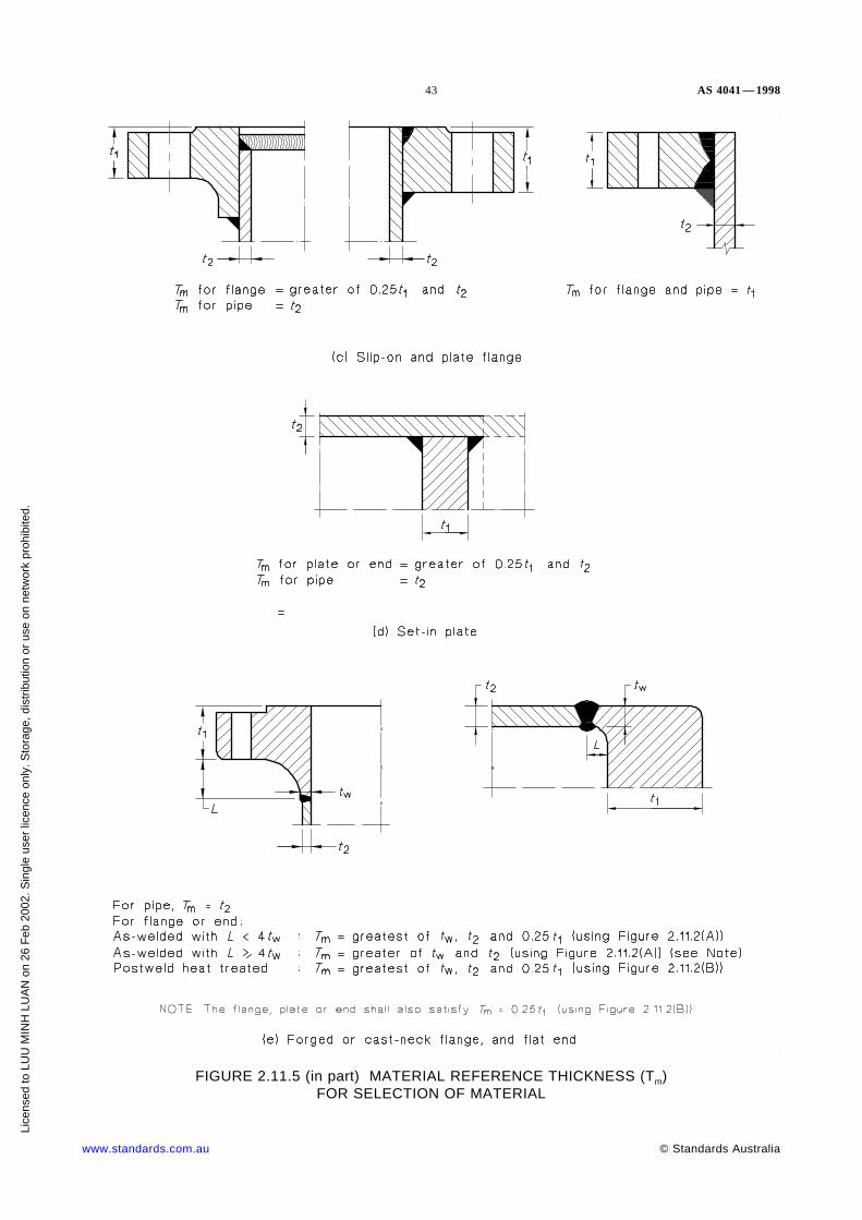
43 AS 4041 — 1998
FIGURE 2.11.5 (in part) MATERIAL REFERENCE THICKNESS (Tm)FOR SELECTION OF MATERIAL
www.standards.com.au © Standards Australia
Lice
nsed
to L
UU
MIN
H L
UA
N o
n 26
Feb
200
2. S
ingl
e us
er li
cenc
e on
ly. S
tora
ge, d
istr
ibut
ion
or u
se o
n ne
twor
k pr
ohib
ited.

AS 4041 — 1998 44
FIGURE 2.11.5 (in part) MATERIAL REFERENCE THICKNESS (Tm)FOR SELECTION OF MATERIAL
© Standards Australia www.standards.com.au
Lice
nsed
to L
UU
MIN
H L
UA
N o
n 26
Feb
200
2. S
ingl
e us
er li
cenc
e on
ly. S
tora
ge, d
istr
ibut
ion
or u
se o
n ne
twor
k pr
ohib
ited.

45 AS 4041 — 1998
FIGURE 2.11.5 (in part) MATERIAL REFERENCE THICKNESS (Tm)FOR SELECTION OF MATERIAL
www.standards.com.au © Standards Australia
Lice
nsed
to L
UU
MIN
H L
UA
N o
n 26
Feb
200
2. S
ingl
e us
er li
cenc
e on
ly. S
tora
ge, d
istr
ibut
ion
or u
se o
n ne
twor
k pr
ohib
ited.

AS 4041 — 1998 46
FIGURE 2.11.6(A) CHARPY TEST PIECE LOCATION AND ORIENTATIONFOR SAW PIPE WELD
FIGURE 2.11.6(B) CHARPY TEST PIECE LOCATIONAND ORIENTATION FOR ERW PIPE
© Standards Australia www.standards.com.au
Lice
nsed
to L
UU
MIN
H L
UA
N o
n 26
Feb
200
2. S
ingl
e us
er li
cenc
e on
ly. S
tora
ge, d
istr
ibut
ion
or u
se o
n ne
twor
k pr
ohib
ited.

47 AS 4041 — 1998
Certified reports of satisfactory impact tests made by the material manufacturer shall beaccepted as evidence that the material complies with the requirements of this Clause,provided that—
(i) during or following fabrication, the test pieces are representative of the materialsupplied and the material is not subjected to heat treatment or forming operationwhich will materially reduce its impact properties; or
(ii) the materials from which the test specimens were removed were heat treated andformed separately so that they are representative of the materials in the finishedstate.
If the manufacturer omits the required impact tests, they may be made by the fabricator.
2.11.6.2 Test method Impact tests shall be performed in accordance with AS 1544.2,except as follows:
(a) Lateral expansion tests shall be in accordance with ASTM A 370 (see Table2.11.2(B) and 2.11.2(C) for use).
(b) Dropweight tests to determine nil-ductility transition temperature (NDTT) shall bein accordance with AS 1663.
(c) Other tests shall be agreed between the parties concerned.
2.11.6.3 Test specimens The selection number and location of test specimens shall beas follows:
(a) Number of Charpy V-notch test specimens The number and location of CharpyV-notch test specimens shall be selected to represent adequately the material used,and the selection shall be in accordance with one of the following Standardsappropriate to the product form:
(i) Pipes and tubes . . . . . . . . . . . . . . . . . . BS 3603, ASTM A 333 and A 334.
(ii) Plates . . . . . . . . . . . . . . . . . . . . . . . . . . . . . . . . AS 1548, AS/NZS 3678.
(iii) Forgings . . . . . . . . . . . . . . . . ASTM A 350 (see Note to Clause 2.11.6.4).
(iv) Castings . . . . . . . . . . . . . . . . . . . . . . . . . . . . . . . . . . . . . . ASTM A 352.
(v) Steel bolting . . . . . . . . . . . . . . . . . . . . . . . . . . . . . . . . . . . ASTM A 320.
(vi) Pipe fittings . . . . . . . . . . . . . . . . . . . . . . . . . . . . . . . . . . . ASTM A 420.
For quenched and tempered steels (group F), and 9% nickel steels (group G), atleast three Charpy V-notch test specimens (see Clause 2.11.6.6 for retests andrequirements for additional test specimens) shall be made from each plate as heattreated, or from each heat of bars, pipe, rolled sections, forged parts, or castingsincluded in any one heat treatment lot. The specimens for plate shall be orientedtransverse to the final direction of rolling; for circular forgings, the specimens shallbe oriented tangentially to the circumference, and for pipes, the specimens shall beoriented longitudinally.
For wrought material, unless elsewhere specified three or more Charpy V-notch testspecimens shall be cut with the specimen parallel to the direction of principal hotworking, except as otherwise approved.
The manufacturer of small cast or forged components, other than bolting, maycertify a lot of not more than 20 duplicate parts by reporting the results of teststaken on one set of impact specimens taken from one such component selected atrandom, provided that the same specification and heat of material and the sameprocess of production, including heat treatment, were used for all of the lot.
www.standards.com.au © Standards Australia
Lice
nsed
to L
UU
MIN
H L
UA
N o
n 26
Feb
200
2. S
ingl
e us
er li
cenc
e on
ly. S
tora
ge, d
istr
ibut
ion
or u
se o
n ne
twor
k pr
ohib
ited.

AS 4041 — 1998 48
(b) Charpy V-notch test specimen dimensions The standard test specimen shall be10 mm square in cross-section and 55 mm long.
Where the nominal thickness of the material is not less than 20 mm, the machiningshall give the 10 mm thickness from the middle of the material and shall remove allmaterial within 3 mm of the original surfaces.
Where the nominal thickness of the material is less than 20 mm, machining shallgive the 10 mm thickness from the middle and shall remove all materialwithin 1 mm of the original surfaces.
A1Where the standard test specimen cannot be obtained from the available material, asubsidiary test specimen shall be used; rectangular cross-section and of nominaldimensions 7.5 mm, 5 mm, 2.5 mm or the full nominal thickness which may bemachined to remove surface irregularities, 10 mm wide, and 55 mm long, andhaving the notch cut in one of the narrower faces. The greatest possible thicknessshall be obtained.
(c) Dropweight tests The number of dropweight tests shall be as follows:
(i) For plate or pipe thickness of 16 mm and over, one dropweight test (twospecimens) shall be made for each plate that has been heat treated.
(ii) For pipe forgings or castings of 16 mm thickness and over, one dropweighttest (two specimens) shall be made for each heat in any one heat treatmentlot, using the procedure specified in ASTM A 350 for forgings, andASTM A 352 for castings.
2.11.6.4 Impact requirements The impact requirements shall be as follows:
(a) Wrought steel The average impact energy value of the set of three 10 mm by10 mm Charpy test specimens shall be not less than the values given inTable 2.11.2(A), and the values for individual test specimens shall be not lessthan 70% of the specified minimum average value.
NOTE: The impact energy at a particular temperature is appreciably lower for testspecimens cut transverse to the grain (i.e. transverse to the direction of principal hotworking) than for pieces cut in the direction of the grain. Where test specimens must be cuttransverse to the grain, the specified minimum impact energy should be reduced. Whereappropriate values are not given in material Specifications, requirements for transversespecimens should be a matter for agreement between the parties concerned. A multiplier of0.67 is suggested. The classification longitudinal or transverse is particularly difficult toapply to flanges. Test piece location at the hub or the rim may be preferred, depending uponrelative dimensions but the original rolling direction may be changed in forging. The rawmaterial for forging stock may be circular, bar or plate. The forging action may be to bendup the hub or to bend up the rim.
Where lateral expansion values are specified, each test piece shall have a minimumlateral expansion opposite the notch of not less than 0.38 mm. This appliesregardless of specimen size.
(b) Attachments The minimum impact energy for non-pressure attachments weldeddirectly to a pressure component shall be not less than that required for the pressurecomponent to which it is attached.
2.11.6.5 Charpy test requirements for subsidiary test specimens For subsidiary Charpytest specimens, the energy shall be not less than values given in Table 2.11.2(A)multiplied by the appropriate equivalent energy factor given in Table 2.11.6.5.
© Standards Australia www.standards.com.au
Lice
nsed
to L
UU
MIN
H L
UA
N o
n 26
Feb
200
2. S
ingl
e us
er li
cenc
e on
ly. S
tora
ge, d
istr
ibut
ion
or u
se o
n ne
twor
k pr
ohib
ited.
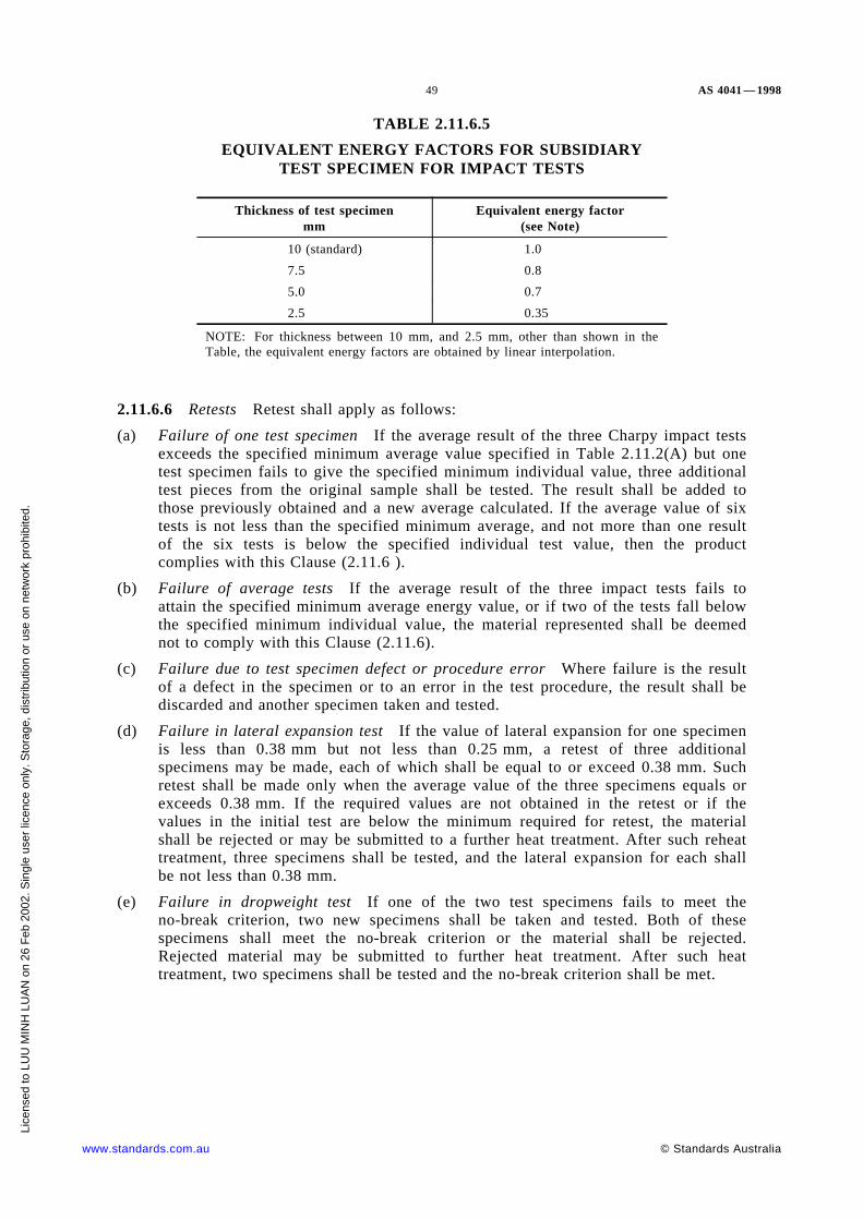
49 AS 4041 — 1998
TABLE 2.11.6.5
EQUIVALENT ENERGY FACTORS FOR SUBSIDIARYTEST SPECIMEN FOR IMPACT TESTS
Thickness of test specimenmm
Equivalent energy factor(see Note)
10 (standard) 1.0
7.5 0.8
5.0 0.7
2.5 0.35
NOTE: For thickness between 10 mm, and 2.5 mm, other than shown in theTable, the equivalent energy factors are obtained by linear interpolation.
2.11.6.6 Retests Retest shall apply as follows:
(a) Failure of one test specimen If the average result of the three Charpy impact testsexceeds the specified minimum average value specified in Table 2.11.2(A) but onetest specimen fails to give the specified minimum individual value, three additionaltest pieces from the original sample shall be tested. The result shall be added tothose previously obtained and a new average calculated. If the average value of sixtests is not less than the specified minimum average, and not more than one resultof the six tests is below the specified individual test value, then the productcomplies with this Clause (2.11.6 ).
(b) Failure of average tests If the average result of the three impact tests fails toattain the specified minimum average energy value, or if two of the tests fall belowthe specified minimum individual value, the material represented shall be deemednot to comply with this Clause (2.11.6).
(c) Failure due to test specimen defect or procedure error Where failure is the resultof a defect in the specimen or to an error in the test procedure, the result shall bediscarded and another specimen taken and tested.
(d) Failure in lateral expansion test If the value of lateral expansion for one specimenis less than 0.38 mm but not less than 0.25 mm, a retest of three additionalspecimens may be made, each of which shall be equal to or exceed 0.38 mm. Suchretest shall be made only when the average value of the three specimens equals orexceeds 0.38 mm. If the required values are not obtained in the retest or if thevalues in the initial test are below the minimum required for retest, the materialshall be rejected or may be submitted to a further heat treatment. After such reheattreatment, three specimens shall be tested, and the lateral expansion for each shallbe not less than 0.38 mm.
(e) Failure in dropweight test If one of the two test specimens fails to meet theno-break criterion, two new specimens shall be taken and tested. Both of thesespecimens shall meet the no-break criterion or the material shall be rejected.Rejected material may be submitted to further heat treatment. After such heattreatment, two specimens shall be tested and the no-break criterion shall be met.
www.standards.com.au © Standards Australia
Lice
nsed
to L
UU
MIN
H L
UA
N o
n 26
Feb
200
2. S
ingl
e us
er li
cenc
e on
ly. S
tora
ge, d
istr
ibut
ion
or u
se o
n ne
twor
k pr
ohib
ited.

AS 4041 — 1998 50
S E C T I O N 3 D E S I G N
3.1 GENERAL
3.1.1 Basis for determining size of pipe This Standard only deals with the mechanicaldesign of the piping system and assumes that a piping and instrument diagram with pipingdiameter is available to the designer.
Where the piping and instrument diagram is not available any assumptions made by thedesigner are to be specified and agreed to by the parties concerned.
A design specification covering service requirements, hazard level and other essentialrequirements shall be agreed by the owner and designer for Class 1 and 2A piping
Wherever possible, to facilitate interchangeability, reduce stock, and increase availability,the outside diameter and wall thickness of pipe should be selected from that specified inthe nominated Standard and sizes which are readily available.
Appendix T provides a method of selecting standard piping components without the needfor specific design calculations.
3.1.2 Design against failure Piping shall be designed to withstand the most severecondition likely to occur during the design life, without failure by bursting, excessiveplastic deformation, buckling, metallurgical deterioration, creep rupture, fatigue cracking,brittle fracture, corrosion or by any other means.
NOTE: Factors which contribute to the most severe condition may include ambient effects,operating pressure, operating temperature, dynamic effects, mass effects, movements ofsupports, cyclic loading and thermal effects.
3.1.3 Other design methods Pressure vessel design methods given in AS 1210 may beused. Methods and equations of the ANSI/ASME B31 series of Standards and BS 806may be used for the determination of calculated stresses due to thermal expansion and fordisplacements. Results shall be in SI units. Calculations may be manual, or by a validatedcomputer program.
3.2 DESIGN PRESSURE The design pressure shall be the highest differential betweeninternal and external pressure that will occur in normal operation, including provision forany unintended pressure changes.
The design pressure of piping for steam boilers shall comply with Clause 3.9.
Provision shall be made to contain or safely relieve any excessive pressure or vacuum.
NOTE: Causes of excessive pressure or vacuum may include improper operation, failure ofcontrol devices, and influence of ambient effects.
3.3 DESIGN TEMPERATURE
3.3.1 General The design temperature of piping for steam boilers shall comply withClause 3.9.
3.3.2 Uninsulated piping Where the temperature of the fluid in uninsulated piping isless than 40°C, the design temperature of the piping material shall be taken to be thetemperature of the fluid.
Where the temperature of the fluid in uninsulated piping is not less than 40°C and adifferent average temperature has not been determined by test or calculation, the designtemperature of the piping material shall be taken to be as follows:
(a) Average metal temperature determined by test or calculation; or
© Standards Australia www.standards.com.au
Lice
nsed
to L
UU
MIN
H L
UA
N o
n 26
Feb
200
2. S
ingl
e us
er li
cenc
e on
ly. S
tora
ge, d
istr
ibut
ion
or u
se o
n ne
twor
k pr
ohib
ited.
51 AS 4041 — 1998
(b) For valves, pipe fittings and components having a wall thickness comparable to thatof the pipe . . . . . . . . . . . . . . . . . . . . . . . . . . . .≥95% of fluid temperature (°C).
(c) For flanges and flanged fittings. . . . . . . . . . . . .≥90% of fluid temperature (°C).
(d) For bolting . . . . . . . . . . . . . . . . . . . . . . . . . . . .≥80% of fluid temperature (°C).
3.3.3 Externally insulated piping The temperature of externally insulated pipingmaterial shall be taken as the temperature of the fluid where a different averagetemperature has not been determined by test, calculation or measurement during operation.
3.3.4 Internally insulated piping The temperature of internally insulated pipingmaterial shall be determined by test or calculation.
3.3.5 Heated piping The effect of any piping heating shall be considered in thedetermination of the design temperature using the average wall temperature as a basis.
3.4 DESIGN LIFE Components within a system may have different design lives.Replaceable components may be designed for a shorter life than the life expectancy of thesystem.
A design life (expressed in hours or number of cycles of pressure or temperaturefluctuation) shall be agreed between owner and designer for the following:
(a) A component for which the design temperature is such that the design strength asgiven in Appendix D is time-dependent.
(b) A component for service requiring a cyclic design factor.
Appendix D provides for design strength values which allow for either specific designlifetimes or indefinite design lifetimes for components subject to elevated temperatures.
3.5 STATIC AND DYNAMIC LOADS AND FORCES Piping shall be designed towithstand the effects of the following static and dynamic loads and forces:
(a) Dead loads due to the mass of the piping components, insulation and othersuperimposed permanent loads.
(b) Temporary loads due to the mass of the cleaning or pressure test fluid.
(c) Live loads due to the mass of the fluid within the pipe, the mass of snow and ice onthe pipe and other superimposed temporary loads.
(d) Other significant static loads including the effect of prestressing.
(e) Earthquake loads as calculated using AS 1170.4. See Clause 3.27 for requirementsand method of application.
(f) Impact forces caused by external or internal conditions, including hydraulic shock,pressure surges, and water hammer.
(g) Reactions due to blowdown or discharge of fluids.
(h) Vibration, which may arise from sources such as impact, pressure, pulsation,resonance, or wind.
(i) Wind loads, determined using AS 1170.2. See Clause 3.27 for requirements andmethod of application. For calculations of the adequacy of design for the hydrostatictest, 75% of the normally applied wind load shall be considered to actsimultaneously with other loads except earthquake loads.
(j) Other significant dynamic loads.
(k) Pressure thrust due to pressurizing expansion joints.
(l) Loads due to possible accidents, e.g. dropping objects.
www.standards.com.au © Standards Australia
Lice
nsed
to L
UU
MIN
H L
UA
N o
n 26
Feb
200
2. S
ingl
e us
er li
cenc
e on
ly. S
tora
ge, d
istr
ibut
ion
or u
se o
n ne
twor
k pr
ohib
ited.

AS 4041 — 1998 52
3.6 RISK ANALYSIS
3.6.1 Hazard and operability study (HAZOP) A HAZOP should be considered forClass 1 piping containing fluid Type 1 or 2. This study would provide a systematicexamination of the design by an interdisciplinary specialist team.
A1 3.6.2 Other methods Failure mode and effect analysis (FMEA), fault tree analysis(FTA), hazard analysis (HAZAN) and other systematic methods may be conducted whenrequired.
3.7 THERMAL EFFECTS Piping shall be designed to withstand the effects of thefollowing:
(a) Heating or cooling where this is expected to change the pressure in the piping fromthe design pressure. Piping shall be designed to withstand the pressure variation, orthere shall be provision for the excess pressure or vacuum to be relieved.
(b) Cooling due to a rapid loss or controlled reduction of pressure.
(c) Movement on expansion joints.
(d) Where the minimum operating temperature is less than 0°C, icing and atmosphericcondensation on moving parts of valves, relief devices, vents or discharge piping,guides and other components.
(e) Forces resulting from differential thermal expansion due to combined or joinedmaterials of different coefficients of expansion.
(f) Forces resulting from stress due to large and rapid temperature changes, or uneventemperature distribution in a pipe wall.
(g) Forces and movements where anchors or restraints restrict free movement of thepiping due to thermal or other effects.
(h) Forces and movements resulting from solar heating.
(i) Condensation and oxygen enrichment where operating temperatures in ambient airare less (i.e. colder) than −191°C.
(j) Other significant thermal effects.
3.8 EFFECTS OF MOVEMENT AT SUPPORTS, ANCHORS AND TERMINALSPiping shall be designed to withstand, for the design life, the effects of movement ofpiping supports, anchors and connected equipment which may result from one or more ofthe following:
(a) Earthquake, settlement and other geophysical effects (see also Clause 3.5(e)).
(b) Thermal expansion or contraction of supports or connected equipment.
(c) Wind.
(d) Vibration.
NOTE: Crevice corrosion and abrasion induced by thermal expansion may cause significantloss of pipe wall thickness at anchors and pipe supports.
3.9 DESIGN PRESSURE AND TEMPERATURE FOR PIPING ASSOCIATEDWITH STEAM BOILERS
3.9.1 Design pressure for main steam piping The design pressure for pipingdownstream of the steam stop valve shall be either—
(a) the design working pressure of the boiler; or
(b) for piping where design stresses are time-dependent and the total capacity of thesafety valves on the super heater is not less than 20% of the evaporative capacity ofthe boiler, the lowest pressure at which any super heater safety valve is set to lift.
© Standards Australia www.standards.com.au
Lice
nsed
to L
UU
MIN
H L
UA
N o
n 26
Feb
200
2. S
ingl
e us
er li
cenc
e on
ly. S
tora
ge, d
istr
ibut
ion
or u
se o
n ne
twor
k pr
ohib
ited.

53 AS 4041 — 1998
3.9.2 Design pressure for reheat piping
3.9.2.1 Time-independent In reheat systems where the design stresses of the piping aretime-independent, the design pressure shall be the highest pressure at which any safetyvalve on the reheat system is set to lift. When no safety valves are mounted at thereheater inlet, the design pressure of the reheater inlet piping shall be the highest pressureat which any reheater outlet safety valve is set to lift, increased to take account of thepressure drop through the reheater corresponding to the most severe conditions ofoperation.
3.9.2.2 Time-dependent In reheat systems where the design stresses of the piping aretime-dependent, the design pressure shall be the lowest pressure to which any safety valveon the reheat system is set to lift. When no safety valves are mounted at the reheater inlet;the design pressure of the reheater inlet piping shall be the lowest pressure at which anyreheater outlet safety valve is set to lift, increased to take account of the pressure dropthrough the reheater corresponding to the most severe conditions of operation.
3.9.3 Design pressure for piping for reduced pressure systems For reduced pressuresystems, it is permissible for the pressure to be controlled at a value below that in theoriginating piping system by reducing valve or by the pressure drop across a fixedrestriction such as an orifice or the blading of the turbine.
Where a protective device consisting of a safety valve or valves or a suitable appliancefor automatically cutting off the supply of steam at a predetermined pressure is fitted, thedesign pressure for piping systems, whose design stresses are time-independent, shall bethat to which the pressure under the most arduous condition is limited by the properoperation of such a device. Where similar provisions are made on piping systems whosedesign stresses are time-dependent, the design pressure shall be the highest controlledoperating pressure, provided that the average pressure in any one year does not exceedthat pressure and that the fluctuations in controlled pressure at no time exceed the designvalue by more than 20%.
Where no protective device is fitted, the design pressure shall be the greatest pressuretherein attainable under the most arduous operating condition, i.e. with the originatingpiping system operating at its design pressure, with the upstream valves (including anyreducing valves or restrictions) fully open, and with the downstream valves (other thannon-return valves) fully closed.
The relieving capacity of safety valves (as determined in accordance with fitteddownstream pressure reducing valves shall be such that the operating pressure limitationshall not be exceeded by more than 10% if the reducing valve fails in the open positionwith the downstream valves (other than non-return valves) fully closed.
3.9.4 Design temperature for steam piping The design temperature for main andreheat steam piping for a land boiler shall be taken as the design temperature at thefollowing points:
(a) For non-superheated main steam piping . . . . . . . . . . . . . at the boiler stop valve.
(b) For superheated main steam piping . . . . . . . . . . . . . . . . at the superheater outlet.
(c) For reheater outlet steam piping (hot reheat) . . . . . . . . . at the boiler reheateroutlet.
(d) For reheater inlet steam piping (cold reheat) . . . . . . . . . at the turbine highpressure cylinder exhaust outlet, or turbine steam by-pass system outlet, whicheveris the greater.
(e) For by-pass systems, the piping for a length of 5 diameters after the high pressureby-pass valve should be designed for both—
(i) the cold reheat pressure and temperature; and
www.standards.com.au © Standards Australia
Lice
nsed
to L
UU
MIN
H L
UA
N o
n 26
Feb
200
2. S
ingl
e us
er li
cenc
e on
ly. S
tora
ge, d
istr
ibut
ion
or u
se o
n ne
twor
k pr
ohib
ited.

AS 4041 — 1998 54
(ii) the condition of cold reheat pressure and a temperature 50°C less than themain steam temperature. Recognizing the intermittent operation, a fraction ofthe boiler design life is appropriate and 30 000 hours is recommended.
The design temperature for other than main steam piping shall be the highest ratedtemperature at the higher temperature end of the piping.
The design temperature may be exceeded during the design life of the piping where atdesign pressure, the annual average operating temperature does not exceed the designtemperature; and—
(i) for ferritic piping having a design temperature equal to or less than 380°C, variationabove the design temperature is not greater than 10 percent of the designtemperature; or
(ii) for ferritic piping having a design temperature greater than 380°C—
(A) normal variations above the design temperature is not greater than 8°C of thedesign temperature; and
(B) abnormal variation above the design temperature is not greater than thefollowing in any one year:
(1) 20°C for a maximum of 400 h.
(2) 30°C for a maximum of 100 h.
(3) 40°C for a maximum of 60 h.
When a piping system is operated above these limits, the design life shall bereduced.
For piping material not provided for above, see Clause 3.10.3.
Where the above temperature limitations are expected to be exceeded, the designtemperature shall be increased appropriately.
3.9.5 Design pressure and temperature for boiler feed water piping The pipingshall be designed for both—
(a) the shut-off pressure of the boiler feed pump when pumping water at 15°C and adesign temperature of 15°C; and
(b) the most arduous combinations of temperature and pressure that can occur inoperation for each section. If a protective device is fitted, the design pressure shallbe the set pressure of the device.
Specific allowance shall be made for water hammer if it results in pressure surges of20 percent over the design pressure.
3.9.6 Design pressure for blowdown and drain systems3.9.6.1 Upstream design pressure The design pressure upstream and including any shutoff valve, control valve, or trap shall be that of the upstream component to which they areconnected, but not less than 700 kPa if the system is handling a flashing liquid.
Where a control or restriction orifice is fitted, then this shall be considered as a control orshut off valve.
3.9.6.2 Downstream design pressure The design pressure downstream from the lastshut off valve, control valve, trap or restrictor treated as a control in accordance withClause 3.9.7.1 shall also comply with Clause 3.9.7.1, except that where—
(a) the downstream pipe has a cross-sectional area of not less than 2.5 times thecombined simultaneous areas that can discharge into it; and
(b) further that this downstream pipe discharges freely into an adequately ventedreceiver;
then the design pressure may be taken as one-half of the upstream pressure specified inClause 3.9.7.1 but shall not be less than 700 kPa if the system is handling a flashingliquid.
© Standards Australia www.standards.com.au
Lice
nsed
to L
UU
MIN
H L
UA
N o
n 26
Feb
200
2. S
ingl
e us
er li
cenc
e on
ly. S
tora
ge, d
istr
ibut
ion
or u
se o
n ne
twor
k pr
ohib
ited.

55 AS 4041 — 1998
3.9.6.3 Blowdown and drain vessels design pressure The design pressure of blowdownvessel or a drain vessel shall be the maximum pressure that can be imposed upon it inoperation but not less than the lower value of 700 kPa or 25% of the maximumpermissible working pressure of the boiler. See Clause 3.25.2 for specific designrequirements.
3.9.7 Design temperature for blowdown and drain systems
3.9.7.1 Upstream design temperature The design temperature for systems describedunder Clause 3.9.6.1 shall be that of the upstream component.
NOTE: Where the design stress is time-dependent, the design lifetime will be the same as thatof the upstream component except where a control or restriction orifice is fitted between the lastvalve and the drain discharge point when for that section of pipe between the last valve and theorifice a reduced design lifetime may be used if the drain is used intermittently.
3.9.7.2 Downstream design temperature The design temperature for systems describedunder Clause 3.9.6.2 shall be the greater of—
(a) the design temperature T (in °C) determined from:
. . . 3.9.8.2T =Ts – 41
1.15
where
Ts is the design temperature (in °C) of the component from which the drainor blowdown system originates; and
(b) the saturation temperature at the design pressure of the system derived fromClause 3.9.6.1.
NOTE: The reduced time design life for intermittent use is also applicable to the systemscovered by this subclause.
3.9.7.3 Blowdown and drain vessel design temperature The design temperature T (in°C) of a blowdown vessel, or drain vessel, or atmospheric vent shall be determined from:
. . . 3.9.8.3T =Ts – 41
1.15
where
Ts is the design temperature (in °C) of the component from which the drain orblowdown system originates.
The design temperature shall neither be higher than the highest design temperature of anypipe discharging into the vessel nor lower than saturation temperature at the vessel designpressure.
3.9.8 Design conditions for safety valve discharge piping
3.9.8.1 Design pressure The design pressure of the discharge piping shall be themaximum pressure which can be imposed upon it, but in no case less than 350 kPa. SeeAppendix J for calculation method. ANSI/ASME B31.1 provides an alternative method.
3.9.8.2 Capacity of safety valve The capacity of the safety valve for the purpose ofcalculation shall be 1.11 times the certified discharge capacity as defined in BS 6759.1.
NOTE: The discharge piping system should be such as not to create a built up back pressure,measured at the safety valve outlet connection, of more than 12% of the set pressure of thesafety valve, subject to a maximum of 1700 kPa. If the discharge piping system gives rise to ahigher built up back pressure, the design should be referred to the safety valve manufacturer foragreement that the safety valve performance will not be adversely affected.
www.standards.com.au © Standards Australia
Lice
nsed
to L
UU
MIN
H L
UA
N o
n 26
Feb
200
2. S
ingl
e us
er li
cenc
e on
ly. S
tora
ge, d
istr
ibut
ion
or u
se o
n ne
twor
k pr
ohib
ited.

AS 4041 — 1998 56
3.9.8.3 Design temperature The design temperature T (in °C) of safety valve dischargepiping shall be:
. . . 3.9.9.3T =
Ts – 41
1.15where
Ts is the temperature (in °C) of steam at the safety valve body inlet.
NOTE: For the purpose of calculating the thermal expansion of the discharge pipe, atemperature 25°C higher than this design temperature should be assumed.
3.9.9 Design temperature for structural attachments The design temperature forstructural attachments shall be as follows:
(a) Welded to pipe: T = Tf − 10°C.
(b) Clamped to pipe: T = Tf − 20°C.
(c) Insulated pipe, outside insulation: T = 80°C
where
T = design temperature
Tf = fluid design temperature.
3.10 DESIGN CRITERIA
3.10.1 Pressure-temperature design criteria
3.10.1.1 Components having specified ratings The pressure-temperature rating of apressurized component complying with a nominated Standard shall not be exceeded.
3.10.1.2 Components not having specified ratings A pressurized component complyingwith a nominated Standard that does not specify a pressure-temperature rating but doesspecify the nominal thickness and the material, may be rated as seamless pipe of the samenominal thickness as determined by Clause 3.12 for material of the same type having thesame design strength.
NOTE: The design pressure of pipe with a design strength complying with Clause 3.12 may belimited by other clauses in this Standard.
3.10.2 Normal operating conditions Piping is considered safe for normal operation ifthe coincident pressure and temperature on a component do not exceed the design pressureand design temperature or the pressure-temperature rating of that component.
3.10.3 Variations in normal operating conditions Occasional variations in pressureand temperature during the design life of ferrous piping are acceptable within thefollowing limits:
(a) Where the fluid is steam . . . . . . . . . . . . . . . . . shall not exceed those specified inClause 3.9.4.
(b) Where the fluid is boiler feed water . . . . . . . . . shall not exceed those specified inClause 3.9.5.
Where the fluid is other than steam or boiler feed water, a piping system shall beconsidered safe during those variations when all the following conditions are fulfilled:
(i) The piping does not contain pressurized components made from cast iron or othernon-ductile material.
(ii) For piping not in the creep range, the hoop stress is not more than the hot yieldstrength at the highest temperature occurring during the variation.
(iii) The number of significant variations, or cycles of pressure during the design life, isnot more than 7000. In this requirement a pressure variation of greater than ±20%of the design is significant.
© Standards Australia www.standards.com.au
Lice
nsed
to L
UU
MIN
H L
UA
N o
n 26
Feb
200
2. S
ingl
e us
er li
cenc
e on
ly. S
tora
ge, d
istr
ibut
ion
or u
se o
n ne
twor
k pr
ohib
ited.

57 AS 4041 — 1998
(iv) The highest pressure occurring during the variation is less than the hydrostatic testpressure.
(v) Occasional variations above the design pressure and temperature comply with thefollowing:
(A) The period of the variation is less than 10 h at any one time and the sum ofthe periods is less than 100 h in a year. The pressure rating of a componentor the yield strength at the highest temperature during any of the variationsmay be increased by not more than 33 percent.
(B) The period of the variation is less than 50 h at any one time and the sum ofthe periods is less than 500 h in a year. The pressure rating of a componentor the yield strength at the highest temperature during any of the variationsmay be increased by not more than 20 percent.
(vi) An evaluation of the combined effects of the sustained and cyclic variations on thedesign life of all components is made and the results of the evaluation are agreedbetween the parties concerned.
3.11 DESIGN STRENGTH
3.11.1 Design strength for pressure-retaining components The value of the designstrength for a pressure-retaining component in tension shall be appropriate for thematerial, design temperature and design life. Design strength values for piping toClasses 1, 2A and 3 are given in Appendix D. Tables of design strength in Appendix Dare independent of weld joint factor (Clause 3.12.2).
Because of the many popular pipe specifications nominally covering the same pipe butperhaps with slightly differing specified mechanical properties, Table D3 deems the listedpipe to take the values of design strength of BS 3601, Grade 320 in Table D2. SimilarlyTable D4 deems the listed pipe to take the values of API 5L B in Table D2. Designstrength for Class 2P are not listed but are 0.72 of the specified room temperature yieldstress (see Appendix I). Values at intermediate temperatures may be obtained by linearinterpolation.
The design strength value determined in accordance with Appendix I may be used withoutverification of the ReT values provided that the heat treatment of the completed pipecomplies with the material standard and is as given in AS 4458.
Allowance shall be made for any degradation of the properties of the material which couldreduce design strength of the piping due to the methods used during fabrication, e.g. hotbending.
NOTE: Clause 2.11 specifies design strength requirements for a material selected for lowtemperature application.
The design strength for unlisted materials shall be in accordance with Appendix I unlessotherwise agreed between the parties concerned.
3.11.2 Compressive stress The value of the stress in compression shall be appropriatefor the material and design temperature, and shall not exceed the design strength intension.
3.11.3 Shear stress The value of any primary shear stress shall be appropriate for thematerial and design temperature. It may be noted that AS 1210 quotes 60% of the tensiledesign stress for vessels and ANSI B31.1 quote 80% for piping.
3.11.4 Bearing stress The value of the stress in bearing shall be appropriate for thematerial and design temperature, and shall not exceed 160 percent of the design strengthin tension.
www.standards.com.au © Standards Australia
Lice
nsed
to L
UU
MIN
H L
UA
N o
n 26
Feb
200
2. S
ingl
e us
er li
cenc
e on
ly. S
tora
ge, d
istr
ibut
ion
or u
se o
n ne
twor
k pr
ohib
ited.

AS 4041 — 1998 58
3.11.5 Sustained longitudinal stress The sustained longitudinal stress (fL), being thesum of the longitudinal stresses due to pressure, weight, and other sustained loads, shallbe not greater than 100 percent of the design strength listed in Appendix D at thetemperature under consideration.
3.11.6 Longitudinal stress due to sustained and occasional loads The longitudinalstress due to the sum of the sustained loads (fL) as defined in Clause 3.11.5 and theoccasional loads (fo) (due to wind, earthquake and the like) shall be less than 1.33 timesthe allowable design strength from Appendix D.
It is recommended that design strength values be limited to 75% of the Appendix Dvalues or two thirds of the yield strength at design temperature, whichever is the least, atflanged joints or where slight deformation can cause leakage.
3.11.7 Design stress range The design stress range (fa), being the maximumdisplacement (expansion or contraction) stress range permitted for the displacement stressrange calculated in accordance with Clause 3.27, shall be determined from one of thefollowing equations as appropriate:
fa = F(1.25fc + 0.25fh) . . . 3.11.7(1)
or, where fh > fL,
fa = F[1.25(fc + fh) − fL] . . . 3.11.7(2)
where
fa = design stress range, in megapascals
A1 F = stress-range reduction factor for the total number of displacement cyclesover the design lifetime. See Table 3.11 or calculate using equation:
F = 6(N)−0.2 but ≤1.0
N = equivalent number of full displacement cycles during the expected
service life of the piping system
fc = design strength at the minimum metal temperature expected duringoperation or shutdown, in megapascals (see Note)
fh = design strength at maximum metal temperature expected during operation
or shutdown, in megapascals (see Note)
fL = sustained longitudinal stress, in megapascals.
In the determination of fa, the value of the weld joint factor (e) shall be taken as unity.
In no case shall the value exceed the minimum of and at minimum metalRm
32
ReT
3temperature (see Appendix D).3.11.8 Creep-fatigue interaction For creep-fatigue interactions the followingStandards may be used:
TRD 300, DesignTRD 301, DesignTRD 301 Design, Annex 1TRD 508 Annex 1Code Case N 47 of ANSI/ASME BPV-III.
NOTE: TRD documents may be obtained from TUV Germany.
© Standards Australia www.standards.com.au
Lice
nsed
to L
UU
MIN
H L
UA
N o
n 26
Feb
200
2. S
ingl
e us
er li
cenc
e on
ly. S
tora
ge, d
istr
ibut
ion
or u
se o
n ne
twor
k pr
ohib
ited.

59 AS 4041 — 1998
TABLE 3.11
STRESS RANGE REDUCTION FACTOR
Total number of full temperaturecycles during the design life
(N)
Stress range reductionfactor (F)
(Notes 1, 2 and 3)
>7 000>14 000
≤7 000≤14 000≤22 000
1.00.90.8
>22 000>45 000
>100 000
≤45 000≤100 000
0.70.60.5
NOTES:
1 F applies to uncorroded piping. Corrosion may severely reducecycle life, therefore corrosion-resistant materials, environmentimprovement, or lower stress are appropriate where a largenumber of high stress cycles is expected.
2 The fatigue life of material operating within the creep range willbe reduced.
3 Where the range of temperature varies, the equivalent fulltemperature cycles, N, may be determined from the followingequation:
. . . 3.11.7(3)N = NE + r 51 N1 + r 5
2 N2 + r 5n Nn
where
NE = number of cycles of full temperature change∆TE for which displacement stress-range (fe)has been calculated.
fE = (fb2 + Ft
2)½
fb = resultant bending stress, in megapascals
ft = torsional stress, in megapascals
N1, N2 ... Nn = number of cycles of lesser temperaturechange ∆T1, ∆T2, etc.
r1, r2 ... rn = ratios of lesser temperature cycles to that forwhich fc has been calculated, i.e.
∆T1
∆TE
,∆T2
∆TE
, ...,∆Tn
∆TE
www.standards.com.au © Standards Australia
Lice
nsed
to L
UU
MIN
H L
UA
N o
n 26
Feb
200
2. S
ingl
e us
er li
cenc
e on
ly. S
tora
ge, d
istr
ibut
ion
or u
se o
n ne
twor
k pr
ohib
ited.
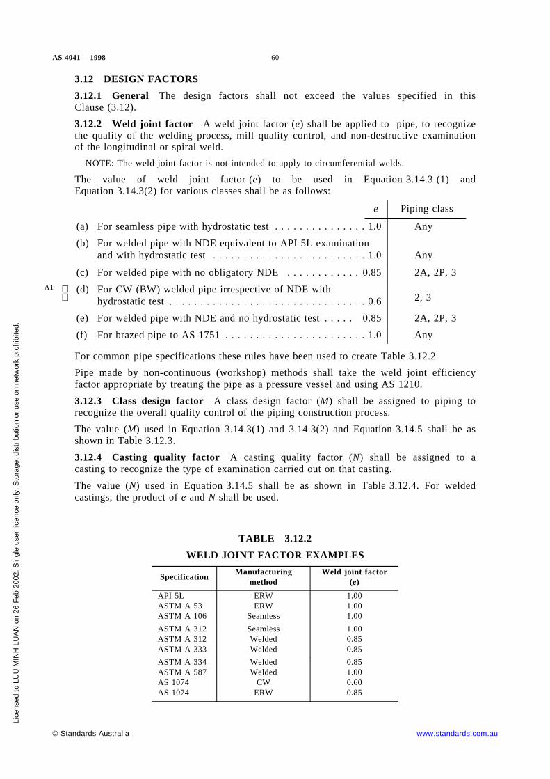
AS 4041 — 1998 60
3.12 DESIGN FACTORS
3.12.1 General The design factors shall not exceed the values specified in thisClause (3.12).
3.12.2 Weld joint factor A weld joint factor (e) shall be applied to pipe, to recognizethe quality of the welding process, mill quality control, and non-destructive examinationof the longitudinal or spiral weld.
NOTE: The weld joint factor is not intended to apply to circumferential welds.
The value of weld joint factor (e) to be used in Equation 3.14.3 (1) andEquation 3.14.3(2) for various classes shall be as follows:
A1
e Piping class
(a) For seamless pipe with hydrostatic test . . . . . . . . . . . . . . . 1.0 Any
(b) For welded pipe with NDE equivalent to API 5L examinationand with hydrostatic test . . . . . . . . . . . . . . . . . . . . . . . . . 1.0 Any
(c) For welded pipe with no obligatory NDE . . . . . . . . . . . . 0.85 2A, 2P, 3
(d) For CW (BW) welded pipe irrespective of NDE withhydrostatic test . . . . . . . . . . . . . . . . . . . . . . . . . . . . . . . . 0.6
2, 3
(e) For welded pipe with NDE and no hydrostatic test . . . . . 0.85 2A, 2P, 3
(f) For brazed pipe to AS 1751 . . . . . . . . . . . . . . . . . . . . . . . 1.0 Any
For common pipe specifications these rules have been used to create Table 3.12.2.
Pipe made by non-continuous (workshop) methods shall take the weld joint efficiencyfactor appropriate by treating the pipe as a pressure vessel and using AS 1210.
3.12.3 Class design factor A class design factor (M) shall be assigned to piping torecognize the overall quality control of the piping construction process.
The value (M) used in Equation 3.14.3(1) and 3.14.3(2) and Equation 3.14.5 shall be asshown in Table 3.12.3.
3.12.4 Casting quality factor A casting quality factor (N) shall be assigned to acasting to recognize the type of examination carried out on that casting.
The value (N) used in Equation 3.14.5 shall be as shown in Table 3.12.4. For weldedcastings, the product of e and N shall be used.
TABLE 3.12.2
WELD JOINT FACTOR EXAMPLES
SpecificationManufacturing
methodWeld joint factor
(e)
API 5LASTM A 53ASTM A 106
ERWERW
Seamless
1.001.001.00
ASTM A 312ASTM A 312ASTM A 333
SeamlessWeldedWelded
1.000.850.85
ASTM A 334ASTM A 587AS 1074AS 1074
WeldedWelded
CWERW
0.851.000.600.85
© Standards Australia www.standards.com.au
Lice
nsed
to L
UU
MIN
H L
UA
N o
n 26
Feb
200
2. S
ingl
e us
er li
cenc
e on
ly. S
tora
ge, d
istr
ibut
ion
or u
se o
n ne
twor
k pr
ohib
ited.
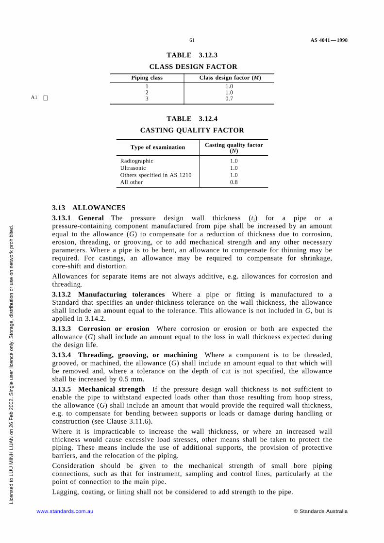
61 AS 4041 — 1998
TABLE 3.12.3
CLASS DESIGN FACTOR
A1
Piping class Class design factor (M)
123
1.01.00.7
TABLE 3.12.4
CASTING QUALITY FACTOR
Type of examination Casting quality factor(N)
RadiographicUltrasonicOthers specified in AS 1210All other
1.01.01.00.8
3.13 ALLOWANCES3.13.1 General The pressure design wall thickness (tf) for a pipe or apressure-containing component manufactured from pipe shall be increased by an amountequal to the allowance (G) to compensate for a reduction of thickness due to corrosion,erosion, threading, or grooving, or to add mechanical strength and any other necessaryparameters. Where a pipe is to be bent, an allowance to compensate for thinning may berequired. For castings, an allowance may be required to compensate for shrinkage,core-shift and distortion.
Allowances for separate items are not always additive, e.g. allowances for corrosion andthreading.
3.13.2 Manufacturing tolerances Where a pipe or fitting is manufactured to aStandard that specifies an under-thickness tolerance on the wall thickness, the allowanceshall include an amount equal to the tolerance. This allowance is not included in G, but isapplied in 3.14.2.
3.13.3 Corrosion or erosion Where corrosion or erosion or both are expected theallowance (G) shall include an amount equal to the loss in wall thickness expected duringthe design life.
3.13.4 Threading, grooving, or machining Where a component is to be threaded,grooved, or machined, the allowance (G) shall include an amount equal to that which willbe removed and, where a tolerance on the depth of cut is not specified, the allowanceshall be increased by 0.5 mm.
3.13.5 Mechanical strength If the pressure design wall thickness is not sufficient toenable the pipe to withstand expected loads other than those resulting from hoop stress,the allowance (G) shall include an amount that would provide the required wall thickness,e.g. to compensate for bending between supports or loads or damage during handling orconstruction (see Clause 3.11.6).
Where it is impracticable to increase the wall thickness, or where an increased wallthickness would cause excessive load stresses, other means shall be taken to protect thepiping. These means include the use of additional supports, the provision of protectivebarriers, and the relocation of the piping.
Consideration should be given to the mechanical strength of small bore pipingconnections, such as that for instrument, sampling and control lines, particularly at thepoint of connection to the main pipe.
Lagging, coating, or lining shall not be considered to add strength to the pipe.
www.standards.com.au © Standards Australia
Lice
nsed
to L
UU
MIN
H L
UA
N o
n 26
Feb
200
2. S
ingl
e us
er li
cenc
e on
ly. S
tora
ge, d
istr
ibut
ion
or u
se o
n ne
twor
k pr
ohib
ited.

AS 4041 — 1998 62
3.14 WALL THICKNESS OF STRAIGHT PIPE
3.14.1 Required wall thickness The required wall thickness (tm) of straight pipe or apressure-containing component made from pipe shall be determined from the followingequation:
tm = tf + G . . . 3.14.1
where
tm = required wall thickness, in millimetres
tf = pressure design wall thickness, in millimetres
G = summation of appropriate allowances (see Clause 3.13), in millimetres.
3.14.2 Nominal wall thickness The nominal wall thickness (tn) shall be—
tn = tm + pipe manufacturing under tolerance but in no case shall be less than thatgiven in Item (a) or (b) as follows:
(a) For Class 1 . . . equal to or greater than the required wall thickness (tm) and shouldbe not less than the thinnest wall thickness appropriate to the diameter nominated inthe appropriate pipe standard or 1 mm.
(b) For Class 2 and Class 3 . . . equal to or greater than the required wall thickness (tm)and not greater than that shown in Table 3.14.2 for respective class.
Where the pressure design wall thickness or the nominal wall thickness is greater thanthat specified in Table 3.14.2, the piping shall be fabricated to the requirements of Class 1or Class 2, as appropriate.
TABLE 3.14.2
MAXIMUM WALL THICKNESS FOR CLASS 2 AND CLASS 3 PIPING
A1
A1
MaterialWall thickness, mm
Class 2piping Class 3 piping
Steel group Type tn* and tf† tn* tf†A1, A2 Carbon and carbon-manganese steel 32 20 12A3 High yield strength C-Mn steel 16 12 12B Low alloy steel (alloy < ¾) 20 12 10
C Cr-Mo steel (¾ ≤ total alloy < 3) 16 0 0D Vanadium and medium Cr-Mo steel
(3 ≤ alloy < 10%)0 0 0
E 3½ nickel steel 16 0 0
F, G 9 nickel and QT steel 0 0 0H Martensitic chromium steel 0 0 0J Ferritic high chromium steel 0 0 0
K Austenitic Cr-Ni steel 32 20 12L High chromium steel 0 0 0M Ferritic austenitic steels 32 10 5
— Non-ferrous alloys 10 6 6
* tn = nominal wall thickness at any weld
† tf = pressure design wall thickness
© Standards Australia www.standards.com.au
Lice
nsed
to L
UU
MIN
H L
UA
N o
n 26
Feb
200
2. S
ingl
e us
er li
cenc
e on
ly. S
tora
ge, d
istr
ibut
ion
or u
se o
n ne
twor
k pr
ohib
ited.

63 AS 4041 — 1998
3.14.3 Pressure design wall thickness for pipe, under internal pressure Thepressure design wall thickness (tf) for cylindrical pipe, or pressurized components, underinternal pressure, shall be determined as follows:
(a) Where the pressure design wall thickness is less than D/6, the pressure design wallthickness, under internal pressure, shall be determined from the following equations:
(i) Where outside diameter is used as the basis of calculation:
. . . 3.14.3(1)tf = pD2feM + p
(ii) Where inside diameter is used as the basis for calculation:
. . . 3.14.3(2)tf = pd2feM − p
where
D = outside diameter, in millimetres
M = class design factor (see Clause 3.12.3 and Note below)
d = inside diameter, in millimetres
e = weld joint factor (see Clause 3.12.2 and Note below)
= N for castings (see Clause 3.12.4)
f = design strength (see Clause 3.11), in megapascals
p = design pressure, in megapascals
tf = pressure design wall thickness, in millimetres
The product of e and M need not be taken as less than 0.6.
NOTE: e relates primarily to hoop stress across a longitudinal weld and percentage NDE. Nrelates primarily to hoop stress in casting and percentage NDE. M relates primarily tolongitudinal stress and percentage of NDE. The use of 0.6 minimum avoids doublypenalizing longitudinal joints.
(b) Where the pressure design wall thickness is equal to or greater than D/6 or d/4, orwhere p/fe or p/fM is greater than 0.385, consideration shall be given to the designand choice of material. If such thick pipe must be used, the use of a thick wallequation is recommended and the value of the pressure design wall thickness shallbe agreed. The possibility of failure due to fatigue and thermal stress shall beinvestigated and the findings of the investigation shall be agreed.
3.14.4 Wall thickness of pipe under external pressure The pressure design wallthickness (tf) and any stiffening requirements for straight cylindrical pipe under externalpressure shall be determined in accordance with AS 1210, except that where D/t < 10 the
calculated hoop stress shall be the lesser of—
pD2tf
,
(a) 1.5 × (the lesser of the design strength given in Appendix D at design metal
temperature andRm
3); and
(b) 0.9 × specified minimum yield strength at design metal temperature.
3.14.5 Pressure design wall thickness of cast pipe The pressure design wall thickness(tf) of ductile pipe, other than ductile iron, shall be determined from Equation 3.14.5 butshall be not less than 10 mm.
www.standards.com.au © Standards Australia
Lice
nsed
to L
UU
MIN
H L
UA
N o
n 26
Feb
200
2. S
ingl
e us
er li
cenc
e on
ly. S
tora
ge, d
istr
ibut
ion
or u
se o
n ne
twor
k pr
ohib
ited.

AS 4041 — 1998 64
. . . 3.14.5tf = pd2fNM − p
where
N = casting quality factor (see Clause 3.12.4)
M, d, f, p and tf have the meanings given in Clause 3.14.3(a).
The product of N and M need not be taken as less than 0.6. (See Note toClause 3.14.3(a)(ii).)
3.15 PIPE BENDS
3.15.1 General Bends may be continuous, wrinkle, mitre or cut and shut, as prescribedin this Clause.
3.15.2 Continuous bends
3.15.2.1 Method of manufacture Continuous pipe bends may be made by cold bending,hot bending, induction bending or by welding together halves pressed from plate. Thedesign thickness ovality and wrinkle requirements are the same for all processes.
Elbows are not included in the requirements for continuous bends. Elbows for piping tothis Standard require a pressure and temperature rating in the elbow specification or if notto be given by the manufacturer.
3.15.2.2 Minimum thickness of bends The minimum thickness of bends shall complywith the following:
(a) Except as specified in Items (b) and (c), pipe bends shall have a minimum wallthickness of tf. No additional thickness tolerance is applicable:
tf = calculated minimum thickness for straight pipe
A1
(b) Where the design stress is time-dependent, i.e. derived from creep data, and thebend centreline radius is less than three times the inside diameter, the intradosthickness ti (in mm) shall not be less than that calculated from the following:
. . . 3.15.2.2(1)ti = tf × 2R − r2R − 2r
(c) Where the design stress is time-independent and the bend radius is less than1.5 times the inside diameter, the intrados thickness ti shall not be less than thatcalculated from the following:
. . . 3.15.2.2(2)ti =tf
1.25× 2R − r
2R − 2rwhere
R = the radius of the bend, in millimetres
r = the mean radius of the pipe, in millimetres
ti = intrados thickness, in millimetres
Equation 3.15.2.2(3) and 3.15.2.2(4) and Table 3.15.2.2 are provided as a guide to initialthickness of straight pipe for hot bends. Other methods may require a greater or lessinitial thickness to finally comply with Items (a), (b) and (c).
For pipes 219.1 mm OD and below bent to any radius and for pipes above 219.1 mm ODbent to the radius listed in column 2 of Table 3.15.2.2, a suggested starting thickness isgiven by—
tb = 1.125 tf . . . 3.15.2.2(3)
© Standards Australia www.standards.com.au
Lice
nsed
to L
UU
MIN
H L
UA
N o
n 26
Feb
200
2. S
ingl
e us
er li
cenc
e on
ly. S
tora
ge, d
istr
ibut
ion
or u
se o
n ne
twor
k pr
ohib
ited.

65 AS 4041 — 1998
A1 For pipes above 219.1 mm OD and where tf is 35 mm or more, and are bent to the radii ofcolumn 4 in Table 3.15.2.2, a suggested starting thickness is given by—
tb = 1.1 tf . . . 3.15.2.2(4)
The radii inferred in Table 3.15.2.2 may be considered typical of tight radius bends forthe respective thicknesses and special techniques will be required for tighter radii.
3.15.2.3 Ovality Ovality (out-of-roundness) of continuous bends shall be calculated inaccordance with the following requirements:
. . . 3.15.2.3(1)Ovality =
Dmax. − Dmin.
Ds
× 100%
where
Dmax. = the maximum outside diameter in the bent section of the pipe, inmillimetres
Dmin. = the minimum diameter of the bent section of the pipe measured at thesame cross-section as Dmax., in millimetres
Ds = the average outside diameter in the straight, in millimetres
For Class 1 and Class 2 piping, the ovality of continuous bends shall not exceed10 percent for pipe designed for internal pressure, or 3 percent for pipe designed forexternal pressure.
For Class 3 piping, the ovality of continuous bends shall not exceed 12 percent for pipedesigned for internal pressure, or 5 percent for pipe designed for external pressure.
Ovality greater than that specified in this Clause (3.15.2.3) may be acceptable subject toanalysis of stress, fluid flow and internal corrosion.
For lines using pigs for internal cleansing, and or other special cases, tighter ovalitytolerances may be specified.
TABLE 3.15.2.2
TIGHT BENDING RADII FOR HOT BENTWROUGHT STEEL PIPES
A1
1 2 3 4 5
Outside diameterRadii measured to centreline of pipe (R)
tb = 1.125 tfall thickness
tb = 1.1 tftb = 35 mm or above
mm R mm R/D R, mm R/D
26.933.742.4
6575
100
2.42.22.4
48.360.376.1
115150190
2.42.52.5
88.9101.6114.3
230265305
2.62.62.7
139.7168.3193.7
380460630
2.72.73.3
219.1244.5273.1
710810
1 020
3.23.33.7
1 1401 270
4.74.7
323.9355.6406.4
1 2201 5001 730
3.84.24.3
1 5201 7802 030
4.75.05.0
457.0 2 030 4.4 2 280 5.0
www.standards.com.au © Standards Australia
Lice
nsed
to L
UU
MIN
H L
UA
N o
n 26
Feb
200
2. S
ingl
e us
er li
cenc
e on
ly. S
tora
ge, d
istr
ibut
ion
or u
se o
n ne
twor
k pr
ohib
ited.
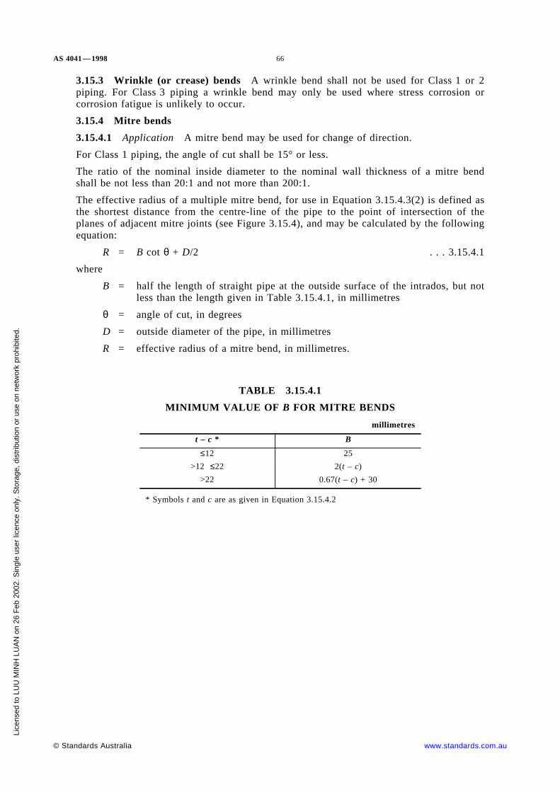
AS 4041 — 1998 66
3.15.3 Wrinkle (or crease) bends A wrinkle bend shall not be used for Class 1 or 2piping. For Class 3 piping a wrinkle bend may only be used where stress corrosion orcorrosion fatigue is unlikely to occur.
3.15.4 Mitre bends
3.15.4.1 Application A mitre bend may be used for change of direction.
For Class 1 piping, the angle of cut shall be 15° or less.
The ratio of the nominal inside diameter to the nominal wall thickness of a mitre bendshall be not less than 20:1 and not more than 200:1.
The effective radius of a multiple mitre bend, for use in Equation 3.15.4.3(2) is defined asthe shortest distance from the centre-line of the pipe to the point of intersection of theplanes of adjacent mitre joints (see Figure 3.15.4), and may be calculated by the followingequation:
R = B cot θ + D/2 . . . 3.15.4.1
where
B = half the length of straight pipe at the outside surface of the intrados, but notless than the length given in Table 3.15.4.1, in millimetres
θ = angle of cut, in degrees
D = outside diameter of the pipe, in millimetres
R = effective radius of a mitre bend, in millimetres.
TABLE 3.15.4.1
MINIMUM VALUE OF B FOR MITRE BENDS
millimetres
t – c * B
≤12 25
>12 ≤22 2(t – c)
>22 0.67(t – c) + 30
* Symbols t and c are as given in Equation 3.15.4.2
© Standards Australia www.standards.com.au
Lice
nsed
to L
UU
MIN
H L
UA
N o
n 26
Feb
200
2. S
ingl
e us
er li
cenc
e on
ly. S
tora
ge, d
istr
ibut
ion
or u
se o
n ne
twor
k pr
ohib
ited.

67 AS 4041 — 1998
FIGURE 3.15.4 DIMENSIONAL PARAMETERS FOR MITRE BENDS
www.standards.com.au © Standards Australia
Lice
nsed
to L
UU
MIN
H L
UA
N o
n 26
Feb
200
2. S
ingl
e us
er li
cenc
e on
ly. S
tora
ge, d
istr
ibut
ion
or u
se o
n ne
twor
k pr
ohib
ited.
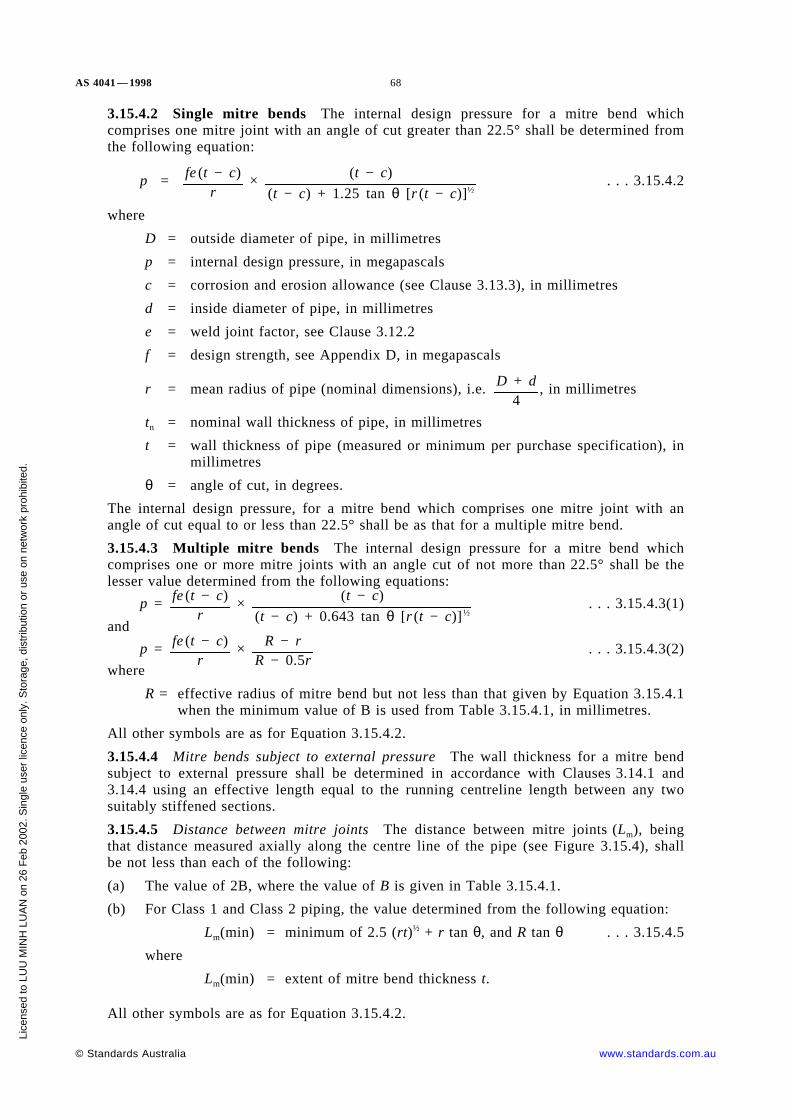
AS 4041 — 1998 68
3.15.4.2 Single mitre bends The internal design pressure for a mitre bend whichcomprises one mitre joint with an angle of cut greater than 22.5° shall be determined fromthe following equation:
. . . 3.15.4.2p = fe (t − c)r
× (t − c)
(t − c) + 1.25 tan θ [r (t − c)]½
where
D = outside diameter of pipe, in millimetres
p = internal design pressure, in megapascals
c = corrosion and erosion allowance (see Clause 3.13.3), in millimetres
d = inside diameter of pipe, in millimetres
e = weld joint factor, see Clause 3.12.2
f = design strength, see Appendix D, in megapascals
r = mean radius of pipe (nominal dimensions), i.e. , in millimetresD + d4
tn = nominal wall thickness of pipe, in millimetres
t = wall thickness of pipe (measured or minimum per purchase specification), inmillimetres
θ = angle of cut, in degrees.
The internal design pressure, for a mitre bend which comprises one mitre joint with anangle of cut equal to or less than 22.5° shall be as that for a multiple mitre bend.
3.15.4.3 Multiple mitre bends The internal design pressure for a mitre bend whichcomprises one or more mitre joints with an angle cut of not more than 22.5° shall be thelesser value determined from the following equations:
. . . 3.15.4.3(1)p = fe (t − c)r
× (t − c)
(t − c) + 0.643 tan θ [r (t − c)]½
and
. . . 3.15.4.3(2)p = fe (t − c)r
× R − rR − 0.5r
where
R = effective radius of mitre bend but not less than that given by Equation 3.15.4.1when the minimum value of B is used from Table 3.15.4.1, in millimetres.
All other symbols are as for Equation 3.15.4.2.
3.15.4.4 Mitre bends subject to external pressure The wall thickness for a mitre bendsubject to external pressure shall be determined in accordance with Clauses 3.14.1 and3.14.4 using an effective length equal to the running centreline length between any twosuitably stiffened sections.
3.15.4.5 Distance between mitre joints The distance between mitre joints (Lm), beingthat distance measured axially along the centre line of the pipe (see Figure 3.15.4), shallbe not less than each of the following:
(a) The value of 2B, where the value of B is given in Table 3.15.4.1.
(b) For Class 1 and Class 2 piping, the value determined from the following equation:
Lm(min) = minimum of 2.5 (rt)½ + r tan θ, and R tan θ . . . 3.15.4.5
where
Lm(min) = extent of mitre bend thickness t.
All other symbols are as for Equation 3.15.4.2.
© Standards Australia www.standards.com.au
Lice
nsed
to L
UU
MIN
H L
UA
N o
n 26
Feb
200
2. S
ingl
e us
er li
cenc
e on
ly. S
tora
ge, d
istr
ibut
ion
or u
se o
n ne
twor
k pr
ohib
ited.

69 AS 4041 — 1998
3.15.4.6 Continuation of thickness The thickness (t − c) shall be maintained for adistance not less than Lm on either side of the mitre joint when measured along the centreline of the pipe (see Figure 3.15.4).
3.15.4.7 Branch connections to mitre bends for Class 1 and Class 2 piping For Class 1and Class 2 piping, a branch pipe connecting to straight pipe forming a mitre joint shallcomply with the requirements of Clause 3.19 and the following:
(a) The ratio of the inside diameter of the pipe to the inside diameter of the branch pipeshall be in accordance with the following:
db ≤ d/10
(b) The distance (l) between intersection of the internal diameter of the branch andstraight pipe forming a mitre joint to the nearest mitre joint when measured alongthe inside of the pipe shall be not less than the greater of:
l = 1.833[r(t − c)]½ . . . 3.15.4.7(2)
and
. . . 3.15.4.7(3)l =
db
sin γwhere
d = inside diameter of the straight pipe, in millimetres
db = inside diameter of the branch pipe, in millimetres
γ = angle between the branch pipe and the straight pipe, in degrees.
All other symbols are as for Equation 3.15.4.2.
3.15.4.8 Branch connections to mitre bends for Class 3 piping For Class 3 piping, abranch pipe connecting to straight pipe forming a mitre joint shall comply with therequirements of Clause 3.19.
3.15.4.9 Attachments to mitre bends Attachments for supports and other purposes maybe welded to a mitre bend.
Where an attachment is made across one or more mitre joints (see Figure 3.15.4); thedistance from the edge of the attachment to the centre-line of the next mitre jointmeasured along the outside of the pipe shall be not less than the value determined fromthe following equation:
l = 1.833[r(t − c)]½ . . . 3.15.4.9
where the symbols are as for Equation 3.15.4.2.
For Class 1 and Class 2 piping, where an attachment is made across a mitre joint, specialconsideration shall be given to the flexibility factor and stress intensification factor.
3.15.5 Cut-and-shut (gussetted) bends For Class 1 and Class 2 piping, a cut-and-shutbend (see Figure 3.15.5) shall not be used.
For Class 3 piping, a cut-and-shut bend (see Figure 3.15.5) shall have the angle of cutdisposed equally about a line at right angles to the axis of the pipe. A hole not less than5 mm in diameter shall be drilled and countersunk at each apex of the wedge beforebending and shall be welded up after bending.
3.16 REDUCERS A reducer fitting which complies with a nominated Standard shallbe considered suitable for use at the pressure-temperature ratings specified in thatStandard.
Reducers not complying with a nominated Standard shall comply with Clause 3.22 or bedesigned to AS 1210 using design strengths from Appendix D.
www.standards.com.au © Standards Australia
Lice
nsed
to L
UU
MIN
H L
UA
N o
n 26
Feb
200
2. S
ingl
e us
er li
cenc
e on
ly. S
tora
ge, d
istr
ibut
ion
or u
se o
n ne
twor
k pr
ohib
ited.

AS 4041 — 1998 70
NOTE: Maximum change of centre-line at each cut is 30°
FIGURE 3.15.5 CUT-AND-SHUT (GUSSETTED) BEND
3.17 BIFURCATIONS, SPECIAL FITTINGS AND CONNECTIONS The design ofa cast, forged, wrought, welded bifurcation fitting, and connections not complying with anominated Standard, shall comply with Clause 3.19, Appendix L or if neither of theseapply, Clause 3.22.
3.18 EXPANSION FITTINGS AND FLEXIBLE HOSE ASSEMBLIES
3.18.1 Expansion fittings These include expansion bellows and expansion joints whichabsorb angular, rotational and axial movement. Designers should be aware that thesecomponents have the potential to generate large pressure thrusts which require balancingand the components, at times, require guiding, restraining, or both, to ensure stability.
Expansion fittings shall comply with the following:
(a) They shall be suitable for the service conditions.
(b) The installation shall comply with the manufacturer’ s recommendations and complywith the American Expansion Joint Manufacturer’ s Standard or other equivalentStandard.
(c) An internal liner or sleeve where fitted shall be fitted at the inlet end.
(d) Where end thrust is not restrained within the assembly the adjacent piping shall beadequately anchored and guided to withstand such thrusts.
(e) The bellows shall withstand vacuum conditions if this can occur in service.
© Standards Australia www.standards.com.au
Lice
nsed
to L
UU
MIN
H L
UA
N o
n 26
Feb
200
2. S
ingl
e us
er li
cenc
e on
ly. S
tora
ge, d
istr
ibut
ion
or u
se o
n ne
twor
k pr
ohib
ited.

71 AS 4041 — 1998
Expansion fittings should comply with the following:
(i) The annulus between an internal sleeve and a bellows should be drained.
(ii) An internal liner should be fitted.
(iii) For fluid types 1 and 2 multiply-bellows with interply-leak monitoring should beconsidered.
(iv) For fluid type 2 using slip or gland type fitting safeguards should be taken toprevent accidental leakage.
3.18.2 Flexible hose assemblies The design of a flexible metal hose assembly shallcomply with Clause 3.1.2. The service conditions and geometry shall be within thelimitations recommended by the manufacturer.
NOTE: A flexible hose assembly may be used to provide flexibility in a piping system, toisolate or control vibration, or to compensate for misalignment.
3.19 BRANCH CONNECTIONS AND OPENINGS
3.19.1 Application This Clause (3.19) is applicable to the design of branchconnections and openings subject to internal or external pressure where—
(a) the axes of the branch or the opening and the main pipe intersect; and
(b) the smaller angle between the axes of the branch and the main pipe is not lessthan—
(i) for Class 1 piping . . . . . . . . . . . . . . . 60°, or 45° when agreed between theparties concerned; or
(ii) for Class 2 or Class 3 piping . . . . . . . 45°.
(c) The rules in Clauses 3.19.7 to 3.19.9, inclusive, are minimum requirements, validonly for branch connections in which (using notations of Figure 3.19.8.2)—
(i) the run pipe diameter-to-thickness ratio (Doh/th) is less than 100 and branch-to-run diameter ratio (Dob/Doh) is not greater than 1.0; and
(ii) for run pipe with (Doh/th) > 100, the branch diameter Dob is less than one-halfthe run diameter Doh.
Where the provisions of Items (a), (b) and (c) are not met, design pressure shall bequalified as required by Clause 3.22.
Where the axes of the branch or openings and the main pipe do not intersect, or where theangle between the axis is less than 60°, the design shall comply with Clauses 3.22 and3.24, but the requirements of this Clause (3.19) may be used as a guide.
NOTE: Due to the difficulty involved in making a satisfactory welded joint at the intersectionof a main pipe and a branch pipe not at right angles, it is recommended that where practicable,the required angle between the main pipe and the branch be obtained by making a straightconnection at right angles to the main pipe and joining a bent length of branch pipe, a bend, orelbow to the straight connection.
3.19.2 Types of branch connections A branch shall be connected to the main pipe bythe use of one of the following:
(a) A flanged fitting such as a tee, cross, 45° lateral, true Y, or double branch elbow asspecified in a nominated Standard.
(b) A welding fitting, being a factory-made wrought steel butt-welding fitting such as atee or a cross as specified in a nominated Standard, or a forged steel socket-weldingor threaded fitting such as a tee, a cross, coupling or half-coupling as specified in anominated Standard.
www.standards.com.au © Standards Australia
Lice
nsed
to L
UU
MIN
H L
UA
N o
n 26
Feb
200
2. S
ingl
e us
er li
cenc
e on
ly. S
tora
ge, d
istr
ibut
ion
or u
se o
n ne
twor
k pr
ohib
ited.

AS 4041 — 1998 72
(c) A reinforced fitting such as the typical integrally reinforced set-on or set-in branchfittings shown in Appendix K.
(d) Welding directly to the main pipe with or without added reinforcement as specifiedin this Clause (3.19).
(e) Socket-welding or threading to attach the branch pipe directly to the main pipe withor without added reinforcement.
(f) An integrally reinforced extruded outlet as specified in this Clause (3.19).
3.19.3 Shape of opening Where the shape of the opening is other than circular, themaximum value for area to be compensated (A7 Figure 3.19.8.2) may not be on thelongitudinal plane of the pipe or header.
NOTE: For the calculation of A7 on a plane other than the longitudinal plane see AS 1210.
3.19.4 Size of branches and openings No limit is specified for the size of a branchand an opening, however, the size of the branch determines the need for additionalreinforcement. See Clause 3.19.7 for branches not requiring additional reinforcement andClause 3.19.8 for branches requiring additional reinforcement.
3.19.5 Location of unreinforced branch connections A branch connection should belocated so the distance from the outside diameter of the branch from any longitudinalspiral or circumferential weld in the main pipe is not less than 4 times the nominalthickness of the main pipe. If the weld cannot be avoided, Clause 3.5.1.3 ofAS 1210—1997 shall be complied with.
3.19.6 Material for branches and reinforcement Material for a branch pipe and thereinforcement for a branch and its opening shall be compatible with the main pipe (seeClause 3.19.8.5 for requirements for reinforcement in material of strength different to thatof the main pipe). It is recommended that in austenitic steel pipes at high temperatures,only forged tees be used.
3.19.7 Branches or openings not requiring additional reinforcement
3.19.7.1 General Certain branches or openings, by virtue of the material, design andmethod of manufacture of the branch or main pipe, have adequate pressure strength andintegral reinforcement and do not require additional reinforcement.
It may be assumed that a branch connection has adequate strength to withstand theinternal and external pressure without additional reinforcement where it complies with thisClause (3.19.7).
3.19.7.2 Fitting A flanged fitting, welded fitting, 45° lateral, reducer, true Y, or doublebranch elbow shall be used within the pressure-temperature rating specified in thenominated Standard, provided that the nominal wall thickness of the fitting is not lessthan that determined in accordance with Clause 3.14.2.
A1
3.19.7.3 Coupling A threaded or socket-welding coupling, or half-coupling, weldeddirectly to the pipe may be used, provided that the nominal size of the branch pipe is notlarger than the smaller of—(a) DN 50; and
(b) one quarter of the outside diameter of the main pipe.
Figures 3.19.7 (f) to (k) apply to Items (a) and (b) above.
The minimum wall thickness of a coupling in the reinforcement zone shall be not lessthan that of the unthreaded branch pipe. The wall thickness of a threaded coupling shallbe measured from the root of the thread to the minimum outside diameter.
For set on fittings, the diameter of the hole in the main pipe shall be not greater than theinside diameter of the coupling, and shall be concentric with the coupling.
© Standards Australia www.standards.com.au
Lice
nsed
to L
UU
MIN
H L
UA
N o
n 26
Feb
200
2. S
ingl
e us
er li
cenc
e on
ly. S
tora
ge, d
istr
ibut
ion
or u
se o
n ne
twor
k pr
ohib
ited.

73 AS 4041 — 1998
A1
3.19.7.4 Reinforced fitting An integrally reinforced set-on or set-in branch connectionfitting (typically MSS SP97 and see Appendix K), or a welding outlet fitting of proveddesign, intended to be welded to the main pipe, shall comply with Clause 3.19.8.
The hole in the main pipe shall be concentric with the hole in the fitting.
A1 3.19.7.5 Small bore branch The nominal size of a small bore branch pipe, socket orcoupling welded directly to the main pipe shall be the smaller of—(a) DN 25; and
(b) one quarter of the outside diameter of the main pipe.
A small bore branch should not be welded if the pipe is formed by cold expansionexceeding 1.5 percent, of the outside diameter or is subjected to work hardening.
3.19.7.6 Threaded connection A threaded connection made by drilling and tapping themain pipe and threading the branch pipe shall comply with the following:
A1 (a) The nominal size of the branch pipe shall be the smaller of DN 25 or one quarter ofthe outside diameter of the main pipe.
(b) The length of thread in the main pipe shall be not less than that shown inTable 3.19.7(A), and Figure 3.19.7.
(c) The minimum diameter of any welded-on or integrally cast connecting boss used toprovide the required length of engagement for the branch pipe shall be not less thanthat shown in Table 3.19.7(B), and Figure 3.19.7(c).
(d) See Clause 3.24.3 for limitations on threaded connections.
TABLE 3.19.7(A)
THREAD LENGTH FOR THREADED CONNECTIONmillimetres
Nominal size of branch, DN 10 15 20 25 32 40 50
Thread length (lt) min. (see Note) 8 12.5 12.5 16.0 18.5 18.5 18.5
NOTE: The thread lengths specified in this table are equal to the effective thread length specified in AS 1722.1.
TABLE 3.19.7(B)
DIAMETER OF WELDED-ON OR INTEGRALLY-CAST CONNECTION BOSSmillimetres
Nominal size of branch, DN 10 15 20 25 32 40 50
Diameter (Db) min. 35 40 45 55 65 70 85
3.19.7.7 Socket-welded connection A socket-welded connection made by drilling andcounter-drilling the main pipe and fillet welding the branch pipe shall comply withFigure 3.19.7 and the following:
A1 (a) The maximum nominal size of the branch pipe shall be the smaller of DN 25 or onequarter of the outside diameter of the main pipe.
(b) The minimum diameter and minimum depth of the socket shall be in accordancewith Table 3.19.7(C).
(c) The minimum thickness of the drilled portion in the main pipe after counter-drillingshall be 1.5 mm (see Figure 3.19.7(b)).
www.standards.com.au © Standards Australia
Lice
nsed
to L
UU
MIN
H L
UA
N o
n 26
Feb
200
2. S
ingl
e us
er li
cenc
e on
ly. S
tora
ge, d
istr
ibut
ion
or u
se o
n ne
twor
k pr
ohib
ited.

AS 4041 — 1998 74
Where necessary, a welded-on connecting boss of weld metal shall be used to provide theminimum length of 1.5 mm. The diameter of a welded-on connecting boss shall be notless than that shown in Table 3.19.7(B).
TABLE 3.19.7(C)
DIAMETER AND DEPTH OF SOCKET-WELDING CONNECTION
millimetres
Nominal size of branch, connection, DN 10 15 20 25 32 40 50
Diameter of socket (A) min. 17.5 22 27 34 43 50 62
Depth of socket (B) min. 5 5 7 7 7 7 8
3.19.7.8 Gamma-ray boss and plug A gamma-ray boss shall be—
(a) of a diameter not less than that shown in Table 3.19.7(B);
(b) located not more than 150 mm from the weld to be radiographed; and
(c) perpendicular to the main pipe.
The material for a gamma-ray boss and plug shall comply with Table 3.19.7(D), or shallbe agreed between the parties concerned.
Figure 3.19.7.8 illustrates a typical gamma-ray boss and plug.
TABLE 3.19.7(D)
GAMMA-RAY BOSS AND PLUG
Pipe materialBoss and plug material —
bar or forging
Carbon steel orcarbon-manganese steel
Carbon steel or carbon-manganese steel
1Cr-½Mo steel Carbon steel, or carbon-manganese steel or samematerial as the pipe
1¼Cr-½Mo steel Carbon steel, carbon-maganese steel, 1Cr-½Mo, or thesame material as the pipe
2¼Cr-1Mo steel 1Cr-½Mo, 1¼Cr-½Mo or the same material as the pipe
½Cr-½Mo-¼V steel 2¼Cr-Mo or the same material as the pipe
Materials not listed above Same as pipe
3.19.8 Branch connections or openings requiring reinforcement
3.19.8.1 General Where there is inadequate inherent reinforcement in the componentsof a branch connection (see Clause 3.19.7), reinforcement shall be provided by one ormore of the following means:
(a) Thickening of the main pipe, or the branch, or both (refer Appendix L).
(b) Adding a reinforcement pad.
(c) Other means agreed between the parties concerned (see Clause 3.22).
© Standards Australia www.standards.com.au
Lice
nsed
to L
UU
MIN
H L
UA
N o
n 26
Feb
200
2. S
ingl
e us
er li
cenc
e on
ly. S
tora
ge, d
istr
ibut
ion
or u
se o
n ne
twor
k pr
ohib
ited.

75 AS 4041 — 1998
This Clause (3.19.8) specifies one method of determining the required reinforcement andAppendix L gives details of another. Other methods shall be used only if agreed betweenthe parties concerned.
The design shall include the appropriate allowances so that the required minimumreinforcement is retained during the design life of the piping.
If flexibility analysis is to be carried out to Appendix R, the branch must satisfyAppendix L.
A1
3.19.8.2 Notation Figure 3.19.8.2 illustrates the notation used in thepressure-temperature design of a branch connection, but does not illustrate the designallowances required to compensate for mill tolerance.The notation shall be as follows:
b = subscript referring to branch pipe
A1 Dob = outside diameter of branch pipe, in millimetres
Doh = outside diameter of main pipe or header, in millimetres
d1 = inside diameter of branch for right-angle connections, in millimetres
A1 =[Dob − 2(tb − Gb)]
sin αfor connections at angles between 45° and 90°
d2 = ‘ half width’ of reinforcing zone, in millimetres
A1 the greater of d1 and
(tb − Gb) + (th − Gh)d1
2but not greater than Doh
h = subscript referring to main pipe or header
G = corrosion, erosion, and other design allowances (see Clause 3.13)
L = height of reinforcement zone outside of main pipe, in millimetres
A1 = 2.5(tb − Gb) + tr or 2.5(th − Gh), whichever is less
t = actual (by measurement), or minimum wall thickness of pipe, permissiblein the pipe specification, in millimetres
α = angle between axes of branch and main pipe, in degrees
tm = required minimum wall thickness of pipe for pressure-temperature designconditions as determined by use of Equation 3.14.1, in millimetres
A1 th = wall thickness of main pipe or header, in millimetres
tr = thickness of attached reinforcing pad, in Figure 3.19.8.2(b); or height ofthe largest 60° right triangle supported by the main and branch pipeoutside diameter projected surfaces and lying completely within the area ofintegral reinforcement, in Figure 3.19.8.2(c), in millimetres.
www.standards.com.au © Standards Australia
Lice
nsed
to L
UU
MIN
H L
UA
N o
n 26
Feb
200
2. S
ingl
e us
er li
cenc
e on
ly. S
tora
ge, d
istr
ibut
ion
or u
se o
n ne
twor
k pr
ohib
ited.
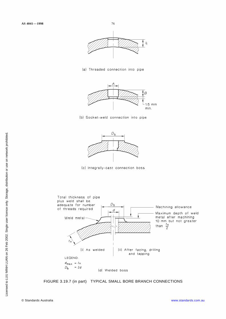
AS 4041 — 1998 76
FIGURE 3.19.7 (in part) TYPICAL SMALL BORE BRANCH CONNECTIONS
© Standards Australia www.standards.com.au
Lice
nsed
to L
UU
MIN
H L
UA
N o
n 26
Feb
200
2. S
ingl
e us
er li
cenc
e on
ly. S
tora
ge, d
istr
ibut
ion
or u
se o
n ne
twor
k pr
ohib
ited.

77 AS 4041 — 1998
FIGURE 3.19.7 (in part) TYPICAL SMALL BORE BRANCH CONNECTIONS
www.standards.com.au © Standards Australia
Lice
nsed
to L
UU
MIN
H L
UA
N o
n 26
Feb
200
2. S
ingl
e us
er li
cenc
e on
ly. S
tora
ge, d
istr
ibut
ion
or u
se o
n ne
twor
k pr
ohib
ited.

AS 4041 — 1998 78
NOTES:
1 Connections shown are suitable for all classes of pipe, except (g), (h), (j) and (k) which are Class 3.
2 Connections shown are applicable where the maximum branch nominal size is the smaller of DN50 orone quarter of the main outside diameter.
3 The minimum throat thickness of the weld in (g), (h), (j) and (k) welds shall be not less than the wallthickness of the boss or the pipe, whichever is the thinner.
4 The toe angle on fillet F on the thinner of the branch and the main pipe is 45° maximum for Class 1and Class 2 piping.
FIGURE 3.19.7 (in part) TYPICAL SMALL BORE BRANCH CONNECTIONS
© Standards Australia www.standards.com.au
Lice
nsed
to L
UU
MIN
H L
UA
N o
n 26
Feb
200
2. S
ingl
e us
er li
cenc
e on
ly. S
tora
ge, d
istr
ibut
ion
or u
se o
n ne
twor
k pr
ohib
ited.

79 AS 4041 — 1998
NOTES:
1 Both plug and boss shall be marked on top with a blunt stamp to identify the material: MS for carbonsteel, CML for 1Cr-½Mo steel.
2 Welding shall comply with this Standard.
3 Boss and plug welds shall blend into the parent metal and crack sensitive steels (2¼Cr-½Mo over20 mm thick, ½Cr-½Mo-¼V, 5Cr-1Mo, 9Cr-1Mo and 12Cr-1Mo-V) shall be crack detected bymagnetic particle examination.
4 Postweld heat treatment which may be required on the weld between the boss and the pipe shall becarried out in the workshop and not on site unless otherwise agreed.
5 After the main joint has been radiographed, the plug in Figure (a), shall be seal-welded to the bossusing a qualified welding procedure which, generally, does not require postweld heat treatment.
6 Both the boss and the plug shall be machined from bars or forgings. The material shall be as specifiedin Table 3.19.7(D) and examined ultrasonically for freedom from laminar inclusions.
FIGURE 3.19.7.8 GAMMA-RAY BOSS AND PLUG
www.standards.com.au © Standards Australia
Lice
nsed
to L
UU
MIN
H L
UA
N o
n 26
Feb
200
2. S
ingl
e us
er li
cenc
e on
ly. S
tora
ge, d
istr
ibut
ion
or u
se o
n ne
twor
k pr
ohib
ited.

AS 4041 — 1998 80
A1
NOTES:
1 Reinforcing saddles are to be used only on 90° branches.
2 When a ring or pad is added as reinforcement (see Figure 3.19.8.2(b)), the value of reinforcing area may betaken in the same manner in which excess material in the main pipe is considered, provided a fullpenetration weld is used between the branch, main pipe, and ring or pad.
3 The ratio of the width to thickness of a ring and a pad shall be as close to 4:1 as the available horizontalspace allows within the limits of the reinforcing zone along the main pipe and the outside diameter of thebranch allows, but the ratio shall be not less than 1:1.
FIGURE 3.19.8.2 (in part) REINFORCEMENT OF BRANCH CONNECTIONS
© Standards Australia www.standards.com.au
Lice
nsed
to L
UU
MIN
H L
UA
N o
n 26
Feb
200
2. S
ingl
e us
er li
cenc
e on
ly. S
tora
ge, d
istr
ibut
ion
or u
se o
n ne
twor
k pr
ohib
ited.

81 AS 4041 — 1998
NOTE: For Items a, b and c the notations do not illustrate allowances for corrosion and erosion (seeClause 3.19.8.2) and under-thickness tolerance.
FIGURE 3.19.8.2 (in part) REINFORCEMENT OF BRANCH CONNECTIONS
3.19.8.3 Weld joint factor Where the main pipe contains a longitudinal or spiral weldand the branch does not intersect the weld, the value of the weld joint factor (e) may betaken to be unity for the purpose of the calculation of reinforcement, or the designstrength value of seamless pipe of comparable grade may be used to determine the valueof pressure design wall thickness.
Where the branch intersects a longitudinal or spiral weld in the main pipe, or if the branchcontains a longitudinal or spiral weld, the weld joint factor (e) for either or both shall beincluded in calculations.
Where both the branch and the main pipe contain a longitudinal or spiral weld, the twowelds shall be staggered and the separation distance between the toes of the weld shall benot less than four times the pipe thickness.
3.19.8.4 Required reinforcement area The required reinforcement area shall bedetermined as follows:
(a) Internal pressure The required reinforcement area for a branch connection underinternal pressure shall be the quantity—
A1 . . . 3.19.8.4(1) A7 = (tmh − Gh)d1 (2 − sin α)
www.standards.com.au © Standards Australia
Lice
nsed
to L
UU
MIN
H L
UA
N o
n 26
Feb
200
2. S
ingl
e us
er li
cenc
e on
ly. S
tora
ge, d
istr
ibut
ion
or u
se o
n ne
twor
k pr
ohib
ited.

AS 4041 — 1998 82
(b) External pressure The required reinforcement area for a branch connection underexternal pressure shall be the quantity—
A1 . . . 3.19.8.4(2) A7 = 0.5(tmh − Gh)d1 (2 − sin α)
The required reinforcement area shall be within the reinforcement zone,(see Clause 3.19.8.6).
3.19.8.5 Reinforcement area The required reinforcement area determined byClause 3.19.8.4 shall be that provided by any combination of areas A1, A2, A3, A4, and A5
as defined below and illustrated in Figure 3.19.8.2.
where
A1 = area provided by excess pipe wall thickness in the main pipe
= (2d2 − d1)(th − tmh)
A2 = area provided by excess pipe wall thickness in the branch pipe for adistance L above the main pipe
=2L(tb − tmb)
sin αA3 = area provided by deposited weld metal joining the main pipe and
branch (see Figure 3.19.8.2(a)), and for fillet welds of rings, pads, andsaddles (see Figure 3.19.8.2(b))
A4 = area provided by a reinforcing ring, pad, or integral reinforcement. Thevalue of A4 may be taken in the same manner in which excess wallthickness in the main pipe is considered, provided a full penetrationweld is used for the branch, main pipe, ring or pad, or integralreinforcement
A5 = area provided by a saddle on a right-angle connection.
Where the material required for reinforcement has a different design strength from themain pipe, the calculated reinforcement area provided by this material shall be reduced inthe ratio of the design strength being applied to the reinforcement area. No credit shall betaken for material having a higher design strength than the main pipe.
3.19.8.6 Reinforcement zone The reinforcement zone shall be a parallelogram of widthdisposed about the centreline of the branch and of height from the inside surface of themain pipe to a point beyond the outside surface of the main pipe measured perpendicularto this outside surface (see Figure 3.19.8.2(a) and Figure 3.19.8.2(b)).
3.19.8.7 Reinforcement of multiple openings Multiple branch openings should bespaced so that their reinforcement zones do not overlap. Where any two or more adjacentopenings are spaced so that their reinforcement zones overlap, the two or more openingsshall be reinforced in accordance with this Clause (3.19.8.7) with a combinedreinforcement giving a strength not less than the combined strength that would be requiredfor the openings if considered separately. No portion of the cross-section shall beconsidered as applying to more than one opening, or be credited more than once in acombined area.
When two or more openings are to have a combined reinforcement, the minimum distancebetween centres of any two of these openings should be not less than 1.5 times theaverage of their diameters, and the area of reinforcement between them shall be not lessthan 50 percent of the total required for these two openings.
3.19.8.8 Rings, pads, and saddles Reinforcement provided in the form of a ring, pad,or saddle shall be of uniform width around its entire circumference unless designed toClause 3.18 of AS 1210—1997.
© Standards Australia www.standards.com.au
Lice
nsed
to L
UU
MIN
H L
UA
N o
n 26
Feb
200
2. S
ingl
e us
er li
cenc
e on
ly. S
tora
ge, d
istr
ibut
ion
or u
se o
n ne
twor
k pr
ohib
ited.
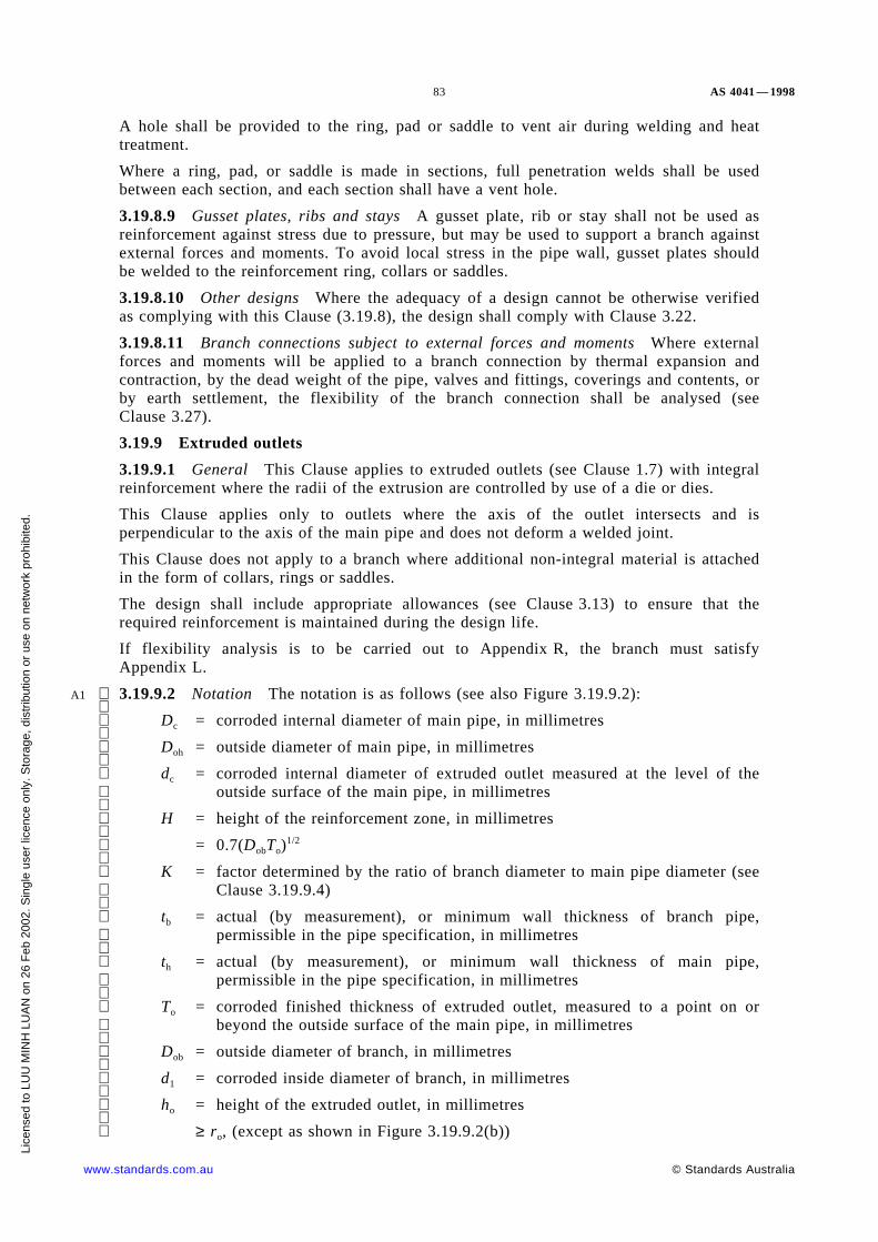
83 AS 4041 — 1998
A hole shall be provided to the ring, pad or saddle to vent air during welding and heattreatment.
Where a ring, pad, or saddle is made in sections, full penetration welds shall be usedbetween each section, and each section shall have a vent hole.
3.19.8.9 Gusset plates, ribs and stays A gusset plate, rib or stay shall not be used asreinforcement against stress due to pressure, but may be used to support a branch againstexternal forces and moments. To avoid local stress in the pipe wall, gusset plates shouldbe welded to the reinforcement ring, collars or saddles.
3.19.8.10 Other designs Where the adequacy of a design cannot be otherwise verifiedas complying with this Clause (3.19.8), the design shall comply with Clause 3.22.
3.19.8.11 Branch connections subject to external forces and moments Where externalforces and moments will be applied to a branch connection by thermal expansion andcontraction, by the dead weight of the pipe, valves and fittings, coverings and contents, orby earth settlement, the flexibility of the branch connection shall be analysed (seeClause 3.27).
3.19.9 Extruded outlets
3.19.9.1 General This Clause applies to extruded outlets (see Clause 1.7) with integralreinforcement where the radii of the extrusion are controlled by use of a die or dies.
This Clause applies only to outlets where the axis of the outlet intersects and isperpendicular to the axis of the main pipe and does not deform a welded joint.
This Clause does not apply to a branch where additional non-integral material is attachedin the form of collars, rings or saddles.
The design shall include appropriate allowances (see Clause 3.13) to ensure that therequired reinforcement is maintained during the design life.
If flexibility analysis is to be carried out to Appendix R, the branch must satisfyAppendix L.
A1 3.19.9.2 Notation The notation is as follows (see also Figure 3.19.9.2):
Dc = corroded internal diameter of main pipe, in millimetres
Doh = outside diameter of main pipe, in millimetres
dc = corroded internal diameter of extruded outlet measured at the level of theoutside surface of the main pipe, in millimetres
H = height of the reinforcement zone, in millimetres
= 0.7(DobTo)
1/2
K = factor determined by the ratio of branch diameter to main pipe diameter (seeClause 3.19.9.4)
tb = actual (by measurement), or minimum wall thickness of branch pipe,
permissible in the pipe specification, in millimetres
th = actual (by measurement), or minimum wall thickness of main pipe,permissible in the pipe specification, in millimetres
To = corroded finished thickness of extruded outlet, measured to a point on or
beyond the outside surface of the main pipe, in millimetres
Dob = outside diameter of branch, in millimetres
d1 = corroded inside diameter of branch, in millimetres
ho = height of the extruded outlet, in millimetres
≥ ro, (except as shown in Figure 3.19.9.2(b))
www.standards.com.au © Standards Australia
Lice
nsed
to L
UU
MIN
H L
UA
N o
n 26
Feb
200
2. S
ingl
e us
er li
cenc
e on
ly. S
tora
ge, d
istr
ibut
ion
or u
se o
n ne
twor
k pr
ohib
ited.

AS 4041 — 1998 84
A1 r1 = half-width of reinforcement zone, in millimetres
= dc
ro = radius of external contoured portion of outlet measured in the planecontaining the axes of the main pipe and branch (see Clause 3.19.9.3), inmillimetres
tmb = required wall thickness of branch, in millimetres
tmh = required wall thickness of main pipe, in millimetres.
3.19.9.3 Radius of external contour The radius of the external contoured portion of anoutlet (see Figure 3.19.9.2) shall comply with the following:
(a) Minimum value of ro:
(i) For outlet outside diameter ≤760 mm . . . . . . . . . . . . 0.05Dob mm.
(ii) For outlet outside diameter >760 mm . . . . . . . . . . . . 38 mm.
(b) Maximum value of ro:
(i) For outlet outside diameter <190 mm . . . . . . . . . . . . 32 mm.
(ii) For outlet outside diameter ≥190 mm . . . . . . . . . . . . (0.10Dob + 13)mm.
(c) More than one radius:
Where the external contour contains more than one radius, the radius of best fit ofany arc sector of 45° shall comply with Item (a) and the radius at any point shallcomply with Item (b).
Machining shall not be employed to achieve compliance with the requirements ofItems (a), (b), and (c).
3.19.9.4 Required reinforcement area The required reinforcement area is defined asequal to K(tmh − Gh) dc, where K shall be determined as follows:
(a) For Dob/Doh ≤ 0.15 . . . . . . . . . . . . . . . . . . . . . . K = 0.70.
(b) For Dob/Doh > 0.15 and ≤ 0.60 . . . . . . . . . . . . . . K = 0.60 + 2/3 × (Dob/Doh).
(c) For Dob/Doh > 0.60 . . . . . . . . . . . . . . . . . . . . . . K = 1.00.
3.19.9.5 Reinforcement area The area required for reinforcement (AR) shall beA1 + A2 + A3,
where
A1 = area lying within the reinforcement zone resulting from any excess
wall thickness available in the main pipe
= dc(th − tmh)
A2 = area lying within the reinforcement zone resulting from excess wallthickness available in the branch pipe
= 2H(tb − tmb)
A3 = area lying within the reinforcement zone resulting from excess
thickness available in the extruded outlet lip
= 2ro(To − tb − Gb)
© Standards Australia www.standards.com.au
Lice
nsed
to L
UU
MIN
H L
UA
N o
n 26
Feb
200
2. S
ingl
e us
er li
cenc
e on
ly. S
tora
ge, d
istr
ibut
ion
or u
se o
n ne
twor
k pr
ohib
ited.

85 AS 4041 — 1998
A1
NOTES:
1 Taper bore ID (if required) to match branch pipe 1:3 maximum taper.
2 Corrosion and other allowances are shown at bores.
FIGURE 3.19.9.2 REINFORCED EXTRUDED OUTLETS
www.standards.com.au © Standards Australia
Lice
nsed
to L
UU
MIN
H L
UA
N o
n 26
Feb
200
2. S
ingl
e us
er li
cenc
e on
ly. S
tora
ge, d
istr
ibut
ion
or u
se o
n ne
twor
k pr
ohib
ited.

AS 4041 — 1998 86
3.20 WELDED BRANCH CONNECTIONS
3.20.1 General A branch connection made by welding shall be designated set-on orset-in, and may be made by the use of a fitting or pipe.
3.20.2 Fittings Typical details for a set-on and a set-in branch connection made fromfittings are shown in Appendix K. Other designs which comply with this Standard may beused.
3.20.3 Branch pipes
3.20.3.1 General Typical details for a set-on and a set-in branch connection made frompipe are shown in Appendix M.
3.20.3.2 Limitations on use Branch connections show in Figure M7 may be used for allpiping classes. Branch connections made in accordance with Figure M6 are onlyapplicable to Class 3 piping.
Branch connections made with partial penetration welds should not be used where—
(a) cyclic stressing can occur;
(b) high thermal gradients can cause overstressing;
(c) high strength crack sensitive materials are used; or
(d) the nominal wall thickness of the thinnest pipe is greater than 50 mm.
3.20.3.3 Weld preparations A weld preparation shall be as shown in the qualifiedwelding procedure specification. Some typical weld preparations and weld connections areshown in Appendix M.
3.20.3.4 Backing rings Permanent backing rings shall not be used for Class 1 piping.
3.21 DESIGN OF CLOSURES FOR PIPE ENDS AND BRANCHES
3.21.1 General Fittings such as threaded plugs, blank flanges, or welded caps used toclose and seal the ends of pipes and branches shall be in accordance with the nominatedStandard, or shall comply with AS 1210, and shall be used within the pressure-temperature rating specified in that Standard.
3.21.2 Openings in closures Openings in closures shall be made by extruding,threading, or welding. Attachments to the closure shall be in accordance with Clause 3.19.Where the size of the opening is greater than half the inside diameter of the closure, theopening shall be designed as a reducer, in accordance with Clause 3.16.
Openings in closures other than provided for above shall be reinforced in accordance withClause 3.19. The total cross-sectional area required for reinforcement in any plane passingthrough the centre of the opening shall be not less than the product of the diameter of thefinished opening and the required wall thickness.
3.21.3 Threaded openings A threaded plug may be used to close an opening, and maybe seal welded. Consideration should be given to the effect of any plug projection into thebore of the pipe. See Clause 3.24.3 for limitations on threaded connections.
3.22 DESIGN OF OTHER PRESSURE-RETAINING COMPONENTS A pressure-retaining component not complying with a nominated Standard, and for which designequation or procedures are not given in this Standard, may be used where the design of asimilarly shaped, proportioned, and sized component has been proved satisfactory incomparable service conditions. Interpolation may be made between similarly shaped,proved components with small differences in size or proportion. In the absence of suchservice experience, the design shall be based on an analysis consistent with the generalphilosophy embodied in this Standard and substantiated by appropriate performancetesting, a proof test such as that described in AS 1210, experimental stress analysis, ortheoretical calculation.
© Standards Australia www.standards.com.au
Lice
nsed
to L
UU
MIN
H L
UA
N o
n 26
Feb
200
2. S
ingl
e us
er li
cenc
e on
ly. S
tora
ge, d
istr
ibut
ion
or u
se o
n ne
twor
k pr
ohib
ited.

87 AS 4041 — 1998
3.23 ATTACHMENTS3.23.1 General External and internal attachments to piping shall be designed so as notto cause flattening of the pipe, excessive localized bending stresses, or harmful thermalgradients in the pipe wall. Where the number of stress cycles from external stress,pressure or thermal changes is relatively large for the design life of the piping.Attachments shall be designed to minimize concentration of stress. See Clause 3.19.5 forlocations of welds relative to other welds.
To eliminate heat treatment at site, it is recommended that attachments should not bewelded direct to the pipe. Intermediate plates should be welded to the pipe in the shop,heat treated where necessary, and the attachments welded to the intermediate plates onsite.
Figure 3.23.1 shows typical items normally attached by welding. For critical attachments,guidance on design may be found in, for example, WRC 198 and BS 5500.
For temporary attachments see AS 4458.
3.23.2 Welding of attachments3.23.2.1 General Steel structural attachments for load-carrying purposes, such as lugsand brackets, may be welded to steel pipe. The attachments shall be of sufficient size toprevent excessive local stresses in the pipe. An attachment weld shall be continuousaround the ends and the sides.
A1 3.23.2.2 Elevated temperature piping A partial penetration weld to join an attachmentfor Class 1 piping is not permitted without detailed analysis for design temperatures above250°C.
A partial penetration weld to join an attachment may be permitted, with agreement by theparties concerned, for Class 2A piping for design temperatures above 250°C.
A1
3.23.2.3 Class 2 and Class 3 piping A single fillet weld may be used to join theattachment for Class 2P and Class 3.3.23.3 Thickness of attachments The thickness and length of any attachment shallcomply with the requirement for intensity of radial loading (see Clause 3.23.4).
Between one and two times the pipe wall thickness is suggested.
3.23.4 Intensity of radial loading An optional method of calculating the intensity ofradial loading is given in this Clause (3.23.4). The intensity of radial loading shall be notgreater than that determined by the following equation:
. . . 3.23.4(1)q =
8ft 2n
3Dwhere
q = intensity of radial loading, in newtons per millimetre
f = design strength of the pipe, in megapascals
tn = nominal wall thickness of pipe, in millimetres
D = outside diameter of pipe, in millimetres.
For a load-carrying attachment welded longitudinally along a pipe (see Figures 3.23.1(a),3.23.1(b) and 3.23.1(c)), the intensity of radial loading may be determined by thefollowing equation:
A1. . . 3.23.4(2)
q RL
± 6We
L 2
whereR = radial component of the force W, in newtonsW = total force carried by attachment, in newtonse = eccentricity of line of action of force W about the line of attachment to the
pipe, in millimetresL = length of attachment, in millimetres.
www.standards.com.au © Standards Australia
Lice
nsed
to L
UU
MIN
H L
UA
N o
n 26
Feb
200
2. S
ingl
e us
er li
cenc
e on
ly. S
tora
ge, d
istr
ibut
ion
or u
se o
n ne
twor
k pr
ohib
ited.

AS 4041 — 1998 88
A1 NOTES:1 Other methods such as given in WRC 198 and BS 5500 are also acceptable.2 Due consideration should be given to the level of stress already in the pipe due to other
loads.
FIGURE 3.23.1 (in part) TYPICAL WELDED ATTACHMENTS
© Standards Australia www.standards.com.au
Lice
nsed
to L
UU
MIN
H L
UA
N o
n 26
Feb
200
2. S
ingl
e us
er li
cenc
e on
ly. S
tora
ge, d
istr
ibut
ion
or u
se o
n ne
twor
k pr
ohib
ited.

89 AS 4041 — 1998
FIGURE 3.23.1 (in part) TYPICAL WELDED ATTACHMENTS
3.24 PIPING JOINTS
3.24.1 General The type of joint between pipes, fittings, and components shall besuitable for the design conditions, including external loadings, and shall take into accountjoint tightness, mechanical strength, the contents, and the method of fabrication. Jointsshall comply with this Clause (3.24).
3.24.2 Welded joints
3.24.2.1 Butt welds Butt welds shall be used for piping joints in Class 1 and 2 pipingexcept as provided in Clauses 3.24.2.2 and 3.24.2.3 below.
The throat thickness of butt welds, excluding any weld reinforcement and excesspenetration, shall be not less than that of the joined thinner part.
The weld preparation for butt welds shall comply with the qualified welding procedurespecification.
Some typical joints and associated preparation are shown in Figures N1 and N2 ofAppendix N.
Permanent backing rings, i.e. those that are not removed after the weld is made, shall notbe used for Class 1 piping unless agreed between the parties concerned. See alsoClause 2.9 for backing rings and inserts.
www.standards.com.au © Standards Australia
Lice
nsed
to L
UU
MIN
H L
UA
N o
n 26
Feb
200
2. S
ingl
e us
er li
cenc
e on
ly. S
tora
ge, d
istr
ibut
ion
or u
se o
n ne
twor
k pr
ohib
ited.

AS 4041 — 1998 90
Where components of different outside diameters are welded together, there shall be agradual transition between the two surfaces. The length of the transition may include theweld. The slope of the transition shall be such that the ratio of length to offset shall benot less than 1 in 2.
3.24.2.2 Fillet welds Fillet welds may be used to attach bell-and-spigots, sleeves,slip-on flanges, small-bore connections and socket-welding components.
Fillet welds may also be used to attach a reinforcing ring, pad, saddle or structuralattachment, to supplement the strength of a joint, to reduce stress concentration at a joint,to prevent disassembly of a joint, and to provide sealing of a joint.
Single fillet welds should not be used where corrosive conditions or cyclic stresses arelikely to occur, or where thermal gradients could overstress the attachment welds.
As shape of a fillet weld could vary from concave to convex, the size of a fillet weld shallbe determined as shown in Appendix N.
3.24.2.3 Socket-welded joints Joints of the socket-welded type shall be as follows:
(a) Dimensions shall comply with Figure O1, Appendix O,
(b) Socket dimensions shall comply with ANSI/ASME B16.5 for flanges, or asspecified in this Standard.
The temperature-pressure rating of the socket-welded joint shall comply with the relevantnominated Standard.
Drain pipe and bypass pipe for a component may be attached directly by socket welding(see Clause 3.19.7.7 for socket-welded branch connections).
A socket-welded joint shall not be used in pipes larger than DN 65 or pipes subject tosevere cyclic conditions.
A socket-welded joint should be located so that the joint may be isolated from largeboilers, vessels, or other sources of supply.
A socket-welded joint should not be used where corrosion may render the jointinadequate.
3.24.2.4 Welded sleeve joints A sleeve joint shall not be used for Class 1 piping, andwhere used for Class 2 and Class 3 piping, it shall comply with Figure P1, Appendix P.
3.24.2.5 Welded bell-and-spigot joints A welded bell-and-spigot joint shall not be usedfor Class 1 and Class 2A piping, and where used for Class 2P and Class 3 piping shallcomply with Figure O1(b), Appendix O.
3.24.2.6 Partial penetration butt welds Partial penetration butt welds may be used forClass 3 low hazard piping on liquid Type 4 only, e.g. fire protection water systems asfollows:
(a) Design temperature in the range 0°C to 50°C.
(b) Not subject to shock, water hammer or vibration.
(c) The penetration shall be not less than 60 percent of the thickness of the thinner ofthe joined parts, and the throat thickness (including any weld reinforcement orexcess penetration) shall be not less than the thickness of the thinner of the joinedparts.
(d) For partial penetration butt welds, V-preparation may not be necessary. SeeFigure N3, Appendix N, for preparation and assembly details.
3.24.2.7 Stress corrosion cracking If heat treatment is required to resist stresscorrosion cracking then this shall be specified to the fabricator. (See also Clause 3.29).
© Standards Australia www.standards.com.au
Lice
nsed
to L
UU
MIN
H L
UA
N o
n 26
Feb
200
2. S
ingl
e us
er li
cenc
e on
ly. S
tora
ge, d
istr
ibut
ion
or u
se o
n ne
twor
k pr
ohib
ited.

91 AS 4041 — 1998
3.24.3 Threaded joints
3.24.3.1 General Threaded joints may be used for all fluid services within thelimitations of Clause 3.14 and this Clause.
The mechanical thread, sealant, male and female, component materials and geometry shallbe suitable for the service conditions.
Threaded joints shall not be used in services where severe erosion, crevice corrosion,shock or fatigue are expected to occur.
Threaded joints are prohibited between components made of different metals withmarkedly different coefficients of expansion.
Threaded joints are permitted for ferrous, non-ferrous and plastics pipe construction.
Threaded joints are not recommended for fluid types 1 and 2.
Sealing compound shall not be used when threaded joints are to be seal welded.
For seal welded joints no strength contribution shall be attributed to the weld material.
Piping layout using threaded joints should minimize stress at joints, with special attentionto stresses due to thermal expansion and operation of valves particularly if the threadedvalve is at the free end. Provision should be made to eliminate the tendency for the pipingsystem to unscrew joints.
For typical outlets see Clause 3.19.7.
3.24.3.2 Leak tightness Leak tightness is generally not a function of pipe diameter,pipe thickness, pipe content or number of turns past hand tightness. Higher performancemay be expected when taper-threaded sockets are used. Leaks seem to be dependent onthe pressure of the fluid and on the number of threads engaged but particularly depend onthe use and effectiveness of a jointing compound. The leak path is usually the spacesformed by thread tolerances, truncation and misformed threads. Such leaks can beprevented by the effective use of a jointing compound.
Compatible sealant shall be used except for special threads that are designed to excludesealant and for which assembly must be confirmed by a procedure test.
At high pressures, failure may occur by elastic expansion of the socket allowing threadjump and leaking.
3.24.3.3 Thread types Threads may be taper to taper, parallel to parallel or taper toparallel.
The limitations of each type are set out in Clause 3.24.3.5 below. Threads to AS 1722.1,AS 1722.2, API 5B and ASME B1.20.1 comply with this Standard. Thread conventions ofsize and direction in respect to contents listed in other Australian Standards arerecommended.
There shall be a minimum of four effective threads operating in the complete joint.
3.24.3.4 Ratings on fittings and screwed flanges Fittings which comply with AS 3672and AS 3673 (which follow British tradition), are limited to DN 150 maximum. Suchfittings are matched with pipe to AS 1074 which also has a DN 150 top limit. AS 1074pipe has a 2 MPa and Class 3 limitation imposed.
The ratings for threaded fittings to Australian Standards are set out in Table 3.24.3. Theratings for threaded fittings to other Standards shall not be exceeded e.g. Fittingsmanufactured to ASME B16.11 have upper limits on service conditions and these shall notbe exceeded.
For the ratings of threaded-boss flanges see Clause 3.24.4.6.
www.standards.com.au © Standards Australia
Lice
nsed
to L
UU
MIN
H L
UA
N o
n 26
Feb
200
2. S
ingl
e us
er li
cenc
e on
ly. S
tora
ge, d
istr
ibut
ion
or u
se o
n ne
twor
k pr
ohib
ited.

AS 4041 — 1998 92
TABLE 3.24.3
RATINGS OF FITTINGSMPa
Temperature range, C°
Material
Malleable cast iron(AS 3673)
Steel(AS 3672)
Diameter range(DN inclusive)
6–150 6–50 65–150
120 < T < 300 2.0 4.0 2.0
−20 < T < 120 2.5 5.0 2.5
In sizes above DN 150, API 5B threads apply. The pressure rating of these threads may bedetermined as follows. By test or calculation determine the pressure at which socketexpansion permits thread jump.
The maximum pressure rating is this pressure multiplied by the ratio design stress/yieldstress applying to the socket.
3.24.3.5 Limitations Limitations for screwed joints in steel piping for steam service aregiven in Table 3.24.3.5.
3.24.3.6 Pressure test Threaded assemblies shall be pressure tested for leak tightness atthe pressures for the material set out in Clause 6.7.
For piping joints with a design pressure determined by the thread jump method, thehydrostatic test pressure may be as high as 0.83 times the thread jump pressure.
3.24.4 Flanged joints
3.24.4.1 General A flange and its bolting shall comply with a nominated Standard (seeClause 2.2.1). Where a flange to a nominated Standard is not available then the flangejoint design shall meet the requirements of AS 1210.
3.24.4.2 Flange ratings A flange shall be used within the pressure-temperature ratingspecified in the nominated Standard.
Where flanges of different ratings are bolted together, the rating of the flanged joint andthe bolting torque shall be that of the lower-rated flange.
3.24.4.3 Flange facings Flange facings shall be suitable for the intended service, thegasket and the bolting used.
Flange facings may be flat face, raised face, ‘ O’ ring grooved, tongue and groove and ringjoint.
Where a raised faced steel flange is to be bolted to a flat face cast iron flange the raisedface only shall be removed from the steel flange.
© Standards Australia www.standards.com.au
Lice
nsed
to L
UU
MIN
H L
UA
N o
n 26
Feb
200
2. S
ingl
e us
er li
cenc
e on
ly. S
tora
ge, d
istr
ibut
ion
or u
se o
n ne
twor
k pr
ohib
ited.

93 AS 4041 — 1998
TABLE 3.24.3.5
LIMITATIONS FOR SCREWED JOINTS IN STEEL PIPINGFOR STEAM SERVICE
A1
Maximumtemperature
°CJoint type Size range
PressureMPa
Thickness(Note 1)
Pipe material
T ≤ 260(Note 2)
Taper/Parallel DN6-DN25 Incl.DN32 & DN40
1.050.95
Medium or heavy AS 1074, BS 1387
T ≤ 260(Note 2)
Taper/Taper DN50 & DN65DN80DN100
1.251.050.90
Medium or heavy AS 1074, BS 1387
T ≤ 495(Note 6)
Taper/Taper(Note 3 & 5)
≤ DN20DN25DN32 ≤ DN50DN65 & DN80
10.358.304.152.75(Note 7)
ANSI/ASMEB36.10 Sch80(Note 4)
Tensile strength330 MPa min
NOTES:
1 In no case shall the thickness for the design conditions be less than that calculated in Clause 3.14including threading allowance.
2 Class 3 only.
3 Alternatively, taper to parallel with seal welding or leak sealing other than threads that has provensatisfactory in service or test demonstrations.
4 May be Sch40 where fluid is steam and pressure ≤1.75 MPa or water with temperature ≤105°C andpressure ≤7 MPa.
5 Taper to parallel is permitted where T ≤260°C and size ≤DN40 for fluid Type 4.
6 Temperatures and pressures in excess of these are permitted for instrument tappings, instrumentinsertions (thermowells etc.) and for plugs for radiographic examinations provided the following are met:
(a) The connection size is less than the smaller of DN50 and main or header pipe size × 0.25.
(b) The minimum number of engaged threads is not less than:
6 for DN ≤ 20 mm
7 for 20 < DN < 40 mm
8 for 40 < DN < 50 mm
(c) The connection is seal welded.
(d) The instrument insertion can withstand the fluid flow characteristics.
7 Pressures of 34.5 MPa are permitted in dead end instrument lines at the outlet end and downstream ofshut-off valves and instruments, control apparatus or discharge of a sampling cooler, where the size is≤12 mm.
3.24.4.4 Gaskets Full face gaskets are used with flat faced flanges, flat ring gaskets areused with raised face and tongue and groove flanges, ‘ O’ rings gaskets are used with ‘ O’ring grooved flanges and ring gaskets are used with ring joint flanges.
Gaskets shall be suitable for the service conditions including temperature, pressure andservice fluids. Gaskets should comply with the gasket manufacturer’ s recommendations.
The flat ring gasket for a raised-face shall have an outside diameter not less than theoutside diameter of the raised face. To ensure correct gasket alignment, the outsidediameter of the gasket should fit neatly within the bolt circle or the gasket should befitted with a centering ring.
The gasket for a full-face flange shall have an outside diameter not less than the outsidediameter of the flange.
Flat ring gasket shall not be fitted to flanges specified in a nominated Standard as flatfaced unless the conditions nominated in Clause 3.24.4.3 are met.
www.standards.com.au © Standards Australia
Lice
nsed
to L
UU
MIN
H L
UA
N o
n 26
Feb
200
2. S
ingl
e us
er li
cenc
e on
ly. S
tora
ge, d
istr
ibut
ion
or u
se o
n ne
twor
k pr
ohib
ited.

AS 4041 — 1998 94
Rubber with canvas insertions may be used only for water at temperature less than 65°C.
The dimensions of any ‘ O’ -ring shall be as specified in AS 2129.
The effect of flange facing finish should be considered in gasket material selection.
3.24.4.5 Bolting Bolting shall comply with AS 2528, AS 2129 and with the appropriatepressure-temperature rating of the flange as specified in the nominated flange Standard.Bolting shall seat the gasket and maintain joint tightness under all design conditions (seeClause 2.6). The calculation method set out in AS 1210 to determine bolt loads forgasket seating and maintaining joint tightness under given pressure and temperatureconditions may be used.
Appendix G provides design strengths most commonly used for ferrous and non-ferrousbolting.
NOTE: Bolting includes bolts, studs, cap screws, nuts and washers.
3.24.4.6 Threaded-boss flanges The maximum pressure and temperature for athreaded-boss flange in which the tightness of the joint depends upon the tightness of thethreads shall be as shown in Table 3.24.4(A).
A threaded flange is not recommended for severe cyclic service, but if it is the pipe andflange shall be seal-welded at the face of the flange.
A threaded flange shall be seal-welded where the tightness of the joint depends on thetightness of the threads and the joint contains a corrosive, flammable or toxic fluid, orfluids which are difficult to contain.
The thread of a taper-to-taper or a taper-to-parallel joint for flammable or toxic fluid shallrun out at a point just inside the hub of the flange.
The socket of a parallel-to-parallel joint shall be fully tightened then seal-welded.
There shall be a seal-weld on the face and the back of a flange for use with corrosivefluid.
3.24.4.7 Limitations on the use of flanges to AS 2129 Except for replacement purposes,a flange specified to Table C of AS 2129—1994 should not be used.
Slip-on flanges single welded should not be used where—
(a) the number of cycles exceeds 7000;
(b) the fluid is type 1, 2 or 3; or
(c) crevice corrosion occurs.
TABLE 3.24.4(A)
RATINGS OF THREADED-BOSS FLANGES
Flange material Method of attachmentMaximum design
pressureMPa
Maximum designtemperature
°C
Carbon and carbon-manganese steel
Threaded and expanded 3.1 370
Taper-to-taper thread 2.1 260
Taper-to-parallel thread 0.86 260
Alloy steel Threaded and expanded 4.2 480
Cast ironTaper-to-taper thread 1.05 180
Taper-to-parallel thread 0.86 180
Copper and copperalloy
Threaded Refer to appropriate Tables in AS 2129.
© Standards Australia www.standards.com.au
Lice
nsed
to L
UU
MIN
H L
UA
N o
n 26
Feb
200
2. S
ingl
e us
er li
cenc
e on
ly. S
tora
ge, d
istr
ibut
ion
or u
se o
n ne
twor
k pr
ohib
ited.

95 AS 4041 — 1998
3.24.4.8 Welded flanges The weld preparation for a welded flange shall comply withthe qualified welding procedure and Figure 3.24.4.8 or other preparation agreed betweenthe parties concerned.
Flanges shall not be a tight fit on the pipe. The maximum clearance between the bore ofthe flange and the outside diameter of the pipe shall be as given in Table 3.24.4(B).
The design condition limits shown in Table 3.24.4(C) shall apply, according to the type offlange.
For attachments in Figure 3.24.4.8(A) to (D) inclusive, there are no additional limitsexcept that full penetration welds shall be used for steel groups E and G.
For attachments in Figure 3.24.4.8(E) to (H) a pressure limit of 8.3 MPa at 50°C forcarbon steel and equivalent applies and the temperature shall not exceed 425°C.
Attachments in Figure 3.24.4.8(B) to (G) inclusive should be avoided whenever thermalgradient may cause overstress in welds or where many large temperature fluctuations areexpected.
Attachments in Figure 3.24.4.8(G) to (H) are not recommended for corrosive conditions.
Additionally, slip on flanges and socket-welded flanges are not recommended for servicebelow minus 45°C.
TABLE 3.24.4(B)
MAXIMUM CLEARANCE BETWEEN PIPES AND FLANGESmillimetres
Nominal thickness of pipeMaximum clearance
between bore of flange andoutside diameter of pipe
Sum of thediametrically oppositeclearances, maximum
Weld leg length,minimum
Over 5 3 5 6
Over 4 up to and including 5 2.5 4 5
Over 3 up to and including 4 2 3 4
Up to and including 3 1.5 2 4
www.standards.com.au © Standards Australia
Lice
nsed
to L
UU
MIN
H L
UA
N o
n 26
Feb
200
2. S
ingl
e us
er li
cenc
e on
ly. S
tora
ge, d
istr
ibut
ion
or u
se o
n ne
twor
k pr
ohib
ited.

AS 4041—1998 96
TABLE 3.24.4(C)
LIMITATIONS ON STEEL FLANGE ATTACHMENT WELDSmillimetres
Type of weld(Figure 3.24.4.8)
Flange Temperature(max.), °C (see
Notes)
Nominal size(max.)
mm
Pipe bore(min.)
mmStandard No. Type Table Class
1 AS 2129ANSI/ASME
B16.5Welding neck — — — — —
2 AS 2129 Plate — — — 150* —
3 and 3A AS 2129 Plate — — — 150* 75
4, 4A and 4B AS 2129 Plate or boss R — 425 — —
5 and 5A AS 2129 Plate R — 425 — 75
6 AS 2129 Plate J — 425 — —
6A AS 2129 Boss J —
ANSI/ASMEB16.5 Slip-on — 300 425† — —
7 AS 2129 Boss H — 400 150 —
ANSI/ASMEB16.5 Slip-on — — † 100 —
See Appendix O ANSI/ASMEB16.5 Socket —
150 to 600 † 80 —
900 and 1 500 † 65 —
— Indicates flange limits of the nominated Standard apply.
* Applies to alloy steel. No restriction for carbon and carbon-manganese steels.
† Not recommended for service above 260°C if severe thermal gradients on thermal cycling are involved.
NOTES:
1 ANSI/ASME B16.5 Class 150 flanged joints may develop leaks when used above 200°C and where severe thermal gradients or severe external loads occur.
2 All flanges are susceptible to leaks when used above 400°C and where severe thermal gradients or severe external loads occur.
© Standards Australia www.standards.com.au
Licensed to LUU MINH LUAN on 26 Feb 2002. Single user licence only. Storage, distribution or use on network prohibited.

97 AS 4041—1998
NOTES:
1 Preparation and assembly for welding to be in accordance with AS 4458.
2 tf is the pressure design wall thickness, see Clause 3.14.
FIGURE 3.24.4.8(A) TYPE 1 ‘WELDING NECK’ FLANGE
www.standards.com.au © Standards Australia
Lice
nsed
to L
UU
MIN
H L
UA
N o
n 26
Feb
200
2. S
ingl
e us
er li
cenc
e on
ly. S
tora
ge, d
istr
ibut
ion
or u
se o
n ne
twor
k pr
ohib
ited.

AS 4041—1998 98
Dimension Steel Design basis
Bafter machining
Carbon tfbut not less than 5
Alloy and 500 Nb 2tf
Cafter machining
Carbon t2but not less than:6 for pipes 15 and 20 DN8 for pipes 25 to 40 DN
10 for pipes 50 DN and overAlloy and 500 Nb 2tf
E Carbon tf but not less than 6
E1 Alloy and 500 Nb Height of weld recess
NOTES:
1 tf is the calculated pipe thickness (see Clause 3.14).
2 The outer surface of the weld needs to lie wholly outside the position indicated by the dotted lineor full line, whichever is applicable.
DIMENSIONS IN MILLIMETRES
FIGURE 3.24.4.8(B) TYPE 2 ‘FACE AND BACK’ WELDED FLANGE(FOR METAL-ARC WELDING)
© Standards Australia www.standards.com.au
Lice
nsed
to L
UU
MIN
H L
UA
N o
n 26
Feb
200
2. S
ingl
e us
er li
cenc
e on
ly. S
tora
ge, d
istr
ibut
ion
or u
se o
n ne
twor
k pr
ohib
ited.

99 AS 4041—1998
Dimension Steel Design basis
Aafter machining
Carbon, alloy and 500 Nb½ tf but not less than 5
B
Carbon, alloy and 500 Nb 8 minimum(tf – 1.5) where tf is over 9.5 up to andincluding 14(tf – 3) where tf is over 14 up to andincluding 22(tf – 6) where tf is over 22
Cafter machining
Carbon tfbut not less than 10
Alloy and 500 Nb 2tf
E Carbon tf but not less than 6
E1 Alloy and 500 Nb Height of weld recess
NOTES:
1 tf is the calculated pipe thickness (see Clause 3.14).
2 The outer surface of the weld needs to lie wholly outside the position indicated by the dotted line orfull line, whichever is applicable.
DIMENSIONS IN MILLIMETRES
FIGURE 3.24.4.8(C) TYPE 3 ‘BORE AND BACK’ WELDED FLANGE(FOR METAL-ARC WELDING)
www.standards.com.au © Standards Australia
Lice
nsed
to L
UU
MIN
H L
UA
N o
n 26
Feb
200
2. S
ingl
e us
er li
cenc
e on
ly. S
tora
ge, d
istr
ibut
ion
or u
se o
n ne
twor
k pr
ohib
ited.

AS 4041—1998 100
Dimension Steel Design basis
Aafter machining
Carbon, alloy and 500 Nb½ tf but not less than 5
Cafter machining
Carbon tfbut not less than 10
Alloy and 500 Nb 2tf
E Carbon tf but not less than 6
E1 Alloy and 500 Nb tf + 6 but not less than tf
NOTES:
1 tf is the calculated pipe thickness (see Clause 3.14).
2 The outer surface of the weld needs to lie wholly outside the position indicated by the dotted line orfull line, whichever is applicable.
DIMENSIONS IN MILLIMETRES
FIGURE 3.24.4.8(D) TYPE 3A ‘BORE AND BACK’ WELDED FLANGE(WELD PREPARATION FOR USE ONLY WITH FLANGES
POSITIONALLY WELDED ON BY THE METAL-ARC PROCESS)
© Standards Australia www.standards.com.au
Lice
nsed
to L
UU
MIN
H L
UA
N o
n 26
Feb
200
2. S
ingl
e us
er li
cenc
e on
ly. S
tora
ge, d
istr
ibut
ion
or u
se o
n ne
twor
k pr
ohib
ited.

101 AS 4041—1998
Dimension Design basis
Bafter machining
tf but not less than the weld leg length given in Table 3.24.4(B)
E 1½ tf but not less than the weld leg length given in Table 3.24.4(B)
NOTES:
1 tf is the calculated pipe thickness (see Clause 3.14).
2 The outer surface of the weld needs to lie wholly outside the position indicated by the dottedline.
DIMENSIONS IN MILLIMETRES
FIGURE 3.24.4.8(E) TYPE 4 AND 4A ‘FACE AND FILLET’ WELDEDFLANGES (FOR METAL-ARC WELDING)
www.standards.com.au © Standards Australia
Lice
nsed
to L
UU
MIN
H L
UA
N o
n 26
Feb
200
2. S
ingl
e us
er li
cenc
e on
ly. S
tora
ge, d
istr
ibut
ion
or u
se o
n ne
twor
k pr
ohib
ited.

AS 4041—1998 102
Dimension Design basis
Aafter machining
½ tf but not less than 5
B 8 minimum(tf – 1.5) where tf is over 9.5 up to and including 14(tf – 3) where tf is over 14 up to and including 22(tf – 6) where tf is over 22
E 1½ tf but not less than the weld leg length given in Table 3.24.4(B)
NOTES:
1 tf is the calculated pipe thickness (see Clause 3.14).
2 The outer surface of the weld needs to lie wholly outside the position indicated by the dottedline.
DIMENSIONS IN MILLIMETRES
FIGURE 3.24.4.8(F) TYPE 5 ‘FACE AND FILLET’ WELDEDFLANGES (FOR METAL-ARC WELDING)
© Standards Australia www.standards.com.au
Lice
nsed
to L
UU
MIN
H L
UA
N o
n 26
Feb
200
2. S
ingl
e us
er li
cenc
e on
ly. S
tora
ge, d
istr
ibut
ion
or u
se o
n ne
twor
k pr
ohib
ited.

103 AS 4041—1998
Dimension Design basis
Aafter machining
½ tf but not less than 5
B 1½ tf but not less than the weld leg length given in Table 3.24.4(B)
NOTES:
1 tf is the calculated pipe thickness (see Clause 3.14).
2 The outer surface of the weld needs to lie wholly outside the position indicated by the dottedline.
DIMENSIONS IN MILLIMETRES
FIGURE 3.24.4.8(G) TYPE 5A ‘FACE AND FILLET’ WELDED FLANGES(WELD PREPARATION FOR USE ONLY WITH FLANGE POSITIONALLY
WELDED ON BY THE METAL-ARC PROCESS)
www.standards.com.au © Standards Australia
Lice
nsed
to L
UU
MIN
H L
UA
N o
n 26
Feb
200
2. S
ingl
e us
er li
cenc
e on
ly. S
tora
ge, d
istr
ibut
ion
or u
se o
n ne
twor
k pr
ohib
ited.

AS 4041—1998 104
Dimension Design basis
B tf but not less than the weld leg length given in Table 3.24.4(B)
E 1½ tf but not less than the weld leg length given in Table 3.24.4(B)
NOTES:
1 All dimensions are finished sizes.
2 tf is the calculated pipe thickness (see Clause 3.14).
3 The outer surface of the weld needs to lie wholly outside the position indicated by the dottedline.
DIMENSIONS IN MILLIMETRES
FIGURE 3.24.4.8(H) TYPE 6 and 6A ‘SLIP-ON’ WELDED FLANGES(FOR METAL-ARC WELDING)
© Standards Australia www.standards.com.au
Lice
nsed
to L
UU
MIN
H L
UA
N o
n 26
Feb
200
2. S
ingl
e us
er li
cenc
e on
ly. S
tora
ge, d
istr
ibut
ion
or u
se o
n ne
twor
k pr
ohib
ited.

105 AS 4041—1998
Dimension Design basis
B tf but not less than the weld leg length given in Table 3.24.4(B)
E 1½ tf but not less than the weld leg length given in Table 3.24.4(B)
NOTES:
1 All dimensions are finished sizes.
2 tf is the calculated pipe thickness (see Clause 3.14).
3 The outer surface of the weld needs to lie wholly outside the position indicated by the dottedline.
FIGURE 3.24.4.8(I) TYPE 7 ‘SLIP-ON’ WELDED BOSSED FLANGES(FOR OXY-ACETYLENE WELDING)
www.standards.com.au © Standards Australia
Lice
nsed
to L
UU
MIN
H L
UA
N o
n 26
Feb
200
2. S
ingl
e us
er li
cenc
e on
ly. S
tora
ge, d
istr
ibut
ion
or u
se o
n ne
twor
k pr
ohib
ited.

AS 4041—1998 106
3.24.5 Flared, flareless and compression joints A flared, flareless or compressionfitting shall be used in accordance with the manufacturer’ s recommendations.
In the absence of Standards or design strength values for the material used for themanufacture of these fittings, the designer shall determine that the type and the materialof each fitting is adequate and safe for the service.
Consideration shall be given to the possible adverse effects on the joints of assembly anddisassembly, cyclic loading, cyclic temperature, low temperature, vibration and shock, andthermal expansion and contraction.
Fittings and joints shall be compatible with the pipe, and fittings shall be assembled andapplied as recommended by the manufacturer. Joints for severe cyclic conditions shall beprotected or guarded to control leakage and failure.
Roll grooved type joints are permitted when assembled and used in accordance with themanufacturer’ s recommendations.
The gripping member of a flareless fitting shall grip or bite into the outer surface of thepipe with sufficient strength to hold the pipe against axial force, but shall not appreciablydistort the inside diameter of the pipe. The gripping member shall form a pressure sealagainst the body of the fitting.
Where a bite-type fitting is used, a spot check shall be made for adequate depth of biteand condition of the pipe, by disassembling and reassembling at least one joint. Grip-typefittings tightened in accordance with the manufacturer’ s instructions need not bedisassembled for checking.
NOTE: The use of olive-type compression fittings is not permitted for flammable gas use (referto AS/NZS 1596 and AG 601).
3.24.6 Caulked joints A caulked joint shall not be used for Class 1 piping or undersevere cyclic conditions. A caulked joint shall be used only within thepressure-temperature limits of the pipe and the joint.
Disengagement of a joint at bends and dead ends shall be prevented. Lateral reactionsshall be restrained.
Material used to caulk a joint shall be appropriate to the fluid, pressure and temperature.
Safeguards shall be taken against fluid type 2.
3.24.7 Soldered joints A soldered joint shall not be used for Class 1 and Class 2piping, nor on piping carrying fluid types 1 and 2, or on piping subject to severe shock,water-hammer, vibration, or where there is a possible fire or explosion hazard. Theservice temperature shall be less than 75°C.
A soldered joint shall be a lap or socket-type, and the solder shall be suitable for anycomponent material and the service conditions. A soldered fillet joint shall not be used.A procedure test shall be made and qualified.
3.24.8 Brazed joints. A brazed joint may be used for Class 1, 2 or 3 piping with servicetemperatures not above 200°C. The maximum nominal size for fluids 1 or 2 is DN 250.For a brazed joint in piping carrying fluid types 1 and 2, to or where there is a possiblefire hazard, mechanical safeguarding shall be provided, e.g. by limiting location,relevance of site, or if conditions are such that any leakages are not likely to impair safetyor the environment.
The joint shall be a lap or socket-type fitting with brazing alloy suitable for thecomponent material and the service conditions. A butt brazed joint or joint depending onfillet only shall not be used. A procedure test shall be made and qualified.
3.24.9 Expansion joints (See Clause 3.18).
© Standards Australia www.standards.com.au
Lice
nsed
to L
UU
MIN
H L
UA
N o
n 26
Feb
200
2. S
ingl
e us
er li
cenc
e on
ly. S
tora
ge, d
istr
ibut
ion
or u
se o
n ne
twor
k pr
ohib
ited.

107 AS 4041—1998
3.24.10 Proprietary and special joints A coupling-type, mechanical gland-type,adhesive or any other proprietary or special joint type may be used only where experienceor tests has demonstrated that the joint is safe for the operating conditions, and whereadequate provision is made to prevent separation of the joint during use. Proprietary jointsshall be used only in accordance with the manufacturer’ s recommendations. Roll groovedtype joints are permitted when used in accordance with the manufacturer’ srecommendations.
3.25 DESIGN REQUIREMENTS PERTAINING TO SPECIFIC PIPING
3.25.1 Drainage systems of steam piping
3.25.1.1 General Every precaution shall be taken in the laying out of steam piping toprevent the accumulation of water in the piping during steady state operation, start upand shutdown. Provision shall be made for water, continuously or occasionally formed, tobe efficiently removed from the piping system during steady start up and shutdown.
As far as is practicable drainage water shall not be allowed to come into contact withmetal at a higher temperature.
Design conditions for drain systems are given in Clauses 3.9.6 and 3.9.7.
3.25.1.2 Fall A suitable fall or grade shall be provided in steam piping to ensure thatthe water flows towards the drainage point and this fall should be in the direction of thesteam flow.
Recommended falls for steam pipe drainage towards drain points are as follows:
(a) Drainage in the direction of steam flow to be 1 in 100 minimum.
(b) Drainage against the direction of steam flow to be 1 in 40 minimum.
Drain lines shall be designed to ensure drainage by gravity when there is little or nopressure in the main line and to accommodate any downward movement of the drainconnections when thermal expansion of the lines takes place.
3.25.1.3 Drainage points Steam piping shall be provided with adequate draining pointswhere water can collect during start up and operation. Such provisions shall be in theform of a drain pockets.
The drain pockets shall have a bore not less than 25% of the bore of the main and shouldbe fitted with a side take-off point which should be located above the bottom of thepocket, to minimize blockage of the drain pipe by scale or other debris.
Drain pockets shall be connected to steam traps or other suitable apparatus to ensure therapid discharge of water from the system. It is recommended that a bypass be fitted toeach trap arranged so that any dirt or debris collection in the pocket can be ejected via theby pass valve.
Where water can collect in the piping due to valve leakage or other causes when thepiping is shutdown, or during warming through, then hand drains shall be provided atthese points.
3.25.1.4 Drain branches Drain branches shall be fitted with suitable means ofcontrolling or isolating the drain flow, such as orifice plates, isolating valves or trapsdepending on the system to be drained. Where two valves in series are used, the upstreamvalve shall be of the ‘ on-off’ type (e.g. parallel slide) and the downstream valve shall beof a type suitable for flow regulation (e.g. globe valve). Where drains are connected to acommon drain pipe, there shall be non-return valve between each drain branch and thecommon drain, and means to isolate each drain.
3.25.1.5 Drains subject to vacuum pressure Drains on piping which may be subject tosub-atmospheric pressure, if connected to an atmospheric drain vessel as an alternativedischarge outlet, shall have a valve or other device to isolate the direct connection to the
www.standards.com.au © Standards Australia
Lice
nsed
to L
UU
MIN
H L
UA
N o
n 26
Feb
200
2. S
ingl
e us
er li
cenc
e on
ly. S
tora
ge, d
istr
ibut
ion
or u
se o
n ne
twor
k pr
ohib
ited.

AS 4041—1998 108
atmospheric drain vessel when the piping is at sub-atmospheric pressure, if connected toan atmospheric drain vessel as an alternative discharge outlet, shall have a valve or otherdevice to isolate the direct connection to the atmospheric drain vessel when the piping isat sub-atmospheric pressure.
3.25.1.6 Separators Separators with drainage outlets should be installed whereentrained water may cause damage to turbines or other equipment.
3.25.2 Drain vessels and vents for boiler and high pressure steam piping
A1 3.25.2.1 Drain vessels A drain vessel and its associated vent pipes shall provide for themost probable adverse condition of discharge of large volumes of steam to atmosphere,and the design shall take into account the kinetic energy and the enthalpy of the steam.(See Clause 3.9.6 and 3.9.7 for design conditions).
3.25.2.2 Vessel shell thickness The vessel shall be designed to AS 1210 and the shellthickness shall be suitable for the loads, particularly at inlet connections and wheresupports impose concentrated loads.
NOTE: It is normally accepted that a thickness/diameter ratio of about 1:100 is sufficient toprovide for the conditions likely to occur in drain vessels.
3.25.2.3 Inlet branches An inlet branch that is subject to vibration shall be suitablyreinforced.
3.25.2.4 Vent pipe guides and supports Vent pipe guides and supports shall allow freeexpansion of the vent pipe to maximum vent temperature. See Clause 3.9.7 for designconditions.
3.25.3 Instrument, control and sampling piping
3.25.3.1 General This Clause (3.25.3) applies to the design of instrument, control, andsampling piping, i.e. piping used to connect instruments to other piping equipment, toconnect pneumatically or hydraulically operated control apparatus, or to collect samples offluids.
This Clause (3.25.3) does not apply to a permanently closed piping system (e.g. afluid-filled temperature-responsive device) or to instruments, control, or signaltransmission devices, or to sampling apparatus to which the piping is attached.
The materials of construction for valves, fittings, or pipes shall be suitable for theparticular conditions of service.
3.25.3.2 Take-off connections Take-off connections and attaching bosses, fittings oradaptors shall be of material able to withstand the maximum design pressure andtemperature of the piping or equipment to which they are attached, and shall be ofsufficient strength to withstand expansion and cyclic service loads and stresses ofinstallation and maintenance.
An isolating valve shall be installed in each take-off line as near as is practicable to thepoint of take-off.
3.25.3.3 Blowdown valve A blowdown valve shall be installed at or near theinstrument, where necessary for the safe operation of the piping, instrument, and otherequipment. A blowdown valve shall be of the gradually opening type. Blowdown shallprovide for safe disposal of the fluid.
3.25.3.4 Piping Instrument, control and sampling piping shall comply with thefollowing:
(a) The arrangement of piping and supports shall ensure safety under operating stresses,and protection of the piping against detrimental sagging, external mechanical injury,abuse and damage due to unusual service conditions other than those related topressure, temperature and service vibration.
© Standards Australia www.standards.com.au
Lice
nsed
to L
UU
MIN
H L
UA
N o
n 26
Feb
200
2. S
ingl
e us
er li
cenc
e on
ly. S
tora
ge, d
istr
ibut
ion
or u
se o
n ne
twor
k pr
ohib
ited.

109 AS 4041—1998
(b) Brass, copper, or aluminium pipe shall not be used where metal temperatures exceed200°C, or in a location where there is a fire hazard. Buried brass pipe shall bedezincification-resistant.
(c) Piping subject to clogging from solids or deposits shall be provided with suitableconnections for cleaning.
(d) Piping to contain fluids that are normally static shall be protected from freezing byheat tracing or other heating where necessary.
(e) Piping in which liquids accumulate and then stagnate shall be provided with drainsor traps.
(f) Where internal corrosion may occur, suitable precautions shall be taken, e.g.increasing the wall thickness.
3.25.3.5 Joints A joint shall be suitable for the pressure and temperature, and mayinclude fittings that are flared, flareless or of the compression type or equivalent. Thefittings may also be of the brazed, screwed, or socket-welded type. Where a screwed-endvalve is used with flareless or compression-type fittings, adaptors shall be used.
A slip-type expansion joint shall not be used; expansion shall be accommodated byproviding flexibility within the piping system.
3.25.4 Pressure relief valve discharge piping
3.25.4.1 General Safety valve discharge piping shall comply with Clause 3.9.8 and beas straight and as short as possible, and drained to prevent the accumulation of fluid. Anyexpansion chamber shall be anchored and allowance made for the difference between hotand cold positions of the safety valve outlet branch. In the hot position, the expansionchamber shall be concentric with the safety valve outlet branch. A slip-type expansionjoint shall, where used, be restrained against upward thrust.
The diameter of discharge piping incorporating an expansion chamber or slip-joint shallbe such that the operating pressure acting on the discharge side of the expansion chamberor slip-joint will not cause steam to blow back into the immediate vicinity of the fittings.(See Clause 3.9.8 for design conditions).
3.25.4.2 Flexible bellows See Clause 3.18.
3.25.4.3 Reaction loads Reaction loads on the piping from operation of safety valvesshall be provided for.
NOTE: ANSI/ASME B31.1 gives guidance on reaction loads.
3.25.4.4 Discharge Discharge from the safety valve shall be safely disposed of.Non-flammable, non-toxic fluids may be discharged direct to atmosphere, where permittedby environmental regulations, but the discharge shall not impinge on piping or equipmentand shall be directed away from areas used by personnel.
A1 3.25.5 Piping located below ground level
3.25.5.1 General Piping which is to be located below ground level shall also complywith this Clause (3.25.5). Such piping includes that installed in basements, cellars, mines,trenches or directly in the ground in order to provide services below ground, or tofacilitate traffic on roads, or within buildings, or to protect piping from fire, sun orexternal interference.In all cases, appropriate provision shall be made for—
(a) prevention or collection, drainage and removal of significant leaks from piping,
particularly lethal and very harmful fluids and gases heavier than air which mayseriously deplete oxygen levels in working spaces or form combustible mixtures;and
www.standards.com.au © Standards Australia
Lice
nsed
to L
UU
MIN
H L
UA
N o
n 26
Feb
200
2. S
ingl
e us
er li
cenc
e on
ly. S
tora
ge, d
istr
ibut
ion
or u
se o
n ne
twor
k pr
ohib
ited.

AS 4041—1998 110
A1 (b) removal of ground water or other material (e.g. silt or debris in open or coveredtrenches) which would seriously affect the performance or safety of the piping.
3.25.5.2 Buried piping Piping buried directly in the ground should, if practicable, beavoided particularly where contents are at temperatures above 100°C or below 5°C.
The design shall consider and when necessary, make provision for—
(a) the soil and surface loads on the piping, particularly for low thickness/diameter ratio
or vacuum piping;
(b) suitable support against ground settlement or conditions which could damage thepiping or its protection coating;
(c) protection against external corrosion by suitable material selection, corrosion
allowance, coatings, clean fill, drainage or cathodic protection (see Clause 7.4);
(d) protection against stray current corrosion;
(e) appropriate means for pressure testing, inspection, internal cleaning, isolation,drainage (slope) and detection of leaks which could cause significant losses orhazards to personnel, plant or environment;
(f) possible rotation of piping which will encounter selective bottom erosion; and
(g) suitable markers and location plans to avoid external damage when modifying or
adding services and to facilitate inspection.
See AS 2885 for further guidance applicable to buried piping.
3.26 NOT ALLOCATED
3.27 FLEXIBILITY, STRESS ANALYSIS AND SUPPORT DESIGN
3.27.1 General All pipe systems shall be designed and installed in such away that—
(a) they can absorb displacements of the piping caused by thermal expansion;
(b) they can absorb displacements of supporting structures and plant caused by thermalexpansion, wind loading and similar effects;
(c) they can absorb forces on piping cause by the wind loading, dead weight andseismic effects (see also Clause 3.5(e));
(d) excessive movement does not cause leakage of joints;
(e) specified categories of stress limitation are satisfied; and
(f) the forces and moments applied to the plant do not exceed the maximum allowablevalues specified by the designer.
These conditions are satisfied by—
(i) providing piping flexibility to ensure that the stress caused by thermal expansiononly (stress range) does not exceed permissible values;
(ii) providing a supporting system to carry the dead weight of the piping and permit itto expand between cold and hot conditions without the stress due to pressure anddead weight (sustained stress) exceeding permissible values; and
(iii) restraining the piping (if necessary) with sway braces and snubbers to ensure thatstresses due to wind and seismic effects (occasional loads) do not exceedpermissible values (see also Clause 3.5(e)).
The piping flexibility method set out in this Clause may be used with branch designsbased on Clause 3.19 or Appendix L. If flexibility analysis to Appendix R is chosen, thenbranch design must satisfy Appendix L.
© Standards Australia www.standards.com.au
Lice
nsed
to L
UU
MIN
H L
UA
N o
n 26
Feb
200
2. S
ingl
e us
er li
cenc
e on
ly. S
tora
ge, d
istr
ibut
ion
or u
se o
n ne
twor
k pr
ohib
ited.

111 AS 4041—1998
3.27.2 Flexibility
3.27.2.1 General The preferred method of absorbing displacements is by designing apiping layout which has inherent flexibility to deflect in bending and torsion.
An alternative method, which may provide more economical plant layouts makes use ofexpansion fittings. (See Clause 3.18).
3.27.2.2 Need for flexibility analysis A formal flexibility analysis (to satisfy stressrange requirements) is generally not required in piping which—
(a) is a duplicate of piping with a satisfactory service record;
(b) can readily be validated by comparison with previously analysed piping; or
(c) is of uniform size, fixed at not more than two points, has no intermediate restraints,and is non-critical piping within the limitations of the Equation 3.27.2.2.
. . . 3.27.2.2Dy
(L − U )2< 208
where
D = outside diameter of pipe in millimetres
L = developed length of the pipe route, in metres
U = the length of the straight line joining the anchor points, in metres
y = resultant thermal expansion and terminal point movement to beabsorbed by the piping system, in millimetres
NOTES:
1 This equation is empirical, and cannot be relied on to give consistently conservativeresults. It is not applicable to piping used under severe cyclic conditions (e.g. wherenumber of significant stress cycles exceeds 7 000). It is used with caution where L/U> 2.5, where stress intensification factors exceed 5, or where displacements which arenot in the direction of the line joining the anchor points are a significant part of thetotal displacement.
2 There is no assurance that terminal reactions will be acceptably low ifEquation 3.27.2.2 is satisfied.
3 The equation assumes that a pipe is free to expand without constraints due to weightand a supporting system. A flexibility analysis may be required to provide data(movements and loads) for the design of a support system which satisfies sustainedweight stress requirements.
4 This equation does not apply if flexible joints or expansion fittings are used in thesystem.
3.27.2.3 Self and cold spring When of sufficient magnitude, stresses caused by thermalexpansion, relax in the hot condition as a result of yielding or creep and reappear asstresses of the opposite sign in the cold condition. This is known as self-springing.
The amount of self-springing which takes place can be reduced by the application of coldspring during the erection of the piping. This is discussed in Appendix Q.
Where cold spring is applied, see Clause 3.27.6 for end reactions.
3.27.2.4 Balanced design All commonly used methods of piping flexibility analysisassume elastic behaviour of the entire piping system. This assumption is sufficientlyaccurate where plastic straining occurs at many points over relatively wide regions, butfails to reflect the actual strain distribution in unbalanced systems where only a smallportion of a system undergoes plastic strain, or where, in piping operating in the creeprange, the strain distributions are uneven. In these cases, the weaker or higher stressed
www.standards.com.au © Standards Australia
Lice
nsed
to L
UU
MIN
H L
UA
N o
n 26
Feb
200
2. S
ingl
e us
er li
cenc
e on
ly. S
tora
ge, d
istr
ibut
ion
or u
se o
n ne
twor
k pr
ohib
ited.

AS 4041—1998 112
portions will be subjected to strain concentrations due to elastic follow-up of the stiffer orlower stressed portions.
Unbalance can be produced—
(a) by the use of pipes with significantly different stiffness in series; or
(b) in a system of uniform pipe size, by the use of a line configuration for which theneutral axis or thrust line is situated close to the major portion of the line, with onlya very small offset portion of the line absorbing most of the expansion.
Conditions of this type should be avoided, particularly where materials of relatively lowductility are used; if unavoidable, the effects may be mitigated by the judiciousapplication of cold spring and limit travel stops.
3.27.3 Stress analysis The flexibility of a piping system can be influencedsignificantly by the geometry of fittings (e.g. bends, reducers) which changecross-sectional shape under the action of bending moments and thus provide greaterflexibility than the same length of straight pipe. This action also increases the stress levelsin the fittings. In a flexibility analysis, these phenomena are covered by the use‘ flexibility’ and ‘ stress intensification’ factors.
Methods of flexibility analysis progress in complexity and accuracy through thefollowing:
(a) Simple ‘ structural’ methods which ignore the effects of pipe fittings.
(b) More comprehensive methods which use similarity methods to evaluate terminalreactions and stress levels from flexibility charts.
(c) Rigorous methods based upon strain energy theory and the use of both flexibilityand stress intensification factors to give an accurate assessment of stresses in apiping system.
Computer programs using algorithms based upon Item (c) are available for the analysis ofmulti-anchor systems and the evaluation of specified stress limitations in accordance withthe methods of ANSI/ASME B31.3 and BS 806 which are covered by this Standard.
It is the designer’ s responsibility to ensure that the method of analysis used for specificpiping system ensures that all categories of stress limitations are satisfied.
A piping system is analysed between points of constraint which control thermal expansionin a predictable manner. In general these include one or more anchor points (stopsmovement and rotation of pipe ends, e.g. pumps, vessels and heat exchangers) plus partialrestraints (stops less than six degrees of freedom of a pipe).
The system between points of constraint shall be treated as a whole and the effects of anymovement at anchor points and of any partial restraints shall be included.
Computer programs which carry out flexibility analysis to ANSI/ASME B31.3, includingflexibility and stress intensification factors but with design strengths as per Clause 3.11also satisfy this Standard.
3.27.4 Data for stress analysis The following data are given for stress analysis:
(a) Material properties The more commonly used mechanical properties of materialsfor—
(i) values of thermal expansion— refer Appendix E ;
(ii) values of Young modulus— refer Appendix F; and
(iii) Poisson ratio— the value may be taken as 0.3 for all metals at alltemperatures although a more accurate value may be used.
(b) Dimensions Nominal dimensions of piping and fittings shall be used.
© Standards Australia www.standards.com.au
Lice
nsed
to L
UU
MIN
H L
UA
N o
n 26
Feb
200
2. S
ingl
e us
er li
cenc
e on
ly. S
tora
ge, d
istr
ibut
ion
or u
se o
n ne
twor
k pr
ohib
ited.

113 AS 4041—1998
(c) Wind loading Piping exposed to the wind shall be designed to carry wind loadscalculated in accordance with AS 1170.2 using permissible stress methods and staticanalysis rules. To determine the drag factor, piping may be regarded as ‘ a smoothcylindrical shape’ .
(d) Seismic loading Earthquake loads on piping shall be calculated according toAS 1170.4 using permissible stress loadings (these are ultimate limit state loadsdivided by 1.4). Unless otherwise agreed, piping shall be regarded as mechanicalcomponents and treated as follows:
(i) Class 1 and 2A piping shall be categorized with ‘ Boilers, furnacesincinerators, water heaters, and other equipment using combustible energysources or high-temperature energy sources, chimneys, flues, smokestacks,vents and pressure vessels’ , i.e. with the Cc2 factor equal to 2 for all pipingDN32 and greater. The exemptions listed in Clause 5.3.2 ofAS 1170.4—1993 are not applicable
(ii) Class 2P and Class 3 piping shall be categorized as ‘ ducts and pipingdistribution systems’ , i.e. with the Cc2 factor equal to 1.
3.27.5 Stress limitations
3.27.5.1 General The methods of evaluation of specified categories of stress in thisSection are based upon the methods of ANSI/ASME B31.3. They do not give any creditfor cold spring.
Alternative methods based upon the methods of BS 806 are given in Appendix R andthese make concessions on allowable hot stress for cold spring.
3.27.5.2 Displacement stress range The displacement stress range, being the stresscaused by the thermal expansion of the piping plus terminal movement shall satisfyEquation 3.27.5.2.
fe < fa M . . . 3.27.5.2
where
fe is the displacement stress range, in megapascals
fa is defined in 3.11.7
3.27.5.3 Sustained longitudinal stress
The sustained longitudinal stress (defined in Clause 3.11.5) shall satisfy Equation 3.27.5.3
. . . 3.27.5.3fL = P Do4 tn
+ fs < f M
where
Do = nominal outside diameter of the pipe, in millimetres
fL = the sustained longitudinal stress, in megapascals
P = internal pressure, in megapascals
tn = the nominal thickness of the pipe, in millimetres
f = the design strength of the material at the temperature under consideration (seeAppendix D), in megapascals
fs = the longitudinal stress cause by dead weight and other sustained loads, inmegapascals
M = piping class design factor (see Table 3.12.3)
www.standards.com.au © Standards Australia
Lice
nsed
to L
UU
MIN
H L
UA
N o
n 26
Feb
200
2. S
ingl
e us
er li
cenc
e on
ly. S
tora
ge, d
istr
ibut
ion
or u
se o
n ne
twor
k pr
ohib
ited.

AS 4041—1998 114
3.27.5.4 Stress due to sustained occasional loads The sustained occasional stress shallsatisfy Equation 3.27.5.4
. . . 3.27.5.4fes = PDo
4 tn
+ fs + fo < 1.33 f M
where
P, Do, tn, fs and f are defined in Clause 3.27.5.3
fo is the longitudinal flexural stress caused by occasional loads such as safety valvethrust, wind and earthquake loads. Wind and earthquake loads need not beconsidered concurrently, in megapascals.
Refer to Clause 3.11.6 for recommended limitations at flanged joints.
3.27.5.5 Flexibility and stress intensification factors The factors known to apply tocomponents other than straight pipe shall be included in the analysis. The flexibilityfactors (k) and stress intensification factors (i) shown in Table 3.27.5 andFigure 3.27.5(A) Charts A and B may be used in the absence of more reliable data. Thevalues of the latter factor for tees are based on tests on equal outlet intersections and maybe used for unequal outlet intersections until more appropriate ones are developed, but itis recommended that moments at these intersections be minimized.
3.27.5.6 Calculation of flexural stresses The magnitude of the flexural stresses fe, fs
and fo shall be calculated from Equation 3.27.5.6(1).
. . . 3.27.5.6(1)fx = ((fb)2 + 4 (ft)
2)½
where
fx = the stress being evaluated (fe, fs or fo as the case may be), in megapascals
fb = the resultant bending stress, in megapascals
ft = torsional stress, in megapascals
=Mt × 103
2ZMt = torsional moment, in newton metres
Z = section modulus of pipe, in millimetres cubed.
For the calculation of—
fs fb and ft are evaluated using moments derived from the load cases which arethe result of sustained load only using values of Young modulus for theoperating temperature.
fo fb and ft are evaluated using moments derived from the load cases which arethe result of occasional loads only using values of Young modulus for theoperating temperature.
fe fb and ft are evaluated using moments derived from the load cases involvingthermal expansion and displacement only, and values of Young modulus forthe as-installed temperature and coefficient of expansion, which is thealgebraic difference between the coefficients derived from Appendix E for thedesign maximum and minimum temperatures.
The resultant bending stress (fb) for elbows and mitre bends shall be calculated fromEquation 3.27.5.6(2) with the moments as shown in Figure 3.27.5(B).
. . . 3.27.5.6(2)fb = 1Z
[(iiMi)2 + (ioMo)
2]½ × 103
where
fb = resultant bending stress, in megapascals
© Standards Australia www.standards.com.au
Lice
nsed
to L
UU
MIN
H L
UA
N o
n 26
Feb
200
2. S
ingl
e us
er li
cenc
e on
ly. S
tora
ge, d
istr
ibut
ion
or u
se o
n ne
twor
k pr
ohib
ited.

115 AS 4041—1998
ii = in-plane stress intensification factor
Mi = in-plane bending moment, in newton metres
io = out-of-plane intensification factor
Mo = out-of-plane bending moment, in newton metres
Z = section modulus of pipe, in millimetres cubed.
The resultant bending stress (fb) for branch connections shall be calculated usingEquations 3.27.5.6(2) and 3.27.5.6(3) with moments as shown in Figure 3.27.5(C).
For header (legs 1 and 2) Equation 3.27.5.6(2) applies.
For branch (leg 3):
. . . 3.27.5.6(3)fb = 1Zc
[(iiMi)2 + (ioMo)
2]½ × 103
where
Ze = effective section modulus of branch, in millimetres cubed
= π(r2)2ts
r2 = mean branch cross sectional radius, in millimetres
ts = effective branch wall thickness (lesser of tnh and tnb), in millimetres
tnh = thickness of pipe matching run of tee or header exclusive of reinforcingelements, in millimetres
tnb = thickness of pipe matching branch, in millimetres
fb, ii, Mi, io, Mo have the meanings in Equation 3.27.5.6(2).
www.standards.com.au © Standards Australia
Lice
nsed
to L
UU
MIN
H L
UA
N o
n 26
Feb
200
2. S
ingl
e us
er li
cenc
e on
ly. S
tora
ge, d
istr
ibut
ion
or u
se o
n ne
twor
k pr
ohib
ited.
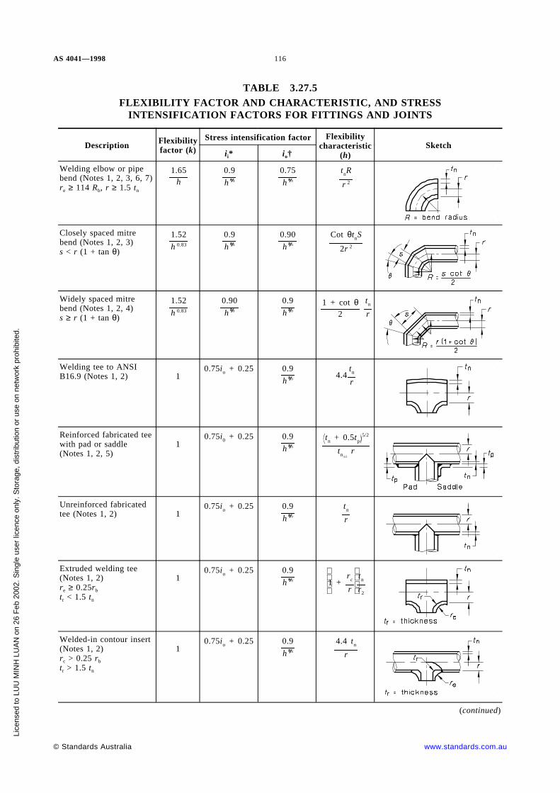
AS 4041—1998 116
TABLE 3.27.5FLEXIBILITY FACTOR AND CHARACTERISTIC, AND STRESS
INTENSIFICATION FACTORS FOR FITTINGS AND JOINTS
Description Flexibilityfactor (k)
Stress intensification factor Flexibilitycharacteristic
(h)Sketch
ii* io†
Welding elbow or pipebend (Notes 1, 2, 3, 6, 7)re ≥ 114 Rb, r ≥ 1.5 tn
1.65h
0.9
h
0.75
h
tnR
r 2
Closely spaced mitrebend (Notes 1, 2, 3)s < r (1 + tan θ)
1.52
h 0.83
0.9
h
0.90
h
Cot θtnS
2r 2
Widely spaced mitrebend (Notes 1, 2, 4)s ≥ r (1 + tan θ)
1.52
h 0.83
0.90
h
0.9
h1 + cot θ
2
tn
r
Welding tee to ANSIB16.9 (Notes 1, 2) 1
0.75io + 0.25 0.9
h4.4
tn
r
Reinforced fabricated teewith pad or saddle(Notes 1, 2, 5)
10.75i0 + 0.25 0.9
htn + 0.5tp
5/2
tn3/2
r
Unreinforced fabricatedtee (Notes 1, 2) 1
0.75io + 0.25 0.9
h
tn
r
Extruded welding tee(Notes 1, 2)re ≥ 0.25rb
tr < 1.5 tn
10.75io + 0.25 0.9
h
1 +rc
r
tn
r2
Welded-in contour insert(Notes 1, 2)rc > 0.25 rb
tr > 1.5 tn
10.75io + 0.25 0.9
h
4.4 tn
r
(continued)
© Standards Australia www.standards.com.au
Lice
nsed
to L
UU
MIN
H L
UA
N o
n 26
Feb
200
2. S
ingl
e us
er li
cenc
e on
ly. S
tora
ge, d
istr
ibut
ion
or u
se o
n ne
twor
k pr
ohib
ited.

117 AS 4041—1998
Description Flexibilityfactor (k)
Stress intensification factor Flexibilitycharacteristic
(h)Sketch
ii* io†
Branch welded-on fitting(integrally reinforced)(Notes 1, 2)
10.9
h
0.9
h
3.3 tn
r
Butt-welded joint,reducer, or welding neckflange
1 1.0 1.0 — —
Double-welded slip-onflange
1 1.2 1.2 — —
Fillet-weld joint (single-welded), or single-welded slip-on flange
1 1.3 1.3 — —
Lapped flange (withANSI/ASME B16.9 lap-joint stub)
1 1.6 1.6 — —
Threaded-pipe joint, orthreaded flange
1 2.3 2.3 — —
* In-plane, see Figure 3.27.5(B) and (C).
† Out-of-plane, see Figure 3.27.5(B) and (C).
NOTES TO TABLE 3.27.5:
1 For fittings and mitre bends, the flexibility factors (k) and stress-intensification factors (i) in the table apply to bendingin any plane and shall be not less than unity. Factors for torsion shall be unity. Both factors apply over the effective arclength (shown by heavy centre lines in the sketches) for curved and mitre elbows, and to the intersection point for tees.
2 The values of k and i can be read directly from Figure 3.27.5(A) (Chart B) by entering the flexibility characteristic hcalculated from the equations given in this Table,
where
R = bend radius of welding elbow or pipe bend, in millimetres
r = mean radius of matching pipe bend, in millimetres
rb = mean radius of branch, in millimetres
re = radius of external contour of tee, in millimetres
s = mitre spacing at centre-line, in millimetres
tn = nominal wall thickness, in millimetres.
NOTE: Where the nominal wall thickness of a fabricated tee is greater than that of the adjoining pipes, thisthickness is to be maintained on each side of the branch, for a length not less than the pipe diameter.
tp = pad or saddle thickness, in millimetres
tr = thickness of crotch of a tee, in millimetres
θ = one-half angle between adjacent mitre axes, in degrees.
3 Where flanges are attached to one or both ends, the values of h and i in the table are to be corrected by the factor Cgiven below, which can be read directly from Figure 3.27.5(A) (Chart B), for the calculated h:
One end flanged C = h1/6 ≥ 1
Both ends flanged C = h1/3 ≥ 1
4 Also includes single mitre joint.
5 When tp ≥ 1.5th, use h = 4tn/r.
6 Cast butt-welding elbows may have considerably heavier walls than those of the pipe with which they are used. Largeerrors may be introduced unless the effect of these greater thicknesses is considered.
www.standards.com.au © Standards Australia
Lice
nsed
to L
UU
MIN
H L
UA
N o
n 26
Feb
200
2. S
ingl
e us
er li
cenc
e on
ly. S
tora
ge, d
istr
ibut
ion
or u
se o
n ne
twor
k pr
ohib
ited.

AS 4041 — 1998 118
7 In large diameter, thin-wall elbows and bends, pressure can significantly affect the magnitude of the flexibility andstress intensification factors. The values obtained from the table for the pressure effect, are to be corrected as follows —
(a) flexibility factor (k) to be divided by a number equal to 1 + [6(p/Ea)(r/tn)7/3(R/r)1/3]
(b) stress intensification factor (i) to be divided by a number equal to 1 + [3.25(p/Ea)(r/tn)5/2(R/r)2/3]
where
Ea = modulus of elasticity, in megapascals
p = pressure, in megapascals.
3.27.6 Reactions
3.27.6.1 General Reaction forces and moments to be used in the evaluation of theeffects of piping displacements on connected plant and in the design of restraints shall beobtained by modifying the reaction range (R), taken from the stress range computation, tomake allowance for cold spring.
3.27.6.2 Maximum reactions for a simple system The reactions for a simple systemmay be derived as follows:
(a) For a two anchor system without intermediate restraints The maximuminstantaneous values of reaction forces and moments may be estimated fromEquations 3.27.6(1) and 3.27.6(2).
(b) For the design operating conditions
. . . 3.27.6(1)Rm = R
1 − 23
CEm
Ea
where
Rm = estimated instantaneous maximum reaction force or moment at designoperating temperature, in newton metres
R = the range of reaction forces and moments used to determine the stressrange in Equation 3.27.5.6(1), in newton metres
C = cold spring factor varying between zero for no cold spring and 1.0 for100% cold spring. (The 2/3 factor is based upon experience whichshow that specified cold spring cannot be assured even with elaborateprecaution.)
Em = Young modulus at design operating temperature, in megapascals
Ea = Young modulus at installation temperature, in megapascals
(c) For the as-installed condition
Ra = CR or C1.R whichever is greater . . . 3.27.6(2)
where
Ra = estimated instantaneous reaction forces and moments at theinstallation temperature, in newton metres
C1 = 1 −f Ea
feEm
= estimated self spring or relaxation factor
= 0 when C1 is negative
© Standards Australia www.standards.com.au
Lice
nsed
to L
UU
MIN
H L
UA
N o
n 26
Feb
200
2. S
ingl
e us
er li
cenc
e on
ly. S
tora
ge, d
istr
ibut
ion
or u
se o
n ne
twor
k pr
ohib
ited.

119 AS 4041 — 1998
where
f = design strength at maximum metal temperature during the cycle, inmegapascals
fe = computed displacement stress range Equation 3.27.5.6(1), inmegapascals
3.27.6.3 Maximum reaction for complex systems For multi-anchor systems withintermediate restraints, Equations 3.27.6(1) and 3.27.6(2) do not apply. Each case shall bestudied to estimate location, nature and extent of local overstrain, and its effect uponstress distribution and reactions.
3.27.6.4 Reaction limits The calculated reactions shall not exceed the limits which theconnected equipment can safely sustain. Special consideration should be given to rotatingmachinery.
3.27.6.5 Calculation of pipe movements Calculations of displacements and rotations atspecific locations may be required for the following purposes:
(a) To check clearances from adjacent plant.
(b) To design piping supports.
(c) For the analysis of branch lines which are being designed separately.
www.standards.com.au © Standards Australia
Lice
nsed
to L
UU
MIN
H L
UA
N o
n 26
Feb
200
2. S
ingl
e us
er li
cenc
e on
ly. S
tora
ge, d
istr
ibut
ion
or u
se o
n ne
twor
k pr
ohib
ited.

AS 4041 — 1998 120
FIGURE 3.27.5(A) FLEXIBILITY AND STRESS-INTENSIFICATION FACTORS
© Standards Australia www.standards.com.au
Lice
nsed
to L
UU
MIN
H L
UA
N o
n 26
Feb
200
2. S
ingl
e us
er li
cenc
e on
ly. S
tora
ge, d
istr
ibut
ion
or u
se o
n ne
twor
k pr
ohib
ited.
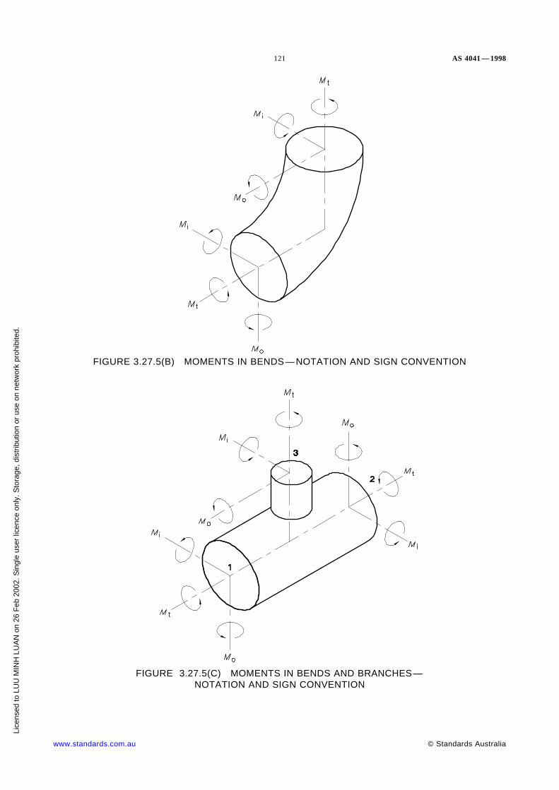
121 AS 4041 — 1998
FIGURE 3.27.5(B) MOMENTS IN BENDS—NOTATION AND SIGN CONVENTION
FIGURE 3.27.5(C) MOMENTS IN BENDS AND BRANCHES—NOTATION AND SIGN CONVENTION
www.standards.com.au © Standards Australia
Lice
nsed
to L
UU
MIN
H L
UA
N o
n 26
Feb
200
2. S
ingl
e us
er li
cenc
e on
ly. S
tora
ge, d
istr
ibut
ion
or u
se o
n ne
twor
k pr
ohib
ited.

AS 4041 — 1998 122
3.28 PIPE SUPPORTS
3.28.1 General
3.28.1.1 Design criteria This Clause (3.28) is intended to apply to support componentsand structure up to the support attachment to the main structure. The pipe support systemshall be designed to support the dead weight of the piping and to permit the supportpoints to move through cold to hot deflections given by the stress range analysis.
In addition the pipe work shall be supported to ensure the following:
(a) Pipe sag and creep are within acceptable limits.
(b) Stresses in the elements of the supporting system do not exceed the values permittedby this Standard.
(c) Suitable control of vibration and oscillation of the piping resulting from fluid flowand machine-induced forces.
(d) Prevention of unintentional disengagement of piping from the supports.
This Clause 3.28 deals with the design of pipe supports up to and including its attachmentto the main structure.
3.28.1.2 Design loads Pipe supports shall be designed to withstand the most adversecombination of the following loads:
(a) Piping expansion and contraction.
(b) Reaction of piping that discharges to atmosphere.
(c) Snow and ice.
(d) Mass of equipment installed to counteract or control expansion, contraction, andassociated reactions.
(e) Mass of insulation.
(f) Mass of the operating, cleaning or test fluid, whichever is heaviest, except thatwhere the pipe is to be held up with additional supports during testing, the mass ofthe test fluid is disregarded.
(g) Mass of the pipes and associated fittings.
(h) Wind or earthquake, whichever is greater.
Where imposed vibration or shock is expected during operation, suitable anchors,dampers, or restraints shall be provided to remove or reduce any adverse effects.
The calculation of loads for variable and constant supports shall be in accordance withClause 3.27.
The design of anchors and guides shall take into account additional forces to overcomefriction in other supports.
Anchors for bellows or slip-type expansion joints shall be designed to withstand thevector sum of the following forces at maximum pressure and temperature:
(i) The force to compress or extend the joint by the calculated expansion movementspecified by the manufacturer.
(ii) The force due to the fluid pressure under normal operating conditions, being theproduct of effective thrust area and design pressure.
(iii) The force to overcome static friction between the pipe and supports duringexpansion or contraction of the piping.
© Standards Australia www.standards.com.au
Lice
nsed
to L
UU
MIN
H L
UA
N o
n 26
Feb
200
2. S
ingl
e us
er li
cenc
e on
ly. S
tora
ge, d
istr
ibut
ion
or u
se o
n ne
twor
k pr
ohib
ited.
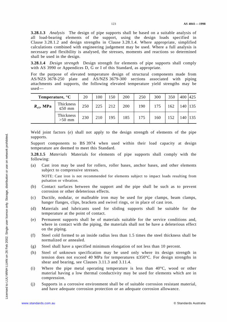
123 AS 4041 — 1998
3.28.1.3 Analysis The design of pipe supports shall be based on a suitable analysis ofall load-bearing elements of the support, using the design loads specified inClause 3.28.1.2 and design strengths in Clause 3.28.1.4. Where appropriate, simplifiedcalculations combined with engineering judgement may be used. Where a full analysis isnecessary and flexibility is analysed, the stresses, moments and reactions so determinedshall be used in the design.
3.28.1.4 Design strength Design strength for elements of pipe supports shall complywith AS 3990 or Appendices D, G or I of this Standard, as appropriate.
For the purpose of elevated temperature design of structural components made fromAS/NZS 3678-250 plate and AS/NZS 3679-300 sections associated with pipingattachments and supports, the following elevated temperature yield strengths may beused—
Temperature, °C 20 100 150 200 250 300 350 400 425
ReT, MPa Thickness≤50 mm 250 225 212 200 190 175 162 140 135
Thickness>50 mm 230 210 195 185 175 160 152 140 135
Weld joint factors (e) shall not apply to the design strength of elements of the pipesupports.
Support components to BS 3974 when used within their load capacity at designtemperature are deemed to meet this Standard.
3.28.1.5 Materials Materials for elements of pipe supports shall comply with thefollowing:
(a) Cast iron may be used for rollers, roller bases, anchor bases, and other elementssubject to compressive stresses.
NOTE: Cast iron is not recommended for elements subject to impact loads resulting frompulsation or vibration.
(b) Contact surfaces between the support and the pipe shall be such as to preventcorrosion or other deleterious effects.
(c) Ductile, nodular, or malleable iron may be used for pipe clamps, beam clamps,hanger flanges, clips, brackets and swivel rings, or in place of cast iron.
(d) Materials and lubricants used for sliding supports shall be suitable for thetemperature at the point of contact.
(e) Permanent supports shall be of materials suitable for the service conditions and,where in contact with the piping, the materials shall not be have a deleterious effecton the piping.
(f) Steel cold formed to an inside radius less than 1.5 times the steel thickness shall benormalized or annealed.
(g) Steel shall have a specified minimum elongation of not less than 10 percent.
(h) Steel of unknown specification may be used only where its design strength intension does not exceed 40 MPa for temperatures ≤350°C. For design strengths inshear and bearing, see Clauses 3.11.3 and 3.11.4.
(i) Where the pipe metal operating temperature is less than 40°C, wood or othermaterial having a low thermal conductivity may be used for elements which are incompression.
(j) Supports in a corrosive environment shall be of suitable corrosion resistant material,and have adequate corrosion protection or an adequate corrosion allowance.
www.standards.com.au © Standards Australia
Lice
nsed
to L
UU
MIN
H L
UA
N o
n 26
Feb
200
2. S
ingl
e us
er li
cenc
e on
ly. S
tora
ge, d
istr
ibut
ion
or u
se o
n ne
twor
k pr
ohib
ited.

AS 4041 — 1998 124
3.28.1.6 Threaded elements The thread on a threaded element shall comply withAS 1721 fine thread with thread tolerance not inferior to Class 6H 8g, or shall be anagreed thread.
The thread in a turnbuckle and adjusting nuts shall be fully engaged. A threadedadjustment shall have a locking device.
The safe load for a threaded element shall be based on the root area of the thread.
3.28.1.7 Springs Helical springs in variable and constant-effort type supports shouldcomply with BS 1726.1. Springs of special form, such as leaf, disc, volute, involute, andtorsion, shall be designed, manufactured and installed so that no permanent deformationoccurs.
If a spring is to be subjected to high temperatures, the spring constants shall be suitable atthose temperatures.
3.28.2 Pipe support spacing Support spacing shall take into account the following:
(a) Bending stresses from uniform and concentrated loads between supports.
(b) Sag, which shall be kept within limits necessary to maintain any necessary drainageif required.
It is recommended that the spacing of pipe supports does not exceed that shown inTable 3.28.2 for steel pipe.
The recommended spacing for water service for copper, copper alloy, UPVC,polyethylene, cross-linked polyethylene and polybutylene pipes is given in AS 3500.1.
TABLE 3.28.2
RECOMMENDED SPACING OF SUPPORTS FOR STEEL PIPE
Nominal size, Recommended spacing, m(see Notes)
DN Water service Steam, gas, or air service
202532
2.02.42.7
3.03.33.7
405065
3.03.43.7
4.04.55.0
80100150
3.94.35.2
5.15.26.5
200250300
6.07.08.0
7.59.0
10.0
350400450
8.48.89.0
10.611.212.0
500600
10.012.0
13.015.0
NOTES:
1 Experience has shown these spacings to be satisfactory.
2 This Table shows recommended maximum spacing between pipe supports for horizontal straight runs ofpipe at maximum operating temperature of 400°C.
3 These spacings do not prevail over calculated spacings and do not apply where there are concentrated loadsbetween supports, such as flanges and valves.
4 These spacings are based on a fixed-beam support with a bending stress not exceeding 16 MPa andinsulated pipe with the appropriate contents, and the pitch of the line being such that sag of 2.5 mmbetween supports is incorporated in the design.
© Standards Australia www.standards.com.au
Lice
nsed
to L
UU
MIN
H L
UA
N o
n 26
Feb
200
2. S
ingl
e us
er li
cenc
e on
ly. S
tora
ge, d
istr
ibut
ion
or u
se o
n ne
twor
k pr
ohib
ited.

125 AS 4041 — 1998
3.28.3 Fixtures
3.28.3.1 Anchors and guides Where necessary, anchors and guides shall be provided tocontrol movement or to direct expansion to parts of the piping designed to absorb thatmovement or expansion.
Anchors and guides (including pivots) shall be designed to secure the desired points ofpiping in relatively fixed positions, and to prevent slipping and twisting of the pipe. Thepiping shall be free to expand and contract as required from the anchored or guided pointand shall be structurally suitable to withstand the thrusts, moments, and other imposedloads.
A rolling or sliding support shall allow free movement of the piping, or the piping shallbe designed to include the imposed load and frictional resistance. The support shallprovide for the expected movement of the supported piping.
3.28.3.2 Non-inextensible supports other than anchors and guides
Hangers include pipe and beam clamps, clips, brackets, rods, straps, chains, and othersimilar devices. They shall be proportioned for all required loads.
Sliding supports (or shoes) and brackets shall be designed to resist the forces due tofriction in addition to the loads imposed by bearing. The dimensions of the support shallprovide for the expected movement of the supported piping.
3.28.3.3 Variable spring supports A spring support shall provide support to the totalload, being the load from weight balance calculations plus the weight of all hanger partsthat will be supported by the spring at the point of attachment to the pipe, e.g. clamps androds.
A spring support shall have means to limit misalignment, buckling, eccentric loading, andmeans to prevent overstressing of any spring or unintentional disengagement of the loadfrom spring failure or other causes.
A hanger with a spring should have means to show the amount of compression of thespring with respect to the approximate hot and cold positions of the piping system, exceptwhere the spring is used to cushion shock or where the operating temperature of thepiping does not exceed 120°C.
A support should have a maximum variation of support effort of 25% for the total travelfrom thermal effects.
The resistance by supports to the movement of the pipe shall be taken into account in theloadings used for flexibility analysis.
3.28.3.4 Constant effort supports Constant effort support hangers with a substantiallyuniform supporting force over the range of travel shall be considered for high-temperatureand critical-service piping. Support load variation shall not be more than ±5% unlessotherwise agreed.
3.28.3.5 Counterweight supports A counterweight-type support shall have atravel-limiting stop, and the counterweight shall be positively secured. The cable, hanger,rocker arm, or other devices used to attach the counterweight to the piping shall complywith Clause 3.28.3.2.
3.28.3.6 Hydraulic supports A support with a hydraulic cylinder shall have a safetydevice and a stop to support the load in the event of hydraulic failure.
3.28.3.7 Special fixtures Special devices to locate piping in the positions assumed forthe purposes of flexibility analysis and to provide for changed operating conditions shallcomply with this Standard. Precautions shall be taken to ensure that malfunction of thesedevices will not give unacceptable forces or movements in the piping system.
www.standards.com.au © Standards Australia
Lice
nsed
to L
UU
MIN
H L
UA
N o
n 26
Feb
200
2. S
ingl
e us
er li
cenc
e on
ly. S
tora
ge, d
istr
ibut
ion
or u
se o
n ne
twor
k pr
ohib
ited.

AS 4041 — 1998 126
3.28.3.8 Sway braces and vibrational dampeners Sway braces and vibration dampenersshould be used, where necessary, to limit vibration.
3.28.4 Support attachments
3.28.4.1 General An attachment to support the piping shall comply with Clause 3.23.
3.28.4.2 Non-integral attachments A clamp supporting a vertical run of piping shouldbe designed to support the total load on each half of the clamp, to provide for shifting ofthe load. Where slipping may occur, clamps should be located below a fitting, or on lugswelded to the pipe or a flange.
NOTE: Non-integral attachments include clamps, slings, cradles, saddles, straps and clevises.
3.28.4.3 Integral attachments Integral attachments shall be used in combination withrestraints or braces where multi-axial restraint in a single member is required.
NOTE: Integral attachments include ears, shoes, lugs, cylindrical attachment rings, and skirtsthat are fabricated so that the attachment is an integral part of the component.
Integral items that are part of an assembly for supporting or guiding pipe may be weldeddirectly to the pipe provided that the materials are compatible for welding and the designis suitable for the temperature and load. Hanger lugs for attachment to piping forhigh-temperature service shall provide for differential expansion between the pipe and theattached lug.
Shear stresses in attachment welds shall not exceed 60 percent of the design strengthgiven in Appendix D. The lower design strength value shall apply where the attachmentand pipe values differ.
3.28.5 Load-supporting structure Supporting structures shall comply with AS 3990,AS/NZS 1664 or other agreed Standards. Welded connections for structural steelattachments shall be designed in accordance with AS/NZS 1554.1, or other agreedStandards.
3.29 INFORMATION TO BE SUPPLIED A designer of piping shall ensure, whenthe design of the piping is made available to the manufacturer, that the manufacturer ofthe pipe is provided with information to enable the piping to be manufactured inaccordance with the design specifications and, if applicable, with information relating to—
(a) the purpose for which the piping is designed;
(b) the hazards and any risk, identified and assessed in accordance with this Standard,associated with the use of the piping;
(c) testing or inspections to be carried out on the piping;
(d) installation, commissioning, de-commissioning, use, transport, storage and, if theplant is capable of being dismantled, dismantling of the piping;
(e) systems of work and competency of operators necessary for the safe use of piping;and
(f) emergency procedures (if any) required if there is a malfunction of the piping.
3.30 INFORMATION TO BE SUPPLIED BY THE OWNER The owner isresponsible for compliance with this Standard and the design, and for the establishment ofthe requirements for design, manufacture, examination, inspection, testing operation andmaintenance which will govern the entire fluid handling or process system of whichpiping is part. Where the owner does not supply sufficient information, the designer mayissue and document the parameters for the design.
© Standards Australia www.standards.com.au
Lice
nsed
to L
UU
MIN
H L
UA
N o
n 26
Feb
200
2. S
ingl
e us
er li
cenc
e on
ly. S
tora
ge, d
istr
ibut
ion
or u
se o
n ne
twor
k pr
ohib
ited.
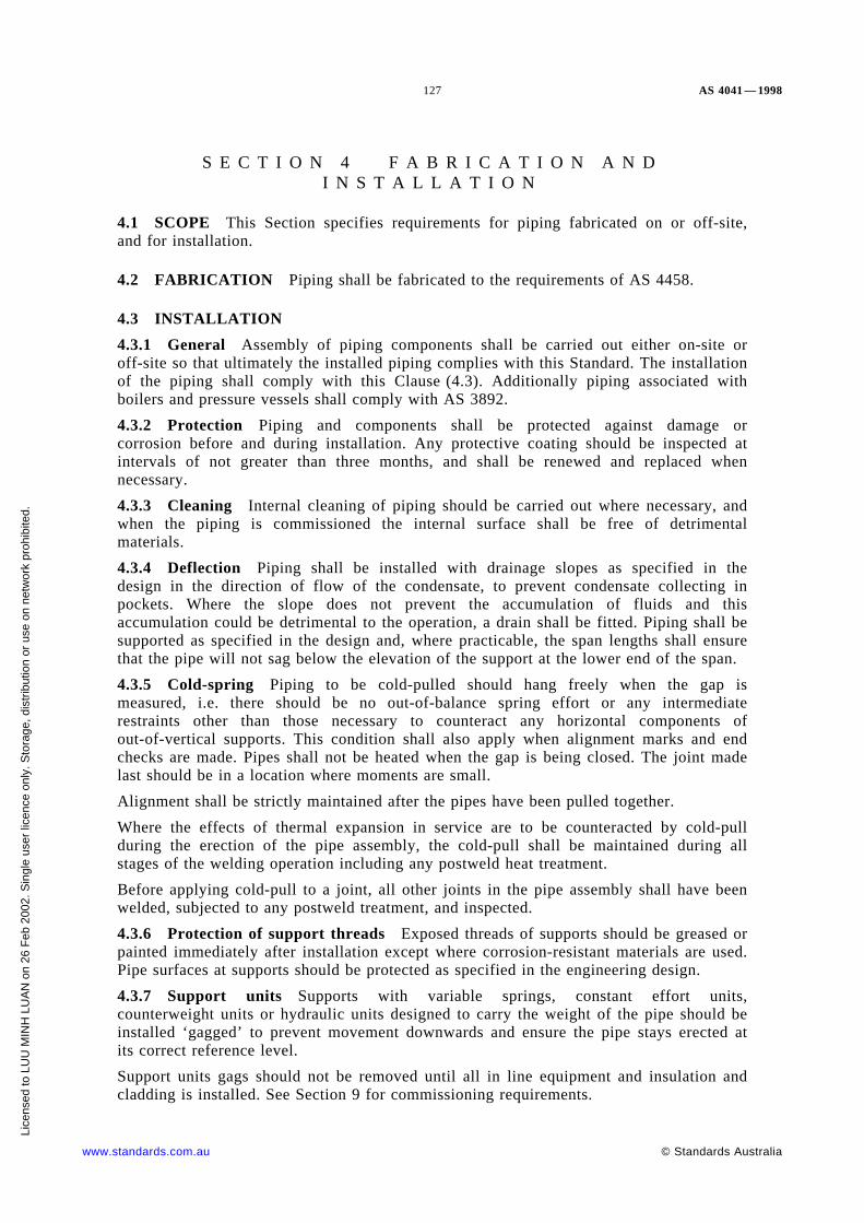
127 AS 4041 — 1998
S E C T I O N 4 F A B R I C A T I O N A N DI N S T A L L A T I O N
4.1 SCOPE This Section specifies requirements for piping fabricated on or off-site,and for installation.
4.2 FABRICATION Piping shall be fabricated to the requirements of AS 4458.
4.3 INSTALLATION
4.3.1 General Assembly of piping components shall be carried out either on-site oroff-site so that ultimately the installed piping complies with this Standard. The installationof the piping shall comply with this Clause (4.3). Additionally piping associated withboilers and pressure vessels shall comply with AS 3892.
4.3.2 Protection Piping and components shall be protected against damage orcorrosion before and during installation. Any protective coating should be inspected atintervals of not greater than three months, and shall be renewed and replaced whennecessary.
4.3.3 Cleaning Internal cleaning of piping should be carried out where necessary, andwhen the piping is commissioned the internal surface shall be free of detrimentalmaterials.
4.3.4 Deflection Piping shall be installed with drainage slopes as specified in thedesign in the direction of flow of the condensate, to prevent condensate collecting inpockets. Where the slope does not prevent the accumulation of fluids and thisaccumulation could be detrimental to the operation, a drain shall be fitted. Piping shall besupported as specified in the design and, where practicable, the span lengths shall ensurethat the pipe will not sag below the elevation of the support at the lower end of the span.
4.3.5 Cold-spring Piping to be cold-pulled should hang freely when the gap ismeasured, i.e. there should be no out-of-balance spring effort or any intermediaterestraints other than those necessary to counteract any horizontal components ofout-of-vertical supports. This condition shall also apply when alignment marks and endchecks are made. Pipes shall not be heated when the gap is being closed. The joint madelast should be in a location where moments are small.
Alignment shall be strictly maintained after the pipes have been pulled together.
Where the effects of thermal expansion in service are to be counteracted by cold-pullduring the erection of the pipe assembly, the cold-pull shall be maintained during allstages of the welding operation including any postweld heat treatment.
Before applying cold-pull to a joint, all other joints in the pipe assembly shall have beenwelded, subjected to any postweld treatment, and inspected.
4.3.6 Protection of support threads Exposed threads of supports should be greased orpainted immediately after installation except where corrosion-resistant materials are used.Pipe surfaces at supports should be protected as specified in the engineering design.
4.3.7 Support units Supports with variable springs, constant effort units,counterweight units or hydraulic units designed to carry the weight of the pipe should beinstalled ‘gagged’ to prevent movement downwards and ensure the pipe stays erected atits correct reference level.
Support units gags should not be removed until all in line equipment and insulation andcladding is installed. See Section 9 for commissioning requirements.
www.standards.com.au © Standards Australia
Lice
nsed
to L
UU
MIN
H L
UA
N o
n 26
Feb
200
2. S
ingl
e us
er li
cenc
e on
ly. S
tora
ge, d
istr
ibut
ion
or u
se o
n ne
twor
k pr
ohib
ited.

AS 4041 — 1998 128
4.4 THERMAL INSULATION Where piping is thermally insulated, the materialsused shall not cause corrosion of the pipe, not char or burn at the maximum temperatureat which the material may be normally operated. Asbestos shall not be used.
Where required, insulation of piping including supports shall be of the agreed fireperformance.
Where flanged or threaded joints are lagged, provision shall be made for the detection ofleaks, and inspection and repair of these joints.
Guidance on thermal insulation is given in BS 5970.
Guidance on the installation of thermally insulated underground piping is given inBS 7572.
4.5 IDENTIFICATION Contents of piping should be suitably identified, e.g. inaccordance with AS 1345 or other agreed means.
© Standards Australia www.standards.com.au
Lice
nsed
to L
UU
MIN
H L
UA
N o
n 26
Feb
200
2. S
ingl
e us
er li
cenc
e on
ly. S
tora
ge, d
istr
ibut
ion
or u
se o
n ne
twor
k pr
ohib
ited.

129 AS 4041 — 1998
S E C T I O N 5 W E L D I N G A N D A L L I E DJ O I N I N G P R O C E S S E S
This Section specifies requirements for the joining of pipes and components, includingsuch fittings as welding neck flanges, welding elbows and forged tees, by welding andbrazing, and associated processes. Welding shall be carried out in accordance withAS 4458 for manufacture and AS/NZS 3992 for welding and brazing qualification.
www.standards.com.au © Standards Australia
Lice
nsed
to L
UU
MIN
H L
UA
N o
n 26
Feb
200
2. S
ingl
e us
er li
cenc
e on
ly. S
tora
ge, d
istr
ibut
ion
or u
se o
n ne
twor
k pr
ohib
ited.

AS 4041 — 1998 130
S E C T I O N 6 E X A M I N A T I O N A N D T E S T I N G
6.1 SCOPE This Section specifies the requirements for the examination and testing ofthe following:
(a) Test welds made to qualify a welding procedure or a welder (see Note 3).
(b) Production welds made in a workshop or on-site.
(c) Repaired welds or repairs by welding.
(d) Partly assembled or installed piping and other components.
This Standard does not specify the methods and acceptance criteria applicable to theexamination and testing of pipes, fittings and other components which are manufacturedin accordance with a nominated Standard.
NOTES:
1 Examination and testing is intended to be applied as a function of quality control carried outby or on behalf of the fabricator of the piping, or, by the component manufacturer.
2 The word‘examiner’ applies to personnel who carry out the examinations and tests requiredfor quality control.
3 Welding in this Section is taken to include brazing.
6.2 RESPONSIBILITY The preparation, examination, and testing of test welds forwelding procedures and qualifying welders, production welds, repaired welds, and repairscarried out by welding are the responsibility of the fabricator, unless otherwise indicatedor agreed.
The fabricator is responsible for—
(a) making any choice necessary within a test method and compliance with theengineering design;
(b) labour and equipment for examination or test;
(c) suitable notice to the inspector of when piping is expected to reach the stage atwhich inspection is required;
(d) records of examinations and tests, including those delegated to others; and
(e) performing and reporting any supplementary tests required by the owner orengineering design.
6.3 QUALIFICATION OF WELDING PROCEDURES AND WELDERSExamination and testing for qualification of welding and brazing procedures or of weldingand brazing personnel shall comply with AS/NZS 3992.
6.4 NON-DESTRUCTIVE EXAMINATION Materials, production welds and brazes,assembly, erection and the completed piping shall be examined in accordance withAS 4037 and the engineering design.
Where the design or method of construction is such that a specified method ofexamination is not effective, an alternative method and acceptance criteria shall be agreedbetween the parties concerned.
Examination shall ensure the piping complies with the Standard with respect to materials,components, dimensions, joint preparation, welds, joints, supports, assembly, erection andinstallation.
© Standards Australia www.standards.com.au
Lice
nsed
to L
UU
MIN
H L
UA
N o
n 26
Feb
200
2. S
ingl
e us
er li
cenc
e on
ly. S
tora
ge, d
istr
ibut
ion
or u
se o
n ne
twor
k pr
ohib
ited.

131 AS 4041 — 1998
6.5 ALTERNATIVES TO NON-DESTRUCTIVE TESTING
A1 6.5.1 Alternative to radiographic or ultrasonic examination Piping is exempt fromradiographic or ultrasonic examination when each of the following apply:
(a) The material is Type A1, A2, A3, B, C, E, K, M or non-ferrous.
(b) The pipe and fittings have a hoop stress less than half of the design strength.
(c) The piping system has been hydrostatically tested in compliance with Clause 6.7.(The alternatives to hydrostatic test as given in Clause 6.8 do not apply).
(d) The piping has passed visual examination in accordance with the limit on surfaceimperfections for pressure piping in AS 4037.
A1 (e) The design pressure and temperature is not greater than 2 MPa and 180°C forTypes 2 or 3 fluids or 0.4 MPa, and 99°C for Type 1 fluids.
A1
6.5.2 Alternative to spot non-destructive testing by use of destructive tests Bendtests and macro examination may be substituted for spot non-destructive examination(other than visual examination) of welds in piping of DN 40 and smaller. The number oftest pieces shall be at least 10 percent for Classes 1 and 2 of each welder’s productionwelds.
6.5.3 Alternative to radiographic or ultrasonic examination by use of in-processexamination
6.5.3.1 Purpose In-process examination is intended for use in specific cases to exposeunacceptable imperfections before completion of a welded joint.
6.5.3.2 Application In-process examination is permitted where—
(a) it is not practicable for radiographic or ultrasonic examination specified in thisStandard to be applied; and
(b) the inspector’s agreement is granted on a weld for weld basis.
6.5.3.3 Stage of examination In-process examination of materials and consumablesshall be carried out before welding starts. Examination of a weld shall be continuousduring the making of the weld. The completed weld shall be examined visually oncooling.
6.5.3.4 Method of examination In-process examination shall be visual examination inaccordance with AS 4037 and assessment of the following:
(a) The qualified welding procedure specification applicable to the weld.
(b) Documentation of the welder’s qualification to weld to the qualified weldingprocedure.
(c) Preparation and cleanliness of the joint.
(d) Fit-up, internal alignment and support before and during welding.
(e) Preheating and interrun temperature control.
(f) Weld position, consumables and all other essential variables specified by thewelding procedure and the welder’s qualification.
(g) Conditions after cleaning of the external and, where accessible, internal surfaces onthe root run. Where specified in the design, a dye penetrant or magnetic particleexamination shall be made.
(h) Condition of the weld between runs, including freedom from slag.
(i) Appearance of the completed weld.
The weld shall comply with the requirements of this Standard.
www.standards.com.au © Standards Australia
Lice
nsed
to L
UU
MIN
H L
UA
N o
n 26
Feb
200
2. S
ingl
e us
er li
cenc
e on
ly. S
tora
ge, d
istr
ibut
ion
or u
se o
n ne
twor
k pr
ohib
ited.
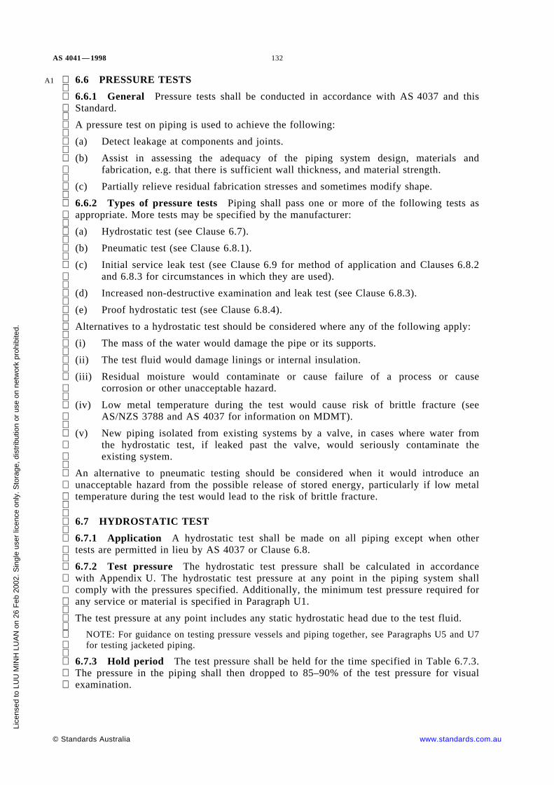
AS 4041 — 1998 132
A1 6.6 PRESSURE TESTS
6.6.1 General Pressure tests shall be conducted in accordance with AS 4037 and thisStandard.
A pressure test on piping is used to achieve the following:
(a) Detect leakage at components and joints.
(b) Assist in assessing the adequacy of the piping system design, materials and
fabrication, e.g. that there is sufficient wall thickness, and material strength.
(c) Partially relieve residual fabrication stresses and sometimes modify shape.
6.6.2 Types of pressure tests Piping shall pass one or more of the following tests asappropriate. More tests may be specified by the manufacturer:
(a) Hydrostatic test (see Clause 6.7).
(b) Pneumatic test (see Clause 6.8.1).
(c) Initial service leak test (see Clause 6.9 for method of application and Clauses 6.8.2
and 6.8.3 for circumstances in which they are used).
(d) Increased non-destructive examination and leak test (see Clause 6.8.3).
(e) Proof hydrostatic test (see Clause 6.8.4).
Alternatives to a hydrostatic test should be considered where any of the following apply:
(i) The mass of the water would damage the pipe or its supports.
(ii) The test fluid would damage linings or internal insulation.
(iii) Residual moisture would contaminate or cause failure of a process or causecorrosion or other unacceptable hazard.
(iv) Low metal temperature during the test would cause risk of brittle fracture (see
AS/NZS 3788 and AS 4037 for information on MDMT).
(v) New piping isolated from existing systems by a valve, in cases where water fromthe hydrostatic test, if leaked past the valve, would seriously contaminate theexisting system.
An alternative to pneumatic testing should be considered when it would introduce anunacceptable hazard from the possible release of stored energy, particularly if low metaltemperature during the test would lead to the risk of brittle fracture.
6.7 HYDROSTATIC TEST
6.7.1 Application A hydrostatic test shall be made on all piping except when othertests are permitted in lieu by AS 4037 or Clause 6.8.
6.7.2 Test pressure The hydrostatic test pressure shall be calculated in accordancewith Appendix U. The hydrostatic test pressure at any point in the piping system shallcomply with the pressures specified. Additionally, the minimum test pressure required forany service or material is specified in Paragraph U1.
The test pressure at any point includes any static hydrostatic head due to the test fluid.
NOTE: For guidance on testing pressure vessels and piping together, see Paragraphs U5 and U7for testing jacketed piping.
6.7.3 Hold period The test pressure shall be held for the time specified in Table 6.7.3.The pressure in the piping shall then dropped to 85–90% of the test pressure for visualexamination.
© Standards Australia www.standards.com.au
Lice
nsed
to L
UU
MIN
H L
UA
N o
n 26
Feb
200
2. S
ingl
e us
er li
cenc
e on
ly. S
tora
ge, d
istr
ibut
ion
or u
se o
n ne
twor
k pr
ohib
ited.

133 AS 4041 — 1998
A1 TABLE 6.7.3
HOLD PERIOD FOR HYDROSTATIC TEST
Nominal sizeMinimum hold period, minutes
Test pressure, kPa≤700 >700
≤DN 300>DN 300
1020
1525
6.8 ALTERNATIVE TO HYDROSTATIC TEST
6.8.1 Alternative to hydrostatic test by use of pneumatic testing As an alternative tohydrostatic testing, and where agreed by the parties concerned, a pneumatic test may beused. The test shall be conducted in accordance with AS 4037. The test pressure shall be90 percent of that specified in Clause 6.7.2.
6.8.2 Alterative to hydrostatic test by use of initial service leak test At the owner’soption, piping is exempt from hydrostatic test when each of the following apply:
(a) The pipe is certified by the pipe manufacturer to a listed Standard as leak tight by
hydrostatic test or non-destructive examination method.
(b) The piping is made from material groups A1, A2, A3, A4, B, C, E, K, M or non-ferrous.
(c) The design temperature is less than or equal to 180°C and greater than −30°C.
(d) The design pressure is less than 2 MPa if the hoop stress≤0.5f or 1 MPa if the hoop
stress >0.5f.
(e) The fluid is either—
(i) fluid types 3 and 4;
(ii) steam; or
(iii) caustic soda or sodium cyanide solutions as used in the mining industry.
In lieu of a hydrostatic test, each of the following shall be carried out:
(i) 100% visual examination of all welds (see Table 8.4 and AS 4037 for form andworking omissions).
(ii) An initial service leak test in accordance with Clause 6.8A.
6.8.3 Alternative to hydrostatic test by use of increased non-destructive examinationand leak test
6.8.3.1 General Increased non-destructive examination and leak tests may be used inlieu of a hydrostatic test for butt welds, branch welds, flange welds and minor attachmentsas given in this Clause 6.8.3. Leak tests should be used on mechanical joints.
6.8.3.2 Butt welds, branch welds and flange welds For Classes 1 and 2 piping, buttwelds, branch welds, and flange welds, including tie-in and cut-in-welds, may beexempted from hydrostatic testing where these welds comply with each of the following:
(a) The pipe is certified by the pipe manufacturer to a listed Standard as leak tight by
hydrostatic test or a non-destructive examination method.
(b) Butt welds are located in straight pipe and are not less than one pipe diameter fromany branch connection or bend. This requirement does not apply to butt weldfittings covered in Clause 2.2.1(f).
Branch welds are located in straight pipe and are not less than one pipe diameterfrom any butt weld or bend.
www.standards.com.au © Standards Australia
Lice
nsed
to L
UU
MIN
H L
UA
N o
n 26
Feb
200
2. S
ingl
e us
er li
cenc
e on
ly. S
tora
ge, d
istr
ibut
ion
or u
se o
n ne
twor
k pr
ohib
ited.

AS 4041 — 1998 134
A1 (c) They comply with the ovality requirements of this Standard.
(d) They are subject to 100% visual examination.
(e) They comply with appropriate non-destructive examination Standards for—
(i) 100% radiographic examination, plus either magnetic particle testing orpenetrant examination; or
(ii) 100% ultrasonic examination, plus either magnetic particle testing or
penetrant examination.
(iii) Fillet welded pressure welds (e.g. slip-on flange or socket weld fittings)either 100% magnetic particle testing or 100% penetrant examination inaccordance with AS 4037.
NOTE: When Items (i) and (ii) are not practical, refer to Clause 6.5.3.
(f) Examinations (d) and (e) have been carried out after any postweld heat treatment
has been carried out.
(g) They comply with the limits of surface imperfection for piping given in AS 4037.
(h) They pass an initial service leak test (Clause 6.8A) or the sensitive leak test(AS 4037). For lethal fluids it shall be the sensitive leak test.
For Class 3 piping, butt welds, branch welds and flange welds (including tie-in and cut-inwelds) are exempt from hydrostatic testing where the welds comply with the initialservice leak test. Any longitudinal welds shall be subject to 20% radiograhic or ultrasonicexamination including either magnetic particle testing or penetrant examination.
6.8.3.3 Mechanical joints Mechanical joints used within their pressure rating for theservice conditions (e.g. bolting and screwing) may be exempted from hydrostatic testingprovided that the completed piping is subjected to—
(a) 100% visual examination;
(b) a sensitive leak test (see AS 4037) where the contents are fluid Types 1 or 2;
(c) an initial service leak test for piping other than Item (b); and
(d) the components being joined have been hydrostatically tested at the time of
manufacture or its equivalent.
6.8.3.4 Minor attachments The welding or brazing of minor attachments, such astemperature and pressure tappings (DN 40 and below) and minor structural attachments,are exempt from hydrostatic provided—
(a) they are subject to 100% visual examination;
(b) the joint is subject to 100% magnetic particle or penetrant examination to AS 4037;
and
(c) failure will not be detrimental to the piping in service.
6.8.4 Proof hydrostatic test Where the strength of components cannot readily becalculated, the design pressure may be determined in accordance with the proofhydrostatic test specified in AS 1210.
6.8A INITIAL SERVICE LEAK TEST The initial service leak test when used shallbe made during or prior to the initial operation and after taking all necessary precautions.The leak test shall be made with the service fluid at the operating condition of the pipingby examining for leaks at each joint and connection not previously pressure tested inaccordance with this Standard. Where the pressurized fluid is gas or vapour, a preliminaryleak test shall be made at one-quarter operating pressure but not more than 200 kPa.When the process fluid is Type 2 (very harmful), it is recommended that the preliminaryleak test be carried out using an inert medium. The pressure shall then be increasedgradually in steps until the operating pressure is reached, holding at each step longenough to equalize piping strain and check for leaks.
© Standards Australia www.standards.com.au
Lice
nsed
to L
UU
MIN
H L
UA
N o
n 26
Feb
200
2. S
ingl
e us
er li
cenc
e on
ly. S
tora
ge, d
istr
ibut
ion
or u
se o
n ne
twor
k pr
ohib
ited.

135 AS 4041 — 1998
A1 6.9 TESTING PRESSURE-LIMITING DEVICES, RELIEF VALVES, PRESSUREREGULATORS, AND CONTROL EQUIPMENT Pressure-limiting devices, reliefvalves, pressure regulators, and control equipment shall be examined for the following:
(a) Good mechanical condition.
(b) Adequate capacity, effectiveness, and reliability for operation of the intended
service.
(c) Proper functioning at the correct pressure and temperature.
(d) Proper installation, and protection from foreign materials or condition that mayprevent proper operation.
(e) Compliance with the relevant product Standard.
6.10 REPORT After Class 1 or 2 piping has been completed and tested, the fabricatoror manufacturer shall add to the manufacturer’ s data report that the piping has been testedin accordance with this Standard.
www.standards.com.au © Standards Australia
Lice
nsed
to L
UU
MIN
H L
UA
N o
n 26
Feb
200
2. S
ingl
e us
er li
cenc
e on
ly. S
tora
ge, d
istr
ibut
ion
or u
se o
n ne
twor
k pr
ohib
ited.

AS 4041 — 1998 136
S E C T I O N 7 P R O T E C T I V E S Y S T E M SA N D D E V I C E S
7.1 GENERAL
7.1.1 Basic requirement Pressure piping shall be protected as specified in thisStandard and as necessary to ensure the piping operates reliably and safely under theexpected conditions of service.
7.1.2 Protective systems Protective systems required in this Section shall be specifiedin the engineering design and be acceptable to the owner.
7.1.3 Design and construction Protective systems and devices shall—
(a) be of material, design (including the number, size, type, and location) andconstruction to permit the system and devices to perform their required functionunder the expected conditions of service; and
(b) comply with AS 1271 or other agreed Standard.
Where any such device or fitting is not supplied by the fabricator, the owner shall beresponsible for ensuring that it is supplied and properly fitted before the piping is placedinto service.
7.2 PRESSURE AND TEMPERATURE CONTROL SYSTEMS Suitable controlshall be provided to ensure that the pressure and temperature of piping components arecontrolled within the limits of the engineering design and this Standard (see Clause 3.9.3for pressure reducing systems).
7.3 PRESSURE RELIEF SYSTEMS
7.3.1 General Where a pressure greater than that specified in the engineering designcan occur such as from a failure of control devices, solar heating or process, suitablepressure relief systems shall be provided.
Such systems, by appropriate design and devices, shall—
(a) prevent the pressure in the piping exceeding 115 percent of the design pressure forClasses 1 and 2 and 125 percent from the design pressure for Class 3;
(b) ensure that discharges from pressure-relieving devices are in positions that will besafe; and
(c) where piping can be shut off between valves when full of liquid, provide forhydrostatic pressure relief to ensure that the maximum safe working component ofthe weakest component in the protected system is not exceeded.
7.3.2 Stop valves in pressure relief systems A stop valve shall not be located betweenprotected piping and the protective device or devices, nor between the protective device ordevices and the point of discharge, except as follows:
(a) One stop valve may be installed on the inlet side and one may be placed on thedischarge side of a pressure-relieving device, where the discharge is connected to aheader common to other discharge lines from other pressure-relieving devices. Thestop valves shall be the full-area type or such other type and size that an increase inpressure drop will not reduce the relieving capacity to less than that required, oradversely affect the proper operation of the pressure-relieving device. The stopvalves shall be lockable or sealable in the open and the closed positions. When thestop valves are in the closed position with the equipment operating, an authorizedperson shall be able to observe the operating pressure, and shall have means forrelieving overpressure. The authorized person shall lock or seal the stop valves inthe open position when observation ceases, or an alternative interlocking system ofequivalent safety shall be used.
© Standards Australia www.standards.com.au
Lice
nsed
to L
UU
MIN
H L
UA
N o
n 26
Feb
200
2. S
ingl
e us
er li
cenc
e on
ly. S
tora
ge, d
istr
ibut
ion
or u
se o
n ne
twor
k pr
ohib
ited.

137 AS 4041 — 1998
(b) The stop valves shall be constructed or controlled positively so that, with themaximum possible number of valves closed at one time, the remainingpressure-relieving capacity will be not less than the required relieving capacity.
7.4 CORROSION PROTECTION Piping shall be protected against internal andexternal corrosion during design life unless the design principle used is to do nothing andmonitor the thickness. Design life may be enhanced by replaceable components.
Protection may be afforded by one or more of the following:
(a) Corrosion-resistant piping components.
(b) Protective coating, e.g. galvanized steel, paints.
(c) Cathodic protection.
(d) Modify pipeline contents.
Piping not protected as above shall be located and installed to prevent corrosion, e.g.trenches shall be drained to prevent accumulation of water, wash, or contaminants whichcould seriously corrode the piping.
7.5 FIRE PROTECTION Piping of nominal size larger than DN 100 containingflammable or combustible fluid in areas where there is risk of fire, e.g. due to rupturedpipe, fitting, or accessory, shall have one or more of the following protective systems:
(a) Flameproof equipment and fire prevention practices (i.e. elimination of ignitionsources).
(b) A suitable firefighting system which shall be maintained.
(c) A slope and drainage that will safely remove spilling flammable liquid from thevicinity of the piping.
(d) Valves or other devices to shut off spilling flammable liquid which can be operatedmanually from a position remote from any resultant fire.
(e) Excess flow or automatic shut-off valves, or automatic depressurization, to limit thequantity and rate of fluid escaping.
(f) Insulation against fire (this includes the location of piping underground).
(g) Flammable vapour detectors should be considered in areas where normal electricalequipment (i.e. not waterproof) is present.
The discharge point of piping which will release flammable fluid into areas where ignitioncould be reasonably expected shall have a flame arrestor, and preferably shall be at apermanently burning flare. In any case, the discharge point shall be safe.
7.6 EARTHING Piping shall, where necessary, be suitably earthed in accordance withthe appropriate Standards (see Clause 7.5) to prevent ignition sources from by staticelectricity and to give corrosion protection (see Clause 7.4) and lightning protection (seeClause 7.8). Precaution to be taken when cutting earthed pipes is given in AS 3500.1.
7.7 PROTECTION FROM IMPACT Piping containing a lethal, flammable or toxicfluid, or a fluid harmful to human tissue, shall be protected against external impact (e.g.colliding trucks) and inadvertent external loads (e.g. persons climbing onto fragilepiping). The means of protection may include a naturally protected location, increasedpipe thickness, sleeving, or crash barriers and the erection of warning signs.
www.standards.com.au © Standards Australia
Lice
nsed
to L
UU
MIN
H L
UA
N o
n 26
Feb
200
2. S
ingl
e us
er li
cenc
e on
ly. S
tora
ge, d
istr
ibut
ion
or u
se o
n ne
twor
k pr
ohib
ited.

AS 4041 — 1998 138
7.8 LIGHTNING PROTECTION Vertical piping, particularly that for ventingflammable gases, shall be located so as to minimize the possibility of strike by lightning,or shall be designed to dissipate lightning strikes (see AS 1768).
7.9 HUMAN CONTACT PROTECTION Piping components with an external surfacetemperature higher than 65°C or lower than −20°C shall be located or protected to preventinadvertent human contact.
7.10 NOISE CONTROL Piping shall be designed, installed and, if necessary, fittedwith devices to control noise levels to any limits specified in the engineering design.Noise control methods include limiting velocities of fluid within pipe, suitable supports,silencers in the pipe or at the discharge, and insulation.
7.11 ISOLATION PROTECTION (FOR INTERCONNECTED PIPING) Piping,components, vessels, and the like which require opening for or entry of personnel forcleaning, maintenance, or repairs shall have a block valve and spade, or a removablespool piece between the piping, component, vessel, and all other piping (including drains)and any other source of pressure or danger. Safe fluids (fluid 4) and low pressures mayuse one isolation mechanism.
7.12 NOT ALLOCATED
7.13 PROTECTION AGAINST INTERFERENCE Piping controls and protectivevalves and other devices shall be located or protected to avoid—
(a) their being rendered inoperative or tampered with by unauthorized persons;
(b) malfunction caused by the entrance of dirt, water, or wild life; and
(c) malfunction caused by the freezing of their operating parts.
Piping containing fluids dangerous to human tissue should be isolated or otherwiseprotected to minimize human interference.
The location of piping controls, protective valves and other devices shall enable access byauthorized persons.
© Standards Australia www.standards.com.au
Lice
nsed
to L
UU
MIN
H L
UA
N o
n 26
Feb
200
2. S
ingl
e us
er li
cenc
e on
ly. S
tora
ge, d
istr
ibut
ion
or u
se o
n ne
twor
k pr
ohib
ited.

139 AS 4041 — 1998
S E C T I O N 8 Q U A L I T Y A S S U R A N C EA N D I N S P E C T I O N
8.1 GENERAL
8.1.1 Scope This Section deals with quality assurance by the manufacturer andinspection by the owner or an inspection body on behalf of the owner. In this Standard‘ inspection’ applies to the inspection function performed for the owner by the owner’ sinspector or representative. ‘ Examination’ and ‘ testing’ are functions performed by thefabricator.
8.1.2 Basic requirements Piping shall be designed and fabricated under an accreditedquality system by the manufacturer or inspected, where specified in AS 3920.1 to provideassurance that the design, material, fabrication, installation, testing, and protective systemsand devices comply with the requirements of this Standard.
The owner, through an inspector shall—
(a) verify that all required examinations and tests have been completed and inspect thepiping to the extent necessary to satisfy that the piping complies with all applicablerequirements of this Standard; or
(b) be satisfied that a current accredited quality system is operated by the manufacturer.
NOTE: The inspection requirements in Clauses 8.2 to 8.4 provide for flexibility on the extent ofinspection by the owner or owner’ s representative, by inclusion of ‘ where required’ . The extentof this inspection will depend on many factors including the hazard level of piping and whetherthe fabricator has an effective quality system. Reduced inspection does not in any way reducethe responsibility of the fabricator.
8.1.3 Inspectors The inspector shall be designated by the owner, and shall be theowner, or an employee of the owner, or an employee of an engineering, inspection orinsurance or other organization acting as an agent for the owner.
The inspector shall be competent in the inspection of piping. The inspector shall haveeach of the following:
(a) A minimum of one year’ s experience in the design, fabrication, or inspection ofpressure piping.
(b) An additional year of similar experience in pressure equipment.
(c) At least one of the following:
(i) Welding Supervisor’ s Certificate No. 10 as specified in AS 1796.
(ii) Welding Inspector’ s Certificate issued by the Welding Technology Instituteof Australia or the Certification board for Inspection Personnel N.Z. orequivalent.
(iii) Certificate, diploma, or degree in engineering.
(iv) Three years’ similar experience in pressure equipment.
NOTE: Pressure equipment embraces piping, boilers, pressure vessels and gascylinders.
(d) The capability to perform the required inspection.
Alternatives to Items (a) to (d) above are compliance with AS 3920.1 or AS/NZS 4481 orequivalent.
www.standards.com.au © Standards Australia
Lice
nsed
to L
UU
MIN
H L
UA
N o
n 26
Feb
200
2. S
ingl
e us
er li
cenc
e on
ly. S
tora
ge, d
istr
ibut
ion
or u
se o
n ne
twor
k pr
ohib
ited.

AS 4041 — 1998 140
8.2 REVIEW OF DESIGN
8.2.1 Design verification The owner shall ensure that the design has been verified asrequired by AS 3920.1.
8.2.2 Approval of design Where required, the design shall be approved by the ownerbefore commissioning and preferably before fabrication is commenced.
8.3 MATERIAL AND COMPONENT INSPECTION
8.3.1 Materials and components Where required materials and components used inthe piping shall be inspected by the inspector before fabrication.
Repairs of defective material or component shall only be made where authorized by theinspector.
8.3.2 Marking For Class 1 piping, the inspector shall examine all materials andcomponents, certificates, and be satisfied that all materials and components are identifiedin accordance with the appropriate material or component specifications.
For piping of Classes 2 and 3, certificates and marking shall be inspected as required bythe inspector.
8.4 GENERAL INSPECTION OF FABRICATION Where required the inspectorshall verify that the examinations and operations have been carried out in accordance withthis Standard. The extent of inspection shall be to satisfy the inspector.
© Standards Australia www.standards.com.au
Lice
nsed
to L
UU
MIN
H L
UA
N o
n 26
Feb
200
2. S
ingl
e us
er li
cenc
e on
ly. S
tora
ge, d
istr
ibut
ion
or u
se o
n ne
twor
k pr
ohib
ited.

141 AS 4041 — 1998
S E C T I O N 9 C O M M I S S I O N I N G A N DO P E R A T I O N
9.1 COMMISSIONING
9.1.1 General Piping shall be placed into operation only when it has been declaredsafe by the inspector.
The piping shall be initially operated in a manner to allow the inspector to safely checkthat all parts of the system function correctly. This shall include an inspection of allcontrols and safety devices, flow, pressure drops and drainage, the tightness of joints, andother features to ensure satisfactory operation.
9.1.2 Commissioning personnel Commissioning shall be carried out by persons judgedto be competent by the purchaser.
9.1.3 Alarm and shutdown systems Instrumentation for safe operation of piping shallbe tested before piping operation in accordance with the manufacturer’ s recommendations.Alarms and emergency shutdowns shall be tested before piping operation.
9.1.4 Pressure-limiting devices, relief valves, pressure regulators and controlequipment All pressure-limiting devices, relief valves, pressure regulators, and controlequipment shall be tested for—
(a) good mechanical condition;
(b) adequate capacity, effectiveness and reliability for operation in the service for whichthey are employed;
(c) function at the correct pressure, temperature or flow; and
(d) proper location and installation, free from foreign materials, or other conditions thatmay prevent proper operation.
9.1.5 Identification See Clause 4.5.
9.1.6 Support settings Supports with variable springs, constant effort units,counterweight units or hydraulic units designed to carry the weight of the pipe shouldhave their load settings checked and set to cold design loads.
Where the fluid is a liquid, the settings should be checked again and reset if necessary tothe ‘ cold and filled design loads’ when the pipe is filled with liquid. Load settings shallbe checked again and set to operating design loads when the pipes have reached theiroperating temperature.
All supports, including wind and earthquake restraints and snubbers, shall be checked toensure that they are within their design travel range under both cold and operatingconditions.
9.2 OPERATION
9.2.1 General The owner shall ensure the safe operation of piping within the limitsand conditions of the engineering design and AS 3873.
www.standards.com.au © Standards Australia
Lice
nsed
to L
UU
MIN
H L
UA
N o
n 26
Feb
200
2. S
ingl
e us
er li
cenc
e on
ly. S
tora
ge, d
istr
ibut
ion
or u
se o
n ne
twor
k pr
ohib
ited.

AS 4041 — 1998 142
APPENDIX A
LIST OF REFERENCED DOCUMENTS
(Normative)
AS
1074 Steel tubes and tubulars for ordinary service
1170 Minimum design loads on structures (known as the SAA Loading Code)1170.2 Part 2: Wind loads1170.4 Part 4: Earthquake loads
1210 Pressure vessels1210 Supp1 Unfired Pressure Vessels—Advance design and construction (Supplement
to AS 1210—1997)
1228 Pressure equipment—Boilers
1271 Safety valves, other valves, liquid level gauges and other fittings forboilers and unfired pressure vessels
1345 Identification of the contents of piping, conduits and ducts
1349 Bourdon tube pressure and vacuum gauges
1375 Industrial fuel-fired appliances (known as the SAA Industrial Fuel-firedAppliances Code)
1391 Methods for tensile testing of metals
1432 Copper tubes for plumbing, gasfitting and drainage applications
1448 Carbon steels and carbon-manganese steels—Forgings
1460 Fittings for use with polyethylene pipes
1544 Methods for impact tests on metals1544.2 Part 2: Charpy V-notch
1548 Steel plates for pressure equipment
1565 Copper and copper alloys— Ingots and castings
1566 Copper and copper alloys—Rolled flat products
1569 Copper and copper alloys—Seamless tubes for heat exchangers
1572 Copper and copper alloys—Seamless tubes for engineering purposes
1579 Arc welded steel pipes and fittings for water and waste water
1628 Water supply—Copper alloy gate, globe and non-return valves
1663 Method for dropweight test for nil-ductility transition temperature offerritic steels
1692 Tanks for flammable and combustible liquids
1697 Gas transmission and distribution systems (known as the SAA Gas PipelineCode)
1721 General purpose metric screw threads
1722 Pipe threads of Whitworth form1722.1 Part 1: Sealing pipe threads1722.2 Part 2: Fastening pipe threads
© Standards Australia www.standards.com.au
Lice
nsed
to L
UU
MIN
H L
UA
N o
n 26
Feb
200
2. S
ingl
e us
er li
cenc
e on
ly. S
tora
ge, d
istr
ibut
ion
or u
se o
n ne
twor
k pr
ohib
ited.

143 AS 4041 — 1998
AS1733 Methods of the determination of grain size in metals
1751 Copper brazed steel tubing
1768 Lightning protection
1796 Certification of welders and welding supervisors
1830 Iron castings—Grey cast iron
1831 Iron castings—Spheroidal or nodular graphite cast iron
1832 Iron castings—Malleable cast iron
1833 Iron castings—Austenitic cast iron
1874 Aluminium and aluminium alloys— Ingots and castings
1940 The storage and handling of flammable and combustible liquids
2018 Liquid petroleum pipelines (known as the SAA Liquid Petroleum PipelineCode)
2022 Anhydrous ammonia—Storage and handling (known as the SAAAnhydrous Ammonia Code)
2129 Flanges for pipes, valves and fittings
2291 Methods for tensile testing of metals at elevated temperatures
2465 Unified hexagon bolts, screws and nuts (UNC and UNF threads)
2528 Bolts, studbolts and nuts for flanges and other high and low temperatureapplications
2809 Road tank vehicles for dangerous goods
2885 Pipelines—Gas and liquid petroleum
3500 National Plumbing and Drainage Code3500.1 Part 1: Water supply
3672 Wrought steel threaded pipe fittings
3673 Malleable cast iron threaded pipe fittings
3688 Water supply—Copper and copper alloy body compression fittings andthreaded-end connection
3689 Automatic fire extinguisher systems using halogenated hydrocarbons
3873 Pressure equipment—Operation and maintenance
3892 Pressure equipment— Installation
3920 Assurance of product quality3920.1 Part 1: Pressure equipment manufacture
3990 Steelwork for engineering applications
A1 4037 Pressure equipment—Examination and testing4087 Metallic flanges for water works purposes
4118 Fire sprinkler systems
A1 4343 Pressure equipment—Hazard levels4458 Pressure equipment—Manufacture
B148 Unified black hexagon bolts, screws and nuts (UNC and UNF threads) andplain washers—Heavy series
www.standards.com.au © Standards Australia
Lice
nsed
to L
UU
MIN
H L
UA
N o
n 26
Feb
200
2. S
ingl
e us
er li
cenc
e on
ly. S
tora
ge, d
istr
ibut
ion
or u
se o
n ne
twor
k pr
ohib
ited.

AS 4041 — 1998 144
AS/NZS1110 ISO metric hexagon precision bolts and screws
1111 ISO metric hexagon commercial bolts and screws
1112 ISO metric hexagon nuts, including thin nuts, slotted nuts and castle nuts
1200 Pressure equipment
1252 High strength steel bolts with associated nuts and washers for structuralengineering
1376 Conversion factors
1477 PVC pipes and fittings for pressure applications
1554 Structural steel welding1554.1 Part 1: Welding of steel structures
1567 Copper and copper alloys—Wrought rods, bars and sections
1571 Copper—Seamless tubes for airconditioning and refrigeration
1594 Hot-rolled steel flat products
1596 Storage and handling of Liquefied Petroelum Gas
1664 Aluminium structures
1677 Refrigerating systems
1734 Aluminium and aluminium alloys—Flat sheet, coiled sheet and plate
1865 Aluminium and aluminium alloys—Drawn wire, rod, bar and strip
1866 Aluminium and aluminium alloys—Extruded rod, bar, solid and hollowshapes
1867 Aluminium and aluminium alloys—Drawn tubes
2280 Ductile iron pressure pipes and fittings
2544 Grey iron pressure fittings
3678 Structural steel—Hot-rolled plates, floor plates and slabs
3679 Structural steel3679.1 Part 1: Hot-rolled bars and sections3679.2 Part 2: Welded I sections
3788 Pressure equipment— In-service inspection
3992 Pressure equipment—Welding and brazing qualification
4129(Int) Fittings for polyethylene (PE) for pressure applications
4130 Polyethylene (PE) pipes for pressure applications
4481 Pressure equipment—Competencies of inspectors
4331 Metallic flanges
ISO9329 Seamless steel tubes for pressure purposes—Technical delivery conditions
9330 Welded steel tubes for pressure purposes—Technical delivery conditions
ANSI/ASMEB1.20.1 Pipe threads, general purpose (inch)
B16.5 Pipe flanges and flanged fittings
B16.9 Factory-made wrought steel butt-welding fittings
© Standards Australia www.standards.com.au
Lice
nsed
to L
UU
MIN
H L
UA
N o
n 26
Feb
200
2. S
ingl
e us
er li
cenc
e on
ly. S
tora
ge, d
istr
ibut
ion
or u
se o
n ne
twor
k pr
ohib
ited.

145 AS 4041 — 1998
ANSI/ASMEB16.10 Face-to-face and end-to-end dimensions of valves
B16.11 Forged fittings, socket-welding and threaded
B16.20 Metallic gaskets for pipe flanges—Ring-joint-spiral wound and jacketed
B16.21 Nonmetallic flat gaskets for pipe flanges
B16.34 Valves—Flanged, threaded and welding end
B16.47 Large diameter steel flanges
B31.1 Power piping
B31.3 Process piping
B31.5 Refrigeration piping
B31.8 Gas transmission and distribution piping systems
B31.11 Slurry transportation piping systems
B36.10 Welded and seamless wrought steel pipe
BPV-III Boiler and Pressure Vessel Code, Section III Rules for construction ofnuclear power plant components
BPV-IX Boiler and Pressure Vessel Code, Section IX Qualification Standard forwelding and brazing procedures, welders, brazers and welding and brazingoperators
API5B Specification for threading, gauging and thread inspection of casing, tubing
and line pipe threads
5L Specification for line pipe
STD 600 Steel gate valves, flanged and butt-welding end
STD 602 Compact steel gate valves
STD 603 Class 150, cast, corrosion resistant, flanged-end gate valve
STD 606 Compact carbon steel gate valves
ASTMA 53 Specification for pipe, steel, black and hot-dipped, zinc-coated welded and
seamless
A 105 Specification for carbon steel forgings for piping applications
A 106 Specification for seamless carbon steel pipe for high-temperature service
A 108 Specification for steel bars, carbon, cold-finished, standard quality
A 135 Specification for electric-resistance-welded steel pipe
A 178 Specification for electric-resistance-welded carbon steel and carbon-manganese steel boiler and superheater tubes
A 179 Specification for seamless cold-drawn low-carbon steel heat-exchanger andcondenser tubes
A 181 Specification for carbon steel forgings for general purpose piping
A 182 Specification for forged or rolled alloy-steel pipe flanges, forged fittings, andvalves and parts for high-temperature service
A 193 Specification for alloy-steel and stainless steel bolting materials forhigh-temperature service
www.standards.com.au © Standards Australia
Lice
nsed
to L
UU
MIN
H L
UA
N o
n 26
Feb
200
2. S
ingl
e us
er li
cenc
e on
ly. S
tora
ge, d
istr
ibut
ion
or u
se o
n ne
twor
k pr
ohib
ited.

AS 4041 — 1998 146
ASTMA 194 Specification for carbon and alloy steel nuts for bolts for high-pressure and
high-temperature service
A 199 Standard specification for seamless cold-drawn intermediate alloy-steel heat-exchanger and condenser tubes
A 203 Specification for pressure vessel plates, alloy steel, nickel
A 204 Specification for pressure vessel plates, alloy steel, molybdenum
A 209 Specification for seamless carbon-molybdenum alloy-steel boiler andsuperheater tubes
A 210 Specification for seamless medium-carbon steel boiler and superheater tubes
A 213 Specification for seamless ferritic and austenitic alloy-steel boiler,superheater, and heat-exchanger tubes
A 216 Specification for steel castings, carbon, suitable for fusion welding forhigh-temperature service
A 217 Specification for steel castings, martensitic stainless and alloy, forpressure-containing parts suitable for high-temperature service
A 234 Specification for piping fittings of wrought carbon steel and alloy steel formoderate and high temperature service
A 240 Specification for heat-resisting chromium and chromium-nickel stainless steelplate, sheet, and strip for pressure vessels
A 249 Specification for welded austenitic steel boiler, superheater, heat-exchanger, andcondenser tubes
A 250 Specification for electric-resistance-welded ferritic alloy-steel boiler andsuperheater tubes
A 268 Specification for seamless and welded ferritic and martensitic stainless steeltubing for general service
A 269 Specification for seamless and welded austenitic stainless steel tubing forgeneral service
A 276 Specification for stainless steel bars and shapes
A 302 Specification for pressure vessel plates, alloy steel, manganese-molybdenum andmanganese-molybdenum-nickel
A 307 Specification for carbon steel bolts and studs, 60 000 psi tensile strength
A 312 Specification for seamless and welded austenitic stainless steel pipes
A 320 Specification for alloy steel bolting materials for low-temperature service
A 325 Specification for structural bolts, steel, heat-treated, 120/105 ksi minimumtensile strength
A 333 Specification for seamless and welded steel pipe for low-temperature service
A 334 Specification for seamless and welded carbon and alloy-steel tubes forlow-temperature service
A 335 Specification for seamless ferritic alloy steel pipe for high-temperatureservice
A 336 Specification for alloy steel forgings for pressure and high-temperature parts
© Standards Australia www.standards.com.au
Lice
nsed
to L
UU
MIN
H L
UA
N o
n 26
Feb
200
2. S
ingl
e us
er li
cenc
e on
ly. S
tora
ge, d
istr
ibut
ion
or u
se o
n ne
twor
k pr
ohib
ited.
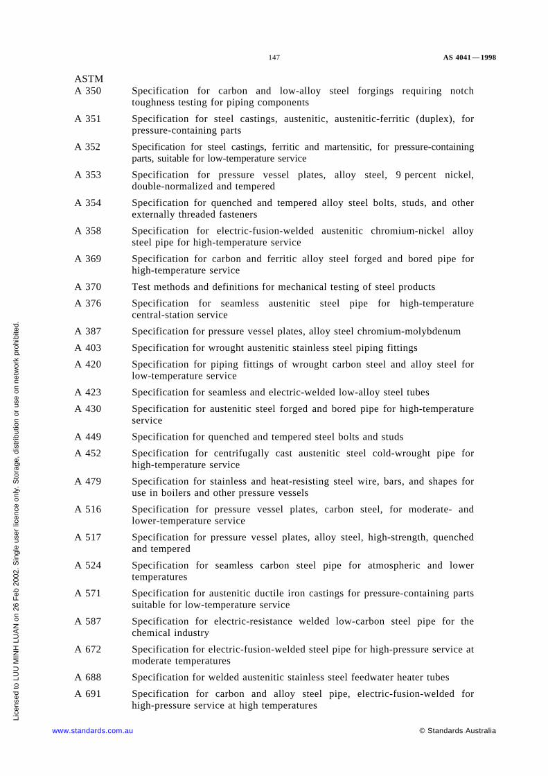
147 AS 4041 — 1998
ASTMA 350 Specification for carbon and low-alloy steel forgings requiring notch
toughness testing for piping components
A 351 Specification for steel castings, austenitic, austenitic-ferritic (duplex), forpressure-containing parts
A 352 Specification for steel castings, ferritic and martensitic, for pressure-containingparts, suitable for low-temperature service
A 353 Specification for pressure vessel plates, alloy steel, 9 percent nickel,double-normalized and tempered
A 354 Specification for quenched and tempered alloy steel bolts, studs, and otherexternally threaded fasteners
A 358 Specification for electric-fusion-welded austenitic chromium-nickel alloysteel pipe for high-temperature service
A 369 Specification for carbon and ferritic alloy steel forged and bored pipe forhigh-temperature service
A 370 Test methods and definitions for mechanical testing of steel products
A 376 Specification for seamless austenitic steel pipe for high-temperaturecentral-station service
A 387 Specification for pressure vessel plates, alloy steel chromium-molybdenum
A 403 Specification for wrought austenitic stainless steel piping fittings
A 420 Specification for piping fittings of wrought carbon steel and alloy steel forlow-temperature service
A 423 Specification for seamless and electric-welded low-alloy steel tubes
A 430 Specification for austenitic steel forged and bored pipe for high-temperatureservice
A 449 Specification for quenched and tempered steel bolts and studs
A 452 Specification for centrifugally cast austenitic steel cold-wrought pipe forhigh-temperature service
A 479 Specification for stainless and heat-resisting steel wire, bars, and shapes foruse in boilers and other pressure vessels
A 516 Specification for pressure vessel plates, carbon steel, for moderate- andlower-temperature service
A 517 Specification for pressure vessel plates, alloy steel, high-strength, quenchedand tempered
A 524 Specification for seamless carbon steel pipe for atmospheric and lowertemperatures
A 571 Specification for austenitic ductile iron castings for pressure-containing partssuitable for low-temperature service
A 587 Specification for electric-resistance welded low-carbon steel pipe for thechemical industry
A 672 Specification for electric-fusion-welded steel pipe for high-pressure service atmoderate temperatures
A 688 Specification for welded austenitic stainless steel feedwater heater tubes
A 691 Specification for carbon and alloy steel pipe, electric-fusion-welded forhigh-pressure service at high temperatures
www.standards.com.au © Standards Australia
Lice
nsed
to L
UU
MIN
H L
UA
N o
n 26
Feb
200
2. S
ingl
e us
er li
cenc
e on
ly. S
tora
ge, d
istr
ibut
ion
or u
se o
n ne
twor
k pr
ohib
ited.

AS 4041 — 1998 148
ASTMA 789 Specification for seamless and welded ferritic/austenitic stainless steel tubing
for general service
A 790 Specification for seamless and welded ferritic/austenitic stainless steel pipe
B 42 Specification for seamless copper pipe, standard sizes
B 43 Specification for seamless red brass pipe, standard sizes
B 75 Specification for seamless copper tube
B 88 Standard specification for seamless copper water tube
B 96 Specification for copper-silicone alloy plate, sheet, strip, and rolled bar forgeneral purposes and pressure vessels
B 111 Specification for copper and copper-alloy seamless condenser tubes andferrule stock
B 127 Specification for nickel-copper alloy (UNS NO4400) plate, sheet, and strip
B 160 Specification for nickel rod and bar
B 161 Specification for nickel seamless pipe and tube
B 162 Specification for nickel plate, sheet and strip
B 163 Specification for seamless nickel and nickel alloy condenser andheat-exchanger tubes
B 164 Specification for nickel-copper alloy rod, bar and wire
B 165 Specification for nickel-copper alloy (UNS N04400) seamless pipe and tube
B 166 Specification for nickel-chromium-iron alloys (UNS N06600) and nickel-chromium-cobalt-molybdenum alloy (UNS N06617) rod, bar, and wire
B 167 Specification for nickel-chromium-iron alloys (UNS N06600, N06601,N06690, N06023 and N06005) seamless pipe and tube
B 171 Specification for copper-alloy plate and sheet for pressure vessels,condensers and heat-exchangers
B 210 Specification for aluminium-alloy drawn seamless tubes (metric)
B 211 Specification for aluminium and aluminium-alloy bar, rod, and wire
B 221 Specification for aluminium and aluminium-alloy extruded bars, rods, wire,profiles, and tubes
B 241 Specification for aluminium and aluminium-alloy seamless pipe and seamlessextruded tube (metric)
B 265 Specification for titanium and titanium alloy strip, sheet and plate
B 315 Specification for seamless copper alloy pipe and tube
B 333 Specification for nickel-molybdenum alloy plate, sheet, and strip
B 335 Specification for nickel-molybdenum alloy rod
B 337 Specification for seamless and welded titanium and titanium alloy pipe
B 338 Specification for seamless and welded titanium and titanium alloy tubes forcondensers and heat exchangers
B 381 Specification for titanium and titanium alloy forgings
B 395 Specification for U-bend seamless copper and copper alloy heat-exchangerand condenser tubes
© Standards Australia www.standards.com.au
Lice
nsed
to L
UU
MIN
H L
UA
N o
n 26
Feb
200
2. S
ingl
e us
er li
cenc
e on
ly. S
tora
ge, d
istr
ibut
ion
or u
se o
n ne
twor
k pr
ohib
ited.

149 AS 4041 — 1998
ASTMB 407 Specification for nickel-iron-chromium alloy seamless pipe and tube
B 408 Specification for nickel-iron-chromium alloy rod and bar
B 409 Specification for nickel-iron-chromium alloy plate, sheet and strip
B 423 Specification for nickel-iron-chromium-molybdenum-copper alloy(UNS N08825 and N08221) seamless pipe and tube
B 424 Specification for Ni-Fe-Cr-Mo-Cu alloy (UNS N08825 and N08821) plate,sheet, and strip
B 425 Specification for Ni-Fe-Cr-Mo-Cu alloy (UNS N08825 and N08821) rod andbar
B 434 Specification for nickel-molybdenum-chromium-iron alloy (UNS N10003)plate, sheet, and strip
B 435 Specification for UNS N06002, UNS N06230, UNS N12160 andUNS R30556 plate, sheet and strip
B 443 Specification for nickel-chromium-molybdenum-columbium alloy(UNS N06625) plate, sheet, and strip
B 444 Specification for nickel-chromium-molybdenum-columbium alloy(UNS N06625) pipe and tube
B 446 Specification for nickel-chromium-molybdenum-columbium alloy(UNS N06625) rod and bar
B 514 Specification for welded nickel-iron-chromium alloy pipe
B 515 Specification for welded UNS N0812D, UNS N08800, UNS N08810 andUNS N08811 alloy tubes
B 516 Specification for welded nickel-chromium-iron alloy (UNS NO6600) tubes
B 517 Specification for welded nickel-chromium-iron alloy (UNS NO6600) pipe
B 535 Specification for nickel-iron-chromium-silicone alloys (UNS N08330 andUNS N08332)) seamless pipe and tube
B 564 Specification for nickel alloy forgings
B 575 Specification for low-carbon nickel-molybdenum-chromium and low-carbonnickel-chromium-molybdenum alloy plate, sheet, and strip
B 619 Specification for welded nickel and nickel-cobalt alloy pipe
B 622 Specification for seamless nickel and nickel-cobalt alloy pipe and tube
B 626 Specification for welded nickel and nickel-cobalt alloy tube
BS806 Specification for design and construction of ferrous piping installations for
and in connection with land boilers
1387 Specification for screwed and socketed steel tubes and tubulars for plain endsteel tubes suitable for welding or screwing to BS 21 pipe threads
1414 Specification for steel wedge gate valves (flanged and butt-welding ends) forthe petroleum, petrochemical and allied industries
1471 Wrought aluminium and aluminium alloys for general engineeringpurposes—drawn tube
1474 Wrought aluminium and aluminium alloys for general engineeringpurposes: bars, extruded round tubes and sections
www.standards.com.au © Standards Australia
Lice
nsed
to L
UU
MIN
H L
UA
N o
n 26
Feb
200
2. S
ingl
e us
er li
cenc
e on
ly. S
tora
ge, d
istr
ibut
ion
or u
se o
n ne
twor
k pr
ohib
ited.
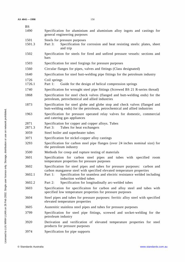
AS 4041 — 1998 150
BS1490 Specification for aluminium and aluminium alloy ingots and castings for
general engineering purposes
1501 Steels for pressure purposes1501.3 Part 3: Specification for corrosion and heat resisting steels: plates, sheet
and trip
1502 Specification for steels for fired and unfired pressure vessels: sections andbars
1503 Specification for steel forgings for pressure purposes
1560 Circular flanges for pipes, valves and fittings (Class designated)
1640 Specification for steel butt-welding pipe fittings for the petroleum industry
1726 Coil springs1726.1 Part 1: Guide for the design of helical compression springs
1740 Specification for wrought steel pipe fittings (Screwed BS 21 R-series thread)
1868 Specification for steel check valves (flanged and butt-welding ends) for thepetroleum, petrochemical and allied industries
1873 Specification for steel globe and globe stop and check valves (flanged andbutt-welding ends) for the petroleum, petrochemical and allied industries
1963 Specification for pressure operated relay valves for domestic, commercialand catering gas appliances
2871 Specification for copper and copper alloys. Tubes2871.3 Part 3: Tubes for heat exchangers
3059 Steel boiler and superheater tubes
3071 Specification for nickel-copper alloy castings
3293 Specification for carbon steel pipe flanges (over 24 inches nominal size) forthe petroleum industry
3500 Methods for creep and rupture testing of materials
3601 Specification for carbon steel pipes and tubes with specified roomtemperature properties for pressure purposes
3602 Specification for steel pipes and tubes for pressure purposes: carbon andcarbon manganese steel with specified elevated temperature properties
3602.1 Part 1: Specification for seamless and electric resistance welded includinginduction welded tubes
3602.2 Part 2: Specification for longitudinally arc-welded tubes
3603 Specification for specificaiton for carbon and alloy steel and tubes withspecified low temperature properties for pressure purposes
3604 Steel pipes and tubes for pressure purposes: ferritic alloy steel with specifiedelevated temperature properties
3605 Austenitic stainless steel pipes and tubes for pressure purposes
3799 Specification for steel pipe fittings, screwed and socket-welding for thepetroleum industry
3920 Derivation and verification of elevated temperature properties for steelproducts for pressure purposes
3974 Specification for pipe supports
© Standards Australia www.standards.com.au
Lice
nsed
to L
UU
MIN
H L
UA
N o
n 26
Feb
200
2. S
ingl
e us
er li
cenc
e on
ly. S
tora
ge, d
istr
ibut
ion
or u
se o
n ne
twor
k pr
ohib
ited.

151 AS 4041 — 1998
BS4882 Specification for bolting for flanges and pressure containing purposes
5150 Specification for cast iron gate valves
5151 Specification for cast iron gate (parallel slide) valves for general purposes
5152 Specification for cast iron globe and globe stop and check valves for generalpurposes
5153 Specification for cast iron check valves for general purposes
5154 Specification for copper alloy globe, globe stop and check, check and gatevalves
5155 Specification for butterfly valves
5156 Specification for diaphragm valves
5157 Specification for steel gate (parallel slide) valves
5158 Specification for cast iron plug valves
5159 Specification for cast iron and carbon steel ball valves for general purposes
5160 Specification for steel globe valves, globe stop and check valves and lift typecheck valves
5352 Specification for steel wedge gate, globe and check valves 50 mm andsmaller for the petroleum, petrochemical and allied industries
5353 Specification for steel plug valves
5500 Specification for unfired fusion welded pressure vessels
5970 Code of practice for thermal insulation of pipework and equipment (in thetemperature range −100°C to +870°C)
6759 Safety valves
7572 Code of practice for thermally insulated underground piping systems
DIN17175 Seamless tubes of heat resisting steels
NZS5258 Gas distribution
AG601 Gas installation
MSSSP-44 Steel pipe line flange
SP-97 Integrally reinforced forged branch outlet fittings—Socket welding, threadedand butt welding ends
TRD300 (Withdrawn) Calculation of the stability of steam boilers
301 Cylindrical shells under internal overpressure
508 Additional testings at the components, calculated with time-dependentstrength characteristics
WRC198 Secondary stress indices for integral structural attachments to straight pipe,
Author W.G. Dodge, Stress indices at lug supports on piping systems,Authors E.C. Rodabaugh, W.G. Dodge and S.E. Moore.
www.standards.com.au © Standards Australia
Lice
nsed
to L
UU
MIN
H L
UA
N o
n 26
Feb
200
2. S
ingl
e us
er li
cenc
e on
ly. S
tora
ge, d
istr
ibut
ion
or u
se o
n ne
twor
k pr
ohib
ited.

AS 4041 — 1998 152
WTIATN 13 Stainless steel for corrosive environments
NACEMR 0175 Sulfide stress cracking resistant metallic materials for oil field equipment
© Standards Australia www.standards.com.au
Lice
nsed
to L
UU
MIN
H L
UA
N o
n 26
Feb
200
2. S
ingl
e us
er li
cenc
e on
ly. S
tora
ge, d
istr
ibut
ion
or u
se o
n ne
twor
k pr
ohib
ited.

153 AS 4041 — 1998
APPENDIX B
NOMINAL SIZES AND OUTSIDE DIAMETERS OF PIPE
(Normative)
TABLE B1
OUTSIDE DIAMETERS OF STEEL PIPE (NOT TUBE)
Nominal sizeDN
OD, mm
American AS, BS
68
10
10.313.717.1
10.213.517.2
152025
21.326.733.4
21.326.933.7
324050
42.248.360.3
42.448.360.3
658090
7388.9
101.6
76.188.9
101.6
100125150
114.3141.3168.3
114.3139.7165.1
200250300
219.1273323.9
———
350400450
355.6406.4457
———
500550600
508559610
———
650700750
660711762
———
800850900
813864914
———
1000* 1016 —
* Larger sizes by agreement.
www.standards.com.au © Standards Australia
Lice
nsed
to L
UU
MIN
H L
UA
N o
n 26
Feb
200
2. S
ingl
e us
er li
cenc
e on
ly. S
tora
ge, d
istr
ibut
ion
or u
se o
n ne
twor
k pr
ohib
ited.

AS 4041 — 1998 154
TABLE B2
NOMINAL SIZE, OUTSIDE DIAMETER AND THICKNESSOF DUCTILE IRON PIPE TO AS/NZS 2280
Nominal sizeMean external
diameterMean wall thickness
mm
DN mm K9 class K12 class
80100150
—121.9177.3
—6.16.3
7.07.27.8
200225250
232.2259.1286.0
6.46.66.8
8.48.79.0
300375450
345.4426.2507.0
7.27.98.6
9.610.511.4
500600750
560.3667.0826.0
9.09.9
11.3
12.013.215.0
© Standards Australia www.standards.com.au
Lice
nsed
to L
UU
MIN
H L
UA
N o
n 26
Feb
200
2. S
ingl
e us
er li
cenc
e on
ly. S
tora
ge, d
istr
ibut
ion
or u
se o
n ne
twor
k pr
ohib
ited.

155 AS 4041 — 1998
TABLE B3
OUTSIDE DIAMETERS OF COPPER AND PLASTIC PIPE
Nominal size, DN(see Clause 1.7.21)
Outside diameter of pipe, mm
Copper pipe toAS 1432 or AS 1572
Plastic pipeAS/NZS 1477*
Plastic pipeAS/NZS 4130†
68
10
6.357.949.52
—13.917.9
———
151618
12.70—15.88
21.5—26.9
—16—
202532
19.0525.4031.75
—33.742.4
202532
404550
38.1044.4550.80
48.4—60.5
40—50
636575
—63.50—
—75.5—
63—75
8090
100
76.2088.90
101.60
89.1101.7114.5
—90—
110125140
—127.00—
—140.4—
110125140
150160175
152.40——
160.5—
200.5
—160—
180200225
—203.20228.60
—225.6250.7
180200225
250280300
254.00——
280.8—
315.9
250280—
315350355
———
—356.0—
315—
355
375400450
———
401.0451.0501.0
—400450
500525550
———
———
500——
560575600
———
—631.0—
560———
630700710
———
———
630—
710
750800850
———
———
—800—
9001000
——
——
9001000
* Maximum diameters only.
† Mean outside diameter, minimum.
www.standards.com.au © Standards Australia
Lice
nsed
to L
UU
MIN
H L
UA
N o
n 26
Feb
200
2. S
ingl
e us
er li
cenc
e on
ly. S
tora
ge, d
istr
ibut
ion
or u
se o
n ne
twor
k pr
ohib
ited.

AS 4041 — 1998 156
APPENDIX C
NOT ALLOCATED
© Standards Australia www.standards.com.au
Lice
nsed
to L
UU
MIN
H L
UA
N o
n 26
Feb
200
2. S
ingl
e us
er li
cenc
e on
ly. S
tora
ge, d
istr
ibut
ion
or u
se o
n ne
twor
k pr
ohib
ited.

157 AS 4041 — 1998
APPENDIX D
MATERIAL PROPERTIES, DESIGN PARAMETERSAND TENSILE STRENGTHS
(Normative)
The following tables of material properties, design parameters and tensile strengths arereferred to in Clause 3.4 and elsewhere in this Standard as Appendix D. The designstrengths in these tables are independent of weld joint factor (see Clause 3.12.2). See alsoAppendix G.
Table D1 . . . . . . . . . . . . . . . . . . . . . . . . . . . . . . . . . . . . . . . . . . . . . . . . . . . . Index
Table D2 . . . . . . . . . . . . . . Carbon, carbon-manganese and low to medium alloy steel.
Table D3 . . . . . . . . . . . . . . . . . . . . . . . . . . . . . . . . . . Equivalents for 200 MPa steels.
Table D4 . . . . . . . . . . . . . . . . . . . . . . . . . . . . . . . . . . Equivalents for 250 MPa steels.
Table D5 . . . . . . . . . . . . . . . . . . . . . . . . . . . . . . . . . . . . . . . . . High alloy steel pipe.
Table D6 . . . . . . . . . . . . . . . . . . . . . . . . . . . Austenitic steel pipe—American source.
Table D7 . . . . . . . . . . . . . . . . . . . . . Copper and copper alloy pipe—American source.
Table D8 . . . . . . . . . . . . . . . Aluminium and aluminium alloy pipe—American source.
Table D9 . . . . . . . . . . . . . . . . . . . . . . Nickel and nickel alloy pipe—American source.
Table D10 . . . . . . . . . . . . . . . . . Titanium and titanium alloy pipe—American source.
Table D11 . . . . . . . . . . . . . . . . . . . . . . . . . . . . . . . . . . . . . . . . . . . . . . Iron castings
Ductile iron to AS/NZS 2280 is a commodity with pressure ratings and needs no designparameters and no elevated temperature ratings.
The temperature of application shall not exceed the value for which the design stress isgiven except as provided in Clause 2.6.1 and Clause 3.4
For plate and other product forms the values in AS 1210 and its Supplement No. 1 areacceptable.
A1 Design strengths at intermediate temperatures may be obtained by linear interpolation.
www.standards.com.au © Standards Australia
Lice
nsed
to L
UU
MIN
H L
UA
N o
n 26
Feb
200
2. S
ingl
e us
er li
cenc
e on
ly. S
tora
ge, d
istr
ibut
ion
or u
se o
n ne
twor
k pr
ohib
ited.

AS 4041 —1998 158
TABLE D1
INDEX OF PIPE SPECIFICATIONS—STEEL
Pipe specification Table reference*
Yield strength 200 MPaAS 1074BS 3601— 320API 5L A
D2D2 and D3
D3
ASTM A 53 AASTM A 106 AASTM A 178 A
D3D3D3
ASTM A 179ASTM A 333 1ASTM A 334 1
D3D3D3
ASTM A 587BS 3601— 320BS 3601— 360
D3D3D2
Yield strength 235 MPaBS 3601— 430BS 3602.1— 360BS 3603— 410 LT50
D2D2D2
Yield strength 245 MPaBS 3602.2— 410 SAWBS 3603— 503 LT100
D2D2
Yield strength 250 MPaAPI 5L BAPI 5L B
D2 and D4D4
ASTM A 53 BASTM A 106 BASTM A 333 6
D4D4D4
ASTM A 334 6ASTM A 524 1
D4D4
Yield strength 275 MPaASTM A 106 Grade C D2
Yield strength 290 MPaAPI 5L X42 D2
Yield strength 350 MPaBS 3602.1— 500 NbAPI 5L X52
D2D2
ASTM A335 pipe for high temperatureserviceASTM A 335— P11, P12ASTM A 335— P22
D2D2
Ferritic low alloy steelBS 3604 591
620— 440620— 460
D2D2D2
(continued)
© Standards Australia www.standards.com.au
Lice
nsed
to L
UU
MIN
H L
UA
N o
n 26
Feb
200
2. S
ingl
e us
er li
cenc
e on
ly. S
tora
ge, d
istr
ibut
ion
or u
se o
n ne
twor
k pr
ohib
ited.

159 AS 4041 — 1998
TABLE D1 (continued)
Pipe specification Table reference*
621660622
D2D2D2
Ferritic high alloy steelBS 3603— 509 LT196BS 3604 762DIN 17175 X20 Cr, Mo, V21
D5D5D5
ASTM A 517 All grades D2
Austenitic stainless steelsBS 3605 304 S14E
S18ES59E
D5D5D5
BS 3605 316 S14E316 S18E316 S59E
D5D5D5
BS 3605 321 S18E321 S59E
D5D5
BS 3605 347 S18E347 S59E
D5D5
Martensitic stainless steelBS 3605 1250E D5
Austenitic steel pipe D6
Copper and copper alloy pipe D7
Aluminium and aluminium alloy pipe D8
Nickel and nickel alloy pipe D9
Titanium and titanium alloy pipe D10
* Tables D6, D7, D8, D9 and D10 contain material properties, design parameters andtensile strengths taken form ANSI/ASME B31.3.
www.standards.com.au © Standards Australia
Lice
nsed
to L
UU
MIN
H L
UA
N o
n 26
Feb
200
2. S
ingl
e us
er li
cenc
e on
ly. S
tora
ge, d
istr
ibut
ion
or u
se o
n ne
twor
k pr
ohib
ited.

AS 4041—1998 160
TABLE D2
MATERIAL PROPERTIES, DESIGN PARAMETERS—CARBON,CARBON-MANGANESE STEEL, PIPE AND TUBE
(Not including joint factor or class design factor)
A1
A1
A1
1 2 3 4 5 6 7 8 9 10 11 12 13 14 15 16 17 18 19 20 21 22 23 24
Source Standard No. GradeRm Re
Base metalgroupletter
fc, fh(max.)*
Designlife
Design tensile strength, (f), MPa,
Maximum metal temperature, °C
MPa MPa MPa h 50 100 150 200 250 300 350 400 410 420 430 440 450 460 470 480
YIELD STRENGTH 200 MPa
BS 806BS 806BS 806
AS 1074BS 3601BS 3601
—320360
320320360
195195215
A1A1A1
106106120
IndefiniteIndefiniteIndefinite
130130154
119119140
108108126
9797
111
868696
867786
797179
756875
———
———
———
———
———
———
———
———
YIELD STRENGTH 235 MPa
BS 806
BS 5500
BS 3602.1
BS 3603
360
410-LT50
360
410
235
235
A1
A1
120
136
100 000150 000200 000250 000
Indefinite
153153153153157
139139139139—
125125125125—
117117117117—
111111111111—
97979797—
87878787—
78787878—
77777777—
77777777—
76747168—
69656259—
60565351—
52484542—
44403735—
36322826—
YIELD STRENGTH 240 MPa
BS 806 API 5L B 413 240 A1 137 100 000150 000200 000250 000
160160160160
147147147147
135135135135
122122122122
110110110110
99999999
91919191
85858585
85858585
84838078
78747168
69656259
60565351
52484542
44403735
36322826
YIELD STRENGTH 245 MPa
BS 806
BS 5500
BS 3602.2
BS 3603
410 SAW
503-LT100
410
440
245
245
A1
A1
136
146
100 000150 000200 000250 000
Indefinite
163163163163164
153153153153—
142142142142—
129129129129—
119119119119—
105105105105—
96969696—
92929292—
91919087—
88838078—
79747168—
69656259—
60565351—
52484542—
44403735—
36322826—
YIELD STRENGTH 275 MPa
BS 806BS 806
ANSI/ASMEB 31.3
BS 3601BS 3601
ASTM A 106
430 ERW430 SAW
C
430430485
275275275
A1A1A2
143143161
IndefiniteIndefiniteIndefinite
183183163
166166163
149149160
132132160
115115150
103—
142
95—
134
89—
103
——96
——91
——84
———
———
———
———
———
* fc, fh(max.) as used in Clause 3.11.7. (continued)
© Standards Australia www.standards.com.au
Licensed to LUU MINH LUAN on 26 Feb 2002. Single user licence only. Storage, distribution or use on network prohibited.

161 AS 4041—1998
TABLE D2 (continued)
1 2 3 4 5 6 7 8 9 10 11 12 13 14 15 16 17 18 19 20 21 22 23 24
Source Standard No. GradeRm Re
Base metalgroupletter
fc, fh(max.)*
Designlife
Design tensile strength, (f), MPa,
Maximum metal temperature, °C
MPa MPa MPa h 50 100 150 200 250 300 350 400 410 420 430 440 450 460 470 480
YIELD STRENGTH 290 MPa
BS 806 API 5L X42 413 289 A1 137 100 000150 000200 000250 000
176176176176
156156156156
135135135135
122122122122
110110110110
99999999
91919191
85858585
85858585
84838078
78747168
69656259
60565351
52484542
44403735
36322826
YIELD STRENGTH 350 MPa
BS 806 BS 3602.1 500Nb 500 345 A1 166 100 000150 000200 000250 000
213213213213
204204204204
194194194194
178178178178
163163163163
148148148148
135135135135
125125121115
12111110498
105958883
90817570
77686359
65585451
56504643
48434037
42383432
BS 806 API 5L X52 455 358 A3 151 100 000150 000200 000250 000
194194194194
165165165165
135135135135
122122122122
110110110110
99999999
91919191
85858585
85858585
84838078
78747168
69656259
60565351
52484542
44403735
36322826
* fc, fh(max.) as used in Clause 3.11.7. (continued)A1
A1
www.standards.com.au © Standards Australia
Licensed to LUU MINH LUAN on 26 Feb 2002. Single user licence only. Storage, distribution or use on network prohibited.

AS 4041—1998 162
TABLE D2 (continued)
A1
1 2 3 4 5 6 7 8 9 10 11 12 13 14 15 16 17 18 19 20 21 22 23 24 25 26 27
Source Standard No. GradeRm Re
Basemetalgroupletter
fc, fh(max.)*
Design lifeDesign tensile strength, (f), MPa,
Maximum metal temperature, °C
MPa MPa MPa h 50 100 150 200 250 300 350 400 450 500 510 520 530 540 550 560 570 580 590
ASTM A 335 PIPE FOR HIGH-TEMPERATURE SERVICE
BS 806 ASTM A 335 P11, P12 415 205 C 138 100 000150 000200 000250 000
138138138138
133133133133
128128128128
121121121121
115115115115
98989898
86868686
84848484
83838383
80808080
80807670
76676157
62554945
52444037
42353230
33292625
27242220
————
————
BS 806 ASTM A 335 P22 N&T 415 205 D2 138 100 000150 000200 000250 000
138138138138
120120120120
102102102102
97979797
91919191
89898989
86868686
83838383
77777777
71717171
70707070
69696865
68635957
61565249
53484542
45423836
39363332
34312827
————
BS 806 ASTM A 335 P22annealed
415 205 D2 138 100 000150 000200 000250 000
138138138138
102102102102
65656565
60606060
56565656
53535353
51515151
48484848
46464646
44444444
43434343
42424242
41414141
40404040
39393939
38383836
36363632
34313127
————
* fc, fh(max.) as used in Clause 3.11.7. (continued)A1
© Standards Australia www.standards.com.au
Licensed to LUU MINH LUAN on 26 Feb 2002. Single user licence only. Storage, distribution or use on network prohibited.

163 AS 4041—1998
TABLE D2 (continued)
A1
1 2 3 4 5 6 7 8 9 10 11 12 13 14 15 16 17 18 19 20 21 22 23 24 25 26 27 28 29 30 31
SourceStandard
No.Grade
Rm Re
Basemetalgroupletter
fc, fh(max.)*
Designlife
Design tensile strength, f, MPa,
Maximum metal temperature, °C
MPa MPa MPa h 50 100 150 200 250 300 350 400 450 460 470 480 490 500 510 520 530 540 550 560 570 580 590
FERRITIC LOW ALLOY STEELS
BS 806 BS 3604 591 610 440 C 203 Indefinite 260 260 260 260 260 255 249 229 — — — — — — — — — — — — — — —
BS 806 BS 3604 620-440 440 290 C 146 100 000150 000200 000250 000
187187187187
178178178178
169169169169
163163163163
157157157157
128128128128
121121121121
116116116116
112112112112
112112112112
111111111111
111111111111
111111111107
1111029488
93837670
76676157
62554945
52444037
42353230
33292625
27242220
————
————
BS 806 BS 3604 620-460 460 180 C 153 100 000150 000200 000250 000
120120120120
120120120120
120120120120
120120120120
120120120120
120120120120
120120120120
120120120120
116116116116
115115115115
115115115115
114114114114
113113113107
1121029488
93837670
76676157
62554945
52444037
42353230
33292625
27242220
————
————
BS 806 BS 3604 621 420 275 C 140 100 000150 000200 000250 000
179179179179
169169169169
158158158158
152152152152
145145145145
116116116116
110110110110
105105105105
101101101101
101101101101
101101101101
101101101101
100100100100
1001009488
93837670
76676157
62554945
52444037
42353230
33292625
27242220
————
————
BS 806 BS 3604 660 460 300 D1 153 100 000150 000200 000250 000
196196196196
190190190190
184184184184
178178178178
161161161161
150150150150
144144144144
139139139139
135135135135
135135135135
135135135135
134134134134
134134130123
131120112106
1151059892
101928478
89787064
77655852
65544742
55443732
45352825
35272220
————
BS 806 BS 3604 622 490 275 D2 163 100 000150 000200 000250 000
183183183183
176176176176
169169169169
163163163163
157157157157
153153153153
149149149149
145145145145
137137137137
135135135135
132132130126
130122117113
118108104110
105979287
94857975
82736865
72635957
61575249
53484542
45423836
39363332
34312827
————
HIGH STRENGTH LOW ALLOY
Bunge ASTM A517
All 790 690 G 263 Indefinite 336 336 336 336 336 336 — — — — — — — — — — — — — — — — —
A1* fc, fh(max.) as used in Clause 3.11.7
www.standards.com.au © Standards Australia
Licensed to LUU MINH LUAN on 26 Feb 2002. Single user licence only. Storage, distribution or use on network prohibited.

AS 4041 —1998 164
The steel tube and pipe specifications in Table D3 are deemed equivalent to theRe 200Group and the values listed under BS 3601 Grade 320 may be used.
TABLE D3
PIPE SPECIFICATIONS EQUIVALENT TO Re 200
Specification Grade Rm Re
API 5LASTM A 53ASTM A 106
AAA
331330330
207205205
ASTM A 135ASTM A 178ASTM A 179
AA
331325325
207180180
ASTM A 333ASTM A 334ASTM A 587BS 3601
11
320
380380331320
205205207195
A1 The steel tube and pipe specifications in Table D4 are deemed equivalent to theRe 240Group and the values listed under API 5L may be used.
TABLE D4
A1 PIPE SPECIFICATIONS EQUIVALENT TO Re 240
Specification Grade Rm Re
API 5LASTM A 53ASTM A 106
BBB
413415415
241240240
ASTM A 135ASTM A 333ASTM A 334ASTM A 524
B661
414415415414
241240240240
© Standards Australia www.standards.com.au
Lice
nsed
to L
UU
MIN
H L
UA
N o
n 26
Feb
200
2. S
ingl
e us
er li
cenc
e on
ly. S
tora
ge, d
istr
ibut
ion
or u
se o
n ne
twor
k pr
ohib
ited.

Licensed to LUU MINH LUAN on 26 Feb 2002. Single user licence only. Storage, distribution or use on network prohibited.

Licensed to LUU MINH LUAN on 26 Feb 2002. Single user licence only. Storage, distribution or use on network prohibited.
Kancy Poon
166

Licensed to LUU MINH LUAN on 26 Feb 2002. Single user licence only. Storage, distribution or use on network prohibited.
Kancy Poon
167
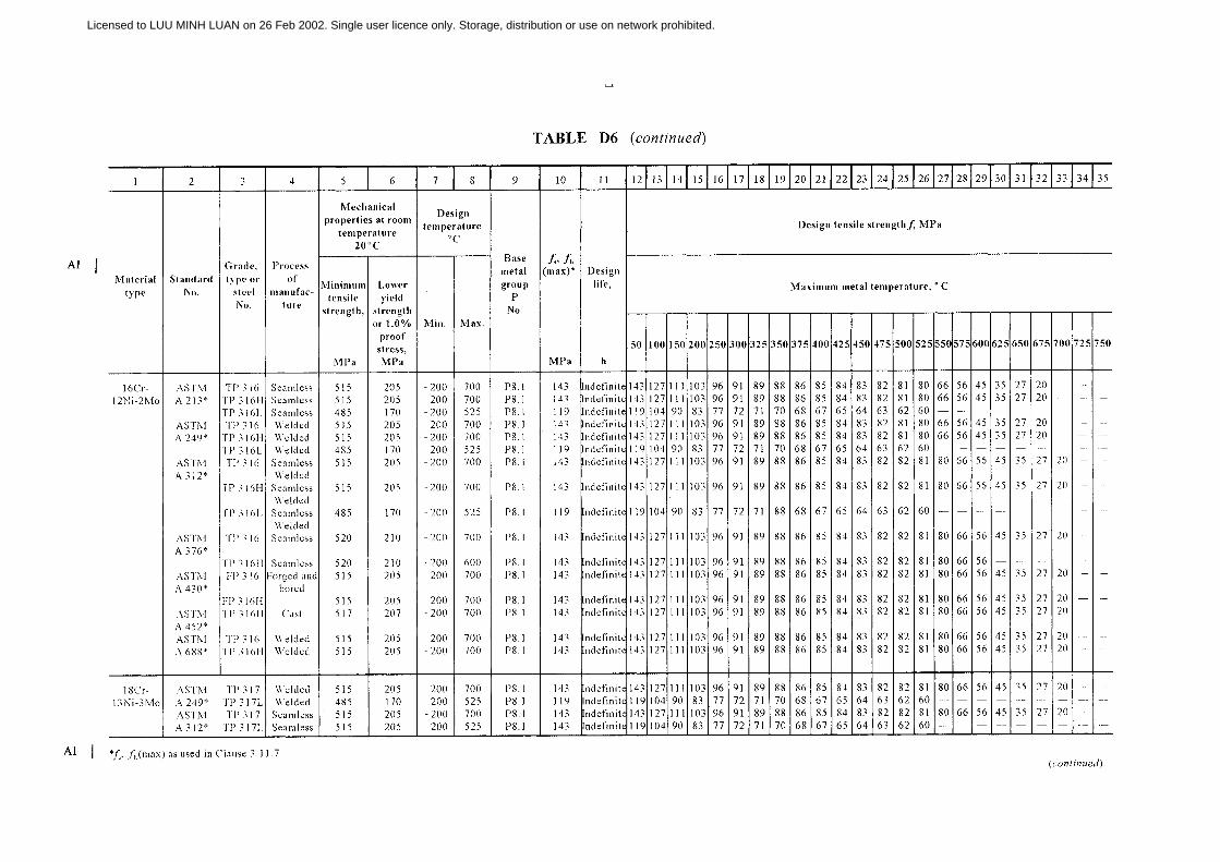
Licensed to LUU MINH LUAN on 26 Feb 2002. Single user licence only. Storage, distribution or use on network prohibited.
Kancy Poon
168

Licensed to LUU MINH LUAN on 26 Feb 2002. Single user licence only. Storage, distribution or use on network prohibited.
Kancy Poon
169

Licensed to LUU MINH LUAN on 26 Feb 2002. Single user licence only. Storage, distribution or use on network prohibited.
Kancy Poon
170

Licensed to LUU MINH LUAN on 26 Feb 2002. Single user licence only. Storage, distribution or use on network prohibited.
Kancy Poon
171

AS 4041—1998 172
TABLE D7
MATERIAL PROPERTIES, DESIGN PARAMETERS AND TENSILE STRENGTH—COPPER AND COPPER ALLOY PIPE—AMERICAN SOURCE
A1
A1
1 2 3 4 5 6 7 8 9 10 11 12 13 14 15 16 17 18 19 20 21 22 23 24 25 26
Materialtype
Standard No.UNS No.,
designationor grade
Temperor
condition
Rm Re
Designtemperature,
°C
Basemetalgroup,
PNo.
fc, fh(max.)*
Design tensile strength, f, MPa
Maximum metal temperature, °C
MPa MPa Min. Max. MPa 50 75 100 125 150 175 200 225 250 275 300 325 350 375 400 425
70/30Arsenicalbrass
AS 1569BS 2871.3
C26130CZ 126
Annealed0
280—
——
−200−200
225225
P34P34
6969
6969
6969
6969
6969
6868
5353
2424
1313
——
——
——
——
——
——
——
——
Admiraltybrass,arsenical
AS 1569BS 2871.3
ASTM B 111
C44300CZ 111C44300C4400C44500
Annealed0
AnnealedAnnealedAnnealed
310—310310310
100—105105105
−200−200−200−200−200
225225225225225
P32P32P32P32P32
6969696969
6969696969
6969696969
6969696969
6969696969
6969696969
6868686868
3434252525
1313151515
—————
—————
—————
—————
—————
—————
—————
—————
76/22/2Aluminiumbrass
AS 1569BS 2871.3
ASTM B 111
C68700CZ 110C68700
Annealed0
061
300—345
120—125
−200−200−200
225225225
P32P32P32
838383
838383
828282
818181
808080
808080
454545
242424
161616
———
———
———
———
———
———
———
———
90/10 Coppernickel
AS 1569BS 2871.3
ASTM B 111
C70610CN 102C70600
Annealed0
061
300—275
100—105
−200−200−200
325325300
P34P34P34
606068
606068
575767
565666
555564
545462
535360
525259
515157
505055
494952
434349
3939—
———
———
———
———
70/30 Coppernickel
AS 1569
BS 2871.3
ASTM B 111
C71500
CN 107
C71500
AnnealedAs drawn
0As drawn
061HR50
370500——360495
120350——125345
−200−200−200−200−200−200
400425400425375425
P34P34P34P34P34P34
8312483
12483
124
8312483
12483
124
7912479
12479
124
7812478
12478
124
7612476
12476
124
7412474
12474
124
7312173
12173
121
7111971
11971
119
7011770
11770
117
6811568
11568
115
6811368
11368
113
6611166
11166
111
6611166
11166
111
6511066
11066
110
6510865
10865
108
6410364
10364
103
—59—59—59
Aluminiumbronze
BS 2871.3ASTM B 111
CA 102C60800
0061
—345
—130
−200−200
250200
P35P35
8686
8686
8585
8484
8282
8080
7064
4746
3032
1919
——
——
——
——
——
——
——
High-siliconebronze A
ASTM B 315 C65500 061 345 103 −200 300 P35 69 69 69 69 69 68 38 32 — — — — — — — — —
Copper-oxygen-freewithoutresidualdeoxidants
ASTM B 42
ASTM B 75ASTM B 111
ASTM B 395
C10200
C10200C10200
C10200
061H55H80060H55H80H55
294250310205250310250
8821028068205275205
−200−200−200−200−200−200−200
200200200200200200200
P31P31P31P31P31P31P31
41627841627862
41627841627862
34627834627862
33627833627862
33627833627862
32607632607660
28597128597159
21573021573057
———————
———————
———————
———————
———————
———————
———————
———————
———————
* fc, fh(max.) as used in Clause 3.11.7. (continued)
© Standards Australia www.standards.com.au
Licensed to LUU MINH LUAN on 26 Feb 2002. Single user licence only. Storage, distribution or use on network prohibited.

173 AS 4041—1998
TABLE D7 (continued)
1 2 3 4 5 6 7 8 9 10 11 12 13 14 15 16 17 18 19 20 21 22 23 24 25 26
Materialtype
Standard No.UNS No.,
designationor grade
Temperor
condition
Rm Re
Designtemperature,
°C
Basemetalgroup,
PNo.
fc, fh(max.)*
Design tensile strength, f, MPa
Maximum metal temperature, °C
MPa MPa Min. Max. MPa 50 75 100 125 150 175 200 225 250 275 300 325 350 375 400 425
Copper-phosphorized,low residualphosphorus
ASTM B 42
ASTM B 75ASTM B 111
ASTM B 395
C12000
C12000C12000
C12000
061H55H80060H55H80H55
294250310205250310250
8821028062
205275205
−200−200−200−200−200−200−200
200200200200200200200
P31P31P31P31P31P31P31
41627841627862
41627841627862
34627834627862
33627833627862
33627833627862
32607632607660
28597128597159
21573021573057
———————
———————
———————
———————
———————
———————
———————
———————
———————
Copper-phosphorized,high residualphosphorus
AS 1569
BS 2871.3
ASTM B 42
ASTM B 75ASTM B 111
ASTM B 395
C12200
C106
C12000
C12200C12200
C12200
AnnealedAs drawn
OM
061H55H80060H55H80H55
200280——
205250310205250310250
—270——62
20529562
205275205
−200−200−200−200−200−200−200−200−200−200−200
200200200200200200200200200200200
P31P31P31P31P31P31P31P31P31P31P31
4178417841627841627862
4178417841627841627862
3478347834627834627862
3378337833627833627862
3378337833627833627862
3276327632607632607660
2871287128597128597159
2130213021573021573057
———————————
———————————
———————————
———————————
———————————
———————————
———————————
———————————
———————————
Copper-phosphorized,arsenical
ASTM B 75ASTM B 111
ASTM B 395
C14200C14200
C14200
060H55H80H55
205250310250
62205275205
−200−200−200−200
200200200200
P31P31P31P31
41627862
41627862
34627862
33627862
33627862
32607660
28597159
21573057
————
————
————
————
————
————
————
————
————
Copper-redbrass
ASTM B 43ASTM B 111ASTM B 395
C23000C23000C23000
061061061
280275275
808585
−200−200−200
200200200
P32P32P32
554141
554141
553434
553333
553333
553232
482828
352121
———
———
———
———
———
———
———
———
———
* fc, fh(max.) as used in Clause 3.11.7.A1
A1
NOTE: If the pipe is brazed, the design strength for the annealed product should be used.
www.standards.com.au © Standards Australia
Licensed to LUU MINH LUAN on 26 Feb 2002. Single user licence only. Storage, distribution or use on network prohibited.

AS 4041—1998 174
TABLE D8
MATERIAL PROPERTIES, DESIGN PARAMETERS AND TENSILE STRENGTH—ALUMINIUM ANDALUMINIUM ALLOY PIPE—AMERICAN SOURCE
A1
A1
1 2 3 4 5 6 7 8 9 10 11 12 13 14 15 16 17 18
Materialtype
StandardNo.
Type ordesignation
Temper
Nationalwall
thickness,mm
Mechanicalproperties at
roomtemperature
20°C
Designtemperature
°C
Basemetal
group,P
No.
fc, fh(max.)*
Design tensile strength, f, MPa not exceeding
Maximum metal temperature, °C
Rm
MPaRe
MPaMin. Max. MPa 50 75 100 125 150 175 200
A1 AS/NZS 1866AS/NZS 1867
BS 1471
BS 1474ASTM B 210
ASTM B 241
10501050
1050A
1050A1060
10601100
H1120
H140
H4M0
H1400
H112
AllAllAll≥12≥12All
>0.5 ≤12>0.5 ≤12
AllAllAll
62—99—
100606085607575
——————1570152020
−270−270−270−270−270−270−270−270−270−270−270
200200200200200200200200200200200
P21P21P21P21P21P21P21P21P21P21P21
1212281228121228121414
1212281228121228121414
1111281128111128111414
1111261126111126111313
1010211021101021101313
99
189
1899
189
1212
88
128
1288
12899
66868668677
Al-1¼Mn AS/NZS 1867
ASTMB 210
ASTMB 241ASTMB 210
ASTMB 241
3202
3003
3003
Alclad3003
Alclad3003
0H14
0H112H114H18
0H112
0H14H18
0H112
AllAll
>0.3 ≤12>0.3 ≤12>0.5 ≤12>0.5 ≤12
AllAll
>0.2 <12>0.2 ≤12>0.3 ≤12
AllAll
—13795
120140185959590
1351809090
——3585
115165353530
1101603030
−270−270−270−270−270−270−270−270−270−270−270−270−270
200200200200200200200200200200200200200
P21P21P21P21P21P21P21P21P21P21P21P21P21
23452323456223232141562121
23452323456223232141562121
23452323456223232141552121
22422222425722222038512020
21332121334321211930391919
17301717303717171426341414
12211212212412121119221111
10161010161710109
141599
A1* fc, fh(max.) as used in Clause 3.11.7. (continued)
© Standards Australia www.standards.com.au
Licensed to LUU MINH LUAN on 26 Feb 2002. Single user licence only. Storage, distribution or use on network prohibited.

175 AS 4041—1998
TABLE D8 (continued)
1 2 3 4 5 6 7 8 9 10 11 12 13 14 15 16 17 18
Materialtype
StandardNo.
Type ordesignation
Temper
Nationalwall
thickness,mm
Mechanicalproperties at
roomtemperature
20°C
Designtemperature
°C
Basemetal
group,P
No.
fc, fh(max.)*
Design tensile strength, f, MPa not exceeding
Maximum metal temperature, °C
Rm
MPaRe
MPaMin. Max. MPa 50 75 100 125 150 175 200
A1
Al-2½MgAS/NZS 1867
BS 1471
ASTMB 210
ASTMB 241
5251
5251
5052
5052
0H32H34
0H40
H32H34
0
AllAllAllAllAll
>0.4 ≤12>0.5 ≤12>0.5 ≤12>0.4 ≤12
172213234160225170215235170
6815817960
17570
16018070
−270−270−270−270−270−270−270−270−270
200200200200200200200200200
P21P21P21P21P21P21P21P21P21
467178467846717846
467178467846717846
467178467846717846
456673457345667345
435258435843525843
384343384338434338
282828282828282828
161616161616161616
Al-3½Mg ASTMB 210
5154 0H34
>0.3 ≤12>0.3 ≤12
205310
75235
−270−270
7575
——
5090
5090
5090
——
——
——
——
——
Al-Mg-Si-Cu AS/NZS 1867
ASTMB 210
ASTMB 241
6061
6061
6061
T4T6T4T6T4
WeldedT4
T6T62
T4Welded
T6Welded
AllAll
>0.5 ≤12>0.5 ≤12
AllAllAll>25
All
All
216293—
290
150180260
180
260
110241—
240
70110240
110
240
−270−270−270−270
−270−270−270−270
−270
−270
200200200200
200200200200
200
200
P23P23P23P23
P23P23P23P23
P23
P23
69966996
55609687
55
55
69966996
55609687
55
55
69966996
55609687
55
55
68956895
54599586
54
54
67926792
54589285
54
54
63786378
51557872
51
51
54545454
42535454
42
42
39393939
30393939
30
30
A1 * fc, fh(max.) as used in Clause 3.11.7. (continued)
www.standards.com.au © Standards Australia
Licensed to LUU MINH LUAN on 26 Feb 2002. Single user licence only. Storage, distribution or use on network prohibited.

AS 4041—1998 176
TABLE D8 (continued)
1 2 3 4 5 6 7 8 9 10 11 12 13 14 15 16 17 18
Materialtype
StandardNo.
Type ordesignation
Temper
Nationalwall
thickness,mm
Mechanicalproperties at
roomtemperature
20°C
Designtemperature
°C
Basemetal
group,P
No.
fc, fh(max.)*
Design tensile strength, f, MPa not exceeding
Maximum metal temperature, °C
Rm
MPaRe
MPaMin. Max. MPa 50 75 100 125 150 175 200
Al-Mg-Si AS/NZS 1867
ASTMB 210
ASTMB 241
6063
6063
6063
0T6T4T6T4
WeldedT6
WeldedT4T5T6T4
WeldedT5
WeldedT6
Welded
AllAll
>0.6 ≤12>0.6 ≤12
All
All≤12≤12≤25
All
All
All
—200150230
150
230130150145
130
150
145
—11770
195
70
19570
110105
70
110
105
−270−270−270−270
−270
−270−270−270−270
−270
−270
−270
200200200200
200
200200200200
200
200
200
P23P23P23P23
P23
P23P23P23P23
P23
P23
P23
29664676
39
39435048
39
39
39
29764676
39
39445069
39
39
39
29744674
39
39445068
39
39
39
27704670
39
39444966
39
39
39
26654665
38
38444761
38
38
38
25484648
36
36444245
36
36
36
19232323
23
23232323
23
23
23
14141414
14
14141414
14
14
14
* fc, fh(max.) as used in Clause 3.11.7.A1
A1
© Standards Australia www.standards.com.au
Licensed to LUU MINH LUAN on 26 Feb 2002. Single user licence only. Storage, distribution or use on network prohibited.

Licensed to LUU MINH LUAN on 26 Feb 2002. Single user licence only. Storage, distribution or use on network prohibited.
Kancy Poon
177

Licensed to LUU MINH LUAN on 26 Feb 2002. Single user licence only. Storage, distribution or use on network prohibited.
Kancy Poon
178

Licensed to LUU MINH LUAN on 26 Feb 2002. Single user licence only. Storage, distribution or use on network prohibited.
Kancy Poon
179
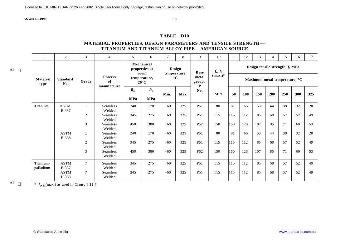
AS 4041—1998 180
TABLE D10
MATERIAL PROPERTIES, DESIGN PARAMETERS AND TENSILE STRENGTH—TITANIUM AND TITANIUM ALLOY PIPE—AMERICAN SOURCE
A1
1 2 3 4 5 6 7 8 9 10 11 12 13 14 15 16 17
Materialtype
StandardNo.
GradeProcess
ofmanufacture
Mechanicalproperties at
roomtemperature,
20°C
Designtemperature,
°C
Basemetal
group,P
No.
fc, fh(max.)*
Design tensile strength, f, MPa
Maximum metal temperature, °C
Rm
MPa
Re
MPaMin. Max. MPa 50 100 150 200 250 300 325
Titanium ASTMB 337
ASTMB 338
1
2
3
1
2
3
SeamlessWelded
SeamlessWelded
SeamlessWelded
SeamlessWelded
SeamlessWelded
SeamlessWelded
240
345
450
240
345
450
170
275
380
170
275
380
−60
−60
−60
−60
−60
−60
325
325
325
325
325
325
P51
P51
P52
P51
P51
P52
80
115
150
80
115
150
81
115
150
81
115
150
66
112
128
66
112
128
53
85
107
53
85
107
44
68
85
44
68
85
38
57
71
38
57
71
32
52
60
32
52
60
28
49
53
28
49
53
Titanium-palladium
ASTMB 337ASTMB 338
7
7
SeamlessWelded
SeamlessWelded
345
345
275
275
−60
−60
325
325
P51
P51
115
115
115
115
112
112
85
85
68
68
57
57
52
52
49
49
* fc, fh(max.) as used in Clause 3.11.7.A1
© Standards Australia www.standards.com.au
Licensed to LUU MINH LUAN on 26 Feb 2002. Single user licence only. Storage, distribution or use on network prohibited.

181 AS 4041—1998
TABLE D11
MATERIAL PROPERTIES, DESIGN PARAMETERS AND TENSILE STRENGTH—IRON CASTINGS
A1
A1
1 2 3 4 5 6 7 8 9 10 11 12 13 14 15
Materialtype
Standard No. Grade
Mechanical properties atroom temperature,
20°C
Minimumdesign
temperature
fc, fh(max.)*
Design tensile strength, f, MPa
Maximum metal temperatures, °C
Rm
MPa
Re
MPa
Specifiedminimumelongation
%
°C MPa 50 100 150 200 250 300 350
Ductile iron (i.e.nodular orspheroidal graphiteiron)
AS/NZS 2280 Pipe fitting 420420
——
105
−30−30
8484
8484
8484
8484
8484
8484
——
——
AS 1831 370-17400-12500-7
370400500
230250320
1712
7
−30−30−30
12380
100
12380
100
12380
100
12380
100
12380
100
12380
100
123——
123——
Austenitic ductile(see Note)
AS 1833 Si-Ni Mn 13 7S-Ni Cr 20 2S-Ni Cr 20 3
390370390
———
1577
−30−30−30
1307478
1307478
1307478
1307478
1307478
1307478
130——
130——
S-Ni Si Cr 20 5 2S-Ni 22S-Ni-Mn 23 4
370370402
———
102025
−30−30−30
123123133
130123133
130123133
130123133
130123133
130123133
—123133
—123133
S-Ni Cr 30 1S-Ni Cr 30 3S-Ni Si Cr 30 5 5
370370370
———
137
—
−30−30−30
747478
747478
747478
747478
747478
747478
———
———
S-Ni 35S-Ni Cr 35 3
370370
——
207
−30−30
12374
12374
12374
12374
12374
12374
123—
123—
Grey iron
Drafting notechange? SeeKotwal.
AS 1830 T-200T-250T-300T-350T-400
200250300350400
—————
—————
−30−30−30−30−30
1520253035
1520253035
1520253035
1520253035
1520253035
1520253035
Note 1
Whiteheartmalleable iron
AS 1832 W 350-4W 400-5
340360
——
45
−30−30
3436
3436
3436
3436
3436
3436
——
——
Blackheartmalleable iron
AS 1832 B 300-6B 350-10
300350
——
610
−30−30
3035
3035
3035
3035
3035
3035
——
——
* fc, fh(max.) as used in Clause 3.11.7.NOTE: Values of ‘ f’ are based on section thickness of 40 mm, higher values are permissible based on thinner actual as-cast thicknesses.
www.standards.com.au © Standards Australia
Licensed to LUU MINH LUAN on 26 Feb 2002. Single user licence only. Storage, distribution or use on network prohibited.

AS 4041 — 1998 182
APPENDIX E
LINEAR EXPANSION
(Normative)
Table E1 gives the values of the linear expansion for certain materials. Where a materialis not listed, the required value should be obtained from the manufacturer or some otherauthoritative source.
NOTES:
1 These data should not be taken to imply that the materials are suitable for all temperaturesshown.
2 Linear interpolation of values is acceptable.
© Standards Australia www.standards.com.au
Lice
nsed
to L
UU
MIN
H L
UA
N o
n 26
Feb
200
2. S
ingl
e us
er li
cenc
e on
ly. S
tora
ge, d
istr
ibut
ion
or u
se o
n ne
twor
k pr
ohib
ited.

183 AS 4041—1998
TABLE E1
LINEAR EXPANSION
Material type
Linear thermal expansion for metal from 20°C to temperature indicated, mm/m
Terminal temperature, °C
−200 −150 −100 −50 0 50 100 150 200 250 300 350 400 450 500 550 600 650 700 750 800 850
Carbon, carbon-molybdenum, and low Cr-Mo steel (≤3 Cr)
−1.97 −1.68 −1.18 −0.72 −0.21 0.34 0.93 1.55 2.21 2.89 3.61 4.35 5.13 5.94 6.78 7.65 8.55 9.48 10.45 17.44
Intermediate Cr-Mo steel (>5 to≤9 Cr) −1.84 −1.58 −1.12 −0.68 −0.20 −0.32 −0.88 1.45 2.05 2.67 3.32 3.98 4.67 5.38 6.12 6.87 7.65 8.45 9.28 18.12
High chromium steel (≥12 Cr) −1.68 −1.36 −1.00 −0.61 −0.18 0.30 0.81 1.34 1.89 2.46 3.06 3.67 4.38 4.96 5.63 6.33 7.84 7.78 8.54 9.31
Austenitic stainless steel (18-8 series) −3.23 −2.56 −1.85 −1.10 −0.32 0.50 1.34 2.21 3.09 4.00 4.92 5.86 6.82 7.80 8.80 9.81 10.85 11.90 12.98 14.07 15.18 16.31
Austenitic stainless steel (25-50 type) −2.51 −2.01 −1.47 −0.89 −0.26 0.42 1.12 1.85 2.61 3.38 4.17 4.98 5.82 6.68 7.55 8.45 9.37 10.31 11.27 12.25
3½ nickel steel −1.89 −1.59 −1.21 −0.76 −0.23 0.33 0.90 1.50 2.13 2.79 3.48 4.19 4.94 5.71 6.51 7.34 8.20 9.08
9% nickel steel −2.11 −1.67 −1.28 −0.72 −0.21 0.33 0.90 1.50 2.13 2.79 3.47 4.19 4.93 5.70 6.50 7.33
Grey cast iron −1 0.31 0.83 1.39 1.97
18 Cr-37 nickel iron alloy 2.03 2.84 3.67 4.52 5.39 6.27 7.18 8.10 9.04 10.90 10.98 11.98 12.99 14.03 15.08
Aluminium −3.91 −3.18 −2.36 −1.44 −0.43 0.67 1.84 3.08 4.39
Copper −3.41 −2.67 −1.91 −1.13 −0.33 0.50 1.34 2.20 3.08
Brass −3.21 −2.54 −1.83 −1.09 −0.32 0.52 1.41 2.34 3.31
Bronze −3.30 −2.61 −1.88 −1.12 −0.33 0.53 1.43 2.35 3.30 4.27
Copper nickel alloy(70 Cu-30 Ni)
−2.63 −2.14 −1.58 −0.97 −0.29 0.44 1.21 2.03 2.91
Nickel-copper alloy(67 Ni-30 Cu)
−2.18 −1.85 −1.42 −0.89 −0.77 0.41 1.12 1.87 2.65 3.47 4.32 5.21 6.13 7.09 8.08
www.standards.com.au © Standards Australia
Licensed to LUU MINH LUAN on 26 Feb 2002. Single user licence only. Storage, distribution or use on network prohibited.

AS 4041 — 1998 184
APPENDIX F
YOUNG MODULUS
(Normative)
Table F1 gives the values of the Young modulus for certain materials. Where a material isnot listed, the required value should be obtained from the manufacturer or some otherauthoritative source.
NOTES:
1 These data should not be taken to imply that the materials are suitable for all temperaturesshown.
2 Linear interpolation of values is acceptable.
© Standards Australia www.standards.com.au
Lice
nsed
to L
UU
MIN
H L
UA
N o
n 26
Feb
200
2. S
ingl
e us
er li
cenc
e on
ly. S
tora
ge, d
istr
ibut
ion
or u
se o
n ne
twor
k pr
ohib
ited.

185 AS 4041—1998
TABLE F1
YOUNG MODULUS
Material type
Young modulus, (E) for metal temperature below that indicated, 10−5 MPa
Reference temperature, °C
−200 −150 −100 −50 0 20 100 200 300 400 500 600 700 800
Carbon and carbon-molybdenum steel (≤0.3 C) 2.07 2.04 2.02 1.98 1.94 1.92 1.91 1.86 1.79 1.66 1.21
Carbon steel (≥0.3 C) 2.14 2.12 2.10 2.09 2.07 2.06 2.03 1.96 1.85 1.69 1.42
Low Cr-Mo steel (<3 Cr) 2.14 2.12 2.10 2.09 2.07 2.06 2.03 1.97 1.90 1.80 1.66 1.37
Intermediate Cr-Mo steel (≥3 <10 Cr) 2.03 1.98 1.95 1.93 1.90 1.89 1.87 1.82 1.76 1.69 1.60 1.50 1.35 1.17
High chromium steel (≥10 Cr) 2.12 2.10 2.07 2.04 2.02 2.01 1.98 1.91 1.81 1.65 1.40 1.05
Austenitic stainless steel (18-8 series and 25-20type)
2.10 2.07 2.04 2.01 1.97 1.95 1.90 1.84 1.76 1.68 1.60 1.51 1.43 1.26
Grey cast iron 0.72 0.91 0.91 0.87 0.82 0.73
Aluminium 0.78 0.76 0.74 0.72 0.70 0.70 0.67 0.60
Copper 1.17 1.16 1.14 1.13 1.11 1.10 1.07 1.04 0.99
Brass 1.03 1.02 1.01 0.99 0.97 0.97 0.94 0.90 0.85
Bronze 0.98 0.96 0.94 0.92 0.90 0.90 0.87 0.83 0.79
Copper nickel alloy (70 Cu-30 Ni) 1.57 1.57 1.55 1.53 1.51 1.50 1.48 1.45 1.38 1.35
Nickel-copper alloy (67 Ni-30 Cu) 1.85 1.84 1.83 1.81 1.80 1.79 1.79 1.77 1.72 1.52 1.23
www.standards.com.au © Standards Australia
Licensed to LUU MINH LUAN on 26 Feb 2002. Single user licence only. Storage, distribution or use on network prohibited.

AS 4041 — 1998 186
APPENDIX G
DESIGN TENSILE STRENGTH FOR FLANGE BOLTING
(Normative)
Table G1 gives the values for the design tensile strength for flange bolting for variousmaterials at given design temperatures.
NOTES TO TABLE G1:
1 D = diameter.
t = thickness.
2 The minimum operating temperature is that for which the material is normally suitablewithout impact testing other than required in the material specification. For lowertemperatures, see Clause 2.11 for necessary impact tests.
3 Stresses at intermediate temperatures may be obtained by linear interpolation.
4 Stress values are established from a consideration of strength only and will be satisfactoryfor average service. For bolted joints, where freedom from leakage over a long periodwithout re-tightening is required, lower stress values may be necessary as determined fromthe relative flexibility of the flange and bolts, and corresponding relaxation properties.
5 Between minimum temperature shown and 200°C, stress values equal to the lower of thefollowing will be permitted: 20 percent of the specified tensile strength, or 25 percent ofthe specified minimum yield strength.
6 Materials listed are normally used because of their corrosion resistance.
7 Stresses are permitted for material which has been carbide-solution treated.
8 At temperatures over 525°C, stress values apply only when the carbon is 0.04 percent orhigher.
9 For temperatures above 525°C, stress values may be used only if the material has been heattreated at a temperature of 975°C minimum.
10 Austenitic steel bolts for use in pressure joints should not be less than 10 mm diameter.
11 For all design temperatures, the maximum hardness shall be Rockwell C35 immediatelyunder the thread roots. The hardness shall be taken on a flat area at least 3 mm diameterprepared by removing threads. No more material than necessary shall be made at the samefrequency as tensile tests.
12 For temperatures above 525°C, stress values may be used only if the material has been heattreated at a temperature of 1075°C minimum.
13 The maximum operating temperature is arbitrarily set at 250°C, because harder temperadversely affects design strength in the creep-rupture temperature range.
14 Design strengths for the cold-drawn temper is based on hot-rolled properties until requireddata on cold drawn are available.
15 Copper-silicone alloys are not always suitable when exposed to certain media and hightemperatures, particularly steam above 100°C. The user should verify that the alloy selectedis satisfactory for the service for which it is to be used.
16 The stress values given for this material are not applicable when either welding or thermalcutting is employed.
© Standards Australia www.standards.com.au
Lice
nsed
to L
UU
MIN
H L
UA
N o
n 26
Feb
200
2. S
ingl
e us
er li
cenc
e on
ly. S
tora
ge, d
istr
ibut
ion
or u
se o
n ne
twor
k pr
ohib
ited.

187 AS 4041—1998
TABLE G1
DESIGN TENSILE STRENGTH FOR FLANGE BOLTING
A1
Material
Notes
Min.oper-ating
temp. °C(Note 2)
Design tensile strength, MPa
Type Specific-ation Grade Temper
Dia.or size(mm)
(Note 1)
For design temperatures not exceeding °C (Note 3)
Min.temp.to 50
100 150 200 250 300 325 350 375 400 425 450 475 500 525 550 575 600 625 650
CARBONSTEELS
AS/NZS 1110AS B 148AS 2465
4.6Class 2
2
AllAllAll
−30
60
60
60
60
50
AS/NZS 1110 5.8 All −30 100 100 100 100 100 100 100 100AS 2465 5 >24 −30 85 85 85 85 85 85 85 85
AS/NZS 1110 8.8 All −30 160 160 160 160 160 160 160 160AS 2465
AS/NZS 12525—
≤24All
−30 130 130 130 130 130 130 130 130
LOW ALLOYSTEELS1Cr-0.2Mo
ASTM A 320 L7, L7A,L7B, L7C
≤63 4,5 −100 172 172 172 (200° max.)
ASTM A 193 B7 ≤634,5 −30 172 172 172 172 172 172 172 172 172 163 145 121 93 69 43
63<t≤102 −30 159 159 159 159 159 159 159 159 159 153 138 115 92 69 435Cr-½Mo ASTM A 193 B5 ≤192 4,5,6 −30 138 138 138 138 138 138 138 138 138 138 129 104 78 59 45 34 26 19 13 8.61Cr−½Mo-V ASTM A 193 B16 ≤63
4,5 −30172 172 172 172 172 172 172 172 172 172 172 163 147 121 92 61 36
63<t≤102 152 152 152 152 152 152 152 152 152 152 152 146 131 113 90 61 35
HIGHALLOYSTEELS13Cr
ASTM A 193 B6(410) ≤102 4,6 −30 146 146 146 146 146 146 146 146 146 146 134 107 89
18Cr-8Ni ASTM A 193 B8(304) Soln.Trtd.
All 4,7,89,10,11
−200 129 106 96 88 85 79 78 77 76 75 73 71 70 69 68 67 65 59 53 42
18Cr-8Ni-Ti ASTM A 193 B8T(321) Soln.Trtd.
All 4,7,810,11,
12
−200 129 109 97 89 84 79 77 76 75 75 74 73 73 73 72 68 58 45 34 25
18Cr-9Ni-Nb ASTM A 193 B8C(347) Soln.Trtd.
All 4,7,810,11
−200 129 118 110 104 98 94 92 90 89 88 88 87 87 87 87 84 78 59 42 30
18Cr-12Ni-2Mo
ASTM A 193 B8M(316) Soln.Trtd.
All 4,7,89,10,11
−200 129 110 101 92 87 83 80 79 78 77 76 75 75 74 74 73 72 69 64 51
See start of this Appendix for Notes. (continued)
www.standards.com.au © Standards Australia
Licensed to LUU MINH LUAN on 26 Feb 2002. Single user licence only. Storage, distribution or use on network prohibited.

AS 4041—1998 188
TABLE G1 (continued)
Material
Notes
Min.oper-ating
temp. °C(Note 2)
Design tensile strength, MPa
Type Specific-ation Grade Temper
Dia.or size(mm)
(Note 1)
For design temperatures not exceeding °C (Note 3)
Min.temp.to 50
75 100 125 150 175 200 225 250 275 300 325 350 375 400 450 500 550 600 650
NICKELANDNICKELALLOYSNickel
ASTM B 160
200 Annealed All −200 26 26 26 26 26 26 26 26 26 26 26
200 Hotfinished
All −200 26 26 26 26 26 26 26 26 26 25 24
200 Colddrawn
All −200 69 66 66 66 66 66 66 66 65 65 64
Low CNickel
ASTM B 160 201 Annealedor hot
finished
All −200 17 17 17 16 16 16 16 16 16 16 16 16 16 16 16 15 14 13 11 8
Nickel-Copper
ASTM B 164 400–405 Annealed All −200 43 40 39 37 36 35 34 34 34 34 34 34 34 34 34 33
400 Hotfinished
Allexcept
hexagons>54
−200 69 67 66 66 65 64 62 61 59 59 59 59 59 59 58 45
400 Hotfinished
Hexagon>54
−200 52 51 50 49 48 47 46 45 45 45 45 45 45 44 43 36
405 Hotfinished
Rounds≤76
−200 61 60 59 58 57 56 55 54 53 52 52 52 52 52 51 41
400 CD stressrel
All 13 −200 86 83 82 80 79 78 78 78
400 CD stressequaliz.
Rounds≤90 13 −200 121 118 116 114 112 109 107 107 106
400 CD stressequaliz.
Othersizes,shapes
13 −20095 91 89 88 87 86 86 85 85
405 Colddrawn
All 13 −200 95 91 89 88 87 86 86 85 85
400 Colddrawn
All 13 −200 86 84 82 81 79 78 77 77 77
Nickel-Chromium-Iron
ASTM B 166 600 Annealed All −200 60 57 56 55 54 54 53 53 52 52 52 51 51 50 50 48 47 41 20 14
600 Hotfinished
Rounds>76
Shapes,all sizes
−200 60 59 58 57 56 56 55 55 55 55 55 55 55 55 54 52 51 50 48 38
See start of this Appendix for Notes. (continued)
© Standards Australia www.standards.com.au
Licensed to LUU MINH LUAN on 26 Feb 2002. Single user licence only. Storage, distribution or use on network prohibited.

189 AS 4041—1998
TABLE G1 (continued)
Material
Notes
Min.oper-ating
temp. °C(Note 2)
Design tensile strength, MPa
Type Specific-ation Grade Temper
Dia.or size(mm)
(Note 1)
For design temperatures not exceeding °C (Note 3)
Min.temp.to 50
75 100 125 150 175 200 225 250 275 300 325 350 375 400 450 500 550 600 650
Nickel-Chromium-Ironcontinued
ASTM B 166continued
600 Hotfinished
Rounds≤76
−200 69 67 65 64 64 63 63 63 63 63 63 62 62 61 61 60 59 56 49 38
600 Colddrawn
All 13,14 −200 69 67 65 64 64 63 63 63 63
Nickel-Moly
ASTM B 335 B Annealed All −200 79 72 69 68 68 68 65 63 62 61 60 58 57 57 57 57
COPPERANDCOPPERALLOYSCopper
AS/NZS 1567102, 110120, 122 O All −200 17 15 14 13 13 11 11
Copper-Silicon
AS/NZS 1567 655 OM
6<D≤706<D≤20
20<D≤50
151515
−200 266560
266560
266459
266257
266156
245954
Aluminium-Bronze
AS/NZS 1567 623 < 6<D≤50 −200 55 55 55 55 54 54 53 52 52
ALUMIN-IUM ANDALUMIN-IUMALLOYSA1-4Cu-Mn-Si
ASTM B 211 2014 T63<D≤200 16 −200 90 83 78 70 50 31 21
ASTM B 211 2024 T4 12<D≤110
16 −200 72 70 68 65 54 43 34
A1-4Cu-1.5Mn
AS/NZS 1865 6061 T6 10<D≤150
16 −200 52 Not available
6062 <10 16 −200 58 56 54 51 43 34 24
ASTM B 211 6061 T6 3<D≤200 16 −200 58 56 54 51 43 34 24
6062 T6 welded 3<D≤200 — −200 33 32 31 30 27 24 19
See start of this Appendix for Notes.
www.standards.com.au © Standards Australia
Licensed to LUU MINH LUAN on 26 Feb 2002. Single user licence only. Storage, distribution or use on network prohibited.

AS 4041 — 1998 190
APPENDIX H
LODMAT ISOTHERMS
(Normative)
ISOTHERMS IN DEGREES CELSIUS
LODMAT (lowest one day mean ambient temperature) based on records 1957-1971supplied by the Australian Bureau of Meteorology and prepared by the WTIA inFebruary 1975.
© Standards Australia www.standards.com.au
Lice
nsed
to L
UU
MIN
H L
UA
N o
n 26
Feb
200
2. S
ingl
e us
er li
cenc
e on
ly. S
tora
ge, d
istr
ibut
ion
or u
se o
n ne
twor
k pr
ohib
ited.

191 AS 4041 — 1998
APPENDIX I
DETERMINATION OF DESIGN STRENGTH
(Normative)
I1 GENERAL This Appendix sets out the basis for the determination of designstrength of materials specified in this Standard. Design strength is to be taken as themaximum primary membrane stress, and does not include any allowance for weld jointefficiency, pipe class factor or casting quality factor. These allowances are provided in theappropriate clauses of this Standard.
This Appendix treats the subject under two major headings:
(a) Design strength for piping Classes 1, 2A and 3.
(b) Design strength for piping Class 2P.
I2 DESIGN STRENGTH FOR PIPING CLASSES 1, 2A and 3
I2.1 General The origins of the basis for determination of design strength are asfollows:
(a) For steel . . mainly BS 806—1986, Amendment No. 4 and BS 806, Enquiry Cases.
Table D2 indicates the source for each pipe specification.
(b) For other materials . . . . . . . . . . . . . . . . . . . . . . . . . . . . . . . ANSI/ASME B31.3.
The source is indicated in the headings of Tables D6, D7, D8, D9 and D10.
The API 5L X42, X52 values at 50°C are derived from Rm values. The API 5L X42, X52values for temperatures above 150°C, use the Grade B values taken from BS 806.
I2.2 Calculation of design strength The source documents BS 806 and ANSI/ASMEB31.3 are comprehensive for pipe specifications. The following notes in this Appendixmay be useful for users who need to allocate a design strength to a pipe specification notlisted in either BS 806 or ANSI/ASME B31.3.
It is reasonable and convenient to base design strengths directly on the characteristicmaterial properties (yield/proof strength or creep strength values), but there are caseswhere this would give a design strength not justified by previous experience or currentunderstanding of structural behaviour. Adjustment has been made in such cases and alsowhere design strength based on the simple relationships (factors) would result in anunwarranted variation in an established design strength.
Except for low ductility cast irons, design strengths are based on the assumption thatmaterials are ductile and capable of reasonable plastic deformation at stress concentrationsabove the permitted range of service temperatures. This assumption is met for materialslisted in Tables D2 to D7 provided fabrication procedures comply with this Standard anddo not significantly reduce the properties of the material.
I2.3 Notation The notation for material properties is as follows:
Rm = specified minimum tensile strength at room temperature for the grade ofmaterial concerned (tested in accordance with AS 1391 or equivalent)
RmT = tensile strength at a temperature T for the grade of material
Re = specified minimum yield strength at room temperature for the grade ofmaterial (tested in accordance with AS 1391 or equivalent)
Where a material standard specified minimum values of ReL or Rp0.2 (Rp1.0 foraustenitic steels), these values are taken as corresponding to Re
www.standards.com.au © Standards Australia
Lice
nsed
to L
UU
MIN
H L
UA
N o
n 26
Feb
200
2. S
ingl
e us
er li
cenc
e on
ly. S
tora
ge, d
istr
ibut
ion
or u
se o
n ne
twor
k pr
ohib
ited.

AS 4041 — 1998 192
ReT = specified minimum value of Re or Rp0.2 (Rp1.0 for austenitic steels) at atemperature T for the grade of material (tested in accordance with AS 2291,BS 3920 or equivalent). Thus ReT is measured at slow strain rate while Re ismeasured at high strain rate. At 20°C Re is therefore higher than ReT.
SRt = mean value of the stress required to produce rupture in time t (at temperatureT) for the particular grade of material (tested in accordance with BS 3500 orequivalent)
ScT = mean value of stress at a temperature T required to produce a creep rate of0.01% in 1000 h
fE = design strength corresponding to the short term tensile strengthcharacteristics of the material (time-independent)
fF = design strength corresponding to the creep characteristics of the material(time-dependent)
f = design strength, which has been taken as the lesser of fE and fF.
These material properties may be obtained from pipe specifications or pipe manufacturers.Design strength for material or product form not listed in Appendix D may be determinedby using this Appendix and Table I1.
I2.4 Design life (see Clause 3.4) Time-dependence of creep and fatigue has beenrecognized by assigning permissible stress levels for different design lifetimes, as follows:
(a) For creep conditions Higher design strengths are permitted for short lifetimes, andlower design strengths are required for very long lifetimes. This is achieved inTable D2 and D5 by listing design strengths for specific lifetimes for those steelswhere SRt data are available.
(b) For fatigue conditions The practice of ANSI/ASME B31.3 is followed wherebystress range reduction factors are applied to design strengths, to cater for the numberof stress cycles expected during the design life (see Table 3.11).
I3 DESIGN STRENGTH FOR PIPING CLASS 2P This Standard embraces roomtemperature safe fluids, e.g. water at ambient temperature and provides a Class 2P pipingfor such service.
Industry had used a variety of conventions for selecting wall thickness of steel pipe forsuch service. Two conventions noted for their relatively thin wall are design at 72% ofspecified minimum yield stress modelled on either natural gas and petroleum pipelines toAS 2885 and ANSI/ASME B31.8 and design at 80% Re for water mineral slurry piping toANSI/ASME B31.11. A related convention is the optional class in ANSI/ASME B31.3designed on 0.67 Re applicable to all metals and suitable for high pressures.
The design strength for Class 2P piping is 0.72 of the normally specified minimum yieldstress (0.72 Re). The limits of application of Class 2P piping as follows:
(a) Limited to fluid 4 (Table 1.4).
(b) Limited to application temperatures of 0°C−99°C inclusive.
(c) Limited to carbon and carbon manganese steel pipe up to Rm 460 and listed inClause 2.2.
Class 2P piping does not permit cast iron, plastic and non-ferrous pipe nor pipe forelevated or low temperature application. The design stress for Class 2P piping onlyapplies to pipe.
The design strength for Class 2P piping is not listed in the Tables of Appendix D.
It is noted that for the steels included in piping Class 2P, the design at 0.72 Re isinherently the lesser of 0.72 Re and Rm/1.75 even though this is not a requirement in thesource from which Class 2P was derived and it is not a requirement of this Standard.
© Standards Australia www.standards.com.au
Lice
nsed
to L
UU
MIN
H L
UA
N o
n 26
Feb
200
2. S
ingl
e us
er li
cenc
e on
ly. S
tora
ge, d
istr
ibut
ion
or u
se o
n ne
twor
k pr
ohib
ited.

193 AS 4041 — 1998
TABLE I1
DETERMINATION OF DESIGN STRENGTH (f) (Note 1)
MaterialDesign
temper-ature °C
f (being lesser of fE and fF)
Design strength (time-independent) (fE) (beingthe lowest of A, B, C and D) Design strength (time-dependent) (fF)
A B C D For indefinite designlifetime (Note 2)
For specific designlifetime, of t(hours)
(Note 4)
1 Ferritic steels
All ≤50°Re
1.5—
Rm
2.35— — —
All >50<150 Linear interpolation of fE between 50 and 150°C — —
ReT specified ortested ≥150 —
ReT
1.5
Rm
2.35—
SR 100 000
1.5
SRt
1.3
ReT not specified ortested ≥150 —
ReT
1.6
Rm
2.35—
SR 100 000
1.5
SRt
1.3
2 Austenitic steels
All ≤50Re
1.5—
Rm
2.35— — —
All >50<100 Linear interpolation of fE between 50 and 100°C — —
ReT specified ortested
≥100 —Ret
1.35
(Note 3)
Rm
2.5—
Lesser of:
SR 100 000
1.5and
SCT 0.01 1000h
1.0
SRt
1.3
ReT not specified ortested
≥100 —Ret
1.45
(Note 3)
Rm
2.5—
Lesser of:
SR 100 000
1.5and
SCT 0.01 1000h
1.0
SRt
1.3
3 Ferritic austenitic steels
All ≤50Re
1.5—
Rm
2.35— — —
All >50<150 Linear interpolation of fE between 50 and 150°C — —
ReT specified ortested ≥150 —
ReT
1.5
Rm
2.35—
SR 100 000
1.5
SRt
1.3
ReT not specified ortested ≥150 —
ReT
1.6
Rm
2.35—
SR 100 000
1.5
SRt
1.3
ReT not specified ortested ≥150 —
ReT
1.6
Rm
2.35—
SR 100 000
1.5
SRt
1.3
(continued)
www.standards.com.au © Standards Australia
Lice
nsed
to L
UU
MIN
H L
UA
N o
n 26
Feb
200
2. S
ingl
e us
er li
cenc
e on
ly. S
tora
ge, d
istr
ibut
ion
or u
se o
n ne
twor
k pr
ohib
ited.

AS 4041—1998 194
TABLE I1 (continued)
MaterialDesign
temper-ature °C
f (being lesser of fE and fF)
Design strength (time-independent) (fE) (beingthe lowest of A, B, C and D) Design strength (time-dependent) (fF)
A B C D For indefinite designlifetime (Note 2)
For specific designlifetime, of t(hours)
(Note 4)
4 Non-ferrous metals
AllRe
1.5
ReT
1.5
Rm
3
RmT
3
Lesser of:
SR 100 000
1.5and
ScT 0.01 1000h
1.0
SRt
1.3
5 Iron castings
SME ≥ 15%(Note 6)
All — —Rm
3
RmT
3— —
Ductile ironSME < 15% ≥ 7% All — —
Rm
5
RmT
5— —
Grey iron andMalleable iron All — —
Rm
10
RmT
10— —
6 Bolting
AllRe
1.5
ReT
1.5
Rm
4
(Note 5)
RmT
4
Lesser of:
SR 100 000
1.5and
ScT 0.01 1000h
1.0
SRt
1.3
7 Class 2P steel pipe
0 to 99 0.72 Re —Rm
1.75— — —
NOTES:
1 Re, RmT, Rm and RmT are based on standard short-term tensile tests while SR and SCT are based on long-term tests.
2 Indefinite means the design lifetime is undefined, but should provide a useful life in the range 150 000 h to 200 000h, provided thatthe design metal temperature is not exceeded. This should be used where reliable, time-dependent properties (SRt) are not available.
3 In this instances (austenitic stainless steels) the factors 1.35 and 1.45 apply to ReT values based on Rp1.0.
For austenitic steels and certain nickel alloys, the value in Column B may be replaced by 0.9ReT. Such increased stress is notrecommended for flanges or gasketed joints, or other applications where slight deformation can cause leakage or malfunction.
4 Where creep deformation is to be limited, an agreed lower value of fF may be necessary.
5 Where the strength of bolting has been increased by heat treatment or strain hardening, the value of fE shall not exceed the lesser
of except fE need not be lower than the value for the annealed condition.Rm
5and
Re
4
6 SME is the specified minimum elongation on gauge length 4√So.
© Standards Australia www.standards.com.au
Lice
nsed
to L
UU
MIN
H L
UA
N o
n 26
Feb
200
2. S
ingl
e us
er li
cenc
e on
ly. S
tora
ge, d
istr
ibut
ion
or u
se o
n ne
twor
k pr
ohib
ited.

195 AS 4041 — 1998
APPENDIX J
DESIGN PRESSURE FOR SAFETY VALVE DISCHARGE PIPING
(Normative)
J1 GENERAL This Appendix gives a method of determining the design pressure for asafety valve discharge piping system.
Pressures calculated from the Equations J2 and J3 should be increased by 25 percentwhere used as a design pressure.
A1
J2 ABSOLUTE PRESSURE The absolute pressure (p) in a pipe carrying acompressible fluid is that calculated by the following equation:
. . . J2 p = rG(B)½ × 10−6
where
p = absolute pressure in pipe, in megapascals
r = velocity of fluid in pipe, in metres per second
=
po × 106
o
½
G = mass flow rate per unit area, in kilograms per square metre per second
B = a factor (see Table J1) depending upon the ratio (k) of the specific heatsduring the expansion and upon the ‘ friction length’ of the pipe
po = absolute pressure at rest in originating vessel, in megapascals
o = density of fluid in originating vessel, in kilograms per cubic metre.
A1 J3 FRICTION LENGTH The friction length (lf) equals 4fl/d where 4f (where 4f is theDarcy friction factor) is the normal friction coefficient in the incompressible flowequation and the pressure loss is that calculated by the following equation:
Pressure loss = . . . J34f ld
v 2
2where
l = length, in metres
d = internal diameter, in metres
v = velocity, in metres per second
That usual allowances for bends and fittings shall be included in determining theresistance through any silencer that might be fitted, and the calculation shall take intoaccount the Reynolds number, Gd/µ, where µ is the dynamic viscosity (in N.s/m2), and thepipe roughness. The friction length shall be measured from the point at which a criticalpressure would develop with the approximate values for G and k.
The value of the critical pressure (pc) is given by Equation J2 using for B the value atlf = 0, and where the ambient pressure (pa) around the outlet of a pipe exceeds pc, a lengthlf ′ shall be added to lf to obtain the value of B from which to calculate the pressure at anypoint.
lf ′ is to correspond to Ba =
pa × 106
rG
2
www.standards.com.au © Standards Australia
Lice
nsed
to L
UU
MIN
H L
UA
N o
n 26
Feb
200
2. S
ingl
e us
er li
cenc
e on
ly. S
tora
ge, d
istr
ibut
ion
or u
se o
n ne
twor
k pr
ohib
ited.

AS 4041—1998 196
J4 EXAMPLE This tabulated example shows calculation of the pressure p1 at theupstream end of a straight pipe of diameter 0.125 m and length 20 m, exhausting steam toatmosphere from a safety valve mounted at a superheater outlet. The absolute pressureis 7 MPa and the steam temperature 500°C, and the maximum quantity delivered by thevalve is Case (a), 7 kg/s and Case (b), 1 kg/s.
ItemCase (a),
7 kg/sCase (b),
1 kg/s
r, m/sG, kg/m2/sk
580570
1.3
58081.5
1.3
pa, MPaBa
lf′ corresponding to Ba
0.10.09150. (as Ba < Bc)
0.14.4752.342
lf, (4f = 0.016)lf + lf′Corresponding Bp1, MPa
2.5602.5604.7430.72
2.5604.9027.4700.129
J5 PIPE JUNCTIONS The pressure in a small bore pipe discharging into a pipe oflarger bore may be calculated from Paragraph J3. The ambient pressure (pa), may be takenas the pressure at the upstream end of the larger pipe, including an allowance for thesudden enlargement. This allowance will be conservative if estimated on the conventionalbasis of fluid incompressibility. A critical pressure may occur at the exit of the small-borepipe or at any enlargement.
J6 MASS FLOW DISCHARGE OF EXHAUST PIPE For the purposes of exhaustpipe design, the mass flow discharge, M (kg/s) from a safety valve is that calculated bythe following equation:
M =Avpo × 106
1.6r
. . . J6= 625Av(Po × o)½
This mass flow may be higher than the rating of the valve specified. Av is the smallestarea, in square metres, available for flow through the valve.
© Standards Australia www.standards.com.au
Lice
nsed
to L
UU
MIN
H L
UA
N o
n 26
Feb
200
2. S
ingl
e us
er li
cenc
e on
ly. S
tora
ge, d
istr
ibut
ion
or u
se o
n ne
twor
k pr
ohib
ited.

197 AS 4041 — 1998
TABLE J1
COMPRESSIBLE FLOW FACTORS
lf = 4fld
B =
p × 106
rG
2
k = 1.000(see Note)
k = 1.100 k = 1.200 k = 1.300 k = 1.400
00.010.02
1.0001.1481.214
0.8661.0101.074
0.7580.8990.961
0.6690.8070.868
0.5950.7890.789
0.030.040.05
1.2651.3101.350
1.1251.1691.208
1.0111.0541.092
0.9170.9590.996
0.8370.8780.915
0.060.070.08
1.3881.4221.455
1.2451.2791.311
1.1281.1621.193
1.0311.0641.095
0.9500.9821.013
0.090.100.12
1.4861.5161.573
1.3421.3711.427
1.2131.2521.307
1.1251.1531.207
1.0421.0701.123
0.140.160.18
1.6261.6771.726
1.4791.5291.577
1.3581.4071.454
1.2581.3061.352
1.1731.2211.266
0.200.300.40
1.7721.9862.179
1.6231.8332.023
1.5001.7071.895
1.3971.6021.787
1.3101.5131.695
0.500.600.70
2.3582.5282.689
2.2002.3672.527
2.0692.2342.393
1.9592.1232.280
1.8662.0282.184
0.800.901.00
2.8462.9983.146
2.6822.8332.979
2.5462.6952.841
2.4322.5802.724
2.3352.4812.624
1.201.401.60
3.4343.7113.982
3.2643.5393.807
3.1233.3963.662
3.0043.2753.539
2.9023.1713.434
1.802.002.5
4.2464.5055.136
4.0694.3264.953
3.9224.1774.800
3.7974.0514.671
3.6913.9434.560
345
5.7496.9378.091
5.5626.7437.891
5.4056.5807.724
5.2726.4437.582
5.1596.3257.461
678
9.22210.3411.44
9.01710.1311.22
8.8469.952
11.05
8.7019.803
10.89
8.5769.676
10.76
91015
12.5313.6118.94
12.3113.3918.71
12.1313.2118.52
11.9813.0518.35
11.8412.9118.20
203040
24.1934.5444.80
23.9434.2844.53
23.7423.0744.31
23.5733.8944.12
23.4233.7343.95
(continued)
www.standards.com.au © Standards Australia
Lice
nsed
to L
UU
MIN
H L
UA
N o
n 26
Feb
200
2. S
ingl
e us
er li
cenc
e on
ly. S
tora
ge, d
istr
ibut
ion
or u
se o
n ne
twor
k pr
ohib
ited.

AS 4041—1998 198
TABLE J1 (continued)
lf = 4fld
B =
p × 106
rG
2
k = 1.000(see Note)
k = 1.100 k = 1.200 k = 1.300 k = 1.400
506070
55.0165.1875.32
54.7364.8975.03
54.5064.5574.79
54.3064.4574.58
54.1364.2874.40
8090
100
85.4595.56
105.7
85.1595.26
105.4
84.9095.00
105.1
84.6994.79
104.9
84.5194.61
104.7
150200300
156.1206.3306.7
155.7206.0306.4
155.5205.7306.1
155.2205.5305.8
155.0205.3305.6
5001 000
507.21 008
506.51 008
506.31 007
506.31 007
506.01 007
NOTE: Or isothermic.
© Standards Australia www.standards.com.au
Lice
nsed
to L
UU
MIN
H L
UA
N o
n 26
Feb
200
2. S
ingl
e us
er li
cenc
e on
ly. S
tora
ge, d
istr
ibut
ion
or u
se o
n ne
twor
k pr
ohib
ited.

199 AS 4041 — 1998
APPENDIX K
TYPICAL FORGED BRANCH FITTINGS
(Normative)
NOTE: The butt-welded connection is illustrated; socket welding or threading is permitted.
www.standards.com.au © Standards Australia
Lice
nsed
to L
UU
MIN
H L
UA
N o
n 26
Feb
200
2. S
ingl
e us
er li
cenc
e on
ly. S
tora
ge, d
istr
ibut
ion
or u
se o
n ne
twor
k pr
ohib
ited.

AS 4041—1998 200
APPENDIX L
REINFORCEMENT OF A BRANCH AND AN OPENING
(Normative)
L1 GENERAL This Appendix sets out a method based on that specified in BS 806 forcalculating the reinforcement required for an opening in a pipe or a branch to a pipe.
A1 Branches shall not be welded to any main at an included angle, γ (see Paragraph L2), lessthan 60° for this method.
This method of branch shall be used if flexibility analysis to Appendix R is chosen.
This method, or the methods in Clauses 3.19.8 and 3.19.9, may be used with flexibilityanalysis to Clause 3.27.
L2 BRANCH CONNECTIONS TO MITRED GUSSETED BENDS Branchconnections shall be made to segments only if their inside diameters do not exceed 10percent of the diameter of the main. Branches shall be designed in accordance withParagraph L3 and Paragraph L4. The distance measured from the intersection of the boreof the branch with that of the main to the centre-line of the nearest mitred joint shall benot less than the greater of:
1.833 √(rt)or
. . . L2d02
sin γwhere
r = mean radius of the pipe based on the mean thickness, in millimetres
t = mean thickness of the main, in millimetres
d02 = mean inside diameter of the branch, in millimetres
γ = angle between the branch and the main, in degrees
NOTE: The dimensional parameters are illustrated in Figure L1.
L3 REINFORCEMENT AND BRANCH THICKNESS Whenever possible, the formof the reinforcement provided shall be by either Item (a) or (b):
(a) When the thickness of the main is not predetermined, by providing main and branchin accordance with Paragraph L5.
(b) When the thickness of the main is predetermined, by providing a branch inaccordance with Paragraph L6.
When reinforcement in accordance with either Item (a) or (b) cannot be provided, othermeans of reinforcement, the use of which has been substantiated by adequate relevantservice experience or by experimental or theoretical analysis, shall be agreed between theparties concerned.
When branch connections are reinforced in accordance with either Item (a) or (b), theratio of branch thickness to main thickness shall comply with the following limitation:
. . . L3t2
t1
≤
2 −D02
D1
© Standards Australia www.standards.com.au
Lice
nsed
to L
UU
MIN
H L
UA
N o
n 26
Feb
200
2. S
ingl
e us
er li
cenc
e on
ly. S
tora
ge, d
istr
ibut
ion
or u
se o
n ne
twor
k pr
ohib
ited.

201 AS 4041 — 1998
where
D1 = mean outside diameter of the main, in millimetres
D02 = mean outside diameter of the branch, in millimetres
t1 = mean wall thickness of the main, in millimetres
t2 = mean wall thickness of the branch, in millimetres
In no case shall the thickness of the main or branch be less than tf, the minimumcalculated thickness.
It is preferable for main and branch to be of the same material, but in no case shall branchmaterial have an allowable stress of less than 75 percent of that of the material of themain. No credit shall be taken where the branch material has an allowable stress that isgreater than that of the main.
The minimum branch thickness tm2, determined from Equation L5(5), assumes the samematerial for branch and main. If the branch is of a material having a lower allowablestress than the main, then the branch thickness shall be increased in the ratio of allowablestress.
Branches designed in accordance with Paragraph L5 or L6 shall be ‘ set-on’ fullpenetration welded, or non-protruding ‘ set in’ full penetration welded, or shall be ofhomogeneous construction.
L4 BRANCH SYSTEMS In assessing main and branch thickness in accordance withParagraph L5 and Paragraph L6, it shall be determined whether branches effect each otherby calculation of—
. . . L4Ld02m + d02n
where
L = distance between perpendiculars projected from the openings ofadjacent branches to the centre-line of the main, in millimetres(see Figure L2);
d02m d02n = inside diameters of the branches under consideration, in millimetres.The subscripts m and n represent the branch suffixes a, b and c, etc.(See Figure L2.)
Branches shall be considered to affect each other if the value calculated from expressionL4 is less than one; they shall be considered not to affect each other if the value is greaterthan or equal to one.
In calculating the thickness required, each branch shall be considered in turn together withall the branches by which it is affected (see Figure L2 for typical examples).
L5 REINFORCEMENT IN ACCORDANCE WITH PARAGRAPH L3(a)
L5.1 Branch not affected by any other branch The minimum thicknesses of thebranch tm2, in millimetres and the main tm1, in millimetres shall be determined fromEquations L5(1) and L5(3) or L5(2) and L5(4).
. . . L5(1)tm2 =pD2
2f2e1x + por
. . . L5(2)tm2 =pd2
2f2e1x − p
www.standards.com.au © Standards Australia
Lice
nsed
to L
UU
MIN
H L
UA
N o
n 26
Feb
200
2. S
ingl
e us
er li
cenc
e on
ly. S
tora
ge, d
istr
ibut
ion
or u
se o
n ne
twor
k pr
ohib
ited.

AS 4041—1998 202
. . .L5(3)tm1 =p D1
2f1e1x + por
. . . L5(4)tm1 =pd1
2f1e1x − pwhere
p = design pressure, in newtons per millimetre squared
D1 = mean outside diameter of the main, in millimetres
D2 = mean outside diameter of the branch multiplied by 1/sin γ, where γ is theangle between the branch and the main (in degrees), in millimetres
d1 = mean inside diameter of the main, in millimetres
d2 = mean inside diameter of the branch multiplied by 1/sin γ, in millimetres
f1 = allowable design stress of the main, in newtons per millimetres squared
f2 = allowable design stress of the branch, in newtons per millimetre squared, butnot greater than f1
e1 = joint efficiency factor particular to the main
x = factor from Figure L3 read against d2/d1
Where d2/d1 does not exceed 0.3; the x value derived from Figure L3 shall beused only to determine main thickness, and the branch thickness shall bedetermined by using an x factor of 1.0.
NOTES:
1 The minimum calculated branch thicknesses are a function of the branch inside or outsidediameter used in the calculation according to the equation used. If availability requires thatthe branch inside or outside diameter be increased above the value used in the calculation,then tm2 has to be recalculated.
2 The values of tm1 and tm2 are minimum thicknesses and further provision has to be made forminus tolerance.
L5.2 A branch affected by one or more other branches The thickness of the mainshall be determined from Equations L5(3) or L5(4), using the x factor applicable to thelargest d2 of the group.
NOTE: Where d2/d1 ratio exceeds 0.8, in order to limit iteration it is suggested that the mainthickness obtained from Equation L5(3) or L5(4) be multiplied by the factor 1.25 d2/d1.
The thickness of each branch shall be obtained from Equation L5(5), except that whered2/d1 ≤ 0.3 and the mean diameter of the branch (d2 + tf) complies with the limitation ofinequality (L5(8)), the branch minimum thickness tm2 shall be tf, the minimum calculatedthickness (see Clause 3.14.3):
. . . L5(5)tm2 = K2 − K
d2
where
. . . L5(6)K =
εZn
½
A1 in which . . . L5(7) ε =2ta
d1 + ta
or2ta
D1 − tad2 + tf ≤ hδ . . . L5(8)
in which δ = (2ta (d1 + ta))½ or (2ta (D1 − ta))
½ . . . L5(9)
Z is read from curve Figure L4 by entering at xa and reading from the appropriated2/d1 line
© Standards Australia www.standards.com.au
Lice
nsed
to L
UU
MIN
H L
UA
N o
n 26
Feb
200
2. S
ingl
e us
er li
cenc
e on
ly. S
tora
ge, d
istr
ibut
ion
or u
se o
n ne
twor
k pr
ohib
ited.

203 AS 4041 — 1998
xa is as defined in Equation L5(12)
n = g1g2g3 for each group of branches considered (see Equation L5(10))
ta is the actual minimum thickness of the main at its junction with a branch, i.e.minimum measured thickness where pipe is available, or ordered thickness lesstube maker’ s tolerance, in millimetres
h is read from curve Figure L5 by entering at Zn
g1 = 1 − C1(1 − Y) . . . L5(10)
g2 = 1 − C2(1 − Y)
g3 = 1 − C3(1 − Y)
A1 Y = . . . L5(11)p(d1 + ta)
2f1 e1 ta
where d1, f1 and e1 are in accordance with Paragraph L5.1
C1, C2, C3 are functions of the distances between the branch being considered and thebranch or branches affecting that branch (the C value is obtained from Table L1).
L = distance between projections of branch inside diameters, d2m and d2n, wherethe subscripts m and n represent the branch designations under consideration(see Figures L2(b) to L2(d),
xa = . . . L5(12)JY
J = 2.2 except where d2/d1 ≤ 0.3, when J = 2.5
Y is as calculated from Equation L5(11)
Where xa is less than 2.5, the main thickness, ta is inadequate and shall be increased.
TABLE L1
FACTOR C
C (see note)
1 or greater0.90.8
00.100.34
0.70.60.5
0.660.800.90
0.40.30.2
0.940.970.98
0.10
0.991
NOTE: Intermediate values may be obtained by linearinterpolation.
www.standards.com.au © Standards Australia
Lice
nsed
to L
UU
MIN
H L
UA
N o
n 26
Feb
200
2. S
ingl
e us
er li
cenc
e on
ly. S
tora
ge, d
istr
ibut
ion
or u
se o
n ne
twor
k pr
ohib
ited.

AS 4041—1998 204
L6 REINFORCEMENT IN ACCORDANCE WITH PARAGRAPH L3(b) (branchreinforcement when the thickness of the main is predetermined)
L6.1 Branch not affected by any other branch The branch thickness shall bedetermined from Equation L5(5) or inequality L5(8) (see Paragraph L5.2) in conjunctionwith Equation L5(12), using a value of n = 1 for these equations.
L6.2 Branch affected by one or more other branches All branch thicknesses shall bedetermined from Equation L5(5) or inequality L5(8) in conjunction withEquations L5(10), L5(11) and L5(12).
L7 LENGTH OF BRANCH REINFORCEMENT The additional thickness of thebranch determined from Equations L5(1), L5(2) and L5(5) for reinforcement shall extendfor a distance not less than (D02tm2)
½ measured from the outside diameter of the mainalong the centre-line of the branch (see Figure L2).
L8 MAINS (See Figure L2) The additional thickness of a main for branchreinforcement shall, in the case of a branch not affected by any other branch, extend oneach side of the branch for a distance that is not less than the inside diameter of thebranch (d2). The distance shall be measured from the periphery of the branch insidediameter.
Where the branch is affected by one or more other branches, the main reinforcementdistance shall be as shown in Figure L2.
FIGURE L1 DIMENSIONAL PARAMETERS FOR BRANCH CONNECTIONSTO MITRED GUSSETED BENDS
© Standards Australia www.standards.com.au
Lice
nsed
to L
UU
MIN
H L
UA
N o
n 26
Feb
200
2. S
ingl
e us
er li
cenc
e on
ly. S
tora
ge, d
istr
ibut
ion
or u
se o
n ne
twor
k pr
ohib
ited.

205 AS 4041 — 1998
FIGURE L2 (in part) TYPICAL BRANCH
www.standards.com.au © Standards Australia
Lice
nsed
to L
UU
MIN
H L
UA
N o
n 26
Feb
200
2. S
ingl
e us
er li
cenc
e on
ly. S
tora
ge, d
istr
ibut
ion
or u
se o
n ne
twor
k pr
ohib
ited.
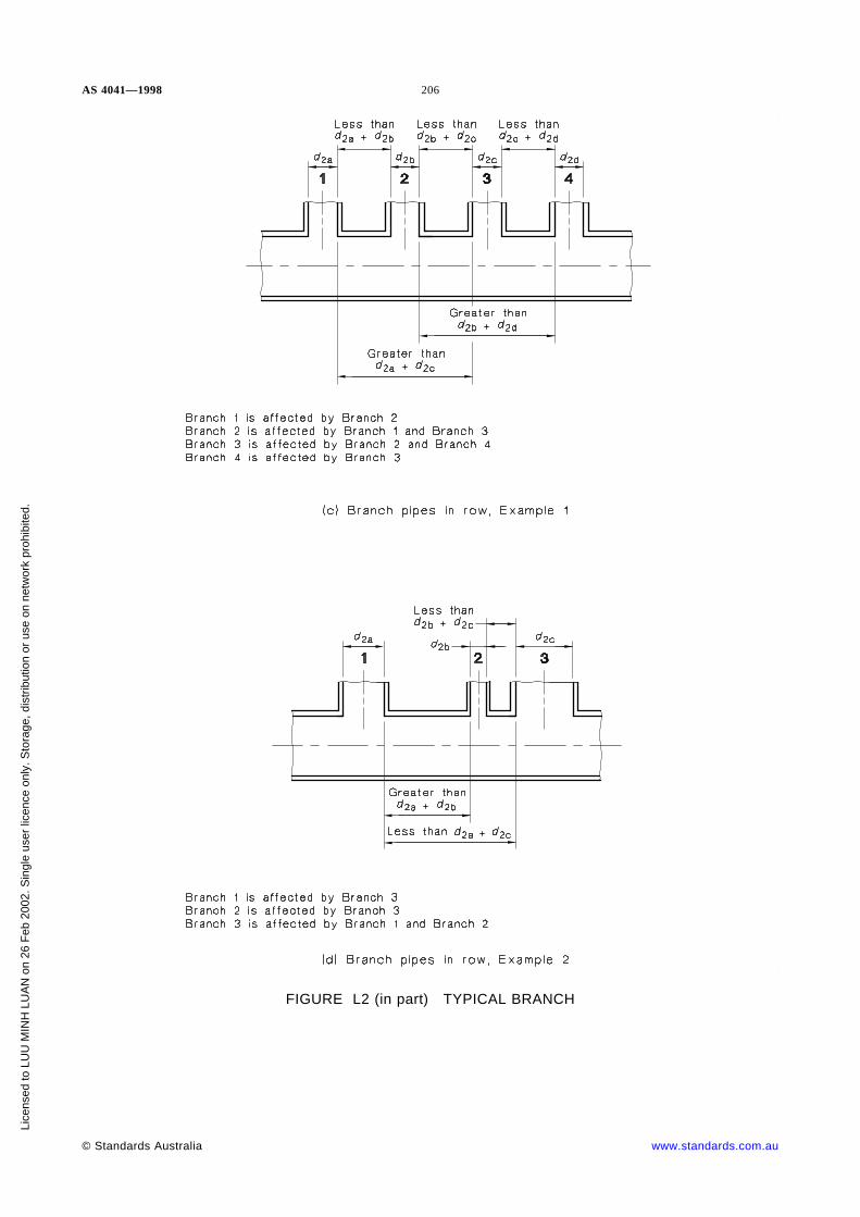
AS 4041—1998 206
FIGURE L2 (in part) TYPICAL BRANCH
© Standards Australia www.standards.com.au
Lice
nsed
to L
UU
MIN
H L
UA
N o
n 26
Feb
200
2. S
ingl
e us
er li
cenc
e on
ly. S
tora
ge, d
istr
ibut
ion
or u
se o
n ne
twor
k pr
ohib
ited.

207A
S4041
—1998
A1
FIGURE L3 REINFORCEMENT OF BRANCH PIPES (x: f1/p)
ww
w.sta
nd
ard
s.com
.au
©S
tan
da
rds
Au
stralia
Licensed to LUU MINH LUAN on 26 Feb 2002. Single user licence only. Storage, distribution or use on network prohibited.

AS
4041—1998
208
FIGURE L4 REINFORCEMENT OF BRANCH PIPES (xa: Z)
©S
tan
da
rds
Au
stralia
ww
w.sta
nd
ard
s.com
.au
Licensed to LUU MINH LUAN on 26 Feb 2002. Single user licence only. Storage, distribution or use on network prohibited.

209A
S4041
—1998FIGURE L5 REINFORCEMENT OF BRANCH PIPES (h: Zn)
A1
A1
A1
ww
w.sta
nd
ard
s.com
.au
©S
tan
da
rds
Au
stralia
Licensed to LUU MINH LUAN on 26 Feb 2002. Single user licence only. Storage, distribution or use on network prohibited.

AS 4041 — 1998 210
APPENDIX M
TYPICAL BRANCH WELDS
(Normative)
This Appendix shows typical weld preparations and the assembly of set-on and set-inbranches where an arc welding process is used.
The details of preparation and assembly are typical and are applicable to ferritic andaustenitic steel. Discretion is needed in applying the maximum and minimum dimensionsgiven, as these depend on the welding procedure, but the gap between a set-in branch pipeand the main pipe shall not exceed 3 mm.
NOTE: Gaps greater than 3 mm increase the tendency for spontaneous cracking during welding,particularly for joints with thick sections.
The minimum preparation angle should apply with a maximum radius or gap and, conversely,the minimum radius or gap should apply with a maximum preparation angle.
On Class 1 piping fillet-welds attaching branches or reinforcement to the main pipe shall havetoes with an included angle of not less than 135° (see Figure M8).
FIGURE M1 TYPICAL PREPARATION AND ASSEMBLY OF SET-ON 90-DEGREEBRANCHES WITHOUT BACKING
© Standards Australia www.standards.com.au
Lice
nsed
to L
UU
MIN
H L
UA
N o
n 26
Feb
200
2. S
ingl
e us
er li
cenc
e on
ly. S
tora
ge, d
istr
ibut
ion
or u
se o
n ne
twor
k pr
ohib
ited.

211 AS 4041 — 1998
FIGURE M2 TYPICAL PREPARATION AND ASSEMBLY OF SET-ON SLOPINGBRANCHES WITHOUT BACKING
www.standards.com.au © Standards Australia
Lice
nsed
to L
UU
MIN
H L
UA
N o
n 26
Feb
200
2. S
ingl
e us
er li
cenc
e on
ly. S
tora
ge, d
istr
ibut
ion
or u
se o
n ne
twor
k pr
ohib
ited.

AS 4041 — 1998 212
NOTES:
1 Root run in each corner in all cases. The backing ring to be removed after welding.
2 In some cases a recessed backing ring may be required.
3 A collapsible copper backing bar may be used as an alternative to a backing ring.
FIGURE M3 TYPICAL PREPARATION AND ASSEMBLY OF SET-ON 90°BRANCHES WITH TEMPORARY BACKING
© Standards Australia www.standards.com.au
Lice
nsed
to L
UU
MIN
H L
UA
N o
n 26
Feb
200
2. S
ingl
e us
er li
cenc
e on
ly. S
tora
ge, d
istr
ibut
ion
or u
se o
n ne
twor
k pr
ohib
ited.

213 AS 4041 — 1998
NOTES:
1 Root run in each corner in all cases. The backing ring to be removed after welding.
2 A recessed backing ring may be necessary in some cases.
3 A collapsible copper backing bar may be used as an alternative to a backing ring.
FIGURE M4 TYPICAL PREPARATION AND ASSEMBLY OF SET-ON SLOPINGBRANCHES WITH TEMPORARY BACKING
www.standards.com.au © Standards Australia
Lice
nsed
to L
UU
MIN
H L
UA
N o
n 26
Feb
200
2. S
ingl
e us
er li
cenc
e on
ly. S
tora
ge, d
istr
ibut
ion
or u
se o
n ne
twor
k pr
ohib
ited.

AS 4041 — 1998 214
NOTE: This Figure shows branches where access from the inside of the pipe is available. Where access is notavailable, full penetration welds from the outside are acceptable with variation to suit the weld procedure.
FIGURE M5 TYPICAL PREPARATION AND ASSEMBLY OF SET-IN BRANCHES
© Standards Australia www.standards.com.au
Lice
nsed
to L
UU
MIN
H L
UA
N o
n 26
Feb
200
2. S
ingl
e us
er li
cenc
e on
ly. S
tora
ge, d
istr
ibut
ion
or u
se o
n ne
twor
k pr
ohib
ited.

215 AS 4041 — 1998
FIGURE M6 TYPICAL PREPARATION AND ASSEMBLY OF SET-IN 90°BRANCHES SUITABLE FOR CLASS 3 PIPING
www.standards.com.au © Standards Australia
Lice
nsed
to L
UU
MIN
H L
UA
N o
n 26
Feb
200
2. S
ingl
e us
er li
cenc
e on
ly. S
tora
ge, d
istr
ibut
ion
or u
se o
n ne
twor
k pr
ohib
ited.

AS 4041 — 1998 216
NOTE: Root run in each corner in all cases. For Classes 1 and 2, the backing is ring is removed after welding,but it may be left in position for Class 3.
DIMENSIONS IN MILLIMETRES
FIGURE M7 TYPICAL PREPARATION AND ASSEMBLY OF SET-ON 90°BRANCHES SUITABLE FOR CLASS 1 AND 2 PIPING
© Standards Australia www.standards.com.au
Lice
nsed
to L
UU
MIN
H L
UA
N o
n 26
Feb
200
2. S
ingl
e us
er li
cenc
e on
ly. S
tora
ge, d
istr
ibut
ion
or u
se o
n ne
twor
k pr
ohib
ited.

217 AS 4041 — 1998
NOTE: If the weld makes an angle α less than 135° at either toe, the weld is to blend with a minimum radiusof 5 mm.
FIGURE M8 WELD TOE DETAIL AT BRANCHES
www.standards.com.au © Standards Australia
Lice
nsed
to L
UU
MIN
H L
UA
N o
n 26
Feb
200
2. S
ingl
e us
er li
cenc
e on
ly. S
tora
ge, d
istr
ibut
ion
or u
se o
n ne
twor
k pr
ohib
ited.

AS 4041 — 1998 218
APPENDIX N
WELD DETAILS
(Normative)
NOTES:
1 For these welds the misalignment shall comply with the requirements of AS 4458 and Figure N2.
2 30° = 1 in 220° = 1 in 314° = 1 in 4
FIGURE N1 WELD PREPARATION FOR BUTT WELDS IN PIPESOF DIFFERENT THICKNESS
© Standards Australia www.standards.com.au
Lice
nsed
to L
UU
MIN
H L
UA
N o
n 26
Feb
200
2. S
ingl
e us
er li
cenc
e on
ly. S
tora
ge, d
istr
ibut
ion
or u
se o
n ne
twor
k pr
ohib
ited.

219 AS 4041 — 1998
NOTES:
1 The combined internal and external transition of thickness shall not exceed an included angle of 30° at anypoint within 1.5tn of the land.
2 For these welds the misalignment shall comply with the requirements of AS 4458.
FIGURE N2 TYPICAL BUTT-WELD ALIGNMENT TOLERANCESAND ACCEPTABLE SLOPES FOR UNEQUAL INTERNAL
DIAMETER AND OUTSIDE DIAMETER
www.standards.com.au © Standards Australia
Lice
nsed
to L
UU
MIN
H L
UA
N o
n 26
Feb
200
2. S
ingl
e us
er li
cenc
e on
ly. S
tora
ge, d
istr
ibut
ion
or u
se o
n ne
twor
k pr
ohib
ited.

AS 4041 — 1998 220
FIGURE N3 (in part) TYPICAL WELD DETAILS FOR CLASS 3 PIPINGIN LOW HAZARD SERVICE (SEE CLAUSE 3.24.2.6)
© Standards Australia www.standards.com.au
Lice
nsed
to L
UU
MIN
H L
UA
N o
n 26
Feb
200
2. S
ingl
e us
er li
cenc
e on
ly. S
tora
ge, d
istr
ibut
ion
or u
se o
n ne
twor
k pr
ohib
ited.

221 AS 4041 — 1998
FIGURE N3 (in part) TYPICAL WELD DETAILS FOR CLASS 3 PIPINGIN LOW HAZARD SERVICE (SEE CLAUSE 3.24.2.6)
www.standards.com.au © Standards Australia
Lice
nsed
to L
UU
MIN
H L
UA
N o
n 26
Feb
200
2. S
ingl
e us
er li
cenc
e on
ly. S
tora
ge, d
istr
ibut
ion
or u
se o
n ne
twor
k pr
ohib
ited.

AS 4041 — 1998 222
FIGURE N3 (in part) TYPICAL WELD DETAILS FOR CLASS 3 PIPINGIN LOW HAZARD SERVICE (SEE CLAUSE 3.24.2.6)
© Standards Australia www.standards.com.au
Lice
nsed
to L
UU
MIN
H L
UA
N o
n 26
Feb
200
2. S
ingl
e us
er li
cenc
e on
ly. S
tora
ge, d
istr
ibut
ion
or u
se o
n ne
twor
k pr
ohib
ited.

223 AS 4041 — 1998
DIMENSIONS IN MILLIMETRES
NOTE: The root face may be zero when the interrupted arc technique is used for the root run or where suchprocedure qualification has been established.
FIGURE N4 BUTT JOINT PREPARATIONS FOR METAL-ARC WELDING(WITHOUT BACKING RING)
DIMENSIONS IN MILLIMETRES
FIGURE N5 BUTT JOINT PREPARATIONS FOR MANUAL GTAW-WELDING(WITH OR WITHOUT FILLER WIRE)
www.standards.com.au © Standards Australia
Lice
nsed
to L
UU
MIN
H L
UA
N o
n 26
Feb
200
2. S
ingl
e us
er li
cenc
e on
ly. S
tora
ge, d
istr
ibut
ion
or u
se o
n ne
twor
k pr
ohib
ited.

AS 4041 — 1998 224
millimetres
TIG-welded root runsRoot gap G
Figure (a) Figure (b) Figure (c)
Without insert of filler wire Nil Nil —
Using filler wire 1 to 3 1 to 3 1.5 to 3
Using fusible insert To suit type and make of fusible insert used
DIMENSIONS IN MILLIMETRES
FIGURE N6 BUTT JOINT PREPARATIONS FOR GTAW-WELDING OF ROOT RUN(WITH OR WITHOUT FILLER WIRE OR WITH FUSIBLE INSERT)
© Standards Australia www.standards.com.au
Lice
nsed
to L
UU
MIN
H L
UA
N o
n 26
Feb
200
2. S
ingl
e us
er li
cenc
e on
ly. S
tora
ge, d
istr
ibut
ion
or u
se o
n ne
twor
k pr
ohib
ited.

225 AS 4041 — 1998
DIMENSIONS IN MILLIMETRES
FIGURE N7 BUTT JOINT PREPARATIONS FOR OXY-ACETYLENEWELDING OF ROOT RUN
www.standards.com.au © Standards Australia
Lice
nsed
to L
UU
MIN
H L
UA
N o
n 26
Feb
200
2. S
ingl
e us
er li
cenc
e on
ly. S
tora
ge, d
istr
ibut
ion
or u
se o
n ne
twor
k pr
ohib
ited.

AS 4041 — 1998 226
APPENDIX O
FILLET-WELDED SOCKETS
(Normative)
© Standards Australia www.standards.com.au
Lice
nsed
to L
UU
MIN
H L
UA
N o
n 26
Feb
200
2. S
ingl
e us
er li
cenc
e on
ly. S
tora
ge, d
istr
ibut
ion
or u
se o
n ne
twor
k pr
ohib
ited.

227 AS 4041 — 1998
APPENDIX P
SLEEVE JOINT
(Normative)
NOTES
1 Sleeve to be centred over gap.
2 Ls shall be 6 tn minimum but it is recommended Ls be not less than twice the depth of equivalent socket.
www.standards.com.au © Standards Australia
Lice
nsed
to L
UU
MIN
H L
UA
N o
n 26
Feb
200
2. S
ingl
e us
er li
cenc
e on
ly. S
tora
ge, d
istr
ibut
ion
or u
se o
n ne
twor
k pr
ohib
ited.

AS 4041 — 1998 228
APPENDIX Q
NOTES ON PIPING STRESS ANALYSIS
(Normative)
Q1 METHODS OF FLEXIBILITY ANALYSIS—SIMPLIFIED ANALYSIS Of themany simplifying assumptions made in flexibility analysis, one of the most common isthat of ‘ square corners’ , where the flexibility factor and geometry of curved members areignored. This assumption enables the piping system to be analysed by normal structuralmethods. The maximum stress will in general be overestimated or underestimated,depending on whether the stress intensification factors are included or ignored. Endreactions will almost always be overestimated by the assumption of square corners.
Another simplified method, which tends to be considerably more accurate than the above,corrects the square corner length of the system by adding a virtual length representing theexcess flexibility of all the elbows, and distributing it uniformly over the system. Thesetwo simplified methods are typical of the many that have been developed, mainly for usewith simple single plane systems. Visual comparison with a similar configuration whichhas been analysed may also be considered a simplified method.
Q2 COLD-SPRING Cold-spring (or cold-pull) is a procedure which uses a reducedlength of the piping system by an amount up to 100 percent of the calculated expansion inthree coordinate directions (including thermal movements of terminal points).
The intention of this is to reduce the piping terminal reactions, flexural stresses anddistortion in operating conditions.
When cold-spring is used, a pipe system shall be erected initially with a space insertedbetween the pipe ends at a selected joint (the final joint to be made). This spacer separatesthe pipe ends by the calculated components of cold spring for the system. After thecompletion of all joints, excluding the final joint, the spacer is removed and the pipe endsare brought together. In principal this must be done without permitting rotation of onepipe end relative to the other in any plane. The pipe end rotations can be controlled (withvarying degrees of success) by the application of moments to the pipe ends or theapplication of controlled displacements at selected points of the pipe system. Themeasurement of parallelism between the planes prior to closing the gap is critical andshall be performed within very close tolerances.
Before deciding to use cold-spring, designers should consider the following points:
(a) The ideal of zero relative rotation of pipe ends cannot be achieved. Rotationalmisalignments will occur and these will cause stresses and reactions of unknownmagnitude. It is possible for errors (which are too small to measure) to createstresses and end reactions which exceed allowable values.
(b) Piping expansion stresses are self-limiting. Self-springing (refer to Q3.1) will limitthe magnitude of the stresses in both the hot and cold condition.
(c) Piping operating in the creep range and erected without cold-spring will approach astress condition equivalent to 100 percent cold-spring in a relatively short time.
(d) For piping operating at moderate temperatures, cold-spring can be used to reducethe magnitude of terminal reactions on plant but it should be applied with caution.
(e) Procedures for the application of cold-spring add significant time to a constructionprogram, often without achieving the intended results.
© Standards Australia www.standards.com.au
Lice
nsed
to L
UU
MIN
H L
UA
N o
n 26
Feb
200
2. S
ingl
e us
er li
cenc
e on
ly. S
tora
ge, d
istr
ibut
ion
or u
se o
n ne
twor
k pr
ohib
ited.

229 AS 4041 — 1998
In general, cold-spring should be used only in single plane piping systems and a momentshould be applied during the cold-springing to ensure that no rotation occurs between theclosing ends of the pipe. It is found that cold-springing of a multi-planed pipe is notpossible in practice without considerable difficulties during erection. An attempt toimpose the necessary moment and forces with a sufficient degree of accuracy is unlikelyto be completely successful and for this reason the factor of two-thirds is used inEquation 3.27.6(1).
Q3 STRESSES AND REACTIONS IN A PIPING SYSTEM
Q3.1 Thermal and sustained stresses Thermal stresses in piping systems areessentially cyclic and the initial hot stresses, if they are of sufficient magnitude, willdecrease with time because of plastic strains and will reappear as a stress of reverseddirection when the pipe cools. This phenomenon forms the basic difference betweenthermal stresses and pressure or weight stresses. Plastic strains can release the magnitudeof thermal stresses by a change in the shape of the pipe centreline. This change in shapehas no effect on the sustained pressure or weight stresses. For this reason, sustainedstresses are limited to the design stress at maximum normal operating temperature. Thephenomenon is called ‘ self-springing’ of the pipe and is similar in its effect tocold-springing. The degree of self-springing will depend on the magnitude of the initialhot stresses and the temperature, so that, whereas the hot stress will in general decreasewith time, the sum of the hot and cold stresses will stay about the same. This sum iscalled the displacement (or expansion) stress range and is, therefore, independent of anycold-spring applied during erection, and no credit for cold-spring is given in theevaluation of the displacement stress range. The concept of a constant displacement stressrange leads to the selection of an allowable displacement stress range, i.e. the designstress range (fa). Since, in general, when self-springing has taken place, maximum stresseswill occur in the cold condition, the calculation of the displacement stress range is basedon the as-installed Young modulus.
Q3.2 Resultant stress range and stress difference For materials below the creeprange the allowable stresses are 62.5 percent to 66.7 percent of the yield stress, so that areasonably conservative estimate of the bending stress at which plastic flow starts at anelevated temperature is 1.6fh, and by similar reasoning 1.6fc will be the stress at whichflow would take place at the minimum temperature. Hence, the sum of these stressesrepresents the maximum stress range to which a system could be subjected without flowoccurring in either the hot condition or the cold condition, i.e.
fmax = 1.6(fc + fh) . . . Q3.2(1)
where fc and fh are as defined in Clause 3.11.7.
However, this Standard limits the stress range to 78 percent of the yield stress; thereforethe total stress range is as shown in the following equation:
fa = 1.25F(fc + fh) . . . Q3.2(2)
where F is a reduction factor for cyclic conditions.
From this total stress range, 0.5fh is deducted for pressure stresses and 0.5fh for weightand other sustained stresses, leaving a stress range for thermal expansion as shown in thefollowing equation:
fa = F(1.25fc + 0.25fh) . . . Q3.2(3)
Q3.3 End reactions Although the sum of the hot and the cold stresses is used as thecriterion for piping failure, it is the maximum hot and cold reactions which shall beconsidered when their effect on connected equipment is being examined.
www.standards.com.au © Standards Australia
Lice
nsed
to L
UU
MIN
H L
UA
N o
n 26
Feb
200
2. S
ingl
e us
er li
cenc
e on
ly. S
tora
ge, d
istr
ibut
ion
or u
se o
n ne
twor
k pr
ohib
ited.

AS 4041 — 1998 230
The expressions for Rm and Ra in Clause 3.27.6.2 take into account any cold-spring andare approximately equal to the maximum hot and cold values to be used where expansioneffects on pumps, compressors, turbines and similar equipment which could be damagedby a single overload are being considered.
For critical layouts, where unequal amounts of cold-spring are used in each of thecoordinate directions, separate calculations should be made for the hot and cold conditionsusing two-thirds of the cold-spring amounts to be stipulated on the piping system.
Q4 PLASTIC STRAINS Plastic strains are caused during the relaxation of the initialhot expansion stresses, and may be reduced by cold-spring. With ductile materials andnormal configurations of the piping, these plastic strains are not important and usuallyneed not be considered. Service conditions and special configurations may in some casescause excessive plastic strains, e.g. in systems involving pipes of different diameter orwall thickness, where plastic straining of the weaker section may be followed by furtherstrain due to the release of elastic forces in the stronger section. Plastic strains can be ofimportance in certain materials, in particular in certain austenitic stainless steels attemperatures of about 600°C and higher, because of the limited capacity of the material towithstand them without stress-to-rupture failures.
It is recommended that 100 percent cold-spring be incorporated in austenitic pipingsystems operating above 400°C and the displacement stress range be reduced to 1.25fc toavoid plastic self-springing, susceptibility to plastic flow accumulation, and failure atstress concentrations due to fatigue or stress.
© Standards Australia www.standards.com.au
Lice
nsed
to L
UU
MIN
H L
UA
N o
n 26
Feb
200
2. S
ingl
e us
er li
cenc
e on
ly. S
tora
ge, d
istr
ibut
ion
or u
se o
n ne
twor
k pr
ohib
ited.

231 AS 4041 — 1998
APPENDIX R
METHOD OF ASSESSING FLEXIBILITY
(Normative)
R1 GENERAL This Appendix gives details of one comprehensive method of assessingflexibility of piping systems, and is based on the method given in BS 806. Data forshorter lives than given in Tables R10(B) to (G) should be obtained from relevantmaterial specifications.
This method is recommended where a comprehensive analysis is required, and where thepipe materials used comply with an Australian or a British Standard. The method isappropriate where fatigue and seismic loads are of minor significance. Clause 3.27 givesan alternative method that is appropriate where fatigue and seismic loads are significant.
The design strengths given in Appendix D may be used without verification of the ReT
values, provided that the heat treatment of completed pipes is in accordance withTable R10(H).
If this method of flexibility analysis is chosen, then the branch design shall satisfyAppendix L.
Computer programs which carry out flexibility analysis to BS 806, including flexibilityand stress intensification factors but with design strengths to this Standard, also satisfythis Standard.
R2 CALCULATION OF STRESS LEVELS
R2.1 General In the calculation of stress levels, the following items shall be included(see Table R2.1):
(a) Pressure stress.
(b) Thermal expansion and cold spring.
(c) Deadweight stress.
(d) Stress caused by external loads.
A worked example of a stress calculation of a typical sectionalized piping system is givenin Appendix S.
TABLE R2.1
ALLOCATION OF LOADS
Loading Stress range Hot stress Sustained stress
PressureThermal
DeadweightCold-spring
XX——
XXXX
X—X—
R2.2 Maximum stress range The maximum stress range shall be determined asfollows:
(a) Combined stress In the calculation of the combined stresses to determine themaximum stress range, all expansion between cold and hot shall be used in thecalculation of the bending stress, and the Young modulus for the as-installedcondition shall apply.
www.standards.com.au © Standards Australia
Lice
nsed
to L
UU
MIN
H L
UA
N o
n 26
Feb
200
2. S
ingl
e us
er li
cenc
e on
ly. S
tora
ge, d
istr
ibut
ion
or u
se o
n ne
twor
k pr
ohib
ited.

AS 4041 — 1998 232
(b) Sectionalized piping system Where a piping system can be sectionalized so thatany point can be subject to fluctuating temperatures, i.e. other than an ‘ all hot’ or‘ all cold’ condition, the following shall apply. In addition to calculating the stressrange as specified in Item (a), the maximum stress range based on the maximumdifference between bending moments, in each plane at that point, when combinedwith the highest pressure stress associated with these moments, shall not exceed theproduct of 0.9 multiplied by the 0.2 percent proof stress at the temperature at eachend of the applicable cycle. The Young modulus for the lowest temperature shallapply.
R2.3 Maximum hot stress The maximum hot stress shall be determined as follows:
(a) Combined stress In the calculation of the combined stress to determine themaximum hot stress, the displacement between the hot condition and the coldcondition minus the amount calculated for the theoretical cold-pull shall be used inthe calculation of the bending stress. The Young modulus at the hot condition shallapply.
(b) Sectionalized piping system Where a piping system can be sectionalized so thatany point can be subject to fluctuating temperatures, i.e. other than ‘ all hot’ or ‘ allcold’ conditions, then the higher value of the maximum moment, or the maximumdifference between the maximum moment and one half the minimum moment in anyplane under each hot condition of operation, shall be considered in addition to thatcalculated from Item (a). The Young modulus at the hot condition shall apply.
R2.4 Sustained stress The sustained stress (see Paragraph R7(c)) is that produced bypressure and deadweight only.
For the determination of sustained stress, only the bending stress derived fromEquations R4.2(2), R4.3(2) and R4.3(3) and the torsional stress derived fromEquation R4.4, and attributable to the deadweight bending moment, shall be used.
R3 ANALYSIS CALCULATION Wherever possible, a piping system shall be treatedas a whole with its anchor points. The analysis of flexibility of a piping system shallinclude the following:
(a) Linear and rotational restraining forces.
(b) Linear and rotational behaviour of the equipment to which the piping is connected.
(c) Flexibility factors for bends, determined from Figures R1 and R2.
(d) Longitudinal stress factors for bends, determined from Figures R3, R4 and R8.
(e) Transverse stress factors for bends, determined from Figures R5, R6 and R8.
(f) Stress intensification correction factors for a flanged bend, other than a mitre bend,determined from Figure R7.
(g) Stress factors for forged tees, un-reinforced branches and reinforced branches,determined from Figure R10.
(h) Pressure/stress multipliers for use with branch connections, determined fromFigure R9.
(i) Changes in length due to temperature changes, determined from Appendix E.
(j) Young modulus, determined from Appendix F.
(k) Poisson ratio, determined from Clause 3.27.4.
(l) Effects of pipe on equipment to which it is connected, with a sign convention forthe forces and moments imposed on the equipment.
© Standards Australia www.standards.com.au
Lice
nsed
to L
UU
MIN
H L
UA
N o
n 26
Feb
200
2. S
ingl
e us
er li
cenc
e on
ly. S
tora
ge, d
istr
ibut
ion
or u
se o
n ne
twor
k pr
ohib
ited.

233 AS 4041 — 1998
(m) Pipe wall thickness and diameter used in a flexibility analysis shall be the meanthickness based on the thickness tolerances detailed in the relevant pipespecification and the nominal outside diameter, or the inside diameter which shallbe the nominal outside diameter minus twice the mean wall thickness.
(n) Where it is necessary to make assumptions to simplify and reduce the complexity ofthe flexibility analysis, the particulars of these assumptions shall be recorded.
(o) The basis of the calculation shall be recorded as follows:
(i) Whether the dead weight has been taken into account.
(ii) Whether the basis is on expansion alone, or cold pull alone.
(iii) How allowances that have been included take into account the variations ofany cold-pull, tolerances on pipe dimensions, movement of pipe supports, theconfiguration of the system, and other relevant factors.
R4 STRESS EVALUATION ON STRAIGHT PIPE AND A BEND
R4.1 Combined stress The combined stress (fc) on a straight pipe and a bend, otherthan a mitre bend, shall be determined from the following equation:
fc = (F2 + 4fs2)½ . . . R4.1
where
fc = combined stress, in megapascals
F = the greater of fT and fL, in megapascals
fs = torsional stress, in megapascals
fT = transverse stress (i.e. the sum of transverse pressure stress and transversebending stress), in megapascals
fL = longitudinal stress (i.e. the sum of longitudinal pressure stress and longitudinalbending stress), in megapascals.
R4.2 Transverse stress The transverse stress (fT) shall be determined as follows:
(a) The transverse pressure stress (fTp) in a straight pipe or a bend, other than a mitrebend, shall be determined from the following equation:
. . . R4.2(1)fTp = pd2t
+ 0.5p
where
fTp = transverse pressure stress, in megapascals
p = design pressure, in megapascals
d = inside diameter, in millimetres
t = mean thickness, in millimetres.
(b) The transverse bending stress (fTB) on straight pipe shall be taken as zero.
(c) The transverse bending stress (fTB) at a bend, other than mitre bend, shall bedetermined from moments as shown in Figure 3.27.5(B) and from the followingequation:
. . . R4.2(2)fTB = rl
[(MiFTi)2 + (MoFTo
2)]½
www.standards.com.au © Standards Australia
Lice
nsed
to L
UU
MIN
H L
UA
N o
n 26
Feb
200
2. S
ingl
e us
er li
cenc
e on
ly. S
tora
ge, d
istr
ibut
ion
or u
se o
n ne
twor
k pr
ohib
ited.

AS 4041 — 1998 234
where
fTB = transverse bending stress, in megapascals
r = mean radius of the pipe, in millimetres
I = second moment of area about the axis through the centroid normal tothe axis of the pipe, in millimetres to the fourth power
Mi = maximum in-plane bending moment, in newton millimetres
FTi = in-plane transverse stress intensification factor determined fromFigure R5
Mo = maximum out-of-plane bending moment, in newton millimetres
FTo = out-of-plane transverse stress intensification factor determined fromFigure R6.
R4.3 Longitudinal stress The longitudinal stress (fL) shall be determined as follows:
(a) The longitudinal pressure stress (fLp) on both a straight pipe and a bend shall bedetermined from the following equation:
. . . R4.3(1)fLp = pd 2
4t(d + t)
(b) The longitudinal bending stress (fLB) on a straight pipe shall be determined from thefollowing equation:
. . . R4.3(2)fLB = d + 2t2I
(Mi2 + Mo
2)½
(c) The longitudinal bending stress (fLB) on a bend shall be determined from thefollowing equation:
. . . R4.3(3)fLB = rI
[(MiFLi)2 + (MoFLo)
2]½
where
FLi = in-plane longitudinal stress intensification factor taken fromFigure R3
FLo = out-of-plane longitudinal stress intensification factor taken fromFigure R4
Other symbols are as given in Paragraph R4.2.
R4.4 Torsional stress The torsional stress (fs) on a straight pipe or a bend shall bedetermined from the following equation:
. . . R4.4fs =Mt(d + 2t)
4I
where
Mt = torsional moment, in newton millimetres.
Other symbols are defined in Paragraph R4.2.
R5 STRESS EVALUATION OF A MITRE BEND
R5.1 Combined stress The combined stress (fc) on a mitre bend shall be determinedfrom Equation R4.1.
NOTE: For a mitre bend designed to comply with this Standard, fT must be greater than fL.
© Standards Australia www.standards.com.au
Lice
nsed
to L
UU
MIN
H L
UA
N o
n 26
Feb
200
2. S
ingl
e us
er li
cenc
e on
ly. S
tora
ge, d
istr
ibut
ion
or u
se o
n ne
twor
k pr
ohib
ited.

235 AS 4041 — 1998
R5.2 Transverse stress The transverse stress (fT) shall be determined as follows:
(a) The transverse pressure stress (fTp) on a mitre bend shall be determined from thefollowing equation:
. . . R5.2fTp =
pd2t
+ 0.5p
1 + 0.6427
d t2t
½
tan α
where
fTp = transverse pressure stress, in megapascals
p = design pressure, in megapascals
d = inside diameter, in millimetres
t = mean thickness, in millimetres
a = angle of mitre, in degrees.
(b) The transverse bending stress (fTB) on a mitre bend shall be determined fromEquation R4.2(2).
R5.3 Longitudinal stress The longitudinal stress (fL) shall be determined as follows:
(a) The longitudinal pressure stress (fLp) on a mitre bend shall be determined fromEquation R4.3(1).
(b) Longitudinal bending stress (fLB) on a mitre bend shall be determined fromEquation R4.3(3).
R5.4 Torsional stress The torsional stress (fs) in a mitre bend shall be determinedfrom Equation R4.4.
R6 STRESS EVALUATION AT A BRANCH CONNECTION
R6.1 Combined stress The combined stress (fCB) at a branch connection shall beconsidered separately at connections 1, 2, and 3 shown in Figure 3.27.5(C), and shall bedetermined from the following equation:
. . . R6.1fCB = q(fB 2 + 4fSB2)½
where
fCB = combined stress, in megapascals
q = relaxation factor used for evaluation of hot stress conditions only (seeParagraph R2.3) shall be either 0.44 where ratio d2/d1 ≤ 0.3, or 0.5 where ratiod2/d1 > 0.3
fB = sum of the transverse pressures stress at the junction and the non-directionalbending stress, in megapascals
fSB = torsional stress at the junction, in megapascals
d2 = inside diameter of the branch pipe, multiplied by 1/sin α , in millimetres
d1 = inside diameter of the main pipe, in millimetres
α = angle between the branch pipe and the main pipe, in degrees.
R6.2 Transverse pressure stress The transverse pressure stress (fTp) at the branchjunction (see Note below) shall be determined from the following equation:
. . . R6.2(1)fTP =(d1 + ta)pm
2ta
www.standards.com.au © Standards Australia
Lice
nsed
to L
UU
MIN
H L
UA
N o
n 26
Feb
200
2. S
ingl
e us
er li
cenc
e on
ly. S
tora
ge, d
istr
ibut
ion
or u
se o
n ne
twor
k pr
ohib
ited.

AS 4041 — 1998 236
where
ta = the actual minimum thickness of the main pipe at the branch junction, i.e. theminimum measured thickness where the pipe is available for measurement or,where it is not, the nominal thickness less the greatest minus tolerance onthickness specified in the pipe specification, in millimetres
m = stress multiplier.
The stress multiplier (m) shall be determined as follows:
(a) For a branch where both r2/r1 and t2/t1 ≤ 0.3, the value of m shall be determinedfrom the following equation:
. . . R6.2(2)m = 1.8 +2.8r2
r1
r1
t1n
½
where
r1 = mean radius of the main pipe at the junction, based on the meanthickness, in millimetres
r2 = mean radius of branch pipe at the junction, based on the mean thickness,in millimetres
t1 = mean thickness of main pipe at the junction with the branch pipe, inmillimetres
n = 1 for branch pipes deemed to be not interacting in accordance withParagraph L3.
Where branch pipes are deemed to be interacting the value of n shall be determinedin accordance with Paragraph L5.2.
(b) For a branch pipe where either or both of the ratios r2/r1 and t2/t1 > 0.3, the valueof m shall be taken from Figure R9, using a value for Z derived from the followingequation:
. . . R6.2(3)Z1 =t1
nr1
r2
t2
2
where
t2 = mean thickness of the branch pipe at the junction of the main pipe, inmillimetres
Other symbols are as defined for Equation R6.2(2).
Equation R6.2(1) incorporates a stress multiplier (m). This Equation applies for afabricated full-penetration welded branch pipe, a non-protruding set-in branch, and ahomogeneous branch where any necessary reinforcement for pressure containment isincorporated in the thickness of the main pipe, or the branch pipe, or both.
Where one or more of these conditions do not apply, the value of m shall be the estimatedstress at peak pressure at the junction, divided by the hoop stress that would occur at themean diameter of the unpierced main pipe.
Where the peak stress cannot be defined from theoretical analysis or experimental data,the transverse pressure stress shall be taken as not less than either 2.5f where ratiod2/d1 ≤ 0.3, or 2.2f where ratio d2/d1 > 0.3, f being the design strength.
The value of the resultant transverse pressure stress is not intended to indicate the actualmaximum peak stress existing, but is used to limit the external loading carried by thejunction.
© Standards Australia www.standards.com.au
Lice
nsed
to L
UU
MIN
H L
UA
N o
n 26
Feb
200
2. S
ingl
e us
er li
cenc
e on
ly. S
tora
ge, d
istr
ibut
ion
or u
se o
n ne
twor
k pr
ohib
ited.

237 AS 4041 — 1998
Use of other forms of reinforcement is to be substantiated by experience gained in service,or by experimental or theoretical analysis, and subject to agreement by the partiesconcerned.
Stiffening pads may be used to reduce bending stresses.
R6.3 Non-directional bending stress The non-directional bending stress at a junctionshall be 1. The maximum value applicable to connections 1, 2, and 3 (seeFigure 3.27.5(C)) shall be determined as follows:
(a) The bending stress (fBB) at the branch junction from the connections 1 or 2 shall bedetermined from the following equation:
. . . R6.3(1)fBB1 or 2
=r1
I[(MiBi)
2 + (MoBo)2]½
where
= bending stress at branch junction from connection 1 or 2 asfBB1 or 2
selected, in megapascals
r1 = as defined in Equation R6.2(2)
I = second moment of area applicable to the branch about an axisthrough the centroid normal to the axis of the pipe, inmillimetres to the fourth power
Mi = in-plane moment from the relevant connection 1 or 2, innewton millimetres
Bi = in-plane stress intensification factor determined fromFigure R10 (see Note)
Mo = out-of-plane moment from the connection 1 or 2, in newtonmillimetres
Bo = out-of-plane stress intensification factor determined fromFigure R10 (see Note).
NOTE: Stiffening pads may be used to reduce bending stresses.
(b) The bending stress (fBB) at the junction from connection 3 shall be determined frommoments as shown in Figure 3.27.5(C) and the following equation:
. . . R6.3(2)fBB3
=r2
I[(MiBi)
2 + (MoBo)2]½
r2 = as defined in Paragraph R6.2(a)
I = second moment of area applicable to the branch about an axis throughthe centroid normal to the axis of the branch, in millimetres to thefourth power.
To calculate this value the lesser of main pipe thickness and thebranch pipe thickness multiplied by Bo should be used, i.e. the lesserof t1 and t2Bo
Other symbols are as defined for Equation R6.3(1).
R6.4 Torsional stress The torsional stress (fSB) at the branch junction shall be thevalue applicable to connection 1, connection 2, or connection 3, (see Figure 3.27.5(C),and shall be determined from the following equation:
. . . R6.4fSB =Mt(d + 2t)
4Iwhere
t, d, and I are applicable to the connections 1, connections 2 or connections 3 underconsideration.
www.standards.com.au © Standards Australia
Lice
nsed
to L
UU
MIN
H L
UA
N o
n 26
Feb
200
2. S
ingl
e us
er li
cenc
e on
ly. S
tora
ge, d
istr
ibut
ion
or u
se o
n ne
twor
k pr
ohib
ited.

AS 4041 — 1998 238
R7 ALLOWABLE STRESS CRITERIA For the purposes of this Appendix, the stresscriteria for piping when cold, or at any operating condition within the design limits, shallbe as follows:
(a) Maximum stress range The maximum stress range shall be the lesser of thefollowing:
(i) The sum of H × 0.2% proof stress at room temperature, and H × 0.2% proofstress at design temperature.
(ii) The sum of H × 0.2% proof stress at room temperature, and the mean stressto rupture for the design life at design temperature.
where
H = 0.9, for all cases and branches where ratio d2/d1 > 0.3
= 1.0, where ratio d2/d1 ≤ 0.3
d1 = inside diameter of main pipe, in millimetres
d2 = inside diameter of the branch pipe, in millimetres multiplied by 1/sin α ,where α is the angle between the branch pipe and main pipe.
(b) Maximum hot stress Where the criterion of the maximum stress range is thatspecified in Paragraph R7(a)(ii), the maximum hot stress determined in accordancewith Paragraph R2.3 shall not exceed the mean stress to rupture for the design lifeat the design temperature.
(c) Sustained stress The sustained stress in the piping when either cold or at anyoperating condition within the design limits, shall not exceed the lesser of—
(i) 0.2 percent proof stress × 0.8; and
(ii) the creep rupture design strength.
Where the non-intensified dead load stress at the junction does not exceed 15percent of the design strength, a sustained stress analysis at branch connectionsdesigned to comply with this Appendix need not be made.
The sustained stress due to the hydrostatic test pressure of a completed system andthe mass of the fluid shall not exceed 0.9 × 0.2% proof stress at test fluidtemperature.
R8 REQUIREMENT FOR FLEXIBILITY ANALYSIS A flexibility analysis shall bemade where the designer has doubt regarding the ability of the system to comply with thedesign requirements. Where interpretation of a simplified analysis indicates that any of theeffects listed in the design requirement may occur, a comprehensive analysis shall bemade. Piping in low-temperature service shall be subject to a flexibility analysis.
R9 BASIS OF FLEXIBILITY ANALYSIS The flexibility between anchor points of apiping system shall be calculated. Anchor points may be the pipe anchors, or relativelyinflexible pieces of equipment to which the pipe is connected, e.g. a pump, heatexchanger or a large vessel. The piping between anchor points shall be treated as a whole,and the effects of any movement at the anchor points and the effects of any intermediaterestraints shall be included if they restrict the free expansion of the piping system.
R10 VALUES OF PROOF STRESS, RUPTURE STRESS, AND DESIGNSTRENGTH Values for proof stress and rupture stress which are to be used incalculations are noted in Tables R10(A) to R10(H). Values of design strength are given inAppendix D.
© Standards Australia www.standards.com.au
Lice
nsed
to L
UU
MIN
H L
UA
N o
n 26
Feb
200
2. S
ingl
e us
er li
cenc
e on
ly. S
tora
ge, d
istr
ibut
ion
or u
se o
n ne
twor
k pr
ohib
ited.

239 AS 4041—1998
TABLE R10(A)
0.2% PROOF STRESS FOR PIPES
Standard Grade
0.2%, Proof stress, MPa
Temperature, °C
≤20 50 100 150 200 250 300 350 400 450 500 550
BS 3601 320360410
176195220
172192217
168187210
158176199
147165188
125145170
100122149
91111137
88109134
———
———
———
BS 3602 360410460490Nb
212242270338
207237264328
198227251309
187213237286
170193220263
150172202240
132155182217
120142168200
112135159184
108128150172
————
————
BS 3604 1 Cr-½ Mo 620:440 (N + T)1 Cr-½ Mo 620:460(N)1 ¼ Cr-½ Mo 621 (N + T)
287180272
276180261
264180248
253180237
245180228
236180218
192180174
182180165
174180157
168174152
166169150
163166149
½ Cr-Mo-V 660 (N + T)2 ¼ Cr-Mo 662 (N + T)12 Cr-Mo-V 762 (N + T)
297272468
289268453
282261439
276253413
267245384
241236362
225230351
216224345
209218337
203205322
200189296
197167—
API 5LASTMA 106
Grade BGrade B
——
——
——
203203
183183
165165
149149
136136
128128
——
——
——
ASTMA 335
Grade P11Grade P12
——
——
——
205205
194194
184184
157157
138138
135135
133133
128128
——
ASTMA 335 Grade P22 (N + T) — — — 163 155 146 142 138 133 123 114 —
ASTMA 335 Grade P22 (Annealed) — — — 104 96 90 85 82 77 74 70 62
www.standards.com.au © Standards Australia
Licensed to LUU MINH LUAN on 26 Feb 2002. Single user licence only. Storage, distribution or use on network prohibited.

AS 4041 — 1998 240
TABLE R10(B)
AVERAGE RUPTURE STRESS FOR PIPE TO BS 3602,GRADE 360 AND GRADE 410, API 5L, GRADE B,
AND ASTM A 106, GRADE B
TemperatureAverage rupture stress, MPa
Design life, h
°C 100 000 150 000 200 000 250 000
380390400
171*155*141*
164*149*134*
159*144*130*
155*140*126*
410420430
127*114*102*
121*108*
96*
116*104*
92*
113*101*
89*
440450460
90*78*67*
84*73*62*
80*69*58*
77*66*55*
470480490
57*47*36*
52*41*29*
48*37*23*
45*34*—
* Value with extended time extrapolation.
TABLE R10(C)
AVERAGE RUPTURE STRESS FOR PIPE TO BS 3602GRADE 460 (Mn ≥0.8%) AND GRADE 490 Nb
TemperatureAverage rupture stress, MPa
Design life, h
°C 100 000 150 000200 000
(see Note)250 000
(see Note)
380390400
227203179
215190167
206*181*157*
199*174*150*
410420430
157136117
144124105
135*115*
97*
128*108*
91*
440450460
1008573
897665
82*70*60*
77*66*56*
470480490
6355
47†
5649†42†
52*44*†37*†
48*†41*†32*†
500510
41†32†
34†—
——
——
* Value with extended time extrapolation.
† Value with extended stress extrapolation.
© Standards Australia www.standards.com.au
Lice
nsed
to L
UU
MIN
H L
UA
N o
n 26
Feb
200
2. S
ingl
e us
er li
cenc
e on
ly. S
tora
ge, d
istr
ibut
ion
or u
se o
n ne
twor
k pr
ohib
ited.

241 AS 4041 — 1998
TABLE R10(D)
AVERAGE RUPTURE STRESS FOR PIPE TO BS 3604, GRADE 620AND GRADE 621, ASTM A 335, GRADE P11 AND GRADE P12
TemperatureAverage rupture stress, MPa
Design life, h
°C 100 000 150 000 200 000 250 000
480490500
210177
146*
194*161*132*
180*148*122*
170*139*114*
510520530
1219981
108*87*
71
99*79*64*
91*74*59*
540550560
675443
574638
52*42*34*
48*39*32*
570 35 31† 28*† 26*†
* Value with extended time extrapolation.
† Value with extended stress extrapolation.
TABLE R10(E)
AVERAGE RUPTURE STRESS FOR PIPE TO BS 3604, GRADE 660
TemperatureAverage rupture stress, MPa
Design life, h
°C 100 000 150 000 200 000 250 000
480490500
218191170
205179156
194*169*146*
185*160*138*
510520530
150131116
136119101
127*109*
91*
119*101*
83*
540550560
1008572
857057
76*61*
48*†
68*54*
42*†
570580
5946†
45†35†
37*†28*†
32*†—
* Value with extended time extrapolation.
† Value with extended stress extrapolation.
www.standards.com.au © Standards Australia
Lice
nsed
to L
UU
MIN
H L
UA
N o
n 26
Feb
200
2. S
ingl
e us
er li
cenc
e on
ly. S
tora
ge, d
istr
ibut
ion
or u
se o
n ne
twor
k pr
ohib
ited.

AS 4041 — 1998 242
TABLE R10(F)
AVERAGE RUPTURE STRESS FOR PIPE TO BS 3604, GRADE 622,ASTM A 335, GRADE P22 (N + T) AND GRADE P22 (ANNEALED)
TemperatureAverage rupture stress, MPa
Design life, h
°C 100 000 150 000 200 000 250 000
450460470
221*204*186*
209*192*175*
203*186*169*
198*181*164*
480490500
170*153*137*
158141*126*
152*135*119*
147*130*113*
510520530
122*107*
93
110*95*82*
103*89*77*
98*84*74*
540550560
796959
73*63*54*
68*58*50*
64*55*47*
570580
5144
4740
43*37*†
41*35*†
* Value with extended time extrapolation.
† Value with extended stress extrapolation.
TABLE R10(G)
AVERAGE RUPTURE STRESS FOR PIPE TO BS 3604, GRADE 762
TemperatureAverage rupture stress, MPa
Design life, h
°C 100 000 150 000 200 000 250 000
500510520
248225202
239*219*197*
234*213*190*
229*208*185*
530540550
180159139
175*150*128*
167*143*122*
161*137*117*
560570580
121104
88
110*94*80*
104*89*76*
100*84*72*
590600
7563
68*57*
64*53*
60*50*
* Value with extended time extrapolation.
© Standards Australia www.standards.com.au
Lice
nsed
to L
UU
MIN
H L
UA
N o
n 26
Feb
200
2. S
ingl
e us
er li
cenc
e on
ly. S
tora
ge, d
istr
ibut
ion
or u
se o
n ne
twor
k pr
ohib
ited.

243 AS 4041 — 1998
TABLE R10(H)
HEAT TREATMENT OF COMPLETED PIPES
Standard numberand grade
Heat treatment temperature, °C
Normalized Tempered Annealed
API 5L, Grade BASTM A 106, Grade BASTM A 335, Grade P12
880 to 940880 to 940900 to 960
——
650 to 720
———
ASTM A 335, Grade P11ASTM A 335, Grade P22 (N + T)ASTM A 335, Grade P22 (Annealed)
900 to 960900 to 960
—
620 to 720650 to 750
—
——
900 to 960
FIGURE R1 IN-PLANE AND OUT-OF-PLANE FLEXIBILITY FACTOR FOR A BEND,OTHER THAN A MITRE BEND
www.standards.com.au © Standards Australia
Lice
nsed
to L
UU
MIN
H L
UA
N o
n 26
Feb
200
2. S
ingl
e us
er li
cenc
e on
ly. S
tora
ge, d
istr
ibut
ion
or u
se o
n ne
twor
k pr
ohib
ited.

AS 4041 — 1998 244
NOTE: K = 1 for single mitre bends.
FIGURE R2 IN-PLANE AND OUT-OF-PLANE FLEXIBILITY FACTOR FORA MITRE BEND
© Standards Australia www.standards.com.au
Lice
nsed
to L
UU
MIN
H L
UA
N o
n 26
Feb
200
2. S
ingl
e us
er li
cenc
e on
ly. S
tora
ge, d
istr
ibut
ion
or u
se o
n ne
twor
k pr
ohib
ited.

245 AS 4041 — 1998
FIGURE R3 IN-PLANE LONGITUDINAL STRESS INTENSIFICATION FACTOR FOR ABEND OTHER THAN A MITRE BEND
www.standards.com.au © Standards Australia
Lice
nsed
to L
UU
MIN
H L
UA
N o
n 26
Feb
200
2. S
ingl
e us
er li
cenc
e on
ly. S
tora
ge, d
istr
ibut
ion
or u
se o
n ne
twor
k pr
ohib
ited.

AS 4041 — 1998 246
FIGURE R4 OUT-OF-PLANE LONGITUDINAL STRESS INTENSIFICATION FACTORFOR A BEND, OTHER THAN A MITRE BEND
© Standards Australia www.standards.com.au
Lice
nsed
to L
UU
MIN
H L
UA
N o
n 26
Feb
200
2. S
ingl
e us
er li
cenc
e on
ly. S
tora
ge, d
istr
ibut
ion
or u
se o
n ne
twor
k pr
ohib
ited.

247 AS 4041 — 1998
FIGURE R5 IN-PLANE TRANSVERSE STRESS INTENSIFICATION FACTORFOR A BEND OTHER THAN A MITRE BEND
www.standards.com.au © Standards Australia
Lice
nsed
to L
UU
MIN
H L
UA
N o
n 26
Feb
200
2. S
ingl
e us
er li
cenc
e on
ly. S
tora
ge, d
istr
ibut
ion
or u
se o
n ne
twor
k pr
ohib
ited.

AS 4041 — 1998 248
FIGURE R6 OUT-OF-PLANE TRANSVERSE STRESS INTENSIFICATION FACTORFOR A BEND, OTHER THAN A MITRE BEND
© Standards Australia www.standards.com.au
Lice
nsed
to L
UU
MIN
H L
UA
N o
n 26
Feb
200
2. S
ingl
e us
er li
cenc
e on
ly. S
tora
ge, d
istr
ibut
ion
or u
se o
n ne
twor
k pr
ohib
ited.

249 AS 4041 — 1998
NOTE: For flange on the correction factor is λ1⁄ 6; for two flanges the correction factor is λ1⁄3.
FIGURE R7 STRESS INTENSIFICATION AND FLEXIBILITYCORRECTION FACTORS FOR A FLANGED BEND
www.standards.com.au © Standards Australia
Lice
nsed
to L
UU
MIN
H L
UA
N o
n 26
Feb
200
2. S
ingl
e us
er li
cenc
e on
ly. S
tora
ge, d
istr
ibut
ion
or u
se o
n ne
twor
k pr
ohib
ited.

AS 4041 — 1998 250
NOTE: See Figure R7 for correction factors for flanges. The product of factors in Figures R7 and R8 shall notbe taken as less than unity.
FIGURE R8 STRESS INTENSIFICATION FACTORS FOR A MITRE BEND
© Standards Australia www.standards.com.au
Lice
nsed
to L
UU
MIN
H L
UA
N o
n 26
Feb
200
2. S
ingl
e us
er li
cenc
e on
ly. S
tora
ge, d
istr
ibut
ion
or u
se o
n ne
twor
k pr
ohib
ited.

251A
S4041
—1998FIGURE R9 PRESSURE/STRESS MULTIPLIER FOR BRANCHES
ww
w.sta
nd
ard
s.com
.au
©S
tan
da
rds
Au
stralia
Licensed to LUU MINH LUAN on 26 Feb 2002. Single user licence only. Storage, distribution or use on network prohibited.

AS 4041 — 1998 252
FIGURE R10 MAXIMUM NON-DIRECTIONAL STRESS FACTORS FOR BRANCHES
© Standards Australia www.standards.com.au
Lice
nsed
to L
UU
MIN
H L
UA
N o
n 26
Feb
200
2. S
ingl
e us
er li
cenc
e on
ly. S
tora
ge, d
istr
ibut
ion
or u
se o
n ne
twor
k pr
ohib
ited.

253 AS 4041 — 1998
APPENDIX S
EXAMPLE OF STRESS CALCULATION IN ASECTIONALIZED PIPING SYSTEM
(Normative)
S1 GENERAL The calculation of bending moments and the identification of themaximum moment or the maximum combined moments where various modes of operationapply can be a lengthy exercise when undertaken manually. Recourse to computer analysisemploying a program incorporating the requirements of this Standard will be expedient.
This Appendix shows how data on moments can be obtained, and uses Appendix R as abasis. It is based on BS 806.
A typical configuration is considered and the data on moments are tabulated to facilitatethe various combinations of moments that are needed for calculations specified in theStandard. One particular point of maximum stress is investigated in detail, and values arecalculated for hot stress and the stress range under all the modes of operation. Thelimiting values for the stress range and the hot stress are identified and calculated.
It will be seen that for the example given, and for the point considered in detail, many ofthe steps are not necessary, e.g. in every case the combined transverse stress is more thanthe combined longitudinal stress, and the latter need not be calculated after solving thefirst case.
Details of the piping used for the example are shown in Figure S1, and the ordinates ofreference are shown in Figure S2.
S2 IDENTIFICATION OF PLANES The point considered in detail is on a bend,where the in-plane and out-of-plane directions are easily identified. In-plane andout-of-plane directions are also easily identified at branch junctions, but there is noapparent planar logic to be applied to a straight pipe.
Calculation of stress levels at points that are subject to varying modes of operation requireinclusion of moments which do not occur simultaneously, and a terminology is necessaryfor the identification of planes in straight sections. The following separation of planes in astraight pipe may be of assistance:
(a) Where a plane is taken as lying between a straight pipe and the vertical axis, thisplane is defined as ‘ in-plane’ .
(b) Where a vertical straight pipe is considered, take the planar direction as that of theupper end bend or junction. Where there is no upper end bend or junction, use thelower end bend or junction to identify the plane of the vertical straight pipe.
S3 MODES OF OPERATION Five modes of operation are considered for thisexample as follows:
(a) Pipe 1 cold (20°C), pipes 2 and 3 hot (450°C); and all at 1.3 MPa.
(b) Pipe 2 cold (20°C), pipes 1 and 3 hot (250°C), all at 1.3 MPa.
(c) Pipe 2 cold (20°C), pipe 1 hot (340°C) and 1.3 MPa, pipe 3 hot (450°C), and1.3 MPa.
(d) All pipes cold (20°C).
(e) All pipes at 1.3 MPa, with pipe 1 hot (340°C), pipe 2 and pipe 3 hot (450°C).
www.standards.com.au © Standards Australia
Lice
nsed
to L
UU
MIN
H L
UA
N o
n 26
Feb
200
2. S
ingl
e us
er li
cenc
e on
ly. S
tora
ge, d
istr
ibut
ion
or u
se o
n ne
twor
k pr
ohib
ited.

AS 4041 — 1998 254
S4 BENDING AND TORSIONAL MOMENTS Table S5(A) to (D), show the valuesand combinations of bending and torsional moments.
S5 DETERMINATION OF MOMENTS Table S5(A) shows moments determined onthe basis of complete thermal expansion from the all pipes cold Item (d) to all pipes hotItem (e) mode.
TABLE S5(A)
MOMENTS FOR STRESS RANGE FROM COLD TO HOT(No cold-pull allowance, see Paragraph R2.2, Item (a))
Mode of operation(see Paragraph S3)
Position
Moment,kN.m
Mx My Mz
Item (d) and Item (e) A1A2A3
1.61.20.4
0.51.00.5
2.00.81.2
BCD
1.30.81.6
0.30.40.2
1.00.80.3
Design conditions
Identification Pressure, MPa Temperature, °C
123
Tee A1, Tee A2, Tee A3
1.31.31.31.3
340450450450
Design life: 100 000 h
Pipe material: BS 3602, Grade 410
Pipe dimensions:
(a) Pipes 1 and 2— outside diameter 168.3 mm, pipe wall thickness 8 mm, and tee piece wallthickness 9.5 mm.
(b) Pipe 3 — outside diameter 114.3 mm, pipe wall thickness 6.3 mm, and tee piece wallthickness 7.1 mm.
FIGURE S1 DETAILS OF EXAMPLE PIPING
© Standards Australia www.standards.com.au
Lice
nsed
to L
UU
MIN
H L
UA
N o
n 26
Feb
200
2. S
ingl
e us
er li
cenc
e on
ly. S
tora
ge, d
istr
ibut
ion
or u
se o
n ne
twor
k pr
ohib
ited.

255 AS 4041 — 1998
FIGURE S2 ORDINATES OF REFERENCE
In this case, there is only one ‘ all hot’ condition. Where there is more than one ‘ all hot’condition, or when there is no ‘ all hot’ condition, each cold to hot mode would need to beconsidered separately and the most adverse condition at any point established.
NOTE: Where there is no cold to hot mode, or where there is more than one cold to hot mode,the maximum moment in each plane for all modes (in the case of no cold to hot mode) and ‘ allhot’ modes (in the case of more than one ‘ all hot’ mode) should be considered first. Where thelimit is not exceeded, then the limits will not be exceeded under any individual mode. This willensure that the necessity to identify the worst case which will apply only where the limit isexceeded.
The moments tabulated in Table S5(A) are used in calculating the maximum stress rangeas defined in Paragraph R2.2, Item (a), in order to comply with the limitations ofParagraph R7(a), Item (i) and Item (ii).
Table S5(B), shows the moments determined on the basis of complete thermal expansionfor the combined modes of operation specified in Paragraph S3, Items (a), (b), (c) and (e).No credit is given for cold-pull.
www.standards.com.au © Standards Australia
Lice
nsed
to L
UU
MIN
H L
UA
N o
n 26
Feb
200
2. S
ingl
e us
er li
cenc
e on
ly. S
tora
ge, d
istr
ibut
ion
or u
se o
n ne
twor
k pr
ohib
ited.

AS 4041 — 1998 256
TABLE S5(B)
MOMENTS FOR STRESS RANGE:SECTIONALIZED SYSTEM, MAXIMUM DIFFERENCE
(No cold-pull allowance, see Paragraph R2.2, Item (b))
Mode of operation(see Paragraph S3)
PositionMoment, kN.m
Mx My Mz
Item (a) A1A2A3BCD
+1.5+0.5−2.0+1.2−0.2+1.7
+0.4+0.2−0.6+0.2+0.2+0.4
+2.6−0.3−2.3+1.0+0.8+0.5
Item (b) A1A2A3BCD
+2.0−0.5−1.5+1.6−2.00.3
−0.2−0.4+0.6−0.4+0.3+0.4
−2.0+1.5+0.5+1.2−0.5+1.5
Item (c) A1A2A3BCD
−1.3+1.0+0.3−1.5+1.2−2.0
−0.3−1.0+1.3+0.1+0.3−0.3
−0.5+2.0−1.5−0.2+1.3+1.2
Item (e) A1A2A3BCD
+1.6−1.2−0.4+1.3+0.8+1.6
+0.5−1.0+0.5−0.3+0.4−0.2
+2.0−0.8−1.2+1.0+0.8+0.3
Item (f)Greatest difference
A1A2A3BCD
3.32.22.33.11.43.7
0.81.21.90.60.20.7
4.62.82.81.41.81.2
NOTE: Boxed values are the greatest positive and greatest negative values for each point, and for eachmoment. These are used to obtain greatest difference of moments.
Example:
Greatest difference in Mx at Position A1.
(a) Maximum positive moment occurs in mode Item (b) = +2.0
(b) Maximum negative moment occurs in mode Item (c) = −1.3
(c) Therefore maximum difference = 3.3
Paragraph R2.2(b) requires that where a piping system can be sectionalized so that anypoint can be subject to conditions other than ‘ all hot’ or ‘ all cold’ then, in addition to thestress range calculation based on the movements in Table S5(A), the maximum stressrange based on the maximum difference between bending movements in each plane shallbe calculated.
© Standards Australia www.standards.com.au
Lice
nsed
to L
UU
MIN
H L
UA
N o
n 26
Feb
200
2. S
ingl
e us
er li
cenc
e on
ly. S
tora
ge, d
istr
ibut
ion
or u
se o
n ne
twor
k pr
ohib
ited.

257 AS 4041 — 1998
The moments tabulated in Table S5(B) are combined to show the maximum difference ineach of the three planes (shown in Table S5(B)) and these differences are used in thecalculation specified in Paragraph R2.2(b).
Paragraph R7 states that at no point in the pipes under cold or any operating conditionwithin the design limits shall the lower of the values derived from Paragraph R7(a),Item (i) or Item (ii) be exceeded. In addition, the limiting requirements specific to thesectionalized system, as defined in Paragraph R2.2(b), shall be met.
Table S5(C) shows moments calculated on the basis of complete thermal expansion of theall hot mode specified in Paragraph S3(e) minus the therorectical cold-pull.
TABLE S5(C)
MOMENTS FOR HOT STRESS ‘ ALL HOT’(Hot expansion, minus cold-pull, see Paragraph R2.3, Item (a))
Mode of operation (seeParagraph S3)
PositionMoment, kN.m
Mx My Mz
Item (e)(All hot)
A1A2A3BCD
0.60.50.80.50.30.6
0.20.40.20.10.20.1
0.80.30.50.40.30.1
The moments tabulated in Table S5(C) are used to calculate the hot stress as defined inParagraph R2.3(a) in order to comply with the limitation of Paragraph R7(b). Thiscalculation is required only if the limitation of Paragraph R7(a), Item (ii) is more onerousthan that of Paragraph R7(a), Item (i).
NOTE: This all hot mode need not be calculated for a sectional system where Paragraph R2.3,Item (b) has to be calculated, as it should always be less than this latter value, and has tocomply with the same limiting value.
www.standards.com.au © Standards Australia
Lice
nsed
to L
UU
MIN
H L
UA
N o
n 26
Feb
200
2. S
ingl
e us
er li
cenc
e on
ly. S
tora
ge, d
istr
ibut
ion
or u
se o
n ne
twor
k pr
ohib
ited.

AS 4041 — 1998 258
TABLE S5(D)
MOMENTS FOR HOT STRESS, SECTIONALIZED SYSTEM,HIGHEST FOR DIFFERENCE
(Hot expansion, minus cold-pull, see Paragraph R2.3, Item (b))
Mode of operation(see Paragraph S3)
PositionMoment, kN.m
Mx My Mz
Item (a) A1A2A3BCD
−0.3*+0.1
+0.2*+0.8†+0.3†−0.2
+0.2†+0.1*−0.3†−0.1+0.2+0.1
+1.2†−0.2−1.0†−0.2*+0.3−0.2*
Item (b) A1A2A3BCD
+0.6+0.2*−0.8†−0.1
+0.2*−0.3
+0.2−0.1−0.1
+0.2†+0.1
+0.1*
−0.1+0.2*−0.1
+0.5†+0.1*+0.2
Item (c) A1A2A3BCD
+0.3−0.1−0.2−0.3*+0.2−0.4*
−0.2*−0.1
+0.3*−0.1−0.1*−0.2†
−0.8*+0.2
+0.6*+0.1
+0.8†+0.7†
Item (e) A1A2A3BCD
+0.6†−0.5†−0.2+0.5+0.3
+0.6†
+0.2−0.4†+0.2−0.1*+0.2†−0.1
+0.8−0.3†−0.5+0.4+0.3+0.1
Item (f)Highest moment(regardless or sign)
A1A2A3BCD
0.60.50.80.80.30.6
0.20.40.30.20.20.2
1.20.31.00.50.80.7
Item (g)Algebraic difference ‡
A1A2A3BCD
0.750.60.90.950.20.8
0.30.450.450.250.250.25
1.60.41.30.60.750.8
* Moment which, when combined with highest moment, gives the greatest algebraic difference.
† Highest moment for each position.
‡ Maximum values from Items (a) to (e) would be used in stress calculation, and are shown shaded.
Table S5(D), Items (a) to (e) show the moments calculated on the basis of completethermal expansion for combined modes of operation specified in Paragraph S3, Items (a),(b), (c), and (e) minus the theoretical cold-pull in each case.
Paragraph R2.3, Item (b) requires that where a piping system can be sectionalized so thatany point can be subject to conditions other than all hot or all cold, the higher value ofeither the maximum moment or the maximum difference between the maximum moment
© Standards Australia www.standards.com.au
Lice
nsed
to L
UU
MIN
H L
UA
N o
n 26
Feb
200
2. S
ingl
e us
er li
cenc
e on
ly. S
tora
ge, d
istr
ibut
ion
or u
se o
n ne
twor
k pr
ohib
ited.

259 AS 4041 — 1998
and 0.5 times the minimum moment in each plane under any hot condition of operationshall be considered in addition to the basic cold to hot condition pertaining to themoments in Table S5(C).
The moments tabulated in Table S5(D), Items (a) to (e) are therefore combined to show,in each plane, the maximum difference obtained from any two moments in that plane, butwith only 0.5 × the smaller of the two considered. The results are given in Table S5(D)Item (g).
This difference is compared with the highest moment in each plane as given inTable S5(D), Item (f), and the higher of the two values is used in the calculations tocomply with Paragraph R2.3, Item (b).
This calculation is required only if the limitation of Paragraph R7(a)(ii) is more onerousthan that of Paragraph R7(a)(i).
S6 LIMITS
S6.1 General In a sectionalized system, the limits applicable to one point in thatsystem need not necessarily apply to another point.
To illustrate the derivation of limits and combined stresses, consider point B of the typicalconfiguration (Figure S1).
S6.2 Stress range limitation The stress range limitation is to be determined asfollows:
(a) By the application of Paragraph R7(a)(i) and (ii), the stress range for all cold to allhot is determined as follows:
(i) 0.9 × 0.2% proof stress at 450°C = 115.2 MPa.
(ii) 0.9 × 0.2% proof stress at room temperature = 217.8 MPa.
(iii) Mean stress to rupture in the design life (100 000 h) at design temperature(450°C) = 78.0 MPa.
Item (ii) plus Item (iii) is less than Item (ii) plus Item (i), therefore limit forthis mode (see Table S5(A)) = 217.8 + 78 = 295.8 MPa.
NOTE: The limitations of Paragraph R7(a)(ii) are more onerous than those ofParagraph R7(a)(i).
(b) Stress range for modes of operation other than all hot should not exceed the all hotlimit (295.8 MPa) and, in addition, should not exceed the sum of 0.9 × 0.2% proofstress at the temperature at each end of the application cycle.
For this additional limit, it is necessary to identify the temperatures specific to themoments used in the sectionalized system calculation. In this case, at point B (see Table S5(D))—
(i) Mx moments used apply to modes of operation, Item (b) and Item (c);
(ii) My moments apply to modes of operation, Item (a) and Item (b); and
(iii) Mz moments apply to modes of operation Item (b) and Item (c).
At point B mode Item (a) the temperature = 450°C
At point B mode Item (b) the temperature = 250°C
At point B mode Item (c) the temperature = 450°C
Therefore the temperature at each end of the cycle used in the calculation is250°C and 450°C respectively.
0.9 × 0.2% proof stress at 450°C = 115.2 MPa
0.9 × 0.2% proof stress at 250°C = 154.8 MPa.
As 154.8 MPa + 115.2 MPa is less than the all hot stress range limit (295.8 MPa),270.0 MPa becomes the limit for sectionalized stress range other than all hot.
www.standards.com.au © Standards Australia
Lice
nsed
to L
UU
MIN
H L
UA
N o
n 26
Feb
200
2. S
ingl
e us
er li
cenc
e on
ly. S
tora
ge, d
istr
ibut
ion
or u
se o
n ne
twor
k pr
ohib
ited.

AS 4041 — 1998 260
S6.3 Hot stress limitation The hot stress limitation is to be determined as follows:
(a) All hot limit is defined by Paragraph R7(b)
Mean stress to rupture in the design life (100 000 h) at design temperature (450°C)= 78.0 MPa.
(b) Hot stress for modes other than all hot should not exceed the all hot limit, i.e.78.0 MPa.
NOTE: The hot stress calculation is necessary only where the stress range limiting criterionis determined by Paragraph R7(a), Item (ii).
S6.4 Calculation of combined stress levels at point B Point B is on a bend.Paragraph R4.1 defines stress evaluation on straight and bends.
Combined stress = . . . S6.4(1)(F 2 + 4f 2s )½
where
F = the greater of fT and fL, in megapascals
fs = torsional stress, in megapascals
fT = the sum of the transverse pressure stress and the transverse bending stress,in megapascals
fL = the sum of longitudinal pressure stress and the longitudinal bending stress,in megapascals.
At point B, the transverse stress = . . . S6.4(2)pd2t
+ 0.5p = 11.07 MPa
where
d is 101.7 mm, t is 6.3 mm, p is 1.3 MPa.
At point B, longitudinal pressure stress
. . . S6.4(3)= pd 2
4t(d t)= 4.935 MPa
At point B, the transverse bending stress
. . .S6.4(4)= rI
[(MiFTi)2 + (MoFTo)
2]½
where
r = 54.0 mm
I = 3.1467 × 10⁶
Mi = the in-plane moment, in newton millimetres
FTi = transverse stress intensification factor in-plane
= 1.8 (see Figure R5)
Mo = out-of-plane moment, in newton millimetres
FTo = transverse stress intensification factor out-of-plane
= 1.9. (see Figure R6)
Moments at point B:
Mt = Mz (see torsional stress)
Mo = My
Mi = Mx
© Standards Australia www.standards.com.au
Lice
nsed
to L
UU
MIN
H L
UA
N o
n 26
Feb
200
2. S
ingl
e us
er li
cenc
e on
ly. S
tora
ge, d
istr
ibut
ion
or u
se o
n ne
twor
k pr
ohib
ited.

261 AS 4041 — 1998
Case 1 Consider the cold to hot stress range in the modes of operation Item (d) toItem (e). The moments are derived from Table S5(A) and are—
(a) Mo = 0.3 × 10³ N.m
(b) Mi = 1.3 × 10³ N.m
The transverse bending stress for this mode = 41.3 MPa
and fT = (41.3 + 11.07) = 52.37 MPa.
At point B, Longitudinal bending stress
. . . S6.4(5)= rI
[(MiFLi)2 + (MoFLo)
2]½
where symbols are as above and—
FLi and FLo = the in-plane and out-of-plane stress intensification factors
and FLi is 1.6, and FLo is 1.7.
Hence the longitudinal bending stress for this mode = 36.73 MPa
and fL = (36.73 + 4.935) = 41.67 MPa.
As fT is greater than fL, then F = fT = 52.37 MPa.
At point B, the torsional stress . . . S6.4(6)=Mt(D + 2t)
4I
Mt = Mz = 1.0 × 10³ N.m (from Table S5(A)).
The torsional stress for this mode of operation = 9.0 MPa.
The combined stress at point B for cold to hot stress range modes of operation Item (d) toItem (e) = 55.38 MPa.
The stress range limit for this mode of operation = 295.8 MPa.
Case 2 Consider the stress range at point B of the sectionalized system for modes ofoperation other than ‘ all hot’ .
The moments derived from Table S5(B), Item(f) are—
(a) Mt = 1.4 × 10³ N.m;
(b) Mo = 0.6 × 10³ N.m; and
(c) Mi = 3.1 × 10³ N.m
These values are used in Equation S6.4(4), Equation S6.4(5) and Equation S6.4(6) and arecombined with pressure stresses from Equation S6.4(2) and Equation S6.4(3) for use inEquation S6.4(1).
The combined stress at point B, stress range for modes of operation other than cold to hot= 108.9 MPa.
The stress range limit for this mode of operation = 270.0 MPa.
Case 3 Consider the hot stress at point B for ‘ all hot’ mode of operation Item (e).
NOTE: If Case 4 (see below) has to be calculated, this Case need not be calculated.
The moments are derived from Table S5(C) and are—
(a) Mt = Mz = 0.4 × 10³ N.m;
(b) Mo = My = 0.1 × 10³ N.m; and
(c) Mi = Mx = 0.5 × 10³ N.m
www.standards.com.au © Standards Australia
Lice
nsed
to L
UU
MIN
H L
UA
N o
n 26
Feb
200
2. S
ingl
e us
er li
cenc
e on
ly. S
tora
ge, d
istr
ibut
ion
or u
se o
n ne
twor
k pr
ohib
ited.

AS 4041 — 1998 262
These values are used in Equation S6.4(4), Equation S6.4(5), and Equation S6.4(6) andare combined with pressure stresses from Equation S6.4(2) and Equation S6.4(3) for usein Equation S6.4(1).
The combined hot stress at point B for the all hot mode of operation Item (e)= 27.72 MPa.
The hot stress limit = 78.0 MPa.
Case 4 Consider the hot stress at point B of the sectionalized system for combinedmodes of operation Items (a), (b), (c), and (e).
The moments are derived from Table S5(D), Item (g), and are—
(a) Mt = Mz = 0.6 × 10³ N.m;
(b) Mo = My = 0.25 × 10³ N.m; and
(c) Mi = Mx = 0.95 × 10³ N.m
These values are used in Equation S6.4(4), Equation S6.4(5), and Equation S6.4(6) andare combined with pressure stresses from Equation S6.4(2) and Equation S6.4(3) for usein Equation S6.4(1).
The combined hot stress at point B for combined modes of operation Items (a), (b), (c)and (e) = 42.9 MPa.
The hot stress limit = 78.0 MPa.
S6.5 Conclusion The stress range and hot stress levels at point B are acceptable.
© Standards Australia www.standards.com.au
Lice
nsed
to L
UU
MIN
H L
UA
N o
n 26
Feb
200
2. S
ingl
e us
er li
cenc
e on
ly. S
tora
ge, d
istr
ibut
ion
or u
se o
n ne
twor
k pr
ohib
ited.
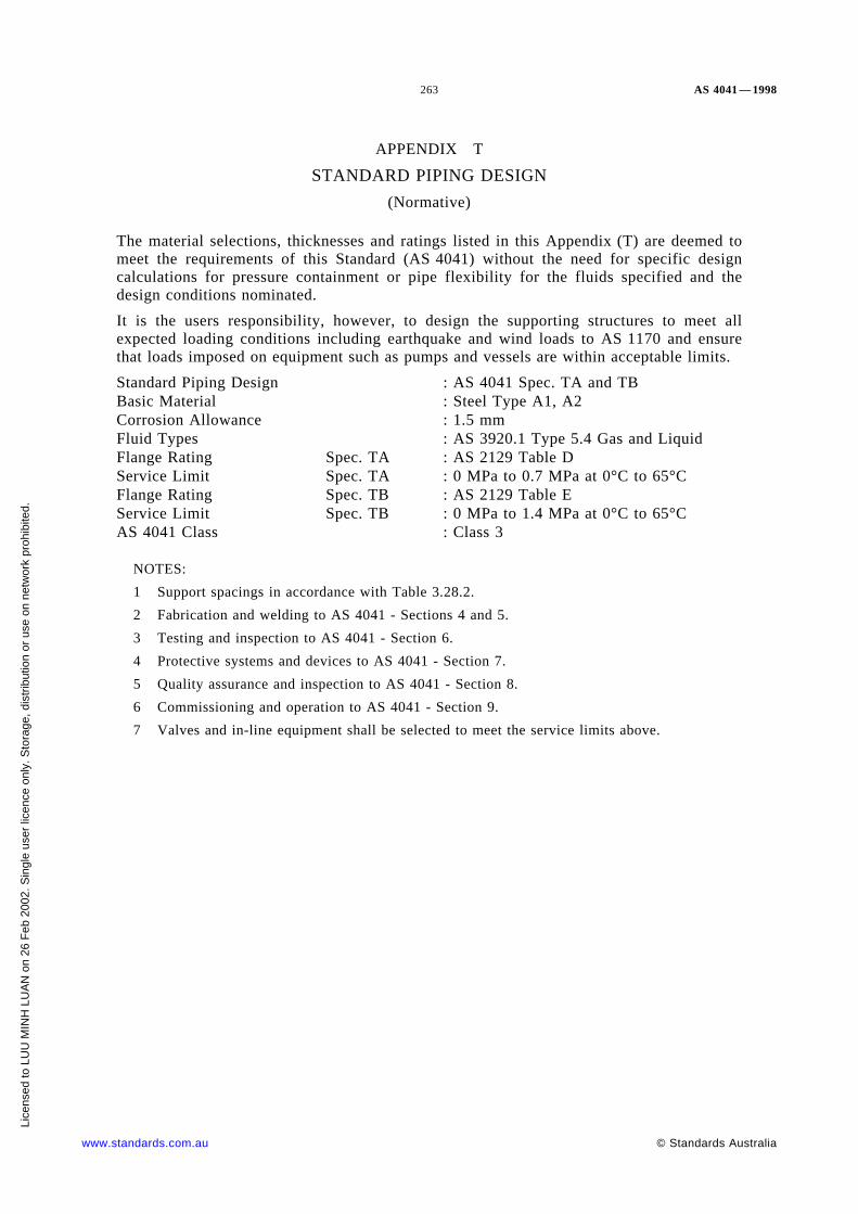
263 AS 4041 — 1998
APPENDIX T
STANDARD PIPING DESIGN
(Normative)
The material selections, thicknesses and ratings listed in this Appendix (T) are deemed tomeet the requirements of this Standard (AS 4041) without the need for specific designcalculations for pressure containment or pipe flexibility for the fluids specified and thedesign conditions nominated.
It is the users responsibility, however, to design the supporting structures to meet allexpected loading conditions including earthquake and wind loads to AS 1170 and ensurethat loads imposed on equipment such as pumps and vessels are within acceptable limits.
Standard Piping Design : AS 4041 Spec. TA and TBBasic Material : Steel Type A1, A2Corrosion Allowance : 1.5 mmFluid Types : AS 3920.1 Type 5.4 Gas and LiquidFlange Rating Spec. TA : AS 2129 Table DService Limit Spec. TA : 0 MPa to 0.7 MPa at 0°C to 65°CFlange Rating Spec. TB : AS 2129 Table EService Limit Spec. TB : 0 MPa to 1.4 MPa at 0°C to 65°CAS 4041 Class : Class 3
NOTES:
1 Support spacings in accordance with Table 3.28.2.
2 Fabrication and welding to AS 4041 - Sections 4 and 5.
3 Testing and inspection to AS 4041 - Section 6.
4 Protective systems and devices to AS 4041 - Section 7.
5 Quality assurance and inspection to AS 4041 - Section 8.
6 Commissioning and operation to AS 4041 - Section 9.
7 Valves and in-line equipment shall be selected to meet the service limits above.
www.standards.com.au © Standards Australia
Lice
nsed
to L
UU
MIN
H L
UA
N o
n 26
Feb
200
2. S
ingl
e us
er li
cenc
e on
ly. S
tora
ge, d
istr
ibut
ion
or u
se o
n ne
twor
k pr
ohib
ited.

AS 4041 — 1998 264
TABLE T1
MATERIAL SELECTION AND THICKNESS FOR VARIOUS TYPESOF PIPING COMPONENTS
PIPE
Size ThicknessMaterial
Spec. TA Spec. TB
DN ≤150 Medium Heavy AS 1074
DN ≤150 Sch40 Sch40 ASTM A53B, API 5LB, ASTM A106B
200 ≤DN ≤400 Sch10 Sch20 ASTM A53B, API 5LB, ASTM A106B
450 ≤ DN ≤600 Sch10 Std wt ASTM A53B, API 5LB, ASTM A106B
SCREWED FITTINGS
Size ThicknessMaterial
Spec. TA Spec. TB
D ≤150 Heavy Heavy AS 3672, AS 3673 Scrd BSP T/P
DN ≤50 3000# 3000# ANSI B16.11/ ASTM A105
SOCKETWELD FITTINGS
Size ThicknessMaterial
Spec. TA Spec. TB
DN ≤50 3000# 3000# ANSI B16.11/ ASTM A105
BUTTWELD FITTINGS
Size ThicknessMaterial
Spec. TA Spec. TB
DN ≤150 Sch40 Sch40 ANSI B16.9/ ASTM A234 WPB
200 ≤ DN ≤400 Sch10 Sch20 ANSI B16.9/ ASTM A234 WPB
450 ≤ DN ≤600 Sch10 Std wt ANSI B16.9/ ASTM A234 WPB
FLANGES
Size FacingMaterial
Spec. TA Spec. TB
DN ≤150 Table ‘ D’ Flat Face Table ‘ E’ FlatFace
AS 2129 Screwed BSP T/P
DN ≤600 Table ‘ D’ Flat Face Table ‘ E’ FlatFace
AS 2129 Slip on Welded Type 6 Weld
DN ≤600 150# Raised Face ANSI B16.5/ ASTM A105
GASKET
Size ThicknessType/material
Spec. TA Spec. TB
DN ≤600 3 mm Table ‘ D’ 1.5 mm Table ‘ E’ Full face, asbestos free
DN ≤600 — 1.5 mm 150# Flat ring, asbestos free
(continued)
© Standards Australia www.standards.com.au
Lice
nsed
to L
UU
MIN
H L
UA
N o
n 26
Feb
200
2. S
ingl
e us
er li
cenc
e on
ly. S
tora
ge, d
istr
ibut
ion
or u
se o
n ne
twor
k pr
ohib
ited.

265 AS 4041—1998
TABLE T1 (continued)
FLANGE BOLTING
Size ThicknessMaterial
Spec. TA Spec. TB
DN ≤600 Bolts and nutsTable ‘ D’
Bolts and nutsTable ‘ E’
AS/NZS 1111 Gr 4.6 and AS/NZS 1112Gr 5
DN ≤600 150#Studs and nuts
Bolts and nuts
ASTM A193 B7/ ASTM A194 2H Nuts
AS/NZS 1111 Gr 4.6 and AS/NZS 1112Gr 5
BRANCHES/TEE FITTINGS
Size ThicknessForm/material
Spec. TA Spec. TB
DN ≤150 Heavy Heavy Screwed/AS 3672, AS 3673, Scrd BSPT/P
DN ≤50 3000# 3000# Threadolet/ANSI B16.11/ ASTM A105
DN ≤50 3000# 3000# Sockolet/ANSI B16.11/ ASTM A105
DN ≤600 Std wt Std wt Weldolet/ANSI B16.11/ ASTM A105
DN ≤150 Sch40 Sch40 ANSI B16.9/ ASTM A234 WPB
200 ≤DN ≤400 Sch10 Sch20 ANSI B16.9/ ASTM A234 WPB
450 ≤ DN ≤600 Sch10 Std wt ANSI B16.9/ ASTM A234 WPB
www.standards.com.au © Standards Australia
Lice
nsed
to L
UU
MIN
H L
UA
N o
n 26
Feb
200
2. S
ingl
e us
er li
cenc
e on
ly. S
tora
ge, d
istr
ibut
ion
or u
se o
n ne
twor
k pr
ohib
ited.

AS 4041—1998 266
TABLE T2
FILLET SIZES AND REINFORCING PAD SIZES FOR WELDED BRANCHES TO FIGURE M6millimetres
Main sizes
Branch sizes ≤20 25 32 40 50 65 80 100 150 200 250 300 350 400 450 500 600
Fillet sizes and reinforcing pad sizes
≤20 6 6 6 6 6 6 6 6 6 6 6 6 6 6 6 6 6
25 6 6 6 6 6 6 6 6 6 6 6 6 6 6 6 6−TA6+6×14−TB
32 7 7 7 7 7 7 7 7 7 7 7 7 7 7 7−TA7+6×18−TB
40 7 7 7 7 7 7 7 7 7 7 7 7 7 7−TA7+6×21−TB
50 7 7 7 7 7 7 7 7 7 7 7 7 7−TA7+6×27−TB
65 10 10 10 10 10 10 10 10 10 10 10 10−TA10+6×31−TB
80 10 10 10 10 10 10 10 10 10 10 10−TA10+6×38−TB
100 12 12 12 12 12 12 12 12 12 12−TA11+6×50−TB
150 12 12 12 12 12 12 12 12 12−TA13+6×76−TB
200 12 12 12 12 12 12 12 12−TA12+6×10³−TB
250 12 12 12 12 12 12 12−TA12+6×130−TB
300 12−TA12+6× 155−TB
12 12 12 12−TA12+6×155−TB
12−TA12+6×155−TB
350 12 12 12 12−TA12+6×171−TB
12−TA12+6×171−TB
400 12 12 12−TA12+6×197−TB
12−TA12+6×197−TB
450 12 12−TA12+6×220−TB
12−TA12+6×220−TB
500 12−TA12+6×243−TB
12+6×248−TA12+6×243−TB
600 12+6×300−TA12+6×294−TB
NOTE: Fillet sizes are the same for Spec. TA and TB unless otherwise noted in the table.
© Standards Australia www.standards.com.au
Licensed to LUU MINH LUAN on 26 Feb 2002. Single user licence only. Storage, distribution or use on network prohibited.
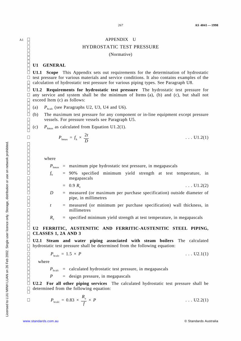
267 AS 4041 — 1998
A1 APPENDIX U
HYDROSTATIC TEST PRESSURE
(Normative)
U1 GENERAL
U1.1 Scope This Appendix sets out requirements for the determination of hydrostatictest pressure for various materials and service conditions. It also contains examples of thecalculation of hydrostatic test pressure for various piping types. See Paragraph U8.
U1.2 Requirements for hydrostatic test pressure The hydrostatic test pressure forany service and system shall be the minimum of Items (a), (b) and (c), but shall notexceed Item (c) as follows:
(a) Phcalc (see Paragraphs U2, U3, U4 and U6).
(b) The maximum test pressure for any component or in-line equipment except pressure
vessels. For pressure vessels see Paragraph U5.
(c) Phmax as calculated from Equation U1.2(1).
. . . U1.2(1) Phmax = fh × 2tD
where
Phmax = maximum pipe hydrostatic test pressure, in megapascals
fh = 90% specified minimum yield strength at test temperature, inmegapascals
= 0.9 Re . . . U1.2(2)
D = measured (or maximum per purchase specification) outside diameter of
pipe, in millimetres
t = measured (or minimum per purchase specification) wall thickness, inmillimetres
Re = specified minimum yield strength at test temperature, in megapascals
U2 FERRITIC, AUSTENITIC AND FERRITIC-AUSTENITIC STEEL PIPING,CLASSES 1, 2A AND 3
U2.1 Steam and water piping associated with steam boilers The calculatedhydrostatic test pressure shall be determined from the following equation:
. . . U2.1(1) Phcalc = 1.5 × P
where
Phcalc = calculated hydrostatic test pressure, in megapascals
P = design pressure, in megapascals
U2.2 For all other piping services The calculated hydrostatic test pressure shall bedetermined from the following equation:
. . . U2.2(1) Phcalc = 0.83 ×Re
f× P
www.standards.com.au © Standards Australia
Lice
nsed
to L
UU
MIN
H L
UA
N o
n 26
Feb
200
2. S
ingl
e us
er li
cenc
e on
ly. S
tora
ge, d
istr
ibut
ion
or u
se o
n ne
twor
k pr
ohib
ited.

AS 4041 — 1998 268
A1 where
Phcalc = calculated hydrostatic test pressure, in megapascals
P = design pressure, in megapascals
Re = specified minimum yield strength at test temperature, in megapascals
f = design strength at design temperature, in megapascals
and
. . . U2.2(2) Maximum value of 0.83 ×Re
f3.5
NOTE: Equation U2.1(1) is based on BS 806. Some values of Re and f are listed in Appendix D.
U3 FERRITIC STEEL PIPING CLASS 2P The calculated hydrostatic test pressurefor piping to Class 2P is Phcalc = 1.25 × P . . . U3(1)
where
Phcalc = calculated hydrostatic test pressure, in megapascals
P = design pressure, in megapascals
U4 NON-FERROUS METALS The calculated hydrostatic test pressure shall bedetermined from the following equation:
. . . U4(1)Phcalc 1.5P
ft
f
except that shall not exceed 6.5,ft
f
where
ft = design strength at test temperature, in megapascals
f = design strength at design temperature, in megapascals
U5 PIPING AND PRESSURE VESSELS TESTED TOGETHER For piping attachedto a pressure vessel where the test pressure is not more than the test pressure for thevessel, the piping may be tested with the vessel at the test pressure of the piping.
Where the test pressure of the piping is greater than the vessel test pressure and it is notpracticable to isolate the piping from the vessel, the piping and the vessel may be testedtogether at the test pressure of the vessel provided that—
(a) the owner agrees; and
(b) the test pressure of the vessel is not less than 77% of the piping calculated test
pressure adjusted for temperature (see Paragraphs U2, U3 and U4).
U6 PIPING SUBJECT TO EXTERNAL PRESSURE Piping subject to externalpressure in service shall be tested to an internal hydrostatic test pressure of the maximumof Items (a) and (b) but shall not be less than Item (b) as follows:
(a) Phcalc = 1.5 Pdiff . . . U6(1)
where
Pdiff = differential design pressure, in megapascals
(b) 100 kPa.
© Standards Australia www.standards.com.au
Lice
nsed
to L
UU
MIN
H L
UA
N o
n 26
Feb
200
2. S
ingl
e us
er li
cenc
e on
ly. S
tora
ge, d
istr
ibut
ion
or u
se o
n ne
twor
k pr
ohib
ited.

269 AS 4041 — 1998
A1 U7 JACKETED PIPING The test pressure for internal piping of jacketed piping shallbe determined according to the internal or external design pressure, whichever is criticalusing Paragraph U1. The test shall, if necessary, be performed before completion of thejacket so that any joints of the internal piping can be visually inspected.
The test pressure for the jacket shall be determined in accordance with Paragraph U1 andaccording to the design pressure of the jacket, unless otherwise limited in the engineeringdesign.
U8 EXAMPLES
Example 1: Paragraph U2
Service = other than steam or water
Pipe specification = API 5L B
Class = 1 or 2A
Temperature = 50°C
Design life = indefinite
Size = 273 × 4.8
Max. OD = 273 mm
Min. thickness = 4.8 mm
Re = 241 MPa (from Table D4 or material specification)
Rm = 413 MPa (from Table D4 or material specification)
f = 160 MPa
depends onRe
1.5
P = 5.62 MPa
Phmax = fh × 2tD
= 7.63 MPa
Phcalc = 0.83Re
f× P
= 1.25 P NOTE: 0.83 ×
Re
f<3.5
= 7.03 MPa
(whenever f = )Re
1.5, Ph = 1.25 P
Since Phcalc < Phmax hydrostatic test pressure is 7.03 MPa.
For steam or water service:
Phcalc = 1.5 P
= 8.43 MPa
Since Phcalc > Phmax hydrostatic test pressure is 7.63 MPa.
Example 2: Paragraph U2.
Service = other than steam or water
Pipe specification = API 5L X42
www.standards.com.au © Standards Australia
Lice
nsed
to L
UU
MIN
H L
UA
N o
n 26
Feb
200
2. S
ingl
e us
er li
cenc
e on
ly. S
tora
ge, d
istr
ibut
ion
or u
se o
n ne
twor
k pr
ohib
ited.

AS 4041 — 1998 270
A1 Class = 1 or 2A
Temperature = 50°C
Design life = indefinite
Size = 273.1 × 4.8
Max. OD = 273.1 mm
Min. thickness = 4.8 mm
Re = 289 MPa (from Table D2 or material specification)
Rm = 413 MPa (from Table D2 or material specification)
f = 176 MPa
depends onRm
2.35
P = 6.2 MPa
Phmax = fh × 2tD
= 9.15 MPa
Phcalc = 0.83Re
f× P
= 1.36 P NOTE: 0.83 ×
Re
f< 3.5
= 8.45 MPa
Since Phcalc < Phmax hydrostatic test pressure is 8.45 MPa.
For steam or water service:
Phcalc = 1.5 P
= 9.30 MPa
Since Phcalc > Phmax hydrostatic test pressure is 9.15 MPa.
Example 3: Paragraph U2.
Service = other than steam or water
Pipe specification = ASTM A106B
Class = 1
Temperature = 450°C
Design life = 150 000 hours
Size = 168.3 × 21.95 (XXS)
Max. OD = 169.9 mm
Min. thickness = 19.21 mm
Re = 240 MPa (from Table D4 or material specification)
Rm = 413 MPa (from Table D4 or material specification)
f = 56 MPa
P = 14.25 MPa
Phmax = fh × 2tD
© Standards Australia www.standards.com.au
Lice
nsed
to L
UU
MIN
H L
UA
N o
n 26
Feb
200
2. S
ingl
e us
er li
cenc
e on
ly. S
tora
ge, d
istr
ibut
ion
or u
se o
n ne
twor
k pr
ohib
ited.

271 AS 4041 — 1998
A1 = 48.84 MPa
Phcalc = 0.83Re
f× P
= 3.56 P NOTE: 0.83 ×
Re
f>3.5
= 3.5 P
= 49.88 MPa
Since Phcalc > Phmax hydrostatic test pressure is 48.84 MPa.
For steam or water service:
Phcalc = 1.5 P
= 21.38 MPa
Since Phcalc < Phmax hydrostatic test pressure is 21.38 MPa.
Example 4: Paragraph U3.
Service = other than steam or water
Pipe specification = API 5L X42
Class = 2P
Temperature = 99°C
Design life = indefinite
Size = 273.1 × 4.8 (Class 2P)
Max. OD = 273.1 mm
Min. thickness = 4.8 mm
Re = 289 MPa (from Table D2 or material specification)
Rm = 413 MPa (from Table D2 or material specification)
f = 208 MPa (0.72 × Re)
P = 7.3 MPa
Phmax = fh × 2tD
= 9.10 MPa
Phcalc = 1.25 P
= 9.13 MPa
NOTE: 1.25 × 0.72 = 0.9
Since Phcalc > Phmax hydrostatic test pressure is 9.14 MPa.
www.standards.com.au © Standards Australia
Lice
nsed
to L
UU
MIN
H L
UA
N o
n 26
Feb
200
2. S
ingl
e us
er li
cenc
e on
ly. S
tora
ge, d
istr
ibut
ion
or u
se o
n ne
twor
k pr
ohib
ited.

AS 4041 — 1998 272
INDEX
Clause Clause
Accessory . . . . . . . . . . . . . . . . . . . . . . . . . 1.7.1, 1.18
Agreement . . . . . . . . . . . . . . . . . . . . . . . . . . . . 1.7.2
Alarm . . . . . . . . . . . . . . . . . . . . . . . . . . . . . . . . 9.1.3
Allowancescorrosion . . . . . . . . . . . . . . . . . . . . . . . . . . . . 3.13.3erosion . . . . . . . . . . . . . . . . . . . . . . . . . . . . . 3.13.3grooving . . . . . . . . . . . . . . . . . . . . . . . . . . . . 3.13.4machining . . . . . . . . . . . . . . . . . . . . . . . . . . . 3.13.4manufacturing tolerance . . . . . . . . . . . . . . . . . 3.13.2mechanical strength . . . . . . . . . . . . . . . . . . . . 3.13.5threading . . . . . . . . . . . . . . . . . . . . . . . . . . . . 3.13.4
Alternative Standards . . . . . . . . . . . . . . . . . . . . . . . 1.6
Alternative tests to hydrostatic and pneumatic tests . . 6.8
Attachmentsintensity of radial loading . . . . . . . . . . . . . . . . 3.23.4thickness . . . . . . . . . . . . . . . . . . . . . . . . . . . . 3.23.3welding . . . . . . . . . . . . . . . . . . . . . . . . . . . . . 3.23.2
Bearing stresses . . . . . . . . . . . . . . . . . . . . . . . . . 3.11.4
Bell and spigot socket . . . . . . . . . . . . . . . . Appendix O
Bifurcations . . . . . . . . . . . . . . . . . . . . . . . . . . . . . 3.17
Blowdownsystems . . . . . . . . . . . . . . . . . . . . . . . . . . 3.9.6, 3.9.7vessel . . . . . . . . . . . . . . . . . . . . . . . . . . . . . . 3.9.6.3
Boiler feed water piping . . . . . . . . . . . . . . . . . . . . 3.9.5
Bolting, design tensile strength . . . . . . . . . . Appendix G
Branch fittings, forged . . . . . . . . . . . . . . . . Appendix K
Branch connections and openingsapplication . . . . . . . . . . . . . . . . . . . . . . . . . . . 3.19.1extruded outlets . . . . . . . . . . . . . . . . . . . . . . . 3.19.9location . . . . . . . . . . . . . . . . . . . . . . . . . . . . . 3.19.5material for . . . . . . . . . . . . . . . . . . . . . . . . . . 3.19.6reinforcement . . . . . . . . . . . . . . . . 3.19.6, Appendix Lreinforcement required . . . . . . . . . . . . . . . . . . 3.19.8reinforcement not required . . . . . . . . . . . . . . . 3.19.7shape . . . . . . . . . . . . . . . . . . . . . . . . . . . . . . 3.19.3size . . . . . . . . . . . . . . . . . . . . . . . . . . . . . . . . 3.19.4types . . . . . . . . . . . . . . . . . . . . . . . . . . . . . . . 3.19.2welded . . . . . . . . . . . . . . . . . . . . . . . . . . . . . 3.20welds . . . . . . . . . . . . . . . . . . . . . . . . . . Appendix M
Brazed piping joints . . . . . . . . . . . . . . . . . . . . . . 3.24.8
Brazing materials . . . . . . . . . . . . . . . . . . . . . . . . 3.24.8
Butt welds . . . . . . . . . . . . . . . . . . . . . . . . . . . 3.24.2.1
Cast, pipe . . . . . . . . . . . . . . . . . . . . . . . . . . . . . 3.14.5
Casting quality factor . . . . . . . . . . . . . . . . . . . . . 3.12.4
Caulked piping joints . . . . . . . . . . . . . . . . . . . . . 3.24.6
Certificates . . . . . . . . . . . . . . . . . . . . . . . . . . . . . . 1.11
Class design factor . . . . . . . . . . . . . . . . . . . . . . 3.12.3
Classificationof fluids . . . . . . . . . . . . . . . . . . . . . . . . . . . . . . 1.4of piping . . . . . . . . . . . . . . . . . . . . . . . . . . . . . . 1.3
Cleaning . . . . . . . . . . . . . . . . . . . . . . . . . . . . . . . 4.3.3
Closures for pipe ends and branches . . . . . . . . . . . . 3.21
Cold spring . . . . . . . . 1.7.3, 3.27.2.3, 4.3.5, Appendix Q
Commissioning . . . . . . . . . . . . . . . . . . . . . . . . . . . 9.1
Component . . . . . . . . . . . . . . . . . . . . . . . . . . . . . 1.7.4
Componentscorrosive service . . . . . . . . . . . . . . . . . . . . . . . . 2.7inspection . . . . . . . . . . . . . . . . . . . . . . . . . . . . . 8.3
identification (see Identification of materials andcomponents)limitations (see Limitations on materials andcomponents)qualification of (see Qualification of materials andcomponents)
Compression piping joints . . . . . . . . . . . . . . . . . 3.24.5
Compressive stress . . . . . . . . . . . . . . . . . . . . . . 3.11.2
Continuous pipe bends . . . . . . . . . . . . . . . . . . . . 3.15.2
Control equipment . . . . . . . . . . . . . . . . . . . . . 6.9, 9.1.4
Control piping . . . . . . . . . . . . . . . . . . . . . . . . . . 3.25.3
Corrosionallowance . . . . . . . . . . . . . . . . . . . . . . . . . . . 3.13.3definition . . . . . . . . . . . . . . . . . . . . . . . . . . . . . 1.7.5protection . . . . . . . . . . . . . . . . . . . . . . . . . . . . . 7.4
© Standards Australia www.standards.com.au
Lice
nsed
to L
UU
MIN
H L
UA
N o
n 26
Feb
200
2. S
ingl
e us
er li
cenc
e on
ly. S
tora
ge, d
istr
ibut
ion
or u
se o
n ne
twor
k pr
ohib
ited.
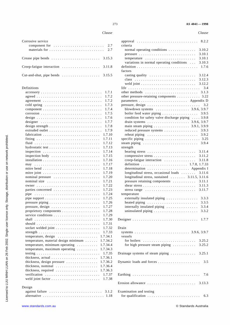
273 AS 4041 — 1998
Clause
Corrosive servicecomponent for . . . . . . . . . . . . . . . . . . . . . . . . 2.7materials for . . . . . . . . . . . . . . . . . . . . . . . . . . 2.7
Crease pipe bends . . . . . . . . . . . . . . . . . . . . . . . 3.15.3
Creep-fatigue interaction . . . . . . . . . . . . . . . . . . 3.11.8
Cut-and-shut, pipe bends . . . . . . . . . . . . . . . . . . 3.15.5
Definitionsaccessory . . . . . . . . . . . . . . . . . . . . . . . . . . . . . 1.7.1agreed . . . . . . . . . . . . . . . . . . . . . . . . . . . . . . . 1.7.2agreement . . . . . . . . . . . . . . . . . . . . . . . . . . . . 1.7.2cold spring . . . . . . . . . . . . . . . . . . . . . . . . . . . 1.7.3component . . . . . . . . . . . . . . . . . . . . . . . . . . . . 1.7.4corrosion . . . . . . . . . . . . . . . . . . . . . . . . . . . . . 1.7.5design . . . . . . . . . . . . . . . . . . . . . . . . . . . . . . . 1.7.6designer . . . . . . . . . . . . . . . . . . . . . . . . . . . . . 1.7.7design strength . . . . . . . . . . . . . . . . . . . . . . . . . 1.7.8extruded outlet . . . . . . . . . . . . . . . . . . . . . . . . . 1.7.9fabrication . . . . . . . . . . . . . . . . . . . . . . . . . . . 1.7.10fitting . . . . . . . . . . . . . . . . . . . . . . . . . . . . . . 1.7.11fluid . . . . . . . . . . . . . . . . . . . . . . . . . . . . . . . 1.7.12hydrostatic test . . . . . . . . . . . . . . . . . . . . . . . . 1.7.13inspection . . . . . . . . . . . . . . . . . . . . . . . . . . . 1.7.14inspection body . . . . . . . . . . . . . . . . . . . . . . . 1.7.15installation . . . . . . . . . . . . . . . . . . . . . . . . . . . 1.7.16may . . . . . . . . . . . . . . . . . . . . . . . . . . . . . . . 1.7.17mitre bend . . . . . . . . . . . . . . . . . . . . . . . . . . . 1.7.18mitre joint . . . . . . . . . . . . . . . . . . . . . . . . . . . 1.7.19nominal pressure . . . . . . . . . . . . . . . . . . . . . . 1.7.20nominal size . . . . . . . . . . . . . . . . . . . . . . . . . 1.7.21owner . . . . . . . . . . . . . . . . . . . . . . . . . . . . . . 1.7.22parties concerned . . . . . . . . . . . . . . . . . . . . . . 1.7.23pipe . . . . . . . . . . . . . . . . . . . . . . . . . . . . . . . 1.7.24pipe support . . . . . . . . . . . . . . . . . . . . . . . . . . 1.7.25pressure piping . . . . . . . . . . . . . . . . . . . . . . . . 1.7.26pressure, design . . . . . . . . . . . . . . . . . . . . . . . 1.7.27proprietory components . . . . . . . . . . . . . . . . . . 1.7.28service conditions . . . . . . . . . . . . . . . . . . . . . . 1.7.29shall . . . . . . . . . . . . . . . . . . . . . . . . . . . . . . . 1.7.30should . . . . . . . . . . . . . . . . . . . . . . . . . . . . . . 1.7.31socket welded joint . . . . . . . . . . . . . . . . . . . . . 1.7.32strength . . . . . . . . . . . . . . . . . . . . . . . . . . . . . 1.7.33temperature, design . . . . . . . . . . . . . . . . . . . 1.7.34.1temperature, material design minimum . . . . . . 1.7.34.2temperature, minimum operating . . . . . . . . . . 1.7.34.4temperature, maximum operating . . . . . . . . . . 1.7.34.3testing . . . . . . . . . . . . . . . . . . . . . . . . . . . . . . 1.7.35thickness, actual . . . . . . . . . . . . . . . . . . . . . . 1.7.36.1thickness, design pressure . . . . . . . . . . . . . . . 1.7.36.2thickness, nominal . . . . . . . . . . . . . . . . . . . . 1.7.36.4thickness, required . . . . . . . . . . . . . . . . . . . . 1.7.36.3verification . . . . . . . . . . . . . . . . . . . . . . . . . . 1.7.37weld joint factor . . . . . . . . . . . . . . . . . . . . . . . 1.7.38
Designagainst failure . . . . . . . . . . . . . . . . . . . . . . . . . 3.1.2alternative . . . . . . . . . . . . . . . . . . . . . . . . . . . . . 1.18
Clause
approval . . . . . . . . . . . . . . . . . . . . . . . . . . . . . 8.2.2criteria
normal operating conditions . . . . . . . . . . . . . 3.10.2pressure . . . . . . . . . . . . . . . . . . . . . . . . . . . 3.10.1temperature . . . . . . . . . . . . . . . . . . . . . . . . 3.10.1variations in normal operating conditions . . . 3.10.3
definition . . . . . . . . . . . . . . . . . . . . . . . . . . . . . 1.7.6factors
casting quality . . . . . . . . . . . . . . . . . . . . . . 3.12.4class . . . . . . . . . . . . . . . . . . . . . . . . . . . . . 3.12.3weld joint . . . . . . . . . . . . . . . . . . . . . . . . . . 3.12.2
life . . . . . . . . . . . . . . . . . . . . . . . . . . . . . . . . . . 3.4other methods . . . . . . . . . . . . . . . . . . . . . . . . . 3.1.3other pressure-retaining components . . . . . . . . . . . 3.22parameters . . . . . . . . . . . . . . . . . . . . . . . Appendix Dpressure, design . . . . . . . . . . . . . . . . . . . . . . . . . 3.2
blowdown systems . . . . . . . . . . . . . . . . 3.9.6, 3.9.7boiler feed water piping . . . . . . . . . . . . . . . . . 3.9.5condition for safety valve discharge piping . . . . 3.9.8drain systems . . . . . . . . . . . . . . . . . . . . 3.9.6, 3.9.7main steam piping . . . . . . . . . . . . . . . . . 3.9.1, 3.9.9reduced pressure systems . . . . . . . . . . . . . . . . 3.9.3reheat piping . . . . . . . . . . . . . . . . . . . . . . . . 3.9.2
specific piping . . . . . . . . . . . . . . . . . . . . . . . . . . 3.25steam piping . . . . . . . . . . . . . . . . . . . . . . . . . . 3.9.4strength
bearing stress . . . . . . . . . . . . . . . . . . . . . . . 3.11.4compressive stress . . . . . . . . . . . . . . . . . . . . 3.11.2creep-fatigue interaction . . . . . . . . . . . . . . . 3.11.8definition . . . . . . . . . . . . . . . . . . . . . . 1.7.8, 1.7.33determination . . . . . . . . . . . . . . . . . . . . Appendix Ilongitudinal stress, occasional loads . . . . . . . 3.11.6longitudinal stress, sustained . . . . . . . 3.11.5, 3.11.6pressure retaining components . . . . . . . . . . . 3.11.1shear stress . . . . . . . . . . . . . . . . . . . . . . . . . 3.11.3stress range . . . . . . . . . . . . . . . . . . . . . . . . 3.11.7
temperatureexternally insulated piping . . . . . . . . . . . . . . . 3.3.3heated piping . . . . . . . . . . . . . . . . . . . . . . . . 3.3.5internally insulated piping . . . . . . . . . . . . . . . 3.3.4uninsulated piping . . . . . . . . . . . . . . . . . . . . . 3.3.2
Designer . . . . . . . . . . . . . . . . . . . . . . . . . . . . . . . 1.7.7
Drainsystems . . . . . . . . . . . . . . . . . . . . . . . . . . 3.9.6, 3.9.7vessels
for boilers . . . . . . . . . . . . . . . . . . . . . . . . . 3.25.2for high pressure steam piping . . . . . . . . . . . 3.25.2
Drainage systems of steam piping . . . . . . . . . . . . 3.25.1
Dynamic loads and forces . . . . . . . . . . . . . . . . . . . . 3.5
Earthing . . . . . . . . . . . . . . . . . . . . . . . . . . . . . . . . 7.6
Erosion allowance . . . . . . . . . . . . . . . . . . . . . . . 3.13.3
Examination and testingfor qualification . . . . . . . . . . . . . . . . . . . . . . . . . 6.3
www.standards.com.au © Standards Australia
Lice
nsed
to L
UU
MIN
H L
UA
N o
n 26
Feb
200
2. S
ingl
e us
er li
cenc
e on
ly. S
tora
ge, d
istr
ibut
ion
or u
se o
n ne
twor
k pr
ohib
ited.

AS 4041 — 1998 274
Clause
non-destructive . . . . . . . . . . . . . . . . . . . . . . . . . 6.4responsibility . . . . . . . . . . . . . . . . . . . . . . . . . . . 6.2
Expansionfittings . . . . . . . . . . . . . . . . . . . . . . . . 3.18, 3.27.2.1linear . . . . . . . . . . . . . . . . . . . . . . . . . . Appendix D
External pressure . . . . . . . . . . . . . . . . . . . . . . . . 3.14.4
Extruded outlet . . . . . . . . . . . . . . . . . . . . . 1.7.9 3.19.9
Fabricationdefinition . . . . . . . . . . . . . . . . . . . . . . . . . . . . . 1.7.10inspection . . . . . . . . . . . . . . . . . . . . . . . . . . . . . 8.4
Fillet-welded sockets . . . . . . . . . . . . . . . . . Appendix O
Fire protection . . . . . . . . . . . . . . . . . . . . . . . . . . . . 7.5
Fitting . . . . . . . . . . . . . . . . . . . . . . . . . . . . . . . 1.7.11
Flange bolting, design tensile strength . . . . . Appendix G
Flanged joints . . . . . . . . . . . . . . . . . . . . . . . . . . 3.24.4
Flared piping joints . . . . . . . . . . . . . . . . . . . . . . 3.24.5
Flareless piping joints . . . . . . . . . . . . . . . . . . . . 3.24.5
Flexibilityanalysis . . . . . . . . . . . . . . . . . . . . . . . . . . . . 3.27, Q1method of assessing . . . . . . . . . . . . . . . . Appendix R
Flexible hose assemblies . . . . . . . . . . . . . . . . . . . . 3.18
Fluiddefinition . . . . . . . . . . . . . . . . . . . . . . . . . . . . . 1.7.12
Forces . . . . . . . . . . . . . . . . . . . . . . . . . . . . . . . . . 3.5
Forged branch fittings . . . . . . . . . . . . . . . . Appendix K
Grooving allowance . . . . . . . . . . . . . . . . . . . . . . 3.13.4
Gusseted pipe bends . . . . . . . . . . . . . . . . . . . . . 3.15.5
Human contact protection . . . . . . . . . . . . . . . . . . . . 7.9
Hydrostatic test . . . . . . . . . . . . . . . . . . . . . . 1.7.13, 6.7
Hydrostatic test calculation examples . . . . . . Appendix U
Identification, materials and components . . . . . . . . . 2.5
Impact, protection from . . . . . . . . . . . . . . . . . . . . . 7.7
Impact tests . . . . . . . . . . . . . . . . . . . . . . . . . . . 2.11.6
Clause
Information to be supplied . . . . . . . . . . . . . . . . . . . 3.29
In-process examination . . . . . . . . . . . . . . . . . . . . . 6.5.3
Initial service leak test . . . . . . . . . . . . . . . . . . . . . 6.8.2
Inspection . . . . . . . . . . . . . . . . . . . . . . . . . . . . . 1.7.14
Inspection body . . . . . . . . . . . . . . . . . . . . . . . . . 1.7.15
Inspection . . . . . . . . . . . . . . . . . . . . . . . . . . . Section 8
Inspectors . . . . . . . . . . . . . . . . . . . . . . . . . . . . . . 8.1.3
Installation . . . . . . . . . . . . . . . . . . . . . . . . . 1.7.16, 4.3
Instrument piping . . . . . . . . . . . . . . . . . . . . . . . 3.25.3
Interference, protection from . . . . . . . . . . . . . . . . . . 7.13
Internal pressure . . . . . . . . . . . . . . . . . . . . . . . . 3.14.3
Isolation protection . . . . . . . . . . . . . . . . . . . . . . . . 7.11
Joint, sleeve . . . . . . . . . . . . . . . . . . . . . . . Appendix P
Joints (see Piping joints)
Lightning protection . . . . . . . . . . . . . . . . . . . . . . . 7.8
Limitation on materials and components . . . . . . . . . 2.3
Limits on applicationambient and high temperature service
aluminium and aluminium alloys . . . . . . . . . 2.6.3.6carbon and low and medium alloy steels . . . . 2.6.3.2copper and copper alloys . . . . . . . . . . . . . . . 2.6.3.5ductile iron . . . . . . . . . . . . . . . . . . . . . . . . . 2.6.3.4high alloy steels . . . . . . . . . . . . . . . . . . . . . 2.6.3.3iron castings . . . . . . . . . . . . . . . . . . . . . . . . 2.6.3.4nickel and nickel alloys . . . . . . . . . . . . . . . . 2.6.3.7steels . . . . . . . . . . . . . . . . . . . . . . . . . . . . . 2.6.3.2titanium and titanium alloys . . . . . . . . . . . . . 2.6.3.8
AS 1074 pipe . . . . . . . . . . . . . . . . . . . . . . . . . 2.6.10bolting for flanges . . . . . . . . . . . . . . . . . . . . . . 2.6.7deterioration . . . . . . . . . . . . . . . . . . . . . . . . . . 2.6.2fittings . . . . . . . . . . . . . . . . . . . . . . . . . . . . . . 2.6.4for forming and bending . . . . . . . . . . . . . . . . . . 2.6.9flange . . . . . . . . . . . . . . . . . . . . . . . . . . . . . . . 2.6.6gaskets . . . . . . . . . . . . . . . . . . . . . . . . . . . . . . 2.6.8valves
bodies . . . . . . . . . . . . . . . . . . . . . . . . . . . . 2.6.5.2bypasses . . . . . . . . . . . . . . . . . . . . . . . . . . 2.6.5.6drain . . . . . . . . . . . . . . . . . . . . . . . . . . . . . 2.6.5.3spindles . . . . . . . . . . . . . . . . . . . . . . . . . . . 2.6.5.5trim . . . . . . . . . . . . . . . . . . . . . . . . . . . . . . 2.6.5.4
Linear expansion . . . . . . . . . . . . . . . . . . . . Appendix E
© Standards Australia www.standards.com.au
Lice
nsed
to L
UU
MIN
H L
UA
N o
n 26
Feb
200
2. S
ingl
e us
er li
cenc
e on
ly. S
tora
ge, d
istr
ibut
ion
or u
se o
n ne
twor
k pr
ohib
ited.

275 AS 4041 — 1998
Clause
Load-supporting structure . . . . . . . . . . . . . . . . . . 3.28.5
Loadmat isotherms . . . . . . . . . . . . . . . . . . . Appendix H
Loads . . . . . . . . . . . . . . . . . . . . . . . . . . . . . . . . . 3.5
Longitudinal stress, occasional loads . . . . . . . . . . 3.11.6
Longitudinal stress, sustained . . . . . . . . . . 3.11.5, 3.11.6
Low temperature (see Materials for low temperatureservice)
Machining allowance . . . . . . . . . . . . . . . . . . . . . 3.13.4
Manufacturing tolerance . . . . . . . . . . . . . . . . . . . 3.13.2
Manufactuer’s data report . . . . . . . . . . . . . . . . . . 1.11.1
Materialproperties . . . . . . . . . . . . . . . . . . . . . . . Appendix Dreference thickness . . . . . . . . . . . . . . . . . . . . . 2.11.5tensile strength . . . . . . . . . . . . . . . . . . . . Appendix D
Materialsbrazing . . . . . . . . . . . . . . . . . . . . . . . . . . . . . . 3.24.8corrosive service . . . . . . . . . . . . . . . . . . . . . . . . 2.7dissimilar . . . . . . . . . . . . . . . . . . . . . . . . . . . . . 2.8identification . . . . . . . . . . . . . . . . . . . . . . . . . . . 4.5limitations (see Limitations on materials andcomponents)low temperature service
alloy steels . . . . . . . . . . . . . . . . . . . . . . . . 2.11.2.3bolting . . . . . . . . . . . . . . . . . . . . . . . . . . . 2.11.2.6cast iron . . . . . . . . . . . . . . . . . . . . . . . . . . 2.11.2.5groups A1 and A2 . . . . . . . . . . . . . . . . . . . 2.11.2.2non-ferrous metals . . . . . . . . . . . . . . . . . . 2.11.2.3non-metallic materials . . . . . . . . . . . . . . . . 2.11.2.7pipes, thin . . . . . . . . . . . . . . . . . . . . . . . . 2.11.2.4tubes, thin . . . . . . . . . . . . . . . . . . . . . . . . 2.11.2.4
propertiesmechanical . . . . . . . . . . . . . . . . . . . . . . . . . . 2.4.2Poisson ratio . . . . . . . . . . . . . . . . . . . . . . . . 2.4.5thermal expansion . . . . . . . . . . . . . . . . . . . . . 2.4.3weldability . . . . . . . . . . . . . . . . . . . . . . . . . . 2.4.6Young Modulus . . . . . . . . . . . . . . . . . . . . . . 2.4.4
qualification of (see Qualification of materials andcomponents)
May . . . . . . . . . . . . . . . . . . . . . . . . . . . . . . . . . 1.7.17
Mechanical strength, allowance . . . . . . . . . . . . . . 3.13.5
Minimum operating temperature . . . . . . . . . . . . . 2.11.3
Mitre bend . . . . . . . . . . . . . . . . . . . . . . . 1.7.18, 3.15.4
Mitre joint . . . . . . . . . . . . . . . . . . . . . . . . . . . . 1.7.19
Clause
Movement at supports, anchors and terminals . . . . . . 3.8
Newdesigns . . . . . . . . . . . . . . . . . . . . . . . . . . . . . . . 1.16fabrication methods . . . . . . . . . . . . . . . . . . . . . . 1.16materials . . . . . . . . . . . . . . . . . . . . . . . . . . . . . . 1.16
Nominal sizes of pipe . . . . . . . . . . . . . . . . Appendix B
Non-metallic piping . . . . . . . . . . . . . . . . . . . . . . . . 1.14
Notation . . . . . . . . . . . . . . . . . . . . . . . . . . . . . . . . 1.8
Opening, reinforcement . . . . . . . . . . . . . . . Appendix L
Operation . . . . . . . . . . . . . . . . . . . . . . . . . . . . . . . 9.2
Outside diameter of pipe . . . . . . . . . . . . . . Appendix B
Owner . . . . . . . . . . . . . . . . . . . . . . . . . . . . . . . 1.7.22
Parties concerned . . . . . . . . . . . . . . . . . . . . . . . . 1.7.23
Pipe . . . . . . . . . . . . . . . . . . . . . . . . . . . . . . . . . . 1.7.24
Pipe bendscontinuous . . . . . . . . . . . . . . . . . . . . . . . . . . . 3.15.2wrinkle . . . . . . . . . . . . . . . . . . . . . . . . . . . . . 3.15.3crease . . . . . . . . . . . . . . . . . . . . . . . . . . . . . . 3.15.3mitre . . . . . . . . . . . . . . . . . . . . . . . . . . . . . . . 3.15.4cut-and-shut . . . . . . . . . . . . . . . . . . . . . . . . . . 3.15.5gusseted . . . . . . . . . . . . . . . . . . . . . . . . . . . . 3.15.5
Pipe support . . . . . . . . . . . . . . . . . . . 1.7.25, 3.28, 9.1.6
Piping classfast track selection . . . . . . . . . . . . . . . . . . . . . . 1.5.3mixing classes . . . . . . . . . . . . . . . . . . . . . . . . . 1.5.2selection . . . . . . . . . . . . . . . . . . . . . . . . . . . . . . 1.5
Pipingcontrol . . . . . . . . . . . . . . . . . . . . . . . . . . . . 1.7.26.1instrument . . . . . . . . . . . . . . . . . . . . . . . . . . 1.7.26.2sampling . . . . . . . . . . . . . . . . . . . . . . . . . . . 1.7.26.3joints
brazed . . . . . . . . . . . . . . . . . . . . . . . . . . . . 3.24.8caulked . . . . . . . . . . . . . . . . . . . . . . . . . . . 3.24.6compression . . . . . . . . . . . . . . . . . . . . . . . . 3.24.5expansion . . . . . . . . . . . . . . . . . . . . . . . . . . 3.24.9flanged . . . . . . . . . . . . . . . . . . . . . . . . . . . 3.24.4flared . . . . . . . . . . . . . . . . . . . . . . . . . . . . . 3.24.5flareless . . . . . . . . . . . . . . . . . . . . . . . . . . . 3.24.5propriety . . . . . . . . . . . . . . . . . . . . . . . . . 3.24.10soldered . . . . . . . . . . . . . . . . . . . . . . . . . . . 3.24.7special . . . . . . . . . . . . . . . . . . . . . . . . . . . 3.24.10threaded . . . . . . . . . . . . . . . . . . . . . . . . . . . 3.24.3welded . . . . . . . . . . . . . . . . . . . . . . . . . . . . 3.24.2
protection . . . . . . . . . . . . . . . . . . . . . . . . . . . . 4.3.6
www.standards.com.au © Standards Australia
Lice
nsed
to L
UU
MIN
H L
UA
N o
n 26
Feb
200
2. S
ingl
e us
er li
cenc
e on
ly. S
tora
ge, d
istr
ibut
ion
or u
se o
n ne
twor
k pr
ohib
ited.

AS 4041 — 1998 276
Clause
Plastic strains . . . . . . . . . . . . . . . . . . . . . . . . . . . . Q4
Pneumatic testing . . . . . . . . . . . . . . . . . . . . . . . . 6.8.1
Pressure control systems . . . . . . . . . . . . . . . . . . . . . 7.2
Pressuredesign (see Design pressure)regulator . . . . . . . . . . . . . . . . . . . . . . . . . . 6.9, 9.1.4
Pressure-limiting devices . . . . . . . . . . . . . . . . 6.9, 9.1.4
Pressure relief systems . . . . . . . . . . . . . . . . . . . . . . 7.3
Pressure relief valve discharge piping . . . . . . . . . 3.25.4
Pressure tests . . . . . . . . . . . . . . . . . . . . . . . . . . . . 6.6
Pressure tests, alternatives . . . . . . . . . . . . . . . . . . . 6.8
Proof hydrostatic test . . . . . . . . . . . . . . . . . . . . . . . 6.8.4
Proprietarycomponents . . . . . . . . . . . . . . . . . . . . . . . . . . 1.7.28piping joints . . . . . . . . . . . . . . . . . . . . . . . . 3.24.10
Protection . . . . . . . . . . . . . . . . . . . . . . . . . . . . . . . 4.3.2
Qualification of materials and componentsalternative product form . . . . . . . . . . . . . . . . . . 2.2.3complying with nominated Standards . . . . . . . . . 2.2.1complying with Standards not nominated . . . . . . 2.2.2for which there are no Standards . . . . . . . . . . . . 2.2.3not fully identified . . . . . . . . . . . . . . . . . . . . . . 2.2.7reclaimed components . . . . . . . . . . . . . . . . . . . . 2.2.6specially tested . . . . . . . . . . . . . . . . . . . . . . . 2.2.10structural . . . . . . . . . . . . . . . . . . . . . . . . . . . . . 2.2.4
Quality assurance . . . . . . . . . . . . . . . . . . . . . . . . . 8.8
Radiography, exemption . . . . . . . . . . . . . . . . . . . . 6.5.1
Reactions . . . . . . . . . . . . . . . . . . . . . . . . . . 3.27.6, Q3
Reduced pressure systems . . . . . . . . . . . . . . . . . . 3.9.1.3
Reducers . . . . . . . . . . . . . . . . . . . . . . . . . . . . . . . . 3.16
Referenced documents . . . . . . . . . . . . 1.10, Appendix A
Reheat piping . . . . . . . . . . . . . . . . . . . . . . . . . . . 3.9.2
Reinforcementbranch connection and openings . . . . . . . . . . . . 3.19.8of a branch . . . . . . . . . . . . . . . . . . . . . . Appendix Lof an opening . . . . . . . . . . . . . . . . . . . . . Appendix L
Relief valves . . . . . . . . . . . . . . . . . . . . . . . . . 6.9, 9.1.4
Clause
Report . . . . . . . . . . . . . . . . . . . . . . . . . . . . 1.11, 6.10
Required material design minimum temperature . . 2.11.4
Responsibilities . . . . . . . . . . . . . . . . . . . . . . . . . . . 1.2
Risk analysis . . . . . . . . . . . . . . . . . . . . . . . . . . . . . 3.6
Safety valve discharge piping . . . . . . . . . . . . . . . . 3.9.8
Safety valve discharge piping, designpressure . . . . . . . . . . . . . . . . . . . . . . . . . . . Appendix J
Sampling piping . . . . . . . . . . . . . . . . . . . . . . . . 3.25.3
Scope . . . . . . . . . . . . . . . . . . . . . . . . . . . . . . . . . . 1.1
Service conditions . . . . . . . . . . . . . . . . . . . . . . . 1.7.29
Shall . . . . . . . . . . . . . . . . . . . . . . . . . . . . . . . . 1.7.30
Shear stresses . . . . . . . . . . . . . . . . . . . . . . . . . . 3.11.3
Should . . . . . . . . . . . . . . . . . . . . . . . . . . . . . . . 1.7.31
Shut down systems . . . . . . . . . . . . . . . . . . . . . . . 9.1.3
Size of pipes basis for determining . . . . . . . . . . . . 3.1.1
Sleeve joint . . . . . . . . . . . . . . . . . . . . . . . . Appendix P
Socketfillet-welded . . . . . . . . . . . . . . . . . . . . . . Appendix Owelded joint . . . . . . . . . . . . . . . . . . . . . . . . . . 1.7.32
Soldered piping joints . . . . . . . . . . . . . . . . . . . . 3.24.7
Special piping joints . . . . . . . . . . . . . . . . . . . . 3.24.10
Specified minimum tensile strength . . . . . . . . . . 1.7.33.1
Specified minimum yield strength . . . . . . . . . . . 1.7.33.2
Standard piping design . . . . . . . . . . . . . . . . Appendix T
Static loads and forces . . . . . . . . . . . . . . . . . . . . . . 3.5
Steam pipingdesign temperature . . . . . . . . . . . . . . . . . . . . . . . 3.9.4drainage . . . . . . . . . . . . . . . . . . . . . . . . . . . . 3.25.1main . . . . . . . . . . . . . . . . . . . . . . . . . . . . . . . . 3.9.1
Strength . . . . . . . . . . . . . . . . . . . . . . . . . . . . . . 1.7.33
Stress analysis . . . . . . . . . . . . . 3.27, 3.27.3, Appendix Q
Stress calculation in a piping system . . . . . . Appendix S
Stresses in a piping system . . . . . . . . . . . . . . . . . . . Q3
© Standards Australia www.standards.com.au
Lice
nsed
to L
UU
MIN
H L
UA
N o
n 26
Feb
200
2. S
ingl
e us
er li
cenc
e on
ly. S
tora
ge, d
istr
ibut
ion
or u
se o
n ne
twor
k pr
ohib
ited.

277 AS 4041 — 1998
Clause
Support attachments . . . . . . . . . . . . . . . . . . . . . . 3.28.4
Temperaturecontrol systems . . . . . . . . . . . . . . . . . . . . . . . . . 7.2design, definition . . . . . . . . . . . . . . . . . . . . . 1.7.34.1design (see Design temperature)material design minimum . . . . . . . . . . . . . . . 1.7.34.2maximum operating . . . . . . . . . . . . . . . . . . . 1.7.34.3minimum operating . . . . . . . . . . . . . . . . . . . . 1.7.34.4
Tensile strengths of materials . . . . . . . . . . . Appendix D
Testing . . . . . . . . . . . . . . . . . . . . . . . . . . . . . . . 1.7.35
Thermaleffects . . . . . . . . . . . . . . . . . . . . . . . . . . . . . . . . 3.7insulation . . . . . . . . . . . . . . . . . . . . . . . . . . . . . . 4.4
Thicknessactual . . . . . . . . . . . . . . . . . . . . . . . . . . . . . 1.7.36.1design pressure . . . . . . . . . . . . . . . . . . . . . . . 1.7.36.2nominal . . . . . . . . . . . . . . . . . . . . . . . . . . . . 1.7.36.4required . . . . . . . . . . . . . . . . . . . . . . . . . . . . 1.7.36.3
Threadedallowance . . . . . . . . . . . . . . . . . . . . . . . . . . . 3.13.4protection . . . . . . . . . . . . . . . . . . . . . . . . . . . . 4.3.6joints . . . . . . . . . . . . . . . . . . . . . . . . . . . . . . . 3.24.3
Tolerances, dimension and mass . . . . . . . . . . . . . . . 1.17
Verification . . . . . . . . . . . . . . . . . . . . . . . . . . . . 1.7.37
Clause
Wall thickness of straight pipecast pipe . . . . . . . . . . . . . . . . . . . . . . . . . . . . 3.14.5external pressure . . . . . . . . . . . . . . . . . . . . . . 3.14.4internal pressure . . . . . . . . . . . . . . . . . . . . . . . 3.14.3nominal . . . . . . . . . . . . . . . . . . . . . . . . . . . . . 3.14.2required . . . . . . . . . . . . . . . . . . . . . . . . . . . . . 3.14.1
Welddetails . . . . . . . . . . . . . . . . . . . . . . . . . . Appendix Njoint factor . . . . . . . . . . . . . . . . . . . . . . . . . . . 3.12.2joint factor, definition . . . . . . . . . . . . . . . . . . . 1.7.38
Welded branch connections . . . . . . . . . . . . . . . . . . 3.20
Welded piping jointsbell and spigot . . . . . . . . . . . . . . . . . . . . . . . 3.24.2.5butt . . . . . . . . . . . . . . . . . . . . . . . . . . . . . . . 3.24.2.1fillet welds . . . . . . . . . . . . . . . . . . . . . . . . . . 3.24.2.2partial penetration . . . . . . . . . . . . . . . . . . . . . 3.24.2.6sleeve . . . . . . . . . . . . . . . . . . . . . . . . . . . . . 3.24.2.4socket welded . . . . . . . . . . . . . . . . . . . . . . . 3.24.2.3stress corrosion cracking . . . . . . . . . . . . . . . . 3.24.2.7
Weldingbacking rings
permanent . . . . . . . . . . . . . . . . . . . . . . . . . 2.9.4temporary . . . . . . . . . . . . . . . . . . . . . . . . . 2.9.5
fusible inserts . . . . . . . . . . . . . . . . . . . . . . . . . . . 2.9.3
Welds, branch . . . . . . . . . . . . . . . . . . . . . . Appendix M
Wrinkle pipe bends . . . . . . . . . . . . . . . . . . . . . . 3.15.3
Young modulus . . . . . . . . . . . . . . . . . . . . . Appendix F
www.standards.com.au © Standards Australia
Lice
nsed
to L
UU
MIN
H L
UA
N o
n 26
Feb
200
2. S
ingl
e us
er li
cenc
e on
ly. S
tora
ge, d
istr
ibut
ion
or u
se o
n ne
twor
k pr
ohib
ited.

Standards Australia
Standards Australia is an independent company, limited by guarantee, which prepares and publishes
most of the voluntary technical and commercial standards used in Australia. These standards are
developed through an open process of consultation and consensus, in which all interested parties are
invited to participate. Through a Memorandum of Understanding with the Commonwealth government,
Standards Australia is recognized as Australia’s peak national standards body.
Australian Standards
Australian Standards are prepared by committees of experts from industry, governments, consumers
and other relevant sectors. The requirements or recommendations contained in published Standards
are a consensus of the views of representative interests and also take account of comments received
from other sources. They reflect the latest scientific and industry experience. Australian Standards are
kept under continuous review after publication and are updated regularly to take account of changing
technology.
International Involvement
Standards Australia is responsible for ensuring that the Australian viewpoint is considered in the
formulation of international Standards and that the latest international experience is incorporated in
national Standards. This role is vital in assisting local industry to compete in international markets.
Standards Australia represents Australia at both ISO (the International Organization for
Standardization) and IEC (the International Electrotechnical Commission).
Electronic Standards
All Australian Standards are available in electronic editions, either downloaded individually from
our Web site, or via on-line and CD ROM subscription services. For more information phone
1300 65 46 46 or visit us at
www.standards.com.au
Lice
nsed
to L
UU
MIN
H L
UA
N o
n 26
Feb
200
2. S
ingl
e us
er li
cenc
e on
ly. S
tora
ge, d
istr
ibut
ion
or u
se o
n ne
twor
k pr
ohib
ited.

GPO Box 5420 Sydney NSW 2001Administration Phone (02) 8206 6000 Fax (02) 8206 6001 Email [email protected] Service Phone 1300 65 46 46 Fax 1300 65 49 49 Email [email protected] www.standards.com.au
ISBN 0 7337 1934 1 Printed in AustraliaLice
nsed
to L
UU
MIN
H L
UA
N o
n 26
Feb
200
2. S
ingl
e us
er li
cenc
e on
ly. S
tora
ge, d
istr
ibut
ion
or u
se o
n ne
twor
k pr
ohib
ited.