TITLE 14—CIVIL AVIATION - The IPL Group LLC 14—CIVIL AVIATION Chapter 1—Civil Aeronautics...
80
CIVIL AIR REGULATIONS —————— PART 4b-AIRPLANE AIRWORTHINESS TRANSPORT CATEGORIES As amended to December 31, 1953 CIVIL AERONAUTICS BOARD WASHINGTON, D.C. TITLE 14—CIVIL AVIATION Chapter 1—Civil Aeronautics Board Subpart A—Civil Air Regulations Part 4b—AIRPLANE AIRWORTHINESS; TRANSPORT CATEGORIES RECAPITULATION OF PART Because of the number of outstanding amendments to Part 4b there follows a recapitulation of Part 4b incorporating all amendments up to December 31, 1953. Subpart A—General APPLICABILITY AND DEFINITIONS Sec. 4b.0 Applicability of this part. 4b.1 Definitions. CERTIFICATION 4b.10 Eligibility for type certificates. 4b.11 Designation of applicable regulations. 4b.12 Amendment of part. 4b.13 Type certificate. 4b.14 Data required. 4b.15 Inspections and tests. 4b.16 Flight tests. 4b.17 Airworthiness, experimental, and production certificates. 4b.18 Approval of materials, parts, processes, and appliances. 4b.19 Changes in type design. Subpart B—Flight GENERAL 4b.100 Proof of compliance. 4b.101 Weight limitations. 4b.102 Center of gravity limitations. 4b.103 Additional limitations on weight distribution. 4b.104 Empty weight. 4b.105 Use of ballast. PERFORMANCE 4b.110 General. 4b.111 Wing flap positions. 4b.112 Stalling speeds. 4b.113 Take-off; general. 4b.114 Take-off speeds. 4b.115 Accelerate-stop distance. 4b.116 Take-off path. 4b.117 Temperature accountability. 4b.118 Climb; general. 4b.119 Climb; all engines operating. 4b.120 One-engine-inoperative climb. 4b.121 Two-engine-inoperative climb. 4b.122 Determination of the landing distance; general 4b.123 Landplanes. 4b.124 Seaplanes or float planes. 4b.125 Skiplanes. CONTROLLABILITY 4b.130 Controllability; general. 4b.131 Longitudinal control. 4b.132 Directional and lateral control. 4b.133 Minimum control speed, V MC . TRIM 4b.140 General. 4b.141 Lateral and directional trim. 4b.142 Longitudinal trim. 4b.143 Longitudinal, directional, and lateral trim. 4b.144 Trim for airplanes with four or more engines. S TABILITY 4b.150 General. 4b.151 Static longitudinal stability 4b.152 Stability during landing. 4b.153 Stability during approach. 4b.154 Stability during climb. 4b.155 Stability during cruising. 4b.156 Dynamic longitudinal stability. 4b.157 Static directional and lateral stability.
Transcript of TITLE 14—CIVIL AVIATION - The IPL Group LLC 14—CIVIL AVIATION Chapter 1—Civil Aeronautics...

CIVIL AIR REGULATIONS——————
PART 4b-AIRPLANEAIRWORTHINESS TRANSPORT
CATEGORIES
As amended to December 31, 1953
CIVIL AERONAUTICS BOARD
WASHINGTON, D.C.
TITLE 14—CIVIL AVIATIONChapter 1—Civil Aeronautics Board
Subpart A—Civil Air Regulations
Part 4b—AIRPLANE AIRWORTHINESS;TRANSPORT CATEGORIES
RECAPITULATION OF PART
Because of the number of outstandingamendments to Part 4b there follows a recapitulationof Part 4b incorporating all amendments up toDecember 31, 1953.
Subpart A—General
APPLICABILITY AND DEFINITIONS
Sec.4b.0 Applicability of this part.4b.1 Definitions.
CERTIFICATION
4b.10 Eligibility for type certificates.4b.11 Designation of applicable regulations.4b.12 Amendment of part.4b.13 Type certificate.4b.14 Data required.4b.15 Inspections and tests.4b.16 Flight tests.4b.17 Airworthiness, experimental, and
production certificates.4b.18 Approval of materials, parts, processes,
and appliances.4b.19 Changes in type design.
Subpart B—Flight
GENERAL
4b.100 Proof of compliance.4b.101 Weight limitations.4b.102 Center of gravity limitations.4b.103 Additional limitations on weight
distribution.4b.104 Empty weight.4b.105 Use of ballast.
PERFORMANCE
4b.110 General.4b.111 Wing flap positions.4b.112 Stalling speeds.4b.113 Take-off; general.4b.114 Take-off speeds.4b.115 Accelerate-stop distance.4b.116 Take-off path.4b.117 Temperature accountability.4b.118 Climb; general.4b.119 Climb; all engines operating.4b.120 One-engine-inoperative climb.4b.121 Two-engine-inoperative climb.4b.122 Determination of the landing distance;
general4b.123 Landplanes.4b.124 Seaplanes or float planes.4b.125 Skiplanes.
CONTROLLABILITY
4b.130 Controllability; general.4b.131 Longitudinal control.4b.132 Directional and lateral control.4b.133 Minimum control speed, VMC.
TRIM
4b.140 General.4b.141 Lateral and directional trim.4b.142 Longitudinal trim.4b.143 Longitudinal, directional, and lateral trim.4b.144 Trim for airplanes with four or more
engines.
S TABILITY
4b.150 General.4b.151 Static longitudinal stability4b.152 Stability during landing.4b.153 Stability during approach.4b.154 Stability during climb.4b.155 Stability during cruising.4b.156 Dynamic longitudinal stability.4b.157 Static directional and lateral stability.

4b.158 Dynamic directional and lateral stability.
S TALLING CHARACTERISTICS
4b.160 Stalling; symmetrical power.4b.161 Stalling; asymmetrical power.4b.162 Stall warning.
GROUND HANDLING CHARACTERISTICS
4b.170 Longitudinal stability and control.4b.171 Directional stability and control.4b.172 Shock absorption.4b.173 Demonstrated cross wind.
WATER HANDLING CHARACTERISTICS
4b.180 Water conditions.4b.181 Wind conditions.4b.182 Control and stability on the water.
MISCELLANEOUS FLIGHT REQUIREMENTS
4b.190 Flutter and vibration.
Subpart C—Structure
GENERAL
4b.200 Loads.4b.201 Strength and deformation.4b.202 Proof of structure.
FLIGHT LOADS
4b.210 General.4b.211 Flight envelopes.4b.212 Effect of high lift devices.4b.213 Symmetrical flight conditions.4b.214 Rolling conditions.4b.215 Yawing conditions.4b.216 Supplementary flight conditions.
CONTROL S URFACE AND S YSTEM LOADS
4b.220 Control surface loads; general.4b.221 Wing flaps.4b.222 Tabs.4b.223 Special devices.4b.224 Primary flight control systems.4b.225 Dual primary flight control systems.4b.226 Ground gust conditions.4b.227 Secondary control systems.
GROUND LOADS
4b.230 General.4b.231 Level landing conditions.4b.232 Tail-down landing conditions4b.233 One-wheel landing condition.4b.234 Lateral drift landing condition.4b.235 Ground handling conditions.4b.236 Unsymmetrical loads on dual-wheel units.
WATER LOADS
4b.250 General.4b.251 Design weights and center of gravity
positions.4b.252 Application of load.
4b.253 Hull and main float load factors.4b.254 Hull and main float landing conditions.4b.255 Hull and main float take-off condition.4b.256 Hull and main float bottom pressures.4b.257 Auxiliary float loads.4b.258 Seawing loads.
EMERGENCY LANDING CONDITIONS
4b.260 General.4b.261 Structural ditching provisions.
Subpart D—Design and Construction
GENERAL
4b.300 Scope.4b.301 Materials.4b.302 Fabrication methods.4b.303 Standard fastenings.4b.304 Protection.4b.305 Inspection Provisions.4b.306 Material strength properties and design
values.4b.307 Special factors.4b.308 Flutter, deformation, and vibration.
CONTROL S URFACES
4b.310 General.4b.311 Proof of strength.4b.312 Installation.4b.313 Hinges.
CONTROL S YSTEMS
4b.320 General.4b.321 Two-control airplanes.4b.322 Trim controls and systems.4b.323 Wing flap controls.4b.324 Wing flat interconnection.4b.325 Control system stops.4b.326 Control system locks.4b.327 Static tests.4b.328 Operation tests.4b.329 Control system details; general.
LANDING GEAR
4b.330 General.4b.331 Shock absorbers.4b.332 Landing gear tests.4b.333 Limit load factor determination.4b.334 Retracting mechanism.4b.335 Wheels.4b.336 Tires.4b.337 Brakes.4b.338 Skis.
HULLS AND FLOATS
4b.340 General.4b.341 Seaplane main floats.4b.342 Boat hulls.

PERSONNEL AND CARGO ACCOMMODATIONS
4b.350 Pilot compartment; general.4b.351 Pilot compartment; vision.4b.352 Windshield and windows.4b.353 Controls.4b.354 Instrument arrangement.4b.355 Instrument marking.4b.356 Doors.4b.357 Door louvres.4b.358 Seats, berths, and safety belts.4b.359 Cargo and baggage compartments.
EMERGENCY PROVISIONS
4b.360 General.4b.361 Ditching4b.362 Emergency evacuation.
VENTILATION , HEATING, AND PRESSURIZATION
4b.370 General.4b.371 Ventilation.4b.372 Heating systems.4b.373 Pressurized cabins; general.4b.374 Pressure supply.4b.375 Pressure control.4b.376 Tests.
FIRE PROTECTION
4b.380 General.4b.381 Cabin interiors.4b.382 Cargo and baggage compartments.4b.383 Cargo compartment classification.4b.384 Proof of compliance.4b.385 Flammable fluid fire protection.4b.386 Combustion heater fire protection.
MISCELLANEOUS
4b.390 Reinforcement near propellers.4b.391 Leveling marks.
Subpart E—Powerplant Installation
INSTALLATION
4b.400 General.4b.401 Engines.4b.402 Propellers.4b.403 Propeller vibration.4b.404 Propeller pitch and speed limitations.4b.405 Propeller clearance.4b.406 Propeller de-icing provisions.
FUEL S YSTEM OPERATION AND ARRANGEMENT
4b.410 General.4b.411 Fuel system independents.4b.412 Pressure cross-feed arrangements.4b.413 Fuel flow rate.4b.414 Pump systems.4b.415 Transfer systems4b.416 Determination of unusable fuel supply
and fuel system operation on low fuel.
4b.417 Fuel system hot weather operation.4b.418 Flow between interconnected tanks.
FUEL SYSTEM CONSTRUCTION AND INSTALLATION
4b.420 General.4b.421 Fuel tank tests.4b.422 Fuel tank installation.4b.423 Fuel tank expansion space.4b.424 Fuel tank sump.4b.425 Fuel tank filler connection.4b.426 Fuel tank vents and carburetor vapor
vents.4b.427 Fuel tank outlet.4b.428 Under-wing fueling provisions.
FUEL S YSTEM COMPONENTS
4b.430 Fuel pumps.4b.431 Fuel pump installation.4b.432 Fuel system lines and fittings.4b.433 Fuel lines and fittings in designated fire
zones.4b.434 Fuel valves.4b.435 Fuel strainer.4b.436 Fuel system drains.4b.437 Fuel jettisoning system.
OIL SYSTEM
4b.440 General.4b.441 Oil tank construction.4b.442 Oil tank tests.4b.443 Oil tank installation.4b.444 Oil lines and fittings.4b.445 Oil valves.4b.446 Oil radiators.4b.447 Oil filters.4b.448 Oil system drains.4b.449 Propeller feathering system.
COOLING S YSTEM
4b.450 General.4b.451 Cooling tests.4b.452 Climb cooling test procedure.4b.453 Take-off cooling test procedure.4b.454 Cooling test procedure for flying boat
operation.4b.455 Liquid cooling systems.4b.456 Coolant tank.4b.457 Coolant system installation.
INDUCTION AND EXHAUST S YSTEMS
4b.460 General.4b.461 Induction system de-icing and anti-icing
provisions.4b.462 Carburetor air preheater design.4b.463 Induction system ducts4b.464 Induction system screens.4b.465 Carburetor air cooling.4b.466 Inter-coolers and after-coolers.
4b.467 Exhaust system and installationcomponents.
POWERPLANT CONTROLS AND ACCESSORIES
4b.470 Powerplant controls; general.4b.471 Throttle and A.D.I. system controls.4b.472 Ignition switches.4b.473 Mixture controls.4b.474 Propeller controls.4b.475 Fuel system controls.4b.476 Carburetor air preheat controls.4b.476a Supercharger controls.4b.477 Powerplant accessories.4b.478 Engine Ignition systems.
POWERPLANT FIRE PROTECTION
4b.480 Designated fire zones.4b.481 Flammable fluids.4b.482 Shut-off means.4b.483 Lines and fittings.4b.484 Fire extinguisher systems4b.485 Fire detector systems4b.486 Fire walls.4b.487 Cowling and nacelle skin.4b.488 Engine accessory section diaphragm.4b.489 Drainage and ventilation of fire zones.4b.490 Protection of other airplane components
against fire.
Subpart F—Equipment
GENERAL
4b.600 Scope.4b.601 Functional and installational requirements.4b.602 Required basic equipment.4b.603 Flight and navigational instrument.4b.604 Powerplant instruments.4b.605 Miscellaneous equipment.4b.606 Equipment, systems, and installations.
INSTRUMENTS; INSTALLATION
4b.610 General.4b.611 Arrangement and visibility of instrument
installations.4b.612 Flight and navigational instruments.4b.613 Powerplant instruments.
ELECTRICAL S YSTEMS AND EQUIPMENT
4b.620 General.4b.621 Electrical system capacity.4b.622 Generating system.4b.623 Distribution system.4b.624 Electrical protection.4b.625 Electrical equipment and installation.4b.626 Electrical system fire and smoke
protection.4b.627 Electrical system tests and analyses.
LIGHTS
4b.630 Instrument lights.4b.631 Landing lights.4b.632 Position light system installation.4b.633 Position light system dihedral angles.4b.634 Position light distribution and intensities.4b.635 Position light color specifications.4b.636 Riding light.4b.637 Anti-collision light.
S AFETY EQUIPMENT
4b.640 Ice protection.4b.641 Hand fire extinguishers.4b.642 Flare installation.4b.643 Safety belts.4b.644 Safety belt signal.4b.645 Ditching equipment.4b.646 Stowage of safety equipment.
MISCELLANEOUS EQUIPMENT
4b.650 Radio and electronic equipment.4b.651 Oxygen equipment and supply.4b.652 Engine-driven accessories.4b.653 Hydraulic systems; strength.4b.654 Hydraulic systems design.4b.655 Hydraulic system fire protection.4b.658 Vacuum systems.
Subpart G——Operating Limitations and Information
GENERAL
4b.700 Scope.
OPERATING LIMITATIONS
4b.710 Air-speed limitations; general.4b.711 Never-exceed speed VNE
4b.712 Normal operating limit speed VNO.4b.713 Maneuvering speed.4b.714 Flap extended speed VFE.4b.715 Landing gear operating speed VLO.4b.716 Landing gear extended speed VLE.4b.717 Minimum control speed VMC.4b.718 Powerplant limitations.4b.719 Airplane weight, center of gravity and
weight distribution limitations.4b.720 Minimum flight crew.4b.72l Types of operation.4b.722 Maximum operating altitude.4b.723 Maneuvering flight load factors
MARKINGS AND PLACARDS
4b.730 General.4b.731 Instrument markings; general.4b.732 Air-speed indicator.4b.733 Magnetic direction indicator.4b.734 Powerplant instruments; general.4b.735 Oil quantity indicators.4b.736 Fuel quantity indicator.4b.737 Control markings; general.

4b.738 Miscellaneous markings and placards.
AIRPLANE FLIGHT MANUAL
4b.740 General.4b.741 Operating limitations.4b.742 Operating procedures.4b.743 Performance information.
AIRPLANE IDENTIFICATION DATA
4b.750 Identification plate.4b.751 Identification marks.
AUTHORITY: §§ 4b.0 to 4b.751 issued undersec. 205, 52 Stat. 984, as amended: 49 U.S.C. 425.Interpret or apply secs. 601, 603, 52 Stat. 1007, asamended, 1009, as amended; 49 U.S.C. 551, 553.
SUBPART A—GENERAL
APPLICABILITY AND DEFINITIONS
§ 4b.0 Applicability of this part. This partestablishes standards with which compliance shall bedemonstrated for the issuance of a type certificate fortransport category airplanes. This part, untilsuperseded or rescinded, shall apply to all transportcategory airplanes for which applications for typecertification in the transport category are made afterthe effective date of this part (November 9, 1945).
§ 4b.1 Definitions. As used in this part termsare defined as follows:
(a) Administration —(1) Administrator. TheAdministrator is the Administrator of CivilAeronautics.
(2) Applicant. An applicant is a person orpersons applying for approval of an airplane or anypart thereof
(3) Approved. Approved, when used alone oras modifying terms such as means, devices,specifications, etc., shall mean approved by theAdministrator. (See § 4b.18.)
(b) General design—(1) Standard atmosphere.The standard atmosphere is an atmosphere defined asfollows:
(i) The air is a dry, perfect gas,
(ii) The temperature at sea level is 59º F.,
(iii) The pressure at sea level is 29.92 inches Hg,
(iv) The temperature gradient from sea level tothe altitude at which the temperature equals -67° F. is -0.003566º F./ft. and zero there above
(v) The density ρ0 at sea level under the aboveconditions is 0.002378 pounds sec.²/ft.4.
(2) Maximum anticipated air temperature. Themaximum anticipated air temperature is a temperature
specified for the purpose of compliance with thepowerplant cooling standard. (See § 4b.451(b).)
(3) Airplane configuration. Airplaneconfiguration is a term referring to the position of thevarious elements affecting the aerodynamicscharacteristics of the airplane (e.g., wing flaps,landing gear).
(4) Aerodynamic coefficients. Aerodynamiccoefficients are nondimensional coefficients for forcesand moments. They correspond with those adoptedby the U.S. National Advisory Committee forAeronautics.
(5) Critical engine(s) . The critical engine isthat engine(s) the failure of which gives the mostadverse effect on the airplane flight characteristicsrelative to the case under consideration.
(6) Critical-engine-failure speed. The critical-engine-failure speed is the airplane speed used in thedetermination of the take-off at which the criticalengine is assumed to fail. (See § 4b.114).
(c) Weights—(1) Maximum weight. Themaximum weight of the airplane is that maximum atwhich compliance with the requirements of this part isdemonstrated. (See § 4b.101 (a).)
(2) Minimum weight. The minimum weight ofthe airplane is that minimum at which compliance withthe requirements of this part is demonstrated. (See4b.101 (c).)
(3) Empty weight. The empty weight of theairplane is a readily reproducible weight which is usedin the determination of the operating weights. (See§ 4b.104.)
(4) Design maximum weight. The designmaximum weight is the maximum weight of the airplaneused in structural design for flight load conditions.(See § 4b.210.)
(5) Design minimum weight. The designminimum weight is the minimum weight of the airplaneat which compliance is shown with the structuralloading conditions. (See § 4b.210.)
(6) Design take-off weight. The design take-offweight is the maximum airplane weight used instructural design for taxying conditions, and forlanding conditions at a reduced velocity of descent.(See § 4b.210.)
(7) Design landing weight. The design landingweight is the maximum airplane weight used in

structural design for landing conditions at themaximum velocity of descent. (See § 4b.230 (b).)
(8) Design unit weight. The design unit weightis a representative weight used to show compliancewith the structural design requirements.
(i) Gasoline 6 pounds per U.S. gallon.
(ii) Lubricating oil 7.5 pounds per U.S. gallon.
(iii) Crew and passengers 170 pounds perperson.
(d) Speeds—(l) IAS: Indicated air speed is equalto the pitot static airspeed indicator reading asinstalled in the airplane without correction forairspeed indicator system errors but including the sealevel standard adiabatic compressible flow correction.(This latter correction is included in the calibration ofthe air-speed instrument dials.) (See §§ 4b.612 (a) and4b.710.)
(2) CAS: Calibrated air speed is equal to theair-speed indicator reading corrected for position andinstrument error. (As a result of the sea leveladiabatic compressible flow correction to theair-speed instrument dial, CAS is equal to the true airspeed TAS in standard atmosphere at sea level.)
(3) EAS: Equivalent air speed is equal to theair-speed indicator reading corrected for positionerror, instrument error, and for adiabatic compressibleflow for the particular altitude. (EAS is equal to CASat sea level in standard atmosphere.)
(4) TAS: True air speed of the airplane relativeto undisturbed air. (TAS=EAS (ρ0/ρ)1/2.)
(5 VA: The design maneuvering speed. (See§ 4b.210 (b) (2).)
(6) VB: The design speed for maximum gustintensity. (See § 4b.210 (b)(3).)
(7) VC: The design cruising speed. (See§ 4b.210 (b)(4).)
(8) VD: The design diving speed. (See § 4b.210(b)(5).)
(9) VDF: The demonstrated flight diving speed.(See § 4b.190.)
(10) VF: The design flap speed for flight loadingconditions with wing flaps in the landing position.(See § 4b.210 (b) (1).)
(11) VFE: The flap extended speed is a maximumspeed with wing flaps in a prescribed extendedposition. (See § 4b.714.)
(12) VLE: The landing gear extended speed is themaximum speed at which the airplane can be flownsafely with the landing gear extended. (See § 4b.716.)
(13) VLO: The landing gear operating speed is amaximum speed at which the landing gear can beraised or lowered safely. (See § 4b.715.)
(14) VMC: The minimum control speed with thecritical engine inoperative. (See § 4b.133.)
(15) VNE: The never-exceed speed. (See § 4b.711.)
(16) VNO: The normal operating limit speed. (See§ 4b.712.)
(17) VSO: The stalling speed or the minimumsteady flight speed with wing flaps in the landingposition. (See §§ 4b.112(a) and 4b.160.)
(18) Vs1: The stalling speed or the minimumsteady flight speed obtained in a specifiedconfiguration. (See § 4b.112 (b).)
(19) V1: The critical-engine-failure speed. (See§ 4b.114.)
(20) V2: The take-off safety speed. (See § 4b.114(b).)
(e) Structural—(1) Limit load. A limit load isthe maximum load anticipated in normal conditions ofoperation. (See § 4b.200.)
(2) Ultimate load. An ultimate load is a limitload multiplied by the appropriate factor of safety.(See § 4b.200.)
(3) Factor of safety. The factor of safety is adesign factor used to provide for the possibility ofloads greater than those anticipated in normalconditions of operation and for uncertainties indesign. (See § 4b.200 (a).)
(4) Load factor. The load factor is the ratio of aspecified load to the total weight of the airplane; thespecified load may be expressed in terms of any of thefollowing: aerodynamic forces, inertia forces, orground or water reactions.
(5) Limit load factor. The limit load factor is theload factor corresponding with limit loads.
(6) Ultimate load factor. The ultimate loadfactor is the load factor corresponding with ultimateloads.
(7) Checked pitching maneuver. A checkedpitching maneuver is one in which the pitchingcontrol is suddenly displaced in one direction andthen suddenly moved in the opposite direction, thedeflections and timing being such as to avoidexceeding the limit maneuvering load factor.

1For engine airworthiness requirements see Part 13 of this subchapter; for propeller airworthiness requirements seePart 14 of this subchapter.
(8) Design wing area. The design wing area isthe area enclosed by the wing outline (including wingflaps in the retracted position and ailerons, butexcluding fillets or fairings) on a surface containingthe wing chords. The outline is assumed to beextended through the nacelles and fuselage to theplane of symmetry in any reasonable manner.
(9) Balancing tail load. A balancing tail load isthat load necessary to place the airplane inequilibrium with zero pitch acceleration.
(10) Fitting. A fitting is a part or terminal used tojoin one structural member to another. (See § 4b.307(c).)
(f) Power installation1—(1) Brake horsepower.Brake horsepower is the power delivered at thepropeller shaft of the engine.
(2) Take-off power. Take-off power is the brakehorsepower developed under standard sea levelconditions, under the maximum conditions ofcrankshaft rotational speed and engine manifoldpressure approved for use in the normal take-off, andlimited in use to a maximum continuous period asindicated in the approved engine specification.
(3) Maximum continuous power. Maximumcontinuous power is the brake horsepower developedin standard atmosphere at a specified altitude underthe maximum conditions of crankshaft rotationalspeed and engine manifold pressure approved for useduring periods of unrestricted duration.
(4) Manifold pressure. Manifold pressure is theabsolute pressure measured at the appropriate pointin the induction system, usually in inches of mercury.
(5) Critical altitude. The critical altitude is themaximum altitude at which in standard atmosphere itis possible to maintain, at a specified rotational speed,a specified power or a specified manifold pressure.Unless otherwise stated, the critical altitude is themaximum altitude at which it is possible to maintain, atthe maximum continuous rotational speed, one of thefollowing:
(i) The maximum continuous power, in the caseof engines for which this power rating is the same atsea level and at the rated altitude.
(ii) The maximum continuous rated manifoldpressure, in the case of engines the maximumcontinuous power of which is governed by a constantmanifold pressure.
(6) Pitch setting. Pitch setting is the propellerblade setting determined by the blade angle measuredin a manner, and at a radius, specified in theinstruction manual for the propeller.
(7) Feathered pitch. Feathered pitch is thepitch setting which in flight, with the enginesstopped, gives approximately the minimum drag andcorresponds with a windmilling torque ofapproximately zero.
(8) Reverse pitch. Reverse pitch is the propellerpitch setting for any blade angle used beyond zeropitch (e.g., the negative angle used for reverse thrust).
(g) Fire protection—(1) Fireproof. Fireproofmaterial means a material which will withstand heat atleast as well as steel in dimensions appropriate for thepurpose for which it is to be used. When applied tomaterial and parts used to confine fires in designatedfire zones, fireproof means that the material or part willperform this function under the most severeconditions of fire and duration likely to occur in suchzones.
(2) Fire-resistant. When applied to sheet orstructural members, fire-resistant material means amaterial which will withstand heat at least as well asaluminum alloy in dimensions appropriate for thepurpose for which it is to be used. When applied tofluid-carrying lines, other flammable fluid systemcomponents, wiring, air ducts, fittings, andpowerplant controls, this term refers to a line andfitting assembly, component, wiring or duct, orcontrols which will perform the intended functionsunder the heat and other conditions likely to occur atthe particular location.
(3) Flame-resistant. Flame-resistant materialmeans material which will not support combustion tothe point of propagating, beyond safe limits, a flameafter the removal of the ignition source.
(4) lash-resistant. Flash-resistant materialmeans material which will not burn violently whenignited.
(5) Flammable. Flammable pertains to thosefluids or gases which will ignite readily or explode.
(h) Miscellaneous—(1) Supplemental breathingequipment. Supplemental breathing equipment isequipment designed to supply the supplementaryoxygen required to protect against anoxia at altitudeswhere the partial pressure of oxygen in ambient air isreduced. (See § 4b.651.)
(2) Protective breathing equipment. Protectivebreathing equipment is equipment designed toprevent the breathing of noxious gases which mightbe present as contaminants in the air within theairplane in emergency situations. (See § 4b.651.)
CERTIFICATION
§ 4b.10 Eligibility for type certificates. Anairplane shall be eligible for type certifications underthe provisions of this part if it complies with theairworthiness provisions established by this part or ifthe Administrator finds that the provision orprovisions not complied with are compensated for byfactors which provide an equivalent level of safety:Provided, That the Administrator finds no feature orcharacteristic of the airplane which renders it unsafefor the transport category.
§ 4b.11 Designation of applicable regulations.(a) The provisions of this part, together with allamendments thereto effective on the date ofapplication for type certificate, shall be considered asincorporated in the type certificate as though set forthin full.
(b) Except as otherwise provided by the Board,or pursuant to § 1.24 of this subchapter by theAdministrator, any change to the type design may beaccomplished, at the option of the holder of the typecertificate, either in accordance with the provisionsincorporated by reference in the certificate pursuantto paragraph (a) of this section, or in accordance withthe provisions in effect at the time the application forchange is filed.
(c) The Administrator, upon approval of achange to a type design, shall designate and keep arecord of the provisions of the regulations in thissubchapter with which compliance was demonstrated.
§ 4b.12 Amendment of part. Unless otherwiseestablished by the Board, an amendment of this partshall be effective with respect to airplanes for whichapplications for type certificates are filed after theeffective date of the amendment.
§ 4b.13 Type certificate. (a) An applicant shallbe issued a type certificate when he demonstrates theeligibility of the airplane by complying with therequirements of this part in addition to the applicablerequirements in Part 1 of this subchapter.
(b) The type certificate shall be deemed toinclude the type design (see § 4b.14 (b)), theoperating limitations for the airplane (see § 4b.700),and any other conditions or limitations prescribed bythe regulations in this subchapter. (See also § 4b.11(a).)
§ 4b.14 Data required. (a) The applicant for atype certificate shall submit to the Administrator suchdescriptive data, test reports, and computations as arenecessary to demonstrate that the airplane complieswith the requirements of this part.
(b) The descriptive data required in paragraph(a) of this section shall be known as the type designand shall consist of such drawings and specificationsas are necessary to disclose the configuration of theairplane and all the design features covered in therequirements of this part, such information ondimensions, materials, and processes as is necessaryto define the structural strength of the airplane, andsuch other data as are necessary to permit bycomparison the determination of the airworthiness ofsubsequent airplanes of the same type.
§ 4b.15 Inspections and tests. Inspections andtests shall include all those found necessary by theAdministrator to insure that the airplane complieswith the applicable airworthiness requirements andconforms to the following:
(a) All materials and products are in accordancewith the specifications in the type design,
(b) All parts of the airplane are constructed inaccordance with the drawings in the type design,
(c) All manufacturing processes, construction,and assembly are as specified in the type design.
§ 4b.16 Flight tests. After proof of compliancewith the structural requirements contained in this part,and upon completion of all necessary inspections andtesting on the ground, and proof of the conformity ofthe airplane with the type design, and upon receiptfrom the applicant of a report of flight tests performedby him, the following shall be conducted:
(a) Such official flight tests as the Administratorfinds necessary to determine compliance with therequirements of this part.
(b) After the conclusion of flight tests specifiedin paragraph (a) of this section, such additional flighttests as the Administrator finds necessary toascertain whether there is reasonable assurance thatthe airplane, its components, and equipment arereliable and function properly. The extent of suchadditional flight tests shall depend upon thecomplexity of the airplane, the number and nature ofnew design features, and the record of previous testsand experience for the particular airplane type, itscomponents, and equipment. If practicable, theseflight tests shall be conducted on the same airplaneused in the flight tests specified in paragraph (a) ofthis section.
§ 4b.17 Airworthiness, experimental, andproduction certificates. (For requirements withregard to these certificates see Part 1 of thissubchapter.)

§ 4b.18 Approval of materials, parts, processes,and appliances. (a) Materials, parts, processes, andappliances shall be approved upon a basis and in amanner found necessary by the Administrator toimplement the pertinent provisions of the regulationsin this subchapter. The Administrator may adopt andpublish such specifications as he finds necessary toadminister this regulation, and shall incorporatetherein such portions of the aviation industry,Federal, and military specifications respecting suchmaterials, parts, processes, and appliances as he findsappropriate.
NOTE: The provisions of this paragraph areintended to allow approval of materials, parts,processes, and appliances under the system ofTechnical Standard Orders, or in conjunction withtype certification procedure for an airplane, or by anyother form of approval by the Administrator.
(b) Any material, part, process, or applianceshall be deemed to have met the requirements forapproval when it meets the pertinent specificationsadopted by the Administrator, and the manufacturerso certifies in a manner prescribed by theAdministrator.
§ 4b.19 Changes in type design. (Forrequirements with regard to changes in type designsee Part 1 of this subchapter.)
SUBPART B—FLIGHT
GENERAL
§ 4b.100 Proof of compliance. (a) Compliancewith the requirements prescribed in this subpart shallbe established by flight or other tests conductedupon an airplane of the type for which a certificate ofairworthiness is sought or by calculations based onsuch tests, provided that the results obtained bycalculations are equivalent in accuracy to the resultsof direct testing.
(b) Compliance with each requirement shall beestablished at all appropriate combinations of airplaneweight and center of gravity position within the rangeof loading conditions for which certification is soughtby systematic investigation of all these combinations,except where compliance can be inferred reasonablyfrom those combinations which are investigated.
(c) The controllability, stability, trim, andstalling characteristics of the airplane shall beestablished at all altitudes up to the maximumanticipated operating altitude.
(d) The applicant shall provide a person holdingan appropriate pilot certificate to make the flight tests,but a designated representative of the Administrator
shall pilot the airplane when it is found necessary forthe determination of compliance with theairworthiness requirements.
(e) Official type tests shall be discontinued untilcorrective measures have been taken by the applicantwhen either:
(1) The applicant's test pilot is unable orunwilling to conduct any of the required flight tests,or
(2) It is found that requirements which have notbeen met are so substantial as to render additionaltest data meaningless or are of such a nature as tomake further testing unduly hazardous.
(f) Adequate provision shall be made foremergency egress and for the use of parachutes bymembers of the crew during the flight tests.
(g) The applicant shall submit to theAdministrator's representative a report covering allcomputations and tests required in connection withcalibration of' instruments used for test purposes andcorrection of test results to standard atmosphericconditions. The Administrator's representative shallconduct any flight tests which he finds necessary tocheck the calibration and correction report.
§ 4b.101 Weight limitations. The maximum andminimum weights at which the airplane will be suitablefor operation shall be established as follows:
(a) Maximum weights shall not exceed any ofthe following:
(1) The weight selected by the applicant:
(2) The design weight for which the structurehas been proven;
(3) The maximum weight at which compliancewith all of the applicable flight requirements has beendemonstrated.
(b) It shall be acceptable to establish maximumweights for each altitude and for each practicablyseparable operating condition (e.g., take-off, en route,landing).
(c) Minimum weights shall not be less than anyof the following:
(1) The minimum weight selected by theapplicant;
(2) The design minimum weight for which thestructure has been proven;
(3) The minimum weight at which compliancewith all of the applicable flight requirements has beendemonstrated.

§ 4b.102 Center of gravity limitations. Centerof gravity limits shall be established as the mostforward position permissible and the most aft positionpermissible for each practicably separable operatingcondition in accordance with § 4b.101 (b). Limits ofthe center of gravity range shall not exceed any of thefollowing:
(a) The extremes selected by the applicant;
(b) The extremes for which the structure hasbeen proven;
(c) The extremes at which compliance with all ofthe applicable flight requirements has beendemonstrated.
§ 4b.103 Additional limitations on weightdistribution. If a weight and center of gravitycombination is permissible only within certain loaddistribution limits (e.g., spanwise) which could beexceeded inadvertently, such limits shall beestablished together with the corresponding weightand center of gravity combinations, and shall notexceed any of the following:
(a) The limits selected by the applicant;
(b) The limits for which the structure has beenproven;
(c) The limits for which compliance with all theapplicable flight requirements has been demonstrated.
§ 4b.104 Empty weight. (a) The empty weightand the corresponding center of gravity position shallbe determined by weighing the airplane. This weightshall exclude the weight of' the crew and payload, butshall include the weight of all fixed ballast, unusablefuel supply (see § 4b.416), undrainable oil, totalquantity of engine coolant, and total quantity ofhydraulic fluid.
(b) The condition of the airplane at the time ofweighing shall be one which can be easily repeatedand easily defined, particularly as regards thecontents of the fuel, oil, and coolant tanks, and theitems of equipment installed.
§ 4b.105 Use of ballast. It shall be acceptable touse removable ballast to enable the airplane to complywith the flight requirements. (See §§ 4b.738 and4b.741 (c).)
PERFORMANCE
§ 4b.110 General. (a) With respect to allairplanes type certificated on or after February 12,1951, the performance prescribed in this subpart shallbe determined, and compliance shall be shown, forstandard atmospheric conditions and still air, exceptthat the performance as affected by engine power,
instead of being based on dry air, shall be based on80 percent relative humidity.
(b) Each set of performance data required for aparticular flight condition shall be determined with thepowerplant accessories absorbing the normal amountof power appropriate to that flight condition. (See also§ 4b.117.)
§ 4b.111 Wing flap positions. (a) The wing flappositions denoted respectively as the take-off, enroute, approach, and landing positions shall beselected by the applicant. (See also § 4b.323.)
(b) It shall be acceptable to make the flappositions variable with weight and altitude.
§ 4b.112 Stalling speeds. (a) The speed, VSO,shall denote the calibrated stalling speed, or theminimum steady flight speed at which the airplane iscontrollable, in miles per hour, with:
(1) Engines idling, throttles closed (or not morethan sufficient power for zero thrust at a speed notgreater than 110 percent of the stalling speed);
(2) Propeller pitch controls in the positionnormally used for take-off;
(3) Landing gear extended;
(4) Wing flaps in the landing position;
(5) Cowl flaps closed;
(6) Center of gravity in the most unfavorableposition within the allowable landing range;
(7) The weight of the airplane equal to theweight in connection with which VSO is being used asa factor to determine a required performance.
(b) The speed, Vs1, shall denote the calibratedstalling speed, or the minimum steady flight speed atwhich the airplane is controllable, in miles per hour,with:
(1) Engines idling, throttles closed (or not morethan sufficient power for zero thrust at a speed notgreater than 110 percent of the stalling speed);
(2) Propeller pitch controls in the positionnormally used for take-off, the airplane in all otherrespects (flaps, landing gear, etc.) in the particularcondition existing in the particular test in connectionwith which Vs1 is being used;
(3) The weight of the airplane equal to theweight in connection with which Vs1 is being used asa factor to determine a required performance.
(c) Stalling speeds shall be determined by flighttests using the procedures outlined in § 4b.160.
§ 4b.113 Take-off; general. (a) The take-off datain §§ 4b.114 to 4b.116, inclusive, shall be determinedunder the following conditions:
(1) At all weights and altitudes selected by theapplicant;
(2) With a constant take-off flap position for theparticular weight and altitude;
(3) With the operating engines not exceedingtheir approved imitations at the particular altitude.
(b) All take-off data, when corrected, shallassume a level take-off surface, and shall bedetermined on a smooth, dry, hard-surfaced runway,in such a manner that reproduction of theperformance does not require exceptional skill oralertness on the part of the pilot. (For temperatureaccountability data see § 4b.117. For wind andrunway gradient corrections see appropriateoperating rules of this subchapter.)
§ 4b.114 Take-off speeds. (a) Thecritical-engine-failure speed V1, in terms of calibratedair speed, shall be selected by the applicant, but itshall not be less than the minimum speed at which thecontrollability is demonstrated during the take-off runto be adequate to permit proceeding safely with thetake-off, using normal piloting skill, when the criticalengine is suddenly made inoperative.
(b) The minimum take-off safety speed V2, interms of calibrated air speed, shall be selected by theapplicant so as to permit the rate of climb required in§ 4b.120 (a) and (b), but it shall not be less than:
(1) 1.20 Vs1 for two-engine airplanes,
(2) 1.15 Vs1 for more than two engines,
(3) 1.10 times the minimum control speed VMC
established under § 4b.133.
(c) If engine failure is assumed to occur at orafter the attainment of V2, the demonstration in whichthe take-off run is continued to include the take-offclimb, as provided in paragraph (a) of this section,shall not be required.
§ 4b.115 Accelerate-stop distance. (a) Theaccelerate-stop distance shall be the sum of thefollowing:
(1) The distance required to accelerate theairplane from a standing start to the speed V1.
(2) Assuming the critical engine to fail at thespeed V1, the distance required to bring the airplaneto a full stop from the point corresponding with thespeed V1.
(b) In addition to, or in lieu of, wheel brakes, theuse of' other braking means shall be acceptable indetermining the accelerate-stop distance, providedthat such braking means shall have been proven to besafe and reliable, that the manner of their employmentis such that consistent results can be expected undernormal conditions of operation, and that exceptionalskill is not required to control the airplane.
(c) The landing gear shall remain extendedthroughout the accelerate-stop distance.
§ 4b.116 Take-off path. The take-off path shallbe considered to consist of the following fiveconsecutive elements:
(a) The distance required to accelerate theairplane to the speed V2, assuming the critical engineto fail at the speed V1.
(b) The horizontal distance traversed and theheight attained by the airplane in the time required toretract the landing gear when operating at the speedV2 with:
(1) The critical engine inoperative, its propeller:
(i) Windmilling with the propeller control in aposition normally used during take-off until (ifapplicable) its rotation has been stopped (seeparagraph (c) (1) of this section).
(ii) If applicable, stopped for the remainder ofthe gear retraction time.
(2) The landing gear extended.
(c) If applicable, the horizontal distancetraversed and the height attained by the airplane inthe time elapsed from the end of element (b) until therotation of the inoperative propeller has been stoppedwhen:
(1) The operation of stopping the propeller isinitiated not earlier than the instant the airplane hasattained a total height of 50 feet above the take-offsurface,
(2) The airplane speed is equal to V2,
(3) The landing gear is retracted,
(4) The inoperative propeller is windmilling withthe propeller control in a position normally usedduring take-off.
(d) The horizontal distance traversed and theheight attained by the airplane in the time elapsedfrom the end of element (c) until the time limit on

the use of take-off power is reached, while operatingat the speed Vs1, with:
(1) The inoperative propeller stopped,
(2) The landing gear retracted.
(e) The slope of the flight path followed by theairplane in the configuration of' element (d), butdrawing not more than maximum continuous power onthe operating engine(s).
§ 4b.117 Temperature accountability. Operatingcorrection factors for take-off weight and take-offdistance shall be determined to account fortemperatures above and below standard, and whenapproved by the Administrator they shall be includedin the Airplane Flight Manual. These factors shall beobtained as follows:
(a) For any specific airplane type, the averagefull temperature accountability shall be computed forthe range of' weights of the airplane, altitudes abovesea level, and ambient temperatures required by theexpected operating conditions. Account shall betaken of the temperature effect on both theaerodynamic characteristics of the airplane and on theengine power. The full temperature accountabilityshall be expressed per degree of temperature in termsof a weight correction, a take-off distance correction,and a change, if any, in the critical-engine-failurespeed V1.
(b) The operating correction factors for theairplane weight and take-off distance shall be at leastone-half of the full accountability values. The valueof V1 shall be further corrected by the average amountnecessary to assure that the airplane can stop withinthe runway length at the ambient temperature, exceptthat the corrected value of V1, shall not be less than aminimum at which the airplane can be controlled withthe critical engine inoperative.
§ 4b.118 Climb; general. Compliance shall beshown with the climb requirements of' §§ 4b.119through 4b.121.
§ 4b.119 Climb; all engines operating—(a)Cruising configuration. In the cruising configurationthe steady rate of climb in feet per minute at 5,000 feetshall not be less than 8VSO. In addition the steadyrate of climb shall be determined at any altitude atwhich the airplane is expected to operate and at anyweight within the range of weights to be specified inthe airworthiness certificate. The cruisingconfiguration shall be with:
(1) Landing gear fully retracted,
(2) Wing flaps in the most favorable position,
(3) Cowl flaps (or other means of controlling theengine cooling) in the position which providesadequate cooling in the hot-day condition,
(4) Center of gravity in the most unfavorableposition,
(5) All engines operating within the maximumcontinuous power limitations
(6) Maximum take-off weight.
(b) Landing configuration. In the landingconfiguration the steady rate of climb in feet perminute shall not be less than 0.07 VSO2, at any altitudewithin the range for which landing weight is to bespecified in the certificate, with:
(1) Landing gear extended,
(2) Wing flaps in the landing position (see§§ 4b.111 and 4b.323),
(3) Cowl flaps in the position normally used inan approach to a landing,
(4) Center of gravity in the most unfavorableposition permitted for landing,
(5) All engines operating at the take-off poweravailable at such altitude,
(6) The weight equal to maximum landing weightfor that altitude.
§ 4b.120 One-engine-Inoperative climb—(a)Flaps in take-off position; landing gear extended.The steady rate of climb without ground effect shallnot be less than 50 ft/min. at any altitude within therange for which take-off weight is to be specified inthe certificate, with:
(1) Wing flaps in the take-off position (see§§ 4b.111 and 4b.323),
(2) Cowl flaps in the position normally usedduring take-off,
(3) Center of gravity in the most unfavorableposition permitted for take-off,
(4) The critical engine inoperative, its propellerwindmilling with the propeller control in a positionnormally used during take-off,
(5) All other engines operating at the take-offpower available at such altitude,
(6) The speed equal to the minimum take-offsafety speed V2 (see § 4b.114 (b)),
(7) The weight equal to maximum take-off weightfor that altitude,
(8) Landing gear extended.
(b) Flaps Intake-off position; landing gearretracted. With the landing gear retracted the steadyrate of climb in feet per minute shall not be less than0.035 Vs1
2 with all other conditions as described inparagraph (a) of this section.
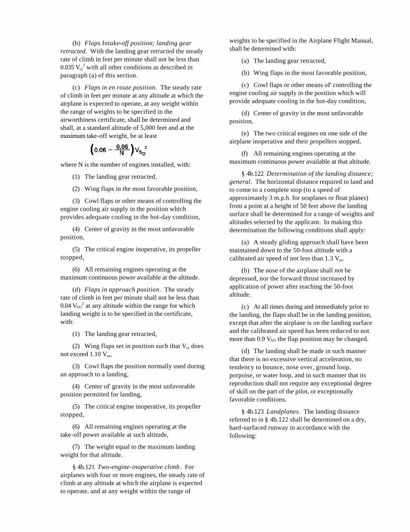
(c) Flaps in en route position. The steady rateof climb in feet per minute at any altitude at which theairplane is expected to operate, at any weight withinthe range of weights to be specified in theairworthiness certificate, shall be determined andshall, at a standard altitude of 5,000 feet and at themaximum take-off weight, be at least
where N is the number of engines installed, with:
(1) The landing gear retracted,
(2) Wing flaps in the most favorable position,
(3) Cowl flaps or other means of controlling theengine cooling air supply in the position whichprovides adequate cooling in the hot-day condition,
(4) Center of gravity in the most unfavorableposition,
(5) The critical engine inoperative, its propellerstopped,
(6) All remaining engines operating at themaximum continuous power available at the altitude.
(d) Flaps in approach position. The steadyrate of climb in feet per minute shall not be less than0.04 VSO
2 at any altitude within the range for whichlanding weight is to be specified in the certificate,with:
(1) The landing gear retracted,
(2) Wing flaps set in position such that Vs1 doesnot exceed 1.10 Vso,
(3) Cowl flaps the position normally used duringan approach to a landing,
(4) Center of' gravity in the most unfavorableposition permitted for landing,
(5) The critical engine inoperative, its propellerstopped,
(6) All remaining engines operating at thetake-off power available at such altitude,
(7) The weight equal to the maximum landingweight for that altitude.
§ 4b.121 Two-engine-inoperative climb . Forairplanes with four or more engines, the steady rate ofclimb at any altitude at which the airplane is expectedto operate, and at any weight within the range of
weights to be specified in the Airplane Flight Manual,shall be determined with:
(a) The landing gear retracted,
(b) Wing flaps in the most favorable position,
(c) Cowl flaps or other means of' controlling theengine cooling air supply in the position which willprovide adequate cooling in the hot-day condition,
(d) Center of gravity in the most unfavorableposition,
(e) The two critical engines on one side of theairplane inoperative and their propellers stopped,
(f) All remaining engines operating at themaximum continuous power available at that altitude.
§ 4b.122 Determination of the landing distance;general. The horizontal distance required to land andto come to a complete stop (to a speed ofapproximately 3 m.p.h. for seaplanes or float planes)from a point at a height of 50 feet above the landingsurface shall be determined for a range of weights andaltitudes selected by the applicant. In making thisdetermination the following conditions shall apply:
(a) A steady gliding approach shall have beenmaintained down to the 50-foot altitude with acalibrated air speed of not less than 1.3 Vso.
(b) The nose of the airplane shall not bedepressed, nor the forward thrust increased byapplication of power after reaching the 50-footaltitude.
(c) At all times during and immediately prior tothe landing, the flaps shall be in the landing position,except that after the airplane is on the landing surfaceand the calibrated air speed has been reduced to notmore than 0.9 VSO the flap position may be changed.
(d) The landing shall be made in such mannerthat there is no excessive vertical acceleration, notendency to bounce, nose over, ground loop,porpoise, or water loop, and in such manner that itsreproduction shall not require any exceptional degreeof skill on the part of the pilot, or exceptionallyfavorable conditions.
§ 4b.123 Landplanes. The landing distancereferred to in § 4b.122 shall be determined on a dry,hard-surfaced runway in accordance with thefollowing:
(a) The operating pressures on the brakingsystem shall not be in excess of those approved bythe manufacturer of' the brakes,
(b) The brakes shall not be used in such manneras to produce excessive wear of brakes or tires,
(c) Means other than wheel brakes may be usedin determining the landing distance: Provided, That:
(1) Exceptional skin is not required to controlthe airplane,
(2) The manner of their employment is such thatconsistent results could be expected under normalservice, and
(3) They are regarded as reliable.
§ 4b.124 Seaplanes or float planes. The landingdistance referred to in § 4b.122 shall be determined onsmooth water.
§ 4b.125 Skiplanes. The landing distancereferred to in § 4b.122 shall be determined on smooth,dry snow.
CONTROLLABILITY
§ 4b.130 Controllability; general. (a) Theairplane shall be safely controllable and maneuverableduring take-off, climb, level flight, descent, andlanding.
(b) It shall be possible to make a smoothtransition from one flight condition to another,including turns and slips, without requiring anexceptional degree of skill, alertness, or strength onthe part of the pilot and without danger of exceedingthe limit load factor under all conditions of operationprobable for the type, including those conditionsnormally encountered in the event of sudden failureof any engine.
§ 4b.131 Longitudinal control. (a) It shall bepossible at all speeds between 1.4 Vs1 and Vs1 to pitchthe nose downward so that a prompt recovery to aspeed equal to 1.4 Vs1, can be made with the followingcombinations of configuration:
(1) The airplane trimmed at 1.4 Vs1,
(2) The landing gear extended,
(3) The wing flaps in a retracted, and in anextended position,
(4) Power off, and maximum continuous poweron all engines.
(b) During each of the following controllabilitydemonstrations a change in the trim control, or theexertion of more control force than can be readilyapplied with one hand for a short period, shall not be
required. Each maneuver shall be performed with thelanding gear extended.
(1) With power off, flaps retracted, and theairplane trimmed at 1.4 Vs1, the flaps shall be extendedas rapidly as possible while maintaining the air speedapproximately 40 percent above the stalling speedprevailing at any instant throughout the maneuver.
(2) The maneuver of subparagraph (1) of thisparagraph shall be repeated, except that it shall bestarted with flaps extended and the airplane trimmedat 1.4 Vs1, after which the flaps shall be retracted asrapidly as possible.
(3) The maneuver of subparagraph (2) of thisparagraph shall be repeated, except that take-offpower shall be used.
(4) With power off, flaps retracted, and theairplane trimmed at 1.4 Vs1, take-off power shall beapplied quickly while maintaining the same air speed.
(5) The maneuver of subparagraph (4) of' thisparagraph shall be repeated, except that the flaps shallbe extended.
(6) With power off, flaps extended, and theairplane trimmed at 1.4 Vs1, air speeds within the rangeof 1.1 Vs1 to 1.7 Vs1 or to VFE, whichever of the two isthe lesser, shall be obtained and maintained.
(c) It shall be possible without the use ofexceptional piloting skill to prevent loss of altitudewhen wing flap retraction from any position isinitiated during steady straight level flight at a speedequal to 1.1 Vs1 with simultaneous application of notmore than maximum continuous power, with thelanding gear extended, and with the airplane weightequal to the maximum sea level landing weight. (Seealso § 4b.323.)
§ 4b.132 Directional and lateral control—(a)Directional control; general. It shall be possible,while holding the wings approximately level, toexecute reasonably sudden changes in heading ineither direction without encountering dangerouscharacteristics. Heading changes up to 15º shall bedemonstrated, except that the heading change atwhich the rudder pedal force is 180 pounds need notbe exceeded the control shall be demonstrated at aspeed equal to 1.4 Vs1, under the following conditions:
(1) The critical engine inoperative and itspropeller in the minimum drag position,

(2) Power required for level flight at 1.4 Vs1, butnot greater than maximum continuous power,
(3) Most unfavorable center of gravity position,
(4) Landing gear retracted,
(5) Wing flaps in the approach position,
(6) Maximum landing weight.
(b) Directional control; four or more engines.Airplanes with four or more engines shall comply withparagraph (a) of this section, except that:
(1) The two critical engines shall be inoperative,their propellers in the minimum drag position,
(2) The center of gravity shall be in the mostforward position,
(3) The wing flaps shall be in the most favorableclimb position.
(c) Lateral control; general. It shall bepossible to execute 20° banked turns with and againstthe inoperative engine from steady flight at a speedequal to 1.4 Vs1 with:
(1) The critical engine inoperative and itspropeller in the minimum drag position,
(2) Maximum continuous power on theoperating engines,
(3) Most unfavorable center of gravity position,
(4) Landing gear retracted and extended,
(5) Wing flaps in the most favorable climbposition,
(6) Maximum take-off weight.
(d) Lateral control; four or more engines. Itshall be possible to execute 20º banked turns with andagainst the inoperative engines from steady flight at aspeed equal to 1.4 Vs1 with maximum continuouspower and with the airplane in the configurationprescribed by paragraph (b) of this section.
§ 4b.133 Minimum control speed, VMC. (a) Aminimum speed shall be determined under theconditions specified in this paragraph, so that whenthe critical engine is suddenly made inoperative atthat speed it shall be possible to recover control of'the airplane with the engine still inoperative, andmaintain it in straight flight at that speed, either withzero yaw or, at the option of the applicant, with anangle of bank not in excess of 5°. Such speed shallnot exceed 1.2 Vs1 with:
(1) Take-off or maximum available power on allengines,
(2) Rearmost center of gravity,
(3) Flaps in take-off position,
(4) Landing gear retracted,
(5) Cowl flaps in the position normally usedduring take-off,
(6) Maximum sea level take-off weight, or suchlesser weight as may be necessary to demonstrateVMC,
(7) The airplane trimmed for take-off,
(8) The propeller of the inoperative enginewindmilling, except that a different position of thepropeller shall be acceptable if the specific design ofthe propeller control makes it more logical to assumethe different position,
(9) The airplane airborne and the ground effectnegligible.
(b) In demonstrating the minimum speed ofparagraph (a) of this section, the rudder force requiredto maintain control shall not exceed 180 pounds, andit shall not be necessary to throttle the remainingengines.
(c) During recovery of the maneuver ofparagraph (a) of this section the airplane shall notassume any dangerous attitude, nor shall it requireexceptional skill, strength, or alertness on the part ofthe pilot to prevent a change of heading in excess of20° before recovery is complete.
NOTE: Interpretation No. 1 (17 F.R. 2112, Mar.12, 1952), adopted by the Civil Aeronautics Board,Mar. 7, 1952, provides as follows:
(1) The Board interprets and construessubparagraph (8) of §4b.133 (a) as requiring theAdministrator to accept for the purposes of §4b.133 avalue for the one-engine-inoperative minimum controlspeed which has been established in accordance withthe provisions of that section with the propeller of theinoperative engine feathered: Provided, That theairplane involved is equipped with an automaticfeathering device acceptable to the Administratorunder § 4b.10 for demonstrating compliance with thetake-off path and climb requirement of §§ 4b.116 and4b.120 (a) and (b).
TRIM
§ 4b.140 General. The means used for trimmingthe airplane shall be such that after being trimmed andwithout further pressure upon, or movement of, eitherthe primary control or its

corresponding trim control by the pilot or theautomatic pilot, the airplane shall comply with the trimrequirements of §§ 4b.141 through 4b.144.
§ 4b.141 Lateral and directional trim. Theairplane shall maintain lateral and directional trimunder the most adverse lateral displacement of thecenter of' gravity within the relevant operatinglimitations, under all normally expected conditions ofoperation, including operation at any speed from 1.4Vs1 to 90 percent of the maximum speed in level flightobtained with maximum continuous power.
§ 4b.142 Longitudinal trim. The airplane shallmaintain longitudinal trim under the followingconditions:
(a) During a climb with maximum continuouspower at a speed not in excess of 1.4 Vs1 with thelanding gear retracted and the wing flaps bothretracted and in the take-off position,
(b) During a glide with power off at a speed notin excess of 1.4 Vs1 with the landing gear extended andthe wing flaps both retracted and extended, with theforward center of gravity position approved forlanding with the maximum landing weight, and withthe most forward center of gravity position approvedfor landing regardless of weight,
(c) During level flight at any speed from 1.4 Vs1
to 90 percent of the maximum speed in level flightobtained with maximum continuous power with thelanding gear and wing flaps retracted, and from 1.4 Vs1
to VLE with the landing gear extended.
§ 4b.143 Longitudinal, directional, and lateraltrim. (a) The airplane shall maintain longitudinal,directional, and lateral trim at a speed equal to 1.4 Vs1
during climbing flight with the critical engineinoperative, with
(1) The remaining engine(s) operating atmaximum continuous power,
(2) Landing gear retracted,
(3) Wing flaps retracted.
(b) In demonstrating compliance with the lateraltrim requirement of paragraph (a) of this section, theangle of bank of the airplane shall not be in excess of5 degrees.
§ 4b.144 Trim for airplanes with four or moreengines. The airplane shall maintain trim in rectilinearflight at the climb speed, configuration, and powerused in establishing the rates of climb in § 4b.121,with the most unfavorable center of gravity position,and at the weight at which the two-engine-inoperativeclimb is equal to at least 0.01 Vso
2 at an altitude of5,000 feet.
S TABILITY
§ 4b.150 General. The airplane shall belongitudinally, directionally, and laterally stable inaccordance with §§ 4b.151 through 4b.157. Suitablestability and control "feel" (static stability) shall berequired in other conditions normally encountered inservice if flight tests show such stability to benecessary for safe operation.
§ 4b.151 Static longitudinal stability. In theconditions outlined in §§ 4b.152 through 4b.155, thecharacteristics of the elevator control forces andfriction shall comply with the following:
(a) A pull shall be required to obtain andmaintain speeds below the specified trim speed, and apush shall be required to obtain and maintain speedsabove the specified trim speed. This criterion shallapply at any speed which can be obtained withoutexcessive control force, except that such speeds neednot be greater than the appropriate operating limitspeed or need not be less than the minimum speed insteady unstalled flight.
(b) The air speed shall return to within 10percent of the original trim speed when the controlforce is slowly released from any speed within thelimits defined in paragraph (a) of this section.
(c) The stable slope of stick force curve versusspeed shall be such that any substantial change inspeed is clearly perceptible to the pilot through aresulting change in stick force.
§ 4b.152 Stability during landing. The stickforce curve shall have a stable slope, and the stickforce shall not exceed 80 pounds at any speedbetween 1.1 Vs1 and 1.8 Vs1 with:
(a) Wing flaps in the landing position,
(b) The landing gear extended,
(c) Maximum landing weight,
(d) Throttles closed on all engines,
(e) The airplane trimmed at 1.4 Vs1 with throttlesclosed.
§ 4b.153 Stability during approach. The stickforce curve shall have a stable slope at all speedsbetween 1.1 Vs1 and 1.8 Vs1 with:
(a) Wing flaps in sea level approach position,
(b) Landing gear retracted,
(c) Maximum landing weight,
(d) The airplane trimmed at 1.4 Vs1 and withpower sufficient to maintain level flight at this speed.

§ 4b.154 Stability during climb . The stick forcecurve shall have a stable slope at all speeds between85 and 115 percent of the speed at which the airplaneis trimmed with:
(a) Wing flaps retracted,
(b) Landing gear retracted,
(c) Maximum take-off weight,
(d) 75 percent of maximum continuous power,
(e) The airplane trimmed at the best rate-of-climbspeed, except that the speed need not be less than1.4 Vs1.
§ 4b.155 Stability during cruising— (a) Landinggear retracted. Between 1.3 Vs1 and VNE the stickforce curve shall have a stable slope at all speedsobtainable with a stick force not in excess of 50pounds with:
(1) Wing flaps retracted,
(2) Maximum take-off weight,
(3) 75 percent of maximum continuous power,
(4) The airplane trimmed for level flight with75 percent of the maximum continuous power.
(b) Landing gear extended. The stick forcecurve shall have a stable slope at all speeds between1.3 Vs1 and the speed at which the airplane is trimmed,except that the range of speeds need not exceed thatobtainable with a stick force of 50 pounds with:
(1) Wing flaps retracted,
(2) Maximum take-off weight,
(3) 75 percent maximum continuous power, orthe power for level flight at the landing gear extendedspeed, VLE whichever is the lesser,
(4) The airplane trimmed for level flight with thepower specified in subparagraph (3) of this paragraph.
§ 4b.156 Dynamic longitudinal stability. Anyshort period oscillation occurring between stallingspeed and maximum permissible speed appropriate tothe configuration of the airplane shall be heavilydamped with the primary controls free and in a fixedposition.
§ 4b.157 Static directional and lateral stability.(a) The static directional stability, as shown by thetendency to recover from a skid with rudder free, shallbe positive with all landing gear and flap positionsand symmetrical power conditions, at all speeds from1.2 Vs1 up to the operating limit speed.
(b) The static lateral stability, as shown by thetendency to raise the low wing in a sideslip with the
aileron controls free and with all landing gear and flappositions and symmetrical power conditions, shall:
(1) Be positive at the operating limit speed,
(2) Not be negative at a speed equal to 1.2 Vs1.
(c) In straight steady sideslips (unacceleratedforward slips) the aileron and rudder controlmovements and forces shall be substantiallyproportional to the angle of sideslip, and the factor ofproportionality shall lie between limits foundnecessary for safe operation throughout the range ofsideslip angles appropriate to the operation of' theairplane. At greater angles up to that at which the fullrudder control is employed or a rudder pedal force of'180 pounds is obtained, the rudder pedal forces shallnot reverse, and increased rudder deflection shallproduce increased angles of sideslip. Sufficient bankshall accompany sideslipping to indicate clearly anydeparture from steady unyawed flight, unless a yawindicator is provided.
§ 4b.158 Dynamic directional and lateralstability. Any short period oscillation occurringbetween stalling speed and maximum permissiblespeed appropriate to the configuration of the airplaneshall be heavily damped with the primary controls freeand in a fixed position.
S TALLING CHARACTERISTICS
§ 4b.160 Stalling; symmetrical power. (a) Stallsshall be demonstrated with the airplane in straightflight and in banked turns at 30 degrees, both withpower off and with power on. In the power-onconditions the power shall be that necessary tomaintain level flight at a speed of 1.6 Vs1, where Vs1
corresponds with the stalling speed with flaps in theapproach position, the landing gear retracted, andmaximum landing weight.
(b) The stall demonstration shall be in thefollowing configurations:
(1) Wing flaps and landing gear in any likelycombination of positions,
(2) Representative weights within the range forwhich certification is sought,
(3) The center of gravity in the most adverseposition for recovery.
(c) The stall demonstration shall be conductedas follows:
(1) With trim controls adjusted for straight flightat a speed of 1.4 Vs1, the speed shall be reduced bymeans of the elevator control until it is steady atslightly above stalling speed; after which the elevatorcontrol shall be applied at a rate such that the airplane

speed reduction does not exceed one mile per hourper second until the airplane is stalled or, if theairplane is not stalled, until the control reaches thestop.
(2) The airplane shall be considered stalledwhen, at an angle of' attack measurably greater thanthat of maximum lift, the inherent flight characteristicsgive a clear indication to the pilot that the airplane isstalled
NOTE: A nose-down pitch or a roll whichcannot be readily arrested are typical indications thatthe airplane is stalled. Other indications, such asmarked loss of control effectiveness, abrupt change incontrol force or motion, characteristic buffeting, or adistinctive vibration of the pilot's controls, may beaccepted if found in a particular care to be sufficientlyclear.
(3) Recovery from the stall shall be effected bynormal recovery techniques, starting as soon as theairplane is stalled.
(d) During stall demonstration it shall bepossible to produce and to correct roll and yaw byunreversed use of the aileron and rudder controls upto the moment the airplane is stalled; there shall occurno abnormal nose-up pitching; and the longitudinalcontrol force shall be positive up to and including thestall.
(e) In straight flight stalls the roll occurringbetween the stall and the completion of the recoveryshall not exceed approximately 20 degrees.
(f) In turning flight stalls the action of theairplane following the stall shall not be so violent orextreme as to make it difficult with normal piloting skillto effect a prompt recovery and to regain control ofthe airplane
(g) In both the straight flight and the turningflight stall demonstrations it shall be possiblepromptly to prevent the airplane from stalling and torecover from the stall condition by normal use of thecontrols.
§ 4b.161 Stalling; asymmetrical power. (a) Theairplane shall be safely recoverable without applyingpower to the inoperative engine when stalled with:
(1) The critical engine inoperative,
(3) Flaps and landing gear retracted,
(3) The remaining engines operating up to75 percent of maximum continuous power, except thatthe power need not be greater than that at which thewings can be held level laterally with the use ofmaximum control travel.
(b) It shall be acceptable to throttle back theoperating engines during the recovery from the stall.
§ 4b.162 Stall warning. Clear and distinctivestall warning shall be apparent to the pilot withsufficient margin to prevent inadvertent stalling of theairplane with flaps and landing gear in all normallyused positions, both in straight and in turning flight.It shall be acceptable for the warning to be furnishedeither through the inherent aerodynamic qualities ofthe airplane or by a device which will give clearlydistinguishable indications under all expectedconditions of flight.
NOTE: A stall warning beginning at a speed7 percent above the stalling speed is normallyconsidered sufficient margin. Other margins may beacceptable depending upon the degree of clarity,duration, and distinctiveness of the warning andupon other characteristics of the airplane evidencedduring the approach to the stall.
GROUND HANDLING CHARACTERISTICS
§ 4b.170 Longitudinal stability and control. (a)There shall be no uncontrollable tendency forlandplanes to nose over in any reasonably expectedoperating condition or when rebound occurs duringlanding or take-off.
(b) Wheel brakes shall operate smoothly andshall exhibit no undue tendency to induce nosingover.
(c) When a tail-wheel landing gear is used itshall be possible during the take-off ground run onconcrete to maintain any attitude up to thrust linelevel at 80 percent of Vs1.
§ 4b.171 Directional stability and control. (a)There shall be no uncontrollable ground-loopingtendency in 90° cross winds of velocity up to 0.2 VSO
at any ground speed at which the airplane is expectedto operate.
(b) All landplanes shall be demonstrated to besatisfactorily controllable with no exceptional degreeof skill or alertness on the part of the pilot inpower-off landings at normal landing speed duringwhich brakes or engine power are not used tomaintain a straight path.
(c) Means shall be provided for directionalcontrol of the airplane during taxying.
2It is not the intent of this requirement to discourage such stall warning buffeting as does not contradict theseprovisions.
§ 4b.172 Shock absorption. The shockabsorbing mechanism shall not produce damage tothe structure when the airplane is taxied on theroughest ground which it is reasonable to expect theairplane to encounter in normal operation.
§ 4b.173 Demonstrated cross wind. There shallbe established a cross component of wind velocity atwhich it has been demonstrated to be safe to take offor land.
WATER HANDLING CHARACTERISTICS
§ 4b.180 Water conditions. The most adversewater conditions in which the seaplane has beendemonstrated to be safe for take-off, taxying, andalighting shall be established:
§ 4b.181 Wind conditions. The following windvelocities shall be established:
(a) A lateral component of wind velocity notless than 0.2 VSO at and below which it has beendemonstrated that the seaplane is safe for taking offand alighting under all water conditions in which theseaplane is likely to be operated;
(b) A wind velocity at and below which it hasbeen demonstrated that the seaplane is safe in taxyingin all directions, under all water conditions in whichthe seaplane is likely to be operated.
§ 4b.182 Control and stability on the water. (a)In taking off, taxying, and alighting, the seaplane shallnot exhibit the following:
(1) Any dangerously uncontrollable porpoising,bouncing, or swinging tendency;
(2) Any submerging of auxiliary floats orsponsons, any immersion of' wing tips, propellerblades, or other parts of the seaplane which are notdesigned to withstand the resulting water loads;
(3) Any spray forming which would impair thepilot's view, cause damage to the seaplane, or result iningress of' an undue quantity of water.
(b) Compliance with paragraph (a) of thissection shall be shown under the followingconditions:
(1) All water conditions from smooth to themost adverse condition established in accordancewith § 4b.180;
(2) All wind and cross-wind velocities, watercurrents, and associated waves and swells which theseaplane is likely to encounter in operation on water;
(3) All speeds at which the seaplane is likely tobe operated on the water;
(4) Sudden failure of the critical engineoccurring at any time while the airplane is operated onwater;
(5) All seaplane weights and center of gravitypositions within the range of loading conditions forwhich certification is sought, relevant to eachcondition of' operation.
(c) In the water conditions of paragraph (b) of'this section and the corresponding wind conditionsthe seaplane shall be able to drift for 5 minutes withengines inoperative, aided if necessary by a seaanchor.
MISCELLANEOUS FLIGHT REQUIREMENTS
§ 4b.190 Flutter and vibration. (a) All parts of'the airplane shall be demonstrated in flight to be freefrom flutter and excessive vibration under all speedand power conditions appropriate to the operation ofthe airplane up to at least the minimum valuepermitted for VD in §4b.210(b)(5). The maximumspeeds so demonstrated shall be used in establishingthe operating limitations of the airplane in accordancewith § 4b.711
(b) There shall be no buffeting condition innormal flight severe enough to interfere with thecontrol of the airplane, to cause excessive fatigue tothe crew, or to cause structural damage.2 (See also§4b.308.)
SUBPART C—STRUCTURE
GENERAL
§ 4b.200 Loads. Strength requirements of thissubpart are specified in terms of limit and ultimateloads. Unless otherwise stated, the specified loadsshall be considered as limit loads. In determiningcompliance with these requirements the followingshall be applicable:
(a) The factor of' safety shall be 1.5 unlessotherwise specified.
(b) Unless otherwise provided, the specified air,ground, and water loads shall be placed in equilibriumwith inertia forces, considering all items of mass in theairplane.
(c) All loads shall be distributed in a mannerclosely approximating or conservatively representingactual conditions.
(d) If deflections under load significantlychange the distribution of' external or internal loads,the redistribution shall be taken into account.
§ 4b.201 Strength and deformation. (a) Thestructure shall be capable of supporting limit loads

without suffering detrimental permanentdeformations.
(b) At all loads up to limit loads the deformationshall be such as not to interfere with safe operation ofthe airplane.
(c) The structure shall be capable of supportingultimate loads without failure. It shall support theload for at least 3 seconds, unless proof of strength isdemonstrated by dynamic tests simulating actualconditions of load application.
(d) Where structural flexibility is such that anyrate of load application likely to occur in the operatingconditions might produce transient stressesappreciably higher than those corresponding withstatic loads, the effects of such rate of' applicationshall be considered.
§ 4b.202 Proof of structure. (a) Proof ofcompliance of the structure with the strength anddeformation requirements of § 4b.201 shall be madefor all critical loading conditions.
(b) Proof of compliance by means of structuralanalysis shall be acceptable only when the structureconforms to types for which experience has shownsuch methods to be reliable. In all other casessubstantiating tests shall be required.
(c) In all cases certain portions of the structureshall be tested as specified in §4b.300.
FLIGHT LOADS
§ 4b.210 General. Flight load requirements shallbe complied with at critical altitudes within the rangeselected by the applicant, at all weights from thedesign minimum weight to the design maximumweight, the latter not being less than the designtake-off weight, with any practicable distribution ofdisposable load within prescribed operatinglimitations stated in the Airplane Flight Manual(see § 4b.740). At all speeds in excess of thosecorresponding with a Mach number of 0.65,compressibility effects shall be taken into account.
(a) Flight load factor. The flight load factorsspecified in this subpart shall represent thecomponent of acceleration in terms of thegravitational constant. The flight load factor shall beassumed to act normal to the longitudinal axis of theairplane, shall be equal in magnitude, and shall beopposite in direction to the airplane inertia load factorat the center of gravity.
(b) Design air speeds. The design air speedsshall be equivalent air speeds (EAS) and shall bechosen by the applicant, except that they shall not beless than the speeds defined in subparagraphs (1)
through (5) of this paragraph. Where estimatedvalues of the speeds VSO and Vs1 are used, suchestimates shall be conservative.
(1) Design flap speed, VF. The minimum valuesof the design flap speed shall be equal to 1.4 Vs1 or1.8 VSO, whichever is the greater, where Vs1 is thestalling speed with flaps retracted at the designlanding weight, and VSO is the stalling speed withflaps in the landing position at the design landingweight. (See § 4b.212 (d) regarding automatic flapoperation.)
(2) Design maneuvering speed, VA. The design
maneuvering speed VA shall be equal to Vs1 wheren is the limit maneuvering load factor used (see§ 4b.211(a)) and Vs1 is the stalling speed with flapsretracted at the design take-off weight. (See fig. 4b-2.)

(3) Design speed for maximum gust intensity,VB. VB shall be the speed at which the 40 f.p.s. gustline intersects the positive CNmax curve on the gustV-n envelope. (See § 4b.211(b) and fig. 4b-3.)
(4) Design cruising speed, VC. The minimumdesign cruising speed VC shall be sufficiently greaterthan VB, to provide for inadvertent speed increaseslikely to occur as a result of severe atmosphericturbulence. In the absence of a rational investigationsubstantiating the use of other values, VC shall not beless than VB+50 (m. p. h.), except that it need notexceed the maximum speed in level flight at maximumcontinuous power for the corresponding altitude. Ataltitudes where VD is limited by Mach number, VC
need not exceed 0.8 VD, as shown in figure 4b-1,except that it shall not be less than 1.3 Vs1 with theflaps retracted at the maximum altitude for whichcertification is desired.
(5) Design dive speed VD. The minimum designdive speed VD shall be sufficiently greater than VC toprovide for safe recovery from inadvertent upsetsoccurring at VC. In the absence of a rationalinvestigation, the minimum value of VD shall not beless than 1.25 VC or VC+70 (m.p.h.), whichever is thegreater, in the altitude range between sea level and analtitude selected by the applicant. At higher altitudesit shall be acceptable to limit VD to a Mach numberselected by the applicant. (See fig. 4b-1.)
§ 4b.211 Flight envelopes. The strengthrequirements shall be met at all combinations of airspeed and load factor on and within the boundaries ofthe V-n diagrams of figures 4b-2 and 4b-3 whichrepresent the maneuvering and gust envelopes.These envelopes shall also be used in determining theairplane structural operating limitations as specified in§ 4b.710.
(a) Maneuvering load factory. (See fig. 4b-2.)The airplane shall be assumed to be subjected tosymmetrical maneuvers resulting in the limit loadfactors prescribed in subparagraphs (1) and (2) of thisparagraph, except where limited by maximum (static)lift coefficients. Pitching velocities appropriate to thecorresponding pull-up and steady turn maneuversshall be taken into account. Lower values ofmaneuvering load factor shall be acceptable only if itis shown that the airplane embodies features ofdesign which make it impossible to exceed suchvalues in flight.
(1) The positive maneuvering load factor n forany flight speed up to VD shall be selected by theapplicant, except that it shall not be less than 2.5.
(2) The negative maneuvering load factor shallhave a minimum value of -1.0 at all speeds up to VC,
and it shall vary linearly with speed from the value atVC to zero at VD.
(b) Gust load factors. The airplane shall beassumed to be subjected to symmetrical vertical gustswhile in level flight. The resulting limit load factorsshall correspond with the following conditions:
(1) Positive (up) and negative (down) gusts of40 f.p.s. nominal intensity at a speed VB shall beapplicable where the positive 40 f.p.s. gust lineintersects the positive CNMAX curve. It this gustintensity produces load factors greater than thoseobtained in condition (2) of this paragraph, it shall beacceptable to modify it at altitudes above 20,000 ft. insuch a manner as to produce a load factor not lessthan that obtained in condition (2) of this paragraph.
(2) Positive and negative gust of 30 f.p.s. shallbe considered at VC.
(3) Positive and negative gusts of 15 f.p.s. shallbe considered at VD.
(4) Gust load factors shall be assumed to varylinearly between the specified conditions as shownon the gust envelope of figure 4b-3.
(5) In the absence of a more rational analysis thegust load factors shall be computed by the followingformula:
§ 4b.212 Effect of high lift devices. When flapsor similar high lift devices intended for use at therelatively low air speeds of approach, landing, andtake-off are installed, the airplane shall be assumed tobe subjected to symmetrical maneuvers and gustswith the flaps in landing position at the design flapspeed VF resulting in limit load factors within therange determined by the following conditions:
(a) Maneuvering to a positive limit load factor of2.0,
(b) Positive and negative 15 fps nominalintensity gusts acting normal to the flight path in levelflight,
(c) In designing flaps and supporting structureon tractor type airplanes, slipstream effects shall betaken into account as specified in § 4b.221. For otherthan tractor type airplanes a head-on gust of 25 feetper second with no alleviations acting along the flightpath shall be considered.
(d) When automatic operation is provided, theairplane shall be designed for the speeds and thecorresponding flap positions which the mechanismpermits. (See § 4b.323.)
§ 4b.213 Symmetrical flight condition— (a)Procedures of analysis. In the analysis ofsymmetrical flight conditions at least those specifiedin paragraphs (b), (c), and (d) of this section shall beconsidered. The following procedure of analysis shallbe applicable:
(1) A sufficient number of points on themaneuvering and gust envelopes shall beinvestigated to insure that the maximum load for eachpart of the airplane structure is obtained. It shall beacceptable to use a conservative combined envelopefor this purpose.
(2) All significant forces acting on the airplaneshall be placed in equilibrium in a rational or aconservative manner. The linear inertia forces shallbe considered in equilibrium with wing and horizontaltail surface loads, while the angular (pitching) inertiaforces shall be considered in equilibrium with wingand fuselage aerodynamic moments and horizontal tailsurface loads.
(3) Where sudden displacement of a control isspecified, the assumed rate of displacement need notexceed that which actually could be applied by thepilot.
(4) In determining elevator angles andchordwise load distribution in the maneuveringconditions of paragraphs (b) and (c) of this section inturns and pull-ups, account shall be taken of theeffect of corresponding pitching velocities.
(b) Maneuvering balanced conditions. Themaneuvering conditions A through I on themaneuvering envelope (fig. 4b-2) shall beinvestigated, assuming the airplane to be inequilibrium with zero pitching acceleration.
(c) Maneuvering pitching conditions. Thefollowing conditions on figure 4b-2 involving pitchingacceleration shall be investigated:
(1) A1, Unchecked pull-up at speed VA . Theairplane shall be assumed to be flying in steady levelflight (point A1 on fig. 4b-2) and the pitching controlsuddenly moved to obtain extreme positive pitching(nose up), except as limited by pilot effort,§ 4b.220 (a).
(2) A2, Checked maneuvers at speed VA. (i) Theairplane shall be assumed to be maneuvered to thepositive maneuvering load factor by a checkedmaneuver from an initial condition of steady levelflight (point A1 on fig. 4b-2). The initial positivepitching portion of this maneuver may be consideredto be covered by subparagraph (1) of this paragraph
(ii) A negative pitching acceleration (nosedown) of at least the following value shall be assumedto be attained concurrently with the airplanemaneuvering load factor (point A2, on fig. 4b-2),unless it is shown that a lesser value could not beexceeded:
where n is equal to the value of the positivemaneuvering load factor as defined by point A2 onfigure 4b-2.
(3) D1 and D2 checked maneuver at VD. Theairplane shall be assumed to be subjected to achecked maneuver from steady level flight (point D1
on fig. 4b-2) to the positive maneuvering load factor(point D2 on fig. 4b-2) as follows:
(i) A positive pitching acceleration (nose up),equal to at least the following value, shall be assumedto be attained concurrently with the airplane loadfactor of unity, unless it is shown that lesser valuescould not be exceeded:
where n is equal to the value of the positivemaneuvering load factor as defined by point D2 onfigure 4b-2.
(ii) A negative pitching acceleration (nosedown) equal to at least the following value shall beassumed to be attained concurrently with the airplanepositive maneuvering load factor (point D2 on fig.4b-2), unless it is shown that lesser values could notbe exceeded:

where n is equal to the value of the positivemaneuvering load factor as defined by point D2, onfigure 4b-2.
(d) Gust condition. The gust conditions B'through J' on figure 4b-3 shall be investigated. Thefollowing provisions shall apply:
(1) The air load increment due to a specifiedgust shall be added to the initial balancing tail loadcorresponding with steady level flight.
(2) It shall be acceptable to include thealleviating effect of wing down-wash and of theairplane's motion in response to the gust incomputing the tail gust load increment.
(3) In lieu of a rational investigation of theairplane response it shall be acceptable to apply thegust factor K (see §4b.211 (b)) to the specified gustintensity for the horizontal tail.
§ 4b.214 Rolling conditions. The airplane shallbe designed for rolling loads resulting from theconditions specified in paragraphs (a) and (b) of thissection. Unbalanced aerodynamic moments about thecenter of gravity shall be reacted in a rational or aconservative manner considering the principal massesfurnishing the reacting inertia forces.
(a) Maneuvering. The following conditions,aileron deflection, and speeds, except as thedeflections may be limited by pilot effort (see § 4b.220(a)), shall be considered in combination with anairplane load factor of zero and of two-thirds of thepositive maneuvering factor used in the design of theairplane. In determining the required ailerondeflections, the torsional flexibility of the wing shallbe taken into account in accordance with § 4b.200 (d).
(1) Conditions corresponding with steadyrolling velocity shall be investigated. In addition,conditions corresponding with maximum angularacceleration shall be investigated for airplanes havingengines or other weight concentrations outboard ofthe fuselage. For the angular acceleration conditions,it shall be acceptable to assume zero rolling velocityin the absence of a rational time history investigationof the maneuver.
(2) At speed VA a sudden deflection of theaileron to the stop shall be assumed.
(3) At speed VC the aileron deflection shall bethat required to produce a rate of roll not less thanthat obtained in condition (2) of this paragraph.
(4) At speed VD the aileron deflection shall bethat required to produce a rate of roll not less thanone-third of that in condition (2) of this paragraph.
(b) Unsymmetrical gusts. The condition ofunsymmetrical gusts shall be considered bymodifying the symmetrical flight conditions B' or C' offigure 4b-3, whichever produces the greater loadfactor it shall be assumed that 100 percent of the wingair load acts on one side of the airplane, and 80percent acts on the other side.
§ 4b.215 Yawing conditions. The airplane shallbe designed for loads resulting from the conditionsspecified in paragraphs (a) and (b) of this section.Unbalanced aerodynamic moments about the centerof gravity shall be reacted in a rational or aconservative manner considering the principal massesfurnishing the reacting inertia forces.
(a) Maneuvering. At all speeds from VMC to VA
the following maneuvers shall be considered. Incomputing the tail loads it shall be acceptable toassume the yawing velocity to be zero.
(1) With the airplane in unaccelerated flight atzero yaw, it shall be assumed that the rudder controlis suddenly displaced to the maximum deflection aslimited by the control stops or by a 300 lb. rudderpedal force, whichever is critical
(2) With the rudder deflected as specified insubparagraph (1) of this paragraph it shall beassumed that the airplane yaws to the resultingsideslip angle.
(3) With the airplane yawed to the static sideslipangle corresponding with the rudder deflectionspecified in subparagraph (1) of this paragraph, itshall be assumed that the rudder is returned toneutral.
(b) Lateral gusts. The airplane shall be assumedto encounter gusts of 30 f. p. s. nominal intensitynormal to the plane of symmetry while inunaccelerated flight at speed VC. In the absence of arational investigation of the airplane's response to atrue gust, it shall be acceptable to compute the gustloading on the vertical tail surfaces by the followingformula:

§ 4b.216 Supplementary conditions.—(a)Engine torque effects. Engine mounts and theirsupporting structures shall be designed for enginetorque effects combined with basic flight conditionsas described in subparagraphs (1) and (2) of thisparagraph. The limit torque shall be obtained bymultiplying the mean torque by a factor of 1.33 in thecase of engines having 5 or more cylinders. For 4, 3,and 2-cylinder engines, the factors shall be 2, 3, and 4,respectively.
(1) The limit torque corresponding with take-offpower and propeller speed shall act simultaneouslywith 75 percent of the limit loads from flight conditionA (see fig 4b-2).
(2) The limit torque corresponding withmaximum continuous power and propeller speed shallact simultaneously with the limit loads from flightcondition A (see fig. 4b-2).
(b) Side load on engine mount. The limit loadfactor in a lateral direction for this condition shall beequal to the maximum obtained in the yawingconditions, but shall not be less than either 1.33 orone-third the limit load factor for flight condition A(see fig. 4b-2). Engine mounts and their supportingstructure shall be designed for this condition whichmay be assumed independent of other flightconditions.
(c) Pressurized cabin loads. When pressurizedcompartments are provided for the occupants of theairplane, the following requirements shall be met. (See§ 4b.373.)
(1) The airplane structure shall have sufficientstrength to withstand the flight loads combined withpressure differential loads from zero up to themaximum relief valve setting. Account shall be takenof the external pressure distribution in flight
(2) If landings are to be permitted with the cabinpressurized, landing loads shall be combined with
pressure differential loads from zero up to themaximum to be permitted during landing.
(3) The airplane structure shall have sufficientstrength to withstand the pressure differential loadscorresponding with the maximum relief valve settingmultiplied by a factor of 1.33 to provide for sucheffects as fatigue and stress concentration. It shall beacceptable to omit all other loads in this case.
(4) Where a pressurized cabin is separated intotwo or more compartments by bulkheads or floor, theprimary structure shall be designed for the effects ofsudden release of pressure in any compartmenthaving external doors or windows. This conditionshall be investigated for the effects resulting from thefailure of the largest opening in a compartment.Where intercompartment venting is provided, it shallbe acceptable to take into account the effects of suchventing.
CONTROL S URFACE AND S YSTEM LOADS
§ 4b.220 Control surface loads; general. Thecontrol surfaces shall be designed for the limit loadsresulting from the flight conditions prescribed in§ 4b.213 through 4b.215 and the ground gustconditions prescribed in § 4b.226, taking into accountthe provisions of paragraphs (a) through (e) of thissection.
(a) Effect of pilot effort, (1) In the control surfaceflight loading conditions the air loads on the movablesurfaces and the corresponding deflections need notexceed those which could be obtained in flight byemploying the maximum pilot control forces specifiedin fig. 4b-5, except that two-thirds of the maximumvalues specified for the aileron and elevator shall beacceptable when control surface hinge moments arebased on reliable data. In applying this criterion,proper consideration shall be given to the effects ofservo mechanisms, tabs, and automatic pilot systemsin assisting the pilot.
(b) Effect of trim tabs. The effect of trim tabs onthe main control surface design conditions need betaken into account only in cases where the surfaceloads are limited by pilot effort in accordance with theprovisions of paragraph (a) of this section. In suchcases the trim tabs shall be considered to be deflectedin the direction which would assist the pilot, and thedeflection shall be as follows:
(1) For elevator trim tabs the deflections shall bethose required to trim the airplane at any point withinthe positive portion of the V-n diagram (fig. 4b-2),except as limited by the stops.
(2) For ailerons and rudder trim tabs thedeflections shall be those required to trim the

airplane in the critical unsymmetrical power andloading conditions, with appropriate allowance forrigging tolerances.
(c) Unsymmetrical loads. Horizontal tailsurfaces and the supporting structure shall bedesigned for unsymmetrical loads arising from yawingand slipstream effects in combination with theprescribed flight conditions.
NOTE: In the absence of more rational data, thefollowing assumptions may be made for airplaneswhich are conventional in regard to location ofpropellers, wings, tail surfaces, and fuselage shape:100 percent of the maximum loading from thesymmetrical flight conditions acting on the surface onone side of the plane of symmetry and 80 percent ofthis loading on the other side. Where the design isnot conventional (e. g., where the horizontal tailsurfaces have appreciable dihedral or are supportedby the vertical tail surfaces), the surfaces andsupporting structures may be designed for combinedvertical and horizontal surface loads resulting fromthe prescribed maneuvers.
(d) Outboard fins. (1) When outboard fins arecarried on the horizontal tail surface, the tail surfacesshall be designed for the maximum horizontal surfaceload in combination with the corresponding loadsinduced on the vertical surfaces by end plate effects.Such induced effect need not be combined with othervertical surface loads.
(2) To provide for unsymmetrical loading whenoutboard fins extend above and below the horizontalsurface, the critical vertical surface loading (load perunit area) as determined by the provisions of thissection shall also be applied as follows:
(i) 100 percent to the area of the verticalsurfaces above (or below) the horizontal surface, and
(ii) 80 percent to the area below (or above) thehorizontal surface.
(e) Loads parallel to hinge line. Controlsurfaces and supporting hinge brackets shall bedesigned for inertia loads acting parallel to the hingeline.
NOTE: In lieu of a more rational analysis theinertial loads may be assumed to be equal to KW,where:
K=24 for vertical surfaces,
K= 12 for horizontal surfaces,
W = weight of the movable surfaces.
§ 4b.221 Wing flaps. (a) Wing flaps, theiroperating mechanism, and supporting structure shall
be designed for critical loads prescribed by § 4b.212with the flaps extended to any position from fullyretracted to the landing position.
(b) The effects of propeller slipstreamcorresponding with take-off power shall be taken intoaccount at an airplane speed of not less than 1.4 Vs1,where Vs1 is the stalling speed with flaps as follows:(For automatic flaps see § 4b.212 (d).)
(1) Landing and approach settings at the designlanding weight,
(2) Take-off and en route settings at the designtake-off weight.
(c) It shall be acceptable to assume the airplaneload factor to be equal to 1.0 for investigating theslipstream condition.
§ 4b.222 Tabs. The following shall apply to tabsand their installations:
(a) Trimming tabs. Trimming tabs shall bedesigned to withstand loads arising from all likelycombinations of tab setting, primary control position,and airplane speed, obtainable without exceeding theflight load conditions prescribed for the airplane as awhole, when the effect of the tab is being opposed bypilot effort loads up to those specified in §4b.220 (a).
(b) Balancing tabs. Balancing tabs shall bedesigned for deflections consistent with the primarycontrol surface loading conditions.
(c) Servo tabs. Servo tabs shall be designed forall deflections consistent with the primary controlsurface loading conditions achievable within the pilotmaneuvering effort (see § 4b.220 (a)) with due regardto possible opposition from the trim tabs.
§ 4b.223 Special devices. The loading forspecial devices employing aerodynamic surfaces,such as slots and spoilers, shall be based on testdata.
§ 4b.224 Primary flight control systems.Elevator, aileron, and rudder control systems and theirsupporting structures shall be designed for loadscorresponding with 125 percent of the computedhinge moments of the movable control surface in theconditions prescribed in § 4b.220, subject to thefollowing provisions:
(a) The system limit loads, except the loadsresulting from ground gusts (§ 4b.226), need notexceed those which can be produced by the pilot orpilots and by automatic devices operating thecontrols. Acceptable maximum and minimum pilotloads for elevator, aileron, and rudder controls areshown in figure 4b-5. These pilot loads shall be

assumed to act at the appropriate control grips orpads in a manner simulating flight conditions and to

be reacted at the attachment of the control system tothe control surface horn.
(b) The loads shall in any case be sufficient toprovide a rugged system for service use, includingconsiderations of jamming, ground gusts, taxying tailto wind, control inertia, and friction.
§ 4b.225 Dual primary flight control systems. (a)When dual controls are provided, the system shall bedesigned for the pilots operating in opposition, usingindividual pilot loads equal to 75 percent of thoseobtained in accordance with § 4b.224, except that theindividual pilot loads shall not be less than theminimum loads specified in figure 4b-5.
(b) The control system shall be designed for thepilots acting in conjunction, using individual pilotloads equal to 75 percent of those obtained inaccordance with § 4b.224.
§ 4b.226 Ground gust conditions. The followingconditions intended to simulate the loadings oncontrol surfaces due to ground gusts and whentaxying downwind shall be investigated:
(a) The loads in the systems between the stopsnearest the surfaces and the cockpit controls neednot exceed those corresponding with the maxima offigure 4b-5 for each pilot alone, or with 75 percent ofthese maxima for each pilot when the pilots act inconjunction.
(b) The control system stops nearest thesurfaces, the control system locks, and the portionsof the systems, if any, between such stops and locksand the control surface horns shall be designed forlimit hinge moments H obtained from the followingformula:
§ 4b.227 Secondary control systems. Secondarycontrols, such as wheel brake, spoiler, and tabcontrols, shall be designed for the loads based on themaximum which a pilot is likely to apply to the controlin question. The values of figure 4b-6 are consideredacceptable.
Surface K Position of Controls(a) Aileron................... 0.75 Control column locked
or lashed in mid-position.
(b) Aileron .................. *±0.50 Ailerons at full throw.(c)(d)
{Elevator .......................{
*±0.75 {(c) Elevator full down.{(d) Elevator full up.
(e)(f)
{Rudder.........................{
0.75 {(e) Rudder in neutral.{(f) Rudder at full throw.
* A positive value of K indicates a momenttending to depress the surface, while a negative valueof K indicates a moment tending to raise the surface.
FIGURE 4b-4—Limit hinge moment factor forground gusts
[Limit pilot loads (one pilot)]Control Maximum Load Minimum
LoadAileron Stick............................. Wheel * .......................
100 lbs...........................80 D in. lbs.**..............
40 lbs.40 D in. lbs.
Elevator: Stick............................. Wheel..........................Rudder...........................
250 lbs...........................300 lbs...........................300 lbs...........................
100 lbs.100 lbs.130 lbs.
* The critical portions of the aileron controlsystem shall be designed for a single tangent forcehaving a limit value equal to 1.25 times the coupleforce determined from these criteria.** D = wheel diameter.
FIGURE 4b-5—Pilot control force limits (primarycontrols).
Control Limit pilot loadsMiscellaneous:*Crank wheel orlever.
1+R x 50lbs., but not 3 less than 50 lbs., nor more than 150 lbs. (R=radius).(Applicable to any anglewithin 20° of plane ofcontrol.)
Twist--------------------- 133 in. lbs.Push-pull-----------------
To be chosen by applicant.
* Limited to flap, tab, stabilizer, spoiler, andlanding gear operating controls.
FIGURE 4b-6—Pilot control force limits(secondary controls).
GROUND LOADS
§ 4b.230 General. The limit loads obtained inthe conditions specified in §§ 4b.231 through 4b.236shall be considered as external forces applied to theairplane structure and shall be placed in equilibriumby linear and angular inertia forces in a rational orconservative manner. In applying the specified

conditions the provisions of paragraph (a) of thissection shall be complied with. In addition, for thelanding conditions of §§ 4b.231 through 4b.234 theairplane shall be assumed to be subjected to forcesand descent velocities prescribed in paragraph (b) of

this section. (The basic landing gear dimensionaldata are given in figure 4b-7.)
(a) Center of gravity positions. The criticalcenter of gravity positions within the certificationlimits shall be selected so that the maximum designloads in each of the landing gear elements areobtained in the landing and the ground handlingconditions.
(b) Load factors, descent velocities, and designweights for landing conditions. (1) In the landingconditions the limit vertical inertia load factors at thecenter of gravity of the airplane shall be chosen bythe applicant, except that they shall not be less thanthe values which would be obtained when landing theairplane with the following limit descent velocities andweights:
FIGURE 4b-8—Level landing
FIGURE 4b-9—Tail down landing

(i) 10 f.p.s. at the design landing weight, and
(ii) 6 f.p.s. at the design take-off weight.
(2) It shall be acceptable to assume a wing lift notexceeding two-thirds of the airplane weight to existthroughout the landing impact and to act through thecenter of gravity of the airplane.
(3) The provisions of subparagraphs (1) and (2) ofthis paragraph shall be predicated on conventionalarrangements of main and nose gears, or main and tailgears, and on normal operating techniques. It shall beacceptable to modify the prescribed descent velocities if itis shown that the airplane embodies features of designwhich make it impossible to develop these velocities. (See§ 4b.332 (a) for requirements on energy absorption testswhich determine the minimum limit inertia load factorscorresponding with the required limit descent velocities.)
§ 4b.231 Level landing conditions—(a) General. Inthe level attitude the airplane shall be assumed to contactthe ground at a forward velocity component parallel to theground equal to 1.2 VSO and shall be assumed to besubjected to the load factors prescribed in § 4b.230 (b) (1).The following three combinations of vertical and dragcomponents shall be considered acting at the axle centerline:
(1) Condition of maximum wheel spin-up load. Dragcomponents simulating the forces required to acceleratethe wheel rolling assembly up to the specified groundspeed shall be combined with the vertical ground reactionsexisting at the instant of peak drag loads. A coefficient offriction between the tires and ground need not be assumedto be greater than 0.8. It shall be acceptable to apply thiscondition only to the landing gear and the directly affectedattaching structure.
(2) Condition of maximum wheel vertical load. Anaft acting drag component not less than 25 percent of themaximum vertical ground reaction shall be combined withthe maximum ground reaction of § 4b.230 (b).
(3) Condition of maximum spring-back load.Forward-acting horizontal loads resulting from a rapidreduction of the spin-up drag loads shall be combined withthe vertical ground reactions at the instant of the peakforward load. It shall be acceptable to apply this conditiononly to the landing gear and the directly affected structure.
(b) Level landing; tail-wheel type. The airplanehorizontal reference line shall be assumed to be horizontal.The conditions specified in paragraph (a) of this sectionshall be investigated (See fig. 4b-8.)
(c) Level landing; nose-wheel type. The followingairplane attitudes shall be considered: (See fig. 4b-8.)
(1) Main wheels shall be assumed to contact theground with the nose wheel just clear of the ground. Theconditions specified in paragraph (a) of this section shallbe investigated.
(2) Nose and main wheels shall be assumed tocontact the ground simultaneously. Conditions in thisattitude need not be investigated if this attitude cannotreasonably be attained at the specified descent andforward velocities. The conditions specified in paragraph(a) of this section shall be investigated, except that inconditions (a)(1) and (a)(3) it shall be acceptable toinvestigate the nose and the main gear separatelyneglecting the pitching moments due to wheel spin-up andspring-back loads, while in condition (a)(2) the pitchingmoment shall be assumed to be resisted by the nose gear.
§ 4b.232 Tail-down landing conditions. Thefollowing conditions shall be investigated for the loadfactors obtained in § 4b.230 (b)(1) with the vertical groundreactions applied to the landing gear axles.
(a) Tail-wheel type. The main and tail wheels shallbe assumed to contact the ground simultaneously. (Seefig. 4b-9.) Two conditions of ground reaction on the tailwheel shall be assumed to act in the following conditions:
(1) Vertical,
(2) Up and aft through the axle at 45° to the groundline.
(b) Nose-wheel type. The airplane shall be assumedto be at an attitude corresponding with either the stallingangle or the maximum angle permitting clearance with theground by all parts of the airplane other than the mainwheels, whichever is the lesser. (See fig. 4b-9.)
§ 4b.233 One-wheel landing condition. The mainlanding gear on one side of the airplane center line shall beassumed to contact the ground in the level attitude. (Seefig. 4b-10.) The ground reactions on this side shall be thesame as those obtained in § 4b.231 (a)(2). The unbalancedexternal loads shall be reacted by inertia of the airplane in arational or conservative manner.
FIGURE 4b-10—One wheel landing
§ 4b.234 Lateral drift landing condition. (a) Theairplane shall be assumed to be in the level attitude withonly the main wheels contacting the ground. (See fig.4b-11.)

FIGURE 4b-11—Lateral draft landing
(b) Side loads of 0.8 of the vertical reaction (on oneside) acting inward and 0.6 of the vertical reaction (on theother side) acting outward shall be combined with one-halfof the maximum vertical ground reactions obtained in thelevel landing conditions. These loads shall be assumed tobe applied at the ground contact point and to be resistedby the inertia of the airplane. It shall be acceptable toassume the drag loads to be zero.
§ 4b.235 Ground handling conditions. The landinggear and airplane structure shall be investigated for theconditions of this section with the airplane at the designtake-off weight, unless otherwise prescribed. No wing liftshall be considered. It shall be acceptable to assume theshock absorbers and tires to be deflected to their staticposition.
(a) Take-off run. The landing gear and the airplanestructure shall be assumed to be subjected to loads notless than those encountered under conditions described in§ 4b.172.
(b) Braked roll (1) Tail-wheel type. The airplaneshall be assumed to be in the level attitude with all load onthe main wheels. The limit vertical load factor shall be 1.2for the airplane at the design landing weight, and 1.0 forthe airplane at the design take-off weight. A drag reactionequal to the vertical reaction multiplied by a coefficient of'friction of 0.8 shall be combined with the vertical groundreaction and applied at the ground contact point. (See fig.4b-12.)
(2) Nose-wheel type. The limit vertical load factorshall be 1.2 for the airplane at the design landing weightand 1.0 for the airplane at the design take-off weight. Adrag reaction equal to the vertical reaction multiplied by acoefficient of friction of 0.8 shall be combined with thevertical reaction and applied at the ground contact point ofeach wheel having brakes. The following two airplaneattitudes shall be considered: (See fig. 4b-12.)
(i) The airplane shall be assumed to be in the levelattitude with all wheels contacting the ground and theloads distributed between the main and nose gear. Zeropitching acceleration shall be assumed.
(ii) The airplane shall be assumed to be in the levelattitude with only the main gear contacting the ground andthe pitching moment resisted by angular acceleration.
(c) Turning. The airplane in the static position shallbe assumed to execute a steady turn by nose gear steeringor by application of differential power such that the limitload factors applied at the center of gravity are 1.0vertically and 0.5 laterally. (See fig. 4b-13.) The sideground reaction of each wheel shall be 0.5 of the verticalreaction.
(d) Pivoting. The airplane shall be assumed to pivotabout one side of the main gear, the brakes on that sidebeing locked. The limit vertical load factor shall be 1.0 andthe coefficient of friction 0.8. The airplane shall beassumed to be in static equilibrium, the loads being appliedat the ground contact points. (See fig. 4b-14.)
(e) Nose-wheel yawing. (1) A vertical load factor of1.0 at the airplane center of gravity and a side componentat the nose wheel ground contact equal to 0.8 of thevertical ground reaction at that point shall be assumed.
(2) The airplane shall be assumed to be in staticequilibrium with the loads resulting from the application ofthe brakes on one side of the main gear. The vertical loadfactor at the center of gravity shall be 1.0. The forwardacting load at the airplane center of gravity shall be 0.8times the vertical load on one main gear. The side andvertical loads at the ground contact point on the nose gearshall be those required for static equilibrium. The side loadfactor at the airplane center of gravity shall be assumed tobe zero.
(f) Tail-wheel yawing. (1) A vertical ground reactionequal to the static load on the tail wheel in combinationwith a side component of equal magnitude shall beassumed.
(2) When a swivel is provided the tail wheel shall beassumed to be swiveled 90° to the airplane longitudinalaxis with the resultant load passing through the axle. Whena lock, steering device or shimmy damper is provided, thetail wheel shall also be assumed to be in the trailingposition with the side load acting at the ground contactpoint.
§ 4b.236 Unsymmetrical loads on dual-wheel units.In dual-wheel units 60 percent of the total ground reactionfor the unit shall be applied to one wheel and 40 percent tothe other To provide for the case of one flat tire, 60 percentof the load which would be assigned to the unit in thespecified conditions shall be applied to either wheel, exceptthat the vertical ground reaction shall not be less than thefull static value.
WATER LOADS
§ 4b.250 General. The structure of hull and float typeseaplanes shall be designed for water loads developedduring take-off and landing with the seaplane in anyattitude likely to occur in normal operation at appropriateforward and sinking velocities under the most severe seaconditions likely to be encountered. Unless a more rational

analysis of the water loads is performed, the requirementsof §§ 4b.251 through 4b.258 shall apply.
§ 4b.251 Design weights and center of gravitypositions—(a) Design weights. The water loadrequirements shall be complied with at all operatingweights up to the design landing weight except that for thetake-off condition prescribed in § 4b.255 the designtake-off weight shall be used.
(b) Center of gravity positions. The critical center ofgravity positions within the limits for which certification issought shall be considered to obtain maximum designloads for each part of the seaplane structure.
§ 4b.252 Application of loads. (a) The seaplane as awhole shall be assumed to be subjected to the loadscorresponding with the load factors specified in § 4b.253,except as otherwise prescribed. In applying the loadsresulting from the load factors prescribed in § 4b.253, itshall be permissible to distribute the loads over the hullbottom in order to avoid excessive local shear loads andbending moments at the location of water load application,using pressures not less than those prescribed in § 4b.256(b).
(b) For twin float seaplanes, each float shall betreated as an equivalent hull on a fictitious seaplanehaving a weight equal to one-half the weight of the twinfloat seaplane.
(c) Except in the take-off condition of § 4b.255, theaerodynamic lift on the seaplane during the impact shall beassumed to be 2/3 of the weight of the seaplane.
§ 4b.253 Hull and main float load factors. Waterreaction load factors shall be computed as follows:
VSO = seaplane stalling speed (mph) with landing flapsextended in the appropriate position and with no slipstreameffect;
β = angle of dead rise at the longitudinal station atwhich the load factor is being determined (see fig. 4-15a);
W = seaplane design landing weight in pounds;
K1 = empirical hull station weighing factor. (See fig.4b-15b.) For a twin float seaplane in recognition of theeffect of flexibility of the attachment of the floats to theseaplane, it shall be acceptable to reduce the factor K1 atthe bow and stern to 0.8 of the value shown in figure4b-15b. This reduction shall not apply to the float designbut only to the design of the carry-through and seaplanestructure;
rχ = ratio of distance, measured parallel to hullreference axis, from the center of gravity of the seaplane tothe hull longitudinal station at which the load factor isbeing computed to the radius of gyration in pitch or theseaplane the hull reference axis being a straight line in theplane of symmetry, tangential to the keel at the main step.
§ 4b.254 Hull and main float landing conditions (a)Symmetrical step landing. The limit water reaction loadfactor shall be in accordance with § 4b.253. The resultantwater load shall be applied at the keel through the center ofgravity perpendicularly to the keel line.
(b) Symmetrical bow landing. The limit waterreaction load factor shall be in accordance with § 4b.253.The resultant water load shall be applied at the keel 1/5 ofthe longitudinal distance from the bow to the step, andshall be directed perpendicularly to the keel line.
(c) Symmetrical stern landing. The limit waterreaction load factor shall be in accordance with § 4b.253.The resultant water load shall be applied at the keel at apoint 85 percent of the longitudinal distance from the stepto the stern post, and shall be directed perpendicularly tothe keel line.
(d) Unsymmetrical landing; hull type and singlefloat seaplanes. Unsymmetrical step, bow, and sternlanding conditions shall be investigated. The loading foreach condition shall consist of an upward component anda side component equal, respectively, to 0.75 and 0.25 tan βtimes the resultant load in the corresponding symmetricallanding condition. (See paragraphs (a), (b), and (c) of thissection.) The point of application and direction of theupward component of the load shall be the same as that inthe symmetrical condition, and the point of application ofthe side component shall be at the same longitudinalstation as the upward component but directed inwardperpendicularly to the plane of symmetry at a point midwaybetween the keel and chine lines.
(e) Unsymmetrical funding; twin float seaplanes.The unsymmetrical loading shall consist of an upward loadat the step of each float of 0.75 and a side load of 0.25 tan βat one float times the step landing load obtained inaccordance with § 4b.253. The side load shall be directedinboard perpendicularly to the plane of symmetry midwaybetween the keel and chine lines of the float at the samelongitudinal station as the upward load.

FIGURE 4b-12—Braked roll.
FIGURE 4b-13—Ground turning
FIGURE 4b-14—Pivoting, nose or tail wheel type.

§ 4b.255 Hull and main float take-off condition. Theprovisions of this section shall apply to the design of' thewing and its attachment to the hull or main float. Theaerodynamic wing lift shall be assumed to be zero. Adownward inertia load shall be applied and shallcorrespond with the following load factor:
§ 4b.256 Hull and main float bottom pressures. Theprovisions of' this section shall apply to the design of' thehull and main float structure, including frames andbulkheads, stringers, and bottom plating. In the absenceof more rational data, the pressures and distributions shallbe as follows:
(a) Local pressures. The following pressuredistributions are applicable for the design of' the bottomplating and stringers and their attachments to thesupporting structure. The area over which these pressuresare applied shall be such as to simulate pressuresoccurring during high localized impacts on the hull or float,and need not extend over an area which would inducecritical stresses in the frames or in the overall structure:
(1) Unflared bottom. The pressure at the keel (psi)shall be computed as follows:
The pressure at the chine shall be 0.75 Pκ, and thepressures between the keel and chine shall vary linearly.(See fig. 4b-15c.)
(2) Flared bottom. The pressure distribution for aflared bottom shall be that for an unflared bottomprescribed in subparagraph (1) of this paragraph, exceptthat the pressure at the chine shall be computed as follows:
The pressure at the beginning of the flare shall be thesame as for an unflared bottom, and the pressure betweenthe chine and the beginning of the flare shall vary linearly.(See fig. 4b-15c.)
(b) Distributed pressures. The following distributedpressures are applicable for the design of the frames, keel,and chine structure. These pressures shall be uniform andshall be applied simultaneously over the entire hull or mainfloat bottom. The loads so obtained shall be carried intothe sidewall structure of the hull proper, but need not betransmitted in a fore and aft direction as shear and bendingloads.
(1) Symmetrical. The symmetrical pressures shall becomputed as follows:
(2) Unsymmetrical. The unsymmetrical pressuredistribution shall consist of the pressures prescribed insubparagraph (1) of this paragraph on one side of the hullor main float center line and one-half of that pressure onthe other side of the hull or main float center line. (See fig.4b-15c.)
§ 4b.257 Auxiliary float loads. Auxiliary floats, theirattachments, and supporting structure shall be designedfor the following conditions. In the cases specified inparagraphs (a), (b), (c), and (d) of this section it shall beacceptable to distribute the prescribed water loads over thefloat bottom to avoid excessive local loads, using bottompressures not less than those prescribed in paragraph (f) ofthis section.
(a) Step loading. The resultant water load shall beapplied in the plane of symmetry of the float at a pointthree-fourths of the distance from the bow to the step andshall be perpendicular to the keel. The resultant limit loadshall be computed as follows, except that the value of L
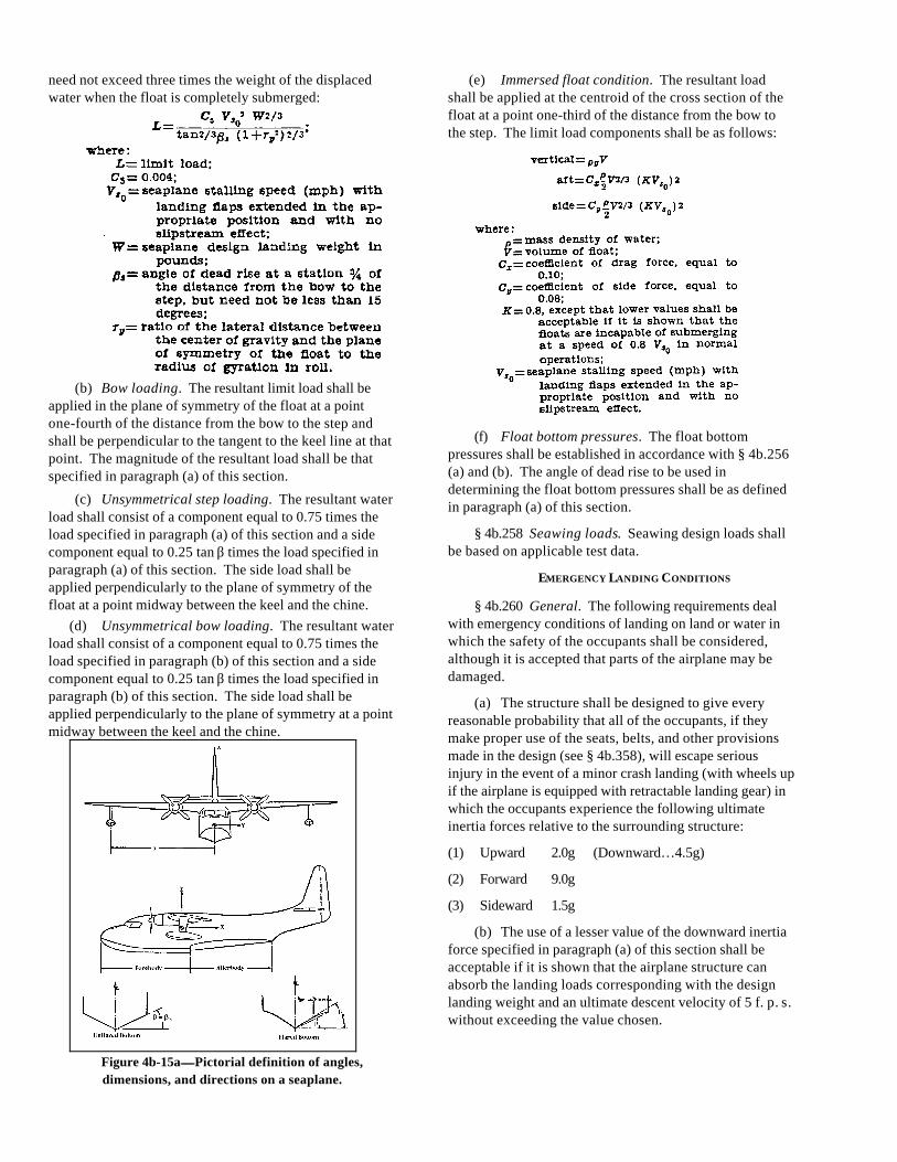
need not exceed three times the weight of the displacedwater when the float is completely submerged:
(b) Bow loading. The resultant limit load shall beapplied in the plane of symmetry of the float at a pointone-fourth of the distance from the bow to the step andshall be perpendicular to the tangent to the keel line at thatpoint. The magnitude of the resultant load shall be thatspecified in paragraph (a) of this section.
(c) Unsymmetrical step loading. The resultant waterload shall consist of a component equal to 0.75 times theload specified in paragraph (a) of this section and a sidecomponent equal to 0.25 tan β times the load specified inparagraph (a) of this section. The side load shall beapplied perpendicularly to the plane of symmetry of thefloat at a point midway between the keel and the chine.
(d) Unsymmetrical bow loading. The resultant waterload shall consist of a component equal to 0.75 times theload specified in paragraph (b) of this section and a sidecomponent equal to 0.25 tan β times the load specified inparagraph (b) of this section. The side load shall beapplied perpendicularly to the plane of symmetry at a pointmidway between the keel and the chine.
Figure 4b-15a——Pictorial definition of angles,dimensions, and directions on a seaplane.
(e) Immersed float condition. The resultant loadshall be applied at the centroid of the cross section of thefloat at a point one-third of the distance from the bow tothe step. The limit load components shall be as follows:
(f) Float bottom pressures. The float bottompressures shall be established in accordance with § 4b.256(a) and (b). The angle of dead rise to be used indetermining the float bottom pressures shall be as definedin paragraph (a) of this section.
§ 4b.258 Seawing loads. Seawing design loads shallbe based on applicable test data.
EMERGENCY LANDING CONDITIONS
§ 4b.260 General. The following requirements dealwith emergency conditions of landing on land or water inwhich the safety of the occupants shall be considered,although it is accepted that parts of the airplane may bedamaged.
(a) The structure shall be designed to give everyreasonable probability that all of the occupants, if theymake proper use of the seats, belts, and other provisionsmade in the design (see § 4b.358), will escape seriousinjury in the event of a minor crash landing (with wheels upif the airplane is equipped with retractable landing gear) inwhich the occupants experience the following ultimateinertia forces relative to the surrounding structure:
(1) Upward 2.0g (Downward…4.5g)
(2) Forward 9.0g
(3) Sideward 1.5g
(b) The use of a lesser value of the downward inertiaforce specified in paragraph (a) of this section shall beacceptable if it is shown that the airplane structure canabsorb the landing loads corresponding with the designlanding weight and an ultimate descent velocity of 5 f. p. s.without exceeding the value chosen.

(c) The inertia forces specified in paragraph (a) ofthis section shall be applied to all items of mass whichwould be apt to injure the passengers or crew if such itemsbecame loose in the event of a minor crash landing, and the
supporting structure shall be designed to restrain theseitems.
§ 4b.261 Structural ditching provisions. (Forstructural strength considerations of ditching provisionssee § 4b.361 (c).)
FIGURE 4b-15b—Hull station weighing factor.
FIGURE 4b-15c—Transverse pressure distributions.
SUBPART D—DESIGN AND CONSTRUCTION
GENERAL
§ 4b.300 Scope. The airplane shall not incorporatedesign features or details which experience has shown tobe hazardous or unreliable. The suitability of allquestionable design details or parts shall be established bytests.
§ 4b.301 Materials. The suitability and durability ofall materials used in the airplane structure shall beestablished on the basis of experience or tests. Allmaterials used in the airplane structure shall conform toapproved specifications which will insure their having thestrength and other properties assumed in the design data.

§ 4b.302 Fabrication methods. The methods offabrication employed in constructing the airplane structureshall be such as to produce a consistently sound structure.When a fabrication process such as gluing, spot welding,or heat treating requires close control to attain thisobjective, the process shall be performed in accordancewith an approved process specification.
§ 4b.303 Standard fastenings. All bolts, pins, screws,and rivets used in the structure shall be of an approvedtype. The use of an approved locking device or method isrequired for all such bolts, pins, and screws. Self-lockingnuts shall not be used on bolts which are subject torotation in operation.
§ 4b.304 Protection. (a) All members of the structureshall be suitably protected against deterioration or loss ofstrength in service due to weathering, corrosion, abrasion,or other causes.
(b) Provision for ventilation and drainage of all partsof the structure shall be made where necessary forprotection.
(c) In seaplanes, special precautions shall be takenagainst corrosion from salt water, particularly where partsmade from different metals are in close proximity.
§ 4b.305 Inspection provisions. Means shall beprovided to permit the close examination of those parts ofthe airplane which require periodic inspection, adjustmentfor proper alignment and functioning, and lubrication ofmoving parts.
§ 4b.306 Material strength properties and designvalues. (a) Material strength properties shall be based on asufficient number of tests of material conforming tospecifications to establish design values on a statisticalbasis.
(b) The design values shall be so chosen that theprobability of any structure being understrength becauseof material variations is extremely remote.
(c) ANC-5, ANC-18, and ANC-23, Part II values shallbe used unless shown to be inapplicable in a particularcase.
NOTE: ANC-5, “Strength of Metal Aircraft Elements,”ANC-18, “Design of Wood Aircraft Structures,” andANC-23, “Sandwich Construction for Aircraft,'' arepublished by the subcommittee on Air Force-Navy-CivilAircraft Design Criteria and may be obtained from thesuperintendent of Documents, Government Printing Office,Washington 25, D.C.
(d) The strength, detail design, and fabrication of thestructure shall be such as to minimize the probability ofdisastrous fatigue failure.
NOTE: Points of stress concentration are one of themain sources of fatigue failure.
§ 4b.307 Special factors. Where there is uncertaintyconcerning the actual strength of a particular part of' thestructure, or where the strength is likely to deteriorate inservice prior to normal replacement of' the part, or wherethe strength is subject to appreciable variability due touncertainties in manufacturing processes and inspectionmethods, the factor of' safety prescribed in § 4b.200 (a)shall be multiplied by a special factor of a value such as tomake the probability of the part being understrength fromthese causes extremely remote. The following specialfactors shall be used:
(a) Casting factors. (1) Where only visual inspectionof a casting is to be employed, the casting factor shall be2.0, except that it need not exceed 1.25 with respect tobearing stresses.
(2) It shall be acceptable to reduce the factor of' 2.0specified in subparagraph (1) of this paragraph to a valueof 1.25 if such a reduction is substantiated by testing atleast three sample castings and if the sample castings aswell as all production castings are visually andradiographically inspected in accordance with an approvedinspection specification. During these tests the samplesshall withstand the ultimate load multiplied by the factor of'1.25 and in addition shall comply with the correspondinglimit load multiplied by a factor of' 1.15.
(3) Casting factors other than those contained insubparagraphs (1) and (2) of' this paragraph shall beacceptable if they are found to be appropriately related toteats and to inspection procedures.
(4) A casting factor need not be employed withrespect to the bearing surface of' a part if the bearing factorused (see paragraph (b) of this section) is of greatermagnitude than the casting factor.
(b) Bearing factors. (1) Bearing factors shall be usedof' sufficient magnitude to provide for the effects of' normalrelative motion between parts and in joints with clearance(free fit) which are subject to pounding or vibration.(Bearing factor values for control surface and system jointsare specified in § 4b.313 (a) and 4b.329 (b).)
(2) A bearing factor need not be employed on a partif another special factor prescribed in this section is ofgreater magnitude than the bearing factor.
(c) Fitting factors. (1) A fitting factor of' at least 1.15shall be used on all fittings the strength of' which is notproven by limit and ultimate load tests in which the actualstress conditions are simulated in the fitting and thesurrounding structure. This factor shall apply to allportions of the fitting, the means of' attachment, and thebearing on the members joined.
(2) In the case of integral fittings the part shall betreated as a fitting up to the point where the sectionproperties become typical of the member.

(3) The fitting factor need not be employed where atype of joint made in accordance with approved practicesis based on comprehensive test data, e. g., continuousjoints in metal plating welded joints, and scarf joints inwood.
(4) A fitting factor need not be employed withrespect to the bearing surface of a part if the bearing factorused (see paragraph (b) of this section) is of greatermagnitude than the fitting factor.
§ 4b.308 Flutter, deformation, and vibration.Compliance with the following provisions shall be shownby such calculations, resonance tests, or other tests as arefound necessary by the Administrator.
(a) Flutter prevention. The airplane shall bedesigned to be free from flutter of wing and tail units,including all control and trim surfaces, and from divergence(i.e. unstable structural distortion due to aerodynamicloading), at all speeds up to 1.2 VD. A smaller marginabove VD shall be acceptable if the characteristics of theairplane (including the effects of compressibility) render aspeed of 1.2 VD unlikely to be achieved, and if it is shownthat a proper margin of' damping exists at speed VD. In theabsence of more accurate data, the terminal velocity in adive of 30 degrees to the horizontal shall be acceptable asthe maximum speed likely to be achieved. If concentratedbalance weights are used on control surfaces, theireffectiveness and strength, including supporting structure,shall be substantiated.
(b) Loss of control due to structural deformation.The airplane shall be designed to be free from controlreversal and from undue loss of longitudinal, lateral, anddirectional stability and control as a result of structuraldeformation, including that of the control surface covering,at all speeds up to the speed prescribed in paragraph (a) ofthis section for flutter prevention.
(c) Vibration and buffeting. The airplane shall bedesigned to withstand all vibration and buffeting whichmight occur in any likely operating conditions.
CONTROL S URFACES
§ 4b.310 General. The requirements of §§ 4b.311through 4b.313 shall apply to the design of' fixed andmovable control surfaces.
§ 4b.311 Proof of strength. (a) Control surface limitload tests shall be conducted to prove compliance withlimit load requirements.
(b) Control surface tests shall include the horn orfitting to which the control system is attached.
(c) Analyses or individual load tests shall beconducted to demonstrate compliance with the specialfactor requirements for control surface hinges. (See§§ 4b.307 and 4b.313 (a).)
§ 4b.312 Installation. (a) Movable tail surfaces shallbe so installed that there is no interference between anytwo surfaces when one is held in its extreme position andall the others are operated through their full angularmovement.
(b) When an adjustable stabilizer is used, stops shallbe provided which will limit its travel, in the event of failureof the adjusting mechanism, to a range equal to themaximum required to trim the airplane in accordance with §4b.140.
§ 4b.313 Hinges. (a) Control surface hinges, exceptball and roller bearings, shall incorporate a special factor of'not less than 6.67 with respect to the ultimate bearingstrength of' the softest material used as a bearing.
(b) For hinges incorporating ball or roller bearings,the approved rating of the bearing shall not be exceeded.
(c) Hinges shall provide sufficient strength andrigidity for loads parallel to the hinge line.
CONTROL S YSTEMS
§ 4b.320 General. All controls and control systemsshall operate with ease, smoothness, and positivenessappropriate to their function. (See also §§ 4b.350 and4b.353.)
§ 4b.321 Two-control airplanes. Two-controlairplanes shall be capable of continuing safely in flightand landing in the event of failure of any one connectingelement in the directional-lateral flight control system.
§ 4b.322 Trim controls and systems. (a) Trim controlsshall be designed to safeguard against inadvertent orabrupt operation.
(b) Each trim control shall operate in the plane andwith the sense of' motion of the airplane. (See fig. 4b-16.)
(c) Means shall be provided adjacent to the trimcontrol to indicate the direction of the control movementrelative to the airplane motion.
(d) Means shall be provided to indicate the positionof the trim device with respect to the range of adjustment.The indicating means shall be clearly visible.
(e) Trim devices shall be capable of continued normaloperation in the event of failure of any one connecting ortransmitting element of the primary flight control system.
(f) Trim tab controls shall be irreversible, unless thetab is appropriately balanced and shown to be free fromflutter.
(g) Where an irreversible tab control system isemployed, the portion from the tab to the attachment of theirreversible unit to the airplane structure shall consist of arigid connection.
§ 4b.323 Wing flap controls. (a) The wing flapcontrols shall operate in a manner to permit the flight crew

to place the flaps in all of the take-off, en route, approach,and landing positions established under § 4b.111 and tomaintain these positions thereafter without furtherattention on the part of' the crew, except for flap movementproduced by an automatic flap positioning or load limitingdevice.
(b) The wing flap control shall be located anddesigned to render improbable its inadvertent operation.
(c) The rate of motion of the wing flap in response tothe operation of' the control and the characteristics of theautomatic flap positioning or load limiting device shall besuch as to obtain satisfactory flight and performancecharacteristics under steady or changing conditions of airspeed, engine power, and airplane attitude.
(d) The wing flap control shall be designed to retractthe flaps from the fully extended position during steadyflight at maximum continuous engine power at all speedsbelow VF + 10 (m.p.h.).
(e) Means shall be provided to indicate the take-off,en route, approach, and landing flap positions.
(f) If any extension of' the flaps beyond the landingposition is possible the flap control shall be clearly markedto identify such range of extension.
§ 4b.324 Wing flap interconnection. (a) The motionof wing flaps on opposite sides of the plane of symmetryshall be synchronized by a mechanical interconnectionunless the airplane is demonstrated to have safe flightcharacteristics while the flaps are retracted on one side andextended on the other.
(b) Where a wing flap interconnection is used, it shallbe designed to account for the applicable unsymmetricalloads, including those resulting from flight with theengines on one side of the plane of symmetry inoperativeand the remaining engines at take-off power. For airplaneswith flaps which are not subjected to slipstreamconditions, the structure shall be designed for the loadsimposed when the wing flaps on one side are carrying themost severe load occurring in the prescribed symmetricalconditions and those on the other side are carrying notmore than 80 percent of that load.
§ 4b.325 Control system stops. (a) All controlsystems shall be provided with stops which positively limitthe range of motion of the control surfaces.
(b) Control system stops shall be so located in thesystem that wear, slackness, or take-up adjustments willnot affect adversely the control characteristics of theairplane because of' a change in the range of surface travel.
(c) Control system stops shall be capable ofwithstanding the loads corresponding with the designconditions for the control system
§ 4b.326 Control system locks. Provision shall bemade to prevent damage to the control surfaces (including
tabs) and the control system which might result from gustsstriking the airplane while it is on the ground or water (seealso § 4b.226). If a device provided for this purpose, whenengaged, prevents normal operation of the control surfacesby the pilot, it shall comply with the following provisions.
(a) The device shall either automatically disengagewhen the pilot operates the primary flight controls in anormal manner, or it shall limit the operation of the airplanein such a manner that the pilot receives unmistakablewarning at the start of take-off.
(b) Means shall be provided to preclude thepossibility of the device becoming inadvertently engagedin flight.
§ 4b.327 Static tests. Tests shall be conducted oncontrol systems to show compliance with limit loadrequirements in accordance with the following provisions.
(a) The direction of the test loads shall be such as toproduce the most severe loading in the control system.
(b) The tests shall include all fittings, pulleys, andbrackets used in attaching the control system to the mainstructure.
(c) Analyses or individual load tests shall beconducted to demonstrate compliance with the specialfactor requirements for control system joints subjected toangular motion. (See §§ 4b.307 and 4b.329 (b).)
§ 4b.328 Operation tests. An operation test shall beconducted for each control system by operating thecontrols from the pilot compartment with the entire systemloaded to correspond with 80 percent of the limit loadspecified for the control system. In this test there shall beno jamming, excessive friction, or excessive deflection.
§ 4b.329 Control system details; general. All detailsof control systems shall be designed and installed toprevent jamming, chafing, and interference from cargo,passengers, and loose objects. Precautionary means shallbe provided in the cockpit to prevent the entry of foreignobjects into places where they would jam the controlsystems. Provisions shall be made to prevent the slappingof cables or tubes against other parts of the airplane. Thefollowing detail requirements shall be applicable withrespect to cable systems and joints.
(a) Cable systems. (1) Cables, cable fittings,turnbuckles, splices, and pulleys shall be of an approvedtype.
(2) Cables smaller than 1/8-inch diameter shall not beused in the aileron, elevator, or rudder systems.
(3) The design of' cable systems shall be such thatthere will be no hazardous change in cable tensionthroughout the range of travel under operating conditionsand temperature variations.
(4) Pulley types and sizes shall correspond with thecables used.

(5) All pulleys and sprockets shall be provided withclosely fitted guards to prevent the cables and chainsbeing displaced or fouled.
(6) Pulleys shall lie in the plane passing through thecable within such limits that the cable does not rub againstthe pulley flange.
(7) Fairleads shall be so installed that they do notcause a change in cable direction of more than 3°.
(8) Clevis pins (excluding those not subject to load ormotion) retained only by cotter pins shall not be used inthe control system.
(9) Turnbuckles attached to parts having angularmotion shall be installed to prevent positively any bindingthroughout the range of travel.
(10) Provision for visual inspection shall be made at allfairleads, pulleys, terminals, and turnbuckles.
(b) Joints. (1) Control system joints subjected toangular motion in push-pull systems, excepting ball androller bearing systems, shall incorporate a special factor ofnot less than 3.33 with respect to the ultimate bearingstrength of the softest material used as a bearing.
(2) It shall be acceptable to reduce the factorspecified in subparagraph (1) of this paragraph to a valueof 2.0 for joints in cable control systems.
(3) The approved rating of ball and roller bearingsshall not be exceeded.
LANDING GEAR
§ 4b.330 General. The requirements of §§ 4b.331through 4b.338 shall apply to the complete landing gear.
§ 4b.331 Shock absorbers. (a) The shock absorbing'elements for the main, nose, and tail wheel units shall besubstantiated by the tests specified in § 4b.332.
(b) The shock absorbing ability of the landing gear intaxying shall be demonstrated by the tests prescribed in§ 4b.172.
§ 4b.332 Landing gear tests. The landing gear shallwithstand the following tests.
(a) Shock absorption tests. (1) It shall bedemonstrated by energy absorption tests that the limit loadfactors selected for design in accordance with § 4b.230 (b)for take-off and landing weights, respectively, will not beexceeded.
(2) In addition to the provisions of subparagraph (1)of this paragraph, a reserve of energy absorption shall bedemonstrated by a test simulating an airplane descentvelocity of 12 f.p.s. at design landing weight, assumingwing lift not greater than the airplane weight acting duringthe landing impact. In this test the landing gear shall notfail. (See paragraph (c) of this section.)
(b) Limit drop tests. (1) If compliance with the limitlanding conditions specified in paragraph (a)(1) of thissection is demonstrated by free drop tests, these shall beconducted on the complete airplane, or on units consistingof wheel, tire, and shock absorber in their proper relation.The free drop heights shall not be less than the following:
(i) 18.7 inches for the design landing weightconditions.
(ii) 6.7 inches for the design take-off weightconditions.
(2) If wing lift is simulated in free drop tests thelanding gear shall be dropped with an effective mass equalto:
(3) The attitude in which a landing gear unit is droptested shall simulate the airplane landing condition criticalfor the unit.
(4) The value of d used in the computation of W e insubparagraph (2) of' this paragraph shall not exceed thevalue actually obtained in the drop test.
(c) Reserve energy absorption drop tests. (1) Ifcompliance with the reserve energy absorption conditionspecified in paragraph (a)(2) of this section isdemonstrated by free drop tests, the landing gear unitsshall be dropped from a free drop height of not less than 27inches.
(2) If wing lift equal to the airplane weight issimulated, the units shall be dropped with an effectivemass equal to:

where the symbols and other details are the same as inparagraph (b) of this section.
§ 4b.333 Limit load factor determination. (a) Indetermining the airplane inertia limit load factor n from thefree drop tests specified in § 4b.332, the following formulashall be used:
(b) The value of η determined in paragraph (a) of thissection shall not be greater than the limit load factor usedfor the landing conditions. (See § 4b.230 (b)).
§ 4b.334 Retracting mechanism—(a) General. (1)The landing gear retracting mechanism, wheel well doors,and supporting structure shall be designed for the loadsoccurring in the flight conditions when the gear is in theretracted position, and for the combination of friction,inertia, brake torque, and air loads occurring duringretraction and extension at any air speed up to 1.6 Vs1 (flapsin the approach position at design landing weight), andany load factor up to those specified in § 4b.212 for theflaps extended condition.
(2) The landing gear, the retracting mechanism, andthe airplane structure including wheel well doors shall bedesigned to withstand the flight loads occurring with thelanding gear in the extended position at any speed up to0.67 VC, unless other means are provided to decelerate theairplane in flight at this speed.
(3) Landing gear doors, their operating mechanism,and their supporting structure shall be designed for theconditions of air speed and load factor prescribed insubparagraphs (1) and (2) of this paragraph, and inaddition they shall be designed for the yawing maneuversprescribed for the airplane
(b) Landing gear lock . A positive means shall beprovided for the purpose of maintaining the landing gear inthe extended position.
(c) Emergency operation. Emergency means ofextending the landing gear shall be provided, so that thelanding gear can be extended in the event of anyreasonably probable failure in the normal retraction system.In any case the emergency system shall provide for thefailure of any single source of hydraulic, electric, orequivalent energy supply.
(d) Operation test. Proper functioning of the landinggear retracting mechanism shall be demonstrated byoperation tests.
(e) Position indicator and warning device. (1)When a retractable landing gear is used, means shall beprovided for indicating to the pilot when the gear issecured in the extended and in the retracted positions.
(2) In addition to the requirement of subparagraph (1)of this paragraph, landplanes shall be provided with anaural warning device which will function continuouslywhen all throttles are closed if the gear is not fullyextended and locked.
(3) If a manual shutoff for the warning deviceprescribed in subparagraph (2) of this paragraph isprovided, it shall be installed so that reopening thethrottles will reset the warning mechanism.
(f) Control. The location and operation of thelanding gear retraction control shall be according to theprovisions of § 4b.353.
§ 4b.335 Wheels. Main wheels and nose wheels shallbe of an approved type. The following provisions shallapply.
(a) The maximum static load rating of each mainwheel and nose wheel shall not be less than thecorresponding static ground reaction under the designtake-off weight of the airplane and the critical center ofgravity position.
(b) The maximum limit load rating of each main wheeland nose wheel shall not be less than the maximum radiallimit load determined in accordance with the applicableground load requirements of this part (see §§ 4b.230through 4b.236).
(c) The maximum kinetic energy capacity rating ofeach main wheel-brake assembly shall not be less than thekinetic energy absorption requirement determined asfollows:
(d) The minimum stalling speed rating of each mainwheel-brake assembly i.e., the initial speed used in thedynamometer tests, shall not be greater than the VSO used
in the determination of kinetic energy in accordance withparagraph (c) of this section.
NOTE: The provision of this paragraph is based uponthe assumption that the testing procedures for wheel-brakeassemblies involve a specified rate of deceleration, and,therefore, for the same amount of kinetic energy the rate ofenergy absorption (the power absorbing ability of thebrake) varies inversely with the initial speed.
§ 4b.336 Tires. (a) Landing gear tires shall be of aproper fit on the rim of the wheel, and their approved ratingshall be such that it is not exceeded under the followingconditions:
(1) Airplane weight equal to the design take-offweight,
(2) Load on each main wheel tire equal to thecorresponding static ground reaction at the critical centerof gravity position.
(3) Load on nose wheel tires (to be compared withthe dynamic rating established for such tires) equal to thereaction obtained at the nose wheel assuming the mass ofthe airplane concentrated at the most critical center ofgravity and exerting a force of l.0g downward and 0.31gforward, the reactions being distributed to the nose andmain wheels by the principles of statics with the dragreaction at the ground applied only at those wheels whichhave brakes.
§ 4b.337 Brakes—(a) General. (1) The airplane shallbe equipped with brakes of an approved type. The brakeratings shall be in accordance with § 4b.335 (c) and (d).
(2) The brake system shall be so designed andconstructed that in the event of a single failure in anyconnection or transmitting element in the brake system(excluding the operating pedal or handle), or the lose ofany single source of hydraulic or other brake operatingenergy supply, it shall be possible to bring the airplane torest under conditions specified in § 4b.122 with a meandeceleration during the landing roll of at least 50 percent ofthat obtained in determining the landing distance asprescribed in that section.
(3) In applying the requirement of subparagraph (2)of this paragraph to hydraulic brakes, the brake drum,shoes, and actuators (or their equivalents) shall beconsidered as connecting or transmitting elements, unlessit is shown that the leakage of hydraulic fluid resultingfrom failure of the sealing elements in these units wouldnot reduce the braking effectiveness below that specifiedin subparagraph (2) of this paragraph.
(b) Brake controls. Brake controls shall not requireexcessive control forces in their operation.
(c) Parking brake controls. A parking brake controlshall be provided and installed so that it can be set by thepilot and, without further attention, will maintain sufficientbraking to prevent the airplane from rolling on a paved,
level runway while take-off power on the critical engine isbeing applied.
§ 4b.338 Skis. Skis shall be of an approved type. Themaximum limit load rating of each ski shall not be less thanthe maximum limit load determined in accordance with theapplicable ground load requirements of this part. (See §§4b.230 through 4b.236.)
HULLS AND FLOATS
§ 4b.340 General. The requirements of §§ 4b.341 and4b.342 shall apply to the design of hulls and floats.
§ 4b.341 Seaplane main floats. Seaplane main floatsshall be of an approved type and shall comply with theprovisions of § 4b.250. In addition, the following shallapply.
(a) Buoyancy. Each seaplane main float shall have abuoyancy of 80 percent in excess of that required tosupport the maximum weight of the seaplane in fresh water.
(b) Compartmentation. Each seaplane main floatshall contain not less than 5 watertight compartments. Thecompartments shall have approximately equal volumes.
§ 4b.342 Boat hulls. (a) The hulls of boat seaplanesand amphibians shall be divided into watertightcompartments so that, with any two adjacentcompartments flooded, the buoyancy of the hull andauxiliary floats (and wheel tires, if used) will provide asufficient margin of positive stability to minimize capsizingin rough fresh water.
(b) For the purpose of communication betweencompartments, bulkheads with watertight doors shall beallowed.

PERSONNEL AND CARGO ACCOMMODATIONS
§ 4b.350 Pilot compartment; general. (a) Thearrangement of the pilot compartment and itsappurtenances shall provide safety and assurance that thepilot will be able to perform all of his duties and operate thecontrols in the correct manner without unreasonableconcentration and fatigue.
(b) The primary flight controls listed on figure 4b-16,excluding cables and control rods, shall be so located withrespect to the propellers that no portion of the pilot or thecontrols lies in the region between the plane of rotation ofany inboard propeller and the surface generated by a linepassing through the center of the propeller hub andmaking an angle of 5° forward or aft of the plane of rotationof the propeller.
(c) When provision is made for a second pilot, theairplane shall be controllable with equal safety from bothseats.
(d) The pilot compartment shall be constructed toprevent leakage likely to be distracting to the crew orharmful to the structure when flying in rain or snow.
(e) A door shall be provided between the pilotcompartment and the passenger compartment.
PRIMARY
Controls Movement and actuation
Aileron.................. Right (clockwise) for right wing down.Elevator ................ Rearward for nose up.Rudder.................. Right pedal forward for nose right.
SECONDARYFlaps (or auxiliarylift devices).
Forward for flaps up; rearward or flapsdown.
Trim tabs (orequivalent).
Rotate to produce similar rotation ofthe airplane about an axis parallel tothe axis of the control.
FIGURE 4b-16— Aerodynamic controls.
(f) The door prescribed in paragraph (e) of thissection shall be equipped with a locking means to preventpassengers from opening the door without the pilot'spermission.
(g) Vibration and noise characteristics of cockpitappurtenances shall not interfere with the safe operation ofthe airplane.
§ 4b.351 Pilot compartment vision—(a)Nonprecipitation conditions. (1) The pilot compartmentshall be arranged to afford the pilots a sufficientlyextensive, clear, and undistorted view to perform safely allmaneuvers within the operating limitations of the airplane,including taxying, take-off, approach, and landing.
(2) It shall be demonstrated by day and night flighttests that the pilot compartment is free of glare andreflections which would tend to interfere with the pilots’vision.
(b) Precipitation conditions. (1) Means shall beprovided for maintaining a sufficient portion of thewindshield clear so that both pilots are afforded asufficiently extensive view along the flight path in allnormal flight attitudes of the airplane. Such means shall bedesigned to function under the following conditionswithout continuous attention on the part of the crew:
(i) In heavy rain at speeds up to 1.6 Vs1, flapsretracted,
(ii) In the most severe icing conditions for whichapproval of the airplane is desired.
(2) In addition to the means prescribed insubparagraph (1) of this paragraph at least the first pilotshall be provided with a window which, when the cabin isnot pressurized, is openable under the conditionsprescribed in subparagraph (1) of this paragraph, andwhich provides the view specified in that subparagraph.The design shall be such that when the window is openedsufficient protection from the elements will be providedagainst the impairment of the pilot's vision.
§ 4b.352 Windshield and windows. (a) All internalglass panes shall be of a nonsplintering safety type.
(b) The windshield, its supporting structure, andother structure in front of the pilots shall have sufficientstrength to withstand without penetration the impact of afour-pound bird when the velocity of the airplane relativeto the bird along the airplane’s flight path is equal to thevalue of VC at sea level selected in accordance with§ 4b.210 (b)(4).
(c) The design of windshields and windows inpressurized airplanes shall be based on factors peculiar tohigh altitude operation. (See also § 4b.373.)
NOTE: Factors peculiar to high altitude operation asthey may affect the design of windshields and windowsinclude the effects of continuous and cyclic pressurizationloadings, the inherent characteristics of the material used,the effects of temperatures and temperature differentials,etc.
§ 4b.353 Controls. (a) All cockpit controls shall belocated to provide convenience in operation and in amanner tending to prevent confusion and inadvertentoperation. (See also § 4b.737.)
(b) The direction of movement of controls shall beaccording to figures 4b-16 and 4b-17. Whereverpracticable the sense of motion involved in the operationof other controls shall correspond with the sense of theeffect of the operation upon the airplane or upon the partoperated. All controls of a variable nature employing arotary motion shall move clockwise from the off position,through an increasing range, to the full on position.
(c) The controls shall be so located and arrangedwith respect to the pilots’ seats that there exists full andunrestricted movement of each control without interference

from either the cockpit structure or the pilots’ clothingwhen seated with the seat belt fastened. This shall bedemonstrated for individuals ranging from 5' 2" to 6' 0" inheight.
(d) Identical powerplant controls for each engineshall be located to prevent any misleading impression as tothe engine to which they relate.
Controls Movement and actuation
PowerplantThrottles .............. Forward to increase forward
thrust and rearward to increaserearward thrust.
Propellers............. Forward to increase rpm.Mixture................. Forward or upward for rich.Carburetor airheat .......................
Forward or upward for cold.
Supercharger....... Forward or upward for low blower.In the case of turbosuperchargers,forward, upward, or clockwise toincrease pressure.
AuxiliaryLanding gear....... Down to extend.
FIGURE 4b-17— Powerplant and Auxiliary Controls.
(e) The wing flap (or auxiliary lift device) and landinggear controls shall comply with the following:
(1) The wing flap control shall be located on top ofthe pedestal aft of the throttle(s), centrally or to the right ofthe pedestal centerline and shall not be less than 10 inchesaft of the landing gear control.
(2) The landing gear control shall be located to theleft of the pedestal centerline.
(f) The control knobs shall be shaped in accordancewith Figure 4b-22, and such knobs shall be of the samecolor, but of a color in contrast with that of not only theother control knobs but also the surrounding cockpit.
NOTE: Figure 4b-22 is not intended to indicate theexact size or proportion of the control knobs.
(g) Where the work load on the flight crew is such asto require a flight engineer (see § 4b.720), a flight engineerstation shall be provided. The station shall be so locatedand arranged that the flight crew members can performtheir functions efficiently and without interfering with eachother.
§ 4b.354 Instrument arrangement. (See § 4b.611.)
§ 4b.355 Instrument marking. (The operationalmarkings, instructions, and placards required for theinstruments, etc., are specified in §§ 4b.730 through4b.738.)
§ 4b.356 Doors. (a) Airplane cabins shall be providedwith at least one easily accessible external door.
(b) Means shall be provided for locking each externaldoor and for safeguarding against opening in flight either
inadvertently by persons or as a result of mechanicalfailure. It shall be possible to open external doors fromeither the inside or the outside even though persons maybe crowding against the door from the inside. The meansof opening shall be simple and obvious and shall be soarranged and marked that it can be readily located andoperated even in darkness.
(c) Reasonable provisions shall be made to preventthe jamming of any external door as a result of fuselagedeformation in a minor crash.
(d) External doors shall be so located that personsusing them will not be endangered by the propellers whenappropriate operating procedures are employed.
(e) Means shall be provided for a direct visualinspection of the locking mechanism by crew members toascertain whether all external doors, including passenger,crew, service, and cargo doors, are fully locked (see also§ 4b.362 (e)(5) for emergency exits). In addition, visualmeans shall be provided to signal to appropriate crewmembers that all normally used external doors are closedand in the fully locked position.
§ 4b.357 Door louvres. Where internal doors areequipped with louvres or other ventilating means,provision convenient to the crew shall be made forstopping the flow of air through the door when such actionis found necessary.
§ 4b.358 Seats, berths, and safety belts—(a) General.At all stations designated as occupiable during take-offand landing, the seats, berths, belts, harnesses, andadjacent parts of the airplane shall be such that a personmaking proper use of these facilities will not suffer seriousinjury in the emergency landing conditions as a result ofinertia forces specified in § 4b.260. Seats and berths shallbe of an approved type (see also § 4b.643 concerningsafety belts).
(b) Arrangement. (1) Passengers and crew shall beafforded protection from head injuries by one of thefollowing means:
(i) Safety belt and shoulder harness which willprevent the head from contacting any injurious object,
(ii) Safety belt and the elimination of all injuriousobjects within striking radius of the head,
(iii) Safety belt and a cushioned rest which willsupport the arms, shoulders, head, and spine.
(2) For arrangements which do not provide a firmhand hold on seat backs, hand grips or rails shall beprovided along aisles to enable passengers or crewmembers to steady themselves while using the aisles inmoderately rough air.
(3) All projecting objects which would cause injuryto persons seated or moving about the airplane in normalflight shall be padded.

(c) Strength. All seats and berths and theirsupporting structure shall be designed for occupantweight of 170 pounds with due account taken of themaximum load factors, inertia forces, and reactions betweenoccupant, seat, and safety belt or harness correspondingwith all relevant flight and ground load conditions,including the emergency landing conditions prescribed in§ 4b.260. In addition, the following shall apply.
(1) Pilot seats shall be designed for the reactionsresulting from the application of pilot forces to the flightcontrols as prescribed in § 4b.224.
(2) In determining the strength of the seat or berthattachments to the structure, and the safety belt orshoulder harness attachments to the seat, berth, orstructure, the inertia forces specified in § 4b.260 (a) shall bemultiplied by a factor of 1.33.
§ 4b.359 Cargo and baggage compartments. (Seealso §§ 4b.382 to 4b.384.)
(a) Each cargo and baggage compartment shall bedesigned for the placarded maximum weight of contentsand the critical load distributions at the appropriatemaximum load factors corresponding with all specifiedflight and ground load conditions excluding the emergencylanding conditions of § 4b.260.
(b) Provisions shall be made to prevent the contentsin the compartments from becoming a hazard by shiftingunder the loads specified in paragraph (a) of this section.
(c) Provisions shall be made to protect thepassengers and crew from injury by the contents of anycompartment, taking into account the emergency landingconditions of § 4b.260.
EMERGENCY PROVISIONS
§ 4b.360 General. The requirements of §§ 4b.361 and4b.362 shall apply to the emergency provisions.
§ 4b.361 Ditching. Compliance with this section isoptional. The requirements of this section are intended tosafeguard the occupants in the event of an emergencylanding during overwater flight. When compliance isshown with the provisions of paragraphs (a) through (c) ofthis section and with the provisions of § 4b.362 (d), 4b.645,and 4b.646, the type certificate shall include certification tothat effect. When an airplane is certificated to includeditching provisions, the recommended ditching proceduresestablished on the basis of these requirements shall be setforth in the Airplane Flight Manual (see § 4b.742 (d)).
(a) All practicable design measures compatible withthe general characteristics of the type airplane shall betaken to minimize the chance of any behavior of theairplane in an emergency landing on water which would belikely to cause immediate injury to the occupants or tomake it impossible for them to escape from the airplane.The probable behavior of the airplane in a water landing
shall be investigated by model tests or by comparison withairplanes off similar configuration for which the ditchingcharacteristics are known. In this investigation accountshall be taken of scoops, flaps, projections, and all otherfactors likely to affect the hydrodynamic characteristics ofthe actual airplane.
(b) It shall be shown that under reasonably probablewater conditions the flotation time and trim of the airplanewill permit all occupants to leave the airplane and tooccupy the life rafts required by § 4b.645. If compliancewith this provision is shown by buoyancy and trimcomputations, appropriate allowances shall be made forprobable structural damage and leakage.
NOTE: In the case of fuel tanks which are equippedwith fuel jettisoning provisions and which can bereasonably expected to withstand a ditching withoutleakage, the jettisonable volume of fuel may be consideredas buoyancy volume.
(c) External doors and windows shall be designed towithstand the probable maximum local pressures, unlessthe effects of the collapse of such parts are taken intoaccount in the investigation of the probable behavior ofthe airplane in a water landing as prescribed in paragraphs(a) and (b) of this section.
§ 4b.362 Emergency evacuation. Crew and passengerareas shall be provided with emergency evacuation meansto permit rapid egress in the event of crash landings,whether with the landing gear extended or retracted, takingaccount of the possibility of the airplane being on fire. Theprovisions of this section shall apply to airplanes wherethe major portion of the passenger area is aft of thepowerplant and the fuel tanks. In airplanes where themajor portion of the passenger area is forward of thepowerplant and the fuel tanks, or in airplanes ofunconventional design where the emergency exit locationsprescribed in paragraph (b) of this section would beinconsistent with safe and rapid egress of passengers,variations of emergency exit locations shall be allowed iffound appropriate by the Administrator. Passengerentrance, crew, and service doors shall be considered asemergency exits if they meet the applicable requirements ofthis section.
(a) Flight crew emergency exits. Flight crewemergency exits shall be located in the flight crew area onboth sides of the airplane or as a top hatch to provide forrapid evacuation. Such exits shall not be required on smallairplanes where the Administrator finds that the proximityof passenger emergency exits to the flight crew arearenders them convenient and readily accessible to theflight crew.
(b) Passenger emergency exits; type and location.The types of exits and their location shall be as follows:
(1) Type I: A rectangular opening of not less than 24inches wide by 48 inches high, with corner radii not greater

than 4 inches, located as far aft in the passenger area aspracticable in the side of the fuselage at floor level.
(2) Type II: Same as Type I (subparagraph (1) of thisparagraph) except that the opening is not less than 20inches wide by 44 inches high.
(3) Type III: A rectangular opening of not less than20 inches wide by 36 inches high, with corner radii notgreater than 4 inches, located as far aft in the passengerarea as practicable in the side of the fuselage.
(4) Type IV: A rectangular opening of not less than19 inches wide by 26 inches high, with corner radii notgreater than 4 inches, located over the wing in the side ofthe fuselage with a step-up inside the airplane of not morethan 29 inches and a step-down outside the airplane of notmore than 36 inches.
NOTE: Larger openings than those specified inparagraph (b) of this section will be acceptable, whether ornot of rectangular shape, provided the specifiedrectangular openings can be inscribed therein, and furtherprovided that the base of the opening affords a flat surfacenot less than the width specified.
(c) Passenger emergency exits; number required.Emergency exits of type and location prescribed inparagraph (b) of this section shall be accessible to thepassengers and shall be provided on each side of thefuselage in accordance with the following:
Passenger seating
Emergency exits required oneach side of fuselage
capacity TypeI
TypeII
TypeIII
TypeIV
1 to 19 inclusive------- ---------
---------
1 ---------
20 to 39 inclusive ----- ---------
1 ---------
1
40 to 69 inclusive ----- 1 ---------
---------
1
70 to 99 inclusive ----- 1 ---------
---------
2
100 to 139 inclusive -- 2 ---------
---------
2
For airplanes with a passenger capacity of over 139 thereshall be, in addition to the emergency exits prescribed for apassenger seating capacity of 100 to 139, inclusive, oneach side of the fuselage, one Type I emergency exit foradditional passengers up to 50, these exits to be located atsuch strategic points as would contribute most to the safeevacuation of passengers.
NOTE: Although similar exits and their locations areprescribed for each side of the fuselage, it is not the intentof this regulation to require that the exits necessarily be atlocations diametrically opposite each other.
(d) Ditching emergency exits. Airplanes certificatedin accordance with the ditching provisions of § 4b.261shall be shown to have, on each side of the fuselage, notless than one emergency exit located above the water linefor every 35 passengers: Provided, That for the purposesof this paragraph an easily accessible overhead hatch ofnot less than the clear dimensions of Type III emergencyexits (see Paragraph (b)(3 ) of this section) shall beconsidered equivalent to one emergency exit on each side.
(e) Emergency exit arrangement. (1) Emergencyexits shall consist of movable doors or hatches in theexternal walls of the fuselage and shall provide anunobstructed opening to the outside.
(2) All emergency exits shall be openable from theinside and from the outside.
(3) The means of opening emergency exits shall besimple and obvious and shall not require exceptional effortof a person opening them.
(4) Means shall be provided for locking eachemergency exit and for safeguarding against opening inflight either inadvertently by persons or as a result ofmechanical failure.
(5) Means shall be provided for a direct visualinspection of the locking mechanism by crew members toascertain whether all emergency exits are fully locked.
(6) Provision shall be made to minimize the possibilityof jamming of emergency exits as a result of fuselagedeformation in a minor crash landing.
(7) For all landplane emergency exits other thanType IV (see paragraph (b) of this section) which are morethan 6 feet from the ground with the airplane on the groundand the landing gear extended, means shall be provided toassist the occupants in descending to the ground.
(8) The proper functioning of emergency exitinstallations shall be demonstrated by test.
(f) Emergency exit marking. (1) All emergency exits,their means of access, and their means of opening shall bemarked conspicuously. The identity and location ofemergency exits shall be recognizable from a distance equalto the width of the cabin. The location of the emergencyexit operating handle and the instructions for opening shallbe marked on or adjacent to the emergency exit and shallbe readable from a distance of 30 inches.
(2) A source or sources of light, with an energysupply independent of the main lighting system, shall beinstalled to illuminate all emergency exit markings. Suchlights shall be designed to function automatically in acrash landing and shall also be operable manually.
(3) All emergency exits and their means of openingshall be marked on the outside of the airplane for guidanceof' rescue personnel.

(g) Emergency exit access. Passageways betweenindividual compartments of the passenger area andpassageways leading to Type I and Type II emergencyexits (see paragraph (b) of this section) shall beunobstructed and shall be not less than 20 inches wide.Adjacent to emergency exits where assisting means arerequired by paragraph (e) (7) of this section, there shall besufficient additional space to allow a crew member to assistin the evacuation of passengers without reduction in theunobstructed width of the passageway to such exit.
(h) Width of main aisle. The main passenger aisle atany point between seats shall not be less than 15 incheswide up to a height above the floor of' 25 inches and notless than 20 inches wide above that height.
VENTILATION , HEATING, AND PRESSURIZATION
§ 4b.370 General. The requirements of §§ 4b.371through 4b.376 shall apply to the ventilation, heating, andpressurization of the aircraft.
§ 4b.371 Ventilation. (a) All crew compartments shallbe ventilated by providing a sufficient amount of fresh airto enable the crew members to perform their duties withoutundue discomfort or fatigue.
NOTE: An outside air supply of approximately 10cubic feet per minute is considered a minimum for eachcrew member.
(b) Ventilating air in crew and passengercompartments shall be free of harmful or hazardousconcentrations of gases or vapors.
NOTE: Carbon monoxide concentrations in excess ofone part in 20,000 parts of air are considered hazardous.Carbon dioxide in excess of 3 percent by volume (sea levelequivalent) is considered hazardous in the case of crewmembers. Higher concentrations of carbon dioxide maynot necessarily be hazardous in crew compartments ifappropriate protective breathing equipment is available.
(c) Provision shall be made to insure the conditionsprescribed in paragraph (b) of this section in the event ofreasonably probable failures or malfunctioning of theventilating, heating, pressurization, or other systems andequipment.
NOTE: Examples of acceptable provisions includesecondary isolation, integral protective devices, and crewwarning and shut-off for equipment the malfunctioning ofwhich could introduce harmful or hazardous quantities ofsmoke or gases.
(d) Where partitions between compartments areequipped with louvres or other means allowing air to flowbetween such compartments, provision convenient to thecrew shall be made for stopping the flow of air through thelouvres or other means when such action is foundnecessary. (See also § 4b.357.)
(e) Means shall be provided to enable the crew tocontrol the temperature and quantity of ventilating airsupplied to the crew compartment independently of thetemperature and quantity of ventilating air supplied toother compartments.
§ 4b.372 Heating systems. Combustion heaters shallbe of an approved type and shall comply with the fireprotection requirements of § 4b.386. Engine exhaustheaters shall comply with the provisions of § 4b.467 (c)and (d).
§ 4b.373 Pressurized cabins; general. The design ofpressurized cabins shall comply with the requirements of§§ 4b.374 through 4b.376. (See also §§ 4b.216 (c) and4b.352.)
§ 4b.374 Pressure supply. (See § 4b.477 (c).)
§ 4b.375 Pressure Control. Pressurized cabins shallbe provided with at least the following valves, controls,and indicators for controlling cabin pressure.
(a) Two pressure relief valves, at least one of whichis the normal regulating valve, shall be installed to limitautomatically the positive pressure differential to apredetermined value at the maximum rate of flow deliveredby the pressure source. The combined capacity of therelief valves shall be such that the failure of any one valvewould not cause an appreciable rise in the pressuredifferential. The pressure differential shall be consideredpositive when the internal pressure is greater than theexternal.
(b) Two reverse pressure differential relief valves (orequivalent) shall be installed to prevent automatically anegative pressure differential which would damage thestructure, except that one such valve shall be consideredsufficient if it is of a design which reasonably precludes itsmalfunctioning.
(c) Means shall be provided by which the pressuredifferential can be rapidly equalized.
(d) An automatic or manual regulator for controllingthe intake and/or exhaust air flow shall be installed so thatthe required internal pressures and air flow rates can bemaintained.
(e) Instruments shall be provided at the pilot or flightengineer station showing the pressure differential, theabsolute pressure in the cabin, and the rate of change ofthe absolute pressure.
(f) Warning indication shall be provided at the pilotor flight engineer station to indicate when the safe orpreset limits on pressure differential and on absolute cabinpressure are exceeded.
(g) If the structure is not designed for pressuredifferentials up to the maximum relief valve setting incombination with landing loads (see § 4b.216 (c)), a

warning placard shall be placed at the pilot or flightengineer station.
§ 4b.376 Tests—(a) Strength test. The completepressurized cabin, including doors, windows, and allvalves, shall be tested as a pressure vessel for the pressuredifferential specified in § 4b.216 (c)(3).
(b) Functional tests. The following functional testsshall be performed.
(1) To simulate the condition of regulator valvesclosed, the functioning and the capacity shall be tested ofthe positive and negative pressure differential valves andof the emergency release valve.
(2) All parts of the pressurization system shall betested to show proper functioning under all possibleconditions of pressure, temperature, and moisture up to themaximum altitude selected for certification.
(3) Flight tests shall be conducted to demonstrate theperformance of the pressure supply, pressure and flowregulators, indicators, and warning signals in steady andstepped climbs and descents at rates corresponding withthe maximum attainable without exceeding the operatinglimitations of the airplane up to the maximum altitudeselected for certification.
(4) All doors and emergency exits shall be tested toascertain that they operate properly after being subjectedto the flight tests prescribed in subparagraph (3) of thisparagraph.
FIRE PROTECTION
§ 4b.380 General. Compliance shall be shown withthe fire protection requirements of §§ 4b.381 through4b.386. (See also §§ 4b.480 through 4b.490.) In addition,the following shall apply.
(a) Hand fire extinguishers. Hand fire extinguishersshall be of an approved type. The types and quantities ofextinguishing agents shall be appropriate for the types offires likely to occur in the compartments where theextinguishers are intended for use. Extinguishers intendedfor use in personnel compartments shall be such as tominimize the hazard of toxic gas concentrations.
(b) Built-in fire extinguishers. Where a built-in fireextinguishing system is required, its capacity in relation tothe compartment volume and ventilation rate shall besufficient to combat any fire likely to occur in thecompartment. All built-in fire extinguishing systems shallbe so installed that any extinguisher agent likely to enterpersonnel compartments will not be hazardous to theoccupants and that discharge of the extinguisher cannotresult in structural damage. (See also § 4b.371.)
(c) Protective breathing equipment. If the airplanecontains Class A or B cargo compartments (see § 4b.383),protective breathing equipment shall be installed for theuse of appropriate crew members. (See § 4b.651 (h).)
§ 4b.381 Cabin interiors. All compartments occupiedor used by the crew or passengers shall comply with thefollowing provisions.
(a) The materials in no case shall be less thanflash-resistant.
(b) The wall and ceiling linings, the covering of allupholstering, floors, and furnishings shall beflame-resistant.
(c) Compartments where smoking is to be permittedshall be equipped with ash trays of the self-contained typewhich are completely removable. All other compartmentsshall be placarded against smoking.
(d) All receptacles for used towels, papers, and wasteshall be of fire-resistant material, and shall incorporatecovers or other provisions for containing possible fires.
(e) At least one hand fire extinguisher shall beprovided for use by the flight crew.
(f) In addition to the requirements of paragraph (e) ofthis section at least the following number of hand fireextinguishers conveniently located for use in passengercompartments shall be provided according to thepassenger capacity of the airplane:
Passenger capacity:Minimum number
of fireextinguishers
6 or less ------------------------------------------------07 through 30 ------------------------------------------131 through 60 ----------------------------------------261 or more---------------------------------------------3
§ 4b.382 Cargo and baggage compartments. (a)Cargo and baggage compartments shall include nocontrols, wiring, lines, equipment, or accessories thedamage or failure of which would affect the safe operationof the airplane, unless such items are shielded, isolated orotherwise protected so that they cannot be damaged bymovement of cargo in the compartment, and so that anybreakage or failure of such item will not create a fire hazard.
(b) Provision shall be made to prevent cargo orbaggage from interfering with the functioning of thefire-protective features of the compartment.
(c) All materials used in the construction of cargo orbaggage compartments, including tie-down equipment,shall be flame-resistant.
§ 4b.383 Cargo compartment classification. Allcargo and baggage compartments shall include provisionsfor safe-guarding against fires according to the followingclassification.
(a) Class A. Cargo and baggage compartments shallbe classified as "A" if the presence of a possible firetherein would be easily discernible to a member of the crewwhile at his station, and if all parts of the compartment areeasily accessible in flight. A hand fire extinguisher shall be
available for each compartment. (See § 4b.380 (c) forprotective breathing requirements.)
(b) Class B. Cargo and baggage compartments shallbe classified as "B" if sufficient access is provided while inflight to enable a member of the crew to move by hand allcontents and to reach effectively all parts of thecompartment with a hand fire extinguisher. Complianceshall be shown with the following:
(1) The design of the compartment shall be such that,when the access provisions are being used, no hazardousquantity of smoke, flames, or extinguishing agent will enterany compartment occupied by the crew or passengers.(See § 4b.380 (c) for protective breathing requirements.)
(2) Each compartment shall be equipped with aseparate system of an approved type smoke detector or firedetector other than a heat detector to give warning at thepilot or flight engineer station.
(3) Hand fire extinguishers shall be readily availablefor use in each compartment.
(4) The compartment shall be completely lined withfire-resistant material.
(c) Class C . Cargo and baggage compartments shallbe classified as "C" if they do not conform to theprerequisites for the "A" or "B" classifications.Compliance shall be shown with the following.
(1) Each compartment shall be equipped with:
(i) A separate system of an approved type smokedetector or fire detector other than heat detector to givewarning at the pilot or flight engineer station, and
(ii) An approved built-in fire-extinguishing systemcontrolled from the pilot or flight engineer station.
(2) Means shall be provided to exclude hazardousquantities of smoke, flames, or extinguishing agent fromentering into any compartment occupied by the crew orpassengers.
(3) Ventilation and drafts shall be controlled withineach compartment so that the extinguishing agentprovided can control any fire which may start within thecompartment.
(4) The compartment shall be completely lined withfire-resistant material.
(d) Class D. Cargo and baggage compartments shallbe classified as "D" if they are so designed andconstructed that a fire occurring therein will be completelyconfined without endangering the safety of the airplane orthe occupants. Compliance shall be shown with thefollowing.
(1) Each compartment shall be equipped with anapproved type smoke detector or fire detector other thanheat detector to give warning at the pilot or flight engineerstation.
(2) Means shall be provided to exclude hazardousquantities of smoke, flames, or other noxious gases fromentering into any compartment occupied by the crew orpassengers.
(3) Ventilation and drafts shall be controlled withineach compartment so that any fire likely to occur in thecompartment will not progress beyond safe limits.
NOTE: For compartments having a volume not inexcess of 500 cu. ft. an airflow of not more than 1,500 cu. ft.per hour is considered acceptable. For largercompartments lesser airflow may be applicable.
(4) The compartment shall be completely lined withfire-resistant material.
(5) Consideration shall be given to the effect of heatwithin the compartment on adjacent critical parts of theairplane.
§ 4b.384 Proof of compliance. (a) Compliance withthose provisions of § 4b.383 which refer to compartmentaccessibility, to the entry of hazardous quantities of smokeor extinguishing agent into compartments occupied by thecrew or passengers, and to the dissipation of theextinguishing agent in class C compartments shall bedemonstrated by tests in flight.
(b) It shall also be demonstrated during the testsprescribed in paragraph (a) of this section that noinadvertent operation of smoke or fire detectors in adjacentor other compartments within the airplane would occur as aresult of fire contained in any one compartment eitherduring or after extinguishment unless the extinguishingsystem floods such compartments simultaneously.
§ 4b.385 Flammable fluid fire protection. In areas ofthe airplane where flammable fluids or vapors might beliberated by leakage or failure in fluid systems, designprecautions shall be made to safeguard against the ignitionof such fluids or vapors due to the operation of otherequipment, or to control any fire resulting from suchignition.
§ 4b.386 Combustion heater fire protection—(a)Combustion heater fire zones. The following shall beconsidered as combustion heater fire zones and shall beprotected against fire in accordance with applicableprovisions of §§ 4b.480 through 4b.486 and § 4b.489.
(1) Region surrounding the heater, if such regioncontains any flammable fluid system components otherthan the heater fuel system which might be damaged byheater malfunctioning or which, in case of leakage orfailure, might permit flammable fluids or vapors to reach theheaters.
(2) Region surrounding the heater, if the heater fuelsystem incorporates fittings the leakage of which wouldpermit fuel or vapors to enter this region.

(3) That portion of the ventilating air passage whichsurrounds the combustion chamber.
(b) Ventilating air ducts. (1) Ventilating air ductswhich pass through fire zones shall be of fireproofconstruction.
(2) Unless isolation is provided by the use offireproof valves or other equivalently effective means, theventilating air duct downstream of the heater shall be offireproof construction for a sufficient distance to assurethat any fire originating from within the heater can becontained within the duct.
(3) Portions of ventilating ducts passing throughregions in the airplane where flammable fluid systems arelocated shall be so constructed or isolated from suchsystems that failure or malfunctioning of the flammablefluid system components cannot introduce flammablefluids or vapors into the ventilating airstream.
(c) Combustion air ducts. (1) Combustion air ductsshall be of fireproof construction for a distance sufficientto prevent damage from backfiring or reverse flamepropagation.
(2) Combustion air ducts shall not communicate withthe ventilating airstream unless it is demonstrated thatflames from backfires or reverse burning cannot enter theventilating airstream under any conditions of ground orflight operation including conditions of reverse flow ormalfunctioning of the heater or its associated components.
(3) Combustion air ducts shall not restrict promptrelief of backfires which can cause heater failure due topressures generated within the heater.
(d) Heater controls; general. Provision shall bemade to prevent hazardous accumulations of water or iceon or within any heater control components, controlsystem tubing, or safety controls.
(e) Heater safety controls. (1) In addition to thecomponents provided for normal continuous control of airtemperature, air flow, and fuel flow, means independent ofsuch components shall be provided with respect to eachheater to shut off automatically that heater’s ignition andfuel supply at a point remote from the heater when the heatexchanger temperature or ventilating air temperature exceedsafe limits or when either the combustion air flow or theventilating air flow becomes inadequate for safe operation.The means provided for this purpose for any individualheater shall be independent of all components servingother heaters the heat output of which is essential to thesafe operation of the airplane.
(2) Warning means shall be provided to indicate tothe crew when a heater, the heat output of which isessential to the safe operation of the airplane, has beenshut off by the operation of the automatic meansprescribed in subparagraph (1) of this paragraph.
(f) Air intakes. Combustion and ventilating airintakes shall be so located that no flammable fluids orvapors can enter the heater system under any conditionsof ground or flight operation either during normaloperation or as a result of malfunctioning, failure, orimproper operation of other airplane components.
(g) Heater exhaust. Heater exhaust systems shallcomply with the provisions of § 4b.467 (a) and (b). Inaddition, the following shall apply:
(1) Exhaust shrouds shall be sealed so that flammablefluids and hazardous quantities of vapors cannot reach theexhaust systems through joints.
(2) Exhaust systems shall not restrict the promptrelief of backfires which can cause heater failure due topressures generated within the heater.
(h) Heater fuel systems. Heater fuel systems shallcomply with all portions of the powerplant fuel systemrequirements which affect safe heater operations. Inaddition, heater fuel system components within theventilating airstream shall be protected by shrouds so thatleakage from such components cannot enter the ventilatingairstream.
(i) Drains. Means shall be provided for safedrainage of fuel accumulations which might occur withinthe combustion chamber or the heat exchanger. Portionsof such drains which operate at high temperatures shall beprotected in the same manner as heater exhausts (seeparagraph (g) of this section). Drains shall be protectedagainst hazardous ice accumulations in flight and duringground operation.
MISCELLANEOUS
§ 4b.390 Reinforcement near propellers. Portions ofthe airplane near propeller tips shall have sufficientstrength and stiffness to withstand the effects of theinduced vibration and of ice thrown from the propeller.Windows shall not be located in such regions unlessshown capable of withstanding the most severe ice impactlikely to occur.
§ 4b.391 Leveling marks. Reference marks shall beprovided for use in leveling the airplane to facilitate weightand balance determinations on the ground.
SUBPART E—POWERPLANT INSTALLATION
INSTALLATION
§ 4b.400 General. The powerplant installations shallbe considered to include all components of the airplanewhich are necessary for its propulsion. It shall also beconsidered to include all components which affect thecontrol of the major propulsive units or which affect theirsafety of operation between normal inspections oroverhaul periods. (See §§ 4b.604 and 4b.613 for instrumentinstallation and marking.)

(a) Scope. Reciprocating engine installations shallcomply with the provisions of this subpart. Turbineengine installations shall comply with such of theprovisions of this subpart as are found applicable to thespecific type of installation.
(b) Functioning. All components of the powerplantinstallation shall be constructed, arranged, and installed ina manner which will assure their continued safe operationbetween normal inspections or overhaul periods.
(c) Accessibility. Accessibility shall be provided topermit such inspection and maintenance as is necessary toassure continued airworthiness.
(d) Electrical bonding. Electrical interconnectionsshall be provided to prevent the existence of differences ofpotential between major components of the powerplantinstallation and other portions of the airplane.
§ 4b.401 Engines—(a) Type certification. All enginesshall be type certificated in accordance with the provisionsof Part 13 of this subchapter.
(b) Engine isolation. The powerplants shall bearranged and isolated each from the other to permitoperation in at least one configuration in a manner suchthat the failure or malfunctioning of any engine, or of anysystem of the airplane the failure of which can affect anengine, will not prevent the continued safe operation of theremaining engine(s) or require immediate action by a crewmember for continued safe operation.
(c) Control of engine rotation. Means shall beprovided for stopping and restarting the rotation of anyengine individually in flight. All components provided forthis purpose which are located on the engine side of thefire wall and which might be exposed to fire shall be offire-resistant construction. If hydraulic propeller featheringsystems are used for this purpose, the feathering lines onall airplanes manufactured after June 30, 1954, shall befire-resistant under the operating conditions which may beexpected to exist when feathering is being accomplished.(See also § 4b.449.)
§ 4b.402 Propellers. Propellers shall be typecertificated in accordance with the provisions of Part 14 ofthis subchapter. The maximum propeller shaft rotationalspeed and the engine power permissible for use in theairplane shall not exceed the corresponding limits for whichthe propeller has been certificated.
§ 4b.403 Propeller vibration. The magnitude of thepropeller blade vibration stresses under all normalconditions of operation shall be determined by actualmeasurement or by comparison with similar installations forwhich such measurements have been made. The vibrationstresses thus determined shall not exceed values whichhave been demonstrated to be safe for continuousoperation.
§ 4b.404 Propeller pitch and speed limitations. (a)The propeller pitch and speed shall be limited to valueswhich will assure safe operation under all normalconditions and which will assure compliance with theperformance requirements specified in §§ 4b.110 through4b.125.
(b) A propeller speed limiting means shall beprovided at the governor. Such means shall be set to limitthe maximum possible governed engine speed to a valuenot exceeding the maximum permissible r.p.m.
(c) The low pitch blade stop in the propeller, or othermeans used to limit the low pitch position, shall be set sothat the propeller speed does not exceed 103 percent of themaximum permissible engine r.p.m. under the followingconditions:
(1) Propeller blades at the low pitch limit andgovernor inoperative, and
(2) Engine operating at take-off manifold pressurewith the airplane stationary under standard atmosphericconditions.
§ 4b.405 Propeller clearance. With the airplaneloaded to the maximum weight and at the most adversecenter of gravity position and the propellers in the mostadverse pitch position, the propeller clearances shall notbe less than the following, unless smaller clearances aresubstantiated for the particular design involved.
(a) Ground. Seven inches of ground clearance forairplanes equipped with nose-wheel type landing gears, ornine inches of ground clearance for airplanes equippedwith tail-wheel type landing gears shall be provided withthe landing gear statically deflected and the airplane in thelevel take-off or in the taxying attitude, whichever is mostcritical. In addition, there shall be positive clearancebetween the propeller and the ground when, with theairplane in the level take-off attitude, the critical tire iscompletely deflated and the corresponding landing gearstrut is completely bottomed.
(b) Water. A water clearance of 18 inches shall beprovided unless compliance with § 4b.182 (a) isdemonstrated with less clearance.
(c) Structure. (1) One inch radial clearance shall beprovided between the blade tips and the airplane structure,or whatever additional radial clearance is necessary topreclude harmful vibration of the propeller or airplane.
(2) One-half inch longitudinal clearance shall beprovided between the propeller blades or cuffs and allstationary portions of the airplane.
(3) Positive clearance shall be provided betweenother rotating portions at the propeller or spinner and allstationary portions of the airplane.
[CAR, 15 F. R 3543 June 8, 1950, as amended Amdt.4b-7, 17 F.R. 11631, Dec. 20, 1952]
§ 4b.406 Propeller de-icing provisions. (a) Airplanesintended for operation under atmospheric conditionsconducive to the formation of ice on propellers or onaccessories where ice accumulation would jeopardizeengine performance shall be provided with means for theprevention or removal of hazardous ice accumulations.
(b) If combustible fluid is used for propeller de-icing,the provisions of §§ 4b.480 through 4b.483, inclusive, shallbe complied with.
FUEL S YSTEM OPERATION AND ARRANGEMENT
§ 4b.410 General. (a) The fuel system shall beconstructed and arranged in such a manner as to assure aflow of fuel to each engine at a rate and pressure whichhave been established for proper engine functioning underall normal conditions, including all maneuvers for whichthe airplane is intended. (For fuel system instruments see§ 4b.604.)
(b) The fuel system shall be so arranged that no onefuel pump can draw fuel from more than one tank at a timeunless means are provided to prevent introducing air intothe system.
§ 4b.411 Fuel system independence. The design ofthe fuel system shall comply with the requirements of§ 4b.401 (b). Unless other provisions are made incompliance with this requirement, the fuel system shall bearranged to permit the supply of fuel to each enginethrough a system independent of any portion of a systemsupplying fuel to any other engine.
§ 4b.412 Pressure cross-feed arrangements. (a)Pressure cross-feed lines shall not pass through portionsof the airplane intended to carry personnel or cargo, unlessmeans are provided to permit the flight personnel to shutoff the supply of fuel to these lines, or unless the lines areenclosed in a fuelproof and fumeproof shroud which isventilated and drained to the exterior of the airplane.
(b) The shrouds specified in paragraph (a) of thissection need not be used if the lines are routed orprotected to safeguard against accidental damage and ifthey do not incorporate any fittings within the personnelor cargo areas.
(c) Lines which can be isolated from the remainder ofthe fuel system by means of valves at each end shallincorporate provisions for the relief of excessive pressureswhich might result from exposure of the isolated line tohigh ambient temperatures.
§ 4b.413 Fuel flow rate. (a) The ability of the fuelsystem to provide the required fuel flow rate shall bedemonstrated when the airplane is in the attitude whichrepresents the most adverse condition from the standpointof fuel feed which the airplane is designed to attain. Thefollowing shall be considered in this respect:
(1) Normal ground attitude,
(2) Climb with take-off flaps, landing gear up, usingtake-off power, at speed V2, as determined in § 4b.114 (b),at landing weight.
(3) Level flight at maximum continuous power or atthe power required for level flight at VC, whichever is thelesser.
(4) Glide at a speed of 1.3 VSO, at landing weight.
(b) During the demonstration prescribed in paragraph(a) of this section, fuel shall be delivered to the engine at apressure not less than the minimum pressure establishedfor proper engine operation. In addition the following shallbe met.
(1) The quantity of fuel in the tank being consideredshall not exceed the amount established as the unusablefuel supply for that tank as determined by demonstratingcompliance with the provisions of § 4b.416 (see also§§ 4b.420 and 4b.613 (b)), together with whatever minimumquantity of fuel it may be necessary to add for the purposeof conducting the flow test.
(2) If a fuel flowmeter is provided, the meter shall beblocked during the flow test and the fuel shall flow throughthe meter by-pass.
(3) It shall be acceptable to conduct thedemonstration prescribed in paragraph (a) of this sectionby a ground test on the airplane or on a representativemock-up of' the fuel system.
§ 4b.414 Pump systems. (a) The fuel flow rate forpump systems (main and reserve supply) shall be 0.9pounds per hour for each take-off horsepower or 125percent of the actual take-off fuel consumption of theengine, whichever is the greater.
(b) The fuel flow rate specified in paragraph (a) ofthis section shall be applicable to both the primaryengine-driven pump and to emergency pumps. The fuelflow rate shall be available when the pump is running at thespeed at which it would normally be operating duringtake-off. In the case of hand-operated pumps, the speedrequired shall not be more than 60 complete cycles (120single strokes) per minute.
§ 4b.415 Transfer systems. The provisions of § 4b.414shall apply to transfer systems, except that the requiredfuel flow rate for the engine or engines involved shall beestablished upon the basis of maximum continuous powerand its corresponding speed instead of take-off power andits corresponding speed.
§ 4b.416 Determination of unusable fuel supply andfuel system operation on low fuel. (a) The quantity of fuelwith which compliance with the provision of this paragraphis demonstrated shall be selected by the applicant who, inaddition, shall indicate which of the conditions specified inparagraph (b) of this section are most likely to be criticalfrom the standpoint of establishing the unusable fuel

supply, and also indicate the order in which the otherconditions may be critical.
(b) The unusable fuel supply for each tank used fortake-off and landing shall be established as not less thanthe quantity at which the first evidence of malfunctioningoccurs under the following conditions: (See § 4b.420.)
(1) Level flight at maximum continuous Power or atthe power required for level flight at VC, whichever is thelesser,
(2) Climb with take-off flaps and landing gear up, attake-off power, at landing weight, and at speed V2
determined in accordance with § 4b.114(b),
(3) Rapid application of maximum continuous powerand subsequent transition to a climb at speed V2
determined in accordance with § 4b.114(b), with retractionof flaps and landing gear from a power-off glide at 1.3 VSO,with flaps and landing gear down, at landing weight.
(c) If an engine can be supplied with fuel from morethan one tank, it shall be possible to regain the full fuelpressure of that engine in not more than 20 seconds afterswitching to any fuel tank after engine malfunctioningbecomes apparent due to the depletion of the fuel supplyin any tank from which the engine can be fed. Compliancewith this provision shall be demonstrated in level flight.
(d) The unusable fuel supply for all tanks other thanthose used for take-off and landing shall be established asnot less than the quantity at which the first evidence ofmalfunctioning occurs under the conditions specified inparagraph (b)(1) of this section. It shall be acceptable todemonstrate compliance with this requirement by a groundtest.
§ 4b.417 Fuel system hot weather operation. (a) Toprove satisfactory hot weather operation the airplane shallbe climbed from the altitude of the airport chosen by theapplicant to the altitude corresponding with that at whichthe one-engine-inoperative best rate of climb is not greaterthan the en route climb with the configuration and at theweight specified in § 4b.120 (c). There shall be noevidence of vapor lock or other malfunctioning. The climbtest shall be conducted under the following conditions.
(1) All engines shall operate at maximum continuouspower, except that take-off power shall be used for thealtitude range extending from 1,000 feet below the criticalaltitude through the critical altitude. The time intervalduring which take-off power is used shall not exceed thetake-off time limitation.
(2) The weight shall be with full fuel tanks, minimumcrew, and such ballast as is required to maintain the centerof gravity within allowable limits.
(3) The speed of climb shall not exceed that whichwill permit compliance with the minimum climb requirementspecified in § 4b.119 (a).
(4) The fuel temperature shall be not less than 110° F.
(b) The test prescribed in paragraph (a) of thissection shall be performed either in flight or on the groundclosely simulating flight conditions. If a flight test isperformed in weather sufficiently cold to interfere with theproper conduct of the test, the fuel tank surfaces, fuellines, and other fuel system parts subjected to coolingaction from cold air shall be insulated to simulate, in so faras practicable, flight in hot weather.
§ 4b.418 Flow between interconnected tanks. (a) Infuel systems where the tank outlets are interconnected, itshall not be possible for fuel to flow between tanks inquantities sufficient to cause an overflow of fuel from thetank vent when the airplane is operated as specified in§ 4b.416 (b) and the tanks are full.
(b) If it is possible to pump fuel from one tank toanother in flight, the design of the fuel tank vents and thefuel transfer system shall be such that structural damage totanks will not occur in the event of overfilling.
FUEL S YSTEM CONSTRUCTION AND INSTALLATION
§ 4b.420 General. (a) Fuel tanks shall be capable ofwithstanding without failure all vibration, inertia, fluid, andstructural loads to which they may be subjected inoperation.
(b) Flexible fuel tank liners shall be of an approvedtype or shall be shown to be suitable for the particularapplication.
(c) The fuel tanks, as installed, shall be designed towithstand a minimum internal pressure of 3.5 p.s.i.
(d) Integral type fuel tanks shall be provided withfacilities for inspection and repair of the tank interior.
(e) The total usable capacity of the fuel tanks shallnot be less than 0.15 gallons for each maximum continuoushorsepower for which the airplane is certificated.
(f) The unusable fuel capacity shall be the minimumquantity of fuel which will permit compliance with theprovisions of § 4b.416.
§ 4b.421 Fuel tank tests. (a) Fuel tanks shall becapable of withstanding the following pressure testswithout failure or leakage. It shall be acceptable to applythe pressures in a manner simulating the actual pressuredistribution in service.
(1) Conventional metal tanks and nonmetallic tanksthe walls of which are not supported by the airplanestructure shall be submitted to a pressure of 3.5 p.s.i., orthe pressure developed during the maximum ultimateacceleration of the airplane with a full tank, whichever isthe greater.
(2) Integral tanks shall be submitted to a pressure of3.5 p.s.i. unless the pressure developed during themaximum limit acceleration of the airplane with a full tank

exceeds this value, in which case a hydrostatic head, orequivalent test, shall be applied to duplicate theacceleration loads in so far as possible, except that thepressure need not exceed 3.5 p.s.i. on surfaces not exposedto the acceleration loading.
(3) Nonmetallic tanks the walls of which aresupported by the airplane structure shall be submitted to apressure of 3.5 p.s.i. when mounted in the airplanestructure.
(b) Tanks with large unsupported or unstiffened flatareas shall be capable of withstanding the following test,or other equivalent test, without leakage or failure.
(1) The complete tank assembly together with itssupports shall be subjected to a vibration test whenmounted in a manner simulating the actual installation.
(2) The tank assembly shall be vibrated for 25 hoursat an amplitude of not less than one thirty-second of aninch while filled two-thirds full of water.
(3) The frequency of vibration shall be 90 percent ofthe maximum continuous rated speed of the engine unlesssome other frequency within the normal operating range ofspeeds of the engine is more critical, in which case thelatter speed shall be employed and the time of test shall beadjusted to accomplish the same number of vibrationcycles.
(4) In conjunction with the vibration test the tankassembly shall be rocked through an angle of 15° on eitherside of the horizontal (30° total) about an axis parallel to theaxis of the fuselage.
(5) The assembly shall be rocked at the rate of 16 to20 complete cycles per minute.
(c) In the case of nonmetallic tanks a specimen tankof the same basic construction as that to be used in theairplane, when installed in a representative test tank, shallwithstand the test as specified in of this section with fuelat a temperature of 110° F.
§ 4b.422 Fuel tank installation. (a) The method ofsupport for fuel tanks shall not permit concentration ofloads, resulting from the weight of the fuel in the tank, onunsupported tank surfaces. The following shall beapplicable.
(1) Pads shall be provided to prevent chafingbetween the tank and its supports.
(2) Materials employed for padding shall benonabsorbent or shall be treated to prevent the absorptionof fluids.
(3) If flexible tank liners are employed they shall be sosupported that the liner is not required to withstand fluidloads.
(4) Interior surfaces of tank compartments shall besmooth and free of projections which could cause wear of
the liner, unless provisions are made for protection of theliner at such points or unless the construction of the lineritself provides such protection.
(b) Spaces adjacent to the surfaces of the tank shallbe ventilated consistent with the size of the compartmentto avoid fume accumulation in the case of minor leakage. Ifthe tank is in a sealed compartment it shall be acceptable tolimit the ventilation to that provided by drain holes ofsufficient size to prevent excessive pressure resulting fromaltitude changes.
(c) Location of fuel tanks shall comply with theprovisions of § 4b.481 (a).
(d) No portion of engine nacelle skin which liesimmediately behind a major air egress opening from theengine compartment shall act as the wall of an integraltank.
(e) Fuel tanks shall be isolated from personnelcompartments by means of fumeproof and fuelproofenclosures.
§ 4b.423 Fuel tank expansion space. (a) Fuel tanksshall be provided with an expansion space of not less than2 percent of the tank capacity.
(b) It shall not be possible to fill the fuel tankexpansion space inadvertently when the airplane is in thenormal ground attitude.
§ 4b.424 Fuel tank sump . (a) Each fuel tank shall beprovided with a sump having a capacity of not less thaneither 0.25 percent of the tank capacity or one-sixteenth ofa gallon, whichever is the greater.
(b) The fuel tank sump capacity specified inparagraph (a) of this section shall be effective with theairplane in the normal ground attitude. The fuel tank shallbe constructed to permit drainage of any hazardousquantity of water from all portions of the tank to the sumpwhen the airplane is in the ground attitude.
(c) Fuel tank sumps shall be provided with anaccessible drain to permit complete drainage of the sumpon the ground. The drain shall discharge clear of allportions of the airplane and shall be provided with meansfor positive locking of the drain in the closed position,either manually or automatically.
§ 4b.425 Fuel tank filler connection. (a) The designof fuel tank filler connections shall be such as to preventthe entrance of fuel into the fuel tank compartment or anyother portion of the airplane other than the tank itself.
(b) Recessed fuel tank filler connections which retainany appreciable quantity of fuel shall incorporate a drain,and the drain shall discharge clear of all portions of theairplane.
(c) The fuel tank filler cap shall provide a fuel-tightseal.

(d) The fuel tank filler connections shall be marked asprescribed in § 4b.738 (b).
§ 4b.426 Fuel tank vents and carburetor vapor vents.(a) Fuel tanks shall be vented from the top portion of theexpansion space in such a manner that venting of the tankis effective under all normal flight conditions. Thefollowing shall be applicable.
(1) Vent outlets shall be located and constructed toprevent the possibility of being obstructed by ice or otherforeign matter.
(2) The vent shall be constructed to preclude thepossibility of siphoning fuel during normal operation.
(3) The vent shall be of sufficient size to prevent theexistence of excessive differences of pressure between theinterior and exterior of the tank during normal flightoperation, during maximum rate of descent, and, ifapplicable, during refueling and defueling.
(4) Air spaces of tanks with interconnected outletsshall also be interconnected.
(5) There shall be no points in the vent line wheremoisture could accumulate with the airplane in either theground or the level flight attitude unless drainage isprovided.
(6) Vents and drainage shall not terminate at pointswhere the discharge of fuel from the vent outlet wouldconstitute a fire hazard or from which fumes could enterpersonnel compartments.
(b) Carburetors which are provided with vaporelimination connections shall be provided with a vent lineto lead vapors back to one of the fuel tanks. The ventsshall comply with the following.
(1) Provisions shall be incorporated in the ventsystem to avoid stoppage by ice.
(2) If more than one fuel tank is provided and it isnecessary to use the tanks in a definite sequence, thevapor vent return line shall lead back to the fuel tank usedfor take-off and landing.
§ 4b.427 Fuel tank outlet. A fuel strainer of 8 to 16meshes per inch shall be provided either for the fuel tankoutlet or for the booster pump. Strainers shall comply withthe following.
(a) The clear area of the fuel tank outlet strainer shallnot be less than 5 times the area of the fuel tank outlet line.
(b) The diameter of the strainer shall not be less thanthe diameter of the fuel tank outlet.
(c) Finger strainers shall be accessible for inspectionand cleaning.
§ 4b.428 Under-wing fueling provisions. Under-wingfuel tank connections shall be provided with means toprevent the escape of hazardous quantities of fuel from the
tank in the event of malfunctioning of the fuel entry valvewhile the cover plate is removed. In addition to the normalmeans provided in the airplane for limiting the tankcontent, a means shall be installed to prevent damage tothe tank in case of failure of the normal means.
FUEL S YSTEM COMPONENTS
§ 4b.430 Fuel pumps—(a) Main pumps. (1) If theengine fuel supply is maintained by means of pumps, onefuel pump for each engine shall be engine-driven.
(2) Fuel pumps shall meet the pertinent flowrequirements of § 4b.413.
(3) All positive displacement fuel pumps shallincorporate an integral bypass, unless provision is madefor a continuous supply of fuel to all engines in case offailure of any one pump. Engine fuel injection pumpswhich are approved as an integral part of the engine neednot incorporate a by-pass.
(4) If the emergency fuel pumps are all dependentupon the same source of motive power, the main fuelpumps shall be capable of providing sufficient fuel flowand pressure to maintain level flight at maximum weightand normal cruising power at an altitude of 6,000 feet with110° F fuel without the aid of any emergency fuel pump.
(b) Emergency pumps. (1) Emergency fuel pumpsshall be provided to permit supplying all engines with fuelin case of failure of any one main fuel pump, except in thecase of installations in which the only fuel pump used inthe system is an engine fuel injection pump which isapproved as an integral part of the engine.
(2) Emergency fuel pumps shall be available forimmediate use in case of failure of any other fuel pump. Nomanipulation of fuel valves shall be necessary on the partof the crew to make an emergency fuel pump available tothe engine which it is normally intended to serve when thefuel system is being operated in the configurationcomplying with the provisions of § 4b.411.
§ 4b.431 Fuel pump installation. (a) Provision shallbe made to maintain the fuel pressure at the inlet to thecarburetor within the range of limits established for properengine operation.
(b) When necessary for the maintenance of theproper fuel delivery pressure, a connection shall beprovided to transmit the carburetor air intake staticpressure to the proper fuel pump relief valve connection. Insuch cases, to avoid erroneous fuel pressure reading, thegauge balance lines shall be independently connected tothe carburetor inlet pressure.
§ 4b.432 Fuel system lines and fittings. (a) Fuel linesshall be installed and supported to prevent excessivevibration and to withstand loads due to fuel pressure anddue to accelerated flight conditions.

(b) Fuel lines which are connected to components ofthe airplane between which relative motion could exist shallincorporate provisions for flexibility.
(c) Flexible connections in fuel lines which may beunder pressure and subjected to axial loading shall employflexible hose assemblies rather than hose clampconnections.
(d) Flexible hose shall be of an approved type or shallbe shown to be suitable for the particular application.
(e) Flexible hoses which might be adversely affectedby exposure to high temperatures shall not be employed inlocations where excessive temperatures will exist duringoperation or after engine shut-down.
§ 4b.433 Fuel lines and fittings in designated firezones. Fuel lines and fittings in all designated fire zones(see § 4b.480) shall comply with the provisions of § 4b.483.
§ 4b.434 Fuel valves. In addition to the requirementsof § 4b.482 for shut-off means, all fuel valves shall beprovided with positive stops or suitable index provisionsin the “on” and “off” positions and shall be supported sothat loads resulting from their operation or from acceleratedflight conditions are not transmitted to the lines attachedto the valve.
§ 4b.435 Fuel strainer. A fuel strainer shall beprovided between the fuel tank outlet and the carburetorinlet and shall comply with the following:
(a) If an engine-driven fuel pump is provided, thestrainer shall be located between the tank outlet and theengine-driven pump inlet.
(b) The fuel strainer shall be accessible for drainageand cleaning, and the strainer screen shall be easilyremovable.
(c) The strainer shall be mounted in a manner not tocause its weight to be supported by the connecting linesor by the inlet or outlet connections of the strainer itself.
§ 4b.436 Fuel system drains. Drainage of the systemshall be accomplished by fuel strainer drains and otherdrains as provided in § 4b.424. The following shall apply:
(a) Drains shall discharge clear of all portions of theairplane and shall incorporate means for positive locking ofthe drain in the closed position, either manually orautomatically.
(b) All fuel system drains shall be accessible.
(c) If drainage of the fuel strainer permits compliancewith paragraphs (a) and (b) of this section, no additionaldrains need be provided unless it is possible for ahazardous quantity of water or sediment to be trappedtherein. (See also § 4b.483 (c).)
§ 4b.437 Fuel jettisoning system. If the maximumtake-off weight for which the airplane is certificatedexceeds 105 percent of the certificated maximum landing
weight, provision shall be made for the jettisoning of fuelfrom the maximum take-off to the maximum landing weight.
(a) The average rate of fuel jettisoning shall be 1percent of the maximum take-off weight per minute, exceptthat the time required to jettison the fuel need not be lessthan 10 minutes. Compliance with these provisions shallbe shown at maximum take-off weight, with flaps andlanding gear up, and in the following flight conditions:
(1) Power-off glide at a speed of 1.4 Vs1.
(2) Climb at the one-engine-inoperative bestrate-of-climb speed with the critical engine inoperative, theremaining engine(s) at maximum continuous power.
(3) Level flight at a speed of 1.4 Vs1 if the results oftests in conditions specified in subparagraphs (1) and (2)of this paragraph indicate that this condition could becritical.
(b) During the flight tests prescribed in paragraph (a)of this section it shall be demonstrated that the fueljettisoning system complies with the following provisions.
(1) The fuel jettisoning system and its operation shallbe free of fire hazard.
(2) The fuel shall discharge clear of all portions of theairplane.
(3) Fuel or fumes shall not enter any portion of theairplane.
(4) The jettisoning operation shall not affectadversely the controllability of the airplane.
(c) The design of the jettisoning system shall besuch that it would not be possible to jettison fuel in thetanks used for take-off and landing below the levelproviding 45 minutes flight at 75 percent maximumcontinuous power, except that it shall be permissible tojettison all fuel where an auxiliary control is providedindependent of the main jettisoning control.
(d) The fuel jettisoning valve shall permit the flightpersonnel to close the valve during any portion of thejettisoning operation. (See § 4b.475 for fuel jettisoningsystem controls.)
(e) Unless it is demonstrated that lowering of theflaps does not adversely affect fuel jettisoning, a placardshall be provided adjacent to the jettisoning control towarn flight personnel against jettisoning fuel while theflaps are lowered. A notation to this effect shall also beincluded in the Airplane Flight Manual. (See § 4b.740.)
OIL S YSTEM
§ 4b.440 General. (a) Each engine shall be providedwith an independent oil system capable of supplying theengine with an appropriate quantity of oil at a temperaturenot exceeding the maximum which has been established as
safe for continuous operation. (For oil system instrumentssee §§ 4b.604 and 4b.735.)
(b) The oil tank capacity available for the use of theengine shall not be less than the product of the enduranceof the airplane under critical operating conditions times themaximum permissible oil consumption rate of the engineunder the same conditions, plus a suitable margin to assuresystem circulation. In lieu of a rational analysis of airplanerange a fuel-oil ratio of 30:1 by volume shall be acceptablefor airplanes not provided with a reserve or transfersystem.
(c) If either an oil transfer system or a reserve oilsystem is provided, the total oil capacity need not exceedone gallon for each 40 gallons of fuel capacity.
(d) Oil-fuel ratios lower than those prescribed inparagraphs (b) and (c) of this section shall be acceptable ifsubstantiated by data on the actual oil consumption of theengine.
(e) The ability of the oil cooling provisions tomaintain the oil inlet temperature to the engine at or belowthe maximum established value shall be demonstrated inaccordance with pertinent provisions of §§ 4b.450 through4b.454.
§ 4b.441 Oil tank construction. The followingrequirements shall apply to the construction of the oil tank.
(a) Oil tank expansion space. (1) Oil tanks shallhave an expansion space of not less than either 10 percentof the tank capacity or 0.5 gallon, whichever is the greater.
(2) Reserve oil tanks which have no directconnection to any engine shall have an expansion spacewhich is not less than 2 percent of the tank capacity.
(3) It shall not be possible to fill the oil tankexpansion space inadvertently when the airplane is in thenormal ground attitude.
(b) Oil tank filler connection. (1) Recessed oil tankfiller connections which retain any appreciable quantity ofoil shall incorporate a drain, and the drain shall dischargeclear of all portions of the airplane.
(2) The oil tank filler cap shall provide an oil-tightseal.
(3) Oil tank filler connections shall be marked asprescribed in § 4b.738 (b).
(c) Oil tank vent. (1) Oil tanks shall be vented fromthe top portion of the expansion space in such a mannerthat venting of the tank is effective under all normal flightconditions.
(2) Oil tank vents shall be arranged so thatcondensation of water vapor which might freeze andobstruct the line cannot accumulate at any point. (See also§ 4b.483 (c).)
(d) Oil tank outlet. Provision shall be made either toprevent entrance into the tank itself or into the tank outletof any foreign object which might obstruct the flow of oilthrough the system. The oil tank outlet shall not beenclosed by any screen or guard which would reduce theflow of oil below a safe value at any operating temperaturecondition.
(e) Flexible oil tank liners. Flexible oil tank linersshall be of an approved type or shall be shown to besuitable for the particular application.
§ 4b.442 Oil tank tests. (a) Oil tanks shall be capableof withstanding without failure all vibration inertia, andfluid loads to which they would be subjected in operation
(b) The provisions of § 4b.421 shall be applicable tooil tanks, except as follows.
(1) The test pressure specified in § 4b.421 (a) shall be5 p.s.i.
(2) The test fluid specified in § 4b.421 (c) shall be oilat a temperature of 250° F.
§ 4b.443 Oil tank installation. The oil tankinstallation shall comply with the provisions of § 4b.422,except that the location of an engine oil tank in adesignated fire zone shall be acceptable if the tank and itssupports are of fireproof construction to the extent thatdamage by fire to any nonfireproof parts would not resultin leakage or spillage of oil.
§ 4b.444 Oil lines and fittings—(a) General. Theprovisions of § 4b.432 shall be applicable to oil lines.
(b) Lines and fittings in designated fire zones. Oillines and fittings in all designated fire zones (see § 4b.480)shall comply with the provisions of § 4b.483.
(c) Engine breather lines. (1) Engine breather linesshall be arranged so that condensation of water vaporwhich might freeze and obstruct the line cannot accumulateat any point.
(2) Breathers shall discharge in a location which willnot constitute a fire hazard in case foaming occurs and in amanner so that the emitted oil will not impinge upon thepilot windshield.
(3) The breather shall not discharge into the engineair induction system. (See also § 4b.483 (c).)
§ 4b.445 Oil valves. (a) The requirements of § 4b.482for shut-off means shall be complied with. Closing of oilshut-off means shall not prevent feathering the propeller.
(b) All oil valves shall be provided with positivestops or suitable index provisions in the “on” and “off”positions, and they shall be supported so that loadsresulting from their operation or from accelerated flightconditions are not transmitted to the lines attached to thevalve.

§ 4b.446 Oil radiators. (a) Oil radiators shall becapable of withstanding without failure all vibration,inertia, and oil pressure loads to which they would besubjected in operation.
(b) Oil radiator air ducts shall be located so that, incase of fire, flames issuing from normal openings of theengine nacelle cannot impinge directly upon the radiator.
§ 4b.447 Oil filters. If the airplane is equipped with anoil filter, the filter shall be constructed or installed in such amanner that complete blocking of the flow through thefilter element will not prevent the safe operation of theengine oil supply system.
§ 4b.448 Oil system drains. Accessible drains shall beprovided to permit safe drainage of the entire oil systemand shall incorporate means for the positive locking of thedrain in the closed position, either manually orautomatically. (See also § 4b.483 (c).)
§ 4b.449 Propeller feathering system. (a) If thepropeller feathering system is dependent upon the use ofthe engine oil supply, provision shall be made to trap aquantity of oil in the tank in case the supply becomesdepleted due to failure of any portion of the lubricatingsystem other than the tank itself.
(b) The quantity of trapped oil shall be sufficient toaccomplish the feathering operation and shall be availableonly to the feathering pump.
(c) The ability of the system to accomplish featheringwith the trapped supply of oil shall be demonstrated. Itshall be acceptable to make this demonstration on theground.
COOLING S YSTEM
§ 4b.450 General. The powerplant cooling provisionsshall be capable of maintaining the temperatures of majorpowerplant components, engine fluids, and the carburetorintake air within the established safe values under allconditions of ground and flight operation. (For coolingsystem instruments see §§ 4b.604 and 4b.734.)
§ 4b.451 Cooling tests—(a) General. Compliancewith the provisions of § 4b.450 shall be demonstratedunder critical ground, water, and flight operatingconditions. If the tests are conducted under conditionswhich deviate from the maximum anticipated airtemperature (see paragraph (b) of this section), therecorded powerplant temperatures shall be corrected inaccordance with the provisions of paragraphs (c) and (d)of this section. The corrected temperatures determined inthis manner shall not exceed the maximum established safevalues. The fuel used during the cooling tests shall be ofthe minimum octane number approved for the enginesinvolved, and the mixture settings shall be those used innormal operation. The test procedures shall be as outlinedin §§ 4b.452 through 4b.454.
(b) Maximum anticipated air temperature. Themaximum anticipated air temperature (hot day condition)shall be 100° F. at sea level, decreasing from this value atthe rate of 3.6° F. per thousand feet of altitude above sealevel until a temperature of -67° F. is reached above whichaltitude the temperature shall be constant at -67° F.
(c) Correction factor for cylinder head, oil inlet,carburetor air, and engine coolant outlet temperatures.The cylinder head, oil inlet, carburetor air, and enginecoolant outlet temperatures shall be corrected by addingthe difference between the maximum anticipated airtemperature and the temperature of the ambient air at thetime of the first occurrence of maximum head, air, oil, orcoolant temperature recorded during the cooling test,unless a more rational correction is shown to be applicable.
(d) Correction factor for cylinder barreltemperatures. Cylinder barrel temperatures shall becorrected by adding 0.7 of the difference between themaximum anticipated air temperature and the temperature ofthe ambient air at the time of the first occurrence of themaximum cylinder barrel temperature recorded during thecooling test, unless a more rational correction is shown tobe applicable.
§ 4b.452 Climb cooling test procedure. (a) The climbcooling test shall be conducted with the critical engineinoperative and its propeller feathered.
(b) All remaining engines shall be operated at theirmaximum continuous power or at full throttle when abovethe critical altitude.
(c) After stabilizing temperatures in flight, the climbshall be started at or below the lower of the two followingaltitudes and shall be continued until at least 5 minutesafter the occurrence of the highest temperature recorded,or until the maximum altitude is reached for whichcertification is desired:
(1) 1,000 feet below the engine critical altitude.
(2) l,000 feet below the maximum altitude at which therate of climb is equal to that established in accordance with§ 4b.120 (c).
(d) The climb shall be conducted at an air speedwhich does not exceed the speed used in establishing therate of climb required in § 4b.120 (c). It shall be acceptableto conduct the climb cooling test in conjunction with thetake-off cooling test of § 4b.453.
§ 4b.453 Take-off cooling test procedure. A take-offcooling test shall be conducted to demonstrate coolingduring take-off and during subsequent climb with oneengine inoperative. The following procedure shall beapplicable.
(a) The take-off cooling test shall be commenced bystabilizing temperatures during level flight with all enginesoperating at 75 percent of maximum continuous power withthe appropriate cowl flap and shutter settings.

(b) After all temperatures have stabilized, the climbshall be started at the lowest practicable altitude and shallbe conducted with one engine inoperative and its propellerfeathered.
(c) The remaining engines shall be operated attake-off rpm and power (or at full throttle when above thetake-off critical altitude) for the same time interval astake-off power is used during determination of the take-offflight path (see § 4b.116).
(d) At the end of the time interval prescribed inparagraph (c) of this section the power shall be reduced tothe maximum continuous power and the climb continueduntil at least 5 minutes after the occurrence of the highesttemperature recorded.
(e) The speed used during take-off power operation(paragraph (c) of this section) shall not exceed the speedused during determination of the take-off flight path (see§ 4b.116).
§ 4b.454 Cooling test procedure for flying boatoperation. In the case of flying boats, cooling shall bedemonstrated during taxying down wind for 10 minutes at 5mph above the step speed.
§ 4b.455 Liquid cooling systems. Each liquid-cooledengine shall be provided with an independent coolantsystem. The coolant system shall be so arranged that noair or vapor can be trapped in any portion of the systemother than the expansion tank, either during filling orduring operation. No flammable coolant shall be used.Means shall be provided to prevent excessive pressuresfrom being generated in the cooling system.
§ 4b.456 Coolant tank—(a) General. The tank shallhave a usable coolant capacity of not less than one gallonand shall be capable of withstanding without failure allvibration, inertia, and fluid loads to which it would besubjected in operation. Coolant tanks shall be providedwith an expansion space of not less than 10 percent of thetotal coolant system capacity. It shall not be possibleinadvertently to fill the expansion space with the airplanein the normal ground attitude.
(b) Coolant tank tests. The provisions of § 4b.421shall be applicable to coolant tanks, except as follows.
(1) The test pressure specified in § 4b.421 (a) shall beeither the sum of the pressure developed during themaximum ultimate acceleration with a full tank plus themaximum working pressure of the system, or 1.25 times themaximum working pressure of the system, whichever is thegreater.
(2) The test fluid specified in § 4b.421 (c) shall becoolant at operating temperature.
(c) Coolant tank installation. (1) Coolant tanksshall be supported so that the tank loads will be distributedover a large portion of the tank surface.
(2) Pads shall be provided to prevent chafingbetween the tank and its supports.
(3) Materials employed for padding shall benonabsorbent or shall be treated to prevent the absorptionof fluids.
(d) Coolant tank filler connection. (1) Recessedcoolant tank filler connections which retain anyappreciable quantity of coolant shall incorporate a drain,and the drain shall discharge clear of all portions of theairplane.
(2) Coolant tank filler connections shall be marked asprescribed in § 4b.738 (b).
§ 4b.457 Coolant system installation. The followingrequirements shall apply to the installation of the coolantsystem components.
(a) Coolant lines. The provisions of § 4b.432 shallbe applicable to coolant lines.
(b) Fire-resistant coolant lines and fittings. If thecoolant used will ignite and burn under the conditions ofpowerplant fires, all lines and fittings located withindesignated fire zones shall comply with the provisions of§ 4b.483.
(c) Coolant radiators. (1) Coolant radiators shall becapable of withstanding without failure all vibration,inertia, and coolant pressure loads to which they would besubjected in operation.
(2) Coolant radiators shall be supported in a mannerwhich will permit expansion due to operating temperaturesand which will prevent the transmittal of harmful vibrationto the radiator.
(3) The air intake duct to the coolant radiator shall belocated so that in case of fire flames issuing from normalopenings of the engine nacelle cannot impinge directlyupon the radiator.
(d) Coolant system drains. (1) One or moreaccessible drains shall be provided to permit drainage ofthe coolant system, including the coolant tank, radiator,and the engine, when the airplane is in the normal groundattitude.
(2) Drains shall discharge clear of all portions of theairplane and shall incorporate means for positive locking ofthe drain in the closed position.
INDUCTION AND EXHAUST S YSTEMS
§ 4b.460 General. (a) The engine air induction systemshall permit supplying the proper quantity of air to theengine under all conditions of operation.
(b) The induction system shall provide air for properfuel metering and mixture distribution with the inductionsystem valves in any position.

(c) Each engine shall be provided with an alternate airsource.
(d) Air intakes shall not open within the cowling,unless that portion of the cowling is isolated from theengine accessory section by means of a fireproofdiaphragm, or unless provision is made to prevent theemergence of backfire flames.
(e) Alternate air intakes shall be so located as topreclude the entrance of rain, ice, or any other foreignmatter.
§ 4b.461 Induction system de-icing and anti-icingprovisions—(a) General. The engine air induction systemshall incorporate means for the prevention and eliminationof ice accumulations.
(b) Heat rise. Unless it is demonstrated that othermeans will accomplish the intent of paragraph (a) of thissection, compliance with the following heat-rise provisionsshall be demonstrated in air free of visible moisture at atemperature of 30° F.
(1) Airplanes equipped with altitude enginesemploying conventional venturi carburetors shall have apreheater capable of providing a heat rise of 120° F. whenthe engine is operating at 60 percent of its maximumcontinuous power.
(2) Airplanes equipped with altitude enginesemploying carburetors which embody features tending toreduce the possibility of ice formation shall have apreheater capable of providing a heat rise of 100° F. whenthe engine is operating at 60 percent of its maximumcontinuous power.
§ 4b.462 Carburetor air preheater design. Carburetorair preheaters shall incorporate the following provisions.
(a) Means shall be provided to assure ventilation ofthe preheater when the engine is being operated with coldair.
(b) The preheater shall be constructed to permitinspection of exhaust manifold parts which it surroundsand also to permit inspection of critical portions of thepreheater itself.
§ 4b.463 Induction system ducts. Induction systemducts shall incorporate the following provisions.
(a) Induction system ducts ahead of the first stage ofthe supercharger shall be provided with drains to preventhazardous accumulations of fuel and moisture in theground attitude. The drains shall not discharge inlocations which might cause a fire hazard.
(b) Sufficient strength shall be incorporated in theducts to prevent induction system failures resulting fromnormal backfire conditions.
(c) Ducts which are connected to components of theairplane between which relative motion could exist shallincorporate provisions for flexibility.
(d) Induction system ducts within any fire zone forwhich a fire-extinguishing system is required shall be offire-resistant construction.
§ 4b.464 Induction system screens. If inductionsystem screens are employed, they shall comply with thefollowing provisions:
(a) Screens shall be located upstream from thecarburetor.
(b) Screens shall not be located in portions of theinduction system which constitute the only passagethrough which air can reach the engine, unless the screenis so located that it can be de-iced by heated air.
(c) De-icing of induction system screens by means ofalcohol alone shall not be acceptable.
(d) It shall not be possible for fuel to impinge uponthe screens.
§ 4b.465 Carburetor air cooling. Installationsemploying two-stage superchargers shall be provided withmeans to maintain the air temperature at the inlet to thecarburetor at or below the maximum established value. Thedemonstration of this provision shall be accomplished inaccordance with § 4b.451.
§ 4b.466 Inter-coolers and after-coolers. Inter-coolersand after-coolers shall be capable of withstanding withoutfailure all vibration, inertia, and air pressure loads to whichthey would be subjected in operation.
§ 4b.467 Exhaust system and installationcomponents—(a) General. (1) The exhaust system shall beconstructed and arranged to assure the safe disposal ofexhaust gases without the existence of a fire hazard orcarbon monoxide contamination of air in personnelcompartments.
(2) Unless appropriate precautions are taken, exhaustsystem parts shall not be located in hazardous proximity toportions of any system carrying flammable fluids or vaporsnor shall they be located under portions of such systemswhere the latter could be subject to leakage.
(3) All airplane components upon which hot exhaustgases might impinge, or which could be subjected to hightemperatures due to proximity to exhaust system parts,shall be constructed of fireproof material. All exhaustsystem components shall be separated by means offireproof shields from adjacent portions of the airplanewhich are outside the engine compartment.
(4) Exhaust gases shall not discharge in a manner tocause a fire hazard with respect to any flammable fluid ventor drain.

(5) Exhaust gases shall not discharge at a locationwhich will cause a glare seriously affecting pilot visibilityat night.
(6) All exhaust system components shall beventilated to prevent the existence of points of excessivelyhigh temperature.
(7) Exhaust shrouds shall be ventilated or insulatedto avoid during normal operation a temperature sufficientlyhigh to ignite any flammable fluids or vapors external to theshrouds.
(b) Exhaust piping. (1) Exhaust piping shall beconstructed of material resistant to heat and corrosion, andshall incorporate provisions to prevent failure due toexpansion when heated to operating temperatures.
(2) Exhaust pipe shall be supported to withstand allvibration and inertia loads to which they would besubjected in operation.
(3) Portions of the exhaust piping which areconnected to components between which relative motioncould exist shall incorporate provisions for flexibility
(c) Exhaust heat exchangers. (1) Exhaust heatexchangers shall be constructed and installed to assuretheir ability to withstand without failure all vibration,inertia, and other loads to which they would be subjectedin operation.
(2) Heat exchangers shall be constructed of materialswhich are suitable for continued operation at hightemperatures and which are resistant to corrosion due toelements contained in exhaust gases.
(3) Provision shall be made for the inspection of allcritical portions of exhaust heat exchangers.
(4) Heat exchangers shall incorporate coolingprovisions wherever they are subject to contact withexhaust gases.
(5) Heat exchangers or muffs shall incorporate nostagnant areas or liquid traps which would increase thepossibility of ignition of flammable fluids or vapors whichmight be present in case of failure or malfunctioning ofcomponents carrying flammable fluids.
(d) Exhaust heating of ventilating air. If an exhaustheat exchanger is used for heating ventilating air, asecondary heat exchanger shall be provided between theprimary exhaust gas heat exchanger and the ventilating airsystem, unless it is demonstrated that other means usedpreclude harmful contamination of the ventilating air.
(e) Exhaust driven turbo-superchargers. (1) Exhaustdriven turbines shall be of an approved type or shall beshown to be suitable for the particular application. Theyshall be installed and supported to assure their safeoperation between normal inspection and overhaulperiods.
(2) Provision for expansion and flexibility shall bemade between exhaust conduits and the turbine.
(3) Provision shall be made for lubrication of theturbine and for cooling of those turbine parts where thetemperatures are critical.
(4) Means shall be provided so that, in the event ofmalfunctioning of the normal turbo-supercharger controlsystem, the turbine speed will not be greater than itsmaximum allowable value. The components provided forthis purpose shall be independent of the normalturbo-supercharger controls with the exception of thewaste gate operating components themselves.
POWERPLANT CONTROLS AND ACCESSORIES
§ 4b.470 Powerplant controls; general. Theprovisions of § 4b.353 shall be applicable to all powerplantcontrols with respect to location, grouping and direction ofmotion, and the provisions of § 4b.737 shall be applicableto all powerplant controls with respect to marking. Inaddition all powerplant controls shall comply with thefollowing.
(a) Controls shall be so located that they cannot beinadvertently operated by personnel entering, leaving, ornormal movements in the cockpit.
(b) Controls shall maintain any set position withoutconstant attention by flight personnel. They shall not tendto creep due to control loads or vibration.
(c) Flexible controls shall be of an approved type orshall be shown to be suitable for the particular application.
(d) Controls shall have strength and rigidity towithstand operating loads without failure and withoutexcessive deflection.
§ 4b.471 Throttle and A.D.I. system controls. (a) Aseparate throttle control shall be provided for each engine.Throttle controls shall be grouped and arranged to permitseparate control of each engine and also simultaneouscontrol of all engines.
(b) Throttle controls shall afford a positive andimmediately responsive means of controlling the engines.
(c) If an antidetonant injection system is provided,the flow of ADI fluid shall be automatically controlled inrelation to the amount of power produced by the engine. Inaddition to the automatic control, a separate control shallbe provided for the ADI pumps.
§ 4b.472 Ignition switches. (a) Ignition switches shallprovide control for each ignition circuit on each engine.
(b) Means shall be provided for quickly shutting offall ignition by the grouping of switches or by providing amaster ignition control.

(c) If a master ignition control is provided, a guardshall be incorporated to prevent inadvertent operation ofthe control.
§ 4b.473 Mixture controls. (a) If mixture controls areprovided, a separate control shall be provided for eachengine. The mixture controls shall be grouped andarranged to permit separate control of each engine and alsosimultaneous control of all engines.
(b) Any intermediate position of the mixture controlwhich corresponds with a normal operating setting shall beprovided with a sensory and a visual identification.
(c) The mixture controls shall be placed in a locationaccessible to both pilots, except where a separate flightengineer station with a control panel is provided, in whichcase the mixture controls shall be accessible to the flightengineer.
§ 4b.474 Propeller controls—(a) Propeller speed andpitch controls. (1) A separate propeller speed and pitchcontrol shall be provided for each propeller. The propellerspeed and pitch controls shall be grouped and arranged topermit separate control of each propeller and alsosimultaneous control of all propellers.
(2) The propeller speed and pitch controls shallprovide for synchronization of all propellers. (See also§ 4b.404.)
(3) Propeller speed and pitch control(s) shall beplaced to the right of the pilot's throttle and shall be atleast 1 inch lower than the throttle controls.
(b) Propeller feathering controls. (1) A separatepropeller feathering control shall be provided for eachpropeller.
(2) Propeller feathering controls shall be providedwith means to prevent inadvertent operation.
(3) If feathering is accomplished by movement of thepropeller pitch or speed control lever, provision shall bemade to prevent the movement of this control to thefeathering position during normal operation.
(c) Propeller reversing controls. Propeller reversingcontrols shall incorporate a means to prevent theirinadvertent movement to the reverse position. The meansprovided shall require a distinct and unmistakableoperation by the crew in order to place the control in thereverse regime both in flight and on the ground.
§ 4b.475 Fuel system controls. (See also § 4b.434.)
(a) Fuel jettisoning sixteen controls shall be providedwith guards to prevent their inadvertent operation.
(b) Fuel jettisoning system controls shall not belocated in close proximity to fire extinguisher controls norto any other controls intended to combat fire.
§ 4b.476 Carburetor air preheat controls. Separatecarburetor air preheat controls shall be provided to
regulate the temperature of the carburetor air for eachengine.
§ 4b.476a Supercharger controls. Superchargercontrols shall be accessible to the pilots, except where aseparate flight engineer station with a control panel isprovided, in which case they shall be accessible to theflight engineer.
§ 4b.477 Powerplant accessories. (a) Enginemounted accessories shall be of a type approved forinstallation on the engine involved, and shall utilize theprovisions made on the engine for mounting.
(b) Items of electrical equipment subject to arcing orsparking shall be installed to minimize the possibility oftheir contact with any flammable fluids or vapors whichmight be present in a free state.
(c) If continued rotation of an engine-driven cabinsupercharger or any remote accessory driven by theengine will constitute a hazard in case malfunctioningoccurs, means shall be provided to prevent hazardousrotation of such accessory without interfering with thecontinued operation of the engine. (See also § 4b.371 (c).)
NOTE: Hazardous rotation may involve considerationof mechanical damage or sustained air flows which may bedangerous under certain conditions.
§ 4b.478 Engine ignition systems. (a) Battery ignitionsystems shall be supplemented with a generator which isautomatically made available as an alternate source ofelectrical energy to permit continued engine operation inthe event of the depletion of any battery.
(b) The capacity of batteries and generators shall besufficient to meet the simultaneous demands of the engineignition system and the greatest demands of any airplaneelectrical system components which would draw electricalenergy from the same source.
(1) The design of the engine ignition system shalltake into consideration the condition of an inoperativegenerator and the condition of a completely depletedbattery when the generator is running at its normaloperating speed.
(2) If only one battery is provided the design of theengine ignition system shall take into consideration thecondition in which the battery is completely depleted andthe generator is operating at idling speed.
(3) Portions of magneto ground wires for separateignition circuits which lie on the engine side of the fire wallshall be installed, located, or protected so as to minimizethe possibility of simultaneous failure of two or more wiresas a result of mechanical damage, electrical faults, etc.
(4) Ground wires for any engine shall not be routedthrough fire zones, except those associated with the enginewhich the wires serve, unless those portions of the wireswhich are located in such fire zones are fireproof or are

protected against the possibility of damage by fire in amanner to render them fireproof. (See § 4b.472 for ignitionswitches.)
(5) Ignition circuits shall be electrically independentof all other electrical circuits except circuits used foranalyzing the operation of the ignition system.
(c) Means shall be provided to warn flight personnelif malfunctioning of any part of the electrical system iscausing the continuous discharging of a battery which isnecessary for engine ignition. (See § 4b.472 for ignitionswitches.)
POWERPLANT FIRE PROTECTION
§ 4b.480 Designated fire zones. (a) Designated firezones shall comprise the following regions:
(1) Engine power section,
(2) Engine accessory section,
(3) Complete powerplant compartments in which noisolation is provided between the engine power sectionand the engine accessory section,
(4) Auxiliary power unit compartments,
(5) Fuel-burning heaters and other combustionequipment installations as defined by § 4b.386.
NOTE: See also § 4b.385.
(b) Designated fire zones shall be protected from fireby compliance with §§ 4b.481 through 4b.490.
(c) The nacelle area immediately behind the fire wallshall comply with the provisions of § 4b.385, 4b.463(d),4b.478(b), (4), 4b.481(c), 4b.482 through 4b.485 and 4b.489.If a retractable landing gear is located in this area,compliance with this paragraph is required only with thelanding gear retracted.
§ 4b.481 Flammable fluids. (a) No tanks or reservoirswhich are a part of a system containing flammable fluids orgases shall be located in designated fire zones, exceptwhere the fluid contained, the design of the system, thematerials used in the tank, the shut-off means, allconnections, lines, and controls are such as to provide anequally high degree of safety.
(b) Not less than one-half inch of clear air space shallbe provided between any tank or reservoir and a fire wall orshroud isolating a designated fire zone.
(c) No component of a flammable fluid-carryingsystem shall be located in close proximity to materialswhich can absorb such a fluid.
§ 4b.482 Shut-off means. (a) Means for eachindividual engine and for each individual fire zonespecified in § 4b.480(a)(4) and (5) shall be provided forshutting off or otherwise preventing hazardous quantitiesof fuel, oil, de-icer, and other flammable fluids from flowing
into, within, or through any designated fire zone, exceptthat means need not be provided to shut off flow in linesforming an integral part of an engine. Closing the fuelshutoff valve for any engine shall not make any of the fuelsupply unavailable to the remaining engines.
(b) Operation of the shutoff means shall not interferewith the subsequent emergency operation of otherequipment, such as feathering the propeller.
(c) The shut-off means shall be located outside ofdesignated fire zones, unless an equally high degree ofsafety is otherwise provided (see § 4b.481). It shall beshown that no hazardous quantity of flammable fluid coulddrain into any designated fire zone after shutting-off hasbeen accomplished.
(d) Provisions shall be made to guard againstinadvertent operation of the shutoff means and to make itpossible for the crew to reopen the shutoff means in flightafter it has once been closed.
§ 4b.483 Lines and fittings. All lines and fittingscarrying flammable fluids or gases in designated fire zonesshall comply with the provisions of paragraphs (a) through(c) of this section.
(a) Lines and fittings which are under pressure, orwhich attach directly to the engine, or which are subject torelative motion between components shall be flexible,fire-resistant lines with fire-resistant end fittings of thepermanently attached, detachable, or other approved type.The provisions of this paragraph shall not apply to thoselines and fittings which form an integral part of the engine.
(b) Lines and fittings which are not subject topressure or to relative motion between components shallbe of fire-resistant materials.
(c) Vent and drain lines and fittings shall be subjectto the provisions of paragraphs (a) and (b) of this section,unless a failure of such line or fitting will not result in, oradd to, a fire hazard.
§ 4b.484 Fire extinguisher systems—(a) General. (1)Fire extinguisher systems shall be provided to serve alldesignated fire zones. This requirement shall be effectivewith respect to applications for type certificates inaccordance with the provisions of § 4b.12. In addition, allother airplanes manufactured after June 30, 1954, shallcomply with this requirement, unless the engine powersection is completely isolated from the engine accessorysection by a fireproof diaphragm complying with theprovisions of § 4b.488 and unless the cowling and nacelleskin comply with the provisions of § 4b.487. In which casefire extinguisher systems need not be provided in theengine power section.
(2) The fire extinguishing system, the quantity ofextinguishing agent, and the rate of discharge shall besuch as to provide two adequate discharges. It shall bepossible to direct both discharges to any main engine

installation. Individual "one-shot" systems shall beacceptable in the case of auxiliary power units,fuel-burning heaters, and other combustion equipment.
(3) The fire-extinguishing system for a nacelle shallbe capable of protecting simultaneously all zones of thenacelle for which protection is provided.
(b) Fire extinguishing agents. (1) Extinguishingagents employed shall be methyl bromide, carbon dioxide,or any other agent which has been shown to provideequivalent extinguishing action.
(2) If methyl bromide, carbon dioxide, or any othertoxic extinguishing agent is employed, provision shall bemade to prevent the entrance of harmful concentration offluid or fluid vapors into any personnel compartmentseither due to leakage during normal operation of theairplane or as a result of discharging the fire extinguisheron the ground or in flight even though a defect may exist inthe extinguishing system. Compliance with thisrequirement shall be demonstrated by appropriate tests.
(3) If a methyl bromide system is provided, thecontainers shall be charged with a dry agent and shall besealed by the fire extinguisher manufacturer or by anyother party employing appropriate recharging equipment.
(c) Extinguishing agent container pressure relief.Extinguisher agent containers shall be provided with apressure relief to prevent bursting of the container due toexcessive internal pressures. The following provisionsshall apply.
(1) The discharge line from the relief connection shallterminate outside the airplane in a location convenient forinspection on the ground.
(2) An indicator shall be provided at the dischargeend of the line to provide a visual indication when thecontainer has discharged.
(d) Extinguishing agent container compartmenttemperature. Under all conditions in which the airplane isintended for operation, the temperature range of theextinguishing agent containers shall be maintained toassure that the pressure in the containers can neither fallbelow the minimum necessary to provide an adequate rateof extinguisher agent discharge nor rise above a safe limitso that the system will not be prematurely discharged.
(e) Fire-extinguishing system materials. Materials inthe fire extinguishing system shall not react chemicallywith the extinguishing agent so as to constitute a hazard.All components of the fire extinguishing systems locatedin designated fire zones shall be constructed of fireproofmaterials.
§ 4b.485 Fire detector systems. Quick-acting firedetectors of an approved type shall be provided in alldesignated fire zones, and they shall be sufficient innumber and location to assure prompt detection of fire in
such zones. Fire detectors shall comply with the followingprovisions:
(a) Fire detectors shall be constructed and installedto assure their ability to resist without failure all vibration,inertia, and other loads to which they would be subjectedin operation.
(b) Fire detectors shall be unaffected by the exposureto oil, water, or other fluids or fumes which might bepresent.
(c) Means shall be provided to permit the crew tocheck in flight the functioning of the electric circuitassociated with the fire-detection system.
(d) Wiring and other components of detectorsystems which are located in fire zones shall be offire-resistant construction.
(e) Detector system components for any fire zoneshall not pass through other fire zones, unless they areprotected against the possibility of false warningsresulting from fires in zones through which they pass. Thisrequirement shall not be applicable with respect to zoneswhich are simultaneously protected by the same detectorand extinguisher systems.
§ 4b.486 Fire walls. All engines, auxiliary powerunits, fuel-burning heaters, and other combustionequipment which are intended for operation in flight shallbe isolated from the remainder of the airplane by means offire walls, shrouds, or other equivalent means. Thefollowing shall apply.
(a) Fire walls and shrouds shall be constructed insuch a manner that no hazardous quantity of air, fluids, orflame can pass from the compartment to other portions ofthe airplane.
(b) All openings in the fire wall or shroud shall besealed with close-fitting fireproof grommets, bushings, orfirewall fittings.
(c) Fire walls and shrouds shall be constructed offireproof material and shall be protected against corrosion.
§ 4b.487 Cowling and nacelle skin. (a) Cowling shallbe constructed and supported so as to make it capable ofresisting all vibration, inertia, and air loads to which itwould be subjected in operation.
(b) Cowling shall have drainage and ventilationprovisions as prescribed in § 4b 489.
(c) On airplanes equipped with a diaphragmcomplying with § 4b.488, the parts of the accessory sectioncowling which might be subjected to flame in the event of afire in the engine power section of the nacelle shall beconstructed of fireproof material and shall comply with theprovisions of § 4b 486.
(d) Those portions of the cowling which would besubjected to high temperatures due to their proximity to

exhaust system parts or exhaust gas impingement shall beconstructed of fireproof material.
(e) The airplane shall be so designed andconstructed that fire originating in the engine power oraccessory sections cannot enter, either through openingsor by burning through external skin, into any other zone ofthe nacelle where such fire would create additional hazards.If the airplane is provided with a retractable landing gear,this provision shall apply with the landing gear retracted.Fireproof materials shall be used for all nacelle skin areaswhich might be subjected to flame in the event of a fireoriginating in the engine power or accessory sections.
§ 4b.488 Engine accessory section diaphragm.Unless equivalent protection can be shown by othermeans, a diaphragm shall be provided on air-cooledengines to isolate the engine power section and allportions of the exhaust system from the engine accessorycompartment. This diaphragm shall comply with theprovisions of § 4b.486.
§ 4b.489 Drainage and ventilation of fire zones. (a)Provision shall be made for the rapid and completedrainage of all portions of designated fire zones in theevent of failure or malfunctioning of componentscontaining flammable fluids. The drainage provisions shallbe so arranged that the discharged fluid will not cause anadditional fire hazard.
(b) All designated fire zones shall be ventilated toprevent the accumulation of flammable vapors. Ventilationopenings shall not be placed in locations which wouldpermit the entrance of flammable fluids, vapors, or flamefrom other zones. The ventilation provisions shall be soarranged that the discharged vapors will not cause anadditional fire hazard.
(c) Except with respect to the engine power sectionof the nacelle and the combustion heater ventilating airducts, provision shall be made to permit the crew to shutoff sources of forced ventilation in any fire zone, unlessthe extinguishing agent capacity and rate of discharge arebased on maximum air flow through the zone.
§ 4b.490 Protection of other airplane componentsagainst fire. All airplane surfaces aft of the nacelles, in theregion of one nacelle diameter on both sides of the nacellecenter line, shall be constructed of fire-resistant material.This provision need not be applied to tail surfaces lyingbehind nacelles, unless the dimensional configuration ofthe aircraft is such that the tail surfaces could be affectedreadily by heat, flames, or sparks emanating from adesignated fire zone or engine compartment of any nacelle.
SUBPART F-EQUIPMENT
GENERAL
§ 4b.600 Scope. The required basic equipment asprescribed in this subpart is the minimum which shall beinstalled in the airplane for certification. Such additional
equipment as is necessary for a specific type of operationis prescribed in the operating rules of this subchapter.
§ 4b.601 Functional and installational requirements.Each item of equipment shall be:
(a) Of a type and design appropriate to perform itsintended function,
(b) Labeled as to its identification, function, oroperational limitations, or any combination of these,whichever is applicable,
(c) Installed in accordance with specified limitationsof the equipment,
(d) Demonstrated to function properly in the airplane.
§ 4b.602 Required basic equipment. The equipmentlisted in §§ 4b.603 through 4b.605 shall be the requiredbasic equipment. (See § 4b.600 )
§ 4b.603 Flight and navigational instruments. (See§ 4b.612 for installation requirements.)
(a) Air-speed indicating system,
(b) Altimeter (sensitive),
(c) Clock (sweep-second),
(d) Free air temperature indicator,
(e) Gyroscopic bank and pitch indicator,
(f) Gyroscopic rate-of-turn indicator ( with bankindicator),
(g) Gyroscopic directional indicator,
(h) Magnetic direction indicator,
(i) Rate-of-climb indicator (vertical speed).
(j) Maximum allowable air-speed indicator if anair-speed limitation results from compressibility hazards.(See § 4b.710.)
§ 4b.604 Powerplant instruments. (See § 4b.613 forinstallation requirements.)
(a) Carburetor air temperature indicator for eachengine,
(b) Coolant temperature indicator for eachliquid-cooled engine,
(c) Cylinder head temperature indicator for eachair-cooled engine,
(d) An individual fuel pressure indicator for eachengine and either an independent warning device for eachengine or a master warning device for all engines withmeans for isolating the individual warning circuit from themaster warning device,
(e) Fuel flowmeter indicator or fuel mixture indicatorfor each engine not equipped with an automatic altitudemixture control,
(f) Fuel quantity indicator for each fuel tank,
(g) Manifold pressure indicator for each engine,
(h) An individual oil pressure indicator for eachengine and either an independent warning device for eachengine or a master warning device for all engines withmeans for isolating the individual warning circuit from themaster warning device,
(i) Oil quantity indicator for each oil tank when atransfer or oil reserve supply system is used,
(j) Oil temperature indicator for each engine,
(k) Tachometer for each engine,
(1) Fire warning indicators (see § 4b.485),
(m) A device for each engine capable of indicating tothe flight crew during flight any change in the poweroutput, if the engine is equipped with an automaticpropeller feathering system the operation of which isinitiated by a power output measuring system or if the totalengine cylinder displacement is 2,000 cubic inches or more.
(n) A means for each reversing propeller to indicateto the pilot when the propeller is in reverse pitch.
§ 4b.605 Miscellaneous equipment. (a) Approvedseats for all occupants (see § 4b.358),
(b) Approved safety belts for all occupants (see§ 4b.643),
(c) Master switch arrangement for electrical circuitsother than ignition (see §§ 4b.623 and 4b.624),
(d) Source(s) of electrical energy (see 4b.620),
(e) Electrical protective devices (see § 4b.624),
(f) Radio communication system (two-way),
(g) Radio navigation system,
(h) Windshield wiper or equivalent for each pilot,
(i) Ignition switch for each and all engines (see§ 4b.472),
(j) Approved portable fire extinguisher (see§ 4b.641).
§ 4b.606 Equipment, systems, and installations—(a)Functioning and reliability. All equipment, systems, andinstallations the functioning of which is necessary inshowing compliance with the regulations in thissubchapter shall be designed and installed to insure thatthey will perform their intended functions reliably under allreasonably foreseeable operating conditions.
(b) Hazards. All equipment, systems, andinstallations shall be designed to safeguard againsthazards to the airplane in the event of their malfunctioningor failure.
(c) Power supply. Where an installation thefunctioning of which is necessary in showing compliancewith the regulations of this subchapter requires a powersupply, such installation shall be considered an essentialload on the power supply, and the power sources and thesystem shall be capable of supplying the following powerloads in probable operating combinations and for probabledurations:
(1) All loads connected to the system with thesystem functioning normally;
(2) All essential loads after failure of any one primemover, power converter, or energy storage device;
(3) All essential loads after failure of any one engineon two- or three-engine airplanes, or after failure of anytwo engines on four-or-more-engine airplanes.


INSTRUMENTS; INSTALLATION
§ 4b.610 General. The provisions of §§ 4b.611through 4b.613 shall apply to the installation ofinstruments.
§ 4b.611 Arrangement and visibility of instrumentinstallations. (a) Flight, navigation, and powerplantinstruments for use by each pilot shall be plainly visible tohim from his station with the minimum practicable deviationfrom his normal position and line of vision when he islooking out and forward along the flight path.
(b) Flight instruments required by § 4b.603 shall begrouped in accordance with one of the flight instrumentpanels in Figure 4b-23 dependent upon which instrumentsare installed. The panel shall be centered as nearly aspracticable about the vertical plane of the pilot's forwardvision. The required flight instruments not shown inFigure 4b-23 shall be placed adjacent to the prescribedgrouping.
(c) All the required powerplant instruments shall beclosely grouped on the instrument panel.
(d) Identical powerplant instruments for the severalengines shall be located to prevent any misleadingimpression as to the engines to which they relate.
(e) Powerplant instruments vital to the safe operationof the airplane shall be plainly visible to the appropriatecrew members.
(f) The vibration characteristics of the instrumentpanel shall be such as not to impair seriously the accuracyof the instruments or to damage them.
§ 4b.612 Flight and navigational instruments-(a)Air-speed indicating systems. (1) Air-speed indicatinginstruments shall be of an approved type and shall becalibrated to indicate true air speed at sea level in thestandard atmosphere with a minimum practicableinstrument calibration error when the corresponding pitotand static pressures are applied to the instrument.
(2) The air-speed indicating system shall becalibrated to determine the system error, i.e., the relationbetween IAS and CAS, in flight and during the acceleratedtake-off ground run. The ground run calibration shall beobtained from 0.8 of the minimum value of V1 to themaximum value of V2 taking into account the approvedaltitude and weight range for the airplane. In the groundrun calibration, the flap and power settings shallcorrespond with the values determined in theestablishment of the take-off path under the provisions of§ 4b.116, assuming the critical engine to fall at the minimumapproved value of V1.
(3) The air-speed error of the installation, excludingthe air-speed indicator instrument calibration error, shallnot exceed 3 percent or 5 mph, whichever is the greater,throughout the speed range from VNO to 1.3 Vs1 with flaps
retracted, and from 1.3 Vso, to VFE with flaps in the landingposition.
(4) The air-speed indicating system shall be arrangedin so far as practicable to preclude malfunctioning orserious error due to the entry of moisture, dirt, or othersubstances.
(5) The air-speed indicating system shall be providedwith a heated pitot tube or equivalent means of preventingmalfunctioning due to icing.
(6) Where duplicate air-speed indicators are required,their respective pitot tubes shall be spaced apart to avoiddamage to both tubes in the event of a collision with a bird.
(b) Static air vent and pressure altimeter systems.(1) All instruments provided with static air caseconnections shall be vented to the outside atmospherethrough an appropriate piping system.
(2) The vent(s) shall be so located on the airplanethat its orifices will be least affected by air flow variation,moisture, or other foreign matter.
(3) The installation shall be such that the system willbe air-tight, except for the vent into the atmosphere.
(4) Pressure altimeters shall be of an approved typeand shall be calibrated to indicate pressure altitude instandard atmosphere with a minimum practicableinstrument calibration error when the corresponding staticpressures are applied to the instrument.
(5) The design and installation of the altimetersystem shall be such that the error in indicated pressurealtitude at sea level in standard atmosphere, excludinginstrument calibration error, does not result in a readingmore than 20 feet high nor more than 50 feet low in thespeed range between 1.3 VsO (flaps extended) and 1 8Vs1
(flaps retracted).
(c) Magnetic direction indicator. (1) The magneticdirection indicator shall be installed so that its accuracywill not be excessively affected by the airplane’s vibrationor magnetic fields of a permanent or transient nature.
(2) After the magnetic direction indicator has beencompensated, the calibration shall be such that thedeviation in level flight does not exceed ± 10° on anyheading.
(3) A calibration placard shall be provided asspecified in § 4b.733.
(d) Automatic pilot system. If an automatic pilotsystem is installed, it shall be of an approved type, and thefollowing shall be applicable:
(1) The actuating (servo) devices shall be of suchdesign that they can, when necessary, be disengagedpositively and be overpowered by the pilot to enable himto maintain control of the airplane.

(2) A means shall be provided to indicate readily tothe pilot the alignment of the actuating device in relation tothe control system which it operates, except whenautomatic synchronization is provided.
(3) The manually operated control(s) for the system’soperation shall be readily accessible to the pilot.
(4) The automatic pilot system shall be of suchdesign and so adjusted that, within the range ofadjustment available to the human pilot, it cannot producehazardous loads on the airplane or create hazardousdeviations in the flight path under any conditions of flightappropriate to its use either during normal operation or inthe event of malfunctioning, assuming that correctiveaction is initiated within a reasonable period of time.
(e) Instruments utilizing a power supply. Eachrequired flight instrument utilizing a power supply shall beprovided with two independent sources of power, a meansof selecting either power source, and a means of indicatingthe adequacy of the power being supplied to theinstrument. The installation and power supply systemshall be such that failure of one instrument, or of theenergy supply from one source or a fault in any part of thepower distribution system, will not interfere with the propersupply of energy from the other source. (See also§§ 4b.606 (c) and 4b.623.)
(f) Duplicate instrument systems. If duplicate sets offlight instruments are required by the regulations in thissubchapter, each set shall be provided with a completelyindependent operating system. Additional instrumentsshall not be connected to the first pilot system. Ifadditional instruments are connected to the other system,provision shall be made to disconnect or isolate in flightsuch additional instruments.
§ 4b.613 Powerplant instruments—(a) Instrumentlines. (1) Powerplant instrument lines carrying flammablefluids or gases under pressure shall be provided withrestricted orifices or equivalent safety devices at thesource of the pressure to prevent the escape of excessivefluid or gas in case of line failure.
(2) The provisions of §§ 4b.432 and 4b.433 shall bemade applicable to powerplant instrument lines.
(b) Fuel quantity indicator. Means shall beprovided to indicate to the flight crew the quantity ingallons or equivalent units of usable fuel in each tankduring flight. The following shall apply.
(1) Tanks, the outlets and air spaces of which areinterconnected, shall be considered as one tank for thepurpose of providing separate indicators.
(2) Exposed sight gauges shall be protected againstdamage.
(3) Fuel quantity indicators shall be calibrated to readzero during level flight when the quantity of fuel remaining
in the tank is equal to the unusable fuel supply as definedby § 4b.416 (see § 4b.736).
(c) Fuel flowmeter system. When a flowmeter systemis installed, the metering component shall include a meansfor by-passing the fuel supply in the event thatmalfunctioning of the metering component results in asevere restriction to fuel flow.
(d) Oil quantity indicator. (1) A stick gauge orother equivalent means shall be provided to indicate thequantity of oil in each tank. (See § 4b.735.)
(2) If an oil transfer system or a reserve oil supplysystem is installed, means shall be provided to indicate tothe crew during flight the quantity of oil in each tank.
ELECTRICAL S YSTEMS AND EQUIPMENT
§ 4b.620 General. The provisions of §§ 4b.621through 4b.627 shall apply to all electrical systems andequipment. (See also § 4b.606.)
§ 4b.621 Electrical system capacity. The requiredgenerating capacity and the number and type of powersources shall be determined by an electrical load analysisand shall comply with § 4b.606 (c).
§ 4b.622 Generating system. (a) The generatingsystem shall be considered to include electrical powersources, main power busses, transmission cables, andassociated control, regulation, and protective devices.
(b) The generating system shall be so designed thatthe power sources function properly both when connectedin combination and independently, and the failure ormalfunctioning of any power source cannot create a hazardor impair the ability of the remaining sources to supplyessential loads.
(c) Means accessible in flight to appropriate crewmembers shall be provided for the individual andcollective disconnection of electrical power sources fromthe main bus.
(d) Means shall be provided to indicate toappropriate crew members those generating systemquantities which are essential for the safe operation of thesystem.
NOTE: The voltage and current supplied by eachgenerator are quantities considered essential.
§ 4b.623 Distribution system. (a) The distributionsystem shall be considered to include all distributionbusses, their associated feeders, and control andprotective devices.
(b) Individual distribution be designed to insure thatessential load circuits can be supplied in the event ofreasonably probable faults or open circuits.
(c) Where two independent sources of electricalpower for particular equipment or systems are required by

the Civil Air Regulations, their electrical energy supplyshall be assured.
NOTE: Various means may be used to assure asupply, such as duplicate electrical equipment, throw-overswitching, and multi-channel loop circuits separatelyrouted.
§ 4b.624 Electrical protection. (a) Automaticprotective devices shall be provided to minimize distress tothe electrical system and hazard to the airplane in the eventof wiring faults or serious malfunctioning of the system orconnected equipment.
(b) In the generating system the protective andcontrol devices shall be such as to de-energize anddisconnect faulty power sources and power transmissionequipment from their associated busses with sufficientrapidity to provide protection against hazardousovervoltage and other malfunctioning.
(c) All resettable type circuit protective devices shallbe so designed that, when an overload or circuit faultexists, they will open the circuit irrespective of the positionof the operating control.
(d) Protective devices or their controls used inessential load circuits shall be accessible for resetting inflight.
(e) Circuits for essential loads shall have individualcircuit protection.
NOTE: This provision does not necessarily requireindividual protection for each circuit in an essential loadsystem (e.g., each position light in the system).
(f) If fuses are used, there shall be provided sparefuses for use in flight equal to at least 50 percent of thenumber of fuses of each rating required for complete circuitprotection.
§ 4b.625 Electrical equipment and installation. (a)In showing compliance with § 4b.606 (a) and (b) withrespect to the electrical system, equipment, andinstallation, consideration shall be given to criticalenvironmental conditions.
NOTE: Critical environmental conditions may includetemperature, pressure, humidity, ventilation, position,acceleration, vibration, and presence of detrimentalsubstances.
(b) All electrical equipment, controls, and wiring shallbe so installed that operation of any one unit or system ofunits will not affect adversely the simultaneous operationof any other electrical unit or system of units essential tothe safe operation of the airplane.
(c) Cables shall be grouped, routed, and spaced sothat damage to essential circuits will be minimized in theevent of faults in heavy current-carrying cables.
(d) Batteries and their installations shall provide forventilation, drainage of fluid, venting of gases, andprotection of other parts of the airplane from corrosivebattery fluids.
§ 4b.626 Electrical system fire and smoke protection.The design and installation of all components of theelectrical system shall be in compliance with pertinent fireand smoke protection provisions of §§ 4b.371(c), 4b.385,and 4b.490. In addition, all electrical cables, terminals, andequipment which are necessary in emergency proceduresand which are located in designated fire zones shall befire-resistant.
§ 4b.627 Electrical system tests and analyses. It shallbe demonstrated by tests and analyses that the electricalsystem functions properly and without electrical or thermaldistress.
LIGHTS
§ 4b.630 Instrument lights. (a) Instrument lights shallprovide sufficient illumination to make all instruments,switches, etc., easily readable.
(b) Instrument lights shall be so installed that theirdirect rays are shielded from the pilot's eyes and so that noobjectionable reflections are visible to him.
(c) A means of controlling the intensity ofillumination shall be provided, unless it is shown thatnon-dimmed instrument lights are satisfactory under allexpected conditions of flight.
§ 4b.631 Landing lights. (a) Landing lights shall be ofan approved type.
(b) Landing lights shall be installed so that there isno objectionable glare visible to the pilot and so that thepilot is not adversely affected by halation.
(c) Landing lights shall be installed in a locationwhere they provide the necessary illumination for nightlanding.
(d) A switch for each light shall be provided, exceptthat where multiple lights are installed at one location asingle switch for the multiple lights shall be acceptable.
§ 4b.632 Position light system installation(a)General. The provisions of §§ 4b.632 through 4b.635 shallbe applicable to the position light system as a whole. Theposition light system shall include the items specified inparagraphs (b) through (f) of this section.
(b) Forward position lights. Forward position lightsshall consist of a red and a green light spaced laterally asfar apart as practicable and installed forward on an airplanein such a location that, with the airplane in normal flyingposition, the red light is displayed on the left side and thegreen light is displayed on the right side. The individuallights shall be of an approved type.

(c) Rear position lights. Rear position lights shallconsist of a red and a white light mounted on the airplaneas far aft as practicable and located in close proximity toeach other. The individual lights shall be of an approvedtype.
(d) Fuselage lights. Fuselage lights shall consist oftwo white lights installed approximately in line with theforward position lights. One or these lights shall bemounted on the top of the fuselage, the other on thebottom. In the case of seaplanes, the location of thebottom fuselage light shall be subject to specific approval.The individual lights shall be of an approved type.
(e) Flasher. A position light flasher of an approvedtype shall be installed and shall comply withsubparagraphs (1) through (3) of this paragraph.
(1) The forward position lights and the fuselagelights shall flash simultaneously at a rate of not less than65 and not more than 85 flashes per minute.
(2) The rear position lights shall be energizedalternately, such that the red light flashes during one flashof the forward position lights and the fuselage lights, andthe white light flashes during the next flash of the forwardposition lights and the fuselage lights.
(3) A switch shall be provided in the system todisconnect the flasher from the circuit so that continuouslight can be supplied by the forward position lights and thewhite rear position light with the remaining lightsunenergized.
(f) Light covers and color filters. Light covers orcolor filters used shall be of noncombustible material andshall be constructed so that they will not change color orshape or suffer any appreciable loss of light transmissionduring normal use.
§ 4b.633 Position light system dihedral angles. Theforward and rear position lights as installed on the airplaneshall show unbroken light within dihedral angles specifiedin paragraphs (a) through (c) of this section.
(a) Dihedral angle L (left) shall be considered formedby two intersecting vertical planes, one parallel to thelongitudinal axis of the airplane and the other at 110° to theleft of the first, when looking forward along thelongitudinal axis.
(b) Dihedral angle R (right) shall be consideredformed by two intersecting vertical planes, one parallel tothe longitudinal axis of the airplane and the other at 110° tothe right of the first, when looking forward along thelongitudinal axis.
(c) Dihedral angle A (aft) shall be considered formedby two intersecting vertical planes making angles of 70° tothe right and 70° to the left, respectively, looking aft alongthe longitudinal axis, to a vertical plane passing throughthe longitudinal axis.
§ 4b.634 Position light distribution andintensities —(a) General. The intensities prescribed inthis section are those to be provided by new equipmentwith all light covers and color filters in place. Intensitiesshall be determined with the light source operating at asteady value equal to the average luminous output of thelight source at the normal operating voltage of the airplane.The light distribution and intensities of position lightsshall comply with the provisions of paragraphs (b) and (c)of this section.
(b) Forward and rear position lights. The lightdistribution and intensities of forward and rear positionlights shall be expressed in terms of minimum intensities inthe horizontal plane, minimum intensities in any verticalplane, and maximum intensities in overlapping beams,within dihedral angles L, R, and A, and shall comply withthe provisions of subparagraphs (1) through (3) of thisparagraph.
(1) Intensities in horizontal plane. The intensities inthe horizontal plane shall not be less than the values givenin figure 4b-18. (The horizontal plane is the planecontaining the longitudinal axis of the airplane and isperpendicular to the plane of symmetry of the airplane.)
(2) Intensities above and below horizontal. Theintensities in any vertical plane shall not be less than theappropriate value given in figure 4b-19, where I is theminimum intensity prescribed in figure 4b-18 for thecorresponding angles in the horizontal plane. (Verticalplanes are planes perpendicular to the horizontal plane.)
(3) Overlaps between adjacent signals. Theintensities in overlaps between adjacent signals shall notexceed the values given in figure 4b-20.
(c) Fuselage lights. The illuminating intensity of thetop and the bottom fuselage lights individually shall beequivalent to that which would be furnished by a32-candlepower lamp installed in a reflector of highreflective properties. The lights shall have a clear coverand the light distribution shall be reasonably uniformthroughout approximately a hemisphere.

§ 4b.635 Position light color specifications. Thecolors of the position lights shall have the InternationalCommission on Illumination chromatically coordinates asset forth in paragraphs (a) through (c) of this section.
(a) Aviation red.
y is not greater than 0.335,z is not greater than 0.002;
(b) Aviation green.
x is not greater than 0.440 - 00.320y,x is not greater than y—0.170,y is not less than 0.390 - 0.170x;
(c) Aviation white.
x is not less than 0.350,x is not greater than 0.540,
y—y0 is not numerically greater than 0.01, y0 being they coordinate of the Planckian radiator for which x0 = x.
§ 4b.636 Riding light. (a) When a riding (anchor)light is required for a seaplane, flying boat, or amphibian, itshall be capable of showing a white light for at least twomiles at night under clear atmospheric conditions.
(b) The riding light shall be installed to show themaximum unbroken light practicable when the airplane is
moored or drifting on the water. Externally hung lightsshall be acceptable.
§ 4b.637 Anti-collision light. If an anti-collision lightis used, it shall be of the rotating beacon type installed ontop of the fuselage or tail in such a location that the lightwould not be detrimental to the crew's vision and wouldnot detract from the conspicuity of the position lights. Thecolor of the anti-collision light shall be aviation red inaccordance with the specifications of § 4b.635(a). Thearrangement of the anti-collision light, i.e. number of lightsources, beam width, speed of rotation, etc., shall be suchas to give an effective flash frequency of not less than 40and not more than 100 cycles per minute, with an on-offratio not less than 1:75. If an anti-collision light is used, itshall be permissible to install the position lights in amanner so that the forward position lights and the rearwhite position light are on steady while the fuselage lightsand the rear red position light are not energized.
NOTE: An on-off ratio of not less than 1:75 isequivalent to a total angular light beam width of not lessthan approximately 5 degrees.
S AFETY EQUIPMENT
§ 4b.640 Ice protection. When an ice protectionsystem is installed, it shall be of an approved type. Ifpneumatic boots are used, at least two independentsources of power and a positive means for the deflation ofthe boots shall be provided.
§ 4b.641 Hand fire extinguishers. (See §§ 4b.381,4b.382, and 4b.383.)
[Amdt. 4b-6, 17 F.R. 1099, Feb. 5, 1952]
§ 4b.642 Flare installation. (a) Parachute flares shallbe releasable from the pilot compartment and installed tominimize the danger of accidental discharge.
(b) It shall be demonstrated in flight that the flareinstallation is such that ejection can be accomplishedwithout hazard to the airplane and its occupants.
(c) If recoil loads are involved in the ejection of theflares, the structure of the airplane shall withstand suchloads.
§ 4b.643 Safety belts. Safety belts shall be of anapproved type. In no case shall the rated strength of thesafety belt be less than that corresponding with theultimate load factors specified in § 4b.260(a), taking dueaccount of the dimensional characteristics of the safetybelt installation for the specific seat or berth arrangement.Safety belts shall be attached so that no part of theanchorage will fail at a load lower than that correspondingwith the ultimate load factors specified in § 4b.260(a).
§ 4b.644 Safety belt signal. When means areprovided to indicate to the passengers when seat beltsshould be fastened, the device shall be so installed that itcan be operated from the seat of either pilot or copilot.

§ 4b.645 Ditching equipment. When the airplane iscertificated for ditching in accordance with § 4b.361, andwhen required by the operating rules for the particularroute to be flown, the ditching equipment shall be asprescribed in paragraphs (a) through (d) of this section.
(a) Life rafts. Life rafts shall be of an approved type.Unless excess rafts of sufficient capacity are provided, thebuoyancy and seating capacity beyond the rated capacityof the rafts shall be such as to accommodate all occupantsof the airplane in the event of a loss of one life raft of thelargest rated capacity on board. Each life raft shall beequipped with a trailing line and with a static line, the latterdesigned to hold the raft near the airplane but to release itin case the airplane becomes totally submerged. Each raftshall contain obvious markings of instruction on theoperation of the raft.
(b) Life raft equipment. Approved equipmentintended for survival shall be attached to each life raft andmarked for identification and method of operation.
NOTE: The extent and type of survival equipment willdepend upon the route over which the airplane is operated.
(c) Long-range signaling device. An approvedlong-range signaling device shall be provided for use inone of the life rafts.
(d) Life preservers. Life preservers shall be of anapproved type. They shall be reversible and shall containobvious markings of instruction on their use.
§ 4b.646 Stowage of safety equipment. Specialstowage provisions shall be made for all prescribed safetyequipment to be used in emergencies. The stowageprovision shall be such that the equipment is directlyaccessible and its location is obvious. All safetyequipment shall be protected against inadvertent damage.The stowage provisions shall be marked conspicuously toidentify the contents and to facilitate removal of theequipment. In addition, the following shall specificallyapply.
(a) Emergency exit means. The stowage provisionsfor the emergency exit means required by § 4b.362 (e) (7)shall be located at the exits which they are intended toserve.
(b) Life rafts. The provisions for the stowage of liferafts required by § 4b.645 (a) shall accommodate asufficient number of rafts for the maximum number ofoccupants for which the airplane is certificated forditching. Stowage shall be near exits through which therafts can be launched during an unplanned ditching. Raftsautomatically or remotely released on the outside of theairplane shall be attached to the airplane by means of thestatic line prescribed in § 4b.645(a).
(c) Long-range signaling device. The stowageprovisions for the long-range signaling device required by
§ 4b.645(c) shall be located near an exit to be availableduring an unplanned ditching.
(d) Life preservers. The provisions for the stowageof life preservers required by § 4b.645(d) shallaccommodate one life preserver for each occupant forwhich the airplane is certificated for ditching. They shallbe located so that a life preserver is within easy reach ofeach occupant while seated.
MISCELLANEOUS EQUIPMENT
§ 4b.650 Radio and electronic equipment. (a) Inshowing compliance with § 4b.606 (a) and (b) with respectto radio and electronic equipment and their installations,consideration shall be given to critical environmentalconditions.
NOTE: Critical environmental conditions may includetemperature, pressure, humidity, ventilation, position,acceleration, vibration, and presence of detrimentalsubstances.
(b) Radio and electronic equipment shall be suppliedwith power in accordance with the provisions of§ 4b.623 (c).
(c) All radio and electronic equipment, controls, andwiring shall be so installed that operation of any one unitor system of units will not affect adversely thesimultaneous operation of any other radio or electronicunit or system of units required by the regulations in thissubchapter.
§ 4b.651 Oxygen equipment and supply. Whenrequired by the operating rules of the regulations in thissubpart, the supplemental and protective breathingequipment and its installation shall meet the followingrequirements.
(a) General. The oxygen system installed shall befree from hazards in itself, in its method of operation, and inits effect on other components of the airplane. Meansshall be provided to enable the crew to determine thequantity of oxygen available in each source of supply.
(b) Required minimum mass flow of supplementaloxygen. The minimum mass flow of supplemental oxygenrequired per person at various cabin pressure altitudesshall be at least that indicated on figure 4b-21.
(c) Equipment standards for distribution system.Where oxygen is to be supplied to both crew andpassengers, the distribution system shall be designed toprovide either:
(1) A source of supply for the flight crew on dutyand a separate source for the passengers and other crewmembers, or
(2) A common source of supply with means providedso that the minimum supply required by the flight crew onduty can be separately reserved.

(d) Equipment standards for dispensing units. Anindividual dispensing unit shall be provided for each crewmember and passenger for whom supplemental oxygen isrequired to be furnished. All units shall be designed tocover the nose, and at least 25 percent of the units requiredto be furnished shall, in addition, cover the mouth. (Forcrew masks to be used for protective breathing purposessee paragraph (h) of this section.)
(e) Means for determining use of oxygen. Meansshall be provided to enable the crew to determine whetheroxygen is being delivered to each user.
(f) Fire protection. (1) Oxygen equipment and linesshall not be located in any designated fire zone.
(2) Oxygen equipment and lines shall be protectedfrom heat which may be generated in or escape from anydesignated fire zone.
(3) Oxygen equipment and lines shall be so installedthat escaping oxygen cannot cause ignition ofaccumulations of grease, fluids, or vapors which are likelyto be present in normal operation or as a result of failure ormalfunctioning of any system.
(g) Protection from rupture. Oxygen pressure tanksand lines between tanks and the shutoff means shall beprotected from the effects of unsafe temperatures, andshall be so located in the airplane as to minimize thepossibility and the hazards of rupture in a crash landing.
(h) Protective breathing system. When protectivebreathing equipment is required by the Civil AirRegulations, it shall be designed to protect the flight crewfrom the effects of smoke, carbon dioxide, and otherharmful gases while on flight deck duty and whilecombating fires in cargo compartments (see § 4b.380 (c)).The protective breathing equipment and the necessarysupply of oxygen shall be in accordance with the followingprovisions.
(1) The protective breathing equipment shall includemasks covering the eyes, nose, and mouth, or only thenose and mouth where accessory equipment is provided toprotect the eyes.
(2) A supply of protective oxygen per crew membershall be of 15-minute duration at a pressure altitude of8,000 feet and a respiratory minute volume of 30 liters perminute BTPD.
NOTE: When a demand type oxygen system isemployed, a supply of 300 liters of free oxygen at 70° F.and 600 mm Hg. pressure is considered to be of 15-minuteduration at the prescribed altitude and minute volume.When a continuous flow protective breathing system isused, including a mask with a standard rebreather bag, aflow rate to of 60 liters per minute at 8,000 feet (45 liters perminute at sea level) and a supply of 600 liters of freeoxygen at 70° F. and 760 mm Hg. pressure is considered tobe of 15-minute duration at prescribed altitude and minute
volume. (BTPD refers to body temperature conditions, i.e.37°C., at ambient pressure, dry.)
§ 4b.652 Engine-driven accessories. Engine-drivenaccessories essential to safe operation of the airplane shallbe so distributed among two or more engines that thefailure of any one engine will not impair the safe operationof the airplane.
§ 4b.653 Hydraulic systems; strength—(a) Structuralloads. All elements of the hydraulic system shall bedesigned to withstand, without detrimental permanentdeformation, all structural loads which may be imposedsimultaneously with the maximum hydraulic loadsoccurring in operation.
(b) Proof pressure tests. All elements of thehydraulic system shall be tested to a proof pressure of 1.5times the maximum pressure to which the part will besubjected in normal operation. In such test no part of thehydraulic system shall fail, malfunction, or sufferdetrimental deformation.
(c) Burst pressure strength. Individual hydraulicsystem elements shall be designed to withstand pressureswhich are sufficiently increased over the pressuresprescribed in paragraph (b) of this section to safeguardagainst rupture under service conditions.
NOTE: The following pressures, in terms of percentageof maximum operating pressure for the particular element,in most instances are sufficient to insure against rupture inservice: 250 percent in units under oil pressure, 400 percentin units containing air and oil under pressure and in lines,hoses, and fittings, 300 percent in units of systemsubjected to back pressure.
§ 4b.654 Hydraulic systems; design—(a) Pressureindication. A means shall be provided to indicate thepressure in each main hydraulic power system.
(b) Pressure limiting provisions. Provision shall bemade to assure that pressures in any part of the system willnot exceed a safe limit above the maximum operatingpressure of the system and to insure against excessivepressures resulting from fluid volumetric changes in alllines which are likely to remain closed long enough forsuch changes to take place. In addition, considerationshall be given to the possible occurrence of detrimentaltransient (surge) pressures during operation.

(c) Installation. Hydraulic lines, fittings, andcomponents shall be installed and supported to preventexcessive vibration and to withstand inertia loads. Allelements of the installation shall be protected fromabrasion, corrosion, and mechanical damage.
(d) Connections. Flexible hose, or other means ofproviding flexibility, shall be used to connect points in ahydraulic fluid line between which there is relative motionor differential vibration.
§ 4b.655 Hydraulic system fire protection. Whenflammable type hydraulic fluid is used, the hydraulicsystem shall comply with the provisions of §§ 4b.385,4b.481, 4b.482, and 4b.483.
§ 4b.658 Vacuum systems. (a) Means, in addition tothe normal pressure relief, shall be provided to relieveautomatically the pressure in the discharge lines from thevacuum pump, if the delivery temperature of the air reachesan unsafe value.
(b) Vacuum system lines and fittings on thedischarge side of the pump which might contain flammablevapors or fluids shall comply with § 4b.483 if they arelocated in a designated fire zone. Other vacuum systemcomponents located in designated fire zones shall befire-resistant.
SUBPART G—OPERATING LIMITATIONS ANDINFORMATION
GENERAL
§ 4b.700 Scope. (a) The operating limitations listed in§§ 4b.710 through 4b.723 shall be established asprescribed in this part.
(b) The operating limitations, together with any otherinformation concerning the airplane found necessary forsafety during operation, shall be included in the AirplaneFlight Manual (§ 4b.740), shall be expressed as markingsand placards (§ 4b.730), and shall be made available bysuch other means as will convey the information to thecrew members.
OPERATING LIMITATIONS
§ 4b.710 Air-speed limitations; general. Whenair-speed limitations are a function of weight, weightdistribution, altitude, or Mach number, the valuescorresponding with all critical combinations of thesevalues shall be established.
§ 4b.711 Never-exceed speed VNE. (a) To allow forpossible variations in the airplane characteristics and tominimize the possibility of inadvertently exceeding safe

speeds, the never-exceed speed VNE shall be a speedestablished sufficiently below the lesser of:
(1) The design dive speed VD chosen in accordancewith § 4b.210 (b) (5), or
(2) The maximum speed demonstrated in flight inaccordance with § 4b.190.
(b) In the absence of a rational investigation, thevalue of VNE shall not exceed 0.9 times the lesser of the twospeeds referred to in paragraph (a) of this section.
§ 4b.712 Normal operating limit VNO. (a) The normaloperating limit speed VNO shall be established not toexceed the design cruising speed VC chosen in accordancewith § 4b.210 (b)(4) and sufficiently below the never-exceed speed VNE to make it unlikely that VNE would beexceeded in a moderate upset occurring at VNO.
(b) In the absence of a rational investigation, thevalue of VNO shall not exceed 09 times VNE.
§ 4b.713 Maneuvering speed. The maneuveringspeed shall not exceed the design maneuvering speed VA
determined in accordance with § 4b.210 (b) (2).
§ 4b.714 Flap extended speed VFE. (a) The flapextended speed VFE shall be established not to exceed thelesser of:
(1) The design flap speed VF chosen in accordancewith § 4b.210(b)(1), or
(2) The design speed for slipstream effects with flapsin the landing position, chosen in accordance with§ 4b.221.
(b) The value of VFE established in accordance withparagraph (a) of this section shall not be less than a valuewhich provides a safe speed margin above the stall duringapproach and landing.
(c) It shall be acceptable to establish supplementaryvalues of VFE for other combinations of flap setting, airspeed, and engine power, if the structure and the flightcharacteristics of the airplane have been shown to besatisfactory for such combinations.
§ 4b.715 Landing gear operating speed VLO. Thelanding gear operating speed VLO shall be established notto exceed a speed at which it is safe to extend or retract thelanding gear as limited by design in accordance with§ 4b.334 or by flight characteristics.
§ 4b.716 Landing gear extended speed VLE. Thelanding gear extended speed VLE shall be established notto exceed a speed at which it has been shown that theairplane can be safely flown with the landing gear securedin the fully extended position, and for which the structurehas been proven in accordance with § 4b.334.
§ 4b.717 Minimum control speed VMC. (See§ 4b.133.)
§ 4b.718 Powerplant limitations. The followingpowerplant limitations shall be established for the airplane.They shall not exceed the corresponding limits establishedas a part of the type certification of the engine andpropeller installed in the airplane.
(a) Take-off operation. (1) Maximum rotational speed(r.p.m.),
(2) Maximum permissible manifold pressure,
(3) The time limit for use of the power whichcorresponds with the values established in subparagraphs(1) and (2) of this paragraph.
(4) Where the time limit established in subparagraph(3) of this paragraph exceeds two minutes, the maximumallowable cylinder head or coolant outlet, and oiltemperatures.
(5) Maximum cylinder head or coolant outlet and oiltemperatures, if these differ from the maximum limits forcontinuous operation.
(b) Maximum continuous operation. (1) Maximumrotational speed (r.p.m.),
(2) Maximum permissible manifold pressure,
(3) Maximum allowable cylinder head or coolantoutlet, and oil temperatures.
(c) Fuel octane rating. The minimum octane ratingof fuel required for satisfactory operation of thepowerplant at the limits specified in paragraphs (a) and (b)of this section.
(d) Cooling limitations. The maximum sea leveltemperature for which satisfactory cooling has beendemonstrated.
§ 4b.719 Airplane weight, center of gravity, andweight distribution limitations. The airplane weight,center of gravity, and weight distribution limitations shallbe those prescribed in §§ 4b.101, 4b.102 and 4b.103.Where the airplane is certificated for more than one centerof gravity range, the appropriate limitations with regard toweight and loading procedures shall be set forth in theAirplane Flight Manual for each separate center of gravityrange.
§ 4b.720 Minimum flight crew. The minimum flightcrew shall be established by the Administrator as thatnumber of persons which he finds necessary for safety inthe operations authorized under § 4b.721. This findingshall be based upon the work load imposed uponindividual crew members with due consideration given tothe accessibility and the ease of operation of all necessarycontrols by the appropriate crew members.
§ 4b.721 Types of operations. The types of operationto which the airplane is limited shall be established by thecategory in which it has been found eligible for

certification and by the equipment installed (See theoperating rules in this subchapter.)
§ 4b.722 Maximum operating altitude. A maximumaltitude shall be established up to which operation ispermitted, as limited by flight, structural, powerplant,functional, or equipment characteristics.
§ 4b.723 Maneuvering flight load factors. Load factorlimitations shall be established not to exceed the positivelimit load factors determined from the maneuveringdiagram, figure 4b-2. (See § 4b.211 (a).)
MARKINGS AND PLACARDS
§ 4b.730 General. (a) Markings and placards shall bedisplayed in conspicuous places and shall be such thatthey cannot be easily erased, disfigured, or obscured.
(b) Additional information, placards, and instrumentmarkings having a direct and important bearing on safeoperation of the airplane shall be required when unusualdesign, operating, or handling characteristics so warrant.
§ 4b.731 Instrument markings; general. (a) Whenmarkings are placed on the cover glass of the instrument,provision shall be made to maintain the correct alignmentof the glass cover with the face of the dial.
(b) All arcs and lines shall be of sufficient width andso located that they are clearly visible to the pilot.
§ 4b.732 Air-speed indicator. The following markingsshall be placed on the air-speed indicator. If speeds varywith altitude, means shall be provided to indicate theappropriate limitation to the pilot throughout the operatingaltitude range.
(a) A radial red line shall indicate the never-exceedspeed VNE (see § 4b.711).
(b) A yellow arc extending from the red line specifiedin paragraph (a) of this section to the upper limit of thegreen arc specified in paragraph (c) of this section shallindicate the caution range.
(c) A green arc with the lower limit at Vs1 asdetermined in accordance with § 4b.112 (b) with maximumtake-off weight, landing gear and wing flaps retracted, andthe upper limit at the normal operating limit speed VNO
established in accordance with § 4b.712 shall indicate thenormal operating range.
(d) A white arc with the lower limit at Vs0 asdetermined in accordance with § 4b.112 (a) at the maximumlanding weight, and the upper limit at the flaps-extendedspeed VFE as established in accordance with § 4b.714 shallindicate the flap operating range.
§ 4b.733 Magnetic direction indicator. A placardshall be installed on or in close proximity to the magneticdirection indicator which shall comply with the following.
(a) The placard shall contain the calibration of theinstrument in a level flight attitude with engine(s)operating.
(b) The placard shall state whether the calibrationwas made with radio receiver(s) on or off.
(c) The calibration readings shall be in terms ofmagnetic headings in not greater than 45° increments.
§ 4b.734 Powerplant instruments; general. Allrequired powerplant instruments shall be marked asfollows.
(a) The maximum and the minimum (if applicable)safe operational limits shall be marked with red radial lines.
(b) The normal operating ranges shall be marked witha green arc not extending beyond the maximum andminimum safe operational limits.
(c) The take-off and precautionary ranges shall bemarked with a yellow arc.
(d) Engine or propeller speed ranges which arerestricted because of excessive vibration stresses shall bemarked with red arcs.
§ 4b.735 Oil quantity indicators. Oil quantityindicators shall be marked in sufficient increments toindicate readily and accurately the quantity of oil.
§ 4b.736 Fuel quantity indicator. When theunusable fuel supply for any tank exceeds 1 gallon or 5percent of the tank capacity, whichever is the greater, a redare shall be marked on the indicator extending from thecalibrated zero reading to the lowest reading obtainable inthe level flight attitude. A notation in the Airplane FlightManual shall be made to indicate that the fuel remaining inthe tank when the quantity indicator reaches zero is notusable in flight. (See § 4b.613 (b).)
§ 4b.737 Control markings; general. All cockpitcontrols , with the exception of the primary flight controlsand other controls the function of which is obvious, shallbe plainly marked and/or identified as to their function andmethod of operation. The markings shall include thefollowing.
(a) Aerodynamic controls. The secondaryaerodynamic controls shall be marked to comply with§§ 4b.322 and 4b.323.
(b) Powerplant fuel controls. (1) Controls for fueltank selector valves shall be marked to indicate theposition corresponding with each tank and with allpossible cross-feed positions.
(2) When more than one fuel tank is provided, and ifsafe operation depends upon the use of tanks in a specificsequence, the fuel tank selector controls shall be markedadjacent to or on the control itself to indicate the order inwhich the tanks should be used.

(3) Controls for engine selector valves shall bemarked to indicate the position corresponding with eachengine.
(c) Accessory and auxiliary controls. (1) When aretractable landing gear is used, the visual indicatorrequired in § 4b.334 (e) shall be marked so that the pilot canascertain at all times when the wheels are locked in eitherextreme position.
(2) Emergency controls, including fuel jettisoningand fluid shutoff controls, shall be colored red and shall bemarked to indicate their function and method of operation.
§ 4b.738 Miscellaneous markings and placards—(a)Baggage compartments and ballast location. Eachbaggage and cargo compartment as well as the ballastlocation shall bear a placard stating maximum allowableweight of contents and, it applicable, any other limitationon contents found necessary due to loading requirements.
(b) Fuel, oil, and coolant filler openings. Thefollowing information shall be marked on or adjacent to theappropriate filler cover:
(1) The word "fuel," the minimum permissible fueloctane number for the engines installed, and the usablefuel tank capacity ( see § 4b.416),
(2) The word "oil" and the oil tank capacity,
(3) The name of the proper coolant fluid and thecapacity of the coolant system.
(c) Emergency exit placards. (See § 4b.362 (f).)
(d) Operating limitation placard . A placard shall beprovided in front of and in clear view of the pilots stating:"This airplane must be operated in compliance with theoperating limitations specified in the CAA approvedAirplane Flight Manual."
(e) Safety equipment. (1) Safety equipment controlswhich the crew is expected to operate in time of emergency,such as flares, automatic life raft releases, etc., shall bereadily accessible and plainly marked as to their method ofoperation.
(2) When fire extinguishers and signaling and otherlifesaving equipment are carried in lockers, compartments,etc., these locations shall be marked accordingly.
AIRPLANE FLIGHT MANUAL
§ 4b.740 General. (a) An Airplane Flight Manual shallbe furnished with each airplane.
(b) The portions of the manual listed in §§ 4b.741through 4b.743 as are appropriate to the airplane shall beverified and approved and shall be segregated, identified,and clearly distinguished from portions not so approved.
(c) Additional items of information having a directand important bearing on safe operation shall be requiredwhen unusual design, operating, or handling
characteristics so warrant.
§ 4b.741 Operating limitations—(a) Air-speedlimitations. The following airspeed limitations shall beincluded together with sufficient information to permitmarking the air-speed indicator in accordance with§ 4b.732:
(1) The never-exceed speed (see § 4b.711);
(2) The normal operating limit speed (see § 4b.712),together with a statement to the effect that normal flightoperations should be confined to speeds below this value,and a further statement to the effect that the range ofspeeds between the normal operating limit speed and thenever-exceed speed should be entered with caution andwith due regard to the prevailing flight and atmosphericconditions;
(3) When an air-speed limitation is based uponcompressibility effects, a statement to this effect, togetherwith information as to any symptoms, the probablebehavior of the airplane, and the recommended recoveryprocedures;
(4) The maneuvering speed (see § 4b.210 (b)(2)),together with a statement to the effect that full applicationof rudder and aileron controls as well as those maneuverswhich involve angles of attack near the stall should beconfined to speeds below this value;
(5) The flap extended speed (see § 4b.714), togetherwith a description of the pertinent flap positions andengine powers;
(6) The landing gear operating speed (see § 4b.715),together with a statement to the effect that this is themaximum speed at which it is safe to extend or retract thelanding gear;
(7) The landing gear extended speed (see § 4b.716), ifgreater than the landing gear operating speed, togetherwith a statement to the effect that this is the maximumspeed at which the airplane can be flown safely with thelanding gear in the extended position.
(b) Powerplant limitations. Information shall beincluded to outline and to explain all powerplant limitations(see § 4b.718) and to permit marking the instruments asrequired by §§ 4b.734 through 4b.736.
(c) Weight and loading distribution. The airplaneweights and center of gravity limits required by §§ 4b.101and 4b.102 shall be included, together with the items ofequipment on which the empty weight is based. Where thevariety of possible loading conditions warrants,instructions shall be included to facilitate observance ofthe limitations.
(d) Flight load acceleration limits. The positivemaneuvering limit load factors for which the airplanestructure has been proven shall be described in terms ofaccelerations, together with a statement to the effect that

these accelerations limit the angle of bank in turns and limitthe severity of pull-up maneuvers.
(e) Flight crew. The number and functions of theminimum flight crew determined in accordance with§ 4b.720 shall be described.
(f) Type of operation. The type(s) of operating(s)shall be listed for which the airplane and its equipmentinstallations have been approved. (See § 4b.721.)
(g) Maximum operating altitude. The altitudeestablished in accordance with § 4b.722 shall be included,together with an explanation of the limiting factors.
§ 4b.742 Operating procedures—(a) Normal.Information and instructions shall be included regardingpeculiarities of starting and warming the engines, taxying,operation of wing flaps, landing gear, automatic pilot, etc.
(b) One engine inoperative. The recommendedprocedure shall be described to be followed in the event ofengine failure, including minimum speeds, trim, operationof remaining engine(s), operation of flaps, etc.
(c) Propeller feathering. The recommendedprocedure shall be described to be followed in stoppingthe rotation of propellers in flight.
(d) Emergency procedures. Recommendedemergency procedures shall be described to be followed inthe event of fire, decompression, ditching, etc.
§ 4b.743 Performance information—(a) Performancedata. A summary of all pertinent performance data shall begiven, including the performance data necessary for theapplication of the operating rules of this subchapter,together with descriptions of the conditions, air speeds,etc., under which these data were determined.
(b) Flap controls. Instructions shall be includeddescribing the use and adjustment of the flap controlsnecessary to obtain the performance referred to inparagraph (a) of this section.
(c) Air speeds. The indicated air speedscorresponding with those determined for take-off shall belisted together with the procedures to be followed in theevent the critical engine becomes inoperative duringtake-off (see § 4b.742 (b)).
(d) Miscellaneous. An explanation shall be includedof any significant or unusual flight or ground handlingcharacteristics.
AIRPLANE IDENTIFICATION DATA
§ 4b.750 Identification plate. A fireproofidentification plate shall be securely attached to thestructure in an accessible location where it will not likely bedefaced during normal service. The identification plateshall not be placed in a location where it might be expectedto be destroyed or lost in the event of an accident. Theidentification plate shall contain the identification data
required by § 1.50 of this subchapter.
§ 4b.751 Identification marks. The nationality andregistration marks shall be permanently affixed inaccordance with § 1.100 of this subchapter.
[Seal]
M. C. MULLIGAN, Secretary.
[F.R. Doc. 53-10780; Filed, Dec. 29, 1953;8:50 a.m.]