
Tissue harmonic imaging (thi)
10
IMAGING PHYSICS 1955 A Primer on the Physical Principles of Tissue Harmonic Imaging 1 Tissue harmonic imaging (THI) is a routinely used component of diagnostic ultrasonography (US). In this method, higher-frequency harmonic waves produced by nonlinear fundamental US wave propagation are used to generate images that contain fewer artifacts than those seen on conventional fundamental wave US tissue imag- ing. Harmonic frequencies are integer multiples of the fundamental frequency. The majority of current clinical US systems use sec- ond harmonic echoes for THI image formation. Image processing techniques (ie, bandwidth receive filtering, pulse inversion, side- by-side phase cancellation, and pulse-coded harmonics) are used to eliminate the fundamental frequency echoes, and the remaining harmonic frequency data are used to generate the diagnostic im- age. Advantages of THI include improved signal-to-noise ratio and reduced artifacts produced by side lobes, grating lobes, and rever- beration. THI has been accepted in US practice, and variations of the technology are available on most US systems typically used for diagnostic imaging in radiologic practice. Differential THI is a further improvement that combines the advantages of THI, includ- ing superior tissue definition and reduced speckle artifact, with the greater penetration of lower frequency US, which permits high- quality harmonic imaging at greater depth than could previously be performed with conventional THI. © RSNA, 2015 • radiographics.rsna.org Arash Anvari, MD Flemming Forsberg, PhD Anthony E. Samir, MD, MPH Abbreviations: DTHI = differential tissue har- monic imaging, THI = tissue harmonic imaging RadioGraphics 2015; 35:1955–1964 Published online 10.1148/rg.2015140338 Content Codes: 1 From the Department of Radiology, Ultra- sound Division, Massachusetts General Hospi- tal, Harvard Medical School, 55 Fruit St, White 270, Boston, MA 02114 (A.A., A.E.S.); and Department of Radiology, Ultrasound Division, Thomas Jefferson University, Philadelphia, Pa (F.F.). Presented as an education exhibit at the 2013 RSNA Annual Meeting. Received Decem- ber 18, 2014; revision requested February 16, 2015 and received March 30; accepted April 8. F.F. has provided disclosures (see p 1964); all other authors have disclosed no relevant rela- tionships. Address correspondence to A.E.S. (e-mail: [email protected]). © RSNA, 2015 Introduction Tissue harmonic imaging (THI) and differential THI (DTHI) are nonlinear ultrasonographic (US) image-processing technologies designed to improve conventional gray-scale image quality (Table 1). THI was introduced in 1997 (1) when researchers who studied the harmonic frequencies from insonating microbubbles realized that native tissue could also produce diagnostically useful harmonic waves. Harmonic frequencies originate from native tissues during US imaging even without injection of microbubbles, but are weaker than those produced during microbubble imaging (2,3). THI and DTHI are forms of native harmonic imaging, which is diagnostic imaging that uses these harmonic waves that arise natively from tis- sue without microbubbles. DTHI was introduced in 2005 (4) and combines the advantages of conventional fundamental frequency US (increased penetration) with THI (superior border and tissue defini- tion, with reduced speckle) (Fig 1). In the first part of this article, we explain essential physical con- cepts, such as fundamental frequency, propagation of US waves in tissue, and harmonic frequency. In the second part, we discuss tech- niques used to eliminate the fundamental frequency in THI, discuss This copy is for personal use only. To order printed copies, contact [email protected]
-
Upload
al-yaqin-diagnostic-ultrasonic-clinic-baghdad -
Category
Health & Medicine
-
view
418 -
download
4
Transcript of Tissue harmonic imaging (thi)

IMA
GIN
G P
HY
SICS
1955
A Primer on the Physical Principles of Tissue Harmonic Imaging1
Tissue harmonic imaging (THI) is a routinely used component of diagnostic ultrasonography (US). In this method, higher-frequency harmonic waves produced by nonlinear fundamental US wave propagation are used to generate images that contain fewer artifacts than those seen on conventional fundamental wave US tissue imag-ing. Harmonic frequencies are integer multiples of the fundamental frequency. The majority of current clinical US systems use sec-ond harmonic echoes for THI image formation. Image processing techniques (ie, bandwidth receive filtering, pulse inversion, side-by-side phase cancellation, and pulse-coded harmonics) are used to eliminate the fundamental frequency echoes, and the remaining harmonic frequency data are used to generate the diagnostic im-age. Advantages of THI include improved signal-to-noise ratio and reduced artifacts produced by side lobes, grating lobes, and rever-beration. THI has been accepted in US practice, and variations of the technology are available on most US systems typically used for diagnostic imaging in radiologic practice. Differential THI is a further improvement that combines the advantages of THI, includ-ing superior tissue definition and reduced speckle artifact, with the greater penetration of lower frequency US, which permits high-quality harmonic imaging at greater depth than could previously be performed with conventional THI.
©RSNA, 2015 • radiographics.rsna.org
Arash Anvari, MD Flemming Forsberg, PhD Anthony E. Samir, MD, MPH
Abbreviations: DTHI = differential tissue har-monic imaging, THI = tissue harmonic imaging
RadioGraphics 2015; 35:1955–1964
Published online 10.1148/rg.2015140338
Content Codes: 1From the Department of Radiology, Ultra-sound Division, Massachusetts General Hospi-tal, Harvard Medical School, 55 Fruit St, White 270, Boston, MA 02114 (A.A., A.E.S.); and Department of Radiology, Ultrasound Division, Thomas Jefferson University, Philadelphia, Pa (F.F.). Presented as an education exhibit at the 2013 RSNA Annual Meeting. Received Decem-ber 18, 2014; revision requested February 16, 2015 and received March 30; accepted April 8. F.F. has provided disclosures (see p 1964); all other authors have disclosed no relevant rela-tionships. Address correspondence to A.E.S. (e-mail: [email protected]).
©RSNA, 2015
IntroductionTissue harmonic imaging (THI) and differential THI (DTHI) are nonlinear ultrasonographic (US) image-processing technologies designed to improve conventional gray-scale image quality (Table 1). THI was introduced in 1997 (1) when researchers who studied the harmonic frequencies from insonating microbubbles realized that native tissue could also produce diagnostically useful harmonic waves. Harmonic frequencies originate from native tissues during US imaging even without injection of microbubbles, but are weaker than those produced during microbubble imaging (2,3). THI and DTHI are forms of native harmonic imaging, which is diagnostic imaging that uses these harmonic waves that arise natively from tis-sue without microbubbles. DTHI was introduced in 2005 (4) and combines the advantages of conventional fundamental frequency US (increased penetration) with THI (superior border and tissue defini-tion, with reduced speckle) (Fig 1).
In the first part of this article, we explain essential physical con-cepts, such as fundamental frequency, propagation of US waves in tissue, and harmonic frequency. In the second part, we discuss tech-niques used to eliminate the fundamental frequency in THI, discuss
This copy is for personal use only. To order printed copies, contact [email protected]

1956 November-December 2015 radiographics.rsna.org
spectrum with a central frequency. These pulses and their resulting echoes form the US image. In conventional B-mode US, the frequency of the transmitted pulses and of the returning echoes is the same (Fig 2).
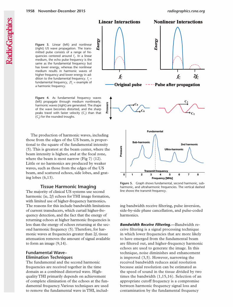
Linear and Nonlinear US PropagationLinear and nonlinear propagation are terms that describe how soft tissue responds as the US wave propagates (Fig 3). When the acoustic pressure of the US wave in a soft tissue is small (<0.5 MPa) (1), tissue behaves in a linear fash-ion, which means that it exhibits completely elastic behavior and that tissue expansion (rar-efaction) and compression propagate at the same speed. With linear propagation, waves that con-tain new frequencies are not created during US energy propagation (5).
Nonlinear propagation occurs when high-pressure US waves (>0.5 MPa) travel through a compressible medium and the transmitted US pulse induces less compression than rarefaction (1) (Fig 3). The propagation speed of US pulses is not constant because it is slightly faster in compressed tissue and slightly slower in rarefied tissue (5–7). Over time, this difference in propa-gation speed will distort even an ideal sine wave into a sawtooth wave (Fig 4).
Harmonic Frequencies
Definitions.—Harmonic frequencies are integer multiples of the fundamental frequency (ie, if the fundamental frequency is f, the harmonics have fre-quencies of 2f, 3f, and so on). The amplitudes of the harmonic waves are almost always lower than those of the fundamental frequency waves. Subharmonic frequencies are integer fractions of the fundamental frequency (eg, f/2, f/3, and so on). Subharmonic
advantages and limitations of THI, and introduce some current clinical applications of THI. Finally, in the third part, we introduce the physical prin-ciples of DTHI, explain how DTHI images are processed, and compare DTHI with THI.
Technical Concepts and Terminology
Fundamental FrequencyThe fundamental frequency is defined for a con-tinuously emitted sine wave from a US trans-ducer (Fig 1) as the lowest frequency in the pulse spectrum. Diagnostic US systems do not continuously emit waves, as they need to receive returning echoes. Consequently, the US trans-ducer emits short pulses that contain a frequency
TEACHING POINTS ■ Linear and nonlinear propagation are terms that describe how
soft tissue responds as the US wave propagates. When the pressure of the US wave in a soft tissue is small (<0.5 MPa), tis-sue behaves in a linear fashion, which means that it becomes completely elastic and that tissue expansion (rarefaction) and compression propagate at the same speed. With linear propa-gation, waves that contain new frequencies are not created during US energy propagation. Nonlinear propagation occurs when high-pressure US waves (>0.5 MPa) propagate through a compressible medium and the transmitted US pulse induces less compression than rarefaction.
■ The production of harmonic waves, including those from the edges of the US beam, is proportional to the square of the fun-damental intensity. This is greatest at the beam center, where the beam intensity is highest, and at the focal zone, where the beam is most narrow. Little or no harmonics are produced by weaker waves, such as those from the edges of the US beam, and scattered echoes, side lobes, and grating lobes.
■ Images produced with THI are often superior to conventional gray-scale images of cysts and abnormalities that contain fat, calcium, or air. Clinically, several advantages are evident.
■ In DTHI, two pulses are transmitted simultaneously at differ-ent frequencies, referred to as f1 and f2. In addition to their har-monic frequencies (2f1 and 2f2), the sum and the difference of the transmitted frequencies (f2 + f1 and f2 – f1, respectively) are generated within the tissue. The second harmonic signal of the lower frequency (f1) and the difference frequency (f2 – f1) are detected by the transducer; other generated frequency components do not fall within the bandwidth of the trans-ducer. Both fundamental frequencies are cancelled by the subtraction technique (a technique similar to pulse inversion) and therefore are not detected in the signal. By receiving the second harmonic 2f1 and the differential frequencies (f2 – f1), the effective bandwidth of the tissue harmonic signals is ex-panded to between f2 – f1 and 2f1. By using DTHI, higher reso-lution, better penetration, and fewer artifacts can be achieved.
■ DTHI and THI are substantially better than fundamental US imaging for noise reduction, detail resolution, image quality, focal abnormality margin sharpness, and penetration for he-patic imaging. DTHI also performed better than THI regard-ing detail resolution, image quality, and contrast-to-noise ra-tio in evaluation of focal hepatic abnormalities.
Table 1: Glossary of Parameters of US Image Quality
Parameter Definition
Axial reso- lution
The ability to resolve objects in the direction of the wave propa-gation, determined by transmit-pulse length or bandwidth
Lateral reso-lution
The ability to resolve adjacent objects across the field of view
Contrast reso-lution
The ability to distinguish between small anatomic structures with similar tissue characteristics
Signal-to- noise ratio
A measure of signal strength rela-tive to background reflections, or noise, and a good predictor of contrast resolution
Nicole Cooper • 10/15/2015, 8:45 AMdone

RG • Volume 35 Number 7 Anvari et al 1957
Figure 2. Diagram of the fundamental frequency imaging process. In this method, transmitted and received bandwidths are identical.
imaging is generally suitable for deep imaging be-cause there is less attenuation of lower-frequency subharmonic signals (8,9). Frequency multiples of the subharmonic frequency component (eg, 3f/2, 5f/2, 7f/2, and so on) are called ultraharmonic frequencies (10) (Fig 5).
Mechanism of Harmonic Wave Generation.—Tissue nonlinearity distorts the fundamental sine wave pattern during propagation through tissue; the compressive pulse wave peaks propagate at higher speed than do rarefactive wave troughs.
Figure 1. Fundamental (a), pulse subtraction (b), and DTHI (c) US images of the upper abdomen. Note the marked reduction in speckle artifacts in the inferior vena cava lumen on b and c, and superior demonstration of the aorta (arrow) on the deep part of c. (Case courtesy of Toshiba Medical Systems.)
This is because the speed of propagation is slightly greater in the compressed regions of the tissue than in the expanded regions. The result-ing waveform distortion depends on the emitted pulse amplitude and distance traveled by the fun-damental wave (5,11). For low-amplitude pulses, the distortion is negligible, but at higher ampli-tudes the effect becomes substantial. At the skin, tissue harmonics are virtually zero; their intensity increases with depth to the point where tissue attenuation predominates and harmonic ampli-tudes decrease (2) (Fig 6).
1958 November-December 2015 radiographics.rsna.org
Figure 5. Graph shows fundamental, second harmonic, sub-harmonic, and ultraharmonic frequencies. The vertical dashed line shows the transmit frequency.
Figure 4. As fundamental frequency waves (left) propagate through medium nonlinearly, harmonic waves (right) are generated. The shape of the wave becomes distorted, and the sharp peaks travel with faster velocity (C1) than that (C2) for the rounded troughs.
The production of harmonic waves, including those from the edges of the US beam, is propor-tional to the square of the fundamental intensity (5). This is greatest at the beam center, where the beam intensity is highest, and at the focal zone, where the beam is most narrow (Fig 7) (12). Little or no harmonics are produced by weaker waves, such as those from the edges of the US beam, and scattered echoes, side lobes, and grat-ing lobes (6,13).
Tissue Harmonic ImagingThe majority of clinical US systems use second harmonic (ie, 2f) echoes for THI image formation, with limited use of higher-frequency harmonics. The reasons for this include bandwidth limitations of current transducers, which curtail higher-fre-quency detection, and the fact that the energy of returning echoes at higher harmonic frequencies is less than the energy of echoes returning at the sec-ond harmonic frequency (5). Therefore, for har-monic waves at frequencies greater than 2f, tissue attenuation removes the amount of signal available to form an image (9,14).
Fundamental Wave– Elimination TechniquesThe fundamental and the second harmonic frequencies are received together in the time domain as a combined distorted wave. High-quality THI primarily depends on achievement of complete elimination of the echoes at the fun-damental frequency. Various techniques are used to remove the fundamental wave in THI, includ-
ing bandwidth receive filtering, pulse inversion, side-by-side phase cancellation, and pulse-coded harmonics.
Bandwidth Receive Filtering.—Bandwidth re-ceive filtering is a signal processing technique in which lower frequencies that are more likely to have emerged from the fundamental beam are filtered out, and higher-frequency harmonic echoes are used to generate the image. In this technique, noise diminishes and enhancement is improved (3,5). However, narrowing the received bandwidth reduces axial resolution because axial resolution can be estimated as the speed of sound in the tissue divided by two times the bandwidth (1,15,16). Selection of an appropriate cutoff frequency is a compromise between harmonic frequency signal loss and contamination by the fundamental frequency
Figure 3. Linear (left) and nonlinear (right) US wave propagation. The trans-mitted pulse consists of a range of fre-quencies centered around fC. In a linear medium, the echo pulse frequency is the same as the fundamental frequency but has lower energy, whereas the nonlinear medium results in harmonic waves of higher frequency and lower energy in ad-dition to the fundamental frequency. fC = fundamental frequency, 2fC = example of a harmonic frequency.
Jim Clinton • 10/14/2015, 12:56 PMDone.
Jim Clinton • 10/14/2015, 12:54 PMFixed.

RG • Volume 35 Number 7 Anvari et al 1959
Figure 8. Diagram shows the filtration technique for fundamental frequency removal. Fundamental pulses (left) are emitted by the transducer, which receives both fundamental and second harmonic frequencies (middle), and the fundamental frequency is selec-tively filtered out and the second harmonic frequency waves are used for image generation (right). Red lines = pulses and echoes, blue lines = transducer bandwidth, fC = fundamental frequency, 2fC = second harmonic frequency.
Figure 7. Diagram shows the harmonic energy profile. Higher-amplitude US pulses produce more harmonic waves. Therefore, harmonic waves are predominantly created in the central, most intense portion of the beam, which causes a narrower imaging plane and reduced artifacts because of side lobes and grating lobes. Note the increase in harmonic wave energy with increasing depth. (Courtesy of Jeff Powers, PhD.)
signal (13) (Fig 8). To overcome this limitation, pulse-inversion methods were developed.
Pulse Inversion.—Pulse inversion is a technique in which two pulses with a 180° phase difference (ie, opposite phase) are emitted sequentially into the tissue along the same line. The summation of these received pulses results in fundamental echoes canceled out with odd harmonic fre-quency components, and the retention of har-monic waves at even frequency multiples of the fundamental frequency, with a doubling of the amplitude of even frequency multiple harmonic waves (3,17) (Fig 9). This technique is also termed a phase cancellation or a temporal cancel-lation technique. The principal advantage of this technique is that axial resolution is not degraded and tissue contrast is better preserved. However,
the insonated tissue must remain stable for the duration of the two opposed-phase pulses for pulse summation to result in phase cancellation only. Consequently, pulse-inversion harmonic im-aging is highly dependent on a fixed tissue frame, and tissue motion can markedly degrade the US image (3,18,19). In addition, some reduction in frame rate will occur.
Side-by-Side Phase Cancellation.—Side-by-side phase cancellation is similar to pulse inversion, but two pulses with opposite phase are transmit-ted along adjacent lines of sight. These adjacent lines are then added to cancel fundamental echoes and odd harmonics. This technique is a spatial cancellation technique. As with pulse inversion, side-by-side cancellation preserves har-monic frequency bandwidth (20).
Figure 6. Graph shows the schematic relationship between fundamental and harmonic frequency wave amplitudes as a function of depth. (Dashed line = sum of skin and subcutaneous thicknesses.)
Jim Clinton • 10/14/2015, 12:54 PMDone.
Done.
Jim Clinton • 10/14/2015, 12:50 PMDone.
Jim Clinton • 10/14/2015, 1:33 PMDone.
Fixed.

1960 November-December 2015 radiographics.rsna.org
Pulse-coded Harmonics.—The pulse-encoding technique transmits relatively complex pulse se-quences into the body with a unique and recogniz-able code imprinted on each pulse. The unique code is then recognized in the echoes (21). Because the fundamental echoes have a specific code, they can be identified and canceled. The remaining har-monic echo is then processed to form the image.
This technique is especially useful in the near field because longer encoded pulses produce har-monics more efficiently in the near field than do conventional THI pulses.
The code can be binary or frequency modu-lation chirp encoding. Binary encoding uses a sequence of wavelengths transmitted as binary numbers. In frequency modulation chirp en-coding, the frequency of the emitted pulse is increased at a known rate during pulse genera-tion. A combination of chirp encoding and pulse inversion improves signal-to-noise ratio (22).
Advantages of THIImages produced with THI are often superior to conventional gray-scale images of cysts and abnormalities that contain fat, calcium, or air (23). Clinically, several advantages are evident: (a) improved contrast resolution: increased signal-to-noise ratio results in better tissue contrast en-hancement, which improves the conspic uousness of subtle parenchymal abnormalities; (b) improved lateral resolution and reduced section thickness: as noted in this article, harmonic waves are predomi-
nantly generated at the center of the US beam, which narrows the imaging plane and improves lateral resolution (16,18,23); (c) beneficial effects on artifacts: THI reduces some artifacts (Table 2), including reverberation artifact, side lobe artifact, and grating lobe artifact, which have their origins in weaker beams, produced on either side of the main lobe of the transmitted beam (5,23–26), and enhances other artifacts such as acoustic enhance-ment deep to fluid (useful for depicting cysts), acoustic shadowing, and comet-tail artifacts (3); (d) reduced noise in the near field: harmonic waves are not produced in the superficial part of tissue, which reduces noise in the near field; and (e) improved imaging of deeper tissue: pref-erential generation of harmonic waves in deeper tissue can improve image quality in obese pa-tients as long as tissue attenuation effects do not dominate (3,23,25,27–29).
Disadvantages of THIAxial resolution is decreased by THI because of the narrowed bandwidth (29). Fundamental frequency imaging may be clinically more effica-cious than harmonic imaging in other situations, such as diffuse fatty liver, because of compro-mise of axial resolution from filtration-related bandwidth reduction, and higher attenuation of the higher frequency harmonic component. As noted in this article, the pulse inversion method is more sensitive to motion than fundamental frequency imaging and also has lower temporal
Figure 9. Pulse-inversion technique for funda-mental frequency removal. The first pulse (top) is transmitted, and the received echoes are stored. A second pulse with an inverted phase (ie, 180° phase shifted) (middle) with respect to the first is transmitted along the same beam. The echoes from the second pulse are added to those from the first pulse, with a resulting summed wave-form (bottom). Low-amplitude echo signals (left) cancel out, whereas distorted high-amplitude signals (right) are retained.
Table 2: US Artifacts Glossary
Artifact Type Definition
Side lobes and grating lobes
Multiple beams of low-amplitude US energy that project radially from the main beam axis, which may create echoes detectable by the transducer
Reverberation Echoes repeatedly reflected between two highly reflective interfaces; the display shows multiple equally spaced signals that extend into the deep field
Comet tail A form of reverberation where the two reflective interfaces are closely spaced; sequen-tial echoes may be so close together that individual signals are not perceivable
fixed

RG • Volume 35 Number 7 Anvari et al 1961
Figure 10. Diagram shows transmission and reception of DTHI. Two frequencies are contained within each pulse. The returning echoes contain frequencies at the sum and difference of the emitted frequencies as well as their harmonics. The two lower-frequency components of the echo are used for image generation.
resolution because of image formation that re-quires two pulses per line.
THI SafetyBoth the thermal and mechanical indexes remain the same for THI as for conventional B-mode US, and therefore THI is considered safe for rou-tine clinical use (30).
Differential Tissue Harmonic Imaging
THI uses only half of the available transducer bandwidth for image formation: The lower half is used for transmission and the upper half is used during reception. DTHI, also known as multitone nonlinear THI, uses the entire transducer band-width, which combines the advantages of con-ventional gray-scale US with those of THI. This is particularly useful at greater depths (>8 cm) (4,9,31). In addition to broadband transducers, fast signal processing is essential for DTHI (9).
In DTHI, two pulses are transmitted simultane-ously at different frequencies, referred to as f1 and f2. In addition to their second harmonic frequencies (2f1 and 2f2), among others, the sum and the dif-ference of the transmitted frequencies (f2 + f1 and f2 – f1, respectively) are generated within the tissue. The second harmonic signal of the lower frequency (2f1), and the difference frequency (f2 – f1), are de-tected by the transducer; other generated frequency components do not fall within the bandwidth of the transducer. Both fundamental frequencies are cancelled by the subtraction technique (a technique similar to pulse inversion) and are therefore not detected in the signal. By receiving the second har-monic 2f1 and the difference of the frequencies (f2 – f1), the effective bandwidth of the tissue harmonic signals is expanded to between f2 – f1 and 2f1 (32) (Fig 10). By using DTHI, higher resolution, better penetration, and fewer artifacts can be achieved.
Comparison of DTHI with THIDTHI and THI are substantially better than fundamental US imaging for noise reduction, detail resolution, image quality, focal abnormal-ity margin sharpness, and penetration for hepatic imaging (31). DTHI also performed better than THI regarding detail resolution, image quality, and contrast-to-noise ratio in evaluation of focal hepatic abnormalities (31,33) (Fig 11).
Clinical Appli- cations of THI and DTHI
THI and DTHI are advantageous in the follow-ing common clinical settings: breast and axillary lymph node, thyroid, hepatobiliary and pancre-atic, genitourinary, and pediatric.
Breast and Axillary Lymph NodeTHI has been shown to improve detection and characterization of focal breast abnormalities, especially in fatty breasts, but it has limited value for needle visualization in interventional breast US (4,34,35). It has better diagnostic ac-curacy in axillary lymph node lesions than does gray-scale US, due to improved contrast and resolution (36).
ThyroidTHI improves the image quality of thyroid US. A limitation that has been reported is increased shadowing from the overlying sternocleidomas-toid muscle in transverse imaging planes, but this is easily overcome by moving the transducer (37,38).
Hepatobiliary and PancreasTHI and DTHI can improve image quality in hepatobiliary US (Fig 12) through a variety of mechanisms: (a) reduced reverberation and side lobe artifacts from the body wall, especially in
Nicole Cooper • 10/15/2015, 8:48 AMfixed

1962 November-December 2015 radiographics.rsna.org
Figure 11. Images of two small hepatic focal abnormali-ties (arrows), thought to be hemangiomas, obtained by us-ing fundamental imaging (a), THI (b), and DTHI (c). Note the superior definition of the liver parenchyma and focal liver abnormalities in b and c in comparison with a.
Figure 12. Images of the gallbladder obtained by using fundamental imaging (a), pulse-subtraction imaging (b), and DTHI (c). Note the marked reduction in reverberation artifact from the anterior gallbladder wall in b and c. The scan in c demonstrates improved delineation of the gallblad-der neck (arrow).
Nicole Cooper • 10/20/2015, 7:50 AMdone
Nicole Cooper • 10/20/2015, 7:50 AMnot needed

RG • Volume 35 Number 7 Anvari et al 1963
obese patients and with narrow intercostal acoustic windows, which can improve visualiza-tion of small anatomic structures such as periph-eral portal veins and smaller biliary branches; (b) improved visualization of focal abnormalities because of reduced artifacts and improved contrast between abnormalities and tissue; (c) improved characterization of focal abnor-malities that contain fluid, which include cysts and fluid collections, because of a reduction in reverberation artifact, which is particularly use-ful to distinguish hypoechoic solid abnormali-ties, such as lymphomatous lymph nodes, from cysts; (d) increased conspicuity of posterior acoustic shadowing from gallstones, especially in obese patients; and (e) improved conspicu-ity of the comet-tail artifact that is diagnostic of adenomyomatosis of the gallbladder (23,39–41). THI techniques improve detection of pancreatic focal abnormalities, especially of abnormalities smaller than 1 cm, and improve fluid-solid differ-entiation (13).
GenitourinaryTHI and DTHI are useful in renal imaging (Fig 13). Clinically, substantial improvements include improved capability to distinguish between cysts and solid renal focal abnormalities, improved
detection of shadowing from urinary calculi, improved renal cell carcinoma and renal paren-chymal tissue contrast enhancement (23), and improved transrectal delineation with US of the prostatic urethra and rectal wall (42–44). Trans-abdominal THI has been shown to have better image quality than transabdominal gray-scale US for ovarian follicle detection in patients with a high body mass index (45).
PediatricHarmonic imaging may be helpful for newborns and toddlers, but because of their smaller size, fundamental frequency imaging with higher-frequency transducers may be more clinically ef-ficacious (13,46–49).
ConclusionTHI and DTHI are technologies that improve US image quality. An understanding of the essen-tial concepts and techniques discussed in this ar-ticle can help radiologists select US technologies suitable for specific clinical problems.
Acknowledgments.—The authors gratefully acknowl-edge Sahar Anvari for creating the diagrams and Jeff Powers, PhD, David Hunt, and Toshiba Medical Sys-tems for contributing images.
Figure 13. Fundamental (a), pulse subtraction (b), and DTHI (c) images of the bladder. Note the reduced rever-beration artifact, especially in c, and improved delineation of the layers of the posterior bladder wall (arrows).
Jim Clinton • 10/14/2015, 12:57 PMFixed.

1964 November-December 2015 radiographics.rsna.org
Disclosures of Conflicts of Interest.—F.F. Activities related to the present article: disclosed no relevant relationships. Activities not related to the present article: grants from the National Institutes of Health, the Department of Defense, and Toshiba; personal fees from General Electric and Toshiba; and nonfinancial sup-port from General Electric, Toshiba, and Siemens. Other activi-ties: disclosed no relevant relationships.
References 1. Averkiou MA, Roundhill DR, Powers JE. A new imaging technique
based on the nonlinear properties of tissues. Proc IEEE Ultrason Symp 1997;2:1561–1566.
2. Desser TS, Jeffrey RB Jr, Lane MJ, Ralls PW. Tissue harmonic imaging: utility in abdominal and pelvic sonography. J Clin Ul-trasound 1999;27(3):135–142.
3. Desser TS, Jeffrey RB. Tissue harmonic imaging techniques: physical principles and clinical applications. Semin Ultrasound CT MR 2001;22(1):1–10.
4. Nowicki A, Wójcik J, Secomski W. Harmonic imaging using multitone nonlinear coding. Ultrasound Med Biol 2007;33(7): 1112–1122.
5. Thomas JD, Rubin DN. Tissue harmonic imaging: why does it work? J Am Soc Echocardiogr 1998;11(8):803–808.
6. Duck FA. Nonlinear acoustics in diagnostic ultrasound. Ultrasound Med Biol 2002;28(1):1–18.
7. Humphrey VF. Nonlinear propagation in ultrasonic fields: mea-surements, modelling and harmonic imaging. Ultrasonics 2000; 38(1-8):267–272.
8. Forsberg F, Shi WT, Goldberg BB. Subharmonic imaging of contrast agents. Ultrasonics 2000;38(1-8):93–98.
9. Kollmann C. New sonographic techniques for harmonic imaging: underlying physical principles. Eur J Radiol 2007;64(2):164–172.
10. Sbeity F, Ménigot S, Charara J, Girault JM. Contrast improve-ment in sub- and ultraharmonic ultrasound contrast imaging by combining several Hammerstein models. Int J Biomed Imaging 2013;2013(1):270523.
11. Lencioni R, Cioni D, Bartolozzi C. Tissue harmonic and contrast-specific imaging: back to gray scale in ultrasound. Eur Radiol 2002;12(1):151–165.
12. Ward B, Baker AC, Humphrey VF. Nonlinear propagation applied to the improvement of resolution in diagnostic medical ultrasound. J Acoust Soc Am 1997;101(1):143–154.
13. Hohl C, Schmidt T, Honnef D, Günther RW, Haage P. Ultraso-nography of the pancreas. 2. Harmonic imaging. Abdom Imaging 2007;32(2):150–160.
14. Rizzatto G. Ultrasound transducers. Eur J Radiol 1998;27(suppl 2):S188–S195.
15. Jensen JA. Medical ultrasound imaging. Prog Biophys Mol Biol 2007;93(1-3):153–165.
16. Turner SP, Monaghan MJ. Tissue harmonic imaging for stan-dard left ventricular measurements: fundamentally flawed? Eur J Echocardiogr 2006;7(1):9–15.
17. Rosenthal SJ, Jones PH, Wetzel LH. Phase inversion tissue harmonic sonographic imaging: a clinical utility study. AJR Am J Roentgenol 2001;176(6):1393–1398.
18. Burns PN, Hope Simpson D, Averkiou MA. Nonlinear imaging. Ultrasound Med Biol 2000;26(Suppl 1):S19–S22.
19. Kim SH, Lee JM, Kim KG, et al. Comparison of fundamental sonography, tissue-harmonic sonography, fundamental compound sonography, and tissue-harmonic compound sonography for focal hepatic lesions. Eur Radiol 2006;16(11):2444–2453.
20. Gan WS. Medical ultrasound imaging. In: Gan WS, ed. Acoustical imaging: techniques and applications for engineers. Chichester, West Sussex, England: Wiley, 2012; 195–263.
21. Ma Q, Ma Y, Gong X, Zhang D. Improvement of tissue harmonic imaging using the pulse-inversion technique. Ultrasound Med Biol 2005;31(7):889–894.
22. Park J, Huang Y, Chen R, et al. Pulse inversion chirp coded tissue harmonic imaging (PI-CTHI) of zebrafish heart using high frame rate ultrasound biomicroscopy. Ann Biomed Eng 2013;41(1):41–52.
23. Choudhry S, Gorman B, Charboneau JW, et al. Comparison of tissue harmonic imaging with conventional US in abdominal disease. RadioGraphics 2000;20(4):1127–1135.
24. Crouse LJ, Kramer PH. Second harmonic imaging: good rever-berations. Am Heart J 1999;138(1 Pt 1):19–20.
25. Shapiro RS, Wagreich J, Parsons RB, Stancato-Pasik A, Yeh HC, Lao R. Tissue harmonic imaging sonography: evaluation of image quality compared with conventional sonography. AJR Am J Roentgenol 1998;171(5):1203–1206.
26. Feldman MK, Katyal S, Blackwood MS. US artifacts. Radio-Graphics 2009;29(4):1179–1189.
27. Harvey CJ, Pilcher JM, Eckersley RJ, Blomley MJ, Cosgrove DO. Advances in ultrasound. Clin Radiol 2002;57(3):157–177.
28. Powers J, Kremkau F. Medical ultrasound systems. Interface Focus 2011;1(4):477–489.
29. Whittingham TA. Tissue harmonic imaging. Eur Radiol 1999;9 (3 suppl 3):S323–S326.
30. Egerton IB, Vella G, Barnett S. Experimental test of harmonic contribution to the thermal index for soft tissue. J Ultrasound Med 1999;18(1):81–86.
31. Chiou SY, Forsberg F, Fox TB, Needleman L. Comparing differential tissue harmonic imaging with tissue harmonic and fundamental gray scale imaging of the liver. J Ultrasound Med 2007;26(11):1557–1563.
32. Kotani A, Hirano Y, Yasuda C, Ishikawa K. A new ultraso-nographic technique for diagnosing deep venous insufficiency imaging and functional evaluation of venous valves by ultraso-nography with improved resolution. Int J Cardiovasc Imaging 2007;23(4):493–500.
33. Mesurolle B, Helou T, El-Khoury M, Edwardes M, Sutton EJ, Kao E. Tissue harmonic imaging, frequency compound imaging, and conventional imaging: use and benefit in breast sonography. J Ultrasound Med 2007;26(8):1041–1051.
34. Szopinski KT, Pajk AM, Wysocki M, Amy D, Szopinska M, Jakubowski W. Tissue harmonic imaging: utility in breast sonog-raphy. J Ultrasound Med 2003;22(5):479–487; quiz 488–489.
35. Mesurolle B, Bining HJ, El Khoury M, Barhdadi A, Kao E. Con-tribution of tissue harmonic imaging and frequency compound imaging in interventional breast sonography. J Ultrasound Med 2006;25(7):845–855.
36. Kubota K, Hisa N, Ogawa Y, Yoshida S. Evaluation of tissue harmonic imaging for breast tumors and axillary lymph nodes. Oncol Rep 2002;9(6):1335–1338.
37. Szopinski KT, Wysocki M, Pajk AM, Slapa RZ, Jakubowski W, Szopinska M. Tissue harmonic imaging of thyroid nodules: initial experience. J Ultrasound Med 2003;22(1):5–12.
38. Saleh A, Cupisti K, Fürst G, Feldkamp J, Grust A, Mödder U. Does tissue harmonic imaging allow early determination of postoperative thyroid volume? [in German]. Rofo 2001;173(4):325–328.
39. Sandhu GK, Angyalfi S, Dunscombe PB, Khan RF. Is tissue harmonic ultrasound imaging (THI) of the prostatic urethra and rectum superior to brightness (B) mode imaging? An observer study. Phys Med 2014;30(6):662–668.
40. Hong HS, Han JK, Kim TK, et al. Ultrasonographic evaluation of the gallbladder: comparison of fundamental, tissue harmonic, and pulse inversion harmonic imaging. J Ultrasound Med 2001;20(1):35–41.
41. Ortega D, Burns PN, Hope Simpson D, Wilson SR. Tissue harmonic imaging: is it a benefit for bile duct sonography? AJR Am J Roentgenol 2001;176(3):653–659.
42. Sodhi KS, Sidhu R, Gulati M, Saxena A, Suri S, Chawla Y. Role of tissue harmonic imaging in focal hepatic lesions: com-parison with conventional sonography. J Gastroenterol Hepatol 2005;20(10):1488–1493.
43. Schmidt T, Hohl C, Haage P, et al. Diagnostic accuracy of phase-inversion tissue harmonic imaging versus fundamental B-mode sonography in the evaluation of focal lesions of the kidney. AJR Am J Roentgenol 2003;180(6):1639–1647.
44. Ozdemir H, Demir MK, Temizöz O, Genchellac H, Unlu E. Phase inversion harmonic imaging improves assessment of renal calculi: a comparison with fundamental gray-scale sonography. J Clin Ultrasound 2008;36(1):16–19.
45. Mahmutyazicioğlu K, Tanriverdi HA, Ozdemir H, Barut A, Davşanci H, Gündoğdu S. Transabdominal pulse inversion harmonic imaging improves assessment of ovarian morphology in virgin patients with PCOS: comparison with conventional B-mode sonography. Eur J Radiol 2005;53(2):280–286.
46. Yücel C, Ozdemir H, Aşik E, Oner Y, Işik S. Benefits of tissue harmonic imaging in the evaluation of abdominal and pelvic le-sions. Abdom Imaging 2003;28(1):103–109.
47. Schmidt T, Hohl C, Haage P, et al. Phase-inversion tissue har-monic imaging compared to fundamental B-mode ultrasound in the evaluation of the pathology of large and small bowel. Eur Radiol 2005;15(9):2021–2030.
48. Kralik R, Trnovsky P, Kopáčová M. Transabdominal ul-trasonography of the small bowel. Gastroenterol Res Pract 2013;2013(2):896704–896711 .
49. Rompel O, Huelsse B, Bodenschatz K, Reutter G, Darge K. Harmonic US imaging of appendicitis in children. Pediatr Radiol 2006;36(12):1257–1264.


![i .] APPROXIMATING HARMONIC FUNCTIONS 499€¦ · APPROXIMATING HARMONIC FUNCTIONS 499 THE APPROXIMATION OF HARMONIC FUNCTIONS BY HARMONIC POLYNOMIALS AND BY HARMONIC RATIONAL FUNCTIONS*](https://static.fdocuments.net/doc/165x107/5f0873ba7e708231d42214c2/i-approximating-harmonic-functions-499-approximating-harmonic-functions-499-the.jpg)
