
Tips and Tricks for Autodesk Land Desktop...Tips and Tricks for Autodesk Land Desktop 3 Once a...
20
December 2-5, 2003 ◊ MGM Grand Hotel Las Vegas Tips and Tricks for Autodesk Land Desktop Gary Rosen CV11-3 Are you squeezing your Prototypes for all they’re worth? Are you using Pipes, or drafting them in with AutoCAD? How about Description Keys or DTM Slope and Elevation ranges? And what about Map? Are you using polygon topologies, overlay analyses, buffers, drawing cleanups, and feature classifications? Learn the tips and tricks for Autodesk Land Desktop in this class. About the Speaker: Gary Rosen is president of Electric Pelican Ink CADD Consulting Services, and is a 24-year veteran of the civil/survey industry. He has spent 16 of those years working with Softdesk and Autodesk software. Gary spends most days providing on-site consulting and training to “Land Nuts” in New England. He is the author of INSIDE Softdesk Civil , Learning Land Desktop , and two training videos, Autodesk Land Desktop in a Nutshell, the Movie , and Autodesk Civil Design in a Nutshell, the Movie . [email protected]
Transcript of Tips and Tricks for Autodesk Land Desktop...Tips and Tricks for Autodesk Land Desktop 3 Once a...

December 2-5, 2003 ◊ MGM Grand Hotel Las Vegas
Tips and Tricks for Autodesk Land
Desktop Gary Rosen
CV11-3 Are you squeezing your Prototypes for all they’re worth? Are you using Pipes, or drafting them in with AutoCAD? How about Description Keys or DTM Slope and Elevation ranges? And what about Map? Are you using polygon topologies, overlay analyses, buffers, drawing cleanups, and feature classifications? Learn the tips and tricks for Autodesk Land Desktop in this class.
About the Speaker: Gary Rosen is president of Electric Pelican Ink CADD Consulting Services, and is a 24-year veteran of the civil/survey industry. He has spent 16 of those years working with Softdesk and Autodesk software. Gary spends most days providing on-site consulting and training to “Land Nuts” in New England. He is the author of INSIDE Softdesk Civil, Learning Land Desktop, and two training videos, Autodesk Land Desktop in a Nutshell, the Movie, and Autodesk Civil Design in a Nutshell, the Movie. [email protected]

Tips and Tricks for Autodesk Land Desktop
2
Tips and Tricks
Autodesk Land Desktop, along with the companion Civil Design, Survey, and Map programs, offers an immense arsenal of tools that can be applied to a wide range of common situations and challenges faced on a daily basis. So-called “Tips and Tricks” are really nothing more than a familiarity with the available tools and their applications. In this class, we will cover a selection of these that I have found, over the years, to be very useful, and often overlooked.
Prototypes
The first item to discuss is the use of LDT Prototypes. Prototypes are used primarily as a place to store LDT Settings. LDT Settings control every aspect of the functionality of the program, and essentially take the shipping “one-size-fits-all” product and tailor it to each user/organizations needs. A significant amount of standardization comes automatically from their use.
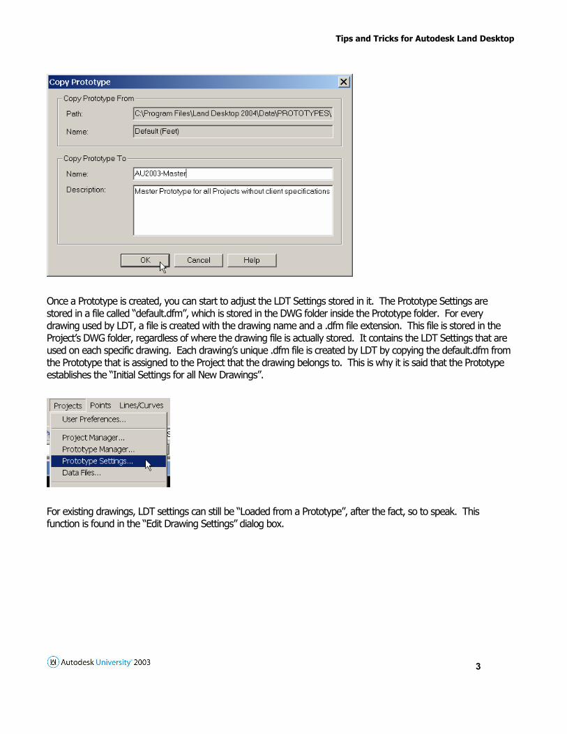
To create a Prototype, use the Projects menu, Prototype Manager.
Tips and Tricks for Autodesk Land Desktop
3
Once a Prototype is created, you can start to adjust the LDT Settings stored in it. The Prototype Settings are stored in a file called “default.dfm”, which is stored in the DWG folder inside the Prototype folder. For every drawing used by LDT, a file is created with the drawing name and a .dfm file extension. This file is stored in the Project’s DWG folder, regardless of where the drawing file is actually stored. It contains the LDT Settings that are used on each specific drawing. Each drawing’s unique .dfm file is created by LDT by copying the default.dfm from the Prototype that is assigned to the Project that the drawing belongs to. This is why it is said that the Prototype establishes the “Initial Settings for all New Drawings”.
For existing drawings, LDT settings can still be “Loaded from a Prototype”, after the fact, so to speak. This function is found in the “Edit Drawing Settings” dialog box.

Tips and Tricks for Autodesk Land Desktop
4
Another slick trick is to add your own sub-folders to the Prototype folder. When a new LDT Project is created using the Prototype, the folder structure is duplicated in the new Project folder. In this way, Prototypes can be used as an effective folder creation tool.

Tips and Tricks for Autodesk Land Desktop
5
The general theory suggests that a Prototype is developed for every organization using LDT, and it stores the LDT Settings that are used on all LDT Projects where the client does not specify their own preferences for the appearance of the drawings, or the layering used. They are basically saying, do it your way, just make it look good. If, however, certain clients do have their own preferences, a special Prototype can be created for them that specifies the use of those variables. All LDT Projects for that client are then created using their Prototype.
The “Data” Folder
When LDT is installed, each computer gets it’s own copy of a very critical folder known as the “Data” folder. This folder is curiously named, as it actually contains no real data, but rather, a collection of folders that contain a variety of settings, rules and styles that need to be shared throughout the organization to facilitate standardization.
It is essential that this folder be copied from one machine to a location on the network where all users can access it. The management of this folder is critical, since you do not want users changing the contents at will, but the creation of some new files here may be necessary on occasion. Unless a robust replication procedure is employed, moving it to the network is the only way to insure that all users create similar drawings. Some of the most important items stored in the Data folder are line, curve, spiral and point label styles, contour styles, drawing setups, text setups, Prototypes, and menu palettes.

Tips and Tricks for Autodesk Land Desktop
6
The location where LDT looks for these things is specified in User Preferences, accessed at the top of the Projects pull-down menu. The paths specified here are stored in a critical file called “sdsk.dfm”, located in the Land Desktop program folder. Once a single machine is set up and working properly, accessing all this information off of a network drive, the other machines in the organization can be set to do the same by copying the sdsk.dfm file to each of their LDT program folders.
North Rotation
This one is so controversial that I almost hesitate to bring it up, but it is a key feature of LDT and so should be understood, regardless of how it is employed. Every drawing that LDT uses has a second coordinate system created within it, a LDT specified UCS, basically. It is a Northing/Easting coordinate system, since civil engineering and surveying works in that language. Initially, North - 0 East - 0 is placed on top of X - 0, Y – 0, and North is pointing straight up, clockwise from the vertical Y-axis, 0 degrees. The question that comes into play is where do you want North to point in any specific drawing? If you want to point straight up, you’re all set, but if it would lend itself to be pointed somewhere else, typically to allow the project to be presented more efficiently, how are you going to make this adjustment. AutoCAD offers a pair of settings to help with this, known as UCS and Dview, Twist. While these AutoCAD commands can change the orientation of the drawing, AutoCAD does not really understand what “North” actually is, so it is really not the application to use to manipulate it. LDT establishes a Northing/Easting system, and can manipulate it quite efficiently. LDT always speaks to this system, which is why it is an elegant solution to the problem of wanting to change where North is pointed.
When a new drawing is created, the initial drawing setup specifies an Orientation, which is where North Rotation is set. No external data is affected, as this is strictly a drawing setting. If a manipulation of the drawing Orientation is performed in an existing drawing, all externally stored data should be recreated in the drawing, such as Points, Surfaces, or Alignments. All remaining AutoCAD drawing entities need to be manually rotated with an AutoCAD Rotate command, the same number of degrees as the North Rotation, but in the opposite direction, since AutoCAD says all angles are counter-clockwise, but a LDT North Rotation is positive to the right.
I recommend that the Base Point X-Y and North-East coordinates always remain at 0,0, North – 0, East – 0, and that all rotation angles be entered as whole degrees, to make use of this feature easier.

Tips and Tricks for Autodesk Land Desktop
7
Templates, Prototypes, and Design Center
One more note on setting up the working environment. In the AutoCAD/LDT 2000-2004 environment, there are actually three areas that can be employed to implement standardization. Drawing templates, or .dwt files, are used by AutoCAD to store AutoCAD settings, LDT Prototypes are used as described above to store LDT settings, and Design Center can be used to store things in “Master” drawings, to be “mined” when needed, sort of a Just-In-Time approach to standardization. The question is what goes where? Let’s look at a short list of items and how these features address them.
Layers – LDT creates many layers as the software is used, as needed, based on LDT settings. These settings are stored in Prototypes, which are assigned to Projects. These layers should not be defined in Templates, but rather created “on-the-fly”, on an as needed basis. Most of these should also be named based on the name of the feature that is being visualized, such as the Surface name or the Alignment name. This is done with the use of an “*” as a layer prefix.
Any layers that will exist in all drawings, with the exact same names, such as “Notes”, or “Dimensions”, can be defined in an AutoCAD template file.

Tips and Tricks for Autodesk Land Desktop
8
All the rest of the layers that might be needed in some drawings, but are not necessarily needed in all drawings, can be stored in a Master Layer file, to be “mined” with Design Center, as needed. This way, you don’t have to have dozens or even hundreds of layers in all drawings, but by the same token they do not have to be created manually every time, which would cause different naming and attributes such as color and linetypes.
Text Styles – LDT creates a set of text styles through the drawing setup routine, and sizes them appropriately for the scale that the drawing is to be plotted. For this reason, text styles should not be defined in drawing templates.
Dimension Styles – LDT does not do anything with dimension styles, so they need to be defined and stored in some other way. Dimension styles designed for all commonly used plot scales are needed, typically 10 scale, 20, 30, 40, 50, 60, 100, and 200, at least for a start. One method is to define this set of dimension styles in an AutoCAD template, but then every new drawing created with that template have all of the styles present. The other method is to define these in a “master dimension styles” drawing file, to be “mined” with Design Center.
Blocks – Design Center is the answer for blocks, especially with the 2004 tool palettes.

Tips and Tricks for Autodesk Land Desktop
9
UCSICON
Turn it ON, and, as the Grateful Dead used to say, “Leave it ON”. If you’re not in the World Coordinate System, LDT will not function properly, and the UCS Icon is the easiest way to visually confirm that you are in the WCS.
Points
For high-end Point functionality, please attend my class on this subject, “Get the Point in Autodesk Land Desktop”. If you are unable to do that, please pick up a copy of the handout. Efficient use of Points is essential, including Description Keys, Point Groups, Point Display Properties, Point Labels, and XDRefs.
Surfaces
Again, the high-end use of Digital Terrain Models is an absolutely essential part of the implementation of the software, but rather than cover it in detail in the limited time we have for this class, please attend my class entitled “The Art of Digital Terrain Modeling”. If you are unable to attend, please get a copy of the handout.
Pipes
The use of Pipes, at least to facilitate the automated drafting of them in plan and profile, is a great feature of Civil Design. I will run through the fundamentals in class, and document the same here.
Using Land Desktop, with Autodesk Civil Design, to work on Sanitary Sewer and Storm Drain projects can save considerable time and effort, as opposed to trying to generate this work using AutoCAD commands alone. This can be accomplished with a little training and a little practice, and it is well worth it to make that investment.
Let’s start with the essentials.
First, in the Autodesk Land Desktop and Civil Design applications, Alignments and Pipe Runs are different things. Very different, in fact.
Alignments are Defined from the Alignment menu.

Tips and Tricks for Autodesk Land Desktop
10
They are 2D, and so have no vertical component.
They can contain line and/or curve segments.
Alignments can be automatically annotated with Stationing labels.
Offsets can be automatically generated from Alignments.
When combined with a Surface, Profiles can be generated from Alignments.
Pipe Runs are defined from the Pipe menu.
Pipe Runs contain a horizontal and a vertical component.
They can contain only line segments.
Pipe Runs cannot be Stationed.
Offsets cannot be generated from Pipe Runs.
Profiles cannot be generated from Pipe Runs.
Pipe Runs must be Associated with Alignments to be automatically generated in an existing Profile.
Pipe Settings control all aspects of working with Pipes. There are Pipe Settings and Node Settings, Drafting Settings, and Design Settings.
Pipe graphics are generated in either Conceptual or Finish Draft modes. Always work with Conceptual first, and then add Finish Draft.
Always Define Pipe Runs from the high elevation, down, regardless of which direction the Associated Alignment is Stationed. Go with the flow.
When combined with an Alignment, a Surface is used to generate a Profile.
When combined with a Pipe Run, a Surface is used to set the Rim elevations.
Here is a bulletproof sequence for working with Pipes:
Determine what Surface(s) you have to work with. An “existing ground” Surface is typically used to generate a Profile, but a “proposed conditions” Surface will be required to set the Rims of the pipe run structures. If you do not have a Surface, make one from something. Sometimes for a pipe project, only a string of shots is collected in the field. Connect them with a 3D polyline, offset it to each side, and Build a Surface from the 3 3D polylines.

Tips and Tricks for Autodesk Land Desktop
11
Decide if the Pipe Run and the Alignment are to be horizontally identical. For instance, are you going to Associate the Pipe Run to the centerline of a roadway, in which case each node of the Run will defined by a Station and Offset from the Alignment, or are the Alignment and the Pipe Run going to be horizontally identical. In the latter case, any change in the horizontal location of the Pipe Run by definition requires a redefining of the Alignment, and the generation of a new Profile. In the former scenario, changes to the horizontal location of the Pipe Run do not require a new Alignment definition or a new Profile generation. In either case…
Define the Alignment.
Generate a Full Profile.
Check Pipe Settings and adjust as necessary.
Define a Pipe Run. Turn a Surface On to set the Rims. When Saving it, Associate it with the Current Alignment.
Import the Pipe Run into the Profile, in Conceptual mode.
Edit the Pipe Run Data, at least to assign names to the nodes, and to set the calculation method, Downstream to Upstream, Upstream to Downstream, or None.
Edit the Pipe Run Graphically to manipulate the Inverts of the nodes and/or Slopes of the Pipes.
Generate Finish Draft graphics in the Profile.
Generate Finish Draft graphics in the Plan view.
When Editing the Pipe Run horizontally, use the appropriate LDT/Civil Design tools, not AutoCAD. The Conceptual Run in the Profile will then update automatically. The Finish Draft will have to be regenerated.
So let’s go through the sequence using 2 typical scenarios. First, a roadway design has already been completed, and we are adding a Pipe Run to it. The Pipe Run will reference the centerline of the roadway.

Tips and Tricks for Autodesk Land Desktop
12
Next, Pipe Settings…
Drafting Settings for the Pipes in the Profile…

Tips and Tricks for Autodesk Land Desktop
13
The Design Settings for the Pipes…
The Structure Library Editor….I added a new Structure called “smh”…
Design Settings for the Structures, or “Nodes”…

Tips and Tricks for Autodesk Land Desktop
14
Turning on the Surface allows Pipes to use the Surface to set the Rims of the Nodes…
Now, draw the Pipe Run in Plan view, from the high elevations, down…Go with the flow…
Save the Pipe Run, and Associate with the Current Alignment…

Tips and Tricks for Autodesk Land Desktop
15
Import Conceptual Pipe Run into the Profile…
Edit Pipe Run Data, using the Tabular Editor
Edit the Pipe Run, graphically…

Tips and Tricks for Autodesk Land Desktop
16
Draw Finish Draft in the Profile…
Draw Finish Draft in the Plan view…

Tips and Tricks for Autodesk Land Desktop
17
These are the basic steps in the sequence. The other typical scenario is a “cross country” run, which is not associated to a roadway centerline. In this case, define the horizontal pipe run as an Alignment first, generate a Profile from it, then go back and define it as a Pipe Run. This seems redundant, but it works. From there, proceed as shown above.
Using Pipes is not a perfect world, but as they say, “it sure beats the alternative”. Practice with it, and I think you will find it to be a significant time saver.
Map
From the first R1 version of Land Desktop, it was decided that rather than building it upon a foundation of AutoCAD alone, as was its predecessor, Softdesk Civil, it would be built upon a foundation of AutoCAD and Map. Map offers a wide range of functionality that can be employed on many civil/survey design and drafting challenges. Unfortunately, many LDT users have not had the opportunity to learn how Map can help. I would urge you to learn Map, take as many Map classes as you can here at AU, take a good comprehensive Map class at a local training center, or give me a call! To get the ball rolling, here is a great example of what Map can do.
A common task required on many civil engineering projects is to perform an analysis of proposed lot areas with some existing condition, such as soil types, or wetland/upland areas. This can be accomplished with Map by defining each of these sets of areas as polygon topologies, assigning the specific data to these areas, and then comparing them through a process known in Map as an Overlay Analysis.
The basic steps are relatively straightforward.
First, the 2 sets of line work must be defined as polygon topologies.
Next, the specific data need to be associated to the polygons.
Third, the 2 topologies need to be overlayed.
Finally, a report is generated of the resulting topology.
I will illustrate these steps in this document as a series of screen captures. Please fill in the details as I demonstrate in class.

Tips and Tricks for Autodesk Land Desktop
18

Tips and Tricks for Autodesk Land Desktop
19

Tips and Tricks for Autodesk Land Desktop
20


![AutoDesk Mechanical Solutions - Inventor Productiviry Secrets[1]. Tips & Tricks](https://static.fdocuments.net/doc/165x107/55cf9cdb550346d033ab4cf9/autodesk-mechanical-solutions-inventor-productiviry-secrets1-tips-tricks.jpg)


