
TippingPoint UnityOne-1200 V1 UnityOne-1200 V1.4 Technical Evaluation An NSS Group Report . First...
66
TippingPoint UnityOne-1200 V1.4 Technical Evaluation An NSS Group Report
Transcript of TippingPoint UnityOne-1200 V1 UnityOne-1200 V1.4 Technical Evaluation An NSS Group Report . First...

TippingPoint UnityOne-1200 V1.4 Technical Evaluation
An NSS Group Report

First published January 2004 (Version 1.0) Published by The NSS Group Mas la Carrière, Route de Ganges 30440 Sumène, France Tel : +33 (0)4 67 81 49 11 E-mail : [email protected] Internet : http://www.nss.co.uk 1991-2004 The NSS Group All rights reserved. No part of this publication may be reproduced, photocopied, stored on a retrieval system, or transmitted without the express written consent of the authors. This report shall be treated at all times as a confidential and proprietary report for internal use only. Please note that access to or use of this Report is conditioned on the following: 1. The information in this Report is subject to change by The NSS Group without notice. 2. The information in this Report is believed by The NSS Group to be accurate and reliable, but is not guaranteed. All use of and reliance on this
Report are at your sole risk. The NSS Group is not liable or responsible for any damages, losses or expenses arising from any error or omission in this Report.
3. NO WARRANTIES, EXPRESS OR IMPLIED ARE GIVEN BY THE NSS GROUP. ALL IMPLIED WARRANTIES, INCLUDING IMPLIED
WARRANTIES OF MERCHANTABILITY, FITNESS FOR A PARTICULAR PURPOSE AND NON-INFRINGEMENT ARE DISCLAIMED AND EXCLUDED BY THE NSS GROUP. IN NO EVENT SHALL THE NSS GROUP BE LIABLE FOR ANY CONSEQUENTIAL, INCIDENTAL OR INDIRECT DAMAGES, OR FOR ANY LOSS OF PROFIT, REVENUE, DATA, COMPUTER PROGRAMS, OR OTHER ASSETS, EVEN IF ADVISED OF THE POSSIBILITY THEREOF.
4. This Report does not constitute an endorsement, recommendation or guarantee of any of the products (hardware or software) tested or the
hardware and software used in testing the products. The testing does not guarantee that there are no errors or defects in the products, or that the products will meet your expectations, requirements, needs or specifications, or that they will operate without interruption.
5. This Report does not imply any endorsement, sponsorship, affiliation or verification by or with any companies mentioned in this report. 6. All trademarks, service marks, and trade names used in this Report are the trademarks, service marks, and trade names of their respective
owners, and no endorsement of, sponsorship of, affiliation with, or involvement in, any of the testing, this Report or The NSS Group is implied, nor should it be inferred.
The NSS Group Limited is registered in England & Wales, Reg No. 3233843
Registered Office: Montagu House, 81 High Street, Huntingdon, Cambs, PE29 3NY, England Tel +44 (0)7005 802 953

TABLE OF CONTENTS
INTRODUCTION .................................................................................................................. 1 Intrusion Prevention Systems (IPS) ........................................................................ 1
Host IPS (HIPS).......................................................................................... 2 Network IPS (NIPS).................................................................................... 2
Implementation Challenges ..................................................................................... 3 Requirements for effective prevention..................................................................... 4 The NSS Intrusion Prevention Group Test.............................................................. 6
Performance ............................................................................................... 6 Security Effectiveness ................................................................................ 9 Usability .................................................................................................... 11
TIPPINGPOINT UNITYONE-1200 V1.4............................................................................. 12 Executive Summary............................................................................................... 12 Architecture............................................................................................................ 12
UnityOne Intrusion Prevention Appliance (IPA) ....................................... 12 UnityOne Intrusion Prevention System (IPS) ........................................... 14 Local Security Manager (LSM)................................................................. 15 Command Line Interface (CLI) ................................................................. 16 Security Management System (SMS) ...................................................... 16
Performance .......................................................................................................... 17 Security Effectiveness ........................................................................................... 18 Usability ................................................................................................................. 18
Installation................................................................................................. 18 Configuration ............................................................................................ 20 Policy Management .................................................................................. 25 Alert Handling ........................................................................................... 33 Reporting and Analysis............................................................................. 36
Verdict.................................................................................................................... 38 Contact Details ...................................................................................................... 40
APPENDIX A – TEST RESULTS....................................................................................... 41 The Test Environment ........................................................................................... 41 Section 1 – Detection Engine ................................................................................ 41 Section 2 – IPS Evasion ........................................................................................ 43 Section 3 – Stateful Operation............................................................................... 45 Section 4 – Detection/Blocking Performance Under Load.................................... 46 Section 5 – Latency & User Response Times....................................................... 51 Section 6 – Stability & Reliability ........................................................................... 52 Section 7 – Management and Configuration......................................................... 53 TippingPoint UnityOne-1200 V1.4 Test Results.................................................... 54
Section 1 - Detection Engine.................................................................... 54 Section 2 - IPS Evasion............................................................................ 54 Section 3 - Stateful Operation .................................................................. 55 Section 4 - Detection/Blocking Performance Under Load........................ 56 Section 5 - Latency & User Response Times .......................................... 57 Section 6 - Stability & Reliability ............................................................... 57 Section 7 - Management Interface ........................................................... 57

TABLE OF FIGURES Figure 1 - TippingPoint: UnityOne-1200 Intrusion Prevention Appliance (IPA).................................................................................................................13 Figure 2 - TippingPoint: Intrusion Prevention System (IPS)..............................................................................................................................................15 Figure 3 - TippingPoint: The Local Security Manager (LSM) ............................................................................................................................................16 Figure 4 - TippingPoint: Managing user accounts.............................................................................................................................................................20 Figure 5 - TippingPoint: The Dashboard...........................................................................................................................................................................21 Figure 6 - TippingPoint: Managing devices.......................................................................................................................................................................23 Figure 7 - TippingPoint: Managing Digital Vaccine packages...........................................................................................................................................24 Figure 8 - TippingPoint: Profile Editor (Action Sets)..........................................................................................................................................................25 Figure 9 - TippingPoint: Profile Editor (Category Settings) ...............................................................................................................................................26 Figure 10 - TippingPoint: Profile Editor (Exceptions) ........................................................................................................................................................27 Figure 11 - TippingPoint: Shared settings.........................................................................................................................................................................29 Figure 12 - TippingPoint: Editing Filters ............................................................................................................................................................................30 Figure 13 - TippingPoint: Advanced Search (Filters) ........................................................................................................................................................32 Figure 14 - TippingPoint: Profile version control includes complete change history .........................................................................................................33 Figure 15 - TippingPoint: Event display ............................................................................................................................................................................34 Figure 16 - TippingPoint: Viewing Event details................................................................................................................................................................35 Figure 17 - TippingPoint: Reports .....................................................................................................................................................................................37

The NSS Group The NSS Group is Europe’s foremost independent security testing facility. Based in the UK with separate security and network infrastructure testing facilities in the South of France, The NSS Group offers a range of specialist IT, networking and security-related services to vendors and end-user organisations throughout Europe and the United States. The Group consists of two wholly-owned subsidiaries : • NSS Network Testing Laboratories • Network Security Services NSS Network Testing Laboratories are available to vendors and end-users for fully independent testing of networking, communications and security hardware and software. NSS Network Testing Laboratories also operates certification schemes for vendors and certification bodies, and currently provides certification of firewalls, VPN’s, crypto products and PKI products. Output from the labs, including detailed research reports, articles and white papers on the latest network and security technologies, are made available on the NSS web site at http://www.nss.co.uk Network Security Services provides a range of security-related services to vendors and end-users including security policy definition, IDS, firewall and VPN implementation, network security auditing and analysis, and penetration testing.

Foreword The NSS Group is pleased to present the results of the first comprehensive Intrusion Prevention System (IPS) test of its kind. This exhaustive review will give readers a complete perspective of the capabilities, maturity and suitability for immediate deployment of each of the products tested. The NSS Group established this test as IPS products are being actively deployed as a new layer in defence-in-depth security architectures. Contrary to recent analyst claims, we do not believe that “IDS is dead” or that “IPS is stillborn”. So-called “deep inspection firewalls” may be where the industry is heading in the long term, but they are simply not ready for prime-time deployments at this point in time. Until they are, security administrators need to make the best use of the technology that is available, and for now that means a combination of firewalls, in-line intrusion prevention devices, and intrusion detection systems. Please note that we fully recognise that each of the above product-types could be considered as “intrusion prevention” systems in some respect, along with Anti Virus gateways, desktop firewalls, and other products designed to “prevent” malicious activity on a network or individual host. However, we also believe that the marketing terms for each of these products are well established, and that the grounds for creating a new market segment - referred to as Intrusion Prevention Systems (IPS) - specifically for those products which are evaluated as part of this report is valid. We have defined what we consider to be IPS (both host- and network-based) in the introductory text to this report. You might not like the marketing hype, but the time for quibbling over the terminology is over - it is now time to get down to the serious issue of evaluating the technology behind it. The NSS IPS Group Test evaluates the performance, reliability, security effectiveness, and usability of both Network IPS and Host IPS products. The test consists of seven sections within three primary areas: performance and reliability, security accuracy, and usability. Overall, the suite contains over 750 individual tests, many of which are run multiple times, to provide the most thorough and complete evaluation of IPS products available anywhere today. We believe that our IPS test methodology will become the de facto standard for testing in-line intrusion prevention devices, and the NSS Approved logo an essential item on the list of requirements when purchasing these products. We also believe that this report is essential reading for anyone considering deploying Intrusion Prevention Systems in their networks, either in a test or live situation, and we hope that you find it both informative and useful in making your purchasing decisions. Bob Walder

TippingPoint UnityOne-1200 V1.4
Page 1
INTRODUCTION In a recent survey commissioned by VanDyke Software, some 66 per cent of the companies who responded said that they perceive system penetration to be the largest threat to their enterprises. The survey revealed that the top eight threats experienced by those surveyed were viruses (78 per cent of respondents), system penetration (50 per cent), DoS (40 per cent), insider abuse (29 per cent), spoofing (28 per cent), data/network sabotage (20 per cent), and unauthorised insider access (16 per cent). Although 86 per cent of respondents use firewalls (a disturbingly low figure in this day and age, to be honest!), it is apparent that firewalls are not always effective against many intrusion attempts. The average firewall is designed to deny clearly suspicious traffic - such as an attempt to telnet to a device when corporate security policy forbids telnet access completely - but is also designed to allow some traffic through - Web traffic to an internal Web server, for example. The problem is, that many exploits attempt to take advantage of weaknesses in the very protocols that are allowed through our perimeter firewalls, and once the Web server has been compromised, this can often be used as a springboard to launch additional attacks on other internal servers. Once a “rootkit” or “back door” has been installed on a server, the hacker has ensured that he will have unfettered access to that machine at any point in the future. Firewalls are also typically employed only at the network perimeter. However, many attacks, intentional or otherwise, are launched from within an organisation. Virtual private networks, laptops, and wireless networks all provide access to the internal network that often bypasses the firewall. Intrusion detection systems may be effective at detecting suspicious activity, but do not provide protection against attacks. Recent worms such as Slammer and Blaster have such fast propagation speeds that by the time an alert is generated, the damage is done and spreading fast.
Intrusion Prevention Systems (IPS) The inadequacies inherent in current defences has driven the development of a new breed of security products known as Intrusion Prevention Systems (IPS). This is a term which has provoked some controversy in the industry since some firewall and IDS vendors think it has been “hijacked” and used as a marketing term rather than as a description for any kind of new technology. Whilst it is true that firewalls, routers, IDS devices and even AV gateways all have intrusion prevention technology included in some form, we believe that there are sufficient grounds to create a new market sector for true Intrusion Prevention Systems. These systems are proactive defence mechanisms designed to detect malicious packets within normal network traffic (something that the current breed of firewalls do not actually do, for example) and stop intrusions dead, blocking the offending traffic automatically before it does any damage rather than simply raising an alert as, or after, the malicious payload has been delivered.

TippingPoint UnityOne-1200 V1.4
Page 2
Within the IPS market place, there are two main categories of product: Host IPS and Network IPS.
Host IPS (HIPS) As with Host IDS systems, the Host IPS relies on agents installed directly on the system being protected. It binds closely with the operating system kernel and services, monitoring and intercepting system calls to the kernel or APIs in order to prevent attacks as well as log them. It may also monitor data streams and the environment specific to a particular application (file locations and Registry settings for a Web server, for example) in order to protect that application from generic attacks for which no “signature” yet exists. One potential disadvantage with this approach is that, given the necessarily tight integration with the host operating system, future OS upgrades could cause problems. Since a Host IPS agent intercepts all requests to the system it protects, it has certain prerequisites - it must be very reliable, must not negatively impact performance, and must not block legitimate traffic. Any HIPS that does not meet these minimum requirements should never be installed in a host, no matter how effectively it blocks attacks.
Network IPS (NIPS) The Network IPS combines features of a standard IDS, an IPS and a firewall, and is sometimes known as an In-line IDS or Gateway IDS (GIDS). The next-generation firewall - the deep inspection firewall - also exhibits a similar feature set, though we do not believe that the deep inspection firewall is ready for mainstream deployment just yet. As with a typical firewall, the NIPS has at least two network interfaces, one designated as internal and one as external. As packets appear at the either interface they are passed to the detection engine, at which point the IPS device functions much as any IDS would in determining whether or not the packet being examined poses a threat. However, if it should detect a malicious packet, in addition to raising an alert, it will discard the packet and mark that flow as bad. As the remaining packets that make up that particular TCP session arrive at the IPS device, they are discarded immediately. Legitimate packets are passed through to the second interface and on to their intended destination. A useful side effect of some NIPS products is that as a matter of course - in fact as part of the initial detection process - they will provide “packet scrubbing” functionality to remove protocol inconsistencies resulting from varying interpretations of the TCP/IP specification (or intentional packet manipulation). Thus any fragmented packets, out-of-order packets, or packets with overlapping IP fragments will be re-ordered and “cleaned up” before being passed to the destination host, and illegal packets can be dropped completely.

TippingPoint UnityOne-1200 V1.4
Page 3
One thing to watch out for - don’t let the “reactive” IDS vendors kid you into believing that they have intrusion prevention capabilities just because they can send TCP reset commands or re-configure a firewall when they detect an attack (a worrying piece of FUD that we have noticed in some IDS marketing literature recently). The problem here is that unless the attacker is operating on a 2400 baud modem, the likelihood is that by the time the IDS has detected the offending packet, raised an alert, and transmitted the TCP Resets - and especially by the time the two ends of the connection have received the Reset packets and acted on them (or the firewall or router has had time to activate new rules to block the remainder of the flow) - the payload of the exploit has long since been delivered….. game over! Our guess is that there are not many crackers using 2400 baud modems these days…. A true IPS device, however, is sitting in-line - all the packets have to pass through it. Therefore, as soon as a suspicious packet has been detected - and before it is passed to the internal interface and on to the protected network, it can be dropped. Not only that, but now that flow has been flagged as suspicious, all subsequent packets that are part of that session can also be dropped with very little additional processing. Oh, and for good measure, some products are also capable of sending TCP Resets or ICMP Unreachable messages to the attacking host.
Implementation Challenges There are a number of challenges to the implementation of an IPS device that do not have to be faced when deploying passive-mode IDS products. These challenges all stem from the fact that the IPS device is designed to work in-line, presenting a potential choke point and single point of failure. If a passive IDS fails, the worst that can happen is that some attempted attacks may go undetected. If an in-line device fails, however, it can seriously impact the performance of the network. Perhaps latency rises to unacceptable values, or perhaps the device fails closed, in which case you have a self-inflicted Denial of Service condition on your hands. On the bright side, there will be no attacks getting through! But that is of little consolation if none of your customers can reach your e-commerce site. Even if the IPS device does not fail altogether, it still has the potential to act as a bottleneck, increasing latency and reducing throughput as it struggles to keep up with up to a Gigabit or more of network traffic. Devices using off-the-shelf hardware will certainly struggle to keep up with a heavily loaded Gigabit network, especially if there is a substantial signature set loaded, and this could be a major concern for both the network administrator - who could see his carefully crafted network response times go through the roof when a poorly designed IPS device is placed in-line - as well as the security administrator, who will have to fight tooth and nail to have the network administrator allow him to place this unknown quantity amongst his high performance routers and switches. As an integral element of the network fabric, the Network IPS device must perform much like a network switch. It must meet stringent network performance and reliability requirements as a prerequisite to deployment, since very few customers are willing to sacrifice network performance and reliability for security. A NIPS that slows down traffic, stops good traffic, or crashes the network is of little use.

TippingPoint UnityOne-1200 V1.4
Page 4
Dropped packets are also an issue, since if even one of those dropped packets is one of those used in the exploit data stream it is possible that the entire exploit could be missed. Most high-end IPS vendors will get around this problem by using custom hardware, populated with advanced FPGAs and ASICs - indeed, it is necessary to design the product to operate as much as a switch as an intrusion detection and prevention device. It is very difficult for any security administrator to be able to characterise the traffic on his network with a high degree of accuracy. What is the average bandwidth? What are the peaks? Is the traffic mainly one protocol or a mix? What is the average packet size and level of new connections established every second - both critical parameters that can have detrimental effects on some IDS/IPS engines? If your IPS hardware is operating “on the edge”, all of these are questions that need to be answered as accurately as possible in order to prevent performance degradation. Another potential problem is the good old false positive. The bane of the security administrator’s life (apart from the script kiddie, of course!), the false positive rears its ugly head when an exploit signature is not crafted carefully enough, such that legitimate traffic can cause it to fire accidentally. Whilst merely annoying in a passive IDS device, consuming time and effort on the part of the security administrator, the results can be far more serious and far reaching in an in-line IPS appliance. Once again, the result is a self-inflicted Denial of Service condition, as the IPS device first drops the “offending” packet, and then potentially blocks the entire data flow from the suspected hacker. If the traffic that triggered the false positive alert was part of a customer order, you can bet that the customer will not wait around for long as his entire session is torn down and all subsequent attempts to reconnect to your e-commerce site (if he decides to bother retrying at all, that is) are blocked by the well-meaning IPS. Another potential problem with any Gigabit IPS/IDS product is, by its very nature and capabilities, the amount of alert data it is likely to generate. On such a busy network, how many alerts will be generated in one working day? Or even one hour? Even with relatively low alert rates of ten per second, you are talking about 36,000 alerts every hour. That is 864,000 alerts each and every day. The ability to tune the signature set accurately is essential in order to keep the number of alerts to an absolute minimum. Once the alerts have been raised, however, it then becomes essential to be able to process them effectively. Advanced alert handling and forensic analysis capabilities - including detailed exploit information and the ability to examine packet contents and data streams - can make or break a Gigabit IDS/IPS product. Of course, one point in favour of IPS when compared with IDS is that because it is designed to prevent the attacks rather than just detect and log them, the burden of examining and investigating the alerts - and especially the problem of rectifying damage done by successful exploits - is reduced considerably.
Requirements for effective prevention Having pointed out the potential pitfalls facing anyone deploying these devices, what features are we looking for that will help us to avoid such problems?

TippingPoint UnityOne-1200 V1.4
Page 5
• In-line operation - only by operating in-line can an IPS device perform true protection, discarding all suspect packets immediately and blocking the remainder of that flow
• Reliability and availability - should an in-line device fail, it has the potential to close a vital network path and thus, once again, cause a DoS condition. An extremely low failure rate is thus very important in order to maximise up-time, and if the worst should happen, the device should provide the option to fail open or support fail-over to another sensor operating in a fail-over group (see below). In addition, to reduce downtime for signature and protocol coverage updates, an IPS must support the ability to receive these updates without requiring a device re-boot. When operating inline, sensors rebooting across the enterprise effectively translate into network downtime for the duration of the reboot
• Resilience - as mentioned above, the very minimum that an IPS device should offer in the way of High Availability is to fail open in the case of system failure or power loss (some environments may prefer this default condition to be “fail closed” as with a typical firewall, however - the most flexible products will allow this to be user-configurable). Active-Active stateful fail-over with cooperating in-line sensors in a fail-over group will ensure that the IPS device does not become a single point of failure in a critical network deployment
• Low latency - when a device is placed in-line, it is essential that its impact on overall network performance is minimal. Packets should be processed quickly enough such that the overall latency of the device is as close as possible to that offered by a layer 2/3 device such as a switch, and no more than a typical layer 4 device such as a firewall or load-balancer.
• High performance - packet processing rates must be at the rated speed of the device under real-life traffic conditions, and the device must meet the stated performance with all signatures enabled. Headroom should be built into the performance capabilities to enable the device to handle any increases in size of signature packs that may occur over the next three years. Ideally, the detection engine should be designed in such a way that the number “signatures” (or “checks”) loaded does not affect the overall performance of the device.
• Unquestionable detection accuracy - it is imperative that the quality of the signatures is beyond question, since false positives can lead to a Denial of Service condition. The user MUST be able to trust that the IDS is blocking only the user selected malicious traffic. New signatures should be made available on a regular basis, and applying them should be quick (applied to all sensors in one operation via a central console) and seamless (no sensor reboot required)
• Fine-grained granularity and control - fine grained granularity is required in terms of deciding exactly which malicious traffic is blocked. The ability to specify traffic to be blocked by attack, by policy, or right down to individual host level is vital. In addition, it may be necessary to only alert on suspicious traffic for further analysis and investigation
• Advanced alert handling and forensic analysis capabilities - once the alerts have been raised at the sensor and passed to a central console, someone has to examine them, correlate them where necessary, investigate them, and eventually decide on an action. The capabilities offered by the console in terms of alert viewing (real time and historic) and reporting are key in determining the effectiveness of the IPS product.

TippingPoint UnityOne-1200 V1.4
Page 6
The NSS Intrusion Prevention Group Test The NSS Group has conducted the first comprehensive IPS test of its kind. This exhaustive review will give readers a complete perspective of the capabilities, maturity and suitability of the products tested for their particular needs. As part of its extensive IPS test methodology (see section on Testing Methodology later in this report for detailed methodology) The NSS Group subjects each product to a brutal battery of tests that verify the stability and performance of each IPS tested, determine the accuracy of its security coverage, and ensure that the device will not block legitimate traffic. If a particular IPS has been designated as NSS Approved, customers can be confident that the device will not significantly impact network/host performance, cause network/host crashes, or otherwise block legitimate traffic. To assess the complex matrix of IPS performance and security requirements, the NSS Group has developed a specialised lab environment that is able to exercise every facet of an IPS product. The test suite contains over 750 individual tests that evaluate IPS products in three main areas: performance and reliability, security accuracy, and usability. This thorough review should give readers a complete perspective of the capabilities, maturity and suitability of the products tested for their particular needs.
Performance Any IPS is expected to be reliable (not crash), to never block legitimate traffic, and to not unduly affect network or host system performance. The latency and throughput of a network IPS (NIPS) device must be on a par with other equipment in the network on which it is deployed, and in this respect, an in-line NIPS must strive to perform much more like a switch than a typical passive security device, especially when it is necessary to install more than one NIPS in the same data path.
Detection/Blocking Performance Under Load This group of tests verifies that the IPS does not adversely impact legitimate traffic, even when new TCP connections are being created rapidly. We also verify that the sensor is capable of detecting and blocking exploits when subjected to increasing loads of background traffic up to the maximum bandwidth supported as claimed by the vendor. An IPS that misses attacks under load can be evaded. An IPS that adversely affects legitimate background traffic will not stay in-line for long. A fixed number of exploits are launched with zero background traffic to ensure the sensor is capable of detecting our baseline attacks. Once that has been established, increasing levels of varying types of background traffic are generated through the IPS device in order to determine the point at which the sensor begins to miss attacks. All tests are repeated with 250Mbps, 500Mbps, 750Mbps and 1000Mbps of background traffic (or up to the maximum rated throughput of the device in 25 per cent increments should this be less than 1Gbps).
TippingPoint UnityOne-1200 V1.4
Page 7
The test is conducted with UDP, HTTP, and mixed-protocol traffic and includes packet rates up to 1.48 million packets per second and connection rates up to 20,000 connections per second.
Latency & User Response Times In any network environment latency is important. Latency may impose an upper bound on throughput and it also has an impact on interactive applications, thus affecting user response time. As such, it is important to understand the impact of latency introduced by a NIPS and to determine the maximum acceptable delay, which will be different for each network. There is a direct relationship between latency introduced by a networking device and the maximum throughput allowed by that device on a single TCP connection. There is a critical value for the round trip time (RTT) of a packet in each network, and if the latency is below this critical value, TCP throughput will be unaffected - instead, it is the line speed of the underlying network which becomes the bottleneck. Above this critical value, however, TCP throughput is negatively impacted. To be specific, the maximum throughput achievable for any given TCP connection in a zero loss network is expressed as: throughput = window / RTT where window is the maximum TCP window size (64 Kbytes by default) and RTT is the round trip time in the network. This equation tells us that the throughput of a TCP connection is inversely proportional to network latency (note that this is TCP throughput for one connection - the aggregate bandwidth is not affected by latency). In other words, if you double latency, you halve throughput. Consider adding a NIPS in an internal Gigabit network where the RTT is 200 microseconds. The critical value for RTT in a Gigabit network is 500 microseconds (below which it may no longer be possible to achieve 1Gbps of throughput), which means the NIPS can add a maximum of 300 microseconds to the RTT without affecting the network. In this particular case, therefore, for an internal, high speed deployment, the administrator may determine that his chosen IPS device needs to be capable of sub-300 microsecond latency under normal traffic loads. Of course, the latency of an IPS device may vary significantly based on packet size, complexity of the protocol, presence of attack traffic, or simply the makeup of the normal traffic passing through it. For example, Gigabit segments, will rarely carry only a single TCP connection. Rather, a saturated Gigabit segment could be supporting hundreds, if not thousands of TCP connections, and this multiplexing eases the impact of latency on the overall throughput on the segment. Although each of these connections carries only a fraction of the total throughput, a few connections tend to dominate. The maximum latency for a NIPS is then determined by the utilisation of the fastest connection. For example, in a Gigabit Ethernet segment carrying 10,000 TCP connections the fastest connection might have a throughput of 250Mbps. In this case, the critical value for round trip latency is as high as 2 milliseconds.

TippingPoint UnityOne-1200 V1.4
Page 8
Assuming the latency without the NIPS is 300 microseconds, an administrator may therefore determine that his chosen NIPS device must be capable of 1700 microsecond round trip latency (850 microseconds in each direction). Such critical value calculations are important when TCP connections achieve maximum throughput, which is true for large data transfers. For smaller data transfers, and non-TCP applications like NFS, latency has a more direct impact on user experience - response time is directly proportional to latency. That is, doubling latency doubles response time. In these situations, the latency of the network in which a NIPS is deployed determines the acceptable latency of the NIPS. Consider deploying a hypothetical NIPS with 1 millisecond one-way latency in the following scenarios: • In internal corporate LANs, the round trip latency could be in the 200-
300 microsecond range. Deploying our hypothetical NIPS would increase the maximum round trip latency to 2.3 milliseconds, an increase of just over 700 per cent. The time to copy a large group of files, for example, would increase by a factor of seven.
• In inter-campus corporate networks connected over a MAN, the latency could be in the 500-1000 microsecond range (or less). Deploying our hypothetical NIPS would increase the maximum round trip latency to 3 milliseconds, a minimum increase of 300 per cent. The time to copy a large group of files, for example, would increase by at least factor of three.
• Internet facing connections experience round-trip latency from 10-100 milliseconds. Deploying our hypothetical NIPS would increase the round trip latency by 1-10 per cent, which would have only a minor impact on the user experience.
The latency of the NIPS must therefore be evaluated in the context of the network in which it is deployed. For example, to protect networks that are accessed over the public Internet, one-way NIPS latencies in the 1-2 millisecond range would be acceptable. Whereas for NIPS deployments on MAN/WAN links, NIPS latencies of well under 1 millisecond would be essential. And as we have already mentioned, for deployments on internal networks where latencies are a few hundred microseconds, NIPS latencies of less than 300 microseconds would be more appropriate. Network administrators have laboured long and hard to reduce latency within the corporate network to an absolute minimum. Core network devices such as switches are frequently chosen as much on their performance - packet loss and latency under all load conditions - as any other feature. Given that Network IPS devices are operating in-line, it is not surprising that they will be evaluated in a similar way. For this reason, part of The NSS Group methodology uses very similar testing techniques to those we would normally employ when testing switches (in order to determine packet latency), in addition to measuring application latency. This group of tests determine the effect the IPS sensor has on the traffic passing through it under various load conditions. High packet latency will lower TCP throughput. High application latency will create a negative user experience.

TippingPoint UnityOne-1200 V1.4
Page 9
Bi-directional network latency of UDP packets is measured under three test conditions: with no load, with 500 Mbps of HTTP traffic (or half the rated load of the device if this is less than 1Gbps), and while the device is under a heavy SYN flood attack (up to 10 per cent of the rated throughput of the sensor). Spirent Avalanche and Reflector devices are also used to generate HTTP sessions through the device in order to gauge how any increases in latency will impact the user experience in terms of failed connections and increased Web response times. This “application latency” is measured both with no background load and while the device is under attack.
Stability & Reliability These tests verify the stability of the IPS device under various extreme conditions. Long-term stability is critical for an in-line IPS device, where failure can produce network outages. In the first part of this test, we expose the external interface of the sensor to a constant stream of attacks over an extended period of time. The device is configured to block and alert, and thus this test provides an indication the effectiveness of both the blocking and alert handling mechanisms. A continuous stream of exploits mixed with some legitimate sessions is transmitted through the sensor at a maximum rate of 90 per cent of the claimed throughput of the device for eight hours with no additional background traffic. The device is expected to remain operational and stable throughout this test, blocking 100 per cent of recognisable exploits, raising an alert for each, and passing 100 per cent of legitimate traffic. If any recognisable exploits are passed - caused by either the volume of traffic or the IPS device failing open for any reason - this will result in a FAIL. If any legitimate traffic is blocked - caused by either the volume of traffic or the IPS device failing closed for any reason - this will also result in a FAIL. In the second part of the test we stress the protocol stack of the device under test by exposing it to malformed traffic from the ISIC test tool for eight hours. The device is expected to remain operational and capable of detecting and blocking exploits throughout the test to attain a PASS. We scan the management interface for open ports and active services and report on known vulnerabilities. We also stress the protocol stack of the management interface of the NIPS by exposing it to malformed traffic from the ISIC test tool. The device is expected to remain (a) operational and capable of detecting and blocking exploits, and (b) capable of communicating in both directions with the management server/console throughout the test to attain a PASS. We also note whether the sensor detects the ISIC attacks even though targeted at the management port.
Security Effectiveness
Detection Accuracy & Breadth This group of tests verifies that the NIPS will not block legitimate traffic (Accuracy) and is capable of detecting and blocking a wide range of common exploits (Breadth).

TippingPoint UnityOne-1200 V1.4
Page 10
Although breadth is extremely important, accuracy is critical because a NIPS that blocks legitimate traffic will not remain in-line for long. We have a number of trace files of normal traffic with “suspicious” content, together with several “neutered” exploits that have been rendered completely ineffective. The IPS attains a “PASS” for each test case if it does not raise an alert and does not block the traffic. Whilst it is not possible to validate completely the entire signature set of any IPS, this test demonstrates how accurately the IPS detects and blocks a wide range of common exploits, port scans, and Denial of Service attempts. This test is repeated twice: the first run with blocking disabled on the IPS in order to determine which attacks are detected and how accurately they are detected (Attack Recognition Rating); the second run with blocking enabled in order to determine which attacks are blocked successfully regardless of how they are detected or what alerts are raised (Attack Blocking Rating) Following the initial test run, each vendor is provided with a list of CVE references of the attacks missed and is allowed 48 hours to produce an updated signature set. This updated signature set must be released to the general public as a standard signature/product update before the report is published - this ensures that vendors do not attempt to code signatures just for this test.
Resistance To Evasion Techniques These tests verify that the IPS is capable of detecting and blocking basic exploits when subjected to varying common evasion techniques. An IPS that cannot detect attacks subjected to these “script kiddie” evasion techniques is easily bypassed. The tests consist of four parts: • Baselines - This establishes that the IPS is capable of detecting and
blocking a number of common basic attacks (our baseline suite) in their normal state, with no evasion techniques applied.
• Packet Fragmentation and Stream Segmentation - The baseline HTTP attacks are repeated, running them through fragroute using 19 evasion techniques.
• URL Obfuscation - The baseline HTTP attacks are repeated, this time applying 9 URL obfuscation techniques made popular by the Whisker Web server vulnerability scanner.
• Miscellaneous Evasion Techniques - Certain baseline attacks are repeated, and are subjected to 7 protocol- or exploit-specific evasion techniques, including altering default ports, inserting spaces in FTP command lines, inserting non-text Telnet opcodes in FTP data streams, and RPC record fragging.
For each of the evasion techniques, we note if (i) the attempted attack is blocked successfully (the primary aim of any IPS device), (ii) the attempted attack is detected and an alert raised in any form, and (iii) if the exploit is successfully “decoded” to provide an accurate alert relating to the original exploit, rather than alerting purely on anomalous traffic detected as a result of the evasion technique itself.

TippingPoint UnityOne-1200 V1.4
Page 11
Stateful Operation If the IPS is tracking TCP session state, then it has the potential to introduce denial of service when the session table becomes full (too many connections) or if it can’t keep up with the creation of new sessions (too many connections per second). As with latency and bandwidth, the number of connections supported by the IPS and its connection per second rate should be matched to the network. For example, a fully saturated Gigabit Ethernet link can handle 22,000 5KByte transfers per second. Assuming each connection lasts 20 seconds, the IPS should be able to handle 448,000 simultaneous connections. These numbers scale proportionately for slower networks. Any IPS that doesn’t offer these capabilities will impact performance of Web or e-commerce servers. The aim of this section is to be able to determine whether the IPS is capable of monitoring stateful sessions established through the device at various traffic loads without either losing state or incorrectly inferring state. An IPS that does not maintain TCP session state can flood the management console with false-positive alerts. Although this should not directly impact the IPS blocking function, it can make it very hard to perform forensic analysis of the attacks. In addition, if the default condition of the sensor is to block all traffic for which it does not believe there is a current connection in place, then an inability to maintain state under extreme conditions could result in the sensor blocking legitimate traffic by mistake. In the first part of this test, we transmit a number of packets taken from capture files of valid exploits, but without first establishing a valid session with the target server. In order to receive a “PASS” in this test, no alerts should be raised for any of the actual exploits. However, each packet should be blocked if possible since it represents a “broken” or “incomplete” session. In part two, we test whether the sensor is capable of preserving state across increasing numbers of open connections, as well as continuing to detect and block new exploits while not blocking legitimate traffic when the state tables are filled. Various numbers of TCP sessions from 10,000 to 1,000,000 (one million) are tested. This test is run in both the out-of-box configuration and then repeated after applying any tuning recommended by the vendor (if applicable) to increase the size of the state tables.
Usability After quantitatively evaluating the network performance and security effectiveness of the IPS, we qualitatively evaluate the features and usability of the product. This evaluation provides the reader with valuable insight into product features, how easy it is to install the IPS and perform common, day-to-day operations with the management console. Areas evaluated include installation, configuration, policy editing, alert handling, and reporting and analysis.
TippingPoint UnityOne-1200 V1.4
Page 12
TIPPINGPOINT UNITYONE-1200 V1.4
Executive Summary Based on custom-designed high-speed security processors, the UnityOne network-based Intrusion Prevention Appliances (IPA) and Intrusion Prevention Systems (IPS) are designed to stop cyber attacks in the network before such attacks can infect, damage or destroy core IT assets. UnityOne Intrusion Prevention Appliances and Systems offer network based filtering of over 1450 worms, Trojans, viruses, hybrid attacks, DDoS and others, as well as a Peer-to-Peer Piracy Prevention option that prevents peer-to-peer theft and limits copyright infringement liability. Overall, the performance of the UnityOne is very impressive, combining near-perfect security effectiveness with the latency close to that of a layer 2 switch. Latency figures were amongst the lowest we have seen for a device of this type, ensuring that the UnityOne will not cause bottlenecks in Gigabit networks. We also found the UnityOne to be very stable, surviving our extended reliability tests without missing a beat, and without blocking any legitimate traffic or succumbing to common evasion techniques. The management system is powerful and flexible, yet easy and intuitive to use. The Profile editor is the best we have seen on any IDS/IPS device at the time of writing, providing one of the most flexible and yet intuitive means to create and deploy policies across all the devices in the system. The concept of “Recommended Settings” is a very simple one and yet the effect on the usability of the system is impressive, making this product extremely straightforward to deploy in blocking mode from day one. Alert handling is extremely powerful and flexible, with a very intuitive mechanism for drilling down in almost any conceivable way to analyse the data behind the alerts that are generated.
Architecture As part of the UnityOne intrusion prevention family of products, there are two different hardware and two different software configurations (in addition to the Command Line Interface):
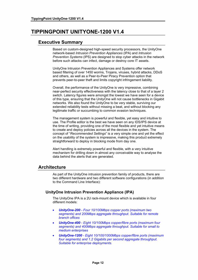
UnityOne Intrusion Prevention Appliance (IPA) The UnityOne IPA is a 2U rack-mount device which is available in four different models: • UnityOne-200 - Four 10/100Mbps copper ports (maximum two
segments) and 200Mbps aggregate throughput. Suitable for remote branch offices
• UnityOne-400 - Eight 10/100Mbps copper/fibre ports (maximum four segments) and 400Mbps aggregate throughput. Suitable for small to medium enterprises
• UnityOne-1200 - Eight 10/100/1000Mbps copper/fibre ports (maximum four segments) and 1.2 Gigabits per second aggregate throughput. Suitable for enterprise deployments.

TippingPoint UnityOne-1200 V1.4
Page 13
Being Gigabit rated, this was the device which was submitted for testing, with four fibre and four copper ports.
• UnityOne-2400 - Eight 10/100/1000Mbps copper/fibre ports (maximum four segments) and 2.0 Gigabits per second aggregate throughput. Suitable for large enterprises
Each UnityOne system uses a front-access, four or eight-port architecture, supporting connection to two or four network segments respectively (or two/four SPAN ports). Note that the individual ports in each port pair can never work independently. Each segment utilises two ports in in-line mode - one for an “inbound” connection (unfiltered traffic from the external network) and one for “outbound” (filtered traffic to the protected network). When configured in passive (SPAN) mode, one port in each port pair is connected to the switch SPAN port (or tap device), and the remaining port in the pair is then unused.
Figure 1 - TippingPoint: UnityOne-1200 Intrusion Prevention Appliance (IPA)
The switch between in-line and SPAN operation is automatic based on how many ports in each pair are connected, but it would be nice to be able to configure this in order to use both ports in each pair in SPAN mode if required, thus providing the ability to monitor up to four segments (as now) or eight SPAN ports (instead of four in the current configuration). At the rear of the device are two redundant hot swappable power supplies and three chassis cooling fans. There are no removable cards in the chassis of the IPA. Each device also has a 10/100Mbps management port, and a serial port for direct configuration. Also on the front panel is a two-line LCD display and a six-key cursor keypad which allows the device to be configured, current status queried, or the system to be rebooted or shut down without having to gain access to a separate management console. At the core of UnityOne is a security-specific processor called the Threat Suppression Engine (TSE) that enables intrusion prevention at multi-gigabit speeds. The TSE, a blend of ASICs and network processors, detects known threats and anomalies in network traffic at high speeds and filters malicious attacks before they become a problem. The TSE inspects and analyses all seven protocol layers of each flow at wire speed, whilst maintaining very low latency to ensure performance that is as close as possible to a standard switching device. All traffic is checked by sending traffic through a pair of ports on the IPA/IPS that are configured with various types of Filters. These filters include Intrusion Prevention Filters, Misuse and Abuse Filters, and IP Filters:

TippingPoint UnityOne-1200 V1.4
Page 14
• Intrusion Prevention Filters protect the network at a flow level, checking network traffic for TCP IP floods (DDoS), anomalies, and attacks.
• Misuse and Abuse Filters protect the network by preventing the misuse of network and supported services. These filters protect peer-to-peer file sharing protocols, ensuring safely used and protected bandwidth.
• IP Filters protect the network by permitting or blocking traffic through scanning header-level information. These filters determine if traffic should pass by comparing the header information against a detailed list of allowed and disallowed settings and IPs (in a similar manner to a traditional packet filtering firewall).
The IPA/IPS identifies attack traffic and denial of service requests (DDoS) on the network by comparing traffic content with these Filters. When the system encounters suspicious traffic (packets that match Filters) or requests, it reacts according to the instructions, called the Action Set, defined for that Filter. In a broad sense, the Action Set tells the system to either block matching packets or permit them. It might also include instructions to notify interested parties and log the information. UnityOne also has built-in intrinsic high-availability features, guaranteeing that the network keeps running in the event of system failure by falling back to a Layer 2 switch mode and allowing packets to pass directly from the input to output ports without being processed by the rest of the device. It is possible to force the device into this “pass through” switch mode via the management console or front-panel keypad/LCD display. Multiple UnityOne appliances can be interlinked to provide consistent, redundant network security, and both active-active and active-passive configurations are supported. The device can handle the failure of a single power supply and maintain normal operation - should both supplies fail (or the external power fail), however, the device would fail closed. To handle this situation, there is also the optional Zero Power High Availability (ZPHA) device which is designed to ensure a constant, uninterrupted flow of network traffic. The ZPHA is a chassis with a set of relays that directs traffic depending on the status of power received through a USB cable connected to the IPA device. If the power interrupts, the ZPHA bypasses the IPA device providing continuous network traffic. The ZPHA can be used to continue network traffic and services by bypassing the IPA entirely when the power no longer feeds into the system, when it is necessary to unplug the system (for maintenance or replacement, perhaps), and to continue service while the IPA reboots (during which period traffic is not passed). High Availability options are well covered by the UnityOne product range.
UnityOne Intrusion Prevention System (IPS) The UnityOne-2000 is rated at 2Gbps, and comes in a 4U chassis designed to handle the extremely high demands of carriers and high-density data centres. The UnityOne IPS uses a front-access, eight-slot multi-port architecture.
TippingPoint UnityOne-1200 V1.4
Page 15
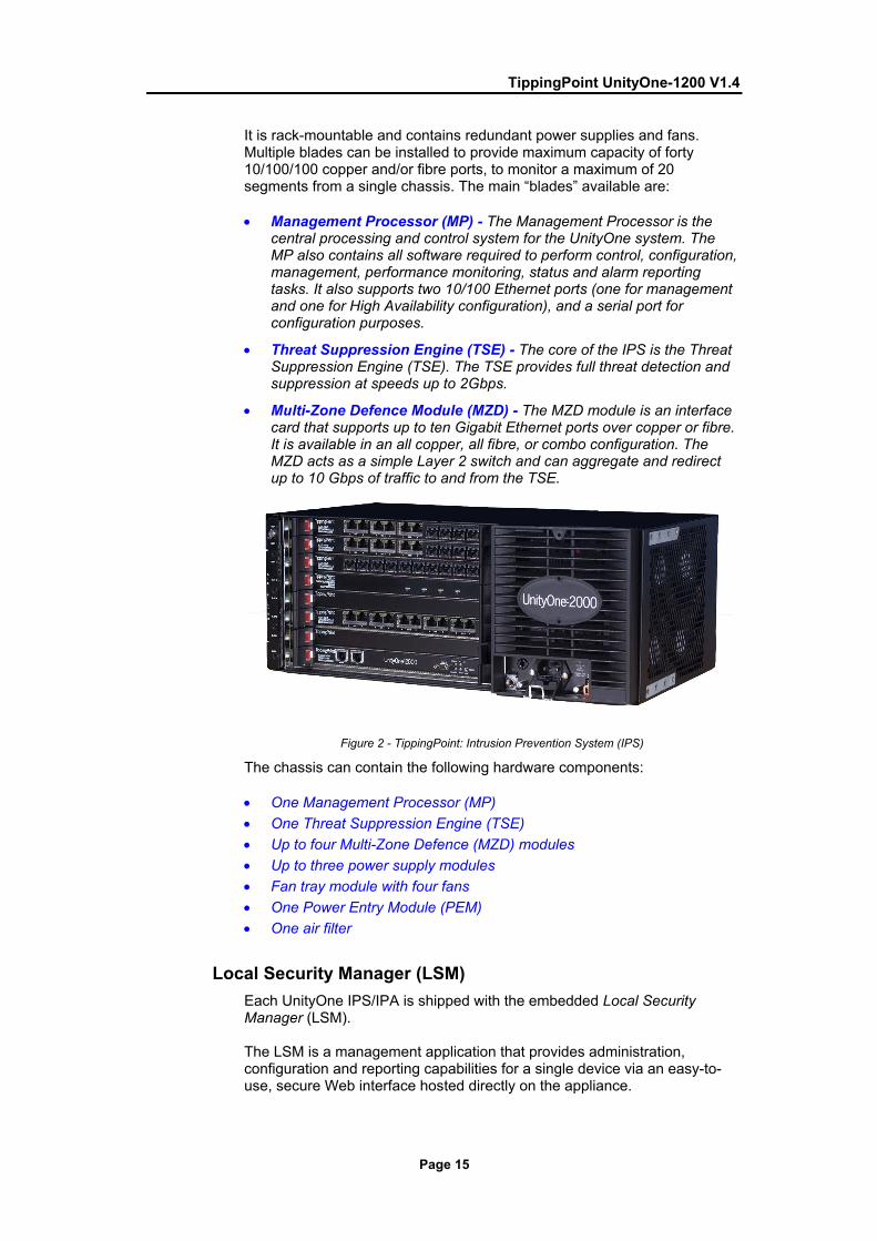
It is rack-mountable and contains redundant power supplies and fans. Multiple blades can be installed to provide maximum capacity of forty 10/100/100 copper and/or fibre ports, to monitor a maximum of 20 segments from a single chassis. The main “blades” available are: • Management Processor (MP) - The Management Processor is the
central processing and control system for the UnityOne system. The MP also contains all software required to perform control, configuration, management, performance monitoring, status and alarm reporting tasks. It also supports two 10/100 Ethernet ports (one for management and one for High Availability configuration), and a serial port for configuration purposes.
• Threat Suppression Engine (TSE) - The core of the IPS is the Threat Suppression Engine (TSE). The TSE provides full threat detection and suppression at speeds up to 2Gbps.
• Multi-Zone Defence Module (MZD) - The MZD module is an interface card that supports up to ten Gigabit Ethernet ports over copper or fibre. It is available in an all copper, all fibre, or combo configuration. The MZD acts as a simple Layer 2 switch and can aggregate and redirect up to 10 Gbps of traffic to and from the TSE.
Figure 2 - TippingPoint: Intrusion Prevention System (IPS)
The chassis can contain the following hardware components: • One Management Processor (MP) • One Threat Suppression Engine (TSE) • Up to four Multi-Zone Defence (MZD) modules • Up to three power supply modules • Fan tray module with four fans • One Power Entry Module (PEM) • One air filter
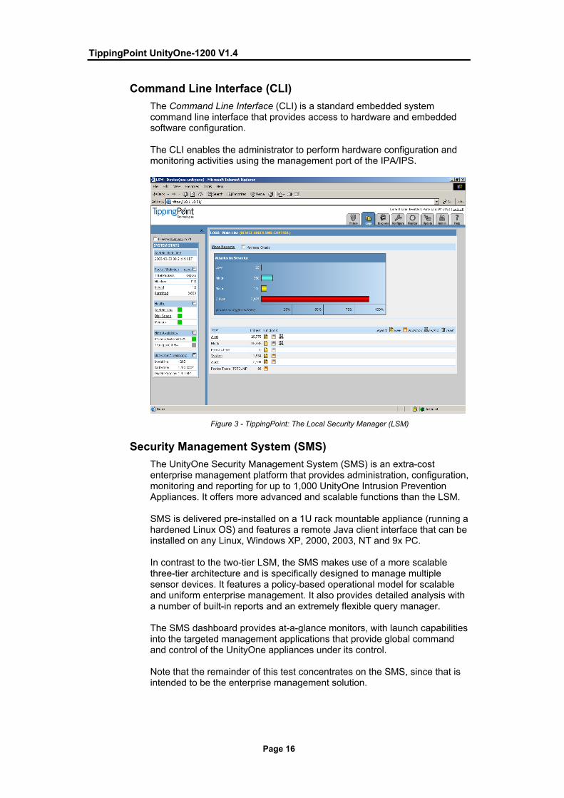
Local Security Manager (LSM) Each UnityOne IPS/IPA is shipped with the embedded Local Security Manager (LSM). The LSM is a management application that provides administration, configuration and reporting capabilities for a single device via an easy-to-use, secure Web interface hosted directly on the appliance.
TippingPoint UnityOne-1200 V1.4
Page 16
Command Line Interface (CLI) The Command Line Interface (CLI) is a standard embedded system command line interface that provides access to hardware and embedded software configuration. The CLI enables the administrator to perform hardware configuration and monitoring activities using the management port of the IPA/IPS.
Figure 3 - TippingPoint: The Local Security Manager (LSM)
Security Management System (SMS) The UnityOne Security Management System (SMS) is an extra-cost enterprise management platform that provides administration, configuration, monitoring and reporting for up to 1,000 UnityOne Intrusion Prevention Appliances. It offers more advanced and scalable functions than the LSM. SMS is delivered pre-installed on a 1U rack mountable appliance (running a hardened Linux OS) and features a remote Java client interface that can be installed on any Linux, Windows XP, 2000, 2003, NT and 9x PC. In contrast to the two-tier LSM, the SMS makes use of a more scalable three-tier architecture and is specifically designed to manage multiple sensor devices. It features a policy-based operational model for scalable and uniform enterprise management. It also provides detailed analysis with a number of built-in reports and an extremely flexible query manager. The SMS dashboard provides at-a-glance monitors, with launch capabilities into the targeted management applications that provide global command and control of the UnityOne appliances under its control. Note that the remainder of this test concentrates on the SMS, since that is intended to be the enterprise management solution.

TippingPoint UnityOne-1200 V1.4
Page 17
Performance The aim of this section is to verify that the sensor is capable of detecting and blocking exploits when subjected to increasing loads of background traffic up to the maximum bandwidth supported as claimed by the vendor. For each type of background traffic, we also determine the maximum load the IPS can sustain before it begins to drop packets/miss alerts. It is worth noting that devices which demonstrate 100 per cent blocking but less than 100 per cent detection in these tests will be prone to blocking legitimate traffic under similar loads. The UnityOne was tested up to 1Gbps, and performance at all levels of our load tests was impeccable, with 100 per cent of all attacks being detected and blocked under all load conditions. We would thus have no hesitation in rating the UnityOne-1200 as a true 1Gbps device. Latency figures were exceptional for a device of this type at all traffic loads and with all packet sizes, ranging from 36µs with 250Mbps of 64 byte packets, to 112µs with 1Gbps of 1514 byte packets. Behaviour throughout the tests was completely predictable, increasing proportionately as packet size was increased, and yet increasing only very slightly as the UDP traffic load increased from 250Mbps to 1Gbps through the device. Latency did increase slightly as we loaded the device with 500Mbps of genuine HTTP traffic, but not to the extent where it would cause problems. With the device under “half load” of normal traffic, latency on 64 byte packets increased from 36 to 55 microseconds, 440 byte packets increased from 56 to 67 microseconds, and 1514 byte packets increased from 111 to 116 microseconds. Throughout the tests, however, latency remained very low - never exceeding 116 microseconds. SYN flood protection was excellent with the UnityOne, which uses a number of methods to determine what constitutes a SYN Flood and to protect against it. Although the initial part of the SYN Flood is allowed onto the protected network because the UnityOne does not proxy SYNs, once the SYN Flood was underway and identified the subsequent mitigation was complete. The impact on latency through the device of the 100Mbps of SYN Flood attack traffic was minimal, showing very little increase over the performance with no attack traffic (a maximum increase in latency of just 7 per cent with 64 byte packets, and less than 1 per cent with 440 and 1514 byte packets). Overall, latency figures were considered to be exceptionally low for a device of this type. The UnityOne performed consistently and reliably throughout our tests. Under 8 hours of extended attack (comprising millions of exploits mixed with genuine traffic) it continued to pass legitimate traffic whilst blocking attack traffic in a consistent manner. Exposing both the sensor and management interfaces to an extended run of ISIC-generated traffic had no adverse effect, and the device continued to detect and block all other exploits throughout and following the ISIC attacks.

TippingPoint UnityOne-1200 V1.4
Page 18
Please refer to the Testing Methodology section for full details of the methodology used and performance results.
Security Effectiveness We installed one UnityOne-1200 sensor with the latest signature pack. All category settings were changed from “Recommended” (the default setting) to “Block + Alert”. No other tuning was necessary. Signature recognition (with blocking disabled) was outstanding out of the box (99 per cent), and was increased to a perfect 100 per cent after the application of a signature pack update which was provided to us in less than 48 hours. Blocking performance was identical. Accuracy was very high, with good alert descriptions, and 100 per cent of our false negative (modified) exploits were also detected out of the box. A major concern in deploying an IPS is the blocking of legitimate traffic. With the UnityOne, however, resistance to false positives was excellent and we would be quite happy to deploy this device in a live network with the “Recommended” settings activated The UnityOne performed perfectly in all of our evasion tests when it came to detecting and blocking obfuscated attacks - Fragroute, Whisker, ADMmutate and even RPC record fragging all failed to trick UnityOne into ignoring valid attacks. When configured correctly, the UnityOne demonstrated perfect performance in our stateful operation tests. Whilst configured in Symmetric mode, the UnityOne was not tricked into alerting on our stateless exploits, indicating that it would be resistant to TCP-based exploits launched via replay tools such as Stick and Snot. It was also capable of blocking these mid-flow streams completely. Note, however, that the default mode of operation is Asymmetric. Out of the box, the device maintained state on 1,000,000 open connections, successfully detecting our half-open exploit as it was completed. It also continued to detect and block new exploits as we maintained 1,000,000 open connections, and no legitimate traffic was blocked throughout these tests. No tuning was necessary in order to support this level of open connections, enabling the UnityOne to display a perfect set of results out of the box. Please refer to the Testing Methodology section for full details of the methodology used and performance results.
Usability This part of the test procedure consists of a subjective evaluation of the features and capabilities of the product, and covers installation, configuration, policy editing, alert handling, and reporting and analysis.
Installation Installation is very straightforward with the UnityOne appliances, even when deploying the three-tier SMS management system (the configuration provided for this test), since everything is supplied in appliance form.

TippingPoint UnityOne-1200 V1.4
Page 19
Once the IPA device has been connected and powered on, the UnityOne Setup wizard displays on the connected COM port terminal. The wizard prompts the administrator to perform basic configuration tasks and can be activated by one or more of the following processes: • Out-of-the-Box Terminal Setup Wizard - Runs when the setup wizard
is activated for the first time or later with the setup command. The Out-of-the-Box Setup Wizard runs on a workstation or laptop connected to the serial port of the IPA device.
Through a set of prompts, the administrator can enter and configure key operational parameters of the IPA such as account security access and super-user setup; IP addresses, ports, and options for the host management port; settings for the default gateway; options for the timekeeping settings, such as daylight saving and SNTP servers; server options for web, CLI, and SNMP; settings for the NMS and SMS; and various settings not covered directly in the wizard, such as Ethernet addresses, management port routes, default e-mail contacts, and remote syslog settings
• Out-of-the-Box LCD Setup Wizard - Runs directly on the LCD panel, overriding any serial port connected system. The LCD Setup Wizard allows the administrator to configure a subset of the critical configuration parameters for the device, enough information to connect via SSH or LSM to complete all the remaining customer-specific settings.
• Additional Configuration - After the setup wizard has been run using the serial terminal or IPA LCD, it is possible to further configure the system using subsequent setup commands through the Command Line Interface (CLI).
Once the IPA has been installed and configured, a similar wizard can be run on the SMS appliance in order to configure it for the management network on which it will reside. All communications between the SMS and sensor are encrypted, and management access to each sensor is restricted to a specific SMS IP address (the administrator also needs to know the Super User login name and password for each sensor as it is added to the SMS console). TippingPoint has done a good job of harmonising the setup wizards for the IPA and SMS in this latest release, making them appear almost identical, and thus simplifying the initial install and configuration procedure. The final step is to install the Java-based client which can run on almost any Linux or Windows XP/2000/2003/NT/9X machine on the management network (some service pack restrictions apply). The client software is available for download from the SMS homepage via an HTTPS connection. By clicking on the link to the client software, the administrator can install the software directly to the client PC. Documentation is extensive and is generally very good, consisting of user guides for each type of appliance, the LSM, the SMS, Zero Power HA option, Command Line Interface, and the Custom Shield Writer (used for writing custom signatures). All of the guides appear to be comprehensive, with clear, easy-to-read, step-by-step instructions on all the main administrative processes (illustrated with copious screen shots) as well as good background information on each of the options available.

TippingPoint UnityOne-1200 V1.4
Page 20
The guides are provided in electronic format initially, though customers can order hard copy versions if required. These are comb bound or contained in loose-leaf binders, and whilst this has a slightly “temporary” feel to it, it does provide the means for the company to keep to documentation more up to date than if a perfect-bound solution were adopted.
Configuration Being a Java application, the performance of the SMS client is affected significantly by the hardware platform on which it is installed - start-up of the client is certainly slower than you would expect from a native Windows application. In addition, since it is on a browser model, the initial display of each admin “page” is also relatively slow as the page is loaded for the first time. Having been accessed once, however, subsequent access is instantaneous due to local caching of the page contents. Once up and running, the client performs well.
Figure 4 - TippingPoint: Managing user accounts
As the client is started, the administrator is prompted for the IP address of the SMS server, the user name and password. A Super User account is included by default, but it is possible to set up multiple administrator accounts, each with different roles : • Super User - Has authority to use to all SMS functionality including
SMS administration. Only the account called Super User can access the SMS Command Line Interface (CLI).
• Administrator - Has IPA/IPS administrator authority. This role has the ability to use all SMS functionality related to IPA/IPS administration for those devices and segments to which he has been granted access.
• Operator - Has view access to all SMS screens, but may not perform some functions such as IPA/ IPS device management or administration functions.

TippingPoint UnityOne-1200 V1.4
Page 21
It is also possible to apply more granular access controls by restricting individual users to specific devices and/or segment groups. Disallowing device access, for example, would prevent a user from seeing and making changes to the device configuration whilst still allowing them to manage and deploy policies. Restricting a user to specific segments or segment groups will ensure that each administrator can only deploy Policies to that segment or group of segments (which can span multiple sensors). This means that if a user is restricted to the DMZ segment group he can deploy policies only to the segments which make up that group, making this perfect for large corporate or managed service environments. A third security tab in the User Admin dialogue box provides the means to restrict users to one or more Profiles, once again making this suitable for managed service environments where it is necessary to ensure that an administrator from one company cannot access or modify Profiles belonging to other companies. Smaller organisations, or those with less complex requirements, can obviously choose to ignore user access rights completely, relying solely on the Super User, Administrator and Operator role distinctions. There are still one or two minor usability-related improvements we would like to see in this area - support for user groups would be useful in order to logically group several users together to apply access control lists en masse, for example, and in the current release only the Super User is capable of defining the access controls on individual Policies - but in general the user access controls work well.
Figure 5 - TippingPoint: The Dashboard
The SMS user interface consists of two main windows: the Dashboard and main user interface. When the client is first initiated, both windows are displayed.

TippingPoint UnityOne-1200 V1.4
Page 22
The Dashboard provides a quick overview of attacks detected and blocked (both as graphs and small “Top 5” reports), device performance, and system statistics, whilst the main user interface provides the functions and windows to manage the system. The Dashboard includes the following sections: • Client/Server Protection - Displays the top 5 attacks in the last hour
(with counts), top 5 destination addresses in the last hour (with counts), and a bar graph showing the number of attacks in the last 24 hours on an hourly basis.
• Infrastructure Protection- Displays the top 5 traffic normalisation Filters in the last hour (with counts), top 5 DDoS and Network Equipment (NE) protection Filters in the last hour (with counts), and a bar graph showing the number of attacks in the last 24 hours on an hourly basis.
• Application Acceleration - Displays the top 5 Peer-to-Peer applications in the last hour (with counts), the top 5 DDoS and NE protection Filters in the last hour (with counts), and a bar graph showing the number of attacks in the last 24 hours on an hourly basis.
• Devices - Displays the number of devices controlled by the SMS and the health of the devices
• Updates - Displays the current updates available or installed and the health of the updates. The number is the build number for the type of software or package file.
Hovering over a particular bar in the graph displays a tool-tip showing the number of attacks in the hour selected, whilst clicking on any of the individual entries or title bars in the “Top 5” lists takes you directly to the event query page with the appropriate criteria set to display the events selected. As mentioned previously, the main user interface is modelled after a standard Web browser. It provides a useful Toolbar along the top of the screen with “Back” and “Forward” buttons allowing the administrator to step quickly through recently-viewed screens - a real help when it is necessary to view and review several reports and queries in quick succession. A text-based menu bar is also available. The remaining buttons on the toolbar provide instant access to the main administrative functions of the client: • Events - Manage and view events such as attack and health alerts. • Reports - Generate, download, and view reports of performance,
Filters, and logs. • Packages - Access Profiles and Filters, global settings, Digital Vaccine
packages, and Custom Shield packages. • Devices - Monitor and manage device features, update the operating
system, and manage device groups. • Admin - User access and accounts, database management, and SMS
system and audit logs The remainder of the screen is divided into two panes - the Navigation pane and the Main/List pane. As the administrator selects an option from the Toolbar the Navigation pane provides the functions for each screen of the application in a hierarchical menu.

TippingPoint UnityOne-1200 V1.4
Page 23
Many functions have multiple levels, shown with an expand icon. Selecting an option from the Navigation pane causes the appropriate admin screen to be loaded and displayed in the Main/List pane on the right.
Figure 6 - TippingPoint: Managing devices
The Devices screen provides a dynamic view of the entire system, enabling the administrator to monitor and manage all those IPA/IPS devices to which he has been granted access. This allows him to control networking configuration, Filters and customisations, and distribution of Filters and software from a single, central location. When an IPA/IPS device is first installed it is controlled by default by the LSM, which is accessed by making an HTTPS connection directly to the management port of the appliance. Once a device is added to SMS, however, the ability to control it from LSM is removed. Although it is still possible to access the LSM and view parameters and events, it is no longer possible to make configuration changes without SMS control being released. The first task when setting up a new system, therefore, is to add the IPA devices to the management console, which requires that the administrator knows and enters the IP address of the IPA management interface, as well as the “Super User” login name and password. Each new device is represented as a graphical icon which shows at a glance its name, IP address, model number and current health status. By right-clicking on a device it is possible to view detailed configuration information (where it is possible to edit much of the information entered during the initial setup wizards), manage or unmanage the device via SMS, view statistics and logs, and even force the device in and out of its “intrinsic HA mode” if required. All of this requires that the user has Super User status, or Administrator status along with access rights to the device in question.

TippingPoint UnityOne-1200 V1.4
Page 24
Double-clicking on a device loads a graphical representation of the front panel showing all of the ports and other components, each one with a “traffic light” display indicating the current health status. If there is a problem with an individual component, the health will be flagged as yellow or red, and an alert raised. The health status will remain yellow or red until the administrator specifically acknowledges or ignores the condition that caused it. One nice feature of UnityOne is the ability to schedule network discovery jobs on each segment, where the IPA will regularly scan the network and inventory the active hosts and services on those hosts. The UnityOne system maintains a database of protected hosts and the services on those hosts and the results can be viewed at the console and used by the administrator to tune attack filters as well as detect rogue hosts and services. The Devices screen also enables the administrator to download and install updates of the TippingPoint Operating System (TOS), as well as create and manage groups of device segments. These groups provide greater management and distribution of profiles and updates for Digital Vaccine packages (see below), TOS software, and SMS software. Depending on the network setting and architecture, it may be necessary to have differing types and versions of filters and action sets running on particular segments. By creating segment groups, it is possible to associate a particular profile of Filters to a particular group.
Figure 7 - TippingPoint: Managing Digital Vaccine packages
The Admin screen provides management options for user access, the system and audit logs, system settings, SMS updates and database administration (including backup, restore and automatic archiving capabilities). Only users with the correct role and access can manage settings on the Admin screen.

TippingPoint UnityOne-1200 V1.4
Page 25
Note that the default mode of operation of a new UnityOne device is Asymmetric mode, which means that in non-asymmetric networks it will not enforce state (i.e. require a 3-way handshake). Users with symmetrically-routed networks would probably want to change this setting. New Filters can be downloaded on a regular basis from the TippingPoint Threat Management Centre (TMC) - each update is known as a Digital Vaccine package. Settings in the Packages screen enable the administrator to specify automatic download and/or automatic distribution to all devices of Digital Vaccine packages if required. Alternatively, they can be downloaded manually and imported to the SMS, and distributed manually to selected devices. Only one Digital Vaccine package can be active at any point in time, and if a new package proves troublesome, it is possible to re-activate and re-distribute a previous package if required. Custom Shield Packages - custom filters written by end-users using the Custom Shield Writer - can also be imported to the SMS and distributed to devices in the same way.
Policy Management The IPA detects and blocks inappropriate, incorrect, or anomalous activity on the network by comparing network traffic with Attack Filters defined by the TippingPoint Threat Management Centre (TMC) or written by end-users using the separate Custom Shield Writer tool. Attack Filters typically describe recognisable header or data content in the attack along with the protocol, service, and the operating system or software the attack affects.
Figure 8 - TippingPoint: Profile Editor (Action Sets)
The Attack Filter includes an Action Set, which defines the reaction when the IPA encounters packets that match Attack Filter parameters. In a broad sense, the IPA either drops matching packets (and the associated TCP flow) or permits them. Attack Filters are grouped together to form Profiles, which are then distributed to IPA/IPS devices in order to instruct each appliance which traffic is to be permitted and which is to be denied.

TippingPoint UnityOne-1200 V1.4
Page 26
The Packages screen provides the interface for tuning the system’s behaviour by managing, editing, and applying Profiles, Filters, Digital Vaccines, Action Sets, and notification contact updates across the UnityOne system. Filters are the key to the protection of hosts and prevention of malicious behaviour on the network, and Profiles allow the administrator to manage Filters and customised settings for each group of segments and devices on the network. Super User or Administrator authority is required to create or edit Attack Filters and related objects. Each Filter consists of a number of possible settings: • Category - Defines the type of Filter, such as a particular Application
Acceleration, Client/Server Protection, or Infrastructure Protection filter. Categories dictate the default and shared settings and actions for a specific type of Filter. It is possible to modify and enhance the Category or particular instance of a Filter through the Action Sets.
Figure 9 - TippingPoint: Profile Editor (Category Settings)
• Action set - Action Sets determine what the IPA/IPS does when a packet triggers a Filter:
o Flow Control - Determines where a packet is sent after it is inspected. A “Permit” action allows a packet to reach its intended destination. A “Block” action discards a packet (and blocks the associated TCP flow, if applicable). A “Rate Limit” action ensures that a given flow is restricted to a specified maximum bandwidth.
o Packet Trace - Allows capture of all or part of a suspicious packet for analysis. It is possible to set the packet trace priority (to ensure that packet trace does not impact overall performance in case of resource shortages) and verbosity (how much of each packet is captured) on a per-Action Set basis.

TippingPoint UnityOne-1200 V1.4
Page 27
Note that a packet trace consists only of the packet that triggered the alert - it is not possible to specify that additional packets are captured.
o Notification Contacts - Lists the contacts to notify about the event. These contacts can be systems, individuals, or groups.
These actions can be combined (such as “Block + Notify + Trace”), and a number of default sets are defined to cover most of the most common requirements. Alerts can be sent to the management console and to an administrator via e-mail. It is also possible to direct alerts to a remote SYSLOG server.
Custom sets can be defined, and individual elements can be configured (such as the amount of data and number of packets to be captured in a packet trace, the maximum bandwidth for rate limits, or which alert options to use). Action Sets can be modified per Filter or across all Filters and Profiles.
• State - Indicates if the Filter is enabled, disabled, or invalid. It indicates if the system actively enacts the Filter against specific types of traffic.
• Notification Contact - Sends e-mail alert messages to recipients according to the Action Set settings. The selected contacts per Category or Filter receive e-mail messages from the SMS. When the administrator modifies or adds contacts, they affect all Filters and Profiles. Alerts can be aggregated over a user-specified time period to ensure that multiple alerts are covered by a single e-mail.
• Exceptions - These are limitations to only allow or ignore specific IP addresses for sources and destinations.
Figure 10 - TippingPoint: Profile Editor (Exceptions)
All of the features provided through the Packages screen affect the system at one of three levels:

TippingPoint UnityOne-1200 V1.4
Page 28
• Enterprise - These settings affect all devices and segments on the network. Examples of these are in the Shared Settings, including Action Sets, shared exceptions, and notification contacts. Digital Vaccine and Custom Shield packages also fall under this type of protection since they can be distributed to all devices.
• Device - These settings affect all of the segments on a particular device. Examples of these are Scans/Sweeps and Traffic Normalisation filters. Digital Vaccine and Custom Shield packages also fall under this type of protection since they can be distributed to particular devices.
• Segment - These settings affect only a particular segment or segment group, and not an entire device. Examples of these include most Client/Server Protection, Infrastructure Protection, and Application Acceleration Filters.
All Filters are assigned to protect either a single segment or an entire device on the system, with per-segment Filters overriding device-wide filters. The SMS includes the following Filter Categories: • Client/Server Protection (Attack Protection) - Filters that defend
against known and unknown exploits targeting applications and operating systems. Attack Protection Filters are themselves broken down into two sub-categories: Vulnerabilities (filters that detect and block against vulnerabilities based on traffic requests and reaction by services) and Exploits (filters that detect and block malicious exploitation of operating system and services weaknesses). This separation is the key to the accuracy of many of the TippingPoint filters. Exploit filters are written for a specific exploit of a particular vulnerability, and thus if another variant of the exploit is released, the filter will not trigger. Vulnerability filters are written to cover the underlying vulnerability, and will trigger no matter which variant of an exploit is used.
• Client/Server Protection (Security Policy Filters) - Security Policy Filters act as attack and policy Filters, and require deployment knowledge and/or operational policy. Traffic which triggers these Filters may be different in its format or content from standard business practice, aimed at specific software or operating systems, or simply contrary to the company’s security policies. These Filters may be susceptible to false positives on some networks, and should be set on a per-organisation basis (i.e. one organisation may wish to alert on Telnet traffic or ICMP echo request packets). For this reason, these Filters are disabled by default.
• Client/Server Protection (Reconnaissance) - These Filters constantly monitor incoming traffic, looking for any sign of network reconnaissance and are disabled by default. Reconnaissance Filters include Probes (Filters that perform scans for vulnerabilities in the system) and Scans/Sweeps (Filters that perform port scans and host sweeps)
• Client/Server Protection (Informational) - Informational Filters are designed for low-level alerts and signatures that are considered out of date or unimportant, but which can be used for IDS/IPS testing (such as those Filters designed to cover the exploits provided with the Blade IDS Informer testing tool). These Filters are disabled by default.

TippingPoint UnityOne-1200 V1.4
Page 29
• Infrastructure Protection - A set of Filters that protect network infrastructure elements such as routers and firewalls from attack using a combination of traffic normalisation, DDoS protection, and application, protocol, and statistical anomaly detection. DDoS Filters detect and block randomised requests, unsolicited responses, amplifiers, reflectors, and indistinguishable request attacks against the system, and are disabled by default.
Network Equipment Protection Filters detect and block exploit and anomaly-based attacks against networking equipment. Traffic Normalisation Filters detect and manage invalid traffic on a network (traffic which includes incorrect checksums, invalid TCP header flags, invalid IP fragments, invalid TCP reassembly and unsolicited requests).
• Application Acceleration (Traffic Management) - Filters that allow key applications to have prioritised access to bandwidth ensuring that mission critical applications have adequate performance during times of high congestion. Applications can be shaped or rate limited (allocated a maximum bandwidth) based on IP address range, application (port number) or protocol. Naturally, no traffic management Filters are defined by default.
• Application Acceleration (Misuse and Abuse) - These Filters allow users to manage policy around non-productive or potentially illegal applications. Initially this includes Peer-to-Peer management, where the user may apply block or shape actions across the category or on an individual basis. All peer-to-peer Filters are user-activated and must be enabled to block peer-to-peer traffic.
Figure 11 - TippingPoint: Shared settings
With all of these building bocks, defining Policies is reasonably straightforward in the SMS Packages page. The Navigation pane contains a hierarchical tree containing available Digital Vaccine packages, Policies and the Shared Settings.

TippingPoint UnityOne-1200 V1.4
Page 30
It is possible to modify all Filters across all Profiles through the Shared Settings function, which include exceptions (ignore particular IP addresses or ranges), restrictions (restrict the systems covered by the IPS to a particular IP address or range), Action Sets, and notification contacts. When a shared setting is modified or created it is added to all default Filters in the system. However, if a Filter is modified with custom settings, these take precedence over shared settings. Exceptions and restrictions are perfect for service providers or larger corporate entities who wish to restrict IPS coverage to one or more subnets, and ignore others. Note, however, that shared settings apply to all Profiles in the system - it is not possible to apply these on a per-Profile basis in the current release. Below the Shared Settings option in the Packages tree menu are one or more named Profiles. A single Profile - named Default - is provided out of the box, and this simply has all category settings set to “Recommended” (more on that shortly). This makes it suitable to deploy to almost any IPS/IPA device, providing instant protection within minutes of defining those devices to the SMS. The default Profile can be copied in order to create a customised version for a particular environment. Since it is possible to deploy each Profile to a different device, segment or group of segments, it is possible to have different Profiles - each with different collections of Filters and custom settings - operational in different parts of the network (for example, you might want a different Profile in place on the DMZ to on your protected network).
Figure 12 - TippingPoint: Editing Filters
Each Profile contains the complete list of Filters grouped according to their Category, and with each Category having its own entry in the Profile menu in the Navigation pane. Thus, at the click of a mouse button it is possible to view only the Client/Server Protection, Attack Protection or Vulnerability filters.

TippingPoint UnityOne-1200 V1.4
Page 31
Each Filter is allocated a Name, Action Set, Category, Severity and detailed information including a full description of the Filter, CVE/Bugtraq references and a Recommended Action. This latter parameter is very important, since this is the setting which the TippingPoint TMC team has determined is the optimum Action Set for this Filter in most networks. If the Recommended setting is “Disabled”, then the Filter is either too customer-specific in its deployment requirements (i.e. a filter that blocks ICMP pings) or is thought to be of little use in most production networks. If the Recommended Setting is “Block/Notify”, then TippingPoint is confident that the corresponding traffic should be blocked in any network. A Recommended Setting of “Permit/Notify” is used to detect traffic that is not an attack per se, but something that the security administrator should know about (i.e. attempted access to a common CGI file with known vulnerabilities). The key point here is that TippingPoint will only allocate a Recommended Setting of “Block/Notify”" to those Filters which can be deployed out of the box without risk of blocking legitimate traffic. All other Filters will be disabled or set to “Permit/Notify”. The Default profile that is included out of the box has all the filters set to their recommended settings, and is thus ready to be deployed across any enterprise. This use of a Recommended Setting is an excellent way of building confidence in a system, and is something that we would like to see in all IPS and IDS products. Each of the main Filter Categories - Client/Server Protection, Infrastructure Protection and Application Acceleration - has a set of global settings whereby the entire Category (or a sub-Category within it, such as Attack Protection within the Client/Server Protection Category) can be enabled or disabled, and have its Action Set defined. As we mentioned before, all the Categories are enabled and set to “Recommended Settings”, but if it was required to disable all Informational Filters and set all Misuse & Abuse Filters to “Block + Notify” then this can be done in a global manner from a single point. It is then possible to select individual Filters or smaller groups of Filters and override both the Action Set and the State (enabled or disabled) individually or in groups. A column in the Profile display shows clearly which Filters are under the control of the Category Settings and which have individual Filter controls. It is possible to sort and search on this parameter too, thus allowing the administrator to select all of those Filters with custom Filter controls and either set them to something else (perhaps turning on Packet Trace) or have them revert to the Category Settings. This is extremely powerful and very intuitive. Right clicking on any given Filter produces a context-sensitive menu which also enables the administrator to create an exception for that Filter (excluding ranges of source and destination IP addresses), view the Action Set (and allow direct editing of the Action Set without having to return to the Shared Settings page), and view related events (which takes you directly into the Events query screen with the appropriate query criteria completed accordingly). Between features such as this and the Browser-style Back and Forward buttons, it is very easy to tune a Profile in SMS, moving quickly from screen to screen in an intuitive manner without having to navigate around the menus in order to accomplish what is required.

TippingPoint UnityOne-1200 V1.4
Page 32
Where this particular policy editor really scores, however, is in its advanced search capabilities, which allow the administrator to produce complex queries in order to select a specific groups of Filters for editing. It is possible to search on the Filter name or part of the name, the TippingPoint reference, CVE reference, Bugtraq ID, Severity, Category, State (enabled/disabled), Category or Filter Control, Action Set and those Filters with Exceptions set, or any combination of these criteria. Once the criteria have been applied and the query run, the matching Filters are displayed at the bottom of the screen. It is then a simple matter to select all Filters and apply the required changes en masse. With this kind of flexibility and power, at the point of writing this is without doubt the best policy editor we have seen on any IDS or IPS product.
Figure 13 - TippingPoint: Advanced Search (Filters)
The top level menu option in the tree for each Profile contains a summary screen which shows to which segments and segment groups that Profile has been distributed. Selecting any profile and clicking on the “Distribute” button allows that Profile to be deployed to a specific segment or segment group. Note that each new device has a segment group named Default (containing all segments on that device) created automatically when added to SMS, thus making it easy to distribute Profiles on a per-device basis too. Since each segment can only exist in one segment group, this ensures that each segment can only have a single Policy active at any given point in time. It is possible to import a Profile from a previously configured device to the SMS, and subsequently re-distribute that Profile to other devices on the network. This makes it very easy to migrate from a single device maintained by the LSM to multiple devices maintained by SMS. There is also an automatic Profile history maintained by the SMS, with full version numbering and version history (detailing every modification to the Policy) available following each change.
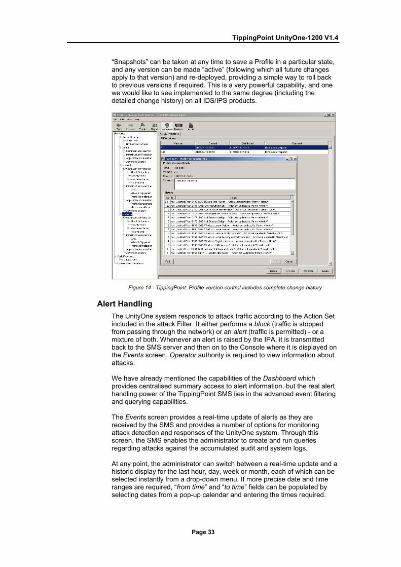
TippingPoint UnityOne-1200 V1.4
Page 33
“Snapshots” can be taken at any time to save a Profile in a particular state, and any version can be made “active” (following which all future changes apply to that version) and re-deployed, providing a simple way to roll back to previous versions if required. This is a very powerful capability, and one we would like to see implemented to the same degree (including the detailed change history) on all IDS/IPS products.
Figure 14 - TippingPoint: Profile version control includes complete change history
Alert Handling The UnityOne system responds to attack traffic according to the Action Set included in the attack Filter. It either performs a block (traffic is stopped from passing through the network) or an alert (traffic is permitted) - or a mixture of both. Whenever an alert is raised by the IPA, it is transmitted back to the SMS server and then on to the Console where it is displayed on the Events screen. Operator authority is required to view information about attacks. We have already mentioned the capabilities of the Dashboard which provides centralised summary access to alert information, but the real alert handling power of the TippingPoint SMS lies in the advanced event filtering and querying capabilities. The Events screen provides a real-time update of alerts as they are received by the SMS and provides a number of options for monitoring attack detection and responses of the UnityOne system. Through this screen, the SMS enables the administrator to create and run queries regarding attacks against the accumulated audit and system logs. At any point, the administrator can switch between a real-time update and a historic display for the last hour, day, week or month, each of which can be selected instantly from a drop-down menu. If more precise date and time ranges are required, “from time” and “to time” fields can be populated by selecting dates from a pop-up calendar and entering the times required.

TippingPoint UnityOne-1200 V1.4
Page 34
A wide range of criteria are available on which to query: • Devices - Select the events according to device and/or segment. Note
that the contents of this window are restricted to those devices/segments to which the user has been granted access.
• Attack Filter - Name of the filter/exploit • Source IP Address/Port • Destination IP Address/Port • Category - Select the category of the filters:
o Attacks - Vulnerabilities o Attacks - Exploits o Security Policy o Reconnaissance - Probes o Reconnaissance - Scans/Sweeps o Informational o DDoS o Network Equipment Protection o Traffic Normalisation o Misuse and Abuse
• Type - Select the type of the attack: o Permit - Permit event o Block - Block event o P2P - Peer-to-peer attack
• Severity - Select the importance of the attack: o Red/Critical o Yellow/Major o Cyan/Minor o Grey/Low
• Packet trace - events with or without a packet trace (or all)
Figure 15 - TippingPoint: Event display
The display of alerts is not updated until the “Refresh” button is pressed, which allows the administrator to make several refinements to the various query criteria before initiating the actual query.

TippingPoint UnityOne-1200 V1.4
Page 35
In general, the operation of the Main/List pane is very consistent and flexible throughout the system. When viewing the lists of matching events the columns can be quickly reordered by dragging and dropping them in a new location, sorted in ascending or descending order by clicking on the column headers, or aggregated (where identical alerts are groups and a single line printed with a total count). It is not possible to hide unwanted columns of data, however. Once the administrator is satisfied with the query, all the criteria and display settings can be saved in the Navigation Pane to allow the same query to be re-run on demand. With a query active, switching back to Real Time mode causes new attack events to be displayed according to the criteria selected, allowing the administrator to focus on a particular attack or category of attacks (i.e. only Critical Severity attacks) as they are happening, filtering out all extraneous data. By default, new rows appear at the top of the attacks pane as the system identifies and responds to packets that match both the attack filters and the query criteria.
Figure 16 - TippingPoint: Viewing Event details
Once the list pane has been populated with a number of events, individual events can be examined. Clicking on “Details” brings up a separate dialogue window containing full details of the event (date, time, source and destination address, and so on), and the Filter which triggered it (including live hyperlinks to external reference material such as Bugtraq and CVE data).

TippingPoint UnityOne-1200 V1.4
Page 36
Several buttons provide immediate access to a Whois facility on source and destination addresses, packet trace (if one was configured as part of the Action Set), and the Filter editor. This enables the administrator to change the State (enabled/disabled) and Action Set, or to create exceptions for that particular filter. This is an excellent way to fine tune an active Profile. Right clicking on any event in the List Pane also brings up a context sensitive menu which provides the means to edit the Filter, create exceptions, create a Traffic Management Filter (block or rate limit), run reports with the specific attack, attacker or target address as the focus, or initiate a search on the value selected. The latter operation is extremely powerful, allowing the administrator to right-click or double click on any of the values in the List Pane entry for that event (the name, address, port, Severity, and so on) and drill down on that value to create a new query. The process can continue to create more and more focussed queries, making it very easy for the administrator to drill down on a particular event. For example, he could first drill down on all Critical events, then on a particular source address in order to see what a specific attacker has been up to. Once again, the Back and Forward browser buttons provide an excellent way to move backwards and forwards through the various queries that are created as a result of this process. As with the Profile editor, the Events screen has been well designed and implemented, providing an extremely powerful and intuitive interface for examining the output from the UnityOne system. The only real criticism we can make of the event handling is the lack of any automatic correlation facility, and no means to group alerts together manually to form “incidents” for further forensic analysis. Nor is there any means for an administrator to delegate an event to another person for investigation, or to mark an event as “resolved”. Admittedly, these features are less essential in an IPS device than they are in an IDS, but some will certainly want to use their IPS in an IDS mode sometimes (even if only for a certain group of Filters) and so IDS-like facilities would be a nice addition.
Reporting and Analysis The SMS provides a set of options to generate reports regarding the compiled and stored log information. These reports include report templates for Attack and Misuse and Abuse reports. Report templates track specific filters and the top ten reported issues encountered, such as destination and source IP addresses and attack filters triggered. Templates included out of the box include: • Attacks:
o All Attack Report o All Destination Report o All Source Report o Specific Attack Report o Specific Destination Report o Specific Source Report o Top 10 Attacks Report o Top 10 Destination Report

TippingPoint UnityOne-1200 V1.4
Page 37
o Top 10 Sources Report • Misuse and Abuse:
o All Misuse and Abuse Filters Report o All Misuse and Abuse Peers Report o Specific Misuse and Abuse Filter Report o Specific Misuse and Abuse Peer Report o Top 10 Misuse and Abuse Filters Report o Top 10 Misuse and Abuse Peers Report
Figure 17 - TippingPoint: Reports
To create a report the administrator selects a template and modifies its settings (such as changing the date range). Custom settings can then be saved as custom reports which appear in the Navigation Pane as “Saved Report” templates. These can be selected and run on demand, or can be scheduled for one off or regular runs. The results from these reports can be saved at the SMS server (where they become available via hyperlinks on the main SMS Web page), or exported to external SMB shares or sent by e-mail in either HTML or CSV format. When a report is run on demand rather than scheduled, the results of the query display in the list panes or tables. The Graph pane includes a summary of the values set in the Query pane and a graphical representation of the report results. Below this, the List pane displays the returned results, which are restricted in scope to alerts from those devices/segments to which the user has been granted access. As with the Event queries, it is possible to sort the List pane as a table of data, and each column of data in the List pane can be sorted in ascending and descending order. Right clicking on an entry in the List pane provides the means to view the events behind that particular report entry.
TippingPoint UnityOne-1200 V1.4
Page 38
This takes you directly to the Event query screen with the appropriate criteria completed automatically. Thus it is possible to drill down to further detail from the Reports window as well as the Events window.
Verdict
Performance Performance at all levels of our load tests was impeccable, with 100 per cent of all attacks being detected and blocked under all load conditions. We would have no hesitation in rating the UnityOne-1200 as a true 1Gbps device. Latency figures were exceptional for a device of this type at all traffic loads and with all packet sizes, ranging from 36 to 112 microseconds depending on load and packet size. Behaviour throughout the tests was predictable, increasing steadily as packet size was increased, and yet increasing only very slightly as the UDP traffic load increased from 250Mbps to 1Gbps through the device. Latency did increase as we loaded the device with 500Mbps of genuine HTTP traffic, but not significantly, and there was only a very slight increase in latency when the UnityOne was subjected to 100Mbps of SYN flood traffic. Overall, latency figures were considered to be exceptionally low for a device of this type. The UnityOne performed consistently and reliably throughout our tests, continuing to pass legitimate traffic whilst blocking attack traffic in a consistent manner. Exposing the sensor interface to an extended run of ISIC-generated traffic had no adverse effect, and the device continued to detect and block all other exploits throughout and following the ISIC attack. High Availability (HA) options are well covered with the TippingPoint product range, covering everything from multiple redundant components (such as fans and power supplies), through intrinsic HA with a single device, to full-blown HA configurations with multiple UnityOne sensors.
Security Effectiveness Signature recognition (with blocking disabled) was outstanding out of the box (99 per cent), and was increased to a perfect 100 per cent after the application of a signature pack update which was provided to us in less than 48 hours. Blocking performance was identical. Resistance to false positives and evasion techniques was excellent, and we would be quite happy to deploy this device in a live network with the “Recommended” settings activated. A perfect score out of the box in our stateful operation tests indicated that the UnityOne would be resistant to TCP-based exploits launched via replay tools such as Stick and Snot, and would be capable of handling 1 million open connections with no tuning required.

TippingPoint UnityOne-1200 V1.4
Page 39
Usability A huge amount of redevelopment work has gone into this latest release, and those who are used to the original SMS console will hardly recognise the latest version. Although most of the underlying architectural and operational principles remain the same, the user interface is much more powerful and flexible, and yet is easier and more intuitive to use. A lot of effort has been put into ensuring that the user experience is consistent throughout the package and that the administrator is not forced to navigate between multiple screens to perform critical operations. Indeed, by judicious use of right-click menus throughout the system and the implementation of the browser model with the Back and Forward buttons on the toolbar, the administrator can usually choose for himself the best way to navigate the system. It is hard to find anything to criticise about the SMS console. If pushed to come up with something, we would like to see some form of event correlation capability introduced, even if only manual - although we do recognise this is more of an IDS function than an IPS one. Even so, many users may wish to use one or more port pairs in an IDS-like mode, and there is no reason why such features should not be included if TippingPoint intends to compete in the IDS market space as well as the IPS space. Initial installation and configuration has been made as simple as possible via the use of similar set-up wizards for both the IPA/IPS and SMS appliances, and the front-panel keypad and display set-up capability means that it is not even necessary to attach a PC to the IPA appliance in order to perform the initial configuration. Within the SMS itself, the Profile editor is the best we have seen on any IDS/IPS device at the time of writing, providing one of the most flexible and yet intuitive means to create and deploy policies across all the devices in the system. It also includes a range of excellent version control capabilities. The concept of “Recommended Settings” is a very simple one and yet the effect on the usability of the system is impressive, making this product extremely straightforward to deploy in blocking mode from day one. Yes, many filters are deployed out of the box in “Permit + Notify” mode, but these can be fine-tuned within the first few days or weeks via the excellent alert handling capabilities. Alert handling is extremely powerful and flexible, with a very intuitive mechanism for drilling down to analyse the data behind the alerts which are generated in almost any conceivable way. Queries are easy to create and quick to run, and numerous links and menu options are provided to enable Filters to be edited and Profiles fine tuned with the minimum of fuss. The reports are also very good, and we liked the ability to be able to publish the high-level trend reports (Top 10 Attacks blocked, and so on) in HTML to the SMS Web server, thus allowing senior management access to such reports without having to use the SMS client. For those who do not require the complexity of the SMS, the LSM provides the ideal means to manage a single device without that hassle of installing a three-tier management system.

TippingPoint UnityOne-1200 V1.4
Page 40
Although this has not been improved to the same degree and does not offer the same level of functionality as SMS, it remains the perfect way for administrators to manage one or two devices. Most vendors eliminate the single-device management option when they introduce a multi-tier management system, and TippingPoint is to be congratulated for continuing to offer the choice.
Contact Details Company name: TippingPoint Technologies, Inc. E-mail: [email protected] Internet: www.tippingpoint.com Address: 7501B North Capital of Texas Highway Austin, Texas 78731 USA Tel (Head Office): +1 (512) 681 8000 Tel (Toll Free): +1 (888) 648 9663 Tel (International): +31 (0)20 561 6222 Fax: +1 (512) 681 8099

TippingPoint UnityOne-1200 V1.4
Page 41
APPENDIX A – TEST RESULTS The aim of this procedure (based on V1.0 of the NSS Group Network IPS Testing Methodology) is to provide a thorough test of all the main components of an in-line Intrusion Prevention System (IPS) device in a controlled and repeatable manner and in the most “real world” environment that can be simulated in a test lab.
The Test Environment The network is 100/1000Mbit Ethernet with CAT 5e cabling and a mix of Allied Telesyn AT-9816GB and AT-9812T switches (these have a mix of fibre and copper Gigabit interfaces). All IPS devices are expected to be provided as appliances - if software-only, the supplier pre-installs the software on the recommended hardware platform. The IPS is configured as a perimeter device during testing (i.e. as if installed behind the main Internet gateway/firewall). There is no firewall protecting the target subnet. Traffic generation equipment - such as the machines generating exploits, Spirent Avalanche and Spirent Smartbits transmit port - is connected to the “external” network, whilst the “receiving” equipment - such as the “target” hosts for the exploits, Spirent Reflector and Smartbits receive port - is connected to the internal network. The IPS device under test is connected between two “gateway” switches - one at the edge of the external network, and one at the edge of the external network. All “normal” network traffic, background load traffic and exploit traffic will therefore be transmitted through the device under test, from external to internal. The same traffic is mirrored to a single SPAN port of the external gateway switch, to which an Adtech network monitoring device is connected. The Adtech AX/4000 monitors the same mirrored traffic to ensure that the total amount of traffic never exceeds 1Gbps (which would invalidate the test run). The management interface is used to connect the IPS appliance to the management console on a private subnet. This ensures that the sensor and console can communicate even when the target subnet is subjected to heavy loads, in addition to preventing attacks on the console itself.
Section 1 – Detection Engine The aim of this section is to verify that the sensor is capable of detecting and blocking a wide range of common exploits accurately, whilst remaining resistant to false positives. All tests in this section are completed with no background network load. The latest signature pack is acquired from the vendor, and sensors are deployed with all available attack signatures enabled (some audit/informational signatures may be disabled).
Test 1.1 - Attack Recognition Whilst it is not possible to validate completely the entire signature set of any IPS sensor, this test attempts to demonstrate how accurately the sensor detects and blocks a wide range of common exploits, port scans, and Denial of Service attempts. All exploits are run with no load on the network and no IP fragmentation.

TippingPoint UnityOne-1200 V1.4
Page 42
Our attack suite contains over 100 exploits covering the following areas: • Test 1.1.1 - Backdoors (standard ports and random ports) • Test 1.1.2 - DNS • Test 1.1.3 - DOS • Test 1.1.4 - False negatives (common exploits which have been
modified to remove or alter obvious “triggers” - this ensures that the signatures are coded for the underlying vulnerability rather than a particular exploit)
• Test 1.1.5 - Finger • Test 1.1.6 - FTP • Test 1.1.7 - HTTP • Test 1.1.8 - ICMP (including unsolicited ICMP response) • Test 1.1.9 - Reconnaissance • Test 1.1.10 - RPC • Test 1.1.11 - SSH • Test 1.1.12 - Telnet • Test 1.1.13 - Database • Test 1.1.14 - Mail A wide range of vulnerable target operating systems and applications are used, and the majority of the attacks are successful, gaining root shell or administrator privileges on the target machine. We expect all the attacks to be reported in as straightforward and clear a manner as possible (i.e. an “RDS MDAC attack” should be reported as such, rather than a “Generic IIS Attack”). Wherever possible, attacks should be identified by their assigned CVE reference. It will also be noted when a response to an exploit is considered too “noisy”, generating multiple similar or identical alerts for the same attack. Finally, we will note whether the device blocks the attack packet only or the entire “suspicious” TCP session. This test is repeated twice: the first run with blocking disabled on the sensor (monitor mode only) in order to determine which attacks are detected and how accurately they are detected (Attack Recognition Rating); the second run with blocking enabled in order to determine which attacks are blocked successfully regardless of how they are detected or what alerts are raised (Attack Blocking Rating) The “default” Attack Recognition Rating-Detect Only (ARRD) and Attack Recognition Rating-Block (ARRB) are each expressed as a percentage of detected/blocked exploits against total number of exploits launched with the default signature set as received by NSS. This demonstrates how effective the sensor can be when simply deploying the default configuration. Following the initial test run, each vendor is provided with a list of CVE references of the attacks missed, and is then allowed 48 hours to produce an updated signature set. This updated signature set must be released to the general public as a standard signature/product update before the report is published - this ensures that vendors do not attempt to code signatures just for this test.

TippingPoint UnityOne-1200 V1.4
Page 43
The sensor is then exposed to a second round of identical tests and the “custom” ARRD/ARRB is determined. This demonstrates how effective the vendor is at responding to a requirement for new or updated signatures. Both the default and custom ARRD/ARRB figures are reported.
Test 1.2 - Resistance To False Positives The aim of this test is to demonstrate how likely it is that a sensor raises a false positive alert - particularly critical for IPS devices. We have a number of trace files of normal traffic with “suspicious” content, together with several “neutered” exploits which have been rendered completely ineffective. If a signature has been coded for a specific piece of exploit code rather then the underlying vulnerability, or if it relies purely on pattern matching, some of these false alarms could be alerted upon. The IPS attains a “PASS” for each test case if it does not raise an alert and does not block the traffic. Raising an alert on any of these test cases is considered a “FAIL”, since none of the “exploits” used in this test represents a genuine threat. A “FAIL” would thus indicate the chance that the IPS device could block legitimate traffic inadvertently. • Test 1.2.1 - False positives
Section 2 – IPS Evasion The aim of this section is to verify that the sensor is capable of detecting and blocking basic exploits when subjected to varying common evasion techniques.
Test 2.1 - Baselines The aim of this test is to establish that the sensor is capable of detecting and blocking a number of common basic attacks (our baseline suite) in their normal state, with no evasion techniques applied. • Test 2.1.1 - Baseline attack replay
Test 2.2 - Packet Fragmentation and Stream Segmentation The baseline HTTP attacks are repeated, running them through fragroute using various evasion techniques, including: • Test 2.2.1 - IP fragmentation - ordered 8 byte fragments • Test 2.2.2 - IP fragmentation - ordered 24 byte fragments • Test 2.2.3 - IP fragmentation - out of order 8 byte fragments • Test 2.2.4 - IP fragmentation - ordered 8 byte fragments, duplicate last
packet • Test 2.2.5 - IP fragmentation - out of order 8 byte fragments, duplicate
last packet • Test 2.2.6 - IP fragmentation - ordered 8 byte fragments, reorder
fragments in reverse • Test 2.2.7 - IP fragmentation - ordered 16 byte fragments, fragment
overlap (favour new)
TippingPoint UnityOne-1200 V1.4
Page 44
• Test 2.2.8 - IP fragmentation - ordered 16 byte fragments, fragment overlap (favour old)
• Test 2.2.9 - TCP segmentation - ordered 1 byte segments, interleaved duplicate segments with invalid TCP checksums
• Test 2.2.10 - TCP segmentation - ordered 1 byte segments, interleaved duplicate segments with null TCP control flags
• Test 2.2.11 - TCP segmentation - ordered 1 byte segments, interleaved duplicate segments with requests to resync sequence numbers mid-stream
• Test 2.2.12 - TCP segmentation - ordered 1 byte segments, duplicate last packet
• Test 2.2.13 - TCP segmentation - ordered 2 byte segments, segment overlap (favour new)
• Test 2.2.14 - TCP segmentation - ordered 1 byte segments, interleaved duplicate segments with out-of-window sequence numbers
• Test 2.2.15 - TCP segmentation - out of order 1 byte segments • Test 2.2.16 - TCP segmentation - out of order 1 byte segments,
interleaved duplicate segments with faked retransmits • Test 2.2.17 - TCP segmentation - ordered 1 byte segments, segment
overlap (favour new) • Test 2.2.18 - TCP segmentation - out of order 1 byte segments, PAWS
elimination (interleaved dup segs with older TCP timestamp options) • Test 2.2.19 - IP fragmentation - out of order 8 byte fragments,
interleaved duplicate packets scheduled for later delivery For each of the evasion techniques, we note if (i) the attempted attack is blocked successfully (the primary aim of any IPS device), (ii) the attempted attack is detected and an alert raised in any form, and (iii) if the exploit is successfully “decoded” to provide an accurate alert relating to the original exploit, rather than alerting purely on anomalous traffic detected as a result of the evasion technique itself.
Test 2.3 - URL Obfuscation The baseline HTTP attacks are repeated, this time applying various URL obfuscation techniques made popular by the Whisker Web server vulnerability scanner, including: • Test 2.3.1 - URL encoding • Test 2.3.2 - /./ directory insertion • Test 2.3.3 - Premature URL ending • Test 2.3.4 - Long URL • Test 2.3.5 - Fake parameter • Test 2.3.6 - TAB separation • Test 2.3.7 - Case sensitivity • Test 2.3.8 - Windows \ delimiter • Test 2.3.9 - Session splicing For each of the evasion techniques, we note if (i) the attempted attack is blocked successfully, (ii) the attempted attack is detected and an alert raised in any form, and (iii) if the exploit is successfully “decoded” to provide an accurate alert relating to the original exploit, rather than alerting purely on anomalous traffic detected as a result of the evasion technique itself.

TippingPoint UnityOne-1200 V1.4
Page 45
Test 2.4 - Miscellaneous Evasion Techniques Certain baseline attacks are repeated, and are subjected to various protocol- or exploit-specific evasion techniques, including: • Test 2.4.1 - Altering default ports • Test 2.4.2 - Inserting spaces in FTP command lines • Test 2.4.3 - Inserting non-text Telnet opcodes in FTP data stream • Test 2.4.4 - Polymorphic mutation (ADMmutate) • Test 2.4.5 - Altering protocol and RPC PROC numbers • Test 2.4.6 - RPC record fragging For each of the evasion techniques, we note if (i) the attempted attack is blocked successfully, (ii) the attempted attack is detected and an alert raised in any form, and (iii) if the exploit is successfully “decoded” to provide an accurate alert relating to the original exploit, rather than alerting purely on anomalous traffic detected as a result of the evasion technique itself.
Section 3 – Stateful Operation The aim of this section is to be able to determine whether the IPS sensor is capable of monitoring stateful sessions established through the device at various traffic loads without either losing state or incorrectly inferring state.
Test 3.1 - Stateless Attack Replay (Mid-Flows) This test determines whether the sensor is resistant to stateless attack flooding tools such as Stick and Snot - these utilities are used to generate large numbers of false alerts on the protected subnet using valid source and destination addresses and a range of protocols. The main characteristic of tools such as Stick and Snot is the fact that they generate single packets containing “trigger” patterns without first attempting to establish a connection with the target server. Whilst this can be effective in raising alerts with some stateless protocols such as UDP and ICMP, they should never be capable of raising an alert for exploits based on stateful protocols such as FTP and HTTP. In this test, we transmit a number of packets taken from capture files of valid exploits, but without first establishing a valid session with the target server. We also remove the session tear down and acknowledgement packets so that the sensor can not “infer” that a valid connection was made. In order to receive a “PASS” in this test, no alerts should be raised for any of the actual exploits. However, each packet should be blocked if possible since it represents a “broken” or “incomplete” session. • Test 3.1.1 - Stateless attack replay
Test 3.2 - Simultaneous Open Connections (default settings) This test determines whether the sensor is capable of preserving state across increasing numbers of open connections, as well as continuing to detect and block new exploits when the state tables are filled.

TippingPoint UnityOne-1200 V1.4
Page 46
It also attempts to determine whether or not the sensor will block legitimate traffic once state tables are filled. A legitimate HTTP session is opened and the first packet of a two-packet exploit is transmitted. The Spirent Avalanche (on the “external” interface of the IPS sensor) then opens various numbers of TCP sessions from 10,000 to 1,000,000 (one million) with the Spirent Reflector (on the “internal” interface of the IPS sensor). The initial HTTP session is then completed with the second half of the exploit and the session is closed. If the IPS is still maintaining state on the first session established, the exploit will be recorded. If the state tables have been exhausted, the exploit string will be seen as a non-stateful attack, and will thus be ignored. Both halves of the exploit are required to trigger an alert - an IPS will fail the test if it fails to generate an alert after the second packet is transmitted, or if it raises an alert on either half of the exploit on its own. At each step, we ensure that the IPS engine is still capable of detecting and blocking freshly-launched exploits once all the connections are open, as well as confirming that the device does not block legitimate traffic (perhaps as a result of state tables filling up). This test is run using the default sensor settings. • Test 3.2.1 - Attack Detection: This test ensures that the sensor
continues to detect new exploits as the number of open sessions is increased in stages from 10,000 to 1,000,000
• Test 3.2.2 - Attack Blocking: This test ensures that the sensor continues to block new exploits as the number of open sessions is increased in stages from 10,000 to 1,000,000
• Test 3.2.3 - State Preservation: This test ensures that the sensor maintains the state of pre-existing sessions as the number of open sessions is increased in stages from 10,000 to 1,000,000
• Test 3.2.4 - Legitimate Traffic Blocking: This test ensures that the sensor does not begin to block legitimate traffic as the number of open sessions is increased in stages from 10,000 to 1,000,000
Test 3.3 - Simultaneous Open Connections (after tuning) Test 3.2 is repeated after any tuning recommended by the vendor (if applicable) to increase the size of the state tables. • Test 3.3.1 - Attack Detection: As Test 3.2.1 following tuning • Test 3.3.2 - Attack Blocking: As Test 3.2.2 following tuning • Test 3.3.3 - State Preservation: As Test 3.2.3 following tuning • Test 3.3.4 - Legitimate Traffic Blocking: As Test 3.2.4 following
tuning
Section 4 – Detection/Blocking Performance Under Load The aim of this section is to verify that the sensor is capable of detecting and blocking exploits when subjected to increasing loads of background traffic up to the maximum bandwidth supported as claimed by the vendor.

TippingPoint UnityOne-1200 V1.4
Page 47
The latest signature pack is acquired from the vendor, and sensors are deployed with all available attack signatures enabled (some audit/informational signatures may be disabled). Each sensor is configured to detect and block suspicious traffic. Our “attacker” host launches a fixed number of exploits at a target host on the subnet being protected by the IPS device. The Adtech network monitor is configured to monitor the switch SPAN port consisting of normal, exploit and background traffic, and is capable of reporting the total number of exploit packets seen on the wire as verification. A fixed number of exploits are launched with zero background traffic to ensure the sensor is capable of detecting our baseline attacks. Once that has been established, increasing levels of varying types of background traffic are generated through the IPS device in order to determine the point at which the sensor begins to miss attacks - all tests are repeated with 250Mbps, 500Mbps, 750Mbps and 1000Mbps of background traffic (or up to the maximum rated throughput of the device should this be less than 1Gbps). At all stages, the Adtech network monitor verifies both the overall traffic loading and the total number of exploits seen on the target subnet. An additional confirmation is provided by the target host which reports the number of exploits which actually made it through. The Attack Blocking Rate (ABR) at each background load is expressed as a percentage of the number of exploits blocked by the sensor (when in blocking mode) against the number verified by the Adtech network monitor and target host. The Attack Detection Rate (ADR) at each background load is expressed as a percentage of the number of exploits detected by the sensor (with blocking mode disabled) against the number verified by the Adtech network monitor and target host. For each type of background traffic, we also determine the maximum load the IPS can sustain before it begins to drop packets/miss alerts. It is worth noting that devices which demonstrate 100 per cent ABR (blocking) but less than 100 per cent ADR (detection) in these tests will be prone to blocking legitimate traffic under similar loads.
Test 4.1 - UDP Traffic To Random Valid Ports This test uses UDP packets of varying sizes generated by a SmartBits SMB6000 with LAN-3301A 10/100/1000Mbps TeraMetrics cards installed. A constant stream of the appropriate mix of packets - with variable source IP addresses and ports transmitting to a single fixed IP address/port - is transmitted through the IPS device bi-directionally (maximum of 1Gbps, or 500Mbps in each direction). Each packet contains dummy data, and is targeted at a valid port on a valid IP address on the target subnet. The percentage load and packets per second (pps) figures are verified by the Adtech Gigabit network monitoring tool before each test begins. Multiple tests are run and averages taken where necessary. This traffic does not attempt to simulate any form of “real world” network condition, and the aim of this test is purely to determine the raw packet processing capability of the IPS device, and its effectiveness at passing “useless” packets quickly in order to pass potential attack packets to the detection engine.

TippingPoint UnityOne-1200 V1.4
Page 48
• Test 4.1.1 - 64 byte packets - maximum 1,480,000 packets per second: The “torture test” - it is unlikely that any real-life network will ever see network loads of almost 1.5 million 64-byte packets per second. This test therefore measure packet processing performance under the most extreme conditions. Repeated with 250Mbps, 500Mbps, 750Mbps and 1000Mbps of background traffic.
• Test 4.1.2 - 440 byte packets - maximum 260,000 packets per second: This test has been included to provide a comparison with our “real world” packet mixes, since the average packet size is similar. No sessions are created during this test and there is very little for the detection engine to do in the way of protocol analysis. This test provides a reasonable indication of the ability of a device to process packets from the wire on an “average” network, and we would expect all products to demonstrate good performance levels. Repeated with 250Mbps, 500Mbps, 750Mbps and 1000Mbps of background traffic.
• Test 4.1.3 - 1514 byte packets - maximum 81,720 packets per second: This test is the complete opposite of the 64 byte packet test, in that we would expect every single product to be capable of returning 100 per cent detection rates across the board when using only 1514 byte packets. We have included this test mainly to demonstrate how easy it is to achieve good results using large packets – beware of test results that only quote performance figures using similar packet sizes. Repeated with 250Mbps, 500Mbps, 750Mbps and 1000Mbps of background traffic.
Test 4.2 - HTTP “Maximum Stress” Traffic With No Transaction Delays
HTTP is the most widely used protocol in most normal networks, as well as being one of the most widely exploited. The number of potential HTTP exploits for the protocol makes a pure HTTP network something of a torture test for the average IPS sensor. The use of the Spirent Communications Gigabit Avalanche and Reflector allows us to create true “real world” traffic at speeds of up to 2.2 Gbps as a background load for our IPS tests. Our Avalanche configuration is capable of simulating over 2.5 million users, with over 2.5 million concurrent sessions, and almost 100,000 HTTP requests per second. By creating genuine session-based traffic with varying session lengths, the IPS is forced to track valid sessions, thus ensuring a higher workload than for simple packet-based background traffic. This provides a test environment that is as close to “real world” as it is possible to achieve in a lab environment, whilst ensuring absolute accuracy and repeatability. The aim of this test is to stress the HTTP detection engine and determine how the sensor copes with detecting and blocking exploits under network loads of varying average packet size and varying connections per second. Each transaction consists of a single HTTP GET request and there are no transaction delays (i.e. the Web server responds immediately to all requests). All packets contain valid payload (a mix of binary and ASCII objects) and address data, and this test provides an excellent representation of a live network (albeit one biased towards HTTP traffic) at various network loads.

TippingPoint UnityOne-1200 V1.4
Page 49
• Test 4.2.1 - Max 2,500 new connections per second - average packet size 1200 bytes - maximum 100,000 packets per second. Repeated with 250Mbps, 500Mbps, 750Mbps and 1000Mbps of background traffic. With relatively low connection rates and large packet sizes, we expect all IPS sensors to achieve 100% blocking rates throughout this test.
• Test 4.2.2 - Max 5,000 new connections per second - average packet size 540 bytes - maximum 230,000 packets per second. Repeated with 250Mbps, 500Mbps, 750Mbps and 1000Mbps of background traffic. With average connection rates average packet sizes, this is a good approximation of a real-world production network, and we expect all IPS sensors to perform well in this test.
• Test 4.2.3 - Max 10,000 new connections per second - average packet size 440 bytes - maximum 280,000 packets per second. Repeated with 250Mbps, 500Mbps, 750Mbps and 1000Mbps of background traffic. With average packet sizes coupled with very high connection rates, this is a strenuous test for any IPS sensor, and represents a very heavily used production network.
• Test 4.2.4 - Max 20,000 new connections per second - average packet size 350 bytes - maximum 360,000 packets per second. Repeated with 250Mbps, 500Mbps, 750Mbps and 1000Mbps of background traffic. With small packet sizes and extremely high connection rates this is an extreme test for any IPS sensor. Not many sensors will perform well at all levels of this test.
Test 4.3 - HTTP “Maximum Stress” Traffic With Transaction Delays
This test is identical to Test 4.2 except that we introduce a 10 second delay in the server response for each transaction. This has the effect of maintaining a high number of open connections throughout the test, thus forcing the sensor to utilise additional resources to track those connections. • Test 4.3.1 - Max 5,000 new connections per second - average packet
size 540 bytes - maximum 230,000 packets per second - 10 second transaction delay - maximum 50,000 open connections. Repeated with 250Mbps, 500Mbps, 750Mbps and 1000Mbps of background traffic. With average connection rates average packet sizes, this is a good approximation of a real-world production network, and we expect all IPS sensors to perform well in this test.
• Test 4.3.2 - Max 10,000 new connections per second - average packet size 440 bytes - maximum 280,000 packets per second - 10 second transaction delay - maximum 100,000 open connections. Repeated with 250Mbps, 500Mbps, 750Mbps and 1000Mbps of background traffic. With average packet sizes coupled with very high connection rates, this is a strenuous test for any IPS sensor, and represents a very heavily used production network.
Test 4.4 - Protocol Mix Traffic Whereas 4.2 and 4.3 provide a pure HTTP environment with varying connection rates and average packet sizes, the aim of this test is to simulate more of a “real world” environment by introducing additional protocols whilst still maintaining a precisely repeatable and consistent background traffic load (something rarely seen in a real world environment).

TippingPoint UnityOne-1200 V1.4
Page 50
The result is a background traffic load that, whilst less stressful than previous tests, is closer to what may be found on a heavily-utilised “normal” production network. • Test 4.4.1 - 72% HTTP traffic (560 byte packets) + 20% FTP traffic +
6% UDP traffic (256 byte packets). Max 380 new connections per second - average packet size 555 bytes - maximum 22,000 packets per second - maximum 136 open connections. Repeated with 250Mbps, 500Mbps, 750Mbps and 1000Mbps of background traffic. With lower connection rates, average packets sizes and a common protocol mix, this is a good approximation of a heavily-used production network, and we expect all IPS sensors to perform well throughout this test.
Test 4.5 - “Real World” Traffic This is as close as it is possible to come to a true “real world” environment under lab conditions. For this test we eliminate the Reflector device and substitute an IIS Web server installed on a dual P4 SuperMicro server with Gigabit interface. This server holds a copy of The NSS Group Web site, and is capable of handling 950Mbps of traffic. We then capture a typical client browsing session on the NSS Group Web site, accessing a mixture of menu pages, lengthy text-based reports and multiple graphical images (screen shots) and have Avalanche replay multiple identical sessions from up to 25 new users per second. It should be noted that whereas the goal of the previous tests is a very predictable, consistent and repeatable background load that never varies, the nature of this test means that traffic is much more “bursty” in nature. • Test 4.5.1 - Pure HTTP Traffic (simulated browsing session on NSS
Web site): Max 100 new connections per second - 25 new users per second - average packet size 1000 bytes - maximum 110,000 packets per second. Repeated with 250Mbps, 500Mbps, 750Mbps and 950Mbps of background traffic. With genuine server responses to genuine browser sessions consisting of multiple transactions per session, this is a typical “real world” background load, albeit pure HTTP. Although the Web server and the network are extremely busy at the higher traffic loads, the “normal” connection rates and packet sizes should enable most IPS sensors to perform well at all load levels in this test.
• Test 4.5.2 - Protocol Mix (72% HTTP traffic (simulated browsing sessions as 4.5.1)) + 20% FTP traffic + 6% UDP traffic (256 byte packets)): Max 550 new connections per second - average packet size 900 bytes - maximum 130,000 packets per second - maximum 11,000 open connections. Repeated with 250Mbps, 500Mbps, 750Mbps and 950Mbps of background traffic. With genuine server responses to genuine browser sessions consisting of multiple transactions per session, mixed with FTP and UDP traffic, this is a typical “real world” background load. Although the Web server and the network are extremely busy at the higher traffic loads, the “normal” connection rates and packet sizes should enable most IPS sensors to perform well at all load levels in this test.
Note that the average packet sizes during this test do not match the various studies on Internet packet size distribution (we consider the average packet size to be in the region of 440-550 bytes).

TippingPoint UnityOne-1200 V1.4
Page 51
However, given that this is a test which utilises real browsing sessions against a real server on a real network, the resulting packet distribution should be considered valid. To gauge the effects of varying (smaller) packet sizes, connection rates and transaction delays, the results of tests 4.2 - 4.4 should be examined.
Section 5 – Latency & User Response Times The aim of this section is to determine the effect the IPS sensor has on the traffic passing through it under various load conditions. Should a device impose a high degree of latency on the packets passing through it, a network or security administrator would need to think carefully about how many devices could be installed in a single data path before user response times became unacceptable or the combination of devices caused excessive timeouts.
Test 5.1 - Latency We use Spirent SmartFlow software and The SmartBits SMB6000 with Gigabit TeraMetrics cards to create multiple traffic flows through the IPS appliance and measure the basic throughput, packet loss, and latency through the sensor. This test - whilst not indicative of real-life network traffic - provides an indication of how much the sensor affects the traffic flow through it. This data is particularly useful for network administrators who need to gauge the effect of any form of in-line device which is likely to be placed at critical points within the corporate network. SmartFlow runs through several iterations of the test varying the traffic load from 250Mbps to 1Gbps bi-directionally (500Mbps in each direction, or up to the maximum rated throughput of the device should this be less than 1Gbps) in steps of 250Mbps. This is repeated for a range of packet sizes (64 bytes, 440 bytes and 1518 bytes) of UDP traffic with variable IP addresses and ports. At each iteration of the test, SmartFlow records the number of packets dropped, together with average and maximum latency. • Test 5.1.1 - Latency With No Background Traffic: SmartFlow traffic
is passed across the infrastructure switches and through the device (the latency of the basic infrastructure is known and is constant throughout the tests). The packet loss and average latency are recorded at each packet size and each load level from 250Mbps to 1Gbps (in 250Mbps steps).
• Test 5.1.2 - Latency With Background Traffic Load: The Avalanche and Reflector are configured to generate a fixed amount of background HTTP traffic through the IPS sensor (up to 50 per cent of the maximum rated bandwidth of the device under test - maximum 500Mbps - maximum 2,500 new connections per second - average packet size 540 bytes - maximum 115,000 packets per second). A 250Mbps load (125Mbps bi-directional) of SmartFlow traffic at various packet sizes (64 byte, 440 byte and 1514 byte) is then passed across the infrastructure switches and through the device and the packet loss and average latency are recorded.
• Test 5.1.3 - Latency When Under Attack: The Spirent WebSuite software is used to generate a fixed load of DOS/DDOS traffic of 10 per cent of the maximum rated bandwidth of the device under test (maximum 100Mbps).

TippingPoint UnityOne-1200 V1.4
Page 52
A 250Mbps load (125Mbps bi-directional) of SmartFlow traffic at various packet sizes (64 byte, 440 byte and 1514 byte) is then passed across the infrastructure switches and through the device and the packet loss and average latency are recorded.
Test 5.2 - User Response Times Avalanche and Reflector devices are used to generate HTTP sessions through the device in order to gauge how any increases in latency will impact the user experience in terms of failed connections and increased Web response times. • Test 5.2.1 - Web Response With No Background Traffic: The
Avalanche and Reflector are configured to generate HTTP traffic through the IPS sensor (up to 50 per cent of the maximum rated bandwidth of the device under test - maximum 500Mbps - maximum 2,500 new connections per second - average packet size 540 bytes - maximum 115,000 packets per second). The minimum, maximum and average page response times and number of failed connections are recorded by Avalanche to provide an indication of the expected response times under normal traffic conditions.
• Test 5.2.2 - Web Response When Under Attack: The Avalanche and Reflector are configured to generate HTTP traffic through the IPS sensor as for Test 5.2.1. The Spirent WebSuite software is then used to generate DOS/DDOS traffic up to 10 per cent of the maximum rated bandwidth of the device under test (maximum 100Mbps). The minimum, maximum and average page response times and number of failed connections are recorded by Avalanche to provide an indication of the expected response times when the IPS device is under attack.
Section 6 – Stability & Reliability These tests attempt to verify the stability of the device under test under various extreme conditions. Long term stability is particularly important for an in-line IPS device, where failure can produce network outages. • Test 6.1.1 - Blocking Under Extended Attack: For this test, we
expose the external interface of the device to a constant stream of alerts over an extended period of time. The device is configured to block and alert, and thus this test provides an indication the effectiveness of both the blocking and alert handling mechanisms. A continuous stream of exploits mixed with some legitimate sessions is transmitted through the device at a maximum of 100Mbps (max 50,000 packets per second, average packet sizes in the range of 120-350 bytes) for 8 hours with no additional background traffic. This is not intended as a stress test in terms of traffic load - merely a reliability test in terms of consistency of blocking performance.
The device is expected to remain operational and stable throughout this test, and to block 100 per cent of recognisable exploits, raising an alert for each. Results are presented as a simple PASS/FAIL. If any recognisable exploits are passed - caused by either the volume of traffic or the IPS device failing open for any reason - this will result in a FAIL.

TippingPoint UnityOne-1200 V1.4
Page 53
• Test 6.1.2 - Passing Legitimate Traffic Under Extended Attack: This test is identical to 6.1.1, where we expose the external interface of the device to a constant stream of alerts over an extended period of time. The device is expected to remain operational and stable throughout this test, and to pass 100 per cent of legitimate traffic. Results are presented as a simple PASS/FAIL. If any legitimate traffic is blocked - caused by either the volume of traffic or the IPS device failing closed for any reason - this will result in a FAIL.
• Test 6.1.3 - ISIC/ESIC/TCPSIC/UDPSIC/ICMPSIC: This test attempts to stress the protocol stack of the device under test by exposing it to traffic from the ISIC test tool. The ISIC test tool host is connected directly to the external interface of the IPS sensor, and the ISIC target directly to the internal interface. ISIC traffic is transmitted through the IPS device (without passing through any other network equipment) and the effects noted. Traffic load is a maximum of 350Mbps and 60,000 packets per second (average packet size is 690 bytes). Results are presented as a simple PASS/FAIL - the device is expected to remain operational and capable of detecting and blocking exploits throughout the test to attain a PASS.
Section 7 – Management and Configuration The aim of this section is to determine the features of the management system, together with the ability of the management port on the device under test to resist attack.
Test 7.1 - Management Port Clearly the ability to manage the alert data collected by the sensor is a critical part of any IDS/IPS system. For this reason, an attacker could decide that it is more effective to attack the management interface of the device than the detection interface. Given access to the management network, this interface is often more visible and more easily subverted than the detection interface, and with the management interface disabled, the administrator has no means of knowing his network is under attack. • Test 7.1.1 - Open ports: We will scan the open ports and active
services on the management interface and report on known vulnerabilities.
Test 7.1.2 - ISIC/ESIC/TCPSIC/UDPSIC/ICMPSIC: This test attempts to stress the protocol stack of the management interface of the device under test by exposing it to traffic from the ISIC test tool. The ISIC test tool host is connected directly to the management interface of the IPS sensor, and that interface is also the target. ISIC traffic is transmitted to the management interface of the IPS device (without passing through any other network equipment) and the effects noted. Traffic load is a maximum of 350Mbps and 60,000 packets per second (average packet size is 690 bytes). Results are presented as a simple PASS/FAIL - the device is expected to remain (a) operational and capable of detecting and blocking exploits, and (b) capable of communicating in both directions with the management server/console throughout the test to attain a PASS. We also note whether the ISIC attacks themselves are detected by the sensor even though targeted at the management port.

TippingPoint UnityOne-1200 V1.4
Page 54
TippingPoint UnityOne-1200 V1.4 Test Results
Section 1 - Detection Engine Test 1.1 – Attack Recognition Attacks Default
ARRD Default ARRB
Custom ARRD
Custom ARRB
Test 1.1.1 - Backdoors 5 4 4 5 5 Test 1.1.2 - DNS 2 2 2 2 2 Test 1.1.3 - DOS 12 12 12 12 12 Test 1.1.4 - False negatives (modified exploits) 13 13 13 13 13 Test 1.1.5 - Finger 4 4 4 4 4 Test 1.1.6 - FTP 5 5 5 5 5 Test 1.1.7 - HTTP 40 40 40 40 40 Test 1.1.8 - ICMP 2 2 2 2 2 Test 1.1.9 - Reconnaissance 8 8 8 8 8 Test 1.1.10 - RPC 3 3 3 3 3 Test 1.1.11 - SSH 1 1 1 1 1 Test 1.1.12 - Telnet 1 1 1 1 1 Test 1.1.13 - Database 1 1 1 1 1 Test 1.1.14 - Mail 1 1 1 1 1 Total 98 97 / 98 97 / 98 98 / 98 98 / 98
Test 1.2 – Resistance to False Positives Pass/Fail Test 1.2.1 - Audiogalaxy FTP traffic PASS Test 1.2.2 - MDAC heap overflow using GET instead of POST PASS Test 1.2.3 - Retrieval of Web page containing “suspicious” URLs PASS Test 1.2.4 - Simple SMTP QUIT command PASS Test 1.2.5 - Normal NetBIOS copy of “suspicious” files PASS Test 1.2.6 - Normal NetBIOS traffic PASS Test 1.2.7 - POP3 e-mail containing “suspicious” URLs PASS Test 1.2.8 - POP3 e-mail with “suspicious” DLL attachment PASS Test 1.2.9 - POP3 e-mail with “suspicious” Web page attachment PASS Test 1.2.10 - SMTP e-mail transfer containing “suspicious” URLs PASS Test 1.2.11 - SMTP e-mail transfer with “suspicious” DLL attachment PASS Test 1.2.12 - SMTP e-mail transfer with “suspicious” Web page attachment PASS Test 1.2.13 - SNMP V3 packet with invalid request ID PASS Test 1.2.14 - Fake DNS /bin/sh buffer overflow PASS Test 1.2.15 - Inter-firewall communication traffic (looks like FW-1 RDP header firewall bypass) PASS Test 1.2.16 - Fake SQL Slammer traffic PASS Test 1.2.17 - File copy of GIF file (contains bytes which look like MS Blaster NOP sled) PASS Total Passed 17 / 17
Section 2 - IPS Evasion Test 2.1 – Evasion Baselines Detected? Blocked? Test 2.1.1 - NSS Back Orifice ping YES YES Test 2.1.2 - Back Orifice connection YES YES Test 2.1.3 - FTP CWD root YES YES Test 2.1.4 - ISAPI printer overflow YES YES Test 2.1.5 - Showmount export lists YES YES Test 2.1.6 - Test CGI probe (/cgi-bin/test-cgi) YES YES Test 2.1.7 - PHF remote command execution YES YES Total 7 / 7 7 / 7
Test 2.2 – Packet Fragmentation/Stream Segmentation Detected? Decoded? Blocked? Test 2.2.1 - IP fragmentation - ordered 8 byte fragments
YES YES YES
Test 2.2.2 - IP fragmentation - ordered 24 byte fragments
YES YES YES
Test 2.2.3 - IP fragmentation - out of order 8 byte fragments
YES YES YES
Test 2.2.4 - IP fragmentation - ordered 8 byte fragments, duplicate last packet
YES YES YES

TippingPoint UnityOne-1200 V1.4
Page 55
Test 2.2.5 - IP fragmentation - out of order 8 byte fragments, duplicate last packet
YES YES YES
Test 2.2.6 - IP fragmentation - ordered 8 byte fragments, reorder fragments in reverse
YES YES YES
Test 2.2.7 - IP fragmentation - ordered 16 byte fragments, fragment overlap (favour new)
YES YES YES
Test 2.2.8 - IP fragmentation - ordered 16 byte fragments, fragment overlap (favour old)
YES YES YES
Test 2.2.9 - TCP segmentation - ordered 1 byte segments, interleaved duplicate segments with invalid TCP checksums
YES NO1 YES
Test 2.2.10 - TCP segmentation - ordered 1 byte segments, interleaved duplicate segments with null TCP control flags
YES NO1 YES
Test 2.2.11 - TCP segmentation - ordered 1 byte segments, interleaved duplicate segments with requests to resync sequence numbers mid-stream
YES YES YES
Test 2.2.12 - TCP segmentation - ordered 1 byte segments, duplicate last packet
YES YES YES
Test 2.2.13 - TCP segmentation - ordered 2 byte segments, segment overlap (favour new)
YES NO1 YES
Test 2.2.14 - TCP segmentation - ordered 1 byte segments, interleaved duplicate segments with out-of-window sequence numbers
YES YES YES
Test 2.2.15 - TCP segmentation - out of order 1 byte segments
YES YES YES
Test 2.2.16 - TCP segmentation - out of order 1 byte segments, interleaved duplicate segments with faked retransmits
YES NO1 YES
Test 2.2.17 - TCP segmentation - ordered 1 byte segments, segment overlap (favour new)
YES NO1 YES
Test 2.2.18 - TCP segmentation - out of order 1 byte segments, PAWS elimination (interleaved dup segments with older TCP timestamp options)
YES NO1 YES
Test 2.2.19 - IP fragmentation - out of order 8 byte fragments, interleaved duplicate packets scheduled for later delivery
YES YES YES
Total 19 / 19 13 / 19 19 / 19
Test 2.3 – URL Obfuscation Detected? Decoded? Blocked? Test 2.3.1 - URL encoding YES YES YES Test 2.3.2 - /./ directory insertion YES YES YES Test 2.3.3 - Premature URL ending YES YES YES Test 2.3.4 - Long URL YES YES YES Test 2.3.5 - Fake parameter YES YES YES Test 2.3.6 - TAB separation YES YES YES Test 2.3.7 - Case sensitivity YES YES YES Test 2.3.8 - Windows \ delimiter YES YES YES Test 2.3.9 - Session splicing YES YES YES Total 9 / 9 9 / 9 9 / 9
Test 2.4 – Miscellaneous Obfuscation Techniques Detected? Decoded? Blocked? Test 2.4.1 - Altering default ports YES YES YES Test 2.4.2 - Inserting spaces in FTP command lines YES YES YES Test 2.4.3 - Inserting non-text Telnet opcodes in FTP data stream YES YES YES Test 2.4.4 - Polymorphic mutation (ADMmutate) YES YES YES Test 2.4.5 - Altering protocol and RPC PROC numbers YES YES YES Test 2.4.6 - RPC record fragging YES YES YES Total 6 / 6 6 / 6 6 / 6
Section 3 - Stateful Operation Test 3.1 – Stateless Attack Replay Alert? Blocked? Pass/Fail Test 3.1.1 - Stateless Web exploits NO YES PASS Test 3.1.2 - Stateless FTP exploits NO YES PASS Test 3.2 – Simultaneous Open Connections (default settings) Number of open connections 10,000 25,000 50,000 100,000 250,000 500,000 1,000,000
Test 3.2.1 - Attack Detection YES YES YES YES YES YES YES Test 3.2.2 - Attack Blocking YES YES YES YES YES YES YES Test 3.2.3 - State Preservation YES YES YES YES YES YES YES Test 3.2.4 - Block legitimate traffic NO NO NO NO NO NO NO
Test 3.3 – Simultaneous Open Connections (after tuning)

TippingPoint UnityOne-1200 V1.4
Page 56
Number of open connections 10,000 25,000 50,000 100,000 250,000 500,000 1,000,000
Test 3.3.1 - Attack Detection YES YES YES YES YES YES YES Test 3.3.2 - Attack Blocking YES YES YES YES YES YES YES Test 3.3.3 - State Preservation YES YES YES YES YES YES YES Test 3.3.4 - Block legitimate traffic NO NO NO NO NO NO NO
Section 4 - Detection/Blocking Performance Under Load Test 4.1 – UDP traffic to random valid ports
250Mbps
500Mbps
750Mbps
1Gbps
Max
Detected 100% 100% 100% 100% Test 4.1.1 - 64 byte packet test - max 1,480,000pps Blocked 100% 100% 100% 100%
1Gbps
Detected 100% 100% 100% 100% Test 4.1.2 - 440 byte packet test - max 260,000pps Blocked 100% 100% 100% 100%
1Gbps
Detected 100% 100% 100% 100% Test 4.1.3 - 1514 byte packet test - max 81,720pps Blocked 100% 100% 100% 100%
1Gbps
Test 4.2 – HTTP “maximum stress” traffic with no transaction delays
250Mbps
500Mbps
750Mbps
1Gbps
Max
Detected 100% 100% 100% 100% Test 4.2.1 - Max 2500 connections per second - ave packet size 1200 bytes - max 100,000 packets per second
Blocked 100% 100% 100% 100%
1Gbps
Detected 100% 100% 100% 100% Test 4.2.2 - Max 5000 connections per second - ave packet size 540 bytes - max 230,000 packets per second
Blocked 100% 100% 100% 100%
1Gbps
Detected 100% 100% 100% 100% Test 4.2.3 - Max 10000 connections per second - ave packet size 440 bytes - max 280,000 packets per second
Blocked 100% 100% 100% 100%
1Gbps
Detected 100% 100% 100% 100% Test 4.2.4 - Max 20000 connections per second - ave packet size 350 bytes - max 360,000 packets per second
Blocked 100% 100% 100% 100%
1Gbps
Test 4.3 – HTTP “maximum stress” traffic with transaction delays
250Mbps
500Mbps
750Mbps
1Gbps
Max
Detected
100%
100%
100%
100%
Test 4.3.1 - Max 5000 connections per second - ave packet size 540 bytes - max 230,000 packets per second - 10 sec delay - max 50,000 open connections
Blocked
100%
100%
100%
100%
1Gbps
Detected
100%
100%
100%
100%
Test 4.3.2 - Max 10000 connections per second - ave packet size 440 bytes - max 100,000 packets per second - 10 sec delay - max 50,000 open connections
Blocked
100%
100%
100%
100%
1Gbps
Test 4.4 – Protocol mix 250Mbps 500Mbps 750Mbps 1Gbps Max
Detected
100%
100%
100%
100%
Test 4.4.1 - 72% HTTP (540 byte packets) + 20% FTP + 4% UDP (256 byte packets). Max 380 connections per second - ave packet size 555 bytes - max 22,000 packets per second - max 136 open connections
Blocked
100%
100%
100%
100%
1Gbps
Test 4.5 – Real World traffic 250Mbps 500Mbps 750Mbps 1Gbps Max
Detected
100%
100%
100%
100%
Test 4.5.1 - Pure HTTP (simulated browsing session on NSS Web site). Max 100 connections per second - 25 new users per second - ave packet size 1000 bytes - max 110,000 packets per second
Blocked
100%
100%
100%
100%
1Gbps
Detected
100%
100%
100%
100%
Test 4.5.2 - Protocol mix - 72% HTTP (simulated browsing sessions as 2.5.1) + 20% FTP + 4% UDP (256 byte packets). Max 550 connections per second - ave packet size 900 bytes - max 130,000 packets per second - max 11,000 open connections
Blocked
100%
100%
100%
100%
1Gbps

TippingPoint UnityOne-1200 V1.4
Page 57
Section 5 - Latency & User Response Times Test 5.1 – Latency Packet
Size
250Mbps
500Mbps
750Mbps
1Gbps 64 36.39 36.52 36.77 36.45 440 55.56 55.75 55.83 56.09
Test 5.1.1 Average latency (µs) with no background traffic
1514 110.65 111.05 111.46 112.15 64 54.74 440 67.30
Test 5.1.2 Average latency (µs) with background traffic (500Mbps HTTP traffic, max 2500 connections per second - ave packet size 540 bytes - max 115,000 packets per second) 1514 116.17
64 39.02 440 55.86
Test 5.1.3 Average latency (µs) when under attack (100Mbps SYN flood)
1514 110.95
Test 5.2 – User Response Times Attempted
Trans Failed Trans
Min Page Response
Ave Page Response
Test 5.2.1 - Web page response (ms) with no background traffic (500Mbps HTTP traffic, max 2500 connections per sec - ave packet size 540 bytes - max 115,000 packets per sec)
1486416
0
<1
<1
Test 5.2.2 - Web page response (ms) when under attack (500Mbps HTTP traffic, max 2500 connections per sec - ave packet size 540 bytes - max 115,000 packets per sec PLUS 100Mbps SYN flood)
1486415
0
<1
<1
Section 6 - Stability & Reliability Test ID Result Test 6.1.1 - Blocking Under Extended Attack PASS Test 6.1.2 - Passing legitimate traffic under extended attack PASS Test 6.1.3 - ISIC/ESIC/TCPSIC/UDPSIC/ICMPSIC PASS
Section 7 - Management Interface Test ID Result Test 7.1.1 - Open Ports PASS Test 7.1.2 - ISIC/ESIC/TCPSIC/UDPSIC/ICMPSIC PASS Test 7.1.3 - ISIC attacks detected against management interface? PASS
Notes: 1. For each of the evasion techniques that was not completely decoded, the exploit traffic
was actually dropped “early” since it was determined to be invalid, thus no attempt was made to accept and decode the rest of the stream.
Section 1: Detection Engine We installed one UnityOne-1200 sensor with the latest signature pack. All category settings were changed from “Recommended” (the default setting) to “Block + Alert”. No other tuning was necessary. Signature recognition (with blocking disabled) was outstanding out of the box (99 per cent), and was increased to a perfect 100 per cent after the application of a signature pack update which was provided to us in less than 48 hours. Blocking performance was identical. Accuracy was very high, with good alert descriptions and relatively few incidences of multiple alerts raised for the same exploit. Out of the box, 100 per cent of our false negative (modified) exploits were also detected. A major concern in deploying an IPS is the blocking of legitimate traffic. With the UnityOne, however, resistance to false positives was excellent and we would be quite happy to deploy this device in a live network with the “Recommended” settings activated.

TippingPoint UnityOne-1200 V1.4
Page 58
Section 2: IPS Evasion The UnityOne performed perfectly in all of our evasion tests when it came to detecting and blocking obfuscated attacks - Fragroute, Whisker, ADMmutate and even RPC record fragging all failed to trick UnityOne into ignoring valid attacks. Although all of our evasion techniques were detected and blocked successfully, a few (specifically those employing TCP segmentation) were not decoded completely - for example, instead of reporting a “test-cgi exploit”, the sensor raised alerts on the invalid segmented traffic. For each of the evasion techniques that was not completely decoded, the exploit traffic was actually blocked “early” (i.e. before complete reassembly had taken place) since it was determined to be invalid immediately, and thus no attempt was made to accept and decode the rest of the data stream. This is purely a design choice intended to maximise efficiency of the detection engine, and has no impact on the ability of the device to detect and/or block obfuscated traffic. Section 3: Stateful Operation When configured correctly, the UnityOne demonstrated perfect performance in our stateful operation tests. Whilst configured in Symmetric mode, the UnityOne was not tricked into alerting on our stateless exploits, indicating that it would be resistant to TCP-based exploits launched via replay tools such as Stick and Snot. It was also capable of blocking these mid-flow streams completely. Note, however, that the default mode of operation is Asymmetric. Out of the box, the device maintained state on 1,000,000 open connections, successfully detecting our half-open exploit as it was completed. It also continued to detect and block new exploits as we maintained 1,000,000 open connections, and no legitimate traffic was blocked throughout these tests. No tuning was necessary in order to support this level of open connections, enabling the UnityOne to display a perfect set of results out of the box. Section 4: Detection/Blocking Performance Under Load Note that the UnityOne 1200 was tested as a 1Gbps device. Performance at all levels of our load tests was impeccable, with 100 per cent of all attacks being detected and blocked under all load conditions. We would have no hesitation in rating the UnityOne-1200 as a true 1Gbps device. Section 5: Latency & User Response Times Latency figures were exceptional for a device of this type at all traffic loads and with all packet sizes, ranging from 36µs with 250Mbps of 64 byte packets, to 112µs with 1Gbps of 1514 byte packets. Behaviour throughout the tests was completely predictable, increasing proportionately as packet size was increased, and yet increasing only very slightly as the UDP traffic load increased from 250Mbps to 1Gbps through the device.

TippingPoint UnityOne-1200 V1.4
Page 59
Latency did increase slightly as we loaded the device with 500Mbps of genuine HTTP traffic, but not to the extent where it would cause problems. With the device under “half load” of normal traffic, latency on 64 byte packets increased from 36 to 55 microseconds, 440 byte packets increased from 56 to 67 microseconds, and 1514 byte packets increased from 111 to 116 microseconds. Throughout the tests, however, latency remained very low - never exceeding 116 microseconds. SYN flood protection was excellent with the UnityOne, which uses a number of methods to determine what constitutes a SYN Flood and to protect against it. Although the initial part of the SYN Flood is allowed onto the protected network because the UnityOne does not proxy SYNs, once the SYN Flood was underway and identified the subsequent mitigation was complete. The impact on latency through the device of the 100Mbps of SYN Flood attack traffic was minimal, showing very little increase over the performance with no attack traffic (a maximum increase in latency of just 7 per cent with 64 byte packets, and less than 1 per cent with 440 and 1514 byte packets). Overall, latency figures were considered to be exceptionally low for a device of this type. Section 6: Stability & Reliability The UnityOne performed consistently and reliably throughout our tests. Under eight hours of extended attack (comprising millions of exploits mixed with genuine traffic) it continued to pass legitimate traffic whilst blocking attack traffic in a consistent manner. Exposing the sensor interface to an extended run of ISIC-generated traffic had no adverse effect, and the device continued to detect and block all other exploits throughout and following the ISIC attack. Section 7: Management Interface Open ports on the management interface are restricted by default to SSH and HTTPS in order to provide management access (HTTP and Telnet ports can also be opened if required, though this is not recommended). Communication between sensor and management server was suspended during our extended ISIC attack against the management interface, although the attack was detected and reported to the management console in a pop-up window and as an entry in the device log. Note that no specific ISIC-related alerts were raised (there is no detection engine on the management port), but instead a generic alert is raised of the form “Management port is under DOS attack: 95% of bad packets dropped in last 60 seconds”. The UnityOne remained fully operational and capable of detecting and blocking attacks during the ISIC attack. No alerts were lost whilst communications between sensor and management server were suspended, since they were buffered at the sensor and then transferred to the SMS database automatically once the attack had ceased. Clearly, if an attack of this nature continued for an extended period of time there is the remote possibility that buffered alerts could be overwritten.

TippingPoint UnityOne-1200 V1.4
Page 60
However, should this occur, the “gap detector” - which is responsible for re-synchronising the sensor and SMS alerts following an interruption in communications - would write an entry in the logs to indicate that alerts had been lost. The sensor continued to work perfectly once the ISIC attack ceased, and there were no residual stability problems.