TIP-OVERRESPONSES OF HYDRAULIC MOBILE …tcsme.org/Papers/Vol30/Vol30No3Paper7.pdf · INTRODUCTION...
22
TIP-OVER RESPONSES OF HYDRAULIC MOBILE CRANES R.F. Abo-Shanab Department of Mechanical Engineering University of Assiut, Egypt N. Sepehri Department of Mechanical and Manufacturing Engineering University of Manitoba, Winnipeg, Manitoba, Canada R3T-5V6 Corresponding Author: [email protected] Received December 2005, Accepted July 2006 No. 05-CSME-66, E.I.C. Accession 2918 Abstract The aim of this paper is to develop a complete simulation model and study the tip-over responses of mobile cranes. The developed model takes into account all factors that could affect the overturning of truck cranes including: (I) detailed dynamics of Ibe manipulator links and the base that can potentially rock back and forth, (iI) combined vehicle suspension and ground-tire compliance, (iiI) condition of the ground under the wheels or Ibe outrigger pontoons, (iv) friction between Ibe outriggers/tires and the ground, (v) spatial motion of load carried, via a rope, by the telescopic boom of the truck crane, and (VI) hydraulic drive system. The model also includes the effect of the presence of the wheels that can support the machine in case of ground failure at any of the outrigger pontoons, aud therefore is capable of predicting subsequent responses in case of soil failure under the cmne supports. Simulation results are presented to understand tip-over responses of a typical mobile crane in the presence of load lifting, load swivel, ground failure and various ground conditions. The model developed in this paper is shown to be capable of producing detailed information about the machine responses, the reaction forces at crane' supports and Ibe state parameters of drive system to various input scenarios. The acquired information could additionally be used for improving Ibe design oflbe cranes in geneml. REPONSES DE RENVERSEMENT DES GRUES MOBILES HYDRAULIQUES Resume Cet article a pour but de creer un modele de stimulation complete et de realiser une etude sur les reponses de renversement des grues mobiles hydmuliques. I.e modele elabore tient compte de tous les facteurs qui pourraient toucher au renversement des grues sur camion : (I) dynamique detamee des liens au manipulateur et la base qui pourrait eventuellement basculer de l'arriere it l'avant, (it) la combinaison d'une suspension de vehicule et de la compliance sol-pneu, (iit) l'etat du sol sous les roues ou les pontons du stabilisateur, (iv) Ia friction entre les stabitisateurs et les pneus etle sol, (v) la motion spatiale de la charge transportee, au moyen de Ia corde, par la fleche telescopique de la grue sur camion, et (1'1) Ie systeme de transmission hydraulique. Le modele comprend egalement l'effet de la presence des roues qui peuvent soutenir la machine en cas d'un defaut it la terre it n'importe quel ponton de stabitisateur; il peut done predire des reponses subsequentes dans Ie cas d'une fissure du sol sous les supports de grue. Les resultats de stimulation sont presentes pour comprendre les reponses de renversement d'une grue mobile typique lors du soulevement et du pivotement d'une charge, d'un defaut II la terre et de differenls etats du sol. I.e modele tllabore dans cet article offre des renseignements detailles sur les reponses de machine, les forces de reaction aux supports de la grue et les parametres d'etat du systeme d'entralnement dans Ie cadre de differents scenarios. En outre, l'information acquise pourrait servir it ameliorer la conception des grues en general. Transactions afthe CSMElde /a SCGM. Vol. 30, No.3, 2006 391
Transcript of TIP-OVERRESPONSES OF HYDRAULIC MOBILE …tcsme.org/Papers/Vol30/Vol30No3Paper7.pdf · INTRODUCTION...
TIP-OVER RESPONSES OF HYDRAULIC MOBILE CRANES
R.F. Abo-ShanabDepartment ofMechanical Engineering
University of Assiut, Egypt
N. SepehriDepartment ofMechanical and Manufacturing Engineering
University ofManitoba, Winnipeg, Manitoba, Canada R3T-5V6Corresponding Author: [email protected]
Received December 2005, Accepted July 2006No. 05-CSME-66, E.I.C. Accession 2918
AbstractThe aim of this paper is to develop a complete simulation model and study the tip-over responses of mobile
cranes. The developed model takes into account all factors that could affect the overturning of truck cranesincluding: (I) detailed dynamics of Ibe manipulator links and the base that can potentially rock back and forth,(iI) combined vehicle suspension and ground-tire compliance, (iiI) condition of the ground under the wheels orIbe outrigger pontoons, (iv) friction between Ibe outriggers/tires and the ground, (v) spatial motion of loadcarried, via a rope, by the telescopic boom of the truck crane, and (VI) hydraulic drive system. The model alsoincludes the effect of the presence of the wheels that can support the machine in case of ground failure at any ofthe outrigger pontoons, aud therefore is capable of predicting subsequent responses in case of soil failure underthe cmne supports. Simulation results are presented to understand tip-over responses ofa typical mobile crane inthe presence of load lifting, load swivel, ground failure and various ground conditions. The model developed inthis paper is shown to be capable of producing detailed information about the machine responses, the reactionforces at crane' supports and Ibe state parameters of drive system to various input scenarios. The acquiredinformation could additionally be used for improving Ibe design oflbe cranes in geneml.
REPONSES DE RENVERSEMENT DES GRUES MOBILES HYDRAULIQUES
ResumeCet article a pour but de creer un modele de stimulation complete et de realiser une etude sur les reponses de
renversement des grues mobiles hydmuliques. I.e modele elabore tient compte de tous les facteurs qui pourraienttoucher au renversement des grues sur camion : (I) dynamique detamee des liens au manipulateur et la base quipourrait eventuellement basculer de l'arriere it l'avant, (it) la combinaison d'une suspension de vehicule et de lacompliance sol-pneu, (iit) l'etat du sol sous les roues ou les pontons du stabilisateur, (iv) Ia friction entre lesstabitisateurs et les pneus etle sol, (v) la motion spatiale de la charge transportee, au moyen de Ia corde, par lafleche telescopique de la grue sur camion, et (1'1) Ie systeme de transmission hydraulique. Le modele comprendegalement l'effet de la presence des roues qui peuvent soutenir la machine en cas d'un defaut it la terre itn'importe quel ponton de stabitisateur; il peut done predire des reponses subsequentes dans Ie cas d'une fissuredu sol sous les supports de grue. Les resultats de stimulation sont presentes pour comprendre les reponses derenversement d'une grue mobile typique lors du soulevement et du pivotement d'une charge, d'un defaut II laterre et de differenls etats du sol. I.e modele tllabore dans cet article offre des renseignements detailles sur lesreponses de machine, les forces de reaction aux supports de la grue et les parametres d'etat du systemed'entralnement dans Ie cadre de differents scenarios. En outre, l'information acquise pourrait servir it ameliorerla conception des grues en general.
Transactions afthe CSMElde /a SCGM. Vol. 30, No.3, 2006 391

INTRODUCTION
Tip-over stability is an important issue that should be addressed when dealing with mobile cranes.Failing to maintain stability of these machines while performing their tasks could endanger people's lifeand damage the machine. Although sensor systems are available for some mobile cranes to detect whethera static load exceeds the safe operating load, there is no mechanism available that includes dynamicsituations. Therefore, the operator must remain alert at all times to accomplish the work efficiently and, atthe same time protect hislher safety and that of others. In spite of much research in this area, the topic ofmobile cranes' stability has not been fully explored and there still exist many issues that need to be furtherinvestigated. PartiCUlarly, understanding the details of the base movement during tipping over can help todefine an accurate measure of stability and therefore potentially help to prevent or recover from thetipping over.
Several published articles related to the dynamics and control of mobile cranes are available in theliterature. Kilicaslan et aI. [I] examined the variation of the piston force with respect to the boom angularpositions for different speeds of boom upward motion. The model, was used to determine the tippingloads for a planar mobile crane only and could not give information about the status of the base, I.e.,whether the crane tips over completely or just rocks back and forth. Posiadala et al. [2] developed a modelfor analyzing load motion produced by selected controls of boom and rope in a truck crane. The truck wasconsidered to be solidly supported by rigid base which is not realistic. Later the influence ofthe flexibilityof the supports on the load motion was investigated by Posiadala [3]. In that work, the drive forces werepresented using the so-called 'method of kinematic forcing'. Sun and Kleeberger [4] argued that 'methodof kinematic forcing' does not comply with the motion during the start-up and braking. They introduced amore accurate crane model that incorporates the dynamic behavior of the hydraulic actuators to accuratelydescribe the crane's responses to different movements of the manipulator and the load. However,modeling of tip-over stability or ground-tire interaction was not discussed in their work. Towarek [5]studied the effect of the flexible soil foundation on the dynamic stability of mobile cranes during therotation of the boom. It was shown that considering rigid soil in the modeling phase, instead of flexible(real) soil, may result in overestimating the machine stability. Maczynski and Wojciech [6] presented a3D model of a telescopic mobile crane. The model allowed rotation of the upper structure as well asIiftingllowering the load by means of a hoisting winch, and was used for optimization of the slewingmotion of the load. Both references by Towarek [5] and, Maczynsld and WOjciech [6], assumed smallrotational angles of the base, and employed up-front approximation to derive the final dynamic equations.The up-front approximation approach greatly reduces the complexity of the modeling, but at the expenseof developing over-simplified and sometimes questionable models. Fukagawa and Muro [7] described analarm system to prevent overturning of truck cranes under condition of ground fuilure. This method,however, could deal with cases where the only destabilizing load is due to the gravitational force. In theactual case of a moving-base manipulator, a large portion of the destabilizing forces and moments couldbe due to the inertia arising from maneuvering the load [8]. In all the above studies, the crane's base waseither considered to be fixed on the ground, or tilted by small angles. None of the pervious work, to thehest of the authors' knowledge, considered the case of large rotational angles and/or translationaldisplacement of the base. Recently, Abo-Shanab and Sepehri [9] developed a simulation model toinvestigate the tip-over stability of excavator machines. They also provided a detailed review of theprevious work related to the general stability analysis of mobile manipulators. Mobile cranes, however,present more complicated dynamics due to the potential movements of the load. Such movements have animpact on crane stability as they increase the lever arm of the hook load and thus the destabilizingmoment.
In this paper, we develop, for the first time, a comprehensive model and present simulation results, ofacomplete three-dimensional model for mobile cranes that are subject to tipping-over. The model includes
Transaclions ofthe CSMEIde la SCGM, Vol. 30, No.3, 2006 392
all /hctors that may affect the stability of mobile cranes: the complete rigid body dynamics of the linkagestructure including the base, the flexibility of the supporting tires and/or the compliant hydraulicallyactuated outriggers, bearing properties of the ground, friction properties of the contact between thesupports and the ground, inertial spatial motion of load carried by a rope and, the coupled dynamicbehavior of the hydraulic drive system. The model also incorporates all possible movements of the liftedload, including the effect of the load sway, which has an impact on the crane stability. Additionally, themodel includes the effect of the extra support by the wheels in case of ground failure under any of theoutrigger pontoons. Thus, the model is capable of predicting the crane's tip-over behavior under variousscenarios including the case in which the ground is rigid or the case where the ground fails. The inclusionofall these features in one integrated model, which has not been studied in any of the previous work, is ofgreat importance to fully understand the tip-over mechanism ofmobile hydraulic cranes.
The approach taken is to flrst consider the connections between the base and the ground and betweenthe end of the boom and the load as multi-degree of freedom joints. The method of virtual links [10] isthen employed to reformulate the problem of modeling the non-fixed-base crane in terms ofa fixed-baseserial link manipulator with single degree of freedom at each joint. This process considerably simplifiesthe derivation of the dynamic equations by facilitating the use of formulations that already exist in manyrobotics textbooks. LuGre tire friction model [II] is used to determine the friction forces between theoutriggers/wheels and the ground. The model is dynamic and captures most friction phenomena. Theinteraction between the crane and the ground is also tnken into account in the development of the model.The magnitude of this interaction is the result of flexibility of the tires, compliance of the hydraulicallypowered outriggers, and the soil strain resulting from variable pressure of the supports and/or failure ofthe foundation. Kelvin-Voigt spring damping system at each outrigger and wheel is used to represent theflexibility between the outriggers/wheels and the ground [6,12]. The detailed dynamics of the hydraulicfunctions are fully described by a system of nonlinear differential equations describing compressibility ofthe hydraulic fluid, nonlinear relation between the input controls, spool displacement of the control valvesand the orifice areas that control the fluid flows into and out ofthe respective actuators [13].
DEVELOPMENT OF THE MODEL
Modeling Multi-body SystemFigure I shows a typical mobile boom crane. The machine consists of five parts: base, cabin, boom
and telescope (which are together called telescopic boom) and the load, which is hanging by a rope via aclamming device or a hook. The base is resting on the outriggers and/or wheels, but is considered to befree to move in all directions and orientations. The cabin rotates over the base by a swing hydraulic motorthrough a gear train. Boom and telescope are two hydraulically-actuated links which, together with theswing motion of the cabin over the base, serve to position the end-point of the telescopic boom. The loadis hanging by inextensible rope of varying length that carries the tensile force only, and has four degreesof freedom with respect to the telescopic boom: three rotations and one vertical translation. The ropepasses over the telescopic boom and is connected to the main winch (hoist drum), which is fixed on thecrane's cabin, and is controlled by a hydraulic motor. Therefore, the vertical movement of the load canresult from the change of the telescopic boom length, its angle with respect to the cabin and, the winding(unwinding) of the rope on the hoist drum.
Figure 2 shows a top view of the machine including the wheels and the outriggers. The models of thecompliance of the outriggers and the wheels, when they are in contact with the ground, are shown inFigure 3 where lVyy(t) and Tyy(t) denote the displacements of soil foundation under the wheels or theoutriggers' pontoons due to the deformation, settlement or failure of the soil. The deformation of soil isapplied to the system as a kinematic input. It is described as a function of the changing strain in time bythe Duhamel integral [5], while the ground failure can be represented by Weibul distribution curve [7,
Transactiolls ofthe CSMElde 10 SCGM, Vol. 3D, No.3, 2006 393
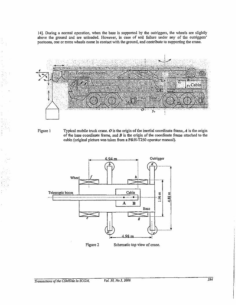
14]. During a nonnal operation, when the base is supported by the outriggers, the wheels are slightlyabove the ground and are unloaded. However, in case of soil fuilure under any of the outriggers'pontoons, one or more wheels come in contact with the ground, and contribute to supporting the crane.
Outrigger
d
Figure I Typical mobile truck crane. 0 is the origin of the inertial coordinate frame,A is the originof the base coordinate frame, and B is the origin of the coordinate frame attached to thecabin (original picture was taken from a P&H-T250 operator manual).
1i"'. .r6L9~4'l..lJm[l- I~
I h 1! 1: Ii I
Wheetl~~If~J.._ll__..c~I~'5:1j'.j .
Telescopic boom
e
a
•
Cabin
A B
498m
g
E~-_._-_.•._.. ~ ~
Base
..I
e00co"<f
Figure 2
Transaclialls afthe CSMEIde la SCGM.
Schematic top view of crane.
Vol. 30, No.3, 2006 394

8'w WklJ
8 c==>rcyrky>Cij "p! Tpf
___ ljX ___ ijx
• "pf •"yy{t;r- " p"
ijy
ryij(;;r-Tp"Tpf
ijy
ij lj
Figure 3 Models of compliance of the wheels and the outriggers when they are in contact with theground that could deform or fail.
To describe the motion of the base, five virtual serial links are added between the ground and the base.This allows the base to be considered as the last link of a six degree-of-freedom serial link manipulator.The configumtion of the manipulator is PPPRRR, i.e., the first three links have prismatic (P) joints andthe last three links are connected together by revolute (R) joints (see Figure 4). Furthermore, three virtuallinks are added between the end-point of the telescopic boom and the load, allowing the motion of theload, with respect to the end of the boom, be described by a four degree-of-freedom serial linkmanipulator with RRRP kinematic configumtion. The addition of these eight virtual links will allow theentire crone that contains a load with multiple-degree-of-freedom joint and a non-fixed base to betronsferred into a thirteen degree-of-freedom fixed base serial-link manipulator with single-degree-offreedom joints. This process allows the use of existing formulations, documented in robotics textbooks, toderive the corresponding dynamic equations. Once, the equations of motion, describing the expandedsystem are derived, the final equations of motion for the original five-link system are obtained by settingall the kinematic and dynamic pammeters pertaining to the virtual links to zero (see reference [10] fordetailed description ofthe method and examples).
Figure 4
Transactians oftlie CSMElcfe la SCGM,
3D presentation ofmobile crane base using virtual links.
Vol. 30, No.3, 2006 395

The Denavit-Hartenberg coordinate systems pertaining to the machine kinematics are shown in Figure5 and the kinematic parameters are given in Table I. The final dynamic equations can be written in thefollowing general form:t=M(q)ij+C(q,q)+G(q)+JTF (I)
where M(q) is the symmetric, positive definite inertial acceleration-related matrix, C(q, q) is the vector
of centripetal and Coriolis torques and, G(q) is the vector of gravitational torques, which also includes
the effect of the inclination of the whole machine. q = {q"qz, ...,ql3l', q and ij are vectors of the joint
variables, velocities and accelerations, t(t) = {T,.TZ'''' TI3l' is the vector ofthe generalized force applied at
the corresponding joints. The term JTF reflects the effect of the external forces, due to the interactionbetween the crane supports and the ground, at the manipulator joints. F is the force/torque vectorrepresenting the summation of all external forces transferred to point A on the base (the origin of thecoordinate frame 6, as shown in Figures I, 2, and 5). J is the Jacobian matrix used to calculate the effectofF on each joint.
Table I Kinematic parameters of the machine under investigation.
Link q, (rad) d,(m) a/em) a; (rad)
I rr/2 ql 0 rr/2
2 rr/2 ql 0 rr/2
3 0 q, 0 0
4 q, 0 0 -rrl2
5 q, 0 0 -rr/2
6 q. 0.66 1.0 0
7 q7 0.85 -LSI -rr/2
8 q8 0 0 -rr/2
9 rr qo 0 0
10 qJO 0 0 -rr/2
II qll 0 0 rr/2
12 qll 0 0 0
13 0 q/J 0 0
The normal force vector at each outrigger, TF n={ TFfi. ,rFJ! ,rF;;, T F:!}T, or each wheel,
WFn ={ "Ffi., wFJ1 , wF;;, wF,7 f, are calculated based on the deflection of the spring damper system. For
example, the normal force component at the front right outrigger, T Ffi., is calculated as follows:
Trallsactions ofthe CSMEIde la SCGM, Vol. 30. No.3. 2006 396

--q'-~8Zs ""'"
(2)
x,Y,
q~", YIO
ZIGXIO
z, tq, y-tY_'_. _A" -t-,:
I Xs
~YII
Z 11 ql2 XII Y,
YIq,
Z,
XIY"
ZI2 ! Z,X12
~
~q" X2
q,Z,-~YI7 / Z,
/ql
)', q,Z"
ZoX13
Y.
X. 0
Figure 5 Denavit-Hartenberg link coordinates.
(4)
(3)
(5)
where R denotes the Rayleigh's dissipation function and V is the potentiaJ energy function due to thespring.
r JT [dJ...r 6) T· ]'Rrr "? cfr diP' rfr,-Yfr(l)
rVfr -~TkA~/r;')/Yfr(t)JThus,
TF;; =(TCfr[{[,~~: q,] rr;'},JYfr(+rkA~/ r;')/Yrr(I)~{~;:T r;'L
Transactions oflhe CSMEIde la SCGM, Vol, 30, N03, 2006 397

where, TTJ, is the position vector of front right outrigger defined in coordinate frame 6 (see Figure 5). c
and k denote the damping and stiffness coefficients, respectively. The sUbscript z means the z componentof the vector and, T6 is the homogeneous transformation matrix from coordinate frame 6 to the reference(base) coordinate frame o.
LuGre tire friction model [11] is used to calculate the friction forces between the outriggers and theground. This dynamic model can describe steady-state friction characteristics and supports hysteresisbehavior due to frictional lag and spring-like behavior in stiction. It also produces a varying breakawayforce depending upon the rate ofchanging the applied force. Using LuGre model, the x component of thefriction force at the front right outrigger, I.e., T F{,.., is determined as:
TFr _'T T. T T~ T T )TFn (6)fr< -\ <Soft, ·r",+ <Slfrx ·r",+ <S2jr, vr", fr
where "0 is the normalized lumped stiffness, CTI the normalized lumped damping, "2 is the normalized
viscous relative damping, F" represents the normal force. The average deflection of the bristles at thefront right outrigger in x direction, TZrm is modeled as
T. -'v TCTnj",ITVj",1 T_ (7).. frx.- In - T "In
'/x (vr",)
where v denotes the relative velocity between the outrigger and the ground. Function TJ(v) containsinformation about the velocity dependence of friction. It is positive and depends on many factors such asmaterial properties, lubrication, and temperature.
1 \0.5
.~
T (T ) r (T T ) T" frx (8)'Ix vr", = l1,frx + l1'j",- l1'j", e
In (8) 11, is the Coulomb friction coefficient and 11, is the static friction coefficient. v, is the Stribeck
velocity, which helps to define the velocity dependence of friction.
Modeling Hydraulic Drive SystemFigure 6 shows a schematic diagram of typical hydraulic power circuit adopted in this paper. The
power required to actuate the hydraulic cylinders and the hydraulic motors is supplied by the engine,which drives four hydraulic pumps through a gear train. The output of each pump is used to operate aseparate hydraulic actuator by an open-center valve as shown in the figure. Figure 7 shows the operationof the open-center valve in actuating the hydraulic cylinder. When the spool of the open-center valve is inneutral position, the flow passes through the valve and returns to the tank. As the spool moves to the leftor to the right, the flow is distributed to the load and the tank, depending upon the orifice arrangement andthe load. A diesel engine is used to tum the four axial-piston variable-displacement pumps. The angles ofthe swash plates, for all four pumps, are equally controlled according to the summing pressure,11 + Pz + P, + p.,. Consequently, these pumps have identical output flow, but could operate at differentoutput pressures.
With reference to Figure 8, the output pump pressures are applied to four small pistons (two are shownin Figure 8) that change the angle of the swash plate against three parallel springs. This mechanicalfeedback system serves to limit the power that is drawn from the engine, so that the pressure-flow curve isbelow the power limit curve as shown in Figure 8.
Assuming that the losses due to leakage are negligible, the equations governing tile flow distribution,for each actuator, can be written as follows [13]:
Transactions oftlie CSMElde la SCGM, Vol. 30, No.3, 2006 398

Q,;ka,~p,-p, (9)
Q,;ka,~p,-P, (10)
Q,; Q-Q, ;ka,~p,-p, (II)
where Q, , Q." and Q, are the inlet, outlet, and exit flows, to and from the cylinder, respectively. Q is
the supply flow. aj , aD and a, are the inlet, outlet and exit areas, respectively (see Figure 7). k is the
orifice coefficient. The rate of change of the inlet pressure p, and the outlet pressure Po, for eachactuator, are:
p,,;-LI~,-AX) (12)J'I(X)~ ,
. fJ (. )P,; Vo(X) A,X -Qo (13)
where X denotes actuator displacement, X is the actuator velocity and fJ is the effective bulk modulus. A,and Ao are the effective piston areas.
Telescopecylinders
Boom hoistcylinders
Hydraulic swingmotor
1-----\ Hydraulic winchmotor
Boom telescopevalve
Winch valve
Swing valve
'-,,1,,
r--i--\ Boom hoist valve
Pumpcontrol
Engine
Figure 6 Schematic diagram of typical hydraulic power circuit. Parts labeled 1,2,3, and 4 are thehydraulic pumps. Boom hoist valve, boom telescope valve and winch valve are similar tothe swing valve, which is shown in detail.
Transactions oftlte CSMEIde la SCGM. Vol. 30, No.3, 2006 399

x
Ap
Figure 7 Typical hydraulic cylinder actuated by an open-center valve.
cUrve oflbemaximumavailable power
,III\\\
\1\
\\ ,,,, ,--........... ---
Q~,I------,
01
!io
,,,,,,---- .. -- .. -.
__ I'--r-' I - --:,,,,,,,,,,,,,,,_______________ 1
Summing Pressure, P,+ P, P,+ P,
Figure 8 Relation between the summing pressure and the pump output flows for the variabledisplacement pumps used in boom crane.
¥;(X) and V.(X) are the volumes of the fluid trapped at the sides of the actuator. They are expressed as
TrallsaClions aJlhe CSMEIde la SCGM. Vol. 30. No.3. 2006 400

J~(X)=V.+XA, (14)
V.(X) = V; - X AD (15)
V. and V. are the volumes of fluid trapped initially at either sides of the actuator. The output force fromeach actuator, F, isF=p,A,-P.A. (16)
Finally, the torque generated by the hydraulic cylinder is:dX
T=F- (17)dO
where ~; represents the nonlinear relationship between the actuator linear velocity, X and the
corresponding link rotational velocity, 8. For the swing and winch hydraulic motors, equations (12), (13)and (17) must be written in the following forms:
p'=.....L(g,-DmX) (18)v, (X)
p'=.....L(Dm,r-Q.) (19)V.(X)
T = II Dm( P, - Po) (20)
where Dm is the volumetric displacement of the motor, and n is the gear reduction from the hydraulic
motor to the output shaft. The relationship between the spool displacement, x,p' and the input voltage, 1I,
to the servovaive can be adequately expressed by a first-order differential equation:T <ix,p I
11=(-')-+(-)x,p (21)k,p dt k,p
where T, and k,p are gains describing the valve dynamics.
SIMULATION STUDIES
Having determined, the comprehensive equations describing the model of the entire crane, in thissection, we present a number ofcase studies illustrating tip-over responses under various motion controlsand soil conditions that influence the overturning of the cranes. For simulations, the values of dynamicparameters corresponding to the adopted model of the machine under investigation are listed in Table 2.The stiffness and damping coefficient values of the wheel-tire compliance were chosen as:wk1'=wkjl=wk,.,=wk,,=17.5xI0'N/m and wc/,="cjI=wc,.,="c,,=7.5xlO'Nsim. These values provide a
natural frequency of'" 3 Hz and a damping ratio of '" 0.4 in the vertical direction for the vehicle with noload. Note that the natural frequencies and damping ratios change with the manipulator configuration andpayload. The stiffuess and damping coefficient of the compliance between the outriggers and the groundwere chosen as Tk1'=Tkjl=Tk".=Tk'f =20xlO' N/m and Tc1'=TCjI=TC".=TC" =2.55xlO' Nslm. The
coefficients of the friction between the wheels and the ground were chosen as
W P'j, ="P'jI=wp,,,, =WP'd = 0.9 and "p,j, =WP,jI="P'''' ="P"t = 0.7. The values of other parameters used
in LuGre model are given below:Ii' W W If 40 II W W 11' W 4 9487 sIcrofr=uoj1 = u Orr = uOrl =- m, UIft'= Ulfl= 0"1":; O'irl =. m,
W 11' W II' 0 0018 sI d Iv I' W 11' 12 5 Iu 1fr = u2j/= u2rr = uzr/=· ffi,an vSfr = \'sj1;;:;' vsrr = v"rl= . ms.
TransacJions oftile CSMEIde 10 SCGM, Vol. 30, No.3. 2006 40/

The above values were used by Canudas de Wit and Tsiotras [11] for tire friction models and gaveresults that matched reasonably well with their experimental data and are therefore adopted here.
Table 2 Masses and coordinates ofcenter of gravities in local coordinate frames.
mass (kg) x,(m) Y,(m) z, (m)
Base 12000 -1.8 0.0 -0.33Cabin 4000 0.0 0.26 0.0Boom 2,400 0.3 0.0 2.83Telescope 1,600 0.35 0.0 -4.5Clamming Device 790 0.0 0.0 0.0
Case Study I: Effect ofGround Failure at One SupportIn this study, we consider a case where the clamming device is holding a load of 5000kg and the boom
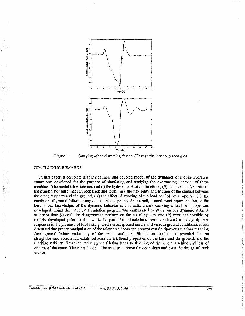
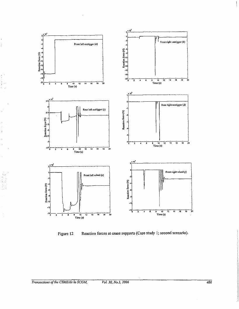
reach is 14m. The machine is initially resting on rigid ground by four outriggers (see Figure 9). We thensimulate tip-over of the crane in case of ground failure under the front left outrigger pontoon (marked 'a'in Figure 9) at t ,,; 4 s. Figure 10 illustrates the course of changes of Euler angles (g" g, and g. in Figure5) that describe the orientation of the base coordinate frame {X6Y6z,,} with respect to the inertial frame{x,y,z.,}, during two possible scenarios. In the first scenario, no action is taken and the crane iscompletely over-turned. In the second scenario, the load is dropped (at !"'7s) when the base tips more than15'. As is seen in Figure 10, in the second scenario, the crane rolls back and regains stability. Figure IIshows the noticeable swaying of the clamming device around the end-point of the telescopic boom in thesecond scenario. The changes of two main rotations (i.e., coordinates, g,o and gil in Figure 5) are shownin the figure. Figure 12 shows the reaction forces at four outriggers as well as the front wheels during thecrane motion. As is seen, there are no reaction forces at the front wheels and the rear right outriggerbefore the ground failure. Thus, the support polygon for the crane before the ground failure is abca (referto Figure 9). After the ground failure occurs under the outrigger pontoon 'a', the front left and the frontright wheels come in contact with the ground in supporting the crane. For a short period of time, thesupport polygon becomes efce. Then the crane starts to tip over around the edge ec; this is clearly seenfrom Figure 12, as the supports at the front and the rear right outriggers as well as the front right wheelbreak free of the soil. Finally, after the crane regains stability, the support polygon becomes efbce.
Case Study 2: Effect ofLifting/Lowering the LoadIn this case study, the effect of a load lowering/lifting action on crane tip-over responses is
investigated. The crane is initially resting on the outriggers and holding a 3500kg load at a boom angle of
,,;550• It then lowers the load to ,,;31o (see Figure 13) at which the crane starts to tip over. At this
moment we consider two different scenarios. In the first scenario, as soon as the crane starts to tip over,the operator moves the boom up in anticipation that this reverse motion will bring the machine back to astable situation. In the second scenario, the operator stops the boom immediately and no further action istaken. With reference to Figure 13, it is seen that the machine tilts about 5.5' in the first scenario whereasit tilts less than 4' in the second scenario. It is therefore concluded that in this case study, the dynamicreaction forces as a result of the reversal motion of the boom, would promote instability. Thus, taking noaction by the operator would produce a safer tip-over response. This case study also reveals theimportance of tip-over simulation studies in understanding the mechanism of tip-over and potentiallydeveloping means to prevent tip-over situations.
TransactiollS ofthe CSMEIde 10 SCGM, Vol. 30. No.3. 2006 402

Case Study 3: Effect ofSwing MotionIn this example, the crane is resting on the outriggers with the clamming device holding a 3500kg load.
The task is to rotate the entire upper structure about 3600 at two different speeds:27 deg/s and 18 deg/s. With reference to Figure 14, when the machine rotates at 27 deg/s, it rocks
approximately 10 around the 'ac' axis and about 20 around the 'cd' axis. When rotating at the lowerspeed of 18 deg/s, it hardly lifts up about these axes. Figure 15 shows that unfavorable oscillations of theload, hanging by the rope, during the swing motion. The projection of the motion trajectory on thehorizontal plane perpendicular to tile axis ofswing rotation is also shown in Figure 15.
Case Study 4: Effect of Friction Between the Wheels and the GroundThe sensitivity of the machine stability to various friction conditions between the wheels and the
ground is investigated in this case study. The crane is initially resting on its wheels and the clammingdevice is holding a IOOOkg load with the boom reaching a 12m length. The load then swings for
approximately 1800• Different values for friction coefficients between the wheels and the ground are
applied for this motion: high friction (Ps =0.9 and Pc =0.7), medium friction
(Ps =0.1 and Pc =0.06), and low friction (Ps =0.08 and fJc =0.03). Figure 16 shows the swivel
motion of the load and the base movement. As is seen, the base rotational angles q. and q, (the latter notshown for the sake of brevity) are almost the same given all three friction conditions. However, the lessthe friction between the wheels and the ground, the more the machine skids around the vertical axis, andthe operator may lose control ofthe machine which is dangerous and should be avoided.
a, C
,
e If
a I b~
(1
)
IAJ6
g hC X6 d
( ,....J~
Figure 9
Transactiolls oJthe CSMEIde 10 SCGM,
Mobile crane configuration in Case study l.
Vol. 30, No.3, 2006 403
..,,--------------,"
". , ,
I
t""I Finl scenario
VUd SClmario
\/'-'--------i10 12 14 113 18 20
Time(s)
Figure 10
•i S
",
~
If'ne ,,'"
V'v.,• , , • • 10 12 " " " '"Time ($)
,.S
l2.Sfif. '
"
\.~ 1.5
e ,,"'OS
•~S• • " 12 " " " '"Time(s)
Trajectories of Euler angles describing spatial base rotation with respect to the inertialframe (Case study 1; two scenarios).
TransactiollS ofthe CSMEIde la SCGM. Vol. 30, No.3, 2006 404
2
~1
";;'
'"!I"'iii ·2
1-334
.,
..
.,, 2
"'"
!"::-40~
!I"
l"0]:"10
2,
6 a ro 12 14 16 18 ~
Timc(s)
8101214161$20Time (s)
Figure 11 Swaying of the clamming device (Case study I; second scenario).
CONCLUDING REMARKS
In this paper, a complete highly nonlinear and coupled model of the dynamics of mobile hydrauliccranes was developed for the purpose of simulating and studying the overturning behavior of thesemachines. The model takes into account (i) the hydraulic actuation functions, (i/) the detailed dynamics ofthe manipulator base that can rock back and forth, (iii) the flexibility and friction of the contact betweenthe crane supports and the ground, (iv) the effect of swaying of the load carried by a rope and (v), thecondition of ground failure at any of the crane supports. As a result, a most exact representation, to thebest of our knowledge, of the dynamic behavior of hydraulic cranes carrying a load by a rope wasdeveloped. Using the model, a simulation program was constructed to study various dynamic stabilityscenarios that: (i) could be dangerous to perfonn on the actual system, and (Ii) were not possible bymodels developed prior to this work. In particular, simulations were conducted to study tip-overresponses in the presence of load lifting, load swivel, ground fuilure and various ground conditions. It wasdiscussed that proper manipulation ofthe telescopic boom can prevent certain tip-over situations resultingfrom ground failure under any of the crane outriggers. Simulation results also revealed that nostraightforward correlation exists between the frictional properties of the base and the ground, and themachine stability. However, reducing the friction leads to skidding of the whole machine and loss ofcontrol of the crane. These results could be used to improve the operations and even the design of truckcranes.
Trallsactions ofthe CSMEIde 10 SCGM, Vol. 30, No.3, 2006 405
x10'
2X 10'0
0
0 .0
.0 Front left outrigger (a) ...
...g~
g.'l~§.
<S.10<
~.".5.12
Ji...~.14
J
."
:;:1...."
0 0.0
0 • • " " .. " 16 "0Time (5)
,rFronl right outrigger (b)
&101214161820Time (s)
8 10 12 14 18 16 20Time (s)
,."0
Rear right outrigger (d),,
••
SX 10
0
1 Rear left outrigger (c),
LY.,,•5
~
.5~028&10121.,61820
Time(s)
6 a w 12 U 16 U ~
Tune(s), ,
2X 10
0Front rig.ht wheel if)
~
...
••""
4 6 8 W 12 M 16 18 WTime ($)
.,
Front left wheel (l!)0
,
°l \y:L
, "
., 0
.,
Figure 12 Reaction forces at crane supports (Case study I; second scenario).
Transactions oJthe CSME/de la SCGM, Vol. 30, No.3, 2006 406

"
"tf 503!i.'5 4$
eeg "'"
""', , 6 m 12 1. W 18 ~
Ti~(S)
f\\
0.lA
0
10 2 .( 6 10 12 H 18 111 20
Time(s)
Figure J3 Effect ofboom motion on base stability (Case study 2).
Trallsactiolls ofthe CSMEJde la SCGM. Vol. 30. No.3, 2006 407

Figure 14 Mobile crane states during swivel ofload hanging by rope (Case study 3).
Transactions oJthe CSME/de la SCGM. Vol. 30. No.3. 2006 408

"'r----~-------~__,
(I
"._~~\I
.",,......--,-,----c,,;;---,,,,--e,,::-----c,'",'-"""""'".Timc(s)
""to 15 ZO
Timc(s)
, oN'Vi\ \ vJ'v,
\j\\ I""'\. I
, ---\/",,
"
..
.,ol?l"",-:..---c-:-.- ..:-~.,="',=';;--;--;----c;---';".
x{m)
Figure 15 Load oscillations and projection on horizontal plane (Case study 3).
Transac/lonsoj/lle CSMEIde la SCGM, Vol. 30, No.3, 2006 409

fe
g h
'"'"'"
~t4(lg 1W
'§ 100
~
,~ ..~ ..
"",, " " " " " "Timc(s)
"'~,-~---;-,--;--:.-7,"'"12'7,,,,7,,,,7,,,'-;'''Time (s).,-----_--.-'_-----,
7
",0--:--o--"'.--:--::":-:-:,,:-:-:,,:-:-:,,:--::,,:--!,,,TIm"'t
Figure 16 Effect of friction on stability (Case study 4).
Transactions ojthe CSMElde la SCGM. Vol. 30. Na.3. 2006 4/0

[I]
[2]
[3]
[4]
[5]
[6]
[7]
[8]
[9]
[10]
[11]
[12]
[13]
[14]
REFERENCES
S. Kilicaslan, T. Balkan, and S.K. Ider, "Tipping loads of mobile cranes with flexiblebooms," Journal ofSolmd and Vibration 223, 645-657, 1999.
B. Posiadala, B. Skalmierski, and L. Toski, "Motion of the lifted load brought by akinematic forcing of the crane telescopic boom," Mechanism and Machine Theory 25,547-556, 1990.
B. Posiadala "Influence of crane support system on motion of lifted load," Mechanismand Machine Theory 32,9-20, 1997.
G. Sun and M. Kleeberger, "Dynamic responses of hydraulic mobile crane withconsideration of the drive system," Mechanism and Machine Theory 38, 1489-1508,2003.
Z. Towarek, "The Dynamic stability of a crane standing on soil during the rotation ofthe boom," International Journal ofMechanical Science 40, 557-574,1998.
A. Maczynski and S. Wojciech, "Dynamic of a mobile crane and optimization of theslewing motion of its upper structure," Nonlinear Dynamics 32,259-290,2003
Fukagawa and T. Muro, "Alarm system to prevent the overturning of truck cranesconsidering possible ground failure," Proceedings ofthe Il'h International Symposiumon Automation and RobotiCS in ConstnlCtion. Brighton, UK, 27-34, 1994.
A. Ghasempoor and N. Sepehri, "A Measure of Stability for Mobile Manipulators WithApplication to Heavy Duty Hydraulic Machines," ASME Journal ofDynamic Systems,Measurement, ond Control 120, 360-370, 1998
R.F. Abo-Shanab and N. Sepehri, "Tip-over Stability of Manipulator-Like MobileHydraulic Machines," ASME Journal ofDynamic Systems, Measurement, and Control127, 295-30 I, 2005.
R.F. Abo-Shanab, N. Sepehri, and Q. Wu, "On Dynamic Modelling of RobotManipulators: The Method of Virtual Links," Proceedings ASME Design EngineeringTechnical Conference, Montreal, Canada, Paper #DETC02IMECH-34225, 2002.
C.C. de Wit and P. Tsiotras, "Dynamic Tire Friction Models for Vehicle TractionControl," Proc. 38th Conf. on Decision and Control, Phoenix, AZ, 3746-3751, 1999.
U.O. Akpan and M. R. Kujath, "Sensitivity of a Mobile Manipulator Response toSystem Parameters," ASME Journal ofVibration andAcoustics 120, 156-163, 1998.
Merritt, H.E., Hydraulic Control Systems, John Wiley and Sons, NY, 1967.
K. Uto, M. Fuyuki and M. Sakurai, "An exponential mathematical model togeotechnical curves", Proc. Int. Symp. on Penetrability and Drivability ofPiles, 1985.
TrQ/lsactiolls Ofthe CSMEIde 10 SCGM. Val. 30, No.3, 2006 411

q,q,qTI
Zi
Pi
I:r i
Ig
JF,1:MC,G·
OJ, GO} ae
PI' Po
P" PeQi, Qo, Q,XfJm,kCADm
x,p
P,Pc0"0,0"1,0"2
zSuperscriptsnfTW,WSubscriptsfrJr, fl, rr, Irfix,flyfIx,flYme, rryrlx, rly
NOMENCLATURE
vectors oftlte joint angles, velocities and accelerations, respectively
homogeneous transfonnation matrix from frame i to reference frame
z-axis of coordinate frame i
position vector ofthe origin ofcoordinate frame i
inertial matrix of link i about its mass center in coordinate frame i
position vector of mass center of link i in coordinate frame i
gravitational acceleration vector in base coordinate frameJacobian matrixvectors of force and generalized force/torque, respectively
inertial matrixcentripetal and Coriolis torques vector, vector ofgravitational torquesinle~ outlet and exit orifice areas, respectively
line pressures
supply and tank pressures, respectively
flow into valve, out of valve and from pump to tank, respectivelyactuator linear displacement.effective bulk modulus ofthe drive system
mass oflink istiffuess coefficientdamping coefficientpiston areavolumetric displacement of the hydraulic motorvalve spool displacementstatic (stick) friction coefficient
coulomb (slip) friction coefficient
nonnalized lumped stiffuess, damping and viscous relative damping, respectively
bristle denection
normal forcefriction forceoutriggerwheel
front wheeIJoutriggerrear wheeIJoutriggerfront righ~ frontle~ rear right and rear left, respectivelyx and y components offriction force at front right wheel/outrigger, respectivelyx andy components offriction force at front left wheeIJoutrigger, respectivelyx and y components of friction force at rear right wheel/outrigger, respectivelyx and y components of friction force at rear left wheeIJoutrigger, respectively
TransacJions oJthe CSMElde la SCGM, Val. 3D, No.3, 2006 412