Timken Spherical Roller Bearing Catalog - feyc.eu · Introduction SPHERICAL ROLLER BEARING CATALOG...
191
Timken ® Spherical Roller Bearing Catalog
Transcript of Timken Spherical Roller Bearing Catalog - feyc.eu · Introduction SPHERICAL ROLLER BEARING CATALOG...
Timken® Spherical Roller Bearing Catalog

2
2
2
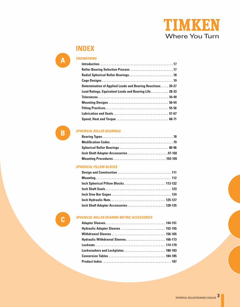
INDEX
A
B
C
ENGINEERING
Introduction . . . . . . . . . . . . . . . . . . . . . . . . . . . . . . . . . . . . . . . . . . . . . . . 17
Roller Bearing Selection Process . . . . . . . . . . . . . . . . . . . . . . . . . . . 17
Radial Spherical Roller Bearings . . . . . . . . . . . . . . . . . . . . . . . . . . . . 18
Cage Designs . . . . . . . . . . . . . . . . . . . . . . . . . . . . . . . . . . . . . . . . . . . . . 19
Determination of Applied Loads and Bearing Reactions . . . . . 20-27
Load Ratings, Equivalent Loads and Bearing Life . . . . . . . . . . . 28-33
Tolerances . . . . . . . . . . . . . . . . . . . . . . . . . . . . . . . . . . . . . . . . . . . . . 34-49
Mounting Designs . . . . . . . . . . . . . . . . . . . . . . . . . . . . . . . . . . . . . . 50-54
Fitting Practices . . . . . . . . . . . . . . . . . . . . . . . . . . . . . . . . . . . . . . . . 55-56
Lubrication and Seals . . . . . . . . . . . . . . . . . . . . . . . . . . . . . . . . . . . 57-67
Speed, Heat and Torque . . . . . . . . . . . . . . . . . . . . . . . . . . . . . . . . . 68-71
SPHERICAL ROLLER BEARINGS
Bearing Types . . . . . . . . . . . . . . . . . . . . . . . . . . . . . . . . . . . . . . . . . . . . . 78
Modifi cation Codes . . . . . . . . . . . . . . . . . . . . . . . . . . . . . . . . . . . . . . . . 79
Spherical Roller Bearings . . . . . . . . . . . . . . . . . . . . . . . . . . . . . . . 80-96
Inch Shaft Adapter Accessories . . . . . . . . . . . . . . . . . . . . . . . . . . 97-102
Mounting Procedures . . . . . . . . . . . . . . . . . . . . . . . . . . . . . . . . . .103-105
SPHERICAL ROLLER BEARING METRIC ACCESSORIES
Adapter Sleeves . . . . . . . . . . . . . . . . . . . . . . . . . . . . . . . . . . . . . . 144-151
Hydraulic Adapter Sleeves . . . . . . . . . . . . . . . . . . . . . . . . . . . . 152-155
Withdrawal Sleeves . . . . . . . . . . . . . . . . . . . . . . . . . . . . . . . . . . 156-165
Hydraulic Withdrawal Sleeves . . . . . . . . . . . . . . . . . . . . . . . . . 166-173
Locknuts. . . . . . . . . . . . . . . . . . . . . . . . . . . . . . . . . . . . . . . . . . . . . 174-179
Lockwashers and Lockplates . . . . . . . . . . . . . . . . . . . . . . . . . . 180-183
Conversion Tables . . . . . . . . . . . . . . . . . . . . . . . . . . . . . . . . . . . . 184-185
Product Index . . . . . . . . . . . . . . . . . . . . . . . . . . . . . . . . . . . . . . . . . . . . 187
SPHERICAL PILLOW BLOCKS
Design and Construction . . . . . . . . . . . . . . . . . . . . . . . . . . . . . . . . . . 111
Mounting . . . . . . . . . . . . . . . . . . . . . . . . . . . . . . . . . . . . . . . . . . . . . . . . 112
Inch Spherical Pillow Blocks . . . . . . . . . . . . . . . . . . . . . . . . . . 113-122
Inch Shaft Seals . . . . . . . . . . . . . . . . . . . . . . . . . . . . . . . . . . . . . . . . . . 123
Inch Sine Bar Gages . . . . . . . . . . . . . . . . . . . . . . . . . . . . . . . . . . . . . . 124
Inch Hydraulic Nuts . . . . . . . . . . . . . . . . . . . . . . . . . . . . . . . . . . . 125-127
Inch Shaft Adapter Accessories . . . . . . . . . . . . . . . . . . . . . . . . 128-135
SPHERICAL ROLLER BEARING CATALOG 3
SPHERICAL ROLLER BEARING CATALOG
2
2
2
4 SPHERICAL ROLLER BEARING CATALOG
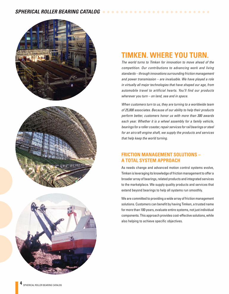
TIMKEN. WHERE YOU TURN.The world turns to Timken for innovation to move ahead of the
competition. Our contributions to advancing work and living
standards – through innovations surrounding friction management
and power transmission – are invaluable. We have played a role
in virtually all major technologies that have shaped our age, from
automobile travel to artificial hearts. You’ll find our products
wherever you turn – on land, sea and in space.
When customers turn to us, they are turning to a worldwide team
of 25,000 associates. Because of our ability to help their products
perform better, customers honor us with more than 300 awards
each year. Whether it is a wheel assembly for a family vehicle,
bearings for a roller coaster, repair services for rail bearings or steel
for an aircraft engine shaft, we supply the products and services
that help keep the world turning.
FRICTION MANAGEMENT SOLUTIONS – A TOTAL SYSTEM APPROACHAs needs change and advanced motion control systems evolve,
Timken is leveraging its knowledge of friction management to offer a
broader array of bearings, related products and integrated services
to the marketplace. We supply quality products and services that
extend beyond bearings to help all systems run smoothly.
We are committed to providing a wide array of friction management
solutions. Customers can benefi t by having Timken, a trusted name
for more than 100 years, evaluate entire systems, not just individual
components. This approach provides cost-effective solutions, while
also helping to achieve specifi c objectives.

Introduction
SPHERICAL ROLLER BEARING CATALOG 5
TECHNOLOGY THAT MOVES YOUToday, major industry turns to Timken for our ability to infl uence the
fundamentals of motion through the creation, transfer, and control
of power. We invest in people, attracting scholars, engineers and
specialists from around the world. We invest in tools – computers,
manufacturing equipment and state-of-the-art laboratories. And we
invest in the future by identifying new concepts that will help Timken
and its customers make their mark for years to come. Innovation
is one of our core values.
The return on our technology investment has grown exponentially.
Our associates increase the reliability of Timken® products and
create designs that can set new performance standards. We help
customers solve their immediate system issues, while developing
the systems of tomorrow.
Our teams of engineers and scientists are dedicated to using
everything they know about friction management and power
transmission. They translate the scientifi c aspects of metallurgy,
bearing operating characteristics, lubrication, torque, noise,
heat treatment, advanced processing concepts and application
development into friction management solutions.
Because our teams are located at technology centers in
North America, Europe and Asia – as well as in our
manufacturing facilities and field offices on
six continents – customers have access to
ideas and resources to transform concepts
into reality. Our technology focuses on
products, materials, processes and
emerging technology to create new
solutions.
SPHERICAL ROLLER BEARING CATALOG
2
2
2
6 SPHERICAL ROLLER BEARING CATALOG
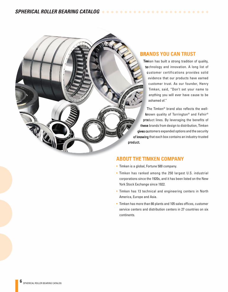
BRANDS YOU CAN TRUSTTimken has built a strong tradition of quality,
technology and innovation. A long list of
customer certifications provides solid
evidence that our products have earned
customer trust. As our founder, Henry
Timken, said, “Don’t set your name to
anything you will ever have cause to be
ashamed of.”
The Timken® brand also refl ects the well-
known quality of Torrington® and Fafnir®
product lines. By leveraging the benefi ts of
these brands from design to distribution, Timken
gives customers expanded options and the security
of knowing that each box contains an industry-trusted
product.
ABOUT THE TIMKEN COMPANY• Timken is a global, Fortune 500 company.
• Timken has ranked among the 250 largest U.S. industrial
corporations since the 1920s, and it has been listed on the New
York Stock Exchange since 1922.
• Timken has 13 technical and engineering centers in North
America, Europe and Asia.
• Timken has more than 66 plants and 105 sales offi ces, customer
service centers and distribution centers in 27 countries on six
continents.
Introduction
SPHERICAL ROLLER BEARING CATALOG 7
TIMKEN SPHERICAL ROLLER BEARINGS Timken spherical roller bearings exceed industry standards for
superior quality and performance and are designed to manage
high radial loads, even when misalignment, marginal lubrication,
contamination, extreme speeds, or critical application stresses
are present.
That’s why industries such as power generation, oilfi eld, steel,
aggregate, cement, mining and power transmission turn to Timken
for a complete line of high-performance spherical roller bearings.
Through expertly designed critical dimensions, such as roller and
raceway contact geometry and topography, our spherical roller
bearings are helping customers increase productivity by reducing
downtime and extending maintenance cycles.
PRODUCT BREADTHTimken offers a complete line of spherical roller bearing designs
ranging from 25 to 1500 millimeter bore (0.98 to 59.06 inches).
Included in this broad portfolio are two fundamental design types:
the Type CJ style and Type YM/YMB design.
Available in 25 to 200 millimeter bore (0.98 to 7.87 inches), Type
CJ-style bearings offer higher load ratings for longer life and
incorporate a stamped steel window-type cage. Similar to all
spherical roller bearings, the CJ design compensates for dynamic
and static misalignment and allows customers to use weldments
for housing frames instead of complex castings.
Type YM bearings feature precision-machined, roller-riding brass
cages and are designed for harsh industrial environments. These
bearings offer higher load ratings for longer life. For larger bore
sizes, the Type YMB design incorporates an inner-ring, land-riding
cage. The YM/YMB design is produced in sizes ranging from 30 to
1500 millimeter bore (1.18 to 59.06 inches).
In addition to the CJ and YM/YMB designs, Timken spherical
roller bearings can be ordered with several enhancements
and modifi cations to extend life and improve performance in
specifi c applications. For example, large-bore spherical bearings
sometimes operate below the bearing’s published speed rating,
causing the cage to push a non-rotating roller across the raceways.
This sliding action breaks down lubrication fi lm and can ultimately
damage the bearing. To help protect the bearing components,
our engineered surfaces coating minimizes skidding and sliding
damage, while withstanding small-particle contamination. In some
cases, engineered surfaces can extend bearing life by up to fi ve
times standard designs, especially in demanding applications like
paper and rolling mills.

SPHERICAL ROLLER BEARING CATALOG
2
2
2
8 SPHERICAL ROLLER BEARING CATALOG
As a Timken customer, you receive an uncompromising standard of
quality across the broadest range of bearings and related products.
Brands like Timken, Torrington and Fafnir refl ect an extensive
line of tapered, needle, spherical, cylindrical, ball bearings and
mounted units ideal for virtually every industrial application. Our
core products are complemented by an ever-growing line of
friction management solutions including lubricants, single-point
lubricators, maintenance tools, safety equipment,
condition monitoring systems and repair services
that help keep operations running smoothly.
SAFETY END CAPSThese easily installed caps offer a high degree of
protection to maintenance personnel as well as to the
bearings integrated within a housing.
HOUSED UNITSBall and spherical roller bearing pillow block units, featuring a
unique sealing design, are easily installed.
CONDITION MONITORING DEVICESFrom wireless units to online systems, condition monitoring
devices give you powerful diagnostic tools to help detect potential
bearing problems, maximizing machine uptime and lowering
maintenance costs.
SPHERICAL ROLLER BEARING METRIC ACCESSORIESBearing sleeves and locking devices, in a wide range of metric
sizes, complement our line of Timken spherical roller bearings.
These accessories are manufactured to the same quality
standards as our bearings, helping to ensure a secure fi t to straight
and stepped shafts. Bearing sleeves are available in two distinct
designs, assembled adapter sleeves and withdrawal sleeves, in
sizes up to 900 mm.
Introduction
SPHERICAL ROLLER BEARING CATALOG 9
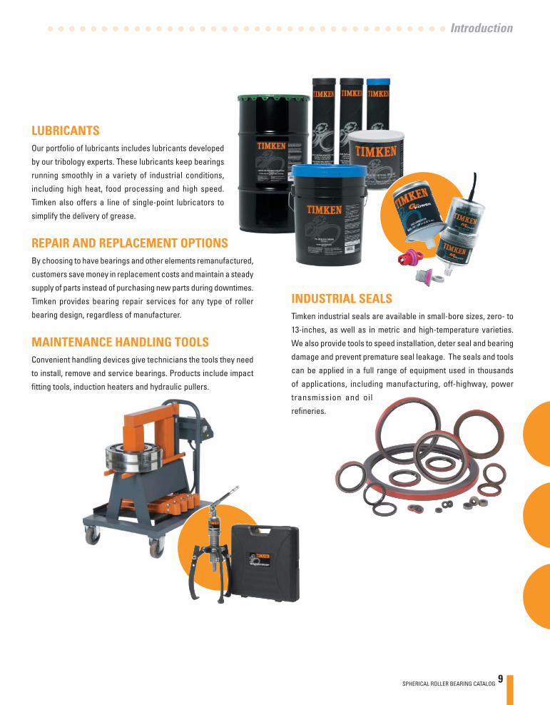
LUBRICANTSOur portfolio of lubricants includes lubricants developed
by our tribology experts. These lubricants keep bearings
running smoothly in a variety of industrial conditions,
including high heat, food processing and high speed.
Timken also offers a line of single-point lubricators to
simplify the delivery of grease.
REPAIR AND REPLACEMENT OPTIONSBy choosing to have bearings and other elements remanufactured,
customers save money in replacement costs and maintain a steady
supply of parts instead of purchasing new parts during downtimes.
Timken provides bearing repair services for any type of roller
bearing design, regardless of manufacturer.
MAINTENANCE HANDLING TOOLSConvenient handling devices give technicians the tools they need
to install, remove and service bearings. Products include impact
fi tting tools, induction heaters and hydraulic pullers.
INDUSTRIAL SEALSTimken industrial seals are available in small-bore sizes, zero- to
13-inches, as well as in metric and high-temperature varieties.
We also provide tools to speed installation, deter seal and bearing
damage and prevent premature seal leakage. The seals and tools
can be applied in a full range of equipment used in thousands
of applications, including manufacturing, off-highway, power
transmission and oil
refi neries.
SPHERICAL ROLLER BEARING CATALOG
2
2
2
10 SPHERICAL ROLLER BEARING CATALOG
ABOUT THIS CATALOGTimken offers an extensive range of bearings and
accessories in both imperial and metric sizes. For
your convenience, size ranges are indicated both in
millimeters and inches. Contact your Timken sales
representative to learn more about our complete
line for the special needs of your application.
USING THIS CATALOGWe are committed to providing our customers with
maximum service and quality. This catalog contains
dimensions, tolerances and load ratings, as well as
an engineering section describing fi tting practices for
shafts and housings, internal clearances, materials, and
other bearing features. It can provide valuable assistance
in the initial consideration of the type and characteristics of the
bearing that may best suit your particular needs.
CATALOG FEATURESDimension and load rating data for the various types and styles of
bearings is organized by size.
ISO, DIN, and ABMA, as used in this catalog, refer to the International
Organization for Standardization, Deutsches Institut für Normung
EV and the American Bearing Manufacturers Association.
TERMS AND CONDITIONS OF SALEAll products described in this catalog are sold subject to Timken’s
Terms and Conditions of Sale.
It is understood that the buyer, in selecting and ordering from this
catalog, which supersedes all previous editions, accepts all Timken
Terms and Conditions of Sale, a copy of which may be obtained by
your Timken sales offi ce.
Note: Product performance is affected by many factors beyond
the control of Timken. Therefore, the suitability and feasibility
of all designs and product selection should be validated by you.
This catalog is provided solely to give you, a customer of Timken
or its parent or affiliates, analysis tools and data to assist you in
your design. No warranty, expressed or implied, including any
warranty of fitness for a particular purpose, is made by Timken.
Timken products are sold subject to the Limited Warranty.
Introduction
SPHERICAL ROLLER BEARING CATALOG 11
LIMITED WARRANTYWe warrant for a period of one year from the date of shipment that
our products shall be free of defects in material and workmanship,
as shall be determined by our manufacturing standards, and shall
conform to the description on the face of this acknowledgment.
THE WARRANTY DESCRIBED HEREIN SHALL BE IN LIEU OF ANY
OTHER WARRANTY, EXPRESS OR IMPLIED, INCLUDING BUT NOT
LIMITED TO ANY IMPLIED WARRANTY OF MERCHANTABILITY
OR FITNESS FOR A PARTICULAR PURPOSE. The terms contained
herein constitute the entire agreement of the parties and the
warranty representations of the seller. There are no other
representations, warranties, or guarantees applicable to the sale of
our products unless otherwise expressly agreed to by us in writing.
SPECIAL APPLICATIONSSome products, such as for aerospace applications, are made to
special standards, and only the original equipment manufacturer
can determine if a particular bearing is suitable for use in their
equipment.
Failure to observe the following warnings could lead to a risk of serious bodily harm: Proper maintenance and handling practices are critical. Failure to follow installation instructions and to maintain proper lubrication can result in equipment failure creating a risk of serious bodily harm. Never spin a bearing with compressed air. The rollers may be forcefully expelled creating a risk of serious bodily harm.
WARNING
PURCHASER’S EXCLUSIVE REMEDY/SELLER’S EXPRESS LIMIT OF LIABILITYPurchaser’s exclusive remedy for any warranty claim, or for
any claim arising out of the purchase or use of our products,
shall be the replacement of said products. We will replace our
products, without charge to the purchaser, f.o.b. our point of
shipment. We will not be liable for any consequential, incidental,
or other damages sustained by purchaser, including but not
limited to, loss of profits or revenue, loss of use of product, cost
of capital, cost of substituted product, facilities, services, or
claims of purchaser’s customers for any damages. Any warranty
claim of purchaser must be made within one year of the date of
shipment of the product. This exclusive remedy applies regardless
of the nature of purchaser’s claim, whether in contract, tort,
express or implied warranty, negligence or strict liability, upon
which damages are claimed and regardless of whether the
same is due to our negligence or any defect in our product.
SPHERICAL ROLLER BEARING CATALOG
2
2
2
12 SPHERICAL ROLLER BEARING CATALOG
ROLLER BEARINGS
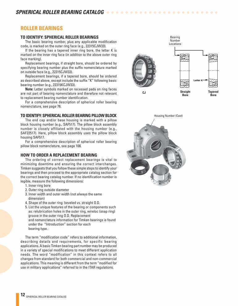
TO IDENTIFY: SPHERICAL ROLLER BEARINGSThe basic bearing number, plus any applicable modifi cation
code, is marked on the outer ring face (e.g., 22315CJW33).If the bearing has a tapered inner ring bore, the letter K is
marked on the inner ring face (in addition to the above outer ring face marking).
Replacement bearings, if straight bore, should be ordered by specifying bearing number plus the suffi x nomenclature marked on outside face (e.g., 22315CJW33).
Replacement bearings, if a tapered bore, should be ordered as described above, except include the suffi x “K” following basic bearing number (e.g., 22315KCJW33).
Note: Letter symbols marked on recessed pads on ring faces are not part of bearing nomenclature and therefore not relevant to replacement bearing number identifi cation.
For a comprehensive description of spherical roller bearing nomenclature, see page 76.
TO IDENTIFY: SPHERICAL ROLLER BEARING PILLOW BLOCKThe end cap and/or base housing is marked with a pillow
block housing number (e.g., SAF517). The pillow block assembly number is closely affiliated with the housing number (e.g., SAF22517). Here, pillow block assembly uses the pillow block housing SAF517.
For a comprehensive description of spherical roller bearing pillow block nomenclature, see page 108.
HOW TO ORDER A REPLACEMENT BEARINGThe ordering of correct replacement bearings is vital to
minimizing downtime and ensuring the correct interchanges.Timken suggests that you follow these simple steps to identify your bearings and then proceed to the appropriate catalog section for the correct bearing catalog number. If no identifi cation number is legible, measure the following dimensions:
1. Inner ring bore2. Outer ring outside diameter3. Inner width and outer width (not always the same dimension) 4. Shape of the outer ring: beveled vs. straight O.D. 5. List the unique features of the bearing or components such as: relubrication holes in the outer ring, wireloc (snap ring) groove in the outer ring O.D. Replacement and nomenclature information for Timken bearings is found under the “Introduction” section for each bearing type.
The term “modifi cation code” refers to additional information, describing details and requirements, for specific bearing applications. A basic Timken bearing part number may be produced in a variety of special modifi cations to meet different application needs. The word “modification” in this context refers to all changes from standard for both commercial and non-commercial applications. This meaning is different from the term “modifi ed for use in military applications” referred to in the ITAR regulations.
Letter K
Straight Tapered Bore Bore
CJ
Bearing Number
Locations
Housing Number (Cast)
Introduction
SPHERICAL ROLLER BEARING CATALOG 13
SPHERICAL ROLLER BEARING CATALOG
2
2
2
14 SPHERICAL ROLLER BEARING CATALOG
INTRODUCTION
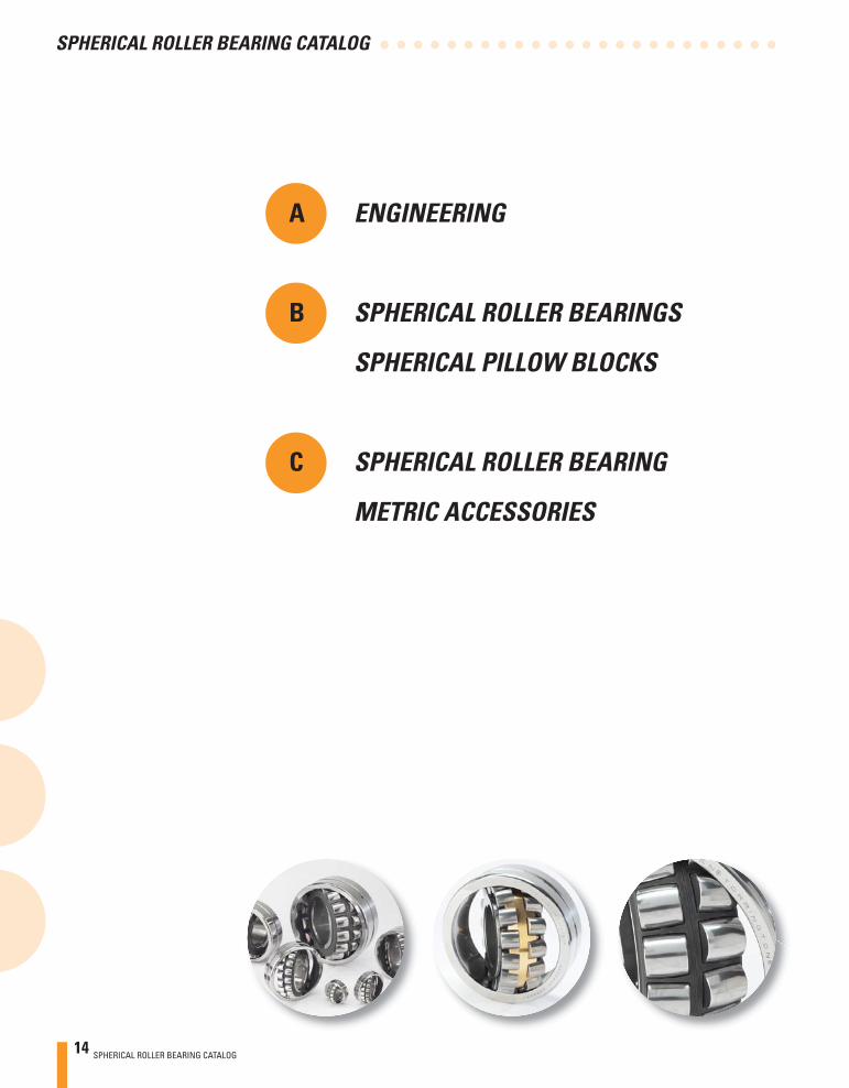
A ENGINEERING
B SPHERICAL ROLLER BEARINGS
SPHERICAL PILLOW BLOCKS
C SPHERICAL ROLLER BEARING
METRIC ACCESSORIES
SPHERICAL ROLLER BEARING CATALOG 15
A
ENGINEERING
AENGINEERIN
GA
A ENGINEERING
Introduction . . . . . . . . . . . . . . . . . . . . . . . . . . . . . . . . . . . . . . . . . . . 17
Roller Bearing Selection Process . . . . . . . . . . . . . . . . . . . . . . . . 17
Radial Spherical Roller Bearings . . . . . . . . . . . . . . . . . . . . . . . . 18
Cage Designs . . . . . . . . . . . . . . . . . . . . . . . . . . . . . . . . . . . . . . . . . . 19
Determination of Applied Loads and Bearing Reactions . 20-27
Load Ratings, Equivalent Loads and Bearing Life . . . . . . . 28-33
Tolerances . . . . . . . . . . . . . . . . . . . . . . . . . . . . . . . . . . . . . . . . . 34-49
Mounting Designs. . . . . . . . . . . . . . . . . . . . . . . . . . . . . . . . . . . 50-54
Fitting Practices . . . . . . . . . . . . . . . . . . . . . . . . . . . . . . . . . . . . 55-56
Lubrication and Seals . . . . . . . . . . . . . . . . . . . . . . . . . . . . . . . 57-67
Speed, Heat and Torque . . . . . . . . . . . . . . . . . . . . . . . . . . . . . . 68-71

16 SPHERICAL ROLLER BEARING CATALOG
AA
ENGINEERING
AEN
GINEERINGA
SPHERICAL ROLLER BEARING CATALOG 17
A
ENGINEERING
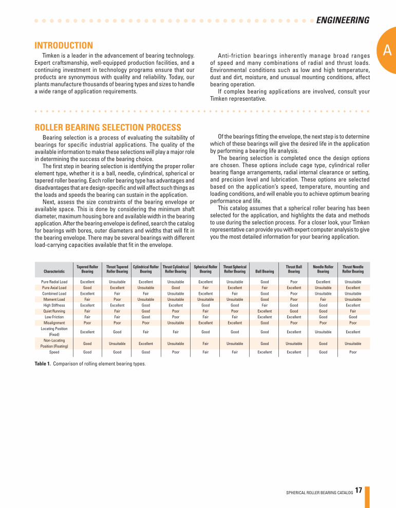
Tapered Roller Thrust Tapered Cylindrical Roller Thrust Cylindrical Spherical Roller Thrust Spherical Thrust Ball Needle Roller Thrust Needle Characteristic Bearing Roller Bearing Bearing Roller Bearing Bearing Roller Bearing Ball Bearing Bearing Bearing Roller Bearing Pure Radial Load Excellent Unsuitable Excellent Unsuitable Excellent Unsuitable Good Poor Excellent Unsuitable Pure Axial Load Good Excellent Unsuitable Good Fair Excellent Fair Excellent Unsuitable Excellent Combined Load Excellent Fair Fair Unsuitable Excellent Fair Good Poor Unsuitable Unsuitable Moment Load Fair Poor Unsuitable Unsuitable Unsuitable Unsuitable Good Poor Fair Unsuitable High Stiffness Excellent Excellent Good Excellent Good Good Fair Good Good Excellent Quiet Running Fair Fair Good Poor Fair Poor Excellent Good Good Fair Low Friction Fair Fair Good Poor Fair Fair Excellent Excellent Good Good Misalignment Poor Poor Poor Unsuitable Excellent Excellent Good Poor Poor Poor Locating Position
Excellent Good Fair Fair Good Good Good Excellent Unsuitable Excellent (Fixed) Non-Locating
Good Unsuitable Excellent Unsuitable Fair Unsuitable Good Unsuitable Good Unsuitable Position (Floating) Speed Good Good Good Poor Fair Fair Excellent Excellent Good Poor
Table 1. Comparison of rolling element bearing types.
INTRODUCTION Timken is a leader in the advancement of bearing technology.
Expert craftsmanship, well-equipped production facilities, and a continuing investment in technology programs ensure that our products are synonymous with quality and reliability. Today, our plants manufacture thousands of bearing types and sizes to handle a wide range of application requirements.
Anti-friction bearings inherently manage broad ranges of speed and many combinations of radial and thrust loads. Environmental conditions such as low and high temperature, dust and dirt, moisture, and unusual mounting conditions, affect bearing operation.
If complex bearing applications are involved, consult your Timken representative.
ROLLER BEARING SELECTION PROCESSBearing selection is a process of evaluating the suitability of
bearings for specifi c industrial applications. The quality of the available information to make these selections will play a major role in determining the success of the bearing choice.
The fi rst step in bearing selection is identifying the proper roller element type, whether it is a ball, needle, cylindrical, spherical or tapered roller bearing. Each roller bearing type has advantages and disadvantages that are design-specifi c and will affect such things as the loads and speeds the bearing can sustain in the application.
Next, assess the size constraints of the bearing envelope or available space. This is done by considering the minimum shaft diameter, maximum housing bore and available width in the bearing application. After the bearing envelope is defi ned, search the catalog for bearings with bores, outer diameters and widths that will fi t in the bearing envelope. There may be several bearings with different load-carrying capacities available that fi t in the envelope.
Of the bearings fi tting the envelope, the next step is to determine which of these bearings will give the desired life in the application by performing a bearing life analysis.
The bearing selection is completed once the design options are chosen. These options include cage type, cylindrical roller bearing fl ange arrangements, radial internal clearance or setting, and precision level and lubrication. These options are selected based on the application’s speed, temperature, mounting and loading conditions, and will enable you to achieve optimum bearing performance and life.
This catalog assumes that a spherical roller bearing has been selected for the application, and highlights the data and methods to use during the selection process. For a closer look, your Timken representative can provide you with expert computer analysis to give you the most detailed information for your bearing application.
18 SPHERICAL ROLLER BEARING CATALOG
AA
ENGINEERING
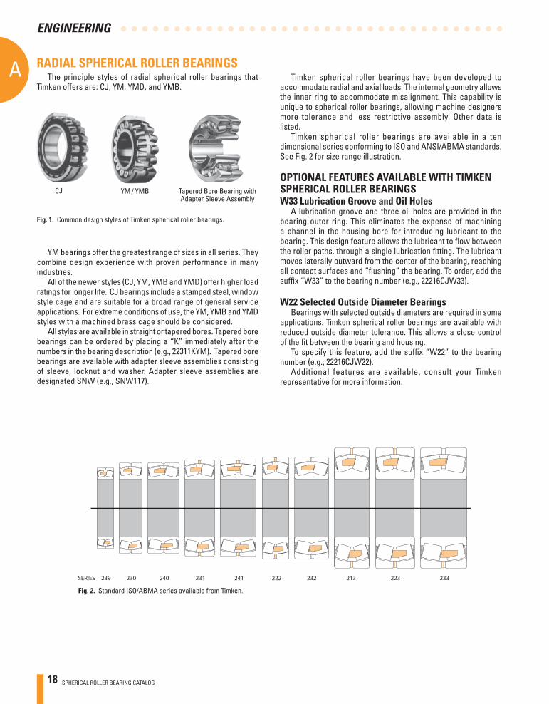
RADIAL SPHERICAL ROLLER BEARINGS The principle styles of radial spherical roller bearings that
Timken offers are: CJ, YM, YMD, and YMB.
Tapered Bore Bearing withAdapter Sleeve Assembly
YM / YMBCJ
YM bearings offer the greatest range of sizes in all series. They combine design experience with proven performance in many industries.
All of the newer styles (CJ, YM, YMB and YMD) offer higher load ratings for longer life. CJ bearings include a stamped steel, window style cage and are suitable for a broad range of general service applications. For extreme conditions of use, the YM, YMB and YMD styles with a machined brass cage should be considered.
All styles are available in straight or tapered bores. Tapered bore bearings can be ordered by placing a “K” immediately after the numbers in the bearing description (e.g., 22311KYM). Tapered bore bearings are available with adapter sleeve assemblies consisting of sleeve, locknut and washer. Adapter sleeve assemblies are designated SNW (e.g., SNW117).
Fig. 1. Common design styles of Timken spherical roller bearings.
Fig. 2. Standard ISO/ABMA series available from Timken.
Timken spherical roller bearings have been developed to accommodate radial and axial loads. The internal geometry allows the inner ring to accommodate misalignment. This capability is unique to spherical roller bearings, allowing machine designers more tolerance and less restrictive assembly. Other data is listed.
Timken spherical roller bearings are available in a ten dimensional series conforming to ISO and ANSI/ABMA standards. See Fig. 2 for size range illustration.
OPTIONAL FEATURES AVAILABLE WITH TIMKEN SPHERICAL ROLLER BEARINGSW33 Lubrication Groove and Oil Holes
A lubrication groove and three oil holes are provided in the bearing outer ring. This eliminates the expense of machining a channel in the housing bore for introducing lubricant to the bearing. This design feature allows the lubricant to fl ow between the roller paths, through a single lubrication fi tting. The lubricant moves laterally outward from the center of the bearing, reaching all contact surfaces and “fl ushing” the bearing. To order, add the suffi x “W33” to the bearing number (e.g., 22216CJW33).
W22 Selected Outside Diameter BearingsBearings with selected outside diameters are required in some
applications. Timken spherical roller bearings are available with reduced outside diameter tolerance. This allows a close control of the fi t between the bearing and housing.
To specify this feature, add the suffi x “W22” to the bearing number (e.g., 22216CJW22).
Additional features are available, consult your Timken representative for more information.
SPHERICAL ROLLER BEARING CATALOG 19
A
ENGINEERING
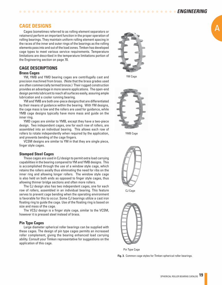
CAGE DESIGNSCages (sometimes referred to as rolling element separators or
retainers) perform an important function in the proper operation of rolling bearings. They maintain uniform rolling element spacing in the races of the inner and outer rings of the bearings as the rolling elements pass into and out of the load zones. Timken has developed cage types to meet various service requirements. Temperature limitations are described in the temperature limitations portion of the Engineering section on page 70.
CAGE DESCRIPTIONS Brass Cages
YM, YMB and YMD bearing cages are centrifugally cast and precision machined from brass. (Note that the brass grades used are often commercially termed bronze.) Their rugged construction provides an advantage in more severe applications. The open-end design permits lubricant to reach all surfaces easily, assuring ample lubrication and a cooler running bearing.
YM and YMB are both one-piece designs that are differentiated by their means of guidance within the bearing. With YM designs, the cage mass is low and the rollers are used for guidance, while YMB cage designs typically have more mass and guide on the inner ring.
YMD cages are similar to YMB, except they have a two-piece design. Two independent cages, one for each row of rollers, are assembled into an individual bearing. This allows each row of rollers to rotate independently when required by the application, and prevents bending of the cage fi ngers.
VCSM designs are similar to YM in that they are single piece, fi nger style cages.
Stamped Steel CagesThese cages are used in CJ design to permit extra load carrying
capabilities in the bearing compared to YM and YMB designs. This is accomplished through the use of a window style cage, which retains the rollers axially thus eliminating the need for ribs on the inner ring and allowing longer rollers. The window style cage is also held on both ends as opposed to fi nger style cages, thus allowing thinner bridge sections and often more rollers.
The CJ design also has two independent cages, one for each row of rollers, assembled in an individual bearing. This feature serves to prevent cage bending when the operating environment is favorable for this to occur. Some CJ bearings utilize a cast iron fl oating ring to guide the cage. Use of the fl oating ring is based on size and mass of the cage.
The VCSJ design is a fi nger style cage, similar to the VCSM, however it is pressed steel instead of brass.
Pin Type CagesLarge diameter spherical roller bearings can be supplied with
these cages. The design of pin type cages permits an increased roller complement, giving the bearing enhanced load carrying ability. Consult your Timken representative for suggestions on the application of this cage.
YMB Cage
Fig. 3. Common cage styles for Timken spherical roller bearings.
YM Cage
CJ Cage
Pin Type Cage
20 SPHERICAL ROLLER BEARING CATALOG
AA
ENGINEERING
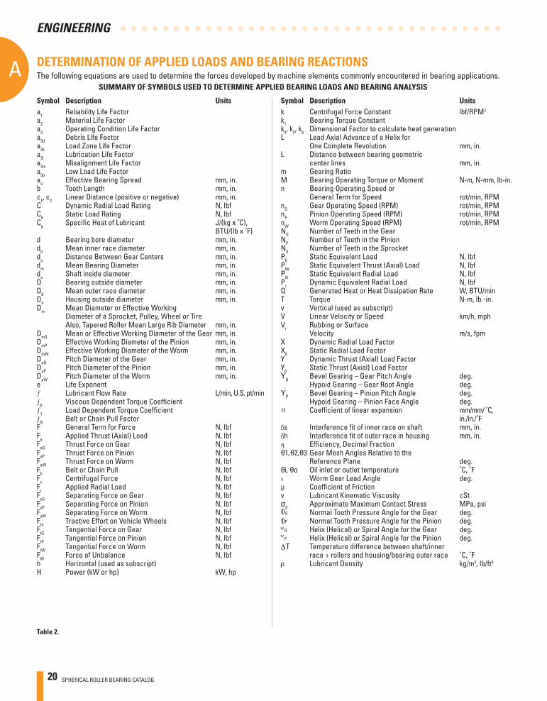
DETERMINATION OF APPLIED LOADS AND BEARING REACTIONS The following equations are used to determine the forces developed by machine elements commonly encountered in bearing applications.
Table 2.
SUMMARY OF SYMBOLS USED TO DETERMINE APPLIED BEARING LOADS AND BEARING ANALYSIS
Symbol Description Unitsa1 Reliability Life Factor a2 Material Life Factor a3 Operating Condition Life Factor a3d Debris Life Factora3k Load Zone Life Factor a3l Lubrication Life Factor a3m Misalignment Life Factor a3p Low Load Life Factor ae Effective Bearing Spread mm, in.b Tooth Length mm, in.c1, c2 Linear Distance (positive or negative) mm, in.C Dynamic Radial Load Rating N, lbfC0 Static Load Rating N, lbfCp Specifi c Heat of Lubricant J/(kg x ˚C), BTU/(lb x ˚F)d Bearing bore diameter mm, in.d0 Mean inner race diameter mm, in.dc Distance Between Gear Centers mm, in.dm Mean Bearing Diameter mm, in.ds Shaft inside diameter mm, in.D Bearing outside diameter mm, in.D0 Mean outer race diameter mm, in.Dh Housing outside diameter mm, in.Dm Mean Diameter or Effective Working Diameter of a Sprocket, Pulley, Wheel or Tire Also, Tapered Roller Mean Large Rib Diameter mm, in.DmG Mean or Effective Working Diameter of the Gear mm, in.DmP Effective Working Diameter of the Pinion mm, in.DmW Effective Working Diameter of the Worm mm, in.DpG Pitch Diameter of the Gear mm, in.DpP Pitch Diameter of the Pinion mm, in.DpW Pitch Diameter of the Worm mm, in.e Life Exponent
Lubricant Flow Rate L/min, U.S. pt/min0 Viscous Dependent Torque Coeffi cient 1 Load Dependent Torque Coeffi cient B Belt or Chain Pull Factor
F General Term for Force N, lbfFa Applied Thrust (Axial) Load N, lbfFaG Thrust Force on Gear N, lbfFaP Thrust Force on Pinion N, lbfFaW Thrust Force on Worm N, lbfFb Belt or Chain Pull N, lbfFc Centrifugal Force N, lbfFr Applied Radial Load N, lbfFsG Separating Force on Gear N, lbfFsP Separating Force on Pinion N, lbfFsW Separating Force on Worm N, lbfFte Tractive Effort on Vehicle Wheels N, lbfFtG Tangential Force on Gear N, lbfFtP Tangential Force on Pinion N, lbfFtW Tangential Force on Worm N, lbfFW Force of Unbalance N, lbfh Horizontal (used as subscript) H Power (kW or hp) kW, hp
Symbol Description Unitsk Centrifugal Force Constant lbf/RPM2
k1 Bearing Torque Constant k4, k5, k6 Dimensional Factor to calculate heat generation L Lead Axial Advance of a Helix for One Complete Revolution mm, in.L Distance between bearing geometric center lines mm, in.m Gearing Ratio M Bearing Operating Torque or Moment N-m, N-mm, lb-in.n Bearing Operating Speed or General Term for Speed rot/min, RPMnG Gear Operating Speed (RPM) rot/min, RPMnP Pinion Operating Speed (RPM) rot/min, RPMnW Worm Operating Speed (RPM) rot/min, RPMNG Number of Teeth in the Gear NP Number of Teeth in the Pinion NS Number of Teeth in the Sprocket P0 Static Equivalent Load N, lbfP0a Static Equivalent Thrust (Axial) Load N, lbfP0r Static Equivalent Radial Load N, lbfPr Dynamic Equivalent Radial Load N, lbfQ Generated Heat or Heat Dissipation Rate W, BTU/minT Torque N-m, lb.-in.v Vertical (used as subscript) V Linear Velocity or Speed km/h, mphVr Rubbing or Surface Velocity m/s, fpmX Dynamic Radial Load Factor X0 Static Radial Load Factor Y Dynamic Thrust (Axial) Load Factor Y0 Static Thrust (Axial) Load Factor ΥG Bevel Gearing – Gear Pitch Angle deg. Hypoid Gearing – Gear Root Angle deg.ΥP Bevel Gearing – Pinion Pitch Angle deg. Hypoid Gearing – Pinion Face Angle deg. Coeffi cient of linear expansion mm/mm/ ˚C, in./in./˚Fs Interference fi t of inner race on shaft mm, in.h Interference fi t of outer race in housing mm, in.η Effi ciency, Decimal Fraction θ1, θ2, θ3 Gear Mesh Angles Relative to the Reference Plane deg.θi, θo Oil inlet or outlet temperature ˚C, ˚Fλ Worm Gear Lead Angle deg.μ Coeffi cient of Friction v Lubricant Kinematic Viscosity cStσ0 Approximate Maximum Contact Stress MPa, psi G Normal Tooth Pressure Angle for the Gear deg. P Normal Tooth Pressure Angle for the Pinion deg.
G Helix (Helical) or Spiral Angle for the Gear deg. P Helix (Helical) or Spiral Angle for the Pinion deg.
T Temperature difference between shaft/inner race + rollers and housing/bearing outer race ˚C, ˚F Lubricant Density kg/m3, lb/ft3
SPHERICAL ROLLER BEARING CATALOG 21
A
ENGINEERING
FsP
FtP
FsG
FtG
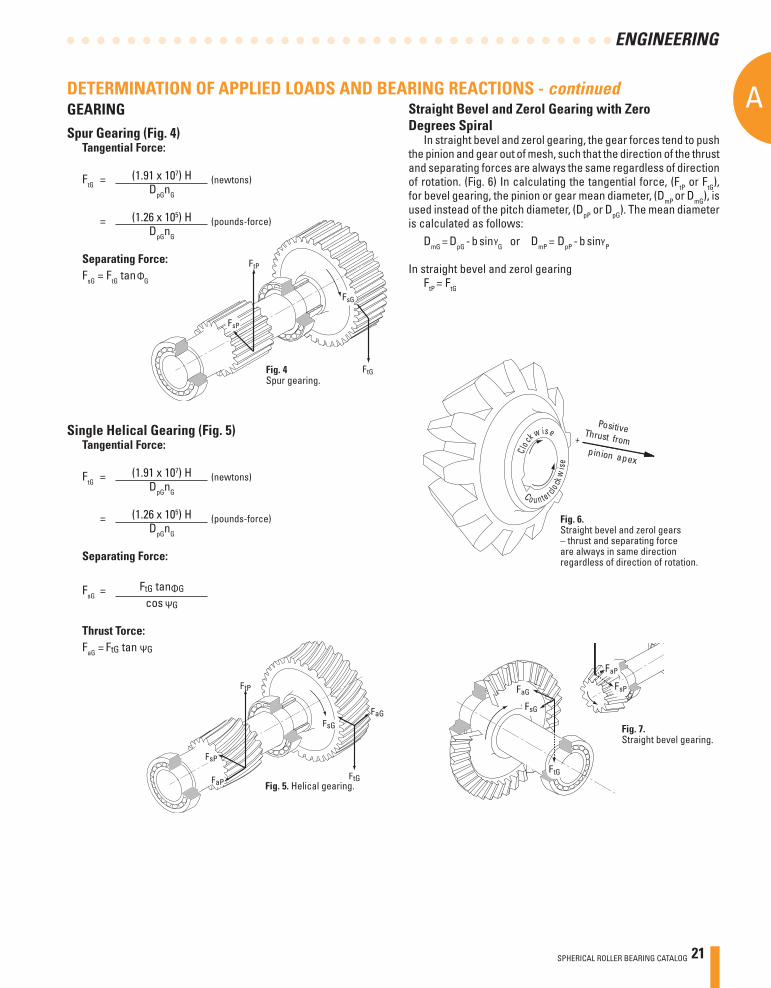
Spur Gearing (Fig. 4)Tangential Force:
FtG = (1.91 x 10⁷) H (newtons) DpGnG
= (1.26 x 10⁵) H (pounds-force) DpGnG
Separating Force:FsG = FtG tan G
Single Helical Gearing (Fig. 5)Tangential Force:
FtG = (1.91 x 10⁷) H (newtons) DpGnG
= (1.26 x 10⁵) H (pounds-force) DpGnG
Separating Force:
FsG =
Thrust Torce:FaG =
FaP
FsP
FtP
FsG
FaG
FtG
Fig. 4Spur gearing.
Fig. 5. Helical gearing.
Straight Bevel and Zerol Gearing with Zero Degrees Spiral
In straight bevel and zerol gearing, the gear forces tend to push the pinion and gear out of mesh, such that the direction of the thrust and separating forces are always the same regardless of direction of rotation. (Fig. 6) In calculating the tangential force, (FtP or FtG), for bevel gearing, the pinion or gear mean diameter, (DmP
or DmG), is used instead of the pitch diameter, (DpP or DpG). The mean diameter is calculated as follows:
DmG = DpG - b sin G or DmP = DpP - b sin P
In straight bevel and zerol gearingFtP = FtG
DETERMINATION OF APPLIED LOADS AND BEARING REACTIONS - continuedGEARING
C lo ck
w ise
Co u n terclo ck
wis
e
+Thrust frompinion apex
Positive
Fig. 6.Straight bevel and zerol gears – thrust and separating force are always in same direction regardless of direction of rotation.
FaP
FsG
FaG
FtG
FsP
Fig. 7.Straight bevel gearing.
22 SPHERICAL ROLLER BEARING CATALOG
AA
ENGINEERING
( )
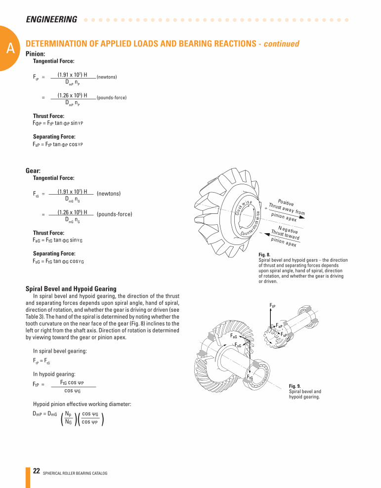
Gear:Tangential Force:
FtG = (1.91 x 10⁷) H (newtons) DmG nG
= (1.26 x 10⁵) H (pounds-force) DmG nG
Thrust Force:
Separating Force:
Spiral Bevel and Hypoid Gearing In spiral bevel and hypoid gearing, the direction of the thrust
and separating forces depends upon spiral angle, hand of spiral, direction of rotation, and whether the gear is driving or driven (see Table 3). The hand of the spiral is determined by noting whether the tooth curvature on the near face of the gear (Fig. 8) inclines to the left or right from the shaft axis. Direction of rotation is determined by viewing toward the gear or pinion apex.
In spiral bevel gearing:
FtP = FtG
In hypoid gearing:
Hypoid pinion effective working diameter:
( )
+
_Co u n tercl o
ckw
iseC lo c
k w ise PositiveThrust away frompinion apex
N egativeThrust towardpinion apex
Fig. 8.Spiral bevel and hypoid gears – the direction of thrust and separating forces depends upon spiral angle, hand of spiral, direction of rotation, and whether the gear is driving or driven.
FaG
FsG
FtP
FsP
FtG
FaP
Fig. 9.Spiral bevel and hypoid gearing.
DETERMINATION OF APPLIED LOADS AND BEARING REACTIONS - continuedPinion:
Tangential Force:
FtP = (1.91 x 10⁷) H (newtons) DmP nP
= (1.26 x 10⁵) H (pounds-force) DmP nP
Thrust Force:
Separating Force:
SPHERICAL ROLLER BEARING CATALOG 23
A
ENGINEERING
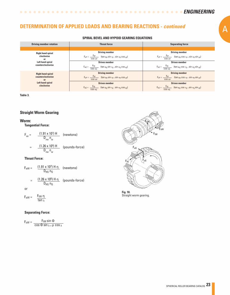
Table 3.
Driving member rotation Thrust force Separating force
Right hand spiral clockwise or Left hand spiral counterclockwise
Right hand spiral counterclockwise or Left hand spiral clockwise
Driving member
Driven member
Driving member
Driven member
Driving member
Driven member
Driving member
Driven member
SPIRAL BEVEL AND HYPOID GEARING EQUATIONS
Straight Worm Gearing
Worm:Tangential Force:
FtW = (1.91 x 10⁷) H (newtons) DpW
nW
= (1.26 x 10⁵) H (pounds-force) DpW
nW
Thrust Force:
or
Separating Force:
FsW
FtW
FaW
FaG
FsGFtG
Fig. 10.Straight worm gearing.
DETERMINATION OF APPLIED LOADS AND BEARING REACTIONS - continued
24 SPHERICAL ROLLER BEARING CATALOG
AA
ENGINEERING
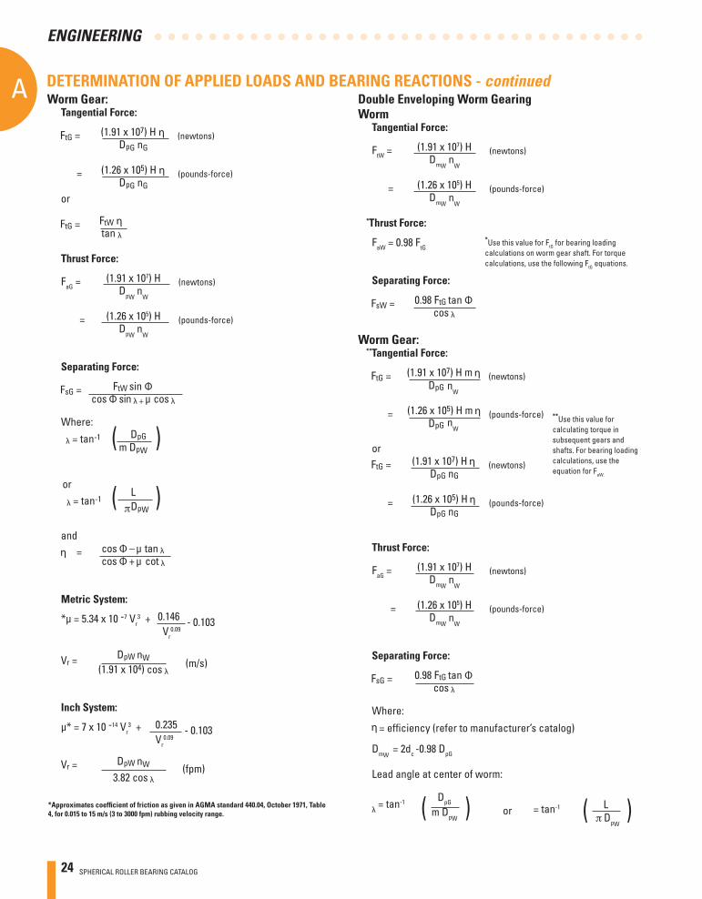
Worm Gear:Tangential Force:
or
Thrust Force:
FaG = (1.91 x 10⁷) H (newtons) DpW
nW
= (1.26 x 10⁵) H (pounds-force) DpW
nW
Separating Force:
Where:
Metric System:
*μ = 5.34 x 10 -7 Vr3 + 0.146 - 0.103
Vr0.09
Inch System:
μ* = 7 x 10 -14 Vr3 + 0.235 - 0.103
Vr0.09
( )
*Approximates coeffi cient of friction as given in AGMA standard 440.04, October 1971, Table 4, for 0.015 to 15 m/s (3 to 3000 fpm) rubbing velocity range.
or
( )
and
Double Enveloping Worm Gearing Worm
Tangential Force:
FtW = (1.91 x 10⁷) H (newtons) DmW
nW
= (1.26 x 10⁵) H (pounds-force) DmW
nW
*Thrust Force:
FaW = 0.98 FtG
Separating Force:
Worm Gear:**Tangential Force:
or
Thrust Force:
FaG = (1.91 x 10⁷) H (newtons) DmW
nW
= (1.26 x 10⁵) H (pounds-force) DmW
nW
Separating Force:
Where:
= effi ciency (refer to manufacturer’s catalog)
DmW = 2dc -0.98 DpG
Lead angle at center of worm:
= tan-1 DpG m DpW
*Use this value for FtG for bearing loading calculations on worm gear shaft. For torque calculations, use the following FtG equations.
( )
**Use this value for calculating torque in subsequent gears and shafts. For bearing loading calculations, use the equation for FaW.
( ) DpW
= tan-1 Lor
DETERMINATION OF APPLIED LOADS AND BEARING REACTIONS - continued
(m/s)
(fpm)
nW
nW
SPHERICAL ROLLER BEARING CATALOG 25
A
ENGINEERING
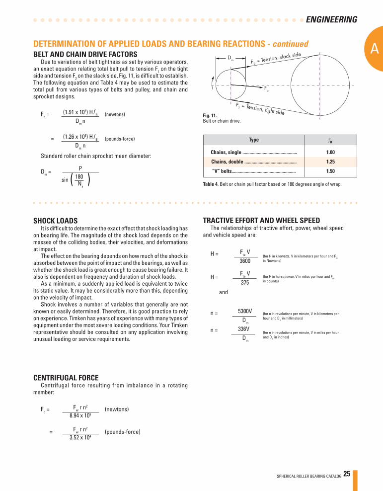
Type B
Chains, single .............................................. 1.00
Chains, double ............................................ 1.25
“V” belts...................................................... 1.50
Table 4. Belt or chain pull factor based on 180 degrees angle of wrap.
F2 = Tension, slack side
Fb
F1 = Tension, tight side
Dm
Standard roller chain sprocket mean diameter:
Dm = P sin 180 Ns
( )
SHOCK LOADSIt is diffi cult to determine the exact effect that shock loading has
on bearing life. The magnitude of the shock load depends on the masses of the colliding bodies, their velocities, and deformations at impact.
The effect on the bearing depends on how much of the shock is absorbed between the point of impact and the bearings, as well as whether the shock load is great enough to cause bearing failure. It also is dependent on frequency and duration of shock loads.
As a minimum, a suddenly applied load is equivalent to twice its static value. It may be considerably more than this, depending on the velocity of impact.
Shock involves a number of variables that generally are not known or easily determined. Therefore, it is good practice to rely on experience. Timken has years of experience with many types of equipment under the most severe loading conditions. Your Timken representative should be consulted on any application involving unusual loading or service requirements.
CENTRIFUGAL FORCE Centrifugal force resulting from imbalance in a rotating
member:
Fc = Fw r n2 (newtons)
8.94 x 105
= Fw r n2 (pounds-force) 3.52 x 10⁴
TRACTIVE EFFORT AND WHEEL SPEEDThe relationships of tractive effort, power, wheel speed
and vehicle speed are:
BELT AND CHAIN DRIVE FACTORSDue to variations of belt tightness as set by various operators,
an exact equation relating total belt pull to tension F1 on the tight side and tension F2 on the slack side, Fig. 11, is diffi cult to establish. The following equation and Table 4 may be used to estimate the total pull from various types of belts and pulley, and chain and sprocket designs.
Fb = (1.91 x 10⁷) H B (newtons)
Dm n
= (1.26 x 10⁵) H B (pounds-force) Dm n
Fig. 9-8Fig. 11.Belt or chain drive.
Fte V H =3600
Fte V 375
and
5300Vn =Dm
336V Dm
(for n in revolutions per minute, V in kilometers per hour and Dm in millimeters)
(for H in kilowatts, V in kilometers per hour and Fte in Newtons)
DETERMINATION OF APPLIED LOADS AND BEARING REACTIONS - continued
H =
n =
(for H in horsepower, V in miles per hour and Fte in pounds)
(for n in revolutions per minute, V in miles per hour and Dm in inches)
26 SPHERICAL ROLLER BEARING CATALOG
AA
ENGINEERING
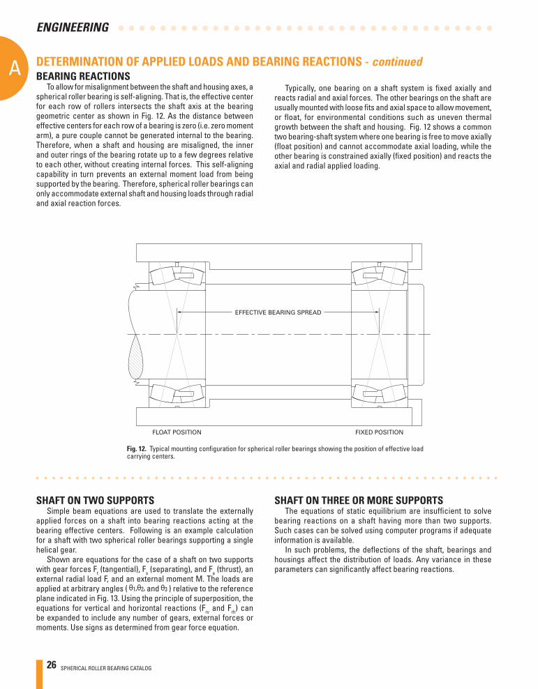
BEARING REACTIONSTo allow for misalignment between the shaft and housing axes, a
spherical roller bearing is self-aligning. That is, the effective center for each row of rollers intersects the shaft axis at the bearing geometric center as shown in Fig. 12. As the distance between effective centers for each row of a bearing is zero (i.e. zero moment arm), a pure couple cannot be generated internal to the bearing. Therefore, when a shaft and housing are misaligned, the inner and outer rings of the bearing rotate up to a few degrees relative to each other, without creating internal forces. This self-aligning capability in turn prevents an external moment load from being supported by the bearing. Therefore, spherical roller bearings can only accommodate external shaft and housing loads through radial and axial reaction forces.
SHAFT ON TWO SUPPORTSSimple beam equations are used to translate the externally
applied forces on a shaft into bearing reactions acting at the bearing effective centers. Following is an example calculation for a shaft with two spherical roller bearings supporting a single helical gear.
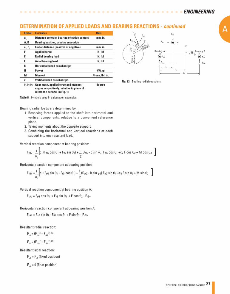
Shown are equations for the case of a shaft on two supports with gear forces Ft (tangential), Fs (separating), and Fa (thrust), an external radial load F, and an external moment M. The loads are applied at arbitrary angles ( and ) relative to the reference plane indicated in Fig. 13. Using the principle of superposition, the equations for vertical and horizontal reactions (Frv and Frh) can be expanded to include any number of gears, external forces or moments. Use signs as determined from gear force equation.
Typically, one bearing on a shaft system is fi xed axially and reacts radial and axial forces. The other bearings on the shaft are usually mounted with loose fi ts and axial space to allow movement, or fl oat, for environmental conditions such as uneven thermal growth between the shaft and housing. Fig. 12 shows a common two bearing-shaft system where one bearing is free to move axially (fl oat position) and cannot accommodate axial loading, while the other bearing is constrained axially (fi xed position) and reacts the axial and radial applied loading.
SHAFT ON THREE OR MORE SUPPORTSThe equations of static equilibrium are insuffi cient to solve
bearing reactions on a shaft having more than two supports. Such cases can be solved using computer programs if adequate information is available.
In such problems, the defl ections of the shaft, bearings and housings affect the distribution of loads. Any variance in these parameters can signifi cantly affect bearing reactions.
Fig. 12. Typical mounting confi guration for spherical roller bearings showing the position of effective load carrying centers.
DETERMINATION OF APPLIED LOADS AND BEARING REACTIONS - continued
EFFECTIVE BEARING SPREAD
FLOAT POSITION FIXED POSITION
SPHERICAL ROLLER BEARING CATALOG 27
A
ENGINEERING
Fig. 13. Bearing radial reactions.
Symbol Description Units
ae Distance between bearing effective centers mm, in.
A, B Bearing position, used as subscripts
c1, c2 Linear distance (positive or negative) mm, in.
F Applied force N, lbf
Fr Radial bearing load N, lbf
Fa Axial bearing load N, lbf
h Horizontal (used as subscript)
H Power kW,hp
M Moment N-mm, lbf. in.
v Vertical (used as subscript)
Gear mesh, applied force and moment degree angles respectively, relative to plane of reference defi ned in Fig. 13
Bearing radial loads are determined by:1. Resolving forces applied to the shaft into horizontal and
vertical components, relative to a convenient reference plane.
2. Taking moments about the opposite support.3. Combining the horizontal and vertical reactions at each
support into one resultant load.
Vertical reaction component at bearing position:
ae
2
Horizontal reaction component at bearing position:
ae
2
Vertical reaction component at bearing position A:
Horizontal reaction component at bearing position A:
Resultant radial reaction:
FrA = (FrAv2 + FrAh
2) 1/2
FrB = (FrBv2 + FrBh
2) 1/2
Resultant axial reaction:
FaA = FaG (fi xed position)
FaB = 0 (fl oat position)
[
[
[
[
DETERMINATION OF APPLIED LOADS AND BEARING REACTIONS - continued
Table 5. Symbols used in calculation examples.
FtG
FrAh
FrAv
c1
c2
ae
FrBh
FrBv
F
FsG
FaG
Bearing A Bearing BM
FaGFsG
F
Plane of
Plan
e of
θ1θ3
θ2
FtG
moment
refe
renc
e
28 SPHERICAL ROLLER BEARING CATALOG
AA
ENGINEERING
LOAD RATINGS, EQUIVALENT LOADS AND BEARING LIFEThe basic dynamic load rating and the static load rating are
commonly used for bearing selection. The basic dynamic load rating is used to estimate the life of a rotating bearing. Static load ratings are used to determine the maximum permissible load that can be applied to a non-rotating bearing.
The basic philosophy of Timken is to provide the most realistic bearing rating to assist our customers in the bearing selection process. Published ratings for Timken bearings include the basic dynamic radial load rating C1. This value is based on a basic rating life of one million revolutions. The basic static radial load rating is C0.
STATIC EQUIVALENT LOADSThe static equivalent load rating is based on an assumed
nominal clearance in both rows of rollers within the bearing, which equates to a load zone of approximately 130º. The static equivalent load is the radial load that will result in the same maximum contact stress as the applied bearing load. The load factors X0 and Y0 are used with the following equation to estimate the static radial equivalent load. The values of X0 (always equal to 1 for SRBs) and Y0 are listed in the bearing tables.
STATIC LOAD RATINGThe basic static radial load rating and thrust load rating for
Timken bearings are based on a maximum contact stress within a non-rotating bearing of 4000 Mpa (580 ksi) at the center of contact on the most heavily loaded roller.
The 4000 Mpa (580 ksi) stress levels may cause visible light Brinell marks on the bearing raceways. This degree of marking will not have a measurable effect on fatigue life when the bearing is subsequently rotating under a lower application load. If sound, vibration or torque is critical, or if a pronounced shock load is present, a lower load limit should be applied. For more information on selecting a bearing for static load conditions, consult your Timken representative.
P0r = X0 Fr + Y0 Fa
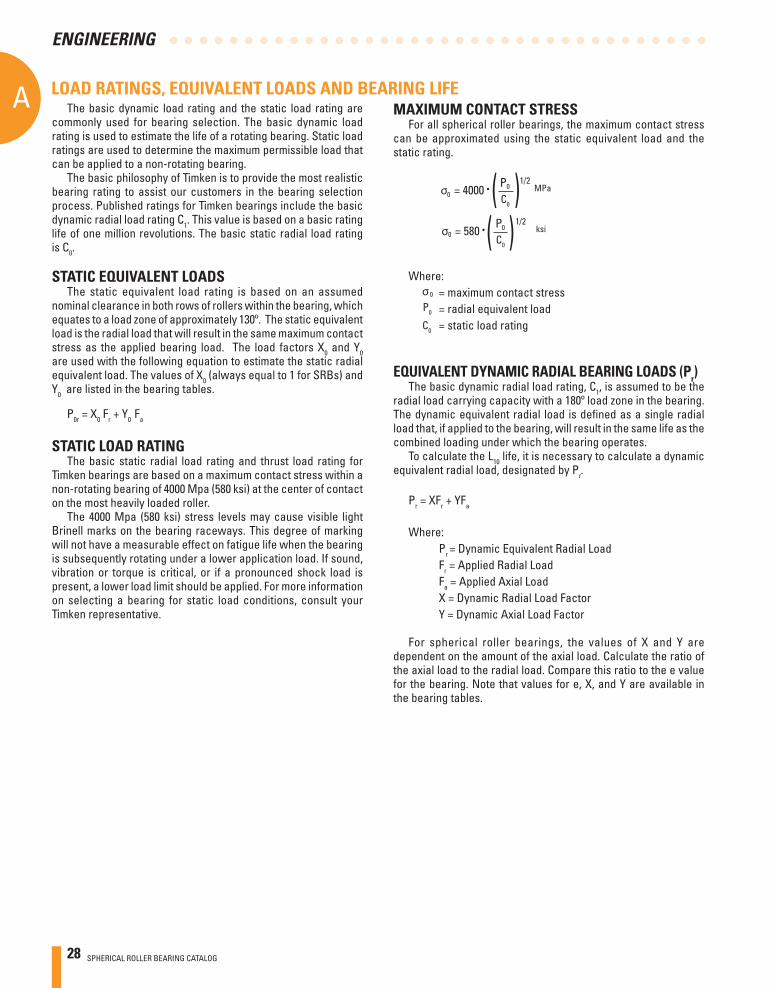
MAXIMUM CONTACT STRESSFor all spherical roller bearings, the maximum contact stress
can be approximated using the static equivalent load and the static rating.
( )( )
Where: = maximum contact stress = radial equivalent load = static load rating
P0
C0
EQUIVALENT DYNAMIC RADIAL BEARING LOADS (Pr)The basic dynamic radial load rating, C1, is assumed to be the
radial load carrying capacity with a 180º load zone in the bearing. The dynamic equivalent radial load is defi ned as a single radial load that, if applied to the bearing, will result in the same life as the combined loading under which the bearing operates.
To calculate the L10 life, it is necessary to calculate a dynamic equivalent radial load, designated by Pr.
Pr = XFr + YFa
Where: Pr = Dynamic Equivalent Radial Load Fr = Applied Radial Load Fa = Applied Axial Load X = Dynamic Radial Load Factor Y = Dynamic Axial Load Factor
For spherical roller bearings, the values of X and Y are dependent on the amount of the axial load. Calculate the ratio of the axial load to the radial load. Compare this ratio to the e value for the bearing. Note that values for e, X, and Y are available in the bearing tables.
0
0
0
0C0
C0
0
SPHERICAL ROLLER BEARING CATALOG 29
A
ENGINEERING
MINIMUM BEARING LOAD Slippage can occur if loads are too light and can cause damage
to the bearings. The minimum load for radial spherical roller bearings is Pr/C1 = 0.04 (Pr is the dynamic equivalent radial load and C1 the basic dynamic load rating).
BEARING LIFE Many different performance criteria exist that dictate how a
bearing should be selected. These include bearing fatigue life, rotational precision, power requirements, temperature limits, speed capabilities, sound, etc. This section deals primarily with bearing life as related to material-associated fatigue. Bearing life is defi ned as the length of time, or number of revolutions, until a fatigue spall of 6 mm2 (0.01 in.2) develops. Since metal fatigue is a statistical phenomenon, the life of an individual bearing is impossible to precisely predetermine. Bearings that may appear to be identical can exhibit considerable life scatter when tested under identical conditions. Thus it is necessary to base life predictions on a statistical evaluation of a large number of bearings operating under similar conditions. The Weibull distribution function is commonly used to predict life of a population of bearings
RATING LIFE Rating life (L10) is the life that 90 percent of a group of apparently
identical bearings will complete or exceed before a fatigue spall develops. The L10 life also is associated with 90 percent reliability for a single bearing under a certain load.
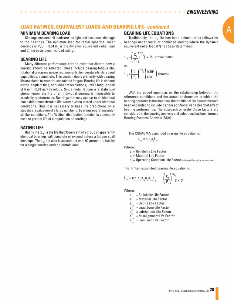
BEARING LIFE EQUATIONS Traditionally, the L10 life has been calculated as follows for
bearings under radial or combined loading where the dynamic equivalent radial load (Pr) has been determined:
= C1
(1x10⁶) (revolutions) Pr
or,
= C
1x10⁶ (hours)
Pr 60n
( )
( ) ( )
10/3
10/3
With increased emphasis on the relationship between the reference conditions and the actual environment in which the bearing operates in the machine, the traditional life equations have been expanded to include certain additional variables that affect bearing performance. The approach whereby these factors are considered in the bearing analysis and selection, has been termed Bearing Systems Analysis (BSA).
The ISO/ABMA expanded bearing life equation is: L10a = a
1a
2a
3L10
Where:a
1 = Reliability Life Factora
2 = Material Life Factora
3 = Operating Condition Life Factor (to be specifi ed by the manufacturer)
The Timken expanded bearing life equation is:
L10a = a1a
2a
3da
3ka
3la
3ma
3p
Where:a
1 = Reliability Life Factora
2 = Material Life Factora
3d = Debris Life Factora
3k = Load Zone Life Factora
3l = Lubrication Life Factor
a3m = Misalignment Life Factor
a3p = Low Load Life Factor
C1
Pr(1x10⁶)( )
10/3
LOAD RATINGS, EQUIVALENT LOADS AND BEARING LIFE- continued
1
30 SPHERICAL ROLLER BEARING CATALOG
AA
ENGINEERING
R (percent) Ln a1
90 L10 1.00 95 L5 0.64 96 L4 0.55 97 L3 0.47 98 L2 0.37 99 L1 0.25 99.5 L0.5 0.175 99.9 L0.1 0.093
RELIABILITY LIFE FACTOR (A1)The equation for the life adjustment factor for reliability is:
a1 = 4.26 ln 100
2/3
+ 0.05 R
ln = natural logarithm (base e)
To adjust the calculated L10 life for reliability, multiply by the a1 factor. If 90 (90 percent reliability) is substituted for R in the above equation, a1 = 1. For R = 99 (99 percent reliability), a1 = 0.25. Table 6 lists the reliability factor for commonly used reliability values.
( )
Table 6. Reliability life factor.
Note that the equation for reliability adjustment assumes there is a short minimum life below which the probability of bearing damage is minimal (e.g., zero probability of bearing damage producing a short life). Extensive bearing fatigue life testing has shown the minimum life, below which the probability of bearing damage is negligible, can be larger than shown above. For a more accurate prediction of bearing lives at high levels of reliability, consult your Timken representative.
MATERIAL LIFE FACTOR (a2) The life adjustment factor for bearing material (a2) for standard
Timken bearings manufactured from bearing quality steel is 1.0. Bearings also are manufactured from premium steels, containing fewer and smaller inclusion impurities than standard steels and providing the benefi t of extending bearing fatigue life (e.g., Duraspexx™). Application of the material life factor requires that fatigue life is limited by nonmetallic inclusions, contact stresses are approximately less than 2400 Mpa (350 ksi), and adequate lubrication is provided. It is important to note that improvements in material cannot offset poor lubrication in an operating bearing system. Consult your Timken representative for applicability of the material factor.
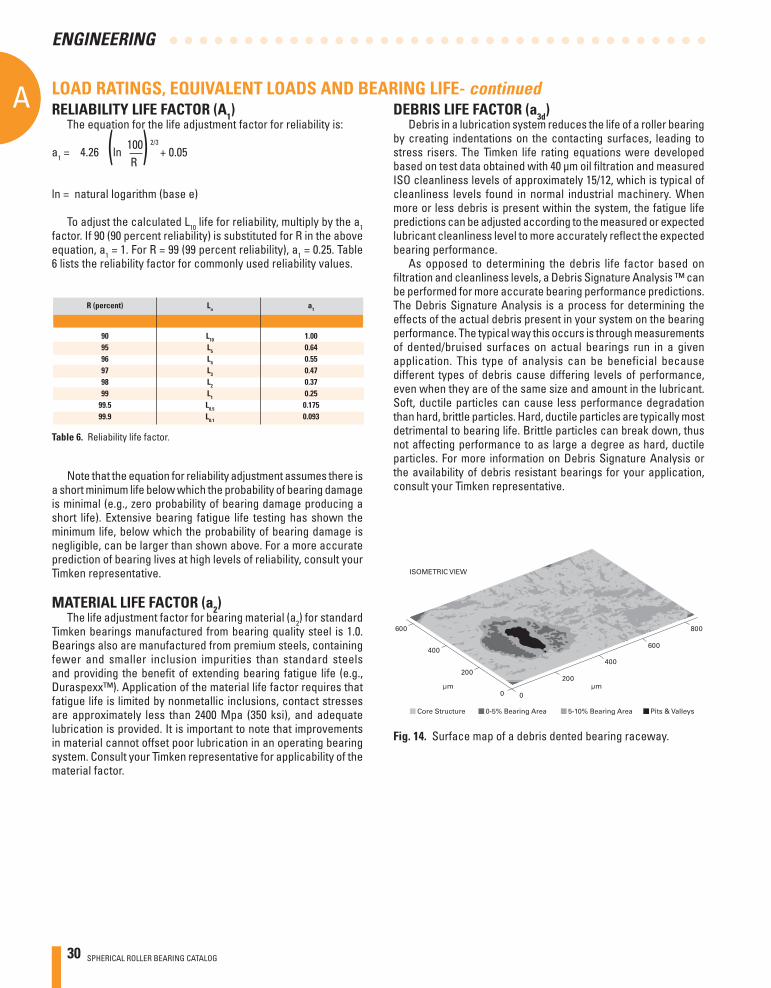
DEBRIS LIFE FACTOR (a3d)Debris in a lubrication system reduces the life of a roller bearing
by creating indentations on the contacting surfaces, leading to stress risers. The Timken life rating equations were developed based on test data obtained with 40 μm oil fi ltration and measured ISO cleanliness levels of approximately 15/12, which is typical of cleanliness levels found in normal industrial machinery. When more or less debris is present within the system, the fatigue life predictions can be adjusted according to the measured or expected lubricant cleanliness level to more accurately refl ect the expected bearing performance.
As opposed to determining the debris life factor based on fi ltration and cleanliness levels, a Debris Signature Analysis ™ can be performed for more accurate bearing performance predictions. The Debris Signature Analysis is a process for determining the effects of the actual debris present in your system on the bearing performance. The typical way this occurs is through measurements of dented/bruised surfaces on actual bearings run in a given application. This type of analysis can be beneficial because different types of debris cause differing levels of performance, even when they are of the same size and amount in the lubricant. Soft, ductile particles can cause less performance degradation than hard, brittle particles. Hard, ductile particles are typically most detrimental to bearing life. Brittle particles can break down, thus not affecting performance to as large a degree as hard, ductile particles. For more information on Debris Signature Analysis or the availability of debris resistant bearings for your application, consult your Timken representative.
Fig. 14. Surface map of a debris dented bearing raceway.
LOAD RATINGS, EQUIVALENT LOADS AND BEARING LIFE- continued
600
400
200
0 0
200
ISOMETRIC VIEW
400
600
μmμm
800
Core Structure 0-5% Bearing Area 5-10% Bearing Area Pits & Valleys
SPHERICAL ROLLER BEARING CATALOG 31
A
ENGINEERING
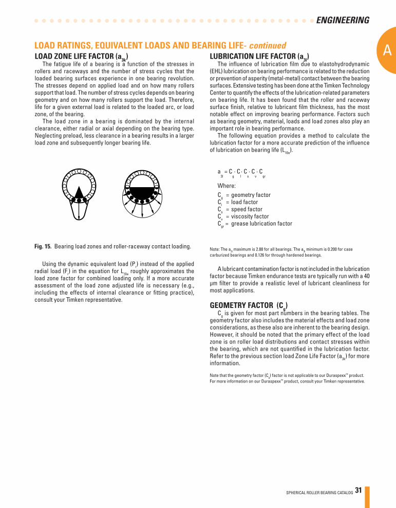
LOAD ZONE LIFE FACTOR (a3k)The fatigue life of a bearing is a function of the stresses in
rollers and raceways and the number of stress cycles that the loaded bearing surfaces experience in one bearing revolution. The stresses depend on applied load and on how many rollers support that load. The number of stress cycles depends on bearing geometry and on how many rollers support the load. Therefore, life for a given external load is related to the loaded arc, or load zone, of the bearing.
The load zone in a bearing is dominated by the internal clearance, either radial or axial depending on the bearing type. Neglecting preload, less clearance in a bearing results in a larger load zone and subsequently longer bearing life.
Fig. 15. Bearing load zones and roller-raceway contact loading.
Using the dynamic equivalent load (Pr) instead of the applied radial load (Fr) in the equation for L10a roughly approximates the load zone factor for combined loading only. If a more accurate assessment of the load zone adjusted life is necessary (e.g., including the effects of internal clearance or fi tting practice), consult your Timken representative.
LUBRICATION LIFE FACTOR (a3l)The infl uence of lubrication fi lm due to elastohydrodynamic
(EHL) lubrication on bearing performance is related to the reduction or prevention of asperity (metal-metal) contact between the bearing surfaces. Extensive testing has been done at the Timken Technology Center to quantify the effects of the lubrication-related parameters on bearing life. It has been found that the roller and raceway surface fi nish, relative to lubricant fi lm thickness, has the most notable effect on improving bearing performance. Factors such as bearing geometry, material, loads and load zones also play an important role in bearing performance.
The following equation provides a method to calculate the lubrication factor for a more accurate prediction of the infl uence of lubrication on bearing life (L10a).
a3l = C
g· C
l· C
s· C
v· C
gr
Where:Cg = geometry factorCl = load factorCs = speed factorCv = viscosity factorCgr = grease lubrication factor
Note: The a3l maximum is 2.88 for all bearings. The a3l minimum is 0.200 for casecarburized bearings and 0.126 for through hardened bearings.
A lubricant contamination factor is not included in the lubrication factor because Timken endurance tests are typically run with a 40 μm fi lter to provide a realistic level of lubricant cleanliness for most applications.
GEOMETRY FACTOR (Cg)Cg is given for most part numbers in the bearing tables. The
geometry factor also includes the material effects and load zone considerations, as these also are inherent to the bearing design. However, it should be noted that the primary effect of the load zone is on roller load distributions and contact stresses within the bearing, which are not quantifi ed in the lubrication factor. Refer to the previous section load Zone Life Factor (a3k) for more information.
Note that the geometry factor (Cg) factor is not applicable to our Duraspexx™ product. For more information on our Duraspexx™ product, consult your Timken representative.
LOAD RATINGS, EQUIVALENT LOADS AND BEARING LIFE- continued
32 SPHERICAL ROLLER BEARING CATALOG
AA
ENGINEERING
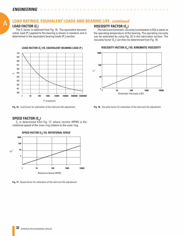
LOAD RATINGS, EQUIVALENT LOADS AND BEARING LIFE- continuedLOAD FACTOR (Cl)
The Cl factor is obtained from Fig. 16. The equivalent dynamic radial load (Pr) applied to the bearing is shown in newtons and is determined in the equivalent bearing loads (Pr) section.
1.0
0.9
0.8
0.7
0.6
0.5
0.4
0.3
0.2
0.1
0.0
1 10 100 1000 10000 100000 1000000 10000000
C l
LOAD FACTOR (Cl) VS. EQUIVALENT BEARING LOAD (Pr)
Fig. 16. Load factor for estimation of the lubricant-life adjustment.
SPEED FACTOR (CS)Cs is determined from Fig. 17, where rev/min (RPM) is the
rotational speed of the inner ring relative to the outer ring.
1000
100
10
1
1 10 100 1000 10000
C s
SPEED FACTOR (CS) VS. ROTATIONAL SPEED
Fig. 17. Speed factor for estimation of the lubricant-life adjustment.
VISCOSITY FACTOR (CV)The lubricant kinematic viscosity [centistokes (cSt)] is taken at
the operating temperature of the bearing. The operating viscosity can be estimated by using Fig. 22 in the lubrication section. The viscosity factor (Cv) can then be determined from Fig. 18.
1 1 10 100 1000 10000Kinematic Viscosity (cSt)
C v
10
100
1000
Fig. 18. Viscosity factor for estimation of the lubricant-life adjustment.
VISCOSITY FACTOR (CV) VS. KINEMATIC VISCOSITY
Pr (newtons)
Rotational Speed (RPM)
SPHERICAL ROLLER BEARING CATALOG 33
A
ENGINEERING
GREASE LUBRICATION FACTOR (Cgr)For grease lubrication, the EHL lubrication film becomes
depleted of oil over time and is reduced in thickness. Consequently, a reduction factor (Cgr) should be used to adjust for this effect.
Cgr= 0.79
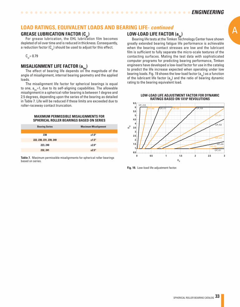
MISALIGNMENT LIFE FACTOR (a3m)The effect of bearing life depends on the magnitude of the
angle of misalignment, internal bearing geometry and the applied loads.
The misalignment life factor for spherical bearings is equal to one, a3m=1, due to its self-aligning capabilities. The allowable misalignment in a spherical roller bearing is between 1 degree and 2.5 degrees, depending upon the series of the bearing as detailed in Table 7. Life will be reduced if these limits are exceeded due to roller-raceway contact truncation.
Bearing Series Maximum Misalignment
238 ±1.0°
222, 230, 231, 239, 249 ±1.5°
223, 240 ±2.0°
232, 241 ±2.5°
MAXIMUM PERMISSIBLE MISALIGNMENTS FORSPHERICAL ROLLER BEARINGS BASED ON SERIES
Table 7. Maximum permissible misalignments for spherical roller bearings based on series.
LOAD RATINGS, EQUIVALENT LOADS AND BEARING LIFE- continuedLOW-LOAD LIFE FACTOR (a3p)
Bearing life tests at the Timken Technology Center have shown greatly extended bearing fatigue life performance is achievable when the bearing contact stresses are low and the lubricant fi lm is suffi cient to fully separate the micro-scale textures of the contacting surfaces. Mating the test data with sophisticated computer programs for predicting bearing performance, Timken engineers have developed a low-load factor for use in the catalog to predict the life increase expected when operating under low bearing loads. Fig. 19 shows the low-load factor (a3p) as a function of the lubricant life factor (a3l) and the ratio of bearing dynamic rating to the bearing equivalent load.
Fig. 19. Low-load life adjustment factor.
LOW-LOAD LIFE ADJUSTMENT FACTOR FOR DYNAMICRATINGS BASED ON 1X10⁶ REVOLUTIONS
34 SPHERICAL ROLLER BEARING CATALOG
AA
ENGINEERING
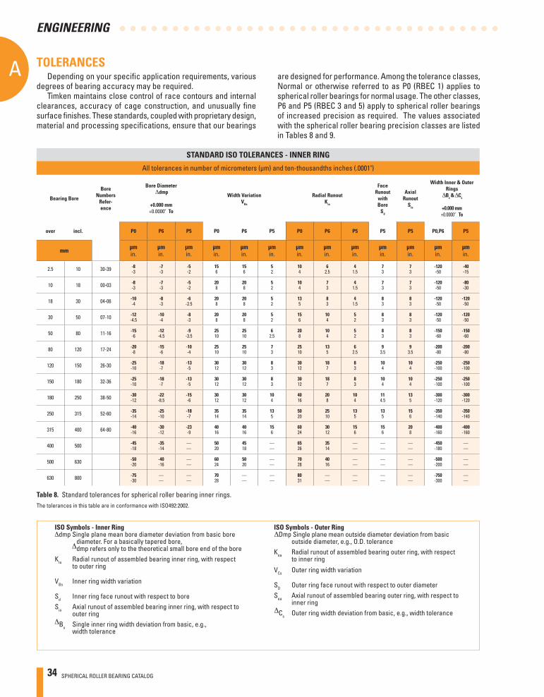
TOLERANCESDepending on your specifi c application requirements, various
degrees of bearing accuracy may be required.Timken maintains close control of race contours and internal
clearances, accuracy of cage construction, and unusually fi ne surface fi nishes. These standards, coupled with proprietary design, material and processing specifi cations, ensure that our bearings
The tolerances in this table are in conformance with ISO492:2002.
are designed for performance. Among the tolerance classes, Normal or otherwise referred to as P0 (RBEC 1) applies to spherical roller bearings for normal usage. The other classes, P6 and P5 (RBEC 3 and 5) apply to spherical roller bearings of increased precision as required. The values associated with the spherical roller bearing precision classes are listed in Tables 8 and 9.
Table 8. Standard tolerances for spherical roller bearing inner rings.
STANDARD ISO TOLERANCES - INNER RING
All tolerances in number of micrometers (μm) and ten-thousandths inches (.0001")
Bearing Bore
Bore Numbers
Refer-ence
Bore Diameter dmp
+0.000 mm+0.0000" To
Width VariationVBs
Radial RunoutKia
FaceRunout
with Bore
Sd
Axial Runout
Sia
Width Inner & Outer Rings
Bs & Cs
+0.000 mm+0.0000" To
over incl. P0 P6 P5 P0 P6 P5 P0 P6 P5 P5 P5 P0,P6 P5
mm μmin.
μmin.
μmin.
μmin.
μmin.
μmin.
μmin.
μmin.
μmin.
μmin.
μmin.
μmin.
μmin.
2.5 10 30-39 -8-3
-7-3
-5-2
156
156
52
104
62.5
41.5
73
73
-120-50
-40-15
10 18 00-03 -8-3
-7-3
-5-2
208
208
52
104
73
41.5
73
73
-120-50
-80-30
18 30 04-06 -10-4
-8-3
-6-2.5
208
208
52
135
83
41.5
83
83
-120-50
-120-50
30 50 07-10 -12-4.5
-10-4
-8-3
208
208
52
156
104
52
83
83
-120-50
-120-50
50 80 11-16 -15-6
-12-4.5
-9-3.5
2510
2510
62.5
208
104
52
83
83
-150-60
-150-60
80 120 17-24 -20-8
-15-6
-10-4
2510
2510
73
2510
135
62.5
93.5
93.5
-200-80
-200-80
120 150 26-30 -25-10
-18-7
-13-5
3012
3012
83
3012
187
83
104
104
-250-100
-250-100
150 180 32-36 -25-10
-18-7
-13-5
3012
3012
83
3012
187
83
104
104
-250-100
-250-100
180 250 38-50 -30-12
-22-8.5
-15-6
3012
3012
104
4016
208
104
114.5
135
-300-120
-300-120
250 315 52-60 -35-14
-25-10
-18-7
3514
3514
135
5020
2510
135
135
156
-350-140
-350-140
315 400 64-80 -40-16
-30-12
-23-9
4016
4016
156
6024
3012
156
156
208
-400-160
-400-160
400 500 -45-18
-35-14
——
5020
4518
——
6526
3514
——
——
——
-450-180
——
500 630 -50-20
-40-16
——
6024
5020
——
7028
4016
——
——
——
-500-200
——
630 800 -75-30
——
——
7028
——
——
8031
——
——
——
——
-750-300
——
ISO Symbols - Inner Ringdmp Single plane mean bore diameter deviation from basic bore
diameter. For a basically tapered bore, dmp refers only to the theoretical small bore end of the boreKia Radial runout of assembled bearing inner ring, with respect to outer ring
VBs Inner ring width variation
Sd Inner ring face runout with respect to boreSia Axial runout of assembled bearing inner ring, with respect to outer ring
Bs Single inner ring width deviation from basic, e.g., width tolerance
ISO Symbols - Outer RingDmp Single plane mean outside diameter deviation from basic
outside diameter, e.g., O.D. toleranceKea Radial runout of assembled bearing outer ring, with respect to inner ring
VCs Outer ring width variation
SD Outer ring face runout with respect to outer diameterSea Axial runout of assembled bearing outer ring, with respect to inner ring
Cs Outer ring width deviation from basic, e.g., width tolerance
SPHERICAL ROLLER BEARING CATALOG 35
A
ENGINEERING
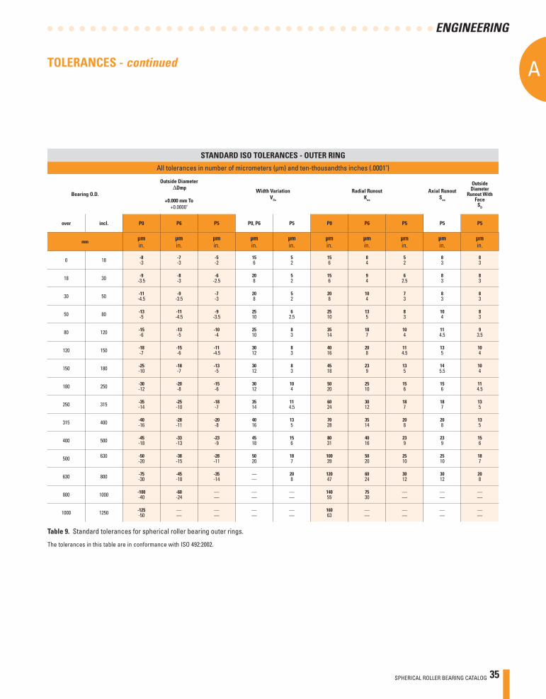
TOLERANCES - continued
The tolerances in this table are in conformance with ISO 492:2002.
Table 9. Standard tolerances for spherical roller bearing outer rings.
STANDARD ISO TOLERANCES - OUTER RING
All tolerances in number of micrometers (μm) and ten-thousandths inches (.0001")
Bearing O.D.
Outside Diameter Dmp
+0.000 mm To+0.0000"
Width VariationVCs
Radial RunoutKea
Axial RunoutSea
Outside Diameter
Runout With Face
SD
over incl. P0 P6 P5 P0, P6 P5 P0 P6 P5 P5 P5
mmμmin.
μmin.
μmin.
μmin.
μmin.
μmin.
μmin.
μmin.
μmin.
μmin.
0 18 -8-3
-7-3
-5-2
156
52
156
84
52
83
83
18 30 -9-3.5
-8-3
-6-2.5
208
52
156
94
62.5
83
83
30 50 -11-4.5
-9-3.5
-7-3
208
52
208
104
73
83
83
50 80 -13-5
-11-4.5
-9-3.5
2510
62.5
2510
135
83
104
83
80 120 -15-6
-13-5
-10-4
2510
83
3514
187
104
114.5
93.5
120 150 -18-7
-15-6
-11-4.5
3012
83
4016
208
114.5
135
104
150 180 -25-10
-18-7
-13-5
3012
83
4518
239
135
145.5
104
180 250 -30-12
-20-8
-15-6
3012
104
5020
2510
156
156
114.5
250 315 -35-14
-25-10
-18-7
3514
114.5
6024
3012
187
187
135
315 400 -40-16
-28-11
-20-8
4016
135
7028
3514
208
208
135
400 500 -45-18
-33-13
-23-9
4518
156
8031
4016
239
239
156
500 630
-50-20
-38-15
-28-11
5020
187
10039
5020
2510
2510
187
630 800 -75-30
-45-18
-35-14
——
208
12047
6024
3012
3012
208
800 1000 -100-40
-60-24
——
——
——
14055
7530
——
——
——
1000 1250 -125-50
——
——
——
——
16063
——
——
——
——
36 SPHERICAL ROLLER BEARING CATALOG
AA
ENGINEERING
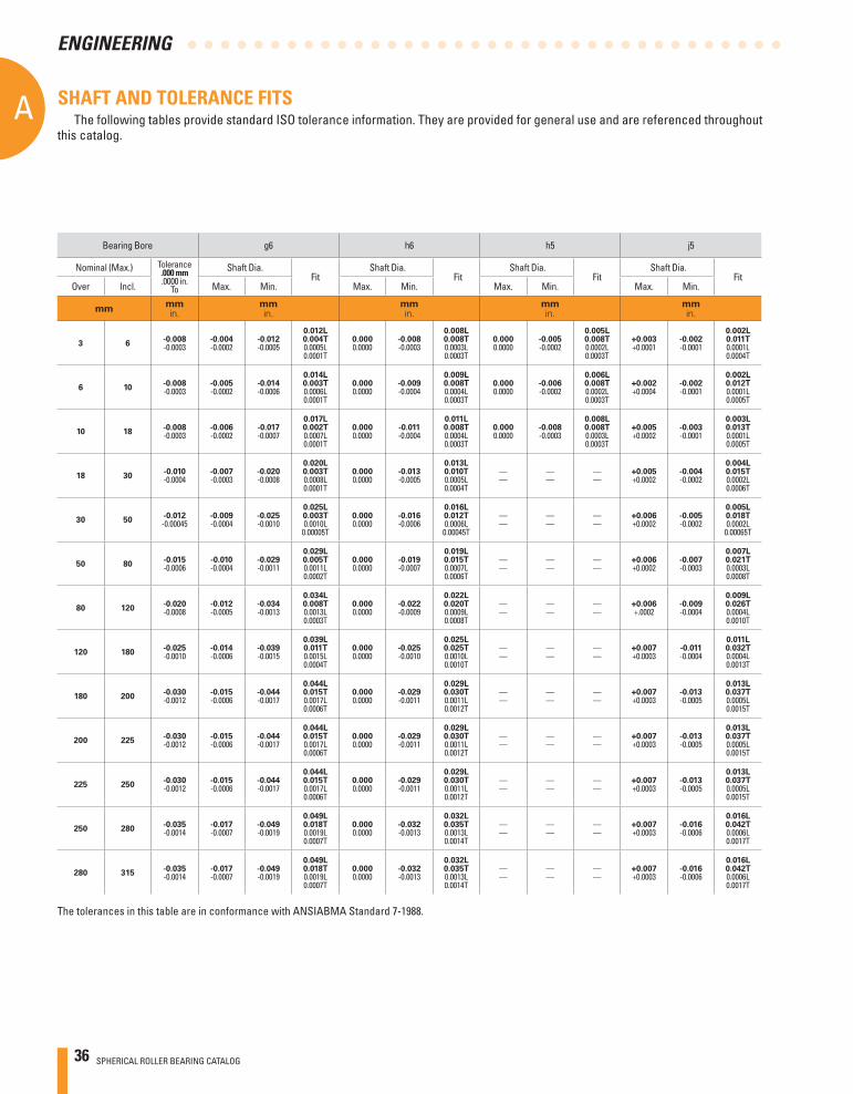
SHAFT AND TOLERANCE FITS
Bearing Bore g6 h6 h5 j5
Nominal (Max.) Tolerance.000 mm.0000 in.
To
Shaft Dia.Fit
Shaft Dia. Fit
Shaft Dia.Fit
Shaft Dia.Fit
Over Incl. Max. Min. Max. Min. Max. Min. Max. Min.
mmmmin.
mmin.
mmin.
mmin.
mmin.
3 6-0.008-0.0003
-0.004-0.0002
-0.012-0.0005
0.012L0.004T0.0005L0.0001T
0.0000.0000
-0.008-0.0003
0.008L0.008T0.0003L0.0003T
0.0000.0000
-0.005-0.0002
0.005L0.008T0.0002L0.0003T
+0.003+0.0001
-0.002-0.0001
0.002L0.011T0.0001L0.0004T
6 10-0.008-0.0003
-0.005-0.0002
-0.014-0.0006
0.014L0.003T0.0006L0.0001T
0.0000.0000
-0.009-0.0004
0.009L0.008T0.0004L0.0003T
0.0000.0000
-0.006-0.0002
0.006L0.008T0.0002L0.0003T
+0.002+0.0004
-0.002-0.0001
0.002L0.012T0.0001L0.0005T
10 18-0.008-0.0003
-0.006-0.0002
-0.017-0.0007
0.017L0.002T0.0007L0.0001T
0.0000.0000
-0.011-0.0004
0.011L0.008T0.0004L0.0003T
0.0000.0000
-0.008-0.0003
0.008L0.008T0.0003L0.0003T
+0.005+0.0002
-0.003-0.0001
0.003L0.013T0.0001L0.0005T
18 30-0.010-0.0004
-0.007-0.0003
-0.020-0.0008
0.020L0.003T0.0008L0.0001T
0.0000.0000
-0.013-0.0005
0.013L0.010T0.0005L0.0004T
——
——
——
+0.005+0.0002
-0.004-0.0002
0.004L0.015T0.0002L0.0006T
30 50-0.012-0.00045
-0.009-0.0004
-0.025-0.0010
0.025L0.003T0.0010L
0.00005T
0.0000.0000
-0.016-0.0006
0.016L0.012T0.0006L
0.00045T
——
——
——
+0.006+0.0002
-0.005-0.0002
0.005L0.018T0.0002L
0.00065T
50 80-0.015-0.0006
-0.010-0.0004
-0.029-0.0011
0.029L0.005T0.0011L0.0002T
0.0000.0000
-0.019-0.0007
0.019L0.015T0.0007L0.0006T
——
——
——
+0.006+0.0002
-0.007-0.0003
0.007L0.021T0.0003L0.0008T
80 120-0.020-0.0008
-0.012-0.0005
-0.034-0.0013
0.034L0.008T0.0013L0.0003T
0.0000.0000
-0.022-0.0009
0.022L0.020T0.0009L0.0008T
——
——
——
+0.006+.0002
-0.009-0.0004
0.009L0.026T0.0004L0.0010T
120 180-0.025-0.0010
-0.014-0.0006
-0.039-0.0015
0.039L0.011T0.0015L0.0004T
0.0000.0000
-0.025-0.0010
0.025L0.025T0.0010L0.0010T
——
——
——
+0.007+0.0003
-0.011-0.0004
0.011L0.032T0.0004L0.0013T
180 200-0.030-0.0012
-0.015-0.0006
-0.044-0.0017
0.044L0.015T0.0017L0.0006T
0.0000.0000
-0.029-0.0011
0.029L0.030T0.0011L0.0012T
——
——
——
+0.007+0.0003
-0.013-0.0005
0.013L0.037T0.0005L0.0015T
200 225-0.030-0.0012
-0.015-0.0006
-0.044-0.0017
0.044L0.015T0.0017L0.0006T
0.0000.0000
-0.029-0.0011
0.029L0.030T0.0011L0.0012T
——
——
——
+0.007+0.0003
-0.013-0.0005
0.013L0.037T0.0005L0.0015T
225 250-0.030-0.0012
-0.015-0.0006
-0.044-0.0017
0.044L0.015T0.0017L0.0006T
0.0000.0000
-0.029-0.0011
0.029L0.030T0.0011L0.0012T
——
——
——
+0.007+0.0003
-0.013-0.0005
0.013L0.037T0.0005L0.0015T
250 280-0.035-0.0014
-0.017-0.0007
-0.049-0.0019
0.049L0.018T0.0019L0.0007T
0.0000.0000
-0.032-0.0013
0.032L0.035T0.0013L0.0014T
——
——
——
+0.007+0.0003
-0.016-0.0006
0.016L0.042T0.0006L0.0017T
280 315-0.035-0.0014
-0.017-0.0007
-0.049-0.0019
0.049L0.018T0.0019L0.0007T
0.0000.0000
-0.032-0.0013
0.032L0.035T0.0013L0.0014T
——
——
——
+0.007+0.0003
-0.016-0.0006
0.016L0.042T0.0006L0.0017T
The tolerances in this table are in conformance with ANSIABMA Standard 7-1988.
The following tables provide standard ISO tolerance information. They are provided for general use and are referenced throughout this catalog.
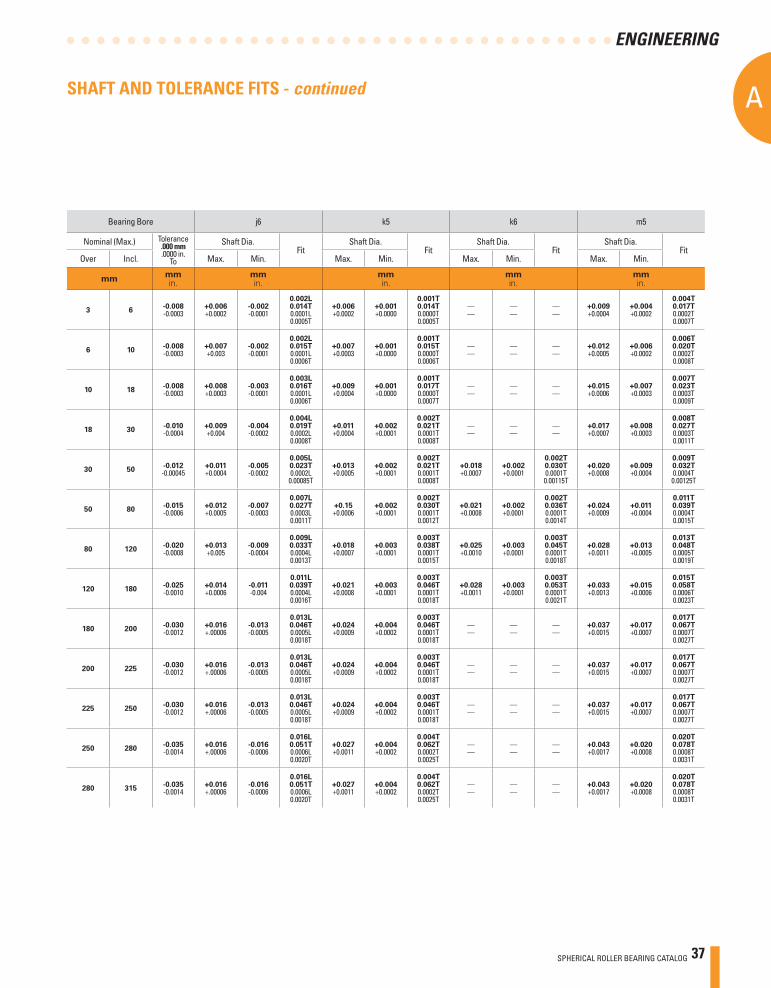
SPHERICAL ROLLER BEARING CATALOG 37
A
ENGINEERING
SHAFT AND TOLERANCE FITS - continued
Bearing Bore j6 k5 k6 m5
Nominal (Max.) Tolerance.000 mm.0000 in.
To
Shaft Dia.Fit
Shaft Dia.Fit
Shaft Dia.Fit
Shaft Dia.Fit
Over Incl. Max. Min. Max. Min. Max. Min. Max. Min.
mmmmin.
mmin.
mmin.
mmin.
mmin.
3 6-0.008-0.0003
+0.006+0.0002
-0.002-0.0001
0.002L0.014T0.0001L0.0005T
+0.006+0.0002
+0.001+0.0000
0.001T0.014T0.0000T0.0005T
——
——
——
+0.009+0.0004
+0.004+0.0002
0.004T0.017T0.0002T0.0007T
6 10-0.008-0.0003
+0.007+0.003
-0.002-0.0001
0.002L0.015T0.0001L0.0006T
+0.007+0.0003
+0.001+0.0000
0.001T0.015T0.0000T0.0006T
——
——
——
+0.012+0.0005
+0.006+0.0002
0.006T0.020T0.0002T0.0008T
10 18-0.008-0.0003
+0.008+0.0003
-0.003-0.0001
0.003L0.016T0.0001L0.0006T
+0.009+0.0004
+0.001+0.0000
0.001T0.017T0.0000T0.0007T
——
——
——
+0.015+0.0006
+0.007+0.0003
0.007T0.023T0.0003T0.0009T
18 30-0.010-0.0004
+0.009+0.004
-0.004-0.0002
0.004L0.019T0.0002L0.0008T
+0.011+0.0004
+0.002+0.0001
0.002T0.021T0.0001T0.0008T
——
——
——
+0.017+0.0007
+0.008+0.0003
0.008T0.027T0.0003T0.0011T
30 50-0.012-0.00045
+0.011+0.0004
-0.005-0.0002
0.005L0.023T0.0002L
0.00085T
+0.013+0.0005
+0.002+0.0001
0.002T0.021T0.0001T0.0008T
+0.018+0.0007
+0.002+0.0001
0.002T0.030T0.0001T0.00115T
+0.020+0.0008
+0.009+0.0004
0.009T0.032T0.0004T0.00125T
50 80-0.015-0.0006
+0.012+0.0005
-0.007-0.0003
0.007L0.027T0.0003L0.0011T
+0.15+0.0006
+0.002+0.0001
0.002T0.030T0.0001T0.0012T
+0.021+0.0008
+0.002+0.0001
0.002T0.036T0.0001T0.0014T
+0.024+0.0009
+0.011+0.0004
0.011T0.039T0.0004T0.0015T
80 120-0.020-0.0008
+0.013+0.005
-0.009-0.0004
0.009L0.033T0.0004L0.0013T
+0.018+0.0007
+0.003+0.0001
0.003T0.038T0.0001T0.0015T
+0.025+0.0010
+0.003+0.0001
0.003T0.045T0.0001T0.0018T
+0.028+0.0011
+0.013+0.0005
0.013T0.048T0.0005T0.0019T
120 180-0.025-0.0010
+0.014+0.0006
-0.011-0.004
0.011L0.039T0.0004L0.0016T
+0.021+0.0008
+0.003+0.0001
0.003T0.046T0.0001T0.0018T
+0.028+0.0011
+0.003+0.0001
0.003T0.053T0.0001T0.0021T
+0.033+0.0013
+0.015+0.0006
0.015T0.058T0.0006T0.0023T
180 200-0.030-0.0012
+0.016+.00006
-0.013-0.0005
0.013L0.046T0.0005L0.0018T
+0.024+0.0009
+0.004+0.0002
0.003T0.046T0.0001T0.0018T
——
——
——
+0.037+0.0015
+0.017+0.0007
0.017T0.067T0.0007T0.0027T
200 225-0.030-0.0012
+0.016+.00006
-0.013-0.0005
0.013L0.046T0.0005L0.0018T
+0.024+0.0009
+0.004+0.0002
0.003T0.046T0.0001T0.0018T
——
——
——
+0.037+0.0015
+0.017+0.0007
0.017T0.067T0.0007T0.0027T
225 250-0.030-0.0012
+0.016+.00006
-0.013-0.0005
0.013L0.046T0.0005L0.0018T
+0.024+0.0009
+0.004+0.0002
0.003T0.046T0.0001T0.0018T
——
——
——
+0.037+0.0015
+0.017+0.0007
0.017T0.067T0.0007T0.0027T
250 280-0.035-0.0014
+0.016+.00006
-0.016-0.0006
0.016L0.051T0.0006L0.0020T
+0.027+0.0011
+0.004+0.0002
0.004T0.062T0.0002T0.0025T
——
——
——
+0.043+0.0017
+0.020+0.0008
0.020T0.078T0.0008T0.0031T
280 315-0.035-0.0014
+0.016+.00006
-0.016-0.0006
0.016L0.051T0.0006L0.0020T
+0.027+0.0011
+0.004+0.0002
0.004T0.062T0.0002T0.0025T
——
——
——
+0.043+0.0017
+0.020+0.0008
0.020T0.078T0.0008T0.0031T
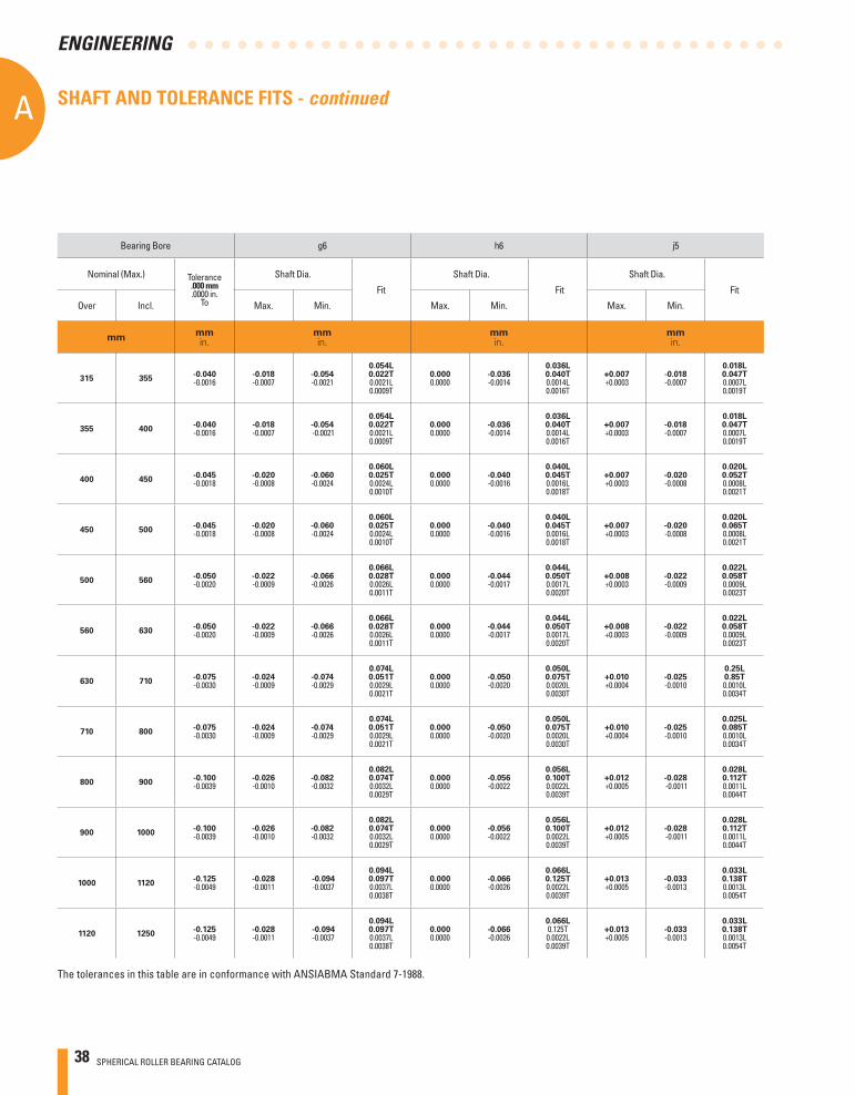
38 SPHERICAL ROLLER BEARING CATALOG
AA
ENGINEERING
Bearing Bore g6 h6 j5
Nominal (Max.) Tolerance.000 mm.0000 in.
To
Shaft Dia.
Fit
Shaft Dia.
Fit
Shaft Dia.
Fit
Over Incl. Max. Min. Max. Min. Max. Min.
mmmmin.
mmin.
mmin.
mmin.
315 355-0.040-0.0016
-0.018-0.0007
-0.054-0.0021
0.054L0.022T0.0021L0.0009T
0.0000.0000
-0.036-0.0014
0.036L0.040T0.0014L0.0016T
+0.007+0.0003
-0.018-0.0007
0.018L0.047T0.0007L0.0019T
355 400-0.040-0.0016
-0.018-0.0007
-0.054 -0.0021
0.054L0.022T0.0021L0.0009T
0.0000.0000
-0.036-0.0014
0.036L0.040T0.0014L0.0016T
+0.007+0.0003
-0.018-0.0007
0.018L0.047T0.0007L0.0019T
400 450-0.045-0.0018
-0.020-0.0008
-0.060-0.0024
0.060L0.025T0.0024L0.0010T
0.0000.0000
-0.040-0.0016
0.040L0.045T0.0016L0.0018T
+0.007+0.0003
-0.020-0.0008
0.020L0.052T0.0008L0.0021T
450 500-0.045-0.0018
-0.020-0.0008
-0.060-0.0024
0.060L0.025T0.0024L0.0010T
0.0000.0000
-0.040-0.0016
0.040L0.045T0.0016L0.0018T
+0.007+0.0003
-0.020-0.0008
0.020L0.065T0.0008L0.0021T
500 560-0.050-0.0020
-0.022-0.0009
-0.066-0.0026
0.066L0.028T0.0026L0.0011T
0.0000.0000
-0.044-0.0017
0.044L0.050T0.0017L0.0020T
+0.008+0.0003
-0.022-0.0009
0.022L0.058T0.0009L0.0023T
560 630-0.050-0.0020
-0.022-0.0009
-0.066-0.0026
0.066L0.028T0.0026L0.0011T
0.0000.0000
-0.044-0.0017
0.044L0.050T0.0017L0.0020T
+0.008+0.0003
-0.022-0.0009
0.022L0.058T0.0009L0.0023T
630 710-0.075-0.0030
-0.024-0.0009
-0.074-0.0029
0.074L0.051T0.0029L0.0021T
0.0000.0000
-0.050-0.0020
0.050L0.075T0.0020L0.0030T
+0.010+0.0004
-0.025-0.0010
0.25L0.85T0.0010L0.0034T
710 800-0.075-0.0030
-0.024-0.0009
-0.074-0.0029
0.074L0.051T0.0029L0.0021T
0.0000.0000
-0.050-0.0020
0.050L0.075T0.0020L0.0030T
+0.010+0.0004
-0.025-0.0010
0.025L0.085T0.0010L0.0034T
800 900-0.100-0.0039
-0.026-0.0010
-0.082-0.0032
0.082L0.074T0.0032L0.0029T
0.0000.0000
-0.056-0.0022
0.056L0.100T0.0022L0.0039T
+0.012+0.0005
-0.028 -0.0011
0.028L0.112T0.0011L0.0044T
900 1000-0.100-0.0039
-0.026-0.0010
-0.082-0.0032
0.082L0.074T0.0032L0.0029T
0.0000.0000
-0.056-0.0022
0.056L0.100T0.0022L0.0039T
+0.012+0.0005
-0.028 -0.0011
0.028L0.112T0.0011L0.0044T
1000 1120-0.125-0.0049
-0.028-0.0011
-0.094 -0.0037
0.094L0.097T0.0037L0.0038T
0.0000.0000
-0.066-0.0026
0.066L0.125T0.0022L0.0039T
+0.013+0.0005
-0.033-0.0013
0.033L0.138T0.0013L0.0054T
1120 1250-0.125-0.0049
-0.028-0.0011
-0.094 -0.0037
0.094L0.097T0.0037L0.0038T
0.0000.0000
-0.066-0.0026
0.066L0.125T0.0022L0.0039T
+0.013+0.0005
-0.033-0.0013
0.033L0.138T0.0013L0.0054T
The tolerances in this table are in conformance with ANSIABMA Standard 7-1988.
SHAFT AND TOLERANCE FITS - continued
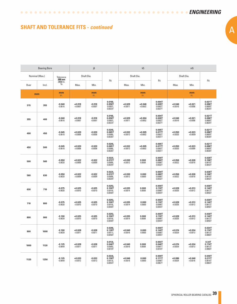
SPHERICAL ROLLER BEARING CATALOG 39
A
ENGINEERING
Bearing Bore j6 k5 m5
Nominal (Max.) Tolerance.000 mm.0000 in.
To
Shaft Dia.
Fit
Shaft Dia.
Fit
Shaft Dia.
Fit
Over Incl. Max. Min. Max. Min. Max. Min.
mmmmin.
mmin.
mmin.
mmin.
315 355-0.040-0.0016
+0.018+0.0007
-0.018-0.0007
0.018L0.058T0.0007L0.0023T
+0.029+0.0011
+0.046+0.0002
0.004T0.009T0.0002T0.0027T
+0.046+0.0018
+0.021+0.0008
0.021T0.086T0.0008T0.0034T
355 400-0.040-0.0016
+0.018+0.0007
-0.018-0.0007
0.018L0.058T0.0007L0.0023T
+0.029+0.0011
+0.004+0.0002
0.004T0.009T0.0002T0.0027T
+0.046+0.0018
+0.021+0.0008
0.021T0.086T0.0008T0.0034T
400 450-0.045-0.0018
+0.020+0.0008
-0.020-0.0008
0.020L0.065T0.0008L0.0026T
+0.032+0.0013
+0.005+0.0002
0.005T0.077T0.0002T0.0031T
+0.050+0.0020
+0.023 +0.0009
0.021T0.086T0.0009T0.0038T
450 500-0.045-0.0018
+0.020+0.0008
-0.020-0.0008
0.020L0.065T0.0008L0.0026T
+0.032+0.0013
+0.005+0.0002
0.005T0.077T0.0002T0.0031T
+0.050+0.0020
+0.023+0.0009
0.021T0.086T0.0009T0.0038T
500 560-0.050-0.0020
+0.022+0.0009
-0.022-0.0009
0.022L0.072T0.0009L0.0029T
+0.030+0.0012
0.0000.0000
0.000T0.080T0.0000T0.0032T
+0.056+0.0022
+0.026+0.0010
0.026T0.106T0.0010T0.0042T
560 630-0.050-0.0020
+0.022+0.0009
-0.022-0.0009
0.022L0.072T0.0009L0.0029T
+0.030+0.0012
0.000 0.0000
0.000T0.080T0.0000T0.0032T
+0.056+0.0022
+0.026+0.0010
0.026T0.106T0.0010T0.0042T
630 710-0.075-0.0030
+0.025+0.0010
-0.025-0.0010
0.025L0.100T0.0010L0.0040T
+0.035+0.0014
0.0000.0000
0.000T0.110T0.0000T0.0044T
+0.028+0.0026
+0.013+0.0012
0.030T0.140T0.0012T0.0056T
710 800-0.075-0.0030
+0.025+0.0010
-0.025-0.0010
0.025L0.100T0.0010L0.0040T
+0.035+0.0014
0.000 0.0000
0.000T0.110T0.0000T0.0044T
+0.028+0.0026
+0.013+0.0012
0.030T0.140T0.0012T0.0056T
800 900-0.100-0.0039
+0.025+0.0010
-0.025-0.0010
0.025L0.100T0.0010L0.0040T
+0.035+0.0014
0.0000.0000
0.000T0.110T0.0000T0.0044T
+0.028+0.0026
+0.013+0.0012
0.030T0.140T0.0012T0.0056T
900 1000-0.100-0.0039
+0.028+0.0011
-0.028-0.0011
0.028L0.128T0.0011L0.0050T
+0.040+0.0016
0.000 0.0000
0.000T0.140T0.0000T0.0055T
+0.074+0.0029
+0.034+0.0013
0.034T0.174T0.0013T0.0068T
1000 1120-0.125-0.0049
+0.028+0.0011
-0.028-0.0011
0.013L0.046T0.0005L0.0018T
+0.040+0.0016
0.0000.0000
0.003T0.046T0.0001T0.0018T
+0.074+0.0029
+0.034+0.0013
0.34T0.174T0.0013T0.0068T
1120 1250-0.125-0.0049
+0.033+0.0013
-0.033-0.0013
0.033L0.158T0.0013L0.0054T
+0.046+0.0018
0.000 0.0000
0.000T0.171T0.0000T0.0067T
+0.086+0.0034
+0.040+0.0016
0.040T0.211T0.0016T0.0083T
SHAFT AND TOLERANCE FITS - continued
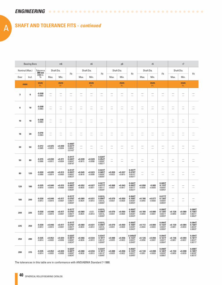
40 SPHERICAL ROLLER BEARING CATALOG
AA
ENGINEERING
The tolerances in this table are in conformance with ANSIABMA Standard 7-1988.
Bearing Bore m6 n6 p6 r6 r7
Nominal (Max.) Tolerance.000 mm.0000 in.
To
Shaft Dia.Fit
Shaft Dia. Fit
Shaft Dia.Fit
Shaft Dia.Fit
Shaft Dia.Fit
Over Incl. Max. Min. Max. Min. Max. Min. Max. Min. Max. Min.
mmmmin.
mmin.
mmin.
mmin.
mmin.
mmin.
3 6-0.008-0.0003
——
——
——
——
——
——
——
——
——
——
——
——
——
——
——
6 10-0.008-0.0003
——
——
——
——
——
——
——
——
——
——
——
——
——
——
——
10 18-0.008-0.0003
——
——
——
——
——
——
——
——
——
——
——
——
——
——
——
18 30-0.010-0.0004
——
——
——
——
——
——
——
——
——
——
——
——
——
——
——
30 50-0.012-0.0005
+0.025+0.0010
+0.009+0.0004
0.009T0.037T0.0004T0.0145T
——
——
——
——
——
——
——
——
——
——
——
——
50 80-0.015-0.0006
+0.030+0.0012
+0.011+0.0004
0.011T0.045T0.0004T0.0018T
+0.039+0.0015
+0.020+0.0008
0.020T0.054T0.0008T0.0021T
——
——
——
——
——
——
——
——
——
80 120-0.020-0.0008
+0.035+0.0014
+0.013 +0.0005
0.013T0.055T0.0005T0.0022T
+0.045+0.0018
+0.023+0.0009
0.023T0.065T0.0009T0.0026T
+0.059+0.0023
+0.037+0.0015
0.037T0.079T0.0015T0.0031T
——
——
——
——
——
——
120 180-0.025-0.0010
+0.040+0.0016
+0.015+0.0006
0.015T0.065T0.0006T0.0026T
+0.052+0.0020
+0.027+0.0011
0.027T0.077T0.0011T0.0030T
+0.068+0.0027
+0.043+0.0017
0.043T0.093T0.0017T0.0037T
+0.090+0.0035
-0.065+0.0026
0.065T0.115T0.0026T0.0045T
——
——
——
180 200-0.030-0.0012
+0.046+0.0018
+0.017+0.0007
0.017T0.076T0.0007T0.0030T
+0.060+0.0024
+0.031+0.0012
0.031L0.090T0.0012L0.0036T
+0.079+0.0031
+0.050+0.0020
0.050T0.109T0.0020T0.0043T
+0.106+0.0042
+0.077+0.0030
0.077T0.136T0.0030T0.0054T
——
——
——
200 225-0.030-0.0012
+0.046+0.0018
+0.017+0.0007
0.017T0.076T0.0007T0.0030T
+0.060+0.0024
+0.031+0.0012
0.031L0.090T0.0012L0.0036T
+0.079+0.0031
+0.050+0.0020
0.050T0.109T0.0020T0.0043T
+0.109+0.0043
+0.080+0.0031
0.080T0.139T0.0031T0.0055T
+0.126+0.0050
+0.080+0.0031
0.080T0.156T0.0031T0.0062T
225 250-0.030-0.0012
+0.046+0.0018
+0.017+0.0007
0.017T0.076T0.0007T0.0030T
+0.060+0.0024
+0.031+0.0012
0.031L0.090T0.0012L0.0036T
+0.079+0.0031
+0.050+0.0020
0.050T0.109T0.0020T0.0043T
+0.113+0.0044
+0.084+0.0033
0.084T0.143T0.0033T0.0056T
+0.130+0.0051
+0.084+0.0033
0.084T0.160T0.0033T0.0063T
250 280-0.035-0.0014
+0.052+0.0020
+0.020+0.0008
0.020T0.087T0.0008T0.0034T
+0.066+0.0026
+0.034+0.0013
0.034T0.101T0.0013T0.0040T
+0.088+0.0035
+0.056+0.0022
0.0056T0.123T0.0022T0.0049T
+0.126+0.0050
+0.094+0.0037
0.094T0.161T0.0037T0.0064T
+0.146+0.0057
+0.094+0.0037
0.094T0.181T0.0037T0.0071T
280 315-0.035-0.0014
+0.052+0.0020
+0.020+0.0008
0.020T0.087T0.0008T0.0034T
+0.066+0.0026
+0.034+0.0013
0.034T0.101T0.0013T0.0040T
+0.088+0.0035
+0.056+0.0022
0.056T0.123T0.0022T0.0049T
+0.130+0.0051
+0.098+0.0039
0.098T0.165T0.0039T0.0065T
+0.150+0.0059
+0.098+0.0039
0.098T0.185T0.0039T0.0073T
SHAFT AND TOLERANCE FITS - continued
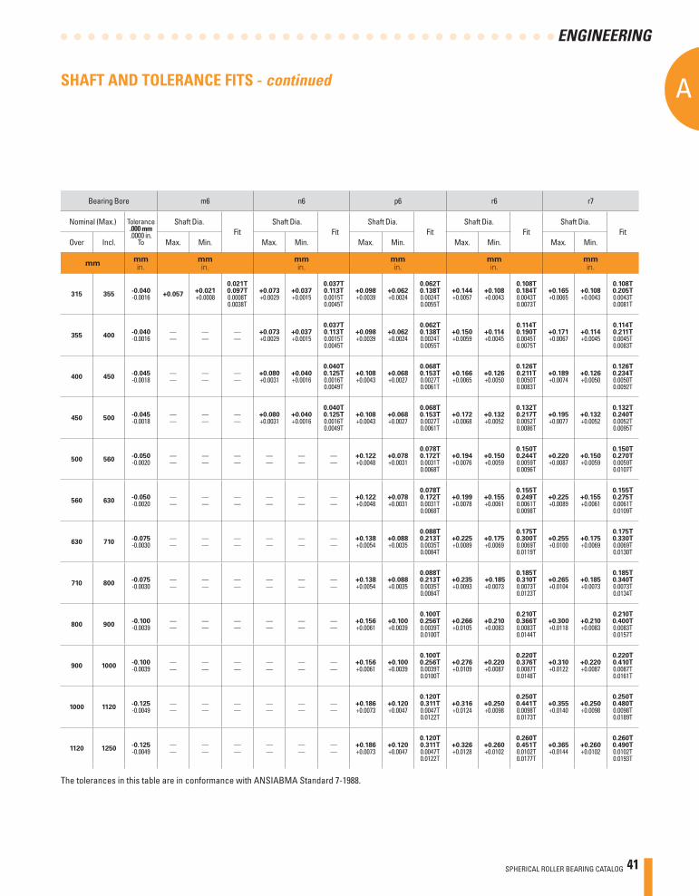
SPHERICAL ROLLER BEARING CATALOG 41
A
ENGINEERING
Bearing Bore m6 n6 p6 r6 r7
Nominal (Max.) Tolerance.000 mm.0000 in.
To
Shaft Dia.Fit
Shaft Dia. Fit
Shaft Dia.Fit
Shaft Dia.Fit
Shaft Dia.Fit
Over Incl. Max. Min. Max. Min. Max. Min. Max. Min. Max. Min.
mmmmin.
mmin.
mmin.
mmin.
mmin.
mmin.
315 355-0.040-0.0016 +0.057
+0.021+0.0008
0.021T0.097T0.0008T0.0038T
+0.073+0.0029
+0.037+0.0015
0.037T0.113T0.0015T0.0045T
+0.098+0.0039
+0.062+0.0024
0.062T0.138T0.0024T0.0055T
+0.144+0.0057
+0.108+0.0043
0.108T0.184T0.0043T0.0073T
+0.165+0.0065
+0.108+0.0043
0.108T0.205T0.0043T0.0081T
355 400-0.040-0.0016
——
——
——
+0.073+0.0029
+0.037+0.0015
0.037T0.113T0.0015T0.0045T
+0.098+0.0039
+0.062+0.0024
0.062T0.138T0.0024T0.0055T
+0.150+0.0059
+0.114+0.0045
0.114T0.190T0.0045T0.0075T
+0.171+0.0067
+0.114+0.0045
0.114T0.211T0.0045T0.0083T
400 450-0.045-0.0018
——
——
——
+0.080+0.0031
+0.040+0.0016
0.040T0.125T0.0016T0.0049T
+0.108+0.0043
+0.068+0.0027
0.068T0.153T0.0027T0.0061T
+0.166+0.0065
+0.126+0.0050
0.126T0.211T0.0050T0.0083T
+0.189+0.0074
+0.126+0.0050
0.126T0.234T0.0050T0.0092T
450 500-0.045-0.0018
——
——
——
+0.080+0.0031
+0.040+0.0016
0.040T0.125T0.0016T0.0049T
+0.108+0.0043
+0.068+0.0027
0.068T0.153T0.0027T0.0061T
+0.172+0.0068
+0.132+0.0052
0.132T0.217T0.0052T0.0086T
+0.195+0.0077
+0.132+0.0052
0.132T0.240T0.0052T0.0095T
500 560 -0.050-0.0020
——
——
——
——
——
——
+0.122+0.0048
+0.078+0.0031
0.078T0.172T0.0031T0.0068T
+0.194+0.0076
+0.150+0.0059
0.150T0.244T0.0059T0.0096T
+0.220+0.0087
+0.150+0.0059
0.150T0.270T0.0059T0.0107T
560 630-0.050-0.0020
——
——
——
——
——
——
+0.122+0.0048
+0.078+0.0031
0.078T0.172T0.0031T0.0068T
+0.199+0.0078
+0.155+0.0061
0.155T0.249T0.0061T0.0098T
+0.225+0.0089
+0.155+0.0061
0.155T0.275T0.0061T0.0109T
630 710-0.075-0.0030
——
——
——
——
——
——
+0.138+0.0054
+0.088+0.0035
0.088T0.213T0.0035T0.0084T
+0.225+0.0089
+0.175+0.0069
0.175T0.300T0.0069T0.0119T
+0.255+0.0100
+0.175+0.0069
0.175T0.330T0.0069T0.0130T
710 800-0.075-0.0030
——
——
——
——
——
——
+0.138+0.0054
+0.088+0.0035
0.088T0.213T0.0035T0.0084T
+0.235+0.0093
+0.185+0.0073
0.185T0.310T0.0073T0.0123T
+0.265+0.0104
+0.185+0.0073
0.185T0.340T0.0073T0.0134T
800 900 -0.100-0.0039
——
——
——
——
——
——
+0.156+0.0061
+0.100+0.0039
0.100T0.256T0.0039T0.0100T
+0.266+0.0105
+0.210+0.0083
0.210T0.366T0.0083T0.0144T
+0.300+0.0118
+0.210+0.0083
0.210T0.400T0.0083T0.0157T
900 1000-0.100-0.0039
——
——
——
——
——
——
+0.156+0.0061
+0.100+0.0039
0.100T0.256T0.0039T0.0100T
+0.276+0.0109
+0.220+0.0087
0.220T0.376T0.0087T0.0148T
+0.310+0.0122
+0.220+0.0087
0.220T0.410T0.0087T0.0161T
1000 1120-0.125-0.0049
——
——
——
——
——
——
+0.186+0.0073
+0.120+0.0047
0.120T0.311T0.0047T0.0122T
+0.316+0.0124
+0.250+0.0098
0.250T0.441T0.0098T0.0173T
+0.355+0.0140
+0.250+0.0098
0.250T0.480T0.0098T0.0189T
1120 1250 -0.125-0.0049
——
——
——
——
——
——
+0.186+0.0073
+0.120+0.0047
0.120T0.311T0.0047T0.0122T
+0.326+0.0128
+0.260+0.0102
0.260T0.451T0.0102T0.0177T
+0.365+0.0144
+0.260+0.0102
0.260T0.490T0.0102T0.0193T
The tolerances in this table are in conformance with ANSIABMA Standard 7-1988.
SHAFT AND TOLERANCE FITS - continued

42 SPHERICAL ROLLER BEARING CATALOG
AA
ENGINEERING
The tolerances in this table are in conformance with ANSIABMA Standard 7-1988.
SHAFT AND TOLERANCE FITS - continued
Bearing O.D. F7 G7 H6 H7
Nominal (Max.) Tolerance.000 mm.0000 in.
To
Housing Bore
Fit
Housing Bore
Fit
Housing Bore
Fit
Housing Bore
Fit
Over Incl. Min. Max. Min. Max. Min. Max. Min. Max.
mmmmin.
mmin.
mmin.
mmin.
mmin.
10 18-0.008-0.0003
+0.016+0.0006
+0.034+0.0013
0.016L0.042L0.0006L0.0016L
+0.002+0.0002
+0.024+0.0009
0.006L0.032L0.0002L0.0012L
0.0000.0000
+0.011+0.0004
0.000L0.019L0.0000L0.0007L
0.0000.0000
+0.018+0.0007
0.000L0.026L0.0000L0.0010L
18 30-0.009-0.0035
+0.020+0.0008
+0.041+0.0016
0.020L0.050L0.0008L0.0195L
+0.007+0.0003
+0.028+0.0011
0.007L0.037L0.0003L0.0145L
0.0000.0000
+0.013+0.0008
0.000L0.022L0.0000L0.0085L
0.0000.0000
+0.021+0.0008
0.000L0.030L0.0000L0.0115L
30 50-0.011-0.0045
+0.025+0.0010
+0.050+0.0020
0.025L0.061L0.0010L0.0245L
+0.009+0.0004
+0.034+0.0013
0.009L0.045L0.0004L0.0175L
0.0000.0000
+0.016+0.0006
0.000L0.027L0.0000L0.0105L
0.0000.0000
+0.025+0.0010
0.000L0.036L0.0000L0.0145L
50 80-0.023-0.0005
+0.030+0.0012
+0.060+0.0024
0.030L0.073L0.0012L0.0029L
+0.010+0.0004
+0.040+0.0016
0.010L0.053L0.0004L0.0021L
0.0000.0000
+0.019+0.0007
0.000L0.032L0.0000L0.0012L
0.0000.0000
+0.030+0.0012
0.000L0.059L0.0000L0.0023L
80 120-0.015-0.0006
+0.036+0.0014
+0.071+0.0028
0.036L0.086L0.0014L0.0034L
+0.012+0.0005
+0.047+0.0019
0.012L0.062L0.0005L0.0025L
0.0000.0000
+0.022+0.0009
0.000L0.037L0.0000L0.0015L
0.0000.0000
+0.035+0.0014
0.000L0.050L0.0000L0.0020L
120 150-0.018-0.0007
+0.043+0.0017
+0.083+0.0033
0.043L0.101L0.0017L0.0040L
+0.014+0.0006
+0.054+0.0021
0.014L0.072L0.0006L0.0028L
0.0000.0000
+0.025+0.0010
0.000L0.043L0.0000L0.0017L
0.0000.0000
+0.040+0.0016
0.000L0.058L0.0000L0.0023L
150 180-0.025-0.0010
+0.043+0.0017
+0.083+0.0033
0.043L0.108L0.0017L0.0043L
+0.014+0.0006
+0.054+0.0021
0.014L0.079L0.0006L0.0031L
0.0000.0000
+0.025+0.0010
0.000L0.050L0.0000L0.0020L
0.0000.0000
+0.040+0.0016
0.000L0.065L0.0000L0.0026L
180 250-0.030-0.0012
+0.050+0.0020
+0.096+0.0038
0.050L0.126L0.0020L0.0050L
+0.015+0.0006
+0.061+0.0024
0.015L0.091L0.0006L0.0036L
0.0000.0000
+0.029+0.0011
0.00L0.059L0.0000L0.0023L
0.0000.0000
+0.046+0.0018
0.000L0.076L0.0000L0.0030L
250 315-0.035-0.0014
+0.056+0.0022
+0.108+0.0043
0.056L0.143L0.0022L0.0057L
+0.017+0.0007
+0.069+0.0027
0.017L0.104L0.0007L0.0041L
0.0000.0000
+0.032+0.0013
0.000L0.067L0.0000L0.0027L
0.0000.0000
+0.052+0.0020
0.000L0.087L0.0000L0.0034L
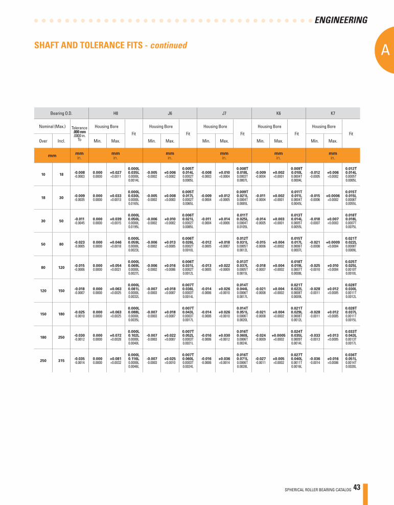
SPHERICAL ROLLER BEARING CATALOG 43
A
ENGINEERING
SHAFT AND TOLERANCE FITS - continued
Bearing O.D. H8 J6 J7 K6 K7
Nominal (Max.) Tolerance.000 mm.0000 in.
To
Housing Bore
Fit
Housing Bore
Fit
Housing Bore
Fit
Housing Bore
Fit
Housing Bore
Fit
Over Incl. Min. Max. Min. Max. Min. Max. Min. Max. Min. Max.
mmmmin.
mmin.
mmin.
mmin.
mmin.
mmin.
10 18-0.008-0.0003
0.0000.0000
+0.027+0.0011
0.000L0.035L0.0000L0.0014L
-0.005-0.0002
+0.006+0.0002
0.005T0.014L0.0002T0.0005L
-0.008-0.0003
+0.010+0.0004
0.008T0.018L0.0003T0.0007L
-0.009-0.0004
+0.002+0.0001
0.009T0.010L0.0004T0.0004L
-0.012-0.0005
+0.006+0.0002
0.012T0.014L0.0005T0.0005L
18 30-0.009-0.0035
0.0000.0000
+0.033+0.0013
0.000L0.030L0.0000L0.0165L
-0.005-0.0002
+0.008+0.0003
0.005T0.017L0.0002T0.0065L
-0.009-0.0004
+0.012+0.0005
0.009T0.021L0.0004T0.0085L
-0.011-0.0004
+0.002+0.0001
0.011T0.011L0.0004T0.0045L
-0.015-0.0006
+0.0006+0.0002
0.015T0.015L0.0006T0.0055L
30 50-0.011-0.0045
0.0000.0000
+0.039+0.0015
0.000L0.050L0.0000L0.0195L
-0.006-0.0002
+0.010+0.0002
0.006T0.021L0.0002T0.0085L
-0.011-0.0004
+0.014+0.0006
0.011T0.025L0.0004T0.0105L
-0.014-0.0005
+0.003+0.0001
0.013T0.014L0.0005T0.0055L
-0.018-0.0007
+0.007+0.0003
0.018T0.018L0.0007T0.0075L
50 80-0.023-0.0005
0.0000.0000
+0.046+0.0018
0.000L0.059L0.0000L0.0023L
-0.006-0.0002
+0.013+0.0005
0.006T0.026L0.0002T0.0010L
-0.012-0.0005
+0.018+0.0007
0.012T0.031L0.0005T0.0012L
-0.015-0.0006
+0.004+0.0002
0.015T0.017L0.0006T0.0007L
-0.021-0.0008
+0.0009+0.0004
0.021T0.022L0.0008T0.0009L
80 120-0.015-0.0006
0.0000.0000
+0.054+0.0021
0.000L0.069L0.0000L0.0027L
-0.006-0.0002
+0.016+0.0006
0.006T0.031L0.0002T0.0012L
-0.013-0.0005
+0.022+0.0009
0.013T0.037L0.0005T0.0015L
-0.018-0.0007
+0.004+0.0002
0.018T0.019L0.0007T0.0008L
-0.025-0.0010
+0.010+0.0004
0.025T0.025L0.0010T0.0010L
120 150-0.018-0.0007
0.0000.0000
+0.063+0.0025
0.000L0.081L0.0000L0.0032L
-0.007-0.0003
+0.018+0.0007
0.007T0.036L0.0003T0.0014L
-0.014-0.0006
+0.026+0.0010
0.014T0.044L0.0006T0.0017L
-0.021-0.0008
+0.004+0.0002
0.021T0.022L0.0008T0.0009L
-0.028-0.0011
+0.012+0.0005
0.028T0.030L0.0011T0.0012L
150 180-0.025-0.0010
0.0000.0000
+0.063+0.0025
0.000L0.088L0.0000L0.0035L
-0.007-0.0003
+0.018+0.0007
0.007T0.043L0.0003T0.0017L
-0.014-0.0006
+0.026+0.0010
0.014T0.051L0.0006T0.0020L
-0.021-0.0008
+0.004+0.0002
0.021T0.029L0.0008T0.0012L
-0.028-0.0011
+0.012+0.0005
0.028T0.037L0.0011T0.0015L
180 250-0.030-0.0012
0.0000.0000
+0.072+0.0028
0.000L0.102L0.0000L0.0040L
-0.007-0.0003
+0.022+0.0007
0.007T0.052L0.0003T0.0021L
-0.016-0.0006
+0.030+0.0012
0.016T0.060L0.0006T0.0024L
-0.024-0.0009
+0.0005+0.0002
0.024T0.035L0.0009T0.0014L
-0.033-0.0013
+0.013+0.0005
0.033T0.043L0.0013T0.0017L
250 315-0.035-0.0014
0.0000.0000
+0.081+0.0032
0.000L0.116L0.0000L0.0046L
-0.007-0.0003
+0.025+0.0010
0.007T0.060L0.0003T0.0024L
-0.016-0.0006
+0.036+0.0014
0.016T0.071L0.0006T0.0028L
-0.027-0.0011
+0.005+0.0002
0.027T0.040L0.0011T0.0016L
-0.036-0.0014
+0.016+0.0006
0.036T0.051L0.0014T0.0020L
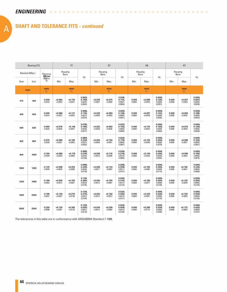
44 SPHERICAL ROLLER BEARING CATALOG
AA
ENGINEERING
Bearing O.D. F7 G7 H8 H7
Nominal (Max.) Tolerance.000 mm.0000 in.
To
HousingBore
Fit
HousingBore
Fit
HousingBore
Fit
HousingBore
Fit
Over Incl. Min. Max. Min. Max. Min. Max. Min. Max.
mmmmin.
mmin.
mmin.
mmin.
mmin.
315 400-0.040-0.0016
+0.062+0.0024
+0.119+0.0047
0.063L0.159L0.0024L0.0062L
+0.018+0.0007
+0.075+0.0030
0.018L0.115L0.0007L0.0046L
0.0000.0000
+0.089+0.0035
0.000L0.129L0.0000L0.0051L
0.0000.0000
+0.057 +0.0022
0.000L0.097L0.0000L0.0038L
400 500-0.045-0.0018
+0.068+0.0027
+0.131+0.0052
0.068L0.176L0.0027L0.0070L
+0.020+0.0008
+0.083+0.0033
0.020L0.128L0.0008L0.0051L
0.0000.0000
+0.097+0.0038
0.000L0.142L0.0000L0.0056L
0.0000.0000
+0.063+0.0025
0.000L0.108L0.0000L0.0043L
500 630-0.050-0.0020
+0.076+0.0030
+0.146+0.0057
0.076L0.196L0.0030L0.0077L
+0.022+0.0009
+0.092+0.0036
0.022L0.142L0.0009L0.0056L
0.0000.0000
+0.110+0.0043
0.000L0.160L0.0000L0.0063L
0.0000.0000
+0.070+0.0028
0.000L0.120L0.0000L0.0048L
630 800-0.075-0.0030
+0.080+0.0031
+0.160+0.0063
0.080L0.235L0.0031L0.0093L
+0.024+0.0009
+0.104+0.0041
0.024L0.179L0.0009L0.0007L
0.0000.0000
+0.125+0.0049
0.000L0.200L0.0000L0.0079L
0.0000.0000
+0.080+0.0031
0.000L0.155L0.0000L0.0061L
800 1000-0.100-0.0039
+0.086+0.0034
+0.179+0.0069
0.086L0.276L0.0034L0.0108L
+0.026+0.0010
+0.116+0.0046
0.026L0.216L0.0010L0.0085L
0.0000.0000
+0.140+0.0055
0.000L0.240L0.0000L0.0094L
0.0000.0000
+0.090+0.0035
0.000L0.190L0.0000L0.0074L
1000 1250-0.125-0.0049
+0.098+0.0039
+0.203+0.0080
0.098L0.328L0.0039L0.0129L
+0.028+0.0011
+0.133+0.0052
0.028L0.258L0.0011L0.0101L
0.0000.0000
+0.165+0.0065
0.000L0.290L0.0000L0.0114L
0.0000.0000
+0.105+0.0041
0.000L0.230L0.0000L0.0090L
1250 1600-0.160-0.0063
+0.030+0.0012
+0.155+0.0061
0.110L0.395L0.0043L0.0156L
+0.030+0.0012
+0.155+0.0061
0.030L0.315L0.0012L0.0124L
0.0000.0000
+0.195+0.0077
0.000L0.355L0.0000L0.0140L
0.0000.0000
+0.125+0.0049
0.000L0.355L0.0000L0.0140L
1600 2000-0.106-0.0047
+0.120+0.0047
+0.270+0.0106
0.120L0.470L0.0047L0.0185L
+0.032+0.0013
+0.182+0.0072
0.032L0.382L0.0013L0.0151L
0.0000.0000
+0.230+0.0091
0.000L0.430L0.0000L0.0170L
0.0000.0000
+0.150+0.0059
0.000L0.350L0.0000L0.0138L
2000 2500-0.250-0.0098
+0.130+0.0051
+0.305+0.0120
0.130L0.555L0.0051L0.0218L
+0.034+0.0013
+0.209+0.0082
0.034L0.459L0.0013L0.0180L
0.0000.0000
+0.280+0.0110
0.000L0.530L0.0000L0.0208L
0.0000.0000
+0.175+0.0069
0.000L0.425L0.0000L0.0167L
The tolerances in this table are in conformance with ANSIABMA Standard 7-1988.
SHAFT AND TOLERANCE FITS - continued

SPHERICAL ROLLER BEARING CATALOG 45
A
ENGINEERING
Bearing O.D. H6 J6 J7 K6 K7
Nominal (Max.) Tolerance.000 mm.0000 in.
To
HousingBore
Fit
HousingBore
Fit
HousingBore
Fit
HousingBore
Fit
HousingBore
Fit
Over Incl. Min. Max. Min. Max. Min. Max. Min. Max. Min. Max.
mmmmin.
mmin.
mmin.
mmin.
mmin.
mmin.
315 400-0.040-0.0016
0.0000.0000
+0.036+0.0014
0.000L0.076L0.0000L0.0030L
-0.007-0.0003
+0.029+0.0011
0.007T0.069L0.0003T0.0027L
-0.018-0.0007
+0.039+0.0015
0.018T0.079L0.0007T0.0031L
-0.029-0.0011
+0.007+0.0003
0.029T0.047L0.0011T0.0019L
-0.040-0.0016
+0.017+0.0007
0.040T0.057L0.0016T0.0023L
400 500-0.045-0.0018
0.0000.0000
+0.040+0.0016
0.000L0.085L0.0000L0.0034L
-0.007-0.0003
+0.033+0.0013
0.007T0.078L0.0003T0.0031L
-0.020-0.0008
+0.0430.0017
0.020T0.088L0.0008T0.0035L
-0.032-0.0013
+0.008+0.0003
0.032T0.053L0.0013T0.0021L
-0.045-0.0018
+0.018+0.0007
0.045T0.063L0.0018T0.0025L
500 630-0.050-0.0020
0.0000.0000
+0.044+0.0017
0.000L0.094L0.0000L0.0037L
-0.007-0.0003
+0.037+0.0015
0.022T0.098L0.0009T0.0039L
-0.022-0.0009
+0.048+0.0019
0.022T0.098L0.0009T0.0039L
-0.044-0.0017
0.0000.0000
0.044T0.050L0.0017T0.0020L
-0.070-0.0028
0.0000.0000
0.070T0.050L0.0028T0.0020L
630 800-0.075-0.0030
0.0000.0000
+0.050+0.0020
0.000L0.125L0.0000L0.0050L
-0.010-0.0004
+0.040+0.0016
0.010T0.115L0.0004T0.0046L
-0.024-0.0009
+0.056+0.0022
0.024T0.131L0.0009T0.0052L
-0.050-0.0020
0.0000.0000
0.050T0.075L0.0020T0.0030L
-0.080-0.0031
0.0000.0000
0.080T0.075L0.0031T0.0030L
800 1000-0.100-0.0039
0.0000.0000
+0.056+0.0022
0.000L0.156L0.0000L0.0061L
-0.010-0.0004
+0.046+0.0018
0.010T0.146L0.0004T0.0057L
-0.026-0.0010
+0.064+0.0025
0.026T0.164L0.0010T0.0064L
-0.056-0.0022
0.0000.0000
0.056T0.100L0.0022T0.0039L
-0.090-0.0035
0.0000.0000
0.090T0.100L0.0035T0.0039L
1000 1250-0.125-0.0049
0.0000.0000
+0.066+0.0026
0.000L0.191L0.0000L0.0075L
-0.010-0.0004
+0.056+0.0022
0.010T0.181L0.0004T0.0071L
-0.028-0.0011
+0.077+0.0030
0.028T0.202L0.0011T0.0079L
-0.066-0.0026
0.0000.0000
0.066T0.125L0.0026T0.0049L
-0.105-0.0041
0.0000.0000
0.105T0.125L0.0041T0.0049L
1250 1600-0.160-0.0063
0.0000.0000
+0.078+0.0031
0.000L0.238L0.0000L0.0094L
-0.010-0.0004
+0.068+0.0027
0.010T0.228L0.0004T0.0090L
-0.030-0.0012
+0.095+0.0037
0.030T0.255L0.0012T0.0100L
-0.078-0.0031
0.0000.0000
0.078T0.160L0.0031T0.0063L
-0.125-0.0049
0.0000.0000
0.125T0.160L0.0049T0.0063L
1600 2000-0.106-0.0047
0.0000.0000
+0.092+0.0036
0.000L0.292L0.0000L0.0115L
-0.010-0.0004
+0.082+0.0032
0.110T0.282L0.0004T0.0011L
-0.032-0.0013
+0.118+0.0046
0.032T0.318L0.0013T0.0125L
-0.092-0.0036
0.0000.0000
0.092T0.200L0.0036T0.0079L
-0.150-0.0059
0.0000.0000
0.150T0.200L0.0059T0.0079L
2000 2500-0.250-0.0098
0.0000.0000
+0.110+0.0043
0.000L0.360L0.0000L0.0141L
-0.010-0.0004
+0.100+0.0039
0.010T0.350L0.0004T0.0137L
-0.034-0.0013
+0.141+0.0056
0.034T0.391L0.0013T0.0154L
-0.110-0.0043
0.0000.0000
0.110T0.250L0.0043T0.0098L
-0.175-0.0069
0.0000.0000
0.175T0.250L0.0069T0.0098L
SHAFT AND TOLERANCE FITS - continued
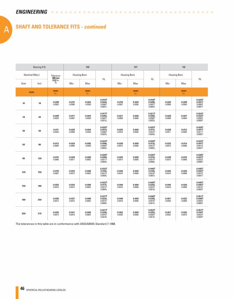
46 SPHERICAL ROLLER BEARING CATALOG
AA
ENGINEERING
Bearing O.D. M6 M7 N6
Nominal (Max.) Tolerance.000 mm.0000 in.
To
Housing Bore
Fit
Housing Bore
Fit
Housing Bore
Fit
Over Incl. Min. Max. Min. Max. Min. Max.
mmmmin.
mmin.
mmin.
mmin.
10 18-0.008-0.0003
-0.015-0.0006
-0.004 -0.0002
0.015T0.004L0.0006T0.0001L
-0.018-0.0007
0.0000.0000
0.018T0.008L0.0007T0.0003L
-0.020-0.0008
-0.009-0.0004
0.020T0.001T0.0008T0.0001T
18 30-0.009-0.0035
-0.017-0.0007
-0.004 -0.0002
0.017T0.005L0.0007T0.0015L
-0.021-0.0008
0.0000.0000
0.021T0.009L0.0008T0.0035L
-0.028-0.0009
-0.007-0.0004
0.024T0.002T0.0009T0.0005T
30 50-0.011-0.0045
-0.020-0.0008
-0.004 -0.0002
0.020T0.007L0.0008T0.0025L
-0.025-0.0010
0.0000.0000
0.025T0.011L0.0010T0.0045L
-0.028-0.0011
-0.012-0.0005
0.028T0.001T0.0011T0.0005T
50 80-0.013-0.0005
-0.024-0.0009
-0.005 -0.0002
0.024T0.008L0.0009T0.0003L
-0.030-0.0012
0.0000.0000
0.030T0.013L0.0012T0.0005L
-0.033-0.0013
-0.014-0.0006
0.033T0.001T0.0013T0.0001T
80 120-0.015-0.0006
-0.028-0.0011
-0.006-0.0002
0.028T0.009L0.0011T0.0004L
-0.035-0.0014
0.0000.0000
0.035T0.015L0.0014T0.0006L
-0.038-0.0015
-0.016-0.0006
0.038T0.001T0.0025T0.0000T
120 150-0.018-0.0007
-0.033-0.0013
-0.008-0.0003
0.033T0.010L0.0013T0.0004L
-0.040-0.0016
0.0000.0000
0.040T0.018L0.0016T0.0007L
-0.045-0.0018
-0.020-0.0008
0.045T0.002T0.0018T0.0001T
150 180-0.025-0.0010
-0.033-0.0013
-0.008-0.0003
0.033T0.017L0.0013T0.0004L
-0.040-0.0016
0.0000.0000
0.040T0.025L0.0016T0.0010L
-0.045-0.0018
-0.020-0.0008
0.045T0.005T0.0018T0.0002T
180 250-0.030-0.0012
-0.037-0.0015
-0.008-0.0003
0.037T0.022L0.0015T0.0009L
-0.046-0.0018
0.0000.0000
0.046T0.030L0.0018T0.0012L
-0.051-0.0020
-0.022-0.0009
0.051T0.008T0.0020T0.0003T
250 315-0.035-0.0014
-0.041-0.0016
-0.009-0.0004
0.041T0.026L0.0016T0.0010L
-0.052-0.0020
0.0000.0000
0.052T0.035L0.0020T0.0014L
-0.057-0.0022
-0.025-0.0010
0.057T0.010T0.0022T0.0004T
The tolerances in this table are in conformance with ANSIABMA Standard 7-1988.
SHAFT AND TOLERANCE FITS - continued
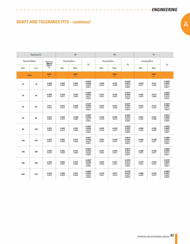
SPHERICAL ROLLER BEARING CATALOG 47
A
ENGINEERING
Bearing O.D. N7 P6 P7
Nominal (Max.) Tolerance.000 mm.0000 in.
To
Housing Bore
Fit
Housing Bore
Fit
Housing Bore
Fit
Over Incl. Min. Max. Min. Max. Min. Max.
mmmmin.
mmin.
mmin.
mmin.
10 18-0.008-0.0003
-0.023-0.0009
-0.005-0.0002
0.023T0.003L0.0009T0.0001L
-0.026-0.0010
-0.015-0.0006
0.026T0.007T0.0010T0.0003T
-0.029-0.0011
-0.011-0.0004
0.029T0.003T0.0011T0.0001T
18 30-0.009-0.0035
-0.028-0.0011
-0.007 -0.0003
0.028T0.002L0.0011T0.0005L
-0.031-0.0012
-0.018-0.0007
0.031T0.009T0.0012T0.0035T
-0.035-0.0014
-0.014-0.0006
0.035T0.005T0.0014T0.0025T
30 50-0.011-0.0045
-0.033-0.0013
-0.008-0.0003
0.033T0.003L0.0013T0.0015L
-0.037-0.0015
-0.021 -0.0008
0.037T0.010T0.0015T0.0035T
-0.042-0.0017
-0.017-0.0007
0.042T0.006T0.0017T0.0025T
50 80-0.013-0.0005
-0.039-0.0015
-0.009 -0.0004
0.039T0.004L0.0015T0.0001L
-0.045-0.0018
-0.026-0.0010
0.045T0.013T0.0018T0.0005T
-0.051-0.0020
-0.021-0.0008
0.051T0.008T0.0020T0.0003T
80 120-0.015-0.0006
-0.045-0.0018
-0.010 -0.0004
0.045T0.005L0.0018T0.0002L
-0.052-0.0020
-0.030-0.0012
0.052T0.015T0.0020T0.0006T
-0.059-0.0023
-0.024-0.0009
0.059T0.009T0.0023T0.0003T
120 150-0.018-0.0007
-0.052-0.0020
-0.012 -0.0005
0.061T0.018L0.0024T0.0007L
-0.061-0.0024
-0.036-0.0014
0.061T0.018T0.0024T0.0007T
-0.068-0.0027
-0.028-0.0011
0.068T0.010T0.0027T0.0004T
150 180-0.025-0.0010
-0.052-0.0020
-0.012 -0.0005
0.052T0.013L0.0020T0.0005L
-0.061-0.0024
-0.036-0.0014
0.061T0.011T0.0024T0.0007T
-0.068-0.0027
-0.028-0.0011
0.068T0.003T0.0011T0.0001T
180 250-0.030-0.0012
-0.060-0.0024
-0.014-0.0006
0.060T0.016L0.0024T0.0006L
-0.070-0.0028
-0.041-0.0016
0.070T0.011T0.0028T0.0004T
-0.079-0.0031
-0.033-0.0013
0.079T0.003T0.0031T0.0001T
250 315-0.035-0.0014
-0.066-0.0026
-0.014-0.0006
0.066T0.021L0.0025T0.0008L
-0.079-0.0031
-0.047-0.0019
0.079T0.012T0.0031T0.0005T
-0.088-0.0035
-0.036-0.0014
0.088T0.001T0.0035T0.0000T
SHAFT AND TOLERANCE FITS - continued
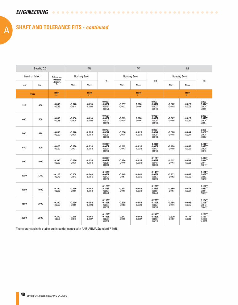
48 SPHERICAL ROLLER BEARING CATALOG
AA
ENGINEERING
Bearing O.D. M6 M7 N6
Nominal (Max.) Tolerance.000 mm.0000 in.
To
Housing Bore
Fit
Housing Bore
Fit
Housing Bore
Fit
Over Incl. Min. Max. Min. Max. Min. Max.
mmmmin.
mmin.
mmin.
mmin.
315 400-0.040-0.0016
-0.046-0.0018
-0.010-0.0004
0.046T0.030L0.0018T0.0012L
-0.057-0.0022
0.0000.0000
0.057T0.040L0.0022T0.0016L
-0.062-0.0029
-0.026-0.0006
0.062T0.014T0.0024T0.0006T
400 500-0.045-0.0018
-0.050-0.0020
-0.010-0.0004
0.050T0.035L0.0020T0.0014L
-0.063-0.0025
0.0000.0000
0.063T0.045L0.0025T0.0018L
-0.067-0.0026
-0.027-0.0011
0.067T0.018T0.0026T0.0007T
500 630-0.050-0.0020
-0.070-0.0028
-0.026-0.0010
0.070T0.024L0.0028T0.0010L
-0.096-0.0038
-0.026-0.0010
0.096T0.024L0.0038T0.0010L
-0.088-0.0035
-0.044-0.0017
0.088T0.006T0.0035T0.0003T
630 800-0.075-0.0030
-0.080-0.0031
-0.030-0.0012
0.080T0.045L0.0031T0.0018L
-0.110-0.0043
-0.030-0.0012
0.110T0.045L0.0043T0.0018L
-0.100-0.0039
-0.050-0.0020
0.100T0.025T0.0039T0.0010T
800 1000-0.100-0.0039
-0.090-0.0035
-0.034-0.0013
0.090T0.066L0.0035T0.0026L
-0.124-0.0049
-0.034-0.0013
0.124T0.066L0.0049T0.0026L
-0.112-0.0044
-0.056-0.0022
0.112T0.044T0.0044T0.0017T
1000 1250-0.125-0.0049
-0.106-0.0042
-0.040-0.0016
0.106T0.085L0.0042T0.0033L
-0.145-0.0057
-0.040-0.0016
0.145T0.085L0.0057T0.0033L
-0.132-0.0052
-0.066-0.0026
0.132T0.059T0.0052T0.0023T
1250 1600-0.160-0.0063
-0.126-0.0050
-0.048-0.0019
0.126T0.112L0.0050T0.0044L
-0.173-0.0068
-0.048-0.0019
0.173T0.112L0.0068T0.0044L
-0.156-0.0061
-0.078-0.0031
0.156T0.082T0.0061T0.0032T
1600 2000-0.200-0.0079
-0.150-0.0059
-0.058-0.0023
0.150T0.142L0.0059T0.0056L
-0.208-0.0082
-0.058-0.0023
0.208T0.142L0.0082T0.0056L
-0.184-0.0072
-0.092-0.0036
0.184T0.108T0.0072T0.0043T
2000 2500-0.250-0.0098
-0.178-0.0070
-0.068-0.0027
0.178T0.182L0.0070T0.0071L
-0.243-0.0096
-0.068-0.0027
0.243T0.182L0.0096T0.0071L
-0.220-0.0087
-0.110-0.0043
0.285T0.140T0.112T0.055T
The tolerances in this table are in conformance with ANSIABMA Standard 7-1988.
SHAFT AND TOLERANCE FITS - continued
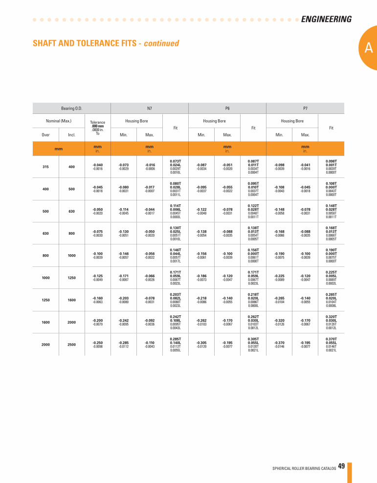
SPHERICAL ROLLER BEARING CATALOG 49
A
ENGINEERING
Bearing O.D. N7 P6 P7
Nominal (Max.) Tolerance.000 mm.0000 in.
To
Housing Bore
Fit
Housing Bore
Fit
Housing Bore
Fit
Over Incl. Min. Max. Min. Max. Min. Max.
mmmmin.
mmin.
mmin.
mmin.
315 400-0.040-0.0016
-0.073-0.0029
-0.016 -0.0006
0.073T0.024L0.0029T0.0010L
-0.087-0.0034
-0.051-0.0020
0.087T0.011T0.0034T0.0004T
-0.098-0.0039
-0.041-0.0016
0.098T0.001T0.0039T0.0000T
400 500-0.045-0.0018
-0.080-0.0031
-0.017-0.0007
0.080T0.028L0.0031T0.0011L
-0.095-0.0037
-0.055-0.0022
0.095T0.010T0.0037T0.0004T
-0.108-0.0043
-0.045-0.0018
0.108T0.000T0.0043T0.0000T
500 630-0.050-0.0020
-0.114-0.0045
-0.044-0.0017
0.114T0.006L0.0045T0.0003L
-0.122-0.0048
-0.078-0.0031
0.122T0.028T0.0048T0.0011T
-0.148-0.0058
-0.078-0.0031
0.148T0.028T0.0058T0.0011T
630 800-0.075-0.0030
-0.130-0.0051
-0.050-0.0020
0.130T0.025L0.0051T0.0010L
-0.138-0.0054
-0.088-0.0035
0.138T0.013T0.0054T0.0005T
-0.168-0.0066
-0.088-0.0035
0.168T0.013T0.0066T0.0005T
800 1000-0.100-0.0039
-0.146-0.0057
-0.056-0.0022
0.146T0.044L0.0057T0.0017L
-0.156-0.0061
-0.100-0.0039
0.156T0.000T0.0061T0.0000T
-0.190-0.0075
-0.100-0.0039
0.190T0.000T0.0075T0.0000T
1000 1250-0.125-0.0049
-0.171-0.0067
-0.066-0.0026
0.171T0.059L0.0067T0.0023L
-0.186-0.0073
-0.120-0.0047
0.171T0.059L0.0067T0.0023L
-0.225-0.0089
-0.120-0.0047
0.225T0.005L0.0089T0.0002L
1250 1600-0.160-0.0063
-0.203-0.0080
-0.078-0.0031
0.203T0.082L0.0080T0.0023L
-0.218-0.0086
-0.140-0.0055
0.218T0.020L0.0086T0.0008L
-0.265-0.0104
-0.140-0.0055
0.265T0.020L0.0104T0.0008L
1600 2000-0.200-0.0079
-0.242-0.0095
-0.092-0.0036
0.242T0.108L0.0095T0.0043L
-0.262-0.0103
-0.170-0.0067
0.262T0.030L0.0103T0.0012L
-0.320-0.0126
-0.170-0.0067
0.320T0.030L0.0126T0.0012L
2000 2500-0.250-0.0098
-0.285-0.0112
-0.110-0.0043
0.285T0.140L0.0112T0.0055L
-0.305-0.0120
-0.195-0.0077
0.305T0.055L0.0120T0.0021L
-0.370-0.0146
-0.195-0.0077
0.370T0.055L0.0146T0.0021L
SHAFT AND TOLERANCE FITS - continued
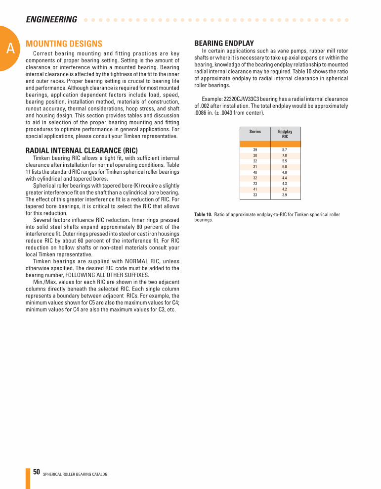
50 SPHERICAL ROLLER BEARING CATALOG
AA
ENGINEERING
MOUNTING DESIGNSCorrect bearing mounting and fitting practices are key
components of proper bearing setting. Setting is the amount of clearance or interference within a mounted bearing. Bearing internal clearance is affected by the tightness of the fi t to the inner and outer races. Proper bearing setting is crucial to bearing life and performance. Although clearance is required for most mounted bearings, application dependent factors include load, speed, bearing position, installation method, materials of construction, runout accuracy, thermal considerations, hoop stress, and shaft and housing design. This section provides tables and discussion to aid in selection of the proper bearing mounting and fi tting procedures to optimize performance in general applications. For special applications, please consult your Timken representative.
RADIAL INTERNAL CLEARANCE (RIC)Timken bearing RIC allows a tight fi t, with suffi cient internal
clearance after installation for normal operating conditions. Table 11 lists the standard RIC ranges for Timken spherical roller bearings with cylindrical and tapered bores.
Spherical roller bearings with tapered bore (K) require a slightly greater interference fi t on the shaft than a cylindrical bore bearing. The effect of this greater interference fi t is a reduction of RIC. For tapered bore bearings, it is critical to select the RIC that allows for this reduction.
Several factors infl uence RIC reduction. Inner rings pressed into solid steel shafts expand approximately 80 percent of the interference fi t. Outer rings pressed into steel or cast iron housings reduce RIC by about 60 percent of the interference fi t. For RIC reduction on hollow shafts or non-steel materials consult your local Timken representative.
Timken bearings are supplied with NORMAL RIC, unless otherwise specifi ed. The desired RIC code must be added to the bearing number, FOLLOWING ALL OTHER SUFFIXES.
Min./Max. values for each RIC are shown in the two adjacent columns directly beneath the selected RIC. Each single column represents a boundary between adjacent RICs. For example, the minimum values shown for C5 are also the maximum values for C4; minimum values for C4 are also the maximum values for C3, etc.
BEARING ENDPLAY In certain applications such as vane pumps, rubber mill rotor
shafts or where it is necessary to take up axial expansion within the bearing, knowledge of the bearing endplay relationship to mounted radial internal clearance may be required. Table 10 shows the ratio of approximate endplay to radial internal clearance in spherical roller bearings.
Example: 22320CJW33C3 bearing has a radial internal clearance of .002 after installation. The total endplay would be approximately .0086 in. (± .0043 from center).
Series Endplay RIC
39 8.7 30 7.0 22 5.5 31 5.0 40 4.8 32 4.4 23 4.3 41 4.2 33 3.9
Table 10. Ratio of approximate endplay-to-RIC for Timken spherical roller bearings.
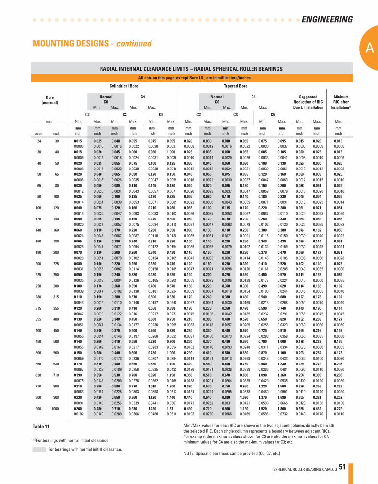
SPHERICAL ROLLER BEARING CATALOG 51
A
ENGINEERING
Min./Max. values for each RIC are shown in the two adjacent columns directly beneath the selected RIC. Each single column represents a boundary between adjacent RIC’s. For example, the maximum values shown for C5 are also the maximum values for C4; minimum values for C4 are also the maximum values for C3; etc.
NOTE: Special clearances can be provided (C6, C7, etc.) : For bearings with normal initial clearance.
RADIAL INTERNAL CLEARANCE LIMITS – RADIAL SPHERICAL ROLLER BEARINGS
All data on this page, except Bore I.D., are in millimeters/inches
Cylindrical Bore Tapered Bore
Normal C4 Normal C4 Suggested Minimum C0 C0 Reduction of RIC RIC after Min. Max. Min. Max. Min. Max. Min. Max. Due to Installation Installation(1)
C2 C3 C5 C2 C3 C5
mm Min. Max. Min. Max. Min. Max. Min. Max. Min. Max. Min. Max. Min. Max. Min.
mm mm mm mm mm mm mm mm mm mm mm mm mm mm mm over incl. inch inch inch inch inch inch inch inch inch inch inch inch inch inch inch
24 30 0.015 0.025 0.040 0.055 0.075 0.095 0.020 0.030 0.040 0.055 0.075 0.095 0.015 0.020 0.015 0.0006 0.0010 0.0016 0.0022 0.0030 0.0037 0.0008 0.0012 0.0016 0.0022 0.0030 0.0037 0.0006 0.0008 0.0006 30 40 0.015 0.030 0.045 0.060 0.080 1.000 0.025 0.035 0.050 0.065 0.085 0.105 0.020 0.025 0.015 0.0006 0.0012 0.0018 0.0024 0.0031 0.0039 0.0010 0.0014 0.0020 0.0026 0.0033 0.0041 0.0008 0.0010 0.0006 40 50 0.020 0.035 0.055 0.075 0.100 0.125 0.030 0.045 0.060 0.080 0.100 0.130 0.025 0.030 0.020 0.0008 0.0014 0.0022 0.0030 0.0039 0.0049 0.0012 0.0018 0.0024 0.0031 0.0039 0.0051 0.0010 0.0012 0.0008 50 65 0.020 0.040 0.065 0.090 0.120 0.150 0.040 0.055 0.075 0.095 0.120 0.160 0.030 0.038 0.025 0.0008 0.0016 0.0026 0.0035 0.0047 0.0059 0.0016 0.0022 0.0030 0.0037 0.0047 0.0063 0.0012 0.0015 0.0010 65 80 0.030 0.050 0.080 0.110 0.145 0.180 0.050 0.070 0.095 0.120 0.150 0.200 0.038 0.051 0.025 0.0012 0.0020 0.0031 0.0043 0.0057 0.0071 0.0020 0.0028 0.0037 0.0047 0.0059 0.0079 0.0015 0.0020 0.0010 80 100 0.035 0.060 0.100 0.135 0.180 0.225 0.055 0.080 0.110 0.140 0.180 0.230 0.046 0.064 0.036 0.0014 0.0024 0.0039 0.0053 0.0071 0.0089 0.0022 0.0030 0.0043 0.0055 0.0071 0.0091 0.0018 0.0025 0.0014 100 120 0.040 0.075 0.120 0.160 0.210 0.260 0.065 0.100 0.135 0.170 0.220 0.280 0.051 0.071 0.051 0.0016 0.0030 0.0047 0.0063 0.0083 0.0102 0.0026 0.0039 0.0053 0.0067 0.0087 0.0110 0.0020 0.0028 0.0020 120 140 0.050 0.095 0.145 0.190 0.240 0.300 0.080 0.120 0.160 0.200 0.260 0.330 0.064 0.089 0.056 0.0020 0.0037 0.0057 0.0075 0.0094 0.0118 0.0031 0.0047 0.0063 0.0079 0.0102 0.0130 0.0025 0.0035 0.0022 140 160 0.060 0.110 0.170 0.220 0.280 0.350 0.090 0.130 0.180 0.230 0.300 0.380 0.076 0.102 0.056 0.0024 0.0043 0.0067 0.0087 0.0110 0.0138 0.0035 0.0051 0.0071 0.0091 0.0118 0.0150 0.0030 0.0040 0.0022 160 180 0.065 0.120 0.180 0.240 0.310 0.390 0.100 0.140 0.200 0.260 0.340 0.430 0.076 0.114 0.061 0.0026 0.0047 0.0071 0.0094 0.0122 0.0154 0.0039 0.0055 0.0079 0.0102 0.0134 0.0169 0.0030 0.0045 0.0024 180 200 0.070 0.130 0.200 0.260 0.340 0.430 0.110 0.160 0.220 0.290 0.370 0.470 0.089 0.127 0.071 0.0028 0.0051 0.0079 0.0102 0.0134 0.0169 0.0043 0.0063 0.0087 0.0114 0.0146 0.0185 0.0035 0.0050 0.0028 200 225 0.080 0.140 0.220 0.290 0.380 0.470 0.120 0.180 0.250 0.320 0.410 0.520 0.102 0.140 0.076 0.0031 0.0055 0.0087 0.0114 0.0150 0.0185 0.0047 0.0071 0.0098 0.0126 0.0161 0.0205 0.0040 0.0055 0.0030 225 250 0.090 0.150 0.240 0.320 0.420 0.520 0.140 0.200 0.270 0.350 0.450 0.570 0.114 0.152 0.089 0.0035 0.0059 0.0094 0.0126 0.0165 0.0205 0.0055 0.0079 0.0106 0.0138 0.0177 0.0224 0.0045 0.0060 0.0035 250 280 0.100 0.170 0.260 0.350 0.460 0.570 0.150 0.220 0.300 0.390 0.490 0.620 0.114 0.165 0.102 0.0039 0.0067 0.0102 0.0138 0.0181 0.0224 0.0059 0.0087 0.0118 0.0154 0.0193 0.0244 0.0045 0.0065 0.0040 280 315 0.110 0.190 0.280 0.370 0.500 0.630 0.170 0.240 0.330 0.430 0.540 0.680 0.127 0.178 0.102 0.0043 0.0075 0.0110 0.0146 0.0197 0.0248 0.0067 0.0094 0.0130 0.0169 0.0213 0.0268 0.0050 0.0070 0.0040 315 355 0.120 0.200 0.310 0.410 0.550 0.690 0.190 0.270 0.360 0.470 0.590 0.740 0.140 0.190 0.114 0.0047 0.0079 0.0122 0.0161 0.0217 0.0272 0.0075 0.0106 0.0142 0.0185 0.0232 0.0291 0.0055 0.0075 0.0045 355 400 0.130 0.220 0.340 0.450 0.600 0.750 0.210 0.300 0.400 0.520 0.650 0.820 0.152 0.203 0.127 0.0051 0.0087 0.0134 0.0177 0.0236 0.0295 0.0083 0.0118 0.0157 0.0205 0.0256 0.0323 0.0060 0.0080 0.0050 400 450 0.140 0.240 0.370 0.500 0.660 0.820 0.230 0.330 0.440 0.570 0.720 0.910 0.165 0.216 0.152 0.0055 0.0094 0.0146 0.0197 0.0260 0.0323 0.0091 0.0130 0.0173 0.0224 0.0283 0.0358 0.0065 0.0085 0.0060 450 500 0.140 0.260 0.410 0.550 0.720 0.900 0.260 0.370 0.490 0.630 0.790 1.000 0.178 0.229 0.165 0.0055 0.0102 0.0161 0.0217 0.0283 0.0354 0.0102 0.0146 0.0193 0.0248 0.0311 0.0394 0.0070 0.0090 0.0065 500 560 0.150 0.280 0.440 0.600 0.780 1.000 0.290 0.410 0.540 0.680 0.870 1.100 0.203 0.254 0.178 0.0059 0.0110 0.0173 0.0236 0.0307 0.0394 0.0114 0.0161 0.0213 0.0268 0.0343 0.0433 0.0080 0.0100 0.0070 560 630 0.170 0.310 0.480 0.650 0.850 1.100 0.320 0.460 0.600 0.760 0.980 1.230 0.229 0.279 0.203 0.0067 0.0122 0.0189 0.0256 0.0335 0.0433 0.0126 0.0181 0.0236 0.0299 0.0386 0.0484 0.0090 0.0110 0.0080 630 710 0.190 0.350 0.530 0.700 0.920 1.190 0.350 0.510 0.670 0.850 1.090 1.360 0.254 0.305 0.203 0.0075 0.0138 0.0209 0.0276 0.0362 0.0469 0.0138 0.0201 0.0264 0.0335 0.0429 0.0535 0.0100 0.0120 0.0080 710 800 0.210 0.390 0.580 0.770 1.010 1.300 0.390 0.570 0.750 0.960 1.220 1.500 0.279 0.356 0.229 0.0083 0.0154 0.0228 0.0303 0.0398 0.0512 0.0154 0.0224 0.0295 0.0378 0.0480 0.0591 0.0110 0.0140 0.0090 800 900 0.230 0.430 0.650 0.860 1.120 1.440 0.440 0.640 0.840 1.070 1.370 1.690 0.305 0.381 0.252 0.0091 0.0169 0.0256 0.0339 0.0441 0.0567 0.0173 0.0252 0.0331 0.0421 0.0539 0.0665 0.0120 0.0150 0.0100 900 1000 0.260 0.480 0.710 0.930 1.220 1.57 0.490 0.710 0.930 1.190 1.520 1.860 0.356 0.432 0.279 0.0102 0.0189 0.0280 0.0366 0.0480 0.0618 0.0193 0.0280 0.0366 0.0469 0.0598 0.0732 0.0140 0.0170 0.0110
Bore(nominal)
(1)For bearings with normal initial clearance.
MOUNTING DESIGNS - continued
Table 11.
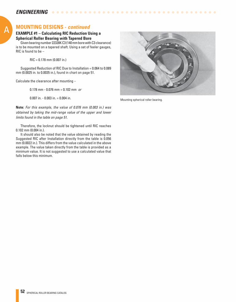
52 SPHERICAL ROLLER BEARING CATALOG
AA
ENGINEERING
EXAMPLE #1 – Calculating RIC Reduction Using a Spherical Roller Bearing with Tapered Bore
Given bearing number 22328K C3 (140 mm bore with C3 clearance) is to be mounted on a tapered shaft. Using a set of feeler gauges, RIC is found to be –
RIC = 0.178 mm (0.007 in.)
Suggested Reduction of RIC Due to Installation = 0.064 to 0.089 mm (0.0025 in. to 0.0035 in.), found in chart on page 51.
Calculate the clearance after mounting –
0.178 mm - 0.076 mm = 0.102 mm or
0.007 in. - 0.003 in. = 0.004 in.
Note: For this example, the value of 0.076 mm (0.003 in.) was obtained by taking the mid-range value of the upper and lower limits found in the table on page 51.
Therefore, the locknut should be tightened until RIC reaches
0.102 mm (0.004 in.).It should also be noted that the value obtained by reading the
Suggested RIC after Installation directly from the table is 0.056 mm (0.0022 in.). This differs from the value calculated in the above example. The value taken directly from the table is provided as a minimum value. It is not suggested to use a calculated value that falls below this minimum.
MOUNTING DESIGNS - continued
Mounting spherical roller bearing.
SPHERICAL ROLLER BEARING CATALOG 53
A
ENGINEERING
EXAMPLE #2 – Calculating RIC Reduction Using a Spherical Roller Bearing with Cylindrical Bore
Observations: • Bearing 22230YM, nominal 150 mm (5.0955 in.) bore and 270 mm (10.6299 in.) O.D., standard class, operating at 1200 RPM. • Float bearing position so the stationary O.D. should be free to move in housing, or loose fi t. • With shaft/inner ring rotation and the moderate loading 0.09C, the bore should be tight fi t.
We can use the nominal fi t charts on page 55 (Shaft Fit) and 56 (Housing Fit) to help guide our ISO fi t selection.
Shaft Fit (page 55) at 150 mm Bore: ISO p6
From the shaft fi t chart at 150 mm nominal bore at p6 (page 40), the shaft tolerance is Nominal +0.043 to +0.068 mm (+0.0017 to +0.0027 in.). Therefore we have the following bore range: Max. Shaft = 150.068 mm (5.0955 in.) Min. Shaft = 150.043 mm (5.0945 in.)
This yields a Shaft Fit:
Min. Fit = Min. Shaft – Max. Bore = 150.043 – 150.000 = 0.043 mm (0.0017 in.) Tight
Max. Fit = Max. Shaft – Min. Bore = 150.068 – 149.075 = 0.093 mm (0.0037 in.) Tight
Housing Fit (page 56) at 270 mm O.D.: ISO H8
From the housing fi t chart at 270 mm nominal O.D. at H8 (page 43), the housing bore tolerance is Nominal +0.000 to +0.081 mm (+0.0000 in., +0.0032 in.). Therefore we have the following bore range:
Max. Housing Bore = 270.081 mm (10.6331 in.) Min. Housing Bore = 270.000 mm (10.6299 in.)
This yields an O.D. Fit:
Min. Fit = Min. Housing Bore – Max. O.D. = 270.000 – 270.000 = 0.000 mm (0.0000 in.) Loose
Max. Fit = Max. Housing Bore – Min O.D. = 270.081 – 269.965 = 0.116 mm (0.0046 in.) Loose
MOUNTING DESIGNS - continuedDETERMINING PROPER RIC
For the primary selection of radial internal clearance, RIC, the major parameters are the bearing speed and the fi ts. For our example, we know that the shaft fi t is 0.043 mm (0.0017 in.) tight to 0.093 mm (0.0037 in.) tight. We know the housing fi t is line to 0.116 mm (0.0046 in.) loose. We also know that the bearing speed is 1200 RPM or 60 percent of the speed rating.
As a general rule of thumb, we bump the clearance up due to operating speeds that exceed 70% of the speed rating, due to concerns over internal heat generation and thermal growth. In this case, we are at 60 percent of the speed rating, so normal clearance, ISO C0 or CNormal, can be selected.
Observing the RIC chart on page 51, we fi nd for 150 mm nominal bore at CNormal the RIC will be 0.110 mm to 0.170 mm (0.0043 in. to 0.0067 in.). We also note that the minimum recommended RIC (installed) is 0.056 mm (0.0022 in.).
Also from page 51, we note that we get an approximate reduction of RIC that is 80 percent of interference fi t on a solid shaft and 60 percent of the OD interference fi t in a steel or cast iron housing. Since we have a loose housing fi t, there will be no RIC reduction from that fi t.
Shaft Fit RIC Reductions and Clearance:
0.043 mm (0.0017 in.) tight = 0.034 mm (0.0014 in.) RIC reduction
0.093 mm (0.0037 in.) tight = 0.074 mm (0.0030 in.) RIC reduction
Max. Clearance = Max. RIC – Min. Fit Reduction = 0.170 – 0.034 = 0.136 mm (0.0054 in.)
Min. Clearance = Min. RIC – Max. Fit Reduction = 0.110 – 0.074 = 0.036 mm (0.0014 in.)
Since the minimum mounted clearance is less than the minimum suggested RIC of 0.056 mm (0.0022 in.), the CNormal RIC clearance limit needs to be re-evaluated.
For a 150mm nominal bore at C3, the RIC will be 0.170 to 0.220 mm (0.0067 to 0.0087 in.). Recalculating shaft fi t RIC reduction and clearance:
Max. Clearance = Max. RIC – Min. Fit Reduction = 0.220 – 0.034 = 0.186 mm (0.0073 in.)
Min. Clearance = Min. RIC – Max. Fit Reduction = 0.170 – 0.074 = 0.096 mm (0.0038 in.)
Since the Minimum mounted clearance is now greater than the minimum suggested RIC of 0.056 mm (0.0022 in.), the C3 RIC clearance limit is acceptable.
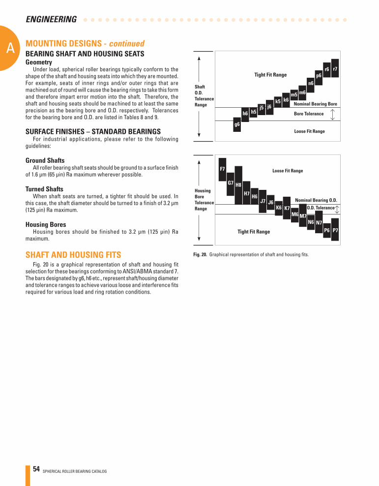
54 SPHERICAL ROLLER BEARING CATALOG
AA
ENGINEERING
BEARING SHAFT AND HOUSING SEATSGeometry
Under load, spherical roller bearings typically conform to the shape of the shaft and housing seats into which they are mounted. For example, seats of inner rings and/or outer rings that are machined out of round will cause the bearing rings to take this form and therefore impart error motion into the shaft. Therefore, the shaft and housing seats should be machined to at least the same precision as the bearing bore and O.D. respectively. Tolerances for the bearing bore and O.D. are listed in Tables 8 and 9.
SURFACE FINISHES – STANDARD BEARINGSFor industrial applications, please refer to the following
guidelines:
Ground ShaftsAll roller bearing shaft seats should be ground to a surface fi nish
of 1.6 μm (65 μin) Ra maximum wherever possible.
Turned ShaftsWhen shaft seats are turned, a tighter fi t should be used. In
this case, the shaft diameter should be turned to a fi nish of 3.2 μm (125 μin) Ra maximum.
Housing BoresHousing bores should be finished to 3.2 μm (125 μin) Ra
maximum.
SHAFT AND HOUSING FITSFig. 20 is a graphical representation of shaft and housing fi t
selection for these bearings conforming to ANSI/ABMA standard 7. The bars designated by g6, h6 etc., represent shaft/housing diameter and tolerance ranges to achieve various loose and interference fi ts required for various load and ring rotation conditions.
MOUNTING DESIGNS - continued
Tight Fit Range
Nominal Bearing Bore
Bore Tolerance
Loose Fit Rangeg6
h6 h5j5 j6
k5 k6m5 m6
n6p6
r6 r7
ShaftO.D.ToleranceRange
Housing BoreToleranceRange
Tight Fit Range
Nominal Bearing O.D.
O.D. Tolerance
Loose Fit RangeF7
G7 H8
H7 H6J7 J6
K6 K7M6 M7
N6 N7P6 P7
Fig. 20. Graphical representation of shaft and housing fi ts.
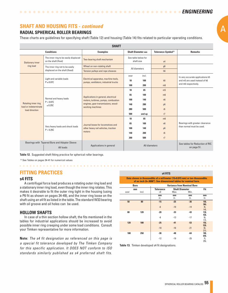
SPHERICAL ROLLER BEARING CATALOG 55
A
ENGINEERING
SHAFT AND HOUSING FITS - continuedRADIAL SPHERICAL ROLLER BEARINGSThese charts are guidelines for specifying shaft (Table 12) and housing (Table 14) fi ts related to particular operating conditions.
(1) See Tables on pages 34-41 for numerical values
Table 12. Suggested shaft fi tting practice for spherical roller bearings.
FITTING PRACTICESs4 FITS
A centrifugal force load produces a rotating outer ring load and a stationary inner ring load, even though the inner ring rotates. This makes it desirable to fi t the outer ring tight in the housing (using a P6 fi t as shown on pages 34-49), and the inner ring loose on the shaft using an s4 fi t as listed in the table. The standard W33 bearing with oil groove and oil holes can be used.
HOLLOW SHAFTSIn case of a thin section hollow shaft, the fi ts mentioned in the
tables for industrial applications should be increased to avoid possible inner ring creeping under some load conditions. Consult your Timken representative for more information.
Note: The s4 fit designation as referenced on this page is a special fit tolerance developed by The Timken Company for this specific application. It DOES NOT conform to ISO standards similarly published as s4 preferred shaft fits.
Data shown in thousandths of a millimeter (15=0.015 mm) or ten-thousandths of an inch (6=.0006"). See dimensional tables for nominal bore.
Bore Variance from Nominal Bore mm Tolerance Shaft Diameter Fit over incl. +0 Max. Min. mm mm mm mm in. in. in. in. 50 80 -15 -25 -36 10L 36L -6 -10 -14 4L 14L 80 120 -20 -33 -43 13L 43L -8 -13 -17 5L 17L 120 180 -25 -41 -53 15L 53L -10 -16 -21 6L 21L 180 250 -30 -48 -64 18L 64L -12 -19 -25 7L 25L
s4 FITS
Table 13. Timken developed s4 fi t designations.
SHAFT
Conditions Examples Shaft Diameter mm Tolerance Symbol(1) Remarks
Stationary inner ring load
The inner ring to be easily displaced on the shaft (fl oat)
Two-bearing shaft mechanismSee table below for
shaft size s4
The inner ring not to be easily displaced on the shaft (fi xed)
Wheel on non-rotating shaft All diameters
g6
Tension pulleys and rope sheaves h6
Rotating inner ring load or indeterminate
load direction
Light and variable loadsP 0.07C
Electrical apparatus, machine tools, pumps, ventilators, industrial trucks
over incl. In very accurate applications k5 and m5 are used instead of k6 and m6 respectively.
18 100 k6
100 200 m6
Normal and heavy loadsP > 0.07C 0.25C
Applications in general, electrical motors, turbines, pumps, combustion engines, gear transmissions, wood-working machines
18 65 m5
65 100 m6
100 140 n6
140 280 p6
280 500 r6
500 and up r7
Very heavy loads and shock loads P > 0.25C
Journal boxes for locomotives and other heavy rail vehicles, traction motors
18 65 m6
Bearings with greater clearance than normal must be used.
65 100 n6
100 140 p6
140 200 r6
200 500 r7
Bearings with Tapered Bore and Adapter SleeveApplications in general All diameters
See tables for Reduction of RIC on page 51.All loads
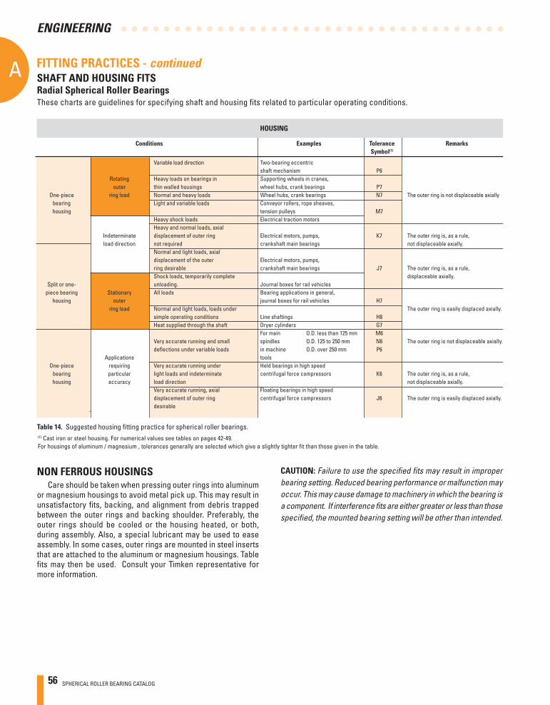
56 SPHERICAL ROLLER BEARING CATALOG
AA
ENGINEERING
Conditions Examples Tolerance Remarks Symbol(1)
Variable load direction Two-bearing eccentric shaft mechanism P6 Rotating Heavy loads on bearings in Supporting wheels in cranes, outer thin walled housings wheel hubs, crank bearings P7 One-piece ring load Normal and heavy loads Wheel hubs, crank bearings N7 The outer ring is not displaceable axially bearing Light and variable loads Conveyor rollers, rope sheaves, housing tension pulleys M7 Heavy shock loads Electrical traction motors Heavy and normal loads, axial Indeterminate displacement of outer ring Electrical motors, pumps, K7 The outer ring is, as a rule, load direction not required crankshaft main bearings not displaceable axially. Normal and light loads, axial displacement of the outer Electrical motors, pumps, ring desirable crankshaft main bearings J7 The outer ring is, as a rule, Shock loads, temporarily complete displaceable axially. Split or one- unloading. Journal boxes for rail vehicles piece bearing Stationary All loads Bearing applications in general, housing outer journal boxes for rail vehicles H7 ring load Normal and light loads, loads under The outer ring is easily displaced axially. simple operating conditions Line shaftings H8 Heat supplied through the shaft Dryer cylinders G7 For main O.D. less than 125 mm M6 Very accurate running and small spindles O.D. 125 to 250 mm N6 The outer ring is not displaceable axially. defl ections under variable loads in machine O.D. over 250 mm P6 Applications tools One-piece requiring Very accurate running under Held bearings in high speed bearing particular light loads and indeterminate centrifugal force compressors K6 The outer ring is, as a rule, housing accuracy load direction not displaceable axially. Very accurate running, axial Floating bearings in high speed displacement of outer ring centrifugal force compressors J6 The outer ring is easily displaced axially. desirable
(1) Cast iron or steel housing. For numerical values see tables on pages 42-49.For housings of aluminum / magnesium , tolerances generally are selected which give a slightly tighter fit than those given in the table.
These charts are guidelines for specifying shaft and housing fi ts related to particular operating conditions.
SHAFT AND HOUSING FITSRadial Spherical Roller Bearings
HOUSING
FITTING PRACTICES - continued
Table 14. Suggested housing fi tting practice for spherical roller bearings.
NON FERROUS HOUSINGSCare should be taken when pressing outer rings into aluminum
or magnesium housings to avoid metal pick up. This may result in unsatisfactory fi ts, backing, and alignment from debris trapped between the outer rings and backing shoulder. Preferably, the outer rings should be cooled or the housing heated, or both, during assembly. Also, a special lubricant may be used to ease assembly. In some cases, outer rings are mounted in steel inserts that are attached to the aluminum or magnesium housings. Table fi ts may then be used. Consult your Timken representative for more information.
CAUTION: Failure to use the specified fits may result in improper bearing setting. Reduced bearing performance or malfunction may occur. This may cause damage to machinery in which the bearing is a component. If interference fits are either greater or less than those specified, the mounted bearing setting will be other than intended.
SPHERICAL ROLLER BEARING CATALOG 57
A
ENGINEERING
ADVANTAGES OF OIL AND GREASE OIL GREASE
Carries heat away from the bearings
Carries away moisture and particulate matter
Easily controlled lubrication
Simplifi es seal design and acts as a sealant
Permits prelubrication of sealedor shielded bearings
Generally requires less frequent lubrication
LUBRICANT ADDITIVESAdditives are materials, usually chemicals, that improve specifi c
properties when added to lubricants. Additives, when properly formulated into a lubricant, can increase lubricant life, provide greater resistance to corrosion, increase load-carrying capacity and enhance other properties. Additives are very complex and should not be added indiscriminately to lubricants as a cure-all for lubrication problems.
The more common lubricant additives include:• Oxidation inhibitors for increasing lubricant service life.• Rust or corrosion inhibitors to protect surfaces from rust or corrosion.
• Demulsifi ers to promote oil and water separation.• Viscosity-index improvers to decrease viscosity sensitivity to temperature change.• Pour-point depressants to lower the pouring point at low temperatures.• Lubricity agents to modify friction.• Antiwear agents to retard wear.• Extreme pressure (EP) additives to prevent scoring under boundary-lubrication conditions.• Detergents and dispersants to maintain cleanliness.• Antifoam agents to reduce foam.• Tackiness agents to improve adhesive properties.
Inorganic additives such as molybdenum disulphide, graphite, and zinc oxide are sometimes included in lubricants. In most roller bearing applications, inorganic additives are of no signifi cant benefi t; conversely, as long as the concentration is low and the particle size small, they are not harmful.
Recently, the effects of lubricant chemistry on bearing life (as opposed to the purely physical characteristics) have received much emphasis. Rust, oxidation, extreme pressure and anti-wear additive packages are widely used in engine and gear oils. Fatigue testing has shown these additives may, depending on their chemical formulation, concentration and operating temperature, have a positive or negative impact on bearing life.
Consult your Timken representative for more information regarding lubricant additives.
GUIDANCE FOR OIL/GREASE SELECTIONOil Lubrication
Oils used for bearing lubrication should be high-quality, non-oxidizing mineral oils or synthetic oils with similar properties. Selection of the proper type of oils depends on bearing speed, load, operating temperature and method of lubrication.
Some features and advantages of oil lubrication, in addition to the above, are as follows:• Oil is a better lubricant for high speeds or high temperatures.
It can be cooled to help reduce bearing temperature.• With oil, it is easier to handle and control the amount of lubricant
reaching the bearing. It is harder to retain in the bearing. Lubricant losses may be higher than with grease.
• As a liquid, oil can be introduced to the bearing in many ways, such as drip-feed, wick-feed, pressurized circulating systems, oil-bath or air-oil mist. Each is suited to certain types of applications.
• Oil is easier to keep clean for recirculating systems.• Oil may be introduced to the bearing housing in many ways.
LUBRICATIONTo help maintain a rolling bearing’s anti-friction characteristics,
lubrication is needed to:• Minimize rolling resistance due to deformation of the rolling
elements and raceway under load by separating the mating surfaces.
• Minimize sliding friction occurring between rolling elements, raceways and cage.
• Transfer heat (with oil lubrication).• Protect from corrosion and, with grease lubrication,
from contaminant ingress.
Modern lubricants do this very effectively, although in many applications the means by which they accomplish this are extremely complex and not completely understood. Because the principles involved with lubricating rolling element bearings are complex and do not have to be known to employ lubricants successfully, this discussion will stress the practical rather than the theoretical aspects of lubrication.
LUBRICATION SELECTIONThe wide range of bearing types and operating conditions
precludes any simple, all-inclusive statement or guideline for the selection of the proper lubricant. At the design level, the fi rst consideration is whether oil or grease is best for the particular operation. The advantages of oil and grease are outlined in the table below. When heat must be carried away from the bearing, oil must be used. It is nearly always preferred for very high speed applications. For speed ratings of grease and oil-lubricated bearings, refer to the section entitled ‘‘Speed, Heat and Torque.’’
LUBRICATION AND SEALS
Table 15.
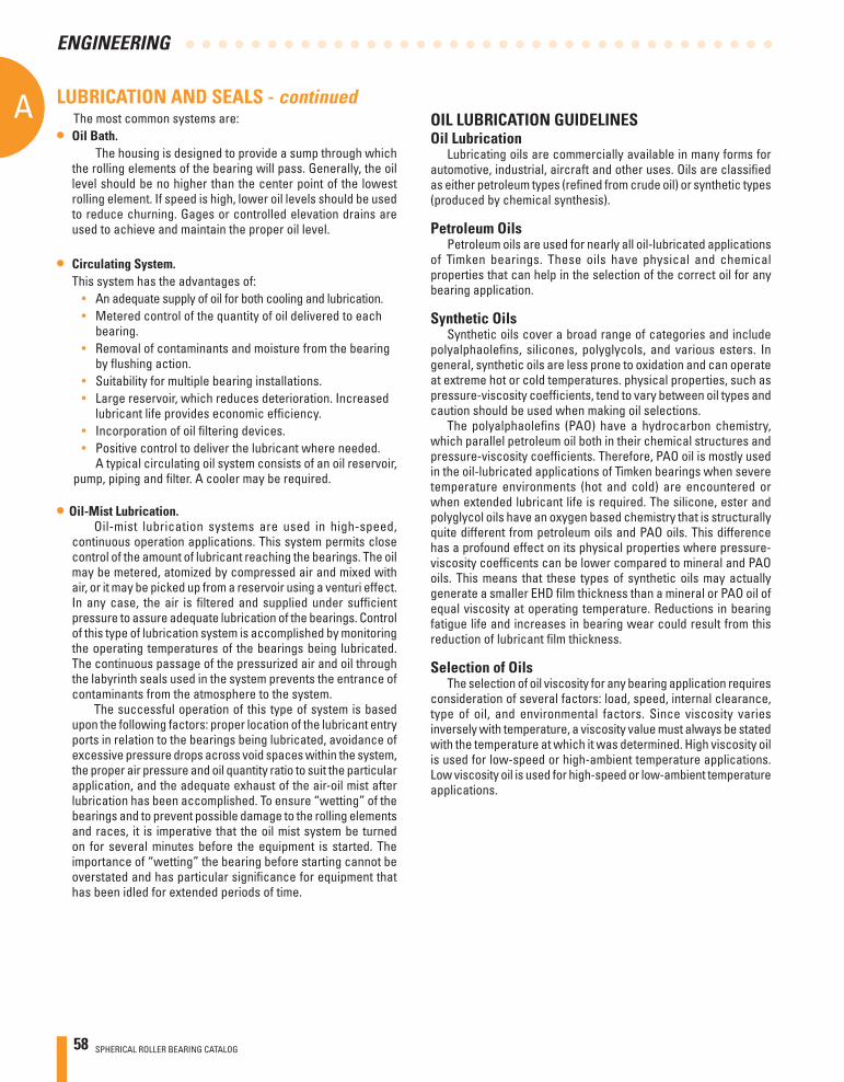
58 SPHERICAL ROLLER BEARING CATALOG
AA
ENGINEERING
OIL LUBRICATION GUIDELINES Oil Lubrication
Lubricating oils are commercially available in many forms for automotive, industrial, aircraft and other uses. Oils are classifi ed as either petroleum types (refi ned from crude oil) or synthetic types (produced by chemical synthesis).
Petroleum OilsPetroleum oils are used for nearly all oil-lubricated applications
of Timken bearings. These oils have physical and chemical properties that can help in the selection of the correct oil for any bearing application.
Synthetic OilsSynthetic oils cover a broad range of categories and include
polyalphaolefi ns, silicones, polyglycols, and various esters. In general, synthetic oils are less prone to oxidation and can operate at extreme hot or cold temperatures. physical properties, such as pressure-viscosity coeffi cients, tend to vary between oil types and caution should be used when making oil selections.
The polyalphaolefi ns (PAO) have a hydrocarbon chemistry, which parallel petroleum oil both in their chemical structures and pressure-viscosity coeffi cients. Therefore, PAO oil is mostly used in the oil-lubricated applications of Timken bearings when severe temperature environments (hot and cold) are encountered or when extended lubricant life is required. The silicone, ester and polyglycol oils have an oxygen based chemistry that is structurally quite different from petroleum oils and PAO oils. This difference has a profound effect on its physical properties where pressure- viscosity coeffi cents can be lower compared to mineral and PAO oils. This means that these types of synthetic oils may actually generate a smaller EHD fi lm thickness than a mineral or PAO oil of equal viscosity at operating temperature. Reductions in bearing fatigue life and increases in bearing wear could result from this reduction of lubricant fi lm thickness.
Selection of OilsThe selection of oil viscosity for any bearing application requires
consideration of several factors: load, speed, internal clearance, type of oil, and environmental factors. Since viscosity varies inversely with temperature, a viscosity value must always be stated with the temperature at which it was determined. High viscosity oil is used for low-speed or high-ambient temperature applications. Low viscosity oil is used for high-speed or low-ambient temperature applications.
LUBRICATION AND SEALS - continuedThe most common systems are:
• Oil Bath. The housing is designed to provide a sump through which
the rolling elements of the bearing will pass. Generally, the oil level should be no higher than the center point of the lowest rolling element. If speed is high, lower oil levels should be used to reduce churning. Gages or controlled elevation drains are used to achieve and maintain the proper oil level.
• Circulating System. This system has the advantages of:
• An adequate supply of oil for both cooling and lubrication.• Metered control of the quantity of oil delivered to each
bearing.• Removal of contaminants and moisture from the bearing
by fl ushing action.• Suitability for multiple bearing installations.• Large reservoir, which reduces deterioration. Increased
lubricant life provides economic effi ciency.• Incorporation of oil fi ltering devices.• Positive control to deliver the lubricant where needed.
A typical circulating oil system consists of an oil reservoir, pump, piping and fi lter. A cooler may be required.
• Oil-Mist Lubrication. Oil-mist lubrication systems are used in high-speed,
continuous operation applications. This system permits close control of the amount of lubricant reaching the bearings. The oil may be metered, atomized by compressed air and mixed with air, or it may be picked up from a reservoir using a venturi effect. In any case, the air is fi ltered and supplied under suffi cient pressure to assure adequate lubrication of the bearings. Control of this type of lubrication system is accomplished by monitoring the operating temperatures of the bearings being lubricated. The continuous passage of the pressurized air and oil through the labyrinth seals used in the system prevents the entrance of contaminants from the atmosphere to the system.
The successful operation of this type of system is based upon the following factors: proper location of the lubricant entry ports in relation to the bearings being lubricated, avoidance of excessive pressure drops across void spaces within the system, the proper air pressure and oil quantity ratio to suit the particular application, and the adequate exhaust of the air-oil mist after lubrication has been accomplished. To ensure “wetting” of the bearings and to prevent possible damage to the rolling elements and races, it is imperative that the oil mist system be turned on for several minutes before the equipment is started. The importance of “wetting” the bearing before starting cannot be overstated and has particular signifi cance for equipment that has been idled for extended periods of time.
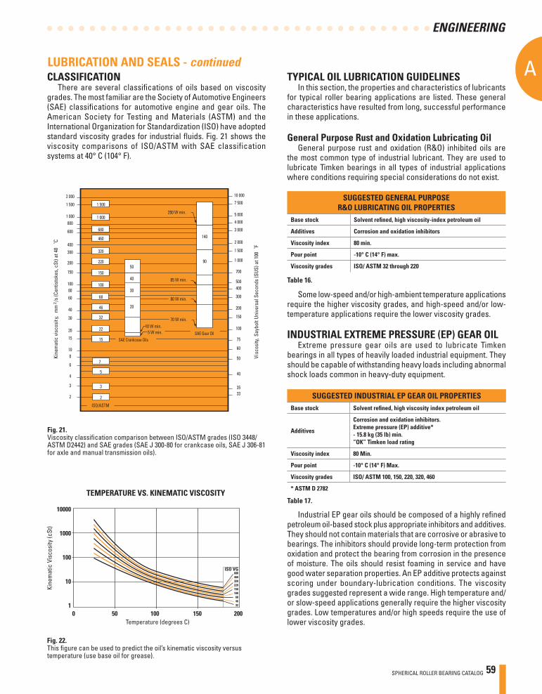
SPHERICAL ROLLER BEARING CATALOG 59
A
ENGINEERING
Fig. 21.Viscosity classifi cation comparison between ISO/ASTM grades (ISO 3448/ASTM D2442) and SAE grades (SAE J 300-80 for crankcase oils, SAE J 306-81 for axle and manual transmission oils).
LUBRICATION AND SEALS - continuedTYPICAL OIL LUBRICATION GUIDELINES
In this section, the properties and characteristics of lubricants for typical roller bearing applications are listed. These general characteristics have resulted from long, successful performance in these applications.
General Purpose Rust and Oxidation Lubricating OilGeneral purpose rust and oxidation (R&O) inhibited oils are
the most common type of industrial lubricant. They are used to lubricate Timken bearings in all types of industrial applications where conditions requiring special considerations do not exist.
10000
1000
100
10
10 50 100 150 200
Temperature (degrees C)
Kine
mat
ic V
isco
sity
(cSt
)
ISO VG680460320220150100
684632
TEMPERATURE VS. KINEMATIC VISCOSITY
2 000
1 500
1 000
600
800
400
300
200
150
10080
60
40
30
20
15
108
6
4
3
2
10 000
7 500
5 000
4 000
3 000
2 000
1 500
700
500
1 000
400
300
200
150
100
75
60
50
3533
1 000
680
320
460
220
100
68
32
15
7
5
2
SAE Crankcase Oils
ISO/ASTM
3
30
10 W min.5 W min.
140
40
250 W min.
85 W min.
80 W min.
15040
5090
70 W min.
Kine
mat
ic v
isco
sity
, m
m2 /
s (C
entis
toke
s, c
St) a
t 40
˚C
Visc
osit y
, Say
bolt
Univ
ersa
l Sec
onds
(SUS
) at 1
00˚F
22
2046
1 500
SAE Gear Oil
CLASSIFICATIONThere are several classifi cations of oils based on viscosity
grades. The most familiar are the Society of Automotive Engineers (SAE) classifi cations for automotive engine and gear oils. The American Society for Testing and Materials (ASTM) and the International Organization for Standardization (ISO) have adopted standard viscosity grades for industrial fl uids. Fig. 21 shows the viscosity comparisons of ISO/ASTM with SAE classification systems at 40° C (104° F).
Fig. 22.This fi gure can be used to predict the oil’s kinematic viscosity versus temperature (use base oil for grease).
SUGGESTED GENERAL PURPOSER&O LUBRICATING OIL PROPERTIES
Base stock Solvent refi ned, high viscosity-index petroleum oil
Additives Corrosion and oxidation inhibitors
Viscosity index 80 min.
Pour point -10° C (14° F) max.
Viscosity grades ISO/ ASTM 32 through 220
SUGGESTED INDUSTRIAL EP GEAR OIL PROPERTIESBase stock Solvent refi ned, high viscosity index petroleum oil
Additives
Corrosion and oxidation inhibitors. Extreme pressure (EP) additive*- 15.8 kg (35 lb) min. “OK” Timken load rating
Viscosity index 80 Min.
Pour point -10° C (14° F) Max.
Viscosity grades ISO/ ASTM 100, 150, 220, 320, 460
* ASTM D 2782
Some low-speed and/or high-ambient temperature applications require the higher viscosity grades, and high-speed and/or low-temperature applications require the lower viscosity grades.
INDUSTRIAL EXTREME PRESSURE (EP) GEAR OILExtreme pressure gear oils are used to lubricate Timken
bearings in all types of heavily loaded industrial equipment. They should be capable of withstanding heavy loads including abnormal shock loads common in heavy-duty equipment.
Industrial EP gear oils should be composed of a highly refi ned petroleum oil-based stock plus appropriate inhibitors and additives. They should not contain materials that are corrosive or abrasive to bearings. The inhibitors should provide long-term protection from oxidation and protect the bearing from corrosion in the presence of moisture. The oils should resist foaming in service and have good water separation properties. An EP additive protects against scoring under boundary-lubrication conditions. The viscosity grades suggested represent a wide range. High temperature and/or slow-speed applications generally require the higher viscosity grades. Low temperatures and/or high speeds require the use of lower viscosity grades.
Table 16.
Table 17.
60 SPHERICAL ROLLER BEARING CATALOG
AA
ENGINEERING
LUBRICATING GREASESDefinition
According to the ASTM defi nition, lubricating grease is a “solid to semi-fl uid product of the dispersion of a thickening agent in a liquid lubricant; other ingredients imparting special properties may be included.” If this defi nition were applied in the manner a chemist would use to illustrate a chemical reaction, the composition of a grease could be described by the formula below.
At this time, there is no known universal anti-friction bearing grease. Each individual grease has certain limiting properties and characteristics.
Synthetic lubricating fl uids, such as esters, organic esters and silicones, are used with conventional thickeners or chemical additives to provide greases capable of performing over an extremely wide range of temperatures, from as low as -73° C (-100° F) to a high of 288° C (550° F).
The successful use of lubricating grease in roller bearings depends on the physical and chemical properties of the lubricant pertaining to the bearing, its application, installation and general environmental factors. Because the choice of a lubricating grease for a particular bearing under certain service conditions is often diffi cult to make, your Timken representative should be consulted for proper suggestions.
Grease LubricationThe simplest lubrication system for any bearing application is
grease. Conventionally, greases used in Timken bearing applications are petroleum oils of some specifi c viscosity that are thickened to the desired consistency by some form of metallic soap. Greases are available in many soap types such as sodium, calcium, lithium, calcium-complex and aluminium-complex. Organic and inorganic type non-soap thickeners also are used in some products.
Soap TypeCalcium greases have good water resistance. Sodium
greases generally have good stability and will operate at higher temperatures, but they absorb water and cannot be used where moisture is present. Lithium, calcium-complex and aluminium-complex greases generally combine the higher temperature properties and stability of sodium grease with the water resistance of calcium grease. These greases are often referred to as multi-purpose greases since they combine the two most important lubricant advantages into one product.
Fluids +Thickening +Special =Lubricating Agents Ingredients Grease
Mineral Oils Soaps Oxidation Inhibitors Esters Lithium, Sodium Rust Inhibitors Organic Barium, Calcium VI Improver Esters Strontium Tackiness Glycols Non-Soap (Inorganic) Perfumes Silicones Microgel (Clay) Dyes Carbon Black Metal Deactivator Silica-gel Non-Soap (Organic) Urea compounds Terepthlamate Organic Dyes
Characteristics and Operating EnvironmentsListed below are the general characteristics of prominent roller
bearing greases.
Polyurea as a thickener for lubricating fl uids is one of the most signifi cant lubrication developments in more than 30 years. Polyurea grease performance in a wide range of bearing applications is outstanding, and in a relatively short time it has gained acceptance as a factory-packed lubricant for ball bearings.
ConsistencyGreases may vary in consistency from semifl uids hardly thicker
than a viscous oil, to solid grades almost as hard as a soft wood.Consistency is measured by a pentrometer, in which a standard
weighted cone is dropped into the grease. The distance the cone penetrates (measured in tenths of a millimeter in a specifi c time) is the penetration number.
The National Lubricating Grease Institute (N.L.G.I.) classifi cation of grease consistency is shown below:
Grease consistency is not fi xed; it normally becomes softer when sheared or “worked.” In the laboratory this “working” is accomplished by forcing a perforated plate up and down through a closed container of grease. This “working” does not compare with the violent shearing action that takes place in a ball bearing and does not necessarily correlate with actual performance.
NLGI Grease Grades Penetration Number
0 355-385 1 310-340 2 265-295 3 220-250 4 175-205 5 130-160 6 85-115
LUBRICATION AND SEALS - continued
Typical Usable** Typical Dropping PT Temperature WaterThickener C F C F Resistance
Sodium Soap 260+ 500+ 121 250 PoorLithium Soap 193 380 104 220 GoodPolyurea 238 460 149 300 ExcellentLithium ComplexSoap 260+ 500+ 163 325 Good
Table 18.
Table 19.
Table 20.
NOTE: The properties of a grease may vary considerably depending on the particular oil, thickener and additives used in the formulation.** Continuous operation with no relubrication. Depending upon the formulation the service limits may vary. The usable limit can be extended signifi cantly with relubrication.
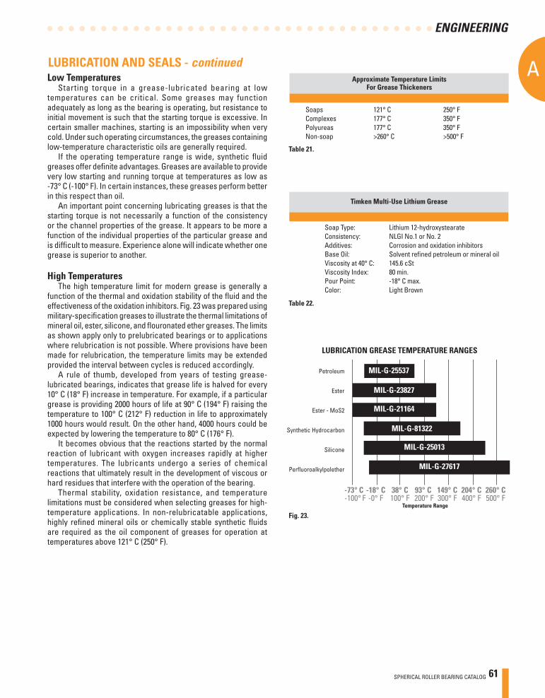
SPHERICAL ROLLER BEARING CATALOG 61
A
ENGINEERING
Low TemperaturesStarting torque in a grease-lubricated bearing at low
temperatures can be critical. Some greases may function adequately as long as the bearing is operating, but resistance to initial movement is such that the starting torque is excessive. In certain smaller machines, starting is an impossibility when very cold. Under such operating circumstances, the greases containing low-temperature characteristic oils are generally required.
If the operating temperature range is wide, synthetic fl uid greases offer defi nite advantages. Greases are available to provide very low starting and running torque at temperatures as low as -73° C (-100° F). In certain instances, these greases perform better in this respect than oil.
An important point concerning lubricating greases is that the starting torque is not necessarily a function of the consistency or the channel properties of the grease. It appears to be more a function of the individual properties of the particular grease and is diffi cult to measure. Experience alone will indicate whether one grease is superior to another.
High TemperaturesThe high temperature limit for modern grease is generally a
function of the thermal and oxidation stability of the fl uid and the effectiveness of the oxidation inhibitors. Fig. 23 was prepared using military-specifi cation greases to illustrate the thermal limitations of mineral oil, ester, silicone, and fl ouronated ether greases. The limits as shown apply only to prelubricated bearings or to applications where relubrication is not possible. Where provisions have been made for relubrication, the temperature limits may be extended provided the interval between cycles is reduced accordingly.
A rule of thumb, developed from years of testing grease- lubricated bearings, indicates that grease life is halved for every 10° C (18° F) increase in temperature. For example, if a particular grease is providing 2000 hours of life at 90° C (194° F) raising the temperature to 100° C (212° F) reduction in life to approximately 1000 hours would result. On the other hand, 4000 hours could be expected by lowering the temperature to 80° C (176° F).
It becomes obvious that the reactions started by the normal reaction of lubricant with oxygen increases rapidly at higher temperatures. The lubricants undergo a series of chemical reactions that ultimately result in the development of viscous or hard residues that interfere with the operation of the bearing.
Thermal stability, oxidation resistance, and temperature limitations must be considered when selecting greases for high- temperature applications. In non-relubricatable applications, highly refi ned mineral oils or chemically stable synthetic fl uids are required as the oil component of greases for operation at temperatures above 121° C (250° F).
Petroleum
Ester
Ester - MoS2
Synthetic Hydrocarbon
Silicone
Perfl uoroalkylpolether
Temperature Range
-73° C -18° C 38° C 93° C 149° C 204° C 260° C-100° F -0° F 100° F 200° F 300° F 400° F 500° F
MIL-G-25537
MIL-G-23827
MIL-G-21164
MIL-G-81322
MIL-G-25013
MIL-G-27617
LUBRICATION GREASE TEMPERATURE RANGES
Approximate Temperature LimitsFor Grease Thickeners
Soaps 121° C 250° F Complexes 177° C 350° FPolyureas 177° C 350° FNon-soap >260° C >500° F
Timken Multi-Use Lithium Grease
Soap Type: Lithium 12-hydroxystearateConsistency: NLGI No.1 or No. 2Additives: Corrosion and oxidation inhibitorsBase Oil: Solvent refi ned petroleum or mineral oilViscosity at 40° C: 145.6 cStViscosity Index: 80 min.Pour Point: -18° C max.Color: Light Brown
LUBRICATION AND SEALS - continued
Table 21.
Table 22.
Fig. 23.
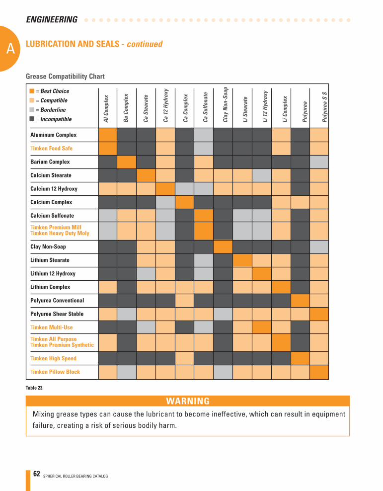
62 SPHERICAL ROLLER BEARING CATALOG
AA
ENGINEERING
Grease Compatibility Chart
n = Best Choice
n = Compatible
n = Borderline
n = Incompatible
Aluminum Complex
Timken Food Safe
Barium Complex
Calcium Stearate
Calcium 12 Hydroxy
Calcium Complex
Calcium Sulfonate
Timken Premium MillTimken Heavy Duty Moly
Clay Non-Soap
Lithium Stearate
Lithium 12 Hydroxy
Lithium Complex
Polyurea Conventional
Polyurea Shear Stable
Timken Multi-Use
Timken All PurposeTimken Premium Synthetic
Timken High Speed
Timken Pillow Block
Al C
ompl
ex
Ba C
ompl
ex
Ca S
tear
ate
Ca 1
2 Hy
drox
y
Ca C
ompl
ex
Ca S
ulfo
nate
Clay
Non
-Soa
p
Li S
tear
ate
Li 1
2 Hy
drox
y
Li C
ompl
ex
Poly
urea
Poly
urea
S S
LUBRICATION AND SEALS - continued
Table 23.
Mixing grease types can cause the lubricant to become ineffective, which can result in equipment failure, creating a risk of serious bodily harm.
WARNING
SPHERICAL ROLLER BEARING CATALOG 63
A
ENGINEERING
WET CONDITIONSWater and moisture can be particularly conducive to bearing
damage. Lubricating greases may provide a measure of protection from this contamination. Certain greases - the calcium, lithium and non-soap type, for example - are highly water-resistant. However, these greases exhibit poor rust preventative characteristics unless properly inhibited.
Sodium-soap greases emulsify with small amounts of moisture that may be present and prevent the moisture from coming in contact with the bearing surfaces. In certain applications, this characteristic may be advantageous; however, emulsions are generally considered undesirable.
Many bearing applications require lubricants with special properties or lubricants formulated specifically for certain environments, such as:
• Friction Oxidation (Fretting Corrosion)• Chemical and Solvent Resistance• Food Handling• Quiet Running• Space and/or Vacuum• Electrical Conductivity
For assistance with these or other areas requiring special lubricants, consult your Timken representative.
CONTAMINATIONAbrasive Particles
When roller bearings operate in a clean environment, the primary cause of damage is the eventual fatigue of the surfaces where rolling contact occurs. However, when particle contamination enters the bearing system, it is likely to cause damage such as bruising, which can shorten bearing life.
When dirt from the environment or metallic wear debris from some component in the application is allowed to contaminate the lubricant, wear can become the predominant cause of bearing damage. If, due to particle contamination of the lubricant, bearing wear becomes signifi cant, changes will occur to critical bearing dimensions that could adversely affect machine operation.
Bearings operating in a contaminated lubricant exhibit a higher initial rate of wear than those not running in a contaminated lubricant. But, with no further contaminant ingress, this wear rate quickly diminishes as the contamination particles are reduced in size as they pass through the bearing contact area during normal operation.
LUBRICATION AND SEALS - continuedWater
Either dissolved or suspended water in lubricating oils can exert a detrimental infl uence on bearing fatigue life. Water can cause bearing etching that also can reduce bearing fatigue life. The exact mechanism by which water lowers fatigue life is not fully understood. It has been suggested that water enters microcracks in the bearing races that are caused by repeated stress cycles. This leads to corrosion and hydrogen embrittlement in the microcracks, reducing the time required for these cracks to propagate to an unacceptable size spall.
Water-base fl uids such as water glycol and invert emulsions also have shown a reduction in bearing fatigue life. Although water from these sources is not the same as contamination, the results support the previous discussion concerning water-contaminated lubricants.
64 SPHERICAL ROLLER BEARING CATALOG
AA
ENGINEERING
GREASESApplications and Lubricating Methods
Grease lubrication is generally applicable to the following conditions, and features low-to-moderate speed applications within operating temperature limits of the grease:
• Easily confi ned in the housing. This is important in the food, textile and chemical industries.• Bearing enclosure and seal design simplifi ed.• Improves the effi ciency of external mechanical seals to give better protection to the bearing.• Successfully used for integrally-sealed, prelubricated ball bearings.
Advantages of Prelubricated BearingsPrelubricated shielded and sealed bearings are extensively
used with much success in applications where:• Grease might be injurious to other parts of the
mechanism.• Cost and space limitations preclude the use of a grease- fi lled housing.• Housings cannot be kept free of dirt and grit, water or other contaminants.• Relubrication is impossible or hazardous
Prelubricated Timken bearings are prepacked with greases that have chemical and mechanical stability and have demonstrated long life characteristics in rotating bearings. Greases are fi ltered several times to remove all harmful material and accurately metered so that each bearing receives the proper amount of grease.
GREASE LUBRICATIONS FOR BEARING ⁄ HOUSING ASSEMBLIES
Polyurea and lithium-based greases are normally preferred for general purpose bearing lubrication and are advantageous in high moisture applications. Both greases have good water-resistant characteristics. For temperature ranges of standard greases, see chart on page 61.
The grease must be carefully selected with regard to its consistency at operating temperature. It should not exhibit thickening, separation of oil, acid formation or hardening to any marked degree. It should be smooth, non-fi brous and entirely free from chemically active ingredients. Its melting point should be considerably higher than the operating temperature.
Frictional torque is infl uenced by the quantity and the quality of lubricant present. Excessive quantities of grease cause churning. This results in excessive temperatures, separation of the grease components, and breakdown in lubrication values. In normal speed applications, the housings should be kept approximately one-third to one-half full.
Only on low-speed applications may the housing be entirely fi lled with grease. This method of lubrication is a safeguard against the entry of foreign matter, where sealing provisions are inadequate for exclusion of contaminants or moisture.
During periods of non-operation, it is often wise to completely fi ll the housings with grease to protect the bearing surfaces. Prior to subsequent operation, the excess grease should be removed and the proper level restored.
Applications utilizing grease lubrication should have a grease fi tting and a vent at opposite ends of the housing near the top. A drain plug should be located near the bottom of the housing to allow purging of the old grease from the bearing.
Relubricate at regular intervals to prevent damage to the bearing. Relubrication intervals are diffi cult to determine. If plant practice or experience with other applications is not available, consult your lubricant supplier.
LUBRICATION AND SEALS - continued
SPHERICAL ROLLER BEARING CATALOG 65
A
ENGINEERING
MULTI-PURPOSE INDUSTRIAL GREASEThese are typical of greases that can be used to lubricate many
Timken bearing applications in all types of standard equipment. Special consideration should be given to applications where speed, load, temperature or environmental conditions are extreme.
LUBRICATION AND SEALS - continuedGrease Fill
For normal industrial applications, fi ll the bearing void to 70 to 100 percent full and the housing void to 50 percent full. For high speed applications, fi ll the bearing void to 30 to 70 percent full and the housing void to 33 percent full. The free volume of the bearing can be estimated by fi rst calculating the “solid ring” volume of the bearing. Then, weigh the bearing and divide the weight by the density of steel. This “actual” volume can then be subtracted from the “solid ring” volume. The resultant value is an estimate of the free volume of the bearing available for grease fi ll. When the grease volume is determined for the application, multiplying this value by the density of the grease will yield the approximate weight of the grease fi ll. After weighing the grease required, apply approximately 75 percent of the amount into the cage and roller assembly. The remaining amount of grease should then be applied to both inner and outer rings in equal amounts.
The preservatives applied to bearing components are compatible with nearly all industrial greases: and should not be wiped or cleaned prior to packing the bearing. If in doubt, contact a local Timken sales representative.
Re-Greasing CycleThe two primary considerations that determine the re-
greasing cycle on any application are operating temperature and sealing effi ciency. Obviously, seal leakage will dictate frequent relubrication. Every attempt should be made to maintain seals at peak effi ciency. Generally the higher the temperature, the more rapidly the grease oxidizes. Grease life is reduced by approximately half for every 10° C (50° F) rise in temperature. The higher the operating temperature, the more often the grease must be replenished. In most cases, experience in the specifi c application will dictate the frequency of lubrication.
Suggested Lithium Soap, Lithium Complex, and Calcium Sulfonate Grease Properties
Thickener type Lithium Complex, or equivalentConsistency NLGI No.1 or No. 2Additives Anti-wear, corrosion and oxidation inhibitorsBase oil Mineral oil or syntheticViscosity at 40° C ISO VG 150-220Viscosity index 80 min.Pour point -18° C max.
Lithium greases, Lithium Complex Greases, or Calcium Sulfonate thickened grease are suitable for most centralized, Single Point, or manual lubricated product. They should be a smooth, homogeneous and uniform, premium-quality product composed of mineral or synthetic oil, a thickener, and appropriate inhibitors. It should not contain materials that are corrosive or abrasive to roller bearings. The grease should have excellent mechanical and chemical stability. The grease should contain inhibitors to provide long-term protection against oxidation in high-performance applications and protect the bearings from corrosion in the presence of moisture.
The suggested base oil viscosity covers a fairly wide range. Lower viscosity products should be used in high-speed and/or lightly loaded applications to minimize heat generation and torque. Higher viscosity products should be used in moderate- to low-speed applications and under heavy loads to maximize lubricant fi lm thickness. Speed ratings are listed for each size/class part number in the Spherical Roller Bearing section (pages 80 to 96) of the catalog. When speeds of application exceed 70% of grease speed rating, consider increasing RIC by one ISO clearance range (CNormal to C3).
Never mix greases (type or manufacturer). Incompatibility can inhibit proper lubrication. Table 23 on page 62 is provided as a reference for typical grease thickener compatibilities. Consult your lubricant supplier for further information for your specifi c requirement. For general industrial applications consider a grease that is NLGI No. 1 or No. 2, with a ISO 150 to 220 viscosity grade.
Application ConsiderationsFor higher speed applications (operating at 75 percent of the
grease speed rating or more), a grease with a lighter base oil viscosity (ISO100-150) can be considered. Conversely, for lower speed applications, a grease with a heavier base oil viscosity (ISO 320-460) can be considered.
For lower speed applications operating at colder start up temperatures (<0 °F), consider a softer grease (NLGI grade 1) with an approved EP additive. The lighter grade will allow more grease fl ow into the bearing contact area and the EP additive will reduce wear during startup. An ISO 460 base oil viscosity can also be considered.
When lower speed applications operate at higher temperatures (>300 °F), consult a local Timken sales representative.
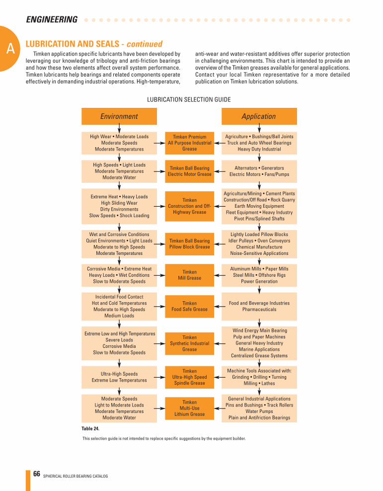
66 SPHERICAL ROLLER BEARING CATALOG
AA
ENGINEERING
Timken application specifi c lubricants have been developed by leveraging our knowledge of tribology and anti-friction bearings and how these two elements affect overall system performance. Timken lubricants help bearings and related components operate effectively in demanding industrial operations. High-temperature,
This selection guide is not intended to replace specifi c suggestions by the equipment builder.
anti-wear and water-resistant additives offer superior protection in challenging environments. This chart is intended to provide an overview of the Timken greases available for general applications. Contact your local Timken representative for a more detailed publication on Timken lubrication solutions.
LUBRICATION AND SEALS - continued
LUBRICATION SELECTION GUIDE
Extreme Heat • Heavy LoadsHigh Sliding WearDirty Environments
Slow Speeds • Shock Loading
Agriculture/Mining • Cement PlantsConstruction/Off Road • Rock Quarry
Earth Moving EquipmentFleet Equipment • Heavy Industry
Pivot Pins/Splined Shafts
TimkenConstruction and Off-
Highway Grease
High Speeds • Light LoadsModerate Temperatures
Moderate Water
Alternators • GeneratorsElectric Motors • Fans/Pumps
Timken Ball BearingElectric Motor Grease
Environment
Corrosive Media • Extreme HeatHeavy Loads • Wet Conditions
Slow to Moderate Speeds
Wet and Corrosive ConditionsQuiet Environments • Light Loads
Moderate to High SpeedsModerate Temperatures
Application
Aluminum Mills • Paper MillsSteel Mills • Offshore Rigs
Power Generation
Lightly Loaded Pillow BlocksIdler Pulleys • Oven Conveyors
Chemical ManufactureNoise-Sensitive Applications
TimkenMill Grease
Timken Ball BearingPillow Block Grease
Extreme Low and High TemperaturesSevere Loads
Corrosive MediaSlow to Moderate Speeds
Wind Energy Main BearingPulp and Paper Machines
General Heavy IndustryMarine Applications
Centralized Grease Systems
TimkenSynthetic Industrial
Grease
Incidental Food ContactHot and Cold TemperaturesModerate to High Speeds
Medium Loads
Food and Beverage IndustriesPharmaceuticals
TimkenFood Safe Grease
Ultra-High SpeedsExtreme Low Temperatures
Machine Tools Associated with:Grinding • Drilling • Turning
Milling • Lathes
TimkenUltra-High SpeedSpindle Grease
Moderate SpeedsLight to Moderate LoadsModerate Temperatures
Moderate Water
General Industrial ApplicationsPins and Bushings • Track Rollers
Water PumpsPlain and Antifriction Bearings
TimkenMulti-Use
Lithium Grease
High Wear • Moderate LoadsModerate Speeds
Moderate Temperatures
Agriculture • Bushings/Ball JointsTruck and Auto Wheel Bearings
Heavy Duty Industrial
Timken PremiumAll Purpose Industrial
Grease
Table 24.
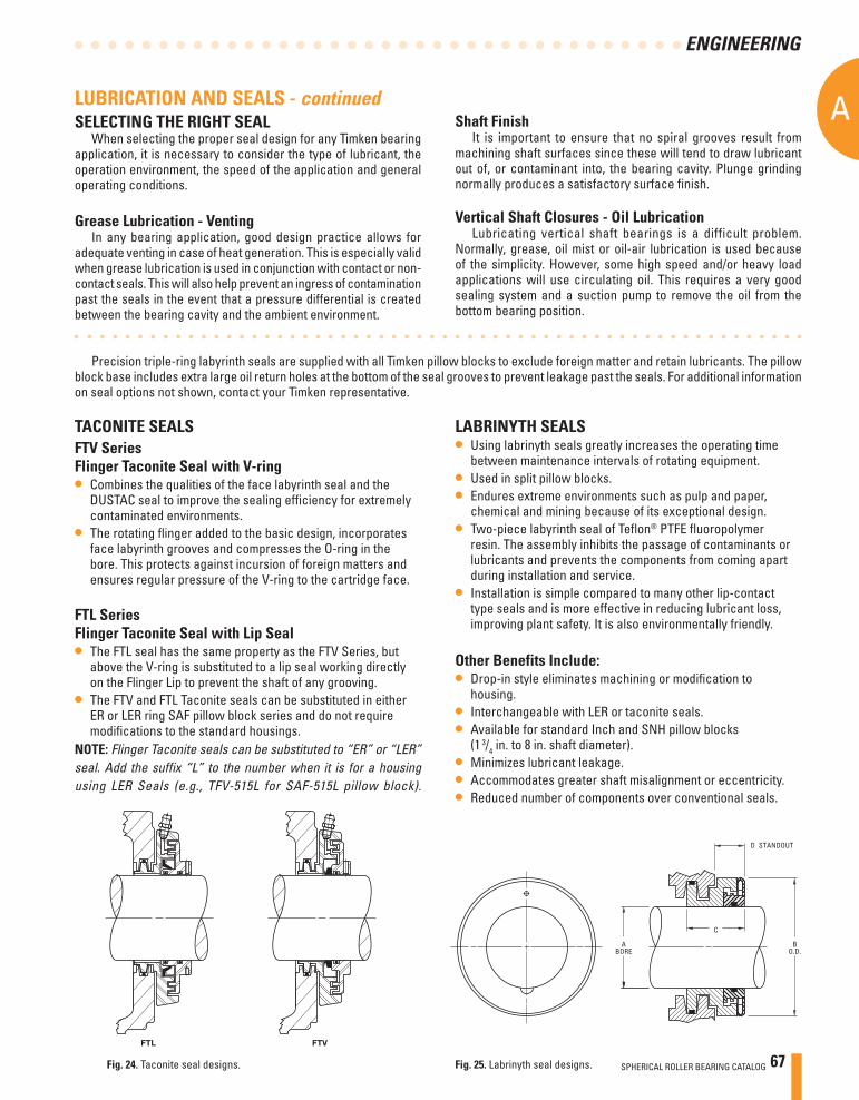
SPHERICAL ROLLER BEARING CATALOG 67
A
ENGINEERING
LUBRICATION AND SEALS - continued
TACONITE SEALSFTV SeriesFlinger Taconite Seal with V-ring• Combines the qualities of the face labyrinth seal and the
DUSTAC seal to improve the sealing effi ciency for extremely contaminated environments.
• The rotating fl inger added to the basic design, incorporates face labyrinth grooves and compresses the O-ring in the bore. This protects against incursion of foreign matters and ensures regular pressure of the V-ring to the cartridge face.
FTL SeriesFlinger Taconite Seal with Lip Seal• The FTL seal has the same property as the FTV Series, but
above the V-ring is substituted to a lip seal working directly on the Flinger Lip to prevent the shaft of any grooving.
• The FTV and FTL Taconite seals can be substituted in either ER or LER ring SAF pillow block series and do not require modifi cations to the standard housings.
NOTE: Flinger Taconite seals can be substituted to “ER” or “LER” seal. Add the suffix “L” to the number when it is for a housing using LER Seals (e.g., TFV-515L for SAF-515L pillow block).
FTL FTV
LABRINYTH SEALS• Using labrinyth seals greatly increases the operating time
between maintenance intervals of rotating equipment. • Used in split pillow blocks. • Endures extreme environments such as pulp and paper,
chemical and mining because of its exceptional design. • Two-piece labyrinth seal of Tefl on® PTFE fl uoropolymer
resin. The assembly inhibits the passage of contaminants or lubricants and prevents the components from coming apart during installation and service.
• Installation is simple compared to many other lip-contact type seals and is more effective in reducing lubricant loss, improving plant safety. It is also environmentally friendly.
ABORE
C
D STANDOUT
BO.D.
Fig. 25. Labrinyth seal designs.Fig. 24. Taconite seal designs.
Other Benefits Include:• Drop-in style eliminates machining or modifi cation to
housing. • Interchangeable with LER or taconite seals. • Available for standard Inch and SNH pillow blocks
(1 3/4 in. to 8 in. shaft diameter). • Minimizes lubricant leakage. • Accommodates greater shaft misalignment or eccentricity. • Reduced number of components over conventional seals.
Shaft FinishIt is important to ensure that no spiral grooves result from
machining shaft surfaces since these will tend to draw lubricant out of, or contaminant into, the bearing cavity. Plunge grinding normally produces a satisfactory surface fi nish.
Vertical Shaft Closures - Oil LubricationLubricating vertical shaft bearings is a difficult problem.
Normally, grease, oil mist or oil-air lubrication is used because of the simplicity. However, some high speed and/or heavy load applications will use circulating oil. This requires a very good sealing system and a suction pump to remove the oil from the bottom bearing position.
SELECTING THE RIGHT SEALWhen selecting the proper seal design for any Timken bearing
application, it is necessary to consider the type of lubricant, the operation environment, the speed of the application and general operating conditions.
Grease Lubrication - Venting In any bearing application, good design practice allows for
adequate venting in case of heat generation. This is especially valid when grease lubrication is used in conjunction with contact or non-contact seals. This will also help prevent an ingress of contamination past the seals in the event that a pressure differential is created between the bearing cavity and the ambient environment.
Precision triple-ring labyrinth seals are supplied with all Timken pillow blocks to exclude foreign matter and retain lubricants. The pillow block base includes extra large oil return holes at the bottom of the seal grooves to prevent leakage past the seals. For additional information on seal options not shown, contact your Timken representative.
68 SPHERICAL ROLLER BEARING CATALOG
AA
ENGINEERING
SPEED, HEAT AND TORQUESPEED RATINGS
There is no precise method for determining the maximum speed at which a bearing may operate. Bearing characteristics and features of surrounding parts, shafts, housing and other components as well as basic service conditions, are all variables dependent upon each other for continued satisfactory high-speed performance.
The safe operating speed of a bearing is often limited by the temperature within the bearing, which in turn is often dependent upon the temperature surrounding the application, accuracy of the bearings, shafts, housings, auxiliary parts and the type and amount of lubricant. Bearings with proper internal refi nements will operate at high speeds for long periods if properly installed and lubricated. Tolerance grade, cage design, and lubricant are bearings characteristics that affect speed limitations.
Although the speed rating values tabulated within are based on many years of research and accumulated data, numerous applications of Timken bearings are successfully operating with speed values in excess of those tabulated. Such applications require particular consideration of proper tolerance grade, lubrication, the effect of centrifugal force on rolling elements and other factors. For further information consult your Timken representative.
Conversely, under certain application conditions of load, temperature, contamination, etc., speed capabilities may be less than published within.
For spherical roller bearings, the thermal speed ratings are listed in the bearing tables. These values have been determined by balancing the heat generated within the bearing with the heat dissipated from the bearing. In calculating these numbers, the following assumptions have been made:
• The radial load is 5 percent of the static load rating.• For oil, it is assumed to be in a bath with the fi ll to the middle
of the lowest rolling element. For grease it is assumed a 30 percent bearing cavity fi ll.
• The oil viscosity is assumed to be 12 cSt (ISO VG 32) operated at 70˚ C (158˚ F) and the grease base oil viscosity is assumed to be 22 cSt operated at 70˚ C (158˚ F). The bearing and its components are at 70˚ C (158˚ F) and the bearing environment is at 20˚ C (68˚ F).
• The housing and shaft are steel or cast iron.• The bearing rotational axis is horizontal.• The outer ring is stationary and the inner ring is rotating.• The bearing radial internal clearance complies with class normal and standard fi ts are used.• The bearing does not contain seals.• The bearing does not experience misalignment or axial load.
The speed ratings are for reference only and can be considerably lower or higher depending on your application. Consult your Timken representative for more accurate information regarding a bearing’s speed capabilities in your application.
SPHERICAL ROLLER BEARING CATALOG 69
A
ENGINEERING
OPERATING TEMPERATURESTemperature Limitations
Bearing equilibrium temperature is not simply a question of speed. It is also dependent on the heat generation rate of all contributing heat sources, nature of the heat fl ow between sources, and heat dissipation rate of the system. Seals, gears, clutches, and oil supply temperature affect bearing operating temperature.
Heat dissipation rate is governed by such factors as type of lubrication system; materials and masses of the shaft and housing and intimacy of contact with the bearing; and surface area and character of the fl uid both inside and outside the housing.
Temperature of the outer surface of the housing is not an accurate indication of bearing temperature. The inner ring temperature is often greater than the outer ring temperature and both are usually greater than the outer surface of the housing. There are temperature gradients within the bearing, with the temperature of the internal parts usually being greater than the outer surfaces. Although the temperature of the outer ring O.D., the inner ring I.D., or the oil outlet often used as an indicator of bearing temperature, it should be recognized that these are generally not the highest bearing temperatures.
During transient conditions, such as at startup, bearing temperatures will often peak and then reduce to a lower level. This is due to the thermal changes taking place between the bearing, shaft and housing, causing variations in internal clearance and internal loading. Also, a new bearing will usually generate more heat until it runs in.
The allowable operating temperature depends on: • Equipment requirements• Lubrication limitations• Bearing material limitations• Reliability requirements
Each factor is an area of increasing concern as operating temperatures rise.
The equipment designer must decide how operating temperature will affect the performance of the equipment being designed. Precision machine tools, for example, can be very sensitive to thermal expansions. In many cases it is important that the temperature rise over ambient be minimized and held to 20 to 25° C (36 to 45° F) for some precision spindles.
Most industrial equipment can operate satisfactorily with considerably higher temperature rises. thermal ratings on gear drives, for example, are based on 93° C (200° F).
Some equipment such as plastic calendars and gas turbine engines operate continuously at temperatures well above 100° C (212° F).
Standard bearing steels cannot maintain the desired minimum hot hardness of 58 Rc much above 135° C (275° F).
Standard Timken spherical roller bearings are dimensionally stabilized up to 200° C (392° F). Upon request, the bearings can be ordered with dimensional stabilization up to 250° C (482° F) or 300°C (572° F).
SPEED, HEAT AND TORQUE - continued
Consult your Timken representative for availability of S1, S2, S3 suffi xes or high-temperature steels in specifi c part numbers and applications.
Although bearings can operate satisfactorily at higher temperatures, an upper temperature limit of 80 to 95°C (176 to 203°F) is usually more practical for small, high volume equipment where prototype testing is possible. Higher operating temperatures increase the risk of damage from some unforeseen, transient condition. If prototype testing is not practical, an upper design limit of 80°C (176°F) is appropriate, unless prior experience on similar equipment suggests otherwise.
History on some machines operating at higher temperatures, such as high-speed rolling mills, offers good background data for establishing limits on new, similar machines.
Obviously none of the above examples of equipment, lubricant or bearing material limitations are single point limitations, but rather areas of gradually increasing concern. It is the responsibility of the equipment designer to weigh all relevant factors and make the fi nal determination of what operating temperature is satisfactory for a particular machine.
Suggested materials for use in rings and rollers at various operating temperatures are listed together with data on chemical composition, hardness and dimensional stability. A temperature of 427° C (800° F) is generally the top limit for successful bearing operation using steels. Above 427° C (800° F), or below where lubricant is not permitted, cast or wrought cobalt alloys are generally used. Although chosen primarily for their good retention of physical properties, they also possess good oxidation resistance at elevated temperatures.
Table 26 provides standard operating temperatures for common bearing component materials. They should be used for reference purposes only as specifi c alloys used may vary. Other bearing component materials are available on request. Contact your Timken representative for further information.
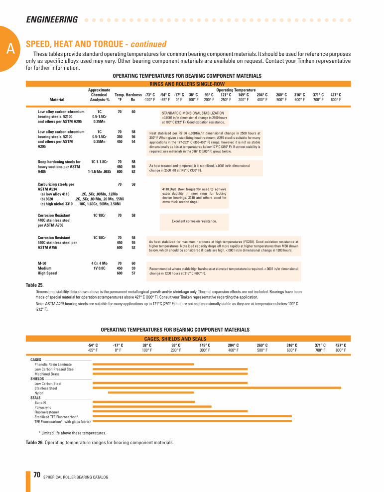
70 SPHERICAL ROLLER BEARING CATALOG
AA
ENGINEERING
These tables provide standard operating temperatures for common bearing component materials. It should be used for reference purposes only as specifi c alloys used may vary. Other bearing component materials are available on request. Contact your Timken representative for further information.
CAGES Phenolic Resin Laminate Low Carbon Pressed Steel Machined Brass SHIELDS Low Carbon Steel Stainless Steel NylonSEALS Buna N Polyacrylic Fluoroelastomer Stabilized TFE Fluorocarbon* TFE Fluorocarbon* (with glass fabric)
-54° C -17° C 38° C 93° C 149° C 204° C 260° C 316° C 371° C 427° C -65° F 0° F 100° F 200° F 300° F 400° F 500° F 600° F 700° F 800° F
* Limited life above these temperatures.
OPERATING TEMPERATURES FOR BEARING COMPONENT MATERIALS
CAGES, SHIELDS AND SEALS
OPERATING TEMPERATURES FOR BEARING COMPONENT MATERIALS
RINGS AND ROLLERS SINGLE-ROW Approximate Operating Temperature Chemical Temp. Hardness -73° C -54° C -17° C 38° C 93° C 121° C 149° C 204° C 260° C 316° C 371° C 427° C Material Analysis-% °F Rc -100° F -65° F 0° F 100° F 200° F 250° F 300° F 400° F 500° F 600° F 700° F 800° F
Dimensional stability data shown above is the permanent metallurgical growth and⁄or shrinkage only. Thermal expansion effects are not included. Bearings have been made of special material for operation at temperatures above 427° C (800° F). Consult your Timken representative regarding the application.
Note: ASTM A295 bearing steels are suitable for many applications up to 121°C (250° F) but are not as dimensionally stable as they are at temperatures below 100° C (212° F).
STANDARD DIMENSIONAL STABILIZATION<0.0001 in/in dimensional change in 2500 hours at 100° C (212° F). Good oxidation resistance.
Heat stabilized per FS136 <.0001in./in dimensional change in 2500 hours at 300° F When given a stabilizing heat treatment, A295 steel is suitable for many applications in the 177-232° C (350-450° F) range; however, it is not as stable dimensionally as it is at temperatures below 177°C (350° F). If utmost stability is required, use materials in the 316° C (600° F) group below.
As heat treated and tempered, it is stabilized, <.0001 in/in dimensional change in 2500 HR at 149° C (300° F).
4118,8620 steel frequently used to achieve extra ductility in inner rings for locking devise bearings. 3310 and others used for extra thick section rings.
Excellent corrosion resistance.
As heat stabilized for maximum hardness at high temperatures (FS238). Good oxidation resistance at higher temperatures. Note load capacity drops off more rapidly at higher temperatures than M50 shown below, which should be considered if loads are high. <.0001 in/in dimensional change in 1200 hours.
Recommended where stable high hardness at elevated temperature is required. <.0001 in/in dimensional change in 1200 hours at 316° C (600° F).
SPEED, HEAT AND TORQUE - continued
Low alloy carbon-chromium 1C 70 60 bearing steels. 52100 0.5-1.5Cr and others per ASTM A295 0.35Mn
Low alloy carbon-chromium 1C 70 58 bearing steels. 52100 0.5-1.5Cr 350 56 and others per ASTM 0.35Mn 450 54 A295
Deep hardening steels for 1C 1-1.8Cr 70 58 heavy sections per ASTM 450 55 A485 1-1.5 Mn .06Si 600 52
Carburizing steels per 70 58 ASTM A534 (a) low alloy 4118 .2C, .5Cr, .80Mn, .12Mo (b) 8620 .2C, .5Cr, .80 Mn, .20 Mo, .55Ni (c) high nickel 3310 .10C, 1.60Cr, .50Mn, 3.50Ni
Corrosion Resistant 1C 18Cr 70 58 440C stainless steel per ASTM A756
Corrosion Resistant 1C 18Cr 70 58 440C stainless steel per 450 55 ASTM A756 600 52
M-50 4 Cr. 4 Mo 70 60 Medium 1V 0.8C 450 59 High Speed 600 57
Table 26. Operating temperature ranges for bearing component materials.
Table 25.
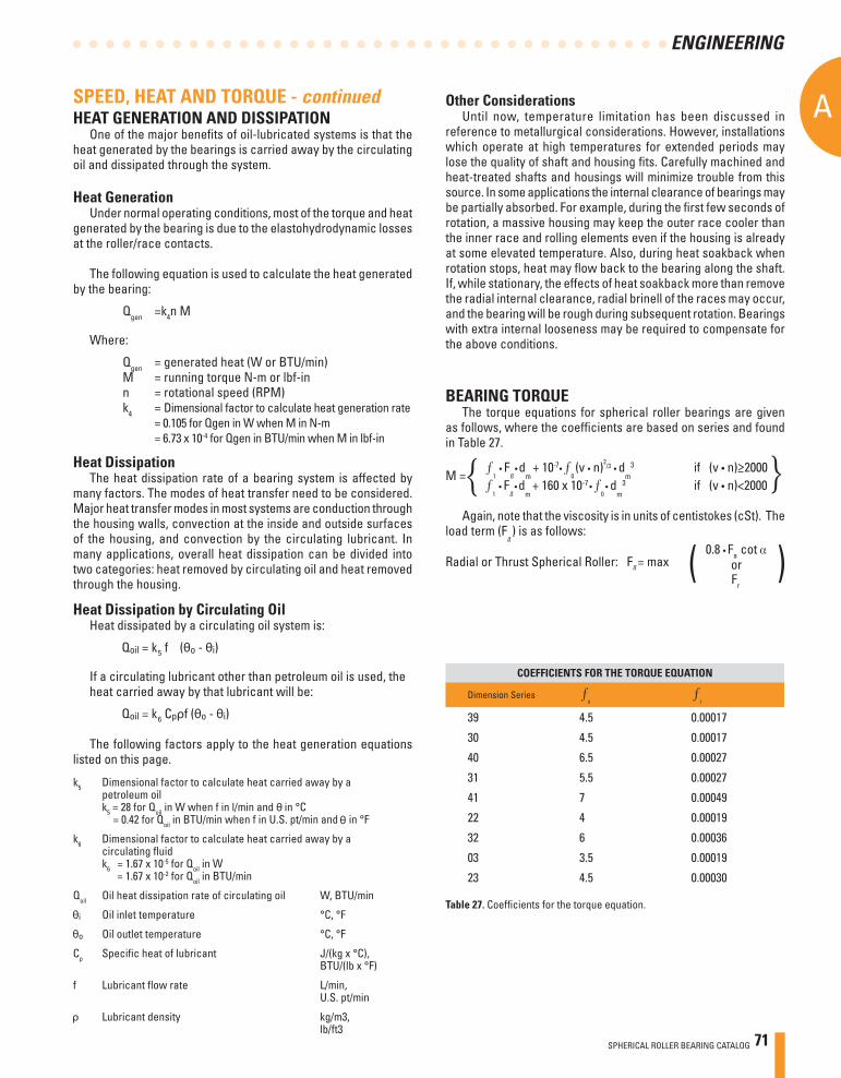
SPHERICAL ROLLER BEARING CATALOG 71
A
ENGINEERING
Other ConsiderationsUntil now, temperature limitation has been discussed in
reference to metallurgical considerations. However, installations which operate at high temperatures for extended periods may lose the quality of shaft and housing fi ts. Carefully machined and heat-treated shafts and housings will minimize trouble from this source. In some applications the internal clearance of bearings may be partially absorbed. For example, during the fi rst few seconds of rotation, a massive housing may keep the outer race cooler than the inner race and rolling elements even if the housing is already at some elevated temperature. Also, during heat soakback when rotation stops, heat may fl ow back to the bearing along the shaft. If, while stationary, the effects of heat soakback more than remove the radial internal clearance, radial brinell of the races may occur, and the bearing will be rough during subsequent rotation. Bearings with extra internal looseness may be required to compensate for the above conditions.
COEFFICIENTS FOR THE TORQUE EQUATION
Dimension Series 0
1
39 4.5 0.00017
30 4.5 0.00017
40 6.5 0.00027
31 5.5 0.00027
41 7 0.00049
22 4 0.00019
32 6 0.00036
03 3.5 0.00019
23 4.5 0.00030
HEAT GENERATION AND DISSIPATIONOne of the major benefi ts of oil-lubricated systems is that the
heat generated by the bearings is carried away by the circulating oil and dissipated through the system.
Heat GenerationUnder normal operating conditions, most of the torque and heat
generated by the bearing is due to the elastohydrodynamic losses at the roller/race contacts.
The following equation is used to calculate the heat generated by the bearing:
Qgen =k4n M
Where:
Qgen = generated heat (W or BTU/min)M = running torque N-m or lbf-inn = rotational speed (RPM)k4 = Dimensional factor to calculate heat generation rate = 0.105 for Qgen in W when M in N-m = 6.73 x 10⁻⁴ for Qgen in BTU/min when M in lbf-in
Heat DissipationThe heat dissipation rate of a bearing system is affected by
many factors. The modes of heat transfer need to be considered. Major heat transfer modes in most systems are conduction through the housing walls, convection at the inside and outside surfaces of the housing, and convection by the circulating lubricant. In many applications, overall heat dissipation can be divided into two categories: heat removed by circulating oil and heat removed through the housing.
k5 Dimensional factor to calculate heat carried away by a petroleum oil k5 = 28 for Qoil in W when f in l/min and in °C = 0.42 for Qoil in BTU/min when f in U.S. pt/min and in °F
k6 Dimensional factor to calculate heat carried away by a circulating fl uid k6 = 1.67 x 10⁻⁵ for Qoil in W = 1.67 x 10⁻² for Qoil in BTU/min
Qoil Oil heat dissipation rate of circulating oil W, BTU/min
Oil inlet temperature °C, °F
Oil outlet temperature °C, °F
Cp Specifi c heat of lubricant J/(kg x °C), BTU/(lb x °F)
f Lubricant fl ow rate L/min, U.S. pt/min
Lubricant density kg/m3, lb/ft3
Heat Dissipation by Circulating OilHeat dissipated by a circulating oil system is:
If a circulating lubricant other than petroleum oil is used, theheat carried away by that lubricant will be:
The following factors apply to the heat generation equations listed on this page.
SPEED, HEAT AND TORQUE - continued
Table 27. Coeffi cients for the torque equation.
BEARING TORQUEThe torque equations for spherical roller bearings are given
as follows, where the coeffi cients are based on series and found in Table 27.
M =
1 • F
ß • d
m + 10-7 • 0 (v • n)2
/3 • dm
3 if (v • n) 2000
1 • F
ß • d
m + 160 x 10-7 • 0
• dm
3 if (v • n)<2000
Again, note that the viscosity is in units of centistokes (cSt). The load term (F
ß ) is as follows:
Radial or Thrust Spherical Roller: Fß = max ( )0.8 • Fa cot
Fr
5
6
or
<

72 SPHERICAL ROLLER BEARING CATALOG
AA
ENGINEERING
A
NOTESAA
ENGINEERING
72 TIMKEN SERVICE CATALOG
SPHERICAL ROLLER BEARING CATALOG 73
B
A
Spherical Roller Bearings
TIMKEN SERVICE CATALOG B73
BSPHERICAL ROLLER BEARIN
GS
B SPHERICAL ROLLER BEARINGS
SPHERICAL PILLOW BLOCKS
AB
74 SPHERICAL ROLLER BEARING CATALOG
B
SPHERICAL ROLLER BEARINGS
BSPH
ERIC
AL R
OLLE
R BEARINGSB
A
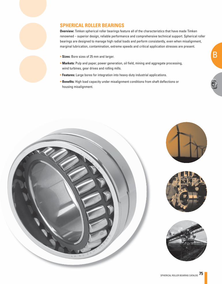
SPHERICAL ROLLER BEARINGSOverview: Timken spherical roller bearings feature all of the characteristics that have made Timken renowned – superior design, reliable performance and comprehensive technical support. Spherical roller bearings are designed to manage high radial loads and perform consistently, even when misalignment, marginal lubrication, contamination, extreme speeds and critical application stresses are present.
• Sizes: Bore sizes of 25 mm and larger.
• Markets: Pulp and paper, power generation, oil fi eld, mining and aggregate processing, wind turbines, gear drives and rolling mills.
• Features: Large bores for integration into heavy-duty industrial applications.
• Benefi ts: High load capacity under misalignment conditions from shaft defl ections or housing misalignment.
A
SPHERICAL ROLLER BEARING CATALOG 75
B
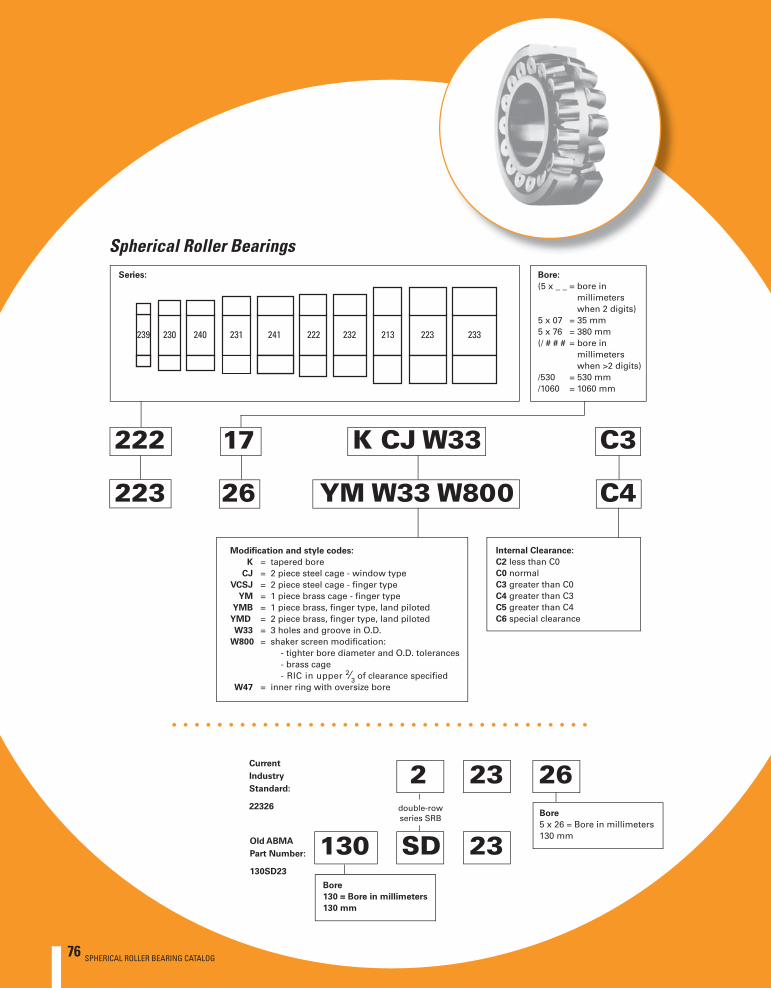
76 SPHERICAL ROLLER BEARING CATALOG
B
A
SPHERICAL ROLLER BEARINGS
Spherical Roller BearingsBore:
(5 x _ _ = bore in millimeters when 2 digits)5 x 07 = 35 mm5 x 76 = 380 mm(/ # # # = bore in millimeters when >2 digits)/530 = 530 mm/1060 = 1060 mm
222 17 K CJ W33 C3
223 26 YM W33 W800 C4
Modifi cation and style codes:
K = tapered bore CJ = 2 piece steel cage - window type VCSJ = 2 piece steel cage - fi nger type YM = 1 piece brass cage - fi nger type YMB = 1 piece brass, fi nger type, land pilotedYMD = 2 piece brass, fi nger type, land piloted W33 = 3 holes and groove in O.D. W800 = shaker screen modifi cation: - tighter bore diameter and O.D. tolerances - brass cage - RIC in upper 2⁄3 of clearance specifi ed W47 = inner ring with oversize bore
Internal Clearance:
C2 less than C0C0 normalC3 greater than C0C4 greater than C3C5 greater than C4C6 special clearance
SD130 23
2 23Current
Industry
Standard:
22326
26
Old ABMA
Part Number:
130SD23
double-rowseries SRB
Bore
5 x 26 = Bore in millimeters 130 mm
Bore
130 = Bore in millimeters
130 mm
Series:
76 SPHERICAL ROLLER BEARING CATALOG
SPHERICAL ROLLER BEARING CATALOG 77
B
A
Spherical Roller Bearings
Spherical Roller Bearings Page
Introduction . . . . . . . . . . . . . . . . . . . . . . . . . . . . . . . . . . . . . . . . . 78
Bearing Types . . . . . . . . . . . . . . . . . . . . . . . . . . . . . . . . . . . . . . . . 78
Modifi cation Codes . . . . . . . . . . . . . . . . . . . . . . . . . . . . . . . . . . . 79
Spherical Roller Bearings . . . . . . . . . . . . . . . . . . . . . . . . . . . . 80-96
Inch Shaft Adapter Accessories for Tapered Bore Bearings . . 97-100
Inch Shaft Adapter Accessories for Cylindrical Bore Bearings 101-102
Mounting Procedures . . . . . . . . . . . . . . . . . . . . . . . . . . . . . 103-105
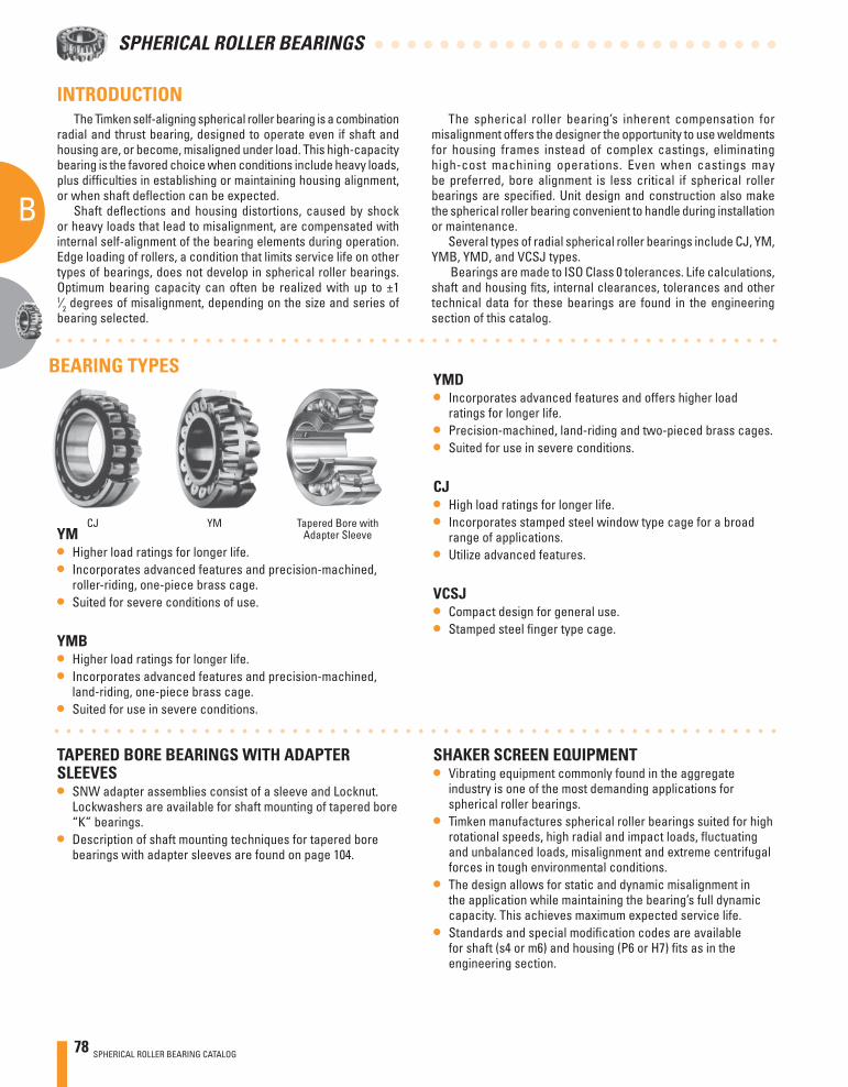
78 SPHERICAL ROLLER BEARING CATALOG
B
A
SPHERICAL ROLLER BEARINGS
YM• Higher load ratings for longer life. • Incorporates advanced features and precision-machined,
roller-riding, one-piece brass cage.• Suited for severe conditions of use.
YMB• Higher load ratings for longer life. • Incorporates advanced features and precision-machined,
land-riding, one-piece brass cage.• Suited for use in severe conditions.
The Timken self-aligning spherical roller bearing is a combination radial and thrust bearing, designed to operate even if shaft and housing are, or become, misaligned under load. This high-capacity bearing is the favored choice when conditions include heavy loads, plus diffi culties in establishing or maintaining housing alignment, or when shaft defl ection can be expected.
Shaft defl ections and housing distortions, caused by shock or heavy loads that lead to misalignment, are compensated with internal self-alignment of the bearing elements during operation. Edge loading of rollers, a condition that limits service life on other types of bearings, does not develop in spherical roller bearings. Optimum bearing capacity can often be realized with up to ±1
1⁄2 degrees of misalignment, depending on the size and series of bearing selected.
INTRODUCTION
YMCJ
TAPERED BORE BEARINGS WITH ADAPTER SLEEVES• SNW adapter assemblies consist of a sleeve and Locknut.
Lockwashers are available for shaft mounting of tapered bore “K” bearings.
• Description of shaft mounting techniques for tapered bore bearings with adapter sleeves are found on page 104.
The spherical roller bearing’s inherent compensation for misalignment offers the designer the opportunity to use weldments for housing frames instead of complex castings, eliminating high-cost machining operations. Even when castings may be preferred, bore alignment is less critical if spherical roller bearings are specifi ed. Unit design and construction also make the spherical roller bearing convenient to handle during installation or maintenance.
Several types of radial spherical roller bearings include CJ, YM, YMB, YMD, and VCSJ types.
Bearings are made to ISO Class 0 tolerances. Life calculations, shaft and housing fi ts, internal clearances, tolerances and other technical data for these bearings are found in the engineering section of this catalog.
YMD• Incorporates advanced features and offers higher load
ratings for longer life.• Precision-machined, land-riding and two-pieced brass cages. • Suited for use in severe conditions.
CJ• High load ratings for longer life.• Incorporates stamped steel window type cage for a broad
range of applications. • Utilize advanced features.
VCSJ• Compact design for general use.• Stamped steel fi nger type cage.
BEARING TYPES
SHAKER SCREEN EQUIPMENT• Vibrating equipment commonly found in the aggregate
industry is one of the most demanding applications for spherical roller bearings.
• Timken manufactures spherical roller bearings suited for high rotational speeds, high radial and impact loads, fl uctuating and unbalanced loads, misalignment and extreme centrifugal forces in tough environmental conditions.
• The design allows for static and dynamic misalignment in the application while maintaining the bearing’s full dynamic capacity. This achieves maximum expected service life.
• Standards and special modifi cation codes are available for shaft (s4 or m6) and housing (P6 or H7) fi ts as in the engineering section.
Tapered Bore withAdapter Sleeve
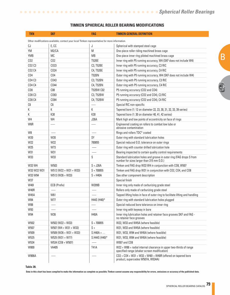
SPHERICAL ROLLER BEARING CATALOG 79
B
A
Spherical Roller Bearings
TIMKEN SPHERICAL ROLLER BEARING MODIFICATIONS
Data in this chart has been compiled to make the information as complete as possible; Timken cannot assume any responsibility for errors, omissions or accuracy of the published data.
TKN SKF FAG TIMKEN GENERAL DEFINITION
Other modifi cations available; contact your local Timken representative for more information.
CJ E, CC J Spherical with stamped steel cageYM M2/CA M One-piece roller riding machined brass cageYMB MC MB One-piece inner ring piloted machined brass cageCO2 CO2 T52BE Inner ring with P5 running accuracy, W4 (SKF does not include W4)CO2 C3 CO23 C3, T52BE Inner ring with P5 running accuracy, C3 RICCO2 C4 CO24 C4, T52BE Inner ring with P5 running accuracy, C4 RICCO4 CO4 T52BN Outer ring with P5 running accuracy, W4 (SKF does not include W4)CO4 C3 CO43 C3, T52BN Outer ring with P5 running accuracy, C3 RICCO4 C4 CO44 C4, T52BN Outer ring with P5 running accuracy, C4 RICCO8 C08 T52BW C02 P5 running accuracy (CO2 and CO4)CO8 C3 CO83 C3, T52BW P5 running accuracy (CO2 and CO4), C3 RICCO8 C4 CO84 C4, T52BW P5 running accuracy (CO2 and CO4), C4 RICC6 C6 ––– Special RIC non-specifi cK K K Tapered bore (1: 12 on diameter 22, 23, 30, 31, 32, 33, 39 series)K K30 K30 Tapered bore (1: 30 on diameter 40, 41, 42 series)W4 W4 J26A Mark high and low points of eccentricity on face of ringsW6R ––– ––– Engineered coating on rollers to combat low lube or abrasive contaminationW8 ––– ––– Rings and rollers TDC® coatedW20 W20 SY Outer ring with standard lubrication holesW22 W22 700855 Special reduced O.D. tolerance on outer ringsW25 W73 ––– Outer ring with counter drilled lubrication holeW31 W31 ––– Bearing inspected to certain quality control requirementsW33 W33 S Standard lubrication holes and groove in outer ring (FAG drops S from number for sizes larger than 315 mm O.D.)W33 W4 W503 S + J26A Timken and FAG drop W33 W4 in conjunction with CO8, W507W33 W22 W31 W512 (W22 + W31 + W33) S + 700855 Timken and FAG drop W31 in conjunction with CO2, CO4, and CO8W33 W94 W513 (W26 + W33) S + H40A See other component descriptionW37 Special fi nishW40I ECB (Prefi x) W209B Inner ring only made of carburizing grade steelW40R ––– ––– Rollers only made of carburizing grade steelW45A W61 ––– Tapped lifting holes in face of outer ring to facilitate lifting and handlingW84 W77 H44S (H40)* Outer ring with standard lubrication holes pluggedW88 ––– ––– Special reduced bore tolerance on inner ringW93 ––– ––– Inner ring with keyway in boreW94 W26 H40A Inner ring lubrication holes and retainer face grooves SKF and FAG - no retainer face groovesW502 W502 (W22 + W33) S + 700855 W22, W33 and W45A (where feasible)W507 W507 (W4 + W31 + W33) S + W31, W33 and W45A (where feasible)W509 W509 (W26 + W31 + W33) S.H40A + … W31, W33, W94 and W45A (where feasible)W525 W525 (W31 + W77) S.H44S (H40)* W31, W33, W84 and W45A (where feasible)W534 W534 (CO8 + W507) ––– W507 and CO8W800 VA405 T41A W22 + W88 + radial internal clearance in upper two-thirds of range specifi ed range (shaker screen modifi cation)W906A ––– ––– CO2 + CO4 + W31 + W33 + W40I + W40R (offered on tapered bore product, supercedes W507A, W534A)
Table 28.
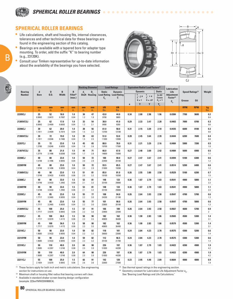
80 SPHERICAL ROLLER BEARING CATALOG
B
A
SPHERICAL ROLLER BEARINGS
Backing Diameter Load Ratings Equivalent Radial Load Factors(1) Lubrication
Bearing d D B R da Da Static Dynamic Dynamic Static Life Speed Ratings(3) Weight Number Bore O.D. Width Fillet(2) Shaft Housing Load Rating Load Rating Adjustment (max.) C0 C Factor(4)
Cg Grease Oil
e Y Y Y0
mm mm mm mm mm mm kN kN RPM RPM kg in. in. in. in. in. in. lbs. lbs. lbs.
SPHERICAL ROLLER BEARINGS- continued• Life calculations, shaft and housing fi ts, internal clearances,
tolerances and other technical data for these bearings are found in the engineering section of this catalog.
• Bearings are available with a tapered bore for adapter type mounting. To order, add the suffi x “K” to bearing number (e.g., 23120K).
• Consult your Timken representative for up-to-date information about the availability of the bearings you have selected.
(3) See thermal speed ratings in the engineering section.(4) Geometry constant for Lubrication Life Adjustment Factor a3l.
See "Bearing Load Ratings and Life Calculations."
(1) These factors apply for both inch and metric calculations. See engineering section for instructions on use.
(2) Maximum shaft or housing fi llet radius that bearing corners will clear.* Available in standard shaker screen bearing design confi guration
(example: 223xxYMW33W800C4).
X = 1
X = .67
> e In All
Cases
X0 = 1
>e
D
R
R
Dadda
B
CJ
22205CJ 25 52 18.0 1.0 30 47 43.0 44.0 0.34 2.00 2.98 1.96 0.0384 7700 9600 0.2 0.9843 2.0472 0.7087 0.04 1.2 1.9 9700 9800 0.4
21305VCSJ 25 62 17.0 1.0 33 54 38.0 41.0 0.29 2.33 3.47 2.28 0.0403 7000 8700 0.3 0.9843 2.4409 0.6693 0.04 1.3 2.1 8400 9200 0.6
22206CJ 30 62 20.0 1.0 38 56 61.0 58.0 0.31 2.15 3.20 2.10 0.0435 6600 8100 0.3 1.1811 2.4409 0.7874 0.04 1.5 2.2 13700 13100 0.6
21306VCSJ 30 72 19.0 1.0 39 63 51.0 53.0 0.28 2.45 3.64 2.39 0.0444 6200 7600 0.4 1.1811 2.8346 0.7480 0.04 1.5 2.5 11300 12000 0.8
22207CJ 35 72 23.0 1.0 45 65 88.0 78.0 0.31 2.21 3.29 2.16 0.0484 5900 7200 0.5 1.3780 2.8346 0.9055 0.04 1.8 2.6 19700 17500 1.0
21307VCSJ 35 80 21.0 1.5 44 71 66.0 67.0 0.27 2.48 3.69 2.42 0.0484 5600 6900 0.5 1.3779 3.1496 0.8268 0.06 1.7 2.8 14800 15000 1.1
22208CJ 40 80 23.0 1.0 50 72 100 90.0 0.27 2.47 3.67 2.41 0.0494 5100 6300 0.6 1.5748 3.1496 0.9055 0.04 2.0 2.9 22400 20100 1.2
22208YM 40 80 23.0 1.0 50 72 93.5 85.5 0.27 2.47 3.67 2.41 0.0514 5200 6400 0.6 1.5748 3.1496 0.9055 0.04 2.0 2.9 21000 19200 1.2
21308VCSJ 40 90 23.0 1.5 51 81 85.0 81.0 0.26 2.55 3.80 2.50 0.0529 5100 6200 0.7 1.5748 3.5433 0.9055 0.06 2.0 3.2 19100 18200 1.5
22308CJ 40 90 33.0 1.5 53 81 148 133 0.36 1.87 2.79 1.83 0.0541 4900 5800 1.1 1.5748 3.5433 1.2992 0.06 2.1 3.2 33100 29800 2.3
22308YM 40 90 33.0 1.5 53 81 148 133 0.36 1.87 2.79 1.83 0.0541 4900 5800 1.1 1.5748 3.5433 1.2992 0.06 2.1 3.2 33100 29800 2.3
22209CJ 45 85 23.0 1.0 55 77 108 94.0 0.26 2.64 3.93 2.58 0.0547 4700 5700 0.6 1.7717 3.3465 0.9055 0.04 2.2 3.0 24200 21100 1.3
22209YM 45 85 23.0 1.0 55 77 101 90.0 0.26 2.64 3.93 2.58 0.0547 4700 5800 0.6 1.7717 3.3465 0.9055 0.04 2.2 3.0 22800 20100 1.3
21309VCSJ 45 100 25.0 1.5 57 91 106 100 0.26 2.64 3.93 2.58 0.0567 4600 5700 0.9 1.7717 3.9370 0.9843 0.06 2.2 3.6 23900 22500 2
22309CJ 45 100 36.0 1.5 58 90 182 162 0.36 1.90 2.83 1.86 0.0565 4500 5300 1.4 1.7717 3.9370 1.4173 0.06 2.3 3.5 40800 36400 3.1
22309YM 45 100 36.0 1.5 58 90 182 162 0.36 1.90 2.83 1.86 0.0579 4500 5300 1.4 1.7717 3.9370 1.4173 0.06 2.3 3.5 40800 36400 3.1
22210CJ 50 90 23.0 1.0 59 82 118 101 0.24 2.84 4.23 2.78 0.0575 4300 5200 0.6 1.9685 3.5433 0.9055 0.04 2.3 3.2 26000 22600 1.4
22210YM 50 90 23.0 1.0 59 82 112 96.5 0.24 2.84 4.23 2.78 0.0575 4300 5300 0.6 1.9685 3.5433 0.9055 0.04 2.3 3.2 25100 21700 1.4
22310CJ 50 110 40.0 2.0 64 98 226 197 0.36 1.87 2.79 1.83 0.0422 4200 4900 1.9 1.9685 4.3307 1.5748 0.08 2.5 3.9 51000 44200 4.2
22310YM 50 110 40.0 2.0 64 98 226 197 0.36 1.87 2.79 1.83 0.0422 4200 4900 1.9 1.9685 4.3307 1.5748 0.08 2.5 3.9 51000 44200 4.2
22211CJ 55 100 25.0 1.5 66 91 142 120 0.23 2.95 4.40 2.89 0.0604 4000 4800 0.9 2.1654 3.9370 0.9843 0.06 2.6 3.6 32000 27000 1.9
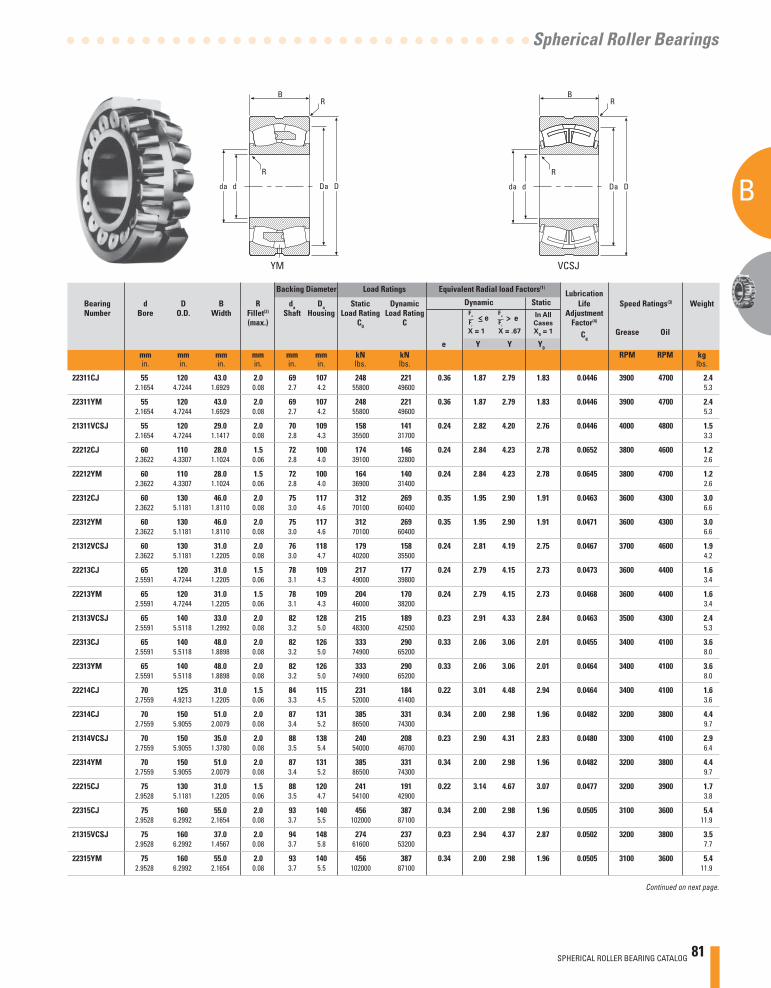
SPHERICAL ROLLER BEARING CATALOG 81
B
A
Spherical Roller Bearings
Continued on next page.
VCSJYM
Backing Diameter Load Ratings Equivalent Radial load Factors(1) Lubrication
Bearing d D B R da Da Static Dynamic Dynamic Static Life Speed Ratings(3) Weight Number Bore O.D. Width Fillet(2) Shaft Housing Load Rating Load Rating Adjustment (max.) C0 C Factor(4)
Cg Grease Oil
e Y Y Y0
mm mm mm mm mm mm kN kN RPM RPM kg in. in. in. in. in. in. lbs. lbs. lbs.
X = 1 X = .67
In All
Cases
X0 = 1
> e>e
d D
R
RB
da Da d D
R
RB
da Da
22311CJ 55 120 43.0 2.0 69 107 248 221 0.36 1.87 2.79 1.83 0.0446 3900 4700 2.4 2.1654 4.7244 1.6929 0.08 2.7 4.2 55800 49600 5.3
22311YM 55 120 43.0 2.0 69 107 248 221 0.36 1.87 2.79 1.83 0.0446 3900 4700 2.4 2.1654 4.7244 1.6929 0.08 2.7 4.2 55800 49600 5.3
21311VCSJ 55 120 29.0 2.0 70 109 158 141 0.24 2.82 4.20 2.76 0.0446 4000 4800 1.5 2.1654 4.7244 1.1417 0.08 2.8 4.3 35500 31700 3.3
22212CJ 60 110 28.0 1.5 72 100 174 146 0.24 2.84 4.23 2.78 0.0652 3800 4600 1.2 2.3622 4.3307 1.1024 0.06 2.8 4.0 39100 32800 2.6
22212YM 60 110 28.0 1.5 72 100 164 140 0.24 2.84 4.23 2.78 0.0645 3800 4700 1.2 2.3622 4.3307 1.1024 0.06 2.8 4.0 36900 31400 2.6
22312CJ 60 130 46.0 2.0 75 117 312 269 0.35 1.95 2.90 1.91 0.0463 3600 4300 3.0 2.3622 5.1181 1.8110 0.08 3.0 4.6 70100 60400 6.6
22312YM 60 130 46.0 2.0 75 117 312 269 0.35 1.95 2.90 1.91 0.0471 3600 4300 3.0 2.3622 5.1181 1.8110 0.08 3.0 4.6 70100 60400 6.6
21312VCSJ 60 130 31.0 2.0 76 118 179 158 0.24 2.81 4.19 2.75 0.0467 3700 4600 1.9 2.3622 5.1181 1.2205 0.08 3.0 4.7 40200 35500 4.2
22213CJ 65 120 31.0 1.5 78 109 217 177 0.24 2.79 4.15 2.73 0.0473 3600 4400 1.6 2.5591 4.7244 1.2205 0.06 3.1 4.3 49000 39800 3.4
22213YM 65 120 31.0 1.5 78 109 204 170 0.24 2.79 4.15 2.73 0.0468 3600 4400 1.6 2.5591 4.7244 1.2205 0.06 3.1 4.3 46000 38200 3.4
21313VCSJ 65 140 33.0 2.0 82 128 215 189 0.23 2.91 4.33 2.84 0.0463 3500 4300 2.4 2.5591 5.5118 1.2992 0.08 3.2 5.0 48300 42500 5.3
22313CJ 65 140 48.0 2.0 82 126 333 290 0.33 2.06 3.06 2.01 0.0455 3400 4100 3.6 2.5591 5.5118 1.8898 0.08 3.2 5.0 74900 65200 8.0
22313YM 65 140 48.0 2.0 82 126 333 290 0.33 2.06 3.06 2.01 0.0464 3400 4100 3.6 2.5591 5.5118 1.8898 0.08 3.2 5.0 74900 65200 8.0
22214CJ 70 125 31.0 1.5 84 115 231 184 0.22 3.01 4.48 2.94 0.0464 3400 4100 1.6 2.7559 4.9213 1.2205 0.06 3.3 4.5 52000 41400 3.6
22314CJ 70 150 51.0 2.0 87 131 385 331 0.34 2.00 2.98 1.96 0.0482 3200 3800 4.4 2.7559 5.9055 2.0079 0.08 3.4 5.2 86500 74300 9.7
21314VCSJ 70 150 35.0 2.0 88 138 240 208 0.23 2.90 4.31 2.83 0.0480 3300 4100 2.9 2.7559 5.9055 1.3780 0.08 3.5 5.4 54000 46700 6.4
22314YM 70 150 51.0 2.0 87 131 385 331 0.34 2.00 2.98 1.96 0.0482 3200 3800 4.4 2.7559 5.9055 2.0079 0.08 3.4 5.2 86500 74300 9.7
22215CJ 75 130 31.0 1.5 88 120 241 191 0.22 3.14 4.67 3.07 0.0477 3200 3900 1.7 2.9528 5.1181 1.2205 0.06 3.5 4.7 54100 42900 3.8
22315CJ 75 160 55.0 2.0 93 140 456 387 0.34 2.00 2.98 1.96 0.0505 3100 3600 5.4 2.9528 6.2992 2.1654 0.08 3.7 5.5 102000 87100 11.9
21315VCSJ 75 160 37.0 2.0 94 148 274 237 0.23 2.94 4.37 2.87 0.0502 3200 3800 3.5 2.9528 6.2992 1.4567 0.08 3.7 5.8 61600 53200 7.7
22315YM 75 160 55.0 2.0 93 140 456 387 0.34 2.00 2.98 1.96 0.0505 3100 3600 5.4 2.9528 6.2992 2.1654 0.08 3.7 5.5 102000 87100 11.9

82 SPHERICAL ROLLER BEARING CATALOG
B
A
SPHERICAL ROLLER BEARINGS
Backing Diameter Load Ratings Equivalent Radial Load Factors(1) Lubrication
Bearing d D B R da Da Static Dynamic Dynamic Static Life Speed Ratings(3) Weight Number Bore O.D. Width Fillet(2) Shaft Housing Load Rating Load Rating Adjustment (max.) C0 C Factor(4)
Cg Grease Oil
e Y Y Y0
mm mm mm mm mm mm kN kN RPM RPM kg in. in. in. in. in. in. lbs. lbs. lbs.
SPHERICAL ROLLER BEARINGS- continued• Life calculations, shaft and housing fi ts, internal clearances,
tolerances and other technical data for these bearings are found in the engineering section of this catalog.
• Bearings are available with a tapered bore for adapter type mounting. To order, add the suffi x “K” to bearing number (e.g., 23120K).
• Consult your Timken representative for up-to-date information about the availability of the bearings you have selected.
(3) See thermal speed ratings in the engineering section.(4) Geometry constant for Lubrication Life Adjustment Factor a3l.
See "Bearing Load Ratings and Life Calculations."
(1) These factors apply for both inch and metric calculations. See engineering section for instructions on use.
(2) Maximum shaft or housing fi llet radius that bearing corners will clear.* Available in standard shaker screen bearing design confi guration
(example: 223xxYMW33W800C4).
X = 1
X = .67
> e In All
Cases
X0 = 1
>e
D
R
R
Dadda
B
CJ
22216CJ 80 140 33.0 2.0 95 129 278 218 0.22 3.14 4.67 3.07 0.0499 3000 3700 2.2 3.1496 5.5118 1.2992 0.08 3.7 5.1 62500 49100 4.7
22216YM 80 140 33.0 2.0 95 129 263 210 0.22 3.14 4.67 3.07 0.0495 3000 3700 2.2 3.1496 5.5118 1.2992 0.08 3.7 5.1 59200 47100 4.7
21316VCSJ 80 170 39.0 2.0 100 158 305 260 0.23 2.95 4.40 2.89 0.0522 3000 3700 4.1 3.1496 6.6929 1.5354 0.08 3.9 6.2 68500 58400 9
22316CJ 80 170 58.0 2.0 97 148 510 427 0.34 2.00 2.98 1.96 0.0526 2900 3500 6.4 3.1496 6.6929 2.2835 0.08 3.8 5.8 115000 96100 14.2
22316YM 80 170 58.0 2.0 97 148 510 427 0.34 2.00 2.98 1.96 0.0526 2900 3500 6.4 3.1496 6.6929 2.2835 0.08 3.8 5.8 115000 96100 14.2
22217CJ 85 150 36.0 2.0 101 139 320 255 0.22 3.07 4.57 3.00 0.0518 2900 3500 2.7 3.3465 5.9055 1.4173 0.08 4.0 5.5 72000 57200 6.0
22217YM 85 150 36.0 2.0 101 139 302 244 0.22 3.07 4.57 3.00 0.0513 2900 3600 2.7 3.3465 5.9055 1.4173 0.08 4.0 5.5 67900 54800 6.0
21317VCSM 85 180 41.0 3.0 107 166 365 301 0.23 2.99 4.46 2.93 0.0547 2900 3500 5.2 3.3465 7.0866 1.6142 0.12 4.2 6.5 82000 67800 11.5
22317CJ 85 180 60.0 2.5 106 158 591 474 0.32 2.09 3.11 2.04 0.0554 2700 3200 7.5 3.3465 7.0866 2.3622 0.10 4.2 6.2 133000 107000 16.4
22317YM 85 180 60.0 2.5 106 158 591 474 0.32 2.09 3.11 2.04 0.0554 2700 3200 7.5 3.3465 7.0866 2.3622 0.10 4.2 6.2 133000 107000 16.4
22218CJ 90 160 40.0 2.0 105 146 388 303 0.23 2.90 4.31 2.83 0.0536 2800 3400 3.5 3.5433 6.2992 1.5748 0.08 4.2 5.8 87200 68100 7.6
22218YM 90 160 40.0 2.0 105 146 388 303 0.23 2.90 4.31 2.83 0.0536 2800 3400 3.5 3.5433 6.2992 1.5748 0.08 4.2 5.8 87200 68100 7.6
23218CJ 90 160 52.0 2.0 104 146 504 369 0.30 2.25 3.34 2.20 0.0536 2300 2700 4.5 3.5433 6.2992 2.0630 0.08 4.1 5.8 113000 83000 10.0
23218YM 90 160 52.0 2.0 104 146 504 369 0.30 2.25 3.34 2.20 0.0536 2300 2700 4.5 3.5433 6.2992 2.0630 0.08 4.1 5.8 113000 83000 10.0
22318CJ 90 190 64.0 2.5 110 167 642 529 0.35 1.92 2.86 1.88 0.0565 2600 3000 8.8 3.5433 7.4803 2.5197 0.10 4.3 6.6 144000 119000 19.4
22318YM 90 190 64.0 2.5 110 167 642 529 0.33 2.06 3.06 2.01 0.0565 2600 3000 8.8 3.5433 7.4803 2.5197 0.10 4.3 6.6 144000 119000 19.4
21318VCSM 90 190 43.0 3.0 113 176 398 327 0.23 3.00 4.47 2.93 0.0567 2800 3300 6.0 3.5433 7.4803 1.6929 0.12 4.5 6.9 89500 73400 13.5
22319CJ 90 190 64.0 2.5 110 167 642 529 0.33 2.06 3.06 2.01 0.0593 2600 3000 8.8 3.5433 7.4803 2.5197 0.10 4.3 6.6 144000 119000 19.4
23318YM 90 190 73.0 2.5 110 167 664 516 0.40 1.70 2.52 1.66 0.0555 1900 2200 10.1 3.5433 7.4803 2.8740 0.10 4.3 6.6 149000 116000 22.2
22219CJ 95 170 43.0 2.0 112 152 383 289 0.25 2.68 3.99 2.62 0.0556 2800 3400 4.2 3.7402 6.6929 1.6929 0.08 4.4 6.0 86200 65000 9.3
22219YM 95 170 43.0 2.0 112 152 383 289 0.25 2.68 3.99 2.62 0.0558 2800 3400 4.2 3.7402 6.6929 1.6929 0.08 4.4 6.0 86200 65000 9.3
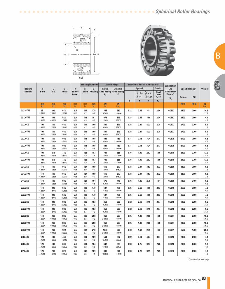
SPHERICAL ROLLER BEARING CATALOG 83
B
A
Spherical Roller Bearings
Continued on next page.
VCSJYM
Backing Diameter Load Ratings Equivalent Radial load Factors(1) Lubrication
Bearing d D B R da Da Static Dynamic Dynamic Static Life Speed Ratings(3) Weight Number Bore O.D. Width Fillet(2) Shaft Housing Load Rating Load Rating Adjustment (max.) C0 C Factor(4)
Cg Grease Oil
e Y Y Y0
mm mm mm mm mm mm kN kN RPM RPM kg in. in. in. in. in. in. lbs. lbs. lbs.
X = 1 X = .67
In All
Cases
X0 = 1
> e>e
d D
R
RB
da Da d D
R
RB
da Da
22319YM 95 200 67.0 2.5 119 175 735 580 0.32 2.09 3.11 2.04 0.0593 2400 2800 10.2 3.7402 7.8740 2.6378 0.10 4.7 6.9 165000 130000 22.5
23120YM 100 165 52.0 2.0 112 151 575 379 0.28 2.39 3.56 2.34 0.0567 2400 2800 4.4 3.9370 6.4961 2.0472 0.08 4.5 6.0 129000 85200 9.7
22220CJ 100 180 46.0 2.0 119 160 484 373 0.24 2.84 4.23 2.78 0.0577 2700 3200 5.1 3.9370 7.0866 1.8110 0.08 4.7 6.3 109000 83800 11.2
22220YM 100 180 46.0 2.0 119 160 484 373 0.24 2.84 4.23 2.78 0.0577 2700 3200 5.1 3.9370 7.0866 1.8110 0.08 4.7 6.3 109000 83800 11.2
23220CJ 100 180 60.3 2.0 118 165 646 463 0.31 2.18 3.24 2.13 0.0579 2100 2500 6.6 3.9370 7.0866 2.3740 0.08 4.7 6.5 145000 104000 15.0
23220YM 100 180 60.3 2.0 118 165 646 463 0.31 2.18 3.24 2.13 0.0579 2100 2500 6.6 3.9370 7.0866 2.3740 0.08 4.7 6.5 145000 104000 15.0
22320CJ 100 215 73.0 2.5 125 187 756 586 0.36 1.90 2.82 1.85 0.0618 2300 2700 13.0 3.9370 8.4646 2.8740 0.10 4.9 7.4 170000 132000 28.7
22320YM 100 215 73.0 2.5 125 187 756 586 0.36 1.90 2.82 1.85 0.0618 2300 2700 13.0 3.9370 8.4646 2.8740 0.10 4.9 7.4 170000 132000 28.7
23122CJ 110 180 56.0 2.0 127 169 615 377 0.28 2.37 3.53 2.32 0.0596 2200 2600 5.6 4.3307 7.0866 2.2047 0.08 5.0 6.7 138000 84800 12.3
23122YM 110 180 56.0 2.0 127 169 615 377 0.28 2.37 3.53 2.32 0.0596 2200 2600 5.6 4.3307 7.0866 2.2047 0.08 5.0 6.7 138000 84800 12.3
24122CJ 110 180 69.0 2.0 124 164 676 448 0.36 1.85 2.76 1.81 0.0588 1800 2100 6.9 4.3307 7.0866 2.7165 0.08 4.9 6.5 152000 101000 15.2
22222CJ 110 200 53.0 2.0 132 179 627 475 0.25 2.69 4.00 2.63 0.0616 2500 3000 7.3 4.3307 7.8740 2.0866 0.08 5.2 7.0 141000 107000 16.1
22222YM 110 200 53.0 2.0 132 179 627 475 0.25 2.69 4.00 2.63 0.0616 2500 3000 7.3 4.3307 7.8740 2.0866 0.08 5.2 7.0 141000 107000 16.1
23222CJ 110 200 69.8 2.0 130 183 853 596 0.32 2.12 3.15 2.07 0.0618 1900 2200 9.6 4.3307 7.8740 2.7480 0.08 5.1 7.2 192000 134000 21.1
23222YM 110 200 69.8 2.0 130 183 853 596 0.32 2.12 3.15 2.07 0.0618 1900 2200 9.6 4.3307 7.8740 2.7480 0.08 5.1 7.2 192000 134000 21.1
22322CJ 110 240 80.0 2.5 139 208 962 733 0.35 1.92 2.86 1.88 0.0654 2000 2300 18.0 4.3307 9.4488 3.1496 0.10 5.5 8.2 216000 165000 39.5
22322YM 110 240 80.0 2.5 139 208 962 733 0.35 1.92 2.86 1.88 0.0654 2000 2300 18.0 4.3307 9.4488 3.1496 0.10 5.5 8.2 216000 165000 39.5
23322YM 110 240 92.1 2.5 137 210 1070 808 0.40 1.67 2.49 1.63 0.0641 1500 1700 20.7 4.3307 9.4488 3.6260 0.10 5.4 8.3 240000 182000 45.5
23024CJ 120 180 46.0 2.0 134 169 564 352 0.22 3.14 4.67 3.07 0.0616 2300 2900 4.1 4.7244 7.0866 1.8110 0.08 5.3 6.6 127000 79200 9.0
24024CJ 120 180 60.0 2.0 131 164 642 393 0.30 2.25 3.34 2.20 0.0610 2000 2400 5.3 4.7244 7.0866 2.3622 0.08 5.2 6.5 144000 88400 11.7
23124CJ 120 200 62.0 2.0 142 189 803 524 0.30 2.28 3.39 2.23 0.0636 2000 2300 7.8 4.7244 7.8740 2.4409 0.08 5.6 7.4 180000 118000 17.2

84 SPHERICAL ROLLER BEARING CATALOG
B
A
SPHERICAL ROLLER BEARINGS
Backing Diameter Load Ratings Equivalent Radial Load Factors(1) Lubrication
Bearing d D B R da Da Static Dynamic Dynamic Static Life Speed Ratings(3) Weight Number Bore O.D. Width Fillet(2) Shaft Housing Load Rating Load Rating Adjustment (max.) C0 C Factor(4)
Cg Grease Oil
e Y Y Y0
mm mm mm mm mm mm kN kN RPM RPM kg in. in. in. in. in. in. lbs. lbs. lbs.
SPHERICAL ROLLER BEARINGS- continued• Life calculations, shaft and housing fi ts, internal clearances,
tolerances and other technical data for these bearings are found in the engineering section of this catalog.
• Bearings are available with a tapered bore for adapter type mounting. To order, add the suffi x “K” to bearing number (e.g., 23120K).
• Consult your Timken representative for up-to-date information about the availability of the bearings you have selected.
(3) See thermal speed ratings in the engineering section.(4) Geometry constant for Lubrication Life Adjustment Factor a3l.
See "Bearing Load Ratings and Life Calculations."
(1) These factors apply for both inch and metric calculations. See engineering section for instructions on use.
(2) Maximum shaft or housing fi llet radius that bearing corners will clear.* Available in standard shaker screen bearing design confi guration
(example: 223xxYMW33W800C4).
X = 1
X = .67
> e In All
Cases
X0 = 1
>e
D
R
R
Dadda
B
CJ
23124YM 120 200 62.0 2.0 142 189 803 524 0.30 2.28 3.39 2.23 0.0636 2000 2300 7.8 4.7244 7.8740 2.4409 0.08 5.6 7.4 180000 118000 17.2
24124CJ 120 200 80.0 2.0 136 181 923 590 0.39 1.74 2.59 1.70 0.0625 1600 1800 10.1 4.7244 7.8740 3.1496 0.08 5.4 7.1 207000 133000 22.2
22224CJ 120 215 58.0 2.0 142 192 667 475 0.27 2.51 3.74 2.46 0.0648 2400 2900 9.1 4.7244 8.4646 2.2835 0.08 5.6 7.6 150000 107000 20.0
22224YM 120 215 58.0 2.0 142 192 667 475 0.27 2.51 3.74 2.46 0.0648 2400 2900 9.1 4.7244 8.4646 2.2835 0.08 5.6 7.6 150000 107000 20.0
23224YM 120 215 76.0 2.0 140 197 977 678 0.32 2.09 3.11 2.04 0.0647 1700 2000 12.0 4.7244 8.4646 2.9921 0.08 5.5 7.8 220000 152000 26.0
22324CJ 120 260 86.0 2.5 151 225 1090 825 0.35 1.92 2.85 1.87 0.0680 1800 2100 22.6 4.7244 10.2362 3.3858 0.10 5.9 8.9 245000 185000 49.6
22324YM 120 260 86.0 2.5 151 225 1090 825 0.35 1.92 2.85 1.87 0.0704 1800 2100 22.6 4.7244 10.2362 3.3858 0.10 5.9 8.9 245000 185000 49.6
23324YM 120 260 106.0 2.5 147 226 1420 1030 0.43 1.57 2.34 1.54 0.0681 1300 1400 27.8 4.7244 10.2362 4.1732 0.10 5.8 8.9 320000 232000 61.2
23926YM 130 180 37.0 1.5 142 169 427 245 0.18 3.76 5.60 3.68 0.0880 2000 2500 2.8 5.1181 7.0866 1.4567 0.06 5.6 6.7 95900 55000 6.2
23026CJ 130 200 52.0 2.0 146 187 703 446 0.22 3.01 4.48 2.94 0.0654 2200 2700 5.9 5.1181 7.8740 2.0472 0.08 5.8 7.4 158000 100000 13.0
24026CJ 130 200 69.0 2.0 144 182 795 501 0.32 2.09 3.11 2.04 0.0642 1900 2200 7.9 5.1181 7.8740 2.7165 0.08 5.7 7.2 179000 113000 17.3
23126CJ 130 210 64.0 2.0 149 195 888 562 0.29 2.34 3.49 2.29 0.0663 1800 2100 8.6 5.1181 8.2677 2.5197 0.08 5.9 7.7 200000 126000 19.0
23126YM 130 210 64.0 2.0 149 195 888 562 0.29 2.34 3.49 2.29 0.0663 1800 2100 8.6 5.1181 8.2677 2.5197 0.08 5.9 7.7 200000 126000 19.0
24126CJ 130 210 80.0 2.0 147 190 967 608 0.36 1.85 2.76 1.81 0.0655 1500 1700 10.7 5.1181 8.2677 3.1496 0.08 5.8 7.5 217000 137000 23.6
22226CJ 130 230 64.0 2.5 152 206 805 562 0.27 2.47 3.68 2.42 0.0676 2200 2600 11.4 5.1181 9.0551 2.5197 0.10 6.0 8.1 181000 126000 25.0
22226YM 130 230 64.0 2.5 152 206 805 562 0.27 2.47 3.68 2.42 0.0676 2200 2600 11.4 5.1181 9.0551 2.5197 0.10 6.0 8.1 181000 126000 25.0
23226YM 130 230 80.0 2.5 151 211 1110 759 0.32 2.12 3.15 2.07 0.0676 1600 1800 14.0 5.1181 9.0551 3.1496 0.10 5.9 8.3 249000 171000 31.0
22326CJ 130 280 93.0 3.0 161 242 1270 952 0.35 1.92 2.85 1.87 0.0610 1700 1900 28.2 5.1181 11.0236 3.6614 0.12 6.4 9.5 286000 214000 62.1
22326YM 130 280 93.0 3.0 161 242 1270 952 0.35 1.92 2.85 1.87 0.0610 1700 1900 28.2 5.1181 11.0236 3.6614 0.12 6.4 9.5 286000 214000 62.1
23326YM 130 280 112.0 3.0 164 244 1550 1090 0.42 1.62 2.42 1.59 0.0600 1200 1300 34.0 5.1181 11.0236 4.4094 0.12 6.5 9.6 348000 245000 74.7
23928YM 140 190 37.0 1.5 152 179 456 253 0.17 4.01 5.97 3.92 0.0920 1900 2300 3.0 5.5118 7.4803 1.4567 0.06 6.0 7.1 102000 56900 6.6

SPHERICAL ROLLER BEARING CATALOG 85
B
A
Spherical Roller Bearings
Continued on next page.
VCSJYM
Backing Diameter Load Ratings Equivalent Radial load Factors(1) Lubrication
Bearing d D B R da Da Static Dynamic Dynamic Static Life Speed Ratings(3) Weight Number Bore O.D. Width Fillet(2) Shaft Housing Load Rating Load Rating Adjustment (max.) C0 C Factor(4)
Cg Grease Oil
e Y Y Y0
mm mm mm mm mm mm kN kN RPM RPM kg in. in. in. in. in. in. lbs. lbs. lbs.
X = 1 X = .67
In All
Cases
X0 = 1
> e>e
d D
R
RB
da Da d D
R
RB
da Da
23028CJ 140 210 53.0 2.0 156 197 764 471 0.22 3.14 4.67 3.07 0.0680 2000 2500 6.4 5.5118 8.2677 2.0866 0.08 6.1 7.8 173000 106000 14.0
24028CJ 140 210 69.0 2.0 154 192 899 527 0.31 2.21 3.29 2.16 0.0676 1700 2000 8.3 5.5118 8.2677 2.7165 0.08 6.1 7.6 202000 118000 18.3
23128YM 140 225 68.0 2.0 159 209 1010 636 0.29 2.37 3.52 2.31 0.0670 1700 2000 10.0 5.5118 8.8583 2.6772 0.08 6.3 8.2 228000 143000 23.0
24128CJ 140 225 85.0 2.0 156 203 1120 701 0.36 1.90 2.83 1.86 0.0684 1300 1500 13.0 5.5118 8.8583 3.3465 0.08 6.2 8.0 252000 158000 28.6
26228YM 140 240 80.0 2.5 161 217 1120 726 0.32 2.08 3.10 2.04 0.0693 1200 1400 14.7 5.5118 9.4488 3.1496 0.10 6.3 8.6 251000 163000 32.4
22228CJ 140 250 68.0 2.5 166 225 930 646 0.27 2.51 3.73 2.45 0.0713 2000 2400 14.4 5.5118 9.8425 2.6772 0.10 6.5 8.9 209000 145000 31.7
22228YM 140 250 68.0 2.5 166 225 930 646 0.27 2.51 3.73 2.45 0.0713 2000 2400 14.4 5.5118 9.8425 2.6772 0.10 6.5 8.9 209000 145000 31.7
22328CJ 140 300 102.0 3.0 174 262 1520 1120 0.36 1.88 2.81 1.84 0.0648 1500 1700 35.4 5.5118 11.8110 4.0157 0.12 6.9 10.3 341000 252000 77.9
22328YM 140 300 102.0 3.0 174 262 1520 1120 0.36 1.88 2.81 1.84 0.0648 1500 1700 35.4 5.5118 11.8110 4.0157 0.12 6.9 10.3 341000 252000 77.9
23328YM 140 300 118.0 3.0 175 261 1920 1310 0.41 1.64 2.45 1.61 0.0632 1000 1100 41.0 5.5118 11.8110 4.6457 0.12 6.9 10.3 432000 295000 90.1
23030YM 150 225 56.0 2.0 169 211 872 521 0.21 3.20 4.77 3.13 0.0714 1900 2300 7.8 5.9055 8.8583 2.2047 0.08 6.6 8.3 196000 117000 17.0
24030CJ 150 225 75.0 2.0 166 206 1000 603 0.31 2.18 3.24 2.13 0.0699 1600 1900 10.4 5.9055 8.8583 2.9528 0.08 6.5 8.1 226000 136000 22.9
23130YM 150 250 80.0 2.0 172 230 1320 837 0.31 2.20 3.27 2.15 0.0614 1500 1700 16.0 5.9055 9.8425 3.1496 0.08 6.8 9.1 298000 188000 35.0
24130CJ 150 250 100.0 2.0 169 225 1400 901 0.38 1.78 2.65 1.74 0.0603 1200 1300 19.7 5.9055 9.8425 3.9370 0.08 6.7 8.9 315000 203000 43.4
22230CJ 150 270 73.0 2.5 179 242 1100 752 0.27 2.52 3.75 2.46 0.0626 1800 2200 18.2 5.9055 10.6299 2.8740 0.10 7.0 9.5 247000 169000 39.9
22230YM 150 270 73.0 3.0 177 248 1200 853 0.25 2.74 4.08 2.68 0.0626 1800 2100 18.0 5.9055 10.6299 2.8740 0.10 7.0 9.8 269000 192000 40.0
23230YM 150 270 96.0 2.5 175 247 1590 1060 0.33 2.03 3.02 1.98 0.0625 1300 1500 24.0 5.9055 10.6299 3.7795 0.10 6.9 9.7 357000 239000 53.0
22330CJ 150 320 108.0 3.0 186 280 1720 1260 0.35 1.91 2.84 1.87 0.0667 1400 1600 42.6 5.9055 12.5984 4.2520 0.12 7.3 11.0 386000 283000 93.6
22330YM 150 320 108.0 3.0 186 280 1720 1260 0.35 1.91 2.84 1.87 0.0667 1400 1600 42.6 5.9055 12.5984 4.2520 0.12 7.3 11.0 386000 283000 93.6
23330YM 150 320 128.0 3.0 185 280 2130 1480 0.41 1.64 2.44 1.60 0.0654 960 1100 50.4 5.9055 12.5984 5.0394 0.12 7.3 11.0 478000 332000 111
23932YM 160 220 45.0 2.0 175 206 655 348 0.19 3.60 5.35 3.52 0.0724 1800 2100 5.1 6.2992 8.6614 1.7717 0.08 6.9 8.1 147000 78200 11.1
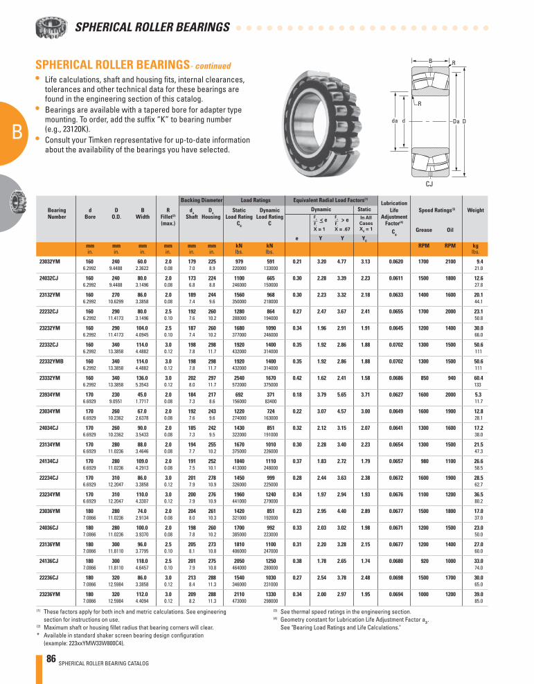
86 SPHERICAL ROLLER BEARING CATALOG
B
A
SPHERICAL ROLLER BEARINGS
Backing Diameter Load Ratings Equivalent Radial Load Factors(1) Lubrication
Bearing d D B R da Da Static Dynamic Dynamic Static Life Speed Ratings(3) Weight Number Bore O.D. Width Fillet(2) Shaft Housing Load Rating Load Rating Adjustment (max.) C0 C Factor(4)
Cg Grease Oil
e Y Y Y0
mm mm mm mm mm mm kN kN RPM RPM kg in. in. in. in. in. in. lbs. lbs. lbs.
SPHERICAL ROLLER BEARINGS- continued• Life calculations, shaft and housing fi ts, internal clearances,
tolerances and other technical data for these bearings are found in the engineering section of this catalog.
• Bearings are available with a tapered bore for adapter type mounting. To order, add the suffi x “K” to bearing number (e.g., 23120K).
• Consult your Timken representative for up-to-date information about the availability of the bearings you have selected.
(3) See thermal speed ratings in the engineering section.(4) Geometry constant for Lubrication Life Adjustment Factor a3l.
See "Bearing Load Ratings and Life Calculations."
(1) These factors apply for both inch and metric calculations. See engineering section for instructions on use.
(2) Maximum shaft or housing fi llet radius that bearing corners will clear.* Available in standard shaker screen bearing design confi guration
(example: 223xxYMW33W800C4).
X = 1
X = .67
> e In All
Cases
X0 = 1
>e
D
R
R
Dadda
B
CJ
23032YM 160 240 60.0 2.0 179 225 979 591 0.21 3.20 4.77 3.13 0.0620 1700 2100 9.4 6.2992 9.4488 2.3622 0.08 7.0 8.9 220000 133000 21.0
24032CJ 160 240 80.0 2.0 173 224 1100 665 0.30 2.28 3.39 2.23 0.0611 1500 1800 12.6 6.2992 9.4488 3.1496 0.08 6.8 8.8 246000 150000 27.8
23132YM 160 270 86.0 2.0 189 244 1560 968 0.30 2.23 3.32 2.18 0.0633 1400 1600 20.1 6.2992 10.6299 3.3858 0.08 7.4 9.6 350000 218000 44.1
22232CJ 160 290 80.0 2.5 192 260 1280 864 0.27 2.47 3.67 2.41 0.0655 1700 2000 23.1 6.2992 11.4173 3.1496 0.10 7.6 10.2 288000 194000 50.8
23232YM 160 290 104.0 2.5 187 260 1680 1090 0.34 1.96 2.91 1.91 0.0645 1200 1400 30.0 6.2992 11.4173 4.0945 0.10 7.4 10.2 377000 246000 66.0
22332CJ 160 340 114.0 3.0 198 298 1920 1400 0.35 1.92 2.86 1.88 0.0702 1300 1500 50.6 6.2992 13.3858 4.4882 0.12 7.8 11.7 432000 314000 111
22332YMB 160 340 114.0 3.0 198 298 1920 1400 0.35 1.92 2.86 1.88 0.0702 1300 1500 50.6 6.2992 13.3858 4.4882 0.12 7.8 11.7 432000 314000 111
23332YM 160 340 136.0 3.0 202 297 2540 1670 0.42 1.62 2.41 1.58 0.0686 850 940 60.4 6.2992 13.3858 5.3543 0.12 8.0 11.7 572000 375000 133
23934YM 170 230 45.0 2.0 184 217 692 371 0.18 3.79 5.65 3.71 0.0627 1600 2000 5.3 6.6929 9.0551 1.7717 0.08 7.3 8.6 156000 83400 11.7
23034YM 170 260 67.0 2.0 192 243 1220 724 0.22 3.07 4.57 3.00 0.0649 1600 1900 12.8 6.6929 10.2362 2.6378 0.08 7.6 9.6 274000 163000 28.1
24034CJ 170 260 90.0 2.0 185 242 1430 851 0.32 2.12 3.15 2.07 0.0641 1300 1600 17.2 6.6929 10.2362 3.5433 0.08 7.3 9.5 322000 191000 38.0
23134YM 170 280 88.0 2.0 194 255 1670 1010 0.30 2.28 3.40 2.23 0.0654 1300 1500 21.5 6.6929 11.0236 3.4646 0.08 7.7 10.2 375000 226000 47.3
24134CJ 170 280 109.0 2.0 191 252 1840 1110 0.37 1.83 2.72 1.79 0.0657 980 1100 26.6 6.6929 11.0236 4.2913 0.08 7.5 10.1 413000 248000 58.5
22234CJ 170 310 86.0 3.0 201 278 1450 999 0.28 2.44 3.63 2.38 0.0672 1600 1900 28.5 6.6929 12.2047 3.3858 0.12 7.9 10.9 326000 225000 62.7
23234YM 170 310 110.0 3.0 200 276 1960 1240 0.34 1.97 2.94 1.93 0.0676 1100 1200 36.5 6.6929 12.2047 4.3307 0.12 7.9 10.9 441000 279000 80.2
23036YM 180 280 74.0 2.0 204 261 1420 851 0.23 2.95 4.40 2.89 0.0677 1500 1800 17.0 7.0866 11.0236 2.9134 0.08 8.0 10.3 321000 192000 37.0
24036CJ 180 280 100.0 2.0 198 260 1700 992 0.33 2.03 3.02 1.98 0.0671 1200 1500 23.0 7.0866 11.0236 3.9370 0.08 7.8 10.2 385000 223000 50.0
23136YM 180 300 96.0 2.5 205 273 1810 1100 0.31 2.20 3.28 2.15 0.0677 1200 1400 27.0 7.0866 11.8110 3.7795 0.10 8.1 10.8 406000 247000 60.0
24136CJ 180 300 118.0 2.5 201 275 2050 1250 0.38 1.78 2.65 1.74 0.0680 920 1000 33.0 7.0866 11.8110 4.6457 0.10 7.9 10.8 464000 280000 74.0
22236CJ 180 320 86.0 3.0 213 288 1540 1030 0.27 2.54 3.78 2.48 0.0698 1500 1700 30.0 7.0866 12.5984 3.3858 0.12 8.4 11.3 346000 231000 65.0
23236YM 180 320 112.0 3.0 209 288 2110 1330 0.34 2.00 2.97 1.95 0.0694 1000 1200 39.0 7.0866 12.5984 4.4094 0.12 8.2 11.3 473000 298000 85.0

SPHERICAL ROLLER BEARING CATALOG 87
B
A
Spherical Roller Bearings
Continued on next page.
VCSJYM
Backing Diameter Load Ratings Equivalent Radial load Factors(1) Lubrication
Bearing d D B R da Da Static Dynamic Dynamic Static Life Speed Ratings(3) Weight Number Bore O.D. Width Fillet(2) Shaft Housing Load Rating Load Rating Adjustment (max.) C0 C Factor(4)
Cg Grease Oil
e Y Y Y0
mm mm mm mm mm mm kN kN RPM RPM kg in. in. in. in. in. in. lbs. lbs. lbs.
X = 1 X = .67
In All
Cases
X0 = 1
> e>e
d D
R
RB
da Da d D
R
RB
da Da
22336YMB 180 380 126.0 3.0 222 334 2460 1760 0.34 1.98 2.94 1.93 0.0730 1100 1200 69.0 7.0866 14.9606 4.9606 0.12 8.8 13.1 554000 395000 153
23938YM 190 260 52.0 2.0 207 245 910 480 0.18 3.84 5.72 3.75 0.0677 1400 1700 8.1 7.4803 10.2362 2.0472 0.08 8.2 9.6 205000 108000 18.0
23038YM 190 290 75.0 2.0 213 271 1540 901 0.22 3.01 4.48 2.94 0.0698 1400 1700 18.0 7.4803 11.4173 2.9528 0.08 8.4 10.7 349000 203000 39.0
24038CJ 190 290 100.0 2.0 211 264 1810 957 0.31 2.16 3.22 2.12 0.0682 1200 1400 24.0 7.4803 11.4173 3.9370 0.08 8.3 10.4 407000 215000 52.0
23138YM 190 320 104.0 2.5 218 290 2090 1250 0.31 2.15 3.21 2.11 0.0716 1100 1300 34.0 7.4803 12.5984 4.0945 0.10 8.6 11.4 470000 282000 75.0
24138CJ 190 320 128.0 2.5 211 286 2310 1350 0.40 1.68 2.50 1.64 0.0710 860 950 42.0 7.4803 12.5984 5.0394 0.10 8.3 11.3 520000 305000 92.0
22238YM 190 340 92.0 3.0 224 306 1810 1200 0.27 2.53 3.77 2.48 0.0725 1400 1600 36.0 7.4803 13.3858 3.6220 0.12 8.8 12.0 407000 270000 79.0
23238YM 190 340 120.0 3.0 221 306 2390 1490 0.34 1.99 2.96 1.95 0.0714 960 1100 47.0 7.4803 13.3858 4.7244 0.12 8.7 12.0 536000 335000 104
22338YMB 190 400 132.0 4.0 236 350 2730 1900 0.34 1.97 2.94 1.93 0.0761 1000 1200 80.0 7.4803 15.7480 5.1969 0.16 9.3 13.8 614000 428000 177
23940YM 200 280 60.0 2.0 219 263 1140 608 0.19 3.65 5.43 3.57 0.0704 1400 1600 11.0 7.8740 11.0236 2.3622 0.08 8.6 10.3 256000 137000 25.0
23040YM 200 310 82.0 2.0 225 289 1760 1040 0.23 2.95 4.40 2.89 0.0723 1300 1600 23.0 7.8740 12.2047 3.2283 0.08 8.9 11.4 398000 234000 50.0
24040CJ 200 310 109.0 2.0 223 284 2080 1120 0.32 2.09 3.11 2.04 0.0710 1100 1300 30.0 7.8740 12.2047 4.2913 0.08 8.8 11.2 468000 251000 66.0
23140YM 200 340 112.0 2.5 230 308 2300 1390 0.31 2.15 3.20 2.10 0.0730 1100 1200 42.0 7.8740 13.3858 4.4094 0.10 9.0 12.1 518000 313000 92.0
23140YMB 200 340 112.0 2.5 230 308 2300 1390 0.31 2.15 3.20 2.10 0.0730 1100 1200 42.0 7.8740 13.3858 4.4094 0.10 9.0 12.1 518000 313000 92.0
24140YMB 200 340 140.0 2.5 226 308 2950 1690 0.39 1.74 2.59 1.70 0.0730 750 830 52.0 7.8740 13.3858 5.5118 0.10 8.9 12.1 663000 380000 115
22240YMB 200 360 98.0 3.0 236 323 2030 1330 0.27 2.50 3.72 2.44 0.0751 1300 1500 43.0 7.8740 14.1732 3.8583 0.12 9.3 12.7 456000 300000 95.0
23240YM 200 360 128.0 3.0 233 323 2720 1670 0.35 1.95 2.90 1.91 0.0746 890 1000 56.0 7.8740 14.1732 5.0394 0.12 9.2 12.7 611000 376000 124
26340YM 200 380 126.0 4.0 240 337 2710 1740 0.33 2.02 3.01 1.98 0.0759 700 780 65.8 7.8740 14.9606 4.9606 0.16 9.4 13.3 610000 391000 145
22340YMB 200 420 138.0 4.0 247 369 2950 2070 0.33 2.02 3.01 1.98 0.0778 970 1100 93.0 7.8740 16.5354 5.4331 0.16 9.7 14.5 663000 465000 204
23340YM 200 420 165.0 4.0 246 366 3750 2450 0.41 1.66 2.47 1.62 0.0784 640 700 111 7.8740 16.5354 6.4961 0.16 9.7 14.4 844000 550000 244
23944YM 220 300 60.0 2.0 239 283 1220 632 0.17 3.94 5.87 3.85 0.0743 1200 1500 12.0 8.6614 11.8110 2.3622 0.08 9.4 11.2 275000 142000 27.0

88 SPHERICAL ROLLER BEARING CATALOG
B
A
SPHERICAL ROLLER BEARINGS
Backing Diameter Load Ratings Equivalent Radial Load Factors(1) Lubrication
Bearing d D B R da Da Static Dynamic Dynamic Static Life Speed Ratings(3) Weight Number Bore O.D. Width Fillet(2) Shaft Housing Load Rating Load Rating Adjustment (max.) C0 C Factor(4)
Cg Grease Oil
e Y Y Y0
mm mm mm mm mm mm kN kN RPM RPM kg in. in. in. in. in. in. lbs. lbs. lbs.
SPHERICAL ROLLER BEARINGS- continued• Life calculations, shaft and housing fi ts, internal clearances,
tolerances and other technical data for these bearings are found in the engineering section of this catalog.
• Bearings are available with a tapered bore for adapter type mounting. To order, add the suffi x “K” to bearing number (e.g., 23120K).
• Consult your Timken representative for up-to-date information about the availability of the bearings you have selected.
(3) See thermal speed ratings in the engineering section.(4) Geometry constant for Lubrication Life Adjustment Factor a3l.
See "Bearing Load Ratings and Life Calculations."
(1) These factors apply for both inch and metric calculations. See engineering section for instructions on use.
(2) Maximum shaft or housing fi llet radius that bearing corners will clear.* Available in standard shaker screen bearing design confi guration
(example: 223xxYMW33W800C4).
X = 1
X = .67
> e In All
Cases
X0 = 1
>e
D
R
R
Dadda
B
CJ
23044YM 220 340 90.0 2.5 247 313 1990 1130 0.24 2.77 4.13 2.71 0.0767 1200 1400 30.0 8.6614 13.3858 3.5433 0.10 9.7 12.3 447000 254000 66.0
24044YM 220 340 118.0 2.5 245 313 2740 1450 0.32 2.14 3.18 2.09 0.0762 930 1100 39.0 8.6614 13.3858 4.6457 0.10 9.6 12.3 616000 326000 86.0
23144YM 220 370 120.0 3.0 252 336 2760 1630 0.31 2.17 3.24 2.12 0.0777 940 1100 52.0 8.6614 14.5669 4.7244 0.12 9.9 13.2 621000 366000 115
23144YMB 220 370 120.0 3.0 252 336 2760 1630 0.31 2.17 3.24 2.12 0.0777 940 1100 52.0 8.6614 14.5669 4.7244 0.12 9.9 13.2 621000 366000 115
24144YMB 220 370 150.0 3.0 248 337 3250 1870 0.36 1.86 2.77 1.82 0.0773 690 760 65.0 8.6614 14.5669 5.9055 0.12 9.8 13.3 730000 421000 144
22244YMB 220 400 108.0 3.0 261 359 2330 1550 0.27 2.51 3.73 2.45 0.0810 1200 1400 59.0 8.6614 15.7480 4.2520 0.12 10.3 14.1 524000 349000 131
23244YM 220 400 144.0 3.0 257 359 3380 2080 0.35 1.95 2.90 1.90 0.0790 780 870 79.0 8.6614 15.7480 5.6693 0.12 10.1 14.1 760000 467000 174
26344YM 220 420 138.0 4.0 265 372 3280 2080 0.33 2.04 3.03 1.99 0.0808 610 680 88.2 8.6614 16.5354 5.4331 0.16 10.4 14.6 738000 468000 194
22344YMB 220 460 145.0 4.0 273 404 3490 2400 0.32 2.08 3.10 2.04 0.0834 840 950 116 8.6614 18.1102 5.7087 0.16 10.7 15.9 784000 540000 257
23344YM 220 460 180.0 4.0 269 402 4500 2900 0.40 1.67 2.48 1.63 0.0832 560 610 145 8.6614 18.1102 7.0866 0.16 10.6 15.8 1010000 652000 319
23948YM 240 320 60.0 2.0 260 303 1360 666 0.16 4.19 6.24 4.09 0.0782 1100 1300 13.0 9.4488 12.5984 2.3622 0.08 10.2 11.9 306000 150000 29.0
23048YM 240 360 92.0 2.5 267 334 2150 1180 0.23 2.91 4.34 2.85 0.0797 1100 1300 33.0 9.4488 14.1732 3.6220 0.10 10.5 13.1 484000 266000 72.0
24048YM 240 360 118.0 2.5 265 334 2920 1500 0.29 2.31 3.44 2.26 0.0797 850 980 42.0 9.4488 14.1732 4.6457 0.10 10.4 13.1 657000 338000 92.0
23148YMB 240 400 128.0 3.0 276 364 3200 1850 0.30 2.28 3.40 2.23 0.0817 850 970 65.0 9.4488 15.7480 5.0394 0.12 10.9 14.3 719000 415000 142
24148YMB 240 400 160.0 3.0 271 364 4090 2250 0.37 1.80 2.68 1.76 0.0817 580 640 81.0 9.4488 15.7480 6.2992 0.12 10.7 14.3 919000 505000 178
22248YMB 240 440 120.0 3.0 284 395 2970 1960 0.27 2.46 3.67 2.41 0.0840 1000 1200 80.0 9.4488 17.3228 4.7244 0.12 11.2 15.6 668000 441000 177
23248YM 240 440 160.0 3.0 281 394 4190 2540 0.35 1.92 2.86 1.88 0.0839 680 760 107 9.4488 17.3228 6.2992 0.12 11.1 15.5 942000 571000 236
26348YM 240 460 147.0 4.0 286 410 3720 2430 0.32 2.08 3.10 2.04 0.0852 550 610 113 9.4488 18.1102 5.7874 0.16 11.3 16.2 836000 547000 248
22348YMB 240 500 155.0 4.0 297 439 3990 2740 0.32 2.10 3.13 2.05 0.0880 760 850 147 9.4488 19.6850 6.1024 0.16 11.7 17.3 897000 616000 324
23348YM 240 500 195.0 4.0 293 437 5320 3380 0.40 1.67 2.49 1.64 0.0878 500 540 185 9.4488 19.6850 7.6772 0.16 11.5 17.2 1200000 761000 407
26250YM 250 410 128.0 3.0 284 374 3180 1830 0.30 2.28 3.39 2.23 0.0831 580 650 64.0 9.8425 16.1417 5.0394 0.12 11.2 14.7 714000 412000 141
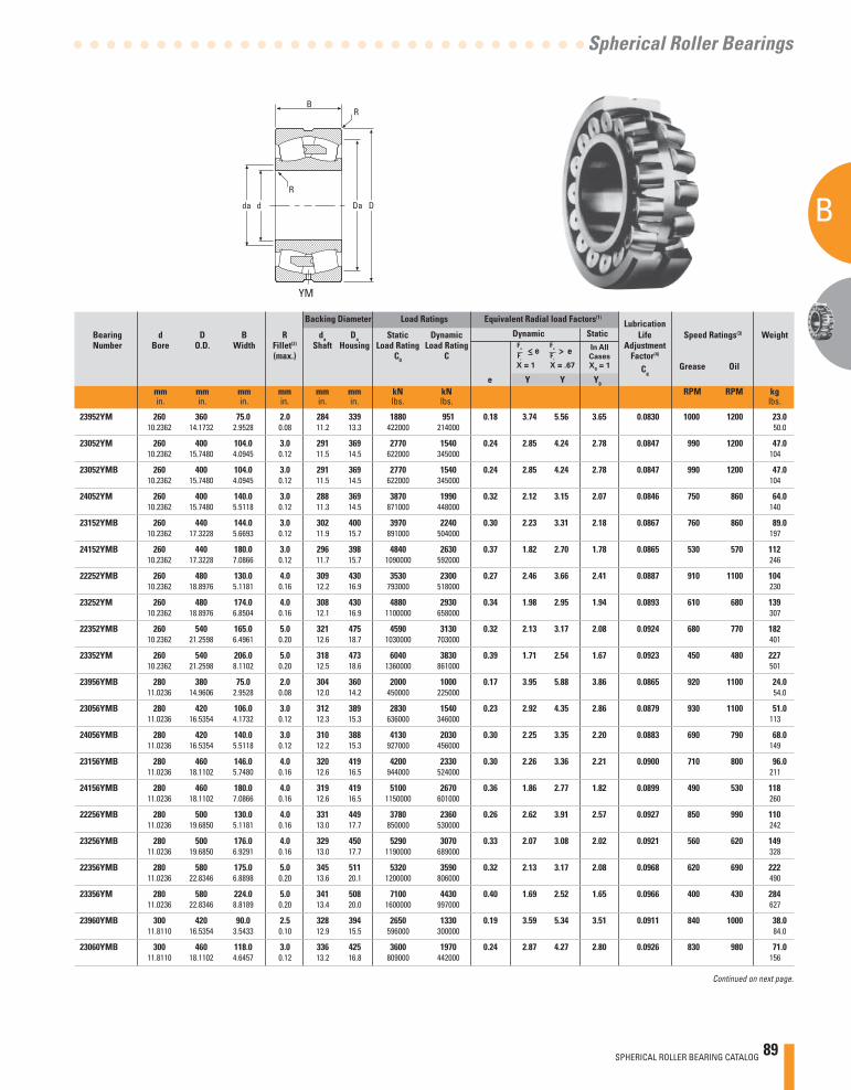
SPHERICAL ROLLER BEARING CATALOG 89
B
A
Spherical Roller Bearings
Continued on next page.
VCSJYM
Backing Diameter Load Ratings Equivalent Radial load Factors(1) Lubrication
Bearing d D B R da Da Static Dynamic Dynamic Static Life Speed Ratings(3) Weight Number Bore O.D. Width Fillet(2) Shaft Housing Load Rating Load Rating Adjustment (max.) C0 C Factor(4)
Cg Grease Oil
e Y Y Y0
mm mm mm mm mm mm kN kN RPM RPM kg in. in. in. in. in. in. lbs. lbs. lbs.
X = 1 X = .67
In All
Cases
X0 = 1
> e>e
d D
R
RB
da Da d D
R
RB
da Da
23952YM 260 360 75.0 2.0 284 339 1880 951 0.18 3.74 5.56 3.65 0.0830 1000 1200 23.0 10.2362 14.1732 2.9528 0.08 11.2 13.3 422000 214000 50.0
23052YM 260 400 104.0 3.0 291 369 2770 1540 0.24 2.85 4.24 2.78 0.0847 990 1200 47.0 10.2362 15.7480 4.0945 0.12 11.5 14.5 622000 345000 104
23052YMB 260 400 104.0 3.0 291 369 2770 1540 0.24 2.85 4.24 2.78 0.0847 990 1200 47.0 10.2362 15.7480 4.0945 0.12 11.5 14.5 622000 345000 104
24052YM 260 400 140.0 3.0 288 369 3870 1990 0.32 2.12 3.15 2.07 0.0846 750 860 64.0 10.2362 15.7480 5.5118 0.12 11.3 14.5 871000 448000 140
23152YMB 260 440 144.0 3.0 302 400 3970 2240 0.30 2.23 3.31 2.18 0.0867 760 860 89.0 10.2362 17.3228 5.6693 0.12 11.9 15.7 891000 504000 197
24152YMB 260 440 180.0 3.0 296 398 4840 2630 0.37 1.82 2.70 1.78 0.0865 530 570 112 10.2362 17.3228 7.0866 0.12 11.7 15.7 1090000 592000 246
22252YMB 260 480 130.0 4.0 309 430 3530 2300 0.27 2.46 3.66 2.41 0.0887 910 1100 104 10.2362 18.8976 5.1181 0.16 12.2 16.9 793000 518000 230
23252YM 260 480 174.0 4.0 308 430 4880 2930 0.34 1.98 2.95 1.94 0.0893 610 680 139 10.2362 18.8976 6.8504 0.16 12.1 16.9 1100000 658000 307
22352YMB 260 540 165.0 5.0 321 475 4590 3130 0.32 2.13 3.17 2.08 0.0924 680 770 182 10.2362 21.2598 6.4961 0.20 12.6 18.7 1030000 703000 401
23352YM 260 540 206.0 5.0 318 473 6040 3830 0.39 1.71 2.54 1.67 0.0923 450 480 227 10.2362 21.2598 8.1102 0.20 12.5 18.6 1360000 861000 501
23956YMB 280 380 75.0 2.0 304 360 2000 1000 0.17 3.95 5.88 3.86 0.0865 920 1100 24.0 11.0236 14.9606 2.9528 0.08 12.0 14.2 450000 225000 54.0
23056YMB 280 420 106.0 3.0 312 389 2830 1540 0.23 2.92 4.35 2.86 0.0879 930 1100 51.0 11.0236 16.5354 4.1732 0.12 12.3 15.3 636000 346000 113
24056YMB 280 420 140.0 3.0 310 388 4130 2030 0.30 2.25 3.35 2.20 0.0883 690 790 68.0 11.0236 16.5354 5.5118 0.12 12.2 15.3 927000 456000 149
23156YMB 280 460 146.0 4.0 320 419 4200 2330 0.30 2.26 3.36 2.21 0.0900 710 800 96.0 11.0236 18.1102 5.7480 0.16 12.6 16.5 944000 524000 211
24156YMB 280 460 180.0 4.0 319 419 5100 2670 0.36 1.86 2.77 1.82 0.0899 490 530 118 11.0236 18.1102 7.0866 0.16 12.6 16.5 1150000 601000 260
22256YMB 280 500 130.0 4.0 331 449 3780 2360 0.26 2.62 3.91 2.57 0.0927 850 990 110 11.0236 19.6850 5.1181 0.16 13.0 17.7 850000 530000 242
23256YMB 280 500 176.0 4.0 329 450 5290 3070 0.33 2.07 3.08 2.02 0.0921 560 620 149 11.0236 19.6850 6.9291 0.16 13.0 17.7 1190000 689000 328
22356YMB 280 580 175.0 5.0 345 511 5320 3590 0.32 2.13 3.17 2.08 0.0968 620 690 222 11.0236 22.8346 6.8898 0.20 13.6 20.1 1200000 806000 490
23356YM 280 580 224.0 5.0 341 508 7100 4430 0.40 1.69 2.52 1.65 0.0966 400 430 284 11.0236 22.8346 8.8189 0.20 13.4 20.0 1600000 997000 627
23960YMB 300 420 90.0 2.5 328 394 2650 1330 0.19 3.59 5.34 3.51 0.0911 840 1000 38.0 11.8110 16.5354 3.5433 0.10 12.9 15.5 596000 300000 84.0
23060YMB 300 460 118.0 3.0 336 425 3600 1970 0.24 2.87 4.27 2.80 0.0926 830 980 71.0 11.8110 18.1102 4.6457 0.12 13.2 16.8 809000 442000 156

90 SPHERICAL ROLLER BEARING CATALOG
B
A
SPHERICAL ROLLER BEARINGS
Backing Diameter Load Ratings Equivalent Radial Load Factors(1) Lubrication
Bearing d D B R da Da Static Dynamic Dynamic Static Life Speed Ratings(3) Weight Number Bore O.D. Width Fillet(2) Shaft Housing Load Rating Load Rating Adjustment (max.) C0 C Factor(4)
Cg Grease Oil
e Y Y Y0
mm mm mm mm mm mm kN kN RPM RPM kg in. in. in. in. in. in. lbs. lbs. lbs.
SPHERICAL ROLLER BEARINGS- continued• Life calculations, shaft and housing fi ts, internal clearances,
tolerances and other technical data for these bearings are found in the engineering section of this catalog.
• Bearings are available with a tapered bore for adapter type mounting. To order, add the suffi x “K” to bearing number (e.g., 23120K).
• Consult your Timken representative for up-to-date information about the availability of the bearings you have selected.
(3) See thermal speed ratings in the engineering section.(4) Geometry constant for Lubrication Life Adjustment Factor a3l.
See "Bearing Load Ratings and Life Calculations."
(1) These factors apply for both inch and metric calculations. See engineering section for instructions on use.
(2) Maximum shaft or housing fi llet radius that bearing corners will clear.* Available in standard shaker screen bearing design confi guration
(example: 223xxYMW33W800C4).
X = 1
X = .67
> e In All
Cases
X0 = 1
>e
D
R
R
Dadda
B
CJ
24060YMB 300 460 160.0 3.0 334 423 5230 2560 0.32 2.11 3.13 2.06 0.0928 620 700 96.0 11.8110 18.1102 6.2992 0.12 13.1 16.7 1180000 576000 211
23160YMB 300 500 160.0 4.0 345 453 5160 2810 0.30 2.25 3.35 2.20 0.0946 630 710 126 11.8110 19.6850 6.2992 0.16 13.6 17.8 1160000 632000 278
24160YMB 300 500 200.0 4.0 338 455 6320 3380 0.37 1.82 2.71 1.78 0.0942 430 460 158 11.8110 19.6850 7.8740 0.16 13.3 17.9 1420000 759000 347
22260YMB 300 540 140.0 4.0 355 484 4430 2760 0.26 2.59 3.86 2.53 0.0965 770 890 139 11.8110 21.2598 5.5118 0.16 14.0 19.1 997000 621000 306
23260YMB 300 540 192.0 4.0 353 482 6210 3510 0.34 2.00 2.98 1.96 0.0967 510 560 191 11.8110 21.2598 7.5591 0.16 13.9 19.0 1400000 788000 420
23964YMB 320 440 90.0 2.5 349 414 2800 1360 0.18 3.79 5.65 3.71 0.0946 780 930 40.0 12.5984 17.3228 3.5433 0.10 13.8 16.3 629000 305000 89.0
23064YMB 320 480 121.0 3.0 357 444 3910 2040 0.23 2.93 4.36 2.86 0.0962 780 910 76.0 12.5984 18.8976 4.7638 0.12 14.1 17.5 880000 458000 168
24064YMB 320 480 160.0 3.0 354 444 5420 2620 0.30 2.24 3.34 2.19 0.0961 580 660 101 12.5984 18.8976 6.2992 0.12 13.9 17.5 1220000 588000 222
23164YMB 320 540 176.0 4.0 367 490 6000 3330 0.31 2.14 3.19 2.10 0.0988 580 650 164 12.5984 21.2598 6.9291 0.16 14.4 19.3 1350000 749000 361
24164YMB 320 540 218.0 4.0 362 489 7580 3980 0.38 1.77 2.63 1.73 0.0986 380 410 203 12.5984 21.2598 8.5827 0.16 14.3 19.3 1710000 894000 448
22264YMB 320 580 150.0 4.0 380 519 5040 3110 0.26 2.58 3.84 2.52 0.1009 710 820 173 12.5984 22.8346 5.9055 0.16 15.0 20.4 1130000 700000 381
23264YMB 320 580 208.0 4.0 379 516 7140 3960 0.34 1.98 2.94 1.93 0.1013 460 510 240 12.5984 22.8346 8.1890 0.16 14.9 20.3 1610000 891000 528
23968YMB 340 460 90.0 2.5 369 435 3020 1420 0.17 3.98 5.93 3.89 0.0983 730 860 43.0 13.3858 18.1102 3.5433 0.10 14.5 17.1 678000 320000 94.0
23068YMB 340 520 133.0 4.0 384 481 4670 2430 0.23 2.96 4.40 2.89 0.1005 710 830 101 13.3858 20.4724 5.2362 0.16 15.1 18.9 1050000 546000 223
24068YMB 340 520 180.0 4.0 377 479 6590 3190 0.32 2.14 3.18 2.09 0.1004 530 600 137 13.3858 20.4724 7.0866 0.16 14.9 18.9 1480000 717000 302
23168YMB 340 580 190.0 4.0 397 526 6900 3750 0.30 2.22 3.30 2.17 0.1033 530 590 206 13.3858 22.8346 7.4803 0.16 15.6 20.7 1550000 843000 455
24168YMB 340 580 243.0 4.0 385 525 8970 4720 0.39 1.75 2.61 1.71 0.1033 340 370 264 13.3858 22.8346 9.5669 0.16 15.2 20.7 2020000 1060000 582
23268YMB 340 620 224.0 5.0 399 554 8290 4700 0.35 1.91 2.84 1.86 0.1051 420 460 296 13.3858 24.4094 8.8189 0.20 15.7 21.8 1860000 1060000 653
23972YMB 360 480 90.0 2.5 389 455 3170 1460 0.16 4.12 6.13 4.03 0.1013 680 810 45.0 14.1732 18.8976 3.5433 0.10 15.3 17.9 712000 328000 98.0
23072YMB 360 540 134.0 4.0 403 499 4640 2390 0.23 2.94 4.38 2.88 0.1035 680 800 107 14.1732 21.2598 5.2756 0.16 15.9 19.7 1040000 538000 236
24072YMB 360 540 180.0 4.0 398 500 6900 3270 0.30 2.24 3.33 2.19 0.1036 500 560 144 14.1732 21.2598 7.0866 0.16 15.7 19.7 1550000 736000 316

SPHERICAL ROLLER BEARING CATALOG 91
B
A
Spherical Roller Bearings
Continued on next page.
VCSJYM
Backing Diameter Load Ratings Equivalent Radial load Factors(1) Lubrication
Bearing d D B R da Da Static Dynamic Dynamic Static Life Speed Ratings(3) Weight Number Bore O.D. Width Fillet(2) Shaft Housing Load Rating Load Rating Adjustment (max.) C0 C Factor(4)
Cg Grease Oil
e Y Y Y0
mm mm mm mm mm mm kN kN RPM RPM kg in. in. in. in. in. in. lbs. lbs. lbs.
X = 1 X = .67
In All
Cases
X0 = 1
> e>e
d D
R
RB
da Da d D
R
RB
da Da
23172YMB 360 600 192.0 4.0 419 546 7360 3880 0.29 2.29 3.42 2.24 0.1065 500 560 218 14.1732 23.6220 7.5591 0.16 16.5 21.5 1650000 872000 480
24172YMB 360 600 243.0 4.0 406 545 9620 4890 0.38 1.79 2.67 1.75 0.1064 320 340 276 14.1732 23.6220 9.5669 0.16 16.0 21.4 2160000 1100000 608
23272YMB 360 650 232.0 5.0 420 583 8900 5040 0.35 1.95 2.91 1.91 0.1086 400 430 334 14.1732 25.5906 9.1339 0.20 16.5 22.9 2000000 1130000 737
23976YMB 380 520 106.0 3.0 416 488 3970 1810 0.18 3.80 5.66 3.72 0.1057 640 750 66.0 14.9606 20.4724 4.1732 0.12 16.4 19.2 893000 407000 145
23076YMB 380 560 135.0 4.0 422 520 5150 2590 0.22 3.08 4.58 3.01 0.1068 630 740 112 14.9606 22.0472 5.3150 0.16 16.6 20.5 1160000 581000 248
24076YMB 380 560 180.0 4.0 418 520 7150 3360 0.29 2.32 3.45 2.27 0.1062 470 530 150 14.9606 22.0472 7.0866 0.16 16.4 20.5 1610000 755000 330
23176YMB 380 620 194.0 4.0 431 566 7670 4100 0.30 2.28 3.39 2.23 0.1090 470 530 229 14.9606 24.4094 7.6378 0.16 17.0 22.3 1720000 922000 505
24176YMB 380 620 243.0 4.0 427 565 10200 5080 0.36 1.87 2.79 1.83 0.1097 300 320 287 14.9606 24.4094 9.5669 0.16 16.8 22.3 2290000 1140000 633
23276YMB 380 680 240.0 5.0 442 611 9630 5430 0.34 1.98 2.95 1.94 0.1119 370 400 376 14.9606 26.7717 9.4488 0.20 17.4 24.1 2170000 1220000 828
23980YMB 400 540 106.0 3.0 436 511 4050 1850 0.17 3.99 5.94 3.90 0.1086 600 720 69.0 15.7480 21.2598 4.1732 0.12 17.2 20.1 910000 415000 151
23080YMB 400 600 148.0 4.0 447 555 6020 3050 0.23 2.98 4.44 2.92 0.1109 590 690 146 15.7480 23.6220 5.8268 0.16 17.6 21.9 1350000 685000 321
24080YMB 400 600 200.0 4.0 442 555 8550 3990 0.30 2.24 3.33 2.19 0.1108 430 480 197 15.7480 23.6220 7.8740 0.16 17.4 21.9 1920000 898000 434
23180YMB 400 650 200.0 5.0 454 594 8210 4350 0.29 2.32 3.46 2.27 0.1123 440 500 258 15.7480 25.5906 7.8740 0.20 17.9 23.4 1850000 979000 570
24180YMB 400 650 250.0 5.0 449 594 10500 5280 0.35 1.91 2.84 1.87 0.1123 290 310 323 15.7480 25.5906 9.8425 0.20 17.7 23.4 2350000 1190000 712
23280YMB 400 720 256.0 5.0 466 646 11000 6110 0.34 1.96 2.93 1.92 0.1159 340 370 452 15.7480 28.3465 10.0787 0.20 18.4 25.4 2460000 1370000 996
22380YMB 400 820 243.0 6.0 496 729 10200 6570 0.30 2.28 3.40 2.23 0.1213 390 430 613 15.7480 32.2835 9.5669 0.24 19.5 28.7 2290000 1480000 1350
23984YMB 420 560 106.0 3.0 454 531 4270 1930 0.16 4.14 6.17 4.05 0.1117 570 670 72.0 16.5354 22.0472 4.1732 0.12 17.9 20.9 961000 434000 158
23084YMB 420 620 150.0 4.0 467 576 6430 3170 0.22 3.05 4.54 2.98 0.1139 560 650 154 16.5354 24.4094 5.9055 0.16 18.4 22.7 1450000 713000 339
24084YMB 420 620 200.0 4.0 463 575 8710 4010 0.29 2.37 3.52 2.31 0.1138 410 460 205 16.5354 24.4094 7.8740 0.16 18.2 22.7 1960000 901000 451
23184YMB 420 700 224.0 5.0 480 637 9760 5210 0.31 2.21 3.28 2.16 0.1166 410 450 346 16.5354 27.5591 8.8189 0.20 18.9 25.1 2190000 1170000 762
24184YMB 420 700 280.0 5.0 473 637 12500 6330 0.37 1.81 2.70 1.77 0.1166 260 280 432 16.5354 27.5591 11.0236 0.20 18.6 25.1 2810000 1420000 953
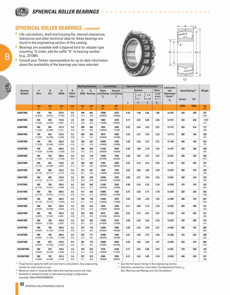
92 SPHERICAL ROLLER BEARING CATALOG
B
A
SPHERICAL ROLLER BEARINGS
Backing Diameter Load Ratings Equivalent Radial Load Factors(1) Lubrication
Bearing d D B R da Da Static Dynamic Dynamic Static Life Speed Ratings(3) Weight Number Bore O.D. Width Fillet(2) Shaft Housing Load Rating Load Rating Adjustment (max.) C0 C Factor(4)
Cg Grease Oil
e Y Y Y0
mm mm mm mm mm mm kN kN RPM RPM kg in. in. in. in. in. in. lbs. lbs. lbs.
SPHERICAL ROLLER BEARINGS- continued• Life calculations, shaft and housing fi ts, internal clearances,
tolerances and other technical data for these bearings are found in the engineering section of this catalog.
• Bearings are available with a tapered bore for adapter type mounting. To order, add the suffi x “K” to bearing number (e.g., 23120K).
• Consult your Timken representative for up-to-date information about the availability of the bearings you have selected.
(3) See thermal speed ratings in the engineering section.(4) Geometry constant for Lubrication Life Adjustment Factor a3l.
See "Bearing Load Ratings and Life Calculations."
(1) These factors apply for both inch and metric calculations. See engineering section for instructions on use.
(2) Maximum shaft or housing fi llet radius that bearing corners will clear.* Available in standard shaker screen bearing design confi guration
(example: 223xxYMW33W800C4).
X = 1
X = .67
> e In All
Cases
X0 = 1
>e
D
R
R
Dadda
B
CJ
23284YMB 420 760 272.0 6.0 490 681 12000 6670 0.35 1.90 2.83 1.86 0.1187 320 350 537 16.5354 29.9213 10.7087 0.24 19.3 26.8 2690000 1500000 1180
23988YMB 440 600 118.0 3.0 479 566 5080 2340 0.17 3.93 5.85 3.84 0.1157 530 630 97.0 17.3228 23.6220 4.6457 0.12 18.9 22.3 1140000 525000 213
23088YMB 440 650 157.0 5.0 489 603 7050 3460 0.22 3.04 4.53 2.97 0.1173 520 610 177 17.3228 25.5906 6.1811 0.20 19.3 23.8 1590000 777000 390
24088YMB 440 650 212.0 5.0 485 603 9870 4480 0.29 2.31 3.44 2.26 0.1173 380 430 239 17.3228 25.5906 8.3465 0.20 19.1 23.7 2220000 1010000 527
23188YMB 440 720 226.0 5.0 500 657 10400 5440 0.30 2.26 3.37 2.21 0.1198 380 430 361 17.3228 28.3465 8.8976 0.20 19.7 25.9 2340000 1220000 797
24188YMB 440 720 280.0 5.0 495 656 13100 6450 0.36 1.88 2.79 1.84 0.1197 250 260 448 17.3228 28.3465 11.0236 0.20 19.5 25.8 2930000 1450000 987
23288YMB 440 790 280.0 6.0 512 710 13400 7350 0.35 1.95 2.91 1.91 0.1231 300 320 593 17.3228 31.1024 11.0236 0.24 20.1 27.9 3010000 1650000 1310
23992YMB 460 620 118.0 3.0 504 582 4700 2050 0.16 4.13 6.15 4.04 0.1187 520 620 101 18.1102 24.4094 4.6457 0.12 19.9 22.9 1060000 460000 221
23092YMB 460 680 163.0 5.0 512 631 7660 3740 0.22 3.06 4.56 2.99 0.1207 500 570 202 18.1102 26.7717 6.4173 0.20 20.1 24.8 1720000 840000 444
24092YMB 460 680 218.0 5.0 507 630 10400 4750 0.28 2.37 3.53 2.32 0.1207 360 410 270 18.1102 26.7717 8.5827 0.20 20.0 24.8 2350000 1070000 593
23192YMB 460 760 240.0 6.0 524 692 11200 5920 0.30 2.24 3.33 2.19 0.1230 370 410 433 18.1102 29.9213 9.4488 0.24 20.6 27.2 2530000 1330000 953
24192YMB 460 760 300.0 6.0 517 692 15000 7420 0.37 1.82 2.71 1.78 0.1239 220 240 542 18.1102 29.9213 11.8110 0.24 20.4 27.2 3360000 1670000 1190
23292YMB 460 830 296.0 6.0 535 746 14200 7870 0.34 1.96 2.93 1.92 0.1259 280 310 697 18.1102 32.6772 11.6535 0.24 21.1 29.4 3190000 1770000 1530
23996YMB 480 650 128.0 4.0 522 614 5430 2490 0.17 3.86 5.75 3.78 0.1224 500 590 121 18.8976 25.5906 5.0394 0.16 20.6 24.2 1220000 559000 267
23096YMB 480 700 165.0 5.0 532 650 8070 3840 0.22 3.14 4.67 3.07 0.1236 470 550 211 18.8976 27.5591 6.4961 0.20 21.0 25.6 1810000 863000 465
24096YMB 480 700 218.0 5.0 527 652 11000 4970 0.28 2.45 3.64 2.39 0.1233 340 380 279 18.8976 27.5591 8.5827 0.20 20.7 25.7 2470000 1120000 614
23196YMB 480 790 248.0 6.0 547 719 12600 6480 0.30 2.26 3.36 2.21 0.1269 340 370 482 18.8976 31.1024 9.7638 0.24 21.5 28.3 2830000 1460000 1060
24196YMB 480 790 308.0 6.0 542 717 16300 7840 0.37 1.85 2.75 1.80 0.1266 210 220 598 18.8976 31.1024 12.1260 0.24 21.3 28.2 3660000 1760000 1320
23296YMB 480 870 310.0 6.0 561 779 16600 8940 0.35 1.92 2.85 1.87 0.1305 250 270 805 18.8976 34.2520 12.2047 0.24 22.1 30.7 3740000 2010000 1770
239/500YMB 500 670 128.0 4.0 544 634 5730 2540 0.17 4.02 5.98 3.93 0.1251 470 560 126 19.6850 26.3780 5.0394 0.16 21.4 25.0 1290000 571000 276
230/500YMB 500 720 167.0 5.0 551 673 8260 3950 0.21 3.26 4.85 3.18 0.1263 460 530 221 19.6850 28.3465 6.5748 0.20 21.7 26.5 1860000 889000 486
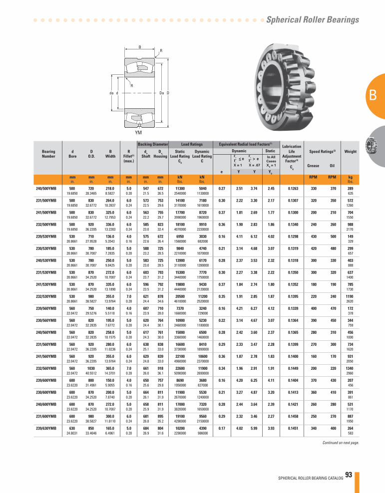
SPHERICAL ROLLER BEARING CATALOG 93
B
A
Spherical Roller Bearings
Continued on next page.
VCSJYM
Backing Diameter Load Ratings Equivalent Radial load Factors(1) Lubrication
Bearing d D B R da Da Static Dynamic Dynamic Static Life Speed Ratings(3) Weight Number Bore O.D. Width Fillet(2) Shaft Housing Load Rating Load Rating Adjustment (max.) C0 C Factor(4)
Cg Grease Oil
e Y Y Y0
mm mm mm mm mm mm kN kN RPM RPM kg in. in. in. in. in. in. lbs. lbs. lbs.
X = 1 X = .67
In All
Cases
X0 = 1
> e>e
d D
R
RB
da Da d D
R
RB
da Da
240/500YMB 500 720 218.0 5.0 547 672 11300 5040 0.27 2.51 3.74 2.45 0.1263 330 370 289 19.6850 28.3465 8.5827 0.20 21.5 26.5 2540000 1130000 635
231/500YMB 500 830 264.0 6.0 573 753 14100 7180 0.30 2.22 3.30 2.17 0.1307 320 350 572 19.6850 32.6772 10.3937 0.24 22.5 29.6 3170000 1610000 1260
241/500YMB 500 830 325.0 6.0 563 755 17700 8720 0.37 1.81 2.69 1.77 0.1300 200 210 704 19.6850 32.6772 12.7953 0.24 22.2 29.7 3990000 1960000 1550
232/500YMB 500 920 336.0 6.0 585 823 18100 9910 0.36 1.90 2.83 1.86 0.1340 240 260 988 19.6850 36.2205 13.2283 0.24 23.0 32.4 4070000 2230000 2170
239/530YMB 530 710 136.0 4.0 575 672 6950 3030 0.16 4.11 6.12 4.02 0.1298 430 500 149 20.8661 27.9528 5.3543 0.16 22.6 26.4 1560000 682000 329
230/530YMB 530 780 185.0 5.0 588 725 9840 4740 0.21 3.14 4.68 3.07 0.1319 420 480 299 20.8661 30.7087 7.2835 0.20 23.2 28.5 2210000 1070000 657
240/530YMB 530 780 250.0 5.0 583 725 13900 6170 0.28 2.37 3.53 2.32 0.1318 300 330 403 20.8661 30.7087 9.8425 0.20 23.0 28.5 3110000 1390000 888
231/530YMB 530 870 272.0 6.0 603 793 15300 7770 0.30 2.27 3.38 2.22 0.1350 300 320 637 20.8661 34.2520 10.7087 0.24 23.7 31.2 3440000 1750000 1400
241/530YMB 530 870 335.0 6.0 596 792 19800 9430 0.37 1.84 2.74 1.80 0.1352 180 190 785 20.8661 34.2520 13.1890 0.24 23.5 31.2 4440000 2120000 1730
232/530YMB 530 980 355.0 7.0 621 878 20500 11200 0.35 1.91 2.85 1.87 0.1395 220 240 1190 20.8661 38.5827 13.9764 0.28 24.4 34.6 4610000 2520000 2620
239/560YMB 560 750 140.0 4.0 607 710 7370 3240 0.16 4.21 6.27 4.12 0.1339 400 470 172 22.0472 29.5276 5.5118 0.16 23.9 28.0 1660000 729000 378
230/560YMB 560 820 195.0 5.0 620 764 10900 5230 0.22 3.14 4.67 3.07 0.1364 390 450 344 22.0472 32.2835 7.6772 0.20 24.4 30.1 2460000 1180000 759
240/560YMB 560 820 258.0 5.0 617 761 15000 6500 0.28 2.42 3.60 2.37 0.1365 280 310 456 22.0472 32.2835 10.1575 0.20 24.3 30.0 3360000 1460000 1000
231/560YMB 560 920 280.0 6.0 638 838 16600 8410 0.29 2.33 3.47 2.28 0.1399 270 300 734 22.0472 36.2205 11.0236 0.24 25.1 33.0 3730000 1890000 1620
241/560YMB 560 920 355.0 6.0 629 839 22100 10600 0.36 1.87 2.78 1.83 0.1400 160 170 931 22.0472 36.2205 13.9764 0.24 24.8 33.0 4960000 2370000 2050
232/560YMB 560 1030 365.0 7.0 661 918 22600 11900 0.34 1.96 2.91 1.91 0.1449 200 220 1340 22.0472 40.5512 14.3701 0.28 26.0 36.1 5090000 2690000 2960
239/600YMB 600 800 150.0 4.0 650 757 8690 3680 0.16 4.20 6.25 4.11 0.1404 370 430 207 23.6220 31.4961 5.9055 0.16 25.6 29.8 1950000 827000 456
230/600YMB 600 870 200.0 5.0 664 811 11900 5530 0.21 3.27 4.87 3.20 0.1413 360 410 391 23.6220 34.2520 7.8740 0.20 26.1 31.9 2670000 1240000 861
240/600YMB 600 870 272.0 5.0 658 811 17000 7320 0.28 2.44 3.64 2.39 0.1421 260 280 531 23.6220 34.2520 10.7087 0.20 25.9 31.9 3820000 1650000 1170
231/600YMB 600 980 300.0 6.0 681 895 19100 9560 0.29 2.32 3.46 2.27 0.1458 250 270 887 23.6220 38.5827 11.8110 0.24 26.8 35.2 4290000 2150000 1950
239/630YMB 630 850 165.0 5.0 684 804 10200 4390 0.17 4.02 5.99 3.93 0.1451 340 400 264 24.8031 33.4646 6.4961 0.20 26.9 31.6 2290000 986000 583

94 SPHERICAL ROLLER BEARING CATALOG
B
A
SPHERICAL ROLLER BEARINGS
Backing Diameter Load Ratings Equivalent Radial Load Factors(1) Lubrication
Bearing d D B R da Da Static Dynamic Dynamic Static Life Speed Ratings(3) Weight Number Bore O.D. Width Fillet(2) Shaft Housing Load Rating Load Rating Adjustment (max.) C0 C Factor(4)
Cg Grease Oil
e Y Y Y0
mm mm mm mm mm mm kN kN RPM RPM kg in. in. in. in. in. in. lbs. lbs. lbs.
SPHERICAL ROLLER BEARINGS- continued• Life calculations, shaft and housing fi ts, internal clearances,
tolerances and other technical data for these bearings are found in the engineering section of this catalog.
• Bearings are available with a tapered bore for adapter type mounting. To order, add the suffi x “K” to bearing number (e.g., 23120K).
• Consult your Timken representative for up-to-date information about the availability of the bearings you have selected.
(3) See thermal speed ratings in the engineering section.(4) Geometry constant for Lubrication Life Adjustment Factor a3l.
See "Bearing Load Ratings and Life Calculations."
(1) These factors apply for both inch and metric calculations. See engineering section for instructions on use.
(2) Maximum shaft or housing fi llet radius that bearing corners will clear.* Available in standard shaker screen bearing design confi guration
(example: 223xxYMW33W800C4).
X = 1
X = .67
> e In All
Cases
X0 = 1
>e
D
R
R
Dadda
B
CJ
230/630YMB 630 920 212.0 6.0 696 858 13600 6370 0.21 3.18 4.74 3.11 0.1466 330 380 469 24.8031 36.2205 8.3465 0.24 27.4 33.8 3050000 1430000 1030
240/630YMB 630 920 290.0 6.0 691 856 18900 8180 0.28 2.41 3.59 2.36 0.1465 240 260 642 24.8031 36.2205 11.4173 0.24 27.2 33.7 4240000 1840000 1410
231/630YMB 630 1030 315.0 6.0 716 940 21500 10600 0.29 2.30 3.42 2.25 0.1505 230 250 1030 24.8031 40.5512 12.4016 0.24 28.2 37.0 4820000 2390000 2270
241/630YMB 630 1030 400.0 6.0 707 939 27900 13000 0.37 1.84 2.74 1.80 0.1504 140 140 1310 24.8031 40.5512 15.7480 0.24 27.8 37.0 6270000 2920000 2880
239/670YMB 670 900 170.0 5.0 727 851 11200 4720 0.16 4.15 6.18 4.06 0.1509 320 370 302 26.3780 35.4331 6.6929 0.20 28.6 33.5 2510000 1060000 666
230/670YMB 670 980 230.0 6.0 744 911 16000 7230 0.22 3.12 4.65 3.05 0.1531 310 350 579 26.3780 38.5827 9.0551 0.24 29.3 35.9 3590000 1630000 1280
240/670YMB 670 980 308.0 6.0 738 910 22100 9280 0.28 2.39 3.55 2.33 0.1530 220 240 775 26.3780 38.5827 12.1260 0.24 29.0 35.8 4960000 2090000 1710
231/670YMB 670 1090 336.0 6.0 760 995 23700 11600 0.29 2.31 3.44 2.26 0.1560 210 230 1220 26.3780 42.9134 13.2283 0.24 29.9 39.2 5340000 2610000 2700
241/670YMD 670 1090 412.0 6.0 751 996 30400 14100 0.36 1.90 2.82 1.85 0.1560 130 130 1500 26.3780 42.9134 16.2205 0.24 29.6 39.2 6830000 3180000 3300
232/670YMD 670 1220 438.0 9.0 779 1097 32100 16900 0.35 1.95 2.91 1.91 0.1608 160 170 2240 26.3780 48.0315 17.2441 0.35 30.7 43.2 7220000 3800000 4940
239/710YMB 710 950 180.0 5.0 771 898 12500 5150 0.16 4.13 6.15 4.04 0.1565 300 340 353 27.9528 37.4016 7.0866 0.20 30.4 35.3 2820000 1160000 778
230/710YMB 710 1030 236.0 6.0 785 960 16900 7680 0.21 3.26 4.86 3.19 0.1583 290 330 647 27.9528 40.5512 9.2913 0.24 30.9 37.8 3800000 1730000 1430
240/710YMD 710 1030 315.0 6.0 779 960 23400 9880 0.27 2.49 3.71 2.44 0.1582 200 220 863 27.9528 40.5512 12.4016 0.24 30.7 37.8 5260000 2220000 1900
231/710YMB 710 1150 345.0 7.0 809 1048 26200 12500 0.28 2.38 3.54 2.32 0.1622 200 210 1390 27.9528 45.2756 13.5827 0.28 31.8 41.3 5880000 2800000 3060
241/710YMD 710 1150 438.0 7.0 795 1050 34300 15700 0.36 1.87 2.78 1.83 0.1613 120 120 1760 27.9528 45.2756 17.2441 0.28 31.3 41.4 7720000 3520000 3890
239/750YMB 750 1000 185.0 5.0 813 946 13500 5550 0.16 4.23 6.30 4.14 0.1619 280 320 398 29.5276 39.3701 7.2835 0.20 32.0 37.3 3040000 1250000 878
230/750YMB 750 1090 250.0 6.0 830 1015 19000 8550 0.21 3.26 4.85 3.18 0.1641 270 300 770 29.5276 42.9134 9.8425 0.24 32.7 40.0 4270000 1920000 1700
240/750YMD 750 1090 335.0 6.0 824 1014 26400 11000 0.27 2.48 3.69 2.42 0.1640 190 200 1030 29.5276 42.9134 13.1890 0.24 32.4 39.9 5940000 2480000 2270
241/750YMD 750 1220 475.0 7.0 840 1114 39200 17800 0.36 1.86 2.77 1.82 0.1676 110 110 2170 29.5276 48.0315 18.7008 0.28 33.1 43.9 8800000 4000000 4770
239/800YMB 800 1060 195.0 5.0 868 1007 13800 5700 0.16 4.20 6.25 4.10 0.1685 270 310 465 31.4961 41.7323 7.6772 0.20 34.2 39.6 3100000 1280000 1020
230/800YMB 800 1150 258.0 6.0 888 1074 20300 8940 0.19 3.50 5.22 3.43 0.1696 250 280 868 31.4961 45.2756 10.1575 0.24 35.0 42.3 4570000 2010000 1910

SPHERICAL ROLLER BEARING CATALOG 95
B
A
Spherical Roller Bearings
Continued on next page.
VCSJYM
Backing Diameter Load Ratings Equivalent Radial load Factors(1) Lubrication
Bearing d D B R da Da Static Dynamic Dynamic Static Life Speed Ratings(3) Weight Number Bore O.D. Width Fillet(2) Shaft Housing Load Rating Load Rating Adjustment (max.) C0 C Factor(4)
Cg Grease Oil
e Y Y Y0
mm mm mm mm mm mm kN kN RPM RPM kg in. in. in. in. in. in. lbs. lbs. lbs.
X = 1 X = .67
In All
Cases
X0 = 1
> e>e
d D
R
RB
da Da d D
R
RB
da Da
240/800YMD 800 1150 345.0 6.0 877 1072 28900 11800 0.26 2.55 3.80 2.50 0.1790 170 190 1160 31.4961 45.2756 13.5827 0.24 34.5 42.2 6500000 2650000 2560
231/800YMB 800 1280 365.0 7.0 906 1171 31900 15000 0.28 2.45 3.65 2.40 0.1741 160 180 1800 31.4961 50.3937 14.3701 0.28 35.7 46.1 7170000 3380000 3950
241/800YMD 800 1280 475.0 7.0 896 1170 41900 18500 0.35 1.95 2.90 1.90 0.1740 97 100 2340 31.4961 50.3937 18.7008 0.28 35.3 46.1 9430000 4170000 5150
232/800YMD 800 1420 488.0 11.0 935 1272 44000 21500 0.33 2.04 3.03 1.99 0.1798 120 130 3310 31.4961 55.9055 19.2126 0.43 36.8 50.1 9900000 4830000 7290
238/850YMB 850 1030 136.0 4.0 900 993 10500 3650 0.11 6.23 9.27 6.09 0.1718 130 150 233 33.4646 40.5512 5.3543 0.16 35.4 39.1 2350000 822000 513
239/850YMB 850 1120 200.0 5.0 919 1050 14700 5720 0.15 4.54 6.76 4.44 0.1747 250 290 525 33.4646 44.0945 7.8740 0.20 36.2 41.4 3300000 1290000 1150
230/850YMB 850 1220 272.0 6.0 938 1138 23400 10200 0.20 3.37 5.02 3.30 0.1771 230 260 1030 33.4646 48.0315 10.7087 0.24 36.9 44.8 5250000 2290000 2260
240/850YMD 850 1220 365.0 6.0 931 1138 32600 13200 0.26 2.56 3.81 2.50 0.1770 160 170 1380 33.4646 48.0315 14.3701 0.24 36.7 44.8 7320000 2960000 3030
231/850YMB 850 1360 400.0 9.0 962 1245 36200 16900 0.28 2.44 3.63 2.39 0.1810 150 160 2220 33.4646 53.5433 15.7480 0.35 37.9 49.0 8140000 3800000 4890
232/850YMD 850 1500 515.0 11.0 990 1347 48400 23500 0.33 2.06 3.06 2.01 0.1864 110 120 3880 33.4646 59.0551 20.2756 0.43 39.0 53.0 10900000 5280000 8540
239/900YMB 900 1180 206.0 5.0 965 1112 18300 7120 0.14 4.69 6.98 4.58 0.1801 220 250 592 35.4331 46.4567 8.1102 0.20 38.0 43.8 4110000 1600000 1300
230/900YMB 900 1280 280.0 6.0 990 1198 25900 11100 0.20 3.41 5.08 3.33 0.1828 210 240 1140 35.4331 50.3937 11.0236 0.24 39.0 47.2 5820000 2500000 2520
240/900YMD 900 1280 375.0 6.0 983 1197 35600 14200 0.26 2.60 3.87 2.54 0.1827 150 160 1530 35.4331 50.3937 14.7638 0.24 38.7 47.1 7990000 3200000 3370
231/900YMB 900 1420 412.0 9.0 1018 1300 39400 17800 0.27 2.49 3.71 2.43 0.1871 140 150 2450 35.4331 55.9055 16.2205 0.35 40.1 51.2 8860000 4010000 5390
241/900YMD 900 1420 515.0 9.0 1008 1298 51000 21700 0.34 2.00 2.98 1.96 0.1869 82 85 3060 35.4331 55.9055 20.2756 0.35 39.7 51.1 11500000 4870000 6740
232/900YMD 900 1580 515.0 11.0 1056 1423 51400 24700 0.32 2.11 3.13 2.06 0.1926 100 110 4280 35.4331 62.2047 20.2756 0.43 41.6 56.0 11600000 5560000 9420
239/950YMB 950 1250 224.0 6.0 1025 1187 20700 8160 0.15 4.39 6.54 4.29 0.1874 210 240 729 37.4016 49.2126 8.8189 0.24 40.3 46.7 4660000 1830000 1600
230/950YMB 950 1360 300.0 6.0 1046 1273 27600 12100 0.19 3.49 5.19 3.41 0.1899 200 230 1400 37.4016 53.5433 11.8110 0.24 41.2 50.1 6190000 2720000 3080
240/950YMD 950 1360 412.0 6.0 1039 1269 41300 16400 0.27 2.53 3.77 2.47 0.1898 130 140 1920 37.4016 53.5433 16.2205 0.24 40.9 50.0 9290000 3680000 4230
231/950YMB 950 1500 438.0 9.0 1074 1373 44400 19900 0.27 2.47 3.68 2.42 0.1937 130 140 2910 37.4016 59.0551 17.2441 0.35 42.3 54.1 9980000 4460000 6400
241/950YMD 950 1500 545.0 9.0 1064 1371 57100 24100 0.34 2.00 2.97 1.95 0.1935 75 77 3620 37.4016 59.0551 21.4567 0.35 41.9 54.0 12800000 5410000 7970
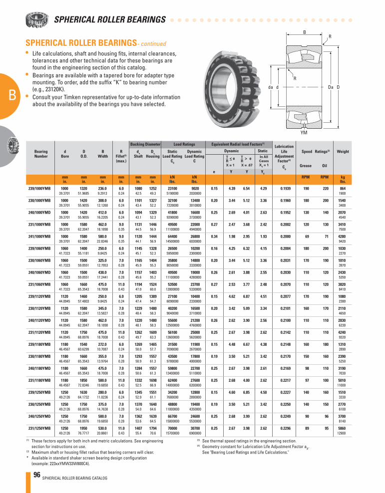
96 SPHERICAL ROLLER BEARING CATALOG
B
A
SPHERICAL ROLLER BEARINGS
d D
R
RB
da Da
Backing Diameter Load Ratings Equivalent Radial load Factors(1) Lubrication
Bearing d D B R da Da Static Dynamic Dynamic Static Life Speed Ratings(3) Weight Number Bore O.D. Width Fillet(2) Shaft Housing Load Rating Load Rating Adjustment (max.) C0 C Factor(4)
Cg Grease Oil
e Y Y Y0
mm mm mm mm mm mm kN kN RPM RPM kg in. in. in. in. in. in. lbs. lbs. lbs.
SPHERICAL ROLLER BEARINGS- continued• Life calculations, shaft and housing fi ts, internal clearances,
tolerances and other technical data for these bearings are found in the engineering section of this catalog.
• Bearings are available with a tapered bore for adapter type mounting. To order, add the suffi x “K” to bearing number (e.g., 23120K).
• Consult your Timken representative for up-to-date information about the availability of the bearings you have selected.
(3) See thermal speed ratings in the engineering section.(4) Geometry constant for Lubrication Life Adjustment Factor a3l.
See "Bearing Load Ratings and Life Calculations."
(1) These factors apply for both inch and metric calculations. See engineering section for instructions on use.
(2) Maximum shaft or housing fi llet radius that bearing corners will clear.* Available in standard shaker screen bearing design confi guration
(example: 223xxYMW33W800C4).
T
R
X = 1
<– e T
R
X = .67
> e
YM
In All
Cases
X0 = 1
239/1000YMB 1000 1320 236.0 6.0 1080 1252 23100 9020 0.15 4.39 6.54 4.29 0.1939 190 220 864 39.3701 51.9685 9.2913 0.24 42.5 49.3 5190000 2030000 1900
230/1000YMB 1000 1420 308.0 6.0 1101 1327 32100 13400 0.20 3.44 5.12 3.36 0.1960 180 200 1540 39.3701 55.9055 12.1260 0.24 43.4 52.2 7220000 3010000 3400
240/1000YMD 1000 1420 412.0 6.0 1094 1329 41800 16600 0.25 2.69 4.01 2.63 0.1952 130 140 2070 39.3701 55.9055 16.2205 0.24 43.1 52.3 9390000 3730000 4540
231/1000YMB 1000 1580 462.0 9.0 1131 1446 49500 22000 0.27 2.47 3.68 2.42 0.2002 120 130 3410 39.3701 62.2047 18.1890 0.35 44.5 56.9 11100000 4940000 7500
241/1000YMB 1000 1580 580.0 9.0 1120 1444 64400 26800 0.34 1.98 2.95 1.93 0.2000 69 71 4280 39.3701 62.2047 22.8346 0.35 44.1 56.9 14500000 6030000 9420
239/1060YMB 1060 1400 250.0 6.0 1145 1328 26500 10200 0.16 4.25 6.32 4.15 0.2004 180 200 1030 41.7323 55.1181 9.8425 0.24 45.1 52.3 5950000 2300000 2270
230/1060YMB 1060 1500 325.0 7.0 1165 1404 35800 14800 0.20 3.44 5.12 3.36 0.2031 170 190 1810 41.7323 59.0551 12.7953 0.28 45.9 55.3 8050000 3330000 3970
240/1060YMD 1060 1500 438.0 7.0 1157 1403 49500 19000 0.26 2.61 3.88 2.55 0.2030 110 120 2430 41.7323 59.0551 17.2441 0.28 45.6 55.2 11100000 4280000 5350
231/1060YMB 1060 1660 475.0 11.0 1194 1524 53500 23700 0.27 2.53 3.77 2.48 0.2070 110 120 3820 41.7323 65.3543 18.7008 0.43 47.0 60.0 12000000 5330000 8410
239/1120YMB 1120 1460 250.0 6.0 1205 1389 27100 10400 0.15 4.62 6.87 4.51 0.2077 170 190 1080 44.0945 57.4803 9.8425 0.24 47.4 54.7 6090000 2330000 2380
230/1120YMB 1120 1580 345.0 7.0 1229 1480 40200 16500 0.20 3.42 5.09 3.34 0.2101 160 170 2110 44.0945 62.2047 13.5827 0.28 48.4 58.3 9040000 3710000 4650
240/1120YMD 1120 1580 462.0 7.0 1220 1480 55600 21200 0.26 2.62 3.90 2.56 0.2100 110 110 2830 44.0945 62.2047 18.1890 0.28 48.1 58.3 12500000 4760000 6230
231/1120YMB 1120 1750 475.0 11.0 1262 1609 56100 25000 0.25 2.67 3.98 2.62 0.2142 110 110 4240 44.0945 68.8976 18.7008 0.43 49.7 63.3 12600000 5620000 9320
239/1180YMB 1180 1540 272.0 6.0 1269 1465 31500 11900 0.15 4.48 6.67 4.38 0.2148 160 180 1310 46.4567 60.6299 10.7087 0.24 50.0 57.7 7090000 2670000 2890
230/1180YMB 1180 1660 355.0 7.0 1293 1557 43500 17800 0.19 3.50 5.21 3.42 0.2170 150 160 2390 46.4567 65.3543 13.9764 0.28 50.9 61.3 9780000 4000000 5250
240/1180YMD 1180 1660 475.0 7.0 1284 1557 59800 22700 0.25 2.67 3.98 2.61 0.2169 98 110 3190 46.4567 65.3543 18.7008 0.28 50.6 61.3 13400000 5110000 7030
231/1180YMB 1180 1850 500.0 11.0 1332 1698 62400 27600 0.25 2.68 4.00 2.62 0.2217 97 100 5010 46.4567 72.8346 19.6850 0.43 52.5 66.9 14000000 6200000 11000
239/1250YMB 1250 1630 280.0 6.0 1345 1551 34200 12800 0.15 4.60 6.85 4.50 0.2227 140 160 1510 49.2126 64.1732 11.0236 0.24 52.9 61.1 7680000 2890000 3330
230/1250YMB 1250 1750 375.0 7.0 1370 1640 48800 19400 0.19 3.50 5.21 3.42 0.2250 140 150 2770 49.2126 68.8976 14.7638 0.28 54.0 64.6 11000000 4350000 6100
240/1250YMD 1250 1750 500.0 7.0 1362 1639 66700 24600 0.25 2.68 3.99 2.62 0.2249 90 96 3700 49.2126 68.8976 19.6850 0.28 53.6 64.5 15000000 5530000 8140
231/1250YMB 1250 1950 530.0 11.0 1407 1794 70000 30700 0.25 2.67 3.98 2.62 0.2296 89 95 5860 49.2126 76.7717 20.8661 0.43 55.4 70.6 15700000 6900000 12900
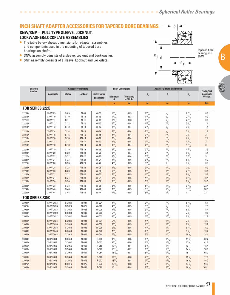
SPHERICAL ROLLER BEARING CATALOG 97
B
A
Spherical Roller Bearings
dD1
S
B2
INCH SHAFT ADAPTER ACCESSORIES FOR TAPERED BORE BEARINGSSNW/SNP – PULL TYPE SLEEVE, LOCKNUT, LOCKWASHER/LOCKPLATE ASSEMBLIES• The table below shows dimensions for adapter assemblies
and components used in the mounting of tapered bore bearings on shafts.
• SNW assembly consists of a sleeve, Locknut and Lockwasher.• SNP assembly consists of a sleeve, Locknut and Lockplate.
Tapered bore bearing plus SNW
Bearing Accessory Numbers Shaft Dimensions Adapter Dimensions Inches Number SNW/SNP Assembly Sleeve Locknut Lockwasher B2 S D1 Assembly Lockplate Diameter Tolerance Weight d +.000 To
in. in. in. in. in. lbs.
FOR SERIES 222K 22209K SNW-09 S-09 N-09 W-09 1 7/16 -.003 1 37/64
1/2 2 17/32 0.6 22210K SNW-10 S-10 N-10 W-10 1 11/16 -.003 1 49/64
9/16 2 11/16 0.7 22211K SNW-11 S-11 N-11 W-11 1 15/16 -.003 1 27/32
9/16 2 31/32 0.8 22212K SNW-12 S-12 N-12 W-12 2 1/16 -.004 1 63/64
19/32 3 5/32 1.1 22213K SNW-13 S-13 N-13 W-13 2 3/16 -.004 2 3/32
5/8 3 3/8 1.4
22214K SNW-14 S-14 N-14 W-14 2 5/16 -.004 2 11/64 5/8 3 5/8 1.8
22215K SNW-15 S-15 AN-15 W-15 2 7/16 -.004 2 19/64 43/64 3 7/8 2
22216K SNW-16 S-16 AN-16 W-16 2 11/16 -.004 2 3/8 43/64 4 5/32 2.4
22217K SNW-17 S-17 AN-17 W-17 2 15/16 -.004 2 31/64 45/64 4 13/32 3
22218K SNW-18 S-18 AN-18 W-18 3 3/16 -.004 2 41/64 25/32 4 21/32 3
22219K SNW-19 S-19 AN-19 W-19 3 5/16 -.004 2 49/64 13/16 4 15/16 3.3
22220K SNW-20 S-20 AN-20 W-20 3 7/16 -.004 2 7/8 27/32 5 3/16 4.4
22222K SNW-22 S-22 AN-22 W-22 3 15/16 -.004 3 13/64 29/32 5 23/32 5
22224K SNW-24 S-24 AN-24 W-24 4 3/16 -.005 3 15/32 15/16 6 1/8 6.7
22226K SNW-26 S-26 AN-26 W-26 4 7/16 -.005 3 49/64 1 6 3/4 8.6
22228K SNW-28 S-28 AN-28 W-28 4 15/16 -.005 3 63/64 1 1/16 7 3/32 10.3 22230K SNW-30 S-30 AN-30 W-30 5 3/16 -.005 4 15/64 1 1/8 7 11/16 13.5 22232K SNW-32 S-32 AN-32 W-32 5 7/16 -.005 4 37/64 1 3/16 8 1/16 15.6 22234K SNW-34 S-34 AN-34 W-34 5 15/16 -.005 4 27/32 1 7/32 8 21/32 19.4 22236K SNW-36 S-36 AN-36 W-36 6 7/16 -.005 5 1/32 1 1/4 9 1/16 20.5
22238K SNW-38 S-38 AN-38 W-38 6 15/16 -.005 5 17/64 1 9/32 9 15/32 23.4 22240K SNW-40 S-40 AN-40 W-40 7 3/16 -.005 5 31/64 1 11/32 9 27/32 30.5 22244K SNW-44 S-44 AN-44 W-44 7 15/16 -.005 5 29/32 1 3/8 11 33
FOR SERIES 230K 23024K SNW-3024 S-3024 N-024 W-024 4 3/16 -.005 2 61/64
13/16 5 11/16 6.1 23026K SNW-3026 S-3026 N-026 W-026 4 7/16 -.005 3 15/64
7/8 6 1/8 7.5 23028K SNW-3028 S-3028 N-028 W-028 4 15/16 -.005 3 11/32
15/16 6 1/2 8.4 23030K SNW-3030 S-3030 N-030 W-030 5 3/16 -.005 3 31/64
31/32 7 1/8 9.8 23032K SNW-3032 S-3032 N-032 W-032 5 7/16 -.005 3 23/32 1 1/32 7 1/2 11.8
23034K SNW-3034 S-3034 N-034 W-034 5 15/16 -.005 4 1/64 1 1/16 7 7/8 13.3 23036K SNW-3036 S-3036 N-036 W-036 6 7/16 -.005 4 11/32 1 3/32 8 1/4 15.2 23038K SNW-3038 S-3038 N-038 W-038 6 15/16 -.005 4 13/32 1 1/8 8 11/16 16.7 23040K SNW-3040 S-3040 N-040 W-040 7 3/16 -.005 4 3/4 1 3/16 9 7/16 19.7 23044K SNW-3044 S-3044 N-044 W-044 7 15/16 -.005 5 1/8 1 1/4 10 1/4 24.4
23048K SNP-3048 S-3048 N-048 P-048 8 15/16 -.006 5 7/16 1 11/32 11 7/16 32.2 23052K SNP-3052 S-3052 N-052 P-052 9 7/16 -.006 6 1/64 1 13/32 12 3/16 41.1 23056K SNP-3056 S-3056 N-056 P-056 10 7/16 -.007 6 3/16 1 1/2 13 45.4 23060K SNP-3060 S-3060 N-060 P-060 10 15/16 -.007 6 47/64 1 9/16 14 3/16 58.9 23064K SNP-3064 S-3064 N-064 P-064 11 15/16 -.007 6 61/64 1 21/32 15 65.7
23068K SNP-3068 S-3068 N-068 P-068 12 7/16 -.008 7 35/64 1 25/32 15 3/4 77.8 23072K SNP-3072 S-3072 N-072 P-072 13 7/16 -.008 7 37/64 1 25/32 16 1/2 86.2 23076K SNP-3076 S-3076 N-076 P-076 13 15/16 -.008 7 3/4 1 57/64 17 3/4 94.3 23080K SNP-3080 S-3080 N-080 P-080 15 -.008 8 13/32 2 1/16 18 1/2 105
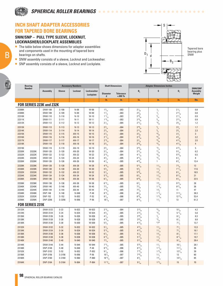
98 SPHERICAL ROLLER BEARING CATALOG
B
A
SPHERICAL ROLLER BEARINGS
INCH SHAFT ADAPTER ACCESSORIES FOR TAPERED BORE BEARINGSSNW/SNP – PULL TYPE SLEEVE, LOCKNUT, LOCKWASHER/LOCKPLATE ASSEMBLIES• The table below shows dimensions for adapter assemblies
and components used in the mounting of tapered bore bearings on shafts.
• SNW assembly consists of a sleeve, Locknut and Lockwasher.• SNP assembly consists of a sleeve, Locknut and Lockplate.
Tapered bore bearing plus SNW
Bearing Accessory Numbers Shaft Dimensions Adapter Dimensions Inches Number SNW/SNP Assembly Sleeve Locknut Lockwasher B2 S D1 Assembly Lockplate Diameter Tolerance Weight d +.000 To
in. in. in. in. in. lbs.
FOR SERIES 223K and 232K 22308K SNW-108 S-108 N-08 W-08 1 5/16 -.003 2 1/64
1/2 2 1/4 0.8 22309K SNW-109 S-109 N-09 W-09 1 7/16 -.003 2 9/64
1/2 2 17/32 0.8 22310K SNW-110 S-110 N-10 W-10 1 11/16 -.003 2 25/64
9/16 2 11/16 0.9 22311K SNW-111 S-111 N-11 W-11 1 15/16 -.003 2 33/64
9/16 2 31/32 0.9 22312K SNW-112 S-112 N-12 W-12 2 1/16 -.004 2 21/32
19/32 3 5/32 1.2
22313K SNW-113 S-113 N-13 W-13 2 3/16 -.004 2 49/64 5/8 3 3/8 1.7
22314K SNW-114 S-114 N-14 W-14 2 5/16 -.004 2 61/64 5/8 3 5/8 2.3
22315K SNW-115 S-115 AN-15 W-15 2 7/16 -.004 3 5/64 43/64 3 7/8 3
22316K SNW-116 S-116 AN-16 W-16 2 11/16 -.004 3 13/64 43/64 4 5/32 3.2
22317K SNW-117 S-117 AN-17 W-17 2 15/16 -.004 3 5/16 45/64 4 13/32 3.5
22318K SNW-118 S-118 AN-18 W-18 3 3/16 -.004 3 35/64 25/32 4 21/32 4
22319K SNW-119 S-119 AN-19 W-19 3 5/16 -.004 3 45/64 13/16 4 15/16 5
22320K 23220K SNW-120 S-120 AN-20 W-20 3 7/16 -.004 3 31/32 27/32 5 3/16 6.2
22322K 23222K SNW-122 S-122 AN-22 W-22 3 15/16 -.004 4 11/32 29/32 5 23/32 6.5
22324K 23224K SNW-124 S-124 AN-24 W-24 4 3/16 -.005 4 41/64 15/16 6 1/8 8
22326K 23226K SNW-126 S-126 AN-26 W-26 4 7/16 -.005 4 63/64 1 6 3/4 12.4
22328K 23228K SNW-128 S-128 AN-28 W-28 4 15/16 -.005 5 21/64 1 1/16 7 3/32 13 22330K 23230K SNW-130 S-130 AN-30 W-30 5 3/16 -.005 5 5/8 1 1/8 7 11/16 17.6 22332K 23232K SNW-132 S-132 AN-32 W-32 5 7/16 -.005 5 59/64 1 3/16 8 1/16 18.5 22334K 23234K SNW-134 S-134 AN-34 W-34 5 15/16 -.005 6 3/16 1 7/32 8 21/32 21 22336K 23236K SNW-136 S-136 AN-36 W-36 6 7/16 -.005 6 29/64 1 1/4 9 1/16 22.5
22338K 23238K SNW-138 S-138 AN-38 W-38 6 15/16 -.005 6 3/4 1 9/32 9 15/32 28 22340K 23240K SNW-140 S-140 AN-40 W-40 7 3/16 -.005 7 3/32 1 11/32 9 27/32 36 22344K 23244K SNW-144 S-144 AN-44 W-44 7 15/16 -.005 7 9/32 1 3/8 11 47 22348K 23248K SNP-148 S-148 N-048 P-48 8 15/16 -.006 8 7/64 1 11/32 11 7/16 38.3 22352K 23252K SNP-152 S-152 N-052 P-52 9 7/16 -.006 8 49/64 1 13/32 12 13/16 53.4 22356K 23256K SNP-3256 S-3256 N-056 P-56 10 7/16 -.007 8 15/16 1 1/2 13 61.3
FOR SERIES 231K 23122K SNW-3122 S-22 N-022 W-022 3 15/16 -.004 3 13/64
25/32 5 5/32 4.2 23124K SNW-3124 S-24 N-024 W-024 4 3/16 -.005 3 15/32
13/16 5 11/16 5.8 23126K SNW-3126 S-26 N-026 W-026 4 7/16 -.005 3 49/64
7/8 6 1/8 8.3 23128K SNW-3128 S-28 N-028 W-028 4 15/16 -.005 3 63/64
15/16 6 1/2 8.8 23130K SNW-3130 S-30 N-030 W-030 5 3/16 -.005 4 15/64
31/32 7 1/8 13.7
23132K SNW-3132 S-32 N-032 W-032 5 7/16 -.005 4 37/64 1 1/32 7 1/2 13.3 23134K SNW-3134 S-34 N-034 W-034 5 15/16 -.005 4 27/32 1 1/16 7 7/8 16.1 23136K SNW-3136 S-36 N-036 W-036 6 7/16 -.005 5 1/32 1 3/32 8 1/4 17.1 23138K SNW-3138 S-38 N-038 W-038 6 15/16 -.005 5 17/64 1 1/8 8 11/16 19.7 23140K SNW-3140 S-40 N-040 W-040 7 3/16 -.005 5 31/64 1 3/16 9 7/16 28.4
23144K SNW-3144 S-44 N-044 W-044 7 15/16 -.005 5 29/32 1 1/4 10 1/4 28.1 23148K SNP-3148 S-48 N-048 P-48 8 15/16 -.006 6 41/64 1 11/32 11 7/16 36 23152K SNP-3152 S-52 N-052 P-052 9 7/16 -.006 7 19/32 1 13/32 12 3/16 39 23156K SNP-3156 S-3156 N-056 P-56 10 7/16 -.007 7 49/64 1 1/2 13 60 23160K SNP-3160 S-3160 N-060 P-060 10 15/16 -.007 8 3/8 1 9/16 14 3/16 65
23164K SNP-3164 S-3164 N-064 P-064 11 15/16 -.007 9 7/64 1 21/32 15 70
dD1
S
B2
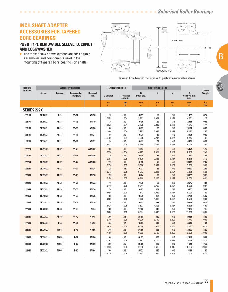
SPHERICAL ROLLER BEARING CATALOG 99
B
A
Spherical Roller Bearings
C
REMOVAL NUT
a
d B
L
Tapered bore bearing mounted with push type removable sleeve.
INCH SHAFT ADAPTER ACCESSORIES FOR TAPERED BORE BEARINGSPUSH TYPE REMOVABLE SLEEVE, LOCKNUT AND LOCKWASHER• The table below shows dimensions for adapter
assemblies and components used in the mounting of tapered bore bearings on shafts.
Bearing Accessory Numbers Shaft Dimensions Sleeve Dimensions Number Sleeve Sleeve Locknut Lockwasher Removal B L a C Weight Lockplate Nut Diameter Tolerance Pitch Dia. Removal Nut d +.000 To O.D.
mm mm mm mm mm mm kg. in. in. in. in. in. in. lbs.
SERIES 222K 22216K SK-8022 N-14 W-14 AN-18 70 -.10 88.19 50 3.5 118.39 0.57 2.7559 -.004 3.472 1.969 0.138 4.661 1.25 22217K SK-8522 AN-15 W-15 AN-19 75 -.10 93.35 52 3.5 125.55 0.65 2.9528 -.004 3.675 2.047 0.138 4.943 1.44 22218K SK-9022 AN-16 W-16 AN-20 80 -.10 98.12 53 3.5 131.90 0.69 3.1496 -.004 3.863 2.087 0.138 5.193 1.53 22219K SK-9522 AN-17 W-17 AN-21 85 -.10 103.28 57 4.0 138.25 0.82 3.3465 -.004 4.066 2.244 0.157 5.443 1.81 22220K SK-10022 AN-18 W-18 AN-22 90 -.10 109.12 59 4.0 145.39 0.91 3.5433 -.004 4.269 2.323 0.157 5.724 2.00
22222K SK-11022 AN-20 W-20 ARN-22 100 -.10 119.94 65 4.0 158.75 1.12 3.9370 -.004 4.722 2.559 0.157 6.250 2.47 22224K SK-12022 AN-22 W-22 ARN-24 110 -.13 130.28 72 4.0 174.63 1.42 4.3307 -.005 5.129 2.835 0.157 6.875 3.13 22226K SK-13022 AN-22 W-22 ARN-26 115 -.13 141.38 78 4.0 184.15 2.27 4.5276 -.005 5.566 3.071 0.157 7.250 5.00 22228K SK-14022 AN-24 W-24 RN-28 125 -.13 152.73 82 5.0 200.03 2.67 4.9213 -.005 6.013 3.228 0.197 7.875 5.88 22230K SK-15022 AN-26 W-26 RN-30 135 -.13 163.04 88 5.0 209.55 3.09 5.3150 -.005 6.419 3.465 0.197 8.250 6.81
22232K SK-16022 AN-28 W-28 RN-32 140 -.13 173.76 96 5.0 225.43 4.51 5.5118 -.005 6.841 3.780 0.197 8.875 9.94 22234K SK-17022 AN-30 W-30 RN-34 150 -.13 184.07 104 5.0 234.95 5.22 5.9055 -.005 7.247 4.095 0.197 9.250 11.50 22236K SK-18022 AN-32 W-32 RN-36 160 -.13 194.79 104 5.0 247.65 5.67 6.2992 -.005 7.669 4.095 0.197 9.750 12.50 22238K SK-19022 AN-34 W-34 RN-38 170 -.13 205.92 112 5.0 269.88 6.58 6.6929 -.005 8.107 4.409 0.197 10.625 14.50 22240K SK-20022 AN-36 W-36 N-44 180 -.13 217.02 118 5.0 279.53 7.43 7.0866 -.005 8.544 4.646 0.197 11.005 16.37
22244K SK-22022 AN-40 W-40 N-048 200 -.13 236.98 130 6.0 290.65 8.89 7.8740 -.005 9.330 5.118 0.236 11.443 19.60 22248K SK-24022 N-44 W-44 N-052 220 -.15 256.03 144 6.0 309.70 11.02 8.6614 -.006 10.080 5.669 0.236 12.193 24.30 22252K SK-26022 N-048 P-48 N-056 240 -.15 276.66 155 6.0 330.33 14.02 9.4488 -.006 10.892 6.102 0.236 13.005 30.90
22256K SK-28022 N-052 P-52 RN-56 260 -.15 301.27 155 8.0 425.45 15.01 10.2362 -.006 11.861 6.102 0.315 16.75 33.10 22260K SK-30022 N-056 P-56 RN-60 280 -.15 325.88 170 8.0 416.10 17.78 11.0236 -.006 12.830 6.693 0.315 16.382 39.20 22264K SK-32022 N-060 P-60 RN-64 300 -.15 345.72 180 10.0 431.80 21.00 11.8110 -.006 13.611 7.087 0.394 17.000 46.30
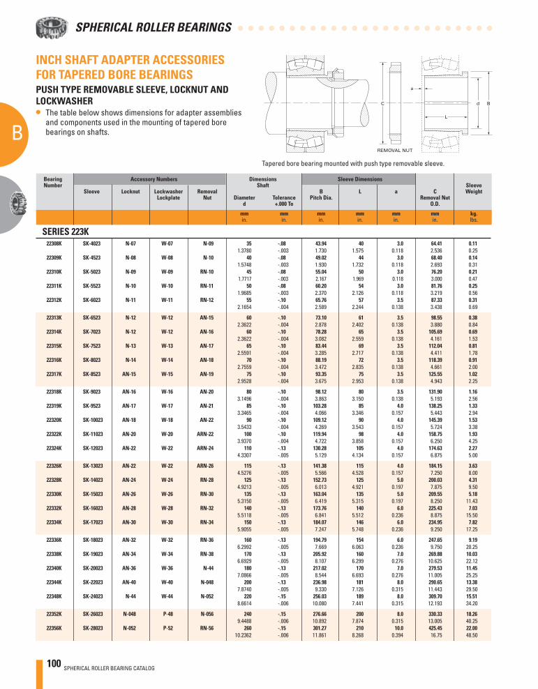
100 SPHERICAL ROLLER BEARING CATALOG
B
A
SPHERICAL ROLLER BEARINGS
Tapered bore bearing mounted with push type removable sleeve.
INCH SHAFT ADAPTER ACCESSORIES FOR TAPERED BORE BEARINGSPUSH TYPE REMOVABLE SLEEVE, LOCKNUT AND LOCKWASHER• The table below shows dimensions for adapter assemblies
and components used in the mounting of tapered bore bearings on shafts.
Bearing Accessory Numbers Dimensions Sleeve Dimensions Number Shaft Sleeve Sleeve Locknut Lockwasher Removal B L a C Weight Lockplate Nut Diameter Tolerance Pitch Dia. Removal Nut d +.000 To O.D.
mm mm mm mm mm mm kg. in. in. in. in. in. in. lbs.
SERIES 223K 22308K SK-4023 N-07 W-07 N-09 35 -.08 43.94 40 3.0 64.41 0.11 1.3780 -.003 1.730 1.575 0.118 2.536 0.25 22309K SK-4523 N-08 W-08 N-10 40 -.08 49.02 44 3.0 68.40 0.14 1.5748 -.003 1.930 1.732 0.118 2.693 0.31 22310K SK-5023 N-09 W-09 RN-10 45 -.08 55.04 50 3.0 76.20 0.21 1.7717 -.003 2.167 1.969 0.118 3.000 0.47 22311K SK-5523 N-10 W-10 RN-11 50 -.08 60.20 54 3.0 81.76 0.25 1.9685 -.003 2.370 2.126 0.118 3.219 0.56 22312K SK-6023 N-11 W-11 RN-12 55 -.10 65.76 57 3.5 87.33 0.31 2.1654 -.004 2.589 2.244 0.138 3.438 0.69
22313K SK-6523 N-12 W-12 AN-15 60 -.10 73.10 61 3.5 98.55 0.38 2.3622 -.004 2.878 2.402 0.138 3.880 0.84 22314K SK-7023 N-12 W-12 AN-16 60 -.10 78.28 65 3.5 105.69 0.69 2.3622 -.004 3.082 2.559 0.138 4.161 1.53 22315K SK-7523 N-13 W-13 AN-17 65 -.10 83.44 69 3.5 112.04 0.81 2.5591 -.004 3.285 2.717 0.138 4.411 1.78 22316K SK-8023 N-14 W-14 AN-18 70 -.10 88.19 72 3.5 118.39 0.91 2.7559 -.004 3.472 2.835 0.138 4.661 2.00 22317K SK-8523 AN-15 W-15 AN-19 75 -.10 93.35 75 3.5 125.55 1.02 2.9528 -.004 3.675 2.953 0.138 4.943 2.25
22318K SK-9023 AN-16 W-16 AN-20 80 -.10 98.12 80 3.5 131.90 1.16 3.1496 -.004 3.863 3.150 0.138 5.193 2.56 22319K SK-9523 AN-17 W-17 AN-21 85 -.10 103.28 85 4.0 138.25 1.33 3.3465 -.004 4.066 3.346 0.157 5.443 2.94 22320K SK-10023 AN-18 W-18 AN-22 90 -.10 109.12 90 4.0 145.39 1.53 3.5433 -.004 4.269 3.543 0.157 5.724 3.38 22322K SK-11023 AN-20 W-20 ARN-22 100 -.10 119.94 98 4.0 158.75 1.93 3.9370 -.004 4.722 3.858 0.157 6.250 4.25 22324K SK-12023 AN-22 W-22 ARN-24 110 -.13 130.28 105 4.0 174.63 2.27 4.3307 -.005 5.129 4.134 0.157 6.875 5.00
22326K SK-13023 AN-22 W-22 ARN-26 115 -.13 141.38 115 4.0 184.15 3.63 4.5276 -.005 5.566 4.528 0.157 7.250 8.00 22328K SK-14023 AN-24 W-24 RN-28 125 -.13 152.73 125 5.0 200.03 4.31 4.9213 -.005 6.013 4.921 0.197 7.875 9.50 22330K SK-15023 AN-26 W-26 RN-30 135 -.13 163.04 135 5.0 209.55 5.18 5.3150 -.005 6.419 5.315 0.197 8.250 11.43 22332K SK-16023 AN-28 W-28 RN-32 140 -.13 173.76 140 6.0 225.43 7.03 5.5118 -.005 6.841 5.512 0.236 8.875 15.50 22334K SK-17023 AN-30 W-30 RN-34 150 -.13 184.07 146 6.0 234.95 7.82 5.9055 -.005 7.247 5.748 0.236 9.250 17.25
22336K SK-18023 AN-32 W-32 RN-36 160 -.13 194.79 154 6.0 247.65 9.19 6.2992 -.005 7.669 6.063 0.236 9.750 20.25 22338K SK-19023 AN-34 W-34 RN-38 170 -.13 205.92 160 7.0 269.88 10.03 6.6929 -.005 8.107 6.299 0.276 10.625 22.12 22340K SK-20023 AN-36 W-36 N-44 180 -.13 217.02 170 7.0 279.53 11.45 7.0866 -.005 8.544 6.693 0.276 11.005 25.25 22344K SK-22023 AN-40 W-40 N-048 200 -.13 236.98 181 8.0 290.65 13.38 7.8740 -.005 9.330 7.126 0.315 11.443 29.50 22348K SK-24023 N-44 W-44 N-052 220 -.15 256.03 189 8.0 309.70 15.51 8.6614 -.006 10.080 7.441 0.315 12.193 34.20
22352K SK-26023 N-048 P-48 N-056 240 -.15 276.66 200 8.0 330.33 18.26 9.4488 -.006 10.892 7.874 0.315 13.005 40.25 22356K SK-28023 N-052 P-52 RN-56 260 -.15 301.27 210 10.0 425.45 22.00 10.2362 -.006 11.861 8.268 0.394 16.75 48.50
C
REMOVAL NUT
a
d B
L
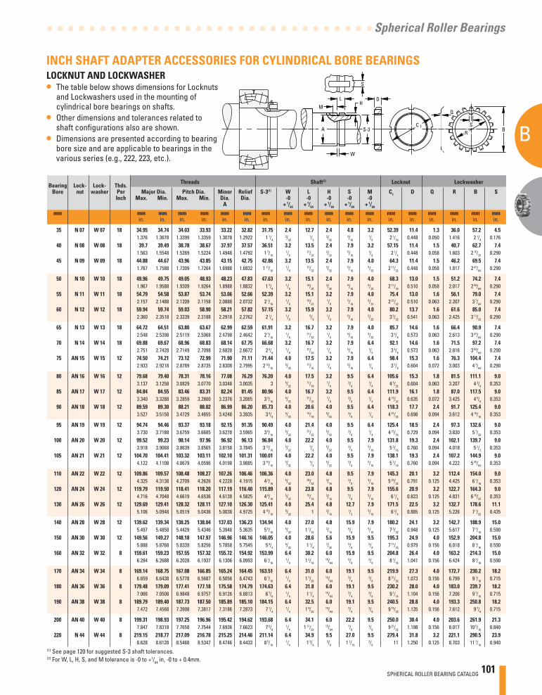
SPHERICAL ROLLER BEARING CATALOG 101
B
A
Spherical Roller Bearings
M
LH
A
S
Q
C 1
R
SS-3
D
B
W
Bearing Lock- Lock- Thds. Threads Shaft(2) Locknut Lockwasher
Bore nut washer Per Major Dia. Pitch Dia. Minor Relief S-3(1) W L H S M C1 D Q R B S Inch Max. Min. Max. Min. Dia. Dia. -0 -0 -0 -0 -0 A + 1/64 + 1/64 + 1/64 + 1/64 + 1/64
mm mm mm mm mm mm mm mm mm mm mm mm mm mm mm mm mm mm mm in. in. in. in. in. in. in. in. in. in. in. in. in. in. in. in. in. in.
35 N 07 W 07 18 34.95 34.74 34.03 33.93 33.22 32.82 31.75 2.4 12.7 2.4 4.8 3.2 52.39 11.4 1.3 36.0 57.2 4.5 1.376 1.3678 1.3399 1.3359 1.3078 1.2922 1 1/4
3/32 1/2
3/32 3/16
1/8 2 1/16 0.448 0.050 1.416 2 1/4 0.176 40 N 08 W 08 18 39.7 39.49 38.78 38.67 37.97 37.57 36.51 3.2 13.5 2.4 7.9 3.2 57.15 11.4 1.5 40.7 62.7 7.4 1.563 1.5548 1.5269 1.5224 1.4948 1.4792 1 7/16
1/8 17/32
3/32 5/16
1/8 2 1/4 0.448 0.058 1.603 2 15/32 0.290 45 N 09 W 09 18 44.88 44.67 43.96 43.85 43.15 42.75 42.86 3.2 13.5 2.4 7.9 4.0 64.3 11.4 1.5 46.2 69.5 7.4 1.767 1.7588 1.7309 1.7264 1.6988 1.6832 1 11/16
1/8 17/32
3/32 5/16
5/32 2 17/32 0.448 0.058 1.817 2 47/64 0.290
50 N 10 W 10 18 49.96 49.75 49.05 48.93 48.23 47.83 47.63 3.2 15.1 2.4 7.9 4.0 68.3 13.0 1.5 51.2 74.2 7.4 1.967 1.9588 1.9309 1.9264 1.8988 1.8832 1 7/8
1/8 19/32
3/32 5/16
5/32 2 11/16 0.510 0.058 2.017 2 59/64 0.290 55 N 11 W 11 18 54.79 54.58 53.87 53.74 53.06 52.66 52.39 3.2 15.1 3.2 7.9 4.0 75.4 13.0 1.6 56.1 79.0 7.4 2.157 2.1488 2.1209 2.1158 2.0888 2.0732 2 1/16
1/8 19/32
1/8 5/16
5/32 2 31/32 0.510 0.063 2.207 3 7/64 0.290 60 N 12 W 12 18 59.94 59.74 59.03 58.90 58.21 57.82 57.15 3.2 15.9 3.2 7.9 4.0 80.2 13.7 1.6 61.6 85.0 7.4 2.360 2.3518 2.3239 2.3188 2.2918 2.2762 2 1/4
1/8 5/8
1/8 5/16
5/32 3 5/32 0.541 0.063 2.425 3 11/32 0.290
65 N 13 W 13 18 64.72 64.51 63.80 63.67 62.99 62.59 61.91 3.2 16.7 3.2 7.9 4.0 85.7 14.6 1.6 66.4 90.9 7.4 2.548 2.5398 2.5119 2.5068 2.4798 2.4642 2 7/16
1/8 21/32
1/8 5/16
5/32 3 3/8 0.573 0.063 2.613 3 37/64 0.290 70 N 14 W 14 18 69.88 69.67 68.96 68.83 68.14 67.75 66.68 3.2 16.7 3.2 7.9 6.4 92.1 14.6 1.6 71.5 97.2 7.4 2.751 2.7428 2.7149 2.7098 2.6828 2.6672 2 5/8
1/8 21/32
1/8 5/16
1/4 3 5/8 0.573 0.063 2.816 3 53/64 0.290 75 AN 15 W 15 12 74.50 74.21 73.12 72.99 71.90 71.11 71.44 4.0 17.5 3.2 7.9 6.4 98.4 15.3 1.6 76.3 104.4 7.4 2.933 2.9218 2.8789 2.8735 2.8308 2.7995 2 13/16
5/32 11/16
1/8 5/16
1/4 3 7/8 0.604 0.072 3.003 4 7/64 0.290
80 AN 16 W 16 12 79.68 79.40 78.31 78.16 77.08 76.29 76.20 4.0 17.5 3.2 9.5 6.4 105.6 15.3 1.8 81.5 111.1 9.0 3.137 3.1258 3.0829 3.0770 3.0348 3.0035 3 5/32
11/16 1/8
3/8 1/4 4 5/32 0.604 0.063 3.207 4 3/8 0.353
85 AN 17 W 17 12 84.84 84.55 83.46 83.31 82.24 81.45 80.96 4.0 16.7 3.2 9.5 6.4 111.9 16.1 1.8 87.0 117.5 9.0 3.340 3.3288 3.2859 3.2800 3.2378 3.2065 3 3/16
5/32 21/32
1/8 3/8
1/4 4 13/32 0.635 0.072 3.425 4 5/8 0.353 90 AN 18 W 18 12 89.59 89.30 88.21 88.02 86.99 86.20 85.73 4.0 20.6 4.0 9.5 6.4 118.3 17.7 2.4 91.7 125.4 9.0 3.527 3.5158 3.4729 3.4655 3.4248 3.3935 3 3/8
5/32 13/16
5/32 3/8
1/4 4 21/32 0.698 0.094 3.612 4 15/16 0.353
95 AN 19 W 19 12 94.74 94.46 93.37 93.18 92.15 91.35 90.49 4.0 21.4 4.0 9.5 6.4 125.4 18.5 2.4 97.3 132.6 9.0 3.730 3.7188 3.6759 3.6685 3.6278 3.5965 3 9/16
5/32 27/32
5/32 3/8
1/4 4 15/16 0.729 0.094 3.830 5 7/32 0.353 100 AN 20 W 20 12 99.52 99.23 98.14 97.96 96.92 96.13 96.84 4.0 22.2 4.0 9.5 7.9 131.8 19.3 2.4 102.1 139.7 9.0 3.918 3.9068 3.8639 3.8565 3.8158 3.7845 3 13/16
5/32 7/8
5/32 3/8
5/16 5 3/16 0.760 0.094 4.018 5 1/2 0.353 105 AN 21 W 21 12 104.70 104.41 103.32 103.11 102.10 101.31 100.01 4.0 22.2 4.0 9.5 7.9 138.1 19.3 2.4 107.2 144.9 9.0 4.122 4.1108 4.0679 4.0596 4.0198 3.9885 3 15/16
5/32 7/8
5/32 3/8
5/16 5 7/16 0.760 0.094 4.222 5 45/64 0.353
110 AN 22 W 22 12 109.86 109.57 108.48 108.27 107.26 106.46 106.36 4.0 23.0 4.8 9.5 7.9 145.3 20.1 3.2 112.4 154.0 9.0 4.325 4.3138 4.2709 4.2626 4.2228 4.1915 4 3/16
5/32 29/32
3/16 3/8
5/16 5 23/32 0.791 0.125 4.425 6 1/16 0.353 120 AN 24 W 24 12 119.79 119.50 118.41 118.20 117.19 116.40 115.89 4.0 23.8 4.8 9.5 7.9 155.6 20.9 3.2 122.7 164.3 9.0 4.716 4.7048 4.6619 4.6536 4.6138 4.5825 4 9/16
5/32 15/16
3/16 3/8
5/16 6 1/8 0.823 0.125 4.831 6 15/32 0.353 130 AN 26 W 26 12 129.69 129.41 128.32 128.11 127.10 126.30 125.41 4.0 25.4 4.8 12.7 7.9 171.5 22.5 3.2 132.7 178.6 11.1 5.106 5.0948 5.0519 5.0436 5.0038 4.9725 4 15/16
5/32 1 3/16 1/2
5/16 6 3/4 0.885 0.125 5.226 7 1/32 0.435
140 AN 28 W 28 12 139.62 139.34 138.25 138.04 137.03 136.23 134.94 4.0 27.0 4.8 15.9 7.9 180.2 24.1 3.2 142.7 188.9 15.0 5.497 5.4858 5.4429 5.4346 5.3948 5.3635 5 5/16
5/32 1 1/16 3/16
5/8 5/16 7 3/32 0.948 0.125 5.617 7 7/16 0.590
150 AN 30 W 30 12 149.56 149.27 148.18 147.97 146.96 146.16 146.05 4.0 28.6 5.6 15.9 9.5 195.3 24.9 4.0 152.9 204.8 15.0 5.888 5.8768 5.8339 5.8256 5.7858 5.7545 5 3/4
5/32 1 1/8 7/32
5/8 3/8 7 11/16 0.979 0.156 6.018 8 1/16 0.590
160 AN 32 W 32 8 159.61 159.23 157.55 157.32 155.72 154.92 153.99 6.4 30.2 6.0 15.9 9.5 204.8 26.4 4.0 163.2 214.3 15.0 6.284 6.2688 6.2028 6.1937 6.1306 6.0993 6 1/16
1/4 1 3/16 15/64
5/8 3/8 8 1/16 1.041 0.156 6.424 8 7/16 0.590
170 AN 34 W 34 8 169.14 168.75 167.08 166.85 165.24 164.45 163.51 6.4 31.0 6.0 19.1 9.5 219.9 27.3 4.0 172.7 230.2 18.2 6.659 6.6438 6.5778 6.5687 6.5056 6.4743 6 7/16
1/4 1 7/32 15/64
3/4 3/8 8 21/32 1.073 0.156 6.799 9 1/16 0.715
180 AN 36 W 36 8 179.48 179.09 177.41 177.18 175.58 174.79 174.63 6.4 31.8 6.0 19.1 9.5 230.2 28.0 4.0 183.0 239.7 18.2 7.066 7.0508 6.9848 6.9757 6.9126 6.8813 6 7/8
1/4 1 1/4 15/64
3/4 3/8 9 1/16 1.104 0.156 7.206 9 7/16 0.715
190 AN 38 W 38 8 189.79 189.40 187.73 187.50 185.89 185.10 184.15 6.4 32.5 6.0 19.1 9.5 240.5 28.8 4.0 193.3 250.8 18.2 7.472 7.4568 7.3908 7.3817 7.3186 7.2873 7 1/4
1/4 1 9/32 15/64
3/4 3/8 9 15/32 1.135 0.156 7.612 9 7/8 0.715
200 AN 40 W 40 8 199.31 198.93 197.25 196.96 195.42 194.62 193.68 6.4 34.1 6.0 22.2 9.5 250.0 30.4 4.0 203.6 261.9 21.3 7.847 7.8318 7.7658 7.7544 7.6936 7.6623 7 5/8
1/4 1 11/32 15/64
7/8 3/8 9 27/32 1.198 0.156 8.017 10 5/16 0.840
220 N 44 W 44 8 219.15 218.77 217.09 216.78 215.25 214.46 211.14 6.4 34.9 9.5 27.0 9.5 279.4 31.8 3.2 221.1 290.5 23.9 8.628 8.6128 8.5468 8.5347 8.4746 8.4433 8 5/16
1/4 1 3/8 3/8 1 1/16
3/8 11 1.250 0.125 8.703 11 7/16 0.940
INCH SHAFT ADAPTER ACCESSORIES FOR CYLINDRICAL BORE BEARINGSLOCKNUT AND LOCKWASHER• The table below shows dimensions for Locknuts
and Lockwashers used in the mounting of cylindrical bore bearings on shafts.
• Other dimensions and tolerances related to shaft confi gurations also are shown.
• Dimensions are presented according to bearing bore size and are applicable to bearings in the various series (e.g., 222, 223, etc.).
(1) See page 120 for suggested S-3 shaft tolerances. (2) For W, L, H, S, and M tolerance is -0 to +1/64 in, -0 to + 0.4mm.
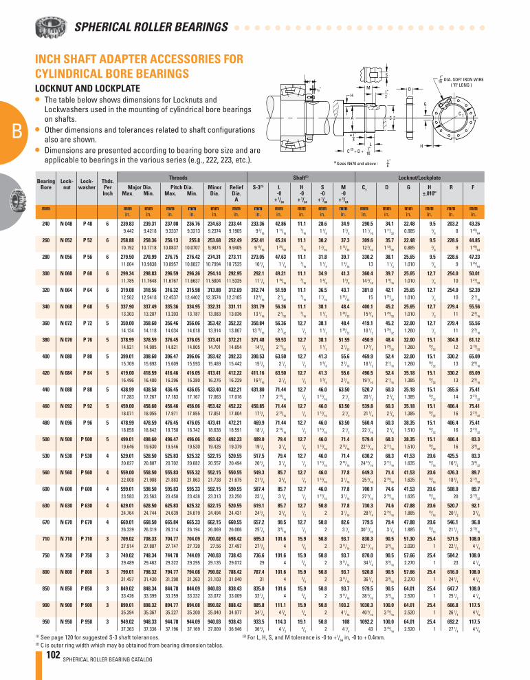
102 SPHERICAL ROLLER BEARING CATALOG
B
A
SPHERICAL ROLLER BEARINGS
1"4
1"16
1"16
1"2
3 "8
M
H
S
C 1
D
LC (2) + D +
G
DIA. SOFT IRON WIRE ( "R" LONG )
H
*
* Sizes N670 and above :
F
1/8"
S-3A
INCH SHAFT ADAPTER ACCESSORIES FOR CYLINDRICAL BORE BEARINGSLOCKNUT AND LOCKPLATE• The table below shows dimensions for Locknuts and
Lockwashers used in the mounting of cylindrical bore bearings on shafts.
• Other dimensions and tolerances related to shaft confi gurations also are shown.
• Dimensions are presented according to bearing bore size and are applicable to bearings in the various series (e.g., 222, 223, etc.).
Bearing Lock- Lock- Thds. Threads Shaft(3) Locknut/Lockplate
Bore nut washer Per Major Dia. Pitch Dia. Minor Relief S-3(1) L H S M C1 D G H R F Inch Max. Min. Max. Min. Dia. Dia. -0 -0 -0 -0 ±.010" A + 1/64 + 1/64 + 1/64 + 1/64
mm mm mm mm mm mm mm mm mm mm mm mm mm mm mm mm mm mm in. in. in. in. in. in. in. in. in. in. in. in. in. in. in. in. in.
240 N 048 P 48 6 239.83 239.31 237.08 236.76 234.63 233.44 233.36 42.86 11.1 28.6 34.9 290.5 34.1 22.48 9.5 203.2 43.26 9.442 9.4218 9.3337 9.3213 9.2374 9.1905 9 3/16 1 11/16
7/16 1 1/8 1 3/8 11 7/16 1 11/32 0.885 3/8 8 1 45/64
260 N 052 P 52 6 258.88 258.36 256.13 255.8 253.68 252.49 252.41 45.24 11.1 30.2 37.3 309.6 35.7 22.48 9.5 228.6 44.85 10.192 10.1718 10.0837 10.0707 9.9874 9.9405 9 15/16 1 25/32
7/16 1 3/16 1 15/32 12 3/16 1 13/32 0.885 3/8 9 1 49/64
280 N 056 P 56 6 279.50 278.99 276.75 276.42 274.31 273.11 273.05 47.63 11.1 31.8 39.7 330.2 38.1 25.65 9.5 228.6 47.23 11.004 10.9838 10.8957 10.8827 10.7994 10.7525 10 3/4 1 7/8
7/16 1 1/4 1 9/16 13 1 1/2 1.010 3/8 9 1 55/64
300 N 060 P 60 6 299.34 298.83 296.59 296.26 294.14 292.95 292.1 49.21 11.1 34.9 41.3 360.4 39.7 25.65 12.7 254.0 50.01 11.785 11.7648 11.6767 11.6637 11.5804 11.5335 11 1/2 1 15/16
7/16 1 3/8 1 5/8 14 3/16 1 9/16 1.010 1/2 10 1 31/32
320 N 064 P 64 6 319.08 318.56 316.32 315.98 313.88 312.69 312.74 51.59 11.1 36.5 43.7 381.0 42.1 25.65 12.7 254.0 52.39 12.562 12.5418 12.4537 12.4402 12.3574 12.3105 12 5/16 2 1/32
7/16 1 7/16 1 23/32 15 1 21/32 1.010 1/2 10 2 1/16
340 N 068 P 68 5 337.90 337.49 335.36 334.95 332.31 331.11 331.79 56.36 11.1 38.1 48.4 400.1 45.2 25.65 12.7 279.4 55.56 13.303 13.287 13.203 13.187 13.083 13.036 13 1/16 2 7/32
7/16 1 1/2 1 29/32 15 3/4 1 25/32 1.010 1/2 11 2 3/16
360 N 072 P 72 5 359.00 358.60 356.46 356.06 353.42 352.22 350.84 56.36 12.7 38.1 48.4 419.1 45.2 32.00 12.7 279.4 55.56 14.134 14.118 14.034 14.018 13.914 13.867 13 13/16 2 7/32
1/2 1 1/2 1 29/32 16 1/2 1 25/32 1.260 1/2 11 2 3/16
380 N 076 P 76 5 378.99 378.59 376.45 376.05 373.41 372.21 371.48 59.53 12.7 38.1 51.59 450.9 48.4 32.00 15.1 304.8 61.12 14.921 14.905 14.821 14.805 14.701 14.654 14 5/8 2 11/32
1/2 1 1/2 2 1/32 17 3/4 1 29/32 1.260 19/32 12 2 13/32
400 N 080 P 80 5 399.01 398.60 396.47 396.06 393.42 392.23 390.53 63.50 12.7 41.3 55.6 469.9 52.4 32.00 15.1 330.2 65.09 15.709 15.693 15.609 15.593 15.489 15.442 15 3/8 2 1/2
1/2 1 5/8 2 3/16 18 1/2 2 1/16 1.260 19/32 13 2 9/16
420 N 084 P 84 5 419.00 418.59 416.46 416.05 413.41 412.22 411.16 63.50 12.7 41.3 55.6 490.5 52.4 35.18 15.1 330.2 65.09 16.496 16.480 16.396 16.380 16.276 16.229 16 3/16 2 1/2
1/2 1 5/8 2 3/16 19 5/16 2 1/16 1.385 19/32 13 2 9/16
440 N 088 P 88 5 438.99 438.58 436.45 436.05 433.40 432.21 431.80 71.44 12.7 46.0 63.50 520.7 60.3 35.18 15.1 355.6 75.41 17.283 17.267 17.183 17.167 17.063 17.016 17 2 13/16
1/2 1 13/16 2 1/2 20 1/2 2 3/8 1.385 19/32 14 2 31/32
460 N 092 P 92 5 459.00 458.60 456.46 456.06 453.42 452.22 450.85 71.44 12.7 46.0 63.50 539.8 60.3 35.18 15.1 406.4 75.41 18.071 18.055 17.971 17.955 17.851 17.804 17 3/4 2 13/16
1/2 1 13/16 2 1/2 21 1/4 2 3/8 1.385 19/32 16 2 31/32
480 N 096 P 96 5 478.99 478.59 476.45 476.05 473.41 472.21 469.9 71.44 12.7 46.0 63.50 560.4 60.3 38.35 15.1 406.4 75.41 18.858 18.842 18.758 18.742 18.638 18.591 18 1/2 2 13/16
1/2 1 13/16 2 1/2 22 1/16 2 3/8 1.510 19/32 16 2 31/32
500 N 500 P 500 5 499.01 498.60 496.47 496.06 493.42 492.23 489.0 79.4 12.7 46.0 71.4 579.4 68.3 38.35 15.1 406.4 83.3 19.646 19.630 19.546 19.530 19.426 19.379 19 1/4 3 1/8
1/2 1 13/16 2 13/16 22 13/16 2 11/16 1.510 19/32 16 3 9/32
530 N 530 P 530 4 529.01 528.50 525.83 525.32 522.15 520.55 517.5 79.4 12.7 46.0 71.4 630.2 68.3 41.53 20.6 425.5 83.3 20.827 20.807 20.702 20.682 20.557 20.494 20 3/8 3 1/8
1/2 1 13/16 2 13/16 24 13/16 2 11/16 1.635 13/16 16 3/4 3 9/32
560 N 560 P 560 4 559.00 558.50 555.83 555.32 552.15 550.55 549.3 85.7 12.7 46.0 77.8 649.3 71.4 41.53 20.6 476.3 89.7 22.008 21.988 21.883 21.863 21.738 21.675 21 5/8 3 3/8
1/2 1 13/16 3 1/16 25 9/16 2 15/16 1.635 13/16 18 3/4 3 17/32
600 N 600 P 600 4 599.01 598.50 595.83 595.33 592.15 590.55 587.4 85.7 12.7 46.0 77.8 700.1 74.6 41.53 20.6 508.0 89.7 23.583 23.563 23.458 23.438 23.313 23.250 23 1/8 3 3/8
1/2 1 13/16 3 1/16 27 9/16 2 15/16 1.635 13/16 20 3 17/32
630 N 630 P 630 4 629.01 628.50 625.83 625.32 622.15 520.55 619.1 85.7 12.7 50.8 77.8 730.3 74.6 47.88 20.6 520.7 92.1 24.764 24.744 24.639 24.619 24.494 24.431 24 3/8 3 3/8
1/2 2 3 1/16 28 3/4 2 15/16 1.885 13/16 20 1/2 3 5/8
670 N 670 P 670 4 669.01 668.50 665.84 665.33 662.15 660.55 657.2 90.5 12.7 50.8 82.6 779.5 79.4 47.88 20.6 546.1 96.8 26.339 26.319 26.214 26.194 26.069 26.006 25 7/8 3 9/16
1/2 2 3 1/4 30 11/16 3 1/8 1.885 13/16 21 1/2 3 13/16
710 N 710 P 710 3 709.02 708.33 704.77 704.09 700.02 698.42 695.3 101.6 15.9 50.8 93.7 830.3 90.5 51.30 25.4 571.5 108.0 27.914 27.887 27.747 27.720 27.56 27.497 27 3/8 4 5/8 2 3 11/16 32 11/16 3 9/16 2.020 1 22 1/2 4 1/4
750 N 750 P 750 3 749.02 748.34 744.78 744.09 740.03 738.43 736.6 101.6 15.9 50.8 93.7 870.0 90.5 57.66 25.4 584.2 108.0 29.489 29.462 29.322 29.295 29.135 29.072 29 4 5/8 2 3 11/16 34 1/4 3 9/16 2.270 1 23 4 1/4
800 N 800 P 800 3 799.01 798.32 794.77 794.08 790.02 788.42 787.4 101.6 15.9 50.8 93.7 920.8 90.5 57.66 25.4 616.0 108.0 31.457 31.430 31.290 31.263 31.103 31.040 31 4 5/8 2 3 11/16 36 1/4 3 9/16 2.270 1 24 1/4 4 1/4
850 N 850 P 850 3 849.02 848.34 844.78 844.09 840.03 838.43 835.0 101.6 15.9 50.8 93.7 979.5 90.5 64.01 25.4 647.7 108.0 33.426 33.399 33.259 33.232 33.072 33.009 32 7/8 4 5/8 2 3 11/16 38 9/16 3 9/16 2.520 1 25 1/2 4 1/4
900 N 900 P 900 3 899.01 898.32 894.77 894.08 890.02 888.42 885.8 111.1 15.9 50.8 103.2 1030.3 100.0 64.01 25.4 666.8 117.5 35.394 35.367 35.227 35.200 35.040 34.977 34 7/8 4 3/8
5/8 2 4 1/16 40 9/16 3 15/16 2.520 1 26 1/4 4 5/8
950 N 950 P 950 3 949.02 948.33 944.78 944.09 940.03 938.43 933.5 114.3 19.1 50.8 108 1092.2 100.0 64.01 25.4 692.2 117.5 37.363 37.336 37.196 37.169 37.009 36.946 36 3/4 4 1/2
3/4 2 4 1/4 43 3 15/16 2.520 1 27 1/4 4 5/8
(1) See page 120 for suggested S-3 shaft tolerances. (3) For L, H, S, and M tolerance is -0 to +1/64 in, -0 to + 0.4mm. (2) C is outer ring width which may be obtained from bearing dimension tables.
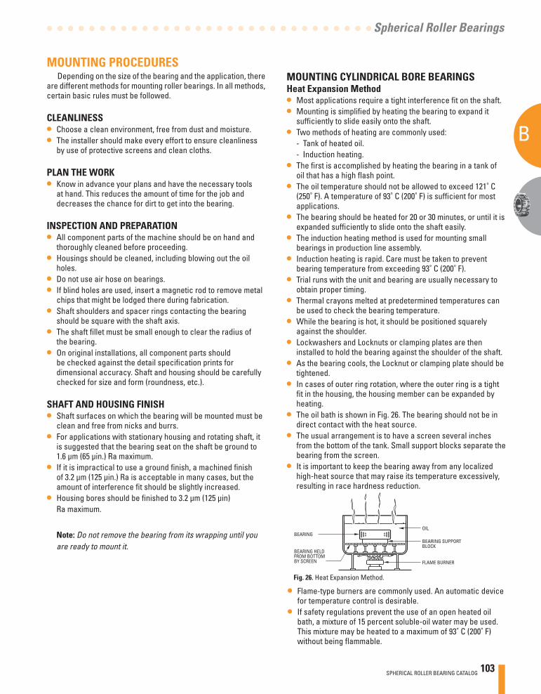
SPHERICAL ROLLER BEARING CATALOG 103
B
A
Spherical Roller Bearings
MOUNTING CYLINDRICAL BORE BEARINGSHeat Expansion Method• Most applications require a tight interference fi t on the shaft.• Mounting is simplifi ed by heating the bearing to expand it
suffi ciently to slide easily onto the shaft.• Two methods of heating are commonly used: - Tank of heated oil. - Induction heating.• The fi rst is accomplished by heating the bearing in a tank of
oil that has a high fl ash point.• The oil temperature should not be allowed to exceed 121˚ C
(250˚ F). A temperature of 93˚ C (200˚ F) is suffi cient for most applications.
• The bearing should be heated for 20 or 30 minutes, or until it is expanded suffi ciently to slide onto the shaft easily.
• The induction heating method is used for mounting small bearings in production line assembly.
• Induction heating is rapid. Care must be taken to prevent bearing temperature from exceeding 93˚ C (200˚ F).
• Trial runs with the unit and bearing are usually necessary to obtain proper timing.
• Thermal crayons melted at predetermined temperatures can be used to check the bearing temperature.
• While the bearing is hot, it should be positioned squarely against the shoulder.
• Lockwashers and Locknuts or clamping plates are then installed to hold the bearing against the shoulder of the shaft.
• As the bearing cools, the Locknut or clamping plate should be tightened.
• In cases of outer ring rotation, where the outer ring is a tight fi t in the housing, the housing member can be expanded by heating.
• The oil bath is shown in Fig. 26. The bearing should not be in direct contact with the heat source.
• The usual arrangement is to have a screen several inches from the bottom of the tank. Small support blocks separate the bearing from the screen.
• It is important to keep the bearing away from any localized high-heat source that may raise its temperature excessively, resulting in race hardness reduction.
MOUNTING PROCEDURESDepending on the size of the bearing and the application, there
are different methods for mounting roller bearings. In all methods, certain basic rules must be followed.
CLEANLINESS• Choose a clean environment, free from dust and moisture.• The installer should make every effort to ensure cleanliness
by use of protective screens and clean cloths.
PLAN THE WORK• Know in advance your plans and have the necessary tools
at hand. This reduces the amount of time for the job and decreases the chance for dirt to get into the bearing.
INSPECTION AND PREPARATION• All component parts of the machine should be on hand and
thoroughly cleaned before proceeding.• Housings should be cleaned, including blowing out the oil
holes.• Do not use air hose on bearings. • If blind holes are used, insert a magnetic rod to remove metal
chips that might be lodged there during fabrication.• Shaft shoulders and spacer rings contacting the bearing
should be square with the shaft axis. • The shaft fi llet must be small enough to clear the radius of
the bearing. • On original installations, all component parts should
be checked against the detail specifi cation prints for dimensional accuracy. Shaft and housing should be carefully checked for size and form (roundness, etc.).
SHAFT AND HOUSING FINISH• Shaft surfaces on which the bearing will be mounted must be
clean and free from nicks and burrs.• For applications with stationary housing and rotating shaft, it
is suggested that the bearing seat on the shaft be ground to 1.6 μm (65 μin.) Ra maximum.
• If it is impractical to use a ground fi nish, a machined fi nish of 3.2 μm (125 μin.) Ra is acceptable in many cases, but the amount of interference fi t should be slightly increased.
• Housing bores should be fi nished to 3.2 μm (125 μin) Ra maximum.
Note: Do not remove the bearing from its wrapping until you are ready to mount it.
OIL
BEARING SUPPORTBLOCK
FLAME BURNER
BEARING
BEARING HELDFROM BOTTOMBY SCREEN
• Flame-type burners are commonly used. An automatic device for temperature control is desirable.
• If safety regulations prevent the use of an open heated oil bath, a mixture of 15 percent soluble-oil water may be used. This mixture may be heated to a maximum of 93˚ C (200˚ F) without being fl ammable.
Fig. 26. Heat Expansion Method.
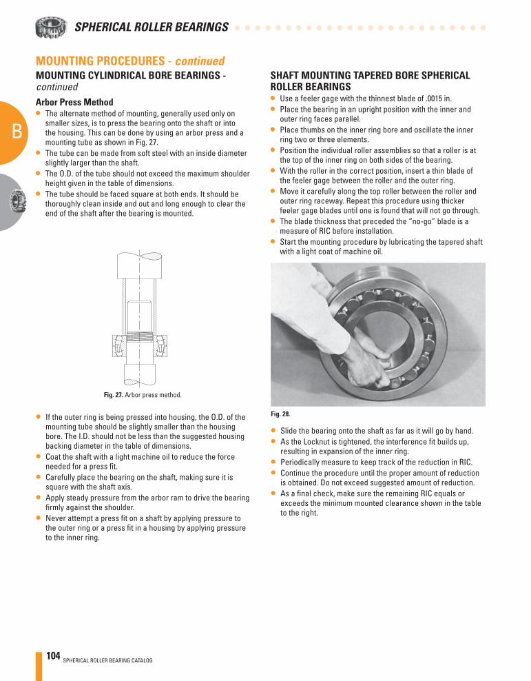
104 SPHERICAL ROLLER BEARING CATALOG
B
A
SPHERICAL ROLLER BEARINGS
Arbor Press Method• The alternate method of mounting, generally used only on
smaller sizes, is to press the bearing onto the shaft or into the housing. This can be done by using an arbor press and a mounting tube as shown in Fig. 27.
• The tube can be made from soft steel with an inside diameter slightly larger than the shaft.
• The O.D. of the tube should not exceed the maximum shoulder height given in the table of dimensions.
• The tube should be faced square at both ends. It should be thoroughly clean inside and out and long enough to clear the end of the shaft after the bearing is mounted.
• If the outer ring is being pressed into housing, the O.D. of the mounting tube should be slightly smaller than the housing bore. The I.D. should not be less than the suggested housing backing diameter in the table of dimensions.
• Coat the shaft with a light machine oil to reduce the force needed for a press fi t.
• Carefully place the bearing on the shaft, making sure it is square with the shaft axis.
• Apply steady pressure from the arbor ram to drive the bearing fi rmly against the shoulder.
• Never attempt a press fi t on a shaft by applying pressure to the outer ring or a press fi t in a housing by applying pressure to the inner ring.
SHAFT MOUNTING TAPERED BORE SPHERICAL ROLLER BEARINGS• Use a feeler gage with the thinnest blade of .0015 in. • Place the bearing in an upright position with the inner and
outer ring faces parallel.• Place thumbs on the inner ring bore and oscillate the inner
ring two or three elements.• Position the individual roller assemblies so that a roller is at
the top of the inner ring on both sides of the bearing.• With the roller in the correct position, insert a thin blade of
the feeler gage between the roller and the outer ring. • Move it carefully along the top roller between the roller and
outer ring raceway. Repeat this procedure using thicker feeler gage blades until one is found that will not go through.
• The blade thickness that preceded the “no-go” blade is a measure of RIC before installation.
• Start the mounting procedure by lubricating the tapered shaft with a light coat of machine oil.
• Slide the bearing onto the shaft as far as it will go by hand.• As the Locknut is tightened, the interference fi t builds up,
resulting in expansion of the inner ring. • Periodically measure to keep track of the reduction in RIC.• Continue the procedure until the proper amount of reduction
is obtained. Do not exceed suggested amount of reduction.• As a fi nal check, make sure the remaining RIC equals or
exceeds the minimum mounted clearance shown in the table to the right.
MOUNTING PROCEDURES - continuedMOUNTING CYLINDRICAL BORE BEARINGS - continued
Fig. 28.
Fig. 27. Arbor press method.
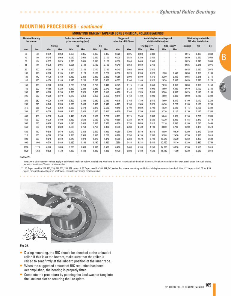
SPHERICAL ROLLER BEARING CATALOG 105
B
A
Spherical Roller Bearings
• During mounting, the RIC should be checked at the unloaded roller. If this is at the bottom, make sure that the roller is raised to seat fi rmly at the inboard position of the inner race.
• When the suggested amount of RIC reduction has been accomplished, the bearing is properly fi tted.
• Complete the procedure by peening the Lockwasher tang into the Locknut slot or securing the Lockplate.
MOUNTING TIMKEN® TAPERED BORE SPHERICAL ROLLER BEARINGS Nominal bearing Radial Internal Clearance Suggested Axial displacement tapered Minimum permissible bore (mm) prior to mounting (mm) reduction of RIC (mm) shaft installation (mm) RIC after installation Normal C3 C4 1:12 Taper** 1:30 Taper** Normal C3 C4 over incl. Min. Max. Min. Max. Min. Max. Min. Max. Min. Max. Min. Max.
30 40 0.035 0.050 0.050 0.065 0.065 0.085 0.020 0.025 0.300 0.380 - - 0.015 0.025 0.040 40 50 0.045 0.060 0.060 0.080 0.080 0.100 0.025 0.030 0.380 0.460 - - 0.020 0.030 0.050 50 65 0.055 0.075 0.075 0.095 0.095 0.120 0.030 0.040 0.460 0.560 - - 0.025 0.040 0.060 65 80 0.070 0.095 0.095 0.120 0.120 0.150 0.040 0.050 0.560 0.760 - - 0.025 0.045 0.075 80 100 0.080 0.110 0.100 0.140 0.140 0.180 0.045 0.065 0.680 0.970 - - 0.035 0.050 0.075 100 120 0.100 0.135 0.135 0.170 0.170 0.220 0.050 0.070 0.760 1.070 1.900 2.540 0.050 0.060 0.100 120 140 0.120 0.160 0.160 0.200 0.200 0.260 0.065 0.090 0.890 1.270 2.290 3.050 0.055 0.075 0.115 140 160 0.130 0.180 0.180 0.230 0.230 0.300 0.075 0.100 1.140 1.520 2.670 3.430 0.055 0.075 0.125
160 180 0.140 0.200 0.200 0.260 0.260 0.340 0.075 0.115 1.140 1.650 2.670 4.060 0.060 0.090 0.150 180 200 0.160 0.220 0.220 0.290 0.290 0.370 0.090 0.125 1.400 1.900 3.050 4.450 0.070 0.100 0.165 200 225 0.180 0.250 0.250 0.320 0.320 0.410 0.100 0.140 1.520 2.030 3.560 4.830 0.075 0.115 0.180 225 250 0.200 0.270 0.270 0.350 0.350 0.450 0.115 0.150 1.780 2.290 4.060 5.330 0.090 0.115 0.200
250 280 0.220 0.300 0.300 0.390 0.390 0.490 0.115 0.165 1.780 2.540 4.060 5.840 0.100 0.140 0.230 280 315 0.240 0.330 0.330 0.430 0.430 0.540 0.125 0.180 1.900 2.670 4.450 6.220 0.100 0.150 0.250 315 355 0.270 0.360 0.360 0.470 0.470 0.590 0.140 0.190 2.030 2.790 4.830 6.600 0.115 0.165 0.280 355 400 0.300 0.400 0.400 0.520 0.520 0.650 0.150 0.200 2.290 3.050 5.330 7.110 0.130 0.190 0.330
400 450 0.330 0.440 0.440 0.570 0.570 0.720 0.165 0.215 2.540 3.300 5.840 7.620 0.150 0.230 0.360 450 500 0.370 0.490 0.490 0.630 0.630 0.790 0.180 0.230 2.670 3.430 6.220 8.000 0.165 0.270 0.410 500 560 0.410 0.540 0.540 0.680 0.680 0.870 0.200 0.250 3.050 3.810 7.110 8.890 0.180 0.290 0.440 560 630 0.460 0.600 0.600 0.760 0.760 0.980 0.230 0.280 3.430 4.190 8.000 9.780 0.200 0.320 0.510
630 710 0.510 0.670 0.670 0.850 0.850 1.090 0.250 0.300 3.810 4.570 8.890 10.670 0.200 0.370 0.550 710 800 0.570 0.750 0.750 0.960 0.960 1.220 0.280 0.350 4.190 5.330 9.780 12.450 0.230 0.390 0.610 800 900 0.640 0.840 0.840 1.070 1.070 1.370 0.300 0.380 4.570 5.720 10.670 13.330 0.250 0.460 0.690 900 1000 0.710 0.930 0.930 1.190 1.190 1.520 .0350 0.430 5.334 6.480 12.450 15.110 0.280 0.490 0.750
1000 1120 0.770 1.030 1.030 1.300 1.300 1.670 0.400 0.480 6.100 7.240 14.220 16.890 0.280 0.550 0.810 1120 1250 0.830 1.120 1.120 1.420 1.420 1.830 0.430 0.500 6.480 7.620 15.110 17.780 0.330 0.610 0.910
MOUNTING PROCEDURES - continued
Fig. 29.
Table 29. Note: Axial displacement values apply to solid steel shafts or hollow steel shafts with bore diameter less than half the shaft diameter. For shaft materials other than steel, or for thin-wall shafts, please consult your Timken representative.
** 1:12 Taper used for 222, 223, 230, 231, 232, 233, 239 series. 1: 30 Taper used for 240, 241, 242 series. For sleeve mounting, multiply axial displacement values by 1.1 for 1:12 taper or by 1.05 for 1:30 taper. For questions on tapered shaft data, consult your Timken representative.
106 SPHERICAL ROLLER BEARING CATALOG
B
A
SPHERICAL ROLLER BEARINGS
NOTES
B
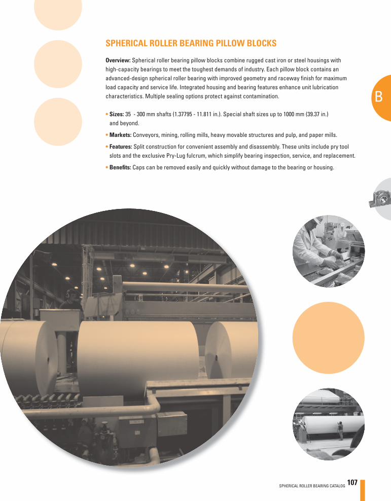
A
SPHERICAL ROLLER BEARING CATALOG 107
B
Spherical Roller Bearing Pillow Blocks
SPHERICAL ROLLER BEARING PILLOW BLOCKS
Overview: Spherical roller bearing pillow blocks combine rugged cast iron or steel housings with high-capacity bearings to meet the toughest demands of industry. Each pillow block contains an advanced-design spherical roller bearing with improved geometry and raceway fi nish for maximum load capacity and service life. Integrated housing and bearing features enhance unit lubrication characteristics. Multiple sealing options protect against contamination.
• Sizes: 35 - 300 mm shafts (1.37795 - 11.811 in.). Special shaft sizes up to 1000 mm (39.37 in.) and beyond.
• Markets: Conveyors, mining, rolling mills, heavy movable structures and pulp, and paper mills.
• Features: Split construction for convenient assembly and disassembly. These units include pry tool slots and the exclusive Pry-Lug fulcrum, which simplify bearing inspection, service, and replacement.
• Benefi ts: Caps can be removed easily and quickly without damage to the bearing or housing.
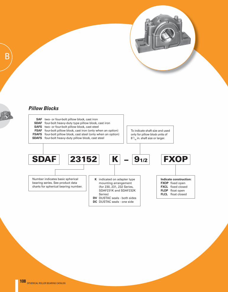
108 SPHERICAL ROLLER BEARING CATALOG
B
SPHERICAL ROLLER BEARINGS
B384 IN CATALOG
SAF two- or four-bolt pillow block, cast iron SDAF four-bolt heavy-duty type pillow block, cast iron SAFS two- or four-bolt pillow block, cast steel FSAF four-bolt pillow block, cast iron (only when an option) FSAFS four-bolt pillow block, cast steel (only when an option) SDAFS four-bolt heavy-duty pillow block, cast steel
To indicate shaft size and used only for pillow block units of 8 7/16 in. shaft size or larger.
–
Number indicates basic spherical bearing series. See product data charts for spherical bearing number.
K indicated on adapter type mounting arrangement (for 230, 231, 232 Series, SDAF231K and SDAF232K Series)
DV DUSTAC seals - both sidesDC DUSTAC seals - one side
Indicate construction:
FXOP fi xed open FXCL fi xed closed FLOP fl oat open FLCL fl oat closed
SDAF 23152 K 91/2 FXOP
Pillow Blocks
BBB
108 SPHERICAL ROLLER BEARING CATALOG
SPHERICAL ROLLER BEARING CATALOG 109
B
Spherical Roller Bearing Pillow Blocks
Page
DIMENSIONS – PILLOW BLOCK UNITS
Inch SAF225, SAF226 Series Adapter Mounting ...................... 113
Inch SDAF225, SDAF226 Series Adapter Mounting ................. 114
Inch SAF230, SDAF230 Series Adapter Mounting ................... 115
Inch SDAF231K, SDAF232K Series Adapter Mounting ............ 116
Inch SAF222, SAF223 Series, Straight Bore Mounting ............ 117
Inch SDAF222, SDAF223 Series, Straight Bore Mounting ....... 118
Inch SDAF231, SDAF232 Series, Straight Bore Mounting ....... 119
Inch Shaft Diameters ................................................................. 120
TAKE-UP UNITS
Inch TU Series Adapter Mounting ............................................ 121
Inch TTU Series Adapter Mounting .......................................... 122
Inch Shaft Seals ......................................................................... 123
Inch Sine Bar Gages ................................................................... 124
Inch Hydraulic Nuts .................................................................... 125
Metric Hydraulic Nuts ................................................................ 126
Inch Hydraulic Nuts ................................................................... 127
Inch Shaft Adapter Accessories for Tapered Bore Bearings .. 128-131
Inch Shaft Adapter Accessories for Straight Bore Bearings .. 132-135
Spherical Roller Bearing Pillow Blocks
Page
Introduction ................................................................................ 111
Design and Construction ........................................................... 111
Mounting ..................................................................................... 112
Adapter vs. Straight Bore
Fixed and Float Pillow Blocks
Closed End Installations
Lubrication .................................................................................. 112
Seals ............................................................................................ 112
Load Ratings and Life ................................................................. 112
110 SPHERICAL ROLLER BEARING CATALOG
B
SPHERICAL ROLLER BEARINGS
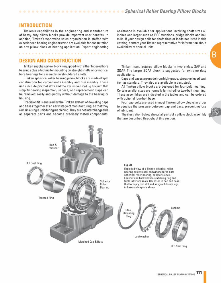
SPHERICAL ROLLER BEARING CATALOG 111
B
Spherical Roller Bearing Pillow Blocks
Fig. 30.Exploded view of a Timken spherical roller bearing pillow block, showing tapered bore spherical roller bearing, adapter sleeve, Locknut and Lockwasher, stabilizing ring and triple labyrinth seals. Recesses in cap and base that form pry tool slot and integral fulcrum lugs in base and cap are shown.
Bolt & Washer
LER Seal Ring
Tapered Ring
Spherical Roller Bearing
Steel Stabilizing
Ring
Locknut
INTRODUCTION
DESIGN AND CONSTRUCTIONTimken supplies pillow blocks equipped with either tapered bore
bearings plus adapters for mounting on straight shafts or cylindrical bore bearings for assembly on shouldered shafts.
Timken spherical roller bearing pillow blocks are made of split construction for convenient assembly and disassembly. These units include pry tool slots and the exclusive Pry-Lug fulcrum that simplify bearing inspection, service, and replacement. Caps can be removed easily and quickly without damage to the bearing or housing.
Precision fi t is ensured by the Timken system of doweling caps and bases together at an early stage of manufacturing, so that they remain a single unit during machining. They are not interchangeable as separate parts and become precisely mated components.
Timken manufactures pillow blocks in two styles: SAF and SDAF. The larger SDAF block is suggested for extreme duty applications.
Caps and bases are made from high-grade, stress-relieved cast iron as standard. They also are available in cast steel.
All Timken pillow blocks are designed for four-bolt mounting. Certain smaller sizes are normally furnished for two-bolt mounting. These assemblies are indicated in the tables and can be ordered with optional four-bolt base.
Four cap bolts are used in most Timken pillow blocks in order to equalize the pressure between cap and base, preventing loss of lubricant.
The illustration below shows all parts of a pillow block assembly that are described throughout this section.
Lockwasher
LER Seal Ring
Matched Cap & Base
Timken’s capabilities in the engineering and manufacture of heavy-duty pillow blocks provide important user benefi ts. In addition, Timken’s worldwide sales organization is staffed with experienced bearing engineers who are available for consultation on any pillow block or bearing application. Expert engineering
assistance is available for applications involving shaft sizes 40 inches and larger such as BOF trunnions, bridge blocks and ball mills. If your design calls for shaft sizes or loads not listed in this catalog, contact your Timken representative for information about availability of special units.
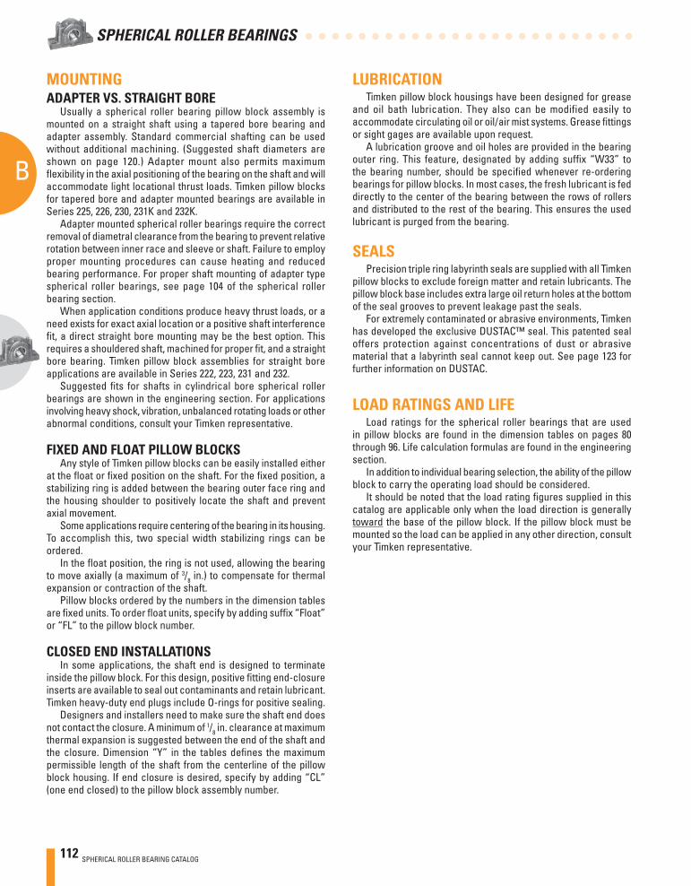
112 SPHERICAL ROLLER BEARING CATALOG
B
SPHERICAL ROLLER BEARINGS
MOUNTINGADAPTER VS. STRAIGHT BORE
Usually a spherical roller bearing pillow block assembly is mounted on a straight shaft using a tapered bore bearing and adapter assembly. Standard commercial shafting can be used without additional machining. (Suggested shaft diameters are shown on page 120.) Adapter mount also permits maximum fl exibility in the axial positioning of the bearing on the shaft and will accommodate light locational thrust loads. Timken pillow blocks for tapered bore and adapter mounted bearings are available in Series 225, 226, 230, 231K and 232K.
Adapter mounted spherical roller bearings require the correct removal of diametral clearance from the bearing to prevent relative rotation between inner race and sleeve or shaft. Failure to employ proper mounting procedures can cause heating and reduced bearing performance. For proper shaft mounting of adapter type spherical roller bearings, see page 104 of the spherical roller bearing section.
When application conditions produce heavy thrust loads, or a need exists for exact axial location or a positive shaft interference fi t, a direct straight bore mounting may be the best option. This requires a shouldered shaft, machined for proper fi t, and a straight bore bearing. Timken pillow block assemblies for straight bore applications are available in Series 222, 223, 231 and 232.
Suggested fi ts for shafts in cylindrical bore spherical roller bearings are shown in the engineering section. For applications involving heavy shock, vibration, unbalanced rotating loads or other abnormal conditions, consult your Timken representative.
FIXED AND FLOAT PILLOW BLOCKSAny style of Timken pillow blocks can be easily installed either
at the fl oat or fi xed position on the shaft. For the fi xed position, a stabilizing ring is added between the bearing outer face ring and the housing shoulder to positively locate the shaft and prevent axial movement.
Some applications require centering of the bearing in its housing. To accomplish this, two special width stabilizing rings can be ordered.
In the fl oat position, the ring is not used, allowing the bearing to move axially (a maximum of 3/8 in.) to compensate for thermal expansion or contraction of the shaft.
Pillow blocks ordered by the numbers in the dimension tables are fi xed units. To order fl oat units, specify by adding suffi x “Float” or “FL” to the pillow block number.
CLOSED END INSTALLATIONSIn some applications, the shaft end is designed to terminate
inside the pillow block. For this design, positive fi tting end-closure inserts are available to seal out contaminants and retain lubricant. Timken heavy-duty end plugs include O-rings for positive sealing.
Designers and installers need to make sure the shaft end does not contact the closure. A minimum of 1/8 in. clearance at maximum thermal expansion is suggested between the end of the shaft and the closure. Dimension “Y” in the tables defi nes the maximum permissible length of the shaft from the centerline of the pillow block housing. If end closure is desired, specify by adding “CL” (one end closed) to the pillow block assembly number.
LUBRICATIONTimken pillow block housings have been designed for grease
and oil bath lubrication. They also can be modified easily to accommodate circulating oil or oil/air mist systems. Grease fi ttings or sight gages are available upon request.
A lubrication groove and oil holes are provided in the bearing outer ring. This feature, designated by adding suffi x “W33” to the bearing number, should be specifi ed whenever re-ordering bearings for pillow blocks. In most cases, the fresh lubricant is fed directly to the center of the bearing between the rows of rollers and distributed to the rest of the bearing. This ensures the used lubricant is purged from the bearing.
SEALSPrecision triple ring labyrinth seals are supplied with all Timken
pillow blocks to exclude foreign matter and retain lubricants. The pillow block base includes extra large oil return holes at the bottom of the seal grooves to prevent leakage past the seals.
For extremely contaminated or abrasive environments, Timken has developed the exclusive DUSTAC™ seal. This patented seal offers protection against concentrations of dust or abrasive material that a labyrinth seal cannot keep out. See page 123 for further information on DUSTAC.
LOAD RATINGS AND LIFELoad ratings for the spherical roller bearings that are used
in pillow blocks are found in the dimension tables on pages 80 through 96. Life calculation formulas are found in the engineering section.
In addition to individual bearing selection, the ability of the pillow block to carry the operating load should be considered.
It should be noted that the load rating fi gures supplied in this catalog are applicable only when the load direction is generally toward the base of the pillow block. If the pillow block must be mounted so the load can be applied in any other direction, consult your Timken representative.
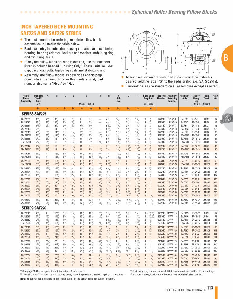
SPHERICAL ROLLER BEARING CATALOG 113
B
Spherical Roller Bearing Pillow Blocks
Pillow Standard A B C D E F H K L Y Base Bolts Bearing Adapter(4) Housing(2) Stabi-(3) Triple Ass'y Block Shaft(1) Oil Required Number Assembly Only lizing Seal Wt. Assembly Diam Level Number Ring S-1 (Max.) (Min.) No. Size 1 Req’d 2 Req’d
in. in. in. in. in. in. in. in. in. in. in. in. in. lbs.
SERIES SAF225 SAF22509 1 7⁄16 2 1⁄4 8 1⁄4 2 3⁄8
13⁄16 7 6 1⁄4 — 4 3⁄8 31⁄32 3 5⁄8 1 3⁄32 2 1⁄2 22209K SNW-9 SAF509 SR-9-9 LER 17 12
SAF22510 1 11⁄16 2 1⁄2 8 1⁄4 2 3⁄8 15⁄16 7 6 1⁄2 — 4 3⁄4 1 3⁄32 3 5⁄8 1 5⁄32 2 1⁄2 22210K SNW-10 SAF510 SR-10-0 LER 20 13
SAF22511 1 15⁄16 2 3⁄4 9 5⁄8 2 3⁄4 15⁄16 7 7⁄8 7 3⁄8 — 5 11⁄32 1 3⁄16 3 3⁄4 1 3⁄16 2 1⁄2 22211K SNW-11 SAF 511 SR-11-0 LER 24 16
SAF22513 2 3⁄16 3 11 3 1⁄8 1 9 1⁄2 8 1⁄8 — 5 25⁄32 1 1⁄8 4 5⁄16 1 7⁄32 2 1⁄2 22213K SNW-13 SAF 513 SR-13-0 LER 29 19.5 SAF22515 2 7⁄16 3 1⁄4 11 1⁄4 3 1⁄8 1 1⁄8 9 5⁄8 8 5⁄8 — 6 3⁄8 1 1⁄4 4 3⁄4 1 9⁄32 2 5⁄8 22215K SNW-15 SAF515 SR-15-0 LER37 30 FSAF22515 2 7⁄16 3 1⁄4 11 1⁄4 3 1⁄8 1 1⁄8 9 5⁄8 8 5⁄8 1 7⁄8 6 3⁄8 1 1⁄4 4 3⁄4 1 9⁄32 4 1⁄2 22215K SNW-15 FSAF515 SR-15-0 LER37 30 SAF22516 2 11⁄16 3 1⁄2 13 3 1⁄2 1 3⁄16 11 9 5⁄8 — 6 7⁄8 1 11⁄32 4 7⁄8 1 21⁄64 2 3⁄4 22216K SNW-16 SAF516 SR-16-13 LER44 37 FSAF22516 2 11⁄16 3 1⁄2 13 3 1⁄2 1 3⁄16 11 9 5⁄8 2 1⁄8 6 7⁄8 1 11⁄32 4 7⁄8 1 21⁄64 4 5⁄8 22216K SNW-16 FSAF516 SR-16-13 LER44 37
SAF22517 2 15⁄16 3 3⁄4 13 3 1⁄2 1 1⁄4 11 9 7⁄8 — 7 1⁄4 1 7⁄16 4 15⁄16 1 27⁄64 2 3⁄4 22217K SNW-17 SAF517 SR-17-14 LER53 40 FSAF22517 2 15⁄16 3 3⁄4 13 3 1⁄2 1 1⁄4 11 9 7⁄8 2 1⁄8 7 1⁄4 1 7⁄16 4 15⁄16 1 27⁄64 4 5⁄8 22217K SNW-17 FSAF517 SR-17-14 LER53 40
SAF22518 3 3⁄16 4 13 3⁄4 3 7⁄8 1 1⁄2 11 5⁄8 10 3⁄8 — 7 3⁄4 1 17⁄32 6 1⁄4 1 37⁄64 2 3⁄4 22218K SNW-18 SAF518 SR-18-15 LER69 49 FSAF22518 3 3⁄16 4 13 3⁄4 3 7⁄8 1 1⁄2 11 5⁄8 10 3⁄8 2 1⁄8 7 3⁄4 1 17⁄32 6 1⁄4 1 37⁄64 4 5⁄8 22218K SNW-18 FSAF518 SR-18-15 LER69 49
SAF22520 3 7⁄16 4 1⁄2 15 1⁄4 4 3⁄8 1 3⁄4 13 1⁄8 11 5⁄8 — 8 11⁄16 1 3⁄4 6 1 49⁄64 2 7⁄8 22220K SNW-20 SAF520 SR-20-17 LER102 65 FSAF22520 3 7⁄16 4 1⁄2 15 1⁄4 4 3⁄8 1 3⁄4 13 1⁄8 11 5⁄8 2 3⁄8 8 11⁄16 1 3⁄4 6 1 49⁄64 4 3⁄4 22220K SNW-20 FSAF520 SR-20-17 LER102 65
SAF22522 3 15⁄16 4 15⁄16 16 1⁄2 4 3⁄4 2 14 1⁄2 12 5⁄8 2 3⁄4 9 9⁄16 1 7⁄8 6 3⁄8 1 61⁄64 4 3⁄4 22222K SNW-22 SAF522 SR-22-19 LER109 81 SAF22524 4 3⁄16 5 1⁄4 16 1⁄2 4 3⁄4 2 1⁄8 14 1⁄2 13 1⁄4 2 3⁄4 10 1⁄4 1 15⁄16 7 3⁄8 2 3⁄32 4 3⁄4 22224K SNW-24 SAF524 SR-24-20 LER113 94 SAF22526 4 7⁄16 6 18 3⁄8 5 1⁄8 2 3⁄8 16 14 5⁄8 3 1⁄4 11 9⁄16 2 7⁄16 8 2 17⁄64 4 7⁄8 22226K SNW-26 SAF526 SR-26-0 LER117 137
SAF22528 4 15⁄16 6 20 1⁄8 5 7⁄8 2 3⁄8 17 1⁄8 16 3 3⁄8 11 3⁄4 2 1⁄8 7 3⁄4 2 13⁄32 4 1 22228K SNW-28 SAF528 SR-28-0 LER122 159 SAF22530 5 3⁄16 6 5⁄16 21 1⁄4 6 1⁄4 2 1⁄2 18 1⁄4 17 3 3⁄4 12 1⁄2 2 3⁄16 8 3⁄8 2 37⁄64 4 1 22230K SNW-30 SAF530 SR-30-0 LER125 189 SAF22532 5 7⁄16 6 11⁄16 22 6 1⁄4 2 5⁄8 19 1⁄4 17 3⁄8 3 3⁄4 13 5⁄16 2 3⁄16 8 3⁄4 2 49⁄64 4 1 22232K SNW-32 SAF532 SR-32-0 LER130 225 SAF22534 5 15⁄16 7 1⁄16 24 3⁄4 6 3⁄4 2 3⁄4 21 5⁄8 19 3⁄8 4 1⁄4 14 9⁄16 2 5⁄16 9 3⁄8 2 59⁄64 4 1 22234K SNW-34 SAF534 SR-34-0 LER140 300 SAF22536 6 7⁄16 7 1⁄2 26 3⁄4 7 1⁄8 3 23 5⁄8 20 7⁄8 4 5⁄8 15 1⁄2 2 9⁄16 9 11⁄16 2 61⁄64 4 1 22236K SNW-36 SAF536 SR-36-30 LER148 330 SAF22538 6 15⁄16 7 7⁄8 28 7 1⁄2 3 1⁄8 24 3⁄8 21 5⁄8 4 1⁄2 15 11⁄16 2 5⁄8 10 3⁄4 3 7⁄64 4 1 1⁄4 22238K SNW-38 SAF538 SR-38-32 LER155 375
SAF22540 7 3⁄16 8 1⁄4 29 1⁄2 8 3 3⁄8 25 22 1⁄2 5 17 3⁄16 2 11⁄16 10 13⁄16 3 9⁄32 4 1 1⁄4 22240K SNW-40 SAF540 SR-40-34 LER159 445 SAF22544 7 15⁄16 9 1⁄2 32 3⁄4 8 3⁄4 3 3⁄4 27 7⁄8 24 3⁄4 5 1⁄4 19 5⁄8 3 3⁄8 11 1⁄2 3 17⁄32 4 1 1⁄2 22244K SNW-44 SAF544 SR-44-38 LER167 615
SERIES SAF226 SAF22615 2 7⁄16 4 13 3⁄4 3 7⁄8 1 5⁄8 11 5⁄8 10 3⁄8 2 1⁄8 7 9⁄16 1 19⁄32 5 7⁄8 1 7⁄8 2,4 3⁄4,
5⁄8 22315K SNW-115 SAF 615 SR-18-15 LOR 37 52 SAF22616 2 11⁄16 4 1⁄4 14 1⁄4 3 7⁄8 1 3⁄4 12 5⁄8 10 5⁄8 2 1⁄8 8 1⁄4 1 11⁄16 6 1⁄2 1 15⁄16 2,4 3⁄4,
5⁄8 22316K SNW-116 SAF 616 SR-19-16 LOR 44 71 SAF22617 2 15⁄16 4 1⁄2 15 1⁄4 4 3⁄8 1 3⁄4 13 1⁄8 11 5⁄8 — 8 11⁄16 1 13⁄16 6 5⁄8 1 57⁄64 2 7⁄8 22317K SNW-117 SAF617 SR-20-17 LER184 81 FSAF22617 2 15⁄16 4 1⁄2 15 1⁄4 4 3⁄8 1 3⁄4 13 1⁄8 11 5⁄8 2 3⁄8 8 11⁄16 1 13⁄16 6 5⁄8 1 57⁄64 4 3⁄4 22317K SNW-117 FSAF617 SR-20-17 LER184 81
SAF22618 3 3⁄16 4 3⁄4 15 1⁄2 4 3⁄8 2 13 1⁄2 12 2 1⁄4 9 3⁄16 2 7 2 3⁄64 4 3⁄4 22318K SNW-118 SAF618 SR-21-18 LER188 90 SAF22620 3 7⁄16 5 1⁄4 16 1⁄2 4 3⁄4 2 1⁄8 14 1⁄2 13 1⁄4 2 3⁄4 10 1⁄4 2 1⁄8 7 3⁄8 2 19⁄64 4 3⁄4 22320K SNW-120 SAF620 SR-24-20 LER102 113 SAF22622 3 15⁄16 6 18 3⁄8 5 1⁄8 2 3⁄8 16 14 5⁄8 3 1⁄4 11 9⁄16 2 1⁄2 8 2 31⁄64 4 7⁄8 22322K SNW-122 SAF622 SR-0-22 LER109 151 SAF22624 4 3⁄16 6 5⁄16 21 1⁄4 6 1⁄4 2 1⁄2 18 1⁄4 17 3 3⁄4 12 1⁄2 2 9⁄16 8 3⁄8 2 41⁄64 4 1 22324K SNW-124 SAF624 SR-0-24 LER113 201
SAF22626 4 7⁄16 6 11⁄16 22 6 1⁄4 2 5⁄8 19 1⁄4 17 3⁄8 3 3⁄4 13 5⁄16 2 5⁄8 8 3⁄4 2 27⁄32 4 1 22326K SNW-126 SAF626 SR-0-26 LER117 245 SAF22628 4 15⁄16 7 1⁄16 24 3⁄4 6 3⁄4 2 3⁄4 21 5⁄8 19 3⁄8 4 1⁄4 14 9⁄16 2 11⁄16 9 3⁄8 3 5⁄64 4 1 22328K SNW-128 SAF628 SR-0-28 LER122 310 SAF22630 5 3⁄16 7 1⁄2 26 3⁄4 7 1⁄8 3 23 5⁄8 20 7⁄8 4 5⁄8 15 1⁄2 2 7⁄8 9 11⁄16 3 17⁄64 4 1 22330K SNW-130 SAF630 SR-36-30 LER125 350 SAF22632 5 7⁄16 7 7⁄8 28 7 1⁄2 3 1⁄8 24 3⁄8 21 5⁄8 4 1⁄2 15 11⁄16 2 15⁄16 10 3⁄4 3 7⁄16 4 1 1⁄4 22332K SNW-132 SAF632 SR-38-32 LER130 420
SAF22634 5 15⁄16 8 1⁄4 29 1⁄2 8 3 3⁄8 25 22 1⁄2 5 17 3⁄16 3 1⁄16 10 13⁄16 3 19⁄32 4 1 1⁄4 22334K SNW-134 SAF634 SR-40-34 LER140 485 SAF22636 6 7⁄16 8 7⁄8 31 1⁄4 8 1⁄4 3 1⁄2 26 5⁄8 24 5 1⁄4 18 1⁄2 3 3⁄8 11 1⁄4 3 47⁄64 4 1 1⁄4 22336K SNW-136 SAF636 SR-0-36 LER148 545 SAF22638 6 15⁄16 9 1⁄2 32 3⁄4 8 3⁄4 3 3⁄4 27 7⁄8 24 3⁄4 5 1⁄4 19 5⁄8 3 11⁄16 11 1⁄2 3 57⁄64 4 1 1⁄2 22338K SNW-138 SAF638 SR-44-38 LER155 655 SAF22640 7 3⁄16 9 7⁄8 34 1⁄4 9 4 29 1⁄2 26 1⁄4 5 1⁄2 20 3⁄16 3 3⁄4 12 1⁄4 4 5⁄64 4 1 1⁄2 22340K SNW-140 SAF640 SR-0-40 LER159 725
INCH TAPERED BORE MOUNTING SAF225 AND SAF226 SERIES• The basic number for ordering complete pillow block
assemblies is listed in the table below.• Each assembly includes the housing cap and base, cap bolts,
bearing, bearing adapter, Locknut and washer, stabilizing ring, and triple ring seals.
• If only the pillow block housing is desired, use the numbers listed in column headed “Housing Only”. These units include: cap, base, cap bolts, triple ring seals and stabilizing ring.
• Assembly and pillow blocks as described on this page constitute a fi xed unit. To order fl oat units, specify part number plus suffi x “Float” or “FL”.
(1) See page 120 for suggested shaft diameter S-1 tolerances. (3) Stabilizing ring is used for fi xed (FX) block; do not use for fl oat (FL) mounting.(2) “Housing Only” includes: cap, base, cap bolts, triple ring seals and stabilizing rings as required. (4) Includes sleeve, Locknut and Lockwasher. Add shaft size to order.
Note: Speed ratings are found in dimension tables in the spherical roller bearing section.
• Assemblies shown are furnished in cast iron. If cast steel is desired, add the letter “S” to the alpha prefi x (e.g., SAFS 22515).
• Four-bolt bases are standard on all assemblies except as noted.
E
B
H
F
A
S-1
K
L
C
FLOATEND
FIXEDEND
D
Y
3 "16
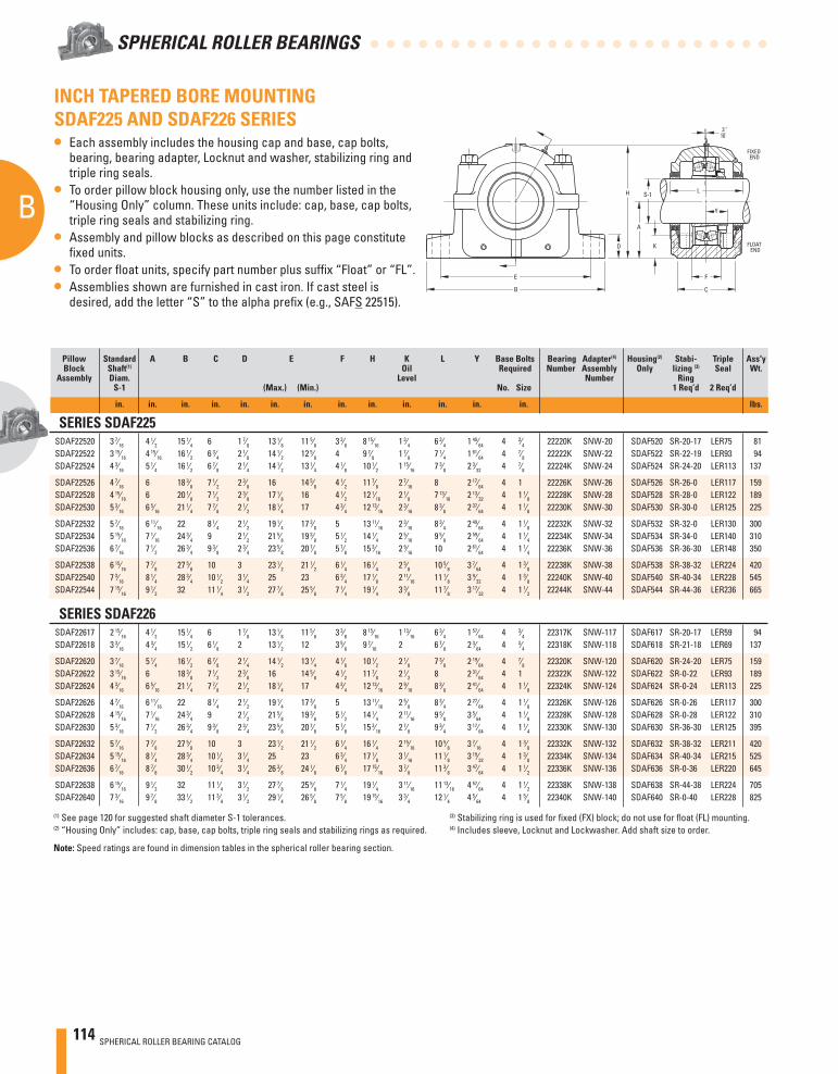
114 SPHERICAL ROLLER BEARING CATALOG
B
SPHERICAL ROLLER BEARINGS
E
B
H
F
A
S-1
K
L
C
FLOATEND
FIXEDEND
D
Y
3 "16
INCH TAPERED BORE MOUNTING SDAF225 AND SDAF226 SERIES• Each assembly includes the housing cap and base, cap bolts,
bearing, bearing adapter, Locknut and washer, stabilizing ring and triple ring seals.
• To order pillow block housing only, use the number listed in the “Housing Only” column. These units include: cap, base, cap bolts, triple ring seals and stabilizing ring.
• Assembly and pillow blocks as described on this page constitute fi xed units.
• To order fl oat units, specify part number plus suffi x “Float” or “FL”.• Assemblies shown are furnished in cast iron. If cast steel is
desired, add the letter “S” to the alpha prefi x (e.g., SAFS 22515).
Pillow Standard A B C D E F H K L Y Base Bolts Bearing Adapter(4) Housing(2) Stabi- Triple Ass'y Block Shaft(1) Oil Required Number Assembly Only lizing (3) Seal Wt. Assembly Diam. Level Number Ring S-1 (Max.) (Min.) No. Size 1 Req’d 2 Req’d
in. in. in. in. in. in. in. in. in. in. in. in. in. lbs.
SERIES SDAF225 SDAF22520 3 7⁄16 4 1⁄2 15 1⁄4 6 1 7⁄8 13 1⁄8 11 5⁄8 3 3⁄8 8 15⁄16 1 3⁄4 6 3⁄4 1 49⁄64 4 3⁄4 22220K SNW-20 SDAF520 SR-20-17 LER75 81 SDAF22522 3 15⁄16 4 15⁄16 16 1⁄2 6 3⁄4 2 1⁄8 14 1⁄2 12 5⁄8 4 9 7⁄8 1 7⁄8 7 1⁄4 1 61⁄64 4 7⁄8 22222K SNW-22 SDAF522 SR-22-19 LER93 94 SDAF22524 4 3⁄16 5 1⁄4 16 1⁄2 6 7⁄8 2 1⁄4 14 1⁄2 13 1⁄4 4 1⁄8 10 1⁄2 1 15⁄16 7 3⁄8 2 3⁄32 4 7⁄8 22224K SNW-24 SDAF524 SR-24-20 LER113 137
SDAF22526 4 7⁄16 6 18 3⁄8 7 1⁄2 2 3⁄8 16 14 5⁄8 4 1⁄2 11 7⁄8 2 7⁄16 8 2 17⁄64 4 1 22226K SNW-26 SDAF526 SR-26-0 LER117 159 SDAF22528 4 15⁄16 6 20 1⁄8 7 1⁄2 2 3⁄8 17 1⁄8 16 4 1⁄2 12 1⁄16 2 1⁄8 7 13⁄16 2 13⁄32 4 1 1⁄8 22228K SNW-28 SDAF528 SR-28-0 LER122 189 SDAF22530 5 3⁄16 6 5⁄16 21 1⁄4 7 7⁄8 2 1⁄2 18 1⁄4 17 4 3⁄4 12 13⁄16 2 3⁄16 8 3⁄8 2 37⁄64 4 1 1⁄8 22230K SNW-30 SDAF530 SR-30-0 LER125 225
SDAF22532 5 7⁄16 6 11⁄16 22 8 1⁄4 2 1⁄2 19 1⁄4 17 3⁄8 5 13 11⁄16 2 3⁄16 8 3⁄4 2 49⁄64 4 1 1⁄8 22232K SNW-32 SDAF532 SR-32-0 LER130 300 SDAF22534 5 15⁄16 7 1⁄16 24 3⁄4 9 2 1⁄2 21 5⁄8 19 3⁄8 5 1⁄2 14 1⁄4 2 5⁄16 9 5⁄8 2 59⁄64 4 1 1⁄4 22234K SNW-34 SDAF534 SR-34-0 LER140 310 SDAF22536 6 7⁄16 7 1⁄2 26 3⁄4 9 3⁄8 2 3⁄4 23 5⁄8 20 7⁄8 5 7⁄8 15 3⁄16 2 9⁄16 10 2 61⁄64 4 1 1⁄4 22236K SNW-36 SDAF536 SR-36-30 LER148 350
SDAF22538 6 15⁄16 7 7⁄8 27 5⁄8 10 3 23 1⁄2 21 1⁄2 6 1⁄4 16 1⁄4 2 5⁄8 10 5⁄8 3 7⁄64 4 1 3⁄8 22238K SNW-38 SDAF538 SR-38-32 LER224 420 SDAF22540 7 3⁄16 8 1⁄4 28 3⁄4 10 1⁄2 3 1⁄4 25 23 6 3⁄4 17 1⁄8 2 11⁄16 11 1⁄8 3 9⁄32 4 1 3⁄8 22240K SNW-40 SDAF540 SR-40-34 LER228 545 SDAF22544 7 15⁄16 9 1⁄2 32 11 1⁄4 3 1⁄2 27 7⁄8 25 5⁄8 7 1⁄4 19 1⁄4 3 3⁄8 11 7⁄8 3 17⁄32 4 1 1⁄2 22244K SNW-44 SDAF544 SR-44-36 LER236 665
SERIES SDAF226 SDAF22617 2 15⁄16 4 1⁄2 15 1⁄4 6 1 7⁄8 13 1⁄8 11 5⁄8 3 3⁄8 8 15⁄16 1 13⁄16 6 3⁄4 1 57⁄64 4 3⁄4 22317K SNW-117 SDAF617 SR-20-17 LER59 94 SDAF22618 3 3⁄16 4 3⁄4 15 1⁄2 6 1⁄8 2 13 1⁄2 12 3 5⁄8 9 7⁄16 2 6 7⁄8 2 3⁄64 4 3⁄4 22318K SNW-118 SDAF618 SR-21-18 LER69 137
SDAF22620 3 7⁄16 5 1⁄4 16 1⁄2 6 7⁄8 2 1⁄4 14 1⁄2 13 1⁄4 4 1⁄8 10 1⁄2 2 1⁄8 7 3⁄8 2 19⁄64 4 7⁄8 22320K SNW-120 SDAF620 SR-24-20 LER75 159 SDAF22622 3 15⁄16 6 18 3⁄8 7 1⁄2 2 3⁄8 16 14 5⁄8 4 1⁄2 11 7⁄8 2 1⁄2 8 2 31⁄64 4 1 22322K SNW-122 SDAF622 SR-0-22 LER93 189 SDAF22624 4 3⁄16 6 5⁄16 21 1⁄4 7 7⁄8 2 1⁄2 18 1⁄4 17 4 3⁄4 12 13⁄16 2 9⁄16 8 3⁄8 2 41⁄64 4 1 1⁄8 22324K SNW-124 SDAF624 SR-0-24 LER113 225
SDAF22626 4 7⁄16 6 11⁄16 22 8 1⁄4 2 1⁄2 19 1⁄4 17 3⁄8 5 13 11⁄16 2 5⁄8 8 3⁄4 2 27⁄64 4 1 1⁄8 22326K SNW-126 SDAF626 SR-0-26 LER117 300 SDAF22628 4 15⁄16 7 1⁄16 24 3⁄4 9 2 1⁄2 21 5⁄8 19 3⁄8 5 1⁄2 14 1⁄4 2 11⁄16 9 5⁄8 3 5⁄64 4 1 1⁄8 22328K SNW-128 SDAF628 SR-0-28 LER122 310 SDAF22630 5 3⁄16 7 1⁄2 26 3⁄4 9 3⁄8 2 3⁄4 23 5⁄8 20 7⁄8 5 7⁄8 15 3⁄16 2 7⁄8 9 3⁄4 3 17⁄64 4 1 1⁄4 22330K SNW-130 SDAF630 SR-36-30 LER125 395
SDAF22632 5 7⁄16 7 7⁄8 27 5⁄8 10 3 23 1⁄2 21 1⁄2 6 1⁄4 16 1⁄4 2 15⁄16 10 5⁄8 3 7⁄16 4 1 3⁄8 22332K SNW-132 SDAF632 SR-38-32 LER211 420 SDAF22634 5 15⁄16 8 1⁄4 28 3⁄4 10 1⁄2 3 1⁄4 25 23 6 3⁄4 17 1⁄8 3 1⁄16 11 1⁄8 3 19⁄32 4 1 3⁄8 22334K SNW-134 SDAF634 SR-40-34 LER215 525 SDAF22636 6 7⁄16 8 7⁄8 30 1⁄2 10 3⁄4 3 1⁄4 26 3⁄8 24 1⁄8 6 7⁄8 17 15⁄16 3 7⁄8 11 3⁄8 3 47⁄64 4 1 1⁄2 22336K SNW-136 SDAF636 SR-0-36 LER220 645
SDAF22638 6 15⁄16 9 1⁄2 32 11 1⁄4 3 1⁄2 27 7⁄8 25 5⁄8 7 1⁄4 19 1⁄4 3 11⁄16 11 13⁄16 4 57⁄64 4 1 1⁄2 22338K SNW-138 SDAF638 SR-44-38 LER224 705 SDAF22640 7 3⁄16 9 7⁄8 33 1⁄2 11 3⁄4 3 1⁄2 29 1⁄4 26 5⁄8 7 5⁄8 19 15⁄16 3 3⁄4 12 1⁄4 4 5⁄64 4 1 5⁄8 22340K SNW-140 SDAF640 SR-0-40 LER228 825
(1) See page 120 for suggested shaft diameter S-1 tolerances. (3) Stabilizing ring is used for fi xed (FX) block; do not use for fl oat (FL) mounting.(2) “Housing Only” includes: cap, base, cap bolts, triple ring seals and stabilizing rings as required. (4) Includes sleeve, Locknut and Lockwasher. Add shaft size to order.
Note: Speed ratings are found in dimension tables in the spherical roller bearing section.
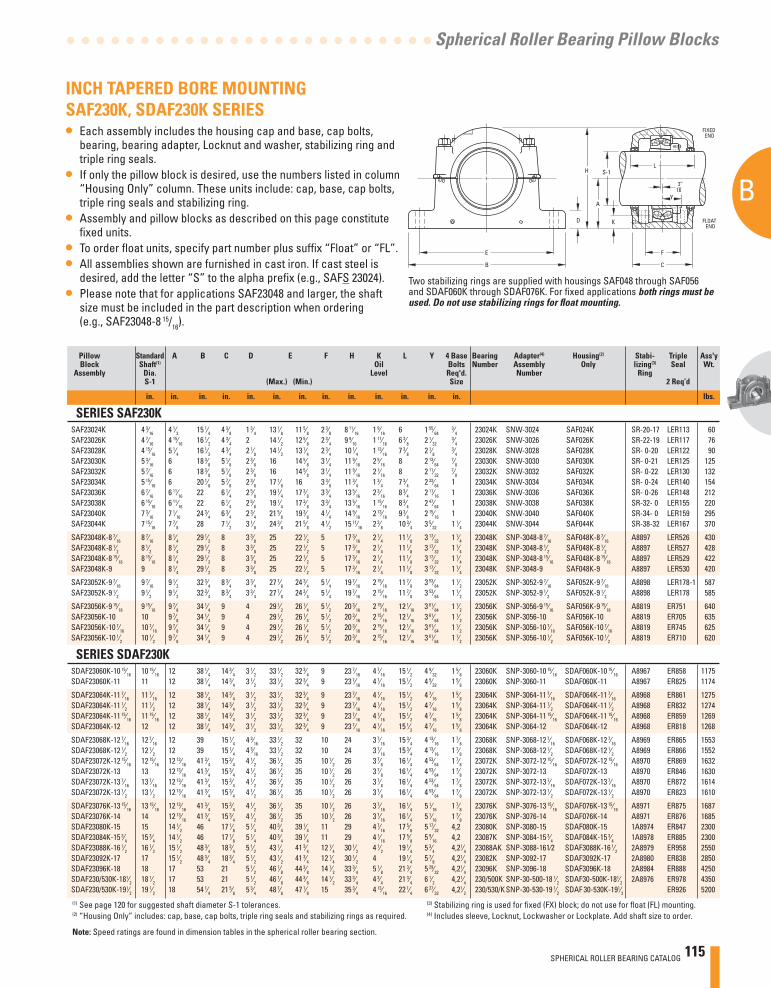
SPHERICAL ROLLER BEARING CATALOG 115
B
Spherical Roller Bearing Pillow Blocks
3’’16
E
B
D
H
F
A
S-1
K
L
C
FLOATEND
FIXEDEND
Y
INCH TAPERED BORE MOUNTING SAF230K, SDAF230K SERIES• Each assembly includes the housing cap and base, cap bolts,
bearing, bearing adapter, Locknut and washer, stabilizing ring and triple ring seals.
• If only the pillow block is desired, use the numbers listed in column “Housing Only” column. These units include: cap, base, cap bolts, triple ring seals and stabilizing ring.
• Assembly and pillow blocks as described on this page constitute fi xed units.
• To order fl oat units, specify part number plus suffi x “Float” or “FL”.• All assemblies shown are furnished in cast iron. If cast steel is
desired, add the letter “S” to the alpha prefi x (e.g., SAFS 23024).• Please note that for applications SAF23048 and larger, the shaft
size must be included in the part description when ordering (e.g., SAF23048-8 15/16).
Two stabilizing rings are supplied with housings SAF048 through SAF056 and SDAF060K through SDAF076K. For fi xed applications both rings must be used. Do not use stabilizing rings for fl oat mounting.
Pillow Standard A B C D E F H K L Y 4 Base Bearing Adapter(4) Housing(2) Stabi- Triple Ass'y Block Shaft(1) Oil Bolts Number Assembly Only lizing(3) Seal Wt. Assembly Dia. Level Req'd. Number Ring S-1 (Max.) (Min.) Size 2 Req’d
in. in. in. in. in. in. in. in. in. in. in. in. in. lbs.
SERIES SAF230K SAF23024K 4 3⁄16 4 1⁄2 15 1⁄4 4 3⁄8 1 3⁄4 13 1⁄8 11 5⁄8 2 3⁄8 8 11⁄16 1 9⁄16 6 1 55⁄64
3⁄4 23024K SNW-3024 SAF024K SR-20-17 LER113 60 SAF23026K 4 7⁄16 4 15⁄16 16 1⁄2 4 3⁄4 2 14 1⁄2 12 5⁄8 2 3⁄4 9 9⁄16 1 11⁄16 6 3⁄8 2 1⁄32
3⁄4 23026K SNW-3026 SAF026K SR-22-19 LER117 76 SAF23028K 4 15⁄16 5 1⁄4 16 1⁄2 4 3⁄4 2 1⁄8 14 1⁄2 13 1⁄4 2 3⁄4 10 1⁄4 1 13⁄16 7 3⁄8 2 1⁄8
3⁄4 23028K SNW-3028 SAF028K SR- 0-20 LER122 90 SAF23030K 5 3⁄16 6 18 3⁄8 5 1⁄8 2 3⁄8 16 14 5⁄8 3 1⁄4 11 9⁄16 2 5⁄16 8 2 13⁄64
7⁄8 23030K SNW-3030 SAF030K SR- 0-21 LER125 125 SAF23032K 5 7⁄16 6 18 3⁄8 5 1⁄8 2 3⁄8 16 14 5⁄8 3 1⁄4 11 9⁄16 2 1⁄16 8 2 11⁄32
7⁄8 23032K SNW-3032 SAF032K SR- 0-22 LER130 132 SAF23034K 5 15⁄16 6 20 1⁄8 5 7⁄8 2 3⁄8 17 1⁄8 16 3 3⁄8 11 3⁄4 1 3⁄4 7 3⁄4 2 33⁄64 1 23034K SNW-3034 SAF034K SR- 0-24 LER140 154 SAF23036K 6 7⁄16 6 11⁄16 22 6 1⁄4 2 5⁄8 19 1⁄4 17 3⁄8 3 3⁄4 13 5⁄16 2 3⁄16 8 3⁄4 2 11⁄16 1 23036K SNW-3036 SAF036K SR- 0-26 LER148 212 SAF23038K 6 15⁄16 6 11⁄16 22 6 1⁄4 2 5⁄8 19 1⁄4 17 3⁄8 3 3⁄4 13 5⁄16 1 15⁄16 8 3⁄4 2 47⁄64 1 23038K SNW-3038 SAF038K SR-32- 0 LER155 220 SAF23040K 7 3⁄16 7 1⁄16 24 3⁄4 6 3⁄4 2 3⁄4 21 5⁄8 19 3⁄8 4 1⁄4 14 9⁄16 2 13⁄16 9 3⁄8 2 15⁄16 1 23040K SNW-3040 SAF040K SR-34- 0 LER159 295 SAF23044K 7 15⁄16 7 7⁄8 28 7 1⁄2 3 1⁄8 24 3⁄8 21 5⁄8 4 1⁄2 15 11⁄16 2 3⁄8 10 3⁄4 3 5⁄32 1 1⁄4 23044K SNW-3044 SAF044K SR-38-32 LER167 370
SAF23048K-8 7⁄16 8 7⁄16 8 1⁄4 29 1⁄2 8 3 3⁄8 25 22 1⁄2 5 17 3⁄16 2 1⁄4 11 1⁄8 3 17⁄32 1 1⁄4 23048K SNP-3048-8 7⁄16 SAF048K-8 7⁄16 A8897 LER526 430 SAF23048K-8 1⁄2 8 1⁄2 8 1⁄4 29 1⁄2 8 3 3⁄8 25 22 1⁄2 5 17 3⁄16 2 1⁄4 11 1⁄8 3 17⁄32 1 1⁄4 23048K SNP-3048-8 1⁄2 SAF048K-8 1⁄2 A8897 LER527 428 SAF23048K-8 15⁄16 8 15⁄16 8 1⁄4 29 1⁄2 8 3 3⁄8 25 22 1⁄2 5 17 3⁄16 2 1⁄4 11 1⁄8 3 17⁄32 1 1⁄4 23048K SNP-3048-8 15⁄16 SAF048K-8 15⁄16 A8897 LER529 422 SAF23048K-9 9 8 1⁄4 29 1⁄2 8 3 3⁄8 25 22 1⁄2 5 17 3⁄16 2 1⁄4 11 1⁄8 3 17⁄32 1 1⁄4 23048K SNP-3048-9 SAF048K-9 A8897 LER530 420
SAF23052K-9 7⁄16 9 7⁄16 9 1⁄2 32 3⁄4 8 3⁄4 3 3⁄4 27 7⁄8 24 3⁄4 5 1⁄4 19 7⁄16 2 15⁄16 11 7⁄8 3 53⁄64 1 1⁄2 23052K SNP-3052-9 7⁄16 SAF052K-9 7⁄16 A8898 LER178-1 587 SAF23052K-9 1⁄2 9 1⁄2 9 1⁄2 32 3⁄4 8 3⁄4 3 3⁄4 27 7⁄8 24 3⁄4 5 1⁄4 19 7⁄16 2 15⁄16 11 7⁄8 3 53⁄64 1 1⁄2 23052K SNP-3052-9 1⁄2 SAF052K-9 1⁄2 A8898 LER178 585
SAF23056K-9 15⁄16 9 15⁄16 9 7⁄8 34 1⁄4 9 4 29 1⁄2 26 1⁄4 5 1⁄2 20 3⁄16 2 15⁄16 12 1⁄16 3 61⁄64 1 1⁄2 23056K SNP-3056-9 15⁄16 SAF056K-9 15⁄16 A8819 ER751 640 SAF23056K-10 10 9 7⁄8 34 1⁄4 9 4 29 1⁄2 26 1⁄4 5 1⁄2 20 3⁄16 2 15⁄16 12 1⁄16 3 61⁄64 1 1⁄2 23056K SNP-3056-10 SAF056K-10 A8819 ER705 635 SAF23056K-10 7⁄16 10 7⁄16 9 7⁄8 34 1⁄4 9 4 29 1⁄2 26 1⁄4 5 1⁄2 20 3⁄16 2 15⁄16 12 1⁄16 3 61⁄64 1 1⁄2 23056K SNP-3056-10 7⁄16 SAF056K-10 7⁄16 A8819 ER745 625 SAF23056K-10 1⁄2 10 1⁄2 9 7⁄8 34 1⁄4 9 4 29 1⁄2 26 1⁄4 5 1⁄2 20 3⁄16 2 15⁄16 12 1⁄16 3 61⁄64 1 1⁄2 23056K SNP-3056-10 1⁄2 SAF056K-10 1⁄2 A8819 ER710 620
SERIES SDAF230K SDAF23060K-10 15⁄16 10 15⁄16 12 38 1⁄4 14 3⁄4 3 1⁄2 33 1⁄2 32 3⁄4 9 23 7⁄16 4 7⁄16 15 1⁄2 4 9⁄32 1 5⁄8 23060K SNP-3060-10 15⁄16 SDAF060K-10 15⁄16 A8967 ER858 1175 SDAF23060K-11 11 12 38 1⁄4 14 3⁄4 3 1⁄2 33 1⁄2 32 3⁄4 9 23 7⁄16 4 7⁄16 15 1⁄2 4 9⁄32 1 5⁄8 23060K SNP-3060-11 SDAF060K-11 A8967 ER825 1174
SDAF23064K-11 7⁄16 11 7⁄16 12 38 1⁄4 14 3⁄4 3 1⁄2 33 1⁄2 32 3⁄4 9 23 7⁄16 4 1⁄16 15 1⁄2 4 7⁄16 1 5⁄8 23064K SNP-3064-11 7⁄16 SDAF064K-11 7⁄16 A8968 ER861 1275 SDAF23064K-11 1⁄2 11 1⁄2 12 38 1⁄4 14 3⁄4 3 1⁄2 33 1⁄2 32 3⁄4 9 23 7⁄16 4 1⁄16 15 1⁄2 4 7⁄16 1 5⁄8 23064K SNP-3064-11 1⁄2 SDAF064K-11 1⁄2 A8968 ER832 1274 SDAF23064K-11 15⁄16 11 15⁄16 12 38 1⁄4 14 3⁄4 3 1⁄2 33 1⁄2 32 3⁄4 9 23 7⁄16 4 1⁄16 15 1⁄2 4 7⁄16 1 5⁄8 23064K SNP-3064-11 15⁄16 SDAF064K-11 15⁄16 A8968 ER859 1269 SDAF23064K-12 12 12 38 1⁄4 14 3⁄4 3 1⁄2 33 1⁄2 32 3⁄4 9 23 7⁄16 4 1⁄16 15 1⁄2 4 7⁄16 1 5⁄8 23064K SNP-3064-12 SDAF064K-12 A8968 ER818 1268
SDAF23068K-12 7⁄16 12 7⁄16 12 39 15 1⁄4 4 3⁄16 33 1⁄2 32 10 24 3 7⁄16 15 3⁄4 4 13⁄16 1 7⁄8 23068K SNP-3068-12 7⁄16 SDAF068K-12 7⁄16 A8969 ER865 1553 SDAF23068K-12 1⁄2 12 1⁄2 12 39 15 1⁄4 4 3⁄16 33 1⁄2 32 10 24 3 7⁄16 15 3⁄4 4 13⁄16 1 7⁄8 23068K SNP-3068-12 1⁄2 SDAF068K-12 1⁄2 A8969 ER866 1552 SDAF23072K-12 15⁄16 12 15⁄16 12 13⁄16 41 3⁄4 15 3⁄4 4 1⁄2 36 1⁄2 35 10 1⁄2 26 3 7⁄8 16 1⁄4 4 53⁄64 1 7⁄8 23072K SNP-3072-12 15⁄16 SDAF072K-12 15⁄16 A8970 ER869 1632 SDAF23072K-13 13 12 13⁄16 41 3⁄4 15 3⁄4 4 1⁄2 36 1⁄2 35 10 1⁄2 26 3 7⁄8 16 1⁄4 4 53⁄64 1 7⁄8 23072K SNP-3072-13 SDAF072K-13 A8970 ER846 1630 SDAF23072K-13 7⁄16 13 7⁄16 12 13⁄16 41 3⁄4 15 3⁄4 4 1⁄2 36 1⁄2 35 10 1⁄2 26 3 7⁄8 16 1⁄4 4 53⁄64 1 7⁄8 23072K SNP-3072-13 7⁄16 SDAF072K-13 7⁄16 A8970 ER872 1614 SDAF23072K-13 1⁄2 13 1⁄2 12 13⁄16 41 3⁄4 15 3⁄4 4 1⁄2 36 1⁄2 35 10 1⁄2 26 3 7⁄8 16 1⁄4 4 53⁄64 1 7⁄8 23072K SNP-3072-13 1⁄2 SDAF072K-13 1⁄2 A8970 ER823 1610
SDAF23076K-13 15⁄16 13 15⁄16 12 13⁄16 41 3⁄4 15 3⁄4 4 1⁄2 36 1⁄2 35 10 1⁄2 26 3 7⁄16 16 1⁄4 5 1⁄16 1 7⁄8 23076K SNP-3076-13 15⁄16 SDAF076K-13 15⁄16 A8971 ER875 1687 SDAF23076K-14 14 12 13⁄16 41 3⁄4 15 3⁄4 4 1⁄2 36 1⁄2 35 10 1⁄2 26 3 7⁄16 16 1⁄4 5 1⁄16 1 7⁄8 23076K SNP-3076-14 SDAF076K-14 A8971 ER876 1685 SDAF23080K-15 15 14 1⁄2 46 17 1⁄8 5 1⁄4 40 3⁄4 39 1⁄4 11 29 4 7⁄16 17 5⁄8 5 17⁄32 4,2 23080K SNP-3080-15 SDAF080K-15 1A8974 ER847 2300 SDAF23084K-15 3⁄4 15 3⁄4 14 1⁄2 46 17 1⁄8 5 1⁄4 40 3⁄4 39 1⁄4 11 29 4 1⁄16 17 5⁄8 5 9⁄16 4,2 23087K SNP-3084-15 3⁄4 SDAF084K-15 3⁄4 1A8978 ER885 2300 SDAF23088K-16 1⁄2 16 1⁄2 15 1⁄2 48 3⁄4 18 3⁄4 5 1⁄2 43 1⁄2 41 3⁄4 12 1⁄4 30 1⁄2 4 1⁄2 19 1⁄4 5 3⁄4 4,21⁄4 23088AK SNP-3088-161⁄2 SDAF3088K-16 1⁄2 2A8979 ER958 2550 SDAF23092K-17 17 15 1⁄2 48 3⁄4 18 3⁄4 5 1⁄2 43 1⁄2 41 3⁄4 12 1⁄4 30 1⁄2 4 19 1⁄4 5 7⁄8 4,21⁄4 23082K SNP-3092-17 SDAF3092K-17 2A8980 ER838 2850 SDAF23096K-18 18 17 53 21 5 1⁄2 46 1⁄8 44 3⁄8 14 1⁄2 33 3⁄4 5 1⁄8 21 3⁄4 5 29⁄32 4,21⁄4 23096K SNP-3096-18 SDAF3096K-18 2A8984 ER888 4250 SDAF230/530K-181⁄2 18 1⁄2 17 53 21 5 1⁄2 46 1⁄8 44 3⁄8 14 1⁄2 33 3⁄4 4 3⁄4 21 3⁄4 6 1⁄2 4,21⁄4 230/500K SNP-30-500-18 1⁄2 SDAF30-500K-181⁄2 2A8976 ER978 4350 SDAF230/530K-191⁄2 19 1⁄2 18 54 1⁄4 21 5⁄8 5 3⁄4 48 7⁄8 47 1⁄8 15 35 3⁄4 4 13⁄16 22 1⁄4 6 27⁄32 4,21⁄2 230/530/K SNP-30-530-19 1⁄2 SDAF 30-530K-191⁄2 ER926 5200
(1) See page 120 for suggested shaft diameter S-1 tolerances. (3) Stabilizing ring is used for fi xed (FX) block; do not use for fl oat (FL) mounting.(2) “Housing Only” includes: cap, base, cap bolts, triple ring seals and stabilizing rings as required. (4) Includes sleeve, Locknut, Lockwasher or Lockplate. Add shaft size to order.
Note: Speed ratings are found in dimension tables in the spherical roller bearing section.
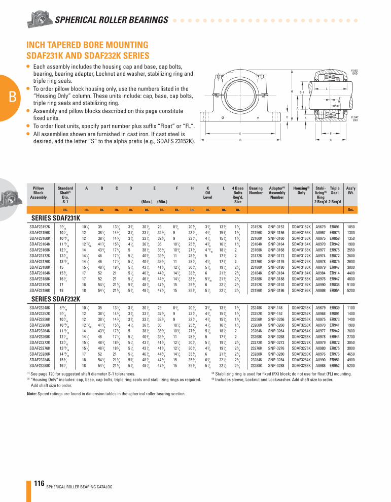
116 SPHERICAL ROLLER BEARING CATALOG
B
SPHERICAL ROLLER BEARINGS
INCH TAPERED BORE MOUNTING SDAF231K AND SDAF232K SERIES• Each assembly includes the housing cap and base, cap bolts,
bearing, bearing adapter, Locknut and washer, stabilizing ring and triple ring seals.
• To order pillow block housing only, use the numbers listed in the “Housing Only” column. These units include: cap, base, cap bolts, triple ring seals and stabilizing ring.
• Assembly and pillow blocks described on this page constitute fi xed units.
• To order fl oat units, specify part number plus suffi x “Float” or “FL”.• All assemblies shown are furnished in cast iron. If cast steel is
desired, add the letter “S” to the alpha prefi x (e.g., SDAFS 23152K).
Pillow Standard A B C D E F H K L 4 Base Bearing Adapter(4) Housing(2) Stabi- Triple Ass'y Block Shaft(1) Oil Bolts Number Assembly Only lizing(3) Seal Wt. Assembly Dia. Level Req'd. Number Ring S-1 (Max.) (Min.) Size 2 Req’d 2 Req’d
in. in. in. in. in. in. in. in. in. in. in. in. lbs.
SERIES SDAF231K SDAF23152K 9 7⁄16 10 1⁄4 35 13 1⁄8 3 3⁄4 30 1⁄2 29 8 3⁄4 20 7⁄8 3 3⁄8 13 3⁄4 1 5⁄8 23152K SNP-3152 SDAF3152K A5679 ER891 1050 SDAF23156K 10 7⁄16 12 38 1⁄4 14 3⁄4 3 3⁄8 33 1⁄2 32 3⁄4 9 23 7⁄16 4 3⁄4 15 3⁄8 1 5⁄8 23156K SNP-3156 SDAF3156K A8967 ER973 1300 SDAF23160K 10 15⁄16 12 38 1⁄4 14 3⁄4 3 3⁄8 33 1⁄2 32 3⁄4 9 23 7⁄16 4 1⁄8 15 3⁄8 1 5⁄8 23160K SNP-3160 SDAF3160K A8975 ER858 1350 SDAF23164K 11 15⁄16 12 13⁄16 41 3⁄4 15 3⁄4 4 1⁄2 36 1⁄2 35 10 1⁄2 25 3⁄4 4 3⁄8 16 1⁄4 1 7⁄8 23164K SNP-3164 SDAF3164K A8970 ER942 1900 SDAF23168K 12 7⁄16 14 43 3⁄4 17 3⁄4 5 38 1⁄4 36 3⁄4 10 3⁄4 27 7⁄8 4 15⁄16 18 1⁄4 2 23168K SNP-3168 SDAF3168K A8977 ER975 2550 SDAF23172K 13 7⁄16 14 1⁄2 46 17 1⁄8 5 1⁄4 40 3⁄4 39 1⁄4 11 28 7⁄8 5 17 3⁄4 2 23172K SNP-3172 SDAF3172K A8974 ER872 2600 SDAF23176K 13 15⁄16 14 1⁄2 46 17 1⁄8 5 1⁄4 40 3⁄4 39 1⁄4 11 28 7⁄8 4 5⁄8 17 3⁄4 2 23176K SNP-3176 SDAF3176K A8978 ER875 2600 SDAF23180K 15 15 1⁄2 48 3⁄4 18 3⁄4 5 1⁄2 43 1⁄2 41 3⁄4 12 1⁄4 30 1⁄2 5 1⁄8 19 1⁄4 2 1⁄4 23180K SNP-3180 SDAF3180K A8979 ER847 3000 SDAF23184K 15 3⁄4 17 52 21 5 1⁄2 46 1⁄8 44 3⁄8 14 1⁄2 33 3⁄4 6 21 3⁄4 2 1⁄4 23184K SNP-3184 SDAF3184K A8984 ER914 4400 SDAF23188K 16 1⁄2 17 52 21 5 1⁄2 46 1⁄8 44 3⁄8 14 1⁄2 33 3⁄4 5 9⁄16 21 3⁄4 2 1⁄4 23188K SNP-3188 SDAF3188K A8976 ER947 4600 SDAF23192K 17 18 54 1⁄4 21 5⁄8 5 3⁄4 48 7⁄8 47 1⁄8 15 35 3⁄4 6 22 1⁄4 2 1⁄2 23192K SNP-3192 SDAF3192K A8990 ER838 5100 SDAF23196K 18 18 54 1⁄4 21 5⁄8 5 3⁄4 48 7⁄8 47 1⁄8 15 35 3⁄4 5 1⁄2 22 1⁄4 2 1⁄2 23196K SNP-3196 SDAF3196K A8998 ER954 5200
SERIES SDAF232K SDAF23248K 8 15⁄16 10 1⁄4 35 13 1⁄8 3 3⁄4 30 1⁄2 29 8 3⁄4 20 7⁄8 3 9⁄16 13 3⁄4 1 5⁄8 23248K SNP-148 SDAF3248K A5679 ER939 1100 SDAF23252K 9 7⁄16 12 38 1⁄4 14 3⁄4 3 3⁄8 33 1⁄2 32 3⁄4 9 23 7⁄16 4 3⁄4 15 3⁄8 1 5⁄8 23252K SNP-152 SDAF3252K A8968 ER891 1400 SDAF23256K 10 7⁄16 12 38 1⁄4 14 3⁄4 3 3⁄8 33 1⁄2 32 3⁄4 9 23 7⁄16 4 3⁄8 15 3⁄8 1 5⁄8 23256K SNP-3256 SDAF3256K A8975 ER973 1400 SDAF23260K 10 15⁄16 12 13⁄16 41 3⁄4 15 3⁄4 4 1⁄2 36 1⁄2 35 10 1⁄2 25 3⁄4 4 1⁄2 16 1⁄4 1 7⁄8 23260K SNP-3260 SDAF3260K A8970 ER941 1900 SDAF23264K 11 15⁄16 14 43 3⁄4 17 3⁄4 5 38 1⁄4 36 3⁄4 10 3⁄4 27 7⁄8 5 1⁄8 18 1⁄4 2 23264K SNP-3264 SDAF3264K A8977 ER942 2600 SDAF23268K 12 7⁄16 14 1⁄2 46 17 1⁄8 5 1⁄4 40 3⁄4 39 1⁄4 11 28 7⁄8 5 17 3⁄4 2 23268K SNP-3268 SDAF3268K A8978 ER944 2700 SDAF23272K 13 7⁄16 15 1⁄2 48 3⁄4 18 3⁄4 5 1⁄2 43 1⁄2 41 3⁄4 12 1⁄4 30 1⁄2 5 1⁄2 19 1⁄4 2 1⁄4 23272K SNP-3272 SDAF3272K A8979 ER872 3050 SDAF23276K 13 15⁄16 15 1⁄2 48 3⁄4 18 3⁄4 5 1⁄2 43 1⁄2 41 3⁄4 12 1⁄4 30 1⁄2 4 3⁄8 19 1⁄4 2 1⁄4 23276K SNP-3276 SDAF3276K A8980 ER875 3000 SDAF23280K 14 15⁄16 17 52 21 5 1⁄2 46 1⁄8 44 3⁄8 14 1⁄2 33 3⁄4 6 21 3⁄4 2 1⁄4 23280K SNP-3280 SDAF3280K A8976 ER976 4650 SDAF23284K 15 3⁄4 18 54 1⁄4 21 5⁄8 5 3⁄4 48 7⁄8 47 1⁄8 15 35 3⁄4 6 3⁄8 22 1⁄4 2 1⁄2 23284K SNP-3284 SDAF3284K A8990 ER951 4900 SDAF23288K 16 1⁄2 18 54 1⁄4 21 5⁄8 5 3⁄4 48 7⁄8 47 1⁄8 15 35 3⁄4 5 7⁄8 22 1⁄4 2 1⁄2 23288K SNP-3288 SDAF3288K A8988 ER952 5200
(1) See page 120 for suggested shaft diameter S-1 tolerances. (3) Stabilizing ring is used for fi xed (FX) block; do not use for fl oat (FL) mounting.(2) “Housing Only” includes: cap, base, cap bolts, triple ring seals and stabilizing rings as required. (4) Includes sleeve, Locknut and Lockwasher. Add shaft size to order. Add shaft size to order.
Note: Speed ratings are found in dimension tables in the spherical roller bearing section.
3 "16
E
B
D
H
F
A
S-1
K
L
C
FLOATEND
FIXEDEND
Y
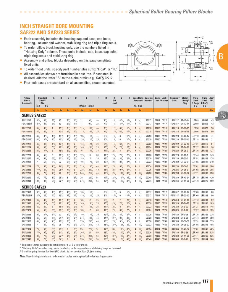
SPHERICAL ROLLER BEARING CATALOG 117
B
Spherical Roller Bearing Pillow Blocks
E
B
D
H
F
A
S-2
K
L
C
FLOATEND
FIXEDEND
S-3Y
3 "16
INCH STRAIGHT BORE MOUNTING SAF222 AND SAF223 SERIES• Each assembly includes the housing cap and base, cap bolts,
bearing, Locknut and washer, stabilizing ring and triple ring seals.• To order pillow block housing only, use the numbers listed in
“Housing Only” column. These units include: cap, base, cap bolts, triple ring seals and stabilizing ring.
• Assembly and pillow blocks described on this page constitute fi xed units.
• To order fl oat units, specify part number plus suffi x “Float” or “FL”.• All assemblies shown are furnished in cast iron. If cast steel is
desired, add the letter “S” to the alpha prefi x (e.g., SAFS 22217).• Four-bolt bases are standard on all assemblies, except as noted.
Pillow Standard A B C D E F H K L Y Base Bolts Bearing Lock Lock Housing(2) Stabil- Triple Triple Ass'y Block Shaft(1) Oil Required Number Nut Washer Only lizing(3) Seal Seal Wt. Assembly Dia. Level Ring 1 Req’d 1 Req’d S-2 S-3 (Max.) (Min.) No. Size S-2 S-3
in. in. in. in. in. in. in. in. in. in. in. in. in. in. lbs.
SERIES SAF222 SAF22217 3 15⁄16 3 3⁄16 3 3⁄4 13 3 1⁄2 1 1⁄4 11 9 7⁄8 — 7 1⁄4 1 7⁄16 4 15⁄16 1 27⁄64 2 3⁄4 22217 AN17 W17 SAF217 SR-17-14 LER89 LER63 43 FSAF22217 3 15⁄16 3 3⁄16 3 3⁄4 13 3 1⁄2 1 1⁄4 11 9 7⁄8 2 1⁄8 7 1⁄4 1 7⁄16 4 15⁄16 1 27⁄64 4 5⁄8 22217 AN17 W17 FSAF217 SR-17-14 LER89 LER63 43
SAF22218 4 1⁄8 3 3⁄8 4 13 3⁄4 3 7⁄8 1 1⁄2 11 5⁄8 10 3⁄8 — 7 3⁄4 1 17⁄32 6 1⁄4 1 37⁄64 2 3⁄4 22218 AN18 W18 SAF218 SR-18-15 LER96 LER72 50 FSAF22218 4 1⁄8 3 3⁄8 4 13 3⁄4 3 7⁄8 1 1⁄2 11 5⁄8 10 3⁄8 2 1⁄8 7 3⁄4 1 17⁄32 6 1⁄4 1 37⁄64 4 5⁄8 22218 AN18 W18 FSAF218 SR-18-15 LER96 LER72 50
SAF22220 4 1⁄2 3 13⁄16 4 1⁄2 15 1⁄4 4 3⁄8 1 3⁄4 13 1⁄8 11 5⁄8 — 8 11⁄16 1 3⁄4 6 1 49⁄64 2 7⁄8 22220 AN20 W20 SAF220 SR-20-17 LER118 LER106 71 FSAF22220 4 1⁄2 3 13⁄16 4 1⁄2 15 1⁄4 4 3⁄8 1 3⁄4 13 1⁄8 11 5⁄8 2 3⁄8 8 11⁄16 1 3⁄4 6 1 49⁄64 4 3⁄4 22220 AN20 W20 FSAF220 SR-20-17 LER118 LER106 71
SAF22222 4 7⁄8 4 3⁄16 4 15⁄16 16 1⁄2 4 3⁄4 2 14 1⁄2 12 5⁄8 2 3⁄4 9 9⁄16 1 7⁄8 6 3⁄8 1 61⁄64 4 3⁄4 22222 AN22 W22 SAF222 SR-22-19 LER121 LER113 81 SAF22224 5 5⁄16 4 9⁄16 5 1⁄4 16 1⁄2 4 3⁄4 2 1⁄8 14 1⁄2 13 1⁄4 2 3⁄4 10 1⁄4 1 15⁄16 7 3⁄8 2 3⁄32 4 3⁄4 22224 AN24 W24 SAF224 SR-24-20 LER127 LER119 90 SAF22226 5 7⁄8 4 15⁄16 6 18 3⁄8 5 1⁄8 2 3⁄8 16 14 5⁄8 3 1⁄4 11 9⁄16 2 7⁄16 8 2 17⁄64 4 7⁄8 22226 AN26 W26 SAF226 SR-26-0 LER136 LER122 127
SAF22228 6 1⁄4 5 5⁄16 6 20 1⁄8 5 7⁄8 2 3⁄8 17 1⁄8 16 3 3⁄8 11 3⁄4 2 1⁄8 7 3⁄4 2 13⁄32 4 1 22228 AN28 W28 SAF228 SR-28-0 LER144 LER127 149 SAF22230 6 5⁄8 5 3⁄4 6 5⁄16 21 1⁄4 6 1⁄4 2 1⁄2 18 1⁄4 17 3 3⁄4 12 1⁄2 2 3⁄16 8 3⁄8 2 37⁄64 4 1 22230 AN30 W30 SAF230 SR-30-0 LER151 LER134 175 SAF22232 7 6 1⁄16 6 11⁄16 22 6 1⁄4 2 5⁄8 19 1⁄4 17 3⁄8 3 3⁄4 13 5⁄16 2 3⁄16 8 3⁄4 2 49⁄64 4 1 22232 AN32 W32 SAF232 SR-32-0 LER156 LER142 210
SAF22234 7 7⁄16 6 7⁄16 7 1⁄16 24 3⁄4 6 3⁄4 2 3⁄4 21 5⁄8 19 3⁄8 4 1⁄4 14 9⁄16 2 5⁄16 9 3⁄8 2 59⁄64 4 1 22234 AN34 W34 SAF234 SR-34-0 LER161 LER148 280 SAF22236 7 13⁄16 6 7⁄8 7 1⁄2 26 3⁄4 7 1⁄8 3 23 5⁄8 20 7⁄8 4 5⁄8 15 1⁄2 2 9⁄16 9 11⁄16 2 61⁄64 4 1 22236 AN36 W36 SAF236 SR-36-0 LER165 LER154 305 SAF22238 8 3⁄8 7 1⁄4 7 7⁄8 28 7 1⁄2 3 1⁄8 24 3⁄8 21 5⁄8 4 1⁄2 15 11⁄16 2 5⁄8 10 3⁄4 3 7⁄64 4 1 1⁄4 22238 AN38 W38 SAF238 SR-38-32 LER171 LER160 350
SAF22240 8 3⁄4 7 5⁄8 8 1⁄4 29 1⁄2 8 3 3⁄8 25 22 1⁄2 5 17 3⁄16 2 11⁄16 10 13⁄16 3 9⁄32 4 1 1⁄4 22240 AN40 W40 SAF240 SR-40-34 LER175 LER164 420 SAF22244 9 9⁄16 8 5⁄16 9 1⁄2 32 3⁄4 8 3⁄4 3 3⁄4 27 7⁄8 24 3⁄4 5 1⁄4 19 5⁄8 3 3⁄8 11 1⁄2 3 17⁄32 4 1 1⁄2 22244 N44 W44 SAF244 SR-44-38 LER179 LER170 590
SERIES SAF223 SAF22317 3 15⁄16 3 3⁄16 4 1⁄2 15 1⁄4 4 3⁄8 1 3⁄4 13 1⁄8 11 5⁄8 – 8 11⁄16 1 13⁄16 6 1 57⁄64 2 7⁄8 22317 AN17 W17 SAF317 SR-20-17 LER109 LER188 80 FSAF22317 3 15⁄16 3 3⁄16 4 1⁄2 15 1⁄4 4 3⁄8 1 3⁄4 13 1⁄8 11 5⁄8 2 3⁄8 8 11⁄16 1 13⁄16 6 1 57⁄64 4 3⁄4 22317 AN17 W17 FSAF317 SR-20-17 LER109 LER188 80
SAF22318 4 1⁄8 3 3⁄8 4 3⁄4 15 1⁄2 4 3⁄8 2 13 1⁄2 12 2 1⁄4 9 3⁄16 2 7 2 3⁄64 4 3⁄4 22318 AN18 W18 FSAF318 SR-21-18 LER112 LER191 92 SAF22320 4 1⁄2 3 13⁄16 5 1⁄4 16 1⁄2 4 3⁄4 2 1⁄8 14 1⁄2 13 1⁄4 2 3⁄4 10 1⁄4 2 1⁄8 7 3⁄8 2 19⁄64 4 3⁄4 22320 AN20 W20 SAF320 SR-24-20 LER118 LER106 109 SAF22322 4 7⁄8 4 3⁄16 6 18 3⁄8 5 1⁄8 2 3⁄8 16 14 5⁄8 3 1⁄4 11 9⁄16 2 1⁄2 8 2 31⁄64 4 7⁄8 22322 AN22 W22 SAF322 SR-0-22 LER121 LER113 145 SAF22324 5 5⁄16 4 9⁄16 6 5⁄16 21 1⁄4 6 1⁄4 2 1⁄2 18 1⁄4 17 3 3⁄4 12 1⁄2 2 9⁄16 8 3⁄8 2 41⁄64 4 1 22324 AN24 W24 SAF324 SR-0-24 LER127 LER119 195
SAF22326 5 7⁄8 4 15⁄16 6 11⁄16 22 6 1⁄4 2 5⁄8 19 1⁄4 17 3⁄8 3 3⁄4 13 15⁄16 2 5⁄8 8 3⁄4 2 27⁄32 4 1 22326 AN26 W26 SAF326 SR-0-26 LER136 LER122 235 SAF22328 6 1⁄4 5 5⁄16 7 1⁄16 24 3⁄4 6 3⁄4 2 3⁄4 21 5⁄8 19 3⁄8 4 1⁄4 14 9⁄16 2 11⁄16 9 3⁄8 3 5⁄64 4 1 22328 AN28 W28 SAF328 SR-0-28 LER144 LER127 300 SAF22330 6 5⁄8 5 3⁄4 7 1⁄2 26 3⁄4 7 1⁄8 3 23 5⁄8 20 7⁄8 4 5⁄8 15 1⁄2 2 7⁄8 9 11⁄16 3 17⁄64 4 1 22330 AN30 W30 SAF330 SR-36-30 LER151 LER134 335 SAF22332 7 6 1⁄16 7 7⁄8 28 7 1⁄2 3 1⁄8 24 3⁄8 21 5⁄8 4 1⁄2 15 11⁄16 2 15⁄16 10 3⁄4 3 7⁄16 4 1 1⁄4 22332 AN32 W32 SAF332 SR-38-32 LER156 LER142 405
SAF22334 7 7⁄16 6 7⁄16 8 1⁄4 29 1⁄2 8 3 3⁄8 25 22 1⁄2 5 17 3⁄16 3 1⁄16 10 13⁄16 3 19⁄32 4 1 1⁄4 22334 AN34 W34 SAF334 SR-40-34 LER161 LER148 465 SAF22336 7 13⁄16 6 7⁄8 8 7⁄8 31 1⁄4 8 1⁄4 3 1⁄2 26 5⁄8 24 5 1⁄4 18 1⁄2 3 3⁄8 11 1⁄4 3 47⁄64 4 1 1⁄4 22336 AN36 W36 SAF336 SR-0-36 LER165 LER154 525 SAF22338 8 3⁄8 7 1⁄4 9 1⁄2 32 3⁄4 8 3⁄4 3 3⁄4 27 7⁄8 24 3⁄4 5 1⁄4 19 5⁄8 3 11⁄16 11 1⁄2 3 57⁄64 4 1 1⁄2 22338 AN38 W38 SAF338 SR-44-38 LER171 LER160 635 SAF22340 8 3⁄4 7 5⁄8 9 7⁄8 34 1⁄4 9 4 29 1⁄2 26 1⁄4 5 1⁄2 20 3⁄16 3 3⁄4 12 1⁄4 4 5⁄64 4 1 1⁄2 22340 AN40 W40 SAF340 SR-0-40 LER175 LER164 700
(1) See page 120 for suggested shaft diameter S-2, S-3 tolerances. (2) “Housing Only” includes: cap, base, cap bolts, triple ring seals and stabilizing rings as required. (3) Stabilizing ring is used for fi xed (FX) block; do not use for fl oat (FL) mounting.
Note: Speed ratings are found in dimension tables in the spherical roller bearing section.
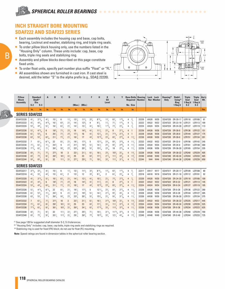
118 SPHERICAL ROLLER BEARING CATALOG
B
SPHERICAL ROLLER BEARINGS
3 "16
E
B
H
D
F
A
S-2
K
L
C
FLOATEND
FIXEDEND
S-3
Y
INCH STRAIGHT BORE MOUNTING SDAF222 AND SDAF223 SERIES• Each assembly includes the housing cap and base, cap bolts,
bearing, Locknut and washer, stabilizing ring, and triple ring seals.• To order pillow block housing only, use the numbers listed in the
“Housing Only” column. These units include: cap, base, cap bolts, triple ring seals and stabilizing ring.
• Assembly and pillow blocks described on this page constitute fi xed units.
• To order fl oat units, specify part number plus suffi x “Float” or “FL”.• All assemblies shown are furnished in cast iron. If cast steel is
desired, add the letter “S” to the alpha prefi x (e.g., SDAS 22220).
Pillow Standard A B C D E F H K L Y Base Bolts Bearing Lock Lock Housing(2) Stabil- Triple Triple Ass'y Block Shaft(1) Oil Required Number Nut Washer Only lizing(3) Seal Seal Wt. Assembly Dia. Level Ring 1 Req’d 1 Req’d S-2 S-3 (Max.) (Min.) No. Size 1 Req’d S-2 S-3
in. in. in. in. in. in. in. in. in. in. in. in. in. in. lbs.
SERIES SDAF222 SDAF22220 4 1⁄2 3 13⁄16 4 1⁄2 15 1⁄4 6 1 7⁄8 13 1⁄8 11 5⁄8 3 3⁄8 8 15⁄16 1 3⁄4 6 3⁄4 1 49⁄64 4 3⁄4 22220 AN20 W20 SDAF220 SR-20-17 LER118 LER106 81 SDAF22222 4 7⁄8 4 3⁄16 4 15⁄16 16 1⁄2 6 3⁄4 2 1⁄8 14 1⁄2 12 5⁄8 4 9 7⁄8 1 7⁄8 7 1⁄4 1 61⁄64 4 7⁄8 22222 AN22 W22 SDAF222 SR-22-19 LER121 LER113 109 SDAF22224 5 5⁄16 4 9⁄16 5 1⁄4 16 1⁄2 6 7⁄8 2 1⁄4 14 1⁄2 13 1⁄4 4 1⁄8 10 1⁄2 1 15⁄16 7 3⁄8 2 3⁄32 4 7⁄8 22224 AN24 W24 SDAF224 SR-24-20 LER127 LER119 113
SDAF22226 5 7⁄8 4 15⁄16 6 18 3⁄8 7 1⁄2 2 3⁄8 16 14 5⁄8 4 1⁄2 11 7⁄8 2 7⁄16 8 2 17⁄64 4 1 22226 AN26 W26 SDAF226 SR-26-0 LER136 LER122 151 SDAF22228 6 1⁄4 5 5⁄16 6 20 1⁄8 7 1⁄2 2 3⁄8 17 1⁄8 16 4 1⁄2 12 1⁄16 2 1⁄8 7 13⁄16 2 13⁄32 4 1 22228 AN28 W28 SDAF228 SR-28-0 LER144 LER127 175 SDAF22230 6 5⁄8 5 3⁄4 6 5⁄16 21 1⁄4 7 7⁄8 2 1⁄2 18 1⁄4 17 4 3⁄4 12 13⁄16 2 3⁄16 8 3⁄8 2 37⁄64 4 1 1⁄8 22230 AN30 W30 SDAF230 SR-30-0 LER151 LER134 201
SDAF22232 7 6 1⁄16 6 11⁄16 22 8 1⁄4 2 1⁄2 19 1⁄4 17 3⁄8 5 13 11⁄16 2 3⁄16 8 3⁄4 2 49⁄64 4 1 1⁄8 22232 AN32 W32 SDAF232 SR-32-0 LER156 LER142 245 SDAF22234 7 7⁄16 6 7⁄16 7 1⁄16 24 3⁄4 9 2 1⁄2 21 5⁄8 19 3⁄8 5 1⁄2 14 1⁄4 2 5⁄16 9 5⁄8 2 59⁄64 4 1 1⁄4 22234 AN34 W34 SDAF234 SR-34-0 LER161 LER148 300 SDAF22236 7 13⁄16 6 7⁄8 7 1⁄2 26 3⁄4 9 3⁄8 2 3⁄4 23 5⁄8 20 7⁄8 5 7⁄8 15 3⁄16 2 9⁄16 10 2 61⁄64 4 1 1⁄4 22236 AN36 W36 SDAF236 SR-36-30 LER165 LER154 335
SDAF22238 8 3⁄8 7 1⁄4 7 7⁄8 27 5⁄8 10 3 23 1⁄2 21 1⁄2 6 1⁄4 16 1⁄4 2 5⁄8 10 5⁄8 3 7⁄64 4 1 3⁄8 22238 AN38 W38 SDAF238 SR-38-32 LER240 LER229 405 SDAF22240 8 3⁄4 7 5⁄8 8 1⁄4 28 3⁄4 10 1⁄2 3 1⁄4 25 23 6 3⁄4 17 1⁄8 2 11⁄16 11 1⁄8 3 9⁄32 4 1 3⁄8 22240 AN40 W40 SDAF240 SR-40-34 LER244 LER233 465 SDAF22244 9 9⁄16 8 5⁄16 9 1⁄2 32 11 1⁄4 3 1⁄2 27 7⁄8 25 5⁄8 7 1⁄4 19 1⁄4 3 3⁄8 11 7⁄8 3 17⁄32 4 1 1⁄2 22244 N44 W44 SDAF240 SR-44-38 LER248 LER239 650
SERIES SDAF223 SDAF22317 3 15⁄16 3 3⁄16 4 1⁄2 15 1⁄4 6 1 7⁄8 13 1⁄8 11 5⁄8 3 3⁄8 8 15⁄16 1 3⁄16 6 3⁄4 1 57⁄64 4 3⁄4 22317 AN17 W17 SDAF317 SR-20-17 LER109 LER188 80 SDAF22318 4 1⁄8 3 3⁄8 4 3⁄4 15 1⁄2 6 1⁄8 2 13 1⁄2 12 3 5⁄8 9 7⁄16 2 6 7⁄8 2 3⁄64 4 3⁄4 22318 AN18 W18 SDAF318 SR-21-18 LER112 LER191 92
SDAF22320 4 1⁄2 3 13⁄16 5 1⁄4 16 1⁄2 6 7⁄8 2 1⁄4 14 1⁄2 13 1⁄4 4 1⁄8 10 1⁄2 2 1⁄8 7 3⁄8 2 19⁄64 4 7⁄8 22320 AN20 W20 SDAF320 SR-24-20 LER118 LER106 109 SDAF22322 4 7⁄8 4 3⁄16 6 18 3⁄8 7 1⁄2 2 3⁄8 16 14 5⁄8 4 1⁄2 11 7⁄8 2 1⁄2 8 2 31⁄64 4 1 22322 AN22 W22 SDAF322 SR-0-22 LER121 LER113 145 SDAF22324 5 5⁄16 4 9⁄16 6 5⁄16 21 1⁄4 7 7⁄8 2 1⁄2 18 1⁄4 17 4 3⁄4 12 13⁄16 2 9⁄16 8 3⁄8 2 41⁄64 4 1 1⁄8 22324 AN24 W24 SDAF324 SR-0-24 LER127 LER119 195
SDAF22326 5 7⁄8 4 15⁄16 6 11⁄16 22 8 1⁄4 2 1⁄2 19 1⁄4 17 3⁄8 5 13 11⁄16 2 5⁄8 8 3⁄4 2 27⁄64 4 1 1⁄8 22326 AN26 W26 SDAF326 SR-0-26 LER136 LER122 280 SDAF22328 6 1⁄4 5 5⁄16 7 1⁄16 24 3⁄4 9 2 1⁄2 21 5⁄8 19 3⁄8 5 1⁄2 14 1⁄4 2 11⁄16 9 5⁄8 3 5⁄64 4 1 1⁄4 22328 AN28 W28 SDAF328 SR-0-28 LER144 LER127 305 SDAF22330 6 5⁄8 5 3⁄4 7 1⁄2 26 3⁄4 9 3⁄8 2 3⁄4 23 5⁄8 20 7⁄8 5 7⁄8 15 3⁄16 2 7⁄8 9 3⁄4 3 17⁄64 4 1 1⁄4 22330 AN30 W30 SDAF330 SR-36-30 LER151 LER134 375
SDAF22332 7 6 1⁄16 7 7⁄8 27 5⁄8 10 3 23 1⁄2 21 1⁄2 6 1⁄4 16 1⁄4 2 15⁄16 10 5⁄8 3 7⁄16 4 1 3⁄8 22332 AN32 W32 SDAF332 SR-38-32 LER225 LER217 445 SDAF22334 7 7⁄16 6 7⁄16 8 1⁄4 28 3⁄4 10 1⁄2 3 1⁄4 25 23 6 3⁄4 17 1⁄8 3 1⁄16 11 1⁄8 3 19⁄32 4 1 3⁄8 22334 AN34 W34 SDAF334 SR-40-34 LER230 LER220 525 SDAF22336 7 13⁄16 6 7⁄8 8 7⁄8 30 1⁄2 10 3⁄4 3 1⁄4 26 3⁄8 24 1⁄8 6 7⁄8 17 15⁄16 3 3⁄8 11 3⁄8 3 47⁄64 4 1 1⁄2 22336 AN36 W36 SDAF336 SR-0-36 LER234 LER223 635
SDAF22338 8 3⁄8 7 1⁄4 9 1⁄2 32 11 1⁄4 3 1⁄2 27 7⁄8 25 5⁄8 7 1⁄4 19 1⁄4 3 11⁄16 11 13⁄16 3 57⁄64 4 1 1⁄2 22338 AN38 W38 SDAF338 SR-44-38 LER240 LER229 700 SDAF22340 8 3⁄4 7 5⁄8 9 7⁄8 33 1⁄2 11 3⁄4 3 1⁄2 29 1⁄4 26 5⁄8 7 5⁄8 19 15⁄16 3 3⁄4 12 1⁄4 4 5⁄64 4 1 5⁄8 22340 AN40 W40 SDAF340 SR-0-40 LER244 LER233 725
(1) See page 120 for suggested shaft diameter S-2, S-3 tolerances. (2) “Housing Only” includes: cap, base, cap bolts, triple ring seals and stabilizing rings as required. (3) Stabilizing ring is used for fi xed (FX) block; do not use for fl oat (FL) mounting.
Note: Speed ratings are found in dimension tables in the spherical roller bearing section.
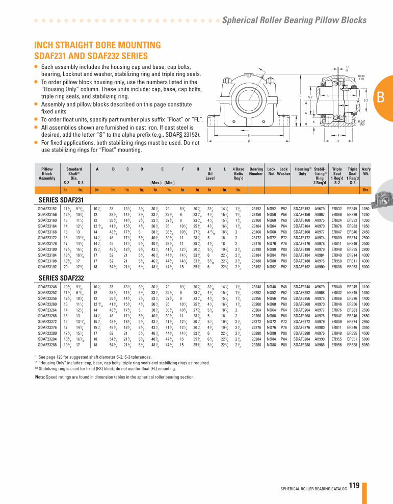
SPHERICAL ROLLER BEARING CATALOG 119
B
Spherical Roller Bearing Pillow Blocks
INCH STRAIGHT BORE MOUNTING SDAF231 AND SDAF232 SERIES• Each assembly includes the housing cap and base, cap bolts,
bearing, Locknut and washer, stabilizing ring and triple ring seals.• To order pillow block housing only, use the numbers listed in the
“Housing Only” column. These units include: cap, base, cap bolts, triple ring seals, and stabilizing ring.
• Assembly and pillow blocks described on this page constitute fi xed units.
• To order fl oat units, specify part number plus suffi x “Float” or “FL”.• All assemblies shown are furnished in cast iron. If cast steel is
desired, add the letter “S” to the alpha prefi x (e.g., SDAFS 23152).• For fi xed applications, both stabilizing rings must be used. Do not
use stabilizing rings for “Float” mounting.
Pillow Standard A B C D E F H K L 4 Base Bearing Lock Lock Housing(2) Stabil- Triple Triple Ass'y Block Shaft(1) Oil Bolts Number Nut Washer Only lizing(3) Seal Seal Wt. Assembly Dia. Level Req'd Ring 1 Req’d 1 Req’d S-2 S-3 (Max.) (Min.) 2 Req’d S-2 S-3
in. in. in. in. in. in. in. in. in. in. in. in. in. lbs.
SERIES SDAF231 SDAF23152 11 1⁄2 9 15⁄16 10 1⁄4 35 13 1⁄8 3 3⁄4 30 1⁄2 29 8 3⁄4 20 7⁄8 3 3⁄8 14 1⁄4 1 5⁄8 23152 NO52 P52 SDAF3152 A5679 ER832 ER845 1050 SDAF23156 12 1⁄2 10 3⁄4 12 38 1⁄4 14 3⁄4 3 3⁄8 33 1⁄2 32 3⁄4 9 23 7⁄16 4 3⁄4 15 7⁄8 1 5⁄8 23156 NO56 P56 SDAF3156 A8967 ER866 ER826 1250 SDAF23160 13 11 1⁄2 12 38 1⁄4 14 3⁄4 3 3⁄8 33 1⁄2 32 3⁄4 9 23 7⁄16 4 1⁄8 15 7⁄8 1 5⁄8 23160 NO60 P60 SDAF3160 A8975 ER824 ER832 1350 SDAF23164 14 12 1⁄4 12 13⁄16 41 3⁄4 15 3⁄4 4 1⁄2 36 1⁄2 35 10 1⁄2 25 3⁄4 4 3⁄8 16 3⁄4 1 7⁄8 23164 NO64 P64 SDAF3164 A8970 ER876 ER983 1850 SDAF23168 15 13 14 43 3⁄4 17 3⁄4 5 38 1⁄4 36 3⁄4 10 3⁄4 27 7⁄8 4 15⁄16 18 3⁄4 2 23168 NO68 P68 SDAF3168 A8977 ER847 ER846 2450 SDAF23172 16 13 13⁄16 14 1⁄2 46 17 1⁄8 5 1⁄4 40 3⁄4 39 1⁄4 11 28 7⁄8 5 18 2 23172 NO72 P72 SDAF3172 A8974 ER809 ER874 2500 SDAF23176 17 14 5⁄8 14 1⁄2 46 17 1⁄8 5 1⁄4 40 3⁄4 39 1⁄4 11 28 7⁄8 4 5⁄8 18 2 23176 NO76 P76 SDAF3176 A8978 ER811 ER946 2500 SDAF23180 17 1⁄2 15 1⁄4 15 1⁄2 48 3⁄4 18 3⁄4 5 1⁄2 43 1⁄2 41 3⁄4 12 1⁄4 30 1⁄2 5 1⁄8 19 3⁄4 2 1⁄4 23180 NO80 P80 SDAF3180 A8979 ER948 ER895 2800 SDAF23184 18 1⁄2 16 3⁄16 17 52 21 5 1⁄2 46 1⁄8 44 3⁄8 14 1⁄2 33 3⁄4 6 22 1⁄4 2 1⁄4 23184 NO84 P84 SDAF3184 A8984 ER949 ER914 4300 SDAF23188 19 1⁄2 17 17 52 21 5 1⁄2 46 1⁄8 44 3⁄8 14 1⁄2 33 3⁄4 5 9⁄16 22 1⁄4 2 1⁄4 23188 NO88 P88 SDAF3188 A8976 ER950 ER811 4300 SDAF23192 20 17 3⁄4 18 54 1⁄4 21 5⁄8 5 3⁄4 48 7⁄8 47 1⁄8 15 35 3⁄4 6 22 3⁄4 2 1⁄2 23192 NO92 P92 SDAF3192 A8990 ER808 ER953 5000
SERIES SDAF232 SDAF23248 10 1⁄2 9 3⁄16 10 1⁄4 35 13 1⁄8 3 3⁄4 30 1⁄2 29 8 3⁄4 20 7⁄8 3 9⁄16 14 1⁄4 1 5⁄8 23248 NO48 P48 SDAF3248 A5679 ER840 ER945 1100 SDAF23252 11 1⁄2 9 15⁄16 12 38 1⁄4 14 3⁄4 3 3⁄8 33 1⁄2 32 3⁄4 9 23 7⁄16 4 3⁄4 15 7⁄8 1 5⁄8 23252 NO52 P52 SDAF3252 A8968 ER832 ER845 1350 SDAF23256 12 1⁄2 10 3⁄4 12 38 1⁄4 14 3⁄4 3 3⁄8 33 1⁄2 32 3⁄4 9 23 7⁄16 4 3⁄8 15 7⁄8 1 5⁄8 23256 NO56 P56 SDAF3256 A8975 ER866 ER826 1400 SDAF23260 13 11 1⁄2 12 13⁄16 41 3⁄4 15 3⁄4 4 1⁄2 36 1⁄2 35 10 1⁄2 25 3⁄4 4 1⁄2 16 3⁄4 1 7⁄8 23260 NO60 P60 SDAF3260 A8970 ER846 ER856 1900 SDAF23264 14 12 1⁄4 14 43 3⁄4 17 3⁄4 5 38 1⁄4 36 3⁄4 10 3⁄4 27 7⁄8 5 1⁄8 18 3⁄4 2 23264 NO64 P64 SDAF3264 A8977 ER876 ER983 2500 SDAF23268 15 13 14 1⁄2 46 17 1⁄8 5 1⁄4 40 3⁄4 39 1⁄4 11 28 7⁄8 5 18 2 23268 NO68 P68 SDAF3268 A8978 ER847 ER846 2650 SDAF23272 16 13 13⁄16 15 1⁄2 48 3⁄4 18 3⁄4 5 1⁄2 43 1⁄2 41 3⁄4 12 1⁄4 30 1⁄2 5 1⁄2 19 3⁄4 2 1⁄4 23272 NO72 P72 SDAF3272 A8979 ER809 ER874 2950 SDAF23276 17 14 5⁄8 15 1⁄2 48 3⁄4 18 3⁄4 5 1⁄2 43 1⁄2 41 3⁄4 12 1⁄4 30 1⁄2 4 3⁄8 19 3⁄4 2 1⁄4 23276 NO76 P76 SDAF3276 A8980 ER811 ER946 3050 SDAF23280 17 1⁄2 15 1⁄4 17 52 21 5 1⁄2 46 1⁄8 44 3⁄8 14 1⁄2 33 3⁄4 6 22 1⁄4 2 1⁄4 23280 NO80 P80 SDAF3280 A8976 ER948 ER895 4500 SDAF23284 18 1⁄2 16 3⁄16 18 54 1⁄2 21 5⁄8 5 3⁄4 48 7⁄8 47 1⁄8 15 35 3⁄4 6 3⁄8 22 3⁄4 2 1⁄2 23284 NO84 P84 SDAF3284 A8990 ER955 ER951 5000 SDAF23288 19 1⁄2 17 18 54 1⁄2 21 5⁄8 5 3⁄4 48 7⁄8 47 1⁄8 15 35 3⁄4 5 7⁄8 22 3⁄4 2 1⁄2 23288 NO88 P88 SDAF3288 A8988 ER956 ER838 5050
(1) See page 120 for suggested shaft diameter S-2, S-3 tolerances. (2) “Housing Only” includes: cap, base, cap bolts, triple ring seals and stabilizing rings as required. (3) Stabilizing ring is used for fi xed (FX) block; do not use for fl oat (FL) mounting.
Note: Speed ratings are found in dimension tables in the spherical roller bearing section.
3 "16
E
B
H
D
F
A
S-2
K
L
C
FLOATEND
FIXEDEND
S-3
Y
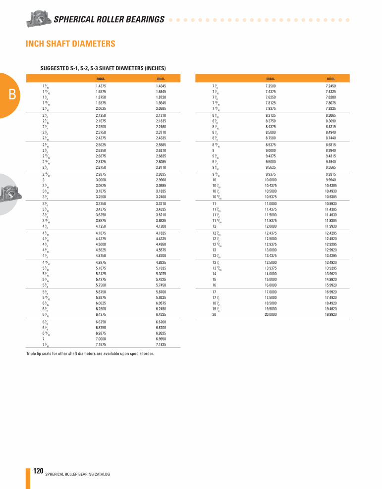
120 SPHERICAL ROLLER BEARING CATALOG
B
SPHERICAL ROLLER BEARINGS
INCH SHAFT DIAMETERS
max. min.
1 7⁄16 1.4375 1.4345 1 11⁄16 1.6875 1.6845 1 7⁄8 1.8750 1.8720 1 15⁄16 1.9375 1.9345 2 1⁄16 2.0625 2.0585
2 1⁄8 2.1250 2.1210 2 3⁄16 2.1875 2.1835 2 1⁄4 2.2500 2.2460 2 3⁄8 2.3750 2.3710 2 7⁄16 2.4375 2.4335
2 9⁄16 2.5625 2.5585 2 5⁄8 2.6250 2.6210 2 11⁄16 2.6875 2.6835 2 13⁄16 2.8125 2.8085 2 7⁄8 2.8750 2.8710
2 15⁄16 2.9375 2.9335 3 3.0000 2.9960 3 1⁄16 3.0625 3.0585 3 3⁄16 3.1875 3.1835 3 1⁄4 3.2500 3.2460
3 3⁄8 3.3750 3.3710 3 7⁄16 3.4375 3.4335 3 5⁄8 3.6250 3.6210 3 15⁄16 3.9375 3.9335 4 1⁄8 4.1250 4.1200
4 3⁄16 4.1875 4.1825 4 7⁄16 4.4375 4.4325 4 1⁄2 4.5000 4.4950 4 9⁄16 4.5625 4.5575 4 7⁄8 4.8750 4.8700
4 15⁄16 4.9375 4.9325 5 3⁄16 5.1875 5.1825 5 5⁄16 5.3125 5.3075 5 7⁄16 5.4375 5.4325 5 3⁄4 5.7500 5.7450
5 7⁄8 5.8750 5.8700 5 15⁄16 5.9375 5.9325 6 1⁄16 6.0625 6.0575 6 1⁄4 6.2500 6.2450 6 7⁄16 6.4375 6.4325
6 5⁄8 6.6250 6.6200 6 7⁄8 6.8750 6.8700 6 15⁄16 6.9375 6.9325 7 7.0000 6.9950 7 3⁄16 7.1875 7.1825
Triple lip seals for other shaft diameters are available upon special order.
max. min.
7 1⁄4 7.2500 7.2450 7 7⁄16 7.4375 7.4325 7 5⁄8 7.6250 7.6200 7 13⁄16 7.8125 7.8075 7 15⁄16 7.9375 7.9325
8 5⁄16 8.3125 8.3065 8 3⁄8 8.3750 8.3690 8 7⁄16 8.4375 8.4315 8 1⁄2 8.5000 8.4940 8 3⁄4 8.7500 8.7440
8 15⁄16 8.9375 8.9315 9 9.0000 8.9940 9 7⁄16 9.4375 9.4315 9 1⁄2 9.5000 9.4940 9 9⁄16 9.5625 9.5565
9 15⁄16 9.9375 9.9315 10 10.0000 9.9940 10 7⁄16 10.4375 10.4305 10 1⁄2 10.5000 10.4930 10 15⁄16 10.9375 10.9305
11 11.0000 10.9930 11 7⁄16 11.4375 11.4305 11 1⁄2 11.5000 11.4930 11 15⁄16 11.9375 11.9305 12 12.0000 11.9930
12 7⁄16 12.4375 12.4295 12 1⁄2 12.5000 12.4920 12 15⁄16 12.9375 12.9295 13 13.0000 12.9920 13 7⁄16 13.4375 13.4295
13 1⁄2 13.5000 13.4920 13 15⁄16 13.9375 13.9295 14 14.0000 13.9920 15 15.0000 14.9920 16 16.0000 15.9920
17 17.0000 16.9920 17 1⁄2 17.5000 17.4920 18 1⁄2 18.5000 18.4920 19 1⁄2 19.5000 19.4920 20 20.0000 19.9920
SUGGESTED S-1, S-2, S-3 SHAFT DIAMETERS (INCHES)
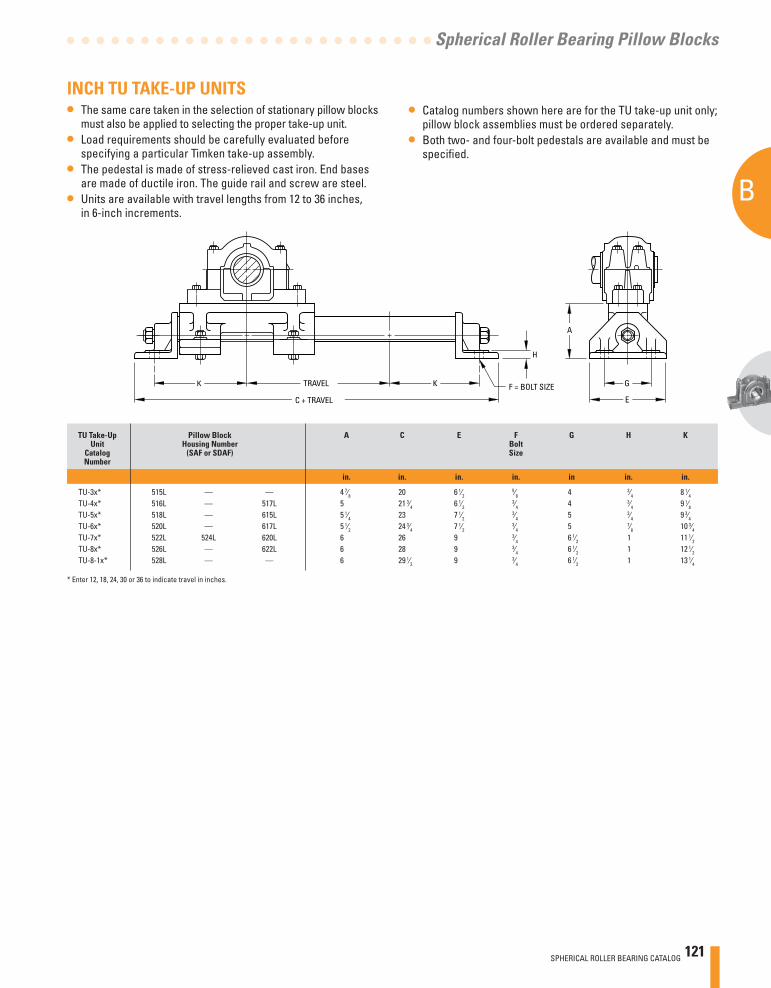
SPHERICAL ROLLER BEARING CATALOG 121
B
Spherical Roller Bearing Pillow Blocks
G
E
A
H
K TRAVEL F = BOLT SIZE
C + TRAVEL
K
INCH TU TAKE-UP UNITS• The same care taken in the selection of stationary pillow blocks
must also be applied to selecting the proper take-up unit.• Load requirements should be carefully evaluated before
specifying a particular Timken take-up assembly.• The pedestal is made of stress-relieved cast iron. End bases
are made of ductile iron. The guide rail and screw are steel.• Units are available with travel lengths from 12 to 36 inches,
in 6-inch increments.
• Catalog numbers shown here are for the TU take-up unit only; pillow block assemblies must be ordered separately.
• Both two- and four-bolt pedestals are available and must be specifi ed.
TU Take-Up Pillow Block A C E F G H K Unit Housing Number Bolt Catalog (SAF or SDAF) Size Number
in. in. in. in. in in. in.
TU-3x* 515L — — 4 7⁄8 20 6 1⁄2 5⁄8 4 3⁄4 8 1⁄4
TU-4x* 516L — 517L 5 21 3⁄4 6 1⁄2 3⁄4 4 3⁄4 9 1⁄8
TU-5x* 518L — 615L 5 1⁄4 23 7 1⁄2 3⁄4 5 3⁄4 9 3⁄4
TU-6x* 520L — 617L 5 1⁄2 24 3⁄4 7 1⁄2 3⁄4 5 7⁄8 10 3⁄4
TU-7x* 522L 524L 620L 6 26 9 3⁄4 6 1⁄2 1 11 1⁄2 TU-8x* 526L — 622L 6 28 9 3⁄4 6 1⁄2 1 12 1⁄2 TU-8-1x* 528L — — 6 29 1⁄2 9 3⁄4 6 1⁄2 1 13 1⁄4
* Enter 12, 18, 24, 30 or 36 to indicate travel in inches.
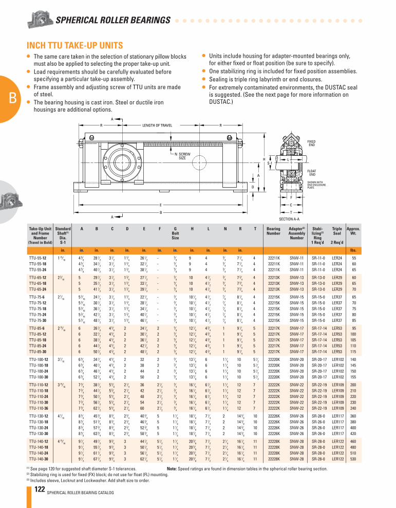
122 SPHERICAL ROLLER BEARING CATALOG
B
SPHERICAL ROLLER BEARINGS
E
B
R RLENGTH OF TRAVEL
D
A
A
A
N SCREWSIZE H
S-1L
F
C
T
FLOATEND
FIXEDEND
SHOWN WITHEND ENCLOSUREPLATE
SECTION A-A
INCH TTU TAKE-UP UNITS• The same care taken in the selection of stationary pillow blocks
must also be applied to selecting the proper take-up unit.• Load requirements should be carefully evaluated before
specifying a particular take-up assembly.• Frame assembly and adjusting screw of TTU units are made
of steel.• The bearing housing is cast iron. Steel or ductile iron
housings are additional options.
• Units include housing for adapter-mounted bearings only, for either fi xed or fl oat position (be sure to specify).
• One stabilizing ring is included for fi xed position assemblies.• Sealing is triple ring labyrinth or end closures.• For extremely contaminated environments, the DUSTAC seal
is suggested. (See the next page for more information on DUSTAC.)
Take-Up Unit Standard A B C D E F G H L N R T Bearing Adapter(3) Stabi- Triple Approx. and Frame Shaft(1) Bolt Number Assembly lizing(2) Seal Wt. Number Dia. Size Number Ring (Travel in Bold) S-1 1 Req’d 2 Req’d
in. in. in. in. in. in. in. in. in. in. in. in. lbs.
TTU-55-12 1 15⁄16 4 5⁄8 28 1⁄2 3 1⁄2 1 3⁄4 26 1⁄2 - 5⁄8 9 4 3⁄4 7 1⁄4 4 22211K SNW-11 SR-11-0 LER24 55 TTU-55-18 4 5⁄8 34 1⁄2 3 1⁄2 1 3⁄4 32 1⁄2 - 5⁄8 9 4 3⁄4 7 1⁄4 4 22211K SNW-11 SR-11-0 LER24 60 TTU-55-24 4 5⁄8 40 1⁄2 3 1⁄2 1 3⁄4 38 1⁄2 - 5⁄8 9 4 3⁄4 7 1⁄4 4 22211K SNW-11 SR-11-0 LER24 65
TTU-65-12 2 3⁄16 5 29 1⁄2 3 1⁄2 1 3⁄4 27 1⁄2 - 5⁄8 10 4 1⁄2 3⁄4 7 3⁄4 4 22213K SNW-13 SR-13-0 LER29 60
TTU-65-18 5 35 1⁄2 3 1⁄2 1 3⁄4 33 1⁄2 - 5⁄8 10 4 1⁄2 3⁄4 7 3⁄4 4 22213K SNW-13 SR-13-0 LER29 65
TTU-65-24 5 41 1⁄2 3 1⁄2 1 3⁄4 39 1⁄2 - 5⁄8 10 4 1⁄2 3⁄4 7 3⁄4 4 22213K SNW-13 SR-13-0 LER29 70
TTU-75-6 2 7⁄16 5 3⁄16 24 1⁄2 3 1⁄2 1 3⁄4 22 1⁄2 - 3⁄4 10 1⁄2 4 1⁄2 7⁄8 8 1⁄4 4 22215K SNW-15 SR-15-0 LER37 65
TTU-75-12 5 3⁄16 30 1⁄2 3 1⁄2 1 3⁄4 28 1⁄2 - 3⁄4 10 1⁄2 4 1⁄2 7⁄8 8 1⁄4 4 22215K SNW-15 SR-15-0 LER37 70
TTU-75-18 5 3⁄16 36 1⁄2 3 1⁄2 1 3⁄4 34 1⁄2 - 3⁄4 10 1⁄2 4 1⁄2 7⁄8 8 1⁄4 4 22215K SNW-15 SR-15-0 LER37 75
TTU-75-24 5 3⁄16 42 1⁄2 3 1⁄2 1 3⁄4 40 1⁄2 - 3⁄4 10 1⁄2 4 1⁄2 7⁄8 8 1⁄4 4 22215K SNW-15 SR-15-0 LER37 80
TTU-75-30 5 3⁄16 48 1⁄2 3 1⁄2 1 3⁄4 46 1⁄2 - 3⁄4 10 1⁄2 4 1⁄2 7⁄8 8 1⁄4 4 22215K SNW-15 SR-15-0 LER37 85
TTU-85-6 2 15⁄16 6 26 1⁄2 4 5⁄8 2 24 1⁄2 2 5⁄8 12 1⁄4 4 3⁄4 1 9 1⁄4 5 22217K SNW-17 SR-17-14 LER53 95 TTU-85-12 6 32 1⁄2 4 5⁄8 2 30 1⁄2 2 5⁄8 12 1⁄4 4 3⁄4 1 9 1⁄4 5 22217K SNW-17 SR-17-14 LER53 100 TTU-85-18 6 38 1⁄2 4 5⁄8 2 36 1⁄2 2 5⁄8 12 1⁄4 4 3⁄4 1 9 1⁄4 5 22217K SNW-17 SR-17-14 LER53 105 TTU-85-24 6 44 1⁄2 4 5⁄8 2 42 1⁄2 2 5⁄8 12 1⁄4 4 3⁄4 1 9 1⁄4 5 22217K SNW-17 SR-17-14 LER53 110 TTU-85-30 6 50 1⁄2 4 5⁄8 2 48 1⁄2 2 5⁄8 12 1⁄4 4 3⁄4 1 9 1⁄4 5 22217K SNW-17 SR-17-14 LER53 115
TTU-100-12 3 7⁄16 6 5⁄8 34 1⁄4 4 5⁄8 2 32 2 3⁄4 13 7⁄8 6 1 1⁄8 10 5 1⁄2 22220K SNW-20 SR-20-17 LER102 140 TTU-100-18 6 5⁄8 40 1⁄4 4 5⁄8 2 38 2 3⁄4 13 7⁄8 6 1 1⁄8 10 5 1⁄2 22220K SNW-20 SR-20-17 LER102 145 TTU-100-24 6 5⁄8 46 1⁄4 4 5⁄8 2 44 2 3⁄4 13 7⁄8 6 1 1⁄8 10 5 1⁄2 22220K SNW-20 SR-20-17 LER102 150 TTU-100-30 6 5⁄8 52 1⁄4 4 5⁄8 2 50 2 3⁄4 13 7⁄8 6 1 1⁄8 10 5 1⁄2 22220K SNW-20 SR-20-17 LER102 155
TTU-110-12 3 15⁄16 7 3⁄4 38 1⁄2 5 5⁄8 2 1⁄4 36 2 1⁄2 3⁄4 16 1⁄4 6 1⁄2 1 1⁄4 12 7 22222K SNW-22 SR-22-19 LER109 200
TTU-110-18 7 3⁄4 44 1⁄2 5 5⁄8 2 1⁄4 42 2 1⁄2 3⁄4 16 1⁄4 6 1⁄2 1 1⁄4 12 7 22222K SNW-22 SR-22-19 LER109 210
TTU-110-24 7 3⁄4 50 1⁄2 5 5⁄8 2 1⁄4 48 2 1⁄2 3⁄4 16 1⁄4 6 1⁄2 1 1⁄4 12 7 22222K SNW-22 SR-22-19 LER109 220
TTU-110-30 7 3⁄4 56 1⁄2 5 5⁄8 2 1⁄4 54 2 1⁄2 3⁄4 16 1⁄4 6 1⁄2 1 1⁄4 12 7 22222K SNW-22 SR-22-19 LER109 230
TTU-110-36 7 3⁄4 62 1⁄2 5 5⁄8 2 1⁄4 60 2 1⁄2 3⁄4 16 1⁄4 6 1⁄2 1 1⁄4 12 7 22222K SNW-22 SR-22-19 LER109 240
TTU-130-12 4 7⁄16 8 5⁄8 45 3⁄4 8 3⁄4 2 3⁄4 40 3⁄4 5 1 1⁄8 18 7⁄8 7 1⁄4 2 14 3⁄8 10 22226K SNW-26 SR-26-0 LER117 360 TTU-130-18 8 5⁄8 51 3⁄4 8 3⁄4 2 3⁄4 46 3⁄4 5 1 1⁄8 18 7⁄8 7 1⁄4 2 14 3⁄8 10 22226K SNW-26 SR-26-0 LER117 380 TTU-130-24 8 5⁄8 57 3⁄4 8 3⁄4 2 3⁄4 52 3⁄4 5 1 1⁄8 18 7⁄8 7 1⁄4 2 14 3⁄8 10 22226K SNW-26 SR-26-0 LER117 400 TTU-130-30 8 5⁄8 63 3⁄4 8 3⁄4 2 3⁄4 58 3⁄4 5 1 1⁄8 18 7⁄8 7 1⁄4 2 14 3⁄8 10 22226K SNW-26 SR-26-0 LER117 420
TTU-140-12 4 15⁄16 9 1⁄2 49 1⁄2 9 3⁄4 3 44 1⁄2 5 1⁄2 1 1⁄4 20 3⁄8 7 1⁄2 2 1⁄4 16 1⁄4 11 22228K SNW-28 SR-28-0 LER122 460 TTU-140-18 9 1⁄2 55 1⁄2 9 3⁄4 3 50 1⁄2 5 1⁄2 1 1⁄4 20 3⁄8 7 1⁄2 2 1⁄4 16 1⁄4 11 22228K SNW-28 SR-28-0 LER122 480 TTU-140-24 9 1⁄2 61 1⁄2 9 3⁄4 3 56 1⁄2 5 1⁄2 1 1⁄4 20 3⁄8 7 1⁄2 2 1⁄4 16 1⁄4 11 22228K SNW-28 SR-28-0 LER122 510 TTU-140-30 9 1⁄2 67 1⁄2 9 3⁄4 3 62 1⁄2 5 1⁄2 1 1⁄4 20 3⁄8 7 1⁄2 2 1⁄4 16 1⁄4 11 22228K SNW-28 SR-28-0 LER122 530
(1) See page 120 for suggested shaft diameter S-1 tolerances. Note: Speed ratings are found in dimension tables in the spherical roller bearing section.(2) Stabilizing ring is used for fi xed (FX) block; do not use for fl oat (FL) mounting.(3) Includes sleeve, Locknut and Lockwasher. Add shaft size to order.
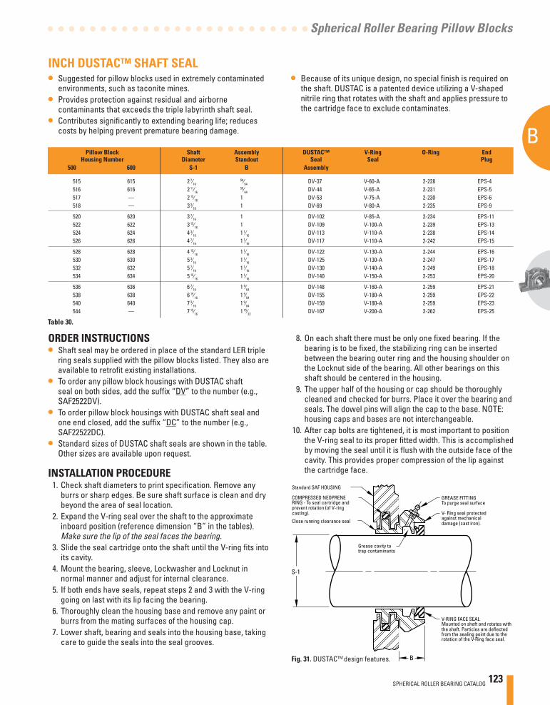
SPHERICAL ROLLER BEARING CATALOG 123
B
Spherical Roller Bearing Pillow Blocks
Standard SAF HOUSING
COMPRESSED NEOPRENE RING - To seal cartridge andprevent rotation (of V-ringcasting).
Close running clearance seal
S-1
GREASE FITTINGTo purge seal surface
V- Ring seal protectedagainst mechanicaldamage (cast iron).
Grease cavity totrap contaminants
V-RING FACE SEALMounted on shaft and rotates with the shaft. Particles are deflectedfrom the sealing point due to the rotation of the V-Ring face seal.
B
Pillow Block Shaft Assembly DUSTAC™ V-Ring O-Ring End Housing Number Diameter Standout Seal Seal Plug 500 600 S-1 B Assembly
515 615 2 7⁄16 59⁄64 DV-37 V-60-A 2-228 EPS-4
516 616 2 11⁄16 59⁄64 DV-44 V-65-A 2-231 EPS-5
517 — 2 15⁄16 1 DV-53 V-75-A 2-230 EPS-6 518 — 3 3⁄16 1 DV-69 V-80-A 2-235 EPS-9
520 620 3 7⁄16 1 DV-102 V-85-A 2-234 EPS-11 522 622 3 15⁄16 1 DV-109 V-100-A 2-239 EPS-13 524 624 4 3⁄16 1 1⁄16 DV-113 V-110-A 2-238 EPS-14 526 626 4 7⁄16 1 1⁄16 DV-117 V-110-A 2-242 EPS-15
528 628 4 15⁄16 1 1⁄16 DV-122 V-130-A 2-244 EPS-16 530 630 5 3⁄16 1 1⁄16 DV-125 V-130-A 2-247 EPS-17 532 632 5 7⁄16 1 1⁄16 DV-130 V-140-A 2-249 EPS-18 534 634 5 15⁄16 1 1⁄16 DV-140 V-150-A 2-253 EPS-20
536 636 6 7⁄16 1 9⁄64 DV-148 V-160-A 2-259 EPS-21 538 638 6 15⁄16 1 9⁄64 DV-155 V-180-A 2-259 EPS-22 540 640 7 3⁄16 1 9⁄64 DV-159 V-180-A 2-259 EPS-23 544 — 7 15⁄16 1 15⁄32 DV-167 V-200-A 2-262 EPS-25
ORDER INSTRUCTIONS• Shaft seal may be ordered in place of the standard LER triple
ring seals supplied with the pillow blocks listed. They also are available to retrofi t existing installations.
• To order any pillow block housings with DUSTAC shaft seal on both sides, add the suffi x “DV” to the number (e.g., SAF2522DV).
• To order pillow block housings with DUSTAC shaft seal and one end closed, add the suffi x “DC” to the number (e.g., SAF22522DC).
• Standard sizes of DUSTAC shaft seals are shown in the table. Other sizes are available upon request.
INSTALLATION PROCEDURE 1. Check shaft diameters to print specifi cation. Remove any
burrs or sharp edges. Be sure shaft surface is clean and dry beyond the area of seal location.
2. Expand the V-ring seal over the shaft to the approximate inboard position (reference dimension “B” in the tables). Make sure the lip of the seal faces the bearing.
3. Slide the seal cartridge onto the shaft until the V-ring fi ts into its cavity.
4. Mount the bearing, sleeve, Lockwasher and Locknut in normal manner and adjust for internal clearance.
5. If both ends have seals, repeat steps 2 and 3 with the V-ring going on last with its lip facing the bearing.
6. Thoroughly clean the housing base and remove any paint or burrs from the mating surfaces of the housing cap.
7. Lower shaft, bearing and seals into the housing base, taking care to guide the seals into the seal grooves.
INCH DUSTAC™ SHAFT SEAL• Suggested for pillow blocks used in extremely contaminated
environments, such as taconite mines. • Provides protection against residual and airborne
contaminants that exceeds the triple labyrinth shaft seal.• Contributes signifi cantly to extending bearing life; reduces
costs by helping prevent premature bearing damage.
• Because of its unique design, no special fi nish is required on the shaft. DUSTAC is a patented device utilizing a V-shaped nitrile ring that rotates with the shaft and applies pressure to the cartridge face to exclude contaminates.
8. On each shaft there must be only one fi xed bearing. If the bearing is to be fi xed, the stabilizing ring can be inserted between the bearing outer ring and the housing shoulder on the Locknut side of the bearing. All other bearings on this shaft should be centered in the housing.
9. The upper half of the housing or cap should be thoroughly cleaned and checked for burrs. Place it over the bearing and seals. The dowel pins will align the cap to the base. NOTE: housing caps and bases are not interchangeable.
10. After cap bolts are tightened, it is most important to position the V-ring seal to its proper fi tted width. This is accomplished by moving the seal until it is fl ush with the outside face of the cavity. This provides proper compression of the lip against the cartridge face.
Fig. 31. DUSTACTM design features.
Table 30.
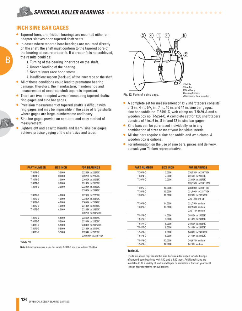
124 SPHERICAL ROLLER BEARING CATALOG
B
SPHERICAL ROLLER BEARINGS
1 Saddle2 Sine Bar3 Web Clamp4 Locking Screws5 Micrometer ( not included )
14 4 53
2
PART NUMBER SIZE INCH FOR BEARINGS
T-3071-C 3.0000 22232K to 22240K T-3071-C 3.0000 22322K to 22328K T-3071-C 3.0000 23040K to 23048K T-3071-C 3.0000 23130K to 23136K T-3071-C 3.0000 23226K to 23230K 23960K to 23972K
T-3072-C 4.0000 22248K to 22256K T-3072-C 4.0000 22330K to 22340K T-3072-C 4.0000 23052K to 23076K T-3072-C 4.0000 23138K to 23148K T-3072-C 4.0000 23232K to 23240K 23976K to 239/560K
T-3073-C 5.5000 22260K to 22264K T-3073-C 5.5000 22344K to 22356K T-3073-C 5.5000 23080K to 230/500K T-3073-C 5.5000 23152K to 23164K T-3073-C 5.5000 23244K to 23256K 239/600K to 239/710K
PART NUMBER SIZE INCH FOR BEARINGS
T-3074-C 7.0000 230/530K to 230/750K T-3074-C 7.0000 23168K to 23196K T-3074-C 7.0000 23260K to 23276K 239/750K to 239/1120K
T-3075-C 10.0000 230/800K to 230/1180 T-3075-C 10.0000 231/500K to 231/710K T-3075-C 10.0000 23280K to 232/530K 230/1250 and up
T-3076-C 14.0000 231/750K and up T-3076-C 14.0000 232/560K and up 239/118K and up
T-5476-C 4.0000 24040K to 24056K T-5476-C 4.0000 24132K to 24144K
T-5477-C 6.0000 24060K to 24084K T-5477-C 6.0000 24148K to 24160K
T-5478-C 8.0000 24089K to 240/630K T-5478-C 8.0000 24164K to 24192K
T-5479-C 12.0000 240/670K and up T-5479-C 12.0000 24196K and up
The table above represents the sine bar sizes developed for a full range of tapered bore bearings with 1:12 and a 1:30 taper. Additional sizes are available to fi t a variety of width and taper combinations. Consult your local Timken representative for availability.
INCH SINE BAR GAGES• Tapered-bore, anti-friction bearings are mounted either on
adapter sleeves or on tapered shaft seats. • In cases where tapered bore bearings are mounted directly
on the shaft, the shaft must conform to the tapered bore of the bearing to assure proper fi t. If a proper fi t is not achieved, the results could be: 1. Turning of the bearing inner race on the shaft. 2. Uneven loading of the bearing. 3. Severe inner race hoop stress. 4. Insuffi cient support (back-up) of the inner race on the shaft.
• All of these conditions could lead to premature bearing damage. Therefore, the manufacture, maintenance and measurement of accurate shaft tapers is important.
• There are two accepted ways of measuring tapered shafts: ring gages and sine bar gages.
• Precision measurement of tapered shafts is diffi cult with ring gages and may be impossible in the case of large shafts where gages are large, cumbersome and heavy.
• Sine bar gages provide an accurate and easy method of measurement.
• Lightweight and easy to handle and learn, sine bar gages achieve precise gaging of the shaft size and taper.
• A complete set for measurement of 1:12 shaft tapers consists of 3 in., 4 in., 5 1/2 in., 7 in., 10 in. and 14 in. sine bar gages, sine bar saddle no. T-5491-C, web clamp no. T-5489-A and a wooden box no. T-5224-C. A complete set for 1:30 shaft tapers consists of 4 in., 6 in., 8 in. and 12 in. sine bar gages.
• Sine bars can be purchased individually, or in any combination of sizes to meet your individual needs.
• All sine bars require a sine bar saddle and web clamp. A wooden box is optional.
• For information on the use of sine bars, prices and delivery, consult your Timken representative.
Fig. 32. Parts of a sine gage.
Table 31.
Table 32.Note: All sine bars require a sine bar saddle, T-5491-C and a web clamp T-5489-A.
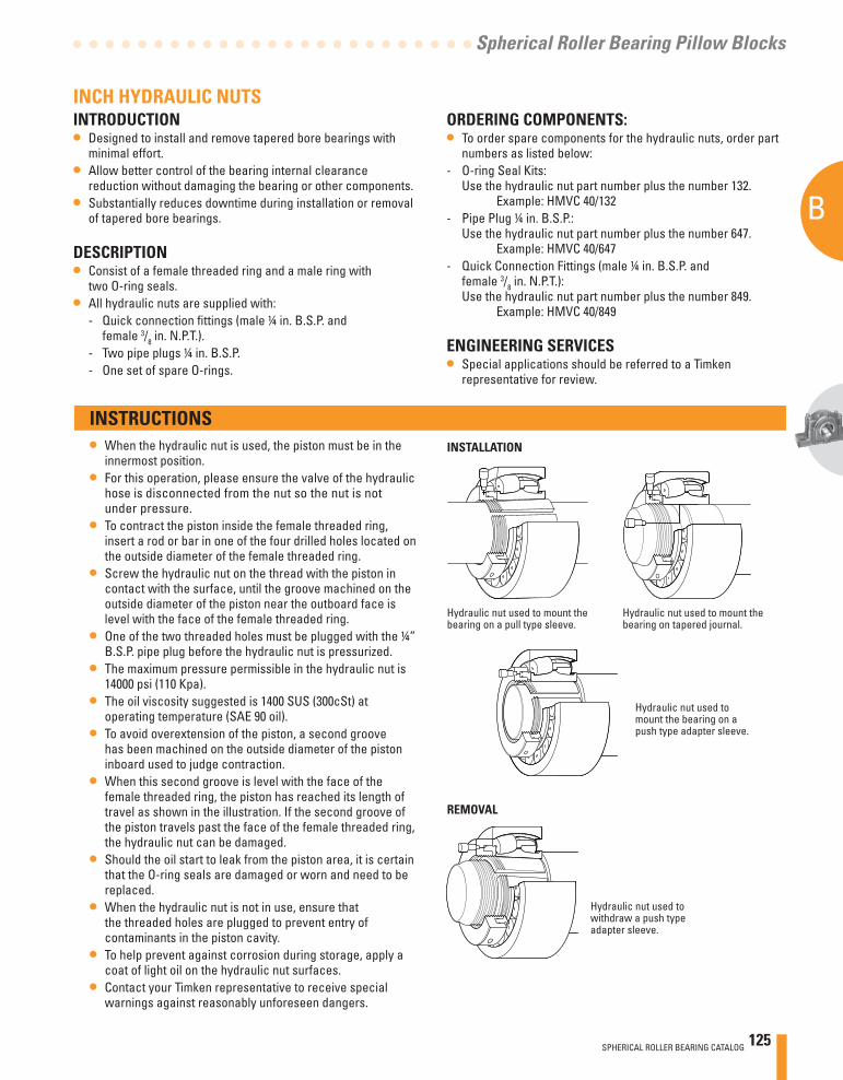
SPHERICAL ROLLER BEARING CATALOG 125
B
Spherical Roller Bearing Pillow Blocks
INSTALLATION
Hydraulic nut used to mount the bearing on a pull type sleeve.
Hydraulic nut used to mount the bearing on tapered journal.
Hydraulic nut used to mount the bearing on a push type adapter sleeve.
Hydraulic nut used to withdraw a push type adapter sleeve.
REMOVAL
INCH HYDRAULIC NUTSINTRODUCTION• Designed to install and remove tapered bore bearings with
minimal effort.• Allow better control of the bearing internal clearance
reduction without damaging the bearing or other components.• Substantially reduces downtime during installation or removal
of tapered bore bearings.
DESCRIPTION• Consist of a female threaded ring and a male ring with
two O-ring seals.• All hydraulic nuts are supplied with: - Quick connection fi ttings (male ¼ in. B.S.P. and
female 3/8 in. N.P.T.). - Two pipe plugs ¼ in. B.S.P. - One set of spare O-rings.
ORDERING COMPONENTS:• To order spare components for the hydraulic nuts, order part
numbers as listed below:- O-ring Seal Kits:
Use the hydraulic nut part number plus the number 132. Example: HMVC 40/132
- Pipe Plug ¼ in. B.S.P.:Use the hydraulic nut part number plus the number 647. Example: HMVC 40/647
- Quick Connection Fittings (male ¼ in. B.S.P. and female 3/8 in. N.P.T.): Use the hydraulic nut part number plus the number 849. Example: HMVC 40/849
ENGINEERING SERVICES• Special applications should be referred to a Timken
representative for review.
INSTRUCTIONS• When the hydraulic nut is used, the piston must be in the
innermost position.• For this operation, please ensure the valve of the hydraulic
hose is disconnected from the nut so the nut is not under pressure.
• To contract the piston inside the female threaded ring, insert a rod or bar in one of the four drilled holes located on the outside diameter of the female threaded ring.
• Screw the hydraulic nut on the thread with the piston in contact with the surface, until the groove machined on the outside diameter of the piston near the outboard face is level with the face of the female threaded ring.
• One of the two threaded holes must be plugged with the ¼” B.S.P. pipe plug before the hydraulic nut is pressurized.
• The maximum pressure permissible in the hydraulic nut is 14000 psi (110 Kpa).
• The oil viscosity suggested is 1400 SUS (300cSt) at operating temperature (SAE 90 oil).
• To avoid overextension of the piston, a second groove has been machined on the outside diameter of the piston inboard used to judge contraction.
• When this second groove is level with the face of the female threaded ring, the piston has reached its length of travel as shown in the illustration. If the second groove of the piston travels past the face of the female threaded ring, the hydraulic nut can be damaged.
• Should the oil start to leak from the piston area, it is certain that the O-ring seals are damaged or worn and need to be replaced.
• When the hydraulic nut is not in use, ensure that the threaded holes are plugged to prevent entry of contaminants in the piston cavity.
• To help prevent against corrosion during storage, apply a coat of light oil on the hydraulic nut surfaces.
• Contact your Timken representative to receive special warnings against reasonably unforeseen dangers.
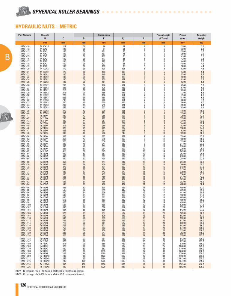
126 SPHERICAL ROLLER BEARING CATALOG
B
SPHERICAL ROLLER BEARINGS
Part Number Threads Dimensions Piston Length Piston Assembly B C D E E1 A of Travel Area Weight
mm mm mm mm mm mm mm mm2 kg.
HMV - 10 M 50X1.5 114 38 86 51 4 5 2900 2.5 HMV - 12 M 60X2 125 38 94 61 5 5 3200 2.8 HMV - 13 M 65X2 135 38 101 66 5 5 3500 3.0 HMV - 14 M 70X2 140 38 107 71 5 5 3900 3.3 HMV - 15 M 75X2 145 38 112 76 5 5 4100 3.5 HMV - 16 M 80X2 150 38 117 81 5 5 4200 3.8 HMV - 17 M 85X2 155 38 122 86 5 5 4400 3.9 HMV - 18 M 90X2 160 38 127 91 5 5 4800 4.1 HMV - 19 M 95X2 165 38 133 96 5 5 5000 4.4 HMV - 20 M 100X2 170 38 138 101 6 5 5200 4.5 HMV - 21 M 105X2 175 38 143 106 6 5 5400 5.4 HMV - 22 M 110X2 180 38 149 111 6 5 5700 5.7 HMV - 23 M 115X2 185 38 154 116 6 5 5900 5.1 HMV - 24 M 120X2 190 38 159 121 6 5 6100 5.3 HMV - 25 M 125X2 195 38 164 126 6 5 6300 5.4 HMV - 26 M 130X2 200 38 170 131 6 5 6500 5.7 HMV - 27 M 135X2 205 38 175 136 6 5 6700 5.9 HMV - 28 M 140X2 210 38 180 141 7 5 6900 6.1 HMV - 29 M 145X2 215 39 186 146 7 5 7300 6.5 HMV - 30 M 150X2 220 39 190 151 7 5 7500 6.6 HMV - 31 M 155X3 225 39 198 156 7 5 8100 6.9 HMV - 32 M 160X3 235 40 206 161 7 6 8600 7.7 HMV - 33 M 165X3 240 40 209 166 7 6 9000 8.0 HMV - 34 M 170X3 245 41 215 171 7 6 9500 8.4 HMV - 36 M 180X3 255 41 227 181 7 6 10300 9.1 HMV - 38 M 190X3 270 42 239 191 8 7 11500 10.8 HMV - 40 M 200X3 280 43 251 201 8 8 12500 11.4 HMV - 41 Tr 205X4 290 43 256 207 8 8 12900 12.2 HMV - 42 Tr 210X4 295 44 262 212 8 9 13500 12.5 HMV - 43 Tr 215X4 300 44 267 217 8 9 13800 13.0 HMV - 44 Tr 220X4 305 44 273 222 8 9 14400 13.4 HMV - 45 Tr 225X4 315 45 280 227 8 9 15200 14.6 HMV - 46 Tr 230X4 320 45 285 232 8 9 15600 14.8 HMV - 47 Tr 235X4 325 46 291 237 8 10 16200 16.0 HMV - 48 Tr 240X4 330 46 296 242 9 10 16500 16.3 HMV - 50 Tr 250X4 345 46 307 252 9 10 17800 17.6 HMV - 52 Tr 260X4 355 47 319 262 9 11 18800 19.0 HMV - 54 Tr 270X4 370 48 330 272 9 12 19700 20.4 HMV - 56 Tr 280X4 380 49 341 282 9 12 21100 22.0 HMV - 58 Tr 290X4 390 49 353 292 9 13 22600 22.5 HMV - 60 Tr 300X4 405 51 364 302 10 14 23600 25.6 HMV - 62 Tr 310X5 415 52 375 312 10 14 24900 27.0 HMV - 64 Tr 320X5 430 53 387 322 10 14 26300 29.6 HMV - 66 Tr 330X5 440 53 397 332 10 14 27000 31.0 HMV - 68 Tr 340X5 450 53 408 342 10 14 28400 32.5 HMV - 69 Tr 345X5 455 54 414 347 10 14 29400 33.6 HMV - 70 Tr 350X5 465 56 420 352 10 14 30000 35.0 HMV - 72 Tr 360X5 475 56 431 362 10 15 31300 37.0 HMV - 73 Tr 365X5 482 57 436 367 11 15 31700 38.5 HMV - 74 Tr 370X5 490 57 442 372 11 16 32800 39.2 HMV - 76 Tr 380X5 500 58 452 382 11 16 33600 41.0 HMV - 77 Tr 385X5 505 58 459 387 11 16 34700 42.0 HMV - 80 Tr 400X5 525 60 475 402 11 17 36700 46.0 HMV - 82 Tr 410X5 535 61 486 412 11 17 38300 48.2 HMV - 84 Tr 420X5 545 61 498 422 11 17 40000 50.4 HMV - 86 Tr 430X5 555 62 508 432 11 17 40800 53.0 HMV - 88 Tr 440X5 565 62 519 442 12 17 42500 55.0 HMV - 90 Tr 450X5 580 64 530 452 12 17 44100 58.2 HMV - 92 Tr 460X5 590 64 541 462 12 17 45000 61.0 HMV - 94 Tr 470X5 600 65 552 472 12 18 46900 63.7 HMV - 96 Tr 480X5 612 65 563 482 12 19 48500 65.0 HMV - 98 Tr 490X5 625 66 573 492 12 19 49800 69.0 HMV - 100 Tr 500X5 635 67 585 502 12 19 52000 71.5 HMV - 102 Tr 510X6 645 68 596 512 12 20 53300 75.0 HMV - 104 Tr 520X6 657 68 606 522 13 20 54200 77.0 HMV - 106 Tr 530X6 670 69 617 532 13 21 56200 80.0 HMV - 108 Tr 540X6 680 69 629 542 13 21 58200 83.0 HMV - 110 Tr 550X6 692 70 639 552 13 21 59200 86.0 HMV - 112 Tr 560X6 705 71 650 562 13 22 61200 90.0 HMV - 114 Tr 570X6 715 72 661 572 13 23 63200 93.0 HMV - 116 Tr 580X6 725 72 671 582 13 23 64200 96.0 HMV - 120 Tr 600X6 750 73 693 602 13 23 67400 100.0 HMV - 126 Tr 630X6 780 74 726 632 14 23 72900 110.0 HMV - 130 Tr 650X6 805 75 747 652 14 23 76200 116.0 HMV - 134 Tr 670X6 825 76 768 672 14 24 79500 123.0 HMV - 138 Tr 690X6 850 77 791 692 14 25 84200 130.0 HMV - 142 Tr 710X7 870 78 812 712 15 25 87700 137.0 HMV - 150 Tr 750X7 915 79 855 752 15 25 97000 150.0 HMV - 160 Tr 800X7 970 80 908 802 16 25 104000 173.0 HMV - 170 Tr 850X7 1020 83 962 852 16 26 114600 190.0 HMV - 180 Tr 900X7 1070 86 1015 902 17 30 124000 210.0 HMV - 190 Tr 950X8 1125 86 1069 952 17 30 135600 238.0 HMV - 200 Tr 1000X8 1180 88 1122 1002 17 34 145600 263.0 HMV - 212 Tr 1060X8 1255 95 1184 1063 18 34 161200 325.0 HMV - 216 Tr 1080X8 1280 100 1206 1083 18 34 167400 345.0 HMV - 224 Tr 1120X8 1340 106 1250 1123 19 36 178200 410.0 HMV - 236 Tr 1180X8 1420 115 1320 1183 22 40 189200 530.0
HMV - 10 through HMV - 40 have a Metric ISO fi ne thread profi le.HMV - 41 through HMV-236 have a Metric ISO trapezoidal thread.
HYDRAULIC NUTS – METRIC
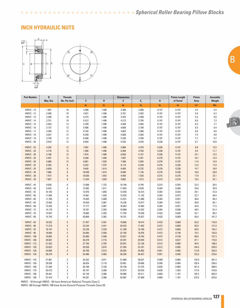
SPHERICAL ROLLER BEARING CATALOG 127
B
Spherical Roller Bearing Pillow Blocks
INCH HYDRAULIC NUTS
Part Number B Threads Dimensions Piston Length Piston Assembly Maj. Dia. No. Per Inch C D E E1 A of Travel Area Weight
in. in. in. in. in. in. in.2 lbs.
HMVC - 10 1.967 18 4.488 1.496 3.386 2.008 0.157 0.197 4.5 5.5 HMVC - 12 2.360 18 4.921 1.496 3.701 2.402 0.197 0.197 5.0 6.2 HMVC - 13 2.548 18 5.315 1.496 3.976 2.598 0.197 0.197 5.4 6.6 HMVC - 14 2.751 18 5.512 1.496 4.213 2.795 0.197 0.197 6.0 7.3 HMVC - 15 2.933 12 5.709 1.496 4.409 2.992 0.197 0.197 6.3 7.7 HMVC - 16 3.137 12 5.906 1.496 4.606 3.189 0.197 0.197 6.5 8.4 HMVC - 17 3.340 12 6.102 1.496 4.803 3.386 0.197 0.197 6.8 8.6 HMVC - 18 3.527 12 6.299 1.496 5.000 3.583 0.197 0.197 7.4 9.0 HMVC - 19 3.730 12 6.496 1.496 5.236 3.780 0.197 0.197 7.7 9.7 HMVC - 20 3.918 12 6.693 1.496 5.433 3.976 0.236 0.197 8.1 10.0
HMVC - 22 4.325 12 7.087 1.496 5.866 4.370 0.236 0.197 8.8 12.5 HMVC - 24 4.716 12 7.480 1.496 6.260 4.764 0.236 0.197 9.5 11.7 HMVC - 26 5.106 12 7.874 1.496 6.693 5.157 0.236 0.197 10.1 12.5 HMVC - 28 5.497 12 8.268 1.496 7.087 5.551 0.276 0.197 10.7 13.4 HMVC - 30 5.888 12 8.661 1.535 7.480 5.945 0.276 0.197 11.6 14.5 HMVC - 32 6.284 8 9.252 1.575 8.110 6.339 0.276 0.236 13.3 17.0 HMVC - 34 6.659 8 9.645 1.614 8.465 6.732 0.276 0.236 14.7 18.5 HMVC - 36 7.066 8 10.039 1.615 8.858 7.126 0.276 0.236 16.0 20.0 HMVC - 38 7.472 8 10.630 1.653 9.409 7.520 0.315 0.276 17.8 23.1 HMVC - 40 7.847 8 11.024 1.693 9.882 7.913 0.315 0.276 19.4 25.1
HMVC - 44 8.628 8 12.008 1.732 10.748 8.740 0.315 0.354 22.3 29.5 HMVC - 48 9.442 6 12.992 1.811 11.654 9.528 0.354 0.394 25.6 35.9 HMVC - 52 10.192 6 13.976 1.850 12.559 10.315 0.354 0.433 29.1 41.8 HMVC - 56 11.004 6 14.961 1.929 13.425 11.102 0.354 0.472 32.7 48.4 HMVC - 60 11.785 6 15.945 2.008 14.331 11.890 0.394 0.551 36.6 56.3 HMVC - 64 12.562 6 16.929 2.087 15.236 12.677 0.394 0.551 40.8 65.1 HMVC - 68 13.334 5 17.717 2.087 16.063 13.465 0.394 0.551 44.0 71.5 HMVC - 72 14.170 5 18.701 2.205 16.969 14.252 0.394 0.590 48.5 81.4 HMVC - 76 14.957 5 19.685 2.283 17.795 15.039 0.433 0.630 52.1 90.2 HMVC - 80 15.745 5 20.669 2.362 18.701 15.827 0.433 0.669 56.9 101.2
HMVC - 84 16.532 5 21.457 2.401 19.606 16.614 0.433 0.669 62.0 110.9 HMVC - 88 17.319 5 22.244 2.441 20.433 17.402 0.472 0.669 65.9 121.0 HMVC - 92 18.107 5 23.228 2.520 21.299 18.189 0.472 0.669 69.8 134.2 HMVC - 96 18.894 5 24.094 2.559 22.165 18.976 0.472 0.748 75.2 143.0 HMVC - 100 19.682 5 25.000 2.598 23.031 19.764 0.472 0.748 80.6 157.3 HMVC - 106 20.867 4 26.378 2.716 24.291 20.945 0.512 0.827 87.1 176.0 HMVC - 112 21.923 4 27.756 2.795 25.591 22.126 0.512 0.866 94.9 198.0 HMVC - 120 23.623 4 29.528 2.874 27.283 23.701 0.512 0.905 104.5 220.0 HMVC - 126 24.804 4 30.709 2.913 28.583 24.882 0.551 0.905 113.0 242.0 HMVC - 134 26.379 4 32.480 2.992 30.236 26.457 0.551 0.945 123.2 270.6
HMVC - 142 27.961 3 34.252 3.071 31.969 28.031 0.590 0.984 135.9 301.4 HMVC - 150 29.536 3 36.024 3.110 33.661 29.606 0.590 0.984 150.4 330.0 HMVC - 160 31.504 3 38.189 3.150 35.748 31.575 0.630 0.984 161.2 380.6 HMVC - 170 33.473 3 40.157 3.268 37.874 33.543 0.630 1.024 177.6 418.0 HMVC - 180 35.441 3 42.126 3.386 39.960 35.511 0.669 1.181 192.2 462.0 HMVC - 190 37.410 3 44.291 3.386 42.087 37.480 0.669 1.181 210.2 523.6
HMVC - 10 through HMVC - 64 have American National Threads Class 3.HMVC -68 through HMVC-190 have Acme General Purpose Threads Class 3G.
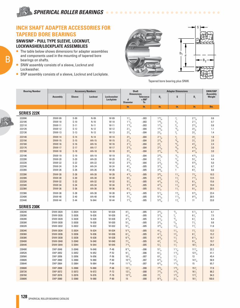
128 SPHERICAL ROLLER BEARING CATALOG
B
SPHERICAL ROLLER BEARINGS
Bearing Number Accessory Numbers Shaft Adapter Dimensions SNW/SNP Dimensions Assembly Assembly Sleeve Locknut Lockwasher Tolerance B2 S D1 Weight Lockplate d +.000" Diameter To
in. in. in. in. in. lbs.
SERIES 222K22209K SNW-09 S-09 N-09 W-09 1 7⁄16 -.003 1 37⁄64
1⁄2 2 17⁄32 0.622210K SNW-10 S-10 N-10 W-10 1 11⁄16 -.003 1 49⁄64
9⁄16 2 11⁄16 0.722211K SNW-11 S-11 N-11 W-11 1 15⁄16 -.003 1 27⁄32
9⁄16 2 31⁄32 0.822212K SNW-12 S-12 N-12 W-12 2 1⁄16 -.004 1 63⁄64
19⁄32 3 5⁄32 1.122213K SNW-13 S-13 N-13 W-13 2 3⁄16 -.004 2 3⁄32
5⁄8 3 3⁄8 1.4
22214K SNW-14 S-14 N-14 W-14 2 5⁄16 -.004 2 11⁄64 5⁄8 3 5⁄8 1.8
22215K SNW-15 S-15 AN-15 W-15 2 7⁄16 -.004 2 19⁄64 43⁄64 3 7⁄8 2.0
22216K SNW-16 S-16 AN-16 W-16 2 11⁄16 -.004 2 3⁄8 43⁄64 4 5⁄32 2.4
22217K SNW-17 S-17 AN-17 W-17 2 15⁄16 -.004 2 31⁄64 45⁄64 4 13⁄32 3.0
22218K SNW-18 S-18 AN-18 W-18 3 3⁄16 -.004 2 41⁄64 25⁄32 4 21⁄32 3.0
22219K SNW-19 S-19 AN-19 W-19 3 5⁄16 -.004 2 49⁄64 13⁄16 4 15⁄16 3.3
22220K SNW-20 S-20 AN-20 W-20 3 7⁄16 -.004 2 7⁄8 27⁄32 5 3⁄16 4.4
22222K SNW-22 S-22 AN-22 W-22 3 15⁄16 -.004 3 13⁄64 29⁄32 5 23⁄32 5.0
22224K SNW-24 S-24 AN-24 W-24 4 3⁄16 -.005 3 15⁄32 15⁄16 6 1⁄8 6.7
22226K SNW-26 S-26 AN-26 W-26 4 7⁄16 -.005 3 49⁄64 1 6 3⁄4 8.6
22228K SNW-28 S-28 AN-28 W-28 4 15⁄16 -.005 3 63⁄64 1 1⁄16 7 3⁄32 10.322230K SNW-30 S-30 AN-30 W-30 5 3⁄16 -.005 4 15⁄64 1 1⁄8 7 11⁄16 13.522232K SNW-32 S-32 AN-32 W-32 5 7⁄16 -.005 4 37⁄64 1 3⁄16 8 1⁄16 15.622234K SNW-34 S-34 AN-34 W-34 5 15⁄16 -.005 4 27⁄32 1 7⁄32 8 21⁄32 19.422236K SNW-36 S-36 AN-36 W-36 6 7⁄16 -.005 5 1⁄32 1 1⁄4 9 1⁄16 20.5
22238K SNW-38 S-38 AN-38 W-38 6 15⁄16 -.005 5 17⁄64 1 9⁄32 9 15⁄32 23.422240K SNW-40 S-40 AN-40 W-40 7 3⁄16 -.005 5 31⁄64 1 11⁄32 9 27⁄32 30.522244K SNW-44 S-44 N-044 W-44 7 15⁄16 -.005 5 29⁄32 1 3⁄8 11 33.0
SERIES 230K23024K SNW-3024 S-3024 N-024 W-024 4 3⁄16 -.005 2 61⁄64
13⁄16 5 11⁄16 6.123026K SNW-3026 S-3026 N-026 W-026 4 7⁄16 -.005 3 15⁄64
7⁄8 6 1⁄8 7.523028K SNW-3028 S-3028 N-028 W-028 4 15⁄16 -.005 3 11⁄32
15⁄16 6 1⁄2 8.423030K SNW-3030 S-3030 N-030 W-030 5 3⁄16 -.005 3 31⁄64
31⁄32 7 1⁄8 9.823032K SNW-3032 S-3032 N-032 W-032 5 7⁄16 -.005 3 23⁄32 1 1⁄32 7 1⁄2 11.8
23034K SNW-3034 S-3034 N-034 W-034 5 15⁄16 -.005 4 1⁄64 1 1⁄16 7 7⁄8 13.323036K SNW-3036 S-3036 N-036 W-036 6 7⁄16 -.005 4 11⁄32 1 3⁄32 8 1⁄4 15.223038K SNW-3038 S-3038 N-038 W-038 6 15⁄16 -.005 4 13⁄32 1 1⁄8 8 11⁄16 16.723040K SNW-3040 S-3040 N-040 W-040 7 3⁄16 -.005 4 3⁄4 1 3⁄16 9 7⁄16 19.723044K SNW-3044 S-3044 N-044 W-044 7 15⁄16 -.005 5 1⁄8 1 1⁄4 10 1⁄4 24.4
23048K SNP-3048 S-3048 N-048 P-48 8 15⁄16 -.006 5 7⁄16 1 11⁄32 11 7⁄16 32.223052K SNP-3052 S-3052 N-052 P-52 9 7⁄16 -.006 6 1⁄64 1 13⁄32 12 3⁄16 41.123056K SNP-3056 S-3056 N-056 P-56 10 7⁄16 -.007 6 3⁄16 1 1⁄2 13 45.423060K SNP-3060 S-3060 N-060 P-60 10 15⁄16 -.007 6 47⁄64 1 9⁄16 14 3⁄16 58.923064K SNP-3064 S-3064 N-064 P-64 11 15⁄16 -.007 6 61⁄64 1 21⁄32 15 65.7
23068K SNP-3068 S-3068 N-068 P-68 12 7⁄16 -.008 7 35⁄64 1 25⁄32 15 3⁄4 77.823072K SNP-3072 S-3072 N-072 P-72 13 7⁄16 -.008 7 37⁄64 1 25⁄32 16 1⁄2 86.223076K SNP-3076 S-3076 N-076 P-76 13 15⁄16 -.008 7 3⁄4 1 57⁄64 17 3⁄4 94.323080K SNP-3080 S-3080 N-080 P-80 15 -.008 8 13⁄32 2 1⁄16 18 1⁄2 100.0
INCH SHAFT ADAPTER ACCESSORIES FOR TAPERED BORE BEARINGSSNW⁄SNP - PULL TYPE SLEEVE, LOCKNUT, LOCKWASHER/LOCKPLATE ASSEMBLIES• The table below shows dimensions for adapter assemblies
and components used in the mounting of tapered bore bearings on shafts.
• SNW assembly consists of a sleeve, Locknut and Lockwasher.
• SNP assembly consists of a sleeve, Locknut and Lockplate.
Tapered bore bearing plus SNW.
dD1
S
B2
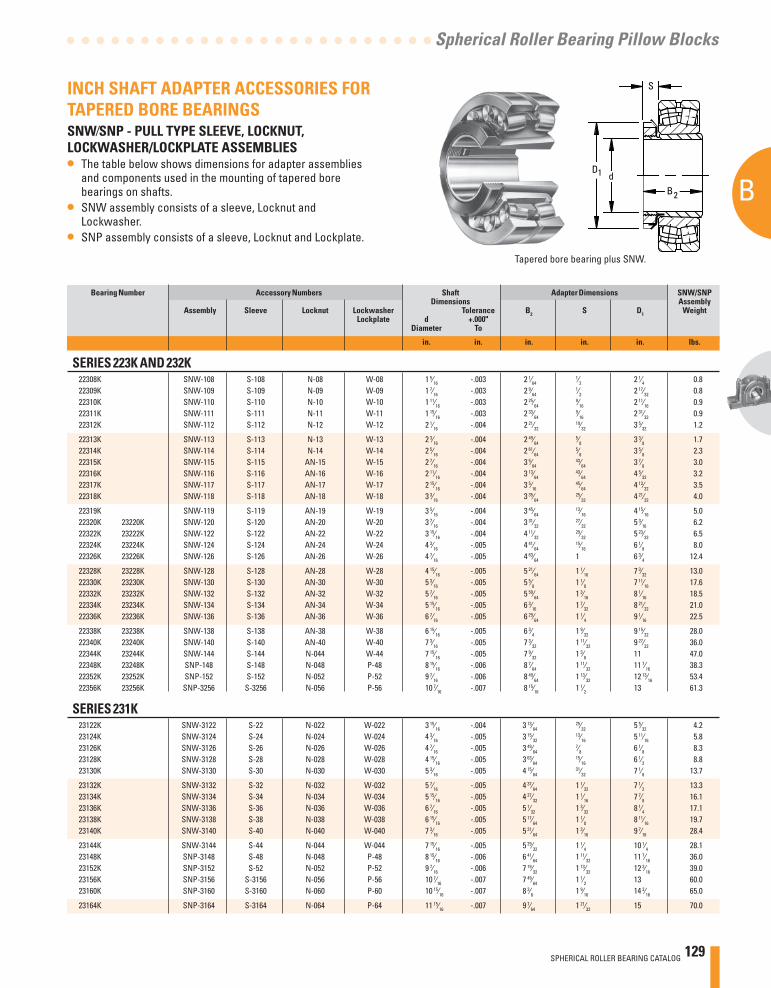
SPHERICAL ROLLER BEARING CATALOG 129
B
Spherical Roller Bearing Pillow Blocks
Bearing Number Accessory Numbers Shaft Adapter Dimensions SNW/SNP Dimensions Assembly Assembly Sleeve Locknut Lockwasher Tolerance B2 S D1 Weight Lockplate d +.000" Diameter To
in. in. in. in. in. lbs.
SERIES 223K AND 232K22308K SNW-108 S-108 N-08 W-08 1 5⁄16 -.003 2 1⁄64
1⁄2 2 1⁄4 0.822309K SNW-109 S-109 N-09 W-09 1 7⁄16 -.003 2 9⁄64
1⁄2 2 17⁄32 0.822310K SNW-110 S-110 N-10 W-10 1 11⁄16 -.003 2 25⁄64
9⁄16 2 11⁄16 0.922311K SNW-111 S-111 N-11 W-11 1 15⁄16 -.003 2 33⁄64
9⁄16 2 31⁄32 0.922312K SNW-112 S-112 N-12 W-12 2 1⁄16 -.004 2 21⁄32
19⁄32 3 5⁄32 1.2
22313K SNW-113 S-113 N-13 W-13 2 3⁄16 -.004 2 49⁄64 5⁄8 3 3⁄8 1.7
22314K SNW-114 S-114 N-14 W-14 2 5⁄16 -.004 2 61⁄64 5⁄8 3 5⁄8 2.3
22315K SNW-115 S-115 AN-15 W-15 2 7⁄16 -.004 3 5⁄64 43⁄64 3 7⁄8 3.0
22316K SNW-116 S-116 AN-16 W-16 2 11⁄16 -.004 3 13⁄64 43⁄64 4 5⁄32 3.2
22317K SNW-117 S-117 AN-17 W-17 2 15⁄16 -.004 3 5⁄16 45⁄64 4 13⁄32 3.5
22318K SNW-118 S-118 AN-18 W-18 3 3⁄16 -.004 3 35⁄64 25⁄32 4 21⁄32 4.0
22319K SNW-119 S-119 AN-19 W-19 3 5⁄16 -.004 3 45⁄64 13⁄16 4 15⁄16 5.0
22320K 23220K SNW-120 S-120 AN-20 W-20 3 7⁄16 -.004 3 31⁄32 27⁄32 5 3⁄16 6.2
22322K 23222K SNW-122 S-122 AN-22 W-22 3 15⁄16 -.004 4 11⁄32 29⁄32 5 23⁄32 6.5
22324K 23224K SNW-124 S-124 AN-24 W-24 4 3⁄16 -.005 4 41⁄64 15⁄16 6 1⁄8 8.0
22326K 23226K SNW-126 S-126 AN-26 W-26 4 7⁄16 -.005 4 63⁄64 1 6 3⁄4 12.4
22328K 23228K SNW-128 S-128 AN-28 W-28 4 15⁄16 -.005 5 21⁄64 1 1⁄16 7 3⁄32 13.022330K 23230K SNW-130 S-130 AN-30 W-30 5 3⁄16 -.005 5 5⁄8 1 1⁄8 7 11⁄16 17.622332K 23232K SNW-132 S-132 AN-32 W-32 5 7⁄16 -.005 5 59⁄64 1 3⁄16 8 1⁄16 18.522334K 23234K SNW-134 S-134 AN-34 W-34 5 15⁄16 -.005 6 3⁄16 1 7⁄32 8 21⁄32 21.022336K 23236K SNW-136 S-136 AN-36 W-36 6 7⁄16 -.005 6 29⁄64 1 1⁄4 9 1⁄16 22.5
22338K 23238K SNW-138 S-138 AN-38 W-38 6 15⁄16 -.005 6 3⁄4 1 9⁄32 9 15⁄32 28.022340K 23240K SNW-140 S-140 AN-40 W-40 7 3⁄16 -.005 7 3⁄32 1 11⁄32 9 27⁄32 36.022344K 23244K SNW-144 S-144 N-044 W-44 7 15⁄16 -.005 7 9⁄32 1 3⁄8 11 47.022348K 23248K SNP-148 S-148 N-048 P-48 8 15⁄16 -.006 8 7⁄64 1 11⁄32 11 7⁄16 38.322352K 23252K SNP-152 S-152 N-052 P-52 9 7⁄16 -.006 8 49⁄64 1 13⁄32 12 13⁄16 53.422356K 23256K SNP-3256 S-3256 N-056 P-56 10 7⁄16 -.007 8 15⁄16 1 1⁄2 13 61.3
SERIES 231K23122K SNW-3122 S-22 N-022 W-022 3 15⁄16 -.004 3 13⁄64
25⁄32 5 5⁄32 4.223124K SNW-3124 S-24 N-024 W-024 4 3⁄16 -.005 3 15⁄32
13⁄16 5 11⁄16 5.823126K SNW-3126 S-26 N-026 W-026 4 7⁄16 -.005 3 49⁄64
7⁄8 6 1⁄8 8.323128K SNW-3128 S-28 N-028 W-028 4 15⁄16 -.005 3 63⁄64
15⁄16 6 1⁄2 8.823130K SNW-3130 S-30 N-030 W-030 5 3⁄16 -.005 4 15⁄64
31⁄32 7 1⁄8 13.7
23132K SNW-3132 S-32 N-032 W-032 5 7⁄16 -.005 4 37⁄64 1 1⁄32 7 1⁄2 13.323134K SNW-3134 S-34 N-034 W-034 5 15⁄16 -.005 4 27⁄32 1 1⁄16 7 7⁄8 16.123136K SNW-3136 S-36 N-036 W-036 6 7⁄16 -.005 5 1⁄32 1 3⁄32 8 1⁄4 17.123138K SNW-3138 S-38 N-038 W-038 6 15⁄16 -.005 5 17⁄64 1 1⁄8 8 11⁄16 19.723140K SNW-3140 S-40 N-040 W-040 7 3⁄16 -.005 5 31⁄64 1 3⁄16 9 7⁄16 28.4
23144K SNW-3144 S-44 N-044 W-044 7 15⁄16 -.005 5 29⁄32 1 1⁄4 10 1⁄4 28.123148K SNP-3148 S-48 N-048 P-48 8 15⁄16 -.006 6 41⁄64 1 11⁄32 11 7⁄16 36.023152K SNP-3152 S-52 N-052 P-52 9 7⁄16 -.006 7 19⁄32 1 13⁄32 12 3⁄16 39.023156K SNP-3156 S-3156 N-056 P-56 10 7⁄16 -.007 7 49⁄64 1 1⁄2 13 60.023160K SNP-3160 S-3160 N-060 P-60 10 15⁄16 -.007 8 3⁄8 1 9⁄16 14 3⁄16 65.0
23164K SNP-3164 S-3164 N-064 P-64 11 15⁄16 -.007 9 7⁄64 1 21⁄32 15 70.0
INCH SHAFT ADAPTER ACCESSORIES FOR TAPERED BORE BEARINGSSNW⁄SNP - PULL TYPE SLEEVE, LOCKNUT, LOCKWASHER/LOCKPLATE ASSEMBLIES• The table below shows dimensions for adapter assemblies
and components used in the mounting of tapered bore bearings on shafts.
• SNW assembly consists of a sleeve, Locknut and Lockwasher.
• SNP assembly consists of a sleeve, Locknut and Lockplate.
Tapered bore bearing plus SNW.
dD1
S
B2
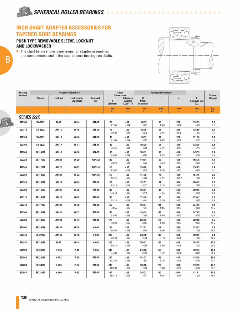
130 SPHERICAL ROLLER BEARING CATALOG
B
SPHERICAL ROLLER BEARINGS
SERIES 222K22216K SK-8022 N-14 W-14 AN-18 70 –.10 88.19 50 3.50 118.39 0.5 2.7559 –.004 3.472 1.969 0.138 4.661 1.2
22217K SK-8522 AN-15 W-15 AN-19 75 –.10 93.35 52 3.50 125.55 0.6 2.9528 –.004 3.675 2.047 0.138 4.943 1.4
22218K SK-9022 AN-16 W-16 AN-20 80 –.10 98.12 53 3.50 131.90 0.6 3.1496 –.004 3.863 2.087 0.138 5.193 1.5
22219K SK-9522 AN-17 W-17 AN-21 85 –.10 103.28 57 4.00 138.25 0.8 3.3465 –.004 4.066 2.244 0.157 5.443 1.8
22220K SK-10022 AN-18 W-18 AN-22 90 –.10 109.12 59 4.00 145.39 0.9 3.5433 –.004 4.269 2.323 0.157 5.724 2.0
22222K SK-11022 AN-20 W-20 ARN-22 100 –.10 119.94 65 4.00 158.75 1.1 3.9370 –.004 4.722 2.559 0.157 6.250 2.4
22224K SK-12022 AN-22 W-22 ARN-24 110 –.13 130.28 72 4.00 174.63 1.4 4.3307 –.005 5.129 2.835 0.157 6.875 3.1
22226K SK-13022 AN-22 W-22 ARN-26 115 –.13 141.38 78 4.00 184.15 2.2 4.5276 –.005 5.566 3.071 0.15.7 7.250 5.0
22228K SK-14022 AN-24 W-24 RN-28 125 –.13 152.73 82 5.00 200.03 2.6 4.9213 –.005 6.013 3.228 0.197 7.875 5.8
22230K SK-15022 AN-26 W-26 RN-30 135 –.13 163.04 88 5.00 209.55 3.0 5.3150 –.005 6.419 3.465 0.197 8.250 6.8
22232K SK-16022 AN-28 W-28 RN-32 140 –.13 173.76 96 5.00 225.43 4.5 5.5118 –.005 6.841 3.780 0.197 8.875 9.9
22234K SK-17022 AN-30 W-30 RN-34 150 –.13 184.07 104 5.00 234.95 5.2 5.9055 –.005 7.247 4.095 0.197 9.250 11.5
22236K SK-18022 AN-32 W-32 RN-36 160 –.13 194.79 104 5.00 247.65 5.6 6.2992 –.005 7.669 4.095 0.197 9.750 12.5
22238K SK-19022 AN-34 W-34 RN-38 170 –.13 205.92 112 5.00 269.88 6.5 6.6929 –.005 8.107 4.409 0.197 10.625 14.5
22240K SK-20022 AN-36 W-36 N-044 180 –.13 217.02 118 5.00 279.53 7.4 7.0866 –.005 8.544 4.646 0.197 11.005 16.3
22244K SK-22022 AN-40 W-40 N-048 200 –.13 236.98 130 6.00 290.65 8.8 7.8740 –.005 9.330 5.118 0.236 11.443 19.6
22248K SK-24022 N-44 W-44 N-052 220 –.15 256.03 144 6.00 309.70 11.0 8.6614 –.006 10.080 5.669 0.236 12.193 24.3
22252K SK-26022 N-048 P-48 N-056 240 –.15 276.66 155 6.00 330.33 14.0 9.4488 –.006 10.892 6.102 0.236 13.005 30.9
22256K SK-28022 N-052 P-52 RN-56 260 –.15 301.27 155 8.00 425.45 15.0 10.2362 –.006 11.861 6.102 0.315 16.750 33.1
22260K SK-30022 N-056 P-56 RN-60 280 –.15 325.88 170 8.00 416.10 17.7 11.0236 –.006 12.830 6.693 0.315 16.382 39.2
22264K SK-32022 N-060 P-60 RN-64 300 –.15 345.72 180 10.00 431.8 21.0 11.8110 –.006 13.611 7.087 0.394 17.000 46.3
INCH SHAFT ADAPTER ACCESSORIES FOR TAPERED BORE BEARINGSPUSH TYPE REMOVABLE SLEEVE, LOCKNUT AND LOCKWASHER• The chart below shows dimensions for adapter assemblies
and components used in the tapered bore bearings on shafts.
Bearing Accessory Numbers Shaft Adapter Dimensions Number Dimensions Sleeve Sleeve Locknut Lockwasher Removal Tolerance B L a C Weight Lockplate Nut d +.00mm Pitch Removal Nut Diameter +.000" To Diameter O.D.
mm mm mm mm mm mm kg. in. in. in. in. in. in. lbs.
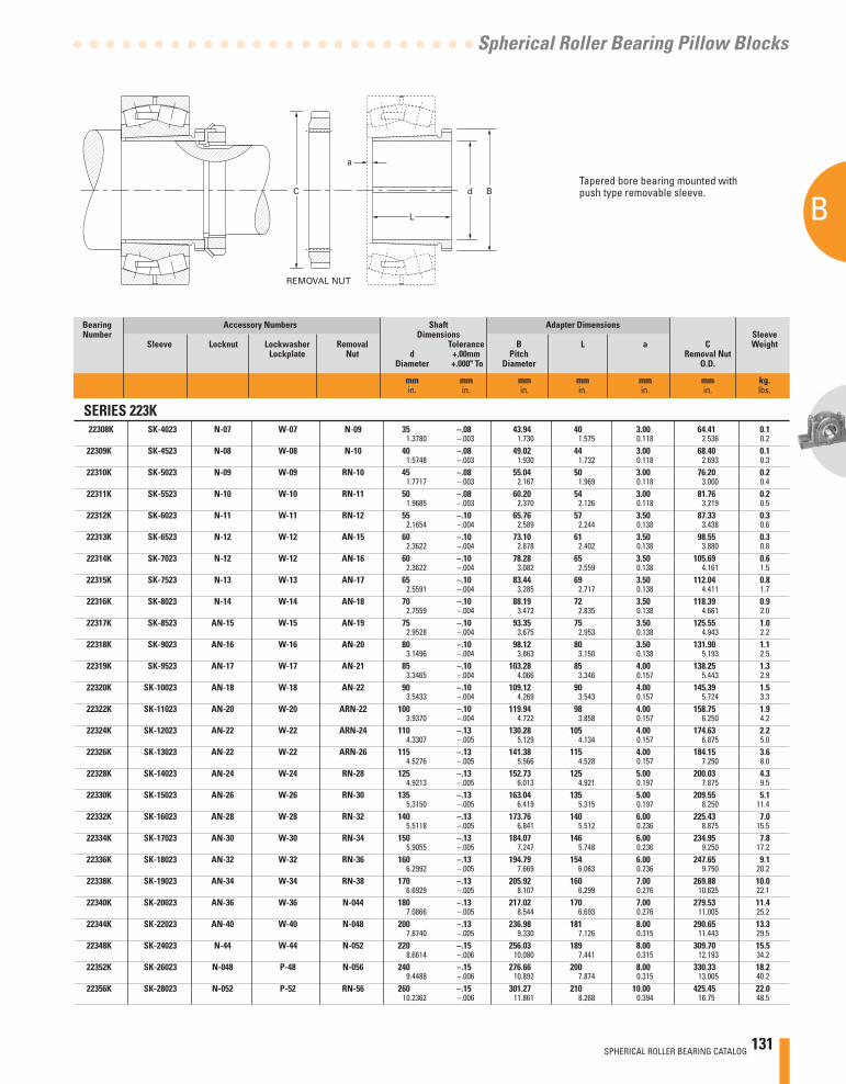
SPHERICAL ROLLER BEARING CATALOG 131
B
Spherical Roller Bearing Pillow Blocks
Tapered bore bearing mounted with push type removable sleeve.
Bearing Accessory Numbers Shaft Adapter Dimensions Number Dimensions Sleeve Sleeve Locknut Lockwasher Removal Tolerance B L a C Weight Lockplate Nut d +.00mm Pitch Removal Nut Diameter +.000" To Diameter O.D.
mm mm mm mm mm mm kg. in. in. in. in. in. in. lbs.
SERIES 223K 22308K SK-4023 N-07 W-07 N-09 35 –.08 43.94 40 3.00 64.41 0.1 1.3780 –.003 1.730 1.575 0.118 2.536 0.222309K SK-4523 N-08 W-08 N-10 40 –.08 49.02 44 3.00 68.40 0.1 1.5748 –.003 1.930 1.732 0.118 2.693 0.322310K SK-5023 N-09 W-09 RN-10 45 –.08 55.04 50 3.00 76.20 0.2 1.7717 –.003 2.167 1.969 0.118 3.000 0.422311K SK-5523 N-10 W-10 RN-11 50 –.08 60.20 54 3.00 81.76 0.2 1.9685 –.003 2.370 2.126 0.118 3.219 0.522312K SK-6023 N-11 W-11 RN-12 55 –.10 65.76 57 3.50 87.33 0.3 2.1654 –.004 2.589 2.244 0.138 3.438 0.622313K SK-6523 N-12 W-12 AN-15 60 –.10 73.10 61 3.50 98.55 0.3 2.3622 –.004 2.878 2.402 0.138 3.880 0.822314K SK-7023 N-12 W-12 AN-16 60 –.10 78.28 65 3.50 105.69 0.6 2.3622 –.004 3.082 2.559 0.138 4.161 1.522315K SK-7523 N-13 W-13 AN-17 65 –.10 83.44 69 3.50 112.04 0.8 2.5591 –.004 3.285 2.717 0.138 4.411 1.722316K SK-8023 N-14 W-14 AN-18 70 –.10 88.19 72 3.50 118.39 0.9 2.7559 –.004 3.472 2.835 0.138 4.661 2.022317K SK-8523 AN-15 W-15 AN-19 75 –.10 93.35 75 3.50 125.55 1.0 2.9528 –.004 3.675 2.953 0.138 4.943 2.222318K SK-9023 AN-16 W-16 AN-20 80 –.10 98.12 80 3.50 131.90 1.1 3.1496 –.004 3.863 3.150 0.138 5.193 2.522319K SK-9523 AN-17 W-17 AN-21 85 –.10 103.28 85 4.00 138.25 1.3 3.3465 –.004 4.066 3.346 0.157 5.443 2.922320K SK-10023 AN-18 W-18 AN-22 90 –.10 109.12 90 4.00 145.39 1.5 3.5433 –.004 4.269 3.543 0.157 5.724 3.322322K SK-11023 AN-20 W-20 ARN-22 100 –.10 119.94 98 4.00 158.75 1.9 3.9370 –.004 4.722 3.858 0.157 6.250 4.222324K SK-12023 AN-22 W-22 ARN-24 110 –.13 130.28 105 4.00 174.63 2.2 4.3307 –.005 5.129 4.134 0.157 6.875 5.022326K SK-13023 AN-22 W-22 ARN-26 115 –.13 141.38 115 4.00 184.15 3.6 4.5276 –.005 5.566 4.528 0.157 7.250 8.022328K SK-14023 AN-24 W-24 RN-28 125 –.13 152.73 125 5.00 200.03 4.3 4.9213 –.005 6.013 4.921 0.197 7.875 9.522330K SK-15023 AN-26 W-26 RN-30 135 –.13 163.04 135 5.00 209.55 5.1 5.3150 –.005 6.419 5.315 0.197 8.250 11.422332K SK-16023 AN-28 W-28 RN-32 140 –.13 173.76 140 6.00 225.43 7.0 5.5118 –.005 6.841 5.512 0.236 8.875 15.522334K SK-17023 AN-30 W-30 RN-34 150 –.13 184.07 146 6.00 234.95 7.8 5.9055 –.005 7.247 5.748 0.236 9.250 17.222336K SK-18023 AN-32 W-32 RN-36 160 –.13 194.79 154 6.00 247.65 9.1 6.2992 –.005 7.669 6.063 0.236 9.750 20.222338K SK-19023 AN-34 W-34 RN-38 170 –.13 205.92 160 7.00 269.88 10.0 6.6929 –.005 8.107 6.299 0.276 10.625 22.122340K SK-20023 AN-36 W-36 N-044 180 –.13 217.02 170 7.00 279.53 11.4 7.0866 –.005 8.544 6.693 0.276 11.005 25.222344K SK-22023 AN-40 W-40 N-048 200 –.13 236.98 181 8.00 290.65 13.3 7.8740 –.005 9.330 7.126 0.315 11.443 29.522348K SK-24023 N-44 W-44 N-052 220 –.15 256.03 189 8.00 309.70 15.5 8.6614 –.006 10.080 7.441 0.315 12.193 34.222352K SK-26023 N-048 P-48 N-056 240 –.15 276.66 200 8.00 330.33 18.2 9.4488 –.006 10.892 7.874 0.315 13.005 40.222356K SK-28023 N-052 P-52 RN-56 260 –.15 301.27 210 10.00 425.45 22.0 10.2362 –.006 11.861 8.268 0.394 16.75 48.5
C
REMOVAL NUT
a
d B
L
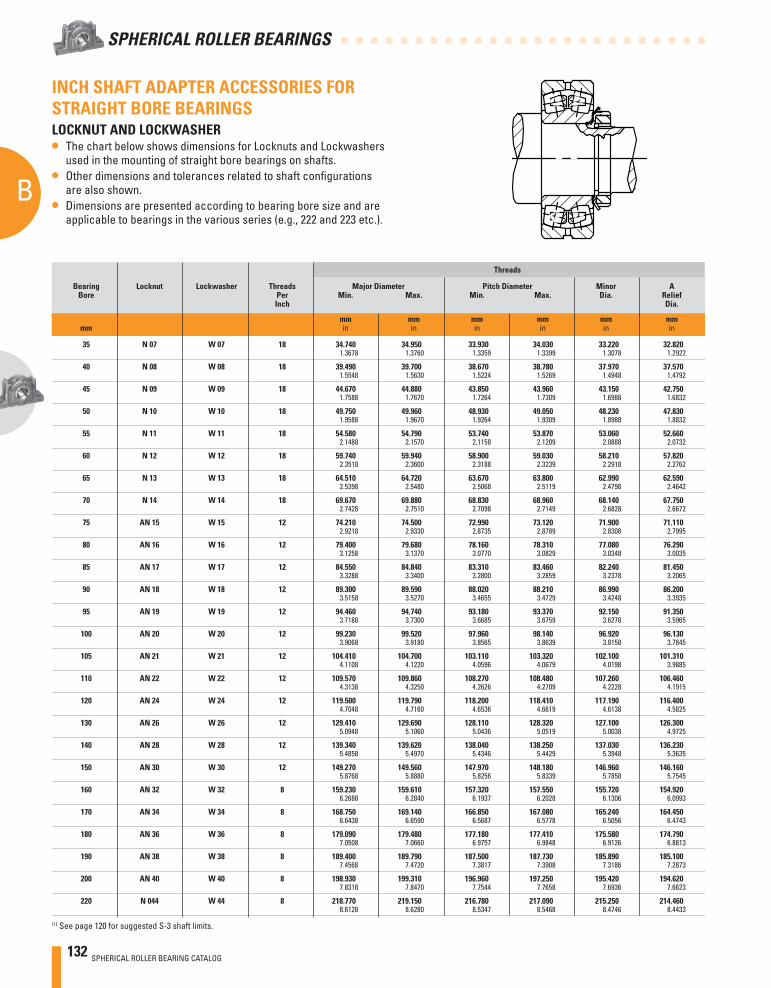
132 SPHERICAL ROLLER BEARING CATALOG
B
SPHERICAL ROLLER BEARINGS
Threads
Bearing Locknut Lockwasher Threads Major Diameter Pitch Diameter Minor A Bore Per Min. Max. Min. Max. Dia. Relief Inch Dia.
mm mm mm mm mm mm mm in in in in in in
35 N 07 W 07 18 34.740 34.950 33.930 34.030 33.220 32.820 1.3678 1.3760 1.3359 1.3399 1.3078 1.2922
40 N 08 W 08 18 39.490 39.700 38.670 38.780 37.970 37.570 1.5548 1.5630 1.5224 1.5269 1.4948 1.4792
45 N 09 W 09 18 44.670 44.880 43.850 43.960 43.150 42.750 1.7588 1.7670 1.7264 1.7309 1.6988 1.6832
50 N 10 W 10 18 49.750 49.960 48.930 49.050 48.230 47.830 1.9588 1.9670 1.9264 1.9309 1.8988 1.8832
55 N 11 W 11 18 54.580 54.790 53.740 53.870 53.060 52.660 2.1488 2.1570 2.1158 2.1209 2.0888 2.0732
60 N 12 W 12 18 59.740 59.940 58.900 59.030 58.210 57.820 2.3518 2.3600 2.3188 2.3239 2.2918 2.2762
65 N 13 W 13 18 64.510 64.720 63.670 63.800 62.990 62.590 2.5398 2.5480 2.5068 2.5119 2.4798 2.4642
70 N 14 W 14 18 69.670 69.880 68.830 68.960 68.140 67.750 2.7428 2.7510 2.7098 2.7149 2.6828 2.6672
75 AN 15 W 15 12 74.210 74.500 72.990 73.120 71.900 71.110 2.9218 2.9330 2.8735 2.8789 2.8308 2.7995
80 AN 16 W 16 12 79.400 79.680 78.160 78.310 77.080 76.290 3.1258 3.1370 3.0770 3.0829 3.0348 3.0035
85 AN 17 W 17 12 84.550 84.840 83.310 83.460 82.240 81.450 3.3288 3.3400 3.2800 3.2859 3.2378 3.2065
90 AN 18 W 18 12 89.300 89.590 88.020 88.210 86.990 86.200 3.5158 3.5270 3.4655 3.4729 3.4248 3.3935
95 AN 19 W 19 12 94.460 94.740 93.180 93.370 92.150 91.350 3.7188 3.7300 3.6685 3.6759 3.6278 3.5965
100 AN 20 W 20 12 99.230 99.520 97.960 98.140 96.920 96.130 3.9068 3.9180 3.8565 3.8639 3.8158 3.7845
105 AN 21 W 21 12 104.410 104.700 103.110 103.320 102.100 101.310 4.1108 4.1220 4.0596 4.0679 4.0198 3.9885
110 AN 22 W 22 12 109.570 109.860 108.270 108.480 107.260 106.460 4.3138 4.3250 4.2626 4.2709 4.2228 4.1915
120 AN 24 W 24 12 119.500 119.790 118.200 118.410 117.190 116.400 4.7048 4.7160 4.6536 4.6619 4.6138 4.5825
130 AN 26 W 26 12 129.410 129.690 128.110 128.320 127.100 126.300 5.0948 5.1060 5.0436 5.0519 5.0038 4.9725
140 AN 28 W 28 12 139.340 139.620 138.040 138.250 137.030 136.230 5.4858 5.4970 5.4346 5.4429 5.3948 5.3635
150 AN 30 W 30 12 149.270 149.560 147.970 148.180 146.960 146.160 5.8768 5.8880 5.8256 5.8339 5.7858 5.7545
160 AN 32 W 32 8 159.230 159.610 157.320 157.550 155.720 154.920 6.2688 6.2840 6.1937 6.2028 6.1306 6.0993
170 AN 34 W 34 8 168.750 169.140 166.850 167.080 165.240 164.450 6.6438 6.6590 6.5687 6.5778 6.5056 6.4743
180 AN 36 W 36 8 179.090 179.480 177.180 177.410 175.580 174.790 7.0508 7.0660 6.9757 6.9848 6.9126 6.8813
190 AN 38 W 38 8 189.400 189.790 187.500 187.730 185.890 185.100 7.4568 7.4720 7.3817 7.3908 7.3186 7.2873
200 AN 40 W 40 8 198.930 199.310 196.960 197.250 195.420 194.620 7.8318 7.8470 7.7544 7.7658 7.6936 7.6623
220 N 044 W 44 8 218.770 219.150 216.780 217.090 215.250 214.460 8.6128 8.6280 8.5347 8.5468 8.4746 8.4433
INCH SHAFT ADAPTER ACCESSORIES FOR STRAIGHT BORE BEARINGSLOCKNUT AND LOCKWASHER• The chart below shows dimensions for Locknuts and Lockwashers
used in the mounting of straight bore bearings on shafts.• Other dimensions and tolerances related to shaft confi gurations
are also shown.• Dimensions are presented according to bearing bore size and are
applicable to bearings in the various series (e.g., 222 and 223 etc.).
(1) See page 120 for suggested S-3 shaft limits.
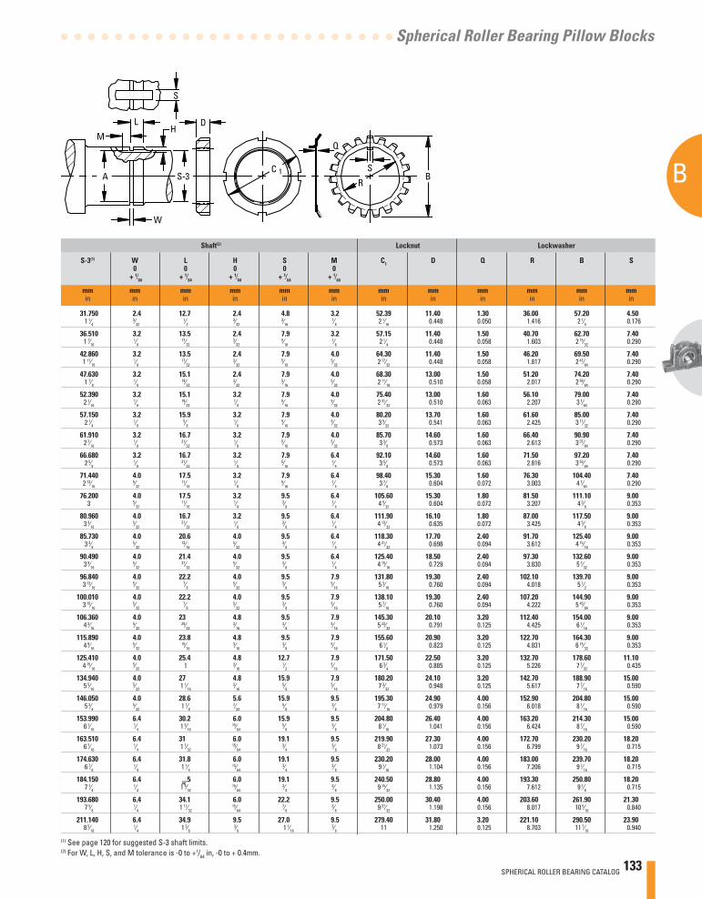
SPHERICAL ROLLER BEARING CATALOG 133
B
Spherical Roller Bearing Pillow Blocks
Shaft(2) Locknut Lockwasher
S-3(1) W L H S M C1 D Q R B S 0 0 0 0 0 + 1⁄64 + 1⁄64 + 1⁄64 + 1⁄64 + 1⁄64
mm mm mm mm mm mm mm mm mm mm mm mmin in in in in in in in in in in in
31.750 2.4 12.7 2.4 4.8 3.2 52.39 11.40 1.30 36.00 57.20 4.501 1⁄4
3⁄32 1⁄2
3⁄32 3⁄16
1⁄8 2 1⁄16 0.448 0.050 1.416 2 1⁄4 0.176
36.510 3.2 13.5 2.4 7.9 3.2 57.15 11.40 1.50 40.70 62.70 7.401 7⁄16
1⁄8 17⁄32
3⁄32 5⁄16
1⁄8 2 1⁄4 0.448 0.058 1.603 2 15⁄32 0.290
42.860 3.2 13.5 2.4 7.9 4.0 64.30 11.40 1.50 46.20 69.50 7.401 11⁄16
1⁄8 17⁄32
3⁄32 5⁄16
5⁄32 2 17⁄32 0.448 0.058 1.817 2 47⁄64 0.290
47.630 3.2 15.1 2.4 7.9 4.0 68.30 13.00 1.50 51.20 74.20 7.401 7⁄8
1⁄8 19⁄32
3⁄32 5⁄16
5⁄32 2 11⁄16 0.510 0.058 2.017 2 59⁄64 0.290
52.390 3.2 15.1 3.2 7.9 4.0 75.40 13.00 1.60 56.10 79.00 7.402 1⁄16
1⁄8 19⁄32
1⁄8 5⁄16
5⁄32 2 31⁄32 0.510 0.063 2.207 3 7⁄64 0.290
57.150 3.2 15.9 3.2 7.9 4.0 80.20 13.70 1.60 61.60 85.00 7.402 1⁄4
1⁄8 5⁄8
1⁄8 5⁄16
5⁄32 3 5⁄32 0.541 0.063 2.425 3 11⁄32 0.290
61.910 3.2 16.7 3.2 7.9 4.0 85.70 14.60 1.60 66.40 90.90 7.402 7⁄16
1⁄8 21⁄32
1⁄8 5⁄16
5⁄32 3 3⁄8 0.573 0.063 2.613 3 37⁄64 0.290
66.680 3.2 16.7 3.2 7.9 6.4 92.10 14.60 1.60 71.50 97.20 7.402 5⁄8
1⁄8 21⁄32
1⁄8 5⁄16
1⁄4 3 5⁄8 0.573 0.063 2.816 3 53⁄64 0.290
71.440 4.0 17.5 3.2 7.9 6.4 98.40 15.30 1.60 76.30 104.40 7.402 13⁄16
5⁄32 11⁄16
1⁄8 5⁄16
1⁄4 3 7⁄8 0.604 0.072 3.003 4 7⁄64 0.290
76.200 4.0 17.5 3.2 9.5 6.4 105.60 15.30 1.80 81.50 111.10 9.003 5⁄32
11⁄16 1⁄8
3⁄8 1⁄4 4 5⁄32 0.604 0.072 3.207 4 3⁄8 0.353
80.960 4.0 16.7 3.2 9.5 6.4 111.90 16.10 1.80 87.00 117.50 9.003 3⁄16
5⁄32 21⁄32
1⁄8 3⁄8
1⁄4 4 13⁄32 0.635 0.072 3.425 4 5⁄8 0.353
85.730 4.0 20.6 4.0 9.5 6.4 118.30 17.70 2.40 91.70 125.40 9.003 3⁄8
5⁄32 13⁄16
5⁄32 3⁄8
1⁄4 4 21⁄32 0.698 0.094 3.612 4 15⁄16 0.353
90.490 4.0 21.4 4.0 9.5 6.4 125.40 18.50 2.40 97.30 132.60 9.003 9⁄16
5⁄32 27⁄32
5⁄32 3⁄8
1⁄4 4 15⁄16 0.729 0.094 3.830 5 7⁄32 0.353
96.840 4.0 22.2 4.0 9.5 7.9 131.80 19.30 2.40 102.10 139.70 9.003 13⁄16
5⁄32 7⁄8
5⁄32 3⁄8
5⁄16 5 3⁄16 0.760 0.094 4.018 5 1⁄2 0.353
100.010 4.0 22.2 4.0 9.5 7.9 138.10 19.30 2.40 107.20 144.90 9.003 15⁄16
5⁄32 7⁄8
5⁄32 3⁄8
5⁄16 5 7⁄16 0.760 0.094 4.222 5 45⁄64 0.353
106.360 4.0 23 4.8 9.5 7.9 145.30 20.10 3.20 112.40 154.00 9.004 3⁄16
5⁄32 29⁄32
3⁄16 3⁄8
5⁄16 5 23⁄32 0.791 0.125 4.425 6 1⁄16 0.353
115.890 4.0 23.8 4.8 9.5 7.9 155.60 20.90 3.20 122.70 164.30 9.004 9⁄16
5⁄32 15⁄16
3⁄16 3⁄8
5⁄16 6 1⁄8 0.823 0.125 4.831 6 15⁄32 0.353
125.410 4.0 25.4 4.8 12.7 7.9 171.50 22.50 3.20 132.70 178.60 11.104 15⁄16
5⁄32 1 3⁄16 1⁄2
5⁄16 6 3⁄4 0.885 0.125 5.226 7 1⁄32 0.435
134.940 4.0 27 4.8 15.9 7.9 180.20 24.10 3.20 142.70 188.90 15.005 5⁄16
5⁄32 1 1⁄16 3⁄16
5⁄8 5⁄16 7 3⁄32 0.948 0.125 5.617 7 7⁄16 0.590
146.050 4.0 28.6 5.6 15.9 9.5 195.30 24.90 4.00 152.90 204.80 15.005 3⁄4
5⁄32 1 1⁄8 7⁄32
5⁄8 3⁄8 7 11⁄16 0.979 0.156 6.018 8 1⁄16 0.590
153.990 6.4 30.2 6.0 15.9 9.5 204.80 26.40 4.00 163.20 214.30 15.006 1⁄16
1⁄4 1 3⁄16 15⁄64
5⁄8 3⁄8 8 1⁄16 1.041 0.156 6.424 8 7⁄16 0.590
163.510 6.4 31 6.0 19.1 9.5 219.90 27.30 4.00 172.70 230.20 18.206 7⁄16
1⁄4 1 7⁄32 15⁄64
3⁄4 3⁄8 8 21⁄32 1.073 0.156 6.799 9 1⁄16 0.715
174.630 6.4 31.8 6.0 19.1 9.5 230.20 28.00 4.00 183.00 239.70 18.206 7⁄8
1⁄4 1 1⁄4 15⁄64
3⁄4 3⁄8 9 1⁄16 1.104 0.156 7.206 9 7⁄16 0.715
184.150 6.4 32.5 6.0 19.1 9.5 240.50 28.80 4.00 193.30 250.80 18.207 1⁄4
1⁄4 1 9⁄32 15⁄64
3⁄4 3⁄8 9 15⁄32 1.135 0.156 7.612 9 7⁄8 0.715
193.680 6.4 34.1 6.0 22.2 9.5 250.00 30.40 4.00 203.60 261.90 21.307 5⁄8
1⁄4 1 11⁄32 15⁄64
7⁄8 3⁄8 9 27⁄32 1.198 0.156 8.017 10 5⁄16 0.840
211.140 6.4 34.9 9.5 27.0 9.5 279.40 31.80 3.20 221.10 290.50 23.908 5⁄16
1⁄4 1 3⁄8 3⁄8 1 1⁄16
3⁄8 11 1.250 0.125 8.703 11 7⁄16 0.940
(1) See page 120 for suggested S-3 shaft limits.(2) For W, L, H, S, and M tolerance is -0 to +1/64 in, -0 to + 0.4mm.
M
LH
A
S
Q
C 1
R
SS-3
D
B
W
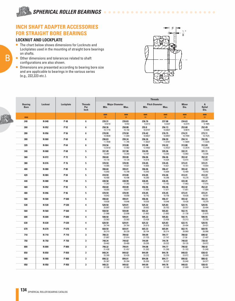
134 SPHERICAL ROLLER BEARING CATALOG
B
SPHERICAL ROLLER BEARINGS
INCH SHAFT ADAPTER ACCESSORIES FOR STRAIGHT BORE BEARINGSLOCKNUT AND LOCKPLATE• The chart below shows dimensions for Locknuts and
Lockplates used in the mounting of straight bore bearings on shafts.
• Other dimensions and tolerances related to shaft confi gurations are also shown.
• Dimensions are presented according to bearing bore size and are applicable to bearings in the various series (e.g., 222,223 etc.).
Threads
Bearing Locknut Lockplate Threads Major Diameter Pitch Diameter Minor A Bore Per Min. Max. Min. Max. Dia. Relief Inch Dia.
mm mm mm mm mm mm mm in in in in in in
240 N 048 P 48 6 239.31 239.83 236.76 237.08 234.63 233.44 9.4218 9.442 9.3213 9.3337 9.2374 9.1905 260 N 052 P 52 6 258.36 258.88 255.8 256.13 253.68 252.49 10.1718 10.192 10.0707 10.0837 9.9874 9.9405 280 N 056 P 56 6 278.99 279.50 276.42 276.75 274.31 273.11 10.9838 11.004 10.8827 10.8957 10.7994 10.7525 300 N 060 P 60 6 298.83 299.34 296.26 296.59 294.14 292.95 11.7648 11.785 11.6637 11.6767 11.5804 11.5335 320 N 064 P 64 6 318.56 319.08 315.98 316.32 313.88 312.69 12.5418 12.562 12.4402 12.4537 12.3574 12.3105 340 N 068 P 68 5 337.49 337.90 334.95 335.36 332.31 331.11 13.287 13.303 13.187 13.203 13.083 13.036 360 N 072 P 72 5 358.60 359.00 356.06 356.46 353.42 352.22 14.118 14.134 14.018 14.034 13.914 13.867 380 N 076 P 76 5 378.59 378.99 376.05 376.45 373.41 372.21 14.905 14.921 14.805 14.821 14.701 14.654 400 N 080 P 80 5 398.60 399.01 396.06 396.47 393.42 392.23 15.693 15.709 15.593 15.609 15.489 15.442 420 N 084 P 84 5 418.59 419.00 416.05 416.46 413.41 412.22 16.480 16.496 16.380 16.396 16.276 16.229 440 N 088 P 88 5 438.58 438.99 436.05 436.45 433.40 432.21 17.267 17.283 17.167 17.183 17.063 17.016 460 N 092 P 92 5 458.60 459.00 456.06 456.46 453.42 452.22 18.055 18.071 17.955 17.971 17.851 17.804 480 N 096 P 96 5 478.59 478.99 476.05 476.45 473.41 472.21 18.842 18.858 18.742 18.758 18.638 18.591 500 N 500 P 500 5 498.60 499.01 496.06 496.47 493.42 492.23 19.630 19.646 19.530 19.546 19.426 19.379 530 N 530 P 530 4 528.50 529.01 525.32 525.83 522.15 520.55 20.807 20.827 20.682 20.702 20.557 20.494 560 N 560 P 560 4 558.50 559.00 555.32 555.83 552.15 550.55 21.988 22.008 21.863 21.883 21.738 21.675 600 N 600 P 600 4 598.50 599.01 595.33 595.83 592.15 590.55 23.563 23.583 23.438 23.458 23.313 23.250 630 N 630 P 630 4 628.50 629.01 625.32 625.83 622.15 520.55 24.744 24.764 24.619 24.639 24.494 24.431 670 N 670 P 670 4 668.50 669.01 665.33 665.84 662.15 660.55 26.319 26.339 26.194 26.214 26.069 26.006 710 N 710 P 710 3 708.33 709.02 704.09 704.77 700.02 698.42 27.887 27.914 27.720 27.747 27.56 27.497 750 N 750 P 750 3 748.34 749.02 744.09 744.78 740.03 738.43 29.462 29.489 29.295 29.322 29.135 29.072 800 N 800 P 800 3 798.32 799.01 794.08 794.77 790.02 788.42 31.430 31.457 31.263 31.290 31.103 31.040 850 N 850 P 850 3 848.34 849.02 844.09 844.78 840.03 838.43 33.399 33.426 33.232 33.259 33.072 33.009 900 N 900 P 900 3 898.32 899.01 894.08 894.77 890.02 888.42 35.367 35.394 35.200 35.227 35.040 34.977 950 N 950 P 950 3 948.33 949.02 944.09 944.78 940.03 938.43 37.336 37.363 37.169 37.196 37.009 36.946
“
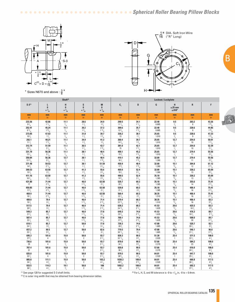
SPHERICAL ROLLER BEARING CATALOG 135
B
Spherical Roller Bearing Pillow Blocks
Shaft(3) Locknut / Lockplate
S-3(1) L H S M C1 D G H R F 0 0 0 0 ±.25 mm + 1⁄64 + 1⁄64 + 1⁄64 + 1⁄64 ±.010"
mm mm mm mm mm mm mm mm mm mm mmin in in in in in in in in in in
233.36 42.86 11.1 28.6 34.9 290.5 34.1 22.48 9.5 203.2 43.269 3⁄16 1 11⁄16
7⁄16 1 1⁄8 1 3⁄8 11 7⁄16 1 11⁄32 0.885 3⁄8 8 1 45⁄64
252.41 45.24 11.1 30.2 37.3 309.6 35.7 22.48 9.5 228.6 44.859 15⁄16 1 25⁄32
7⁄16 1 3⁄16 1 15⁄32 12 3⁄16 1 13⁄32 0.885 3⁄8 9 1 49⁄64
273.05 47.63 11.1 31.8 39.7 330.2 38.1 25.65 9.5 228.6 47.2310 3⁄4 1 7⁄8
7⁄16 1 1⁄4 1 9⁄16 13 1 1⁄2 1.010 3⁄8 9 1 55⁄64
292.1 49.21 11.1 34.9 41.3 360.4 39.7 25.65 12.7 254.0 50.0111 1⁄2 1 15⁄16
7⁄16 1 3⁄8 1 5⁄8 14 3⁄16 1 9⁄16 1.010 1⁄2 10 1 31⁄32
312.74 51.59 11.1 36.5 43.7 381.0 42.1 25.65 12.7 254.0 52.3912 5⁄16 2 1⁄32
7⁄16 1 7⁄16 1 23⁄32 15 1 21⁄32 1.010 1⁄2 10 2 1⁄16
331.79 56.36 11.1 38.1 48.4 400.1 45.2 25.65 12.7 279.4 55.5613 1⁄16 2 7⁄32
7⁄16 1 1⁄2 1 29⁄32 15 3⁄4 1 25⁄32 1.010 1⁄2 11 2 3⁄16
350.84 56.36 12.7 38.1 48.4 419.1 45.2 32.00 12.7 279.4 55.5613 13⁄16 2 7⁄32
1⁄2 1 1⁄2 1 29⁄32 16 1⁄2 1 25⁄32 1.260 1⁄2 11 2 3⁄16
371.48 59.53 12.7 38.1 51.59 450.9 48.4 32.00 15.1 304.8 61.1214 5⁄8 2 11⁄32
1⁄2 1 1⁄2 2 1⁄32 17 3⁄4 1 29⁄32 1.260 19⁄32 12 2 13⁄32
390.53 63.50 12.7 41.3 55.6 469.9 52.4 32.00 15.1 330.2 65.0915 3⁄8 2 1⁄2
1⁄2 1 5⁄8 2 3⁄16 18 1⁄2 2 1⁄16 1.260 19⁄32 13 2 9⁄16
411.16 63.50 12.7 41.3 55.6 490.5 52.4 35.18 15.1 330.2 65.0916 3⁄16 2 1⁄2
1⁄2 1 5⁄8 2 3⁄16 19 5⁄16 2 1⁄16 1.385 19⁄32 13 2 9⁄16
431.80 71.44 12.7 46.0 63.50 520.7 60.3 35.18 15.1 355.6 75.4117 2 13⁄16
1⁄2 1 13⁄16 2 1⁄2 20 1⁄2 2 3⁄8 1.385 19⁄32 14 2 31⁄32
450.85 71.44 12.7 46.0 63.50 539.8 60.3 35.18 15.1 406.4 75.4117 3⁄4 2 13⁄16
1⁄2 1 13⁄16 2 1⁄2 21 1⁄4 2 3⁄8 1.385 19⁄32 16 2 31⁄32
469.9 71.44 12.7 46.0 63.50 560.4 60.3 38.35 15.1 406.4 75.4118 1⁄2 2 13⁄16
1⁄2 1 13⁄16 2 1⁄2 22 1⁄16 2 3⁄8 1.510 19⁄32 16 2 31⁄32
489.0 79.4 12.7 46.0 71.4 579.4 68.3 38.35 15.1 406.4 83.319 1⁄4 3 1⁄8
1⁄2 1 13⁄16 2 13⁄16 22 13⁄16 2 11⁄16 1.510 19⁄32 16 3 9⁄32
517.5 79.4 12.7 46.0 71.4 630.2 68.3 41.53 20.6 425.5 83.320 3⁄8 3 1⁄8
1⁄2 1 13⁄16 2 13⁄16 24 13⁄16 2 11⁄16 1.635 13⁄16 16 3⁄4 3 9⁄32
549.3 85.7 12.7 46.0 77.8 649.3 74.6 41.53 20.6 476.3 89.721 5⁄8 3 3⁄8
1⁄2 1 13⁄16 3 1⁄16 25 9⁄16 2 15⁄16 1.635 13⁄16 18 3⁄4 3 17⁄32
587.4 85.7 12.7 46.0 77.8 700.1 74.6 41.53 20.6 508.0 89.723 1⁄8 3 3⁄8
1⁄2 1 13⁄16 3 1⁄16 27 9⁄16 2 15⁄16 1.635 13⁄16 20 3 17⁄32
619.1 85.7 12.7 50.8 77.8 730.3 74.6 47.88 20.6 520.7 92.124 3⁄8 3 3⁄8
1⁄2 2 3 1⁄16 28 3⁄4 2 15⁄16 1.885 13⁄16 20 1⁄2 3 5⁄8657.2 90.5 12.7 50.8 82.6 779.5 79.4 47.88 20.6 546.1 96.825 7⁄8 3 9⁄16
1⁄2 2 3 1⁄4 30 11⁄16 3 1⁄8 1.885 13⁄16 21 1⁄2 3 13⁄16
695.3 101.6 15.9 50.8 93.7 830.3 90.5 51.30 25.4 571.5 108.027 3⁄8 4 5⁄8 2 3 11⁄16 32 11⁄16 3 9⁄16 2.020 1 22 1⁄2 4 1⁄4736.6 101.6 15.9 50.8 93.7 870.0 90.5 57.66 25.4 584.2 108.0
29 4 5⁄8 2 3 11⁄16 34 1⁄4 3 9⁄16 2.270 1 23 4 1⁄4787.4 101.6 15.9 50.8 93.7 920.8 90.5 57.66 25.4 616.0 108.0
31 4 5⁄8 2 3 11⁄16 36 1⁄4 3 9⁄16 2.270 1 24 1⁄4 4 1⁄4835.0 101.6 15.9 50.8 93.7 979.5 90.5 64.01 25.4 647.7 108.032 7⁄8 4 5⁄8 2 3 11⁄16 38 9⁄16 3 9⁄16 2.520 1 25 1⁄2 4 1⁄4885.8 111.1 15.9 50.8 103.2 1030.3 100.0 64.01 25.4 666.8 117.534 7⁄8 4 3⁄8
5⁄8 2 4 1⁄16 40 9⁄16 3 15⁄16 2.520 1 26 1⁄4 4 5⁄8933.5 114.3 19.1 50.8 108 1092.2 100.0 64.01 25.4 692.2 117.536 3⁄4 4 1⁄2
3⁄4 2 4 1⁄4 43 3 15⁄16 2.520 1 27 1⁄4 4 5⁄8(1) See page 120 for suggested S-3 shaft limits. (3) For L, H, S, and M tolerance is -0 to +1/64 in, -0 to + 0.4mm.(2) C is outer ring width that may be obtained from bearing dimension tables.
DIA. Soft Iron Wire(”R” Long)
136 SPHERICAL ROLLER BEARING CATALOG
B
SPHERICAL ROLLER BEARINGS
NOTES
SPHERICAL ROLLER BEARING CATALOG 137
C
Spherical Roller Bearing Metric Accessories
CSPHERICAL ROLLER BEARING M
ETRIC ACCESSORIES
C SPHERICAL ROLLER BEARING METRIC
ACCESSORIES
C

138 SPHERICAL ROLLER BEARING CATALOG
SPHERICAL ROLLER BEARING METRIC ACCESSORIES
C
CSPH
ERIC
AL R
OLLE
R BE
ARIN
G MET
RIC ACCESSORIES
C
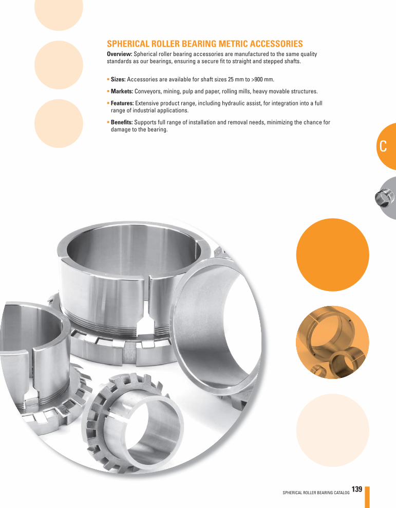
SPHERICAL ROLLER BEARING METRIC ACCESSORIESOverview: Spherical roller bearing accessories are manufactured to the same quality standards as our bearings, ensuring a secure fi t to straight and stepped shafts.
• Sizes: Accessories are available for shaft sizes 25 mm to >900 mm.
• Markets: Conveyors, mining, pulp and paper, rolling mills, heavy movable structures.
• Features: Extensive product range, including hydraulic assist, for integration into a full range of industrial applications.
• Benefi ts: Supports full range of installation and removal needs, minimizing the chance for damage to the bearing.
SPHERICAL ROLLER BEARING CATALOG 139
C
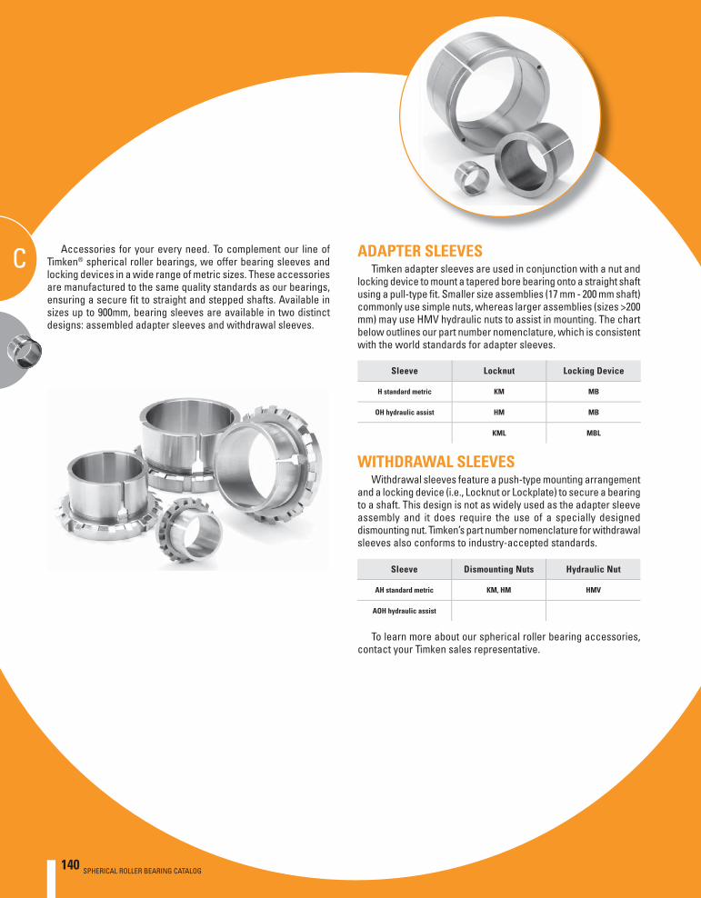
140 SPHERICAL ROLLER BEARING CATALOG
SPHERICAL ROLLER BEARING METRIC ACCESSORIES
CC
140 SPHERICAL ROLLER BEARING CATALOG
ADAPTER SLEEVESTimken adapter sleeves are used in conjunction with a nut and
locking device to mount a tapered bore bearing onto a straight shaft using a pull-type fi t. Smaller size assemblies (17 mm - 200 mm shaft) commonly use simple nuts, whereas larger assemblies (sizes >200 mm) may use HMV hydraulic nuts to assist in mounting. The chart below outlines our part number nomenclature, which is consistent with the world standards for adapter sleeves.
Accessories for your every need. To complement our line of Timken® spherical roller bearings, we offer bearing sleeves and locking devices in a wide range of metric sizes. These accessories are manufactured to the same quality standards as our bearings, ensuring a secure fi t to straight and stepped shafts. Available in sizes up to 900mm, bearing sleeves are available in two distinct designs: assembled adapter sleeves and withdrawal sleeves.
Sleeve Locknut Locking Device
H standard metric KM MB
OH hydraulic assist HM MB
KML MBL
Sleeve Dismounting Nuts Hydraulic Nut
AH standard metric KM, HM HMV
AOH hydraulic assist
WITHDRAWAL SLEEVESWithdrawal sleeves feature a push-type mounting arrangement
and a locking device (i.e., Locknut or Lockplate) to secure a bearing to a shaft. This design is not as widely used as the adapter sleeve assembly and it does require the use of a specially designed dismounting nut. Timken’s part number nomenclature for withdrawal sleeves also conforms to industry-accepted standards.
To learn more about our spherical roller bearing accessories, contact your Timken sales representative.
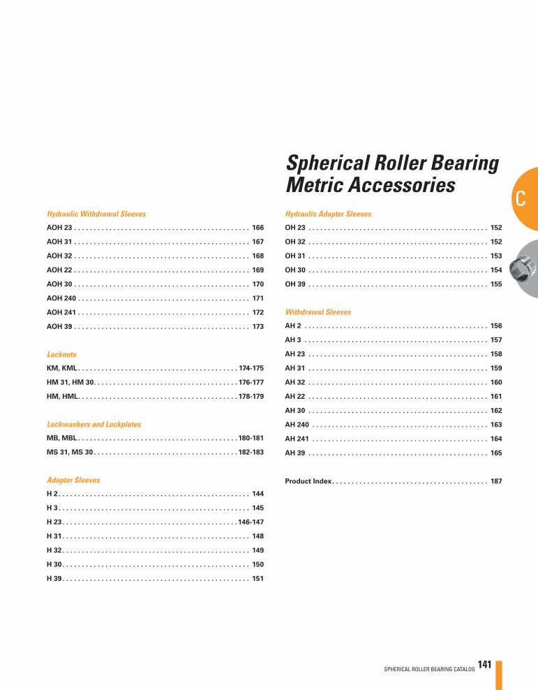
SPHERICAL ROLLER BEARING CATALOG 141
C
Spherical Roller Bearing Metric Accessories
Spherical Roller Bearing Metric Accessories
Hydraulic Withdrawal Sleeves
AOH 23 . . . . . . . . . . . . . . . . . . . . . . . . . . . . . . . . . . . . . . . . . . . . . 166
AOH 31 . . . . . . . . . . . . . . . . . . . . . . . . . . . . . . . . . . . . . . . . . . . . . 167
AOH 32 . . . . . . . . . . . . . . . . . . . . . . . . . . . . . . . . . . . . . . . . . . . . . 168
AOH 22 . . . . . . . . . . . . . . . . . . . . . . . . . . . . . . . . . . . . . . . . . . . . . 169
AOH 30 . . . . . . . . . . . . . . . . . . . . . . . . . . . . . . . . . . . . . . . . . . . . . 170
AOH 240 . . . . . . . . . . . . . . . . . . . . . . . . . . . . . . . . . . . . . . . . . . . . 171
AOH 241 . . . . . . . . . . . . . . . . . . . . . . . . . . . . . . . . . . . . . . . . . . . . 172
AOH 39 . . . . . . . . . . . . . . . . . . . . . . . . . . . . . . . . . . . . . . . . . . . . . 173
Locknuts
KM, KML . . . . . . . . . . . . . . . . . . . . . . . . . . . . . . . . . . . . . . . . . 174-175
HM 31, HM 30 . . . . . . . . . . . . . . . . . . . . . . . . . . . . . . . . . . . . . 176-177
HM, HML . . . . . . . . . . . . . . . . . . . . . . . . . . . . . . . . . . . . . . . . . 178-179
Lockwashers and Lockplates
MB, MBL . . . . . . . . . . . . . . . . . . . . . . . . . . . . . . . . . . . . . . . . . 180-181
MS 31, MS 30 . . . . . . . . . . . . . . . . . . . . . . . . . . . . . . . . . . . . . 182-183
Adapter Sleeves
H 2 . . . . . . . . . . . . . . . . . . . . . . . . . . . . . . . . . . . . . . . . . . . . . . . . . 144
H 3 . . . . . . . . . . . . . . . . . . . . . . . . . . . . . . . . . . . . . . . . . . . . . . . . . 145
H 23 . . . . . . . . . . . . . . . . . . . . . . . . . . . . . . . . . . . . . . . . . . . . .146-147
H 31 . . . . . . . . . . . . . . . . . . . . . . . . . . . . . . . . . . . . . . . . . . . . . . . . 148
H 32 . . . . . . . . . . . . . . . . . . . . . . . . . . . . . . . . . . . . . . . . . . . . . . . . 149
H 30 . . . . . . . . . . . . . . . . . . . . . . . . . . . . . . . . . . . . . . . . . . . . . . . . 150
H 39 . . . . . . . . . . . . . . . . . . . . . . . . . . . . . . . . . . . . . . . . . . . . . . . . 151
Hydraulic Adapter Sleeves
OH 23 . . . . . . . . . . . . . . . . . . . . . . . . . . . . . . . . . . . . . . . . . . . . . . 152
OH 32 . . . . . . . . . . . . . . . . . . . . . . . . . . . . . . . . . . . . . . . . . . . . . . 152
OH 31 . . . . . . . . . . . . . . . . . . . . . . . . . . . . . . . . . . . . . . . . . . . . . . 153
OH 30 . . . . . . . . . . . . . . . . . . . . . . . . . . . . . . . . . . . . . . . . . . . . . . 154
OH 39 . . . . . . . . . . . . . . . . . . . . . . . . . . . . . . . . . . . . . . . . . . . . . . 155
Withdrawal Sleeves
AH 2 . . . . . . . . . . . . . . . . . . . . . . . . . . . . . . . . . . . . . . . . . . . . . . . 156
AH 3 . . . . . . . . . . . . . . . . . . . . . . . . . . . . . . . . . . . . . . . . . . . . . . . 157
AH 23 . . . . . . . . . . . . . . . . . . . . . . . . . . . . . . . . . . . . . . . . . . . . . . 158
AH 31 . . . . . . . . . . . . . . . . . . . . . . . . . . . . . . . . . . . . . . . . . . . . . . 159
AH 32 . . . . . . . . . . . . . . . . . . . . . . . . . . . . . . . . . . . . . . . . . . . . . . 160
AH 22 . . . . . . . . . . . . . . . . . . . . . . . . . . . . . . . . . . . . . . . . . . . . . . 161
AH 30 . . . . . . . . . . . . . . . . . . . . . . . . . . . . . . . . . . . . . . . . . . . . . . 162
AH 240 . . . . . . . . . . . . . . . . . . . . . . . . . . . . . . . . . . . . . . . . . . . . . 163
AH 241 . . . . . . . . . . . . . . . . . . . . . . . . . . . . . . . . . . . . . . . . . . . . . 164
AH 39 . . . . . . . . . . . . . . . . . . . . . . . . . . . . . . . . . . . . . . . . . . . . . . 165
Product Index . . . . . . . . . . . . . . . . . . . . . . . . . . . . . . . . . . . . . . . . 187
142 SPHERICAL ROLLER BEARING CATALOG
SPHERICAL ROLLER BEARING METRIC ACCESSORIES
C
SPHERICAL ROLLER BEARING M
ETRIC ACCESSORIES
C
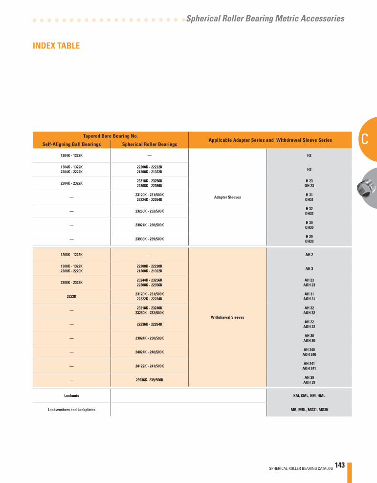
SPHERICAL ROLLER BEARING CATALOG 143
C
Spherical Roller Bearing Metric Accessories
Tapered Bore Bearing No.Applicable Adapter Series and Withdrawal Sleeve Series
Self-Aligning Ball Bearings Spherical Roller Bearings
1204K - 1222K —
Adapter Sleeves
H2
1304K - 1322K2204K - 2222K
22208K - 22222K21308K - 21322K H3
2304K - 2322K 23218K - 23256K22308K - 22356K
H 23OH 23
— 23120K - 231/500K22224K - 22264K
H 31OH31
— 23260K - 232/500K H 32OH32
— 23024K - 230/500K H 30OH30
— 23936K - 239/500K H 39OH39
1208K - 1222K —
Withdrawal Sleeves
AH 2
1308K - 1322K2208K - 2220K
22208K - 22220K21308K - 21322K AH 3
2308K - 2322K 23244K - 23256K22308K - 22356K
AH 23AOH 23
2222K 23120K - 231/500K22222K - 22234K
AH 31AOH 31
— 23218K - 23240K23260K - 232/500K
AH 32AOH 32
— 22236K - 22264K AH 22AOH 22
— 23024K - 230/500K AH 30AOH 30
— 24024K - 240/500K AH 240AOH 240
— 24122K - 241/500K AH 241AOH 241
— 23936K- 239/500K AH 39AOH 39
Locknuts KM, KML, HM, HML
Lockwashers and Lockplates MB, MBL, MS31, MS30
INDEX TABLE
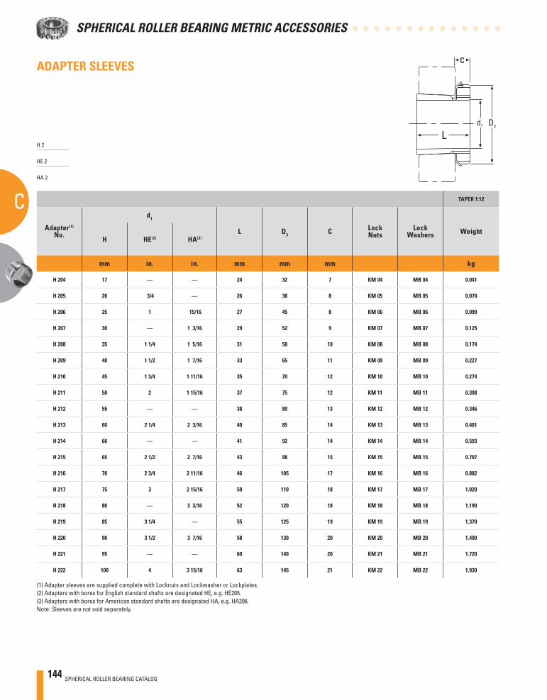
144 SPHERICAL ROLLER BEARING CATALOG
SPHERICAL ROLLER BEARING METRIC ACCESSORIES
C
ADAPTER SLEEVES
TAPER 1:12
Adapter(1)
No.
d1
L D3 C LockNuts
LockWashers Weight
H HE(2) HA(3)
mm in. in. mm mm mm kg
H 204 17 — — 24 32 7 KM 04 MB 04 0.041
H 205 20 3/4 — 26 38 8 KM 05 MB 05 0.070
H 206 25 1 15/16 27 45 8 KM 06 MB 06 0.099
H 207 30 — 1 3/16 29 52 9 KM 07 MB 07 0.125
H 208 35 1 1/4 1 5/16 31 58 10 KM 08 MB 08 0.174
H 209 40 1 1/2 1 7/16 33 65 11 KM 09 MB 09 0.227
H 210 45 1 3/4 1 11/16 35 70 12 KM 10 MB 10 0.274
H 211 50 2 1 15/16 37 75 12 KM 11 MB 11 0.308
H 212 55 — — 38 80 13 KM 12 MB 12 0.346
H 213 60 2 1/4 2 3/16 40 85 14 KM 13 MB 13 0.401
H 214 60 — — 41 92 14 KM 14 MB 14 0.593
H 215 65 2 1/2 2 7/16 43 98 15 KM 15 MB 15 0.707
H 216 70 2 3/4 2 11/16 46 105 17 KM 16 MB 16 0.882
H 217 75 3 2 15/16 50 110 18 KM 17 MB 17 1.020
H 218 80 — 3 3/16 52 120 18 KM 18 MB 18 1.190
H 219 85 3 1/4 — 55 125 19 KM 19 MB 19 1.370
H 220 90 3 1/2 3 7/16 58 130 20 KM 20 MB 20 1.490
H 221 95 — — 60 140 20 KM 21 MB 21 1.720
H 222 100 4 3 15/16 63 145 21 KM 22 MB 22 1.930
(1) Adapter sleeves are supplied complete with Locknuts and Lockwasher or Lockplates.(2) Adapters with bores for English standard shafts are designated HE, e.g. HE205.(3) Adapters with bores for American standard shafts are designated HA, e.g. HA206.Note: Sleeves are not sold separately.
c
Ld1 D3
H 2
HE 2
HA 2
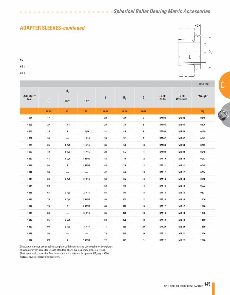
SPHERICAL ROLLER BEARING CATALOG 145
C
Spherical Roller Bearing Metric Accessories
ADAPTER SLEEVES-continued
TAPER 1:12
Adapter(1)
No.
d1
L D3 C LockNuts
LockWashers
Weight
H HE(2) HA(3)
mm in. in. mm mm mm kg
H 304 17 — — 28 32 7 KM 04 MB 04 0.045
H 305 20 3/4 — 29 38 8 KM 05 MB 05 0.075
H 306 25 1 15/16 31 45 8 KM 06 MB 06 0.109
H 307 30 — 1 3/16 35 52 9 KM 07 MB 07 0.142
H 308 35 1 1/4 1 5/16 36 58 10 KM 08 MB 08 0.189
H 309 40 1 1/2 1 7/16 39 65 11 KM 09 MB 09 0.248
H 310 45 1 3/4 1 11/16 42 70 12 KM 10 MB 10 0.303
H 311 50 2 1 15/16 45 75 12 KM 11 MB 11 0.345
H 312 55 — — 47 80 13 KM 12 MB 12 0.394
H 313 60 2 1/4 2 3/16 50 85 14 KM 13 MB 13 0.458
H 314 60 — — 52 92 14 KM 14 MB 14 0.723
H 315 65 2 1/2 2 7/16 55 98 15 KM 15 MB 15 0.831
H 316 70 2 3/4 2 11/16 59 105 17 KM 16 MB 16 1.030
H 317 75 3 2 15/16 63 110 18 KM 17 MB 17 1.180
H 318 80 — 3 3/16 65 120 18 KM 18 MB 18 1.370
H 319 85 3 3/4 — 68 125 19 KM 19 MB 19 1.560
H 320 90 3 1/2 3 7/16 71 130 20 KM 20 MB 20 1.690
H 321 95 — — 74 140 20 KM 21 MB 21 1.950
H 322 100 4 3 15/16 77 145 21 KM 22 MB 22 2.180
(1) Adapter sleeves are supplied complete with Locknuts and Lockwasher or Lockplates.(2) Adapters with bores for English standard shafts are designated HE, e.g. HE306.(3) Adapters with bores for American standard shafts are designated HA, e.g. HA306.Note: Sleeves are not sold separately.
H 3
HE 3
HA 3
c
Ld1 D3
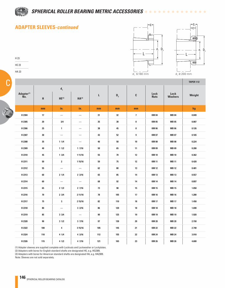
146 SPHERICAL ROLLER BEARING CATALOG
SPHERICAL ROLLER BEARING METRIC ACCESSORIES
C TAPER 1:12
Adapter(1)
No.
d1
L D3 C LockNuts
LockWashers Weight
H HE(2) HA(3)
mm in. in. mm mm mm kg
H 2304 17 — — 31 32 7 KM 04 MB 04 0.049
H 2305 20 3/4 — 35 38 8 KM 05 MB 05 0.087
H 2306 25 1 — 38 45 8 KM 06 MB 06 0.126
H 2307 30 — — 43 52 9 KM 07 MB 07 0.165
H 2308 35 1 1/4 — 46 58 10 KM 08 MB 08 0.224
H 2309 40 1 1/2 1 7/16 50 65 11 KM 09 MB 09 0.280
H 2310 45 1 3/4 1 11/16 55 70 12 KM 10 MB 10 0.362
H 2311 50 2 1 15/16 59 75 12 KM 11 MB 11 0.420
H 2312 55 — — 62 80 13 KM 12 MB 12 0.481
H 2313 60 2 1/4 2 3/16 65 85 14 KM 13 MB 13 0.557
H 2314 60 — — 68 92 14 KM 14 MB 14 0.897
H 2315 65 2 1/2 2 7/16 73 98 15 KM 15 MB 15 1.050
H 2316 70 2 3/4 2 11/16 78 105 17 KM 16 MB 16 1.280
H 2317 75 3 2 15/16 82 110 18 KM 17 MB 17 1.450
H 2318 80 — 3 3/16 86 120 18 KM 18 MB 18 1.690
H 2319 85 3 3/4 — 90 125 19 KM 19 MB 19 1.920
H 2320 90 3 1/2 3 7/16 97 130 20 KM 20 MB 20 2.150
H 2322 100 4 3 15/16 105 145 21 KM 22 MB 22 2.740
H 2324 110 4 1/4 4 3/16 112 155 22 KM 24 MB 24 3.910
H 2326 115 4 1/2 4 7/16 121 165 23 KM 26 MB 26 4.600
(1) Adapter sleeves are supplied complete with Locknuts and Lockwasher or Lockplates.(2) Adapters with bores for English standard shafts are designated HE, e.g. HE2305.(3) Adapters with bores for American standard shafts are designated HA, e.g. HA2309.Note: Sleeves are not sold separately.
H 23
HE 23
HA 23
c
Ld1 D3
c
Ld1 D3
c1
d1 180 mm d
1 200 mm
ADAPTER SLEEVES-continued
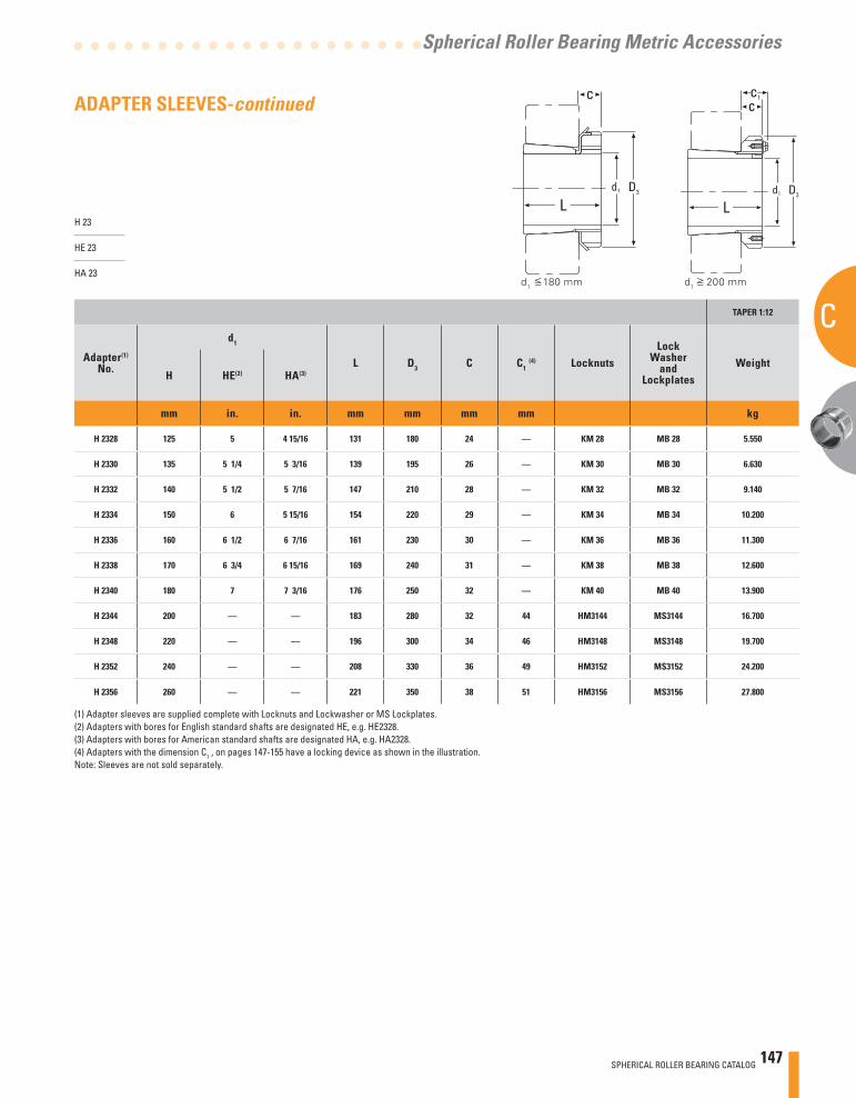
SPHERICAL ROLLER BEARING CATALOG 147
C
Spherical Roller Bearing Metric Accessories
(1) Adapter sleeves are supplied complete with Locknuts and Lockwasher or MS Lockplates.(2) Adapters with bores for English standard shafts are designated HE, e.g. HE2328.(3) Adapters with bores for American standard shafts are designated HA, e.g. HA2328.(4) Adapters with the dimension C1 , on pages 147-155 have a locking device as shown in the illustration.Note: Sleeves are not sold separately.
H 23
HE 23
HA 23
TAPER 1:12
Adapter(1)
No.
d1
L D3 C C1 (4) Locknuts
LockWasher
andLockplates
WeightH HE(2) HA(3)
mm in. in. mm mm mm mm kg
H 2328 125 5 4 15/16 131 180 24 — KM 28 MB 28 5.550
H 2330 135 5 1/4 5 3/16 139 195 26 — KM 30 MB 30 6.630
H 2332 140 5 1/2 5 7/16 147 210 28 — KM 32 MB 32 9.140
H 2334 150 6 5 15/16 154 220 29 — KM 34 MB 34 10.200
H 2336 160 6 1/2 6 7/16 161 230 30 — KM 36 MB 36 11.300
H 2338 170 6 3/4 6 15/16 169 240 31 — KM 38 MB 38 12.600
H 2340 180 7 7 3/16 176 250 32 — KM 40 MB 40 13.900
H 2344 200 — — 183 280 32 44 HM3144 MS3144 16.700
H 2348 220 — — 196 300 34 46 HM3148 MS3148 19.700
H 2352 240 — — 208 330 36 49 HM3152 MS3152 24.200
H 2356 260 — — 221 350 38 51 HM3156 MS3156 27.800
d1 180 mm d
1 200 mm
c
Ld1 D3
c
Ld1 D3
c1ADAPTER SLEEVES-continued
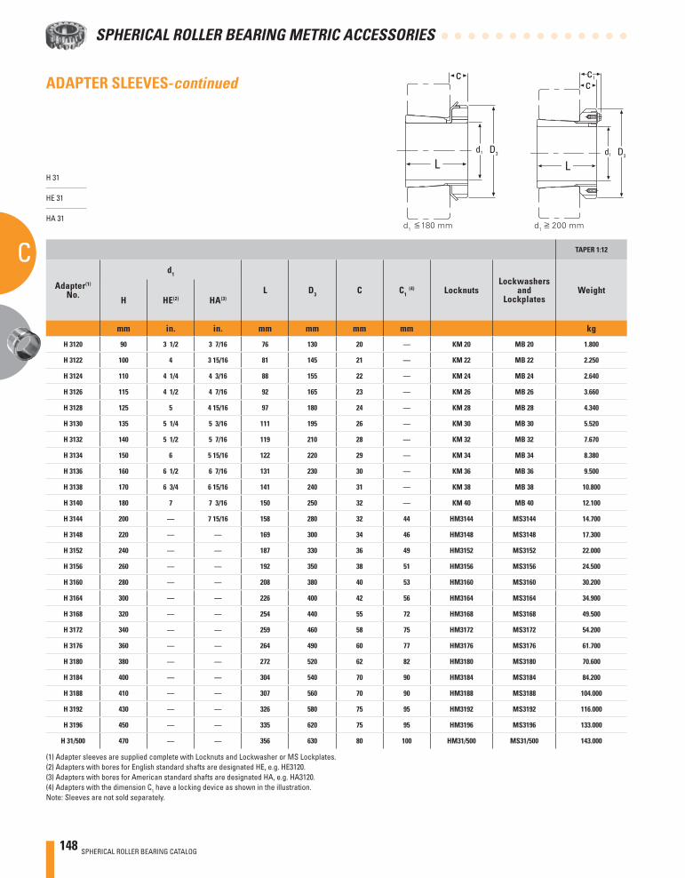
148 SPHERICAL ROLLER BEARING CATALOG
SPHERICAL ROLLER BEARING METRIC ACCESSORIES
C TAPER 1:12
Adapter(1)
No.
d1
L D3 C C1 (4) Locknuts
Lockwashersand
LockplatesWeight
H HE(2) HA(3)
mm in. in. mm mm mm mm kg
H 3120 90 3 1/2 3 7/16 76 130 20 — KM 20 MB 20 1.800
H 3122 100 4 3 15/16 81 145 21 — KM 22 MB 22 2.250
H 3124 110 4 1/4 4 3/16 88 155 22 — KM 24 MB 24 2.640
H 3126 115 4 1/2 4 7/16 92 165 23 — KM 26 MB 26 3.660
H 3128 125 5 4 15/16 97 180 24 — KM 28 MB 28 4.340
H 3130 135 5 1/4 5 3/16 111 195 26 — KM 30 MB 30 5.520
H 3132 140 5 1/2 5 7/16 119 210 28 — KM 32 MB 32 7.670
H 3134 150 6 5 15/16 122 220 29 — KM 34 MB 34 8.380
H 3136 160 6 1/2 6 7/16 131 230 30 — KM 36 MB 36 9.500
H 3138 170 6 3/4 6 15/16 141 240 31 — KM 38 MB 38 10.800
H 3140 180 7 7 3/16 150 250 32 — KM 40 MB 40 12.100
H 3144 200 — 7 15/16 158 280 32 44 HM3144 MS3144 14.700
H 3148 220 — — 169 300 34 46 HM3148 MS3148 17.300
H 3152 240 — — 187 330 36 49 HM3152 MS3152 22.000
H 3156 260 — — 192 350 38 51 HM3156 MS3156 24.500
H 3160 280 — — 208 380 40 53 HM3160 MS3160 30.200
H 3164 300 — — 226 400 42 56 HM3164 MS3164 34.900
H 3168 320 — — 254 440 55 72 HM3168 MS3168 49.500
H 3172 340 — — 259 460 58 75 HM3172 MS3172 54.200
H 3176 360 — — 264 490 60 77 HM3176 MS3176 61.700
H 3180 380 — — 272 520 62 82 HM3180 MS3180 70.600
H 3184 400 — — 304 540 70 90 HM3184 MS3184 84.200
H 3188 410 — — 307 560 70 90 HM3188 MS3188 104.000
H 3192 430 — — 326 580 75 95 HM3192 MS3192 116.000
H 3196 450 — — 335 620 75 95 HM3196 MS3196 133.000
H 31/500 470 — — 356 630 80 100 HM31/500 MS31/500 143.000
(1) Adapter sleeves are supplied complete with Locknuts and Lockwasher or MS Lockplates.(2) Adapters with bores for English standard shafts are designated HE, e.g. HE3120.(3) Adapters with bores for American standard shafts are designated HA, e.g. HA3120.(4) Adapters with the dimension C1 have a locking device as shown in the illustration.Note: Sleeves are not sold separately.
H 31
HE 31
HA 31d
1 180 mm d
1 200 mm
c
Ld1 D3
c
Ld1 D3
c1ADAPTER SLEEVES-continued
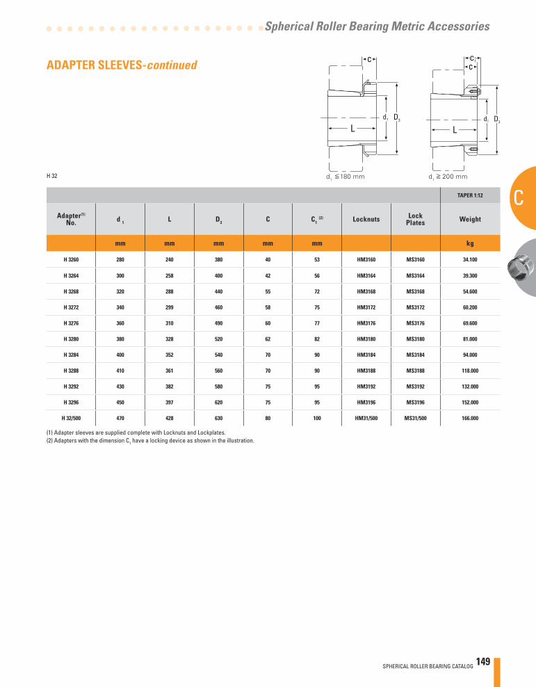
SPHERICAL ROLLER BEARING CATALOG 149
C
Spherical Roller Bearing Metric Accessories
TAPER 1:12
Adapter(1)
No. d 1 L D3 C C1 (2) Locknuts Lock
Plates Weight
mm mm mm mm mm kg
H 3260 280 240 380 40 53 HM3160 MS3160 34.100
H 3264 300 258 400 42 56 HM3164 MS3164 39.300
H 3268 320 288 440 55 72 HM3168 MS3168 54.600
H 3272 340 299 460 58 75 HM3172 MS3172 60.200
H 3276 360 310 490 60 77 HM3176 MS3176 69.600
H 3280 380 328 520 62 82 HM3180 MS3180 81.000
H 3284 400 352 540 70 90 HM3184 MS3184 94.000
H 3288 410 361 560 70 90 HM3188 MS3188 118.000
H 3292 430 382 580 75 95 HM3192 MS3192 132.000
H 3296 450 397 620 75 95 HM3196 MS3196 152.000
H 32/500 470 428 630 80 100 HM31/500 MS31/500 166.000
(1) Adapter sleeves are supplied complete with Locknuts and Lockplates.(2) Adapters with the dimension C1 have a locking device as shown in the illustration.
H 32 d1 180 mm d
1 200 mm
c
Ld1 D3
c
Ld1 D3
c1ADAPTER SLEEVES-continued
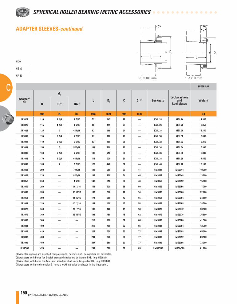
150 SPHERICAL ROLLER BEARING CATALOG
SPHERICAL ROLLER BEARING METRIC ACCESSORIES
C TAPER 1:12
Adapter(1)
No.
d1
L D3 C C1 (4) Locknuts
Lockwashersand
LockplatesWeight
H HE(2) HA(3)
mm in. in. mm mm mm mm kg
H 3024 110 4 1/4 4 3/16 72 145 22 — KML 24 MBL 24 1.930
H 3026 115 4 1/2 4 7/16 80 155 23 — KML 26 MBL 26 2.850
H 3028 125 5 4 15/16 82 165 24 — KML 28 MBL 28 3.160
H 3030 135 5 1/4 5 3/16 87 180 26 — KML 30 MBL 30 3.890
H 3032 140 5 1/2 5 7/16 93 190 28 — KML 32 MBL 32 5.210
H 3034 150 6 5 15/16 101 200 29 — KML 34 MBL 34 5.990
H 3036 160 6 1/2 6 7/16 109 210 30 — KML 36 MBL 36 6.830
H 3038 170 6 3/4 6 15/16 112 220 31 — KML 38 MBL 38 7.450
H 3040 180 7 7 3/16 120 240 32 — KML 40 MBL 40 9.190
H 3044 200 — 7 15/16 128 260 30 41 HM3044 MS3044 10.300
H 3048 220 — 8 15/16 133 290 34 46 HM3048 MS3048 13.200
H 3052 240 — 9 7/16 147 310 34 46 HM3052 MS3052 15.300
H 3056 260 — 10 7/16 152 330 38 50 HM3056 MS3056 17.700
H 3060 280 — 10 15/16 168 360 42 54 HM3060 MS3060 22.800
H 3064 300 — 11 15/16 171 380 42 55 HM3064 MS3064 24.600
H 3068 320 — 12 7/16 187 400 45 58 HM3068 MS3068 28.700
H 3072 340 — 13 7/16 188 420 45 58 HM3072 MS3072 30.500
H 3076 360 — 13 15/16 193 450 48 62 HM3076 MS3076 35.800
H 3080 380 — — 210 470 52 66 HM3080 MS3080 41.300
H 3084 400 — — 212 490 52 66 HM3084 MS3084 43.700
H 3088 410 — — 228 520 60 77 HM3088 MS3088 65.200
H 3092 430 — — 234 540 60 77 HM3092 MS3092 69.500
H 3096 450 — — 237 560 60 77 HM3096 MS3096 73.300
H 30/500 470 — — 247 580 68 85 HM30/500 MS30/500 81.800
H 30
HE 30
HA 30
(1) Adapter sleeves are supplied complete with Locknuts and Lockwasher or Lockplates.(2) Adapters with bores for English standard shafts are designated HE, (e.g. HE3024).(3) Adapters with bores for American standard shafts are designated HA, (e.g. HA3024).(4) Adapters with the dimension C1 have a locking device as shown in the illustration.
d1 180 mm d
1 200 mm
c
Ld1 D3
c
Ld1 D3
c1ADAPTER SLEEVES-continued
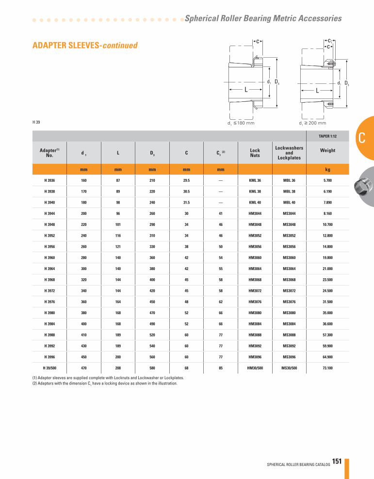
SPHERICAL ROLLER BEARING CATALOG 151
C
Spherical Roller Bearing Metric Accessories
TAPER 1:12
Adapter(1)
No. d 1 L D3 C C1 (2) Lock
NutsLockwashers
andLockplates
Weight
mm mm mm mm mm kg
H 3936 160 87 210 29.5 — KML 36 MBL 36 5.700
H 3938 170 89 220 30.5 — KML 38 MBL 38 6.190
H 3940 180 98 240 31.5 — KML 40 MBL 40 7.890
H 3944 200 96 260 30 41 HM3044 MS3044 8.160
H 3948 220 101 290 34 46 HM3048 MS3048 10.700
H 3952 240 116 310 34 46 HM3052 MS3052 12.800
H 3956 260 121 330 38 50 HM3056 MS3056 14.800
H 3960 280 140 360 42 54 HM3060 MS3060 19.800
H 3964 300 140 380 42 55 HM3064 MS3064 21.000
H 3968 320 144 400 45 58 HM3068 MS3068 23.500
H 3972 340 144 420 45 58 HM3072 MS3072 24.500
H 3976 360 164 450 48 62 HM3076 MS3076 31.500
H 3980 380 168 470 52 66 HM3080 MS3080 35.000
H 3984 400 168 490 52 66 HM3084 MS3084 36.600
H 3988 410 189 520 60 77 HM3088 MS3088 57.300
H 3992 430 189 540 60 77 HM3092 MS3092 59.900
H 3996 450 200 560 60 77 HM3096 MS3096 64.900
H 39/500 470 208 580 68 85 HM30/500 MS30/500 73.100
(1) Adapter sleeves are supplied complete with Locknuts and Lockwasher or Lockplates.(2) Adapters with the dimension C1 have a locking device as shown in the illustration.
H 39 d1 180 mm d
1 200 mm
c
Ld1 D3
c
Ld1 D3
c1ADAPTER SLEEVES-continued
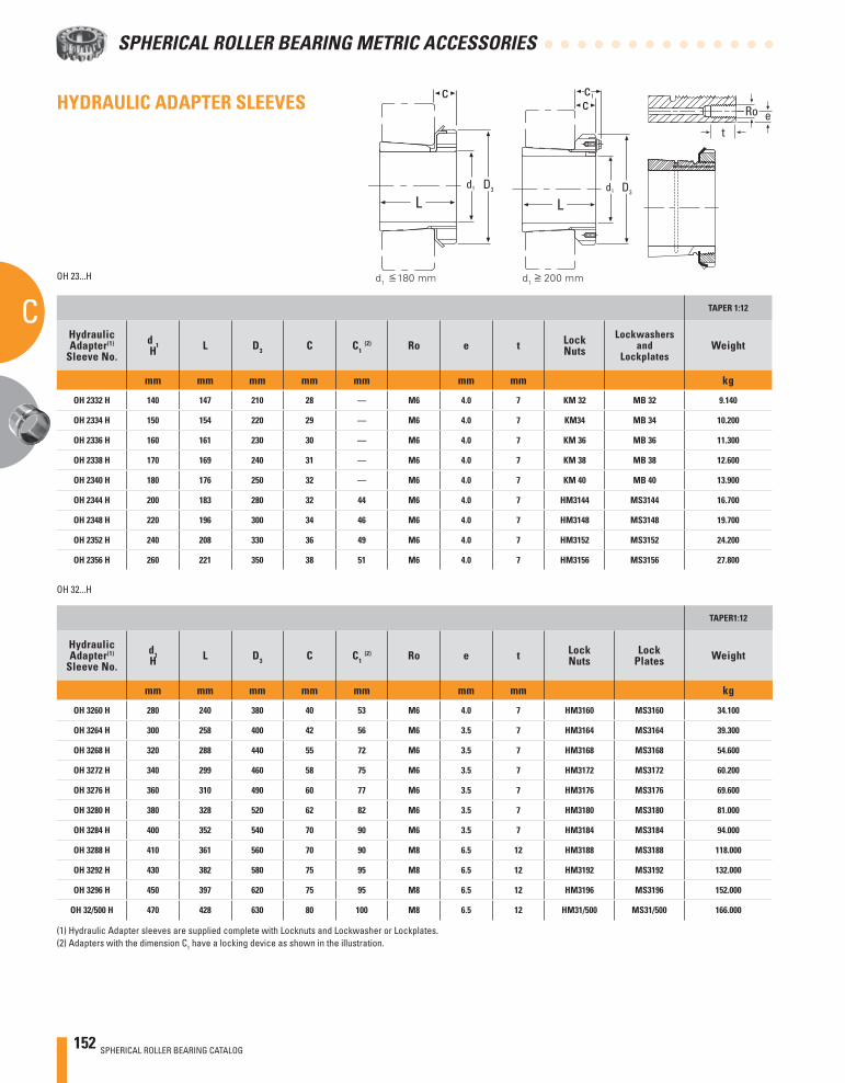
152 SPHERICAL ROLLER BEARING CATALOG
SPHERICAL ROLLER BEARING METRIC ACCESSORIES
COH 23...H
TAPER 1:12
HydraulicAdapter(1)
Sleeve No.d 1H L D3 C C1
(2) Ro e t LockNuts
Lockwashersand
LockplatesWeight
mm mm mm mm mm mm mm kg
OH 2332 H 140 147 210 28 — M6 4.0 7 KM 32 MB 32 9.140
OH 2334 H 150 154 220 29 — M6 4.0 7 KM34 MB 34 10.200
OH 2336 H 160 161 230 30 — M6 4.0 7 KM 36 MB 36 11.300
OH 2338 H 170 169 240 31 — M6 4.0 7 KM 38 MB 38 12.600
OH 2340 H 180 176 250 32 — M6 4.0 7 KM 40 MB 40 13.900
OH 2344 H 200 183 280 32 44 M6 4.0 7 HM3144 MS3144 16.700
OH 2348 H 220 196 300 34 46 M6 4.0 7 HM3148 MS3148 19.700
OH 2352 H 240 208 330 36 49 M6 4.0 7 HM3152 MS3152 24.200
OH 2356 H 260 221 350 38 51 M6 4.0 7 HM3156 MS3156 27.800
OH 32...H
TAPER1:12
HydraulicAdapter(1)
Sleeve No.d1H L D3 C C1
(2) Ro e t LockNuts
LockPlates Weight
mm mm mm mm mm mm mm kg
OH 3260 H 280 240 380 40 53 M6 4.0 7 HM3160 MS3160 34.100
OH 3264 H 300 258 400 42 56 M6 3.5 7 HM3164 MS3164 39.300
OH 3268 H 320 288 440 55 72 M6 3.5 7 HM3168 MS3168 54.600
OH 3272 H 340 299 460 58 75 M6 3.5 7 HM3172 MS3172 60.200
OH 3276 H 360 310 490 60 77 M6 3.5 7 HM3176 MS3176 69.600
OH 3280 H 380 328 520 62 82 M6 3.5 7 HM3180 MS3180 81.000
OH 3284 H 400 352 540 70 90 M6 3.5 7 HM3184 MS3184 94.000
OH 3288 H 410 361 560 70 90 M8 6.5 12 HM3188 MS3188 118.000
OH 3292 H 430 382 580 75 95 M8 6.5 12 HM3192 MS3192 132.000
OH 3296 H 450 397 620 75 95 M8 6.5 12 HM3196 MS3196 152.000
OH 32/500 H 470 428 630 80 100 M8 6.5 12 HM31/500 MS31/500 166.000
(1) Hydraulic Adapter sleeves are supplied complete with Locknuts and Lockwasher or Lockplates.(2) Adapters with the dimension C1 have a locking device as shown in the illustration.
eRo
t
d1 180 mm d
1 200 mm
HYDRAULIC ADAPTER SLEEVES c
Ld1 D3
c
Ld1 D3
c1
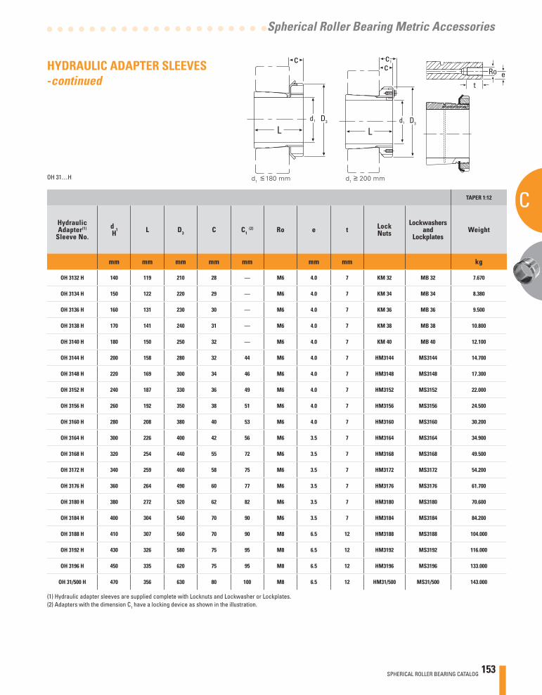
SPHERICAL ROLLER BEARING CATALOG 153
C
Spherical Roller Bearing Metric Accessories
TAPER 1:12
HydraulicAdapter(1)
Sleeve No.d 1H L D3 C C1
(2) Ro e t LockNuts
Lockwashersand
LockplatesWeight
mm mm mm mm mm mm mm kg
OH 3132 H 140 119 210 28 — M6 4.0 7 KM 32 MB 32 7.670
OH 3134 H 150 122 220 29 — M6 4.0 7 KM 34 MB 34 8.380
OH 3136 H 160 131 230 30 — M6 4.0 7 KM 36 MB 36 9.500
OH 3138 H 170 141 240 31 — M6 4.0 7 KM 38 MB 38 10.800
OH 3140 H 180 150 250 32 — M6 4.0 7 KM 40 MB 40 12.100
OH 3144 H 200 158 280 32 44 M6 4.0 7 HM3144 MS3144 14.700
OH 3148 H 220 169 300 34 46 M6 4.0 7 HM3148 MS3148 17.300
OH 3152 H 240 187 330 36 49 M6 4.0 7 HM3152 MS3152 22.000
OH 3156 H 260 192 350 38 51 M6 4.0 7 HM3156 MS3156 24.500
OH 3160 H 280 208 380 40 53 M6 4.0 7 HM3160 MS3160 30.200
OH 3164 H 300 226 400 42 56 M6 3.5 7 HM3164 MS3164 34.900
OH 3168 H 320 254 440 55 72 M6 3.5 7 HM3168 MS3168 49.500
OH 3172 H 340 259 460 58 75 M6 3.5 7 HM3172 MS3172 54.200
OH 3176 H 360 264 490 60 77 M6 3.5 7 HM3176 MS3176 61.700
OH 3180 H 380 272 520 62 82 M6 3.5 7 HM3180 MS3180 70.600
OH 3184 H 400 304 540 70 90 M6 3.5 7 HM3184 MS3184 84.200
OH 3188 H 410 307 560 70 90 M8 6.5 12 HM3188 MS3188 104.000
OH 3192 H 430 326 580 75 95 M8 6.5 12 HM3192 MS3192 116.000
OH 3196 H 450 335 620 75 95 M8 6.5 12 HM3196 MS3196 133.000
OH 31/500 H 470 356 630 80 100 M8 6.5 12 HM31/500 MS31/500 143.000
OH 31…H
(1) Hydraulic adapter sleeves are supplied complete with Locknuts and Lockwasher or Lockplates.(2) Adapters with the dimension C1 have a locking device as shown in the illustration.
HYDRAULIC ADAPTER SLEEVES -continued
d1 180 mm d
1 200 mm
eRo
t
c
Ld1 D3
c
Ld1 D3
c1
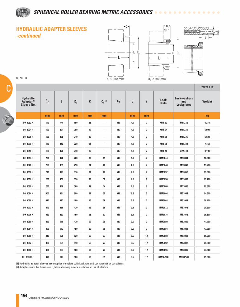
154 SPHERICAL ROLLER BEARING CATALOG
SPHERICAL ROLLER BEARING METRIC ACCESSORIES
C TAPER 1:12
HydraulicAdapter(1)
Sleeve No.d 1H L D3 C C1
(2) Ro e t LockNuts
Lockwashersand
LockplatesWeight
mm mm mm mm mm mm mm kg
OH 3032 H 140 93 190 28 — M6 4.0 7 KML 32 MBL 32 5.210
OH 3034 H 150 101 200 29 — M6 4.0 7 KML 34 MBL 34 5.990
OH 3036 H 160 109 210 30 — M6 4.0 7 KML 36 MBL 36 6.830
OH 3038 H 170 112 220 31 — M6 4.0 7 KML 38 MBL 38 7.450
OH 3040 H 180 120 240 32 — M6 4.0 7 KML 40 AWL 40 9.190
OH 3044 H 200 128 260 30 41 M6 4.0 7 HM3044 MS3044 10.300
OH 3048 H 220 133 290 34 46 M6 4.0 7 HM3048 MS3048 13.200
OH 3052 H 240 147 310 34 46 M6 4.0 7 HM3052 MS3052 15.300
OH 3056 H 260 152 330 38 50 M6 4.0 7 HM3056 MS3056 17.700
OH 3060 H 280 168 360 42 54 M6 4.0 7 HM3060 MS3060 22.800
OH 3064 H 300 171 380 42 55 M6 3.5 7 HM3064 MS3064 24.600
OH 3068 H 320 187 400 45 58 M6 3.5 7 HM3068 MS3068 28.700
OH 3072 H 340 188 420 45 58 M6 3.5 7 HM3072 MS3072 30.500
OH 3076 H 360 193 450 48 62 M6 3.5 7 HM3076 MS3076 35.800
OH 3080 H 380 210 470 52 66 M6 3.5 7 HM3080 MS3080 41.300
OH 3084 H 400 212 490 52 66 M6 3.5 7 HM3084 MS3084 43.700
OH 3088 H 410 228 520 60 77 M8 6.5 12 HM3088 MS3088 65.200
OH 3092 H 430 234 540 60 77 M8 6.5 12 HM3092 MS3092 69.500
OH 3096 H 450 237 560 60 77 M8 6.5 12 HM3096 MS3096 73.300
OH 30/500 H 470 247 580 68 85 M8 6.5 12 HM30/500 MS30/500 81.800
OH 30…H
(1) Hydraulic adapter sleeves are supplied complete with Locknuts and Lockwasher or Lockplates.(2) Adapters with the dimension C1 have a locking device as shown in the illustration.
d1 180 mm d
1 200 mm
eRo
t
c
Ld1 D3
c
Ld1 D3
c1HYDRAULIC ADAPTER SLEEVES -continued
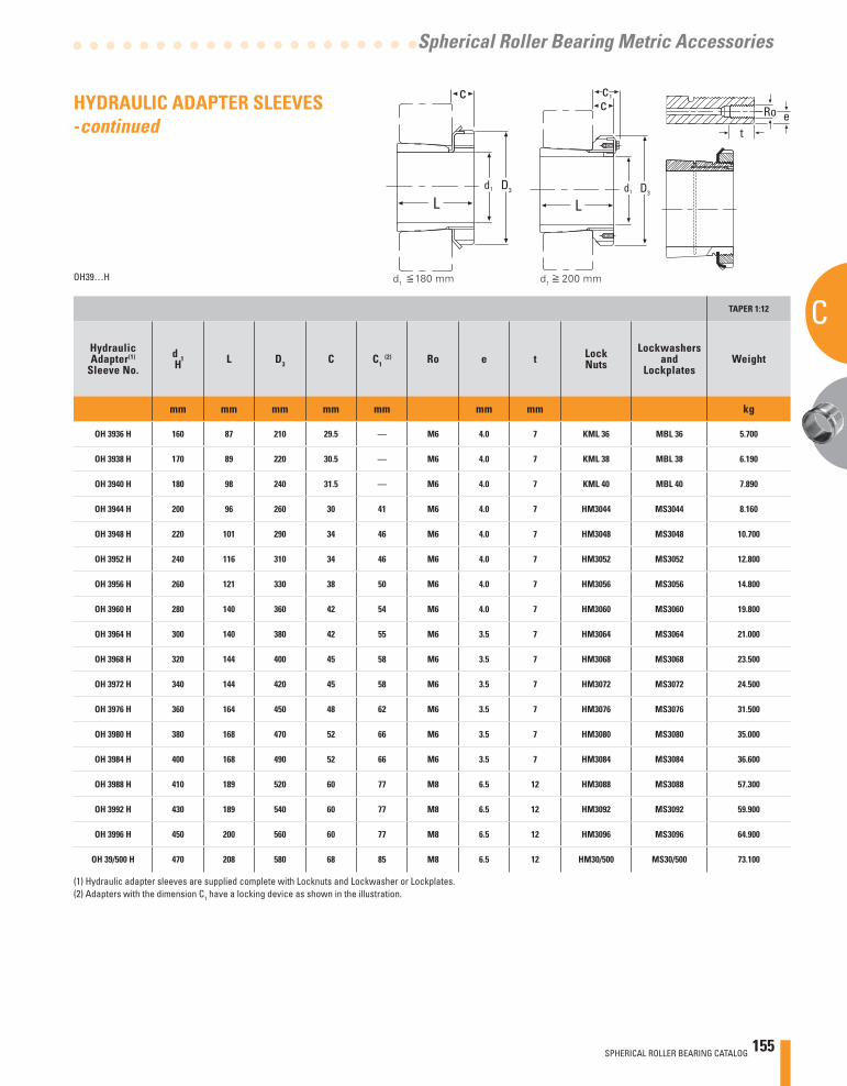
SPHERICAL ROLLER BEARING CATALOG 155
C
Spherical Roller Bearing Metric Accessories
TAPER 1:12
HydraulicAdapter(1)
Sleeve No.d 1H L D3 C C1
(2) Ro e t LockNuts
Lockwashersand
LockplatesWeight
mm mm mm mm mm mm mm kg
OH 3936 H 160 87 210 29.5 — M6 4.0 7 KML 36 MBL 36 5.700
OH 3938 H 170 89 220 30.5 — M6 4.0 7 KML 38 MBL 38 6.190
OH 3940 H 180 98 240 31.5 — M6 4.0 7 KML 40 MBL 40 7.890
OH 3944 H 200 96 260 30 41 M6 4.0 7 HM3044 MS3044 8.160
OH 3948 H 220 101 290 34 46 M6 4.0 7 HM3048 MS3048 10.700
OH 3952 H 240 116 310 34 46 M6 4.0 7 HM3052 MS3052 12.800
OH 3956 H 260 121 330 38 50 M6 4.0 7 HM3056 MS3056 14.800
OH 3960 H 280 140 360 42 54 M6 4.0 7 HM3060 MS3060 19.800
OH 3964 H 300 140 380 42 55 M6 3.5 7 HM3064 MS3064 21.000
OH 3968 H 320 144 400 45 58 M6 3.5 7 HM3068 MS3068 23.500
OH 3972 H 340 144 420 45 58 M6 3.5 7 HM3072 MS3072 24.500
OH 3976 H 360 164 450 48 62 M6 3.5 7 HM3076 MS3076 31.500
OH 3980 H 380 168 470 52 66 M6 3.5 7 HM3080 MS3080 35.000
OH 3984 H 400 168 490 52 66 M6 3.5 7 HM3084 MS3084 36.600
OH 3988 H 410 189 520 60 77 M8 6.5 12 HM3088 MS3088 57.300
OH 3992 H 430 189 540 60 77 M8 6.5 12 HM3092 MS3092 59.900
OH 3996 H 450 200 560 60 77 M8 6.5 12 HM3096 MS3096 64.900
OH 39/500 H 470 208 580 68 85 M8 6.5 12 HM30/500 MS30/500 73.100
OH39…H
(1) Hydraulic adapter sleeves are supplied complete with Locknuts and Lockwasher or Lockplates.(2) Adapters with the dimension C1 have a locking device as shown in the illustration.
d1 180 mm d
1 200 mm
eRo
t
c
Ld1 D3
c
Ld1 D3
c1HYDRAULIC ADAPTER SLEEVES -continued
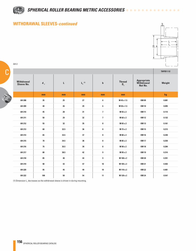
156 SPHERICAL ROLLER BEARING CATALOG
SPHERICAL ROLLER BEARING METRIC ACCESSORIES
C
WITHDRAWAL SLEEVES-continued
AH 2
TAPER 1:12
WithdrawalSleeve No. d 1 L L1
(1) b ThreadD1
AppropriateWithdrawal
Nut No.Weight
mm mm mm mm mm kg
AH 208 35 25 27 6 M 45 x 1.5 KM 09 0.081
AH 209 40 26 29 6 M 50 x 1.5 KM 10 0.095
AH 210 45 28 31 7 M 55 x 2 KM 11 0.114
AH 211 50 29 32 7 M 60 x 2 KM 12 0.132
AH 212 55 32 35 8 M 65 x 2 KM 13 0.161
AH 213 60 32.5 36 8 M 75 x 2 KM 15 0.213
AH 214 65 33.5 37 8 M 80 x 2 KM 16 0.240
AH 215 70 34.5 38 8 M 85 x 2 KM 17 0.259
AH 216 75 35.5 39 8 M 90 x 2 KM 18 0.284
AH 217 80 38.5 42 9 M 95 x 2 KM 19 0.314
AH 218 85 40 44 9 M 100 x 2 KM 20 0.351
AH 219 90 43 47 10 M 105 x 2 KM 21 0.403
AH 220 95 45 49 10 M 110 x 2 KM 22 0.481
AH 222 100 50 54 11 M 120 x 2 KM 24 0.547
(1) Dimension L1 decreases as the withdrawal sleeve is driven in during mounting.
d1
b
D1
L1
L
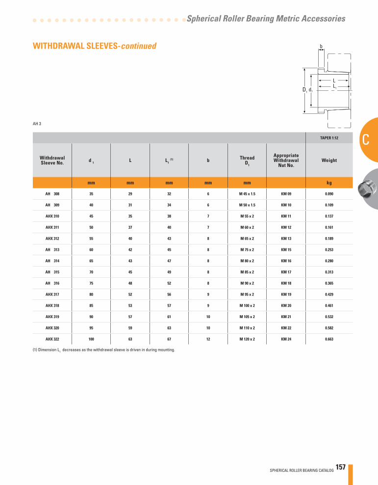
SPHERICAL ROLLER BEARING CATALOG 157
C
Spherical Roller Bearing Metric Accessories
WITHDRAWAL SLEEVES-continued
AH 3
TAPER 1:12
WithdrawalSleeve No. d 1 L L1
(1) b ThreadD1
AppropriateWithdrawal
Nut No.Weight
mm mm mm mm mm kg
AH 308 35 29 32 6 M 45 x 1.5 KM 09 0.090
AH 309 40 31 34 6 M 50 x 1.5 KM 10 0.109
AHX 310 45 35 38 7 M 55 x 2 KM 11 0.137
AHX 311 50 37 40 7 M 60 x 2 KM 12 0.161
AHX 312 55 40 43 8 M 65 x 2 KM 13 0.189
AH 313 60 42 45 8 M 75 x 2 KM 15 0.253
AH 314 65 43 47 8 M 80 x 2 KM 16 0.280
AH 315 70 45 49 8 M 85 x 2 KM 17 0.313
AH 316 75 48 52 8 M 90 x 2 KM 18 0.365
AHX 317 80 52 56 9 M 95 x 2 KM 19 0.429
AHX 318 85 53 57 9 M 100 x 2 KM 20 0.461
AHX 319 90 57 61 10 M 105 x 2 KM 21 0.532
AHX 320 95 59 63 10 M 110 x 2 KM 22 0.582
AHX 322 100 63 67 12 M 120 x 2 KM 24 0.663
(1) Dimension L1 decreases as the withdrawal sleeve is driven in during mounting.
d1
b
D1
L1
L
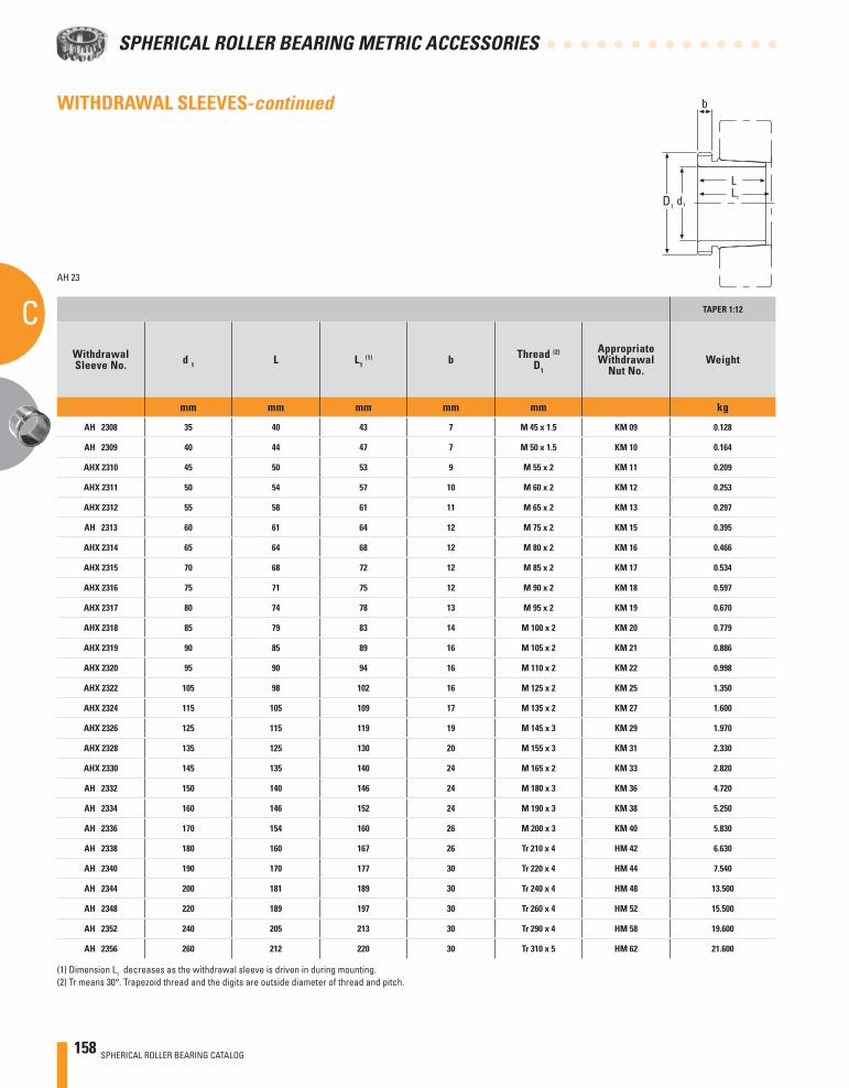
158 SPHERICAL ROLLER BEARING CATALOG
SPHERICAL ROLLER BEARING METRIC ACCESSORIES
CAH 23
TAPER 1:12
WithdrawalSleeve No. d 1 L L1
(1) b Thread (2)
D1
AppropriateWithdrawal
Nut No.Weight
mm mm mm mm mm kg
AH 2308 35 40 43 7 M 45 x 1.5 KM 09 0.128
AH 2309 40 44 47 7 M 50 x 1.5 KM 10 0.164
AHX 2310 45 50 53 9 M 55 x 2 KM 11 0.209
AHX 2311 50 54 57 10 M 60 x 2 KM 12 0.253
AHX 2312 55 58 61 11 M 65 x 2 KM 13 0.297
AH 2313 60 61 64 12 M 75 x 2 KM 15 0.395
AHX 2314 65 64 68 12 M 80 x 2 KM 16 0.466
AHX 2315 70 68 72 12 M 85 x 2 KM 17 0.534
AHX 2316 75 71 75 12 M 90 x 2 KM 18 0.597
AHX 2317 80 74 78 13 M 95 x 2 KM 19 0.670
AHX 2318 85 79 83 14 M 100 x 2 KM 20 0.779
AHX 2319 90 85 89 16 M 105 x 2 KM 21 0.886
AHX 2320 95 90 94 16 M 110 x 2 KM 22 0.998
AHX 2322 105 98 102 16 M 125 x 2 KM 25 1.350
AHX 2324 115 105 109 17 M 135 x 2 KM 27 1.600
AHX 2326 125 115 119 19 M 145 x 3 KM 29 1.970
AHX 2328 135 125 130 20 M 155 x 3 KM 31 2.330
AHX 2330 145 135 140 24 M 165 x 2 KM 33 2.820
AH 2332 150 140 146 24 M 180 x 3 KM 36 4.720
AH 2334 160 146 152 24 M 190 x 3 KM 38 5.250
AH 2336 170 154 160 26 M 200 x 3 KM 40 5.830
AH 2338 180 160 167 26 Tr 210 x 4 HM 42 6.630
AH 2340 190 170 177 30 Tr 220 x 4 HM 44 7.540
AH 2344 200 181 189 30 Tr 240 x 4 HM 48 13.500
AH 2348 220 189 197 30 Tr 260 x 4 HM 52 15.500
AH 2352 240 205 213 30 Tr 290 x 4 HM 58 19.600
AH 2356 260 212 220 30 Tr 310 x 5 HM 62 21.600
(1) Dimension L1 decreases as the withdrawal sleeve is driven in during mounting.(2) Tr means 30°. Trapezoid thread and the digits are outside diameter of thread and pitch.
d1
b
D1
L1
L
WITHDRAWAL SLEEVES-continued
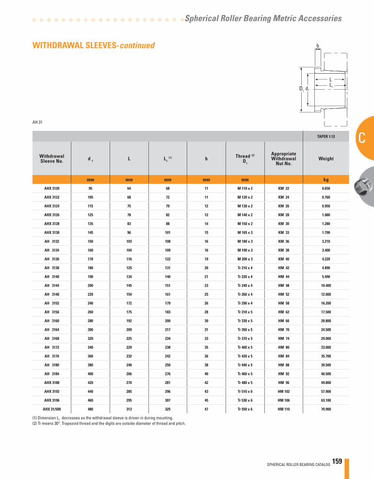
SPHERICAL ROLLER BEARING CATALOG 159
C
Spherical Roller Bearing Metric Accessories
AH 31
TAPER 1:12
WithdrawalSleeve No. d 1 L L1
(1) b Thread (2)
D1
AppropriateWithdrawal
Nut No.Weight
mm mm mm mm mm kg
AHX 3120 95 64 68 11 M 110 x 2 KM 22 0.650
AHX 3122 105 68 72 11 M 120 x 2 KM 24 0.760
AHX 3124 115 75 79 12 M 130 x 2 KM 26 0.950
AHX 3126 125 78 82 12 M 140 x 2 KM 28 1.080
AHX 3128 135 83 88 14 M 150 x 2 KM 30 1.280
AHX 3130 145 96 101 15 M 165 x 3 KM 33 1.790
AH 3132 150 103 108 16 M 180 x 3 KM 36 3.210
AH 3134 160 104 109 16 M 190 x 3 KM 38 3.400
AH 3136 170 116 122 19 M 200 x 3 KM 40 4.220
AH 3138 180 125 131 20 Tr 210 x 4 HM 42 4.890
AH 3140 190 134 140 21 Tr 220 x 4 HM 44 5.490
AH 3144 200 145 151 23 Tr 240 x 4 HM 48 10.400
AH 3148 220 154 161 25 Tr 260 x 4 HM 52 12.000
AH 3152 240 172 179 26 Tr 290 x 4 HM 58 16.200
AH 3156 260 175 183 28 Tr 310 x 5 HM 62 17.500
AH 3160 280 192 200 30 Tr 330 x 5 HM 66 20.800
AH 3164 300 209 217 31 Tr 350 x 5 HM 70 24.500
AH 3168 320 225 234 33 Tr 370 x 5 HM 74 29.000
AH 3172 340 229 238 35 Tr 400 x 5 HM 80 33.000
AH 3176 360 232 242 36 Tr 420 x 5 HM 84 35.700
AH 3180 380 240 250 38 Tr 440 x 5 HM 88 39.500
AH 3184 400 266 276 40 Tr 460 x 5 HM 92 46.500
AHX 3188 420 270 281 42 Tr 480 x 5 HM 96 49.800
AHX 3192 440 285 296 43 Tr 510 x 6 HM 102 57.900
AHX 3196 460 295 307 45 Tr 530 x 6 HM 106 63.100
AHX 31/500 480 313 325 47 Tr 550 x 6 HM 110 70.900
(1) Dimension L1 decreases as the withdrawal sleeve is driven in during mounting.(2) Tr means 30°. Trapezoid thread and the digits are outside diameter of thread and pitch.
d1
b
D1
L1
L
WITHDRAWAL SLEEVES-continued
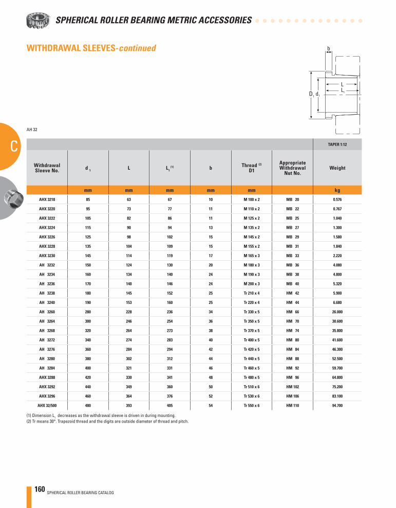
160 SPHERICAL ROLLER BEARING CATALOG
SPHERICAL ROLLER BEARING METRIC ACCESSORIES
CAH 32
TAPER 1:12
WithdrawalSleeve No. d 1 L L1
(1) b Thread (2)
D1AppropriateWithdrawal
Nut No.Weight
mm mm mm mm mm kg
AHX 3218 85 63 67 10 M 100 x 2 MB 20 0.576
AHX 3220 95 73 77 11 M 110 x 2 MB 22 0.767
AHX 3222 105 82 86 11 M 125 x 2 MB 25 1.040
AHX 3224 115 90 94 13 M 135 x 2 MB 27 1.300
AHX 3226 125 98 102 15 M 145 x 2 MB 29 1.580
AHX 3228 135 104 109 15 M 155 x 2 MB 31 1.840
AHX 3230 145 114 119 17 M 165 x 3 MB 33 2.220
AH 3232 150 124 130 20 M 180 x 3 MB 36 4.080
AH 3234 160 134 140 24 M 190 x 3 MB 38 4.800
AH 3236 170 140 146 24 M 200 x 3 MB 40 5.320
AH 3238 180 145 152 25 Tr 210 x 4 HM 42 5.900
AH 3240 190 153 160 25 Tr 220 x 4 HM 44 6.680
AH 3260 280 228 236 34 Tr 330 x 5 HM 66 26.000
AH 3264 300 246 254 36 Tr 350 x 5 HM 70 30.600
AH 3268 320 264 273 38 Tr 370 x 5 HM 74 35.800
AH 3272 340 274 283 40 Tr 400 x 5 HM 80 41.600
AH 3276 360 284 294 42 Tr 420 x 5 HM 84 46.300
AH 3280 380 302 312 44 Tr 440 x 5 HM 88 52.500
AH 3284 400 321 331 46 Tr 460 x 5 HM 92 59.700
AHX 3288 420 330 341 48 Tr 480 x 5 HM 96 64.800
AHX 3292 440 349 360 50 Tr 510 x 6 HM 102 75.200
AHX 3296 460 364 376 52 Tr 530 x 6 HM 106 83.100
AHX 32/500 480 393 405 54 Tr 550 x 6 HM 110 94.700
(1) Dimension L1 decreases as the withdrawal sleeve is driven in during mounting.(2) Tr means 30°. Trapezoid thread and the digits are outside diameter of thread and pitch.
d1
b
D1
L1
L
WITHDRAWAL SLEEVES-continued
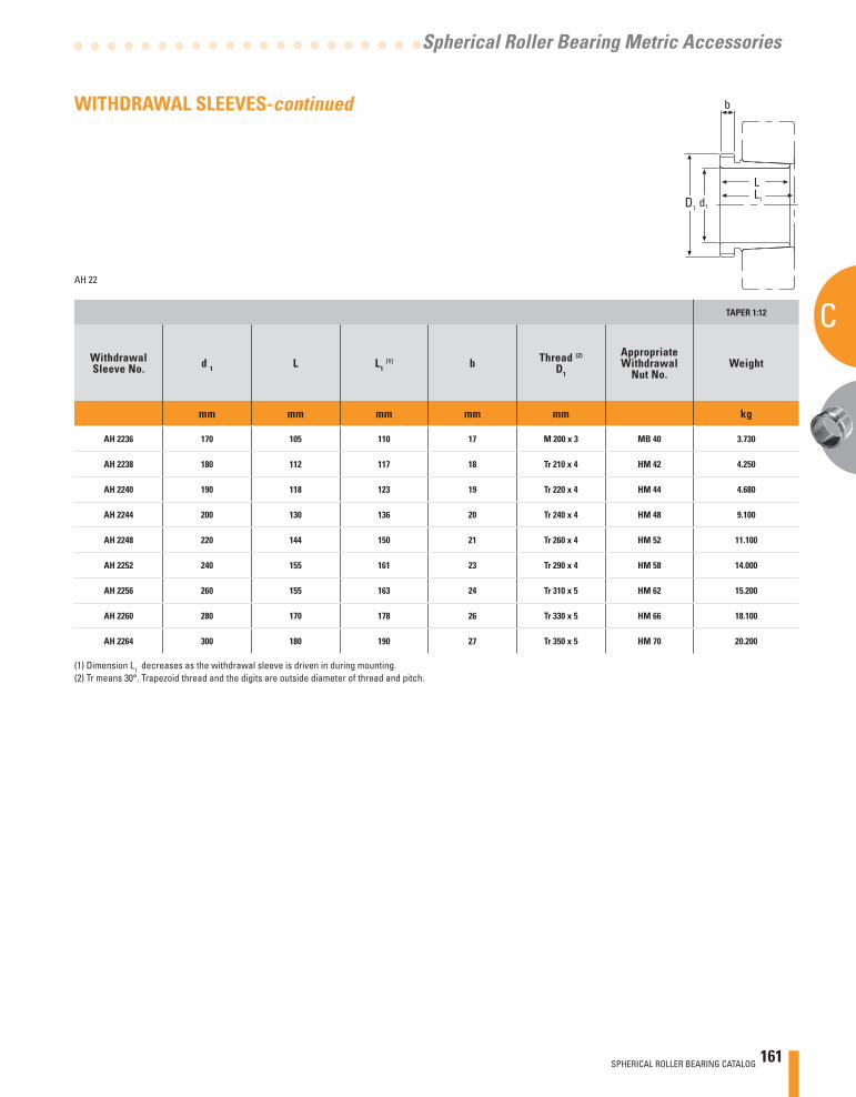
SPHERICAL ROLLER BEARING CATALOG 161
C
Spherical Roller Bearing Metric Accessories
AH 22
TAPER 1:12
WithdrawalSleeve No. d 1 L L1
(1) b Thread (2)
D1
AppropriateWithdrawal
Nut No.Weight
mm mm mm mm mm kg
AH 2236 170 105 110 17 M 200 x 3 MB 40 3.730
AH 2238 180 112 117 18 Tr 210 x 4 HM 42 4.250
AH 2240 190 118 123 19 Tr 220 x 4 HM 44 4.680
AH 2244 200 130 136 20 Tr 240 x 4 HM 48 9.100
AH 2248 220 144 150 21 Tr 260 x 4 HM 52 11.100
AH 2252 240 155 161 23 Tr 290 x 4 HM 58 14.000
AH 2256 260 155 163 24 Tr 310 x 5 HM 62 15.200
AH 2260 280 170 178 26 Tr 330 x 5 HM 66 18.100
AH 2264 300 180 190 27 Tr 350 x 5 HM 70 20.200
(1) Dimension L1 decreases as the withdrawal sleeve is driven in during mounting.(2) Tr means 30°. Trapezoid thread and the digits are outside diameter of thread and pitch.
d1
b
D1
L1
L
WITHDRAWAL SLEEVES-continued
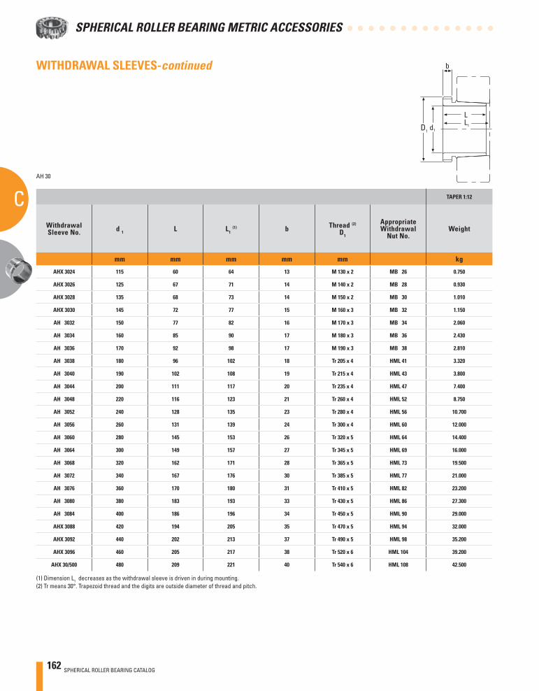
162 SPHERICAL ROLLER BEARING CATALOG
SPHERICAL ROLLER BEARING METRIC ACCESSORIES
CAH 30
TAPER 1:12
WithdrawalSleeve No. d 1 L L1
(1) b Thread (2)
D1
AppropriateWithdrawal
Nut No.Weight
mm mm mm mm mm kg
AHX 3024 115 60 64 13 M 130 x 2 MB 26 0.750
AHX 3026 125 67 71 14 M 140 x 2 MB 28 0.930
AHX 3028 135 68 73 14 M 150 x 2 MB 30 1.010
AHX 3030 145 72 77 15 M 160 x 3 MB 32 1.150
AH 3032 150 77 82 16 M 170 x 3 MB 34 2.060
AH 3034 160 85 90 17 M 180 x 3 MB 36 2.430
AH 3036 170 92 98 17 M 190 x 3 MB 38 2.810
AH 3038 180 96 102 18 Tr 205 x 4 HML 41 3.320
AH 3040 190 102 108 19 Tr 215 x 4 HML 43 3.800
AH 3044 200 111 117 20 Tr 235 x 4 HML 47 7.400
AH 3048 220 116 123 21 Tr 260 x 4 HML 52 8.750
AH 3052 240 128 135 23 Tr 280 x 4 HML 56 10.700
AH 3056 260 131 139 24 Tr 300 x 4 HML 60 12.000
AH 3060 280 145 153 26 Tr 320 x 5 HML 64 14.400
AH 3064 300 149 157 27 Tr 345 x 5 HML 69 16.000
AH 3068 320 162 171 28 Tr 365 x 5 HML 73 19.500
AH 3072 340 167 176 30 Tr 385 x 5 HML 77 21.000
AH 3076 360 170 180 31 Tr 410 x 5 HML 82 23.200
AH 3080 380 183 193 33 Tr 430 x 5 HML 86 27.300
AH 3084 400 186 196 34 Tr 450 x 5 HML 90 29.000
AHX 3088 420 194 205 35 Tr 470 x 5 HML 94 32.000
AHX 3092 440 202 213 37 Tr 490 x 5 HML 98 35.200
AHX 3096 460 205 217 38 Tr 520 x 6 HML 104 39.200
AHX 30/500 480 209 221 40 Tr 540 x 6 HML 108 42.500
(1) Dimension L1 decreases as the withdrawal sleeve is driven in during mounting.(2) Tr means 30°. Trapezoid thread and the digits are outside diameter of thread and pitch.
d1
b
D1
L1
L
WITHDRAWAL SLEEVES-continued
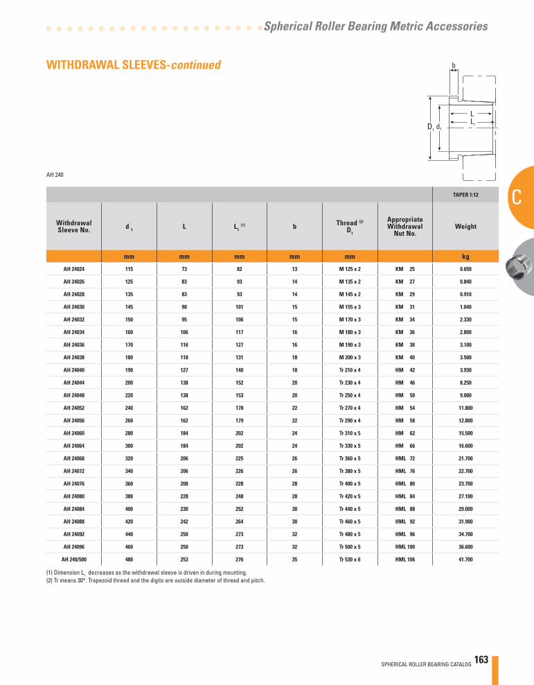
SPHERICAL ROLLER BEARING CATALOG 163
C
Spherical Roller Bearing Metric Accessories
AH 240
TAPER 1:12
WithdrawalSleeve No. d 1 L L1
(1) b Thread (2)
D1
AppropriateWithdrawal
Nut No.Weight
mm mm mm mm mm kg
AH 24024 115 73 82 13 M 125 x 2 KM 25 0.650
AH 24026 125 83 93 14 M 135 x 2 KM 27 0.840
AH 24028 135 83 93 14 M 145 x 2 KM 29 0.910
AH 24030 145 90 101 15 M 155 x 3 KM 31 1.040
AH 24032 150 95 106 15 M 170 x 3 KM 34 2.330
AH 24034 160 106 117 16 M 180 x 3 KM 36 2.800
AH 24036 170 116 127 16 M 190 x 3 KM 38 3.100
AH 24038 180 118 131 18 M 200 x 3 KM 40 3.500
AH 24040 190 127 140 18 Tr 210 x 4 HM 42 3.930
AH 24044 200 138 152 20 Tr 230 x 4 HM 46 8.250
AH 24048 220 138 153 20 Tr 250 x 4 HM 50 9.000
AH 24052 240 162 178 22 Tr 270 x 4 HM 54 11.800
AH 24056 260 162 179 22 Tr 290 x 4 HM 58 12.800
AH 24060 280 184 202 24 Tr 310 x 5 HM 62 15.500
AH 24064 300 184 202 24 Tr 330 x 5 HM 66 16.600
AH 24068 320 206 225 26 Tr 360 x 5 HML 72 21.700
AH 24072 340 206 226 26 Tr 380 x 5 HML 76 22.700
AH 24076 360 208 228 28 Tr 400 x 5 HML 80 23.700
AH 24080 380 228 248 28 Tr 420 x 5 HML 84 27.100
AH 24084 400 230 252 30 Tr 440 x 5 HML 88 29.000
AH 24088 420 242 264 30 Tr 460 x 5 HML 92 31.900
AH 24092 440 250 273 32 Tr 480 x 5 HML 96 34.700
AH 24096 460 250 273 32 Tr 500 x 5 HML 100 36.600
AH 240/500 480 253 276 35 Tr 530 x 6 HML 106 41.700
(1) Dimension L1 decreases as the withdrawal sleeve is driven in during mounting.(2) Tr means 30°. Trapezoid thread and the digits are outside diameter of thread and pitch.
d1
b
D1
L1
L
WITHDRAWAL SLEEVES-continued
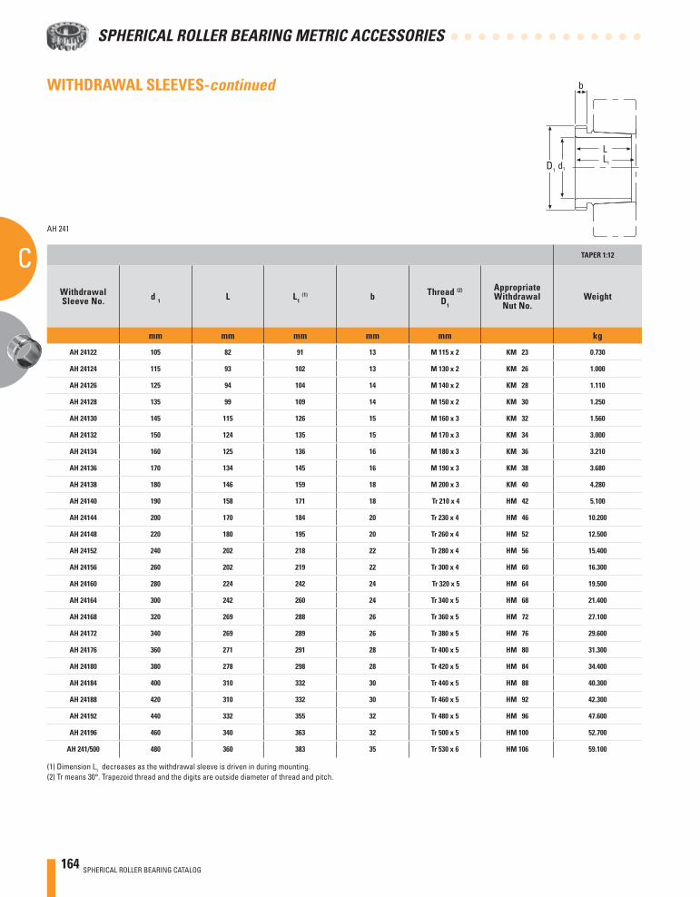
164 SPHERICAL ROLLER BEARING CATALOG
SPHERICAL ROLLER BEARING METRIC ACCESSORIES
CAH 241
TAPER 1:12
WithdrawalSleeve No. d 1 L L1
(1) b Thread (2)
D1
AppropriateWithdrawal
Nut No.Weight
mm mm mm mm mm kg
AH 24122 105 82 91 13 M 115 x 2 KM 23 0.730
AH 24124 115 93 102 13 M 130 x 2 KM 26 1.000
AH 24126 125 94 104 14 M 140 x 2 KM 28 1.110
AH 24128 135 99 109 14 M 150 x 2 KM 30 1.250
AH 24130 145 115 126 15 M 160 x 3 KM 32 1.560
AH 24132 150 124 135 15 M 170 x 3 KM 34 3.000
AH 24134 160 125 136 16 M 180 x 3 KM 36 3.210
AH 24136 170 134 145 16 M 190 x 3 KM 38 3.680
AH 24138 180 146 159 18 M 200 x 3 KM 40 4.280
AH 24140 190 158 171 18 Tr 210 x 4 HM 42 5.100
AH 24144 200 170 184 20 Tr 230 x 4 HM 46 10.200
AH 24148 220 180 195 20 Tr 260 x 4 HM 52 12.500
AH 24152 240 202 218 22 Tr 280 x 4 HM 56 15.400
AH 24156 260 202 219 22 Tr 300 x 4 HM 60 16.300
AH 24160 280 224 242 24 Tr 320 x 5 HM 64 19.500
AH 24164 300 242 260 24 Tr 340 x 5 HM 68 21.400
AH 24168 320 269 288 26 Tr 360 x 5 HM 72 27.100
AH 24172 340 269 289 26 Tr 380 x 5 HM 76 29.600
AH 24176 360 271 291 28 Tr 400 x 5 HM 80 31.300
AH 24180 380 278 298 28 Tr 420 x 5 HM 84 34.400
AH 24184 400 310 332 30 Tr 440 x 5 HM 88 40.300
AH 24188 420 310 332 30 Tr 460 x 5 HM 92 42.300
AH 24192 440 332 355 32 Tr 480 x 5 HM 96 47.600
AH 24196 460 340 363 32 Tr 500 x 5 HM 100 52.700
AH 241/500 480 360 383 35 Tr 530 x 6 HM 106 59.100
(1) Dimension L1 decreases as the withdrawal sleeve is driven in during mounting.(2) Tr means 30°. Trapezoid thread and the digits are outside diameter of thread and pitch.
d1
b
D1
L1
L
WITHDRAWAL SLEEVES-continued
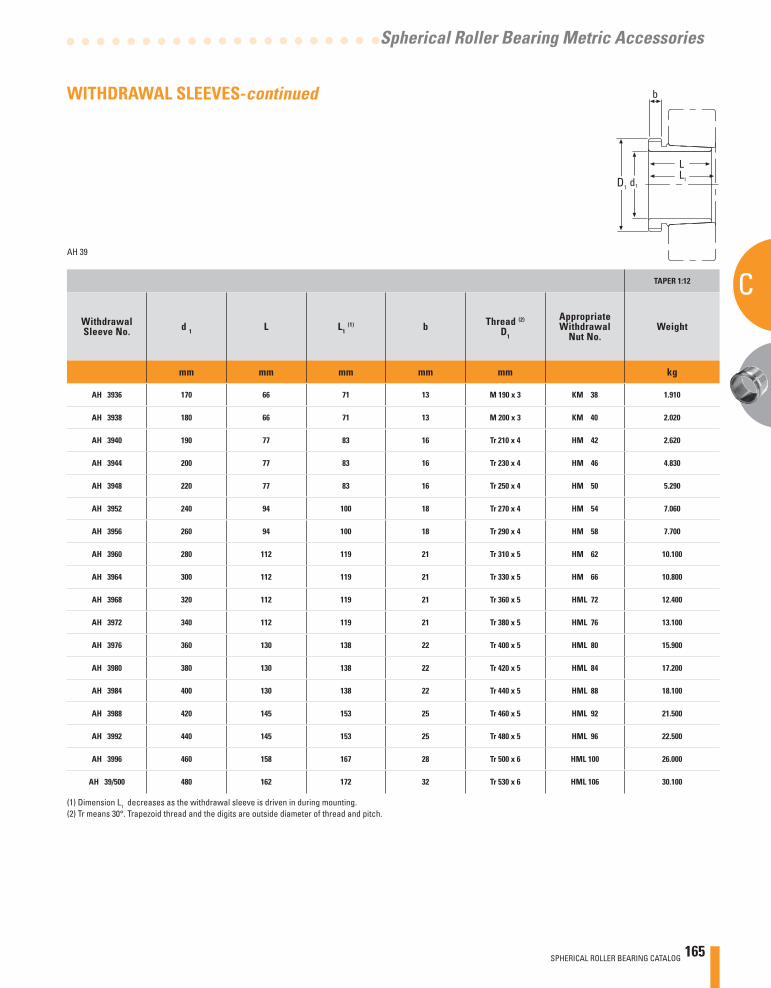
SPHERICAL ROLLER BEARING CATALOG 165
C
Spherical Roller Bearing Metric Accessories
AH 39
TAPER 1:12
WithdrawalSleeve No. d 1 L L1
(1) b Thread (2)
D1
AppropriateWithdrawal
Nut No.Weight
mm mm mm mm mm kg
AH 3936 170 66 71 13 M 190 x 3 KM 38 1.910
AH 3938 180 66 71 13 M 200 x 3 KM 40 2.020
AH 3940 190 77 83 16 Tr 210 x 4 HM 42 2.620
AH 3944 200 77 83 16 Tr 230 x 4 HM 46 4.830
AH 3948 220 77 83 16 Tr 250 x 4 HM 50 5.290
AH 3952 240 94 100 18 Tr 270 x 4 HM 54 7.060
AH 3956 260 94 100 18 Tr 290 x 4 HM 58 7.700
AH 3960 280 112 119 21 Tr 310 x 5 HM 62 10.100
AH 3964 300 112 119 21 Tr 330 x 5 HM 66 10.800
AH 3968 320 112 119 21 Tr 360 x 5 HML 72 12.400
AH 3972 340 112 119 21 Tr 380 x 5 HML 76 13.100
AH 3976 360 130 138 22 Tr 400 x 5 HML 80 15.900
AH 3980 380 130 138 22 Tr 420 x 5 HML 84 17.200
AH 3984 400 130 138 22 Tr 440 x 5 HML 88 18.100
AH 3988 420 145 153 25 Tr 460 x 5 HML 92 21.500
AH 3992 440 145 153 25 Tr 480 x 5 HML 96 22.500
AH 3996 460 158 167 28 Tr 500 x 6 HML 100 26.000
AH 39/500 480 162 172 32 Tr 530 x 6 HML 106 30.100
(1) Dimension L1 decreases as the withdrawal sleeve is driven in during mounting.(2) Tr means 30°. Trapezoid thread and the digits are outside diameter of thread and pitch.
d1
b
D1
L1
L
WITHDRAWAL SLEEVES-continued
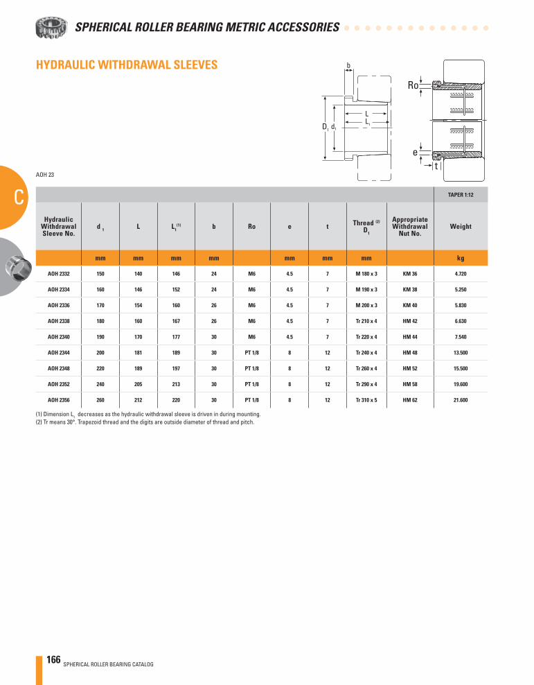
166 SPHERICAL ROLLER BEARING CATALOG
SPHERICAL ROLLER BEARING METRIC ACCESSORIES
C
HYDRAULIC WITHDRAWAL SLEEVES
AOH 23
TAPER 1:12
HydraulicWithdrawalSleeve No.
d 1 L L1(1) b Ro e t Thread (2)
D1
AppropriateWithdrawal
Nut No.Weight
mm mm mm mm mm mm mm kg
AOH 2332 150 140 146 24 M6 4.5 7 M 180 x 3 KM 36 4.720
AOH 2334 160 146 152 24 M6 4.5 7 M 190 x 3 KM 38 5.250
AOH 2336 170 154 160 26 M6 4.5 7 M 200 x 3 KM 40 5.830
AOH 2338 180 160 167 26 M6 4.5 7 Tr 210 x 4 HM 42 6.630
AOH 2340 190 170 177 30 M6 4.5 7 Tr 220 x 4 HM 44 7.540
AOH 2344 200 181 189 30 PT 1/8 8 12 Tr 240 x 4 HM 48 13.500
AOH 2348 220 189 197 30 PT 1/8 8 12 Tr 260 x 4 HM 52 15.500
AOH 2352 240 205 213 30 PT 1/8 8 12 Tr 290 x 4 HM 58 19.600
AOH 2356 260 212 220 30 PT 1/8 8 12 Tr 310 x 5 HM 62 21.600
(1) Dimension L1 decreases as the hydraulic withdrawal sleeve is driven in during mounting.(2) Tr means 30°. Trapezoid thread and the digits are outside diameter of thread and pitch.
et
Ro
d1
b
D1
L1
L
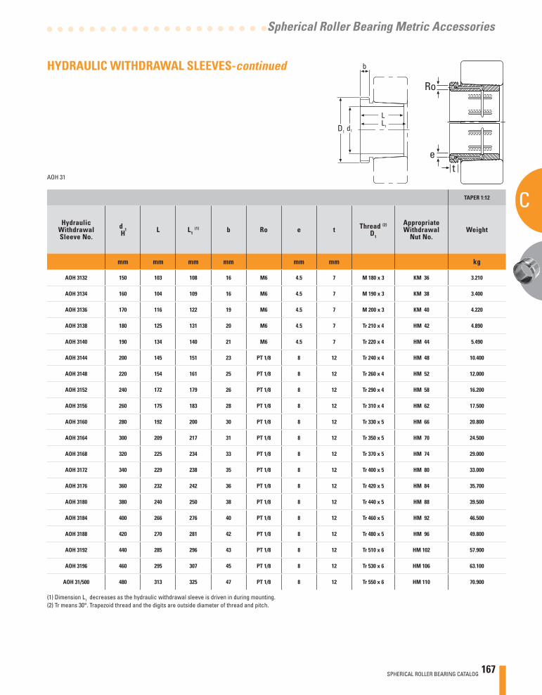
SPHERICAL ROLLER BEARING CATALOG 167
C
Spherical Roller Bearing Metric Accessories
AOH 31
TAPER 1:12
HydraulicWithdrawalSleeve No.
d 1H L L1
(1) b Ro e t Thread (2)
D1
AppropriateWithdrawal
Nut No.Weight
mm mm mm mm mm mm kg
AOH 3132 150 103 108 16 M6 4.5 7 M 180 x 3 KM 36 3.210
AOH 3134 160 104 109 16 M6 4.5 7 M 190 x 3 KM 38 3.400
AOH 3136 170 116 122 19 M6 4.5 7 M 200 x 3 KM 40 4.220
AOH 3138 180 125 131 20 M6 4.5 7 Tr 210 x 4 HM 42 4.890
AOH 3140 190 134 140 21 M6 4.5 7 Tr 220 x 4 HM 44 5.490
AOH 3144 200 145 151 23 PT 1/8 8 12 Tr 240 x 4 HM 48 10.400
AOH 3148 220 154 161 25 PT 1/8 8 12 Tr 260 x 4 HM 52 12.000
AOH 3152 240 172 179 26 PT 1/8 8 12 Tr 290 x 4 HM 58 16.200
AOH 3156 260 175 183 28 PT 1/8 8 12 Tr 310 x 4 HM 62 17.500
AOH 3160 280 192 200 30 PT 1/8 8 12 Tr 330 x 5 HM 66 20.800
AOH 3164 300 209 217 31 PT 1/8 8 12 Tr 350 x 5 HM 70 24.500
AOH 3168 320 225 234 33 PT 1/8 8 12 Tr 370 x 5 HM 74 29.000
AOH 3172 340 229 238 35 PT 1/8 8 12 Tr 400 x 5 HM 80 33.000
AOH 3176 360 232 242 36 PT 1/8 8 12 Tr 420 x 5 HM 84 35.700
AOH 3180 380 240 250 38 PT 1/8 8 12 Tr 440 x 5 HM 88 39.500
AOH 3184 400 266 276 40 PT 1/8 8 12 Tr 460 x 5 HM 92 46.500
AOH 3188 420 270 281 42 PT 1/8 8 12 Tr 480 x 5 HM 96 49.800
AOH 3192 440 285 296 43 PT 1/8 8 12 Tr 510 x 6 HM 102 57.900
AOH 3196 460 295 307 45 PT 1/8 8 12 Tr 530 x 6 HM 106 63.100
AOH 31/500 480 313 325 47 PT 1/8 8 12 Tr 550 x 6 HM 110 70.900
(1) Dimension L1 decreases as the hydraulic withdrawal sleeve is driven in during mounting.(2) Tr means 30°. Trapezoid thread and the digits are outside diameter of thread and pitch.
d1
b
D1
L1
L
et
Ro
HYDRAULIC WITHDRAWAL SLEEVES-continued
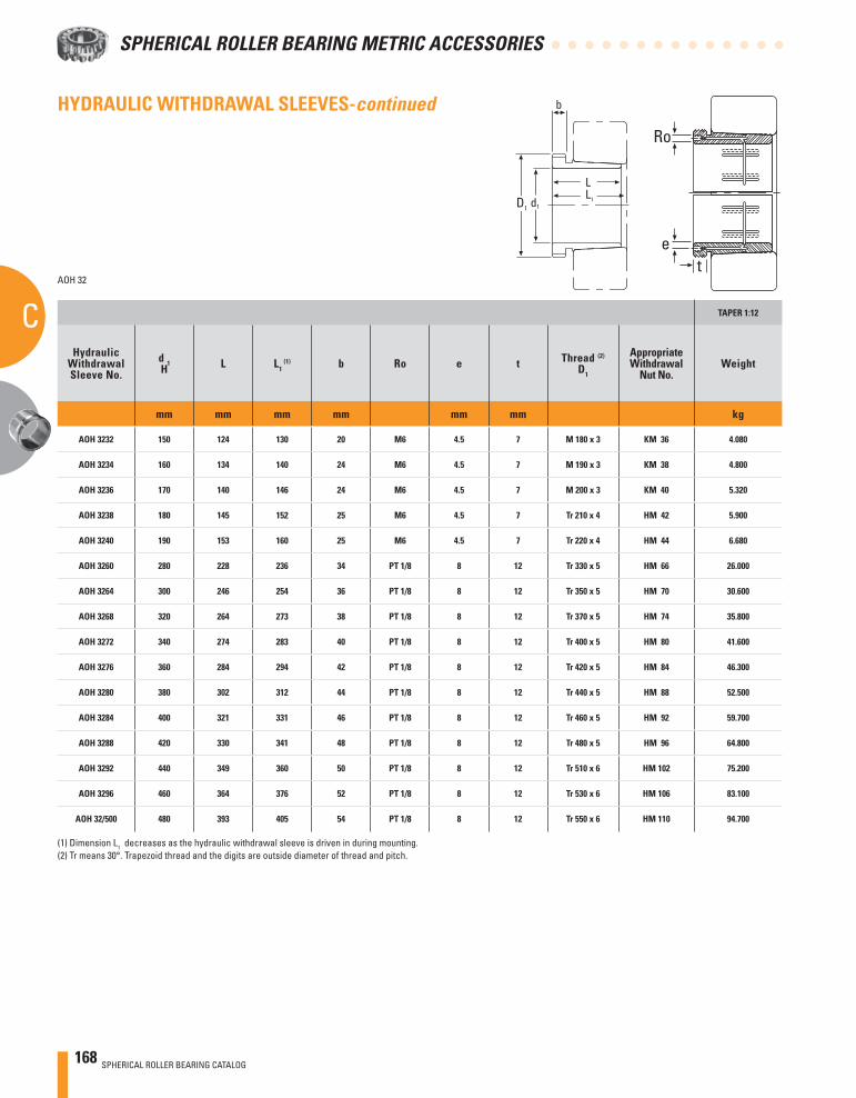
168 SPHERICAL ROLLER BEARING CATALOG
SPHERICAL ROLLER BEARING METRIC ACCESSORIES
CAOH 32
TAPER 1:12
HydraulicWithdrawalSleeve No.
d 1H L L1
(1) b Ro e t Thread (2)
D1
AppropriateWithdrawal
Nut No.Weight
mm mm mm mm mm mm kg
AOH 3232 150 124 130 20 M6 4.5 7 M 180 x 3 KM 36 4.080
AOH 3234 160 134 140 24 M6 4.5 7 M 190 x 3 KM 38 4.800
AOH 3236 170 140 146 24 M6 4.5 7 M 200 x 3 KM 40 5.320
AOH 3238 180 145 152 25 M6 4.5 7 Tr 210 x 4 HM 42 5.900
AOH 3240 190 153 160 25 M6 4.5 7 Tr 220 x 4 HM 44 6.680
AOH 3260 280 228 236 34 PT 1/8 8 12 Tr 330 x 5 HM 66 26.000
AOH 3264 300 246 254 36 PT 1/8 8 12 Tr 350 x 5 HM 70 30.600
AOH 3268 320 264 273 38 PT 1/8 8 12 Tr 370 x 5 HM 74 35.800
AOH 3272 340 274 283 40 PT 1/8 8 12 Tr 400 x 5 HM 80 41.600
AOH 3276 360 284 294 42 PT 1/8 8 12 Tr 420 x 5 HM 84 46.300
AOH 3280 380 302 312 44 PT 1/8 8 12 Tr 440 x 5 HM 88 52.500
AOH 3284 400 321 331 46 PT 1/8 8 12 Tr 460 x 5 HM 92 59.700
AOH 3288 420 330 341 48 PT 1/8 8 12 Tr 480 x 5 HM 96 64.800
AOH 3292 440 349 360 50 PT 1/8 8 12 Tr 510 x 6 HM 102 75.200
AOH 3296 460 364 376 52 PT 1/8 8 12 Tr 530 x 6 HM 106 83.100
AOH 32/500 480 393 405 54 PT 1/8 8 12 Tr 550 x 6 HM 110 94.700
(1) Dimension L1 decreases as the hydraulic withdrawal sleeve is driven in during mounting.(2) Tr means 30°. Trapezoid thread and the digits are outside diameter of thread and pitch.
et
Ro
d1
b
D1
L1
L
HYDRAULIC WITHDRAWAL SLEEVES-continued
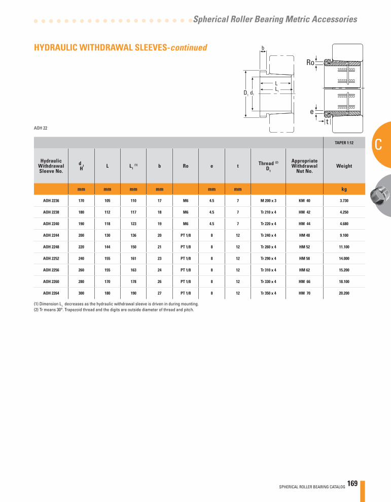
SPHERICAL ROLLER BEARING CATALOG 169
C
Spherical Roller Bearing Metric Accessories
AOH 22
TAPER 1:12
HydraulicWithdrawalSleeve No.
d 1H L L1
(1) b Ro e t Thread (2)
D1
AppropriateWithdrawal
Nut No.Weight
mm mm mm mm mm mm kg
AOH 2236 170 105 110 17 M6 4.5 7 M 200 x 3 KM 40 3.730
AOH 2238 180 112 117 18 M6 4.5 7 Tr 210 x 4 HM 42 4.250
AOH 2240 190 118 123 19 M6 4.5 7 Tr 220 x 4 HM 44 4.680
AOH 2244 200 130 136 20 PT 1/8 8 12 Tr 240 x 4 HM 48 9.100
AOH 2248 220 144 150 21 PT 1/8 8 12 Tr 260 x 4 HM 52 11.100
AOH 2252 240 155 161 23 PT 1/8 8 12 Tr 290 x 4 HM 58 14.000
AOH 2256 260 155 163 24 PT 1/8 8 12 Tr 310 x 4 HM 62 15.200
AOH 2260 280 170 178 26 PT 1/8 8 12 Tr 330 x 4 HM 66 18.100
AOH 2264 300 180 190 27 PT 1/8 8 12 Tr 350 x 4 HM 70 20.200
(1) Dimension L1 decreases as the hydraulic withdrawal sleeve is driven in during mounting.(2) Tr means 30°. Trapezoid thread and the digits are outside diameter of thread and pitch.
d1
b
D1
L1
L
et
Ro
HYDRAULIC WITHDRAWAL SLEEVES-continued
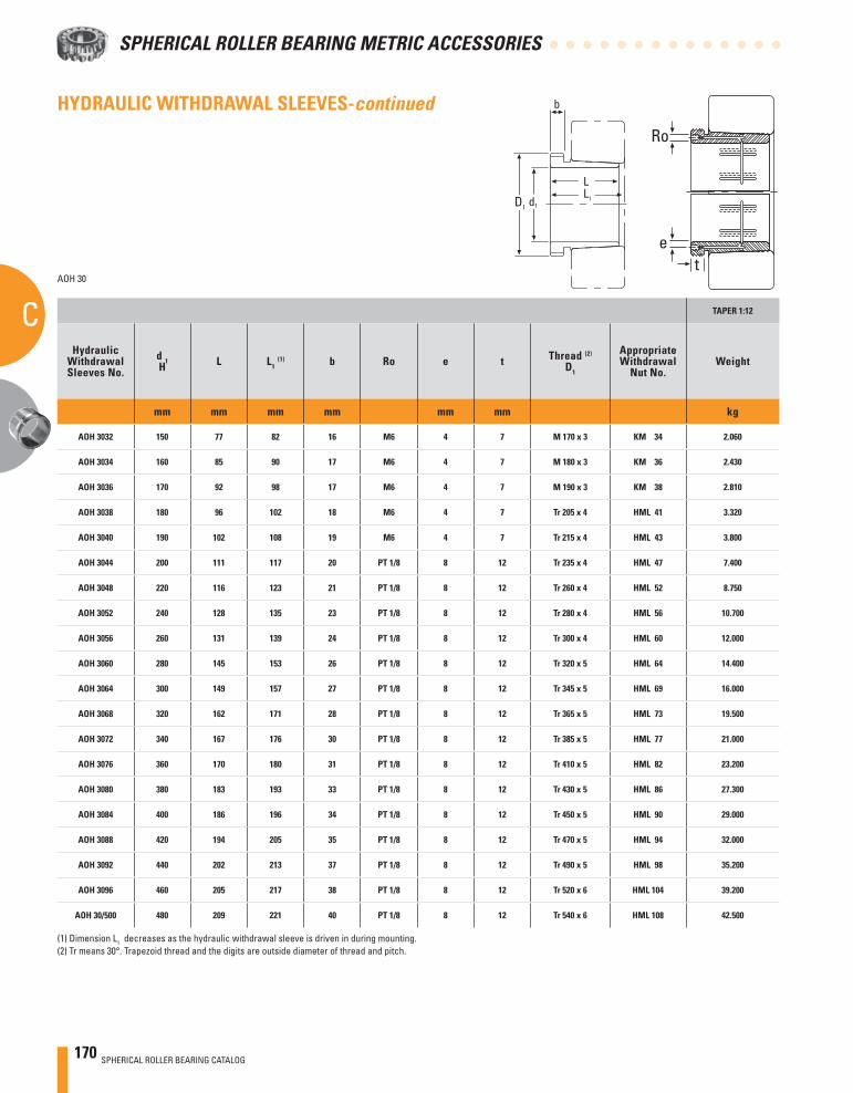
170 SPHERICAL ROLLER BEARING CATALOG
SPHERICAL ROLLER BEARING METRIC ACCESSORIES
CAOH 30
TAPER 1:12
HydraulicWithdrawalSleeves No.
d 1H L L1
(1) b Ro e t Thread (2)
D1
AppropriateWithdrawal
Nut No.Weight
mm mm mm mm mm mm kg
AOH 3032 150 77 82 16 M6 4 7 M 170 x 3 KM 34 2.060
AOH 3034 160 85 90 17 M6 4 7 M 180 x 3 KM 36 2.430
AOH 3036 170 92 98 17 M6 4 7 M 190 x 3 KM 38 2.810
AOH 3038 180 96 102 18 M6 4 7 Tr 205 x 4 HML 41 3.320
AOH 3040 190 102 108 19 M6 4 7 Tr 215 x 4 HML 43 3.800
AOH 3044 200 111 117 20 PT 1/8 8 12 Tr 235 x 4 HML 47 7.400
AOH 3048 220 116 123 21 PT 1/8 8 12 Tr 260 x 4 HML 52 8.750
AOH 3052 240 128 135 23 PT 1/8 8 12 Tr 280 x 4 HML 56 10.700
AOH 3056 260 131 139 24 PT 1/8 8 12 Tr 300 x 4 HML 60 12.000
AOH 3060 280 145 153 26 PT 1/8 8 12 Tr 320 x 5 HML 64 14.400
AOH 3064 300 149 157 27 PT 1/8 8 12 Tr 345 x 5 HML 69 16.000
AOH 3068 320 162 171 28 PT 1/8 8 12 Tr 365 x 5 HML 73 19.500
AOH 3072 340 167 176 30 PT 1/8 8 12 Tr 385 x 5 HML 77 21.000
AOH 3076 360 170 180 31 PT 1/8 8 12 Tr 410 x 5 HML 82 23.200
AOH 3080 380 183 193 33 PT 1/8 8 12 Tr 430 x 5 HML 86 27.300
AOH 3084 400 186 196 34 PT 1/8 8 12 Tr 450 x 5 HML 90 29.000
AOH 3088 420 194 205 35 PT 1/8 8 12 Tr 470 x 5 HML 94 32.000
AOH 3092 440 202 213 37 PT 1/8 8 12 Tr 490 x 5 HML 98 35.200
AOH 3096 460 205 217 38 PT 1/8 8 12 Tr 520 x 6 HML 104 39.200
AOH 30/500 480 209 221 40 PT 1/8 8 12 Tr 540 x 6 HML 108 42.500
(1) Dimension L1 decreases as the hydraulic withdrawal sleeve is driven in during mounting.(2) Tr means 30°. Trapezoid thread and the digits are outside diameter of thread and pitch.
et
Ro
d1
b
D1
L1
L
HYDRAULIC WITHDRAWAL SLEEVES-continued

SPHERICAL ROLLER BEARING CATALOG 171
C
Spherical Roller Bearing Metric Accessories
AOH 240
(1) Dimension L1 decreases as the hydraulic withdrawal sleeve is driven in during mounting.(2) Tr means 30°. Trapezoid thread and the digits are outside diameter of thread and pitch.
TAPER 1:30
HydraulicWithdrawalSleeve No.
d 1H L L1
(1) b Ro e t Thread (2)
D1
AppropriateWithdrawal
Nut No.Weight
mm mm mm mm mm mm kg
AOH 24044 200 138 152 20 M6 8 7 Tr 230 x 4 HM 46 8.250
AOH 24048 220 138 153 20 M6 8 7 Tr 250 x 4 HM 50 9.000
AOH 24052 240 162 178 22 M6 8 7 Tr 270 x 4 HM 54 11.800
AOH 24056 260 162 179 22 M6 8 7 Tr 290 x 4 HM 58 12.800
AOH 24060 280 184 202 24 M6 8 7 Tr 310 x 5 HM 62 15.500
AOH 24064 300 184 202 24 M6 8 7 Tr 330 x 5 HM 66 16.600
AOH 24068 320 206 225 26 PT 1/8 8 12 Tr 360 x 5 HML 72 21.700
AOH 24072 340 206 226 26 PT 1/8 8 12 Tr 380 x 5 HML 76 22.700
AOH 24076 360 208 228 28 PT 1/8 8 12 Tr 400 x 5 HML 80 23.700
AOH 24080 380 228 248 28 PT 1/8 8 12 Tr 420 x 5 HML 84 27.100
AOH 24084 400 230 252 30 PT 1/8 8 12 Tr 440 x 5 HML 88 29.000
AOH 24088 420 242 264 30 PT 1/8 8 12 Tr 460 x 5 HML 92 31.900
AOH 24092 440 250 273 32 PT 1/8 8 12 Tr 480 x 5 HML 96 34.700
AOH 24096 460 250 273 32 PT 1/8 8 12 Tr 500 x 5 HML 100 36.600
AOH 240/500 480 253 276 35 PT 1/8 8 12 Tr 530 x 6 HML 106 43.900
d1
b
D1
L1
L
et
Ro
HYDRAULIC WITHDRAWAL SLEEVES-continued
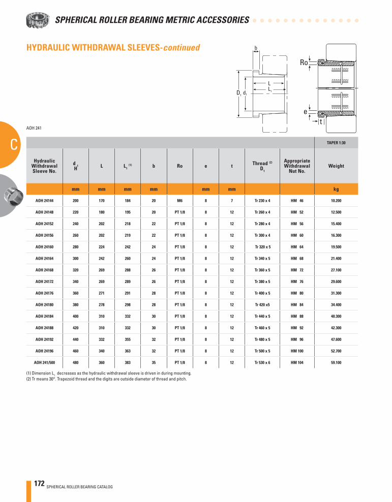
172 SPHERICAL ROLLER BEARING CATALOG
SPHERICAL ROLLER BEARING METRIC ACCESSORIES
CAOH 241
TAPER 1:30
HydraulicWithdrawalSleeve No.
d 1H L L1
(1) b Ro e t Thread (2)
D1
AppropriateWithdrawal
Nut No.Weight
mm mm mm mm mm mm kg
AOH 24144 200 170 184 20 M6 8 7 Tr 230 x 4 HM 46 10.200
AOH 24148 220 180 195 20 PT 1/8 8 12 Tr 260 x 4 HM 52 12.500
AOH 24152 240 202 218 22 PT 1/8 8 12 Tr 280 x 4 HM 56 15.400
AOH 24156 260 202 219 22 PT 1/8 8 12 Tr 300 x 4 HM 60 16.300
AOH 24160 280 224 242 24 PT 1/8 8 12 Tr 320 x 5 HM 64 19.500
AOH 24164 300 242 260 24 PT 1/8 8 12 Tr 340 x 5 HM 68 21.400
AOH 24168 320 269 288 26 PT 1/8 8 12 Tr 360 x 5 HM 72 27.100
AOH 24172 340 269 289 26 PT 1/8 8 12 Tr 380 x 5 HM 76 29.600
AOH 24176 360 271 291 28 PT 1/8 8 12 Tr 400 x 5 HM 80 31.300
AOH 24180 380 278 298 28 PT 1/8 8 12 Tr 420 x5 HM 84 34.400
AOH 24184 400 310 332 30 PT 1/8 8 12 Tr 440 x 5 HM 88 40.300
AOH 24188 420 310 332 30 PT 1/8 8 12 Tr 460 x 5 HM 92 42.300
AOH 24192 440 332 355 32 PT 1/8 8 12 Tr 480 x 5 HM 96 47.600
AOH 24196 460 340 363 32 PT 1/8 8 12 Tr 500 x 5 HM 100 52.700
AOH 241/500 480 360 383 35 PT 1/8 8 12 Tr 530 x 6 HM 104 59.100
(1) Dimension L1 decreases as the hydraulic withdrawal sleeve is driven in during mounting.(2) Tr means 30°. Trapezoid thread and the digits are outside diameter of thread and pitch.
et
Ro
d1
b
D1
L1
L
HYDRAULIC WITHDRAWAL SLEEVES-continued
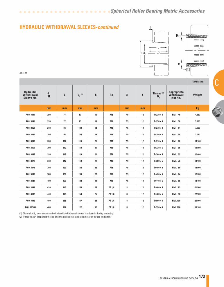
SPHERICAL ROLLER BEARING CATALOG 173
C
Spherical Roller Bearing Metric Accessories
AOH 39
TAPER 1:12
HydraulicWithdrawalSleeve No.
d 1
H L L1 (1) b Ro e t Thread (2)
D1
AppropriateWithdrawal
Nut No.Weight
mm mm mm mm mm mm kg
AOH 3944 200 77 83 16 M8 7.5 12 Tr 230 x 4 HM 46 4.830
AOH 3948 220 77 83 16 M8 7.5 12 Tr 250 x 4 HM 50 5.290
AOH 3952 240 94 100 18 M8 7.5 12 Tr 270 x 4 HM 54 7.060
AOH 3956 260 94 100 18 M8 7.5 12 Tr 290 x 4 HM 58 7.070
AOH 3960 280 112 119 21 M8 7.5 12 Tr 310 x 5 HM 62 10.100
AOH 3964 300 112 119 21 M8 7.5 12 Tr 330 x 5 HM 66 10.800
AOH 3968 320 112 119 21 M8 7.5 12 Tr 360 x 5 HML 72 12.400
AOH 3972 340 112 119 21 M8 7.5 12 Tr 380 x 5 HML 76 13.100
AOH 3976 360 130 138 22 M8 7.5 12 Tr 400 x 5 HML 80 15.900
AOH 3980 380 130 138 22 M8 7.5 12 Tr 420 x 5 HML 84 17.200
AOH 3984 400 130 138 22 M8 7.5 12 Tr 440 x 5 HML 88 18.100
AOH 3988 420 145 153 25 PT 1/8 8 12 Tr 460 x 5 HML 92 21.500
AOH 3992 440 145 153 25 PT 1/8 8 12 Tr 480 x 5 HML 96 22.500
AOH 3996 460 158 167 28 PT 1/8 8 12 Tr 500 x 5 HML 100 26.000
AOH 39/500 480 162 172 32 PT 1/8 8 12 Tr 530 x 6 HML 106 30.100
(1) Dimension L1 decreases as the hydraulic withdrawal sleeve is driven in during mounting.(2) Tr means 30°. Trapezoid thread and the digits are outside diameter of thread and pitch.
d1
b
D1
L1
L
et
Ro
HYDRAULIC WITHDRAWAL SLEEVES-continued
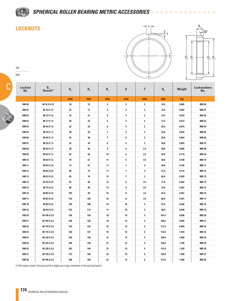
174 SPHERICAL ROLLER BEARING CATALOG
SPHERICAL ROLLER BEARING METRIC ACCESSORIES
C
LOCKNUTS
AN
KM
LocknutNo.
D1Thread(1) D3 D4 Bn S T D6 Weight Lockwashers
No.
mm mm mm mm mm mm kg
KM 00 M 10 X 0.75 18 13 4 3 2 10.5 0.005 MB 00
KM 01 M 12 X 1.0 22 17 4 3 2 12.5 0.007 MB 01
KM 02 M 15 X 1.0 25 21 5 4 2 15.5 0.010 MB 02
KM 03 M 17 X 1.0 28 24 5 4 2 17.5 0.013 MB 03
KM 04 M 20 X 1.0 32 26 6 4 2 20.5 0.019 MB 04
KM 05 M 25 X 1.5 38 32 7 5 2 25.8 0.025 MB 05
KM 06 M 30 X 1.5 45 38 7 5 2 30.8 0.043 MB 06
KM 07 M 35 X 1.5 52 44 8 5 2 35.8 0.053 MB 07
KM 08 M 40 X 1.5 58 50 9 6 2.5 40.8 0.085 MB 08
KM 09 M 45 X 1.5 65 56 10 6 2.5 45.8 0.119 MB 09
KM 10 M 50 X 1.5 70 61 11 6 2.5 50.8 0.148 MB 10
KM 11 M 55 X 2.0 75 67 11 7 3 56.0 0.158 MB 11
KM 12 M 60 X 2.0 80 73 11 7 3 61.0 0.174 MB 12
KM 13 M 65 X 2.0 85 79 12 7 3 66.0 0.203 MB 13
KM 14 M 70 X 2.0 92 85 12 8 3.5 71.0 0.242 MB 14
KM 15 M 75 X 2.0 98 90 13 8 3.5 76.0 0.287 MB 15
KM 16 M 80 X 2.0 105 95 15 8 3.5 81.0 0.397 MB 16
KM 17 M 85 X 2.0 110 102 16 8 3.5 86.0 0.451 MB 17
KM 18 M 90 X 2.0 120 108 16 10 4 91.0 0.556 MB 18
KM 19 M 95 X 2.0 125 113 17 10 4 96.0 0.658 MB 19
KM 20 M 100 X 2.0 130 120 18 10 4 101.0 0.698 MB 20
KM 21 M 105 X 2.0 140 126 18 12 5 106.0 0.845 MB 21
KM 22 M 110 X 2.0 145 133 19 12 5 111.0 0.965 MB 22
KM 23 M 115 X 2.0 150 137 19 12 5 116.0 1.010 MB 23
KM 24 M 120 X 2.0 160 148 21 12 5 126.0 1.800 MB 24
KM 25 M 125 X 2.0 160 148 21 12 5 126.0 1.190 MB 25
KM 26 M 130 X 2.0 165 149 21 12 5 131.0 1.250 MB 26
KM 27 M 135 X 2.0 175 160 22 14 6 136.0 1.550 MB 27
KM 28 M 140 X 2.0 180 160 22 14 6 141.0 1.560 MB 28
(1) M means metric thread and the digits are major diameter of thread and pitch.
Bn
30°
D4D3 D6D1
s
T
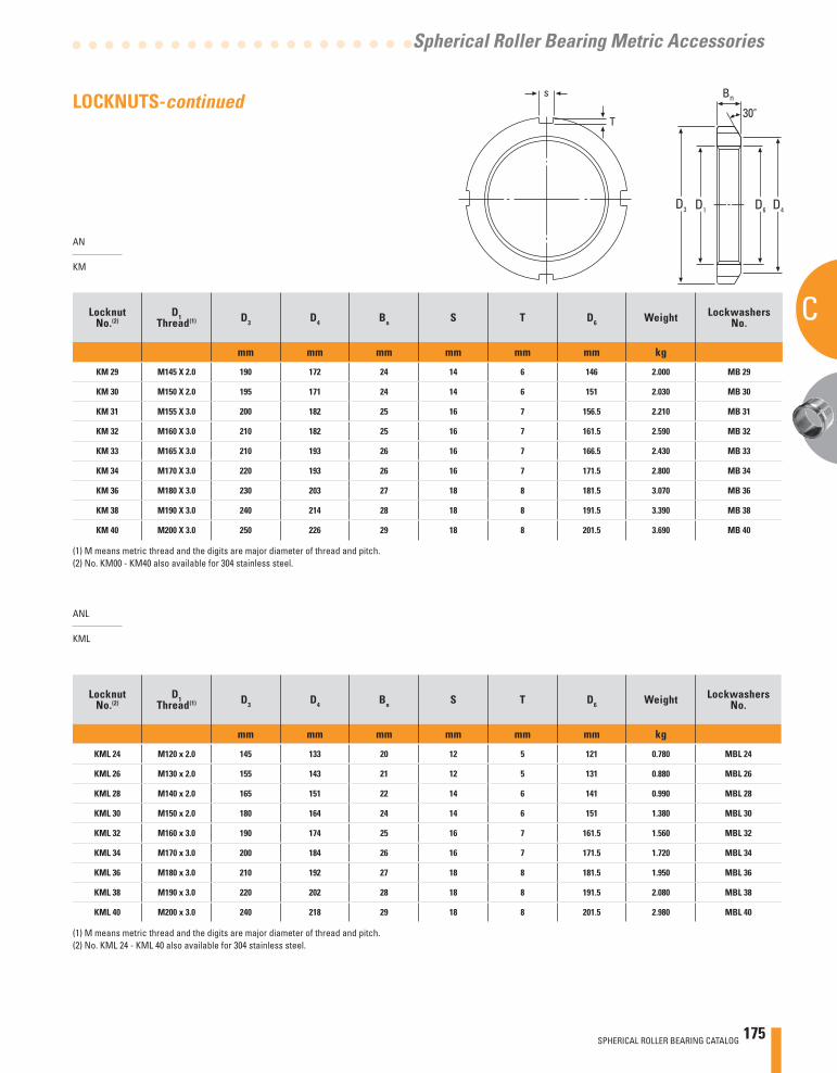
SPHERICAL ROLLER BEARING CATALOG 175
C
Spherical Roller Bearing Metric Accessories
AN
KM
LocknutNo.(2)
D1Thread(1) D3 D4 Bn S T D6 Weight Lockwashers
No.
mm mm mm mm mm mm kg
KM 29 M145 X 2.0 190 172 24 14 6 146 2.000 MB 29
KM 30 M150 X 2.0 195 171 24 14 6 151 2.030 MB 30
KM 31 M155 X 3.0 200 182 25 16 7 156.5 2.210 MB 31
KM 32 M160 X 3.0 210 182 25 16 7 161.5 2.590 MB 32
KM 33 M165 X 3.0 210 193 26 16 7 166.5 2.430 MB 33
KM 34 M170 X 3.0 220 193 26 16 7 171.5 2.800 MB 34
KM 36 M180 X 3.0 230 203 27 18 8 181.5 3.070 MB 36
KM 38 M190 X 3.0 240 214 28 18 8 191.5 3.390 MB 38
KM 40 M200 X 3.0 250 226 29 18 8 201.5 3.690 MB 40
(1) M means metric thread and the digits are major diameter of thread and pitch.(2) No. KM00 - KM40 also available for 304 stainless steel.
LocknutNo.(2)
D1Thread(1) D3 D4 Bn S T D6 Weight Lockwashers
No.
mm mm mm mm mm mm kg
KML 24 M120 x 2.0 145 133 20 12 5 121 0.780 MBL 24
KML 26 M130 x 2.0 155 143 21 12 5 131 0.880 MBL 26
KML 28 M140 x 2.0 165 151 22 14 6 141 0.990 MBL 28
KML 30 M150 x 2.0 180 164 24 14 6 151 1.380 MBL 30
KML 32 M160 x 3.0 190 174 25 16 7 161.5 1.560 MBL 32
KML 34 M170 x 3.0 200 184 26 16 7 171.5 1.720 MBL 34
KML 36 M180 x 3.0 210 192 27 18 8 181.5 1.950 MBL 36
KML 38 M190 x 3.0 220 202 28 18 8 191.5 2.080 MBL 38
KML 40 M200 x 3.0 240 218 29 18 8 201.5 2.980 MBL 40
ANL
KML
(1) M means metric thread and the digits are major diameter of thread and pitch.(2) No. KML 24 - KML 40 also available for 304 stainless steel.
LOCKNUTS-continued Bn
30°
D4D3 D6D1
s
T
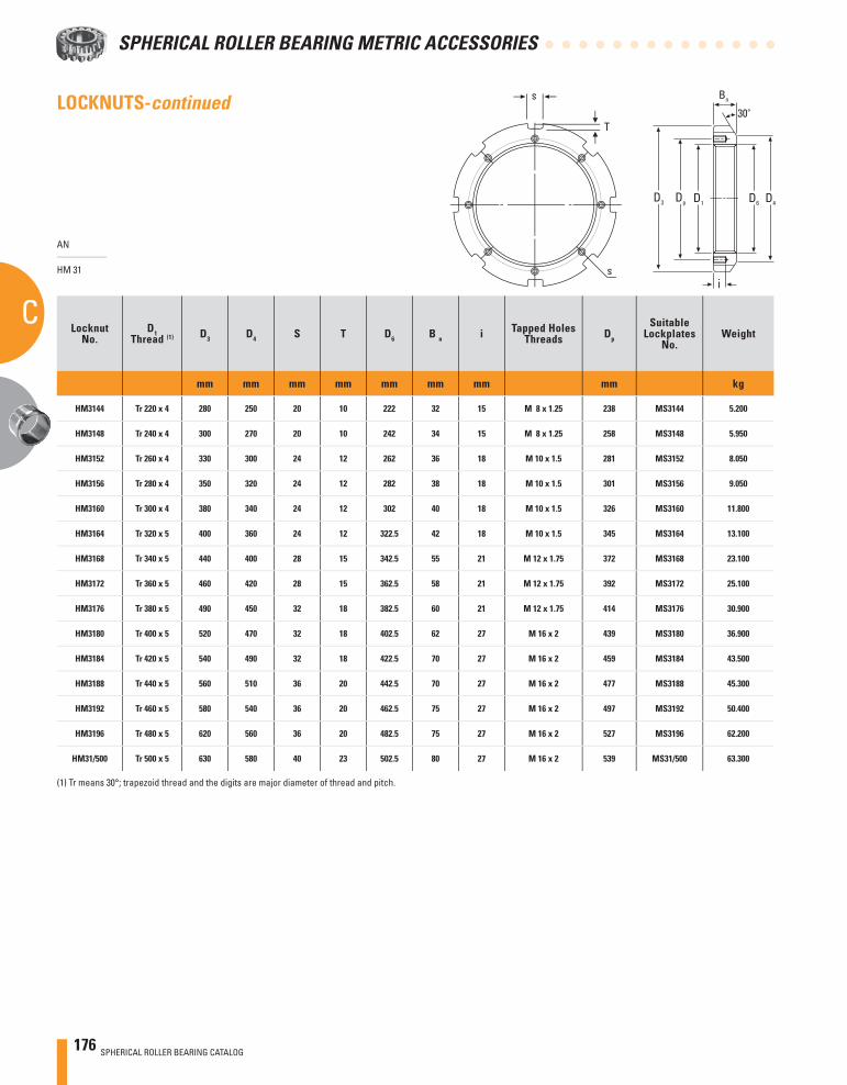
176 SPHERICAL ROLLER BEARING CATALOG
SPHERICAL ROLLER BEARING METRIC ACCESSORIES
C
AN
HM 31
LocknutNo.
D1Thread (1) D3 D4 S T D6 B n i Tapped Holes
Threads Dp
SuitableLockplates
No.Weight
mm mm mm mm mm mm mm mm kg
HM3144 Tr 220 x 4 280 250 20 10 222 32 15 M 8 x 1.25 238 MS3144 5.200
HM3148 Tr 240 x 4 300 270 20 10 242 34 15 M 8 x 1.25 258 MS3148 5.950
HM3152 Tr 260 x 4 330 300 24 12 262 36 18 M 10 x 1.5 281 MS3152 8.050
HM3156 Tr 280 x 4 350 320 24 12 282 38 18 M 10 x 1.5 301 MS3156 9.050
HM3160 Tr 300 x 4 380 340 24 12 302 40 18 M 10 x 1.5 326 MS3160 11.800
HM3164 Tr 320 x 5 400 360 24 12 322.5 42 18 M 10 x 1.5 345 MS3164 13.100
HM3168 Tr 340 x 5 440 400 28 15 342.5 55 21 M 12 x 1.75 372 MS3168 23.100
HM3172 Tr 360 x 5 460 420 28 15 362.5 58 21 M 12 x 1.75 392 MS3172 25.100
HM3176 Tr 380 x 5 490 450 32 18 382.5 60 21 M 12 x 1.75 414 MS3176 30.900
HM3180 Tr 400 x 5 520 470 32 18 402.5 62 27 M 16 x 2 439 MS3180 36.900
HM3184 Tr 420 x 5 540 490 32 18 422.5 70 27 M 16 x 2 459 MS3184 43.500
HM3188 Tr 440 x 5 560 510 36 20 442.5 70 27 M 16 x 2 477 MS3188 45.300
HM3192 Tr 460 x 5 580 540 36 20 462.5 75 27 M 16 x 2 497 MS3192 50.400
HM3196 Tr 480 x 5 620 560 36 20 482.5 75 27 M 16 x 2 527 MS3196 62.200
HM31/500 Tr 500 x 5 630 580 40 23 502.5 80 27 M 16 x 2 539 MS31/500 63.300
(1) Tr means 30°; trapezoid thread and the digits are major diameter of thread and pitch.
s
s
T
Bn
30°
D4DpD3 D6D1
i
LOCKNUTS-continued
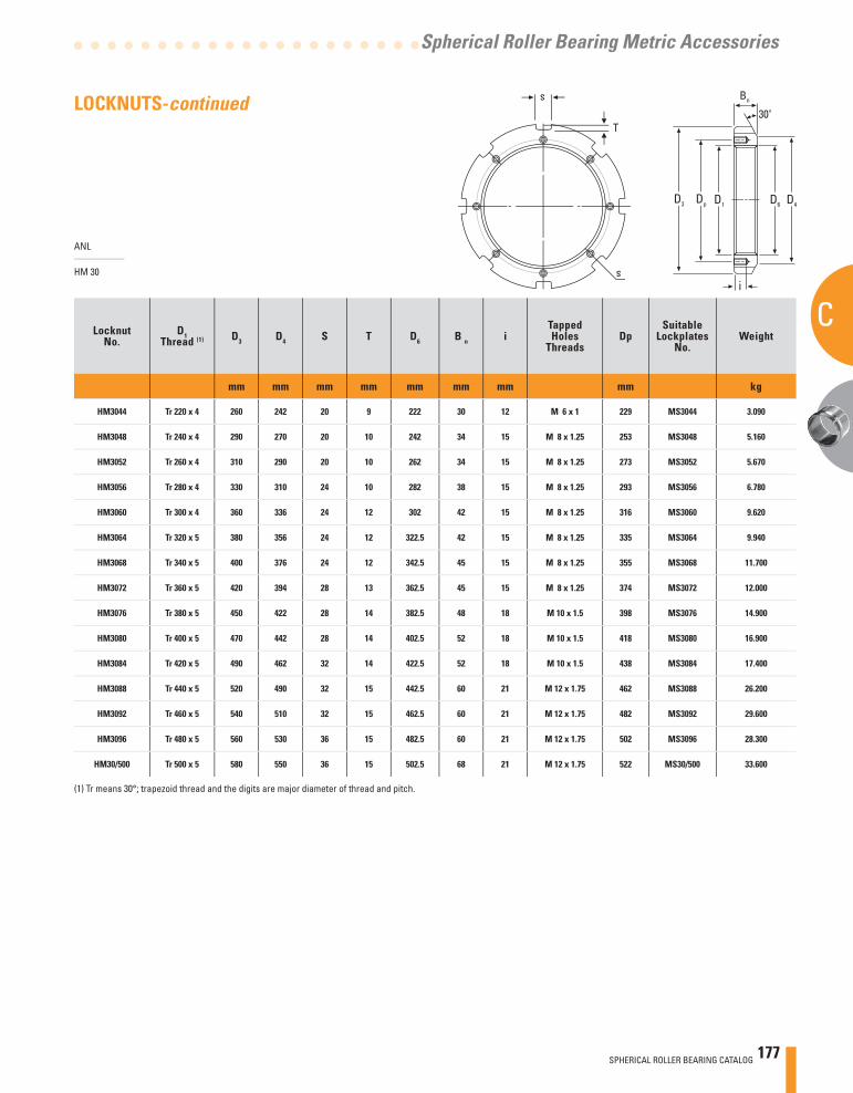
SPHERICAL ROLLER BEARING CATALOG 177
C
Spherical Roller Bearing Metric Accessories
ANL
HM 30
LocknutNo.
D1Thread (1) D3 D4 S T D6 B n i
Tapped Holes
ThreadsDp
SuitableLockplates
No.Weight
mm mm mm mm mm mm mm mm kg
HM3044 Tr 220 x 4 260 242 20 9 222 30 12 M 6 x 1 229 MS3044 3.090
HM3048 Tr 240 x 4 290 270 20 10 242 34 15 M 8 x 1.25 253 MS3048 5.160
HM3052 Tr 260 x 4 310 290 20 10 262 34 15 M 8 x 1.25 273 MS3052 5.670
HM3056 Tr 280 x 4 330 310 24 10 282 38 15 M 8 x 1.25 293 MS3056 6.780
HM3060 Tr 300 x 4 360 336 24 12 302 42 15 M 8 x 1.25 316 MS3060 9.620
HM3064 Tr 320 x 5 380 356 24 12 322.5 42 15 M 8 x 1.25 335 MS3064 9.940
HM3068 Tr 340 x 5 400 376 24 12 342.5 45 15 M 8 x 1.25 355 MS3068 11.700
HM3072 Tr 360 x 5 420 394 28 13 362.5 45 15 M 8 x 1.25 374 MS3072 12.000
HM3076 Tr 380 x 5 450 422 28 14 382.5 48 18 M 10 x 1.5 398 MS3076 14.900
HM3080 Tr 400 x 5 470 442 28 14 402.5 52 18 M 10 x 1.5 418 MS3080 16.900
HM3084 Tr 420 x 5 490 462 32 14 422.5 52 18 M 10 x 1.5 438 MS3084 17.400
HM3088 Tr 440 x 5 520 490 32 15 442.5 60 21 M 12 x 1.75 462 MS3088 26.200
HM3092 Tr 460 x 5 540 510 32 15 462.5 60 21 M 12 x 1.75 482 MS3092 29.600
HM3096 Tr 480 x 5 560 530 36 15 482.5 60 21 M 12 x 1.75 502 MS3096 28.300
HM30/500 Tr 500 x 5 580 550 36 15 502.5 68 21 M 12 x 1.75 522 MS30/500 33.600
(1) Tr means 30°; trapezoid thread and the digits are major diameter of thread and pitch.
s
s
T
Bn
30°
D4DpD3 D6D1
i
LOCKNUTS-continued
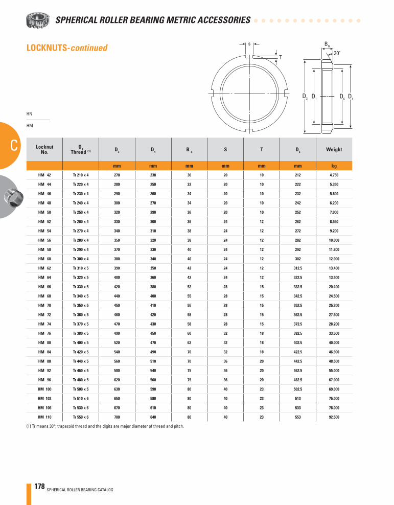
178 SPHERICAL ROLLER BEARING CATALOG
SPHERICAL ROLLER BEARING METRIC ACCESSORIES
C
HN
HM
LocknutNo.
D1Thread (1) D3 D4 B n S T D6 Weight
mm mm mm mm mm mm kg
HM 42 Tr 210 x 4 270 238 30 20 10 212 4.750
HM 44 Tr 220 x 4 280 250 32 20 10 222 5.350
HM 46 Tr 230 x 4 290 260 34 20 10 232 5.800
HM 48 Tr 240 x 4 300 270 34 20 10 242 6.200
HM 50 Tr 250 x 4 320 290 36 20 10 252 7.000
HM 52 Tr 260 x 4 330 300 36 24 12 262 8.550
HM 54 Tr 270 x 4 340 310 38 24 12 272 9.200
HM 56 Tr 280 x 4 350 320 38 24 12 282 10.000
HM 58 Tr 290 x 4 370 330 40 24 12 292 11.800
HM 60 Tr 300 x 4 380 340 40 24 12 302 12.000
HM 62 Tr 310 x 5 390 350 42 24 12 312.5 13.400
HM 64 Tr 320 x 5 400 360 42 24 12 322.5 13.500
HM 66 Tr 330 x 5 420 380 52 28 15 332.5 20.400
HM 68 Tr 340 x 5 440 400 55 28 15 342.5 24.500
HM 70 Tr 350 x 5 450 410 55 28 15 352.5 25.200
HM 72 Tr 360 x 5 460 420 58 28 15 362.5 27.500
HM 74 Tr 370 x 5 470 430 58 28 15 372.5 28.200
HM 76 Tr 380 x 5 490 450 60 32 18 382.5 33.500
HM 80 Tr 400 x 5 520 470 62 32 18 402.5 40.000
HM 84 Tr 420 x 5 540 490 70 32 18 422.5 46.900
HM 88 Tr 440 x 5 560 510 70 36 20 442.5 48.500
HM 92 Tr 460 x 5 580 540 75 36 20 462.5 55.000
HM 96 Tr 480 x 5 620 560 75 36 20 482.5 67.000
HM 100 Tr 500 x 5 630 590 80 40 23 502.5 69.000
HM 102 Tr 510 x 6 650 590 80 40 23 513 75.000
HM 106 Tr 530 x 6 670 610 80 40 23 533 78.000
HM 110 Tr 550 x 6 700 640 80 40 23 553 92.500
(1) Tr means 30°; trapezoid thread and the digits are major diameter of thread and pitch.
Bn
30°
D4D3 D6D1
s
T
LOCKNUTS-continued
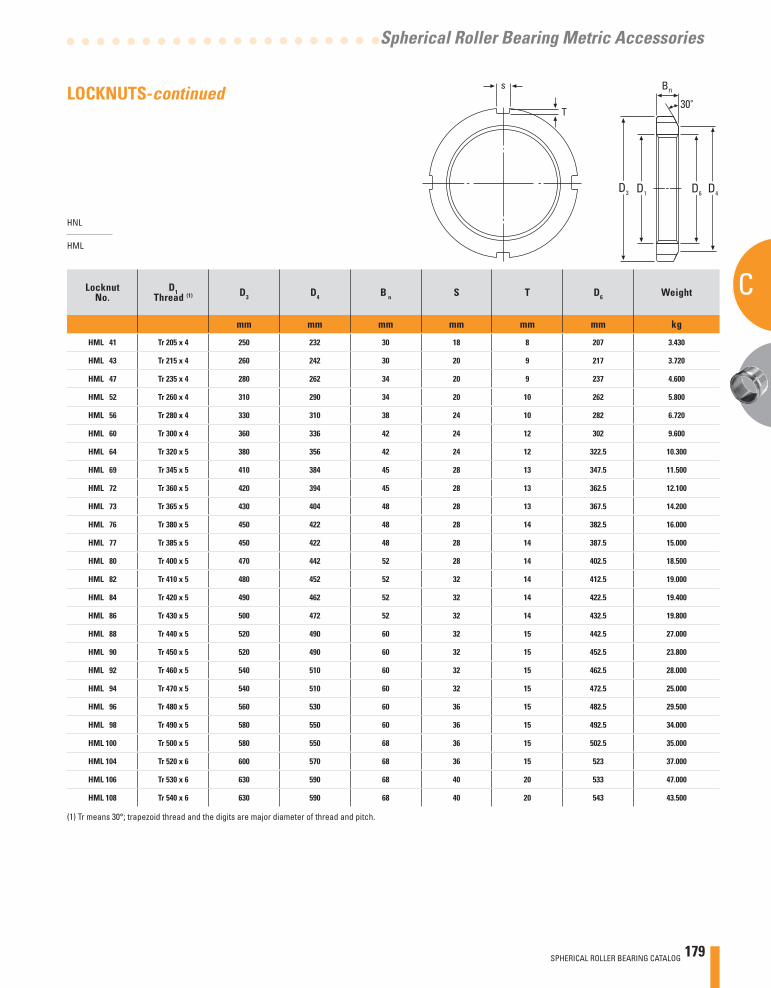
SPHERICAL ROLLER BEARING CATALOG 179
C
Spherical Roller Bearing Metric Accessories
HNL
HML
Locknut No.
D1Thread (1) D3 D4 B n S T D6 Weight
mm mm mm mm mm mm kg
HML 41 Tr 205 x 4 250 232 30 18 8 207 3.430
HML 43 Tr 215 x 4 260 242 30 20 9 217 3.720
HML 47 Tr 235 x 4 280 262 34 20 9 237 4.600
HML 52 Tr 260 x 4 310 290 34 20 10 262 5.800
HML 56 Tr 280 x 4 330 310 38 24 10 282 6.720
HML 60 Tr 300 x 4 360 336 42 24 12 302 9.600
HML 64 Tr 320 x 5 380 356 42 24 12 322.5 10.300
HML 69 Tr 345 x 5 410 384 45 28 13 347.5 11.500
HML 72 Tr 360 x 5 420 394 45 28 13 362.5 12.100
HML 73 Tr 365 x 5 430 404 48 28 13 367.5 14.200
HML 76 Tr 380 x 5 450 422 48 28 14 382.5 16.000
HML 77 Tr 385 x 5 450 422 48 28 14 387.5 15.000
HML 80 Tr 400 x 5 470 442 52 28 14 402.5 18.500
HML 82 Tr 410 x 5 480 452 52 32 14 412.5 19.000
HML 84 Tr 420 x 5 490 462 52 32 14 422.5 19.400
HML 86 Tr 430 x 5 500 472 52 32 14 432.5 19.800
HML 88 Tr 440 x 5 520 490 60 32 15 442.5 27.000
HML 90 Tr 450 x 5 520 490 60 32 15 452.5 23.800
HML 92 Tr 460 x 5 540 510 60 32 15 462.5 28.000
HML 94 Tr 470 x 5 540 510 60 32 15 472.5 25.000
HML 96 Tr 480 x 5 560 530 60 36 15 482.5 29.500
HML 98 Tr 490 x 5 580 550 60 36 15 492.5 34.000
HML 100 Tr 500 x 5 580 550 68 36 15 502.5 35.000
HML 104 Tr 520 x 6 600 570 68 36 15 523 37.000
HML 106 Tr 530 x 6 630 590 68 40 20 533 47.000
HML 108 Tr 540 x 6 630 590 68 40 20 543 43.500
(1) Tr means 30°; trapezoid thread and the digits are major diameter of thread and pitch.
Bn
30°
D4D3 D6D1
s
T
LOCKNUTS-continued
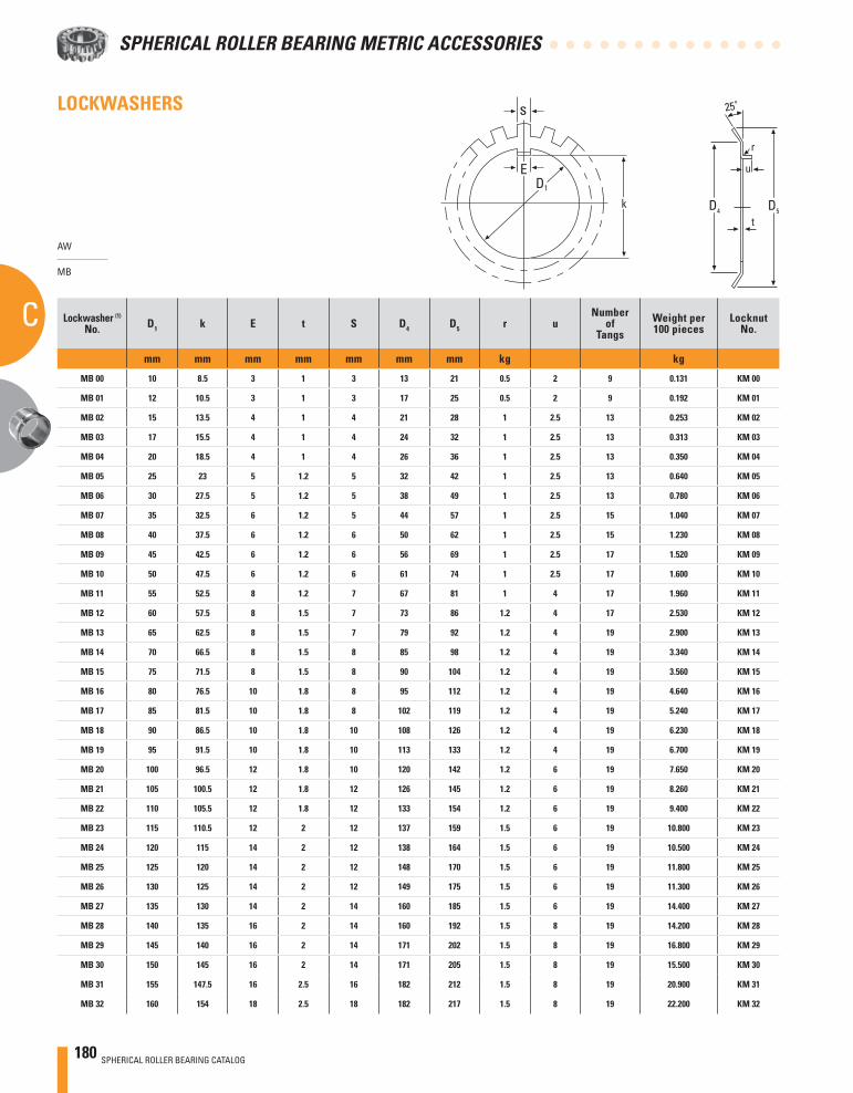
180 SPHERICAL ROLLER BEARING CATALOG
SPHERICAL ROLLER BEARING METRIC ACCESSORIES
C
LOCKWASHERS
AW
MB
Lockwasher (1)
No. D1 k E t S D4 D5 r uNumber
ofTangs
Weight per100 pieces
LocknutNo.
mm mm mm mm mm mm mm kg kg
MB 00 10 8.5 3 1 3 13 21 0.5 2 9 0.131 KM 00
MB 01 12 10.5 3 1 3 17 25 0.5 2 9 0.192 KM 01
MB 02 15 13.5 4 1 4 21 28 1 2.5 13 0.253 KM 02
MB 03 17 15.5 4 1 4 24 32 1 2.5 13 0.313 KM 03
MB 04 20 18.5 4 1 4 26 36 1 2.5 13 0.350 KM 04
MB 05 25 23 5 1.2 5 32 42 1 2.5 13 0.640 KM 05
MB 06 30 27.5 5 1.2 5 38 49 1 2.5 13 0.780 KM 06
MB 07 35 32.5 6 1.2 5 44 57 1 2.5 15 1.040 KM 07
MB 08 40 37.5 6 1.2 6 50 62 1 2.5 15 1.230 KM 08
MB 09 45 42.5 6 1.2 6 56 69 1 2.5 17 1.520 KM 09
MB 10 50 47.5 6 1.2 6 61 74 1 2.5 17 1.600 KM 10
MB 11 55 52.5 8 1.2 7 67 81 1 4 17 1.960 KM 11
MB 12 60 57.5 8 1.5 7 73 86 1.2 4 17 2.530 KM 12
MB 13 65 62.5 8 1.5 7 79 92 1.2 4 19 2.900 KM 13
MB 14 70 66.5 8 1.5 8 85 98 1.2 4 19 3.340 KM 14
MB 15 75 71.5 8 1.5 8 90 104 1.2 4 19 3.560 KM 15
MB 16 80 76.5 10 1.8 8 95 112 1.2 4 19 4.640 KM 16
MB 17 85 81.5 10 1.8 8 102 119 1.2 4 19 5.240 KM 17
MB 18 90 86.5 10 1.8 10 108 126 1.2 4 19 6.230 KM 18
MB 19 95 91.5 10 1.8 10 113 133 1.2 4 19 6.700 KM 19
MB 20 100 96.5 12 1.8 10 120 142 1.2 6 19 7.650 KM 20
MB 21 105 100.5 12 1.8 12 126 145 1.2 6 19 8.260 KM 21
MB 22 110 105.5 12 1.8 12 133 154 1.2 6 19 9.400 KM 22
MB 23 115 110.5 12 2 12 137 159 1.5 6 19 10.800 KM 23
MB 24 120 115 14 2 12 138 164 1.5 6 19 10.500 KM 24
MB 25 125 120 14 2 12 148 170 1.5 6 19 11.800 KM 25
MB 26 130 125 14 2 12 149 175 1.5 6 19 11.300 KM 26
MB 27 135 130 14 2 14 160 185 1.5 6 19 14.400 KM 27
MB 28 140 135 16 2 14 160 192 1.5 8 19 14.200 KM 28
MB 29 145 140 16 2 14 171 202 1.5 8 19 16.800 KM 29
MB 30 150 145 16 2 14 171 205 1.5 8 19 15.500 KM 30
MB 31 155 147.5 16 2.5 16 182 212 1.5 8 19 20.900 KM 31
MB 32 160 154 18 2.5 18 182 217 1.5 8 19 22.200 KM 32
s
ED1
k D5
r
u
t
25°
D4
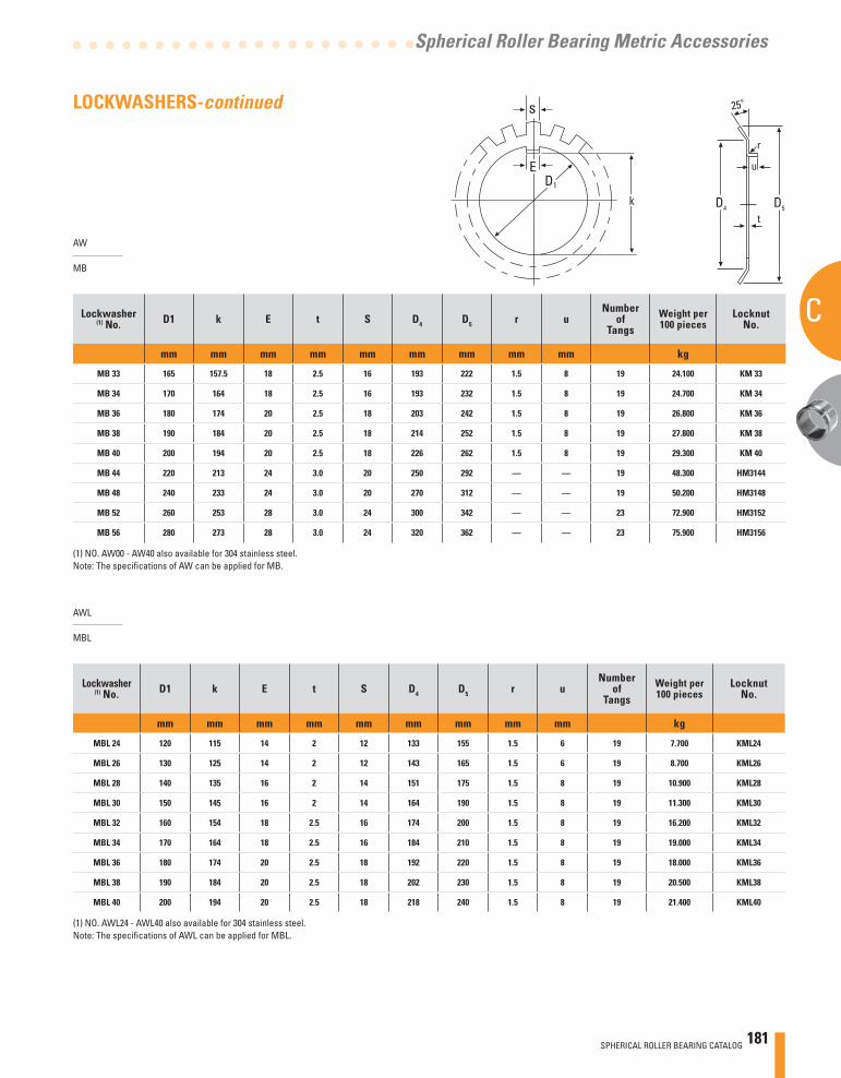
SPHERICAL ROLLER BEARING CATALOG 181
C
Spherical Roller Bearing Metric Accessories
LOCKWASHERS-continued
AW
MB
Lockwasher (1) No. D1 k E t S D4 D5 r u
Numberof
TangsWeight per100 pieces
LocknutNo.
mm mm mm mm mm mm mm mm mm kg
MB 33 165 157.5 18 2.5 16 193 222 1.5 8 19 24.100 KM 33
MB 34 170 164 18 2.5 16 193 232 1.5 8 19 24.700 KM 34
MB 36 180 174 20 2.5 18 203 242 1.5 8 19 26.800 KM 36
MB 38 190 184 20 2.5 18 214 252 1.5 8 19 27.800 KM 38
MB 40 200 194 20 2.5 18 226 262 1.5 8 19 29.300 KM 40
MB 44 220 213 24 3.0 20 250 292 — — 19 48.300 HM3144
MB 48 240 233 24 3.0 20 270 312 — — 19 50.200 HM3148
MB 52 260 253 28 3.0 24 300 342 — — 23 72.900 HM3152
MB 56 280 273 28 3.0 24 320 362 — — 23 75.900 HM3156
AWL
MBL
Lockwasher (1) No. D1 k E t S D4 D5 r u
Numberof
TangsWeight per100 pieces
LocknutNo.
mm mm mm mm mm mm mm mm mm kg
MBL 24 120 115 14 2 12 133 155 1.5 6 19 7.700 KML24
MBL 26 130 125 14 2 12 143 165 1.5 6 19 8.700 KML26
MBL 28 140 135 16 2 14 151 175 1.5 8 19 10.900 KML28
MBL 30 150 145 16 2 14 164 190 1.5 8 19 11.300 KML30
MBL 32 160 154 18 2.5 16 174 200 1.5 8 19 16.200 KML32
MBL 34 170 164 18 2.5 16 184 210 1.5 8 19 19.000 KML34
MBL 36 180 174 20 2.5 18 192 220 1.5 8 19 18.000 KML36
MBL 38 190 184 20 2.5 18 202 230 1.5 8 19 20.500 KML38
MBL 40 200 194 20 2.5 18 218 240 1.5 8 19 21.400 KML40
(1) NO. AWL24 - AWL40 also available for 304 stainless steel.Note: The specifi cations of AWL can be applied for MBL.
(1) NO. AW00 - AW40 also available for 304 stainless steel.Note: The specifi cations of AW can be applied for MB.
s
ED1
k D5
r
u
t
25°
D4
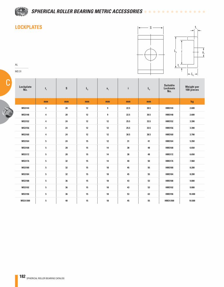
182 SPHERICAL ROLLER BEARING CATALOG
SPHERICAL ROLLER BEARING METRIC ACCESSORIES
C
LOCKPLATES
AL
MS 31
LockplateNo. t1 S L2 s1 i L3
SuitableLocknuts
No.Weight per100 pieces
mm mm mm mm mm mm kg
MS3144 4 20 12 9 22.5 30.5 HM3144 2.600
MS3148 4 20 12 9 22.5 30.5 HM3148 2.600
MS3152 4 24 12 12 25.5 33.5 HM3152 3.390
MS3156 4 24 12 12 25.5 33.5 HM3156 3.390
MS3160 4 24 12 12 30.5 38.5 HM3160 3.790
MS3164 5 24 15 12 31 41 HM3164 5.350
MS3168 5 28 15 14 38 48 HM3168 6.650
MS3172 5 28 15 14 38 48 HM3172 6.650
MS3176 5 32 15 14 40 50 HM3176 7.960
MS3180 5 32 15 18 45 55 HM3180 8.200
MS3184 5 32 15 18 45 55 HM3184 8.200
MS3188 5 36 15 18 43 53 HM3188 9.000
MS3192 5 36 15 18 43 53 HM3192 9.000
MS3196 5 36 15 18 53 63 HM3196 10.400
MS31/500 5 40 15 18 45 55 HM31/500 10.500
S
L3
t1
t1
s1
L2
i
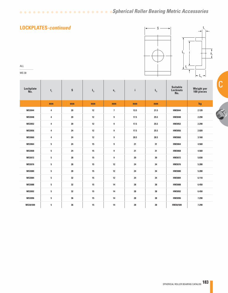
SPHERICAL ROLLER BEARING CATALOG 183
C
Spherical Roller Bearing Metric Accessories
ALL
MS 30
LockplateNo. t1 S L2 s1 i L3
SuitableLocknuts
No.Weight per100 pieces
mm mm mm mm mm mm kg
MS3044 4 20 12 7 13.5 21.5 HM3044 2.120
MS3048 4 20 12 9 17.5 25.5 HM3048 2.290
MS3052 4 20 12 9 17.5 25.5 HM3052 2.290
MS3056 4 24 12 9 17.5 25.5 HM3056 2.920
MS3060 4 24 12 9 20.5 28.5 HM3060 3.160
MS3064 5 24 15 9 21 31 HM3064 4.560
MS3068 5 24 15 9 21 31 HM3068 4.560
MS3072 5 28 15 9 20 30 HM3072 5.030
MS3076 5 28 15 12 24 34 HM3076 5.280
MS3080 5 28 15 12 24 34 HM3080 5.280
MS3084 5 32 15 12 24 34 HM3084 6.110
MS3088 5 32 15 14 28 38 HM3088 6.450
MS3092 5 32 15 14 28 38 HM3092 6.450
MS3096 5 36 15 14 28 38 HM3096 7.290
MS30/500 5 36 15 14 28 38 HM30/500 7.290
LOCKPLATES-continued S
L3
t1
t1
s1
L2
i
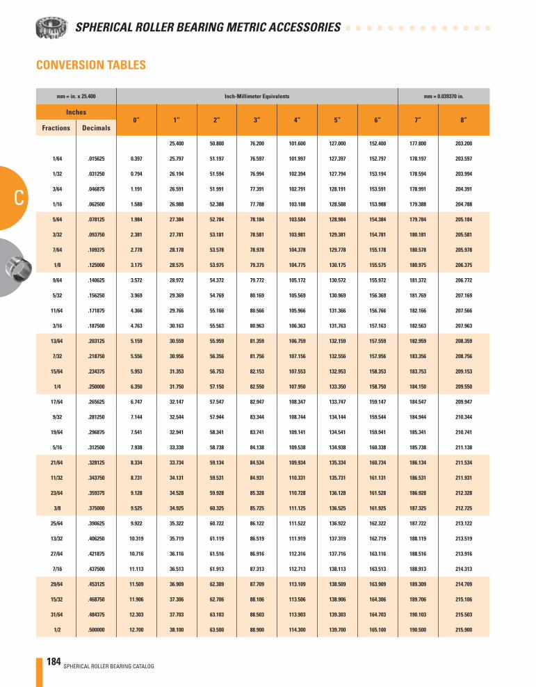
184 SPHERICAL ROLLER BEARING CATALOG
SPHERICAL ROLLER BEARING METRIC ACCESSORIES
C
CONVERSION TABLES
mm = in. x 25.400 Inch-Millimeter Equivalents mm = 0.039370 in.
Inches0” 1” 2” 3” 4” 5” 6” 7” 8”
Fractions Decimals
25.400 50.800 76.200 101.600 127.000 152.400 177.800 203.200
1/64 .015625 0.397 25.797 51.197 76.597 101.997 127.397 152.797 178.197 203.597
1/32 .031250 0.794 26.194 51.594 76.994 102.394 127.794 153.194 178.594 203.994
3/64 .046875 1.191 26.591 51.991 77.391 102.791 128.191 153.591 178.991 204.391
1/16 .062500 1.588 26.988 52.388 77.788 103.188 128.588 153.988 179.388 204.788
5/64 .078125 1.984 27.384 52.784 78.184 103.584 128.984 154.384 179.784 205.184
3/32 .093750 2.381 27.781 53.181 78.581 103.981 129.381 154.781 180.181 205.581
7/64 .109375 2.778 28.178 53.578 78.978 104.378 129.778 155.178 180.578 205.978
1/8 .125000 3.175 28.575 53.975 79.375 104.775 130.175 155.575 180.975 206.375
9/64 .140625 3.572 28.972 54.372 79.772 105.172 130.572 155.972 181.372 206.772
5/32 .156250 3.969 29.369 54.769 80.169 105.569 130.969 156.369 181.769 207.169
11/64 .171875 4.366 29.766 55.166 80.566 105.966 131.366 156.766 182.166 207.566
3/16 .187500 4.763 30.163 55.563 80.963 106.363 131.763 157.163 182.563 207.963
13/64 .203125 5.159 30.559 55.959 81.359 106.759 132.159 157.559 182.959 208.359
7/32 .218750 5.556 30.956 56.356 81.756 107.156 132.556 157.956 183.356 208.756
15/64 .234375 5.953 31.353 56.753 82.153 107.553 132.953 158.353 183.753 209.153
1/4 .250000 6.350 31.750 57.150 82.550 107.950 133.350 158.750 184.150 209.550
17/64 .265625 6.747 32.147 57.547 82.947 108.347 133.747 159.147 184.547 209.947
9/32 .281250 7.144 32.544 57.944 83.344 108.744 134.144 159.544 184.944 210.344
19/64 .296875 7.541 32.941 58.341 83.741 109.141 134.541 159.941 185.341 210.741
5/16 .312500 7.938 33.338 58.738 84.138 109.538 134.938 160.338 185.738 211.138
21/64 .328125 8.334 33.734 59.134 84.534 109.934 135.334 160.734 186.134 211.534
11/32 .343750 8.731 34.131 59.531 84.931 110.331 135.731 161.131 186.531 211.931
23/64 .359375 9.128 34.528 59.928 85.328 110.728 136.128 161.528 186.928 212.328
3/8 .375000 9.525 34.925 60.325 85.725 111.125 136.525 161.925 187.325 212.725
25/64 .390625 9.922 35.322 60.722 86.122 111.522 136.922 162.322 187.722 213.122
13/32 .406250 10.319 35.719 61.119 86.519 111.919 137.319 162.719 188.119 213.519
27/64 .421875 10.716 36.116 61.516 86.916 112.316 137.716 163.116 188.516 213.916
7/16 .437500 11.113 36.513 61.913 87.313 112.713 138.113 163.513 188.913 214.313
29/64 .453125 11.509 36.909 62.309 87.709 113.109 138.509 163.909 189.309 214.709
15/32 .468750 11.906 37.306 62.706 88.106 113.506 138.906 164.306 189.706 215.106
31/64 .484375 12.303 37.703 63.103 88.503 113.903 139.303 164.703 190.103 215.503
1/2 .500000 12.700 38.100 63.500 88.900 114.300 139.700 165.100 190.500 215.900
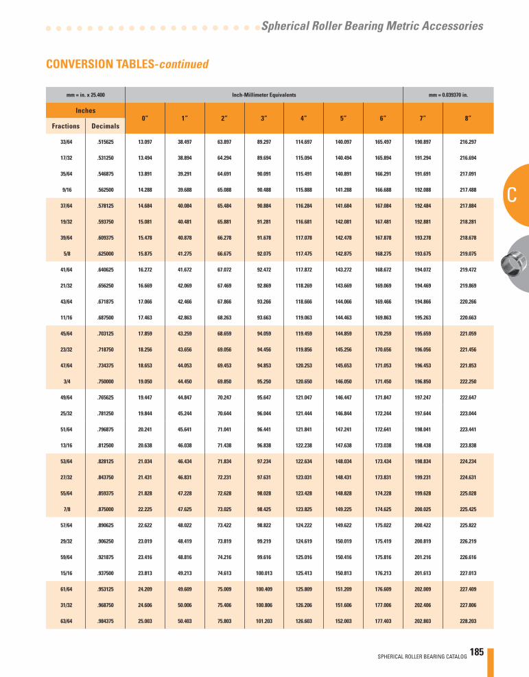
SPHERICAL ROLLER BEARING CATALOG 185
C
Spherical Roller Bearing Metric Accessories
mm = in. x 25.400 Inch-Millimeter Equivalents mm = 0.039370 in.
Inches0” 1” 2” 3” 4” 5” 6” 7” 8”
Fractions Decimals
33/64 .515625 13.097 38.497 63.897 89.297 114.697 140.097 165.497 190.897 216.297
17/32 .531250 13.494 38.894 64.294 89.694 115.094 140.494 165.894 191.294 216.694
35/64 .546875 13.891 39.291 64.691 90.091 115.491 140.891 166.291 191.691 217.091
9/16 .562500 14.288 39.688 65.088 90.488 115.888 141.288 166.688 192.088 217.488
37/64 .578125 14.684 40.084 65.484 90.884 116.284 141.684 167.084 192.484 217.884
19/32 .593750 15.081 40.481 65.881 91.281 116.681 142.081 167.481 192.881 218.281
39/64 .609375 15.478 40.878 66.278 91.678 117.078 142.478 167.878 193.278 218.678
5/8 .625000 15.875 41.275 66.675 92.075 117.475 142.875 168.275 193.675 219.075
41/64 .640625 16.272 41.672 67.072 92.472 117.872 143.272 168.672 194.072 219.472
21/32 .656250 16.669 42.069 67.469 92.869 118.269 143.669 169.069 194.469 219.869
43/64 .671875 17.066 42.466 67.866 93.266 118.666 144.066 169.466 194.866 220.266
11/16 .687500 17.463 42.863 68.263 93.663 119.063 144.463 169.863 195.263 220.663
45/64 .703125 17.859 43.259 68.659 94.059 119.459 144.859 170.259 195.659 221.059
23/32 .718750 18.256 43.656 69.056 94.456 119.856 145.256 170.656 196.056 221.456
47/64 .734375 18.653 44.053 69.453 94.853 120.253 145.653 171.053 196.453 221.853
3/4 .750000 19.050 44.450 69.850 95.250 120.650 146.050 171.450 196.850 222.250
49/64 .765625 19.447 44.847 70.247 95.647 121.047 146.447 171.847 197.247 222.647
25/32 .781250 19.844 45.244 70.644 96.044 121.444 146.844 172.244 197.644 223.044
51/64 .796875 20.241 45.641 71.041 96.441 121.841 147.241 172.641 198.041 223.441
13/16 .812500 20.638 46.038 71.438 96.838 122.238 147.638 173.038 198.438 223.838
53/64 .828125 21.034 46.434 71.834 97.234 122.634 148.034 173.434 198.834 224.234
27/32 .843750 21.431 46.831 72.231 97.631 123.031 148.431 173.831 199.231 224.631
55/64 .859375 21.828 47.228 72.628 98.028 123.428 148.828 174.228 199.628 225.028
7/8 .875000 22.225 47.625 73.025 98.425 123.825 149.225 174.625 200.025 225.425
57/64 .890625 22.622 48.022 73.422 98.822 124.222 149.622 175.022 200.422 225.822
29/32 .906250 23.019 48.419 73.819 99.219 124.619 150.019 175.419 200.819 226.219
59/64 .921875 23.416 48.816 74.216 99.616 125.016 150.416 175.816 201.216 226.616
15/16 .937500 23.813 49.213 74.613 100.013 125.413 150.813 176.213 201.613 227.013
61/64 .953125 24.209 49.609 75.009 100.409 125.809 151.209 176.609 202.009 227.409
31/32 .968750 24.606 50.006 75.406 100.806 126.206 151.606 177.006 202.406 227.806
63/64 .984375 25.003 50.403 75.803 101.203 126.603 152.003 177.403 202.803 228.203
CONVERSION TABLES-continued
186 SPHERICAL ROLLER BEARING CATALOG
SPHERICAL ROLLER BEARING METRIC ACCESSORIES
C
NOTES
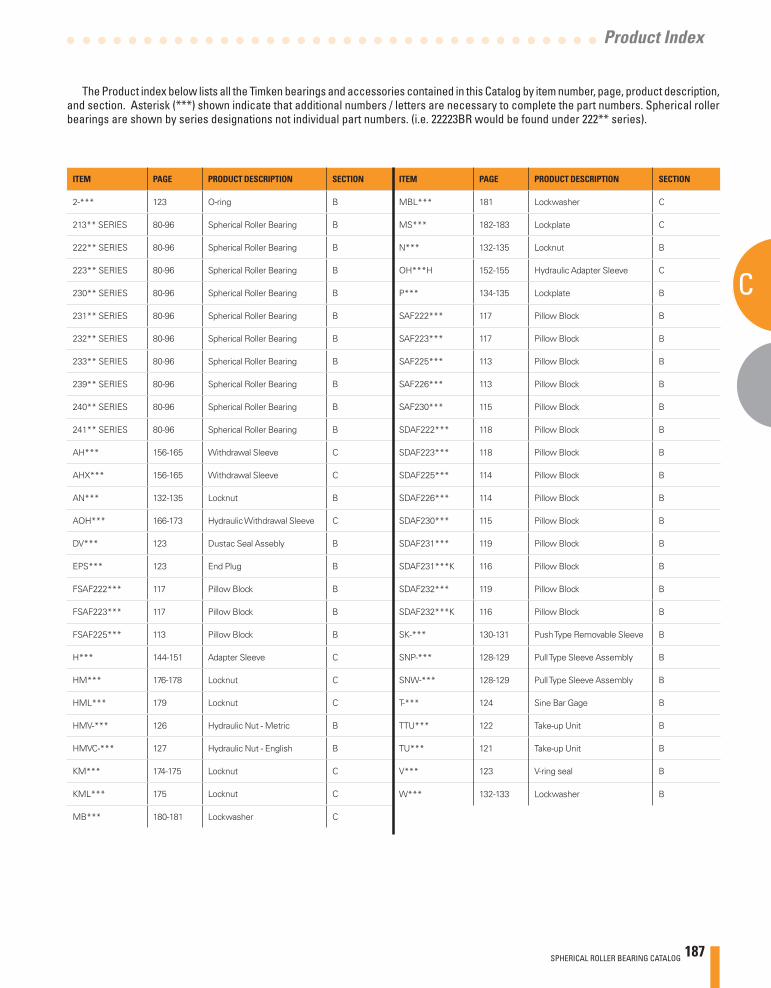
ITEM PAGE PRODUCT DESCRIPTION SECTION
2-*** 123 O-ring B
213** SERIES 80-96 Spherical Roller Bearing B
222** SERIES 80-96 Spherical Roller Bearing B
223** SERIES 80-96 Spherical Roller Bearing B
230** SERIES 80-96 Spherical Roller Bearing B
231** SERIES 80-96 Spherical Roller Bearing B
232** SERIES 80-96 Spherical Roller Bearing B
233** SERIES 80-96 Spherical Roller Bearing B
239** SERIES 80-96 Spherical Roller Bearing B
240** SERIES 80-96 Spherical Roller Bearing B
241** SERIES 80-96 Spherical Roller Bearing B
AH*** 156-165 Withdrawal Sleeve C
AHX*** 156-165 Withdrawal Sleeve C
AN*** 132-135 Locknut B
AOH*** 166-173 Hydraulic Withdrawal Sleeve C
DV*** 123 Dustac Seal Assebly B
EPS*** 123 End Plug B
FSAF222*** 117 Pillow Block B
FSAF223*** 117 Pillow Block B
FSAF225*** 113 Pillow Block B
H*** 144-151 Adapter Sleeve C
HM*** 176-178 Locknut C
HML*** 179 Locknut C
HMV-*** 126 Hydraulic Nut - Metric B
HMVC-*** 127 Hydraulic Nut - English B
KM*** 174-175 Locknut C
KML*** 175 Locknut C
MB*** 180-181 Lockwasher C
ITEM PAGE PRODUCT DESCRIPTION SECTION
MBL*** 181 Lockwasher C
MS*** 182-183 Lockplate C
N*** 132-135 Locknut B
OH***H 152-155 Hydraulic Adapter Sleeve C
P*** 134-135 Lockplate B
SAF222*** 117 Pillow Block B
SAF223*** 117 Pillow Block B
SAF225*** 113 Pillow Block B
SAF226*** 113 Pillow Block B
SAF230*** 115 Pillow Block B
SDAF222*** 118 Pillow Block B
SDAF223*** 118 Pillow Block B
SDAF225*** 114 Pillow Block B
SDAF226*** 114 Pillow Block B
SDAF230*** 115 Pillow Block B
SDAF231*** 119 Pillow Block B
SDAF231***K 116 Pillow Block B
SDAF232*** 119 Pillow Block B
SDAF232***K 116 Pillow Block B
SK-*** 130-131 Push Type Removable Sleeve B
SNP-*** 128-129 Pull Type Sleeve Assembly B
SNW-*** 128-129 Pull Type Sleeve Assembly B
T-*** 124 Sine Bar Gage B
TTU*** 122 Take-up Unit B
TU*** 121 Take-up Unit B
V*** 123 V-ring seal B
W*** 132-133 Lockwasher B
Product Index
SPHERICAL ROLLER BEARING CATALOG 187
The Product index below lists all the Timken bearings and accessories contained in this Catalog by item number, page, product description, and section. Asterisk (***) shown indicate that additional numbers / letters are necessary to complete the part numbers. Spherical roller bearings are shown by series designations not individual part numbers. (i.e. 22223BR would be found under 222** series).
C
NOTES
188 SPHERICAL ROLLER BEARING CATALOG
SPHERICAL ROLLER BEARING METRIC ACCESSORIES
C
NOTES
SPHERICAL ROLLER BEARING CATALOG 189
C
Spherical Roller Bearing Metric Accessories
190 SPHERICAL ROLLER BEARING CATALOG
SPHERICAL ROLLER BEARING METRIC ACCESSORIES

Bearings • Steel • Precision Components • Lubrication •Seals • Remanufacture and Repair • Industrial Services
www.timken.com
Timken® is the registered trademark of The Timken Company.
© 2007 The Timken CompanyPrinted in U.S.A.15M 06-07-29 Order No. 10142
Tim
ken® S
ph
erical Ro
ller Bearin
g C
atalog