TIMING CHAIN REMOVAL/INSTALLA - JustAnswer · PDF fileCrankshaft Pulley Lock Bolt Removal Note...
13
TIMING CHAIN REMOVAL/INSTALLA... < Previous Next > 2004 - MAZDA3 - Workshop Manual - Engine TIMING CHAIN REMOVAL/INSTALLATION WARNING: Fuel vapor is hazardous. It can very easily ignite, causing serious injury and damage. Always keep sparks and flames away from fuel. Fuel line spills and leakage are dangerous. Fuel can ignite and cause serious injuries or death and damage. Fuel can also irritate skin and eyes. To prevent this, always complete the Fuel Line Safety Procedure. (See Fuel Line Safety Procedure .) 1. Remove the following parts. a. Plug hole plate (See PLUG HOLE PLATE REMOVAL/INSTALLATION .) b. Plug hole plate bracket c. Accelerator cable and bracket d. Battery cover (See BATTERY REMOVAL/INSTALLATION .) 2. Disconnect the negative battery cable. 3. Remove the following parts. a. Ignition coils (See IGNITION COIL REMOVAL/INSTALLATION .) b. Front wheel and tire (RH) (See GENERAL PROCEDURES (SUSPENSION) .) c. Under cover and splash shields d. Crankshaft position (CKP) sensor (See CRANKSHAFT POSITION (CKP) SENSOR REMOVAL/INSTALLATION .) e. Drive belt (See DRIVE BELT REPLACEMENT .) f. A/C compressor with the oil hose still connected and position the A/C compressor so that it is out of the way (See A/C COMPRESSOR REMOVAL/INSTALLATION .) g. Coolant reserve tank with the hose still connected and position the coolant reserve tank so that it is out of the way 4. Remove in the order indicated in the table. 5. Install in the reverse order of removal. 6. Start the engine. 7. Inspect the following and adjust if necessary. Pulley and belt for runout and contact Leakage of engine oil Ignition timing, idle speed, and amount of CO and HC (See ENGINE TUNE-UP .) Engine-driven accessories operation
-
Upload
truongtuong -
Category
Documents
-
view
216 -
download
0
Transcript of TIMING CHAIN REMOVAL/INSTALLA - JustAnswer · PDF fileCrankshaft Pulley Lock Bolt Removal Note...

TIMING CHAIN REMOVAL/INSTALLA...
< Previous Next >
2004 - MAZDA3 - Workshop Manual - Engine
TIMING CHAIN REMOVAL/INSTALLATION
WARNING:
Fuel vapor is hazardous. It can very easily ignite, causing serious injury and damage. Always keepsparks and flames away from fuel.
Fuel line spills and leakage are dangerous. Fuel can ignite and cause serious injuries or death anddamage. Fuel can also irritate skin and eyes. To prevent this, always complete the Fuel Line SafetyProcedure. (See Fuel Line Safety Procedure.)
1. Remove the following parts.
a. Plug hole plate (See PLUG HOLE PLATE REMOVAL/INSTALLATION.)
b. Plug hole plate bracket
c. Accelerator cable and bracket
d. Battery cover (See BATTERY REMOVAL/INSTALLATION.)
2. Disconnect the negative battery cable.
3. Remove the following parts.
a. Ignition coils (See IGNITION COIL REMOVAL/INSTALLATION.)
b. Front wheel and tire (RH) (See GENERAL PROCEDURES (SUSPENSION).)
c. Under cover and splash shields
d. Crankshaft position (CKP) sensor (See CRANKSHAFT POSITION (CKP) SENSORREMOVAL/INSTALLATION.)
e. Drive belt (See DRIVE BELT REPLACEMENT.)
f. A/C compressor with the oil hose still connected and position the A/C compressor so that it isout of the way (See A/C COMPRESSOR REMOVAL/INSTALLATION.)
g. Coolant reserve tank with the hose still connected and position the coolant reserve tank sothat it is out of the way
4. Remove in the order indicated in the table.
5. Install in the reverse order of removal.
6. Start the engine.
7. Inspect the following and adjust if necessary.
Pulley and belt for runout and contact
Leakage of engine oil
Ignition timing, idle speed, and amount of CO and HC (See ENGINE TUNE-UP.)
Engine-driven accessories operation

1 Cylinder head cover
(See Cylinder Head Cover Installation Note.)
2 Crankshaft pulley lock bolt
(See Crankshaft Pulley Lock Bolt Removal NoteE.)
(See Crankshaft Pulley Lock Bolt Installation Note.)
3 Crankshaft pulley
4 Water pump pulley

5 Drive belt auto tensioner
6 No.3 engine mount rubber and No.3 engine joint bracket
(See No.3 Engine Mount Rubber Removal Note.)
(See No.3 Engine Mount Rubber and No.3 Engine Mount Bracket Installation Note.)
7 Engine front cover
(See Engine Front Cover Installation Note.)
8 Front oil seal
(See Engine Front Cover Removal Note.)
(See Front Oil Seal Installation Note.)
9 Chain tensioner
(See Chain Tensioner Removal Note.)
10Tensioner arm
11Chain guide
12Timing chain
(See Timing Chain Installation Note.)
13Oil pump chain tensioner
14Oil pump chain guide
15Oil pump sprocket
(See Oil Pump Sprocket Removal Note.)
(See Oil Pump Sprocket Installation Note.)
16Oil pump chain
17Crankshaft sprocket
Crankshaft Pulley Lock Bolt Removal Note
1. Remove the cylinder block lower blind plug.
2. Install the SST.
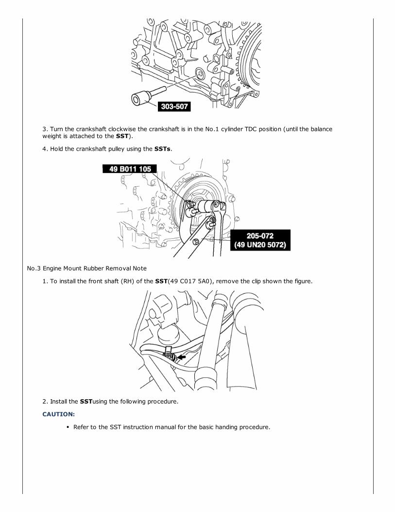
3. Turn the crankshaft clockwise the crankshaft is in the No.1 cylinder TDC position (until the balanceweight is attached to the SST).
4. Hold the crankshaft pulley using the SSTs.
No.3 Engine Mount Rubber Removal Note
1. To install the front shaft (RH) of the SST(49 C017 5A0), remove the clip shown the figure.
2. Install the SSTusing the following procedure.
CAUTION:
Refer to the SST instruction manual for the basic handing procedure.

a. Install the right rear shaft of the SSTto the bolt of the right shock absorber as shown in thefigure.
b. Install the left rear shaft of the SSTto the bolt of the left shock absorber. (identical positionto the right side)
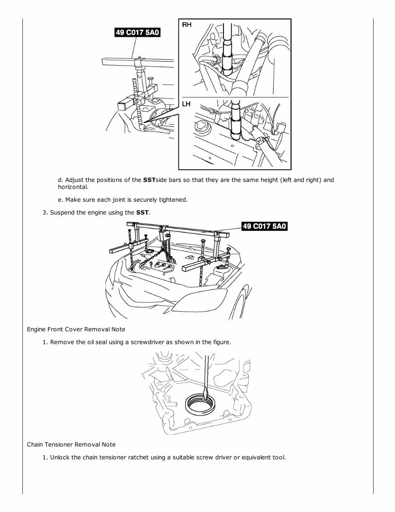
c. Install front foot No.2 to the left/right front shaft of the SST, then align the groove of thefront shaft of the SST with the folded up part of the vehicle as shown in the figure.
d. Adjust the positions of the SSTside bars so that they are the same height (left and right) andhorizontal.
e. Make sure each joint is securely tightened.
3. Suspend the engine using the SST.
Engine Front Cover Removal Note
1. Remove the oil seal using a screwdriver as shown in the figure.
Chain Tensioner Removal Note
1. Unlock the chain tensioner ratchet using a suitable screw driver or equivalent tool.

2. Slowly compress the tensioner piston.
3. Hold the tensioner piston using a 1.5 mm {0.059 in}wire or paper clip.
Oil Pump Sprocket Removal Note
1. Temporarily install the crankshaft pulley and crankshaft pulley lock bolt to the crankshaft, and lock theoil pump against rotation as shown in figure.
2. Remove the oil pump sprocket, and then remove the crankshaft pulley and crankshaft pulley lock bolt.
Oil Pump Sprocket Installation Note
1. Temporarily install the crankshaft pulley and crankshaft pulley lock bolt to the crankshaft, and lock theoil pump against rotation as shown in figure.
2. Install the oil pump sprocket, and then remove the crankshaft pulley and crankshaft pulley lock bolt.
Tightening torque
20—30 N·m {2.1—3.0 kgf·m, 15.2—21.6 ft·lbf}
Timing Chain Installation Note
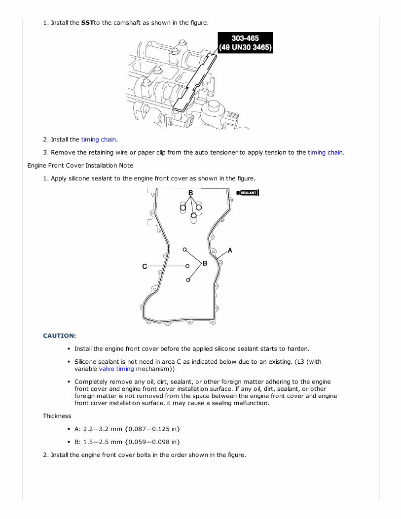
1. Install the SSTto the camshaft as shown in the figure.
2. Install the timing chain.
3. Remove the retaining wire or paper clip from the auto tensioner to apply tension to the timing chain.
Engine Front Cover Installation Note
1. Apply silicone sealant to the engine front cover as shown in the figure.
CAUTION:
Install the engine front cover before the applied silicone sealant starts to harden.
Silicone sealant is not need in area C as indicated below due to an existing. (L3 (withvariable valve timing mechanism))
Completely remove any oil, dirt, sealant, or other foreign matter adhering to the enginefront cover and engine front cover installation surface. If any oil, dirt, sealant, or otherforeign matter is not removed from the space between the engine front cover and enginefront cover installation surface, it may cause a sealing malfunction.
Thickness
A: 2.2—3.2 mm {0.087—0.125 in}
B: 1.5—2.5 mm {0.059—0.098 in}
2. Install the engine front cover bolts in the order shown in the figure.
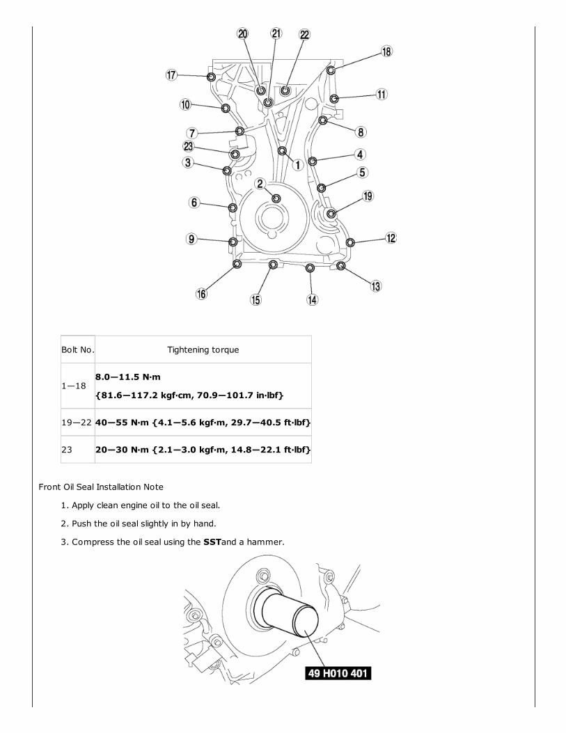
Bolt No. Tightening torque
1—188.0—11.5 N·m
{81.6—117.2 kgf·cm, 70.9—101.7 in·lbf}
19—22 40—55 N·m {4.1—5.6 kgf·m, 29.7—40.5 ft·lbf}
23 20—30 N·m {2.1—3.0 kgf·m, 14.8—22.1 ft·lbf}
Front Oil Seal Installation Note
1. Apply clean engine oil to the oil seal.
2. Push the oil seal slightly in by hand.
3. Compress the oil seal using the SSTand a hammer.

No.3 Engine Mount Rubber and No.3 Engine Mount Bracket Installation Note
1. Tighten the stud bolt of the No.3 engine mount bracket.
Tightening torque 7.0—13 N·m {71.4—132.5 kgf·cm, 62.0—115.0 in·lbf}
NOTE:
Tightening stud bolt when the nut of No.3 engine mount nut is loosened.
2. Hand-tighten the No.3 engine mount rubber and No.3 engine mount bracket.
3. Tighten the bolts and nuts in the order as shown in the figure.
Tightening torque
Nuts : 74.5—104.9 N·m {7.6—10.6 kgf·m, 55.0—77.3 ft·lbf}
Bolts : 74.5—93.1 N·m {7.6—9.5 kgf·m, 55.0—68.7 ft·lbf}
Crankshaft Pulley Lock Bolt Installation Note
1. Install the SSTto the camshaft as shown in the figure.

2. Install the M6 x 1.0bolt in by hand.
3. Turn the crankshaft clockwise until the crankshaft is in the No.1 cylinder TDC position (until the balanceweight is attached to the SST).
4. Hold the crankshaft pulley using the SST.
5. Tighten the crankshaft pulley lock bolt in the order shown with the following two steps using the SST(49 D032 316).
Tightening torque
(1) 96—104 N·m {9.8—10.6 kgf·m, 70.9—76.7 ft·lbf}
(2) 87°—93°
6. Remove the M6 x 1.0bolt.
7. Remove the SSTfrom the camshaft.
8. Remove the SSTfrom the cylinder block lower blind plug.
9. Rotate the crankshaft clockwise two turns until the TDC position.
If not aligned, loosen the crankshaft pulley lock bolt and repeat from Step 1.

10. Install the cylinder block lower blind plug.
Tightening torque 18—22 N·m {1.9—2.2 kgf·m, 13.3—16.2 ft·lbf}
Cylinder Head Cover Installation Note
1. Apply silicone sealant to the mating faces as shown in the figure.
CAUTION:
Install the cylinder head cover within 10 min of applying the silicone sealant.
Thickness 4.0—7.0 mm {0.16—0.24 in}
2. Install the cylinder head cover with a new gasket.
3. Tighten the bolts in the order shown in the figure.
Tightening torque 8.0—9.5 N·m {82—96 kgf·cm, 71—84 in·lbf}
< Previous Next >Back to Top
© 2012 Mazda North American Operations, U.S.A.
Portions of materials contained herein are sourced from Mazda Motor Corporation.

Copyright 2013 Service Repair Solutions, Inc.