
Time-Triggered Ethernet - Computer Sciencehzhang/courses/8260/Lectures/Chapter 42 - Time...of the...
34
Time-Triggered Ethernet Chapters 42 in the Textbook Professor: HONGWEI ZHANG CSC8260 Winter’2016 Presented By: Priyank Baxi (fr0630) [email protected]
Transcript of Time-Triggered Ethernet - Computer Sciencehzhang/courses/8260/Lectures/Chapter 42 - Time...of the...
Time-Triggered Ethernet
Chapters 42 in the Textbook
Professor: HONGWEI ZHANGCSC8260 Winter’2016
Presented By: Priyank Baxi (fr0630)[email protected]
Outline
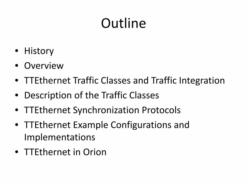
• History• Overview• TTEthernet Traffic Classes and Traffic Integration• Description of the Traffic Classes• TTEthernet Synchronization Protocols• TTEthernet Example Configurations and
Implementations• TTEthernet in Orion

TTEthernet – A Powerful Network Solution for All Purposes
• Ethernet offers far higher bandwidths. But when Ethernet was developed in the first place, tasks with time-critical, deterministic or safety-relevant conditions were not taken into account. TTEthernet expands classical Ethernet with powerful services to meet all new requirements.

From Ethernet to TTEthernet• Ethernet systems have limits when it comes to
combining them with classical Ethernet networks, devices and services. The scalability of these systems is also limited and the network solution is tailored for a specific application area. The use of Real-Time and Safe Ethernet systems outside engine and plant construction is no option. The industry is striving to reduce the number of networks and to cut costs for effort and resources. TTEthernet combines the proven determinism, fault-tolerance and real-time properties of the time-triggered technology with the flexibility, dynamics and legacy of “best effort” of Ethernet and is therefore suited for all types of applications.
Overview
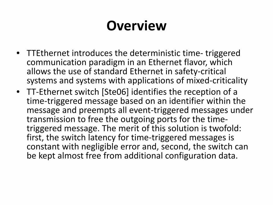
• TTEthernet introduces the deterministic time- triggered communication paradigm in an Ethernet flavor, which allows the use of standard Ethernet in safety-critical systems and systems with applications of mixed-criticality
• TT-Ethernet switch [Ste06] identifies the reception of a time-triggered message based on an identifier within the message and preempts all event-triggered messages under transmission to free the outgoing ports for the time-triggered message. The merit of this solution is twofold: first, the switch latency for time-triggered messages is constant with negligible error and, second, the switch can be kept almost free from additional configuration data.
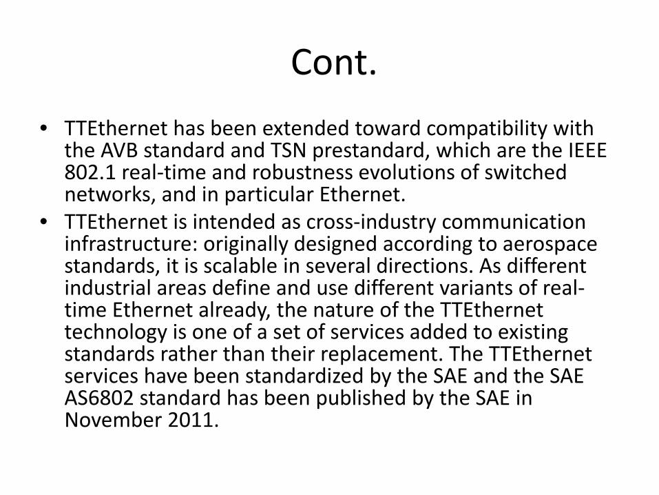
Cont.• TTEthernet has been extended toward compatibility with
the AVB standard and TSN prestandard, which are the IEEE 802.1 real-time and robustness evolutions of switched networks, and in particular Ethernet.
• TTEthernet is intended as cross-industry communication infrastructure: originally designed according to aerospace standards, it is scalable in several directions. As different industrial areas define and use different variants of real-time Ethernet already, the nature of the TTEthernettechnology is one of a set of services added to existing standards rather than their replacement. The TTEthernetservices have been standardized by the SAE and the SAE AS6802 standard has been published by the SAE in November 2011.
Cont.
• A TTEthernet network consists of end systems and switches and bidirectional communication links to connect these devices to each other. Furthermore, an end system and a switch may be integrated into a single device


TTEthernet Traffic Classes and Traffic Integration
• TTEthernet is fully compliant with the Ethernet frame format as standardized in IEEE 802.3.
• TTEthernet defines the term traffic class to differentiate communication modes. The prime communication mode of TTEthernet is, of course, the time-triggered traffic class (TT). Besides this mandatory traffic class, TTEthernet also supports the optional rate-constrained traffic class (RC) and the optional best-effort traffic class (BE). TTEthernet is an integrative communication protocol capable of communicating frames of these three traffic classes on the same physical network.
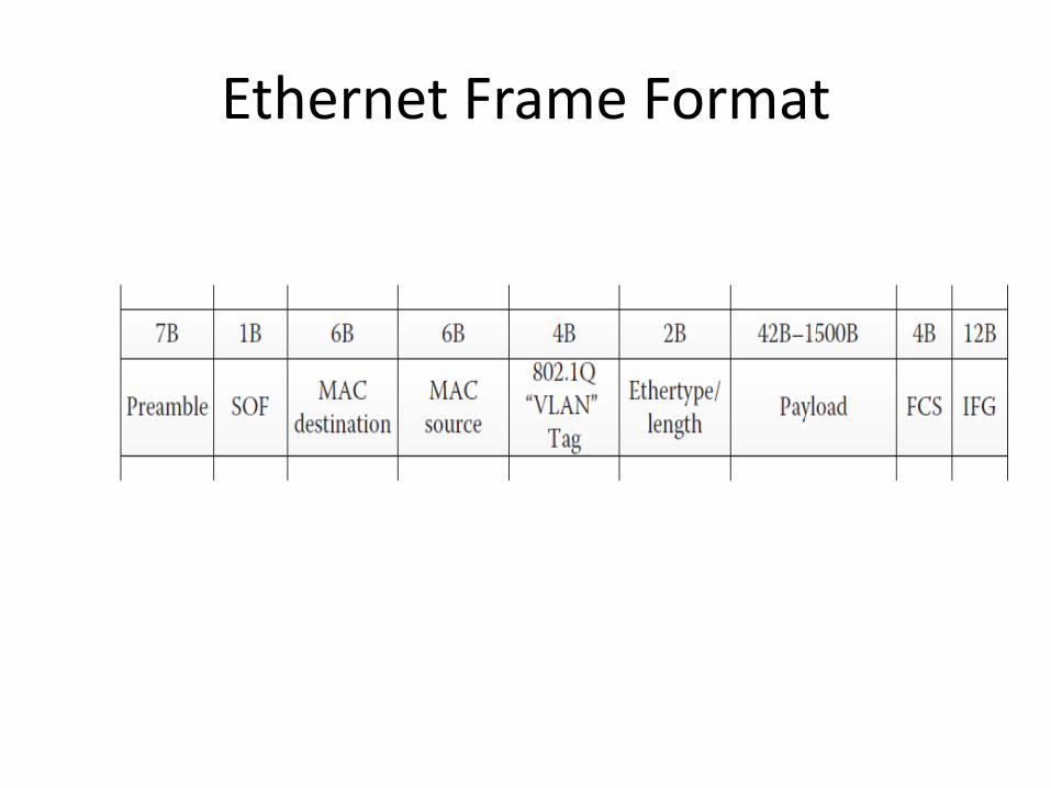
Ethernet Frame Format

Example of communication scenario in a TTEthernet network

Description of the Traffic Classes• A TTEthernet end system implements services to
synchronize its local clock with the local clocks of other end systems and switches in the system. The end system can then send messages at off-line planned (or online assigned) points in this synchronized global time.
• Time-triggered (TT) messages are used when tight latency, jitter, and determinism are required. All TT messages are sent at predefined times. In cases where an end system decides not to use one of its assigned timed slots, for example, if there are no new data to be sent, the switch recognizes the inactivity of the sender and frees the bandwidth for the other traffic classes. TT messages are optimally suited for communication in distributed real-time systems with regular communication pattern.

CONT.• Rate-constrained (RC) messages realize a communication paradigm that
aims at establishing well-shaped data flows: successive messages belonging to the same rate-constrained dataflow are guaranteed to be offset by a minimum duration as configured. RC messages are used when determinism and real-time requirements are less strict than provided by time-triggered communication. For RC messages, sufficient bandwidth must be allocated such that delays and temporal deviations have defined limits.
• In contrast to TT messages, RC messages are not sent with respect to a system-wide synchronized time base. Hence, different communication controllers may send RC messages at the same point in time to the same receiver. Consequently, the RC messages may queue up in the network switches, leading to increased transmission jitter and requiring increased buffer space. As the transmission rate of the RC messages is bound a priori and controlled in the network switches, an upper bound on the transmission latency can be calculated off-line and message loss is avoided.

CONT.• Best-Effort (BE) messages implement the classic switched Ethernet
approach.• There is no guarantee whether or when these messages can be
transmitted, what delays occur, and if BE messages arrive at the recipient at all.
• BE messages use the remaining bandwidth of the network and have lower priority than TT and RC messages.
• However, BE traffic may be attractive, for example, during maintenance and configuration phases: as during such phases no critical traffic in form of TT or RC may be present, the whole network bandwidth is available for BE traffic without explicitly changing the network mode: RC messages will not be sent and bandwidth reserved for TT messages is automatically reclaimed by the Switches.
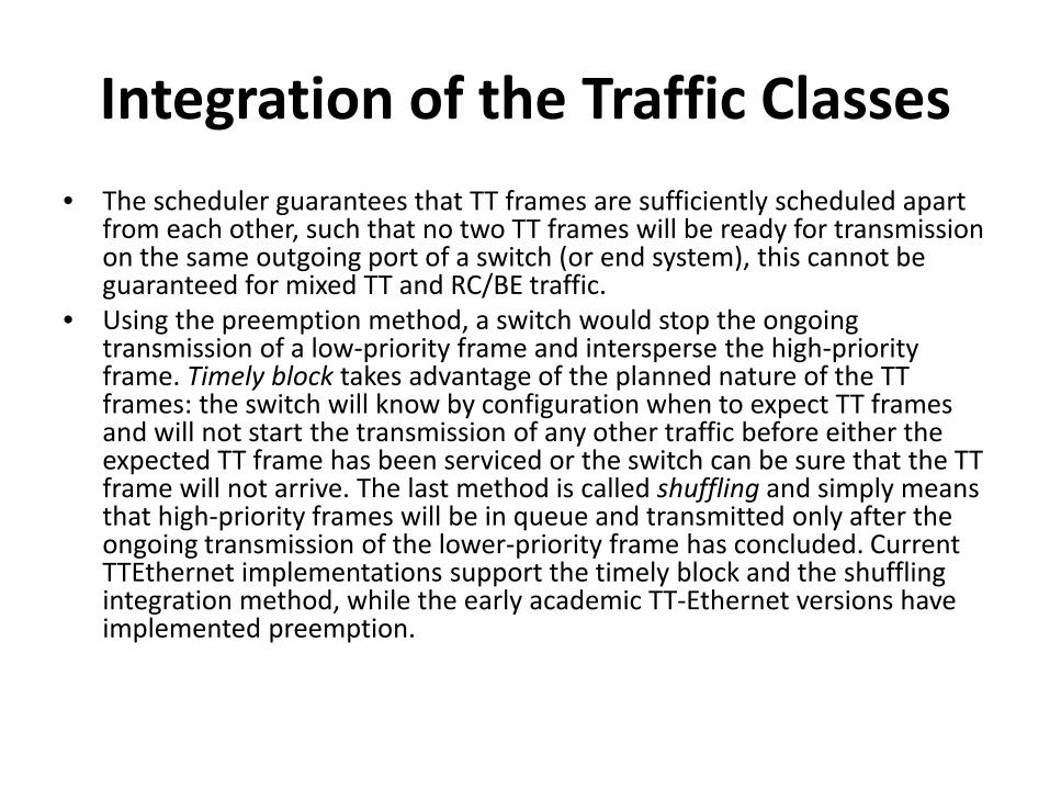
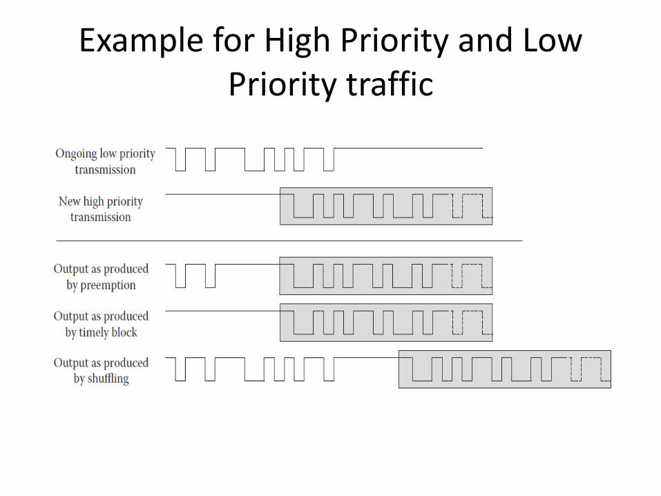
Integration of the Traffic Classes• The scheduler guarantees that TT frames are sufficiently scheduled apart
from each other, such that no two TT frames will be ready for transmission on the same outgoing port of a switch (or end system), this cannot be guaranteed for mixed TT and RC/BE traffic.
• Using the preemption method, a switch would stop the ongoing transmission of a low-priority frame and intersperse the high-priority frame. Timely block takes advantage of the planned nature of the TT frames: the switch will know by configuration when to expect TT frames and will not start the transmission of any other traffic before either the expected TT frame has been serviced or the switch can be sure that the TT frame will not arrive. The last method is called shuffling and simply means that high-priority frames will be in queue and transmitted only after the ongoing transmission of the lower-priority frame has concluded. Current TTEthernet implementations support the timely block and the shuffling integration method, while the early academic TT-Ethernet versions have implemented preemption.
Example for High Priority and Low Priority traffic

TTEthernet Synchronization Protocols
• TTEthernet specifies and standardizes in SAE AS6802 several synchronization protocols that ensure close synchronization of the local clocks in the end systems and switches during all modes of operation of the network. These protocols have been designed to tolerate the failure of end systems and/or switches in the network. In particular, end systems are allowed to fail either arbitrarily or according to an inconsistent-omission failure Mode . Switches are always considered to fail according to an inconsistent-omission failure mode.
• The TTEthernet protocol defines three different roles for synchronization: the Synchronization Master (SM), the Synchronization Client (SC), and the Compression Master (CM). The SM role is typically assigned to end systems, while switches act as CMs. As a minimum, one switch per channel is configured as CM. Both, switches and end systems, can be configured as SCs.
Start-Up and Integration• After initial power-on of the network, the start-up protocol ensures that the end
systems and switches will synchronize their local clocks within a bounded duration. More precisely, during start-up typically two protocols are executed, the coldstartprotocol and the integration protocol.
• Coldstart is the actual protocol that establishes synchronized time. However, typically a newly powered- on end system or switch will not know initially, if the system as a whole is currently in start-up mode or already synchronized, and consequently will assume that a subsystem of the system is already synchronized. The component will, thus, aim to synchronize toward these subsystems. Hence, it will try to integrate into an operational synchronized time base. Only if this integration is not successful, then the component will assume that there does not exist an already synchronized subsystem and will undergo the coldstart protocol.
• The TTEthernet start-up protocol is only executed between the SMs and the CMs. SCs will synchronize only after a synchronized time base has been established. The start-up protocol involves the exchange of a sequence of PCFs (protocol control frames), in particular coldstart and coldstart acknowledgment messages. Although the start-up protocol is rather small, its real-time behavior, the nature of distributed algorithms, and the behavior of faulty switches and/or end systems make the analysis of protocols like these rather complex.

Clock Synchronization• Once the start-up protocol has initially established the
synchronized time base, the clock synchronization protocol is periodically executed to resynchronize the local clocks in the end systems and switches.
• The TTEthernet clock synchronization algorithm operates in two steps. In the first step, all SMs Concurrently send PCFs to all CMs at their same local time.
• In the second step, all the SMs and SCs use the reception times of the compressed PCFs from the CMs to derive a new reference point in time for synchronization.

Clique Detection and Restart• The synchronized time base is essential to communicate the TT messages in
TTEthernet, while the network is always able to communicate RC and BE messages, whether the components are synchronized or not. However, as the TT messages are likely to be critical messages in a given system TTEthernetincorporates synchronization protocols also for extremely unlikely situations such as system-wide Communication blackouts and recovery when one or many components have lost synchronization.
• The protocols that detect failures in the synchronization are commonly referred to as clique detection algorithms. TTEthernet implements three clique detection algorithms: the synchronous clique detection algorithm, the asynchronous clique detection algorithm, and the relative clique detection algorithm.
• Using the synchronous algorithm, a component will continually check as to how many SMs are currently Synchronized and will report a clique if this number falls below a configured threshold.
• Analogously, using the asynchronous algorithm, a component will continually check if there are components in the system it is not synchronized to and will count how many such components there are.

TTEthernet Example Configurations and Implementations
Configurations• TTEthernet network configurations may differ with respect to the
number of end systems and the number of switches, as well as their connecting topology. In particular for the synchronization algorithms, configurations are determined by the assignment of synchronization roles to TTEthernet devices.
• As a reminder, we have introduced three roles in the synchronization algorithms of TTEthernet: the synchronization master (SM), the compression master (CM), and the synchronization client (SC). More general characteristics of time-triggered networks include the quality of oscillators used in the TTEthernet devices, the wire speed and associated physical layer, the communication interface, and the activated fault-containment measures.
Master-Based Configuration• The most basic TTEthernet configuration consists of an SM and a CM,
where both synchronization roles may be integrated into a single device. From this configuration, classic single-master multiple slave networks.
• This single-master configuration is attractive for low-cost applications with a requirement of quality of- service such as real-time performance. This configuration can be enhanced by safety mechanisms like the activation of the central guardian function in the switches or by the high-integrity design of key devices. Hence, given that the appropriate fault-isolation measures are in place, even this basic configuration is appropriate for fail-safe applications.
• Availability, on the other hand, is limited: the failure of an arbitrary number of SCs will not affect the services as provided by TTEthernet. However, as in all single-master-based systems, the loss of the SM or CM means a loss of the synchronization source and so of the TTEthernetprotocol services. Availability requires the implementation of a sufficient degree of redundancy.


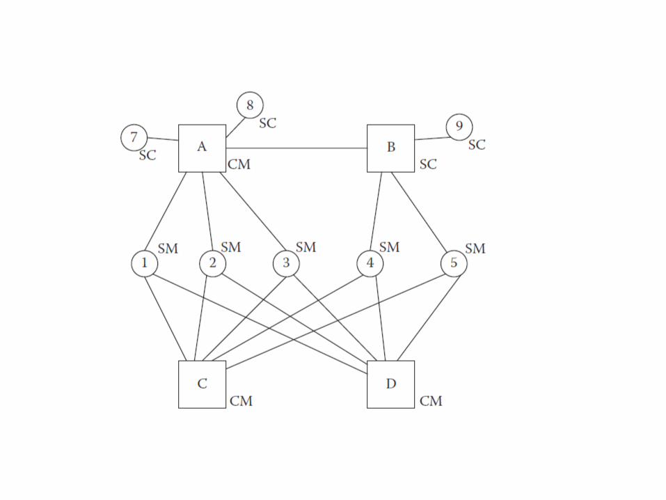
Dual-Fault-Tolerant Configuration
• TTEthernet network that tolerates two faulty devices without degradation of the TTEthernet services.
• The SMs and CMs have to be high-integrity devices supporting an inconsistent-omission failure mode. In this configuration, the failure of any two devices is masked by the TTEthernet services without quality degradation.

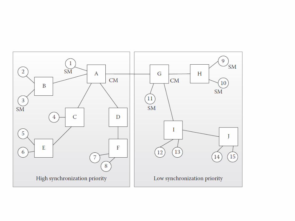
System-of-Systems Configuration
• Two TTEthernet subnetworks, a high-priority subnetwork and a low-priority subnetwork. The priority of the respective network is stored in the configuration data of each TTEthernet device as well as in the Sync_Priority field in the PCFs. A TTEthernet end system can be configured to automatically synchronize to the highest priority PCF it receives. Alternatively, the change of a TTEthernet current priority to a higher priority can demand host interaction. This priority mechanism supports the full operation of parts of the network, for example, to realize power-down modes.

Implementations• The FPGA-based solutions of TTEthernet mainly differ with respect to the
communication speed they support. The 100 Mb/s FPGA-based version of the TTEthernet switch is specified as follows:
• Eight 100 Mb/s and one 1 Gb/s uplink port.• Guaranteed real-time delivery and clock synchronization in the microseconds
range.• Legacy Ethernet devices can synchronize to network time base without knowing
about TTEthernet• Support for legacy and best-effort traffic.• Standard TCP/IP protocols and applications can be used.• Flexibility for customer-specific extensions (ALTERA Cyclone III FPGA).• Digital I/O for triggering measurements.• Dimensions: 170 × 121 × 55 mm; weight: 800 g; operating temperature: 0°C–
70°C; storage:−40°C to +85°C.• Robust housing.
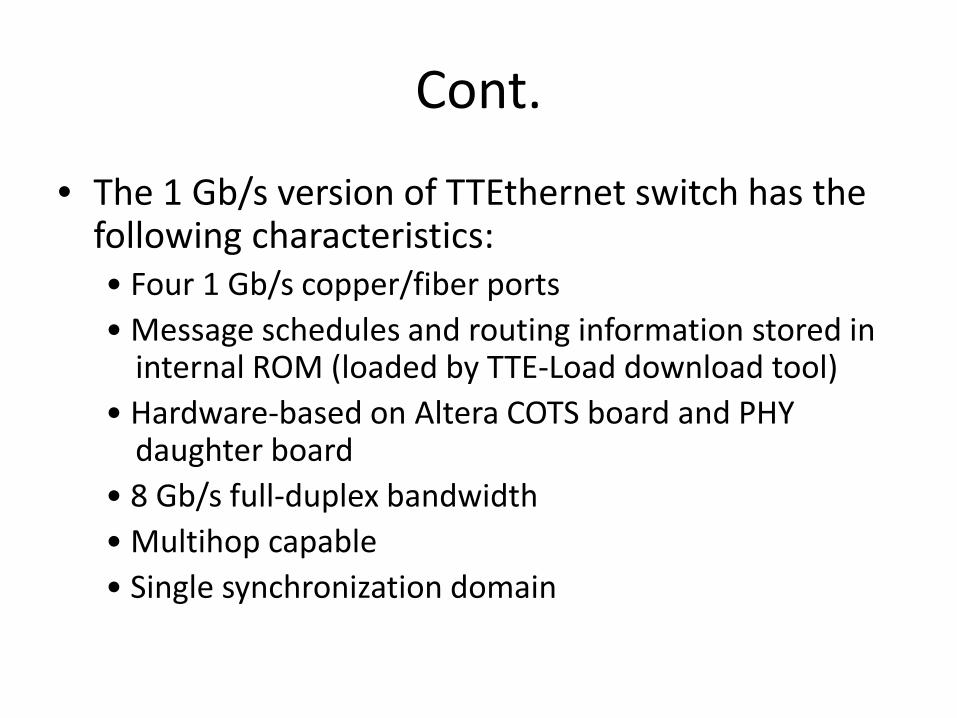
Cont.
• The 1 Gb/s version of TTEthernet switch has the following characteristics:• Four 1 Gb/s copper/fiber ports• Message schedules and routing information stored in
internal ROM (loaded by TTE-Load download tool)• Hardware-based on Altera COTS board and PHY
daughter board• 8 Gb/s full-duplex bandwidth• Multihop capable• Single synchronization domain

TTEthernet in Orion• Orion has very specific mission requirements. It has to
meet a mission requirement of up to 5000 h (about 200 days) of continuous operation at a time. It must be a flexible vehicle that will interface to several other space elements (the International Space Station, the Altair Lunar Lander, Ground Systems, and the Space Network, in addition to the Ares I interface) over the next several decades. Additionally, Orion has strict weight and power restrictions that make it desirable for its avionics system to maintain full protection against erroneous behavior even when operated in a low-power partial system mode, which is a mode when part of the avionics system is shut off to conserve power

Cont.• Orion’s requirements
• The Orion CEV (crew exploration vehicle) shall meet an ascent reliability allocation of 0.9999.
• The Orion CEV shall meet an overall mission reliability allocation of 0.999.
• The Orion CEV shall be one-fault-tolerant for safe return of the crew with exceptions for design for minimum risk.
• The Orion CEV shall safely recover and return the crew in case of loss of output and erroneous output from the vehicle flight computers due to software common-cause failure.
• The Orion CEV shall allow the crew to manually control, inhibit, and/or override autonomous or ground-controlled critical functions.
• The Orion CEV shall be one-fault-tolerant for mission completion with exceptions for design for minimum risk.

Cont.• The presented and deployed Architecture has the following
advantages:• Good error detection for bit flips in processors as well as in
associated memories. In all cases, no inadvertent action is performed due to single event upsets with a very high probability (or in other words, the probability of undetected failures is smaller than 10−9).
• No inadvertent violation of space partitioning (memory and I/O) due to features like memory management units (MMUs).
– Cross-compare monitors perform constant comparison of computing outputs and validate MMU integrity.
• Data integrity management (freshness monitoring for partition usage).
• Support of bus error containment (more Orion details later).


THANK YOU!!!


