Time-resolved fluorescence imaging of solvent … Resolved fluorescence...Time-resolved fluorescence...
11
Time-resolved fluorescence imaging of solvent interactions in microfluidic devices Richard K. P. Benninger, Oliver Hofmann, James McGinty, Jose Requejo-Isidro, Ian Munro, Mark A. A. Neil, Andrew J. deMello and Paul M. W. French Department of Physics and Department of Chemistry, Imperial College London, South Kensington, London, SW7 2AZ, UK. [email protected] Abstract: We present the application of wide-field time-resolved fluorescence imaging methods for the study of solvent interactions and mixing in microfluidic devices. Time-resolved imaging of fluorescence polarization anisotropy allows us to image the local viscosity of fluorescein in three dimensions in order to directly monitor solvent mixing within a microfluidic channel. This provides a viscosity image acquisition time of the order of minutes, and has been applied to a steady-state laminar flow configuration. To image dynamic fluid mixing in real-time, we demonstrate high-speed fluorescence lifetime imaging at 12.3 Hz applied to DASPI, which directly exhibits a solvent viscosity-dependant fluorescence lifetime. These two methods facilitate a high degree of quantification of microfluidic flow in 3-D and/or at high speed, providing a tool for studying fluid dynamics and for developing enhanced microfluidic assays. © 2005 Optical Society of America OCIS codes: (180.6900) Microscopy; (180.2520) Microscopy; (170.3650) Medical Optics and Biotechnology; (320.5390) Ultrafast optics. References and links 1. D. R. Reyes, D. Iossifidis, P. A. Auroux and A. Manz, "Micro total analysis systems. 1. Introduction, theory, and technology," Anal. Chem. 74, 2623-2636 (2002) 2. P. A. Auroux, D. Iossifidis, D. R. Reyes and A. Manz, "Micro total analysis systems. 2. Analytical standard operations and applications," Anal. Chem. 74, 2637-2652 (2002) 3. T. Vilkner, D. Janasek and A. Manz, "Micro total analysis systems. Recent developments," Anal. Chem. 76, 3373-3385 (2004) 4. E. Verpoorte, "Chip vision - optics for microchips," Lab Chip 3, 42N-52N (2003) 5. A. E. Kamholz, B. H. Weigl, B. A. Finlayson and P. Yager, "Quantitative analysis of molecular interaction in a microfluidic channel: The T-sensor," Anal. Chem. 71, 5340-5347 (1999) 6. A. Hatch, A. E. Kamholz, K. R. Hawkins, M. S. Munson, E. A. Schilling, B. H. Weigl and P. Yager, "A rapid diffusion immunoassay in a T-sensor," Nat. Biotechnol. 19, 461-465 (2001) 7. D. Ross, M. Gaitan and L. E. Locascio, "Temperature measurement in microfluidic systems using a temperature-dependent fluorescent dye," Anal. Chem. 73, 4117-4123 (2001) 8. R. P. Hertzberg and A. J. Pope, "High-throughput screening: new technology for the 21st century," Curr. Opin. Chem. Biol. 4, 445-451 (2000) 9. K. Suhling, J. Siegel, P. M. P. Lanigan, S. Leveque-Fort, S. E. D. Webb, D. Phillips, D. M. Davis and P. M. W. French, "Time-resolved fluorescence anisotropy imaging applied to live cells," Opt. Lett. 29, 584- 586 (2004) 10. A. H. A. Clayton, Q. S. Hanley, D. J. Arndt-Jovin, V. Subramaniam and T. M. Jovin, "Dynamic fluorescence anisotropy imaging microscopy in the frequency domain (rFLIM)," Biophys. J. 83, 1631- 1649 (2002) 11. G. H. Patterson and D. W. Piston, "Photobleaching in two-photon excitation microscopy," Biophys. J. 78, 2159-2162 (2000) 12. J. Requejo-Isidro, J. McGinty, I. Munro, D. S. Elson, N. P. Galletly, M. J. Lever, M. A. A. Neil, G. W. H. Stamp, P. M. W. French, P. A. Kellett, J. D. Hares and A. K. L. Dymoke-Bradshaw, "High-speed wide- field time-gated endoscopic fluorescence- lifetime imaging," Opt. Lett. 29, 2249-2251 (2004) (C) 2005 OSA 8 August 2005 / Vol. 13, No. 16 / OPTICS EXPRESS 6275 #7079 - $15.00 US Received 6 April 2005; revised 1 August 2005; accepted 1 August 2005
-
Upload
nguyentruc -
Category
Documents
-
view
245 -
download
0
Transcript of Time-resolved fluorescence imaging of solvent … Resolved fluorescence...Time-resolved fluorescence...

Time-resolved fluorescence imaging of solvent interactions in microfluidic devices
Richard K. P. Benninger, Oliver Hofmann, James McGinty, Jose Requejo-Isidro,
Ian Munro, Mark A. A. Neil, Andrew J. deMello and Paul M. W. French Department of Physics and Department of Chemistry, Imperial College London, South Kensington,
London, SW7 2AZ, UK. [email protected]
Abstract: We present the application of wide-field time-resolved fluorescence imaging methods for the study of solvent interactions and mixing in microfluidic devices. Time-resolved imaging of fluorescence polarization anisotropy allows us to image the local viscosity of fluorescein in three dimensions in order to directly monitor solvent mixing within a microfluidic channel. This provides a viscosity image acquisition time of the order of minutes, and has been applied to a steady-state laminar flow configuration. To image dynamic fluid mixing in real-time, we demonstrate high-speed fluorescence lifetime imaging at 12.3 Hz applied to DASPI, which directly exhibits a solvent viscosity-dependant fluorescence lifetime. These two methods facilitate a high degree of quantification of microfluidic flow in 3-D and/or at high speed, providing a tool for studying fluid dynamics and for developing enhanced microfluidic assays.
© 2005 Optical Society of America
OCIS codes: (180.6900) Microscopy; (180.2520) Microscopy; (170.3650) Medical Optics and Biotechnology; (320.5390) Ultrafast optics.
References and links 1. D. R. Reyes, D. Iossifidis, P. A. Auroux and A. Manz, "Micro total analysis systems. 1. Introduction,
theory, and technology," Anal. Chem. 74, 2623-2636 (2002) 2. P. A. Auroux, D. Iossifidis, D. R. Reyes and A. Manz, "Micro total analysis systems. 2. Analytical
standard operations and applications," Anal. Chem. 74, 2637-2652 (2002) 3. T. Vilkner, D. Janasek and A. Manz, "Micro total analysis systems. Recent developments," Anal. Chem.
76, 3373-3385 (2004) 4. E. Verpoorte, "Chip vision - optics for microchips," Lab Chip 3, 42N-52N (2003) 5. A. E. Kamholz, B. H. Weigl, B. A. Finlayson and P. Yager, "Quantitative analysis of molecular
interaction in a microfluidic channel: The T-sensor," Anal. Chem. 71, 5340-5347 (1999) 6. A. Hatch, A. E. Kamholz, K. R. Hawkins, M. S. Munson, E. A. Schilling, B. H. Weigl and P. Yager, "A
rapid diffusion immunoassay in a T-sensor," Nat. Biotechnol. 19, 461-465 (2001) 7. D. Ross, M. Gaitan and L. E. Locascio, "Temperature measurement in microfluidic systems using a
temperature-dependent fluorescent dye," Anal. Chem. 73, 4117-4123 (2001) 8. R. P. Hertzberg and A. J. Pope, "High-throughput screening: new technology for the 21st century," Curr.
Opin. Chem. Biol. 4, 445-451 (2000) 9. K. Suhling, J. Siegel, P. M. P. Lanigan, S. Leveque-Fort, S. E. D. Webb, D. Phillips, D. M. Davis and P.
M. W. French, "Time-resolved fluorescence anisotropy imaging applied to live cells," Opt. Lett. 29, 584-586 (2004)
10. A. H. A. Clayton, Q. S. Hanley, D. J. Arndt-Jovin, V. Subramaniam and T. M. Jovin, "Dynamic fluorescence anisotropy imaging microscopy in the frequency domain (rFLIM)," Biophys. J. 83, 1631-1649 (2002)
11. G. H. Patterson and D. W. Piston, "Photobleaching in two-photon excitation microscopy," Biophys. J. 78, 2159-2162 (2000)
12. J. Requejo-Isidro, J. McGinty, I. Munro, D. S. Elson, N. P. Galletly, M. J. Lever, M. A. A. Neil, G. W. H. Stamp, P. M. W. French, P. A. Kellett, J. D. Hares and A. K. L. Dymoke-Bradshaw, "High-speed wide-field time-gated endoscopic fluorescence- lifetime imaging," Opt. Lett. 29, 2249-2251 (2004)
(C) 2005 OSA 8 August 2005 / Vol. 13, No. 16 / OPTICS EXPRESS 6275#7079 - $15.00 US Received 6 April 2005; revised 1 August 2005; accepted 1 August 2005

13. R. K. P. Benninger, B. Onfelt, M. A. A. Neil, D. M. Davis and P. M. W. French, "Fluorescence imaging of two-photon linear dichroism: Cholesterol depletion disrupts molecular orientation in cell membranes," Biophys. J. 88, 609-622 (2005)
14. J. Siegel, K. Suhling, S. Lévêque-Fort, S. E. D. Webb, D. M. Davis, D. Phillips, Y. Sabharwal and P. M. W. French, "Wide-field time-resolved fluorescence anisotropy imaging (TR- FAIM): Imaging the rotational mobility of a fluorophore," Rev. Sci. Instrum. 74, 182-192 (2003)
15. M. Tramier, K. Kemnitz, C. Durieux, J. Coppey, P. Denjean, R. B. Pansu and M. Coppey-Moisan, "Restrained torsional dynamics of nuclear DNA in living proliferative mammalian cells," Biophys. J. 78, 2614-2627 (2000)
16. D. Axelrod, "Carbocyanine dye orientation in red cell membrane studied by microscopic fluorescence polarization," Biophys. J. 26, 557-573 (1979)
17. C. Z. Wan and C. K. Johnson, "Time-Resolved Anisotropic 2-Photon Spectroscopy," Chem. Phys. 179, 513-531 (1994)
18. A. V. Agronskaia, L. Tertoolen and H. C. Gerritsen, "High frame rate fluorescence lifetime imaging," J. Phys. D. 36, 1655-1662 (2003)
19. K. Dowling, M. J. Dayel, S. C. W. Hyde, P. M. W. French, M. J. Lever, J. D. Hares and A. K. L. Dymoke-Bradshaw, "High resolution time-domain fluorescence lifetime imaging for biomedical applications," J. Mod. Opt. 46, 199-209 (1999)
20. J. R. Lakowicz, Principles of Fluorescence Spectroscopy 2nd edition (Kluwer Academic/Plenum Publishers: New York,1999)
21. J. R. Taylor, M. C. Adams and W. Sibbett, "Investigation of viscosity dependent fluorescence lifetime using a synchronously operated picosecond streak camera," Appl. Phys. 21, 13-17 (1980)
22. M. J. Cole, J. Siegel, S. E. D. Webb, R. Jones, K. Dowling, P. M. W. French, M. J. Lever, L. O. D. Sucharov, M. A. A. Neil, R. Juskaitis and T. Wilson, "Whole-field optically sectioned fluorescence lifetime imaging," Opt. Lett. 25, 1361-1363 (2000)
23. D. Grant, E. Auksorius, D. N. Schimpf, P. M. P. Lanigan, P. A. A. De Beule, J. McGinty, D. S. Elson, C. Dunsby, J. Requejo-Isidro, I. Munro, N. Galletly, G. W. H. Stamp, P. Courtney, M. A. A. Neil and P. M. W. French, "An Electronically Tuneable Ultrafast Laser Source applied to Fluorescence Imaging including Wide-Field Optically-Sectioned Fluoescence Lifetime Imaging using a Nipkow Disk Microscope" presented at Focus on Microscopy, Jena, Germany, 20-23 March, 2005.
24. K. Dowling, S. C. W. Hyde, J. C. Dainty, P. M. W. French and J. D. Hares, "2-D fluorescence lifetime imaging using a time-gated image intensifier," Opt. Commun. 135, 27-31 (1997)
25. D. S. Elson, I. Munro, J. Requejo-Isidro, J. McGinty, C. Dunsby, N. Galletly, G. W. Stamp, M. A. A. Neil, M. J. Lever, P. A. Kellett, A. Dymoke-Bradshaw, J. Hares and P. M. W. French, "Real-time time-domain fluorescence lifetime imaging including single-shot acquisition with a segmented optical image intensifier," New J. Phys. 6, art. no.-180 (2004)
1. Introduction
Microfluidic chip technology offers many promising applications in the fields of chemistry and biology including immunoassays, DNA amplification, DNA sequence analysis, high-throughput screening, process control, environmental monitoring and cell sorting; providing advantages such as low cost fabrication, reduced reagent consumption, high analytical throughput, improved analytical performance and enhanced portability [1-3]. Fluorescence detection, in imaging or single point measurement modalities, provides a useful read-out that is potentially rapid, non-invasive, sensitive and straightforward to implement [4]. Imaging of (time-integrated) fluorescence intensity has been applied to monitor reactions such as miniaturized immunoassays [5, 6] and also to measure temperature profiles within microchannel environments [7]. Quantification using fluorescence intensity, however, has several drawbacks including pollution from scattered light, substrate and reagent autofluorescence (inner filter effects) and fluorophore concentration artefacts. Multidimensional fluorescence imaging (MDFI) techniques, including spectrally-resolved imaging, fluorescence lifetime imaging (FLIM), polarization-resolved imaging and fluorescence correlation spectroscopy can address these issues by providing a read-out signal that is independent of intensity (excitation and collection efficiency), fluorophore concentration and photon path-length. Various MDFI techniques have been successfully implemented in microscopy and high throughput screening modalities [8] and we now report the application of MDFI – and particularly time-resolved fluorescence imaging techniques to microscale analysis. We suggest that studies of fluid flow and dynamics in microfluidic
(C) 2005 OSA 8 August 2005 / Vol. 13, No. 16 / OPTICS EXPRESS 6276#7079 - $15.00 US Received 6 April 2005; revised 1 August 2005; accepted 1 August 2005
devices will aid the further development of this technology and may also lead to new assay tools in which effects resulting from fluid dynamics may be differentiated from, e.g. photochemical reactions.
Bulk measurements of fluid viscosity have previously been shown to be possible (averaged over the whole fluid) in micro-channels from inter-diffusion of 2 flows; one of known viscosity [5]. In this work we apply time-resolved fluorescence imaging to directly and quantitatively image the depth-resolved 3-D viscosity distribution of solvents flowing through a microfluidic mixer channel. For maximum benefit we apply two complementary techniques. We image the local viscosity of fluorescein utilizing time-resolved fluorescence anisotropy imaging [9], which is analogous to the “rFLIM” frequency domain technique [10], and which essentially allows us to determine the distribution of fluorophore rotational mobility. In the work presented here we add optical sectioning to this technique, implemented in a ‘wide-field’, multi-photon microscope. This multiphoton microscope system multiplexes the input femtosecond laser beam to produce multiple foci, and images with a wide-field detector, such that the sample can be scanned rapidly, and produces a greater signal-to-noise whilst minimizing the non-linear photodamage associated with two-photon microscopy [11]. The calculation of the rotational mobility requires a high signal to noise ratio in the measured fluorescence decay profiles that typically results in acquisition times of up to several minutes per sectioned “image”, rendering this technique suitable for imaging steady-state fluid distributions to a high degree of quantification. To image dynamic fluids, we can use high-speed (up to video rate) FLIM based on rapid lifetime determination, which we have previously demonstrated for real-time FLIM endoscopy [12]. To obtain viscosity distributions, we employ a fluorophore (DASPI) whose fluorescence lifetime is directly dependant on the local solvent viscosity. This permits real-time imaging of dynamic fluid flow.
2. Experimental procedure
2.1 Microfluidic system
The microfluidic devices were fabricated by poly(dimethylsiloxane) (PDMS) molding from SU-8 masters. Negative tone SU-8-50 photoresist was first spun onto a glass support at 2000 or 3000 rpm yielding 60 or 30-μm-thick layers, respectively (Microchem Corp, Newton, MA). Soft-baking was performed on a hot plate at 95° C for 20 min. Exposure of the SU-8 substrates was through a chromium mask fabricated in-house. In short, the microchannel layouts were designed in AutoCAD and transferred onto a glass wafer pre-coated with chromium and positive photoresist (Nanofilm, Westlake Village, CA), using a direct writing laser system (DWL2.0, Heidelberg Instruments, Germany). Illuminated photoresist was subsequently removed with developer (Microposit, UK) and exposed chromium etched away with Lodyne etchant (Microchem Systems, UK), yielding the mask. Illumination of the SU-8 substrate through the mask was performed for 20 s with a 200 Watt UV lamp in a customized collimating lamp housing (Goulding & Partners, UK). This was followed by a post exposure bake for 10 min at 95° C and development with propylene glycol monomethyl ether acetate (PGMEA) for 5 min. For PDMS molding a 10:1 w/w-mixture of monomer and hardener (Sylgard 184, Dow Corning) was degassed under vacuum for 10 min, poured onto the SU-8 master and then cured at 95° C for 1 hour. After pealing off the hardened PDMS, access holes were punched at the channel ends with 2-mm-diameter glass Pasteur pipettes. To yield rigid microfluidic test devices, 1-mm-thick microscope slides were used as the chip-to-world interface. Holes coinciding with the access holes in the PDMS microfluidic layer were drilled with a 1-mm-diameter diamond drill bit. Standard fused silica capillaries (150 μm I.D., 367 μm O.D., Composite Metal Services, Hallow, UK) were then inserted and fixed with chemically resistant epoxy to serve as fluidic reservoirs (Araldite 2014, RS Components,
(C) 2005 OSA 8 August 2005 / Vol. 13, No. 16 / OPTICS EXPRESS 6277#7079 - $15.00 US Received 6 April 2005; revised 1 August 2005; accepted 1 August 2005

Corby, UK). For optical imaging the PDMS microchip was reversibly attached to a microscope cover slip.
The microchip layouts comprise three inlets (only two were used for the presented work), a mixing channel and a common outlet. For 3-D viscosity mapping, two different microchips were employed. Microchip 1 has 50-μm-wide, 30-μm-deep and 1-cm long inlets and a 50-μm-wide, 30-μm-deep and 7-cm-long mixing channel. Microchip 2 has identical dimensions but is 60-μm-deep. For high speed dynamic viscosity imaging Microchip 3 with 100-μm-wide, 60-μm-deep and 1-cm long inlets and a 100-μm-wide, 60-μm-deep and 7-cm-long mixing channel was used.
For flow generation a Baby Bee syringe pump with 1 mL and 0.5 mL Bee Stinger gastight syringes (BAS, West Lafayette, In, USA) was employed. The syringes were connected to 1.6mm I.D. high-pressure finger-tights (VWR, Poole, UK) via 762μm I.D. PEEK tubing (Supelco, Bellefonte, PA, USA). The outlet of the finger-tights comprised 356μm I.D. Teflon tubing (Anachem, Luton, UK) which could be connected to the capillary reservoirs of the PDMS microchips.
2.2 Time-resolved imaging of fluorescence anisotropy of fluorescein for 3-D imaging of viscosity.
This method utilizes a wide-field sectioning approach, as described in [13], in combination with polarization-resolved time gated imaging [14]. A schematic of the experimental configuration can be seen in Fig. 1. Laser illumination is provided by a mode-locked Ti:Sapphire laser (Tsunami, Spectra Physics,) pumped by the 10.5 W (single line at 514.5 nm) output of an argon ion laser (Beam Lock, Spectra Physics). This produces pulses of ~100 fs full width at half-maximum (FWHM) at a repetition rate of 80 MHz with an average power of ~1.2 W at 780 nm. This ultrafast laser output is coupled into a beam multiplexer (TriMScope, LaVision BioTec GmbH) that is connected to a modified inverted microscope (IX-71, Olympus) in epi-illumination geometry. Briefly the single input laser beam is dispersion compensated (pre-chirp) before entering a cascaded beam splitter. Here the beam is split into two sets of 32 beams with orthogonal polarizations, where both, either or neither sets of polarized beams can be selected through use of a shutter. These two sets of beams are recombined, passed through a scanner, and overfill the back aperture of a x63 NA1.4 oil immersion objective or a x40 NA0.75 air objective (Leica Microsystems AG). At the back aperture each beam is incident at a differing angle such that at our sample plane we have a line of 32 evenly spaced foci. This line of foci can be scanned in one direction parallel to the line to create a more homogeneous line excitation that may also be scanned in a perpendicular direction to produce a quasi-wide-field two-photon excited fluorescence image that may be viewed directly or recorded using a wide-field detector such as a CCD camera.
For this work we use just one set of 32 linearly polarized excitation beams to scan the sample and the resulting fluorescence is imaged onto a wide-field two channel polarization-resolved imager (Dual View, Optical Insights Inc.) that splits the image into two sub-images resolved with polarization parallel and perpendicular to the excitation polarization. This composite image is relayed to a wide-field time-gated image intensifier (HRI, Kentech Instruments Ltd) and CCD Camera (Imager Intense, LaVision GmbH) to acquire a series of pairs of time-gated, polarization resolved images.
(C) 2005 OSA 8 August 2005 / Vol. 13, No. 16 / OPTICS EXPRESS 6278#7079 - $15.00 US Received 6 April 2005; revised 1 August 2005; accepted 1 August 2005

For each time delay after excitation we calculate the fluorescence anisotropy:
( ) ( ) ( )[ ]( ) ( )[ ]tGItI
tGItItr
⊥
⊥
+−
=2||
||
Where r(t) is the fluorescence anisotropy at time t after excitation; I||(t) and I⊥(t) are time gated intensities at time t after excitation, in the polarization channel parallel and perpendicular to excitation polarization, respectively. G refers to the G factor, and accounts for the fact that parallel and perpendicular emission channels might have different fluorescence collection efficiencies. In our case the G factor is calculated as follows in Eq. (2): [15]
21
⎟⎟⎠
⎞⎜⎜⎝
⎛=
HH
HV
VH
VV
I
I
I
IG
Assuming the excitation polarization in the measurement is directed ‘vertical’, IVV refers to vertical excitation, vertical emission. IVH is vertical excitation horizontal emission, etc. The intensity used here is the time gated intensity to account for the fact that the G factor could vary throughout the fluorescence decay [9]. When fluorescence detection is made using a high NA objective, there can be significant depolarization of the fluorescence. This results in cross talk between the two polarization channels as well as detection of axially polarized emission [16]. The detected polarizations are a function of the 3 emission polarizations:
zcybxa IKIKIKI ++=|| yczbxa IKIKIKI ++=⊥ (3a,b)
where Ka,b,c are constants expressed in [16] that depend on the detection NA (in the limit of 0 NA, Kc=1, Ka=Kb=0) , Ix,y,z are emission intensities polarized along the x,y,z axis. x refers to the optical axis, y refers to perpendicular emission, and z to parallel emission. For an isotropically orientated system as studied here, Ix=Iy, and so the parallel and perpendicular polarization emission at the sample can be calculated for a given NA.
We thus obtain the time variation of the fluorescence anisotropy parameter, the decay constant of which is the rotational correlation time or rotational diffusion time. This is calculated by fitting the anisotropy decay to the following single exponential decay in Eq. (4). This equation assumes that we are dealing with a spherical molecule, without any hindered motion, which is valid for fluorophores in solution, as applied here, but could be invalid if dealing with fluorescein in cells. We also note that with multi-photon excitation, fluorescence anisotropy decays can, in principle, be different from the single-photon case. In the case of
Fig. 1. Schematic of rFLIM setup
(1)
(2)
(C) 2005 OSA 8 August 2005 / Vol. 13, No. 16 / OPTICS EXPRESS 6279#7079 - $15.00 US Received 6 April 2005; revised 1 August 2005; accepted 1 August 2005

fluorescein, this difference has been shown to be insignificant, e.g. [9], although for some fluorophores, there can be a more significant variation [17].
( ) ( )θtrtr −= exp0
The decay constant θ is directly proportional to the viscosity through the Stokes-Debye-Einstein relationship.
kT
V
3
ηθ =
V is the molecular size, η is the viscosity, k is Boltzman’s constant, and T is temperature. We have established that this relationship holds well for fluorescein over viscosities of 1-70 cP (equivalent to pure water and pure glycerol respectively) [9], but for other fluorophores this would need to be verified.
Since our fluorescence emission is intrinsically sectioned due to the multiphoton excitation, we can step the excitation to different z planes using a motorized focus adjustment (MFD, Märzhäuser), and reconstruct the full x,y,z viscosity profile. Instrumentation is controlled through the “Imspector” software developed by LaVision BioTec and image processing is carried out using Matlab and Labview programmes developed in-house. The images are translated, rotated and expanded such that they overlay to within 1 pixel. A background subtraction is then performed by taking an average over a dark corner of the last time gate. Fluorescence anisotropy is calculated and fitted on a pixel by pixel basis using a Levenberg-Marquardt nonlinear least squares fitting algorithm. Images are represented in HSV format, where Hue encodes rotational correlation time, Saturation is at a constant maximum, and Value encodes total isotropic intensity.
2.3 Real-time FLIM of DASPI for dynamic viscosity imaging
A schematic for this experimental configuration for wide-field time-domain FLIM can be seen in Fig. 2. Laser illumination is provided by a mode-locked, all solid state, Ti:Sapphire laser (MaiTai, Spectra Physics), frequency doubled with a BBO crystal to produce pulses with ~100 fs full width at half-maximum (FWHM) at a repetition rate of 80 MHz with an average power of ~20 mW at 440 nm. This illumination is directed onto a rotating diffuser wheel to create spatially incoherent excitation, and then relayed to the back aperture of a x10 air objective (Olympus), to realize Köhler illumination. The resultant fluorescence emission is imaged onto a wide-field time-gated intensifier and CCD camera (Orca ER, Hamamatsu). This allows time gated images to be acquired at given delays after excitation. A high speed trigger delay unit (TDU, Kentech Instruments Ltd) allows this delay to be changed in ~2 ms, such that we can rapidly acquire the FLIM data at frame rates up to ~ 30 Hz [12].
Fig. 2. Schematic of high speed FLIM setup
(4)
(5)
(C) 2005 OSA 8 August 2005 / Vol. 13, No. 16 / OPTICS EXPRESS 6280#7079 - $15.00 US Received 6 April 2005; revised 1 August 2005; accepted 1 August 2005

For high-speed data processing (suitable for real-time display), we implement an RLD algorithm [18] to calculate the fluorescence lifetime from just two time gated images.
⎟⎠⎞
⎜⎝⎛
Δ=
2
1ln II
tRLDτ
In this case we are indirectly imaging the viscosity, using DASPI, for which the rate of non-radiative relaxation of the fluorophore is related to the local viscosity. This is because the structure of DASPI allows relaxation through rotational diffusion, where increased viscosity leads to lower rotational diffusion, and thus a longer fluorescence lifetime [19]. The instrumentation is controlled using LabView programmes developed in-house and subsequent processing of successive pairs of intensity images is undertaken using Matlab routines, as before, to produce a sequence of HSV images, where Hue encodes fluorescence lifetime, Saturation is set at the constant maximum value, and Value encodes the (time-integrated) intensity.
3. Results
3.1 3-D imaging of rotational correlation times (solvent viscosity) in the microfluidic mixer
Fluorescein solutions of 0% and 50% glycerol in water were pumped through the inlets of Microchips 1 or 2 at a flow ratio of 2 to 1. Pairs of polarization resolved sub-images were acquired at 200 ps intervals after excitation, and the resultant time series of anisotropy points was fitted to a single exponential decay model on a pixel by pixel basis, after correction using the G factor and for high NA detection. Figure 3 shows a schematic of the microfluidic device used, with a false color image of the fitted rotational correlation time at the point of confluence at the start of the mixing channel. Representative data points from an average over two small groups of ~ 80 pixels (numbered) are also shown, together with a single exponential fit. We can see a clear demarcation between the two liquids through different correlation times or viscosities, with a fine region of intermediate viscosity at the interface between the two liquids. The correlation times observed here are consistent with previously published time-resolved fluorescence anisotropy data [9]. Initial anisotropy values are markedly higher than the single photon limit of 0.4. This greater range of anisotropy values is a consequence of the enhanced anisotropic photoselection of the nonlinear multi-photon excitation, resulting in increased sensitivity compared to single photon excitation.
Fig. 3. (a) Channel schematic, (b) image of correlation time at junction and (c) Sample data points with fit
(6)
(C) 2005 OSA 8 August 2005 / Vol. 13, No. 16 / OPTICS EXPRESS 6281#7079 - $15.00 US Received 6 April 2005; revised 1 August 2005; accepted 1 August 2005
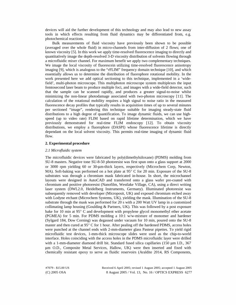
The viscosity was determined at various points downstream of the point of confluence, using equation 5 and a molecular volume determined in [9]. Within microfluidic environments, laminar flow is typically prevalent (rather than turbulent flow) and mixing occurs by diffusion only. The extent of mixing between the two solutions of different viscosity is thus dependent on the average on-chip residence time [5]. Figure 4. shows two false color maps (~ 1 μm thick horizontal optical sections ) of the correlation time across the channel at 0.4 cm downstream of the point of confluence, for flow rates of 10 and 1μl/min A profile of the correlation time (and calculated viscosity) across the channel is also shown. It can be seen that with reduced flow rate (higher residence time) the degree of mixing increases as evidenced by the widening of the intermediate viscosity zone between the two streams. At the lower flow rate, the average on-chip residence time in the 0.4 cm segment of the mixing channel is calculated to be 500 ms. For fluorescein in aqueous solution this corresponds to a mean inter-diffusion distance of ~22 μm or approximately half channel width (based on a molecular diffusion coefficient of 5x10⁻¹⁰ m2s-1). This is sufficient for near-complete intermixing of the two co-flowing streams.
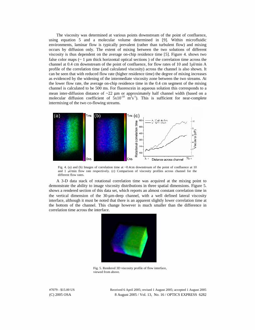
A 3-D data stack of rotational correlation time was acquired at the mixing point to
demonstrate the ability to image viscosity distributions in three spatial dimensions. Figure 5. shows a rendered section of this data set, which reports an almost constant correlation time in the vertical dimension of the 30-μm-deep channel, with a well defined lateral viscosity interface, although it must be noted that there is an apparent slightly lower correlation time at the bottom of the channel. This change however is much smaller than the difference in correlation time across the interface.
Fig. 5. Rendered 3D viscosity profile of flow interface, viewed from above.
Fig. 4. (a) and (b) Images of correlation time at ~0.4cm downstream of the point of confluence at 10 and 1 μl/min flow rate respectively. (c) Comparison of viscosity profiles across channel for the different flow rates.
(C) 2005 OSA 8 August 2005 / Vol. 13, No. 16 / OPTICS EXPRESS 6282#7079 - $15.00 US Received 6 April 2005; revised 1 August 2005; accepted 1 August 2005

It is also possible to calculate the “true” fluorescence lifetime from the polarization resolved data. This lifetime corresponds to what would be observed in the absence of polarization effects [20] and is the decay of the “total” or “isotropic” intensity:
( ) ( ) ( )tGItItF ⊥+= 2||
The temporal decay of this “isotropic” intensity time series is determined only by the excited state decay. Figure 6 shows false color images of time-resolved fluorescence anisotropy and isotropic fluorescence intensity that have been calculated from the same point of confluence data stack and the mean profile across the channel. There is not significant contrast in the fluorescence lifetime image of the interface, compared to significant contrast observed in the rotational correlation time image. This illustrates that the fluorescence lifetime of fluorescein is independent on solvent viscosity.
3.2 High-speed dynamic viscosity imaging
As discussed above, the fluorescence lifetime of DASPI, unlike fluorescein, is a function of local solvent viscosity and provides a means to image fluid dynamics directly when combined with high-speed FLIM. To illustrate this potential, DASPI solutions of 0% and 50% glycerol in water were pumped through the inlets of Microchip 3 at a flow ratio of 2 to 1. The starting flow rate was 0.1μl/min. Pairs of time gated images were acquired sequentially with gate widths of 500 ps starting ~25 ps and 175 ps after the excitation. Images were acquired at 12.3 Hz frame rate.
Figure 7 shows a single frame from a compressed FLIM movie (see Multimedia file 1) where the two solutions of different viscosity interact dynamically. The movie shows the transient effects at the starting flow rate of 0.1 μl/min, prior to the formation of a stable flow interface. It then shows the transient effect as the flow rate is increased to 1 μl/min, resulting in a slightly more fluctuating flow interface. At this point a very low degree of mixing is observed, as evidenced by an approximate step profile in viscosity. The calculated fluorescence lifetime values are 120±10 ps in 0% glycerol and 230±20 ps in 50% glycerol.
Fig. 6. Comparison of (a) rotational correlation time images, (b) fluorescence lifetime images and (c) profiles across the channel.
(6)
(C) 2005 OSA 8 August 2005 / Vol. 13, No. 16 / OPTICS EXPRESS 6283#7079 - $15.00 US Received 6 April 2005; revised 1 August 2005; accepted 1 August 2005

Figure 8 shows a frame from a compressed FLIM movie (see Multimedia file 2) taken at ~6 cm downstream of the point of confluence. It can be seen how the viscosity gradient across the channel changes as a function of the volumetric flow rate. As the flow rate is decreased from 10 μl/min to 0.1 μl/min and then flow is completely stopped, the viscosity gradient across the channel becomes less steep.
4. Discussion
We have presented two applications of time-resolved fluorescence imaging to study fluidic motion and mixing within microfluidic devices by imaging solvent viscosity. We have demonstrated the potential to implement these techniques in conventional wide-field imaging systems and in a multibeam multiphoton microscope that can provide wide-field optical sections and 3-D mapping of fluid viscosity with sub-micron spatial resolution. The first method reports the viscosity through determination of the rotational tumbling of the fluorophore. Implemented in a multibeam, multiphoton microscope, we demonstrate how this 3-D imaging modality shows the diffusive mixing that results as two solutions of different viscosity flow together, with the viscosity profile flattening out as the intermediate viscosity zone widens. The lower (x40) magnification viscosity images are noisier due to the lower two photon excitation efficiency but are still sufficient to map the viscosity distribution. This system is more suited for imaging smaller field of views with high spatial resolution, due to the requirement of having a high NA for efficient two-photon excitation.
The second high-speed wide-field wide-field FLIM approach reports variations in the local fluorophore viscosity through the viscosity-dependent non-radiative relaxation rate of
Fig. 7. (3.33MB) Movie of fluorescence lifetime at point of confluence, with color scale attached. Flows were applied through the two side inlets while the center inlet was unused.
Fig. 8. (3.33MB) Movie of fluorescence lifetime at channel 5cm from mixing point as flow is decreased from 10 to 0 μl/min. Color scale as in fig. 7.
(C) 2005 OSA 8 August 2005 / Vol. 13, No. 16 / OPTICS EXPRESS 6284#7079 - $15.00 US Received 6 April 2005; revised 1 August 2005; accepted 1 August 2005

the DASPI fluorophore. This approach is less rigorous because there is only an empirical relationship between the observed fluorescence lifetime and the solvent viscosity [21]. The fluorescence lifetime could thus, in principle, also be impacted by other factors. Nevertheless, it still provides a useful qualitative tool to image fluid dynamics on millisecond timescales. The implementation with single-photon excitation in a wide-field microscope permits significantly larger fields of view to be imaged, compared to the multibeam multiphoton microscope, and the higher single photon excitation efficiency is important because the ultimate imaging rates are limited by the number of available fluorescence photons We have applied this technique to show transient flow effects in the microfluidic device, illustrating the gradual blurring of the intermediate viscosity interface as flow rates decrease. We note that the absolute values of the fluorescence lifetime are over-estimates compared to previously obtained results [19]. This is expected considering that two 500 ps time gates were used to measure ~ 50 ps lifetimes. A more accurate lifetime determination could be achieved by using shorter time gates but the important point is that we have a repeatable, intensity-independent measure of the viscosity that can be pre-calibrated to provide quantitative data.
Further improvements are possible for both systems. For the first approach, we have used a relatively large number of points (up to 32) to obtain high quality data but it is feasible to reduce the number of data points to two or more – depending on the extent to which absolute quantification of viscosity values is required. For the second approach it may be desirable to realize wide-field optical sectioning FLIM with single photon excitation, e.g. using structured illumination [22], or a Nipkow disk [23] microscope. This could provide lower cost instrumentation although such an approach would not enjoy the enhanced polarisation sensitivity resulting from multi-photon excitation.
Higher lifetime resolution may be achieved using faster gated optical image intensifier technology, albeit at lower repetition rates [24] and higher imaging rates may be realized using single-shot FLIM techniques, e.g. [18, 25].
We note that this imaging rotation correlation time is not restricted to imaging viscosity: it may also be applied to monitor any chemical, biological or physical processes that increase the apparent fluorophore size, such as binding or conformational changes. This enabling technology can allow us to assay events such as protein or DNA binding in multiple 3-D flow structures. High speed FLIM will also find other applications in microfluidic analysis. Currently we apply FLIM to collect excited state relaxation information, which could also be used for further process characterisation. It could be useful for the quantitative profiling of other important microfluidic system parameters such as temperature [7]. Additionally, FLIM and FRET may be applied to cellular assays. In short there is considerable scope for time-resolved fluorescence imaging to be combined with microfluidic technology.
Acknowledgments
This work was funded by the Department of Trade and Industry (DTI), the Biotechnology and Biological Sciences Research Council (BBSRC) and the Wellcome Trust. RKPB acknowledges a CASE studentship awarded by the Engineering and Physical Sciences Research Council (EPSRC) and Kentech Instruments Ltd. OH acknowledges financial support from Molecular Vision Ltd. JM acknowledges a studentship supported by the DTI Beacon Award.
(C) 2005 OSA 8 August 2005 / Vol. 13, No. 16 / OPTICS EXPRESS 6285#7079 - $15.00 US Received 6 April 2005; revised 1 August 2005; accepted 1 August 2005