QR Codes. 1D Barcodes Common Types UPC EAN13 JAN 13 CODE 39 CODE 128 Two-out-of-five code.
Key Features• 12channelGPSreceiverwithTRAIM• Betterthan30nanosecondsRMSaccuracytoUTC
• Betterthan1x10-12frequencyaccuracy
• Supportsprimaryandsecondaryreferenceinputs(GPS,timecode,1PPS)
• ConfigurablewithdualredundantGPSreceiversinonechassis
• Standard10/100Base-Tnetworkport• HTTP,Telnet,SNMPwithMIBstandard• Vacuumfluorescentdisplayandkeypad
• Timecodereader/generator(IRIGA,B;IEEE1344;NASA36)AMandDC
• Auxiliaryreferenceinputsupportslocktoexternalcesiumtoenhanceholdover
• Standardoutputs:1PPS,selectablepulseratesandalarm
Key Benefits•Intuitivewebbasedmanagement• Completelymodularwithplug-andplaycapability
• Numerousfield-upgradeable,plug-inoptioncardsavailable
• Flashmemoryforremotesoftwareupgrades
The modular ultra precision XLi Time and Frequency System is the most versatile and flexible solution for timing and synchronization requirements. The XLi is completely modular with a variety of option cards that are easily configured by the user. The wide range of option cards make it easy to tailor your system to support nearly every possible output/input needed for time and frequency applications, by combining up to ten option modules (2U chassis), oscillator upgrades, and two GPS receivers per unit.
Configuration recognition software automatically detects the unit’s setup, without modifications to the operating system, providing “plug-and-play” configuration capability for current and future application needs. Modularity delivers the freedom to configure the XLi as a GPS timing instrument, or a time code unit (TCU). Deploy the Symmetricom® GPS technology to generate ultra high precision time and frequency outputs for a wide range of synchronization requirements, or leverage Symmetricom’s years of expertise in Time Code technology, which is built into the heart of the XLi system.
Page 1 of 13
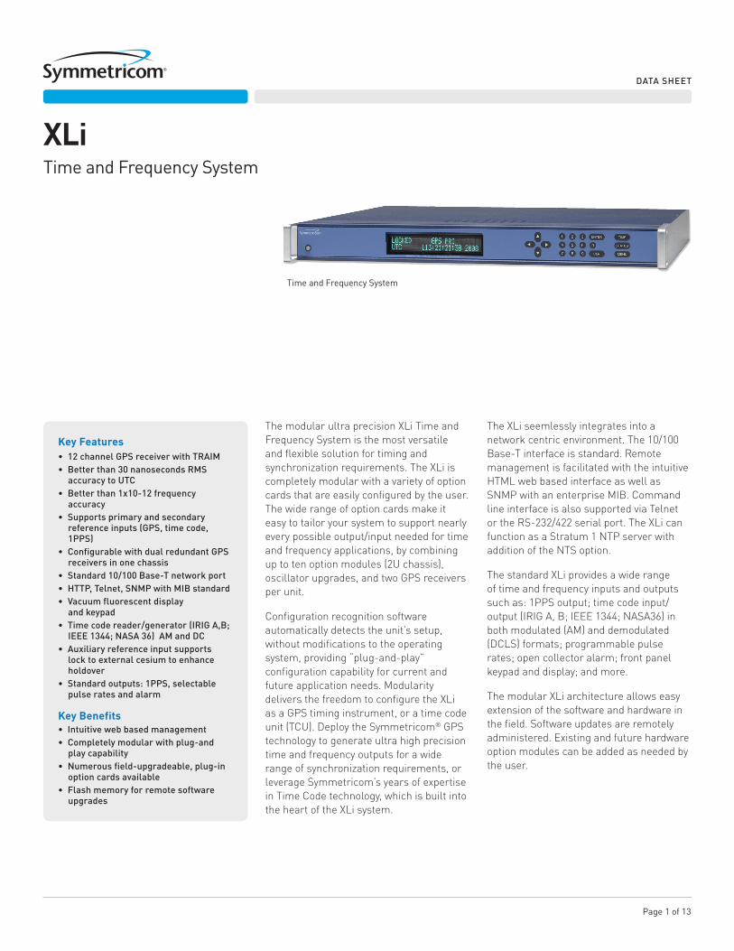
XLiTime and Frequency System
The XLi seemlessly integrates into a network centric environment. The 10/100 Base-T interface is standard. Remote management is facilitated with the intuitive HTML web based interface as well as SNMP with an enterprise MIB. Command line interface is also supported via Telnet or the RS-232/422 serial port. The XLi can function as a Stratum 1 NTP server with addition of the NTS option.
The standard XLi provides a wide range of time and frequency inputs and outputs such as: 1PPS output; time code input/output (IRIG A, B; IEEE 1344; NASA36) in both modulated (AM) and demodulated (DCLS) formats; programmable pulse rates; open collector alarm; front panel keypad and display; and more.
The modular XLi architecture allows easy extension of the software and hardware in the field. Software updates are remotely administered. Existing and future hardware option modules can be added as needed by the user.
DATASHEET
Time and Frequency System
Page 2 of 13
XLi
DATA SHEET
XLi
DATASHEET
GPS RECEIVER (OPTIONAL)
•Receiverinput: 1575.42MHzL1C/Acode.Coarseacquisition Positionaccuracy:typical10mRMStracking 4satellites.•Tracking: 12parallelchannels.Multisatelliteensembling withTRAIM.•Acquisitiontime: Coldstart<20min.(typical)•1PPSoutputaccuracy: UTC(USNO):±30nSRMS100nspeak•Frequencyoutputaccuracy: 1x10-12 @ 1 day •Frequency/timingAllan Deviationstability(TCXO): 1x10⁻⁹ @ 1 sec 3x10⁻¹⁰@10sec 3x10⁻¹⁰@100sec 2x10⁻¹⁰@1000sec 1x10-12 @ 1 day•Stabilitywhennot trackingsatellites(TCXO): 5x10⁻⁷(0°Cto50°C)typical
TIME CODE UNIT (TCU) SYNC GENERATOR•Synccode: IRIGA,B;IEEE1344;NASA36•Codeout: IRIGA,B;IEEE1344;NASA36
OSCILLATOR•Standardoscillator: VCTCXO•Optionaloscillators: OCXO,highstabilityOCXO,Rubidium,andhigh stabilityRubidium.
STANDARD INPUT/OUTPUT SIGNALS•EightstandardI/Os Twoforcontroland monitoring: SerialandEthernetport. Sixforsignals: 1PPSout,codein,codeout,rateout,auxreference, andOpenCollectorAlarmoutput(allwithBNCfemale connector).I/Osareconfigurableviathekeypad/ displayRS232/422,andthestandardnetworkport.•RS-232/422: Userselectableupto19200bps Connector:Male9-pinDsubminiature•Networkinterface: Standard10/100Base-TRJ-45. Protocols:HTTP,TelnetandSNMPfortheuser interface,FTP(forfirmwareupgrades),andoptional NTPandSNTP.•1PPS: Pulsewidth:20µs(±1µs)ontherisingedgeontime, TTLlevelsinto50Ω,BNCfemaleconnector.•Codeinput: AMorDCcode(IRIGA,B;NASA36)AMCode:0.5Vp-p to10Vp-p,100kΩground,ratio(AM):3:1±10% DCCode:Logiclow<1.25VandMin300mV,LogicHi >1.25VandMax10V. Impedance:100kor50Ω Polarity:positiveornegative Connector:BNCfemale•Codeout: DefaultisIRIG-BAM Format:AMorDCcode(IRIGA,B;NASA36) AMCode:3Vp-p,into50Ω±10%,ratio(AM):3:1. DCCode:TTLinto50Ω Connector:BNCfemale•Rateout: Default:10MPPS.Rate:1PPS,10PPS,100PPS, 1kPPS,10kPPS,100kPPS,1MPPS,5MPPS, and10MPPS.Dutycycle:60/40%(±10%). Amplitude:TTLlevelsinto50Ω Connector:BNCfemale•Auxrefinput: Inputfrequency:1,5,and10MHzsine-wave. Amplitude:1Vp-pto10Vp-pat1kΩtoground. 1Vp-pto3Vp-pat50Ωtoground. Impedance:Configurable1kΩor50Ωtoground Connector:BNCfemale•Alarm: Opencollector.Max25V/50mA. Connector:BNCfemale
MECHANICAL/ENVIRONMENTAL
•Timeandfrequencysystem Power: Voltage:90–260Vac Frequency:47–440Hz Connector: IEC320 Size: 1U:1.75”x17.1”x15.35” (4.44cmx43.4cmx38.9cm) 2U:3.5”x17.1”x15.35” (8.89cmx43.4cmx38.9cm) Standard19"(48.26cm)EIAracksystem,hardware included. Operatingtemperature: 0°Cto+50°C(+32°Fto+122°F) Storagetemperature: –55°Cto+85°C(–67°Fto+185°F) Humidity: 95%,non-condensing Display: Graphics(160X16)vacuumfluorescentdisplay. Onelinefortimeanddayofyear(TOD).Two-line alpha-numericdisplayforstatusmessagesand userinput. Keypad:numeric0–9,left,right,up,down,CLR, Enter,timekey,statuskeyandmenukey.•Antenna Size: 3”Dia.x3”H(7.62cmx7.62cm) Input: BNCfemaletoGPSreceiver.TNConantenna Power: +12Vdc Operatingtemperature: –55°Cto+85°C(–67°Fto+185°F) Storagetemperature: –55°Cto+85°C(–67°Fto+185°F) Humidity: 95%,non-condensing Certification: UL,FCC,CE,andC-UL
OPTIONSSoftware:•Networktimeserveronstandardnetworkport•Frequencymeasurement•Timeinterval/eventtiming•Programmablepulseoutput•TimeMonitorSoftwareforXLiHardware:•GPSTimingengine•Oscillatorupgrades:OCXO,HighStabilityOCXO,Rubidium,HighStabilityRubidium•1,5,10MHz/MPPSfrequencyoutputs•Lowphasenoisefrequencyoutput(5MHzand10MHz)•EnhancedLowPhaseNoise10MHzoutput•N.1FrequencySynthesizer,1PPSto50MPPSin1PPSsteps•HaveQuick/1PPSTimeandFrequencyReference•HaveQuickoutput•N.8FrequencySynthesizer•MulticodeoutputforIRIGA,B,E,G,H;XR3/2137andNASA36•DCpowersupplies(12VDC,24VDC,and48VDCoptions)•Telecommunicationsinterface(E1andT1outputoptions)•PowerUtilityFrequencyandTimeDeviationMonitor(FTM)•ParallelBCDoutput•PTTIBCDoutputwith10volt1PPS&1PPM•ExpansionModule(4userselectedtimingoutputs)•Extendedcablelengthsolutions:in-lineamplifier(to300'),down/upconverter (to1500'),fiberoptic(to2km).
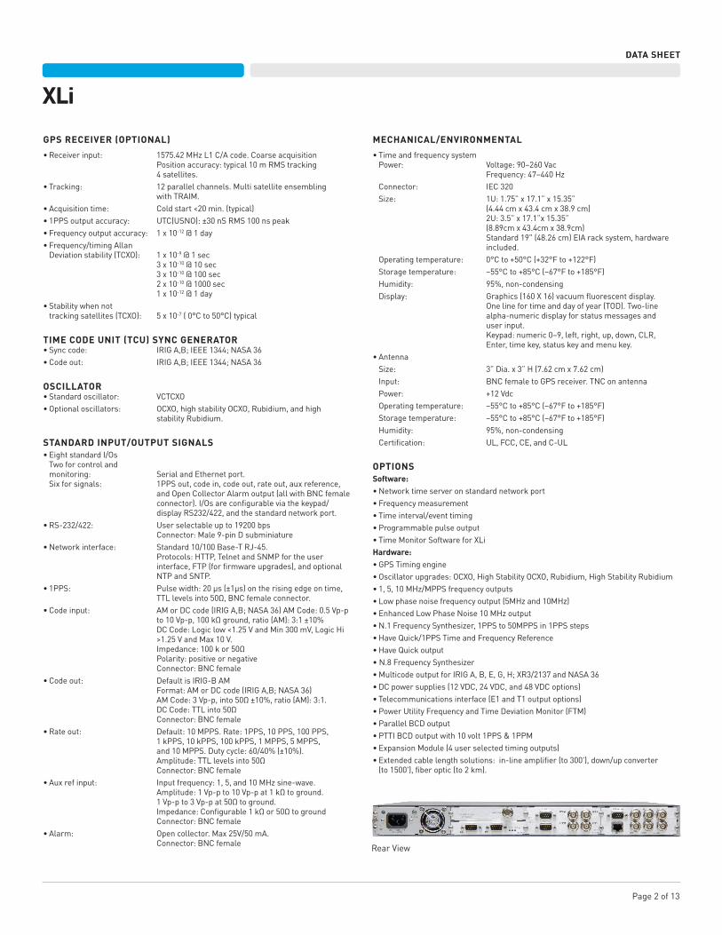
RearView
Page 3 of 13
XLi
DATA SHEET
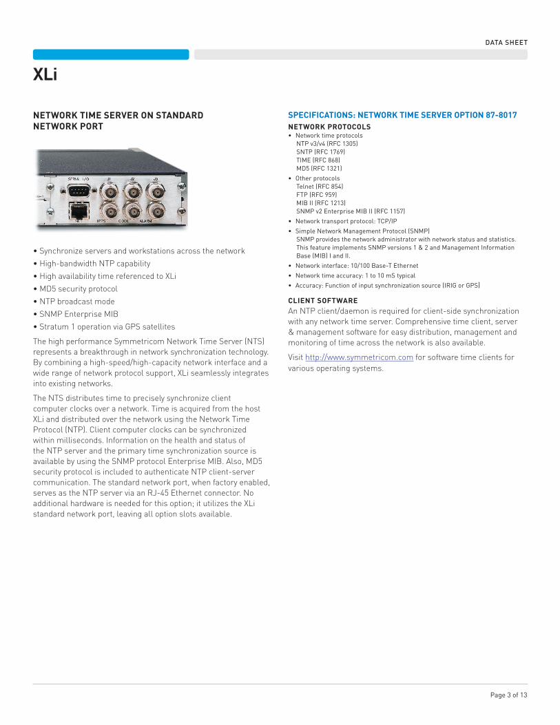
NETWORK TIME SERVER ON STANDARD NETWORK PORT
•Synchronize servers and workstations across the network
•High-bandwidth NTP capability
•High availability time referenced to XLi
•MD5 security protocol
•NTP broadcast mode
•SNMP Enterprise MIB
•Stratum 1 operation via GPS satellites
The high performance Symmetricom Network Time Server (NTS) represents a breakthrough in network synchronization technology. By combining a high-speed/high-capacity network interface and a wide range of network protocol support, XLi seamlessly integrates into existing networks.
The NTS distributes time to precisely synchronize client computer clocks over a network. Time is acquired from the host XLi and distributed over the network using the Network Time Protocol (NTP). Client computer clocks can be synchronized within milliseconds. Information on the health and status of the NTP server and the primary time synchronization source is available by using the SNMP protocol Enterprise MIB. Also, MD5 security protocol is included to authenticate NTP client-server communication. The standard network port, when factory enabled, serves as the NTP server via an RJ-45 Ethernet connector. No additional hardware is needed for this option; it utilizes the XLi standard network port, leaving all option slots available.
SPECIFICATIONS: NETWORK TIME SERVER OPTION 87-8017NETWORK PROTOCOLS• Networktimeprotocols
NTPv3/v4(RFC1305) SNTP(RFC1769) TIME(RFC868) MD5(RFC1321)
• Otherprotocols Telnet(RFC854) FTP(RFC959) MIBII(RFC1213) SNMPv2EnterpriseMIBII(RFC1157)
• Networktransportprotocol:TCP/IP
• SimpleNetworkManagementProtocol(SNMP) SNMPprovidesthenetworkadministratorwithnetworkstatusandstatistics.ThisfeatureimplementsSNMPversions1&2andManagementInformationBase(MIB)IandII.
• Networkinterface:10/100Base-TEthernet
• Networktimeaccuracy:1to10mStypical
• Accuracy:Functionofinputsynchronizationsource(IRIGorGPS)
CLIENT SOFTWAREAn NTP client/daemon is required for client-side synchronization with any network time server. Comprehensive time client, server & management software for easy distribution, management and monitoring of time across the network is also available.
Visit http://www.symmetricom.com for software time clients for various operating systems.
Page4of13
XLi
DATA SHEET
PROGRAMMABLE PULSE OUTPUTThe Programmable Pulse Output option is a software option that provides a user configurable TTL level pulse output that can be used to supply a precisely synchronized “trigger” pulse at specific times or provide periodic pulse outputs. The rising edge of the trigger output may be programmed with microsecond resolution for fine control. The periodic pulse rates supports several popular frequencies such as 1 PPS, 1 PP 10 SEC, 1 PPM, 1 PP 10 MIN, 1 PPH, 1 PP 10 HR, 1 PPD, 1 PP 10 DAYS or 1 PP 100 DAYS are available. The pulse width is also programmable. The pulse is supplied via a rear panel BNC.
SPECIFICATIONS: PROGRAMMABLE PULSE OUTPUT (PPO) 87-8024• Range:500kHzto1PPYear(integermultiplesof1uS)• Pulsewidth:Programmablein1μSstepsupto1year• Ontimeedge:Rising• Amplitude:TTLLevelsinto50Ω• Accuracy:100nSec
FREQUENCY MEASUREMENTThe Frequency Measurement is a software option that provides the ability to precisely measure the frequency of an externally applied 1, 5, or 10 MHz signal. Measurement resolution is better than 120 x 10-12 with only a 1-second averaging time. It supports a periodic, zero dead-time mode of operation as well as a single-shot, measurement-on-demand mode. The measurement interval can be specified in integer seconds over the range of 1 to 100,000 seconds. Frequency measurement results appear on the front panel display and are output via the communication port.
SPECIFICATIONS: FREQUENCY MEASUREMENT 87-8025INPUT FREQUENCIES• Keypadselectablefrequenciesof1,5,10MHz.
InputLevel:1.0to10Vpp InputImpedance:1kΩ,jumperselectableto50Ω MeasurementRange:±1x10⁻⁵maximumoffset;comparestheexternalfrequencyundertestdirectlytotheclock’sdisciplinedoscillator InputFrequency:1MHz,5MHz,10MHzResolution: 120x10-12 @ 1 second 12x10-12@10seconds 1x10-12@100seconds
• Accuracy:ThesespecificationsaresubjecttochangedependingonthespecificoscillatorinstalledintheXLi.*
TCXO1x10-9 @ 1 second 2x10⁻¹⁰@100seconds 1x10-12 @ 1 day
Ovenized quartz1x10-10 @ 1 second 1x10⁻¹⁰@100second 1x10-12 @ 1 day
High-stability quartz4x10-11 @ 1 second 4x10-11@100seconds 1x10-12 @ 1 day
Rubidium4x10-11 @ 1 second 6x10-12@100seconds 1x10-12 @ 1 day
High-stability Rubidium4x10-11 @ 1 second 6x10-12@100seconds 1x10-12 @ 1 day
*Foroscillatorinformation,refertoSymmetricom’soscillatordatasheet.
Page5of13
XLi
DATA SHEET
TIME INTERVAL/EVENT TIMINGTIME INTERVALThe Time Interval function is a software option that provides the user with the ability to precisely measure the interval between the time of occurrence of the clock-derived 1 Hz reference pulse and the rising edge of the user-supplied 1 Hz pulse.
EVENT TIMINGThe Event Timing feature offers the capability of locating the time of occurrence of the rising edge of the applied pulse with respect to the time of year. A “burst” mode provides increased performance during short intervals. The collected data is available via the RS-232 or the Telnet port.
SPECIFICATIONS: TIME INTERVAL/ EVENT TIMING (TI/ET) 87-8026INPUT FREQUENCIES• Rate:1PPS• Highlevel:LogicHi>1.25V<10V• Lowlevel:LogicLow<1.25V>0V• Activeedge:Rising(Positive)• Pulsewidth:100nSminimum• Inputimpedance:>1k,jumperselectableto50
TIME INTERVAL FEATURE• Measurement:
Rate:1persecondResolution:5nSAccuracy:±5nS(+clockaccuracy**)Range:0.0to1year
• Display:Timeintothesecond,updatedoncepersecond,isdisplayedtothenanoseconduntilanothereventoccursoruntilthe“TIME”,“STATUS”,or“POSITION”push-buttonispressed.
EVENT TIMING FEATURE• Measurement
Rate:10/secondor100/secondburst Resolution:5nS Accuracy:±5nS(+clockaccuracy**) Range:0.0to1year
• Display:EventTimeoccurrence,hundredsofdaysthroughnanoseconds,isdisplayeduntilanothereventoccursoruntilthe“TIME”,“STATUS”,or“POSITION”push-buttonispressed.
**Forclockaccuracyseeaccuracyofhostunit.
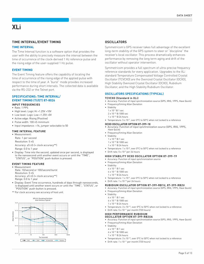
OSCILLATORS Symmetricom’s GPS receiver takes full advantage of the excellent long-term stability of the GPS system to steer or “discipline” the receiver’s local oscillator. This process dramatically enhances performance by removing the long term aging and drift of the oscillator without operator intervention.
Symmetricom provides a full spectrum of ultra-precise frequency reference standards for every application. Upgrades to the XLi standard Temperature Compensated Voltage Controlled Crystal Oscillator (TCVCXO) are the Ovenized Crystal Oscillator (OCXO), High Stability Ovenized Crystal Oscillator (OCXO), Rubidium Oscillator, and the High Stability Rubidium Oscillator.
OSCILLATORS SPECIFICATIONS (TYPICAL) TCVCXO (Standard in XLi)• Accuracy:Functionofinputsynchronizationsource(GPS,IRIG,1PPS,HaveQuick)• Frequency/timingAllanDeviation• Stability
1x10⁻⁹ @ 1 sec2x10–10@1000sec1x10–12@24hours
• Temperature:5x10⁻⁷,over0°Cto50°Cwhennotlockedtoareference
OCXO OSCILLATOR OPTION 87-399-18• Accuracy:Functionofinputsynchronizationsource(GPS,IRIG,1PPS,
HaveQuick)• Frequency/timingAllanDeviation• Stability:
1x10⁻¹⁰ @ 1 sec1x10–10@1000sec1x10–12@24hours
• Temperature:1x10⁻⁸,over0°Cto50°Cwhennotlockedtoareference• Driftrate:5x10⁻⁹per24hours
HIGH STABILITY OCXO OSCILLATOR OPTION 87-399-19 • Accuracy:Functionofinputsynchronizationsource• Frequency/timingAllanDeviation• Stability:
4x10–11 @ 1 sec4x10–11@1000sec1x10–12@24hours
• Temperature:1x10⁻⁹,over0°Cto50°Cwhennotlockedtoareference• Driftrate:1x10⁻¹⁰per24hours
RUBIDIUM OSCILLATOR OPTION 87-399-RB1U, 87-399-RB2U• Accuracy:Functionofinputsynchronizationsource(GPS,IRIG,1PPS,HaveQuick)• Frequency/timingAllanDeviation• Stability:
4x10–11 @ 1 sec6x10–12@1000sec1x10–12@24hours
• Temperature:3x10⁻¹⁰,over0°Cto50°Cwhennotlockedtoareference• Driftrate:5x10–11permonth(720hours)
HIGH PERFORMANCE RUBIDIUM OSCILLATOR OPTION 87-399-RB2UA• Accuracy:Functionofinputsynchronizationsource(GPS,IRIG,1PPS,HaveQuick)• Frequency/timingAllanDeviation• Stability:
4x10–11 @ 1 sec6x10–12@1000sec1x10–12@24hours
• Temperature:3x10⁻¹⁰,over0°Cto50°Cwhennotlockedtoareference• Driftrate:1x10–11permonth(720hours)
1E-09
1E-10
1E-11
AllanDeviatio
n
1E-12
1E-1310 100 1000 10000 100000
GPS-XLiDisciplinedOscillatorAllanVariance(Typical)
Tau(seconds)
TCXO OCXO Hi-StabOCXO Rubidium
Page6of13
XLi
DATA SHEET
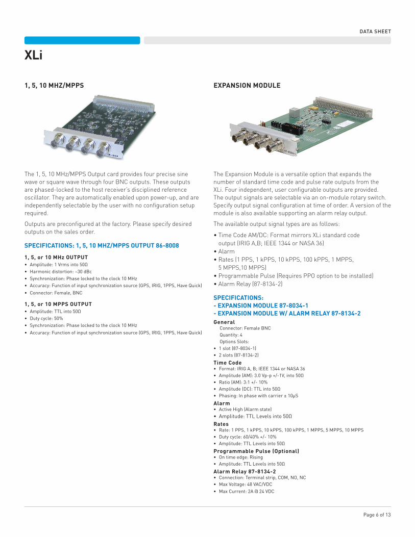
1, 5, 10 MHZ/MPPS EXPANSION MODULE
The 1, 5, 10 MHz/MPPS Output card provides four precise sine wave or square wave through four BNC outputs. These outputs are phased-locked to the host receiver’s disciplined reference oscillator. They are automatically enabled upon power-up, and are independently selectable by the user with no configuration setup required.
Outputs are preconfigured at the factory. Please specify desired outputs on the sales order.
SPECIFICATIONS: 1, 5, 10 MHZ/MPPS OUTPUT 86-8008
1, 5, or 10 MHz OUTPUT• Amplitude:1Vrmsinto50Ω• Harmonicdistortion:–30dBc• Synchronization:Phaselockedtotheclock10MHz• Accuracy:Functionofinputsynchronizationsource(GPS,IRIG,1PPS,HaveQuick)
• Connector:Female,BNC
1, 5, or 10 MPPS OUTPUT• Amplitude:TTLinto50Ω• Dutycycle:50%• Synchronization:Phaselockedtotheclock10MHz
• Accuracy:Functionofinputsynchronizationsource(GPS,IRIG,1PPS,HaveQuick)
The Expansion Module is a versatile option that expands the number of standard time code and pulse rate outputs from the XLi. Four independent, user configurable outputs are provided. The output signals are selectable via an on-module rotary switch. Specify output signal configuration at time of order. A version of the module is also available supporting an alarm relay output.
The available output signal types are as follows:
•Time Code AM/DC: Format mirrors XLi standard code output (IRIG A,B; IEEE 1344 or NASA 36)
•Alarm•Rates (1 PPS, 1 kPPS, 10 kPPS, 100 kPPS, 1 MPPS,
5 MPPS,10 MPPS)•Programmable Pulse (Requires PPO option to be installed)•Alarm Relay (87-8134-2)
SPECIFICATIONS:- EXPANSION MODULE 87-8034-1- EXPANSION MODULE W/ ALARM RELAY 87-8134-2General
Connector:FemaleBNCQuantity:4OptionsSlots:
• 1slot(87-8034-1)• 2slots(87-8134-2)
Time Code• Format:IRIGA,B;IEEE1344orNASA36• Amplitude(AM):3.0Vp-p+/-1V,into50Ω• Ratio(AM):3:1+/-10%• Amplitude(DC):TTLinto50Ω• Phasing:Inphasewithcarrier±10μS
Alarm• ActiveHigh(Alarmstate)• Amplitude:TTLLevelsinto50ΩRates• Rate:1PPS,1kPPS,10kPPS,100kPPS,1MPPS,5MPPS,10MPPS• Dutycycle:60/40%+/-10%• Amplitude:TTLLevelsinto50Ω
Programmable Pulse (Optional)• Ontimeedge:Rising• Amplitude:TTLLevelsinto50Ω
Alarm Relay 87-8134-2• Connection:Terminalstrip,COM,NO,NC• MaxVoltage:48VAC/VDC• MaxCurrent:2A@24VDC
Page7of13
XLi
DATA SHEET
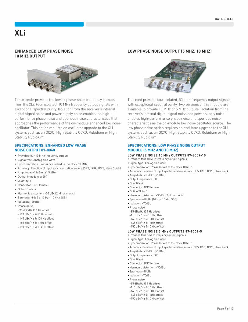
ENHANCED LOW PHASE NOISE10 MHZ OUTPUT
LOW PHASE NOISE OUTPUT (5 MHZ, 10 MHZ)
This module provides the lowest phase noise frequency outputs from the XLi. Four isolated, 10 MHz frequency output signals with exceptional spectral purity. Isolation from the receiver’s internal digital signal noise and power supply noise enables the high-performance phase noise and spurious noise characteristics that approaches the performance of the on-module enhanced low noise oscillator. This option requires an oscillator upgrade to the XLi system, such as an OCXO, High Stability OCXO, Rubidium or High Stability Rubidium.
SPECIFICATIONS: ENHANCED LOW PHASENOISE OUTPUT 87-8040• Providesfour10MHzfrequencyoutputs• Signaltype:Analogsinewave• Synchronization:Frequencylockedtotheclock10MHz• Accuracy:Functionofinputsynchronizationsource(GPS,IRIG,1PPS,HaveQuick)• Amplitude:+13dBm(±1.5dBm)• Outputimpedance:50Ω• Quantity:4• Connector:BNCfemale• OptionSlots:2• Harmonicdistortion:-50dBc(2ndharmonic)• Spurious:-80dBc(10Hz-10kHzSSB)• Isolation:-60dBc• Phasenoise
-98dBc/Hz@1Hzoffset-127dBc/Hz@10Hzoffset-145dBc/Hz@100Hzoffset-150dBc/Hz@1kHzoffset
-153dBc/Hz@10kHzoffset
This card provides four isolated, 50 ohm frequency output signals with exceptional spectral purity. Two versions of this module are available to provide 10 MHz or 5 MHz outputs. Isolation from the receiver’s internal digital signal noise and power supply noise enables high-performance phase noise and spurious noise characteristics as the on-module low noise oscillator source. The low phase noise option requires an oscillator upgrade to the XLi system, such as an OCXO, High Stability OCXO, Rubidium or High Stability Rubidium.
SPECIFICATIONS: LOW PHASE NOISE OUTPUTMODULE (5 MHZ AND 10 MHZ)LOW PHASE NOISE 10 MHz OUTPUTS 87-8009-10•Providesfour10MHzfrequencyoutputsignals•Signaltype:Analogsinewave•Synchronization:Phaselockedtotheclock10MHz•Accuracy:Functionofinputsynchronizationsource(GPS,IRIG,1PPS,HaveQuick)•Amplitude:+13dBm(±1dBm)•Outputimpedance:50Ω•Quantity:4•Connector:BNCfemale•OptionSlots:1•Harmonicdistortion:–30dBc(2ndharmonic)•Spurious:–90dBc(10Hz-10kHzSSB)•Isolation:–70dBc•Phasenoise–85dBc/Hz@1Hzoffset–115dBc/Hz@10Hzoffset–140dBc/Hz@100Hzoffset–145dBc/Hz@1kHzoffset–150dBc/Hz@10kHzoffset
LOW PHASE NOISE 5 MHz OUTPUTS 87-8009-5•Providesfour5-MHzfrequencyoutputsignals•Signaltype:Analogsinewave•Synchronization:Phaselockedtotheclock10MHz•Accuracy:Functionofinputsynchronizationsource(GPS,IRIG,1PPS,HaveQuick)•Amplitude:+13dBm(±1dBm)•Outputimpedance:50Ω•Quantity:4•Connector:BNCfemale•Harmonicdistortion:–30dBc•Spurious:–90dBc•Isolation:–70dBc•Phasenoise–85dBc/Hz@1Hzoffset–115dBc/Hz@10Hzoffset–140dBc/Hz@100Hzoffset–145dBc/Hz@1kHzoffset–150dBc/Hz@10kHzoffset
Page8of13
XLi
DATA SHEET
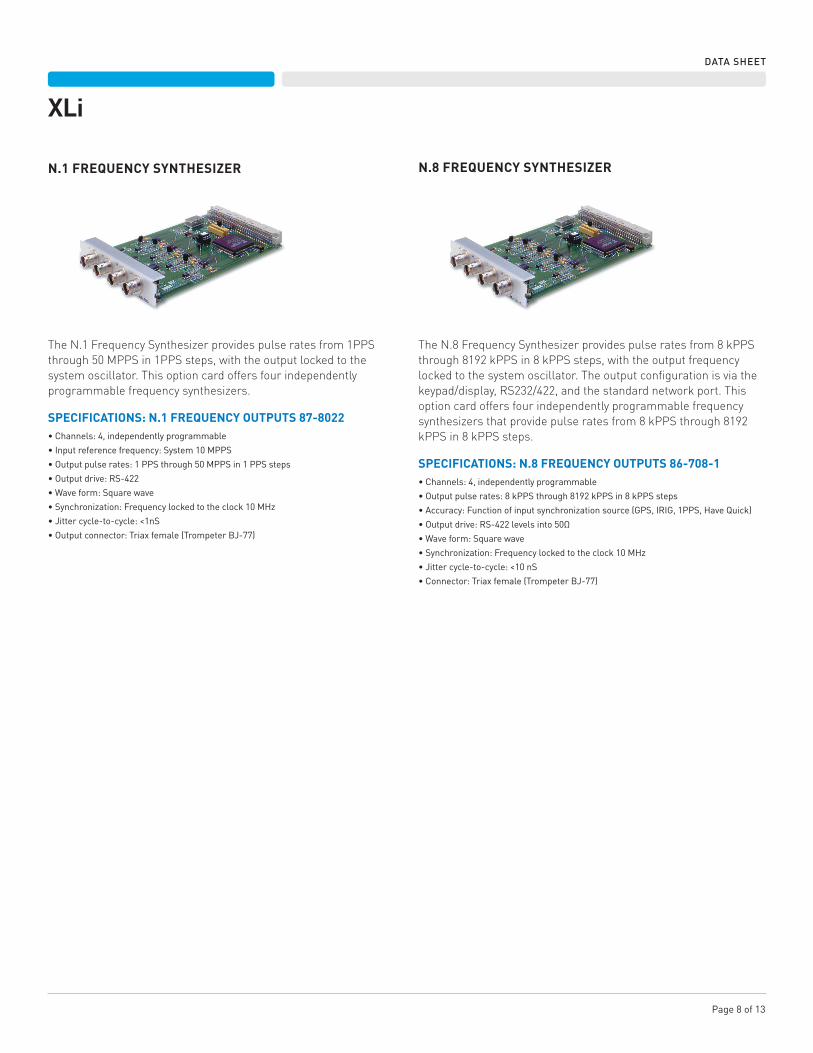
N.1 FREQUENCY SYNTHESIZER N.8 FREQUENCY SYNTHESIZER
The N.1 Frequency Synthesizer provides pulse rates from 1PPS through 50 MPPS in 1PPS steps, with the output locked to the system oscillator. This option card offers four independently programmable frequency synthesizers.
SPECIFICATIONS: N.1 FREQUENCY OUTPUTS 87-8022•Channels:4,independentlyprogrammable
•Inputreferencefrequency:System10MPPS
•Outputpulserates:1PPSthrough50MPPSin1PPSsteps
•Outputdrive:RS-422
•Waveform:Squarewave
•Synchronization:Frequencylockedtotheclock10MHz
•Jittercycle-to-cycle:<1nS
•Outputconnector:Triaxfemale(TrompeterBJ-77)
The N.8 Frequency Synthesizer provides pulse rates from 8 kPPS through 8192 kPPS in 8 kPPS steps, with the output frequency locked to the system oscillator. The output configuration is via the keypad/display, RS232/422, and the standard network port. This option card offers four independently programmable frequency synthesizers that provide pulse rates from 8 kPPS through 8192 kPPS in 8 kPPS steps.
SPECIFICATIONS: N.8 FREQUENCY OUTPUTS 86-708-1•Channels:4,independentlyprogrammable
•Outputpulserates:8kPPSthrough8192kPPSin8kPPSsteps
•Accuracy:Functionofinputsynchronizationsource(GPS,IRIG,1PPS,HaveQuick)
•Outputdrive:RS-422levelsinto50Ω
•Waveform:Squarewave
•Synchronization:Frequencylockedtotheclock10MHz
•Jittercycle-to-cycle:<10nS
•Connector:Triaxfemale(TrompeterBJ-77)
Page 9 of 13
XLi
DATA SHEET
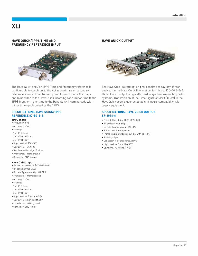
HAVE QUICK/1PPS TIME ANDFREQUENCY REFERENCE INPUT
HAVE QUICK OUTPUT
The Have Quick and / or 1PPS Time and Frequency reference is configurable to synchronize the XLi as a primary or secondary reference source. It can be configured to synchronize the major and minor time to the Have Quick incoming code, minor time to the 1PPS input, or major time to the Have Quick incoming code with minor time synchronized by the 1PPS.
SPECIFICATIONS: HAVE QUICK/1PPSREFERENCE 87-8016-31PPS Input•Frequency:1Hz
•Accuracy:1μSec
•Stability:
1x10⁻⁹ @ 1 sec
2x10⁻¹⁰@1000sec
3x10-12 @ 1 day
•HighLevel:>1.25V<10V
•LowLevel:<1.25V>0V
•Synchronizationedge:Positive
•Impedance:1kΩtoground
•Connector:BNCfemale
Have Quick Input•Format:HaveQuickII(ICD-GPS-060)
•Bitperiod:600μs±10μs
•Bitrate:Approximately1667BPS
•Framerate:1frame/second
•Accuracy:1μSec
•Stability:
1x10⁻⁹ @ 1 sec
2x10⁻¹⁰@1000sec
3x10-12 @ 1 day
•HighLevel:>4.5andMax5.5V
•LowLevel:<+0.5VandMin0V
•Impedance:1kΩtoground
•Connector:BNCfemale
The Have Quick Output option provides time of day, day of year and year in the Have Quick II format conforming to ICD-GPS-060. Have Quick II output is typically used to synchronize military radio systems. Transmission of the Time Figure of Merit (TFOM) in the Have Quick code is user selectable to insure compatibility with legacy equipment.
SPECIFICATIONS: HAVE QUICK OUTPUT87-8016-6•Format:HaveQuickII(ICD-GPS-060)
•Bitperiod:600μs±10μs
•Bitrate:Approximately1667BPS
•Framerate:1frame/second
•Framelength:512bitsor504bitswithnoTFOM
•Accuracy:1μs
•Connector:4IsolatedfemaleBNC
•HighLevel:>4.5andMax5.5V
•LowLevel:<0.5VandMin0V
Page10of13
XLi
DATA SHEET
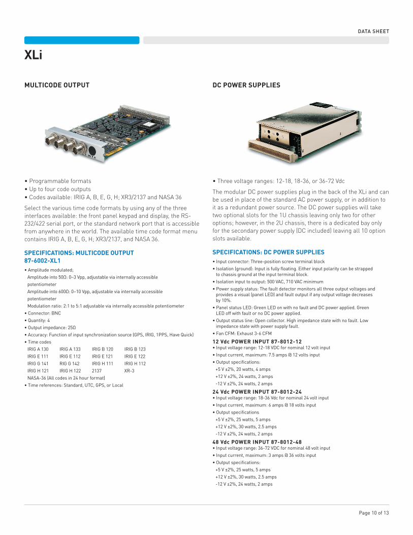
MULTICODE OUTPUT DC POWER SUPPLIES
•Programmable formats•Up to four code outputs•Codes available: IRIG A, B, E, G, H; XR3/2137 and NASA 36
Select the various time code formats by using any of the three interfaces available: the front panel keypad and display, the RS-232/422 serial port, or the standard network port that is accessible from anywhere in the world. The available time code format menu contains IRIG A, B, E, G, H; XR3/2137, and NASA 36.
SPECIFICATIONS: MULTICODE OUTPUT87-6002-XL1•Amplitudemodulated;
Amplitudeinto50Ω:0–3Vpp,adjustableviainternallyaccessible
potentiometer
Amplitudeinto600Ω:0–10Vpp,adjustableviainternallyaccessible
potentiometer
Modulationratio:2:1to5:1adjustableviainternallyaccessiblepotentiometer
•Connector:BNC
•Quantity:4
•Outputimpedance:25Ω
•Accuracy:Functionofinputsynchronizationsource(GPS,IRIG,1PPS,HaveQuick)
•Timecodes
IRIGA130 IRIGA133 IRIGB120 IRIGB123
IRIGE111 IRIGE112 IRIGE121 IRIGE122
IRIGG141 RIGG142 IRIGH111 IRIGH112
IRIGH121 IRIGH122 2137 XR-3
NASA-36(Allcodesin24hourformat)
•Timereferences:Standard,UTC,GPS,orLocal
•Threevoltageranges:12-18,18-36,or36-72Vdc
The modular DC power supplies plug in the back of the XLi and can be used in place of the standard AC power supply, or in addition to it as a redundant power source. The DC power supplies will take two optional slots for the 1U chassis leaving only two for other options; however, in the 2U chassis, there is a dedicated bay only for the secondary power supply (DC included) leaving all 10 option slots available.
SPECIFICATIONS: DC POWER SUPPLIES•Inputconnector:Three-positionscrewterminalblock
•Isolation(ground):Inputisfullyfloating.Eitherinputpolaritycanbestrapped tochassisgroundattheinputterminalblock.
•Isolationinputtooutput:500VAC,710VACminimum
•Powersupplystatus:Thefaultdetectormonitorsallthreeoutputvoltagesand providesavisual(panelLED)andfaultoutputifanyoutputvoltagedecreases by10%.
•PanelstatusLED:GreenLEDonwithnofaultandDCpowerapplied.Green LEDoffwithfaultornoDCpowerapplied.
•Outputstatusline:Opencollector.Highimpedancestatewithnofault.Low impedancestatewithpowersupplyfault.
•FanCFM:Exhaust3-6CFM
12 Vdc POWER INPUT 87-8012-12•Inputvoltagerange:12-18VDCfornominal12voltinput
•Inputcurrent,maximum:7.5amps@12voltsinput
•Outputspecifications:
+5V±2%,20watts,4amps
+12V±2%,24watts,2amps
-12V±2%,24watts,2amps
24 Vdc POWER INPUT 87-8012-24•Inputvoltagerange:18-36Vdcfornominal24voltinput
•Inputcurrent,maximum:6amps@18voltsinput
•Outputspecifications
+5V±2%,25watts,5amps
+12V±2%,30watts,2.5amps
-12V±2%,24watts,2amps
48 Vdc POWER INPUT 87-8012-48•Inputvoltagerange:36-72VDCfornominal48voltinput
•Inputcurrent,maximum:3amps@36voltsinput
•Outputspecifications:
+5V±2%,25watts,5amps
+12V±2%,30watts,2.5amps
-12V±2%,24watts,2amps
Page 11 of 13
XLi
DATA SHEET
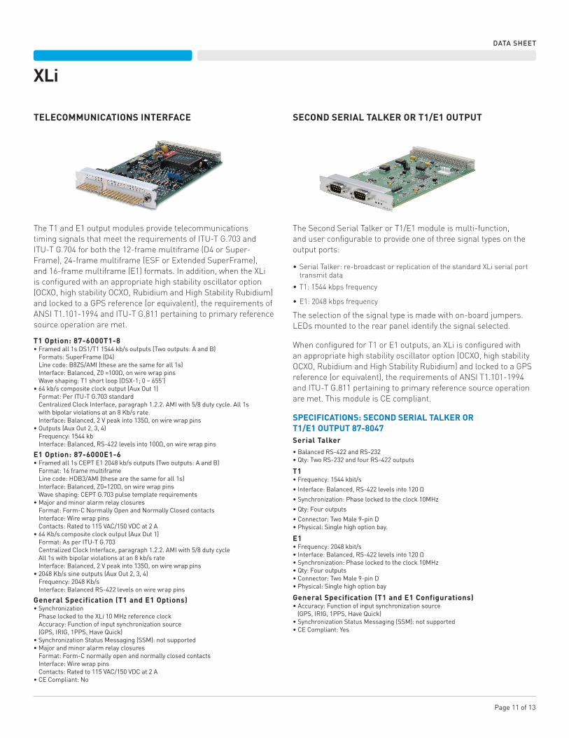
TELECOMMUNICATIONS INTERFACE SECOND SERIAL TALKER OR T1/E1 OUTPUT
The T1 and E1 output modules provide telecommunications timing signals that meet the requirements of ITU-T G.703 and ITU-T G.704 for both the 12-frame multiframe (D4 or Super- Frame), 24-frame multiframe (ESF or Extended SuperFrame), and 16-frame multiframe (E1) formats. In addition, when the XLi is configured with an appropriate high stability oscillator option (OCXO, high stability OCXO, Rubidium and High Stability Rubidium) and locked to a GPS reference (or equivalent), the requirements of ANSI T1.101-1994 and ITU-T G.811 pertaining to primary reference source operation are met.
T1 Option: 87-6000T1-8•Framedall1sDS1/T11544kb/soutputs(Twooutputs:AandB)Formats:SuperFrame(D4)Linecode:B8ZS/AMI(thesearethesameforall1s)Interface:Balanced,Z0=100Ω,onwirewrappinsWaveshaping:T1shortloop(DSX-1;0–655’)
•64kb/scompositeclockoutput(AuxOut1)Format:PerITU-TG.703standardCentralizedClockInterface,paragraph1.2.2.AMIwith5/8dutycycle.All1swithbipolarviolationsatan8Kb/srate.Interface:Balanced,2Vpeakinto135Ω,onwirewrappins
•Outputs(AuxOut2,3,4)Frequency:1544kbInterface:Balanced,RS-422levelsinto100Ω,onwirewrappins
E1 Option: 87-6000E1-6•Framedall1sCEPTE12048kb/soutputs(Twooutputs:AandB)Format:16framemultiframeLinecode:HDB3/AMI(thesearethesameforall1s)Interface:Balanced,Z0=120Ω,onwirewrappinsWaveshaping:CEPTG.703pulsetemplaterequirements
•MajorandminoralarmrelayclosuresFormat:Form-CNormallyOpenandNormallyClosedcontactsInterface:WirewrappinsContacts:Ratedto115VAC/150VDCat2A
•64Kb/scompositeclockoutput(AuxOut1)Format:AsperITU-TG.703CentralizedClockInterface,paragraph1.2.2.AMIwith5/8dutycycleAll1swithbipolarviolationsatan8kb/srateInterface:Balanced,2Vpeakinto135Ω,onwirewrappins
•2048Kb/ssineoutputs(AuxOut2,3,4)Frequency:2048Kb/sInterface:BalancedRS-422levelsonwirewrappins
General Specification (T1 and E1 Options)•SynchronizationPhaselockedtotheXLi10MHzreferenceclockAccuracy:Functionofinputsynchronizationsource(GPS,IRIG,1PPS,HaveQuick)
•SynchronizationStatusMessaging(SSM):notsupported•MajorandminoralarmrelayclosuresFormat:Form-CnormallyopenandnormallyclosedcontactsInterface:WirewrappinsContacts:Ratedto115VAC/150VDCat2A
•CECompliant:No
The Second Serial Talker or T1/E1 module is multi-function, and user configurable to provide one of three signal types on the output ports:
•Serial Talker: re-broadcast or replication of the standard XLi serial port transmit data
•T1: 1544 kbps frequency
•E1: 2048 kbps frequency
The selection of the signal type is made with on-board jumpers. LEDs mounted to the rear panel identify the signal selected.
When configured for T1 or E1 outputs, an XLi is configured with an appropriate high stability oscillator option (OCXO, high stability OCXO, Rubidium and High Stability Rubidium) and locked to a GPS reference (or equivalent), the requirements of ANSI T1.101-1994 and ITU-T G.811 pertaining to primary reference source operation are met. This module is CE compliant.
SPECIFICATIONS: SECOND SERIAL TALKER ORT1/E1 OUTPUT 87-8047Serial Talker•BalancedRS-422andRS-232•Qty:TwoRS-232andfourRS-422outputs
T1•Frequency:1544kbit/s
•Interface:Balanced,RS-422levelsinto120Ω
•Synchronization:Phaselockedtotheclock10MHz
•Qty:Fouroutputs
•Connector:TwoMale9-pinD•Physical:Singlehighoptionbay.
E1•Frequency:2048kbit/s•Interface:Balanced,RS-422levelsinto120Ω•Synchronization:Phaselockedtotheclock10MHz•Qty:Fouroutputs•Connector:TwoMale9-pinD•Physical:Singlehighoptionbay
General Specification (T1 and E1 Configurations)•Accuracy:Functionofinputsynchronizationsource(GPS,IRIG,1PPS,HaveQuick)•SynchronizationStatusMessaging(SSM):notsupported•CECompliant:Yes
Page 12 of 13
XLi
DATA SHEET
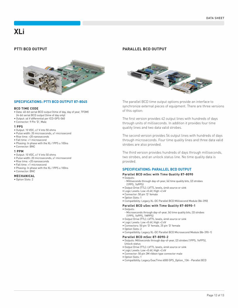
PTTI BCD OUTPUT PARALLEL BCD OUTPUT
SPECIFICATIONS: PTTI BCD OUTPUT 87-8045
BCD TIME CODE•Data:40-bitserialBCDoutput(timeofday,dayofyear,TFOM)24-bitserialBCDoutput(timeofdayonly)•Output:±6VdifferentialperICD-GPS-060•Connector:9Pin'D',Male
1 PPS•Output:10VDC,±1Vinto50ohms•Pulsewidth:20microseconds,±1microsecond•Risetime:<20nanoseconds•Falltime:<1microsecond•Phasing:InphasewiththeXLi1PPS±100ns•Connector:BNC
1 PPM•Output:10VDC,±1Vinto50ohms•Pulsewidth:20microseconds,±1microsecond•Risetime:<20nanoseconds•Falltime:<1microsecond•Phasing:InphasewiththeXLi1PPS±100ns•Connector:BNC
MECHANICAL•OptionSlots:2
The parallel BCD time output options provide an interface to synchronize external pieces of equipment. There are three versions of this option:
The first version provides 42 output lines with hundreds of days through units of milliseconds. In addition it provides four time quality lines and two data valid strobes.
The second version provides 54 output lines with hundreds of days through microseconds. Four time quality lines and three data valid strobes are also provided.
The third version provides hundreds of days through milliseconds, two strobes, and an unlock status line. No time quality data is provided.
SPECIFICATIONS: PARALLEL BCD OUTPUTParallel BCD mSec with Time Quality 87-8090•Outputs:-Millisecondsthroughday-of-year,(4)timequalitybits,(2)strobes(1PPS,1kPPS)
•OutputDrive(TTL):LVTTLlevels,4mAsourceorsink•LogicLevels:Low<0.4V,High>2.4V•Connector:50pin'D'female•OptionSlots:1•Compatibility:LegacyXL-DCParallelBCDMillisecondModule(86-390)
Parallel BCD uSec with Time Quality 87-8090-1•Outputs:-Microsecondsthroughday-of-year,(4)timequalitybits,(3)strobes(1PPS,1kPPS,1MPPS)
•OutputDrive(TTL):LVTTLlevels,4mAsourceorsink•LogicLevels:Low<0.4V,High>2.4V•Connectors:50pin'D'female,25pin'D'female•OptionSlots:2•Compatibility:LegacyXL-DCParallelBCDMicrosecondModule(86-390-1)
Parallel BCD mSec 87-8090-2•Outputs:Millisecondsthroughday-of-year,(2)strobes(1PPS,1kPPS),Unlockstatus•OutputDrive(TTL):LVTTLlevels,4mAsourceorsink•LogicLevels:Low<0.4V,High>2.4V•Connector:50pin3Mribbontypeconnectormale•OptionSlots:1•Compatibility:LegacyExacTime6000GPS_Option_13A-ParallelBCD
XLi
DATA SHEET
2300 Orchard Parkway San Jose, California 95131-1017 tel: 408.433.0910 fax: 408.428.7896 www.symmetricom.com DS/XLi/020813 900-00504-000 A
XLi
©2013 Symmetricom. Symmetricom and the Symmetricom logo are registered trademarks of Symmetricom, Inc. All specifications subject to change without notice.
DATASHEET
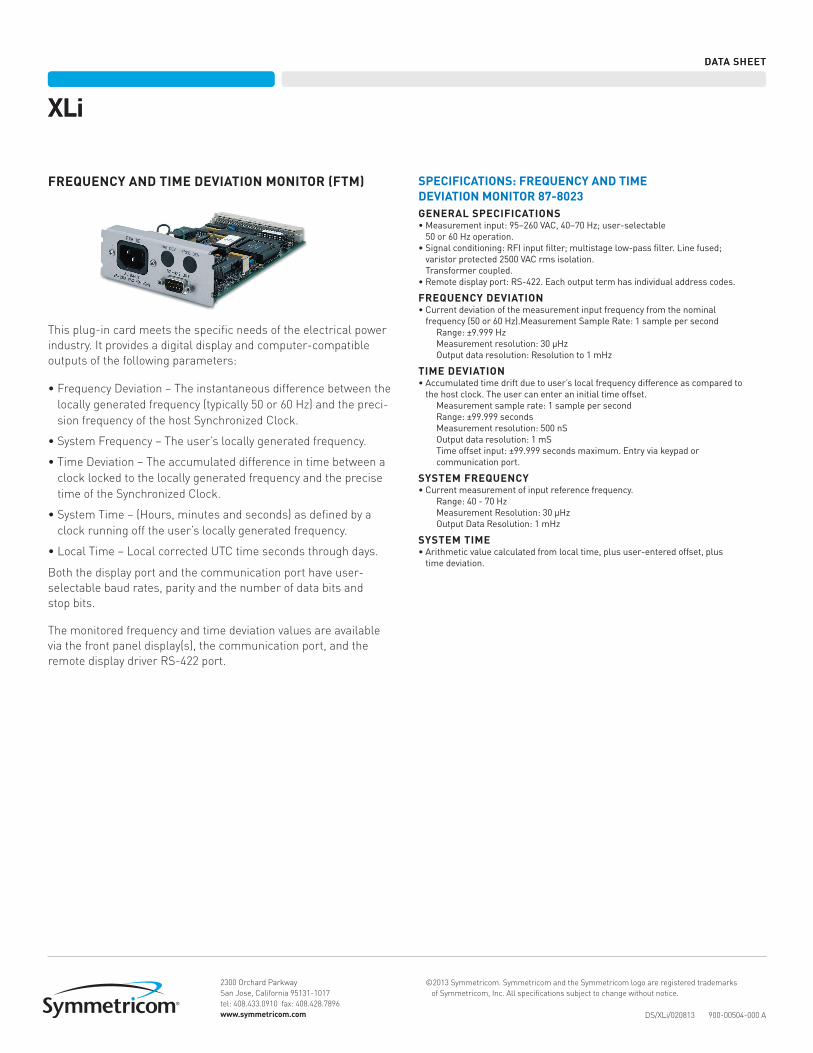
FREQUENCY AND TIME DEVIATION MONITOR (FTM)
This plug-in card meets the specific needs of the electrical power industry. It provides a digital display and computer-compatible outputs of the following parameters:
•Frequency Deviation – The instantaneous difference between the locally generated frequency (typically 50 or 60 Hz) and the preci-sion frequency of the host Synchronized Clock.
•System Frequency – The user’s locally generated frequency.
•Time Deviation – The accumulated difference in time between a clock locked to the locally generated frequency and the precise time of the Synchronized Clock.
•System Time – (Hours, minutes and seconds) as defined by a clock running off the user’s locally generated frequency.
•Local Time – Local corrected UTC time seconds through days.
Both the display port and the communication port have user-selectable baud rates, parity and the number of data bits and stop bits.
The monitored frequency and time deviation values are available via the front panel display(s), the communication port, and the remote display driver RS-422 port.
SPECIFICATIONS: FREQUENCY AND TIMEDEVIATION MONITOR 87-8023GENERAL SPECIFICATIONS•Measurementinput:95–260VAC,40–70Hz;user-selectable50or60Hzoperation.
•Signalconditioning:RFIinputfilter;multistagelow-passfilter.Linefused;varistorprotected2500VACrmsisolation.Transformercoupled.
•Remotedisplayport:RS-422.Eachoutputtermhasindividualaddresscodes.
FREQUENCY DEVIATION•Currentdeviationofthemeasurementinputfrequencyfromthenominalfrequency(50or60Hz).MeasurementSampleRate:1samplepersecond
Range:±9.999HzMeasurementresolution:30μHzOutputdataresolution:Resolutionto1mHz
TIME DEVIATION•Accumulatedtimedriftduetouser’slocalfrequencydifferenceascomparedtothehostclock.Theusercanenteraninitialtimeoffset.
Measurementsamplerate:1samplepersecondRange:±99.999secondsMeasurementresolution:500nSOutputdataresolution:1mSTimeoffsetinput:±99.999secondsmaximum.Entryviakeypadorcommunicationport.
SYSTEM FREQUENCY•Currentmeasurementofinputreferencefrequency.
Range:40-70HzMeasurementResolution:30μHzOutputDataResolution:1mHz
SYSTEM TIME•Arithmeticvaluecalculatedfromlocaltime,plususer-enteredoffset,plustimedeviation.