Tile vaults as integrated formwork for reinforced concrete...
16
Contents lists available at ScienceDirect Engineering Structures journal homepage: www.elsevier.com/locate/engstruct Tile vaults as integrated formwork for reinforced concrete: Construction, experimental testing and a method for the design and analysis of two- dimensional structures David López López a, ⁎ , Pere Roca b , Andrew Liew c , Tom Van Mele c , Philippe Block c a ETH Zurich, Institute of Technology in Architecture, Block Research Group Stefano-Franscini-Platz 1, HIB E45, 8093 Zurich, Switzerland b Universitat Politècnica de Catalunya, Department of Civil and Environmental Engineering, Spain c ETH Zurich, Institute of Technology in Architecture, Block Research Group, Switzerland ARTICLE INFO Keywords: Catalan vault Guastavino vault Tile vault Masonry Reinforced brick Formwork Concrete shell Limit analysis ELARM ABSTRACT Tile vaults are traditional, unreinforced masonry structures made of thin bricks (tiles), mortar and fast-setting cement or gypsum. They can be constructed without the need for a formwork, except at the boundaries, making them inherently economic. Tile vaults have historically provided a solution for the efficient construction of vaulted structures. Today, they can be used as permanent formwork for concrete shells, allowing for a significant reduction of the construction cost and waste produced, due to the possibility of reducing or even eliminating the need for traditional formwork. The concrete can be poured directly onto a tile-vaulted formwork to form a composite structure. This paper presents a technique for the construction of single-curvature shells consisting of a composite structure combining tile vaulting and reinforced concrete. A method for the design of these composite vaults and the assessment of their strength and stability against external loading is also presented. This method is based on limit analysis but takes into account the reinforcement’s contribution to the composite cross-section’s bending capacity. The equilibrium method is implemented computationally to provide fast results for the user. It provides graphical and intuitive results and opens the possibility for the future extension to fully three-dimensional problems. The design and structural analysis method is called Extended Limit Analysis for Reinforced Masonry (ELARM). Both the proposed construction technique and the computational method have been validated through ex- perimental research. The feasibility of the building technique has been validated by the construction of two full- scale prototypes. In addition, the prototypes have been load-tested to failure to compare the results with those predicted by ELARM. 1. Introduction Tile vaults (sometimes also referred to as thin-tile, timbrel, Catalan or Guastavino vaults) are masonry structures made with thin bricks (tiles), mortar and fast-setting cement or gypsum. The bricks are placed flat, building up to two, three or more courses. Traditionally, tiles are used because of their light weight, which is a necessary condition to build the first course “in space” without supporting falsework (Fig. 1). The first course is achieved using the quick adhesion of fast-setting cement or gypsum. The bricks bind within seconds to the edge walls, or the already finished arches/stable sections, eliminating the need for centring [1]. Using this first layer as a stay-in-place formwork, the second and subsequent courses can be set with lime or Portland cement mortar. The ability of the courses to be built without support and in stable sections, is one of the most relevant characteristics of this tech- nique and what makes it inherently economic. Tile vaulting is currently being rediscovered in contemporary architecture and has been used in a series of recent projects that investigate novel applications and design possibilities of the traditional technique [2–9]. Concrete shell construction was particularly popular from the 1920s to the early 1960s. A main reason for concrete shell’s demise after this period can be found in the construction costs [11], specifically the cost of the formwork, which is typically expensive, complex and wasteful. Using tile vaults as stay-in-place formwork for concrete shells could https://doi.org/10.1016/j.engstruct.2019.03.034 Received 15 June 2018; Received in revised form 6 March 2019; Accepted 12 March 2019 ⁎ Corresponding author. E-mail address: [email protected] (D. López López). Engineering Structures 188 (2019) 233–248 0141-0296/ © 2019 Elsevier Ltd. All rights reserved. T
Transcript of Tile vaults as integrated formwork for reinforced concrete...

Contents lists available at ScienceDirect
Engineering Structures
journal homepage: www.elsevier.com/locate/engstruct
Tile vaults as integrated formwork for reinforced concrete: Construction,experimental testing and a method for the design and analysis of two-dimensional structures
David López Lópeza,⁎, Pere Rocab, Andrew Liewc, Tom Van Melec, Philippe Blockc
a ETH Zurich, Institute of Technology in Architecture, Block Research Group Stefano-Franscini-Platz 1, HIB E45, 8093 Zurich, SwitzerlandbUniversitat Politècnica de Catalunya, Department of Civil and Environmental Engineering, Spainc ETH Zurich, Institute of Technology in Architecture, Block Research Group, Switzerland
A R T I C L E I N F O
Keywords:Catalan vaultGuastavino vaultTile vaultMasonryReinforced brickFormworkConcrete shellLimit analysisELARM
A B S T R A C T
Tile vaults are traditional, unreinforced masonry structures made of thin bricks (tiles), mortar and fast-settingcement or gypsum. They can be constructed without the need for a formwork, except at the boundaries, makingthem inherently economic. Tile vaults have historically provided a solution for the efficient construction ofvaulted structures. Today, they can be used as permanent formwork for concrete shells, allowing for a significantreduction of the construction cost and waste produced, due to the possibility of reducing or even eliminating theneed for traditional formwork. The concrete can be poured directly onto a tile-vaulted formwork to form acomposite structure.
This paper presents a technique for the construction of single-curvature shells consisting of a compositestructure combining tile vaulting and reinforced concrete. A method for the design of these composite vaults andthe assessment of their strength and stability against external loading is also presented. This method is based onlimit analysis but takes into account the reinforcement’s contribution to the composite cross-section’s bendingcapacity.
The equilibrium method is implemented computationally to provide fast results for the user. It providesgraphical and intuitive results and opens the possibility for the future extension to fully three-dimensionalproblems. The design and structural analysis method is called Extended Limit Analysis for Reinforced Masonry(ELARM).
Both the proposed construction technique and the computational method have been validated through ex-perimental research. The feasibility of the building technique has been validated by the construction of two full-scale prototypes. In addition, the prototypes have been load-tested to failure to compare the results with thosepredicted by ELARM.
1. Introduction
Tile vaults (sometimes also referred to as thin-tile, timbrel, Catalanor Guastavino vaults) are masonry structures made with thin bricks(tiles), mortar and fast-setting cement or gypsum. The bricks are placedflat, building up to two, three or more courses. Traditionally, tiles areused because of their light weight, which is a necessary condition tobuild the first course “in space” without supporting falsework (Fig. 1).The first course is achieved using the quick adhesion of fast-settingcement or gypsum. The bricks bind within seconds to the edge walls, orthe already finished arches/stable sections, eliminating the need forcentring [1]. Using this first layer as a stay-in-place formwork, the
second and subsequent courses can be set with lime or Portland cementmortar. The ability of the courses to be built without support and instable sections, is one of the most relevant characteristics of this tech-nique and what makes it inherently economic. Tile vaulting is currentlybeing rediscovered in contemporary architecture and has been used in aseries of recent projects that investigate novel applications and designpossibilities of the traditional technique [2–9].
Concrete shell construction was particularly popular from the 1920sto the early 1960s. A main reason for concrete shell’s demise after thisperiod can be found in the construction costs [11], specifically the costof the formwork, which is typically expensive, complex and wasteful.Using tile vaults as stay-in-place formwork for concrete shells could
https://doi.org/10.1016/j.engstruct.2019.03.034Received 15 June 2018; Received in revised form 6 March 2019; Accepted 12 March 2019
⁎ Corresponding author.E-mail address: [email protected] (D. López López).
Engineering Structures 188 (2019) 233–248
0141-0296/ © 2019 Elsevier Ltd. All rights reserved.
T

significantly reduce construction costs and material waste, makingconcrete shells more economic and sustainable for modern construc-tion. The construction costs are reduced mainly due to the low cost ofthe materials involved, and to the fact that no additional formwork orrelated foundations are needed. The use of the tile vault as formworkdoes not cause a large increase of the total thickness of the shell becausethe tile vault is structural and contributes by resisting, at least, theoverall self-weight of the composite system. As an additional bonus, theuse of a tile vault as a permanent formwork has the added value of thearchitectural quality: if left exposed, it adds a unique, unconventionalfinish. Compared to unreinforced masonry structures, the addition ofreinforcement allows a minimum thickness for long-span shells, whichmight become too large and heavy otherwise, and allows for the con-struction of expressive structures beyond compression-only designs,capable of resisting tensile stresses and bending moments. Note, how-ever, that non-compression-only structures need a formwork for theirconstruction in the areas of the structure where the tile vault does notwork only in compression under its self-weight.
The combination of masonry and reinforced concrete creates a new
type of composite structure that needs new calculation methods andmodels to deal with the specific features of the system. There is cur-rently no method for designing these structures and no (simple) modelto analyse and assess them. This paper therefore presents a simple anduser-friendly method for the design and structural analysis of singly-curved, reinforced tile vaults. The method is called Extended LimitAnalysis for Reinforced Masonry (ELARM) and is an extension of thework by Roca et al. [12] on the assessment of the structural behaviourof the mentioned composite structure. ELARM applies limit analysis[13–15] as is common with regular masonry, but using the boundariesof a vault whose thickness is virtually increased to indirectly take intoaccount the additional tensile and bending strength provided by thesteel reinforcement. This method benefits from the simplicity of limitanalysis to safely design and assess the strength and stability of singly-curved, concrete-reinforced, tile-vaulted structures against self-weightand external loading. Moreover, the design method allows for the as-sessment of the structure during all of the construction stages, as it canbe also utilized to verify the stability of the tile vault subject to both itsself-weight (the tile vault in isolation) and the weight of the concretelayer prior to its hardening where it is acting as dead weight. ELARMhas been parametrised and implemented computationally, resulting in afast, straightforward and user-friendly tool that provides graphical andintuitive results.
The proposed construction technique required physical tests to va-lidate both the feasibility of construction technology and the perfor-mance of the numerical method. This validation has been attained byconstructing and testing two full-scale prototypes in the laboratory.Specifically, the numerical method has been validated by comparing itspredictions, in terms of the collapse mechanism and ultimate loads,with the experimental results.
This paper presents a construction system using the tile vault asintegrated formwork for reinforced concrete, a method for the designand analysis of two-dimensional arched structures built with thistechnique, experimental research to validate both of them and appli-cations of the method including form-finding and optimisation proce-dures. The construction system is explained in Section 2, whereasSection 3 focuses on the design and structural analysis method, fol-lowed by its computational implementation in Section 4. The experi-mental research is described in Sections 5 and 6, presenting load testson full-scale prototypes and material characterisation, respectively. Theresults of the experimental research and those provided by the methodare compared in Section 7. The last section before the conclusions isSection 8, which presents examples of different applications of themethod.
2. Construction system
The proposed structure is composed of a tile vault and an added
Fig. 1. Construction “in space” of a tile-vaulted stair [10].
Fig. 2. Possible transversal and longitudinal cross-sections of the composite system. Featuring a two-layered tile vault and reinforced concrete.
D. López López, et al. Engineering Structures 188 (2019) 233–248
234
layer of reinforced concrete working together as a composite system(Fig. 2). The tile vault acts as permanent formwork for the concreteduring its hardening, supporting the concrete’s weight and constructionloads. After the concrete hardening, the structure becomes a compositesystem.
The first course of tiles is laid with fast-setting cement or gypsum.For the second and subsequent courses, and also for the mortar bedsbetween them, regular lime or Portland cement mortar is used.Continuous joints between courses through the thickness of the ma-sonry should be avoided, as they create weak points in the structure.
A longer spanning structure will require a thicker tile vault to beable to support the self-weight of the structure and the constructionloads. In order to achieve a specified thickness, the tile vault can, ifneeded, be built with bricks of different thicknesses. To keep a light firstlayer of bricks, necessary for building without formwork, hollow bricksinstead of solid tiles can be used. Furthermore, the second and sub-sequent courses can be built with heavier and thicker bricks to build upstructural depth more effectively, as they are not built “in space”.Striped or rough bricks can provide the required bond between tilevault and concrete to guarantee the composite behaviour of the hybridsystem. If this interface bond is not sufficient, shear connectors can alsobe used.
The proportioning of the concrete mixture plays an important roleto achieve a good balance between low flowability and a certain degreeof self-compaction, which are material requirements that will ease theconstruction process. Low flowability is necessary to work on steepsurfaces with a certain degree of self-compaction to avoid the need forintense vibration on the masonry structure. Reinforcement also offersmany possibilities depending on the structure’s features. Reinforcementbars (rebars) can be placed easily on singly-curved or ruled surfaces,but fibre or mesh/textile reinforced concrete may be a better choice forfree-form structures which otherwise would require complex re-inforcement plans and a difficult pre-bending process of the bars. Inaddition, non-metallic reinforcement may reduce the overall thickness
of the shell as the otherwise-mandatory concrete covering to preventcorrosion is not required.
3. Extended limit analysis of reinforced masonry
3.1. Background
Jacques Heyman set down in 1966 the modern formulation of limitanalysis for masonry arches [14]. Three assumptions were a key aspectin his theory: (1) masonry has no tensile strength, (2) the compressivestrength of masonry is effectively infinite, and (3) sliding of one ma-sonry unit upon another cannot occur. The great success of Heyman’sassessment framework relies on the simplicity of the method and itsapplication to many types of masonry structures. These foundationseliminated doubts expressed 13 years before by Kooharian, on thediscussion of his article from 1952 “Limit Analysis of Voussoir (Seg-mental) and Concrete Arches” [13,16]. These doubts were based on hisown research and were supported by the comprehensive theoretical andexperimental research by Alfred J. S. Pippard [17–19]. Kooharianmainly expressed the need to consider the influence of the mortar’stensile capacity and the limited compressive strength of the material(which may cause crushing failure) in the analysis of unreinforcedmasonry structures. About the sliding of masonry units, he quotedPippard and Chitty: “Slip only occurred in the tests as an accompaniment ofcrushing or spalling, and never as a distinct type of failure” [19]. In thediscussion part of Kooharian’s article [16], he also mentioned thesuitability of the theory of limit analysis “to structures made of suchplastic materials as reinforced concrete”. Limit analysis is framed withinthe plastic theory and its applicability is therefore restricted to struc-tures able to develop the sufficient number of hinges to become aductile mechanism. Further references support the suitability of limitanalysis for the kind of structures presented in this document; it wasalso proposed as a tool for the analysis of reinforced concrete arches byLourenço et al. [20], reinforced masonry by Roca et al. [12] and
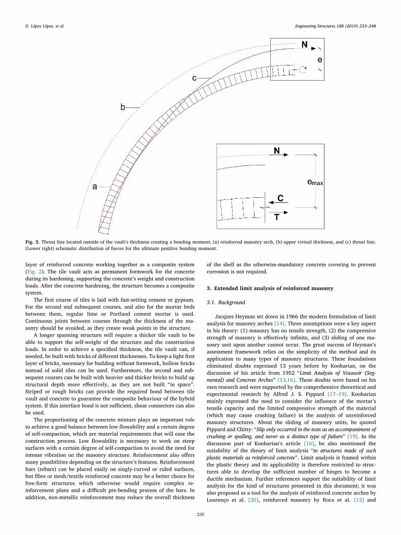
Fig. 3. Thrust line located outside of the vault’s thickness creating a bending moment; (a) reinforced masonry arch, (b) upper virtual thickness, and (c) thrust line.(Lower right) schematic distribution of forces for the ultimate positive bending moment.
D. López López, et al. Engineering Structures 188 (2019) 233–248
235

unreinforced masonry including tensile capacity by Ramaglia et al. [21]and Fabbrocino et al. [22].
The method presented in this paper is based on limit analysis, buttakes into account the finite compressive strength of the tile vault andconcrete as well as the tensile capacity of the reinforcement embeddedwithin the concrete. It allows both design and structural analysis andintroduces the possibility to include an additional material, being sui-table for the proposed composite construction system.
3.2. Concept
The presented method analyses the composite cross-section to ob-tain its ultimate positive and negative moment for the given axial load,which varies along the structure and is determined by the self-weightand the external loads. The ratio between the ultimate moment and theaxial force is equal to the maximum possible eccentricity (Fig. 3). Theeccentricity related to the positive moment defines the upper limit ofthe new virtual thickness and the eccentricity related to the negativemoment defines the corresponding lower limit. As is done in the clas-sical theory of limit analysis of masonry arches, the structure is dividedin a number of virtual voussoirs, which allow the construction of thethrust line and sets the specific sections where axial forces, momentsand eccentricities are calculated.
The thrust line and axial forces can be obtained graphically oranalytically. The stability of the vault is verified when it is possible tofind a thrust line, in equilibrium with the applied loads, that is fullycontained within the new virtual thickness of the vault, meaning thatthe safe theorem is satisfied. The uniqueness theorem can also be ap-plied to obtain the collapse load and mechanism of the composite vault.
The support conditions of the vault are of great importance for thedefinition of the thrust line and the stability of the vault. If the vault ispinned at its supports (Fig. 4k) with a single contact point, then thethrust line must pass through that point. In the case of a support con-sisting of a contact surface, unable to take bending moments, the thrustline can pass through any point of the mentioned surface. Finally, in thecase of a fixed support (Fig. 4a), the limits for the thrust line at thesupports coincide with the virtual thickness.
ELARM is not only limited to the design and structural analysis ofcomposite vaults with a cross-section as given in Fig. 2. This method isapplicable for reinforced concrete, reinforced masonry and reinforcedcomposite (masonry and concrete) arched structures, provided that thefailure mode corresponds to that of a ductile mechanism characterisedby the development of a sufficient number of hinges. Additionally, forconcrete-reinforced tile-vaulted structures and prior to the hardening ofthe concrete, the method presented can be also utilized to verify thepossibility of finding an admissible thrust line solution for the tile vaultsubject to its self-weight and the tile vault subject to its self-weight andthe addition of the dead weight of the concrete layer.
3.3. Geometry
The geometry of the vault is defined by its intrados, i.e. its innersurface, and the thicknesses of the tile vault and the concrete layer, htvand hc. The vault is divided into a number of fictitious voussoirs, with a
tile vault voussoir and a concrete voussoir in each transversal cross-section. The voussoirs’ volumes of these materials need to be consideredseparately to compute their weights, as the tile vault and the concretehave different specific weight values.
3.4. Loads
External, vertical and horizontal loads (VLi and HLi) can be appliedat any extrados (outer surface) voussoir edge (Fig. 5). Furthermore,horizontal loads (Hwtvi and Hwci) can be applied at the centroid of everytile vault and concrete portion (Gvtv and Gvc) within each voussoir.These forces are calculated as the self-weight of the voussoir (Wtvi andWci), multiplied by a factor specified by the user. This feature allows fora quick and preliminary equivalent-static seismic analysis by applyinghorizontal loads as a multiplier of the gravitational loads.
3.5. Thrust line
ELARM determines the thrust line analytically. When using limitanalysis for the study of an arch, different thrust lines that are inequilibrium with the applied loads, can be obtained by setting differentvalues to three independent variables defining their geometry. In thepresented method, these three variables are (highlighted in blue inFig. 5): (1) the horizontal thrust at the left support, Hl, (2) the end pointof the thrust line at the left support, el, defined by its distance from theintrados, and (3) the end point of the thrust line at the right support, er,also defined by its distance from the intrados. The forces acting on theglobal structure and those acting on an individual virtual voussoir areindicated in Fig. 5.
The global equilibrium of the vertical forces, horizontal forces andmoments can be expressed with the following equations, respectively:
∑+ = + +=
V V W W VLl r c tv i
ni1 (1)
∑= + + +=
H Hw Hw HL Hr c tv i
ni l1 (2)
∑ ∑+ + + + +
+ = + +
= =H y HL y VL x W x Hw y W x
Hw y V x H y V x
l H i
ni HL i
ni VL c W c Hw tv W
tv Hw l V r H r V
0 0l i i c c tv
tv l r r (3)
where n is the number of fictitious voussoirs, i indicates the specificvoussoir on which the force, VLi or HLi, is applied and xo and yo are thecoordinates of the point on which the load o is applied. The globalequilibrium equations allow one to obtain the vertical and horizontalreactions: the vertical reaction at the left support, Vl, the vertical re-action at the right support, Vr, and the horizontal thrust at the rightsupport, Hr.
The position of the points defining the thrust line, Pi and Pi+1, andthe axial force, N, acting on each of those points are obtained using thevertical forces, horizontal forces and moment equilibrium equations foreach voussoir (Fig. 5, left). They can be expressed as follows:
= + + + +V W W VL Vi c tv i i 1i i (4)
= + + + +H Hw Hw HL Hi c tv i i 1i i (5)
Fig. 4. Application of uniqueness theorem with ELARM: (a) fixed support, (b) applied load, (c) tile vault, (d) concrete, (e) reinforcement, (f) thrust line, (g) lowervirtual thickness, (h) upper virtual thickness, (i) real lower thickness, (j) real upper thickness, (k) pinned support.
D. López López, et al. Engineering Structures 188 (2019) 233–248
236

+ + + + + +
+ + = + ++ + + + + ++ +
H y HL y VL x W x Hw y W x Hw y
V x e sinα V x H y e cosα( ) ( )
i H i HL i VL c W c Hw tv W tv Hw
i Q i i i V i Q i i1 1 1 1 1 1
i i i i ci c tv tv
i i i1 1 (6)
where xk and yk are either the coordinates of the point k or the co-ordinates of the point on which the load k is applied and α the angle ofthe voussoir’s joint with a vertical plane (Fig. 5, left). These equationsare computed for each voussoir to obtain the vertical and horizontalforces acting on them, Vi+1 and Hi+1, and the distances, ei+1, from theintrados to the position of the points defining the thrust line, Pi+1
(Fig. 5, left). Knowing Vi+1 and Hi+1, the axial and shear forces, N andS, can be computed for each voussoir using the following equationsrespectively:
= ++ + + + +N V sinα H cosαi i i i i1 1 1 1 1 (7)
= −+ + + + +S V cosα H sinαi i i i i1 1 1 1 1 (8)
The cross-section can be then checked against shear using theequations for reinforced concrete in clause 6.2.2 from Eurocode 2 [23].The axial force is used during the cross-section analysis to compute thenew virtual thickness.
3.6. Cross-section analysis. New virtual thickness
The method adopted for the calculation of the ultimate sectionalmoments is based on the approach presented in Eurocode 2 for re-inforced concrete [23] and Eurocode 6 for reinforced masonry [24] formembers subjected to combined axial loading and bending moment.
The stress-strain relationship of concrete or masonry are taken to belinear or rectangular depending on the strain state of the materials. Thecross-section is analysed in bending at its ultimate limit state, meaningthat either the steel, the concrete or the tile vault masonry have reachedtheir ultimate strain, which is set to 0.01 for steel (εsmax) and 0.0035 forconcrete (εcmax) or tile vault masonry (εtvmax) according to [23,24].
The masonry’s strain and deformation under both its self-weight andthe concrete’s weight before curing are considered negligible and arenot taken into account for the calculation of the ultimate sectionalstrengths. The local point loads that would be expected during con-struction, for which the tile vault needs to be dimensioned as well,represent a much more significant loading condition on a compression-only structure than the relatively-low distributed dead weight load ofthe thin concrete layer. The local point loads become therefore thegoverning loads determining the thickness of the tile vault. In thiscontext, the resulting strain state in the thin tile layer caused by only itsown self-weight and that of the concrete layer, is negligible in com-parison with the magnitude of the strain at the ultimate state. This hasbeen checked through a comparison of strains in a finite element modelof the tested vaults (Section 5), in which the maximum compressivestrain of the tile vault supporting its self-weight and the concrete layer’sweight represents 0.39% of the ultimate compressive strain, εtvmax.Furthermore, the maximum deformation of the model (calculated as0.077mm) is 0.25% of the tested vaults’ maximum deformation at thepeak load (29 and 32mm). Even though the mentioned strain and de-formation are considered negligible, further research on this methodcould involve the modification of the algorithm to include this
Fig. 5. (Left) Forces acting on each fictitious voussoir. (Right) Global equilibrium, (a) thrust line, (b) tile vault, and (c) concrete.
Fig. 6. The different strain domains that the cross-section state can be within.
D. López López, et al. Engineering Structures 188 (2019) 233–248
237
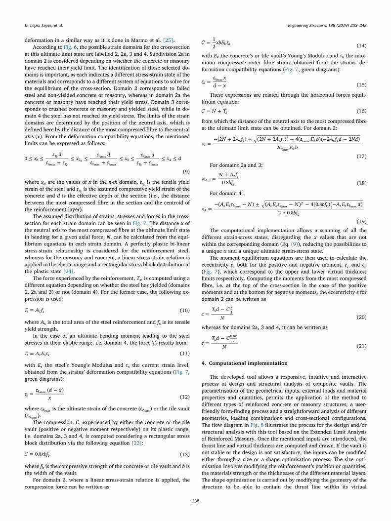
deformation in a similar way as it is done in Marmo et al. [25].According to Fig. 6, the possible strain domains for the cross-section
at this ultimate limit state are labelled 2, 2a, 3 and 4. Subdivision 2a indomain 2 is considered depending on whether the concrete or masonryhave reached their yield limit. The identification of these selected do-mains is important, as each indicates a different stress-strain state of thematerials and corresponds to a different system of equations to solve forthe equilibrium of the cross-section. Domain 2 corresponds to failedsteel and non-yielded concrete or masonry, whereas in domain 2a theconcrete or masonry have reached their yield stress. Domain 3 corre-sponds to crushed concrete or masonry and yielded steel, while in do-main 4 the steel has not reached its yield stress. The limits of the straindomains are determined by the position of the neutral axis, which isdefined here by the distance of the most compressed fibre to the neutralaxis (x). From the deformation compatibility equations, the mentionedlimits can be expressed as follows:
≤ ≤+
≤ ≤+
≤ ≤+
≤ ≤xε d
ε εx
ε dε ε
xε d
ε εx0 dy
s y
c
s c
c
y c2 2 3 4
c
max ca
max
max max
max
s max
(9)
where xn are the values of x in the n-th domain, εys is the tensile yieldstrain of the steel and εyc is the assumed compressive yield strain of theconcrete and d is the effective depth of the section (i.e., the distancebetween the most compressed fibre in the section and the centroid ofthe reinforcement layer).
The assumed distribution of strains, stresses and forces in the cross-section for each strain domain can be seen in Fig. 7. The distance x ofthe neutral axis to the most compressed fibre at the ultimate limit statein bending for a given axial force, N, can be calculated from the equi-librium equations in each strain domain. A perfectly plastic bi-linearstress-strain relationship is considered for the reinforcement steel,whereas for the masonry and concrete, a linear stress-strain relation isapplied in the elastic range and a rectangular stress block distribution inthe plastic state [24].
The force experienced by the reinforcement, Ts, is computed using adifferent equation depending on whether the steel has yielded (domains2, 2a and 3) or not (domain 4). For the former case, the following ex-pression is used:
=T A fs s s (10)
where As is the total area of the steel reinforcement and fs is its tensileyield strength.
In the case of an ultimate bending moment leading to the steelstresses in their elastic range, i.e. domain 4, the force Ts results from:
=T A E εs s s s (11)
with Es the steel’s Young’s Modulus and εs the current strain level,obtained from the strains’ deformation compatibility equations (Fig. 7,green diagrams):
=−
εε d x
x( )
skmax
(12)
where εkmax is the ultimate strain of the concrete (εcmax) or the tile vault(εtvmax).
The compression, C, experienced by either the concrete or the tilevault (positive or negative moment respectively) on its plastic range,i.e. domains 2a, 3 and 4, is computed considering a rectangular stressblock distribution via the following equation [23]:
=C xbf0.8 k (13)
where fk is the compressive strength of the concrete or tile vault and b isthe width of the vault.
For domain 2, where a linear stress-strain relation is applied, thecompression force can be written as
=C xbE ε12 k k (14)
with Ek the concrete’s or tile vault’s Young’s Modulus and εk the max-imum compressive outer fibre strain, obtained from the strains’ de-formation compatibility equations (Fig. 7, green diagrams):
=−
εε xd xk
smax
(15)
These expressions are related through the horizontal forces equili-brium equation:
= +C N Ts (16)
from which the distance of the neutral axis to the most compressed fibreat the ultimate limit state can be obtained. For domain 2:
=− + ± + − − −
xN A f N A f ε E b A f d Nd
ε E b(2 2 ) (2 2 ) 4( )( 2 2 )
2s s s s s k s s
s k2
2max
max
(17)
For domains 2a and 3:
=+
xN A f
bf0.8as s
k2 ,3
(18)
For domain 4:
=− − ± − − −
∗x
A E ε N A E ε N bf A E ε dbf
( ) ( ) 4(0.8 )( )2 0.8
s s k s s k k s s k
k4
2max max max
(19)
The computational implementation allows a scanning of all thedifferent strain-stress states, disregarding the x values that are notwithin the corresponding domain (Eq. (9)), reducing the possibilities toa unique x and a unique ultimate strain-stress state.
The moment equilibrium equations are then used to calculate theeccentricity e, both for the positive and negative moment, ep and en(Fig. 7), which correspond to the upper and lower virtual thicknesslimits respectively. Computing the moments from the most compressedfibre, i.e. at the top of the cross-section in the case of the positivemoments and at the bottom for negative moments, the eccentricity e fordomain 2 can be written as
=−
eT d C
Ns
x3
(20)
whereas for domains 2a, 3 and 4, it can be written as
=−
eT d C
Ns
x0.82
(21)
4. Computational implementation
The developed tool allows a responsive, intuitive and interactiveprocess of design and structural analysis of composite vaults. Theparametrisation of the geometrical inputs, external loads and materialproperties and quantities, permits the application of the method todifferent types of reinforced concrete or masonry structures, a user-friendly form-finding process and a straightforward analysis of differentgeometries, loading combinations and cross-sectional configurations.The flow diagram in Fig. 8 illustrates the process for the design and/orstructural analysis with this tool based on the Extended Limit Analysisof Reinforced Masonry. Once the mentioned inputs are introduced, thethrust line and virtual thickness are computed and drawn. If the vault isnot stable or the design is not satisfactory, the inputs can be modifiedeither through a size or a shape optimisation process. The size opti-misation involves modifying the reinforcement’s position or quantities,the materials strength or the thicknesses of the different material layers.The shape optimisation is carried out by modifying the geometry of thestructure to be able to contain the thrust line within its virtual
D. López López, et al. Engineering Structures 188 (2019) 233–248
238

thickness’ limits. Both of these structurally informed processes arecarried out with the immediate feedback from ELARM, which auto-matically computes the thrust line and virtual thickness again. Once astable and satisfying vault is achieved, further load combinations can bechecked if needed.
The computational implementation has been coded in the scriptinglanguage Python and uses the software Rhinoceros and pluginGrasshopper to visualise the results and to introduce and modify inputparameters.
4.1. Safe theorem
According to the safe theorem, “If a line of thrust can be found whichis in equilibrium with the external loads and which lies wholly within themasonry, then the structure is safe.” [14]. Note, that in this case, we lookfor a thrust line staying within the new virtual thickness.
Every thrust line results from the combination of the values of thethree variables Hl, el and er. These parameters are varied and combinedaccording to ranges and divided by small increments as defined by theuser, in order to scan (in a discrete manner) all the possible thrust linesof the structure. Any of the thrust lines lying entirely within the virtual
thickness satisfy the safe theorem. However, a single thrust line ischosen to be drawn and to determine the value of the three parameters.For each point defining a thrust line, the distances to the upper limit,dui, and to the lower limit, dli, of the virtual thickness are measured,squared and summed. A summation of each point’s resulting values iscomputed for each thrust line, which has therefore an associatednumber, R, indicating how far the thrust line is, on average, from thelimits of the virtual thickness, i.e., how central its position is in relationto those limits. This can be expressed as follows:
∑= +=
R d d( )i
nu l0
2 2i i (22)
where n is the number of fictitious voussoirs and i indicates the specificjoint of the fictitious voussoir on which the distances, d, are computed.The thrust line having the lowest associated value of R is then chosen.
4.2. Uniqueness theorem
According to the uniqueness theorem, “If a line of thrust can be foundwhich represents an equilibrium state for the structure under the action of thegiven external loads […] and which allows the formation of sufficient hinges
Fig. 7. Distribution of strains, stresses and forces in the different strain domains.
D. López López, et al. Engineering Structures 188 (2019) 233–248
239

to transform the structure into a mechanism, then the structure is on thepoint of collapse” [14].
The uniqueness theorem is computationally implemented by ap-plying an incremental factor to the external loads, scanning the possiblethrust lines and selecting the one creating the mechanism. For a givenload condition, small increments of the multiplier factor are applied tothe external loads. The possible thrust lines of the structure, resultingfrom the combination of the three variables Hl, el and er according tocertain domains and increments defined by the user, are checked forevery incremented load condition. Among all the resulting thrust lineslying entirely within the virtual thickness bounds, the selected solutionis the one with the highest load multiplier factor. This solution is theonly one tangent to the virtual thickness’ limits in the sufficient numberof alternating intrados-versus-extrados points as to create the hingesrequired to transform the structure into a mechanism.
5. Load tests on full-scale prototypes
In order to validate both the construction technology and the pro-posed computational implementation, a set of experiments was carriedout at the Laboratory for Technological Innovation in Structures andMaterials (LITEM) at the Polytechnic University of Catalonia (UPC).
Two full-scale prototypes were built and load-tested to failure. Thevaults were cylindrical in shape and had a span of 2.78m, a height of0.25m and a width of 1m. The two vaults were composed of a two-layered, 36-mm-thick tile vault and a 50-mm-thick reinforced concretelayer (Fig. 9). The tiles had sizes of 277× 134×13mm. The firstcourse ones had a smooth side facing the intrados and 6.5-mm-deepgrooves to receive the mortar, whereas the ones at the second courseincluded a rough, striped, top face to increase the contact with theconcrete instead of the smooth surface (Fig. 2). The binders were fast-setting cement for the first course of tiles and Portland cement mortarfor the second one and the 10-mm joint in between courses. The re-inforcement, placed at the central level of the concrete layer, consistedof 6-mm-diameter steel rebars at 7 cm spacings in both directions(Fig. 10). The boundary conditions consisted of pinned supports thatwere able to rotate, but translationally constrained (Fig. 11). Thesehinges at the supports were blocked (not allowed to rotate) duringconstruction, so that the barrel vaults could have been built in thetraditional way, i.e. without the need of a formwork, except at one of itsboundaries (only required for the first row of bricks to form the firstarch/stable section). However, seeking the maximum possible accuracy
in the construction of these laboratory specimens, the vaults were builtusing a complete formwork.
A vertical load was applied at quarter span to a loading pad with abreath of 115mm and stretching the entire width of the vault. The testwas carried out under displacement control at a constant speed of0.4 mm/min until failure.
Fig. 12 shows the load-displacement curves of the two tested vaults.Both vaults developed the same mechanism with the formation of twohinges (the supports were pinned). The first hinge was located underthe loading platform and the second one, at the opposite side of thevault, revealed itself not as a single crack, but as a group of cracks onthe extrados due to the reinforcement’s influence (Fig. 13). Compositevault 2 featured a post-peak plastic behaviour and an unloading re-sponse up to a displacement of 76mm, beyond which no further loadcould be applied due to the delamination between masonry and con-crete. The peak load was 53.15 kN.
In vault 1, the test stopped before the expected unloading branchdue to debonding as well. Considering the match of the two plots at thefirst stretch in Fig. 12, the observed cracks at the extrados of the vaultsevidencing the formation of the second hinge (Fig. 13) and the almostnull stiffness reached around the peak load (note the slopes’
Fig. 8. Flow diagram of the computational approach.
Fig. 9. Photo of one of the full-scale prototypes. View of the intrados showingthe tile vault’s pattern.
D. López López, et al. Engineering Structures 188 (2019) 233–248
240

horizontality of the load-displacement curves), the authors concludethat debonding occurred either simultaneously or right after the gen-eration of the second hinge, linked to the excessive deformation due tothe formation of the mechanism. This fact prevented the developmentof the expected post-peak unloading branch. The load-displacementcurve showed a non-linear behaviour until failure with an ultimate loadof 52.43 kN for a vertical displacement of 29mm at the loading point.
From these results, the system showed in principle the ductilityrequired for the use of limit analysis for its assessment. However, suf-ficient shear bond at the interfaces between all layers of the designedcomposite cross-section has to be guaranteed. In order to grant suffi-cient ductility, an improvement of the shear bond strength could beattained by using masonry units with deeper grooves in contact withthe concrete for mechanical keying action, or by integrating shear
connectors in the cross-section, such as steel shear studs or nails.
6. Material characterisation
The characterisation of the tile vault presents various difficultiesdue to its heterogeneity, slenderness, handmade fabrication and mul-tilayer condition. Its compressive strength was estimated from theproperties of the material components (tiles, Portland cement mortarand fast-setting cement). Considering the orthotropic behaviour of thetiles, they were tested in the longitudinal and in the transversal direc-tions, which coincide with the alignment of the loads in relation to thebricks in the first and the second course of the tile vault respectively(Fig. 2). Four compression tests were carried out for each case. Themean value for the bricks with the load applied in the longitudinaldirection (load applied as in the first course of the tile vault) was 111 N/
Fig. 10. Setup of the prototype for the load test. (Top) cross-section, (Bottom) plan view.
Fig. 11. Detail of the pinned support.
Fig. 12. Ultimate load test. Load-displacement curves of the two compositevaults.
D. López López, et al. Engineering Structures 188 (2019) 233–248
241

mm2, whereas for the bricks with the load applied in the orthogonaldirection (load applied as in the second course of the tile vault) theresult was 87 N/mm2. Portland cement mortar and fast-setting cementwere tested in compression with average results for the compressivestrength of 6.98 N/mm2 and 4.47 N/mm2 respectively. Nine masonrysamples were weighed, resulting in an average unit weight of 2000 kg/m3.
A curved (faceted) structure built with straight masonry units fea-tures unavoidably slight variations of its thickness. The construction ofthe first course of the tested vaults maintained the centre of the tilestangent to a fictitious cylindrical intrados. Due to this fact and for thepresented vault’s geometry and tile’s sizes, the tile vault had a max-imum thickness of 36 mm, which decreased 2.4mm at the intrados’transversal joints. The tile vault’s thickness is therefore taken as theresulting 33.6mm.
Eurocode 6 [24] offers an equation for the estimation of the ma-sonry’s compressive strength,
=f Kf fk b m0.7 0.3 (23)
where fk is the characteristic compressive strength of the tile vault in N/mm2, K is a constant, fb is the normalised mean compressive strength ofthe units (to be taken not greater than 75 N/mm2 in the direction of theapplied action effect), and fm is the compressive strength of the mortar,also in N/mm2.
The tile vault’s entire cross-section cannot be clearly classifiedwithin the Eurocode 6, mainly due to its multilayer condition and itscontinuous thick mortar joint parallel to the intrados and extrados(Fig. 2). Therefore, the compressive strength of each of its three layers(first course of bricks, mortar layer and second course of bricks) hasbeen considered separately to compute subsequently a total compres-sive strength of the tile vault taking into account the thickness of eachlayer. The tiles are considered solid and the thicknesses of the twocourses of tiles are taken as the tile’s total thickness subtracting the
grooves’ depth (6.5 mm). The considered thickness of the in-betweenmortar layer is increased adding the grooves’ depth of both the upperand lower tiles. Therefore, the three layers consist of: (1) 6.5-mm-thickmasonry composed of tiles in the longitudinal direction with fast-settingcement joints, (2) a 20.6-mm-thick mortar joint, and (3) 6.5-mm-thickmasonry composed of tiles in the transversal direction with Portlandcement mortar. The compressive strength of (2) is the one of the mortar(6.98 N/mm2), whereas Eq. (23) is used for (1) and (3). Constant K isdetermined from Table 3.3 from Eurocode 6, in which the material andgroup of the masonry units, together with the kind of mortar have to beintroduced. For clay masonry units classified in group 1 and generalpurpose mortar, Table 3.3 provides a value of K equal to 0.55. The testsof the different materials composing the tile vault allow obtaining fband fm. The results from the compression tests on tiles in both directionswere over 75 N/mm2, which is therefore the value taken as fb in Eq.(23) for both (1) and (3). For the first course, joined with fast-settingcement, fm is taken as 4.47 N/mm2, whereas for the second course oftiles, joined with Portland cement mortar, fm is taken as 6.98 N/mm2.With these values, Eq. (23) provides the characteristic compressivestrength, which is divided by 0.8 to obtain the average compressivestrength [26]. The entire tile vault’s compressive strength is estimatedby multiplying each strength by the corresponding thickness, summingthe results and dividing by the total thickness of the tile vault, with aresult of 13.45 N/mm2.
Ten 100-mm cubic samples of concrete were produced during theconstruction of the two prototypes. The results of the compression testsgave a mean value fc cube, equal to 27.75 N/mm2. A factor of 0.8 wasused to convert the average compressive strength of cubic samples to a150-mm-diameter by 300-mm-high cylindrical samples (as documentedin Eurocode 2 [23]). The result is a concrete compressive strength of fcequal to 22.20 N/mm2, which is the value used in the model. The unitweight of the concrete was calculated as 2460 kg/m3.
Ten 6-mm-diameter steel reinforcement bars were tested in tensionto obtain their yield tensile strength and Young’s modulus. The meanyield tensile strength was equal to 581 N/mm2 and the Young’sModulus was equal to 207,000 N/mm2.
7. Comparison of results.
The geometry of the vaults and the material properties indicated inthe previous section were introduced into the computational model toapply the uniqueness theorem and obtain the ultimate load carryingcapacity of the vault (Fig. 14). The thrust line’s ends were set to thecross-section’s centre line to represent the pinned support condition(Fig. 11). The vault was divided into 100 voussoirs and the load wasapplied evenly as point loads onto four voussoirs at quarter span, re-plicating the 11.5-cm-wide loading platform of the experimental tests.
The load predicted by the numerical method is 53.6 kN (Fig. 14),which is 1.5% higher than the average of the two values obtained in theexperimental tests, 52.8 kN. The results of the cross-sectional analysiswith ELARM showed that the failure had occurred with concrete at itsultimate strain and steel not yielded for the positive moment and tilevault at ultimate strain and steel yielded for the negative moment. Theposition of the neutral axis in the case of the negative moment (between32.1 and 32.8 mm from the intrados) showed the compression stressblock as fully developed within the tile vault (33.6mm thick).
In addition to the uncertainty in the compressive strength of themasonry layers (for which only an estimation is available as described
Fig. 13. Cracks on the extrados evidencing the development of the secondhinge at the composite vault 1.
Fig. 14. Application of the uniqueness the-orem with ELARM to the tested vaults: (a)upper virtual thickness, (b) thrust line, and(c) lower virtual thickness.
D. López López, et al. Engineering Structures 188 (2019) 233–248
242

in Section 6), small deviations in the prediction of the ultimate load canbe explained by the handmade condition of the structure, in which,even with an exhaustive construction control, small fluctuations on themortar and cement strength are expected and little variations on thethicknesses may occur frequently.
It is important to highlight that even though the cross-section in-troduced in ELARM does not vary along the length of the vault, thecomputed virtual thickness, as well as the position of the neutral axisand the equilibrium of forces in each voussoir are different because ofthe changing axial force, N, which varies according to the externalforces and the self-weight of the structure. An external load increasesthe axial force, which reduces the eccentricity for the same resistedbending moment. This is the reason why the virtual thickness experi-ences a sudden narrowing where the loads are applied.
8. Form-finding and optimisation procedures
The ELARM implementation coded in Python, results in an inter-active tool providing quick structural feedback. As can be expectedfrom any computational implementation, it offers speed, accuracy andthe possibility to extend the analysis to similar structures with differentsizes or properties. The next subsections describe specific features thatthis method offers for the design and structural analysis of reinforcedmasonry/concrete arches.
The use of the software Rhinoceros and the plug-in Grasshopper forthe visualisation of graphical results and for the efficient introductionand modification of input parameters, allows for a fast and user-inter-active form-finding process. The starting intrados of the analysed vaultcan be drawn as a curve in Rhinoceros, which can be easily modifiedthrough its control points. As the curve is being adjusted, calculationsare computed and graphical updates are provided. The shape andparameters of the vault can be adapted and optimised according to thestructural feedback received in near real-time.
8.1. Form finding
The presented tool allows the optimization of the vault’s shape re-garding a defined loading condition, e.g. the permanent loads acting onthe structure, by modifying the inputs that define the vault’s geometry,and then adapting to the tool’s structural feedback. A shape optimizedfor certain given loads would be one that includes within its virtualthickness boundaries the thrust line supplied by ELARM with aminimum thickness and reinforcement. Therefore, instead of startingfrom an invariable, predefined shape and modifying thickness, materialstrength and/or reinforcement to increase the virtual boundaries andmake the thrust line fit within, a form finding process consists ofmodifying the geometrical inputs of the structure to make geometry andthrust line match as much as other design constraints would allow.
The case study of Gaudí’s graphical design for the Laundry RoomPortico in Park Güell (Barcelona) is presented as an example of theimplementation's interactive feature (Fig. 15). The portico is a coveredspace featuring inclined columns at one side and a long, curved re-taining wall at the opposite side to counteract the soil’s thrust (Fig. 15,right). A structure with a traditional arch geometry such as a parabolawould be excessively massive given the specific existing loads, whichdemand a clever structural design to create an efficient structure. De-signing the structure with these permanent, asymmetric and pre-dominant dead loads as main inputs is a clever strategy to obtain anapproximate efficient solution.
The modification of the vault’s shape during the form-finding pro-cess should be combined with an iterative process of variation of thevertical and horizontal loads, as they are dependent on the soil’s weightand thrust. These loads could be obtained using an algorithm to com-pute the soil’s volume on top and next to the vault each time the in-trados is modified. However, to simplify calculations in this example,the vertical and horizontal loads applied are taken as constant
throughout the form-finding process. The loads’ values decrease gra-dually as they are applied in a higher position and range from 3 kN to0.15 kN for the horizontal loads and from 0.9 kN to 0.4 kN for thevertical ones.
The form-finding process for this case study starts by introducing inthe model the mentioned constant, predominant and permanent loads(Fig. 15, left, a). The material properties are introduced as well. In thiscase, it is considered as a masonry structure with a compressivestrength of 15 N/mm2 and a unit weight of 2000 kg/m3. A curve with aheight of 3.75m (Fig. 15, left, b) is drawn as the input intrados of apreliminary vault and the tool provides immediate structural feedback.Then a process of adjustment of the thrust line and the vault’s shapestarts by finding a solution in which the thrust line lies entirely in thevault’s thickness. The three variables Hl, el and er and the intradoscurve’s control points allow the modification of the thrust line and thevault’s shape respectively. Once a stable unreinforced masonry vault isfound (Fig. 15, left, c), the thickness of the masonry and the steel re-inforcement position and amount can be updated considering otherloading combinations, including further asymmetric live loads or if ahigher safety factor is desired. Fig. 16 shows two examples of this casestudy’s analysis with ELARM, adding at the top of the structure a 2-kN-punctual load (Fig. 16, left) or a distributed 3-kN load (Fig. 16, right).In both cases, reinforcement is needed and placed at a central level ofthe cross-section (Fig. 16, b). For the former, a reinforcement of 5-mm-diameter steel rebars at 33 cm spacings (equivalent to 59mm2/m) isenough, whereas for the latter the same rebars at 16 cm spacings areneeded (118mm2/m). The steel’s yield tensile strength for the re-inforcement is taken as 500 N/mm2.
8.2. Reinforcement optimisation
A cross-section optimisation can be carried-out by adjusting thethickness of the structural layers and the amount and positions of thereinforcement, while accounting for different load combinations. Themethod permits the placement of the required reinforcement in specificregions along the vault’s length. This feature can be very helpful, forexample, to check the adequacy of a particular reinforcement scheme ina certain part of the vault, either for design or in the retrofitting ofexisting structures.
Fig. 17 and Fig. 18 show an example of a specific case with variabledistribution of reinforcement. The studied structure is a 3-m-span, 0.5-m-rise, 1-m-wide and 9-cm-thick masonry barrel vault, to which a newpermanent load of 7 kN needs to be added due to a hypothetical changein the use of the building. The load is divided into 10 equal loads of0.7 kN applied on 10 voussoirs at the right-hand-side quarter-span lo-cation over a horizontal distance of 0.28m. The compressive strength ofthe masonry is taken as 8 N/mm2 with a density of 2200 kg/m3, and thesteel’s yield tensile strength for the reinforcement as 500 N/mm2.
The possibility to modify the thrust line and the amount and posi-tion of the reinforcement, both along the length of the vault and thethickness of the cross-section, allows the exploration of a large range ofpossibilities for the reinforcement of the existing vault. In this case, thereinforcement is applied at either the extrados (Fig. 17) or the intrados(Fig. 18). The application of reinforcement on the extrados increasesthe ultimate negative bending moment and affects the lower virtualthickness limit (Fig. 17), whereas the reinforcement on the intradosincreases the upper limit (Fig. 18). A small amount of reinforcementequivalent to a steel area of 21mm2 and 23mm2 was sufficient to ob-tain a solution applying the uniqueness theorem for the extrados-re-inforced and intrados-reinforced vaults respectively. The case with re-inforcement partially applied to the extrados results in a largerhorizontal thrust because of the shallower thrust line.
8.3. Seismic analysis
A simple preliminary seismic analysis can be carried out by
D. López López, et al. Engineering Structures 188 (2019) 233–248
243

considering equivalent-static horizontal loads proportional to the ver-tical self-weight loads. A horizontal load can be applied at the centroidsof every voussoir (at both the centroids of the tile vault and concreteportions), equal to its self-weight multiplied by a factor that can beinteractively modified by the user, and depends on expected ground
accelerations. Fig. 19 shows an example of seismic analysis combiningvertical and horizontal loads. The dimensioning of the thickness andreinforcement can be performed as an envelope of different load com-binations.
The studied barrel vault is made of a cylindrical composite structure
Fig. 15. Case study of Gaudí’s graphical design for the Laundry Room Portico in Park Güell (Barcelona). Left) form-finding with ELARM: (a) permanent vertical andhorizontal loads, (b) input intrados, (c) form-found shape, and (d) thrust line. Right) view of the Laundry Room Portico.
Fig. 16. Examples of loading combinations. (Left) permanent vertical and horizontal loads and a 2 kN punctual load. (Right) permanent vertical and horizontal loadsand a load of 3 kN distributed on the top voussoirs. (a) Permanent vertical and horizontal loads, (b) position of the reinforcement, (c) thrust line, (d) upper virtualthickness, and (e) lower virtual thickness.
Fig. 17. Partial reinforcement along the extrados of a masonry vault: (a) thrust line, (b) virtual thickness limit, and (c) reinforcement.
D. López López, et al. Engineering Structures 188 (2019) 233–248
244

including a 36-mm-thick tile vault and a thin concrete layer with athickness of 30mm. The compressive strength of the tile vault and theconcrete are taken as 10 N/mm2 and 25 N/mm2 respectively, withdensities of 2000 kg/m3 for the tile vault and 2400 kg/m3 for the con-crete. The steel’s yield tensile strength for the reinforcement is 500 N/mm2. The structure has a span of 3m and a rise and width of 0.5 m. Thesupports consist of a contact surface, unable to take bending moments.The horizontal loads are applied in the positive x direction (Fig. 19). Forthis example, the factor multiplying the self-weight of the vault is takenequal to 1.25. The reinforcement is placed on top of the masonry, at theinterface of the tile vault and the concrete. A structural analysis iscarried out for two different loading combinations. The first combina-tion includes self-weight and horizontal loads (Fig. 19, up). The secondcase has an additional vertical load of 7.5 kN (together with its relatedseismic horizontal load) divided in 50 equal loads of 0.15 kN applied onthe 50 voussoirs at the left-hand half-side of the vault (Fig. 19, down).The first case needs very little tensile capacity to remain stable againstthe applied horizontal loads. The steel reinforcement area was gradu-ally increased until the safe theorem could be fulfilled, reaching only asteel area of 7mm2. As expected, the combination adding the 7.5-kNload is more unfavourable, requiring four 5-mm-diameter steel re-inforcement bars (total steel area of 78mm2).
Additional factors multiplying the self-weight of the structure andconverted to horizontal loads have been applied to the same vault,namely, 0.5 (Fig. 20, up) and 1 (Fig. 20, down). Two strategies havebeen followed to obtain a stable structure: increasing either the re-inforcement or the concrete layer’s thickness. The unreinforced vault isstable without any change in its thickness considering the multiplyingfactor 0.5 (Fig. 20, up). The application of horizontal loads corre-sponding to factor 1 requires a small tensile capacity, achieved with areinforcement equivalent to a steel area of 4mm2 (Fig. 20, down). Forthis load condition, to remain unreinforced, the thickness of the
concrete layer should be increased 40mm, resulting in a vault’s totalthickness of 106mm (Fig. 21, up). For the multiplying factor 1.25, astable unreinforced vault would have a concrete thickness of 95mm (anincrease of 65mm and a total thickness of 131mm), while, as men-tioned above, the required reinforcement would only be 7mm2 of steelarea (Fig. 19, up). The 106-mm-thick vault with a multiplying factor of1.25, would require a small tensile capacity, equivalent to 3mm2 ofsteel area (Fig. 21, down).
In this case and according to these results, when dealing withseismic loads, the addition of reinforcement provides better results thanincreasing the mass of the structure.
8.4. Beyond compression-only
The addition of reinforcement to the composite vault allows for thedesign of structures that are not restricted to being compression-only.These structures, while adding a higher degree of flexibility, versatilityand expressivity to the technique, require the use of a formwork tobuild the non-compression-only parts. Fig. 22, Fig. 23 and Fig. 24 showthree examples of different reinforcement and thrust line configurationsin a free-form composite vault with a tile vault thickness of 36mm anda concrete layer of 50mm. The vault has no external forces applied andhas a span of 6m, a width of 1m and a rise of 0.75m at mid-span. Thematerial properties in terms of strength and density are the same as inthe previous example in Section 8.3. As ELARM showed ultimate po-sitive bending moments in domain 1 for the examples in Fig. 22 andFig. 24, the concrete’s Young’s Modulus is also required for the com-putation of the virtual thickness and is taken as 27,000 N/mm2.
The vault features a shape that requires some tensile capacity to bestructurally stable. Reinforcement is required in the regions where thethrust line is not contained within the section of the vault. Three dif-ferent thrust lines are chosen, which result in three different
Fig. 18. Partial reinforcement along the intrados of a masonry vault: (a) thrust line, (b) virtual thickness limit, and (c) reinforcement.
Fig. 19. Seismic analysis with multiplying factor 1.25. (Up) self-weight and horizontal loads. (Down) self-weight, horizontal loads and a load of 7.5 kN. (a) thrustline, (b) upper virtual thickness, (c) lower virtual thickness, and (d) reinforcement.
D. López López, et al. Engineering Structures 188 (2019) 233–248
245

reinforcement configurations.The thrust line in Fig. 22(a) avoids reinforcement in parts of the
vault by following the middle line of the cross-section at the first andlast 20 voussoirs. In the central part of the vault, due to its shape, thethrust line largely exceeds the physical upper boundary. Therefore,
bottom level reinforcement has to be supplied to virtually extend thethickness of the vault upwards (Fig. 22b). The reinforcement is placedat the intrados to maximise the vault’s bending capacity for positivemoments (Fig. 22c). A reinforcement equivalent to a total steel area of115mm2 (corresponding to 6 steel reinforcement bars of 5mm
Fig. 20. Seismic analysis: self-weight and horizontal loads. (Up) multiplying factor 0.5. (Down) multiplying factor 1. (a) thrust line, (b) upper virtual thickness, (c)lower virtual thickness, and (d) reinforcement.
Fig. 21. Seismic analysis: self-weight and horizontal loads. (Up) multiplying factor 1. (Down) multiplying factor 1.25. (a) thrust line, (b) upper virtual thickness, (c)lower virtual thickness, and (d) reinforcement.
Fig. 22. Free-form composite vault partially reinforced at the intrados: (a) thrust line, (b) upper virtual thickness and (c) reinforcement at the intrados.
Fig. 23. Free-form composite vault partiallyreinforced at the extrados: (a) thrust line, (b)lower virtual thickness and (c) reinforce-ment at the extrados.
D. López López, et al. Engineering Structures 188 (2019) 233–248
246

diameter) was introduced in the model and was enough to keep thethrust line within the new virtual boundaries (Fig. 22).
The example in Fig. 23 seeks to avoid reinforcement at the intrados.The thrust line (Fig. 23a) is shallower and the horizontal thrust is thusbigger (12.2 kN against 5.7 kN from the previous example). A total steelarea of 136mm2 (corresponding to 7 steel reinforcement bars of 5mmdiameter) is applied at the extrados (Fig. 23c). Although in a realconstruction the reinforcement would very likely be applied on theentire vault’s extrados in order to ease the building process and as anadditional safety factor, it is worth to highlight that, unlike in theprevious thrust line configuration, the central part of the vault wouldnot need any reinforcement, as the thrust line lies within its physicallimits (Fig. 23).
The last example (Fig. 24) shows an intermediate solution betweenthe two previous ones. The chosen thrust line (Fig. 24a) has an equalmaximum distance from the intrados and from the extrados (when lo-cated below or above the vault respectively) and generates also an in-termediate horizontal thrust equal to 9.2 kN. The solution requires re-inforcement at the intrados of the vault’s central part (Fig. 24e) of atotal steel area of 57mm2 and at the extrados of the remaining parts ofthe vault for a steel area of 64mm2 (Fig. 24d).
The specific steel area multiplied by the length on which it is ap-plied allows the computation of the required volume of reinforcementfor each of the three cases, namely 455,400mm3, 878,560mm3 and442,980mm3 for the examples in Fig. 22, Fig. 23 and Fig. 24 respec-tively. The solution with the shallower thrust line (Fig. 23) is, in thiscase, the one requiring more steel. Besides, it is also the option with thehighest horizontal thrust. Taking advantage of the vault’s funicularshape close to the supports, the thrust line in Fig. 22 reduces theamount of required reinforcement, being only slightly higher than theone required for the most reinforcement-efficient example in Fig. 24, inwhich the horizontal thrust is, however, 61% higher.
9. Conclusions
A construction technique based on the use of tile vaults as in-tegrated formwork for reinforced concrete has been described. In ad-dition, a 2D method for the design and structural analysis of suchcomposite structures has been presented. The method’s computationalimplementation allows for an interactive and user-friendly form-findingprocess and a straight-forward assessment with responsive structurallyinformed feedback. Several examples showing the application to non-compression-only designs, non-uniform reinforcement layouts andhorizontal loads have also been discussed.
The construction technique, the method, and the developed com-putational tool, have been validated through experimental research.Two full-scale prototypes were built and load-tested, allowing theidentification of features to improve. In this sense, it is important toconsider sufficient bond between the tile vault and the layer of concreteto attain satisfactory structural performance. This can be achieved byusing tiles with deeper grooves in contact with the concrete or by in-tegrating shear connectors into the system.
The applicability and accuracy of the proposed analysis method hasbeen validated through its capacity to predict well the results from theexperimental results. The method is based on traditional limit analysis,but extends it by considering the tensile capacity of the reinforcement
and the compressive strength of the masonry and concrete. The methodcan also be applied to other structures with a sufficiently ductile re-sponse, such as reinforced masonry or concrete arches and vaults, andsimilar reinforced composite structures combining masonry and con-crete.
Acknowledgements
This work was supported by the Swiss National Science Foundation(SNSF), Switzerland [grant number P1EZP2_165203] and the Instituteof Technology in Architecture (ITA) at the Swiss Federal Institute ofTechnology in Zurich (ETH Zurich), Switzerland. It was also sponsoredby the construction company URCOTEX, from which Pep Brazo,Antonio Haro and Albert Martí are especially acknowledged. The con-struction of the prototypes was carried out together with JordiDomènech, to whom the authors are very thankful.
Experimental support and facilities were kindly offered by theLaboratory for Technological Innovation in Structures and Materials(LITEM) at the Polytechnic University of Catalonia (UPC), from whichLluís Gil, Ernest Bernat, Christian Escrig and Luis Mercedes are espe-cially acknowledged.
References
[1] Huerta S. La mecánica de las bóvedas tabicadas en su contexto histórico: laaportación de los Guastavino. In: Huerta S, editor. Las bóvedas de Guastavino enAmérica. Madrid: Instituto Juan de Herrera; 2001. p. 87–112.
[2] Ramage MH, Ochsendorf J, Rich P, Bellamy J, Block P. Design and construction ofthe Mapungubwe National Park Interpretive Centre, South Africa. ATDF J (AfricanTechnology Development Forum) 2010;7(1/2):14–23.
[3] Block P, DeJong M, Davis L, Ochsendorf J. Tile vaulted systems for low-cost con-struction in Africa. ATDF J (African Technology Development Forum) 2010;7(1/2):4–13.
[4] Block P, Bayl-Smith M, Schork T, Bellamy J, Pigram D. Ribbed tile vaulting –Innovation through two design-build workshops. In: Gramazio F, Kohler M,Langenberg S, editors. FABRICATE 2014. Zurich: ETH Zurich; 2014. p. 22–9.
[5] Davis L, Rippmann M, Pawlofsky T, Block P. Innovative funicular tile vaulting; aprototype in switzerland. Struct Eng 2012;90(11):46–56.
[6] López López D, Domènech M, Palumbo M. “Brick-topia”, the thin-tile vaulted pa-vilion. Case Stud Struct Eng 2014;2:33–40.
[7] López López D, Domènech M, Palumbo M. Using a construction technique to un-derstand it: thin-tile vaulting. In: Peña F, Chávez M, editors. SAHC2014 – 9th in-ternational conference on structural analysis of historical constructions. MexicoCity. 2014.
[8] López López D, Van Mele T, Block P. Tile vaulting in the 21st century. Informes de laConstrucción 2016;68(544):e162https://doi.org/10.3989/ic.15.169.m15.
[9] López López D, Domènech M. Tile vaults. Structural analysis and experimentation.2nd Guastavino Biennial. Barcelona: Diputació de Barcelona. 2016.
[10] Truñó A. Construcción de Bóvedas Tabicadas. Manuscript at the Library of theCol·legi d’Arquitectes de Catalunya; ca. 1951.
[11] Tang G. An overview of historical and contemporary concrete shells, their con-struction and factors in their general disappearance. Int J Space Struct 2015:30(1).
[12] Roca P, López-Almansa F, Miquel J, Hanganu A. Limit analysis of reinforced ma-sonry vaults. Eng Struct 2007;29:431–9.
[13] Kooharian A. Limit analysis of voussoir (segmental) and concrete arches. J AmConcr lnstit 1952;49:317–28.
[14] Heyman J. The stone skeleton. Int J Solids Struct 1966;2:249–79.[15] Heyman J. The masonry arch. Chichester: Ellis Horwood Ltd.; 1982.[16] Herbert A, Sawyer JR, Kooharian A. Discussion of a paper by Anthony Kooharian:
limit analysis of voussoir (segmental) and concrete arches. J Am Concr lnstit1953;25(4). 328-(1–4).
[17] Pippard AJS, Tranter E, Chitty L. The mechanics of the Voussoir Arch. J Inst C.E.1936;4:281–306.
[18] Pippard AJS, Ashby RJ. An experimental study of the Voussoir Arch. J Inst C.E.1939;:10.
[19] Pippard AJS, Chitty L. A study of the Voussoir Arch. National Building Studies,
Fig. 24. Free-form composite vault re-inforced at both the intrados and the ex-trados: (a) thrust line, (b) lower virtualthickness, (c) upper virtual thickness, (d)reinforcement at the extrados, and (e) re-inforcement at the intrados.
D. López López, et al. Engineering Structures 188 (2019) 233–248
247
Research Paper No. 11. London: His Majesty’s Stationery Office; 1951.[20] Lourenço PB, Palacio K, Barros J. Design recommendations for reinforced masonry
arches. Arch Bridges VI. Barcelona: International Center for Numerical Methods inEngineering (CIMNE). 2004. p. 583–92.
[21] Ramaglia G, Lignola GP, Prota A. Collapse analysis of slender masonry barrel vaults.Eng Struct 2016;117:86–100.
[22] Fabbrocino F, Ramaglia G, Lignola GP, Prota A. Ductility-based incremental ana-lysis of curved masonry structures. Eng Fail Anal 2019;97:653–75. https://doi.org/10.1016/j.engfailanal.2019.01.027.
[23] CEN. Eurocode 2: Design of concrete structures. EN 1992-1-1: 2004. Brussels: CEN;
2004.[24] CEN. Eurocode 6: Design of masonry structures. EN 1996-1-1: 2005. Brussels: CEN;
2005.[25] Marmo F, Serpieri R, Rosati L. Ultimate strength analysis of prestressed reinforced
concrete sections under axial force and biaxial bending. Comput Struct2011;89(1–2):91–108. https://doi.org/10.1016/j.compstruc.2010.08.005.
[26] Jäger W, Pech A. Background of the values for compressive strength of masonry acc.to EC6 – evaluation of data. Mauerwerk 2014;18(3–4):229–38. https://doi.org/10.1002/dama.201400629.
D. López López, et al. Engineering Structures 188 (2019) 233–248
248