Tightly Coupled Accelerators Architecture
22
Center for Computational Sciences, Univ. of Tsukuba Tightly Coupled Accelerators Architecture Yuetsu Kodama Division of High Performance Computing Systems Center for Computational Sciences University of Tsukuba, Japan 2014/02/19 External Review 1
Transcript of Tightly Coupled Accelerators Architecture

Center for Computational Sciences, Univ. of Tsukuba
Tightly Coupled Accelerators Architecture
Yuetsu Kodama
Division of High Performance Computing Systems
Center for Computational Sciences
University of Tsukuba, Japan
2014/02/19 External Review 1
Center for Computational Sciences, Univ. of Tsukuba
What is “Tightly Coupled Accelerators (TCA)” ?
Concept:
Direct connection between accelerators (GPUs) over the nodes
Eliminate extra memory copies to the host
Improve latency, improve strong scaling with small data size
Using PCIe as a communication device between accelerator
Most accelerator devices and other I/O devices are connected by PCIe as end-point (slave device)
An intelligent PCIe device logically enables an end-point device to directly communicate with other end-point devices
PEACH2: PCI Express Adaptive Communication Hub ver. 2
In order to configure TCA, each node is connected to other nodes through PEACH2 chip.
2014/02/19 External Review 2

Center for Computational Sciences, Univ. of Tsukuba
Design policy of PEACH2
Implement by FPGA with four PCIe Gen.2 IPs Altera Stratix IV GX Prototyping, flexible enhancement
Sufficient communication bandwidth PCI Express Gen2 x8 for each port Sophisticated DMA controller
Chaining DMA
Latency reduction Hardwired logic Low-overhead routing mechanism
Efficient address mapping in PCIe address area using unused bits Simple comparator for decision of output port
Not only is it proof-of-concept implementation, but it will also be available for product-run in GPU cluster.
2014/02/19 External Review 3

Center for Computational Sciences, Univ. of Tsukuba
TCA node structure example
PEACH2 can access
every GPUs
NVIDIA Kepler architecture + CUDA 5.0 “GPUDirect Support for RDMA”
Performance over QPI is quite bad. => support only for GPU0, GPU1
Connect among 3
nodes using PEACH2
2014/02/19 External Review
CPU
(Xeon
E5)
CPU
(Xeon
E5) QPI
PCIe
GPU
0
GPU
2
GPU
3 IB
HCA PEA
CH2
GPU
1
G2
x8 G2
x16
G2
x16
G3
x8 G2
x16
G2
x16
G2
x8
G2
x8
G2
x8
Single PCIe address
GPU: NVIDIA K20, K20X (Kepler architecture)
4

Center for Computational Sciences, Univ. of Tsukuba
Overview of PEACH2 chip
Fully compatible with PCIe Gen2 spec.
Root and EndPoint must be paired according to PCIe spec.
Port N: connected to the host and GPUs
Port E and W: form the ring topology
Port S: connected to the other ring
Selectable between Root and Endpoint
Write only except Port N Instead, “Proxy write” on remote node
realizes pseudo-read.
CPU & GPU side
(Endpoint)
To PEACH2
(Root Complex /
Endpoint)
To
PE
AC
H2
(En
dp
oin
t)
To
PE
AC
H2
(Ro
ot C
om
ple
x)
NIOS
(CPU)
Memory
DMAC
Routing
function
Port N
Port E
Port W
Port S
2014/02/19 External Review 5

Center for Computational Sciences, Univ. of Tsukuba
Communication by PEACH2
PIO CPU can store the data to remote node directly
using mmap.
DMA Chaining mode
DMA requests are prepared as the DMA descriptors chained in the host memory.
DMA transactions are operated automatically according to the DMA descriptors by hardware.
Register mode DMA requests are registered into the PEACH2 by
up to 16. Lower overhead than chaining mode by omitting
transfer for descriptors from host
Block stride transfer function
2014/02/19 External Review 6
Descriptor0
Descriptor1
Descriptor2
Descriptor3
Descriptor (n-1)
…
Source
Destination
Length
Flags
Next
Center for Computational Sciences, Univ. of Tsukuba
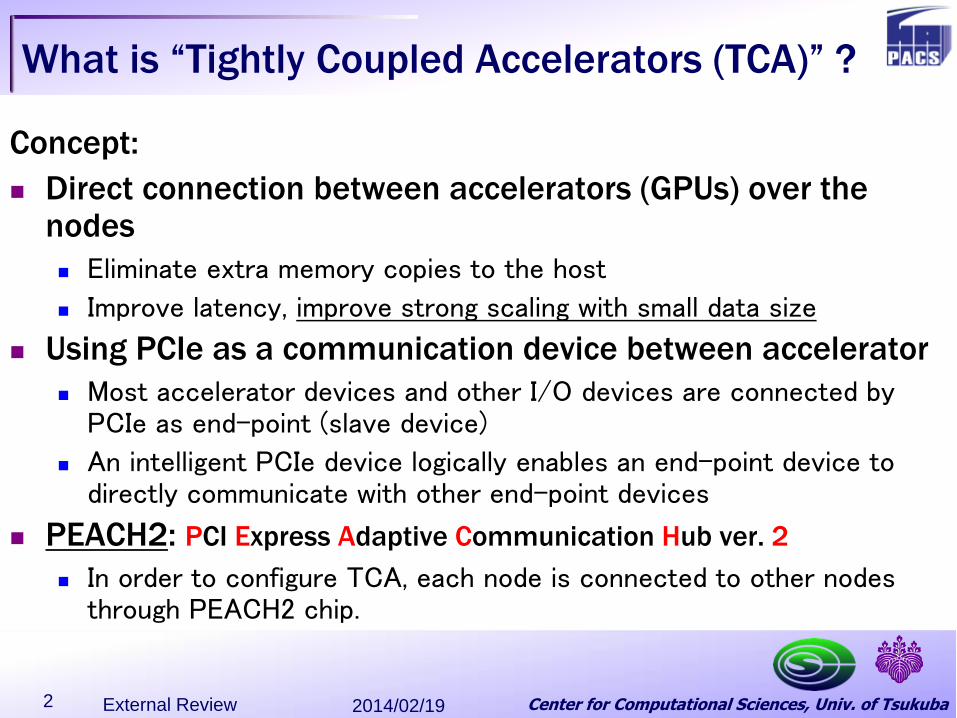
PEACH2 board (Production version for
HA-PACS/TCA)
PCI Express Gen2 x8 peripheral board
Compatible with PCIe Spec.
2014/02/19 External Review 7
Top View Side View

Center for Computational Sciences, Univ. of Tsukuba
PEACH2 board (Production version for
HA-PACS/TCA)
2014/02/19 External Review 8
Main board + sub board Most part operates at 250 MHz
(PCIe Gen2 logic runs at 250MHz)
PCI Express x8 card edge
Power supply for various voltage
DDR3- SDRAM
FPGA (Altera Stratix IV
530GX)
PCIe x16 cable connecter
PCIe x8 cable connecter

Center for Computational Sciences, Univ. of Tsukuba
HA-PACS System
Base Cluster since Feb. 2012 TCA
since Nov. 2013
TCA: 5Rack x 2Line
2013/12/18 ACHPC 9
Center for Computational Sciences, Univ. of Tsukuba
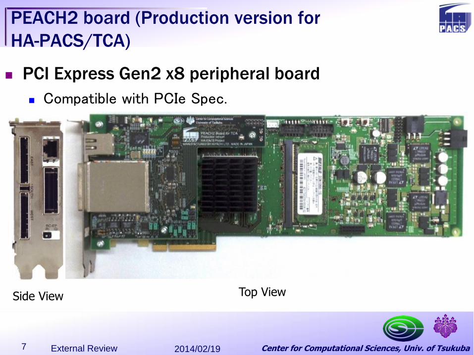
HA-PACS Total System
InfiniBand QDR 40port x 2ch between base cluster and
TCA
HA-PACS Base Cluster 268 nodes
HA-PACS / TCA
64 nodes
InfiniBand QDR 324port sw
InfiniBand QDR 324port sw
InfiniBand QDR 108 port sw
InfiniBand QDR 108 port sw
40
40
Lustre Filesystem
421 TFLOPS, Efficiency 54%, 41st 2012.6 Top500 1.15 GFLOPS/W
277 TFLOPS, Efficiency 76%, 134th 2013.11 Top500 3.52 GFLOPS/W 3rd 2013.11 Green500
2013/12/18 ACHPC 10

Center for Computational Sciences, Univ. of Tsukuba
(2.8 GHz x 8 flop/clock)
Total: 5.688 TFLOPS
8 GB/s
AVX
1.31 TFLOPSx4 =5.24 TFLOPS
22.4 GFLOPS x20 =448.0 GFLOPS
(16 GB, 14.9 GB/s)x8 =128 GB, 119.4 GB/s
(6 GB, 250 GB/s)x4 =24 GB, 1 TB/s
4 Channels 1,866 MHz 59.7 GB/sec
4 Channels 1,866 MHz 59.7 GB/sec
Ivy Bridge Ivy Bridge
4 x NVIDIA K20X
HA-PACS/TCA (Computation node)
Gen 2
x 1
6
Gen 2
x 1
6
Gen 2
x 1
6
Gen 2
x 1
6
PEACH2 board (TCA interconnect)
Gen 2
x 8
Gen 2
x 8
Gen 2
x 8
Legacy Devices
2013/12/18 ACHPC 11
Center for Computational Sciences, Univ. of Tsukuba
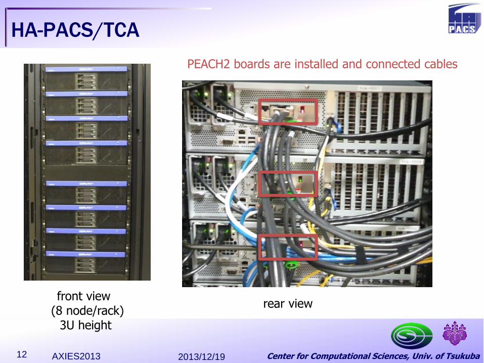
HA-PACS/TCA
2013/12/19 AXIES2013 12
PEACH2 boards are installed and connected cables
front view (8 node/rack)
3U height
rear view
Center for Computational Sciences, Univ. of Tsukuba
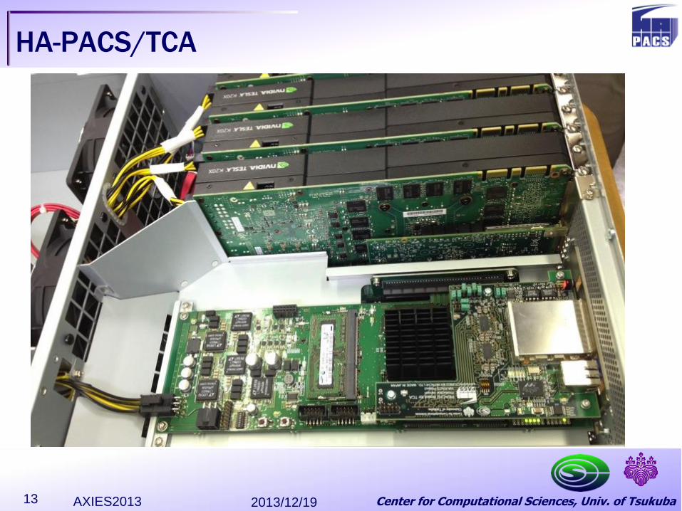
HA-PACS/TCA
2013/12/19 AXIES2013 13

Center for Computational Sciences, Univ. of Tsukuba
TCA sub-cluster (16 nodes)
TCA has four sub-clusters, and TCA sub cluster consists of two racks. 2x8 torus (one example) A ring consists of 8 nodes
(between East port and West port, Orange links)
Two rings are connected at each node(between both South port, Red links)
We can use 32 GPUs in a sub-cluster seamlessly as same as multi-GPUs in a node. only use 2GPU in a node
because of bottleneck of QPI
Sub-clusters are connected by IB(QDR 2port)
2013/12/19 AXIES2013 14
Center for Computational Sciences, Univ. of Tsukuba
Evaluation items
Ping-pong performance
between nodes
Latency and bandwidth
Written as application
Comparison with MVAPICH2 1.9 (with CUDA support) for GPU-GPU communication and MVAPICH2-GDR (with support GPU Direct support for RDMA) using IB (dual QDRx4 that bandwidth is twice of TCA)
In order to access GPU memory by the other device, “GPU Direct support for RDMA” in CUDA5 API is used.
Special driver named “TCA p2p driver” to enable memory mapping is developed.
“PEACH2 driver” to control the board is also developed.
2014/02/19 External Review 15

Center for Computational Sciences, Univ. of Tsukuba
Ping-pong Latency Minimum Latency
PIO (CPU to CPU): 0.9us
DMA:CPU to CPU: 1.9us
GPU to GPU: 2.3us
(cf. MVAPICH2 1.9:19 us
MVAPICH2-GDR: 6us)
2013/12/19 AXIES2013 16
0
10
20
30
40
50
60
70
80
8 128 2048 32768
CPU(IVB)
GPU(SB)
GPU(IVB)
MV2-GPU(SB)
MV2GDR-GPU(IVB)0
1
2
3
4
5
6
7
8
8 32 128 512

Center for Computational Sciences, Univ. of Tsukuba
Ping-pong Bandwidth
CPU-CPU DMA Max. 3.5GByte/sec (95% of theoretical peak)
GPU-GPU DMA Max. 2.6GByte/sec
GPU(SB) was saturated at 880MByte/sec because of poor performance of PCIe switch in CPU
GPU(IVB) is faster than MV2GDR less than 512KB message size
2013/12/19 AXIES2013 17
0
500
1000
1500
2000
2500
3000
3500
4000
4500
5000
8 128 2048 32768 524288
CPU(IVB)
GPU(SB)
GPU(IVB)
MV2-GPU(SB)
MV2GDR-GPU(IVB)
Center for Computational Sciences, Univ. of Tsukuba
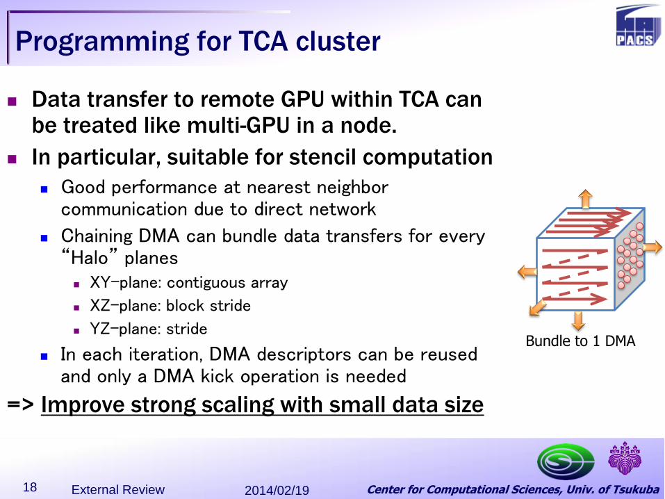
Programming for TCA cluster
Data transfer to remote GPU within TCA can be treated like multi-GPU in a node.
In particular, suitable for stencil computation
Good performance at nearest neighbor communication due to direct network
Chaining DMA can bundle data transfers for every “Halo” planes
XY-plane: contiguous array
XZ-plane: block stride
YZ-plane: stride
In each iteration, DMA descriptors can be reused and only a DMA kick operation is needed
=> Improve strong scaling with small data size
2014/02/19 External Review 18
Bundle to 1 DMA

Center for Computational Sciences, Univ. of Tsukuba
Current activities
Develop API for user programming
similar to CudaMemcpy API. It enables use GPUs in a sub cluster seamlessly as same as Multi-GPUs in a node using CudaMemcpy API.
XMP for TCA
cooperating with RIKEN AICS, we develop XMP for TCA.
Function offloading on TCA
a reduction mechanism between GPUs in a sub cluster will be offloaded on TCA cooperating with Keio-Univ. Amano lab. and astrophysics group in CCS
QUDA (QCD libraries for CUDA)
TCA feature will be added to QUDA cooperating with NVIDIA.
2014/02/19 External Review 19
Supported by JST/CREST program entitled “Research and Development on Unified Environment of Accelerated Computing and Interconnection for Post-Petascale Era.”
Center for Computational Sciences, Univ. of Tsukuba
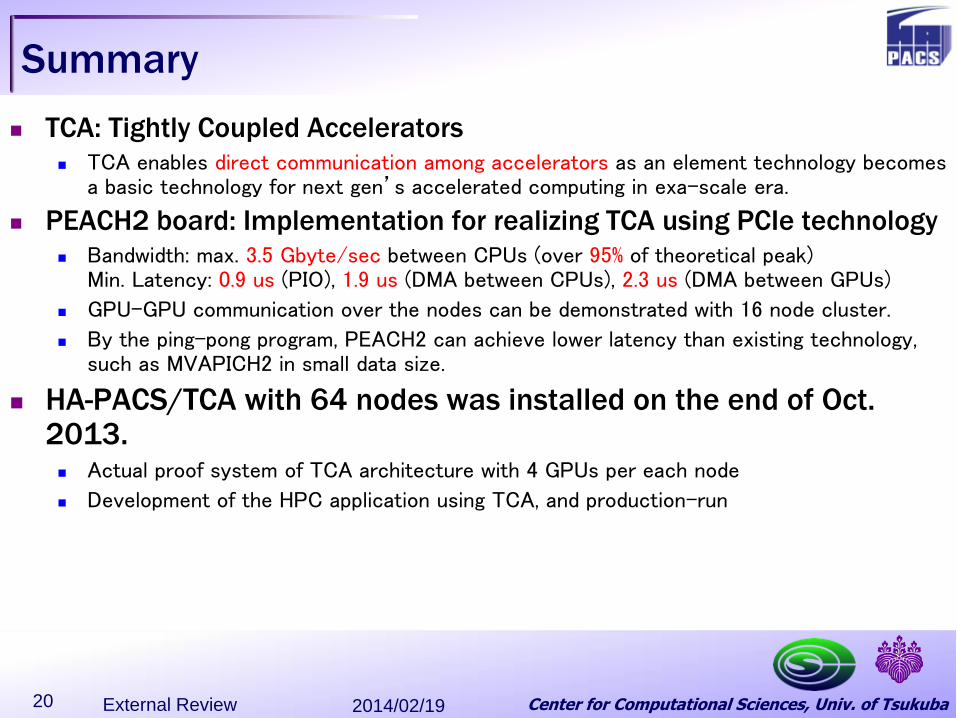
Summary
TCA: Tightly Coupled Accelerators
TCA enables direct communication among accelerators as an element technology becomes a basic technology for next gen’s accelerated computing in exa-scale era.
PEACH2 board: Implementation for realizing TCA using PCIe technology
Bandwidth: max. 3.5 Gbyte/sec between CPUs (over 95% of theoretical peak) Min. Latency: 0.9 us (PIO), 1.9 us (DMA between CPUs), 2.3 us (DMA between GPUs)
GPU-GPU communication over the nodes can be demonstrated with 16 node cluster.
By the ping-pong program, PEACH2 can achieve lower latency than existing technology, such as MVAPICH2 in small data size.
HA-PACS/TCA with 64 nodes was installed on the end of Oct. 2013. Actual proof system of TCA architecture with 4 GPUs per each node
Development of the HPC application using TCA, and production-run
2014/02/19 External Review 20
Center for Computational Sciences, Univ. of Tsukuba 2014/02/19 External Review 21
Center for Computational Sciences, Univ. of Tsukuba
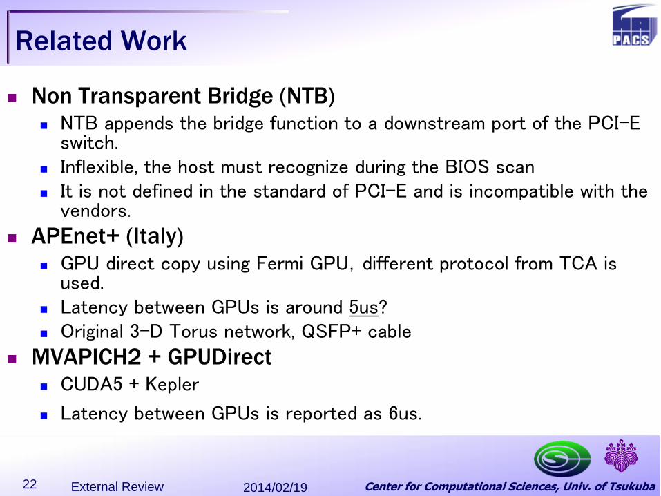
Related Work
Non Transparent Bridge (NTB) NTB appends the bridge function to a downstream port of the PCI-E
switch. Inflexible, the host must recognize during the BIOS scan It is not defined in the standard of PCI-E and is incompatible with the
vendors.
APEnet+ (Italy) GPU direct copy using Fermi GPU,different protocol from TCA is
used. Latency between GPUs is around 5us? Original 3-D Torus network, QSFP+ cable
MVAPICH2 + GPUDirect CUDA5 + Kepler
Latency between GPUs is reported as 6us.
2014/02/19 External Review 22