TIG Welding Machines
6
1077-2618/11/$26.00©2011 IEEE BY ROSARIO CASANUEVA, FRANCISCO J. AZCONDO, FRANCISCO J. DI ´ AZ, & CHRISTIAN BRAN ˜ AS A MULTIPLE TWO-PHASE resonant converter module connected in parallel is the chosen architecture for a tungsten inert gas (TIG) welding power supply. Connection to the utility is performed through a front- end power factor correction stage. Fine tuning is performed by overlapping the control signals of the resonant converter phases. Output ripple is reduced by interleaving each module, and the arc strike is achieved with no extra circuitry and at low voltage. DC and multiple pulsating operations from 20 Hz to 5 kHz with different pulse widths have been tested. The resulting arc stability, welding parameters, and effi- ciency are analyzed in this article. The experimental results show the welding perform- ance and near unity power factor. A design for multiple two-phase resonant converter modules Digital Object Identifier 10.1109/MIAS.2010.939654 Date of publication: 5 July 2011 PHOTO COURTESY OF U.S. NAVY 53 IEEE INDUSTRY APPLICATIONS MAGAZINE SEPT j OCT 2011 WWW.IEEE.ORG/IAS
Transcript of TIG Welding Machines

1077-2618/11/$26.00©2011 IEEE
BY ROSAR IO CASANUEVA ,FRANC I SCO J . AZCONDO,
FRANC I SCO J . D IA Z , &CHR I S T IAN BRANAS
AMULTIPLE TWO-PHASE
resonant converter module
connected in parallel is the
chosen architecture for a
tungsten inert gas (TIG) welding power supply.
Connection to the utility is performed through a front-
end power factor correction stage. Fine tuning is performed
by overlapping the control signals of the resonant converter
phases. Output ripple is reduced by interleaving each module, and
the arc strike is achieved with no extra circuitry and at low voltage. DC
and multiple pulsating operations from 20 Hz to 5 kHz with different pulse
widths have been tested. The resulting arc stability, welding parameters, and effi-
ciency are analyzed in this article. The experimental results show the welding perform-
ance and near unity power factor.
A design for multipletwo-phase resonantconverter modules
Digital Object Identifier 10.1109/MIAS.2010.939654
Date of publication: 5 July 2011
PHOTO COURTESY OF U.S. NAVY
53
IEEE
INDUSTR
YAPPLIC
ATIO
NS
MAGAZIN
E�
SEPTjO
CT
2011�
WW
W.IE
EE.O
RG/IA
S

TIG or GTAW WeldingTIG or gas-tungsten-arc welding (GTAW) is a widely usedhigh-quality, high-precision welding process. In TIG weld-ing (Figure 1), an arc is established between a nonconsum-able tungsten electrode and the metal that is heated andmelted. Filler wire may be added for the weld. The inert gas:1) shields the welding area from the air, preventing oxida-tion, 2) transfers heat from the electrode to metal, and 3)helps to start and maintain a stable arc (due to the low ioni-zation potential). This process can be used for many types ofmaterials in all welding positions, and it provides a concen-trated, stable arc and a high-quality and neat weld deposit.
Before the arc is initiated, the electrode is too cold toemit electrons to establish the arc. Any of the followingthree methods can be used to start the arc: 1) touching theelectrodes together and then separating them, 2) applyinga high-voltage pulse, or 3) high-voltage, high-frequency(HF) ac pulses [1]–[3].
In TIG welding, dc, pulsed dc, or ac power supply isused [4]–[12]. DC current sources provide constant polar-ity current, resulting in high arc stability. Pulsed powersupplies provide current pulses between two current levels:a maximum current value, enough to melt the base mate-rial, and a background current level, sufficient to maintaina stable arc. The duration of the current pulses can bechanged to weld different thicknesses of the same material,and the current levels are set for each material [13]. ACpower supplies provide a combination of negative and posi-tive current at both polarities, which are suitable for weld-ing aluminum or its alloys.
Auxiliary arc starters are commonly added to the powersource to supply the high-voltage or HF, high-voltage acpulses (�2 kV, �1 MHz) across the weld terminals, andtheir operation can be seen in [3], [14].
Arc-welding machines are potential sources of harmon-ics as the nonlinear behavior of the process and the use ofpulsed supplies lead to unwanted frequencies superim-posed on the supply voltage. To improve the input behav-ior and power factor, active power rectifiers are used.
Resonant converters have applications in the control ofdischarges including arc welding [15]–[17]. These convert-ers are known for their advantages such as HF dc-to-dcpower supplies, which in turn result in small size, light-weight, and high-efficiency systems. These converters canbe operated to achieve zero voltage and/or zero current
switching, which results in minimum switching losses. TheHF operationminimizes the size of magnetic components.
This article proposes a design of multiple two-phase res-onant converter modules connected in parallel operating ata constant switching frequency to generate a highly flexi-ble power supply for arc-welding applications. The con-verters are designed as a current source. In this way, the v–icharacteristic of the power supply is vertical, which meansthat the welding current remains constant when the arclength changes that provides good arc stability.
The proposed solution includes one or more powermodules depending on the current requirements, and thearc strike is achieved with no extra circuitry at low voltageby means of a high switching frequency during the off state(twice the switching frequency during the welding pulse).
Arc-Welding Power Supply RequirementsThe arc is electrically characterized by a low-voltage value(�10 V) and high-current values. Changes in the distancebetween the tungsten electrode and base metal from opento short circuit are possible conditions of the weldingprocess; thus, it is necessary to limit the open-circuit volt-age and short-circuit current. The standard InternationalElectrotechnical Commission (IEC) 60974-1 [18] estab-lishes safety isolation and a maximum permissible open cir-cuit voltage of 113 V.
In summary, the requirements for the TIG weldingpower supply are as follows:
n small sizen lightweightn high efficiencyn to limit the load current under short-circuit conditionsn to limit the load voltage under open-circuit conditionsn transformer isolationn scalability.The power supply should provide a constant and pulsed
dc current. The established electrical specifications areas follows:
n input voltage: single phase, 220 V, 50 Hzn maximum open circuit voltage: 113 Vn arc voltage: 10–50 Vn maximum arc current per module: �25 An switching frequency: in the range of 100 kHzn pulsing frequency up to 5 kHzn pulse width: adjustable.
Description of the Arc-WeldingPower SupplyAs shown in Figure 2, the proposed power supply consistsof the following blocks. Each block is discussed in detail.
Input StageA power converter transforms the ac mains voltage into astabilized dc voltage. The power factor corrector (PFC) isused to improve the input performance regarding the har-monic injection in the utility line. The objective of thePFC is to act as an ideal resistor emulator. This allows thepower distribution system to operate more efficiently,reducing energy consumption.
The PFC section is a boost converter supplying constantvoltage to the dc bus, Vdc¼ 400 V. This is a common solu-tion in practical applications for two-stage power supplies
Arc Shielding Gas
TIG Torch
Tungsten Electrode
Base Material
1TIG or GTAW welding process.
54
IEEE
INDUSTR
YAPPLICATIONS
MAGAZIN
E�
SEPTjO
CT
2011�
WW
W.IEEE.O
RG/IAS

connected to mains to obtain the maximum efficiency andcomponents utilization ratio. The control of the PFC out-put voltage, Vdc, is the only feedback loop in the arc-weld-ing power supply system.
Resonant Inverter StageA two-phase resonant inverter [19], [20] transforms the dcvoltage into a HF ac current (dc/ac). The inverter is designedas a current source operating at a frequency slightly abovethe unloaded resonant frequency. Although the output cur-rent value is fixed at this frequency by the dc input voltage,an output current regulation capability is included in thisarchitecture by means of the phase shift between the controlsignals of each branch.
At this switching frequency, the resonant circuit has aninductive behavior, and the switch devices are turned on atzero voltage for all load conditions, which results in mini-mum switching losses.
The resonant inverter stage is composed of as many reso-nant inverter modules as required connected in parallel toincrease the output current capability until the specifiedoutput current is reached to perform the welding operation.
TransformerThe transformer increases the current to supply the weldwith the specified current level.
Output StageIt is a HF, full-wave rectifier that converts the ac currentinto dc current with an overlapped high-frequency ripple.A discharge capacitor is required to establish the arc.
Control CircuitThe control circuit performs several functions (not shownin Figure 2) such as
n generation of MOSFET switching signalsn setting the pulsating modesn setting the operating point at the maximum cur-rent or at different reduced current levels underthe same stability conditions
n overvoltage protection.The control circuit is implemented bymeans in a complex
programmable logic device (CPLD), which enables easymodification of the design, clocked by a 4-MHz crystal oscil-lator. The CPLD is capable of controlling up to 24 modules;thus, the target maximum current of 600 A can be achieved.
With this system, it is possible to produce dc current,15 output current selection and pulsed dc current with fre-quencies such as 20 Hz, 60 Hz, 120 Hz, 250 Hz, 1 kHz,and 5 kHz and different duty cycles (D): 25, 50, and 75%.
In the case of the pulsating modes, the power supplycontrol establishes the switching frequency of the resonantinverter slightly above the unloaded resonant frequency to
fix the desired output current during the welding pulse ontime. During the off time, the switching frequency is set attwice the unloaded resonant frequency since it has beenfound that the required strike overvoltage and necessaryoutput capacitor value are reduced in this way.
Welding Test SetupPractical TIG welding operations have been carried out totest a proposed prototype of two 25-A modules in parallel.Current mode operation requires overvoltage protectionthat has been set at 50 V.
The manual TIG welding process is performed using a1.6-mm diameter 2% thoriated tungsten electrode, andthe anode base metal pieces are two flat 150 mm 3
30 mm 3 3 mm thick American Iron and Steel Institute(AISI) 316 stainless steel plates. In manual TIG welding,
(a)
(b)
20 A/div
5 A/div
3Mains voltage (Ch1) and current (Ch4) waveforms: (a)conventional inverter arc welder and (b) proposed arc-welding power supply. DC constant welding current, 60 A.Ch4 scale 3 10 mV/A.
ac220 V50 Hz
Vdc
+
–
PowerFactor
Corrector
Two-PhaseLCsCp Resonant
Inverter HF
TransformerHF
Rectifier
2Block diagram of the TIG welding power supply module using resonant inverters.
55
IEEE
INDUSTR
YAPPLIC
ATIO
NS
MAGAZIN
E�
SEPTjO
CT
2011�
WW
W.IE
EE.O
RG/IA
S
the operator moves the torch in the direction of the weld-ing, maintaining the arc. The shielding gas is pure argon,and no filler metal is used during the welding experiments.The argon is supplied at a constant flow rate of 12 L/min.
In the operations performed, the arc is initiated by man-ually shorting the electrode and workpiece.
The arc voltage and current are monitored with an oscil-loscope. The arc-voltage waveform is monitored directlybetween the tungsten electrode and metals to be welded,and the current waveform is monitored with a 100-A ac/dccurrent probe (scale: 10 mA/V).
The average dc voltage is measured with a voltmeterconnected at the output of the power supply and the dccurrent with an ammeter.
Experimental Results
Mains WaveformsThe power factor correction stage has the function of main-taining the power factor close to unity. Figure 3(a) showsmains voltage and current waveforms of a commercialinverter arc-welding power supply, which produces low-order harmonics and has a measured power factor of 0.478.The operation has been set at 60-A output current.
Measurements under the same condition of outputcurrent have been performed with the proposed arc-welding power supply providing a dc current. Mainsvoltage and current waveforms are shown in Figure 3(b).As shown, the current waveform is almost sinusoidal,and mains current and voltage are in phase with ameasured power factor of 0.992.
Figure 4 shows the same waveforms for the denomi-nated HF mode of the commercial power supply that cor-responds to a pulsed current at 250 Hz with a 50% dutycycle and the proposed arc-welding power supply at250 Hz with a duty cycle of 50%. The measured powerfactors are 0.451 and 0.991 in the first and second cases,respectively.
Resonant Circuit Input WaveformsFigure 5 shows the resonant tank square-wave voltage andcurrent. The resonant current lags the input voltage. Inthis way, zero voltage switching transitions reduce theMOSFET’s switching losses.
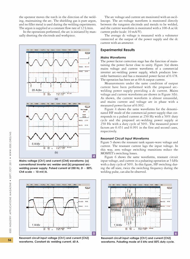
Figure 6 shows the same waveforms, resonant circuitinput voltage, and current in a pulsating operation at 5 kHzwith a duty cycle of 50%. In this figure, HF switching dur-ing the off state, twice the switching frequency during thewelding pulse, can also be observed.
(a)
(b)
20 A/div
5 A/div
4Mains voltage (Ch1) and current (Ch4) waveforms: (a)conventional inverter arc welder and (b) proposed arc-welding power supply. Pulsed current at 250 Hz, D ¼ 50%.Ch4 scale 3 10 mV/A.
1 A/div
5Resonant circuit input voltage (Ch1) and current (Ch2)waveforms. Constant dc welding current, 60 A.
1 A/div
6Resonant circuit input voltage (Ch1) and current (Ch2)waveforms. Pulsating mode at 5 kHz and 50% duty cycle.
56
IEEE
INDUSTR
YAPPLICATIONS
MAGAZIN
E�
SEPTjO
CT
2011�
WW
W.IEEE.O
RG/IAS

Arc WaveformsThe arc voltage (top) and current (bottom) waveformswith a duty cycle of 50% for TIG welding are shown inFigure 7. The corresponding pulsed power supplyfrequency is (a) 20 Hz, (b) 60 Hz, (c) 120 Hz, (d) 250 Hz,(e) 1 kHz, and (f) 5 kHz.
TIG Welding ResultsWelding tests have been carried out to characterize theoperation of the proposed power supply. Figure 8 showsthe resulting weld lengths in millimeters during 45 s fordifferent frequency and duty cycle settings. For this thick-ness (3 mm), the arc stability at low frequencies (20, 120,
and 250 Hz) with D¼ 25% is not good enough to achievea stable welding. This behavior can be explained by the factthat the arc extinguishes each cycle; thus, arc initiation isnecessary in each cycle. There are not enough remainingelectrons to flow when the voltage rises above the thresholdvalue. This situation does not occur when the duration ofthe off state is shorter or with higher pulse frequencies.
For the power supply settings shown in Figure 8, thequality of the resulting welding beads fulfills the weldingrequirements.
Figure 9 shows photographs of a selection of the weldscarried out. Figure 9(a) shows a weld performed with theconstant dc current operation mode (59 A), and Figure 9(b)
7
(c)
(e)
(a)
(d)
(f)
(b)
10 ms/div 4 ms/div
2 ms/div 1 ms/div
200 µs/div 40 µs/div
Arc voltage (Ch1) and current (Ch4) waveforms for TIG welding: (a) f ¼ 20 Hz, (b) f ¼ 60 Hz, (c) f ¼ 120 Hz, (d) f ¼ 250 Hz,(e) f ¼ 1 kHz, and (f) f ¼ 5 kHz. D ¼ 50%. Ch4 scale x 10 mV/A.
57
IEEE
INDUSTR
YAPPLIC
ATIO
NS
MAGAZIN
E�
SEPTjO
CT
2011�
WW
W.IE
EE.O
RG/IA
S

shows a weld bead performed at 5 kHz with a 50%duty cycle.
Tests with 1-mm-thick AISI 316 stainless steel plateshave been carried out to verify the behavior of the power sup-ply for different frequency and duty cycle settings, includinglow frequencies (20, 120, and 250 Hz) with D ¼ 25%. Asexpected, the tests show that for this thickness, the resultingweld length is longer than that in the 3-mm-thick plates,and the arc stability and quality of the welding beads at lowfrequencies andD¼ 25% fulfill the welding requirements.
ConclusionsA new dc and pulsed dc TIG welding power supply hasbeen designed. Power modules connected in parallel withinterleaving operation achieve scalable output current withno reduction of the single module performance and limit-ing the output current ripple. The resonant converter issupplied by an active rectifier from the ac mains with areduction of mains current peak by five times.
AcknowledgmentThis work is sponsored by the Spanish Government in theframework of the project CICYT TEC2008-01753 titled“Digital Power Processing for the Control of GaseousDischarges.”
References[1] Y. Liu, G. E. Cook, R. J. Barnett, and J. Springfield, “PC-based arc
ignition and arc length control system for gas tungsten arc welding,”IEEE Trans. Ind. Applicat., vol. 28, no. 5, pp. 1160–1165, 1992.
[2] H. Edels, “A technique for arc initiation,” Br. J. Appl. Phys., vol. 2,no. 6, pp. 171–174, 1951.
[3] A. K. Paul, “Optimizing the transition process from sparking fornon-contact TIG welding inverters,” in Proc. IEEE Int. Conf. IndustrialTechnology (ICIT), 2006, pp. 1413–418.
[4] M. Thamodharan, H. P. Beck, and A. Wolf, “Steady and pulsed directcurrent welding with a single converter,” Welding J., vol. 78, no. 3,pp. 75.s–79.s, Mar. 1999.
[5] Y. K. Lo and J. M. Wang, “Current-regulated inverters with an out-put coupled inductor for AC arc welding machines,” IET Power Elec-tron., vol. 1, no. 4, pp. 445–454, 2008.
[6] S. J. Jeon and G. H. Cho, “Zero-voltage and zero-current switchingfull bridge DC-DC converter for arc welding machines,” Electron.Lett., vol. 35, no. 13, pp. 1043–1044, June 1999.
[7] J. Borka and M. Horvath, “A new, simple, low-cost, modular arrange-ment of high power factor for both DC and AC welding,” in Proc.EEE ISIE, July 1999, pp. 757–761.
[8] J.-M. Wang, T.-P. Lee, and Y.-K. Lo, “Energy-retaining snubbers foran AC arc welding machine,” in Proc. Int. Aegean Conf. ElectricalMachines and Power Electronics (ACEMP 2007), Sept. 2004, pp. 52–54.
[9] Y.-M. Chae, J.-S. Gho, G.-H. Choe, W.-S. Shin, and J.-Y. Choi,“PWM converter-inverter arc welding machine using new typeN.C.T,” in Proc. IEEE PESC, May 1998, pp. 1636–1641.
[10] L. Zhao, X. Bai-Lu, W. Shu-Hui, D. Shan-Xu, and K. Yong, “Thesliding mode control for arc welding inverter power source,” in Proc.IEEE ICIEA, June 2008, pp. 1100–1104.
[11] P. Verdelho, M. Pıo Silva, E. Margado, and J. Esteves, “An electronicwelder control circuit,” in Proc. IEEE IECON, Sept. 1998, pp. 612–617.
[12] T.-J. Kim, G.-H. Rim, and C.-U. Kim, “Development of a powersupply for the pulse MIG arc welding with the changes of outputcurrent polarity,” in Proc. IEEE IECON, Nov. 2004, pp. 953–956.
[13] K. Sloan and J. Lucas, “Microprocessor control of TIG welding sys-tem,” Proc. Inst. Elect. Eng., vol. 129 pt. E, no. 1, pp. 1–8, Jan. 1982.
[14] J. A. Ferreira and J. A. Roux, “A series resonant converter for arc-striking applications,” IEEE Trans. Ind. Electron., vol. 45, no. 4,pp. 585–592, Aug. 1998.
[15] H. Pollock and J. O. Flower, “Series-parallel load-resonant converterfor controlled-current arc welding power supply,” Proc. Inst. Elect.Eng.—Electr. Power Appl., vol. 143, no. 3, pp. 211–218, May 1996.
[16] L. Malesani, P. Mattavelli, L. Rossetto, P. Tenti, W. Marin, and A. Poll-mann, “Electronic welder with high-frequency resonant inverter,” IEEETrans. Ind. Applicat., vol. 31, no. 2, pp. 273–279, Mar./Apr. 1995.
[17] T.-F. Wu, H.-P. Yang, and C.-M. Pan, “Analysis and design ofvariable frequency and phase-shift controlled series resonant converterapplied for electric arc welding machines,” in Proc. IEEE IECON,Nov. 1995, pp. 656–661.
[18] Arc Welding Equipment. Welding Power Sources, IEC 60974-1, 2005.[19] D. Czarkowski and M. K. Kazimierczuk, “Phase-controlled series-par-
allel resonant converter,” IEEE Trans. Power Electron., vol. 8, no. 3,pp. 309–319, July 1993.
[20] C. Branas, F. J. Azcondo, R. Casanueva, and S. Bracho, “Multi-phaseparallel resonant inverter applied to HID lamp control,” in Proc. 26thInt. Exhibition and Conf. Power Electronics, Intelligent Motion, Power Qual-ity PCIM Europe, 2005, pp. 187–192.
Rosario Casanueva ([email protected]), Francisco J. Azcondo,Francisco J. Dıaz, and Christian Branas are with the Univer-sity of Cantabria, Spain. Casanueva, Dıaz, and Branas areMembers of the IEEE. Azcondo is a Senior Member of the IEEE.This article first appeared as “DC and Pulsed DC TIG Weld-ing Experiences with a Scalable Power Supply” at the IEEE2009 Industry Applications Society Annual Meeting.
(a)
(b)
9Photographs of weld bead in the butt joint welding: (a) dcconstant welding current and (b) pulsed current at 5 kHz,D ¼ 50%.
Wel
d Le
ngth
(m
m)
120
100
80
60
40
20
0
dc
20 H
z, 7
5%
20 H
z, 5
0%
120
Hz,
75%
120
Hz,
50%
250
Hz,
75%
250
Hz,
50%
1 kH
z, 7
5%
1 kH
z, 5
0%
1 kH
z, 2
5%
5 kH
z, 7
5%
5 kH
z, 5
0%
5 kH
z, 2
5%
8Weld lengths (mm) for different power supply settings.
58
IEEE
INDUSTR
YAPPLICATIONS
MAGAZIN
E�
SEPTjO
CT
2011�
WW
W.IEEE.O
RG/IAS