Tier III Compliance Low Speed Engines
31
7/27/2019 Tier III Compliance Low Speed Engines http://slidepdf.com/reader/full/tier-iii-compliance-low-speed-engines 1/31 Tier III Compliance Low Speed Engines
Transcript of Tier III Compliance Low Speed Engines

7/27/2019 Tier III Compliance Low Speed Engines
http://slidepdf.com/reader/full/tier-iii-compliance-low-speed-engines 1/31
Tier III ComplianceLow Speed Engines

7/27/2019 Tier III Compliance Low Speed Engines
http://slidepdf.com/reader/full/tier-iii-compliance-low-speed-engines 2/31

7/27/2019 Tier III Compliance Low Speed Engines
http://slidepdf.com/reader/full/tier-iii-compliance-low-speed-engines 3/31
Contents
Introduction .................................................................................................3
NOx Compliance with EGR ...........................................................................3
Investigation of EGR NOx Reduction Potential ..........................................3
EGR Principle .........................................................................................4
EGR Experimental Test ........................................................................... 4
EGR Test Results ....................................................................................4
Parameter Variation Tests ........................................................................5
Heat Release With EGR ..........................................................................6
Combined EGR and WIF Test ..................................................................6
Cylinder Condition Running with EGR ......................................................8
EGR Service Test on Cont. Vessel ...........................................................8
Service Test Objective .............................................................................9
Design of a Retrofit EGR System .............................................................9
Fully Automated EGR System ............................................................... 11
Installation of EGR ................................................................................ 12
EGR in Service......................................................................................13
Results of EGR in Service ..................................................................... 13
EGR in the Future ................................................................................. 14
NOx Compliance with SCR .........................................................................15
SCR Technology ...................................................................................15
Objective ..............................................................................................15Content of the Development Work.........................................................16
Outcome of the Project .........................................................................17
Test Faci lities and Time Schedule ...... ...... ...... ...... ...... ...... ....... ...... ...... ... 18
Fulfilling IMO Sulphur Requirements in Fuel and/or SO2 in Exhaust Gas .. 18
SOx Compliance with Wet Scrubber ...........................................................19
Wet Scrubber Implementation on MAN B&W Engines ............................19
Full Scale Installation on DFDS Vessel Tor Ficaria ...................................20
Sea Water Scrubbing ............................................................................21
Fresh Water Scrubbing .........................................................................21
Results of Scrubber in Service ..............................................................22
Low Sulphur Fuel Operation .......................................................................23
Engine Challenges and Recommended Solutions ..................................23
Distillate Tests .......................................................................................24
Further Tests.........................................................................................25
Conclusion .................................................................................................26

7/27/2019 Tier III Compliance Low Speed Engines
http://slidepdf.com/reader/full/tier-iii-compliance-low-speed-engines 4/31
7/27/2019 Tier III Compliance Low Speed Engines
http://slidepdf.com/reader/full/tier-iii-compliance-low-speed-engines 5/31
MAN B&W Diesel
3 Tier III Compliance – Low Speed Engines
Tier III Compliance – Low Speed Engines
Introduction
Even though IMO Tier II regulations
have not yet come into force (keel laying
after 1 January 2011), clear develop-
ment and research targets for fulfilling
IMO Tier III (valid from 1 January 2016 in
ECA areas) must already now be fixed
and initiated.
A flexible and agile two-way strategy
on NOx emission reduction has been
chosen for our MAN B&W two-stroke
engines. MAN B&W two-stroke engines
will in due time, before 2016, have full
design specifications for engines oper-
ating with EGR (Exhaust Gas Recircula-
tion) and with SCR (Selective Catalyst
Reduction) available for a complete en-
gine programme.
This paper describes MAN Diesel & Tur-bo’s progress in the development of the
EGR system and shows performance
and emission results from both testbed
testing of EGR systems, details on ret-
rofitting of EGR system on a 7S50MC
engine on the container vessel Alexan-
der Maersk and the first service results
from the service testing. The paper also
outlines results from EGR/WIF (Water In
Fuel) combination tests and underlines
the advantages of utilising the flexibility
of electronically controlled engines and
turbochargers in combination with EGR
and WIF systems. Also the potential for
utilising both EGR and/or WIF for ob-
taining Tier II compliance with improved
engine efficiency is explained.
Furthermore, this paper describes our
efforts in connection with making a de-
tailed specification of SCR applicationon the high pressure side of the turbo-
chargers for two-stroke engines.
As for NOx emission, MAN Diesel &
Turbo has chosen a flexible and agile
two-way approach for MAN B&W two-
stroke engines with regard to fulfilling
future SOx emission legisation. This pa-
per outlines the efforts for improving the
capability of our engines for low sulphur
fuel operation and describes the results
from both testbed and service testing
of wet scrubbers for SOx
and PM (Par-
ticulate Matter) reduction. The descrip-
tion includes comments to water treat-
ment methods for both closed loop (FW
(Fresh Water)) and open loop operation
(SW (Sea Water)), energy consumption
of scrubber system and consumption
of neutralising agents.
NOx Compliance with EGR
Investigation of EGR NOx Reduction
Potential The potential of using Exhaust Gas Re-
circulation (EGR) for NOx reduction on
HFO burning large two-stroke marine
diesel engines has been investigated
by MAN Diesel & Turbo for the last 10
years.
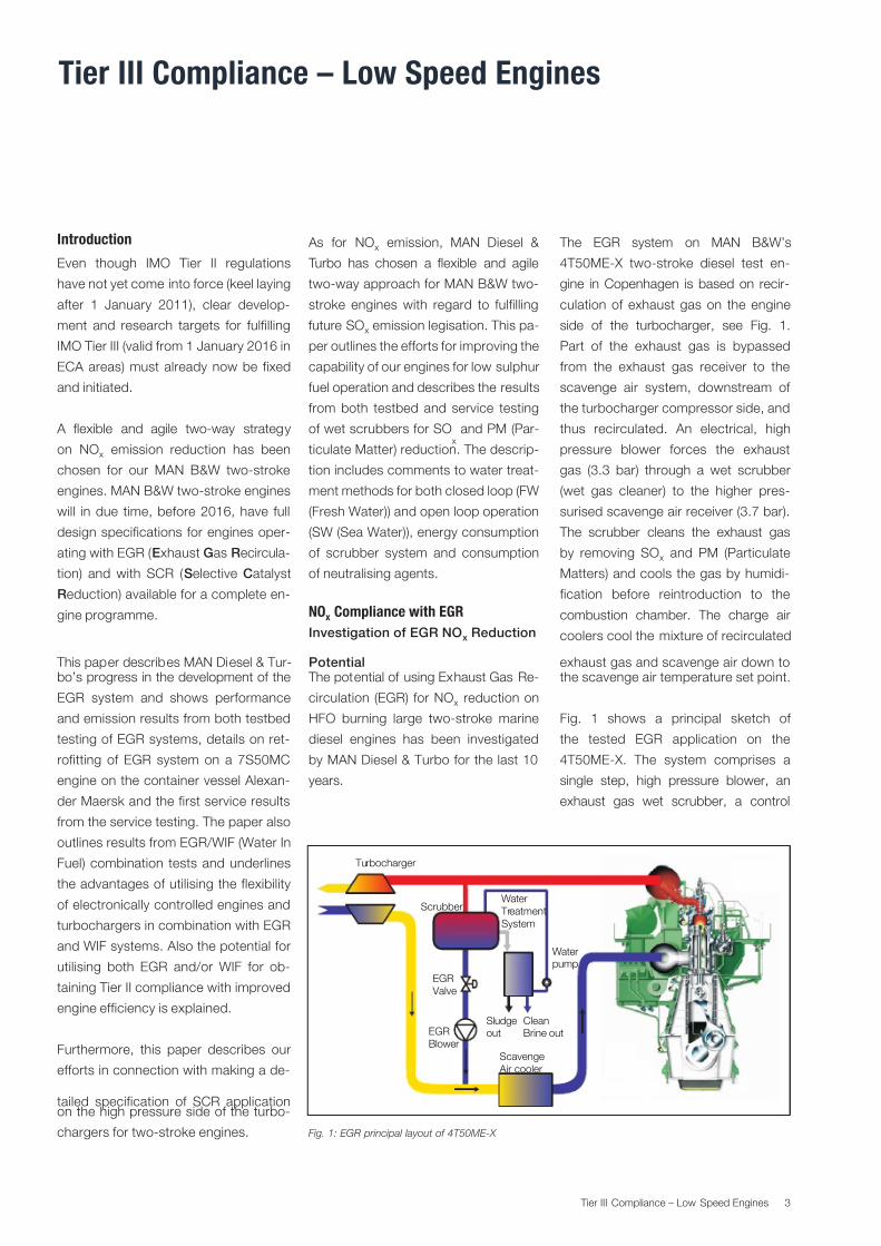
The EGR system on MAN B&W’s
4T50ME-X two-stroke diesel test en-
gine in Copenhagen is based on recir-
culation of exhaust gas on the engine
side of the turbocharger, see Fig. 1.
Part of the exhaust gas is bypassed
from the exhaust gas receiver to the
scavenge air system, downstream of
the turbocharger compressor side, and
thus recirculated. An electrical, high
pressure blower forces the exhaust
gas (3.3 bar) through a wet scrubber
(wet gas cleaner) to the higher pres-
surised scavenge air receiver (3.7 bar).
The scrubber cleans the exhaust gas
by removing SOx and PM (Particulate
Matters) and cools the gas by humidi-
fication before reintroduction to the
combustion chamber. The charge air
coolers cool the mixture of recirculated
exhaust gas and scavenge air down tothe scavenge air temperature set point.
Fig. 1 shows a principal sketch of
the tested EGR application on the
4T50ME-X. The system comprises a
single step, high pressure blower, an
exhaust gas wet scrubber, a control
Water
pump
Turbocharger
Scrubber
Clean
Brine out
Scavenge
Air cooler
Water
Treatment
System
Sludge
outEGR
Blower
EGR
Valve
Fig. 1: EGR principal layout of 4T50ME-X

7/27/2019 Tier III Compliance Low Speed Engines
http://slidepdf.com/reader/full/tier-iii-compliance-low-speed-engines 6/31
4 Tier III Compliance – Low Speed Engines
valve, a water treatment system and a
PLC-based control unit for controlling
the water treatment system. A NaOH
dosing system neutralises the scrubber
water keeping the sulphur removal in
the scrubber at a certain level accord-
ing to the decided sulphur removal ef-
ficiency.
EGR Principle
The basic concept of the technology is
that the higher heat capacity and the
lower oxygen content of the recircu-
lated exhaust gas lower the peak com-
bustion temperature in the combustion
chamber significantly, which suppress-
es the formation of thermal NOx.
EGR Experimental Test
In May 2009, the EGR was tested to
full extent on the MAN B&W 4T50ME- X 7MW test engine in Copenhagen
in the so-called Extreme EGR test
programme. In the Extreme test pro-
gramme, a combination of an EGR and
WIF (Water In Fuel) emulsion test was
included in order to disclose the syn-
ergy effects between these two NOx
reducing measures.
Around 50 different tests running with
EGR alone and with a combination of
EGR and WIF were carried out on the
4T50ME-X test engine, using either
MDO or HFO for targeting the following
objectives:
Investigate the “maximum” NOx re-
duction with EGR
Determine the performance condi-
tions when Tier II and III NOx cycle
values are obtained by using EGR Parameter variation for investigation
of optimal SFOC and CO emission
values when using EGR
Investigate low load performance
with EGR.
The main focus point has been to find
the necessary EGR rates for fulfilling the
Tier III emission legislat ion and at the
same time securing minimum effect on
the combustion efficiency, and thereby
the minimum SFOC penalty. Further-
more, the test also concentrated on se-
curing minimum penalty on other emis-
sion parameters as CO (highly related
to SFOC), HC and particulate matter.
The EGR tests were also performed at
NOx Tier II level in order to investigate
the potential in SFOC benefits com-
pared to a non-EGR Tier II engine.
EGR Test Results
The achieved NOx cycle value with EGR
confirmed that the IMO Tier III level (3.4
g/kWh) was obtainable with EGR as the
only remedy to reduce NOx, even with
the engine in a normal Tier I configura-
tion as reference.
The tests also confirmed that signifi-
cantly improved SFOC can be obtained
at the Tier II emission level with an en-
gine using EGR, rather than with an en-
gine using normal Tier II tuning meas-
ures, especially at part load.
Fig. 3 summarises the results from the
EGR test, with the EGR rate given by
the oxygen content in the scavenge
air and, as it can be seen, Tier III level
emissions of 3.4 g/kWh as cycle value
and 5.1 g/kWh at NTE (Not To Exceed)
limit at all load points are obtained at
scavenge air oxygen contents of 15.5to 18%.
Fig. 2: EGR system on 4T50ME-X

7/27/2019 Tier III Compliance Low Speed Engines
http://slidepdf.com/reader/full/tier-iii-compliance-low-speed-engines 7/31
MAN B&W Diesel
5 Tier III Compliance – Low Speed Engines
Parameter Variation Tests
The main results from the parameter
variation test can be seen in Table 1. The variation was performed with con-
stant wet O2 concentration in the scav-
enge air, except for the max. EGR test
(visual smoke limit) and for the Tier III
setup case were the chosen O2 con-
16.8% oxygen in scavenge air), with
only a minimum influence on the NOx
emission. Combining these measuresand increasing the EGR rate secures
compliance with the NOx Tier III level
with a minimum penalty on the SFOC
and CO emission.
0
4
8
12
16
20
24
14 15 16 17 18 19 20 21 22
S p e c i fi c N O
x ( g
/ k W h )
Oxygen conc. in Scav.Rec (wet, vol %)
100% load
75% load
50% load
25% load
NTE NOx
IMO Tier III cycle value
Fig. 3: NO x emission as a function of oxygen content in the scavenge air
Test results from parameter variation test at 75% load
NOx
[g/kWh]
dSFOC
[g/kWh]
CO
[g/kWh]
Pmax
[barabs]
EGR rate
[%]
O2 Scav.air
[vol. %]
No EGR 17.8 0 0.65 152 0 -
Max. EGR 2.3 +4.9 4.17 151 39 16.0
EGR ref 3.7 +3.0 2.57 151 36 16.8
Incr. pcomp /pscav 4.0 +2.5 2.18 156 36 16.8
Incr. Phyd 4.2 +2.8 1.83 151 37 16.6
Incr. pscav 3.6 +1.9 2.12 156 37 16.6
Incr. Tscav 3.9 +3,6 2.82 156 34 16.8
Tier III setup 3.4 +0.6 1.34 157 41 16.2
Table 1
centration was targeting the Tier III NOx
level.
As Table 1 clearly indicates, increased
pcomp/pscav, increased pscav and in-
creased injection pressure (Incr. Phyd)
have a positive influence on the SFOC
at a relatively high EGR rate (16.6-

7/27/2019 Tier III Compliance Low Speed Engines
http://slidepdf.com/reader/full/tier-iii-compliance-low-speed-engines 8/31
6 Tier III Compliance – Low Speed Engines
Heat Release With EGR
Applying EGR generally means a reduc-
tion in the maximum combustion rate
due to local lack of oxygen. At the same
time, the burn duration is generally in-
creased, see Fig. 4, giving a typical ex-
ample from the literature on the EGR
influence on a high speed diesel en-
gine (heavy truck engine). The reduced
maximum combustion rate and the in-
creased burning time result in increased
SFOC, increased formation of particu-
late matter and high CO formation.
Combined EGR and WIF Test
The test results at 75% load from com-
bined WIF and EGR tests are summa-
rised in Table 2. The water content in
the fuel is shown as added water to the
fuel volume. As can be seen from the
figures using WIF in combination with
EGR is a very effective way of reducing
CO emissions in agreement with small
engine results. At the highest applied
water content using EGR (WIF 50% and
EGR 37%), the CO emission is reduced
by a factor of almost 5 compared to
0.00
-5 0 5 10 15 20 25 30 35 40 45 50 55 50 65 70
0.01
0.02 H H R ( 1 / d
e g )
0.03
0.04
0.05
0.061600 bar, SOI = 3, no EGR
1600 bar, SOI = EGR = 20%
0.00
-5 0 5 10 15 20 25 30 35 40 45 50 55 50 65 70
0.10
0.20
( - )
Crank angle
0.300.40
0.50
0.60
0.70
0.80
0.96
1.00
Fig. 4: Influence of EGR on heat release and cumulative heat release of a Heavy
Duty DI-Diesel Engine equipped with a Common Rail Injection System running
at 1,460 rpm, MEP=18.7 bar (100% load) taken from SAE 2001-01-3497
0.00
0 5 10 15 20 25 30 35 40 45 50 55 50 65 70
0.01
0.02 H H R ( 1 / d
e g )
0.03
0.04
0.05
0.06
0.07 Phyd = 200 bar, EGR = 0%
Phyd = 200 bar, EGR = 29%
0 5 10 15 20 25 30 35 40 45 50
( - )
Crank angle
0.10
0.20
0.300.40
0.50
0.60
0.70
0.80
0.96
1.00
Fig. 5: Heat release and cumultative heat release on 4T50ME-X with
(29%) and without EGR
On the slow running 4T50ME-X engine,
the same measurements were made as
given above for the typical high speed
engine, and the result is shown in Fig.
5. The influence of 29% EGR is nearly
not noticeable, the negative effect on
SFOC, CO and PM is accordingly also
much less (nearly zero) than for the high
speed four-stroke engine.
The slight negative effect on heat relase
is fully compensated by increasing in-
jection pressures as shown in Fig. 6.

7/27/2019 Tier III Compliance Low Speed Engines
http://slidepdf.com/reader/full/tier-iii-compliance-low-speed-engines 9/31
MAN B&W Diesel
7 Tier III Compliance – Low Speed Engines
the tests using only EGR and the CO
emission is even lower than the refer-
ence case (0% WIF 0% EGR). Even with
more moderate amounts of water (WIF
28% and EGR 37%), the CO emissionis equal to that of the reference case.
Thus, indeed it is possible to combine
WIF and EGR in order to reduce their
individual drawbacks. The drawback of
WIF on SFOC is, however, significant
and a further optimisation of the injec-
tion system for the WIF systems must
be performed in order to obtain accept-
able SFOC penalties.
Fig. 6: Heat release rate and cumulative heat release at 75% load with and without EGR
0.000 5 10 15 20 25 30 35 40 45 50 55 50 65 70
0.01
0.02 H H R ( 1 / d e g )
Crank angle
0.03
0.04
0.05
0.06
0.07Phyd = 200 bar, EGR = 0%
Phyd = 200 bar, EGR = 29%
Phyd = 275 bar, EGR = 40%
0 5 10 15 20 25 30 35 40 45 50
( - )
Crank angle
0.10
0.20
0.30
0.40
0.50
0.60
0.70
0.80
0.96
1.00
Test results, EGR and WIF combinations at 75% engine load
Ref. EGR
Tier III
EGR
Tier II
50% WIF
(added)
50% WIF
(added) + EGR
28% WIF
(added)
28% WIF
(added) + EGR
EGR rate % 0 37 18 0 37 0 37
WIF % 0 0 0 50 50 28 28
NOx g/kWh 17.4 3.4 12.3 10.4 1.3 13.5 2.0
CO g/kWh 0.7 1.4 0.4 0.24 0.30 0.25 0.67SFOC % 0 0.3 -2.6 2.4 3.9 0.4 2.5
Table 2
In general, the EGR testing confirms
that CO emissions increase and un-
burnt hydrocarbon emissions decrease
with increasing EGR ratios. For WIF, the
opposite is experienced, i.e. increasedemissions of hydrocarbons, but signifi-
cantly reduced CO emissions.
While EGR has the potential to reduce
the NOx emissions below the Tier III
limit, it seems to be out of reach for
WIF alone, since too high water con-
tents are required and simply because
the SFOC penalty will become too high.
By combining the two methods, ex-
tremely low NOx emissions (down to
0.2 g/kWh) have been realised while the
emissions of CO and unburned hydro-
carbons remained at the low levels usu-ally observed from large two-stroke die-
sel engines. The NOx reduction achieved
during these tests is well above 90%, in
some cases above 98%, and accord-
ingly a competitor to the SCR system
with regard to making the “zero emis-
sion” two-stroke diesel engine.

7/27/2019 Tier III Compliance Low Speed Engines
http://slidepdf.com/reader/full/tier-iii-compliance-low-speed-engines 10/31
8 Tier III Compliance – Low Speed Engines
Cylinder Condition Running with EGR
Running with EGR on two-stroke die-
sel engines burning HFO, changes the
chemical composition of the scavenge
air entering the combustion chamber.
The O2 content is decreased, the CO2
and CO (running without WIF) content
is increased, the SOx (SO2 and SO3 )
content is increased, to some extent
depending on the scrubbing efficiency,
the HC amount is increased, the PM
mass is increased and the H2O con-
tent is increased. Of all these species
the SOx (in the form of sulphuric acid)
and the H2O are considered potential to
have the most important impact on the
cylinder condition if present in the form
of free droplets.
The presence of water droplets enter-
ing the combustion chamber must bereduced to a minimum by securing opti-
mal efficiency of the water mist catcher
system, and the presence of SOx must
be controlled by addition of NaOH to
the scrubber water.
The cyl inder condition was investigated
before and after completion of more
than 100 hours of extreme EGR test-
ing, and the conclusion was that there
were no negative effects to see when
inspecting the liner, piston and piston
rings, see Fig. 7.
EGR Service Test on Cont. Vessel
From August 2008 until March 2010,
MAN Diesel & Turbo has developed and
manufactured the very first Exhaust Gas
Recirculation (EGR) system for a two-
stroke diesel engine and installed it on
a container vessel in service.
In partnership with A. P. Moller-Maersk,
the EGR prototype system has been
Fig. 7: Cylinder condition before and after >100 hours’ testing
Fig. 8: A. P. Moller-Maersk container vessel Alexander Maersk
installed on the vessel Alexander Mae-
rsk. The vessel was built in 1998, and
is a 1,092 TEU container vessel cur-rently sailing between Southern Europe
and Northern Africa. The main engine
is a Hitachi B&W 7S50MC Mk 6, with
a Specified Maximum Continuous rat-
ing of 10,126 kW at 127 rpm, originally
equipped with two turbochargers. In or-der to optimise engine performance for
the prototype EGR test, modifications in
the engine room are carried out to the
Before - cylinder 1
Before - cylinder 4
After - cyl inder 1
After - cyl inder 1

7/27/2019 Tier III Compliance Low Speed Engines
http://slidepdf.com/reader/full/tier-iii-compliance-low-speed-engines 11/31
MAN B&W Diesel
9 Tier III Compliance – Low Speed Engines
existing main engine scavenge air cool-
ers, and the turbochargers:
The two existing turbochargers are
replaced with one high effiency tur-
bocharger with variable turbine areas
A new charge air inlet pipe
The exist ing exhaust gas receiver tur-
bocharger outlet pipes are blanked
off, and a new exhaust outlet pipe is
installed
The existing turbocharger exhaust
outlet pipe is modified to fit the new
turbocharger
Strengthening of the existing turbo-
charger foundation.
The EGR system is designed for mini-
mum 20% recirculation of the exhaust
gas corresponding to minimum 50%
reduction of emitted NOx compared to
the basis emission level.
Service Test Objective
The main objective of the service test is
to investigate the engine impact of run-
ning with EGR, i.e. cylinder condition,
exhaust system condition and EGR
system condition. Besides perform-
ance, settings and controlling software
need to be tested “in situ” in order to
tune the controlling system to the best
possible performance.
Design of a Retrofit EGR System
The first retrofit EGR system is specifi-
cally designed for installation on Alex-
ander Maersk, using know-how ob-
tained during years of testing on the
4T50ME-X test engine in Copenhagen.
The fi rst stage was to establish the en-
gine performance on Alexander Mae-
rsk, followed by a simulation of the EGR
process. The next stage was to specify
the EGR components.
The main EGR components are: scrub-
ber, cooler, water mist catcher, blower,
shut-down valve, change-over valve,
water treatment plant, NaOH dosing
Shut down valveScrubber
Prescrubber
Blower
SeaWMC
FW
Cooler
Sludge
tank
Water
cleaning
P o l i s h i n g
Scrubber pump
NaOH
tank
NaOH
pump
Buffer
tank
Change over valve
Discharge
control
valve
On/off
valve
Stop
valve
Exhaust outlet
Mix
Cooler
WMC
Fig. 9: EGR system layout on Alexander Maersk
7/27/2019 Tier III Compliance Low Speed Engines
http://slidepdf.com/reader/full/tier-iii-compliance-low-speed-engines 12/31
10 Tier III Compliance – Low Speed Engines
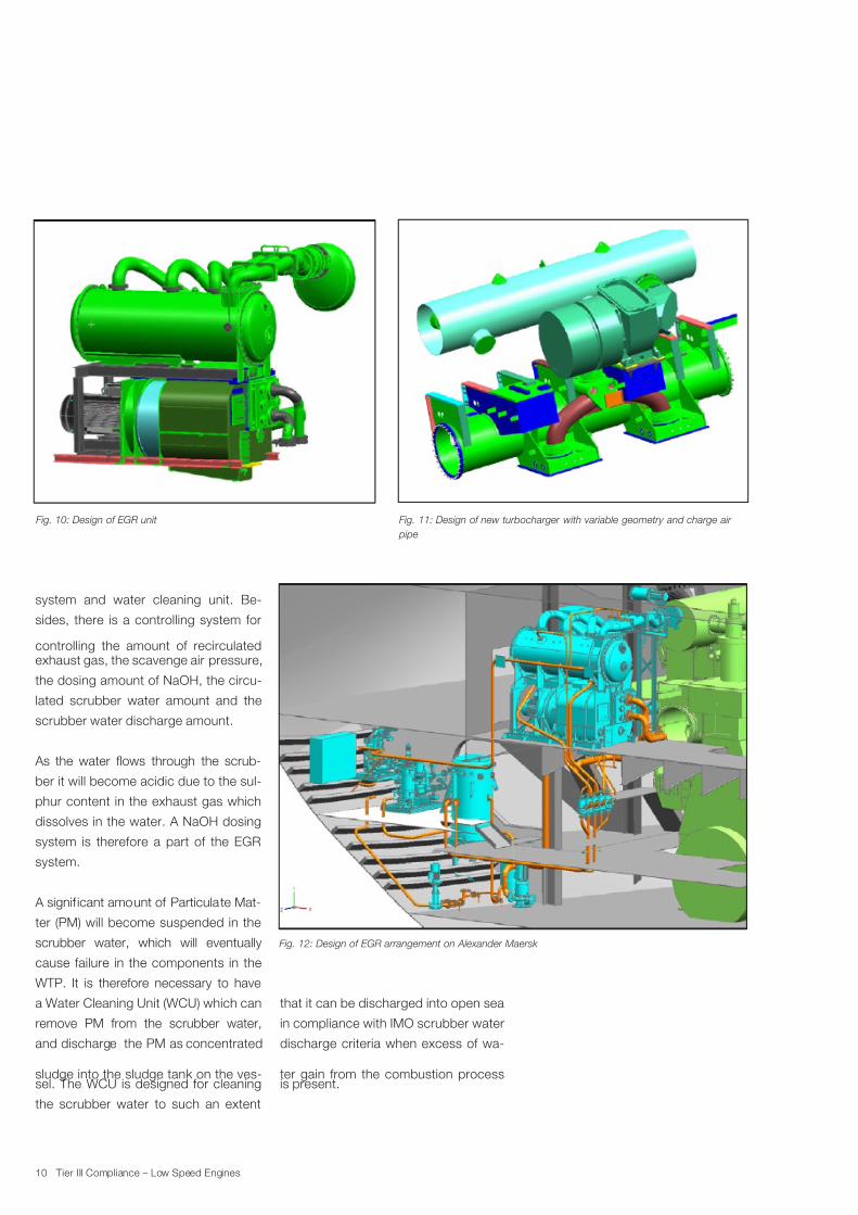
system and water cleaning unit. Be-
sides, there is a controlling system for
controlling the amount of recirculatedexhaust gas, the scavenge air pressure,
the dosing amount of NaOH, the circu-
lated scrubber water amount and the
scrubber water discharge amount.
As the water flows through the scrub-
ber it will become acidic due to the sul-
phur content in the exhaust gas which
dissolves in the water. A NaOH dosing
system is therefore a part of the EGR
system.
A signif icant amount of Particulate Mat-
ter (PM) will become suspended in the
scrubber water, which will eventually
cause failure in the components in the
WTP. It is therefore necessary to have
a Water Cleaning Unit (WCU) which can
remove PM from the scrubber water,
and discharge the PM as concentrated
sludge into the sludge tank on the ves-sel. The WCU is designed for cleaning
the scrubber water to such an extent
Fig. 10: Design of EGR unit Fig. 11: Design of new turbocharger with variable geometry and charge air
pipe
Fig. 12: Design of EGR arrangement on Alexander Maersk
that it can be discharged into open sea
in compliance with IMO scrubber water
discharge criteria when excess of wa-
ter gain from the combustion processis present.

7/27/2019 Tier III Compliance Low Speed Engines
http://slidepdf.com/reader/full/tier-iii-compliance-low-speed-engines 13/31
MAN B&W Diesel
11 Tier III Compliance – Low Speed Engines
Fully Automated EGR System
In order to make the EGR system easy
to operate for the ship crew and to en-
sure correct and fast reactions to engine
load variations, a fully automated EGR
control system has been developed.
A standard MAN Diesel & Turbo MPC
controller is used as the main controller,
and as a secondary system, a Siemens
PLC is used for controlling the water
system.
The EGR Control Unit controls:
The EGR ratio (the ratio between re-
circulated exhaust gas and the scav-
enge air). The EGR ratio is measured
by the O2 concentration in the scav-
enge air and is controlled by adjust-
ing the blower speed and the position
of the change-over valve.
The scavenge air pressure (pscav).
The scavenge air pressure is adjust-
ed to a specified value as a function
of load and EGR rate. The scavenge
air pressure is controlled by adjusting
the variable nozzle ring on the turbine
inlet with the MC-SCU controlling
unit.
Fig. 13: Scrubber WCU (Water Cleaning Unit) from Bollfilter
WTP (HMI) MOP (HMI)
WTP CS
Water treatment
Plant
EGRCU
C O
V
a l v e
S D V a l v e
B l ow e r
V T
P s c a v m e a s
R P M ,I n d e x
O2 m e a s
SCU
Engine
Engine control room Engine room
EGR control system
EGR System
The WTP PLC controls the following:
EGR cooler water flow
scrubber water flow scrubber water discharge amount
pH value of the scrubber water
water cleaning unit.
Fig. 14: EGR SW architecture Fig. 15: EGR user interface on the Main Operating Panel
The timing of start-up and shut-
down of the WTP (Water Treatment
Plant) is controlled through a genericinterface.
A separate control system for the WTP
has also been developed by MAN Die-
sel & Turbo, based on a standard PLC
controller.

7/27/2019 Tier III Compliance Low Speed Engines
http://slidepdf.com/reader/full/tier-iii-compliance-low-speed-engines 14/31
12 Tier III Compliance – Low Speed Engines
Installation of EGR
In July 2009, Alexander Maersk docked
at Lisnave shipyard for 30 days, during
which all the large EGR components
were installed and the majority of the
installation work completed.
The EGR unit is installed on the mid-
dle platform, adjacent to the exhaust
receiver on the main engine. A hole is
cut in the exhaust receiver and a gas
pipe mounted inside to divert the ex-
haust through the EGR system. The
recirculated exhaust is then reintro-
duced to the Main Engine (ME) before
the scavenge air coolers, by means of
a specially designed charge air pipe.
The two original standard efficiency tur-
bochargers are removed and a single
high efficiency turbocharger with vari-
able turbine geometry installed in theirplace, so the new charge air pipe also
distributes the compressed scavenge
air between the two existing charge air
cooler housings. The charge air cooler
elements have also been replaced by
special nano-coating elements to pre-
vent corrosion that may occur due to
the condensation of sulphuric acid,
caused by possible carry-over of SOx.
Fig. 16: EGR unit installed on Alexander Maersk
Fig. 17: Turbocharger with variale geometry Fig. 18: EGR blower at testbed
A significant amount of pipe work for
the WTP has been carried out in or-der to provide feed water for the EGR
scrubber. The largest component of the
WTP is the buffer tank, which ensures a
constant water flow to the EGR scrub-
ber. The scrubber pump is located be-
neath the buffer tank and supplies wa-
ter to both the EGR scrubber and the
EGR pre-scrubber (cooling the exhaust
gas). Dirty scrubber water then drains
from the bottom of the EGR scrubberto the buffer tank through a steam trap
to separate any remaining exhaust gas.
A separate pump circulates dirty wa-
ter in the buffer tank through the Wa-
ter Cleaning Unit, where the water is
cleaned for PM and returned to the
buffer tank. When required the cleaned
7/27/2019 Tier III Compliance Low Speed Engines
http://slidepdf.com/reader/full/tier-iii-compliance-low-speed-engines 15/31
MAN B&W Diesel
13 Tier III Compliance – Low Speed Engines
water can be discharged overboard,
or sent to the vessel’s dirty bilge tank,
by means of a three-way valve. Addi-
tional connections to the vessel include,
a fresh water supply directly into the
buffer tank and seawater for the EGR
cooler.
EGR in Service
Commissioning of the EGR system
on Alexander Maersk was carried
out in March 2010. All gas and water
pipe work is pressure-tested, the sys-
tem functionality has been established
and an initial service test of 500 hrs is
planned to evaluate the performance of
the EGR system. An additional 3,000
hrs in service is then planned for further
evaluation of the EGR. An important
part of the service test is to assess the
effect of EGR on a main engine over aperiod of time with the engine running
on Heavy Fuel Oil (HFO). Therefore,
there will be regular inspections on the
main engine by MAN Diesel & Turbo to
investigate and observe the conditions
of the cylinder impact, if any, of EGR on
the two-stroke marine engine.
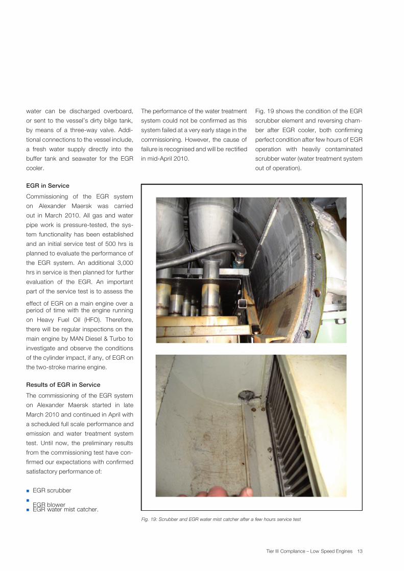
Results of EGR in Service
The commissioning of the EGR system
on Alexander Maersk started in late
March 2010 and continued in April with
a scheduled full scale performance and
emission and water treatment system
test. Until now, the preliminary results
from the commissioning test have con-
firmed our expectations with confirmed
satisfactory performance of:
EGR scrubber
EGR blower EGR water mist catcher.
Fig. 19: Scrubber and EGR water mist catcher after a few hours service test
The performance of the water treatment
system could not be confirmed as this
system failed at a very early stage in the
commissioning. However, the cause of
failure is recognised and will be rectified
in mid-April 2010.
Fig. 19 shows the condition of the EGR
scrubber element and reversing cham-
ber after EGR cooler, both confirming
perfect condition after few hours of EGR
operation with heavily contaminated
scrubber water (water treatment system
out of operation).

7/27/2019 Tier III Compliance Low Speed Engines
http://slidepdf.com/reader/full/tier-iii-compliance-low-speed-engines 16/31
14 Tier III Compliance – Low Speed Engines
EGR in the Future
The EGR test results obtained on the
4T50ME-X test engine show that EGR
is a promising IMO Tier III candidate
for the large two-stroke diesel engines,
especially for electronically controlled
engines equipped with turbochargers
having variable turbine areas, where
suitable control of excess air ratio
(scavenge air pressure and compres-
sion ratio) and injection pressure and
pattern (combustion process) can se-
cure minimum penalty on CO2 (SFOC)
and other emission parameters like CO
and HC (Hydro Carbons). Implementa-
tion of high-ratio EGR on mechanically
controlled engines needs further inves-
tigation if acceptable penalties on other
emission components than NOx have to
be secured.
Investigation of the EGR blower per-
formance and efficiency will be contin-
ued in a cooporation between our tur-
bocharger department and low speed
department. A new EGR blower design
based on the standard TCA/TCR turbo-
charger compressor design with an ef-
ficiency of approx 80% will be tested at
the end of 2010.
Further integraton of the EGR system
into the engine design is a future chal-
lenge which already today is taken into
consideration, as can be seen in Fig.
20.
Fig. 20: Future concept of an EGR Tier III two-stroke diesel engine

7/27/2019 Tier III Compliance Low Speed Engines
http://slidepdf.com/reader/full/tier-iii-compliance-low-speed-engines 17/31
MAN B&W Diesel
15 Tier III Compliance – Low Speed Engines
N O
40% urea solution
CO (NH2 )
2• 5(H
2O)
Exhaust gasNO
2
N2
NH3
H2O
SCR
Reactor
4NO + 4NH3
+ O2
= 4N2
+ 6H20
6NO2
+ 8NH3
= 7N2
+ 12H20
NN
N N
N
N
N N
N
N
N
N
O
O
OO
H
H
H
H
H
H
H
H
H
H
Fig. 21: Principles of the SCR system
NOx Compliance with SCR
SCR Technology
An alternative way of meeting the IMO
Tier III NOx limits is to install a SCR reac-
tor. In the reactor, NOx is reduced cata-
lytically by a suitable reducing agent to
nitrogen and water, see Fig. 21.
Compared to other NOx reducing tech-
nologies, the SCR technology has the
advantage that it is a proven technol-
ogy. SCR reactors have been used in
power plant applications since the late
seventies, and MAN Diesel & Turbo was
involved in one of the first marine appli-
cations in 1989. However, whereas the
technology involves mature and robust
power plant applications, the technol-
ogy still needs to be matured for daily
and continuous marine operation on
HFO. Therefore, MAN Diesel & Turbo isinvolved in a targeted development of
this technology together with a catalyst
manufacturer and engine builder.
Objective
The SCR project was initiated together
with external partners in 2009, and the
purpose of the project is to develop
SCR solutions for the entire MAN Diesel
& Turbo two-stroke engine programme.
This means that SCR solutions will be
available for both MC, ME and ME-B
engines in due time for Tier III. Cur-
rently, it has been decided to target the
development at high-pressure (between
engine and turbocharger) SCR and op-
eration on heavy fuel oils (HFO). This is
illustrated in Fig. 22.
The objective for MAN Diesel & Turbo
Low Speed is to have a specification fora Tier III engine available by the end of
2012. For the catalyst manufacturer, the
Fig. 22: Arrangement of a high-pressure SCR solution
main objective is to obtain a specifica-tion for an SCR reactor, which matches
large two-stroke diesel engines.
7/27/2019 Tier III Compliance Low Speed Engines
http://slidepdf.com/reader/full/tier-iii-compliance-low-speed-engines 18/31
16 Tier III Compliance – Low Speed Engines
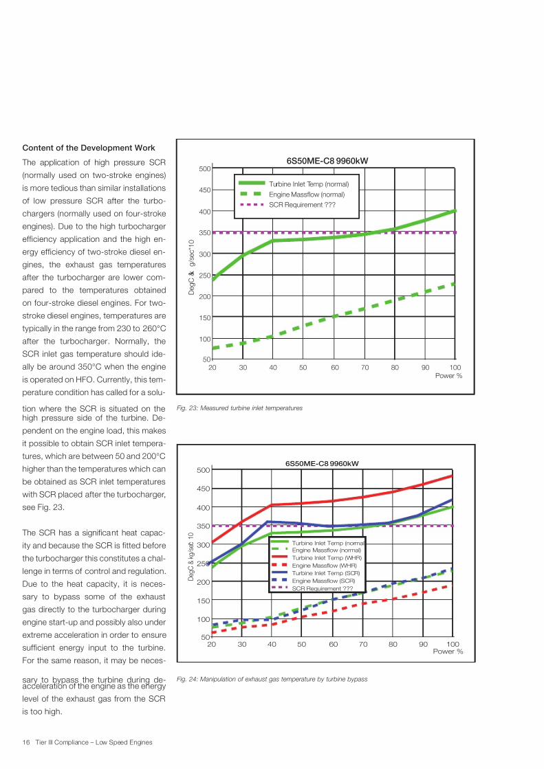
Content of the Development Work
The application of high pressure SCR
(normally used on two-stroke engines)
is more tedious than similar installations
of low pressure SCR after the turbo-
chargers (normally used on four-stroke
engines). Due to the high turbocharger
efficiency application and the high en-
ergy efficiency of two-stroke diesel en-
gines, the exhaust gas temperatures
after the turbocharger are lower com-
pared to the temperatures obtained
on four-stroke diesel engines. For two-
stroke diesel engines, temperatures are
typically in the range from 230 to 260°C
after the turbocharger. Normally, the
SCR inlet gas temperature should ide-
ally be around 350°C when the engine
is operated on HFO. Currently, this tem-
perature condition has called for a solu-
tion where the SCR is situated on thehigh pressure side of the turbine. De-
pendent on the engine load, this makes
it possible to obtain SCR inlet tempera-
tures, which are between 50 and 200°C
higher than the temperatures which can
be obtained as SCR inlet temperatures
with SCR placed after the turbocharger,
see Fig. 23.
The SCR has a significant heat capac-
ity and because the SCR is fitted before
the turbocharger this constitutes a chal-
lenge in terms of control and regulation.
Due to the heat capacity, it is neces-
sary to bypass some of the exhaust
gas directly to the turbocharger during
engine start-up and possibly also under
extreme acceleration in order to ensure
sufficient energy input to the turbine.
For the same reason, it may be neces-
sary to bypass the turbine during de-acceleration of the engine as the energy
level of the exhaust gas from the SCR
is too high.
500
450
400
350
300
250
200
150
100
50
20 30 40 50 60 70 80 90 100
Turbine Inlet Temp (normal)
Engine Massflow (normal)
SCR Requirement ???
6S50ME-C8 9960kW
Power %
D e g C & k
g / s e c * 1 0
Fig. 23: Measured turbine inlet temperatures
500
450
400
350
300
250
200
150
100
5020 30 40 50 60 70 80 90 100
Turbine Inlet Temp (normal)
Engine Massflow (normal)
Turbine Inlet Temp (WHR)
Engine Massflow (WHR)
Turbine Inlet Temp (SCR)
Engine Massflow (SCR)
SCR Requirement ???
6S50ME-C8 9960kW
Power %
D e g C &
k g / s e c *
1 0
Fig. 24: Manipulation of exhaust gas temperature by turbine bypass

7/27/2019 Tier III Compliance Low Speed Engines
http://slidepdf.com/reader/full/tier-iii-compliance-low-speed-engines 19/31
MAN B&W Diesel
17 Tier III Compliance – Low Speed Engines
Despite this arrangement, the required
exhaust gas temperature for trouble-
free SCR operation may not be ob-
tained. This is especially a problem at
lower loads where the temperature is
well below 300°C, see Fig. 23. As a
countermeasure for the too low exhaust
gas temperature, it will be possible to
increase the exhaust gas temperature
by utilising a turbine bypass possible in
combination with variable turbocharg-
ers. This measure decreases the air
flow through the engine and thus in-
creases the exhaust gas temperature.
The preliminary calculations shown in
Fig. 24 reveal that it is possible to tailor
the desired exhaust gas temperature for
a broad range of load points. However,
the figure also clearly shows that the
exhaust gas temperature in the lowest
IMO load point remains a challenge.
The exhaust gas temperature is not the
only issue, which is addressed in this
project. In previous SCR installations,
clogging of the catalyst has caused ma-
jor operational problems. Clogging is
mainly caused by the presence of sul-
phur which together with ammonia and
calcium forms ammonium sulphates
and gypsum, respectively, see Fig. 25.
This phenomenon may be further ac-
celerated due to the vanadium in the
HFO, which facilitates oxidation of SO2
to SO3.
These problems may be avoided by an
increased exhaust gas temperature, but
it needs to be confirmed by actual tests.
Furthermore, it has also been found that
the purity of the urea is a main key for
Fig. 25: Catalyst blocked by various sulphates
trouble-free SCR operation. Certain im-
purities may cause polymerisation of the
urea, which eventually causes blockage
of the catalyst elements.
Outcome of the Project
The previous sections illustrate that sev-
eral parameters related to the operation
of marine SCR remain unknown, or less
well understood, despite the extensive
industrial application of SCR since the
late seventies. However, the collabo-
ration between the engine designer,
engine builder and SCR manufacturer
constitutes a strong partnership, which
will make it possible to overcome these
challenges. In due time for Tier III, MAN
Diesel & Turbo will provide the following
to its licensees.
Software specifications for the by-
pass system
Hardware specifications for the by-
pass system
Detailed requirement specifications
for an SCR reactor.
MAN Diesel & Turbo will not provide
Detailed design related to the SCR
system.

7/27/2019 Tier III Compliance Low Speed Engines
http://slidepdf.com/reader/full/tier-iii-compliance-low-speed-engines 20/31
18 Tier III Compliance – Low Speed Engines
Test Facilities and Time Schedule
To ensure a proper and targeted de-
velopment of the entire SCR system,
a widespread test programme is in the
making. This involves fundamental high
pressure SCR tests on a 1,000 kW two-
stroke test engine, and on an 8,000 kW
production engine on testbed. In par-
allel, service tests are planned to take
place from the middle of 2011 on an
8,000 kW two-stroke diesel engine. The
time schedule is summarised in Fig. 26.
described. The description includes
comments to water treatment methods
for both closed loop (FW (Fresh Water))
and open loop operation (SW (Sea Wa-
ter)), energy consumption of scrubber
system and consumption of neutralising
agents.
Design & Build
experimental
SCR system
Collect
Experiences
Selection
of
ship for
prototype
installation
Design of SCR
system for
marine
application
Installation
of
prototype
in a ship
In service
experiments
Evaluation
of
SCR
performance
Fundamental
SCR
experiments
Fundmental
control
experiments
on
production
engine
Final
implement of
choosen
control and
SCR solution
2009 2010
2010
2011
2011 2012
SCR investigations
SCR sevice test on marine installation
Fig. 26: Development schedule for the SCR project
Fulfilling IMO Sulphur Requirements
in Fuel and/or SO2 in Exhaust Gas
As for NOx emission, MAN Diesel &
Turbo has chosen a flexible and ag-
ile two-way approach for MAN B&W
two-stroke engines with regard to SOx
emission fulfilling future regulations. In
the following, the efforts for improving
the capability of our engines for low
sulphur fuel operation and the results
from both testbed and service test-
ing of wet scrubbers for SOx and PM
(Particulate Matter) will be outlined and

7/27/2019 Tier III Compliance Low Speed Engines
http://slidepdf.com/reader/full/tier-iii-compliance-low-speed-engines 21/31
MAN B&W Diesel
19 Tier III Compliance – Low Speed Engines
SOx Compliance with Wet Scrubber
Wet Scrubber Implementation on
MAN B&W Engines
Scrubber test on 1 MW four-stroke engine at
MAN Diesel & Turbo at the Holeby plant
In 2008, a test programme for exhaust
gas scrubbers was commenced in the
MAN Diesel Holeby plant. The test pro-
gramme was run in cooperation with
Aalborg Industr ies and MAN Diesel &
Turbo.
The test series comprised a total of 126
different tests on a four-stroke 1 MW
HFO burning MAN Holeby GenSet en-
gine.
A number of running scenarios and
cleaning principles were investigated,
the primary being Salt Water scrubbing,
Fresh Water scrubbing with NaOH addi-tion, Straight flow, Jet and Venturi solu-
tions.
At the same time, a separate test pro-
gramme was carried out on water treat-
ment solutions by Alfa Laval in Sweden.
The main purpose was to test the ca-
pabilities of the Alfa Laval Eco Streamer
system.
The test series in Holeby yielded very
promising results – a more than 98%
SO2 reduction and a reduction of up to
78% PM was reached.
Based on the good results from the
scrubber tests, it was decided to carry
out a full scale test on a larger two-
stroke engine and the search started for
a test vessel.
Fig. 27: Holeby test plant
The main advantages of wet scrubbing
are:
SO2 reduction at least 98%
PM reductions up to 78%
Substantial fuel savings – especially
after July 2010 – compared to run-
ning low sulphur or distillate fuels
which are mandatory within ECA
Lower global CO2
footprint com-
pared to distillate fuels which require
significant energy consumption at re-
fineries.
During the prototype testing period,
talks were initiated between MAN Die-
sel & Turbo, Aalborg Industries and the
Danish shipowners DFDS.
Due to the fact that DFDS’s core traf-
fic is almost 100% inside the ECA ar-
eas with the consequent restrictions
in SOx emissions, the company had
for some time been looking at different
SOx cleaning solutions. After discuss-
ing the test results from Holeby, it was
decided to carry out a full scale testing
of the scrubber system on a DFDS Ro-
Ro vessel.

7/27/2019 Tier III Compliance Low Speed Engines
http://slidepdf.com/reader/full/tier-iii-compliance-low-speed-engines 22/31
20 Tier III Compliance – Low Speed Engines
Full Scale Installation on DFDS
Vessel Tor Ficaria
The vessel chosen for the full scale in-
stallation is a 32,389 GT Ro-Ro vessel
built in 2006 by Flensburger Schiffbau
Gesellschaft in Germany.
The vessel is equipped with a 20 MW
MAN B&W 9L60MC-C main engine,
giving her a service speed of 22.5 knots
and the vessel is trading a fixed North
Sea route between Gothenburg in Swe-
den and Immingham, the UK.
The 20 MW installat ion will be the big-
gest scrubber in the world on a seago-
ing vessel.
The installation of the main scrubber
components was carried out during a
docking in June/July of 2009. The fi-nal installation work of pumps, coolers,
piping systems and electrical systems
has been carried out in service during
the fall/winter of 2009 and was finished
by the end of February 2010. Commis-
sioning and initial testing of the system
will follow immediately after finishing the
installation.
The system chosen for DFDS is capa-
ble of running as an open loop pure Sea
Water (SW) scrubber as well as a closed
loop Fresh Water (FW) scrubber.
The system will run as a pure SW scrub-
ber during normal sea passage. When
entering coastal areas, ports or an
estuary, the system will automatically
be switched over to a closed loop FW
scrubbing.
By-pass
Steam or
Jacket water
Demister
Sea Water
Overboard
Engine
exhaust
gas
Jetscrubber
By-pass
Engine
exhaust
gas
Fresh WaterNaOH
Sea Water
Demister
Water polishing / sludge tank
Steam or
Jacket water
Fig. 28: Running in Sea Water mode
Fig. 29: Running in Fresh Water mode

7/27/2019 Tier III Compliance Low Speed Engines
http://slidepdf.com/reader/full/tier-iii-compliance-low-speed-engines 23/31
MAN B&W Diesel
21 Tier III Compliance – Low Speed Engines
Fig. 30: Installation of scrubber at yard
Sea Water Scrubbing
Sea water scrubbing is intended as the
main running mode. Sea water is sup-
plied via the vessel’s normal cooling wa-
ter pumps, through a booster pump for
a one time passage through the scrub-
ber. The amount of sea water through
the scrubber ensures sufficient reaction
to the sea salts and sufficient dilution
to allow the scrubber water to be dis-
charged directly into the sea without
further cleaning. All values and criteria
for wash water discharge with regard to
PH values and PAH are fulfilled.
To ensure sufficient Sea Water, as much
as 900 m3/hr has to be pumped (at 20
MW engine power). However, as the
engine is normally running only around
80% MCR, the sea water pump is con-
trolled through a frequency converter,adapting the pump power to the engine
power and thus saving KW power.
The maximum fuel penalty for running
the scrubber system in sea water mode
is expected to be around 1% main en-
gine power.
Fresh Water Scrubbing
When entering coastal areas or ports
where no discharge is allowed, the sys-
tem will be switched over to fresh water
scrubbing. The switch will be carried
out automatically by a push button re-
quest from ECR or BC.
When running in fresh water mode,
99% of the fresh water is recirculated in
a closed loop from a special fresh wa-
ter/dosage tank through the scrubber,
using the same booster pump as used
by the SW mode. Thus, only a fraction
of the water will have to be cleaned anddischarged.
Due to the addition of NaOH as a SO2
neutralising agent to the scrubber fresh
water, a significantly lower amount of
water is needed. It is expected that a
fresh water maximum of 200 m3 /hr (at
MCR) is sufficient. As this is only around
one fifth of the needed sea water power,
this will of course significantly reduce
the necessary power costs to run the
system.
To be able to neutralise the SO2, NaOH
is added via a small dosage pump into
the dosage tank. If running on HFO, fuel
with a 3% SO2 content, calculations
confirmed by the prototype tests, will
show a needed NaOH consumption of
approximately 10-12 kg/MWh.
Since the FW mode is used only dur-
ing harbour or coastal sailing, the mainengine power will be low and the sail-
ing time will be short, further reducing
the NaOH consumption. A typical arrival
to port will be maximum two hours and
maximum 2-3 MW engine power, giv-
ing a total consumption of around 50 kg
NaOH.
During FW running, no water is dis-
charged from the vessel. As the running
time is short the circulated amount of
fresh water is fully capable of consum-
ing the PAH and SO2 extracted from
the exhaust gas. When leaving port and
switching back to SW mode, the now
polluted fresh water in the fresh water
system tank will be cleaned through a
filtration unit working independently of
the scrubber system.

7/27/2019 Tier III Compliance Low Speed Engines
http://slidepdf.com/reader/full/tier-iii-compliance-low-speed-engines 24/31
22 Tier III Compliance – Low Speed Engines
Results of Scrubber in Service
The commissioning of the full scale
scrubber installation on Tor Ficaria
started, as for the EGR system, in late
March 2010 and will continue in April
and May 2010 with a planned per-
formance on SO2 and PM (Particulate
Matter) reduction capabilities in both
closed loop and open loop operation
in the last week of April. Unfortunately,
obtained results from the performance
test cannot be reported on in this pa-
per. However, it can be reported that all
sub-system commissioning has been
completed with satisfactory results.
Fig. 31: Tor Ficaria
7/27/2019 Tier III Compliance Low Speed Engines
http://slidepdf.com/reader/full/tier-iii-compliance-low-speed-engines 25/31
MAN B&W Diesel
23 Tier III Compliance – Low Speed Engines
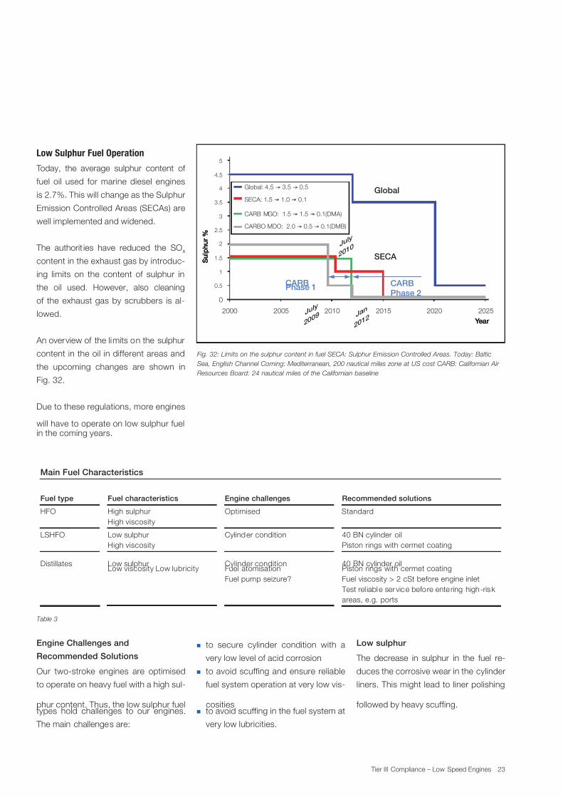
Low Sulphur Fuel Operation
Today, the average sulphur content of
fuel oil used for marine diesel engines
is 2.7%. This will change as the Sulphur
Emission Controlled Areas (SECAs) are
well implemented and widened.
The authorit ies have reduced the SOx
content in the exhaust gas by introduc-
ing limits on the content of sulphur in
the oil used. However, also cleaning
of the exhaust gas by scrubbers is al-
lowed.
An overview of the limits on the sulphur
content in the oil in different areas and
the upcoming changes are shown in
Fig. 32.
Due to these regulations, more engines
will have to operate on low sulphur fuelin the coming years.
Engine Challenges and
Recommended Solutions
Our two-stroke engines are optimised
to operate on heavy fuel with a high sul-
phur content. Thus, the low sulphur fueltypes hold challenges to our engines.
The main challenges are:
Global: 4.5 → 3.5 → 0.5
SECA: 1.5 → 1.0 → 0.1
CARB MGO: 1.5 → 1.5 → 0.1(DMA)
CARBO MDO: 2.0 → 0.5 → 0.1(DMB)
Global
SECA
CARBPhase 1
CARB
Phase 2
2000 2005 2010 2015 2020 2025
0
0.5
1
1.5
2
2.5
3
3.5
4
4.5
5
S u l p h u r %
S u l p h u r %
S u l p h u r %
Year Year Year
July
2009
July
2010
Jan
2012
Fig. 32: Limits on the sulphur content in fuel SECA: Sulphur Emission Controlled Areas. Today: Baltic
Sea, English Channel Coming: Mediterranean, 200 nautical miles zone at US cost CARB: Californian Air
Resources Board: 24 nautical miles of the Californian baseline
Table 3
Main Fuel Characteristics
Fuel type Fuel characteristics Engine challenges Recommended solutions
HFO High sulphur
High viscosity
Optimised Standard
LSHFO Low sulphur
High viscosity
Cylinder condition 40 BN cylinder oil
Piston rings with cermet coating
Distillates Low sulphurLow viscosity Low lubricity
Cylinder conditionFuel atomisation
Fuel pump seizure?
40 BN cylinder oilPiston rings with cermet coating
Fuel viscosity > 2 cSt before engine inlet
Test rel iable ser vice before ente ring high-risk
areas, e.g. ports
to secure cylinder condition with a
very low level of acid corrosion
to avoid scuffing and ensure reliable
fuel system operation at very low vis-
cosities to avoid scuffing in the fuel system at
very low lubricities.
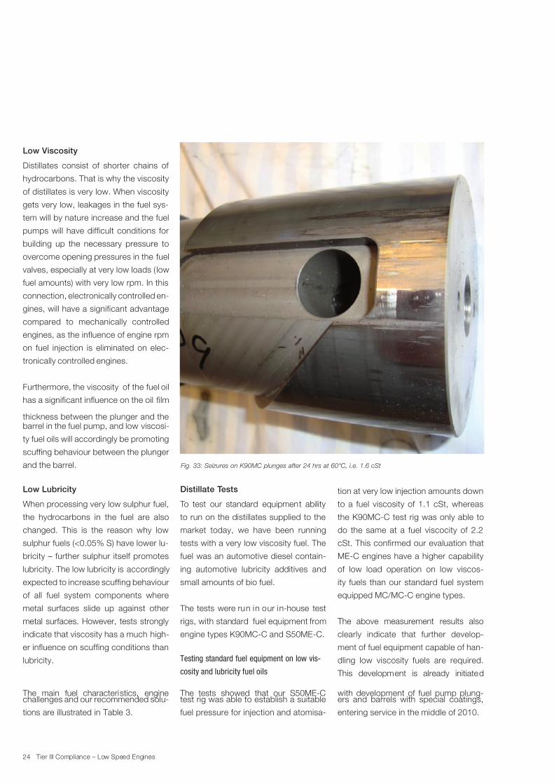
Low sulphur
The decrease in sulphur in the fuel re-
duces the corrosive wear in the cylinder
liners. This might lead to liner polishing
followed by heavy scuffing.
7/27/2019 Tier III Compliance Low Speed Engines
http://slidepdf.com/reader/full/tier-iii-compliance-low-speed-engines 26/31
24 Tier III Compliance – Low Speed Engines
Fig. 33: Seizures on K90MC plunges after 24 hrs at 60°C, i.e. 1.6 cSt
Low Viscosity
Distillates consist of shorter chains of
hydrocarbons. That is why the viscosity
of distillates is very low. When viscosity
gets very low, leakages in the fuel sys-
tem will by nature increase and the fuel
pumps will have difficult conditions for
building up the necessary pressure to
overcome opening pressures in the fuel
valves, especially at very low loads ( low
fuel amounts) with very low rpm. In this
connection, electronically controlled en-
gines, will have a significant advantage
compared to mechanically controlled
engines, as the influence of engine rpm
on fuel injection is eliminated on elec-
tronically controlled engines.
Furthermore, the viscosity of the fuel oil
has a significant influence on the oil film
thickness between the plunger and thebarrel in the fuel pump, and low viscosi-
ty fuel oils will accordingly be promoting
scuffing behaviour between the plunger
and the barrel.
Low Lubricity
When processing very low sulphur fuel,
the hydrocarbons in the fuel are also
changed. This is the reason why low
sulphur fuels (<0.05% S) have lower lu-
bricity – further sulphur itself promotes
lubricity. The low lubricity is accordingly
expected to increase scuffing behaviour
of all fuel system components where
metal surfaces slide up against other
metal surfaces. However, tests strongly
indicate that viscosity has a much high-
er influence on scuffing conditions than
lubricity.
The main fuel characteristics, enginechallenges and our recommended solu-
tions are illustrated in Table 3.
Distillate Tests
To test our standard equipment ability
to run on the distillates supplied to the
market today, we have been running
tests with a very low viscosity fuel. The
fuel was an automotive diesel contain-
ing automotive lubricity additives and
small amounts of bio fuel.
The tests were run in our in-house test
rigs, with standard fuel equipment from
engine types K90MC-C and S50ME-C.
Testing standard fuel equipment on low vis-
cosity and lubricity fuel oils
The tests showed that our S50ME-Ctest rig was able to establish a suitable
fuel pressure for injection and atomisa-
tion at very low injection amounts down
to a fuel viscosity of 1.1 cSt, whereas
the K90MC-C test rig was only able to
do the same at a fuel viscocity of 2.2
cSt. This confirmed our evaluation that
ME-C engines have a higher capability
of low load operation on low viscos-
ity fuels than our standard fuel system
equipped MC/MC-C engine types.
The above measurement results also
clearly indicate that further develop-
ment of fuel equipment capable of han-
dling low viscosity fuels are required.
This development is already initiated
with development of fuel pump plung-ers and barrels with special coatings,
entering service in the middle of 2010.
7/27/2019 Tier III Compliance Low Speed Engines
http://slidepdf.com/reader/full/tier-iii-compliance-low-speed-engines 27/31
MAN B&W Diesel
25 Tier III Compliance – Low Speed Engines
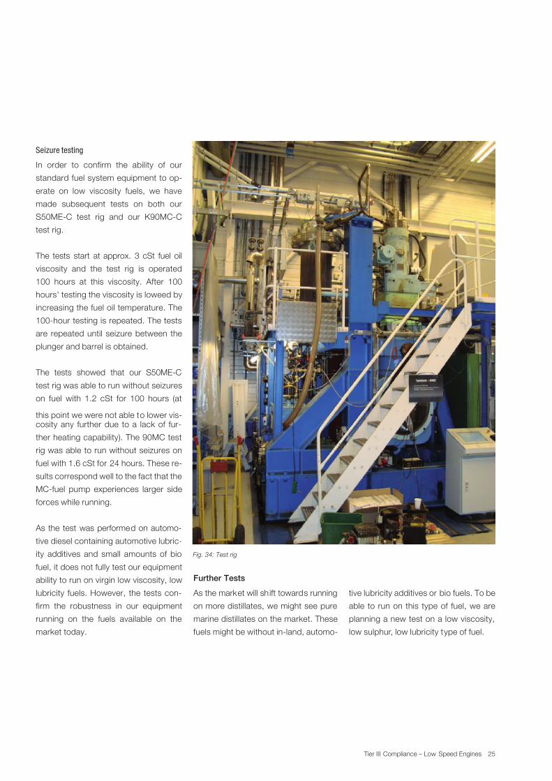
Fig. 34: Test rig
Seizure testing
In order to confirm the ability of our
standard fuel system equipment to op-
erate on low viscosity fuels, we have
made subsequent tests on both our
S50ME-C test rig and our K90MC-C
test rig.
The tests start at approx. 3 cSt fuel oil
viscosity and the test rig is operated
100 hours at this viscosity. After 100
hours' testing the viscosity is loweed by
increasing the fuel oil temperature. The
100-hour testing is repeated. The tests
are repeated until seizure between the
plunger and barrel is obtained.
The tests showed that our S50ME-C
test rig was able to run without seizures
on fuel with 1.2 cSt for 100 hours (at
this point we were not able to lower vis-cosity any further due to a lack of fur-
ther heating capability). The 90MC test
rig was able to run without seizures on
fuel with 1.6 cSt for 24 hours. These re-
sults correspond well to the fact that the
MC-fuel pump experiences larger side
forces while running.
As the test was performed on automo-
tive diesel containing automotive lubric-
ity additives and small amounts of bio
fuel, it does not fully test our equipment
ability to run on virgin low viscosity, low
lubricity fuels. However, the tests con-
firm the robustness in our equipment
running on the fuels available on the
market today.
Further Tests
As the market will shift towards running
on more distillates, we might see pure
marine distillates on the market. These
fuels might be without in-land, automo-
tive lubricity additives or bio fuels. To be
able to run on this type of fuel, we are
planning a new test on a low viscosity,
low sulphur, low lubricity type of fuel.

7/27/2019 Tier III Compliance Low Speed Engines
http://slidepdf.com/reader/full/tier-iii-compliance-low-speed-engines 28/31
26 Tier III Compliance – Low Speed Engines
Conclusion
This paper has illustrated that MAN Die-
sel & Turbo takes the Tier III challenge
very seriously, and is securing that suit-
able solutions can and will be available
in due time before the IMO legislation
on emissions is enforced.
The near future will require further de-
velopment testing of EGR systems,
SCR systems and fuel system com-
ponents for very low sulphur fuels but,
even more importantly and challenging,
these systems will also require further
full scale testing in service. Securing
the possibility of full scale testing of full
scale systems on newbuildings to come
in the near future will call for our licen-
sees’ full cooperation and assistance to
find and convince yards and owners to
participate in the testing efforts.

7/27/2019 Tier III Compliance Low Speed Engines
http://slidepdf.com/reader/full/tier-iii-compliance-low-speed-engines 29/31

7/27/2019 Tier III Compliance Low Speed Engines
http://slidepdf.com/reader/full/tier-iii-compliance-low-speed-engines 30/31

7/27/2019 Tier III Compliance Low Speed Engines
http://slidepdf.com/reader/full/tier-iii-compliance-low-speed-engines 31/31
C o p y r i gh t © MA N D i e s e l & T ur b o· S u b j e
c t t om o d i f i c a t i oni n t h e i n t e r e s t of t e c h ni c a l pr o gr e s s .·
5 5 1 0 - 0 0 8 8 - 0 0 p pr J ul 2 0 1 0 P r i n t e d i nD
e nm a r k
MAN Diesel & Turbo Teglholmsgade 41, 2450 Copenhagen
Denmark
Phone +45 33 85 11 00
Fax +45 33 85 10 30
www.mandieselturbo.com