TIdefleX Tf-1 ANd Tf-2 All-RubbeR check vAlves PIPe INsTAllATION For installation on corrugated...
8
The revolutionary design of the all-rubber Tideflex ® Check Valve provides reliable backflow protection. This unique duck bill design eliminates costly back-flow from oceans, rivers or storm water and is the ideal valve for effluent diffuser systems. Tideflex ® Valves seal on entrapped solids and debris without jamming. Unlike traditional flap gates there are no hinged gates to hang open and no warping or freezing. It’s virtually maintenance-free. The Tideflex ® Check Valve is available in a wide variety of elastomers and is designed to meet your exact flow specifications. IMPORTANT Please take a moment to review this manual. Before performing any maintenance on the valve be sure the pipeline has been de-pressurized. The improper installation or use of this product may result in personal injury, product failure, or reduced product life. Tideflex ® Technologies can accept NO liability resulting from the improper use or installation of this product. If you have any questions or problems, please call the customer service department at (412) 279-0044. We appreciate your comments. Thank you for choosing Tideflex ® Technologies. TIDEFLEX ® TF-1 AND TF-2 ALL-RUBBER CHECK VALVES INSTALLATION, OPERATION, AND MAINTENANCE MANUAL TF-1 TF-2 Division of Red Valve,Inc.
-
Upload
hoanghuong -
Category
Documents
-
view
215 -
download
0
Transcript of TIdefleX Tf-1 ANd Tf-2 All-RubbeR check vAlves PIPe INsTAllATION For installation on corrugated...
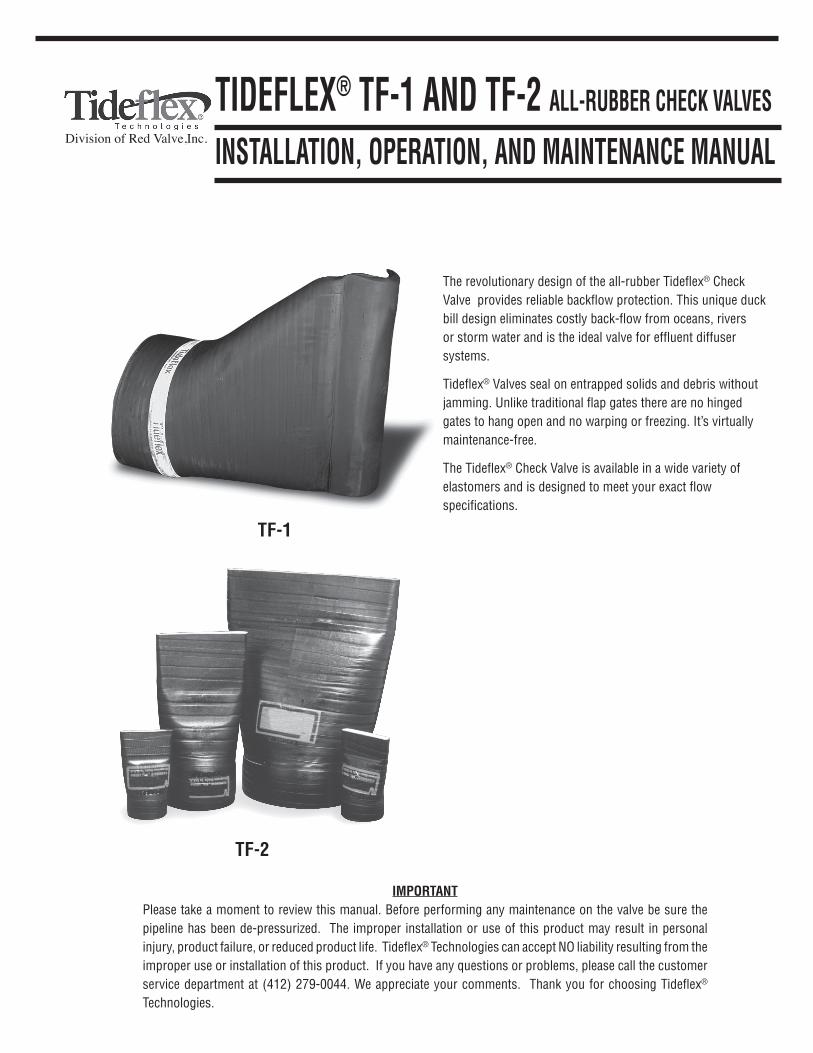
The revolutionary design of the all-rubber Tideflex® Check Valve provides reliable backflow protection. This unique duck bill design eliminates costly back-flow from oceans, rivers or storm water and is the ideal valve for effluent diffuser systems.
Tideflex® Valves seal on entrapped solids and debris without jamming. Unlike traditional flap gates there are no hinged gates to hang open and no warping or freezing. It’s virtually maintenance-free.
The Tideflex® Check Valve is available in a wide variety of elastomers and is designed to meet your exact flow specifications.
IMPORTANTPlease take a moment to review this manual. Before performing any maintenance on the valve be sure the pipeline has been de-pressurized. The improper installation or use of this product may result in personal injury, product failure, or reduced product life. Tideflex® Technologies can accept NO liability resulting from the improper use or installation of this product. If you have any questions or problems, please call the customer service department at (412) 279-0044. We appreciate your comments. Thank you for choosing Tideflex® Technologies.
TIdefleX® Tf-1 ANd Tf-2 All-RubbeR check vAlves
INsTAllATION, OPeRATION, ANd MAINTeNANce MANuAl
Tf-1
Tf-2
Division of Red Valve,Inc.
NeveR...Cut or modifycheck valve.
dO...Use a soapy water solution to slide check valve on pipe.
dO...Keep valve on pallet until ready to install.
dO...Tighten clampbolts evenly.
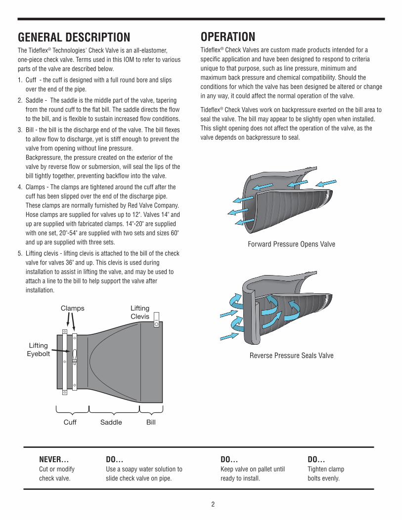
Saddle Bill
LiftingClevis
Cuff
Clamps
LiftingEyebolt
2
Forward Pressure Opens Valve
Reverse Pressure Seals Valve
GeNeRAl descRIPTIONThe Tideflex® Technologies' Check Valve is an all-elastomer, one-piece check valve. Terms used in this IOM to refer to various parts of the valve are described below.
1. Cuff - the cuff is designed with a full round bore and slips over the end of the pipe.
2. Saddle - The saddle is the middle part of the valve, tapering from the round cuff to the flat bill. The saddle directs the flow to the bill, and is flexible to sustain increased flow conditions.
3. Bill - the bill is the discharge end of the valve. The bill flexes to allow flow to discharge, yet is stiff enough to prevent the valve from opening without line pressure. Backpressure, the pressure created on the exterior of the valve by reverse flow or submersion, will seal the lips of the bill tightly together, preventing backflow into the valve.
4. Clamps - The clamps are tightened around the cuff after the cuff has been slipped over the end of the discharge pipe. These clamps are normally furnished by Red Valve Company. Hose clamps are supplied for valves up to 12". Valves 14" and up are supplied with fabricated clamps. 14"-20" are supplied with one set, 20"-54" are supplied with two sets and sizes 60" and up are supplied with three sets.
5. Lifting clevis - lifting clevis is attached to the bill of the check valve for valves 36" and up. This clevis is used during installation to assist in lifting the valve, and may be used to attach a line to the bill to help support the valve after installation.
OPeRATIONTideflex® Check Valves are custom made products intended for a specific application and have been designed to respond to criteria unique to that purpose, such as line pressure, minimum and maximum back pressure and chemical compatibility. Should the conditions for which the valve has been designed be altered or change in any way, it could affect the normal operation of the valve.
Tideflex® Check Valves work on backpressure exerted on the bill area to seal the valve. The bill may appear to be slightly open when installed. This slight opening does not affect the operation of the valve, as the valve depends on backpressure to seal.

STORE VERTICALLY
NeveR sTORe hORIZONTAllY
sTORAGeTideflex® Check Valves should be stored in a cool, dry location on original shipping pallet with the bill facing upward, not on its side (see Figure 2). Do not drop, bend or twist check valve, or damage may occur.
1. Store valve in a cool, clean, dry location.
2. Avoid exposure to light, electric motors, dirt or chemicals. Resilient check valves are subject to deterioration when exposed to ozones and non-compatible chemicals. Ozone especially causes age hardening of the elastomer.
3. Store Installation Operation Manual with product so it will be readily available for installation.
4. Do not remove wooden brace or metal shipping ring (36"+) until valve is installed.
1. INsPecTION Of check vAlveCheck the inside diameter of the cuff of the Tideflex® Check Valve to compare it to the O.D. of the outfall pipe. Inspect the outfall pipe for sharp or damaged areas. The pipeline should be in a smooth condition to prevent cutting the rubber check valve. Lifting clevis and lifting eye bolts are provided only for sizes 36" and over.
Imperfections on the inside of the cuff area can be filled with a silicone sealant prior to installing the valve on the pipe. This will ensure a seal in the cuff area after clamps are tightened.
2. INsPecTION Of The PIPeCheck the outside diameter of the pipe to determine if it matches the I.D. of the cuff of the Tideflex® Check Valve. The cuff of the check valve is usually made slightly larger to permit ease of installation.
INsTAllATION INsTRucTIONsTIdefleX® check vAlves
3
figure 2
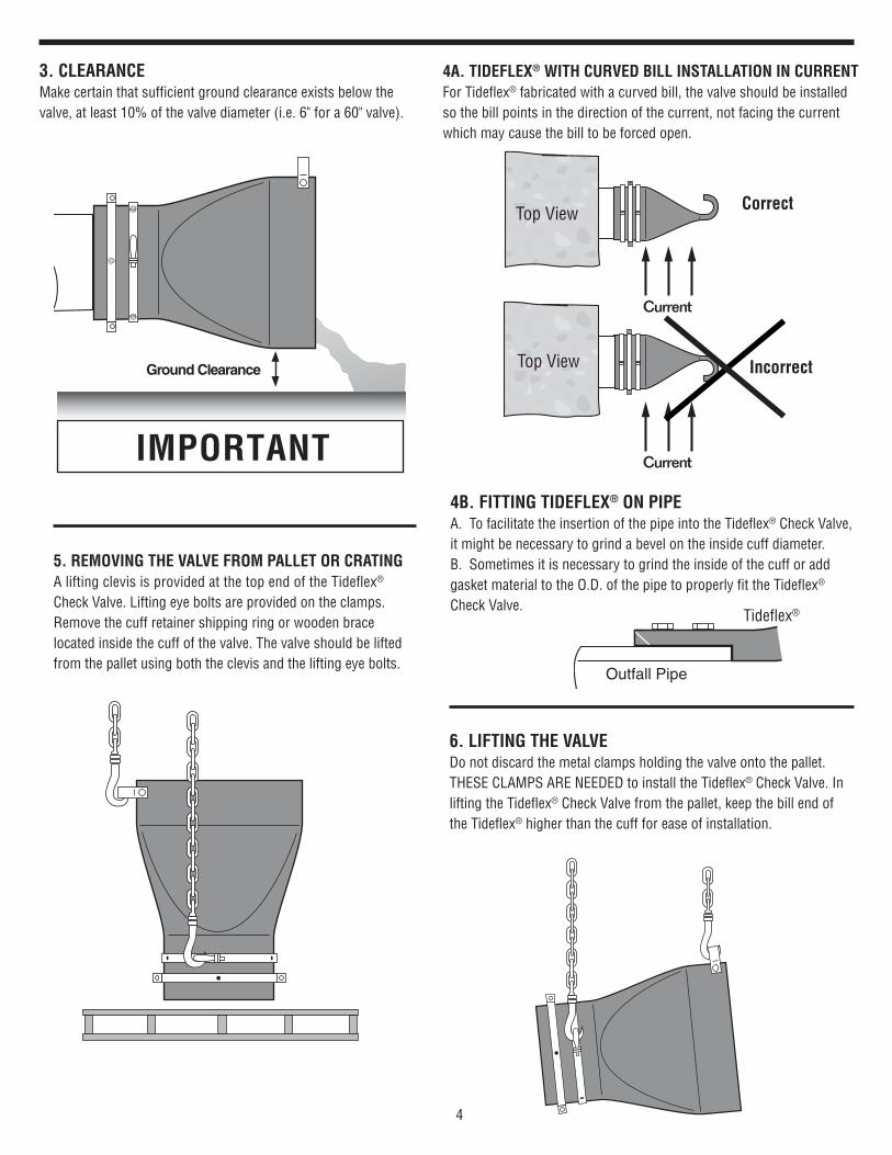
5. ReMOvING The vAlve fROM PAlleT OR cRATINGA lifting clevis is provided at the top end of the Tideflex® Check Valve. Lifting eye bolts are provided on the clamps. Remove the cuff retainer shipping ring or wooden brace located inside the cuff of the valve. The valve should be lifted from the pallet using both the clevis and the lifting eye bolts.
4
Ground Clearance
IMPORTANT
6. lIfTING The vAlveDo not discard the metal clamps holding the valve onto the pallet. THESE CLAMPS ARE NEEDED to install the Tideflex® Check Valve. In lifting the Tideflex® Check Valve from the pallet, keep the bill end of the Tideflex® higher than the cuff for ease of installation.
Current
Current
Incorrect
correct
4b. fITTING TIdefleX® ON PIPeA. To facilitate the insertion of the pipe into the Tideflex® Check Valve, it might be necessary to grind a bevel on the inside cuff diameter.B. Sometimes it is necessary to grind the inside of the cuff or add gasket material to the O.D. of the pipe to properly fit the Tideflex® Check Valve.
Outfall Pipe
Tideflex®
3. cleARANce Make certain that sufficient ground clearance exists below the valve, at least 10% of the valve diameter (i.e. 6" for a 60" valve).
4A. TIdefleX® WITh cuRved bIll INsTAllATION IN cuRReNT For Tideflex® fabricated with a curved bill, the valve should be installed so the bill points in the direction of the current, not facing the current which may cause the bill to be forced open.
Top View
Top View
Tideflex®

Clamp Angles
Cuff O.D.
Gasket Material
Holes90º
1
2
10. POsITIONING fOR ThRee clAMPsAfter the unit is securely pegged into position, proceed to install and tighten the first clamp. A mild lubricant may be applied to the I.D. of the clamp to prevent a brake shoe effect when tightening down clamps.
Install the second and third clamps on the cuff of the Tideflex®. Rotating the first and second clamps 60° and 120°, respectively, in relation to the first clamp will ensure even pressure around the valve and pipe, thus increasing the effectiveness of the clamps.
5
8. seAT TIdefleX® ON PIPeThe Tideflex® Check Valve should fit snugly against the outfall pipe, leaving no gap. If possible, inspect installation from the inlet end of the Tideflex® Check Valve to insure that the check valve cuff fits snugly on the pipe. Do not allow a gap between the cuff and the end face of the outfall pipe. A gap will create an imbalance which will not provide proper support for the Tideflex® Check Valve. For more information, see troubleshooting.
1
2
3
60º
60º
7. POsITIONING The vAlve
With the bill end of the Tideflex® lifted higher than the cuff end start to fit cuff on the outfall line. The Tideflex® Check Valve should fit snugly against the outfall pipe, leaving no gap.
Flat portion of the valve to be at the bottom of the pipe. Flare to be at the top.
Tf-1
Tf-2
Apply a soap/water solution to the outside of the pipe in which the check valve is being installed on, to ease installation.
Outfall Pipe
Tideflex®
Snug Fit
Tideflex®
Outfall Pipe
Gap
Outfall Pipe
Tideflex®
Snug Fit
Tideflex®
Outfall Pipe
Gap
Tideflex®
After the unit is securely pegged into position, proceed to install and tighten the first clamp. A mild lubricant may be applied to the I.D. of the clamp to prevent a brake shoe effect when tightening down the clamps.
Tideflex®
9. POsITIONING fOR TWO clAMPs Install the second clamp on the cuff of the Tideflex®. Rotating the clamp 90° in relation to the first clamp will ensure even pressure around the valve and pipe, thus increasing the effectiveness of the clamps.
If a greater distance between the angles of the clamps is required to provide more range for tightening the bolts, especially if angles are bottoming out, gasket material can be wrapped around the O.D. of the cuff as shown.

Drill HoleThroughValve &
Pipe
InsertHolding Bolt &Fasten
TackWeld
Bolt toClamp
Clampwith Hole
6
Outfall Pipe
Tideflex®
Snug Fit
Tideflex®
Outfall Pipe
Gap
11. POsITIONING blANk hOles IN clAMPs Tighten all clamps and bolts once all components have been positioned properly. Pre-drilled holes are drilled in each clamp. These are provided so as to secure the Tideflex® Check Valve with holding pins to the outfall pipe. This will secure the Tideflex® Check Valve to the pipe and assure a long, trouble-free service life. After tightening the clamps, the pre-drilled holes should be staggered. Holes are not drilled in the rubber cuff of the Tideflex® at the factory since they would not line up to the tightened clamps.
12. TAck WeldING hOldING bOlTs TO clAMPs Once clamps are secure use a standard steel drill bit and drill holes through the rubber cuff. Insert holding bolts through the cuff and secure opposite side with nut, if possible. Holding bolts should be stainless steel. Steel bolts can corrode and break off, causing the check valve to slip off the pipe. Holding bolts are not provided because of various widths of the outfall pipe.
13. bOlTs TAck Welded TO clAMPs After tightening, heads of holding bolts can be tack welded to the clamps using small tacks. Certain installations will not permit installing of nuts to bolts. In these situations, the tightness of the clamps and tack weld of the bolts will assure good support.
14. cORRuGATed PIPe ANd sMOOTh WAll (Pvc, hdPe) PIPe INsTAllATION For installation on corrugated pipe, it is recommended that the corrugations be filled with hydraulic cement (or similar material) that will provide a smooth O.D.
For smooth wall pipe, it is recommended that the valve be pinned.
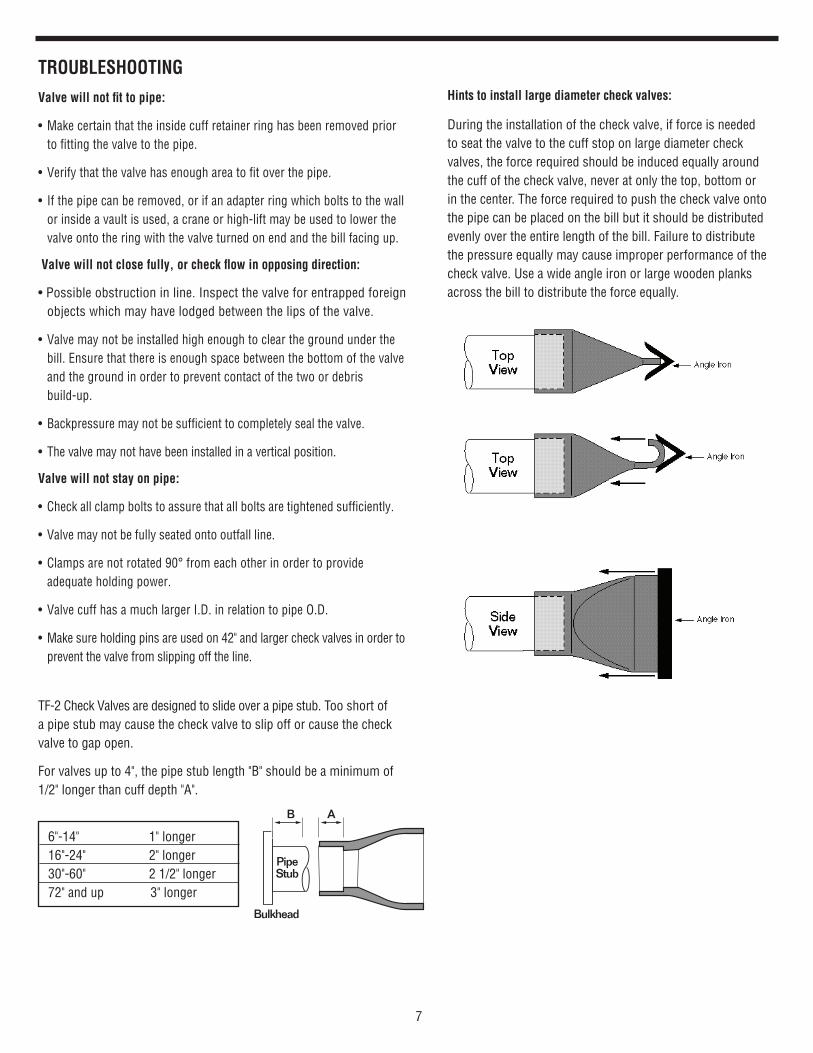
TF-2 Check Valves are designed to slide over a pipe stub. Too short of a pipe stub may cause the check valve to slip off or cause the check valve to gap open.
For valves up to 4", the pipe stub length "B" should be a minimum of 1/2" longer than cuff depth "A".
6"-14" 1" longer 16"-24" 2" longer 30"-60" 2 1/2" longer 72" and up 3" longer
7
AB
Bulkhead
PipeStub
hints to install large diameter check valves:
During the installation of the check valve, if force is needed to seat the valve to the cuff stop on large diameter check valves, the force required should be induced equally around the cuff of the check valve, never at only the top, bottom or in the center. The force required to push the check valve onto the pipe can be placed on the bill but it should be distributed evenly over the entire length of the bill. Failure to distribute the pressure equally may cause improper performance of the check valve. Use a wide angle iron or large wooden planks across the bill to distribute the force equally.
TROubleshOOTING
valve will not fit to pipe:
• Makecertainthattheinsidecuffretainerringhasbeenremovedpriorto fitting the valve to the pipe.
•Verifythatthevalvehasenoughareatofitoverthepipe.
• Ifthepipecanberemoved,orifanadapterringwhichboltstothewallor inside a vault is used, a crane or high-lift may be used to lower the valve onto the ring with the valve turned on end and the bill facing up.
valve will not close fully, or check flow in opposing direction:
•Possibleobstructioninline.Inspectthevalveforentrappedforeignobjects which may have lodged between the lips of the valve.
• Valvemaynotbeinstalledhighenoughtoclearthegroundunderthebill. Ensure that there is enough space between the bottom of the valve and the ground in order to prevent contact of the two or debris build-up.
• Backpressuremaynotbesufficienttocompletelysealthevalve.
• Thevalvemaynothavebeeninstalledinaverticalposition.
valve will not stay on pipe:
• Checkallclampboltstoassurethatallboltsaretightenedsufficiently.
• Valvemaynotbefullyseatedontooutfallline.
•Clampsarenotrotated90°fromeachotherinordertoprovide adequate holding power.
•ValvecuffhasamuchlargerI.D.inrelationtopipeO.D.
• Makesureholdingpinsareusedon42"andlargercheckvalvesinordertoprevent the valve from slipping off the line.

600 North Bell AvenueCarnegie, PA 15106Phone: 412 279-0044Fax: 412 279-7878Web: www.tideflex.com
WARRANTIES - REMEDIES - DISCLAIMERS - LIMITATION OF LIABILITYUnless otherwise agreed to in writing signed by Tideflex® Technologies, all Products supplied by Tideflex® Technologies will be described in the specifications set forth on the face hereof.
THE WARRANTIES SET FORTH IN THIS PROVISION ARE EXCLUSIVE AND IN LIEU OF ALL OTHER WARRANTIES WHETHER STATUTORY, EXPRESS OR IMPLIED (INCLUDING ALL WARRANTIES OF MERCHANTABILITY AND FITNESS FOR A PARTICULAR PURPOSE AND ALL WARRANTIES ARISING FROM COURSE OF DEALING OR USAGE OR TRADE).
Tideflex® Technologies Products are guaranteed for a period of one year from date of shipment, against defective workmanship and material only, when prop-erly installed, operated and serviced in accordance with Tideflex® Technologies' recommendations. Replacement for items of Red Valve's manufacture will be made free of charge if proved to be defective within such year; but not claim for transportation, labor or consequential damages shall be allowed. We shall have the option of requiring the return of the defective product to our factory, with transportation charges prepaid, to establish the claim and our liability shall be limited to the repair or replacement of the defective product, F.O.B. our factory. Tideflex® Technologies will not assume costs incurred to remove or install defective products nor shall we incur backcharges or liquidated damages as a result of warranty work. Tideflex® Technologies does not guarantee resistance to corrosion erosion, abrasion or other sources of failure, nor does Tideflex® Technologies guarantee a minimum length of service, or that the product shall be fit for any particular service. Failure of purchaser to give prompt written notice of any alleged defect under this guarantee forthwith upon its discovery, or use, and possession thereof after an attempt has been made and completed to remedy defects therein, or failure to return product or part for replacement as herein provided, or failure to install and operate said products and parts according to instructions furnished by Tideflex® Technologies, or failure to pay entire contract price when due, shall be a waiver by purchaser of all rights under these representations. All orders accepted shall be deemed accepted subject to this warranty which shall be exclusive of any other or previous warranty, and shall be the only effective guarantee or warranty binding on Tideflex® Technolo-gies, anything on the contrary contained in purchaser's order, or represented by any agent or employee of Tideflex® Technologies in writing or otherwise, not withstanding implied warranties. Tideflex® Technologies MAKES NO WARRANTY THAT THE PRODUCTS, AUXILIARIES AND PARTS ARE MERCHANTABLE OR FIT FOR ANY PARTICULAR PURPOSE.
Tideflex® Technologies Warranty
MAINTeNANce Line pressure should flush the valve clean of debris in most cases. Periodic inspections for trapped debris should be conducted.
In vacation seashore areas quart size plastic bottles have a tendency to float on top and not flush through except during a major storm.
A feathered 1" x 4", 1-1/2" x 12", or suitable plank inserted into the bill of the valve and turned 90° is a simple method of clearing the check valve of small debris which may be trapped between the lips.
cAuTION: Sharp objects should not be used on the Tideflex® Check Valve, as there is a chance of cutting the rubber and damaging the protective fabric covering.
Any gouges in the cover wrap that occur should be sealed to safeguard against ozone or chemical attack. This is best done with rubber cement or a good brand of silicone or polyurethane rubber sealer made by the major manufacturers.
TF-1/TF-2 IOM Rev. 10/16/15