TIDAL ENERGY RESEARCH GROUP DEPARTMENT … 11th week, Hilary Term, 2012 TIDAL ENERGY RESEARCH GROUP...
16
Friday 11th week, Hilary Term, 2012 TIDAL ENERGY RESEARCH GROUP DEPARTMENT OF ENGINEERING SCIENCE On the Garrett & Cummins limit Tom Adcock Friday, 30 March 2012
-
Upload
hoangxuyen -
Category
Documents
-
view
215 -
download
2
Transcript of TIDAL ENERGY RESEARCH GROUP DEPARTMENT … 11th week, Hilary Term, 2012 TIDAL ENERGY RESEARCH GROUP...

Friday 11th week, Hilary Term, 2012
TIDAL ENERGY RESEARCH GROUPDEPARTMENT OF ENGINEERING SCIENCE
On the Garrett & Cummins limit
Tom Adcock
Friday, 30 March 2012

The most basic tidal channel
§ Channel connecting two oceans§ Sinusoidal head difference§ Channel length << tidal wavelength — volume flow rate is
constant along length§ Drag is proportional to Q2
§ Natural drag in channel
§ Turbine drag
§ Classic paper analysing this by Garrett & Cummins (2005) in
Proc. R. Soc. A
Friday, 30 March 2012

Is the channel length really much shorter than the wavelength?
§ The naturally occurring tide will have a much longer
wavelength than most channels§ In this analysis we are going to use a time-varying resistance
which will generate higher harmonics and hence shorter
wavelengths§ Write
§ These will be multiplied together — hence higher harmonics§ I will explore this further numerically when I next have a free
weekend
u |u| =U2
�8
3πsin(ωt) +
8
15πsin(3ωt)
�+ . . . k(t) =k0 + k2 sin(2ωt+ φ2) + k4 sin(4ωt+ φ4) + . . .
Friday, 30 March 2012

P =1
2π
� 2π
0λ1Q
2 |Q| dt
Equations (after non-dimensionalisation)
dQ
dt= cos (t)− (λ0 + λ1)Q |Q|
Inertia Naturalfriction
Driving head Turbinedrag
Power averaged over tidal cycle
Friday, 30 March 2012

Finding the optimum turbine drag
0 2 4 6 8 10 120
0.02
0.04
0.06
0.08
0.1
0.12
0.14
0.16
0.18
0.2
1
Power
Power normalised by ρgaQnat
Example: λ0=0.8
Friday, 30 March 2012
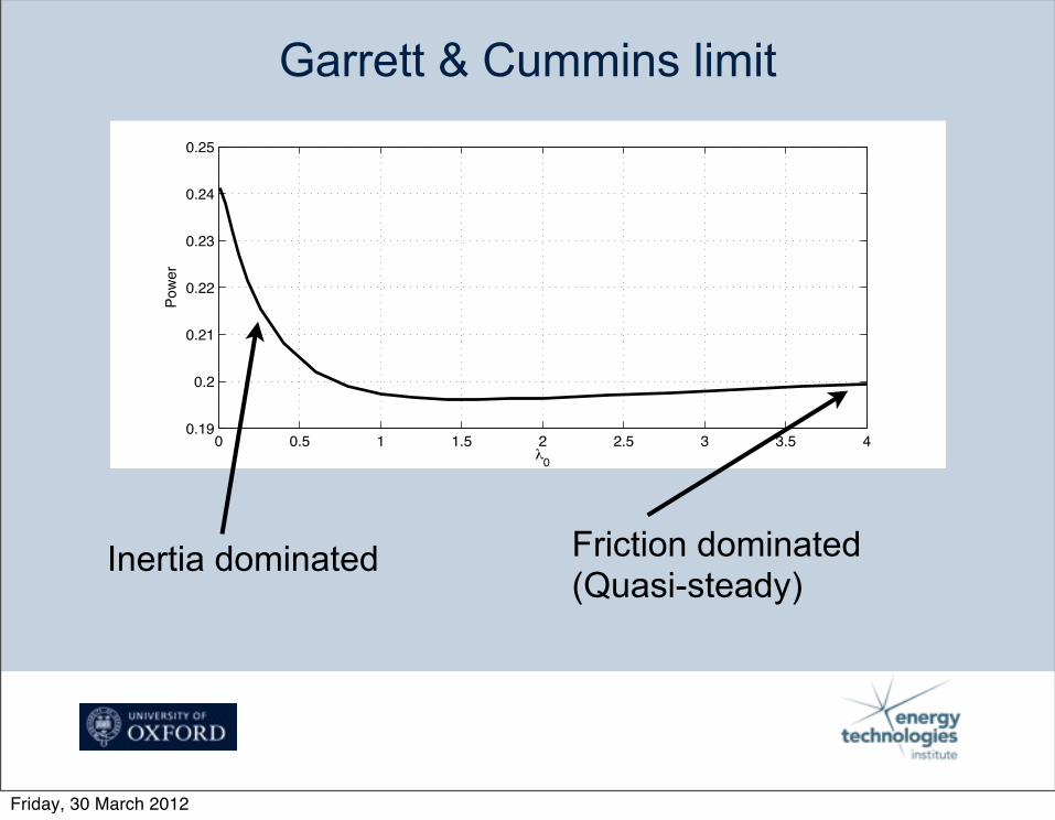
Garrett & Cummins limit
0 0.5 1 1.5 2 2.5 3 3.5 40.19
0.2
0.21
0.22
0.23
0.24
0.25
0
Power
Inertia dominated Friction dominated(Quasi-steady)
Friday, 30 March 2012
Why should λ1 not vary in time?
§ Define λ1 at N points over the half tidal cycle§ Linearly interpolate between these§ Use optimisation routine to find form of λ1 which maximises
power output
Friday, 30 March 2012

Example λ1=0.8 — convergence
1 2 3 4 5 6 7 8 9 10 11 12 130.19
0.2
0.21
0.22
0.23
0.24
0.25
0.26
N
Power
0 0.5 1 1.5 2 2.5 30
100
200
300
400
500
600
Time
1
0 0.5 1 1.5 2 2.5 30
0.5
1
1.5
2
2.5
3
3.5
4
Time
1
N=1N=5N=9N=13
Friday, 30 March 2012

Example λ1=0.8 — tidal dynamics
0 1 2 3 4 5 61
0.5
0
0.5
1
0 1 2 3 4 5 6
0.5
0
0.5
0 1 2 3 4 5 610 2
100
102
0 1 2 3 4 5 60
0.1
0.2
0.3
0.4
0.5
0.6
Q/Qnat
Powerλ1
Driving head
Friday, 30 March 2012

Power extraction
0 0.5 1 1.5 2 2.5 3 3.5 4
0.2
0.25
0.3
0.35
0.4
0.45
0.5
0.55
0
Pow
er
N=1N=2N=5N=13
Garrett & Cummins
Friday, 30 March 2012

More realistic turbines
§ Represent turbines using actuator disc theory
§ Use small Froude number theory as keeps analysis simple
§ Very close to results with finite Froude number model
§ Turbine Ct and Cp a function of blockage, B, and wake
induction factor, α4
§ Choose a blockage and find value of α4 which maximises
power available at the turbine§ Constant α4 analysis by Vennel (2010) in JFM
Friday, 30 March 2012

Time varying wake induction factor§ Define λ1 at N points over the half tidal cycle§ Linearly interpolate between these§ Use optimisation routine to find form of λ1 which maximises
power output
Friday, 30 March 2012
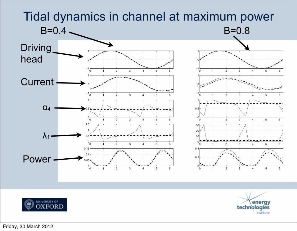
Tidal dynamics in channel at maximum powerB=0.4 B=0.8
Driving head
Current
α4
λ1
0 1 2 3 4 5 61
0
1
0 1 2 3 4 5 61
0
1
0 1 2 3 4 5 61
0
1
0 1 2 3 4 5 61
0
1
0 1 2 3 4 5 60
0.5
1
0 1 2 3 4 5 60
0.5
1
0 1 2 3 4 5 60
0.5
1
1.5
0 1 2 3 4 5 60
10
20
30
0 1 2 3 4 5 60
0.05
0.1
0.15
0 1 2 3 4 5 60
0.2
0.4
Power
Friday, 30 March 2012

Power extraction — 1 row of turbines
0 0.5 1 1.5 2 2.5 3 3.5 40.02
0.04
0.06
0.08
0.1
0.12
0.14
0
Power
0 0.5 1 1.5 2 2.5 3 3.5 40.1
0.15
0.2
0.25
0.3
0.35
0.4
0.45
0
Power
B=0.4 B=0.8
Friday, 30 March 2012

Power extraction — 5 rows of turbines
B=0.4 B=0.8
0 0.5 1 1.5 2 2.5 3 3.5 40.1
0.15
0.2
0.25
0.3
0.35
0.4
0.45
0
Power
0 0.5 1 1.5 2 2.5 3 3.5 40.05
0.1
0.15
0.2
0.25
0.3
0.35
0.4
0
Power
Friday, 30 March 2012

Conclusions
§ For low friction/high inertia channels it is possible to extract
more energy than the value given by Garrett & Cummins
(2005).§ The analysis of Vennel (2010) also (slightly) underestimates
the energy which may be extracted used actuator discs.§ No real turbine is going to be able to produce the thrust
needed by this analysis.§ Small improvement in energy output may be possible
Friday, 30 March 2012