tiastarTM Motor Control Center - Siemens · such as rubber gloves, hard hat, safety glasses or face...
44
Instruction guide tiastar TM Motor Control Center www.usa.siemens.com/mcc
Transcript of tiastarTM Motor Control Center - Siemens · such as rubber gloves, hard hat, safety glasses or face...

Instruction guide
tiastarTM
Motor Control Center
www.usa.siemens.com/mcc

THISEQUIPMENTCONTAINSHAZARDOUSVOLTAGES.DEATH,SERIOUSPERSONALINJURY,ORPROPERTYDAMAGECANRESULTIFSAFETYINSTRUCTIONSARENOTFOLLOWED.ONLYQUALIFIEDPERSONNELSHOULDWORKONORAROUNDTHISEQUIPMENTAFTERBECOMINGTHOROUGHLYFAMILIARWITHALLWARNINGS,SAFETYNOTICES,ANDMAINTENANCEPROCEDURESCONTAINEDHEREIN.
THESUCCESSFULANDSAFEOPERATIONOFTHISEQUIPMENTISDEPENDENTUPONPROPERHANDLING,INSTALLATION,OPERATIONANDMAINTENANCE.
Signal wordsThesignalwords“DANGER”, “WARNING”and“CAUTION”usedinthismanualindicatethedegreeofhazardthatmaybeencounteredbytheuser.Thesewordsaredefinedas:DANGER–Forthepurposeofthismanualandproductlabels,DANGERindicatesanimminentlyhazardoussituationwhich,ifnotavoidedwillresultindeathorseriousinjury.
WARNING–Forthepurposeofthismanualandproductlabels,WARNINGindicatesapotentiallyhazardoussituationwhich,ifnotavoided,couldresultindeathorseriousinjury.
CAUTION–Forthepurposeofthismanualandproductlabels,CAUTIONindicatesapotentiallyhazardoussituationwhich,ifnotavoided,mayresultinminorormoderateinjury.
Qualified personForthepurposesofthismanualandproductlabels,aqualifiedpersonisonewhoisfamiliarwiththeinstallation,construction,operationormaintenanceoftheequipmentandthehazardsinvolved.Inadditionthispersonhasthefollowingqualifications:(a)istrainedandauthorizedtoenergize,de-energize,clear,
groundandtagcircuitsandequipmentinaccordancewith establishedsafetypractices.(b)istrainedinthepropercareanduseofprotectiveequipment
suchasrubbergloves,hardhat,safetyglassesorfaceshields,flashclothing,etc.,inaccordancewithestablishedsafetypractices.
(c)istrainedinrenderingfirstaid.
Hazardous voltage.Will cause death or serious injury.Alwaysde-energizeandgroundtheequipmentbeforemaintenance.Readandunderstandthismanualbeforeinstalling,operatingormaintainingtheequipment.Maintenanceshouldbeperformedonlybyqualifiedpersonnel.Theuseofunauthorizedpartsintherepairoftheequipmentortamperingbyunqualifiedpersonnelmayresultindangerousconditionswhichmaycausedeathorseriousinjury,orequipmentorpropertydamage.Followallsafetyinstructionscontainedherein.
DANGER
tiastar TM Motor Control CenterTable of contents
Arc Resistant Equipment Special Considerations:ForArcResistantEquipment,seealsothesupplementalInstructionandInstallationGuideforType2AArcResistantMotorControlCenterE87010-A0098-T004-A5-MCC.
E87010-A0156-T002-A5-MCC
1 General information 4 1.1Partsillustrations 4-52 Receiving and handling 62.1Receiving 62.2Handling 62.3Skidremoval 82.4Storage 83 Installation 93.1Installationquickchecklist 93.2Operatingenvironment 103.3Sitepreparation 103.4Mounting 113.5Topandbottomcovers 123.6Installationofseismicqualifiedstructures 133.7Joiningshippingsections 133.8Groundbus 133.9Splicekits 153.10Pullboxinstallation 163.11Incomingpowerconnections 163.12Incominglineterminationarrangements,mainlugs 18-193.13Incominglineterminationarrangements,maincircuitbreakers 20-213.14Incominglineterminationarrangements,mainfusibleswitches 22-233.15Loadandcontrolwiring 243.16Fieldadditions 25
3.17Plug-inunitremoval 253.18Plug-inunitaddition 263.19Highdensityunitinstallation 273.20Insulation(Megger)test 284 Operation 294.1Pre-energizationchecks 294.2Energizingequipment 304.3Permissibleloadingofmotorcontrolcenters 305 Maintenance 315.1Maintenancequickcheck 315.2GeneralinspectionoftheMCC 325.3Periodiccleaning 335.4Stabfingersandverticalbus 335.5Recommendedtighteningtorques 335.6Disconnectoperatinghandleadjustment 345.7Adjustmentnotes 355.8Maintenanceafterafaulthasoccurred 355.9Disconnectingmeans 355.10Terminalsandinternalconductors 365.11AdjustmentofSentronTypeETIinstantaneoustripmotorcircuitinterrupter(1A-125A) 375.12Fieldtestingofthecircuitbreakers 375.13Overloadrelay 376 Troubleshooting 38-407 Heater tables 41-42
ImportantTheseinstructionsdonotpurporttocoveralldetailsorvariationsinequipment,nortoprovideforeverypossiblecontingencytobemetinconnectionwithinstallation,operationormaintenance.Shouldfurtherinformationbedesiredorshouldparticularproblemsarisewhicharenotcoveredsufficientlyforthepurchaser’spurposes,themattershouldbereferredtothelocalSiemenssalesoffice.Thecontentsofthisinstructionmanualshallnotbecomepartoformodifyanypriororexistingagreement,commitmentorrelationship.ThesalescontractcontainstheentireobligationofSiemens.ThewarrantycontainedinthecontractbetweenthepartiesisthesolewarrantyofSiemens.Anystatementscontainedhereindonotcreatenewwarrantiesormodifytheexistingwarranty.
tiastarMotorControlCenterInstructionGuide

tiastar Motor Control CenterGeneral information
4 tiastar Motor Control Center Instruction Guide
Key to section construction features1. Rearbrace2. Sidesheetassembly(onouterof
motorcontrolcenters)3. Bottomwireway4. Frontbottombasechannel5. Channelsills6. Topwireway
7. Horizontalbus8. Verticalbus,300A, 600A,and800A9. Horizontalgroundbus
10. Dividersidesheetassembly(betweenadjoiningsections)
11. Horizontalbussupport12. Standardverticalbusbrace
13. Horizontalbussupport(rearview)14. Standardverticalbusbarrier15. Unitstabholes16. Unitsupportassembly
1.1 Parts Illustrations
1
2
3
4
5
6
Standard bus
12
8
9
10
13
7
14
15
16
11

tiastar Motor Control CenterGeneral information
Optional bus
5tiastar Motor Control Center Instruction Guide
1.1 Parts Illustrations
Key to section construction features17. Wiretiesupport18. Verticalwireway19. Removabledoorhinge20. Verticalwirewaydoor
21. Bottomhorizontalwireway(6”)andformedcoverplate22. Bottomendcoverplate23. Tophorizontalwirewayandfloor(wireway12”high)24. TopPlates25. Liftingangle
19
13
15
117
18
17
25
20
23
24
21
22

tiastar Motor Control CenterReceiving and handling
6 tiastar Motor Control Center Instruction Guide
2.1 Receiving
Uponreceiptofthemotorcontrolcenter,animmediateinspectionshouldbemadeforanydamagewhichmayhaveoccurredduringshipment.Theinspectionshouldbeginwiththepackagingmaterialandproceedtotheequipmentwithin.Besuretolookforconcealeddamageanddonotdiscardthepackingmaterial.Ifdamageisfound,notedamageon“BillofLading”priortoacceptingreceiptoftheshipment,ifpossible.
Note:Thewayvisibleshippingdamageistreatedbytheconsigneepriortosigningthedeliveryreceiptcandeterminetheoutcomeofthedamageclaimtobefiled.Notificationtothecarrierwithinthe15daylimitonconcealeddamageisessentialiflossresultingfromunsettledclaimsistobeeliminatedorminimized.
TheSiemenssalesofficeshouldbenotifiedimmediatelyifdamageorlossisdiscovered.Adescriptionofthedamageandasmuchidentificationinformationaspossibleshouldbegiven.
2.2 HandlingThemotorcontrolcentersareshippedingroupsofonetofourverticalframeswhicharemountedonwoodenshippingskids.Liftinganglesareoneachshippingsection.
Figure1.Liftingamotorcontrolcenterwithanoverheadcrane.
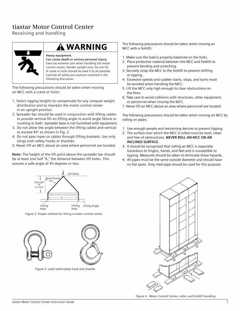
Heavy equipment.Can cause death or serious personal injury.Exerciseextremecarewhenhandlingthemotorcontrolcenter.Handleuprightonly.Donottilt.Acraneorhoistshouldbeusedifatallpossible.Exerciseallsafetypre-cautionsoutlinedinthefollowingdiscussion.
WARNING
ThefollowingprecautionsmustbetakenwhenevermovinganMCC:
1. Handlethemotorcontrolcenterwithcaretoavoiddamagetocomponentsandtotheframeoritsfinish.
2. Handlethemotorcontrolcenterinanuprightpositiononly.Motorcontrolcentersarenormallyfrontheavyandfrequentlytopheavy.Balancetheloadcarefullyandsteadythemotorcontrolcenter,asnecessary,whilemoving.Somemotorcontrolcenterinteriorsmaycontainheavyequipment,suchastransformersmountedwithin,thatcouldbeadverselyaffectedbytilting.
3. Knowthecapabilitiesofthemovingmeansavailabletohandletheweightofthemotorcontrolcenter.Adequatehandlingfacilitiesshouldbeavailable.Thefollowingtablegivestheapproximateweightsofsingleverticalframesandwillbehelpfulindeterminingtherequiredcapacityofthehandlingmeans.Ifaverticalframecontainspowerfactorcorrectioncapacitors,reactors,oralargetransformer,sufficientadditionalweighthandlingcapacitymustbeallowed.
NEMA 1, Gasketed, and 12 structures only
Frame Weight
20”Wx15”DFrontOnly 550lb.
20”Wx20”DFrontOnly 600lb.
30”Wx15”DFrontOnly 600lb.
30”Wx20”DFrontOnly 650lb.
4. ItisrecommendedthatacraneorhoistbeusedtohandletheMCCifatallpossible.Ifacraneorhoistisnotavailableandotherhandlingmeansarenecessary,extremecaremustbeexercisedtoinsurethattheequipmentissecuredduringthemovementandplacementoperationstopreventtippingandfalling.Jacks,prybars,dollies,rollerlifts,andsimilardevicesallrequiresupplementalblockingbeneaththeMCCandrestraintstopreventtipping.Thesedevicesarenotrecommendedduetothehazardsimplicitintheiruse.
tiastar Motor Control CenterReceiving and handling
7tiastar Motor Control Center Instruction Guide
ThefollowingprecautionsshouldbetakenwhenmovinganMCCwithacraneorhoist:
1. Selectrigginglengthstocompensateforanyunequalweightdistributionandtomaintainthemotorcontrolcenterinanuprightposition.
2. Spreaderbarshouldbeusedinconjunctionwithliftingcablestoprovideverticalliftonliftingangletoavoidanglefailureorcrushingorboth.Spreaderbaseisnotfurnishedwithequipment.
3. Donotallowtheanglebetweentheliftingcablesandverticaltoexceed45°asshowninFig.2.
4. Donotpassropesorcablesthroughliftingbrackets.Useonlyslingswithsafetyhooksorshackles.
5. NeverliftanMCCaboveanareawherepersonnelarelocated.
Note:Theheightoftheliftpointabovethespreaderbarshouldbeatleastonehalf“A,”thedistancebetweenliftholes.Thisassuresasafeangleof45degreesorless.
ThefollowingprecautionsshouldbetakenwhenmovinganMCCwithaforklift:
1. Makesuretheloadisproperlybalancedontheforks.2. PlaceprotectivematerialbetweentheMCCandforkliftto
preventbendingandscratching.3. SecurelystraptheMCCtotheforklifttopreventshifting
ortipping.4. Excessivespeedsandsuddenstarts,stops,andturnsmust
beavoidedwhenhandlingtheMCC.5. LifttheMCConlyhighenoughtoclearobstructionson
thefloor.6. Takecaretoavoidcollisionswithstructures,otherequipment,
orpersonnelwhenmovingtheMCC.7. NeverliftanMCCaboveanareawherepersonnelarelocated.
ThefollowingprecautionsshouldbetakenwhenmovinganMCCbyrollingonpipes:
1. Useenoughpeopleandrestrainingdevicestopreventtipping.2. ThesurfaceoverwhichtheMCCisrolledmustbelevel,clean
andfreeofobstructions.NEVER ROLL AN MCC ON ANINCLINED SURFACE.
3. ItshouldberecognizedthatrollinganMCCisespeciallyhazardoustofingers,hands,andfeetandissusceptibletotipping.Measuresshouldbetakentoeliminatethesehazards.
4. Allpipesmustbethesameoutsidediameterandshouldhavenoflatspots.Onlysteelpipeshouldbeusedforthispurpose.
Figure2.Propermethodforliftingamotorcontrolcenter
Figure3.Loadratedsafetyhookandshackle
Figure4.MotorControlCenter,roller,andforklifthandling
Heavy equipment.Can cause death or serious personal injury.Exerciseextremecarewhenhandlingthemotorcontrolcenter.Handleuprightonly.Donottilt.Acraneorhoistshouldbeusedifatallpossible.Exerciseallsafetypre-cautionsoutlinedinthefollowingdiscussion.
WARNING
LiftingHole
LiftingHole
LiftingAngle
LiftPoint
One-half“A”
ormore
NeverExceed45º

tiastar Motor Control CenterReceiving and handling
8 tiastar Motor Control Center Instruction Guide
2.3 Skid removal
Skidremovalshouldbeperformedjustpriortofinalplacementofthemotorcontrolcenterandisachievedbyfirstremovingthebottomhorizontalwirewaycoverswhichallowsaccesstotheskidlagbolts.AttachcraneriggingtoliftingangleontopofMCCstructure.Applysufficienttensionontheriggingtoremoveallslackwithoutliftingtheequipment.Thisisarecommendedsafetymeasuretoreducethepossibilityoftipping.Thelagboltsmaynowberemoved,theMCClifted,theskidsremoved,theMCCloweredintoplace,andtheanchorboltssecured.Thelastoperationshouldbeperformedwithadequateriggingtensiontopreventtipping.Afteralladditionalshippingsectionsaresecuredinasimilarmanner,sectionsandbusbarsshouldbejoinedinaccordancewiththeinstructionsintheInstallationsectionofthismanual.ClosedoorsandreinstallcoversassoonaspossibletoeliminateintrusionofdirtandforeignmaterialsintotheMCCenclosure.
2.4 Storage
Amotorcontrolcenterorseparateunit,whichisnotinstalledandenergizedimmediately,shouldbestoredinacleandryspacewhereauniformtemperaturepreventscondensation.Preferably,itshouldbestoredinaheatedbuilding,withadequateaircirculationandprotectedfromdirtandwater.Motorcontrolcentersandunitsshouldbestoredwheretheyarenotsubjecttomechanicaldamage.
Ifthemotorcontrolcenteristobestoredforanylengthoftime,priortoinstallation,restorethepackingforprotectionduringthatperiod.Whereconditionspermit,leavethepackingintactuntilthemotorcontrolcenterorsectionsareattheirfinalinstallationposition.Ifthepackingisremoved,coverthetopandopeningsoftheequipmentduringtheconstructionperiodtoprotectthemagainstdustanddebris.
Iftheequipmentistobestoredinacoolordamparea,donotcompletelycovertheequipment,butprovideheattopreventcondensationofmoistureintheequipment.Ifthecontrolcenterhasbeenorderedwithspaceheaters,connecttoatemporaryfeedforheat.Asimplemethodofheatingthemotorcontrolcenterwhenspaceheatersarenotorderedistoplaceastandard120V/15Wlampinsidethebottomofeachverticalsection.
Anunenergizedoutdoormotorcontrolcentershouldbekeptdryinternallybyinstallingtemporaryheating(seepreviousparagraphs),orbyenergizingoptionalself-containedspaceheaters.
Anyscratchesorgougessufferedfromshippingorhandlingshouldbetoucheduptopreventrusting.
Heavy equipment.Can cause death or serious personal injury.Exerciseextremecarewhenhandlingthemotorcontrolcenter.Handleuprightonly.Donottilt.Acraneorhoistshouldbeusedifatallpossible.Exerciseallsafetypre-cautionsoutlinedinthefollowingdiscussion.
WARNING

tiastar Motor Control CenterInstallation
9tiastar Motor Control Center Instruction Guide
Incoming line connectionswChoosetheshortest,mostdirectroutefromremotemains.w Ifcablescannotbedirectlyroutedtoterminals,provide adequatespaceforclampingthecables.wTorqueincominglinestomainlugsonlyat85ft.-lbs.wTorqueallincomingconnectionstomaincircuitbreakers
andfusibledisconnectsasperthebreakerordisconnectmanufacturer’srecommendations.Thetorquerequirementsarefoundonalabellocatedonthedisconnectingdevice.
Outgoing power and control wiringwDisengageplug-inunitstabsfromverticalbus.Connect controlandpowerwiringtounits.wUsestrandedwire.wLeaveenoughslacktopermitpartialwithdrawalofunittotestpositionformaintenance.wPullwiringbetweenunitsthroughverticalandhorizontal
wirewaysecuringwiresintheverticalwirewaywithwirefromwiretiesprovided.wRoutewiringbetweensectionsthroughthetoporbottom
horizontalwireways.wReinsertplug-inunitstoengagestabs.
Pre-operation checkswTestinsulationresistanceofallcircuitswiththecontrolcenterasground.wRemoverestrainingdevicesfromcontactorsandshunts
fromcurrenttransformers.Makesurethatallpartsofmagneticdevicesoperatefreely.wCheckelectricalinterlocksforpropercontactoperation.wMakesurethateachmotorisconnectedtoitsproperstarter.wCheckallheaterelementsforproperinstallation.wCheckalltimersforpropertimeintervalsettingandcontact
operation.wCheckfusibledisconnectstartersforproperfusesize.wCleanthecontrolcenter.Riditofallextraneousmaterial.Useavacuumcleaner,notcompressedair.wCheck all connections for mechanical and electrical tightness.wCloseallaccessplatesanddoors.
Energizing motor control centerswMakesureallunitdisconnecthandlesandcontrolcentermains areturnedtoOFF.wTurnonremotemains.wTurnonmotorcontrolcentermaincircuitbreakersorfusibledisconnects.wTurnonunitdisconnecthandlesonebyone.wJogmotorstocheckforproperrotation.wAdjustETIBreakers.
Insulation (Megger) test (see page 28)
3 Installation 3.1 Installation quick check list – Indoor MCCs only
ReceivingwInspectpackagefordamage.wAfterunpacking,inspectequipmentfordamageintransit.w Ifdamagedorincomplete,pleasenotifySiemenssalesoffice
withidentificationofparts,descriptionofdamage,andphotographs.
HandlingwSimplifyhandlingbyleavingequipmentonshippingskid.wUsetheliftingangleprovidedformovingtheequipment.wTakecaretousethepropermethodofmovingamotor
controlcenter.
StoragewStoreinaclean,dryspaceatmoderatetemperature.wCoverwithacanvasorheavy-dutyplasticcover.w Ifstorageareaiscoolordamp,coverequipmentcompletely
andheattopreventcondensation.
Location selectionwFlatandlevelfloor.wOverheadclearance.wAccessibilityfrontandrear(ifrequired).wProtectionfromsplashanddrip,dust,andheat.wSpaceforfutureexpansion.wIfbottomconduitentryisused,conduitshouldbeinplace
andstubbedupbeforeequipmentisinstalled.
Installation methodwGroutintothefoundation.wWeldchannelsillstosteellevelingplates.w Imbeddedanchorboltsinthefloor.
Field assembly(Instruction sheet included with shipment)wRemovehardwareandhorizontalbusconnectinglinksfromshippingsplits.w Installfirstshippingsplit.wRemoveendcoverplatesofstructurestobejoined(ifrequired).wCarefullyalignsecondsplitwithfirst.Boltstructurestogetherat fourcornersandmiddle,front,andrear.wRemovehorizontalwirewaybarriertoexposehorizontalbus.wConnecthorizontalbuseswithbuslinks.Torqueboltsto 20ft.-lbs.wGrommettopandbottomhorizontalwireways.wInstallheatercoils.(Checkselectionagainstmotor nameplatedata.)w Installfuses.
Conduit entry at topwRemovetopplatesfromstructure.wCutconduitentryholesintopplates.wReinstalltopplates.w Installconduits
Note: Thischecklistisnotexhaustiveandparticularapplicationsmayrequirefurtherprocedures.

tiastar Motor Control CenterInstallation
10 tiastar Motor Control Center Instruction Guide
3.2 Operating environment
ThemotorcontrolcenterconformswiththeprovisionsofNEMAStandardICS1-108,AltitudeClass2KMwhichdefinestheusualserviceconditionforelectromagneticcontrol.Itisdesignedforindoorusewherethetemperatureinsidethecontrolcenterishigherthantheambienttemperature.Thecontrolcenteriscapableofcarryingitsratedloadwhentheambienttemperaturedoesnotexceed40°Candthealtitudedoesnotexceed6600feetabovesealevel.Whereunusualserviceconditionsexistorwheretemperatureoraltitudelimitationsareexceeded,thecontrolcenterconstruction,ratings,orprotectionmayrequirealteration.Someexamplesofunusualserviceconditionsareexcessivemoisture,vibration,ordust.
3.3 Site preparation
InstallationshallbeinaccordancewiththeNationalElectricalCode,ANSI,andNFPA70Standards.Unlessthemotorcontrolcenterhasbeendesignedforunusualserviceconditions,itshouldnotbelocatedwhereitwillbeexposedtoambienttemperaturesabove40°C(104°F),corrosiveorexplosivefumes,dust,vapors,drippingorstandingwater,abnormalvibration,shockortilting,orotherunusualoperatingconditions.
Themotorcontrolcentershouldbeinstalledinaclean,dry,heatedplacewithgoodventilationanditshouldbereadilyaccessibleforscheduledmaintenance.Aflat,level,concretesurfaceshouldbepreparedforthemountingsite.Ifthemountingsiteisnotflatandlevel,themotorcontrolcentermustbeshimmedwherenecessarytopreventdistortionofthestructure.
Allconduitenteringfromthebottomshouldbeinplaceandstubbedupabouttwoinchesabovethefinishedfloorlevelbeforeinstallingthecontrolcenter.RefertotheMCCleadsheetplanviewlocatedintheinformationpacketforspecificconduitareadimensions.
Note:Conduitshouldnotextendmorethan21/2inchesabovethefloorsurface.

tiastar Motor Control CenterInstallation
11tiastar Motor Control Center Instruction Guide
Figure6.Anchorboltlocationandbottomconduitentry:15”20”
Alldimensionsareshownininchesunlessotherwisespecified.
3.4 Mounting
Motorcontrolcentersmaybemountedbymanydifferentfasteningsystemsincludingtruedropin,castinplace,powderactuated,orthreadedinsertfasteners.SeeFigure6foranchorboltlocations.Theboltpatternisdependentonframewidth,depth,locationintheline-up.RefertothestructuremountingdetailincludedontheL1layoutdrawingleadsheet.ThecoordinationbetweenboltsandtheMCCshouldbeverifiedpriortoattemptinginstallation.Expandableinsertsinpredrilledholesorembedded‘L’boltsarerecommended.
Woodenplugsdrivenintoholesinmasonryorconcretearenotrecommendedforanchoringinsertsandshouldneverbeused.Theboltsizemustbe1/2”.
Groutingthesillchannelsisanothermethodoffastening.Thismethodrequiresthefoundationtobegroovedasshowntoacceptthesillchannels.SeeFigure7fordetails.
Weldingthesteelbaseorsillchannelstoasteelfloorplateisanalternatemountingmethod.SeeFigure6fordetails.
Figure5.Topconduitentry:15”20”
Note:Reartopplatecanbeusedforconduiton20”deepMCC.Cablescanthenberunfromreartofrontthroughoptionalwirewayholestoconnectunits.
Alldimensionsshownininches.
20
20
17
17
3
3
3 3
2 Z\v 2 Z\v5Z\x14Z\x
19ZZ\zn
13ZZ\zn
16ZZ\zn
Mtg. Holes
(Typ.)1 Z\x
(Typ.)1 Z\x
Vertical Bus
14ZZ\znSpace Open forConduit Entry
Space Open forConduit Entry
11ZZ\zn
5Z\x
8ZZ\zn
14Z\x
Vertical Bus
Typical9ZZ\zn
6 B\,
Channel SillChannel Sill Remove bottom unit to pull wire.
Shadedareaindicatesconduitentry.

tiastar Motor Control CenterInstallation
12 tiastar Motor Control Center Instruction Guide
Figure8.Weldedinstallation
Reversiblebottomend-coverplatescoverthebottomhorizontalwireway,groundbusopening,andtheendchannels.Theyperformthisfunctionifthesectionismountedonitssills,orifthesectionwithsillsisgroutedintothefloor,theplatesaresimplyrotated180°.SeeFigure9.
Ifthecontrolcenterislocatedonstructuralsteelplatformsovergrids,itisrecommendedthatthecenterbemodifiedwithbottomplates.
Note:TocomplywithNEC380-8(a)HeightRequirements,thecustomershouldascertainthattheoperatingpersonnel’sworkingbaseisatthesamelevelastheMCCbase.
3.5 Top and bottom covers
Topcoversareprovidedonallmotorcontrolcentersasanintegralpartoftheenclosure.BottomcoversaresuppliedoncertaintypesofconstructionsuchasNEMA12.Thesecoversshouldberemovedonlyforthepurposeofpiercingholesforconduitorwireentryandmustbeimmediatelyreplacedtoreducethepossibilitythatfallingmaterial,tools,orpersonnelcouldunintentionallycontactthebussystemorotherliveparts.
Figure7.GroutingmethodoffasteningMotorControlCenter
Figure9.Reversiblebottomend-coverplates
A
A
6”3”
Typ. (4) Corners Typ. (4) Places
Bottom Filler
MCC Frame
Steel Floor Plate
MotorControlCenter
SillChannel
Grooves

tiastar Motor Control CenterInstallation
13tiastar Motor Control Center Instruction Guide
3.6 Installation of seismic qualified structures
Siemens tiastar MCCs are qualified to withstand seismic activity as specified in IBC 2012, CBC 2013, and IEEE 693. This includes all tiastar MCCs, all NEMA types and MCC sizes. tiastar MCCs are rated at importance factor 1.5.1 The seismic qualifications include mounting locations from ground level to roof top.
3.7 Joining shipping sections
Shipping sections consist of up to four vertical frames shipped as a single unit. It is often necessary to join two or more shipping sections at the job site. All necessary electrical and structural joining components are provided and the following procedures are recommended.
1. Position the first shipping section into place on the foundationand level.
2. Remove the front horizontal bus barrier and the side covers(if applicable) from the end(s) to be joined. If the rear isaccessible, the back cover plates should be removed fromthe two adjoining sections.
3. Position the second shipping section on the foundationadjacent to the first and level it. The horizontal bus shouldbe inspected for proper positioning and alignment atthis time.
4. Bolt structures together at six points (see Figure 11). Ifaccess to the rear of the structures is restricted, the rearcenter bolt may be omitted.
Note: When aligning different depths of structures (i.e. 15” front only or 20” deep front only), align the fronts of the structures and bolt together using front three bolts.
5. Assemble the bus bar links to join the horizontal power busand neutral bus, if supplied, in the two shipping sections asshown on page 15. The horizontal and neutral buses maydiffer in size, material, or plating, therefore, the links mustbe matched to the proper bars. All links and associatedmounting hardware are provided with the motor controlcenter.
6. Torque all bus connections to 20 ft. lbs.7. If the motor control center has interwiring, connect the
interunit wiring between shipping sections.8. Join the ground bus between the two adjacent sections, if
supplied. The Ground Bus Section in the manual detailsthis procedure.
9. If there are other shipping sections to be joined, repeatsteps 1 through 8 above.
10. Secure the motor control center to the foundation.11. NEMA 3R enclosure sections should be securely joined and
sealed to prohibit intrusion of dust and moisture.
3.8 Ground bus
All hardware and links are supplied for joining the ground bus between two shipping sections. This joining may be accomplished by loosening the screw securing the connection link so that the link pivots freely. Remove the screw securing the ground bus in the adjacent frame to which the link will attach. Pivot the free end of the link such that the hole is aligned with the bolt, then reassemble the screw and link assembly. Tighten hardware. See Figure 10.
1 Importance factor 1.5 identifies components whose post-event operation is essential to supporting life, safety, and/or if the components contain materials that would be dangerous to building occupants if released during an earthquake.
Figure 10. 300A and 600A horizontal ground bus connection
Hazardous voltage.Will cause death or serious personal injury.Turn off power before working on thisequipment.
DANGER
MCC StructureSteel Member
Horizontal GroundBus Bar
Ground Bus BarSplice Link
Taptite ScrewGround Splice Kit Shipped Boltedto Ground Bus as shown.
The motor control center should be anchored to the floor with appropriate hardware and 1/2” bolts. For seismically qualified MCC installations, all mounting holes supplied in the standard base channel sills must be used. Welding is also an acceptable method of mounting, if the installation instructions are followed.

tiastar Motor Control CenterInstallation
14 tiastar Motor Control Center Instruction Guide
Figure11
Note:Donotusegrommetsonthebackhorizontalwirewayopeningsof‘FrontOnly’sections.Alldimensionsareshownininchesunlessotherwisespecified.
See detail Ato left
Bolt (6 pieces) B\zn – 18 x C\v lg.
Removablelifting angle
C\zn GrommetL= 8 M\, D45130-1
C\, GrommetL= 8 M\, D45130-11
C\zn GrommetL= 4Z\v D45130-4
Detail A
C\zn GrommetL= 7Z\, D45130-2
C\zn GrommetL= 3M\, D45130-3
Detail B
C\zn GrommetL= 3M\, D45130-2
C\zn GrommetL= 3M\, D45130-3Omit when ground busor neutral bus is supplied
See detail Bto left
Figure11

tiastar Motor Control CenterInstallation
15tiastar Motor Control Center Instruction Guide
Figure12.1200A,1600AL1connection
3.9 Splice kits
Note:Forcompletesplicekitinstallationdetails,refertoinstructionssuppliedwithsplicekits.
Horizontal Bus Splice
Splice Bar Adapter
Parallel HorizontalBelleville Washer
Bolts
Figure13.1200A,1600AL2andL3connection1200A,1600Aneutralbusconnection
Figure14.600A,800Amainbusconnection600A,800Aneutralbusconnection
600Ahorizontalgroundbusconnection
Bus Bar Clamp
Horizontal Bus Splice
Parallel HorizontalBus Bar (L2 & L3)
Belleville Washer Nut
Belleville Washer Nut
Bus Bar Clamp
HorizontalBus Bar
HorizontalBus Splice

tiastar Motor Control CenterInstallation
16 tiastar Motor Control Center Instruction Guide
3.10 Pull box installation
RefertoFigure15forthefollowingprocedure.
1. Removetopfrontconduitplate(A)frommotorcontrolcenterstructurebyremovingtwoscrews(B).Therearetwofrontplateson.back-to-back.motorcontrolcenters.
2. Removetworearscrews(C).3. Removethetoptwoscrewsholdingonthebusinsulator
cover(E).Dothistobothsidesofaback-to-back”motorcontrolcenter.
4. Installbarrier(F)andreplacethescrewsfromstep3.5. Removetopplateofpullbox(G).6. PlacepullboxonMCCandscrewdownusingfour1/4-20x
3/4”taptitescrews.Therearmountingholesmayhavetobedrilledon“FrontOnly”motorcontrolcenters.UsethePullBox/TopHatasadrillingtemplate.
7. Replacetopplatethatwasremovedinstepfive.
3.11 Incoming power connections
Note:Removetopcoversbeforecuttingholesforconduittopreventmetalchipsfromfallingintothemotorcontrolcenter.Conduitsshouldbecarefullyinstalledtopreventmoistureorwaterfromenteringandaccumulatingwithintheenclosure.Allconduits(includingstubs)shouldbebondedtothemotorcontrolcenter.Afterallshippingsectionsareinplace,leveled,andjoinedtogetherintoasinglemotorcontrolcenter,cablesmaybepulledandtopentryconduitmaybeinstalled.Bottomentryconduitwillhavebeenstubbedthroughthefloorattheproperlocationspriortoplacementofthemotorcontrolcenter.Theincomingsourcecablesmaybeconnectedatthistime,however,thepowersourcedisconnectingmeansmustremainopenandlockedoutuntilallwiringiscompletedandtheentiresystemhasbeencheckedout.
Caremustbeexercisedtomakesurethatthelugswhichhavebeenprovidedaresuitableforusewiththetypeofcablesbeinginstalledinthemotorcontrolcenter.Ifcrimplugsaresupplied,useonlythecrimpingtoolrecommendedbythelugmanufacturer.
Careshouldbeexercisedinstrippinginsulationfromtheconductorstopreventnickingtheconductor.Foraluminum,cleanalloxidefromthestrippedportionandapplyinhibitingcompoundatonce.Tightenallscrewlugsandboltedelectricalconnectionstothespecifiedtorquelistedinthetableinthemaintenancesectionofthisinstructionmanual.
Tominimizethelengthofunsupportedcable,theshortest,mostdirectroutingshouldbechosen.However,thelargestpracticalbendingradiishouldbemaintainedtoavoiddamagingtheinsulationandtoavoidcausingterminalstoloosen.Allcablesenteringthemotorcontrolcentermustbeadequatelysupportedandrestrainedtowithstandthemaximumfaultcurrentcapableofbeingdeliveredbythesource.Therecommendeddistancesbetweenstrapsfor80poundratedstrapis6inchesfor25KAbracing,4inchesfor42KAbracingand3inchesfor65KAbracing.Usingastrapratedlessthan80poundswillrequirethespacingdistancestobereduced.For100KAbracing,cablesmustbesupportedinaccordancewiththespecialinstructionsprovidedwiththemotorcontrolcenter.
Hazardous voltage.Will cause death or serious injury.Turnoffpowerbeforeworkingonthisequipment.
DANGER

tiastar Motor Control CenterInstallation
17tiastar Motor Control Center Instruction Guide
Figure15
Top ViewTop View
Front Top PlateRemoved
Front View(Top Wireway Door –
Not Shown)
Front View(Top Wireway Door –
Not Shown andBarrier F Installed)
Pull Box / Top Hat
Front
MCC
F
E
G
DE
D
F
F
C
H
A

tiastar Motor Control Center
18 tiastar Motor Control Center Instruction Guide
3.12 Incoming line termination arrangements –Main lugsTop main lugs only can be moved from one section to anotherin the field without drilling holes in bus or structure.
Horizontal lugs are available with 600A bus, 42,000A symmetrical bus bracing only.
Note: Special lugs such as NEMA 2-hole compression lugs, can be accommodated. Consult factory for space requirements.
Amp/Bracing (A/K) Location IncomingCable size
Fig. ref.Next page
Wire bendingSpace dim. A
Total assemblyHeight dim. B
Required unitSpace dim. C
600A/42K Top Qty = 2#4 - 350kcmi CU
16 13 12 0
600A/42K-65K Top Qty = 2#2 - 600kcmi CU
17 16 24 12
600A/85-100K TopQty = 2#2 - 600kcmi CU
18 20 30 18
600A/42K1 Bottom Qty = 2#4 - 350kcmi CU
19 13 18 12
600A/65K1 Bottom Qty = 2#4 - 350kcmi CU
19 13 24 18
800A/42K-65K Top Qty = 2#2 - 600kcmi CU
17 16 24 12
800A/85K-100K Top Qty = 2#2 - 600kcmi CU
18 20 30 18
800A/42K-65K2 Bottom Qty = 2#2 - 600kcmi CU
20 18 30 24
1200A/42K-100K Top Qty = 3#2 - 600kcmi CU
18 20 30 18
1200A/42K-65K2 Bottom Qty = 3#2 - 600kcmi CU
20 18 30 24
1600A/42K-100K Top Qty = 4#2 - 600kcmi CU
18 20 30 18
1600A/42K-100K BottomQty = 4#2 - 600kcmi CU
20 18 30 24
2000A/42K-100K Top Qty = 6#2
-
600kcmi CU21 29 48 36
2000A/42K-100K Bottom Qty = 6#2 - 600kcmi CU
22 46 72 72
2500A/42K-100K Top Qty = 6#2 - 600kcmi CU
21 29 48 36
2500A/42K-100K Bottom Qty = 6#2 - 600kcmi CU
22 46 72 72
1 Space behind structure not available.2 Entire rear of structure not available.Optional lugs available. Contact factory for size and rating.
Installation

tiastar Motor Control Center
19tiastar Motor Control Center Instruction Guide
Alldimensionsareshownininchesunlessotherwisespecified.
3.12 Main lugs
Installation
Figure16 Figure17 Figure18 Figure19
Figure20 Figure21 Figure22

tiastar Motor Control Center
20 tiastar Motor Control Center Instruction Guide
All dimensions are shown in inches unless otherwise specified.
3.13 Incoming line termination arrangements –Main circuit breakersMolded Case Thermal Magnetic circuit breakers, Molded Case Solid State circuit breakers, and Insulated Case WL Power circuit breakers can be used as mains in the MCC. These circuit breakers are 80% rated, however, 100% rated options are also available (see below).
Installation
1 Space in rear of structure not available.2 Entire rear of structure not available3 Molded case circuit breakers.4 WL power circuit breakers.
5 15-25A lug size 12-10AL, 14-10CU, 30-100A, 10-1/0 CU. 6 800A-1200A not available in back to back bottom mounting. 7 Stab opening at bottom of unit not available in rear.8 All circuit breakers are calibrated for 40oC
Optional lugs available. Contact factory for size and rating.
Circuit breaker frame Location Incoming cable size
Fig. ref.next pg.
Wire bending space dim. A
Total assembly height dim. B
Required unitspace dim. C
125A Top Qty = 1 5
#3 - 3/0 CU23 14 24 12
125A Bottom Qty = 1 5
#3 - 3/0 CU26 8 24 18
250A Top Qty = 1 #6 - 350kcmil CU
24 15 30 18
250A Bottom Qty = 1#6 - 350kcmil CU
15 36 30
400A 7 8 Top Qty = 2 3/0 - 500kcmil CU
24 15 30 18
400A 7 8 Bottom Qty = 2 3/0 - 500kcmil CU
28 15 42 36
600A 7 8 Top Qty = 2 3/0 - 500kcmil CU
24 15 30 18
600A 7 8 Bottom Qty = 2 3/0 - 500kcmil CU
28 15 42 36
800A 1 8 Top Qty = 3#1 - 500kcmil CU
25 15 48 36
800A 2 6 8 Bottom Qty = 3 #1 - 500kcmil CU
29 22 54 48
1200A 1 8 Top Qty = 4 250 - 500kcmil CU
25 16 48 36
1200A 2 3 6 8 Bottom Qty = 4 250 - 500kcmil CU
29 22 54 48
1600A 3 8 Top Qty = 4 300 - 600kcmil CU
32 16 90 72
1600A 3 8 BottomQty = 4 300 - 600kcmil CU
33 16 90 72
2000A 3 TopQty = 6300 - 600kcmil CU
30 19 70 72
2000A 3 BottomQty = 6300 - 600kcmil CU
33 26 90 72
1600A 4 TopQty = 4300 - 600kcmil CU
30 16 90 72
1600A 4 BottomQty = 4300 - 600kcmil CU
31 16 90 72
2000A 4 TopQty = 6300 - 600kcmil CU
30 19 90 72
2000A 4 BottomQty = 6300 - 600kcmil CU
31 26 90 72
2500A 4 TopQty = 6300 600kcmil
30 19 90 72
2500A 4 BottomQty = 6300 600kcmil
31 26 90 72
27

tiastar Motor Control Center
21tiastar Motor Control Center Instruction Guide
Alldimensionsareshownininchesunlessotherwisespecified.
Installation
3.13 Main circuit breakers
Figure23 Figure24 Figure25 Figure26 Figure27 Figure28
Figure31Figure29 Figure30 Figure32
20
A
C
12
6
B
Figure33
A
12
CB
20
6

tiastar Motor Control Center
22 tiastar Motor Control Center Instruction Guide
All dimensions are shown in inches unless otherwise specified.
3.14 Incoming line arrangements – Main disconnect switches
Main fusible switches consist of the following:• 600A to 100A, Class R fuse clips • 200A to 600A, Class R fuse holder • 800A to 1200A, Class L fuse holder
Fusible disconnect Switch/clips Location
Incomingcable size
Fig ref.Next pg.
Wire bendingSpace dim. A
Total assemblyHeight dim. B
Required unitSpace dim. C
60A/30A or 60A Top Qty = 1#14 - #14 CU
34 14 24 12
60A/30A or 60A Bottom Qty = 1#14 - #14 CU
39 8 24 18
100A/100A Top Qty =1#14 - #14 CU
35 13 30 18
100A/100A Bottom Qty = 1#14 - #14 CU
40 7 30 24
200A/200A Top Qty = 1 #6 - 350kcmil CU
36 16 42 30
200A/200A Bottom Qty = 1 #6 - 350kcmil CU
41 10 48 42
400A/400A Top Qty = 23/0 - 500kcmil CU
37 14 48 36
400A/400A Bottom Qty = 23/0 - 500kcmil CU
42 14 60 54
600A/600A Top Qty = 23/0 - 500kcmil CU
37 14 48 36
600A/600A Bottom Qty = 23/0 - 500kcmil CU
42 14 60 54
800A/800A1 Top Qty = 3250-500kcmil CU
44 22 90 72
800A/800A1 Bottom Qty = 3250-500kcmil CU
43 22 90 72
1200A/1200A1 Top Qty = 4250-500kcmil CU
44 22 90 72
1200A/1200A1 Bottom Qty = 4250-500kcmil CU
43 22 90 72
1 Space in rear of structure not available. Optional lugs available. Contact factory for size and rating.
Installation

tiastar Motor Control Center
23tiastar Motor Control Center Instruction Guide
All dimensions are shown in inches unless otherwise specified.
Installation
3.14 Main disconnect switches
Figure 34 Figure 35 Figure 36 Figure 37 Figure 38
Figure 40 Figure 41 Figure 42 Figure 43 Figure 44
Figure 39

tiastar Motor Control Center
24 tiastar Motor Control Center Instruction Guide
Figure46.Type“C”wiringterminal
3.15 Load and control wiring
Allinterconnectionsbetweendeviceswithineachcontrolunitareprewiredatthefactory.Fieldwiringtoeachcontrolunitshouldbemadeinaccordancewiththewiringdiagramindicatedontheleadsheetforthatparticularunit.Theleadsheetandwiringdiagramsareincludedintheinformationpacket.Whenwiringorperforminganymaintenanceonplug-inunits,disengagethestabsbywithdrawingtheunit.Refertopage25,“Plug-InUnitRemoval”section.Wiringdonewiththeunitinthispositionwillensureadequatecableslacktoallowunitwithdrawaltothesamepositionwhenfuturemaintenanceisrequired.Alwaysusestrandedwire.
Theverticalwiringbetweencontrolunitsorbetweenacontrolunitandconduitshouldbepulledthroughtheverticalwirewayontherightsideoftheframe.Thesewiresshouldthenbetiedorlacedtogetherandtheresultingbundlethensecurelyfastenedtothewiresupports.Interconnectingwiringbetweencontrolunitsshouldberoutedthroughthetoporbottomhorizontalwireways.
InstallationandwiringmustbeinaccordancewithNFPA-70,ANSI,theNationalElectricalCode,andanyotherapplicableregionalcodesorregulations.
3.15.1 NEMA Type A wiringMotorcontrolcenterswithNEMATypeAwiringdonotincludeterminalblocks.Allfieldwiring,bothpowerandcontrol,shouldbeconnecteddirectlytotheindividualcomponents.
3.15.2 NEMA Type B wiringMotorControlCenterswithNEMAtypeBwiringincludeterminalblocksforcontrolcircuitconnections.
NEMATypeBuserfieldloadwiringforcombinationmotorcontrolunitssize3orsmallershallbedesignatedasB-DorB-T,accordingtothefollowing:
B-Dconnectsdirectlytothedeviceterminals,whicharelocatedimmediatelyadjacent,andreadilyaccessible,totheverticalwireway.
B-Tconnectsdirectlytoaloadterminalblockin,oradjacentto,theunit.
3.15.3 NEMA Type C wiring
MotorcontrolcentersequippedwithNEMATypeCwiringincludeallthefeaturesdescribedforNEMAtypeBwiringinadditiontomasterterminalblockslocatedateitherthetoporbottomhorizontalwireway.(Figure46)Motorcontrolcenterunitsarefactorywiredtotheirmasterterminalblocks.
Themotorcontrolcenterleadsheet,locatedintheinformationpacket,indicatesthetypeofwiringprovidedforthisinstallation.
Figure 45.Masterterminalblocklocation
Field Terminations: NEMA Classes and Types
Description Class I types A B-D B-T C
Class II typesB-D B-T C
Terminals Furnished
Forallcontrolconnections XXX XXX
ForstarterloadconnectionsSizes1thru3 XX XX
Terminals Mounted
Oncontrolunit XXX XXX
Inmasterterminalcompartment X X
Interwiring
Betweenunitsinthesamemotorcontrolcenter XXX
Installation

tiastar Motor Control Center
25tiastar Motor Control Center Instruction Guide
Figure47.Rackingleverallowseasyunitremoval
3.16 Field additions
Fieldadditionsmaybemadetothemotorcontrolcenterifthecurrentratingofthemainorverticalbusisnotexceeded.Thepreparationofthefloorandconduitisthesameasinanewinstallation.Anynewshippingsectionwillcontainallofthenecessaryhardwareandbusconnectinglinks.De-energizetheexistingmotorcontrolcenterandremovethetopandbottomsidecoversfromthenewandexistingverticalframeswhicharetobejoined.Afterjoiningthestructurespertheinstructionsintheinstallationsectionofthismanual,performthepre-energizationchecksoutlinedintheoperationsectionofthisinstructionmanual.
Additionstomotorcontrolcentersfallintotwogeneralcategories:additionsofstructuresandadditionsorreplacementofplug-inunits.Theadditionofstructuresissimilartotheinstallationofmotorcontrolcenterswhichhavebeenshippedinseveralsections.Whenmountingmethodsormodelsofnewandexistingsectionsdiffer,caremustbeexercisedtoensureproperalignmentofhorizontalbus.Thenewstructuresarethentreatedthesameasinanewinstallation.ThisisdiscussedindetailintheJoiningShippingSectionsportionofthismanual.
3.17 Plug-in unit removal
1. Putthedisconnectoperatinghandleinthe“OFF”position(Fig.47).Theinterlockingmechanismwillnotpermitremovingorinsertingtheunitwiththehandleinthe“ON”position.
2. Unscrewthemulti-turnlatchonbottomplateoftheunit.Rotatethelatchuntilitdisengagesfromtheseparatorangle.Note:Highdensity(6”)unitsdonotutilizeamulti-turnlatch.
3. Openverticalwirewaydoor.4. Movetheunittothe“test”positionbyopeningtheracking
lever(Fig.47)onthetopbarrierplatewhilepullingonthe supplementaryinstallationhandleonthebottombarrierplate. Theunitcanbepadlockedinthetestposition(Figure54).
5. Disconnectcontrolandloadwiring.6. Removetheunitbytiltingandslidingout.7. Pilotdevicesaremountedinapilotdevicepanelattachesto
theunitdoorwithtwocaptivescrews(Figure48).Toremove thepilotdevicepanelfromtheunitdoor,loosenthebottom screwacoupleofturns,thenloosenthetopscrewtorelease thetopofthepilotdevicepanel.Tiltthetopofthepilotdevice panelawayfromthebackoftheunitdoorandliftthepilot devicepaneloffoftheunitdoor.Thetopmountingscrewis captivetotheunitdoorwhilethebottommountingscrewis captivetothepilotdevicepanel.
8. Oncethepilotdevicepanelhasbeenremovedfromtheunitdoor,tabslocatedonthemetalpilotdevicepanelallowthepilotdevicesmountedonthemotorcontrolcenterunitforunitremovalandservice(Figure50).
9. Tore-installthepilotdevicepanelontheunitdoor,placethebottompilotdevicepanelscrewintheslotatthebottomofthepilotdevicepanelcutout.Pushthepilotdevicepanelagainsttheinsideoftheunitdoorandtightenbothpilotdevicepanelmountingscrews.
Figure 48
Figure 49 Figure 50
Installation
Captivescrews
Hazardous voltage.Will cause death or serious personal injury.Energizedverticalbusmaybepartiallyexposedthroughtheaccessholesinthebarrierwhentheunitisnotfullyinserted.Useextremecautionwhenperforminganywiringormaintenancewiththeunitwithdrawn.
DANGER
wraykc
Highlight
wraykc
Highlight

tiastar Motor Control Center
26 tiastar Motor Control Center Instruction Guide
10. Ifsoequipped,theSAMMSpanelmaybereleasedbylooseningthecaptivescrewafewturns,thenswingingthepaneltotherighttogainaccesstocomponentsmountedbehindit.
11. Thedrawoutunitshouldbeprotectedfromabuse,dust,andmoisturewhileitisoutofthemotorcontrol.
12. Latchunitdooroveropenspacebyrotatingthetop1/4turnlatchsothatthearrowispointingup.
3.18 Plug-in unit addition
1. Removetheblankdoorbyremovingthehingepins,closingthedoorhalfway,andpullingitoffthehinges.
2. Removethedoorgasketangle(intermediateangle)byremovingthescrewwhichfastensittotheseparatorangleandtippingslightlytoremovetheformedtabattopfromtheslotintheshelfbracketabove.
3. Ifnecessary,installtheunitsupportassemblybyinsertingtheshelfbracketsataslightangleintotheappropriateholesintheverticalbussupportangleandsnappingintoplace.Securethesupportassemblywiththetwoscrewsprovided.Onescrewfastenstheright-handshelfbrackettotheverticalbussupportangle.Thesecondscrewfastenstheseparatorangletotheleftsideofthestructure.
4. Removetheappropriateunitstabholecovers.5. Mounttheunitdoorbyplacingitonthehingeswhilehalf
open.Opencompletelyandinsertthehingepins.6. Plug-In:Movetheunitoperatorhandletothe“OFF”position.
Slidethecontrolunitintoplaceonthesupportassembly.Completeunitengagementbyslidingoverthestopontheshelfbracketswiththesupplementaryinstallationhandleonthebottombarrierplateandclosingtherackingleverinthetopbarrierplate.Engagethemulti-turnlockinglatchonthebottomplateoftheunittotheseparatorangleandtightenthescrew.
Note:Highdensity(6”)unitsdonotutilizeamulti-turnlatch.7. Fixmounted:Forthelocationofthepanelmountingbrackets,
seethefixedmountedpaneldiagraminFigure55.Usethe bracketwiththetabforthetopmountingholes.
8. Followproceduresforconnectingoutgoingpowerandcontrolwiring.
9. Closethedoorandperformallpre-operationcheckprocedures.
Figure51.Operatinghandlein“OFF"position
Figure52.Terminalblocksonswingplate
Figure53.Pullapartterminalblocks
Figure54.Padlockingin“test”position
Figure55.Fixedmountedpaneldiagram
Installation
Hazardous voltage.Will cause death or serious personal injury.Energizedverticalbusmaybepartiallyexposedthroughtheaccessholesinthebarrierwhentheunitisnotfullyinserted.Useextremecautionwhenperforminganywiringormaintenancewiththeunitwithdrawn.
DANGER
Left Hand Bracket(Top)
Right Hand Bracket(Top)
Slotted HexWasher HeadScrew(4 Places)
Right Hand Bracket(Bottom)Hex Head
Cap Screw(4 Places)
Fixed Mounted Panel
Left Hand Bracket(Bottom)

tiastar Motor Control Center
27tiastar Motor Control Center Instruction Guide
3.19 High density unit installation
3.19.1 Coil removal
1. Foreasycoilreplacement,removetheunitfromthestructure.2. Loosenscrew“A”whichsecuresthecover.3. RotatethecoverasshowninFigure56 aroundthepivotpoint.4. Disconnectwiringtocoil.5. Removecoilthroughtopofunit.
3.19.3 Arc cover access slots
WithdrawtheunitforaccesstothearccoverscrewsthroughtheslotsintheunitbottomplateasshowninFigure58.
Figure 59
Figure 56
3.19.2 Terminal block swing plate
1. Towiretheunit,rotatetheterminalblockswingplateasshown inFigure57.
2. Routethewiresfromheverticalwirewayintotheunitbehindtherightunitsideangle.
Figure 57
Figure 58
3.19.4 Hinge installation
1. Removetheexistinghinge(ifpresent)inthe6”space.2. Installtheunitsupportbracketper89-H2Binstallation
manualunitonly.3. Locateandinstallthenewhingewiththetwomounting
screws.4. Installthedoorusingtwonewhingepinssuppliedwith
theunit.
3.19.5 Unit Access For Maintenance
1. Removetheunitfromthestructure.2. Loosenscrew"B"showninFigure59.3. Liftthehandlebracketandpullforwardtodisengage.4. RotatetheleftsideoftheunitopenasshowninFigure59.5. Whenclosingtheunit,thehandlemustbeinthe"OFF"position.
Installation
Hazardous voltage.Will cause death or serious personal injury.Energizedverticalbusmaybepartiallyexposedthroughtheaccessholesinthebarrierwhentheunitisnotfullyinserted.Useextremecautionwhenperforminganywiringormaintenancewiththeunitwithdrawn.
DANGER
Screw“A”
Handlebracket Screw“B”
tiastar Motor Control Center
28 tiastar Motor Control Center Instruction Guide
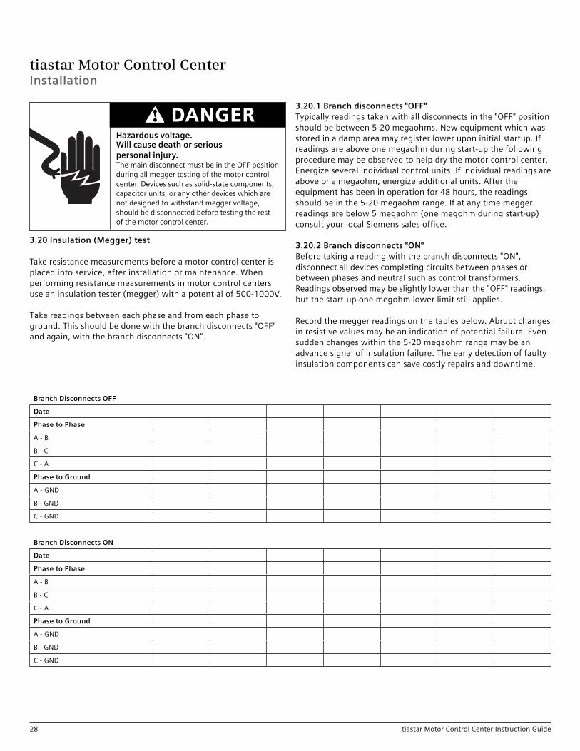
3.20 Insulation (Megger) test
Takeresistancemeasurementsbeforeamotorcontrolcenterisplacedintoservice,afterinstallationormaintenance.Whenperformingresistancemeasurementsinmotorcontrolcentersuseaninsulationtester(megger)withapotentialof500-1000V.
Takereadingsbetweeneachphaseandfromeachphaseto ground.Thisshouldbedonewiththebranchdisconnects"OFF" andagain,withthebranchdisconnects"ON".
3.20.1 Branch disconnects "OFF"Typicallyreadingstakenwithalldisconnectsinthe"OFF"positionshouldbebetween5-20megaohms.Newequipmentwhichwasstoredinadampareamayregisterloweruponinitialstartup.Ifreadingsareaboveonemegaohmduringstart-upthefollowingproceduremaybeobservedtohelpdrythemotorcontrolcenter.Energizeseveralindividualcontrolunits.Ifindividualreadingsareaboveonemegaohm,energizeadditionalunits.Aftertheequipmenthasbeeninoperationfor48hours,thereadingsshouldbeinthe5-20megaohmrange.Ifatanytimemeggerreadingsarebelow5megaohm(onemegohmduringstart-up)consultyourlocalSiemenssalesoffice.
3.20.2 Branch disconnects "ON"Beforetakingareadingwiththebranchdisconnects"ON",disconnectalldevicescompletingcircuitsbetweenphasesorbetweenphasesandneutralsuchascontroltransformers. Readingsobservedmaybeslightlylowerthanthe"OFF"readings,butthestart-uponemegohmlowerlimitstillapplies.
Recordthemeggerreadingsonthetablesbelow.Abruptchangesinresistivevaluesmaybeanindicationofpotentialfailure.Evensuddenchangeswithinthe5-20megaohmrangemaybeanadvancesignalofinsulationfailure.Theearlydetectionoffaultyinsulationcomponentscansavecostlyrepairsanddowntime.
Branch Disconnects OFF
Date
Phase to Phase
A-B
B-C
C-A
Phase to Ground
A-GND
B-GND
C-GND
Branch Disconnects ON
Date
Phase to Phase
A-B
B-C
C-A
Phase to Ground
A-GND
B-GND
C-GND
Installation
Hazardous voltage.Will cause death or serious personal injury.ThemaindisconnectmustbeintheOFFpositionduringallmeggertestingofthemotorcontrolcenter.Devicessuchassolid-statecomponents,capacitorunits,oranyotherdeviceswhicharenotdesignedtowithstandmeggervoltage,shouldbedisconnectedbeforetestingtherestofthemotorcontrolcenter.
DANGER

tiastar Motor Control Center
29tiastar Motor Control Center Instruction Guide
Hazardous voltage.Will cause death or serious personal injury.Dielectricormeggertestingshouldonlybeconductedbyqualifiedpersonnel.Refertotestdeviceinstructionsforsafetyinstructions.
DANGER
Hazardous voltage.Will cause death or serious personal injury.Neveroperateanycontactor,relay,orswitchunlessitsarcchuteisproperlyinstalledandsecuredandundamaged.
DANGER
Explosive hazard.Installation of fuses of insufficient interruption rating can cause death or serious personal injury,Toensurepropercoordinationandsufficientcapacitytointerrupttheavailablefaultcurrent,alwaysinstallreplacementfuseswithULclass,continuouscurrentrating,type,andinterruptingcapacityidenticaltotheoriginal.Neverdefeatrejectionmechanismswhichareprovidedtopreventtheinstallationofthewrongtypeoffuses.
WARNING
Operation
4 Operation
4.1 Pre-energization checks
Afterinstallation,fieldaddition,ormaintenance,performthefollowingchecksbeforeenergizingequipment:1.Check all connections for tightness, both mechanical and
electrical. Factory connections may loosen during shipmentand storage. It is of utmost importance to inspect allconnections and bolted joints for tightness prior toenergizing the equipment.
2.Compareallcircuitsforagreementwiththewiringdiagramswhichareprovidedwiththemotorcontrolcenter.Besurethateachmotorisconnectedtoitsintendedstarter.
3.Verifythatinsertsorautomaticshuttersareinstalledinallexposedopeningsintheverticalbusbarriers.
4.Inspectthemotorcontrolcenterforaccumulationofdustordirt.Ifrequired,cleantheMCCasexplainedintheMaintenancesectionofthismanual.
5.Testthemotorcontrolcenterpowercircuitforpossibleshortcircuitsandgrounds.Adielectrictestat2timesthenominalsystemvoltageplus1000voltsappliedforoneminutebetweenphasesandfromallphasestogroundisthepreferredmethod.Themaximumallowableleakagecurrentis1.5mAper1000testvoltsapplied.Ifahigh-pottesterisnotavailable,thenameggertestusinga500or1000voltmeggerisasuitablesecondchoice.Theminimumallowableresistancemeasuredfromphasetophaseandfromphasetogroundisonemegohm.Besuretodisconnectanycontroldevices,controlpowertransformer,etc,fromthecircuitwhichcouldbedamagedbythetestvoltage.
6.Manuallyexerciseallswitches,circuitbreakers,contactors,magneticdevices,andotheroperatingmechanismsseveraltimestomakecertaintheyareproperlyalignedandoperatefreely.Somecontactorsareshippedwithrestrainingdevicestominimizevibrationeffectsduringshipment.Besurethat
allsuchrestraintshavebeenremoved.Noneofthesedevicesmusteverbeblockedinthe“ON”position.Checkallelectricalinterlocksforpropercontactoperation.Checkallmechanicalinterlocksforproperfreedomandoperation.
7. Checkalltimersforproperintervalsettingandcontactoperation.
8. Checkoverloadrelaytripsettingorheatersizeandverifythattheyareadjustedpertheinstructionsgivenfortheoverloadrelayinthisinstructionmanual.
9. CheckallpowercircuitfusesandcontrolfusestoverifythattheyaresizedinaccordancewiththeNationalElectricalCodeapplicationrequirements.ClassK-9andHfusesarenotrecommended.
10. Currenttransformerstowhichcustomerdeviceswillbeconnected,areshippedwiththeirsecondariesshorted.Allshortingdevicesshouldberemovedwhenthesecondaryconnectionstothesetransformersarecompleted.Makesurethatthecurrenttransformersecondaryiscomplete.Currenttransformersmustnotbeenergizedwiththeirsecondariesopencircuited.
11. Checkalldevicesformissingorbrokenparts,properspringtension,freemovement,rustingorcorrosion,dirt,andexcessivewear.Makeallnecessaryrepairs.
12. Checkallelectricalrelays,meters,andinstrumentstoverifythatconnectionsaremadeproperlyandthatthedevicesfunctionproperly.Verifythatadjustablevoltageandcurrenttripmechanismsaresettothepropervalues.
13. Makesurethatnofuses,overloadrelays,incompletesequencerelays,shunttrips,groundfaultprotectionassemblies,electricalinterlocks,ortripcontactsfromanyofthesedevicesarestrapped,bypassed,ordefeatedinanymanner.
14. Turnallcircuitbreakersandfusibleswitchestothe“OFF”position.
15. Makesurethatallbarriers,braces,andshieldsareinstalledintheequipmentasintended.
16. Checktheintegrityofallbusmountingmeansandcableconnectionstothebus.Makecertainthatfieldwiringisclearoflinebusandphysicallysecuredtowithstandtheeffectsofthelargestfaultcurrentwhichthesupplysystemiscapableofdelivering.Makesurethatcontrolwiresorpowercablesarenottouchingthepowerbus.

tiastar Motor Control Center
30 tiastar Motor Control Center Instruction Guide
17. Verifythatallgroundconnectionshavebeenproperlymade.Thesectionsofthemotorcontrolcenterwhichwereshippedseparatelymustbeconnectedinsuchawaytoassureacontinuousgroundingpath.
18. Installcovers,installunits,closeandsecuredoors,makecertainthatnowiresarepinchedandthatallenclosurepartsareproperlyalignedandsecured.
19. Makesurethedoorinterlocksonalldisconnectoperatorsareproperlyadjustedandsecured.Ifadjustmentisrequired,usetheprocedureexplainedintheMaintenancesectionofthisinstructionmanual.
20. Disconnectanysafetygroundswhichhavebeenconnectedtothepowerbus.
21. Checkallconnectionsformechanicalandelectricaltightness.
4.2 Energizing equipment
1. Inordertominimizeriskofinjuryordamage,orboth,thereshouldbenoloadonthemotorcontrolcenterwhenitisenergized.Turnoffallofthedownstreamleads,includingthosesuchasdistributionequipmentandotherdeviceswhichareremotefromthemotorcontrolcenter.
2. Theequipmentshouldbeenergizedinsequencebystartingatthesourceendofthesystemandworkingtowardstheloadend.Inotherwords,energizethemaindevices,thenthefeederdevices,andthenthebranch-circuitdevices.Withbarriers(ifapplicable)inplace,andunitdoorsclosed
andlatched,turnthedevicesonwithafirmpositivemotion.Protectivedevicesthatarenotquick-actingshouldnotbe “teased”intotheclosedposition.
3. Afteralldisconnectdeviceshavebeenclosed,loadssuchaslightingcircuits,starters,contactors,heaters,andmotors,maybeturnedontoverifythatthesystemoperatesasintended.
4.3 Permissible loading of motor control centers
1. Formotorcontrolcenterswithoutmainovercurrentprotectivedevices,thetotalcontinuousloadcurrentthroughthehorizontalbusshouldnotexceedthecurrentratingofthemotorcontrolcenter.
2. Formotorcontrolcenterswithasinglemainovercurrentprotectivedevice,thetotalcontinuousloadcurrentontheprotectivedeviceshouldnotexceed80percentofitsampereratingunlessthedeviceisratedtocarry100percentofitsampererating,inanenclosure.
3. Formotorcontrolcenterswithmultiplemainovercurrentprotectivedevices,thetotalcontinuouscurrentthroughthehorizontalbusshouldnotexceedthecurrentratingofthemotorcontrolcenter.Thetotalcontinuousloadcurrentoneachovercurrentprotectivedeviceshouldnotexceed80percentofitsampereratingunlessthedeviceisratedtocarry100percentofitsampererating,inanenclosure.
4. Forbranch-circuitovercurrentprotectivedevicesinamotorcontrolcenter,thetotalcontinuousloadcurrentontheprotectivedeviceshouldnotexceed80percentofitsampereratingunlessthedeviceisratedtocarry100percentofitsampererating,inanenclosure.
5. Unlessacurrentlimitingmeansisusedinaseriescombination,themaximumshort-circuitcurrentratingoftheentiremotorcontrolcenteristhesmallestofthefollowing:a. theratingofthebusstructure,orb. thelowestratingofthemotorcontrolunits,orc. thelowestratingofthefeederunits.
Thismotorcontrolcenterratingisclearlyindicatedontheleadsheetlocatedintheinformationpacket.
Hazardous voltage.Failure to check this equipment prior to energization can cause death or serious personal injury.Allpre-energizedchecksoutlinedinthisinstructionmanualmustbeperformedbeforetheequipmentisenergizedbyQualifiedPersonnelonly.
WARNING
Operation

tiastar Motor Control Center
31tiastar Motor Control Center Instruction Guide
Addition and replacement of control units (page 25-27)wDe-energizemotorcontrolcenterincominglineconnections
Adding to a blank unit space (page 26)wOpenblankdoor.wRemovehingepinswithdooropen.wClosedoorhalfwayandremovedoor.w Ifnecessary,installunitsupportassemblyandblankcoversordoors.wInsertshelfbracketsataslightangleintoverticalbussupportangleandsnapintoplace.wSecurebracketsbyfasteningtheright-handbrackettobus
supportangleandtheseparatorangletotheleftsideof structurewiththetwoscrewsprovided.wMountunitdoor.(Oppositeprocedureofremovingblankdoor.)wRemove(ifrequired)unitstabholecovers.wVerifythatstabislubricatedwithapprovedlubricant.wSlidecontrolunitintoplacewithdisconnecthandle“OFF”.wCompleteengagementbyclosingrackinglever.Engagelockinglatchtoseparatorangleandscrewdown.wConnectoutgoingpowerandcontrolwiring.wClosedoorandperformpre-operationchecks(seepage29).
Replacing with unit of the same size (page 25) wIfpossible,deenergizemotorcontrolcenter. wMovedisconnectoperatinghandleto"OFF".wOpendoor,loosenanddisengagelockinglatch. wOpenverticalwirewaydoor.wMoveunitto.test.position.wDisconnectcontrolandloadwiringwRemoveunitbytiltingandslidingout.wReverseprocedureforreplacementunit.wPerformpre-operationchecks(seepage29).
Rearranging control units of different sizes (page 25)wRemoveallnecessaryunits,doorsandunitsupportassemblies.wRealignsupportassemblieswhereappropriate.wRemovestabholecoverswhereappropriate(andcoverthestabholecoversthatwillnotbeused).wMountunitdoors.w Installrearrangedunits.
Insulation test (Megger) (page 28)Thischecklistdoesnotrepresentanexhaustivesurveyofmaintenancestepsnecessarytoensuresafeoperationoftheequipment.Particularapplicationsmayrequirefurtherprocedures.Shouldfurtherinformationbedesiredorshouldparticularproblemsarisewhicharenotcoveredsufficientlyforthepurchaser’spurposes,themattershouldbereferredtothelocalSiemenssalesoffice.
Dangerousvoltagesarepresentintheequipmentwhichcancausedeath,seriousinjury,orpropertydamage.Alwaysde-energizeandgroundtheequipmentbeforemaintenance.Maintenanceshouldbeperformedonlybyqualifiedpersonnel.Theuseofunauthorizedpartsintherepairoftheequipment,tamperingbyunqualifiedpersonnel,willresultindangerousconditionswhichcancausedeath,seriousinjury,orequipmentdamage.Followallsafetyinstructionscontainedherein.
5 Maintenance
5.1 Maintenance quick check listFailuretoproperlymaintaintheequipmentcanresultindeath,seriousinjury,orproductfailure.Theinstructionscontainedhereinshouldbecarefullyreviewed,understood,andfollowed.Thefollowingmaintenanceproceduresmustbeperformedregularly.
SchedulingwSchedulemaintenanceappropriatetotheseverityofservice.wConsiderenvironment(dampness,heat,anddust),severity
ofoperations,andtheimportanceofthemachinerybeing controlled.wControlunitmaintenanceshouldcoincidewithinspection
ofthemotorbeingcontrolled.wBusworkinspectionentailsshuttingdowntheentire
controlcenter.
Cleaning (page 33)wUseavacuumcleaner,notcompressedair.wExcessdepositsofforeignmaterialssignifyfaultygasketing.wPayparticularattentiontoconductivedeposits.
Loose connections (page 33)wPeriodiccheckingoftightnessofconnectionspromotesreliability andreducesheating.wOverheatinganddiscolorationssignifylooseconnections.wTorquehorizontalbusboltsto20ft.-lbs.wTorqueincominglineconnectionstomainlugsonlyto85ft.-lbs.wTorqueallincomingconnectionstomaincircuitbreakersand
fusibledisconnectsasperthebreakerordisconnectmanufacturer’srecommendations.Thetorquerequirementswillbefoundonalabellocatedonthedisconnectingdevice.
Test position plug-in units (page 25)wUnscrewthelockinglatchinthelowerfrontleft-handcornerand disengagelatchfromseparatorangle.wReleasetherackingleverinthetopbarrierplate.wSlideunitouttothepositivestopontheshelfbrackets.wAsmanyastwopadlocksmaybeusedtolockunitin“test”
positiontopreventaccidentalstabengagement.
ContactswMakesurethatallcontactsarefreefromextraneousmaterials, excesspittingorburning.wCheckforspringpressure.wLubricatestabconnectionswithapprovedlubricant.
Locking in engaged position (page 34)wTolockin"ON",drillouttheindentationsonthedisconnectoperatinghandleandinsertapadlock.wTolockin"OFF",asmanyasthreepadlocksmaybeinsertedin
thedisconnectoperatinghandle.
Field additions of sections (page 14)wForfieldadditionsofsections,followthesameprocedureas
forthefieldassemblyofshippingsplits.
Maintenance

tiastar Motor Control Center
32 tiastar Motor Control Center Instruction Guide
Itisrecommendedthatasafetygroundbeconnectedtothepowerbusafterthesystemhasbeende-energized,andpriortoworkingontheequipment.FollowtheprocedureoutlinedinthePre-energization Checksectionofthismanualbeforepowerisrestored.
Forthesafetyofmaintenancepersonnelaswellasotherswhomightbeexposedtohazardsassociatedwithmaintenanceactivities,thesafetyrelatedworkpracticesofNFPA70Eshouldalwaysbefollowedwhenworkingonelectricalequipment.Maintenancepersonnelshouldbetrainedinthesafetypractices,procedures,andrequirementsthatpertaintotheirrespectivejobassignments.Thismanualshouldbereviewedandretainedinalocationreadilyaccessibleforreferenceduringmaintenanceofthisequipment.
Thecustomermustestablishaperiodicmaintenanceprogramtoensuretrouble-freeandsafeoperation.Thefrequencyofinspection,periodiccleaning,andpreventivemaintenanceschedulewilldependupontheoperationconditions.NFPAPublication70B,ElectricalEquipmentMaintenance.maybeusedasaguidetoestablishsuchaprogram.Apreventivemaintenanceprogramisnotintendedtocoverreconditioningormajorrepair,butshouldbedesignedtoreveal,ifpossible,theneedforsuchactionsintimetopreventmalfunctionsduringoperation.
Thefollowingitemsshouldbeincludedinanymaintenancechecklist.Formoredetailsreadthesucceedingpages.
• GeneralinspectionoftheMCC• Periodiccleaning• Tighteningtorques• Stabfingersandverticalbus• Circuitbreaker/disconnectoperator• Mechanicalinterlocks
Aspecificchecklistofroutinepreventivemaintenancerequirementsisrecommendedforeachitemofequipment,aswellasalogbooktorecordthemaintenancehistory.
5.2 General Inspection of the MCC
1. Carefullyinspectthedoors,enclosuresides,anddeadfrontsurfacesoverallunitsforexcessiveheat.Asageneralrule,atemperaturewhichthepalmofthehandcannotstandforabout3secondsmayindicatetrouble.Infra-redheatdetectorsareavailableforthepurposeofdetectingheatproblems.
2. Inspectthemotorcontrolcenteraminimumofonceeachyear,ormoreoftenasdeemednecessary.LookforanymoistureorsignsofpreviouswetnessordrippinginsidetheMCC.Lookforanyaccumulationofdustordirt.CleanasexplainedinthePeriodicCleaningsection.
3. Looseelectricalconnectionscancauseoverheatingthatcanleadtoequipmentmalfunctionorfailure.Loosebondingorgroundingcancompromisesafetyand/orfunction.Terminalscrews,lugs,busconnections,bondingandgroundingconnectionsshouldbeinspectedfortightnessandretightenedsecurelyasrequired.RecommendedtighteningtorquesareshownintheRecommendedTighteningTorquesectionofthismanual.Fuseclipsshouldbecheckedforsignsofoverheating,looseness,orinadequatespringpressure,andreplacedifnecessary.Allterminals,connections,andconductorsshouldbeexaminedforevidenceofoverheating,corrosion,orpitting.Anypartsfoundtobedamagedshouldbereplaced,usingpartssuppliedorrecommendedbySiemens.Evidenceofoverheatingmayincludediscoloredconductors,terminals,orparts;ormelted,charred,orburnedinsulation.
4. Examineinsulationonconductorsforoverheatingorchafingagainstmetaledgesthatcouldprogressintoaninsulationfailure.Anydamagedconductorsshouldbereplaced.Replacementconductorsshouldbererouted,braced,orshieldedifneededtoavoidsimilardamageinfutureoperation.Temporarywiringshouldberemovedorreplacedbypermanentwiring.
Maintenance
Hazardous voltage.Will cause death or serious personal injury.1)Disconnectandlockoutincomingpowerandcontrolvoltagesourcesbeforebeginningworkonthisoranyotherelectricalequipment.2)Checkallpowerandcontrolcircuitterminalswithavoltmetertomakecertainthattheequipmentistotallydeenergized.3)EnsurethatonlyQualifiedPersonnelbeinstructedandauthorizedtousethedefeatermechanismtogainaccesstoandeenergizedcompartment.4)Neverattempttowithdrawunitordisconnectanyterminationswhenthedefeatermechanismhasbeenusedtoopenthecompartmentdoor.
DANGER

tiastar Motor Control Center
33tiastar Motor Control Center Instruction Guide
Hazardous voltage.Will cause death or serious personal injury.Disconnectpowerbeforeworkingonthisequipment.
DANGER
Maintenance
5. Operateeachswitchorcircuitbreakerseveraltimestoinsurethatallmechanismsarefreeandinproperworkingorder.Checktheoperationofthemechanicalsafetyinterlocksprovidedwiththeoperator(seesectiononCircuitBreaker/DisconnectOperator).Neverattempttooperateaswitchorcircuitbreakerbyuseofexcessiveforce.
6. Visuallyinspectinstrumentsandpilotlights.Replacedefectivepilotlights.Checkinstrumentcalibrations.
7. Checkalldevicesformissingorbrokenparts,properspringtension,freemovement,rustingorcorrosion,dirt,andexcessivewear.Performperiodicmaintenanceoncomponentsasdetailedinthecomponentinstructionbooks.
8. Recommendedtogoalongwiththemaintenanceprogramforamotorcontrolcenterisanadequatestockofrenewalparts.Thisisimportantwhereservicebecomesacriticalfactorordowntimeisextremelyexpensive.Theitemskeptinstockwilldependonthetypeofmotorcontrolcenteranditsapplication.Typicalitemskeptinstockshouldincludecontactkits,magnetcoils,andfuses.Whenorderingrenewalparts,thefollowinginformationmustbeprovided.1. Completepartnumbersofitemsrequired.2. Quantityofpartsrequired.3. Descriptionofparts.4. Motorcontrolcentercatalognumber.Thecatalognumber
isfoundonthecontrolcenternameplatelocatedonfrontofthecenter.
5. Unitidentificationnumber.Thenumberislocatedonalabelonthesideofthecontrolunitforwhichtheorderedpartsareneeded.
SeetheSiemenscontrolcatalogandthefollowingreplacementpartpublicationsforstarters.0-13/4 14-GCF 4 14-GJB2-21/2 14-GFF 41/2-514-GKF3-31/2 14-GHF 6 14-GMF
5.3 Periodic cleaningAccumulationofdustandforeignmaterialsuchascoaldust,cementdust,orlampblackmustberemovedfromallcontrolequipmentandallsurfacesmustbewipedcleanatregularintervals.Dirty,wet,orcontaminatedpartsshouldbereplacedunlesstheycanbecleanedeffectively.Dustcancollectmoisture,causingvoltagebreakdownanditcanreducetheeffectivenessofheatsinks.
Controlequipmentpartsshouldbecleanedbyvacuumingorwipingwithadryclothorsoftbrush.Usecaretoavoiddamaging
delicateparts.Liquidcleaners,includingspraycleaners,arenotrecommendedduetothepossibilityofresidues.Compressedairisnotrecommendedforcleaningbecauseitwillonlydistributecontaminantsonothersurfaces,andmaydamagedelicateparts.Theinsidebottomofthemotorcontrolcentershouldalsobecleaned,includingremovalofanyhardwareordebris,sothatanyneworunusualwearorlossofpartsoccurringaftertheinspectionmaybemorereadilydetectedduringsubsequentmaintenance.Inspectthemotorcontrolcenterforanysignsofpreviouswetnessordrippinginsidethecontroller.
Condensationinconduitsordrippingfromanoutsidesourceisacommoncauseoffailure.Sealoffanyconduitsthathavedrippedcondensate,andprovideanalternativemeansfortheconduittodrain.Sealoffanycracksoropeningswhichhaveallowedmoisturetoentertheenclosure.Eliminatethesourceofanydrippingontheenclosureandanyothersourceofmoisture.Replaceandthoroughlydryandcleananyaccumulationofdepositedmaterialfrompreviouswettings.
5.4 Stab Fingers and vertical bus
Lookforwearofthetinplatingwheretheunitstabfingersengagetheverticalbus.Theplatingispartoftheenvironmentalprotectionsystem.Oxideand/orotherfilmscanformonexposedbusresultinginapoorcontact.
Lubricatestabconnectionpointswithanapprovedlubricant.Thesepartsmustbereplacedwhentheplatingisworntothepointwherecoppercanbeseenbecausecontactresistancebecomeshigher,increasingtheheatgeneratedatthecontactpoint.
5.5 Recommended tightening torquesWhenmakingboltedassemblies,thefollowingconsiderationsshouldbegenerallyfollowed.Thetighteningtorquesaredeterminedbythesizeofhardwareused.
1. Metal-to-metal–Applystandardtighteningtorqueaslisted:Recommended tightening torques
Thread size Torque (lb.-in.)8-32 2010-32 27-321/4-20 755/16-18 1003/8-16 2471/2-13 613
2. Metal-to-Insert Molded in Compound Part–Apply2/3ofstandardtighteningtorque.
3. Compound-to-Compound–Apply1/2ofstandardtightenintorque.
4. ControlTerminals–11lb.-in.5. Tightenboxtypeincomingcablelugsetscrewsto85ft.lbs.-in.6. Tightenboltedbusconnectionsto20ft.-lbs.7. 400Aand600Afixedmountedunitclampassemblybolts
shouldbetightenedto35ft.-lbs.

tiastar Motor Control Center
34 tiastar Motor Control Center Instruction Guide
5.6 Disconnect operating handle adjustment
Inrarecircumstances,suchaswhenchangingacircuitbreakerorafusibleswitchorwhenaunitistakenapart,itmaybenecessarytoadjustthedisconnectoperatinghandle.(TheSiemensfusibledisconnectswitchfor30A,60A,100A,and200Aratingsdoesnotrequireadjustment.)
1. Performalldisconnectoperatinghandleadjustmentswiththeunitremovedfromthemotorcontrolcenterorinthe“test”position.
2. Theadjustablelinkrodcanadjusttoincreaseordecreaseitsoveralllengthbyrotatingthesleeve.Byrotatingthesleeveclockwisethelengthisincreasedandbyrotatingitcounterclockwisethelengthisdecreased.Ahexnutisprovidedas
partoftheadjustablelinkrodandistightenedagainstthesleevetopreventitfromgoingoutofadjustment.Thehexnutmustbelooseandsufficientlyawayfromthesleevetoallowittorotateduringtheadjustmentofthehandle.
Hazardous voltage.Will cause death or serious personal injury.Disconnectpowerbeforeworkingonthisequipment.
DANGER
Figure60
On
Trip
Off
Park
Figure61
Maintenance
Adjustable Link Rod
Sleeve
Hex Nut
Escutcheon
Slot “B”
125A FrameCircuit Breaker
PivotMechanism
Escutcheon
30/60A Disconnect Switch
Slot “A”
A

tiastar Motor Control Center
35tiastar Motor Control Center Instruction Guide
3. Thehandleassemblymustbeadjustedtoperformthefollowingfunctions:
Disconnect switch Unitmustturn"ON" Unitmustturn"OFF"
Circuit breaker Unitmustturn"ON"Unitmustturn"OFF"Unitmustindicate"TRIP" Unitmust"RESET"
4. Operatethehandlefromthe"ON"positiontothe"OFF"position andcircuitbreakerordisconnectswitchwillturn"OFF".
5. Returnthehandletothe"ON"positionandthecircuitbreakeror disconnectswitchwillturn"ON".Ifitdoesnot,rotatethesleeve slightlyclockwiseandtryagain.Repeatthisstepuntilthehandle assemblyturnstheunit"ON".Then,repeatstep4.
6.1Oncesteps4and5havebeensatisfactorilycompleted,the adjustmentforthedisconnectswitchwillhavebeencompleted.Tightenthehexnutagainstthesleevetolockintheadjustment.Thefollowingstepswillnowonlypertaintocircuitbreakers.
7. Tripthecircuitbreakerandthehandleshouldmovetoaposition midwaybetweenthe"ON"and"RESET"positions.Circuitbreakers fromdifferentmanufacturersrequiredifferentmethodstotrip them.Onecanbetrippedbyrotatingaredbutton,anotherby passingahighcurrentatlowvoltagethroughoneofthepoles.(Thedefeatermechanismshouldengage.)
8.1Nowmovethehandledownpastthe"OFF"positiontoresetthecircuitbreaker.Ifthecircuitbreakerresetsandcanbereturned tothe"ON"positionbythehandle,theadjustmenthasbeen completedandthehexnutshouldbetightenedagainstthe sleeve.Ifthecircuitbreakerdoesnotreset,turnthesleeve counterclockwiseslightlyandtryagain.Repeatthisstepuntil thebreakerresets.Thenrepeatsteps4-8toverifythatthe previousadjustmentshavenotbeenadverselyeffected.
9. Inthecaseofboththecircuitbreakeranddisconnectswitch,theadjustmentshouldbesuchtheyturnonwiththeknobnocloserthe1/8”awayfromtheescutcheon.
1Alwaysusetwowrencheswhenloosening,adjusting,ortighteningtheadjustablelinkrod.Onewrenchadjuststhehexsleevewhilethesecondwrenchholdsthehexnut.
AprovisionismadeforQualifiedPersonstodefeatthedooroperatorinterlockwhenthehandleisinthe“ON”position.Thisisaccomplishedbyturningthedefeaterscrewcounterclockwiseapproximately1/8turnuntilthedoorisreleased.Itisnotnecessarytooperatethedefeaterscrewtoclosetheunitdoor.Releasethedefeaterscrewandsecurethe1/4turndoorfasteners.
Thissafetyinterlockalsoservestopreventinadvertentclosingofthedisconnectwhenthedoorisopen.Authorizedpersonnelmaydefeattheinterlockinthissituationbypushingdowntheexposedinterlockarmlever.Thisreleasestheinterlocksothattheprotectivedevicemaybeturned“ON”.
5.7 Adjustment notes
Nofieldadjustmenttothedoorinterlockmechanismshouldbenecessaryundernormaloperatingconditions.However,should
adjustmentbecomenecessaryasaresultofmechanicaldamageorwear,thefollowingprocedureisrecommended.
Withdisconnectingdeviceinthe“OFF”position,andtheunitdooropen,defeattheinterlockbypushingthetopofthelevertotheleftandturnbreaker“ON”and“OFF”severaltimes.Ifthedisconnectingdevicefailstoturn“ON”orifoperatingresistanceisexperienced,turnprotector“OFF”.Withdrawtheunitandinspectformisalignmentoftheoperatorextension(s)orthedriver.Makenecessaryadjustmentstocorrectanymisalignment.
5.8 Maintenance after a fault has occurred
Theexcessivecurrentsoccurringduringafaultmayresultincomponentorbusdamageduetomechanicaldistortion,thermaldamage,metaldeposits,orsmoke.Afterafault,repairthecauseofthefault,inspectallequipmentperNEMAStandardsPublicationNo.ICS2-1987,PartICS2-302andmakeanynecessaryrepairsorreplacementspriortoplacingtheequipmentintoserviceagain.Thefollowingprocedureisrecommendedforthisinspection.
Bus –Retightenallbusconnections.Replaceburntormeltedbusorbuswithmelted,worn,ordamagedplating.Replaceallinsulatorsshowingdeterioration,deposits,orcracks.
Enclosure–Inspecttheenclosureanddoorsforevidenceofdamagesuchasdeformation,displacementofparts,orburning.Extensivedamagewillrequirereplacementoftheentirecontroller.
5.9 Disconnect Means
1. CircuitBreakers:Examinethecircuitbreakerforevidenceofpossibledamage.Ifthereisnotapparentevidenceofdamage,thebreakermayberesetandturned“ON.”Ifitissuspectedthatthecircuitbreakerhasopenedseveralshortcircuitsoriftherearesignsofpossibledeterioration,replacethebreakerorsubjectittothedescribedinPara.AB1-2.38oftheNEMAStandardsPublicationfor“MoldedCaseCircuitBreakers”beforerestoringittoservice.
Hazardous voltage.Will cause death or serious personal injury.Disconnectpowerbeforeworkingonthisequipment.
DANGER
Maintenance
Hazardous voltage.Will cause death or serious personal injury.Disconnectpowerbeforeworkingonthisequipment.
DANGER

tiastar Motor Control Center
36 tiastar Motor Control Center Instruction Guide
2. DisconnectSwitch:Theexternaloperatinghandlemustbecapableofopeningtheswitchafterafault.Replacetheswitchiftheexternaloperatinghandlefailstoopenitorifvisualinspectionafteropeningindicatesdeteriorationbeyondnormalwear,suchasoverheating,contactbladeorjawpitting,charring,orinsulationbreakage.
3. FuseHolders:Replacefuseholdersiftheinsulatingmounts,barriers,orfuseclipsshowsignsofdeterioration,heating,distortion,orlooseness.
4. OperatingHandle:Thedisconnectingmeansmustbereplacediftheoperatinghandlefailstoopenandclosethedisconnectdevice.Thedoorinterlockmustbeinspectedanditsproperfunctionverifiedpriortorestoringthecontrollertoservice.
5. StabFingers:(Figure62)Inspectstabfingersasinstructed underStabFingersSectionandVerticalBusSectionandreplace ifnecessary.Lubricatestabfingerswithapprovedlubricant.
5.10 Terminals and internal conductors
Replacealldamagedpartswhichshowevidenceofdiscoloration,melting,orarcingdamage.
5.10.1 Motor starter1. Contactor–Replacethecontactsandcontactspringsifthe
contactsareweldedorshowheatdamage,displacementofmetal,evidenceofbindingintheguides,orwearinexcessofwearallowance.Ifdeteriorationextendsbeyondthecontacts,replacethecontactor.Examplesofsuchdeteriorationincludeevidenceofarcingonthecontactormoldingsandinsulationdamage.Arcchutesmustbeinplaceandsecuredpriortooperatingcontactor.
2. OverloadRelays–a)Anyindicationofanarcstrikingorburningtheoverloadrelaymayrequirereplacement.b)Contactoperationmustbeverifiedbyelectricallyormechanicallytrippingandresettingtherelayevenifthereisnovisualindicationofdamagethatwouldrequirereplacement.
3. Fuses–Alwaysreplaceallthreefuseseventhoughonlyoneortwoareopencircuitedsinceinternaldamagesufferedbyfusesnotreplacedcouldresultinnuisanceshutdownlater.
4. PerformthePre-energizationchecksproceduresdetailedonPage29herein,beforerestoringtheequipmenttoservice.
5.11 Adjustment of Sentron Type ETIInstantaneous Trip Motor Circuit Interrupter (1A-125A)
ETIinstantaneoustripmotorcircuitinterruptersaresuppliedasstandardwithSize1throughSize6motorstarters.Themotorcircuitinterruptercontinuouscurrentratingshouldnotbelessthan115%ofmotorfullloadcurrent(MFLC).TheMFLCisobtainedfromthemotornameplateorfromTable430-150oftheNEC(1999).Usethefollowingproceduretoadjusttheinstantaneoustripsetting.
1. Movetheoperatinghandletothe“OFF”positionandopentheunitdoor.
2. TheinstantaneoustripcircuitbreakerisfactorysetattheLOWposition.
Toset:determinemotorfullloadcurrentfromthemotornameplate.Refertothetableanddeterminetherecommendedsettingposition.Useascrewdrivertosettheindicatorontheadjustmentscrewtotheappropriateposition.
Formaximumprotectionthetrippositionshouldbesetaslowaspossible.Turntheadjustmentscrewcounterclockwisetosuccessivelylowerpositionsuntilthebreakertripsonmotorstarting.
Afterthispositionisdetermined,turntheadjustmentscrewclockwisetothenexthighersettingfornormaloperation.Theadjustmentscrewisinfinitelyadjustableforcustomerconvenience.Ifthebreakerdoesnottripatthelowestsettingleavetheindicatoratthissetting.
3. Adjustthetripsettingbyrotatingtheadjustmentdialtothepositionselectedinstep2above.
Hazardous voltage.Will cause death or serious personal injury.Disconnectandlock-outallpowerandcontrolvoltagesourcessupplyingthemotorcircuitinterrupterbeforeadjustingtripsettingorperforminganyothermaintenanceoperations.
DANGER
Maintenance
Figure62.Thestabassembly.

tiastar Motor Control Center
37tiastar Motor Control Center Instruction Guide
Ensurethatthesettingonamagneticonlymotorcircuitprotectordoesnotexceedthemaximumallowablesettingasdefinedinthe1999NationalElectricalCode,section430-S2(C)(3).
5.12 Field testing of the circuit breakers
Atestcanbeperformedusingtheprocedureoutlinedinthefollowingdiscussiontoverifythatacircuitbreakertripmechanismisfunctioning.
1. Wirethethreecircuitbreakerpolesinseries.2. Connecttheseriescombinationofbreakerpolestoavariablelow
voltagehighcurrentpowersource.3. Graduallyincreasethecurrentfrom“0”untilthecircuitbreaker
trips.Ifthecircuitbreakerfailstotripwhenthetestcurrentreaches150%ofthelargesttripsetting,thetripunitisnotfunctioningproperlyandthecircuitbreakerrequiresreplacement.
5.13 Overload relay
Forproperoverloadrelaycoordination,thecablesontheloadsideoftheoverloadrelayshouldbesizedinaccordancewiththetablesinArticle310oftheNationalElectricalCode.Thewireformotorswithfullloadcurrentsof100amperesorlessmaybeselectedfromthe60°Cor75°Ccolumn.Selectwirefromthe75°Ccolumnwhenthemotorcurrentisgreaterthan100amperes.Whenconditionsdictatetheuseofcableslargerthanthese,therelaytrippingtimemaybeaffected.Anotherconditionwhichmayaffecttrippingisalongaccelerationtimesuchasthatcausedbyamotordrivingahighinertiaload.Ifeitheroftheseconditionsexists,consultSiemensforoverloadrelayapplicationinstructions.
I-T-E Type ETI setting positions
Cont. Amps
Trip settings positions
LOW 2 3 4 5 6 7 HI
1 2.6 4.5 6 7.5 — — — 9
2 7 11 15 19 — — — 22
3 10 17 23 30 — — — 35
5 16 26 36 46 — — — 54
10 30 50 70 85 — — — 100
25 55 90 125 155 — — — 180
30 80 135 185 235 — — — 270
40 115 185 255 325 — — — 375
50 180 300 410 520 — — — 600
100 315 540 740 890 — — — 1000
FXD62AJXD62HLXD62HMXD62A ContactSiemensSalesOfficeforsettingswithcurrentlimiters.
HEM Setting Positions
CatalogNumber
ContactAmps
NEMAStarter size
Trip settings positions
A B C D E F
HEM3M003L 3 0 9 15 21 27 30 33
HEM3M007L 7 0 21 35 49 63 70 77
HEM3M015L 15 0 45 75 100 135 150 165
HEM3M030L 30 1 90 150 210 270 300 330
HEM3M050L 50 2 150 250 350 450 500 550
HEM3M070L 70 2 210 350 490 630 700 770
HEM3M100L 100 3 300 500 700 900 1000 1100
Maintenance

tiastar Motor Control Center
38 tiastar Motor Control Center Instruction Guide
Problem Probable cause Corrective action
Doorswillnotcloseoroutofalignment.
Enclosureisnotbolteddowntightly.
Enclosuresprungoutofshape.Doorhingesnotproperlyadjusted.
Usinglevel,addshimsasnecessaryandtightenanchoringbolts.
Straightenorrepairenclosure.Removedoorhinges.Addorsubtractshimsasnecessary.
Contactorwillnotclose. Controlcircuitorpowerfuseblownorcircuitbreakertripped.
Inspectfuses,replaceifblown.Resetcircuitbreaker.
Incomingpowerlinenotenergized. Closefeedercircuitbreakersortieswitch.
Magnetcoildefective. Checkmagnetoperation,replacecoilasnecessary.
Interposingrelaydefective.1
Controlpowertransformerdefective.Overloadrelaytrippedordefective.Missingjumper,looseconnections,remoteconnections,etc.
Checkandreplaceifdefective.Checkandreplaceifnecessary.Checkandreplaceifnecessary.Checkwiringdiagramcarefullytomakesurethatallexternaloralternateconnectionshavebeenmadesatisfactorily.Thisisespeciallytruewhereremoteprotectiveorcontroldevicesareused.
Contactorchatterorhum. Looseconnectionincontrolcircuit.Defectiveinterposingrelay.1
Defectivecoil.Lowcontrolvoltage.Corrodedordirtymagnetpolefaces.
Tightenconnectionsincontrolcircuit.Checkrelay,replaceifnecessary.Checkmaincoil,replaceifnecessary.Checklinevoltage.Cleanorreplacemagnetassembly.
Contactsoverheating. Looseconnections.Contactsnotmatingfirmly.
Contacttiperoded.
Tightenconnections.Checkforweakordeformedcontactspring,replaceifnecessary.Replacecontacts.
1Notsuppliedonallstarters.
6. Troubleshooting
Intheunlikelyeventthatoperatingproblemsareencountered,usethefollowingtroubleshootingcharttoisolatethecauseoftheproblemandfindtheremedy.Ifthecorrectiveactiongiveninthechartfailstocorrectthedifficulty,consultyourfieldsalesrepresentative.
ThefollowinginformationisrequiredifitisnecessarytowriteSiemensControlsrelativetotheequipmentproblem.
1. Manufacturer’sordernumberandpartnumber,ifavailable.2. Nameplatedataoncontactororcontroller.3. Dutycycleandanydetailsofoperation.4. Lengthoftimeinserviceandapproximatetotalnumber
ofoperations.5. Voltage,current,andfrequency.6. Descriptionofanyproblem.7. Anyotherpertinentinformation,suchasdrawing,layout,
andschematicnumber.
Hazardous voltage.Will cause death or serious personal injury.Disconnectpowerbeforeworkingonthisequipment.
DANGER
Troubleshooting

tiastar Motor Control Center
39tiastar Motor Control Center Instruction Guide
Problem Probable cause Corrective action
Overloadrelaystripduringstartingorsoonaftermotorisuptospeed.
Motoroverloaded. Limitstartingloadandrunningloadtomotorcapabilities.
Motorbeingstartedtoofrequentlyatcloseintervals.
Joggingandstartingoperationsmustbelimitedtocapabilitiesofthemotorandcontrol.Checkstartinglimitationsinmotorinstructionmanualbeforerepeatedstarts.
Excessivemotoraccelerationtime. Thestartingofhighinertialoadsmaynotpermittheuseofstandardoverloadrelayapplication.Whereacceleratingtimeapproaches12secondsormore,specialoverloadrelaybypassdevicesandcircuitswouldusuallyberequired.ContactSiemensregardingsuchproblemsandsupplycompletedataonlocked-rotorstartingcurrentandtotalacceleratingtimeundermaximumloadconditions.
Lowlinevoltage. Linevoltageshouldbemaintainedbetween-+10%ofmotornameplatevoltage.
Overloadrelaytripsduringmotoroperation. Motorbeingoverloaded. Reduceloadorcorrectconditionscausingoverload.
Overloadrelaynotadjustedtomotorcapabilitiesorsizedproperly.
Adjustrelaysettinginaccordancewithinstructionsfortheoverloadrelay.
Adjustmentshouldcorrespondtothermalratingandservicefactor.Replaceoverloadifnotsizedproperly.
Overloadrelayfailstotriponoverloadcurrent. Relaytrippingmechanismjammed. Replacerelay.
Incorrectrelayorrelaysetincorrectly. Checkrelayselectionandadjustmentperoverloadrelayinstructions.
Currenttransformerswithimproperratioorwithshort-circuitedsecondaryterminals.
Currenttransformersmusthavestep-downratiotocorrespondtofullloadmotorcurrentandrelayselection.Protectivejumpersmaybeprovidedatcurrenttransformersecondaryterminalsoronterminalblockconnectionstoguardagainstopentransformersecondarycircuit,andjumpersmustberemovedbeforeplacingequipmentinoperation.
Hazardous voltage.Will cause death or serious personal injury.Disconnectpowerbeforeworkingonthisequipment.
DANGER
Troubleshooting

tiastar Motor Control Center
40 tiastar Motor Control Center Instruction Guide
Problem Probable causes Corrective action
Blowingofmotorpowerfuses. Shortcircuitontheloadsideofthemotorfuses. Usemeggerandothertestinstrumentstolocatefaultandcorrect.
Joggingortoofrequentstarting. Onfrequentstarting,fusesaccumulateabnormalrelays.Sincefusesmorecloselyfollowcoolingandheatingofmotorwindings,successivestartingoperationsmustbelimitedtothesafecapacityofthemotortopreventfuseblowingfromthiscause.Checksizeratingonfuseagainstmotorfullloadcurrentsandservicefactor.
Fusesinternallydamagedbecauseofimproperhandling.
Motorpowerfusesmaybedamaged,dropped,orroughlyhandled.Replacewithfuseofsametype,rating,andvoltage.
Blowingofprimarycontroltransformerfuses. Shortedprimarywiringincontroltransformer. Replaceorrepairtransformer.
Fusemaybe“open”duetoroughhandlingbeforeinstalling.
Replacewithfuseofsametype,rating,andvoltage.
Secondaryfusesnotproperlycoordinated. Meltingcharacteristicsofsecondaryfuseshouldnotintersectmeltingcharacteristicofprimaryfuse.RatingofstandardNECfuseshouldnotexceedtwicethesecondarycurrentrating.
Blowingofsecondarycontrol. Abnormalcurrentorshortcircuitin Checkforshortedmagnetcoils,shortedrectifiers,ifsupplied,grounds,looseorbentconnections,mechanicalbindinginrelayandcontactormechanisms,excessiveoperations,andincorrectsecondaryterminalconnections.
Hazardous voltage.Will cause death or serious personal injury.Disconnectpowerbeforeworkingonthisequipment.
DANGER
Troubleshooting

tiastar Motor Control Center
41tiastar Motor Control Center Instruction Guide
Full loadmo. amps Min. Max.
Heatercode no.
Max rat.of prot.device1
Size 0 & 10.67 0.72 E14 30.73 0.80 E16 30.81 0.85 E17 30.86 0.92 E18 30.93 0.99 E19 31.00 1.08 E23 31.09 1.23 E24 31.24 1.37 E26 31.38 1.54 E27 31.55 1.69 E28 31.70 1.80 E29 31.81 1.94 E31 31.95 2.07 E32 32.08 2.26 E33 32.27 2.54 E34 72.55 2.69 E36 72.70 2.88 E37 72.89 3.14 E38 73.15 3.40 E39 73.41 3.81 E41 73.82 4.26 E42 74.27 4.62 E44 74.63 5.09 E46 75.10 5.61 E47 75.62 5.91 E48 75.92 6.15 E49 156.16 6.70 E50 156.71 7.54 E51 157.55 8.29 E52 158.30 8.99 E53 159.00 9.85 E54 159.86 10.4 E55 1510.5 12.0 E56 1512.1 13.6 E57 3013.7 15.8 E60 3015.7 17.0 E61 3017.1 18.4 E62 3018.5 19.4 E65 3019.5 21.3 E66 3021.4 24.4 E67 3024.5 25.9 E69 3026.0 26.0 E70 30
Size1onlyD25385-7
Full loadmo. amps Min. Max.
Heatercode no.
Max rat.of prot.device1
Size 1 3/42.27 2.54 E34 72.55 2.69 E36 72.70 2.88 E37 72.89 3.14 E38 73.15 3.40 E39 73.41 3.81 E41 73.82 4.25 E42 74.26 4.62 E44 74.63 5.09 E46 75.10 5.61 E47 75.62 5.91 E48 75.92 6.15 E49 156.16 6.70 E50 156.71 7.54 E51 157.55 8.29 E52 158.30 8.99 E53 159.00 9.85 E54 159.86 10.4 E55 1510.5 12.0 E56 1512.1 13.6 E57 3013.7 15.6 E60 3015.7 17.0 E61 3017.1 19.4 E62 3019.5 20.9 E65 3021.0 22.2 E66 3022.3 25.3 E67 3025.4 26.9 E69 5027.0 30.2 E70 5030.3 33.3 E72 50
D25556-3Size 2 & 2 1/210.5 12.0 E56 5012.1 13.6 E57 5013.7 15.6 E60 5015.7 17.1 E61 5017.2 19.4 E62 5019.5 20.9 E65 5021.0 22.2 E66 5022.3 25.3 E67 5025.4 26.9 E69 5027.0 30.2 E70 5030.3 33.3 E72 5033.4 35.3 E73 5035.4 41.5 E74 5041.6 45.0 E76 100
Size21/2onlyD26069-5
Full loadMo. amps Min. Max.
Heatercode no.
Max rat.of prot.device1
Size 4 1/2 & 588.0 98.0 E27 25098.1 108 E28 250109 114 E29 250115 122 E31 250123 130 E32 250131 140 E33 250141 155 E34 250156 166 E36 250167 177 E37 250178 193 E38 400194 209 E39 400210 233 E41 400234 248 E42 400
Size5onlyD25651-5
Size 456.9 60.9 E89 15061.0 63.9 E91 15064.0 67.7 E92 15067.8 72.4 E93 15072.5 77.7 E94 15077.8 85.9 E96 15086.0 91.9 E97 15092.0 96.7 E98 15096.8 105 E99 150106 115 E103 150116 130 E104 150
D36024-2
Full loadmo. amps Min. Max.
Heatercode no.
Max rat.of prot.device1
Size 3 & 3 1/230.0 33.5 E69 10033.6 36.4 E70 10036.5 39.6 E71 10039.7 43.6 E73 10043.7 46.5 E73A 10046.6 51.6 E74 10051.7 54.4 E76 10054.5 58.0 E77 10058.1 63.0 E78 10063.1 67.7 E79 10067.8 72.4 E80 10072.5 80.0 E94 10080.1 88.1 E96 10088.2 91.5 E97 15091.6 96.8 E98 15096.9 99.0 E99 15099.1 108 E101 150
Size31/2onlyD26801-3
Size 6166 195 E27 400196 217 E28 400218 229 E29 400230 245 E31 400246 261 E32 400262 281 E33 400282 311 E34 400312 331 E36 400332 355 E37 400356 387 E38 600388 419 E39 600420 467 E41 600468 500 E42 600
D25665-3
Heatersshowninthetableprovideamaximumtripratingof125%ofthemotornameplateamperes,whichissuitablefor40°Cmotors.Forallothermotorsselectheatersonecodenumberlowerthanspecifiedinthetable,whichgiveamaxi-mumtripratingofapproximately115%.
Thetrippingcurrentofanyheaterina40°Cambientis25%greaterthanthelowervalueofmotoramperesshowninthetable.Startersdonotprovideprotectionfromshortcircuits.AprotectivedeviceshouldbeprovidedinaccordancewiththeNEC
(CECinCanada)andnotexceedthevaluesshowninthetable.
Note:Iftheratingspecifiedisnotastandardsizeforthecircuitbreakermanufacturer,usethenextlargestsize.
Wye-Delta starters: Ifthemotornameplateshowsthefullloaddeltalinecurrentonly,dividethisvalueby1.73ormultiplyby.58toselecttheproperheaterrating.
1Ratingsspecifiedareforinstantaneoustripcircuitbreakers.
Maximumcurrentratingforthermalmagneticcircuitbreakersis250%ofmaximumheaterFLA.
Maximumcurrentratingoffusesis:a. 150%ofmaximumheaterFLAforClassR,
K,orL(timedelay).b. 250%ofmaximumheaterFLAforClassK
orL(non-timedelay).c. 300%ofmaximumheaterFLAforClassJ(non-timedelay).
Ifthecalculatedratingisbetweenstandardsizes,thenextlargersizemaybeused.Fusesizemaynotexceedswitchsize.
Hazardous voltage.Can cause death or serious personal injury.Automaticresetwillcontinuetoresetontwo-wirecontrol.Whennotdesired,usethree-wirecontrolDonotusemanualtripbuttonwhenrelayissetinautomaticresetposition.
WARNING
Heater tables

tiastar Motor Control Center
42 tiastar Motor Control Center Instruction Guide
K “Standard trip” heater elements for ambient temp. comp. bimetal relaysSize Heater
code00, 0, 1,1 3/4 2, 2 1/2 3, 3 1/2 4 (JB) 4 (JG) 4 1/2, 5 61.52-1.651.66-1.791.80-1.941.95-2.152.16-2.37
1.52-1.651.66-1.791.80-1.941.95-2.152.16-2.37
98-106107-115116-124125-136137-149
196-213214-231232-249250-273274-299
K21K22K23K24K26
2.38-2.562.57-2.872.88-3.133.14-3.373.38-3.72
2.38-2.562.57-2.872.88-3.133.14-3.373.38-3.72
150-160161-171172-192193-206207-228
300-321322-343344-385386-413414-457
K27K28K29K31K32
3.73-4.004.01-4.354.36-4.995.00-5.385.39-5.79
3.73-4.004.01-4.354.36-4.995.00-5.385.39-5.79
229-248 458-514515-563
K33K34K36K37K39
5.80-6.436.44-6.836.84-7.837.84-8.238.24-9.59
5.80-6.436.44-6.836.84-7.837.84-8.238.24-9.59
K41K42K43K49K50
9.60-9.9010.0-10.710.8-11.611.7-12.312.4-13.4
9.60-9.9010.0-10.710.8-11.611.7-12.312.4-13.4
10.0-10.911.0-12.012.1-12.712.8-13.513.6-14.6
K52K53K54K55K56
13.5-14.214.3-15.115.2-17.517.6-18.718.8-20.0
13.5-14.214.3-15.115.2-17.517.6-18.718.8-20.0
14.7-15.916.0-16.917.0-18.218.3-19.519.6-20.9
14.3-15.615.7-17.117.2-18.919.0-20.720.8-22.8
18.9-20.420.5-22.122.2-24.3
K57K58K60K61K62
20.1-21.521.6-23.924.0-25.8
20.1-21.521.6-23.924.0-25.825.9-29.5
21.0-23.123.2-25.425.5-27.9
28.0-30.5
22.9-25.625.7-27.627.7-30.330.4-33.333.4-36.7
24.4-26.726.8-29.329.4-32.332.4-35.535.6-39.0
K63K64K67K68K69
29.6-32.732.8-36.0
30.6-33.533.6-37.237.3-40.740.8-43.043.1-47.9
36.8-40.040.1-42.442.5-46.346.4-49.649.7-52.3
39.1-42.943.0-46.546.6-50.951.0-55.956.0-59.1 49.7-52.3
K70K72K73K74K75
48.0-52.752.8-58.358.4-60.0
52.4-57.557.6-63.964.0-67.968.8-80.774.4-77.9
59.2-68.7
68.0-74.3
80.8-92.7
52.4-57.557.6-63.063.1-68.168.2-74.374.4-79.9
K76K77K78K83K85
78.0-83.183.2-91.491.5-99.9100.0-108
92.8-103.9104.0-113.5
113.6-127.9
80.0-87.487.5-90.090.1-100.1100.1-108.0108.1-119.0
K86K87K88K89K90
128.0-143.9144.0-163.9164.0-180.0
119.1-130.0 K92K94K96
Heatersshowninthetableprovideamaximumtripratingof125%ofthemotornameplateamperes,whichissuitablefor40°Cmotors.Forallothermotorsselectheatersonecodenumberlowerthanspecifiedinthetable,whichgiveamaximumtripratingofapproximately115%.
Thetrippingcurrentofanyheaterina40°Cambientis25%greaterthanthelowervalueofmotoramperesshowninthetable.
Startersdonotprovideprotectionfromshortcircuits.Aprotectivedeviceshould
beprovidedinaccordancewiththeNEC(CECinCanada)andnotexceedthevaluesshowninthetable.
Note:Iftheratingspecifiedisnotastandardsizeforthecircuitbreakermanufacturer,usethenextlargestsize.
Wye-delta starters:Ifthemotornameplateshowsthefullloaddeltalinecurrentonly,dividethisvalueby1.73ormultiplyby.58toselecttheproperheaterrating.
*Ratingsspecifiedareforinstantaneoustripcircuitbreakers.
Maximumcurrentratingforthermalmagneticcircuitbreakersis250%ofmaximumheaterFLA.Maximumcurrentratingoffusesis:a.150%ofmaximumheaterFLAforClassR,K,orL(timedelay).b. 250%ofmaximumheaterFLAforClassKorL(non-timedelay).c. 300%ofmaximumheaterFLAforClassJ(non-timedelay).
Ifthecalculatedratingisbetweenstandardsizes,thenextlargersizemaybeused.Fusesizemaynotexceedswitchsize.
Heater tables

tiastar Motor Control Center
43tiastar Motor Control Center Instruction Guide

Subject to change without prior notice.
A5E31166545A-002 Part No: CCIM-TIAST-1115All rights reserved. Printed in USA
©2016 Siemens Industry, Inc.
Siemens Industry, Inc.3333 Old Milton ParkwayAlpharetta, GA 30005
1-800 [email protected]
The information provided in this brochure contains merelygeneral descriptions or characteristics of performancewhich in case of actual use do not always apply as describedor which may change as a result of further developmentof the products. An obligation to provide the respectivecharacteristics shall only exist if expressly agreed in theterms of contract.
All product designations may be trademarks or productnames of Siemens AG or supplier companies whose use bythird parties for their own purposes could violate the rightsof the owners.
www.usa.siemens.com/mcc