TI DSP/BIOS Real-time Operating System v6.x User’s...
202
TI DSP/BIOS Real-time Operating System v6.x User’s Guide Literature Number: SPRUEX3D October 2009
Transcript of TI DSP/BIOS Real-time Operating System v6.x User’s...

TI DSP/BIOS Real-time Operating System v6.x User’s Guide
Literature Number: SPRUEX3DOctober 2009

IMPORTANT NOTICETexas Instruments Incorporated and its subsidiaries (TI) reserve the right to make corrections, modifications, enhancements,improvements, and other changes to its products and services at any time and to discontinue any product or service without notice.Customers should obtain the latest relevant information before placing orders and should verify that such information is current andcomplete. All products are sold subject to TI's terms and conditions of sale supplied at the time of order acknowledgment.TI warrants performance of its hardware products to the specifications applicable at the time of sale in accordance with TI's standardwarranty. Testing and other quality control techniques are used to the extent TI deems necessary to support this warranty. Exceptwhere mandated by government requirements, testing of all parameters of each product is not necessarily performed.TI assumes no liability for applications assistance or customer product design. Customers are responsible for their products andapplications using TI components. To minimize the risks associated with customer products and applications, customers shouldprovide adequate design and operating safeguards.TI does not warrant or represent that any license, either express or implied, is granted under any TI patent right, copyright, maskwork right, or other TI intellectual property right relating to any combination, machine, or process in which TI products or servicesare used. Information published by TI regarding third-party products or services does not constitute a license from TI to use suchproducts or services or a warranty or endorsement thereof. Use of such information may require a license from a third party underthe patents or other intellectual property of the third party, or a license from TI under the patents or other intellectual property of TI.Reproduction of information in TI data books or data sheets is permissible only if reproduction is without alteration and is accompaniedby all associated warranties, conditions, limitations, and notices. Reproduction of this information with alteration is an unfair anddeceptive business practice. TI is not responsible or liable for such altered documentation. Information of third parties may besubject to additional restrictions.Resale of TI products or services with statements different from or beyond the parameters stated by TI for that product or servicevoids all express and any implied warranties for the associated TI product or service and is an unfair and deceptive business practice.TI is not responsible or liable for any such statements.TI products are not authorized for use in safety-critical applications (such as life support) where a failure of the TI product wouldreasonably be expected to cause severe personal injury or death, unless officers of the parties have executed an agreementspecifically governing such use. Buyers represent that they have all necessary expertise in the safety and regulatory ramificationsof their applications, and acknowledge and agree that they are solely responsible for all legal, regulatory and safety-related require-ments concerning their products and any use of TI products in such safety-critical applications, notwithstanding any applications-related information or support that may be provided by TI. Further, Buyers must fully indemnify TI and its representatives againstany damages arising out of the use of TI products in such safety-critical applications.TI products are neither designed nor intended for use in military/aerospace applications or environments unless the TI products arespecifically designated by TI as military-grade or "enhanced plastic." Only products designated by TI as military-grade meet militaryspecifications. Buyers acknowledge and agree that any such use of TI products which TI has not designated as military-grade issolely at the Buyer's risk, and that they are solely responsible for compliance with all legal and regulatory requirements in connectionwith such use.TI products are neither designed nor intended for use in automotive applications or environments unless the specific TI productsare designated by TI as compliant with ISO/TS 16949 requirements. Buyers acknowledge and agree that, if they use any non-designated products in automotive applications, TI will not be responsible for any failure to meet such requirements.Following are URLs where you can obtain information on other Texas Instruments products and application solutions:
Mailing Address: Texas Instruments, Post Office Box 655303 Dallas, Texas 75265Copyright © 2009, Texas Instruments Incorporated
Products ApplicationsAmplifiers amplifier.ti.com Audio www.ti.com/audioData Converters dataconverter.ti.com Automotive www.ti.com/automotiveDLP® Products www.dlp.com Broadband www.ti.com/broadbandDSP dsp.ti.com Digital Control www.ti.com/digitalcontrolClocks and Timers www.ti.com/clocks Medical www.ti.com/medicalInterface interface.ti.com Military www.ti.com/militaryLogic logic.ti.com Optical Networking www.ti.com/opticalnetworkPower Mgmt power.ti.com Security www.ti.com/securityMicrocontrollers microcontroller.ti.com Telephony www.ti.com/telephonyRFID www.ti-rfid.com Video & Imaging www.ti.com/videoRF/IF and ZigBee® Solutions www.ti.com/lprf Wireless www.ti.com/wireless

This is a draft version printed from file: pref.fm on 10/12/09
Preface
Read This First
About This ManualThis manual describes the TI DSP/BIOS Real-time Operating System. Thelatest version number as of the publication of this manual is DSP/BIOS 6.21.
DSP/BIOS gives developers of mainstream applications on TexasInstruments devices the ability to develop embedded real-time software.DSP/BIOS provides a small firmware real-time library and easy-to-use toolsfor real-time tracing and analysis.
Notational ConventionsThis document uses the following conventions:
❏ Program listings, program examples, and interactive displays are shownin a special typeface. Examples use a bold version of the special typefacefor emphasis.
Here is a sample program listing:
#include <xdc/runtime/System.h>
int main(){
System_printf("Hello World!\n");
return (0);
}
❏ Square brackets ( [ and ] ) identify an optional parameter. If you use anoptional parameter, you specify the information within the brackets.Unless the square brackets are in a bold typeface, do not enter thebrackets themselves.
iii

Related Documentation From Texas Instruments
Related Documentation From Texas Instruments❏ DSP/BIOS 6 Release Notes
(BIOS_INSTALL_DIR/Bios_#_#_release_notes.html). Includes information about software version, upgrades and compatibility,host and target device support, validation, and known issues.
❏ DSP/BIOS 6 Getting Started Guide(BIOS_INSTALL_DIR/docs/Bios_Getting_Started_Guide.pdf). Includes steps for installing and validating the installation. Provides aquick introduction to DSP/BIOS.
❏ RTSC-Pedia wiki: http://rtsc.eclipse.org/docs-tip
❏ Code Composer Studio Mediawiki:http://tiexpressdsp.com/wiki/index.php?title=CCSv4
❏ CCSv4 online help contains reference information about XDCtools andDSP/BIOS packages and their modules, APIs, XDCtools configuration,data structures, etc. See Section 1.5.1.
❏ Migrating a DSP/BIOS 5 Application to DSP/BIOS 6 (SPRAAS7).(BIOS_INSTALL_DIR/docs/Bios_Legacy_App_Note.pdf)
Related DocumentationYou can use the following books to supplement this reference guide:
The C Programming Language (second edition), by Brian W. Kernighanand Dennis M. Ritchie, published by Prentice-Hall, Englewood Cliffs, NewJersey, 1988
Programming in C, Kochan, Steve G., Hayden Book Company
Programming Embedded Systems in C and C++, by Michael Barr, AndyOram (Editor), published by O'Reilly & Associates; ISBN: 1565923545,February 1999
Real-Time Systems, by Jane W. S. Liu, published by Prentice Hall; ISBN:013099651, June 2000
Principles of Concurrent and Distributed Programming (Prentice HallInternational Series in Computer Science), by M. Ben-Ari, published byPrentice Hall; ISBN: 013711821X, May 1990
American National Standard for Information Systems-ProgrammingLanguage C X3.159-1989, American National Standards Institute (ANSIstandard for C); (out of print)
iv

Trademarks
TrademarksThe Texas Instruments logo and Texas Instruments are registeredtrademarks of Texas Instruments. Trademarks of Texas Instruments include:TI, Code Composer, Code Composer Studio, DSP/BIOS, SPOX, TMS320,TMS320C54x, TMS320C55x, TMS320C62x, TMS320C64x, TMS320C67x,TMS320C28x, TMS320C5000, TMS320C6000 and TMS320C2000.
Windows is a registered trademark of Microsoft Corporation.
Linux is a registered trademark of Linus Torvalds.
All other brand or product names are trademarks or registered trademarks oftheir respective companies or organizations.
October 14, 2009
Read This First v

vi

This is a draft version printed from file: bios6ugtoc.fm on 10/12/09
Contents
1 About DSP/BIOS . . . . . . . . . . . . . . . . . . . . . . . . . . . . . . . . . . . . . . . . . . . . . . . . . . . . . . . . . . .1-1This chapter provides an overview of DSP/BIOS and describes its relationship to XDCtools.1.1 What is DSP/BIOS? . . . . . . . . . . . . . . . . . . . . . . . . . . . . . . . . . . . . . . . . . . . . . . . . . . . .1-21.2 What’s New? . . . . . . . . . . . . . . . . . . . . . . . . . . . . . . . . . . . . . . . . . . . . . . . . . . . . . . . . .1-31.3 How are DSP/BIOS and RTSC Related? . . . . . . . . . . . . . . . . . . . . . . . . . . . . . . . . . . . .1-41.4 DSP/BIOS Packages . . . . . . . . . . . . . . . . . . . . . . . . . . . . . . . . . . . . . . . . . . . . . . . . . . .1-61.5 For More Information . . . . . . . . . . . . . . . . . . . . . . . . . . . . . . . . . . . . . . . . . . . . . . . . . . .1-7
2 Threading Modules . . . . . . . . . . . . . . . . . . . . . . . . . . . . . . . . . . . . . . . . . . . . . . . . . . . . . . . . .2-1This chapter describes the types of threads a DSP/BIOS program can use.2.1 DSP/BIOS Startup Sequence. . . . . . . . . . . . . . . . . . . . . . . . . . . . . . . . . . . . . . . . . . . . .2-22.2 Overview of Threading Modules. . . . . . . . . . . . . . . . . . . . . . . . . . . . . . . . . . . . . . . . . . .2-42.3 Hardware Interrupts . . . . . . . . . . . . . . . . . . . . . . . . . . . . . . . . . . . . . . . . . . . . . . . . . . .2-152.4 Software Interrupts . . . . . . . . . . . . . . . . . . . . . . . . . . . . . . . . . . . . . . . . . . . . . . . . . . . .2-242.5 Tasks . . . . . . . . . . . . . . . . . . . . . . . . . . . . . . . . . . . . . . . . . . . . . . . . . . . . . . . . . . . . . .2-432.6 The Idle Loop . . . . . . . . . . . . . . . . . . . . . . . . . . . . . . . . . . . . . . . . . . . . . . . . . . . . . . . .2-612.7 Example Using Hwi, Swi, and Task Threads . . . . . . . . . . . . . . . . . . . . . . . . . . . . . . . .2-62
3 Synchronization Modules . . . . . . . . . . . . . . . . . . . . . . . . . . . . . . . . . . . . . . . . . . . . . . . . . . . .3-1This chapter describes modules that can be used to synchronize access to shared resources.3.1 Semaphores . . . . . . . . . . . . . . . . . . . . . . . . . . . . . . . . . . . . . . . . . . . . . . . . . . . . . . . . . .3-23.2 Event Module . . . . . . . . . . . . . . . . . . . . . . . . . . . . . . . . . . . . . . . . . . . . . . . . . . . . . . . . .3-83.3 Gates . . . . . . . . . . . . . . . . . . . . . . . . . . . . . . . . . . . . . . . . . . . . . . . . . . . . . . . . . . . . . .3-143.4 Mailboxes . . . . . . . . . . . . . . . . . . . . . . . . . . . . . . . . . . . . . . . . . . . . . . . . . . . . . . . . . . .3-18
4 Timing Services . . . . . . . . . . . . . . . . . . . . . . . . . . . . . . . . . . . . . . . . . . . . . . . . . . . . . . . . . . . .4-1This chapter describes modules that can be used for timing purposes.4.1 Overview of Timing Services . . . . . . . . . . . . . . . . . . . . . . . . . . . . . . . . . . . . . . . . . . . . .4-24.2 Clock. . . . . . . . . . . . . . . . . . . . . . . . . . . . . . . . . . . . . . . . . . . . . . . . . . . . . . . . . . . . . . . .4-24.3 Timer Module . . . . . . . . . . . . . . . . . . . . . . . . . . . . . . . . . . . . . . . . . . . . . . . . . . . . . . . . .4-64.4 Timestamp Module . . . . . . . . . . . . . . . . . . . . . . . . . . . . . . . . . . . . . . . . . . . . . . . . . . . . .4-6
5 Memory . . . . . . . . . . . . . . . . . . . . . . . . . . . . . . . . . . . . . . . . . . . . . . . . . . . . . . . . . . . . . . . . . . .5-1This chapter describes modules that can be used to allocate memory.5.1 Memory Allocation . . . . . . . . . . . . . . . . . . . . . . . . . . . . . . . . . . . . . . . . . . . . . . . . . . . . .5-2
vii

Contents
6 Hardware Abstraction Layer . . . . . . . . . . . . . . . . . . . . . . . . . . . . . . . . . . . . . . . . . . . . . . . . . 6-1This chapter describes modules that provide hardware abstractions.6.1 Hardware Abstraction Layer APIs . . . . . . . . . . . . . . . . . . . . . . . . . . . . . . . . . . . . . . . . . 6-26.2 HWI Module . . . . . . . . . . . . . . . . . . . . . . . . . . . . . . . . . . . . . . . . . . . . . . . . . . . . . . . . . 6-36.3 Timer Module . . . . . . . . . . . . . . . . . . . . . . . . . . . . . . . . . . . . . . . . . . . . . . . . . . . . . . . 6-116.4 Cache Module . . . . . . . . . . . . . . . . . . . . . . . . . . . . . . . . . . . . . . . . . . . . . . . . . . . . . . . 6-166.5 HAL Package Organization. . . . . . . . . . . . . . . . . . . . . . . . . . . . . . . . . . . . . . . . . . . . . 6-18
7 Instrumentation . . . . . . . . . . . . . . . . . . . . . . . . . . . . . . . . . . . . . . . . . . . . . . . . . . . . . . . . . . . 7-1This chapter describes modules and other tools that can be used for instrumentation purposes.7.1 Overview of Instrumentation . . . . . . . . . . . . . . . . . . . . . . . . . . . . . . . . . . . . . . . . . . . . . 7-27.2 Load Module . . . . . . . . . . . . . . . . . . . . . . . . . . . . . . . . . . . . . . . . . . . . . . . . . . . . . . . . . 7-27.3 Real-Time Analysis Tools in CCS v4.x . . . . . . . . . . . . . . . . . . . . . . . . . . . . . . . . . . . . . 7-57.4 RTA Agent. . . . . . . . . . . . . . . . . . . . . . . . . . . . . . . . . . . . . . . . . . . . . . . . . . . . . . . . . . 7-167.5 Performance Optimization. . . . . . . . . . . . . . . . . . . . . . . . . . . . . . . . . . . . . . . . . . . . . . 7-20
A DSP/BIOS Emulation on Windows . . . . . . . . . . . . . . . . . . . . . . . . . . . . . . . . . . . . . . . . . . . . A-1This appendix describes DSP/BIOS emulation when using the Microsoft Windows operating sys-tem.
B Timing Benchmarks . . . . . . . . . . . . . . . . . . . . . . . . . . . . . . . . . . . . . . . . . . . . . . . . . . . . . . . . B-1This appendix describes DSP/BIOS timing benchmark statistics.
C Size Benchmarks . . . . . . . . . . . . . . . . . . . . . . . . . . . . . . . . . . . . . . . . . . . . . . . . . . . . . . . . . . C-1This appendix describes DSP/BIOS size benchmark statistics.
D Minimizing the Application Footprint . . . . . . . . . . . . . . . . . . . . . . . . . . . . . . . . . . . . . . . . . . D-1This appendix describes how to minimize the size of a DSP/BIOS application.
viii

ix
Figures
Figures
2-1 Thread Priorities ..............................................................................................................2-92-2 Preemption Scenario .....................................................................................................2-122-3 Using Swi_inc() to Post a Swi........................................................................................2-292-4 Using Swi_andn() to Post a Swi ....................................................................................2-302-5 Using Swi_or() to Post a Swi. ........................................................................................2-312-6 Using Swi_dec() to Post a Swi ......................................................................................2-322-7 Execution Mode Variations ............................................................................................2-463-1 Trace Window Results from Example 3-4 .......................................................................3-7
Contents x
Tables
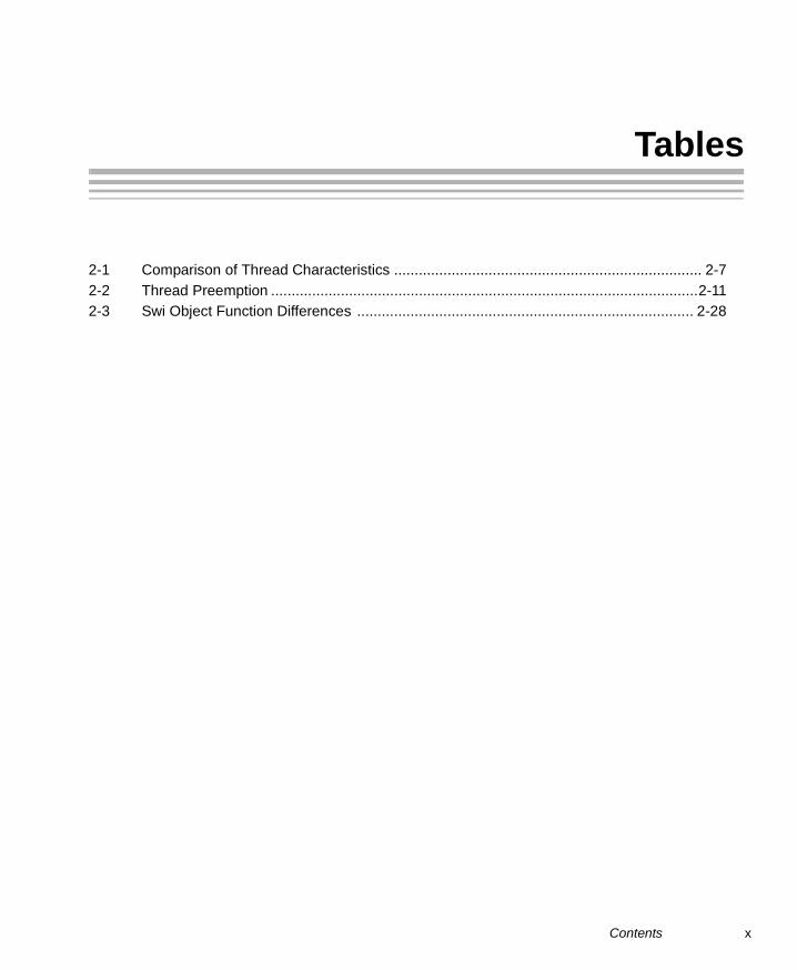
Tables
2-1 Comparison of Thread Characteristics ........................................................................... 2-72-2 Thread Preemption ........................................................................................................2-112-3 Swi Object Function Differences .................................................................................. 2-28

Examples
Examples
2-1 Time-Slice Scheduling.................................................................................................. 2-563-1 Creating and Deleting a Semaphore .............................................................................. 3-23-2 Setting a Timeout with Semaphore_pend() .................................................................... 3-33-3 Signaling a Semaphore with Semaphore_post() ............................................................ 3-33-4 Semaphore Example Using Three Writer Tasks ............................................................ 3-4
xi

xii

Chapter 1
About DSP/BIOS
This chapter provides an overview of DSP/BIOS and describes itsrelationship to XDCtools.
1.1 What is DSP/BIOS? . . . . . . . . . . . . . . . . . . . . . . . . . . . . . . . . . . . . . . . 1-2
1.2 What’s New? . . . . . . . . . . . . . . . . . . . . . . . . . . . . . . . . . . . . . . . . . . . . . 1-3
1.3 How are DSP/BIOS and RTSC Related?. . . . . . . . . . . . . . . . . . . . . . . 1-4
1.4 DSP/BIOS Packages. . . . . . . . . . . . . . . . . . . . . . . . . . . . . . . . . . . . . . . 1-6
1.5 For More Information . . . . . . . . . . . . . . . . . . . . . . . . . . . . . . . . . . . . . . 1-7
Topic Page
1-1

What is DSP/BIOS?
1.1 What is DSP/BIOS?
DSP/BIOS is a scalable real-time kernel. It is designed to be used byapplications that require real-time scheduling and synchronization or real-time instrumentation. DSP/BIOS provides preemptive multi-threading,hardware abstraction, real-time analysis, and configuration tools. DSP/BIOSis designed to minimize memory and CPU requirements on the target.
DSP/BIOS provides the following benefits:
❏ All DSP/BIOS objects can be configured statically or dynamically.
❏ To minimize memory size, the APIs are modularized so that only thoseAPIs that are used by the program need to be bound into the executableprogram. In addition, statically-configured objects reduce code size byeliminating the need to include object creation calls.
❏ Error checking and debug instrumentation is configurable and can becompletely removed from production code versions to maximizeperformance and minimize memory size.
❏ Almost all system calls provide deterministic performance to enableapplications to reliably meet real-time deadlines.
❏ To improve performance, instrumentation data (such as logs and traces)is formatted on the host.
❏ The threading model provides thread types for a variety of situations.Hardware interrupts, software interrupts, tasks, idle functions, andperiodic functions are all supported. You can control the priorities andblocking characteristics of threads through your choice of thread types.
❏ Structures to support communication and synchronization betweenthreads are provided. These include semaphores, mailboxes, events,gates, and variable-length messaging.
❏ Dynamic memory management services offering both variable-sized andfixed-sized block allocation.
❏ An interrupt dispatcher handles low-level context save/restore operationsand enables interrupt service routines to be written entirely in C.
❏ System services support the enabling/disabling of interrupts and theplugging of interrupt vectors, including multiplexing interrupt vectors ontomultiple sources.
1-2

What’s New?
1.2 What’s New?
This book describes DSP/BIOS 6, a major new release that introducessignificant changes. If you have used previous versions of DSP/BIOS, youwill encounter these major changes to basic functionality:
❏ DSP/BIOS uses a new configuration technology based on the Real-TimeSoftware Components (RTSC) technology. For more information, seeSection 1.3 of this book and the RTSC-Pedia wiki athttp://rtsc.eclipse.org/docs-tip.
❏ The APIs have changed. A compatibility layer ensures that DSP/BIOS 5.xapplications will work unmodified. However, note that the PIP module isno longer supported. For details, see the Migrating a DSP/BIOS 5Application to DSP/BIOS 6 (SPRAAS7A) application note.
❏ The DSP/BIOS RTA tools are Eclipse Plug-ins, which work in CodeComposer Studio (CCS) v4. Support for CCSv3.x is no longer provided.
In addition, significant enhancements have been made in the areas thatinclude the following:
❏ Up to 32 priority levels are available for both tasks and software interrupt(Swi) threads.
❏ A new timer module is provided that enables applications to configureand use timers directly rather than have time-driven events limited tousing the system tick.
❏ All kernel objects may be created by statically and dynamically.
❏ An additional heap manager, called HeapMultiBuf, enables fast,deterministic variable-sized memory allocation performance that doesnot degrade regardless of memory fragmentation.
❏ A more flexible memory manager supports the use of multiple, concurrentheaps and enables developers to easily add custom heaps.
❏ A new Event object enables tasks to pend on multiple events, includingsemaphores, mailboxes, message queues, and user-defined events.
❏ An additional Gate object supports priority inheritance.
❏ Hook functions are supported for hardware and software interrupt objectsas well as tasks.
❏ An option is provided to build the operating system with parameterchecking APIs that assert if invalid parameter values are passed to asystem call.
❏ A standardized method allows DSP/BIOS APIs to handle errors, basedon an error block approach. This enables errors to be handled efficientlywithout requiring the application to catch return codes. In addition, you
About DSP/BIOS 1-3

How are DSP/BIOS and RTSC Related?
can easily have the application halted whenever a DSP/BIOS erroroccurs, because all errors now pass through a single handler.
❏ The system log and execution graph in the Real-Time Analysis (RTA)tools support both dynamically and statically-created tasks.
❏ More powerful logging functions include a timestamp, up to 6 words perlog entry, and the ability for logging events to span more than one log ifadditional storage is required.
❏ Per-task CPU load is now supported in addition to total CPU load.
❏ Host-native execution is provided. This enables developers to createprototype DSP/BIOS applications using Windows developer tools suchas Visual C++, without the need for a DSP board or simulator.
1.3 How are DSP/BIOS and RTSC Related?
Real-Time Software Components (RTSC) provides a standard for packagingand configuring modules. DSP/BIOS is delivered as a set of RTSC packagesthat provide the modules that make up DSP/BIOS.
RTSC includes a set of tools (XDCtools) and a run-time (xdc.runtime)package that enable the development of real-time applications. DSP/BIOSuses both the XDCtools and run-time package. This is different from earlierreleases (prior to DSP/BIOS 6.00), in which the configuration tools wereincluded with the kernel and all target-resident functions were part of thekernel.
In addition the configuration tool changes, users should note the followingsignificant differences, compared to previous versions:
❏ Some commonly used run-time APIs are now in xdc.runtime, includingmemory allocation, logging, timestamp, and system (error handling, exit,abort, system printf, …).
❏ System start-up is now handled by the xdc.runtime package andDSP/BIOS installs its start-up modules into the xdc.runtime package.Developers will now need to install their initialization code into the XDCruntime start-up, not DSP/BIOS.
1-4

How are DSP/BIOS and RTSC Related?
You can picture the architecture of the tools used to create applications asshown in the following figure:
This book describes the DSP/BIOS packages. The XDCtools ConsumerUser’s Guide describes the components with the red background (XDCtoolsand the xdc.runtime package).
Before continuing with this book, you may wish familiarize yourself with thebasics of RTSC by visiting the RTSC-Pedia wiki athttp://rtsc.eclipse.org/docs-tip. This book assumes that you know the generalprocedure for using XDCtools to configure objects: to create objectsstatically, to set module-wide and instance-only properties. It also assumesthat you know the general procedure for including the header file of a packageand calling a function from that package.
Other(3rd Party)Packages
Other(3rd Party)Packages
DSP/BIOSPackages
DSP/BIOSPackages
DSP/BIOSPackages
XDC Tools
xdc.runtimePackage
DSP/BIOSPackages
Other(3rd Party)Packages
TexasInstrumentscompilers
Microsoftcompilers
othercompilers
About DSP/BIOS 1-5

DSP/BIOS Packages
1-6
1.4 DSP/BIOS Packages
DSP/BIOS provides the following packages:
Table 1–1 Packages and Modules Provides by DSP/BIOS
Package Description
ti.bios, ti.bios.tconf Contains header files and configuration parameters used by DSP/BIOS 5.x programs. See SPRAAS7.
ti.bios.conversion Provides a command-line conversion tool for DSP/BIOS 5.x applications. See SPRAAS7.
ti.sysbios.benchmark Contains specifications for benchmark tests. Provides no modules, APIs, or configuration. See Appendix B.
ti.sysbios.family.* Contains specifications for target/device-specific func-tions.
ti.sysbios.gates Contains several implementations of the IGatePro-vider interface for use in various situations. These include GateHwi, GateSwi, GateTask, GateMutex, and GateMutexPri. See Section 3.3.
ti.sysbios.genx Provides a command-line tool to build example appli-cations.
ti.sysbios.hal Contains Hwi, Timer, and Cache modules. See Sec-tion 6.2, Section 6.3, and Section 6.4.
ti.sysbios.heaps Provides several implementations of the XDCtools IHeap interface. These include HeapBuf (fixed-size buffers), HeapMem (variable-sized buffers), and HeapMultiBuf (multiple fixed-size buffers). See Chap-ter 5.
ti.sysbios.interfaces Contains interfaces for modules to be implemented, for example, on a device or platform basis.
ti.sysbios.ipc Contains modules related to inter-process communi-cation: Event, Mailbox, and Semaphore. See Chapter 3.
ti.sysbios.knl Contains modules for the DSP/BIOS kernel, including Swi, Task, Idle, and Clock. See Chapter 2 and Chapter 4.
ti.sysbios.utils Contains Load module, which provides global CPU load as well as thread-specific load.

For More Information
1.5 For More Information
You can read the following additional documents to learn more aboutDSP/BIOS and XDCtools:
❏ XDCtools Release Notes (in XDC_INSTALL_DIR). Includes informationabout software version, upgrades and compatibility, host and targetdevice support, validation, and known issues.
❏ DSP/BIOS Release Notes (BIOS_INSTALL_DIR/release_notes.html).Includes information about changes in each version, known issues,validation, and device support.
❏ DSP/BIOS Getting Started Guide (BIOS_INSTALL_DIR/docs/Bios_Getting_Started_Guide.doc). Includes steps for installing andvalidating the installation.
❏ Migrating a DSP/BIOS 5 Application to DSP/BIOS 6 (SPRAAS7A).(BIOS_INSTALL_DIR/docs/Bios_Legacy_App_Note.pdf)
❏ RTSC-Pedia wiki: http://rtsc.eclipse.org/docs-tip
❏ Code Composer Studio Mediawiki:http://tiexpressdsp.com/wiki/index.php?title=CCSv4
❏ CCSv4 online help contains reference information about XDCtools andDSP/BIOS packages and their modules, APIs, XDCtools configuration,data structures, etc. See Section 1.5.1.
1.5.1 Using the API Reference Help System
To open the online help for DSP/BIOS, you can choose DSP/BIOS APIDocumentation from the Texas Instruments > DSP/BIOS group in theWindows Start menu.
To open online help for XDCtools, you can choose XDCtoolsDocumentation from the Texas Instruments > XDCtools group in theWindows Start menu.
You can also open help for CCSv4, DSP/BIOS, and XDCtools together fromwithin CCSv4.
To see the DSP/BIOS API documentation, you must have included yourDSP/BIOS installation directory path in the XDCPATH environment variable.Please refer to the XDCtools Getting Started Guide for details on how to dothis.
About DSP/BIOS 1-7

For More Information
Click "+" next to a repository to expand its list of packages. Click "+" next toa package name to see the list of modules it provides. You can further expandthe tree to see a list of the functions provided by a module. Double-click on apackage or module to see its reference information.
The DSP/BIOS API documentation is under the "sysbios" package. To viewAPI documentation on memory allocation, logs, timestamps, asserts, andsystem, expand the "xdc.runtime" package. The "bios" package contains onlythe compatibility modules for earlier versions of DSP/BIOS.
Notice the following icons in this window:
Busy displaying the requested page.
Close all page tabs.
For each topic you view, there is a tab across the top of the page area. Youcan use these to quickly return to other pages you have viewed. You can alsouse the arrows next to "Views" to move backward and forward in your historyof page views.
To close a page and remove its tab, click the X on the tab.
The xs option '--xp' adds the DSP/BIOS 6.0 packages to the path searchedfor XDCtools packages. If you have added this directory to your XDCPATHenvironment variable definition as described in the DSP/BIOS 6 GettingStarted Guide, you do not need to use the --xp command-line option.
1-8

Chapter 2
Threading Modules
This chapter describes the types of threads a DSP/BIOS program can use.
2.1 DSP/BIOS Startup Sequence . . . . . . . . . . . . . . . . . . . . . . . . . . . . . . . . 2-2
2.2 Overview of Threading Modules . . . . . . . . . . . . . . . . . . . . . . . . . . . . . 2-4
2.3 Hardware Interrupts . . . . . . . . . . . . . . . . . . . . . . . . . . . . . . . . . . . . . . 2-15
2.4 Software Interrupts . . . . . . . . . . . . . . . . . . . . . . . . . . . . . . . . . . . . . . . 2-24
2.5 Tasks . . . . . . . . . . . . . . . . . . . . . . . . . . . . . . . . . . . . . . . . . . . . . . . . . . 2-43
2.6 The Idle Loop. . . . . . . . . . . . . . . . . . . . . . . . . . . . . . . . . . . . . . . . . . . . 2-61
2.7 Example Using Hwi, Swi, and Task Threads . . . . . . . . . . . . . . . . . . 2-62
Topic Page
2-1

DSP/BIOS Startup Sequence
2.1 DSP/BIOS Startup Sequence
The DSP/BIOS startup sequence is logically divided into two phases—thoseoperations that occur prior to the application's "main()" function being calledand those operations that are performed after the application's "main()"function is invoked. Control points are provided at various places in each ofthe two startup sequences for user startup functions to be inserted.
The "before main()" startup sequence is governed completely by theXDCtools runtime package. For more information about the boot sequenceprior to main, refer to the "XDCtools Boot Sequence and Control Points"section in the XDCtools Consumer User's Guide.
The "after main()" startup sequence is governed by DSP/BIOS and is initiatedby an explicit call to the BIOS_start() function at the end of the application'smain() function.
The XDCtools runtime startup sequence is as follows:
1) Immediately after CPU reset, perform target/device-specific CPUinitialization (beginning at c_int00).
2) Prior to cinit(), run the single user-supplied "reset function" (thexdc.runtime.Startup module provides this hook).
3) Run cinit() to initialize C runtime environment.
4) Run the user-supplied "first functions" (the xdc.runtime.Startup moduleprovides this hook).
5) Run all the module initialization functions.
6) Run pinit().
7) Run the user-supplied "last functions" (the xdc.runtime.Startup moduleprovides this hook).
8) Run main().
The DSP/BIOS startup sequence begins at the end of main() whenBIOS_start() is called:
1) Startup Functions. Run the user-supplied "startup functions" (seeBIOS.startupFxns).
2) Enable Hardware Interrupts.
3) Enable Software Interrupts. If the system supports software interrupts(Swis) (see BIOS.swiEnabled), then the DSP/BIOS startup sequenceenables Swis at this point.
2-2

DSP/BIOS Startup Sequence
4) Timer Startup. If the system supports Timers, then at this point allconfigured timers are initialized per their user-configuration. If a timer wasconfigured to start "automatically", it is started here.
5) Task Startup. If the system supports Tasks (see BIOS.taskEnabled),then task scheduling begins here. If there are no statically or dynamicallycreated Tasks in the system, then execution proceeds directly to the idleloop.
The following configuration script excerpt installs a user-supplied startupfunction at every possible control point in the RTSC and DSP/BIOS startupsequence:
/* get handle to xdc Startup module */
var Startup = xdc.useModule('xdc.runtime.Startup');
/* install "reset function" */
Startup.resetFxn = '&myReset';
/* install a "first function" */
var len = Startup.firstFxns.length
Startup.firstFxns.length++;
Startup.firstFxns[len] = '&myFirst';
/* install a "last function" */
var len = Startup.lastFxns.length
Startup.lastFxns.length++;
Startup.lastFxns[len] = '&myLast';
/* get handle to BIOS module */
var BIOS = xdc.useModule('ti.sysbios.BIOS');
/* install a BIOS startup function */
BIOS.addUserStartupFunction('&myBiosStartup');
Threading Modules 2-3

Overview of Threading Modules
2.2 Overview of Threading Modules
Many real-time applications must perform a number of seemingly unrelatedfunctions at the same time, often in response to external events such as theavailability of data or the presence of a control signal. Both the functionsperformed and when they are performed are important.
These functions are called threads. Different systems define threads eithernarrowly or broadly. Within DSP/BIOS, the term is defined broadly to includeany independent stream of instructions executed by the processor. A threadis a single point of control that can activate a function call or an interruptservice routine (ISR).
DSP/BIOS enables your applications to be structured as a collection ofthreads, each of which carries out a modularized function. Multithreadedprograms run on a single processor by allowing higher-priority threads topreempt lower-priority threads and by allowing various types of interactionbetween threads, including blocking, communication, and synchronization.
Real-time application programs organized in such a modular fashion—asopposed to a single, centralized polling loop, for example—are easier todesign, implement, and maintain.
DSP/BIOS provides support for several types of program threads withdifferent priorities. Each thread type has different execution and preemptioncharacteristics. The thread types (from highest to lowest priority) are:
❏ Hardware interrupts (Hwi), which includes Timer functions❏ Software interrupts (Swi), which includes Clock functions❏ Tasks (Task)❏ Background thread (Idle)
These thread types are described briefly in the following section anddiscussed in more detail in the rest of this chapter.
2.2.1 Types of ThreadsThe four major types of threads in a DSP/BIOS program are:
❏ Hardware interrupt (Hwi) threads. Hwi threads (also called InterruptService Routines or ISRs) are the threads with the highest priority in aDSP/BIOS application. Hwi threads are used to perform time critical tasksthat are subject to hard deadlines. They are triggered in response toexternal asynchronous events (interrupts) that occur in the real-timeenvironment. Hwi threads always run to completion but can bepreempted temporarily by Hwi threads triggered by other interrupts, if
2-4

Overview of Threading Modules
enabled. See Section 4.2, Hardware Interrupts, page 4-11, for detailsabout hardware interrupts. See Section 2.3, Hardware Interrupts, page 2-15, for details about hardware interrupts.
❏ Software interrupt (Swi) threads. Patterned after hardware interrupts(Hwi), software interrupt threads provide additional priority levelsbetween Hwi threads and Task threads. Unlike Hwis, which are triggeredby hardware interrupts, Swis are triggered programmatically by callingcertain Swi module APIs. Swis handle threads subject to time constraintsthat preclude them from being run as tasks, but whose deadlines are notas severe as those of hardware ISRs. Like Hwi's, Swi's threads alwaysrun to completion. Swis allow Hwis to defer less critical processing to alower-priority thread, minimizing the time the CPU spends inside aninterrupt service routine, where other Hwis can be disabled. See Section2.4, Software Interrupts, page 2-24, for details about Swis.
❏ Task (Task) threads. Task threads have higher priority than thebackground (Idle) thread and lower priority than software interrupts.Tasks differ from software interrupts in that they can wait (block) duringexecution until necessary resources are available. DSP/BIOS provides anumber of mechanisms that can be used for inter-task communicationand synchronization. These include Semaphores, Events, Messagequeues, and Mailboxes. See Section 2.5, Tasks, page 2-43, for detailsabout tasks.
❏ Idle Loop (Idle) thread. Idle threads execute at the lowest priority in aDSP/BIOS application and are executed one after another in acontinuous loop (the Idle Loop). After main returns, a DSP/BIOSapplication calls the startup routine for each DSP/BIOS module and thenfalls into the Idle Loop. Each thread must wait for all others to finishexecuting before it is called again. The Idle Loop runs continuouslyexcept when it is preempted by higher-priority threads. Only functionsthat do not have hard deadlines should be executed in the Idle Loop. SeeSection 2.6, The Idle Loop, page 2-61, for details about the backgroundthread.
Another type of thread, a Clock thread, is run within the context of a Swithread that is triggered by a Hwi thread invoked by a repetitive timerperipheral interrupt. See Section 4.2 for details.
Threading Modules 2-5
Overview of Threading Modules
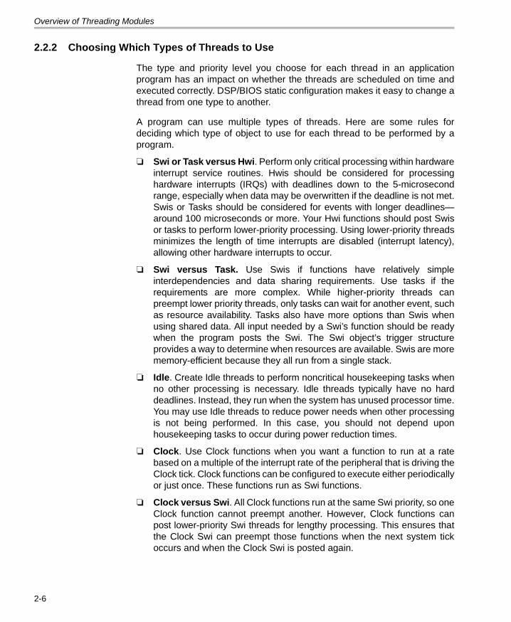
2.2.2 Choosing Which Types of Threads to Use
The type and priority level you choose for each thread in an applicationprogram has an impact on whether the threads are scheduled on time andexecuted correctly. DSP/BIOS static configuration makes it easy to change athread from one type to another.
A program can use multiple types of threads. Here are some rules fordeciding which type of object to use for each thread to be performed by aprogram.
❏ Swi or Task versus Hwi. Perform only critical processing within hardwareinterrupt service routines. Hwis should be considered for processinghardware interrupts (IRQs) with deadlines down to the 5-microsecondrange, especially when data may be overwritten if the deadline is not met.Swis or Tasks should be considered for events with longer deadlines—around 100 microseconds or more. Your Hwi functions should post Swisor tasks to perform lower-priority processing. Using lower-priority threadsminimizes the length of time interrupts are disabled (interrupt latency),allowing other hardware interrupts to occur.
❏ Swi versus Task. Use Swis if functions have relatively simpleinterdependencies and data sharing requirements. Use tasks if therequirements are more complex. While higher-priority threads canpreempt lower priority threads, only tasks can wait for another event, suchas resource availability. Tasks also have more options than Swis whenusing shared data. All input needed by a Swi’s function should be readywhen the program posts the Swi. The Swi object’s trigger structureprovides a way to determine when resources are available. Swis are morememory-efficient because they all run from a single stack.
❏ Idle. Create Idle threads to perform noncritical housekeeping tasks whenno other processing is necessary. Idle threads typically have no harddeadlines. Instead, they run when the system has unused processor time.You may use Idle threads to reduce power needs when other processingis not being performed. In this case, you should not depend uponhousekeeping tasks to occur during power reduction times.
❏ Clock. Use Clock functions when you want a function to run at a ratebased on a multiple of the interrupt rate of the peripheral that is driving theClock tick. Clock functions can be configured to execute either periodicallyor just once. These functions run as Swi functions.
❏ Clock versus Swi. All Clock functions run at the same Swi priority, so oneClock function cannot preempt another. However, Clock functions canpost lower-priority Swi threads for lengthy processing. This ensures thatthe Clock Swi can preempt those functions when the next system tickoccurs and when the Clock Swi is posted again.
2-6

Overview of Threading Modules
❏ Timer. Timer threads are run within the context of a Hwi thread. As such,they inherit the priority of the corresponding Timer interrupt. They areinvoked at the rate of the programmed Timer period. Timer threadsshould do the absolute minimum necessary to complete the taskrequired. If more processing time is required, consider posting a Swi todo the work or posting a Semaphore for later processing by a task so thatCPU time is efficiently managed.
2.2.3 A Comparison of Thread Characteristics
Table 2-1 provides a comparison of the thread types supported by DSP/BIOS.
Table 2-1. Comparison of Thread Characteristics
Notes: 1) If you disable the Task Manager, Idle threads use the system stack.
Characteristic Hwi Swi Task Idle
Priority Highest 2nd highest 2nd lowest Lowest
Number of priority levels
family/device-specific
Up to 32. Periodic functions run at the priority of the Clock Swi.
Up to 32 (including 1 for the Idle Loop)
1
Can yield and pend No, runs to completion except for preemption
No, runs to completion except for preemption
Yes Should not pend. Pending would dis-able all registered Idle threads.
Execution states Inactive, ready, running
Inactive, ready, running
Ready, running, blocked, terminated
Ready, running
Thread scheduler disabled by
Hwi_disable() Swi_disable() Task_disable() Program exit
Posted or made ready to run by
Interrupt occurs Swi_post(), Swi_andn(), Swi_dec(), Swi_inc(), Swi_or()
Task_create() and various task synchroni-zation mecha-nisms (Event, Semaphore, Mailbox)
main() exits and no other thread is cur-rently running
Stack used System stack(1 per program)
System stack(1 per program)
Task stack(1 per task)
Task stack used by default (see Note 1)
Threading Modules 2-7

Overview of Threading Modules
Table 2.1. Comparison of Thread Characteristics (continued)
Notes: 1) Some devices allow hardware interrupt priorities to by modified.
Characteristic Hwi Swi Task Idle
Context saved when preempts other thread
Entire context minus saved-by-callee registers (as defined by the TI C compiler) are saved to system.
Certain registers saved to system.
Entire context saved to task stack
--Not applicable--
Context saved when blocked
--Not applicable-- --Not applicable-- Saves the saved-by-callee registers (see optimizing compiler user’s guide for your plat-form).
--Not applicable--
Share data with thread via
Streams, lists, pipes, global variables
Streams, lists, pipes, global variables
Streams, lists, pipes, gates, mailboxes, message queues, global variables
Streams, lists, pipes, global variables
Synchronize with thread via
--Not applicable-- Swi trigger Semaphores, events, mailboxes
-Not applicable--
Function hooks Yes: register, create, begin, end, delete
Yes:register, create, ready, begin, end, delete
Yes: register, create, ready, switch, exit, delete
No
Static creation Yes Yes Yes Yes
Dynamic creation Yes Yes Yes No
Dynamically change priority
See Note 1 Yes Yes No
Implicit logging Interrupt event Post, begin, end Switch, yield, ready, exit
None
Implicit statistics None None None None
2-8

Overview of Threading Modules
2.2.4 Thread Priorities
Within DSP/BIOS, hardware interrupts have the highest priority. The prioritiesamong the set of Hwi objects are not maintained implicitly by DSP/BIOS. TheHwi priority only applies to the order in which multiple interrupts that are readyon a given CPU cycle are serviced by the CPU. Hardware interrupts arepreempted by another interrupt unless interrupts are globally disabled orwhen specific interrupts are individually disabled.
Figure 2-1. Thread Priorities
Swis have lower priority than Hwis. There are up to 32 priority levels availablefor Swis (16 by default). Swis can be preempted by a higher-priority Swi orany Hwi. Swis cannot block.
Tasks have lower priority than Swis. There are up to 32 task priority levels (16by default). Tasks can be preempted by any higher-priority thread. Tasks canblock while waiting for resource availability and lower-priority threads.
The background Idle Loop is the thread with the lowest priority of all. It runsin a loop when the CPU is not busy running another thread. When tasks areenabled, the Idle Loop is implemented as the only task running at priority 0.When tasks are disabled, the Idle Loop is fallen into after the application's"main()" function is called.
HardwareInterrupts
(Hwi)
SoftwareInterrupts
(Swi) up to 32 levels
Tasksup to 32 levels
Background thread(Idle)
ClockFunctions
Prio
rity
TimerFunctions
Threading Modules 2-9
Overview of Threading Modules
2.2.5 Yielding and Preemption
The DSP/BIOS thread schedulers run the highest-priority thread that is readyto run except in the following cases:
❏ The thread that is running disables some or all hardware interruptstemporarily with Hwi_disable() or Hwi_disableInterrupt(), preventinghardware ISRs from running.
❏ The thread that is running disables Swis temporarily with Swi_disable().This prevents any higher-priority Swi from preempting the current thread.It does not prevent Hwis from preempting the current thread.
❏ The thread that is running disables task scheduling temporarily withTask_disable(). This prevents any higher-priority task from preemptingthe current task. It does not prevent Hwis and Swis from preempting thecurrent task.
Both Hwis and Swis can interact with the DSP/BIOS task scheduler. When atask is blocked, it is often because the task is pending on a semaphore whichis unavailable. Semaphores can be posted from Hwis and Swis as well asfrom other tasks. If a Hwi or Swi posts a semaphore to unblock a pendingtask, the processor switches to that task if that task has a higher priority thanthe currently running task (after the Hwi or Swi completes).
When running either a Hwi or Swi, DSP/BIOS uses a dedicated systeminterrupt stack, called the system stack (sometimes called the ISR stack).Each task uses its own private stack. Therefore, if there are no Tasks in thesystem, all threads share the same system stack. For performance reasons,sometimes it is advantageous to place the system stack in precious fastmemory.
2-10

Overview of Threading Modules
Table 2-2 shows what happens when one type of thread is running (top row)and another thread becomes ready to run (left column). The action shown isthat of the newly posted (ready to run) thread.
Table 2-2. Thread Preemption
* On some targets, hardware interrupts can be individually enabled anddisabled. This is not true on all targets. Also, some targets have controllersthat support hardware interrupt prioritization, in which case a Hwi can only bepreempted by a higher-priority Hwi.
Note that Table 2-2 shows the results if the type of thread that is posted isenabled. If that thread type is disabled (for example, by Task_disable), athread cannot run in any case until its thread type is reenabled.
Figure 2-2 shows the execution graph for a scenario in which Swis and Hwisare enabled (the default), and a Hwi posts a Swi whose priority is higher thanthat of the Swi running when the interrupt occurs. Also, a second Hwi occurswhile the first ISR is running and preempts the first ISR.
Running Thread
Newly Posted Thread Hwi Swi Task Idle
Enabled Hwi Preempts if enabled*
Preempts Preempts Preempts
Disabled Hwi Waits for reenable
Waits for reenable
Waits for reenable
Waits for reenable
Enabled, higher-priority Swi Waits Preempts Preempts Preempts
Lower-priority Swi Waits Waits Preempts Preempts
Enabled, higher-priority Task Waits Waits Preempts Preempts
Low-priority Task Waits Waits Waits Preempts
Threading Modules 2-11

Overview of Threading Modules
Figure 2-2. Preemption Scenario
In Figure 2-2, the low-priority Swi is asynchronously preempted by the Hwis.The first Hwi posts a higher-priority Swi, which is executed after both Hwisfinish executing.
Here is sample pseudo-code for the example depicted in Figure 2-2:
backgroundThread()
{
Swi_post(Swi_B) /* priority = 5 */
}
Hwi_1 ()
{
. . .
}
Hwi_2 ()
{
Swi_post(Swi_A) /* priority = 7 */
}
Back
grou
ndpo
sts
Swi B
Time
Thread Priority
Hardware interrupt 1(Hwi 1)
Hardware interrupt 2(Hwi 2)
Software interrupt A(Swi A)
Software interrupt B(Swi B)
Background(Idle)
EventsIn
crea
sing
Prio
rity
Hw
i 2 o
ccur
s
Hw
i 2 p
osts
Swi A
Hw
i 1 o
ccur
s
Hw
i 1 fi
nish
es
Hw
i 2 fi
nish
es
Swi A
fini
shes
Swi B
fini
shes
Swi A ready
background preempted
Swi B preempted
preempted
2-12

Overview of Threading Modules
2.2.6 Hooks
Hwi, Swi, and Task threads optionally provide points in a thread's life cycle toinsert user code for instrumentation, monitoring, or statistics gatheringpurposes. Each of these code points is called a "hook" and the user functionprovided for the hook is called a "hook function".
The following hook functions can be set for the various thread types:
Hooks are declared as a set of hook functions called "hook sets". You do notneed to define all hook functions within a set, only those that are required bythe application.
Hook functions can only be declared statically (in an XDCtools configuration)so that they may be efficiently invoked when provided and result in no runtimeoverhead when a hook function is not provided.
Except for the Register hook, all hook functions are invoked with a handle tothe object associated with that thread as its argument (that is, a Hwi object, aSwi object, or a Task object). Other arguments are provided for some thread-type-specific hook functions.
You can define as many hook sets as necessary for your application. Whenmore than one hook set is defined, the individual hook functions within eachset are invoked in hook ID order for a particular hook type. For example,during Task_create() the order that the Create hook within each Task hook setis invoked is the order in which the Task hook sets were originally defined.
The argument to a thread's Register hook (which is invoked only once) is anindex (the "hook ID") indicating the hook set's relative order in the hookfunction calling sequence.
Each set of hook functions has a unique associated "hook context pointer".This general-purpose pointer can be used by itself to hold hook set specificinformation, or it can be initialized to point to a block of memory allocated bythe Create hook function within a hook set if more space is required for aparticular application.
Thread Type Hook Functions
Hwi Register, Create, Begin, End, and Delete. See Section 2.3.2.
Swi Register, Create, Ready, Begin, End, and Delete. See Section 2.4.8.
Task Register, Create, Ready, Switch, Exit, and Delete. See Section 2.5.4.
Threading Modules 2-13

Overview of Threading Modules
An individual hook function obtains the value of its associated context pointerthrough thread-type-specific APIs—Hwi_getHookContext(),Swi_getHookContext(), and Task_getHookContext(). Corresponding APIs forinitializing the context pointers are also provided—Hwi_setHookContext(),Swi_setHookContext(), and Task_setHookContext(). Each of these APIs takethe hook ID as an argument.
The following diagram shows an application with three Hwi hook sets:
The hook context pointers are accessed using Hwi_getHookContext() usingthe index provided to the three Register hook functions.
Just prior to invoking your ISR functions, the Begin Hook functions areinvoked in the following order:
1) beginHookFunc0();
2) beginHookFunc1();
3) beginHookFunc2();
Likewise, upon return from your ISR functions the End Hook functions areinvoked in the following order:
1) endHookFunc0();
2) endHookFunc1();
3) endHookFunc2();
registerHookFunc0() createHookFunc0() beginHookFunc0() endHookFunc0() deleteHookFunc0()
Hwi Hook Set [0]
registerHookFunc1() createHookFunc1() beginHookFunc1() endHookFunc1() deleteHookFunc1()
Hwi Hook Set [1]
hookContextPtr[0]
hookContextPtr[1]
hookContextPtr[2]
registerHookFunc2() createHookFunc2() beginHookFunc2() endHookFunc2() deleteHookFunc2()
Hwi Hook Set [2]
Hwi_getHookContext(0)
Hwi_getHookContext(1)
Hwi_getHookContext(2)
2-14

Hardware Interrupts
2.3 Hardware Interrupts
Hardware interrupts (Hwis) handle critical processing that the applicationmust perform in response to external asynchronous events. The DSP/BIOStarget/device specific Hwi modules are used to manage hardware interrupts.
In a typical embedded system, hardware interrupts are triggered either by on-device peripherals or by devices external to the processor. In both cases, theinterrupt causes the processor to vector to the ISR address.
Any interrupt processing that may invoke DSP/BIOS APIs that affect Swi andTask scheduling must be written in C or C++. The HWI_enter()/HWI_exit()macros provided in earlier versions of DSP/BIOS for calling assemblylanguage ISRs are no longer provided.
Assembly language ISRs that do not interact with DSP/BIOS can be specifiedwith Hwi_plug(). Such ISRs must do their own context preservation. Theymay use the "interrupt" keyword, C functions, or assembly languagefunctions.
All hardware interrupts run to completion. If a Hwi is posted multiple timesbefore its ISR has a chance to run, the ISR runs only one time. For thisreason, you should minimize the amount of code performed by a Hwifunction.
If interrupts are globally enabled—that is, by calling Hwi_enable()—ahardware interrupt can be preempted by any interrupt that has been enabled.
Hwis must not use the Chip Support Library (CSL) for the target. Instead, seeChapter 6 for a description of Hardware Abstraction Layer APIs.
Associating an ISR function with a particular interrupt is done by creating aHwi object.
2.3.1 Creating Hwi Objects
The Hwi module maintains a table of pointers to Hwi objects that containinformation about each Hwi managed by the dispatcher. To create a Hwiobject dynamically, use a call with this syntax:
Hwi_Handle hwi0;
Hwi_Params hwiParams;
Hwi_Params_init(&hwiParams);
hwiParams.arg = 5;
hwi0 = Hwi_create(id, hwiFunc, &hwiParams, &eb);
Threading Modules 2-15

Hardware Interrupts
Here, hwi0 is a handle to the created Hwi object, id is the interrupt numberbeing defined, hwiFunc is the name of the function associated with the Hwi,and hwiParams is a structure that contains Hwi instance parameters(enable/restore masks, the Hwi function argument, etc). Here,hwiParams.arg is set to 5. If NULL is passed instead of a pointer to an actualHwi_Params struct, a default set of parameters is used. The "eb" is an errorblock that you can use to handle errors that may occur during Hwi objectcreation.
The corresponding static configuration Hwi object creation syntax is:
var Hwi = xdc.useModule('ti.sysbios.hal.Hwi');
var hwiParams = new Hwi.Params;
hwiParams.arg = 5;
Program.global.hwi0 = Hwi.create(id, '&hwiFunc', hwiParams);
Here, the "hwiParams = new Hwi.Params" statement does the equivalent ofcreating and initializing the hwiParams structure with default values. In thestatic configuration world, no Error Block (eb) is required for the "create"function. The "Program.global.hwi0" name becomes a a runtime-accessiblehandle (symbol name = "hwi0") to the statically-created Hwi object.
2.3.2 Hwi Hooks
The Hwi module supports the following set of Hook functions:
❏ Register. A function called before any statically created Hwis areinitialized at runtime. The register hook is called at boot time beforemain() and before interrupts are enabled.
❏ Create. A function called when a Hwi is created. This includes Hwis thatare created statically and those created dynamically using Hwi_create().
❏ Begin. A function called just prior to running a Hwi ISR function.
❏ End. A function called just after a Hwi ISR function finishes.
❏ Delete. A function called when a Hwi is deleted at runtime withHwi_delete().
2-16

Hardware Interrupts
The following HookSet structure type definition encapsulates the hookfunctions supported by the Hwi module:
typedef struct Hwi_HookSet {
Void (*registerFxn)(Int); /* Register Hook */
Void (*createFxn)(Handle, Error.Block *); /* Create Hook */
Void (*beginFxn)(Handle); /* Begin Hook */
Void (*endFxn)(Handle); /* End Hook */
Void (*deleteFxn)(Handle); /* Delete Hook */
};
Hwi Hook functions can only be configured statically.
2.3.2.1 Register Function
The register function is provided to allow a hook set to store its correspondinghook ID. This ID can be passed to Hwi_setHookContext() andHwi_getHookContext() to set or get hook-specific context. The Registerfunction must be specified if the hook implementation needs to useHwi_setHookContext() or Hwi_getHookContext().
The registerFxn hook function is called during system initialization beforeinterrupts have been enabled.
The Register function has the following signature:
Void registerFxn(Int id);
2.3.2.2 Create and Delete Functions
The Create and Delete functions are called whenever a Hwi is created ordeleted. The Create function is passed an Error_Block that is to be passed toMemory_alloc() for applications that require additional context storage space.
The createFxn and deleteFxn functions are called with interrupts enabled(unless called at boot time or from main()).
These functions have the following signatures:
Void createFxn(Hwi_Handle hwi, Error_Block *eb);
Void deleteFxn(Hwi_Handle hwi);
2.3.2.3 Begin and End Functions
The Begin and End hook functions are called with interrupts globally disabled,therefore any hook processing function contributes to overall system interruptresponse latency. In order to minimize this impact, carefully consider theprocessing time spent in a Hwi beginFxn or endFxn hook function.
Threading Modules 2-17

Hardware Interrupts
The beginFxn is invoked just prior to calling the ISR function. The endFxn isinvoked immediately after the return from the ISR function.
These functions have the following signatures:
Void beginFxn(Hwi_Handle hwi);
Void endFxn(Hwi_Handle hwi);
When more than one Hook Set is defined, the individual hook functions of acommon type are invoked in hook ID order.
2.3.2.4 Hwi Hooks Example
The following example application uses two Hwi hook sets. The Hwiassociated with a statically-created Timer is used to exercise the Hwi hookfunctions. This example demonstrates how to read and write the HookContext Pointer associated with each hook set.
The XDCtools configuration script and program output are shown after the Ccode listing.
This is the C code for the example:
/* ======== HwiHookExample.c ========
* This example demonstrates basic Hwi hook usage. */
#include <xdc/std.h>
#include <xdc/runtime/Error.h>
#include <xdc/runtime/System.h>
#include <xdc/runtime/Timestamp.h>
#include <ti/sysbios/BIOS.h>
#include <ti/sysbios/knl/Task.h>
#include <ti/sysbios/hal/Timer.h>
#include <ti/sysbios/hal/Hwi.h>
extern Timer_Handle myTimer;
volatile Bool myEnd2Flag = FALSE;
Int myHookSetId1, myHookSetId2;
/* HookSet 1 functions */
2-18

Hardware Interrupts
/* ======== myRegister1 ========
* invoked during Hwi module startup before main()
* for each HookSet */
Void myRegister1(Int hookSetId)
{
System_printf("myRegister1: assigned hookSet Id = %d\n",
hookSetId);
myHookSetId1 = hookSetId;
}
/* ======== myCreate1 ========
* invoked during Hwi module startup before main()
* for statically created Hwis */
Void myCreate1(Hwi_Handle hwi, Error_Block *eb)
{
Ptr pEnv;
pEnv = Hwi_getHookContext(hwi, myHookSetId1);
/* pEnv should be 0 at this point. If not, there's a bug. */
System_printf("myCreate1: pEnv = 0x%x, time = %d\n", pEnv,
Timestamp_get32());
Hwi_setHookContext(hwi, myHookSetId1, (Ptr)0xdead1);
}
/* ======== myBegin1 ========
* invoked before Timer Hwi func */
Void myBegin1(Hwi_Handle hwi)
{
Ptr pEnv;
pEnv = Hwi_getHookContext(hwi, myHookSetId1);
System_printf("myBegin1: pEnv = 0x%x, time = %d\n", pEnv,
Timestamp_get32());
Hwi_setHookContext(hwi, myHookSetId1, (Ptr)0xbeef1);
}
Threading Modules 2-19

Hardware Interrupts
2-20
/* ======== myEnd1 ========
* invoked after Timer Hwi func */
Void myEnd1(Hwi_Handle hwi)
{
Ptr pEnv;
pEnv = Hwi_getHookContext(hwi, myHookSetId1);
System_printf("myEnd1: pEnv = 0x%x, time = %d\n", pEnv,
Timestamp_get32());
Hwi_setHookContext(hwi, myHookSetId1, (Ptr)0xc0de1);
}
/* HookSet 2 functions */
/* ======== myRegister2 ========
* invoked during Hwi module startup before main
* for each HookSet */
Void myRegister2(Int hookSetId)
{
System_printf("myRegister2: assigned hookSet Id = %d\n",
hookSetId);
myHookSetId2 = hookSetId;
}
/* ======== myCreate2 ========
* invoked during Hwi module startup before main
* for statically created Hwis */
Void myCreate2(Hwi_Handle hwi, Error_Block *eb)
{
Ptr pEnv;
pEnv = Hwi_getHookContext(hwi, myHookSetId2);
/* pEnv should be 0 at this point. If not, there's a bug. */
System_printf("myCreate2: pEnv = 0x%x, time = %d\n", pEnv,
Timestamp_get32());
Hwi_setHookContext(hwi, myHookSetId2, (Ptr)0xdead2);
}
/* ======== myBegin2 ========
* invoked before Timer Hwi func */
Void myBegin2(Hwi_Handle hwi)
{
Ptr pEnv;
pEnv = Hwi_getHookContext(hwi, myHookSetId2);
System_printf("myBegin2: pEnv = 0x%x, time = %d\n", pEnv,
Timestamp_get32());
Hwi_setHookContext(hwi, myHookSetId2, (Ptr)0xbeef2);
}

Hardware Interrupts
/* ======== myEnd2 ========
* invoked after Timer Hwi func */
Void myEnd2(Hwi_Handle hwi)
{
Ptr pEnv;
pEnv = Hwi_getHookContext(hwi, myHookSetId2);
System_printf("myEnd2: pEnv = 0x%x, time = %d\n", pEnv,
Timestamp_get32());
Hwi_setHookContext(hwi, myHookSetId2, (Ptr)0xc0de2);
myEnd2Flag = TRUE;
}
/* ======== myTimerFunc ========
* Timer interrupt handler */
Void myTimerFunc(UArg arg)
{
System_printf("Entering myTimerHwi\n");
}
/* ======== myTaskFunc ======== */
Void myTaskFunc(UArg arg0, UArg arg1)
{
System_printf("Entering myTask.\n");
Timer_start(myTimer);
/* wait for timer interrupt and myEnd2 to complete */
while (!myEnd2Flag) {
;
}
System_printf("myTask exiting ...\n");
}
/* ======== myIdleFunc ======== */
Void myIdleFunc()
{
System_printf("Entering myIdleFunc().\n");
System_exit(0);
}
Threading Modules 2-21

Hardware Interrupts
/* ======== main ======== */
Int main(Int argc, Char* argv[])
{
System_printf("Starting HwiHookExample...\n");
BIOS_start();
return (0);
}
This is the XDCtools configuration script for the example:
/* pull in Timestamp to print time in hook functions */
xdc.useModule('xdc.runtime.Timestamp');
/* Disable Clock so that ours is the only Timer allocated */
var BIOS = xdc.useModule('ti.sysbios.BIOS');
BIOS.clockEnabled = false;
var Idle = xdc.useModule('ti.sysbios.knl.Idle');
Idle.addFunc('&myIdleFunc');
/* Create myTask with default task params */
var Task = xdc.useModule('ti.sysbios.knl.Task');
var taskParams = new Task.Params();
Program.global.myTask = Task.create('&myTaskFunc', taskParams);
/* Create myTimer as source of Hwi */
var Timer = xdc.useModule('ti.sysbios.hal.Timer');
var timerParams = new Timer.Params();
timerParams.startMode = Timer.StartMode_USER;
timerParams.runMode = Timer.RunMode_ONESHOT;
timerParams.period = 1000; // 1ms
Program.global.myTimer = Timer.create(Timer.ANY, "&myTimerFunc", timerParams);
2-22

Hardware Interrupts
/* Define and add two Hwi HookSets
* Notice, no deleteFxn is provided.
*/
var Hwi = xdc.useModule('ti.sysbios.hal.Hwi');
/* Hook Set 1 */
Hwi.addHookSet({
registerFxn: '&myRegister1',
createFxn: '&myCreate1',
beginFxn: '&myBegin1',
endFxn: '&myEnd1',
});
/* Hook Set 2 */
Hwi.addHookSet({
registerFxn: '&myRegister2',
createFxn: '&myCreate2',
beginFxn: '&myBegin2',
endFxn: '&myEnd2',
});
The program output is as follows:
myRegister1: assigned hookSet Id = 0
myRegister2: assigned hookSet Id = 1
myCreate1: pEnv = 0x0, time = 0
myCreate2: pEnv = 0x0, time = 0
Starting HwiHookExample...
Entering myTask.
myBegin1: pEnv = 0xdead1, time = 75415
myBegin2: pEnv = 0xdead2, time = 75834
Entering myTimerHwi
myEnd1: pEnv = 0xbeef1, time = 76427
myEnd2: pEnv = 0xbeef2, time = 76830
myTask exiting ...
Entering myIdleFunc().
Threading Modules 2-23

Software Interrupts
2.4 Software Interrupts
Software interrupts are patterned after hardware ISRs. The Swi module inDSP/BIOS provides a software interrupt capability. Software interrupts aretriggered programmatically, through a call to a DSP/BIOS API such asSwi_post(). Software interrupts have priorities that are higher than tasks butlower than hardware interrupts.
Note: The Swi module should not be confused with the SWI instruction thatexists on many processors. The DSP/BIOS Swi module is independentfrom any target/device-specific software interrupt features.
Swi threads are suitable for handling application tasks that occur at slowerrates or are subject to less severe real-time deadlines than those of Hwis.
The DSP/BIOS APIs that can trigger or post a Swi are:
❏ Swi_andn()❏ Swi_dec()❏ Swi_inc()❏ Swi_or()❏ Swi_post()
The Swi Manager controls the execution of all Swi functions. When theapplication calls one of the APIs above, the Swi Manager schedules thefunction corresponding to the specified Swi for execution. To handle Swifunctions, the Swi Manager uses Swi objects.
If a Swi is posted, it runs only after all pending Hwis have run. A Swi functionin progress can be preempted at any time by a Hwi; the Hwi completes beforethe Swi function resumes. On the other hand, Swi functions always preempttasks. All pending Swis run before even the highest priority task is allowed torun. In effect, a Swi function is like a task with a priority higher than all ordinarytasks.
Note:
Two things to remember about Swi functions are:
A Swi function runs to completion unless it is interrupted by a Hwi orpreempted by a higher-priority Swi.
Any Hwi ISR that triggers or posts a Swi must have been invoked by theHwi dispatcher.
2-24

Software Interrupts
2.4.1 Creating Swi Objects
As with many other DSP/BIOS objects, you can create Swi objects eitherdynamically—with a call to Swi_create()—or statically in the configuration.Swis you create dynamically can also be deleted during program execution.
To add a new Swi to the configuration, create a new Swi object in theconfiguration script. Set the function property for each Swi to run a functionwhen the object is triggered by the application. You can also configure up totwo arguments to be passed to each Swi function.
As with all modules with instances, you can determine from which memorysegment Swi objects are allocated. Swi objects are accessed by the SwiManager when Swis are posted and scheduled for execution.
For complete reference information on the Swi API, configuration, andobjects, see the Swi module in the "ti.sysbios.knl" package documentation inthe online documentation. (For information on running online help, seeSection 1.5.1, Using the API Reference Help System, page 1-7.)
To create a Swi object dynamically, use a call with this syntax:
Swi_Handle swi0;
Swi_Params swiParams;
Swi_Params_init(swiParams);
swi0 = Swi_create(swiFunc, &swiParams, &eb);
Here, swi0 is a handle to the created Swi object, swiFunc is the name of thefunction associated with the Swi, and swiParams is a structure of typeSwi_Params that contains the Swi instance parameters (priority, arg0, arg1,etc). If NULL is passed instead of a pointer to an actual Swi_Params struct,a default set of parameters is used. "eb" is an error block you can use tohandle errors that may occur during Swi object creation.
Note:
Swi_create() can only be called from the task level, not from a Hwi oranother Swi.
To create a Swi object in an XDCtools configuration file, use statements likethese:
var Swi = xdc.useModule('ti.sysbios.knl.Swi');
var swiParams = new Swi.Params();
program.global.swi0 = Swi.create(swiParams);
Threading Modules 2-25

Software Interrupts
2.4.2 Setting Software Interrupt Priorities
There are different priority levels among Swis. You can create as many Swisas your memory constraints allow for each priority level. You can choose ahigher priority for a Swi that handles a thread with a shorter real-timedeadline, and a lower priority for a Swi that handles a thread with a lesscritical execution deadline.
The number of Swi priorities supported within an application is configurableup to a maximum 32. The default number of priority levels is 16. The lowestpriority level is 0. Thus, by default, the highest priority level is 15.
You cannot sort Swis within a single priority level. They are serviced in theorder in which they were posted.
2.4.3 Software Interrupt Priorities and Application Stack Size
When a Swi is posted, its associated Swi function is invoked using the systemstack. While you can have up to 32 Swi priority levels, keep in mind that in theworst case, each Swi priority level can result in a nesting of the Swischeduling function (that is, the lowest priority Swi is preempted by the nexthighest priority Swi, which, in turn, is preempted by the next highest, …). Thisresults in an increasing stack size requirement for each Swi priority levelactually used. Thus, giving Swis the same priority level is more efficient interms of stack size than giving each Swi a separate priority.
The default system stack size is 4096 bytes. You can set the system stacksize by adding the following line to your config script:
Program.stack = yourStackSize;
Note: The Clock module creates and uses a Swi with the maximum Swipriority (that is, if there are 16 Swi priorities, the Clock Swi has priority 15).
2.4.4 Execution of Software Interrupts
Swis can be scheduled for execution with a call to Swi_andn(), Swi_dec(),Swi_inc(), Swi_or(), and Swi_post(). These calls can be used virtuallyanywhere in the program—Hwi functions, Clock functions, Idle functions, orother Swi functions.
When a Swi is posted, the Swi Manager adds it to a list of posted Swis thatare pending execution. The Swi Manager checks whether Swis are currentlyenabled. If they are not, as is the case inside a Hwi function, the Swi Managerreturns control to the current thread.
2-26

Software Interrupts
If Swis are enabled, the Swi Manager checks the priority of the posted Swiobject against the priority of the thread that is currently running. If the threadcurrently running is the background Idle Loop or a lower priority Swi, the SwiManager removes the Swi from the list of posted Swi objects and switchesthe CPU control from the current thread to start execution of the posted Swifunction.
If the thread currently running is a Swi of the same or higher priority, the SwiManager returns control to the current thread, and the posted Swi functionruns after all other Swis of higher priority or the same priority that werepreviously posted finish execution.
There are two important things to remember about Swi:
❏ When a Swi starts executing it must run to completion without blocking.
❏ When called from within a Hwi, the code sequence calling any Swifunction that can trigger or post a Swi must be invoked by the Hwidispatcher.
Swi functions can be preempted by threads of higher priority (such as a Hwior a Swi of higher priority). However, Swi functions cannot block. You cannotsuspend a Swi while it waits for something—like a device—to be ready.
If a Swi is posted multiple times before the Swi Manager has removed it fromthe posted Swi list, its Swi function executes only once, much like a Hwi isexecuted only once if the Hwi is triggered multiple times before the CPUclears the corresponding interrupt flag bit in the interrupt flag register. (SeeSection 2.4.5, Using a Swi Object’s Trigger Variable, page 2-27, for moreinformation on how to handle Swis that are posted multiple times before theyare scheduled for execution.)
Applications should not make any assumptions about the order in which Swifunctions of equal priority are called. However, a Swi function can safely postitself (or be posted by another interrupt). If more than one is pending, all Swifunctions are called before any tasks run.
2.4.5 Using a Swi Object’s Trigger Variable
Each Swi object has an associated 32-bit trigger variable for C6x targets anda 16-bit trigger variable for C5x targets. This is used either to determinewhether to post the Swi or to provide values that can be evaluated within theSwi function.
Swi_post(), Swi_or(), and Swi_inc() post a Swi object unconditionally:
❏ Swi_post() does not modify the value of the Swi object trigger when it isused to post a Swi.
Threading Modules 2-27

Software Interrupts
❏ Swi_or() sets the bits in the trigger determined by a mask that is passedas a parameter, and then posts the Swi.
❏ Swi_inc() increases the Swi's trigger value by one before posting the Swiobject.
Swi_andn() and Swi_dec() post a Swi object only if the value of its triggerbecomes 0:
❏ Swi_andn() clears the bits in the trigger determined by a mask passed asa parameter.
❏ Swi_dec() decreases the value of the trigger by one.
Table 2-3 summarizes the differences between these functions.
Table 2-3. Swi Object Function Differences
The Swi trigger allows you to have tighter control over the conditions thatshould cause a Swi function to be posted, or the number of times the Swifunction should be executed once the Swi is posted and scheduled forexecution.
To access the value of its trigger, a Swi function can call Swi_getTrigger().Swi_getTrigger() can be called only from the Swi object’s function. The valuereturned by Swi_getTrigger() is the value of the trigger before the Swi objectwas removed from the posted Swi queue and the Swi function was scheduledfor execution.
When the Swi Manager removes a pending Swi object from the postedobject’s queue, its trigger is reset to its initial value. The initial value of thetrigger should be set in the application’s configuration script. If while the Swifunction is executing, the Swi is posted again, its trigger is updatedaccordingly. However, this does not affect the value returned bySwi_getTrigger() while the Swi function executes. That is, the trigger valuethat Swi_getTrigger() returns is the latched trigger value when the Swi wasremoved from the list of pending Swis. The Swi's trigger however, isimmediately reset after the Swi is removed from the list of pending Swis andscheduled for execution. This gives the application the ability to keepupdating the value of the Swi trigger if a new posting occurs, even if the Swifunction has not finished its execution.
Action
Treats Trigger as Bitmask
Treats Trigger as Counter
Does not Modify Trigger
Always post Swi_or() Swi_inc() Swi_post()
Post if it becomes zero Swi_andn() Swi_dec() —
2-28

Software Interrupts
For example, if a Swi object is posted multiple times before it is removed fromthe queue of posted Swis, the Swi Manager schedules its function to executeonly once. However, if a Swi function must always run multiple times whenthe Swi object is posted multiple times, Swi_inc() should be used to post theSwi as shown in Figure 2-3.
When a Swi has been posted using Swi_inc(), once the Swi Manager callsthe corresponding Swi function for execution, the Swi function can access theSwi object trigger to know how many times it was posted before it wasscheduled to run, and proceed to execute the same function as many timesas the value of the trigger.
Figure 2-3. Using Swi_inc() to Post a Swi
Program ConfigurationSwi object mySwi,
Function mySwiFxn
ProgramExecution
mySwiFxn(){ . . . repetitions = SWI_getTrigger(); while (repetitions --) { 'run Swi function' }...}
TriggerValue
Value returned bySwi_getTrigger
0
1
2
0
0
1
1
2
2
2
2
-- Calls Swi_inc(&mySwi)-- mySwi is posted
-- Calls Swi_inc(&mySwi)-- mySwi is posted again before it isscheduled for execution
-- Swi manager removes mySwi fromposted Swi queue-- mySwiFxn is scheduled for execution
-- mySwiFxn begins execution
-- mySwiFxn is preempted by ISR thatcalls Swi_inc(&mySwi)-- mySwi is added to posted Swi queue
-- mySwiFxn continues execution
not callableoutside Swi
not callableoutside Swi
not callableoutside Swi
Threading Modules 2-29

Software Interrupts
If more than one event must always happen for a given Swi to be triggered,Swi_andn() should be used to post the corresponding Swi object as shown inFigure 2-4. For example, if a Swi must wait for input data from two differentdevices before it can proceed, its trigger should have two set bits when theSwi object is configured. When both functions that provide input data havecompleted their tasks, they should both call Swi_andn() with complementarybitmasks that clear each of the bits set in the Swi trigger default value. Hence,the Swi is posted only when data from both processes is ready.
Figure 2-4. Using Swi_andn() to Post a Swi
not callableoutside Swi
Program ConfigurationSwi object mySwi,
Function mySwiFxn
ProgramExecution
TriggerValue
Value returned bySwi_getTrigger
-- Calls Swi_andn(&mySwi, 0x1)-- mySwi is not posted
-- Calls Swi_andn(&mySwi, 0x2)-- mySwi is posted
-- Swi manager removes mySwi fromposted Swi queue-- mySwiFxn is scheduled for execution
-- mySwiFxn begins execution
0 ... 1 1
0 ... 1 0
0 ... 1 1
0 ... 0 0
0 ... 1 1
0 ... 0 0
0 ... 0 0
not callableoutside Swi
not callableoutside Swi
2-30

Software Interrupts
In some situations the Swi function can call different functions depending onthe event that posted it. In that case the program can use Swi_or() to post theSwi object unconditionally when an event happens. This is shown in Figure2-5. The value of the bitmask used by Swi_or() encodes the event type thattriggered the post operation, and can be used by the Swi function as a flagthat identifies the event and serves to choose the function to execute.
Figure 2-5. Using Swi_or() to Post a Swi.
not callableoutside Swi
Program ConfigurationSwi object mySwi,
Function mySwiFxn
ProgramExecution
TriggerValue
Value returned bySwi_getTrigger
-- Calls Swi_or(&mySwi, 0x1)-- mySwi is posted
-- mySwiFxn is executed
-- Calls Swi_or(&mySwi, 0x2)-- mySwi is posted
-- mySwiFxn is executed
0 ... 0 0
0 ... 0 1 not callableoutside Swi
not callableoutside Swi
0 ... 0 1
mySwiFxn(){ ... eventType = Swi_getTrigger(); switch (eventType) { case '0x1': 'run alg 1' case '0x2': 'run alg 2' case '0x3': 'run alg 3' } ...}
0 ... 0 0
0 ... 1 0
0 ... 0 0 0 ... 1 0
Threading Modules 2-31

Software Interrupts
If the program execution requires that multiple occurrences of the same eventmust take place before a Swi is posted, Swi_dec() should be used to post theSwi as shown in Figure 2-6. By configuring the Swi trigger to be equal to thenumber of occurrences of the event before the Swi should be posted andcalling Swi_dec() every time the event occurs, the Swi is posted only after itstrigger reaches 0; that is, after the event has occurred a number of timesequal to the trigger value.
Figure 2-6. Using Swi_dec() to Post a Swi
2.4.6 Benefits and Tradeoffs
There are several benefits to using Swis instead of Hwis:
❏ By modifying shared data structures in a Swi function instead of a Hwi,you can get mutual exclusion by disabling Swis while a Task accessesthe shared data structure (see page 2–33). This allows the system torespond to events in real-time using Hwis. In contrast, if a Hwi functionmodified a shared data structure directly, Tasks would need to disableHwis to access data structures in a mutually exclusive way. Obviously,disabling Hwis may degrade the performance of a real-time system.
❏ It often makes sense to break long ISRs into two pieces. The Hwi takescare of the extremely time-critical operation and defers less criticalprocessing to a Swi function by posting the Swi within the Hwi function.
Remember that a Swi function must complete before any blocked Task isallowed to run.
Program ConfigurationSwi object mySwi,
Function mySwiFxn
ProgramExecution
TriggerValue
Value returned bySwi_getTrigger
2
1
0
2
2
0
0
-- Calls Swi_dec(&mySwi)-- mySwi is not posted
-- Calls Swi_dec(&mySwi)-- mySwi is posted
-- Swi manager removes mySwi fromposted Swi queue-- mySwiFxn is scheduled for execution
-- mySwiFxn begins execution
not callableoutside Swi
not callableoutside Swi
not callableoutside Swi
2-32

Software Interrupts
2.4.7 Synchronizing Swi Functions
Within an Idle, Task, or Swi function, you can temporarily prevent preemptionby a higher-priority Swi by calling Swi_disable(), which disables all Swipreemption. To reenable Swi preemption, call Swi_restore().
Swis are enabled or disabled as a group. An individual Swi cannot be enabledor disabled on its own.
When DSP/BIOS finishes initialization and before the first task is called, Swishave been enabled. If an application wishes to disable Swis, it callsSwi_disable() as follows:
key = Swi_disable();
The corresponding enable function is Swi_restore().
Swi_restore(key);
where key is a value used by the Swi module to determine if Swi_disable()has been called more than once. This allows nesting of Swi_disable() /Swi_restore() calls, since only the outermost Swi_restore() call actuallyenables Swis. In other words, a task can disable and enable Swis withouthaving to determine if Swi_disable() has already been called elsewhere.
When Swis are disabled, a posted Swi function does not run at that time. Theinterrupt is “latched” in software and runs when Swis are enabled and it is thehighest-priority thread that is ready to run.
To delete a dynamically created Swi, use Swi_delete(). The memoryassociated with Swi is freed. Swi_delete() can only be called from the tasklevel.
2.4.8 Swi Hooks
The Swi module supports the following set of Hook functions:
❏ Register. A function called before any statically created Swis areinitialized at runtime. The register hook is called at boot time beforemain() and before interrupts are enabled.
❏ Create. A function called when a Swi is created. This includes Swis thatare created statically and those created dynamically using Swi_create().
❏ Ready. A function called when any Swi becomes ready to run.
❏ Begin. A function called just prior to running a Swi function.
❏ End. A function called just after returning from a Swi function.
Threading Modules 2-33

Software Interrupts
❏ Delete. A function called when a Swi is deleted at runtime withSwi_delete().
The following Swi_HookSet structure type definition encapsulates the hookfunctions supported by the Swi module:
typedef struct Swi_HookSet {
Void (*registerFxn)(Int); /* Register Hook */
Void (*createFxn)(Handle, Error.Block *); /* Create Hook */
Void (*readyFxn)(Handle); /* Ready Hook */
Void (*beginFxn)(Handle); /* Begin Hook */
Void (*endFxn)(Handle); /* End Hook */
Void (*deleteFxn)(Handle); /* Delete Hook */
};
Swi Hook functions can only be configured statically.
When more than one Hook Set is defined, the individual hook functions of acommon type are invoked in hook ID order.
2.4.8.1 Register Function
The Register function is provided to allow a hook set to store itscorresponding hook ID. This ID can be passed to Swi_setHookContext() andSwi_getHookContext() to set or get hook-specific context. The Registerfunction must be specified if the hook implementation needs to useSwi_setHookContext() or Swi_getHookContext().
The registerFxn function is called during system initialization before interruptshave been enabled.
The Register functions has the following signature:
Void registerFxn(Int id);
2.4.8.2 Create and Delete Functions
The Create and Delete functions are called whenever a Swi is created ordeleted. The Create function is passed an Error_Block that is to be passed toMemory_alloc() for applications that require additional context storage space.
The createFxn and deleteFxn functions are called with interrupts enabled(unless called at boot time or from main()).
These functions have the following signatures.
Void createFxn(Swi_Handle swi, Error_Block *eb);
Void deleteFxn(Swi_Handle swi);
2-34

Software Interrupts
2.4.8.3 Ready, Begin and End Functions
The Ready, Begin and End hook functions are called with interrupts enabled.The readyFxn function is called when a Swi is posted and made ready to run.The beginFxn function is called right before the function associated with thegiven Swi is run. The endFxn function is called right after returning from theSwi function.
These functions have the following signatures:
Void readyFxn(Swi_Handle swi);
Void beginFxn(Swi_Handle swi);
Void endFxn(Swi_Handle swi);
2.4.8.4 Swi Hooks Example
The following example application uses two Swi hook sets. This exampledemonstrates how to read and write the Hook Context Pointer associatedwith each hook set.
The XDCtools configuration script and program output are shown after the Ccode listing.
This is the C code for the example:
/* ======== SwiHookExample.c ========
* This example demonstrates basic Swi hook usage */
#include <xdc/std.h>
#include <xdc/runtime/Error.h>
#include <xdc/runtime/System.h>
#include <xdc/runtime/Timestamp.h>
#include <ti/sysbios/BIOS.h>
#include <ti/sysbios/knl/Task.h>
#include <ti/sysbios/hal/Timer.h>
#include <ti/sysbios/knl/Swi.h>
Swi_Handle mySwi;
Int myHookSetId1, myHookSetId2;
/* HookSet 1 functions */
Threading Modules 2-35

Software Interrupts
/* ======== myRegister1 ========
* invoked during Swi module startup before main
* for each HookSet */
Void myRegister1(Int hookSetId)
{
System_printf("myRegister1: assigned hookSet Id = %d\n", hookSetId);
myHookSetId1 = hookSetId;
}
/* ======== myCreate1 ========
* invoked during Swi_create for dynamically created Swis */
Void myCreate1(Swi_Handle swi, Error_Block *eb)
{
Ptr pEnv;
pEnv = Swi_getHookContext(swi, myHookSetId1);
/* pEnv should be 0 at this point. If not, there's a bug. */
System_printf("myCreate1: pEnv = 0x%x, time = %d\n", pEnv,
Timestamp_get32());
Swi_setHookContext(swi, myHookSetId1, (Ptr)0xdead1);
}
/* ======== myReady1 ========
* invoked when Swi is posted */
Void myReady1(Swi_Handle swi)
{
Ptr pEnv;
pEnv = Swi_getHookContext(swi, myHookSetId1);
System_printf("myReady1: pEnv = 0x%x, time = %d\n", pEnv,
Timestamp_get32());
Swi_setHookContext(swi, myHookSetId1, (Ptr)0xbeef1);
}
2-36

Software Interrupts
/* ======== myBegin1 ========
* invoked just before Swi func is run */
Void myBegin1(Swi_Handle swi)
{
Ptr pEnv;
pEnv = Swi_getHookContext(swi, myHookSetId1);
System_printf("myBegin1: pEnv = 0x%x, time = %d\n", pEnv,
Timestamp_get32());
Swi_setHookContext(swi, myHookSetId1, (Ptr)0xfeeb1);
}
/* ======== myEnd1 ========
* invoked after Swi func returns */
Void myEnd1(Swi_Handle swi)
{
Ptr pEnv;
pEnv = Swi_getHookContext(swi, myHookSetId1);
System_printf("myEnd1: pEnv = 0x%x, time = %d\n", pEnv,
Timestamp_get32());
Swi_setHookContext(swi, myHookSetId1, (Ptr)0xc0de1);
}
/* ======== myDelete1 ========
* invoked upon Swi deletion */
Void myDelete1(Swi_Handle swi)
{
Ptr pEnv;
pEnv = Swi_getHookContext(swi, myHookSetId1);
System_printf("myDelete1: pEnv = 0x%x, time = %d\n", pEnv,
Timestamp_get32());
}
Threading Modules 2-37

Software Interrupts
/* HookSet 2 functions */
/* ======== myRegister2 ========
* invoked during Swi module startup before main
* for each HookSet */
Void myRegister2(Int hookSetId)
{
System_printf("myRegister2: assigned hookSet Id = %d\n",
hookSetId);
myHookSetId2 = hookSetId;
}
/* ======== myCreate2 ========
* invoked during Swi_create for dynamically created Swis */
Void myCreate2(Swi_Handle swi, Error_Block *eb)
{
Ptr pEnv;
pEnv = Swi_getHookContext(swi, myHookSetId2);
/* pEnv should be 0 at this point. If not, there's a bug. */
System_printf("myCreate2: pEnv = 0x%x, time = %d\n", pEnv,
Timestamp_get32());
Swi_setHookContext(swi, myHookSetId2, (Ptr)0xdead2);
}
/* ======== myReady2 ========
* invoked when Swi is posted */
Void myReady2(Swi_Handle swi)
{
Ptr pEnv;
pEnv = Swi_getHookContext(swi, myHookSetId2);
System_printf("myReady2: pEnv = 0x%x, time = %d\n", pEnv,
Timestamp_get32());
Swi_setHookContext(swi, myHookSetId2, (Ptr)0xbeef2);
}
2-38

Software Interrupts
/* ======== myBegin2 ========
* invoked just before Swi func is run */
Void myBegin2(Swi_Handle swi)
{
Ptr pEnv;
pEnv = Swi_getHookContext(swi, myHookSetId2);
System_printf("myBegin2: pEnv = 0x%x, time = %d\n", pEnv,
Timestamp_get32());
Swi_setHookContext(swi, myHookSetId2, (Ptr)0xfeeb2);
}
/* ======== myEnd2 ========
* invoked after Swi func returns */
Void myEnd2(Swi_Handle swi)
{
Ptr pEnv;
pEnv = Swi_getHookContext(swi, myHookSetId2);
System_printf("myEnd2: pEnv = 0x%x, time = %d\n", pEnv, Timestamp_get32());
Swi_setHookContext(swi, myHookSetId2, (Ptr)0xc0de2);
}
/* ======== myDelete2 ========
* invoked upon Swi deletion */
Void myDelete2(Swi_Handle swi)
{
Ptr pEnv;
pEnv = Swi_getHookContext(swi, myHookSetId2);
System_printf("myDelete2: pEnv = 0x%x, time = %d\n", pEnv,
Timestamp_get32());
}
/* ======== mySwiFunc ======== */
Void mySwiFunc(UArg arg0, UArg arg1)
{
System_printf("Entering mySwi.\n");
}
Threading Modules 2-39

Software Interrupts
/* ======== myTaskFunc ======== */
Void myTaskFunc(UArg arg0, UArg arg1)
{
System_printf("Entering myTask.\n");
System_printf("Posting mySwi.\n");
Swi_post(mySwi);
System_printf("Deleting mySwi.\n");
Swi_delete(&mySwi);
System_printf("myTask exiting ...\n");
}
/* ======== myIdleFunc ======== */
Void myIdleFunc()
{
System_printf("Entering myIdleFunc().\n");
System_exit(0);
}
/* ======== main ======== */
Int main(Int argc, Char* argv[])
{
System_printf("Starting SwiHookExample...\n");
/* Create mySwi with default params
* to exercise Swi Hook Functions */
mySwi = Swi_create(mySwiFunc, NULL, NULL);
BIOS_start();
return (0);
}
2-40

Software Interrupts
This is the XDCtools configuration script for the example:
/* pull in Timestamp to print time in hook functions */
xdc.useModule('xdc.runtime.Timestamp');
/* Disable Clock so that ours is the
* only Swi in the application */
var BIOS = xdc.useModule('ti.sysbios.BIOS');
BIOS.clockEnabled = false;
var Idle = xdc.useModule('ti.sysbios.knl.Idle');
Idle.addFunc('&myIdleFunc');
/* Create myTask with default task params */
var Task = xdc.useModule('ti.sysbios.knl.Task');
var taskParams = new Task.Params();
Program.global.myTask = Task.create('&myTaskFunc', taskParams);
/* Define and add two Swi Hook Sets */
var Swi = xdc.useModule("ti.sysbios.knl.Swi");
/* Hook Set 1 */
Swi.addHookSet({
registerFxn: '&myRegister1',
createFxn: '&myCreate1',
readyFxn: '&myReady1',
beginFxn: '&myBegin1',
endFxn: '&myEnd1',
deleteFxn: '&myDelete1'
});
/* Hook Set 2 */
Swi.addHookSet({
registerFxn: '&myRegister2',
createFxn: '&myCreate2',
readyFxn: '&myReady2',
beginFxn: '&myBegin2',
endFxn: '&myEnd2',
deleteFxn: '&myDelete2'
});
Threading Modules 2-41

Software Interrupts
This is the output for the application:
myRegister1: assigned hookSet Id = 0
myRegister2: assigned hookSet Id = 1
Starting SwiHookExample...
myCreate1: pEnv = 0x0, time = 315
myCreate2: pEnv = 0x0, time = 650
Entering myTask.
Posting mySwi.
myReady1: pEnv = 0xdead1, time = 1275
myReady2: pEnv = 0xdead2, time = 1678
myBegin1: pEnv = 0xbeef1, time = 2093
myBegin2: pEnv = 0xbeef2, time = 2496
Entering mySwi.
myEnd1: pEnv = 0xfeeb1, time = 3033
myEnd2: pEnv = 0xfeeb2, time = 3421
Deleting mySwi.
myDelete1: pEnv = 0xc0de1, time = 3957
myDelete2: pEnv = 0xc0de2, time = 4366
myTask exiting ...
Entering myIdleFunc().
2-42

Tasks
2.5 Tasks
DSP/BIOS task objects are threads that are managed by the Task module.Tasks have higher priority than the Idle Loop and lower priority than hardwareand software interrupts.
The Task module dynamically schedules and preempts tasks based on thetask’s priority level and the task’s current execution state. This ensures thatthe processor is always given to the highest priority thread that is ready to run.There are up to 32 priority levels available for tasks, with the default numberof levels being 16. The lowest priority level (0) is reserved for running the IdleLoop.
The Task module provides a set of functions that manipulate task objects.They access Task objects through handles of type Task_Handle.
The kernel maintains a copy of the processor registers for each task object.Each task has its own runtime stack for storing local variables as well as forfurther nesting of function calls.
Stack size can be specified separately for each Task object. Each stack mustbe large enough to handle normal function calls as well as a single taskpreemption context and two interrupting Hwi contexts. A task preemptioncontext is the context that gets saved when one task preempts another as aresult of an interrupt thread readying a higher priority task. If the task blocks,only those registers that a C function must save are saved to the task stack.To find the correct stack size, you can make the stack size large and then useCode Composer Studio software to find the stack size actually used.
All tasks executing within a single program share a common set of globalvariables, accessed according to the standard rules of scope defined for Cfunctions.
Communication between the target and the DSP/BIOS Analysis Tools isperformed in a Real-Time Analysis (RTA) task. The priority of this task isconfigurable and defaults to "1", the lowest priority. This ensures that theDSP/BIOS Analysis Tools do not interfere with higher-priority processing.
2.5.1 Creating Tasks
You can create Task objects either dynamically with a call to Task_create() orstatically in the configuration. Tasks that you create dynamically can also bedeleted during program execution.
Threading Modules 2-43

Tasks
2.5.1.1 Creating and Deleting Tasks Dynamically
You can spawn DSP/BIOS tasks by calling the function Task_create(), whoseparameters include the address of a C function in which the new task beginsits execution. The value returned by Task_create() is a handle of typeTask_Handle, which you can then pass as an argument to other Taskfunctions.
Task_Handle Task_create(Task_FuncPtr fxn,
Task_Params *params,
Error_Block *eb);
A task becomes active when it is created and preempts the currently runningtask if it has a higher priority.
The memory used by Task objects and stacks can be reclaimed by callingTask_delete(). Task_delete() removes the task from all internal queues andfrees the task object and stack.
Any Semaphores or other resources held by the task are not released.Deleting a task that holds such resources is often an application design error,although not necessarily so. In most cases, such resources should bereleased prior to deleting the task. It is only safe to delete a Task that is eitherin the Terminated or Inactive State.
Void Task_delete(Task_Handle *task);
2.5.1.2 Creating Tasks Statically
You can also create tasks statically within a configuration script. Theconfiguration allows you to set a number of properties for each task and forthe Task Manager itself.
For a complete description of all Task properties, see the Task module in the"ti.sysbios.knl" package documentation in the online documentation. (Forinformation on running online help, see Section 1.5.1, Using the APIReference Help System, page 1-7.)
While it is running, a task that was created statically behaves exactly thesame as a task created with Task_create(). You cannot use the Task_delete()function to delete statically-created tasks. See the XDCtools ConsumerUser’s Guide for a discussion of the benefits of creating objects statically.
The Task module automatically creates the Task_idle task and gives it thelowest task priority (0). It runs the functions defined for the Idle objects whenno higher-priority Hwi, Swi, or Task is running.
2-44

Tasks
When you configure tasks to have equal priority, they are scheduled in theorder in which they are created in the configuration script. Tasks can have upto 32 priority levels with 16 being the default. The highest level is the numberof priorities defined minus 1, and the lowest is 0. The priority level of 0 isreserved for the system idle task. You cannot sort tasks within a single prioritylevel by setting the order property.
If you want a task to be initially inactive, set its priority to -1. Such tasks arenot scheduled to run until their priority is raised at runtime.
2.5.2 Task Execution States and Scheduling
Each Task object is always in one of four possible states of execution:
❏ Task_Mode_RUNNING, which means the task is the one actuallyexecuting on the system’s processor;
❏ Task_Mode_READY, which means the task is scheduled for executionsubject to processor availability;
❏ Task_Mode_BLOCKED, which means the task cannot execute until aparticular event occurs within the system; or
❏ Task_Mode_TERMINATED, which means the task is “terminated” anddoes not execute again.
❏ Task_Mode_INACTIVE, which means the task was created with priorityequal to -1 and is in a pre-Ready state.
Tasks are scheduled for execution according to a priority level assigned to theapplication. There can be no more than one running task. As a rule, no readytask has a priority level greater than that of the currently running task, sinceTask preempts the running task in favor of the higher-priority ready task.Unlike many time-sharing operating systems that give each task its “fairshare” of the processor, DSP/BIOS immediately preempts the current taskwhenever a task of higher priority becomes ready to run.
The maximum priority level is Task_numPriorities-1 (default=15;maximum=31). The minimum priority is 1. If the priority is less than 0, the taskis barred from further execution until its priority is raised at a later time byanother task. If the priority equals Task_numPriorities-1, the task executioneffectively locks out all other program activity except for the handling of Hwisand Swis.
During the course of a program, each task’s mode of execution can changefor a number of reasons. Figure 2-7 shows how execution modes change.
Threading Modules 2-45

Tasks
Figure 2-7. Execution Mode Variations
Functions in the Task, Semaphore, Event, and Mailbox modules alter theexecution state of task objects: blocking or terminating the currently runningtask, readying a previously suspended task, re-scheduling the current task,and so forth.
There is one task whose execution mode is Task_Mode_RUNNING. If allprogram tasks are blocked and no Hwi or Swi is running, Task executes theTask_idle task, whose priority is lower than all other tasks in the system.When a task is preempted by a Hwi or Swi, the task execution mode returnedfor that task by Task_stat() is still Task_Mode_RUNNING because the taskwill run when the preemption ends.
Note:
Do not make blocking calls, such as Semaphore_pend() or Task_sleep(),from within an Idle function. Doing so causes the application to terminate.
When the Task_Mode_RUNNING task transitions to any of the other threestates, control switches to the highest-priority task that is ready to run (that is,whose mode is Task_Mode_READY). A Task_Mode_RUNNING tasktransitions to one of the other modes in the following ways:
❏ The running task becomes Task_Mode_TERMINATED by callingTask_exit(), which is automatically called if and when a task returns from
Task_create()Task is created
Task_yield()Task is preemptedTask_delete()
Task is deleted
Task_exit()Task exits
Task_sleep(),Semaphore_pend(), ...
Task suspends
Semaphore_post(), ...Task is readied
Task_Mode_RUNNING
Task_Mode_READY
Task_Mode_BLOCKEDTask_Mode_TERMINATED
Task runs
2-46

Tasks
its top-level function. After all tasks have returned, the Task Managerterminates program execution by calling System_exit() with a status codeof 0.
❏ The running task becomes Task_Mode_BLOCKED when it calls afunction (for example, Semaphore_pend() or Task_sleep() ) that causesthe current task to suspend its execution; tasks can move into this statewhen they are performing certain I/O operations, awaiting availability ofsome shared resource, or idling.
❏ The running task becomes Task_Mode_READY and is preemptedwhenever some other, higher-priority task becomes ready to run.Task_setpri() can cause this type of transition if the priority of the currenttask is no longer the highest in the system. A task can also useTask_yield() to yield to other tasks with the same priority. A task thatyields becomes ready to run.
A task that is currently Task_Mode_BLOCKED transitions to the ready statein response to a particular event: completion of an I/O operation, availabilityof a shared resource, the elapse of a specified period of time, and so forth.By virtue of becoming Task_Mode_READY, this task is scheduled forexecution according to its priority level; and, of course, this task immediatelytransitions to the running state if its priority is higher than the currentlyexecuting task. Task schedules tasks of equal priority on a first-come, first-served basis.
2.5.3 Testing for Stack Overflow
When a task uses more memory than its stack has been allocated, it can writeinto an area of memory used by another task or data. This results inunpredictable and potentially fatal consequences. Therefore, a means ofchecking for stack overflow is useful.
Two functions, Task_checkstacks(), and Task_stat(), can be used to watchstack size. The structure returned by Task_stat() contains both the size of itsstack and the maximum number of MADUs ever used on its stack, so thiscode segment could be used to warn of a nearly full stack:
Task_Stat statbuf; /* declare buffer */
Task_stat(Task_self(), &statbuf); /* call func to get status */
if (statbuf.used > (statbuf.stacksize * 9 / 10)) {
Log_printf(&trace, "Over 90% of task's stack is in use.\n")
}
See the Task_stat() and Task_checkstacks() information in the "ti.sysbios.knl"package documentation in the online documentation.
Threading Modules 2-47

Tasks
2.5.4 Task Hooks
The Task module supports the following set of Hook functions:
❏ Register. A function called before any statically created Tasks areinitialized at runtime. The register hook is called at boot time beforemain() and before interrupts are enabled.
❏ Create. A function called when a Task is created. This includes Tasksthat are created statically and those created dynamically usingTask_create() or Task_construct(). The Create hook is called outside ofa Task_disable/enable block and before the task has been added to theready list.
❏ Ready. A function called when a Task becomes ready to run. The readyhook is called from within a Task_disable/enable block with interruptsenabled.
❏ Switch. A function called just before a task switch occurs. The 'prev' and'next' task handles are passed to the Switch hook. 'prev' is set to NULLfor the initial task switch that occurs during DSP/BIOS startup. TheSwitch hook is called from within a Task_disable/enable block withinterrupts enabled.
❏ Exit. A function called when a task exits using Task_exit(). The exit hookis passed the handle of the exiting task. The exit hook is called outside ofa Task_disable/enable block and before the task has been removed fromthe kernel lists.
❏ Delete. A function called when a task is deleted at runtime withTask_delete().
The following HookSet structure type definition encapsulates the hookfunctions supported by the Task module:
typedef struct Task_HookSet {
Void (*registerFxn)(Int); /* Register Hook */
Void (*createFxn)(Handle, Error.Block *); /* Create Hook */
Void (*readyFxn)(Handle); /* Ready Hook */
Void (*switchFxn)(Handle, Handle); /* Switch Hook */
Void (*exitFxn)(Handle); /* Exit Hook */
Void (*deleteFxn)(Handle); /* Delete Hook */
};
When more than one hook set is defined, the individual hook functions of acommon type are invoked in hook ID order.
Task hook functions can only be configured statically.
2-48

Tasks
2.5.4.1 Register Function
The Register function is provided to allow a hook set to store itscorresponding hook ID. This ID can be passed to Task_setHookContext() andTask_getHookContext() to set or get hook-specific context. The Registerfunction must be specified if the hook implementation needs to useTask_setHookContext() or Task_getHookContext().
The registerFxn function is called during system initialization before interruptshave been enabled.
The Register function has the following signature:
Void registerFxn(Int id);
2.5.4.2 Create and Delete Functions
The Create and Delete functions are called whenever a Task is created ordeleted. The Create function is passed an Error_Block which is to be passedto Memory_alloc() for applications that require additional context storagespace.
The createFxn and deleteFxn functions are called with interrupts enabled(unless called at boot time or from main()).
These functions have the following signatures.
Void createFxn(Task_Handle task, Error_Block *eb);
Void deleteFxn(Task_Handle task);
2.5.4.3 Switch Function
If a switch function is specified, it is invoked just before the new task isswitched to. The switch function is called with interrupts enabled.
This function can be used for purposes such as saving/restoring additionaltask context (for example, external hardware registers), checking for taskstack overflow, and monitoring the time used by each task.
The switchFxn has the following signature:
Void switchFxn(Task_Handle prev, Task_Handle next);
2.5.4.4 Ready Function
If a Ready Function is specified, it is invoked whenever a task is made readyto run. The Ready Function is called with interrupts enabled (unless called atboot time or from main()).
The readyFxn has the following signature:
Void readyFxn(Task_Handle task);
Threading Modules 2-49

Tasks
2.5.4.5 Exit Function
If an Exit Function is specified, it is invoked when a task exits (via call toTask_exit() or when a task returns from its' main function). The exitFxn iscalled with interrupts enabled.
The exitFxn has the following signature:
Void exitFxn(Task_Handle task);
2.5.4.6 Task Hooks Example
The following example application uses a single Task hook set. This exampledemonstrates how to read and write the Hook Context Pointer associatedwith each hook set.
The XDCtools configuration script and program output are shown after the Ccode listing.
This is the C code for the example:
/* ======== TaskHookExample.c ========
* This example demonstrates basic task hook processing
* operation for dynamically created tasks. */
#include <xdc/std.h>
#include <xdc/runtime/Error.h>
#include <xdc/runtime/Memory.h>
#include <xdc/runtime/System.h>
#include <xdc/runtime/Types.h>
#include <ti/sysbios/BIOS.h>
#include <ti/sysbios/knl/Task.h>
Task_Handle myTsk0, myTsk1, myTsk2;
Int myHookSetId, myHookSetId2;
/* HookSet functions */
/* ======== myRegister ========
* invoked during Swi module startup before main()
* for each HookSet */
Void myRegister(Int hookSetId)
{
System_printf("myRegister: assigned HookSet Id = %d\n",
hookSetId);
myHookSetId = hookSetId;
}
2-50

Tasks
/* ======== myCreate ========
* invoked during Task_create for dynamically
* created Tasks */
Void myCreate(Task_Handle task, Error_Block *eb)
{
String name;
Ptr pEnv;
name = Task_Handle_name(task);
pEnv = Task_getHookContext(task, myHookSetId);
System_printf("myCreate: task name = '%s', pEnv = 0x%x\n",
name, pEnv);
Task_setHookContext(task, myHookSetId, (Ptr)0xdead);
}
/* ======== myReady ========
* invoked when Task is made ready to run */
Void myReady(Task_Handle task)
{
String name;
Ptr pEnv;
name = Task_Handle_name(task);
pEnv = Task_getHookContext(task, myHookSetId);
System_printf("myReady: task name = '%s', pEnv = 0x%x\n",
name, pEnv);
Task_setHookContext(task, myHookSetId, (Ptr)0xc0de);
}
/* ======== mySwitch ========
* invoked whenever a Task switch occurs/is made ready to run */
Void mySwitch(Task_Handle prev, Task_Handle next)
{
String prevName;
String nextName;
Ptr pPrevEnv;
Ptr pNextEnv;
if (prev == NULL) {
System_printf("mySwitch: ignoring dummy 1st prev Task\n");
}
Threading Modules 2-51
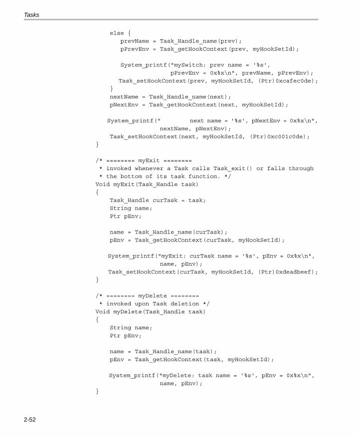
Tasks
else {
prevName = Task_Handle_name(prev);
pPrevEnv = Task_getHookContext(prev, myHookSetId);
System_printf("mySwitch: prev name = '%s',
pPrevEnv = 0x%x\n", prevName, pPrevEnv);
Task_setHookContext(prev, myHookSetId, (Ptr)0xcafec0de);
}
nextName = Task_Handle_name(next);
pNextEnv = Task_getHookContext(next, myHookSetId);
System_printf(" next name = '%s', pNextEnv = 0x%x\n",
nextName, pNextEnv);
Task_setHookContext(next, myHookSetId, (Ptr)0xc001c0de);
}
/* ======== myExit ========
* invoked whenever a Task calls Task_exit() or falls through
* the bottom of its task function. */
Void myExit(Task_Handle task)
{
Task_Handle curTask = task;
String name;
Ptr pEnv;
name = Task_Handle_name(curTask);
pEnv = Task_getHookContext(curTask, myHookSetId);
System_printf("myExit: curTask name = '%s', pEnv = 0x%x\n",
name, pEnv);
Task_setHookContext(curTask, myHookSetId, (Ptr)0xdeadbeef);
}
/* ======== myDelete ========
* invoked upon Task deletion */
Void myDelete(Task_Handle task)
{
String name;
Ptr pEnv;
name = Task_Handle_name(task);
pEnv = Task_getHookContext(task, myHookSetId);
System_printf("myDelete: task name = '%s', pEnv = 0x%x\n",
name, pEnv);
}
2-52

Tasks
/* Define 3 identical tasks */
Void myTsk0Func(UArg arg0, UArg arg1)
{
System_printf("myTsk0 Entering\n");
System_printf("myTsk0 Calling Task_yield\n");
Task_yield();
System_printf("myTsk0 Exiting\n");
}
Void myTsk1Func(UArg arg0, UArg arg1)
{
System_printf("myTsk1 Entering\n");
System_printf("myTsk1 Calling Task_yield\n");
Task_yield();
System_printf("myTsk1 Exiting\n");
}
Void myTsk2Func(UArg arg0, UArg arg1)
{
System_printf("myTsk2 Entering\n");
System_printf("myTsk2 Calling Task_yield\n");
Task_yield();
System_printf("myTsk2 Exiting\n");
}
/* ======== main ======== */
Int main(Int argc, Char* argv[])
{
Task_Params params;
Task_Params_init(¶ms);
params.instance->name = "myTsk0";
myTsk0 = Task_create(myTsk0Func, ¶ms, NULL);
params.instance->name = "myTsk1";
myTsk1 = Task_create(myTsk1Func, ¶ms, NULL);
params.instance->name = "myTsk2";
myTsk2 = Task_create(myTsk2Func, ¶ms, NULL);
BIOS_start();
return (0);
}
Threading Modules 2-53

Tasks
/* ======== myIdleFunc ======== */
Void myIdleFunc()
{
System_printf("Entering idleFunc().\n");
Task_delete(&myTsk0);
Task_delete(&myTsk1);
Task_delete(&myTsk2);
System_exit(0);
}
The XDCtools configuration script is as follows:
/* Lots of System_printf() output requires a bigger bufSize */
SysMin = xdc.useModule('xdc.runtime.SysMin');
SysMin.bufSize = 4096;
var Idle = xdc.useModule('ti.sysbios.knl.Idle');
Idle.addFunc('&myIdleFunc');
var Task = xdc.useModule('ti.sysbios.knl.Task');
/* Enable instance names */
Task.common$.namedInstance = true;
/* Define and add one Task Hook Set */
Task.addHookSet({
registerFxn: '&myRegister',
createFxn: '&myCreate',
readyFxn: '&myReady',
switchFxn: '&mySwitch',
exitFxn: '&myExit',
deleteFxn: '&myDelete',
});
2-54

Tasks
The program output is as follows:
myRegister: assigned HookSet Id = 0
myCreate: task name = 'ti.sysbios.knl.Task.IdleTask', pEnv = 0x0
myReady: task name = 'ti.sysbios.knl.Task.IdleTask', pEnv = 0xdead
myCreate: task name = 'myTsk0', pEnv = 0x0
myReady: task name = 'myTsk0', pEnv = 0xdead
myCreate: task name = 'myTsk1', pEnv = 0x0
myReady: task name = 'myTsk1', pEnv = 0xdead
myCreate: task name = 'myTsk2', pEnv = 0x0
myReady: task name = 'myTsk2', pEnv = 0xdead
mySwitch: ignoring dummy 1st prev Task
next name = 'myTsk0', pNextEnv = 0xc0de
myTsk0 Entering
myTsk0 Calling Task_yield
mySwitch: prev name = 'myTsk0', pPrevEnv = 0xc001c0de
next name = 'myTsk1', pNextEnv = 0xc0de
myTsk1 Entering
myTsk1 Calling Task_yield
mySwitch: prev name = 'myTsk1', pPrevEnv = 0xc001c0de
next name = 'myTsk2', pNextEnv = 0xc0de
myTsk2 Entering
myTsk2 Calling Task_yield
mySwitch: prev name = 'myTsk2', pPrevEnv = 0xc001c0de
next name = 'myTsk0', pNextEnv = 0xcafec0de
myTsk0 Exiting
myExit: curTask name = 'myTsk0', pEnv = 0xc001c0de
mySwitch: prev name = 'myTsk0', pPrevEnv = 0xdeadbeef
next name = 'myTsk1', pNextEnv = 0xcafec0de
myTsk1 Exiting
myExit: curTask name = 'myTsk1', pEnv = 0xc001c0de
mySwitch: prev name = 'myTsk1', pPrevEnv = 0xdeadbeef
next name = 'myTsk2', pNextEnv = 0xcafec0de
myTsk2 Exiting
myExit: curTask name = 'myTsk2', pEnv = 0xc001c0de
mySwitch: prev name = 'myTsk2', pPrevEnv = 0xdeadbeef
next name = 'ti.sysbios.knl.Task.IdleTask', pNextEnv = 0xc0de
Entering idleFunc().
myDelete: task name = 'myTsk0', pEnv = 0xcafec0de
myDelete: task name = 'myTsk1', pEnv = 0xcafec0de
myDelete: task name = 'myTsk2', pEnv = 0xcafec0de
Threading Modules 2-55

Tasks
2.5.5 Task Yielding for Time-Slice Scheduling
Example 2-1 demonstrates a time-slicing scheduling model that can bemanaged by a user. This model is preemptive and does not require anycooperation (that is, code) by the tasks. The tasks are programmed as if theywere the only thread running. Although DSP/BIOS tasks of differing prioritiescan exist in any given application, the time-slicing model only applies to tasksof equal priority.
In this example, a periodic Clock object is configured to run a simple functionthat calls the Task_yield() function every 4 clock ticks. Another periodic Clockobject is to run a simple function that calls the Semaphore_post() functionevery 16 milliseconds.
The output of the example code is shown after the code.
Example 2-1. Time-Slice Scheduling
/*
* ======== slice.c ========
* This example utilizes time-slice scheduling among three
* tasks of equal priority. A fourth task of higher
* priority periodically preempts execution.
*
* A periodic Clock object drives the time-slice scheduling.
* Every 4 milliseconds, the Clock object calls Task_yield()
* which forces the current task to relinquish access to
* to the CPU.
*
* Because a task is always ready to run, this program
* does not spend time in the idle loop. Calls to Idle_run()
* are added to give time to the Idle loop functions
* occasionally. The call to Idle_run() is within a
* Task_disable(), Task_restore() block because the call
* to Idle_run() is not reentrant.
*/
2-56

Tasks
#include <xdc/std.h>
#include <xdc/runtime/System.h>
#include <ti/sysbios/BIOS.h>
#include <ti/sysbios/ipc/Semaphore.h>
#include <ti/sysbios/knl/Clock.h>
#include <ti/sysbios/knl/Clock.h>
#include <ti/sysbios/knl/Idle.h>
#include <ti/sysbios/knl/Task.h>
#include <xdc/cfg/global.h>
Void hiPriTask(UArg arg0, UArg arg1);
Void task(UArg arg0, UArg arg1);
Void clockHandler1(UArg arg);
Void clockHandler2(UArg arg);
Semaphore_Handle sem;
/* ======== main ======== */
Void main()
{
Task_Params taskParams;
Clock_Params clockParams;
UInt i;
System_printf("Slice example started!\n");
/* Create 1 task with priority 15 */
Task_Params_init(&taskParams);
taskParams.stackSize = 512;
taskParams.priority = 15;
Task_create((Task_FuncPtr)hiPriTask, &taskParams, NULL);
/* Create 3 tasks with priority 1 */
/* re-uses taskParams */
taskParams.priority = 1;
for (i = 0; i < 3; i++) {
taskParams.arg0 = i;
Task_create((Task_FuncPtr)task, &taskParams, NULL);
}
Threading Modules 2-57

Tasks
/*
* Create clock that calls Task_yield() every
* 4 Clock ticks
*/
Clock_Params_init(&clockParams);
clockParams.period = 4;/* every 4 Clock ticks */
clockParams.startFlag = TRUE;/* start immediately */
Clock_create((Clock_FuncPtr)clockHandler1, 4, &clockParams,
NULL);
/*
* Create clock that calls Semaphore_post() every
* 16 Clock ticks
*/
clockParams.period = 16;/* every 16 Clock ticks */
clockParams.startFlag = TRUE;/* start immediately */
Clock_create((Clock_FuncPtr)clockHandler2, 16,
&clockParams, NULL);
/*
* Create semaphore with
* initial count = 0
* and default params
*/
sem = Semaphore_create(0, NULL, NULL);
/* Start DSP/BIOS */
BIOS_start();
}
/* ======== clockHandler1 ======== */
Void clockHandler1(UArg arg)
{
/* Call Task_yield every 4 ms */
Task_yield();
}
/* ======== clockHandler2 ======== */
Void clockHandler2(UArg arg)
{
/* Call Semaphore_post every 16 ms */
Semaphore_post(sem);
}
2-58

Tasks
/* ======== task ======== */
Void task(UArg arg0, UArg arg1)
{
Int time;
Int prevtime = -1;
UInt taskKey;
/* While loop simulates work load of time-sharing tasks */
while (1) {
time = Clock_getTicks();
/* print time once per clock tick */
if (time >= prevtime + 1) {
prevtime = time;
System_printf("Task %d: time is %d\n",
(Int)arg0, time);
}
/* check for rollover */
if (prevtime > time) {
prevtime = time;
}
/* Process the Idle Loop functions */
taskKey = Task_disable();
Idle_run();
Task_restore(taskKey);
}
}
/* ======== hiPriTask ======== */
Void hiPriTask(UArg arg0, UArg arg1)
{
static Int numTimes = 0;
while (1) {
System_printf("hiPriTask here\n");
if (++numTimes < 3) {
Semaphore_pend(sem, BIOS_WAIT_FOREVER);
}
else {
System_printf("Slice example ending.\n");
System_exit(0);
}
}
}
Threading Modules 2-59

Tasks
The System_printf() output for this example is as follows:
Slice example started!
hiPriTask here
Task 0: time is 0
Task 0: time is 1
Task 0: time is 2
Task 0: time is 3
Task 1: time is 4
Task 1: time is 5
Task 1: time is 6
Task 1: time is 7
Task 2: time is 8
Task 2: time is 9
Task 2: time is 10
Task 2: time is 11
Task 0: time is 12
Task 0: time is 13
Task 0: time is 14
Task 0: time is 15
hiPriTask here
Task 1: time is 16
Task 1: time is 17
Task 1: time is 18
Task 1: time is 19
Task 2: time is 20
Task 2: time is 21
Task 2: time is 22
Task 2: time is 23
Task 0: time is 24
Task 0: time is 25
Task 0: time is 26
Task 0: time is 27
Task 1: time is 28
Task 1: time is 29
Task 1: time is 30
Task 1: time is 31
hiPriTask here
Slice example ending.
2-60

The Idle Loop
2.6 The Idle Loop
The Idle Loop is the background thread of DSP/BIOS, which runscontinuously when no Hwi, Swi, or Task is running. Any other thread canpreempt the Idle Loop at any point.
The Idle Manager allows you to insert functions that execute within the IdleLoop. The Idle Loop runs the Idle functions you configured. Idle_loop calls thefunctions associated with each one of the Idle objects one at a time, and thenstarts over again in a continuous loop. The functions are called in the sameorder in which they were created. Therefore, an Idle function must run tocompletion before the next Idle function can start running. When the last idlefunction has completed, the Idle Loop starts the first Idle function again. IdleLoop functions are often used to poll non-real-time devices that do not (orcannot) generate interrupts, monitor system status, or perform otherbackground activities.
The Idle Loop is the thread with lowest priority in a DSP/BIOS application.The Idle Loop functions run only when no Hwis, Swis, or Tasks need to run.
The CPU load and thread load are computed in an Idle loop function. (Datatransfer for between the target and the host is handled by a low-priority task.)
Threading Modules 2-61

Example Using Hwi, Swi, and Task Threads
2.7 Example Using Hwi, Swi, and Task Threads
This example depicts a stylized version of the DSP/BIOS Clock moduledesign. It uses a combination of Hwi, Swi, and Task threads.
A periodic timer interrupt posts a Swi that processes the Clock object list.Each entry in the Clock object list has its own period and Clock function.When an object's period has expired, the Clock function is invoked and theperiod restarted.
Since there is no limit to the number of Clock objects that can be placed inthe list and no way to determine the overhead of each Clock function, thelength of time spent servicing all the Clock objects is non-deterministic. Assuch, servicing the Clock objects in the timer's Hwi thread is impractical.Using a Swi for this function is a relatively (as compared with using a Task)lightweight solution to this problem.
The XDCtools configuration script and program output are shown after the Ccode listing. This is the C code for the example:
/*
* ======== HwiSwiTaskExample.c ========
*/
#include <xdc/std.h>
#include <xdc/runtime/System.h>
#include <ti/sysbios/BIOS.h>
#include <ti/sysbios/hal/Timer.h>
#include <ti/sysbios/ipc/Semaphore.h>
#include <ti/sysbios/knl/Swi.h>
#include <ti/sysbios/knl/Task.h>
#include <ti/sdo/utils/List.h>
#include <xdc/cfg/global.h>
typedef struct {
List_Elem elem;
UInt32 timeout;
UInt32 period;
Void (*fxn)(UArg);
UArg arg;
} Clock_Object;
2-62

Example Using Hwi, Swi, and Task Threads
Clock_Object clk1, clk2;
Timer_Handle timer;
Semaphore_Handle sem;
Swi_Handle swi;
Task_Handle task;
List_Handle clockList;
/* Here on Timer interrupt */
Void hwiFxn(UArg arg)
{
Swi_post(swi);
}
/* Swi thread to handle Timer interrupt */
Void swiFxn(UArg arg1, UArg arg2)
{
List_Elem *elem;
Clock_Object *obj;
/* point to first clock object in the clockList */
elem = List_next(clockList, NULL);
/* service all the Clock Objects in the clockList */
while (elem != NULL) {
obj = (Clock_Object *)elem;
/* decrement the timeout counter */
obj->timeout -= 1;
/* if period has expired, refresh the timeout
* value and invoke the clock func */
if (obj->timeout == 0) {
obj->timeout = obj->period;
(obj->fxn)(obj->arg);
}
/* advance to next clock object in clockList */
elem = List_next(clockList, elem);
}
}
Threading Modules 2-63

Example Using Hwi, Swi, and Task Threads
/* Task thread pends on Semaphore posted by Clock thread */
Void taskFxn(UArg arg1, UArg arg2)
{
System_printf("In taskFxn pending on Sempahore.\n");
Semaphore_pend(sem, BIOS_WAIT_FOREVER);
System_printf("In taskFxn returned from Sempahore.\n");
System_exit(0);
}
/* First Clock function, invoked every 5 timer interrupts */
Void clk1Fxn(UArg arg)
{
System_printf("In clk1Fxn, arg = %d.\n", arg);
clk1.arg++;
}
/* Second Clock function, invoked every 20 timer interrupts */
Void clk2Fxn(UArg sem)
{
System_printf("In clk2Fxn, posting Semaphore.\n");
Semaphore_post((Semaphore_Object *)sem);
}
/* main() */
Int main(Int argc, char* argv[])
{
Timer_Params timerParams;
Task_Params taskParams;
System_printf("Starting HwiSwiTask example.\n");
Timer_Params_init(&timerParams);
Task_Params_init(&taskParams);
/* Create a Swi with default priority (15).
* Swi handler is 'swiFxn' which runs as a Swi thread. */
swi = Swi_create(swiFxn, NULL, NULL);
/* Create a Task with priority 3.
* Task function is 'taskFxn' which runs as a Task thread. */
taskParams.priority = 3;
task = Task_create(taskFxn, &taskParams, NULL);
/* Create a binary Semaphore for example task to pend on */
sem = Semaphore_create(0, NULL, NULL);
2-64

Example Using Hwi, Swi, and Task Threads
/* Create a List to hold the Clock Objects on */
clockList = List_create(NULL, NULL);
/* setup clk1 to go off every 5 timer interrupts. */
clk1.fxn = clk1Fxn;
clk1.period = 5;
clk1.timeout = 5;
clk1.arg = 1;
/* add the Clock object to the clockList */
List_put(clockList, &clk1.elem);
/* setup clk2 to go off every 20 timer interrupts. */
clk2.fxn = clk2Fxn;
clk2.period = 20;
clk2.timeout = 20;
clk2.arg = (UArg)sem;
/* add the Clock object to the clockList */
List_put(clockList, &clk2.elem);
/* Configure a periodic interrupt using any available Timer
* with a 1000 microsecond (1ms) interrupt period.
*
* The Timer interrupt will be handled by 'hwiFxn' which
* will run as a Hwi thread.
*/
timerParams.period = 1000;
timer = Timer_create(Timer_ANY, hwiFxn, &timerParams, NULL);
BIOS_start();
return(0);
}
Threading Modules 2-65

Example Using Hwi, Swi, and Task Threads
The XDCtools configuration script is as follows:
/*
* ======== HwiSwiTaskExample.cfg ========
*/
/* Configure System to use SysMin */
System = xdc.useModule('xdc.runtime.System');
System.SupportProxy = xdc.useModule('xdc.runtime.SysMin')
/* Use HeapMem for default heap manager and give it 8192
* bytes to work with */
var Memory = xdc.useModule('xdc.runtime.Memory');
var HeapMem = xdc.useModule('ti.sysbios.heaps.HeapMem');
var heapParams = new HeapMem.Params;
heapParams.size = 8192;
Memory.defaultHeapInstance = HeapMem.create(heapParams);
/* Pull in Timer, Semaphore, Swi, Task, and List modules
* used in this example. */
xdc.useModule('ti.sysbios.hal.Timer');
xdc.useModule('ti.sysbios.ipc.Semaphore');
xdc.useModule('ti.sysbios.knl.Swi');
xdc.useModule('ti.sysbios.knl.Task');
xdc.useModule('ti.sdo.utils.List');
The program output is as follows:
Starting HwiSwiTask example.
In taskFxn pending on Semaphore.
In clk1Fxn, arg = 1.
In clk1Fxn, arg = 2.
In clk1Fxn, arg = 3.
In clk1Fxn, arg = 4.
In clk2Fxn, posting Semaphore.
In taskFxn returned from Semaphore
2-66

Chapter 3
Synchronization Modules
This chapter describes modules that can be used to synchronize access toshared resources.
3.1 Semaphores . . . . . . . . . . . . . . . . . . . . . . . . . . . . . . . . . . . . . . . . . . . . . 3-2
3.2 Event Module . . . . . . . . . . . . . . . . . . . . . . . . . . . . . . . . . . . . . . . . . . . . 3-8
3.3 Gates . . . . . . . . . . . . . . . . . . . . . . . . . . . . . . . . . . . . . . . . . . . . . . . . . . 3-14
3.4 Mailboxes . . . . . . . . . . . . . . . . . . . . . . . . . . . . . . . . . . . . . . . . . . . . . . 3-18
Topic Page
3-1

Semaphores
3.1 Semaphores
DSP/BIOS provides a fundamental set of functions for inter-tasksynchronization and communication based upon semaphores. Semaphoresare often used to coordinate access to a shared resource among a set ofcompeting tasks. The Semaphore module provides functions that manipulatesemaphore objects accessed through handles of type Semaphore_Handle.
Semaphore objects can be declared as either counting or binarysemaphores. They can be used for task synchronization and mutualexclusion. The same APIs are used for both counting and binarysemaphores.
Binary semaphores are either available or unavailable. Their value cannot beincremented beyond 1. Thus, they should be used for coordinating access toa shared resource by a maximum of two tasks. Binary semaphores providebetter performance than counting semaphores.
Counting semaphores keep an internal count of the number of correspondingresources available. When count is greater than 0, tasks do not block whenacquiring a semaphore. The maximum count value for a semaphores plusone is the number of tasks a counting semaphore can coordinate.
To configure the type of semaphore, use the following configurationparameter:
config Mode mode = Mode_COUNTING;
The functions Semaphore_create() and Semaphore_delete() are used tocreate and delete semaphore objects, respectively, as shown in Example 3-1. You can also create semaphore objects statically. See the XDCtoolsConsumer User’s Guide for a discussion of the benefits of creating objectsstatically.
Example 3-1. Creating and Deleting a Semaphore
Semaphore_Handle Semaphore_create(Uns count,
Semaphore_Params *attrs);
Void Semaphore_delete(Semaphore_Handle *sem);
The semaphore count is initialized to count when it is created. In general,count is set to the number of resources that the semaphore is synchronizing.
Semaphore_pend() waits for a semaphore. If the semaphore count is greaterthan 0, Semaphore_pend() simply decrements the count and returns.Otherwise, Semaphore_pend() waits for the semaphore to be posted bySemaphore_post().
3-2

Semaphores
The timeout parameter to Semaphore_pend(), as shown in Example 3-2,allows the task to wait until a timeout, to wait indefinitely(BIOS_WAIT_FOREVER), or to not wait at all (BIOS_NO_WAIT).Semaphore_pend()’s return value is used to indicate if the semaphore wasacquired successfully.
Example 3-2. Setting a Timeout with Semaphore_pend()
Bool Semaphore_pend(Semaphore_Handle sem,
UInt timeout);
Example 3-3 shows Semaphore_post(), which is used to signal a semaphore.If a task is waiting for the semaphore, Semaphore_post() removes the taskfrom the semaphore queue and puts it on the ready queue. If no tasks arewaiting, Semaphore_post() simply increments the semaphore count andreturns.
Example 3-3. Signaling a Semaphore with Semaphore_post()
Void Semaphore_post(Semaphore_Handle sem);
3.1.1 Semaphore Example
Example 3-4 provides sample code for three writer tasks that create uniquemessages and place them on a list for one reader task. The writer tasks callSemaphore_post() to indicate that another message is available on the list.The reader task calls Semaphore_pend() to wait for messages.Semaphore_pend() returns only when a message is available on the list. Thereader task prints the message using the System_printf() function.
The three writer tasks, a reader task, a semaphore, and a list in this exampleprogram were created statically as follows:
Program.system = xdc.useModule('xdc.runtime.SysMin');
var Sem = xdc.useModule('ti.sysbios.ipc.Semaphore');
Program.global.sem = Sem.create(0);
Program.global.sem.mode = Sem.Mode_COUNTING;
var Task = xdc.useModule('ti.sysbios.knl.Task');
Task.idleTaskVitalTaskFlag = false;
var reader = Task.create('&reader');
reader.priority = 5;
var writer0 = Task.create('&writer');
writer0.priority = 3;
writer0.arg0 = 0;
Synchronization Modules 3-3

Semaphores
var writer1 = Task.create('&writer');
writer1.priority = 3;
writer1.arg0 = 1;
var writer2 = Task.create('&writer');
writer2.priority = 3;
writer2.arg0 = 2;
var List = xdc.useModule('ti.sdo.utils.List');
Program.global.msgList = List.create();
Program.global.freeList = List.create();
Since this program employs multiple tasks, a counting semaphore is used tosynchronize access to the list. Figure 3-1 provides a view of the results fromExample 3-3. Though the three writer tasks are scheduled first, the messagesare read as soon as they have been put on the list because the reader’s task priority is higher than that of the writer.
Example 3-4. Semaphore Example Using Three Writer Tasks
/* ======== semtest.c ======== */
#include <xdc/std.h>
#include <xdc/runtime/Memory.h>
#include <xdc/runtime/System.h>
#include <ti/sysbios/BIOS.h>
#include <ti/sdo/utils/List.h>
#include <ti/sysbios/ipc/Semaphore.h>
#include <ti/sysbios/knl/Task.h>
#define NUMMSGS 3 /* number of messages */
#define NUMWRITERS 3 /* number of writer tasks created with */
/* Config Tool */
typedef struct MsgObj {
List_Elem elem; /* first field for List */
Int id; /* writer task id */
Char val; /* message value */
} MsgObj, *Msg;
Void reader();
Void writer();
/* The following objects are created statically. */
extern Semaphore_Handle sem;
extern List_Handle msgList;
extern List_Handle freeList;
3-4

Semaphores
/* ======== main ======== */
Int main(Int argc, Char* argv[])
{
Int i;
MsgObj *msg;
msg = (MsgObj *) Memory_alloc(NULL, NUMMSGS * sizeof(MsgObj),
0, NULL);
/* Put all messages on freeList */
for (i = 0; i < NUMMSGS; msg++, i++) {
List_put(freeList, (List_Elem *) msg); }
BIOS_start();
System_exit(0);
return(0);
}
/* ======== reader ======== */
Void reader()
{
Msg msg;
Int i;
for (i = 0; i < NUMMSGS * NUMWRITERS; i++) {
/* Wait for semaphore to be posted by writer(). */
Semaphore_pend(sem, BIOS_WAIT_FOREVER);
/* get message */ msg = List_get(msgList); /* print value */
System_printf("read '%c' from (%d).\n", msg->val,
msg->id);
/* free msg */
List_put(freeList, (List_Elem *) msg); }
System_printf("reader done.\n");
}
Synchronization Modules 3-5

Semaphores
/* ======== writer ======== */
Void writer(Int id)
{
Msg msg;
Int i;
for (i = 0; i < NUMMSGS; i++) {
/* Get msg from the free list. Since reader is higher
* priority and only blocks on sem, list is never
* empty. */
msg = List_get(freeList);
/* fill in value */
msg->id = id;
msg->val = (i & 0xf) + 'a';
System_printf("(%d) writing '%c' ...\n", id, msg->val);
/* put message */ List_put(msgList, (List_Elem *) msg);
/* post semaphore */
Semaphore_post(sem);
}
System_printf("writer (%d) done.\n", id);
}
3-6

Semaphores
Figure 3-1. Trace Window Results from Example 3-4
(0) writing 'a' ...
read 'a' from (0).
(0) writing 'b' ...
read 'b' from (0).
(0) writing 'c' ...
read 'c' from (0).
writer (0) done.
(1) writing 'a' ...
read 'a' from (1).
(1) writing 'b' ...
read 'b' from (1).
(1) writing 'c' ...
read 'c' from (1).
writer (1) done.
(2) writing 'a' ...
read 'a' from (2).
(2) writing 'b' ...
read 'b' from (2).
(2) writing 'c' ...
read 'c' from (2).
reader done.
writer (2) done.
Synchronization Modules 3-7

Event Module
3.2 Event Module
Events provide a means for communicating between and synchronizingthreads. They are similar to Semaphores (see Section 3.1), except that theyallow you to specify multiple conditions ("events") that must occur before thewaiting thread returns.
An Event instance is used with calls to "pend" and "post", just as for aSemaphore. However, calls to Event_pend() additionally specify whichevents to wait for, and calls to Event_post() specify which events are beingposted.
Note: Only a single Task can pend on an Event object at a time.
A single Event instance can manage up to 32 events, each represented byan event ID. Event IDs are simply bit masks that correspond to a unique eventmanaged by the Event object.
Each Event behaves like a binary semaphore.
A call to Event_pend() takes an "andMask" and an "orMask". The andMaskconsists of the event IDs of all the events that must occur, and the orMaskconsists of the event IDs of any events of which only one must occur.
As with Semaphores, a call to Event_pend() takes a timeout value andreturns 0 if the call times out. If a call to Event_pend() is successful, it returnsa mask of the "consumed" events—that is, the events that occurred to satisfythe call to Event_pend(). The task is then responsible for handling ALL of theconsumed events.
Only Tasks can call Event_pend(), whereas Hwis, Swis, and other Tasks canall call Event_post().
The Event_pend() prototype is as follows:
UInt Event_pend(Event_Handle event,
UInt andMask,
UInt orMask,
UInt timeout);
The Event_post() prototype is as follows:
Void Event_post(Event_Handle event,
UInt eventIds);
3-8

Event Module
Configuration example: These XDCtools configuration statements createan event statically. The Event object has an Event_Handle named "myEvent".
var Event = xdc.useModule("ti.sysbios.ipc.Event");
Program.global.myEvent = Event.create();
Runtime example: The following C code creates an Event object with anEvent_Handle named "myEvent".
Event_Handle myEvent;
/* Default instance configuration params and NULL Error Block */
myEvent = Event_create(NULL, NULL);
Runtime example: The following C code blocks on an event. It wakes thetask only when both events 0 and 6 have occurred. It sets the andMask toenable both Event_Id_00 and Event_Id_06. It sets the orMask toEvent_Id_NONE.
Event_pend(myEvent, (Event_Id_00 + Event_Id_06), Event_Id_NONE,
BIOS_WAIT_FOREVER);
Runtime example: The following C code has a call to Event_post() to signalwhich events have occurred. The eventMask should contain the IDs of theevents that are being posted.
Event_post(myEvent, Event_Id_00);
Synchronization Modules 3-9

Event Module
Runtime Example: The following C code example shows a task thatprovides the background processing required for three Interrupt ServiceRoutines:
Event_Handle myEvent;
main()
{
/* create an Event object. All events are binary */
myEvent = Event_create(NULL, NULL);
}
isr0()
{
...
Event_post(myEvent, Event_Id_00);
...
}
isr1()
{
...
Event_post(myEvent, Event_Id_01);
...
}
isr2()
{
...
Event_post(myEvent, Event_Id_02);
...
}
isr0
isr1
isr2
task
3-10

Event Module
task()
{
UInt events;
while (TRUE) {
/* Wait for ANY of the ISR events to be posted *
events = Event_pend(myEvent, Event_Id_NONE,
Event_Id_00 + Event_Id_01 + Event_Id_02,
BIOS_WAIT_FOREVER);
/* Process all the events that have occurred */
if (events & Event_Id_00) {
processISR0();
}
if (events & Event_Id_01) {
processISR1();
}
if (events & Event_Id_02) {
processISR2();
}
}
}
3.2.1 Implicitly Posted Events
In addition to supporting the explicit posting of events through theEvent_post() API, some DSP/BIOS objects support implicit posting of eventsassociated with their objects. For example, a Mailbox can be configured topost an associated event whenever a message is available (that is, wheneverMailbox_post() is called) thus allowing a task to block while waiting for aMailbox message and/or some other event to occur.
Mailbox and Semaphore objects currently support the posting of eventsassociated with their resources becoming available.
DSP/BIOS objects that support implicit event posting must be configured withan event object and event ID when created. You can decide which event IDto associate with the specific resource availability signal (that is, a messageavailable in Mailbox, room available in Mailbox, or Semaphore available).
Note: As mentioned earlier, only one Task can pend on an Event object ata time. Consequently, DSP/BIOS objects that are configured for implicitevent posting should only be waited on by a single Task at a time.
When Event_pend() is used to acquire a resource from implicitly postingobjects, the BIOS_NO_WAIT timeout parameter should be used tosubsequently retrieve the resource from the object.
Synchronization Modules 3-11

Event Module
Runtime example: The following C code example shows a task processingthe messages posted to a Mailbox message as well as performing an ISR’spost-processing requirements.
Event_Handle myEvent;
Mailbox_Handle mbox;
typedef struct msg {
UInt id;
Char buf[10];
}
main()
{
Mailbox_Params &mboxParams;
myEvent = Event_create(NULL, NULL);
Mailbox_Params_init(mboxParams);
mboxParams.notEmptyEvent = myEvent;
/* Assign Event_Id_00 to Mailbox "not empty" event */
mboxParams.notEmptyEventId = Event_Id_00;
mbox = Mailbox_create(sizeof(msg), 50, &mboxParams, NULL);
/* Mailbox_create() sets Mailbox's notEmptyEvent to
* counting mode and initial count = 50 */
}
WriterTask
ReaderTask
Mailbox ISR
3-12

Event Module
writerTask()
{
...
Mailbox_post(mbox, &msgA, FOREVER);
/* implicitly posts Event_Id_00 to myEvent */
...
}
isr()
{
Event_post(myEvent, Event_Id_01);
}
readerTask()
{
while (TRUE) { /* Wait for either ISR or Mailbox message */
events = Event_pend(myEvent,
Event_Id_NONE, /* andMask = 0 */
Event_Id_00 + Event_Id_01, /* orMask */
BIOS_WAIT_FOREVER); /* timeout */
if (events & Event_Id_00) {
/* Get the posted message.
* Mailbox_pend() will not block since Event_pend()
* has guaranteed that a message is available.
* Notice that the special BIOS_NO_WAIT
* parameter tells Mailbox that Event_pend()
* was used to acquire the available message.
*/
Mailbox_pend(mbox, &msgB, BIOS_NO_WAIT);
processMsg(&msgB);
}
if (events & Event_Id_01) {
processISR();
}
}
}
Synchronization Modules 3-13

Gates
3.3 Gates
A "Gate" is a module that implements the IGateProvider interface. Gates aredevices for preventing concurrent accesses to critical regions of code. Thevarious Gate implementations differ in how they attempt to lock the criticalregions.
Since xdc.runtime.Gate is provided by XDCtools, the base module isdocumented in the online help and the RTSC-pedia wiki. Implementations ofGates provided by DSP/BIOS are discussed here.
Threads can be preempted by other threads of higher priority, and somesections of code need to be completed by one thread before they can beexecuted by another thread. Code that modifies a linked list is a commonexample of a critical region that may need to be protected by a Gate.
Gates generally work by either disabling some level of preemption such asdisabling task switching or even hardware interrupts, or by using a binarysemaphore.
All Gate implementations support nesting through the use of a "key". ForGates that function by disabling preemption, it is possible that multiplethreads would call Gate_enter(), but preemption should not be restored untilall of the threads have called Gate_leave(). This functionality is providedthrough the use of a key. A call to Gate_enter() returns a key that must thenbe passed back to Gate_leave(). Only the outermost call to Gate_enter()returns the correct key for restoring preemption. (The actual module name forthe implementation is used instead of "Gate" in the function name.)
Runtime example: The following C code protects a critical region with aGate. This example uses a GateHwi, which disables and enables interruptsas the locking mechanism.
UInt gateKey;
GateHwi_Handle gateHwi;
GateHwi_Params prms;
GateHwi_Params_init(&prms);
gateHwi = GateHwi_create(&prms, NULL);
/* Simultaneous operations on a List by multiple threads could
* corrupt the List structure, so modifications to the List
* are protected with a Gate. */
gateKey = GateHwi_enter(gateHwi);
List_get(myList);GateHwi_leave(gateHwi, gateKey);
3-14

Gates
3.3.1 Preemption-Based Gate Implementations
The following implementations of gates use some form of preemptiondisabling:
❏ ti.sysbios.gates.GateHwi
❏ ti.sysbios.gates.GateSwi
❏ ti.sysbios.gates.GateTask
3.3.1.1 GateHwi
GateHwi disables and enables interrupts as the locking mechanism. Such agate guarantees exclusive access to the CPU. This gate can be used whenthe critical region is shared by Task, Swi, or Hwi threads.
The duration between the enter and leave should be as short as possible tominimize Hwi latency.
3.3.1.2 GateSwi
GateSwi disables and enables software interrupts as the locking mechanism.This gate can be used when the critical region is shared by Swi or Taskthreads. This gate cannot be used by a Hwi thread.
The duration between the enter and leave should be as short as possible tominimize Swi latency.
3.3.1.3 GateTask
GateTask disables and enables tasks as the locking mechanism. This gatecan be used when the critical region is shared by Task threads. This gatecannot be used by a Hwi or Swi thread.
The duration between the enter and leave should be as short as possible tominimize Task latency.
3.3.2 Semaphore-Based Gate Implementations
The following implementations of gates use a semaphore:
❏ ti.sysbios.gates.GateMutex
❏ ti.sysbios.gates.GateMutexPri
Synchronization Modules 3-15

Gates
3.3.2.1 GateMutex
GateMutex uses a binary Semaphore as the locking mechanism. EachGateMutex instance has its own unique Semaphore. Because this gate canpotentially block, it should not be used a Swi or Hwi thread, and should onlybe used by Task threads.
3.3.2.2 GateMutexPri
GateMutexPri is a mutex Gate (it can only be held by one thread at a time)that implements "priority inheritance" in order to prevent priority inversion.Priority inversion occurs when a high-priority Task has its priority effectively"inverted" because it is waiting on a Gate held by a lower-priority Task. Issuesand solutions for priority inversion are described in Section 3.3.3.
Configuration example: The following example specifies a GateType to beused by HeapMem. (See section 5.1.1, HeapMem for further discussion.)
var GateMutexPri = xdc.useModule('ti.sysbios.gates.GateMutexPri');
var HeapMem = xdc.useModule('ti.sysbios.heaps.HeapMem');
HeapMem.common$.gate = GateMutexPri.create();
3.3.3 Priority Inversion
The following example shows the problem of priority inversion. A system hasthree tasks—Low, Med, and High—each with the priority suggested by itsname. Task Low runs first and acquires the gate. Task High is scheduled andpreempts Low. Task High tries to acquire the gate, and waits on it. Next, taskMed is scheduled and preempts task Low. Now task High must wait for bothtask Med and task Low to finish before it can continue. In this situation, taskLow has, in effect, lowered task High's priority to that of Low.
Solution: Priority InheritanceTo guard against priority inversion, GateMutexPri implements priorityinheritance. When task High tries to acquire a gate that is owned by task Low,task Low's priority is temporarily raised to that of High, as long as High iswaiting on the gate. So, task High "donates" its priority to task Low.
When multiple tasks wait on the gate, the gate owner receives the highestpriority of any of the tasks waiting on the gate.
CaveatsPriority inheritance is not a complete guard against priority inversion. Tasksonly donate their priority on the call to enter a gate, so if a task has its priorityraised while waiting on a gate, that priority is not carried through to the gateowner.
3-16

Gates
This can occur in situations involving multiple gates. For example, a systemhas four tasks: VeryLow, Low, Med, and High, each with the prioritysuggested by its name. Task VeryLow runs first and acquires gate A. TaskLow runs next and acquires gate B, then waits on gate A. Task High runs andwaits on gate B. Task High has donated its priority to task Low, but Low isblocked on VeryLow, so priority inversion occurs despite the use of the gate.The solution to this problem is to design around it. If gate A may be neededby a high-priority, time-critical task, then it should be a design rule that no taskholds this gate for a long time or blocks while holding this gate.
When multiple tasks wait on this gate, they receive the gate in order of priority(higher-priority tasks receive the gate first). This is because the list of taskswaiting on a GateMutexPri is sorted by priority, not FIFO.
Calls to GateMutexPri_enter() may block, so this gate can only be used in thetask context.
GateMutexPri has non-deterministic calls because it keeps the list of waitingtasks sorted by priority.
Synchronization Modules 3-17

Mailboxes
3.4 Mailboxes
The ti.sysbios.ipc.Mailbox module provides a set of functions to managemailboxes. Mailboxes can be used to pass buffers from one task to anotheron the same processor.
A Mailbox instance can be used by multiple readers and writers.
The Mailbox module copies the buffer to fixed-size internal buffers. The sizeand number of these buffers are specified when a Mailbox instance is created(or constructed). A copy is done when a buffer is sent via Mailbox_post().Another copy occurs when the buffer is retrieved via a Mailbox_pend().
Mailbox_create() and Mailbox_delete() are used to create and deletemailboxes, respectively. You can also create mailbox objects statically. Seethe XDCtools Consumer User’s Guide for a discussion of the benefits ofcreating objects statically.
Mailboxes can be used to ensure that the flow of incoming buffers does notexceed the ability of the system to process those buffers. The examples givenlater in this section illustrate just such a scheme.
You specify the number of internal mailbox buffers and size of each of thesebuffers when you create a mailbox. Since the size is specified when youcreate the Mailbox, all buffers sent and received with the Mailbox instancemust be of this same size.
Mailbox_Handle Mailbox_create(SizeT bufsize,
UInt numBufs,
Mailbox_Params *params,
Error_Block *eb)
Void Mailbox_delete(Mailbox_Handle *handle);
Mailbox_pend() is used to read a buffer from a mailbox. If no buffer isavailable (that is, the mailbox is empty), Mailbox_pend() blocks. The timeoutparameter allows the task to wait until a timeout, to wait indefinitely(BIOS_WAIT_FOREVER), or to not wait at all (BIOS_NO_WAIT). The unit oftime is system clock ticks.
Bool Mailbox_pend(Mailbox_Handle handle,
Ptr buf,
UInt timeout);
3-18

Mailboxes
Mailbox_post() is used to post a buffer to the mailbox. If no buffer slots areavailable (that is, the mailbox is full), Mailbox_post() blocks. The timeoutparameter allows the task to wait until a timeout, to wait indefinitely(BIOS_WAIT_FOREVER), or to not wait at all (BIOS_NO_WAIT).
Bool Mailbox_post(Mailbox_Handle handle,
Ptr buf,
UInt timeout);
Mailbox provides configuration parameters to allow you to associate eventswith a mailbox. This allows you to wait on a mailbox message and anotherevent at the same time. Mailbox provides two configuration parameters tosupport events for the reader(s) of the mailbox—notEmptyEvent andnotEmptyEventId. These allow a mailbox reader to use an event object towait for the mailbox message. Mailbox also provides two configurationparameters for the mailbox writer(s)—notFullEvent and notFullEventId.These allow mailbox writers to use an event object to wait for room in themailbox.
When using events, a thread calls Event_pend() and waits on several events.Upon returning from Event_pend(), the thread must call Mailbox_pend() orMailbox_post()—depending on whether it is a writer or a reader—with aspecial timeout value of BIOS_EVENT_ACQUIRED. This timeout valueallows the thread to get/put the message into the mailbox. This specialtimeout value is necessary for correct operation of the mailbox when usingEvents.
Synchronization Modules 3-19

3-20

Chapter 4
Timing Services
This chapter describes modules that can be used for timing purposes.
4.1 Overview of Timing Services . . . . . . . . . . . . . . . . . . . . . . . . . . . . . . . . 4-2
4.2 Clock . . . . . . . . . . . . . . . . . . . . . . . . . . . . . . . . . . . . . . . . . . . . . . . . . . . 4-2
4.3 Timer Module. . . . . . . . . . . . . . . . . . . . . . . . . . . . . . . . . . . . . . . . . . . . . 4-6
4.4 Timestamp Module . . . . . . . . . . . . . . . . . . . . . . . . . . . . . . . . . . . . . . . . 4-6
Topic Page
4-1

Overview of Timing Services
4.1 Overview of Timing Services
Several modules are involved in timekeeping and clock-related serviceswithin DSP/BIOS and XDCtools:
❏ The ti.sysbios.knl.Clock module is responsible for the periodic systemtick that the kernel uses to keep track of time. All DSP/BIOS APIs thatexpect a timeout parameter interpret the timeout in terms of Clock ticks.The Clock module is used to schedule functions that run at intervalsspecified in clock ticks. By default, the Clock module uses the hal.Timermodule to get a hardware-based tick. Alternately, the Clock module canbe configured to use an application-provided tick source. See Section 4.2for details. (The Clock module replaces both the CLK and PRD modulesin earlier versions of DSP/BIOS.)
❏ The ti.sysbios.hal.Timer module provides a standard interface forusing timer peripherals. It hides any target/device-specific characteristicsof the timer peripherals. Target/device-specific properties for timers aresupported by the ti.sysbios.family.xxx.Timer modules (for example,ti.sysbios.family.c64.Timer). You can use the Timer module to select atimer that calls a tickFxn when the timer expires. See Section 4.3 andSection 6.3 for details.
❏ The xdc.runtime.Timestamp module provides simple timestampingservices for benchmarking code and adding timestamps to logs. Thismodule uses a target/device-specific TimestampProvider in DSP/BIOS tocontrol how timestamping is implemented. See Section 4.4 for details.
4.2 Clock
The ti.sysbios.knl.Clock module is responsible for the periodic system tickthat the kernel uses to keep track of time. All DSP/BIOS APIs that expect atimeout parameter interpret the timeout in terms of Clock ticks.
The Clock module, by default, uses the ti.sysbios.hal.Timer module to createa timer to generate the system tick, which is basically a periodic call toClock_tick(). See Section 4.3 for more about the Timer module.
The Clock module can be configured not to use the timer with either of thefollowing configuration statements:
ti.sysbios.knl.Clock.tickSource = Clock.tickSource_USER
or
ti.sysbios.knl.Clock.tickSource = Clock.tickSource_NULL
The period for the system tick is set by the configuration parameterClock.tickPeriod. This is set in microseconds.
4-2
Clock
The Clock_tick() and the tick period are used as follows:
❏ If the tickSource is Clock.tickSource_TIMER (the default), Clock usesti.sysbios.hal.Timer to create a timer to generate the system tick, whichis basically a periodic call to Clock_tick(). Clock uses Clock.tickPeriod tocreate the timer. Clock.timerId can be changed to make Clock use adifferent timer.
❏ If the tickSource is Clock.tickSource_USER, then your applicationmust call Clock_tick() from a user interrupt and set the tickPeriod to theapproximate frequency of the user interrupt in microseconds.
❏ If the tickSource is Clock.tickSource_NULL, you cannot call anyDSP/BIOS APIs with a timeout value and cannot call any Clock APIs. Youcan still use the Task module but you cannot call APIs that require atimeout, for example, Task_sleep(). Clock.tickPeriod values is not valid inthis configuration.
Clock_getTicks() gets the number of Clock ticks that have occurred sincestartup. The value returned wraps back to zero after it reaches the maximumvalue that can be stored in 32 bits.
The Clock module provides APIs to start, stop and reconfigure the tick. TheseAPIs allow you to make frequency changes at runtime. These three APIs arenot reentrant and gates need to be used to protect them.
❏ Clock_tickStop() stops the timer used to generate the Clock tick bycalling Timer_stop().
❏ Clock_tickReconfig() calls Timer_setPeriodMicroseconds() internally toreconfigure the timer. Clock_tickReconfig() fails if the timer cannotsupport Clock.tickPeriod at the current CPU frequency.
❏ Clock_tickStart() restarts the timer used to generate the Clock tick bycalling Timer_start().
The Clock module lets you create Clock object instances, which referencefunctions that run when a timeout value specified in Clock ticks expires.
All Clock functions run in the context of a Swi. That is, the Clock moduleautomatically creates a Swi for its use and run the Clock functions within thatSwi. The priority of the Swi used by Clock can be changed by configuringClock.swiPriority.
You can dynamically create clock instances using Clock_create(). Clockinstances can be "one-shot" or continuous. You can start a clock instancewhen it is created or start it later by calling Clock_start(). This is controlled bythe startFlag configuration parameter.
Timing Services 4-3

Clock
A function and a non-zero timeout value are required arguments toClock_create(). The function is called when the timeout expires. The timeoutvalue is used to compute the first expiration time. For one-shot Clockinstances, the timeout value used to compute the single expiration time, andthe period is zero. For periodic Clock instances, the timeout value is used tocompute the first expiration time; the period value (part of the params) is usedafter the first expiration.
Table 4–1 Timeline for One-shot and Continuous Clocks
Clock instances (both one-shot and periodic) can be stopped and restartedby calling Clock_start() and Clock_stop(). Notice that while Clock_tickStop()stops the timer used to generate the Clock tick, Clock_stop() stops only oneinstance of a clock object. The expiration value is recomputed when you callClock_start().
APIs that start or stop a Clock Instance—Clock_create(), Clock_start(), andClock_stop()—can only be called in the Swi context.
The Clock module provides the Clock_setPeriod(), Clock_setTimeout(), andClock_setFunc() APIs to modify Clock instance properties for Clock instancesthat have been stopped.
Clock created andstarted with startFlagor Clock_start()
Time
One-shot Clock
Continuous Clock
Func runs
Func runs Func runs Func runs
period period ...timeout
timeout
4-4

Clock
Runtime example: This C example shows how to create a Clock instance.This instance is dynamic (runs repeatedly) and starts automatically. It runsthe myHandler function every 5 ticks. A user argument (UArg) is passed tothe function.
Clock_Params clockParams;
Error_Block eb;
Clock_Params_init(&clockParams);
clockParams.period = 5;
clockParams.startFlag = TRUE;
clockParams.arg = (UArg)0x5555;
obj1 = Clock_create(myHandler1, 5, &clockParams, &eb);
Configuration example: This example uses XDCtools to create a Clockinstance with the same properties as the previous example.
var Clock = xdc.useModule('ti.sysbios.knl.Clock');
var clockParams = new Clock.Params();
clockParams.period = 5;
clockParams.startFlag = true;
clockParams.arg = (UArg)0x5555;
Program.global.clockInst1 = Clock.create("&myHandler1", 5,
clockParams);
Runtime example: This C example uses some of the Clock APIs to printmessages about how long a Task sleeps.
UInt32 time1, time2;
. . .
System_printf("task going to sleep for 10 ticks... \n");
time1 = Clock_getTicks();
Task_sleep(10);
time2 = Clock_getTicks();
System_printf("...awake! Delta time is: %lu\n",
(ULong) (time2 - time1));
Timing Services 4-5

Timer Module
Runtime example: This C example uses some of the Clock APIs to lower theClock module frequency.
BIOS_getCpuFreq(&cpuFreq);
cpuFreq.lo = cpuFreq.lo / 2;
BIOS_setCpuFreq(&cpuFreq);
key = Hwi_disable();
Clock_tickStop();
Clock_tickReconfig();
Clock_tickStart();
Hwi_restore(key);
4.3 Timer Module
The ti.sysbios.hal.Timer module presents a standard interface for using thetimer peripherals. This module is described in detail in Section 6.3 because itis part of the Hardware Abstraction Layer (HAL) package
You can use this module to create a timer (that is, to mark a timer for use) andconfigure it to call a tickFxn when the timer expires. Use this module only ifyou do not need to do any custom configuration of the timer peripheral.
The timer can be configured as a one-shot or a continuous mode timer. Theperiod can be specified in timer counts or microseconds.
4.4 Timestamp Module
The xdc.runtime.Timestamp module, as the name suggests, providestimestamping services. The Timestamp module can be used forbenchmarking code and adding timestamps to logs. (In previous versions ofDSP/BIOS, this is the functionality provided by CLK_gethtime().)
Since xdc.runtime.Timestamp is provided by XDCtools, it is documented inthe online help and the RTSC-pedia wiki.
4-6

Chapter 5
Memory
This chapter describes modules that can be used to allocate memory.
5.1 Memory Allocation . . . . . . . . . . . . . . . . . . . . . . . . . . . . . . . . . . . . . . . . 5-2
Topic Page
5-1

Memory Allocation
5.1 Memory Allocation
A "Heap" is a module that implements the IHeap interface. Heaps arememory managers: they manage a specific piece of memory and supportallocating and freeing pieces ("blocks") of that memory.
The xdc.runtime.Memory module is the common interface for all memoryoperations. The actual memory management is performed by a Heapinstance, such as an instance of HeapMem or HeapBuf. For example,Memory_alloc() is used at runtime to dynamically allocate memory. All of theMemory APIs take a Heap instance as one of their parameters. Internally, theMemory module calls into the heap’s interface functions.
The xdc.runtime.Memory module is documented in the online help and theRTSC-pedia wiki. Implementations of Heaps provided by DSP/BIOS arediscussed here.
Memory allocations sizes are measured in "Minimum Addressable Units"(MAUs) of memory. The size of an MAU in bits is determined by the target.
The different heap implementations optimize for different memorymanagement traits. The HeapMem module (Section 5.1.1) accepts requestsfor all possible sizes of blocks, so it minimizes internal fragmentation. TheHeapBuf module (Section 5.1.2), on the other hand, can only allocate blocksof a fixed size, so it minimizes external fragmentation in the heap and is alsofaster at allocating and freeing memory.
DSP/BIOS provides the following Heap implementations:
❏ HeapMem. Allocate variable-size blocks. Section 5.1.1
❏ HeapBuf. Allocate fixed-size blocks. Section 5.1.2
❏ HeapMultiBuf. Specify variable-size allocation, but internally allocatefrom a variety of fixed-size blocks. Section 5.1.3
5.1.1 HeapMem
HeapMem can be considered the most "flexible" of the Heaps because itallows you to allocate variable-sized blocks. When the size of memoryrequests is not known until runtime, it is ideal to be able to allocate exactlyhow much memory is required each time. For example, if a program needs tostore an array of objects, and the number of objects needed isn't known untilthe program actually executes, the array will likely need to be allocated froma HeapMem.
The flexibility offered by HeapMem has a number of performance tradeoffs.
5-2

Memory Allocation
❏ External Fragmentation. Allocating variable-sized blocks can result infragmentation. As memory blocks are "freed" back to the HeapMem, theavailable memory in the HeapMem becomes scattered throughout theheap. The total amount of free space in the HeapMem may be large, butbecause it is not contiguous, only blocks as large as the "fragments" inthe heap can be allocated.
This type of fragmentation is referred to as "external" fragmentationbecause the blocks themselves are allocated exactly to size, so thefragmentation is in the overall heap and is "external" to the blocksthemselves.
❏ Non-Deterministic Performance. As the memory managed by theHeapMem becomes fragmented, the available chunks of memory arestored on a linked list. To allocate another block of memory, this list mustbe traversed to find a suitable block. Because this list can vary in length,it's not known how long an allocation request will take, and so theperformance becomes "non-deterministic".
A number of suggestions can aide in the optimal use of a HeapMem.
❏ Larger Blocks First. If possible, allocate larger blocks first. Previousallocations of small memory blocks can reduce the size of the blocksavailable for larger memory allocations.
❏ Overestimate Heap Size. To account for the negative effects offragmentation, use a HeapMem that is significantly larger than theabsolute amount of memory the program will likely need.
When a block is freed back to the HeapMem, HeapMem combines the blockwith adjacent free blocks to make the available block sizes as large aspossible.
Note: HeapMem uses a user-provided lock to lock access to the memory.For details, see Section 3.3, Gates.
The following examples create a HeapMem instance with a size of 1024MAUs.
Configuration example: The first example uses XDCtools to staticallyconfigure the heap:
var HeapMem = xdc.useModule('ti.sysbios.heaps.HeapMem');
/* Create heap as global variable so it can be used in C code */
Program.global.myHeap = HeapMem.create();
Program.global.myHeap.size = 1024;
Memory 5-3

Memory Allocation
Runtime example: This second example uses C code to dynamically createa HeapMem instance:
HeapMem_Params prms;
static char *buf[1024];
HeapMem_Handle heap;
HeapMem_Params_init(&prms);
prms.size = 1024;
prms.buf = (Ptr)buf;
heap = HeapMem_create(&prms, NULL);
HeapMem uses a Gate (see the Gates section for an explanation of Gates)to prevent concurrent accesses to the code which operates on a HeapMem'slist of free blocks. The type of Gate used by HeapMem is staticallyconfigurable through the HeapMem's common defaults.
Configuration example: This example configures HeapMem to use aGateMutexPri to protect critical regions of code.
var GateMutexPri = xdc.useModule('ti.sysbios.gates.GateMutexPri');
var HeapMem = xdc.useModule('ti.sysbios.heaps.HeapMem');
HeapMem.common$.gate = GateMutexPri.create();
The type of Gate used depends upon the level of protection needed for theapplication. If there is no risk of concurrent accesses to the heap, then "null"can be assigned to forgo the use of any Gate, which would improveperformance. For an application that could have concurrent accesses, aGateMutex is a likely choice. Or, if it is possible that a critical thread willrequire the HeapMem at the same time as a low-priority thread, then aGateMutexPri would be best suited to ensuring that the critical threadreceives access to the HeapMem as quickly as possible. See Section 3.3.2.2,GateMutexPri for more information.
5.1.2 HeapBuf
HeapBuf is used for allocating fixed-size blocks of memory, and is designedto be fast and deterministic. Often a program needs to create and delete avarying number of instances of a fixed-size object. A HeapBuf is ideal forallocating space for such objects, since it can handle the request quickly andwithout any fragmentation.
A HeapBuf may also be used for allocating objects of varying sizes whenresponse time is more important than efficient memory usage. In this case, aHeapBuf will suffer from "internal" fragmentation. There will never be any
5-4

Memory Allocation
fragmented space in the heap overall, but the allocated blocks themselvesmay contain wasted space, so the fragmentation is "internal" to the allocatedblock.
Allocating from and freeing to a HeapBuf always takes the same amount oftime, so a HeapBuf is a "deterministic" memory manager.
The following examples create a HeapBuf instance with a size of 1024 MAUsand a block size of 128 MAUs.
Configuration example: The first example uses XDCtools to staticallyconfigure the heap:
var HeapBuf = xdc.useModule('ti.sysbios.heaps.HeapBuf');
/* Create heap as global variable so it can be used in C code */
Program.global.myHeap = HeapBuf.create();
Program.global.myHeap.blockSize = 128;
Program.global.myHeap.numBlocks = 10;
Runtime example: This second example uses C code to dynamically createa HeapBuf instance:
HeapBuf_Params prms;
static char *buf[1280];
HeapBuf_Handle heap;
HeapBuf_Params_init(&prms);
prms.blockSize = 128;
prms.numBlocks = 10;
prms.buf = buf;
prms.bufSize = 1280;
heap = HeapBuf_create(&prms, NULL);
5.1.3 HeapMultiBuf
HeapMultiBuf is intended to balance the strengths of HeapMem andHeapBuf. Internally, a HeapMultiBuf maintains a collection of HeapBufinstances, each with a different block size, alignment, and number of blocks.A HeapMultiBuf instance can accept memory requests of any size, andsimply determines which of the HeapBufs to allocate from.
A HeapMultiBuf provides more flexibility in block size than a single HeapBuf,but largely retains the fast performance of a HeapBuf. A HeapMultiBufinstance has the added overhead of looping through the HeapBufs todetermine which to allocate from. In practice, though, the number of differentblock sizes is usually small and is always a fixed number, so a HeapMultiBufcan be considered deterministic by some definitions.
Memory 5-5

Memory Allocation
A HeapMultiBuf services a request for any memory size, but always returnsone of the fixed-sized blocks. The allocation will not return any informationabout the actual size of the allocated block. When freeing a block back to aHeapMultiBuf, the size parameter is ignored. HeapMultiBuf determines thebuffer to free the block to by comparing addresses.
When a HeapMultiBuf runs out of blocks in one of its buffers, it can beconfigured to allocate blocks from the next largest buffer. This is referred toas "block borrowing". See the online reference described in Section 1.5.1 formore about HeapMultiBuf.
The following examples create a HeapMultiBuf that manages 1024 MAUs ofmemory, which are divided into 3 buffers. It will manage 8 blocks of size 16MAUs, 8 blocks of size 32 MAUs, and 5 blocks of size 128 MAUs as shownin the following diagram.
Configuration example: The first example uses XDCtools to staticallyconfigure the HeapMultiBuf instance:
var HeapMultiBuf = xdc.useModule('ti.sysbios.heaps.HeapMultiBuf');
/* HeapMultiBuf without blockBorrowing. */
/* Create as a global variable to access it from C Code. */
Program.global.myHeap = HeapMultiBuf.create();
Program.global.myHeap.numBufs = 3;
Program.global.myHeap.blockBorrow = false;
Program.global.myHeap.bufParams = [{blockSize: 16, numBlocks:8, align: 0},
{blockSize: 32, numBlocks:8, align: 0},
{blockSize: 128, numBlocks:5, align: 0}];
Program.global.myHeap16 MAUs 16 MAUs 16 MAUs 16 MAUs 16 MAUs 16 MAUs 16 MAUs 16 MAUs
32 MAUs32 MAUs
32 MAUs 32 MAUs 32 MAUs32 MAUs 32 MAUs 32 MAUs
128 MAUs128 MAUs128 MAUs128 MAUs128 MAUs
5-6

Memory Allocation
Runtime example: This second example uses C code to dynamically createa HeapMultiBuf instance:
HeapMultiBuf_Params prms;
HeapMultiBuf_Handle heap;
/* Create the buffers to manage */
Char buf0[128];
Char buf1[256];
Char buf2[640];
/* Create the array of HeapBuf_Params */
HeapBuf_Params bufParams[3];
/* Load the default values */
HeapMultiBuf_Params_init(&prms);
prms.numBufs = 3;
prms.bufParams = bufParams;
HeapBuf_Params_init(&prms.bufParams[0]);
prms.bufParams[0].align = 0;
prms.bufParams[0].blockSize = 16;
prms.bufParams[0].numBlocks = 8;
prms.bufParams[0].buf = (Ptr) buf0;
prms.bufParams[0].bufSize = 128;
HeapBuf_Params_init(&prms.bufParams[1]);
prms.bufParams[1].align = 0;
prms.bufParams[1].blockSize = 32;
prms.bufParams[1].numBlocks = 8;
prms.bufParams[1].buf = (Ptr) buf1;
prms.bufParams[1].bufSize = 256;
HeapBuf_Params_init(&prms.bufParams[2]);
prms.bufParams[2].align = 0;
prms.bufParams[2].blockSize = 128;
prms.bufParams[2].numBlocks = 5;
prms.bufParams[2].buf = (Ptr) buf2;
prms.bufParams[2].bufSize = 640;
heap = HeapMultiBuf_create(&prms, NULL);
Memory 5-7

5-8

Chapter 6
Hardware Abstraction Layer
This chapter describes modules that provide hardware abstractions.
6.1 Hardware Abstraction Layer APIs . . . . . . . . . . . . . . . . . . . . . . . . . . . 6-2
6.2 HWI Module. . . . . . . . . . . . . . . . . . . . . . . . . . . . . . . . . . . . . . . . . . . . . . 6-3
6.3 Timer Module . . . . . . . . . . . . . . . . . . . . . . . . . . . . . . . . . . . . . . . . . . . 6-11
6.4 Cache Module . . . . . . . . . . . . . . . . . . . . . . . . . . . . . . . . . . . . . . . . . . . 6-16
6.5 HAL Package Organization . . . . . . . . . . . . . . . . . . . . . . . . . . . . . . . . 6-18
Topic Page
6-1

Hardware Abstraction Layer APIs
6.1 Hardware Abstraction Layer APIs
DSP/BIOS provides services for configuration and management of interrupts,cache, and timers. Unlike other DSP/BIOS services such as threading, thesemodules directly program aspects of a device's hardware and are groupedtogether in the Hardware Abstraction Layer (HAL) package. Services such asenabling and disabling interrupts, plugging of interrupt vectors, multiplexingof multiple interrupts to a single vector, and cache invalidation or writebackare described in this chapter.
Note: Any configuration or manipulation of interrupts and their associatedvectors, the cache, and timers in a DSP/BIOS application must be donethrough the DSP/BIOS HAL APIs. In earlier versions of DSP/BIOS, someHAL services were not available and developers were expected to usefunctions from the Chip Support Library (CSL) for a device. The most recentreleases of CSL (3.0 or above) are designed for use in applications that donot use DSP/BIOS. Some of their services are not compatible withDSP/BIOS. Usage of CSL interrupt, cache, and timer functions andDSP/BIOS in the same application should be avoided since thiscombination is known to result in complex interrupt-related debuggingproblems.
The HAL APIs fall into two categories:
❏ Generic APIs that are available across all targets and devices
❏ Target/device-specific APIs that are available only for a specific device orISA family
The generic APIs are designed to cover the great majority of use cases.Developers who are concerned with ensuring easy portability betweendifferent TI devices are best served by using the generic APIs as much aspossible. In cases where the generic APIs cannot enable use of a device-specific hardware feature that is advantageous to the software application,you may choose to use the target/device-specific APIs, which provide fullhardware entitlement.
In this chapter, an overview of the functionality of each HAL package isprovided along with usage examples for that package’s generic APIfunctions. After the description of the generic functions, examples oftarget/device-specific APIs, based on those provided for ’C64x+ devices, arealso given. For a full description of the target/device-specific APIs availablefor a particular family or device, please refer to the API referencedocumentation. section 6.5, HAL Package Organization provides anoverview of the generic HAL packages and their associated target/device-specific packages to facilitate finding the appropriate packages.
6-2

HWI Module
6.2 HWI Module
The ti.sysbios.hal.Hwi module provides a collection of APIs for managinghardware interrupts. These APIs are generic across all supported targets anddevices and should provide sufficient functionality for most applications.
6.2.1 Associating a C Function with a System Interrupt Source
To associate a user-provided C function with a particular system interrupt,you create a Hwi object that encapsulates information regarding the interruptrequired by the Hwi module.
The standard static and dynamic forms of the "create" function are supportedby the ti.sysbios.hal.Hwi module.
Configuration example: The following example statically creates a Hwiobject that associates interrupt 5 with the "myIsr" C function using defaultinstance configuration parameters:
Var Hwi = xdc.useModule('ti.sysbios.hal.Hwi');
Hwi.create(5, '&myIsr');
Runtime example: The C code required to configure the same interruptdynamically would be as follows:
#include <ti/sysbios/hal/Hwi>
Hwi_create(5, myIsr, NULL, NULL);
The NULL, NULL arguments are used when the default instance parametersand generic error handling is satisfactory for creating a Hwi object.
6.2.2 Hwi Instance Configuration Parameters
The following configuration parameters and their default values are definedfor each Hwi object. For a more detailed discussion of these parameters andtheir values see the ti.sysbios.hal.Hwi module in the online documentation.(For information on running online help, see Section 1.5.1, Using the APIReference Help System, page 1-7.)
❏ The "maskSetting" defines how interrupt nesting is managed by theinterrupt dispatcher.
MaskingOption maskSetting = MaskingOption_SELF;
Hardware Abstraction Layer 6-3

HWI Module
❏ The configured "arg" parameter will be passed to the Hwi function whenthe dispatcher invokes it.
UArg arg = 0;
❏ The "enabledInt" parameter is used to automatically enable or disable aninterrupt upon Hwi object creation.
Bool enableInt = true;
❏ The "eventId" accommodates 'C6000 devices that allow dynamicassociation of a peripheral event to an interrupt number. The defaultvalue of -1 leaves the eventId associated with an interrupt number in itsnormal (reset) state (that is, no re-association is required).
Int eventId = -1;
❏ The "priority" parameter is provided for those architectures that supportinterrupt priority setting. The default value of -1 informs the Hwi moduleto set the interrupt priority to a default value appropriate to the device.
Int priority = -1;
6.2.3 Creating a Hwi Object Using Non-Default Instance Configuration Parameters
Building on the examples given in Section 6.2.1, the following examples showhow to associate interrupt number 5 with the "myIsr" C function, passing "10"as the argument to "myIsr" and leaving the interrupt disabled after creation.
Configuration example:
var Hwi = xdc.useModule('ti.sysbios.hal.Hwi');
/* initialize hwiParams to default values */
var hwiParams = new Hwi.Params;
hwiParams.arg = 10; /* Set myIsr5 argument to 10 */
hwiParams.enableInt = false; /* override default setting */
/* Create a Hwi object for interrupt number 5
* that invokes myIsr5() with argument 10 */
Hwi.create(5, '&myIsr', hwiParams);
6-4

HWI Module
Runtime example:
#include <ti/sysbios/hal/Hwi>
Hwi_Params hwiParams;
/* initialize hwiParams to default values */
Hwi_Params_init(&hwiParams);
hwiParams.arg = 10;
hwiParams.enableInt = FALSE;
Hwi_create(5, myIsr, &hwiParms, NULL);
6.2.4 Enabling and Disabling Interrupts
You can enable and disable interrupts globally as well as individually with thefollowing Hwi module APIs:
❏ UInt Hwi_enable();
Globally enables all interrupts. Returns the previous enabled/disabledstate.
❏ UInt Hwi_disable();
Globally disables all interrupts. Returns the previous enabled/disabledstate.
❏ Hwi_restore(UInt key);
Restores global interrupts to their previous enabled/disabled state. The"key" is the value returned from Hwi_disable() or Hwi_enable().
❏ The APIs that follow are used for enabling, disabling, and restoringspecific interrupts given by "intNum". They have the same semantics asthe global Hwi_enable/disable/restore APIs.:■ UInt Hwi_enableInterrupt(UInt intNum);
■ UInt Hwi_disableInterrupt(UInt intNum);
■ Hwi_restoreInterrupt(UInt key);
❏ Hwi_clearInterrupt(UInt intNum);
Clears "intNum" from the set of currently pending interrupts.
Disabling hardware interrupts is useful during a critical section of processing.
On the C6000 platform, Hwi_disable() clears the GIE bit in the control statusregister (CSR). On the C2000 platform, Hwi_disable() sets the INTM bit in theST1 register.
Hardware Abstraction Layer 6-5

HWI Module
6.2.5 A Simple Example Hwi Application
The following example creates two Hwi objects. One for interrupt number 5and another for interrupt number 6. For illustrative purposes, one interrupt iscreated statically and the other dynamically. An idle function that waits for theinterrupts to complete is also added to the Idle function list.
Configuration example:
/* Pull in BIOS module required by ALL BIOS applications */
xdc.useModule('ti.sysbios.BIOS');
/* Pull in XDC runtime System module for various APIs used */
xdc.useModule('xdc.runtime.System');
/* Get handle to Hwi module for static configuration */
var Hwi = xdc.useModule('ti.sysbios.hal.Hwi');
/* Initialize hwiParams to default values */
var hwiParams = new Hwi.Params;
/* Set myIsr5 argument */
hwiParams.arg = 10;
/* Keep interrupt 5 disabled until later */
hwiParams.enableInt = false;
/* Create a Hwi object for interrupt number 5
* that invokes myIsr5() with argument 10 */
Hwi.create(5, '&myIsr5', hwiParams);
/* Add an idle thread 'myIdleFunc' that monitors interrupts. */
var Idle = xdc.useModule(ti.sysbios.knl.Idle);
Idle.addFunc('&myIdleFunc');
Runtime example:
#include <xdc/std.h>
#include <xdc/runtime/System.h>
#include <ti/sysbios/hal/Hwi>
Bool Hwi5 = FALSE;
Bool Hwi6 = FALSE;
6-6

HWI Module
Main(Void) {
Hwi_Params hwiParams;
/* Initialize hwiParams to default values */
Hwi_Params_init(&hwiParams);
/* Set myIsr6 parameters */
hwiParams.arg = 12;
hwiParams.enableInt = FALSE;
/* Create a Hwi object for interrupt number 6
* that invokes myIsr6() with argument 12 */
Hwi_create(6, myIsr6, &hwiParms, NULL);
/* enable both interrupts */
Hwi_enableInterrupt(5);
Hwi_enableInterrupt(6);
/* start BIOS */
BIOS_start();
}
/* Runs when interrupt 5 occurs */
Void myIsr5(UArg arg) {
If (arg == 10) {
Hwi5 = TRUE;
}
}
/* Runs when interrupt 6 occurs */
Void myIsr6(UArg arg) {
If (arg == 12) {
Hwi6 = TRUE;
}
}
/* The Idle thread checks for completion of interrupts 5 & 6
* and exits when they have both completed. */
Void myIdleFunc()
{
If (Hwi5 && Hwi6) {
System_printf("Both interrupts have occurred!");
System_exit(0);
}
}
Hardware Abstraction Layer 6-7

HWI Module
6.2.6 The Interrupt Dispatcher
To consolidate code that performs register saving and restoration for eachinterrupt, DSP/BIOS provides an interrupt dispatcher that automaticallyperforms these actions for an interrupt routine. Use of the Hwi dispatcherallows ISR functions to be written in C.
In addition to preserving the interrupted thread's context, the DSP/BIOS Hwidispatcher orchestrates the following actions:
❏ Disables DSP/BIOS Swi and Task scheduling during interrupt processing
❏ Automatically manages nested interrupts on a per-interrupt basis.
❏ Invokes any configured "begin" Hwi Hook functions.
❏ Runs the Hwi function.
❏ Invokes any configured "end" Hwi Hook functions.
❏ Invokes Swi and Task schedulers after interrupt processing to performany Swi and Task operations resulting from actions within the Hwifunction.
Note: The interrupt keyword or INTERRUPT pragma must not be used todefine the C function invoked by the Hwi dispatcher. The Hwi dispatchercontains this functionality, and the use of the C modifier will causecatastrophic results.
Functions that use the interrupt keyword or INTERRUPT pragma may notuse the Hwi dispatcher and may not call DSP/BIOS APIs.
6.2.7 Registers Saved and Restored by the Interrupt Dispatcher
The registers saved and restored by the dispatcher in preparation for invokingthe user's Hwi function conform to the "saved by caller" or "scratch" registersas defined in the register usage conventions section of the C compilerdocuments. For more information, either about which registers are saved andrestored, or about the TMS320 functions conforming to the TexasInstruments C runtime model, see the Optimizing Compiler User's Guide foryour platform.
6-8

HWI Module
6.2.8 Additional Target/Device-Specific Hwi Module Functionality
As described in Section 6.5, the ti.sysbios.hal.Hwi module is implementedusing the RTSC proxy-delegate mechanism. All ti.sysbios.hal.Hwi moduleAPIs are forwarded to a target/device-specific Hwi module that implementsall of the ti.sysbios.hal.Hwi required APIs. Each of these Hwi moduleimplementations provide additional APIs and functionality unique to thefamily/device and can be used instead of the ti.sysbios.hal.Hwi module ifneeded.
For example, the ’C64x+ target-specific Hwi module provides the followingAPIs in addition to those defined in the ti.sysbios.hal.Hwi module:
❏ Hwi_eventMap(UInt intNum, UInt eventId;
Remaps a peripheral event number to an interrupt number.
❏ Bits16 Hwi_enableIER(Bits16 mask);
Bits16 Hwi_disableIER(Bits16 mask);Bits16 Hwi_restoreIER(Bits16 mask);
These three APIs allow enabling, disabling and restoring a set ofinterrupts defined by a "mask" argument. These APIs provide directmanipulation of the ’C64x+'s internal IER registers.
To gain access to these additional APIs, you use the target/device-specificHwi module associated with the ’C64x+ target rather than theti.sysbios.hal.Hwi module.
The following examples are modified versions of portions of the example inSection 6.2.5. The modifications are shown in bold.
Configuration example:
var Hwi = xdc.useModule('ti.sysbios.family.c64p.Hwi');
/* Initialize hwiParams to default values */
var hwiParams = new Hwi.Params;
/* Set myIsr5 parameters */
hwiParams.arg = 10;
hwiParams.enableInt = false;
/* Create a Hwi object for interrupt number 5
* that invokes myIsr5() with argument 10 */
Hwi.create(5, '&myIsr5', hwiParams);
Hardware Abstraction Layer 6-9

HWI Module
Runtime example:
#include <ti/sysbios/family/c64p/Hwi>
Main(Void) {
Hwi_Params hwiParams;
/* Initialize hwiParams to default values */
Hwi_Params_init(&hwiParams);
/* Set myIsr6 parameters */
hwiParams.arg = 12;
hwiParams.enableInt = FALSE;
/* Create a Hwi object for interrupt number 6
* that invokes myIsr6() with argument 12 */
Hwi_create(6, myIsr6, &hwiParms, NULL);
/* Enable interrupts 5 & 6 simultaneously using the C64x+
* Hwi module Hwi_enableIER() API. */
Hwi_enableIER(0x0060);
. . .
6-10

Timer Module
6.3 Timer Module
The ti.sysbios.hal.Timer module presents a standard interface for using thetimer peripherals. It hides any target/device-specific characteristics of thetimer peripherals. It inherits the ti.sysbios.interfaces.ITimer interface.
You can use this module to create a timer (that is, to mark a timer for use) andconfigure it to call a tickFxn when the timer expires. Use this module only ifyou do not need to do any custom configuration of the timer peripheral.
This module has a configuration parameter called TimerProxy which isplugged by default with a target/device-specific implementation. Forexample, the implementation for C64x targets is ti.sysbios.family.c64.Timer.
The timer can be configured as a one-shot or a continuous mode timer. Theperiod can be specified in timer counts or microseconds.
The timer interrupt always uses the Hwi dispatcher. The Timer tickFxn runsin the context of a Hwi thread. The Timer module automatically creates a Hwiinstance for the timer interrupt.
The Timer_create() API takes a timerId. The timerId can range from zero toa target/device-specific value determined by the TimerProxy. The timerId isjust a logical ID; its relationship to the actual timer peripheral is controlled bythe TimerProxy.
If it does not matter to your program which timer is used, in a C program orXDCtools configuration you can specify a timerId of Timer_ANY_TIMERwhich means "use any available timer". For example, in an XDCtoolsconfiguration use:
Timer.create(Timer_ANY_TIMER, "&myIsr", timerParams);
In a C program, use:
Timer_create(Timer_ANY_TIMER, myIsr, &timerParams, NULL);
The timerParams includes a number of parameters to configure the timer. Forexample timerParams.startMode can be set to StartMode_AUTO orStartMode_USER. The StartMode_AUTO setting indicates that statically-created timers will be started in BIOS_start() and dynamically-created timerswill be started at create() time. The StartMode_USER indicates that yourprogram starts the timer using Timer_start(). See the example in Section6.3.1.
You can get the total number of timer peripherals by callingTimer_getNumTimers() at runtime. This includes both used and availabletimer peripherals. You can query the status of the timers by callingTimer_getStatus().
Hardware Abstraction Layer 6-11

Timer Module
If you want to use a specific timer peripheral or want to use a custom timerconfiguration (setting timer output pins, emulation behavior, etc.), you shoulduse the target/device-specific Timer module. For example,ti.sysbios.family.c64.Timer.
The Timer module also allows you to specify the extFreq (external frequency)property for the timer peripheral and provides an API to get the timerfrequency at runtime. This external frequency property is supported only ontargets where the timer frequency can be set separately from the CPUfrequency.
You can use Timer_getFreq() to convert from timer interrupts to real time.
The Timer module provides APIs to start, stop, and modify the timer period atruntime. These APIs have the following side effects.
❏ Timer_setPeriod() stops the timer before setting the period register. Itthen restarts the timer.
❏ Timer_stop() stops the timer and disables the timer interrupt.
❏ Timer_start() clears counters, clears any pending interrupts, and enablesthe timer interrupt before starting the timer.
Runtime example: This C example creates a timer with a period of 10microseconds. It passes an argument of 1 to the myIsr function. It instructsthe Timer module to use any available timer peripheral:Timer_Params timerParams;
Timer_Params_init(&timerParams);
timerParams.period = 10;
timerparams.periodType = Timer_PeriodType_MICROSECS;
timerParams.arg = 1;
Timer_create(Timer_ANY_TIMER, myIsr, &timerParams, NULL);
Configuration example: This XDCtools example statically creates a timerwith the same characteristics as the previous C example. It specifies a timerIdof 1:var timer = xdc.useModule('ti.sysbios.hal.Timer');
var timerParams = new Timer.Params();
timerParams.period = 10;
timerParams.periodType = Timer.PeriodType_MICROSECS;
timerParams.arg = 1;
timer.create(1, '&myIsr', timerParams);
6-12

Timer Module
Runtime example: This C example specifies a frequency for a timer that itcreates. The extFreq.hi and extFreq.lo properties set the high and low 32-bitportions of the structure used to represent the frequency in Hz.
Timer_Params timerParams;
Timer_Params_init(&timerParams);
timerParams.extFreq.lo = 270000000; /* 27 MHz */
timerParams.extFreq.hi = 0;
...
Timer_create(Timer_ANY_TIMER, myIsr, &timerParams, NULL);
Configuration example: This XDCtools configuration example specifies afrequency for a timer that it creates.
var Timer = xdc.useModule('ti.sysbios.hal.Timer');
var timerParams = new Timer.Params();
timerParams.extFreq.lo = 270000000;
timerParams.extFreq.hi = 0;
...
Timer.create(1, '&myIsr', timerParams);
Runtime example: This C example creates a timer that runs the tickFxn()every 2 milliseconds using any available timer peripheral. It also creates atask that, when certain conditions occur, changes the timer’s period from 2 to4 milliseconds. The tickFxn() itself prints a message that shows the currentperiod of the timer.
Timer_Handle timerHandle;
Int main(Void)
{
Error_Block eb;
Timer_Params timerParams;
Timer_Params_init(&timerParams);
timerParams.period = 2000; /* 2 ms */
timerHandle = Timer_create(Timer_ANY_TIMER, tickFxn, &timerParams, &eb);
if (Error_check(&eb)) {
System_abort("Timer create failed");
}
Task_create(masterTask, NULL, NULL);
}
Hardware Abstraction Layer 6-13

Timer Module
Void masterTask(UArg arg0 UArg arg1)
{
...
// Condition detected requiring a change to timer period
Timer_stop(timerHandle);
Timer_setPeriodMicroSecs(4000); /* change 2ms to 4ms */
Timer_start(timerHandle();
...
}
Void tickFxn(UArg arg0 UArg arg1)
{
System_printf("Current period = %d\n",
Timer_getPeriod(timerHandle);
}
6.3.1 Target/Device-Specific Timer Modules
As described in Section 6.5, the ti.sysbios.hal.Timer module is implementedusing the RTSC proxy-delegate mechanism. A separate target/device-specific Timer module is provided for each supported family. For example,the ti.sysbios.timers.timer64.Timer module acts as the timer peripheralsmanager for the 64P family.
These target/device-specific modules provide additional configurationparameters and APIs that are not supported by the genericti.sysbios.hal.Timer module.
In the case of the ti.sysbios.timers.timer64.Timer module, the configurationparameters controlInit, globalControlInit, and emuMgtInit are provided toconfigure various timer properties. This module also exposes a Hwi Paramsstructure as part of its create parameters to allow you to configure the Hwiobject associated with the Timer. This module also exposes aTimer_reconfig() API to allow you to reconfigure a statically-created timer.
6-14

Timer Module
Configuration example: This XDCtools configuration example specifiestimer parameters, including target/device-specific parameters for a timercalled myTimer that it creates.
var Timer = xdc.useModule('ti.sysbios.timers.timer64.Timer');
var timerParams = new Timer.Params();
timerParams.period = 2000; //2ms
timerParams.arg = 1;
timerParams.startMode = Timer.StartMode_USER;
timerParams.controlInit.invout = 1;
timerParams.globalControlInit.chained = false;
timerParams.emuMgtInit.free = false;
timerParams.suspSrc = SuspSrc_ARM;
Program.global.myTimer = Timer.create(1, "&myIsr", timerParams);
Runtime example: This C example uses the myTimer created in thepreceding XDCtools configuration example and reconfigures the timer with adifferent function argument and startMode in the program’s main() functionbefore calling BIOS_start().
#include <ti/sysbios/timers/timer64/Timer.h>
#include <xdc/cfg/global.h>
Void myIsr(UArg arg)
{
System_printf("myIsr arg = %d\n", (Int)arg);
System_exit(0);
}
Int main(Int argc, char* argv[])
{
Timer_Params timerParams;
Timer_Params_init(&timerParams);
timerParams.arg = 2;
timerparams.startMode = Timer_StartMode_AUTO;
Timer_reconfig(myTimer, &timerParams, NULL);
BIOS_start();
return(0);
}
Hardware Abstraction Layer 6-15
Cache Module
6.4 Cache Module
The cache support provides API functions that perform cache coherencyoperations at the cache line level or globally. The cache coherencyoperations are:
❏ Invalidate. Makes valid cache lines invalid and discards the content ofthe affected cache lines.
❏ Writeback. Writes the contents of cache lines to a lower-level memory,such as the L2 cache or external memory, without discarding the lines inthe original cache.
❏ Writeback-Invalidation. Writes the contents of cache lines to lower-levelmemory, and then discards the contents of the lines in the original cache.
6.4.1 Cache Interface Functions
The cache interface is defined in ti.sysbios.interfaces.ICache. The Cacheinterface contains the following functions. The implementations for thesefunctions are target/device-specific.
❏ Cache_enable(); Enables all caches.
❏ Cache_disable(); Disables all caches.
❏ Cache_inv(blockPtr, byteCnt, wait); Invalidates the specified range ofmemory. When you invalidate a cache line, its contents are discardedand the cache tags the line as "dirty" so that next time that particularaddress is read, it is obtained from external memory. All lines in the rangeare invalidated in all caches.
❏ Cache_wb(blockPtr, byteCnt, wait); Writes back the specified range ofmemory. When you perform a writeback, the contents of the cache linesare written to lower-level memory. All lines within the range are left validin caches and the data within the range is written back to the sourcememory.
❏ Cache_wbInv(blockPtr, byteCnt, wait); Writes back and invalidates thespecified range of memory. When you perform a writeback, the contentsof the cache lines are written to lower-level memory. When you invalidatea cache line, its contents are discarded. All lines within the range arewritten back to the source memory and then invalidated in all caches.
These Cache APIs operate on an address range beginning with the startingaddress of blockPtr and extending for the specified byte count. The range ofaddresses operated on is quantized to whole cache lines in each cache.
6-16

Cache Module
The blockPtr points to an address in non-cache memory that may be cachedin one or more caches or not at all. If the blockPtr does not correspond to thestart of a cache line, the start of that cache line is used.
If the byteCnt is not equal to a whole number of cache lines, the byteCnt isrounded up to the next size that equals a whole number of cache lines.
If the wait parameter is true, then this function waits until the invalidationoperation is complete to return. If the wait parameter is false, this functionreturns immediately. You can use Cache_wait() later to ensure that thisoperation is complete.
❏ Cache_wait(); Waits for the cache wb/wbInv/inv operation to complete.A cache operation is not truly complete until it has worked its way throughall buffering and all memory writes have landed in the source memory.
As described in Section 6.5, this module is implemented using the RTSCproxy-delegate mechanism. A separate target/device-specific Cache moduleis provided for each supported family.
Additional APIs are added to this module for certain target/device-specificimplementations. For example, the ti.sysbios.family.c64p.Cache moduleadds APIs specific to the C64x+ caches. These extensions have functionsthat also have the prefix "Cache_".
Currently the C64x+, C674x, and ARM caches are supported.
C64x+ specific: The caches on these devices are Level 1 Program (L1P),Level 1 Data (L1D), and Level 2 (L2). See the TMS320C64x+ DSPMegamodule Reference Guide (SPRU871) for information about the L1P,L1D, and L2 caches.
Hardware Abstraction Layer 6-17

HAL Package Organization
6.5 HAL Package Organization
The three DSP/BIOS modules that reside in the ti.sysbios.hal package: Hwi,Timer, and Cache require target/device-specific API implementations toachieve their functionality. In order to provide a common set of APIs for thesemodules across all supported families/devices, DSP/BIOS uses the RTSCproxy-delegate module mechanism. (See the "RTSC Interface Primer:Lesson 12" for details.)
Each of these three modules serves as a proxy for a correspondingtarget/device-specific module implementation. In use, all Timer/Hwi/CacheAPI invocations are forwarded to an appropriate target/device-specificmodule implementation.
During the configuration step of the application build process, the proxymodules in the ti.sysbios.hal package locate and bind themselves toappropriate delegate module implementations based on the current targetand platform specified in the user's config.bld file. The delegate bindingprocess is done internally.
The following tables show the currently supported (as of this document’spublication) Timer, Hwi, and Cache delegate modules that may be selectedbased on an application's target and device. The mapping of target/device tothe delegate modules used by Timer, Cache, and Hwi is accessible througha link in the ti.sysbios.hal package online help.
Table 6–1 Proxy to Delegate Mappings
Proxy Module Delegate Modules
ti.sysbios.hal.Timer ti.sysbios.hal.TimerNull *ti.sysbios.timers.gptimer.Timerti.sysbios.timers.timer64.Timerti.sysbios.family.c64.Timerti.sysbios.family.c67p.Timerti.sysbios.family.windows.Timerti.sysbios.family.m3.Timer
ti.sysbios.hal.Hwi ti.sysbios.family.c64.Hwiti.sysbios.family.c64p.Hwiti.sysbios.family.c67p.Hwiti.sysbios.family.windows.Hwiti.sysbios.family.arm9.dm6446.Hwiti.sysbios.family.arm9.dm510.Hwiti.sysbios.family.arm9.primus.Hwiti.sysbios.family.m3.Hwi
6-18

HAL Package Organization
* For targets/devices for which a Timer or Cache module has not yet beendeveloped, the hal.TimerNull or hal.CacheNull delegate is used. InTimerNull/CacheNull, the APIs defined in ITimer/ICache are implementedusing null functions.
For the proxy-delegate mechanism to work properly, both the proxy and thedelegate modules must be implementations of a common RTSC interfacespecification. The Timer, Hwi, and Cache interface specifications reside inti.sysbios.interfaces and are ITimer, IHwi, and ICache respectively. Theseinterface specifications define a minimum set of general APIs that, it isbelieved, will satisfy a vast majority of application requirements. For thoseapplications that may need target/device-specific functionality not defined inthese interface specifications, the corresponding Timer, Hwi, and Cachedelegate modules contain extensions to the APIs defined in the interfacespecifications.
To access to these extended API sets, you must directly reference thetarget/device-specific module in your configuration file and include itscorresponding header file in your C source files.
ti.sysbios.hal.Cache ti.sysbios.hal.CacheNull *ti.sysbios.family.c64p.Cacheti.sysbios.family.c67p.Cacheti.sysbios.family.arm9.Cache
Table 6–1 Proxy to Delegate Mappings
Proxy Module Delegate Modules
Hardware Abstraction Layer 6-19

6-20

Chapter 7
Instrumentation
This chapter describes modules and other tools that can be used forinstrumentation purposes.
7.1 Overview of Instrumentation. . . . . . . . . . . . . . . . . . . . . . . . . . . . . . . . 7-2
7.2 Load Module . . . . . . . . . . . . . . . . . . . . . . . . . . . . . . . . . . . . . . . . . . . . . 7-2
7.3 Real-Time Analysis Tools in CCS v4.x . . . . . . . . . . . . . . . . . . . . . . . . 7-5
7.4 RTA Agent. . . . . . . . . . . . . . . . . . . . . . . . . . . . . . . . . . . . . . . . . . . . . . 7-16
7.5 Performance Optimization. . . . . . . . . . . . . . . . . . . . . . . . . . . . . . . . . 7-20
Topic Page
7-1

Overview of Instrumentation
7.1 Overview of Instrumentation
Much of the instrumentation available to DSP/BIOS applications is providedby the XDCtools modules and APIs. See the XDCtools documentation fordetails about the Assert, Diags, Error, Log, LoggerBuf, and LoggerSysmodules.
7.2 Load ModuleThe ti.sysbios.utils.Load module reports execution times and load informationfor threads in a system.
DSP/BIOS manages four distinct levels of execution threads: hardwareinterrupt service routines, software interrupt routines, tasks, and backgroundidle functions. The Load module reports execution time and load on a per-task basis, and also provides information globally for hardware interruptservice routines, software interrupt routines, and idle functions (in the form ofthe idle task). It can also report an estimate of the global CPU load, which iscomputed as the percentage of time in the measurement window that was notspent in the idle loop. More specifically, the load is computed as follows.
global CPU load = 100 * (1 - ((x * t) / w) )
where:
❏ 'x' is the number of times the idle loop has been executed during themeasurement window.
❏ 't' is the minimum time for a trip around the idle loop, meaning the time ittakes to complete the idle loop if no work is being done in it.
❏ 'w' is the length in time of the measurement window.
Any work done in the idle loop is included in the CPU load. In other words,any time spent in the loop beyond the shortest trip around the idle loop iscounted as non-idle time.
The Load module relies on "update" to be called to compute load andexecution times from the time when "update" was last called. This isautomatically done for every period specified by Load.windowInMs (default =500 ms) in a ti.sysbios.knl.Idle function when Load.updateInIdle is set to true(the default). The benchmark time window is the length of time between 2calls to "update".
The execution time is reported in units of xdc.runtime.Timestamp counts, andthe load is reported in percentages.
By default, load data is gathered for all threads. You can use the configurationparameters Load.hwiEnabled, Load.swiEnabled, and Load.taskEnabled toselect which type(s) of threads are monitored.
7-2

Load Module
7.2.1 Load Module Configuration
The Load module has been setup to provide data with as little configurationas possible. Using the default configuration, load data is gathered and loggedfor all threads roughly every 500 ms.
The following code configures the Load module to write Load statistics to aLoggerBuf instance.
var LoggerBuf = xdc.useModule('xdc.runtime.LoggerBuf');
var Load = xdc.useModule('ti.sysbios.utils.Load');
var Diags = xdc.useModule('xdc.runtime.Diags');
var loggerBuf = LoggerBuf.create();
Load.common$.logger = loggerBuf;
Load.common$.diags_USER4 = Diags.ALWAYS_ON;
For information on advanced configuration and caveats of the Load module,see the online reference documentation.
7.2.2 Obtaining Load Statistics
Load statistics recorded by the Load module can be obtained in one of twoways:
❏ Load module logger. If you configure the Load module with a logger andhave turned on the diags_USER4, the statistics gathered by the Loadmodule are recorded to the load module's logger instance. You can usethe RTA tool to visualize the Load based on these Log records. SeeSection 7.3 for more information.
Alternatively, you can configure the logger to print the logs to the console.The global CPU load log prints a percentage. For example:
LS_cpuLoad: 10
The global Swi and Hwi load logs print two numbers: the time in thethread, and the length of the measurement window. For example:
LS_hwiLoad: 13845300,158370213
LS_swiLoad: 11963546,158370213
These evaluate to loads of 8.7% and 7.6%.
The Task load log uses the same format, with the addition of the Taskhandle address as the first argument. For example:
LS_taskLoad: 0x11802830,56553702,158370213
This evaluates to a load of 35.7%.
Instrumentation 7-3

Load Module
❏ Runtime APIs. You can also choose to call Load_getTaskLoad(),Load_getGlobalSwiLoad(), Load_getGlobalHwiLoad() orLoad_getCPULoad() at any time to obtain the statistics at runtime.
The Load_getCPULoad() API returns an actual percentage load,whereas Load_getTaskLoad(), Load_getGlobalSwiLoad(), andLoad_getGlobalHwiLoad() return a Load_Stat structure. This structurecontains two fields, the length of time in the thread, and the length of timein the measurement window. The load percentage can be calculated bydividing these two numbers and multiplying by 100%. However, the Loadmodule also provides a convenience function, Load_calculateLoad(), forthis purpose. For example, the following code retrieves the Hwi Load:
Load_Stat stat;
UInt32 hwiLoad;
Load_getGlobalHwiLoad(&stat);
hwiLoad = Load_calculateLoad(&stat);
7-4

Real-Time Analysis Tools in CCS v4.x
7.3 Real-Time Analysis Tools in CCS v4.x
DSP/BIOS 6 supports a number of Real-Time Analysis (RTA) tools that areprovided in Code Composer Studio v4.x. These tools provides raw loginformation as well as execution and load graphs in real-time (while the targetis running) or stop mode (while the target is halted).
The subsections that follow briefly introduce the RTA tools.
In order to use RTA tools, your application must be configured to includesupport for RTA. DSP/BIOS 6 includes an RTA "Agent" module,ti.sysbios.rta.Agent, which retrieves Log data from the target and sends it tothe host. See Section 7.4 for details on configuring RTA support.
You may open RTA tools in CCS at any time, typically just before running thetarget application or while the application is running.
To open the tool, choose Tools > RTA from the CCS menu bar. This showsa list of the available graphs and tables provided for real-time analysis.
In addition to the RTA tools, the Runtime Object Viewer (ROV) is a stop-modedebugging tool provided by XDCtools. You can use ROV with DSP/BIOSapplications to see state information about all the modules in your application.For information, see the RTSC-pedia page on ROV athttp://rtsc.eclipse.org/docs-tip/RTSC_Object_Viewer.
Instrumentation 7-5

Real-Time Analysis Tools in CCS v4.x
7.3.1 Raw Logs
By default, the Raw Logs tool displays complete unformatted log data. Thedefault columns displayed are: time, seqID, module, formattedMsg,currentThread, and logger.
You can open this tool by choosing Tools > RTA > Raw Logs from the CCSmenu bar.
This table displays all the log records that have been sent from the target.This contains all the records used by the RTA tools to populate their graphsand tables. In addition, the following types of logs are also shown:❏ Any Log records from other modules❏ Any user-defined Logs or Log_print*() calls
This tool contains the following toolbar icons:
Toggle View With Group setting on and off. (Shift+G)
Open the Find In dialog for searching this log.
Filter the log records to match a pattern by using the Set FilterExpression dialog.
Freeze Data Updates from the target. This is useful when you are usingthe Find or Filter dialogs. (Shift+F5)
Choose the type of log messages you want listed.
Auto Fit Columns sets the column widths to fit their current contents.
Refresh the GUI displays. This button does not collect data from thetarget.
Stream RTA Data toggles the collection of RTA data at runtime. Thedefault is on if the application is configured to use RTDX. Changing thesetting of this toggle affects the setting in all RTA tools.
7-6

Real-Time Analysis Tools in CCS v4.x
Toggle Autorefresh Mode is available only when the target is stopped.Toggling this icon on causes the RTA tools to collect stop mode data from thetarget once per target halt. Changing the setting of this toggle affects thesetting in all RTA tools. This mode is on by default.
Refresh RTA Buffers in Stop Mode is available only when the target isstopped, and only when the Autorefresh Mode toggle is off. Clicking this iconcauses the RTA tools to collect stop mode data from the target one time.
See Section 7.4.2 and Section 7.4.3 for more about using the , , and icons.
"Groups" in the RTA views refers to synchronizing the views so that movingaround in one view causes similar movement to happen automatically inanother. For example, if you group the CPU load graph with Raw Logs, thenif you click on the CPU Load graph, the Raw Log displays the closest recordto where you clicked in the graph.
You can right-click on this tool to choose from a menu of options. In additionto some of the toolbar commands, you can use the following additionalcommands from the right-click menu:
❏ Column Settings. This command opens a dialog that lets you hide ordisplay various columns. You can also change the alignment, font, anddisplay format of a column (for example, decimal, binary, or hex).
❏ Copy. This command copies the selected text to the clipboard.
❏ Enable Auto Scroll. This command allows the log to scroll automaticallyas new data is available.
❏ Data > Export Selected. This command lets you select a .csv (comma-separated value) file to contain the selected data.
❏ Data > Export All. This command lets you select a .csv (comma-separated value) file to contain all the data currently displayed in the log.
❏ Groups. This command lets you define groups to contain various typesof log messages.
Instrumentation 7-7

Real-Time Analysis Tools in CCS v4.x
7.3.2 Printf Logs
The Printf Log is a convenient way to view all the user-generated trace andprintf logs. By default, the Printf Log tool displays the time, seqID,formattedMsg, and logger.
You can open this tool by choosing Tools > RTA > Printf Logs from the CCSmenu bar.
The toolbar icons and right-click menu for the Printf Logs tool are the sameas for the Raw Logs tool (Section 7.3.1).
7.3.3 Exec Graph
The Exec Graph shows which thread is running at a given time. You can openthis tool by choosing Tools > RTA > Exec Graph from the CCS menus.
7-8

Real-Time Analysis Tools in CCS v4.x
In this graph, square brackets “[ ]” indicate the beginning and end of Hwi andSwi threads.
Red flags facing right on the Swi timeline indicate Swi post events.
Green flags on the Semaphore and Event timelines indicate “post”events, and red flags facing left indicate “pend” events.
These icons do not indicate which Hwi, Swi, Semaphore, or Event instancethe brackets and flags refer to. For this information, group the Exec Graphwith the Raw Logs view (they are grouped by default). Then you can clickanywhere on the Exec Graph to jump to the corresponding Raw Log record.
This tool contains the following toolbar icons:
Toggle Measurement Marker Mode selects a measuring mode for timemarking. The mode choices are "Freeform" or "Snap to Data". The axischoices are X-Axis, Y-Axis, or Both. When you click on the graph, a markerof the type you have selected is placed. When you drag your mouse aroundthe graph, the time is shown in red.
Toggle View With Group setting on and off. (Shift+G)
Align Horizontal Center can be used if you have enabled the View WithGroup toggle. This icon aligns a group by centering.
Align Horizontal Range can be used if you have enabled the View WithGroup toggle. This icon aligns a group using a horizontal range.
Click this icon to Zoom In on the graph by spreading out the x-axis.
Click this icon to Zoom Out.
Choose to Reset Zoom level to the default or use the drop-down list tochoose a specific zoom level.
Refresh the GUI displays. This button does not collect data from thetarget.
Open the Find In dialog for searching this graph.
Filter the log records to match a pattern by using the Set FilterExpression dialog.
Freeze Data Updates data updates from the target. This is useful whenyou are using the Find or Filter dialogs. (Shift+F5)
Stream RTA Data toggles the collection of RTA data at runtime. Thedefault is on if the application is configured to use RTDX. Changing thesetting of this toggle affects the setting in all RTA tools.
Instrumentation 7-9

Real-Time Analysis Tools in CCS v4.x
Toggle Autorefresh Mode is available only when the target is stopped.Toggling this icon on causes the RTA tools to collect stop mode data from thetarget once per target halt. Changing the setting of this toggle affects thesetting in all RTA tools. This mode is on by default.
Refresh RTA Buffers in Stop Mode is available only when the target isstopped, and only when the Autorefresh Mode toggle is off. Clicking this iconcauses the RTA tools to collect stop mode data from the target one time.
See Section 7.4.2 and Section 7.4.3 for more about using the , , and icons.
You can right-click on this tool to choose from a menu of options. In additionto some of the toolbar commands, you can use the following additionalcommands from the right-click menu:
❏ Legend. Toggle this command to hide the graph legend.
❏ Horizontal Axis. Toggle this command to hide the x-axis time markings.
❏ Vertical Axis. Toggle this command to hide the y-axis thread labels.
❏ Data > Export All. This command lets you select a .csv (comma-separated value) file to contain all the data currently displayed in the log.
❏ Groups. This command lets you define groups to contain various typesof log messages.
❏ Insert Measurement Mark. Inserts a marker at the location where youright clicked.
❏ Remove Measurement Mark. Lets you select a marker to remove.
❏ Remove All Measurement Marks. Removes all markers you haveplaced.
❏ Display Properties. Opens a dialog that lets you change the colors,scales, display formats, and labels on the graph.
❏ RTA Time Unit. Choose between displaying units for the x axis in ticksor time (ns).
7-10

Real-Time Analysis Tools in CCS v4.x
7.3.4 Exec Graph Data
The Exec Graph Data tool is a convenient way to view all the thread-relatedlogs. By default, the Exec Graph Data tool displays the time, taskHandle,task, stateID, state, and func for each thread-related message.
You can open this tool by choosing Tools > RTA > Exec Graph Data fromthe CCS menu bar.
The messages shown in this tool are the raw data used to plot the ExecGraph.
The toolbar icons and right-click menu for the Exec Graph Data tool are thesame as for the Raw Logs tool (Section 7.3.1).
7.3.5 CPU Load
The CPU Load tool shows the percentage of time the application is not in theidle loop.
You can open this tool by choosing Tools > RTA > CPU Load from the CCSmenu bar. See Section 7.2, Load Module for details on load statistics.
Instrumentation 7-11

Real-Time Analysis Tools in CCS v4.x
The CPU Load tool has the same toolbar icons and right-click menu as theExec Graph tool (Section 7.3.3). However, in addition, the following right-clickmenu commands are provided:
❏ Show Grid Lines. Toggle on or off the x-axis and y-axis grid lines youwant to see.
❏ Display As. Choose the marker you want to use to display the data. Thedefault is a connected line, but you can choose from various markerstyles and sizes.
❏ Auto Scale. Scales the load data to fit the range in use. For example, ifthe range is between 70% and 90%, it zooms in on that range to makechanges more visible. When auto scale is turned on, the scale maychange as new data arrives.
❏ Reset Auto Scale. Resets the scale to better display the current data.
7.3.6 Thread Load
The Thread Load tool shows the percentage of time the application spend ineach thread.
You can open this tool by choosing Tools > RTA > Thread Load from theCCS menu bar. See Section 7.2, Load Module for details on load statistics.
The toolbar icons and right-click menu for the Thread Load tool are the sameas for the Exec Graph tool (Section 7.3.3).
7-12

Real-Time Analysis Tools in CCS v4.x
7.3.7 CPU Load Data
The CPU Load Data tool is a convenient way to view CPU load-related logs.By default, the CPU Load Data tool displays the time, taskHandle, task,cpuTime, total, and load for each load-related message.
Open this tool by choosing Tools > RTA > CPU Load Data from the CCSmenu bar.
The messages in this tool are raw data used to plot the CPU Load graph.
The toolbar icons and right-click menu for the Load Data tool are the same asfor the Raw Logs tool (Section 7.3.1).
7.3.8 RTA Control Panel
The RTA Control Panel provides access to some general RTA settings andgives you control over which Log events are logged on the target.
You can open this panel by choosing Tools > RTA > RTA Control Panel fromthe CCS menu bar.
Instrumentation 7-13

Real-Time Analysis Tools in CCS v4.x
The RTA Control Panel contains the following toolbar icons:
Close All RTA Views, including this one.
Refresh Runtime Configuration information gets the current runtimesettings for this tool from the target application.
RTA Update Rate sets the minimum wait time between attempts for theTask that collects RTA information and sends it to the host. In practice, thetime may be longer than what you specify if the Task needs to wait to runbecause its priority is lower than that of other threads.
Auto Fit Columns sets the column widths to fit their current contents.
Expand All nodes in the Logger Buffer column.
Collapse All nodes in the Logger Buffer column.
Duration for RTA Streaming sets how long data is sent from the targetto the host computer. The duration is in minutes. The default is to stream aslong as the target application is running.
Disk Usage Quota is the amount of disk space on the host computeravailable to the RTA tools for temporary data storage. The default is 2 GB.This button will take you to the CCS Preferences dialog to set the size andlocation of these temporary files.
Toggle Autorefresh Mode is available only when the target is stopped.Toggling this icon on causes the RTA tools to collect stop mode data from thetarget once per target halt. Changing the setting of this toggle affects thesetting in all RTA tools.
Refresh RTA Buffers in Stop Mode is available only when the target isstopped, and only when the Autorefresh Mode toggle is off. Clicking this iconcauses the RTA tools to collect stop mode data from the target one time.
Stream RTA Data toggles the collection of RTA data at runtime. Thedefault is on if the application is configured to use RTDX. Changing thesetting of this toggle affects the setting in all RTA tools.
See Section 7.4.2 and Section 7.4.3 for more about using the , , and icons.
The RTA Control Panel lets you make runtime changes to the types of Logevents that are logged on the target. This allows you to make better use oflimited buffer sizes and transport bandwidth and to focus on the events thatare currently important to you.
7-14

Real-Time Analysis Tools in CCS v4.x
The RTA Control Panel provides control over logging in two ways:
❏ You can enable or disable particular LoggerBuf instances
❏ You can enable or disable specific Diags levels on a per-module basis.
The RTA Control Panel lists the LoggerBuf instances in the left column. If aname was given to the instance, that name is shown. Otherwise, a LoggerBufinstance is labeled with its address.
Click on a LoggerBuf instance name to see a drop-down menu that allowsyou to enable or disable that instance. Disabling a LoggerBuf instance meansthat when the target calls Log_write() or Log_print() to that LoggerBuf, therecord will not actually be written into the buffer—any record written to adisabled LoggerBuf is discarded.
Expanding a LoggerBuf instance shows you the list of modules that arelogging to that buffer. For each module you can see the current Diags settingsfor that module (See http://rtsc.eclipse.org/cdoc-tip/xdc/runtime/Diags.htmlfor an explanation of Diags levels and settings). If the checkmark or checkboxis gray, that item is configured as ALWAYS_ON or ALWAYS_OFF.
If a particular Diags level is configured as "RUNTIME_OFF" or"RUNTIME_ON", then you can enable or disable that particular Diags levelfor a given module. Click on the Diags setting to see a drop-down menu thatlets you to turn the level on or off. (You may need to make the columns widerbefore you can open the drop-down list of settings.)
Note: Modifying log settings requires a data transport. Changing settings inthe RTA Control Panel is not possible if your configuration sets theAgent.transport property to Agent.Transport_STOP_MODE_ONLY.
If you know you will never be interested in receiving a particular set of events,you may want to disable them in your application’s configuration by settingthem to ALWAYS_OFF. (If your configuration uses the Agent module to
Instrumentation 7-15

RTA Agent
automatically configure logging, you can still change individual Diags levels,and your settings will override those of the Agent. Seehttp://rtsc.eclipse.org/docs-tip/Using_xdc.runtime_Logging for information.)
If you used the RTA Agent to configure system logging for your application,you should see three LoggerBuf instances whose labels begin with "RTA":
❏ RTASystemLog is a large buffer that holds all system log records frommodules such as Hwi, Swi, Task, Idle, Clock, Event, Semaphore, andTimer. See the documentation for each of these modules for details onthe events they log. The RTA tools use User1 and User2 logging for thisLoggerBuf.
❏ RTALoadLog is a separate log that holds the Load module records.These records are logged relatively infrequently, but are required tosupport the CPU and Thread Load graphs. They are sent to a dedicatedLoggerBuf instance so that they are not overwritten by other morefrequent events. The RTA tools use User4 logging for this LoggerBuf.
❏ RTASupportLog is used internally by RTA. It is used to log a singlerecord when the application starts to provide RTA with the Timestampfrequency so that timestamps can be converted into seconds.
7.4 RTA Agent
This section describes the ti.sysbios.rta.Agent module, which supports theRTA tool in Code Composer Studio 4.x. For information on the RTA tools inCCS 4, see Section 7.3.
The ti.sysbios.rta.Agent module is responsible for transmitting Log recordsfrom the target to the host for use by the RTA tool. This is accomplished usinga ti.sysbios.knl.Task instance that is periodically awoken to send all the Logrecords to the host.
The RTA Agent operates on each of the xdc.runtime.LoggerBuf instances inthe system in turn. It transmits all available Log records from a givenLoggerBuf to the host before servicing the next LoggerBuf instance. In theevent that records are being written to a LoggerBuf faster than they are beingread, the Agent sends a limited number of records (roughly the size of theLoggerBuf) before moving on to the next LoggerBuf.
The RTA Agent is designed to work with a number of transports, such asTCP/IP, RTDX, or in stop-mode. Configuring the transport is yourresponsibility, since the transport may be configured for other purposesbesides RTA.
7-16

RTA Agent
7.4.1 Configuring the RTA Agent and RTDX
You can use the following code as a template for a simple configuration ofRTA support using RTDX as the transport:
/* Bring in and configure the RTA Agent */
var Agent = xdc.useModule('ti.sysbios.rta.Agent');
/* Have the Agent auto-configure RTDX */
Agent.transport = Agent.Transport_RTDX;
Alternately, you can set the transport to Transport_USER (if your applicationhas a custom data gathering setup) or Transport_STOP_MODE_ONLY.
Older configuration examples use significantly more statements to configureRTDX. These are no longer needed if you set the Agent.transport property.
In the configuration editor, you can examine the properties of theti.sysbios.rta.Agent and ti.rtdx.RtdxModule modules. For example, thefollowing statement sets the priority of the Task used by the Agent to collectlog information to a higher priority than an example Task called"taskLoadTask".
Agent.priority = taskLoadTask.priority + 1;
The following statement sets the size of the buffer used to hold log messagesbefore transferring them to the host:
Agent.numSystemRecords = 2048;
For more examples of statements used to configure the Agent, create a CCSproject and use the "RTA Example" template.
By default, the target is expected to be a hardware target with a JTAGconnection to the host. If your target is a simulator, your configuration shouldinclude the following lines:
var RtdxModule = xdc.useModule('ti.rtdx.RtdxModule');
RtdxModule.protocol = RtdxModule.PROTOCOL_SIMULATION;
Instrumentation 7-17

RTA Agent
7.4.2 Getting Log Data from a Running Target
If you set the Agent.transport property to Transport_RTDX, you can get RTAinformation either at runtime or in Stop Mode (see Section 7.4.3).
When you use Transport_RTDX, the RTA Agent creates a Task thread in thetarget application. That thread gathers all the log records stored in thedifferent LoggerBuf instances on the target.
If the icon is toggled on in the RTA tools, the Agent sends these recordsto the host over RTDX automatically. This means that in order for records tobe collected and sent to the host via the Agent, the target must be running.
When the target halts, the RTA tools show all the records that the RTA Agenthas sent thus far. This typically doesn’t include the most recent records,though, since those haven’t been collected and sent yet. This may be aproblem if you need to see the most recent messages for debuggingpurposes. This problem is the reason for also supporting Stop Mode updates.
7.4.3 Getting Log Data from a Halted Target
When the target is halted, you can get RTA information from the target (inStop Mode) if you set the Agent.transport property to either Transport_RTDXor Transport_STOP_MODE_ONLY.
If you set the Agent.transport property to Transport_STOP_MODE_ONLY,the Agent’s Task thread for gathering log records is not created, and you canuse the RTA tools in Stop Mode but not in Run Mode.
When you use a Stop Mode refresh, the RTA tools read the memory locationsof the LoggerBufs on the halted target to get all the log records and add themto the RTA tool displays.
The icon toggles whether an auto-refresh of Stop Mode data happenswhen the target halts. This auto-refresh is on by default. However, reading thetarget’s LoggerBuf buffers via the host can be slow, especially for larger buffersizes, so you may not always want to use this Auto-Refresh capability.
The RTA tools do not show whether they are still collecting data when thetarget is halted. You can find out how long it takes to collect the LoggerBufrecords for your application by opening the ROV tool, moving to thexdc.runtime.LoggerBuf module, and choosing the Records tab. The dataacquisition time for these records in the ROV tool should be the same as thetime needed to refresh the RTA tools in Stop Mode.
If the update takes a long time for your application, you can use the iconto manually trigger a refresh when the target halts and you want to see thelatest data in the target’s LoggerBufs.
7-18

RTA Agent
7.4.4 Automatic System Logging Configuration
By default, the Agent module automatically configures logging for all themodules needed by the RTA tool. The RTA tool expects all logs from thefollowing modules to be logged to a single LoggerBuf instance with theinstance name "RTASystemLog":❏ ti.sysbios.knl
■ Clock■ Idle■ Swi■ Task
❏ ti.sysbios.ipc■ Event■ Semaphore
❏ ti.sysbios.family.*■ Hwi■ Timer
❏ ti.sysbios.utils■ Load
For all of these modules except Load, the Agent sets diags_USER1 anddiags_USER2 to RUNTIME_ON. For the Load module, it sets diags_USER4to RUNTIME_ON.
To change any of these settings (for example, to set the diags toALWAYS_ON), set Agent.configureSystemLog to false and perform theconfiguration manually. To perform the configuration manually, create aLoggerBuf instance and give it the instance name "RTASystemLog". Ensurethat all of the above modules log to this "RTASystemLog" LoggerBuf.
Instrumentation 7-19

Performance Optimization
7.5 Performance Optimization
This section provides tips and suggestions for optimizing the performance ofa DSP/BIOS-based application. This is accomplished in two ways: by usingcompiler and linker optimizations, and by optimizing the configuration ofDSP/BIOS.
7.5.1 Whole-Program Optimization
Whole-program optimization is a compiler optimization technique thatenables the compiler to look across multiple source files when generatingobject code.
This optimization is central to the promise of RTSC's ability to provideflexibility during configuration without sacrificing system performance. Givenan application's configuration, RTSC generates a C file that contains manyinitialized constants and small code fragments (often "glue" code). Usingwhole-program optimization, all of these items will typically be removed fromthe final executable image through classic optimizations such as constantfolding and function inlining. Whole-program optimization allows this to occuracross independent module boundaries.
7-20

Performance Optimization
Whole-program optimization increases the time to build an application, butimproves the application’s performance dramatically. To build a configurationproject with whole-program optimization, choose "whole_program" or"whole_program_debug" in the RTSC Build-Profile field of the RTSCConfiguration tab of the CCS Build Settings dialog.
The "whole_program_debug" profile preserves enough debug information tomake it still possible to step through the optimized code in CCS and locateglobal variables. In DSP/BIOS performance benchmark testing, applicationscompiled with "whole_program_debug" have been found to haveperformance that matches that of "whole_program", so it is recommendedthat you use whole_program_debug.
Instrumentation 7-21

Performance Optimization
7.5.2 Configuring Logging
Logging can significantly impact the performance of a system. You canreduce the impact of logging by optimizing the configuration. There are twomain ways to optimize the logging used in your application:
❏ No logging. In DSP/BIOS, logging is not enabled by default. However, ifyou enable the ti.sysbios.rta.Agent module as described in Section 7.4.1,logging is performed for all DSP/BIOS system modules. To configure yourapplication without logging support, do not enable the RTA Agent, and nologging will occur by default.
❏ Optimizing logging. If you need some logging enabled in yourapplication, there are some configuration choices you can make tooptimize performance. These are described in the following subsections.
7.5.2.1 Diags Settings
There are four diagnostics settings for each diagnostics level:RUNTIME_OFF, RUNTIME_ON, ALWAYS_OFF, and ALWAYS_ON.
The two runtime settings (RUNTIME_OFF and RUNTIME_ON) allow you toenable or disable a particular diagnostics level at runtime. However, a checkmust be performed to determine whether logging is enabled or disabled everytime an event is logged.
If you use ALWAYS_OFF or ALWAYS_ON instead, you will not be able tochange the setting at runtime, but the logging call will either be a direct call tolog the event (ALWAYS_ON) or will be optimized out of the code altogether(ALWAYS_OFF).
var Defaults = xdc.useModule('xdc.runtime.Defaults');
var Diags = xdc.useModule('xdc.runtime.Diags');
/* 'RUNTIME' settings allow you to turn it off or on at runtime,
* but require a check at runtime. */
Defaults.common$.diags_USER1 = Diags.RUNTIME_ON;
Defaults.common$.diags_USER2 = Diags.RUNTIME_OFF;
/* These settings cannot be changed at runtime, but optimize out
* the check for better performance. */
Defaults.common$.diags_USER3 = Diags.ALWAYS_OFF;
Defaults.common$.diags_USER4 = Diags.ALWAYS_ON;
7-22

Performance Optimization
7.5.2.2 Choosing Diagnostics Levels
DSP/BIOS modules only log to two levels: USER1 and USER2. They followthe convention that USER1 is for basic events and USER2 is for more detail.
To improve performance, you could only turn on USER1, or turn on USER2for particular modules only.
Refer to each module's documentation to see which events are logged asUSER1 and which are logged as USER2.
7.5.2.3 Choosing Modules to Log
To optimize logging, enable logging only for modules that interest you fordebugging.
For example, Hwi logging tends to be the most expensive in terms ofperformance due to the frequency of hardware interrupts. Two Hwi events arelogged on every Clock tick when the Clock's timer expires.
7.5.3 Configuring Diagnostics
By default, ASSERTS are enabled for all modules. DSP/BIOS uses assertsto check for common user mistakes such as calling an API with an invalidargument or from an unsupported context. Asserts are useful for catchingcoding mistakes that may otherwise lead to confusing bugs.
To optimize performance after you have done basic debugging of API calls,your configuration file can disable asserts as follows:
var Defaults = xdc.useModule('xdc.runtime.Defaults');
var Diags = xdc.useModule('xdc.runtime.Diags');
/* Disable asserts in all modules. */
Defaults.common$.diags_ASSERT = Diags.ALWAYS_OFF;
7.5.4 Choosing a Heap Manager
DSP/BIOS provides three different heap manager implementations:HeapMem, HeapBuf, and HeapMultiBuf. Each of these has variousperformance trade-offs when allocating and freeing memory.
HeapMem can allocate a block of any size, but is the slowest of the three.HeapBuf can only allocate blocks of a single configured size, but is veryquick. HeapMultiBuf manages a pool of HeapBuf instances and balances theadvantages of the other two. HeapMultiBuf is quicker than HeapMem, butslower than HeapMem.
Instrumentation 7-23

Performance Optimization
See the documentation for each of these modules for a detailed discussion ofthe trade-offs of each module.
Consider also using different heap implementations for different roles. Forexample, HeapBuf is ideally suited for allocating a fixed-size object that isfrequently created and deleted. If you were creating and deleting many Taskinstances, you could create a HeapBuf instance just for allocating Tasks.
7.5.5 Hwi Configuration
The hardware interrupt dispatcher provides a number of features by defaultthat add to interrupt latency. If your application does not require some of thesefeatures, you can disable them to reduce interrupt latency.
❏ dispatcherAutoNestingSupport. You may disable this feature if youdon't need interrupts enabled during the execution of your Hwi functions.
❏ dispatcherSwiSupport. You may disable this feature if no Swi threadswill be posted from any Hwi threads.
❏ dispatcherTaskSupport. You may disable this feature if no APIs arecalled from Hwi threads that would lead to a Task being scheduled. Forexample, Semaphore_post() would lead to a Task being scheduled.
❏ dispatcherIrpTrackingSupport. This feature supports the Hwi_getIrp()API, which returns an interrupt's most recent return address. You candisable this feature if your application does not use that API.
7.5.6 Stack Checking
By default, the Task module checks to see whether a Task stack hasoverflowed at each Task switch. To improve Task switching latency, you candisable this feature the Task.checkStackFlag property to false.
7-24

Appendix A
DSP/BIOS Emulation on Windows
This appendix describes DSP/BIOS emulation when using the MicrosoftWindows operating system.
A.1 Motivation. . . . . . . . . . . . . . . . . . . . . . . . . . . . . . . . . . . . . . . . . . . . . . . A–2A.2 High-Level Description . . . . . . . . . . . . . . . . . . . . . . . . . . . . . . . . . . . . A–2A.3 Clock Rate Considerations. . . . . . . . . . . . . . . . . . . . . . . . . . . . . . . . . A–4
Topic Page
A-1

Motivation
A.1 Motivation
You can use DSP/BIOS emulation on Windows to model your DSP/BIOSapplications on a high-level operating system before moving tosimulators or hardware.
When you are developing a software module, such as a codec, acommon practice is to first write a "Golden C" version. Once the softwaremodule is functioning properly, the Golden C version is used as abaseline for porting the software to specific target platforms.
When developing the Golden C version, it is often preferable to do thiswork on a High-Level Operating System (HLOS), such as Windows. Thisallows the use of HLOS tool-chains for code profiling and validation.Providing a DSP/BIOS Emulation layer that runs on Windows makes thiseffort more efficient. It allows a native DSP/BIOS application to be builtand run as a native Windows executable.
A.2 High-Level Description
DSP/BIOS emulation is supported by implementing the platform proxymodules for Windows. These modules are contained in theti.sysbios.family.windows package. These proxy modules provideinterfaces for the following:
❏ hardware interrupts
❏ thread context switching
❏ general purpose timers
❏ system clock tick counter
To implement these interfaces, some hardware functionality is emulatedin the proxy modules because Windows does not allow direct access tothe hardware.
A-2

High-Level Description
The following figure shows a block diagram of both a ‘C64x+implementation and a Windows implementation.
Application code written in C that makes only DSP/BIOS API calls shouldnot require any changes. However, any code written for peripheral controlwill need to be replaced. Peripherals are not modeled in the emulationpackage.
The DSP/BIOS Kernel does not require any changes. Through XDCtoolsconfiguration, the kernel binds with the appropriate proxy modulesrelevant to the target platform (that is, for the Windows platform or ahardware platform).
When building the application, XDCtools configuration is used to selectthe runtime platform. Through configuration options, the application canbind with the appropriate modules that are hardware or emulationspecific. This will most likely pertain to peripheral and/or test frameworkcode.
On hardware platforms, peripheral devices typically raise interrupts to theCPU, which then invokes the Hwi dispatcher to service the interrupt. Toemulate this behavior, the DSP/BIOS Emulation package simulates aninterrupt that preempts the currently running task and invokes the HwiDispatcher. This is done asynchronously with respect to DSP/BIOStasks.
Application
BIOS
Platform Proxy ti.sysbios.family.c64p
C64x+ Hardware
Windows HLOS
Platform Proxy ti.sysbios.family.windows
Hardware
DSP/BIOS Emulation on Windows A-3

Clock Rate Considerations
The Windows Emulation package faithfully emulates the DSP/BIOSscheduler behavior. That is to say that task scheduling will occur in thesame order on Windows as on hardware. However, interrupts are notreal-time. Therefore, interrupt preemption will differ, and this may invokethe scheduler in a different sequence than observed when running onhardware.
Windows Win32 API functions may be invoked along side DSP/BIOS APIfunctions. This should be kept to a minimum in order to encourage codeencapsulation and to maximize code reuse between hardware and theWindows platforms.
A.3 Clock Rate Considerations
When running on Windows Emulation, the DSP/BIOS clock is configuredto tick much slower. This is necessary because the Windows clock ticksslower than a typical hardware clock. Thus, any code that depends onclock ticks, instead of wall clock duration, should take this into account inthe configuration phase.
For example, if Task_sleep(500) is called on a hardware platform wherethe DSP/BIOS clock ticks every 1 millisecond (resulting in a 500millisecond sleep period), then it should be normalized for the Windowsplatform using the following formula:
windowsTicks = 500 / (Clock_tickPeriod / 1000)
where the Clock_tickPeriod is the DSP/BIOS clock tick period onWindows.
A-4

Appendix B
Timing Benchmarks
This appendix describes DSP/BIOS timing benchmark statistics.
B.1 Timing Benchmarks . . . . . . . . . . . . . . . . . . . . . . . . . . . . . . . . . . . . . . B–2B.2 Interrupt Latency . . . . . . . . . . . . . . . . . . . . . . . . . . . . . . . . . . . . . . . . . B–2B.3 Hwi-Hardware Interrupt Benchmarks . . . . . . . . . . . . . . . . . . . . . . . . B–2B.4 Swi-Software Interrupt Benchmarks . . . . . . . . . . . . . . . . . . . . . . . . . B–4B.5 Task Benchmarks . . . . . . . . . . . . . . . . . . . . . . . . . . . . . . . . . . . . . . . . B–5B.6 Semaphore Benchmarks . . . . . . . . . . . . . . . . . . . . . . . . . . . . . . . . . . B–8
Topic Page
B-1

Timing Benchmarks
B.1 Timing Benchmarks
This appendix describes the timing benchmarks for DSP/BIOS functions,explaining the meaning of the values as well as how they were obtained,so that designers may better understand their system performance.
The sections that follow explain the meaning of each of the timingbenchmarks. The name of each section corresponds to the name of thebenchmark in the actual benchmark data table.
The explanations in this appendix are best viewed along side the actualbenchmark data. Since the actual benchmark data depends on the targetand the memory configuration, and is subject to change, the data isprovided in HTML files in the ti.sysbios.benchmarks package (that is, inthe BIOS_INSTALL_DIR\packages\ti\sysbios\benchmarks directory).
B.2 Interrupt Latency
The Interrupt Latency benchmark is the maximum number of instructionsduring which the DSP/BIOS kernel disables maskable interrupts.Interrupts are disabled in order to modify data shared across multiplethreads. DSP/BIOS minimizes this time as much as possible to allow thefastest possible interrupt response time.
The interrupt latency of the kernel is measured across the scenario withinDSP/BIOS in which maskable interrupts will be disabled for the longestperiod of time. The measurement provided here is the cycle countmeasurement for executing that scenario.
B.3 Hwi-Hardware Interrupt Benchmarks
Hwi_enable(). This is the execution time of a Hwi_enable() function call,which is used to globally enable hardware interrupts.
Hwi_disable(). This is the execution time of a Hwi_disable() function call,which is used to globally disable hardware interrupts.
B-2

Hwi-Hardware Interrupt Benchmarks
Hwi dispatcher. These are execution times of specified portions of Hwidispatcher code. This dispatcher handles running C code in response toan interrupt. The benchmarks provide times for the following cases:
❏ Interrupt prolog for calling C function. This is the execution timefrom when an interrupt occurs until the user's C function is called.
❏ Interrupt epilog following C function call. This is the executiontime from when the user's C function completes execution until theHwi dispatcher has completed its work and exited.
Hardware interrupt to blocked task. This is a measurement of theelapsed time from the start of an ISR that posts a semaphore, to theexecution of first instruction in the higher-priority blocked task, as shownin Figure B–1.
Figure B–1 Hardware Interrupt to Blocked Task
Hardware interrupt to software interrupt. This is a measurement of theelapsed time from the start of an ISR that posts a software interrupt, tothe execution of the first instruction in the higher-priority posted softwareinterrupt.
This duration is shown in Figure B–2. Swi 2, which is posted from the ISR,has a higher priority than Swi 1, so Swi 1 is preempted. The contextswitch for Swi 2 is performed within the Swi executive invoked by the Hwidispatcher, and this time is included within the measurement. In this case,the registers saved/restored by the Hwi dispatcher correspond to that of"C" caller saved registers.
Figure B–2 Hardware Interrupt to Software Interrupt
Task 1 executing Semaphore_post()
Task 2 executing
Hardware Interrupt to Blocked Task
Time
Hwi dispatcher epilog
Hwi dispatcher prolog
Interrupt asserted Interrupt response
Swi 1 executing Swi_post() Swi 2 executing
Hardware Interrupt to Software Interrupt
Time
Hwi dispatcher
Hwi dispatcher
Interrupt asserted Interrupt response
Timing Benchmarks B-3

Swi-Software Interrupt Benchmarks
B.4 Swi-Software Interrupt Benchmarks
Swi_enable(). This is the execution time of a Swi_enable() function call,which is used to enable software interrupts.
Swi_disable(). This is the execution time of a Swi_disable() function call,which is used to disable software interrupts.
Swi_post(). This is the execution time of a Swi_post() function call, whichis used to post a software interrupt. Benchmark data is provided for thefollowing cases of Swi_post():
❏ Post software interrupt again. This case corresponds to a call toSwi_post() of a Swi that has already been posted but hasn't startedrunning as it was posted by a higher-priority Swi. Figure B–3 showsthis case. Higher-priority Swi1 posts lower-priority Swi2 twice. Thecycle count being measured corresponds to that of second post ofSwi2.
Figure B–3 Post of Software Interrupt Again
❏ Post software interrupt, no context switch. This is a measurementof a Swi_post() function call, when the posted software interrupt is oflower priority then currently running Swi. Figure B–4 shows this case.
Figure B–4 Post Software Interrupt without Context Switch
Swi 1 executing Swi_post() of Swi 2 Swi 1 executing Swi 1 executing
Post a Swi that has already been posted
Time
Swi_post() of Swi 2 again
Swi 1 executing Swi_post() of Swi 2 Swi 1 executing
Post Software Interrupt, No Context Switch
Time
B-4

Task Benchmarks
❏ Post software interrupt, context switch. This is a measurement ofthe elapsed time between a call to Swi_post() (which causespreemption of the current Swi) and the execution of the firstinstruction in the higher-priority software interrupt, as shown in FigureB–5. The context switch to Swi2 is performed within the Swiexecutive, and this time is included within the measurement.
Figure B–5 Post Software Interrupt with Context Switch
B.5 Task Benchmarks
Task_enable(). This is the execution time of a Task_enable() functioncall, which is used to enable DSP/BIOS task scheduler.
Task_disable(). This is the execution time of a Task_disable() functioncall, which is used to disable DSP/BIOS task scheduler.
Task_create(). This is the execution time of a Task_create() function call,which is used to create a task ready for execution. Benchmark data isprovided for the following cases of Task_create():
❏ Create a task, no context switch. The executing task creates andreadies another task of lower or equal priority, which results in nocontext switch. See Figure B–6.
Figure B–6 Create a New Task without Context Switch
Swi 1 executing Swi_post() of Swi 2 Swi 2 executing
Post Software Interrupt, Context Switch
Time
Task 1 executing Task_create() Task 1 executing
Create a Task, No Context Switch
Time
(Readies lower priority new Task 2)
Timing Benchmarks B-5

Task Benchmarks
❏ Create a task, context switch. The executing task creates anothertask of higher priority, resulting in a context switch. See Figure B–7.
Figure B–7 Create a New Task with Context Switch
Note: The benchmarks for Task_create() assume that memory allocatedfor a Task object is available in the first free list and that no other taskholds the lock to that memory. Additionally the stack has been pre-allocated and is being passed as a parameter.
Task_delete(). This is the execution time of a Task_delete() function call,which is used to delete a task. The Task handle created by Task_create()is passed to the Task_delete() API.
Task_setpri(). This is the execution time of a Task_setpri() function call,which is used to set a task's execution priority. Benchmark data isprovided for the following cases of Task_setpri():
❏ Set a task priority, no context switch. This case measures theexecution time of the Task_setpri() API called from a task Task1 asin Figure B–8 if the following conditions are all true:
■ Task_setpri() sets the priority of a lower-priority task that is inready state.
■ The argument to Task_setpri() is less then the priority of currentrunning task.
Figure B–8 Set a Task's Priority without a Context Switch
Task 1 executing Task_create() Task 2 executing
Create a Task, Context Switch
Time
(Readies higher priority new Task 2, Task Context Switch)
Task 1 executing Task_setpri() Task 1 executing
Time Set a Task Priority,No Context Switch
B-6

Task Benchmarks
❏ Lower the current task's own priority, context switch. This casemeasures execution time of Task_setpri() API when it is called tolower the priority of currently running task. The call to Task_setpri()would result in context switch to next higher-priority ready task.Figure B–9 shows this case.
Figure B–9 Lower the Current Task's Priority, Context Switch
❏ Raise a ready task's priority, context switch. This case measuresexecution time of Task_setpri() API called from a task Task1 if thefollowing conditions are all true:
■ Task_setpri() sets the priority of a lower-priority task that is inready state.
■ The argument to Task_setpri() is greater then the priority ofcurrent running task.
The execution time measurement includes the context switch time asshown in Figure B–10.
Figure B–10 Raise a Ready Task's Priority, Context Switch
❏ Task_yield(). This is a measurement of the elapsed time between afunction call to Task_yield() (which causes preemption of the currenttask) and the execution of the first instruction in the next ready taskof equal priority, as shown in Figure B–11.
Figure B–11 Task Yield
Task 1 executing Task_setpri() Task 2 executing
Lower the Current Task’s Own Priority, Context Switch
Time
(Lower Task 1’s priority, Task Context Switch)
Task 1 executing Task_setpri() Task 2 executing
Raise a Task’s Priority, Context Switch
Time
(Raise Task 2’s priority, Task Context Switch)
Task 1 executing Task_yield() Task 2 executing
Task yieldTime
(Task Context Switch)
Timing Benchmarks B-7

Semaphore Benchmarks
B.6 Semaphore Benchmarks
Semaphore benchmarks measure the time interval between issuing aSemaphore_post() or Semaphore_pend() function call and theresumption of task execution, both with and without a context switch.
Semaphore_post(). This is the execution time of a Semaphore_post()function call. Benchmark data is provided for the following cases ofSemaphore_post():
❏ Post a semaphore, no waiting task. In this case, theSemaphore_post() function call does not cause a context switch asno other task is waiting for the semaphore. This is shown in FigureB–12.
Figure B–12 Post Semaphore, No Waiting Task
❏ Post a semaphore, no context switch. This is a measurement of aSemaphore_post() function call, when a lower-priority task is pendingon the semaphore. In this case, Semaphore_post() readies thelower-priority task waiting for the semaphore and resumes executionof the original task, as shown in Figure B–13.
Figure B–13 Post Semaphore, No Context Switch
❏ Post a semaphore, context switch. This is a measurement of theelapsed time between a function call to Semaphore_post() (whichreadies a higher-priority task pending on the semaphore causing acontext switch to higher-priority task) and the execution of the firstinstruction in the higher-priority task, as shown in Figure B–14.
Figure B–14 Post Semaphore with Task Switch
Task 1 executing Task 1 executing
Post Semaphore, No Waiting Task
Time
Task 1 executing Semaphore_post()
Post Semaphore, No Context Switch
Time
Task 1 executing
Task 1 executing Semaphore_post() Task 2 executing
Post Semaphore, Context Switch Time
(Readies higher priority Task 2, Context Switch)
B-8

Semaphore Benchmarks
Semaphore_pend(). This is the execution time of a Semaphore_pend()function call, which is used to acquire a semaphore. Benchmark data isprovided for the following cases of Semaphore_pend():
❏ Pend on a semaphore, no context switch. This is a measurementof a Semaphore_pend() function call without a context switch (as thesemaphore is available.) See Figure B–15.
Figure B–15 Pend on Semaphore, No Context Switch
❏ Pend on a semaphore, context switch. This is a measurement ofthe elapsed time between a function call to Semaphore_pend()(which causes preemption of the current task) and the execution offirst instruction in next higher-priority ready task. See Figure B–16.
Figure B–16 Pend on Semaphore with Task Switch
Task 1 executing Task 1 executing
Pend on Semaphore, No Context Switch
Time
Task 1 executing Task 2 executing
Pend on Semaphore, Task SwitchTime
(Task 1 suspends, Task Context Switch)
Timing Benchmarks B-9

B-10

Appendix C
Size Benchmarks
This appendix describes DSP/BIOS size benchmark statistics.
C.1 Overview. . . . . . . . . . . . . . . . . . . . . . . . . . . . . . . . . . . . . . . . . . . . . . . . C–2C.2 Comparison to DSP/BIOS 5 . . . . . . . . . . . . . . . . . . . . . . . . . . . . . . . . C–3C.3 Default Configuration Sizes . . . . . . . . . . . . . . . . . . . . . . . . . . . . . . . . C–4C.4 Static Module Application Sizes . . . . . . . . . . . . . . . . . . . . . . . . . . . . C–4C.5 Dynamic Module Application Sizes . . . . . . . . . . . . . . . . . . . . . . . . . . C–9C.6 Timing Application Size . . . . . . . . . . . . . . . . . . . . . . . . . . . . . . . . . . . C–9
Topic Page
C-1

Overview
C.1 Overview
This appendix contains information on the size impact of usingDSP/BIOS modules in an application.
Tradeoffs between different DSP/BIOS 6 modules and their impact onsystem memory can be complex, because applying a module usuallyrequires support from other modules.
Also, even if one module's code is linked in by another module, it doesnot necessarily link in the entire module, but typically only the functionsreferenced by the application—an optimization that keeps the overall sizeimpact of the DSP/BIOS 6 kernel to a minimum.
Because of the complexity of these tradeoffs, it is important to understandthat this appendix does not provide an analytical model of estimatingDSP/BIOS 6 overhead, but rather gives sizing information for a numberof DSP/BIOS configurations.
The size benchmarks are a series of applications that are built on top ofone another. Moving down Table C–1, each application includes all of theconfiguration settings and API calls in the previous applications.Applications lower on the table generally require the modules in theapplications above them (The Clock module, for example, requires theHwi module), so this progression allows for measuring the size impact ofa module by subtracting the sizes of all of the other modules it dependsupon. (The data in the table, however, is provided in absolute numbers.)
The actual size benchmark data is included in the DSP/BIOS 6installation in the ti.sysbios.benchmarks package (that is, in theBIOS_INSTALL_DIR\packages\ti\sysbios\benchmarks directory). Thereis a separate HTML file for each target. For example, the ‘C64x sizinginformation can be found in the c6400Sizing.html file.
For each benchmark application, the table provides four pieces of sizinginformation, all in 8-bit bytes.
❏ Code Size is the total size of all of the code in the final executable.
❏ Initialized Data Size is the total size of all constants (the size of the.const section).
❏ Uninitialized Data Size is the total size of all variables.
❏ C-Initialization Size is the total size of C-initialization records.
The following sections should be read alongside the actual sizinginformation as a reference.
C-2

Comparison to DSP/BIOS 5
C.2 Comparison to DSP/BIOS 5
Where possible, DSP/BIOS 6 size benchmarks have been designed tomatch the DSP/BIOS 5 benchmarks so that the results can be compareddirectly. The following table shows which data to compare.
Table C–1 Comparison of Benchmark Applications
1 DSP/BIOS 6 does not have a PRD module. Instead, the DSP/BIOS 6Clock module supports the functionality of both the DSP/BIOS 5 CLK andPRD modules.2 The RTA application is not yet implemented for DSP/BIOS 6.3 The new benchmark is the application used to generate the timingbenchmarks for DSP/BIOS 6 (see Appendix B). This applicationleverages all of the key components of the operating system in ameaningful way. It does not utilize any of the size-reducing measuresemployed in the base configuration of the size benchmarks.
DSP/BIOS 5 DSP/BIOS 6
Default configuration Default configuration
Base configuration Basic configuration
HWI application Hwi application
CLK application Clock application
CLK Object application Clock Object application
SWI application Swi application
SWI Object application Swi Object application
PRD application None1
PRD Object application None1
TSK application Task application
TSK Object application Task Object application
SEM application Semaphore application
SEM Object application Semaphore Object application
MEM application Memory application
Dynamic TSK application Dynamic Task application
Dynamic SEM application Dynamic Semaphore application
RTA application None2
None3 Timing Application
Size Benchmarks C-3

Default Configuration Sizes
C.3 Default Configuration Sizes
There are two minimal configurations provided as base size benchmarks:
❏ Default Configuration. This is the true "default" configuration ofDSP/BIOS. The configuration script simply includes the BIOSmodule as follows:
xdc.useModule('ti.sysbios.BIOS');
This shows the size of an empty application with everything left at itsdefault value; no attempts have been made here to minimize theapplication size.
❏ Basic Configuration. This configuration strips the application of allunneeded features and is essentially the smallest possibleDSP/BIOS application. Appendix D details tactics used to reduce thememory footprint of this configuration. This is the configuration thatthe size benchmarks will be built off of.
C.4 Static Module Application Sizes
This section is the focus of the size benchmarks. Each application buildson top of the applications above it in Table C–1.
For each module there are generally two benchmarks. For example,there is the "Clock application" benchmark and the "Clock Objectapplication" benchmark.
The first of the two benchmarks (Clock application) does three things:
1) In the configuration script, it includes the module.
2) In the configuration script, it creates a static instance of the module.
3) In the C code, it makes a call to one of the module's APIs.
The second benchmark (the "object" application) creates a second staticinstance in the configuration script. This demonstrates the size impact ofcreating an instance of that object. For example, if the Clock applicationrequires x bytes of initialized data, and the Clock Object applicationrequires y bytes of initialized data, then the impact of one Clock instanceis (y - x) bytes of data.
The code snippets for each application apply to all targets, except wherenoted.
C-4

Static Module Application Sizes
C.4.1 Hwi Application
The Hwi Application configuration script creates a Hwi instance, and theC code calls the Hwi_plug() API.
Configuration Script Addition// Use target/device-specific Hwi module.var Hwi = xdc.useModule('ti.sysbios.family.c64.Hwi');var hwi5 = Program.global.hwi5 = Hwi.create(5, '&oneArgFxn');
C Code AdditionHwi_plug(7, (Hwi_PlugFuncPtr)main);
C.4.2 Clock Application
The Clock Application enables the Clock module, creates a Clockinstance, and pulls in the modules necessary to call theTimestamp_get32() API in the C code.
Configuration Script Additionvar BIOS = xdc.useModule('ti.sysbios.BIOS');BIOS.clockEnabled = true;
var Clock = xdc.useModule('ti.sysbios.knl.Clock');Clock.create("&oneArgFxn", 5, {startFlag:true,arg:10});
xdc.useModule('xdc.runtime.Timestamp');
C Code AdditionTimestamp_get32();
C.4.3 Clock Object Application
The Clock Object Application statically creates an additional Clockinstance to illustrate the size impact of each Clock instance.
Configuration Script AdditionClock.create("&oneArgFxn", 5, {startFlag:true,arg:10});
Size Benchmarks C-5

Static Module Application Sizes
C.4.4 Swi Application
The Swi Application enables the Swi module and creates a static Swiinstance in the configuration script. It calls the Swi_post() API in the Ccode.
Configuration Script Additionvar BIOS = xdc.useModule('ti.sysbios.BIOS');BIOS.swiEnabled = true;
var Swi = xdc.useModule('ti.sysbios.knl.Swi');Program.global.swi0 = Swi.create('&twoArgsFxn');
C Code AdditionSwi_post(swi0);
C.4.5 Swi Object Application
The Swi Object Application creates an additional Swi instance to illustratethe size impact of each new Swi instance.
Configuration Script AdditionProgram.global.swi1 = Swi.create('&twoArgsFxn');
C.4.6 Task Application
The Task Application configuration script enables Tasks and creates aTask instance. It also configures the stack sizes to match the sizes in theDSP/BIOS 5 benchmarks (for comparison).
In the C code, the Task application makes a call to the Task_yield() API.
Configuration Script Additionvar BIOS = xdc.useModule('ti.sysbios.BIOS');BIOS.taskEnabled = true;
var Task = xdc.useModule('ti.sysbios.knl.Task');Program.global.tsk0 = Task.create("&twoArgsFxn");
Task.idleTaskStackSize = 0x200;Program.global.tsk0.stackSize = 0x200;
C Code AdditionTask_yield();
C-6

Static Module Application Sizes
C.4.7 Task Object Application
The Task Object Application creates an additional Task instance toillustrate the size impact of each new Task instance.
Configuration Script AdditionProgram.global.tsk1 = Task.create("&twoArgsFxn");Program.global.tsk1.stackSize = 0x200;
C.4.8 Semaphore Application
The Semaphore Application configuration script creates a Semaphoreinstance and disables support for Events in the Semaphore for anequitable comparison with the DSP/BIOS 5 SEM module.
In the C code, the Semaphore application makes a call to theSemaphore_post() and Semaphore_pend() APIs.
Configuration Script Additionvar Sem = xdc.useModule('ti.sysbios.ipc.Semaphore');Sem.supportsEvents = false;Program.global.sem0 = Sem.create(0);
C Code AdditionSemaphore_post(sem0);Semaphore_pend(sem0, BIOS_WAIT_FOREVER);
C.4.9 Semaphore Object Application
The Semaphore Object Application configuration script creates anadditional Semaphore instance to illustrate the size impact of each newSemaphore instance.
Configuration Script AdditionProgram.global.sem1 = Sem.create(0);
Size Benchmarks C-7

Static Module Application Sizes
C.4.10 Memory Application
The Memory Application configuration script configures the default heapused for memory allocations. It creates a HeapMem instance to managea 4 KB heap, places the heap into its own section in memory, thenassigns the HeapMem instance as the default heap to use for Memory.
In the C code, the Memory application makes calls to the Memory_alloc()and Memory_free() APIs. It allocates a block from the default heap bypassing NULL as the first parameter to Memory_alloc(), then frees theblock back to the default heap by again passing NULL as the firstparameter to Memory_free().
Configuration Script Additionvar mem = xdc.useModule('xdc.runtime.Memory');
var HeapMem = xdc.useModule('ti.sysbios.heaps.HeapMem');var heap0 = HeapMem.create();heap0.sectionName = "myHeap";Program.sectMap["myHeap"] = Program.platform.dataMemory;heap0.size = 0x1000;
mem.defaultHeapInstance = heap0;
C Code AdditionPtr *buf;buf = Memory_alloc(NULL, 128, 0, NULL); Memory_free(NULL, buf, 128);
C-8

Dynamic Module Application Sizes
C.5 Dynamic Module Application Sizes
The following application demonstrate the size effects of creating objectdynamically (in the C code).
C.5.1 Dynamic Task Application
The Dynamic Task Application demonstrates the size impact ofdynamically (in the C code) creating and deleting a Task instance. Thisapplication comes after the Memory application because it must use theMemory module to allocate space for the new Task instance.
C Code AdditionTask_Handle task;task = Task_create((Task_FuncPtr)main, NULL, NULL);Task_delete(&task);
C.5.2 Dynamic Semaphore Application
The Dynamic Semaphore Application demonstrates the size impact ofdynamically (in the C code) creating and deleting a Semaphore instance.This application comes after the Memory application because it must usethe Memory module to allocate space for the new Semaphore instance.
C Code AdditionSemaphore_Handle sem;sem = Semaphore_create(1, NULL, NULL);Semaphore_delete(&sem);
C.6 Timing Application Size
The timing application is the application used to generate the timingbenchmarks for DSP/BIOS 6 (see Appendix B). This applicationleverages all of the key components of the operating system in ameaningful way, and does not utilize any of the size-reducing measuresemployed in the base configuration of the size benchmarks. Therefore,this is the largest application provided as a benchmark.
Size Benchmarks C-9

C-10

Appendix D
Minimizing the Application Footprint
This appendix describes how to minimize the size of a DSP/BIOSapplication.
D.1 Overview. . . . . . . . . . . . . . . . . . . . . . . . . . . . . . . . . . . . . . . . . . . . . . . . D–2D.2 Reducing Data Size . . . . . . . . . . . . . . . . . . . . . . . . . . . . . . . . . . . . . . . D–2D.3 Reducing Code Size . . . . . . . . . . . . . . . . . . . . . . . . . . . . . . . . . . . . . . D–4D.4 Basic Size Benchmark Configuration Script. . . . . . . . . . . . . . . . . . . D–6
Topic Page
D-1

Overview
D.1 Overview
This section provides tips and suggestions for minimizing the memoryrequirements of a DSP/BIOS-based application. This is accomplished bydisabling features of the operating system that are enabled by default andby reducing the size of certain buffers in the system.
All of the tips described here are applied to the base configuration for thesize benchmarks. The final section of this chapter presents theconfiguration script used for the base size benchmark.
The actual size benchmark data is included in the DSP/BIOS 6installation in the ti.sysbios.benchmarks package (that is, in theBIOS_INSTALL_DIR\packages\ti\sysbios\benchmarks directory). Thereis a separate HTML file for each target. For example, the ‘C64x sizinginformation can be found in the c6400Sizing.html file.
The following sections simply describe different configuration options andtheir effect on reducing the application size. For further details on theimpact of these settings, refer to the documentation for the relevantmodules.
Because the code and data sections are often placed in separatememory segments, it may be more important to just reduce either codesize data size. Therefore the suggestions are divided based on whetherthey reduce code or data size. In general, it is easier to reduce data sizethan code size.
D.2 Reducing Data Size
D.2.1 Removing the malloc Heap
Calls to malloc are satisfied by a separate heap, whose size isconfigurable. The following code minimizes the size of this heap. (Sometargets do not support a heap size of 0, so this command sets it to 1.)
Program.heap = 0x1;
The Program variable is automatically available to all scripts. It definesthe "root" of the configuration object model. It comes from thexdc.cfg.Program module, and is implicitly initialized as follows:
var Program = xdc.useModule('xdc.cfg.Program');
D-2

Reducing Data Size
D.2.2 Reducing Space for Arguments to main()
A special section in memory is created to store any arguments to themain() function of the application. The size of this section is configurable,and can be reduced depending on the application's needs.
Program.argSize = 0x4;
D.2.3 Reducing Size of System Stack
The size of the System stack, which is used as the stack for interruptservice routines, is configurable, and can be reduced depending on theapplication's needs.
Program.stack = 0x400;
D.2.4 Disabling Named Modules
The space used to store module name strings can be reclaimed with thefollowing configuration setting:
var Defaults = xdc.useModule('xdc.runtime.Defaults');Defaults.common$.namedModule = false;
D.2.5 Leaving Text Strings Off the Target
By default, all of the text strings in the system, such as module andinstance names and error strings, are loaded into the target's memory.These strings can be left out of the application using the followingsettings.
var Text = xdc.useModule('xdc.runtime.Text');Text.isLoaded = false;
D.2.6 Disabling the Module Function Table
Modules that inherit from an interface (such as GateHwi, which inheritsfrom IGate) by default have a generated function table that is used insupporting abstract handles for instances. For example, an API takes ahandle to an IGate as one of its parameters. Because the type of the gateis abstract, it must use a function table to access the module functions forthat gate.
If the instances of one of these modules are never used in an abstractway, however, then the function table for the module is unnecessary andcan be removed. For example, if none of the GateHwi instances in a
Minimizing the Application Footprint D-3

Reducing Code Size
system are ever cast to IGate instances, then the GateHwi function tablecan be disabled as follows.
var GateHwi = xdc.useModule('ti.sysbios.gates.GateHwi');GateHwi.common$.fxntab = false;
D.3 Reducing Code Size
D.3.1 Disabling Logging
Logging can be disabled with the following configuration settings:
var Defaults = xdc.useModule('xdc.runtime.Defaults');var Diags = xdc.useModule('xdc.runtimg.Diags');Defaults.common$.diags_ASSERT = Diags.ALWAYS_OFF;
D.3.2 Setting Memory Policies
The Memory module supports different “memory policies” for creatingand deleting objects. If all of the objects in an application can be staticallycreated in the configuration script, then all of the code associated withdynamically creating instances of modules can be left out of theapplication. This is referred to as a static memory policy.
var Defaults = xdc.useModule('xdc.runtime.Defaults');var Types = xdc.useModule('xdc.runtime.Types');Defaults.common$.memoryPolicy = Types.STATIC_POLICY;
D.3.3 Disabling Core Features
Some of the core features of DSP/BIOS can be enabled or disabled asneeded. These include the Swi, Clock, and Task modules.
var BIOS = xdc.useModule('ti.sysbios.BIOS');BIOS.swiEnabled = false;BIOS.clockEnabled = false;BIOS.taskEnabled = false;
D-4

Reducing Code Size
D.3.4 Eliminating printf()
There is no way to explicitly remove printf from the application. However,the printf code and related data structures are not included if theapplication is free of references to System_printf(). This requires twothings:
❏ The application code cannot contain any calls to System_printf().
❏ The following configuration settings need to be made to DSP/BIOS:
var System = xdc.useModule('xdc.runtime.System');var SysMin = xdc.useModule('xdc.runtime.SysMin');SysMin.bufSize = 0;SysMin.flushAtExit = false;System.SupportProxy = SysMin;
//Remove Error_raiseHook, which brings System_printfvar Error = xdc.useModule('xdc.runtime.Error');Error.raiseHook = null;
See the module documentation for details. Essentially, these settings willeliminate all references to the printf code.
D.3.5 Disabling RTS Thread Protection
If an application does not require the RTS library to be thread safe, it canspecify to not use any Gate module in the RTS library. This can preventthe application from bringing in another type of Gate module.
var BIOS = xdc.useModule('ti.sysbios.BIOS');BIOS.rtsGateType = BIOS.NoLocking;
Minimizing the Application Footprint D-5

Basic Size Benchmark Configuration Script
D.4 Basic Size Benchmark Configuration Script
The basic size benchmark configuration script puts together all of theseconcepts to create an application that is close to the smallest possiblesize of a DSP/BIOS application.
The values chosen for Program.stack and Program.argSize are chosento match the settings used in generating the DSP/BIOS 5 benchmarks inorder to support a fair comparison of the two systems.
This configuration script works on any target.
var Defaults = xdc.useModule('xdc.runtime.Defaults');var System = xdc.useModule('xdc.runtime.System');var SysMin = xdc.useModule('xdc.runtime.SysMin');var Error = xdc.useModule('xdc.runtime.Error');var Text = xdc.useModule('xdc.runtime.Text');var Types = xdc.useModule('xdc.runtime.Types');var Diags = xdc.useModule('xdc.runtime.Diags');var BIOS = xdc.useModule('ti.sysbios.BIOS');var GateHwi = xdc.useModule('ti.sysbios.gates.GateHwi');var HeapStd = xdc.useModule('xdc.runtime.HeapStd');var Memory = xdc.useModule('xdc.runtime.Memory');
//Assumption: app needs SysMin at a minimum, //but may not use printf, so buf can be zero.SysMin.bufSize = 0;SysMin.flushAtExit = false;System.SupportProxy = SysMin;
//Get rid of Error_raiseHook which brings in System_printfError.raiseHook = null;
//Heap used by malloc is set to zero length.Program.heap = 0x1;
//arg and stack size made same as BIOS 5.00Program.argSize = 0x4;Program.stack = 0x400;
//Logger disabled for benchmarkingDefaults.common$.logger = null;
D-6

Basic Size Benchmark Configuration Script
//Set isLoaded for Text moduleText.isLoaded = false;
//Set STATIC_POLICYDefaults.common$.memoryPolicy = Types.STATIC_POLICY;Defaults.common$.diags_ASSERT = Diags.ALWAYS_OFF;Defaults.common$.namedModule = false;
BIOS.swiEnabled = false;BIOS.clockEnabled = false;BIOS.taskEnabled = false;BIOS.rtsGateType = BIOS.NoLocking;
//App not using abstract GateHwi instancesGateHwi.common$.fxntab = false;HeapStd.common$.fxntab = false;
Minimizing the Application Footprint D-7

D-8

This is a draft version printed from file: bios6ugix.fm on 10/12/09
Index
AAgent module 7-16alloc() function, Memory module 5-2andn() function, Swi module 2-26, 2-28, 2-30application stack size 2-26Assert module 7-2
optimizing 7-23
Bbackground thread (see Idle Loop)Begin hook function
for hardware interrupts 2-16, 2-17for software interrupts 2-33, 2-35
binary semaphores 3-2BIOS_Start() function 2-2blocked state 2-45, 2-47books (resources) 1-7build profile 7-21Build Settings 7-21
CCache interface 6-16caches 6-16
coherency operations for 6-16disabling all caches 6-16enabling all caches 6-16invalidating range of memory 6-16waiting on 6-17writing back a range of memory 6-16writing back and invalidating a range of memory 6-
16CCS (Code Composer Studio) plugs-ins, replaced by
Eclipse Plug-ins 1-3CCS Build Settings 7-21CDOC reference help system 1-7checkstacks() function, Task module 2-47clock application size C-5Clock module 4-2clocks 2-5, 4-2
creating dynamically 4-3, 4-5creating statically 4-5disabling D-4starting 4-3stopping 4-4tick rate, for Windows emulation A-4ticks for, manipulating 4-3, 4-6ticks for, tracking 4-5when to use 2-6
Code Composer Studio (CCS) plug-ins, replaced by Eclipse Plug-ins 1-3
Code Composer Studio Mediawiki 1-7code size, reducing D-4configuration script
XDCtools technology used for 1-3configuration size
basic size benchmark configuration script D-6default C-4
counting semaphores 3-2CPU Load Data tool 7-13CPU Load tool 7-11Create hook function
for hardware interrupts 2-16, 2-17for software interrupts 2-33, 2-34for tasks 2-48, 2-49
create() functionClock module 4-3Hwi module 2-16Mailbox module 3-18Semaphore module 3-2Swi module 2-25Task module 2-44, B-5Timer module 6-11
critical regions, protecting (see gates)
Ddata size, reducing D-2debugging 7-2dec() function, Swi module 2-26, 2-28, 2-32Delete hook function
for hardware interrupts 2-16, 2-17for software interrupts 2-34
Index-1

Index
Index-2
for tasks 2-48, 2-49delete() function
Mailbox module 3-18Semaphore module 3-2Swi module 2-33Task module 2-44, B-6
Diags module 7-2optimizing 7-22
disable() functionCache interface 6-16Hwi module 2-10, 6-5, B-2Swi module 2-10, 2-33, B-4Task module 2-10, B-5
disableInterrupt() function, Hwi module 2-10dispatcher 6-8
optimization 7-24documents (resources) 1-7DSP/BIOS 1-2
benefits of 1-2new features 1-3packages in 1-6relationship to XDCtools 1-4startup sequence for 2-2
DSP/BIOS 5migration from 1-7size benchmark comparisons C-3
DSP/BIOS Getting Started Guide 1-7DSP/BIOS Release Notes 1-7dynamic configuration 1-2dynamic module application sizes C-9
EEclipse Plug-ins, replacing CCS plug-ins 1-3enable() function
Cache interface 6-16Hwi module 2-15, 6-5, B-2Swi module B-4Task module B-5
End hook functionfor hardware interrupts 2-16, 2-17for software interrupts 2-33, 2-35
enter() function, Gate module 3-14Error module 7-2Event module 3-8Event object 1-3events 3-8
associating with mailboxes 3-19creating dynamically 3-9creating statically 3-9examples of 3-9posting 3-8, 3-9posting implicitly 3-11waiting on 3-8, 3-9
Exec Graph Data tool 7-11Exec Graph tool 7-8
execution states of tasks 2-45Task_Mode_BLOCKED 2-45, 2-47Task_Mode_INACTIVE 2-45Task_Mode_READY 2-45, 2-47Task_Mode_RUNNING 2-45, 2-46Task_Mode_TERMINATED 2-45, 2-46
execution states of threads 2-7Exit hook function, for tasks 2-48, 2-50exit() function, Task module 2-46eXpress Dsp Components (see XDCtools)
Ffunctions
(see also hook functions)
GGate module 3-14Gate object 1-3GateHwi implementation 3-15GateMutex implementation 3-16GateMutexPri implementation 3-16gates 3-14
preemption-based implementations of 3-15priority inheritance with 3-16priority inversion, resolving 3-16semaphore-based implementations of 3-15
GateSwi implementation 3-15GateTask implementation 3-15getFreq() function, Timer module 6-12getHookContext() function, Swi module 2-34getNumTimers() function, Timer module 6-11getStatus() function, Timer module 6-11getTicks() function, Clock module 4-3getTrigger() function, Swi module 2-28
Hhardware interrupt application size C-9hardware interrupts 2-4, 2-15
compared to other types of threads 2-7creating 2-15disabling 6-5enabled at startup 2-2enabling 6-5hook functions for 2-16, 2-18interrupt dispatcher for 6-8, 7-24priority of 2-9registers saved and restored by 6-8timing benchmarks for B-2when to use 2-6
HeapBuf implementation 5-4

Index
HeapMem implementation 5-2HeapMultiBuf implementation 5-5heaps 5-2
HeapBuf implementation 5-4HeapMem implementation 5-2HeapMultiBuf implementation 5-5implementations of 5-2optimizing 7-23
help system 1-7hook context pointer 2-13hook functions 2-8, 2-13
for hardware interrupts 2-16, 2-18for software interrupts 2-33for tasks 2-48, 2-50new features of 1-3
hook sets 2-13host tools, plug-ins used by 1-3host-native execution 1-4Hwi dispatcher 6-8Hwi module 2-15, 2-16Hwi threads (see hardware interrupts)
IICache interface 6-16Idle Loop 2-5, 2-61
compared to other types of threads 2-7priority of 2-9when to use 2-6
Idle Manager 2-61IGateProvider interface 3-14inactive state 2-45inc() function, Swi module 2-26, 2-27, 2-28, 2-29instrumentation 7-2interrupt keyword 6-8Interrupt Latency benchmark B-2INTERRUPT pragma 6-8Interrupt Service Routines (ISRs) (see hardware inter-
rupts)interrupts (see hardware interrupts, software inter-
rupts)inter-task synchronization (see semaphores)inv() function, Cache interface 6-16ISR stack (see system stack)ISRs (Interrupt Service Routines) (see hardware inter-
rupts)
JJTAG 7-17
Lleave() function, Gate module 3-14Load module 7-2Log module 7-2LoggerBuf module 7-2, 7-16LoggerSys module 7-2logging
disabling D-4implicit, for threads 2-8optimizing 7-22records on host 7-6
MMailbox module 3-18mailboxes 3-18
associating events with 3-19creating 3-18deleting 3-18posting buffers to 3-19posting implicitly 3-11reading buffers from 3-18
main() function, reducing argument space for D-3malloc heap, reducing size of D-2MAUs (Minimum Addressable Units) 5-2memory
allocation of (see heaps)manager for, new features of 1-3policies for, setting D-4requirements for, minimizing D-2
memory application size C-8Memory module 5-2migration 1-7Minimum Addressable Units (MAUs) 5-2module function table, disabling D-3modules
list of 1-6named, disabling D-3upward compatibility of 1-3
multithreading (see threads)mutual exclusion (see semaphores)
Nnamed modules, disabling D-3
Oonline help 1-7optimization 7-20
Index-3

Index
or() function, Swi module 2-26, 2-27, 2-28, 2-31
Ppackages, list of 1-6pend() function
Event module 3-8, 3-9, 3-19Mailbox module 3-18Semaphore module 3-2, B-9
performance 7-20PIP module, not supported 1-3plug() function, Hwi module 2-15post() function
Event module 3-8, 3-9Mailbox module 3-19Semaphore module 3-3, B-8Swi module 2-26, 2-27, 2-28, B-4
preemption-based gate implementations 3-15Printf Logs tool 7-8printf() function, removing D-5priority inheritance, with gates 3-16priority inversion problem, with gates 3-16priority levels of threads 2-7
RRaw Logs tool 7-6Ready hook function
for software interrupts 2-33, 2-35for tasks 2-48, 2-49
ready state 2-45, 2-47Real-Time Analysis tools 7-5Register hook function
for hardware interrupts 2-16, 2-17for software interrupts 2-33, 2-34for tasks 2-48, 2-49
resources 1-7restore() function
Hwi module 6-5Swi module 2-33
RTA Control Panel 7-13RTA tools 7-5RTDX transport 7-17RtdxModule module 7-17RTS thread protection, disabling D-5RTSC Build Profile 7-21RTSC-Pedia wiki 1-7running state 2-45, 2-46
Ssemaphore application size C-7, C-9
Semaphore module 3-2semaphore-based gate implementations 3-15semaphores 3-2
binary semaphores 3-2configuring type of 3-2counting semaphores 3-2creating 3-2deleting 3-2example of 3-3posting implicitly 3-11signaling 3-3timing benchmarks for B-8waiting on 3-2
setHookContext() function, Swi module 2-34setPeriod() function, Timer module 6-12setpri() function, Task module B-6simulator 7-17size benchmarks C-2
compared to version 5.x C-3default configuration size C-4dynamic module application sizes C-9static module application sizes C-4timing application size C-9
software interrupt application size C-6software interrupts 2-5, 2-24
compared to other types of threads 2-7creating dynamically 2-25creating statically 2-25deleting 2-33disabling D-4enabled at startup 2-2enabling and disabling 2-33hook functions for 2-33, 2-35posting, functions for 2-24, 2-26posting multiple times 2-27posting with Swi_andn() function 2-30posting with Swi_dec() function 2-32posting with Swi_inc() function 2-29posting with Swi_or() function 2-31preemption of 2-27, 2-33priorities for 2-9, 2-26priority levels, number of 2-26timing benchmarks for B-4trigger variable for 2-27when to use 2-6, 2-32
stacks used by threads 2-7optimization 7-24
standardization 1-2start() function
Clock module 4-3Timer module 6-11, 6-12
startup sequence for DSP/BIOS 2-2stat() function, Task module 2-47static configuration 1-2static module application sizes C-4
Index-4

Index
statistics, implicit, for threads 2-8Stop Mode 7-18stop() function
Clock module 4-4Timer module 6-12
Swi Manager 2-24Swi module 2-24Swi threads (see software interrupts)Switch hook function, for tasks 2-48, 2-49synchronization (see events; semaphores)system stack 2-10
reducing size of D-3threads using 2-7
Ttarget/device-specific timers 6-14task application size C-6, C-9Task module 2-43task stack
determining size used by 2-43overflow checking for 2-47threads using 2-7
task synchronization (see semaphores)Task_Mode_BLOCKED state 2-45, 2-47Task_Mode_INACTIVE state 2-45Task_Mode_READY state 2-45, 2-47Task_Mode_RUNNING state 2-45, 2-46Task_Mode_TERMINATED state 2-45, 2-46tasks 2-5, 2-43
begun at startup 2-3blocked 2-10, 2-47compared to other types of threads 2-7creating dynamically 2-44creating statically 2-44deleting 2-44disabling D-4execution states of 2-45hook functions for 2-48, 2-50idle 2-46priority level of 2-45priority of 2-9scheduling 2-45terminating 2-46timing benchmarks for B-5when to use 2-6yielding 2-56
terminated state 2-45, 2-46text strings, not storing on target D-3Thread Load tool 7-12thread scheduler, disabling 2-7threads 2-4
creating dynamically 2-8creating statically 2-8
execution states of 2-7hook functions in 2-8, 2-13implicit logging for 2-8implicit statistics for 2-8pending, ability to 2-7posting mechanism of 2-7preemption of 2-10, 2-11priorities of 2-9priorities of, changing dynamically 2-8priority levels, number of 2-7sharing data with 2-8stacks used by 2-7synchronizing with 2-8types of 2-4types of, choosing 2-6types of, comparing 2-7yielding of 2-10yielding, ability to 2-7
ti.bios package 1-6ti.bios.conversion package 1-6ti.bios.tconf package 1-6ti.sysbios.benchmark package 1-6ti.sysbios.family.* packages 1-6ti.sysbios.gates package 1-6ti.sysbios.genx package 1-6ti.sysbios.hal package 1-6ti.sysbios.heaps package 1-6ti.sysbios.interfaces package 1-6ti.sysbios.ipc package 1-6ti.sysbios.knl package 1-6ti.sysbios.utils package 1-6tick() function, Clock module 4-2tickReconfig() function, Clock module 4-3tickStart() function, Clock module 4-3tickStop() function, Clock module 4-3Timer module 4-6timer peripherals
number of 6-11specifying 6-12status of 6-11
timers 4-2, 4-6clocks using 4-2converting from timer interrupts to real time 6-12creating 6-11, 6-12frequency for, setting 6-13initialized at startup 2-3modifying period for 6-12starting 6-11, 6-12stopping 6-12target/device-specific 6-14when to use 2-7
time-slice scheduling 2-56timestamps 4-2, 4-6timing application size C-9timing benchmarks B-2
Index-5

Index
hardware interrupt benchmarks B-2Interrupt Latency benchmark B-2semaphore benchmarks B-8software interrupt benchmarks B-4task benchmarks B-5
timing services (see clocks; timers; timestamps)Transport_RTDX 7-18Transport_STOP_MODE_ONLY 7-18trigger variable for software interrupts 2-27
Wwait() function, Cache interface 6-17wb() function, Cache interface 6-16wbInv() function, Cache interface 6-16whole_program build profile 7-21whole_program_debug build profile 7-21wiki 1-7Windows, DSP/BIOS emulation for A-2
clock rate considerations for A-4
reasons for A-2
Xxdc.runtime package 1-4xdc.runtime.Gate module 3-14XDCtools (eXpress Dsp Components)
configuration using 1-3relationship to DSP/BIOS 1-4
XDCtools Consumer User’s Guide 1-5XDCtools Release Notes 1-7--xp option, xs command 1-8xs command
--xp option 1-8
Yyield() function, Task module B-7
Index-6