Throughput)of)an)Optical)Instrument)II:) Physical ... · ! 1!...
12
1 Throughput of an Optical Instrument II: Physical measurements, Source, Optics Question Value Answer (w/ units) Q1 Percent output between 450550 nm by mass Q2 Energy in J of a 500 nm photon Q3 Flux in mW per nm generated by lamp Q4 Number of 500 nm photons per second generated at source Q5 Surface area sphere radius AA’ Q6 Percent surface area collected at beam combiner Q7Flux in μ W per nm leaving beam combiner Q8 Surface area of sphere incident on source mirror Q8 Is source mirror over or under filled? Q9 Flux (nW per nm) incident on source mirror Q10 Flux (nW per nm) leaving transfer mirror Q11 Vignetting factor Q12 Flux (pW per nm) entering entrance slit Q13 Diffraction efficiency at 500 nm Q14 Flux (pW per nm) leaving exit slit Q15 Calculated θ r Q16 Width of spectrum Q17 Effective bandwidth Q18Flux leaving sample mirror (pW per nm) Q19 Photons per second leaving sample mirror (photons per second) Q20 Flux after sample (pW per nm)
Transcript of Throughput)of)an)Optical)Instrument)II:) Physical ... · ! 1!...

1
Throughput of an Optical Instrument II: Physical measurements, Source, Optics
Question-‐ Value Answer (w/ units) Q1-‐ Percent output between 450-‐550 nm by mass
Q2-‐ Energy in J of a 500 nm photon
Q3-‐ Flux in mW per nm generated by lamp
Q4-‐ Number of 500 nm photons per second generated at source
Q5-‐ Surface area sphere radius AA’
Q6-‐ Percent surface area collected at beam combiner
Q7-‐Flux in µW per nm leaving beam combiner
Q8-‐ Surface area of sphere incident on source mirror
Q8-‐ Is source mirror over or under filled?
Q9-‐ Flux (nW per nm) incident on source mirror
Q10-‐ Flux (nW per nm) leaving transfer mirror
Q11-‐ Vignetting factor
Q12-‐ Flux (pW per nm) entering entrance slit
Q13-‐ Diffraction efficiency at 500 nm
Q14-‐ Flux (pW per nm) leaving exit slit
Q15-‐ Calculated θr
Q16-‐ Width of spectrum
Q17-‐ Effective bandwidth
Q18-‐Flux leaving sample mirror (pW per nm)
Q19-‐ Photons per second leaving sample mirror (photons per second)
Q20-‐ Flux after sample (pW per nm)

2
Q21-‐ Photons per second incident on detector
Q22-‐ PMT current in pA without sample
Q23-‐ PMT current in fA with sample Part A-‐ Instrumental Physical Measurements !!!!DO NOT TOUCH OPTICAL COMPONENTS OF THE INSTURMENT!!!! Measure each of the distances below. AA’
A’B
BC
CD
DE
EF
FG
GH
HJ 19 cm
JK 3 cm
Estimated slit dimensions:
D & F vert-‐ 2.5 mm; horz-‐ 0.5mm
Estimated mirror sizes:
A’ 1cm diameter
B 2 x 2 cm
C 2 x 2 cm
G 2 x 2 cm
H 4.5 x 4 cm
Estimated monochromator angles:
θi= 29
θr= 10
3
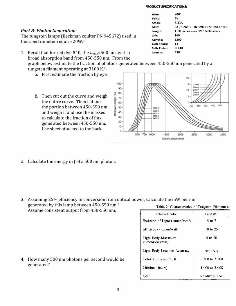
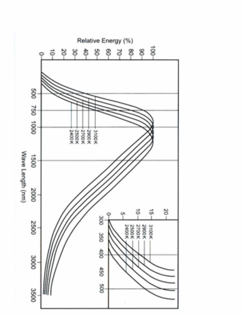
Part B-‐ Photon Generation The tungsten lamps (Beckman coulter PN 945672) used in this spectrometer require 20W.1 1. Recall that for red dye #40, the λmax=500 nm, with a
broad absorption band from 450-‐550 nm. From the graph below, estimate the fraction of photons generated between 450-‐550 nm generated by a tungsten filament operating at 3100 K.2-‐
a. First estimate the fraction by eye.
b. Then cut out the curve and weigh the entire curve. Then cut out the portion between 450-‐550 nm and weigh it and use the masses to calculate the fraction of flux generated between 450-‐550 nm. Use sheet attached to the back.
2. Calculate the energy in J of a 500 nm photon. 3. Assuming 25% efficiency in conversion from optical power, calculate the mW per nm
generated by this lamp between 450-‐550 nm.3 Assume consistent output from 450-‐550 nm,
4. How many 500 nm photons per second would be generated?

4
Part C-‐ Photons at Beam Combiner 5. Assume an isotropic point source, meaning: 1. The source is infinitely small, and 2. It emits
light uniformly in 3D. Calculate the surface area of a sphere with radius AA’. 6. Calculate the percentage surface area a 0.5 cm diameter beam combiner represents of the
sphere above. Ignore that the surface of the beam combiner is flat while the surface of the theoretical sphere is curved.
7. The beam combiner located at A’ is partially silvered, meaning 50% transmission and 50%
reflection of incident light. Only the light that is reflected participates in the measurement. Calculate the flux (µW/nm) of the light leaving the beam combiner.

5
Part D-‐ Flux leaving Source and Transfer Mirrors The purpose of the source mirror is to collimate the beam. Diagram the beam coming onto the collimating mirror below. Determine and label the focal distance and radius of curvature of the mirror.4 8. Calculate the surface area of the sphere incident on the source mirror. Calculate the
percentage surface area the source mirror represents of the sphere generated at the point source. Is the source mirror over or under filled relative to the beam combiner?
9. If the answer to the above question is overfilled, then the source mirror would limit the
amount of flux from source that is transmitted. Recalculate the flux incident on the source mirror (nW per nm).

6
10. Assuming that the source and transfer mirrors reflect about 85% of the beam (percent reflection calculated for a 45° incidence angle), calculate the flux (νW per nm) in the 2x2cm image leaving the transfer mirror.5
11. Calculate the vignetting factor (ratio of area of the image from the transfer mirror and the area
of the entrance slit. 12. Calculate the pW/nm entering the entrance slit, assuming uniform irradiance (the photons
from the transfer mirror are evenly distributed). Part E-‐ Wavelength Dispersion in the Monochromator The Echellette grating disperses polychromatic light into component wavelengths on the exit slit. Assuming first order diffraction, the parameters for the monochromator grating are as follows: Focal length= 30 cm; grooves per mm= 1200; reciprocal linear dispersion= 3nm per mm. The light gathering power of monochromator matched to the rest of the optics.
7
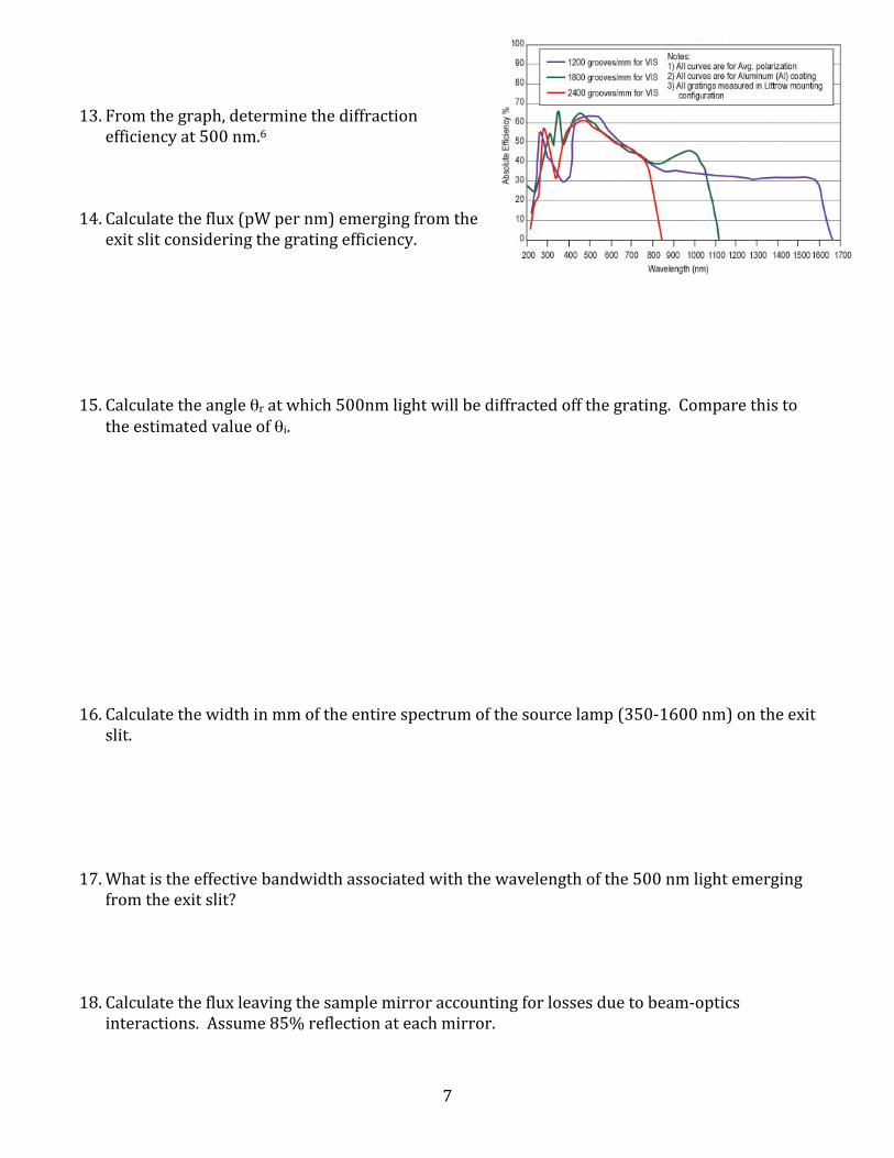
13. From the graph, determine the diffraction efficiency at 500 nm.6
14. Calculate the flux (pW per nm) emerging from the
exit slit considering the grating efficiency. 15. Calculate the angle θr at which 500nm light will be diffracted off the grating. Compare this to
the estimated value of θi. 16. Calculate the width in mm of the entire spectrum of the source lamp (350-‐1600 nm) on the exit
slit. 17. What is the effective bandwidth associated with the wavelength of the 500 nm light emerging
from the exit slit? 18. Calculate the flux leaving the sample mirror accounting for losses due to beam-‐optics
interactions. Assume 85% reflection at each mirror.
8
19. Calculate the number of 500 nm photons leaving the sample mirror Part F-‐ Beam-‐sample interaction and photon detection 20. Calculate the flux in pW incident on the detector if A=0.4 at 500 nm. Be sure to account for
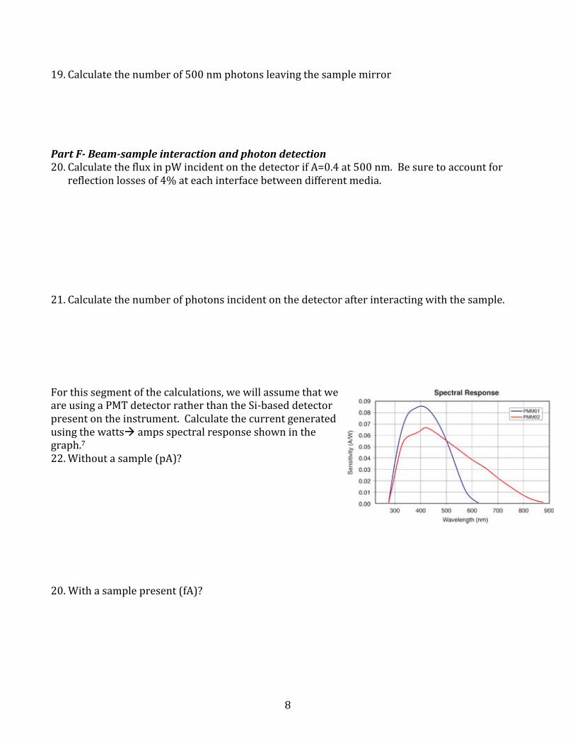
reflection losses of 4% at each interface between different media. 21. Calculate the number of photons incident on the detector after interacting with the sample. For this segment of the calculations, we will assume that we are using a PMT detector rather than the Si-‐based detector present on the instrument. Calculate the current generated using the watts amps spectral response shown in the graph.7 22. Without a sample (pA)? 20. With a sample present (fA)?
9
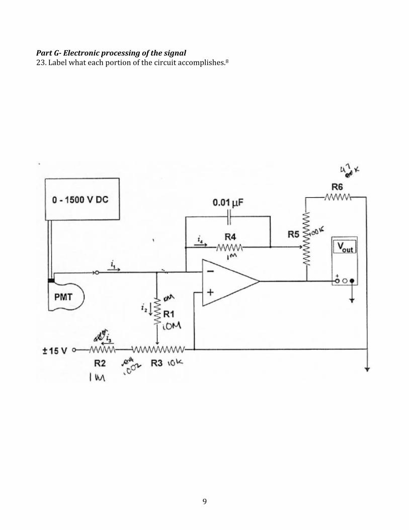
Part G-‐ Electronic processing of the signal 23. Label what each portion of the circuit accomplishes.8
10
References 1 Beckman coulter PN 945672) 2 http://www.intl-‐lighttech.com/applications/light-‐sources/tungsten-‐halogen-‐lamps 3 Not sure where the table came from. 4 http://spie.org/Documents/Publications/00%20STEP%20Module%2003.pdf 5 http://www.calctool.org/CALC/phys/optics/reflec_refrac 6 http://www.edmundoptics.com/optics/gratings/reflective-‐holographic-‐gratings/1621?#products 7 http://www.thorlabs.com/newgrouppage9.cfm?objectgroup_id=2909 8 Advanced Analytical Chemistry Laboratory Manual. Spring 2004. University of Arizona, Department of Chemistry, pg 95.
11

12
1 Beckman coulter PN 945672) 2 http://www.intl-‐lighttech.com/applications/light-‐sources/tungsten-‐halogen-‐lamps 3 Not sure where the table came from. 4 http://spie.org/Documents/Publications/00%20STEP%20Module%2003.pdf 5 http://www.calctool.org/CALC/phys/optics/reflec_refrac 6 http://www.edmundoptics.com/optics/gratings/reflective-‐holographic-‐gratings/1621?#products 7 http://www.thorlabs.com/newgrouppage9.cfm?objectgroup_id=2909 8 Advanced Analytical Chemistry Laboratory Manual. Spring 2004. University of Arizona, Department of Chemistry, pg 95.


