Throttle position sensorFrequently asked questions …...The throttle position sensor has a signal...
2
Transcript of Throttle position sensorFrequently asked questions …...The throttle position sensor has a signal...

AB
Typewritten Text
AB
Typewritten Text
AB
Typewritten Text
AB
Typewritten Text
AB
Typewritten Text
AB
Typewritten Text
AB
Typewritten Text
AB
Typewritten Text
Throttle position sensor
AB
Typewritten Text
AB
Typewritten Text
AB
Typewritten Text
AB
Typewritten Text
AB
Typewritten Text
AB
Typewritten Text
AB
Typewritten Text
AB
Typewritten Text
AB
Typewritten Text
AB
Typewritten Text
Frequently asked questions
AB
Typewritten Text
FAQ
AB
Typewritten Text
AB
Typewritten Text
AB
Typewritten Text
AB
Typewritten Text
AB
Typewritten Text
AB
Typewritten Text
AB
Typewritten Text
AB
Typewritten Text
AB
Typewritten Text
AB
Typewritten Text
AB
Typewritten Text
AB
Typewritten Text
AB
Typewritten Text
AB
Typewritten Text
AB
Typewritten Text
AB
Typewritten Text
AB
Typewritten Text
AB
Typewritten Text
AB
Typewritten Text
AB
Typewritten Text
AB
Typewritten Text
AB
Typewritten Text
AB
Typewritten Text
AB
Typewritten Text
AB
Typewritten Text
AB
Typewritten Text
AB
Typewritten Text
AB
Typewritten Text
AB
Typewritten Text
AB
Typewritten Text
AB
Typewritten Text
AB
Typewritten Text
AB
Typewritten Text
AB
Typewritten Text
AB
Typewritten Text
AB
Typewritten Text
AB
Typewritten Text
Sensors
1 www.aim-sportline.com Release 1.00 – November 6th 2017
Throttle position sensor
Question: How do I connect my car/bike throttle position sensor to my AiM device?
Answer: The throttle position sensor has a signal already represented by a variable voltage that can be red directly by the AiM device. In these cases, the signal must not be conditioned, because it won’t be recognized by the vehicle ECU: it is only necessary to configure the AiM logger and perform the calibration.
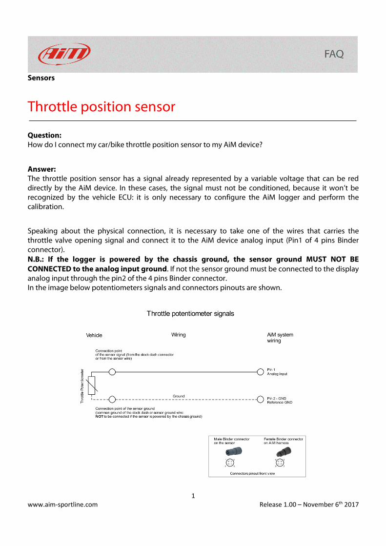
Speaking about the physical connection, it is necessary to take one of the wires that carries the throttle valve opening signal and connect it to the AiM device analog input (Pin1 of 4 pins Binder connector). N.B.: If the logger is powered by the chassis ground, the sensor ground MUST NOT BE CONNECTED to the analog input ground. If not the sensor ground must be connected to the display analog input through the pin2 of the 4 pins Binder connector. In the image below potentiometers signals and connectors pinouts are shown.