Three ways to assess mining-induced fault instability ...
13
The Southern African Institute of Mining and Metallurgy 6 th South African Rock Engineering Symposium SARES 2014 T. Wiles 1 Three ways to assess mining-induced fault instability using numerical modelling T. Wiles Mine Modelling (Pty) Ltd The ability to simulate fault slip response has been available in numerical modelling programs for many decades but is rarely used. This important component is often overlooked in assessing ground stability, in spite of the fact that it can be the key mechanism in causing ground failure. The reason for this is not only the difficulty in characterizing the fault behaviour, but also due to the difficulty in setting up such problems. The detailed location and orientation of the fault is generally poorly known. Calibration can be a time-consuming process, and most attempts at fault slip simulations result either in faults that are locked so tight that they have no reaction to mining at all, or alternatively faults that slip in an uncontrolled manner even without advancing the mining. This behaviour gives little confidence in the results of these simulations. This paper highlights several ways of overcoming these problems. A case history for a slipping fault is used to assess the possibility of mining-induced slip. This is assessed using three different methods. First, the excess shear stress (elastic) concept is used. Second, the traditional methodology is used where a plastic fault is assigned a ’reasonable’ value for shear strength such that the entire fault is assigned the same homogeneous value for strength. Finally, a more recent method is used whereby the fault is automatically placed into a critical equilibrium state such that the entire fault is exactly at the point of failure. This is done by using a heterogeneous strength distribution. Prior to advancing the mining, the strength is adjusted across the fault such that every point is assigned unique strength parameters required to put that point into equilibrium with the existing stresses. This makes the fault very sensitive to advancing mining, since any mining-induced stress change will result in a reaction on the fault. The author can conceive of no other way of making the fault more sensitive to mining, and hence concludes that this represents the worst-case scenario (i.e. an upper bound solution). It is found that all three methods provide similar fault slip response predictions provided the model results are interpreted correctly. This result is important in itself since it goes a long way to confirming that simpler elastic interpretation methods are as equally valid as more complex elasto-plastic simulations. Introduction The behaviour of faults is an important consideration because mining-induced fault slip can adversely affect mine stability. Unfortunately, fault slip behaviour is difficult to model, stability is difficult to assess, and the reliability of predictions are poorly known. Numerical modelling programs have had the ability to simulate fault slip response for many decades; however, a scan of the existing literature shows that this capability is rarely used. In the author’s experience, the reason for this is the difficulty in characterizing the fault behaviour. It is difficult to set up such problems. Details of the location and orientation of the fault are often poorly known. Calibration can be a time-consuming process, and most attempts at fault slip simulation result either in faults that are locked so tight that they have no reaction to mining at all, or alternatively in faults that slip in an uncontrolled manner even without advancing the mining. This behaviour gives little confidence in the results of these simulations. The objective of this paper is to demonstrate several alternative methods of approaching fault slip simulation in order to assess the pseudo-static fault slip behaviour. Numerical modelling results are used to compare these approaches in an attempt to demonstrate that these results are valid and reliable.
Transcript of Three ways to assess mining-induced fault instability ...

The Southern African Institute of Mining and Metallurgy 6th South African Rock Engineering Symposium SARES 2014 T. Wiles
1
Three ways to assess mining-induced fault instability using numerical modelling
T. Wiles Mine Modelling (Pty) Ltd
The ability to simulate fault slip response has been available in numerical modelling programs for many decades but is rarely used. This important component is often overlooked in assessing ground stability, in spite of the fact that it can be the key mechanism in causing ground failure. The reason for this is not only the difficulty in characterizing the fault behaviour, but also due to the difficulty in setting up such problems. The detailed location and orientation of the fault is generally poorly known. Calibration can be a time-consuming process, and most attempts at fault slip simulations result either in faults that are locked so tight that they have no reaction to mining at all, or alternatively faults that slip in an uncontrolled manner even without advancing the mining. This behaviour gives little confidence in the results of these simulations. This paper highlights several ways of overcoming these problems.
A case history for a slipping fault is used to assess the possibility of mining-induced slip. This is assessed using three different methods. First, the excess shear stress (elastic) concept is used. Second, the traditional methodology is used where a plastic fault is assigned a ’reasonable’ value for shear strength such that the entire fault is assigned the same homogeneous value for strength. Finally, a more recent method is used whereby the fault is automatically placed into a critical equilibrium state such that the entire fault is exactly at the point of failure. This is done by using a heterogeneous strength distribution. Prior to advancing the mining, the strength is adjusted across the fault such that every point is assigned unique strength parameters required to put that point into equilibrium with the existing stresses. This makes the fault very sensitive to advancing mining, since any mining-induced stress change will result in a reaction on the fault. The author can conceive of no other way of making the fault more sensitive to mining, and hence concludes that this represents the worst-case scenario (i.e. an upper bound solution).
It is found that all three methods provide similar fault slip response predictions provided the model results are interpreted correctly. This result is important in itself since it goes a long way to confirming that simpler elastic interpretation methods are as equally valid as more complex elasto-plastic simulations.
Introduction
The behaviour of faults is an important consideration because mining-induced fault slip can adversely affect mine stability. Unfortunately, fault slip behaviour is difficult to model, stability is difficult to assess, and the reliability of predictions are poorly known.
Numerical modelling programs have had the ability to simulate fault slip response for many decades; however, a scan of the existing literature shows that this capability is rarely used. In the author’s experience, the reason for this is the difficulty in characterizing the fault behaviour. It is difficult to set up such problems. Details of the location and orientation of the fault are often poorly known. Calibration can be a time-consuming process, and most attempts at fault slip simulation result either in faults that are locked so tight that they have no reaction to mining at all, or alternatively in faults that slip in an uncontrolled manner even without advancing the mining. This behaviour gives little confidence in the results of these simulations.
The objective of this paper is to demonstrate several alternative methods of approaching fault slip simulation in order to assess the pseudo-static fault slip behaviour. Numerical modelling results are used to compare these approaches in an attempt to demonstrate that these results are valid and reliable.

6th South African Rock Engineering Symposium SARES 2014
2
Methodology
A case history for a slipping fault is used to assess the possibility of mininginduced slip. This problem was studied in detail for 10 years (Hudyma, 1996, Bruneau, 2000, Bruneau et al., 2003, Mincad Systems, 2003, 2006), without providing a satisfactory numerical model to link the advancing mining to the observed fault slip response. The author attributes this lack of success to errors in location and orientation of the geometry of the fault plane as well as the magnitude and orientation of the pre-mining stress state. This has made satisfactory characterization of the fault behaviour impossible.
In this paper, several alternative methods of analysis are considered in an effort to overcome this problem. Here, Map3D numerical modelling (Wiles, 2013) is used with three different methods. First, the excess shear stress (elastic) concept is used. The fault is constructed using grid planes, and tested with ’reasonable’ value for shear strength (zero cohesion and 10°–30° friction angle) such that the entire fault is assigned the same homogeneous value for strength. In this case, instead of simulating the fault slip behaviour, the shear and normal stresses are compared to the strength to determine whether conditions are right for slip or not.
With this method it is not possible to find strength parameters such that the fault is stable prior to mining, while also exhibiting mining-induced slip. It is easy to build models where faults are locked so tight that they have no reaction to mining at all, or alternatively faults that slip in an uncontrolled manner even without advancing the mining. This result inspires little confidence in our ability to reliably predict fault slip behaviour.
To address this issue, the change in excess shear stress due to advancing mining can be assessed to determine if the likelihood of slip is increasing or decreasing.
Secondly, a fault is constructed using DD elements capable of slipping in an elasto-plastic manner. As above, the fault is assigned a ‘reasonable’ value for shear strength (the same as in the first method above) such that the entire fault is assigned the same homogeneous value for strength. Here the geometry will have a large influence on the results, since small changes in the assumed location and orientation of the fault will have a large influence on its behaviour.
Choosing an appropriate value for the strength can often be a time-consuming process where many values for the strength parameters must be tested by trial and error. As in the first method, it is often impossible to set such models up such that the fault is stable prior to mining while also exhibiting mining-induced slip. To address this issue, low shear strength can be assigned, and then the change in shear displacement (ride) due to advancing mining can be assessed to determine where slip is likely.
Thirdly, a heterogeneous strength distribution is used. Set-up is similar to either the first or second methods, although in this case the fault is placed into a critical equilibrium state such that the fault is at the point of failure. This is done by using a heterogeneous strength distribution. Normally this would require a set of time-consuming and painstaking calculations to adjust each parameter to exactly the right value. To overcome this problem, a methodology was implemented into Map3D (Wiles, 2010) so that the heterogeneous strength distribution is calculated automatically during the course of analysis. This Map3D functionality is utilized in papers by Orrego et al. (2010) and Jarufe et al. (2012).
Prior to advancing the mining, the strength is adjusted across the fault such that every point uses unique strength parameters required to put that point into equilibrium with the existing stresses. This provides a fault that is stable prior to advancing the mining, while also exhibiting mining-induced slip with advancing mining. This procedure makes the fault very sensitive to any mining-induced stress changes, since any mining-induced stress change will result in a reaction on the fault. This lessens the sensitivity of the model to fine details regarding the orientation and location of the fault, and eases the user’s burden of setting up and calibrating the fault. The author can conceive of no other way of making the fault more sensitive to mining, and hence concludes that this represents the worst-case scenario (i.e. an upper bound solution). This logic goes some way to providing confidence in our ability to reliably assess the possibility of fault slip response.
Results
The case history that is presented here considers the influence of faulting on the X41 shaft at Mount Isa copper mine. The area of interest is located at a depth of approximately 725 m with Hmax = 37 MPa, Hmin = 19 MPa, and Vert = 19 MPa. Hmax is oriented at approximately 60–65° from the strike of the fault. This model was set up by mine personnel in 1996 (Hudyma, 1996), and subsequently utilized by Bruneau, 2000; Bruneau et al., 2003a, 2003b.
Three ways to assess mining-induced fault instability using numerical modelling
3
Figure 1. Model geometry
As shown in Figure 1, a mine shaft (shown in yellow) intersects a steeply dipping (75–85° dip) fault (shown in red).
As the mining (shown in blue and green) advances, the fault slips cause offsets in the shaft and necessitate periodic resetting of the shaft guides. Although few measurements of actual displacements were made, these indicated offsets on the order of 36 mm for several stages of mining (Bruneau, 2000). The mine would like to understand the driving mechanisms for this problem with the hope of predicting the fault response in advance of mining to assure the long-term integrity of the shaft.
Method 1a: homogeneous strength using grids planes
This simplest way of considering this problem is to represent the fault as a series of grid planes. By calculating the shear and normal stresses acting at the local orientation of each grid, it can be determined whether the stresses exceed the strength or not.
The analysis has been conducted in two steps: first without the mining, then with the mining.

6th South African Rock Engineering Symposium SARES 2014
4
Figure 2. Friction angle contours prior to mining
By examining the shear and normal stresses acting at the orientation of the fault, it can be determined that prior to
mining (as shown in Figure 2) a friction angle of 19° or more (assuming zero for cohesion) is necessary in order for the fault to be stable (i.e. the stresses do not exceed the strength) under the pre-mining stress field (without any mining-induced stresses).
Figure 3. Friction angle contours with mining-induced stresses
However, if this strength were to be used for the fault, then it is also clear that the mining would not induce fault slip
in the vicinity of the shaft. In Figure 3 it is shown that a friction angle of less than 17° is necessary in order for the mining to induce slip on the fault in the vicinity of the shaft.
Three ways to assess mining-induced fault instability using numerical modelling
5
The problem here is that if a value of 17° or less is used, then the fault is predicted to slip in an uncontrolled manner prior to mining.
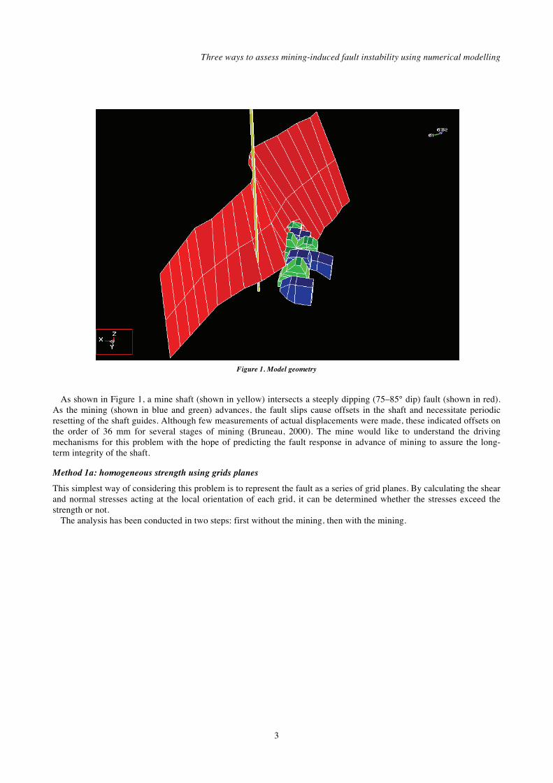
This can be illustrated by plotting the excess shear stress:
= – [Cohesion + tan( ) ] [1]
where and represent respectively the shear and normal stress acting in the fault plane.
Figure 4. Shear and normal stresses at the local orientation of the grid plane
As shown in Figure 4, in areas where the shear stress exceeds the shear strength, the excess shear stress has a positive
value and we can anticipate plastic fault slip response. In areas where the shear stress is below the shear strength, the excess shear stress has a negative value and we can anticipate elastic response (i.e. no fault slip). The excess shear stress methodology can be considered to be an elastic response model for fault slip.
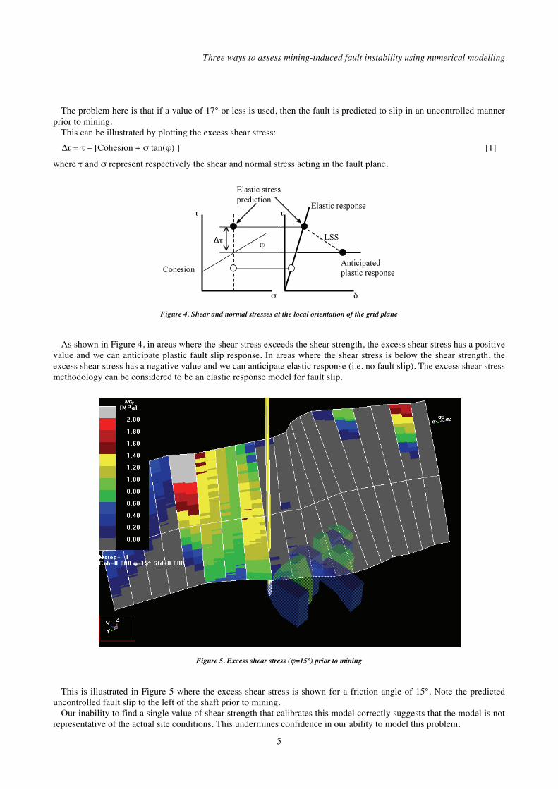
Figure 5. Excess shear stress ( =15°) prior to mining
This is illustrated in Figure 5 where the excess shear stress is shown for a friction angle of 15°. Note the predicted
uncontrolled fault slip to the left of the shaft prior to mining. Our inability to find a single value of shear strength that calibrates this model correctly suggests that the model is not
representative of the actual site conditions. This undermines confidence in our ability to model this problem.

6th South African Rock Engineering Symposium SARES 2014
6
Method 1b: change in excess shear stress using grids planes
An alternative approach can be considered here.
Figure 6. Change in excess shear stress ( =15°) induced by mining
If we now plot the change in excess shear stress with advancing mining (Figure 6), it can be clearly observed that the
mining does induce increased excess shear stress in the vicinity of the shaft. It can also be seen that this plot is relatively insensitive to the value chosen for friction angle.
In spite of the result that no single value for friction angle can be found to represent this situation properly, it is still clear that since the shear stresses are increasing, with the right strength the mining could induce fault slip in the vicinity of the shaft. This is not possible to arrange with a homogeneous strength distribution. This contradictory situation suggests that this model is not representative of the actual site conditions and does little to inspire confidence in our predictive capability.
Method 2a: homogeneous strength using DDs
Such irregularities are often attributed to shortcomings of the model. It is frequently suggested that plasticity modelling is necessary to obtain better modelling results. It is proposed that plastic simulations will significantly improve results due to the incorporation of stress redistribution originating from plastic slip. While it is undoubtedly true that a properly calibrated plasticity model will provide a better representation of the actual site response than an elastic model, what is not clear is how much better this will be or whether we can even create a properly calibrated model.
Plasticity models require a large number of input parameters, a much larger model size, and longer run times. Proper calibration requires a large number of trial-and-error analyses to determine appropriate input parameters, and verification that the model is representative of reality.
To test the hypothesis that plasticity models provide a better simulation than elastic models, the actual fault slip response of the fault was modelled. Here, a fault is constructed using DD elements capable of slipping in an elasto-plastic manner.
Through repeated trial-and-error back-analyses, it was determined that prior to mining, a friction angle of at least 19° is necessary in order for the fault to be stable under the pre-mining stress field (i.e. without any mining-induced stresses). However, if this strength is used for the fault, then it is also found that the mining does not induce slip in the vicinity of the shaft. Since the fault actually did slip, this model is unsatisfactory. This is the same response predicted with the excess shear stress (elastic) model in method 1. Also, this trial-and-error process is very time-consuming since the model has to be rerun and examined repeatedly.
Three ways to assess mining-induced fault instability using numerical modelling
7
Additional back-analyses have determined that a friction angle of less than 17° is necessary, otherwise the fault will not slip in the vicinity of the shaft. This is also the response predicted with the excess shear stress model in method 1.
A model was set up with both the peak and residual strength at 15° friction angle and zero for cohesion, and then run in two steps.
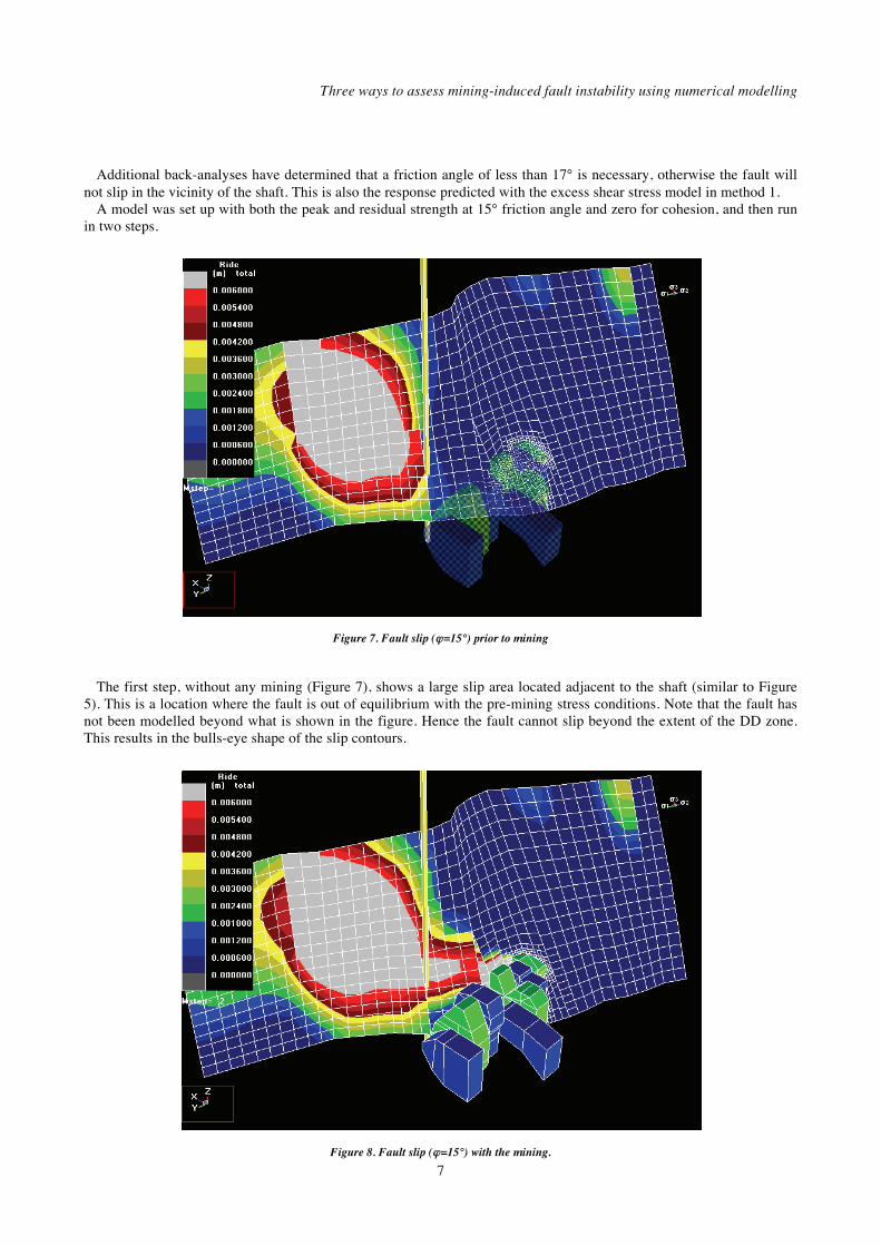
Figure 7. Fault slip ( =15°) prior to mining
The first step, without any mining (Figure 7), shows a large slip area located adjacent to the shaft (similar to Figure
5). This is a location where the fault is out of equilibrium with the pre-mining stress conditions. Note that the fault has not been modelled beyond what is shown in the figure. Hence the fault cannot slip beyond the extent of the DD zone. This results in the bulls-eye shape of the slip contours.
Figure 8. Fault slip ( =15°) with the mining.

6th South African Rock Engineering Symposium SARES 2014
8
A comparison of Figures 7 and 8 shows that mining has induced slip in the vicinity of the shaft. It is clear that the large amount of slip due to the lack of equilibrium with the pre-mining stress state is confusing the situation. This inconsistency gives little confidence that this approach is realistic.
A great deal of extra effort was required to set up and analyse this problem plastically. Many additional assumptions had to be made regarding the constitutive behaviour of the fault gouge. In spite of this effort and added complexity, no new information was obtained.
Method 2b: change in excess shear displacement DDs
The method can be made improved by presenting the change in the fault slip with advancing mining (see Figure 9).
Figure 9. Change in fault slip ( =15°) induced by mining
By comparing Figures 6 and 9 it can be observed that both the elastic and plastic models give the same prediction for
slip. However, one thing that the plastic model does provide that the elastic model does not, is an indication of the magnitude of slip to be expected (6 mm in this case). Note that the 36 mm displacement discussed by Bruneau (2000) is for several stages of mining, not just the single step considered here.
Given that the elastic model predicts an excess shear stress of 2 MPa and the plastic model predicts a shear displacement of 6 mm, one can conclude that the loading system stiffness is on the order of 333 MPa/mm (see LSS in Figure 4). Using this value one can determine the expected shear displacement from elastic excess shear stress modelling.
Considering the difference in shear displacement as mining advances, the results appear to indicate that mining could induce fault slip in the vicinity of the shaft. However, one must keep in mind that, as with method 1, there are problems with this model. No single value for friction angle can be found to represent this situation properly. This model does not behave in the way that the actual fault does (the actual fault does not slip in an uncontrolled manner prior to mining). Unfortunately, this contradictory situation suggests that this model is not representative of the actual site conditions.
It seems that the homogeneous strength plastic model (method 2) suffers from the same shortcomings as the homogeneous strength elastic model (method 1). The difficulty in calibration cannot be attributed to shortcomings of the elastic approach. Implementation of plasticity modelling has markedly increased the analysis and set-up time, but has not provided better modelling results in this case. For all of the extra effort, the only new information that has been obtained is an estimate of the shear displacement.

Three ways to assess mining-induced fault instability using numerical modelling
9
Method 3: equilibrated heterogeneous strength
A third possibility presents itself. Here a heterogeneous strength distribution can be used. In this case the fault is placed into a critical equilibrium state such that the fault is exactly at the point of failure. This is done by using a heterogeneous strength distribution.
The strength distribution is determined by calculating the unique strength parameters required to place every point on the fault surface exactly at the point of failure, prior to advancing the mining. This type of model can be described as equilibrated-gouge, since the gouge is placed into a state of critical equilibrium with the pre-mining stress state (see Figure 10). This procedure will make the fault very sensitive to any mining-induced stress changes.
Figure 10. Critical equilibrium stress state prior to mining
A model was set up and run in two steps: the first step without any mining. It is at this step that the heterogeneous
strength distribution is calculated and assigned to the fault surface.
Figure 11. The heterogeneous strength distribution,

6th South African Rock Engineering Symposium SARES 2014
10
The resulting strength distribution (friction angle is illustrated with zero cohesion) is illustrated in Figure 11. The analysis results show that no slip occurs on the fault at this time.
Note that a value for friction angle of approximately 19° has been selected in the zone to the left of the shaft, and a value of approximately 15° has been selected in the vicinity of the shaft. Here, the cohesion has been set to zero. The residual strength and peak strength are set to the same values.
Figure 12. Excess shear stress (heterogeneous strength) with mining
At step 2, the mining is added into the analysis, and results for the excess shear stress from the elastic analysis
(method 1) are shown in Figure 12. It can be observed in this figure that the mining has induced positive values of excess stress in the vicinity of the shaft. This plot shows nearly identical results to those from method 1 (Figure 6 – elastic approach), as it should since
2 - 1 e [2]
where 2 and 1 represent the excess shear stress determined from the two steps of mining in method 1, and e represents the excess shear stress determined from the second step of mining in method 3.
Either subtracting the excess stress for step 1, or adjusting the heterogeneous strength such that the excess stress is zero at step 1, amount to the same thing mathematically (see Figure 13) provided the normal stress does not change.
Figure 13. Excess stress change for homogeneous vs equilibrated strength

Three ways to assess mining-induced fault instability using numerical modelling
11
The same procedure can be used for the plastic model (method 2). As in the second method, a fault is constructed using DD elements capable of slipping in an elasto-plastic manner. At step 2, the mining is added into the analysis. The results in the slip are shown in Figure 14.
Figure 14. Fault slip (heterogeneous strength) with the mining
It can be observed in this figure that mining has induced slip in the vicinity of the shaft. This plot shows almost
identical results to those from method 1 (Figure 6 and 12 – elastic approach) and method 2 (Figure 9 – plastic approach), and method 3 (Figure 13 – elastic approach). This plastic model has also predicted the magnitude of slip to be expected of the order of 6 mm, the same as for method 2.
Discussion
By assuming a homogeneous strength distribution (methods 1 and 2), it has been found that no single value for friction angle (for zero cohesion) could be found to represent the site conditions properly. If too low a value of friction angle is used, the fault is predicted to slip uncontrollably prior to mining. If too high a value is used, the fault does not slip in the vicinity of the shaft. This is contrary to site conditions as they are understood. This inability to properly represent site conditions undermines our confidence that the models are realistic.
It has been found here that an equilibrated heterogeneous strength distribution can overcome this problem. This approach provides a model that is stable prior to mining, then slip in the vicinity of the shaft is induced by the advancing mining. Of the three methods, this is the only model that can be considered representative of the actual site conditions. This provides confidence in our ability to reliably simulate fault slip behaviour.
A possible, but unlikely, explanation for this success is that the shear strength distribution is in fact heterogeneous, and the model has successfully determined this (Figure 11 – angles varying from 10° to 20°). A more likely explanation is that there are errors in location and orientation of the geometry of the fault plane as well as the magnitude and orientation of the pre-mining stress state. By adjusting the local value of strength, the model is compensating for these model input errors. As such, the back-calculated strength distribution should not be considered as the actual strength, but rather an approximation of this with local deviations necessary to compensate for other model input errors.
The extremely limited range of allowable friction angles that can provide a model that represents the observed site conditions properly suggests that, at least for this problem, this method is providing a first best estimate of the plastic

6th South African Rock Engineering Symposium SARES 2014
12
ride as well as its spatial distribution. This is contrary to the conclusion of Jarufe et al. (2012), who see this approach as being limited to ‘an assessment of the total potential for seismic slip and its relative spatial distribution’.
It is possible that a more complex constitutive model (e.g. a normal stress-dependent friction model, or a cohesion softening, friction-hardening model) could be contrived to limit the amount of slip prior to advancing the mining as well as allowing slip in the vicinity of the shaft when mining is advanced. In order to stabilize the fault prior to mining, it would be necessary that the resulting strain induced strength distribution is very similar to that determined in Figure 11 (equilibrated heterogeneous strength distribution). To accept such a model one would have to be willing to accept that the resulting heterogeneous strength distribution (friction angles varying from 10° to 20°) actually exists. This is no evidence to support this assumption.
The extremely limited amount of observational data available here and the large number of input parameters required for more complex approaches makes these impossible to calibrate with any confidence (Wiles, 2007). There is a real risk of over-representation of the data. With limited data, our inability to ascertain the reliability of complex models undermines the benefits. A well-calibrated simple model with known reliability is far more desirable.
Conclusions
For the case example presented it is found that the three methods used (elastic, plastic, and equilibrated) provide similar predictions regarding the expected fault slip response, provided that the model results are interpreted correctly (considering changes only with methods 1 and 2, or by using an equilibrated heterogeneous strength distribution). The agreement with observations gives confidence that the predictions are realistic. The fact that the same result is obtained using quite different models gives confidence that all of the models are a good representation. Had the three methods disagreed, this would have suggested a lack of understanding of the underlying driving mechanism.
For the case study presented, models using a homogeneous strength distribution (either elastic or plastic) cannot be set up such that the fault is stable prior to mining but slips with advancing mining. Such models are not representative of actual site conditions. This contradictory situation undermines our confidence that the models are realistic.
Although calibration using homogenous strength parameters poses difficulties, this can be partially overcome by considering how the predictions change as the mining advances, rather than just considering the results at any one step. This method provides more realistic results, but still suffers from the inability to create a satisfactory set-up noted above.
By using a heterogeneous strength distribution, the difficulty in calibration can be overcome. By automating this process, the time-consuming step of calculating and assigning the necessary strength parameters can be circumvented. This provides a model that has both a satisfactory set-up and provides results that agree with observed behaviour.
It has been found that simpler excess stress (elastic) interpretation methods yield the same result as more complex plastic simulations, and both are in agreement with observations. This suggests that simpler elastic interpretation methods are equally valid.
Plastic models provide an estimate of shear displacement that cannot be determined from an elastic model unless the loading system stiffness is known.
References
Bruneau, G. 2000. The influence of faulting on the structural integrity of the X41 shaft, copper mine, Mount Isa. M Sc
thesis, University of Laval, Canada.
Bruneau, G., Tyler, D.B., Hadjigeorgiou, J., and Potvin, E. 2003. Influence of faulting on a mine shaft – a case study:
part I – background and instrumentation. International Journal of Rock Mechanics and Mining Sciences, vol. 40.
pp. 95-111.
Bruneau, G., Hudyma, M.R., Hadjigeorgiou, J., and Potvin, E. 2003. Influence of faulting on a mine shaft – a case
study: part II – numerical modelling. International Journal of Rock Mechanics and Mining Sciences, vol. 40. pp.
113-125.
Hudyma, M.R. 1996. Fault modelling near X41 shaft. Mining Research Memorandum, MRH/RES 9.1, Mount Isa. 19
pp.
Jarufe, J., Potvin, Y., and Wesseloo, J. 2012, Application of the limit equilibrium strength to the seismic assessment of
shear related seismicity. Proceedings of the 6th International Seminar on Deep and High Stress Mining, Perth,
Australia, 28-30 March. pp. 389-400.

Three ways to assess mining-induced fault instability using numerical modelling
13
Mincad Systems Report. 2003. Mt Isa X41 Stage 2 Modelling: September 2003. Analysis of the present mining position
in relation to faults.
Mincad Systems Report. 2006, Map3D 1100OB X41 Shaft model for end of mining (all supplied stopes) – including
fault models section.
Orrego, C., Cuello, D., and Rojas, E. 2010. Determination of induced stress condition inside Pilar Norte sector.
Proceedings of the 5th
International Seminar on Deep and High Stress Mining, Santiago, Chile, 6-8 October 2010.
pp. 155-168.
Wiles, T.D. 2007, Evidence based model calibration for reliable predictions. 4th
International Seminar on Deep and
High Stress Mining, Perth, Australia, 7-9 November 2007. pp. 3-20.
Wiles, T.D. 2010. Map3D User’s Manual. Mine Modelling Pty, Australia.
Wiles, T.D. 2013, Map3D User’s Manual, Mine Modelling Pty, Australia.
The Author
Terry Wiles, Director, Mine Modelling Pty Ltd Numerical simulation for rock mass stability assessment, including analysis of failure processes, faulting, backfill, rockbursting, and slabbing/discing. Teaching and training in the application of rock mechanics and numerical modelling for use in mine design. Setup, assessment, and review of rock mechanics/numerical modelling applications at mining operations. Author of Map3D numerical modelling program. 2011 Rock Mechanics Award of the Rock Engineering Society of the Canadian Institute of Mining, Metallurgy and Petroleum (CIM).