Three Way Convertible Semi-Automatic Wedge-Wedge · PDF fileWEST•BOND MODEL 545657E...
97
WEST•BOND MODEL 545657E SERIES INSTRUCTION MANUAL © Copyright 2010 All rights reserved MODEL 545657E Three Way Convertible Semi-Automatic Wedge-Wedge and Ball-Wedge Bonder SERIAL#_________________ P.O.#____________________
Transcript of Three Way Convertible Semi-Automatic Wedge-Wedge · PDF fileWEST•BOND MODEL 545657E...

WEST•BOND MODEL 545657E SERIES INSTRUCTION MANUAL
© Copyright 2010
All rights reserved
MODEL 545657E
Three Way Convertible
Semi-Automatic Wedge-Wedge
and Ball-Wedge Bonder
SERIAL#_________________ P.O.#____________________

WEST•BOND MODEL 545657E SERIES INSTRUCTION MANUAL
Rev: 12 April, 2010 ii
WEST•BOND MODEL 545657E SERIES INSTRUCTION MANUAL
Rev: 12 April, 2010 iii
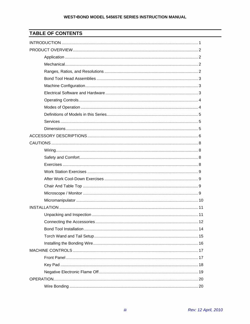
TABLE OF CONTENTS
INTRODUCTION ......................................................................................................................... 1 PRODUCT OVERVIEW............................................................................................................... 2
Application ...................................................................................................................... 2 Mechanical...................................................................................................................... 2 Ranges, Ratios, and Resolutions ................................................................................... 2 Bond Tool Head Assemblies .......................................................................................... 3 Machine Configuration.................................................................................................... 3 Electrical Software and Hardware .................................................................................. 3 Operating Controls.......................................................................................................... 4 Modes of Operation ........................................................................................................ 4 Definitions of Models in this Series................................................................................. 5 Services .......................................................................................................................... 5 Dimensions ..................................................................................................................... 5
ACCESSORY DESCRIPTIONS .................................................................................................. 6 CAUTIONS .................................................................................................................................. 8
Wiring.............................................................................................................................. 8 Safety and Comfort......................................................................................................... 8 Exercises ........................................................................................................................ 8 Work Station Exercises .................................................................................................. 9 After Work Cool-Down Exercises ................................................................................... 9 Chair And Table Top ...................................................................................................... 9 Microscope / Monitor ...................................................................................................... 9 Micromanipulator ............................................................................................................ 10
INSTALLATION ........................................................................................................................... 11 Unpacking and Inspection .............................................................................................. 11 Connecting the Accessories ........................................................................................... 12 Bond Tool Installation ..................................................................................................... 14 Torch Wand and Tail Setup............................................................................................ 15 Installing the Bonding Wire............................................................................................. 16
MACHINE CONTROLS ............................................................................................................... 17 Front Panel ..................................................................................................................... 17 Key Pad .......................................................................................................................... 18 Negative Electronic Flame Off........................................................................................ 19
OPERATION................................................................................................................................ 20 Wire Bonding .................................................................................................................. 20
WEST•BOND MODEL 545657E SERIES INSTRUCTION MANUAL
Rev: 12 April, 2010 iv
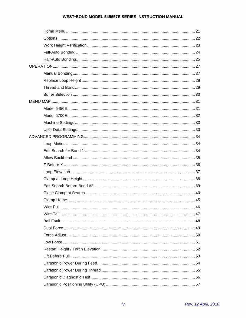
Home Menu .................................................................................................................... 21 Options ........................................................................................................................... 22 Work Height Verification ................................................................................................. 23 Full-Auto Bonding ........................................................................................................... 24 Half-Auto Bonding........................................................................................................... 25
OPERATION................................................................................................................................ 27 Manual Bonding.............................................................................................................. 27 Replace Loop Height ...................................................................................................... 28 Thread and Bond............................................................................................................ 29 Buffer Selection .............................................................................................................. 30
MENU MAP ................................................................................................................................. 31 Model 5456E................................................................................................................... 31 Model 5700E................................................................................................................... 32 Machine Settings ............................................................................................................ 33 User Data Settings.......................................................................................................... 33
ADVANCED PROGRAMMING.................................................................................................... 34 Loop Motion .................................................................................................................... 34 Edit Search for Bond 1 ................................................................................................... 34 Allow Backbend .............................................................................................................. 35 Z-Before-Y ...................................................................................................................... 36 Loop Elevation ................................................................................................................ 37 Clamp at Loop Height ..................................................................................................... 38 Edit Search Before Bond #2 ........................................................................................... 39 Close Clamp at Search................................................................................................... 40 Clamp Home................................................................................................................... 45 Wire Pull ......................................................................................................................... 46 Wire Tail.......................................................................................................................... 47 Ball Fault ......................................................................................................................... 48 Dual Force ...................................................................................................................... 49 Force Adjust.................................................................................................................... 50 Low Force ....................................................................................................................... 51 Restart Height / Torch Elevation..................................................................................... 52 Lift Before Pull ................................................................................................................ 53 Ultrasonic Power During Feed........................................................................................ 54 Ultrasonic Power During Thread .................................................................................... 55 Ultrasonic Diagnostic Test.............................................................................................. 56 Ultrasonic Positioning Utility (UPU) ................................................................................ 57
WEST•BOND MODEL 545657E SERIES INSTRUCTION MANUAL
Rev: 12 April, 2010 v
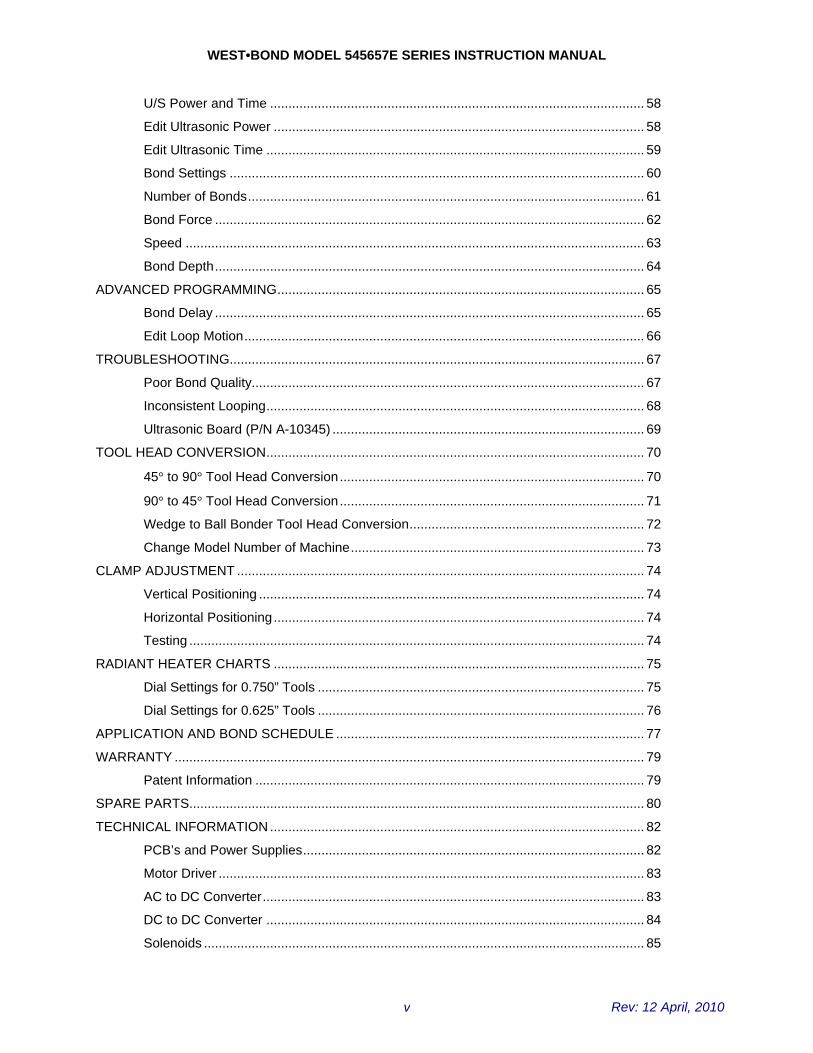
U/S Power and Time ...................................................................................................... 58 Edit Ultrasonic Power ..................................................................................................... 58 Edit Ultrasonic Time ....................................................................................................... 59 Bond Settings ................................................................................................................. 60 Number of Bonds............................................................................................................ 61 Bond Force ..................................................................................................................... 62 Speed ............................................................................................................................. 63 Bond Depth..................................................................................................................... 64
ADVANCED PROGRAMMING.................................................................................................... 65 Bond Delay ..................................................................................................................... 65 Edit Loop Motion............................................................................................................. 66
TROUBLESHOOTING................................................................................................................. 67 Poor Bond Quality........................................................................................................... 67 Inconsistent Looping....................................................................................................... 68 Ultrasonic Board (P/N A-10345) ..................................................................................... 69
TOOL HEAD CONVERSION....................................................................................................... 70
45° to 90° Tool Head Conversion................................................................................... 70 90° to 45° Tool Head Conversion................................................................................... 71 Wedge to Ball Bonder Tool Head Conversion................................................................ 72 Change Model Number of Machine................................................................................ 73
CLAMP ADJUSTMENT ............................................................................................................... 74 Vertical Positioning ......................................................................................................... 74 Horizontal Positioning..................................................................................................... 74 Testing ............................................................................................................................ 74
RADIANT HEATER CHARTS ..................................................................................................... 75 Dial Settings for 0.750” Tools ......................................................................................... 75 Dial Settings for 0.625” Tools ......................................................................................... 76
APPLICATION AND BOND SCHEDULE .................................................................................... 77 WARRANTY ................................................................................................................................ 79
Patent Information .......................................................................................................... 79 SPARE PARTS............................................................................................................................ 80 TECHNICAL INFORMATION ...................................................................................................... 82
PCB’s and Power Supplies............................................................................................. 82 Motor Driver .................................................................................................................... 83 AC to DC Converter........................................................................................................ 83 DC to DC Converter ....................................................................................................... 84 Solenoids ........................................................................................................................ 85

WEST•BOND MODEL 545657E SERIES INSTRUCTION MANUAL
Rev: 12 April, 2010 vi
Ultrasonic Power Supply ................................................................................................ 85 X-Y-Z Head Assembly .................................................................................................... 87
SCHEMATIC INFORMATION ..................................................................................................... 89

WEST•BOND MODEL 545657E SERIES INSTRUCTION MANUAL
Rev: 12 April, 2010 vii
WEST•BOND MODEL 545657E SERIES INSTRUCTION MANUAL
1
INTRODUCTION
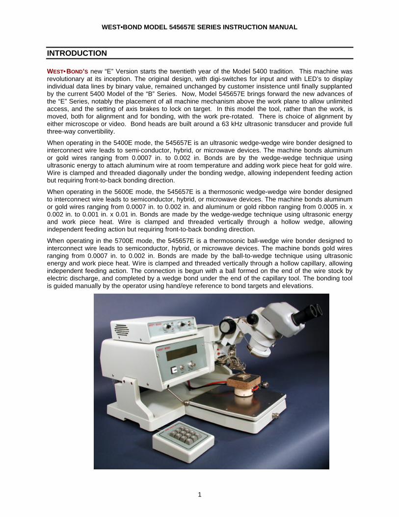
WEST•BOND’S new “E” Version starts the twentieth year of the Model 5400 tradition. This machine was revolutionary at its inception. The original design, with digi-switches for input and with LED’s to display individual data lines by binary value, remained unchanged by customer insistence until finally supplanted by the current 5400 Model of the “B” Series. Now, Model 545657E brings forward the new advances of the “E” Series, notably the placement of all machine mechanism above the work plane to allow unlimited access, and the setting of axis brakes to lock on target. In this model the tool, rather than the work, is moved, both for alignment and for bonding, with the work pre-rotated. There is choice of alignment by either microscope or video. Bond heads are built around a 63 kHz ultrasonic transducer and provide full three-way convertibility.
When operating in the 5400E mode, the 545657E is an ultrasonic wedge-wedge wire bonder designed to interconnect wire leads to semi-conductor, hybrid, or microwave devices. The machine bonds aluminum or gold wires ranging from 0.0007 in. to 0.002 in. Bonds are by the wedge-wedge technique using ultrasonic energy to attach aluminum wire at room temperature and adding work piece heat for gold wire. Wire is clamped and threaded diagonally under the bonding wedge, allowing independent feeding action but requiring front-to-back bonding direction.
When operating in the 5600E mode, the 545657E is a thermosonic wedge-wedge wire bonder designed to interconnect wire leads to semiconductor, hybrid, or microwave devices. The machine bonds aluminum or gold wires ranging from 0.0007 in. to 0.002 in. and aluminum or gold ribbon ranging from 0.0005 in. x 0.002 in. to 0.001 in. x 0.01 in. Bonds are made by the wedge-wedge technique using ultrasonic energy and work piece heat. Wire is clamped and threaded vertically through a hollow wedge, allowing independent feeding action but requiring front-to-back bonding direction.
When operating in the 5700E mode, the 545657E is a thermosonic ball-wedge wire bonder designed to interconnect wire leads to semiconductor, hybrid, or microwave devices. The machine bonds gold wires ranging from 0.0007 in. to 0.002 in. Bonds are made by the ball-to-wedge technique using ultrasonic energy and work piece heat. Wire is clamped and threaded vertically through a hollow capillary, allowing independent feeding action. The connection is begun with a ball formed on the end of the wire stock by electric discharge, and completed by a wedge bond under the end of the capillary tool. The bonding tool is guided manually by the operator using hand/eye reference to bond targets and elevations.

WEST•BOND MODEL 545657E SERIES INSTRUCTION MANUAL
2
PRODUCT OVERVIEW
Application
Machines of this series bond aluminum or gold wires from 0.0007 in. to 0.002 in. diameter to interconnect wire leads to semiconductor, hybrid or microwave devices. Three bond methods are available by tool head conversion; angled-feed wedge bonding, vertical-feed wedge bonding, and ball bonding. Both wedge bond methods require front-to-back wire progress, hence pre-rotation of the work piece. Wherever possible, angled feed wedge bonding is recommended because clamps very near the bond foot can have the best effect to work the wire into arches.
Mechanical
The bonding mechanism is constructed of three axes, straight-line and orthogonal, stacked in an array. Two axes, X and Y, are driven by micromanipulator for positioning, then held by pneumatic brakes for bonding. The Z Axis is driven by its programmed motor to create and arch the connection. Work is aligned by microscope, with the target judged by an angled view of the tool at a search elevation just above the work. Approach to search and then down to contact can be controlled by a separate manual encoder that generates clocks to drive the Z Motor directly, or can be controlled at the keypad or by a push-button on the right-hand control. These different methods can be used interchangeably in any sequence. Microscope alignment allows direct view of and placement of all bonds with minimum movements. The work piece is aligned front-to-back on a large fixed platform. Optional rotating and adjustable height platforms are available.
Ranges, Ratios, and Resolutions
• X-Y Positioning, by Manipulator 0.625" Total, +/- 0.3125" @ 8/1 Ratio
• Y Stroke (W axis), by Motor 0.500" Total, 0.200" Forward, 0.300" Rearward
• Resolution 0.00333" per half-step, 0.000208" per micro-step
• Z Stroke, by Motor 0.500" Total, 0.460" Up, 0.040" Down
• Resolution 0.00333" per half-step, 0.000208" per micro-step
• Z Encoder, Manual 0.125" Touchdown from Search @ 8/1 Ratio
• Resolution 0.001" per encoder transition
• Work Platform, by Thumbscrew 0.730" Total, 0.140" Above, 0.590" Below (measurements made with respect to bond height)
WEST•BOND MODEL 545657E SERIES INSTRUCTION MANUAL
3
PRODUCT OVERVIEW
Bond Tool Head Assemblies
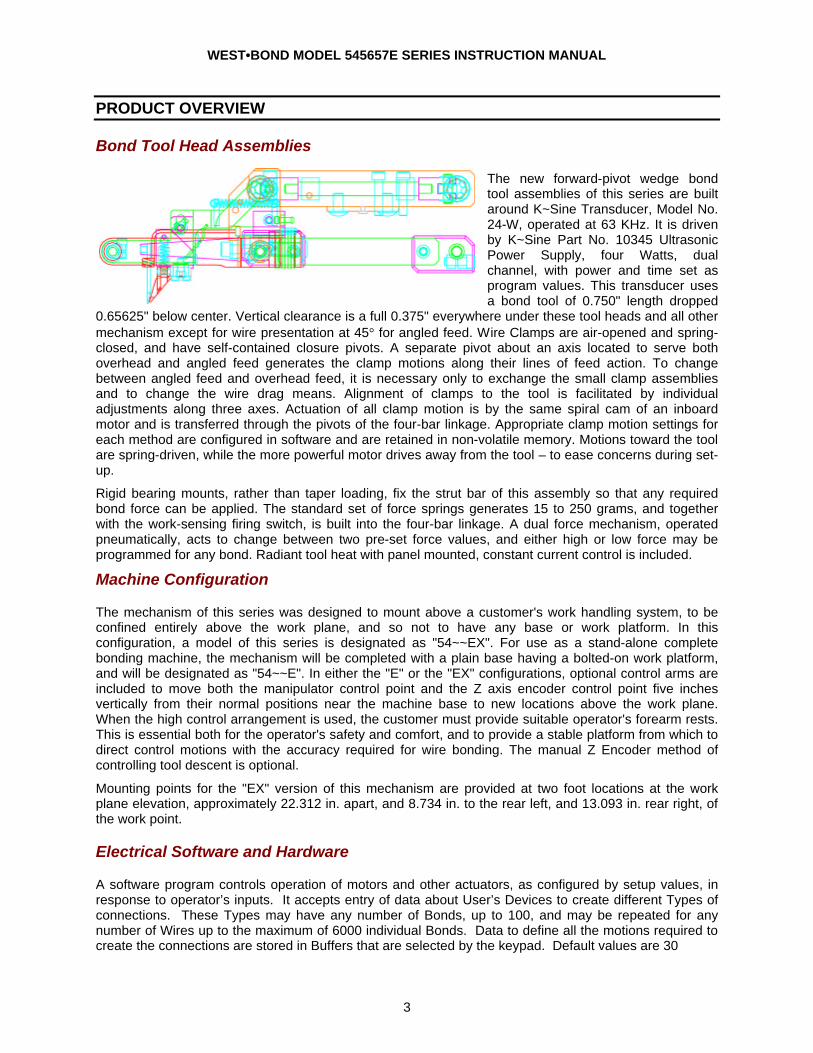
The new forward-pivot wedge bond tool assemblies of this series are built around K~Sine Transducer, Model No. 24-W, operated at 63 KHz. It is driven by K~Sine Part No. 10345 Ultrasonic Power Supply, four Watts, dual channel, with power and time set as program values. This transducer uses a bond tool of 0.750" length dropped
0.65625" below center. Vertical clearance is a full 0.375" everywhere under these tool heads and all other mechanism except for wire presentation at 45° for angled feed. Wire Clamps are air-opened and spring-closed, and have self-contained closure pivots. A separate pivot about an axis located to serve both overhead and angled feed generates the clamp motions along their lines of feed action. To change between angled feed and overhead feed, it is necessary only to exchange the small clamp assemblies and to change the wire drag means. Alignment of clamps to the tool is facilitated by individual adjustments along three axes. Actuation of all clamp motion is by the same spiral cam of an inboard motor and is transferred through the pivots of the four-bar linkage. Appropriate clamp motion settings for each method are configured in software and are retained in non-volatile memory. Motions toward the tool are spring-driven, while the more powerful motor drives away from the tool – to ease concerns during set-up.
Rigid bearing mounts, rather than taper loading, fix the strut bar of this assembly so that any required bond force can be applied. The standard set of force springs generates 15 to 250 grams, and together with the work-sensing firing switch, is built into the four-bar linkage. A dual force mechanism, operated pneumatically, acts to change between two pre-set force values, and either high or low force may be programmed for any bond. Radiant tool heat with panel mounted, constant current control is included.
Machine Configuration
The mechanism of this series was designed to mount above a customer's work handling system, to be confined entirely above the work plane, and so not to have any base or work platform. In this configuration, a model of this series is designated as "54~~EX". For use as a stand-alone complete bonding machine, the mechanism will be completed with a plain base having a bolted-on work platform, and will be designated as "54~~E". In either the "E" or the "EX" configurations, optional control arms are included to move both the manipulator control point and the Z axis encoder control point five inches vertically from their normal positions near the machine base to new locations above the work plane. When the high control arrangement is used, the customer must provide suitable operator's forearm rests. This is essential both for the operator's safety and comfort, and to provide a stable platform from which to direct control motions with the accuracy required for wire bonding. The manual Z Encoder method of controlling tool descent is optional.
Mounting points for the "EX" version of this mechanism are provided at two foot locations at the work plane elevation, approximately 22.312 in. apart, and 8.734 in. to the rear left, and 13.093 in. rear right, of the work point.
Electrical Software and Hardware
A software program controls operation of motors and other actuators, as configured by setup values, in response to operator’s inputs. It accepts entry of data about User’s Devices to create different Types of connections. These Types may have any number of Bonds, up to 100, and may be repeated for any number of Wires up to the maximum of 6000 individual Bonds. Data to define all the motions required to create the connections are stored in Buffers that are selected by the keypad. Default values are 30
WEST•BOND MODEL 545657E SERIES INSTRUCTION MANUAL
4
PRODUCT OVERVIEW
Electrical Software and Hardware
Types of 5 Bonds per Type which yields 40 Device Buffers. WEST•BOND Part No 8100 CPU, containing a Motorola 68000 microprocessor and 256 KB of nonvolatile RAM executes the software program.
A keypad is provided for direct entry and editing of both configuration and user data and for selection of operation options. Entry and execution is prompted at the machine panel by a series of "screens" displayed on a 4-line 40-character LCD. All programmed values are displayed during bonding.
Built in ultrasonic power supply is K~Sine Part No 10345, four Watts, dual channel. Settings of power and time program values are sent via an eight-bit interface. Adjustment of current for radiant tool heat is included with the panel controls.
Operating Controls
KEYPAD
Twelve-key pad for entry of program data, setting of Modes, and direct control of machine actions. At left hand.
Z ENCODER
Generates Z-Axis motor step clocks: A home sensor parallels the G Key and the Ball Button. At left hand with both high and low control arms.
X-Y MANIPULATOR
Moves tool head, TV camera, and motorized slides atop X-Y-Axes with 8-to-1 mechanical advantage. At right hand with both high and low control arms.
BALL BUTTON
Push-button switch in the manipulator control ball. Parallels the G Key but also acts to lock only the X-Axis for scanning the bond path along the Y-Axis, front-to-back.
ROTARY WORK TABLE (OPTIONAL)
Rotates about the center of tool motion range to pre-set the alignment of bonds front-to-back.
Modes of Operation
INHIBIT AUTO
Modifies only the Full-Auto Mode. It is set for each bond during Bond Edit.
On: Full-Auto pauses at each search elevation for X-Y targeting while the key is held.
Off: Full-Auto proceeds with no pauses.
FULL-AUTO OR HALF-AUTO
This mode is toggled by Key 8
Full-Auto: Start by G Key or Ball Button or Z Encoder. Lock manual X-Y slides and bond all bonds of this wire. Pausing is controlled by Inhibit Auto described above.
Half-Auto: Controlled by G Key or Ball Button or Z Encoder. This is a press and release sequence with pauses at each search and loop elevation.
INCH MODE
Start by Zero Key. Executes Half-Auto mode except proceeds down in slow steps from each search to contact while key is held. Available any time tool is stopped.
WEST•BOND MODEL 545657E SERIES INSTRUCTION MANUAL
5
PRODUCT OVERVIEW
Definitions of Models in this Series
All E Series machine models are finished with selected materials and protective coatings to prevent electrostatic discharge to user's work piece.
MODEL NO. 5456E This machine with single wedge bond tool head, Assembly No. 9004, with angled clamp Assembly No 9048 and overhead clamp Assembly No 9049, for bonding by either wedge method.
MODEL NO. 5456EX This machine, specified as Model 5456E, except without base.
MODEL NO. 545630E Designed with a high frequency transducer (115kHz) to aid in bonding to fragile materials such as Gallium Arsenide and assorted duroids. The higher frequency allows the use of lower power, time, and force, thus preserving delicate parts and materials. This machine is built with single wedge bond tool head, Assembly No. 9004, with angled clamp Assembly No 9048 and overhead clamp Assembly No 9049, for bonding by either wedge method.
MODEL NO. 545630EX This machine, specified as Model 545630E, except without base.
MODEL NO. 545657E This machine with two bond tool heads, Assembly No 9004 with the two clamp assemblies for wedge bonding as above, and with tool head Assembly No 9044 for ball bonding, all convertible.
MODEL NO. 545657EX This machine specified as Model 545657E, except without base.
MODEL NO. 545730E Designed with a high frequency transducer (115kHz) to aid in bonding to fragile materials such as Gallium Arsenide and assorted duroids. The higher frequency allows the use of lower power, time, and force, thus preserving delicate parts and materials. This machine comes with two bond tool heads, Assembly No 9004 with the two clamp assemblies for wedge bonding as above, and with tool head Assembly No 9044 for ball bonding, all convertible.
MODEL NO. 545730EX This machine specified as Model 545730E, except without base.
MODEL NO. 5700E This machine with one tool head Assembly No 9044 with K~Sine Transducer, Model No. 34-C, for ball-wedge applications. Software also allows spaced, single-ball bonding.
MODEL NO. 5700EX This machine specified as Model 5700E, except without base.
Services Compressed air, regulated to 50 psi, is required. Connection is via 1/4-inch tubing.
Electrical service required is 50-60 Hz, single phase, either 115 VAC or 230 VAC; however, input must be configured at the factory for 230 VAC. A fuse and three-prong power cord connector are provided for 115 VAC: For 230 VAC, these must be changed to conform to local requirements.
Dimensions "E" Series machine size is 24.218" wide x 22.297" deep x 11.000" high, exclusive of microscope, or 15.000" in height to scope eyepieces. Weight is 75 lb. uncrated, or 110 lb. crated.
"EX" Series machine size is 22.312" wide x 16.500" deep x 6.000" high above work plane, exclusive of microscope, or 10.0" high from work plane to scope eyepieces. Weight is 55 lb. uncrated, or 90 lb. crated.
WEST•BOND MODEL 545657E SERIES INSTRUCTION MANUAL
6
ACCESSORY DESCRIPTIONS
The specifications define Features that add additional capabilities or utilities to the basic machine models, and cross reference those models with which the Features may be combined.
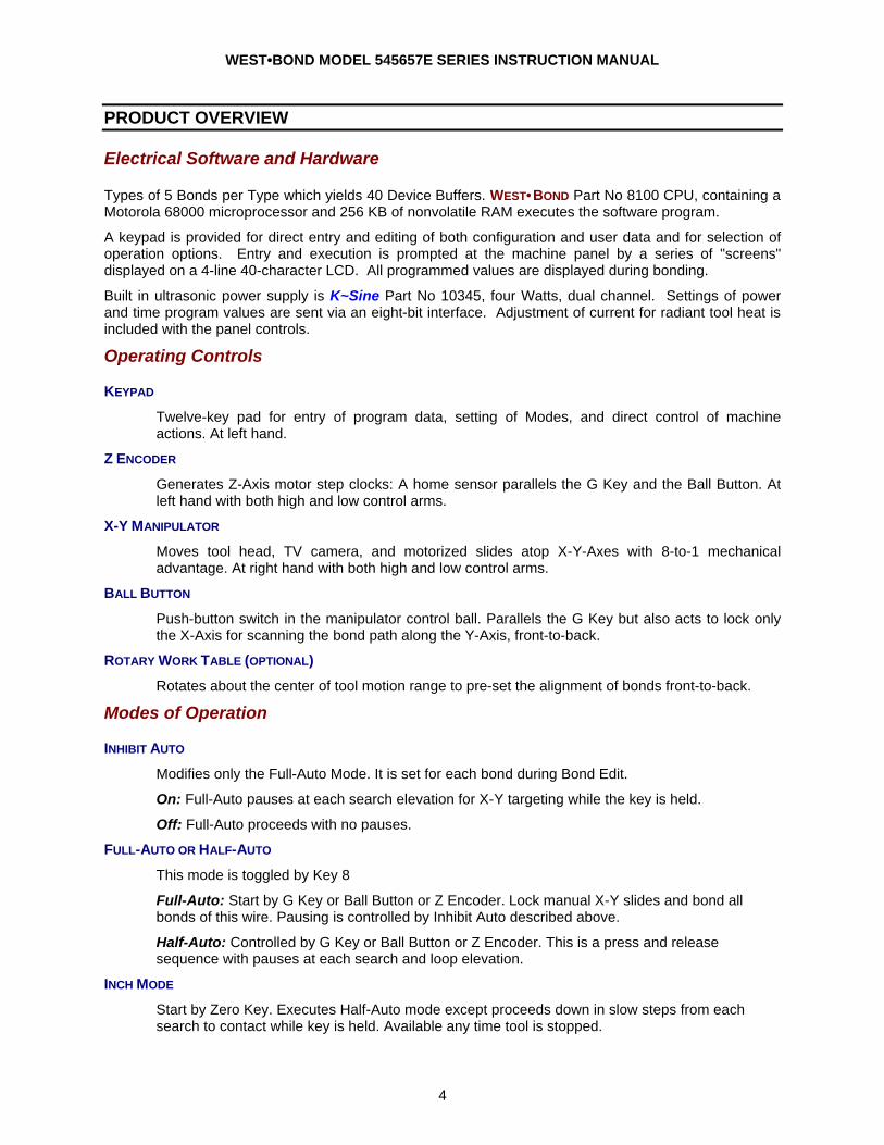
Non Heated Workholder: Non-rotating Epoxy Transfer & Die Placement workholder for substrates up to 1.000" x 1.000", with mechanical clamp and adjustable back rails: Assembly No. 3600.018
Non Heated Workholder: Non-rotating workholder for substrates up to 1.000" x 1.000". Work piece is held by mechanical clamp, with 2 Position, 2.000" x 2.000" fluoroware supports. Assembly No. 3600.220
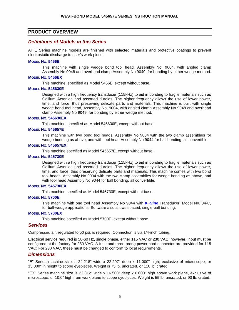
K~1200D, Temperature Controller: A 400 watt microprocessor-based Temperature Controller provides precise control with a minimum of set-up. The K~1200D is a programmable controller linked to the workholder heating elements through two solid state relays. The controller offers flexibility, while the solid state relays offer dependability. K~1201D is a 600 watts version for larger applications.
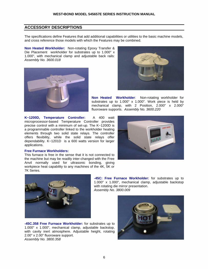
Free Furnace Workholders: This furnace is free in the sense that it is not connected to the machine but may be readily inter-changed with the Free Anvil normally used for ultrasonic bonding, giving workpiece heat capability to any machines of the 4K, 5K or 7K Series.
-45C: Free Furnace Workholder: for substrates up to 1.000" x 1.000", mechanical clamp, adjustable backstop with rotating die mirror presentation. Assembly No. 3800.009
-45C.358 Free Furnace Workholder: for substrates up to 1.000" x 1.000", mechanical clamp, adjustable backstop, with cavity inert atmosphere. Adjustable height, rotating 2.00" x 2.00" fluoroware support. Assembly No. 3800.358
WEST•BOND MODEL 545657E SERIES INSTRUCTION MANUAL
7
ACCESSORY DESCRIPTIONS
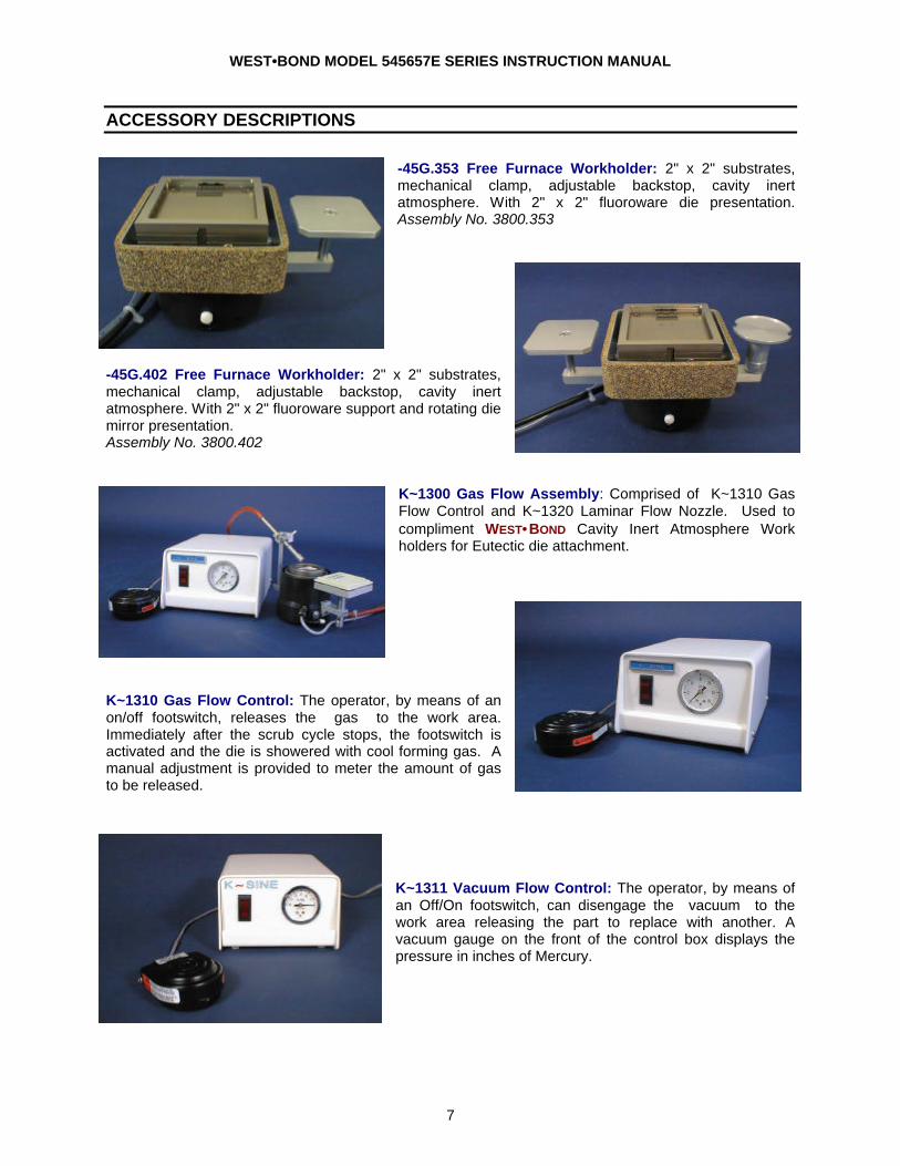
-45G.353 Free Furnace Workholder: 2" x 2" substrates, mechanical clamp, adjustable backstop, cavity inert atmosphere. With 2" x 2" fluoroware die presentation. Assembly No. 3800.353
-45G.402 Free Furnace Workholder: 2" x 2" substrates, mechanical clamp, adjustable backstop, cavity inert atmosphere. With 2" x 2" fluoroware support and rotating die mirror presentation. Assembly No. 3800.402
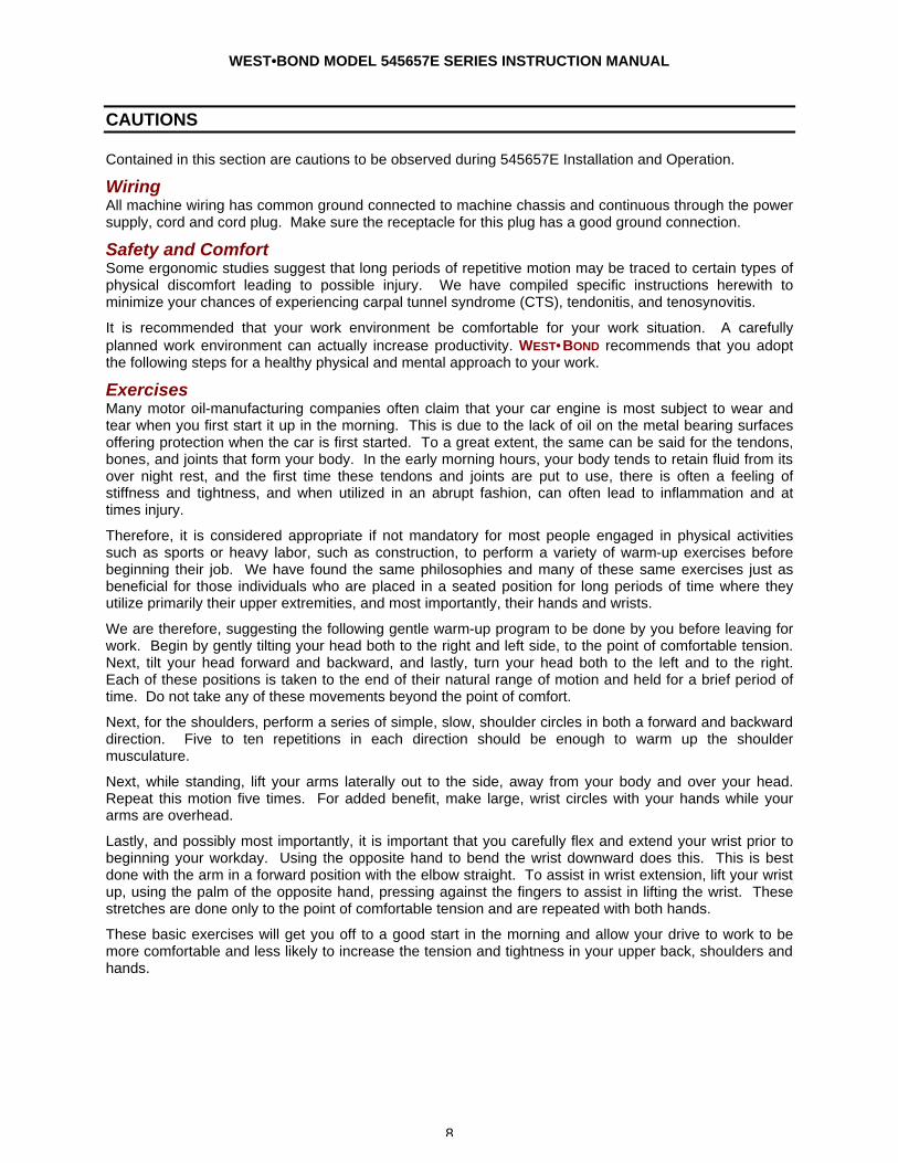
K~1300 Gas Flow Assembly: Comprised of K~1310 Gas Flow Control and K~1320 Laminar Flow Nozzle. Used to compliment WEST•BOND Cavity Inert Atmosphere Work holders for Eutectic die attachment.
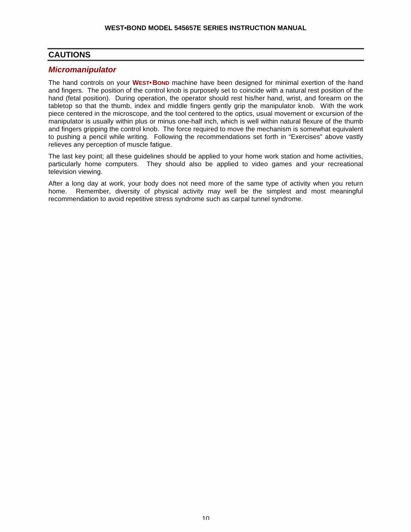
K~1310 Gas Flow Control: The operator, by means of an on/off footswitch, releases the gas to the work area. Immediately after the scrub cycle stops, the footswitch is activated and the die is showered with cool forming gas. A manual adjustment is provided to meter the amount of gas to be released.
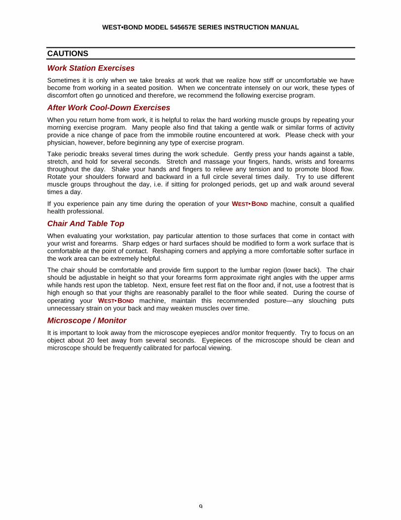
K~1311 Vacuum Flow Control: The operator, by means of an Off/On footswitch, can disengage the vacuum to the work area releasing the part to replace with another. A vacuum gauge on the front of the control box displays the pressure in inches of Mercury.
WEST•BOND MODEL 545657E SERIES INSTRUCTION MANUAL
8
CAUTIONS
Contained in this section are cautions to be observed during 545657E Installation and Operation.
Wiring All machine wiring has common ground connected to machine chassis and continuous through the power supply, cord and cord plug. Make sure the receptacle for this plug has a good ground connection.
Safety and Comfort Some ergonomic studies suggest that long periods of repetitive motion may be traced to certain types of physical discomfort leading to possible injury. We have compiled specific instructions herewith to minimize your chances of experiencing carpal tunnel syndrome (CTS), tendonitis, and tenosynovitis.
It is recommended that your work environment be comfortable for your work situation. A carefully planned work environment can actually increase productivity. WEST•BOND recommends that you adopt the following steps for a healthy physical and mental approach to your work.
Exercises Many motor oil-manufacturing companies often claim that your car engine is most subject to wear and tear when you first start it up in the morning. This is due to the lack of oil on the metal bearing surfaces offering protection when the car is first started. To a great extent, the same can be said for the tendons, bones, and joints that form your body. In the early morning hours, your body tends to retain fluid from its over night rest, and the first time these tendons and joints are put to use, there is often a feeling of stiffness and tightness, and when utilized in an abrupt fashion, can often lead to inflammation and at times injury.
Therefore, it is considered appropriate if not mandatory for most people engaged in physical activities such as sports or heavy labor, such as construction, to perform a variety of warm-up exercises before beginning their job. We have found the same philosophies and many of these same exercises just as beneficial for those individuals who are placed in a seated position for long periods of time where they utilize primarily their upper extremities, and most importantly, their hands and wrists.
We are therefore, suggesting the following gentle warm-up program to be done by you before leaving for work. Begin by gently tilting your head both to the right and left side, to the point of comfortable tension. Next, tilt your head forward and backward, and lastly, turn your head both to the left and to the right. Each of these positions is taken to the end of their natural range of motion and held for a brief period of time. Do not take any of these movements beyond the point of comfort.
Next, for the shoulders, perform a series of simple, slow, shoulder circles in both a forward and backward direction. Five to ten repetitions in each direction should be enough to warm up the shoulder musculature.
Next, while standing, lift your arms laterally out to the side, away from your body and over your head. Repeat this motion five times. For added benefit, make large, wrist circles with your hands while your arms are overhead.
Lastly, and possibly most importantly, it is important that you carefully flex and extend your wrist prior to beginning your workday. Using the opposite hand to bend the wrist downward does this. This is best done with the arm in a forward position with the elbow straight. To assist in wrist extension, lift your wrist up, using the palm of the opposite hand, pressing against the fingers to assist in lifting the wrist. These stretches are done only to the point of comfortable tension and are repeated with both hands.
These basic exercises will get you off to a good start in the morning and allow your drive to work to be more comfortable and less likely to increase the tension and tightness in your upper back, shoulders and hands.
WEST•BOND MODEL 545657E SERIES INSTRUCTION MANUAL
9
CAUTIONS
Work Station Exercises Sometimes it is only when we take breaks at work that we realize how stiff or uncomfortable we have become from working in a seated position. When we concentrate intensely on our work, these types of discomfort often go unnoticed and therefore, we recommend the following exercise program.
After Work Cool-Down Exercises When you return home from work, it is helpful to relax the hard working muscle groups by repeating your morning exercise program. Many people also find that taking a gentle walk or similar forms of activity provide a nice change of pace from the immobile routine encountered at work. Please check with your physician, however, before beginning any type of exercise program.
Take periodic breaks several times during the work schedule. Gently press your hands against a table, stretch, and hold for several seconds. Stretch and massage your fingers, hands, wrists and forearms throughout the day. Shake your hands and fingers to relieve any tension and to promote blood flow. Rotate your shoulders forward and backward in a full circle several times daily. Try to use different muscle groups throughout the day, i.e. if sitting for prolonged periods, get up and walk around several times a day.
If you experience pain any time during the operation of your WEST•BOND machine, consult a qualified health professional.
Chair And Table Top When evaluating your workstation, pay particular attention to those surfaces that come in contact with your wrist and forearms. Sharp edges or hard surfaces should be modified to form a work surface that is comfortable at the point of contact. Reshaping corners and applying a more comfortable softer surface in the work area can be extremely helpful.
The chair should be comfortable and provide firm support to the lumbar region (lower back). The chair should be adjustable in height so that your forearms form approximate right angles with the upper arms while hands rest upon the tabletop. Next, ensure feet rest flat on the floor and, if not, use a footrest that is high enough so that your thighs are reasonably parallel to the floor while seated. During the course of operating your WEST•BOND machine, maintain this recommended posture—any slouching puts unnecessary strain on your back and may weaken muscles over time.
Microscope / Monitor It is important to look away from the microscope eyepieces and/or monitor frequently. Try to focus on an object about 20 feet away from several seconds. Eyepieces of the microscope should be clean and microscope should be frequently calibrated for parfocal viewing.
WEST•BOND MODEL 545657E SERIES INSTRUCTION MANUAL
10
CAUTIONS
Micromanipulator
The hand controls on your WEST•BOND machine have been designed for minimal exertion of the hand and fingers. The position of the control knob is purposely set to coincide with a natural rest position of the hand (fetal position). During operation, the operator should rest his/her hand, wrist, and forearm on the tabletop so that the thumb, index and middle fingers gently grip the manipulator knob. With the work piece centered in the microscope, and the tool centered to the optics, usual movement or excursion of the manipulator is usually within plus or minus one-half inch, which is well within natural flexure of the thumb and fingers gripping the control knob. The force required to move the mechanism is somewhat equivalent to pushing a pencil while writing. Following the recommendations set forth in “Exercises” above vastly relieves any perception of muscle fatigue.
The last key point; all these guidelines should be applied to your home work station and home activities, particularly home computers. They should also be applied to video games and your recreational television viewing.
After a long day at work, your body does not need more of the same type of activity when you return home. Remember, diversity of physical activity may well be the simplest and most meaningful recommendation to avoid repetitive stress syndrome such as carpal tunnel syndrome.
WEST•BOND MODEL 545657E SERIES INSTRUCTION MANUAL
11
INSTALLATION
Unpacking and Inspection
STEP 1
Remove the accessory box, identify, and account for all contents. 3 ITEM OPTION 3 ITEM OPTION Manipulator Control Arms standard Air Regulator standard Key Pad standard Microscope (optional) Additional Wire Clamps (90°) standard Illuminator (optional) Additional Ball Bond Head standard Work Holder (optional) NEFO Unit standard Temperature Controller (optional)
STEP 2
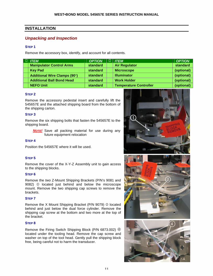
Remove the accessory pedestal insert and carefully lift the 545657E and the attached shipping board from the bottom of the shipping carton.
STEP 3
Remove the six shipping bolts that fasten the 545657E to the shipping board.
NOTE! Save all packing material for use during any future equipment relocation
STEP 4
Position the 545657E where it will be used.
STEP 5
Remove the cover of the X-Y-Z Assembly unit to gain access to the shipping blocks.
STEP 6
Remove the two Z-Mount Shipping Brackets (P/N’s 9081 and 9082) 1 located just behind and below the microscope mount. Remove the two shipping cap screws to remove the brackets.
STEP 7
Remove the X Mount Shipping Bracket (P/N 9079) 2 located behind and just below the dual force cylinder. Remove the shipping cap screw at the bottom and two more at the top of the bracket.
STEP 8
Remove the Firing Switch Shipping Block (P/N 6873.002) � located under the tooling head. Remove the cap screw and washer on top of the tool head. Gently pull the shipping block free, being careful not to harm the transducer.
WEST•BOND MODEL 545657E SERIES INSTRUCTION MANUAL
12
INSTALLATION
Unpacking and Inspection
STEP 9
Locate the micromanipulator arm from the accessory box and install it in the mounting collar. Tighten the two mounting collar cap screws with approximately equal force. The vertical registration pin in the mounting collar should interconnect with the manipulator to insure correct installation.
CAUTION! Never attempt to lift the machine by the micromanipulator arm!
STEP 10
Remove all tie wraps and foam from machine.
STEP 11
Replace the machine cover removed in STEP 6.
STEP 12
Remove the Air Regulator from its bag and attach it to the rear panel of the machine using the two 8-32 button head screws provided. Once the regulator is installed with its air line connected to the back panel, connect the regulator to “house air” using ¼” OD polyethylene tubing to supply 50 psi air pressure.
STEP 13
Plug the AC line cord of the power supply into 100VAC to 110VAC and 50/60Hz.
Connecting the Accessories
STEP 1 - AIR
Connect ¼” poly-flow tubing from air regulator to rear panel fitting. Adjust for approximately 50 psi nominal.
STEP 2 - MICROSCOPE
Attach the Microscope Mount to the Microscope Support, located in the center of the machine, using the screw and washer provided. Position the Mount so that it is completely forward, close to the operator.
Attach the Microscope to the Microscope Arm assembly. Adjust the arm to place the Microscope in the maximum up position. Attach the Illuminator to the Microscope using the adapter which threads into the Microscope. Position the wire for the Illuminator in the direction of the Microscope Arm Assembly, away from the operator.
Place the Microscope into the Microscope mount on the machine using caution not to interfere with the video camera assembly.
After all accessories are connected and the machine is ready to bond, the Microscope needs to be adjusted and properly centered. (See Thread and Bond Section, page 29).

WEST•BOND MODEL 545657E SERIES INSTRUCTION MANUAL
13
INSTALLATION
Connecting the Accessories
STEP 5 - KEY PAD
Attach the Key Pad cable to the 9 pin D-Sub connector that exits from the left-rear side of the machine.
STEP 6 - NEGATIVE EFO GENERATOR
Set the Generator on top the crosshair generator, ensure the power switch is off and plug into 110VAC. Locate the cable with the Honda connector coming out of the back of the 545657E and connect it into the back of the NEFO Generator. Remove the torch cable from its bag and plug into the rear of the NEFO Generator. Attach the ground to the provided thumb nut. Finally plug the torch cable into the 545657E paying special attention to ensure that each end of the cable is plugged into its correct color connectors. (i.e. red to red and black to black)
STEP 7** - WORKHOLDER /TEMPERATURE CONTROLLER
Connect the 5-pin Bendix connector of the Workholder to the rear of the Temperature Controller. If the Workholder has Vacuum, connect the Orange hose from the Workholder to a Vacuum Supply. Plug the Temperature Controller to 110VAC, 50-60Hz.
** OPTIONAL
WEST•BOND MODEL 545657E SERIES INSTRUCTION MANUAL
14
INSTALLATION
Bond Tool Installation
45° AND 90° WEDGE BONDING TOOL
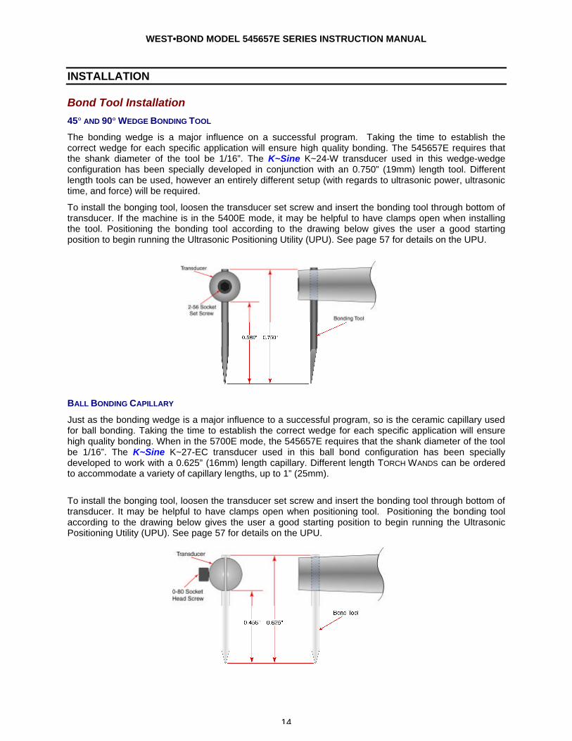
The bonding wedge is a major influence on a successful program. Taking the time to establish the correct wedge for each specific application will ensure high quality bonding. The 545657E requires that the shank diameter of the tool be 1/16”. The K~Sine K~24-W transducer used in this wedge-wedge configuration has been specially developed in conjunction with an 0.750” (19mm) length tool. Different length tools can be used, however an entirely different setup (with regards to ultrasonic power, ultrasonic time, and force) will be required.
To install the bonging tool, loosen the transducer set screw and insert the bonding tool through bottom of transducer. If the machine is in the 5400E mode, it may be helpful to have clamps open when installing the tool. Positioning the bonding tool according to the drawing below gives the user a good starting position to begin running the Ultrasonic Positioning Utility (UPU). See page 57 for details on the UPU.
BALL BONDING CAPILLARY
Just as the bonding wedge is a major influence to a successful program, so is the ceramic capillary used for ball bonding. Taking the time to establish the correct wedge for each specific application will ensure high quality bonding. When in the 5700E mode, the 545657E requires that the shank diameter of the tool be 1/16”. The K~Sine K~27-EC transducer used in this ball bond configuration has been specially developed to work with a 0.625” (16mm) length capillary. Different length TORCH WANDS can be ordered to accommodate a variety of capillary lengths, up to 1” (25mm).
To install the bonging tool, loosen the transducer set screw and insert the bonding tool through bottom of transducer. It may be helpful to have clamps open when positioning tool. Positioning the bonding tool according to the drawing below gives the user a good starting position to begin running the Ultrasonic Positioning Utility (UPU). See page 57 for details on the UPU.

WEST•BOND MODEL 545657E SERIES INSTRUCTION MANUAL
15
INSTALLATION
Torch Wand and Tail Setup
Ball size is affected by many different factors including Ball Size setting, Tail Length, distance between the tool and the Torch Wand, wire diameter, wire elongation, wire quality (age), and Torch Wand cleanliness. When all settings are optimized (per application), the ball will form just below the tip of the capillary and the machine will pull the ball up into the pocket on the bottom of the tool in preparation of the next bond. If the tail length is too short, the Tool to Torch distance is too short, or the ball size setting is turned up too high, the ball will form up inside the capillary. This causes deformed balls and also shortens the life of the ceramic tool.
This drawing represents the recommended setup for 0.001” gold wire. These numbers are approximations and may vary for different applications.
RECOMMENDED SETTINGS
Wire Size: 0.001”
Tail Length: ~0.035”
Tool to Torch: ~0.045”
Wire Gap: ~0.010”
WEST•BOND MODEL 545657E SERIES INSTRUCTION MANUAL
16
INSTALLATION
Installing the Bonding Wire
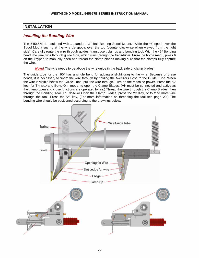
The 545657E is equipped with a standard ½” Ball Bearing Spool Mount. Slide the ½” spool over the Spool Mount such that the wire de-spools over the top (counter-clockwise when viewed from the right side). Carefully route the wire through guides, transducer, clamps and bonding tool. With the 45° Bonding head, the wire runs through guide tube, which runs through the transducer. From the home menu, press 6 on the keypad to manually open and thread the clamp blades making sure that the clamps fully capture the wire.
NOTE! The wire needs to be above the wire guide in the back side of clamp blades.
The guide tube for the 90° has a single bend for adding a slight drag to the wire. Because of these bends, it is necessary to “inch” the wire through by holding the tweezers close to the Guide Tube. When the wire is visible below the Guide Tube, pull the wire through. Turn on the machine power. Press the “6” key, for THREAD and BOND-OFF mode, to open the Clamp Blades. (Air must be connected and active as the clamp open and close functions are operated by air.) Thread the wire through the Clamp Blades, then through the Bonding Tool. To Close or Open the Clamp Blades, press the “9” Key, or to feed more wire through the tool, Press the “A” key, (For more information on threading the tool see page 29.) The bonding wire should be positioned according to the drawings below.
WEST•BOND MODEL 545657E SERIES INSTRUCTION MANUAL
17
MACHINE CONTROLS
Front Panel
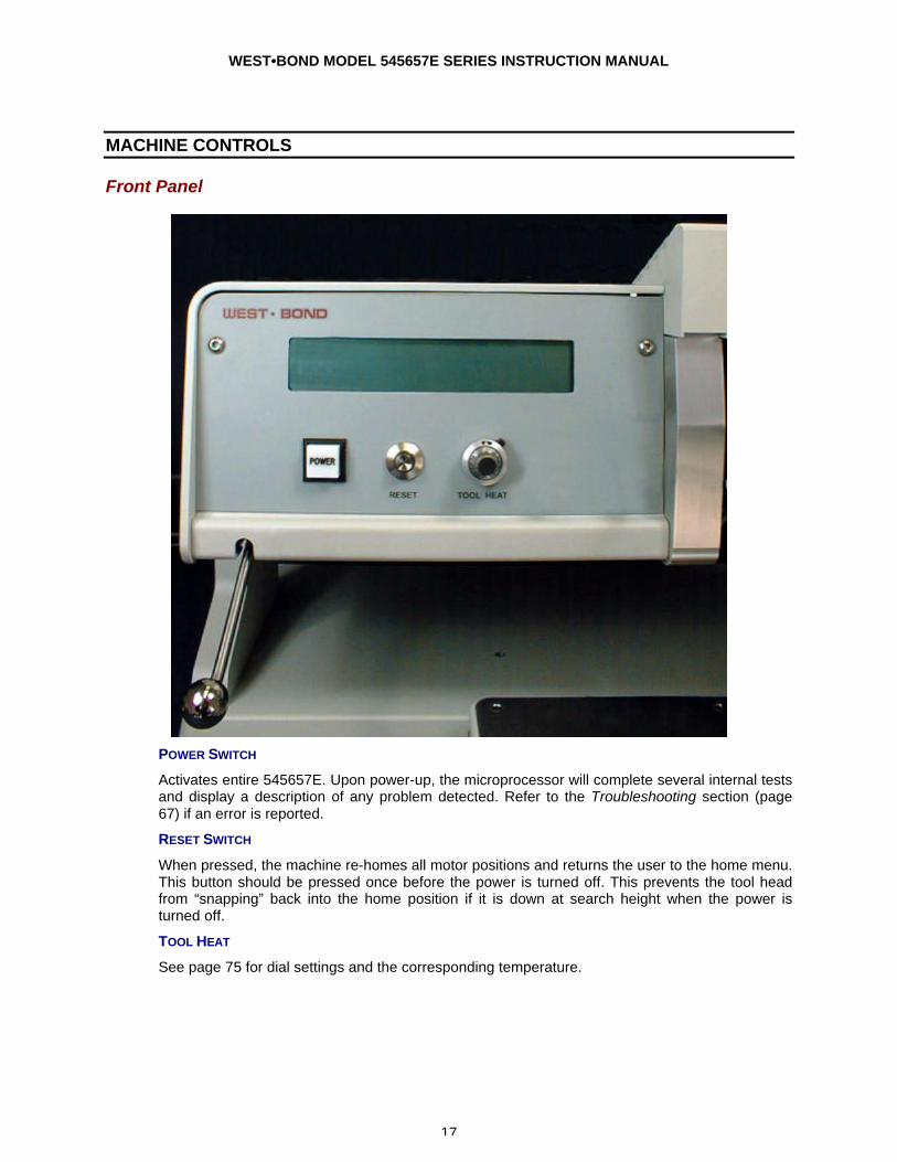
POWER SWITCH
Activates entire 545657E. Upon power-up, the microprocessor will complete several internal tests and display a description of any problem detected. Refer to the Troubleshooting section (page 67) if an error is reported.
RESET SWITCH
When pressed, the machine re-homes all motor positions and returns the user to the home menu. This button should be pressed once before the power is turned off. This prevents the tool head from “snapping” back into the home position if it is down at search height when the power is turned off.
TOOL HEAT
See page 75 for dial settings and the corresponding temperature.
WEST•BOND MODEL 545657E SERIES INSTRUCTION MANUAL
18
MACHINE CONTROLS
Front Panel
LCD
The Liquid Crystal Display is used by the 545657E to communicate machine status, menu prompts, explanations, and options. Four lines of text are available and each line is capable of displaying 40 characters.
Z CONTROL LEVER
Located at the far left on the machine front panel, this lever acts to bring the tool down to bond. As with the manipulator arm, WEST•BOND includes two Z-control levers (one high position style and the other low position style).
GO BUTTON (NOT SHOWN)
This is the small push-button switch located in the manipulator control ball. The Go button controls two different features depending upon how it is used. When the button is quickly pressed and released it operates the X-Axis braking system. This is done to aid the operator in scanning the bond path along the Y-Axis. If this button is pressed and held, the bonder automatically goes to Search before first bond. It pauses at search until the Go button is released. Once released, the machine will complete the bonding sequence (if in Full-Auto mode). If the machine is set in Half-Auto mode, it will pause before each operation, requiring a press of the Go button to proceed.
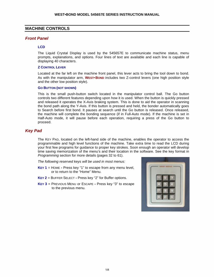
Key Pad
The KEY PAD, located on the left-hand side of the machine, enables the operator to access the programmable and high level functions of the machine. Take extra time to read the LCD during your first few programs for guidance to proper key strokes. Soon enough an operator will develop time saving memorization of the menu’s and their location in the software. See the key format in Programming section for more details (pages 32 to 61).
The following reserved keys will be used in most menus:
KEY 1 = HOME - Press key “1” to escape from any menu level, or to return to the “Home” Menu.
KEY 2 = BUFFER SELECT - Press key “2” for Buffer options.
KEY 3 = PREVIOUS MENU or ESCAPE - Press key “3” to escape to the previous menu.

WEST•BOND MODEL 545657E SERIES INSTRUCTION MANUAL
19
MACHINE CONTROLS
Negative Electronic Flame Off
POWER SWITCH
The power switch turns the power on to the NEFO unit. Always turn this unit off when servicing the torch or head assembly.
POWER DIAL
Sets the Ball Forming Current to a constant. The voltage will vary to keep the power the same to consistently make the same size ball each time. The power dial will set the current from 7.5ma – 25ma.
The current setting can be adjusted to a 9ma – 35.5ma range for larger balls on 1.5 – 2.0 mil wire. Jumper E1 on the mother board (Lower PCB) should be changed from pins 1-2 to 2-3 for the high power setting.
TIME DIAL
Ball Forming Time, or a cut-off time for ball formation. Forming time is set between 2.1ms to a maximum of 10ms. Factory setting of the time is at 2.5 (approximately 4ms), this is the optimum setting.
LED’S
The Open and Short LED’s are for designation of a ball fault. If the Open LED is lit, then the gap between the end of the wire and the torch tip is too large for ball formation. If the Short LED is lit, then the wire has contacted the torch tip causing a short where no spark is formed.
NEFOPower & Time Settings
0369
12151821242730333639
0 1 2 3 4 5 6 7 8 9 10
Dial Setting
Cu
rren
t (m
a)
/ T
ime
(ms)
- Factory Setting
WEST•BOND MODEL 545657E SERIES INSTRUCTION MANUAL
20
OPERATION
The 545657E Semi-Automatic Wire Bonder has been specifically designed to be versatile, dependable, and easy to use. To effect this end, the following sections have been developed to help the operator take advantage of its advanced bonding features. A in-depth study and understanding of this section will result in better bonds, higher gram pulls, and faster set up times.
Wire Bonding
The process of wire bonding with WEST•BOND’S 545657E is rather straight forward. The micromanipulator control, positioned to the right of the work platform, is linked to the tool head and camera assemblies through an 8:1 ratio. This mechanical link allows the operator to accomplish extremely precise and fine adjustments to the tool head and camera assemblies.
To create the first wire bond, simply use the micromanipulator to position the monitor’s crosshairs over the critical bond and press the G key, the manipulator GO BUTTON, or the 0 key. Below is a list of 4 different machine modes that correspond to the keys listed above.
FULL-AUTO MODE
Once this mode is selected and the G key or GO BUTTON is pressed, the bonding sequence will continue without operator intervention until the completion of one entire wire run. In this mode the operator may stop the bonding at anytime by pressing and holding any key. For selection details and more information regarding this mode see page 24.
HALF-AUTO MODE
The operator is required to press the G key, or the GO BUTTON, each time the machine approaches the work to make a bond. This mode allows the operator to manually select a bonding point by using the micromanipulator to position the tool prior to contact. The bonding sequence of this mode is described as follows: At first bond, the tool will stop at search if the “G” key is pressed and held, allowing XY movement, and the bonding sequence will continue upon release of the “G” key. For selection details and more information regarding this mode see page 25.
MANUAL MODE
This mode allows the operator to slowly lower the Tooling Head by pressing the 0 key until the Bonding Tool gently touches the bond surface. At anytime the operator can manually select a bonding point by using the micromanipulator to position the tool prior to contact. If it is necessary to raise the already lowered bond tool, the operator can press the 5 key to raise the Tooling Head. For more information regarding this mode see page 27.
Z-LEVER MANUAL MODE
By using the Z-axis control arm, the operator can slowly inch down to the first SEARCH ELEVATION. The operator can take over with the keypad or Go button at any time.
WEST•BOND MODEL 545657E SERIES INSTRUCTION MANUAL
21
OPERATION
Home Menu
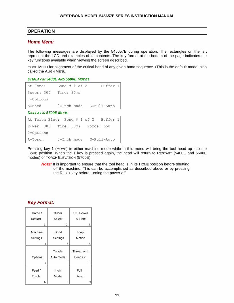
The following messages are displayed by the 545657E during operation. The rectangles on the left represent the LCD and examples of its contents. The key format at the bottom of the page indicates the key functions available when viewing the screen described.
HOME MENU for alignment of the critical bond of any given bond sequence. (This is the default mode, also called the ALIGN MENU.
DISPLAY IN 5400E AND 5600E MODES
At Home: Bond # 1 of 2 Buffer 1
Power: 300 Time: 30ms
7=Options
A=Feed 0=Inch Mode G=Full-Auto
DISPLAY IN 5700E MODE
At Torch Elev: Bond # 1 of 2 Buffer 1
Power: 300 Time: 30ms Force: Low
7=Options
A=Torch 0=Inch mode G=Full-Auto
Pressing key 1 (HOME) in either machine mode while in this menu will bring the tool head up into the HOME position. When the 1 key is pressed again, the head will return to RESTART (5400E and 5600E modes) or TORCH ELEVATION (5700E).
NOTE! It is important to ensure that the tool head is in its HOME position before shutting off the machine. This can be accomplished as described above or by pressing the RESET key before turning the power off.
Key Format:
Home /
Restart
1
Buffer
Select
2
U/S Power
& Time
3
Machine
Settings
4
Bond
Settings
5
Loop
Motion
6
Options
7
Toggle
Auto mode
8
Thread and
Bond Off
9
Feed /
Torch
A
Inch
Mode
0
Full
Auto
G
WEST•BOND MODEL 545657E SERIES INSTRUCTION MANUAL
22
OPERATION
Options
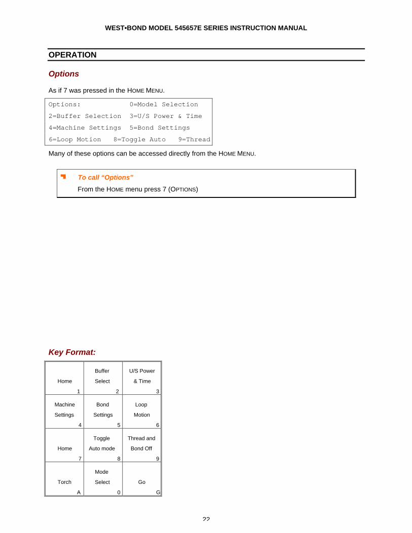
As if 7 was pressed in the HOME MENU.
Options: 0=Model Selection
2=Buffer Selection 3=U/S Power & Time
4=Machine Settings 5=Bond Settings
6=Loop Motion 8=Toggle Auto 9=Thread
Many of these options can be accessed directly from the HOME MENU.
J To call “Options”
From the HOME menu press 7 (OPTIONS)
Key Format:
Home
1
Buffer
Select
2
U/S Power
& Time
3
Machine
Settings
4
Bond
Settings
5
Loop
Motion
6
Home
7
Toggle
Auto mode
8
Thread and
Bond Off
9
Torch
A
Mode
Select
0
Go
G
WEST•BOND MODEL 545657E SERIES INSTRUCTION MANUAL
23
OPERATION
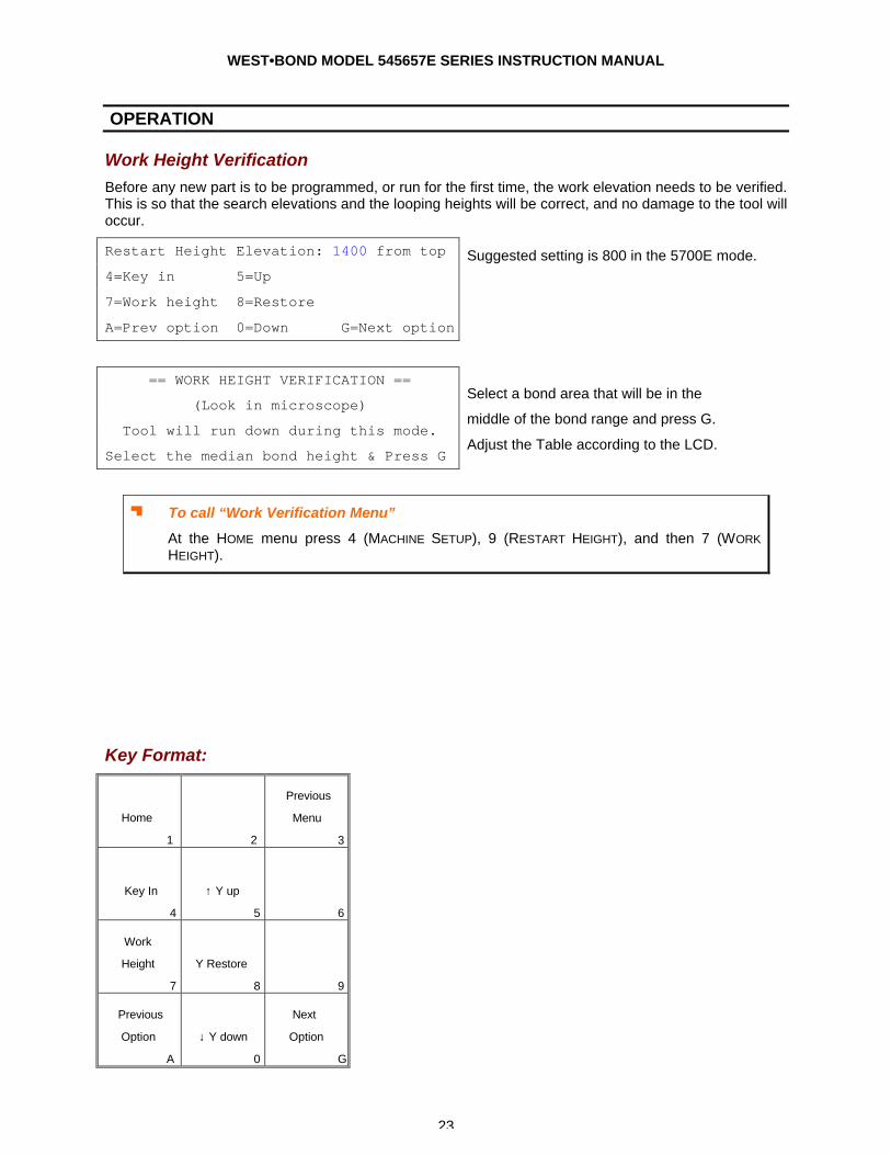
Work Height Verification Before any new part is to be programmed, or run for the first time, the work elevation needs to be verified. This is so that the search elevations and the looping heights will be correct, and no damage to the tool will occur.
Restart Height Elevation: 1400 from top Suggested setting is 800 in the 5700E mode. 4=Key in 5=Up 7=Work height 8=Restore A=Prev option 0=Down G=Next option
== WORK HEIGHT VERIFICATION ==
(Look in microscope)
Tool will run down during this mode.
Select the median bond height & Press G
Select a bond area that will be in the
middle of the bond range and press G.
Adjust the Table according to the LCD.
J To call “Work Verification Menu”
At the HOME menu press 4 (MACHINE SETUP), 9 (RESTART HEIGHT), and then 7 (WORK HEIGHT).
Key Format:
Home
1
2
Previous
Menu
3
Key In
4
↑ Y up
5
6
Work
Height
7
Y Restore
8
9
Previous
Option
A
↓ Y down
0
Next
Option
G
WEST•BOND MODEL 545657E SERIES INSTRUCTION MANUAL
24
OPERATION
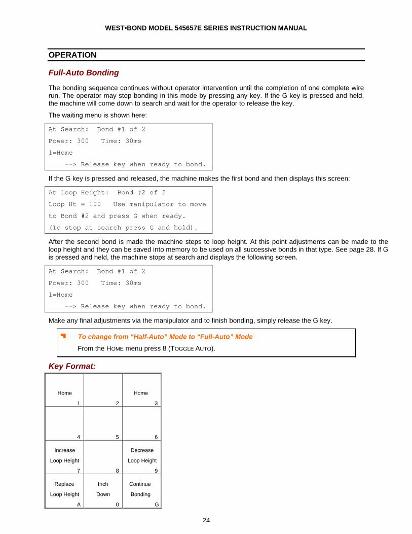
Full-Auto Bonding
The bonding sequence continues without operator intervention until the completion of one complete wire run. The operator may stop bonding in this mode by pressing any key. If the G key is pressed and held, the machine will come down to search and wait for the operator to release the key.
The waiting menu is shown here:
At Search: Bond #1 of 2
Power: 300 Time: 30ms
1=Home
--> Release key when ready to bond.
If the G key is pressed and released, the machine makes the first bond and then displays this screen:
At Loop Height: Bond #2 of 2
Loop Ht = 100 Use manipulator to move
to Bond #2 and press G when ready.
(To stop at search press G and hold).
After the second bond is made the machine steps to loop height. At this point adjustments can be made to the loop height and they can be saved into memory to be used on all successive bonds in that type. See page 28. If G is pressed and held, the machine stops at search and displays the following screen.
At Search: Bond #1 of 2
Power: 300 Time: 30ms
1=Home
--> Release key when ready to bond.
Make any final adjustments via the manipulator and to finish bonding, simply release the G key.
J To change from “Half-Auto” Mode to “Full-Auto” Mode
From the HOME menu press 8 (TOGGLE AUTO).
Key Format:
Home
1
2
Home
3
4
5
6
Increase
Loop Height
7
8
Decrease
Loop Height
9
Replace
Loop Height
A
Inch
Down
0
Continue
Bonding
G

WEST•BOND MODEL 545657E SERIES INSTRUCTION MANUAL
25
OPERATION
Half-Auto Bonding The operator is required to press the “G” key, or the “GO” button, to step through the bonding sequence. This mode allows the operator to manually select a bond contact point by using the micromanipulator. At the first bond, the tool will stop at search, allowing XY movement. The bonding sequence will continue once the “G” key is pressed. Before the second bond, the tool will automatically stop at the Loop Height, allowing XY movement. Press GO again and the tool will come down to search elevation for final XY adjustments. The “G” key is pressed once more to complete the next bond.
Next, when G is pressed, the first bond is automatically completed and the machine pauses at the next menu, Loop Height. It is in this menu that adjustments can be made to the loop height. They can also be saved into memory to be used on all successive bonds in that type. See page 28.
Key Format:
Home
1
2
Home
3
4
5
6
Increase
Loop Height
7
8
Decrease
Loop Height
9
Replace
Loop Height
A
Inch
Down
0
Continue
Bonding
G
At Search: Bond #1 of 2
1=Home 5=Inch up
7=Inch Tail(+) 9=Inch Tail(-)
A=Feed 0=Inch down G=Half-Auto
At Loop Height: Bond 2 of 2
Power: 240 Time: 20ms
Loop ht = 100. Use manipulator to move
to bond #2 and press G when ready.
Next, when G is pressed, the machine will stop at
Search and the next menu is displayed before the last
bond is completed.
At Search: Bond #1 of 2
1=Home 5=Inch up 6=Close Clamp
0=Inch down G=Half-Auto
Pressing G one more time will complete the last
bond.
J To change from “Half-Auto” Mode to “Full-Auto” Mode
From the HOME menu press 8 (TOGGLE AUTO).
WEST•BOND MODEL 545657E SERIES INSTRUCTION MANUAL
26
OPERATION
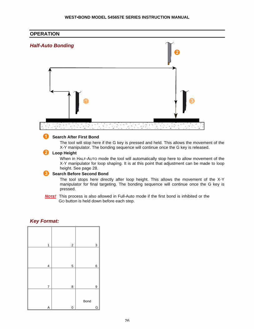
Half-Auto Bonding
1. Search After First Bond The tool will stop here if the G key is pressed and held. This allows the movement of the X-Y manipulator. The bonding sequence will continue once the G key is released.
2. Loop Height When in HALF-AUTO mode the tool will automatically stop here to allow movement of the X-Y manipulator for loop shaping. It is at this point that adjustment can be made to loop height. See page 28.
3. Search Before Second Bond The tool stops here directly after loop height. This allows the movement of the X-Y manipulator for final targeting. The bonding sequence will continue once the G key is pressed.
NOTE! This process is also allowed in Full-Auto mode if the first bond is inhibited or the GO button is held down before each step.
Key Format:
1
2
3
4
5
6
7
8
9
A
0
Bond
G
WEST•BOND MODEL 545657E SERIES INSTRUCTION MANUAL
27
OPERATION
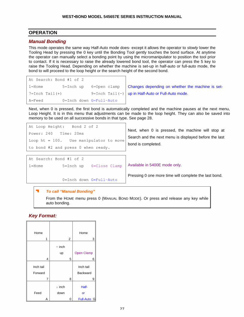
Manual Bonding This mode operates the same way Half-Auto mode does- except it allows the operator to slowly lower the Tooling Head by pressing the 0 key until the Bonding Tool gently touches the bond surface. At anytime the operator can manually select a bonding point by using the micromanipulator to position the tool prior to contact. If it is necessary to raise the already lowered bond tool, the operator can press the 5 key to raise the Tooling Head. Depending on whether the machine is set-up in half-auto or full-auto mode, the bond to will proceed to the loop height or the search height of the second bond.
Next, when 0 is pressed, the first bond is automatically completed and the machine pauses at the next menu, Loop Height. It is in this menu that adjustments can be made to the loop height. They can also be saved into memory to be used on all successive bonds in that type. See page 28.
Key Format:
Home
1
2
Home
3
4
↑ inch
up
5
Open Clamp
6
Inch tail
Forward
7
8
Inch tail
Backward
9
Feed
A
↓ inch
down
0
Half-
or
Full-Auto G
At Search: Bond #1 of 2
1=Home 5=Inch up 6=Open clamp
7=Inch Tail(+) 9=Inch Tail(-)
A=Feed 0=Inch down G=Full-Auto
Changes depending on whether the machine is set-
up in Half-Auto or Full-Auto mode.
At Loop Height: Bond 2 of 2
Power: 240 Time: 20ms
Loop ht = 100. Use manipulator to move
to bond #2 and press 0 when ready.
Next, when 0 is pressed, the machine will stop at
Search and the next menu is displayed before the last
bond is completed.
At Search: Bond #1 of 2
1=Home 5=Inch up 6=Close Clamp
0=Inch down G=Full-Auto
Available in 5400E mode only.
Pressing 0 one more time will complete the last bond.
J To call “Manual Bonding”
From the HOME menu press 0 (MANUAL BOND MODE). Or press and release any key while auto bonding.
WEST•BOND MODEL 545657E SERIES INSTRUCTION MANUAL
28
OPERATION
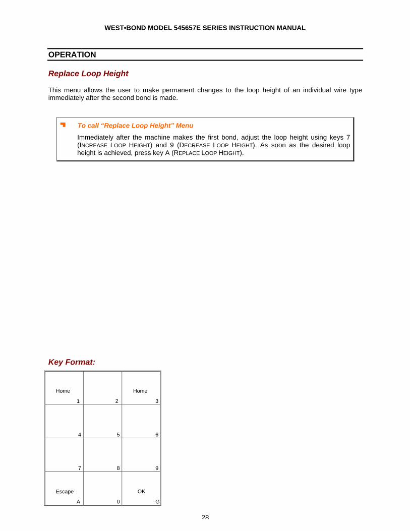
Replace Loop Height
This menu allows the user to make permanent changes to the loop height of an individual wire type immediately after the second bond is made.
J To call “Replace Loop Height” Menu
Immediately after the machine makes the first bond, adjust the loop height using keys 7 (INCREASE LOOP HEIGHT) and 9 (DECREASE LOOP HEIGHT). As soon as the desired loop height is achieved, press key A (REPLACE LOOP HEIGHT).
Key Format:
Home
1
2
Home
3
4
5
6
7
8
9
Escape
A 0
OK
G
WEST•BOND MODEL 545657E SERIES INSTRUCTION MANUAL
29
OPERATION
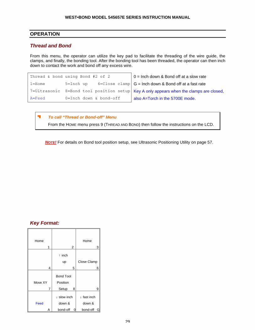
Thread and Bond
From this menu, the operator can utilize the key pad to facilitate the threading of the wire guide, the clamps, and finally, the bonding tool. After the bonding tool has been threaded, the operator can then inch down to contact the work and bond off any excess wire. Thread & bond using Bond #2 of 2
1=Home 5=Inch up 6=Close clamp
7=Ultrasonic 8=Bond tool position setup
A=Feed 0=Inch down & bond-off
0 = Inch down & Bond off at a slow rate
G = Inch down & Bond off at a fast rate
Key A only appears when the clamps are closed,
also A=Torch in the 5700E mode.
J To call “Thread or Bond-off” Menu
From the HOME menu press 9 (THREAD AND BOND) then follow the instructions on the LCD.
NOTE! For details on Bond tool position setup, see Ultrasonic Positioning Utility on page 57.
Key Format:
Home
1
2
Home
3
4
↑ inch
up
5
Close Clamp
6
Move XY
7
Bond Tool
Position
Setup 8
9
Feed
A
↓ slow inch
down &
bond-off 0
↓ fast inch
down &
bond-off G
WEST•BOND MODEL 545657E SERIES INSTRUCTION MANUAL
30
OPERATION
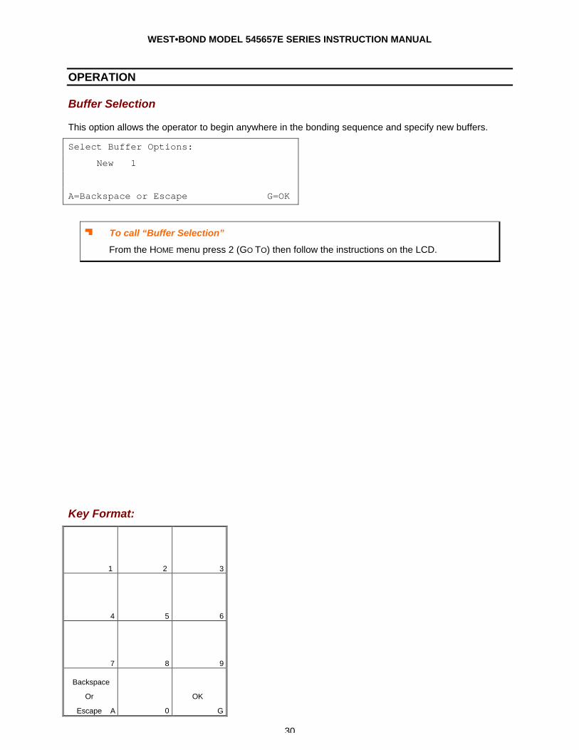
Buffer Selection
This option allows the operator to begin anywhere in the bonding sequence and specify new buffers.
Select Buffer Options:
New 1
A=Backspace or Escape G=OK
J To call “Buffer Selection”
From the HOME menu press 2 (GO TO) then follow the instructions on the LCD.
Key Format:
1
2
3
4
5
6
7
8
9
Backspace
Or
Escape A
0
OK
G
WEST•BOND MODEL 545657E SERIES INSTRUCTION MANUAL
31
MENU MAP
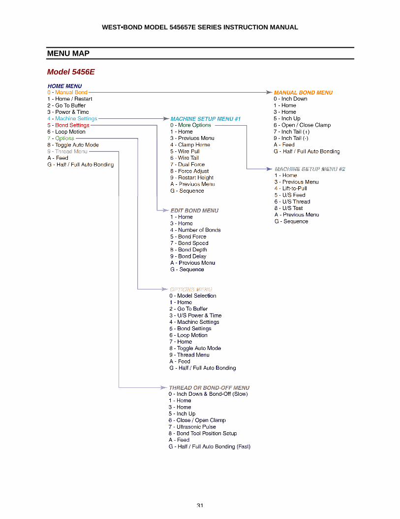
Model 5456E
WEST•BOND MODEL 545657E SERIES INSTRUCTION MANUAL
32
MENU MAP
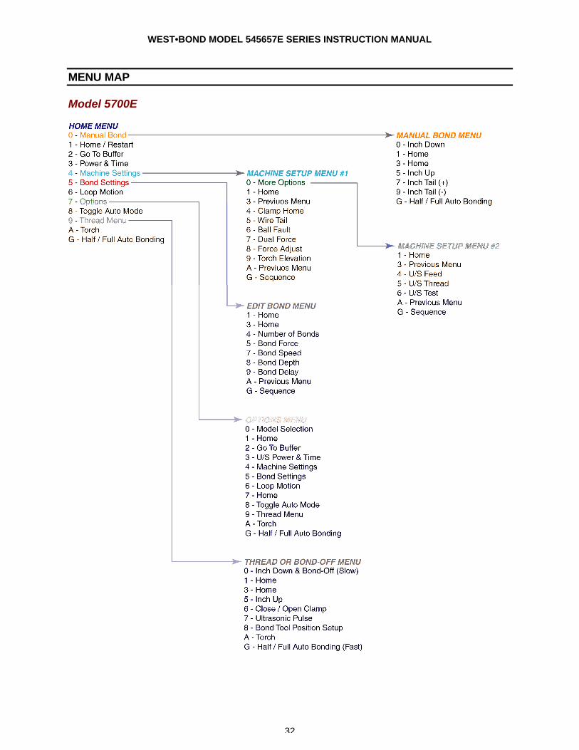
Model 5700E
WEST•BOND MODEL 545657E SERIES INSTRUCTION MANUAL
33
PROGRAMMING The following pages demonstrate the expected displays and programmable options of the 545657E. The programmable features are broken into two sections: One section is called MACHINE SETTINGS and the other is called USER DATA SETTINGS.
Machine Settings These are items generally used for initial machine set-up and are infrequently changed. Options in this section may require some modification if the application changes significantly. Here are the options available for programming in this section:
1. CLAMP HOME – page 45
2. WIRE PULL – page 46
3. WIRE TAIL – page 47
4. BALL FAULT – page 48
5. DUAL FORCE – page 49
6. FORCE ADJUST – page 50
7. RESTART HEIGHT – page 52
8. WORK HEIGHT ELEVATION – page 23
9. LIFT-TO-PULL – page 53
10. ULTRASONIC POWER DURING FEED – page 54
11. ULTRASONIC POWER DURING THREAD – page 55
12. ULTRASONIC DIAGNOSTIC TEST – page 56
User Data Settings These are options commonly used by the operator. For this reason they have been separated from the MACHINE SETTINGS and stored into BUFFER, POWER/TIME, and BOND SETTINGS. Each wire buffer allows one or more bonds. Here are the options available for programming in this section:
1. BUFFER SELECTIONS – page 30
2. U/S POWER and TIME – page 58
3. BOND SETTINGS – page 60
The BUFFER SELECTION menu is designed to store the following data:
a. U/S POWER
b. U/S TIME
c. BOND SETTINGS
The BOND EDIT MENU is designed to do the following tasks:
1. EDIT BOND – page 58
a. EDIT ULTRASONIC POWER – page 58
b. EDIT ULTRASONIC TIME – page 59
c. EDIT BOND FORCE – page 62
d. EDIT BOND DEPTH – page 64
e. EDIT SPEED – page 63
f. EDIT PRE-BOND DELAY – page 65
2. EDIT NUMBER OF BONDS - page 61
WEST•BOND MODEL 545657E SERIES INSTRUCTION MANUAL
34
ADVANCED PROGRAMMING
Loop Motion
This option is designed to take the operator through a quick setup. Other parameters may need to be adjusted for optimum bonding results, but this quick setup will cover the major looping controls. The following pages describe each step in detail. This section is included to help the operator prefect their wire loop shape as a integral part of process control.
J To call “Loop Motion”
From the HOME menu press 6 (LOOP MOTION) and then continue to press G (SEQUENCE).
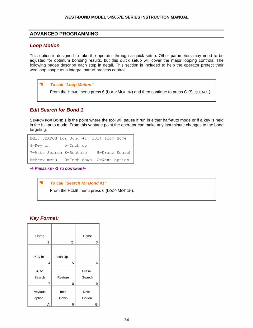
Edit Search for Bond 1
SEARCH FOR BOND 1 is the point where the tool will pause if run in either half-auto mode or if a key is held in the full-auto mode. From this vantage point the operator can make any last minute changes to the bond targeting.
Edit SEARCH for Bond #1: 2024 from Home
4=Key in 5=Inch up
7=Auto Search 8=Restore 9=Erase Search
A=Prev menu 0=Inch down G=Next option
à PRESS KEY G TO CONTINUEß
J To call “Search for Bond #1”
From the HOME menu press 6 (LOOP MOTION).
Key Format:
Home
1
2
Home
3
Key In
4
Inch Up
5
6
Auto
Search
7
Restore
8
Erase
Search
9
Previous
option
A
Inch
Down
0
Next
Option
G
WEST•BOND MODEL 545657E SERIES INSTRUCTION MANUAL
35
ADVANCED PROGRAMMING
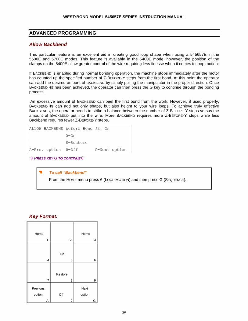
Allow Backbend
This particular feature is an excellent aid in creating good loop shape when using a 545657E in the 5600E and 5700E modes. This feature is available in the 5400E mode, however, the position of the clamps on the 5400E allow greater control of the wire requiring less finesse when it comes to loop motion.
If BACKBEND is enabled during normal bonding operation, the machine stops immediately after the motor has counted up the specified number of Z-BEFORE-Y steps from the first bond. At this point the operator can add the desired amount of BACKBEND by simply pulling the manipulator in the proper direction. Once BACKBENDING has been achieved, the operator can then press the G key to continue through the bonding process.
An excessive amount of BACKBEND can peel the first bond from the work. However, if used properly, BACKBENDING can add not only shape, but also height to your wire loops. To achieve truly effective BACKBENDS, the operator needs to strike a balance between the number of Z-BEFORE-Y steps versus the amount of BACKBEND put into the wire. More BACKBEND requires more Z-BEFORE-Y steps while less Backbend requires fewer Z-BEFORE-Y steps.
ALLOW BACKBEND before Bond #2: On
5=On
8=Restore
A=Prev option 0=Off G=Next option
à PRESS KEY G TO CONTINUEß
J To call “Backbend”
From the HOME menu press 6 (LOOP MOTION) and then press G (SEQUENCE).
Key Format:
Home
1
2
Home
3
4
On
5
6
7
Restore
8
9
Previous
option
A
Off
0
Next
option
G
WEST•BOND MODEL 545657E SERIES INSTRUCTION MANUAL
36
ADVANCED PROGRAMMING
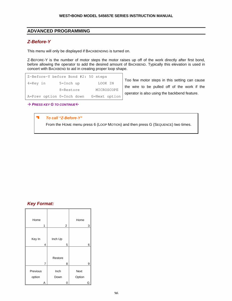
Z-Before-Y
This menu will only be displayed if BACKBENDING is turned on.
Z-BEFORE-Y is the number of motor steps the motor raises up off of the work directly after first bond, before allowing the operator to add the desired amount of BACKBEND. Typically this elevation is used in concert with BACKBEND to aid in creating proper loop shape.
Z-Before-Y before Bond #2: 50 steps
4=Key in 5=Inch up LOOK IN
8=Restore MICROSCOPE
A=Prev option 0=Inch down G=Next option
Too few motor steps in this setting can cause
the wire to be pulled off of the work if the
operator is also using the backbend feature.
à PRESS KEY G TO CONTINUEß
J To call “Z-Before-Y”
From the HOME menu press 6 (LOOP MOTION) and then press G (SEQUENCE) two times.
Key Format:
Home
1
2
Home
3
Key In
4
Inch Up
5
6
7
Restore
8
9
Previous
option
A
Inch
Down
0
Next
Option
G
WEST•BOND MODEL 545657E SERIES INSTRUCTION MANUAL
37
ADVANCED PROGRAMMING
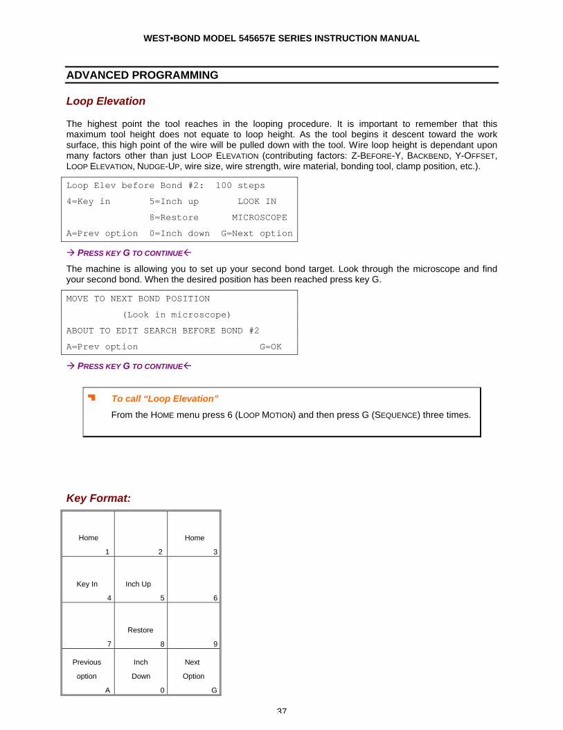
Loop Elevation
The highest point the tool reaches in the looping procedure. It is important to remember that this maximum tool height does not equate to loop height. As the tool begins it descent toward the work surface, this high point of the wire will be pulled down with the tool. Wire loop height is dependant upon many factors other than just LOOP ELEVATION (contributing factors: Z-BEFORE-Y, BACKBEND, Y-OFFSET, LOOP ELEVATION, NUDGE-UP, wire size, wire strength, wire material, bonding tool, clamp position, etc.).
Loop Elev before Bond #2: 100 steps
4=Key in 5=Inch up LOOK IN
8=Restore MICROSCOPE
A=Prev option 0=Inch down G=Next option
à PRESS KEY G TO CONTINUEß
The machine is allowing you to set up your second bond target. Look through the microscope and find your second bond. When the desired position has been reached press key G.
MOVE TO NEXT BOND POSITION
(Look in microscope)
ABOUT TO EDIT SEARCH BEFORE BOND #2
A=Prev option G=OK
à PRESS KEY G TO CONTINUEß
J To call “Loop Elevation”
From the HOME menu press 6 (LOOP MOTION) and then press G (SEQUENCE) three times.
Key Format:
Home
1
2
Home
3
Key In
4
Inch Up
5
6
7
Restore
8
9
Previous
option
A
Inch
Down
0
Next
Option
G

WEST•BOND MODEL 545657E SERIES INSTRUCTION MANUAL
38
ADVANCED PROGRAMMING
Clamp at Loop Height
A feature available only in the 5400E model mode, the CLAMP AT LOOP option can help to create a higher, more pronounced loop shape when the clamps close at LOOP HEIGHT.
5400E ONLY
Close CLAMP AT LOOP HT above Bond #2:
5=Close
8=Restore
A=Prev option 0=Open G=Next option
à PRESS KEY G TO CONTINUEß
J To call “Clamp at Loop Height”
From the HOME menu press 6 (LOOP MOTION) and then press G (SEQUENCE) four times.
Key Format:
Home
1
2
Home
3
4
Close
5
6
7
Restore
8
9
Previous
option
A
Open
0
Next
option
G
WEST•BOND MODEL 545657E SERIES INSTRUCTION MANUAL
39
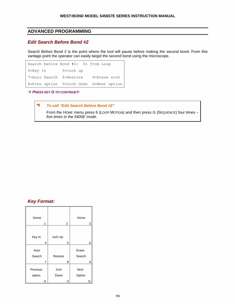
ADVANCED PROGRAMMING
Edit Search Before Bond #2
Search Before Bond 2 is the point where the tool will pause before making the second bond. From this vantage point the operator can easily target the second bond using the microscope.
Search before Bond #2: 61 from Loop
4=Key in 5=Inch up
7=Auto Search 8=Restore 9=Erase srch
A=Prev option 0=Inch down G=Next option
à PRESS KEY G TO CONTINUEß
J To call “Edit Search Before Bond #2”
From the HOME menu press 6 (LOOP MOTION) and then press G (SEQUENCE) four times – five times in the 5400E mode.
Key Format:
Home
1
2
Home
3
Key In
4
Inch Up
5
6
Auto
Search
7
Restore
8
Erase
Search
9
Previous
option
A
Inch
Down
0
Next
Option
G
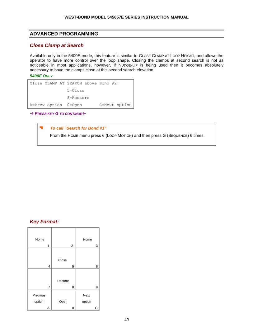
WEST•BOND MODEL 545657E SERIES INSTRUCTION MANUAL
40
ADVANCED PROGRAMMING
Close Clamp at Search
Available only in the 5400E mode, this feature is similar to CLOSE CLAMP AT LOOP HEIGHT, and allows the operator to have more control over the loop shape. Closing the clamps at second search is not as noticeable in most applications, however, if NUDGE-UP is being used then it becomes absolutely necessary to have the clamps close at this second search elevation. 5400E ONLY
Close CLAMP AT SEARCH above Bond #2:
5=Close
8=Restore
A=Prev option 0=Open G=Next option
à PRESS KEY G TO CONTINUEß
J To call “Search for Bond #1”
From the HOME menu press 6 (LOOP MOTION) and then press G (SEQUENCE) 6 times.
Key Format:
Home
1
2
Home
3
4
Close
5
6
7
Restore
8
9
Previous
option
A
Open
0
Next
option
G
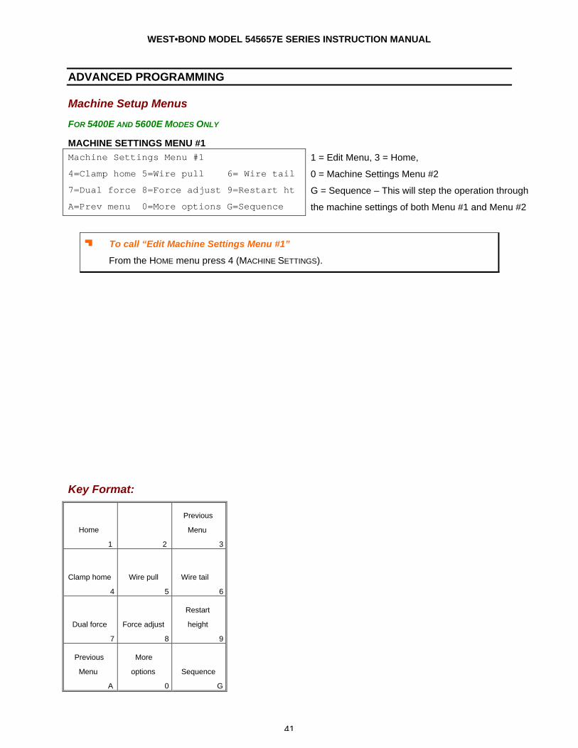
WEST•BOND MODEL 545657E SERIES INSTRUCTION MANUAL
41
ADVANCED PROGRAMMING
Machine Setup Menus
FOR 5400E AND 5600E MODES ONLY
MACHINE SETTINGS MENU #1 Machine Settings Menu #1
4=Clamp home 5=Wire pull 6= Wire tail
7=Dual force 8=Force adjust 9=Restart ht
A=Prev menu 0=More options G=Sequence
1 = Edit Menu, 3 = Home,
0 = Machine Settings Menu #2
G = Sequence – This will step the operation through
the machine settings of both Menu #1 and Menu #2
J To call “Edit Machine Settings Menu #1”
From the HOME menu press 4 (MACHINE SETTINGS).
Key Format:
Home
1
2
Previous
Menu
3
Clamp home
4
Wire pull
5
Wire tail
6
Dual force
7
Force adjust
8
Restart
height
9
Previous
Menu
A
More
options
0
Sequence
G
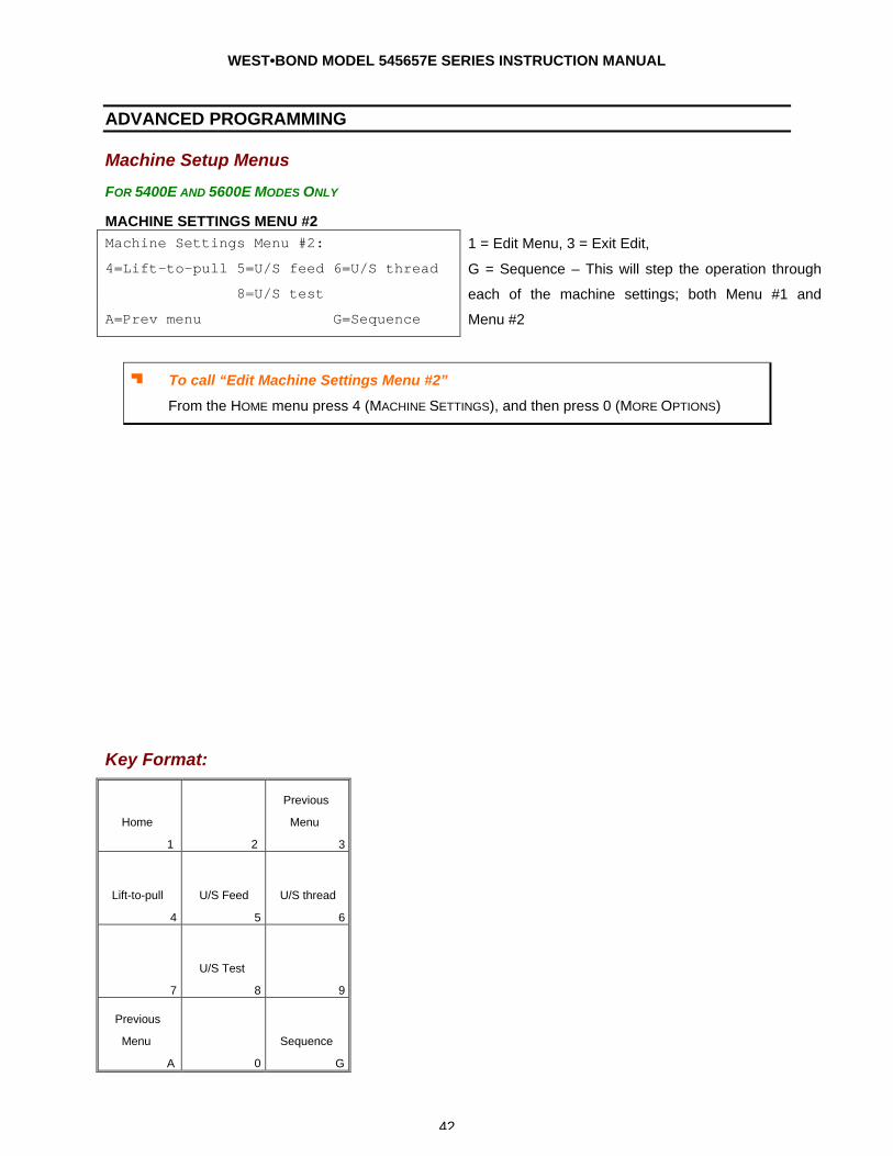
WEST•BOND MODEL 545657E SERIES INSTRUCTION MANUAL
42
ADVANCED PROGRAMMING
Machine Setup Menus
FOR 5400E AND 5600E MODES ONLY
MACHINE SETTINGS MENU #2 Machine Settings Menu #2:
4=Lift-to-pull 5=U/S feed 6=U/S thread
8=U/S test
A=Prev menu G=Sequence
1 = Edit Menu, 3 = Exit Edit,
G = Sequence – This will step the operation through
each of the machine settings; both Menu #1 and
Menu #2
J To call “Edit Machine Settings Menu #2”
From the HOME menu press 4 (MACHINE SETTINGS), and then press 0 (MORE OPTIONS)
Key Format:
Home
1
2
Previous
Menu
3
Lift-to-pull
4
U/S Feed
5
U/S thread
6
7
U/S Test
8
9
Previous
Menu
A
0
Sequence
G
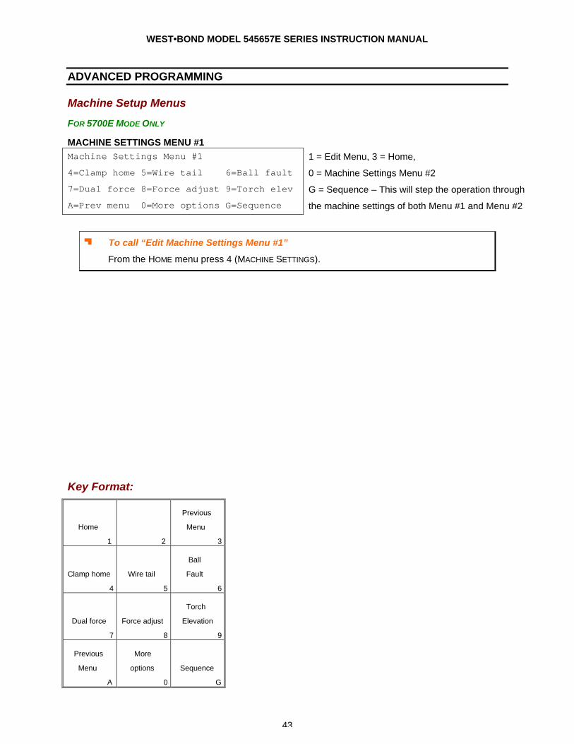
WEST•BOND MODEL 545657E SERIES INSTRUCTION MANUAL
43
ADVANCED PROGRAMMING
Machine Setup Menus
FOR 5700E MODE ONLY
MACHINE SETTINGS MENU #1 Machine Settings Menu #1
4=Clamp home 5=Wire tail 6=Ball fault
7=Dual force 8=Force adjust 9=Torch elev
A=Prev menu 0=More options G=Sequence
1 = Edit Menu, 3 = Home,
0 = Machine Settings Menu #2
G = Sequence – This will step the operation through
the machine settings of both Menu #1 and Menu #2
J To call “Edit Machine Settings Menu #1”
From the HOME menu press 4 (MACHINE SETTINGS).
Key Format:
Home
1
2
Previous
Menu
3
Clamp home
4
Wire tail
5
Ball
Fault
6
Dual force
7
Force adjust
8
Torch
Elevation
9
Previous
Menu
A
More
options
0
Sequence
G
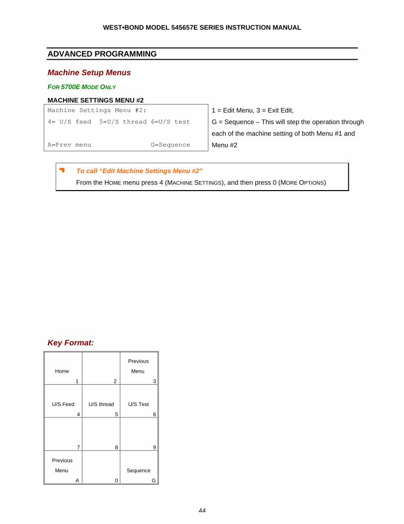
WEST•BOND MODEL 545657E SERIES INSTRUCTION MANUAL
44
ADVANCED PROGRAMMING
Machine Setup Menus
FOR 5700E MODE ONLY
MACHINE SETTINGS MENU #2 Machine Settings Menu #2:
4= U/S feed 5=U/S thread 6=U/S test
A=Prev menu G=Sequence
1 = Edit Menu, 3 = Exit Edit,
G = Sequence – This will step the operation through
each of the machine setting of both Menu #1 and
Menu #2
J To call “Edit Machine Settings Menu #2”
From the HOME menu press 4 (MACHINE SETTINGS), and then press 0 (MORE OPTIONS)
Key Format:
Home
1
2
Previous
Menu
3
U/S Feed
4
U/S thread
5
U/S Test
6
7
8
9
Previous
Menu
A
0
Sequence
G
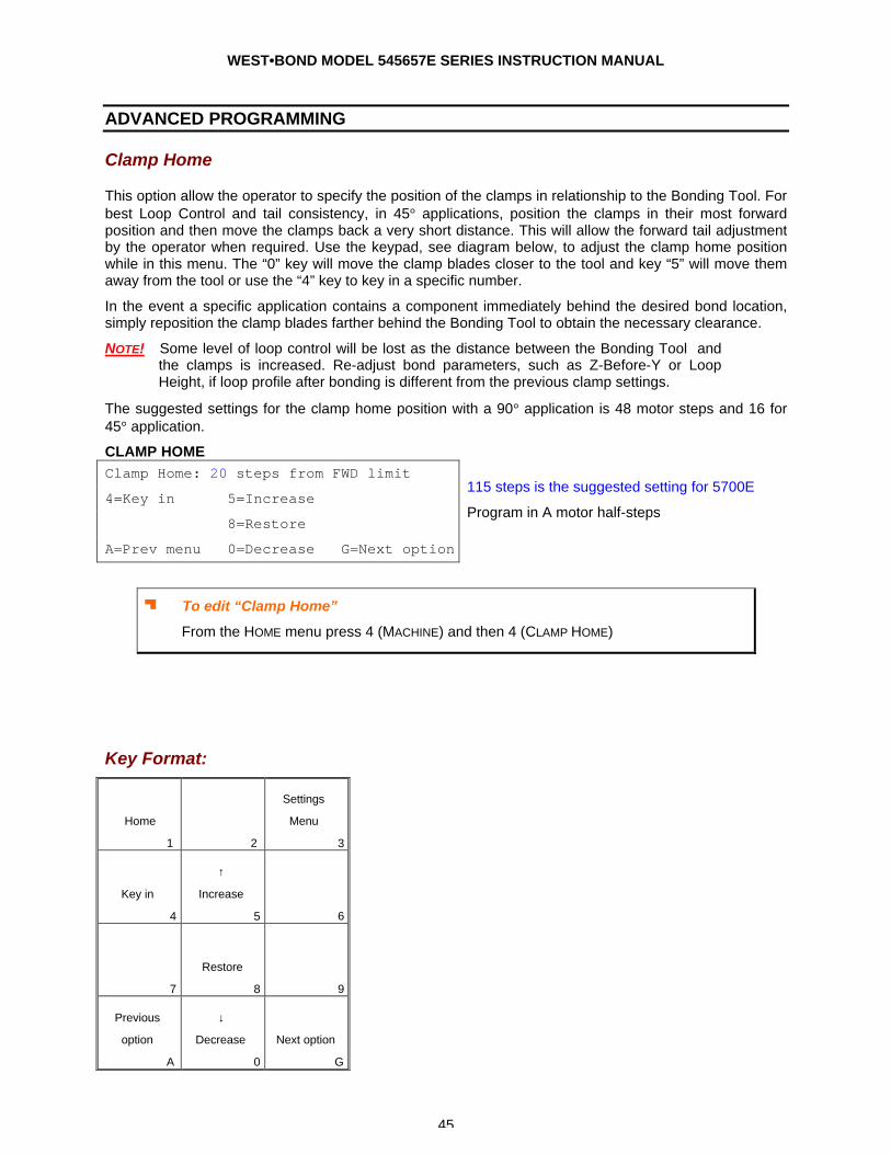
WEST•BOND MODEL 545657E SERIES INSTRUCTION MANUAL
45
ADVANCED PROGRAMMING
Clamp Home
This option allow the operator to specify the position of the clamps in relationship to the Bonding Tool. For best Loop Control and tail consistency, in 45° applications, position the clamps in their most forward position and then move the clamps back a very short distance. This will allow the forward tail adjustment by the operator when required. Use the keypad, see diagram below, to adjust the clamp home position while in this menu. The “0” key will move the clamp blades closer to the tool and key “5” will move them away from the tool or use the “4” key to key in a specific number.
In the event a specific application contains a component immediately behind the desired bond location, simply reposition the clamp blades farther behind the Bonding Tool to obtain the necessary clearance.
NOTE! Some level of loop control will be lost as the distance between the Bonding Tool and the clamps is increased. Re-adjust bond parameters, such as Z-Before-Y or Loop Height, if loop profile after bonding is different from the previous clamp settings.
The suggested settings for the clamp home position with a 90° application is 48 motor steps and 16 for 45° application.
CLAMP HOME Clamp Home: 20 steps from FWD limit
4=Key in 5=Increase
8=Restore
A=Prev menu 0=Decrease G=Next option
115 steps is the suggested setting for 5700E
Program in A motor half-steps
J To edit “Clamp Home”
From the HOME menu press 4 (MACHINE) and then 4 (CLAMP HOME)
Key Format:
Home
1
2
Settings
Menu
3
Key in
4
↑
Increase
5
6
7
Restore
8
9
Previous
option
A
↓
Decrease
0
Next option
G
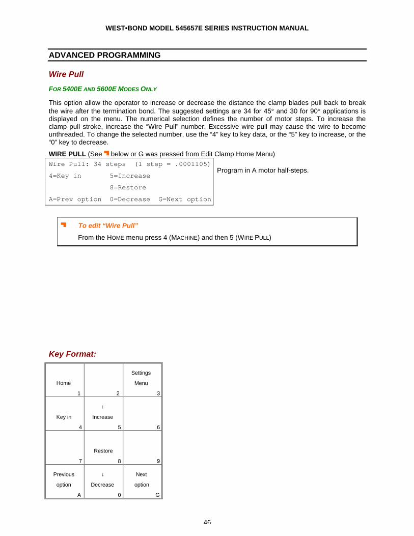
WEST•BOND MODEL 545657E SERIES INSTRUCTION MANUAL
46
ADVANCED PROGRAMMING
Wire Pull
FOR 5400E AND 5600E MODES ONLY
This option allow the operator to increase or decrease the distance the clamp blades pull back to break the wire after the termination bond. The suggested settings are 34 for 45° and 30 for 90° applications is displayed on the menu. The numerical selection defines the number of motor steps. To increase the clamp pull stroke, increase the “Wire Pull” number. Excessive wire pull may cause the wire to become unthreaded. To change the selected number, use the “4” key to key data, or the “5” key to increase, or the “0” key to decrease.
WIRE PULL (See J below or G was pressed from Edit Clamp Home Menu) Wire Pull: 34 steps (1 step = .0001105)
4=Key in 5=Increase
8=Restore
A=Prev option 0=Decrease G=Next option
Program in A motor half-steps.
J To edit “Wire Pull”
From the HOME menu press 4 (MACHINE) and then 5 (WIRE PULL)
Key Format:
Home
1
2
Settings
Menu
3
Key in
4
↑
Increase
5
6
7
Restore
8
9
Previous
option
A
↓
Decrease
0
Next
option
G
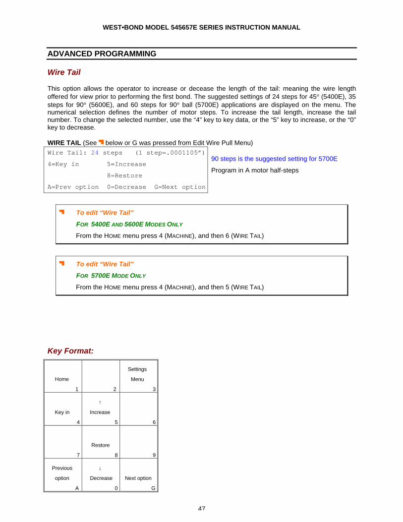
WEST•BOND MODEL 545657E SERIES INSTRUCTION MANUAL
47
ADVANCED PROGRAMMING
Wire Tail
This option allows the operator to increase or decease the length of the tail: meaning the wire length offered for view prior to performing the first bond. The suggested settings of 24 steps for 45° (5400E), 35 steps for 90° (5600E), and 60 steps for 90° ball (5700E) applications are displayed on the menu. The numerical selection defines the number of motor steps. To increase the tail length, increase the tail number. To change the selected number, use the “4” key to key data, or the “5” key to increase, or the “0” key to decrease.
WIRE TAIL (See J below or G was pressed from Edit Wire Pull Menu) Wire Tail: 24 steps (1 step=.0001105”)
4=Key in 5=Increase
8=Restore
A=Prev option 0=Decrease G=Next option
90 steps is the suggested setting for 5700E
Program in A motor half-steps
J To edit “Wire Tail”
FOR 5400E AND 5600E MODES ONLY
From the HOME menu press 4 (MACHINE), and then 6 (WIRE TAIL)
J To edit “Wire Tail”
FOR 5700E MODE ONLY
From the HOME menu press 4 (MACHINE), and then 5 (WIRE TAIL)
Key Format:
Home
1
2
Settings
Menu
3
Key in
4
↑
Increase
5
6
7
Restore
8
9
Previous
option
A
↓
Decrease
0
Next option
G
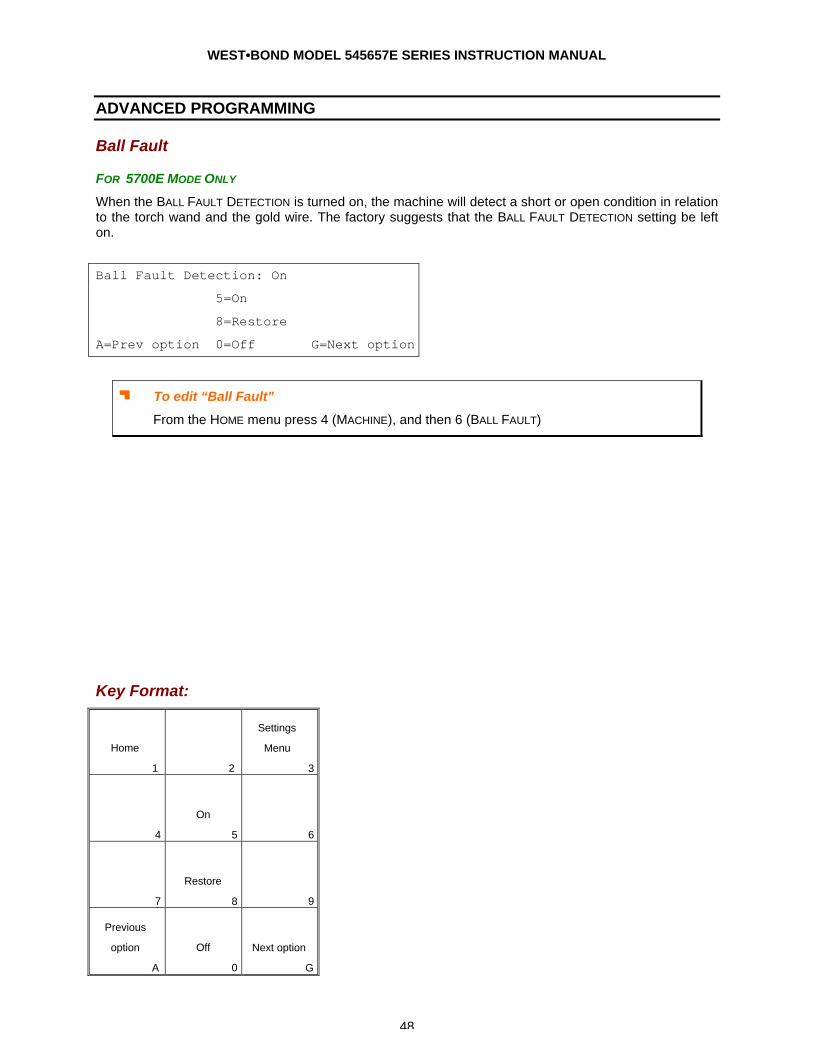
WEST•BOND MODEL 545657E SERIES INSTRUCTION MANUAL
48
ADVANCED PROGRAMMING
Ball Fault
FOR 5700E MODE ONLY
When the BALL FAULT DETECTION is turned on, the machine will detect a short or open condition in relation to the torch wand and the gold wire. The factory suggests that the BALL FAULT DETECTION setting be left on.
Ball Fault Detection: On
5=On
8=Restore
A=Prev option 0=Off G=Next option
J To edit “Ball Fault”
From the HOME menu press 4 (MACHINE), and then 6 (BALL FAULT)
Key Format:
Home
1
2
Settings
Menu
3
4
On
5
6
7
Restore
8
9
Previous
option
A
Off
0
Next option
G
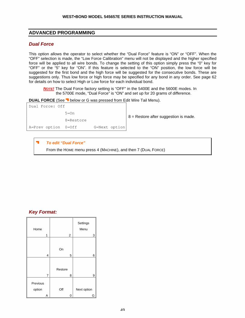
WEST•BOND MODEL 545657E SERIES INSTRUCTION MANUAL
49
ADVANCED PROGRAMMING
Dual Force
This option allows the operator to select whether the “Dual Force” feature is “ON” or “OFF”. When the “OFF” selection is made, the “Low Force Calibration” menu will not be displayed and the higher specified force will be applied to all wire bonds. To change the setting of this option simply press the “0” key for “OFF” or the “5” key for “ON”. If this feature is selected to the “ON” position, the low force will be suggested for the first bond and the high force will be suggested for the consecutive bonds. These are suggestions only. Thus low force or high force may be specified for any bond in any order. See page 62 for details on how to select High or Low force for each individual bond.
NOTE! The Dual Force factory setting is “OFF” in the 5400E and the 5600E modes. In the 5700E mode, “Dual Force” is “ON” and set up for 20 grams of difference.
DUAL FORCE (See J below or G was pressed from Edit Wire Tail Menu). Dual Force: Off
5=On
8=Restore
A=Prev option 0=Off G=Next option
8 = Restore after suggestion is made.
J To edit “Dual Force”
From the HOME menu press 4 (MACHINE), and then 7 (DUAL FORCE)
Key Format:
Home
1
2
Settings
Menu
3
4
On
5
6
7
Restore
8
9
Previous
option
A
Off
0
Next option
G
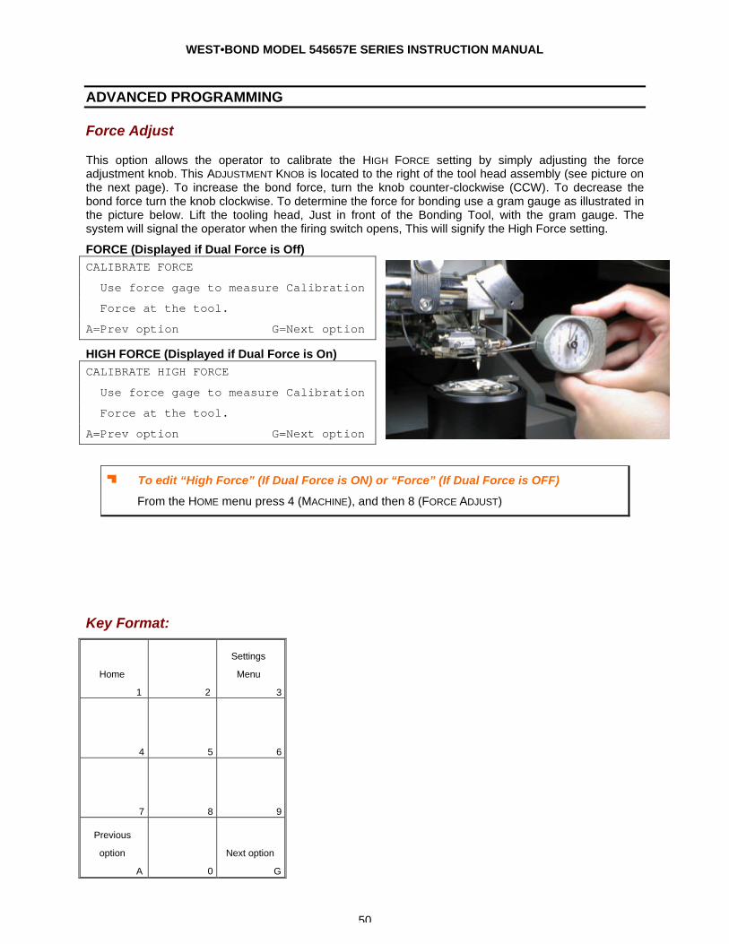
WEST•BOND MODEL 545657E SERIES INSTRUCTION MANUAL
50
ADVANCED PROGRAMMING
Force Adjust
This option allows the operator to calibrate the HIGH FORCE setting by simply adjusting the force adjustment knob. This ADJUSTMENT KNOB is located to the right of the tool head assembly (see picture on the next page). To increase the bond force, turn the knob counter-clockwise (CCW). To decrease the bond force turn the knob clockwise. To determine the force for bonding use a gram gauge as illustrated in the picture below. Lift the tooling head, Just in front of the Bonding Tool, with the gram gauge. The system will signal the operator when the firing switch opens, This will signify the High Force setting.
FORCE (Displayed if Dual Force is Off) CALIBRATE FORCE
Use force gage to measure Calibration
Force at the tool.
A=Prev option G=Next option
HIGH FORCE (Displayed if Dual Force is On) CALIBRATE HIGH FORCE
Use force gage to measure Calibration
Force at the tool.
A=Prev option G=Next option
J To edit “High Force” (If Dual Force is ON) or “Force” (If Dual Force is OFF)
From the HOME menu press 4 (MACHINE), and then 8 (FORCE ADJUST)
Key Format:
Home
1
2
Settings
Menu
3
4
5
6
7
8
9
Previous
option
A
0
Next option
G
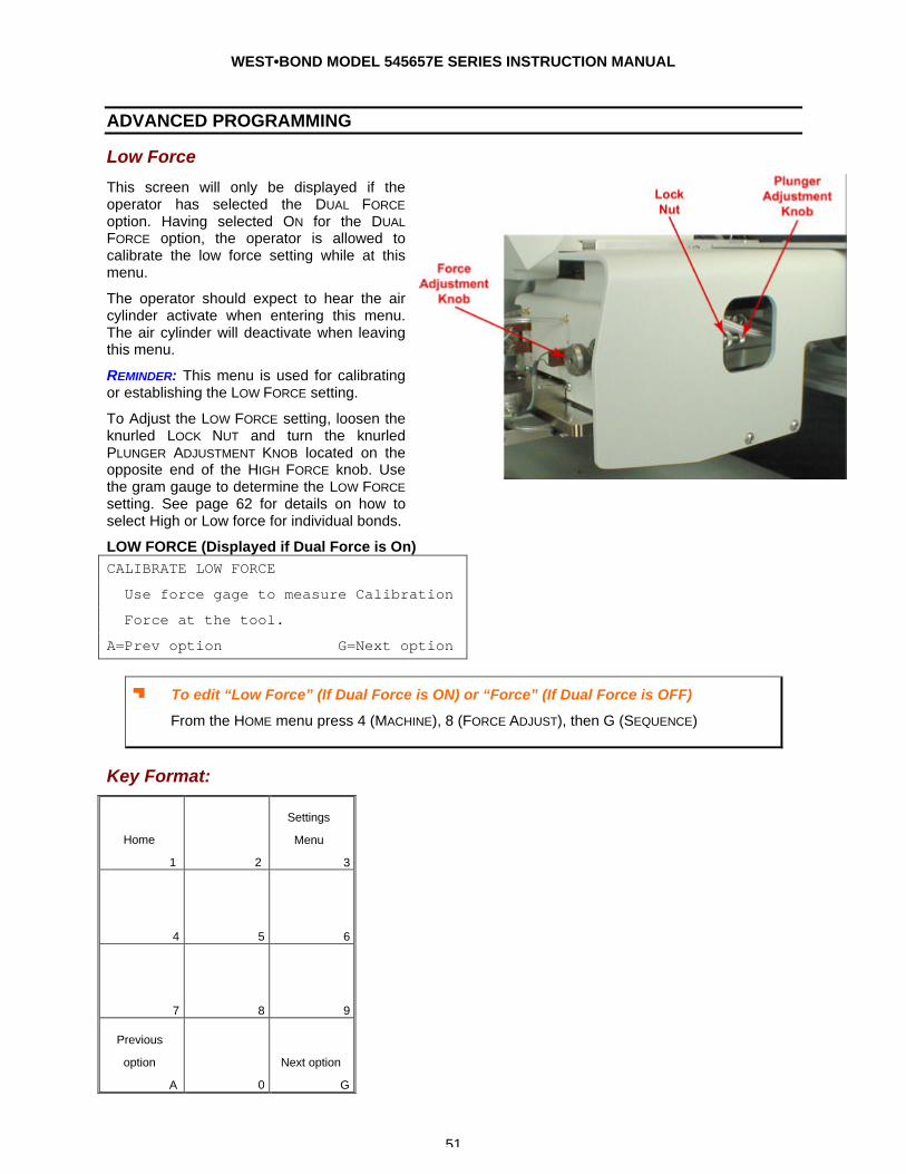
WEST•BOND MODEL 545657E SERIES INSTRUCTION MANUAL
51
ADVANCED PROGRAMMING
Low Force
This screen will only be displayed if the operator has selected the DUAL FORCE option. Having selected ON for the DUAL FORCE option, the operator is allowed to calibrate the low force setting while at this menu.
The operator should expect to hear the air cylinder activate when entering this menu. The air cylinder will deactivate when leaving this menu.
REMINDER: This menu is used for calibrating or establishing the LOW FORCE setting.
To Adjust the LOW FORCE setting, loosen the knurled LOCK NUT and turn the knurled PLUNGER ADJUSTMENT KNOB located on the opposite end of the HIGH FORCE knob. Use the gram gauge to determine the LOW FORCE setting. See page 62 for details on how to select High or Low force for individual bonds.
LOW FORCE (Displayed if Dual Force is On) CALIBRATE LOW FORCE
Use force gage to measure Calibration
Force at the tool.
A=Prev option G=Next option
J To edit “Low Force” (If Dual Force is ON) or “Force” (If Dual Force is OFF)
From the HOME menu press 4 (MACHINE), 8 (FORCE ADJUST), then G (SEQUENCE)
Key Format:
Home
1
2
Settings
Menu
3
4
5
6
7
8
9
Previous
option
A
0
Next option
G

WEST•BOND MODEL 545657E SERIES INSTRUCTION MANUAL
52
ADVANCED PROGRAMMING
Restart Height / Torch Elevation
RESTART HEIGHT ELEVATION Restart Height Elevation: 1400 from top
4=Key in 5=Up
7=Work height 8=Restore
A=Prev option 0=Down G=Next option
800 is the suggested elevation for the 5700E
Programmed in Z Motor half-steps from home
7=Work Height Verification (see page 23)
Key Format:
Home
1
2
Settings
Menu
3
Key in
4
↑
Up
5
6
Work height
7
Restore
8
9
Previous
option
A
↓
Down
0
Next option
G
J To edit “Restart Height Elevation”
From the HOME menu press 4 (MACHINE SETTINGS), and then 9 (RESTART HT).

WEST•BOND MODEL 545657E SERIES INSTRUCTION MANUAL
53
ADVANCED PROGRAMMING
Lift Before Pull
FOR 5400E AND 5600E MODES ONLY
To change the selection of this feature press the “5” key for ON or the “0” key for OFF option. The 545657E will wait until the Tooling Head has lifted off the terminating bond site before actuating the pull stroke if this feature is selected to “ON”. The suggested setting is “OFF”. This feature can prove beneficial for those applications in which the terminating bond is made on delicate or sensitive components, or for applications with extremely soft wire.
LIFT BEFORE PULL (Displays this menu if 45° feed tool is in use.) Lift Before Pull: Off
5=On
8=Restore
A=Prev option 0=Off G=Next option
LIFT BEFORE PULL (Displays this menu if 90° feed tool is in use.) Lift Before Pull: 6 (1Z= .0002083”)
4=Key in 5=Up
8=Restore
A=Prev option 0=Down G=Next option
µ To edit “Lift Before Pull”
From the HOME menu press 4 (MACHINE), 0 (MORE OPTIONS), then 4 (LIFT-TO-PULL).
Key Format:
Home
1
2
Settings
Menu
3
4
On
5
6
7
Restore
8
9
Previous
option
A
Off
0
Next option
G
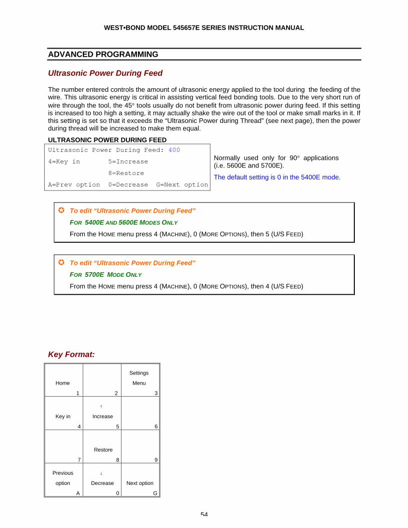
WEST•BOND MODEL 545657E SERIES INSTRUCTION MANUAL
54
ADVANCED PROGRAMMING
Ultrasonic Power During Feed
The number entered controls the amount of ultrasonic energy applied to the tool during the feeding of the wire. This ultrasonic energy is critical in assisting vertical feed bonding tools. Due to the very short run of wire through the tool, the 45° tools usually do not benefit from ultrasonic power during feed. If this setting is increased to too high a setting, it may actually shake the wire out of the tool or make small marks in it. If this setting is set so that it exceeds the “Ultrasonic Power during Thread” (see next page), then the power during thread will be increased to make them equal.
ULTRASONIC POWER DURING FEED Ultrasonic Power During Feed: 400
4=Key in 5=Increase
8=Restore
A=Prev option 0=Decrease G=Next option
Normally used only for 90° applications (i.e. 5600E and 5700E).
The default setting is 0 in the 5400E mode.
µ To edit “Ultrasonic Power During Feed”
FOR 5400E AND 5600E MODES ONLY
From the HOME menu press 4 (MACHINE), 0 (MORE OPTIONS), then 5 (U/S FEED)
µ To edit “Ultrasonic Power During Feed”
FOR 5700E MODE ONLY
From the HOME menu press 4 (MACHINE), 0 (MORE OPTIONS), then 4 (U/S FEED)
Key Format:
Home
1
2
Settings
Menu
3
Key in
4
↑
Increase
5
6
7
Restore
8
9
Previous
option
A
↓
Decrease
0
Next option
G
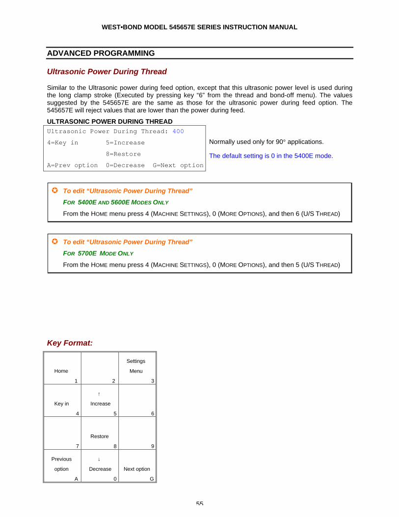
WEST•BOND MODEL 545657E SERIES INSTRUCTION MANUAL
55
ADVANCED PROGRAMMING
Ultrasonic Power During Thread
Similar to the Ultrasonic power during feed option, except that this ultrasonic power level is used during the long clamp stroke (Executed by pressing key “6” from the thread and bond-off menu). The values suggested by the 545657E are the same as those for the ultrasonic power during feed option. The 545657E will reject values that are lower than the power during feed.
ULTRASONIC POWER DURING THREAD Ultrasonic Power During Thread: 400
4=Key in 5=Increase
8=Restore
A=Prev option 0=Decrease G=Next option
Normally used only for 90° applications.
The default setting is 0 in the 5400E mode.
µ To edit “Ultrasonic Power During Thread”
FOR 5400E AND 5600E MODES ONLY
From the HOME menu press 4 (MACHINE SETTINGS), 0 (MORE OPTIONS), and then 6 (U/S THREAD)
µ To edit “Ultrasonic Power During Thread”
FOR 5700E MODE ONLY
From the HOME menu press 4 (MACHINE SETTINGS), 0 (MORE OPTIONS), and then 5 (U/S THREAD)
Key Format:
Home
1
2
Settings
Menu
3
Key in
4
↑
Increase
5
6
7
Restore
8
9
Previous
option
A
↓
Decrease
0
Next option
G
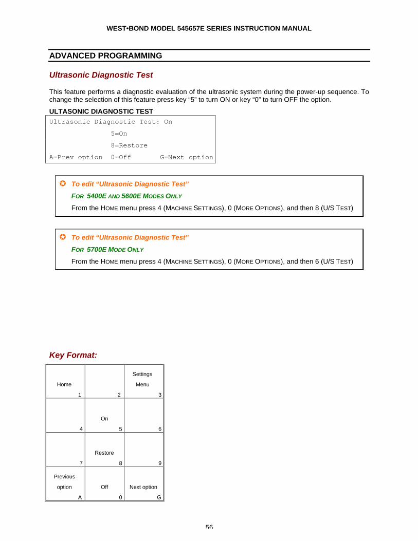
WEST•BOND MODEL 545657E SERIES INSTRUCTION MANUAL
56
ADVANCED PROGRAMMING
Ultrasonic Diagnostic Test
This feature performs a diagnostic evaluation of the ultrasonic system during the power-up sequence. To change the selection of this feature press key “5” to turn ON or key “0” to turn OFF the option.
ULTASONIC DIAGNOSTIC TEST Ultrasonic Diagnostic Test: On
5=On
8=Restore
A=Prev option 0=Off G=Next option
µ To edit “Ultrasonic Diagnostic Test”
FOR 5400E AND 5600E MODES ONLY
From the HOME menu press 4 (MACHINE SETTINGS), 0 (MORE OPTIONS), and then 8 (U/S TEST)
µ To edit “Ultrasonic Diagnostic Test”
FOR 5700E MODE ONLY
From the HOME menu press 4 (MACHINE SETTINGS), 0 (MORE OPTIONS), and then 6 (U/S TEST)
Key Format:
Home
1
2
Settings
Menu
3
4
On
5
6
7
Restore
8
9
Previous
option
A
Off
0
Next option
G
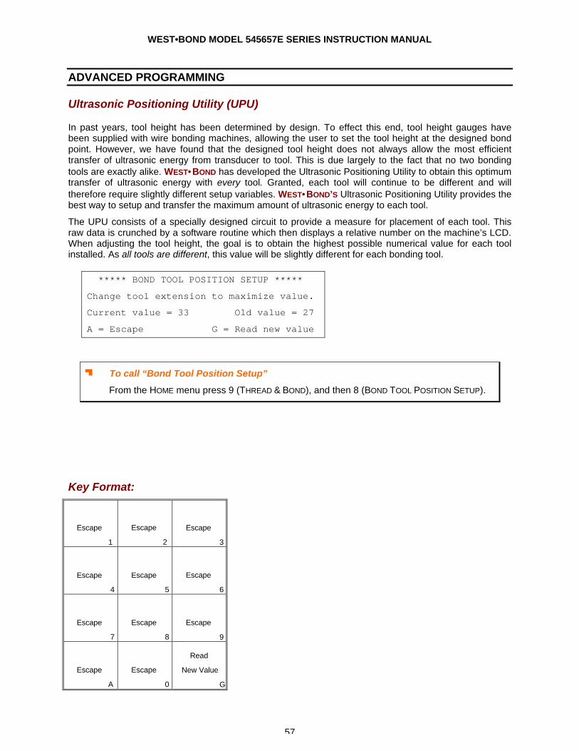
WEST•BOND MODEL 545657E SERIES INSTRUCTION MANUAL
57
ADVANCED PROGRAMMING
Ultrasonic Positioning Utility (UPU)
In past years, tool height has been determined by design. To effect this end, tool height gauges have been supplied with wire bonding machines, allowing the user to set the tool height at the designed bond point. However, we have found that the designed tool height does not always allow the most efficient transfer of ultrasonic energy from transducer to tool. This is due largely to the fact that no two bonding tools are exactly alike. WEST•BOND has developed the Ultrasonic Positioning Utility to obtain this optimum transfer of ultrasonic energy with every tool. Granted, each tool will continue to be different and will therefore require slightly different setup variables. WEST•BOND’S Ultrasonic Positioning Utility provides the best way to setup and transfer the maximum amount of ultrasonic energy to each tool.
The UPU consists of a specially designed circuit to provide a measure for placement of each tool. This raw data is crunched by a software routine which then displays a relative number on the machine’s LCD. When adjusting the tool height, the goal is to obtain the highest possible numerical value for each tool installed. As all tools are different, this value will be slightly different for each bonding tool.
J To call “Bond Tool Position Setup”
From the HOME menu press 9 (THREAD & BOND), and then 8 (BOND TOOL POSITION SETUP).
Key Format:
Escape
1
Escape
2
Escape
3
Escape
4
Escape
5
Escape
6
Escape
7
Escape
8
Escape
9
Escape
A
Escape
0
Read
New Value
G
***** BOND TOOL POSITION SETUP *****
Change tool extension to maximize value.
Current value = 33 Old value = 27
A = Escape G = Read new value
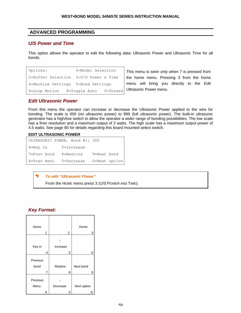
WEST•BOND MODEL 545657E SERIES INSTRUCTION MANUAL
58
ADVANCED PROGRAMMING
U/S Power and Time
This option allows the operator to edit the following data: Ultrasonic Power and Ultrasonic Time for all bonds.
Options: 0=Model Selection
2=Buffer Selection 3=U/S Power & Time
4=Machine Settings 5=Bond Settings
6=Loop Motion 8=Toggle Auto 9=Thread
This menu is seen only when 7 is pressed from the home menu. Pressing 3 from the home menu will bring you directly to the Edit Ultrasonic Power menu.
Edit Ultrasonic Power
From this menu the operator can increase or decrease the Ultrasonic Power applied to the wire for bonding. The scale is 000 (no ultrasonic power) to 999 (full ultrasonic power). The built-in ultrasonic generator has a high/low switch to allow the operator a wider range of bonding possibilities. The low scale has a finer resolution and a maximum output of 2 watts. The high scale has a maximum output power of 4.5 watts. See page 85 for details regarding this board mounted select switch.
EDIT ULTRASONIC POWER ULTRASONIC POWER, Bond #1: 300
4=Key in 5=Increase
7=Prev bond 8=Restore 9=Next bond
A=Prev menu 0=Decrease G=Next option
J To edit “Ultrasonic Power”
From the HOME menu press 3 (U/S POWER AND TIME).
Key Format:
Home
1
2
Home
3
Key in
4
↑
Increase
5
6
Previous
bond
7
Restore
8
Next bond
9
Previous
Menu
A
↓
Decrease
0
Next option
G
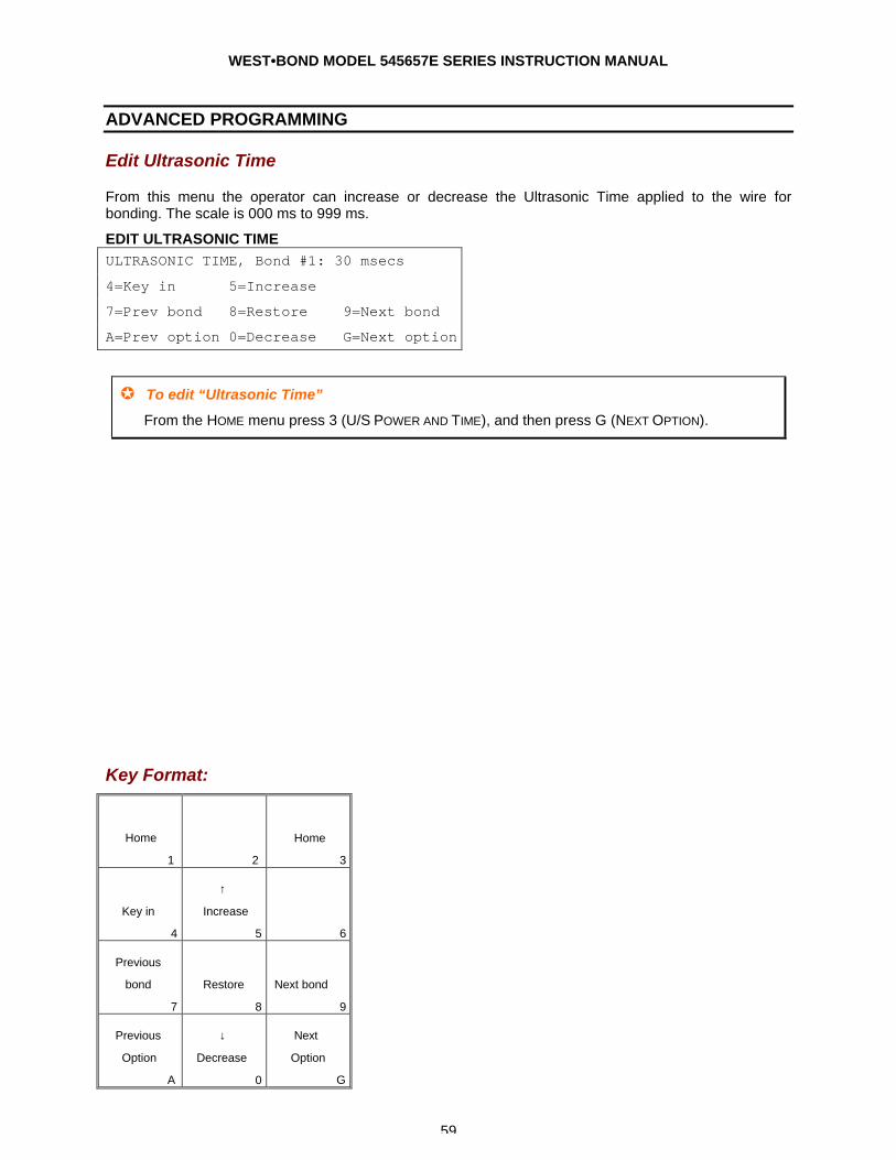
WEST•BOND MODEL 545657E SERIES INSTRUCTION MANUAL
59
ADVANCED PROGRAMMING
Edit Ultrasonic Time
From this menu the operator can increase or decrease the Ultrasonic Time applied to the wire for bonding. The scale is 000 ms to 999 ms.
EDIT ULTRASONIC TIME ULTRASONIC TIME, Bond #1: 30 msecs
4=Key in 5=Increase
7=Prev bond 8=Restore 9=Next bond
A=Prev option 0=Decrease G=Next option
µ To edit “Ultrasonic Time”
From the HOME menu press 3 (U/S POWER AND TIME), and then press G (NEXT OPTION).
Key Format:
Home
1
2
Home
3
Key in
4
↑
Increase
5
6
Previous
bond
7
Restore
8
Next bond
9
Previous
Option
A
↓
Decrease
0
Next
Option
G
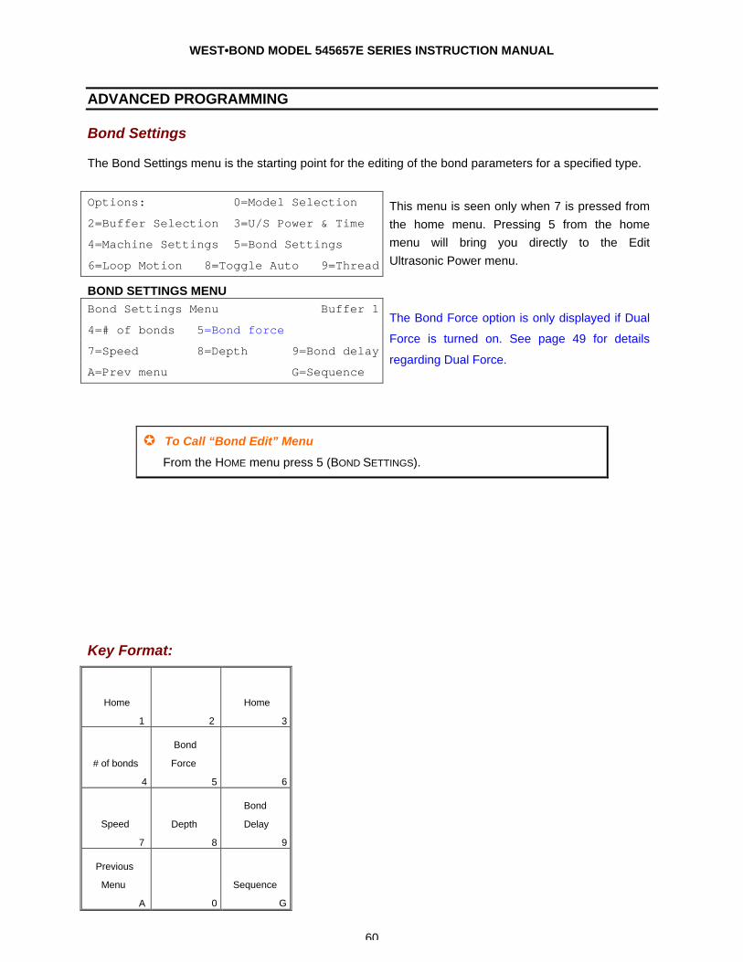
WEST•BOND MODEL 545657E SERIES INSTRUCTION MANUAL
60
ADVANCED PROGRAMMING
Bond Settings
The Bond Settings menu is the starting point for the editing of the bond parameters for a specified type.
Options: 0=Model Selection
2=Buffer Selection 3=U/S Power & Time
4=Machine Settings 5=Bond Settings
6=Loop Motion 8=Toggle Auto 9=Thread
This menu is seen only when 7 is pressed from the home menu. Pressing 5 from the home menu will bring you directly to the Edit Ultrasonic Power menu.
BOND SETTINGS MENU Bond Settings Menu Buffer 1
4=# of bonds 5=Bond force
7=Speed 8=Depth 9=Bond delay
A=Prev menu G=Sequence
The Bond Force option is only displayed if Dual
Force is turned on. See page 49 for details
regarding Dual Force.
µ To Call “Bond Edit” Menu
From the HOME menu press 5 (BOND SETTINGS).
Key Format:
Home
1
2
Home
3
# of bonds
4
Bond
Force
5
6
Speed
7
Depth
8
Bond
Delay
9
Previous
Menu
A
0
Sequence
G
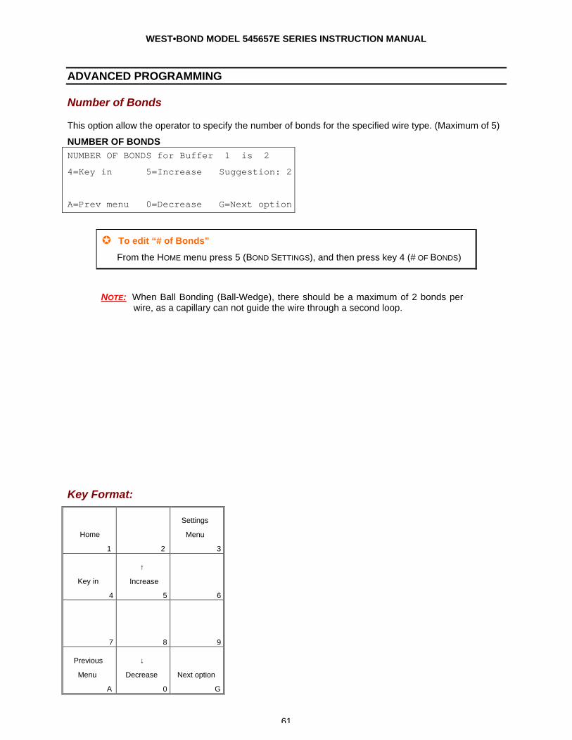
WEST•BOND MODEL 545657E SERIES INSTRUCTION MANUAL
61
ADVANCED PROGRAMMING
Number of Bonds
This option allow the operator to specify the number of bonds for the specified wire type. (Maximum of 5)
NUMBER OF BONDS NUMBER OF BONDS for Buffer 1 is 2
4=Key in 5=Increase Suggestion: 2
A=Prev menu 0=Decrease G=Next option
µ To edit “# of Bonds”
From the HOME menu press 5 (BOND SETTINGS), and then press key 4 (# OF BONDS)
NOTE: When Ball Bonding (Ball-Wedge), there should be a maximum of 2 bonds per wire, as a capillary can not guide the wire through a second loop.
Key Format:
Home
1
2
Settings
Menu
3
Key in
4
↑
Increase
5
6
7
8
9
Previous
Menu
A
↓
Decrease
0
Next option
G
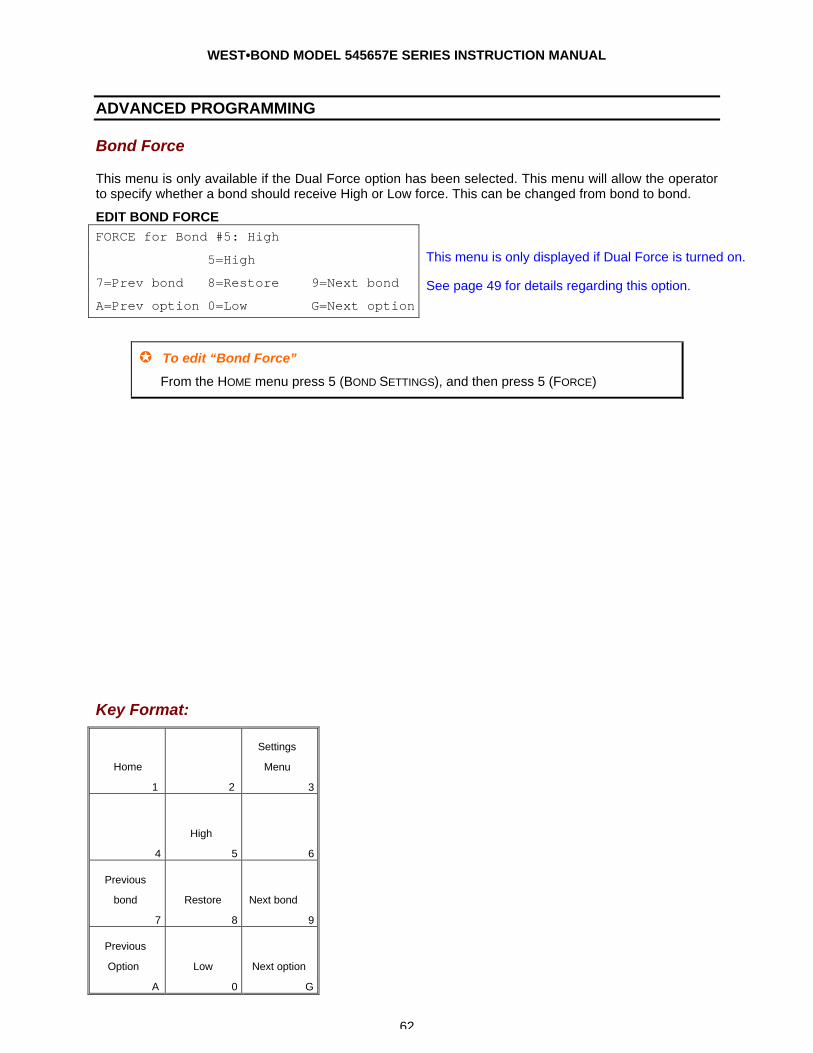
WEST•BOND MODEL 545657E SERIES INSTRUCTION MANUAL
62
ADVANCED PROGRAMMING
Bond Force
This menu is only available if the Dual Force option has been selected. This menu will allow the operator to specify whether a bond should receive High or Low force. This can be changed from bond to bond.
EDIT BOND FORCE FORCE for Bond #5: High
5=High
7=Prev bond 8=Restore 9=Next bond
A=Prev option 0=Low G=Next option
This menu is only displayed if Dual Force is turned on.
See page 49 for details regarding this option.
µ To edit “Bond Force”
From the HOME menu press 5 (BOND SETTINGS), and then press 5 (FORCE)
Key Format:
Home
1
2
Settings
Menu
3
4
High
5
6
Previous
bond
7
Restore
8
Next bond
9
Previous
Option
A
Low
0
Next option
G
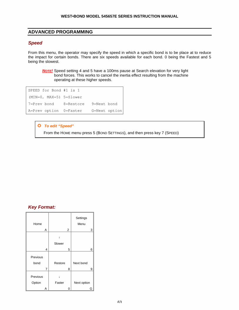
WEST•BOND MODEL 545657E SERIES INSTRUCTION MANUAL
63
ADVANCED PROGRAMMING
Speed
From this menu, the operator may specify the speed in which a specific bond is to be place at to reduce the impact for certain bonds. There are six speeds available for each bond. 0 being the Fastest and 5 being the slowest.
NOTE! Speed setting 4 and 5 have a 100ms pause at Search elevation for very light bond forces. This works to cancel the inertia effect resulting from the machine operating at these higher speeds.
SPEED for Bond #1 is 1
(MIN=0, MAX=5) 5=Slower
7=Prev bond 8=Restore 9=Next bond
A=Prev option 0=Faster G=Next option
µ To edit “Speed”
From the HOME menu press 5 (BOND SETTINGS), and then press key 7 (SPEED)
Key Format:
Home
A
2
Settings
Menu
3
4
↑
Slower
5
6
Previous
bond
7
Restore
8
Next bond
9
Previous
Option
A
↓
Faster
0
Next option
G
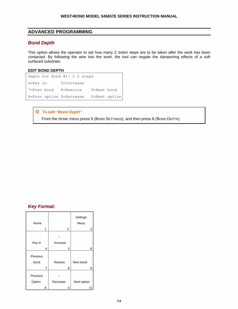
WEST•BOND MODEL 545657E SERIES INSTRUCTION MANUAL
64
ADVANCED PROGRAMMING
Bond Depth
This option allows the operator to set how many Z motor steps are to be taken after the work has been contacted. By following the wire into the work, the tool can negate the dampening effects of a soft surfaced substrate.
EDIT BOND DEPTH Depth for Bond #1: 2 Z steps
4=Key in 5=Increase
7=Prev bond 8=Restore 9=Next bond
A=Prev option 0=Decrease G=Next option
µ To edit “Bond Depth”
From the HOME menu press 5 (BOND SETTINGS), and then press 8 (BOND DEPTH)
Key Format:
Home
1
2
Settings
Menu
3
Key in
4
↑
Increase
5
6
Previous
bond
7
Restore
8
Next bond
9
Previous
Option
A
↓
Decrease
0
Next option
G
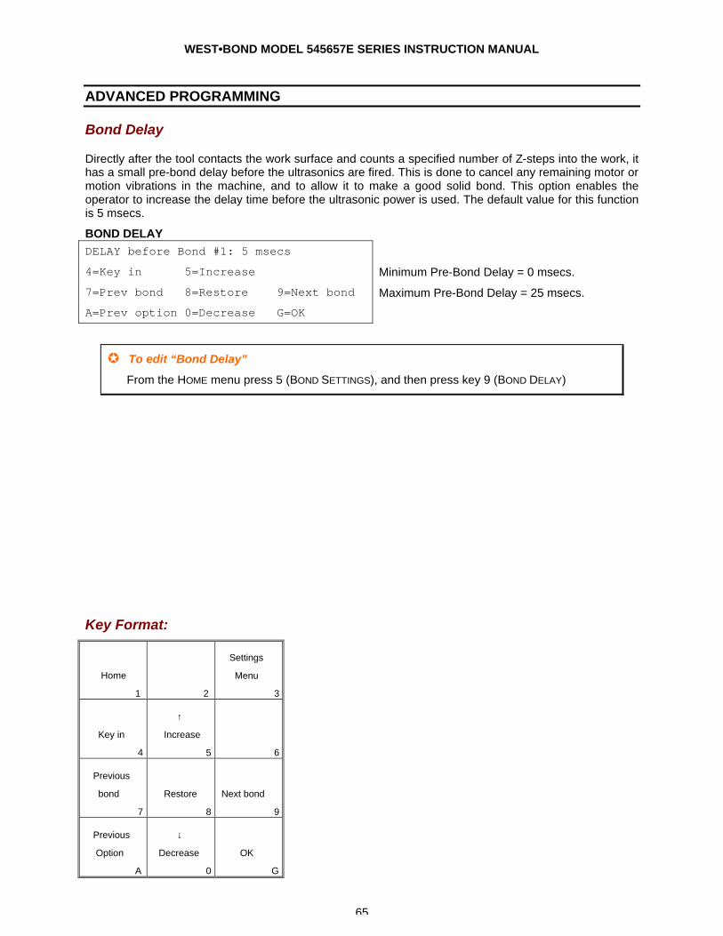
WEST•BOND MODEL 545657E SERIES INSTRUCTION MANUAL
65
ADVANCED PROGRAMMING
Bond Delay
Directly after the tool contacts the work surface and counts a specified number of Z-steps into the work, it has a small pre-bond delay before the ultrasonics are fired. This is done to cancel any remaining motor or motion vibrations in the machine, and to allow it to make a good solid bond. This option enables the operator to increase the delay time before the ultrasonic power is used. The default value for this function is 5 msecs.
BOND DELAY DELAY before Bond #1: 5 msecs
4=Key in 5=Increase
7=Prev bond 8=Restore 9=Next bond
A=Prev option 0=Decrease G=OK
Minimum Pre-Bond Delay = 0 msecs.
Maximum Pre-Bond Delay = 25 msecs.
µ To edit “Bond Delay”
From the HOME menu press 5 (BOND SETTINGS), and then press key 9 (BOND DELAY)
Key Format:
Home
1
2
Settings
Menu
3
Key in
4
↑
Increase
5
6
Previous
bond
7
Restore
8
Next bond
9
Previous
Option
A
↓
Decrease
0
OK
G
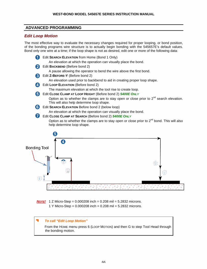
WEST•BOND MODEL 545657E SERIES INSTRUCTION MANUAL
66
ADVANCED PROGRAMMING
Edit Loop Motion
The most effective way to evaluate the necessary changes required for proper looping, or bond position, of the bonding programs wire structure is to actually begin bonding with the 545657E’s default values. Bond only one wire at a time; if the loop shape is not as desired, edit one or more of the following data:
1. Edit SEARCH ELEVATION from Home (Bond 1 Only) An elevation at which the operation can visually place the bond.
2. Edit BACKBEND (Before bond 2) A pause allowing the operator to bend the wire above the first bond.
3. Edit Z-BEFORE-Y (Before bond 2) An elevation used prior to backbend to aid in creating proper loop shape.
4. Edit LOOP ELEVATION (Before bond 2) The maximum elevation at which the tool rise to create loop.
5. Edit CLOSE CLAMP AT LOOP HEIGHT (Before bond 2) 5400E ONLY Option as to whether the clamps are to stay open or close prior to 2nd search elevation. This will also help determine loop shape.
6. Edit SEARCH ELEVATION Before bond 2 (below loop) An elevation at which the operation can visually place the bond.
7. Edit CLOSE CLAMP AT SEARCH (Before bond 2) 5400E ONLY Option as to whether the clamps are to stay open or close prior to 2nd bond. This will also help determine loop shape.
NOTE! 1 Z Micro-Step = 0.000208 inch = 0.208 mil = 5.2832 microns. 1 Y Micro-Step = 0.000208 inch = 0.208 mil = 5.2832 microns.
J To call “Edit Loop Motion”
From the HOME menu press 6 (LOOP MOTION) and then G to step Tool Head through the bonding motion.
WEST•BOND MODEL 545657E SERIES INSTRUCTION MANUAL
67
TROUBLESHOOTING
Poor Bond Quality
The following are possible causes for poor bond quality. Poor bond quality could either mean a bond does not meet visual criteria, does not adhere to bonding surface, or produce unacceptable bond pull tests.
There are six key areas where the problem may be found causing poor bond quality. 1. Tool
a. Position b. Clamping Force, Set Screw Torque c. Characteristics / Geometry of Tool / Condition of Tool d. Condition of Bonding Surface e. Bonding Surface Area
2. Workholder a. Temperature / Stability b. Heat Transfer c. Rigidity d. Environment e. Positioning Accuracy
3. Wire a. Size b. Type c. Breaking Load d. Elongation e. Age / Condition / Quality f. Uniformity / Twist / Curl
4. Bonded Wire a. Wire / Tool Interface b. Optimized Bonding Schedule c. Location d. Wire Curl e. Intermetallics f. Time / Temperature Environment g. Bond Interface Condition h. Ergonomics
5. Bonding Surface a. Metal Purity b. Metal Uniformity c. Metal Thickness d. Surface Contamination e. Surface Texture f. Metal Bondability, Initial and after Time/Temp.
6. Bonder a. Mechanical / Electrical Calibration of Machine b. Optimized Bonding Schedule
i. Ultrasonic Energy ii. Ultrasonic Time iii. Bond Pressure iv. Temperature
c. Operator Skill d. Ergonomics
WEST•BOND MODEL 545657E SERIES INSTRUCTION MANUAL
68
TROUBLESHOOTING
Inconsistent Looping
The 545657E’s 45° Tooling Head configuration offers excellent looping control. The bonding wire’s natural characteristics and tendencies are to resist and sometimes refuse to bend or form a loop in a desired fashion. Please refer to the following list of suggested considerations in solving any problems you may encounter with loop control.
1. “Loop Height” Profile is too low.
2. Insufficient “Backbend” during looping.
3. Insufficient “Z-Before-Y” during looping.
4. Excessive “Loop Pull” during looping.
5. Clamps remain open while descending to the 2nd Bond.
6. Bonding tool feed through hole is excessive for wire diameter.
7. Bonding tool feed through hole angle is not applicable for this application. (Generally, a 45° feed through hole is recommended.)
8. Clamps are not centered properly with Bonding Tool.
9. Force Calibration need to be verified.
10. Using of aged or damaged wire.
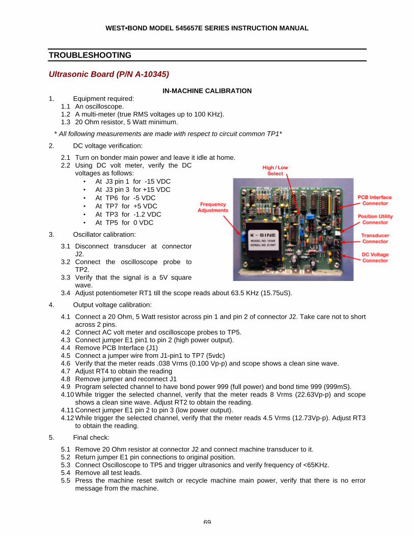
WEST•BOND MODEL 545657E SERIES INSTRUCTION MANUAL
69
TROUBLESHOOTING
Ultrasonic Board (P/N A-10345)
IN-MACHINE CALIBRATION 1. Equipment required:
1.1 An oscilloscope. 1.2 A multi-meter (true RMS voltages up to 100 KHz). 1.3 20 Ohm resistor, 5 Watt minimum.
* All following measurements are made with respect to circuit common TP1*
2. DC voltage verification:
2.1 Turn on bonder main power and leave it idle at home. 2.2 Using DC volt meter, verify the DC
voltages as follows: • At J3 pin 1 for -15 VDC • At J3 pin 3 for +15 VDC • At TP6 for -5 VDC • At TP7 for +5 VDC • At TP3 for -1.2 VDC • At TP5 for 0 VDC
3. Oscillator calibration:
3.1 Disconnect transducer at connector J2.
3.2 Connect the oscilloscope probe to TP2.
3.3 Verify that the signal is a 5V square wave.
3.4 Adjust potentiometer RT1 till the scope reads about 63.5 KHz (15.75uS).
4. Output voltage calibration:
4.1 Connect a 20 Ohm, 5 Watt resistor across pin 1 and pin 2 of connector J2. Take care not to short across 2 pins.
4.2 Connect AC volt meter and oscilloscope probes to TP5. 4.3 Connect jumper E1 pin1 to pin 2 (high power output). 4.4 Remove PCB Interface (J1) 4.5 Connect a jumper wire from J1-pin1 to TP7 (5vdc) 4.6 Verify that the meter reads .038 Vrms (0.100 Vp-p) and scope shows a clean sine wave. 4.7 Adjust RT4 to obtain the reading 4.8 Remove jumper and reconnect J1 4.9 Program selected channel to have bond power 999 (full power) and bond time 999 (999mS). 4.10 While trigger the selected channel, verify that the meter reads 8 Vrms (22.63Vp-p) and scope
shows a clean sine wave. Adjust RT2 to obtain the reading. 4.11 Connect jumper E1 pin 2 to pin 3 (low power output). 4.12 While trigger the selected channel, verify that the meter reads 4.5 Vrms (12.73Vp-p). Adjust RT3
to obtain the reading.
5. Final check:
5.1 Remove 20 Ohm resistor at connector J2 and connect machine transducer to it. 5.2 Return jumper E1 pin connections to original position. 5.3 Connect Oscilloscope to TP5 and trigger ultrasonics and verify frequency of <65KHz. 5.4 Remove all test leads. 5.5 Press the machine reset switch or recycle machine main power, verify that there is no error
message from the machine.
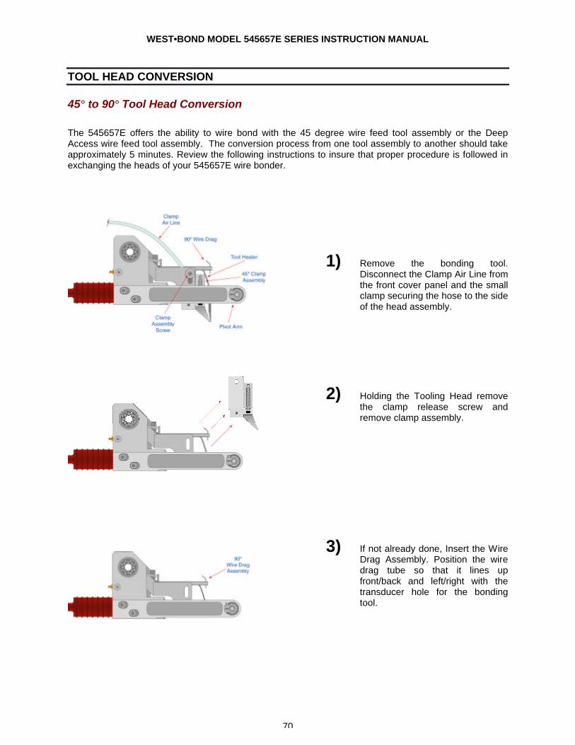
WEST•BOND MODEL 545657E SERIES INSTRUCTION MANUAL
70
TOOL HEAD CONVERSION
45° to 90° Tool Head Conversion
The 545657E offers the ability to wire bond with the 45 degree wire feed tool assembly or the Deep Access wire feed tool assembly. The conversion process from one tool assembly to another should take approximately 5 minutes. Review the following instructions to insure that proper procedure is followed in exchanging the heads of your 545657E wire bonder.
1) Remove the bonding tool. Disconnect the Clamp Air Line from the front cover panel and the small clamp securing the hose to the side of the head assembly.
2) Holding the Tooling Head remove the clamp release screw and remove clamp assembly.
3) If not already done, Insert the Wire
Drag Assembly. Position the wire drag tube so that it lines up front/back and left/right with the transducer hole for the bonding tool.
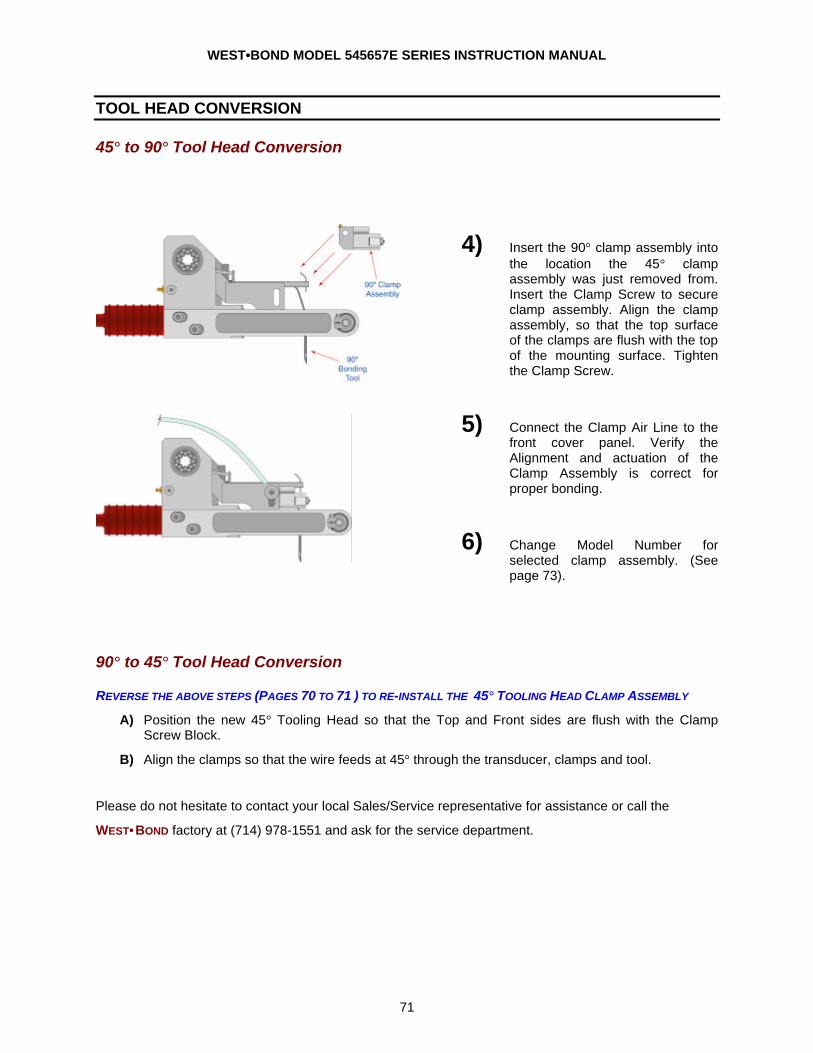
WEST•BOND MODEL 545657E SERIES INSTRUCTION MANUAL
71
TOOL HEAD CONVERSION
45° to 90° Tool Head Conversion
4) Insert the 90° clamp assembly into the location the 45° clamp assembly was just removed from. Insert the Clamp Screw to secure clamp assembly. Align the clamp assembly, so that the top surface of the clamps are flush with the top of the mounting surface. Tighten the Clamp Screw.
5) Connect the Clamp Air Line to the front cover panel. Verify the Alignment and actuation of the Clamp Assembly is correct for proper bonding.
6) Change Model Number for selected clamp assembly. (See page 73).
90° to 45° Tool Head Conversion
REVERSE THE ABOVE STEPS (PAGES 70 TO 71 ) TO RE-INSTALL THE 45° TOOLING HEAD CLAMP ASSEMBLY
A) Position the new 45° Tooling Head so that the Top and Front sides are flush with the Clamp Screw Block.
B) Align the clamps so that the wire feeds at 45° through the transducer, clamps and tool.
Please do not hesitate to contact your local Sales/Service representative for assistance or call the
WEST•BOND factory at (714) 978-1551 and ask for the service department.
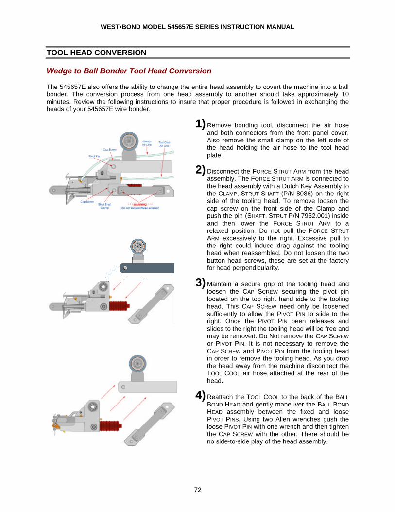
WEST•BOND MODEL 545657E SERIES INSTRUCTION MANUAL
72
TOOL HEAD CONVERSION
Wedge to Ball Bonder Tool Head Conversion
The 545657E also offers the ability to change the entire head assembly to covert the machine into a ball bonder. The conversion process from one head assembly to another should take approximately 10 minutes. Review the following instructions to insure that proper procedure is followed in exchanging the heads of your 545657E wire bonder.
1) Remove bonding tool, disconnect the air hose and both connectors from the front panel cover. Also remove the small clamp on the left side of the head holding the air hose to the tool head plate.
2) Disconnect the FORCE STRUT ARM from the head assembly. The FORCE STRUT ARM is connected to the head assembly with a Dutch Key Assembly to the CLAMP, STRUT SHAFT (P/N 8086) on the right side of the tooling head. To remove loosen the cap screw on the front side of the Clamp and push the pin (SHAFT, STRUT P/N 7952.001) inside and then lower the FORCE STRUT ARM to a relaxed position. Do not pull the FORCE STRUT ARM excessively to the right. Excessive pull to the right could induce drag against the tooling head when reassembled. Do not loosen the two button head screws, these are set at the factory for head perpendicularity.
3) Maintain a secure grip of the tooling head and loosen the CAP SCREW securing the pivot pin located on the top right hand side to the tooling head. This CAP SCREW need only be loosened sufficiently to allow the PIVOT PIN to slide to the right. Once the PIVOT PIN been releases and slides to the right the tooling head will be free and may be removed. Do Not remove the CAP SCREW or PIVOT PIN. It is not necessary to remove the CAP SCREW and PIVOT PIN from the tooling head in order to remove the tooling head. As you drop the head away from the machine disconnect the TOOL COOL air hose attached at the rear of the head.
4) Reattach the TOOL COOL to the back of the BALL BOND HEAD and gently maneuver the BALL BOND HEAD assembly between the fixed and loose PIVOT PINS. Using two Allen wrenches push the loose PIVOT PIN with one wrench and then tighten the CAP SCREW with the other. There should be no side-to-side play of the head assembly.
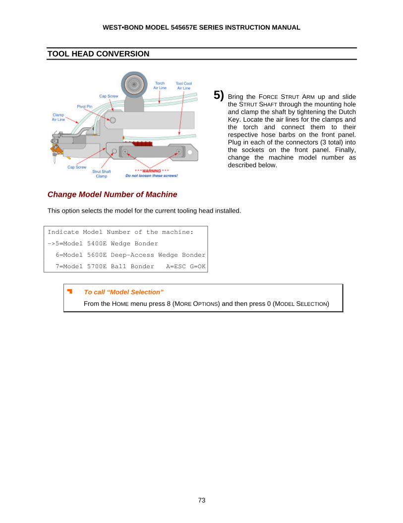
WEST•BOND MODEL 545657E SERIES INSTRUCTION MANUAL
73
TOOL HEAD CONVERSION
5) Bring the FORCE STRUT ARM up and slide the STRUT SHAFT through the mounting hole and clamp the shaft by tightening the Dutch Key. Locate the air lines for the clamps and the torch and connect them to their respective hose barbs on the front panel. Plug in each of the connectors (3 total) into the sockets on the front panel. Finally, change the machine model number as described below.
Change Model Number of Machine
This option selects the model for the current tooling head installed.
Indicate Model Number of the machine:
->5=Model 5400E Wedge Bonder
6=Model 5600E Deep-Access Wedge Bonder
7=Model 5700E Ball Bonder A=ESC G=OK
J To call “Model Selection”
From the HOME menu press 8 (MORE OPTIONS) and then press 0 (MODEL SELECTION)
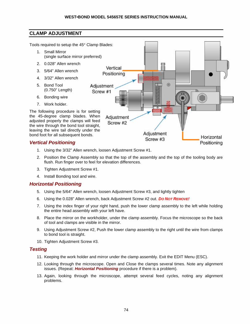
WEST•BOND MODEL 545657E SERIES INSTRUCTION MANUAL
74
CLAMP ADJUSTMENT
Tools required to setup the 45° Clamp Blades:
1. Small Mirror (single surface mirror preferred)
2. 0.028” Allen wrench
3. 5/64” Allen wrench
4. 3/32” Allen wrench
5. Bond Tool (0.750” Length)
6. Bonding wire
7. Work holder.
The following procedure is for setting the 45-degree clamp blades. When adjusted properly the clamps will feed the wire through the bond tool straight, leaving the wire tail directly under the bond foot for all subsequent bonds.
Vertical Positioning 1. Using the 3/32” Allen wrench, loosen Adjustment Screw #1.
2. Position the Clamp Assembly so that the top of the assembly and the top of the tooling body are flush. Run finger over to feel for elevation differences.
3. Tighten Adjustment Screw #1.
4. Install Bonding tool and wire.
Horizontal Positioning 5. Using the 5/64” Allen wrench, loosen Adjustment Screw #3, and lightly tighten
6. Using the 0.028” Allen wrench, back Adjustment Screw #2 out. DO NOT REMOVE!
7. Using the index finger of your right hand, push the lower clamp assembly to the left while holding the entire head assembly with your left have.
8. Place the mirror on the workholder, under the clamp assembly. Focus the microscope so the back of tool and clamps are visible in the mirror.
9. Using Adjustment Screw #2, Push the lower clamp assembly to the right until the wire from clamps to bond tool is straight.
10. Tighten Adjustment Screw #3.
Testing 11. Keeping the work holder and mirror under the clamp assembly. Exit the EDIT Menu (ESC).
12. Looking through the microscope. Open and Close the clamps several times. Note any alignment issues. (Repeat: Horizontal Positioning procedure if there is a problem).
13. Again, looking through the microscope, attempt several feed cycles, noting any alignment problems.
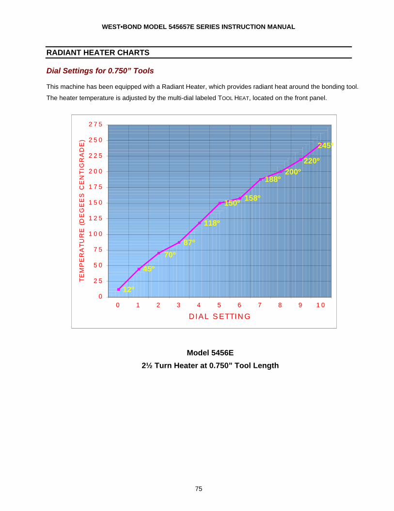
WEST•BOND MODEL 545657E SERIES INSTRUCTION MANUAL
75
RADIANT HEATER CHARTS
Dial Settings for 0.750” Tools
This machine has been equipped with a Radiant Heater, which provides radiant heat around the bonding tool.
The heater temperature is adjusted by the multi-dial labeled TOOL HEAT, located on the front panel.
Model 5456E
2½ Turn Heater at 0.750” Tool Length
12º
45º
87º
118º
150º158º
188º200º
220º
245º
70º
0
25
50
75
100
125
150
175
200
225
250
275
0 1 2 3 4 5 6 7 8 9 10
DIAL SETTING
TEM
PER
ATU
RE (D
EG
EES
CEN
TIG
RAD
E)

WEST•BOND MODEL 545657E SERIES INSTRUCTION MANUAL
76
RADIANT HEATER CHARTS
Dial Settings for 0.625” Tools
This machine has been equipped with a Radiant Heater, which provides radiant heat around the bonding tool.
The heater temperature is adjusted by the multi-dial labeled TOOL HEAT, located on the front panel.
Model 5700E
2½ Turn Heater at 0.625” Tool Length
13º
65º
100º
125º135º
150º
168º183º
192º205º
82º
0
25
50
75
100
125
150
175
200
225
0 1 2 3 4 5 6 7 8 9 10
DIAL SETTING
TEM
PER
ATU
RE (D
EG
EES
CEN
TIG
RAD
E)
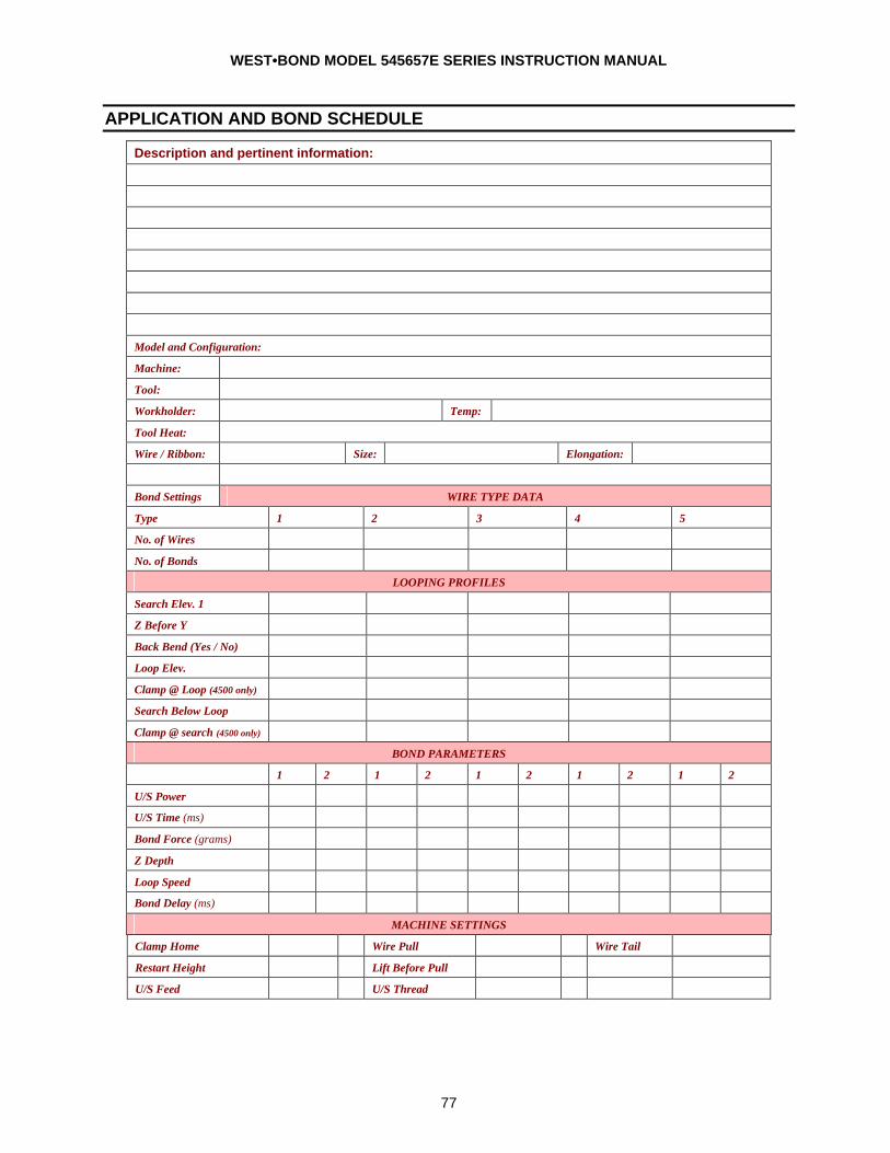
WEST•BOND MODEL 545657E SERIES INSTRUCTION MANUAL
77
APPLICATION AND BOND SCHEDULE
Description and pertinent information:
Model and Configuration:
Machine:
Tool:
Workholder: Temp:
Tool Heat:
Wire / Ribbon: Size: Elongation:
Bond Settings WIRE TYPE DATA
Type 1 2 3 4 5
No. of Wires
No. of Bonds
LOOPING PROFILES
Search Elev. 1
Z Before Y
Back Bend (Yes / No)
Loop Elev.
Clamp @ Loop (4500 only)
Search Below Loop
Clamp @ search (4500 only)
BOND PARAMETERS
1 2 1 2 1 2 1 2 1 2
U/S Power
U/S Time (ms)
Bond Force (grams)
Z Depth
Loop Speed
Bond Delay (ms)
MACHINE SETTINGS
Clamp Home Wire Pull Wire Tail
Restart Height Lift Before Pull
U/S Feed U/S Thread
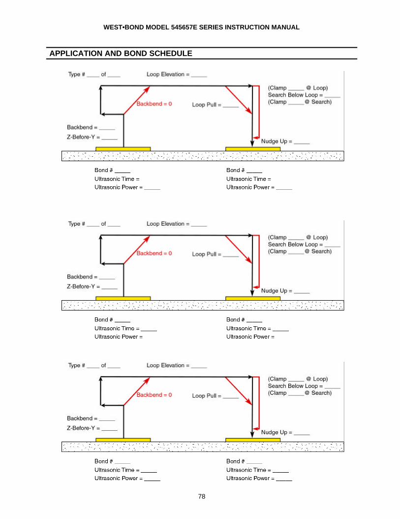
WEST•BOND MODEL 545657E SERIES INSTRUCTION MANUAL
78
APPLICATION AND BOND SCHEDULE
WEST•BOND MODEL 545657E SERIES INSTRUCTION MANUAL
79
WARRANTY
a. Seller warrants to the original Buyer that each new product manufactured by WEST•BOND is free from defects in material and workmanship. Seller’s liability hereunder shall be limited to the replacement of any product manufactured by WEST•BOND provided that the defective product is returned within one year from date of invoice to the WEST•BOND factory in Anaheim, California, with transportation charges prepaid. Upon examination by WEST•BOND, a product found defective due to manufacture and not the result of abuse, unauthorized alteration or normal wear, will be replaced. Seller makes no warranty concerning products or accessories not manufactured by WEST•BOND. However, Seller will give all reasonable assistance to Buyer in obtaining from the respective manufacturer whatever adjustment is appropriate under the terms of that manufacturer’s own warranty. No product may be returned to the factory without a Return Material Authorization (RMA) number issued by authorized factory personnel.
b. This warranty is in lieu of all other warranties expressed or implied. WEST•BOND expressly
disclaims any and all warranties of merchantability and fitness for a particular purpose. No employee, agent or representative of Seller has any authority to obligate Seller beyond that specifically included herein unless agreed to in writing by an authorized officer of Seller.
c. Seller assumes no liability or risk for any special, direct, indirect or consequential damage caused by defective products manufactured by WEST•BOND.
Rev. 4/99
Patent Information This series machine is covered under the following patents:
6164514 “E” Series – X-Y-Z Micromanipulator, orthogonal and independently locked axes.
1551 S. Harris Court
Anaheim, California 92806-5932
Web Site: www.westbond.com
E-mail: [email protected]
Phone: (714)978-1551
Fax: (714)978-0431 XXX
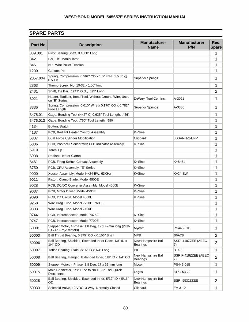
WEST•BOND MODEL 545657E SERIES INSTRUCTION MANUAL
80
SPARE PARTS
Part No Description Manufacturer Name
Manufacturer P/N
Rec. Spare
339.001 Pivot Bearing Shaft, 0.4300" Long 1 342 Bar, Tie, Manipulator 1 846 Nut, Wire Puller Tension 1 1200 Contact Pin 1 2057.004 Spring, Compression, 0.562" OD x 1.5" Free; 1.5 Lb @
0.50 in. Superior Springs 1 2363 Thumb Screw, No. 10-32 x 1.50" long 1 2431 Shaft, Tie Bar, .1247" O.D., .625" Long 2 3021 Heater, Radiant, Bond Tool, Without Ground Wire, Used
on "E" Series DeWeyl Tool Co., Inc. A-3021 1
3336 Spring, Compression, 0.010" Wire x 0.170" OD x 0.782" Free Length Superior Springs A-3336 1
3475.01 Gage, Bonding Tool (K~27-C) 0.625" Tool Length, .456" 1 3475.013 Gage, Bonding Tool, .750" Tool Length, .580" 1 4134 Button, Switch 1 4187 PCB, Radiant Heater Control Assembly K~Sine 1 6307 Dual Force Cylinder Modification Clippard 3SSAR-1/2-ENP 1 6836 PCB, Photocell Sensor with LED Indicator Assembly K~Sine 1 6919 Torch Tip 1 6938 Radiant Heater Clamp 1 8461 PCB, Firing Switch Contact Assembly K~Sine K~8461 1 8750 PCB, CPU Assembly, "E" Series K~Sine 1 9000 Xducer Assembly, Model K~24-EW, 63KHz K~Sine K~24-EW 1 9011 Piston, Clamp Blade, Model 4500E 1 9028 PCB, DC/DC Converter Assembly, Model 4500E K~Sine 1 9037 PCB, Motor Driver, Model 4500E K~Sine 1 9090 PCB, I/O Circuit, Model 4500E K~Sine 1 9258 Wire Drag Tube, Model 7700D, 7600E 1 9303 Wire Drag Tube, Model 7400E 1 9744 PCB, Interconnector, Model 7476E K~Sine 1 9747 PCB, Interconnector, Model 7700E K~Sine 1 50001 Stepper Motor, 4 Phase, 1.8 Deg, 17 x 47mm long (2KB-
F,G 4KE-Y,Z motors) Mycom PS445-01B 1 50003 Ball Thrust Bearing, 0.375" OD x 0.156" Shaft MPB S6A7B 2 50006 Ball Bearing, Shielded, Extended Inner Race, 1/8" ID x
1/4" OD New Hampshire Ball Bearings
SSRI-418ZZEE (ABEC 7) 2
50007 Teflon Bearing, Plain, 3/16" ID x 1/4" Long PIC B14-3 1 50008 Ball Bearing, Flanged, Extended Inner, 1/8" ID x 1/4" OD New Hampshire Ball
Bearings SSRIF-418ZZEE (ABEC 7) 2
50009 Stepper Motor, 4 Phase, 1.8 Deg, 17 x 33 mm long Mycom PS443-01B 1 50015 Male Connector, 1/8" Tube to No 10-32 Thd, Quick
Disconnect Legris 3171-53-20 1
50028 Ball Bearing, Shielded, Extended Inner, 5/32" ID x 5/16" OD
New Hampshire Ball Bearings SSRI-5532ZZEE 2
50033 Solenoid Valve, 12 VDC, 3 Way, Normally Closed Clippard EV-3-12 1
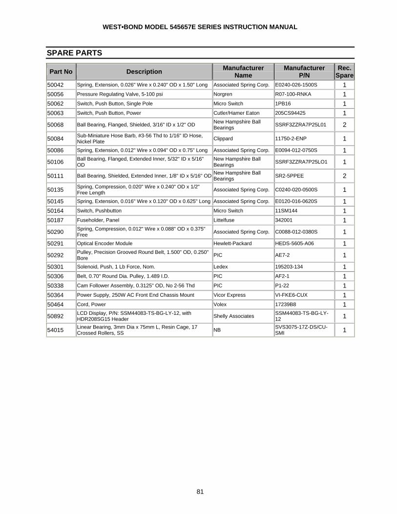
WEST•BOND MODEL 545657E SERIES INSTRUCTION MANUAL
81
SPARE PARTS
Part No Description Manufacturer Name
Manufacturer P/N
Rec. Spare
50042 Spring, Extension, 0.026" Wire x 0.240" OD x 1.50" Long Associated Spring Corp. E0240-026-1500S 1 50056 Pressure Regulating Valve, 5-100 psi Norgren R07-100-RNKA 1 50062 Switch, Push Button, Single Pole Micro Switch 1PB16 1 50063 Switch, Push Button, Power Cutler/Hamer Eaton 205CS94425 1 50068 Ball Bearing, Flanged, Shielded, 3/16" ID x 1/2" OD New Hampshire Ball
Bearings SSRF3ZZRA7P25L01 2
50084 Sub-Miniature Hose Barb, #3-56 Thd to 1/16" ID Hose, Nickel Plate Clippard 11750-2-ENP 1
50086 Spring, Extension, 0.012" Wire x 0.094" OD x 0.75" Long Associated Spring Corp. E0094-012-0750S 1 50106 Ball Bearing, Flanged, Extended Inner, 5/32" ID x 5/16"
OD New Hampshire Ball Bearings SSRF3ZZRA7P25LO1 1
50111 Ball Bearing, Shielded, Extended Inner, 1/8" ID x 5/16" OD New Hampshire Ball Bearings SR2-5PPEE 2
50135 Spring, Compression, 0.020" Wire x 0.240" OD x 1/2" Free Length Associated Spring Corp. C0240-020-0500S 1
50145 Spring, Extension, 0.016" Wire x 0.120" OD x 0.625" Long Associated Spring Corp. E0120-016-0620S 1 50164 Switch, Pushbutton Micro Switch 11SM144 1 50187 Fuseholder, Panel Littelfuse 342001 1 50290 Spring, Compression, 0.012" Wire x 0.088" OD x 0.375"
Free Associated Spring Corp. C0088-012-0380S 1 50291 Optical Encoder Module Hewlett-Packard HEDS-5605-A06 1 50292 Pulley, Precision Grooved Round Belt, 1.500" OD, 0.250"
Bore PIC AE7-2 1 50301 Solenoid, Push, 1 Lb Force, Nom. Ledex 195203-134 1 50306 Belt, 0.70" Round Dia. Pulley, 1.489 I.D. PIC AF2-1 1 50338 Cam Follower Assembly, 0.3125" OD, No 2-56 Thd PIC P1-22 1 50364 Power Supply, 250W AC Front End Chassis Mount Vicor Express VI-FKE6-CUX 1 50464 Cord, Power Volex 17239B8 1 50892 LCD Display, P/N: SSM44083-TS-BG-LY-12, with
HDR208SG15 Header Shelly Associates SSM44083-TS-BG-LY-12 1
54015 Linear Bearing, 3mm Dia x 75mm L, Resin Cage, 17 Crossed Rollers, SS NB SVS3075-17Z-DS/CU-
SMI 1
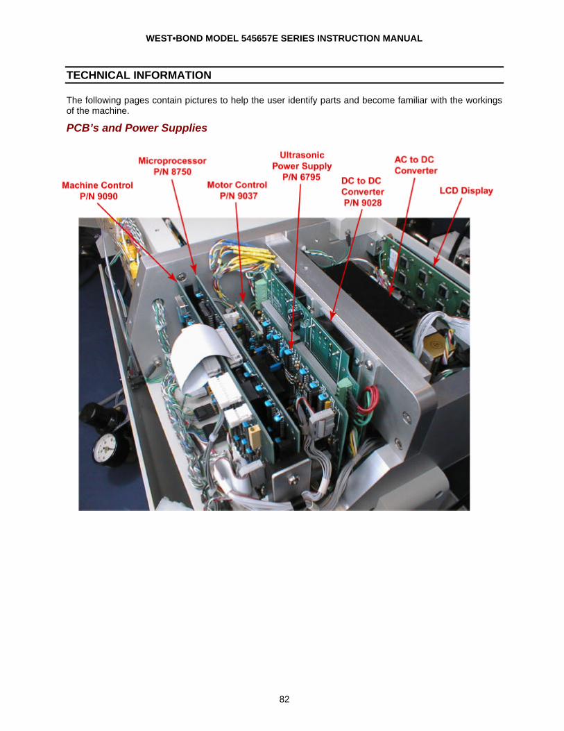
WEST•BOND MODEL 545657E SERIES INSTRUCTION MANUAL
82
TECHNICAL INFORMATION
The following pages contain pictures to help the user identify parts and become familiar with the workings of the machine.
PCB’s and Power Supplies
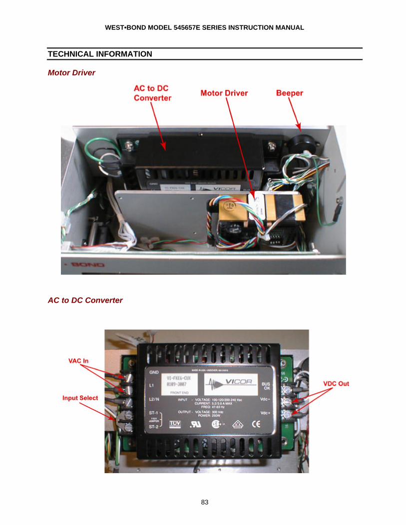
WEST•BOND MODEL 545657E SERIES INSTRUCTION MANUAL
83
TECHNICAL INFORMATION
Motor Driver
AC to DC Converter
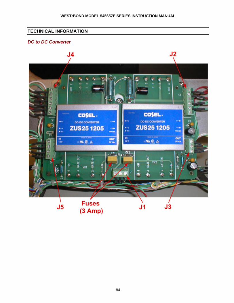
WEST•BOND MODEL 545657E SERIES INSTRUCTION MANUAL
84
TECHNICAL INFORMATION
DC to DC Converter
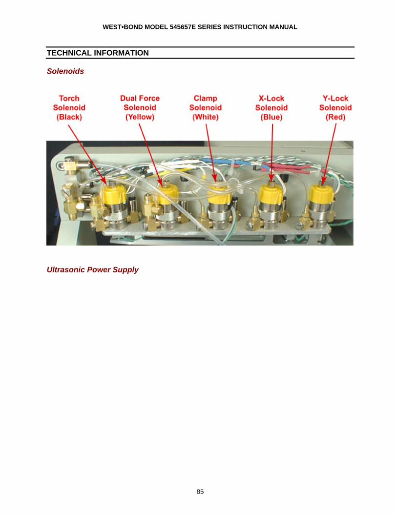
WEST•BOND MODEL 545657E SERIES INSTRUCTION MANUAL
85
TECHNICAL INFORMATION
Solenoids
Ultrasonic Power Supply
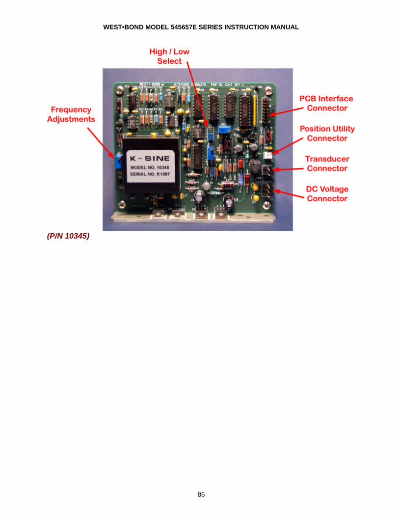
WEST•BOND MODEL 545657E SERIES INSTRUCTION MANUAL
86
(P/N 10345)
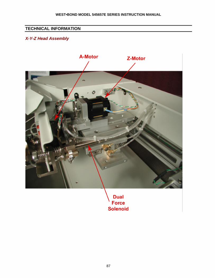
WEST•BOND MODEL 545657E SERIES INSTRUCTION MANUAL
87
TECHNICAL INFORMATION
X-Y-Z Head Assembly

WEST•BOND MODEL 545657E SERIES INSTRUCTION MANUAL
88
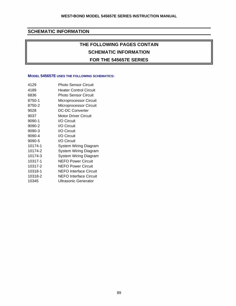
WEST•BOND MODEL 545657E SERIES INSTRUCTION MANUAL
89
SCHEMATIC INFORMATION
THE FOLLOWING PAGES CONTAIN
SCHEMATIC INFORMATION
FOR THE 545657E SERIES
MODEL 545657E USES THE FOLLOWING SCHEMATICS: 4129 Photo Sensor Circuit 4189 Heater Control Circuit 6836 Photo Sensor Circuit 8750-1 Microprocessor Circuit 8750-2 Microprocessor Circuit 9028 DC-DC Converter 9037 Motor Driver Circuit 9090-1 I/O Circuit 9090-2 I/O Circuit 9090-3 I/O Circuit 9090-4 I/O Circuit 9090-5 I/O Circuit 10174-1 System Wiring Diagram 10174-2 System Wiring Diagram 10174-3 System Wiring Diagram 10317-1 NEFO Power Circuit 10317-2 NEFO Power Circuit 10318-1 NEFO Interface Circuit 10318-2 NEFO Interface Circuit 10345 Ultrasonic Generator

WEST•BOND MODEL 545657E SERIES INSTRUCTION MANUAL
90