Design, Modeling, And Control Of Three-port Converters For ...

Journal of Power Electronics, Vol. 17, No. 6, pp. 1433-1444, November 2017 1433
https://doi.org/10.6113/JPE.2017.17.6.1433
ISSN(Print): 1598-2092 / ISSN(Online): 2093-4718
JPE 17-6-5
Three-Port Converters with a Flexible Power Flow for Integrating PV and Energy Storage into a DC Bus
Tian Cheng† and Dylan Dah-Chuan Lu*,**
†,*School of Electrical and Information Engineering, The University of Sydney, Sydney, Australia **School of Electrical and Data Engineering, University of Technology Sydney (UTS), Sydney, Australia
Abstract
A family of non-isolated DC-DC three-port converters (TPCs) that allows for a more flexible power flow among a renewable energy source, an energy storage device and a current-reversible DC bus is introduced. Most of the reported non-isolated topologies in this area consider only a power consuming load. However, for applications such as hybrid-electric vehicle braking systems and DC microgrids, the load power generating capability should also be considered. The proposed three-port family consists of one unidirectional port and two bi-directional ports. Hence, they are well-suited for photovoltaic (PV)-battery-DC bus systems from the power flow viewpoint. Three-port converters are derived by combining different commonly known power converters in an integrated manner while considering the voltage polarity, voltage levels among the ports and the overall voltage conversion ratio. The derived converter topologies are able to allow for seven different modes of operation among the sources and load. A three-port converter which integrates a boost converter with a buck converter is used as a design example. Extensions of these topologies by combining the soft-switching technique with the proposed design example are also presented. Experiment results are given to verify the proposed three-port converter family and its analysis. Key words: Bi-directional loads, Dual-input single-output (DISO), Energy storage, Renewable energy, Single-input dual-output (SIDO), Single-input single-output (SISO), Three-port converter (TPC)
I. INTRODUCTION
Recently, a number of power converter topologies have been introduced to integrate renewable energies (e.g. solar, wind), energy storage systems (e.g. batteries, supercapacitors), and loads [1]-[6]. In the majority of these topologies, the battery is designed as the only bi-directional port, which is suitable for applications such as the PV-battery powered stand-alone systems. However, there also exist some applications where the DC-DC converter needs to handle a bi-directional interface. In other words, these power systems require one unidirectional port and two bi-directional ports. In [7], a three-port series-resonant converter is presented to interface with renewable sources and storage systems, along with a
regenerative load port such as in a vehicle braking system. In [8], a three phase PV-battery-DC bus system that provides a reversible power flow path is proposed. It is capable of charging a battery without PV cells. In [9], a galvanic TPC for fuel cells (FCs), a battery system and a bi-directional load is presented. In [10], a control strategy for a bi-directional converter applied in electric vehicles (EVs) or hybrid electric vehicles (HEVs) is proposed. Energy can be further recycled from the braking system and the life of battery is improved with the help of the supercapacitor. For bi-directional TPCs [7]-[10], isolated transformers are used to achieve the bi-directional power flow function. The conventional rectifier diodes in the secondary side are replaced by switches, so that a bi-directional power flow is allowed. Although transformer-based TPCs offer electrical isolation and make it easier to achieve a higher voltage gain, when compared with non-isolated three-port converters (NITPCs), they require more power switches, which increases the number of components and the complexity of the control circuits. Based on this concern, research has been directed toward NITPCs with a flexible power flow. In [11], a family of DC-link inductor
Manuscript received Mar. 30, 2017; accepted Jul. 22, 2017 Recommended for publication by Associate Editor Honnyong Cha.
†Corresponding Author: [email protected] Tel: + 61-433227909, The University of Sydney
*School of Electrical and Information Engineering, The University of Sydney, Australia
**School of Electrical and Data Engineering, University of Technology Sydney (UTS), Australia
© 2017 KIPE

1434 Journal of Power Electronics, Vol. 17, No. 6, November 2017
(DLI) based multiport converters (MPCs) are illustrated with bi-directional power flow capability among all of the ports. In [12], a systematic approach for deriving both dual-input and dual-output converters for NITPCs is discussed.
Although there has been a lot of work on TPCs, these topologies are mainly designed for the consuming load. Solutions for integrating a regenerative load in TPCs are still limited. The most common TPCs for a regenerative load employ a three-winding transformer associated with a full bridge configuration in each port. This can fulfill the purpose of bi-directional power flow between any two ports. However, the bulkiness of the transformers and the need for more switches increases in the converter volume and cost. NITPCs present a compact solution and are capable of driving a regenerative load. Some reported topologies have good potential for regenerative loads or DC buses. However, there is a lack of comprehensive studies based on commonly known power converters that can form NITPCs for integrating a renewable energy source, an energy storage system and a regenerative load/bus.
The main purpose and contribution of this paper is to derive, analyze and develop a new family of NITPCs for the PVs, a storage system and a DC bus (or regenerative load) in a systemic manner. This family of converters maintains the merits of the conventional TPCs which has a single power conversion stage between any two ports for better conversion efficiency. To achieve a more flexible power flow, the proposed converter family integrates an extra power flow path into the traditional TPCs, instead of adding a separate DC-DC converter, which further compacts the power design. The derivation method is simple, and many basic power converters can be used as bi-directional ports. Different combinations of converters can be derived to meet different requirements.
This paper is organized as follows. In Section II, the characteristics of the resultant power converter circuits and the synthesis of NITPCs with one unidirectional and two bi-directional ports is presented. A design example with a detailed circuit description and an operation analysis is shown in Section III. Experimental verifications of the design example are provided in Section IV, and some conclusions are made in Section V.
II. ANALYSIS OF THE NON-ISOLATED THREE-PORT CONVERTERS WITH ONE UNIDIRECTIONAL PORT AND TWO BI-DIRECTIONAL PORTS
A. Circuit Characteristics
This section discusses the characteristics and commonalities of the NITPCs in this converter family.
Firstly, this converter family consists of one unidirectional power port for irreversible renewable energy sources such as PV and wind sources and two bi-directional power ports for an energy storage device and a bi-directional terminal/load such as DC grid and motor load.
Secondly, the NITPC family allows for possible combinations of basic converters (e.g. buck, boost and buck-boost) according to the voltage level and polarity of each port. To provide a more complete picture, higher-order converters such as SEPIC and ZETA converters, are also taken into consideration. To clarify the explanation, this family can be divided into several groups. In each group, a specific converter is used as a base converter to combine other different converters to form a converter group.
Thirdly, this family should be capable of operating in seven different modes according to the PV panel power generation capability, the battery state of charge (SOC) and the bi-directional load conditions. The detailed operation modes of this family to interface with a DC bus include:
Mode 1 (PV to battery)
Mode 2 (PV to battery and DC bus)
Mode 3 (PV and battery to DC bus)
Mode 4 (PV to DC bus)
Mode 5 (Battery to DC bus)
Mode 6 (DC bus to battery)
Mode 7 (PV and DC bus to battery)
In addition, they can be further separated into grid-connected modes (Mode 1, 2, 4, 6 and 7) and islanded modes (Mode 3 and 5). When in the grid-connected mode, the battery should not be considered as a power source from the point of view of the effective usage of the power when the DC bus is supplied by both the PV and the utility grid. The battery is treated as a back-up source, and needs to remain at a high SOC. Due to the self-discharge nature of the battery, it needs to charge periodically. When in the islanded mode, the battery is the main power source and is responsible for maintaining the DC bus voltage. This mode happens in situations such as a fault in the distribution system or regular maintenance in a power plant.
Fourthly, although there are seven operation modes, the system only selects one mode to operate at any time. Thus, all of the NITPCs in this family can work as either a single-input single-output (SISO) converter, a dual-input single-output (DISO) converter or a single-input dual-output (SIDO) converter.
Fifthly, for the purpose of simplifying the configurations while efficiently using circuitry components, redundant elements are removed or functionally merged. Therefore, a compact design can be achieved.
B. Possible Combinations and Derivation
To classify the combinations, this section introduces boost, buck, non-inverting buck-boost (NIBB), SEPIC and ZETA converter based configurations. The base configuration serves as a SIDO converter, and if a specific type is chosen, the voltage relationship between the input and the outputs is confirmed. Fig. 1(a) is applied to all of the three-port converters to achieve single-input and dual-output. In [12], a
Three-Port Converters with a Flexible Power Flow for Integrating PV and … 1435
(a) (b) (c)
(d) (e)
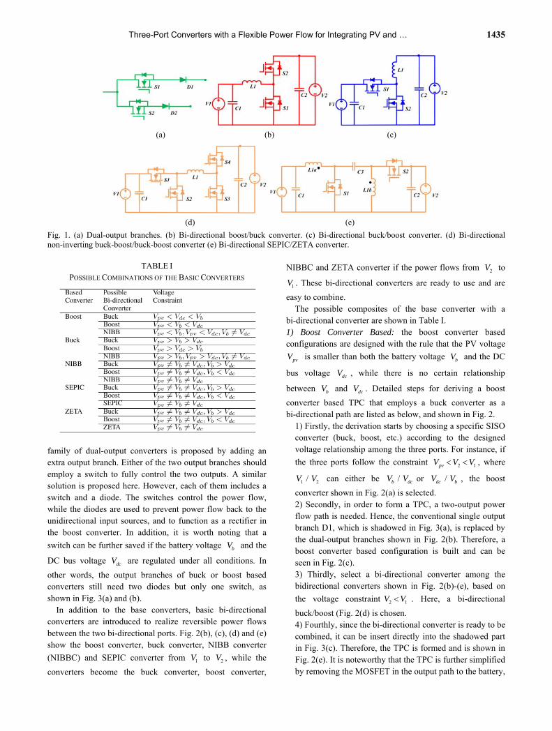
Fig. 1. (a) Dual-output branches. (b) Bi-directional boost/buck converter. (c) Bi-directional buck/boost converter. (d) Bi-directional non-inverting buck-boost/buck-boost converter (e) Bi-directional SEPIC/ZETA converter.
TABLE I
POSSIBLE COMBINATIONS OF THE BASIC CONVERTERS
family of dual-output converters is proposed by adding an extra output branch. Either of the two output branches should employ a switch to fully control the two outputs. A similar solution is proposed here. However, each of them includes a switch and a diode. The switches control the power flow, while the diodes are used to prevent power flow back to the unidirectional input sources, and to function as a rectifier in the boost converter. In addition, it is worth noting that a
switch can be further saved if the battery voltage bV and the
DC bus voltage dcV are regulated under all conditions. In
other words, the output branches of buck or boost based converters still need two diodes but only one switch, as shown in Fig. 3(a) and (b).
In addition to the base converters, basic bi-directional converters are introduced to realize reversible power flows between the two bi-directional ports. Fig. 2(b), (c), (d) and (e) show the boost converter, buck converter, NIBB converter
(NIBBC) and SEPIC converter from 1V to 2V , while the
converters become the buck converter, boost converter,
NIBBC and ZETA converter if the power flows from 2V to
1V . These bi-directional converters are ready to use and are
easy to combine. The possible composites of the base converter with a
bi-directional converter are shown in Table I.
1) Boost Converter Based: the boost converter based configurations are designed with the rule that the PV voltage
pvV is smaller than both the battery voltage bV and the DC
bus voltage dcV , while there is no certain relationship
between bV and dcV . Detailed steps for deriving a boost
converter based TPC that employs a buck converter as a bi-directional path are listed as below, and shown in Fig. 2.
1) Firstly, the derivation starts by choosing a specific SISO converter (buck, boost, etc.) according to the designed voltage relationship among the three ports. For instance, if
the three ports follow the constraint 2 1pvV V V , where
1V / 2V can either be bV / dcV or dcV / bV , the boost
converter shown in Fig. 2(a) is selected. 2) Secondly, in order to form a TPC, a two-output power flow path is needed. Hence, the conventional single output branch D1, which is shadowed in Fig. 3(a), is replaced by the dual-output branches shown in Fig. 2(b). Therefore, a boost converter based configuration is built and can be seen in Fig. 2(c). 3) Thirdly, select a bi-directional converter among the bidirectional converters shown in Fig. 2(b)-(e), based on
the voltage constraint 2 1V V . Here, a bi-directional
buck/boost (Fig. 2(d) is chosen. 4) Fourthly, since the bi-directional converter is ready to be combined, it can be insert directly into the shadowed part in Fig. 3(c). Therefore, the TPC is formed and is shown in Fig. 2(e). It is noteworthy that the TPC is further simplified by removing the MOSFET in the output path to the battery,

1436 Journal of Power Electronics, Vol. 17, No. 6, November 2017
(a) (b) (c)
(d) (e)
Fig. 2. (a) Typical boost converter. (b) Dual-output branches. (c) Boost converter based configuration. (d) Bi-directional buck converter. (e) Boost converter based TPC integrated with a buck converter.
(a) (b) (c)
(d) (e)
Fig. 3. Example composites of a based converter with a bi-directional converter: (a) boost converter based with a bi-directional buck/boost converter; (b) buck converter based with a bi-directional boost/buck converter; (c) NIBBC based with a bi-directional NIBBC/NIBBC; (d) SEPIC based with a bi-directional SEPIC/ZETA converter; (e) ZETA converter based with a bi-directional ZETA/SEPIC converter.
since the voltage relationship between 1V and 2V is
certain. The same procedure can be applied to derive any of the other converters within this family. 2) Buck Converter Based: an alternative to the boost converter based configuration, is the buck converter that
requires that 1 pvV V and 2 pvV V , but 2V can be either
larger or smaller than 1V . An example is shown in Fig. 3(b)
with the voltage constraint 1 2 pvV V V .
3) Non-Inverting Buck-Boost Converter Based: the buck-boost converter is flexible since it can either step up or down the input voltage to a required output voltage within the same configuration. It is an effective solution to those TPCs which have similar voltage levels among the ports. The
structure of the inverting buck-boost converter is simpler than the non-inverting structure, but it has an inverted output polarity of the input. This causes difficulties in designing the three-port converter in terms of interfacing the sensing devices with the control and driving circuits due to different grounds. Hence a NIBBC is used as a base.
A NIBBC based TPC with a bi-directional NIBBC/NIBBC is shown in Fig. 3(c). Due to the uncertainty of the voltage constraints among the three ports, the converter structure is more complicated than the converter examples given in Fig. 3(a) and (b). As can be seen, 8 switches are employed to handle the varied voltages of the three ports. However, they do not operate at the same time. As with different voltage constraints, the NIBBC based TPC with a bi-directional NIBBC/NIBBC can be reconfigured into different types. Fig.

Three-Port Converters with a Flexible Power Flow for Integrating PV and … 1437
(a)
(b) (c)
(d) (e)
(f) (g)
Fig. 4. Possible reconfigured TPCs from a NIBBC based with a bi-directional NIBBC/NIBBC: (a) NIBBC based with a bi-directional NIBBC/NIBBC; (b) buck converter based with a bi-directional boost/buck converter; (c) buck converter based with a bi-directional buck/boost converter; (d) boost converter based with a bi-directional boost/buck converter; (e) boost converter based with a bi-directional buck/boost converter.
4(a) presents a NIBBC based TPC with a bidirectional NIBBC/NIBBC, and Fig. 4(b)-(g) show the reconfigured converters from Fig. 4(a). To simplify the converter structures for observation, the idled switches are removed and the always turned on switches are replaced with wires. The actual converter in operation can be switched with the converters shown in Fig. 4(b)-(h) according to the voltage constraints. This scenario can be explained in the context of a
DC microgrid. Assuming that pvV , 1V and 2V are the PV,
battery and DC bus voltages, respectively. Among them,
pvV and 1V are variables since they vary with the solar
irradiance and the battery state of charge while 2V remains
stable. For example, at dawn when the solar irradiance is insufficient, the converter Fig. 4(f) or (g) may be in operation,
since pvV is small. At midday, when the irradiance is
adequate, the operation converter may switch to Fig. 4(d) or
(e), where pvV is higher than the loads. The active switches
of the different reconfigured TPCs (Fig. 4(b)-(e)) can be found in Table II. Both “√” and “1” represent that the switch
is in the active state, where “√” indicates that the switch needs to be controlled and “1” indicates that the switch is always turned on. In addition, “0” means that the switch is turned off. Furthermore, when the converter operates in a specific operation mode, even less switches are in use. Detailed explanations of the operation modes are given with a design example in Section III.
1) Fig. 4(b) and (c) are NIBBCs based with a bi-directional boost/buck (buck/boost) converter to deal with the design specifications of 2 1pvV V V and 1 2pvV V V .
2) Fig. 4(d) and (e) are buck converters based with a bidirectional boost/buck (buck/boost) converter to deal with the design specifications of 1 2 pvV V V and
2 1 pvV V V .
3) Fig. 4(f) and (g) are boost converters based with a bidirectional boost/buck (buck/boost) converter to deal with the design specifications of 1 2pvV V V and
2 1pvV V V .
As can be seen from Fig. 4(b)-(g), the reconfigured converters actually belong to the NIBBC based, buck

1438 Journal of Power Electronics, Vol. 17, No. 6, November 2017
TABLE II
SWITCHES LOOKUP TABLE FOR RECONFIGURED NIBBCS BASED WITH A BI-DIRECTIONAL NIBBC/NIBBC IN DIFFERENT OPERATION
MODES ("\CHECKMARK," "1" AND "0" REPRESENT SWITCHES IN OPERATION, ALWAYS ON AND ALWAYS OFF STATUSES, RESPECTIVELY)
converter based and boost converter based TPCs groups. In other words, although a NIBBC based with a bi-directional NIBBC/NIBBC employs many switches, it covers most of the possible boost or buck converter based TPCs. However, it is unavoidable that extra switches are needed to satisfy the step up or down when compared to the conventional buck or boost converter when in a specific operation mode. For
instance, when the PV charges 1V alone, assuming that
1pvV V , apart from 2S , which is the main switch of the
boost converter, 1S and 3S need to be turned on during the
whole operation period. This causes extra losses on 1S and
3S , and the conduction loss is dominant.
4) SEPIC Based: to reduce the number of switches of the NIBBC, the SEPIC based configurations are analyzed. The SEPIC has the advantage of stepping up or stepping down the input voltage without changing the input voltage polarity. In addition, although it employs two inductors, it needs only one switch. Therefore, the control strategy is simplified. Instead of using two separate inductors in the SEPIC, the advantages of using a coupled-inductor, which include a lower component number, a more compact design and a smaller inductance, are mentioned in [13]. In [14], the authors proposed a bi-directional SEPIC-ZETA, as shown in Fig. 1(e), by replacing a diode with a switch. This reduces the output voltage ripple and results in a lower switch stress. Based on this finding, coupled inductors are used for both the base converter part and the bi-directional ports. For the purpose of achieving a simplified structure and control strategy, the proposed topology in [10] is adopted and combined with a SEPIC based converter instead of a bi-directional buck-boost converter, as shown in Fig. 3(d).
5) ZETA converter based: ZETA converter based
topologies are explained for further illustration. The ZETA converter has the same benefits as the SEPIC, and the coupled-inductor is also employed for its aforementioned benefits. The bi-directional converter shown in Fig. 1(e)
becomes a ZETA converter if power flows from 2V to 1V .
Similarly, a bi-directional ZETA converter merged with a ZETA based configuration is shown in Fig. 3(e).
III. DESIGN EXAMPLE OF A BOOST CONVERTER BASED THREE-PORT CONVERTER
A. Design Example To further facilitate the derivation and explanation of the
converter, a boost converter based TPC that integrates with a buck converter is used as an example. This configuration was first introduced in [15]. However, it only served as a single-phase power factor correction (PFC) converter with an sinusoidal input current and a wide DC output voltage range, which is suitable for plug-in HEV charging systems. The main advantage of this topology is its compact design due to a simplified converter structure with a lower component count. However, the load terminal operates in a unidirectional manner. It is proposed in this paper that the load terminal be replaced by a bi-directional interface (a DC bus), making it a fully flexible converter with seven different power flow patterns. A circuit diagram is shown in Fig. 3(a). The normal operation of the converter is based on the following voltage
constraint: 2 1pvV V V , where 1V and 2V are the battery
voltage bV and DC bus voltage dcV , respectively. This is
different from [7], where the input is AC and output voltage varies.
A PV panel, which is connected in series with an input inductor 1L , is an intermittent power source and the only
unidirectional port. Hence, it can supply power to the battery,

Three-Port Converters with a Flexible Power Flow for Integrating PV and … 1439
to the DC bus or to both. The inductors 1L and 2L are
essential energy storage elements to step up or step down the input voltage. There are four MOSFETs in the converter, namely, 1 2 3, ,S S S and 4S . The switch 1S is responsible for
managing the amount of the energy stored in 1L and for
achieving maximum power point tracking (MPPT). The switch 2S , is used to control the power flow from the PV
due to the voltage difference and different power requirements between the battery and the DC bus. The diode
2D works as a rectifier of the boost converter, and
contributes to preventing the power from the DC bus or the battery from flowing back to the PV cells through the body diode of 2S . The free-wheeling diode in the conventional
buck converter is replaced by the switch 4S . This is
necessary, since when a battery charges the DC bus, a buck converter is formed. In return, when the DC bus charges the battery, a boost converter is also formed with the exact same components. This maximizes the use of the components. The duty cycles are determined as 1 2 3 4, , ,d d d d and 5d , which
are the switch turn on ratios of 1 2 1 3,S ,D ,SS and 4S ,
respectively. 1) Mode 1 (PV to Battery; Fig. 5(a)): This mode occurs when the solar irradiance is weak while the battery SOC is not full due to the self-discharge. The DC bus is powered by the utility grid. Therefore, only the SISO boost converter is in
operation. When 1S turns on, 1L is charging, and when it
is off, 1D is conducting.
2) Mode 2 (PV to Battery and DC Bus; Fig. 5(b)): This mode occurs when the PV has sufficient power to charge the battery and the remaining energy feeds the DC bus. The converter works as a SIDO boost converter. The relationship among the three ports follows the power conservation (1), which is when the PV power is equal to the sum of the
battery power and DC bus power. When 1S turns on, 1L
stores energy. When 1S is off, 2S and 1D dispatch power
to the two loads in turn. The duty cycles, 1 2,d d and 3d of
1 2,S S , and 1D form a switching period when the converter
operates in the continuous conduction mode (CCM) (2). Power management of the two loads is achieved by the
different switching ratios of 2d and 3d , which are decided
by the current ratio (3). The total energy which 1L is
required to store is resolved by (4). In this case, 1L and 1S
are functionally shared by the two loads.
pv pv b b dc dcV I V I V I (1)
1 2 3s s s sd T d T d T T (2)
2
3
dc
b
I d
I d (3)
11 dc b
pv
I Id
I
(4)
3) Mode 3 (PV and Battery to DC Bus; Fig. 5(c)): This mode occurs when the DC bus requires more power than the PV can generate. Hence, the backup battery needs to provide the extra power. This mode occurs when the DC microgrid operates in the islanded mode, where the DC bus connects only with the local consuming loads. The ideal power conservation equation is (5). The converter operates as a DISO converter with the PV input from the boost converter and the battery input from the buck converter. They work
independently, so that when 1S and 3S are turned on, 1L
and 2L are storing energy. When 1S is off, both the PV
and the inductor 1L release power to the DC bus. 2S turns
on during the whole switching period to reduce the switching
loss. When 3S is off, the inductor 2L releases its power
through the body diode of 4S to the DC bus. In the boost
converter, 1S and 2D work in a complementary manner,
and 1d is regulated to achieve MPPT of the PV panel (6).
Similarly, in the buck converter, 3S and the body diode of
4S also work in tandem, and 3d is responsible for
maintaining the DC bus voltage (7).
pv pv b b dc dcV I V I V I (5)
11 pv
dc
Vd
V (6)
3dc
b
Vd
V (7)
4) Mode 4 (PV to DC Bus; Fig. 5(d)): This mode occurs when the battery is in a high SOC situation and the PV panel provides power to the DC bus. In this mode, the battery is idle. As a result, no energy is being absorbed or released. The
converter operates as a SISO boost converter, and 1S and
2D work in a complementary manner. 2S turns on for the
whole switching period to reduce the switching loss. Since the battery voltage is higher than the DC bus voltage level,
both the body diode of 3S and the rectifier 1D do not
conduct. 5) Mode 5 (Battery to DC Bus; Fig. 5(e)): This mode occurs when the TPC works in the islanded mode and there is an absence of PV panel power, for example, during the night time. Since only the battery provides power, the converter
operates as a SISO buck converter. The duty cycle 3S is
decided by the output and input voltage ratio. 6) Mode 6 (DC Bus to Battery; Fig. 5(f)): This mode also
occurs when there is no PV power, and the battery has a low SOC. For example, the battery has a deep discharge when the converter operates in the islanded mode. As a result, it is the main power source to supply the DC bus, particularly in the nighttime. Hence, after the DC bus connects with the utility grid, it charges the battery for reserve and protects the battery

1440 Journal of Power Electronics, Vol. 17, No. 6, November 2017
(a)
(b)
(c)
(d)
(e)
(f)
(g)
Fig. 5. (a) Mode 1 (PV to battery). (b) Mode 2 (PV to battery and DC bus). (c) Mode 3 (PV and battery to DC bus). (d) Mode 4 (PV to DC bus). (e) Mode 5 (battery to DC bus). (f) Mode 6 (DC bus to battery). (g) Mode 7 (PV and DC bus to battery).
from over-charging. A SISO boost is in use when 4S turns
on first to power 2L . When it is off, the power from the DC
bus and 2L is released though the body diode of 3S and
Fig. 6. A schematic of the proposed design example with soft-switching cells.
then to the battery. 4S and the body diode of 3S work in a
complementary manner.
7) Mode 7 (PV and DC Bus to Battery; Fig. 5(g)): Similar to mode 6, this mode occurs when the PV still supplies power and the battery has a low SOC. The PV panel works in the MPPT mode by adjusting 1S and the remaining energy is
supplied from the DC bus. In this case, the converter operates as a DISO converter since two boost converters are in use.
2S and 2D are the only two elements that are not in
operation. The duty cycles of 1S and 4S can be obtained
by the MPPT function and the battery voltage regulation, respectively.
B. Soft-Switching Technique
To minimize the switching losses of the switches, a brief discussion about the feasibility of introducing soft-switching techniques into the design example is given. A traditional zero-current switching (ZCS) boost converter for a battery charger is explained in [16]. A resonant inductor and a resonant capacitor are added to limit the inductor charging/discharging rate and to transfer energy during transitions. Zero-voltage switching (ZVS) is proposed in a non-isolated bi-directional buck/boost converter in [17]. The
proposed resonant cell includes an inductor rL , a capacitor
rC and a snubber capacitor sC . ZVS can be achieved when
sC reaches the output voltage during the switch turns off
period and then resonant to zero with rL and rC . It is
reported that both buck and boost operation can achieve soft-switching.
The converters in this family are composites of a SIDO base converter and a bi-directional converter, and these two converters work independently as explained in the previous section. Therefore, the soft-switching techniques proposed in [16], [17] can be adopted in the design example, as shown in
Fig. 6. The ZCS cell, which includes 1rL and 1rC for the
boost converter is highlighted and labeled as soft-switching
cell 1 in Fig. 6. In addition, 1rL is connected in series with
the main switch 1S for limiting /i td d . When 1S is on,
1rL starts to resonant with 1rC , and when the current flow to
rL decreases to zero, the switch turns off with ZCS. The ZVS

Three-Port Converters with a Flexible Power Flow for Integrating PV and … 1441
Fig. 7. Flow Chart of the operation mode selection.
cell, which is labeled as soft-switching cell 2 includes a
snubber capacitor sC , a resonant inductor 2rL and a
capacitor 2rC , which is put in parallel with 4S . ZVS can be
achieved in the aforementioned operation manner.
C. Mode Selection Flow Chart
In Fig. 7, an algorithm for operation mode selection is presented. As mentioned previously, the selection procedure is based on the power conditions of the PV, the DC bus port in either the on-grid or off-grid status along with the battery voltage. To achieve such power management, a continuous monitoring of the current and voltage of each port is needed. Due to the close relationship between the SOC and the battery voltage and ease of implementation, the battery
voltage bV is used to determine the charging or discharging
state instead of the SOC. There are two occasions when the battery port is abandoned for the purpose of protection. One
occurs in the battery charging stage. If bV reaches the
battery preset maximum voltage maxbV , which means that the
battery is close to the full SOC, the battery port is idle or trickle-charged. The other occasion occurs in the battery
discharging stage. If bV is less than the preset lower
voltage minbV , the port is also idle to prevent over discharge.
In most cases, the MPPT function is enabled to maximize the use of solar energy. Apart from the seven modes, the system can shut down if none of the selections meets the requirements, and the DC bus is feed by the utility grid.
IV. EXPERIMENTAL VERIFICATIONS
For further verification, experimental results for the aforementioned design example are given. Since the PV is the current dominated source, the voltage varies slightly when the PV operates at the maximum power point or at a low
TABLE III COMPONENTS SPECIFICATIONS
power point. Hence, for ease of explanation, the DC source is used to mimic the solar panel and to assume it works in the maximum power point voltage range. Detailed information of components used in the experiment is shown in Table III.
Since the operation of the SISO converter is straightforward and well documented, the key waveforms of the SIDO and DISO operations are shown instead. Figs. 8(a) shows the SIDO operation where the inductor slope changes during the discharge phase. This shows the current flowing to
the output load 2Di and the battery 1Di at different times
according to Eq. (1). The DISO operations, as shown in Fig. 8 (b) and (c), represent Mode 3 and Mode 7. To verify the feasibility of the DISO, independent converter operation can be illustrated through the difference in the inductor current
2Li and diode current 2Di for mode 3. Similarly, mode 7 can
be verified by the waveforms of 2Li and 1Di .
Fig. 9 shows the transition waveforms for shifting the operation modes. The following four practical scenarios are given as examples:
1) Battery charges the DC bus with the bus suddenly starting to supply power to the battery (Mode 5 and Mode 6).
2) DC bus charges the battery with PV power changes (Mode 6 to Mode 7).
3) PV switches from charging the battery to powering the DC bus (Mode 1 to Mode 4).

1442 Journal of Power Electronics, Vol. 17, No. 6, November 2017
(a) (b)
(c)
Fig. 8. Experimental Results: (a) Mode 2 (PV to battery and DC bus); (b) Mode 3 (PV and battery to DC bus); (c) Mode 7 (PV and DC bus to battery).
4) PV has inadequate power for both ports with less than
full SOC of the battery (Mode 2 to Mode 1). In Case 1), a main focus of this paper is to show the
practicality of the bi-directional operations of the storage system and the generative load. Hence, the experimental results of the bi-directional, transient operation are shown in
Fig. 9(a). The battery current bi , the DC bus current dci and
the inductor 2Li illustrate that power flow directions are
reversed when the system switches from the battery charging the DC bus to the DC bus charging the battery. As can be
observed, 2Li needs to fully release its stored energy before it
can reverse. Likewise, bi and dci follows the same
behavior. In Case 2), Fig. 9(b) illustrates that the battery is charged
by the DC bus with the PV beginning to supply power. 1Li
shows that the PV starts to generate power, and 2Li decreases
as the system sets the priority to consuming more renewable
energy. Both the battery voltage bV and the current bi are
increased. Case 3) is realized in Fig. 9(c), where the PV has a small
power rate. In the beginning, the PV charges the battery when the battery voltage has not reached the preset maximum limit. After it approaches to this limit, the PV no longer provides power to the battery and starts to feed the DC bus.
Case 4) is realized in Fig. 9(d). This case is set for the scenario that the PV has inadequate power to power both of the two ports, and the battery port are not in a full SOC, for instance, when self-discharging. Hence, the TPC switches the operation mode, so that the PV charges only the battery. If the battery is in a full SOC, the PV can also switch to power
the DC bus. As can be observed, the battery current bi is
(a) (b)
(c) (d)
Fig. 9. Transient waveforms: (a) Mode 5 to Mode 6; (b) Mode 6 to Mode 7; (c) Mode 1 to Mode 4; (d) Mode 2 to Mode 1.
Fig. 10. Conversion efficiencies of four representative operation modes.
increased when 2S is turned off, since all of the PV power
is flowing to the battery. The current flow to the DC bus, dci ,
decreases to zero. When switching back to Mode 2, the currents increase or decrease gradually due to the soft-start to avoid large overshoots.
The conversion efficiencies of four representative operation modes are shown in Fig. 10. The duty cycle is adjusted to meet different power levels, and the input voltages are kept the same during the measurements. A 20 Ω and a 40 Ω resistor are connected in the DC bus and the battery port instead of the battery tanks. The efficiencies of the measured converters are in the range of 78%-96%, which verifies the good performances of the proposed converter in different operation states. The blue line depicts the efficiency of Mode 4 (PV to DC bus) which is a SISO boost converter.
Although an extra switch 2S is in the fully on state, the
conduction loss is small and the boost converter can still achieve a high conversion rate. Another SISO converter

Three-Port Converters with a Flexible Power Flow for Integrating PV and … 1443
under investigation is the buck converter, which is adopted in Mode 5 (battery to DC bus) in the green line. The buck converter shows a relatively low conversion ratio at a light load. However, is shows a high efficiency when the DC bus
voltage dcV is close to the input voltage bV . The other two
modes are Mode 2 (PV to battery and DC bus) in the red line and Mode 3 (PV and battery to DC bus) in the black line. Since Mode 2 is a SIDO boost converter, which is just a transformation of the conventional boost converter, the efficiency follows the trend of Mode 4. Mode 3 is a combination of two separate buck and boost converters. Hence, its efficiency is the product of these two efficiencies.
V. CONCLUSION
A family of non-isolated three-port DC-DC converters that integrate a renewable energy source, a battery and a bi-directional port into a simplified converter structure is synthesized and experimentally verified. The bi-directional interface is useful for connecting and controlling the DC bus and regenerative loads such as HEVs with dynamic braking. These converters are capable of working in seven operation modes based on the power conditions of the three ports. The components in this converter can be selectively configured in real-time to operate as SISO, SIDO or DISO converters. Some components are functionally integrated. For example, in the SIDO converter mode a single inductor is used for transferring power from PVs to both the battery and the DC bus. In addition, the same converter is used for power transfer between the DC bus and the battery. A detailed design example of a boost converter based TPC with a bi-directional buck converter is given. Experimental results are reported and discussed to verify the feasible and flexible operations of the proposed converter family.
REFERENCES
[1] M. S. Nathan, R. Rajasekaran, and P. U. Rani, “Rules based functional control of bi-directional DC-DC converter for stand-alone PV with hybrid energy storage system,” 2015 International Conference on Innovations in Information, Embedded and Communication Systems (ICIIECS), pp. 1-6,
[2] L. An and D. D. C. Lu, “Design of a single-switch DC/DC converter for a PV-battery-powered pump system with PFM+ PWM control,” IEEE Trans. Ind. Electron., Vol. 62, No. 2, pp. 910-921, Feb. 2015.
[3] Y. Du and D. D. C. Lu, “Battery-integrated boost converter utilizing distributed MPPT configuration for photovoltaic systems,” Solar Energy, Vol. 85, No. 9, pp. 1992-2002, 2011.
[4] T. Cheng, D. D. C. Lu, A. Gong, and D. Verstraete, “Analysis of a three-port DC-DC converter for PV-battery system using DISO boost and SISO buck converters,” in Australasian Universities Power Engineering Conference (AUPEC), pp. 1-6, 2015.
[5] X. Sun, Y. Shen, W. L,i and H. Wu, “A PWM and PFM hybrid modulated three-port converter for a stand-alone
PV/battery power system,” IEEE Journal of Emerging and Selected Topics in Power Electronics, Vol. 3, No. 4, pp. 984-1000, Dec. 2015.
[6] Z. Qian, O. Abdel-Rahman, H. Al-Atrash, and I. Batarseh, “Modeling and control of three-port DC/DC converter interface for satellite applications,” IEEE Trans. Power Electron., Vol. 25, No. 3, pp. 637-649, Mar. 2010.
[7] K. Hariharan and N. Mohan, “Three-port series-resonant DC/DC converter to interface renewable energy sources with bi-directional load and energy storage ports,” IEEE Trans. Power Electron., Vol. 24, No. 10, pp. 2289-2297, Oct. 2009.
[8] Z. Wang and H. Li, “An integrated three-port bi-directional DC/DC converter for PV application on a DC distribution system,” IEEE Trans. Power Electron., Vol. 28, No. 10, pp. 4612-4624, 2013.
[9] J. L. Duarte, M. Hendrix, and M. G. Simoes, “Three-port bi-directional converter for hybrid fuel cell systems,” IEEE Trans. Power Electron., Vol. 22, No. 2, pp. 480-487, Oct. 2007.
[10] D. S. Kanchan and N. Hadagali, “Bidirectional DC/DC converter system for solar and fuel cell powered hybrid electric vehicle.” Annual International Conference on Emerging Research Areas: Magnetics, Machines and Drives (AICERA/iCMMD), pp. 1-6, 2014.
[11] H. Wu, J. Zhang, and Y. Xing, “A family of multiport buck-boost converters based on DC-link-inductors (DLIs).” IEEE Trans. Power Electron., Vol. 30, No. 2, pp. 735-746, Feb.2015.
[12] H. Wu, K. Sun, S. Ding, and Y. Xing, “Topology derivation of non-isolated three-port DCDC converters from DIC and DOC.” IEEE Trans. Power Electron., Vol. 28, No. 7, pp. 3297-3307, Feb. 2013.
[13] J. Betten, “Benefits of a coupled-inductor SEPIC converter,” Power Management, 2011.
[14] D. C Dimna and M. Shahin, “Analysis of bi-directional SEPIC/Zeta converter with coupled inductor.” 2015 International Conference on Advancements in Power and Energy (TAP Energy), pp. 103-108, 2015.
[15] Y. Tang, D. Zhu, C. Jin, P. Wang, and F. Blaabjerg, “A three-level quasi-two-stage single-phase PFC converter with flexible output voltage and improved conversion efficiency,” IEEE Trans. Power Electron., Vol. 30, No. 2, pp. 717-726, Feb. 2015.
[16] Y. C. Chuang, C. H. Yang, H. S. Chuang, and J. F. Chou, “Highly efficient ZCS boost converter used in rechargeable batteries,” in IEEE 11th International Conference on Power Electronics and Drive Systems, pp. 964-974, 2015.
[17] S. H. Hwang, D. Y. Jung, Y. C. Jung, S. W. Lee, and C. Y. Won, “Soft-switching bi-directional DC/DC converter using a LC series resonant circuit,” in International Conference on Electrical Machines and Systems, pp. 1-5, 2011.
Tian Cheng received her B.S. and M.S. degrees in Electrical Engineering from the University of Sydney, Sydney, Australia, in 2014 and 2017, respectively. Her current research interests include power converters and control for photovoltaic systems, energy storage and DC microgrid systems.

1444 Journal of Power Electronics, Vol. 17, No. 6, November 2017
Dylan Dah-Chuan Lu received his B.S. (Honors) and Ph.D. degrees in Electronic and Information Engineering from the Hong Kong Polytechnic University, Hong Kong, in 1999 and 2004, respectively. In 2003, he joined PowereLab Ltd., Hong Kong, as a Senior Design Engineer. His major responsibilities include project development
and management, custom circuit design, and research in power electronics. In 2006, he became a Lecturer in the School of Electrical and Information Engineering, the University of Sydney, Sydney, Australia, and he was promoted to Associate Professor in 2016. He was a Visiting Associate Professor at the University of Hong Kong, Hong Kong, in 2013. Since July 2016, he has been with the School of Electrical and Data Engineering, University of Technology Sydney, Sydney, Australia, where he is presently working as an Associate Professor. His current research interests include power electronics circuits and control for efficient and reliable power conversion, and applications such as renewable energy systems, microgrids, motor drives, and power quality improvement. Dr. Lu received a Best Paper Award from the IEEE International Conference on Power Electronics and Drives Systems in 2015. He is presently an Associate Editor of the IEEE TRANSACTIONS ON CIRCUITS AND SYSTEMS-II, and IET Renewable Power Generation. He also served as a Guest Editor of the IEEE TRANSACTIONS ON INDUSTRIAL ELECTRONICS: special issue on Power Converters, Control, and Energy Management for Distributed Generation. He is a member of Engineers Australia.