Three phase six-switch PWM buck rectifier with power factor
11
Journal of Physics: Conference Series OPEN ACCESS Three phase six-switch PWM buck rectifier with power factor improvement To cite this article: M Zafarullah Khan et al 2013 J. Phys.: Conf. Ser. 439 012028 View the article online for updates and enhancements. You may also like Design and Development of Three-Phase Voltage Source Inverter for Variable Frequency Drive A S Nurhaida, A Z Ahmad Firdaus, Kamarulzaman Kamarudin et al. - Single-Phase Sine Wave Frequency Inverter Power Supply Si Jie Shangguan - Design and Implementation of Three- phase Sine Wave AC Power Supply Based on the Embedded System STM32 Yongxi Wang and Mei Hu - This content was downloaded from IP address 40.72.98.2 on 05/01/2022 at 21:13
Transcript of Three phase six-switch PWM buck rectifier with power factor

Journal of Physics Conference Series
OPEN ACCESS
Three phase six-switch PWM buck rectifier withpower factor improvementTo cite this article M Zafarullah Khan et al 2013 J Phys Conf Ser 439 012028
View the article online for updates and enhancements
You may also likeDesign and Development of Three-PhaseVoltage Source Inverter for VariableFrequency DriveA S Nurhaida A Z Ahmad FirdausKamarulzaman Kamarudin et al
-
Single-Phase Sine Wave FrequencyInverter Power SupplySi Jie Shangguan
-
Design and Implementation of Three-phase Sine Wave AC Power SupplyBased on the Embedded System STM32Yongxi Wang and Mei Hu
-
This content was downloaded from IP address 4072982 on 05012022 at 2113
Three phase six-switch PWM buck rectifier with power factor improvement
M Zafarullah Khan1 M Mohsin Naveed1 and D M Akbar Hussain2
1Institute of Industrial Control Systems PO Box 1398 Rawalpindi Pakistan 2Department of Energy Technology Aalborg University Denmark
E-mail mohsinnaveed30gmailcom
Abstract Conventional Phase Controlled Rectifier injects low order current harmonics into the AC mains Large size filtering components are required to attenuate these harmonics In this paper three phase six-switch PWM buck rectifier is presented which operates at nearly unity power factor and provides variable output voltage Small size energy storing components are required depending upon switching frequency MATLAB simulation is performed and modified Sinusoidal Pulse Width Modulation (SPWM) switching technique is used in 3kW prototype converter to demonstrate low input current THD nearly unity displacement factor well regulated output voltage and reduced switching losses compared to conventional SPWM
1 Introduction In most of the power electronic applications ACDC converter is widely used as a first stage rectifier DC obtained from this rectifier is further converted into desired amplitude and frequency Most common topology of rectifier is three phase controlled rectifier (PCR) PCR is capable of delivering controlled DC voltage but it has a very low input power factor at low conduction angle and introduces unwanted distortion in AC mains It does not comply with IEEE-519 standard of low input current harmonics Large size low frequency input filters are required in PCR to improve its power factor This results in both increased cost and large size of the PCR PWM rectifiers have replaced the conventional PCR due to their high efficiency good voltage regulation nearly unity power factor and small inputoutput filter size depending upon switching frequency PWM rectifiers are normally operated at high switching frequency where low frequency harmonics are easily suppressed PWM rectifiers are increasingly becoming popular due to the availability of fast switching high voltage and high current IGBTs[1] Three phase PWM regenerative boost rectifier [2] is shown in figure 1 Output voltage is greater than the peak of the line to line RMS voltage in this rectifier This is a four quadrant rectifier capable of bidirectional power flow Operation of this rectifier is similar to boost SMPS When SWR2 is turned on voltage is applied across the inductor and it gets energized When SWR2 is turned off inductor de-energizes through the diode of SWR1 charging the capacitor Unity power factor is achieved by controlling the current in the inductor
6th Vacuum and Surface Sciences Conference of Asia and Australia (VASSCAA-6) IOP PublishingJournal of Physics Conference Series 439 (2013) 012028 doi1010881742-65964391012028
Content from this work may be used under the terms of the Creative Commons Attribution 30 licence Any further distributionof this work must maintain attribution to the author(s) and the title of the work journal citation and DOI
Published under licence by IOP Publishing Ltd 1
Figure 1 Three phase PWM regenerative boost rectifier
Three phase six-switch PWM buck rectifier is shown in figure 2 Output voltage of this rectifier is less than 126 times line to line RMS voltage [3] It is a unidirectional converter and power flow is controlled by controlling the depth of modulation and delay angle Modulation index and delay angle provide a flexible control over output voltage as well as input displacement factor [3] Change in delay angle produces lagging power factor which compensates the leading power factor of input capacitor resulting in unity displacement factor [3] However unity displacement factor is not achieved if capacitor current is greater than rectifier current for low loads Some applications of this rectifier are UPS battery chargers DC motor speed control front end converter in wind farms and front end converter in variable speed ac drives
Figure 2 Three phase six-switch PWM buck rectifier
6th Vacuum and Surface Sciences Conference of Asia and Australia (VASSCAA-6) IOP PublishingJournal of Physics Conference Series 439 (2013) 012028 doi1010881742-65964391012028
2
The rest of this paper discusses the design simulation and implementation of three phase six-switch PWM buck rectifier optimized to provide variable output voltage with low ripple contents and nearly unity power factor using small filters
2 Design of three phase six-switch PWM buck rectifier 21 PWM technique Assuming balanced set of three-phase input voltages the objective of this rectifier is to draw sinusoidal input currents in phase with input voltages Only active power flows through the bridge The ripple content is very low in the output voltage and it is well regulated since the devices are being switched at high frequency As the input voltages are balanced a three phase modified Sinusoidal PWM (SPWM) is applied to the switches and switching waveforms are shown in figure 3 Switching instants of all the switches are clearly mentioned in figure 3 Each switch is continuously conducting for 600 in the center of switching pattern There are no overlapping pulses in the switching waveforms instead freewheeling diode is used for overlapping instants resulting in the reduction of switching losses up-to 30 Switching pattern of 2kHz SPWM is generated using analogue discrete ICs and also both the modulation index and the delay angle is controlled
6th Vacuum and Surface Sciences Conference of Asia and Australia (VASSCAA-6) IOP PublishingJournal of Physics Conference Series 439 (2013) 012028 doi1010881742-65964391012028
3
Figure 3 Modified Sinusoidal Pulse Width Modulation
6th Vacuum and Surface Sciences Conference of Asia and Australia (VASSCAA-6) IOP PublishingJournal of Physics Conference Series 439 (2013) 012028 doi1010881742-65964391012028
4
22 Power topology Power topology consists of power semiconductors devices AC-side filter [4] and DC-side filter IGBTs are used with series fast recovery diode to block the reverse voltages across the IGBT The reverse blocking capability of IGBT is poor and series diode is required AC-side filter is implemented using gapped core inductor of 3mH and paper capacitor of 10uF It results in a small size filter with cut-off frequency of 920Hz DC-side filter consists of an inductor and capacitor Inductor is designed to maintain low ripple current and continuous flow of load current Small capacitor is required to filter out high frequency ripple components from the load current15mH inductor and 1000uF capacitor are used in the prototype and simulation RC snubber of 10 and 01uF is used across each switch Resistive load of 39 is used 23 MATLAB Simulink simulation Three phase six-switch PWM buck rectifier circuit has been simulated with Simulink using the values described in the last section Input voltage is 400Vp-p rms and output voltage is variable from 80V to 342V Figure 4(a) shows the simulation results of R phase voltage and current It can be seen that voltage and current are in phase displacement factor is nearly unity and THD is also low resulting in nearly unity power factor Figure 4(b) shows the simulation results of output voltage and current Voltage across DW is shown in figure 5
6th Vacuum and Surface Sciences Conference of Asia and Australia (VASSCAA-6) IOP PublishingJournal of Physics Conference Series 439 (2013) 012028 doi1010881742-65964391012028
5
Figure 4(a)VRrms and IRrms
6th Vacuum and Surface Sciences Conference of Asia and Australia (VASSCAA-6) IOP PublishingJournal of Physics Conference Series 439 (2013) 012028 doi1010881742-65964391012028
6
Figure 4(b) Vdc and Idc
Figure 5 VDW
6th Vacuum and Surface Sciences Conference of Asia and Australia (VASSCAA-6) IOP PublishingJournal of Physics Conference Series 439 (2013) 012028 doi1010881742-65964391012028
7
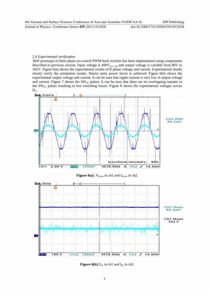
24 Experimental verification 3kW prototype of three phase six-switch PWM buck rectifier has been implemented using components described in previous section Input voltage is 400Vp-p rms and output voltage is variable from 80V to 342V Figure 6(a) shows the experimental results of R phase voltage and current Experimental results clearly verify the simulation results Nearly unity power factor is achieved Figure 6(b) shows the experimental output voltage and current It can be seen that ripple content is very low in output voltage and current Figure 7 shows the SWR1 pulses It can be seen that there are no overlapping instants in the SWR1 pulses resulting in low switching losses Figure 8 shows the experimental voltages across Dw
Figure 6(a) VRrms in ch1 and IRrms in ch2
Figure 6(b)Vdc in ch1 and Idc in ch2
6th Vacuum and Surface Sciences Conference of Asia and Australia (VASSCAA-6) IOP PublishingJournal of Physics Conference Series 439 (2013) 012028 doi1010881742-65964391012028
8
Figure 7 SWR1 pulses
Figure 8 VDW
6th Vacuum and Surface Sciences Conference of Asia and Australia (VASSCAA-6) IOP PublishingJournal of Physics Conference Series 439 (2013) 012028 doi1010881742-65964391012028
9
3 Conclusions It has been shown that three phase six-switch PWM buck rectifier is capable of drawing input current with low THD and nearly unity displacement factor using the modified SPWM Switching losses may be reduced up-to 30 using the suggested SPWM scheme Output voltage is variable over a wide range Energy storing components are small in size compared to PCR due to high switching frequency It is highly suitable for replacing conventional PCR at medium power level References [1] Conde-Enriques J Benites-Read J S Duran-Gomez J L and Pachecho-Sotelo J O 1999 IEE
Proceedings-Electric Power Applications Vol 146 issue (6) 637 [2] Ming-Tsung Tsai and Tsai W I 1999 Analysis IEEE Transactions on Industrial Electronics Vol
46 issue (3) 535 [3] Bin Wu High-power converters and Ac drives (John Wiley amp Sons Inc Hoboken New Jersey
2006) p219 [4] Navid R Zargari Geza Joos Phoivos D Ziogas 1994 IEEE Transactions on Industrial Electronics
Vol 30 issue (6) 235
6th Vacuum and Surface Sciences Conference of Asia and Australia (VASSCAA-6) IOP PublishingJournal of Physics Conference Series 439 (2013) 012028 doi1010881742-65964391012028
10

Three phase six-switch PWM buck rectifier with power factor improvement
M Zafarullah Khan1 M Mohsin Naveed1 and D M Akbar Hussain2
1Institute of Industrial Control Systems PO Box 1398 Rawalpindi Pakistan 2Department of Energy Technology Aalborg University Denmark
E-mail mohsinnaveed30gmailcom
Abstract Conventional Phase Controlled Rectifier injects low order current harmonics into the AC mains Large size filtering components are required to attenuate these harmonics In this paper three phase six-switch PWM buck rectifier is presented which operates at nearly unity power factor and provides variable output voltage Small size energy storing components are required depending upon switching frequency MATLAB simulation is performed and modified Sinusoidal Pulse Width Modulation (SPWM) switching technique is used in 3kW prototype converter to demonstrate low input current THD nearly unity displacement factor well regulated output voltage and reduced switching losses compared to conventional SPWM
1 Introduction In most of the power electronic applications ACDC converter is widely used as a first stage rectifier DC obtained from this rectifier is further converted into desired amplitude and frequency Most common topology of rectifier is three phase controlled rectifier (PCR) PCR is capable of delivering controlled DC voltage but it has a very low input power factor at low conduction angle and introduces unwanted distortion in AC mains It does not comply with IEEE-519 standard of low input current harmonics Large size low frequency input filters are required in PCR to improve its power factor This results in both increased cost and large size of the PCR PWM rectifiers have replaced the conventional PCR due to their high efficiency good voltage regulation nearly unity power factor and small inputoutput filter size depending upon switching frequency PWM rectifiers are normally operated at high switching frequency where low frequency harmonics are easily suppressed PWM rectifiers are increasingly becoming popular due to the availability of fast switching high voltage and high current IGBTs[1] Three phase PWM regenerative boost rectifier [2] is shown in figure 1 Output voltage is greater than the peak of the line to line RMS voltage in this rectifier This is a four quadrant rectifier capable of bidirectional power flow Operation of this rectifier is similar to boost SMPS When SWR2 is turned on voltage is applied across the inductor and it gets energized When SWR2 is turned off inductor de-energizes through the diode of SWR1 charging the capacitor Unity power factor is achieved by controlling the current in the inductor
6th Vacuum and Surface Sciences Conference of Asia and Australia (VASSCAA-6) IOP PublishingJournal of Physics Conference Series 439 (2013) 012028 doi1010881742-65964391012028
Content from this work may be used under the terms of the Creative Commons Attribution 30 licence Any further distributionof this work must maintain attribution to the author(s) and the title of the work journal citation and DOI
Published under licence by IOP Publishing Ltd 1
Figure 1 Three phase PWM regenerative boost rectifier
Three phase six-switch PWM buck rectifier is shown in figure 2 Output voltage of this rectifier is less than 126 times line to line RMS voltage [3] It is a unidirectional converter and power flow is controlled by controlling the depth of modulation and delay angle Modulation index and delay angle provide a flexible control over output voltage as well as input displacement factor [3] Change in delay angle produces lagging power factor which compensates the leading power factor of input capacitor resulting in unity displacement factor [3] However unity displacement factor is not achieved if capacitor current is greater than rectifier current for low loads Some applications of this rectifier are UPS battery chargers DC motor speed control front end converter in wind farms and front end converter in variable speed ac drives
Figure 2 Three phase six-switch PWM buck rectifier
6th Vacuum and Surface Sciences Conference of Asia and Australia (VASSCAA-6) IOP PublishingJournal of Physics Conference Series 439 (2013) 012028 doi1010881742-65964391012028
2
The rest of this paper discusses the design simulation and implementation of three phase six-switch PWM buck rectifier optimized to provide variable output voltage with low ripple contents and nearly unity power factor using small filters
2 Design of three phase six-switch PWM buck rectifier 21 PWM technique Assuming balanced set of three-phase input voltages the objective of this rectifier is to draw sinusoidal input currents in phase with input voltages Only active power flows through the bridge The ripple content is very low in the output voltage and it is well regulated since the devices are being switched at high frequency As the input voltages are balanced a three phase modified Sinusoidal PWM (SPWM) is applied to the switches and switching waveforms are shown in figure 3 Switching instants of all the switches are clearly mentioned in figure 3 Each switch is continuously conducting for 600 in the center of switching pattern There are no overlapping pulses in the switching waveforms instead freewheeling diode is used for overlapping instants resulting in the reduction of switching losses up-to 30 Switching pattern of 2kHz SPWM is generated using analogue discrete ICs and also both the modulation index and the delay angle is controlled
6th Vacuum and Surface Sciences Conference of Asia and Australia (VASSCAA-6) IOP PublishingJournal of Physics Conference Series 439 (2013) 012028 doi1010881742-65964391012028
3
Figure 3 Modified Sinusoidal Pulse Width Modulation
6th Vacuum and Surface Sciences Conference of Asia and Australia (VASSCAA-6) IOP PublishingJournal of Physics Conference Series 439 (2013) 012028 doi1010881742-65964391012028
4
22 Power topology Power topology consists of power semiconductors devices AC-side filter [4] and DC-side filter IGBTs are used with series fast recovery diode to block the reverse voltages across the IGBT The reverse blocking capability of IGBT is poor and series diode is required AC-side filter is implemented using gapped core inductor of 3mH and paper capacitor of 10uF It results in a small size filter with cut-off frequency of 920Hz DC-side filter consists of an inductor and capacitor Inductor is designed to maintain low ripple current and continuous flow of load current Small capacitor is required to filter out high frequency ripple components from the load current15mH inductor and 1000uF capacitor are used in the prototype and simulation RC snubber of 10 and 01uF is used across each switch Resistive load of 39 is used 23 MATLAB Simulink simulation Three phase six-switch PWM buck rectifier circuit has been simulated with Simulink using the values described in the last section Input voltage is 400Vp-p rms and output voltage is variable from 80V to 342V Figure 4(a) shows the simulation results of R phase voltage and current It can be seen that voltage and current are in phase displacement factor is nearly unity and THD is also low resulting in nearly unity power factor Figure 4(b) shows the simulation results of output voltage and current Voltage across DW is shown in figure 5
6th Vacuum and Surface Sciences Conference of Asia and Australia (VASSCAA-6) IOP PublishingJournal of Physics Conference Series 439 (2013) 012028 doi1010881742-65964391012028
5
Figure 4(a)VRrms and IRrms
6th Vacuum and Surface Sciences Conference of Asia and Australia (VASSCAA-6) IOP PublishingJournal of Physics Conference Series 439 (2013) 012028 doi1010881742-65964391012028
6
Figure 4(b) Vdc and Idc
Figure 5 VDW
6th Vacuum and Surface Sciences Conference of Asia and Australia (VASSCAA-6) IOP PublishingJournal of Physics Conference Series 439 (2013) 012028 doi1010881742-65964391012028
7
24 Experimental verification 3kW prototype of three phase six-switch PWM buck rectifier has been implemented using components described in previous section Input voltage is 400Vp-p rms and output voltage is variable from 80V to 342V Figure 6(a) shows the experimental results of R phase voltage and current Experimental results clearly verify the simulation results Nearly unity power factor is achieved Figure 6(b) shows the experimental output voltage and current It can be seen that ripple content is very low in output voltage and current Figure 7 shows the SWR1 pulses It can be seen that there are no overlapping instants in the SWR1 pulses resulting in low switching losses Figure 8 shows the experimental voltages across Dw
Figure 6(a) VRrms in ch1 and IRrms in ch2
Figure 6(b)Vdc in ch1 and Idc in ch2
6th Vacuum and Surface Sciences Conference of Asia and Australia (VASSCAA-6) IOP PublishingJournal of Physics Conference Series 439 (2013) 012028 doi1010881742-65964391012028
8
Figure 7 SWR1 pulses
Figure 8 VDW
6th Vacuum and Surface Sciences Conference of Asia and Australia (VASSCAA-6) IOP PublishingJournal of Physics Conference Series 439 (2013) 012028 doi1010881742-65964391012028
9
3 Conclusions It has been shown that three phase six-switch PWM buck rectifier is capable of drawing input current with low THD and nearly unity displacement factor using the modified SPWM Switching losses may be reduced up-to 30 using the suggested SPWM scheme Output voltage is variable over a wide range Energy storing components are small in size compared to PCR due to high switching frequency It is highly suitable for replacing conventional PCR at medium power level References [1] Conde-Enriques J Benites-Read J S Duran-Gomez J L and Pachecho-Sotelo J O 1999 IEE
Proceedings-Electric Power Applications Vol 146 issue (6) 637 [2] Ming-Tsung Tsai and Tsai W I 1999 Analysis IEEE Transactions on Industrial Electronics Vol
46 issue (3) 535 [3] Bin Wu High-power converters and Ac drives (John Wiley amp Sons Inc Hoboken New Jersey
2006) p219 [4] Navid R Zargari Geza Joos Phoivos D Ziogas 1994 IEEE Transactions on Industrial Electronics
Vol 30 issue (6) 235
6th Vacuum and Surface Sciences Conference of Asia and Australia (VASSCAA-6) IOP PublishingJournal of Physics Conference Series 439 (2013) 012028 doi1010881742-65964391012028
10
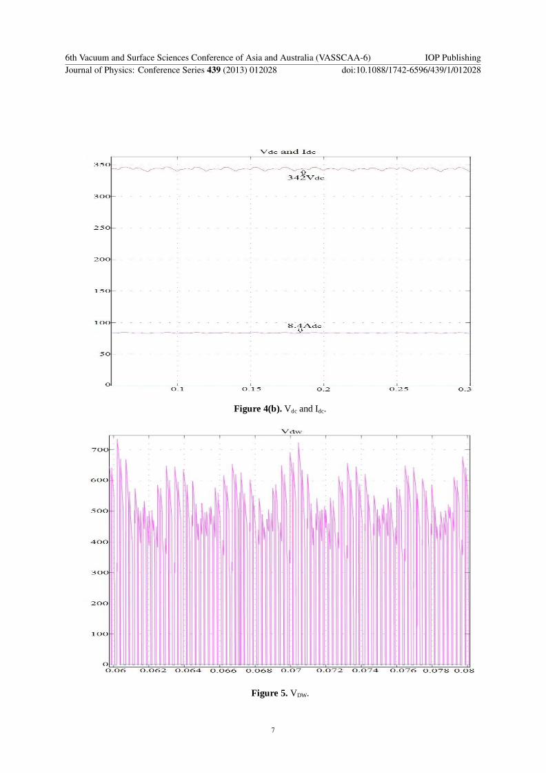