Three-Phase Power Circuits
24
NAME: BUTA SINGH KUSHWAHA Roll no: 10MUBEEE020 Class : A-1
-
Upload
hodeegits9526 -
Category
Documents
-
view
57 -
download
2
description
PPT on three phase system
Transcript of Three-Phase Power Circuits

NAME: BUTA SINGH KUSHWAHA
Roll no: 10MUBEEE020
Class : A-1

Almost all electric power generation and most of the power transmission in the world is in the form of three-phase AC circuits. A three-phase AC system consists of three-phase generators, transmission lines, and loads.
There are two major advantages of three-phase systems over a single-phase system:1)More power per kilogram of metal form a three-phase machine;2)Power delivered to a three-phase load is constant at all time, instead of pulsing as it does in a single-phase system.
The first three-phase electrical system was patented in 1882 by John Hopkinson - British physicist, electrical engineer, Fellow of the Royal Society.

A three-phase generator consists of three single-phase generators with voltages of equal amplitudes and phase differences of 1200.

Each of three-phase generators can be connected to one of three identical loads.
This way the system would consist of three single-phase circuits differing in phase angle by 1200.
The current flowing to each load can be found as
VIZ
(3.4.1)

Therefore, the currents flowing in each phase are
0
0
0
0
120120
240240
A
B
A
VI I
Z
VI I
Z
VI I
Z
(3.5.1)
(3.5.2)
(3.5.3)
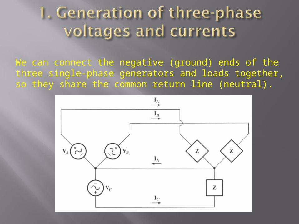
We can connect the negative (ground) ends of the three single-phase generators and loads together, so they share the common return line (neutral).
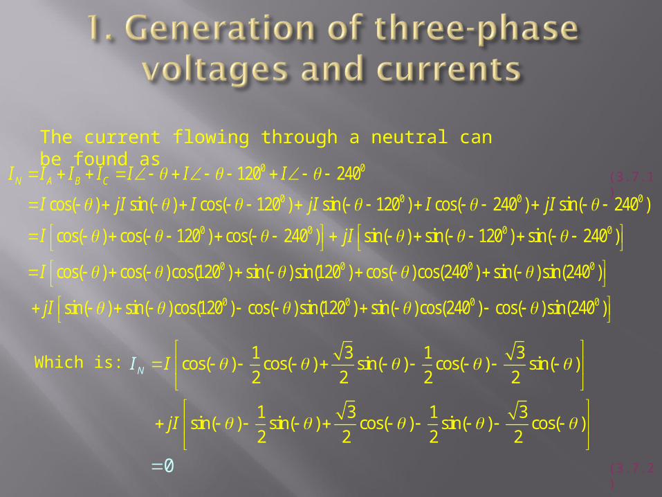
The current flowing through a neutral can be found as
0 0
0 0 0 0
0 0 0 0
120 240
cos( ) sin( ) cos( 120 ) sin( 120 ) cos( 240 ) sin( 240 )
cos( ) cos( 120 ) cos( 240 ) sin( ) sin( 120 ) sin( 240 )
cos(
N A B CI I I I I I I
I jI I jI I jI
I jI
I
0 0 0 0
0 0 0 0
) cos( )cos(120 ) sin( )sin(120 ) cos( )cos(240 ) sin( )sin(240 )
sin( ) sin( )cos(120 ) cos( )sin(120 ) sin( )cos(240 ) cos( )sin(240 )jI
1 3 1 3cos( ) cos( ) sin( ) cos( ) sin( )
2 2 2 2
1 3 1 3sin( ) sin( ) cos( ) sin( ) cos( )
2 2 2 2
0
NI I
jI
Which is:
(3.7.1)
(3.7.2)

As long as the three loads are equal, the return current in the neutral is zero!
Such three-phase power systems (equal magnitude, phase differences of 1200, identical loads) are called balanced.
In a balanced system, the neutral is unnecessary!
Phase Sequence is the order in which the voltages in the individual phases peak.
abc acb

There are two types of connections in three-phase circuits: Y and .
Each generator and each load can be either Y- or -connected. Any number of Y- and -connected elements may be mixed in a power system.
Phase quantities - voltages and currents in a given phase.Line quantities – voltages between the lines and currents in the lines connected to the generators.

1. Y-connection
Assuming a resistive load…
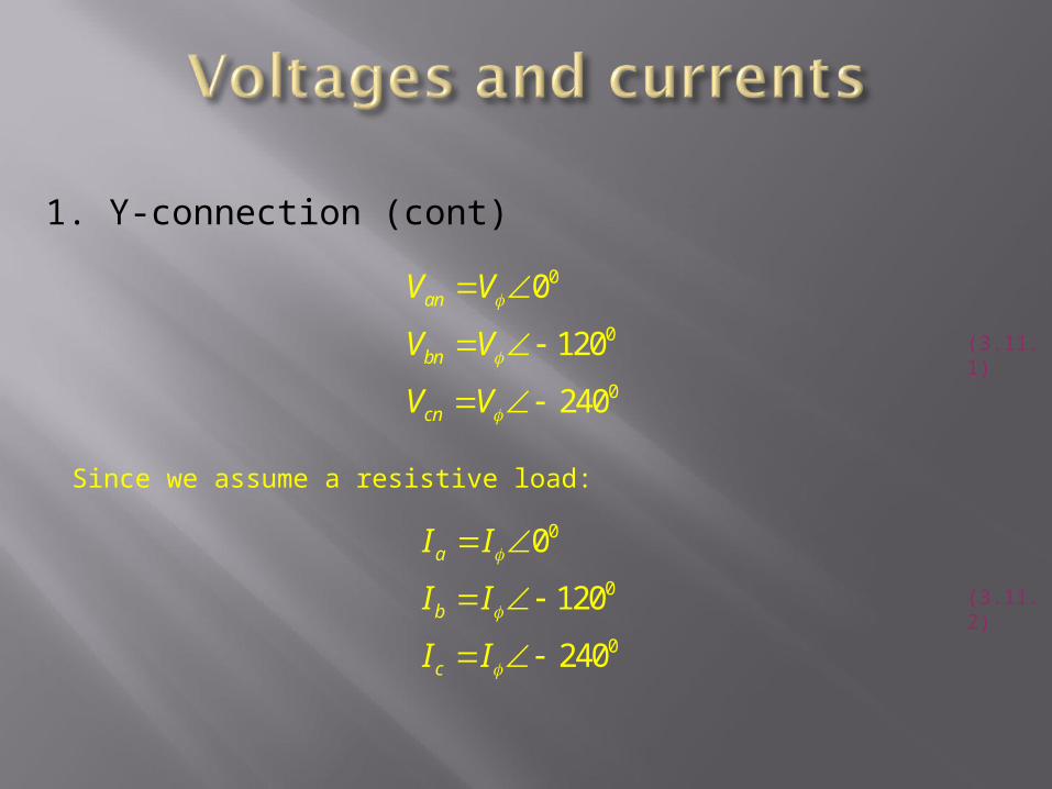
1. Y-connection (cont)
0
0
0
0
120
240
an
bn
cn
V V
V V
V V
0
0
0
0
120
240
a
b
c
I I
I I
I I
Since we assume a resistive load:
(3.11.1)
(3.11.2)
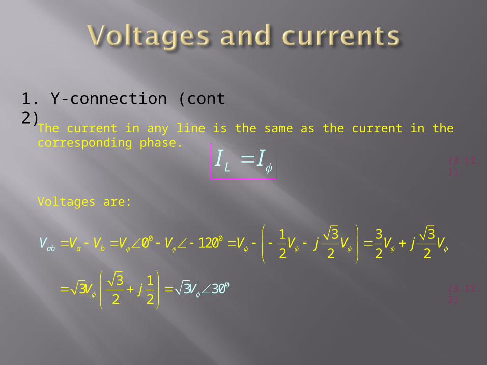
1. Y-connection (cont 2)
The current in any line is the same as the current in the corresponding phase.
LI I
Voltages are:
0
0
0 1 3 3 30 120
2 2 2 2
3 13
2 2303
aab bV V V V V V jV V j V
j V
V
V
(3.12.1)
(3.12.2)

1. Y-connection (cont 3)
3LLV V
Magnitudes of the line-to-line voltages and the line-to-neutral voltages are related as:
In addition, the line voltages are shifted by 300 with respect to the phase voltages.
(3.13.1)
In a connection with abc sequence, the voltage of a line leads the phase voltage.
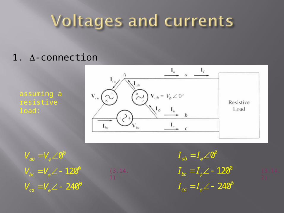
1. -connection
0
0
0
0
120
240
ab
bc
ca
V V
V V
V V
0
0
0
0
120
240
ab
bc
ca
I I
I I
I I
assuming a resistive load:
(3.14.1) (3.14.2)
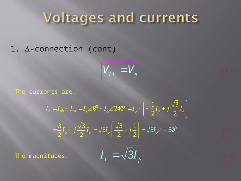
1. -connection (cont)
LLV V
The currents are:
0 0
0
1 30 240
2 2
3 3 3 13
2 2 2 23 30
ab caa I I I I I II
I
j I
I j I I j
3LI I
(3.15.1)
(3.15.2)
(3.15.3)The magnitudes:

For the connections with the abc phase sequences, the current of a line lags the corresponding phase current by 300 (see Figure below).
For the connections with the acb phase sequences, the line current leads the corresponding phase current by 300.
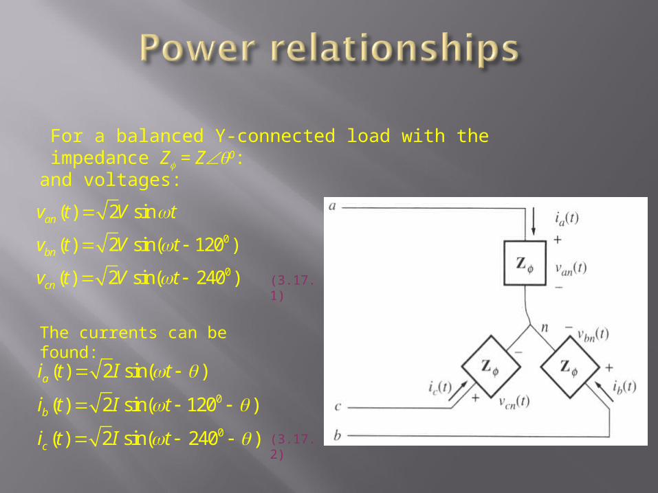
For a balanced Y-connected load with the impedance Z = Z0:
0
0
( ) 2 sin
( ) 2 sin( 120 )
( ) 2 sin( 240 )
an
bn
cn
v t V t
v t V t
v t V t
and voltages:
The currents can be found:
0
0
( ) 2 sin( )
( ) 2 sin( 120 )
( ) 2 sin( 240 )
a
b
c
i t I t
i t I t
i t I t
(3.17.1)
(3.17.2)
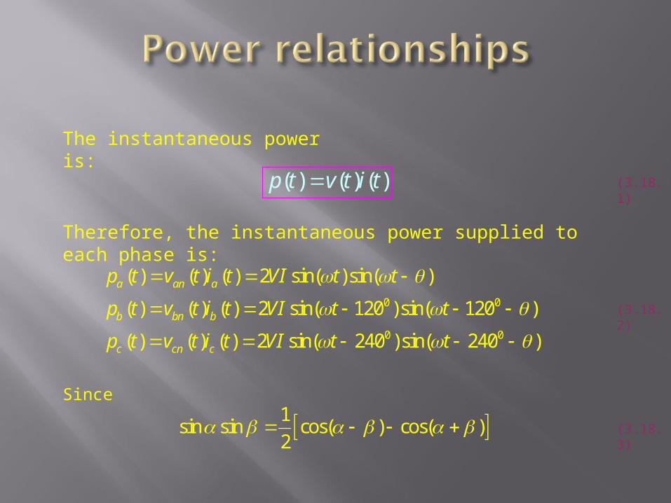
The instantaneous power is:
( ) ( ) ( )p t v t i t
Therefore, the instantaneous power supplied to each phase is:
0 0
0 0
( ) ( ) ( ) 2 sin( )sin( )
( ) ( ) ( ) 2 sin( 120 )sin( 120 )
( ) ( ) ( ) 2 sin( 240 )sin( 240 )
a an a
b bn b
c cn c
p t v t i t VI t t
p t v t i t VI t t
p t v t i t VI t t
(3.18.1)
(3.18.2)
Since
1sin sin cos( ) cos( )
2 (3.18.3)

Therefore
0
0
( ) cos cos(2 )
( ) cos cos(2 240 )
( ) cos cos(2 480 )
a
b
c
p t VI t
p t VI t
p t VI t
The total power on the load
( ) ( )( ) 3 cos( )tot a b cp t p tp t Vp t I
The pulsing components cancel each other because of 1200 phase shifts.
(3.19.1)
(3.19.2)

The instantaneous power in phases.
The total power supplied to the load is constant.

Phase quantities in each phase of a Y- or -connection.
23 cos 3 cosP V I I Z
23 sin 3 sinQ V I I Z
23 3S V I I Z
Real
Reactive
Apparent
Note: these equations are valid for balanced loads only.
(3.21.1)
(3.21.1)
(3.21.1)

Line quantities: Y-connection.
Power consumed by a load: 3 cosP V I
Since for this load 3L LLI I and V V
Therefore: 3 cos3LL
L
VP I
Finally: 3 cosLL LP V I
(3.22.1)
(3.22.2)
(3.22.3)
(3.22.4)
Note: these equations are valid for balanced loads only.

Line quantities: -connection.
Power consumed by a load: 3 cosP V I (3.23.1)
Since for this load 3L LLI I and V V (3.23.2)
Note: these equations were derived for a balanced load.
Therefore: 3 cos3L
LL
IP V
Finally: 3 cosLL LP V I
(3.23.3)
(3.23.4)
Same as for a Y-connected load!

Line quantities: Y- and -connection.
3 sinLL LQ V I
3 LL LS V I
Reactive power
Apparent power
(3.24.1)
(3.24.2)
Note: is the angle between the phase voltage and the phase current – the impedance angle.