Three Phase Multi-function DIN rail meter · Eastron SDM530-Modbus User Manual - 1 - SDM530-Modbus...
19
Eastron SDM530-Modbus User Manual - 1 - SDM530-Modbus Three Phase Multi-function DIN rail meter Measures kWh Kvarh, KW, Kvar, KVA, P, F, PF, Hz, dmd, V, A, etc. Bi-directional measurement IMP & EXP Two pulse outputs RS485 Modbus Din rail mounting 35mm 100A direct connection Better than Class 1 / B accuracy USER MANUAL 2015 V1.5
-
Upload
nguyenkien -
Category
Documents
-
view
229 -
download
0
Transcript of Three Phase Multi-function DIN rail meter · Eastron SDM530-Modbus User Manual - 1 - SDM530-Modbus...
Eastron SDM530-Modbus User Manual
- 1 -
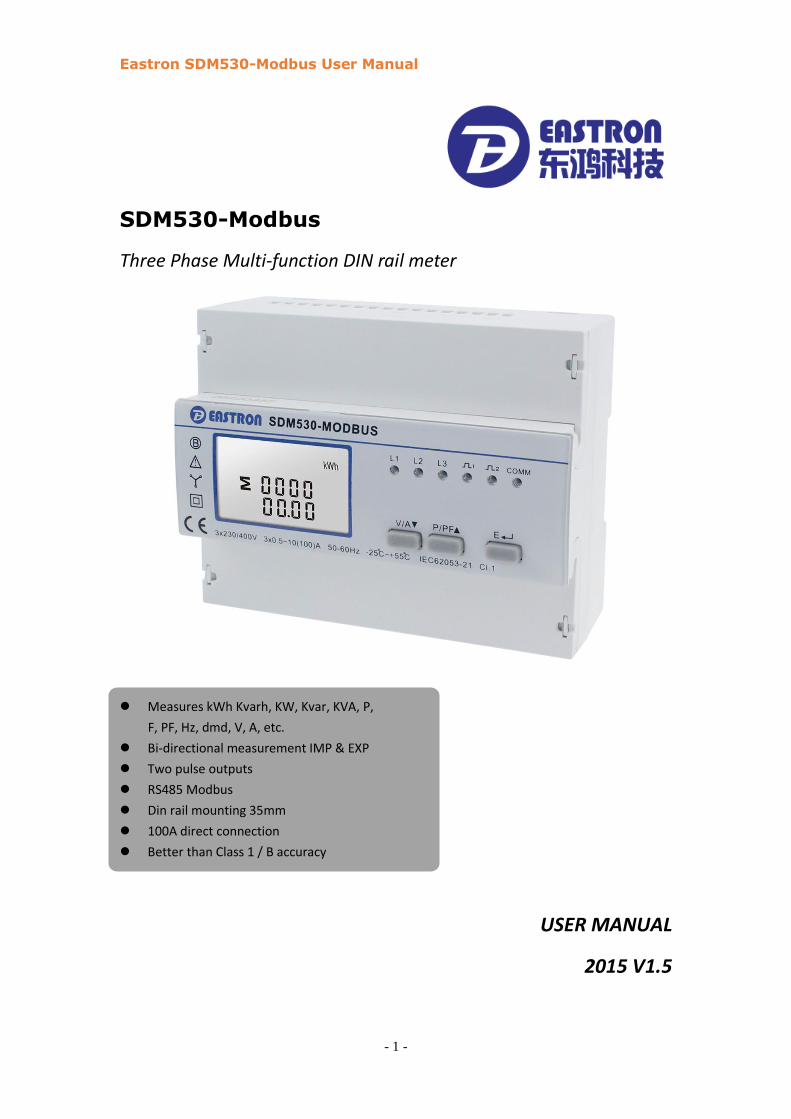
SDM530-Modbus
Three Phase Multi-function DIN rail meter
Measures kWh Kvarh, KW, Kvar, KVA, P,
F, PF, Hz, dmd, V, A, etc.
Bi-directional measurement IMP & EXP
Two pulse outputs
RS485 Modbus
Din rail mounting 35mm
100A direct connection
Better than Class 1 / B accuracy
USER MANUAL
2015 V1.5

Eastron SDM530-Modbus User Manual
- 2 -
Introduction
The SDM530-Modbus measures and displays the characteristics of three phase four wires (3p4w)
supplies, including voltage, frequency, current, power, active and reactive energy, imported or
exported. Energy is measured in terms of kWh, kVArh. Maximum demand current can be
measured over preset periods of up to 60 minutes. In order to measure energy, the unit requires
voltage and current inputs in addition to the supply required to power the product.
SDM530-Modbus supports max. 100A direct connection, saves the cost and avoid the trouble to
connect external CTs, giving the unit a cost-effective and easy operation. Built-in interfaces
provides pulse and RS485 Modbus RTU outputs. Configuration is password protected.
Unit Characteristics
The Unit can measure and display:
Line voltage
Line Frequency
Currents, Current demands
Power, maximum power demand and power factor
Active energy imported and exported
Reactive energy imported and exported
The unit has password-protected set-up screens for:
Changing password
Demand Interval Time(DIT)
Reset for demand measurements
Pulse output duration
Two pulse output indicates real-time energy measurement. An RS485 output allows remote
monitoring from another display or a computer.
RS485 Serial–Modbus RTU
This uses an RS485 serial port with Modbus RTU protocol to provide a means of remotely
monitoring and controlling the Unit
Set-up screens are provided for setting up the RS485 port.
Pulse output
This provides two pulse outputs that clock up measured active and reactive energy. The constant
of pulse output 2 for active energy is 400imp/kWh (un-configurable), its width is fixed at 100ms.
The default constant of configurable pulse output 1 is 400imp/kWh, default pulse width is
100ms.The configurable pulse output 1 can be set from the set-up menu.

Eastron SDM530-Modbus User Manual
- 3 -
Start-up Screens
1
The first screen lights up all display
segments and can be used as a display
check
2
The second screen indicates the
firmware installed in the unit and its
build number.
3
The interface performs a self-test and
indicates the result if the test passes.
After 5 seconds delay, the screen will display active energy measurements.
Measurements
The buttons operate as follows:
1
Select the Voltage and Current display screens
In Set-up Mode, this is the “Up” or “back” button
2
Select the Power ,Frequency and Power factor
display screens
In Set-up Mode, this is the “Down” button
3
Select the Energy display screens
In Set-up mode, this is the “Enter” or “Right”
button

Eastron SDM530-Modbus User Manual
- 4 -
Voltage and Current and Max Demand
Each successive pressing of the button selects a new range:
1-1
Phase to neutral voltages
1-2
Phase to phase voltages
2-1
Current on each phase
2-2
Neutral current
3
Maximum Current Demand
Power and Frequency and Power factor
Each successive pressing of the button selects a new range:

Eastron SDM530-Modbus User Manual
- 5 -
1-1
Instantaneous Active Power in kW
When it’s exported, there will be a mark
of minus “-”.
1-2
Instantaneous Reactive Power in kVAr
When it’s exported, there will be a mark
of minus “-”.
1-3
Instantaneous Volt-amps in KVA
When it’s exported, there will be a mark
of minus “-”.
1-4
Total kW, kVArh, kVA
When it’s exported, there will be a mark
of minus “-”.
2
Frequency and Power Factor (total)
3
Power Factor of each phase

Eastron SDM530-Modbus User Manual
- 6 -
4
Maximum Power Demand
Energy Measurements
Each successive short pressing (lasting less than 3s) of the button selects a new
range:
1-1
Total active energy in kWh
Total kWh=imported +exported (kWh)
1-2
Total Imported active energy in kWh
1-3
Total Exported active energy in kWh
2-1
Total reactive energy in kVArh
Total kVArh=imported +exported (kVArh)

Eastron SDM530-Modbus User Manual
- 7 -
2-2
Imported reactive energy in kVArh
2-3
Exported reactive energy in kVArh
Set-up
To enter set-up mode, long pressing the button for 3 seconds, until the password
screen appears.
Setting up is password-protected so you must enter the correct password (default ‘1000’) before
processing. If an incorrect password is entered, the display will show: Err
To exit setting-up mode, press repeatedly until the measurement screen is restored.
Menu Option Selection
1) Use the and buttons to select the required item from the menu
2) Press to confirm your selection

Eastron SDM530-Modbus User Manual
- 8 -
3) If an item flashes, then it can be adjusted by the and buttons. If
not, there maybe a further layer.
4) Having selected an option from the current layer, press to confirm your selection.
The SET indicator will appear.
5) Having completed a parameter setting, press to return to a higher menu level. The
SET indicator will be removed and you will be able to use the and
buttons for further menu selection.
6) On completion of all set-up, press repeatedly until the measurement screen is
restored.
Number Entry Procedure
When setting up the unit, some screens require the entering of a number. In particular, on entry
to the setting up section, a password must be entered. Digits are set individually, from left to
right. The procedure is as follows:
1) The current digit to be set flashes and is set using the and buttons
2) Press to confirm each digit setting. The SET indicator appears after the last digit
has been set.
3) After setting the last digit, press to exit the number setting routine. The SET
indicator will be removed.
Change password
1
Use the and to
choose the change password option
2-1
Press the to enter the change
password routine. The new password
screen will appear with the first digit
flashing

Eastron SDM530-Modbus User Manual
- 9 -
2-2
Use and to set
the first digit and press to
confirm your selection. The next digit will
flash.
2-3
Repeat the procedure for the remaining
three digits
2-4
After setting the last digit, SET will show.
Press to exit the number setting routine and return to the Set-up menu. SET will
be removed
DIT Demand Integration Time
This sets the period in minutes over which the current and power readings are integrated for
maximum demand measurement. The options are: 1, 5, 8, 10, 15, 30, 60 minutes
1
From the set-up menu,
use and buttons
to select the DIT option. The screen will
show the currently selected integration
time.
Default is 60
2-1
Press to enter the selection
routine.
The current time interval will flash

Eastron SDM530-Modbus User Manual
- 10 -
2-2
Use and
buttons to select the time required.
2-3
Press to confirm the
selection. SET indicator will appear.
Press to exit the DIT selection routine and return to the menu.
Backlit set-up
1
The backlit lasting time is settable
Default lasting time is 60minutes
For example, if it’s set as 5, the backlit
will be off in 5minutes from the last time
operation on the meter.
2
Press to enter the selection
routine. The current time interval will
flash.
The options can be:0/10/30/60/120
“0” means always on
Default is 60 minutes
Use and buttons to select the time required. Press to
confirm the set-up,
Pulse output
This option allows you to configure the pulse output 1. The output can be set to provide a pulse
for a defined amount of energy active or reactive.
Use this section to set up the pulse output for:
Total kWh/ Total kVArh
Active kWh/Reactive kWh
Active kVArh/Reactive kVArh

Eastron SDM530-Modbus User Manual
- 11 -
1
From the Set-up menu, use
and buttons to select the
Pulse output option.
2-1
Press to enter the selection
routine. The unit symbol will flash.
2-2
Use and buttons
to choose kWh or kVArh.
On completion of the entry procedure, press to confirm the setting and press
to return to the main set up menu.
Pulse rate
Use this to set the energy represented by each pulse. Rate can be set to 1 pulse per
DFt/0.1/1/10/100kWh/kVArh
(It shows 1 impulse = 0.01kWh/kVArh)
1
From the Set-up menu, use
and buttons to select the
Pulse Rate option.

Eastron SDM530-Modbus User Manual
- 12 -
2
Press to enter the selection
routine. The current setting will flash.
Default is DFt(0.025kWh/kVArh)
Use and buttons to choose pulse rate. On completion of the entry
procedure, press to confirm the setting and press to return to the
main set up menu.
Pulse Duration
The energy monitored can be active or reactive and the pulse width can be selected as
200, 100(default) or 60ms.
(It shows pulse width of 100ms)
1-1
From the Set-up menu, use
and buttons to select the
Pulse width option.
1-2
Press to enter the selection
routine. The current setting will flash.
Default is 100
Use and buttons to choose pulse width. On Completion of the entry
procedure, press to confirm the setting and press to return to the
main set up menu.

Eastron SDM530-Modbus User Manual
- 13 -
Scroll display
1-1
From the Set-up menu, use
and buttons to select the
Pulse scroll display option.
1-2
Press to enter the selection
routine. The current setting will flash.
The options can be:1 to255 Seconds
Default is 255s
Use and buttons to choose interval of scroll display. On completion of
the entry procedure, press to confirm the setting and press to return
to the main set up menu. To activate the scroll display mode, press the lasting for
2seconds on the main interface. To close it, press button lasting for 2seconds
accordingly. The default status of scroll display is closed.
Communication
There is a RS485 port can be used for communication using Modbus RTU protocol.
RS485 Address
(The range is from 001 to 247)
1
From the Set-up menu, use
and buttons to select the
Address ID

Eastron SDM530-Modbus User Manual
- 14 -
2-1
Press button to enter the
selection routine. The current setting will
be flashing.
2-2
Use and
buttons to choose Modbus Address(001
to 247)
On completion of the entry procedure, press button to confirm the setting and
press button to return the main set-up menu.
Baud Rate
1
From the Set-up menu, use
and buttons to select the
Baud Rate option.
2-1
Press to enter the selection
routine. The current setting will flash.
2-2
Use and
buttons to choose Baud rate 2.4k. 4.8k,
9.6k (default).
On completion of the entry procedure, press to confirm the setting and press

Eastron SDM530-Modbus User Manual
- 15 -
to return to the main set up menu.
Parity
1
From the Set-up menu, use
and buttons to select the
Parity option.
2-1
Press to enter the selection
routine. The current setting will flash.
2-2
Use and buttons
to choose Parity (EVEN / ODD / NONE)
Default is NONE
On completion of the entry procedure, press to confirm the setting and press
to return to the main set up menu.
Stop bits
1
From the Set-up menu, use
and buttons to select the
Stop Bit option.
Eastron SDM530-Modbus User Manual
- 16 -
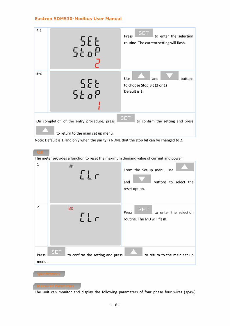
2-1
Press to enter the selection
routine. The current setting will flash.
2-2
Use and buttons
to choose Stop Bit (2 or 1)
Default is 1.
On completion of the entry procedure, press to confirm the setting and press
to return to the main set up menu.
Note: Default is 1, and only when the parity is NONE that the stop bit can be changed to 2.
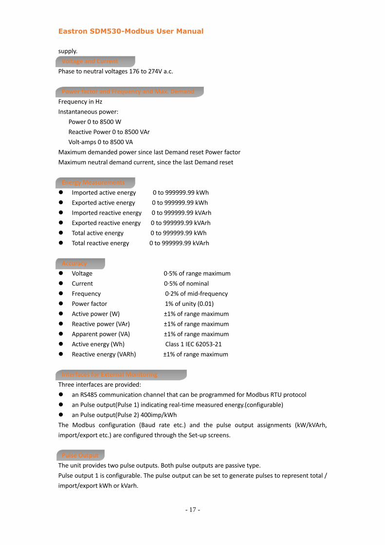
CLR
The meter provides a function to reset the maximum demand value of current and power.
1
From the Set-up menu, use
and buttons to select the
reset option.
2
Press to enter the selection
routine. The MD will flash.
Press to confirm the setting and press to return to the main set up
menu.
Specifications
Measured Parameters
The unit can monitor and display the following parameters of four phase four wires (3p4w)
Eastron SDM530-Modbus User Manual
- 17 -
supply.
Voltage and Current
Phase to neutral voltages 176 to 274V a.c.
Power factor and Frequency and Max. Demand
Frequency in Hz
Instantaneous power:
Power 0 to 8500 W
Reactive Power 0 to 8500 VAr
Volt-amps 0 to 8500 VA
Maximum demanded power since last Demand reset Power factor
Maximum neutral demand current, since the last Demand reset
Energy Measurements
Imported active energy 0 to 999999.99 kWh
Exported active energy 0 to 999999.99 kWh
Imported reactive energy 0 to 999999.99 kVArh
Exported reactive energy 0 to 999999.99 kVArh
Total active energy 0 to 999999.99 kWh
Total reactive energy 0 to 999999.99 kVArh
Accuracy
Voltage 0·5% of range maximum
Current 0·5% of nominal
Frequency 0·2% of mid-frequency
Power factor 1% of unity (0.01)
Active power (W) ±1% of range maximum
Reactive power (VAr) ±1% of range maximum
Apparent power (VA) ±1% of range maximum
Active energy (Wh) Class 1 IEC 62053-21
Reactive energy (VARh) ±1% of range maximum
Interfaces for External Monitoring
Three interfaces are provided:
an RS485 communication channel that can be programmed for Modbus RTU protocol
an Pulse output(Pulse 1) indicating real-time measured energy.(configurable)
an Pulse output(Pulse 2) 400imp/kWh
The Modbus configuration (Baud rate etc.) and the pulse output assignments (kW/kVArh,
import/export etc.) are configured through the Set-up screens.
Pulse Output
The unit provides two pulse outputs. Both pulse outputs are passive type.
Pulse output 1 is configurable. The pulse output can be set to generate pulses to represent total /
import/export kWh or kVarh.

Eastron SDM530-Modbus User Manual
- 18 -
The pulse constant can be set to generate 1 pulse per:
DFt=25 Wh/VArh
0.01 = 10 Wh/VArh
0.1 = 100 Wh/VArh
1 = 1 kWh/kVArh
10=10Wh/kVArh
100 = 100 kWh/kVArh
Pulse width: 200/100/60ms
Pulse output 2 is non-configurable. It is fixed up with active kWh. The constant is 400imp/kWh.
RS485 Output for Modbus RTU
For Modbus RTU, the following RS485 communication parameters can be configured from the
Set-up menu:
Baud rate 2400, 4800, 9600
Parity none (default)/odd/even
Stop bits 1 or 2
RS485 network address nnn – 3-digit number, 001 to 247
Modbus™ Word order Hi/Lo byte order is set automatically to normal or reverse. It cannot
be configured from the set-up menu.
Reference Conditions of Influence Quantities
Influence Quantities are variables that affect measurement errors to a minor degree. Accuracy is
verified under nominal value (within the specified tolerance) of these conditions.
Ambient temperature 23°C ±1°C
Input waveform 50 or 60Hz ±2%
Input waveform Sinusoidal (distortion factor < 0·005)
Magnetic field of external origin Terrestrial flux
Environment
Operating temperature -25°C to +55°C*
Storage temperature -40°C to +70°C*
Relative humidity 0 to 90%, non-condensing
Altitude Up to 2000m
Warm up time 1 minute
Vibration 10Hz to 50Hz, IEC 60068-2-6, 2g

Eastron SDM530-Modbus User Manual
- 19 -
Dimensions
Wiring diagram