THREE EQUAL ALTITUDE PROBLEM, ASTROLABE,...
36
THREE EQUAL ALTITUDE PROBLEM, ASTROLABE, APPLICATION OF A NEW COMPUTATION METHOD AND ITS THEORY Kasım YAŞAR Mobil Exploration Mediterranean Inc., Ankara ABSTRACT. — The method described in this dissertation was investigated and discussed at first in 1785 by Aboe and then in 1808 by Gauss and later in 1811 by Delamber under the name of «Three equal altitude star problem.» The primitiveness of fine mechanics and drawback in the precision technique of the 19th century was limiting the astronomers of those days to get their best results in time and latitude determinations. Especially by using «Chandler's Almucantar» and «Beck's Nadir device>> one could get highly 1 second of arc accuracy in latitude and 1/2 second of time accuracy in longitude obser- vations. So that the above-mentioned method was used by travelers particularly on the geographi- cal expeditions. At the beginning of the 20th century measuring tools developed to such an extent that the instruments, like universal theodolites, zenith telescopes, astrolabes, etc., have been carefully designed and constructed. So that the observational precision became very high and especially one could obtain In order to establish astronomical points on the wide extended areas for high accurate triangulation chains the above-mentioned limits pertaining 10 precision were adequate, but very often difficulties were confronted in operations on the moun ainous regions because of transporta- tion of the heavy observational equipment. In eliminating this disadvantage, both the geodesist and the instrument makers, have de- cided to furnish measuring devices of considerable small size and light weight, such as Gautier, Tavistock, Wild, etc., theodolites. In this investigation the writer made use of one of the above-written instruments and found the opportunity to make several observations and practiced and tested different methods, which are described in the original text. The writer developed theoretically a new computation method and derived formulae for computing the time and latitude correctio is and in addition to that he worked out a mean error formula for determining the accuracy of his principles. He compared separately his observation system with J. Ball and Th. Niethammer funda- mentals in order to give an idea how safe the results of his measurements were and how convenient the usage of his new ocular attachment was and at last how fast was the observational operations which were carried out against above-mentioned classical methods. The writer gave also a detailed summary in Part 2, regarding the computational results of the different methods. By the utilization of this table one can have an immediate and relative estimation between time, latitude and prism angle corrections and of their accuracy. At the end of this paper the writer developed a special chronometer rate formula by using the rates which were obtained from star observations and from the signal receptions. With regard to the longitude computations, he made use of two different chronometer rate values which were calculated on the base of time signal receptions and the formula mention- ed above.
Transcript of THREE EQUAL ALTITUDE PROBLEM, ASTROLABE,...
THREE EQUAL ALTITUDE PROBLEM, ASTROLABE, APPLICATIONOF A NEW COMPUTATION METHOD AND ITS THEORY
Kasım Y A Ş A R
Mobil Exploration Mediterranean Inc., Ankara
ABSTRACT. — The method described in this dissertation was investigated and discussed
at f irst in 1785 by Aboe and then in 1808 by Gauss and later in 1811 by Delamber under the
name of «Three equal al t i tude star problem.»
The primitiveness of fine mechanics and drawback in the precision technique of the 19th
century was l imit ing the astronomers of those days to get their best results in time and latitudedeterminations.
Especially by using «Chandler's Almucantar» and «Beck's Nadir device>> one could get
highly 1 second of arc accuracy in latitude and 1/2 second of time accuracy in longitude obser-
vations. So that the above-mentioned method was used by travelers particularly on the geographi-
cal expeditions.
At the beginning of the 20th century measuring tools developed to such an extent that
the instruments, l ike universal theodolites, zenith telescopes, astrolabes, etc., have been carefully
designed and constructed. So that the observational precision became very high and especially one
could obtain
In order to establish astronomical points on the wide extended areas for high accurate
triangulation chains the above-mentioned l imits pertaining 10 precision were adequate, but very
often difficulties were confronted in operations on the moun ainous regions because of transporta-
tion of the heavy observational equipment.
In eliminating this disadvantage, both the geodesist and the instrument makers, have de-
cided to furnish measuring devices of considerable smal l size and light weight, such as Gautier,Tavistock, Wild, etc., theodolites.
In this investigation the writer made use of one of the above-written instruments and
found the opportunity to make several observations and practiced and tested different methods,
which are described in the original text.
The writer developed theoretically a new computation method and derived formulae for
computing the t ime and latitude correctio is and in addition to that he worked out a mean error
formula for determining the accuracy of his principles.
He compared separately his observation system with J. Ball and Th. Niethammer funda-
mentals in order to give an idea how safe the results of h i s measurements were and how convenient
the usage of h i s new ocular attachment was and at last how fast was the observational operations
which were carried out against above-mentioned classical methods.
The writer gave also a detailed summary in Part 2, regarding the computational results
of the different methods. By the ut i l izat ion of this table one can have an immediate and relative
estimation between time, la t i tude and prism angle corrections and of their accuracy.
At the end of this paper the writer developed a special chronometer rate formula by using
the rates which were obtained from star observations and from the signal receptions.
With regard to the longitude computations, he made use of two different chronometer
rate values which were calculated on the base of time signal receptions and the formula mention-ed above.
98 Kasım YAŞAR
For eliminating the influence of rate variation in regard to time correction, the writerused the chronometer rate which is obtained from signal receptions for J. Ball and Th. Nietham-mer longitude values.
At the end, the writer presents a f inal comparison between the semi-definitive values andhis results both in longitude and lat i tude determinations and in addition to that he explains thesuperiority of his method with regard to the accuracy and rapidity against J. Ball and Th. Niet-hammer methods.
PART I
This method was investigated and discussed in principle and detail first in1785 by Aboe and then in 1808 by Gauss and later on in 1811 by Delambrewith a view to determining the longitude and latitude; i.e., the geophysicalcoordinates of a locality on earth surface.
In addition to the above-mentioned investigations, Knorre extended theapplication of this method to the case of more than three stars. But due to theprimitiveness of the f ine mechanics and the drawbacks in the precision techni-ques of the 19th century, these methods have not been used for a long period, l
until Chandler's Almucantar and Beck's Nadir instruments were developed.
By using the above-mentioned devices one could get easily one second ofarc accuracy in latitude observations; as a result of this Knorre's method wasused by travelers, only and particularly on the geophysical expeditions.
Nowadays geodesy is proceeding with such extreme precision limits thatthe application of astrometry should meet the requirements for determiningaccurately the locations of Laplace stations of the triangulation chains. Todayin practice, the astronomers are using portable high-precision universal theo-dolites and/or transit instruments with 6.5 to 7.0 cm. free objective lense widthsand 21 to 27.5 cm. alidade circle radii and 1 second of arc hang levels. In spiteof this, the obtainable accuracy in latitude determination is + 0.15 second ofarc and in longitude determination + 0.02 second of time.
As for the determination of the deflections of the vertical, one can main-tain the above precision figures as maximum limits.
In order to eliminate the errors of accidental and systematical nature anderrors of unknown character as well as the orientation error due to deflection ofthe plumb line, one can combine longitude, latitude and azimuth observationsas pair-wise observation system with the same object and in one instrument set-up.
The general advantages of the applied method and the sufficiency ofobtained data for solving the problems of position determination in astrometrywill now be described and discussed in detail :
A. Computation of the three equal altitude problem will be carried outusing the formulae derived by Gauss. We wil l now use the cosine theorem., withthe signs having the following significances :
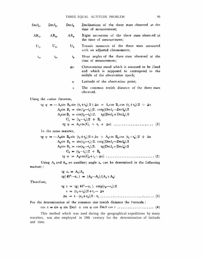
THREE EQUAL ALTITUDE PROBLEM 99
This method which was used during the geographical expeditions by manytravelers, was also employed in 19th century for the determination of latitudeand time.
100 Kasım YAŞAR
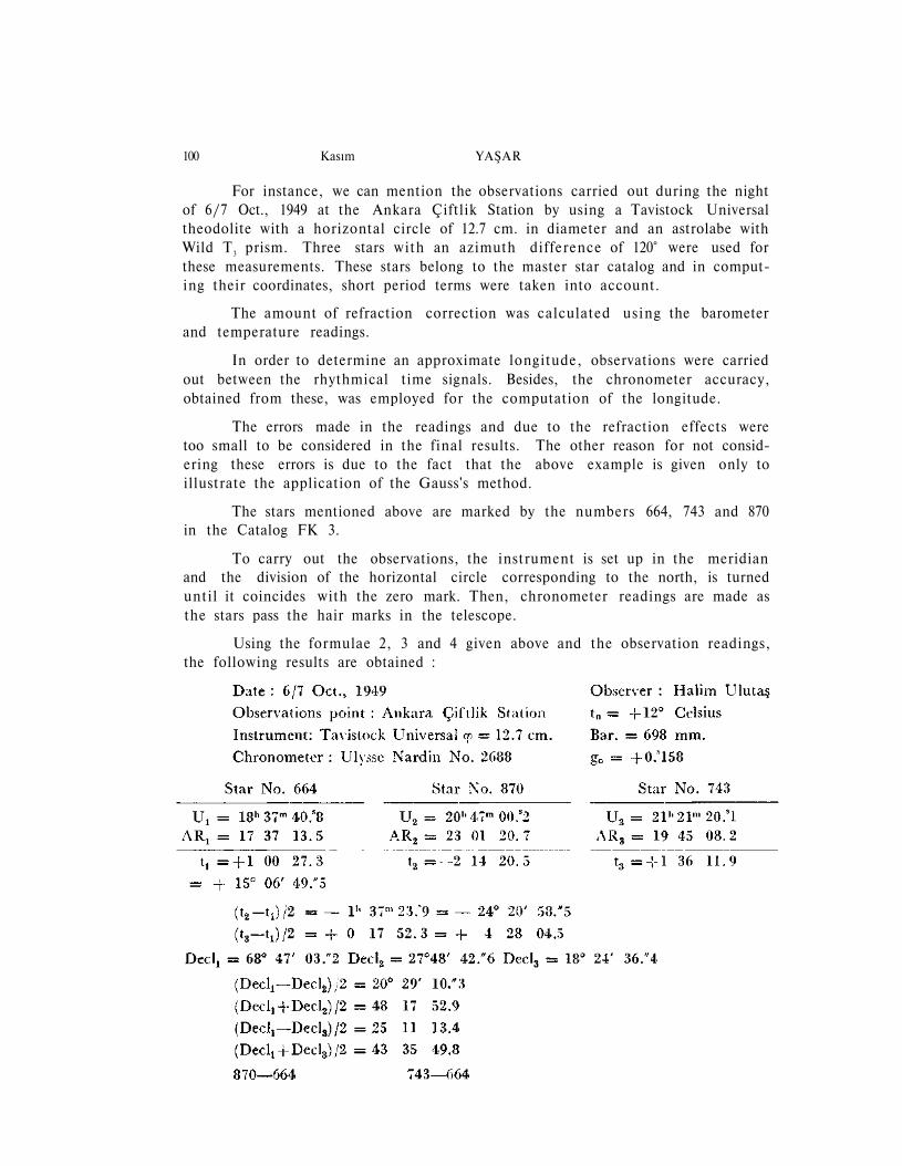
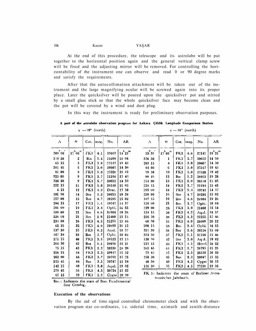
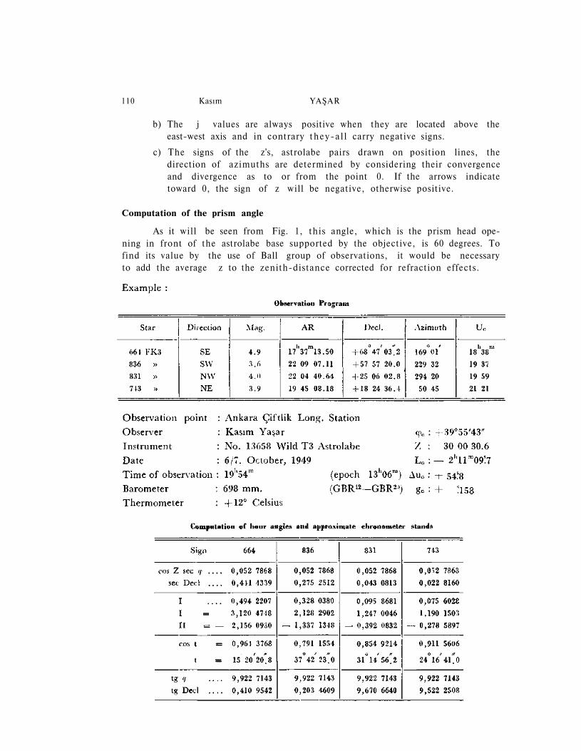
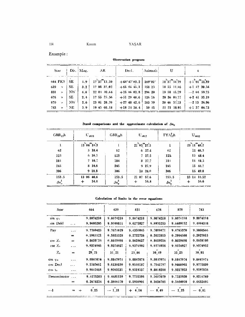
For instance, we can mention the observations carried out during the nightof 6/7 Oct., 1949 at the Ankara Çiftlik Station by using a Tavistock Universaltheodolite with a horizontal circle of 12.7 cm. in diameter and an astrolabe withWild T3 prism. Three stars with an azimuth difference of 120° were used forthese measurements. These stars belong to the master star catalog and in comput-ing their coordinates, short period terms were taken into account.
The amount of refraction correction was calculated us ing the barometerand temperature readings.
In order to determine an approximate longitude, observations were carriedout between the rhythmical time signals. Besides, the chronometer accuracy,obtained from these, was employed for the computation of the longitude.
The errors made in the readings and due to the refraction effects weretoo small to be considered in the final results. The other reason for not consid-ering these errors is due to the fact that the above example is given only toillustrate the application of the Gauss's method.
The stars mentioned above are marked by the numbers 664, 743 and 870in the Catalog FK 3.
To carry out the observations, the instrument is set up in the meridianand the division of the horizontal circle corresponding to the north, is turneduntil it coincides with the zero mark. Then, chronometer readings are made asthe stars pass the hair marks in the telescope.
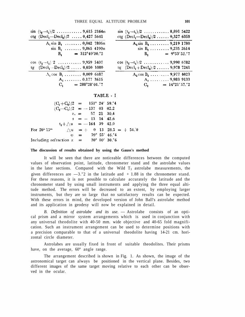
Using the formulae 2, 3 and 4 given above and the observation readings,the following results are obtained :
THREE EQUAL ALTITUDE PROBLEM 101
The discussion of results obtained by using the Gauss's method
It will be seen that there are noticeable differences between the computedvalues of observation point, latitude, chronometer stand and the astrolabe valuesin the later sections. Compared with the Wild T3 astrolabe measurements, thegiven differences are —3."2 in the latitude and + 1.88 in the chronometer stand.For these reasons, it is not possible to calculate accurately the latitude and thechronometer stand by using small instruments and applying the three equal alti-tude method. The errors will be decreased to an extent, by employing largerinstruments, but they are so large that no satisfactory results can be expected.With these errors in mind, the developed version of John Ball's astrolabe methodand its application in geodesy will now be explained in detail .
B. Definition of astrolabe and its use. — Astrolabe consists of an opti-cal prism and a mirror system arrangements which is used in conjunction withany universal theodolite with 40-50 mm. wide objective and 40-65 fold magnifi-cation. Such an instrument arrangement can be used to determine positions witha precision comparable to that of a universal theodolite having 14-21 cm. hori-zontal circle diameter.
Astrolabes are usually fixed in front of suitable theodolites. Their prismshave, on the average, 60° angle range.
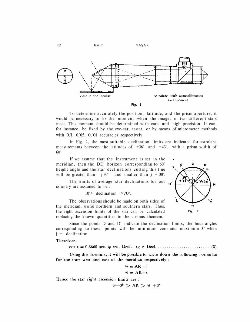
The arrangement described is shown in Fig. 1. As shown, the image of theastronomical target can always be positioned in the vertical plane. Besides, twodifferent images of the same target moving relative to each other can be obser-ved in the ocular.
102 Kasım YAŞAR
To determine accurately the position, latitude, and the prism aperture, itwould be necessary to f ix the moment when the images of two dif ferent starsmeet. This moment should be determined with care and high precision. It can,for instance, be fixed by the eye-ear, taster, or by means of micrometer methods
with 0.sl, 0.s05, 0.s0l accuracies respectively.
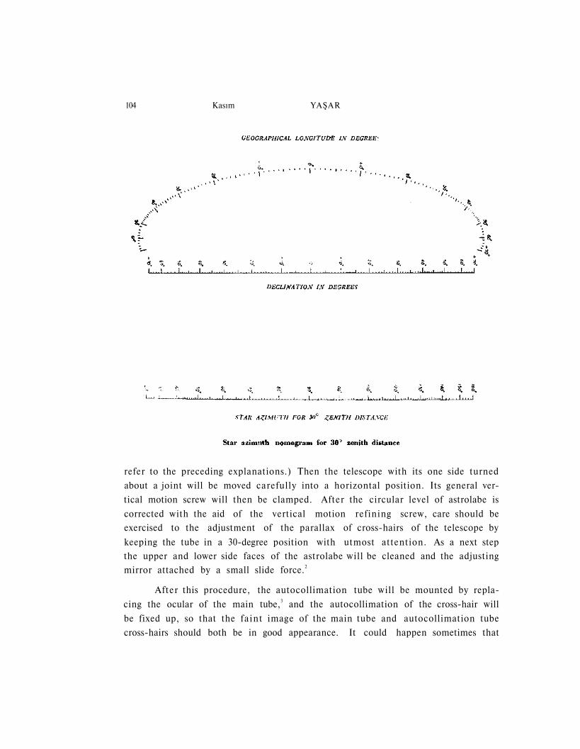
In Fig. 2, the most suitable declination limits are indicated for astrolabemeasurements between the latitudes of +36° and +43o, with a prism width of60°.
If we assume that the instrument is set in themeridian, then the DD' horizon corresponding to 60°height angle and the star declinations cutting this linewill be greater than j-30° and smaller than j + 30°.
The l imits of average star declinations for ourcountry are assumed to be :
10°> declination >70°.
The observations should be made on both sides ofthe meridian, using northern and southern stars. Thus,the right ascension limits of the star can be calculatedreplacing the known quantities in the cosinus theorem.
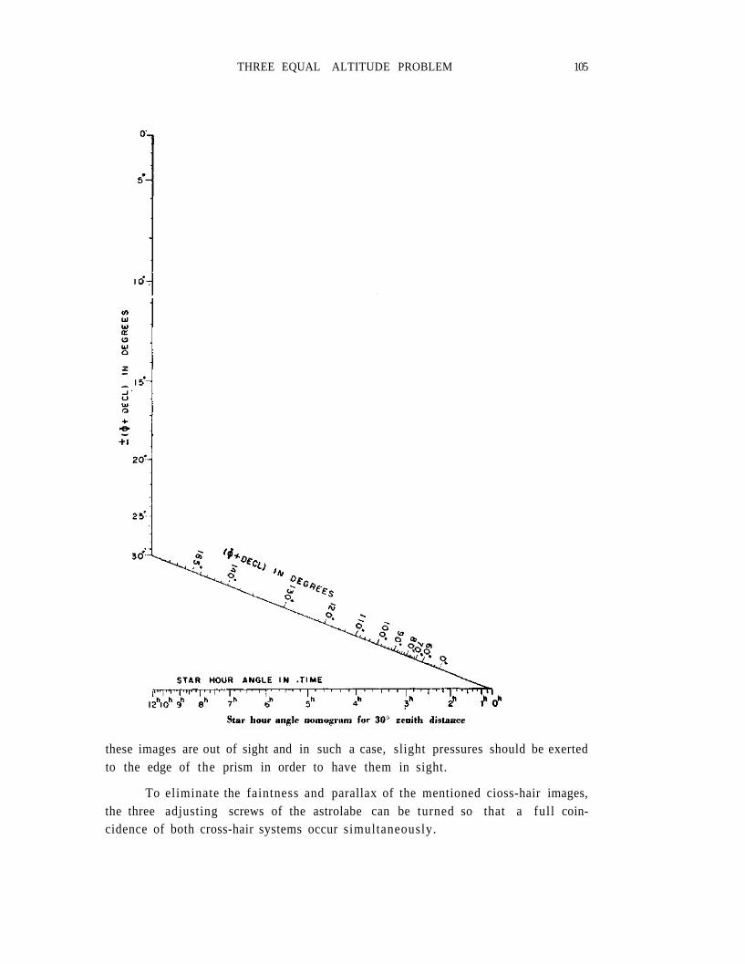
Since the points D and D' indicate the declination limits, the hour anglescorresponding to these points will be minimum zero and maximum 3h whenj = declination.
THREE EQUAL ALTITUDE PROBLEM 103
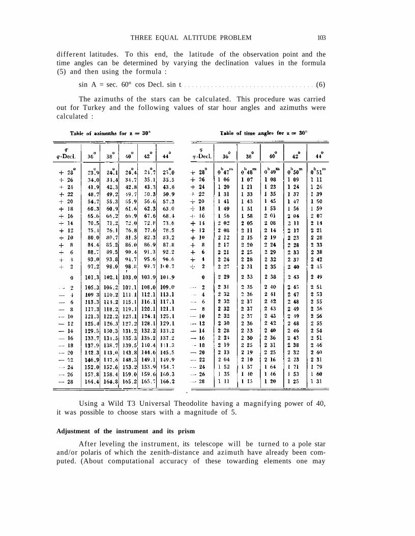
different latitudes. To this end, the latitude of the observation point and thetime angles can be determined by varying the declination values in the formula(5) and then using the formula :
sin A = sec. 60° cos Decl. sin t (6)
The azimuths of the stars can be calculated. This procedure was carriedout for Turkey and the following values of star hour angles and azimuths werecalculated :
Using a Wild T3 Universal Theodolite having a magnifying power of 40,it was possible to choose stars with a magnitude of 5.
Adjustment of the instrument and its prism
After leveling the instrument, its telescope will be turned to a pole starand/or polaris of which the zenith-distance and azimuth have already been com-puted. (About computational accuracy of these towarding elements one may
104 Kasım YAŞAR
refer to the preceding explanations.) Then the telescope with its one side turned
about a joint will be moved carefully into a horizontal position. Its general ver-
tical motion screw will then be clamped. After the circular level of astrolabe is
corrected with the aid of the vertical motion refining screw, care should be
exercised to the adjustment of the parallax of cross-hairs of the telescope by
keeping the tube in a 30-degree position with utmost attention. As a next step
the upper and lower side faces of the astrolabe will be cleaned and the adjusting
mirror attached by a small slide force.2
After this procedure, the autocollimation tube will be mounted by repla-
cing the ocular of the main tube,3 and the autocollimation of the cross-hair will
be fixed up, so that the fa int image of the main tube and autocollimation tube
cross-hairs should both be in good appearance. It could happen sometimes that
THREE EQUAL ALTITUDE PROBLEM 105
these images are out of sight and in such a case, slight pressures should be exertedto the edge of the prism in order to have them in sight.
To eliminate the faintness and parallax of the mentioned cioss-hair images,the three adjusting screws of the astrolabe can be turned so that a full coin-cidence of both cross-hair systems occur simultaneously.
106 Kasım YAŞAR
At the end of this procedure, the telescope and its astrolabe will be puttogether to the horizontal position again and the general vertical clamp screwwill be fixed and the adjusting mirror will be removed. For controlling the hori-zontability of the instrument one can observe and read 0 or 90 degree marksand sat is fy the requirements.
After that the autocoll imation attachment will be taken out of the ins-trument and the large magnifying ocular wil l be screwed again into its properplace. Later the quicksilver will be poured upon the quicksilver pot and stirredby a small glass stick so that the whole quicksilver face may become clean andthe pot will be covered by a wind and dust plug.
In this way the instrument is ready for preliminary observation purposes.
Execution of the observations
By the aid of time signal controlled chronometer clock and with the obser-vation program star co-ordinates, i.e. siderial time, azimuth and zenith-distance
THREE EQUAL ALTITUDE PROBLEM 107
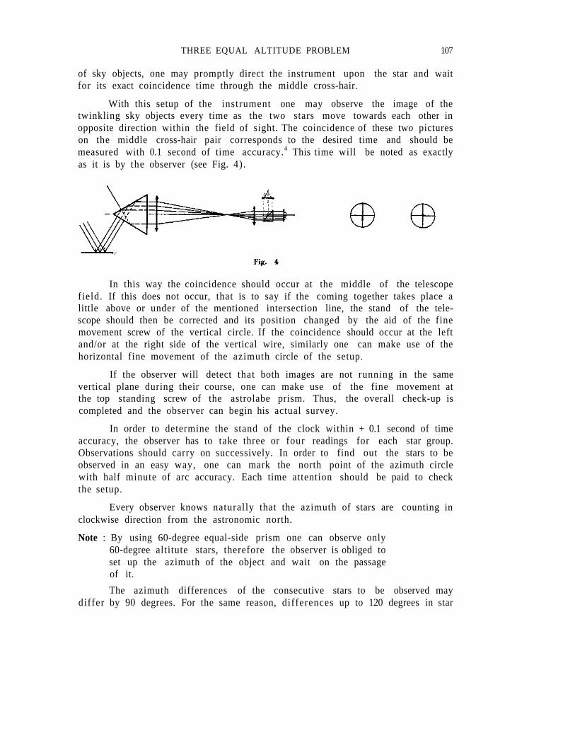
of sky objects, one may promptly direct the instrument upon the star and waitfor its exact coincidence time through the middle cross-hair.
With this setup of the instrument one may observe the image of thetwinkling sky objects every time as the two stars move towards each other inopposite direction within the field of sight. The coincidence of these two pictureson the middle cross-hair pair corresponds to the desired time and should bemeasured with 0.1 second of time accuracy.4 This time will be noted as exactlyas it is by the observer (see Fig. 4).
In this way the coincidence should occur at the middle of the telescopefield. If this does not occur, that is to say if the coming together takes place alittle above or under of the mentioned intersection line, the stand of the tele-scope should then be corrected and its position changed by the aid of the finemovement screw of the vertical circle. If the coincidence should occur at the leftand/or at the right side of the vertical wire, similarly one can make use of thehorizontal fine movement of the azimuth circle of the setup.
If the observer will detect that both images are not running in the samevertical plane during their course, one can make use of the fine movement atthe top standing screw of the astrolabe prism. Thus, the overall check-up iscompleted and the observer can begin his actual survey.
In order to determine the stand of the clock within + 0.1 second of timeaccuracy, the observer has to take three or four readings for each star group.Observations should carry on successively. In order to find out the stars to beobserved in an easy way, one can mark the north point of the azimuth circlewith half minute of arc accuracy. Each time attention should be paid to checkthe setup.
Every observer knows naturally that the azimuth of stars are counting inclockwise direction from the astronomic north.
Note : By using 60-degree equal-side prism one can observe only60-degree altitute stars, therefore the observer is obliged toset up the azimuth of the object and wait on the passageof it.
The azimuth differences of the consecutive stars to be observed maydiffer by 90 degrees. For the same reason, differences up to 120 degrees in star
108 Kasım Y A Ş A R
azimuths can also be expected. Beyond these limits observation results are notsatisfactory.
Dr. John Ball's graphical computation method
By the aid of this method the latitude and the clock stand will be evalu-ated in a very practical way. Thus the observed stars wi l l f irst be separated totheir groups and in every group a NE, SE, SW and NW star scries should beencountered. Later on by the aid of a geometrical configuration system u, jand Az corrections will be computed.
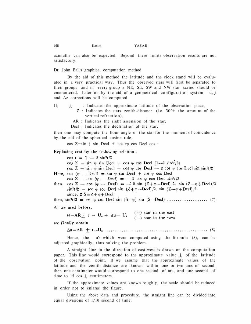
If, jo : Indicates the approximate latitude of the observation place,Z : Indicates the stars zenith-distance (i.e. 30°+ the amount of the
vertical refraction),AR : Indicates the right assension of the star,
Decl : Indicates the declination of the star,
then one may compute the hour angle of the star for the moment of coincidenceby the aid of the spherical cosine rule,
cos Z=sin j sin Decl + cos rp cos Decl cos t
Hence, the u's which were computed using the formula (8), can beadjusted graphically, thus solving the problem.
A straight line in the direction of cast-west is drawn on the computationpaper. This line would correspond to the approximate value jo of the latitudeof the observation point. If we assume that the approximate values of thelatitude and the zenith-distance are known within one or two arcs of second,then one centimeter would correspond to one second of arc, and one second oftime to 15 cos jo centimeters.
If the approximate values are known roughly, the scale should be reducedin order not to enlarge the figure.
Using the above data and procedure, the straight line can be divided intoequal divisions of 1/10 second of time.
THREE EQUAL ALTITUDE PROBLEM 109
If the sign of the stands is positive, this straight line should be markedfrom left to right, and vice versa. Then the stands are marked with their properpositions on the line, in their order of magnitude.
The perpendiculars from every point u to the mentioned straight linewill indicate the astronomical north-south direction. Therefore the azimuth ofthe stars can be plotted simply by the aid of a protractor in relation to thesenorth-south lines. Also perpendiculars from the same points will be drawn. Thedirection of the star azimuth will then be represented by the position lines ofthe stars. Intersections of these position lines with each other should form atriangle and/or a quadrilate.
Note : For the reason of comparison of this method with the otherobservation methods and due to unexpected weather con-ditions, such as dust, fog and sudden cloud coverings, onemay have to select three each group program stars insteadof four each group with 90-degree azimuth differences.Thus the accuracy of results of the observations will beaffected under different weights.
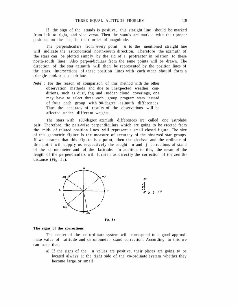
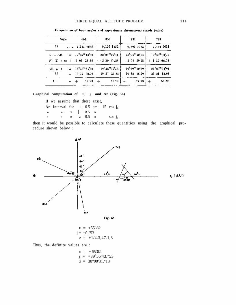
The stars with 180-degrec azimuth differences are called one astrolabepair. Therefore, the pair-wise perpendiculars which are going to be erected fromthe mids of related position lines will represent a small closed figure. The sizeof this geometric f igure is the measure of accuracy of the observed star groups.If we assume that this figure is a point, then the abscissa and the ordinate ofthis point will supply us respectively the sought u and j corrections of standof the chronometer and of the latitude. In addition to this, the mean of thelength of the perpendiculars will furnish us directly the correction of the zenith-distance (Fig. 5a).
The signs of the corrections
The center of the co-ordinate system will correspond to a good approxi-mate value of latitude and chronometer stand correction. According to this wecan state that,
a) If the signs of the u values are positive, their places are going to belocated always at the right side of the co-ordinate system whether theybecome large or small.
110 Kasım YAŞAR
b) The j values are always positive when they are located above theeast-west axis and in contrary t h e y - a l l carry negative signs.
c) The signs of the z's, astrolabe pairs drawn on position lines, thedirection of azimuths are determined by considering their convergenceand divergence as to or from the point 0. If the arrows indicatetoward 0, the sign of z will be negative, otherwise positive.
Computation of the prism angle
As it wil l be seen from Fig. 1, this angle, which is the prism head ope-ning in front of the astrolabe base supported by the objective, is 60 degrees. Tofind its value by the use of Ball group of observations, it would be necessaryto add the average z to the zenith-distance corrected for refraction effects.
THREE EQUAL ALTITUDE PROBLEM 111
Graphical computation of u, j and Az (Fig. 56)
If we assume that there exist,An interval for u, 0.5 cm., 15 cos jo
» » » j 0.5 »» » » z 0.5 » sec jo
then it would be possible to calculate these quantities using the graphical pro-cedure shown below :
u = +55s.82j = +0."53
z = +1/4.3,47.1,3
Thus, the definite values are :
u = + 55s.82j = +39o55'43."53z = 30°00'31."13
112 Kasım YAŞAR
Discussion of the results obtained by the graphical method
The values of latitude, time and the position determined through the cal-culations are compared with those obtained by Dr. Th. Niethammer's adjustmentsmethod which will be explained later. The differences between the two d i f f e r e n tvalues are. as follows :
Chr. stand and longitude : (Niethammer - Ball) =—0.s0l
Latitude of observation point : (Niethammer - Ball) = —1."29
Zenith distance : (Niethammer - Ball) = —0."90
In the determination of the last d i f ference, variations in the refractionare not taken into account.
It is seen that although the discrepancies in time and longitude stay withinnarrow limits, those in the latitude and zenith distances are rather large. Theselarge differences are due to the sudden variations in the barometric values andtemperature during the observation of the star 639 and to the rather high (—1)value of the star 831.
The azimuth differences in the two programs could not be kept constantat 90° because of cloud hindrance, too strong winds and dust. Thus, it was be-yond the writer's means to be able to use two groups of four in both methodsand to carry out a satisfactory comparison.
The main and essential purpose of the writer is to compare the knownmethods among each other and then to explain in detail the results obtained byusing his method of observation and computation.
Dr. Niethammer's adjustments method
The following theoretical data and information should be provided with aview to establishing the accuracy in determining quantities by using the approxi-mate values relating to the positions of the instrument and the observation point.
If z is the zenith distance corresponding to the moment when the celestialbody crosses the horizontal hair and dr is the amount of correction applied tothe average refraction for the zenith distance at the moment of the measurement,then the true value of zenith distance is :
z' = z + Ref o + dr
Here let us assume that
z" = z + Refo , then
z' = z" + dr
Besides, we can put down the fol lowing relations between the approximateand the true values :
z" = zo" + dz
j = jo + d j (9)
u = uo + d u
THREE EQUAL ALTITUDE PROBLEM 113
114 Kasım Y A Ş A R
THREE EQUAL ALTITUDE PROBLEM 115
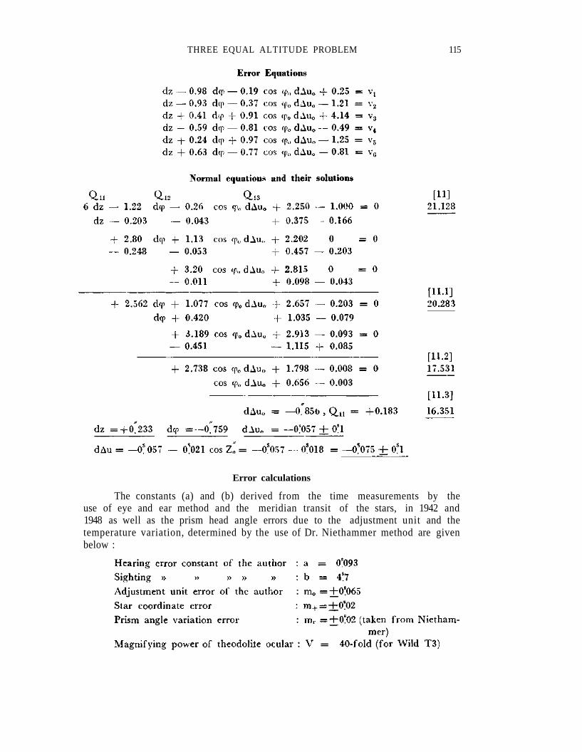
Error calculations
The constants (a) and (b) derived from the time measurements by theuse of eye and ear method and the meridian transit of the stars, in 1942 and1948 as well as the prism head angle errors due to the adjustment unit and thetemperature variation, determined by the use of Dr. Niethammer method are givenbelow :
116 Kasım YAŞAR
Discussion of results of the least square method
The results of the graphical method have so far been discussed in detailand comparisons of different outstanding points of Dr. Ball's method have beenmade critically. Meanwhile some other comparisons were also considered relatingto the results of Dr. Niethammer's method. We can state here that the previousexplanations have bearings on the discussion of this method. Additional consider-ations about the accuracy of the method pertaining to the azimuth differencesof stars and their separations could not be carried out.
It should also be mentioned here that the writer's unit weight mean error,which he computed from a large number of the meridian transit measurementsof different declination stars. For preliminary computations, his assumed astrolabeprism top angle variation and its mean error were notable read accurately. Theabnormal changes of mean errors in chronometer stand, in latitude correctionand in zenith-distance were under functional influence of above-mentioned facts.Accordingly chronometer stand and latitude correction mean errors became highand combined zenith-distance variational mean error became fairly low.
The mean errors in right ascension and in declination of the programstars were extracted from the mean of the mean error of 1949 FK3 Star Catalog.Therefore their magnitudes were small and their influence to the obtained resultsof accuracy were very l i t t le and inconsiderable.
THREE EQUAL ALTITUDE PROBLEM 117
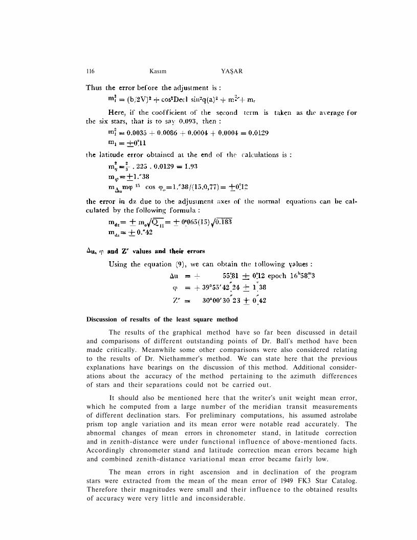
The mean error of the variation of the constant prism angle has beencomputed according to the formula No. 78a of Dr. Niethammer. See «DieGenauen Methoden Der Astronomisch-Geographischen Ortsbestimmung, 1947»page No. 157. The evaluated value of this error is + 0."27.
It is obvious from page No. 21 that this mean error value is 1.6 timessmaller than the value which is computed for dz after the adjustment.
From the results of observations evaluated author's value shows a slightdifference of 0.008 time second when it is compared with Dr. Niethammer'saccepted value. One may think that this discrepancy ties itself with the obser-vation ability of the author and is the cause of unstability of the instrumentused.
PART II
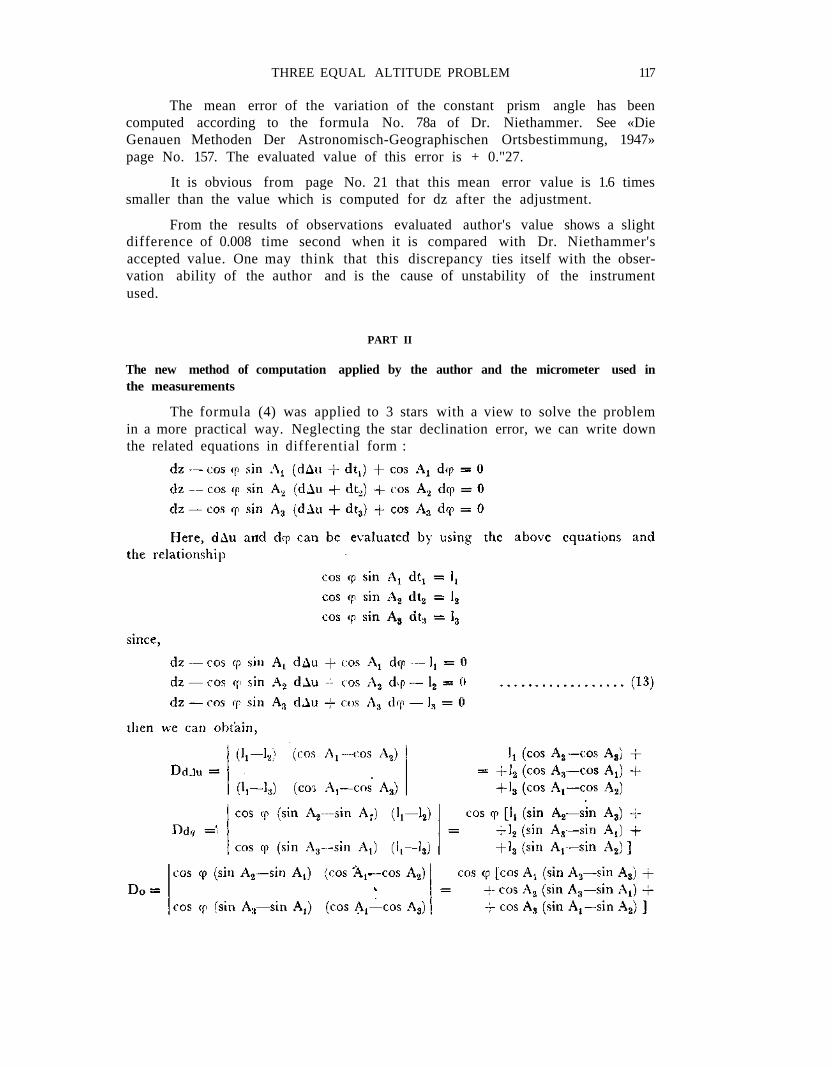
The new method of computation applied by the author and the micrometer used inthe measurements
The formula (4) was applied to 3 stars with a view to solve the problemin a more practical way. Neglecting the star declination error, we can write downthe related equations in differential form :
118 Kasım YAŞAR
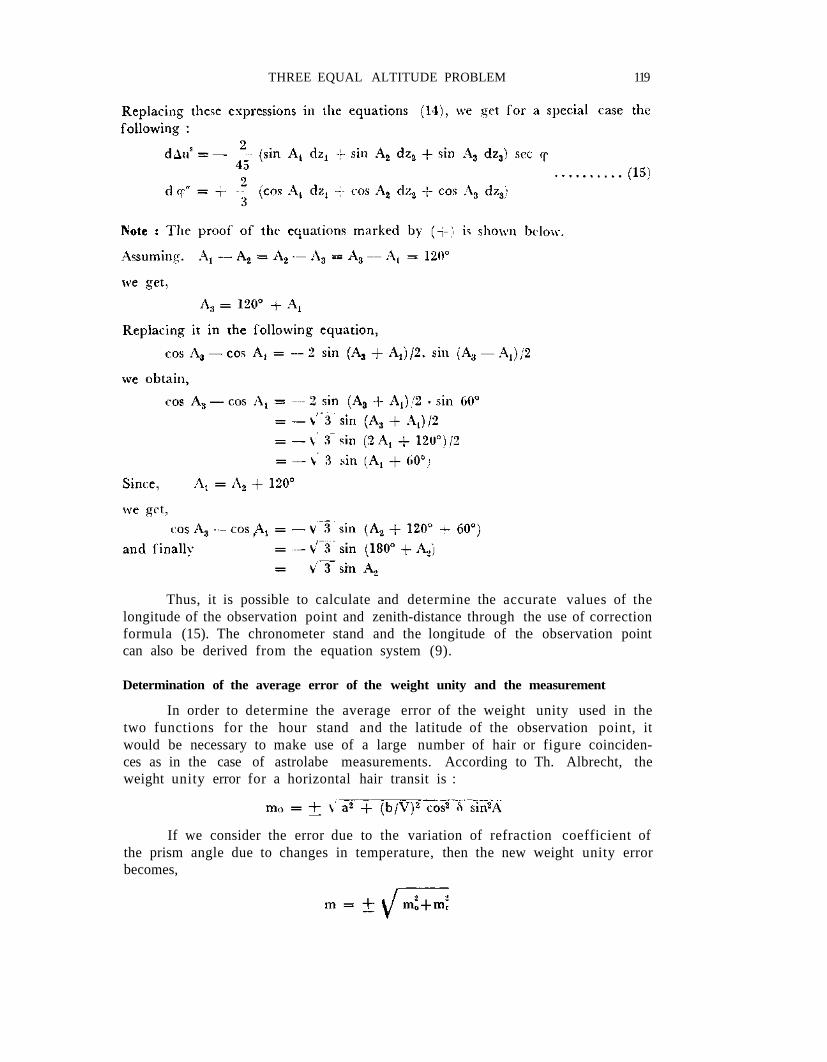
THREE EQUAL ALTITUDE PROBLEM 119
Thus, it is possible to calculate and determine the accurate values of thelongitude of the observation point and zenith-distance through the use of correctionformula (15). The chronometer stand and the longitude of the observation pointcan also be derived from the equation system (9).
Determination of the average error of the weight unity and the measurement
In order to determine the average error of the weight unity used in thetwo functions for the hour stand and the latitude of the observation point, itwould be necessary to make use of a large number of hair or figure coinciden-ces as in the case of astrolabe measurements. According to Th. Albrecht, theweight unity error for a horizontal hair transit is :
If we consider the error due to the variation of refraction coefficient ofthe prism angle due to changes in temperature, then the new weight unity errorbecomes,
120 Kasım YAŞAR
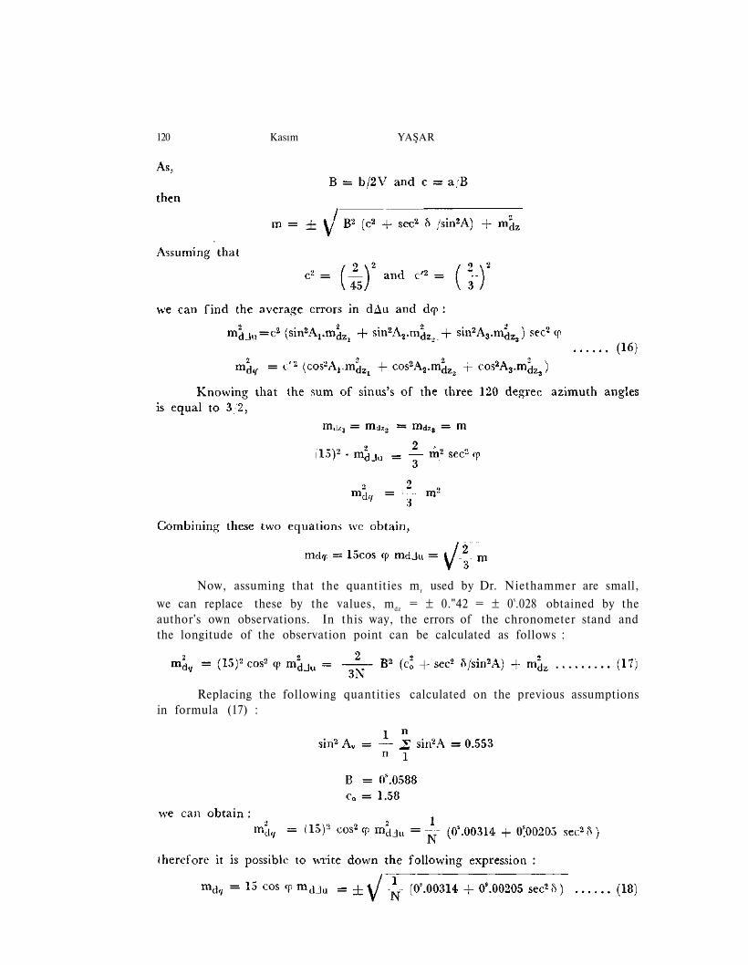
Now, assuming that the quantities mr used by Dr. Niethammer are small,
we can replace these by the values, mdz = ± 0."42 = ± 0s.028 obtained by theauthor's own observations. In this way, the errors of the chronometer stand andthe longitude of the observation point can be calculated as follows :
Replacing the following quantities calculated on the previous assumptionsin formula (17) :
THREE EQUAL ALTITUDE PROBLEM 121
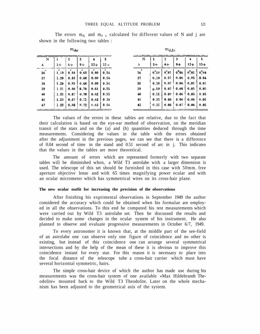
The errors mdj and md u calculated for different values of N and j areshown in the following two tables :
The values of the errors in these tables are relative, due to the fact thattheir calculation is based on the eye-ear method of observation, on the meridiantransit of the stars and on the (a) and (b) quantities deduced through the timemeasurements. Considering the values in the table with the errors obtainedafter the adjustment in the previous pages, we can see that there is a differenceof 0.04 second of time in the stand and 0.51 second of arc in j. This indicatesthat the values in the tables are more theoretical.
The amount of errors which are represented formerly with two separatetables will be diminished when, a Wild T3 astrolabe with a larger dimension isused. The telescope of this set should be furnished in this case with 50mm. freeaperture objective lense and with 65 times magnifying power ocular and withan ocular micrometer which has symmetrical wires on its cross-hair plane.
The new ocular outfit for increasing the precision of the observations
After finishing his exprimental observations in September 1949 the authorconsidered the accuracy which could be obtained when his formulae are employ-ed in all the observations. To this end he computed his test measurements whichwere carried out by Wild T3 astrolabe set. Then he discussed the results anddecided to make some changes in the ocular system of his instrument. He alsoplanned to observe and evaluate progressive measurements in October 6/7, 1949.
To every astronomer it is known that, at the middle part of the see-fieldof an astrolabe one can observe only one figure of coincidence and no other isexisting, but instead of this coincidence one can arrange several symmetricalintersections and by the help of the mean of these it is obvious to improve thiscoincidence instant for every star. For this reason it is necessary to place intothe focal distance of the telescope tube a cross-hair carrier which must haveseveral horizontal symmetric, hairs.
The simple cross-hair device of which the author has made use during hismeasurements was the cross-hair system of one available «Max Hildebrandt The-odolite» mounted back to the Wild T3 Theodolite. Later on the whole mecha-nism has been adjusted to the geometrical axis of the system.
122 Kasım Y A Ş A R
To understand how to operate with this new ocular system, we may thinkfirst of all that the cross-hair attachment should carry only one single hair atthe upper and lower part of the middle hair.
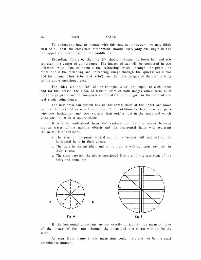
Regarding Figure 6, the l ine (f) should indicate the lower hair and (O)represent the center of coincidence. The images of star wil l be composed in twodifferent ways. One of them is the refracting image through the prism, theother one is the reflecting and refracting image through the quicksilver mirrorand the prism. Thus (OA) and (OA') are the trace images of the star relatingto the above-mentioned case.
The sides OA and OA' of the triangle OAA' are equal to each otherand for this reason the mean of transit times of both images which were builtup through prism and mirror-prism combination, should give us the time of thereal single coincidence.
The new cross-hair system has six horizontal hairs at the upper and lowerpart of the see-field as seen from Figure 7. In addition to these there are pair-wise two horizontal and two vertical hair outfits just in the mids and whichcross each other in a square shape.
It will be understood from the explanations that the angles betweenmotion traces of the moving objects and the horizontal hairs will representthe azimuth of the stars.
a. The stars in the prime vertical and in its vicinity will intersect all thehorizontal hairs in their course.
b. The stars in the meridian and in its vicinity will not cross any hair intheir course.
c. The stars between the above-mentioned limits wi l l intersect some of thehairs and some not.
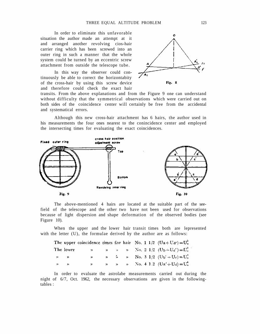
If the horizontal cross-hairs are not exactly horizontal, the mean of timesof the images of the stars through the prism and the mirror will not be thesame.
As seen from Figure 8 this mean time could naturally not be the exactcoincidence moment.
THREE EQUAL ALTITUDE PROBLEM 123
In order to eliminate this unfavorablesituation the author made an attempt at itand arranged another revolving cios-haircarrier ring which has been screwed into anouter ring in such a manner that the wholesystem could be turned by an eccentric screwattachment from outside the telescope tube.
In this way the observer could con-tinuously be able to correct the horizontabityof the cross-hair by using this screw deviceand therefore could check the exact hairtransits. From the above explanations and from the Figure 9 one can understandwithout difficulty that the symmetrical observations which were carried out onboth sides of the coincidence center will certainly be free from the accidentaland systematical errors.
Although this new cross-hair attachment has 6 hairs, the author used inhis measurements the four ones nearest to the conincidence center and employedthe intersecting times for evaluating the exact coincidences.
The above-mentioned 4 hairs are located at the suitable part of the see-field of the telescope and the other two have not been used for observationsbecause of light dispersion and shape deformation of the observed bodies (seeFigure 10).
When the upper and the lower hair transit times both are lepresentedwith the letter (U), the formulae derived by the author are as follows:
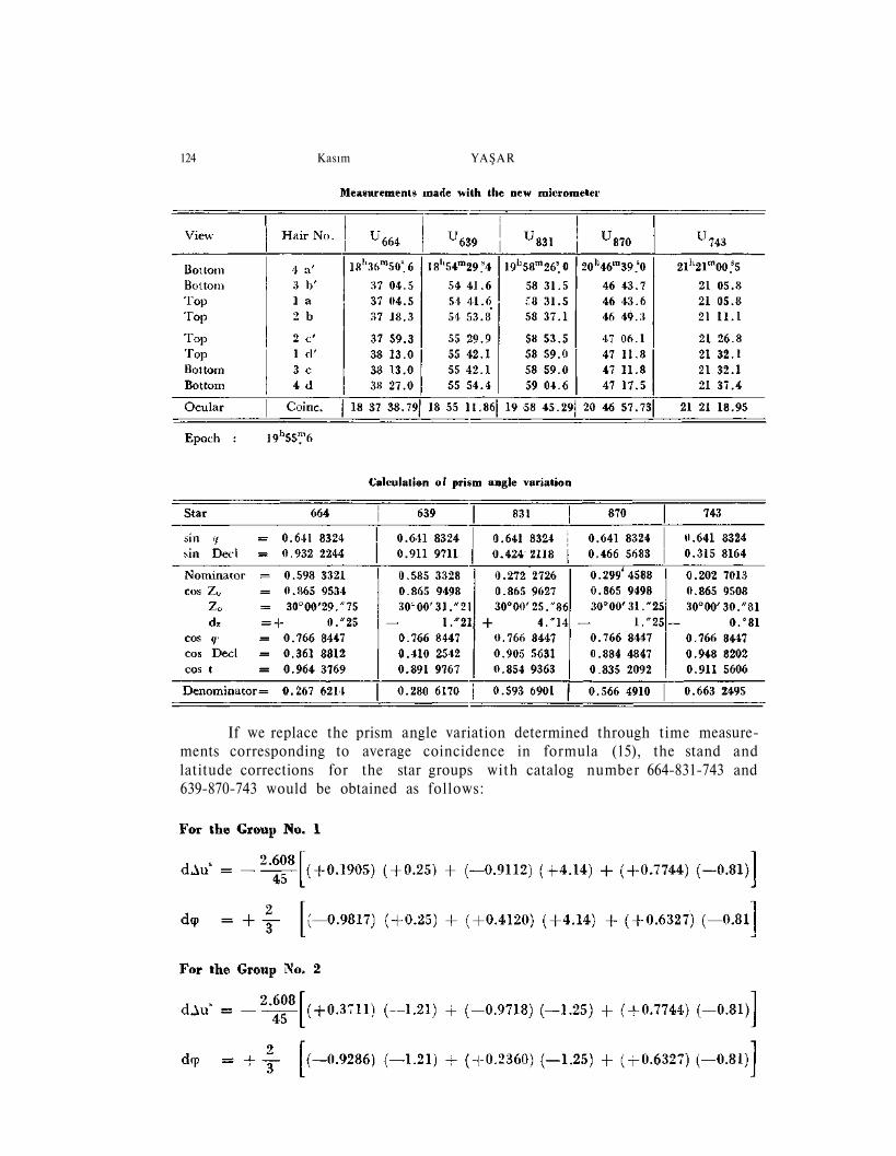
In order to evaluate the astrolabe measurements carried out during thenight of 6/7, Oct. 1962, the necessary observations are given in the following-tables :
124 Kasım Y A Ş A R
If we replace the prism angle variation determined through time measure-ments corresponding to average coincidence in formula (15), the stand andlatitude corrections for the star groups with catalog number 664-831-743 and639-870-743 would be obtained as follows:
THREE EQUAL ALTITUDE PROBLEM 125
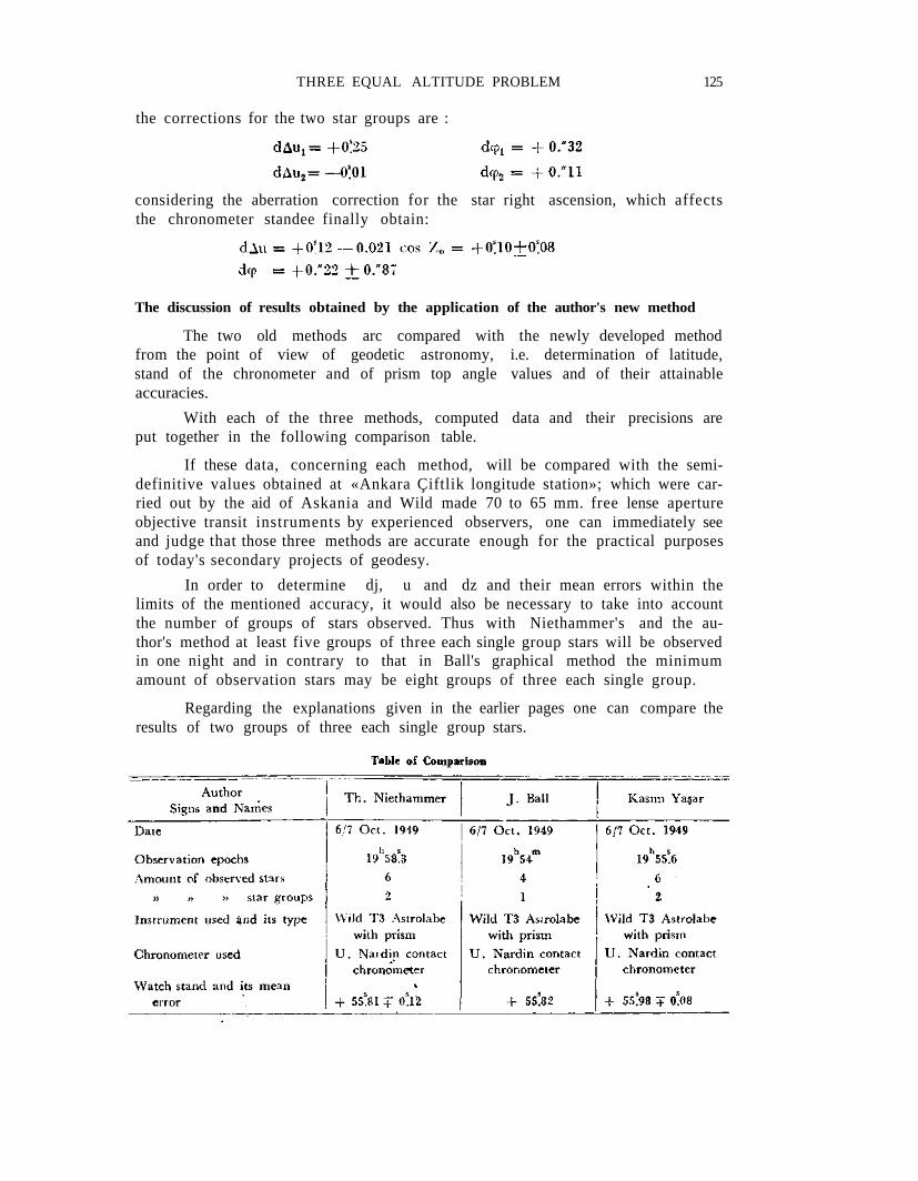
the corrections for the two star groups are :
considering the aberration correction for the star right ascension, which affectsthe chronometer standee finally obtain:
The discussion of results obtained by the application of the author's new method
The two old methods arc compared with the newly developed methodfrom the point of view of geodetic astronomy, i.e. determination of latitude,stand of the chronometer and of prism top angle values and of their attainableaccuracies.
With each of the three methods, computed data and their precisions areput together in the following comparison table.
If these data, concerning each method, will be compared with the semi-definitive values obtained at «Ankara Çiftlik longitude station»; which were car-ried out by the aid of Askania and Wild made 70 to 65 mm. free lense apertureobjective transit instruments by experienced observers, one can immediately seeand judge that those three methods are accurate enough for the practical purposesof today's secondary projects of geodesy.
In order to determine dj, u and dz and their mean errors within thelimits of the mentioned accuracy, it would also be necessary to take into accountthe number of groups of stars observed. Thus with Niethammer's and the au-thor's method at least five groups of three each single group stars will be observedin one night and in contrary to that in Ball's graphical method the minimumamount of observation stars may be eight groups of three each single group.
Regarding the explanations given in the earlier pages one can compare theresults of two groups of three each single group stars.
126 Kasım YAŞAR
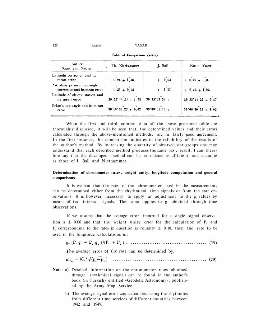
When the first and third column data of the above presented table arethoroughly discussed, it wil l be seen that, the determined values and their errorscalculated through the above-mentioned methods, arc in fair ly good agreement.In the first instance, this comparison indicates to the reliability of the results ofthe author's method. By increasing the quantity of observed star groups one mayunderstand that each described method produces the same basic result. I can there-fore say that the developed method can be considered as efficient and accurateas those of J. Ball and Niethammer.
Determination of chronometer rates, weight unity, longitude computation and generalcomparisons
It is evident that the rate of the chronometer used in the measurementscan be determined either from the rhythmical time signals or from the star ob-servations. It is however necessary to apply an adjustment to the gs values bymeans of two interval signals. The same applies to g* obtained through timeobservations.
If we assume that the average error incurred for a single signal observa-
tion is ± 0s.06 and that the weight unity error for the calculation of P* and
Ps corresponding to the rates in question is roughly ± 0s.10, then the rate to be
used in the longitude calculations is :
Note: a) Detailed information on the chronometer rates obtainedthrough rhythmical signals can be found in the author'sbook (in Turkish) entitled «Geodetic Astronomy», publish-ed by the Army Map Service.
b) The average signal error was calculated using the rhythmicsfrom different time services of di f ferent countries between1942 and 1949.
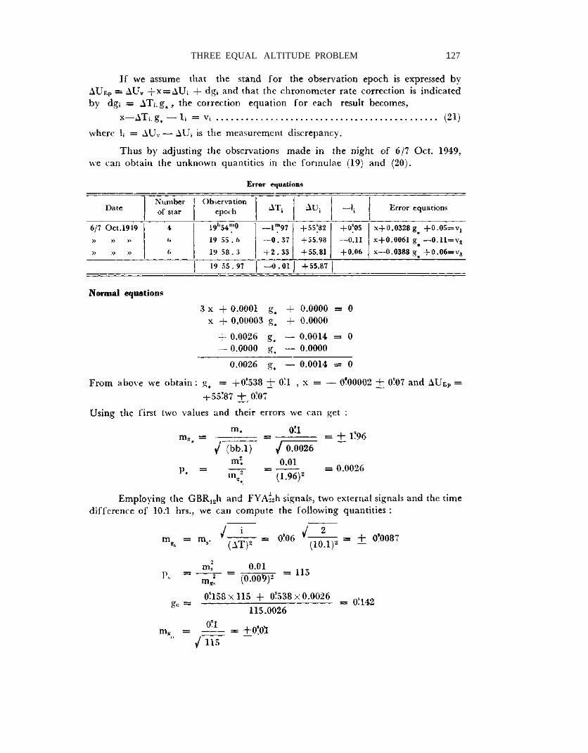
THREE EQUAL ALTITUDE PROBLEM 127
128 Kasım YAŞAR
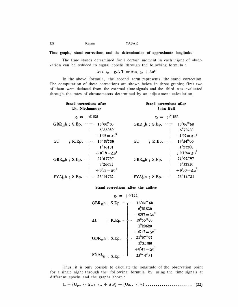
Time graphs, stand corrections and the determination of approximate longitudes
The time stands determined for a certain moment in each night of obser-vation can be reduced to signal epochs through the following formula :
In the above formula, the second term represents the stand correction.The computation of these corrections are shown below in three graphs; f i rs t twoof them were deduced from the external time signals and the third was evaluatedthrough the rates of chronometers determined by an adjustment calculation.
Thus, it is only possible to calculate the longitude of the observation pointfor a single night through the following formula by using the time signals atdifferent epochs and the graphs above :
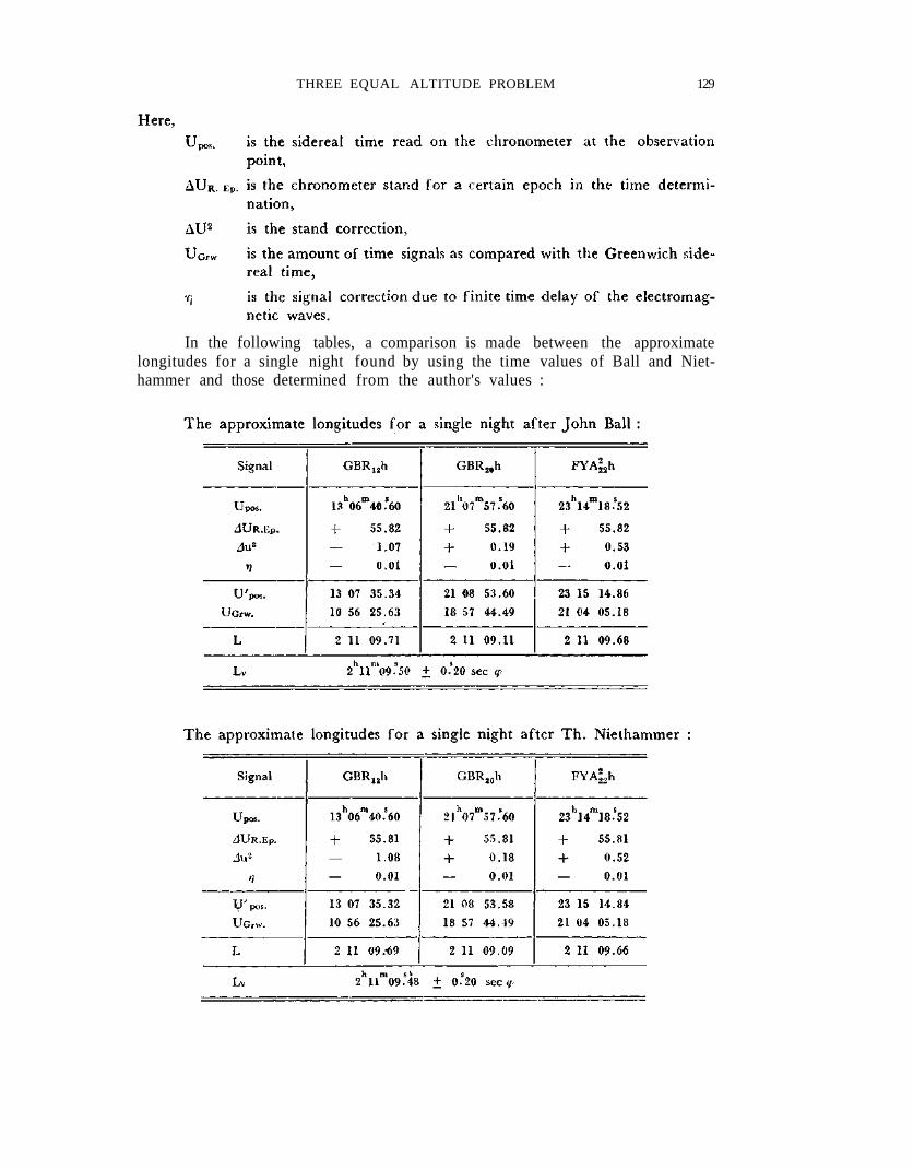
THREE EQUAL ALTITUDE PROBLEM 129
In the following tables, a comparison is made between the approximatelongitudes for a single night found by using the time values of Ball and Niet-hammer and those determined from the author's values :
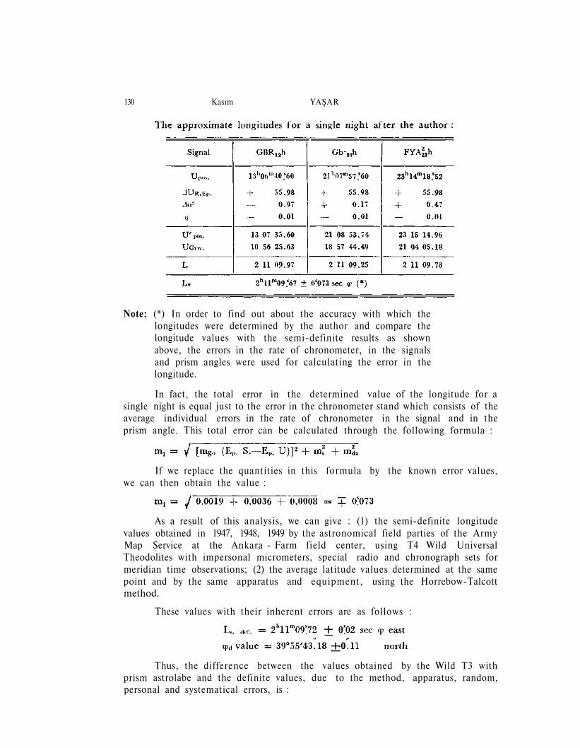
130 Kasım YAŞAR
Note: (*) In order to find out about the accuracy with which thelongitudes were determined by the author and compare thelongitude values with the semi-definite results as shownabove, the errors in the rate of chronometer, in the signalsand prism angles were used for calculating the error in thelongitude.
In fact, the total error in the determined value of the longitude for asingle night is equal just to the error in the chronometer stand which consists of theaverage individual errors in the rate of chronometer in the signal and in theprism angle. This total error can be calculated through the following formula :
If we replace the quantities in this formula by the known error values,we can then obtain the value :
As a result of this analysis, we can give : (1) the semi-definite longitudevalues obtained in 1947, 1948, 1949 by the astronomical field parties of the ArmyMap Service at the Ankara - Farm field center, using T4 Wild UniversalTheodolites with impersonal micrometers, special radio and chronograph sets formeridian time observations; (2) the average latitude values determined at the samepoint and by the same apparatus and equipment, using the Horrebow-Talcottmethod.
These values with their inherent errors are as follows :
Thus, the difference between the values obtained by the Wild T3 withprism astrolabe and the definite values, due to the method, apparatus, random,personal and systematical errors, is :
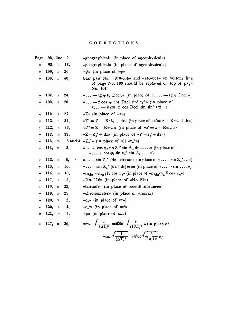
C O R R E C T I O N S
THREE EQUAL ALTITUDE PROBLEM 131
Hence, as a result, it can be stated that this method is faster and fur-nishes an easier way of computation than the methods of John Ball an Th. Niet-hammer, provided that the approximate values for the author's method are ob-tained either from the existing topographical maps or determined by the secon-dary methods.
Manuscript received December 20, 1961
B I B L I O G R A P H Y
ANDOYER, H. H. (1909) : Course D'Astronomie, p. 243-218.
BALL KNOX SHAX, J. (1919) : Handbook of the prizmatic Astrolabe Cairo.
CHANDON, E. - GOUGENHEIM, A. (1935) : Hydrographical Review XII, Nr. 1, p. 39-121.
HARZER, P. (1922-1924) : Berechnung der Ablenkungen der Lichtstrahlen in der Atmosphaereder Erde auf rein meteorologisch physikalischer Grundlage Publ. Kiel 13-14.
NIETHAMMER, TH. (1917) Die genauen Methoden der Astronomisch-Geographischen Ortsbe-stimmung, Basel.
SCHÜTTE, K. (1939) : Astronomische-Geodatische Arbeiten der Bayrischen Erdmessung. K. Heft12.
SCHWIDEFSKY, K. (1936) : Allgemeine Vermessungs Nachrichten. Band 254, p. 256-258 Jena.
STECHERT, C. (1905) : Zeit und Breitenbestimmung, durch die Methoden der gleichen Zenit-distanzen.
ZINGER, N. (1874) : Die Zeitbestimmung aus korrespondierenden Hohen verschiedener Sterne.
WUNSCHMANN, F. (1931) : Über die Konstitution der Atmosphaere und die astronomischerInflexion in ihr, Gerlands Beitrage. 31-83.