THORNTON BANK OFFSHORE WIND FARM - Museum of...
15
ANNUAL REPORT 2012 THORNTON BANK OFFSHORE WIND FARM
-
Upload
nguyentram -
Category
Documents
-
view
217 -
download
2
Transcript of THORNTON BANK OFFSHORE WIND FARM - Museum of...
ANNUAL REPORT 2012
THORNTON BANK OFFSHORE WIND FARM
Table of Contents
1 GENERAL PROJECT INFORMATION............................................................................................. 3
2 ACTIVITIES DURING 2012 .......................................................................................................... 6
3 CONSTRUCTION & OPERATION PERMIT CONDITIONS ................................................................ 9
4 ENVIRONMENTAL MONITORING ACTIVITIES ............................................................................ 14
5 HEALTH, SAFETY AND ENVIRONMENT (HSE) ............................................................................ 15
3/15
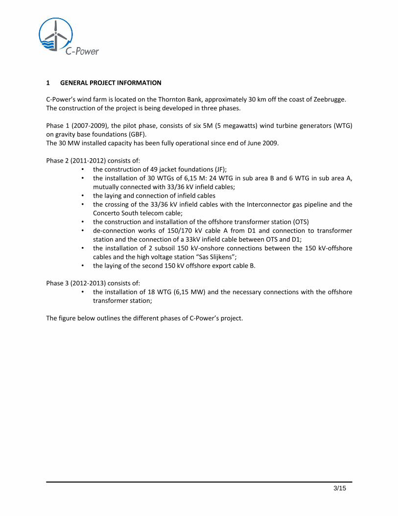
1 GENERAL PROJECT INFORMATION
C-Power’s wind farm is located on the Thornton Bank, approximately 30 km off the coast of Zeebrugge. The construction of the project is being developed in three phases. Phase 1 (2007-2009), the pilot phase, consists of six 5M (5 megawatts) wind turbine generators (WTG) on gravity base foundations (GBF). The 30 MW installed capacity has been fully operational since end of June 2009. Phase 2 (2011-2012) consists of:
• the construction of 49 jacket foundations (JF); • the installation of 30 WTGs of 6,15 M: 24 WTG in sub area B and 6 WTG in sub area A,
mutually connected with 33/36 kV infield cables; • the laying and connection of infield cables • the crossing of the 33/36 kV infield cables with the Interconnector gas pipeline and the
Concerto South telecom cable; • the construction and installation of the offshore transformer station (OTS) • de-connection works of 150/170 kV cable A from D1 and connection to transformer
station and the connection of a 33kV infield cable between OTS and D1; • the installation of 2 subsoil 150 kV-onshore connections between the 150 kV-offshore
cables and the high voltage station “Sas Slijkens”; • the laying of the second 150 kV offshore export cable B.
Phase 3 (2012-2013) consists of:
• the installation of 18 WTG (6,15 MW) and the necessary connections with the offshore transformer station;
The figure below outlines the different phases of C-Power’s project.

4/15
Figure 1: the different phases of C-Power’s project
The completed project will comprise 54 WTGs with a total rated power of 325 MW plus the supporting infrastructure. Full operation is scheduled to commence in July 2013. Project certification Project quality verification activities are completed by a number of separate bodies within the project management structure. Each verification body and its area of responsibility are outlined in table 1. Table 1: Project Verification Bodies
Company Scope of Work
Mott MacDonald Advisor to Lenders
DEWI-OCC Offshore and Certification Centre
Project certification:
Design Basis;
Detailed Design;
Manufacturing;
Transport and installation; and
Commissioning.
Mwaves Marine Warranty Surveyor
AIB Vincotte Periodic inspections including electrical, lifting and hoisting and safety

5/15
Overall responsibility for the quality verification of manufacturing and installation activities is within the remit of DEWI-OCC.
6/15
2 ACTIVITIES DURING 2012
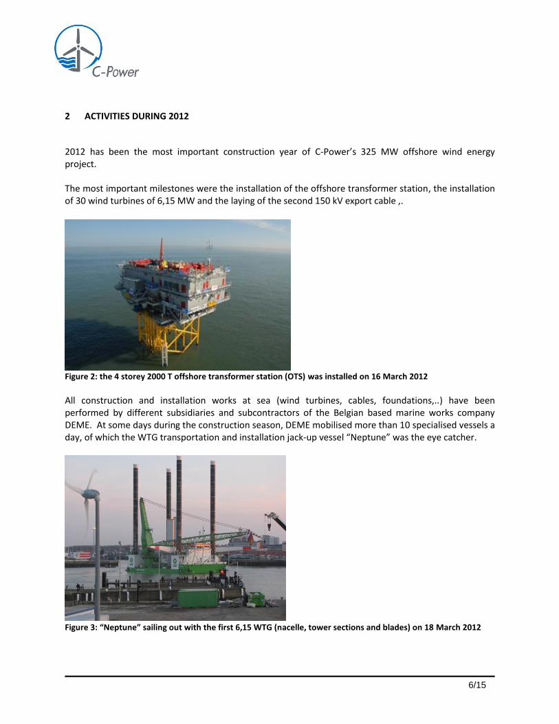
2012 has been the most important construction year of C-Power’s 325 MW offshore wind energy project. The most important milestones were the installation of the offshore transformer station, the installation of 30 wind turbines of 6,15 MW and the laying of the second 150 kV export cable ,.
Figure 2: the 4 storey 2000 T offshore transformer station (OTS) was installed on 16 March 2012
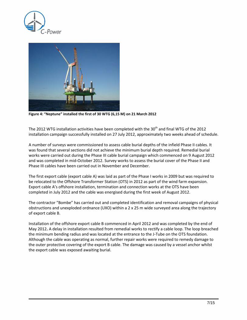
All construction and installation works at sea (wind turbines, cables, foundations,..) have been performed by different subsidiaries and subcontractors of the Belgian based marine works company DEME. At some days during the construction season, DEME mobilised more than 10 specialised vessels a day, of which the WTG transportation and installation jack-up vessel “Neptune” was the eye catcher.
Figure 3: “Neptune” sailing out with the first 6,15 WTG (nacelle, tower sections and blades) on 18 March 2012
7/15
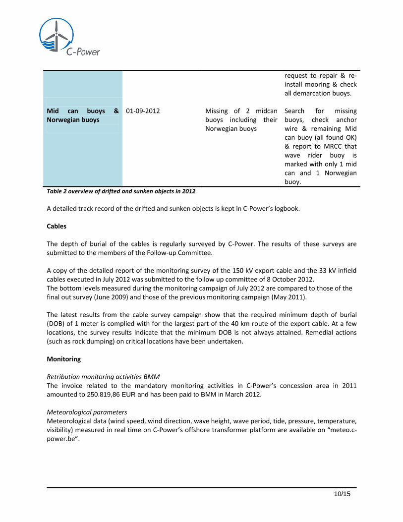
Figure 4: “Neptune” installed the first of 30 WTG (6,15 M) on 21 March 2012
The 2012 WTG installation activities have been completed with the 30th and final WTG of the 2012 installation campaign successfully installed on 27 July 2012, approximately two weeks ahead of schedule.
A number of surveys were commissioned to assess cable burial depths of the infield Phase II cables. It was found that several sections did not achieve the minimum burial depth required. Remedial burial works were carried out during the Phase III cable burial campaign which commenced on 9 August 2012 and was completed in mid-October 2012. Survey works to assess the burial cover of the Phase II and Phase III cables have been carried out in November and December.
The first export cable (export cable A) was laid as part of the Phase I works in 2009 but was required to be relocated to the Offshore Transformer Station (OTS) in 2012 as part of the wind farm expansion. Export cable A’s offshore installation, termination and connection works at the OTS have been completed in July 2012 and the cable was energised during the first week of August 2012.
The contractor “Bombe” has carried out and completed identification and removal campaigns of physical obstructions and unexploded ordnance (UXO) within a 2 x 25 m wide surveyed area along the trajectory of export cable B.
Installation of the offshore export cable B commenced in April 2012 and was completed by the end of May 2012. A delay in installation resulted from remedial works to rectify a cable loop. The loop breached the minimum bending radius and was located at the entrance to the J-Tube on the OTS foundation. Although the cable was operating as normal, further repair works were required to remedy damage to the outer protective covering of the export B cable. The damage was caused by a vessel anchor whilst the export cable was exposed awaiting burial.

8/15
Figure 5: export cable B on the cable laying vessel (3 July 2012)
Cable lay mattresses have no longer been used where cables cross other buried services. Instead, in order to protect the Concerto South and Interconnector crossings, rock dumping and rock armouring has being executed. These works commenced on 4 October 2012 and were completed by the end of October 2012. A detailed description of C-Power’s construction activities on a week per week basis is available on C-Power’s website. Next to the intensive construction works in 2012, normal operating and maintaining (O&M) activities continued in sub area A. O&M activities are carried out by the wind turbine manufacturer (Repower), under the supervision of C-Power. By the end of 2012 a total installed capacity of 215 MW was operational.

9/15
3 CONSTRUCTION & OPERATION PERMIT CONDITIONS
All permit obligations are integrated and implemented in the daily management of the activities offshore by C-Power and its contractors.
The institutionalised Follow-up Committee (“Begeleidingscomité”) has been organised three times in 2012:
- 28 March 2012, Ostend
- 24 July 2012, Brussels
- 8 October 2012, Ostend
During these follow-up committees, the progress of the project has been discussed as well as the compliance of the offshore construction, installation and maintenance activities with the permit conditions.
On top of this regular and official reporting to the authorities, C-Power informs the federal and nautical authorities on a frequent, voluntary and transparent basis, including a regular dialogue with the relevant authorities via e-mail (status reports, coordinates, maps, plans, intruders tracking, etc..), ad hoc meetings, telephone exchanges etc..
During the construction season in 2012, quarterly reports from the technical adviser Mott Mac Donald were submitted to BMM.
An overview of the main permit conditions is described below.
Drifting or sunken objects Table 2 gives an overview of drifted and sunken objects in 2012.
Object Date Description Action-Follow up
East cardinal buoy
04-01-2012
Loss of buoy due to severe storm (wave heights exceeding 6 m)
Reported to MRCC & DAB Vloot. New CP-E placed by DAB Vloot.
Pennant buoy
28-04-2012 Drifting of a pennant buoy
Reported to MRCC, buoy recovered next day & transported back to site.
CP1 demarcation buoy 08-11-2012 Drifting of the CP1 demarcation buoy in the vicinity of the West Diep
Search and recovery of CP1 buoy by MCS Alix, notification to all involved in the project and authorities, buoy transported to port,
10/15
request to repair & re-install mooring & check all demarcation buoys.
Mid can buoys & Norwegian buoys
01-09-2012
Missing of 2 midcan buoys including their Norwegian buoys
Search for missing buoys, check anchor wire & remaining Mid can buoy (all found OK) & report to MRCC that wave rider buoy is marked with only 1 mid can and 1 Norwegian buoy.
Table 2 overview of drifted and sunken objects in 2012
A detailed track record of the drifted and sunken objects is kept in C-Power’s logbook. Cables The depth of burial of the cables is regularly surveyed by C-Power. The results of these surveys are submitted to the members of the Follow-up Committee. A copy of the detailed report of the monitoring survey of the 150 kV export cable and the 33 kV infield cables executed in July 2012 was submitted to the follow up committee of 8 October 2012. The bottom levels measured during the monitoring campaign of July 2012 are compared to those of the final out survey (June 2009) and those of the previous monitoring campaign (May 2011). The latest results from the cable survey campaign show that the required minimum depth of burial (DOB) of 1 meter is complied with for the largest part of the 40 km route of the export cable. At a few locations, the survey results indicate that the minimum DOB is not always attained. Remedial actions (such as rock dumping) on critical locations have been undertaken. Monitoring Retribution monitoring activities BMM The invoice related to the mandatory monitoring activities in C-Power’s concession area in 2011 amounted to 250.819,86 EUR and has been paid to BMM in March 2012. Meteorological parameters Meteorological data (wind speed, wind direction, wave height, wave period, tide, pressure, temperature, visibility) measured in real time on C-Power’s offshore transformer platform are available on “meteo.c-power.be”.

11/15
Bathymetry: dredging activities & erosion protection
An overview of the dredging & rock dump activities in 2012 is outlined in Table 3.
Type Date Dimension (length x width x height / depth)
Location (UTM ED50) KPs numbers (for the first 2 activities and the last one) represent the distance in kilometers from OTS
Dredging works March-April 2012
Area 1: ~9km x 10m x 2m Area 2: ~10.5km x 10m x ~2m
Pre-trenching along export B route (material dumped in indicated area by BMM in area 3A) - Area 1: ~KP0.225 (E497011, N5709074) to
~KP6.719 (E497242, N5702747) - Area 2: ~KP9.300 (E496817, N5700201) to
~KP19.783 (E493592, N5690692)
Back-filling works
April-June 2012
Area 1: ~9km x 10m x 2m Area 2: ~10.5km x 10m x ~2m
Back-filling works along export B route including the area where export B is crossing Vaargeul 1 (back-fill material from spoil ground 3A) - Area 1: ~KP0.225 (E497011, N5709074) to
~KP6.719 (E497242, N5702747) - Area 2: ~KP9.300 (E496817, N5700201) to
~KP19.783 (E493592, N5690692)
Rock dump
April 2012 ~40m x ~10m ~0.7m
Post-lay rock dump at D1 foundation (approx. position middle of rock berm E496860, N5709828)
Rock dump
April 2012 ~65m x ~85m ~0.7m Post-lay rock dump at Interconnector pipeline crossing with four infield cables in area B (approx. position middle of rock berm E497712, N5710410)
1 mattress + removal
June 2012/ July 2012
23m x 10m x 0.35m Post-lay mattress installation at Concerto 1 South crossing with four infield cables area B (approx. position NW corner of mattress E497435, N5710068) The mattress was removed by divers because found damaged during installation
Rock dump October 2012
~65m x ~95m ~1.3m
Post-lay rock dump at Concerto 1 South crossing with four infield cables area B (approx. position middle of rock berm (E497463, N5710072)
Rock dump
October 2012
~150m x ~2m x ~1.0m
Post-lay rock dump at PEC Telecom cable crossing with Export B cable From KP 24.254 (E491753, N5686631) to KP 24.428 (E491748, N5686457)
Table 3: overview of the dredging and erosion protection activities in 2012

12/15
Risks & Safety Internal emergency plan C-Power’s internal emergency plan (IEP) for phase 1 (exploitation) and phase 2 & 3 (construction), consisting of a general emergency plan and the respective internal emergency plans of the contractors, is regularly updated and available on Buzzsaw. The IEP contains, in the respective emergency plans of the contractors:
- a list of all vessels, for the construction and maintenance activities offshore; - the risks related to oils and hazardous substances in the WTG and on the OTS; - procedures describing how to react to the incidental release of oil and hazardous substances in
the marine environment; - a list with the features and the quantities of hazardous and noxious substances (HNS)
Emergency exercises On 23 August 2012, a Tier 2 emergency exercise (Man overboard) was organised with the Authorities and the Marine & Electrical Contractor (MEC). On 7 September 2012, a Tier 1 internal emergency exercise has been organised (evacuation on boat landing). Signalisation All signalisation features for navigation and aviation are in the Navigation and Aviation Plan of October 2012, which has been transmitted to all relevant authorities. The buoyage in the concession area, the colour marking, the numbering, the navigation lights, the aviation lights, the sound signalisation, the SCADA system and the Automatic Identification System (AIS) on the WTGs are installed according to international norms and standards. The wind turbines have lighting devices according to international IALA and ICAO standards. During and after the construction, all foundation structures have temporary navigation warning lights (solar lamps). The wind turbines J2, I1, E1, E5, A1, A7, D1 and D6 dispose of fog horns that automatically operate at weather conditions of less than 2 miles visibility. Guard vessel During the construction activities, a guard vessel assured the coordination of the incoming and outgoing nautical traffic and signalled the presence of non-authorized intruders into C-Power’s concession area. A safety zone of ≥ 500 m around the larger work zone has been established with cardinal buoys. This safety zone has to prevent the passage through C-Power’s concession area of vessels that are not related to the project.

13/15
Harmful substances In order to prevent the release of harmful substances into the marine environment, each wind turbine and the offshore transformer platform has leakage bins inside which are capable to collect and store temporarily unintended spills or leakages The paint used for the maintenance of the WTG structures does not contain TBT (Tributyltin). The fouling on the substructures has not been removed. The building materials and rock dumps are natural materials and do not contain waste products. No slags have been used. During grouting activities (installation of jacket foundations) from March until May 2012, small amounts of mortar (grout) have been unintentionally released into the marine environment. Noise/Sea mammals No pile driving activities have taken place in 2012. Permit compliance procedures An overview of permit conditions and a full copy of all permits have been integrated in all contracts with third parties operating offshore. All contractors are consequently fully informed on the mandatory permit conditions. The contractors have integrated the permit requirements in their project planning and budget. C-Power coordinates and supervises the permit conditions’ compliance of the respective contractors. The planning of all construction related activities offshore are communicated via a daily report sent to all relevant authorities by the Vessel Movement Coordinator and via a weekly planning notice. This includes the contact details of C-Power’s point of contact for the authorities and changes in the schedule of the project planning. A log book, in which all incident reports of the marine works contractor and the wind turbine contractor are registered, is kept on C-Power’s internal server.

14/15
4 ENVIRONMENTAL MONITORING ACTIVITIES
Bathymetric surveys of export cable A and phase I infield cable routes, of the gravity-based foundations and of the sand dumping locations L1, L2 and L3 on the Thornton bank have been executed in July 2012 in order to monitor the burial depth of the cables, the evolution of the morphology of the seabed around the foundations and around the disposal areas. The results of the surveys are described in a detailed report (ref 1-CPO-GEN-MEM-020) which has been transmitted to the authorities during the follow up committee of 8 October 2012.
Sedimentation and erosion foundations A monitoring campaign in July 2012 has measured the seabed levels around the phase I wind turbine locations. Bathymetric surveys were performed in January, March, May, July, September and October 2012. The results have been presented in report 1-CPO-GEN-MEM-020- Yearly Monitoring Survey July 2012, dd. 05/10/12.
Sedimentation and erosion cable
The monitoring campaign in July 2012 has measured the burial depth levels of the phase I infield cables and the re-routed export cable A. The results have been presented in report 1-CPO-GEN-MEM-020- Yearly Monitoring Survey July 2012, dd. 05/10/12. In October 2012, a second monitoring campaign has been carried out. Together with the results of the survey of January 2013, these results will be presented shortly. In the pre-lay phase of export cable B, dredging activities were monitored with surveys during March-April 2012. After the export cable B was laid in the dredged trench, the backfill campaign was surveyed in April -June 2012. The zones -subject to ROV trenching- were regularly monitored as well during the summer of 2012. In September and October 2012 respectively, two monitoring surveys of export cable B were performed. Together with the results of the post cable repair survey of January 2013, these results will be presented shortly. In order to determine the zones for remedial trenching, a pre-survey of the infield cables in area B was performed in September 2012, followed with a post-trenching survey in October 2012. In- and outsurveys during the cable lay and cable burial works of the infield cables in area A were performed between June - October 2012.
Movement of dumped sand The disposal areas have been monitored in July 2012. The results have been presented in report 1-CPO-GEN-MEM-020 _ Yearly Monitoring Survey July 2012, dd. 05/10/12.
15/15
5 HEALTH, SAFETY AND ENVIRONMENT (HSE) The health, safety and environment standards at the Thornton Bank are considered to be good, which is reflected in the low occurrence of incidents. A detailed record of all HSE incidents is kept in C-Power’s logbook. Even with the intensive offshore activities in 2012, no major HSE incidents occurred in or around the wind farm zone. The following elements constitute the corner stones of C-Power’s HSE policy:
- Dedicated HSE manager for C-Power; - Extensive HSE plan for construction works of phase 2 and 3; - Emergency plan construction phase 2 and 3; - C-Power’s safety charter, also signed by the CEO’s of the three main contractors; - Introduction of HSE key performance indicator (KPI); - Report of HSE observations by C-Power’s offshore representatives; - Regular safety walks by C-Power’s management; - HSE and emergency plan training and exercises. A dedicated HSE manager coordinates and supervises the respective HSSE policies and practices of the different contractors. The HSE manager is charged with the coordination of the HSE initiatives of the different contractors, the organisation of internal HSE emergency exercises, training and information sessions, etc... Specific training sessions (climbing, rescuing and basic rules of accident prevention) are regularly organised for all personnel that has to work offshore. In 2012 Tier 1 and Tier 2 exercises have been organised in close collaboration with the authorities. The goal is to train safe practices, such as safe access procedures in emergency cases. Safety regulations for helicopters transporting staff to the Thornton bank turbines have also been established and implemented. The regular updates of the emergency plan are systematically sent to the nautical and other federal and Flemish authorities in charge of maritime safety. Remote Monitoring system C-Power has a 24-hour SCADA (Supervisory Control and Data Acquisition) surveillance system in operation. The SCADA system enables both the operational management of C-Power and Repower to have a complete overview of all turbines. On each wind turbine, 2 cameras are installed at the height of the boat landings. The camera images are sent through in real time to the operational centre in Ostend and Hamburg and are stored for 24 h. These images are also available for the nautical authorities (MRCC) in real time.