Thomson Linear Motion Systems · Linear Motion Systems 3 Table of Contents Thomson Linear Motion...
224
www.thomsonlinear.com Linear Motion Systems New! RediMount™ motor mounting adapter kit available as standard
Transcript of Thomson Linear Motion Systems · Linear Motion Systems 3 Table of Contents Thomson Linear Motion...
USA, CANADA and MEXICOThomson203A West Rock RoadRadford, VA 24141, USAPhone: 1-540-633-3549Fax: 1-540-633-0294E-mail: [email protected]: literature.thomsonlinear.com
EUROPEUnited KingdomThomsonOffice 9, The BarnsCaddsdown Business ParkBideford, Devon, EX39 3BT Phone: +44 (0) 1271 334 500E-mail: [email protected]
GermanyThomsonNürtinger Straße 7072649 WolfschlugenPhone: +49 (0) 7022 504 403Fax: +49 (0) 7022 504 405E-mail: [email protected]
FranceThomsonPhone: +33 (0) 243 50 03 30Fax: +33 (0) 243 50 03 39E-mail: [email protected]
ItalyThomsonLargo Brughetti20030 Bovisio MasciagoPhone: +39 0362 594260Fax: +39 0362 594263E-mail: [email protected]
SpainThomsonE-mail: [email protected]
SwedenThomsonEstridsväg 1029109 KristianstadPhone: +46 (0) 44 24 67 00Fax: +46 (0) 44 24 40 85E-mail: [email protected]
ASIA Asia Pacific Thomson E-mail: [email protected] China Thomson Rm 2205, Scitech Tower 22 Jianguomen Wai Street Beijing 100004 Phone: +86 400 6661 802 Fax: +86 10 6515 0263 E-mail: [email protected]
IndiaThomson c/o Fortive India Pvt. Ltd.Unit No. FF A 07Art Guild House, A Wing, 1st Floor, L.B.S MargKurla – West, Mumbai – 400070 IndiaPhone: +0091 22 6249 5043Email: [email protected]
JapanThomsonMinami-Kaneden 2-12-23, SuitaOsaka 564-0044 JapanPhone: +81-6-6386-8001Fax: +81-6-6386-5022E-mail: [email protected]
South KoreaThomson ROA704 ASEM Tower (Samsung-dong)517 Yeongdong-daero, Gangnam-gu Seoul, S. Korea, Zip Code: 06164Phone: +82 2 6917 5048 & 5049Fax: +82 2 528 1456 & 1457 E-mail: [email protected]
SOUTH AMERICA Brazil Thomson Av. Tamboré, 1077 Barueri, SP - 06460-000 Phone: +55 11 3616-0191 Fax: +55 11 3611 1982 E-mail: [email protected]
Linear Motion System
s
Linear_Motion_Systems_CTEN-0008-05 | 20180612TJSpecifications are subject to change without notice. It is the responsibility of the product user to determine the suitability of this product for a specific application. All trademarks property of their respective owners. © Thomson Industries, Inc. 2018
www.thomsonlinear.com
www.thomsonlinear.com
Linear Motion Systems
June 2018
New! RediMount™ motor mounting adapter kit available as standard

Thomson - the Choice for Optimized Motion SolutionsOften the ideal design solution is not about finding the fastest, sturdiest, most accurate or even the least expensive option. Rather, the ideal solution is the optimal balance of performance, life and cost.
Quickly Configure the Optimal Mechanical Motion SolutionThomson has several advantages that makes us the supplier of choice for motion control technology.• Thomson owns the broadest standard product offering of mechanical motion technologies in the industry. • Modified versions of standard product or white sheet design solutions are routine for us. • Choose Thomson and gain access to over 70 years of global application experience in industries including packaging, factory automation, material handling, medical, clean energy, printing, automotive, machine tool, aerospace and defense. • As part of Fortive Corporation, we are financially strong and unique in our ability to bring together control, drive, motor, power transmission and precision linear motion technologies.
A Name You Can TrustA wealth of product and application information as well as 3D models, software tools, our distributor locator and global contact information is available at www.thomsonlinear.com/contact_us. Talk to us early in the design process to see how Thomson can help identify the optimal balance of performance, life and cost for your next application. And, call us or any of our 2000+ distribution partners around the world for fast delivery of replacement parts.
Local Support Around the Globe
Application Centers Global Design & Engineering CentersGlobal Manufacturing Operations
Linear Motion Systems
3www.thomsonlinear.com
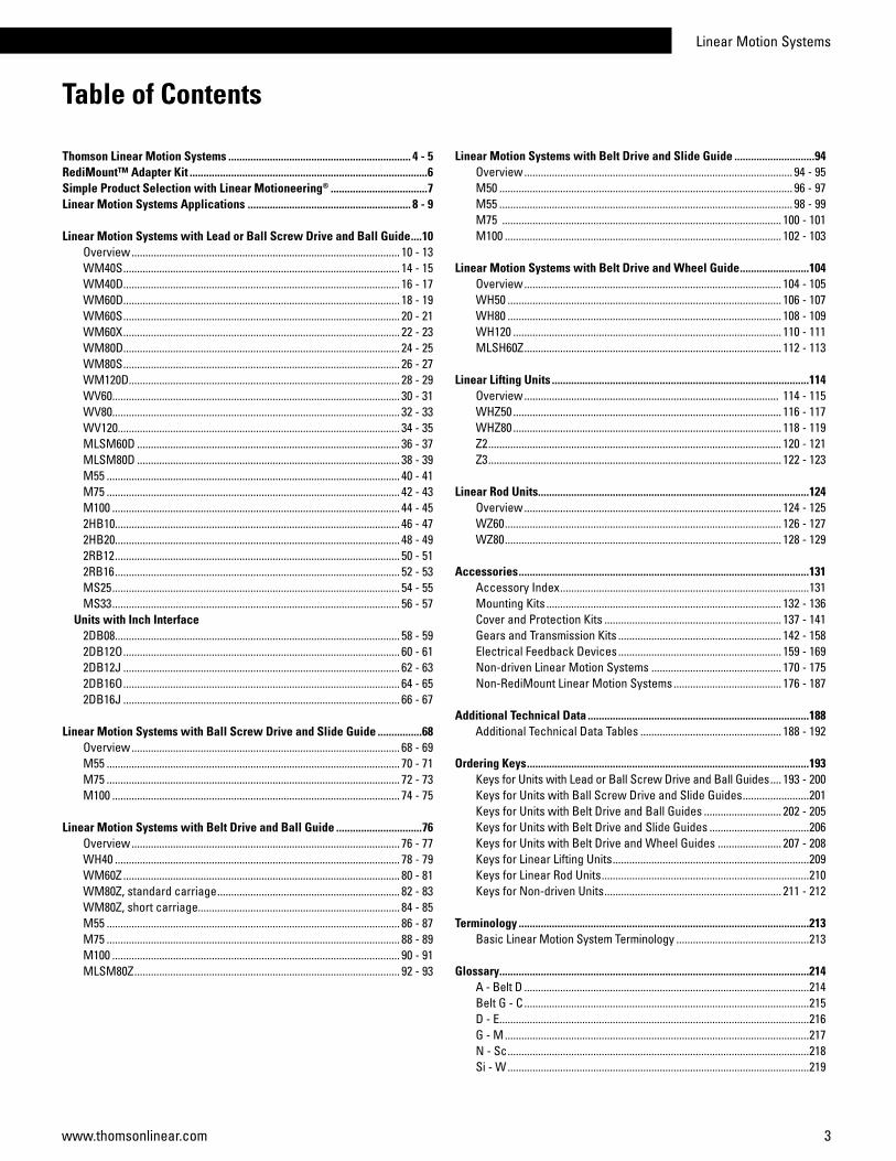
Table of Contents
Thomson Linear Motion Systems .................................................................. 4 - 5RediMount™ Adapter Kit ......................................................................................6 Simple Product Selection with Linear Motioneering® ...................................7Linear Motion Systems Applications ........................................................... 8 - 9
Linear Motion Systems with Lead or Ball Screw Drive and Ball Guide ....10 Overview ................................................................................................. 10 - 13WM40S .................................................................................................... 14 - 15WM40D.................................................................................................... 16 - 17WM60D.................................................................................................... 18 - 19WM60S .................................................................................................... 20 - 21WM60X .................................................................................................... 22 - 23WM80D.................................................................................................... 24 - 25WM80S .................................................................................................... 26 - 27WM120D.................................................................................................. 28 - 29WV60........................................................................................................ 30 - 31WV80........................................................................................................ 32 - 33WV120...................................................................................................... 34 - 35MLSM60D ............................................................................................... 36 - 37MLSM80D ............................................................................................... 38 - 39M55 .......................................................................................................... 40 - 41M75 .......................................................................................................... 42 - 43M100 ........................................................................................................ 44 - 452HB10....................................................................................................... 46 - 472HB20....................................................................................................... 48 - 492RB12 ....................................................................................................... 50 - 512RB16 ....................................................................................................... 52 - 53MS25 ........................................................................................................ 54 - 55MS33 ........................................................................................................ 56 - 57
Units with Inch Interface2DB08....................................................................................................... 58 - 592DB12O .................................................................................................... 60 - 612DB12J .................................................................................................... 62 - 632DB16O .................................................................................................... 64 - 652DB16J .................................................................................................... 66 - 67
Linear Motion Systems with Ball Screw Drive and Slide Guide ................68Overview ................................................................................................. 68 - 69M55 .......................................................................................................... 70 - 71M75 .......................................................................................................... 72 - 73M100 ........................................................................................................ 74 - 75
Linear Motion Systems with Belt Drive and Ball Guide ...............................76Overview ................................................................................................. 76 - 77WH40 ....................................................................................................... 78 - 79WM60Z .................................................................................................... 80 - 81WM80Z, standard carriage .................................................................. 82 - 83 WM80Z, short carriage......................................................................... 84 - 85M55 .......................................................................................................... 86 - 87M75 .......................................................................................................... 88 - 89M100 ........................................................................................................ 90 - 91MLSM80Z ................................................................................................ 92 - 93
Linear Motion Systems with Belt Drive and Slide Guide .............................94Overview ................................................................................................. 94 - 95M50 .......................................................................................................... 96 - 97M55 .......................................................................................................... 98 - 99M75 ..................................................................................................... 100 - 101M100 .................................................................................................... 102 - 103
Linear Motion Systems with Belt Drive and Wheel Guide .........................104Overview ............................................................................................. 104 - 105WH50 ................................................................................................... 106 - 107WH80 ................................................................................................... 108 - 109WH120 ................................................................................................. 110 - 111MLSH60Z ............................................................................................. 112 - 113
Linear Lifting Units .............................................................................................114Overview ............................................................................................ 114 - 115WHZ50 ................................................................................................. 116 - 117WHZ80 ................................................................................................. 118 - 119Z2 .......................................................................................................... 120 - 121Z3 .......................................................................................................... 122 - 123
Linear Rod Units..................................................................................................124Overview ............................................................................................. 124 - 125WZ60 .................................................................................................... 126 - 127 WZ80 .................................................................................................... 128 - 129
Accessories .........................................................................................................131Accessory Index ..........................................................................................131Mounting Kits ..................................................................................... 132 - 136Cover and Protection Kits ................................................................ 137 - 141Gears and Transmission Kits ........................................................... 142 - 158Electrical Feedback Devices ........................................................... 159 - 169Non-driven Linear Motion Systems ............................................... 170 - 175Non-RediMount Linear Motion Systems ....................................... 176 - 187
Additional Technical Data ................................................................................188Additional Technical Data Tables ................................................... 188 - 192
Ordering Keys ......................................................................................................193Keys for Units with Lead or Ball Screw Drive and Ball Guides .... 193 - 200Keys for Units with Ball Screw Drive and Slide Guides ........................201Keys for Units with Belt Drive and Ball Guides ............................ 202 - 205Keys for Units with Belt Drive and Slide Guides ....................................206 Keys for Units with Belt Drive and Wheel Guides ....................... 207 - 208Keys for Linear Lifting Units .......................................................................209Keys for Linear Rod Units ...........................................................................210Keys for Non-driven Units ................................................................ 211 - 212
Terminology .........................................................................................................213Basic Linear Motion System Terminology ................................................213
Glossary................................................................................................................214A - Belt D .......................................................................................................214Belt G - C .......................................................................................................215D - E................................................................................................................216G - M ..............................................................................................................217N - Sc .............................................................................................................218Si - W .............................................................................................................219
4 www.thomsonlinear.com
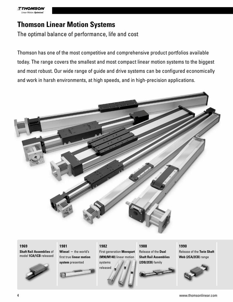
Thomson Linear Motion SystemsThe optimal balance of performance, life and cost
Thomson has one of the most competitive and comprehensive product portfolios available
today. The range covers the smallest and most compact linear motion systems to the biggest
and most robust. Our wide range of guide and drive systems can be configured economically
and work in harsh environments, at high speeds, and in high-precision applications.
1969Shaft Rail Assemblies of model 1CA/1CB released
1981Wiesel – the world’s
first true linear motion
system presented
1982First generation Movopart
(M90/M140) linear motion
systems
released
1988Release of the Dual
Shaft Rail Assemblies
(2DB/2EB) family
1990Release of the Twin Shaft
Web (2CA/2CB) range
Linear Motion Systems
5www.thomsonlinear.com
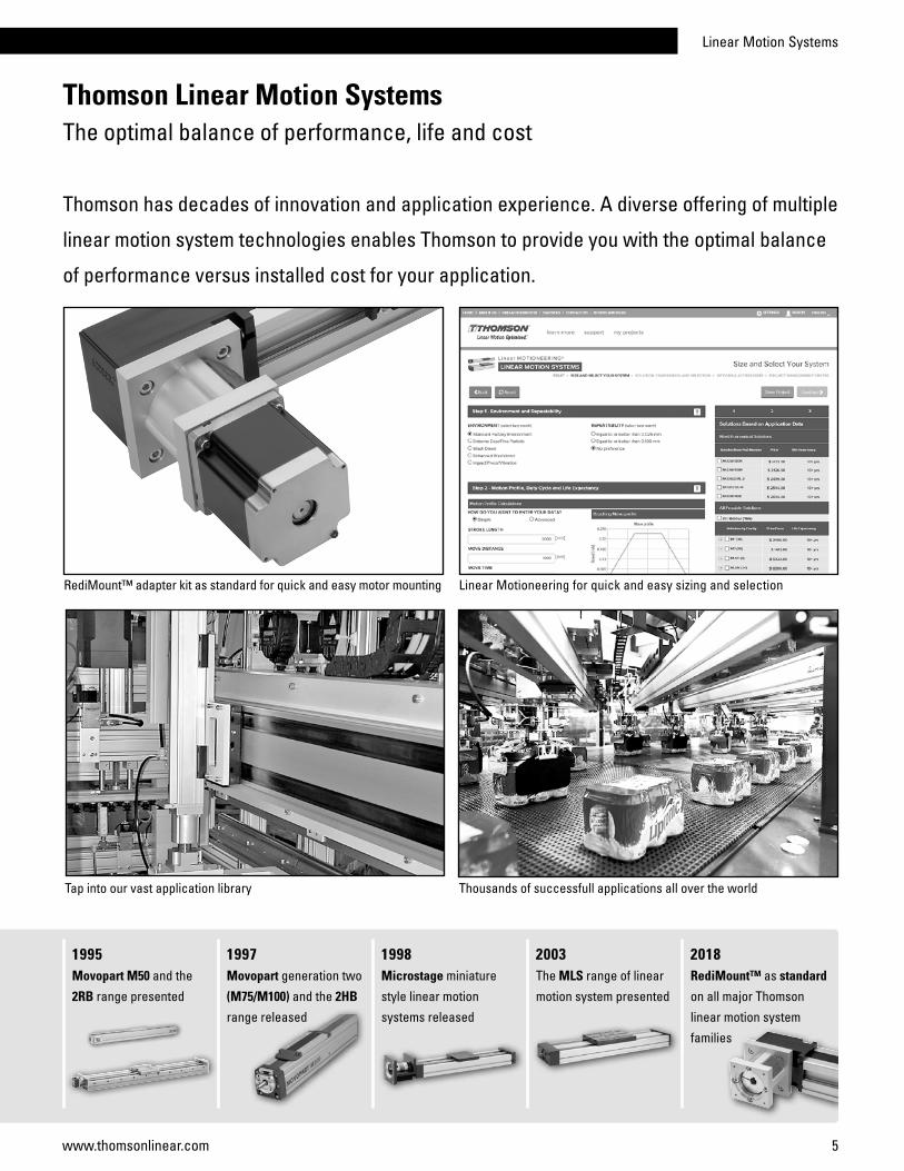
Thomson Linear Motion SystemsThe optimal balance of performance, life and cost
Thomson has decades of innovation and application experience. A diverse offering of multiple
linear motion system technologies enables Thomson to provide you with the optimal balance
of performance versus installed cost for your application.
1995Movopart M50 and the
2RB range presented
1997Movopart generation two
(M75/M100) and the 2HB
range released
1998Microstage miniature
style linear motion
systems released
2003The MLS range of linear
motion system presented
2018RediMount™ as standard
on all major Thomson
linear motion system
families
RediMount™ adapter kit as standard for quick and easy motor mounting
Thousands of successfull applications all over the worldTap into our vast application library
Linear Motioneering for quick and easy sizing and selection

6 www.thomsonlinear.com
Designed to accommodate more than 500 different motors and gearheads from a variety of manufacturers, the Thomson RediMount adapter kit eliminates the need for custom-made, intermediate flanges between your choice of linear motion system and motor or gearhead. With the optimized RediMount kit, you’ll be ready to order your complete linear motion system for your application within five minutes.
A RediMount kit includes a flange and coupling to mount to your preferred motor or gearhead. The flange has been machined to exactly match the motor pilot and mounting holes, while the coupling has been bored to match the diameter of the motor shaft and the corresponding shaft key. All necessary hardware is included.
Each RediMount kit alternative is identified by a three- character code that can be designated within the overall linear motion system part number. You can configure this RediMount code as well as your entire part number on www.LinearMotioneering.com. There, you can enter your application parameters to configure a solution that provides an optimal balance of performance, life, and cost. Once you’ve sized your system and ordered and received your linear motion system, installation is easy.
RediMount™ Adapter KitFast, Accurate and Hassle-Free Motor Mounting
The popular and easy to use Thomson RediMount motor mounting adapter kit is now available
as standard on all Thomson linear motion systems, making the whole process of choosing and
mounting a motor much faster and easier.
The linear motion system will arrive with the motor interface flange mounted to the unit. In a separate bag, you will find the motor coupling half, the motor bolts and the plug.
Insert the motor onto the interface flange, attach and tighten the included motor bolts, and tighten the coupling to the motor shaft. Finally, secure the plug over the coupling access window.

Linear Motion Systems
7www.thomsonlinear.com
1. Visit www.LinearMotioneering.com.
2. Enter your application parameters.
3. Choose a unit from the list of solutions, optimized for your application.
4. Add options and accessories to create your bill of material, with price and lead time.
5. Request a quote. Costs for shipping, packaging and import taxes should be requested directly from Thomson Customer Support.
6. Place an order.
Simple Product Selection with Linear Motioneering®
Online Product Selection
The Linear Motioneering sizing and selection tool is designed to make it simple to choose the right
linear motion system for your application. Simply enter the basic parameters for your application
and let Linear Motioneering do all the work. Once a solution is selected, you can add accessories
and options, download a CAD model, and get price and delivery time.
8 www.thomsonlinear.com
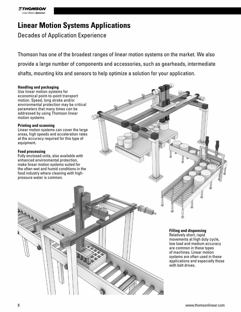
Linear Motion Systems Applications Decades of Application Experience
Thomson has one of the broadest ranges of linear motion systems on the market. We also
provide a large number of components and accessories, such as gearheads, intermediate
shafts, mounting kits and sensors to help optimize a solution for your application.
Handling and packagingUse linear motion systems for economical point-to-point transport motion. Speed, long stroke and/or environmental protection may be critical parameters that many times can be addressed by using Thomson linear motion systems.
Printing and scanningLinear motion systems can cover the large areas, high speeds and acceleration rates at the accuracy required for this type of equipment.
Food processingFully enclosed units, also available with enhanced environmental protection, make linear motion systems suited for the often wet and humid conditions in the food industry where cleaning with high- pressure water is common.
Filling and dispensingRelatively short, rapid movements at high duty cycle, low load and medium accuracy are common in these types of machines. Linear motion systems are often used in these applications and especially those with belt drives.
Linear Motion Systems
9www.thomsonlinear.com
Linear Motion Systems ApplicationsDecades of Application Experience
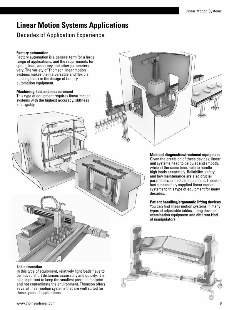
Factory automationFactory automation is a general term for a large range of applications, and the requirements for speed, load, accuracy and other parameters vary. The variety of Thomson linear motion systems makes them a versatile and flexible building block in the design of factory automation equipment.
Machining, test and measurementThis type of equipment requires linear motion systems with the highest accuracy, stiffness and rigidity.
Medical diagnostics/treatment equipmentGiven the precision of these devices, linear unit systems need to be quiet and smooth, while at the same time, able to handle high loads accurately. Reliability, safety and low maintenance are also crucial parameters in medical equipment. Thomson has successfully supplied linear motion systems to this type of equipment for many decades.
Patient handling/ergonomic lifting devicesYou can find linear motion systems in many types of adjustable tables, lifting devices, examination equipment and different kind of manipulators.
Lab automationIn this type of equipment, relatively light loads have to be moved short distances accurately and quickly. It is also important to keep the smallest possible footprint and not contaminate the environment. Thomson offers several linear motion systems that are well suited for these types of applications.

10 www.thomsonlinear.com
Parameter WM40S WM40D WM60D WM60S WM60X WM80D WM80S WM120D
Profile size (width × height) [mm] 40 × 40 40 × 40 60 × 60 60 × 60 60 × 60 80 × 80 80 × 80 120 × 120
Stroke length (Smax), maximum [mm] 2000 1950 11000 10390 10340 11000 10540 11000
Linear speed, maximum [m/s] 0,25 0,25 2,5 2,5 0,25 2,5 2,5 2,0
Dynamic carriage load (Fz), maximum [N] 600 600 2000 1400 2000 3000 2100 6000
Remarks single ball nut
double ball nuts
double ball nuts
single ball nut
left/right screw
double ball nuts
single ball nut
double ball nuts
Page 14 16 18 20 22 24 26 28
Features• Can be installed in any orientation• Patented guide system• Patented self-adjusting plastic cover band1
• Patented screw support system
1 Not on WM40 units
PowerLine WM
WM80
Linear Motion Systems with Ball Screw Drive and Ball Guide Overview
WM-Series Technical Presentation
Screw supportPatented screw support system permits high speeds at long stroke lengths while reducing the available stroke with a minimum.
Double ball nutsDouble pre-tensioned ball nuts improve the accuracy and allow re-tensioning, increasing the lifetime of the unit.
Central lubricationOne central lubrication point on the carriage services the entire unit resulting in a minimum maintenance requirement.
Ball guidesIntegrated patented ball guides with hard-ened steel tracks for optimum performance.
Cover bandThe patented self-adjusting cover band protect the unit from the penetration of dirt, dust and liquids.
Ball cagesThe balls in the ball guides are protected by a ball cage which ensures a long life.
Note! the unit is pictured without a RediMount™ flange

Linear Motion Systems
11www.thomsonlinear.com
Parameter WV60 WV80 WV120
Profile size (width × height) [mm] 60 × 60 80 × 80 120 × 120
Stroke length (Smax), maximum [mm] 11000 11000 11000
Linear speed, maximum [m/s] 2,5 2,5 2,0
Dynamic carriage load (Fz), maximum [N] - - -
Remarks double ball nuts the units has no guides
double ball nutsthe units has no guides
double ball nutsthe units has no guides
Page 30 32 34
Parameter MLSM60D MLSM80D
Profile size (width × height) [mm] 160 × 65 240 × 85
Stroke length (Smax), maximum [mm] 4985 4810
Linear speed, maximum [m/s] 2,5 2,0
Dynamic carriage load (Fz), maximum [N] 6000 8000
Remarks double ball nuts double ball nuts
Page 36 38
Features• Can be installed in any orientation• Patented guide system• Patented plastic cover band• Patented screw support system
Features• Can be installed in any orientation• Patented self-adjusting plastic cover band• Patented screw support system• Require external guides
ForceLine MLSM
PowerLine WV
WV80
MLSM60D
Linear Motion Systems with Lead or Ball Screw Drive and Ball Guide Overview
12 www.thomsonlinear.com
Linear Motion Systems with Lead or Ball Screw Drive and Ball Guide Overview
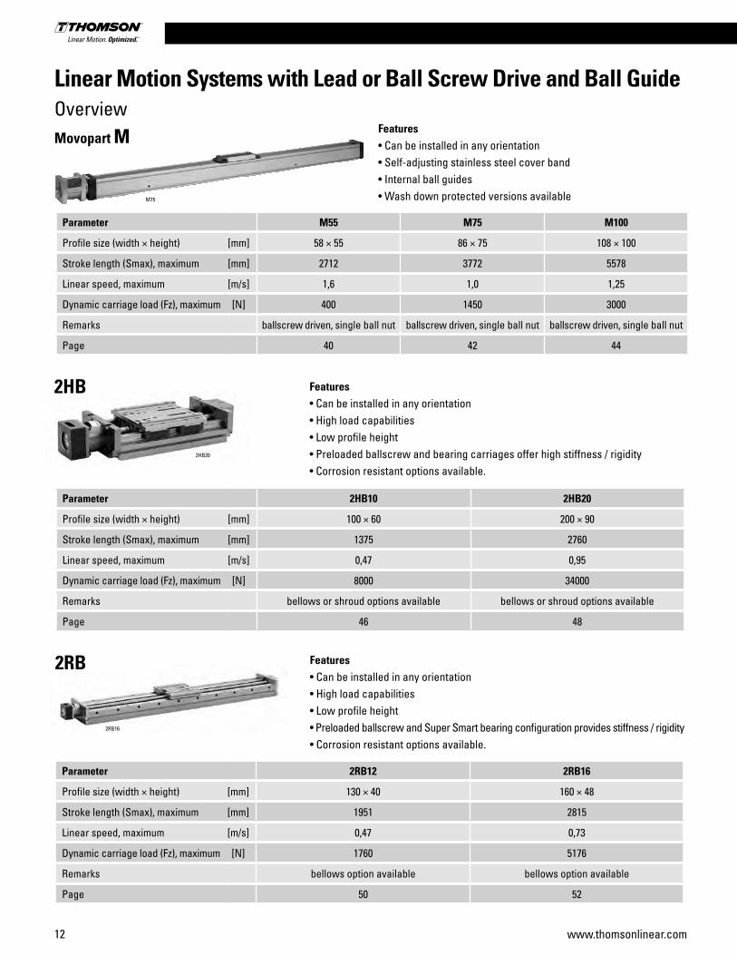
Parameter 2HB10 2HB20
Profile size (width × height) [mm] 100 × 60 200 × 90
Stroke length (Smax), maximum [mm] 1375 2760
Linear speed, maximum [m/s] 0,47 0,95
Dynamic carriage load (Fz), maximum [N] 8000 34000
Remarks bellows or shroud options available bellows or shroud options available
Page 46 48
Parameter 2RB12 2RB16
Profile size (width × height) [mm] 130 × 40 160 × 48
Stroke length (Smax), maximum [mm] 1951 2815
Linear speed, maximum [m/s] 0,47 0,73
Dynamic carriage load (Fz), maximum [N] 1760 5176
Remarks bellows option available bellows option available
Page 50 52
Features• Can be installed in any orientation• High load capabilities• Low profile height• Preloaded ballscrew and bearing carriages offer high stiffness / rigidity• Corrosion resistant options available.
Features• Can be installed in any orientation• High load capabilities• Low profile height• Preloaded ballscrew and Super Smart bearing configuration provides stiffness / rigidity• Corrosion resistant options available.
2HB20
2RB16
Parameter M55 M75 M100
Profile size (width × height) [mm] 58 × 55 86 × 75 108 × 100
Stroke length (Smax), maximum [mm] 2712 3772 5578
Linear speed, maximum [m/s] 1,6 1,0 1,25
Dynamic carriage load (Fz), maximum [N] 400 1450 3000
Remarks ballscrew driven, single ball nut ballscrew driven, single ball nut ballscrew driven, single ball nut
Page 40 42 44
Features• Can be installed in any orientation• Self-adjusting stainless steel cover band• Internal ball guides• Wash down protected versions available
Movopart M
2HB
2RB
M75
Linear Motion Systems
13www.thomsonlinear.com
Linear Motion Systems with Lead or Ball Screw Drive and Ball Guide Overview
Parameter MS25 MS33
Profile size (width × height) [mm] 50 × 25 60 × 33
Stroke length (Smax), maximum [mm] 705,5 704
Linear speed, maximum [m/s] 0,85 1,02
Dynamic carriage load (Fz), maximum [N] 100 150
Remarks bellows option available bellows option available
Page 54 56
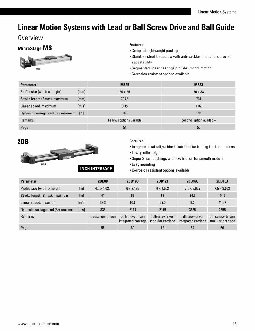
Features• Compact, lightweight package• Stainless steel leadscrew with anti-backlash nut offers precise repeatability• Segmented linear bearings provide smooth motion• Corrosion resistant options available
MS33
MicroStage MS
Parameter 2DB08 2DB12O 2DB12J 2DB16O 2DB16J
Profile size (width × height) [in] 4.5 × 1.625 6 × 2.125 6 × 2.562 7.5 × 2.625 7.5 × 3.062
Stroke length (Smax), maximum [in] 41 63 63 84.5 84.5
Linear speed, maximum [in/s] 33.3 10.0 25.0 8.3 41.67
Dynamic carriage load (Fz), maximum [lbs] 336 2115 2115 3555 3555
Remarks leadscrew driven ballscrew driven integrated carriage
ballscrew driven modular carriage
ballscrew driven integrated carriage
ballscrew driven modular carriage
Page 58 60 62 64 66
Features• Integrated dual-rail, webbed shaft ideal for loading in all orientations• Low-profile height• Super Smart bushings with low friction for smooth motion• Easy mounting• Corrosion resistant options available
2DB
2DB12
INCH INTERFACE

14 www.thomsonlinear.com
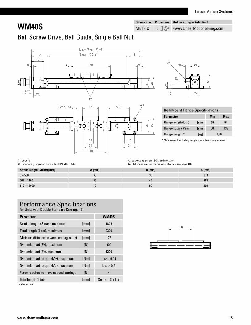
WM40SBall Screw Drive, Ball Guide, Single Ball Nut
Performance Specificationsfor Units with Single Standard Carriage (N)1
Parameter WM40S
Stroke length (Smax), maximum [mm] 2000
Total length (L tot), maximum [mm] 2300
Linear speed, maximum [m/s] 0,25
Acceleration, maximum [m/s2] 20
Repeatability [± mm] 0,02
Input speed, maximum [rpm] 3000
Operation temperature limits [°C] 0 – 80
Dynamic load (Fx), maximum [N] 1000
Dynamic load (Fy), maximum [N] 450
Dynamic load (Fz), maximum [N] 600
Dynamic load torque (Mx), maximum [Nm] 10
Dynamic load torque (My), maximum [Nm] 30
Dynamic load torque (Mz), maximum [Nm] 30
Drive shaft force (Frd), maximum 2 [N] 100
Input/drive shaft torque (Mta), maximum [Nm] 3
Ball screw diameter (d0) [mm] 12
Ball screw lead (p) [mm] 5
Weight of unit with zero stroke of every 100 mm of stroke of each carriage
[kg]1,500,300,36
1 See next page for deviating values of units with other carriage types.2 Only relevant for units without RediMount flange.
General SpecificationsParameter WM40S
Profile size (w × h) [mm] 40 × 40
Type of screw ball screw with single nut
Carriage sealing system plastic cover band
Screw supports included in all units that require screw supports
Lubrication central lubrication of all parts that require lubrication
Included accessories 4 × mounting clamps
Carriage Idle Torque (M idle) [Nm]
Input speed [rpm]Screw lead [mm]
p = 5
150 0,3
1500 0,5
3000 0,8M idle = the input torque needed to move the carriage with no load on it.
» Ordering key - see page 193» Accessories - see page 131» Additional data - see page 188
Definition of Forces
Deflection of the Profile
A mounting clamp must be installed at least every 750 mm to be able to operate at maximum load. Less clamps may be required if less load is being operated, see the additional technical data for more information.
Critical Speed
Linear Motion Systems
15www.thomsonlinear.com
WM40SBall Screw Drive, Ball Guide, Single Ball Nut
Performance Specificationsfor Units with Double Standard Carriage (Z)
Parameter WM40S
Stroke length (Smax), maximum [mm] 1825
Total length (L tot), maximum [mm] 2300
Minimum distance between carriages (L C) [mm] 175
Dynamic load (Fy), maximum [N] 900
Dynamic load (Fz), maximum [N] 1200
Dynamic load torque (My), maximum [Nm] L C1 × 0,45
Dynamic load torque (Mz), maximum [Nm] L C1 × 0,6
Force required to move second carriage [N] 4
Total length (L tot) [mm] Smax + C + L C
A1: depth 7A2: lubricating nipple on both sides DIN3405 D 1/A
Stroke length (Smax) [mm] A [mm] B [mm] C [mm]
0 – 500 65 35 270
501 – 1100 65 45 280
1101 – 2000 70 60 300
A3: socket cap screw ISO4762-M5×12 8.8A4: ENF inductive sensor rail kit (optional - see page 166)
1 Value in mm
Dimensions Projection Online Sizing & Selection!
METRIC www.LinearMotioneering.com
RediMount Flange SpecificationsParameter Min Max
Flange length (Lrm) [mm] 59 94
Flange square (Srm) [mm] 60 139
Flange weight * [kg] 1,86
* Max. weight including coupling and fastening screws

16 www.thomsonlinear.com
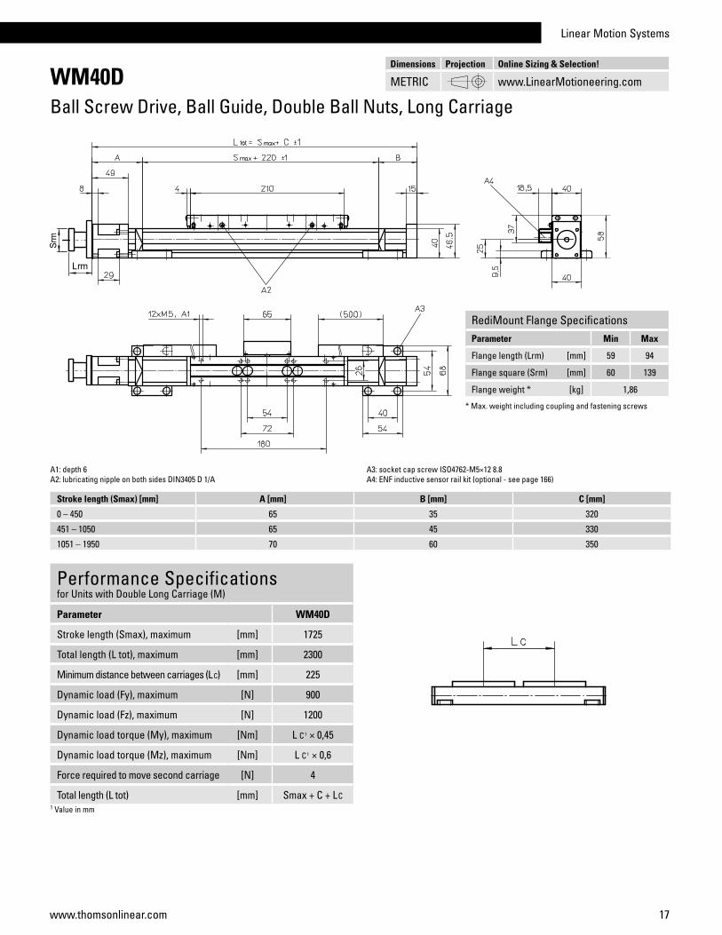
WM40DBall Screw Drive, Ball Guide, Double Ball Nuts, Long Carriage
Performance Specificationsfor Units with Single Long Carriage (L)1
Parameter WM40D
Stroke length (Smax), maximum [mm] 1950
Total length (L tot), maximum [mm] 2300
Linear speed, maximum [m/s] 0,25
Acceleration, maximum [m/s2] 20
Repeatability [± mm] 0,01
Input speed, maximum [rpm] 3000
Operation temperature limits [°C] 0 – 80
Dynamic load (Fx), maximum [N] 1000
Dynamic load (Fy), maximum [N] 450
Dynamic load (Fz), maximum [N] 600
Dynamic load torque (Mx), maximum [Nm] 10
Dynamic load torque (My), maximum [Nm] 30
Dynamic load torque (Mz), maximum [Nm] 30
Drive shaft force (Frd), maximum 2 [N] 100
Input/drive shaft torque (Mta), maximum [Nm] 3
Ball screw diameter (d0) [mm] 12
Ball screw lead (p) [mm] 5
Weight of unit with zero stroke of every 100 mm of stroke of each carriage
[kg]1,900,300,60
1 See next page for deviating values of units with other carriage types.2 Only relevant for units without RediMount flange.
General SpecificationsParameter WM40D
Profile size (w × h) [mm] 40 × 40
Type of screw ball screw with double nuts
Carriage sealing system plastic cover band
Screw supports included in all units that require screw supports
Lubrication central lubrication of all parts that require lubrication
Included accessories 4 × mounting clamps
Carriage Idle Torque (M idle) [Nm]
Input speed [rpm]Screw lead [mm]
p = 5
150 0,4
1500 0,6
3000 0,9M idle = the input torque needed to move the carriage with no load on it.
Definition of Forces
Deflection of the Profile
A mounting clamp must be installed at least every 750 mm to be able to operate at maximum load. Less clamps may be required if less load is being operated, see the additional technical data for more information.
Critical Speed
» Ordering key - see page 193» Accessories - see page 131» Additional data - see page 188
Linear Motion Systems
17www.thomsonlinear.com
WM40DBall Screw Drive, Ball Guide, Double Ball Nuts, Long Carriage
Performance Specificationsfor Units with Double Long Carriage (M)
Parameter WM40D
Stroke length (Smax), maximum [mm] 1725
Total length (L tot), maximum [mm] 2300
Minimum distance between carriages (L C) [mm] 225
Dynamic load (Fy), maximum [N] 900
Dynamic load (Fz), maximum [N] 1200
Dynamic load torque (My), maximum [Nm] L C1 × 0,45
Dynamic load torque (Mz), maximum [Nm] L C1 × 0,6
Force required to move second carriage [N] 4
Total length (L tot) [mm] Smax + C + LC1 Value in mm
A1: depth 6A2: lubricating nipple on both sides DIN3405 D 1/A
A3: socket cap screw ISO4762-M5×12 8.8A4: ENF inductive sensor rail kit (optional - see page 166)
Stroke length (Smax) [mm] A [mm] B [mm] C [mm]
0 – 450 65 35 320
451 – 1050 65 45 330
1051 – 1950 70 60 350
Dimensions Projection Online Sizing & Selection!
METRIC www.LinearMotioneering.com
RediMount Flange SpecificationsParameter Min Max
Flange length (Lrm) [mm] 59 94
Flange square (Srm) [mm] 60 139
Flange weight * [kg] 1,86
* Max. weight including coupling and fastening screws
18 www.thomsonlinear.com
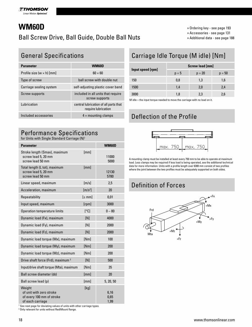
WM60DBall Screw Drive, Ball Guide, Double Ball Nuts
Performance Specificationsfor Units with Single Standard Carriage (N)1
Parameter WM60D
Stroke length (Smax), maximum screw lead 5, 20 mm screw lead 50 mm
[mm]11000 5000
Total length (L tot), maximum screw lead 5, 20 mm screw lead 50 mm
[mm]121305780
Linear speed, maximum [m/s] 2,5
Acceleration, maximum [m/s2] 20
Repeatability [± mm] 0,01
Input speed, maximum [rpm] 3000
Operation temperature limits [°C] 0 – 80
Dynamic load (Fx), maximum [N] 4000
Dynamic load (Fy), maximum [N] 2000
Dynamic load (Fz), maximum [N] 2000
Dynamic load torque (Mx), maximum [Nm] 100
Dynamic load torque (My), maximum [Nm] 200
Dynamic load torque (Mz), maximum [Nm] 200
Drive shaft force (Frd), maximum 2 [N] 500
Input/drive shaft torque (Mta), maximum [Nm] 35
Ball screw diameter (d0) [mm] 20
Ball screw lead (p) [mm] 5, 20, 50
Weight of unit with zero stroke of every 100 mm of stroke of each carriage
[kg]6,160,651,99
1 See next page for deviating values of units with other carriage types.2 Only relevant for units without RediMount flange.
General SpecificationsParameter WM60D
Profile size (w × h) [mm] 60 × 60
Type of screw ball screw with double nut
Carriage sealing system self-adjusting plastic cover band
Screw supports included in all units that require screw supports
Lubrication central lubrication of all parts that require lubrication
Included accessories 4 × mounting clamps
Carriage Idle Torque (M idle) [Nm]
Input speed [rpm]Screw lead [mm]
p = 5 p = 20 p = 50
150 0,8 1,3 1,6
1500 1,4 2,0 2,4
3000 1,8 2,3 2,6M idle = the input torque needed to move the carriage with no load on it.
Definition of Forces
Deflection of the Profile
A mounting clamp must be installed at least every 750 mm to be able to operate at maximum load. Less clamps may be required if less load is being operated, see the additional technical data for more information. Units with a profile length over 6300 mm consist of two profiles where the joint between the two profiles must be adequately supported on both sides.
» Ordering key - see page 193» Accessories - see page 131» Additional data - see page 188
Linear Motion Systems
19www.thomsonlinear.com
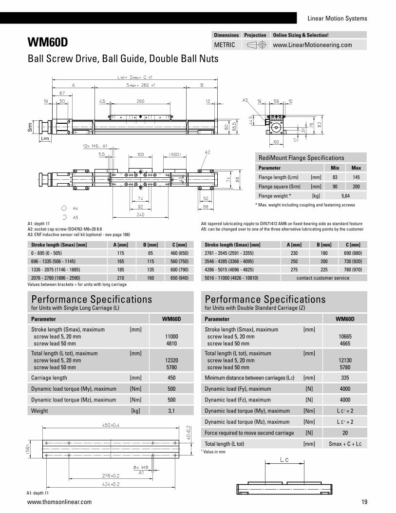
WM60DBall Screw Drive, Ball Guide, Double Ball Nuts
Performance Specificationsfor Units with Single Long Carriage (L)
Parameter WM60D
Stroke length (Smax), maximum screw lead 5, 20 mm screw lead 50 mm
[mm]110004810
Total length (L tot), maximum screw lead 5, 20 mm screw lead 50 mm
[mm]123205780
Carriage length [mm] 450
Dynamic load torque (My), maximum [Nm] 500
Dynamic load torque (Mz), maximum [Nm] 500
Weight [kg] 3,1
Performance Specificationsfor Units with Double Standard Carriage (Z)
Parameter WM60D
Stroke length (Smax), maximum screw lead 5, 20 mm screw lead 50 mm
[mm]106654665
Total length (L tot), maximum screw lead 5, 20 mm screw lead 50 mm
[mm]121305780
Minimum distance between carriages (L C) [mm] 335
Dynamic load (Fy), maximum [N] 4000
Dynamic load (Fz), maximum [N] 4000
Dynamic load torque (My), maximum [Nm] L C1 × 2
Dynamic load torque (Mz), maximum [Nm] L C1 × 2
Force required to move second carriage [N] 20
Total length (L tot) [mm] Smax + C + LC1 Value in mm
A1: depth 11A2: socket cap screw ISO4762-M6×20 8.8 A3: ENF inductive sensor rail kit (optional - see page 166)
A1: depth 11
A4: tapered lubricating nipple to DIN71412 AM6 on fixed-bearing side as standard featureA5: can be changed over to one of the three alternative lubricating points by the customer
Stroke length (Smax) [mm] A [mm] B [mm] C [mm]
0 - 695 (0 - 505) 115 65 460 (650)
696 - 1335 (506 - 1145) 165 115 560 (750)
1336 - 2075 (1146 - 1885) 185 135 600 (790)
2076 - 2780 (1886 - 2590) 210 160 650 (840)Values between brackets = for units with long carriage
Stroke length (Smax) [mm] A [mm] B [mm] C [mm]
2781 - 3545 (2591 - 3355) 230 180 690 (880)
3546 - 4285 (3366 - 4095) 250 200 730 (920)
4286 - 5015 (4096 - 4825) 275 225 780 (970)
5016 - 11000 (4826 - 10810) contact customer service
Dimensions Projection Online Sizing & Selection!
METRIC www.LinearMotioneering.com
RediMount Flange SpecificationsParameter Min Max
Flange length (Lrm) [mm] 83 145
Flange square (Srm) [mm] 90 200
Flange weight * [kg] 5,64
* Max. weight including coupling and fastening screws

20 www.thomsonlinear.com
WM60SBall Screw Drive, Ball Guide, Single Ball Nut, Short Carriage
Performance Specificationsfor Units with Single Short Carriage (S)1
Parameter WM60S
Stroke length (Smax), maximum screw lead 5, 20 mm screw lead 50 mm
[mm]103905000
Total length (L tot), maximum screw lead 5, 20 mm screw lead 50 mm
[mm]114005650
Linear speed, maximum [m/s] 2,5
Acceleration, maximum [m/s2] 10
Repeatability [± mm] 0,02
Input speed, maximum [rpm] 3000
Operation temperature limits [°C] 0 – 80
Dynamic load (Fx), maximum [N] 2800
Dynamic load (Fy), maximum [N] 1400
Dynamic load (Fz), maximum [N] 1400
Dynamic load torque (Mx), maximum [Nm] 50
Dynamic load torque (My), maximum [Nm] 100
Dynamic load torque (Mz), maximum [Nm] 100
Drive shaft force (Frd), maximum 2 [N] 500
Input/drive shaft torque (Mta), maximum [Nm] 35
Ball screw diameter (d0) [mm] 20
Ball screw lead (p) [mm] 5, 20, 50
Weight of unit with zero stroke of every 100 mm of stroke of each carriage
[kg]3,800,651,00
1 See next page for deviating values of units with other carriage types.2 Only relevant for units without RediMount flange.
General SpecificationsParameter WM60S
Profile size (w × h) [mm] 60 × 60
Type of screw ball screw with single nut
Carriage sealing system self-adjusting plastic cover band
Screw supports included in all units that require screw supports
Lubrication central lubrication of all parts that require lubrication
Included accessories 4 × mounting clamps
Carriage Idle Torque (M idle) [Nm]
Input speed [rpm]Screw lead [mm]
p = 5 p = 20 p = 50
150 0,7 1,0 1,4
1500 1,1 1,6 2,0
3000 1,5 1,8 2,2M idle = the input torque needed to move the carriage with no load on it.
Definition of Forces
Deflection of the Profile
A mounting clamp must be installed at least every 750 mm to be able to operate at maximum load. Less clamps may be required if less load is being operated, see the additional technical data for more information. Units with a profile length over 6300 mm consist of two profiles where the joint between the two profiles must be adequately supported on both sides.
» Ordering key - see page 193» Accessories - see page 131» Additional data - see page 188

Linear Motion Systems
21www.thomsonlinear.com
WM60SBall Screw Drive, Ball Guide, Single Ball Nut, Short Carriage
Stroke length (Smax) [mm] A [mm] B [mm] C [mm]
0 - 580 95 20 335
581 - 1140 110 60 390
1141 - 1805 130 80 430
1806 - 2460 155 105 480
Stroke length (Smax) [mm] A [mm] B [mm] C [mm]
2461 - 3125 175 125 520
3126 - 3780 200 150 570
3781 - 4445 220 170 610
4446 - 5000 240 190 650
5001 - 10390 contact customer service
Performance Specificationsfor Units with Double Short Carriage (Y)
Parameter WM60S
Stroke length (Smax), maximum screw lead 5, 20 mm screw lead 50 mm
[mm]101354745
Total length (L tot), maximum screw lead 5, 20 mm screw lead 50 mm
[mm]114005650
Minimum distance between carriages (L C) [mm] 255
Dynamic load (Fy), maximum [N] 2800
Dynamic load (Fz), maximum [N] 2800
Dynamic load torque (My), maximum [Nm] L C1 × 1,4
Dynamic load torque (Mz), maximum [Nm] L C1 × 1,4
Force required to move second carriage [N] 18
Total length (L tot) [mm] Smax + C + LC1 Value in mm
A1: depth 11A2: socket cap screw ISO4762-M6×20 8.8A3: ENF inductive sensor rail kit (optional - see page 166)
A4: tapered lubricating nipple to DIN71412 AM6 on fixed-bearing side as standard featureA5: can be changed over to one of the three alternative lubricating points by the customer
Dimensions Projection Online Sizing & Selection!
METRIC www.LinearMotioneering.com
RediMount Flange SpecificationsParameter Min Max
Flange length (Lrm) [mm] 83 145
Flange square (Srm) [mm] 90 200
Flange weight * [kg] 5,64
* Max. weight including coupling and fastening screws

22 www.thomsonlinear.com
WM60XBall Screw Drive, Ball Guide, Left/Right Moving Carriages
Performance Specificationsfor Units with Single Standard Carriage (N)1
Parameter WM60X
Stroke length (Smax), maximum [mm] 10340
Linear speed, maximum [m/s] 0,25
Acceleration, maximum [m/s2] 20
Repeatability [± mm] 0,01
Input speed, maximum [rpm] 3000
Operation temperature limits [°C] 0 – 80
Dynamic load (Fx), maximum [N] 4000
Dynamic load (Fy), maximum [N] 2000
Dynamic load (Fz), maximum [N] 2000
Dynamic load torque (Mx), maximum [Nm] 100
Dynamic load torque (My), maximum [Nm] 200
Dynamic load torque (Mz), maximum [Nm] 200
Drive shaft force (Frd), maximum 2 [N] 500
Input/drive shaft torque (Mta), maximum [Nm] 35
Ball screw diameter (d0) [mm] 20
Ball screw lead (p) [mm] 5
Weight of unit with zero stroke of every 100 mm of stroke of each carriage
[kg]10,33 0,65 1,99
1 See next page for deviating values of units with other carriage types.2 Only relevant for units without RediMount flange.
General SpecificationsParameter WM60X
Profile size (w × h) [mm] 60 × 60
Type of screw ball screw with double nut
Carriage sealing system self-adjusting plastic cover band
Screw supports included in all units that require screw supports
Lubrication central lubrication of all parts that require lubrication
Included accessories 4 × mounting clamps
Carriage Idle Torque (M idle) [Nm]
Input speed [rpm]Screw lead [mm]
p = 5
150 1,6
1500 2,8
3000 3,6M idle = the input torque needed to move the carriage with no load on it.
Definition of Forces
Deflection of the Profile
A mounting clamp must be installed at least every 750 mm to be able to operate at maximum load. Less clamps may be required if less load is being operated, see the additional technical data for more information. Units with a profile length over 6300 mm consist of two profiles where the joint between the two profiles must be adequately supported on both sides.
» Ordering key - see page 193» Accessories - see page 131» Additional data - see page 188

Linear Motion Systems
23www.thomsonlinear.com
WM60XBall Screw Drive, Ball Guide, Left/Right Moving Carriages
Stroke length (Smax) [mm] A [mm] B [mm] C [mm] X [mm] Y [mm] Z [mm]
0 - 1390 (0 - 1200) 115 65 60 80 620 800
1391 - 2670 (1201 - 2480) 165 115 210 230 770 1050
2671 - 4150 (2481 - 3960) 185 135 250 270 810 1130
4151 - 5560 (3961 - 5370) 210 160 300 320 860 1230
5561 - 10340 (5371 - 10150) contact customer service
Performance Specificationsfor Units with Single Long Carriage (L)
Parameter WM60X
Carriage length [mm] 450
Dynamic load torque (My), maximum [Nm] 500
Dynamic load torque (Mz), maximum [Nm] 500
Weight [kg] 3,1
Values between brackets = for units with long carriage
A1: depth 11
A1: depth 11A2: socket cap screw ISO4762-M6×20 8.8A3: ENF inductive sensor rail kit (optional - see page 166)
A4: tapered lubricating nipple to DIN71412 AM6 on fixed-bearing side as standard featureA5: can be changed over to one of the three alternative lubricating points by the customer
Dimensions Projection Online Sizing & Selection!
METRIC www.LinearMotioneering.com
RediMount Flange SpecificationsParameter Min Max
Flange length (Lrm) [mm] 83 145
Flange square (Srm) [mm] 90 200
Flange weight * [kg] 5,64
* Max. weight including coupling and fastening screws

24 www.thomsonlinear.com
WM80DBall Screw Drive, Ball Guide, Double Ball Nuts
Performance Specificationsfor Units with Single Standard Carriage (N)1
Parameter WM80D
Stroke length (Smax), maximum screw lead 5, 10, 20 mm screw lead 50 mm
[mm]11000 4965
Total length (L tot), maximum screw lead 5, 10, 20 mm screw lead 50 mm
[mm]120755780
Linear speed, maximum [m/s] 2,5
Acceleration, maximum [m/s2] 20
Repeatability [± mm] 0,01
Input speed, maximum [rpm] 3000
Operation temperature limits [°C] 0 – 80
Dynamic load (Fx), maximum [N] 5000
Dynamic load (Fy), maximum [N] 3000
Dynamic load (Fz), maximum [N] 3000
Dynamic load torque (Mx), maximum [Nm] 350
Dynamic load torque (My), maximum [Nm] 300
Dynamic load torque (Mz), maximum [Nm] 300
Drive shaft force (Frd), maximum 2 [N] 700
Input/drive shaft torque (Mta), maximum [Nm] 55
Ball screw diameter (d0) [mm] 25
Ball screw lead (p) [mm] 5, 10, 20, 50
Weight of unit with zero stroke of every 100 mm of stroke of each carriage
[kg]11,571,084,26
1 See next page for deviating values of units with other carriage types.2 Only relevant for units without RediMount flange.
General SpecificationsParameter WM80D
Profile size (w × h) [mm] 80 × 80
Type of screw ball screw with double nuts
Carriage sealing system self-adjusting plastic cover band
Screw supports included in all units that require screw supports
Lubrication central lubrication of all parts that require lubrication
Included accessories 4 × mounting clamps
Carriage Idle Torque (M idle) [Nm]
Input speed [rpm]Screw lead [mm]
p = 5 p = 10 p = 20 p = 50
150 1,1 1,5 1,8 2,3
1500 1,7 2.1 2,3 3,0
3000 2,1 2,5 2,6 3,6M idle = the input torque needed to move the carriage with no load on it.
Definition of Forces
Deflection of the Profile
A mounting clamp must be installed at least every 750 mm to be able to operate at maximum load. Less clamps may be required if less load is being operated, see the additional technical data for more information. Units with a profile length over 6300 mm consist of two profiles where the joint between the two profiles must be adequately supported on both sides.
» Ordering key - see page 193» Accessories - see page 131» Additional data - see page 188
Linear Motion Systems
25www.thomsonlinear.com
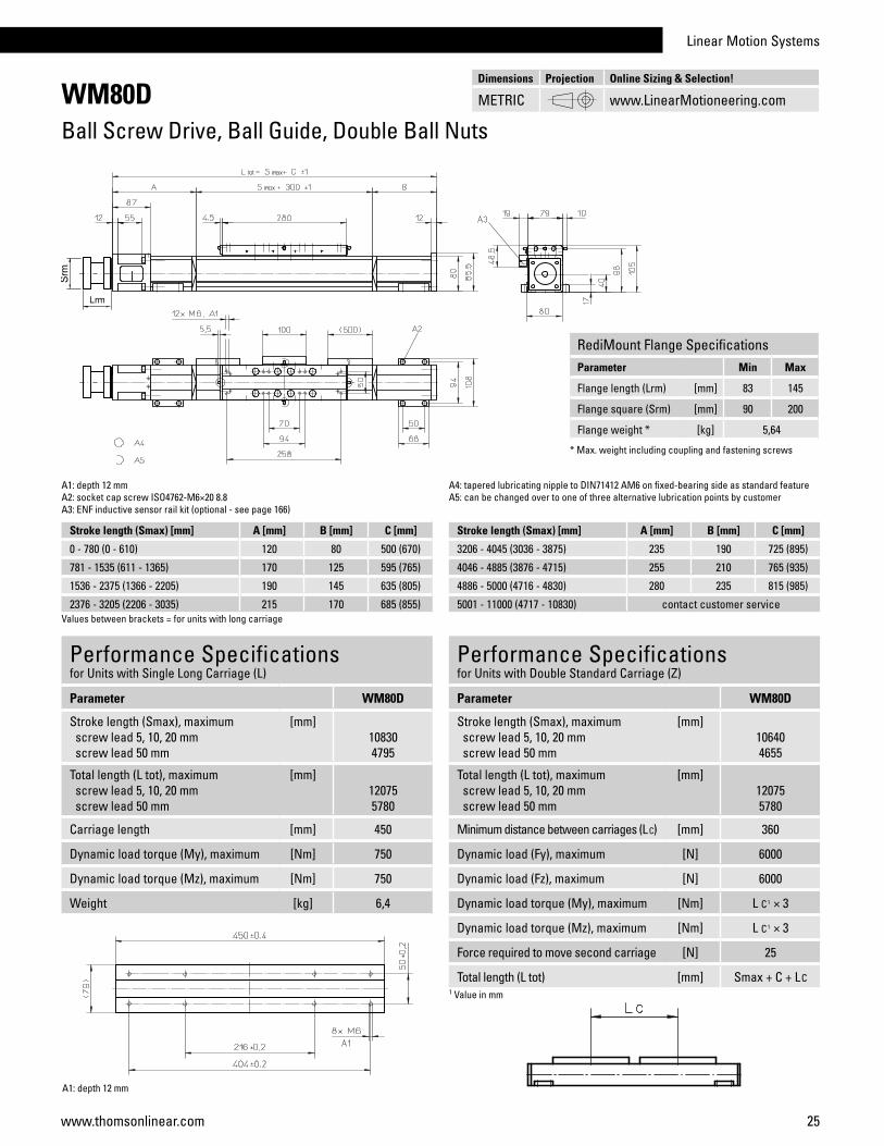
WM80DBall Screw Drive, Ball Guide, Double Ball Nuts
Performance Specificationsfor Units with Single Long Carriage (L)
Parameter WM80D
Stroke length (Smax), maximum screw lead 5, 10, 20 mm screw lead 50 mm
[mm]108304795
Total length (L tot), maximum screw lead 5, 10, 20 mm screw lead 50 mm
[mm]120755780
Carriage length [mm] 450
Dynamic load torque (My), maximum [Nm] 750
Dynamic load torque (Mz), maximum [Nm] 750
Weight [kg] 6,4
Performance Specificationsfor Units with Double Standard Carriage (Z)
Parameter WM80D
Stroke length (Smax), maximum screw lead 5, 10, 20 mm screw lead 50 mm
[mm]106404655
Total length (L tot), maximum screw lead 5, 10, 20 mm screw lead 50 mm
[mm]120755780
Minimum distance between carriages (L C) [mm] 360
Dynamic load (Fy), maximum [N] 6000
Dynamic load (Fz), maximum [N] 6000
Dynamic load torque (My), maximum [Nm] L C1 × 3
Dynamic load torque (Mz), maximum [Nm] L C1 × 3
Force required to move second carriage [N] 25
Total length (L tot) [mm] Smax + C + LC1 Value in mm
A1: depth 12 mmA2: socket cap screw ISO4762-M6×20 8.8A3: ENF inductive sensor rail kit (optional - see page 166)
Stroke length (Smax) [mm] A [mm] B [mm] C [mm]
0 - 780 (0 - 610) 120 80 500 (670)
781 - 1535 (611 - 1365) 170 125 595 (765)
1536 - 2375 (1366 - 2205) 190 145 635 (805)
2376 - 3205 (2206 - 3035) 215 170 685 (855)
A4: tapered lubricating nipple to DIN71412 AM6 on fixed-bearing side as standard featureA5: can be changed over to one of three alternative lubrication points by customer
Values between brackets = for units with long carriage
Stroke length (Smax) [mm] A [mm] B [mm] C [mm]
3206 - 4045 (3036 - 3875) 235 190 725 (895)
4046 - 4885 (3876 - 4715) 255 210 765 (935)
4886 - 5000 (4716 - 4830) 280 235 815 (985)
5001 - 11000 (4717 - 10830) contact customer service
A1: depth 12 mm
Dimensions Projection Online Sizing & Selection!
METRIC www.LinearMotioneering.com
RediMount Flange SpecificationsParameter Min Max
Flange length (Lrm) [mm] 83 145
Flange square (Srm) [mm] 90 200
Flange weight * [kg] 5,64
* Max. weight including coupling and fastening screws
26 www.thomsonlinear.com
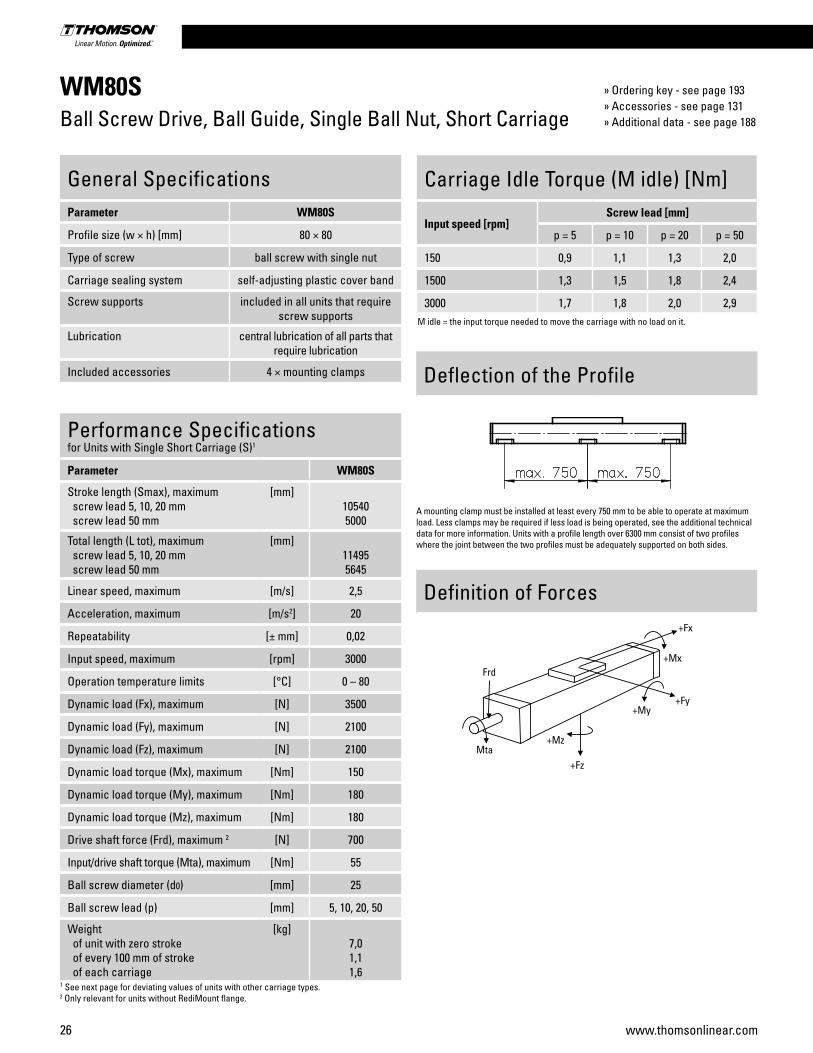
WM80SBall Screw Drive, Ball Guide, Single Ball Nut, Short Carriage
Performance Specificationsfor Units with Single Short Carriage (S)1
Parameter WM80S
Stroke length (Smax), maximum screw lead 5, 10, 20 mm screw lead 50 mm
[mm]105405000
Total length (L tot), maximum screw lead 5, 10, 20 mm screw lead 50 mm
[mm]114955645
Linear speed, maximum [m/s] 2,5
Acceleration, maximum [m/s2] 20
Repeatability [± mm] 0,02
Input speed, maximum [rpm] 3000
Operation temperature limits [°C] 0 – 80
Dynamic load (Fx), maximum [N] 3500
Dynamic load (Fy), maximum [N] 2100
Dynamic load (Fz), maximum [N] 2100
Dynamic load torque (Mx), maximum [Nm] 150
Dynamic load torque (My), maximum [Nm] 180
Dynamic load torque (Mz), maximum [Nm] 180
Drive shaft force (Frd), maximum 2 [N] 700
Input/drive shaft torque (Mta), maximum [Nm] 55
Ball screw diameter (d0) [mm] 25
Ball screw lead (p) [mm] 5, 10, 20, 50
Weight of unit with zero stroke of every 100 mm of stroke of each carriage
[kg]7,01,11,6
1 See next page for deviating values of units with other carriage types.2 Only relevant for units without RediMount flange.
General SpecificationsParameter WM80S
Profile size (w × h) [mm] 80 × 80
Type of screw ball screw with single nut
Carriage sealing system self-adjusting plastic cover band
Screw supports included in all units that require screw supports
Lubrication central lubrication of all parts that require lubrication
Included accessories 4 × mounting clamps
Carriage Idle Torque (M idle) [Nm]
Input speed [rpm]Screw lead [mm]
p = 5 p = 10 p = 20 p = 50
150 0,9 1,1 1,3 2,0
1500 1,3 1,5 1,8 2,4
3000 1,7 1,8 2,0 2,9M idle = the input torque needed to move the carriage with no load on it.
Definition of Forces
Deflection of the Profile
A mounting clamp must be installed at least every 750 mm to be able to operate at maximum load. Less clamps may be required if less load is being operated, see the additional technical data for more information. Units with a profile length over 6300 mm consist of two profiles where the joint between the two profiles must be adequately supported on both sides.
» Ordering key - see page 193» Accessories - see page 131» Additional data - see page 188
Linear Motion Systems
27www.thomsonlinear.com
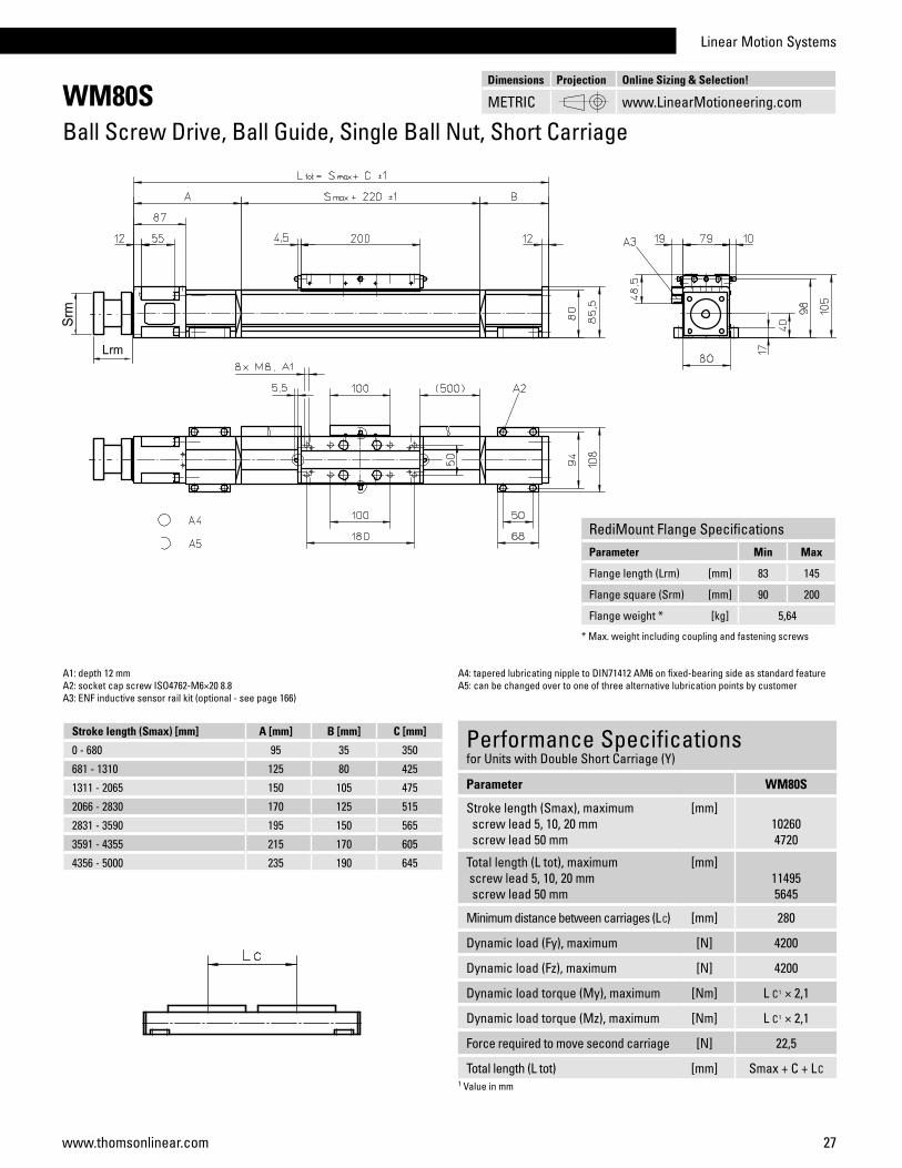
WM80SBall Screw Drive, Ball Guide, Single Ball Nut, Short Carriage
Stroke length (Smax) [mm] A [mm] B [mm] C [mm]
0 - 680 95 35 350
681 - 1310 125 80 425
1311 - 2065 150 105 475
2066 - 2830 170 125 515
2831 - 3590 195 150 565
3591 - 4355 215 170 605
4356 - 5000 235 190 645
Performance Specificationsfor Units with Double Short Carriage (Y)
Parameter WM80S
Stroke length (Smax), maximum screw lead 5, 10, 20 mm screw lead 50 mm
[mm]102604720
Total length (L tot), maximum screw lead 5, 10, 20 mm screw lead 50 mm
[mm]114955645
Minimum distance between carriages (L C) [mm] 280
Dynamic load (Fy), maximum [N] 4200
Dynamic load (Fz), maximum [N] 4200
Dynamic load torque (My), maximum [Nm] L C1 × 2,1
Dynamic load torque (Mz), maximum [Nm] L C1 × 2,1
Force required to move second carriage [N] 22,5
Total length (L tot) [mm] Smax + C + LC1 Value in mm
A1: depth 12 mmA2: socket cap screw ISO4762-M6×20 8.8A3: ENF inductive sensor rail kit (optional - see page 166)
A4: tapered lubricating nipple to DIN71412 AM6 on fixed-bearing side as standard featureA5: can be changed over to one of three alternative lubrication points by customer
Dimensions Projection Online Sizing & Selection!
METRIC www.LinearMotioneering.com
RediMount Flange SpecificationsParameter Min Max
Flange length (Lrm) [mm] 83 145
Flange square (Srm) [mm] 90 200
Flange weight * [kg] 5,64
* Max. weight including coupling and fastening screws
28 www.thomsonlinear.com
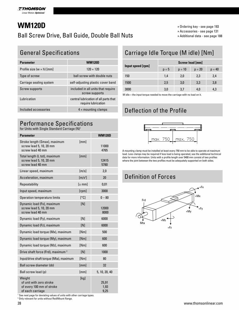
WM120DBall Screw Drive, Ball Guide, Double Ball Nuts
Performance Specificationsfor Units with Single Standard Carriage (N)1
Parameter WM120D
Stroke length (Smax), maximum screw lead 5, 10, 20 mm screw lead 40 mm
[mm]110004765
Total length (L tot), maximum screw lead 5, 10, 20 mm screw lead 40 mm
[mm]124155780
Linear speed, maximum [m/s] 2,0
Acceleration, maximum [m/s2] 20
Repeatability [± mm] 0,01
Input speed, maximum [rpm] 3000
Operation temperature limits [°C] 0 – 80
Dynamic load (Fx), maximum screw lead 5, 10, 20 mm screw lead 40 mm
[N]12000 8000
Dynamic load (Fy), maximum [N] 6000
Dynamic load (Fz), maximum [N] 6000
Dynamic load torque (Mx), maximum [Nm] 500
Dynamic load torque (My), maximum [Nm] 600
Dynamic load torque (Mz), maximum [Nm] 600
Drive shaft force (Frd), maximum 2 [N] 1000
Input/drive shaft torque (Mta), maximum [Nm] 80
Ball screw diameter (d0) [mm] 32
Ball screw lead (p) [mm] 5, 10, 20, 40
Weight of unit with zero stroke of every 100 mm of stroke of each carriage
[kg]25,91 1,93 9,25
1 See next page for deviating values of units with other carriage types.2 Only relevant for units without RediMount flange.
General SpecificationsParameter WM120D
Profile size (w × h) [mm] 120 × 120
Type of screw ball screw with double nuts
Carriage sealing system self-adjusting plastic cover band
Screw supports included in all units that require screw supports
Lubrication central lubrication of all parts that require lubrication
Included accessories 4 × mounting clamps
Carriage Idle Torque (M idle) [Nm]
Input speed [rpm]Screw lead [mm]
p = 5 p = 10 p = 20 p = 40
150 1,4 2,0 2,3 2,4
1500 2,5 3,0 3,3 3,8
3000 3,0 3,7 4,0 4,3M idle = the input torque needed to move the carriage with no load on it.
Definition of Forces
Deflection of the Profile
A mounting clamp must be installed at least every 750 mm to be able to operate at maximum load. Less clamps may be required if less load is being operated, see the additional technical data for more information. Units with a profile length over 5400 mm consist of two profiles where the joint between the two profiles must be adequately supported on both sides.
» Ordering key - see page 193» Accessories - see page 131» Additional data - see page 188

Linear Motion Systems
29www.thomsonlinear.com
WM120DBall Screw Drive, Ball Guide, Double Ball Nuts
Performance Specificationsfor Units with Single Long Carriage (L)
Parameter WM120D
Stroke length (Smax), maximum screw lead 5, 10, 20 mm screw lead 40 mm
[mm]110004585
Total length (L tot), maximum screw lead 5, 10, 20 mm screw lead 40 mm
[mm]125955780
Carriage length [mm] 500
Dynamic load torque (My), maximum [Nm] 1500
Dynamic load torque (Mz), maximum [Nm] 1500
Weight [kg] 14,2
Performance Specificationsfor Units with Double Standard Carriage (Z)
Parameter WM120D
Stroke length (Smax), maximum screw lead 5, 10, 20 mm screw lead 40 mm
[mm]107304385
Total length (L tot), maximum screw lead 5, 10, 20 mm screw lead 40 mm
[mm]125955780
Minimum distance between carriages (L C) [mm] 450
Dynamic load (Fy), maximum [N] 12000
Dynamic load (Fz), maximum [N] 12000
Dynamic load torque (My), maximum [Nm] L C1 × 6
Dynamic load torque (Mz), maximum [Nm] L C1 × 6
Force required to move second carriage [N] 30
Total length (L tot) [mm] Smax + C + LC1 Value in mm
A1: depth 22A2: socket cap screw ISO4762-M8×20 8.8
Stroke length (Smax) [mm] A [mm] B [mm] C [mm]
0 - 890 (0 - 710) 155 100 595 (775)
891 - 1695 (711 - 1515) 225 170 735 (915)
1696 - 2625 (1516 - 2445) 260 205 805 (985)
2626 - 3555 (2446 - 3375) 295 240 875 (1055)
A3: tapered lubricating nipple to DIN71412 M8×1 on fixed-bearing side as standard featureA4: can be changed over to one of the three alternative lubricating points by the customer
Values between brackets = for units with long carriage
Stroke length (Smax) [mm] A [mm] B [mm] C [mm]
3556 - 4485 (3376 - 4305) 330 275 945 (1125)
4486 - 5000 (4306 - 4820) 365 310 1015 (1195)
5001 - 11000 (4307 - 10820) contact customer service
A1: depth 22
Dimensions Projection Online Sizing & Selection!
METRIC www.LinearMotioneering.com
RediMount Flange SpecificationsParameter Min Max
Flange length (Lrm) [mm] 87 149
Flange square (Srm) [mm] 90 200
Flange weight * [kg] 6,03
* Max. weight including coupling and fastening screws

30 www.thomsonlinear.com
WV60Ball Screw Drive, No Guides
Performance SpecificationsParameter WV60
Stroke length (Smax), maximum screw lead 5, 20 mm screw lead 50 mm
[mm]11000 5000
Total length (L tot), maximum screw lead 5, 20 mm screw lead 50 mm
[mm]120505700
Linear speed, maximum [m/s] 2,5
Acceleration, maximum [m/s2] 20
Repeatability [± mm] 0,01
Input speed, maximum [rpm] 3000
Operation temperature limits [°C] 0 – 80
Dynamic load (Fx), maximum [N] 4000
Dynamic load (Fy), maximum [N] 0
Dynamic load (Fz), maximum [N] 0
Dynamic load torque (Mx), maximum [Nm] 0
Dynamic load torque (My), maximum [Nm] 0
Dynamic load torque (Mz), maximum [Nm] 0
Drive shaft force (Frd), maximum 1 [N] 500
Input/drive shaft torque (Mta), maximum [Nm] 35
Ball screw diameter (d0) [mm] 20
Ball screw lead (p) [mm] 5, 20, 50
Weight of unit with zero stroke of every 100 mm of stroke of each carriage
[kg]4,720,551,42
1 Only relevant for units without RediMount flange.
General SpecificationsParameter WV60
Profile size (w × h) [mm] 60 × 60
Type of screw ball screw with double nut
Carriage sealing system self-adjusting plastic cover band
Screw supports included in all units that require screw supports
Lubrication central lubrication of all parts that require lubrication
Included accessories 4 × mounting clamps
Carriage Idle Torque (M idle) [Nm]
Input speed [rpm]Screw lead [mm]
p = 5 p = 20 p = 50
150 0,7 0,9 1,1
1500 1,3 1,5 1,5
3000 1,7 1,9 2,1M idle = the input torque needed to move the carriage with no load on it.
Definition of Forces
Deflection of the Profile
A mounting clamp must be installed at least every 750 mm to be able to operate at maximum load. Less clamps may be required if less load is being operated, see the additional technical data for more information. Units with a profile length over 6300 mm consist of two profiles where the joint between the two profiles must be adequately supported on both sides.
» Ordering key - see page 194» Accessories - see page 131» Additional data - see page 188

Linear Motion Systems
31www.thomsonlinear.com
WV60Ball Screw Drive, No Guides
Stroke length (Smax) [mm] A [mm] B [mm] C [mm]
0 - 690 130 80 430
691 - 1415 155 105 480
1416 - 2155 175 125 520
2156 - 2885 200 150 570
Stroke length (Smax) [mm] A [mm] B [mm] C [mm]
2886 - 3625 220 170 610
3626 - 4355 245 195 660
4256 - 5095 265 215 700
5096 - 11000 contact customer service
A1: depth 11A2: socket cap screw ISO4762-M6×20 8.8A3: ENF inductive sensor rail kit (optional - see page 166)A4: tapered lubricating nipple to DIN71412 AM6 on fixed-bearing side as standard featureA5: can be changed over to one of the three alternative lubricating points by the customer
Dimensions Projection Online Sizing & Selection!
METRIC www.LinearMotioneering.com
RediMount Flange SpecificationsParameter Min Max
Flange length (Lrm) [mm] 83 145
Flange square (Srm) [mm] 90 200
Flange weight * [kg] 5,64
* Max. weight including coupling and fastening screws
32 www.thomsonlinear.com
WV80Ball Screw Drive, No Guides
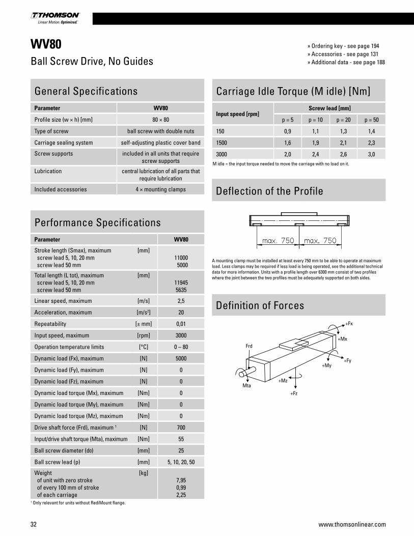
Performance SpecificationsParameter WV80
Stroke length (Smax), maximum screw lead 5, 10, 20 mm screw lead 50 mm
[mm]11000 5000
Total length (L tot), maximum screw lead 5, 10, 20 mm screw lead 50 mm
[mm]119455635
Linear speed, maximum [m/s] 2,5
Acceleration, maximum [m/s2] 20
Repeatability [± mm] 0,01
Input speed, maximum [rpm] 3000
Operation temperature limits [°C] 0 – 80
Dynamic load (Fx), maximum [N] 5000
Dynamic load (Fy), maximum [N] 0
Dynamic load (Fz), maximum [N] 0
Dynamic load torque (Mx), maximum [Nm] 0
Dynamic load torque (My), maximum [Nm] 0
Dynamic load torque (Mz), maximum [Nm] 0
Drive shaft force (Frd), maximum 1 [N] 700
Input/drive shaft torque (Mta), maximum [Nm] 55
Ball screw diameter (d0) [mm] 25
Ball screw lead (p) [mm] 5, 10, 20, 50
Weight of unit with zero stroke of every 100 mm of stroke of each carriage
[kg]7,950,992,25
1 Only relevant for units without RediMount flange.
General SpecificationsParameter WV80
Profile size (w × h) [mm] 80 × 80
Type of screw ball screw with double nuts
Carriage sealing system self-adjusting plastic cover band
Screw supports included in all units that require screw supports
Lubrication central lubrication of all parts that require lubrication
Included accessories 4 × mounting clamps
Carriage Idle Torque (M idle) [Nm]
Input speed [rpm]Screw lead [mm]
p = 5 p = 10 p = 20 p = 50
150 0,9 1,1 1,3 1,4
1500 1,6 1,9 2,1 2,3
3000 2,0 2,4 2,6 3,0M idle = the input torque needed to move the carriage with no load on it.
Definition of Forces
Deflection of the Profile
A mounting clamp must be installed at least every 750 mm to be able to operate at maximum load. Less clamps may be required if less load is being operated, see the additional technical data for more information. Units with a profile length over 6300 mm consist of two profiles where the joint between the two profiles must be adequately supported on both sides.
» Ordering key - see page 194» Accessories - see page 131» Additional data - see page 188

Linear Motion Systems
33www.thomsonlinear.com
WV80Ball Screw Drive, No Guides
Stroke length (Smax) [mm] A [mm] B [mm] C [mm]
0 - 775 125 50 395
776 - 1670 145 95 460
1671 - 2505 170 115 505
2506 - 3340 190 140 550
Stroke length (Smax) [mm] A [mm] B [mm] C [mm]
3341 - 4175 210 160 590
4176 - 5015 235 180 635
5016 - 11000 contact customer service
A1: depth 12 mmA2: socket cap screw ISO4762-M6×20 8.8A3: ENF inductive sensor rail kit (optional - see page 166)A4: tapered lubricating nipple to DIN71412 AM6 on fixed-bearing side as standard featureA5: can be changed over to one of three alternative lubrication points by customer
Dimensions Projection Online Sizing & Selection!
METRIC www.LinearMotioneering.com
RediMount Flange SpecificationsParameter Min Max
Flange length (Lrm) [mm] 83 145
Flange square (Srm) [mm] 90 200
Flange weight * [kg] 5,64
* Max. weight including coupling and fastening screws

34 www.thomsonlinear.com
WV120Ball Screw Drive, No Guides
Performance SpecificationsParameter WV120
Stroke length (Smax), maximum screw lead 5, 10, 20 mm screw lead 40 mm
[mm]11000 5000
Total length (L tot), maximum screw lead 5, 10, 20 mm screw lead 40 mm
[mm]122605845
Linear speed, maximum [m/s] 2,0
Acceleration, maximum [m/s2] 20
Repeatability [± mm] 0,01
Input speed, maximum [rpm] 3000
Operation temperature limits [°C] 0 – 80
Dynamic load (Fx), maximum screw lead 5, 10, 20 mm screw lead 40 mm
[N]12000 8000
Dynamic load (Fy), maximum [N] 0
Dynamic load (Fz), maximum [N] 0
Dynamic load torque (Mx), maximum [Nm] 0
Dynamic load torque (My), maximum [Nm] 0
Dynamic load torque (Mz), maximum [Nm] 0
Drive shaft force (Frd), maximum 1 [N] 1000
Input/drive shaft torque (Mta), maximum [Nm] 80
Ball screw diameter (d0) [mm] 32
Ball screw lead (p) [mm] 5, 10, 20, 40
Weight of unit with zero stroke of every 100 mm of stroke of each carriage
[kg]18,10 1,94 4,75
1 Only relevant for units without RediMount flange.
General SpecificationsParameter WV120
Profile size (w × h) [mm] 120 × 120
Type of screw ball screw with double nuts
Carriage sealing system self-adjusting plastic cover band
Screw supports included in all units that require screw supports
Lubrication central lubrication of all parts that require lubrication
Included accessories 4 × mounting clamps
Carriage Idle Torque (M idle) [Nm]
Input speed [rpm]Screw lead [mm]
p = 5 p = 10 p = 20 p = 40
150 1,0 1,1 1,4 1,5
1500 2,1 2,2 2,5 2,8
3000 2,4 2,6 3,0 3,5M idle = the input torque needed to move the carriage with no load on it.
Definition of Forces
Deflection of the Profile
A mounting clamp must be installed at least every 750 mm to be able to operate at maximum load. Less clamps may be required if less load is being operated, see the additional technical data for more information. Units with a profile length over 5400 mm consist of two profiles where the joint between the two profiles must be adequately supported on both sides.
» Ordering key - see page 194» Accessories - see page 131» Additional data - see page 188

Linear Motion Systems
35www.thomsonlinear.com
WV120Ball Screw Drive, No Guides
Stroke length (Smax) [mm] A [mm] B [mm] C [mm]
0 - 940 145 50 465
941 - 1860 180 120 570
1861 - 2790 215 155 640
2791 - 3720 250 190 710
Stroke length (Smax) [mm] A [mm] B [mm] C [mm]
3721 - 4650 285 225 780
4651 - 5000 320 255 845
5001 - 11000 contact customer service
A1: depth 22A2: socket cap screw ISO4762-M8×20 8.8A3: tapered lubricating nipple to DIN71412 M8×1 on fixed-bearing side as standard featureA4: can be changed over to one of the three alternative lubricating points by the customer
Dimensions Projection Online Sizing & Selection!
METRIC www.LinearMotioneering.com
RediMount Flange SpecificationsParameter Min Max
Flange length (Lrm) [mm] 87 149
Flange square (Srm) [mm] 90 200
Flange weight * [kg] 6,03
* Max. weight including coupling and fastening screws
36 www.thomsonlinear.com
MLSM60DBall Screw Drive, Ball Guide
Performance Specificationsfor Units with Single Standard Carriage (N)1
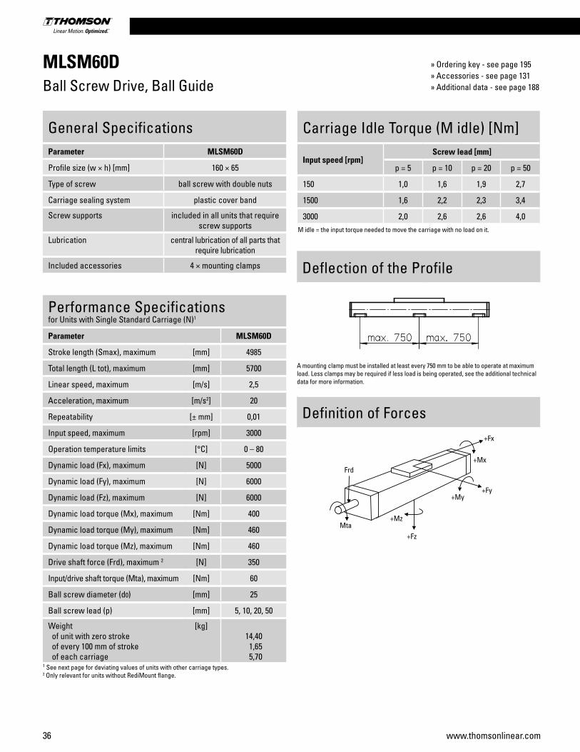
Parameter MLSM60D
Stroke length (Smax), maximum [mm] 4985
Total length (L tot), maximum [mm] 5700
Linear speed, maximum [m/s] 2,5
Acceleration, maximum [m/s2] 20
Repeatability [± mm] 0,01
Input speed, maximum [rpm] 3000
Operation temperature limits [°C] 0 – 80
Dynamic load (Fx), maximum [N] 5000
Dynamic load (Fy), maximum [N] 6000
Dynamic load (Fz), maximum [N] 6000
Dynamic load torque (Mx), maximum [Nm] 400
Dynamic load torque (My), maximum [Nm] 460
Dynamic load torque (Mz), maximum [Nm] 460
Drive shaft force (Frd), maximum 2 [N] 350
Input/drive shaft torque (Mta), maximum [Nm] 60
Ball screw diameter (d0) [mm] 25
Ball screw lead (p) [mm] 5, 10, 20, 50
Weight of unit with zero stroke of every 100 mm of stroke of each carriage
[kg]14,40 1,65 5,70
1 See next page for deviating values of units with other carriage types.2 Only relevant for units without RediMount flange.
General SpecificationsParameter MLSM60D
Profile size (w × h) [mm] 160 × 65
Type of screw ball screw with double nuts
Carriage sealing system plastic cover band
Screw supports included in all units that require screw supports
Lubrication central lubrication of all parts that require lubrication
Included accessories 4 × mounting clamps
Carriage Idle Torque (M idle) [Nm]
Input speed [rpm]Screw lead [mm]
p = 5 p = 10 p = 20 p = 50
150 1,0 1,6 1,9 2,7
1500 1,6 2,2 2,3 3,4
3000 2,0 2,6 2,6 4,0M idle = the input torque needed to move the carriage with no load on it.
Definition of Forces
Deflection of the Profile
A mounting clamp must be installed at least every 750 mm to be able to operate at maximum load. Less clamps may be required if less load is being operated, see the additional technical data for more information.
» Ordering key - see page 195» Accessories - see page 131» Additional data - see page 188

Linear Motion Systems
37www.thomsonlinear.com
MLSM60DBall Screw Drive, Ball Guide
Performance Specificationsfor Units with Single Long Carriage (L)
Parameter MLSM60D
Stroke length (Smax), maximum [mm] 4815
Total length (L tot), maximum [mm] 5700
Carriage length [mm] 450
Dynamic load torque (My), maximum [Nm] 940
Dynamic load torque (Mz), maximum [Nm] 940
Weight [kg] 6,5
Performance Specificationsfor Units with Double Standard Carriage (Z)
Parameter MLSM60D
Stroke length (Smax), maximum [mm] 4665
Total length (L tot), maximum [mm] 5700
Minimum distance between carriages (L C) [mm] 320
Dynamic load (Fy), maximum [N] 12000
Dynamic load (Fz), maximum [N] 12000
Dynamic load torque (My), maximum [Nm] L C1 × 6
Dynamic load torque (Mz), maximum [Nm] L C1 × 6
Force required to move second carriage [N] 27
Total length (L tot) [mm] Smax + C + LC1 Value in mm
A1: depth 10A2: socket cap screw ISO4762-M6×20 8.8A3: ENF inductive sensor rail kit (optional - see page 166)A4: tapered lubricating nipple to DIN71412 AM6 on fixed-bearing side as standard featureA5: can be changed over to one of the three alternative lubricating points by the customer
Stroke length (Smax) [mm] A [mm] B [mm] C [mm]
0 - 750 (0 - 580) 90 45 435 (605)
751 - 1220 (581 - 1050) 105 90 495 (665)
1221 - 1980 (1051 - 1810) 125 110 535 (705)
1981 - 2730 (1811 - 2560) 150 135 585 (765)Values between brackets = for units with long carriage
Stroke length (Smax) [mm] A [mm] B [mm] C [mm]
2731 - 3490 (2561 - 3320) 170 155 625 (795)
3491 - 4240 (3321 - 4070) 195 180 675 (845)
4241 - 5000 (4071 - 4830) 215 200 715 (885)
5001 - 5500 (4831 - 5330) 235 220 755 (925)
A1: depth 10
Dimensions Projection Online Sizing & Selection!
METRIC www.LinearMotioneering.com
RediMount Flange SpecificationsParameter Min Max
Flange length (Lrm) [mm] 81 143
Flange square (Srm) [mm] 90 200
Flange weight * [kg] 5,58
* Max. weight including coupling and fastening screws
38 www.thomsonlinear.com
MLSM80DBall Screw Drive, Ball Guide
Performance Specificationsfor Units with Single Standard Carriage (N)1
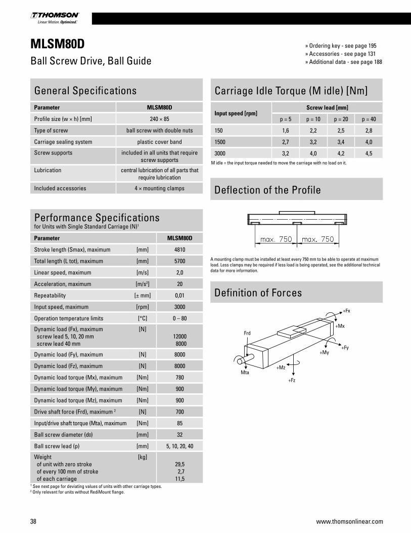
Parameter MLSM80D
Stroke length (Smax), maximum [mm] 4810
Total length (L tot), maximum [mm] 5700
Linear speed, maximum [m/s] 2,0
Acceleration, maximum [m/s2] 20
Repeatability [± mm] 0,01
Input speed, maximum [rpm] 3000
Operation temperature limits [°C] 0 – 80
Dynamic load (Fx), maximum screw lead 5, 10, 20 mm screw lead 40 mm
[N]12000 8000
Dynamic load (Fy), maximum [N] 8000
Dynamic load (Fz), maximum [N] 8000
Dynamic load torque (Mx), maximum [Nm] 780
Dynamic load torque (My), maximum [Nm] 900
Dynamic load torque (Mz), maximum [Nm] 900
Drive shaft force (Frd), maximum 2 [N] 700
Input/drive shaft torque (Mta), maximum [Nm] 85
Ball screw diameter (d0) [mm] 32
Ball screw lead (p) [mm] 5, 10, 20, 40
Weight of unit with zero stroke of every 100 mm of stroke of each carriage
[kg]29,5 2,711,5
1 See next page for deviating values of units with other carriage types.2 Only relevant for units without RediMount flange.
General SpecificationsParameter MLSM80D
Profile size (w × h) [mm] 240 × 85
Type of screw ball screw with double nuts
Carriage sealing system plastic cover band
Screw supports included in all units that require screw supports
Lubrication central lubrication of all parts that require lubrication
Included accessories 4 × mounting clamps
Carriage Idle Torque (M idle) [Nm]
Input speed [rpm]Screw lead [mm]
p = 5 p = 10 p = 20 p = 40
150 1,6 2,2 2,5 2,8
1500 2,7 3,2 3,4 4,0
3000 3,2 4,0 4,2 4,5M idle = the input torque needed to move the carriage with no load on it.
Definition of Forces
Deflection of the Profile
A mounting clamp must be installed at least every 750 mm to be able to operate at maximum load. Less clamps may be required if less load is being operated, see the additional technical data for more information.
» Ordering key - see page 195» Accessories - see page 131» Additional data - see page 188
Linear Motion Systems
39www.thomsonlinear.com
MLSM80DBall Screw Drive, Ball Guide
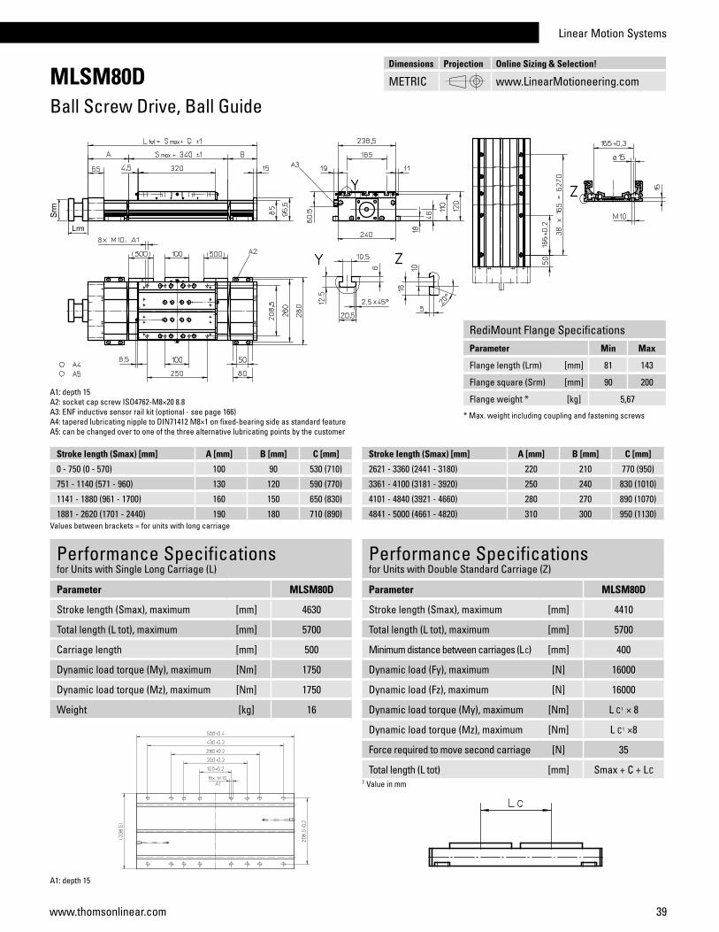
Performance Specificationsfor Units with Single Long Carriage (L)
Parameter MLSM80D
Stroke length (Smax), maximum [mm] 4630
Total length (L tot), maximum [mm] 5700
Carriage length [mm] 500
Dynamic load torque (My), maximum [Nm] 1750
Dynamic load torque (Mz), maximum [Nm] 1750
Weight [kg] 16
Performance Specificationsfor Units with Double Standard Carriage (Z)
Parameter MLSM80D
Stroke length (Smax), maximum [mm] 4410
Total length (L tot), maximum [mm] 5700
Minimum distance between carriages (L C) [mm] 400
Dynamic load (Fy), maximum [N] 16000
Dynamic load (Fz), maximum [N] 16000
Dynamic load torque (My), maximum [Nm] L C1 × 8
Dynamic load torque (Mz), maximum [Nm] L C1 ×8
Force required to move second carriage [N] 35
Total length (L tot) [mm] Smax + C + LC1 Value in mm
A1: depth 15A2: socket cap screw ISO4762-M8×20 8.8A3: ENF inductive sensor rail kit (optional - see page 166)A4: tapered lubricating nipple to DIN71412 M8×1 on fixed-bearing side as standard featureA5: can be changed over to one of the three alternative lubricating points by the customer
Stroke length (Smax) [mm] A [mm] B [mm] C [mm]
0 - 750 (0 - 570) 100 90 530 (710)
751 - 1140 (571 - 960) 130 120 590 (770)
1141 - 1880 (961 - 1700) 160 150 650 (830)
1881 - 2620 (1701 - 2440) 190 180 710 (890)Values between brackets = for units with long carriage
Stroke length (Smax) [mm] A [mm] B [mm] C [mm]
2621 - 3360 (2441 - 3180) 220 210 770 (950)
3361 - 4100 (3181 - 3920) 250 240 830 (1010)
4101 - 4840 (3921 - 4660) 280 270 890 (1070)
4841 - 5000 (4661 - 4820) 310 300 950 (1130)
A1: depth 15
Dimensions Projection Online Sizing & Selection!
METRIC www.LinearMotioneering.com
RediMount Flange SpecificationsParameter Min Max
Flange length (Lrm) [mm] 81 143
Flange square (Srm) [mm] 90 200
Flange weight * [kg] 5,67
* Max. weight including coupling and fastening screws

40 www.thomsonlinear.com
M55Ball Screw Drive, Ball Guide
Deflection of the Profile
Performance Specificationsfor Units with Single Standard Carriage (A)1
Parameter M55
Stroke length (Smax), maximum [mm] 2712
Total length (L tot), maximum [mm] 2975
Linear speed, maximum [m/s] 1,6
Acceleration, maximum [m/s2] 8
Repeatability [± mm] 0,05
Input speed, maximum [rpm] 3000
Operation temperature limits [°C] -20 – 70
Dynamic load (Fx), maximum [N] 1000
Dynamic load (Fy), maximum [N] 900
Dynamic load (Fz), maximum [N] 900
Dynamic load torque (Mx), maximum [Nm] 9
Dynamic load torque (My), maximum [Nm] 48
Dynamic load torque (Mz), maximum [Nm] 48
Drive shaft force (Frd), maximum 2 [N] 200
Input/drive shaft torque (Mta), maximum [Nm] 12
Screw diameter (d0) [mm] 16
Screw lead (p) [mm] 5, 10, 20
Weight of unit with zero stroke of every 100 mm of stroke of carriage of option single screw support of option double screw supports
[kg]3,900,561,200,831,88
1 See next page for deviating values of units with other carriage types.2 Only relevant for units without RediMount flange.
General SpecificationsParameter M55
Profile size (w × h) [mm] 58 × 55
Type of screw ball screw with single nut
Carriage sealing system self-adjusting steel cover band
Screw supports number of screw supports to be specified by customer at order
Lubrication lubrication of ball screw
Included accessories none
Definition of Forces
Carriage Idle Torque (M idle) [Nm]
Input speed [rpm]Screw lead [mm]
p = 5 p = 10 p = 20
500 - no screw supports 0,02 0,03 0,04
500 - with screw supports 0,03 0,05 0,07M idle = the input torque needed to move the carriage with no load on it.
Critical Speed
1: No screw support required2: Single screw support required3: Double screw supports required
» Ordering key - see page 196» Accessories - see page 131» Additional data - see page 188

Linear Motion Systems
41www.thomsonlinear.com
M55Ball Screw Drive, Ball Guide
Screw support configuration A [mm] B [mm] Total length (L tot) [mm]
No screw support 6 6 L tot = Smax + A + B + 251
Single screw support 40 40 L tot = Smax + A + B + 251
Double screw supports 92 92 L tot = Smax + A + B + 251
A1: lubrication holesA2: ø9,5/ø5,5 for socket head cap screw M5
Performance Specificationsfor Units with Double Standard Carriage (C)
Parameter M55
Stroke length (Smax), maximum [mm] 2512
Total length (L tot), maximum [mm] 2975
Minimum distance between carriages (Lc) [mm] 200
Dynamic load (Fy), maximum [N] 1350
Dynamic load (Fz), maximum [N] 1350
Dynamic load torque (My), maximum [Nm] Lc1 × 0,675
Dynamic load torque (Mz), maximum [Nm] Lc1 × 0,675
Force required to move second carriage [N] 2
Weight of unit with zero stroke of carriages
[kg]6,52,4
1 Value in mm
Screw support configuration A [mm] B [mm] Total length (L tot) [mm]
No screw support 6 6 L tot = Smax + A + B + Lc + 251
Single screw support 40 40 L tot = Smax + A + B + Lc + 251
Double screw supports 92 92 L tot = Smax + A + B + Lc + 251
Dimensions Projection Online Sizing & Selection!
METRIC www.LinearMotioneering.com
RediMount Flange SpecificationsParameter Min Max
Flange length (Lrm) [mm] 57 92
Flange square (Srm) [mm] 60 139
Flange weight * [kg] 1,84
* Max. weight including coupling and fastening screws

42 www.thomsonlinear.com
M75Ball Screw Drive, Ball Guide
Performance Specificationsfor Units with Single Standard Carriage (A)1
Parameter M75
Stroke length (Smax), maximum screw lead 5, 20 mm screw lead 12,7 mm
[mm]37722665
Total length (L tot), maximum screw lead 5, 20 mm screw lead 12,7 mm
[mm]40752968
Linear speed, maximum [m/s] 1,0
Acceleration, maximum [m/s2] 8
Repeatability [± mm] 0,05
Input speed, maximum [rpm] 3000
Operation temperature limits [°C] -20 – 70
Dynamic load (Fx), maximum [N] 2500
Dynamic load (Fy), maximum [N] 2000
Dynamic load (Fz), maximum [N] 2000
Dynamic load torque (Mx), maximum [Nm] 18
Dynamic load torque (My), maximum [Nm] 130
Dynamic load torque (Mz), maximum [Nm] 130
Drive shaft force (Frd), maximum 2 [N] 600
Input/drive shaft torque (Mta), maximum [Nm] 30
Screw diameter (d0) [mm] 20
Screw lead (p) [mm] 5, 12,7, 20
Weight of unit with zero stroke of every 100 mm of stroke of carriage of option single screw support of option double screw supports
[kg]6,901,052,501,703,58
1 See next page for deviating values of units with other carriage types.2 Only relevant for units without RediMount flange.
General SpecificationsParameter M75
Profile size (w × h) [mm] 86 × 75
Type of screw ball screw with single nut
Carriage sealing system self-adjusting steel cover band
Screw supports number of screw supports to be specified by customer at order
Lubrication lubrication of ball screw
Included accessories none Deflection of the Profile
Definition of Forces
Carriage Idle Torque (M idle) [Nm]
Input speed [rpm] Screw lead [mm]
p = 5 p = 12,7 p = 20
500 - no screw supports 0,04 0,1 0,16
500 - with screw supports 0,06 0,12 0,2M idle = the input torque needed to move the carriage with no load on it.
Critical Speed
1: No screw support required2: Single screw support required3: Double screw supports required
» Ordering key - see page 196» Accessories - see page 131» Additional data - see page 188

Linear Motion Systems
43www.thomsonlinear.com
M75Ball Screw Drive, Ball Guide
Performance Specificationsfor Units with Double Standard Carriage (C)
Parameter M75
Stroke length (Smax), maximum screw lead 5, 20 mm screw lead 12,7 mm
[mm]35222415
Total length (L tot), maximum screw lead 5, 20 mm screw lead 12,7 mm
[mm]40752968
Minimum distance between carriages (Lc) [mm] 250
Dynamic load (Fy), maximum [N] 3000
Dynamic load (Fz), maximum [N] 3000
Dynamic load torque (My), maximum [Nm] Lc1 × 1,5
Dynamic load torque (Mz), maximum [Nm] Lc1 × 1,5
Force required to move second carriage [N] 2
Weight of unit with zero stroke of carriages
[kg]12,2 5,0
A1: lubrication holesA2: ø13,5/ø8,5 for socket head cap screw M8
1 Value in mm
Screw support configuration A [mm] B [mm] Total length (L tot) [mm]
No screw support 5 5 L tot = Smax + A + B + 293
Single screw support 60 60 L tot = Smax + A + B + 293
Double screw supports 126 126 L tot = Smax + A + B + 293
Screw support configuration A [mm] B [mm] Total length (L tot) [mm]
No screw support 5 5 L tot = Smax + A + B + Lc + 293
Single screw support 60 60 L tot = Smax + A + B + Lc + 293
Double screw supports 126 126 L tot = Smax + A + B + Lc + 293
Dimensions Projection Online Sizing & Selection!
METRIC www.LinearMotioneering.com
RediMount Flange SpecificationsParameter Min Max
Flange length (Lrm) [mm] 81 143
Flange square (Srm) [mm] 90 200
Flange weight * [kg] 5,60
* Max. weight including coupling and fastening screws

44 www.thomsonlinear.com
M100Ball Screw Drive, Ball Guide
General SpecificationsParameter M100
Profile size (w × h) [mm] 108 × 100
Type of screw ball screw with single nut
Carriage sealing system self-adjusting steel cover band
Screw supports number of screw supports to be specified by customer at order
Lubrication lubrication of ball screw
Included accessories none Deflection of the Profile
Definition of Forces
Critical Speed
1: No screw support required2: Single screw support required3: Double screw supports required
Performance Specificationsfor Units with Single Standard Carriage (A)1
Parameter M100
Stroke length (Smax), maximum screw lead 5, 10 mm screw lead 25 mm
[mm]55784378
Total length (L tot), maximum screw lead 5, 10 mm screw lead 25 mm
[mm]59744774
Linear speed, maximum [m/s] 1,25
Acceleration, maximum [m/s2] 8
Repeatability [± mm] 0,05
Input speed, maximum [rpm] 3000
Operation temperature limits [°C] -20 – 70
Dynamic load (Fx), maximum [N] 5000
Dynamic load (Fy), maximum [N] 5000
Dynamic load (Fz), maximum [N] 5000
Dynamic load torque (Mx), maximum [Nm] 60
Dynamic load torque (My), maximum [Nm] 400
Dynamic load torque (Mz), maximum [Nm] 400
Drive shaft force (Frd), maximum 2 [N] 1000
Input/drive shaft torque (Mta), maximum [Nm] 45
Screw diameter (d0) [mm] 25
Screw lead (p) [mm] 5, 10, 25
Weight of unit with zero stroke of every 100 mm of stroke of carriage of option single screw support of option double screw supports
[kg]14,31,724,001,864,42
1 See next page for deviating values of units with other carriage types.2 Only relevant for units without RediMount flange.
Carriage Idle Torque (M idle) [Nm]
Input speed [rpm] Screw lead [mm]
p = 5 p = 10 p = 25
500 - no screw supports 0,08 0,14 0,32
500 - with screw supports 0,1 0,16 0,37M idle = the input torque needed to move the carriage with no load on it.
» Ordering key - see page 196» Accessories - see page 131» Additional data - see page 188
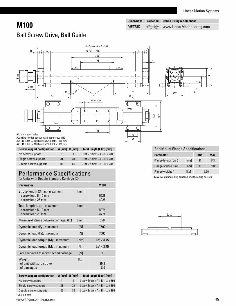
Linear Motion Systems
45www.thomsonlinear.com
M100Ball Screw Drive, Ball Guide
Performance Specificationsfor Units with Double Standard Carriage (C)
Parameter M100
Stroke length (Smax), maximum screw lead 5, 10 mm screw lead 25 mm
[mm]52284028
Total length (L tot), maximum screw lead 5, 10 mm screw lead 25 mm
[mm]59744774
Minimum distance between carriages (Lc) [mm] 350
Dynamic load (Fy), maximum [N] 7500
Dynamic load (Fz), maximum [N] 7500
Dynamic load torque (My), maximum [Nm] Lc1 × 3,75
Dynamic load torque (Mz), maximum [Nm] Lc1 × 3,75
Force required to move second carriage [N] 2
Weight of unit with zero stroke of carriages
[kg]25,3 8,0
A1: lubrication holesA2: ø17/ø10,5 for socket head cap screw M10A3: 147 (L tot <= 1088 mm), 367 (L tot > 1088 mm)A4: 141 (L tot <= 1088 mm), 471 (L tot > 1088 mm)
1 Value in mm
Screw support configuration A [mm] B [mm] Total length (L tot) [mm]
No screw support 1 1 L tot = Smax + A + B + 394
Single screw support 31 31 L tot = Smax + A + B + 394
Double screw supports 86 86 L tot = Smax + A + B + 394
Screw support configuration A [mm] B [mm] Total length (L tot) [mm]
No screw support 1 1 L tot = Smax + A + B + Lc + 394
Single screw support 31 31 L tot = Smax + A + B + Lc + 394
Double screw supports 86 86 L tot = Smax + A + B + Lc + 394
RediMount Flange SpecificationsParameter Min Max
Flange length (Lrm) [mm] 81 143
Flange square (Srm) [mm] 90 200
Flange weight * [kg] 5,60
* Max. weight including coupling and fastening screws
Dimensions Projection Online Sizing & Selection!
METRIC www.LinearMotioneering.com
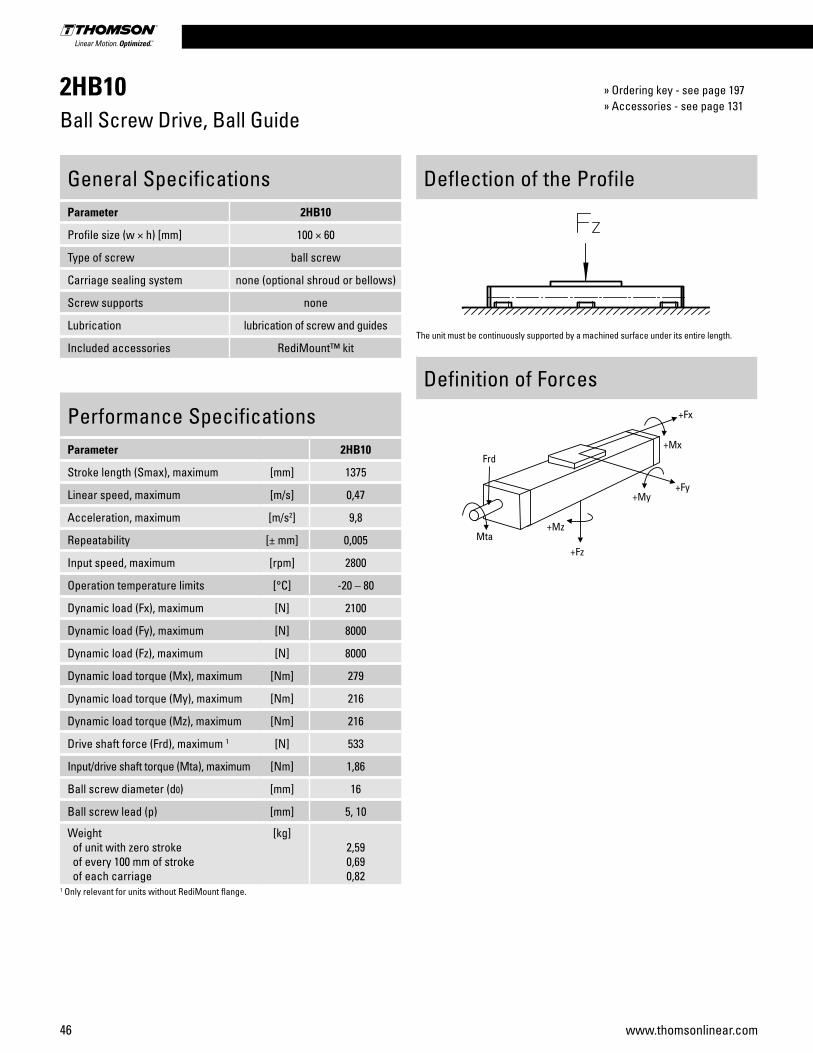
46 www.thomsonlinear.com
2HB10Ball Screw Drive, Ball Guide
» Ordering key - see page 197» Accessories - see page 131
General SpecificationsParameter 2HB10
Profile size (w × h) [mm] 100 × 60
Type of screw ball screw
Carriage sealing system none (optional shroud or bellows)
Screw supports none
Lubrication lubrication of screw and guides
Included accessories RediMount™ kit
Deflection of the Profile
Performance SpecificationsParameter 2HB10
Stroke length (Smax), maximum [mm] 1375
Linear speed, maximum [m/s] 0,47
Acceleration, maximum [m/s2] 9,8
Repeatability [± mm] 0,005
Input speed, maximum [rpm] 2800
Operation temperature limits [°C] -20 – 80
Dynamic load (Fx), maximum [N] 2100
Dynamic load (Fy), maximum [N] 8000
Dynamic load (Fz), maximum [N] 8000
Dynamic load torque (Mx), maximum [Nm] 279
Dynamic load torque (My), maximum [Nm] 216
Dynamic load torque (Mz), maximum [Nm] 216
Drive shaft force (Frd), maximum 1 [N] 533
Input/drive shaft torque (Mta), maximum [Nm] 1,86
Ball screw diameter (d0) [mm] 16
Ball screw lead (p) [mm] 5, 10
Weight of unit with zero stroke of every 100 mm of stroke of each carriage
[kg]2,590,690,82
1 Only relevant for units without RediMount flange.
Definition of Forces
The unit must be continuously supported by a machined surface under its entire length.

Linear Motion Systems
47www.thomsonlinear.com
2HB10Ball Screw Drive, Ball Guide
A1: lubrication nipple (using the unit with the nipple mounted makes the stroke 10 mm shorter). Standard NEMA23 motor dimensions are shown. Other mounting sizes are available and easily configured. Please see www.LinearMotioneering.com for details.
Ordering Length (L) and Maximum Stroke (Smax)
L = Smax + 125
A1
Dimensions Projection Online Sizing & Selection!
METRIC www.LinearMotioneering.com

48 www.thomsonlinear.com
2HB20Ball Screw Drive, Ball Guide
General SpecificationsParameter 2HB20
Profile size (w × h) [mm] 200 × 90
Type of screw ball screw
Carriage sealing system none (optional shroud or bellows)
Screw supports none
Lubrication lubrication of screw and guides
Included accessories RediMount™ kit
Performance SpecificationsParameter 2HB20
Stroke length (Smax), maximum [mm] 2760
Linear speed, maximum [m/s] 0,75
Acceleration, maximum [m/s2] 9,8
Repeatability [± mm] 0,005
Input speed, maximum [rpm] 1800
Operation temperature limits [°C] -20 – 80
Dynamic load (Fx), maximum [N] 4697
Dynamic load (Fy), maximum [N] 34000
Dynamic load (Fz), maximum [N] 34000
Dynamic load torque (Mx), maximum [Nm] 2463
Dynamic load torque (My), maximum [Nm] 1903
Dynamic load torque (Mz), maximum [Nm] 1903
Drive shaft force (Frd), maximum 1 [N] 533
Input/drive shaft torque (Mta), maximum [Nm] 15,5
Ball screw diameter (d0) [mm] 25
Ball screw lead (p) [mm] 5, 10, 25
Weight of unit with zero stroke of every 100 mm of stroke of each carriage
[kg]13,321,704,47
1 Only relevant for units without RediMount flange.
Deflection of the Profile
Definition of Forces
The unit must be continuously supported by a machined surface under its entire length.
» Ordering key - see page 197» Accessories - see page 131
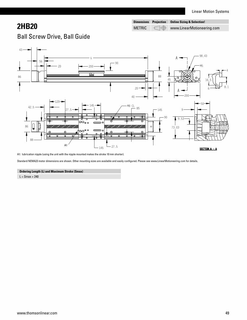
Linear Motion Systems
49www.thomsonlinear.com
2HB20Ball Screw Drive, Ball Guide
A1: lubrication nipple (using the unit with the nipple mounted makes the stroke 10 mm shorter). Standard NEMA23 motor dimensions are shown. Other mounting sizes are available and easily configured. Please see www.LinearMotioneering.com for details.
Ordering Length (L) and Maximum Stroke (Smax)
L = Smax + 240
A1
Dimensions Projection Online Sizing & Selection!
METRIC www.LinearMotioneering.com

50 www.thomsonlinear.com
2RB12Ball Screw Drive, Ball Guide
Performance SpecificationsParameter 2RB12
Stroke length (Smax), maximum [mm] 1951
Linear speed, maximum [m/s] 0,47
Acceleration, maximum [m/s2] 9,8
Repeatability [± mm] 0,005
Accuracy [± mm] 0,025 / 300 mm
Input speed, maximum [rpm] 2800
Operation temperature limits [°C] -20 – 80
Dynamic load (Fx), maximum [N] 2100
Dynamic load (Fy), maximum [N] 880
Dynamic load (Fz), maximum [N] 1760
Dynamic load torque (Mx), maximum [Nm] 65,5
Dynamic load torque (My), maximum [Nm] 76,8
Dynamic load torque (Mz), maximum [Nm] 38,4
Drive shaft force (Frd), maximum 1 [N] 533
Input/drive shaft torque (Mta), maximum [Nm] 1,86
Ball screw diameter (d0) [mm] 16
Ball screw lead (p) [mm] 5, 10
Weight of unit with zero stroke of every 100 mm of stroke of each carriage
[kg]3,880,931,32
1 Only relevant for units without RediMount flange.
General SpecificationsParameter 2RB12
Profile size (w × h) [mm] 1 130 × 40
Type of screw ball screw
Carriage sealing system none (optional bellows)
Screw supports none
Lubrication lubrication of screws and guides
Included accessories RediMount™ kit1 Base width × carriage height.
Deflection of the Profile
Definition of Forces
The unit must be continuously supported by a machined surface under its entire length.
Fz
» Ordering key - see page 198» Accessories - see page 131

Linear Motion Systems
51www.thomsonlinear.com
2RB12Ball Screw Drive, Ball Guide
A1: lubrication nipples (using the unit with the nipples mounted makes the stroke 10 mm shorter). Standard NEMA23 motor dimensions are shown. Other mounting sizes are available and easily configured. Please see www.LinearMotioneering.com for details.
Ordering Length (L) and Maximum Stroke (Smax)
L = Smax + 149
A1
Dimensions Projection Online Sizing & Selection!
METRIC www.LinearMotioneering.com

52 www.thomsonlinear.com
2RB16Ball Screw Drive, Ball Guide
Performance SpecificationsParameter 2RB16
Stroke length (Smax), maximum [mm] 2815
Linear speed, maximum [m/s] 0,73
Acceleration, maximum [m/s2] 9,8
Repeatability [± mm] 0,005
Accuracy [± mm] 0,025 / 300 mm
Input speed, maximum [rpm] 2200
Operation temperature limits [°C] -20 – 80
Dynamic load (Fx), maximum [N] 2998
Dynamic load (Fy), maximum [N] 2588
Dynamic load (Fz), maximum [N] 5176
Dynamic load torque (Mx), maximum [Nm] 243
Dynamic load torque (My), maximum [Nm] 299
Dynamic load torque (Mz), maximum [Nm] 150
Drive shaft force (Frd), maximum 1 [N] 533
Input/drive shaft torque (Mta), maximum [Nm] 2,66
Ball screw diameter (d0) [mm] 20
Ball screw lead (p) [mm] 5, 10, 20
Weight of unit with zero stroke of every 100 mm of stroke of each carriage
[kg]6,171,442,25
1 Only relevant for units without RediMount flange.
General SpecificationsParameter 2RB16
Profile size (w × h) [mm] 1 160 × 48
Type of screw ball screw
Carriage sealing system none (optional bellows)
Screw supports none
Lubrication lubrication of screws and guides
Included accessories RediMount™ kit1 Base width × carriage height.
Deflection of the Profile
Definition of Forces
The unit must be continuously supported by a machined surface under its entire length.
Fz
» Ordering key - see page 198» Accessories - see page 131

Linear Motion Systems
53www.thomsonlinear.com
2RB16Ball Screw Drive, Ball Guide
A1: lubrication nipples (using the unit with the nipples mounted makes the stroke 10 mm shorter). Standard NEMA23 motor dimensions are shown. Other mounting sizes are available and easily configured. Please see www.LinearMotioneering.com for details.
Ordering Length (L) and Maximum Stroke (Smax)
L = Smax + 185
A1
Dimensions Projection Online Sizing & Selection!
METRIC www.LinearMotioneering.com
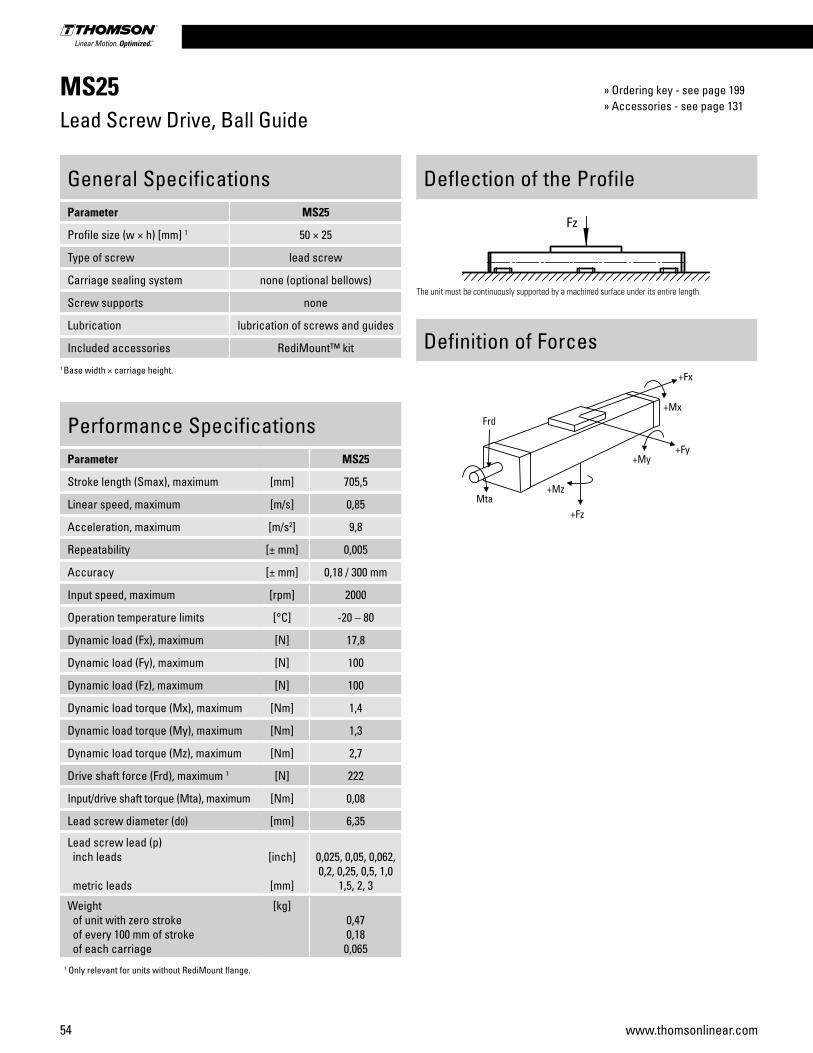
54 www.thomsonlinear.com
MS25Lead Screw Drive, Ball Guide
Performance SpecificationsParameter MS25
Stroke length (Smax), maximum [mm] 705,5
Linear speed, maximum [m/s] 0,85
Acceleration, maximum [m/s2] 9,8
Repeatability [± mm] 0,005
Accuracy [± mm] 0,18 / 300 mm
Input speed, maximum [rpm] 2000
Operation temperature limits [°C] -20 – 80
Dynamic load (Fx), maximum [N] 17,8
Dynamic load (Fy), maximum [N] 100
Dynamic load (Fz), maximum [N] 100
Dynamic load torque (Mx), maximum [Nm] 1,4
Dynamic load torque (My), maximum [Nm] 1,3
Dynamic load torque (Mz), maximum [Nm] 2,7
Drive shaft force (Frd), maximum 1 [N] 222
Input/drive shaft torque (Mta), maximum [Nm] 0,08
Lead screw diameter (d0) [mm] 6,35
Lead screw lead (p) inch leads
metric leads
[inch]
[mm]
0,025, 0,05, 0,062, 0,2, 0,25, 0,5, 1,0
1,5, 2, 3
Weight of unit with zero stroke of every 100 mm of stroke of each carriage
[kg]0,470,180,065
1 Only relevant for units without RediMount flange.
General SpecificationsParameter MS25
Profile size (w × h) [mm] 1 50 × 25
Type of screw lead screw
Carriage sealing system none (optional bellows)
Screw supports none
Lubrication lubrication of screws and guides
Included accessories RediMount™ kit1 Base width × carriage height.
Deflection of the Profile
Definition of Forces
The unit must be continuously supported by a machined surface under its entire length.
Fz
» Ordering key - see page 199» Accessories - see page 131
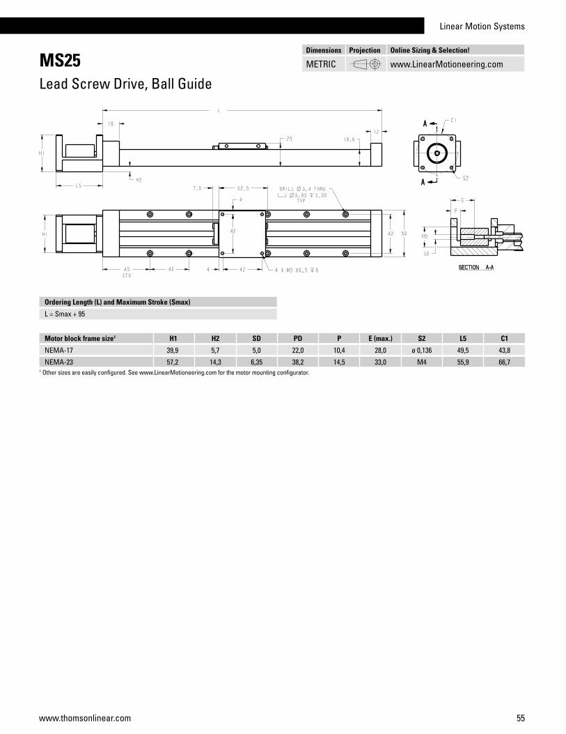
Linear Motion Systems
55www.thomsonlinear.com
MS25Lead Screw Drive, Ball Guide
Motor block frame size1 H1 H2 SD PD P E (max.) S2 L5 C1
NEMA-17 39,9 5,7 5,0 22,0 10,4 28,0 ø 0,136 49,5 43,8
NEMA-23 57,2 14,3 6,35 38,2 14,5 33,0 M4 55,9 66,71 Other sizes are easily configured. See www.LinearMotioneering.com for the motor mounting configurator.
Ordering Length (L) and Maximum Stroke (Smax)
L = Smax + 95
Dimensions Projection Online Sizing & Selection!
METRIC www.LinearMotioneering.com

56 www.thomsonlinear.com
MS33Lead Screw Drive, Ball Guide
Performance SpecificationsParameter MS33
Stroke length (Smax), maximum [mm] 704
Linear speed, maximum [m/s] 1,02
Acceleration, maximum [m/s2] 9,8
Repeatability [± mm] 0,005
Accuracy [± mm] 0,18 / 300 mm
Input speed, maximum [rpm] 2000
Operation temperature limits [°C] -20 – 80
Dynamic load (Fx), maximum [N] 80,1
Dynamic load (Fy), maximum [N] 150
Dynamic load (Fz), maximum [N] 150
Dynamic load torque (Mx), maximum [Nm] 2,8
Dynamic load torque (My), maximum [Nm] 2,5
Dynamic load torque (Mz), maximum [Nm] 5,1
Drive shaft force (Frd), maximum 1 [N] 222
Input/drive shaft torque (Mta), maximum [Nm] 0,43
Lead screw diameter (d0) [mm] 9,525
Lead screw lead (p) inch leads
metric leads
[inch]
[mm]
0,0625, 0,1, 0,125, 0,2, 0,25, 0,375,
0,5, 1,0, 1,2 2
Weight of unit with zero stroke of every 100 mm of stroke of each carriage
[kg]0,690,310,12
1 Only relevant for units without RediMount flange.
General SpecificationsParameter MS33
Profile size (w × h) [mm] 1 60 × 33
Type of screw lead screw
Carriage sealing system none (optional bellows)
Screw supports none
Lubrication lubrication of screws and guides
Included accessories RediMount™ kit1 Base width × carriage height.
Deflection of the Profile
Definition of Forces
The unit must be continuously supported by a machined surface under its entire length.
Fz
» Ordering key - see page 199» Accessories - see page 131

Linear Motion Systems
57www.thomsonlinear.com
MS33Lead Screw Drive, Ball Guide
Motor block frame size1 H1 H2 SD PD P E (max.) S2 L5 C1
NEMA-17 39,9 1,2 2 5,0 22,0 7,8 28,0 ø 0,136 49,5 43,8
NEMA-23 57,2 7,5 6,35 38,2 14,0 33,0 M4 55,9 66,7
Ordering Length (L) and Maximum Stroke (Smax)
L = Smax + 96
1 Other sizes are easily configured. See www.LinearMotioneering.com for the motor mounting configurator.2 Above base.
Dimensions Projection Online Sizing & Selection!
METRIC www.LinearMotioneering.com
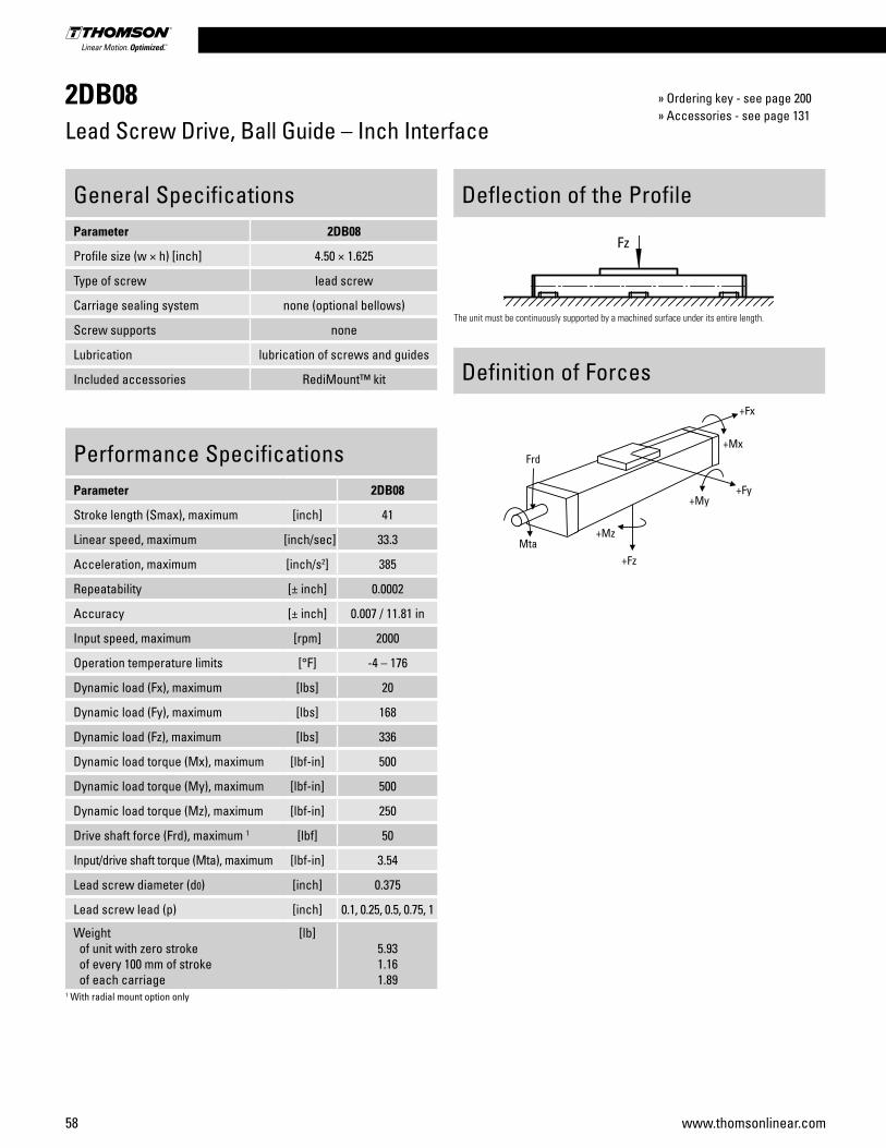
58 www.thomsonlinear.com
2DB08Lead Screw Drive, Ball Guide – Inch Interface
Performance SpecificationsParameter 2DB08
Stroke length (Smax), maximum [inch] 41
Linear speed, maximum [inch/sec] 33.3
Acceleration, maximum [inch/s2] 385
Repeatability [± inch] 0.0002
Accuracy [± inch] 0.007 / 11.81 in
Input speed, maximum [rpm] 2000
Operation temperature limits [°F] -4 – 176
Dynamic load (Fx), maximum [lbs] 20
Dynamic load (Fy), maximum [lbs] 168
Dynamic load (Fz), maximum [lbs] 336
Dynamic load torque (Mx), maximum [lbf-in] 500
Dynamic load torque (My), maximum [lbf-in] 500
Dynamic load torque (Mz), maximum [lbf-in] 250
Drive shaft force (Frd), maximum 1 [lbf] 50
Input/drive shaft torque (Mta), maximum [lbf-in] 3.54
Lead screw diameter (d0) [inch] 0.375
Lead screw lead (p) [inch] 0.1, 0.25, 0.5, 0.75, 1
Weight of unit with zero stroke of every 100 mm of stroke of each carriage
[lb]5.931.161.89
1 With radial mount option only
General SpecificationsParameter 2DB08
Profile size (w × h) [inch] 4.50 × 1.625
Type of screw lead screw
Carriage sealing system none (optional bellows)
Screw supports none
Lubrication lubrication of screws and guides
Included accessories RediMount™ kit
Deflection of the Profile
Definition of Forces
The unit must be continuously supported by a machined surface under its entire length.
Fz
» Ordering key - see page 200» Accessories - see page 131
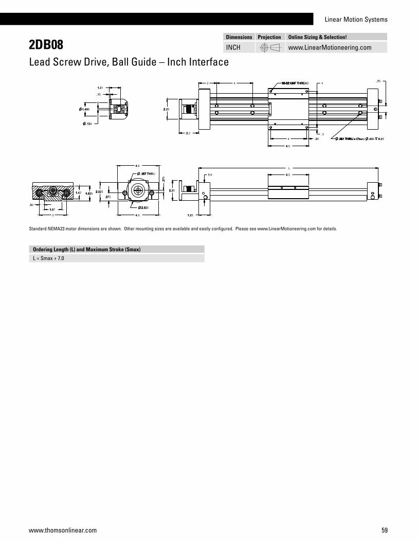
Linear Motion Systems
59www.thomsonlinear.com
2DB08Lead Screw Drive, Ball Guide – Inch Interface
Ordering Length (L) and Maximum Stroke (Smax)
L = Smax + 7.0
Standard NEMA23 motor dimensions are shown. Other mounting sizes are available and easily configured. Please see www.LinearMotioneering.com for details.
Dimensions Projection Online Sizing & Selection!
INCH www.LinearMotioneering.com

60 www.thomsonlinear.com
2DB12OBall Screw Drive, Ball Guide – Inch Interface
Performance SpecificationsParameter 2DB12O
Stroke length (Smax), maximum [inch] 63
Linear speed, maximum [inch/sec] 10.0
Acceleration, maximum [inch/s2] 385
Repeatability standard nut preloaded nut
[± inch] 0.00200.0002
Accuracy [± inch] 0.002 / 12 in
Input speed, maximum [rpm] 3000
Operation temperature limits [°F] -4 – 176
Dynamic load (Fx), maximum [lbs] 190
Dynamic load (Fy), maximum [lbs] 1058
Dynamic load (Fz), maximum [lbs] 2115
Dynamic load torque (Mx), maximum [lbf-in] 4150
Dynamic load torque (My), maximum [lbf-in] 4150
Dynamic load torque (Mz), maximum [lbf-in] 2071
Drive shaft force (Frd), maximum 1 [lbf] 120
Input/drive shaft torque (Mta), maximum [lbf-in] 6.73
Ball screw diameter (d0) [inch] 0.5
Ball screw lead (p) [inch] 0.631
Weight of unit with zero stroke of every 100 mm of stroke of each carriage
[lb]13.172.304.29
1 With radial mount option only.
General SpecificationsParameter 2DB12O
Profile size (w × h) [inch] 6 × 2.125
Type of screw ball screw
Carriage sealing system none (optional bellows)
Screw supports none
Lubrication lubrication of screws and guides
Included accessories RediMount™ kit
Deflection of the Profile
Definition of Forces
The unit must be continuously supported by a machined surface under its entire length.
Fz
» Ordering key - see page 200» Accessories - see page 131

Linear Motion Systems
61www.thomsonlinear.com
2DB12OBall Screw Drive, Ball Guide – Inch Interface
Ordering Length (L) and Maximum Stroke (Smax)
L = Smax + 9.0
Standard NEMA23 motor dimensions are shown. Other mounting sizes are available and easily configured. Please see www.LinearMotioneering.com for details.
Y1 6
2.63.688
Dimensions Projection Online Sizing & Selection!
INCH www.LinearMotioneering.com

62 www.thomsonlinear.com
2DB12JBall Screw Drive, Ball Guide – Inch Interface
Performance SpecificationsParameter 2DB12J
Stroke length (Smax), maximum [inch] 63
Linear speed, maximum [inch/sec] 25.0
Acceleration, maximum [inch/s2] 385
Repeatability [± inch] 0.0002
Accuracy [± inch] 0.002 / 12 in
Input speed, maximum [rpm] 3000
Operation temperature limits [°F] -4 – 176
Dynamic load (Fx), maximum [lbs] 375
Dynamic load (Fy), maximum [lbs] 1058
Dynamic load (Fz), maximum [lbs] 2115
Dynamic load torque (Mx), maximum [lbf-in] 4150
Dynamic load torque (My), maximum [lbf-in] 4150
Dynamic load torque (Mz), maximum [lbf-in] 2071
Drive shaft force (Frd), maximum 1 [lbf] 120
Input/drive shaft torque (Mta), maximum [lbf-in] 33.19
Ball screw diameter (d0) [inch] 0.50
Ball screw lead (p) [inch] 0.5
Weight of unit with zero stroke of every 100 mm of stroke of each carriage
[lb]13.582.2964.850
1 With radial mount option only.
General SpecificationsParameter 2DB12J
Profile size (w × h) [inch] 6 × 2.562
Type of screw ball screw
Carriage sealing system none (optional bellows)
Screw supports none
Lubrication lubrication of screws and guides
Included accessories RediMount™ kit
Deflection of the Profile
Definition of Forces
The unit must be continuously supported by a machined surface under its entire length.
Fz
» Ordering key - see page 200» Accessories - see page 131

Linear Motion Systems
63www.thomsonlinear.com
2DB12JBall Screw Drive, Ball Guide – Inch Interface
Ordering Length (L) and Maximum Stroke (Smax)
L = Smax + 9.0
Standard NEMA23 motor dimensions are shown. Other mounting sizes are available and easily configured. Please see www.LinearMotioneering.com for details.
Y1
2.63.688
2.346 2.562
Dimensions Projection Online Sizing & Selection!
INCH www.LinearMotioneering.com
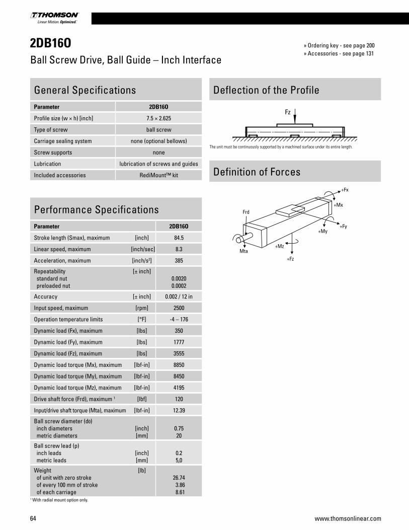
64 www.thomsonlinear.com
2DB16OBall Screw Drive, Ball Guide – Inch Interface
Performance SpecificationsParameter 2DB16O
Stroke length (Smax), maximum [inch] 84.5
Linear speed, maximum [inch/sec] 8.3
Acceleration, maximum [inch/s2] 385
Repeatability standard nut preloaded nut
[± inch]0.00200.0002
Accuracy [± inch] 0.002 / 12 in
Input speed, maximum [rpm] 2500
Operation temperature limits [°F] -4 – 176
Dynamic load (Fx), maximum [lbs] 350
Dynamic load (Fy), maximum [lbs] 1777
Dynamic load (Fz), maximum [lbs] 3555
Dynamic load torque (Mx), maximum [lbf-in] 8850
Dynamic load torque (My), maximum [lbf-in] 8450
Dynamic load torque (Mz), maximum [lbf-in] 4195
Drive shaft force (Frd), maximum 1 [lbf] 120
Input/drive shaft torque (Mta), maximum [lbf-in] 12.39
Ball screw diameter (d0) inch diameters metric diameters
[inch][mm]
0.7520
Ball screw lead (p) inch leads metric leads
[inch][mm]
0.25,0
Weight of unit with zero stroke of every 100 mm of stroke of each carriage
[lb]26.74 3.86 8.61
1 With radial mount option only.
General SpecificationsParameter 2DB16O
Profile size (w × h) [inch] 7.5 × 2.625
Type of screw ball screw
Carriage sealing system none (optional bellows)
Screw supports none
Lubrication lubrication of screws and guides
Included accessories RediMount™ kit
Deflection of the Profile
Definition of Forces
The unit must be continuously supported by a machined surface under its entire length.
Fz
» Ordering key - see page 200» Accessories - see page 131
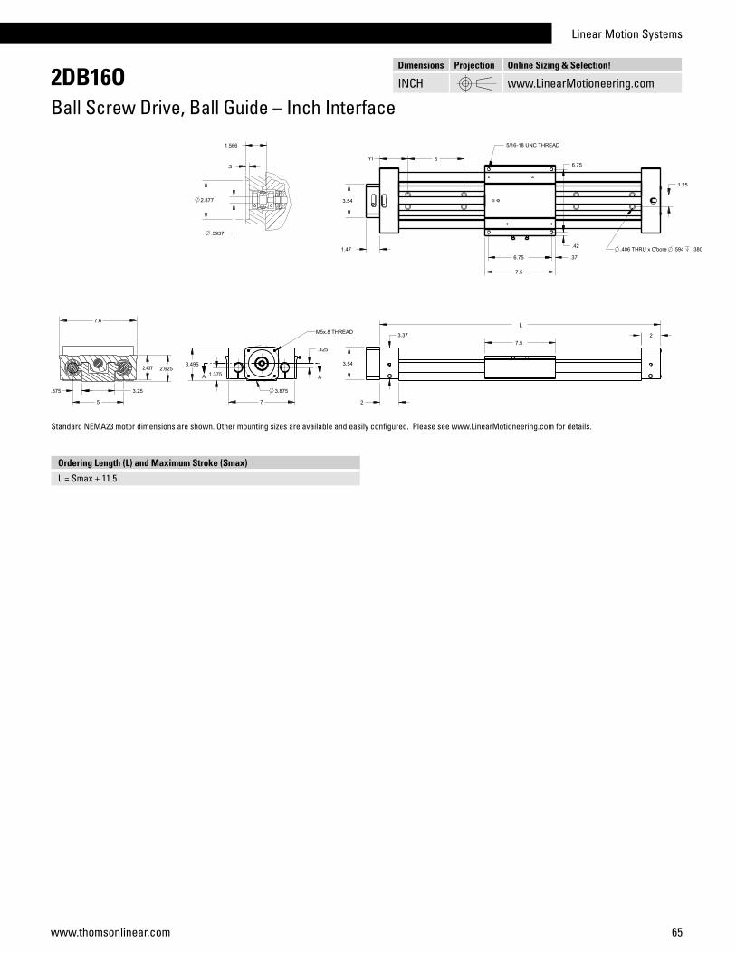
Linear Motion Systems
65www.thomsonlinear.com
2DB16OBall Screw Drive, Ball Guide – Inch Interface
Ordering Length (L) and Maximum Stroke (Smax)
L = Smax + 11.5
Standard NEMA23 motor dimensions are shown. Other mounting sizes are available and easily configured. Please see www.LinearMotioneering.com for details.
Y1
2.437
Dimensions Projection Online Sizing & Selection!
INCH www.LinearMotioneering.com

66 www.thomsonlinear.com
2DB16JBall Screw Drive, Ball Guide – Inch Interface
Performance SpecificationsParameter 2DB16J
Stroke length (Smax), maximum [inch] 84.5
Linear speed, maximum [inch/sec] 41.67
Acceleration, maximum [inch/s2] 385
Repeatability [± inch] 0.0002
Accuracy [± inch] 0.002 / 12 in
Input speed, maximum [rpm] 2500
Operation temperature limits [°F] -4 – 176
Dynamic load (Fx), maximum [lbs] 350
Dynamic load (Fy), maximum [lbs] 1777
Dynamic load (Fz), maximum [lbs] 3555
Dynamic load torque (Mx), maximum [lbf-in] 8877
Dynamic load torque (My), maximum [lbf-in] 8098
Dynamic load torque (Mz), maximum [lbf-in] 4053
Drive shaft force (Frd), maximum 1 [lbf] 120
Input/drive shaft torque (Mta), maximum [lbf-in] 30.98
Ball screw diameter (d0) [inch] 0.631, 0.750
Ball screw lead (p) [inch] 0.5, 1.0
Weight of unit with zero stroke of every 100 mm of stroke of each carriage
[lb]25.73 3.86 7.70
1 With radial mount option only.
General SpecificationsParameter 2DB16J
Profile size (w × h) [inch] 7.5 × 3.062
Type of screw ball screw
Carriage sealing system none (optional bellows)
Screw supports none
Lubrication lubrication of screws and guides
Included accessories RediMount™ kit
Deflection of the Profile
Definition of Forces
The unit must be continuously supported by a machined surface under its entire length.
Fz
» Ordering key - see page 200» Accessories - see page 131
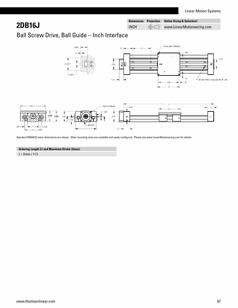
Linear Motion Systems
67www.thomsonlinear.com
2DB16JBall Screw Drive, Ball Guide – Inch Interface
Ordering Length (L) and Maximum Stroke (Smax)
L = Smax + 11.5
Standard NEMA23 motor dimensions are shown. Other mounting sizes are available and easily configured. Please see www.LinearMotioneering.com for details.
7.5
Y1
6.50
.34
.50
7.5
5.50
2.846 3.062
Dimensions Projection Online Sizing & Selection!
INCH www.LinearMotioneering.com

68 www.thomsonlinear.com
Parameter M55 M75 M100
Profile size (width × height) [mm] 58 × 55 86 × 75 108 × 100
Stroke length (Smax), maximum [mm] 2712 3772 5578
Linear speed, maximum [m/s] 1,0 1,6 1,6
Dynamic carriage load (Fz), maximum [N] 400 1485 3005
Remarks single ball nut single ball nut single ball nut
Page 70 72 74
Features• Can be installed in any orientation• Self-adjusting stainless steel cover band• Patented internal self-adjusting prism slide guides• Wash down protected versions available.
Movopart M
M75
Linear Motion Systems with Ball Screw Drive and Slide Guide Overview
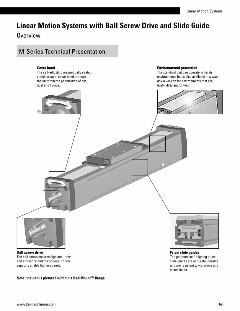
Linear Motion Systems
69www.thomsonlinear.com
Linear Motion Systems with Ball Screw Drive and Slide Guide Overview
M-Series Technical Presentation
Cover bandThe self-adjusting magnetically sealed stainless steel cover band protects the unit from the penetration of dirt, dust and liquids.
Note! the unit is pictured without a RediMount™ flange
Environmental protectionThe standard unit can operate in harsh environments but is also available in a wash down version for environments that aredusty, dirty and/or wet.
Ball screw driveThe ball screw ensures high accuracy and efficiency and the optional screw supports enable higher speeds.
Prism slide guidesThe patented self-aligning prism slide guides are accurate, durable and are resistant to vibrations and shock loads.
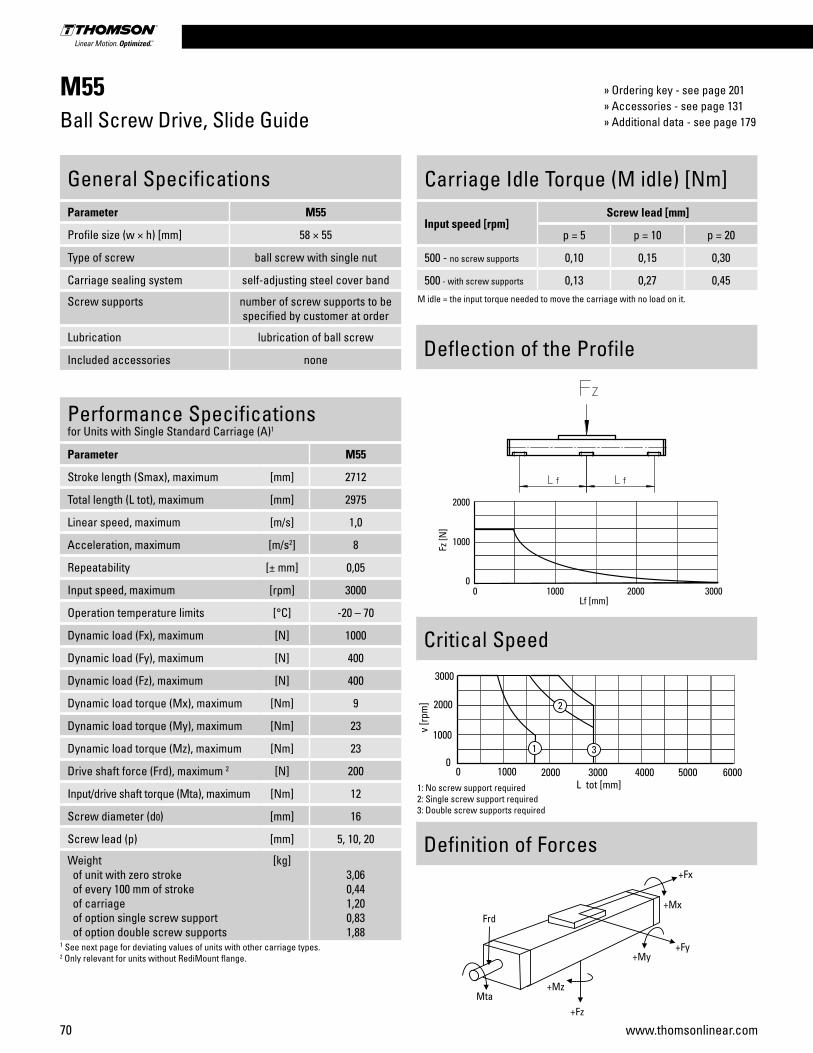
70 www.thomsonlinear.com
Deflection of the Profile
M55Ball Screw Drive, Slide Guide
Performance Specificationsfor Units with Single Standard Carriage (A)1
Parameter M55
Stroke length (Smax), maximum [mm] 2712
Total length (L tot), maximum [mm] 2975
Linear speed, maximum [m/s] 1,0
Acceleration, maximum [m/s2] 8
Repeatability [± mm] 0,05
Input speed, maximum [rpm] 3000
Operation temperature limits [°C] -20 – 70
Dynamic load (Fx), maximum [N] 1000
Dynamic load (Fy), maximum [N] 400
Dynamic load (Fz), maximum [N] 400
Dynamic load torque (Mx), maximum [Nm] 9
Dynamic load torque (My), maximum [Nm] 23
Dynamic load torque (Mz), maximum [Nm] 23
Drive shaft force (Frd), maximum 2 [N] 200
Input/drive shaft torque (Mta), maximum [Nm] 12
Screw diameter (d0) [mm] 16
Screw lead (p) [mm] 5, 10, 20
Weight of unit with zero stroke of every 100 mm of stroke of carriage of option single screw support of option double screw supports
[kg]3,060,441,200,831,88
1 See next page for deviating values of units with other carriage types.2 Only relevant for units without RediMount flange.
General SpecificationsParameter M55
Profile size (w × h) [mm] 58 × 55
Type of screw ball screw with single nut
Carriage sealing system self-adjusting steel cover band
Screw supports number of screw supports to be specified by customer at order
Lubrication lubrication of ball screw
Included accessories none
Definition of Forces
Carriage Idle Torque (M idle) [Nm]
Input speed [rpm]Screw lead [mm]
p = 5 p = 10 p = 20
500 - no screw supports 0,10 0,15 0,30
500 - with screw supports 0,13 0,27 0,45M idle = the input torque needed to move the carriage with no load on it.
Critical Speed
1: No screw support required2: Single screw support required3: Double screw supports required
» Ordering key - see page 201» Accessories - see page 131» Additional data - see page 179

Linear Motion Systems
71www.thomsonlinear.com
M55Ball Screw Drive, Slide Guide
A1: slide guide tensioning holesA2: ø9,5/ø5,5 for socket head cap screw M5
Performance Specificationsfor Units with Double Standard Carriage (C)
Parameter M55
Stroke length (Smax), maximum [mm] 2512
Total length (L tot), maximum [mm] 2975
Minimum distance between carriages (Lc) [mm] 200
Dynamic load (Fy), maximum [N] 600
Dynamic load (Fz), maximum [N] 600
Dynamic load torque (My), maximum [Nm] Lc1 × 0,3
Dynamic load torque (Mz), maximum [Nm] Lc1 × 0,3
Force required to move second carriage [N] 35
Weight of unit with zero stroke of carriages
[kg]5,142,40
1 Value in mm
Screw support configuration A [mm] B [mm] Total length (L tot) [mm]
No screw support 6 6 L tot = Smax + A + B + 251
Single screw support 32 32 L tot = Smax + A + B + 251
Double screw supports 83 83 L tot = Smax + A + B + 251
Screw support configuration A [mm] B [mm] Total length (L tot) [mm]
No screw support 6 6 L tot = Smax + A + B + Lc + 251
Single screw support 32 32 L tot = Smax + A + B + Lc + 251
Double screw supports 83 83 L tot = Smax + A + B + Lc + 251
Dimensions Projection Online Sizing & Selection!
METRIC www.LinearMotioneering.com
RediMount Flange SpecificationsParameter Min Max
Flange length (Lrm) [mm] 57 92
Flange square (Srm) [mm] 60 139
Flange weight * [kg] 1,84
* Max. weight including coupling and fastening screws

72 www.thomsonlinear.com
M75Ball Screw Drive, Slide Guide
Performance Specificationsfor Units with Single Standard Carriage (A)1
Parameter M75
Stroke length (Smax), maximum screw lead 5, 20 mm screw lead 12,7 mm
[mm]37722665
Total length (L tot), maximum screw lead 5, 20 mm screw lead 12,7 mm
[mm]40752968
Linear speed, maximum [m/s] 1,6
Acceleration, maximum [m/s2] 8
Repeatability [± mm] 0,05
Input speed, maximum [rpm] 5000
Operation temperature limits [°C] -20 – 70
Dynamic load (Fx), maximum [N] 2500
Dynamic load (Fy), maximum [N] 1485
Dynamic load (Fz), maximum [N] 1485
Dynamic load torque (Mx), maximum [Nm] 49
Dynamic load torque (My), maximum [Nm] 85
Dynamic load torque (Mz), maximum [Nm] 85
Drive shaft force (Frd), maximum 2 [N] 600
Input/drive shaft torque (Mta), maximum [Nm] 30
Screw diameter (d0) [mm] 20
Screw lead (p) [mm] 5, 12,7, 20
Weight of unit with zero stroke of every 100 mm of stroke of carriage of option single screw support of option double screw supports
[kg]6,070,821,701,703,58
1 See next page for deviating values of units with other carriage types.2 Only relevant for units without RediMount flange.
General SpecificationsParameter M75
Profile size (w × h) [mm] 86 × 75
Type of screw ball screw with single nut
Carriage sealing system self-adjusting steel cover band
Screw supports number of screw supports to be specified by customer at order
Lubrication lubrication of ball screw
Included accessories none Deflection of the Profile
Definition of Forces
Carriage Idle Torque (M idle) [Nm]
Input speed [rpm] Screw lead [mm]
p = 5 p = 12,7 p = 20
500 - no screw supports 0,10 0,24 0,37
500 - with screw supports 0,15 0,39 0,57M idle = the input torque needed to move the carriage with no load on it.
Critical Speed
1: No screw support required2: Single screw support required3: Double screw supports required
» Ordering key - see page 201» Accessories - see page 131» Additional data - see page 179
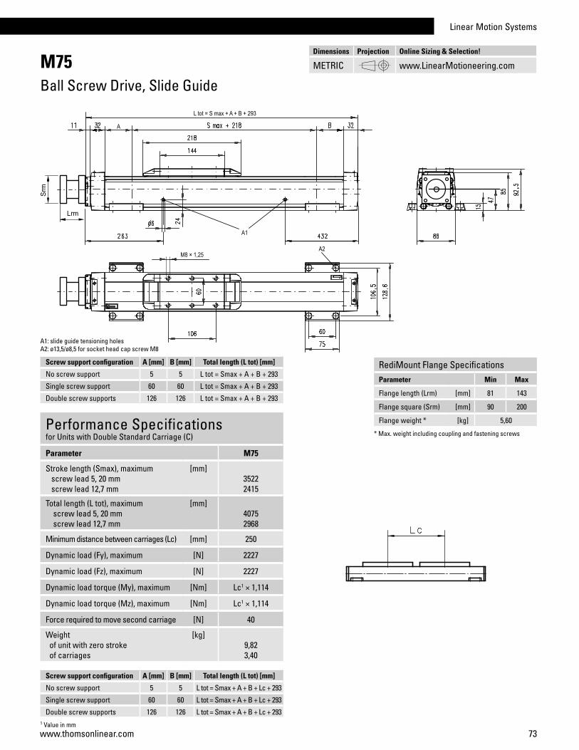
Linear Motion Systems
73www.thomsonlinear.com
M75Ball Screw Drive, Slide Guide
Performance Specificationsfor Units with Double Standard Carriage (C)
Parameter M75
Stroke length (Smax), maximum screw lead 5, 20 mm screw lead 12,7 mm
[mm]35222415
Total length (L tot), maximum screw lead 5, 20 mm screw lead 12,7 mm
[mm]40752968
Minimum distance between carriages (Lc) [mm] 250
Dynamic load (Fy), maximum [N] 2227
Dynamic load (Fz), maximum [N] 2227
Dynamic load torque (My), maximum [Nm] Lc1 × 1,114
Dynamic load torque (Mz), maximum [Nm] Lc1 × 1,114
Force required to move second carriage [N] 40
Weight of unit with zero stroke of carriages
[kg]9,823,40
A1: slide guide tensioning holesA2: ø13,5/ø8,5 for socket head cap screw M8
1 Value in mm
Screw support configuration A [mm] B [mm] Total length (L tot) [mm]
No screw support 5 5 L tot = Smax + A + B + 293
Single screw support 60 60 L tot = Smax + A + B + 293
Double screw supports 126 126 L tot = Smax + A + B + 293
Screw support configuration A [mm] B [mm] Total length (L tot) [mm]
No screw support 5 5 L tot = Smax + A + B + Lc + 293
Single screw support 60 60 L tot = Smax + A + B + Lc + 293
Double screw supports 126 126 L tot = Smax + A + B + Lc + 293
Dimensions Projection Online Sizing & Selection!
METRIC www.LinearMotioneering.com
RediMount Flange SpecificationsParameter Min Max
Flange length (Lrm) [mm] 81 143
Flange square (Srm) [mm] 90 200
Flange weight * [kg] 5,60
* Max. weight including coupling and fastening screws
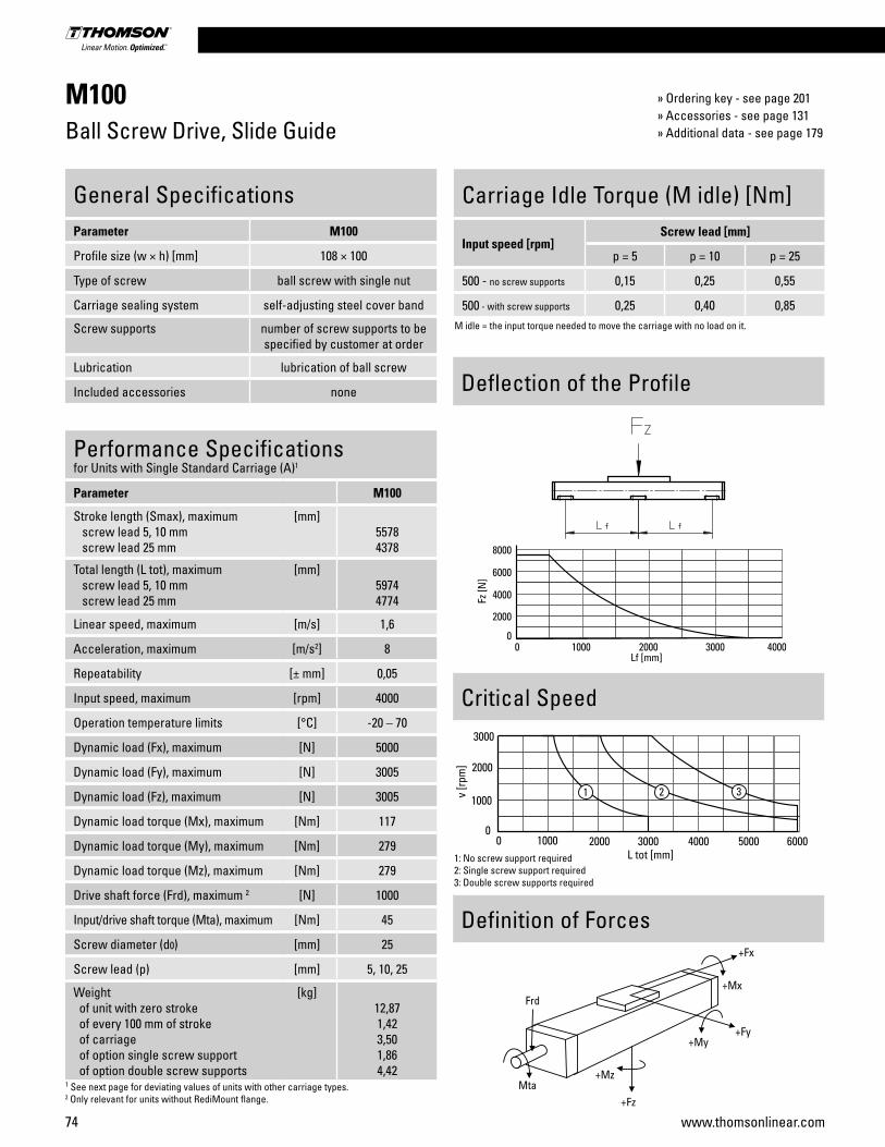
74 www.thomsonlinear.com
M100Ball Screw Drive, Slide Guide
Performance Specificationsfor Units with Single Standard Carriage (A)1
Parameter M100
Stroke length (Smax), maximum screw lead 5, 10 mm screw lead 25 mm
[mm]55784378
Total length (L tot), maximum screw lead 5, 10 mm screw lead 25 mm
[mm]59744774
Linear speed, maximum [m/s] 1,6
Acceleration, maximum [m/s2] 8
Repeatability [± mm] 0,05
Input speed, maximum [rpm] 4000
Operation temperature limits [°C] -20 – 70
Dynamic load (Fx), maximum [N] 5000
Dynamic load (Fy), maximum [N] 3005
Dynamic load (Fz), maximum [N] 3005
Dynamic load torque (Mx), maximum [Nm] 117
Dynamic load torque (My), maximum [Nm] 279
Dynamic load torque (Mz), maximum [Nm] 279
Drive shaft force (Frd), maximum 2 [N] 1000
Input/drive shaft torque (Mta), maximum [Nm] 45
Screw diameter (d0) [mm] 25
Screw lead (p) [mm] 5, 10, 25
Weight of unit with zero stroke of every 100 mm of stroke of carriage of option single screw support of option double screw supports
[kg]12,871,423,501,864,42
1 See next page for deviating values of units with other carriage types.2 Only relevant for units without RediMount flange.
General SpecificationsParameter M100
Profile size (w × h) [mm] 108 × 100
Type of screw ball screw with single nut
Carriage sealing system self-adjusting steel cover band
Screw supports number of screw supports to be specified by customer at order
Lubrication lubrication of ball screw
Included accessories none Deflection of the Profile
Definition of Forces
Carriage Idle Torque (M idle) [Nm]
Input speed [rpm] Screw lead [mm]
p = 5 p = 10 p = 25
500 - no screw supports 0,15 0,25 0,55
500 - with screw supports 0,25 0,40 0,85M idle = the input torque needed to move the carriage with no load on it.
Critical Speed
1: No screw support required2: Single screw support required3: Double screw supports required
» Ordering key - see page 201» Accessories - see page 131» Additional data - see page 179

Linear Motion Systems
75www.thomsonlinear.com
M100Ball Screw Drive, Slide Guide
Performance Specificationsfor Units with Double Standard Carriage (C)
Parameter M100
Stroke length (Smax), maximum screw lead 5, 10 mm screw lead 25 mm
[mm]52284028
Total length (L tot), maximum screw lead 5, 10 mm screw lead 25 mm
[mm]59744774
Minimum distance between carriages (Lc) [mm] 350
Dynamic load (Fy), maximum [N] 4508
Dynamic load (Fz), maximum [N] 4508
Dynamic load torque (My), maximum [Nm] Lc1 × 2,254
Dynamic load torque (Mz), maximum [Nm] Lc1 × 2,254
Force required to move second carriage [N] 45
Weight of unit with zero stroke of carriages
[kg]21,34 7,00
A1: slide guide tensioning holeA2: ø17/ø10,5 for socket head cap screw M10A3: 147 (L order <= 1088 mm), 367 (L order > 1088 mm)A4: 141 (L order <= 1088 mm), 471 (L order > 1088 mm)
1 Value in mm
Screw support configuration A [mm] B [mm] Total length (L tot) [mm]
No screw support 1 1 L tot = Smax + A + B + 394
Single screw support 31 31 L tot = Smax + A + B + 394
Double screw supports 86 86 L tot = Smax + A + B + 394
Screw support configuration A [mm] B [mm] Total length (L tot) [mm]
No screw support 1 1 L tot = Smax + A + B + Lc + 394
Single screw support 31 31 L tot = Smax + A + B + Lc + 394
Double screw supports 86 86 L tot = Smax + A + B + Lc + 394
RediMount Flange SpecificationsParameter Min Max
Flange length (Lrm) [mm] 81 143
Flange square (Srm) [mm] 90 200
Flange weight * [kg] 5,60
* Max. weight including coupling and fastening screws
Dimensions Projection Online Sizing & Selection!
METRIC www.LinearMotioneering.com

76 www.thomsonlinear.com
Parameter WH40
Profile size (width × height) [mm] 40 × 40
Stroke length (Smax), maximum [mm] 2000
Linear speed, maximum [m/s] 3,0
Dynamic carriage load (Fz), maximum [N] 600
Remarks no cover band
Page 78
Parameter M55 M75 M100
Profile size (width × height) [mm] 58 × 55 86 × 75 108 × 100
Stroke length (Smax), maximum [mm] 7000 12000 11900
Linear speed, maximum [m/s] 5,0 5,0 5,0
Dynamic carriage load (Fz), maximum [N] 750 1750 4000
Remarks - - -
Page 86 88 90
Features• Can be installed in any orientation• Stroke up to 2 m• Acceleration up to 40 m/s2
• Compact
Features• Can be installed in any orientation• Self-adjusting stainless steel cover band• Stroke up to 12 m• Wash down protected versions available.
SpeedLine WH
Movopart M
WH40
M75
Parameter WM60Z WM80Z
Profile size (width × height) [mm] 60 × 60 80 × 80
Stroke length (Smax), maximum [mm] 4000 5500
Linear speed, maximum [m/s] 2,5 5,0
Dynamic carriage load (Fz), maximum [N] 1400 2100
Remarks - -
Page 80 82, 84
Features• Can be installed in any orientation• Stroke up to 5,5 m• Speed up to 5 m/s• Patented plastic cover band
PowerLine WMZ
WM80Z
Linear Motion Systems with Belt Drive and Ball Guide Overview
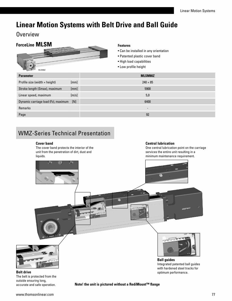
Linear Motion Systems
77www.thomsonlinear.com
Parameter MLSM80Z
Profile size (width × height) [mm] 240 × 85
Stroke length (Smax), maximum [mm] 5900
Linear speed, maximum [m/s] 5,0
Dynamic carriage load (Fz), maximum [N] 6400
Remarks -
Page 92
Features• Can be installed in any orientation• Patented plastic cover band• High load capabilities• Low profile height
ForceLine MLSM
MLSM80Z
WMZ-Series Technical PresentationCover bandThe cover band protects the interior of the unit from the penetration of dirt, dust and liquids.
Central lubricationOne central lubrication point on the carriage services the entire unit resulting in a minimum maintenance requirement.
Belt driveThe belt is protected from the outside ensuring long, accurate and safe operation.
Ball guidesIntegrated patented ball guides with hardened steel tracks for optimum performance.
Linear Motion Systems with Belt Drive and Ball Guide Overview
Note! the unit is pictured without a RediMount™ flange
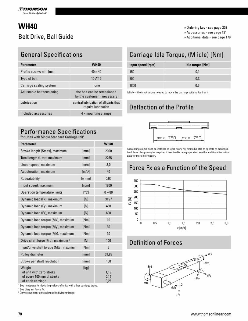
78 www.thomsonlinear.com
WH40Belt Drive, Ball Guide
Performance Specificationsfor Units with Single Standard Carriage (N)1
Parameter WH40
Stroke length (Smax), maximum [mm] 2000
Total length (L tot), maximum [mm] 2265
Linear speed, maximum [m/s] 3,0
Acceleration, maximum [m/s2] 40
Repeatability [± mm] 0,05
Input speed, maximum [rpm] 1800
Operation temperature limits [°C] 0 – 80
Dynamic load (Fx), maximum [N] 315 2
Dynamic load (Fy), maximum [N] 450
Dynamic load (Fz), maximum [N] 600
Dynamic load torque (Mx), maximum [Nm] 10
Dynamic load torque (My), maximum [Nm] 30
Dynamic load torque (Mz), maximum [Nm] 30
Drive shaft force (Frd), maximum 3 [N] 100
Input/drive shaft torque (Mta), maximum [Nm] 6
Pulley diameter [mm] 31,83
Stroke per shaft revolution [mm] 100
Weight of unit with zero stroke of every 100 mm of stroke of each carriage
[kg]1,190,150,28
1 See next page for deviating values of units with other carriage types.2 See diagram Force Fx.3 Only relevant for units without RediMount flange.
General SpecificationsParameter WH40
Profile size (w × h) [mm] 40 × 40
Type of belt 10 AT 5
Carriage sealing system none
Adjustable belt tensioning the belt can be retensioned by the customer if necessary
Lubrication central lubrication of all parts that require lubrication
Included accessories 4 × mounting clamps
Carriage Idle Torque, (M idle) [Nm]Input speed [rpm] Idle torque [Nm]
150 0,1
900 0,3
1800 0,6
M idle = the input torque needed to move the carriage with no load on it.
Force Fx as a Function of the Speed
Definition of Forces
Deflection of the Profile
A mounting clamp must be installed at least every 750 mm to be able to operate at maximum load. Less clamps may be required if less load is being operated, see the additional technical data for more information.
» Ordering key - see page 202» Accessories - see page 131» Additional data - see page 179
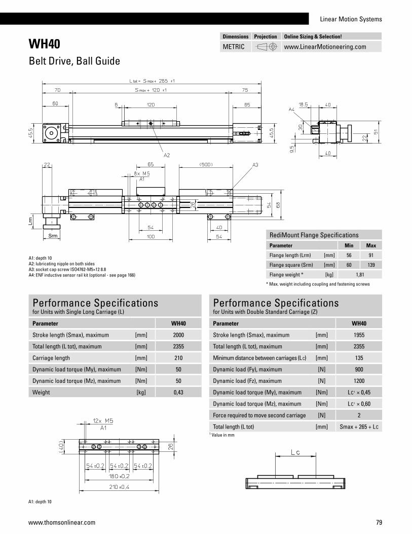
Linear Motion Systems
79www.thomsonlinear.com
WH40Belt Drive, Ball Guide
Performance Specificationsfor Units with Single Long Carriage (L)
Parameter WH40
Stroke length (Smax), maximum [mm] 2000
Total length (L tot), maximum [mm] 2355
Carriage length [mm] 210
Dynamic load torque (My), maximum [Nm] 50
Dynamic load torque (Mz), maximum [Nm] 50
Weight [kg] 0,43
A1: depth 10A2: lubricating nipple on both sidesA3: socket cap screw ISO4762-M5×12 8.8A4: ENF inductive sensor rail kit (optional - see page 166)
Performance Specificationsfor Units with Double Standard Carriage (Z)
Parameter WH40
Stroke length (Smax), maximum [mm] 1955
Total length (L tot), maximum [mm] 2355
Minimum distance between carriages (L C) [mm] 135
Dynamic load (Fy), maximum [N] 900
Dynamic load (Fz), maximum [N] 1200
Dynamic load torque (My), maximum [Nm] LC1 × 0,45
Dynamic load torque (Mz), maximum [Nm] LC1 × 0,60
Force required to move second carriage [N] 2
Total length (L tot) [mm] Smax + 265 + LC1 Value in mm
A1: depth 10
Dimensions Projection Online Sizing & Selection!
METRIC www.LinearMotioneering.com
RediMount Flange SpecificationsParameter Min Max
Flange length (Lrm) [mm] 56 91
Flange square (Srm) [mm] 60 139
Flange weight * [kg] 1,81
* Max. weight including coupling and fastening screws
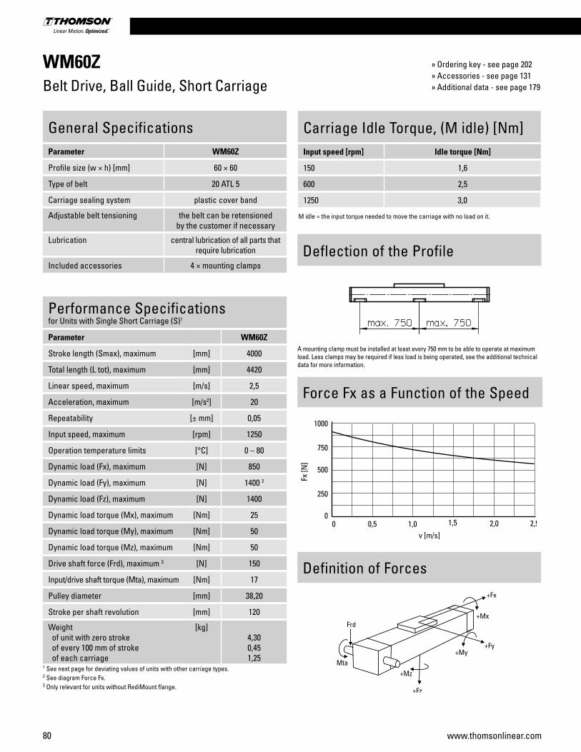
80 www.thomsonlinear.com
WM60ZBelt Drive, Ball Guide, Short Carriage
Performance Specificationsfor Units with Single Short Carriage (S)1
Parameter WM60Z
Stroke length (Smax), maximum [mm] 4000
Total length (L tot), maximum [mm] 4420
Linear speed, maximum [m/s] 2,5
Acceleration, maximum [m/s2] 20
Repeatability [± mm] 0,05
Input speed, maximum [rpm] 1250
Operation temperature limits [°C] 0 – 80
Dynamic load (Fx), maximum [N] 850
Dynamic load (Fy), maximum [N] 1400 2
Dynamic load (Fz), maximum [N] 1400
Dynamic load torque (Mx), maximum [Nm] 25
Dynamic load torque (My), maximum [Nm] 50
Dynamic load torque (Mz), maximum [Nm] 50
Drive shaft force (Frd), maximum 3 [N] 150
Input/drive shaft torque (Mta), maximum [Nm] 17
Pulley diameter [mm] 38,20
Stroke per shaft revolution [mm] 120
Weight of unit with zero stroke of every 100 mm of stroke of each carriage
[kg]4,300,451,25
1 See next page for deviating values of units with other carriage types.2 See diagram Force Fx.3 Only relevant for units without RediMount flange.
General SpecificationsParameter WM60Z
Profile size (w × h) [mm] 60 × 60
Type of belt 20 ATL 5
Carriage sealing system plastic cover band
Adjustable belt tensioning the belt can be retensioned by the customer if necessary
Lubrication central lubrication of all parts that require lubrication
Included accessories 4 × mounting clamps
Carriage Idle Torque, (M idle) [Nm]Input speed [rpm] Idle torque [Nm]
150 1,6
600 2,5
1250 3,0
M idle = the input torque needed to move the carriage with no load on it.
Force Fx as a Function of the Speed
Definition of Forces
Deflection of the Profile
A mounting clamp must be installed at least every 750 mm to be able to operate at maximum load. Less clamps may be required if less load is being operated, see the additional technical data for more information.
» Ordering key - see page 202» Accessories - see page 131» Additional data - see page 179
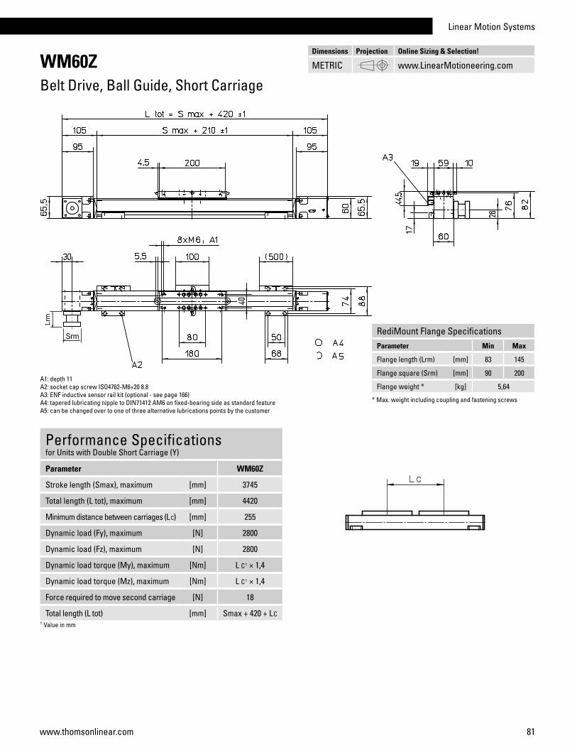
Linear Motion Systems
81www.thomsonlinear.com
WM60ZBelt Drive, Ball Guide, Short Carriage
A1: depth 11A2: socket cap screw ISO4762-M6×20 8.8A3: ENF inductive sensor rail kit (optional - see page 166)A4: tapered lubricating nipple to DIN71412 AM6 on fixed-bearing side as standard featureA5: can be changed over to one of three alternative lubrications points by the customer
Performance Specificationsfor Units with Double Short Carriage (Y)
Parameter WM60Z
Stroke length (Smax), maximum [mm] 3745
Total length (L tot), maximum [mm] 4420
Minimum distance between carriages (L C) [mm] 255
Dynamic load (Fy), maximum [N] 2800
Dynamic load (Fz), maximum [N] 2800
Dynamic load torque (My), maximum [Nm] L C1 × 1,4
Dynamic load torque (Mz), maximum [Nm] L C1 × 1,4
Force required to move second carriage [N] 18
Total length (L tot) [mm] Smax + 420 + LC1 Value in mm
Dimensions Projection Online Sizing & Selection!
METRIC www.LinearMotioneering.com
RediMount Flange SpecificationsParameter Min Max
Flange length (Lrm) [mm] 83 145
Flange square (Srm) [mm] 90 200
Flange weight * [kg] 5,64
* Max. weight including coupling and fastening screws
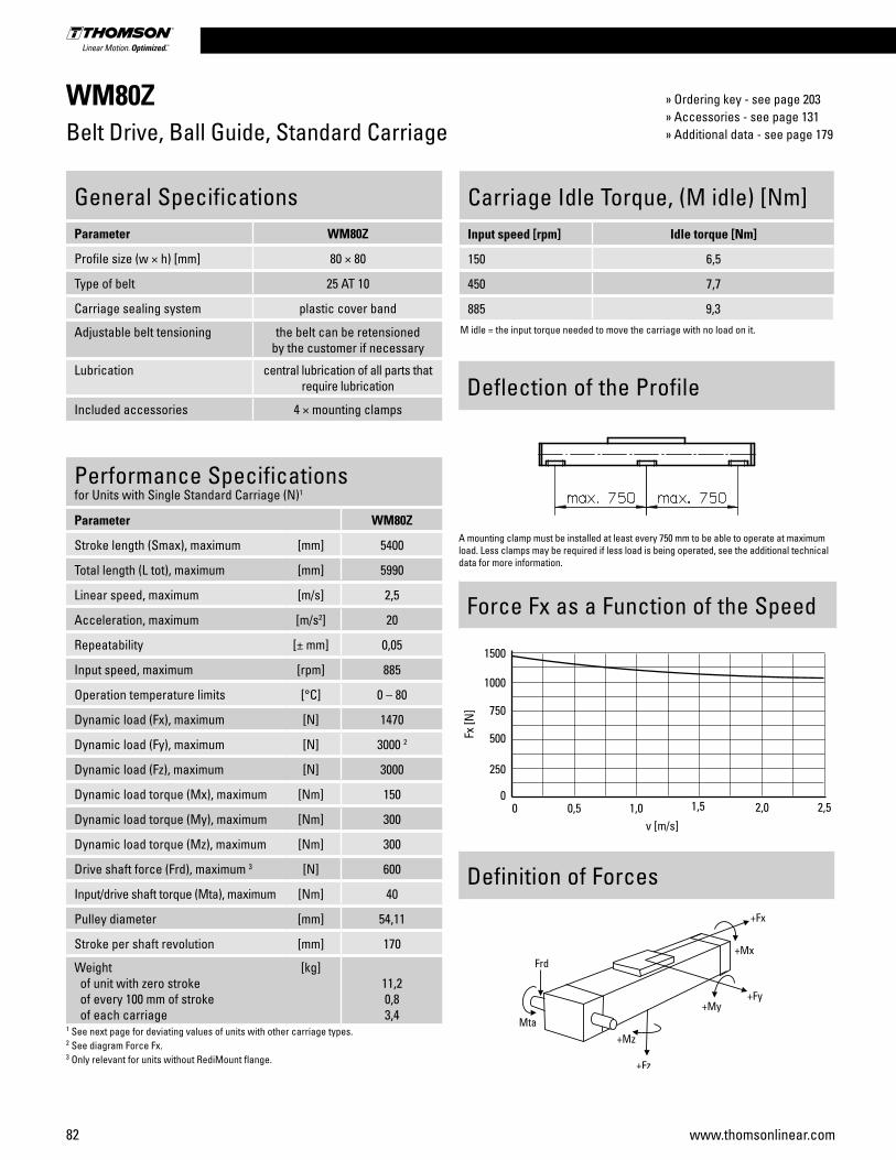
82 www.thomsonlinear.com
WM80ZBelt Drive, Ball Guide, Standard Carriage
Performance Specificationsfor Units with Single Standard Carriage (N)1
Parameter WM80Z
Stroke length (Smax), maximum [mm] 5400
Total length (L tot), maximum [mm] 5990
Linear speed, maximum [m/s] 2,5
Acceleration, maximum [m/s2] 20
Repeatability [± mm] 0,05
Input speed, maximum [rpm] 885
Operation temperature limits [°C] 0 – 80
Dynamic load (Fx), maximum [N] 1470
Dynamic load (Fy), maximum [N] 3000 2
Dynamic load (Fz), maximum [N] 3000
Dynamic load torque (Mx), maximum [Nm] 150
Dynamic load torque (My), maximum [Nm] 300
Dynamic load torque (Mz), maximum [Nm] 300
Drive shaft force (Frd), maximum 3 [N] 600
Input/drive shaft torque (Mta), maximum [Nm] 40
Pulley diameter [mm] 54,11
Stroke per shaft revolution [mm] 170
Weight of unit with zero stroke of every 100 mm of stroke of each carriage
[kg]11,20,83,4
1 See next page for deviating values of units with other carriage types.2 See diagram Force Fx.3 Only relevant for units without RediMount flange.
General SpecificationsParameter WM80Z
Profile size (w × h) [mm] 80 × 80
Type of belt 25 AT 10
Carriage sealing system plastic cover band
Adjustable belt tensioning the belt can be retensioned by the customer if necessary
Lubrication central lubrication of all parts that require lubrication
Included accessories 4 × mounting clamps
Carriage Idle Torque, (M idle) [Nm]Input speed [rpm] Idle torque [Nm]
150 6,5
450 7,7
885 9,3M idle = the input torque needed to move the carriage with no load on it.
Force Fx as a Function of the Speed
Definition of Forces
Deflection of the Profile
A mounting clamp must be installed at least every 750 mm to be able to operate at maximum load. Less clamps may be required if less load is being operated, see the additional technical data for more information.
» Ordering key - see page 203» Accessories - see page 131» Additional data - see page 179
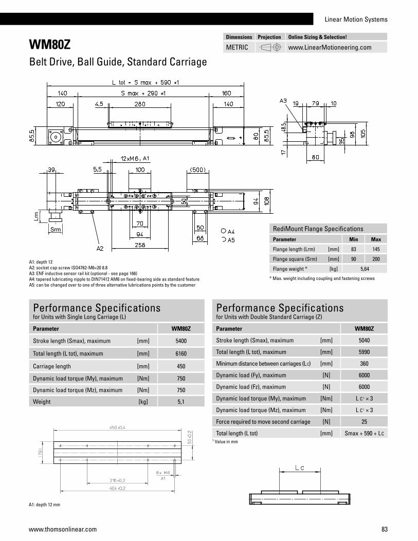
Linear Motion Systems
83www.thomsonlinear.com
WM80ZBelt Drive, Ball Guide, Standard Carriage
A1: depth 12A2: socket cap screw ISO4762-M6×20 8.8A3: ENF inductive sensor rail kit (optional - see page 166)A4: tapered lubricating nipple to DIN71412 AM6 on fixed-bearing side as standard featureA5: can be changed over to one of three alternative lubrications points by the customer
Performance Specificationsfor Units with Double Standard Carriage (Z)
Parameter WM80Z
Stroke length (Smax), maximum [mm] 5040
Total length (L tot), maximum [mm] 5990
Minimum distance between carriages (L C) [mm] 360
Dynamic load (Fy), maximum [N] 6000
Dynamic load (Fz), maximum [N] 6000
Dynamic load torque (My), maximum [Nm] L C1 × 3
Dynamic load torque (Mz), maximum [Nm] L C1 × 3
Force required to move second carriage [N] 25
Total length (L tot) [mm] Smax + 590 + LC1 Value in mm
Performance Specificationsfor Units with Single Long Carriage (L)
Parameter WM80Z
Stroke length (Smax), maximum [mm] 5400
Total length (L tot), maximum [mm] 6160
Carriage length [mm] 450
Dynamic load torque (My), maximum [Nm] 750
Dynamic load torque (Mz), maximum [Nm] 750
Weight [kg] 5,1
A1: depth 12 mm
Dimensions Projection Online Sizing & Selection!
METRIC www.LinearMotioneering.com
RediMount Flange SpecificationsParameter Min Max
Flange length (Lrm) [mm] 83 145
Flange square (Srm) [mm] 90 200
Flange weight * [kg] 5,64
* Max. weight including coupling and fastening screws

84 www.thomsonlinear.com
WM80ZBelt Drive, Ball Guide, Short Carriage
Performance Specificationsfor Units with Single Short Carriage (S)1
Parameter WM80Z
Stroke length (Smax), maximum [mm] 5500
Total length (L tot), maximum [mm] 5990
Linear speed, maximum [m/s] 2,5
Acceleration, maximum [m/s2] 20
Repeatability [± mm] 0,05
Input speed, maximum [rpm] 885
Operation temperature limits [°C] 0 – 80
Dynamic load (Fx), maximum [N] 1470
Dynamic load (Fy), maximum [N] 2100 2
Dynamic load (Fz), maximum [N] 2100
Dynamic load torque (Mx), maximum [Nm] 68
Dynamic load torque (My), maximum [Nm] 135
Dynamic load torque (Mz), maximum [Nm] 135
Drive shaft force (Frd), maximum 3 [N] 600
Input/drive shaft torque (Mta), maximum [Nm] 40
Pulley diameter [mm] 54,11
Stroke per shaft revolution [mm] 170
Weight of unit with zero stroke of every 100 mm of stroke of each carriage
[kg]9,20,82,1
1 See next page for deviating values of units with other carriage types.2 See diagram Force Fx.3 Only relevant for units without RediMount flange.
General SpecificationsParameter WM80Z
Profile size (w × h) [mm] 80 × 80
Type of belt 25 AT 10
Carriage sealing system plastic cover band
Adjustable belt tensioning the belt can be retensioned by the customer if necessary
Lubrication central lubrication of all parts that require lubrication
Included accessories 4 × mounting clamps
Carriage Idle Torque, (M idle) [Nm]Input speed [rpm] Idle torque [Nm]
150 4,0
450 5,4
885 6,2
M idle = the input torque needed to move the carriage with no load on it.
Force Fx as a Function of the Speed
Definition of Forces
Deflection of the Profile
A mounting clamp must be installed at least every 750 mm to be able to operate at maximum load. Less clamps may be required if less load is being operated, see the additional technical data for more information.
» Ordering key - see page 203» Accessories - see page 131» Additional data - see page 179

Linear Motion Systems
85www.thomsonlinear.com
WM80ZBelt Drive, Ball Guide, Short Carriage
A1: depth 12A2: socket cap screw ISO4762-M6×20 8.8A3: ENF inductive sensor rail kit (optional - see page 166)A4: tapered lubricating nipple to DIN71412 AM6 on fixed-bearing side as standard featureA5: can be changed over to one of three alternative lubrications points by the customer
Performance Specificationsfor Units with Double Short Carriage (Y)1
Parameter WM80Z
Stroke length (Smax), maximum [mm] 5220
Total length (L tot), maximum [mm] 5990
Minimum distance between carriages (L C) [mm] 280
Dynamic load (Fy), maximum [N] 4200
Dynamic load (Fz), maximum [N] 4200
Dynamic load torque (My), maximum [Nm] LC1 × 2,1
Dynamic load torque (Mz), maximum [Nm] LC1 × 2,1
Force required to move second carriage [N] 22,5
Total length (L tot) [mm] Smax + 490 + LC1 Value in mm
Dimensions Projection Online Sizing & Selection!
METRIC www.LinearMotioneering.com
RediMount Flange SpecificationsParameter Min Max
Flange length (Lrm) [mm] 83 145
Flange square (Srm) [mm] 90 200
Flange weight * [kg] 5,64
* Max. weight including coupling and fastening screws

86 www.thomsonlinear.com
M55Belt Drive, Ball Guide
Carriage Idle Torque (M idle) [Nm]Input speed [rpm] Single Carriage Double Carriages
150 1,0 1,9
M idle = the input torque needed to move the carriage with no load on it.
Performance Specificationsfor Units with Single Standard Carriage (A)1
Parameter M55
Stroke length (Smax), maximum [mm] 7000
Total length (L tot), maximum [mm] 7373
Linear speed, maximum [m/s] 5,0
Acceleration, maximum [m/s2] 40
Repeatability [± mm] 0,1
Input speed, maximum [rpm] 2850
Operation temperature limits [°C] -20 – 70
Dynamic load (Fx), maximum < 2,5 m/s > 2,5 m/s
[N]400200
Dynamic load (Fy), maximum [N] 750
Dynamic load (Fz), maximum [N] 750
Dynamic load torque (Mx), maximum [Nm] 5
Dynamic load torque (My), maximum [Nm] 29
Dynamic load torque (Mz), maximum [Nm] 29
Drive shaft force (Frd), maximum 2 [N] 200
Input/drive shaft torque (Mta), maximum [Nm] 12
Pulley diameter [mm] 33,42
Stroke per shaft revolution [mm] 105
Weight of unit with zero stroke of every 100 mm of stroke of carriage
[kg]4,800,531,20
1 See next page for deviating values of units with other carriage types.2 Only relevant for units without RediMount flange.
General SpecificationsParameter M55
Profile size (w × h) [mm] 58 × 55
Type of belt 22-STD SM5-HP
Carriage sealing system self-adjusting steel cover band
Adjustable belt tensioning the belt can be retensioned by the customer if necessary
Lubrication lubrication of ball guide carriages
Included accessories none
Deflection of the Profile
Definition of Forces
» Ordering key - see page 204» Accessories - see page 131» Additional data - see page 179
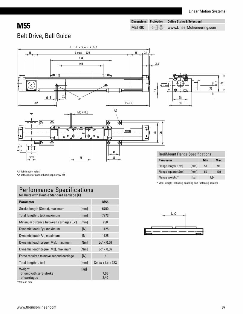
Linear Motion Systems
87www.thomsonlinear.com
M55Belt Drive, Ball Guide
Performance Specificationsfor Units with Double Standard Carriage (C)
Parameter M55
Stroke length (Smax), maximum [mm] 6750
Total length (L tot), maximum [mm] 7373
Minimum distance between carriages (Lc) [mm] 250
Dynamic load (Fy), maximum [N] 1125
Dynamic load (Fz), maximum [N] 1125
Dynamic load torque (My), maximum [Nm] Lc1 × 0,56
Dynamic load torque (Mz), maximum [Nm] Lc1 × 0,56
Force required to move second carriage [N] 2
Total length (L tot] [mm] Smax + Lc + 373
Weight of unit with zero stroke of carriages
[kg]7,062,40
1 Value in mm
A1: lubrication holesA2: ø9,5/ø5,5 for socket head cap screw M5
Dimensions Projection Online Sizing & Selection!
METRIC www.LinearMotioneering.com
RediMount Flange SpecificationsParameter Min Max
Flange length (Lrm) [mm] 57 92
Flange square (Srm) [mm] 60 139
Flange weight * [kg] 1,84
* Max. weight including coupling and fastening screws

88 www.thomsonlinear.com
M75Belt Drive, Ball Guide
Carriage Idle Torque (M idle) [Nm]Input speed [rpm] Single Carriage Double Carriages
150 1,0 1,9
M idle = the input torque needed to move the carriage with no load on it.
Performance Specificationsfor Units with Single Standard Carriage (A)1
Parameter M75
Stroke length (Smax), maximum [mm] 12000
Total length (L tot), maximum [mm] 12368
Linear speed, maximum [m/s] 5,0
Acceleration, maximum [m/s2] 40
Repeatability [± mm] 0,1
Input speed, maximum [rpm] 2300
Operation temperature limits [°C] -20 – 70
Dynamic load (Fx), maximum < 2,5 m/s > 2,5 m/s
[N]900450
Dynamic load (Fy), maximum [N] 1750
Dynamic load (Fz), maximum [N] 1750
Dynamic load torque (Mx), maximum [Nm] 16
Dynamic load torque (My), maximum [Nm] 84
Dynamic load torque (Mz), maximum [Nm] 84
Drive shaft force (Frd), maximum 2 [N] 600
Input/drive shaft torque (Mta), maximum [Nm] 30
Pulley diameter [mm] 41,38
Stroke per shaft revolution [mm] 130
Weight of unit with zero stroke of every 100 mm of stroke of carriage
[kg]7,500,882,00
1 See next page for deviating values of units with other carriage types.2 Only relevant for units without RediMount flange.
General SpecificationsParameter M75 / T75
Profile size (w × h) [mm] 86 × 75
Type of belt STD5-40
Carriage sealing system self-adjusting steel cover band
Adjustable belt tensioning the belt can be retensioned by the customer if necessary
Lubrication lubrication of ball guide carriages
Included accessories none
Deflection of the Profile
Definition of Forces
» Ordering key - see page 204» Accessories - see page 131» Additional data - see page 179
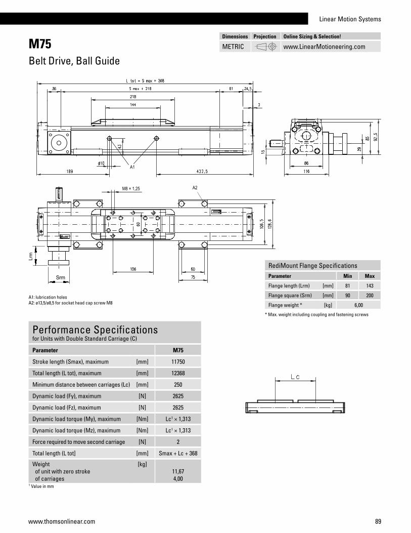
Linear Motion Systems
89www.thomsonlinear.com
M75Belt Drive, Ball Guide
Performance Specificationsfor Units with Double Standard Carriage (C)
Parameter M75
Stroke length (Smax), maximum [mm] 11750
Total length (L tot), maximum [mm] 12368
Minimum distance between carriages (Lc) [mm] 250
Dynamic load (Fy), maximum [N] 2625
Dynamic load (Fz), maximum [N] 2625
Dynamic load torque (My), maximum [Nm] Lc1 × 1,313
Dynamic load torque (Mz), maximum [Nm] Lc1 × 1,313
Force required to move second carriage [N] 2
Total length (L tot] [mm] Smax + Lc + 368
Weight of unit with zero stroke of carriages
[kg]11,674,00
1 Value in mm
A1: lubrication holesA2: ø13,5/ø8,5 for socket head cap screw M8
Dimensions Projection Online Sizing & Selection!
METRIC www.LinearMotioneering.com
RediMount Flange SpecificationsParameter Min Max
Flange length (Lrm) [mm] 81 143
Flange square (Srm) [mm] 90 200
Flange weight * [kg] 6,00
* Max. weight including coupling and fastening screws

90 www.thomsonlinear.com
M100Belt Drive, Ball Guide
Carriage Idle Torque (M idle) [Nm]Input speed [rpm] Single Carriage Double Carriages
150 1,6 3,1
M idle = the input torque needed to move the carriage with no load on it.
Performance Specificationsfor Units with Single Standard Carriage (A)1
Parameter M100
Stroke length (Smax), maximum [mm] 11900
Total length (L tot), maximum [mm] 12361
Linear speed, maximum [m/s] 5,0
Acceleration, maximum [m/s2] 40
Repeatability [± mm] 0,1
Input speed, maximum [rpm] 1700
Operation temperature limits [°C] -20 – 70
Dynamic load (Fx), maximum < 2,5 m/s > 2,5 m/s
[N]1250 625
Dynamic load (Fy), maximum [N] 4000
Dynamic load (Fz), maximum [N] 4000
Dynamic load torque (Mx), maximum [Nm] 43
Dynamic load torque (My), maximum [Nm] 280
Dynamic load torque (Mz), maximum [Nm] 280
Drive shaft force (Frd), maximum 2 [N] 1000
Input/drive shaft torque (Mta), maximum [Nm] 45
Pulley diameter [mm] 56,02
Stroke per shaft revolution [mm] 176
Weight of unit with zero stroke of every 100 mm of stroke of carriage
[kg]11,61 1,43 2,20
1 See next page for deviating values of units with other carriage types.2 Only relevant for units without RediMount flange.
General SpecificationsParameter M100
Profile size (w × h) [mm] 108 × 100
Type of belt STD8-50
Carriage sealing system self-adjusting steel cover band
Adjustable belt tensioning the belt can be retensioned by the customer if necessary
Lubrication lubrication of ball guide carriages
Included accessories none
Deflection of the Profile
Definition of Forces
» Ordering key - see page 204» Accessories - see page 131» Additional data - see page 179

Linear Motion Systems
91www.thomsonlinear.com
M100Belt Drive, Ball Guide
Performance Specificationsfor Units with Double Standard Carriage (C)
Parameter M100
Stroke length (Smax), maximum [mm] 11550
Total length (L tot), maximum [mm] 12361
Minimum distance between carriages (Lc) [mm] 350
Dynamic load (Fy), maximum [N] 6000
Dynamic load (Fz), maximum [N] 6000
Dynamic load torque (My), maximum [Nm] Lc1 × 3
Dynamic load torque (Mz), maximum [Nm] Lc1 × 3
Force required to move second carriage [N] 2
Total length (L tot] [mm] Smax + Lc + 461
Weight of unit with zero stroke of carriages
[kg]18,924,40
1 Value in mm
A1: lubrication hole A2: lubrication hole (no hole if L order is < 856 mm)A3: ø17/ø10,5 for socket head cap screw M10
Dimensions Projection Online Sizing & Selection!
METRIC www.LinearMotioneering.com
RediMount Flange SpecificationsParameter Min Max
Flange length (Lrm) [mm] 81 143
Flange square (Srm) [mm] 90 200
Flange weight * [kg] 6,00
* Max. weight including coupling and fastening screws

92 www.thomsonlinear.com
MLSM80ZBelt Drive, Ball Guide
Performance Specificationsfor Units with Single Standard Carriage (N)1
Parameter MLSM80Z
Stroke length (Smax), maximum [mm] 5900
Total length (L tot), maximum [mm] 6500
Linear speed, maximum [m/s] 5,0
Acceleration, maximum [m/s2] 20
Repeatability [± mm] 0,05
Input speed, maximum [rpm] 1500
Operation temperature limits [°C] 0 – 80
Dynamic load (Fx), maximum [N] 5000 2
Dynamic load (Fy), maximum [N] 6400
Dynamic load (Fz), maximum [N] 6400
Dynamic load torque (Mx), maximum [Nm] 600
Dynamic load torque (My), maximum [Nm] 720
Dynamic load torque (Mz), maximum [Nm] 720
Drive shaft force (Frd), maximum 3 [N] 700
Input/drive shaft torque (Mta), maximum [Nm] 150
Pulley diameter [mm] 63,66
Stroke per shaft revolution [mm] 200
Weight of unit with zero stroke of every 100 mm of stroke of each carriage
[kg]30,8 2,2 9,6
1 See next page for deviating values of units with other carriage types.2 See diagram Force Fx.3 Only relevant for units without RediMount flange.
General SpecificationsParameter MLSM80Z
Profile size (w × h) [mm] 240 × 85
Type of belt 75 ATL 10
Carriage sealing system plastic cover band
Adjustable belt tensioning the belt can be retensioned by the customer if necessary
Lubrication central lubrication of all parts that require lubrication
Included accessories 4 × mounting clamps
Carriage Idle Torque, (M idle) [Nm]Input speed [rpm] Idle torque [Nm]
150 8,5
750 12
1500 14,5
M idle = the input torque needed to move the carriage with no load on it.
Force Fx as a Function of the Speed
Definition of Forces
Deflection of the Profile
A mounting clamp must be installed at least every 750 mm to be able to operate at maximum load. Less clamps may be required if less load is being operated, see the additional technical data for more information.
» Ordering key - see page 205» Accessories - see page 131» Additional data - see page 179
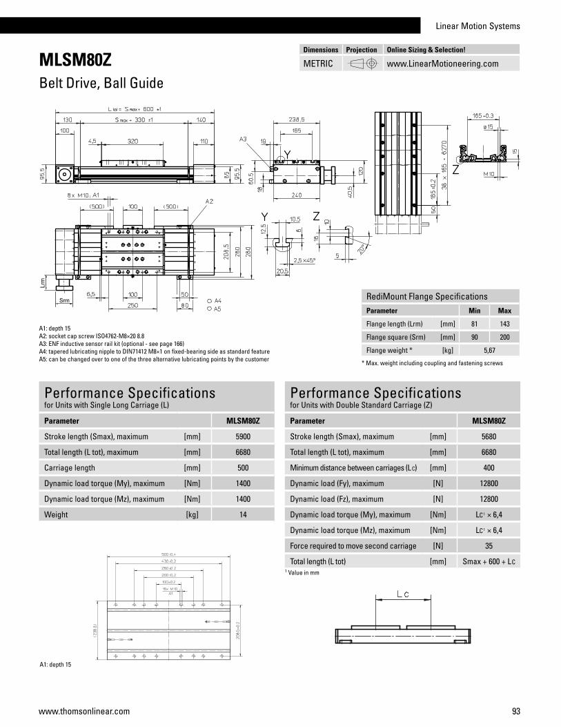
Linear Motion Systems
93www.thomsonlinear.com
MLSM80ZBelt Drive, Ball Guide
Performance Specificationsfor Units with Single Long Carriage (L)
Parameter MLSM80Z
Stroke length (Smax), maximum [mm] 5900
Total length (L tot), maximum [mm] 6680
Carriage length [mm] 500
Dynamic load torque (My), maximum [Nm] 1400
Dynamic load torque (Mz), maximum [Nm] 1400
Weight [kg] 14
A1: depth 15A2: socket cap screw ISO4762-M8×20 8.8A3: ENF inductive sensor rail kit (optional - see page 166)A4: tapered lubricating nipple to DIN71412 M8×1 on fixed-bearing side as standard featureA5: can be changed over to one of the three alternative lubricating points by the customer
Performance Specificationsfor Units with Double Standard Carriage (Z)
Parameter MLSM80Z
Stroke length (Smax), maximum [mm] 5680
Total length (L tot), maximum [mm] 6680
Minimum distance between carriages (L C) [mm] 400
Dynamic load (Fy), maximum [N] 12800
Dynamic load (Fz), maximum [N] 12800
Dynamic load torque (My), maximum [Nm] LC1 × 6,4
Dynamic load torque (Mz), maximum [Nm] LC1 × 6,4
Force required to move second carriage [N] 35
Total length (L tot) [mm] Smax + 600 + LC1 Value in mm
A1: depth 15
Dimensions Projection Online Sizing & Selection!
METRIC www.LinearMotioneering.com
RediMount Flange SpecificationsParameter Min Max
Flange length (Lrm) [mm] 81 143
Flange square (Srm) [mm] 90 200
Flange weight * [kg] 5,67
* Max. weight including coupling and fastening screws
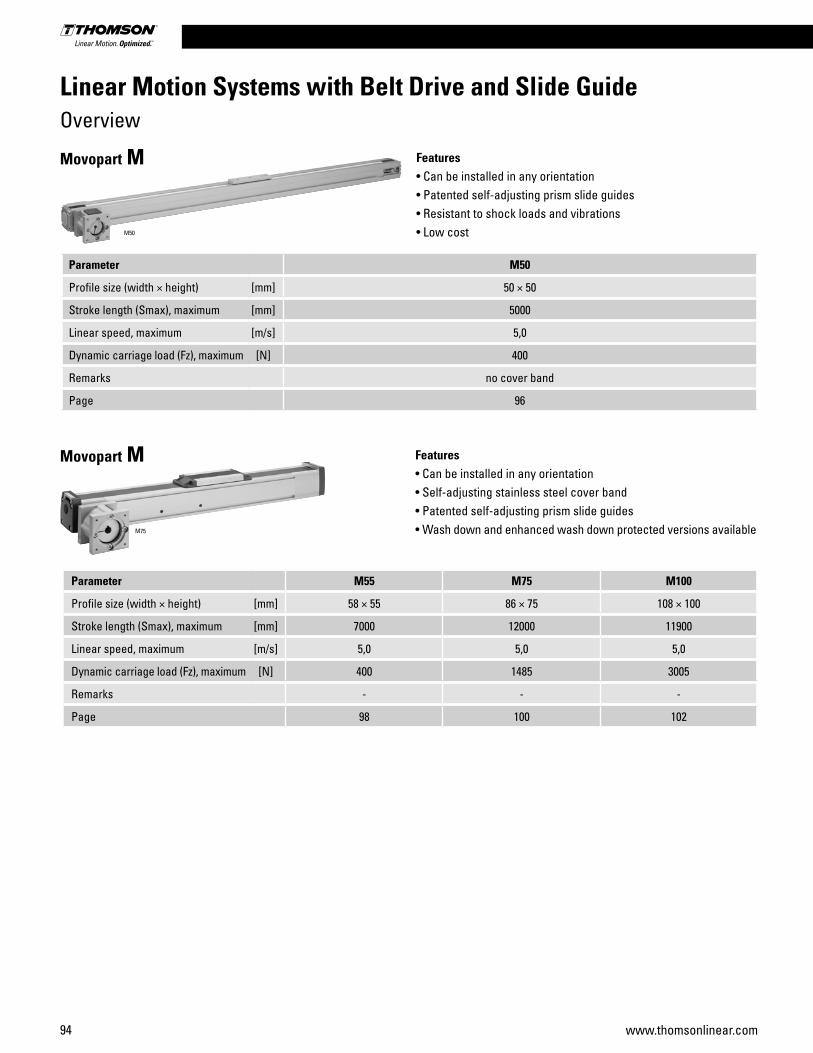
94 www.thomsonlinear.com
Parameter M50
Profile size (width × height) [mm] 50 × 50
Stroke length (Smax), maximum [mm] 5000
Linear speed, maximum [m/s] 5,0
Dynamic carriage load (Fz), maximum [N] 400
Remarks no cover band
Page 96
Features• Can be installed in any orientation• Patented self-adjusting prism slide guides• Resistant to shock loads and vibrations• Low cost
Movopart M
M50
Parameter M55 M75 M100
Profile size (width × height) [mm] 58 × 55 86 × 75 108 × 100
Stroke length (Smax), maximum [mm] 7000 12000 11900
Linear speed, maximum [m/s] 5,0 5,0 5,0
Dynamic carriage load (Fz), maximum [N] 400 1485 3005
Remarks - - -
Page 98 100 102
Features• Can be installed in any orientation• Self-adjusting stainless steel cover band • Patented self-adjusting prism slide guides• Wash down and enhanced wash down protected versions available
Movopart M
M75
Linear Motion Systems with Belt Drive and Slide GuideOverview
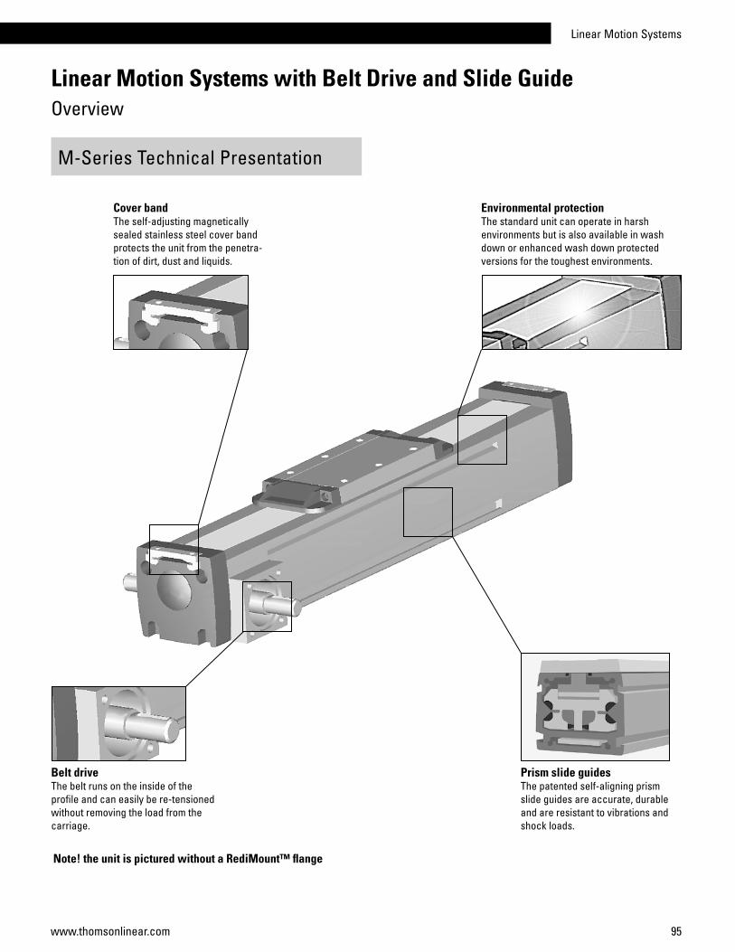
Linear Motion Systems
95www.thomsonlinear.com
M-Series Technical Presentation
Cover bandThe self-adjusting magnetically sealed stainless steel cover band protects the unit from the penetra-tion of dirt, dust and liquids.
Environmental protectionThe standard unit can operate in harsh environments but is also available in wash down or enhanced wash down protected versions for the toughest environments.
Belt driveThe belt runs on the inside of the profile and can easily be re-tensioned without removing the load from the carriage.
Prism slide guidesThe patented self-aligning prism slide guides are accurate, durable and are resistant to vibrations and shock loads.
Linear Motion Systems with Belt Drive and Slide GuideOverview
Note! the unit is pictured without a RediMount™ flange

96 www.thomsonlinear.com
M50Belt Drive, Slide Guide
Performance Specificationsfor Units with Single Standard Carriage (A00)
Parameter M50
Stroke length (Smax), maximum [mm] 5000
Total length (L tot), maximum [mm] 5296
Linear speed, maximum [m/s] 5,0
Acceleration, maximum [m/s2] 40
Repeatability [± mm] 0,2
Input speed, maximum [rpm] 2300
Operation temperature limits [°C] -20 – 70
Dynamic load (Fx), maximum < 2,5 m/s > 2,5 m/s
[N]400200
Dynamic load (Fy), maximum [N] 400
Dynamic load (Fz), maximum [N] 400
Dynamic load torque (Mx), maximum [Nm] 5
Dynamic load torque (My), maximum [Nm] 21
Dynamic load torque (Mz), maximum [Nm] 21
Drive shaft force (Frd), maximum 1 [N] 350
Input/drive shaft torque (Mta), maximum [Nm] 10
Pulley diameter [mm] 41,38
Stroke per shaft revolution [mm] 130
Weight of unit with zero stroke of every 100 mm of stroke of carriage
[kg]0,710,960,33
1 Only relevant for units without RediMount flange.
General SpecificationsParameter M50
Profile size (w × h) [mm] 50 × 50
Type of belt GT 5MR-19
Carriage sealing system none
Adjustable belt tensioning the belt can be retensioned by the customer if necessary
Lubrication lubricated for life
Included accessories none
Carriage Idle Torque (M idle) [Nm]Input speed [rpm] Idle torque [Nm]
150 2,1
M idle = the input torque needed to move the carriage with no load on it.
Deflection of the Profile
Definition of Forces
» Ordering key - see page 206» Accessories - see page 131» Additional data - see page 180

Linear Motion Systems
97www.thomsonlinear.com
M50Belt Drive, Slide Guide
A1: ø6,5 for M6 screwA2: depth 9, Heli coil
Dimensions Projection Online Sizing & Selection!
METRIC www.LinearMotioneering.com
RediMount Flange SpecificationsParameter Min Max
Flange length (Lrm) [mm] 57 92
Flange square (Srm) [mm] 60 139
Flange weight * [kg] 1,84
* Max. weight including coupling and fastening screws

98 www.thomsonlinear.com
M55Belt Drive, Slide Guide
Performance Specificationsfor Units with Single Standard Carriage (A)1
Parameter M55
Stroke length (Smax), maximum [mm] 7000
Total length (L tot), maximum [mm] 7313
Linear speed, maximum [m/s] 5,0
Acceleration, maximum [m/s2] 40
Repeatability [± mm] 0,2
Input speed, maximum [rpm] 2850
Operation temperature limits [°C] -20 – 70
Dynamic load (Fx), maximum < 2,5 m/s > 2,5 m/s
[N]400200
Dynamic load (Fy), maximum [N] 400
Dynamic load (Fz), maximum [N] 400
Dynamic load torque (Mx), maximum [Nm] 9
Dynamic load torque (My), maximum [Nm] 21
Dynamic load torque (Mz), maximum [Nm] 21
Drive shaft force (Frd), maximum 2 [N] 200
Input/drive shaft torque (Mta), maximum [Nm] 7
Pulley diameter [mm] 33,42
Stroke per shaft revolution [mm] 105
Weight of unit with zero stroke of every 100 mm of stroke of carriage
[kg]4,100,411,10
1 See next page for deviating values of units with other carriage types.2 Only relevant for units without RediMount flange.
General SpecificationsParameter M55
Profile size (w × h) [mm] 58 × 50
Type of belt 22-STD SM5-HP
Carriage sealing system self-adjusting steel cover band
Adjustable belt tensioning the belt can be retensioned by the customer if necessary
Lubrication lubricated for life
Included accessories none
Carriage Idle Torque (M idle) [Nm]Input speed [rpm] Single Carriage Double Carriages
150 2,1 3,8
M idle = the input torque needed to move the carriage with no load on it.
Deflection of the Profile
Definition of Forces
» Ordering key - see page 206» Accessories - see page 131» Additional data - see page 180
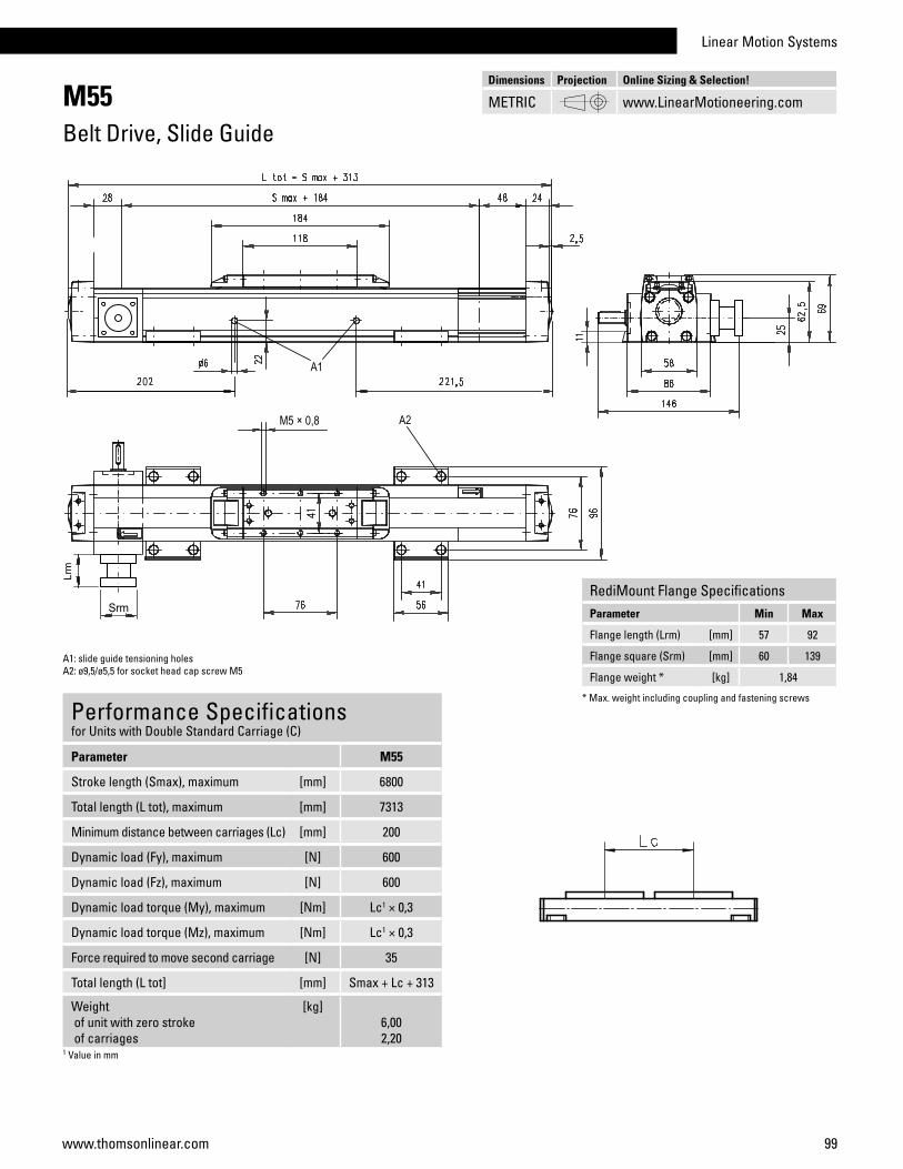
Linear Motion Systems
99www.thomsonlinear.com
M55Belt Drive, Slide Guide
Performance Specificationsfor Units with Double Standard Carriage (C)
Parameter M55
Stroke length (Smax), maximum [mm] 6800
Total length (L tot), maximum [mm] 7313
Minimum distance between carriages (Lc) [mm] 200
Dynamic load (Fy), maximum [N] 600
Dynamic load (Fz), maximum [N] 600
Dynamic load torque (My), maximum [Nm] Lc1 × 0,3
Dynamic load torque (Mz), maximum [Nm] Lc1 × 0,3
Force required to move second carriage [N] 35
Total length (L tot] [mm] Smax + Lc + 313
Weight of unit with zero stroke of carriages
[kg]6,002,20
1 Value in mm
A1: slide guide tensioning holesA2: ø9,5/ø5,5 for socket head cap screw M5
Dimensions Projection Online Sizing & Selection!
METRIC www.LinearMotioneering.com
RediMount Flange SpecificationsParameter Min Max
Flange length (Lrm) [mm] 57 92
Flange square (Srm) [mm] 60 139
Flange weight * [kg] 1,84
* Max. weight including coupling and fastening screws
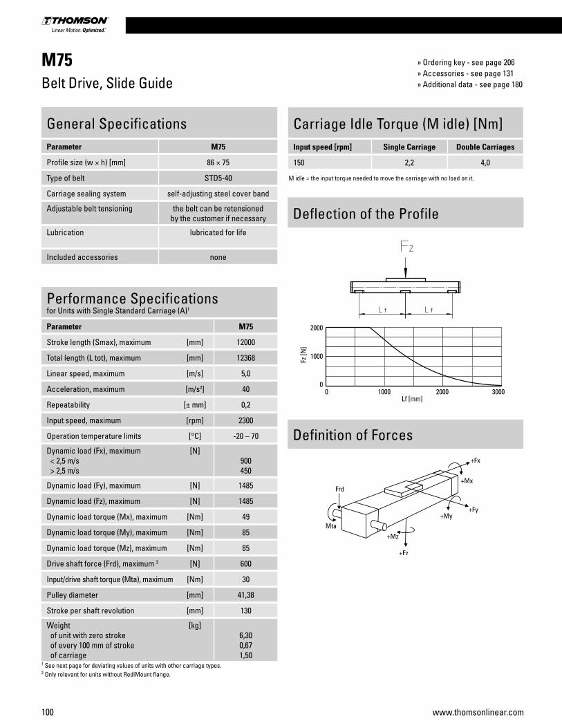
100 www.thomsonlinear.com
M75Belt Drive, Slide Guide
Performance Specificationsfor Units with Single Standard Carriage (A)1
Parameter M75
Stroke length (Smax), maximum [mm] 12000
Total length (L tot), maximum [mm] 12368
Linear speed, maximum [m/s] 5,0
Acceleration, maximum [m/s2] 40
Repeatability [± mm] 0,2
Input speed, maximum [rpm] 2300
Operation temperature limits [°C] -20 – 70
Dynamic load (Fx), maximum < 2,5 m/s > 2,5 m/s
[N]900450
Dynamic load (Fy), maximum [N] 1485
Dynamic load (Fz), maximum [N] 1485
Dynamic load torque (Mx), maximum [Nm] 49
Dynamic load torque (My), maximum [Nm] 85
Dynamic load torque (Mz), maximum [Nm] 85
Drive shaft force (Frd), maximum 2 [N] 600
Input/drive shaft torque (Mta), maximum [Nm] 30
Pulley diameter [mm] 41,38
Stroke per shaft revolution [mm] 130
Weight of unit with zero stroke of every 100 mm of stroke of carriage
[kg]6,300,671,50
1 See next page for deviating values of units with other carriage types.2 Only relevant for units without RediMount flange.
General SpecificationsParameter M75
Profile size (w × h) [mm] 86 × 75
Type of belt STD5-40
Carriage sealing system self-adjusting steel cover band
Adjustable belt tensioning the belt can be retensioned by the customer if necessary
Lubrication lubricated for life
Included accessories none
Carriage Idle Torque (M idle) [Nm]Input speed [rpm] Single Carriage Double Carriages
150 2,2 4,0
M idle = the input torque needed to move the carriage with no load on it.
Deflection of the Profile
Definition of Forces
» Ordering key - see page 206» Accessories - see page 131» Additional data - see page 180

Linear Motion Systems
101www.thomsonlinear.com
M75Belt Drive, Slide Guide
Performance Specificationsfor Units with Double Standard Carriage (C)
Parameter M75
Stroke length (Smax), maximum [mm] 11750
Total length (L tot), maximum [mm] 12368
Minimum distance between carriages (Lc) [mm] 250
Dynamic load (Fy), maximum [N] 2227
Dynamic load (Fz), maximum [N] 2227
Dynamic load torque (My), maximum [Nm] Lc1 × 1,114
Dynamic load torque (Mz), maximum [Nm] Lc1 × 1,114
Force required to move second carriage [N] 40
Total length (L tot] [mm] Smax + Lc + 368
Weight of unit with zero stroke of carriages
[kg]9,503,00
1 Value in mm
A1: slide guide tensioning holesA2: ø13,5/ø8,5 for socket head cap screw M8
Dimensions Projection Online Sizing & Selection!
METRIC www.LinearMotioneering.com
RediMount Flange SpecificationsParameter Min Max
Flange length (Lrm) [mm] 81 143
Flange square (Srm) [mm] 90 200
Flange weight * [kg] 6,00
* Max. weight including coupling and fastening screws
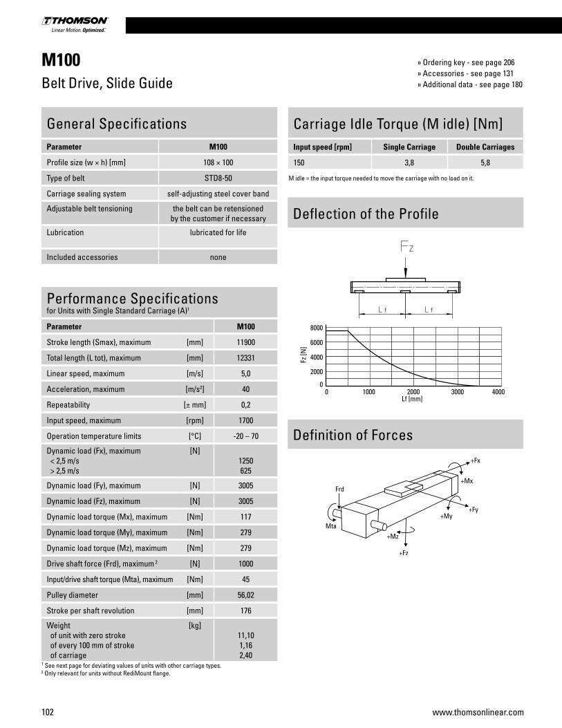
102 www.thomsonlinear.com
M100Belt Drive, Slide Guide
Performance Specificationsfor Units with Single Standard Carriage (A)1
Parameter M100
Stroke length (Smax), maximum [mm] 11900
Total length (L tot), maximum [mm] 12331
Linear speed, maximum [m/s] 5,0
Acceleration, maximum [m/s2] 40
Repeatability [± mm] 0,2
Input speed, maximum [rpm] 1700
Operation temperature limits [°C] -20 – 70
Dynamic load (Fx), maximum < 2,5 m/s > 2,5 m/s
[N]1250625
Dynamic load (Fy), maximum [N] 3005
Dynamic load (Fz), maximum [N] 3005
Dynamic load torque (Mx), maximum [Nm] 117
Dynamic load torque (My), maximum [Nm] 279
Dynamic load torque (Mz), maximum [Nm] 279
Drive shaft force (Frd), maximum 2 [N] 1000
Input/drive shaft torque (Mta), maximum [Nm] 45
Pulley diameter [mm] 56,02
Stroke per shaft revolution [mm] 176
Weight of unit with zero stroke of every 100 mm of stroke of carriage
[kg]11,101,162,40
1 See next page for deviating values of units with other carriage types.2 Only relevant for units without RediMount flange.
General SpecificationsParameter M100
Profile size (w × h) [mm] 108 × 100
Type of belt STD8-50
Carriage sealing system self-adjusting steel cover band
Adjustable belt tensioning the belt can be retensioned by the customer if necessary
Lubrication lubricated for life
Included accessories none
Carriage Idle Torque (M idle) [Nm]Input speed [rpm] Single Carriage Double Carriages
150 3,8 5,8
M idle = the input torque needed to move the carriage with no load on it.
Deflection of the Profile
Definition of Forces
» Ordering key - see page 206» Accessories - see page 131» Additional data - see page 180
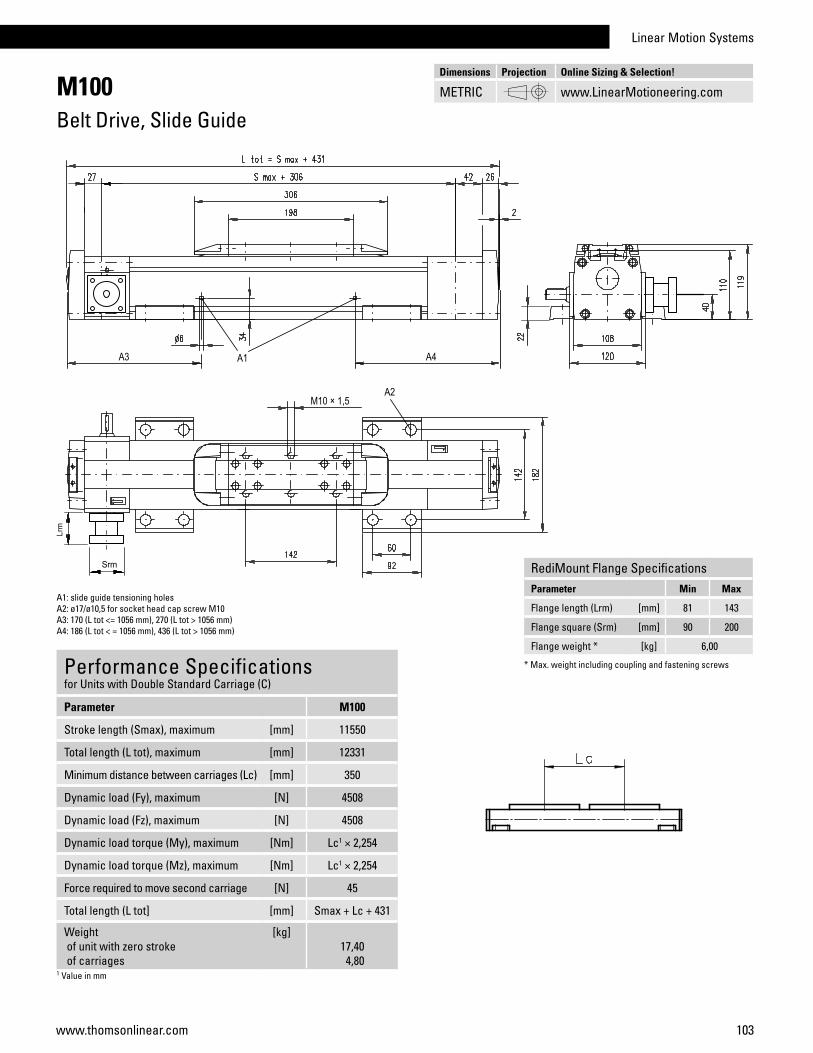
Linear Motion Systems
103www.thomsonlinear.com
M100Belt Drive, Slide Guide
Performance Specificationsfor Units with Double Standard Carriage (C)
Parameter M100
Stroke length (Smax), maximum [mm] 11550
Total length (L tot), maximum [mm] 12331
Minimum distance between carriages (Lc) [mm] 350
Dynamic load (Fy), maximum [N] 4508
Dynamic load (Fz), maximum [N] 4508
Dynamic load torque (My), maximum [Nm] Lc1 × 2,254
Dynamic load torque (Mz), maximum [Nm] Lc1 × 2,254
Force required to move second carriage [N] 45
Total length (L tot] [mm] Smax + Lc + 431
Weight of unit with zero stroke of carriages
[kg]17,40 4,80
1 Value in mm
A1: slide guide tensioning holesA2: ø17/ø10,5 for socket head cap screw M10A3: 170 (L tot <= 1056 mm), 270 (L tot > 1056 mm)A4: 186 (L tot < = 1056 mm), 436 (L tot > 1056 mm)
Dimensions Projection Online Sizing & Selection!
METRIC www.LinearMotioneering.com
RediMount Flange SpecificationsParameter Min Max
Flange length (Lrm) [mm] 81 143
Flange square (Srm) [mm] 90 200
Flange weight * [kg] 6,00
* Max. weight including coupling and fastening screws

104 www.thomsonlinear.com
Belt driveThe steel reinforced belt is wear resistant, highly efficient and very accurate even at high speeds and loads.
Parameter WH50 WH80 WH120
Profile size (width × height) [mm] 50 × 50 80 × 80 120 × 110
Stroke length (Smax), maximum [mm] 3000 11000 11000
Linear speed, maximum [m/s] 6,5 10,0 10,0
Dynamic carriage load (Fz), maximum [N] 730 2100 9300
Remarks external wheel guidesno cover band
external wheel guidesno cover band
external wheel guidesno cover band
Page 106 108 110
Features• Can be installed in any orientation• Speed up to 11 m/s and stroke up to 11 m• Acceleration up to 40 m/s2
• Felt pad wipers cleaning the guides as standard
SpeedLine WH
WH80
WH-Series Technical Presentation
Belt tensioningThe belt can easily be replaced or re-tensioned from the outside of the unit without the load being removed from the carriage.
Wheel guidesThe H-type arrangement of the guides allows fast moves and high forces and moments.
Central lubricationThe guides are lubricated from a central point that is easy and fast to access.
Linear Units with Belt Drive and Wheel Guide Overview
Note! the unit is pictured without a RediMount™ flange

Linear Motion Systems
105www.thomsonlinear.com
Parameter MLSH60Z
Profile size (width × height) [mm] 160 × 65
Stroke length (Smax), maximum [mm] 5500
Linear speed, maximum [m/s] 10,0
Dynamic carriage load (Fz), maximum [N] 3000
Remarks internal wheel guides
Page 112
Features• Can be installed in any orientation• Patented plastic cover band• Speed up to 10 m/s• Low profile height
ForceLine MLSH
MLSH60Z
Cover bandThe patented cover band protects the interior of the unit from the penetration of dirt, dust and liquids.
Belt tensioningThe belt can easily be re-tensioned from the outside of the unit without the load being removed from the carriage.
Wheel guidesThe robust wheel guides run inside of the profile providing superior motion dynamics.
Unique profileThe unique design of the profile guarantees the highest performance and protection of the guides and belt.
MLSH-Series Technical Presentation
Belt driveThe highly dynamic and accurate belt is protected by the cover band ensuring long and trouble free operation.
Linear Units with Belt Drive and Wheel Guide Overview
Note! the unit is pictured without a RediMount™ flange
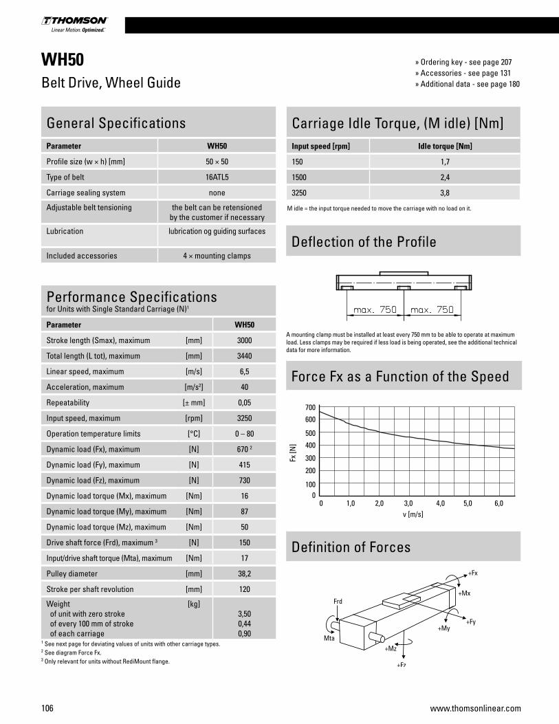
106 www.thomsonlinear.com
WH50Belt Drive, Wheel Guide
Performance Specificationsfor Units with Single Standard Carriage (N)1
Parameter WH50
Stroke length (Smax), maximum [mm] 3000
Total length (L tot), maximum [mm] 3440
Linear speed, maximum [m/s] 6,5
Acceleration, maximum [m/s2] 40
Repeatability [± mm] 0,05
Input speed, maximum [rpm] 3250
Operation temperature limits [°C] 0 – 80
Dynamic load (Fx), maximum [N] 670 2
Dynamic load (Fy), maximum [N] 415
Dynamic load (Fz), maximum [N] 730
Dynamic load torque (Mx), maximum [Nm] 16
Dynamic load torque (My), maximum [Nm] 87
Dynamic load torque (Mz), maximum [Nm] 50
Drive shaft force (Frd), maximum 3 [N] 150
Input/drive shaft torque (Mta), maximum [Nm] 17
Pulley diameter [mm] 38,2
Stroke per shaft revolution [mm] 120
Weight of unit with zero stroke of every 100 mm of stroke of each carriage
[kg]3,500,440,90
1 See next page for deviating values of units with other carriage types.2 See diagram Force Fx.3 Only relevant for units without RediMount flange.
General SpecificationsParameter WH50
Profile size (w × h) [mm] 50 × 50
Type of belt 16ATL5
Carriage sealing system none
Adjustable belt tensioning the belt can be retensioned by the customer if necessary
Lubrication lubrication og guiding surfaces
Included accessories 4 × mounting clamps
Carriage Idle Torque, (M idle) [Nm]Input speed [rpm] Idle torque [Nm]
150 1,7
1500 2,4
3250 3,8
M idle = the input torque needed to move the carriage with no load on it.
Force Fx as a Function of the Speed
Definition of Forces
Deflection of the Profile
A mounting clamp must be installed at least every 750 mm to be able to operate at maximum load. Less clamps may be required if less load is being operated, see the additional technical data for more information.
» Ordering key - see page 207» Accessories - see page 131» Additional data - see page 180
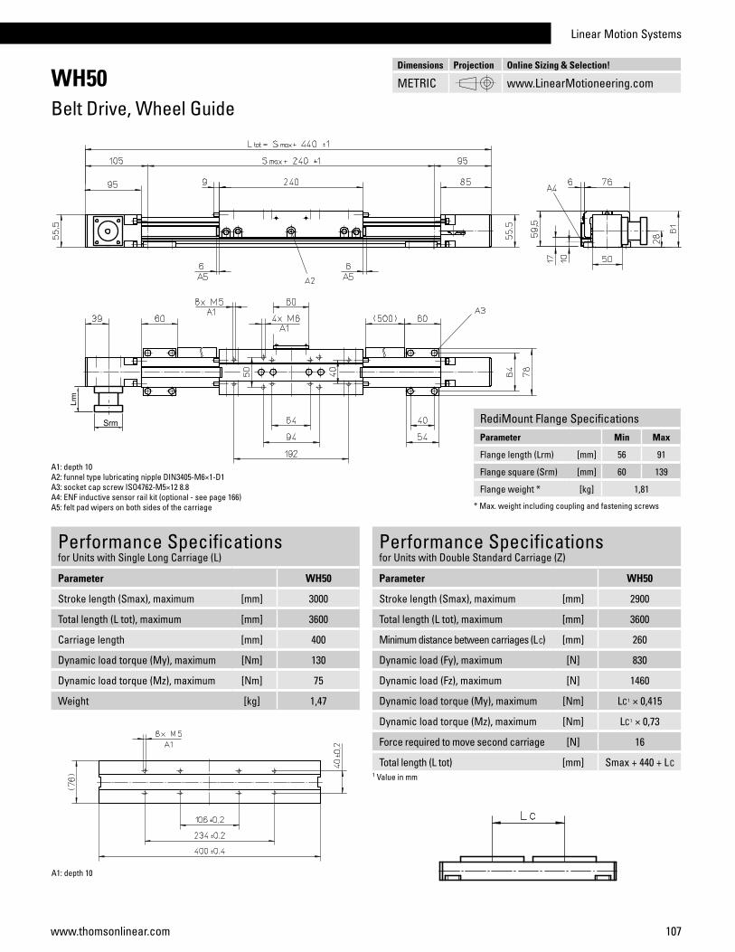
Linear Motion Systems
107www.thomsonlinear.com
WH50Belt Drive, Wheel Guide
Performance Specificationsfor Units with Single Long Carriage (L)
Parameter WH50
Stroke length (Smax), maximum [mm] 3000
Total length (L tot), maximum [mm] 3600
Carriage length [mm] 400
Dynamic load torque (My), maximum [Nm] 130
Dynamic load torque (Mz), maximum [Nm] 75
Weight [kg] 1,47
A1: depth 10A2: funnel type lubricating nipple DIN3405-M6×1-D1A3: socket cap screw ISO4762-M5×12 8.8A4: ENF inductive sensor rail kit (optional - see page 166)A5: felt pad wipers on both sides of the carriage
Performance Specificationsfor Units with Double Standard Carriage (Z)
Parameter WH50
Stroke length (Smax), maximum [mm] 2900
Total length (L tot), maximum [mm] 3600
Minimum distance between carriages (L C) [mm] 260
Dynamic load (Fy), maximum [N] 830
Dynamic load (Fz), maximum [N] 1460
Dynamic load torque (My), maximum [Nm] LC1 × 0,415
Dynamic load torque (Mz), maximum [Nm] LC1 × 0,73
Force required to move second carriage [N] 16
Total length (L tot) [mm] Smax + 440 + LC1 Value in mm
A1: depth 10
Dimensions Projection Online Sizing & Selection!
METRIC www.LinearMotioneering.com
RediMount Flange SpecificationsParameter Min Max
Flange length (Lrm) [mm] 56 91
Flange square (Srm) [mm] 60 139
Flange weight * [kg] 1,81
* Max. weight including coupling and fastening screws
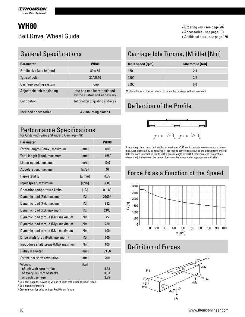
108 www.thomsonlinear.com
WH80Belt Drive, Wheel Guide
Performance Specificationsfor Units with Single Standard Carriage (N)1
Parameter WH80
Stroke length (Smax), maximum [mm] 11000
Total length (L tot), maximum [mm] 11550
Linear speed, maximum [m/s] 10,0
Acceleration, maximum [m/s2] 40
Repeatability [± mm] 0,05
Input speed, maximum [rpm] 3000
Operation temperature limits [°C] 0 – 80
Dynamic load (Fx), maximum [N] 2700 2
Dynamic load (Fy), maximum [N] 882
Dynamic load (Fz), maximum [N] 2100
Dynamic load torque (Mx), maximum [Nm] 75
Dynamic load torque (My), maximum [Nm] 230
Dynamic load torque (Mz), maximum [Nm] 100
Drive shaft force (Frd), maximum 3 [N] 500
Input/drive shaft torque (Mta), maximum [Nm] 100
Pulley diameter [mm] 63,66
Stroke per shaft revolution [mm] 200
Weight of unit with zero stroke of every 100 mm of stroke of each carriage
[kg]8,630,932,75
1 See next page for deviating values of units with other carriage types.2 See diagram Force Fx.3 Only relevant for units without RediMount flange.
General SpecificationsParameter WH80
Profile size (w × h) [mm] 80 × 80
Type of belt 32ATL10
Carriage sealing system none
Adjustable belt tensioning the belt can be retensioned by the customer if necessary
Lubrication lubrication of guiding surfaces
Included accessories 4 × mounting clamps
Carriage Idle Torque, (M idle) [Nm]Input speed [rpm] Idle torque [Nm]
150 2,4
1500 3,5
3000 5,0
M idle = the input torque needed to move the carriage with no load on it.
Force Fx as a Function of the Speed
Definition of Forces
Deflection of the Profile
A mounting clamp must be installed at least every 750 mm to be able to operate at maximum load. Less clamps may be required if less load is being operated, see the additional technical data for more information. Units with a profile length over 6300 mm consist of two profiles where the joint between the two profiles must be adequately supported on both sides.
» Ordering key - see page 207» Accessories - see page 131» Additional data - see page 180
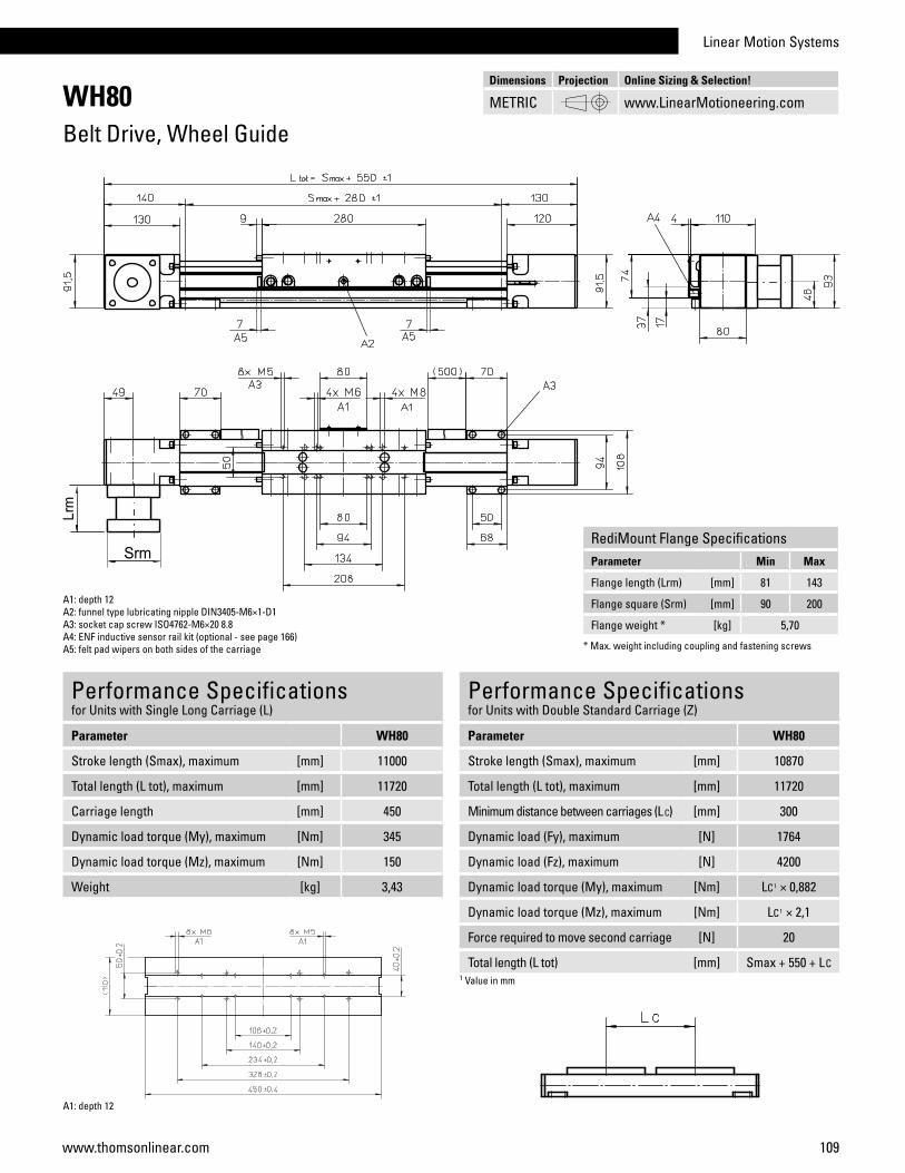
Linear Motion Systems
109www.thomsonlinear.com
WH80Belt Drive, Wheel Guide
Performance Specificationsfor Units with Single Long Carriage (L)
Parameter WH80
Stroke length (Smax), maximum [mm] 11000
Total length (L tot), maximum [mm] 11720
Carriage length [mm] 450
Dynamic load torque (My), maximum [Nm] 345
Dynamic load torque (Mz), maximum [Nm] 150
Weight [kg] 3,43
A1: depth 12A2: funnel type lubricating nipple DIN3405-M6×1-D1A3: socket cap screw ISO4762-M6×20 8.8A4: ENF inductive sensor rail kit (optional - see page 166)A5: felt pad wipers on both sides of the carriage
Performance Specificationsfor Units with Double Standard Carriage (Z)
Parameter WH80
Stroke length (Smax), maximum [mm] 10870
Total length (L tot), maximum [mm] 11720
Minimum distance between carriages (L C) [mm] 300
Dynamic load (Fy), maximum [N] 1764
Dynamic load (Fz), maximum [N] 4200
Dynamic load torque (My), maximum [Nm] LC1 × 0,882
Dynamic load torque (Mz), maximum [Nm] LC1 × 2,1
Force required to move second carriage [N] 20
Total length (L tot) [mm] Smax + 550 + LC1 Value in mm
A1: depth 12
Dimensions Projection Online Sizing & Selection!
METRIC www.LinearMotioneering.com
RediMount Flange SpecificationsParameter Min Max
Flange length (Lrm) [mm] 81 143
Flange square (Srm) [mm] 90 200
Flange weight * [kg] 5,70
* Max. weight including coupling and fastening screws

110 www.thomsonlinear.com
WH120Belt Drive, Wheel Guide
Performance Specificationsfor Units with Single Standard Carriage (N)1
Parameter WH120
Stroke length (Smax), maximum [mm] 11000
Total length (L tot), maximum [mm] 11605
Linear speed, maximum [m/s] 10,0
Acceleration, maximum [m/s2] 40
Repeatability [± mm] 0,05
Input speed, maximum [rpm] 2308
Operation temperature limits [°C] 0 – 80
Dynamic load (Fx), maximum [N] 5000 2
Dynamic load (Fy), maximum [N] 4980
Dynamic load (Fz), maximum [N] 9300
Dynamic load torque (Mx), maximum [Nm] 500
Dynamic load torque (My), maximum [Nm] 930
Dynamic load torque (Mz), maximum [Nm] 500
Drive shaft force (Frd), maximum 3 [N] 700
Input/drive shaft torque (Mta), maximum [Nm] 200
Pulley diameter [mm] 82,76
Stroke per shaft revolution [mm] 260
Weight of unit with zero stroke of every 100 mm of stroke of each carriage
[kg]17,00 1,64 5,50
1 See next page for deviating values of units with other carriage types.2 See diagram Force Fx.2 Only relevant for units without RediMount flange.
General SpecificationsParameter WH120
Profile size (w × h) [mm] 120 × 110
Type of belt 50ATL10
Carriage sealing system none
Adjustable belt tensioning the belt can be retensioned by the customer if necessary
Lubrication lubrication og guiding surfaces
Included accessories 4 × mounting clamps
Carriage Idle Torque, (M idle) [Nm]Input speed [rpm] Idle torque [Nm]
150 4,8
1500 7,0
2308 10,0
M idle = the input torque needed to move the carriage with no load on it.
Force Fx as a Function of the Speed
Definition of Forces
Deflection of the Profile
A mounting clamp must be installed at least every 750 mm to be able to operate at maximum load. Less clamps may be required if less load is being operated, see the additional technical data for more information. Units with a profile length over 4900 mm consist of two profiles where the joint between the two profiles must be adequately supported on both sides.
» Ordering key - see page 207» Accessories - see page 131» Additional data - see page 180
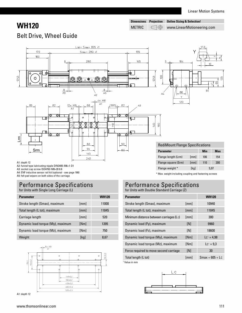
Linear Motion Systems
111www.thomsonlinear.com
WH120Belt Drive, Wheel Guide
Performance Specificationsfor Units with Single Long Carriage (L)
Parameter WH120
Stroke length (Smax), maximum [mm] 11000
Total length (L tot), maximum [mm] 11845
Carriage length [mm] 520
Dynamic load torque (My), maximum [Nm] 1395
Dynamic load torque (Mz), maximum [Nm] 750
Weight [kg] 8,67
A1: depth 12A2: funnel type lubricating nipple DIN3405-M6×1-D1A3: socket cap screw ISO4762-M8×20 8.8A4: ENF inductive sensor rail kit (optional - see page 166)A5: felt pad wipers on both sides of the carriage
Performance Specificationsfor Units with Double Standard Carriage (Z)
Parameter WH120
Stroke length (Smax), maximum [mm] 10940
Total length (L tot), maximum [mm] 11845
Minimum distance between carriages (L C) [mm] 300
Dynamic load (Fy), maximum [N] 9960
Dynamic load (Fz), maximum [N] 18600
Dynamic load torque (My), maximum [Nm] LC1 × 4,98
Dynamic load torque (Mz), maximum [Nm] LC1 × 9,3
Force required to move second carriage [N] 30
Total length (L tot) [mm] Smax + 605 + LC1 Value in mm
A1: depth 12
Dimensions Projection Online Sizing & Selection!
METRIC www.LinearMotioneering.com
RediMount Flange SpecificationsParameter Min Max
Flange length (Lrm) [mm] 106 154
Flange square (Srm) [mm] 110 200
Flange weight * [kg] 5,97
* Max. weight including coupling and fastening screws

112 www.thomsonlinear.com
MLSH60ZBelt Drive, Wheel Guide
Performance Specificationsfor Units with Single Standard Carriage (N)1
Parameter MLSH60Z
Stroke length (Smax), maximum [mm] 5500
Total length (L tot), maximum [mm] 5980
Linear speed, maximum [m/s] 6,5
Acceleration, maximum [m/s2] 40
Repeatability [± mm] 0,05
Input speed, maximum [rpm] 3000
Operation temperature limits [°C] 0 – 80
Dynamic load (Fx), maximum [N] 1480 2
Dynamic load (Fy), maximum [N] 3000
Dynamic load (Fz), maximum [N] 3000
Dynamic load torque (Mx), maximum [Nm] 165
Dynamic load torque (My), maximum [Nm] 310
Dynamic load torque (Mz), maximum [Nm] 310
Drive shaft force (Frd), maximum 3 [N] 200
Input/drive shaft torque (Mta), maximum [Nm] 45
Pulley diameter [mm] 42,97
Stroke per shaft revolution [mm] 135
Weight of unit with zero stroke of every 100 mm of stroke of each carriage
[kg]12,60 1,33 3,90
1 See next page for deviating values of units with other carriage types.2 See diagram Force Fx.3 Only relevant for units without RediMount flange.
General SpecificationsParameter MLSH60Z
Profile size (w × h) [mm] 160 × 65
Type of belt 32ATL5
Carriage sealing system plastic cover band
Adjustable belt tensioning the belt can be retensioned by the customer if necessary
Lubrication no lubrication required
Included accessories 4 × mounting clamps
Carriage Idle Torque, (M idle) [Nm]Input speed [rpm] Idle torque [Nm]
150 4,6
1500 9,0
3000 12,0
M idle = the input torque needed to move the carriage with no load on it.
Force Fx as a Function of the Speed
Definition of Forces
Deflection of the Profile
A mounting clamp must be installed at least every 750 mm to be able to operate at maximum load. Less clamps may be required if less load is being operated, see the additional technical data for more information.
» Ordering key - see page 208» Accessories - see page 131» Additional data - see page 180

Linear Motion Systems
113www.thomsonlinear.com
MLSH60ZBelt Drive, Wheel Guide
Performance Specificationsfor Units with Single Long Carriage (L)
Parameter MLSH60Z
Stroke length (Smax), maximum [mm] 5500
Total length (L tot), maximum [mm] 6150
Carriage length [mm] 450
Dynamic load torque (My), maximum [Nm] 585
Dynamic load torque (Mz), maximum [Nm] 585
Weight [kg] 6
A1: depth 10A2: depth 4A3: socket cap screw ISO4762-M6x20 8.8A4: ENF inductive sensor rail kit (optional - see page 166)
Performance Specificationsfor Units with Double Standard Carriage (Z)
Parameter MLSH60Z
Stroke length (Smax), maximum [mm] 5380
Total length (L tot), maximum [mm] 6150
Minimum distance between carriages (L C) [mm] 290
Dynamic load (Fy), maximum [N] 6000
Dynamic load (Fz), maximum [N] 6000
Dynamic load torque (My), maximum [Nm] LC1 × 3
Dynamic load torque (Mz), maximum [Nm] LC1 × 3
Force required to move second carriage [N] 10
Total length (L tot) [mm] Smax + 480 + LC1 Value in mm
A1: depth 10
Dimensions Projection Online Sizing & Selection!
METRIC www.LinearMotioneering.com
RediMount Flange SpecificationsParameter Min Max
Flange length (Lrm) [mm] 81 143
Flange square (Srm) [mm] 90 200
Flange weight * [kg] 5,58
* Max. weight including coupling and fastening screws

114 www.thomsonlinear.com
Parameter WHZ50 WHZ80
Profile size (width × length) [mm] 50 × 50 80 × 80
Stroke length (Smax), maximum [mm] 1500 3000
Linear speed, maximum [m/s] 6,5 10,0
Dynamic load (Fx), maximum [N] 670 1480
Remarks The load is always attached to the end of the lifting profile
The load is always attached to the end of the lifting profile
Page 116 118
SpeedLine WHZ Features• Can be installed in any orientation• Belt drive• External wheel guides• Speed up to 10 m/s• Acceleration up to 40 m/s2
WHZ50
Linear Lifting UnitsOverview
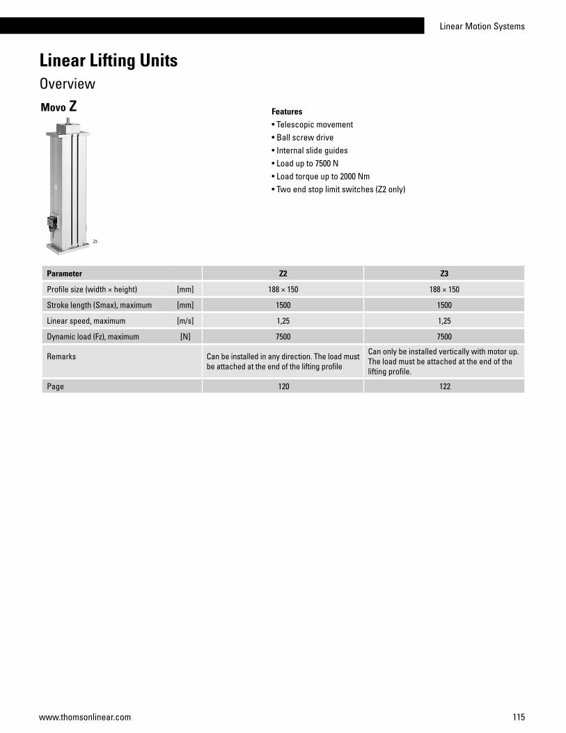
Linear Motion Systems
115www.thomsonlinear.com
Parameter Z2 Z3
Profile size (width × height) [mm] 188 × 150 188 × 150
Stroke length (Smax), maximum [mm] 1500 1500
Linear speed, maximum [m/s] 1,25 1,25
Dynamic load (Fz), maximum [N] 7500 7500
Remarks Can be installed in any direction. The load must be attached at the end of the lifting profile
Can only be installed vertically with motor up. The load must be attached at the end of the lifting profile.
Page 120 122
Features• Telescopic movement• Ball screw drive• Internal slide guides• Load up to 7500 N• Load torque up to 2000 Nm• Two end stop limit switches (Z2 only)
Movo Z
Z2
Linear Lifting UnitsOverview

116 www.thomsonlinear.com
WHZ50Belt Drive, Wheel Guide
Performance Specificationsfor Units with Single Standard Carriage (N)1
Parameter WHZ50
Stroke length (Smax), maximum [mm] 1500
Total length (L tot), maximum [mm] 1850
Linear speed, maximum [m/s] 6,5
Acceleration, maximum [m/s2] 40
Repeatability [± mm] 0,05
Input speed, maximum [rpm] 3250
Operation temperature limits [°C] 0 – 80
Dynamic load (Fx), maximum [N] 670 2
Dynamic load (Fy), maximum [N] 415
Dynamic load (Fz), maximum [N] 730
Dynamic load torque (Mx), maximum [Nm] 16
Dynamic load torque (My), maximum [Nm] 87
Dynamic load torque (Mz), maximum [Nm] 50
Drive shaft force (Frd), maximum 3 [N] 150
Input/drive shaft torque (Mta), maximum [Nm] 17
Pulley diameter [mm] 38,2
Stroke per shaft revolution [mm] 120
Weight of unit with zero stroke of every 100 mm of stroke of each drive station box
[kg]4,500,422,90
1 See next page for deviating values of units with other carriage types.2 See diagram Force Fx.3 Only relevant for units without RediMount flange.
General SpecificationsParameter WHZ50
Profile size (w × h) [mm] 50 × 50
Type of belt 16 ATL 5
Carriage sealing system none
Adjustable belt tensioning the belt can be retensioned by the customer if necessary
Lubrication lubrication of carriage and guide surfaces
Included accessories -
Carriage Idle Torque, (M idle) [Nm]Input speed [rpm] Idle torque [Nm]
150 1,7
1500 2,4
3250 3,8
M idle = the input torque needed to move the carriage with no load on it.
Force Fx as a Function of the Speed
Definition of Forces
» Ordering key - see page 209» Accessories - see page 131» Additional data - see page 181

Linear Motion Systems
117www.thomsonlinear.com
WHZ50Belt Drive, Wheel Guide
Performance Specificationsfor Units with Single Long Carriage (L)
Parameter WHZ50
Stroke length (Smax), maximum [mm] 1500
Total length (L tot), maximum [mm] 2010
Carriage length [mm] 400
Dynamic load torque (My), maximum [Nm] 130
Dynamic load torque (Mz), maximum [Nm] 75
Weight [kg] 3,3
A1: funnel type lubricating nipple DIN3405-M6×1-D1A2: depth 16A3: depth 4A4: depth 8A5: ENF inductive sensor rail kit (optional - see page 166) A6: felt pad wipers on both sides of the carriage
Performance Specificationsfor Units with Double Standard Carriage (Z)
Parameter WHZ50
Stroke length (Smax), maximum [mm] 1400
Total length (L tot), maximum [mm] 2010
Minimum distance between carriages (L C) [mm] 260
Dynamic load (Fy), maximum [N] 830
Dynamic load (Fz), maximum [N] 1460
Dynamic load torque (My), maximum [Nm] LC1 × 0,415
Dynamic load torque (Mz), maximum [Nm] LC1 × 0,73
Force required to move second carriage [N] 16
Total length (L tot) [mm] Smax + 350 + LC1 Value in mm
Dimensions Projection Online Sizing & Selection!
METRIC www.LinearMotioneering.com
RediMount Flange SpecificationsParameter Min Max
Flange length (Lrm) [mm] 56 91
Flange square (Srm) [mm] 60 139
Flange weight * [kg] 1,81
* Max. weight including coupling and fastening screws
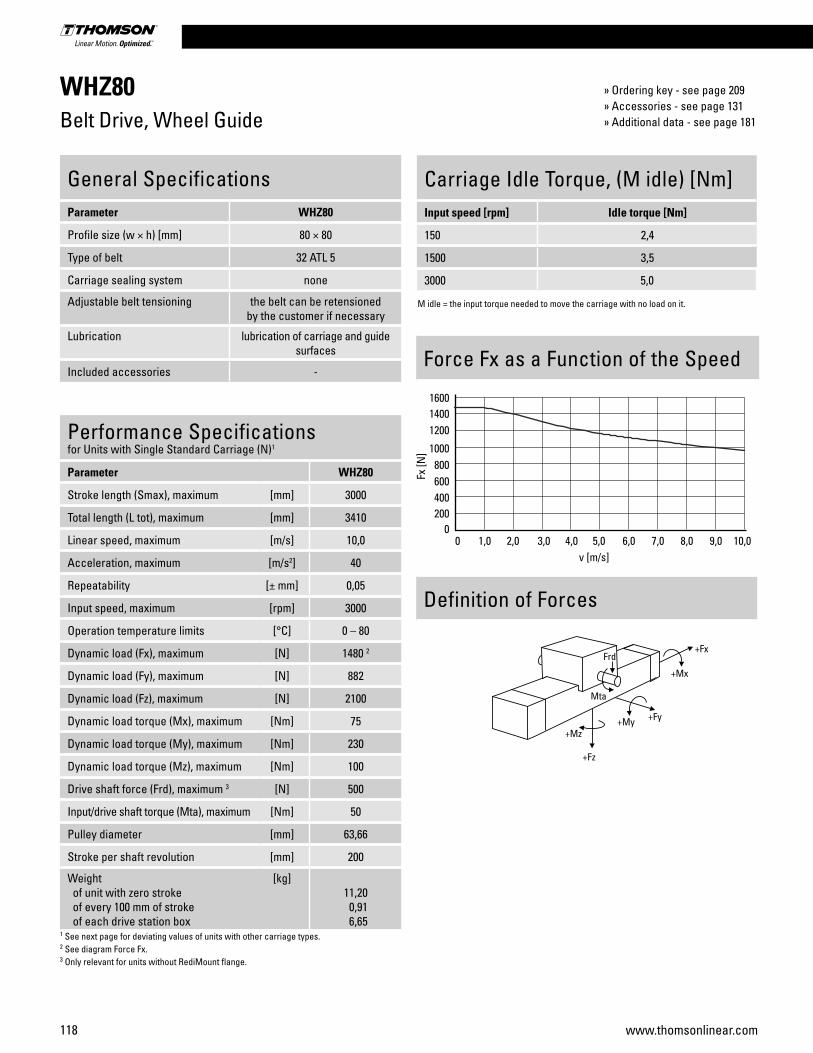
118 www.thomsonlinear.com
WHZ80Belt Drive, Wheel Guide
Performance Specificationsfor Units with Single Standard Carriage (N)1
Parameter WHZ80
Stroke length (Smax), maximum [mm] 3000
Total length (L tot), maximum [mm] 3410
Linear speed, maximum [m/s] 10,0
Acceleration, maximum [m/s2] 40
Repeatability [± mm] 0,05
Input speed, maximum [rpm] 3000
Operation temperature limits [°C] 0 – 80
Dynamic load (Fx), maximum [N] 1480 2
Dynamic load (Fy), maximum [N] 882
Dynamic load (Fz), maximum [N] 2100
Dynamic load torque (Mx), maximum [Nm] 75
Dynamic load torque (My), maximum [Nm] 230
Dynamic load torque (Mz), maximum [Nm] 100
Drive shaft force (Frd), maximum 3 [N] 500
Input/drive shaft torque (Mta), maximum [Nm] 50
Pulley diameter [mm] 63,66
Stroke per shaft revolution [mm] 200
Weight of unit with zero stroke of every 100 mm of stroke of each drive station box
[kg]11,20 0,91 6,65
1 See next page for deviating values of units with other carriage types.2 See diagram Force Fx.3 Only relevant for units without RediMount flange.
General SpecificationsParameter WHZ80
Profile size (w × h) [mm] 80 × 80
Type of belt 32 ATL 5
Carriage sealing system none
Adjustable belt tensioning the belt can be retensioned by the customer if necessary
Lubrication lubrication of carriage and guide surfaces
Included accessories -
Carriage Idle Torque, (M idle) [Nm]Input speed [rpm] Idle torque [Nm]
150 2,4
1500 3,5
3000 5,0
M idle = the input torque needed to move the carriage with no load on it.
Force Fx as a Function of the Speed
Definition of Forces
» Ordering key - see page 209» Accessories - see page 131» Additional data - see page 181

Linear Motion Systems
119www.thomsonlinear.com
WHZ80Belt Drive, Wheel Guide
Performance Specificationsfor Units with Single Long Carriage (L)
Parameter WHZ80
Stroke length (Smax), maximum [mm] 3000
Total length (L tot), maximum [mm] 3580
Carriage length [mm] 450
Dynamic load torque (My), maximum [Nm] 345
Dynamic load torque (Mz), maximum [Nm] 150
Weight [kg] 7,4
A1: funnel type lubricating nipple DIN3405-M6×1-D1A2: depth 4A3: depth 15A4: ENF inductive sensor rail kit (optional - see page 166)A5: felt pad wipers on both sides of the carriage
Performance Specificationsfor Units with Double Standard Carriage (Z)
Parameter WHZ80
Stroke length (Smax), maximum [mm] 2870
Total length (L tot), maximum [mm] 3580
Minimum distance between carriages (L C) [mm] 300
Dynamic load (Fy), maximum [N] 1764
Dynamic load (Fz), maximum [N] 4200
Dynamic load torque (My), maximum [Nm] LC1 × 0,882
Dynamic load torque (Mz), maximum [Nm] LC1 × 2,1
Force required to move second carriage [N] 20
Total length (L tot) [mm] Smax + 410 + LC1 Value in mm2 Second carriage is always a long carriage
Dimensions Projection Online Sizing & Selection!
METRIC www.LinearMotioneering.com
RediMount Flange SpecificationsParameter Min Max
Flange length (Lrm) [mm] 81 143
Flange square (Srm) [mm] 90 200
Flange weight * [kg] 5,70
* Max. weight including coupling and fastening screws

120 www.thomsonlinear.com
Performance SpecificationsParameter Z2
Stroke length (Smax), maximum [mm] 1500
Linear speed, maximum [m/s] 1,25
Acceleration, maximum [m/s2] 8
Repeatability [± mm] 0,1
Input speed, maximum screw diameter/lead [mm] 25/10, 25/25 screw diameter/lead [mm] 32/20
[rpm] 30002500
Operation temperature limits [°C] -20 – 70
Dynamic load (Fz), maximum screw diameter/lead [mm] 25/10, 25/25 screw diameter/lead [mm] 32/20
[N]50007500
Dynamic load torque (Mx), maximum [Nm] 700
Dynamic load torque (My), maximum [Nm] 700
Dynamic load torque (Mz), maximum [Nm] 330
Drive shaft force (Frd), maximum screw diameter/lead [mm] 25/10, 25/25 screw diameter/lead [mm] 32/20
[N]10001200
Input/drive shaft torque (Mta), maximum screw diameter/lead [mm] 25/10, 25/25 screw diameter/lead [mm] 32/20
[Nm]4593
Screw versions, diameter (d0) / lead (p) [mm] 25/10, 25/25, 32/20
Weight of unit with zero stroke, ball screw ø 25 mm of unit with zero stroke, ball screw ø 32 mm of every 100 mm of stroke, ball screw ø 25 mm of every 100 mm of stroke, ball screw ø 32 mm
[kg]19,0023,64 2,50 2,80
General SpecificationsParameter Z2
Profile size (w × h) [mm] 188 × 150
Type of screw ball screw with single nut
Sealing system none
Screw supports none
Lubrication lubrication of screw and slide surfaces
Included accessories none
Definition of Forces and Stroke
Idle Torque (M idle) [Nm]
Input speed [rpm]Screw diameter/lead [mm]
d0 = 25 / p = 10 d0 = 25 / p = 25 d0 = 32 / p = 20
500 0,7 1,9 1,5M idle = the input torque needed to move the lifting profiles without any load.
Critical Speed
Z2Ball Screw Drive, Slide Guide
1: screw diameter 25 mm2: screw diameter 32 mm
** Smax = maximum stroke between the mechanical ends of the unit. The practical stroke is normally 100 mm shorter to avoid running into the ends of the unit.
» Ordering key - see page 209» Accessories - see page 131» Additional data - see page 181

Linear Motion Systems
121www.thomsonlinear.com
A1: depth 12, Heli coilA2: T-slot
Type of unit Minimum retracted length (L min) [mm] Maximum extended length (L max) [mm]
Standard L min = Smax + 380 L max = L min + Smax
Elongated* L min = Smax + 380 + Lx L max = L min + Smax
Z2Ball Screw Drive, Slide Guide
* Elongated versions have an extra length (Lx) added to the total length of the unit which makes the unit longer but does not add any extra length to the stroke (Smax).
A1: depth 9, Heli coilA2: T-slot
MGZ2K25screw ø25 mm
MGZ2K32screw ø32 mm
Dimensions Projection Online Sizing & Selection!
METRIC www.LinearMotioneering.com

122 www.thomsonlinear.com
Performance SpecificationsParameter Z3
Stroke length (Smax), maximum [mm] 1500
Linear speed, maximum [m/s] 1,25
Acceleration, maximum [m/s2] 8
Repeatability [± mm] 0,1
Input speed, maximum screw diameter/lead [mm] 25/10, 25/25 screw diameter/lead [mm] 32/20
[rpm] 30002500
Operation temperature limits [°C] -20 – 70
Dynamic load (Fz), maximum screw diameter/lead [mm] 25/10, 25/25 screw diameter/lead [mm] 32/20
[N]50007500
Dynamic load torque (Mx), maximum [Nm] 2000
Dynamic load torque (My), maximum [Nm] 2000
Dynamic load torque (Mz), maximum [Nm] 330
Drive shaft force (Frd), maximum screw diameter/lead [mm] 25/10, 25/25 screw diameter/lead [mm] 32/20
[N]10001200
Input/drive shaft torque (Mta), maximum screw diameter/lead [mm] 25/10, 25/25 screw diameter/lead [mm] 32/20
[Nm]4593
Screw versions, diameter (d0) / lead (p) [mm] 25/10, 25/25, 32/20
Weight of unit with zero stroke, ball screw ø 25 mm of unit with zero stroke, ball screw ø 32 mm of every 100 mm of stroke, ball screw ø 25 mm of every 100 mm of stroke, ball screw ø 32 mm
[kg]21,1422,65 4,20 4,50
General SpecificationsParameter Z3
Profile size (w × h) [mm] 188 × 150
Type of screw ball screw with single nut
Sealing system none
Screw supports none
Lubrication lubrication of screw and slide surfaces
Included accessories none
Idle Torque (M idle) [Nm]
Input speed [rpm]Screw diameter/lead [mm]
d0 = 25 / p = 10 d0 = 25 / p = 25 d0 = 32 / p = 20
500 1,1 2,7 2,2M idle = the input torque needed to move the lifting profiles without any load.
Critical Speed
Z3Ball Screw Drive, Slide Guide
1: screw diameter 25 mm2: screw diameter 32 mm
Definition of Forces and Stroke
** Smax = maximum stroke between the mechanical ends of the unit. The practical stroke is normally 100 mm shorter to avoid running into the ends of the unit.
» Ordering key - see page 209» Accessories - see page 131» Additional data - see page 181

Linear Motion Systems
123www.thomsonlinear.com
Type of unit Minimum retracted length (L min) [mm] Maximum extended length (L max) [mm]
Standard L min = Smax + 170 L max = L min + Smax
Elongated* L min = Smax + 170 + Lx L max = L min + Smax
Z3Ball Screw Drive, Slide Guide
* Elongated versions have an extra length (Lx) added to the total length of the unit which makes the unit longer but does not add any extra length to the stroke (Smax).
A1: depth 12, Heli coilA2: T-slot
A1: depth 9, Heli coilA2: T-slot
MGZ3K25screw ø25 mm
MGZ3K32screw ø32 mm
Dimensions Projection Online Sizing & Selection!
METRIC www.LinearMotioneering.com

124 www.thomsonlinear.com
Parameter WZ60 WZ80
Profile size (width × height) [mm] 60 × 60 80 × 80
Stroke length (Smax), maximum [mm] 400 500
Linear speed, maximum [m/s] 1,5 1,5
Dynamic carriage load (Fx), maximum [N] 2800 3500
Remarks - -
Page 126 128
Features• Can be installed in any orientation• Ball screw drive• Ball guides• Compact
VarioLine WZ
WZ60
Linear Rod UnitsOverview
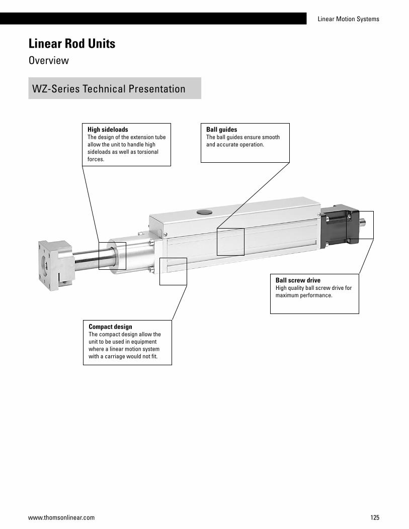
Linear Motion Systems
125www.thomsonlinear.com
Ball guidesThe ball guides ensure smooth and accurate operation.
WZ-Series Technical Presentation
High sideloadsThe design of the extension tubeallow the unit to handle high sideloads as well as torsionalforces.
Ball screw driveHigh quality ball screw drive for maximum performance.
Compact designThe compact design allow the unit to be used in equipment where a linear motion system with a carriage would not fit.
Linear Rod UnitsOverview
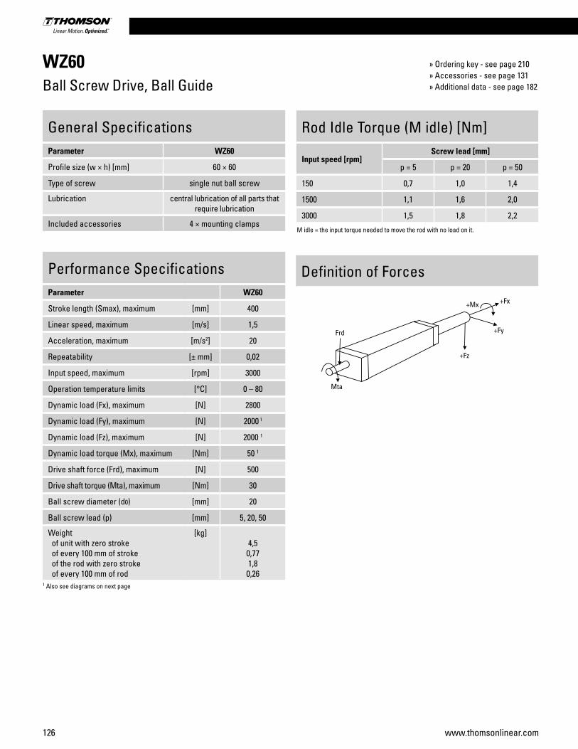
126 www.thomsonlinear.com
WZ60Ball Screw Drive, Ball Guide
Performance SpecificationsParameter WZ60
Stroke length (Smax), maximum [mm] 400
Linear speed, maximum [m/s] 1,5
Acceleration, maximum [m/s2] 20
Repeatability [± mm] 0,02
Input speed, maximum [rpm] 3000
Operation temperature limits [°C] 0 – 80
Dynamic load (Fx), maximum [N] 2800
Dynamic load (Fy), maximum [N] 2000 1
Dynamic load (Fz), maximum [N] 2000 1
Dynamic load torque (Mx), maximum [Nm] 50 1
Drive shaft force (Frd), maximum [N] 500
Drive shaft torque (Mta), maximum [Nm] 30
Ball screw diameter (d0) [mm] 20
Ball screw lead (p) [mm] 5, 20, 50
Weight of unit with zero stroke of every 100 mm of stroke of the rod with zero stroke of every 100 mm of rod
[kg]4,50,771,80,26
General SpecificationsParameter WZ60
Profile size (w × h) [mm] 60 × 60
Type of screw single nut ball screw
Lubrication central lubrication of all parts that require lubrication
Included accessories 4 × mounting clamps
Rod Idle Torque (M idle) [Nm]
Input speed [rpm]Screw lead [mm]
p = 5 p = 20 p = 50
150 0,7 1,0 1,4
1500 1,1 1,6 2,0
3000 1,5 1,8 2,2
M idle = the input torque needed to move the rod with no load on it.
Definition of Forces
1 Also see diagrams on next page
» Ordering key - see page 210» Accessories - see page 131» Additional data - see page 182

Linear Motion Systems
127www.thomsonlinear.com
WZ60Ball Screw Drive, Ball Guide
Maximum Rod Side Forces (Fy, Fz)
A1: depth 13A2: locking plug for lubricating nippleA3: socket cap screw ISO4762-M6×20 8.8A4: tapered lubricating nipple to DIN71412 AM6 as standard feature
Deflection (f) of Rod due to Fy and Fz
Torsion (j) of Rod due to Mx
1: Load = 2000 N2: Load = 1500 N3: Load = 1000 N4: Load = 500 N5: Load = 250 N6: Load = 125 N
Dimensions Projection Online Sizing & Selection!
METRIC www.LinearMotioneering.com

128 www.thomsonlinear.com
WZ80Ball Screw Drive, Ball Guide
Performance SpecificationsParameter WZ80
Stroke length (Smax), maximum [mm] 500
Linear speed, maximum [m/s] 1,5
Acceleration, maximum [m/s2] 20
Repeatability [± mm] 0,02
Input speed, maximum [rpm] 3000
Operation temperature limits [°C] 0 – 80
Dynamic load (Fx), maximum [N] 3500
Dynamic load (Fy), maximum [N] 3000 1
Dynamic load (Fz), maximum [N] 3000 1
Dynamic load torque (Mx), maximum [Nm] 150 1
Drive shaft force (Frd), maximum [N] 700
Drive shaft torque (Mta), maximum [Nm] 55
Ball screw diameter (d0) [mm] 25
Ball screw lead (p) [mm] 5, 10, 20, 50
Weight of unit with zero stroke of every 100 mm of stroke of the rod with zero stroke of every 100 mm of rod
[kg]7,51,353,00,5
General SpecificationsParameter WZ80
Profile size (w × h) [mm] 80 × 80
Type of screw single nut ball screw
Lubrication central lubrication of all parts that require lubrication
Included accessories 4 × mounting clamps
Rod Idle Torque (M idle) [Nm]
Input speed [rpm]Screw lead [mm]
p = 5 p = 10 p = 20 p = 50
150 0,6 1,1 1,3 1,8
1500 1,1 1,5 1,6 2,2
3000 1,4 1,8 1,8 2,7
M idle = the input torque needed to move the rod with no load on it.
Definition of Forces
1 Also see diagrams on next page
» Ordering key - see page 210» Accessories - see page 131» Additional data - see page 182

Linear Motion Systems
129www.thomsonlinear.com
WZ80Ball Screw Drive, Ball Guide
Maximum Rod Side Forces (Fy, Fz)
A1: depth 13A2: locking plug for lubricating nippleA3: socket cap screw ISO4762-M6×20 8.8A4: tapered lubricating nipple to DIN71412 AM6 as standard feature
Deflection (f) of Rod due to Fy and Fz
Torsion (j) of Rod due to Mx
1: Load = 3000 N2: Load = 2500 N3: Load = 2000 N4: Load = 1500 N5: Load = 1000 N6: Load = 500 N7: Load = 250 N8: Load = 125 N
Dimensions Projection Online Sizing & Selection!
METRIC www.LinearMotioneering.com

130 www.thomsonlinear.com
Linear Motion Systems
131www.thomsonlinear.com
Accessories Accessory Index
Electrical Feedback Devices.............................................................................page 159
Mounting Kits.............................................................................................page 132
Motors, Gears and Transmission Kits...............................................................page 142
Non-driven Linear Motion Systems..................................................................page 170
Non-RediMount Linear Motion Systems..........................................................page 176
• Felt pad wipers type FA .............................................................137 • Shaft protection cover ...............................................................137• Protective bellows .....................................................................138
• Limit switch brackets and limit switches .............................. 159 • Inductive and magnetic sensors and sensor brackets ....... 160 • Encoders ................................................................................... 163
• WHxx non-driven units ............................................................. 170• WMxx non-driven units ............................................................ 172• Mxx non-driven units ................................................................ 175
• MLSM80Z non-RediMount units .............................................183• M50 belt driven non-RediMount units ....................................184• WHxx non-RediMount units .....................................................184• MLSH60Z non-RediMount units ..............................................186• WHZxx non-RediMount units ..................................................186
• WMxx and WVxx non-RediMount units .................................176• MLSMxx non-RediMount units................................................178• Mxx ball screw driven non-RediMount units ........................179• WH40 non-RediMount units .....................................................180• WMxxZ non-RediMount units .................................................181• Mxx belt driven non-RediMount units ....................................182
Cover and Protection Kits.........................................................................page 137
• Mounting clamps ..................................................................... 132• Mounting clamps for multi axis systems .............................. 134• Mounting plates for multi axis systems ................................ 135
• Worm gears type BS40 and TBS40 ........................................142• Belt gears type RT and BGM ..................................................146• Planetary gears type Micron DT and DTR ............................152
• Adapter plates .......................................................................... 135• T-slot bolts and nuts................................................................. 136
• Protective shrouds ................................................................... 139 • Environment protection type S1 and S2 ................................ 140
• Intermediate shafts type VWZ and DSP ...............................154• Brakes ........................................................................................ 158
• Limit switch kits type ES .......................................................... 164• Sensor rails and kits type ENT, ENF and ENK....................... 166• Encoder kits type ADG ............................................................. 168

132 www.thomsonlinear.com
AccessoriesMounting Kits
Mounting Clamps Type N1 and N2 (single clamp)1
Unit type N1 N2 A B C D øE F øG H Screws Ms [Nm]
WH40 890 885 0001 – 54 16 9,5 40 10 5,7 5,5 7 ISO4762-8.8 5,4
WH50 890 885 0001 – 54 16 9,5 40 10 5,7 5,5 7 ISO4762-8.8 5,4
WH80 / WB60 890 190 02 – 68 17,5 17 50 11 6,5 6,6 7 ISO4762-8.8 9
WH120 890 192 13 – 80 25 18 50 15 8,5 9 10 ISO4762-8.8 20
WM40 / WB40 890 885 001 – 54 16 9,5 40 10 5,7 5,5 7 ISO4762-8.8 5,4
WM60 / WV60 / WZ60 890 190 02 – 68 17,5 17 50 11 6,5 6,6 7 ISO4762-8.8 9
WM80 / WV80 / WZ80 890 190 02 – 68 17,5 17 50 11 6,5 6,6 7 ISO4762-8.8 9
WM60Z / WM80Z 890 190 02 – 68 17,5 17 50 11 6,5 6,6 7 ISO4762-8.8 9
WM120 / WV120 890 192 13 – 80 25 18 50 15 8,5 9 10 ISO4762-8.8 20
MLS60 890 190 02 890 192 26 68/120 17,5 17 50 11 6,5 6,6 7 ISO4762-8.8 9
MLS80 890 192 13 890 192 31 80/200 25 18 50 15 8,5 9 10 ISO4762-8.8 20
Mounting Clamps Type M1 and M2 (single clamp)1
Unit type M1 M2 A B C D øE F øG H Screws Ms [Nm]
M50 1 D312 248 – 25 30 20 – – – 6,5 14 ISO4762-8.8 9,4
M55 1 D313 403 D313 402 25/56 25,5 10,7 41 9,5 5,3 5,5 10,2 ISO4762-8.8 5,5
M75 1 D312 747 D312 748 30/75 28,5 15 60 14 8,5 8,5 11 ISO4762-8.8 23
M100 1 D312 339 D312 334 45/92 46,5 22 60 17 10,5 10,5 20 ISO4762-8.8 45
1 Screws included in the shipment of above clamps
1 No screws included in the shipment of above clamps Ms = tightening torque of screws
N1
M1
N2
M2
Ms = tightening torque of screws
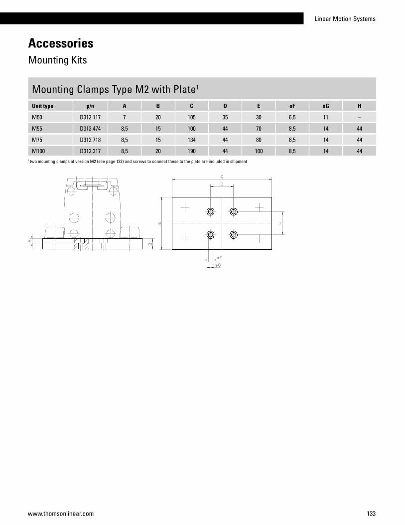
Linear Motion Systems
133www.thomsonlinear.com
Mounting Clamps Type M2 with Plate1
Unit type p/n A B C D E øF øG H
M50 D312 117 7 20 105 35 30 6,5 11 –
M55 D313 474 8,5 15 100 44 70 8,5 14 44
M75 D312 718 8,5 15 134 44 80 8,5 14 44
M100 D312 317 8,5 20 190 44 100 8,5 14 441 two mounting clamps of version M2 (see page 132) and screws to connect these to the plate are included in shipment
AccessoriesMounting Kits

134 www.thomsonlinear.com
AccessoriesMounting Kits
Mounting Clamps Type N1 for Multi Axis Systems1
Unit type X-axis Unit type Y-axis Clamps A B C D øE F øG H
WM40 / WH40 WM40 / WH40 on request – – – – – – – –
WM60 WM60 890 191 94 58 17,5 17 40 11 6,5 6,6 71 all necessary screws are included in the shipment
The clamps + plate consist of two clamps type
M2, one plate and necessary screws.
Clamps Clampswith Plate
Clamps +PlateClamps
Mounting Clamps Type M2 for Multi Axis Systems1
Unit type X-axis Unit type Y-axis p/n A B C D øE F øG H
M55 M55 D313 424 56 25,5 10,7 41 9,5 5,3 5,5 10,2
M75 M75 D312 719 75 28,5 15 60 14 8,5 8,5 11
M100 M100 D312 304 92 46,5 22 60 17 10,5 10,5 20
Mounting Clamps Type M2 with Plate for Multi Axis Systems1
Unit type X-axis Unit type Y-axis p/n A B C D E øF øG H
M55 M75 D313 470 5,5 15 134 76 80 5,5 9,5 41
M75 M55 D313 060 8,5 15 134 106 80 8,5 14 60
M75 M100 D313 062 8,5 20 190 106 100 8,5 14 60
M100 M75 D313 292 10,5 20 190 142 100 10,5 17 601 all necessary screws are included in the shipment
-axis -axis
-axis
-axis -axis
-axis
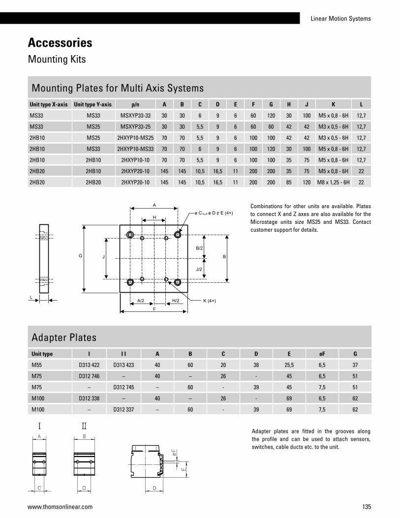
Linear Motion Systems
135www.thomsonlinear.com
Mounting Plates for Multi Axis SystemsUnit type X-axis Unit type Y-axis p/n A B C D E F G H J K L
MS33 MS33 MSXYP33-33 30 30 6 9 6 60 120 30 100 M5 x 0,8 - 6H 12,7
MS33 MS25 MSXYP33-25 30 30 5,5 9 6 60 60 42 42 M3 x 0,5 - 6H 12,7
2HB10 MS25 2HXYP10-MS25 70 70 5,5 9 6 100 100 42 42 M3 x 0,5 - 6H 12,7
2HB10 MS33 2HXYP10-MS33 70 70 6 9 6 100 120 30 100 M5 x 0,8 - 6H 12,7
2HB10 2HB10 2HXYP10-10 70 70 5,5 9 6 100 100 35 75 M5 x 0,8 - 6H 12,7
2HB20 2HB10 2HXYP20-10 145 145 10,5 16,5 11 200 200 35 75 M5 x 0,8 - 6H 22
2HB20 2HB20 2HXYP20-10 145 145 10,5 16,5 11 200 200 85 120 M8 x 1,25 - 6H 22
AccessoriesMounting Kits
Adapter PlatesUnit type I I I A B C D E øF G
M55 D313 422 D313 423 40 60 20 38 25,5 6,5 37
M75 D312 746 – 40 – 26 - 45 6,5 51
M75 – D312 745 – 60 - 39 45 7,5 51
M100 D312 338 – 40 – 26 - 69 6,5 62
M100 – D312 337 – 60 - 39 69 7,5 62
Adapter plates are fitted in the grooves along the profile and can be used to attach sensors, switches, cable ducts etc. to the unit.
Combinations for other units are available. Plates to connect X and Z axes are also available for the Microstage units size MS25 and MS33. Contact customer support for details.
Mounting Clamps Type M2 with Plate for Multi Axis Systems1
Unit type X-axis Unit type Y-axis p/n A B C D E øF øG H
M55 M75 D313 470 5,5 15 134 76 80 5,5 9,5 41
M75 M55 D313 060 8,5 15 134 106 80 8,5 14 60
M75 M100 D313 062 8,5 20 190 106 100 8,5 14 60
M100 M75 D313 292 10,5 20 190 142 100 10,5 17 60
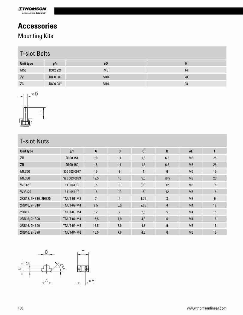
136 www.thomsonlinear.com
AccessoriesMounting Kits
T-slot BoltsUnit type p/n øD H
M50 D312 221 M5 14
Z2 D800 089 M10 28
Z3 D800 089 M10 28
T-slot NutsUnit type p/n A B C D øE F
ZB D900 151 18 11 1,5 6,3 M6 25
ZB D900 150 18 11 1,5 6,3 M8 25
MLS60 920 303 0037 16 8 4 6 M6 16
MLS80 920 303 0039 19,5 10 5,5 10,5 M8 20
WH120 911 044 19 15 10 6 12 M8 15
WM120 911 044 19 15 10 6 12 M8 15
2RB12, 2HB10, 2HB20 TNUT-01-M3 7 4 1,75 3 M3 9
2RB16, 2HB10 TNUT-02-M4 9,5 5,5 2,25 4 M4 12
2RB12 TNUT-03-M4 12 7 2,5 5 M4 15
2RB16, 2HB20 TNUT-04-M4 16,5 7,9 4,8 6 M4 16
2RB16, 2HB20 TNUT-04-M5 16,5 7,9 4,8 6 M5 16
2RB16, 2HB20 TNUT-04-M6 16,5 7,9 4,8 6 M6 16
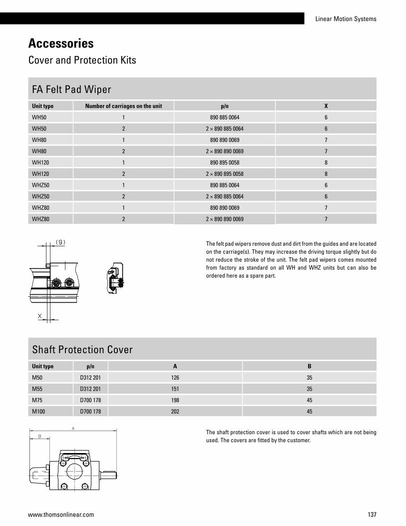
Linear Motion Systems
137www.thomsonlinear.com
AccessoriesCover and Protection Kits
FA Felt Pad WiperUnit type Number of carriages on the unit p/n X
WH50 1 890 885 0064 6
WH50 2 2 × 890 885 0064 6
WH80 1 890 890 0069 7
WH80 2 2 × 890 890 0069 7
WH120 1 890 895 0058 8
WH120 2 2 × 890 895 0058 8
WHZ50 1 890 885 0064 6
WHZ50 2 2 × 890 885 0064 6
WHZ80 1 890 890 0069 7
WHZ80 2 2 × 890 890 0069 7
The felt pad wipers remove dust and dirt from the guides and are located on the carriage(s). They may increase the driving torque slightly but do not reduce the stroke of the unit. The felt pad wipers comes mounted from factory as standard on all WH and WHZ units but can also be ordered here as a spare part.
Shaft Protection CoverUnit type p/n A B
M50 D312 201 126 35
M55 D312 201 151 35
M75 D700 178 198 45
M100 D700 178 202 45
The shaft protection cover is used to cover shafts which are not being used. The covers are fitted by the customer.
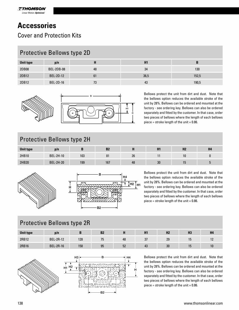
138 www.thomsonlinear.com
Protective Bellows type 2DUnit type p/n H H1 B
2DB08 BEL-2DB-08 48 34 130
2DB12 BEL-2D-12 61 36,5 152,5
2DB12 BEL-2D-16 73 43 190,5
Protective Bellows type 2HUnit type p/n B B2 H H1 H2 H4
2HB10 BEL-2H-10 103 81 26 11 10 0
2HB20 BEL-2H-20 199 167 48 30 15 5
Protective Bellows type 2RUnit type p/n B B2 H H1 H2 H3 H4
2RB12 BEL-2R-12 128 75 48 37 29 15 12
2RB16 BEL-2R-16 158 95 52 43 30 15 10
Bellows protect the unit from dirt and dust. Note that the bellows option reduces the available stroke of the unit by 28%. Bellows can be ordered and mounted at the factory - see ordering key. Bellows can also be ordered separately and fitted by the customer. In that case, order two pieces of bellows where the length of each bellows piece = stroke length of the unit × 0.86.
Bellows protect the unit from dirt and dust. Note that the bellows option reduces the available stroke of the unit by 28%. Bellows can be ordered and mounted at the factory - see ordering key. Bellows can also be ordered separately and fitted by the customer. In that case, order two pieces of bellows where the length of each bellows piece = stroke length of the unit × 0.86.
Bellows protect the unit from dirt and dust. Note that the bellows option reduces the available stroke of the unit by 28%. Bellows can be ordered and mounted at the factory - see ordering key. Bellows can also be ordered separately and fitted by the customer. In that case, order two pieces of bellows where the length of each bellows piece = stroke length of the unit × 0.86.
AccessoriesCover and Protection Kits
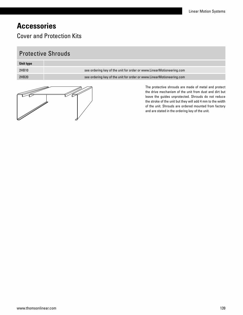
Linear Motion Systems
139www.thomsonlinear.com
Protective ShroudsUnit type
2HB10 see ordering key of the unit for order or www.LinearMotioneering.com
2HB20 see ordering key of the unit for order or www.LinearMotioneering.com
The protective shrouds are made of metal and protect the drive mechanism of the unit from dust and dirt but leave the guides unprotected. Shrouds do not reduce the stroke of the unit but they will add 4 mm to the width of the unit. Shrouds are ordered mounted from factory and are stated in the ordering key of the unit.
AccessoriesCover and Protection Kits
140 www.thomsonlinear.com
AccessoriesCover and Protection Kits
Environment Protection Option Type S1 and S2, compatibility tableUnit type Drive type Guide type S1 S2 Ordering
M55 ball screw slide • see ordering key of the unit for order
M55 belt driveslide • • see ordering key of the unit for order
ball • see ordering key of the unit for order
M75 ball screw slide • see ordering key of the unit for order
M75 belt driveslide • • see ordering key of the unit for order
ball • see ordering key of the unit for order
M100 ball screw slide • see ordering key of the unit for order
M100 belt driveslide • • see ordering key of the unit for order
ball • see ordering key of the unit for order
WM60 / WM80 / WM120 ball screw ball • see ordering key of the unit for order
WV60 / WV80 / WV120 ball screw no guide • see ordering key of the unit for order
WH50 / WH80 / WH120 belt drive wheel • • see ordering key of the unit for order
WHZ50 / WHZ80 belt drive wheel • see ordering key of the unit for order
The S1 and S2 environment protection options are available for some of the units as per table above. All performance data and the life expectancy are the same as for standard units except for WH and WHZ units (contact customer service for more information). S1 can be ordered for both ball screw and belt driven units with ball, slide or wheel guides while S2 only is possible for belt driven units with slide or wheel guides. Never use chemical agents and/or cleaning detergents before contacting your local Thomson customer service for advice.
S1 - Wash down protectionTypical places where S1 is used are in slaughter houses, dairy plants, food plants or in any other light wash down application.
S2 - Enhanced wash down protectionTypical places where S2 is used are in moderately wet areas such as in paper mills, galvanizing equipment, food industries or in any other harsh environment application where enhanced wash down capabilities are required.
Linear Motion Systems
141www.thomsonlinear.com
Environment Protection Options Type S1 and S2, technical specificationItem S1 S2
External screws, bolts and nuts stainless material class A2 or better stainless material class A4 or better
Internal screws, bolts and nuts standard material stainless material class A2 or better
Drive shaft, ball screw driven units standard material -
Drive shaft, belt driven units stainless material SS2333 or better stainless material SS2343 or better
Tension wheel shaft standard material stainless material SS2333 or better
Bearings type standard bearings 2RS
Bearing sealings, belt driven units radial sealings radial sealings
Surface treatment of machined extruded aluminum parts none anodizing
Surface treatment of machined casted aluminum parts none anodizing
Cam rollers and idler shafting (WH and WHZ units) standard material stainless material
Belt retainer (WH units) none stainless material
AccessoriesCover and Protection Kits

142 www.thomsonlinear.com
AccessoriesGears and Transmission Kits
BS40 Worm Gears, dimensionsGear A B C D E F
BS40 54 40 46 10 100 92
BS40 Worm Gears, compatibility tableUnit BS40 IEC71B14 IEC80B14 IEC90B14 A L
Z2 (MGZ2K32) • • 17 58
Z2 (MGZ2K32) • • 17 68
The worm gear includes the gear, the bell house and a matching coupling.
To be able to install the gear to the unit an adaptor flange must be used between the gear and the unit. In addition, the adaptor flange must be ordered separately.
Adaptor flange
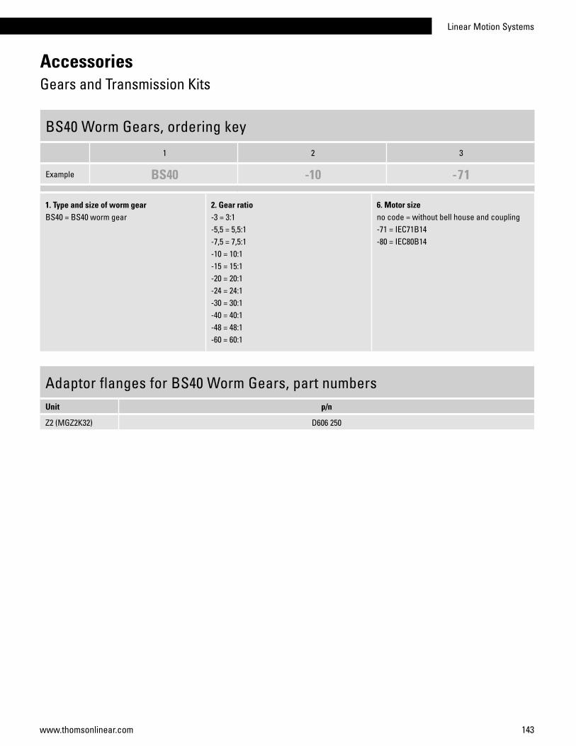
Linear Motion Systems
143www.thomsonlinear.com
AccessoriesGears and Transmission Kits
BS40 Worm Gears, ordering key
1 2 3
Example BS40 -10 -71
1. Type and size of worm gearBS40 = BS40 worm gear
2. Gear ratio-3 = 3:1-5,5 = 5,5:1-7,5 = 7,5:1-10 = 10:1-15 = 15:1-20 = 20:1-24 = 24:1-30 = 30:1-40 = 40:1-48 = 48:1-60 = 60:1
6. Motor sizeno code = without bell house and coupling-71 = IEC71B14-80 = IEC80B14
Adaptor flanges for BS40 Worm Gears, part numbersUnit p/n
Z2 (MGZ2K32) D606 250

144 www.thomsonlinear.com
AccessoriesGears and Transmission Kits
TBS40 Worm Gears, dimensionsGear A B C D E F øG H øI J K
TBS40 54 40 46 10 100 125 14j6 45 65 M8 (4×) 25
TBS40 Worm Gears, compatibility tableUnit TBS40 IEC71B14 IEC80B14 A L
Z2 (MGZ2K25) • • 32 58
Z2 (MGZ2K25) • • 32 68
Z3 (MGZ3K25) • • 32 58
Z3 (MGZ3K25) • • 32 68
M75 • • 32 58
M75 • • 32 68
M100 • • 32 58
M100 • • 32 68
The worm gear is installed directly to the unit and requires no intermediate coupling between the two.
To be able to install the gear to the motor a bell house flange must be used between the gear and the motor. The bell house flange, which includes a matching coupling, is ordered separately. A shaft cover can be ordered to cover the second primary shaft on the gear in case it is not being used.Bell house flange
Shaft cover

Linear Motion Systems
145www.thomsonlinear.com
AccessoriesGears and Transmission Kits
TBS40 Worm Gears, ordering key
1 2 3
Example TBS40 -3 -216
1. Type and size of worm gearTBS40 = TBS40 worm gear
2. Gear ratio-3 = 3:1-5,5 = 5,5:1-7,5 = 7,5:1-10 = 10:1-15 = 15:1-20 = 20:1-24 = 24:1-30 = 30:1-40 = 40:1-48 = 48:1-60 = 60:1
3. Fixed code-216
Bell house flanges for TBS40 Worm Gears, part numbersMotor size p/n
IEC71B14 D701 011
IEC80B14 D701 015
Shaft Cover for TBS40 Worm Gears, part numbersGear type p/n
TBS40 D701 020

146 www.thomsonlinear.com
AccessoriesGears and Transmission Kits
RT Belt Gears, dimensionsGear A B C D
RT40 110 30 176 68
RT60 175 74 345 170
RT80 175 74 345 170
RT40 RT60/80
RT Belt Gears, dataGear i nmax [rpm] Mmax [Nm] M idle [Nm] h J [kgm2] Weight [kg}
RT40 1:1 3000 1,75 0,3 0,80 0,000025 0,62
RT60 1:1 3000 15 0,7 0,85 0,000438 5,6
RT60 2:1 3000 15 0,7 0,85 0,001011 7,1
RT80 1:1 3000 30 0,7 0,85 0,000465 5,5
RT80 2:1 3000 30 0,7 0,85 0,001038 7
i = gear ratio M idle = idle torque
nmax = max. input speed h = efficiency factor
Mmax = max. input torque J = inertia
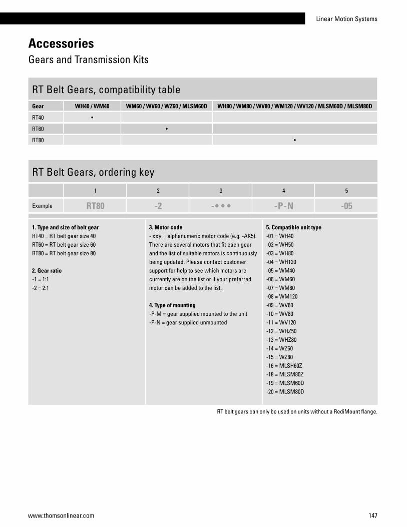
Linear Motion Systems
147www.thomsonlinear.com
AccessoriesGears and Transmission Kits
RT Belt Gears, compatibility tableGear WH40 / WM40 WM60 / WV60 / WZ60 / MLSM60D WH80 / WM80 / WV80 / WM120 / WV120 / MLSM60D / MLSM80D
RT40 •
RT60 •
RT80 •
RT Belt Gears, ordering key
1 2 3 4 5
Example RT80 -2 -• • • -P-N -05
1. Type and size of belt gearRT40 = RT belt gear size 40RT60 = RT belt gear size 60RT80 = RT belt gear size 80
2. Gear ratio-1 = 1:1-2 = 2:1
3. Motor code - xxy = alphanumeric motor code (e.g. -AK5). There are several motors that fit each gear and the list of suitable motors is continuously being updated. Please contact customer support for help to see which motors are currently are on the list or if your preferred motor can be added to the list.
4. Type of mounting-P-M = gear supplied mounted to the unit-P-N = gear supplied unmounted
5. Compatible unit type-01 = WH40-02 = WH50 -03 = WH80-04 = WH120 -05 = WM40-06 = WM60 -07 = WM80-08 = WM120-09 = WV60-10 = WV80-11 = WV120-12 = WHZ50-13 = WHZ80-14 = WZ60-15 = WZ80-16 = MLSH60Z-18 = MLSM80Z-19 = MLSM60D-20 = MLSM80D
RT belt gears can only be used on units without a RediMount flange.

148 www.thomsonlinear.com
AccessoriesGears and Transmission Kits
BGM Belt Gears, dimensionsGear A B C D øE F G H I J
BGM09 118,7 52 255 140 20 H9 95 115 60 – –
BGM41 155,2 70 305 165 25 H9 122 147 70 – –
BGM81 200 73 399 224 30 H9 134 159 90 90H14 170
BGM09/41/81 - WITHOUT CLEVIS OPTION
BGM09/41/81 - WITH CLEVIS OPTION TYPE S BGM81 - WITH CLEVIS OPTION TYPE R
BGM belt gears can only be used on units without a RediMount flange. The belt gear comes in parts and is assembled to the unit and motor by the customer.

Linear Motion Systems
149www.thomsonlinear.com
BGM Belt Gears, ordering keys
AccessoriesGears and Transmission Kits
BGM Belt Gears, dataGear i nmax [rpm] Mmax [Nm] h J [kgm2] Weight [kg}
BGM09 1,04:1 4000 4,1 0,85 0,000102 2
BGM09 1,85:1 4000 4,1 0,85 0,000112 2,1
BGM09 2,85:1 4000 4,1 0,85 0,000213 2,5
BGM41 1:1 4000 22,0 0,85 0,000438 3,4
BGM41 2:1 4000 15,8 0,85 0,000342 3,7
BGM41 3:1 4000 16,7 0,85 0,000583 4,6
BGM81 1:1 4000 29,0 0,85 0,000836 12,1
BGM81 2,25:1 4000 32,3 0,85 0,001051 12,9
BGM81 3,13:1 4000 30,3 0,85 0,001439 14
i = gear ratio h = efficiency factor
nmax = max. input speed J = inertia
Mmax = max. input torque
BGM Belt Gears, compatibility tableGear WM/V/Z60 WM/V80 WM/V120 MLSM80D WB60 M50 M55 M75 M100 Z2
BGM09 • • • • •
BGM41 • • • • •
BGM81 • •
See next page for ordering keys.

150 www.thomsonlinear.com
AccessoriesGears and Transmission Kits
BGM 09 Belt Gears, ordering key
1 2 3 4 5 6 7 8
Example BGM09 -2 -CC 063 P 050 X +XX
1. Type and size of belt gearBGM09 = BGM belt gear size 09
2. Gear ratio-1 = 1,04:1-2 = 1,85:1-3 = 2,85:1
3. Type of couplings-CC = conical couplings
4. Motor size1
063 = IEC 63 B14071 = IEC 71 B14S80 = servo motor size 80AK4 = servo motor type AKM 4
5. Type of mountingP = standard
6. Compatible unit typeW06 = WM60, WV60, WZ60WB6 = WB60050 = M50060 = M55070 = M75
7. Clevis optionX = no clevis optionS = clevis option type S
8. Protection+XX = standard+S1 = wash down protection
1This is only a selection of all motors that fit this gear. Please contact customer support to see if your preferred motor fits the gear.
BGM 41 Belt Gears, ordering key
1 2 3 4 5 6 7 8
Example BGM41 -1 -CC 071 P 070 X +S1
1. Type and size of belt gearBGM41 = BGM belt gear size 41
2. Gear ratio-1 = 1:1-2 = 2:1-3 = 3:1
3. Type of couplings-CC = conical couplings
4. Motor size1
071 = IEC 71 B14080 = IEC 80 B14S80 = servo motor size 80S95 = servo motor size 95AK5 = servo motor type AKM 5
5. Type of mountingP = standard
6. Compatible unit typeW06 = WM60, WV60, WZ60W08 = WM80, WV80070 = M7510B = M100 (MF/G10B)10K = M100 (MF/G10K/C/D)
7. Clevis optionX = no clevis optionS = clevis option type S
8. Protection+XX = standard+S1 = wash down protection
1This is only a selection of all motors that fit this gear. Please contact customer support to see if your preferred motor fits the gear.
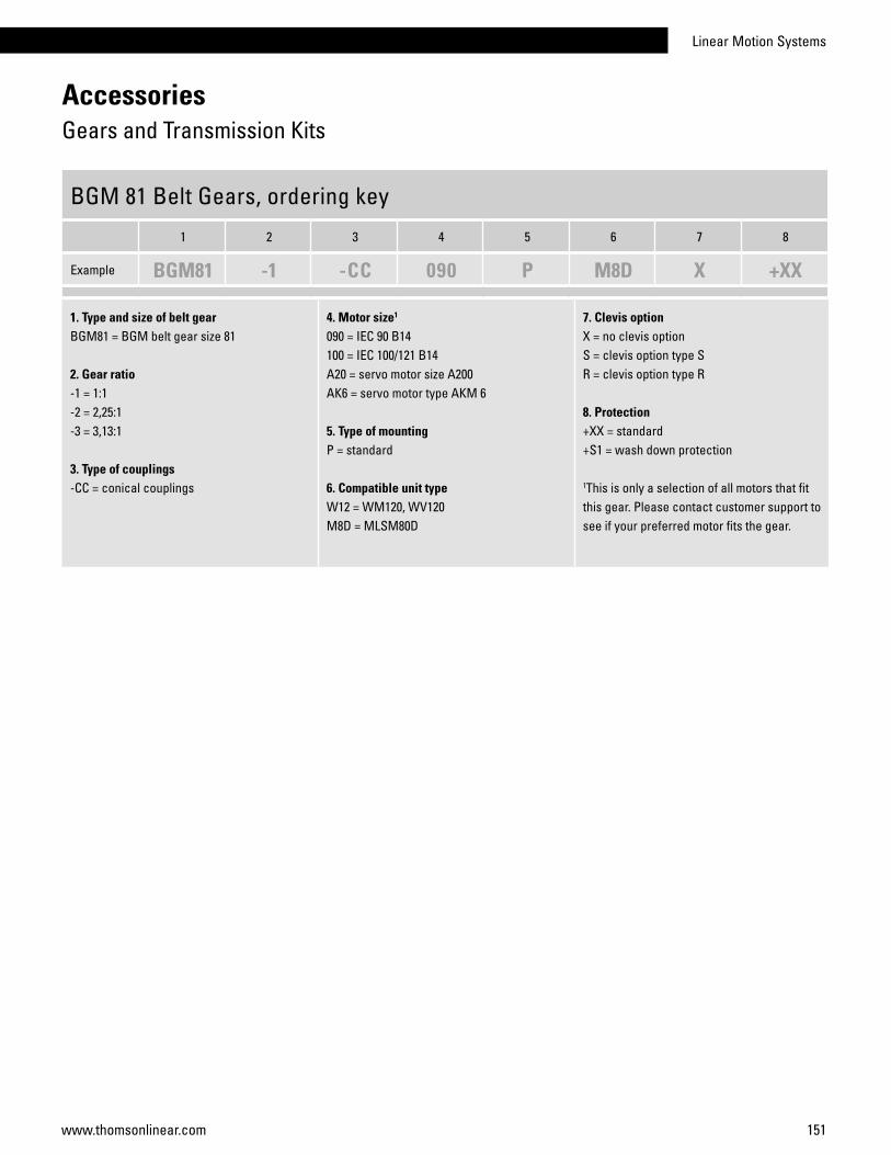
Linear Motion Systems
151www.thomsonlinear.com
AccessoriesGears and Transmission Kits
BGM 81 Belt Gears, ordering key
1 2 3 4 5 6 7 8
Example BGM81 -1 -CC 090 P M8D X +XX
1. Type and size of belt gearBGM81 = BGM belt gear size 81
2. Gear ratio-1 = 1:1-2 = 2,25:1-3 = 3,13:1
3. Type of couplings-CC = conical couplings
4. Motor size1
090 = IEC 90 B14100 = IEC 100/121 B14A20 = servo motor size A200AK6 = servo motor type AKM 6
5. Type of mountingP = standard
6. Compatible unit typeW12 = WM120, WV120M8D = MLSM80D
7. Clevis optionX = no clevis optionS = clevis option type SR = clevis option type R
8. Protection+XX = standard+S1 = wash down protection
1This is only a selection of all motors that fit this gear. Please contact customer support to see if your preferred motor fits the gear.
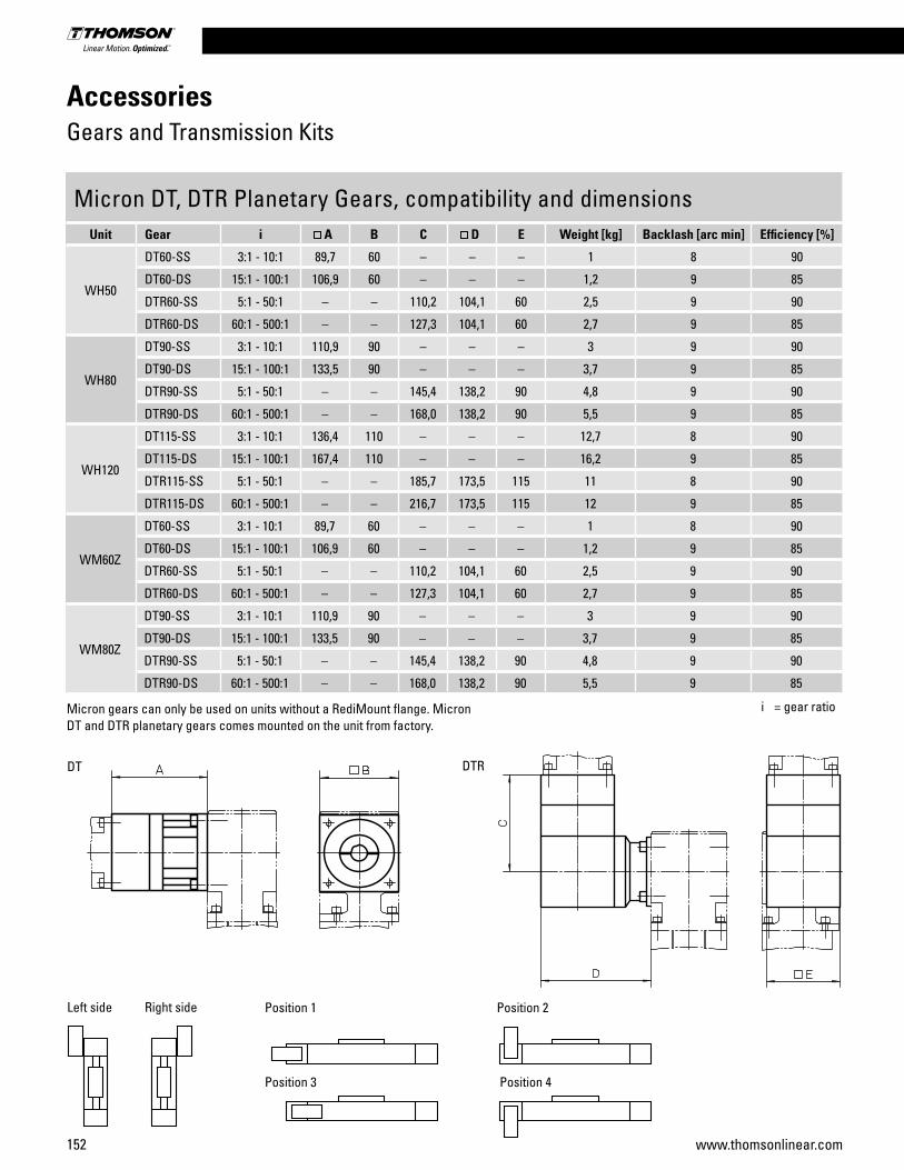
152 www.thomsonlinear.com
AccessoriesGears and Transmission Kits
Micron DT, DTR Planetary Gears, compatibility and dimensionsUnit Gear i A B C D E Weight [kg] Backlash [arc min] Efficiency [%]
WH50
DT60-SS 3:1 - 10:1 89,7 60 – – – 1 8 90
DT60-DS 15:1 - 100:1 106,9 60 – – – 1,2 9 85
DTR60-SS 5:1 - 50:1 – – 110,2 104,1 60 2,5 9 90
DTR60-DS 60:1 - 500:1 – – 127,3 104,1 60 2,7 9 85
WH80
DT90-SS 3:1 - 10:1 110,9 90 – – – 3 9 90
DT90-DS 15:1 - 100:1 133,5 90 – – – 3,7 9 85
DTR90-SS 5:1 - 50:1 – – 145,4 138,2 90 4,8 9 90
DTR90-DS 60:1 - 500:1 – – 168,0 138,2 90 5,5 9 85
WH120
DT115-SS 3:1 - 10:1 136,4 110 – – – 12,7 8 90
DT115-DS 15:1 - 100:1 167,4 110 – – – 16,2 9 85
DTR115-SS 5:1 - 50:1 – – 185,7 173,5 115 11 8 90
DTR115-DS 60:1 - 500:1 – – 216,7 173,5 115 12 9 85
WM60Z
DT60-SS 3:1 - 10:1 89,7 60 – – – 1 8 90
DT60-DS 15:1 - 100:1 106,9 60 – – – 1,2 9 85
DTR60-SS 5:1 - 50:1 – – 110,2 104,1 60 2,5 9 90
DTR60-DS 60:1 - 500:1 – – 127,3 104,1 60 2,7 9 85
WM80Z
DT90-SS 3:1 - 10:1 110,9 90 – – – 3 9 90
DT90-DS 15:1 - 100:1 133,5 90 – – – 3,7 9 85
DTR90-SS 5:1 - 50:1 – – 145,4 138,2 90 4,8 9 90
DTR90-DS 60:1 - 500:1 – – 168,0 138,2 90 5,5 9 85
i = gear ratio
DT DTR
Left side Right side Position 1 Position 2
Position 3 Position 4
Micron gears can only be used on units without a RediMount flange. Micron DT and DTR planetary gears comes mounted on the unit from factory.
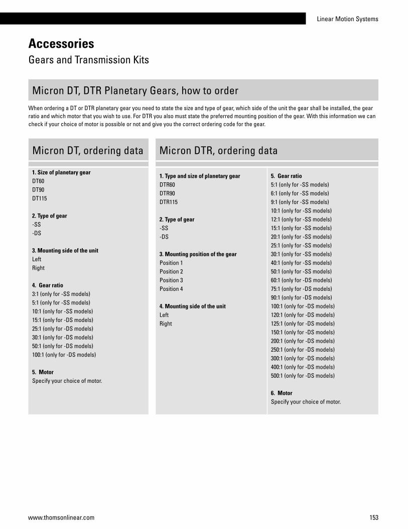
Linear Motion Systems
153www.thomsonlinear.com
i = gear ratio
AccessoriesGears and Transmission Kits
1. Size of planetary gearDT60DT90DT115
2. Type of gear-SS-DS
3. Mounting side of the unit Left Right
4. Gear ratio3:1 (only for -SS models)5:1 (only for -SS models)10:1 (only for -SS models)15:1 (only for -DS models)25:1 (only for -DS models)30:1 (only for -DS models)50:1 (only for -DS models)100:1 (only for -DS models)
5. MotorSpecify your choice of motor.
1. Type and size of planetary gearDTR60DTR90DTR115
2. Type of gear-SS-DS
3. Mounting position of the gear Position 1 Position 2 Position 3Position 4
4. Mounting side of the unitLeft Right
5. Gear ratio5:1 (only for -SS models)6:1 (only for -SS models)9:1 (only for -SS models)10:1 (only for -SS models)12:1 (only for -SS models)15:1 (only for -SS models)20:1 (only for -SS models)25:1 (only for -SS models)30:1 (only for -SS models)40:1 (only for -SS models)50:1 (only for -SS models)60:1 (only for -DS models)75:1 (only for -DS models)90:1 (only for -DS models)100:1 (only for -DS models)120:1 (only for -DS models)125:1 (only for -DS models)150:1 (only for -DS models)200:1 (only for -DS models)250:1 (only for -DS models)300:1 (only for -DS models)400:1 (only for -DS models)500:1 (only for -DS models)
6. MotorSpecify your choice of motor.
Micron DT, DTR Planetary Gears, how to orderWhen ordering a DT or DTR planetary gear you need to state the size and type of gear, which side of the unit the gear shall be installed, the gear ratio and which motor that you wish to use. For DTR you also must state the preferred mounting position of the gear. With this information we can check if your choice of motor is possible or not and give you the correct ordering code for the gear.
Micron DT, ordering data Micron DTR, ordering data
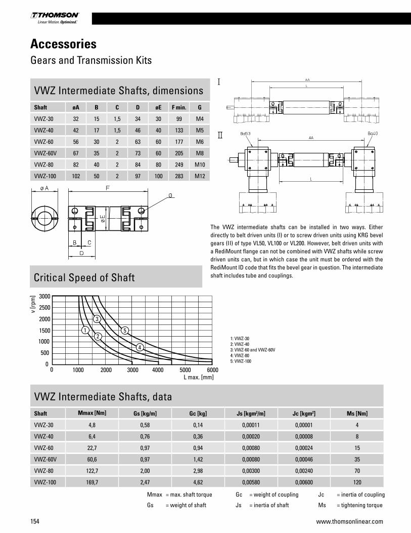
154 www.thomsonlinear.com
AccessoriesGears and Transmission Kits
VWZ Intermediate Shafts, dimensionsShaft øA B C D øE F min. G
VWZ-30 32 15 1,5 34 30 99 M4
VWZ-40 42 17 1,5 46 40 133 M5
VWZ-60 56 30 2 63 60 177 M6
VWZ-60V 67 35 2 73 60 205 M8
VWZ-80 82 40 2 84 80 249 M10
VWZ-100 102 50 2 97 100 283 M12
Mmax = max. shaft torque Gc = weight of coupling Jc = inertia of coupling
Gs = weight of shaft Js = inertia of shaft Ms = tightening torque
VWZ Intermediate Shafts, dataShaft Mmax [Nm] Gs [kg/m] Gc [kg] Js [kgm2/m] Jc [kgm2] Ms [Nm]
VWZ-30 4,8 0,58 0,14 0,00011 0,00001 4
VWZ-40 6,4 0,76 0,36 0,00020 0,00008 8
VWZ-60 22,7 0,97 0,94 0,00080 0,00024 15
VWZ-60V 60,6 0,97 1,42 0,00080 0,00046 35
VWZ-80 122,7 2,00 2,98 0,00300 0,00240 70
VWZ-100 169,7 2,47 4,62 0,00580 0,00600 120
The VWZ intermediate shafts can be installed in two ways. Either directly to belt driven units (I) or to screw driven units using KRG bevel gears (II) of type VL50, VL100 or VL200. However, belt driven units with a RediMount flange can not be combined with VWZ shafts while screw driven units can, but in which case the unit must be ordered with the RediMount ID code that fits the bevel gear in question. The intermediate shaft includes tube and couplings.Critical Speed of Shaft
1: VWZ-302: VWZ-403: VWZ-60 and VWZ-60V4: VWZ-805: VWZ-100

Linear Motion Systems
155www.thomsonlinear.com
Mmax = max. shaft torque Gc = weight of coupling Jc = inertia of coupling
Gs = weight of shaft Js = inertia of shaft Ms = tightening torque
AccessoriesGears and Transmission Kits
VWZ Intermediate Shafts, compatibility tableUnit I I I VWZ-30 VWZ-40 VWZ-60 VWZ-60V VWZ-80 VWZ-100 AA [mm]
WH40 • • AA = L + 56
WH50 / WHZ50 • • AA = L + 54
WM60Z • • AA = L + 64
WH80 / WHZ80 • • AA = L + 84
WH120 • • AA = L + 124
WM80Z • • AA = L + 84
MLSH60Z • • AA = L + 164
WB40 / WM40 VL50 • AA = L + 170
WB60 VL100 • AA = L + 184
WM60 / WV60 / WZ60 VL100 • AA = L + 184
WM80 / WV80 / MLSM60D VL100 • AA = L + 176
MLSM80Z • • AA = L + 244
WM120 / WV120 / MLSM60D / MLSM80D VL200 • AA = L + 244
AA = C/C distance between unitsL = total length of shaft and coupling assembly
VWZ Intermediate Shafts, ordering key
1 2 3
Example VWZ-060 -02 -0700
1. Intermediate shaft sizeVWZ-030 = VWZ-30 VWZ-040 = VWZ-40VWZ-060 = VWZ-60VWZ-06V = VWZ-60VVWZ-080 = VWZ-80VWZ-100 = VWZ-100
2. Type of unit and type of mounting-01 = WH40 for type I mounting-02 = WH50 / WHZ50 for type I mounting-03 = WM80Z for type I mounting-04 = WH80 / WHZ80 for type I mounting-05 = WH120 for type I mounting-06 = WM60Z for type I mounting-07 = MLSH60Z for type I mounting-08 = WB40 / WM40 for type II mounting on VL5O gears-09 = WB60 for type II mounting on VL100 gears-10 = WM60 / WV60 / WZ60 for type II mounting on VL100 gears-11 = WM80 / WV80 / MLSM60D for type II mounting on VL100 gears-12 = MLSM80Z for type I mounting-13 = WM120 / WV120 / MLSM60D / MLSM80D for type II mounting on VL200 gears
3. C/C distance between units (AA) - xxxx = distance in mm
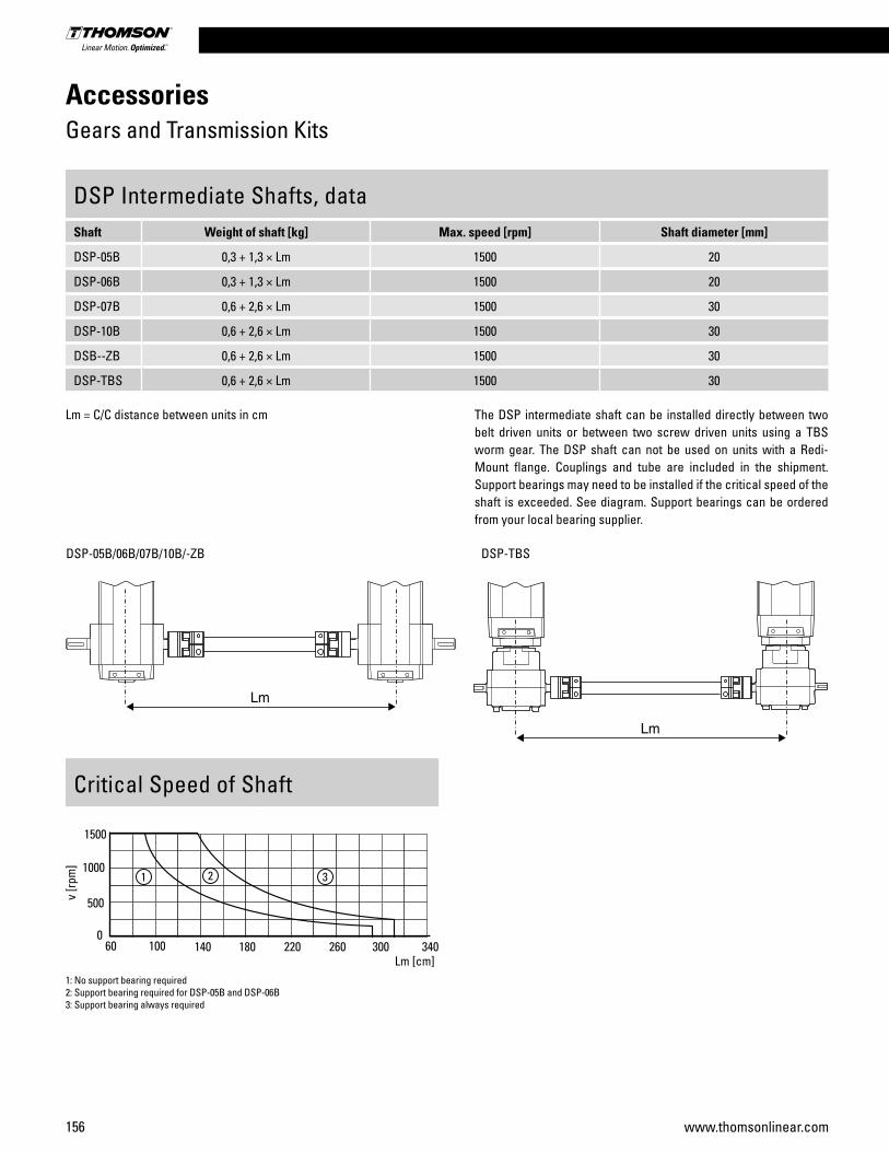
156 www.thomsonlinear.com
AccessoriesGears and Transmission Kits
DSP Intermediate Shafts, dataShaft Weight of shaft [kg] Max. speed [rpm] Shaft diameter [mm]
DSP-05B 0,3 + 1,3 × Lm 1500 20
DSP-06B 0,3 + 1,3 × Lm 1500 20
DSP-07B 0,6 + 2,6 × Lm 1500 30
DSP-10B 0,6 + 2,6 × Lm 1500 30
DSB--ZB 0,6 + 2,6 × Lm 1500 30
DSP-TBS 0,6 + 2,6 × Lm 1500 30
The DSP intermediate shaft can be installed directly between two belt driven units or between two screw driven units using a TBS worm gear. The DSP shaft can not be used on units with a Redi-Mount flange. Couplings and tube are included in the shipment. Support bearings may need to be installed if the critical speed of the shaft is exceeded. See diagram. Support bearings can be ordered from your local bearing supplier.
Critical Speed of Shaft
1: No support bearing required2: Support bearing required for DSP-05B and DSP-06B3: Support bearing always required
DSP-05B/06B/07B/10B/-ZB DSP-TBS
Lm = C/C distance between units in cm

Linear Motion Systems
157www.thomsonlinear.com
AccessoriesGears and Transmission Kits
DSP Intermediate Shafts, compatibility tableUnit Drive type DSP-05B DSP-06B DSP-07B DSP-10B DSP--ZB DSP-TBS
M50 belt •
M55 belt •
M75 belt •
M100 belt •
ZB belt •
M55 screw •
M75 screw •
M100 screw •
DSP Intermediate Shafts, ordering key
1 2
Example DSP-06B -305
1. Intermediate shaft size and typeDSP-05B = for belt driven M50 unitsDSP-06B = for belt driven M55 unitsDSP-07B = for belt driven M75 unitsDSP-10B = for belt driven M100 unitsDSP--ZB = for belt driven ZB unitsDSP-TBS = for screw driven M55, M75 or M100 units with TBS worm gear
2. C/C distance between units in cm (Lm) - xxx = length in cm
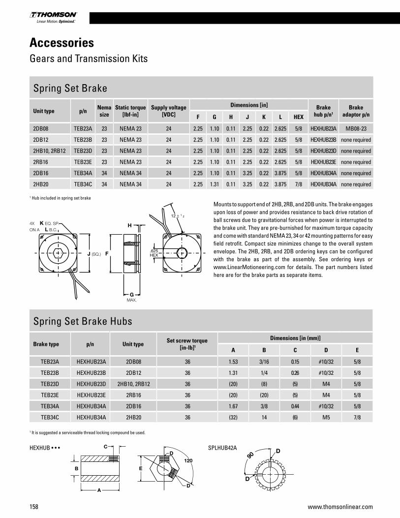
158 www.thomsonlinear.com
AccessoriesGears and Transmission Kits
Spring Set Brake
Unit type p/n Nema size
Static torque [lbf-in]
Supply voltage [VDC]
Dimensions [in] Brake hub p/n1
Brake adaptor p/nF G H J K L HEX
2DB08 TEB23A 23 NEMA 23 24 2.25 1.10 0.11 2.25 0.22 2.625 5/8 HEXHUB23A MB08-23
2DB12 TEB23B 23 NEMA 23 24 2.25 1.10 0.11 2.25 0.22 2.625 5/8 HEXHUB23B none required
2HB10, 2RB12 TEB23D 23 NEMA 23 24 2.25 1.10 0.11 2.25 0.22 2.625 5/8 HEXHUB23D none required
2RB16 TEB23E 23 NEMA 23 24 2.25 1.10 0.11 2.25 0.22 2.625 5/8 HEXHUB23E none required
2DB16 TEB34A 34 NEMA 34 24 2.25 1.10 0.11 3.25 0.22 3.875 5/8 HEXHUB34A none required
2HB20 TEB34C 34 NEMA 34 24 2.25 1.31 0.11 3.25 0.22 3.875 7/8 HEXHUB34A none required
Spring Set Brake Hubs
Brake type p/n Unit type Set screw torque [in-lb]1
Dimensions [in (mm)]
A B C D E
TEB23A HEXHUB23A 2DB08 36 1.53 3/16 0.15 #10/32 5/8
TEB23B HEXHUB23B 2DB12 36 1.31 1/4 0.26 #10/32 5/8
TEB23D HEXHUB23D 2HB10, 2RB12 36 (20) (8) (5) M4 5/8
TEB23E HEXHUB23E 2RB16 36 (20) (20) (5) M4 5/8
TEB34A HEXHUB34A 2DB16 36 1.67 3/8 0.44 #10/32 5/8
TEB34C HEXHUB34A 2HB20 36 (32) 14 (6) M5 7/8
1 Hub included in spring set brakeMounts to support end of 2HB, 2RB, and 2DB units. The brake engages upon loss of power and provides resistance to back drive rotation of ball screws due to gravitational forces when power is interrupted to the brake unit. They are pre-burnished for maximum torque capacity and come with standard NEMA 23, 34 or 42 mounting patterns for easy field retrofit. Compact size minimizes change to the overall system envelope. The 2HB, 2RB, and 2DB ordering keys can be configured with the brake as part of the assembly. See ordering keys or www.LinearMotioneering.com for details. The part numbers listed here are for the brake parts as separate items.
1 It is suggested a serviceable thread locking compound be used.
SPLHUB42AHEXHUB • • •
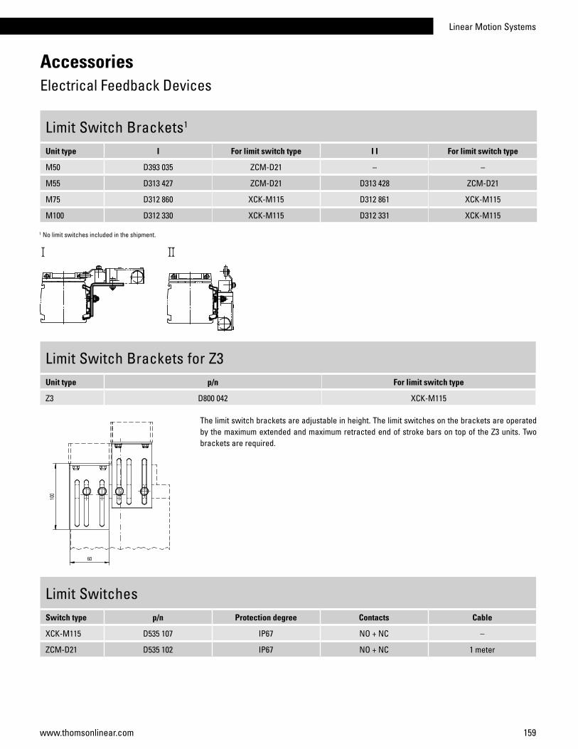
Linear Motion Systems
159www.thomsonlinear.com
AccessoriesElectrical Feedback Devices
Limit Switch Brackets1
Unit type I For limit switch type I I For limit switch type
M50 D393 035 ZCM-D21 – –
M55 D313 427 ZCM-D21 D313 428 ZCM-D21
M75 D312 860 XCK-M115 D312 861 XCK-M115
M100 D312 330 XCK-M115 D312 331 XCK-M115
1 No limit switches included in the shipment.
Limit SwitchesSwitch type p/n Protection degree Contacts Cable
XCK-M115 D535 107 IP67 NO + NC –
ZCM-D21 D535 102 IP67 NO + NC 1 meter
Limit Switch Brackets for Z3Unit type p/n For limit switch type
Z3 D800 042 XCK-M115
The limit switch brackets are adjustable in height. The limit switches on the brackets are operated by the maximum extended and maximum retracted end of stroke bars on top of the Z3 units. Two brackets are required.

160 www.thomsonlinear.com
AccessoriesElectrical Feedback Devices
Sensor Brackets for Cylindrical Sensors1
Unit type I For sensor diameter I I For sensor diameter
M55 D313 429 M12 D313 430 M12
M75 D312 862 M18 D312 863 M18
M100 D312 332 M18 D312 333 M18
1 no sensors included in the shipment
Cylindrical Inductive SensorsSensor type p/n Diameter Input voltage Max. current Protection degree Contacts Cable
PNP D535 085 M12 12 - 48 Vdc 0,2 A IP67 NO connector
PNP D535 089 M18 12 - 48 Vdc 0,2 A IP67 NO connector
Cylindrical Inductive Sensor ConnectorsFor sensor diameter p/n
M12 D535 092
M18 D535 091
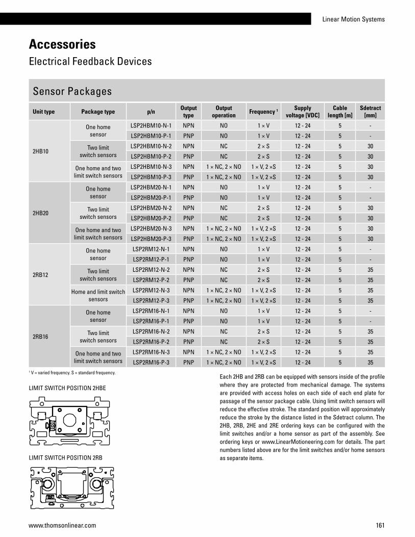
Linear Motion Systems
161www.thomsonlinear.com
Sensor Packages
Unit type Package type p/n Output type
Outputoperation Frequency 1 Supply
voltage [VDC]Cable
length [m]Sdetract
[mm]
2HB10
One home sensor
LSP2HBM10-N-1 NPN NO 1 × V 12 - 24 5 -
LSP2HBM10-P-1 PNP NO 1 × V 12 - 24 5 -
Two limit switch sensors
LSP2HBM10-N-2 NPN NC 2 × S 12 - 24 5 30
LSP2HBM10-P-2 PNP NC 2 × S 12 - 24 5 30
One home and two limit switch sensors
LSP2HBM10-N-3 NPN 1 × NC, 2 × NO 1 × V, 2 ×S 12 - 24 5 30
LSP2HBM10-P-3 PNP 1 × NC, 2 × NO 1 × V, 2 ×S 12 - 24 5 30
2HB20
One home sensor
LSP2HBM20-N-1 NPN NO 1 × V 12 - 24 5 -
LSP2HBM20-P-1 PNP NO 1 × V 12 - 24 5 -
Two limit switch sensors
LSP2HBM20-N-2 NPN NC 2 × S 12 - 24 5 30
LSP2HBM20-P-2 PNP NC 2 × S 12 - 24 5 30
One home and two limit switch sensors
LSP2HBM20-N-3 NPN 1 × NC, 2 × NO 1 × V, 2 ×S 12 - 24 5 30
LSP2HBM20-P-3 PNP 1 × NC, 2 × NO 1 × V, 2 ×S 12 - 24 5 30
2RB12
One home sensor
LSP2RM12-N-1 NPN NO 1 × V 12 - 24 5 -
LSP2RM12-P-1 PNP NO 1 × V 12 - 24 5 -
Two limit switch sensors
LSP2RM12-N-2 NPN NC 2 × S 12 - 24 5 35
LSP2RM12-P-2 PNP NC 2 × S 12 - 24 5 35
Home and limit switch sensors
LSP2RM12-N-3 NPN 1 × NC, 2 × NO 1 × V, 2 ×S 12 - 24 5 35
LSP2RM12-P-3 PNP 1 × NC, 2 × NO 1 × V, 2 ×S 12 - 24 5 35
2RB16
One home sensor
LSP2RM16-N-1 NPN NO 1 × V 12 - 24 5 -
LSP2RM16-P-1 PNP NO 1 × V 12 - 24 5 -
Two limit switch sensors
LSP2RM16-N-2 NPN NC 2 × S 12 - 24 5 35
LSP2RM16-P-2 PNP NC 2 × S 12 - 24 5 35
One home and two limit switch sensors
LSP2RM16-N-3 NPN 1 × NC, 2 × NO 1 × V, 2 ×S 12 - 24 5 35
LSP2RM16-P-3 PNP 1 × NC, 2 × NO 1 × V, 2 ×S 12 - 24 5 35
AccessoriesElectrical Feedback Devices
Each 2HB and 2RB can be equipped with sensors inside of the profile where they are protected from mechanical damage. The systems are provided with access holes on each side of each end plate for passage of the sensor package cable. Using limit switch sensors will reduce the effective stroke. The standard position will approximately reduce the stroke by the distance listed in the Sdetract column. The 2HB, 2RB, 2HE and 2RE ordering keys can be configured with the limit switches and/or a home sensor as part of the assembly. See ordering keys or www.LinearMotioneering.com for details. The part numbers listed above are for the limit switches and/or home sensors as separate items.
1 V = varied frequency. S = standard frequency.
LIMIT SWITCH POSITION 2HBE
LIMIT SWITCH POSITION 2RB

162 www.thomsonlinear.com
AccessoriesElectrical Feedback Devices
EN2 Inductive Sensors, dataParameter EN2
Supply voltage [Vdc] 10 – 30
Max. load current [A] 0,2
Operating distance [mm) 2
LED indicator for switch yes
Protection class IP67
Cable type screened
Weight with cable L = 2 m with cable L= 10 m
[kg]0,040,19
EN2 Inductive Sensors, part numbersSensor type Cable length [m] p/n
Normally closed 2 671 545 0305
Normally open 2 671 545 0304
Normally closed 10 671 545 0307
Normally open 10 671 545 0306
To be able to mount the EN2 inductive sensors on a unit the ENT14x16 sensor rail is required (see page 178) except for units WM120 and WV120 where they can be fitted directly to the profile of the unit.
Magnetic Sensors, dataParameter
Max. power [W] 10
Max. voltage [Vdc] 100
Max. current [A] 0,5
LED indicator for switch no
Protection class IP67
Cable length [m] 3
Cable cross section [mm2] 2 × 0,15
Operating temperature limits [°C] -25 – 65
Weight [kg] 0,050
Magnetic Sensors, part numbersSensor type suitable units p/n
Normally closed M50, Z2, Z3 D535 071
Normally open M50, Z2, Z3 D535 070
On M50 the magnetic sensors are mounted directly in the sensor slot of the profiles of the units and require no mounting bracket while Z2 and Z3 require magnetic sensor mounting brackets. The sensor is fixed in position by two M3 size locking screws (A1). The cable (A2) is molded into the sensor.
blue
black
blue
black

Linear Motion Systems
163www.thomsonlinear.com
AccessoriesElectrical Feedback Devices
IG602 Encoders, dataParameter IG602
Supply voltage Type 1 Type 2
[Vdc]5 ±10%10 – 30
Output type Type 1 Type 2
line driverpush-pull
Pulses per revolution Type 1 Type 2
[ppr]100 – 2500100 – 600
Length (L) Type 1 Type 2
[mm]51,556,0
Weight Type 1 Type 2
[kg]0,360,36
STE001 Encoder Connector, dataParameter STE001
Number of poles 12
Protection class IP67
Execution jack
Cable entrance straight
Weight [kg] 0,04
Part number 6715600153
IG602 Encoders, part numbersEncoder type Supply voltage
[Vdc)Pulses per revolution
p/n
Type 1 5 100 671 521 0194
Type 1 5 200 671 521 0195
Type 1 5 500 671 521 0196
Type 1 5 600 671 521 0197
Type 1 5 1000 671 521 0198
Type 1 5 1250 671 521 0199
Type 1 5 1500 671 521 0200
Type 1 5 2000 671 521 0192
Type 1 5 2500 671 521 0201
Type 2 10 – 30 100 671 521 0193
Type 2 10 – 30 200 671 521 0202
Type 2 10 – 30 500 671 521 0203
Type 2 10 – 30 600 671 521 0204
Type 2 10 – 30 600
The IG602 encoders come with mounting screws but no coupling or connector. To be able to mount the encoder to the unit, the unit must have a shaft for encoders. See the ordering keys of the units. The encoders can also be ordered mounted to the unit from factory. See ADG encoder option kit on page 170.
Encoder Cable, dataParameter p/n
5 m cable length 671 555 0068
10 m cable length 671 555 0069
The encoder cables come fitted with a STE001 encoder connector in one of the ends.

164 www.thomsonlinear.com
ES Limit Switch Option KitUnit type I I I I I I A B C D E F G
WH50 1 • 34 60,5 10 26 49 58,5 196
WH80 • 31 76 10 39 49 78,5 196
WH120 • 34 88 10 51 49 78,5 196
WHZ50 • 34 61 10 26 49 58,5 196
WHZ80 • 31 76 10 39 49 78,5 196
WM60 • 40 69 32 38 50 63 200
WM80 • 40 73 32 42 50 79 200
WM120 • 40 89 32 58 50 94 200
WM60Z • 40 69 32 38 50 73 200
WM80Z 2 • 40 73 32 42 50 99 (89) 200
WV60 • 40 69 32 38 50 33 200
WV80 • 40 73 32 42 50 39 200
WV120 • 40 89 32 58 50 59 200
MLSM60D • 40 73 32 32 50 79 200
MLSH60Z • 40 73 32 42 50 79 200
MLSM80D • 40 85 32 54 50 101 200
MLSM80Z • 40 85 32 54 50 101 200
WZ60 1 • 60 22,5 16 30 113 53 –
WZ80 1 • 60 22,5 16 30 112 84 –
1 Limit switches for these units can not be moved. On all other units the switches can be re-positioned by the customer. 2 Value in brackets = for short carriage.
The ES limit switch assembly is an option that is mounted at the factory. The limit switches are placed 10 mm from the mechanical ends of the unit. Each limit switch has one NO and one NC contact with positive opening action. Protection degree is IP67. Type I and II switches can be repositioned along the profile by the customer. Note! The ES limit switch option and any of the sensor rail options ENT14x16, ENF14x16 or ENK can not be mounted on the same side of the unit.
AccessoriesElectrical Feedback Devices
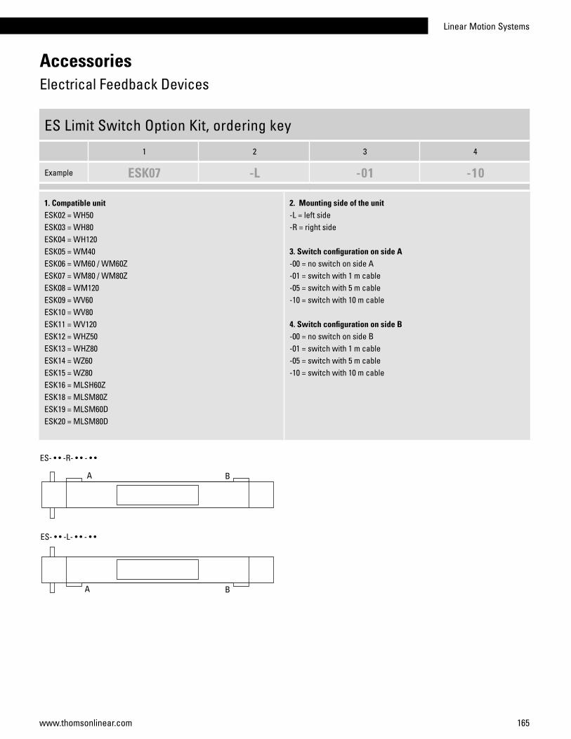
Linear Motion Systems
165www.thomsonlinear.com
AccessoriesElectrical Feedback Devices
ES Limit Switch Option Kit, ordering key
1 2 3 4
Example ESK07 -L -01 -10
1. Compatible unitESK02 = WH50ESK03 = WH80ESK04 = WH120ESK05 = WM40ESK06 = WM60 / WM60ZESK07 = WM80 / WM80ZESK08 = WM120ESK09 = WV60ESK10 = WV80ESK11 = WV120ESK12 = WHZ50ESK13 = WHZ80ESK14 = WZ60ESK15 = WZ80ESK16 = MLSH60ZESK18 = MLSM80ZESK19 = MLSM60DESK20 = MLSM80D
2. Mounting side of the unit-L = left side-R = right side
3. Switch configuration on side A-00 = no switch on side A-01 = switch with 1 m cable-05 = switch with 5 m cable-10 = switch with 10 m cable
4. Switch configuration on side B-00 = no switch on side B-01 = switch with 1 m cable-05 = switch with 5 m cable-10 = switch with 10 m cable

166 www.thomsonlinear.com
AccessoriesElectrical Feedback Devices
ENT14x16 Inductive Sensor RailUnit type p/n
WH40 / WH50 / WH80 / WH120 / WHZ50 / WHZ80 / WM40 / WM60 / WM80 / WM60Z / WM80Z / WV60 / WV80 / MLSM60D / MLSM80D / MLSH60Z / MLSM80Z / WZ60 / WZ80 / WB40 / WB60 671 545 0283
The ENT14x16 inductive sensor rail is mounted to the side of a unit or along any type of beam or profile. Sensors of type EN2 can be mounted in the rail. The rail can also serve as a cable duct for the sensor cables. The rail is sealed with a cover which comes with the rail. The rail comes in lengths of max 3000 mm. Drilling in the profile of the unit is required when mounting the rail. When ordering, specify part number and length of the rail. Note1! WM120 and WV120 units do not require any rail as the EN2 sensors can be fitted directly to the profile of the units. Note2! ES limit switch option and ENT14x16 rail can not be mounted on the same side of the unit.
The ENF and ENK inductive sensor rail option kits are mounted at the factory. The ENF option consists of two 500 mm long ENT14x16 sensor rails mounted in each end of the unit on the left or right side of the profile. In cases where the unit is too short to allow two 500 mm sensor rails to be mounted, then one rail is mounted along the entire profile of the unit. The ENK option also consists of ENT14 x16 sensor rails but the ENK option has sensor profiles that run along the entire profile of the unit. In the shipment of both ENF and ENK the specified amount and type of EN2 sensors are included. The sensors are fitted to the sensor rail by the customer at the desired positions.
Note1! WM120 and WV120 units do not require any ENF or ENK options as the EN2 sensors can be fitted directly to the profile of the units.Note2! The ES limit switch option and ENF rail can not be mounted on the same side of the unit.Note3! Movopart M50/75/100 units require adapter plates for mounting the ENF/ENK to the profile. See page 135 for adapter plate dimensions.
ENF and ENK Inductive Sensor Rail Option Kit, compatibility tableUnit type ENF / ENK
WH40 / WH50 / WH80 / WH120 / WHZ50 / WHZ80 / WM40 / WM60 / WM80 / WM60Z / WM80Z / WV60 / WV80 / MLSM60D / MLSM80D / MLSH60Z / MLSM80Z / WZ60 / WZ80 / WB40 / WB60 / M50 / M75 / M100 •
ENF
ENK

Linear Motion Systems
167www.thomsonlinear.com
AccessoriesElectrical Feedback Devices
ENK and ENF Inductive Sensor Rail Option Kit, ordering key
1 2 3 4 5 6 7 8
Example ENK16 -S -04000 -R -2 -0 -1 -6
1. Type of rail and compatible unitENK01 = ENK rail for WH40ENK02 = ENK rail for WH50ENK03 = ENK rail for WH80ENK04 = ENK rail for WH120ENK05 = ENK rail for WM40ENK06 = ENK rail for WM60 / WV60ENK07 = ENK rail for WM80 / WV80ENK08 = ENK rail for WM120 / WV120ENK09 = ENK rail for WM60ZENK10 = ENK rail for WM80ZENK11 = ENK rail for WHZ50ENK12 = ENK rail for WHZ80ENK13 = ENK rail for WZ60ENK14 = ENK rail for WZ80ENK15 = ENK rail for MLSH60ZENK17 = ENK rail for MLSM80ZENK18 = ENK rail for MLSM60DENK19 = ENK rail for MLSM80DENK20 = ENK rail for WB40ENK21 = ENK rail for WB60ENK28 = ENK rail for MF/MG07KENK29 = ENK rail for MF/MG06KENK30 = ENK rail for MF/MG06BENK31 = ENK rail for MF/MG07BENK32 = ENK rail for MF/MG10KENK33 = ENK rail for MF/MG10B
ENF01 = ENF rail for WH40ENF02 = ENF rail for WH50ENF03 = ENF rail for WH80ENF04 = ENF rail for WH120ENF05 = ENF rail for WM40ENF06 = ENF rail for WM60 / WV60ENF07 = ENF rail for WM80 / WV80ENF08 = ENF rail for WM120 / WV120ENF09 = ENF rail for WM60ZENF10 = ENF rail for WM80ZENF11 = ENF rail for WHZ50ENF12= ENF rail for WHZ80ENF13 = ENF rail for WZ60ENF14 = ENF rail for WZ80ENF15 = ENF rail for MLSH60ZENF17 = ENF rail for MLSM80ZENF18 = ENF rail for MLSM60DENF19 = ENF rail for MLSM80DENF20 = ENF rail for WB40ENF21 = ENF rail for WB60ENF28 = ENF rail for MF/MG07KENF29 = ENF rail for MF/MG06KENF30 = ENF rail for MF/MG06BENF31 = ENF rail for MF/MG07BENF32 = ENF rail for MF/MG10KENF33 = ENF rail for MF/MG10B
2. Number of carriages-S = single carriage-D = double carriages
3. Total length of unit (L tot)- vvvvv = distance in mm
4. Mounting side of the unit-L = left side-R = right side
5. Number of EN2 sensors with NC contact and 2 m cable- w = 0 – 9 sensors / normally closed / 2 m cable
6. Number of EN2 sensors with NO contact and 2 m cable- x = 0 – 9 sensors / normally open / 2 m cable
7. Number of EN2 sensors with NC contact and 10 m cable- y = 0 – 9 sensors / normally closed / 10 m cable
8. Number of EN2 sensors with NO contact and 10 m cable- z = 0 – 9 sensors / normally open / 10 m cable
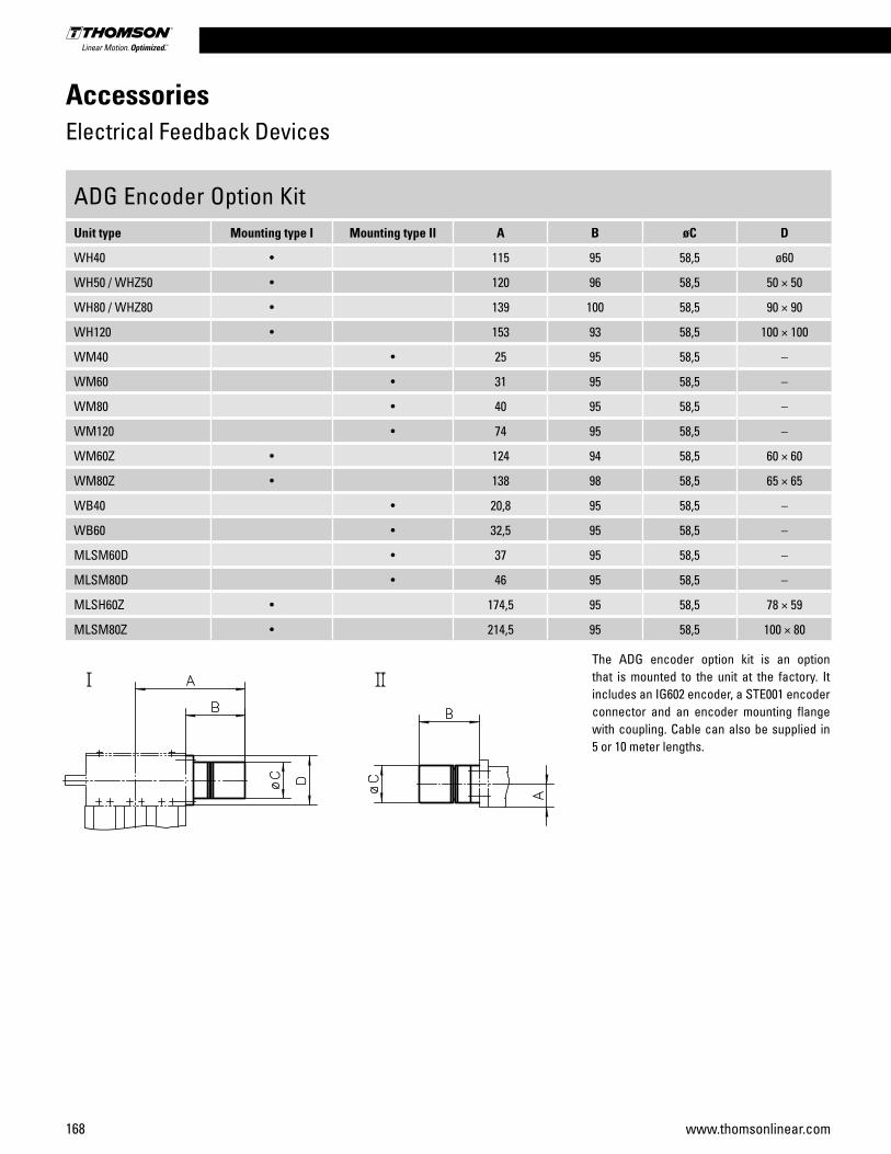
168 www.thomsonlinear.com
AccessoriesElectrical Feedback Devices
ADG Encoder Option KitUnit type Mounting type I Mounting type II A B øC D
WH40 • 115 95 58,5 ø60
WH50 / WHZ50 • 120 96 58,5 50 × 50
WH80 / WHZ80 • 139 100 58,5 90 × 90
WH120 • 153 93 58,5 100 × 100
WM40 • 25 95 58,5 –
WM60 • 31 95 58,5 –
WM80 • 40 95 58,5 –
WM120 • 74 95 58,5 –
WM60Z • 124 94 58,5 60 × 60
WM80Z • 138 98 58,5 65 × 65
WB40 • 20,8 95 58,5 –
WB60 • 32,5 95 58,5 –
MLSM60D • 37 95 58,5 –
MLSM80D • 46 95 58,5 –
MLSH60Z • 174,5 95 58,5 78 × 59
MLSM80Z • 214,5 95 58,5 100 × 80
The ADG encoder option kit is an option that is mounted to the unit at the factory. It includes an IG602 encoder, a STE001 encoder connector and an encoder mounting flange with coupling. Cable can also be supplied in 5 or 10 meter lengths.

Linear Motion Systems
169www.thomsonlinear.com
AccessoriesElectrical Feedback Devices
ADG Encoder Option Kit, ordering key
1 2 3
Example ADG-08 -05-0600 -00
1. Compatible unitADG-01 = WH40ADG-02 = WH50 / WHZ50ADG-03 = WH80 / WHZ80ADG-04 = WH120ADG-05 = WM40ADG-06 = WM60 / WV60ADG-07 = WM80 / WV80ADG-08 = WM120 / WV120ADG-09 = WM60ZADG-10 = WM80Z ADG-11 = MLSH60ZADG-13 = MLSM80ZADG-14 = MLSM60DADG-15 = MLSM80DADG-16 = WB40ADG-17 = WB60
2. Supply voltage and number of pulses-05-0100 = 5 volts, 100 pulses per revolution-05-0200 = 5 volts, 200 pulses per revolution-05-0500 = 5 volts, 500 pulses per revolution-05-0600 = 5 volts, 600 pulses per revolution-05-1000 = 5 volts, 1000 pulses per revolution-05-1250 = 5 volts, 1250 pulses per revolution-05-2000 = 5 volts, 2000 pulses per revolution-05-2500 = 5 volts, 2500 pulses per revolution-24-0100 = 10 - 30 volts, 100 pulses per revolution-24-0200 = 10 - 30 volts, 200 pulses per revolution-24-0500 = 10 - 30 volts, 500 pulses per revolution-24-0600 = 10 - 30 volts, 600 pulses per revolution
3. Cable and connector configuration-00 = no cable only STE001 encoder connector -05 = 5 m cable with STE001 encoder connector in one of the ends-10 = 10 m cable with STE001 encoder connector in one of the ends
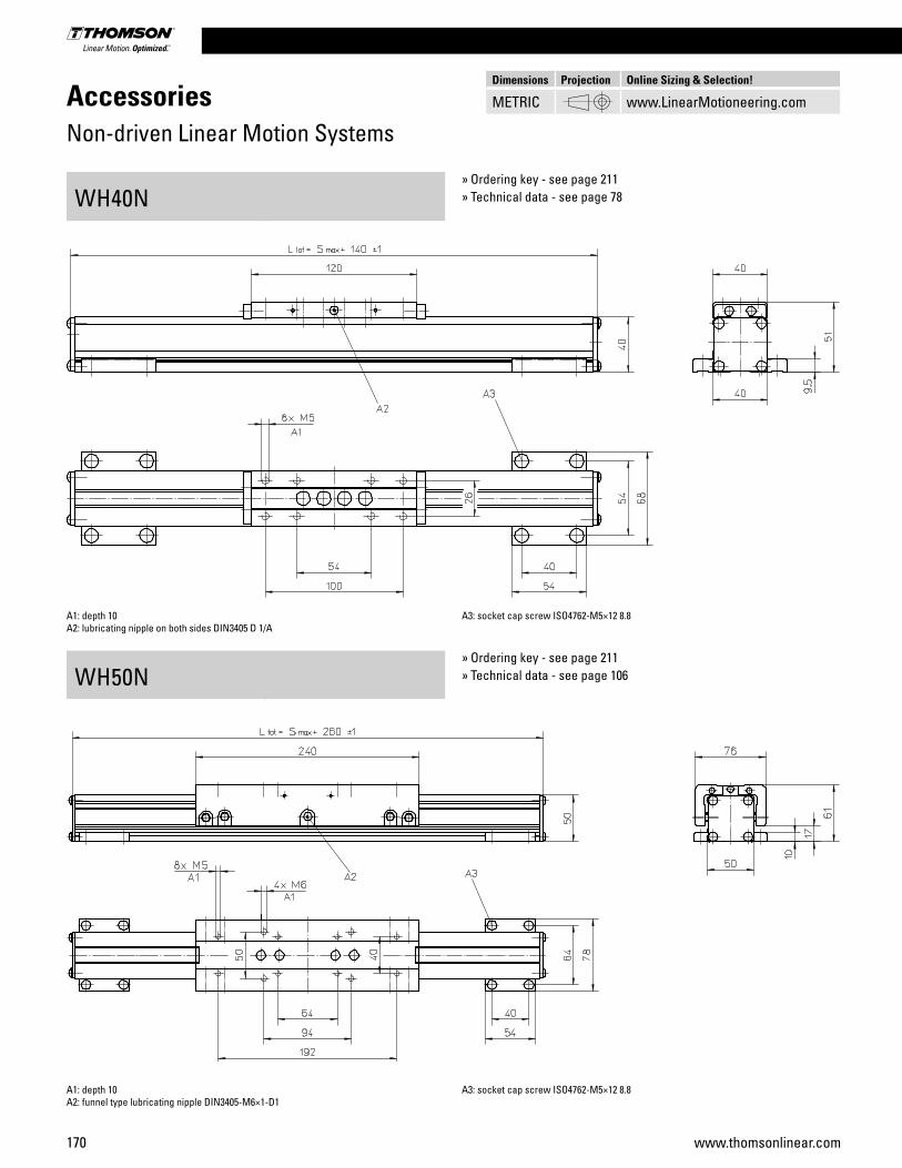
170 www.thomsonlinear.com
AccessoriesNon-driven Linear Motion Systems
WH40N
WH50N
A1: depth 10A2: lubricating nipple on both sides DIN3405 D 1/A
A3: socket cap screw ISO4762-M5×12 8.8
A1: depth 10A2: funnel type lubricating nipple DIN3405-M6×1-D1
A3: socket cap screw ISO4762-M5×12 8.8
» Ordering key - see page 211» Technical data - see page 78
» Ordering key - see page 211» Technical data - see page 106
Dimensions Projection Online Sizing & Selection!
METRIC www.LinearMotioneering.com

Linear Motion Systems
171www.thomsonlinear.com
AccessoriesNon-driven Linear Motion Systems
WH80N
WH120N
A1: depth 12A2: funnel type lubricating nipple DIN3405-M6×1-D1
A3: socket cap screw ISO4762-M6×20 8.8
A1: depth 12A2: funnel type lubricating nipple DIN3405-M6×1-D1
A3: socket cap screw ISO4762-M8×20 8.8
» Ordering key - see page 211» Technical data - see page 108
» Ordering key - see page 211» Technical data - see page 110
Dimensions Projection Online Sizing & Selection!
METRIC www.LinearMotioneering.com

172 www.thomsonlinear.com
AccessoriesNon-driven Linear Motion Systems
WM40N
WM60N
A1: depth 7A2: lubricating nipple on both sides DIN3405 D 1/A
A3: socket cap screw ISO4762-M5×12 8.8
A1: depth 11A2: socket cap screw ISO4762-M6×20 8.8
A3: tapered lubricating nipple to DIN71412 AM6A4: can be changed over to one of the three alternative lubricating points by the customer
» Ordering key - see page 211» Technical data - see page 14
» Ordering key - see page 211» Technical data - see page 18
Dimensions Projection Online Sizing & Selection!
METRIC www.LinearMotioneering.com

Linear Motion Systems
173www.thomsonlinear.com
AccessoriesNon-driven Linear Motion Systems
WM60N with Single Short Carriage
WM80N
A1: depth 11A2: socket cap screw ISO4762-M6×20 8.8
A3: tapered lubricating nipple to DIN71412 AM6A4: can be changed over to one of the three alternative lubricating points by the customer
A1: depth 12A2: socket cap screw ISO4762-M6×20 8.8
A3: tapered lubricating nipple to DIN71412 AM6A4: can be changed over to one of the three alternative lubricating points by the customer
» Ordering key - see page 211» Technical data - see page 20
» Ordering key - see page 211» Technical data - see page 24
Dimensions Projection Online Sizing & Selection!
METRIC www.LinearMotioneering.com

174 www.thomsonlinear.com
AccessoriesNon-driven Linear Motion Systems
WM80N with Single Short Carriage
WM120N
A1: depth 12A2: socket cap screw ISO4762-M6×20 8.8
A3: tapered lubricating nipple to DIN71412 AM6A4: can be changed over to one of the three alternative lubricating points by the customer
A1: depth 22A2: socket cap screw ISO4762-M8×20 8.8
A3: tapered lubricating nipple to DIN71412 M8×1A4: can be changed over to one of the three alternative lubricating points by the customer
» Ordering key - see page 211» Technical data - see page 26
» Ordering key - see page 211» Technical data - see page 34
Dimensions Projection Online Sizing & Selection!
METRIC www.LinearMotioneering.com
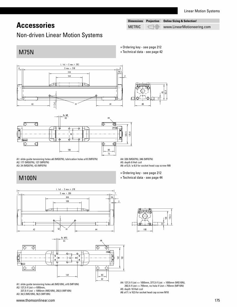
Linear Motion Systems
175www.thomsonlinear.com
AccessoriesNon-driven Linear Motion Systems
M75N
M100N
A1: slide guide tensioning holes ø6 (MG07N), lubrication holes ø10 (MF07N)A2: 177 (MG07N), 127 (MF07N)A3: 24 (MG07N), 43 (MF07N)
A4: 326 (MG07N), 346 (MF07N)A5: depth 8 Heli coilA6: ø13,5 / ø 8,5 for socket head cap screw M8
A1: slide guide tensioning holes ø6 (MG10N), ø10 (MF10N)A2: 127,5 if Ltot <=1055mm, 227,5 if Ltot > 1055mm (MG10N), 292,5 (MF10N)A3: 34,5 (MG10N), 56,5 (MF10N)
A4: 127,5 if Ltot <= 1055mm, 377,5 if Ltot > 1055mm (MG10N), 292,5 if Ltot => 755mm, no hole if Ltot < 755mm (MF10N)A5: depth 10 Heli coilA6: ø17 / ø 10,5 for socket head cap screw M10
» Ordering key - see page 212» Technical data - see page 42
» Ordering key - see page 212» Technical data - see page 44
Dimensions Projection Online Sizing & Selection!
METRIC www.LinearMotioneering.com
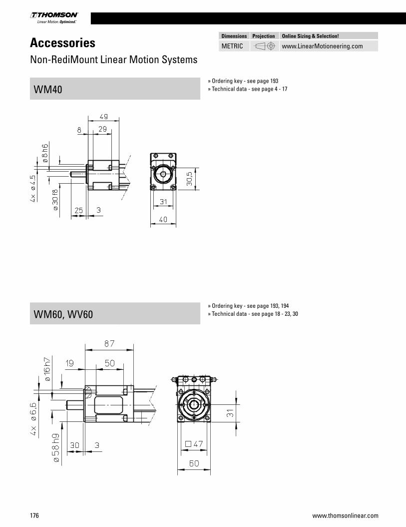
176 www.thomsonlinear.com
AccessoriesNon-RediMount Linear Motion Systems
WM40
WM60, WV60
» Ordering key - see page 193» Technical data - see page 4 - 17
» Ordering key - see page 193, 194» Technical data - see page 18 - 23, 30
Dimensions Projection Online Sizing & Selection!
METRIC www.LinearMotioneering.com

Linear Motion Systems
177www.thomsonlinear.com
WM120, WV120» Ordering key - see page 193. 194» Technical data - see page 28, 32
AccessoriesNon-RediMount Linear Motion Systems
WM80, WV80» Ordering key - see page 193, 194» Technical data - see page 24 - 27, 32
Dimensions Projection Online Sizing & Selection!
METRIC www.LinearMotioneering.com

178 www.thomsonlinear.com
AccessoriesNon-RediMount Linear Motion Systems
MLSM60D
MLSM80D
» Ordering key - see page 195» Technical data - see page 36
» Ordering key - see page 195» Technical data - see page 38
Dimensions Projection Online Sizing & Selection!
METRIC www.LinearMotioneering.com
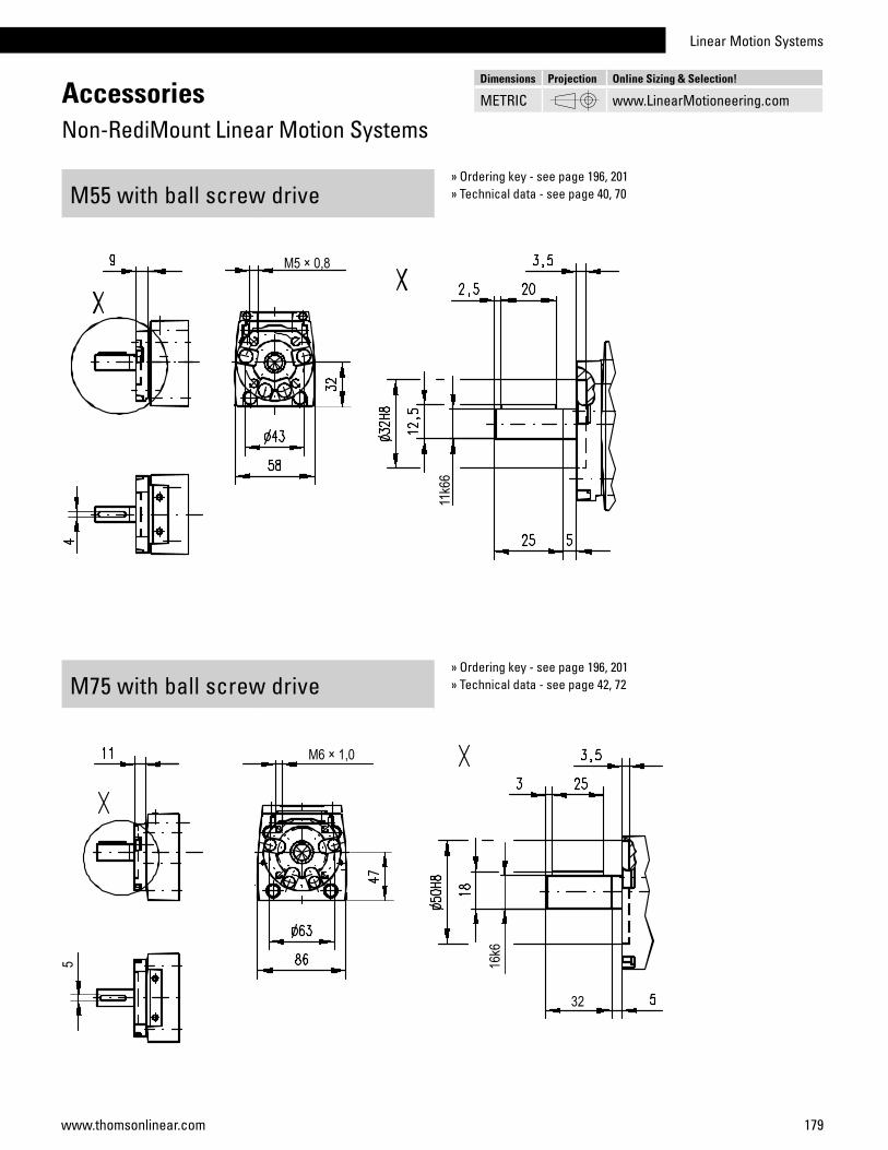
Linear Motion Systems
179www.thomsonlinear.com
M75 with ball screw drive» Ordering key - see page 196, 201» Technical data - see page 42, 72
AccessoriesNon-RediMount Linear Motion Systems
M55 with ball screw drive» Ordering key - see page 196, 201» Technical data - see page 40, 70
Dimensions Projection Online Sizing & Selection!
METRIC www.LinearMotioneering.com
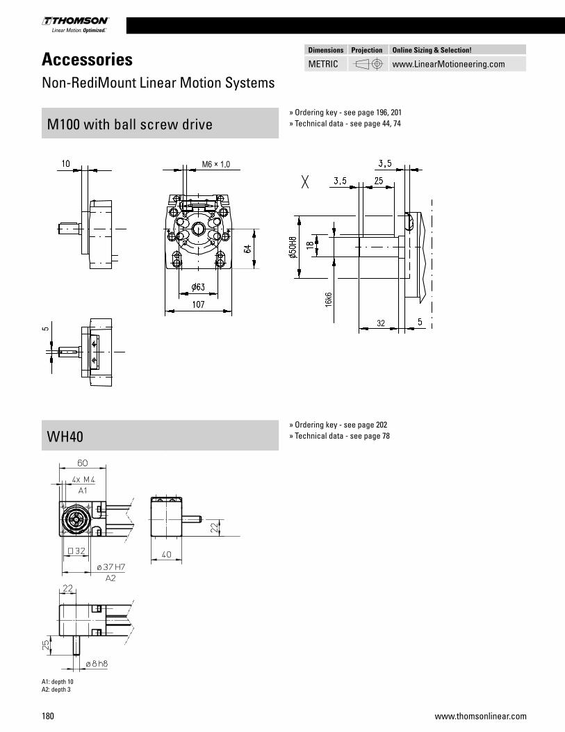
180 www.thomsonlinear.com
AccessoriesNon-RediMount Linear Motion Systems
M100 with ball screw drive
WH40
» Ordering key - see page 196, 201» Technical data - see page 44, 74
» Ordering key - see page 202» Technical data - see page 78
Dimensions Projection Online Sizing & Selection!
METRIC www.LinearMotioneering.com
A1: depth 10A2: depth 3

Linear Motion Systems
181www.thomsonlinear.com
WM80Z» Ordering key - see page 203» Technical data - see page 82
AccessoriesNon-RediMount Linear Motion Systems
WM60Z» Ordering key - see page 203» Technical data - see page 80
Dimensions Projection Online Sizing & Selection!
METRIC www.LinearMotioneering.com
A1: depth 15A2: depth 4
A1: depth 15A2: depth 2,5
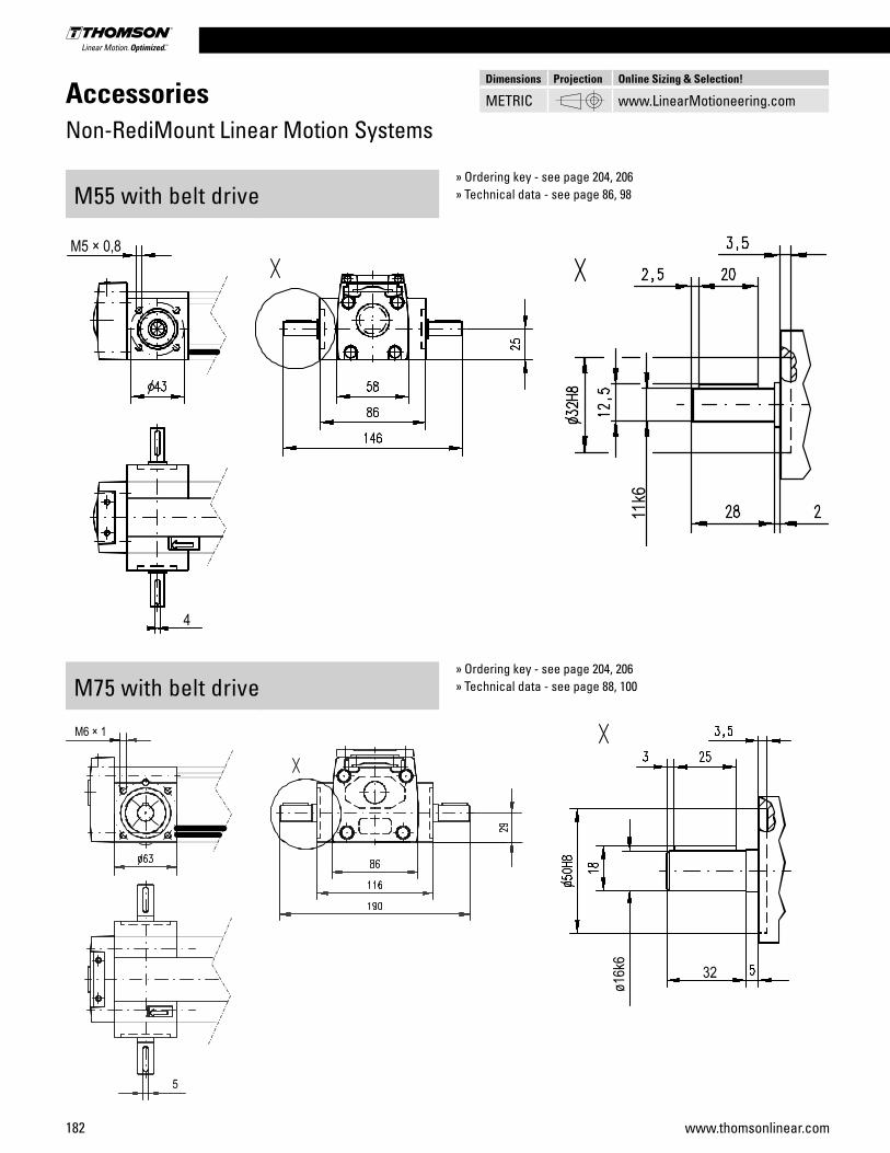
182 www.thomsonlinear.com
AccessoriesNon-RediMount Linear Motion Systems
M55 with belt drive
M75 with belt drive
» Ordering key - see page 204, 206» Technical data - see page 86, 98
» Ordering key - see page 204, 206» Technical data - see page 88, 100
Dimensions Projection Online Sizing & Selection!
METRIC www.LinearMotioneering.com
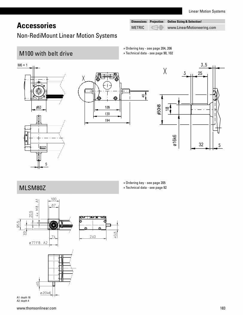
Linear Motion Systems
183www.thomsonlinear.com
MLSM80Z» Ordering key - see page 205» Technical data - see page 92
AccessoriesNon-RediMount Linear Motion Systems
M100 with belt drive» Ordering key - see page 204, 206» Technical data - see page 90, 102
Dimensions Projection Online Sizing & Selection!
METRIC www.LinearMotioneering.com
A1: depth 18A2: depth 4
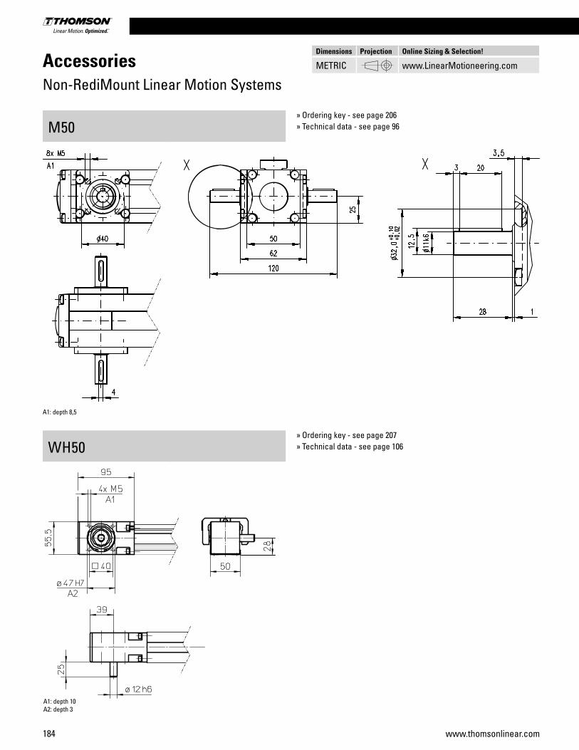
184 www.thomsonlinear.com
AccessoriesNon-RediMount Linear Motion Systems
M50
WH50
» Ordering key - see page 206» Technical data - see page 96
» Ordering key - see page 207» Technical data - see page 106
Dimensions Projection Online Sizing & Selection!
METRIC www.LinearMotioneering.com
A1: depth 8,5
A1: depth 10A2: depth 3
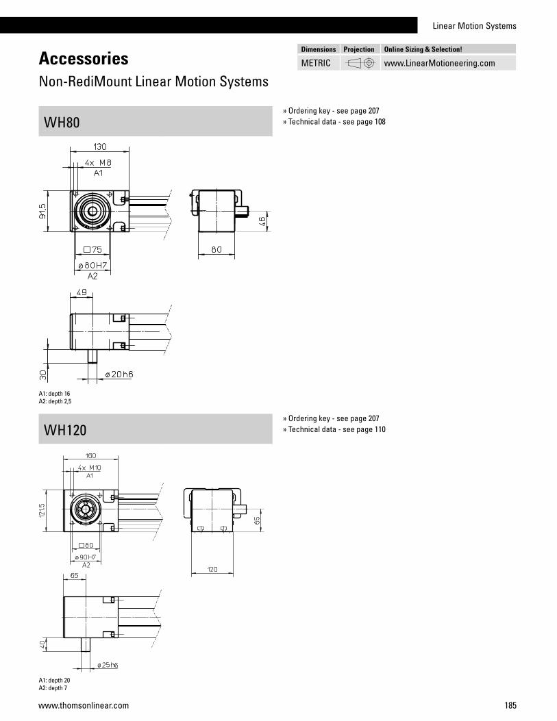
Linear Motion Systems
185www.thomsonlinear.com
WH120» Ordering key - see page 207» Technical data - see page 110
AccessoriesNon-RediMount Linear Motion Systems
WH80» Ordering key - see page 207» Technical data - see page 108
Dimensions Projection Online Sizing & Selection!
METRIC www.LinearMotioneering.com
A1: depth 16A2: depth 2,5
A1: depth 20A2: depth 7
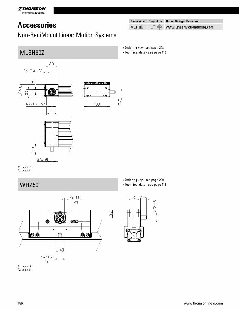
186 www.thomsonlinear.com
AccessoriesNon-RediMount Linear Motion Systems
MLSH60Z
WHZ50
» Ordering key - see page 208» Technical data - see page 112
» Ordering key - see page 209» Technical data - see page 116
Dimensions Projection Online Sizing & Selection!
METRIC www.LinearMotioneering.com
A1: depth 10A2: depth 4
A1: depth 12A2: depth 3,5
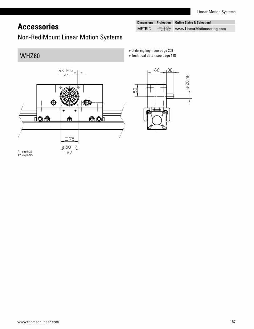
Linear Motion Systems
187www.thomsonlinear.com
AccessoriesNon-RediMount Linear Motion Systems
WHZ80» Ordering key - see page 209» Technical data - see page 118
Dimensions Projection Online Sizing & Selection!
METRIC www.LinearMotioneering.com
A1: depth 20A2: depth 3,5
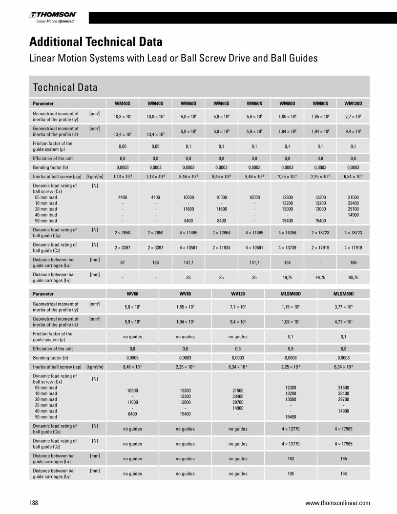
188 www.thomsonlinear.com
Additional Technical DataLinear Motion Systems with Lead or Ball Screw Drive and Ball Guides
Technical DataParameter WM40S WM40D WM60D WM60S WM60X WM80D WM80S WM120D
Geometrical moment of inertia of the profile (ly)
[mm4] 10,8 × 10⁴ 10,8 × 10⁴ 5,8 × 10⁵ 5,8 × 10⁵ 5,8 × 10⁵ 1,85 × 10⁶ 1,85 × 10⁶ 7,7 × 10⁶
Geometrical moment of inertia of the profile (lz)
[mm4]13,4 × 10⁴ 13,4 × 10⁴ 5,9 × 10⁵ 5,9 × 10⁵ 5,9 × 10⁵ 1,94 × 10⁶ 1,94 × 10⁶ 9,4 × 10⁶
Friction factor of the guide system (µ) 0,05 0,05 0,1 0,1 0,1 0,1 0,1 0,1
Efficiency of the unit 0,8 0,8 0,8 0,8 0,8 0,8 0,8 0,8
Bending factor (b) 0,0003 0,0003 0,0003 0,0003 0,0003 0,0003 0,0003 0,0003
Inertia of ball screw (jsp) [kgm2/m] 1,13 × 10⁻⁵ 1,13 × 10⁻⁵ 8,46 × 10⁻⁵ 8,46 × 10⁻⁵ 8,46 × 10⁻⁵ 2,25 × 10⁻⁴ 2,25 × 10⁻⁴ 6,34 × 10⁻⁴
Dynamic load rating of ball screw (Cx) 05 mm lead 10 mm lead 20 mm lead 40 mm lead 50 mm lead
[N]
4400----
4400----
10500-
11600-
8400
10500-
11600-
8400
10500----
123001320013000
-15400
123001320013000
-15400
21500334002970014900
-
Dynamic load rating of ball guide (Cy)
[N] 2 × 2650 2 × 2650 4 × 11495 2 × 12964 4 × 11495 4 × 14356 2 × 18723 4 × 18723
Dynamic load rating of ball guide (Cz)
[N] 2 × 3397 2 × 3397 4 × 10581 2 × 11934 4 × 10581 4 × 13739 2 × 17919 4 × 17919
Distance between ball guide carriages (Lx)
[mm] 87 136 141,7 - 141,7 154 - 186
Distance between ball guide carriages (Ly)
[mm] - - 35 35 35 49,75 49,75 80,75
Parameter WV60 WV80 WV120 MLSM60D MLSM80D
Geometrical moment of inertia of the profile (ly)
[mm4] 5,8 × 10⁵ 1,85 × 10⁶ 7,7 × 10⁶ 1,19 × 10⁶ 3,77 × 10⁶
Geometrical moment of inertia of the profile (lz)
[mm4] 5,9 × 10⁵ 1,94 × 10⁶ 9,4 × 10⁶ 1,08 × 10⁷ 4,71 × 10⁷
Friction factor of the guide system (µ) no guides no guides no guides 0,1 0,1
Efficiency of the unit 0,8 0,8 0,8 0,8 0,8
Bending factor (b) 0,0003 0,0003 0,0003 0,0003 0,0003
Inertia of ball screw (jsp) [kgm2/m] 8,46 × 10⁻⁵ 2,25 × 10⁻⁴ 6,34 × 10⁻⁴ 2,25 × 10⁻⁴ 6,34 × 10⁻⁴
Dynamic load rating of ball screw (Cx) 05 mm lead 10 mm lead 20 mm lead 25 mm lead 40 mm lead 50 mm lead
[N]
10500-
11600-
8400
123001320013000
-15400
21500334002970014900
-
123001320013000
--
15400
215003340029700
-14900
-
Dynamic load rating of ball guide (Cy)
[N] no guides no guides no guides 4 × 13770 4 × 17965
Dynamic load rating of ball guide (Cz)
[N] no guides no guides no guides 4 × 13770 4 × 17965
Distance between ball guide carriages (Lx)
[mm] no guides no guides no guides 163 185
Distance between ball guide carriages (Ly)
[mm] no guides no guides no guides 105 164
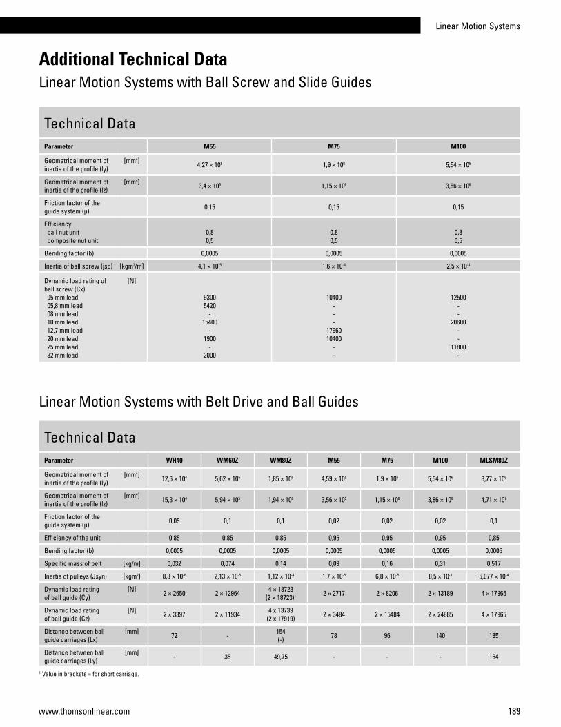
Linear Motion Systems
189www.thomsonlinear.com
Additional Technical DataLinear Motion Systems with Ball Screw and Slide Guides
Technical DataParameter M55 M75 M100
Geometrical moment of inertia of the profile (ly)
[mm4] 4,27 × 10⁵ 1,9 × 10⁶ 5,54 × 10⁶
Geometrical moment of inertia of the profile (lz)
[mm4] 3,4 × 10⁵ 1,15 × 10⁶ 3,86 × 10⁶
Friction factor of the guide system (µ) 0,15 0,15 0,15
Efficiency ball nut unit composite nut unit
0,80,5
0,80,5
0,80,5
Bending factor (b) 0,0005 0,0005 0,0005
Inertia of ball screw (jsp) [kgm2/m] 4,1 × 10⁻⁵ 1,6 × 10⁻⁴ 2,5 × 10⁻⁴
Dynamic load rating of ball screw (Cx) 05 mm lead 05,8 mm lead 08 mm lead 10 mm lead 12,7 mm lead 20 mm lead 25 mm lead 32 mm lead
[N]
93005420
-15400
-1900
-2000
10400---
1796010400
--
12500--
20600--
11800-
Technical DataParameter WH40 WM60Z WM80Z M55 M75 M100 MLSM80Z
Geometrical moment of inertia of the profile (ly)
[mm4] 12,6 × 10⁴ 5,62 × 10⁵ 1,85 × 10⁶ 4,59 × 10⁵ 1,9 × 10⁶ 5,54 × 10⁶ 3,77 × 10⁶
Geometrical moment of inertia of the profile (lz)
[mm4] 15,3 × 10⁴ 5,94 × 10⁵ 1,94 × 10⁶ 3,56 × 10⁵ 1,15 × 10⁶ 3,86 × 10⁶ 4,71 × 10⁷
Friction factor of the guide system (µ) 0,05 0,1 0,1 0,02 0,02 0,02 0,1
Efficiency of the unit 0,85 0,85 0,85 0,95 0,95 0,95 0,85
Bending factor (b) 0,0005 0,0005 0,0005 0,0005 0,0005 0,0005 0,0005
Specific mass of belt [kg/m] 0,032 0,074 0,14 0,09 0,16 0,31 0,517
Inertia of pulleys (Jsyn) [kgm2] 8,8 × 10⁻⁶ 2,13 × 10⁻⁵ 1,12 × 10⁻⁴ 1,7 × 10⁻⁵ 6,8 × 10⁻⁵ 8,5 × 10⁻⁵ 5,077 × 10-4
Dynamic load rating of ball guide (Cy)
[N] 2 × 2650 2 × 12964 4 × 18723(2 × 18723)1 2 × 2717 2 × 8206 2 × 13189 4 × 17965
Dynamic load rating of ball guide (Cz)
[N] 2 × 3397 2 × 11934 4 x 13739(2 x 17919) 2 × 3484 2 × 15484 2 × 24885 4 × 17965
Distance between ball guide carriages (Lx)
[mm] 72 - 154(-) 78 96 140 185
Distance between ball guide carriages (Ly)
[mm] - 35 49,75 - - - 164
1 Value in brackets = for short carriage.
Linear Motion Systems with Belt Drive and Ball Guides

190 www.thomsonlinear.com
Technical DataParameter M50 M55 M75 M100
Geometrical moment of inertia of the profile (ly)
[mm4] 2,61 × 10⁵ 4,59 × 10⁵ 1,9 × 10⁶ 5,54 × 10⁶
Geometrical moment of inertia of the profile (lz)
[mm4] 2,44 × 10⁵ 3,56 × 10⁵ 1,15 × 10⁶ 3,86 × 10⁶
Friction factor of the guide system (µ) 0,15 0,15 0,15 0,15
Efficiency of the unit 0,85 0,85 0,85 0,85
Bending factor (b) 0,0005 0,0005 0,0005 0,0005
Specific mass of belt [kg/m] 0,086 0,09 0,16 0,31
Inertia of pulleys (Jsyn) [kgm2] 3,1 × 10⁻⁵ 1,7 × 10⁻⁵ 6,8 × 10⁻⁵ 8,5 × 10⁻⁵
Additional Technical DataLinear Motion Systems with Belt Drive and Slide Guides
Technical DataParameter WH50 WH80 WH120 MLSH60Z
Geometrical moment of inertia of the profile (ly)
[mm4] 3,3 × 10⁵ 1,93 × 10⁶ 6,69 × 10⁶ 1,29 × 10⁶
Geometrical moment of inertia of the profile (lz)
[mm4] 2,65 × 10⁵ 1,8 × 10⁶ 6,88 × 10⁶ 1,2 × 10⁷
Friction factor of the guide system (µ) 0,1 0,1 0,1 0,1
Efficiency of the unit 0,85 0,85 0,85 0,85
Bending factor (b) 0,0005 0,0005 0,0005 0,0005
Specific mass of belt [kg/m] 0,055 0,21 0,34 0,119
Inertia of pulleys (Jsyn) [kgm2] 1,928 × 10-5 2.473 × 10⁻⁴ 1,004 × 10-3 4,604× 10-5
Dynamic load rating of wheel guide (Cy)
[N] - - - 4 × 1266
Dynamic load rating of wheel guide (Cz)
[N] 4 × 1270 4 × 3670 4 × 16200 4 × 1266
Distance between carriage wheels (Lx)
[mm] 198 220 180 109
Distance between carriage wheels (Ly)
[mm] 39 65 97 102,5
Linear Motion Systems with Belt Drive and Wheel Guides
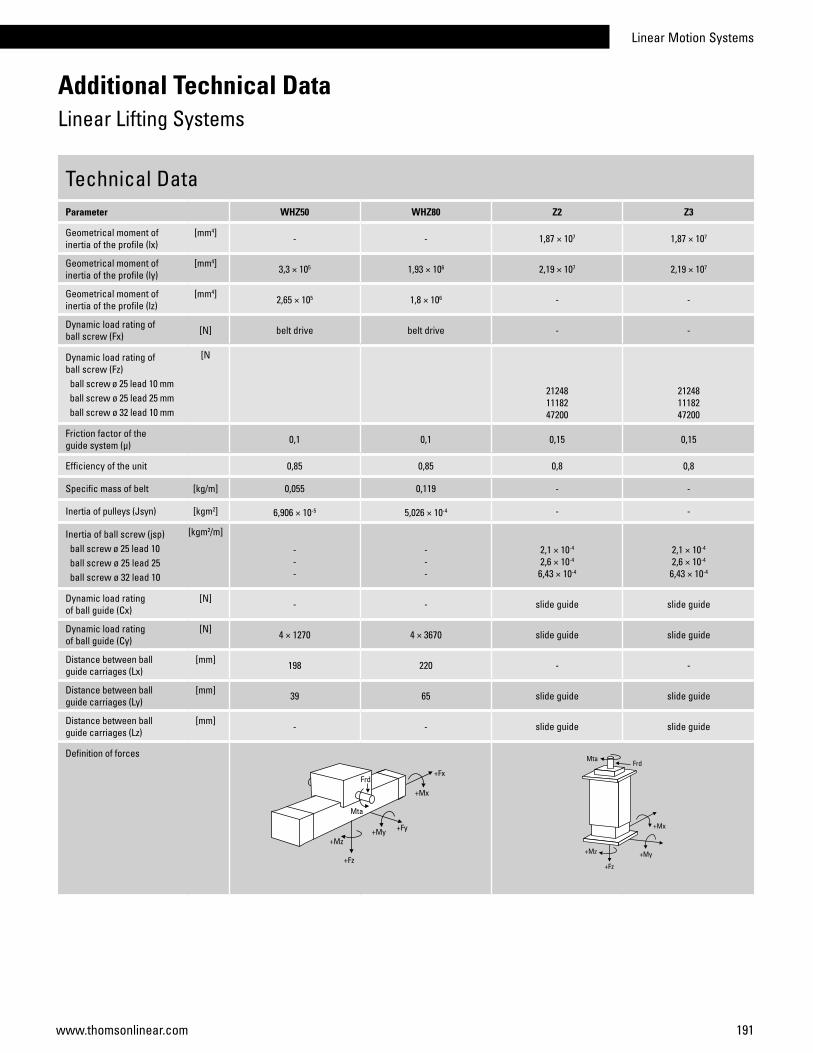
Linear Motion Systems
191www.thomsonlinear.com
Technical DataParameter WHZ50 WHZ80 Z2 Z3
Geometrical moment of inertia of the profile (lx)
[mm4] - - 1,87 × 10⁷ 1,87 × 10⁷
Geometrical moment of inertia of the profile (ly)
[mm4] 3,3 × 10⁵ 1,93 × 10⁶ 2,19 × 10⁷ 2,19 × 10⁷
Geometrical moment of inertia of the profile (lz)
[mm4] 2,65 × 10⁵ 1,8 × 10⁶ - -
Dynamic load rating of ball screw (Fx) [N] belt drive belt drive - -
Dynamic load rating of ball screw (Fz) ball screw ø 25 lead 10 mm ball screw ø 25 lead 25 mm ball screw ø 32 lead 10 mm
[N
212481118247200
212481118247200
Friction factor of the guide system (µ) 0,1 0,1 0,15 0,15
Efficiency of the unit 0,85 0,85 0,8 0,8
Specific mass of belt [kg/m] 0,055 0,119 - -
Inertia of pulleys (Jsyn) [kgm2] 6,906 × 10-5 5,026 × 10-4 - -
Inertia of ball screw (jsp) ball screw ø 25 lead 10 ball screw ø 25 lead 25 ball screw ø 32 lead 10
[kgm2/m]
---
---
2,1 × 10⁻⁴
2,6 × 10⁻⁴
6,43 × 10⁻⁴
2,1 × 10⁻⁴
2,6 × 10⁻⁴
6,43 × 10⁻⁴
Dynamic load rating of ball guide (Cx)
[N] - - slide guide slide guide
Dynamic load rating of ball guide (Cy)
[N] 4 × 1270 4 × 3670 slide guide slide guide
Distance between ball guide carriages (Lx)
[mm] 198 220 - -
Distance between ball guide carriages (Ly)
[mm] 39 65 slide guide slide guide
Distance between ball guide carriages (Lz)
[mm] - - slide guide slide guide
Definition of forces
Additional Technical DataLinear Lifting Systems
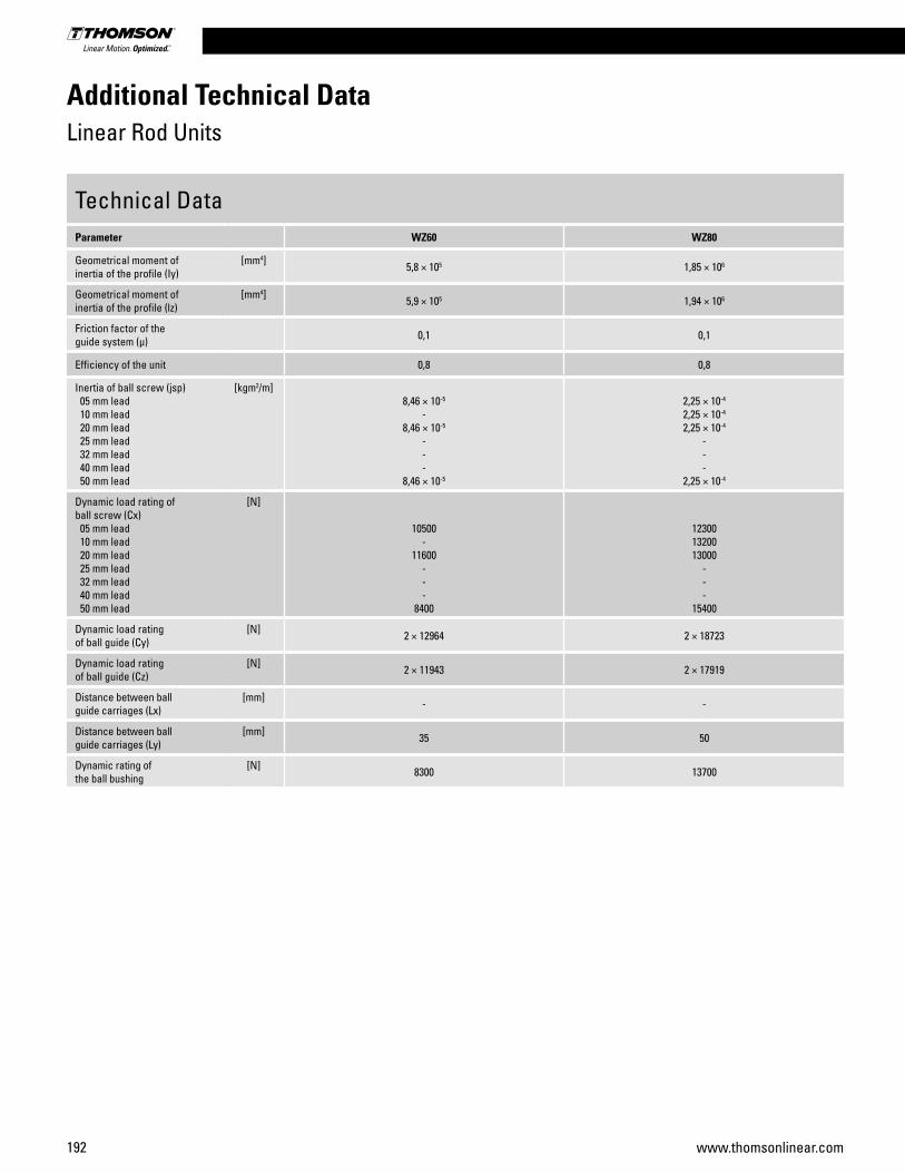
192 www.thomsonlinear.com
Technical DataParameter WZ60 WZ80
Geometrical moment of inertia of the profile (Iy)
[mm4] 5,8 × 10⁵ 1,85 × 10⁶
Geometrical moment of inertia of the profile (lz)
[mm4] 5,9 × 10⁵ 1,94 × 10⁶
Friction factor of the guide system (µ) 0,1 0,1
Efficiency of the unit 0,8 0,8
Inertia of ball screw (jsp) 05 mm lead 10 mm lead 20 mm lead 25 mm lead 32 mm lead 40 mm lead 50 mm lead
[kgm2/m]8,46 × 10-5
-8,46 × 10⁻⁵
---
8,46 × 10⁻⁵
2,25 × 10⁻⁴
2,25 × 10⁻⁴
2,25 × 10⁻⁴
---
2,25 × 10⁻⁴
Dynamic load rating of ball screw (Cx) 05 mm lead 10 mm lead 20 mm lead 25 mm lead 32 mm lead 40 mm lead 50 mm lead
[N]
10500-
11600---
8400
123001320013000
---
15400
Dynamic load rating of ball guide (Cy)
[N] 2 × 12964 2 × 18723
Dynamic load rating of ball guide (Cz)
[N] 2 × 11943 2 × 17919
Distance between ball guide carriages (Lx)
[mm] - -
Distance between ball guide carriages (Ly)
[mm] 35 50
Dynamic rating of the ball bushing
[N] 8300 13700
Additional Technical DataLinear Rod Units

Linear Motion Systems
193www.thomsonlinear.com
1. Type of unitWM04S = WM40S unit with single ball nutWM04D = WM40D unit with double ball nutsWM06S = WM60S unit with single ball nutWM06D = WM60D unit with double ball nutsWM06X = WM60X unit with left/right screwWM08S = WM80S unit with single ball nutWM08D = WM80D unit with double ball nutsWM12D = WM120D unit with double ball nuts
2. Screw lead1
05 = 5 mm 10 = 10 mm20 = 20 mm40 = 40 mm50 = 50 mm 3. Transmission typeLX = inline style, directly coupled, RediMount flange SX = inline style, directly coupled, no RediMount flange
4. RediMount motor ID codevvw = alphanumeric motor code for suitable RediMount flange when motor is known 999 = RediMount code used when motor is unknown XXX = for units without RediMount flange
5. Maximum stroke (Smax)- xxxxx = distance in mm
6. Total length of unit (L tot)- yyyyy = distance in mm
7. Drive shaft / RediMount configuration2
A = single shaft without key wayC = single shaft with key way or RediMount G = double shafts, first without key way and second for encoderI = double shafts, first with key way or RediMount and second for encoder3
8. Carriage configuration4
N = single standard carriageS = single short carriageL = single long carriageZ = double standard carriagesY = double short carriagesM = double long carriages
9. Distance between double carriages (Lc)0000 = always for single carriageszzzz = distance in mm
10. Protection option5
S1 = wash down protection (not available for WM04 units)
1 See table below for available combinations of units and ball screw leads.
2 See below for the definition of shafts.
3 Drive shaft configuration I not available for WM 40.
4 See table below for available combinations of units and carriage types.
5 Leave position blank if no additional protection is required.
Ordering KeysLinear Motion Systems with Ball Screw Drive and Ball Guides
WM40S, WM40D, WM60S, WM60D, WM60X, WM80S, WM80D, WM120D
1 2 3 4 5 6 7 8 9 10
WM06D 20 LX ZZ6 -02545 -03715 A Z 0520 S1
Type of unitAvailable screw leads [mm]
5 10 20 40 50
WM04S x
WM04D x
WM06S x x x
WM06D x x x
WM06X x
WM08S x x x x
WM08D x x x x
WM12D x x x x
Type of unitAvailable carriage types
N S L Z Y M
WM04S x x
WM04D x x
WM06S x x
WM06D x x x
WM06X x x x
WM08S x x
WM08D x x x
WM12D x x x
Single and double shafts with RediMount
Single and double shafts without RediMount
Note! for ordering of options type EN, ES, KRG, RT, ADG and MGK, see accessory index on page 131.
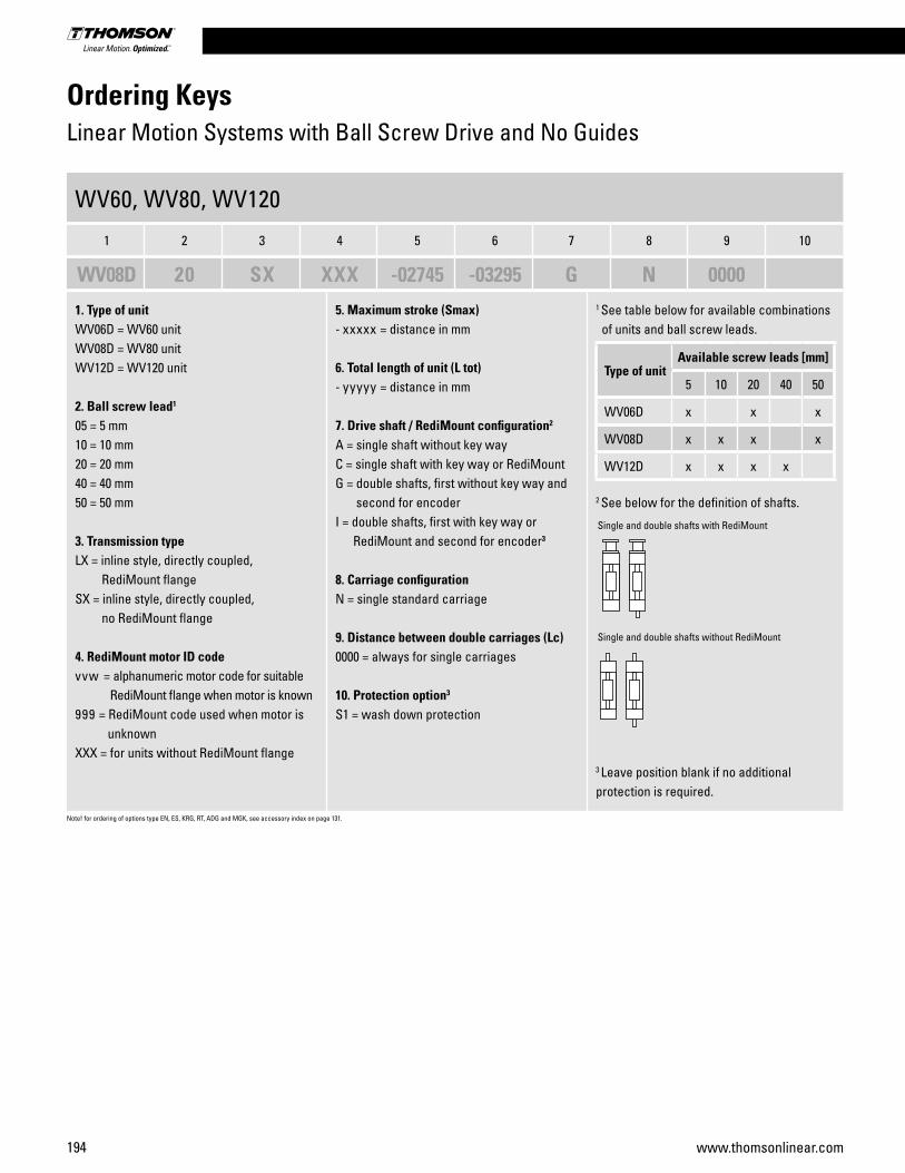
194 www.thomsonlinear.com
Ordering KeysLinear Motion Systems with Ball Screw Drive and No Guides
WV60, WV80, WV120
1 2 3 4 5 6 7 8 9 10
WV08D 20 SX XXX -02745 -03295 G N 0000
1. Type of unitWV06D = WV60 unit WV08D = WV80 unit WV12D = WV120 unit
2. Ball screw lead1
05 = 5 mm 10 = 10 mm20 = 20 mm40 = 40 mm50 = 50 mm
3. Transmission typeLX = inline style, directly coupled, RediMount flange SX = inline style, directly coupled, no RediMount flange
4. RediMount motor ID codevvw = alphanumeric motor code for suitable RediMount flange when motor is known 999 = RediMount code used when motor is unknown XXX = for units without RediMount flange
5. Maximum stroke (Smax)- xxxxx = distance in mm
6. Total length of unit (L tot)- yyyyy = distance in mm
7. Drive shaft / RediMount configuration2
A = single shaft without key wayC = single shaft with key way or RediMount G = double shafts, first without key way and second for encoderI = double shafts, first with key way or RediMount and second for encoder3
8. Carriage configurationN = single standard carriage
9. Distance between double carriages (Lc)0000 = always for single carriages
10. Protection option3
S1 = wash down protection
1 See table below for available combinations of units and ball screw leads.
2 See below for the definition of shafts.
3 Leave position blank if no additional protection is required.
Type of unitAvailable screw leads [mm]
5 10 20 40 50
WV06D x x x
WV08D x x x x
WV12D x x x x
Note! for ordering of options type EN, ES, KRG, RT, ADG and MGK, see accessory index on page 131.
Single and double shafts with RediMount
Single and double shafts without RediMount
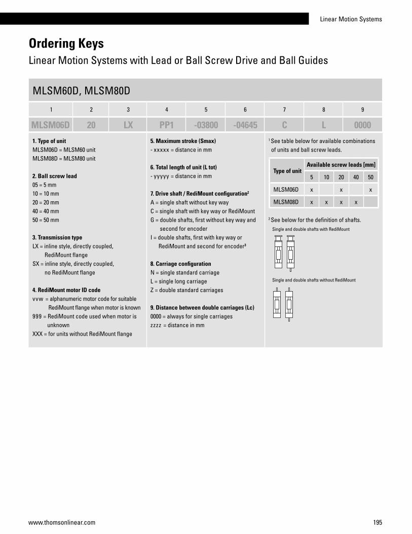
Linear Motion Systems
195www.thomsonlinear.com
MLSM60D, MLSM80D
1 2 3 4 5 6 7 8 9
MLSM06D 20 LX PP1 -03800 -04645 C L 0000
1. Type of unitMLSM06D = MLSM60 unit MLSM08D = MLSM80 unit
2. Ball screw lead05 = 5 mm10 = 10 mm20 = 20 mm40 = 40 mm50 = 50 mm
3. Transmission typeLX = inline style, directly coupled, RediMount flange SX = inline style, directly coupled, no RediMount flange
4. RediMount motor ID codevvw = alphanumeric motor code for suitable RediMount flange when motor is known 999 = RediMount code used when motor is unknown XXX = for units without RediMount flange
5. Maximum stroke (Smax)- xxxxx = distance in mm
6. Total length of unit (L tot)- yyyyy = distance in mm
7. Drive shaft / RediMount configuration2
A = single shaft without key wayC = single shaft with key way or RediMount G = double shafts, first without key way and second for encoderI = double shafts, first with key way or RediMount and second for encoder3
8. Carriage configurationN = single standard carriageL = single long carriageZ = double standard carriages
9. Distance between double carriages (Lc) 0000 = always for single carriageszzzz = distance in mm
1 See table below for available combinations of units and ball screw leads.
2 See below for the definition of shafts.
Ordering KeysLinear Motion Systems with Lead or Ball Screw Drive and Ball Guides
Type of unitAvailable screw leads [mm]
5 10 20 40 50
MLSM06D x x x
MLSM08D x x x x
Single and double shafts with RediMount
Single and double shafts without RediMount

196 www.thomsonlinear.com
Ordering KeysLinear Motion Systems with Ball Screw Drive and Ball Guides
M55, M75, M100
1 2 3 4 5 6 7 8 9 10
MF07S 05 LX MC8 -01000 -01500 X N 0000 S1
1. Type of unitMF06S = M55 unit, ball guides, ball screwMF07S = M75 unit, ball guides, ball screwMF10S = M100 unit, ball guides, ball screw
2. Screw lead and tolerance class1
05 = 5 mm10 = 10 mm12 = 12,7 mm20 = 20 mm25 = 25 mm
3. Transmission typeLX = inline style, directly coupled, RediMount flange SX = inline style, directly coupled, no RediMount flange
4. RediMount motor ID codevvw = alphanumeric motor code for suitable RediMount flange when motor is known 999 = RediMount code used when motor is unknown XXX = for units without RediMount flange
5. Maximum stroke (Smax)- xxxxx = distance in mm
6. Total length of unit (L tot)- yyyyy = distance in mm
7. Screw supportsX = no screw supportsS = single screw supportsD = double screw supports
8. Carriage configurationN = single standard carriageZ = double standard carriages
9. Distance between carriages (Lc)0000 = for all single standard carriage unitszzzz = distance in mm between carriages
10. Protection option2
S1 = wash down protection
1 See table below for available combinations of units and ball screw type, lead and tolerance.
2 Leave position blank if no additional protection is required.
Ballscrewtype
Type of unit
M55 M75 M100
05 x x x
10 x x
12 x
20 x x
25 x

Linear Motion Systems
197www.thomsonlinear.com
1. Type of unit2HB10 = 2HB10 unit 2HB20 = 2HB20 unit
2. Ball screw diameter, lead and nut typeG0 = 16 mm, 5 mm, preloaded (2HB10 only)H0 = 16 mm, 10 mm, preloaded (2HB10 only)
L0 = 25 mm, 5 mm, preloaded (2HB20 only)M0 = 25 mm, 10 mm, preloaded( 2HB20 only)N0 = 25 mm, 25 mm, preloaded (2HB20 only)
3. Ordering length (L)N xxxxx = distance in mm
4. Y-distance- 038 = standard distance in mm between motor end plate to first set of mounting holes on 2HB10 - 043 = standard distance in mm between motor end plate to first set of mounting holes on 2HB20- yyy = custom distance in mm between motor end plate to first set of mounting holes
5. Brake optionN = no brake B = brake
6. RediMount motor ID code001 = NEMA 23002 = NEMA 34zzz = consult www.LinearMotioneering.com for complete list of available standard RediMount motor flanges
7. Ball guide rail coating optionA = standardD = Duralloy
8. Ball guide carriage coating option0 = standard1 = Duralloy
9. Profile cover optionA = noneB = bellows (bellows will reduce stroke length app. 28%)C = shrouds
10. Hardware option0 = alloy plated1 = stainless steel
11. Home and end of stroke sensor option0 = no sensors1 = home sensor, NPN type 2 = end of stroke sensors, NPN type3 = home and end of stroke sensors, NPN type4 = home sensor, PNP type 5 = end of stroke sensors, PNP type6 = home and end of stroke sensors, PNP type
Ordering KeysLinear Motion Systems with Lead or Ball Screw Drive and Ball Guides
2HB10, 2HB20
1 2 3 4 5 6 7 8 9 10 11
2HB10 H0 N1285 -038 N 001 A 0 A 0 0
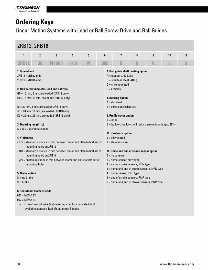
198 www.thomsonlinear.com
1. Type of unit2RB12 = 2RB12 unit 2RB16 = 2RB16 unit
2. Ball screw diameter, lead and nut typeG0 = 16 mm, 5 mm, preloaded (2RB12 only)H0 = 16 mm, 10 mm, preloaded (2RB12 only)
I0 = 20 mm, 5 mm, preloaded (2RB16 only)J0 = 20 mm, 10 mm, preloaded ( 2RB16 only)K0 = 20 mm, 25 mm, preloaded (2RB16 only)
3. Ordering length (L)N xxxx = distance in mm
4. Y-distance- 075 = standard distance in mm between motor end plate to first set of mounting holes on 2RB12 - 100 = standard distance in mm between motor end plate to first set of mounting holes on 2RB16- yyy = custom distance in mm between motor end plate to first set of mounting holes
5. Brake optionN = no brake B = brake
6. RediMount motor ID code001 = NEMA 23002 = NEMA 34zzz = consult www.LinearMotioneering.com for complete list of available standard RediMount motor flanges
7. Ball guide shaft coating optionA = standard, 60 CaseB = stainless steel (440C)C = chrome platedE = armoloy
8. Bearing option0 = standard1 = corrosion resistance
9. Profile cover optionA = noneB = bellows (bellows will reduce stroke length app. 28%)
10. Hardware option0 = alloy plated1 = stainless steel
11. Home and end of stroke sensor option0 = no sensors1 = home sensor, NPN type 2 = end of stroke sensors, NPN type3 = home and end of stroke sensors, NPN type4 = home sensor, PNP type 5 = end of stroke sensors, PNP type6 = home and end of stroke sensors, PNP type
Ordering KeysLinear Motion Systems with Lead or Ball Screw Drive and Ball Guides
2RB12, 2RB16
1 2 3 4 5 6 7 8 9 10 11
2RB12 J0 N1000 -100 N 002 B 0 A 0 0
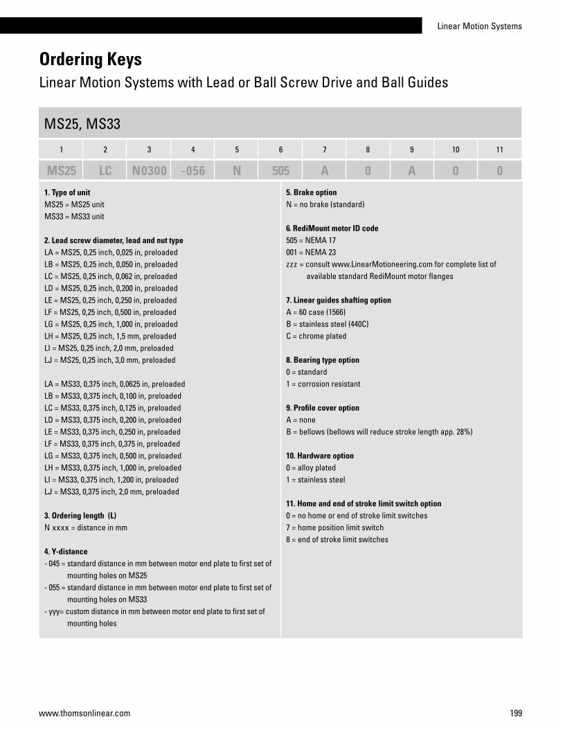
Linear Motion Systems
199www.thomsonlinear.com
1. Type of unitMS25 = MS25 unit MS33 = MS33 unit
2. Lead screw diameter, lead and nut typeLA = MS25, 0,25 inch, 0,025 in, preloadedLB = MS25, 0,25 inch, 0,050 in, preloadedLC = MS25, 0,25 inch, 0,062 in, preloadedLD = MS25, 0,25 inch, 0,200 in, preloadedLE = MS25, 0,25 inch, 0,250 in, preloadedLF = MS25, 0,25 inch, 0,500 in, preloadedLG = MS25, 0,25 inch, 1,000 in, preloadedLH = MS25, 0,25 inch, 1,5 mm, preloadedLI = MS25, 0,25 inch, 2,0 mm, preloadedLJ = MS25, 0,25 inch, 3,0 mm, preloaded
LA = MS33, 0,375 inch, 0,0625 in, preloadedLB = MS33, 0,375 inch, 0,100 in, preloadedLC = MS33, 0,375 inch, 0,125 in, preloadedLD = MS33, 0,375 inch, 0,200 in, preloadedLE = MS33, 0,375 inch, 0,250 in, preloadedLF = MS33, 0,375 inch, 0,375 in, preloadedLG = MS33, 0,375 inch, 0,500 in, preloadedLH = MS33, 0,375 inch, 1,000 in, preloadedLI = MS33, 0,375 inch, 1,200 in, preloadedLJ = MS33, 0,375 inch, 2,0 mm, preloaded
3. Ordering length (L)N xxxx = distance in mm
4. Y-distance - 045 = standard distance in mm between motor end plate to first set of mounting holes on MS25- 055 = standard distance in mm between motor end plate to first set of mounting holes on MS33 - yyy= custom distance in mm between motor end plate to first set of mounting holes
5. Brake optionN = no brake (standard)
6. RediMount motor ID code505 = NEMA 17001 = NEMA 23 zzz = consult www.LinearMotioneering.com for complete list of available standard RediMount motor flanges
7. Linear guides shafting optionA = 60 case (1566)B = stainless steel (440C)C = chrome plated
8. Bearing type option0 = standard1 = corrosion resistant
9. Profile cover optionA = noneB = bellows (bellows will reduce stroke length app. 28%)
10. Hardware option0 = alloy plated1 = stainless steel
11. Home and end of stroke limit switch option0 = no home or end of stroke limit switches 7 = home position limit switch8 = end of stroke limit switches
Ordering KeysLinear Motion Systems with Lead or Ball Screw Drive and Ball Guides
MS25, MS33
1 2 3 4 5 6 7 8 9 10 11
MS25 LC N0300 -056 N 505 A 0 A 0 0

200 www.thomsonlinear.com
1. Type of unit2DB08 = 2DB08 unit 2DB12 = 2DB12 unit2DB16 = 2DB16 unit
2. Screw type, diameter, lead and nut typeA0 = leadscrew, 0.375 in, 0.100 in, preloaded (2DB08 only)B0 = leadscrew, 0.375 in, 0.250 in, preloaded (2DB08 only) C0 = leadscrew, 0.375 in, 0.500 in, preloaded (2DB08 only) D0 = leadscrew, 0.375 in, 0.750 in, preloaded (2DB08 only) E0 = leadscrew, 0.375 in, 1.000 in, preloaded (2DB08 only) F0 = ballscrew, 0.631 in, 0.200 in, non-preloaded (2DB12 only) V0 = ballscrew, 0.631 in, 0.200 in, preloaded (2DB12 only) QJ = ballscrew, 0.500 in, 0.500 in, preloaded (2DB12 only)
G0 = ballscrew, 0.750 in, 0.200 in, non-preloaded (2DB16 only)W0 = ballscrew, 0.750 in, 0.200 in, preloaded (2DB16 only) RJ = ballscrew, 0.750 in, 0.500 in, preloaded (2DB16 only) LJ = ballscrew, 0.631 in, 1.0 in, preloaded (2DB16 only) D0 = ballscrew, 20 mm, 5 mm, preloaded (2DB16 only)
3. Ordering length (L)N xxxx = distance in inch (e.g. 0250 = 25 inch)
4. Y-distance- 200 = standard distance in inch between motor end plate to first set of mounting holes for 2DB08 (e.g. 200 = 2 in)- 300 = standard distance in inch between motor end plate to first set of mounting holes for 2DB12 and 2DB16 (e.g. 300 = 3 in) - yyy = custom distance in inch between motor end plate to first set of mounting holes
5. Brake optionN = no brake B = brake
6. RediMount motor ID code001 = NEMA 23002 = NEMA 34zzz = consult www.LinearMotioneering.com for complete list of available standard RediMount motor flanges
7. Ball guide shaft coating optionA = standard, 60 CaseB = stainless steel (440C)C = chrome platedE = Armoloy
8. Bearing option0 = standard1 = corrosion resistance
9. Profile cover optionA = noneB = bellows (bellows will reduce stroke length app. 28%)
10. Hardware option0 = alloy plated1 = stainless steel
11. Home and end of stroke sensor option0 = no sensors7 = home8 = ends of travel9 = both
Ordering KeysLinear Motion Systems with Lead or Ball Screw Drive and Ball Guides
2DB08, 2DB12, 2DB16
1 2 3 4 5 6 7 8 9 10 11
2DB12 FO N0250 -300 N 002 A 0 A 0 0
2DB08, 2DB12, 2DB16
1 2 3 4 5 6 7 8 9 10 11
2DB12 F0 N0250 -300 N 002 A 0 A 0 0
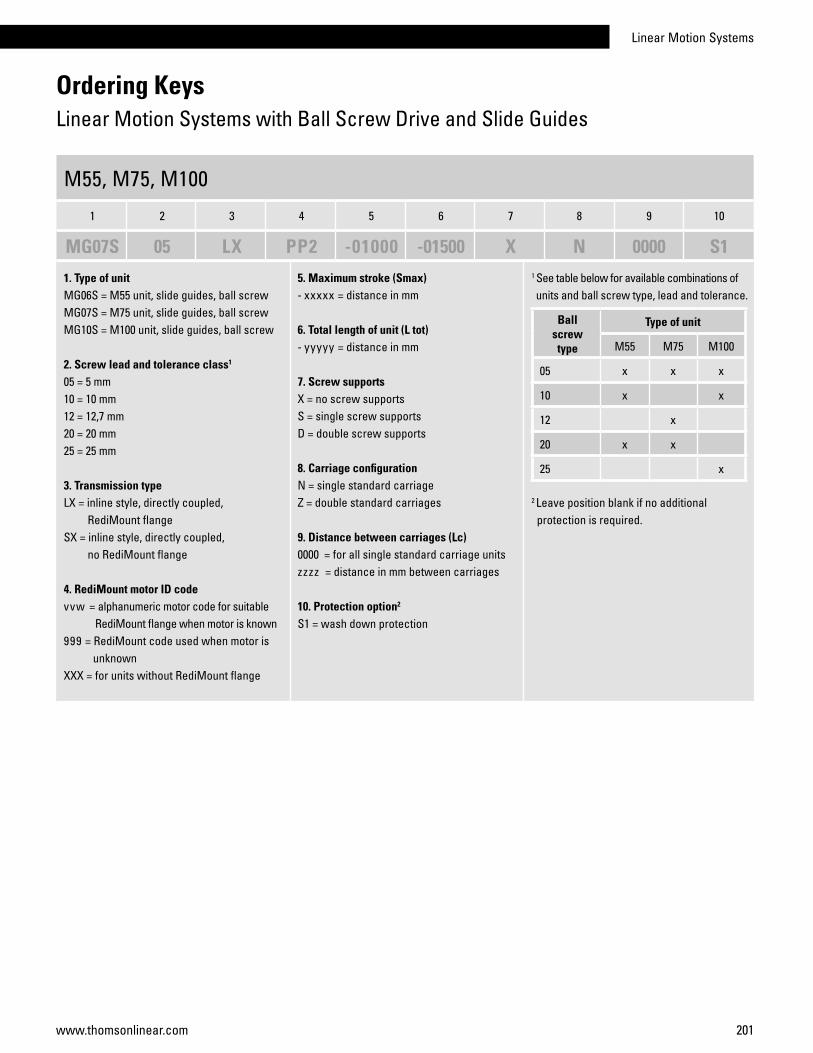
Linear Motion Systems
201www.thomsonlinear.com
Ordering KeysLinear Motion Systems with Ball Screw Drive and Slide Guides
M55, M75, M100
1 2 3 4 5 6 7 8 9 10
MG07S 05 LX PP2 -01000 -01500 X N 0000 S1
1. Type of unitMG06S = M55 unit, slide guides, ball screwMG07S = M75 unit, slide guides, ball screwMG10S = M100 unit, slide guides, ball screw
2. Screw lead and tolerance class1
05 = 5 mm10 = 10 mm12 = 12,7 mm20 = 20 mm25 = 25 mm
3. Transmission typeLX = inline style, directly coupled, RediMount flange SX = inline style, directly coupled, no RediMount flange
4. RediMount motor ID codevvw = alphanumeric motor code for suitable RediMount flange when motor is known 999 = RediMount code used when motor is unknown XXX = for units without RediMount flange
5. Maximum stroke (Smax)- xxxxx = distance in mm
6. Total length of unit (L tot)- yyyyy = distance in mm
7. Screw supportsX = no screw supportsS = single screw supportsD = double screw supports
8. Carriage configurationN = single standard carriageZ = double standard carriages
9. Distance between carriages (Lc)0000 = for all single standard carriage unitszzzz = distance in mm between carriages
10. Protection option2
S1 = wash down protection
1 See table below for available combinations of units and ball screw type, lead and tolerance.
2 Leave position blank if no additional protection is required.
Ballscrewtype
Type of unit
M55 M75 M100
05 x x x
10 x x
12 x
20 x x
25 x
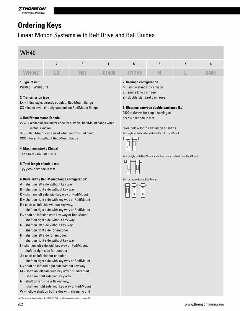
202 www.thomsonlinear.com
Ordering KeysLinear Motion Systems with Belt Drive and Ball Guides
WH40
1 2 3 4 5 6 7 8
WH04Z LX FB7 -01400 -01755 H L 0400
1. Type of unitWH04Z = WH40 unit 2. Transmission typeLX = inline style, directly coupled, RediMount flangeSX = inline style, directly coupled, no RediMount flange
3. RediMount motor ID codevvw = alphanumeric motor code for suitable RediMount flange when motor is known 999 = RediMount code used when motor is unknown XXX = for units without RediMount flange
4. Maximum stroke (Smax)- xxxxx = distance in mm
5. Total length of unit (L tot)- yyyyy= distance in mm
6. Drive shaft / RediMount flange configuration1
A = shaft on left side without key wayB = shaft on right side without key wayC = shaft on left side with key way or RediMount D = shaft on right side with key way or RediMountE = shaft on left side without key way, shaft on right side with key way or RediMountF = shaft on left side with key way or RediMount, shaft on right side without key wayG = shaft on left side without key way, shaft on right side for encoderH = shaft on left side for encoder, shaft on right side without key wayI = shaft on left side with key way or RediMount, shaft on right side for encoderJ = shaft on left side for encoder, shaft on right side with key way or RediMountL = shaft on left and right side without key wayM = shaft on left side with key way or RediMount, shaft on right side with key wayN = shaft on left side with key way, shaft on right side with key way or RediMountW = hollow shaft on both sides with clamping unit
7. Carriage configurationN = single standard carriageL = single long carriageZ = double standard carriages
8. Distance between double carriages (Lc)0000 = always for single carriageszzzz = distance in mm
1 See below for the definition of shafts.
Note! for ordering of options type EN, ES, KRG, RT, ADG and MGK, see accessory index on page 131.
Left, right or both sides with shafts with RediMount
Left or right without RediMount
Left or right with RediMount and other side a shaft without RediMount

Linear Motion Systems
203www.thomsonlinear.com
WM60Z, WM80Z
1 2 3 4 5 6 7 8
WM06Z LX AG5 -01400 -01755 H L 0400
1. Type of unitWM06Z = WM60Z unitWM08Z = WM80Z unit 2. Transmission typeLX = inline style, directly coupled, RediMount flangeSX = inline style, directly coupled, no RediMount flange
3. RediMount motor ID codevvw = alphanumeric motor code for suitable RediMount flange when motor is known 999 = RediMount code used when motor is unknown XXX = for units without RediMount flange
4. Maximum stroke (Smax)- xxxxx = distance in mm
5. Total length of unit (L tot)- yyyyy= distance in mm
6. Drive shaft / RediMount flange configuration1
A = shaft on left side without key wayB = shaft on right side without key wayC = shaft on left side with key way or RediMount D = shaft on right side with key way or RediMountE = shaft on left side without key way, shaft on right side with key way or RediMountF = shaft on left side with key way or RediMount, shaft on right side without key wayG = shaft on left side without key way, shaft on right side for encoderH = shaft on left side for encoder, shaft on right side without key wayI = shaft on left side with key way or RediMount, shaft on right side for encoderJ = shaft on left side for encoder, shaft on right side with key way or RediMountL = shaft on left and right side without key wayM = shaft on left side with key way or RediMount, shaft on right side with key wayN = shaft on left side with key way, shaft on right side with key way or RediMountW = hollow shaft on both sides with clamping unit
7. Carriage configuration2
N = single standard carriageS = single short carriageL = single long carriageZ = double standard carriagesY = double short carriages
8. Distance between double carriages (Lc)0000 = always for single carriageszzzz = distance in mm
1 See below for the definition of shafts.
2 See table below for available combinations of units and carriage types.
Note! for ordering of options type EN, ES, KRG, RT, ADG and MGK, see accessory index on page 131.
Ordering KeysLinear Motion Systems with Belt Drive and Ball Guides
Type of unitAvailable carriage types
N S L Z Y
WM06Z x x
WM08Z x x x x x
Left, right or both sides with shafts with RediMount
Left or right without RediMount
Left or right with RediMount and other side a shaft without RediMount

204 www.thomsonlinear.com
Ordering KeysLinear Motion Systems with Belt Drive and Ball Guides
M55, M75, M100
1 2 3 4 5 6 7 8 9
MF10B LX 999 -01000 -01500 D N 0000 S1
1. Type of unitMF06B = M55 unit, ball guides, belt driveMF07B = M75 unit, ball guides, belt driveMF10B = M100 unit, ball guides, belt drive
2. Transmission typeLX = inline style, directly coupled, RediMount flangeSX = inline style, directly coupled, no RediMount flange
3. RediMount motor ID codevvw = alphanumeric motor code for suitable RediMount flange when motor is known 999 = RediMount code used when motor is unknown XXX = for units without RediMount flange
4. Maximum stroke (Smax)- xxxxx = distance in mm
5. Total length of unit (L tot)- yyyyy = distance in mm
6. Drive shaft / RediMount flange configuration1
C = shaft on left side with key way or RediMount D = shaft on right side with key way or RediMountM = shaft on left side with key way or RediMount, shaft on right side with key wayN = shaft on left side with key way, shaft on right side with key way or RediMount
7. Carriage configurationN = single standard carriageZ = double standard carriages
8. Distance between carriages (Lc)0000 = for all single standard carriage unitszzzz = distance in mm between carriages
9. Protection optionS1 = wash down protection (blank if no protection option required).
1 See below for the definition of shafts.Left, right or both sides with shafts with RediMount
Left or right without RediMount
Left or right with RediMount and other side a shaft without RediMount
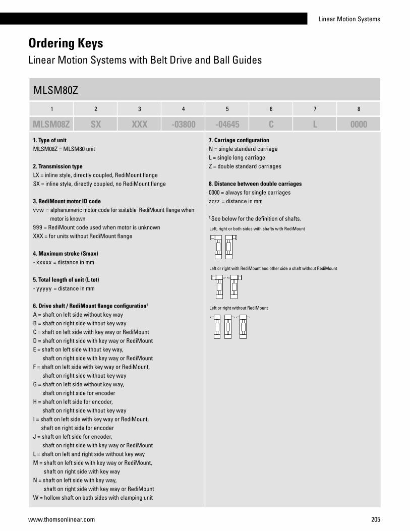
Linear Motion Systems
205www.thomsonlinear.com
Ordering KeysLinear Motion Systems with Belt Drive and Ball Guides
1. Type of unitMLSM08Z = MLSM80 unit
2. Transmission typeLX = inline style, directly coupled, RediMount flangeSX = inline style, directly coupled, no RediMount flange
3. RediMount motor ID codevvw = alphanumeric motor code for suitable RediMount flange when motor is known 999 = RediMount code used when motor is unknown XXX = for units without RediMount flange
4. Maximum stroke (Smax)- xxxxx = distance in mm
5. Total length of unit (L tot)- yyyyy = distance in mm
6. Drive shaft / RediMount flange configuration1
A = shaft on left side without key wayB = shaft on right side without key wayC = shaft on left side with key way or RediMount D = shaft on right side with key way or RediMountE = shaft on left side without key way, shaft on right side with key way or RediMountF = shaft on left side with key way or RediMount, shaft on right side without key wayG = shaft on left side without key way, shaft on right side for encoderH = shaft on left side for encoder, shaft on right side without key wayI = shaft on left side with key way or RediMount, shaft on right side for encoderJ = shaft on left side for encoder, shaft on right side with key way or RediMountL = shaft on left and right side without key wayM = shaft on left side with key way or RediMount, shaft on right side with key wayN = shaft on left side with key way, shaft on right side with key way or RediMountW = hollow shaft on both sides with clamping unit
7. Carriage configurationN = single standard carriageL = single long carriageZ = double standard carriages
8. Distance between double carriages0000 = always for single carriageszzzz = distance in mm
1 See below for the definition of shafts.
MLSM80Z
1 2 3 4 5 6 7 8
MLSM08Z SX XXX -03800 -04645 C L 0000
Left, right or both sides with shafts with RediMount
Left or right without RediMount
Left or right with RediMount and other side a shaft without RediMount
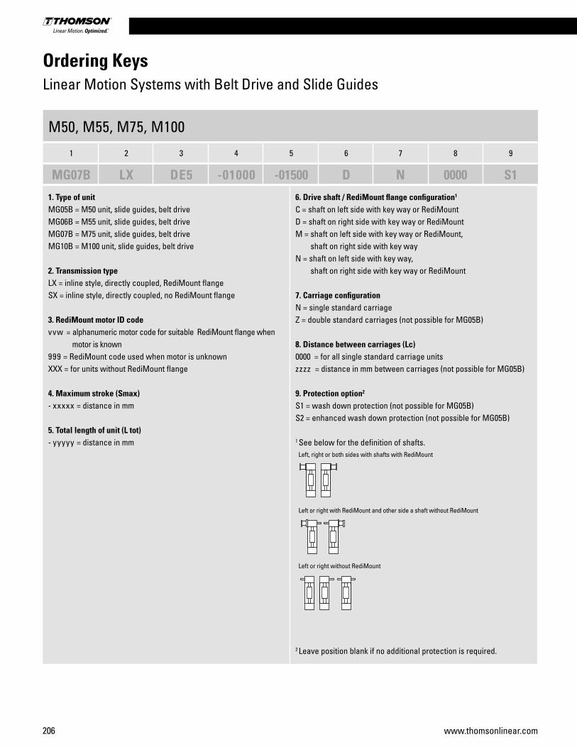
206 www.thomsonlinear.com
Ordering KeysLinear Motion Systems with Belt Drive and Slide Guides
M50, M55, M75, M100
1 2 3 4 5 6 7 8 9
MG07B LX DE5 -01000 -01500 D N 0000 S1
1. Type of unitMG05B = M50 unit, slide guides, belt driveMG06B = M55 unit, slide guides, belt driveMG07B = M75 unit, slide guides, belt driveMG10B = M100 unit, slide guides, belt drive
2. Transmission typeLX = inline style, directly coupled, RediMount flangeSX = inline style, directly coupled, no RediMount flange
3. RediMount motor ID codevvw = alphanumeric motor code for suitable RediMount flange when motor is known 999 = RediMount code used when motor is unknown XXX = for units without RediMount flange
4. Maximum stroke (Smax)- xxxxx = distance in mm
5. Total length of unit (L tot)- yyyyy = distance in mm
6. Drive shaft / RediMount flange configuration1
C = shaft on left side with key way or RediMount D = shaft on right side with key way or RediMountM = shaft on left side with key way or RediMount, shaft on right side with key wayN = shaft on left side with key way, shaft on right side with key way or RediMount
7. Carriage configurationN = single standard carriageZ = double standard carriages (not possible for MG05B)
8. Distance between carriages (Lc)0000 = for all single standard carriage unitszzzz = distance in mm between carriages (not possible for MG05B)
9. Protection option2
S1 = wash down protection (not possible for MG05B)S2 = enhanced wash down protection (not possible for MG05B)
1 See below for the definition of shafts.
2 Leave position blank if no additional protection is required.
Left, right or both sides with shafts with RediMount
Left or right without RediMount
Left or right with RediMount and other side a shaft without RediMount
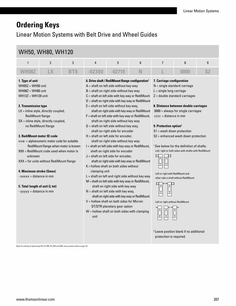
Linear Motion Systems
207www.thomsonlinear.com
Ordering KeysLinear Motion Systems with Belt Drive and Wheel Guides
1. Type of unitWH05Z = WH50 unit WH08Z = WH80 unitWH12Z = WH120 unit
2. Transmission typeLX = inline style, directly coupled, RediMount flange SX = inline style, directly coupled, no RediMount flange
3. RediMount motor ID codevvw = alphanumeric motor code for suitable RediMount flange when motor is known 999 = RediMount code used when motor is unknown XXX = for units without RediMount flange
4. Maximum stroke (Smax)- xxxxx = distance in mm
5. Total length of unit (L tot)- yyyyy = distance in mm
6. Drive shaft / RediMount flange configuration1
A = shaft on left side without key wayB = shaft on right side without key wayC = shaft on left side with key way or RediMount D = shaft on right side with key way or RediMountE = shaft on left side without key way, shaft on right side with key way or RediMountF = shaft on left side with key way or RediMount, shaft on right side without key wayG = shaft on left side without key way, shaft on right side for encoderH = shaft on left side for encoder, shaft on right side without key wayI = shaft on left side with key way or RediMount, shaft on right side for encoderJ = shaft on left side for encoder, shaft on right side with key way or RediMount K = hollow shaft on both sides without clamping unitL = shaft on left and right side without key wayM = shaft on left side with key way or RediMount, shaft on right side with key wayN = shaft on left side with key way, shaft on right side with key way or RediMountV = hollow shaft on both sides for Micron DT/DTR planetary gear optionW = hollow shaft on both sides with clamping unit
7. Carriage configurationN = single standard carriageL = single long carriageZ = double standard carriages
8. Distance between double carriages 0000 = always for single carriages zzzz = distance in mm
9. Protection option2
S1 = wash down protection S2 = enhanced wash down protection
1 See below for the definition of shafts.
2 Leave position blank if no additional protection is required.
Note! for ordering of options type EN, ES, KRG, RT, ADG and MGK, see accessory index on page 131.
WH50, WH80, WH120
1 2 3 4 5 6 7 8 9
WH08Z LX BT8 -02300 -02710 N L 0000 S2
Left, right or both sides with shafts with RediMount
Left or right without RediMount
Left or right with RediMount and
other side a shaft without RediMount

208 www.thomsonlinear.com
Ordering KeysLinear Motion Systems with Belt Drive and Wheel Guides
1. Type of unitMLSH06Z = MLSH60 unit
2. Transmission typeLX = inline style, directly coupled, RediMount flangeSX = inline style, directly coupled, no RediMount flange
3. RediMount motor ID codevvw = alphanumeric motor code for suitable RediMount flange when motor is known 999 = RediMount code used when motor is unknown XXX = for units without RediMount flange
4. Maximum stroke (Smax)- xxxxx = distance in mm
5. Total length of unit (L tot)- yyyyy = distance in mm
6. Drive shaft / RediMount flange configuration1
A = shaft on left side without key wayB = shaft on right side without key wayC = shaft on left side with key way or RediMount D = shaft on right side with key way or RediMountE = shaft on left side without key way, shaft on right side with key way or RediMountF = shaft on left side with key way or RediMount, shaft on right side without key wayG = shaft on left side without key way, shaft on right side for encoderH = shaft on left side for encoder, shaft on right side without key wayI = shaft on left side with key way or RediMount, shaft on right side for encoderJ = shaft on left side for encoder, shaft on right side with key way or RediMountL = shaft on left and right side without key wayM = shaft on left side with key way or RediMount, shaft on right side with key wayN = shaft on left side with key way, shaft on right side with key way or RediMount
7. Carriage configurationN = single standard carriageL = single long carriageZ = double standard carriages
8. Distance between double carriages0000 = always for single carriageszzzz = distance in mm
1 See below for the definition of shafts.
MLSH60Z
1 2 3 4 5 6 7 8
MLSH06Z SX XXX -04500 -05580 D D 0600
Left, right or both sides with shafts with RediMount
Left or right without RediMount
Left or right with RediMount and other side a shaft without RediMount

Linear Motion Systems
209www.thomsonlinear.com
Ordering KeysLinear Lifting Units
Z2, Z3
1 2 3 4
MGZ3K 25259 -250 450
1. Type of unitMGZ2K = Z2 unitMGZ3K = Z3 unit
2. Ball screw diameter, lead and tolerance class25109 = 25 mm, 10 mm, T925259 = 25 mm, 25 mm, T932207 = 32 mm, 20 mm, T7
3. Minimum retracted length (L min)- • • • = distance in cm
4. Maximum extended length (L max)• • • = distance in cm
WHZ50, WHZ80
1 2 3 4 5 6 7 8 9
WHZ05Z LX KB5 -01000 -01410 A N 00001. Type of unitWHZ05Z = WHZ50 unit WHZ08Z = WHZ80 unit
2. Transmission typeLX = inline style, directly coupled, RediMount flange SX = inline style, directly coupled, no RediMount flange
3. RediMount motor ID codevvw = alphanumeric motor code for suitable RediMount flange when motor is known 999 = RediMount code used when motor is unknown XXX = for units without RediMount flange
4. Maximum stroke (Smax)- xxxxx = distance in mm
5. Total length of unit (L tot)- yyyyy = distance in mm
6. Drive shaft / RediMount flange configuration1
A = shaft on left side without key wayB = shaft on right side without key wayC = shaft on left side with key way or RediMount D = shaft on right side with key way or RediMountE = shaft on left side without key way, shaft on right side with key way or RediMountF = shaft on left side with key way or RediMount, shaft on right side without key wayG = shaft on left side without key way, shaft on right side for encoderH = shaft on left side for encoder, shaft on right side without key wayI = shaft on left side with key way or RediMount, shaft on right side for encoderJ = shaft on left side for encoder, shaft on right side with key way or RediMountL = shaft on left and right side without key wayM = shaft on left side with key way or RediMount, shaft on right side with key wayN = shaft on left side with key way, shaft on right side with key way or Redi-MountV = hollow shaft on both sides for Micron DT/DTR planetary gear optionW = hollow shaft on both sides with clamping unit
7. Carriage configurationN = single standard carriageL = single long carriageZ = double standard carriages
8. Distance between double carriages 0000 = always for single carriages zzzz = distance in mm
9. Protection option2
S1 = wash down protection
1 See below for the definition of shafts.
2 Blank if no additional protection is required.
Left, right or both sides with shafts without RediMount
Left or right with RediMount
Left or right with RediMount and other side a shaft without RediMount
Up
Down
Note! for ordering of options type EN, ES, KRG, RT, ADG and MGK, s
ee accessory index on page 131.
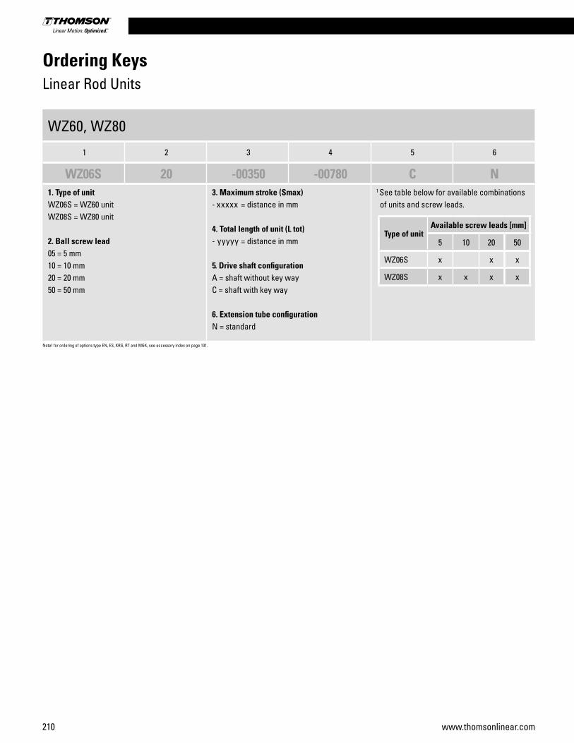
210 www.thomsonlinear.com
Ordering KeysLinear Rod Units
1. Type of unitWZ06S = WZ60 unitWZ08S = WZ80 unit
2. Ball screw lead05 = 5 mm10 = 10 mm20 = 20 mm50 = 50 mm
3. Maximum stroke (Smax)- xxxxx = distance in mm
4. Total length of unit (L tot)- yyyyy = distance in mm
5. Drive shaft configurationA = shaft without key wayC = shaft with key way
6. Extension tube configurationN = standard
1 See table below for available combinations of units and screw leads.
Note! for ordering of options type EN, ES, KRG, RT and MGK, see accessory index on page 131.
Type of unitAvailable screw leads [mm]
5 10 20 50
WZ06S x x x
WZ08S x x x x
WZ60, WZ80
1 2 3 4 5 6
WZ06S 20 -00350 -00780 C N

Linear Motion Systems
211www.thomsonlinear.com
Ordering KeysNon-driven Linear Motion Systems
1. Type of unitWH04N00 = WH40N unitWH05N00 = WH50N unit WH08N00 = WH80N unitWH12N00 = WH120N unit
2. Transmission typeSX = inline style, directly coupled, no RediMount flange
3. RediMount motor ID codeXXX = for units without RediMount flange
4. Maximum stroke (Smax)- xxxxx = distance in mm
5. Total length of unit (L tot)- yyyyy = distance in mm
6. Drive shaft / RediMount flange configurationK = no shaft or RediMount flange
7. Carriage configurationN = single standard carriageL = single long carriageZ = double standard carriages
8. Distance between double carriages 0000 = always for single carriages zzzz = distance in mm
1. Type of unitWM04N00 = WM40N unitWM06N00 = WM60N unit WM08N00 = WM80N unitWM12N00 = WM120N unit
2. Transmission typeSX = inline style, directly coupled, no RediMount flange
3. RediMount motor ID codeXXX = for units without RediMount flange
4. Maximum stroke (Smax)- xxxxx = distance in mm
5. Total length of unit (L tot)- yyyyy = distance in mm
6. Drive shaft / RediMount flange configurationK = no shaft or RediMount flange
7. Carriage configuration1
N = single standard carriageS = single short carriageL = single long carriageZ = double standard carriagesY = double short carriages
8. Distance between double carriages 0000 = always for single carriages zzzz = distance in mm
1 See table below for available combinations of units and carriage configurations.
WH40N, WH50N, WH80N, WH120N
1 2 3 4 5 6 7 8
WH04N00 SX XXX -04500 -04640 K L 0000
WM40N, WM60N, WM80N, WM120N
1 2 3 4 5 6 7 8
WM08N00 SX XXX -07100 -07210 K N 0000
Type of unitAvailable carriage types
N S L Z Y
WM04N x x x
WM06N x x x x x
WM08N x x x x x
WM12N x x x
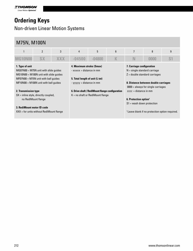
212 www.thomsonlinear.com
Ordering KeysNon-driven Linear Motion Systems
1. Type of unitMG07N00 = M75N unit with slide guidesMG10N00 = M100N unit with slide guidesMF07N00 = M75N unit with ball guidesMF10N00 = M100N unit with ball guides
2. Transmission typeSX = inline style, directly coupled, no RediMount flange
3. RediMount motor ID codeXXX = for units without RediMount flange
4. Maximum stroke (Smax)- xxxxx = distance in mm
5. Total length of unit (L tot)- yyyyy = distance in mm
6. Drive shaft / RediMount flange configurationK = no shaft or RediMount flange
7. Carriage configurationN = single standard carriageZ = double standard carriages
8. Distance between double carriages 0000 = always for single carriages zzzz = distance in mm
6. Protection option1
S1 = wash down protection
1 Leave blank if no protection option required.
M75N, M100N
1 2 3 4 5 6 7 8 9
MG10N00 SX XXX -04500 -04800 K N 0000 S1
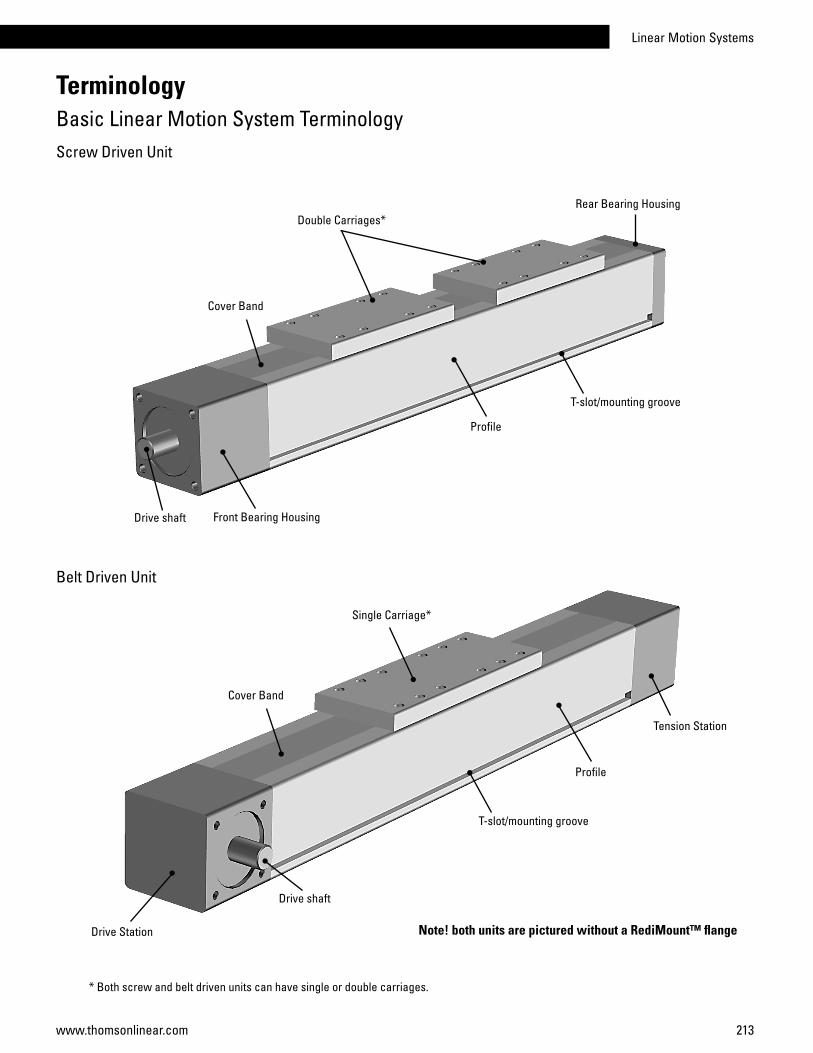
Linear Motion Systems
213www.thomsonlinear.com
Screw Driven Unit
Belt Driven Unit
Double Carriages*
Drive shaft Front Bearing Housing
Profile
Rear Bearing Housing
TerminologyBasic Linear Motion System Terminology
Single Carriage*
T-slot/mounting groove
Cover Band
Drive Station
Tension Station
Drive shaft
Profile
T-slot/mounting groove
Cover Band
* Both screw and belt driven units can have single or double carriages.
Note! both units are pictured without a RediMount™ flange
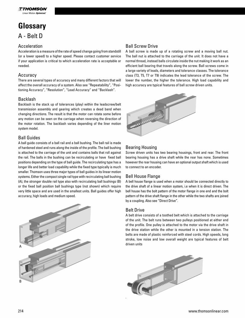
214 www.thomsonlinear.com
AccelerationAcceleration is a measure of the rate of speed change going from standstill (or a lower speed) to a higher speed. Please contact customer service if your application is critical to which acceleration rate is acceptable or needed.
AccuracyThere are several types of accuracy and many different factors that will affect the overall accuracy of a system. Also see “Repeatability”, “Posi-tioning Accuracy”, “Resolution”, “Lead Accuracy” and “Backlash”.
BacklashBacklash is the stack up of tolerances (play) within the leadscrew/belt transmission assembly and gearing which creates a dead band when changing directions. The result is that the motor can rotate some before any motion can be seen on the carriage when reversing the direction of the motor rotation. The backlash varies depending of the liner motion system model.
Ball GuidesA ball guide consists of a ball rail and a ball bushing. The ball rail is made of hardened steel and runs along the inside of the profile. The ball bushing is attached to the carriage of the unit and contains balls that roll against the rail. The balls in the bushing can be recirculating or have fixed ball positions depending on the type of ball guide. The recirculating type has a longer life and better load capability while the fixed type typically is much smaller. Thomson uses three major types of ball guides in its linear motion systems. Either the compact single rail type with recirculating ball bushing (A), the stronger double rail type also with recirculating ball bushings (B) or the fixed ball position ball bushings type (not shown) which require very little space and are used in the smallest units. Ball guides offer high accuracy, high loads and medium speed.
A
B
GlossaryA - Belt D
Ball Screw DriveA ball screw is made up of a rotating screw and a moving ball nut. The ball nut is attached to the carriage of the unit. It does not have a normal thread, instead balls circulate inside the nut making it work as an efficient ball bearing that travels along the screw. Ball screws come in a large variety of leads, diameters and tolerance classes. The tolerance class (T3, T5, T7 or T9) indicates the lead tolerance of the screw. The lower the number, the higher the tolerance. High load capability and high accuracy are typical features of ball screw driven units.
Bearing HousingScrew driven units has two bearing housings, front and rear. The front bearing housing has a drive shaft while the rear has none. Sometimes however the rear housing can have an optional output shaft which is used to connect to an encoder.
Bell House FlangeA bell house flange is used when a motor should be connected directly to the drive shaft of a linear motion system, i.e when it is direct driven. The bell house has the bolt pattern of the motor flange in one end and the bolt pattern of the drive shaft flange in the other while the two shafts are joined by a coupling. Also see “Direct Drive”.
Belt DriveA belt drive consists of a toothed belt which is attached to the carriage of the unit. The belt runs between two pulleys positioned at either end of the profile. One pulley is attached to the motor via the drive shaft in the drive station while the other is mounted in a tension station. The belts are made of plastic reinforced with steel cords. High speeds, long stroke, low noise and low overall weight are typical features of belt driven units
.
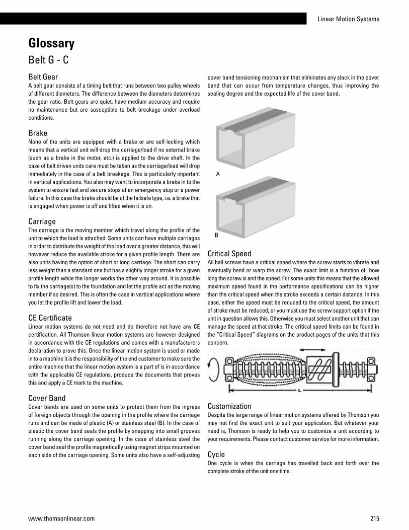
Linear Motion Systems
215www.thomsonlinear.com
Belt GearA belt gear consists of a timing belt that runs between two pulley wheels of different diameters. The difference between the diameters determines the gear ratio. Belt gears are quiet, have medium accuracy and require no maintenance but are susceptible to belt breakage under overload conditions.
BrakeNone of the units are equipped with a brake or are self-locking which means that a vertical unit will drop the carriage/load if no external brake (such as a brake in the motor, etc.) is applied to the drive shaft. In the case of belt driven units care must be taken as the carriage/load will drop immediately in the case of a belt breakage. This is particularly important in vertical applications. You also may want to incorporate a brake in to the system to ensure fast and secure stops at an emergency stop or a power failure. In this case the brake should be of the failsafe type, i.e. a brake that is engaged when power is off and lifted when it is on.
CarriageThe carriage is the moving member which travel along the profile of the unit to which the load is attached. Some units can have multiple carriages in order to distribute the weight of the load over a greater distance, this will however reduce the available stroke for a given profile length. There are also units having the option of short or long carriage. The short can carry less weight than a standard one but has a slightly longer stroke for a given profile length while the longer works the other way around. It is possible to fix the carriage(s) to the foundation and let the profile act as the moving member if so desired. This is often the case in vertical applications where you let the profile lift and lower the load.
CE CertificateLinear motion systems do not need and do therefore not have any CE certification. All Thomson linear motion systems are however designed in accordance with the CE regulations and comes with a manufacturers declaration to prove this. Once the linear motion system is used or made in to a machine it is the responsibility of the end customer to make sure the entire machine that the linear motion system is a part of is in accordance with the applicable CE regulations, produce the documents that proves this and apply a CE mark to the machine.
Cover BandCover bands are used on some units to protect them from the ingress of foreign objects through the opening in the profile where the carriage runs and can be made of plastic (A) or stainless steel (B). In the case of plastic the cover band seals the profile by snapping into small grooves running along the carriage opening. In the case of stainless steel the cover band seal the profile magnetically using magnet strips mounted on each side of the carriage opening. Some units also have a self-adjusting
cover band tensioning mechanism that eliminates any slack in the cover band that can occur from temperature changes, thus improving the sealing degree and the expected life of the cover band.
A
B
Critical SpeedAll ball screws have a critical speed where the screw starts to vibrate and eventually bend or warp the screw. The exact limit is a function of how long the screw is and the speed. For some units this means that the allowed maximum speed found in the performance specifications can be higher than the critical speed when the stroke exceeds a certain distance. In this case, either the speed must be reduced to the critical speed, the amount of stroke must be reduced, or you must use the screw support option if the unit in question allows this. Otherwise you must select another unit that can manage the speed at that stroke. The critical speed limits can be found in the “Critical Speed” diagrams on the product pages of the units that this concern.
Customization Despite the large range of linear motion systems offered by Thomson you may not find the exact unit to suit your application. But whatever your need is, Thomson is ready to help you to customize a unit according to your requirements. Please contact customer service for more information.
CycleOne cycle is when the carriage has travelled back and forth over the complete stroke of the unit one time.
GlossaryBelt G - C

216 www.thomsonlinear.com
DecelerationDeceleration is a measure of the rate of speed change going from a higher speed to a lower speed (or standstill). Please contact customer service if your application is critical to which deceleration rate is acceptable or needed.
Definition of ForcesThe designations of the forces that acts on the unit are defined on the product page of each unit in the “Definition of Forces” drawing (see example below). Please always use the same definitions whenever communicating with Thomson.
Deflection of the Profile Some units require support along the whole profile whilst some are self-supporting over a specified span. Further details can be found on the product data pages. The recommended support intervals should be followed to minimize deflection of the unit. The maximum distance between the support points is shown on the product data pages. The deflection of the unit can also be calculated using the information in the “Additional data and calculations” section.
Direct DriveDirect drive means that there is no gearing between the motor and the drive shaft of the linear motion system. Instead the motor is connected to the unit directly via a coupling and a bell house adapter flange. Also see “Bell House Flange”.
Double Ball NutsUsing double ball nuts will increase the repeatability of the unit. The ball nuts are installed so that they are pre-tensioned against each other eliminating the play between the nuts and the screw. A double nut unit will have a slightly shorter stroke for a given overall length.
Double CarriagesDouble carriage units have two carriages which gives them higher load capabilities than single carriage units. When ordering a double carriage unit the distance between the two carriages needs to be defined. This distance is called La or Lc depending on the model.
Drive ShaftThe drive shaft is the is the shaft to which the motor is connected, either directly, via a bell house flange or via a gear box. There are many sizes and types of drive shafts, such as shafts with or without key way or hollow shafts, depending on the type and size of the unit. Belt driven units can often have two drive shafts (same or different type and size), one on each side of the drive station, while screw driven only have on pointing out of the end of the unit. Customized drive shafts are possible, please contact customer service for more information.
Drive StationThe drive station is the mechanical assembly in one of the ends of a belt driven unit where the drive shaft is situated.
Duty CycleAll units are designed for a 100% duty cycle. However, where the unit runs at extreme load, speed, acceleration and temperature or for long operating periods the expected life time may be reduced.
Encoder FeedbackEncoders provide a digital output signal in the form of a square shaped pulse train that can be used to determine the position of the extension tube. The encoder signal in a servo motor system is connected to the motion control so that it can control the servo drive and hence close the position feedback loop.
End of Stroke Limit SwitchesIf a unit runs at speed to the ends of its stroke there is a risk of damage. Damage can be prevented by using end of stroke limit switches to detect and engage a brake and/or cut power to the motor when the unit nears the end of the unit. You must ensure that there is sufficient distance between the end of stroke limit switch and the end of the unit, to allow the carriage to come to a complete stop before colliding with the end. The required stopping distance depends on the speed and the load and will have to be calculated for each application. The stopping distance must be taken into account when defining the necessary stroke.
GlossaryD - E

Linear Motion Systems
217www.thomsonlinear.com
GuidesGuides are in essence a form of linear bearings on which the carriage(s) travel. Thomson uses three main types of guides that all have different characteristics and which to choose depends on the demands of the application. Also see “Ball Guides”, “Slide Guides” and “Wheel Guides”.
Idle TorqueIdle torque is the torque needed to move the carriage with no load in it by rotating the drive shaft. The idle torque will vary with the input speed and the idle torque tables on the product pages gives a value for some speeds. The value given in the table is for a unit having a single carriage of standard length. If you need the exact value for another speed, multiple carriages or short/long carriages, please contact our customer service.
InertiaInertia is the property of an object to resist speed changes and is dependent on the shape and the mass of the object. The inertia is important when sizing and selecting and also when tuning a servo system to optimum performance. Consult customer service for more information.
Input ShaftThe input shaft is the shaft to which the power source (motor) is connected to on a gear box. Primary shaft is another term for this. Sometimes the drive shaft on a linear unit also is referred to as the input shaft.
Input SpeedInput speed is the rotational speed that the drive shaft/input shaft of a linear motion system or a gear box is subjected to.
Installation and Service ManualEach linear motion system has an installation and service manual to answer typical questions about mounting and servicing the unit.
Lead AccuracyLead accuracy is a measure of how accurate the lead of a ball screw is. For a ball screw with a lead of 25 mm, the screw should in theory move the nut 25 mm per each revolution. In reality there will be a deviation between the expected traveling distance and what is actually achieved. The deviation is typically for a ball screw 0,05 mm per 300 mm of stroke. Contact customer service for more information.
Left/right Moving CarriagesUnits with left/right moving carriages have two carriages moving in opposite directions when the drive shaft is rotated. This type of unit has a ball screw where half of the screw has a left hand thread and the other half a right hand thread.
Lifetime ExpectancyWhen determining the lifetime for a linear motion system it is necessary to evaluate all forces and moments that are acting on the unit. The data and formulas given in this catalogue serve as a basis for this. For a more detailed lifetime calculation please use our sizing and se lection software. Please contact us for further guidance.
Linear Lifting SystemA linear lifting system is in essence a linear motion system specially designed for vertical lifting applications. Some units can be used in horizontal applications as well under certain criteria. Please contact us if you plan to mount a lifting unit in any other position than vertically with the load carrying plate pointing down.
Linear Motion SystemA linear motion system is a mechanical assembly that translates the rotating motion of a motor to the linear motion of a carriage that travel along a load supporting beam/profile. Other names for linear motion systems are linear units, linear drive units and rodless actuators among others.
Load RatingThere are many types of load ratings that all needs to be considered. Normally when you speak about the load you refer to the load that the carriage will move; which is the dynamic load. But there may also be static, side, moment and forces from acceleration, deceleration, gravity and friction that are all equally important. For some units the load and load torque values are given for both the com plete unit and the guiding system. The values for the complete unit are the values under which the unit can operate. The values for the guiding system should only be used when comparing different units and do not describe the actual performance of the complete unit.
MaintenanceMost units require lubrication. General lubrication requirements can be found in the general specifications table on the product data pages. The lubrication intervals, grease qualities and specific lubrication instructions can be found in the installation and service manual of each unit. No other regular maintenance is needed except for normal cleaning and inspection. Units with a cover band may also require irregular cover band replacement due to wear. The belt in belt driven units should not require re-tensioning under normal operating conditions.
Manufacturers DeclarationAll Thomson linear motion systems comes with a manufacturers declaration to prove that it is built according to the CE regulations.
MountingMost units can be mounted in any direction. Any restrictions on mounting posi tions are shown on the product presentation pages at the beginning of each product category chapter. Even where units may be mounted in any direction there are some considerations. None of the units are self-locking which means that a vertical unit will drop the carriage/load if no
GlossaryG - M
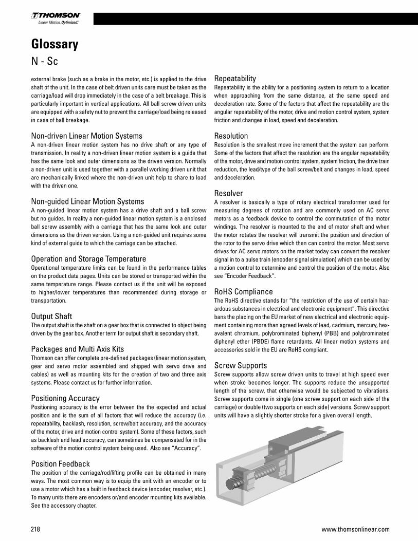
218 www.thomsonlinear.com
external brake (such as a brake in the motor, etc.) is applied to the drive shaft of the unit. In the case of belt driven units care must be taken as the carriage/load will drop immediately in the case of a belt breakage. This is particularly important in vertical applications. All ball screw driven units are equipped with a safety nut to prevent the carriage/load being released in case of ball breakage.
Non-driven Linear Motion SystemsA non-driven linear motion system has no drive shaft or any type of transmission. In reality a non-driven linear motion system is a guide that has the same look and outer dimensions as the driven version. Normally a non-driven unit is used together with a parallel working driven unit that are mechanically linked where the non-driven unit help to share to load with the driven one.
Non-guided Linear Motion SystemsA non-guided linear motion system has a drive shaft and a ball screw but no guides. In reality a non-guided linear motion system is a enclosed ball screw assembly with a carriage that has the same look and outer dimensions as the driven version. Using a non-guided unit requires some kind of external guide to which the carriage can be attached.
Operation and Storage TemperatureOperational temperature limits can be found in the performance tables on the product data pages. Units can be stored or transported within the same temperature range. Please contact us if the unit will be exposed to higher/lower temperatures than recommended during storage or transportation.
Output ShaftThe output shaft is the shaft on a gear box that is connected to object being driven by the gear box. Another term for output shaft is secondary shaft.
Packages and Multi Axis KitsThomson can offer complete pre-defined packages (linear motion system, gear and servo motor assembled and shipped with servo drive and ca bles) as well as mounting kits for the creation of two and three axis sys tems. Please contact us for further information.
Positioning Accuracy Positioning accuracy is the error between the the expected and actual position and is the sum of all factors that will reduce the accuracy (i.e. repeatability, backlash, resolution, screw/belt accuracy, and the accuracy of the motor, drive and motion control system). Some of these factors, such as backlash and lead accuracy, can sometimes be compensated for in the software of the motion control system being used. Also see “Accuracy”.
Position FeedbackThe position of the carriage/rod/lifting profile can be obtained in many ways. The most common way is to equip the unit with an encoder or to use a motor which has a built in feedback device (encoder, resolver, etc.). To many units there are encoders or/and encoder mounting kits available. See the accessory chapter.
RepeatabilityRepeatability is the ability for a positioning system to return to a location when approaching from the same distance, at the same speed and deceleration rate. Some of the factors that affect the repeatability are the angular repeatability of the motor, drive and motion control system, system friction and changes in load, speed and deceleration.
ResolutionResolution is the smallest move increment that the system can perform. Some of the factors that affect the resolution are the angular repeatability of the motor, drive and motion control system, system friction, the drive train reduction, the lead/type of the ball screw/belt and changes in load, speed and deceleration.
ResolverA resolver is basically a type of rotary electrical transformer used for measuring degrees of rotation and are commonly used on AC servo motors as a feedback device to control the commutation of the motor windings. The resolver is mounted to the end of motor shaft and when the motor rotates the resolver will transmit the position and direction of the rotor to the servo drive which then can control the motor. Most servo drives for AC servo motors on the market today can convert the resolver signal in to a pulse train (encoder signal simulation) which can be used by a motion control to determine and control the position of the motor. Also see “Encoder Feedback”.
RoHS ComplianceThe RoHS directive stands for “the restriction of the use of certain haz-ardous substances in electrical and electronic equipment”. This directive bans the placing on the EU market of new electrical and electronic equip-ment containing more than agreed levels of lead, cadmium, mercury, hex-avalent chromium, polybrominated biphenyl (PBB) and polybrominated diphenyl ether (PBDE) flame retardants. All linear motion systems and accessories sold in the EU are RoHS compliant.
Screw SupportsScrew supports allow screw driven units to travel at high speed even when stroke becomes longer. The supports reduce the unsupported length of the screw, that otherwise would be subjected to vibrations. Screw supports come in single (one screw support on each side of the carriage) or double (two supports on each side) versions. Screw support units will have a slightly shorter stroke for a given overall length.
GlossaryN - Sc
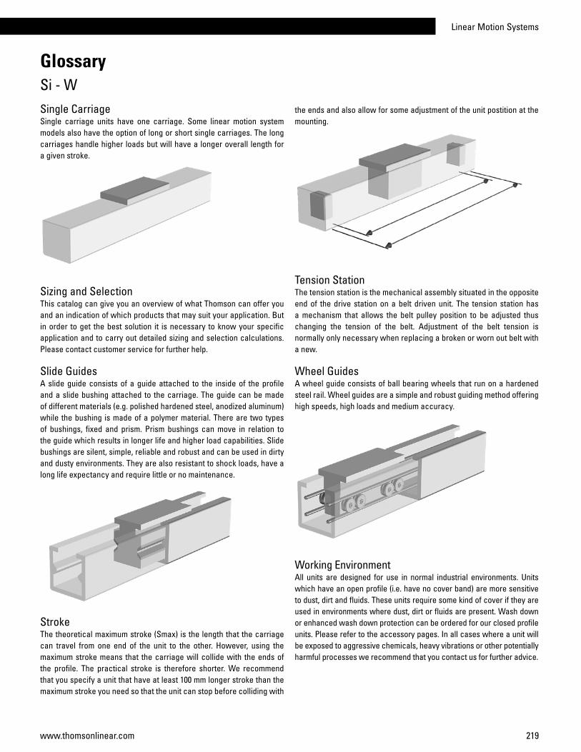
Linear Motion Systems
219www.thomsonlinear.com
Single Carriage Single carriage units have one carriage. Some linear motion system models also have the option of long or short single carriages. The long carriages handle higher loads but will have a longer overall length for a given stroke.
Sizing and SelectionThis catalog can give you an overview of what Thomson can offer you and an indication of which products that may suit your application. But in order to get the best solution it is necessary to know your specific application and to carry out detailed sizing and selection calculations. Please contact customer service for further help.
Slide GuidesA slide guide consists of a guide attached to the inside of the profile and a slide bushing attached to the carriage. The guide can be made of different materials (e.g. polished hardened steel, anodized aluminum) while the bushing is made of a polymer material. There are two types of bushings, fixed and prism. Prism bushings can move in relation to the guide which results in longer life and higher load capabilities. Slide bushings are silent, simple, reliable and robust and can be used in dirty and dusty environments. They are also resistant to shock loads, have a long life expectancy and require little or no maintenance.
StrokeThe theoretical maximum stroke (Smax) is the length that the carriage can travel from one end of the unit to the other. However, using the maximum stroke means that the carriage will collide with the ends of the profile. The practical stroke is therefore shorter. We recommend that you specify a unit that have at least 100 mm longer stroke than the maximum stroke you need so that the unit can stop before colliding with
GlossarySi - W
the ends and also allow for some adjustment of the unit postition at the mounting.
Tension StationThe tension station is the mechanical assembly situated in the opposite end of the drive station on a belt driven unit. The tension station has a mechanism that allows the belt pulley position to be adjusted thus changing the tension of the belt. Adjustment of the belt tension is normally only necessary when replacing a broken or worn out belt with a new.
Wheel GuidesA wheel guide consists of ball bearing wheels that run on a hardened steel rail. Wheel guides are a simple and robust guiding method offering high speeds, high loads and medium accuracy.
Working EnvironmentAll units are designed for use in normal industrial environments. Units which have an open profile (i.e. have no cover band) are more sensitive to dust, dirt and fluids. These units require some kind of cover if they are used in environments where dust, dirt or fluids are present. Wash down or enhanced wash down protection can be ordered for our closed profile units. Please refer to the accessory pages. In all cases where a unit will be exposed to aggressive chemicals, heavy vibrations or other potentially harmful processes we recommend that you con tact us for further advice.


Thomson - the Choice for Optimized Motion SolutionsOften the ideal design solution is not about finding the fastest, sturdiest, most accurate or even the least expensive option. Rather, the ideal solution is the optimal balance of performance, life and cost.
Quickly Configure the Optimal Mechanical Motion SolutionThomson has several advantages that makes us the supplier of choice for motion control technology.• Thomson owns the broadest standard product offering of mechanical motion technologies in the industry. • Modified versions of standard product or white sheet design solutions are routine for us. • Choose Thomson and gain access to over 70 years of global application experience in industries including packaging, factory automation, material handling, medical, clean energy, printing, automotive, machine tool, aerospace and defense. • As part of Fortive Corporation, we are financially strong and unique in our ability to bring together control, drive, motor, power transmission and precision linear motion technologies.
A Name You Can TrustA wealth of product and application information as well as 3D models, software tools, our distributor locator and global contact information is available at www.thomsonlinear.com/contact_us. Talk to us early in the design process to see how Thomson can help identify the optimal balance of performance, life and cost for your next application. And, call us or any of our 2000+ distribution partners around the world for fast delivery of replacement parts.
Local Support Around the Globe
Application Centers Global Design & Engineering CentersGlobal Manufacturing Operations
USA, CANADA and MEXICOThomson203A West Rock RoadRadford, VA 24141, USAPhone: 1-540-633-3549Fax: 1-540-633-0294E-mail: [email protected]: literature.thomsonlinear.com
EUROPEUnited KingdomThomsonOffice 9, The BarnsCaddsdown Business ParkBideford, Devon, EX39 3BT Phone: +44 (0) 1271 334 500E-mail: [email protected]
GermanyThomsonNürtinger Straße 7072649 WolfschlugenPhone: +49 (0) 7022 504 403Fax: +49 (0) 7022 504 405E-mail: [email protected]
FranceThomsonPhone: +33 (0) 243 50 03 30Fax: +33 (0) 243 50 03 39E-mail: [email protected]
ItalyThomsonLargo Brughetti20030 Bovisio MasciagoPhone: +39 0362 594260Fax: +39 0362 594263E-mail: [email protected]
SpainThomsonE-mail: [email protected]
SwedenThomsonEstridsväg 1029109 KristianstadPhone: +46 (0) 44 24 67 00Fax: +46 (0) 44 24 40 85E-mail: [email protected]
ASIA Asia Pacific Thomson E-mail: [email protected] China Thomson Rm 2205, Scitech Tower 22 Jianguomen Wai Street Beijing 100004 Phone: +86 400 6661 802 Fax: +86 10 6515 0263 E-mail: [email protected]
IndiaThomson c/o Fortive India Pvt. Ltd.Unit No. FF A 07Art Guild House, A Wing, 1st Floor, L.B.S MargKurla – West, Mumbai – 400070 IndiaPhone: +0091 22 6249 5043Email: [email protected]
JapanThomsonMinami-Kaneden 2-12-23, SuitaOsaka 564-0044 JapanPhone: +81-6-6386-8001Fax: +81-6-6386-5022E-mail: [email protected]
South KoreaThomson ROA704 ASEM Tower (Samsung-dong)517 Yeongdong-daero, Gangnam-gu Seoul, S. Korea, Zip Code: 06164Phone: +82 2 6917 5048 & 5049Fax: +82 2 528 1456 & 1457 E-mail: [email protected]
SOUTH AMERICA Brazil Thomson Av. Tamboré, 1077 Barueri, SP - 06460-000 Phone: +55 11 3616-0191 Fax: +55 11 3611 1982 E-mail: [email protected]
Linear Motion System
s
Linear_Motion_Systems_CTEN-0008-05 | 20180612TJSpecifications are subject to change without notice. It is the responsibility of the product user to determine the suitability of this product for a specific application. All trademarks property of their respective owners. © Thomson Industries, Inc. 2018
www.thomsonlinear.com
www.thomsonlinear.com
Linear Motion Systems
June 2018
New! RediMount™ motor mounting adapter kit available as standard