Thomas & Betts Kopex-Ex Hazardous Location Conduits and...
28
-
Upload
hoangquynh -
Category
Documents
-
view
235 -
download
5
Transcript of Thomas & Betts Kopex-Ex Hazardous Location Conduits and...
www.youtube.com/user/ebhorsman
Visit our Shop Online
ebhorsman.com
proud distributorof
w w w . t n b . c a
Hazardous Location Conduits and Fittings
F1
Kopex-Ex TM
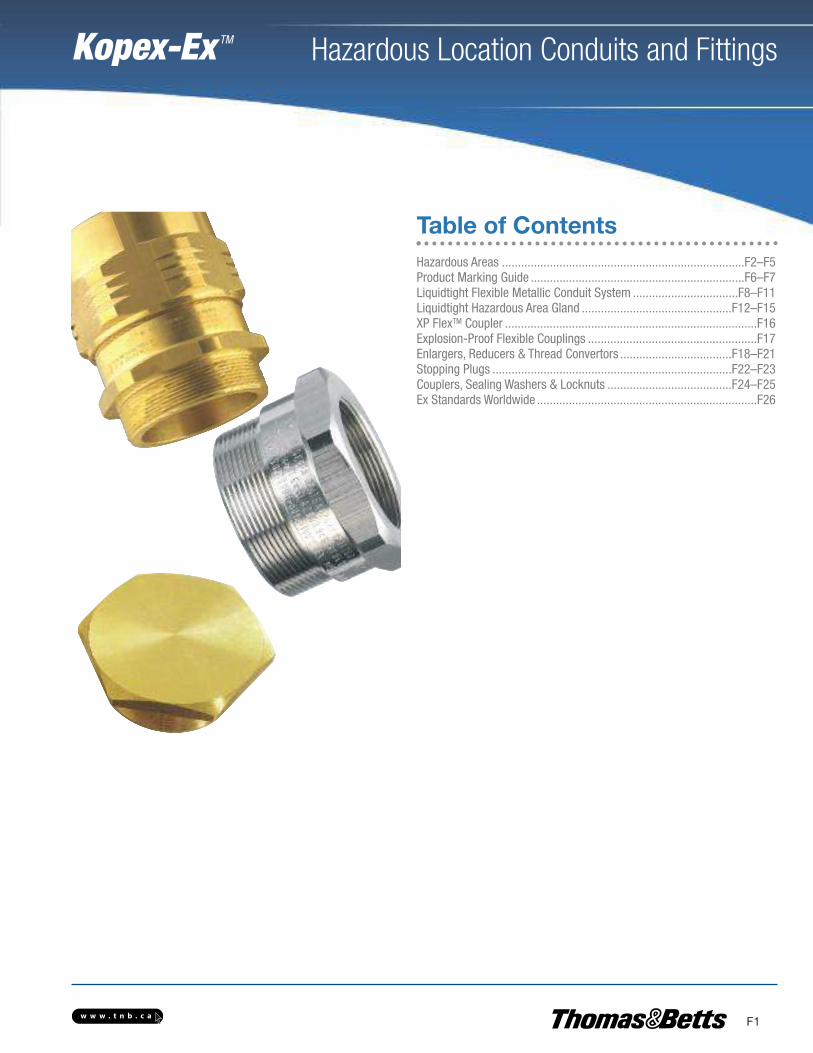
Hazardous Areas ............................................................................F2–F5Product Marking Guide ...................................................................F6–F7Liquidtight Flexible Metallic Conduit System .................................F8–F11Liquidtight Hazardous Area Gland ...............................................F12–F15XP FlexTM Coupler ...............................................................................F16Explosion-Proof Flexible Couplings .....................................................F17Enlargers, Reducers & Thread Convertors ...................................F18–F21Stopping Plugs ...........................................................................F22–F23Couplers, Sealing Washers & Locknuts .......................................F24–F25Ex Standards Worldwide .....................................................................F26
Table of Contents
w w w . t n b . c a
Hazardous Location Conduits and Fittings
F2
Kopex-Ex TM
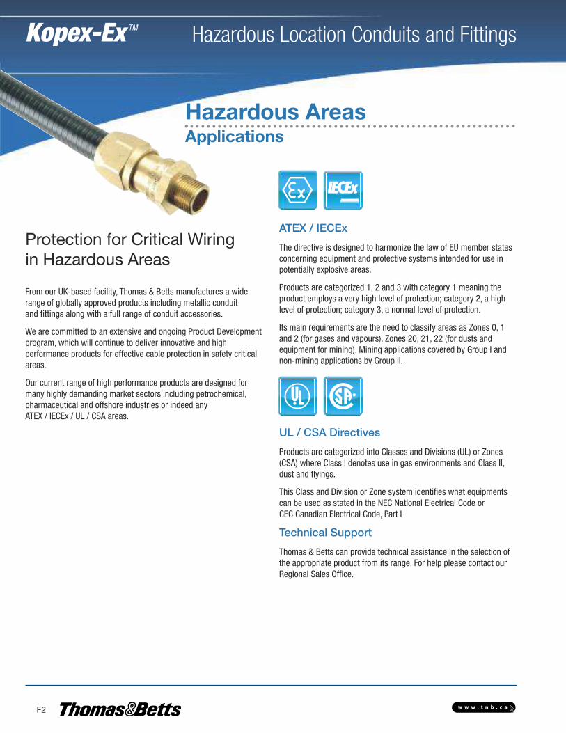
Hazardous AreasApplications
From our UK-based facility, Thomas & Betts manufactures a widerange of globally approved products including metallic conduitand fittings along with a full range of conduit accessories.
We are committed to an extensive and ongoing Product Developmentprogram, which will continue to deliver innovative and high performance products for effective cable protection in safety criticalareas.
Our current range of high performance products are designed formany highly demanding market sectors including petrochemical,pharmaceutical and offshore industries or indeed any ATEX / IECEx / UL / CSA areas.
Protection for Critical Wiringin Hazardous Areas
ATEX / IECEx
The directive is designed to harmonize the law of EU member statesconcerning equipment and protective systems intended for use inpotentially explosive areas.
Products are categorized 1, 2 and 3 with category 1 meaning theproduct employs a very high level of protection; category 2, a highlevel of protection; category 3, a normal level of protection.
Its main requirements are the need to classify areas as Zones 0, 1and 2 (for gases and vapours), Zones 20, 21, 22 (for dusts andequipment for mining), Mining applications covered by Group I andnon-mining applications by Group II.
UL / CSA Directives
Products are categorized into Classes and Divisions (UL) or Zones(CSA) where Class I denotes use in gas environments and Class II,dust and flyings.
This Class and Division or Zone system identifies what equipmentscan be used as stated in the NEC National Electrical Code orCEC Canadian Electrical Code, Part I
Technical Support
Thomas & Betts can provide technical assistance in the selection ofthe appropriate product from its range. For help please contact ourRegional Sales Office.
w w w . t n b . c a
Hazardous Location Conduits and Fittings
F3
Kopex-Ex TM
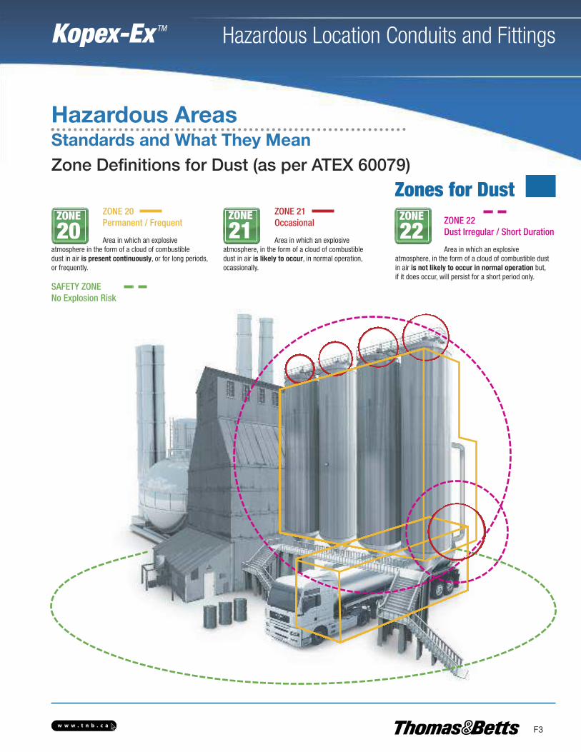
Hazardous AreasStandards and What They MeanZone Definitions for Dust (as per ATEX 60079)
ZONE 20Permanent / Frequent
Area in which an explosiveatmosphere in the form of a cloud of combustibledust in air is present continuously, or for long periods,or frequently.
SAFETY ZONENo Explosion Risk
ZONE 21Occasional
Area in which an explosiveatmosphere, in the form of a cloud of combustibledust in air is likely to occur, in normal operation,ocassionally.
ZONE 22Dust Irregular / Short Duration
Area in which an explosiveatmosphere, in the form of a cloud of combustible dustin air is not likely to occur in normal operation but,if it does occur, will persist for a short period only.
ZONE
20ZONE
21ZONE
22
Zones for Dust
w w w . t n b . c a
Hazardous Location Conduits and Fittings
F4
Kopex-Ex TM
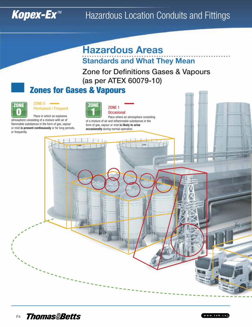
Zone for Definitions Gases & Vapours(as per ATEX 60079-10)
Zones for Gases & Vapours
Hazardous AreasStandards and What They Mean
ZONE 0Permanent / Frequent
Place in which an explosiveatmosphere consisting of a mixture with air offlammable substances in the form of gas, vapouror mist is present continuously or for long periods,or frequently.
ZONE 1OccasionalPlace where an atmosphere consisting
of a mixture of air and inflammable substances in theform of gas, vapour or mist is likely to ariseoccasionally during normal operation.
ZONE
0ZONE
1
w w w . t n b . c a
Hazardous Location Conduits and Fittings
F5
Kopex-Ex TM
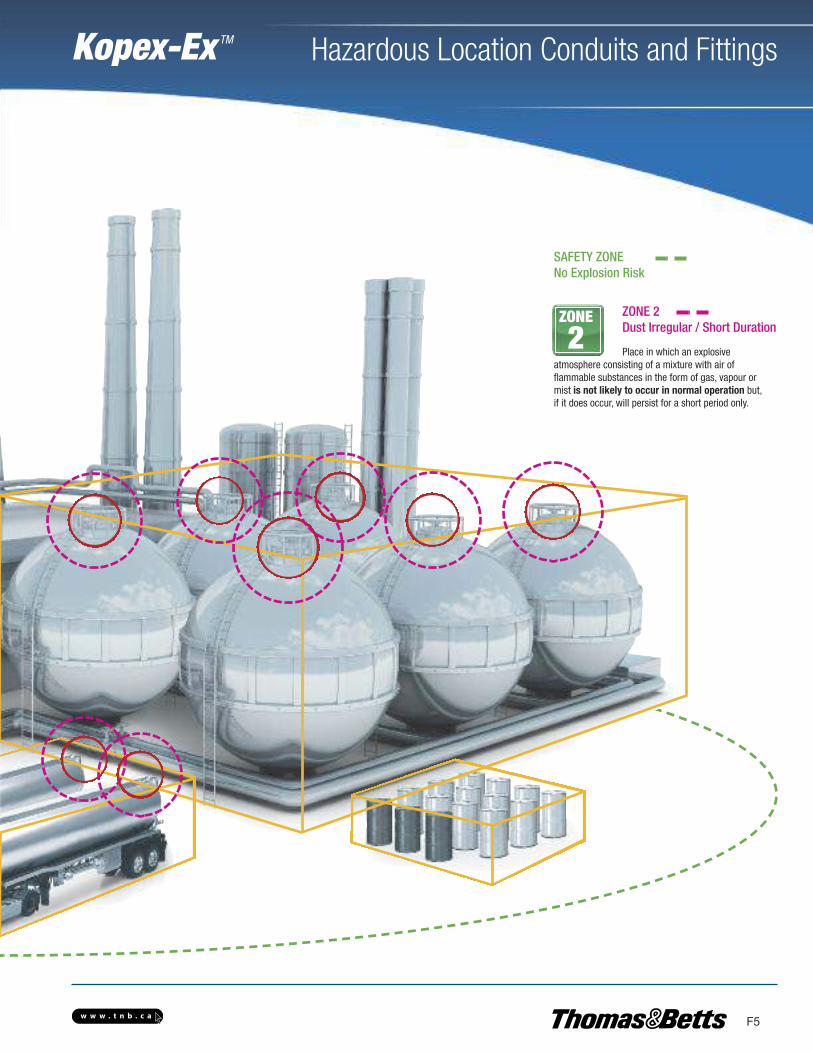
SAFETY ZONENo Explosion Risk
ZONE 2Dust Irregular / Short Duration
Place in which an explosiveatmosphere consisting of a mixture with air offlammable substances in the form of gas, vapour ormist is not likely to occur in normal operation but,if it does occur, will persist for a short period only.
ZONE
2
w w w . t n b . c a
Hazardous Location Conduits and Fittings
F6
Kopex-Ex TM
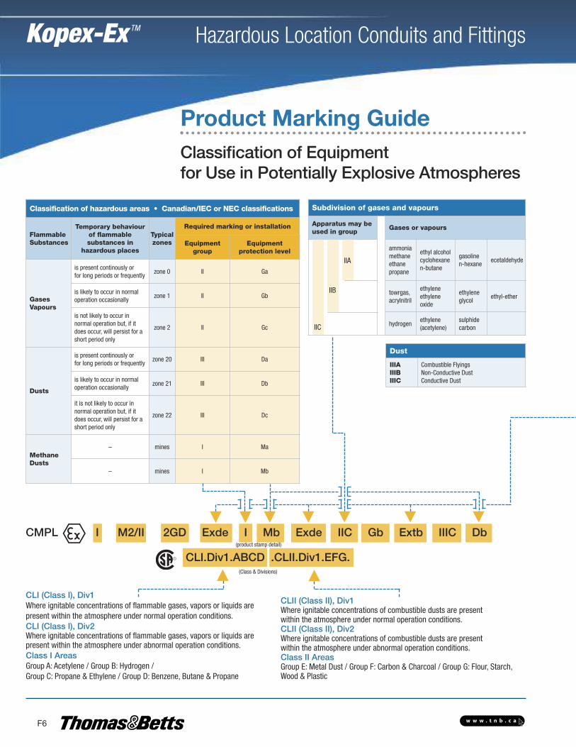
Classification of Equipmentfor Use in Potentially Explosive Atmospheres
Product Marking Guide
CLII (Class II), Div1Where ignitable concentrations of combustible dusts are presentwithin the atmosphere under normal operation conditions.CLII (Class II), Div2Where ignitable concentrations of combustible dusts are presentwithin the atmosphere under abnormal operation conditions.Class II AreasGroup E: Metal Dust / Group F: Carbon & Charcoal / Group G: Flour, Starch,Wood & Plastic
CLI (Class I), Div1Where ignitable concentrations of flammable gases, vapors or liquids arepresent within the atmosphere under normal operation conditions.CLI (Class I), Div2Where ignitable concentrations of flammable gases, vapors or liquids arepresent within the atmosphere under abnormal operation conditions.Class I AreasGroup A: Acetylene / Group B: Hydrogen / Group C: Propane & Ethylene / Group D: Benzene, Butane & Propane
Classification of hazardous areas • Canadian/IEC or NEC classifications
FlammableSubstances
Temporary behaviourof flammablesubstances in
hazardous places
Typicalzones
Required marking or installation
Equipmentgroup
Equipmentprotection level
GasesVapours
is present continously orfor long periods or frequently
zone 0 II Ga
is likely to occur in normaloperation occasionally
zone 1 II Gb
is not likely to occur innormal operation but, if itdoes occur, will persist for ashort period only
zone 2 II Gc
Dusts
is present continously orfor long periods or frequently
zone 20 III Da
is likely to occur in normaloperation occasionally
zone 21 III Db
it is not likely to occur innormal operation but, if itdoes occur, will persist for ashort period only
zone 22 III Dc
MethaneDusts
– mines I Ma
– mines I Mb
Subdivision of gases and vapours
Apparatus may beused in group
Gases or vapours
ammoniamethaneethanepropane
ethyl alcoholcyclohexanen-butane
gasolinen-hexane
ecetaldehyde
towrgas,acrylnitril
ethyleneethyleneoxide
ethyleneglycol
ethyl-ether
hydrogenethylene(acetylene)
sulphidecarbon
IIA
IIB
IIC
Dust
IIIAIIIBIIIC
Combustible FlyingsNon-Conductive DustConductive Dust
CMPL I M2/II 2GD Exde I Mb Exde IIC Gb Extb IIIC Db
CLI.Div1.ABCD .CLII.Div1.EFG.(product stamp detail)
(Class & Divisions)
w w w . t n b . c a
Hazardous Location Conduits and Fittings
F7
Kopex-Ex TM
Classification of Equipmentfor Use in Potentially Explosive Atmospheres
Product Marking Guide
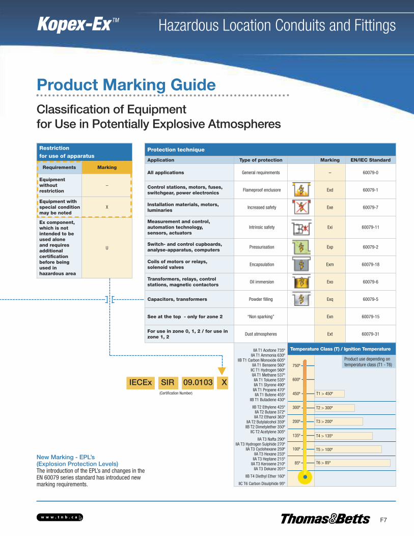
New Marking - EPL’s (Explosion Protection Levels)The introduction of the EPL’s and changes in the EN 60079 series standard has introduced new marking requirements.
Restrictionfor use of apparatus
Requirements Marking
Equipmentwithoutrestriction
–
Equipment withspecial conditionmay be noted
X
Ex component,which is notintended to beused aloneand requiresadditionalcertificationbefore beingused inhazardous area
U
Protection technique
Application Type of protection Marking EN/IEC Standard
All applications General requirements – 60079-0
Control stations, motors, fuses,switchgear, power electronics
Flameproof enclusore Exd 60079-1
Installation materials, motors,luminaries
Increased safety Exe 60079-7
Measurement and control, automation technology,sensors, actuators
Intrinsic safety Exi 60079-11
Switch- and control cupboards,analyse-apparatus, computers
Pressurisation Exp 60079-2
Coils of motors or relays,solenoid valves
Encapsulation Exm 60079-18
Transformers, relays, controlstations, magnetic contactors
Oil immersion Exo 60079-6
Capacitors, transformers Powder filling Exq 60079-5
See at the top - only for zone 2 “Non sparking” Exn 60079-15
For use in zone 0, 1, 2 / for use inzone 1, 2
Dust atmospheres Ext 60079-31
IIA T1 Acetone 735ºIIA T1 Ammonia 630º
IIB T1 Carbon Monoxide 605ºIIA T1 Bensene 560ºIIC T1 Hydrogen 560ºIIA T1 Methane 537ºIIA T1 Toluene 535ºIIA T1 Styrene 490ºIIA T1 Propane 470ºIIA T1 Butene 455º
IIB T1 Butadiene 430º
IIB T2 Ethylene 425ºIIA T2 Butane 372ºIIA T2 Ethanol 363º
IIA T2 Butylalcohol 359ºIIB T2 Dimetylether 350º
IIC T2 Acetylene 305º
IIA T3 Nafta 290ºIIA T3 Hydrogen Sulphide 270º
IIA T3 Cyclohexane 259ºIIA T3 Hexane 233ºIIA T3 Heptane 215ºIIA T3 Kerosene 210ºIIA T3 Dekane 201º
IIB T4 Diethyl Ether 160º
IIC T6 Carbon Disulphide 95º
Temperature Class (T) / Ignition Temperature
(Certification Number)
750º
600º
450º
300º
200º
135º
100º
85º
Product use depending ontemperature class (T1 - T6)
T1 > 450º
T2 > 300º
T3 > 200º
T4 > 135º
T5 > 100º
T6 > 85º
IECEx SIR 09.0103 X
w w w . t n b . c a
Hazardous Location Conduits and Fittings
F8
Kopex-Ex TM
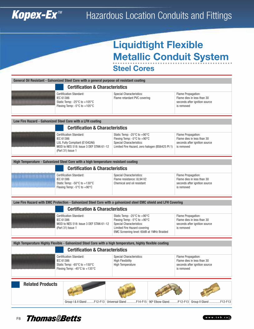
General Oil Resistant - Galvanized Steel Core with a general purpose oil resistant coating
Certification & CharacteristicsCertification Standard: IEC 61386Static Temp: -25°C to +105°CFlexing Temp: -5°C to +105°C
Special Characteristics: Flame retardant PVC covering
Flame Propagation:Flame dies in less than 30seconds after ignition source is removed
Low Fire Hazard - Galvanized Steel Core with a LFH coating
Certification & CharacteristicsCertification Standard: IEC 61386LUL Fully Compliant (E1042A6)MOD to NES 518: Issue 3 DEF STAN 61-12(Part 31) Issue 1
Static Temp: -25°C to +90°CFlexing Temp: -5°C to +90°CSpecial Characteristics: Limited Fire Hazard, zero halogen (BS6425 Pt 1)
Flame Propagation:Flame dies in less than 30seconds after ignition source is removed
High Temperature - Galvanized Steel Core with a high temperature resistant coating
Certification & CharacteristicsCertification Standard: IEC 61386Static Temp: -50°C to +130°CFlexing Temp: -5°C to +90°C
Special Characteristics: Flame resistance: UL94 V2Chemical and oil resistant
Flame Propagation:Flame dies in less than 30seconds after ignition source is removed
Low Fire Hazard with EMC Protection - Galvanized Steel Core with a galvanized steel EMC shield and LFH Covering
Certification & CharacteristicsCertification Standard: IEC 61386MOD to NES 518: Issue 3 DEF STAN 61-12(Part 31) Issue 1
Static Temp: -25°C to +90°CFlexing Temp: -5°C to +90°CSpecial Characteristics: Limited Fire Hazard coveringEMC Screening level: 60dB at 1MHz Braided
Flame Propagation:Flame dies in less than 30seconds after ignition source is removed
High Temperature Highly Flexible - Galvanized Steel Core with a high temperature, highly flexible coating
Certification & CharacteristicsCertification Standard: IEC 61386Static Temp: -65°C to +150°CFlexing Temp: -45°C to +135°C
Special Characteristics: High FlexibilityHigh Temperature
Flame Propagation:Flame dies in less than 30seconds after ignition source is removed
Related Products
Group I & II Gland .........F12-F13 Universal Gland ............F14-F15 90º Elbow Gland.........F12-F13 Group II Gland ..............F12-F13
Liquidtight FlexibleMetallic Conduit SystemSteel Cores
w w w . t n b . c a
Hazardous Location Conduits and Fittings
F9
Kopex-Ex TM
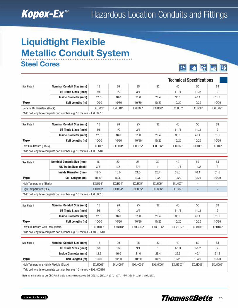
Technical Specifications
Type
Nominal Conduit Size (mm) 16 20 25 32 40 50 63
US Trade Sizes (inch) 3/8 1/2 3/4 1 1-1/4 1-1/2 2
Inside Diameter (mm) 12.5 16.0 21.0 26.4 35.3 40.4 51.6
Coil Lengths (m) 10/30 10/30 10/30 10/20 10/20 10/20 10/20
General Oil Resistant (Black) EXLB03* EXLB04* EXLB05* EXLB06* EXLB07* EXLB08* EXLB09*
*Add coil length to complete part number, e.g. 10 metres = EXLB0510
Type
Nominal Conduit Size (mm) 16 20 25 32 40 50 63
US Trade Sizes (inch) 3/8 1/2 3/4 1 1-1/4 1-1/2 2
Inside Diameter (mm) 12.5 16.0 21.0 26.4 35.3 40.4 51.6
Coil Lengths (m) 10/30 10/30 10/30 10/20 10/20 10/20 10/20
Low Fire Hazard (Black) EXLT03* EXLT04* EXLT05* EXLT06* EXLT07* EXLT08* EXLT09*
*Add coil length to complete part number, e.g. 10 metres = EXLT0510
Type
Nominal Conduit Size (mm) 16 20 25 32 40 50 63
US Trade Sizes (inch) 3/8 1/2 3/4 1 1-1/4 1-1/2 2
Inside Diameter (mm) 12.5 16.0 21.0 26.4 35.3 40.4 51.6
Coil Lengths (m) 10/30 10/30 10/30 10/20 10/20 10/20 10/20
Low Fire Hazard with EMC (Black) EXBBT03* EXBBT04* EXBBT05* EXBBT06* EXBBT07* EXBBT08* EXBBT09*
*Add coil length to complete part number, e.g. 10 metres = EXBBT0510
Type
Nominal Conduit Size (mm) 16 20 25 32 40 50 63
US Trade Sizes (inch) 3/8 1/2 3/4 1 1-1/4 1-1/2 2
Inside Diameter (mm) 12.5 16.0 21.0 26.4 35.3 40.4 51.6
Coil Lengths (m) 10/30 10/30 10/30 10/20 10/20 10/20 10/20
High Temperature Highly Flexible (Black) EXLHC03* EXLHC04* EXLHC05* EXLHC06* EXLHC07* EXLHC08* EXLHC09*
*Add coil length to complete part number, e.g. 10 metres = EXLHC0510
Type
Nominal Conduit Size (mm) 16 20 25 32 40 50 63
US Trade Sizes (inch) 3/8 1/2 3/4 1 1-1/4 1-1/2 2
Inside Diameter (mm) 12.5 16.0 21.0 26.4 35.3 40.4 51.6
Coil Lengths (m) 10/30 10/30 10/30 10/20 10/20 10/20 10/20
High Temperature (Black) EXLH03* EXLH04* EXLH05* EXLH06* EXLH07* – –
High Temperature (Blue) EXLB03* EXLB04* EXLB05* EXLB06* EXLB07* – –
*Add coil length to complete part number, e.g. 10 metres = EXLH0510
Liquidtight FlexibleMetallic Conduit System
See Note 1
See Note 1
See Note 1
See Note 1
See Note 1
Note 1: In Canada, as per CEC Part I, trade size are respectively 3/8 (12), 1/2 (16), 3/4 (21), 1 (27), 1-1/4 (35), 1-1/2 (41) and 2 (53).
Steel Cores
w w w . t n b . c a
Hazardous Location Conduits and Fittings
F10
Kopex-Ex TM
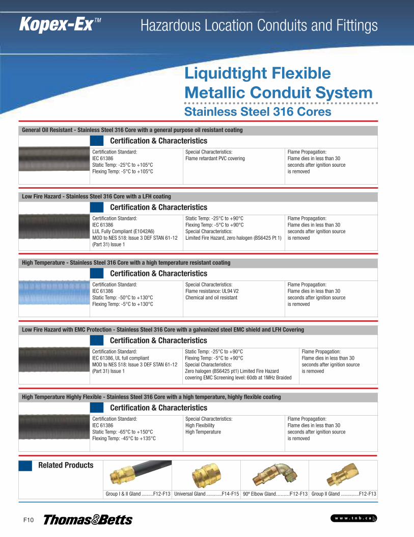
General Oil Resistant - Stainless Steel 316 Core with a general purpose oil resistant coating
Certification & CharacteristicsCertification Standard: IEC 61386Static Temp: -25°C to +105°CFlexing Temp: -5°C to +105°C
Special Characteristics: Flame retardant PVC covering
Flame Propagation:Flame dies in less than 30 seconds after ignition source is removed
Low Fire Hazard - Stainless Steel 316 Core with a LFH coating
Certification & CharacteristicsCertification Standard: IEC 61386LUL Fully Compliant (E1042A6)MOD to NES 518: Issue 3 DEF STAN 61-12(Part 31) Issue 1
Static Temp: -25°C to +90°CFlexing Temp: -5°C to +90°CSpecial Characteristics: Limited Fire Hazard, zero halogen (BS6425 Pt 1)
Flame Propagation:Flame dies in less than 30 seconds after ignition source is removed
High Temperature - Stainless Steel 316 Core with a high temperature resistant coating
Certification & CharacteristicsCertification Standard: IEC 61386Static Temp: -50°C to +130°CFlexing Temp: -5°C to +130°C
Special Characteristics: Flame resistance: UL94 V2Chemical and oil resistant
Flame Propagation:Flame dies in less than 30seconds after ignition source is removed
Low Fire Hazard with EMC Protection - Stainless Steel 316 Core with a galvanized steel EMC shield and LFH Covering
Certification & CharacteristicsCertification Standard: IEC 61386, UL full compliantMOD to NES 518: Issue 3 DEF STAN 61-12(Part 31) Issue 1
Static Temp: -25°C to +90°CFlexing Temp: -5°C to +90°CSpecial Characteristics: Zero halogen (BS6425 pt1) Limited Fire Hazard covering EMC Screening level: 60db at 1MHz Braided
Flame Propagation:Flame dies in less than 30 seconds after ignition source is removed
High Temperature Highly Flexible - Stainless Steel 316 Core with a high temperature, highly flexible coating
Certification & CharacteristicsCertification Standard: IEC 61386Static Temp: -65°C to +150°CFlexing Temp: -45°C to +135°C
Special Characteristics: High FlexibilityHigh Temperature
Flame Propagation:Flame dies in less than 30 seconds after ignition source is removed
Related Products
Group I & II Gland .........F12-F13 Universal Gland ............F14-F15 90º Elbow Gland.........F12-F13 Group II Gland ..............F12-F13
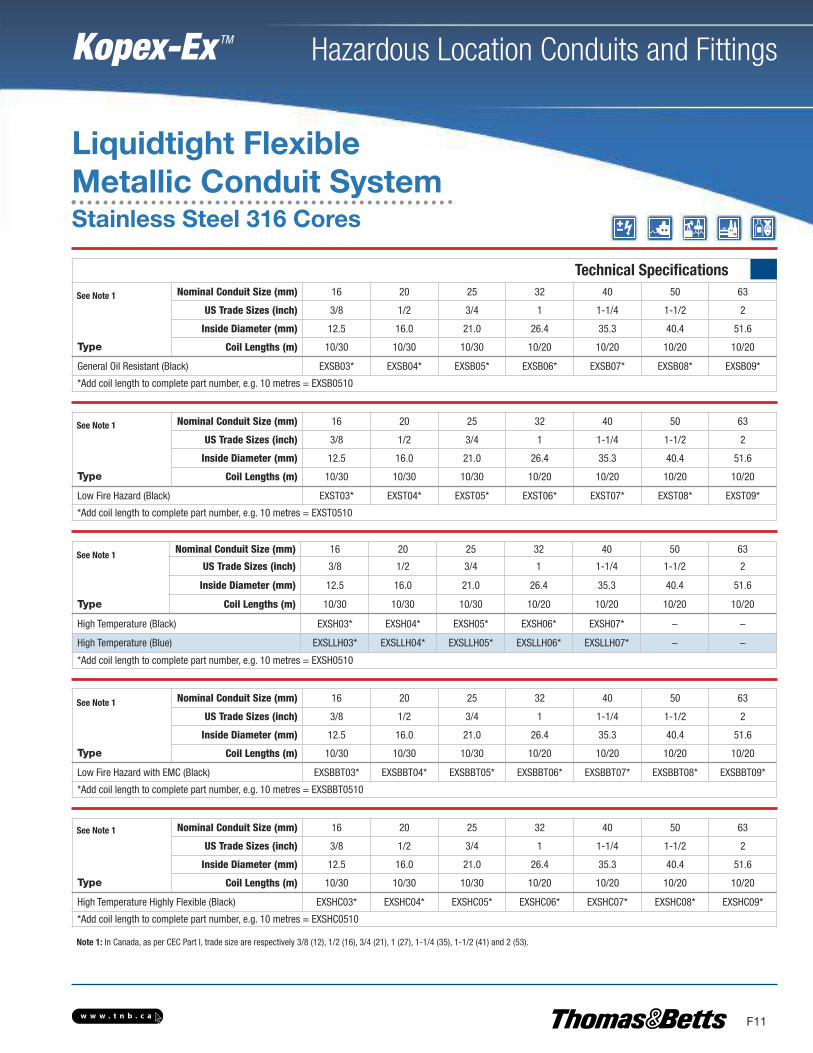
Liquidtight FlexibleMetallic Conduit SystemStainless Steel 316 Cores
w w w . t n b . c a
Hazardous Location Conduits and Fittings
F11
Kopex-Ex TM
Technical Specifications
Type
Nominal Conduit Size (mm) 16 20 25 32 40 50 63
US Trade Sizes (inch) 3/8 1/2 3/4 1 1-1/4 1-1/2 2
Inside Diameter (mm) 12.5 16.0 21.0 26.4 35.3 40.4 51.6
Coil Lengths (m) 10/30 10/30 10/30 10/20 10/20 10/20 10/20
General Oil Resistant (Black) EXSB03* EXSB04* EXSB05* EXSB06* EXSB07* EXSB08* EXSB09*
*Add coil length to complete part number, e.g. 10 metres = EXSB0510
Type
Nominal Conduit Size (mm) 16 20 25 32 40 50 63
US Trade Sizes (inch) 3/8 1/2 3/4 1 1-1/4 1-1/2 2
Inside Diameter (mm) 12.5 16.0 21.0 26.4 35.3 40.4 51.6
Coil Lengths (m) 10/30 10/30 10/30 10/20 10/20 10/20 10/20
Low Fire Hazard (Black) EXST03* EXST04* EXST05* EXST06* EXST07* EXST08* EXST09*
*Add coil length to complete part number, e.g. 10 metres = EXST0510
Type
Nominal Conduit Size (mm) 16 20 25 32 40 50 63
US Trade Sizes (inch) 3/8 1/2 3/4 1 1-1/4 1-1/2 2
Inside Diameter (mm) 12.5 16.0 21.0 26.4 35.3 40.4 51.6
Coil Lengths (m) 10/30 10/30 10/30 10/20 10/20 10/20 10/20
Low Fire Hazard with EMC (Black) EXSBBT03* EXSBBT04* EXSBBT05* EXSBBT06* EXSBBT07* EXSBBT08* EXSBBT09*
*Add coil length to complete part number, e.g. 10 metres = EXSBBT0510
Type
Nominal Conduit Size (mm) 16 20 25 32 40 50 63
US Trade Sizes (inch) 3/8 1/2 3/4 1 1-1/4 1-1/2 2
Inside Diameter (mm) 12.5 16.0 21.0 26.4 35.3 40.4 51.6
Coil Lengths (m) 10/30 10/30 10/30 10/20 10/20 10/20 10/20
High Temperature Highly Flexible (Black) EXSHC03* EXSHC04* EXSHC05* EXSHC06* EXSHC07* EXSHC08* EXSHC09*
*Add coil length to complete part number, e.g. 10 metres = EXSHC0510
Type
Nominal Conduit Size (mm) 16 20 25 32 40 50 63
US Trade Sizes (inch) 3/8 1/2 3/4 1 1-1/4 1-1/2 2
Inside Diameter (mm) 12.5 16.0 21.0 26.4 35.3 40.4 51.6
Coil Lengths (m) 10/30 10/30 10/30 10/20 10/20 10/20 10/20
High Temperature (Black) EXSH03* EXSH04* EXSH05* EXSH06* EXSH07* – –
High Temperature (Blue) EXSLLH03* EXSLLH04* EXSLLH05* EXSLLH06* EXSLLH07* – –
*Add coil length to complete part number, e.g. 10 metres = EXSH0510
Liquidtight FlexibleMetallic Conduit System
See Note 1
See Note 1
See Note 1
See Note 1
See Note 1
Note 1: In Canada, as per CEC Part I, trade size are respectively 3/8 (12), 1/2 (16), 3/4 (21), 1 (27), 1-1/4 (35), 1-1/2 (41) and 2 (53).
Stainless Steel 316 Cores
w w w . t n b . c a
Hazardous Location Conduits and Fittings
F12
Kopex-Ex TM
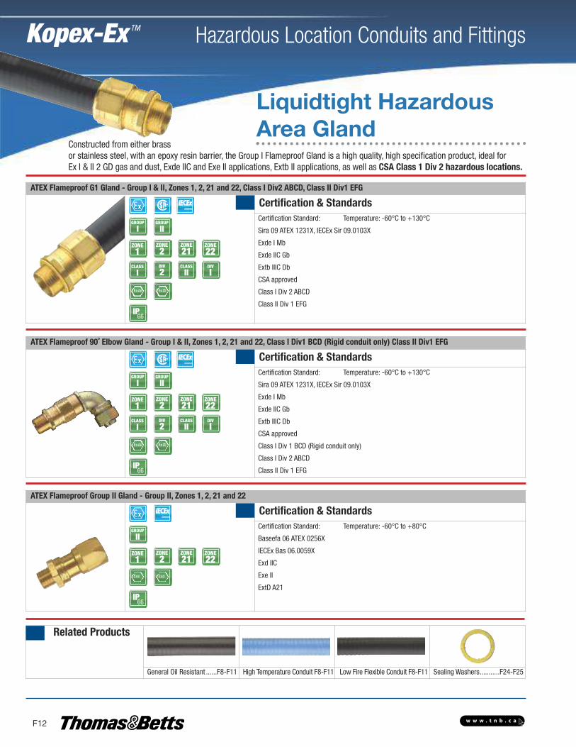
ATEX Flameproof G1 Gland - Group I & II, Zones 1, 2, 21 and 22, Class I Div2 ABCD, Class II Div1 EFG
Certification & StandardsCertification Standard: Temperature: -60°C to +130°C
Sira 09 ATEX 1231X, IECEx Sir 09.0103X
Exde I Mb
Exde IIC Gb
Extb IIIC Db
CSA approved
Class I Div 2 ABCD
Class II Div 1 EFG
ZONE1
ZONE2
GROUP
IGROUP
II
ZONE21
ZONE22
CLASS
IDIV
2CLASS
IIDIV
I
Exde
IP66
Extb
ATEX Flameproof 90˚ Elbow Gland - Group I & II, Zones 1, 2, 21 and 22, Class I Div1 BCD (Rigid conduit only) Class II Div1 EFG
Certification & StandardsCertification Standard: Temperature: -60°C to +130°C
Sira 09 ATEX 1231X, IECEx Sir 09.0103X
Exde I Mb
Exde IIC Gb
Extb IIIC Db
CSA approved
Class I Div 1 BCD (Rigid conduit only)
Class I Div 2 ABCD
Class II Div 1 EFG
ZONE1
ZONE2
GROUP
IGROUP
II
ZONE21
ZONE22
CLASS
IDIV
2CLASS
IIDIV
I
Exde
IP66
Extb
ATEX Flameproof Group II Gland - Group II, Zones 1, 2, 21 and 22
Certification & StandardsCertification Standard: Temperature: -60°C to +80°C
Baseefa 06 ATEX 0256X
IECEx Bas 06.0059X
Exd IIC
Exe II
ExtD A21
ZONE1
ZONE2
GROUP
II
ZONE21
ZONE22
Exe
IP66
Exd
Related Products
General Oil Resistant ......F8-F11 High Temperature Conduit F8-F11 Low Fire Flexible Conduit F8-F11 Sealing Washers...........F24-F25
Liquidtight HazardousArea Gland
Constructed from either brassor stainless steel, with an epoxy resin barrier, the Group I Flameproof Gland is a high quality, high specification product, ideal forEx I & II 2 GD gas and dust, Exde IIC and Exe II applications, Extb II applications, as well as CSA Class 1 Div 2 hazardous locations.

w w w . t n b . c a
Hazardous Location Conduits and Fittings
F13
Kopex-Ex TM
Technical Specifications
Type
Nominal Conduit Size (mm) 16 20 25 32 40 50 63
Metric Thread Size (mm) 16 20 25 32 40 50 63
NPT Thread Size (inch) 1/2 1/2 3/4 1 1-1/4 1-1/2 2
Metric - Brass HAM0304G1 HAM0404G1 HAM0505G1 HAM0606G1 HAM0707G1 HAM0808G1 HAM0909G1
Metric - Nickel Plated HAMM0304G1 HAMM0404G1 HAMM0505G1 HAMM0606G1 HAMM0707G1 HAMM0808G1 HAMM0909G1
Metric - Stainless Steel HAMS0304G1 HAMS0404G1 HAMS0505G1 HAMS0606G1 HAMS0707G1 HAMS0808G1 HAMS0909G1
NPT Thread - Brass HAA0304G1 HAA0404G1 HAA0505G1 HAA0606G1 HAA0707G1 HAA0808G1 HAA0909G1
NPT Thread - Nickel Plated HAAM0304G1 HAAM0404G1 HAAM0505G1 HAAM0606G1 HAAM0707G1 HAAM0808G1 HAAM0909G1
NPT Thread - Stainless Steel HAAS0304G1 HAAS0404G1 HAAS0505G1 HAAS0606G1 HAAS0707G1 HAAS0808G1 HAAS0909G1
See pages F6-F7 for suitable conduits
Type
Nominal Conduit Size (mm) 16 20 25 32 40 50 63
Metric Thread Size (mm) 16 20 25 32 40 50 63
NPT Thread Size (inch) 1/2 1/2 3/4 1 1-1/4 1-1/2 2
Metric - Brass HAM0304E HAM0404E HAM0505E HAM0606E HAM0707E HAM0808E HAM0909E
Metric - Nickel Plated HAMM0304E HAMM0404E HAMM0505E HAMM0606E HAMM0707E HAMM0808E HAMM0909E
NPT Thread - Brass HAA0304E HAA0404E HAA0505E HAA0606E HAA0707E HAA0808E HAA0909E
NPT Thread - Nickel Plated HAAM0304E HAAM0404E HAAM0505E HAAM0606E HAAM0707E HAAM0808E HAAM0909E
See pages F6-F7 for suitable conduitsStainless Steel available but elbow is Nickel Plated BrassElbow supplied is for liquidtight conduit only
Type
Nominal Conduit Size (mm) 16 20 25 32 40 50 63
Metric Thread Size (mm) 16 20 25 32 40 50 63
NPT Thread Size (inch) 1/2 1/2 3/4 1 1-1/4 1-1/2 2
Metric - Brass HAM0304 HAM0404 HAM0505 HAM0606 HAM0707 HAM0808 HAM0909
Metric - Nickel Plated HAMM0304 HAMM0404 HAMM0505 HAMM0606 HAMM0707 HAMM0808 HAMM0909
Metric - Stainless Steel HAMS0304 HAMS0404 HAMS0505 HAMS0606 HAMS0707 HAMS0808 HAMS0909
NPT Thread - Brass HAA0304 HAA0404 HAA0505 HAA0606 HAA0707 HAA0808 HAA0909
NPT Thread - Nickel Plated HAAM0304 HAAM0404 HAAM0505 HAAM0606 HAAM0707 HAAM0808 HAAM0909
NPT Thread - Stainless Steel HAAS0304 HAAS0404 HAAS0505 HAAS0606 HAAS0707 HAAS0808 HAAS0909
See pages F6-F7 for suitable conduits
Liquidtight HazardousArea Gland
w w w . t n b . c a
Hazardous Location Conduits and Fittings
F14
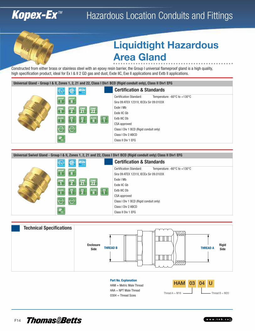
Universal Gland - Group I & II, Zones 1, 2, 21 and 22, Class I Div1 BCD (Rigid conduit only), Class II Div1 EFG
Certification & StandardsCertification Standard: Temperature: -60°C to +130°C
Sira 09 ATEX 1231X, IECEx Sir 09.0103X
Exde I Mb
Exde IIC Gb
Extb IIIC Db
CSA approved
Class I Div 1 BCD (Rigid conduit only)
Class I Div 2 ABCD
Class II Div 1 EFG
ZONE1
ZONE2
GROUP
IGROUP
II
ZONE21
ZONE22
CLASS
IDIV
1CLASS
IIDIV
1
Exde
IP66
DIV
2
Extb
Universal Swivel Gland - Group I & II, Zones 1, 2, 21 and 22, Class I Div1 BCD (Rigid conduit only) Class II Div1 EFG
Certification & StandardsCertification Standard: Temperature: -60°C to +130°C
Sira 09 ATEX 1231X, IECEx Sir 09.0103X
Exde I Mb
Exde IIC Gb
Extb IIIC Db
CSA approved
Class I Div 1 BCD (Rigid conduit only)
Class I Div 2 ABCD
Class II Div 1 EFG
ZONE1
ZONE2
GROUP
IGROUP
II
ZONE21
ZONE22
CLASS
IDIV
1CLASS
IIDIV
1
Exde
66
DIV
2
Extb
Technical Specifications
THREAD B THREAD A
Thread A = M16 Thread B = M20
Part No. Explanation
HAM = Metric Male Thread
HAA = NPT Male Thread
0304 = Thread Sizes
HAM 03 04 U
IP
Liquidtight HazardousArea Gland
Constructed from either brass or stainless steel with an epoxy resin barrier, the Group I universal flameproof gland is a high quality, high specification product, ideal for Ex I & II 2 GD gas and dust, Exde IIC, Exe II applications and Extb II applications.
Kopex-Ex TM
EnclosureSide
RigidSide
w w w . t n b . c a
Hazardous Location Conduits and Fittings
F15
Kopex-Ex TM
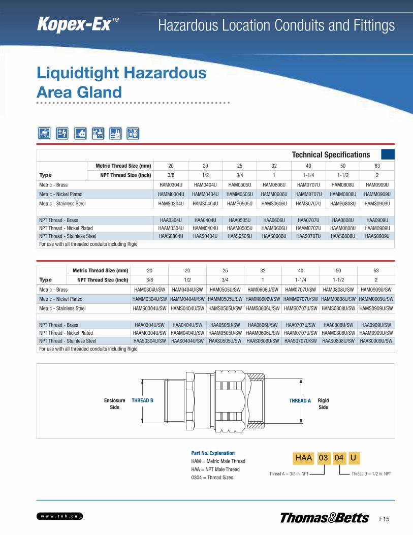
Technical Specifications
Type
Metric Thread Size (mm) 20 20 25 32 40 50 63
NPT Thread Size (inch) 3/8 1/2 3/4 1 1-1/4 1-1/2 2
Metric - Brass HAM0304U HAM0404U HAM0505U HAM0606U HAM0707U HAM0808U HAM0909U
Metric - Nickel Plated HAMM0304U HAMM0404U HAMM0505U HAMM0606U HAMM0707U HAMM0808U HAMM0909U
Metric - Stainless Steel HAMS0304U HAMS0404U HAMS0505U HAMS0606U HAMS0707U HAMS0808U HAMS0909U
NPT Thread - Brass HAA0304U HAA0404U HAA0505U HAA0606U HAA0707U HAA0808U HAA0909U
NPT Thread - Nickel Plated HAAM0304U HAAM0404U HAAM0505U HAAM0606U HAAM0707U HAAM0808U HAAM0909U
NPT Thread - Stainless Steel HAAS0304U HAAS0404U HAAS0505U HAAS0606U HAAS0707U HAAS0808U HAAS0909U
For use with all threaded conduits including Rigid
Type
Metric Thread Size (mm) 20 20 25 32 40 50 63
NPT Thread Size (inch) 3/8 1/2 3/4 1 1-1/4 1-1/2 2
Metric - Brass HAM0304U/SW HAM0404U/SW HAM0505U/SW HAM0606U/SW HAM0707U/SW HAM0808U/SW HAM0909U/SW
Metric - Nickel Plated HAMM0304U/SW HAMM0404U/SW HAMM0505U/SW HAMM0606U/SW HAMM0707U/SW HAMM0808U/SW HAMM0909U/SW
Metric - Stainless Steel HAMS0304U/SW HAMS0404U/SW HAMS0505U/SW HAMS0606U/SW HAMS0707U/SW HAMS0808U/SW HAMS0909U/SW
NPT Thread - Brass HAA0304U/SW HAA0404U/SW HAA0505U/SW HAA0606U/SW HAA0707U/SW HAA0808U/SW HAA0909U/SW
NPT Thread - Nickel Plated HAAM0304U/SW HAAM0404U/SW HAAM0505U/SW HAAM0606U/SW HAAM0707U/SW HAAM0808U/SW HAAM0909U/SW
NPT Thread - Stainless Steel HAAS0304U/SW HAAS0404U/SW HAAS0505U/SW HAAS0606U/SW HAAS0707U/SW HAAS0808U/SW HAAS0909U/SW
For use with all threaded conduits including Rigid
THREAD B THREAD A
Thread A = 3/8 in. NPT Thread B = 1/2 in. NPT
Part No. Explanation
HAM = Metric Male Thread
HAA = NPT Male Thread
0304 = Thread Sizes
HAA 03 04 U
Liquidtight HazardousArea Gland
EnclosureSide
RigidSide

w w w . t n b . c a
Hazardous Location Conduits and Fittings
F16
Kopex-Ex TM
Explosion-ProofFlexible Couplings• UL Listed for use in hazardous and wet locations• Corrosion-resistant - ideal for washdown areas• Flexible bronze construction with arc-resistantinner sleeve and brass fittings
• Terminated with two threaded female end fittingsand male close nipples
Certification & Standards
Not Listed or Certified1/2 in. and 3/4 in. Hub Sizes: Class I Div 1 & 2 ABCD; Class II Div 1 EFG, Class III1 Hub Size: Class I Div 1 & 2 CD; Class II Div 1 EFG, Class IIIUL Listed
Approvals
ZONE1
ZONE2
ZONE21
ZONE22
CLASS
IDIV
1CLASS
IIDIV
1CLASS
IIIDIV
2
NPTThreads
FlexibleLength
ABDimensions
Related Products
Enlargers, Reducers & Thread Convertors ....F18-F21 Locknuts ..................F24-F25 Sealing Washers ..........F24-F25
XP FlexTM Coupler
Not Listed as per CSA or UL
w w w . t n b . c a
Hazardous Location Conduits and Fittings
F17
Kopex-Ex TM
Technical Specifications
Reference Thread Type (inch) Flexible Length (mm)
Dimensions (mm)
A B
XPLFL16 1/2 NPT 150 39.1 36.6
XPLFL18 1/2 NPT 200 39.1 36.6
XPLFL110 1/2 NPT 250 39.1 36.6
XPLFL112 1/2 NPT 300 39.1 36.6
XPLFL115 1/2 NPT 380 39.1 36.6
XPLFL118 1/2 NPT 460 39.1 36.6
XPLFL124 1/2 NPT 610 39.1 36.6
XPLFL212 3/4 NPT 300 40.6 47.5
XPLFL215 3/4 NPT 380 40.6 47.5
XPLFL218 3/4 NPT 460 40.6 47.5
XPLFL224 3/4 NPT 610 40.6 47.5
XPLFL236 3/4 NPT 915 40.6 47.5
XPLFL318 1 NPT 460 50.08 58.7
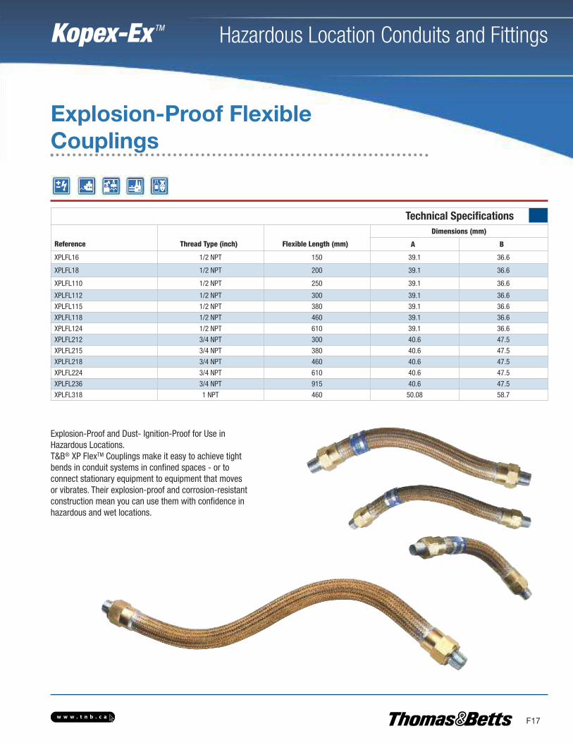
Explosion-Proof and Dust- Ignition-Proof for Use inHazardous Locations.T&B® XP FlexTM Couplings make it easy to achieve tightbends in conduit systems in confined spaces - or toconnect stationary equipment to equipment that movesor vibrates. Their explosion-proof and corrosion-resistantconstruction mean you can use them with confidence inhazardous and wet locations.
Explosion-Proof FlexibleCouplings
w w w . t n b . c a
Hazardous Location Conduits and Fittings
F18
Kopex-Ex TM
Metric - Technical SpecificationMaleExternal Thread
Female Internal Thread
M16 M20 M25 M32 M40
M16 EX/M16-M20/E EX/M16-M25/E
M20 EX/M20-M16/R EX/M20-M25/E EX/M20-M32/E
M25 EX/M25-M16/R EX/M25-M20/R EX/M25-M32/E EX/M25-M40/E
M32 EX/M32-M16/R EX/M32-M20/R EX/M32-M25/R EX/M32-M40/E
M40 EX/M40-M16/R EX/M40-M20/R EX/M40-M25/R EX/M40-M32/R
M50 EX/M50-M16/R EX/M50-M20/R EX/M50-M25/R EX/M50-M32/R EX/M50-M40/R
M63 EX/M63-M16/R EX/M63-M20/R EX/M63-M25/R EX/M63-M32/R EX/M63-M40/R
M75 EX/M75-M16/R EX/M75-M20/R EX/M75-M25/R EX/M75-M32/R EX/M75-M40/R
PG9 EX/PG9-M16/TC EX/PG9-M20/TC
PG11 EX/PG11-M16/TC EX/PG11-M20/TC
PG13 EX/PG13-M16/TC EX/PG13-M20/TC
PG16 EX/PG16-M16/TC EX/PG16-M20/TC EX/PG16-M25/TC
PG21 EX/PG21-M16/TC EX/PG21-M20/TC EX/PG21-M25/TC EX/PG21-M32/TC
PG29 EX/PG29-M16/TC EX/PG29-M20/TC EX/PG29-M25/TC EX/PG29-M32/TC EX/PG29-M40/TC
PG36 EX/PG36-M16/TC EX/PG36-M20/TC EX/PG36-M25/TC EX/PG36-M32/TC EX/PG36-M40/TC
PG42 EX/PG42-M16/TC EX/PG42-M20/TC EX/PG42-M25/TC EX/PG42-M32/TC EX/PG42-M40/TC
PG48 EX/PG48-M16/TC EX/PG48-M20/TC EX/PG48-M25/TC EX/PG48-M32/TC EX/PG48-M40/TC
NPT 3/8 EX/038-M16/TC
NPT 1/2 EX/050-M16/TC EX/050-M20/TC EX/050-M25/TC
NPT 3/4 EX/075-M16/TC EX/075-M20/TC EX/075-M25/TC EX/075-M32/TC
NPT 1 EX/100-M16/TC EX/100-M20/TC EX/100-M25/TC EX/100-M32/TC EX/100-M40/TC
NPT 1 1/4 EX/125-M16/TC EX/125-M20/TC EX/125-M25/TC EX/125-M32/TC EX/125-M40/TC
NPT 1 1/2 EX/150-M16/TC EX/150-M20/TC EX/150-M25/TC EX/150-M32/TC EX/150-M40/TC
NPT 2 EX/200-M16/TC EX/200-M20/TC EX/200-M25/TC EX/200-M32/TC EX/200-M40/TC
NPT 2 1/2 EX/250-M16/TC EX/250-M20/TC EX/250-M25/TC EX/250-M32/TC EX/250-M40/TC
NPT 3 EX/300-M16/TC EX/300-M20/TC EX/300-M25/TC EX/300-M32/TC EX/300-M40/TC
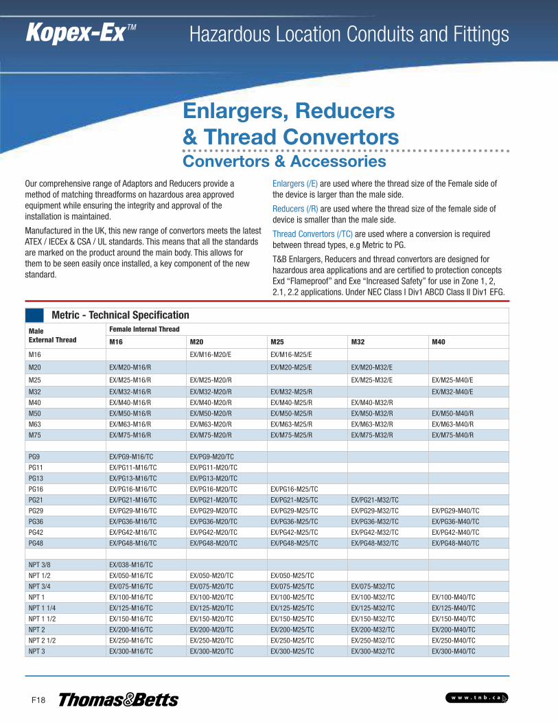
Enlargers, Reducers& Thread ConvertorsConvertors & Accessories
Our comprehensive range of Adaptors and Reducers provide amethod of matching threadforms on hazardous area approvedequipment while ensuring the integrity and approval of theinstallation is maintained.
Manufactured in the UK, this new range of convertors meets the latestATEX / IECEx & CSA / UL standards. This means that all the standardsare marked on the product around the main body. This allows forthem to be seen easily once installed, a key component of the newstandard.
Enlargers (/E) are used where the thread size of the Female side ofthe device is larger than the male side.
Reducers (/R) are used where the thread size of the female side ofdevice is smaller than the male side.
Thread Convertors (/TC) are used where a conversion is requiredbetween thread types, e.g Metric to PG.
T&B Enlargers, Reducers and thread convertors are designed forhazardous area applications and are certified to protection conceptsExd “Flameproof” and Exe “Increased Safety” for use in Zone 1, 2,2.1, 2.2 applications. Under NEC Class I Div1 ABCD Class II Div1 EFG.

w w w . t n b . c a
Hazardous Location Conduits and Fittings
F19
Kopex-Ex TM
Enlargers, Reducers& Thread Convertors
Certification & Standards
Connector Description:EX - BrassEXN - Nickel Plated BrassEXS - Stainless Steel 316Certification Standard: Baseefa07 ATEX 0247X, IECEx BAS 07.0090XClass I Div1 ABCD, Class II Div1 EFG (does not include M16 & 3/8 in.NPT or unplated brass products)Approved to ULApproved to CSA
ZONE1
ZONE2
GROUP
IGROUP
II
ZONE21
ZONE22
CLASS
IDIV
1DIV
1
Exe
CLASS
II
Exd
66IP
Metric - Technical SpecificationFemale Internal Thread
M50 M63 M75
EX/M32-M50/E
EX/M40-M50/E EX/M40-M63/E
EX/M50-M63/E EX/M50-M75/E
EX/M63-M50/R EX/M63-M75/E
EX/M75-M50/R EX/M75-M63/R
EX/PG36-M50/TC
EX/PG42-M50/TC EX/PG42-M63/TC
EX/PG48-M50/TC EX/PG48-M63/TC
EX/125-M50/TC
EX/150-M50/TC EX/150-M63/TC
EX/200-M50/TC EX/200-M63/TC
EX/250-M50/TC
EX/300-M50/TC EX/300-M75/TC
w w w . t n b . c a
Hazardous Location Conduits and Fittings
F20
Kopex-Ex TM
NPT - Technical SpecificationMaleExternal Thread
Female Internal ThreadNPT 3/8 NPT 1/2 NPT 3/4 NPT 1 NPT 1-1/4
M16 EX/M16-038/TC EX/M16-050/TCM20 EX/M20-050/TC EX/M20-075/TCM25 EX/M25-050/TC EX/M25-075/TC EX/M25-100/TCM32 EX/M32-050/TC EX/M32-075/TC EX/M32-100/TC EX/M32-125/TCM40 EX/M40-050/TC EX/M40-075/TC EX/M40-100/TC EX/M40-125/TCM50 EX/M50-050/TC EX/M50-075/TC EX/M50-100/TC EX/M50-125/TCM63 EX/M63-050/TC EX/M63-075/TC EX/M63-100/TC EX/M63-125/TCM75 EX/M75-050/TC EX/M75-075/TC EX/M75-100/TC EX/M75-125/TC
PG9 EX/PG9-050/TCPG11 EX/PG11-050/TCPG13 EX/PG13-050/TCPG16 EX/PG16-050/TC EX/PG16-075/TCPG21 EX/PG21-050/TC EX/PG21-075/TC EX/PG21-100/TCPG29 EX/PG29-050/TC EX/PG29-075/TC EX/PG29-100/TC EX/PG29-125/TCPG36 EX/PG36-050/TC EX/PG36-075/TC EX/PG36-100/TC EX/PG36-125/TCPG42 EX/PG42-050/TC EX/PG42-075/TC EX/PG42-100/TC EX/PG42-125/TCPG48 EX/PG48-050/TC EX/PG48-075/TC EX/PG48-100/TC EX/PG48-125/TC
NPT 1/2 EX/050-075/ENPT 3/4 EX/075-050/R EX/075-100/ENPT 1 EX/100-050/R EX/100-075/R EX/100-125/ENPT 1-1/4 EX/125-050/R EX/125-075/R EX/125-100/RNPT 1-1/2 EX/150-050/R EX/150-075/R EX/150-100/R EX/150-125/RNPT 2 EX/200-050/R EX/200-075/R EX/200-100/R EX/200-125/RNPT 2-1/2 EX/250-050/R EX/250-075/R EX/250-100/R EX/250-125/RNPT 3 EX/300-050/R EX/300-075/R EX/300-100/R EX/300-125/R
PG - Technical SpecificationMaleExternal Thread
Female Internal ThreadPG9 PG11 PG13 PG16 PG21
M16 EX/M16-PG9/TC EX/M16-PG11/TC EX/M16-PG13/TCM20 EX/M20-PG9/TC EX/M20-PG11/TC EX/M20-PG13/TC EX/M20-PG16/TCM25 EX/M25-PG9/TC EX/M25-PG11/TC EX/M25-PG13/TC EX/M25-PG16/TC EX/M25-PG21/TCM32 EX/M32-PG9/TC EX/M32-PG11/TC EX/M32-PG13/TC EX/M32-PG16/TC EX/M32-PG21/TCM40 EX/M40-PG9/TC EX/M40-PG11/TC EX/M40-PG13/TC EX/M40-PG16/TC EX/M40-PG21/TCM50 EX/M50-PG9/TC EX/M50-PG11/TC EX/M50-PG13/TC EX/M50-PG16/TC EX/M50-PG21/TCM63 EX/M63-PG9/TC EX/M63-PG11/TC EX/M63-PG13/TC EX/M63-PG16/TC EX/M63-PG21/TCM75 EX/M75-PG9/TC EX/M75-PG11/TC EX/M75-PG13/TC EX/M75-PG16/TC EX/M75-PG21/TC
PG11 EX/PG11-PG9/RPG13 EX/PG13-PG9/R EX/PG13-PG11/RPG16 EX/PG16-PG9/R EX/PG16-PG11/R EX/PG16-PG13/R EX/P16-PG21/EPG21 EX/PG21-PG9/R EX/PG21-PG11/R EX/PG21-PG13/R EX/PG21-PG16/RPG29 EX/PG29-PG9/R EX/PG29-PG11/R EX/PG29-PG13/R EX/PG29-PG16/R EX/PG29-PG21/RPG36 EX/PG36-PG9/R EX/PG36-PG11/R EX/PG36-PG13/R EX/PG36-PG16/R EX/PG36-PG21/RPG42 EX/PG42-PG9/R EX/PG42-PG11/R EX/PG42-PG13/R EX/PG42-PG16/R EX/PG42-PG21/RPG48 EX/PG48-PG9/R EX/PG48-PG11/R EX/PG48-PG13/R EX/PG48-PG16/R EX/PG48-PG21/R
NPT 1/2 EX/050-PG9/TC EX/050-PG11/TC EX/050-PG13/TC EX/050-PG16/TCNPT 3/4 EX/075-PG9/TC EX/075-PG11/TC EX/075-PG13/TC EX/075-PG16/TC EX/075-PG21/TCNPT 1 EX/100-PG9/TC EX/100-PG11/TC EX/100-PG13/TC EX/100-PG16/TC EX/100-PG21/TCNPT 1-1/4 EX/125-PG9/TC EX/125-PG11/TC EX/125-PG13/TC EX/125-PG16/TC EX/125-PG21/TCNPT 1-1/2 EX/150-PG9/TC EX/150-PG11/TC EX/150-PG13/TC EX/150-PG16/TC EX/150-PG21/TCNPT 2 EX/200-PG9/TC EX/200-PG11/TC EX/200-PG13/TC EX/200-PG16/TC EX/200-PG21/TC
w w w . t n b . c a
Hazardous Location Conduits and Fittings
F21
Kopex-Ex TM
NPT - Technical SpecificationFemale Internal ThreadNPT 1-1/2 NPT 2 NPT 2-1/2 NPT 3
EX/M40-150/TCEX/M50-150/TC EX/M50-200/TCEX/M63-150/TC EX/M63-200/TCEX/M75-150/TC EX/M75-200/TC
EX/PG29-150/TCEX/PG36-150/TCEX/PG42-150/TC EX/PG42-200/TCEX/PG48-150/TC EX/PG48-200/TC
EX/125-150/EEX/150-200/E
EX/200-150/REX/250-150/R EX/250-200/R EX/250-300/EEX/300-150/R EX/300-200/R EX/300-250/R
PG - Technical SpecificationFemale Internal ThreadPG29 PG36 PG42 PG48
EX/M32-PG29/TCEX/M40-PG29/TC EX/M40-PG36/TCEX/M50-PG29/TC EX/M50-PG36/TC EX/M50-PG42/TCEX/M63-PG29/TC EX/M63-PG36/TC EX/M63-PG42/TC EX/M63-PG48/TCEX/M75-PG29/TC EX/M75-PG36/TC EX/M75-PG42/TC EX/M75-PG48/TC
EX/PG21-PG29/EEX/PG29-PG36/E
EX/PG36-PG29/R EX/PG36-PG48/EEX/PG42-PG29/R EX/PG42-PG36/R EX/PG42-PG48/EEX/PG48-PG29/R EX/PG48-PG36/R EX/PG48-PG42/R
EX/100-PG29/TCEX/125-PG29/TC EX/125-PG36/TCEX/150-PG29/TC EX/150-PG36/TC EX/150-PG42/TCEX/200-PG29/TC EX/200-PG36/TC EX/200-PG42/TC EX/200-PG48/TC
w w w . t n b . c a
Hazardous Location Conduits and Fittings
F22
Kopex-Ex TM
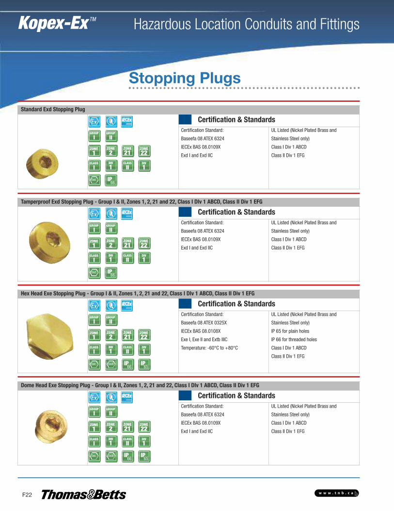
Standard Exd Stopping Plug
Certification & StandardsCertification Standard:
Baseefa 08 ATEX 6324
IECEx BAS 08.0109X
Exd I and Exd IIC
UL Listed (Nickel Plated Brass and
Stainless Steel only)
Class I Div 1 ABCD
Class II Div 1 EFGZONE1
ZONE2
GROUP
IGROUP
II
ZONE21
ZONE22
CLASS
IDIV
1CLASS
IIDIV
1
Exd
Tamperproof Exd Stopping Plug - Group I & II, Zones 1, 2, 21 and 22, Class I DIv 1 ABCD, Class II Div 1 EFG
Certification & StandardsCertification Standard:
Baseefa 08 ATEX 6324
IECEx BAS 08.0109X
Exd I and Exd IIC
UL Listed (Nickel Plated Brass and
Stainless Steel only)
Class I Div 1 ABCD
Class II Div 1 EFGZONE1
ZONE2
GROUP
IGROUP
II
ZONE21
ZONE22
CLASS
IDIV
1CLASS
IIDIV
1
Exd
Hex Head Exe Stopping Plug - Group I & II, Zones 1, 2, 21 and 22, Class I DIv 1 ABCD, Class II Div 1 EFG
Certification & StandardsCertification Standard:
Baseefa 08 ATEX 0325X
IECEx BAS 08.0108X
Exe I, Exe II and Extb IIIC
Temperature: -60°C to +80°C
UL Listed (Nickel Plated Brass and
Stainless Steel only)
IP 65 for plain holes
IP 66 for threaded holes
Class I Div 1 ABCD
Class II Div 1 EFG
ZONE1
ZONE2
GROUP
IGROUP
II
ZONE21
ZONE22
CLASS
IDIV
1CLASS
IIDIV
1
Exe Extb
Dome Head Exe Stopping Plug - Group I & II, Zones 1, 2, 21 and 22, Class I DIv 1 ABCD, Class II Div 1 EFG
Certification & StandardsCertification Standard:
Baseefa 08 ATEX 6324
IECEx BAS 08.0109X
Exd I and Exd IIC
UL Listed (Nickel Plated Brass and
Stainless Steel only)
Class I Div 1 ABCD
Class II Div 1 EFGZONE1
ZONE2
GROUP
IGROUP
II
ZONE21
ZONE22
CLASS
IDIV
1CLASS
IIDIV
1
Exe Extb
IP66
IP66
IP66
IP65
IP66
IP65
Stopping Plugs
w w w . t n b . c a
Hazardous Location Conduits and Fittings
F23
Kopex-Ex TM
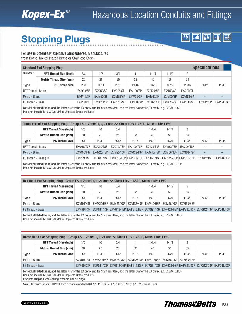
Standard Exd Stopping Plug Specifications
Type
NPT Thread Size (inch) 3/8 1/2 3/4 1 1-1/4 1-1/2 2
Metric Thread Size (mm) 20 20 25 32 40 50 63
PG Thread Size PG9 PG11 PG13 PG16 PG21 PG29 PG36 PG42 PG48
NPT Thread - Brass EX/038/SP EX/050/SP EX/075/SP EX/100/SP EX/125/SP EX/150/SP EX/200/SP – –
Metric - Brass EX/M16/SP EX/M20/SP EX/M25/SP EX/M32/SP EX/M40/SP EX/M50/SP EX/M63/SP – –
PG Thread - Brass EX/PG9/SP EX/PG11/SP EX/PG13/SP EX/PG16/SP EX/PG21/SP EX/PG29/SP EX/PG36/SP EX/PG42/SP EX/PG48/SP
For Nickel Plated Brass, add the letter N after the EX prefix and for Stainless Steel, add the letter S after the EX prefix, e.g. EXS/M16/SPDoes not include M16 & 3/8 NPT or Unplated Brass products
Tamperproof Exd Stopping Plug - Group I & II, Zones 1, 2, 21 and 22, Class I DIv 1 ABCD, Class II Div 1 EFG
Type
NPT Thread Size (inch) 3/8 1/2 3/4 1 1-1/4 1-1/2 2
Metric Thread Size (mm) 20 20 25 32 40 50 63
PG Thread Size PG9 PG11 PG13 PG16 PG21 PG29 PG36 PG42 PG48
NPT Thread - Brass EX/038/TSP EX/050/TSP EX/075/TSP EX/100/TSP EX/125/TSP EX/150/TSP EX/200/TSP – –
Metric - Brass EX/M16/TSP EX/M20/TSP EX/M25/TSP EX/M32/TSP EX/M40/TSP EX/M50/TSP EX/M63/TSP – –
PG Thread - Brass (EX) EX/PG9/TSP EX/PG11/TSP EX/PG13/TSP EX/PG16/TSP EX/PG21/TSP EX/PG29/TSP EX/PG36/TSP EX/PG42/TSP EX/PG48/TSP
For Nickel Plated Brass, add the letter N after the EX prefix and for Stainless Steel, add the letter S after the EX prefix, e.g. EXS/M16/TSPDoes not include M16 & 3/8 NPT or Unplated Brass products
Hex Head Exe Stopping Plug - Group I & II, Zones 1, 2, 21 and 22, Class I DIv 1 ABCD, Class II Div 1 EFG
Type
NPT Thread Size (inch) 3/8 1/2 3/4 1 1-1/4 1-1/2 2
Metric Thread Size (mm) 20 20 25 32 40 50 63
PG Thread Size PG9 PG11 PG13 PG16 PG21 PG29 PG36 PG42 PG48
Metric - Brass EX/M16/HSP EX/M20/HSP EX/M25/HSP EX/M32/HSP EX/M40/HSP EX/M50/HSP EX/M63/HSP – –
PG Thread - Brass EX/PG9/HSP EX/PG11/HSP EX/PG13/HSP EX/PG16/HSP EX/PG21/HSP EX/PG29/HSP EX/PG36/HSP EX/PG42/HSP EX/PG48/HSP
For Nickel Plated Brass, add the letter N after the EX prefix and for Stainless Steel, add the letter S after the EX prefix, e.g. EXS/M16/HSPDoes not include M16 & 3/8 NPT or Unplated Brass products
Dome Head Exe Stopping Plug - Group I & II, Zones 1, 2, 21 and 22, Class I DIv 1 ABCD, Class II Div 1 EFG
Type
NPT Thread Size (inch) 3/8 1/2 3/4 1 1-1/4 1-1/2 2
Metric Thread Size (mm) 20 20 25 32 40 50 63
PG Thread Size PG9 PG11 PG13 PG16 PG21 PG29 PG36 PG42 PG48
Metric - Brass EX/M16/DSP EX/M20/DSP EX/M25/DSP EX/M32/DSP EX/M40/DSP EX/M50/DSP EX/M63/DSP – –
PG Thread - Brass EX/PG9/DSP EX/PG11/DSP EX/PG13/DSP EX/PG16/DSP EX/PG21/DSP EX/PG29/DSP EX/PG36/DSP EX/PG42/DSP EX/PG48/DSP
For Nickel Plated Brass, add the letter N after the EX prefix and for Stainless Steel, add the letter S after the EX prefix, e.g. EXS/M16/DSPDoes not include M16 & 3/8 NPT or Unplated Brass productsProducts supplied with sealing washers and ‘0’ rings
For use in potentially explosive atmospheres. Manufacturedfrom Brass, Nickel Plated Brass or Stainless Steel.
Stopping Plugs
See Note 1
Note 1: In Canada, as per CEC Part I, trade size are respectively 3/8 (12), 1/2 (16), 3/4 (21), 1 (27), 1-1/4 (35), 1-1/2 (41) and 2 (53).
w w w . t n b . c a
Hazardous Location Conduits and Fittings
F24
Kopex-Ex TM
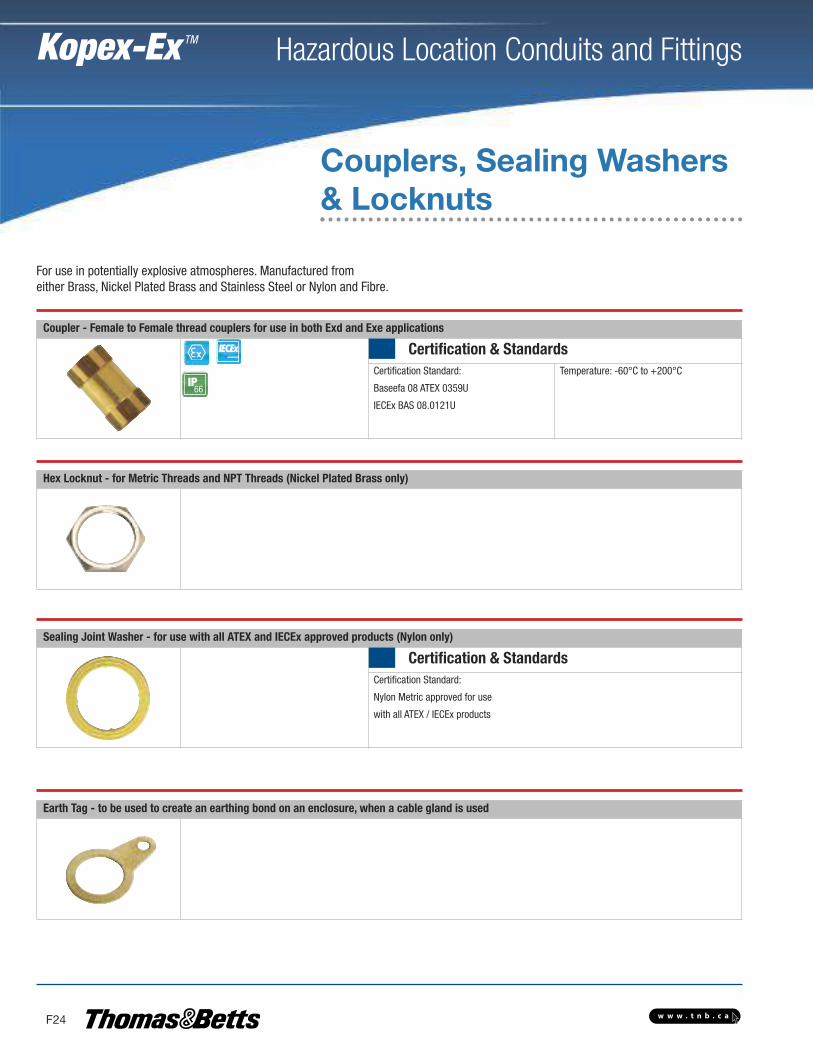
For use in potentially explosive atmospheres. Manufactured fromeither Brass, Nickel Plated Brass and Stainless Steel or Nylon and Fibre.
Earth Tag - to be used to create an earthing bond on an enclosure, when a cable gland is used
Hex Locknut - for Metric Threads and NPT Threads (Nickel Plated Brass only)
Coupler - Female to Female thread couplers for use in both Exd and Exe applications
Certification & StandardsCertification Standard:
Baseefa 08 ATEX 0359U
IECEx BAS 08.0121U
Temperature: -60°C to +200°CIP66
Couplers, Sealing Washers& Locknuts
Sealing Joint Washer - for use with all ATEX and IECEx approved products (Nylon only)
Certification & StandardsCertification Standard:
Nylon Metric approved for use
with all ATEX / IECEx products
w w w . t n b . c a
Hazardous Location Conduits and Fittings
F25
Kopex-Ex TM
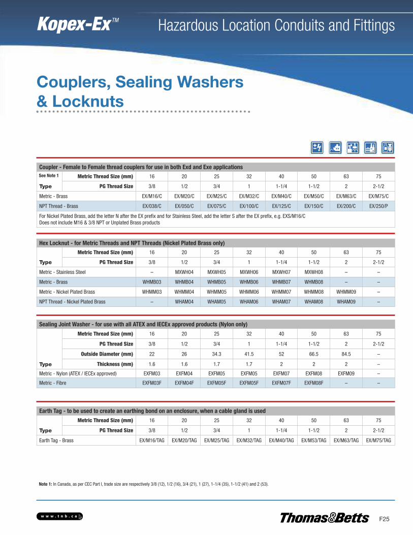
Earth Tag - to be used to create an earthing bond on an enclosure, when a cable gland is used
Type
Metric Thread Size (mm) 16 20 25 32 40 50 63 75
PG Thread Size 3/8 1/2 3/4 1 1-1/4 1-1/2 2 2-1/2
Earth Tag - Brass EX/M16/TAG EX/M20/TAG EX/M25/TAG EX/M32/TAG EX/M40/TAG EX/M53/TAG EX/M63/TAG EX/M75/TAG
Coupler - Female to Female thread couplers for use in both Exd and Exe applications
Type
Metric Thread Size (mm) 16 20 25 32 40 50 63 75
PG Thread Size 3/8 1/2 3/4 1 1-1/4 1-1/2 2 2-1/2
Metric - Brass EX/M16/C EX/M20/C EX/M25/C EX/M32/C EX/M40/C EX/M50/C EX/M63/C EX/M75/C
NPT Thread - Brass EX/038/C EX/050/C EX/075/C EX/100/C EX/125/C EX/150/C EX/200/C EX/250/P
For Nickel Plated Brass, add the letter N after the EX prefix and for Stainless Steel, add the letter S after the EX prefix, e.g. EXS/M16/CDoes not include M16 & 3/8 NPT or Unplated Brass products
Sealing Joint Washer - for use with all ATEX and IECEx approved products (Nylon only)
Type
Metric Thread Size (mm) 16 20 25 32 40 50 63 75
PG Thread Size 3/8 1/2 3/4 1 1-1/4 1-1/2 2 2-1/2
Outside Diameter (mm) 22 26 34.3 41.5 52 66.5 84.5 –
Thickness (mm) 1.6 1.6 1.7 1.7 2 2 2 –
Metric - Nylon (ATEX / IECEx approved) EXFM03 EXFM04 EXFM05 EXFM05 EXFM07 EXFM08 EXFM09 –
Metric - Fibre EXFM03F EXFM04F EXFM05F EXFM05F EXFM07F EXFM08F – –
Hex Locknut - for Metric Threads and NPT Threads (Nickel Plated Brass only)
Type
Metric Thread Size (mm) 16 20 25 32 40 50 63 75
PG Thread Size 3/8 1/2 3/4 1 1-1/4 1-1/2 2 2-1/2
Metric - Stainless Steel – MXWH04 MXWH05 MXWH06 MXWH07 MXWH08 – –
Metric - Brass WHMB03 WHMB04 WHMB05 WHMB06 WHMB07 WHMB08 – –
Metric - Nickel Plated Brass WHMM03 WHMM04 WHMM05 WHMM06 WHMM07 WHMM08 WHMM09 –
NPT Thread - Nickel Plated Brass – WHAM04 WHAM05 WHAM06 WHAM07 WHAM08 WHAM09 –
Couplers, Sealing Washers& Locknuts
See Note 1
Note 1: In Canada, as per CEC Part I, trade size are respectively 3/8 (12), 1/2 (16), 3/4 (21), 1 (27), 1-1/4 (35), 1-1/2 (41) and 2 (53).
w w w . t n b . c a
Hazardous Location Conduits and Fittings
F26
Kopex-Ex TM
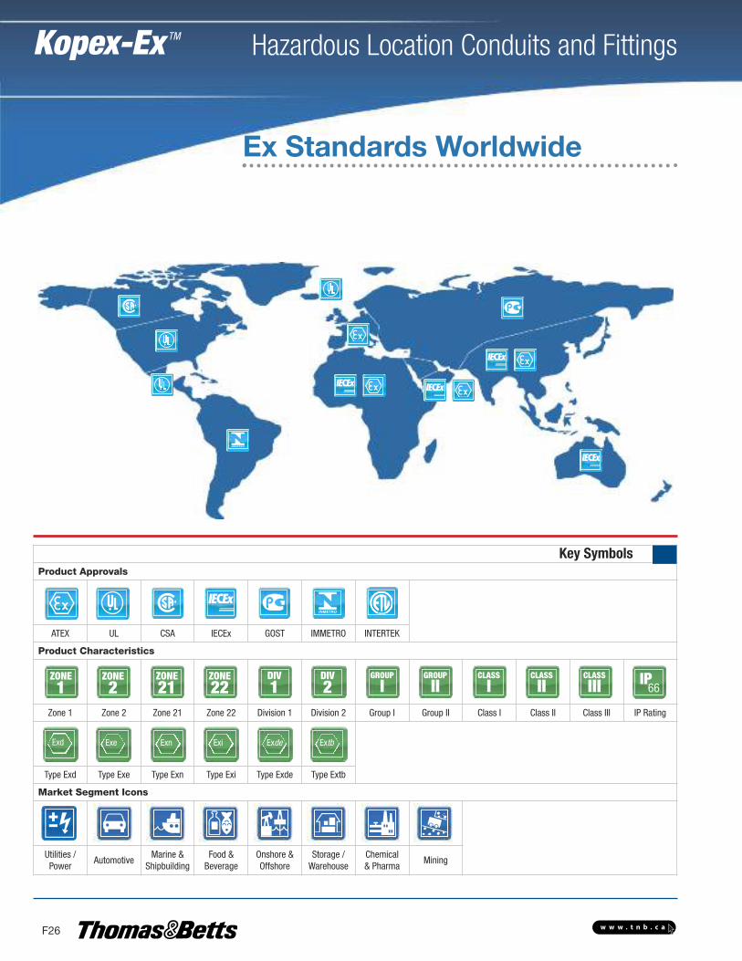
Key SymbolsProduct Approvals
ATEX UL CSA IECEx GOST IMMETRO INTERTEK
Product Characteristics
Zone 1 Zone 2 Zone 21 Zone 22 Division 1 Division 2 Group I Group II Class I Class II Class III IP Rating
Type Exd Type Exe Type Exn Type Exi Type Exde Type Extb
Market Segment Icons
Utilities /Power
AutomotiveMarine &
ShipbuildingFood &Beverage
Onshore &Offshore
Storage /Warehouse
Chemical& Pharma
Mining
ZONE1
ZONE2
ZONE21
ZONE22
DIV1
DIV2
GROUP
IGROUP
IICLASS
ICLASS
IICLASS
III IP66
ExdExe Exn Exi Exde Extb
Ex Standards Worldwide
Exd
ZONE1

Head Office19295 25th AvenueSurrey, BC V3Z 3X1Tel: 778-545-9916Fax: 778-545-3099
Toll Free: 1-888-467-7626
Terrace5000 Pohle AvenueTerrace, BC V8G 4S8Tel: 250-635-6379
Prince George2255 S. Quinn StreetPrince George, BC V2N 2X4Tel: 250-563-0575
Kitimat622 Commercial AvenueKitimat, BC V8C 2C5Tel: 250-632-3774
Fort NelsonPO Box 3266 - 5016 48th AvenueFort Nelson, BC V0C 1R0Tel: 250-233-8570
Dawson Creek1101 97th AvenueDawson Creek, BC V1G 1N5Tel: 250-782-4896
Williams Lake527 S. MacKenzie AvenueWilliams Lake, BC V2G 1C8Tel: 250-392-7795
Vernon5203 24th StreetVernon, BC V1T 8X7Tel: 250-545-2191
Penticton401 Okanagan AvenuePenticton, BC V2A 3K1Tel: 250-492-4032
KamloopsB-983 Camosun CrescentKamloops, BC V2C 6G1Tel: 250-374-3191
CranbrookUnit A #800 Industrial Road. #2Cranbrook, BC V1C 4C9Tel: 250-489-4591
Parksville#105 - 425 E. Stanford AvenueParksville, BC V9P 2N4Tel: 250-954-1797
Duncan5286 Polkey RoadDuncan, BC V9L 6W3Tel: 250-748-3377
Courtenay2615 Moray PlaceCourtenay, BC V9N 8A9Tel: 250-334-0338
Campbell River1030 B - 9th AvenueCampbell River, BC V9W 4C2Tel: 250-287-9265
Surrey13055 80th AvenueSurrey, BC V3W 3B1Tel: 604-596-7111
Richmond12360 Vickers WayRichmond, BC V6V 1H9Tel: 604-273-1981
Langley#101 - 20550 Duncan WayLangley, BC V3A 7A3Tel: 604-533-1275
Burnaby3935 2nd AvenueBurnaby, BC V5C 3W9Tel: 604-292-4800
Lighting SpecialistTel: 778-545-9916
Projects GroupTel: 604-596-7111
Data Communications GroupTel: 778-545-9916
Process, Automation &Controls GroupTel: 778-545-9916
Unit 9, 7223 68 Avenue,Edmonton, Alberta T6B 3T6