This sample chapter is for review purposes only. Copyright ...radio interference radio waves...
27
■ ■ ■ ■ ■ ■ ■ ■ ■ Network+ 147 After studying this chapter, you will be able to: ❑ Explain the principles of radio wave transmission. ❑ Identify the major antenna styles. ❑ Explain three transmission techniques used in radio wave-based transmission. ❑ Recall the characteristics of the U-NII classifications. ❑ Recall the key characteristics of the IEEE 802.11 wireless networking standards. ❑ Explain the CSMA/CA access method. ❑ Recall the key characteristics of the Bluetooth standard. ❑ Explain how cellular technology works. ❑ Compare the two types of microwave networks. ❑ Compare the two types of infrared transmission. ❑ Summarize the advantages and disadvantages of wireless networking. ❑ Recall the purpose of the SSID. ❑ Give examples of how security is provided in wireless networks. Network+ Exam—Key Points To prepare for the CompTIA Network+ exam, you must be able to specify the characteristics of the IEEE 802.11 standards. These characteristics include speed, cable lengths, and access method. You should also be able to define and identify an ad hoc wireless network and an infrastructure wireless network. To better prepare yourself to answer questions on wireless technology, be sure to install and configure a wireless network card and view all of the configuration properties that are featured. Wireless Technology 4 This sample chapter is for review purposes only. Copyright © The Goodheart-Willcox Co., Inc. All rights reserved.
Transcript of This sample chapter is for review purposes only. Copyright ...radio interference radio waves...
■ ■ ■ ■ ■ ■ ■ ■ ■
Network+
147
After studying this chapter, you will be able to:❑ Explain the principles of radio wave transmission.❑ Identify the major antenna styles.❑ Explain three transmission techniques used in radio wave-based
transmission.❑ Recall the characteristics of the U-NII classifi cations.❑ Recall the key characteristics of the IEEE 802.11 wireless networking
standards.❑ Explain the CSMA/CA access method.❑ Recall the key characteristics of the Bluetooth standard.❑ Explain how cellular technology works.❑ Compare the two types of microwave networks.❑ Compare the two types of infrared transmission.❑ Summarize the advantages and disadvantages of wireless networking.❑ Recall the purpose of the SSID.❑ Give examples of how security is provided in wireless networks.
Network+ Exam—Key PointsTo prepare for the CompTIA Network+ exam, you must be able to specify
the characteristics of the IEEE 802.11 standards. These characteristics include speed, cable lengths, and access method. You should also be able to defi ne and identify an ad hoc wireless network and an infrastructure wireless network.
To better prepare yourself to answer questions on wireless technology, be sure to install and confi gure a wireless network card and view all of the confi guration properties that are featured.
Wireless Technology
4This sample chapter is for review purposes only. Copyright © The Goodheart-Willcox Co., Inc. All rights reserved.

■ ■ ■ ■ ■ ■ ■
148 Networking Fundamentals
The following words and terms will become important pieces of your networking vocabulary. Be sure you can defi ne them.ad hoc modeBasic Service Set (BSS)carrier wavecellular technologychanneldemodulationdirect sequencingdirectionalExtended Service Set Identifi er (ESSID)Extensible Authentication Protocol (EAP)frequency hoppinggeosynchronous orbitIndependent Basic Service Set (IBSS)infrastructure modeISM bandmodulationMultiple Input Multiple Output
(MIMO)omni-directional
orthogonal frequency-division multiplexing (OFDM)
piconetpropagation delayradio interferenceradio wavesreceiverspatial multiplexingspread spectrumtransmitterunbounded mediaWi-FiWi-Fi Protected Access (WPA)Wired Equivalent Privacy (WEP)Wireless Access Point (WAP)Wireless Application Protocol (WAP)Wireless Personal Area Networks
(WPAN)working group
Key Words and Terms
Wireless media is often referred to as unbounded media, which means the path for network transmissions is unrestricted. When copper core or fi ber-optic cable is used, the transmitted network signals are bound to the medium. When the atmosphere is used, the transmission is spread throughout the atmosphere and is not limited to a single path.
Network signals transmitted through the atmosphere are electromagnetic waves. In Chapter 3—Fiber-Optic Cable, you learned that light waves are a part of the electromagnetic wave spectrum and are categorized as visible light. You learned specifi cally how light waves travel through fi ber-optic cable to transmit data. In this chapter, you will learn about the three categories of electromagnetic waves that are used to transmit data across the atmosphere: radio waves, infrared, and microwaves. You will also learn about wireless transmission techniques and associated standards. To help you better understand wireless networking technologies, electromagnetic waves will be discussed in detail.
unbounded mediaan unrestricted path for network transmissions.
Chapter 4 Wireless Technology 149
Electromagnetic WavesThe atmosphere is full of electromagnetic waves. Electromagnetic waves are
categorized according to frequency ranges. For example, common radio waves used for communications start at 0.5 MHz for AM radio and span to 22 GHz for satellite communications. The frequency of an electromagnetic wave is based on the repeating pattern of its waveform just as it is with electrical energy. One complete waveform is called a cycle, Figure 4-1, and frequency is the number of times a cycle occurs in one second.
Electromagnetic waves are produced both intentionally and unintentionally as a by-product of electrical energy. Radio and television stations produce electromagnetic waves intentionally while many household appliances produce electromagnetic waves unintentionally. You should recall from Chapter 2, Network Media—Copper Core Cable that unintentional electromagnetic waves are referred to as interference, or more specifi cally, noise.
Radio and Microwave TransmissionRadio and microwave transmission works on the principle of producing a
carrier wave as the means of communication between two wireless devices. A carrier wave is an electromagnetic wave of a set frequency that is used to carry data. It is identifi ed by a frequency number. For example, radio and television stations are assigned specifi c frequencies on which they must transmit. A radio identifi cation such as 104.5 FM represents a carrier wave of 104.5 MHz. The carrier wave is how individual stations are identifi ed on a radio or television, Figure 4-2.
The carrier wave is mixed with the data signal. The mixing of the carrier wave and data signal is known as modulation. The technique of modulation is how AM radio, FM radio, and television operate. A simple radio broadcast
Figure 4-1.Electromagnetic frequency is based on the repeating pattern of a waveform. One complete waveform is called a cycle. The frequency is how many cycles occur in one second.
Electromagneticwave
1 cycle
1 second
carrier wavean electromag-netic wave of a set frequency that is used to carry data.
modulationthe process of mixing a data signal with a carrier wave.

150 Networking Fundamentals
transmitteran electronic device that generates a carrier wave and modulates the data signal into the carrier wave.
receiveran electronic device that receives a modu-lated signal and demodulates it.
consists of a transmitter, which generates the carrier wave and modulates information into the carrier wave, and a receiver, which receives the modulated wave and demodulates it. The transceiver and receiver must both be at or very near the same carrier wave frequency for communication to occur.
Look at the example of a voice wave broadcast in Figure 4-3. In the example, a carrier wave of 104.5 MHz, is shown. The human voice produces sound at a much lower frequency, typically in a range from a 400 cycles per second to approximately 4,000 cycles per second. The human voice is converted into electrical energy using a microphone. The microphone produces a pattern of electrical energy in direct proportion to the human voice. The electrical energy is mixed with the carrier wave. The carrier wave has a much higher frequency than the electromagnetic wave produced by the human voice. The two are combined so that the human voice can be transmitted.
Figure 4-2.A carrier wave is the means of communication between two wireless devices. In this example, a radio station assigned the 104.5-MHz frequency transmits data on a 104.5-MHz carrier wave. A radio with its dial set to 104.5 picks up the information broadcast from the radio station.
104.5
Radio station
104.5-MHzcarrier wave
Figure 4-3.Example of a voice wave broadcast.
The speakerconverts electricalenergy into avoice wave.
The electrical energyproduced from thesound wave is mixedwith the carrier wave.
The transmitterproduces thecarrier wave.
104.5104.5 MHz
The receiver acceptsthe combined wave,and then separates thevoice wave from thecarrier wave. The voicewave is converted toelectrical energy.
The voice waveis converted toelectrical energy.
~400 to~4,000 MHz
Chapter 4 Wireless Technology 151
demodulationthe process of sepa-rating a data signal from a carrier wave.
channelthe bandwidth of a carrier wave.
The combined wave is transmitted across the atmosphere. When the combined wave reaches the receiver and is accepted, the electromagnetic energy is converted into electrical energy. The receiver separates the voice wave from the carrier wave. This process is known as demodulation. After the combined wave is demodulated, the transceiver discards the carrier wave and then amplifi es the voice wave and sends it to a speaker. The speaker converts the electrical energy into a voice wave. While this is a simple, nontechnical explanation, it is important to remember that the carrier wave and the voice wave are combined, or modulated, before they are transmitted and are separated, or demodulated, after they are received.
The same principle is used to transmit digital data signals. A carrier wave establishes the transmitter/receiver relationship. The carrier wave is modulated with a wave pattern resembling the digital data signal. The two waves are combined before transmission and then separated at the receiver.
To modulate data, the carrier wave must be at a much higher frequency than the digital data. In the example of the voice wave and carrier wave frequency, the carrier wave is 104.5 MHz while the voice wave fl uctuates between 400 Hz and 4,000 Hz. Based on an average voice frequency of 2,000 Hz, an approximate 500:1 ratio exists between the two frequencies. The carrier wave is only slightly distorted when combined with the voice wave. The same principle applies when a carrier wave is combined with a digital data signal. If the two signals do not have a high ratio, the digital data signal distorts the carrier wave to a point where the transmitter cannot recognize it.
A 104.5-MHz carrier wave is 200 kHz in width. Technically, a 104.5-MHz carrier wave has a bandwidth of 200 kHz. The bandwidth of a carrier wave is referred to as a channel. Technically, a channel is a small portion of the electromagnetic spectrum and is used to designate a set of frequencies for a particular electronic application. The FCC assigns channels and bandwidths for electromagnetic waves.
A channel is identifi ed by the assigned frequency that represents the starting point of the band. For example, 104.5 is the identifi cation of the channel even though the channel spans the next 200 kHz. Look at Figure 4-4. The 145 MHz is the designated channel for the carrier wave. This channel is a single position in the entire radio frequency spectrum represented by the 145-MHz designation. The carrier wave channel is 200 kHz wide starting at exactly 145 MHz and ending at 145.2 MHz. The carrier wave must stay within the 200-kHz band as specifi ed by FCC regulation.
The exact center of the bandwidth area is 145.1 MHz. It is nearly impossible for the carrier wave to remain exactly at 145.1 MHz. The electronic components that are used to create the circuit that produce the exact frequency change directly with temperature. The components heat up because of the electrical energy passing through them and are also infl uenced by environmental temperatures. Electronic transmitters are enclosed and air-conditioned to keep the components at a predetermined temperature. The enclosure compensates for environmental changes in temperature and the heat effects of the electronic components. A change in component temperature causes a direct change in the carrier wave frequency produced by electronic components.
Infrared TransmissionInfrared uses a series of digital light pulses. The light is either on or off. A typical
television remote control uses infrared technology rather than radio wave technology to transmit to the television receiver. There are two distinct disadvantages to infrared

152 Networking Fundamentals
radio interferenceinterference that matches the frequency of a carrier wave.
technology. First, the two devices that are communicating must be in direct line of sight of each other. This means that the infrared receiver/transmitter of each device must be aimed, or at least positioned, in the general direction of the other.
The infrared beam is weak and must be transmitted through an optical lens to prevent dispersion. The other disadvantage is an infrared beam can travel a relatively limited distance when compared with wireless radio wave technologies. Some infrared communication links for networks use a laser to achieve greater distances.
Even with its disadvantages, infrared can be found in many of the same applications as Bluetooth. It is commonly used in some models of personal digital assistants, palm tops, and laptops. Typical data rates for infrared devices are 1 Mbps and 2 Mbps. Data rates can be much higher when lasers are used for the direct connection of two LANs.
Radio InterferenceRadio interference is interference that matches the frequency of the carrier
wave. The Federal Communications Commission (FCC) is responsible for dividing the entire electromagnetic spectrum to prevent electronic equipment from interfering with one another. However, this is not always possible. Think for a minute how many different devices use and produce electromagnetic waves—remote controls for remote control cars, remote control airplanes, garage door openers, television, AM radio, FM radio, satellites, pagers, cellular phones,
Figure 4-4.The carrier wave and the data wave are electronically combined or modulated. The modulated signal must remain inside the radio frequency range or channel assigned by the FCC.
Wave patternsrepresent binarydata patterns
Assigned carrierwave bandwidth200 kHz
Carrier wave
Carrier wavedesignated as145 MHz
145 MHz
Data wave
Zoomed close-up of the modulated radiosignal, which is a combination of carrierwave and data wave patterns
Ent
ire
elec
trom
agne
tic
spec
trum
0 MHz
Tech Tip
Chapter 4 Wireless Technology 153
electrical power lines, radar, motors, fl uorescent lights, and such. The list is ever increasing. There are thousands of products that produce electromagnetic waves. The FCC regulates the electromagnetic spectrum and dictates the frequency that is to be used for each group of devices. Even with all these regulations, equipment fails and produces undesirable frequencies that can interfere with a regulated frequency. If you move the tuner of an AM radio across the various stations, you will hear an excellent example of interference.
AM radio is an old technology that was susceptible to radio interference. FM radio is an improvement over AM radio because it is less susceptible to radio interference.
Virtually any type of electrical equipment can produce radio interference even if it is not assigned to the radio frequency spectrum assigned to wireless LAN communications. For example, some other sources of radio interference that could corrupt data packets are fl uorescent lighting, electric motors, electrical control systems, welding equipment, portable radios, and such. While not intended to produce radio interference in the assigned wireless spectrum, a defective piece of equipment can produce electrical radio harmonics. The harmonic signal is a multiple of an original signal. For example, a radio frequency of 12,000 can also produce signals of 24,000, 36,000, 48,000, and so on. This means that harmonic frequencies produced by other areas of the electromagnetic spectrum can cause interference with the wireless network.
Another major factor is proximity to the source of the signal. If radio interference is in close proximity to the wireless network system, it need not be at the same frequency. Close proximity and a powerful signal can disrupt the wireless communication. Radio signals can also refl ect or bounce off surrounding materials, usually metallic surfaces, Figure 4-5. The refl ected signal is an exact copy of the original signal. The refl ected signal does not always disrupt the original signal. At times, it actually increases the strength of the original signal
Figure 4-5.A reflected radio signal can combine with the intended radio signal and either disrupt the intended signal or enhance it.
Reflective surface
Reflected signalOriginal signal
Original signal

154 Networking Fundamentals
ISM bandthe band of radio frequencies associ-ated with indus-trial, scientifi c, and medical devices.
omni-directionalthe ability of an antenna to transmit electromagnetic signals in all directions.
directionalthe ability of an antenna to transmit electromagnetic signals in a focused or aimed direction.
by combining with it. The problem occurs if there is too much delay between the original signal and the refl ected signal. When there is too much delay, the two signals overlap causing the combined signal to be distorted. The difference in time it takes the two signals to travel from the source to the destination determines the level of distortion. The amount of time it takes to reach the destination depends on the angle and distance of the refl ection.
There are many sources of radio interference that can affect communication on an IEEE 802.11 wireless LAN. Industrial, scientifi c, and medical devices occupy the frequency band allocated to the wireless network devices specifi ed under the IEEE 802.11 standard. Wireless phones and microwave ovens are also included in the same frequency ranges. The band of radio frequencies associated with industrial, scientifi c, and medical devices is referred to as the ISM band, Figure 4-6. The acronym ISM represents Industrial, Scientifi c, and Medical.
Antenna StylesTwo major classifi cations of antennae are associated with radio wave- and
microwave-based wireless networks: omni-directional and directional. These classifi cations are based on an antenna’s ability to transmit electromagnetic signals. Omni-directional is the transmission of electromagnetic signals in all directions. Directional is the transmission of electromagnetic signals in a focused or aimed direction. Antennae can be further broken down by their individual style of construction such as omni, dipole, fl at panel, Yagi, and parabolic dish. Figure 4-7 shows each antenna style and the electromagnetic wave pattern it produces. Note that the electromagnetic wave patterns are viewed from overhead.
OmniThe omni is a straight piece of wire. The wire is engineered to match the
exact length or a fraction of the frequency’s wavelength. For example, a frequency of 2.4 GHz produces a wavelength of approximately 2.19″. An antenna 2.19″ in length would match the wavelength exactly. Matching the antenna length to the wavelength of the radio frequency ensures the best possible reception and reduces the possibility of picking up interference.
The omni antenna is typically used for a wireless transmitter to broadcast in a 360° pattern. This type of antenna is used for the source of a wireless transmission. For example, a wireless Internet service provider would use an omni antenna to facilitate broadcasting in all directions to better serve customers throughout the area.
Figure 4-6.The Industrial, Scientific, and Medical (ISM) band is often a source of wireless network interference.
Industrial Scientific Medical
902–928 MHz 2.4–2.48 GHz
2.4–2.48 GHz802.11b802.11g802.11n
5.15–5.825 GHz802.11a802.11n
ISM band
5.725–5.85 GHz
Chapter 4 Wireless Technology 155
DipoleThe dipole is one of the most common radio antennae used. What makes it
popular is it is relatively inexpensive to manufacture when compared with many other antenna styles. The dipole is commonly used as a client or receiver antenna rather than as a broadcast antenna. The dipole antenna is bidirectional, as seen in Figure 4-7. Rotating the antenna until the dipole aligns with the source of the radio wave transmission can enhance the received signal.
YagiThe Yagi antenna is used for point-to-point links. It is a directional-type
antenna. A Yagi antenna is typically designed from many radio antenna elements (tubes). Each element is progressively larger or smaller than the main element by approximately 5%. The way the Yagi antenna enhances the radiation of the electromagnetic wave is beyond the scope of this textbook. For now, just note and recognize the shape of the Yagi antenna and its electromagnetic wave pattern. Some Yagi antennae are constructed inside a metal tube to further enhance the reception and transmission of electromagnetic waves. See Figure 4-8.
Figure 4-7.Basic antenna styles and the electromagnetic wave patterns they produce.
ElectromagneticWave Pattern(as viewed from overhead)Antenna
Omni
Dipole
Yagi
Flat panel
Parabolic

156 Networking Fundamentals
Flat PanelThe fl at panel is a directional-type antenna used for point-to-point links.
The main advantage of a fl at panel is the aesthetics. The antenna blends in well with building architecture, and many times it is unnoticeable. However, the disadvantage of a fl at panel antenna is the consideration of wind load. High wind areas can catch the fl at panel design like a sail on a ship. Flat panels must be rigidly supported to reduce the effects of wind.
ParabolicThe parabolic antenna is used for point-to-point links. It a directional-type
antenna typically constructed from a grid of rods or mesh wiring. The parabolic antenna enhances reception by refl ecting incoming electromagnetic waves with its curved surface to a horn at its center. When the parabolic antenna transmits electromagnetic waves, the horn transmits the signal toward the curved surface of the antenna. The curved surface refl ects the electromagnetic waves to produce a beamlike pattern in the same way light is refl ected from the curved surface of a fl ashlight to produce a beam of light. The parabolic antenna is constructed as a simple, curved surface or in the shape of a dish. When it is constructed in the shape of a dish, it is usually called a parabolic disk or simply dish antenna. The parabolic antenna greatly amplifi es a weak radio wave signal when compared with other antenna types.
Figure 4-8.Yagi antenna constructed inside a metal tube. The metal tube enhances reception and transmission. (Photo reprinted with the permission of PCTEL, Maxrad Product Group.)
Chapter 4 Wireless Technology 157
radio waveselectromagnetic waves with a frequency range of 10 kHz to 3,000,000 MHz.
spread spectruma transmission technique that uses multiple channels to transmit data either simultaneously or sequentially.
frequency hoppinga spread spectrum technique that transmits data on multiple channels simultaneously.
direct sequencinga spread spectrum technique that transmits data on multiple channels sequentially.
Radio Wave Transmission Techniques and Networking
Radio waves are electromagnetic waves with a frequency range of 10 kHz to 3,000,000 MHz. They have the longest wavelength when compared with microwave and infrared. Radio waves are used in LANs. Radio wave-based networks adhere to the IEEE 802.11 and Bluetooth standards and operate at 2.4 GHz.
Radio Wave-Based Transmission TechniquesTo communicate between radio-based wireless network devices, several
transmission techniques are used: single-frequency, spread-spectrum, and orthogonal frequency-division multiplexing. You must become familiar with these techniques because most wireless network technologies are described using these terms. The techniques are based on the technology, the frequency band of operation, and the manufacturer’s idea of the best way to achieve a high data rate. A high data rate not only relies on how fast the data can move between two points, but also on how much data has to be retransmitted because of interference.
Transmission techniques divide an allocated frequency band into many separate frequency ranges, or channels. After the frequency band is divided, a carrier wave is generated for each of the channels.
Spread SpectrumSpread spectrum is a transmission technique that uses multiple channels to
transmit data either simultaneously or sequentially. The term spread spectrum refers to transmission channels spread across the spectrum of the available bandwidth.
Spread spectrum transmission works in a similar manner that highways work. A highway system consists of several separate lanes to carry vehicles. You can think of spread spectrum as several radio wave paths designed to carry radio waves. In the highway system, trucks carry supplies to a store. Each truck uses a separate lane. If one of the lanes is blocked (interference), the other lanes can still carry the supplies to the store. This is the same method employed by spread spectrum. If one of the channels is blocked by radio interference, the other channels can still carry the radio wave data.
In the spread spectrum technique, data can be transmitted on multiple channels simultaneously or sequentially (one at a time). The spread spectrum technique that transmits data on multiple channels simultaneously is called frequency hopping. The spread spectrum technique that transmits data on multiple channels sequentially is called direct sequencing.
Spread spectrum is the chosen transmission method of most wireless technologies. Transmitting data on multiple channels decreases the likelihood of interference. Interference is typically limited to only one or two of the channels. The other channels in the frequency band are free to carry data undisturbed. Data that is lost can be easily retransmitted on a channel that is not affected by the interference.
Frequency hoppingFrequency hopping is also referred to as frequency hopping spread spectrum
(FHSS). Frequency hopping is used with wireless devices that use the 2.4-GHz radio band. The 2.4-GHz frequency has a bandwidth of 83.5 MHz. Rather than use the entire range as a single channel to carry radio data, the frequency band is divided into 79 1-MHz channels. See Figure 4-9.
158 Networking Fundamentals
Instead of transmitting the data packets over a single channel, the data packets hop from one channel to another in a set pattern determined by a software algorithm. None of the 79 channels are occupied for more than 0.4 seconds. Since the data packets switch from channel to channel, or rather frequency to frequency, this transmission technique is called frequency hopping.
Many people assume that because data packets hop to various channels, this transmission technique was designed as a security measure. This assumption is false. The reason that the frequency hopping technique is used is to avoid interference. If any interference matches the same frequency as the wireless networking devices, the data would be corrupted. If only one frequency was used and it encountered interference, then the network would be useless. By using the frequency hopping technique, interference can be tolerated. The interference would likely only affect one or two of the available frequencies in the entire 79 1-MHz channels. This allows more than an ample number of channels to ensure continuous transmission between wireless networking devices.
The frequency hopping technique is limited to a maximum of a 2-Mbps data rate. A much higher data rate can be accomplished using direct sequencing.
Direct sequencingDirect sequencing divides the 2.4-GHz frequency band into eleven
overlapping channels of 83 MHz each. Within the eleven channels are three channels with a 22-MHz bandwidth. The three channels do not overlap and can be used simultaneously. Using three channels at the same time results in higher data rates than frequency hopping. The data rates for direct sequencing are 11 Mbps and 33 Mbps. The 33 Mbps is a result of using all three 22-Mbps channels at the same time, Figure 4-10.
One disadvantage of direct sequencing is that a much larger portion of the transmitted data is affected by electromagnetic interference than with frequency hopping. The data rate of direct sequencing, therefore, is drastically affected by interference.
Direct sequencing is also referred to as direct sequencing spread spectrum (DSSS). Most vendors use DSSS technology at 11 Mbps for wireless network systems.
Figure 4-9.In frequency hopping, data is transmitted over 79 1-MHz channels. The data transmissions continuously use different channels in short increments of less than 0.4 seconds each.
2.4-
GH
z fr
equ
ency
ban
d
Data packetFrequency Hopping Spread Spectrum (FHSS)
79 1-MHz channels
Chapter 4 Wireless Technology 159
orthogonal frequency- division multiplexing (OFDM)a transmission tech-nique that transmits data over different channels within an assigned frequency range. Each channel is broadcast separately and is referred to as multiplexed. It can achieve data rates as high as 54 Mbps.
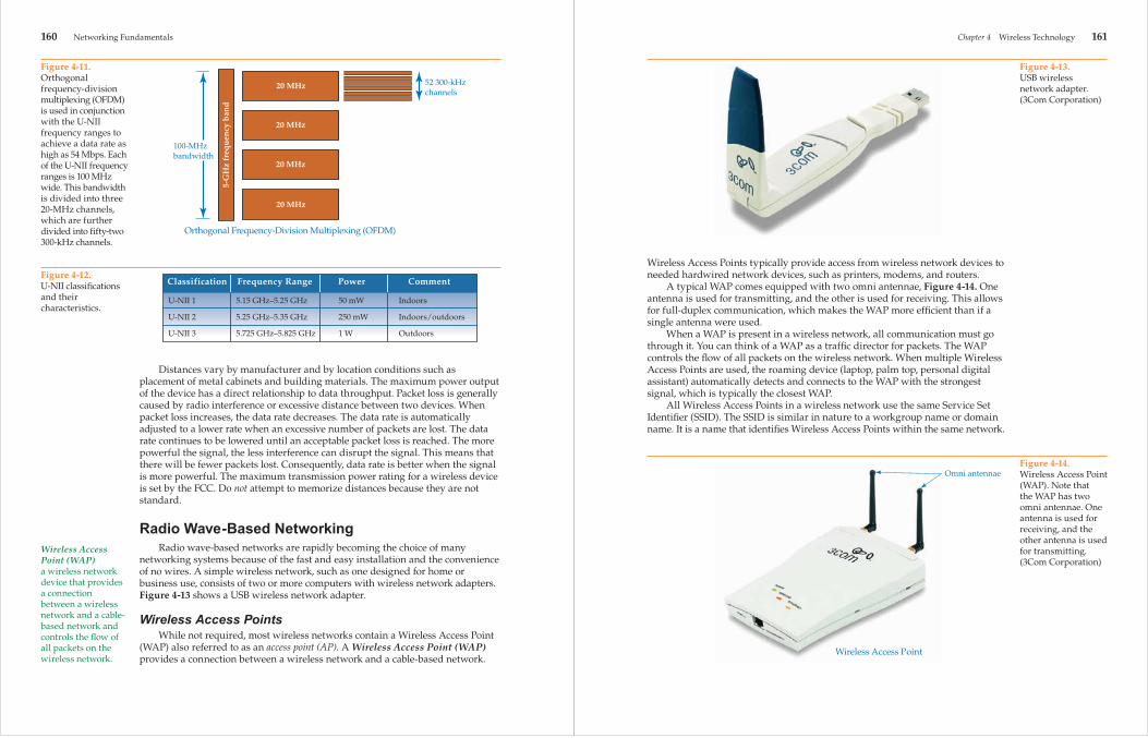
Orthogonal Frequency-Division MultiplexingThe orthogonal frequency-division multiplexing (OFDM) transmission
technique is used with wireless devices that use the 5-GHz radio band and can achieve a data rate as high as 54 Mbps. The OFDM transmission technique divides the allotted frequency into channels similar to frequency hopping and direct sequencing. Orthogonal means separate side by side over a range of values. In wireless application, the term orthogonal means there are multiple separate radio channels side by side within an assigned radio band. Frequency division means to divide the assigned frequency range into multiple, narrow sub-frequencies. Multiplexing is an electronics term, which means to combine content from different sources and transmit them collectively over a single, common carrier. By combining the three terms, OFDM means to communicate wireless data over several different channels within an assigned frequency range. However, in OFDM, each channel is broadcast separately and is referred to as multiplexed.
OFDM is used in conjunction with the Unlicensed National Information Infrastructure (U-NII) frequency ranges. The FCC divided the 5-GHz radio frequency into three, 20-MHz channels and classifi ed them as the Unlicensed National Information Infrastructure (U-NII). The three classifi cations are U-NII-1, U-NII-2, and U-NII-3. See Figure 4-11. Each of the three U-NII classifi cations has a frequency range of 100 MHz. Using the OFDM transmission technique, each 100-MHz frequency range is broken into four separate 20-MHz channels. Each of the 20-MHz channels is further divided into fi fty-two, 300-kHz sub-channels. Forty-eight of the fi fty-two sub-channels are used to transmit data, and the remaining four are used for error correction. It is the large number of channels that provide the high data rates. Additionally, communication is not affected as adversely by interference as it is with the other techniques mentioned. If one or two sub-channels are affected, the overall data rate is not affected.
The FCC U-NII classifi cations are based on the frequency range of the broadcast, the allowable maximum amount of power allotted to the broadcast, and the location of where the device may be used. There is no maximum distance measurement in feet or meters for the different classifi cations. The maximum distances are controlled by the maximum amount of output wattage that can be generated by the devices. The actual range varies considerably due to infl uences such as building structures and materials, the electromagnetic environment, and atmospheric conditions. Use the chart in Figure 4-12 to get a relative idea of expected maximum distances.
Figure 4-10.In direct sequencing, a 2.4-GHz frequency band is divided into eleven overlapping 83-MHz channels. Each 83-MHz channel is further divided into three 22-MHz channels.
Direct Sequencing Spread Spectrum (DSSS)
11 overlapping83-MHz channels
Each 83-MHz channelis divided into3 22-MHz channels
2.4-
GH
z fr
equ
ency
ban
d
160 Networking Fundamentals
Wireless Access Point (WAP)a wireless network device that provides a connection between a wireless network and a cable-based network and controls the fl ow of all packets on the wireless network.
Distances vary by manufacturer and by location conditions such as placement of metal cabinets and building materials. The maximum power output of the device has a direct relationship to data throughput. Packet loss is generally caused by radio interference or excessive distance between two devices. When packet loss increases, the data rate decreases. The data rate is automatically adjusted to a lower rate when an excessive number of packets are lost. The data rate continues to be lowered until an acceptable packet loss is reached. The more powerful the signal, the less interference can disrupt the signal. This means that there will be fewer packets lost. Consequently, data rate is better when the signal is more powerful. The maximum transmission power rating for a wireless device is set by the FCC. Do not attempt to memorize distances because they are not standard.
Radio Wave-Based NetworkingRadio wave-based networks are rapidly becoming the choice of many
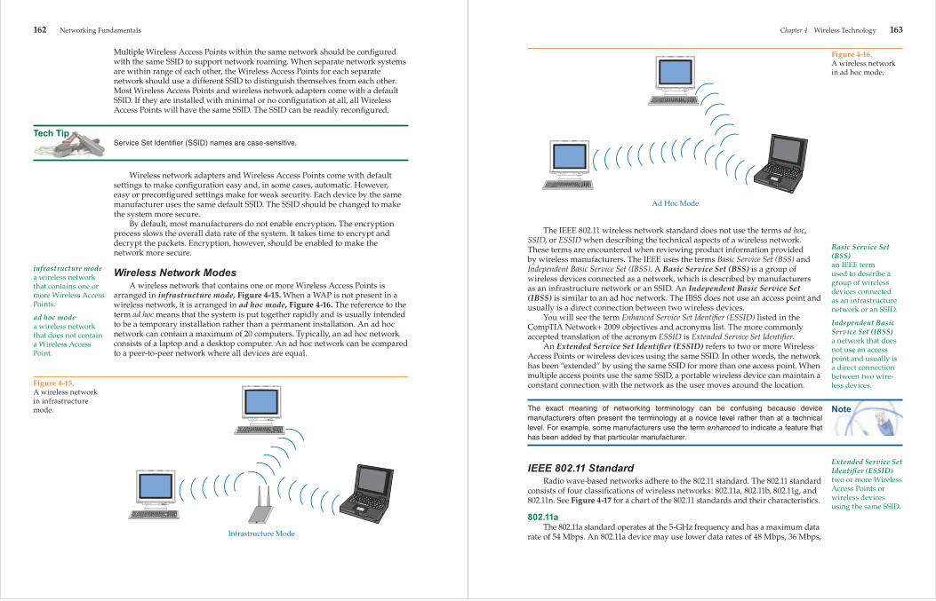
networking systems because of the fast and easy installation and the convenience of no wires. A simple wireless network, such as one designed for home or business use, consists of two or more computers with wireless network adapters. Figure 4-13 shows a USB wireless network adapter.
Wireless Access PointsWhile not required, most wireless networks contain a Wireless Access Point
(WAP) also referred to as an access point (AP). A Wireless Access Point (WAP) provides a connection between a wireless network and a cable-based network.
Figure 4-11.Orthogonal frequency-division multiplexing (OFDM) is used in conjunction with the U-NII frequency ranges to achieve a data rate as high as 54 Mbps. Each of the U-NII frequency ranges is 100 MHz wide. This bandwidth is divided into three 20-MHz channels, which are further divided into fifty-two 300-kHz channels.
5-G
Hz
freq
uen
cy b
and
20 MHz
20 MHz
20 MHz
20 MHz
Orthogonal Frequency-Division Multiplexing (OFDM)
100-MHzbandwidth
52 300-kHzchannels
Figure 4-12.U-NII classifications and their characteristics.
U-NII 1 5.15 GHz–5.25 GHz 50 mW Indoors
U-NII 2 5.25 GHz–5.35 GHz 250 mW Indoors/outdoors
U-NII 3 5.725 GHz–5.825 GHz 1 W Outdoors
Classification Frequency Range Power Comment
Chapter 4 Wireless Technology 161
Wireless Access Points typically provide access from wireless network devices to needed hardwired network devices, such as printers, modems, and routers.
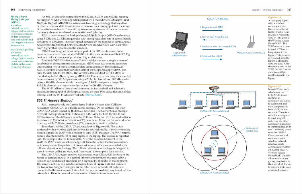
A typical WAP comes equipped with two omni antennae, Figure 4-14. One antenna is used for transmitting, and the other is used for receiving. This allows for full-duplex communication, which makes the WAP more effi cient than if a single antenna were used.
When a WAP is present in a wireless network, all communication must go through it. You can think of a WAP as a traffi c director for packets. The WAP controls the fl ow of all packets on the wireless network. When multiple Wireless Access Points are used, the roaming device (laptop, palm top, personal digital assistant) automatically detects and connects to the WAP with the strongest signal, which is typically the closest WAP.
All Wireless Access Points in a wireless network use the same Service Set Identifi er (SSID). The SSID is similar in nature to a workgroup name or domain name. It is a name that identifi es Wireless Access Points within the same network.
Figure 4-13.USB wireless network adapter. (3Com Corporation)
Figure 4-14.Wireless Access Point (WAP). Note that the WAP has two omni antennae. One antenna is used for receiving, and the other antenna is used for transmitting. (3Com Corporation)
Omni antennae
Wireless Access Point
Tech Tip
162 Networking Fundamentals
infrastructure modea wireless network that contains one or more Wireless Access Points.
ad hoc modea wireless network that does not contain a Wireless Access Point.
Multiple Wireless Access Points within the same network should be confi gured with the same SSID to support network roaming. When separate network systems are within range of each other, the Wireless Access Points for each separate network should use a different SSID to distinguish themselves from each other. Most Wireless Access Points and wireless network adapters come with a default SSID. If they are installed with minimal or no confi guration at all, all Wireless Access Points will have the same SSID. The SSID can be readily reconfi gured.
Service Set Identifi er (SSID) names are case-sensitive.
Wireless network adapters and Wireless Access Points come with default settings to make confi guration easy and, in some cases, automatic. However, easy or preconfi gured settings make for weak security. Each device by the same manufacturer uses the same default SSID. The SSID should be changed to make the system more secure.
By default, most manufacturers do not enable encryption. The encryption process slows the overall data rate of the system. It takes time to encrypt and decrypt the packets. Encryption, however, should be enabled to make the network more secure.
Wireless Network ModesA wireless network that contains one or more Wireless Access Points is
arranged in infrastructure mode, Figure 4-15. When a WAP is not present in a wireless network, it is arranged in ad hoc mode, Figure 4-16. The reference to the term ad hoc means that the system is put together rapidly and is usually intended to be a temporary installation rather than a permanent installation. An ad hoc network can contain a maximum of 20 computers. Typically, an ad hoc network consists of a laptop and a desktop computer. An ad hoc network can be compared to a peer-to-peer network where all devices are equal.
Figure 4-15.A wireless network in infrastructure mode.
Infrastructure Mode
Note
Chapter 4 Wireless Technology 163
Basic Service Set (BSS)an IEEE term used to describe a group of wireless devices connected as an infrastructure network or an SSID.
Independent Basic Service Set (IBSS)a network that does not use an access point and usually is a direct connection between two wire-less devices.
Extended Service Set Identifi er (ESSID)two or more Wireless Access Points or wireless devices using the same SSID.
The IEEE 802.11 wireless network standard does not use the terms ad hoc, SSID, or ESSID when describing the technical aspects of a wireless network. These terms are encountered when reviewing product information provided by wireless manufacturers. The IEEE uses the terms Basic Service Set (BSS) and Independent Basic Service Set (IBSS). A Basic Service Set (BSS) is a group of wireless devices connected as a network, which is described by manufacturers as an infrastructure network or an SSID. An Independent Basic Service Set (IBSS) is similar to an ad hoc network. The IBSS does not use an access point and usually is a direct connection between two wireless devices.
You will see the term Enhanced Service Set Identifi er (ESSID) listed in the CompTIA Network+ 2009 objectives and acronyms list. The more commonly accepted translation of the acronym ESSID is Extended Service Set Identifi er.
An Extended Service Set Identifi er (ESSID) refers to two or more Wireless Access Points or wireless devices using the same SSID. In other words, the network has been “extended” by using the same SSID for more than one access point. When multiple access points use the same SSID, a portable wireless device can maintain a constant connection with the network as the user moves around the location.
The exact meaning of networking terminology can be confusing because device manufacturers often present the terminology at a novice level rather than at a technical level. For example, some manufacturers use the term enhanced to indicate a feature that has been added by that particular manufacturer.
IEEE 802.11 StandardRadio wave-based networks adhere to the 802.11 standard. The 802.11 standard
consists of four classifi cations of wireless networks: 802.11a, 802.11b, 802.11g, and 802.11n. See Figure 4-17 for a chart of the 802.11 standards and their characteristics.
802.11aThe 802.11a standard operates at the 5-GHz frequency and has a maximum data
rate of 54 Mbps. An 802.11a device may use lower data rates of 48 Mbps, 36 Mbps,
Figure 4-16.A wireless network in ad hoc mode.
Ad Hoc Mode

164 Networking Fundamentals
Wi-Fia term coined by the Wi-Fi Alliance that refers to 802.11 wire-less network products.
24 Mbps, 18 Mbps, 12 Mbps, 9 Mbps, and 6 Mbps. At the 5-GHz frequency, 802.11a networking devices are not susceptible to interference from devices that cause interference at the 2.4-GHz frequency range. 802.11a devices are incompatible with 802.11b and 802.11g devices. Also, 802.11a devices use a higher frequency than 802.11b or 802.11g devices. The higher frequency cannot penetrate materials such as building walls like the lower frequency devices can. This results in 802.11a devices having a shorter range when compared with 802.11b, 802.11g, and 802.11n devices.
802.11bAlthough the 802.11a and 802.11b standards were developed at the same time,
802.11b was the fi rst to be adopted by industry. The maximum data rate for 802.11b is 11 Mbps. When the highest rate cannot be achieved because of distance or radio interference, a lower rate is automatically selected. The lower rates are 5.5 Mbps, 2 Mbps, and 1 Mbps. An 802.11b device can operate over any of 11 channels within the assigned bandwidth. When communicating between wireless devices, all devices should use the same channel. When using devices from the same manufacturer, the same channel is automatically selected by default. Two wireless networks, one constructed of 802.11b devices and the other constructed of 802.11a devices, can coexist without interfering with each other because they use different assigned frequencies. This allows for two different wireless networks to operate within the same area without interfering with the other.
802.11 network devices are often referred to as Wi-Fi, which stands for “wireless fi delity.” The use of the term Wi-Fi was due to manufacturers forming the Wireless Ethernet Compatibility Alliance (WECA) in an effort to standardize wireless network devices. Devices approved as compatible with
Figure 4-17.IEEE 802.11 standards and their characteristics. 802.11a 5 GHz 5.15 GHz– 6 Mbps 50 m OFDM
5.825 GHz 9 Mbps 12 Mbps 18 Mbps 24 Mbps 36 Mbps 54 Mbps
802.11b 2.4 GHz 2.4 GHz– 1 Mbps 100 m DSSS 2.4835 GHz 2 Mbps 5.5 Mbps 11 Mbps
802.11g 2.4 GHz 2.4 GHz– 1 Mbps 100 m DSSS 2.4835 GHz 2 Mbps 5.5 Mbps 11 Mbps
5 GHz 5.15 GHz- 54 Mbps 50 m OFDM 5.825 GHz
802.11n 2.4 GHz 2.4 GHz– All previous data 300 m OFDM 2.4835 GHz rates up to 300 Mbps and 5 GHz 5.15 GHz- possibly as high 5.825 GHz as 600 Mbps
802.11 Radio Frequency Data Rate
Range TransmissionStandard Frequency Range (approximate) Method
Note
Chapter 4 Wireless Technology 165
the 802.11standards are given a “Wi-Fi compliant” seal, which means any device bearing the Wi-Fi seal is compatible with any other device bearing the seal, Figure 4-18. This process led to competing yet compatible standards by both organizations. As a result, users are able to mix and match components from various manufacturers. There are many proprietary devices and software products on the market that may not be fully compatible with other devices.
802.11gThe IEEE 802.11g standard followed the 802.11a and 802.11b standards. 802.11g
operates in the 802.11b frequency range of 2.4 GHz. This makes it downward compatible with 802.11b devices. When communicating with 802.11b devices, the maximum data rate is reduced to 11 Mbps. The maximum throughput for the 802.11g standard is 54 Mbps, but the maximum distance is typically much shorter than an 802.11b device. An 802.11g device can use the lower data rates of 48 Mbps, 36 Mbps, 28 Mbps, 24 Mbps, 12 Mbps, 11 Mbps, 9 Mbps, 6 Mbps, 5.5 Mbps, 2 Mbps, and 1 Mbps. Since 802.11g is assigned to the same frequency range as 802.11b, it is susceptible to the same sources of radio interference.
802.11g and 802.11b devices are not compatible with 802.11a devices because they use different frequencies. It must be noted that while the standards are different, there are devices on the market that can communicate with any of the mentioned wireless standards. In other words, there are wireless devices that can communicate with 802.11a, 802.11b, and 802.11g devices.
802.11nThe 802.11n standard operates at 5 GHz and is backward compatible
with the 2.4-GHz frequency range. In 2009, the Wi-Fi Alliance organization ratifi ed (approved) a standard based on a draft version of 802.11n. However, manufacturers developed 802.11n wireless network devices before the 802.11n classifi cation was ratifi ed in an effort to offer superior wireless devices. Therefore, these devices may not exactly match the 802.11n ratifi ed standard.
There cannot be a defi nitive range for individual IEEE wireless standards, only approximations. Range is determined by radio wave power expressed in watts. There are many electronic factors that affect radio wave ranges.
Figure 4-18.Wireless PCMCIA adapter card with the Wi-Fi compliant seal. (3Com Corporation)
Wi-Fi compliant seal
166 Networking Fundamentals
Multiple Input Multiple Output (MIMO)a wireless networking tech-nology that transmits two or more streams of data to increase data throughput and the range of the wire-less network.
spatial multiplexinga wireless networking tech-nology that transmits two or more streams of data in the same frequency channel.
An 802.11n device is compatible with 802.11a, 802.11b, and 802.11g, but may not support MIMO technology when paired with these devices. Multiple Input Multiple Output (MIMO) is a wireless networking technology that uses two or more streams of data transmission to increase data throughput and the range of the wireless network. Transmitting two or more streams of data in the same frequency channel is referred to as spatial multiplexing.
802.11n incorporates the Multiple Input Multiple Output (MIMO) technology using 5-GHz and 2.4-GHz frequencies with an expected data rate of approximately 300 Mbps to 600 Mbps. The exact speed depends on the number of simultaneous data streams transmitted. Some 802.11n devices are advertised with data rates much higher than specifi ed in the standard.
MIMO was designed as an integral part of the 802.11n standard. Some manufacturers have incorporated MIMO into the latest revisions of their 802.11g devices to take advantage of producing higher data rates.
Prior to MIMO, Wireless Access Points and devices sent a single stream of data between the transmitter and receiver. MIMO uses two or more antennae, thus creating two or more streams of data simultaneously. For example, an 802.11n wireless device that transmits data at 150 Mbps can apply MIMO and raise the data rate to 300 Mbps. The latest 802.11n standard is 144.4 Mbps or rounded up to 150 Mbps. By using MIMO, 802.11n devices can raise the expected data rate to nearly 300 Mbps when using a 20-MHz channel and 600 Mbps when using a 40-MHz channel inside the assigned 2.4-GHz frequency range. The 40-MHz channel can carry twice the data as the 20-MHz channel.
The WI-FI Alliance uses a similar method in its standard and achieves a maximum throughput of 450 Mbps as posted on their Web site at the time of this writing. Visit the Wi-Fi Alliance Web site (http://wi-fi .org).
802.11 Access Method802.11 networks rely on Carrier Sense Multiple Access with Collision
Avoidance (CSMA/CA) as a media access protocol. Do not confuse this with CSMA/CD, which is used by IEEE 802.3 networks. The Carrier Sense Multiple Access (CSMA) portion of the technology is the same for both the 802.11 and 802.3 networks. The difference is in the Collision Detection (CD) versus Collision Avoidance (CA). Collision Detection (CD) detects a collision on the network after it occurs, while Collision Avoidance (CA) attempts to avoid a collision.
To understand the CSMA/CA process, look at Figure 4-19. The laptop equipped with a wireless card fi rst listens for network traffi c. If the airwaves are clear, it signals the WAP with a request to send (RTS) message. The WAP returns either a clear to send (CTS) or busy signal to the laptop. The process is repeated until the laptop is cleared to send data. After the data has been sent to the WAP, the WAP sends an acknowledge (ACK) to the laptop. Collision avoidance technology solves the problem of broadcast storms, which are associated with collision detection technology. The collision detection technology is designed to accept network collisions, wait, and then resend the complete transmission.
The CSMA/CA access method was selected over CSMA/CD because of the nature of wireless media. In a typical Ethernet environment that uses cable, a collision can be detected anywhere on a segment by all nodes in that segment. The same is not true of a wireless network. Look at Figure 4-20 and compare the two networking technologies. In the cable-based network, all nodes are connected to the same segment via a hub. All nodes can detect any broadcast that takes place. There is no need to broadcast an intention to communicate.
Chapter 4 Wireless Technology 167
Figure 4-19.A laptop equipped with a wireless network adapter listens for network traffic. If all is clear, it sends a request to send (RTS) signal to the Wireless Access Point (WAP). The WAP returns a clear to send (CTS) or a busy signal to the laptop. This process is repeated until the laptop is cleared to send the data. After the data is sent to the WAP, the WAP sends an acknowledge (AWK) signal to the laptop.
CSMA/CA Process
1. Request to send (RTS)
2. Busy or clear to send (CTS)
3. Sends data after clear to send (CTS)
4. Acknowledge (ACK)
Laptop withwireless adapter
Wireless Access Point (WAP)
Figure 4-20.In an 802.3 network, which uses the CSMA/CD access method, all computers are wired to each other and each computer can hear traffic on the network. There is no need for a computer to send a signal notifying the other computers it is about to transmit data. In an 802.11 network, which uses the CSMA/CA access method, computers with wireless network interface cards communicate within an overlap area. A Wireless Access Point (WAP) controls all communication giving permission to the individual devices to communicate in an organized fashion.
CSMA/CA Access Method
CSMA/CD Access Method
Radio signaloverlap area

168 Networking Fundamentals
For nodes to communicate with each other on a wireless network, all nodes must be inside the same broadcast area, called an overlap area. See Figure 4-21. This is not always possible, especially with mobile devices such as laptops, PDAs, cell phones, automobiles, and such. It is not unusual to have a mobile computer outside of the normal overlap area. There is also the possibility of mobile users moving in and out of the overlap area, further complicating communication. The best logical choice of media access for a wireless network is CSMA/CA.
Figure 4-21.Overlap area of an ad hoc and infrastructure wireless network. A—For computers in an ad hoc wireless network to communicate with each other, all computers must be in the same overlap area.B—In an infrastructure wireless network, the Wireless Access Point (WAP) must be in the common overlap area of the wireless network computers. The WAP controls all communication. A
Overlap area
B
Overlap area
Wireless Access Point
Chapter 4 Wireless Technology 169
CSMA/CA is used because of the way wireless networks communicate as opposed to the way wired networks communicate. When communicating on a wired network, all devices in the same collision domain can hear each other when they are communicating. The idea is that each device waits for when the cable is clear of communication before it communicates on the cable. When a collection of wireless devices are connected as a network, not all devices will always be within the range of all other devices. This causes a problem because a wireless device may not be aware when other devices are communicating. This is why a wireless network system requires CSMA/CA to access the network media, the wireless network area.
CSMA/CA is designed to make the WAP in charge of all communication. The WAP permits wireless devices to communicate or denies wireless devices to communicate. The WAP is centrally located and can communicate with all the devices in the wireless network. The WAP hears all communication. A device sitting at the edge of the wireless network cannot hear the devices farthest from it, but the WAP can. If CSMA/CD was used as the access method, the devices would not take turns as permitted by the WAP and the result would be too many communication collisions on the network caused by two or more devices attempting to communicate at the same time.
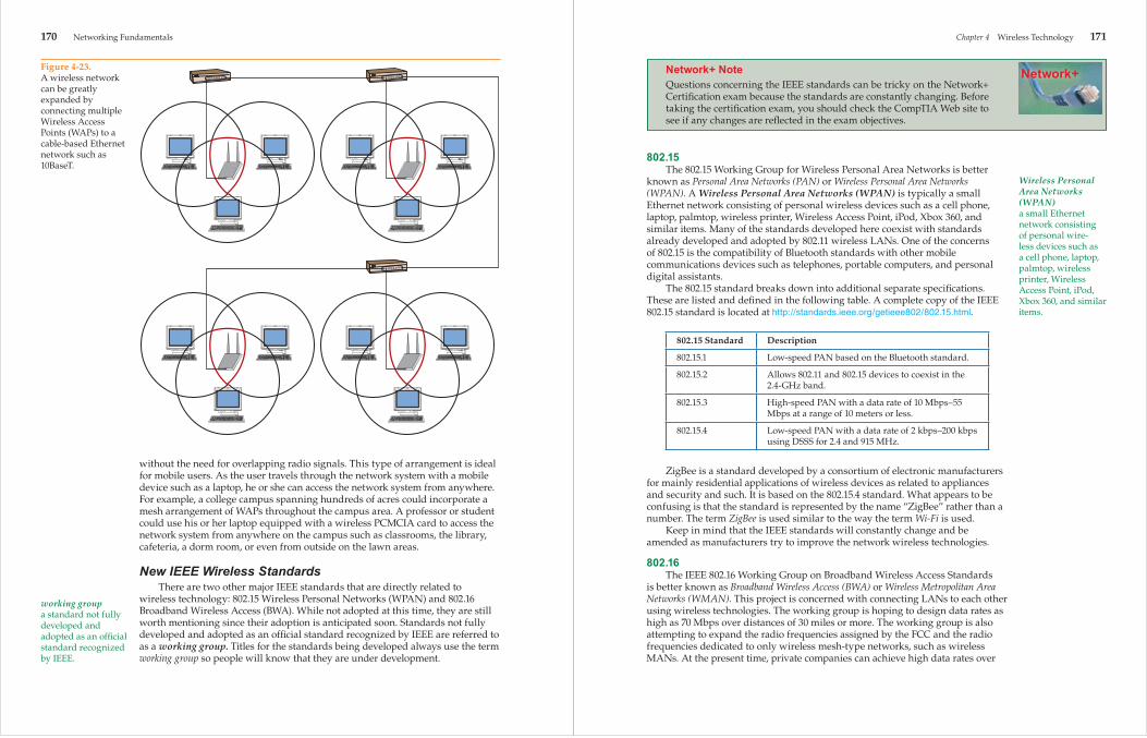
Adding more Wireless Access Points can expand the geographic area covered by a wireless network, Figure 4-22. Connecting several WAPs with cable can also enlarge a wireless LAN. Figure 4-23 shows several WAPs joined by copper core cable. This connection allows multiple WAPs to be spread over a large area
Figure 4-22.The range of a wireless network can be extended by adding additional Wireless Access Points (WAPs).
170 Networking Fundamentals
working groupa standard not fully developed and adopted as an offi cial standard recognized by IEEE.
without the need for overlapping radio signals. This type of arrangement is ideal for mobile users. As the user travels through the network system with a mobile device such as a laptop, he or she can access the network system from anywhere. For example, a college campus spanning hundreds of acres could incorporate a mesh arrangement of WAPs throughout the campus area. A professor or student could use his or her laptop equipped with a wireless PCMCIA card to access the network system from anywhere on the campus such as classrooms, the library, cafeteria, a dorm room, or even from outside on the lawn areas.
New IEEE Wireless StandardsThere are two other major IEEE standards that are directly related to
wireless technology: 802.15 Wireless Personal Networks (WPAN) and 802.16 Broadband Wireless Access (BWA). While not adopted at this time, they are still worth mentioning since their adoption is anticipated soon. Standards not fully developed and adopted as an offi cial standard recognized by IEEE are referred to as a working group. Titles for the standards being developed always use the term working group so people will know that they are under development.
Figure 4-23.A wireless network can be greatly expanded by connecting multiple Wireless Access Points (WAPs) to a cable-based Ethernet network such as 10BaseT.
Network+
Chapter 4 Wireless Technology 171
Wireless Personal Area Networks (WPAN)a small Ethernet network consisting of personal wire-less devices such as a cell phone, laptop, palmtop, wireless printer, Wireless Access Point, iPod, Xbox 360, and similar items.
Network+ NoteQuestions concerning the IEEE standards can be tricky on the Network+ Certifi cation exam because the standards are constantly changing. Before taking the certifi cation exam, you should check the CompTIA Web site to see if any changes are refl ected in the exam objectives.
802.15The 802.15 Working Group for Wireless Personal Area Networks is better
known as Personal Area Networks (PAN) or Wireless Personal Area Networks (WPAN). A Wireless Personal Area Networks (WPAN) is typically a small Ethernet network consisting of personal wireless devices such as a cell phone, laptop, palmtop, wireless printer, Wireless Access Point, iPod, Xbox 360, and similar items. Many of the standards developed here coexist with standards already developed and adopted by 802.11 wireless LANs. One of the concerns of 802.15 is the compatibility of Bluetooth standards with other mobile communications devices such as telephones, portable computers, and personal digital assistants.
The 802.15 standard breaks down into additional separate specifi cations. These are listed and defi ned in the following table. A complete copy of the IEEE 802.15 standard is located at http://standards.ieee.org/getieee802/802.15.html.
802.15 Standard Description
802.15.1 Low-speed PAN based on the Bluetooth standard.
802.15.2 Allows 802.11 and 802.15 devices to coexist in the 2.4-GHz band.
802.15.3 High-speed PAN with a data rate of 10 Mbps–55 Mbps at a range of 10 meters or less.
802.15.4 Low-speed PAN with a data rate of 2 kbps–200 kbps using DSSS for 2.4 and 915 MHz.
ZigBee is a standard developed by a consortium of electronic manufacturers for mainly residential applications of wireless devices as related to appliances and security and such. It is based on the 802.15.4 standard. What appears to be confusing is that the standard is represented by the name “ZigBee” rather than a number. The term ZigBee is used similar to the way the term Wi-Fi is used.
Keep in mind that the IEEE standards will constantly change and be amended as manufacturers try to improve the network wireless technologies.
802.16The IEEE 802.16 Working Group on Broadband Wireless Access Standards
is better known as Broadband Wireless Access (BWA) or Wireless Metropolitan Area Networks (WMAN). This project is concerned with connecting LANs to each other using wireless technologies. The working group is hoping to design data rates as high as 70 Mbps over distances of 30 miles or more. The working group is also attempting to expand the radio frequencies assigned by the FCC and the radio frequencies dedicated to only wireless mesh-type networks, such as wireless MANs. At the present time, private companies can achieve high data rates over

Tech Tip
172 Networking Fundamentals
piconeta Bluetooth network. Also called a Personal Area Network (PAN).
many miles, but there is no single standard that allows devices manufactured by different companies to communicate with the other.
USB WirelessWireless USB is a standard for devices that connect through the USB port of
a PC. Wireless USB is most often used to support the transfer of data between the PC and devices such as cameras, printers, mobile phones, DVD players, televisions, external hard drives, and AV receivers. Wireless USB provides data speeds of up to 480 Mbps at a maximum range of 3 meters and up to 100 Mbps at a maximum range of 10 meters.
BluetoothBluetooth is a short-range, wireless system that is designed for limited distances.
Typical Bluetooth devices have an effective range of 30 meters or less. Look at the following table to see approximate values based on output wattage of the device.
Class Power Approximate Range
Class 1 100 mW 100 m
Class 2 2.5 mW 10 m
Class 3 1 mW 1 m
The abbreviation “mW” represents “milliwatt” or “1/1000 of a watt.” As you can see, most Bluetooth devices have a very limited range.
The Bluetooth standard has evolved over the years in an effort to increase its data rates. Look at the maximum data rates for each Bluetooth standard listed in the following table.
Bluetooth Standard Maximum Data Rate
1.0 1 Mbps
2.0 3 Mbps
3.0 24 Mbps
As always when working with radio wave devices, expect that practical data rates will be much lower than the data rate printed for the standard, except in ideal conditions.
Bluetooth uses 79 channels that use the frequency hopping spread spectrum transmission technique, starting at 2.4 GHz. The Bluetooth standard was developed separately from the IEEE network standards. It was never intended as a networking standard designed to carry massive amounts of information. Bluetooth was designed for appliances such as telephones, laptops, palm tops, digital cameras, personal digital assistants, headsets, printers, keyboards, and mice.
A Bluetooth network is referred to as a piconet or a Personal Area Network (PAN). A piconet is a very small network. Bluetooth became recognized by the IEEE organization and was incorporated into the IEEE 802.15 Working Group
Note
Chapter 4 Wireless Technology 173
cellular technologya technology based on radio waves connecting to desig-nated areas referred to as cells.
Wireless Personal Area Networks in July, 2004. Bluetooth suffers from the same radio interference sources as other 802.11 devices, which are part of the ISM band. Bluetooth will not interfere with 802.11b devices when operated in the same area because they use different formats for confi guring data. In other words, a wireless keyboard and mouse based on the Bluetooth standard will not interfere with the operation of an 802.11b wireless network.
For the very latest information about the Bluetooth standard, always check the Bluetooth organization Web site at www.Bluetooth.com and www.bluetooth.org.
The name “Wireless Personal Area Network (WPAN)” is often used in place of “piconet.”
Cellular TechnologyCellular technology is based on radio waves connecting to designated areas
referred to as cells. Rather than communicate directly by radio wave from one cell to another, a remote device connects to a radio transmitter/receiver within its cell. The radio transmitter/receiver communicates to remote cells via microwave transmission or telephone lines. In the remote cell, the message is sent to a radio transceiver/receiver. The radio transceiver/receiver sends, via radio waves, the message to the remote device within its cell. See Figure 4-24.
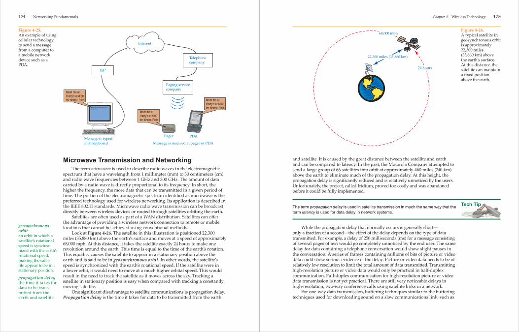
Cellular technology is responsible for wireless telephone and telephone technology. The same technology connects mobile and stationary computer equipment. A text message can be transmitted to a pager by typing in a message using a desktop computer. The message is sent over an Internet connection to a mobile telephone switching offi ce. From there, radio microwaves transmit the encoded message to the distant pager system. See Figure 4-25.
Cellular technology supports duplex communication using a device such as a personal digital assistant or a palmtop confi gured for wireless radio services.
Figure 4-24.Cellular technology communications system.
Each cell, or geographicarea, is equipped with aradio transmitter/receiver
Remote devicescommunicatewith radiotransmitter/receiverwithin its cell
Cell
Each cell communicateswith other cells viamicrowave transmissionor telephone lines
174 Networking Fundamentals
geosynchronous orbitan orbit in which a satellite’s rotational speed is synchro-nized with the earth’s rotational speed, making the satel-lite appear to be in a stationary position.
propagation delaythe time it takes for data to be trans-mitted from the earth and satellite.
Microwave Transmission and NetworkingThe term microwave is used to describe radio waves in the electromagnetic
spectrum that have a wavelength from 1 millimeter (mm) to 30 centimeters (cm) and radio wave frequencies between 1 GHz and 300 GHz. The amount of data carried by a radio wave is directly proportional to its frequency. In short, the higher the frequency, the more data that can be transmitted in a given period of time. The portion of the electromagnetic spectrum identifi ed as microwave is the preferred technology used for wireless networking. Its application is described in the IEEE 802.11 standards. Microwave radio wave transmission can be broadcast directly between wireless devices or routed through satellites orbiting the earth.
Satellites are often used as part of a WAN distribution. Satellites can offer the advantage of providing a wireless network connection to remote or mobile locations that cannot be achieved using conventional methods.
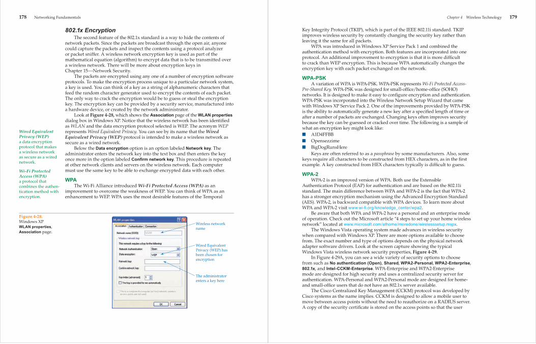
Look at Figure 4-26. The satellite in this illustration is positioned 22,300 miles (35,880 km) above the earth’s surface and moves at a speed of approximately 68,000 mph. At this distance, it takes the satellite exactly 24 hours to make one revolution around the earth. This time is equal to the time of the earth’s rotation. This equality causes the satellite to appear in a stationary position above the earth and is said to be in geosynchronous orbit. In other words, the satellite’s speed is synchronized with the earth’s rotational speed. If the satellite were in a lower orbit, it would need to move at a much higher orbital speed. This would result in the need to track the satellite as it moves across the sky. Tracking a satellite in stationary position is easy when compared with tracking a constantly moving satellite.
One signifi cant disadvantage to satellite communications is propagation delay. Propagation delay is the time it takes for data to be transmitted from the earth
Figure 4-25.An example of using cellular technology to send a message from a computer to a mobile network device such as a PDA.
Meet me at Harry’sat 8:00 for dinner. Rich.
Meet me atHarry’s at 8:00for dinner. Rich.
Meet me atHarry’s at 8:00 fordinner. Rich.
Meet me at Harry’s at 8:00 fordinner. Rich.
Meet me atHarry’s at 8:00for dinner. Rich.
Meet me atHarry’s at 8:00for dinner. Rich.
Internet
ISP
Telephonecompany
Pager PDAMessage is typedin at keyboard Message is received at pager or PDA
Paging servicecompany
Tech Tip
Chapter 4 Wireless Technology 175
and satellite. It is caused by the great distance between the satellite and earth and can be compared to latency. In the past, the Motorola Company attempted to send a large group of 66 satellites into orbit at approximately 460 miles (740 km) above the earth to eliminate much of the propagation delay. At this height, the propagation delay is signifi cantly reduced and is relatively unnoticed by the users. Unfortunately, the project, called Iridium, proved too costly and was abandoned before it could be fully implemented.
The term propagation delay is used in satellite transmission in much the same way that the term latency is used for data delay in network systems.
While the propagation delay that normally occurs is generally short—only a fraction of a second—the effect of the delay depends on the type of data transmitted. For example, a delay of 250 milliseconds (ms) for a message consisting of several pages of text would go completely unnoticed by the end user. The same delay for data containing a telephone conversation would show slight pauses in the conversation. A series of frames containing millions of bits of picture or video data could show serious evidence of the delay. Picture or video data needs to be of relatively low resolution to limit the total amount of data transmitted. Transmitting high-resolution picture or video data would only be practical in half-duplex communication. Full-duplex communication for high-resolution picture or video data transmission is not yet practical. There are still very noticeable delays in high-resolution, two-way conference calls using satellite links in a network.
For one-way data transmission, buffering techniques similar to the buffering techniques used for downloading sound on a slow communications link, such as
Figure 4-26.A typical satellite in geosynchronous orbit is approximately 22,300 miles (35,860 km) above the earth’s surface. At this distance, the satellite can maintain a fixed position above the earth.
68,000 mph
24 hours
22,300 miles (35,860 km)

176 Networking Fundamentals
a 56 k modem, could be used to prevent jitter in the transmission of the video. But this can only be used in one direction. Two-way transmissions in real time could not take advantage of buffering to eliminate jitter. Delays of 250 milliseconds (ms) or less are tolerable for live telephone conversations and low-resolution graphics. Delays above 250 milliseconds (ms) are generally unacceptable.
Infrared Transmission and NetworkingInfrared transmission is used in point-to-point communications, which
are also known as direct line of sight. Direct line of sight means that both devices are in direct alignment with each other and that there are no objects between the two devices. The infrared light beam is positioned to aim directly at the receiving device. Each device must be oriented in a position that aims toward the other device. This is one of the main limitations to using infrared in networking applications.
Infrared is typically used for point-to-point communications between two devices such as a personal digital assistant and a desktop computer. Infrared point-to-point communications can also be used in place of radio wave communications where there might be excessive interference, such as in factory or manufacturing settings.
Advantages and Disadvantages of Wireless Technology
Wireless technology can be cost-effective as compared with cable-based network media when spanning long distances such as continents or oceans. Spanning across a city, a business district, or across a college campus can be diffi cult and expensive with copper-core cable or fi ber-optic cable. The installation of landlines are not only expensive, they can cause major disruption while digging up streets and parking lots for installation. When installing a temporary network, wireless technology can be much more cost-effective than remodeling a building to accommodate wiring. Wireless technology is most appropriate for mobile devices such as palmtops, communicators, personal digital assistants, and laptops. Handheld scanners used to scan bar codes on product packages also use wireless technology to transmit data to a computer or cash register system.
Certain wireless technologies are also affected to various degrees by atmospheric conditions such as rain, lightning, fog, and sunspots. The greatest disadvantage or concern for wireless technology is security. Network signals are transmitted in the open air and are capable of being picked up by an unauthorized receiver. Of course, data transmission may be encrypted for security, but even the best security can sometimes be compromised.
Wireless SecurityOne major concern of wireless networks is security. Network infrastructures
designed to use cable are inherently more secure than wireless networks. Cable can be installed so that it is physically secured. Cables can be installed inside walls, pipes, and locked server rooms. Because cables can be physically secured, cabled networks are considered more secure than wireless networks. Unauthorized persons cannot readily connect physically to a private, cabled network system. Wireless networks, on the other hand, transmit data through
Chapter 4 Wireless Technology 177
Extensible Authentication Protocol (EAP)a protocol that ensures authorized access to the network system and network resources. It is used on both wired and wireless network systems.
the air, making it possible for anyone with a standard wireless network card to intercept the radio waves.
Radio waves fi ll the building areas and areas outside the building. One of the most common building materials used today is glass, especially in commercial establishments. Windows do not limit radio wave transmissions. Anyone near a building that uses wireless devices can easily intercept the wireless network signals with a laptop equipped with a wireless network adapter. However, security features can be implemented that will secure the transmission.
This section covers common wireless security features and provides a brief overview of wireless security. A more in-depth exploration of security features, such as encryption methods, authentication, and security standards are covered in Chapter 15⎯Network Security.
802.1x AuthenticationIEEE 802.1x is a draft standard for authentication methods for wireless
networking. It is referred to as a draft standard because it is not complete. The 802.1x draft standard provides a means for a client and server to authenticate with each other. Authentication is typically achieved through the exchange of a user name and password based on the Extensible Authentication Protocol (EAP).
The Extensible Authentication Protocol (EAP) is used for both wired and wireless network systems. EAP ensures authorized access to the network system and network resources. The improved version of EAP is called PEAP, which represents Protected EAP.
Look at Figure 4-27, which shows the WLAN properties, Authentication page in Windows XP. Notice that the Enable IEEE 802.1x authentication for this networkoption has been selected and note the EAP type options, such as Protected EAP (PEAP) and Smart Card or other Certifi cate. The computer is authenticated, not the person using the computer. A person who has their password compromised could have their password used to access a wireless network. However, when confi gured to authenticate the computer, an intruder would have to use the computer to access the wireless network.
Figure 4-27.Windows XP WLAN properties, Authentication page.Extensible
AuthenticationProtocol (EAP) types
Computer isselected to beauthenticated
IEEE 802.1xauthenticationis enabled
178 Networking Fundamentals
Wired Equivalent Privacy (WEP)a data encryption protocol that makes a wireless network as secure as a wired network.
Wi-Fi Protected Access (WPA)a protocol that combines the authen-tication method with encryption.
802.1x EncryptionThe second feature of the 802.1x standard is a way to hide the contents of
network packets. Since the packets are broadcast through the open air, anyone could capture the packets and inspect the contents using a protocol analyzer or packet sniffer. A wireless network encryption key is used as part of the mathematical equation (algorithm) to encrypt data that is to be transmitted over a wireless network. There will be more about encryption keys in Chapter 15⎯Network Security.
The packets are encrypted using any one of a number of encryption software protocols. To make the encryption process unique to a particular network system, a key is used. You can think of a key as a string of alphanumeric characters that feed the random character generator used to encrypt the contents of each packet. The only way to crack the encryption would be to guess or steal the encryption key. The encryption key can be provided by a security service, manufactured into a hardware device, or created by the network administrator.
Look at Figure 4-28, which shows the Association page of the WLAN properties dialog box in Windows XP. Notice that the wireless network has been identifi ed as WLAN and the data encryption protocol selected is WEP. The acronym WEP represents Wired Equivalent Privacy. You can see by its name that the Wired Equivalent Privacy (WEP) protocol is intended to make a wireless network as secure as a wired network.
Below the Data encryption option is an option labeled Network key. The administrator enters the network key into the text box and then enters the key once more in the option labeled Confi rm network key. This procedure is repeated at other network clients and servers on the wireless network. Each computer must use the same key to be able to exchange encrypted data with each other.
WPAThe Wi-Fi Alliance introduced Wi-Fi Protected Access (WPA) as an
improvement to overcome the weakness of WEP. You can think of WPA as an enhancement to WEP. WPA uses the most desirable features of the Temporal
Figure 4-28.Windows XP WLAN properties, Association page.
Wireless networkname
Wired EquivalentPrivacy (WEP) hasbeen chosen forencryption
The administratorenters a key here
Chapter 4 Wireless Technology 179
Key Integrity Protocol (TKIP), which is part of the IEEE 802.11i standard. TKIP improves wireless security by constantly changing the security key rather than leaving it the same for all packets.
WPA was introduced in Windows XP Service Pack 1 and combined the authentication method with encryption. Both features are incorporated into one protocol. An additional improvement to encryption is that it is more diffi cult to crack than WEP encryption. This is because WPA automatically changes the encryption key with each packet exchanged on the network.
WPA-PSKA variation of WPA is WPA-PSK. WPA-PSK represents Wi-Fi Protected Access-
Pre-Shared Key. WPA-PSK was designed for small-offi ce/home-offi ce (SOHO) networks. It is designed to make it easy to confi gure encryption and authentication. WPA-PSK was incorporated into the Wireless Network Setup Wizard that came with Windows XP Service Pack 2. One of the improvements provided by WPA-PSK is the ability to automatically generate a new key after a specifi ed length of time or after a number of packets are exchanged. Changing keys often improves security because the key can be guessed or cracked over time. The following is a sample of what an encryption key might look like:■ A1D4FFBB■ Opensezzime■ BigDogRunsHere
Keys are often referred to as a passphrase by some manufacturers. Also, some keys require all characters to be constructed from HEX characters, as in the fi rst example. A key constructed from HEX characters typically is diffi cult to guess.
WPA-2WPA-2 is an improved version of WPA. Both use the Extensible
Authentication Protocol (EAP) for authentication and are based on the 802.11i standard. The main difference between WPA and WPA-2 is the fact that WPA-2 has a stronger encryption mechanism using the Advanced Encryption Standard (AES). WPA-2, is backward compatible with WPA devices. To learn more about WPA and WPA-2 visit www.wi-fi .org/knowledge_center/wpa2.
Be aware that both WPA and WPA-2 have a personal and an enterprise mode of operation. Check out the Microsoft article “4 steps to set up your home wireless network” located at www.microsoft.com/athome/moredone/wirelesssetup.mspx.
The Windows Vista operating system made advances in wireless security when compared with Windows XP. There are more options available to choose from. The exact number and type of options depends on the physical network adapter software drivers. Look at the screen capture showing the typical Windows Vista wireless network security properties, Figure 4-29.
In Figure 4-29A, you can see a wide variety of security options to choose from such as No authentication (Open), Shared, WPA2-Personal, WPA2-Enterprise, 802.1x, and Intel-CCKM-Enterprise. WPA-Enterprise and WPA2-Enterprise mode are designed for high security and uses a centralized security server for authentication. WPA-Personal and WPA2-Personal mode are designed for home- and small-offi ce users that do not have an 802.1x server available.
The Cisco Centralized Key Management (CCKM) protocol was developed by Cisco systems as the name implies. CCKM is designed to allow a mobile user to move between access points without the need to reauthorize on a RADIUS server. A copy of the security certifi cate is stored on the access points so that the user
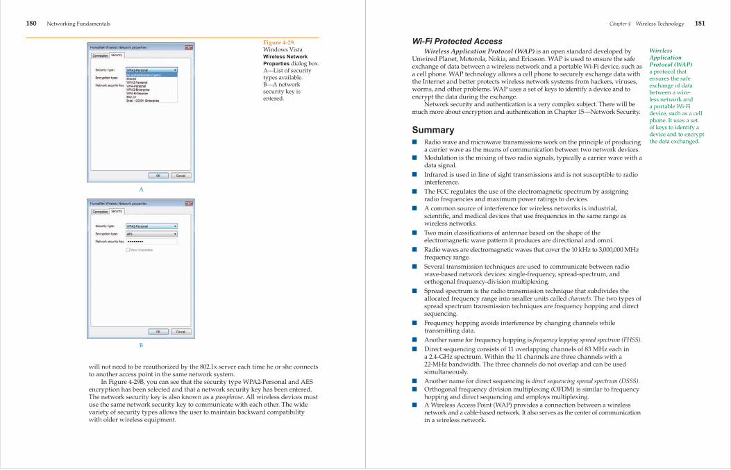
180 Networking Fundamentals
will not need to be reauthorized by the 802.1x server each time he or she connects to another access point in the same network system.
In Figure 4-29B, you can see that the security type WPA2-Personal and AES encryption has been selected and that a network security key has been entered. The network security key is also known as a passphrase. All wireless devices must use the same network security key to communicate with each other. The wide variety of security types allows the user to maintain backward compatibility with older wireless equipment.
Figure 4-29.Windows Vista Wireless Network Properties dialog box. A—List of security types available. B—A network security key is entered.
A
B
Chapter 4 Wireless Technology 181
Wi-Fi Protected AccessWireless Application Protocol (WAP) is an open standard developed by
Unwired Planet, Motorola, Nokia, and Ericsson. WAP is used to ensure the safe exchange of data between a wireless network and a portable Wi-Fi device, such as a cell phone. WAP technology allows a cell phone to securely exchange data with the Internet and better protects wireless network systems from hackers, viruses, worms, and other problems. WAP uses a set of keys to identify a device and to encrypt the data during the exchange.
Network security and authentication is a very complex subject. There will be much more about encryption and authentication in Chapter 15—Network Security.
Summary■ Radio wave and microwave transmissions work on the principle of producing
a carrier wave as the means of communication between two network devices.■ Modulation is the mixing of two radio signals, typically a carrier wave with a
data signal.■ Infrared is used in line of sight transmissions and is not susceptible to radio
interference.■ The FCC regulates the use of the electromagnetic spectrum by assigning
radio frequencies and maximum power ratings to devices.■ A common source of interference for wireless networks is industrial,
scientifi c, and medical devices that use frequencies in the same range as wireless networks.
■ Two main classifi cations of antennae based on the shape of the electromagnetic wave pattern it produces are directional and omni.
■ Radio waves are electromagnetic waves that cover the 10 kHz to 3,000,000 MHz frequency range.
■ Several transmission techniques are used to communicate between radio wave-based network devices: single-frequency, spread-spectrum, and orthogonal frequency-division multiplexing.
■ Spread spectrum is the radio transmission technique that subdivides the allocated frequency range into smaller units called channels. The two types of spread spectrum transmission techniques are frequency hopping and direct sequencing.
■ Frequency hopping avoids interference by changing channels while transmitting data.
■ Another name for frequency hopping is frequency hopping spread spectrum (FHSS).■ Direct sequencing consists of 11 overlapping channels of 83 MHz each in
a 2.4-GHz spectrum. Within the 11 channels are three channels with a 22-MHz bandwidth. The three channels do not overlap and can be used simultaneously.
■ Another name for direct sequencing is direct sequencing spread spectrum (DSSS).■ Orthogonal frequency division multiplexing (OFDM) is similar to frequency
hopping and direct sequencing and employs multiplexing.■ A Wireless Access Point (WAP) provides a connection between a wireless
network and a cable-based network. It also serves as the center of communication in a wireless network.
Wireless Application Protocol (WAP)a protocol that ensures the safe exchange of data between a wire-less network and a portable Wi-Fi device, such as a cell phone. It uses a set of keys to identify a device and to encrypt the data exchanged.

182 Networking Fundamentals
■ A wireless network that contains one or more Wireless Access Points is arranged in infrastructure mode.
■ A wireless network that does not contain a Wireless Access Point (WAP) is arranged in ad hoc mode.
■ The IEEE 802.11a standard describes wireless networks operating at 5 GHz with a maximum data rate of 54 Mbps.
■ The IEEE 802.11b standard describes wireless networks operating at 2.4 GHz with a maximum data rate of 11 Mbps.
■ The IEEE 802.11g standard describes wireless networks operating at either 2.4 GHz or 5 GHz with a maximum data rate of 54 Mbps.
■ IEEE 802.11n standard operates at 5 GHZ and 2.4 GHz with a maximum data rate of 300 Mbps to 600 Mbps.
■ Multiple Input Multiple Output (MIMO) uses two or more streams of data transmission to increase data throughput and the range of the wireless network. MIMO is described in the IEEE 802.11n standard.
■ Spatial multiplexing is the transmission of two or more streams of data simultaneously.
■ IEEE 802.15 standard describes the use of Wireless Personal Area Networks (WPANs).
■ Wireless networks specifi ed under the IEEE 802.11 standard use Carrier Sense Multiple Access with Collision Avoidance (CSMA/CA) as the media access method.
■ Bluetooth is a standard developed by a group of manufacturers to allow their devices to interoperate. Bluetooth is recognized by the 802.11 standard and is used for short-range data transfer applications using the 2.4-GHz radio band.
■ Infrared is commonly used for point-to-point transmission between two devices such as a personal digital assistant and a PC.
■ Satellite communications experience propagation delay because of the great distance a signal must travel.
■ Wireless technology can be cost-effective when compared with cable-based network media.
■ A disadvantage of employing wireless technology is security.
■ A Service Set Identifi er (SSID) is similar in function to a workgroup name or domain name and must be assigned to a Wireless Access Point (WAP).
■ Wireless networks are not secure when default settings are used for the confi guration.
■ Wireless encryption keys should be changed on a regular basis to maintain a high degree of security.
Review QuestionsAnswer the following questions on a separate sheet of paper. Please do not write in this book. 1. A(n) _____ is an electromagnetic wave of a set frequency that is used to carry
data in radio wave- and microwave-based networks. 2. What is modulation?
Chapter 4 Wireless Technology 183
3. A simple radio broadcast consists of a(n) _____, which generates a carrier wave and a(n) _____, which receives a carrier wave.
4. What is a channel? 5. What are the two major classifi cations of antennae? 6. Which of the following antenna types is not used in point-to-point links?
A. Flat panelB. OmniC. ParabolicD. Yagi
7. Which antenna style was developed with aesthetics in mind? 8. What is spread spectrum? 9. The spread spectrum technique that transmits data on multiple channels
simultaneously is called _____. 10. The spread spectrum technique that transmits data on multiple channels
sequentially is called _____. 11. Why is frequency hopping used? 12. The _____ transmission technique uses the 5-GHz frequency and can achieve
data rates as high as 54 Mbps. 13. List the frequency range and related power rating of each of the three U-NII
classifi cations. 14. What is an SSID? 15. What frequency does the IEEE 802.11a standard specify, and what is the
maximum achievable distance? 16. What frequency does IEEE 802.11b standard specify, and what is the
maximum achievable distance? 17. What frequencies does IEEE 802.11g standard specify, and what are the
related maximum achievable distances? 18. What is the maximum throughput based on the IEEE 802.11n standard? 19. Which media access method does the 802.11 wireless standard specify? 20. What is the difference between CSMA/CA and CSMA/CD? 21. What does the acronym MIMO represent? 22. What is MIMO wireless technology? 23. What is the maximum achievable distance of a Bluetooth device? 24. What is the data rate of the Bluetooth 2.0 standard? 25. What is the data rate of the Bluetooth 3.0 standard? 26. Which IEEE specifi cation addresses WPAN? 27. _____ technology is based on radio waves connecting to designated areas
referred to as cells. 28. What is a disadvantage of satellite communications? 29. What is a geosynchronous orbit? 30. What is generally the maximum amount of satellite transmission delay
acceptable for telephone conversations? 31. What is an advantage of wireless networking? 32. What is the one major disadvantage of wireless technology? 33. What does the acronym WEP represent? 34. Write an example of an encryption key. 35. What does the acronym CCKM represent?

Network+
184 Networking Fundamentals
Sample Network+ Exam QuestionsAnswer the following questions on a separate sheet of paper. Please do not write in this book. 1. Which IEEE 802.11 standard specifi es a data rate of 300 Mbps?
A. 802.11aB. 802.11bC. 802.11gD. 802.11n
2. Which media access method is associated with wireless networks?A. ARCnetB. CSMA/CAC. CSMA/CDD. Token Ring
3. Which of the following items is used to connect a wireless network to an Ethernet network?A. Wireless Access PointB. Ad hoc converterC. Ethernet converterD. Ethernet sequencing device
4. What would most likely generate radio interference for an 802.11b network device?A. A cordless phone assigned to work at 2.4 GHz.B. Another computer using an 802.11g network adapter card.C. A wireless keyboard.D. An HP LaserJet printer.
5. Who is responsible for regulating the electromagnetic spectrum and dictating the frequency that is to be used for each group of devices?A. IEEEB. The telephone company in the local area.C. FCCD. WECA
6. Which item would most likely interfere with the operation of an 802.11b wireless network?A. HubB. Cordless phoneC. Incandescent lightsD. Copier
7. What is the function of an SSID?A. To replace the network MAC address.B. To encrypt all wireless communication.C. To identify the wireless network by name.D. To increase the data throughput of a wireless network.
8. Which protocol is used to encrypt data inside packets on a wireless network?A. HTTPB. SNMPC. FTPD. WEP
Chapter 4 Wireless Technology 185
Suggested Laboratory Activities 1. Set up an ad hoc network using a PC and a laptop. 2. Set up a two- or three-station wireless network using a Wireless Access
Point (WAP). 3. Research a particular brand of wireless network device and list the expected
transmission ranges and related speeds. 4. Transfer data between a laptop and a PC by using an infrared port. 5. Observe the effect of a variety of materials on a wireless network. For example,
separate two computers on the wireless network with a wooden wall, sheet rock, metal door, or fi le cabinet. Note the effects on distance and data rate.
6. Observe the effect of a common electric drill being operated near the wireless network, and then observe the effects of a cell phone or walkie-talkie on the wireless network.
Interesting Web Sites for More Informationhttp://standards.ieee.org/getieee802/802.15.htmlhttp://wi-fi .orgwww.bluetooth.com/Bluetooth/Technology/Works/Comparewww.cwt.vt.eduwww.palowireless.com/ofdm/tutorials.aspwww.proxim.comwww.tech-faq.com
Network+ 9. Which IEEE standard is used to describe how to achieve secure authentication to a wireless network?A. 802.3B. 802.1xC. 802.5bD. 802.4a
10. Which wireless transmission technique is used to transmit data according to the IEEE 802.11b standard?A. DSSSB. OFDMC. Both DSSS and OFDMD. Neither DSSS nor OFDM

186 Networking Fundamentals
Wireless technology is ideal for college campuses. It can allow students to access the school network, Internet, and mail server from any location on campus, giving students more options on where and how they study.
Chapter 4 Wireless Technology 187
Chapter 4Laboratory Activity
Installing a USB Network Adapter and Confi guring a Wireless RouterAfter completing this laboratory activity, you will be able to:■ Summarize the purpose of a Wireless Access Point (WAP).■ Recall typical wireless network confi guration requirements.■ Summarize the purpose of an SSID.■ Summarize why wireless device default settings usually do not provide security.■ Carry out proper procedures to install an 802.11 USB network adapter.■ Carry out proper procedures to install an 802.11 wireless router/WAP.
IntroductionIn this laboratory activity, you will install an 802.11 USB wireless network
adapter and then install and confi gure a wireless router/WAP. Wireless devices fall into four categories as defi ned by the IEEE: 802.11a, 802.11b, 802.11g, and 802.11n.
NoteThe chart refl ects maximum theoretical data rates as defi ned by the IEEE standard. Some manufacturers specify data rates that exceed the data rates defi ned by IEEE. However, the actual throughput will be considerably lower than the advertised rate.
IEEEClassification
802.11a
802.11b
802.11g
802.11n
Assigned Frequency
5 GHz
2.4 GHz
2.4 GHz5 GHz
2.4 GHz5 GHz
Maximum Data Rate
54 Mbps
11 Mbps
11 Mbps in 802.11b mode54 Mbps in 802.11g mode
54 Mbps in 802.11a mode11 Mbps in 802.11b mode54 Mbps in 802.11g mode300 Mbps in 802.11n mode
Comments
Not compatible with other wireless classifi-cations. Obsolete at this time.
Compatible with 802.11g and 802.11n.
Some manufacturers exceed the 54 Mbps as defined in the IEEE standard and can support over 100 Mbps.
A maximum data rate as high as 600 Mbps has been reported.

188 Networking Fundamentals
Maximum data rates can only be experienced under ideal conditions. For best data rates, devices need to be in close proximity and in direct line of sight with no partitions or other objects blocking the radio waves. Radio waves can penetrate through solid objects such as wood or concrete but not through metallic objects such as metal building walls, metallic fi le cabinets, or some types of window tint that is derived from metallic substances.
New wireless device technologies are typically designed to be backward compatible with other earlier wireless device technologies. As you can see in the table, 802.11n is backward compatible with all earlier wireless standards.
Microsoft Windows XP was the fi rst operating system released by Microsoft that came with generic drivers and applications to support and confi gure wireless devices. Wireless device manufacturers almost always recommend using its installation CD/DVD to install device drivers and applications before installing the wireless device. Microsoft operating systems such as Windows Vista will typically recognize a new device, such as a USB adapter, and automatically confi gure the wireless device without the need of the manufacturer CD/DVD. When installing a wireless router, it is best to install the router software before connecting the wireless router.
Wireless routers typically provide both wireless connectivity and wired connection ports. Look at the wireless router in following illustration.
The router comes with an electrical power converter that changes the 120 volts AC to a much lower 12 volts DC. This particular router comes with one Ethernet cable to connect the router to the Internet modem or to a computer. The next illustration shows a close-up of typical router connections.
Chapter 4 Wireless Technology 189
The Internet connection connects to the Cable or DSL modem, and the Ethernet cable connections connect to computers using network cable. The reset button is used to reset the router confi guration to the default confi guration set by the manufacturer. The electrical power connection connects to the electrical power converter.
Wireless routers are commonly encountered today and incorporate features such as Wireless Access Point (WAP) and Dynamic Host Confi guration Protocol (DHCP). DHCP is a feature that automatically issues IP addresses to wireless client devices.
Wireless devices can be confi gured in two different confi gurations: Ad hoc and infrastructure mode. In ad hoc mode, wireless devices are free to communicate with each other and all devices are considered equal. Ad hoc mode does not use a router or WAP to control the connections between devices. In infrastructure mode, a WAP is used to control communication between devices. Wireless routers incorporate the WAP feature. Thus, the router controls communication between wireless devices and wired devices connected to the same router. Wireless devices such as routers and WAPs are also referred to at times as bridges because they bridge the connection between two dissimilar media types: wireless and cable.
The Service Set Identifi er (SSID) is the name used to identify the wireless network. Manufacturers assign a default SSID to their wireless devices. For example, D-Link uses “WLAN” or “Default,” Netgear uses “Wireless” or “NETGEAR,” Linksys uses “Linksys,” and 3Com uses “WLAN” or “3Com.” You can usually locate the default SSID as well as the default user name and password to access the wireless router setup program by conducting a search on the Internet. Because it is so easy to locate the default SSID and user name and password, the default values are considered an extreme security risk. You can actually perform a Google search for the default user name and password for most router devices. During or after the initial confi guration, you should change the SSID to a name other than the default name. Wireless devices from the same manufacturer will automatically connect to other wireless devices using the same SSID unless they are encrypted or have password authentication confi gured. The default SSID, user name, and password can be reset to the original manufacturer’s values by pressing the reset button on the router for approximately 15 seconds or more.
The default wireless channel, or dedicated frequency, also varies according to manufacturer. In the United States, the FCC has assigned 11 wireless channels for use with wireless devices. Each wireless device in the wireless network
Internetconnection
Ethernet cableconnections
Resetbutton
Electricalpower connection

190 Networking Fundamentals
should be assigned the exact same channel. When wireless devices automatically confi gure themselves, they assign a specifi c channel to themselves. You can manually assign the wireless channel if need be. For example, a specifi c channel may be experiencing radio interference resulting in very low data speeds or not connecting at all. You can sometimes overcome the effects of the radio interference by changing the assigned channel.
The wireless router confi guration can be changed remotely from a wireless laptop or wireless workstation. The router or WAP is typically accessed by using a browser and entering the assigned IP address of the wireless router into the browser’s address bar. Typical default assigned IP addresses are 192.168.0.1 and 192.168.1.1. Check the wireless router documentation for the assigned default IP address. During the connection process, you will be prompted for a user name and password. Again, the default user name and password assigned by the manufacturer should be changed to make the wireless network more secure.
Equipment and Materials■ 802.11(g or n) USB wireless network adapter with installation CD/DVD and
manual.■ 802.11(g or n) Wireless Access Point or wireless router with installation CD/
DVD and manual.■ Patch cable (Cat 5, Cat 5e, or Cat 6).■ Paper clip. (Used to press the reset button if needed.)■ Computer (desktop or laptop) running Windows Vista.■ On a separate sheet of paper, record the following information provided by
your instructor:
User name: ________________________________________________________________
Password: _________________________________________________________________
IP address: ________________________________________________________________
Subnet mask: ______________________________________________________________
Default gateway: __________________________________________________________
Wireless channel: _________________________________________________________
Wireless router: ___________________________________________________________
IP address: ________________________________________________________________
Subnet mask: ______________________________________________________________
Default gateway: __________________________________________________________
User name: ________________________________________________________________
User password: ____________________________________________________________
Wireless channel: _________________________________________________________
SSID: _____________________________________________________________________
NoteBoth wireless devices should be the same IEEE standard, either 802.11g or 802.11n, and should (but not required) be the same brand to allow for easier set up and confi guration.
Chapter 4 Wireless Technology 191
NoteMost modern routers and USB wireless network adapters will automatically confi gure most of the values using the default settings. Review the manufacturer’s installation procedures before attempting to install any devices or running the installation CD/DVD.
Part I—Installing a USB Wireless Network Adapter
Procedure 1. ______ Gather all required materials and report to your assigned workstation.
2. ______ Boot the computer and verify it is in working order.
3. _____ Review the manufacturer’s installation manual for the USB wireless network adapter. You may have a “Quick Start” guide or need to open the CD/DVD that came with the device to view the installation manual. Typically, you install the software for the wireless device before installing the device. A typical installation consists of inserting the device’s CD/DVD and having the disc automatically detected and its installation program started. A series of windows will appear prompting you for information while the device drivers are automatically installed. At the end of the software installation process, you will be prompted to insert the USB wireless network adapter.
4. ______ Insert the USB wireless network adapter. It should automatically be detected and configured by the operating system.
5. ______ After successfully installing the USB network adapter, an icon should appear in the taskbar representing the wireless network device.
6. ______ Verify that the USB wireless adapter card has been installed successfully by opening Device Manager. If you see a red X or a yellow exclamation mark (!) beside the device, there is a problem. Some older wireless device drivers are not compatible with Windows Vista or Windows 7. If there is a problem, check the manufacturer’s Web site for troubleshooting information. Also, check the manufacturer’s Web site for the very latest drivers.
7. ______ Call your instructor to inspect your USB wireless network adapter installation.
Part II—Confi guring a Wireless Network RouterThe screen captures used in this portion of the lab activity are based on a Cisco Linksys router and may not necessarily match your router configuration screens. However, they will be somewhat similar.
The wireless router CD/DVD will have a wizard program to assist you in the automatic configuration of the router. Because of the discovery-type protocols widely used today, the router cannot only discover information about your Internet provider, it can automatically configure your Internet connection in most cases. You will very seldom need to manually configure the wireless router, but you will still have the manual configuration option available to you.

192 Networking Fundamentals
Procedure 1. ______ Insert the router setup disc into the CD/DVD drive and wait for the
installation program to open. A screen similar to the following will appear.
2. ______ Click the Start Setup button and then follow the instructions as presented in the setup wizard. The following is a series of some of the typical screens you will encounter while installing and configuring the router. These are not steps to perform but rather an overview of a typical wireless router configuration.
The setup wizard will automatically check for an Internet connection and install and configure the router. You may be asked to respond to some simple questions as the router is configured.
The installation wizard will even provide you with illustrations of how to connect your router to the Internet and to the computer.
Chapter 4 Wireless Technology 193
In the following screens, the setup wizard configures the router with minimal input from the user.

194 Networking Fundamentals
In the following two screens, notice the default SSID entry “linksys” has been replaced with the “HomeNet” SSID.
Chapter 4 Wireless Technology 195
In the following screen, you are prompted to select the type of security you wish to configure.
When the installation is finished, you should see a dialog box similar to the following.
The Microsoft Vista operating system works in collaboration with the router when configuring the local area network. Security on the local area network is controlled by the Microsoft Vista operating system. As you can see in the following screen capture, you simply verify the network location, which is set to “Private” by default in the Network and Sharing Center. You may change the network location to “Public.” The difference between public and private is that the Network Discovery feature is enabled in a private location and Network Discovery is disabled in public locations.
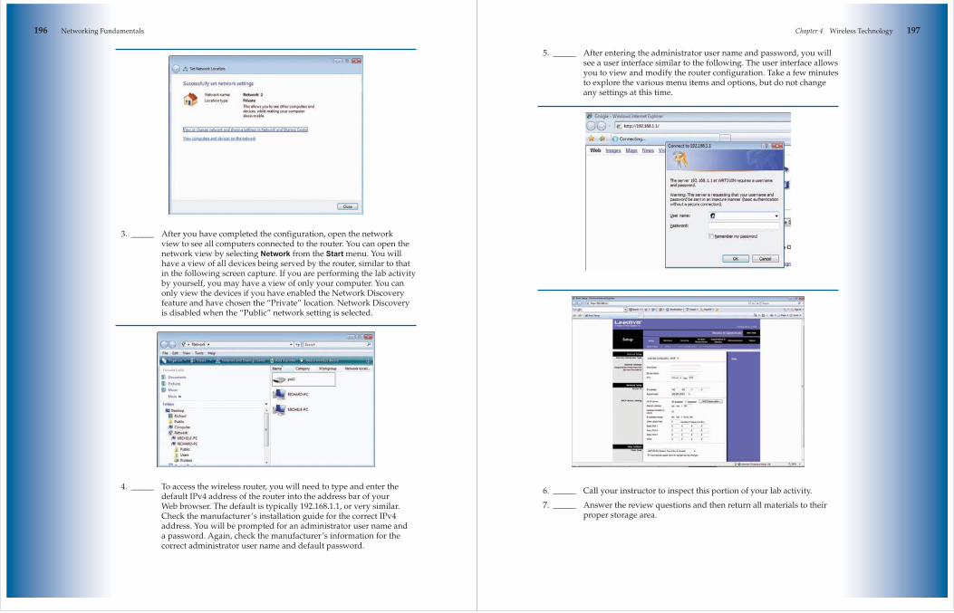
196 Networking Fundamentals
3. ______ After you have completed the configuration, open the network view to see all computers connected to the router. You can open the network view by selecting Network from the Start menu. You will have a view of all devices being served by the router, similar to that in the following screen capture. If you are performing the lab activity by yourself, you may have a view of only your computer. You can only view the devices if you have enabled the Network Discovery feature and have chosen the “Private” location. Network Discovery is disabled when the “Public” network setting is selected.
4. ______ To access the wireless router, you will need to type and enter the default IPv4 address of the router into the address bar of your Web browser. The default is typically 192.168.1.1, or very similar. Check the manufacturer’s installation guide for the correct IPv4 address. You will be prompted for an administrator user name and a password. Again, check the manufacturer’s information for the correct administrator user name and default password.
Chapter 4 Wireless Technology 197
5. ______ After entering the administrator user name and password, you will see a user interface similar to the following. The user interface allows you to view and modify the router configuration. Take a few minutes to explore the various menu items and options, but do not change any settings at this time.
6. ______ Call your instructor to inspect this portion of your lab activity.
7. ______ Answer the review questions and then return all materials to their proper storage area.

198 Networking Fundamentals
Review QuestionsAnswer the following questions on a separate sheet of paper. Please do not write in this book. 1. What does the acronym WAP represent? 2. What is the maximum throughput for 802.11g? 3. What is the maximum throughput for 802.11b? 4. What is the maximum throughput for 802.11a? 5. What is the throughput for 802.11n? 6. What is the assigned frequency for 802.11b? 7. What is the assigned frequency for 802.11g? 8. What is the assigned frequency for 802.11a? 9. What is the assigned frequency for 802.11n? 10. With which standards are an 802.11g device backward compatible? 11. What does the acronym SSID represent? 12. What are the two general wireless confi gurations? 13. True or False? All wireless device manufacturers use the same SSID. 14. What is the purpose of the SSID?


![Orthogonal Frequency Division Multiplexing -OFDM€¦ · Multipath Radio Channel Frequency-Selective Radio Channel-10-5 0 5 10 15 20 Frequency Power response [dB]](https://static.fdocuments.net/doc/165x107/5f5c80bfeaef451e7a268f33/orthogonal-frequency-division-multiplexing-ofdm-multipath-radio-channel-frequency-selective.jpg)