This programed text on resistive networks was developed ...
143
DOCUMENT itEf,'1/ME ED 021 741 24 SE 004 648 By- Balabanian. Norman RESISTIVE NETWORKS Syracuse Univ., N.Y. Dept. of Electrical Engineering. Spons Agency-Office of Education (DHEW), Washington D.C. Bureau of Research Report No-3 Bureau Ncr BR-5-0796 Pub Date 64 Contract- OEC-4-10-102 Note- I42p EDRS Price MF-SO.75 HC-SS76 Descriiptors-*COLLEGE SCIENCE, ELECTRICITY, *ELECTRONICS *ENGINEERING EDUCATION, *INSTRUCTIONAL MATRIALS PHYSICAL SCIENCES, *PROGRAMED INSTRUCTION TEXTBOOKS UNDERGRADUATE STWY Identifiers-United States Office of Education University of Syracuse This programed text on resistive networks was developed under contract with the United States Office of Education as part of a series of materials for use in an electrical engineering sequence. It is to be used in conjunction with other materials and with other short texts in the series, this one being Number 3. (DH)
Transcript of This programed text on resistive networks was developed ...

DOCUMENT itEf,'1/ME
ED 021 741 24 SE 004 648
By- Balabanian. NormanRESISTIVE NETWORKSSyracuse Univ., N.Y. Dept. of Electrical Engineering.Spons Agency-Office of Education (DHEW), Washington D.C. Bureau of ResearchReport No-3Bureau Ncr BR-5-0796Pub Date 64Contract- OEC-4-10-102Note- I42pEDRS Price MF-SO.75 HC-SS76Descriiptors-*COLLEGE SCIENCE, ELECTRICITY, *ELECTRONICS *ENGINEERING EDUCATION, *INSTRUCTIONAL
MATRIALS PHYSICAL SCIENCES, *PROGRAMED INSTRUCTION TEXTBOOKS UNDERGRADUATE STWY
Identifiers-United States Office of Education University of SyracuseThis programed text on resistive networks was developed under contract with
the United States Office of Education as part of a series of materials for use in anelectrical engineering sequence. It is to be used in conjunction with other materials andwith other short texts in the series, this one being Number 3. (DH)

No.
U.S
. DE
PA
RT
ME
NT
Of H
EA
LTH
, ED
UC
AT
ION
&W
ELF
AR
E
OF
FIC
E O
f ED
UC
AT
ION
TH
IS D
OC
UM
EN
T H
AS
BE
EN
RE
PR
OD
UC
ED
EX
AC
TLY
AS
RE
CE
IVE
D F
RO
M T
HE
PE
RS
ON
OR
OR
GA
NIZ
AT
ION
OR
IGIN
AT
IPG
IT.
PO
INT
S O
f VIE
W O
R O
PIN
ION
S
ST
AT
ED
DO
NO
T N
EC
ES
SA
RIL
Y R
EP
RE
SE
NI O
FF
ICIA
LO
FF
ICE
Of E
DU
CA
TIO
N,
PO
SIT
ION
OR
PO
LIC
Y. RE
SIS
TIV
E N
ET
WO
RK
S
by'
Nor
man
Bal
aba
ni a
n
El e
ctri
cal E
n gi
nee
ri n
g D
epar
tmen
t
1
u..1
; tt--
Syr
acus
e U
ni v
ersi
ty
Cop
yri g
ht 1
964
--
"PE
RM
ISS
ION
TO
RE
PR
OD
UC
E T
HIS
CO
PY
RIG
HT
ED
MA
TE
RIA
L H
AS
BE
EN
GR
AN
TE
D
BY
47)
TO
ER
IC A
D O
RG
AN
IZA
TIO
NS
OP
ER
AT
I GU
ND
ER
AG
RE
EM
EN
TS
WIT
H T
HE
U.S
. OF
FIC
E O
F
ED
UC
AT
ION
. FU
RT
HE
R R
EP
RO
DU
CT
ION
OU
TS
IDE
TH
E E
RIC
SY
ST
EM
RE
QU
IRE
S P
ER
MIS
SIO
N O
FT
HE
CO
PY
RIG
HT
OW
NE
R."
No .
3
r-
RESTSTIVE NETWORKS
by
Norman Balabanian
Electrical Engineering Department
Syracuse University
copyrtght 1964
Contract No. OE 4-10-102
U.S. Office of Education
,r-
1
RESISTIVE NETWORKS
Generally speaking, engineers and scientists performtwo different kinds
of work:
analysis, or the examination of a whole structure
in order to under-
stand its parts and their relationships; and synthesis pr
design, or the com-
bination of separate parts into a whole whose characteristicshave been pre-
scribed beforehand.
Many of the problems which an engineer is
called upon to solve involve
finding either the voltage across,the current, or the power
abso
rbed
by
an
electrical device when the device is connected in a
network of other devices
and electrical sources of energy.
This is a problem cf analysis.
Conversely,
an engineer may be asked to specifythe characteristics of one electrical
de-
vice in a network of other devices, or the amount of power a
given source is
required to deliver, in order that the voltage,.current, or powerabsorbed
somewhere in the network be equal to a specified value.
This is a problem of
synthesis or design.

2
Up to this point, we have introduced three hypothetical devices (models) and
several laws.
We have considered an idealresistor, an ideal voltage source, and
an ideal current source.
(We will often abbreviate these as v-source and i-source.)
We have also introduced Kirchhoff's and Ohm's laws which describe the interrelations
of voltage and current in a network containing these three models (ideal devices).
Now, if the behavior of real, physical devices in a network can be adequately rep-
resented by combinations of these models, the result will be a network of resistors,
v-sources, and i-sources to which we can apply Kirchhoff's and Ohm's laws.
In this unit we shall discuss methods which will lead to the successful solu-
tion of problems of analysis and design involving networks containing only resistors,
voltage sources, and current sources.
Specifically, by the end of this unit you
should be able to do the following things:
1.
Find the voltages and/or currents and/or power dissipated in one or more
branches of a circuit, or the power delivered by one or more sources, when
given a network of moderate complexity (up to 3 closed -oaths or 10 branches)
containing resistors, v-sources and i-sources whose values are specified
(Analysis).
Li
Int
!MI
3
2.
Find the values of unspecifiedresistances or sources, when given anet-
work (similar to those above) in
which an appropriate number of branch
voltages, currents, or power
dissipation is specified (Synthesis
or Design).
3.
Do both of the above by-anyof the following methods:
a) Reduction of a network to an equivalent
network;
b) Alternate application ofXVI and Kcl and Ohm's law;
c)
Direct application of KV11 leading
to equations into which Ohm's
law and Kel are substituted, resulting
in equations involving only
current variables (i.e., "loop"
equations).
d)
Direct application of Kell leading
to equations into which Ohm's
law and. Kvl are substituted, resultingin equations involving only
voltage variables (i.e.,
"node" equations).

Ow
leam
onam
orew
orw
orm
erol
battery
chargei)
current
limiting
resistor
(a)
R1
a
storage
battery
C)
(b)
Figure 1
5
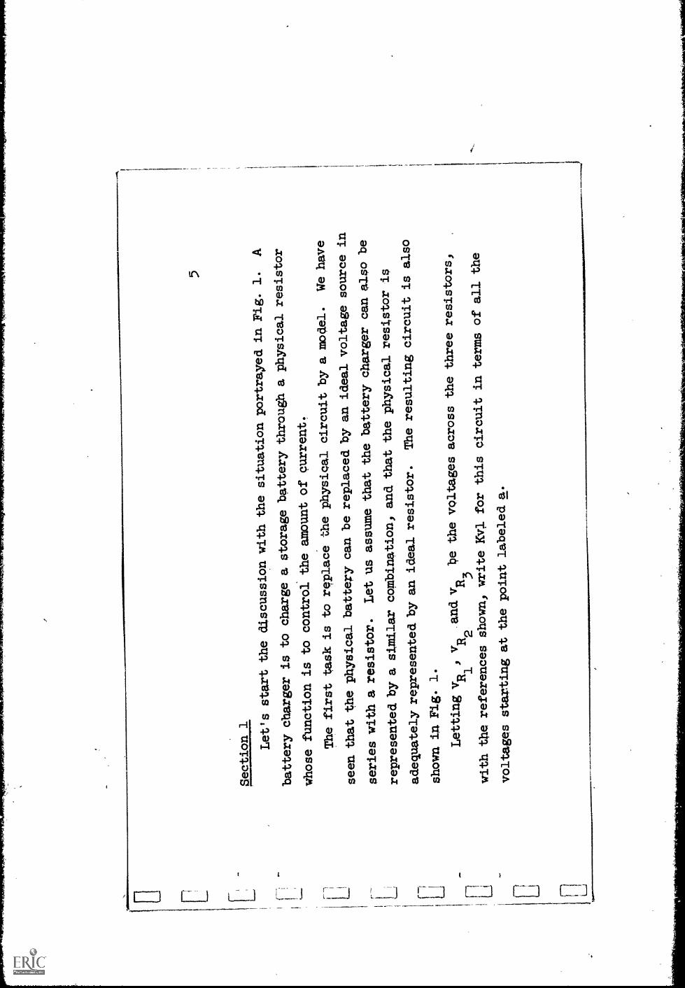
Section 1
Let's start the discussionwith the situation portrayed
in Fig. 1.
A
battery charger is to charge astorage battery through a
physical resistor
whose function is to
control the amount of
current.
The first task is to
rcplace the physical circuit
by a model.
We have
seen that the physicalbattery can be replaced by an
ideal voltage source in
series with a resistor.
Let us assume that thebattery charger can also
be
represented by a sinalar
cambination, and that thephysical resistor is
adequately represented by anideal resistor.
The resulting circuit is
also
shown in Fig. 1.
Letting vit
vu.
and
be the voltages across the
three resistors,
1412
3with Vie references shown,
write Kv1 for this circuit
in terms of all the
voltages starting at the point
labeled a.

6 Answer:
v R3
+ vR2
+ v0
- vl + vR
= 0
1
(or the same thing multiplied
by -1 if you went, counter-
clockwise.)
E

MN
7
Nextlnotehow the current in the
components are related to each other;
,019
=11
Branches which are connectedend-to-end so that they carry the same
current are said to be in series.
A network in which thebranches are con-
nected as in Fig. 1 is called a
network.
8 Answer:
"7.
-717
.,
the same (or equal, or identical)
series
1
..
c - -1
9
Redraw Fig. 1, and. choose a reference direction for the current.
Then
apply Ohm's law to substitute current functions for v
, vp
andv R3
in the
R"
equation. :
12

10
Answer:
R1
(Youmay have chosenthe opposite
reference for current in whichcase
all the terms containing i would
have the opposite sign.)
E
-
i i
4--- -
11
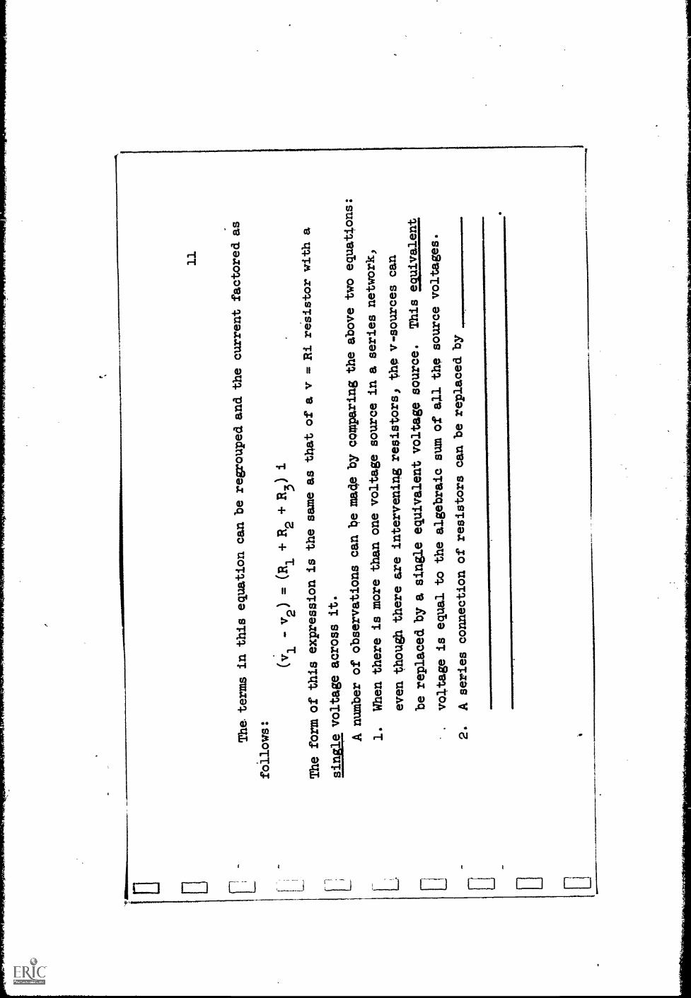
The terms in this equation canbe regrouped. and the current
factored as
follows:
(v1
-v2) = (R1 + R2 + R3) i
The form of this expression
is the same as that
of a
v =
Ri
re's
isto
r w
itha
sing
le v
olta
ge a
cros
s it.
A number of observations canbe
mad
eby comparing the above two
equations:
1.
When there is more than onevoltage source in a series
network,
even though there are
inte
rven
ing
resistors, the v-sources can
be replaced by a single
equivalent voltage source.
Thi
s w
ival
ent
.voltage is equal to thealgebraic sum o
all the source voltages.
2.
A series connection
ofresistors can be replacedby
12
Answer: A series connection of resistors can
be replaced by a single equivalent resistor
whose value equals the sum of the series
resistances.
., r"--
./10I
13
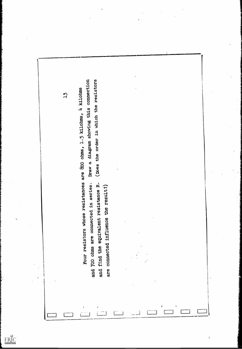
Four resistorswhose resistances are
800 ohms, 1.5 kilohms,
4 kilohms
and TOO ohms are
connected in series.
Draw a diagram
showing this
connection
and find the
equivalent resistance
R.
(Does the order inwhich the resistors
are
connected influence
the result?)

Answer:
800a
1.5K
700a
R = .8
1.5 + 4 + .7 = 7 kilohms.
(Connection order is immaterial.)
v 1
Figure 2
(b )
=R1+R2
^ T1 ,,

15
Whenever resistors are
connected in series they canbe combined into a
single equivalentresistance, as already
discussed.
If there is a voltage across
the series combination,
the resulting current can
be found by Ohm's law.
However,
suppose it is
required to find the
voltage across just oneof the series con-
nected. resistors.
,For .example, suppose it
is desired to findthe voltage'across
R2
in Fig. 2.
If the two resistors are
combined into anequivalent-resistor,
the identity of R2
is lost.
Nevertheless, once the current
i is detsimined
from Fig. 2(b)) thevoltage v2 can be calculatedfrom Fig. 2(a) to be
R2
v2 = R 2i = R2R1 + R2
R1 + R2v
In the same way, the
voltage vl across R1
is
V, =
`.. L-1 F-1 E..._: 1 .._i 1 1 i I
H
HCkl
14
÷H
14. !
;-1(1) Hcrl
4
_
I

17
Thus, the voltage v
divides itself betweenthe two resistors.
This leads
to the name voltage
divider for the*structure we
have been discussing
(i.e.)
resistors in series, with avoltage across the
combiLation.)
This structure
ariaes often innetworks, and remembering
the relationships for
the voltages,
as ybu just
derived them, helps insolving networkproblems.
An easy.way to
remember the Voltage dividerformula is to think of a
proportionality: "The voltage across oneresistor is to the voltage
across the
series.combination what thevalue of that
resistance is to the totalresistance."
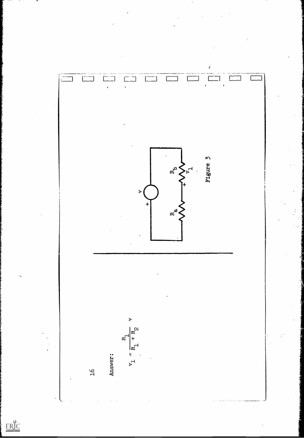
Using the voltage divider
formula, write the expression
for vl in Fig. 3.
Is
r
18 Ans
wer
:
v 1R
b-
vR
b+
Ra
or
Rb
v -
v1
R.,3
+ R
a
1---
-IT
1r-
-0
Ipa
I
II
ITvo
II
i
I-0-
R
1T
1I
,
01
ob,
IL
.....-
......
.._ -
J
MIN
IM
(a)
Fig
ure
4=
NM
OE
M*
OW
N. I
IIIIII
IIIin
owil
(a)
OM
. 111
1110
Figure
5
v ( b
)
(b )
.. ...
- 11 7 i t- L-...
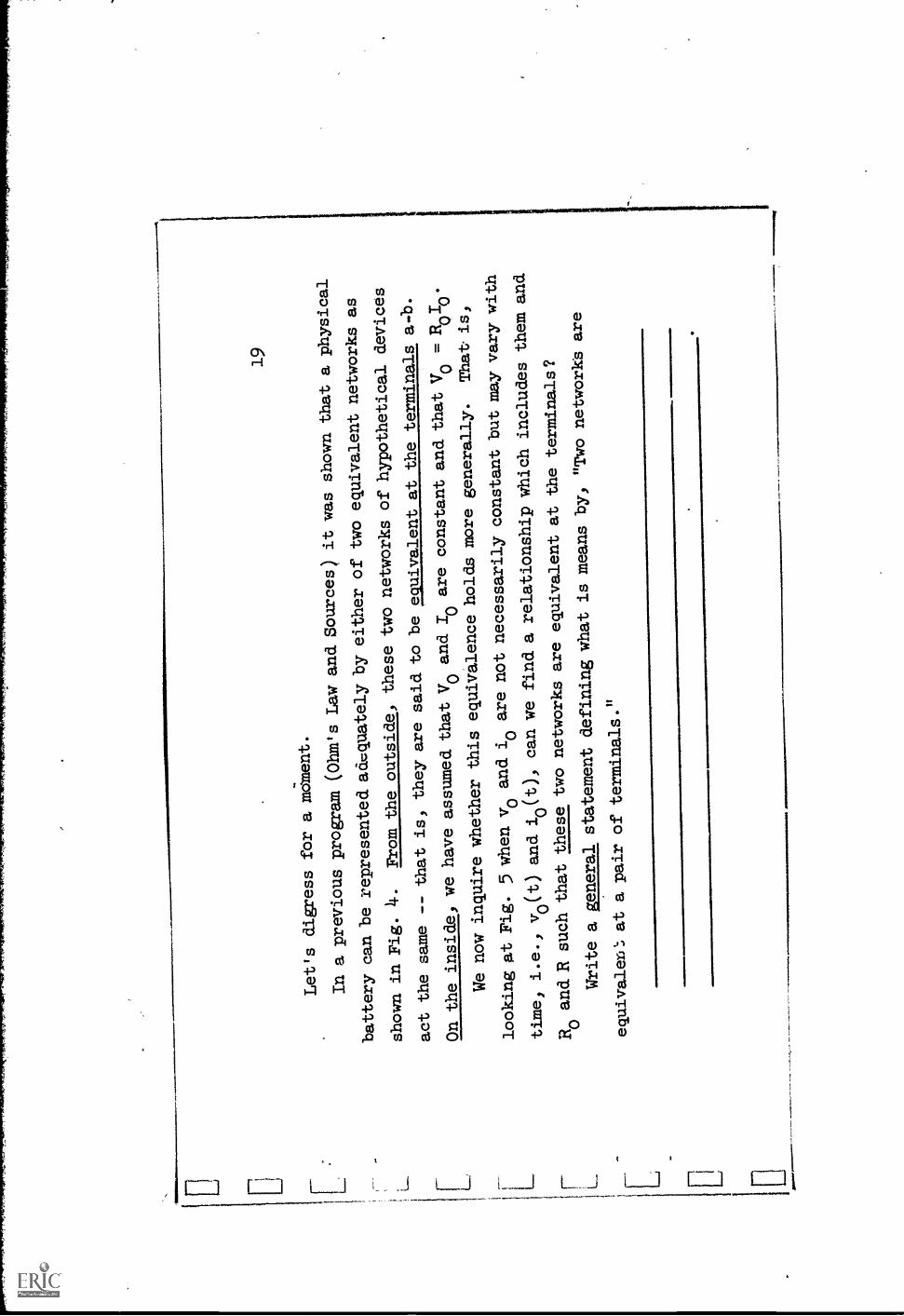
19
Let's digress
for a
mc;ment.
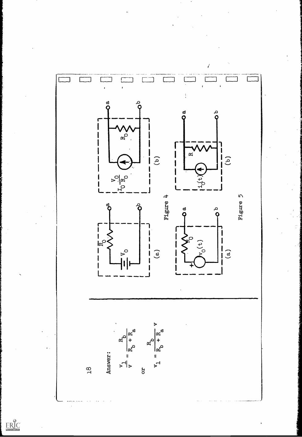
In a previous program
(Ohm's Law and Sources) it was
shown that a physical
battery can berepresented adquatelyby either of two
equivalent networks as
shown in Fig.
4.
From the outside,
these two networks
of hypothetical
devices
act the same --
that is, they are
said to be equivalent
at the terminals
a-b.
On the inside, wehave assumed that Vo
and Io are constant
and that Vo =RoTo.
We now inquire
whether this equivalenceholds more generally.
That-is,
looking at Fig. 5 when vo
and io are not
necessarily constant
but may-vary with
time, i.e.,
vo(t) and io(t), can we find a
relationship which includes
them and
R and R such
that these two
networks are equivalentat the terminals?
0Write a general
statement defiAing what
is means by,
"Two networks are
equivalen.`; at a pair ofterminals."

20
Answer:
Your answer should imply two things:
(1) that the v-i relationship at the
terminals of the two networks are the
same, and (2) this v-irelationship holds
regardless of the actual values
of v and
i.
For example, you might have said:
"Two networks are equivalent at a
pair of terminals if their v-i
relations are always identical."
Review your own statement and correct or
improve it as needed.
1111
1 11 .

21
By analogy with
the case of the
battery, you mightsuspect that R =Ro
and io(t) =vo(t)/Ro.
If we assume
that this is the case,
and we determine
the voltage-current
relationship for
each Of the twonetworks and findthat
they are the same,
we willhave demonstratedthat the two
networks are equiva-
lent.
Assume a current
i and voltage vat the terminals
of each of thenet-
works in Fig. 5and write the
two v-i relationshipsusing the basic
laws
(Kvl, Kcl or Ohm's
law).
Then insert the
suspected relationships:
R = Ro
and 1_0(0 =vo(t)/Ro.
What is your
conclusions; are
thb-two networks
equivalent?
run
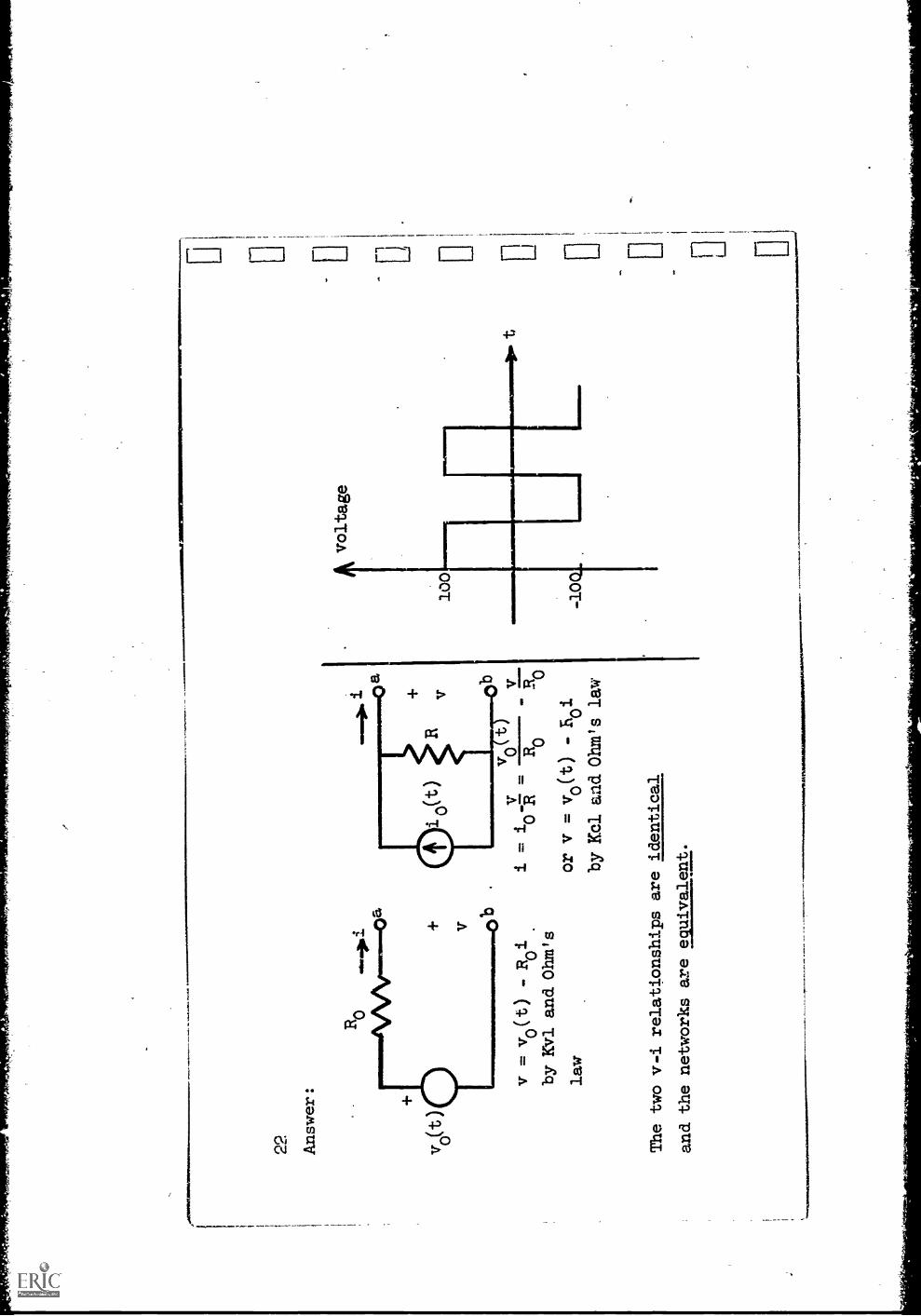
Answer:
v o(t
v = v(t)
Roi
by Kvl and Ohm's
law
ii
-0 R
Ro
Ro
or v = vo(t)
- E i
0by Kbl arid Ohm's law
The two v-i relationships are identical
and the networks are equivalent.
1
By measurements made at the terminals of a physical laboratory source,
it is found that the internal resistance is 50 ohms and that, with a 50
ohm resistor connected externally to the terminals, the voltage is a square
wave with a peak-to-peak voltage of 200 volts, as shown
in the diagram.
Draw both a v-source and an i-source equivalent of the laboratory source.
Label the parts and specify appropriate values either numerically:orby a
graph..

24
Answer:
v-source.equivalent
vo
is a square wave with
with a peak-to-peak voltage
of 400 volts.
(This can be
obtained from the voltage
divider formula.)
i-source equivalenta
io is a square wave
with a peak-to-peak
current of
8amps.
Figure
6
50v
4.0E
04

L.
25
Let us now use
this v- andi-source equivalence
to permit
simplification
of a network so
that it may be
easily solved.
It is desiredto find thevoltage v across
the external
10 ohm resistor
in Fig.
6.
We might be
tempted to use
the voltage-divider
formula but,
in its
present form,
this is not a
simple series
network.
Redraw thenetwork using the
equivalence of sources
to get a
series net-
work.
Then use the
voltage divider
formula to find an
expression for V.
When consideringwhat happens
externally, the
two networks
internal to the
dashed lines are
equivalent.

26 Answer: -
1 175sin2t
L_
11IM
411
1111
1..O
MO
NO
-I15
+ v
ON
IMIP
OM
MI
MO
M. M
INIM
10
V. =
(75 sin 2t + 5))
25
(30 sin 2t + 20) volts
Figure 6(a)
5sin2t
a+
V
Figure
6 (repeated)
Li

27
Suppose that in the original network of Fig.
6 it is desired to determine
the current in the internal 15 ohm resistor.
One might be tempted to find it
from the equivalent network in Fig.
6(a) where the current in the 15 ohm
resistor is the same as that in the 10 ohm resistor.
This external current
can be easily found.
Another person might return to the original
network (repeated on page 26)
and note that, with v now known, the current in
the 10 ohm resistor is known;
applying KC1 to the node labeled a will then leadto i.
Carry out both of these suggestions.
Compare the answers and comment on
their appropriateness in answering the question.
.zurrent in 15 ohm resistor in original network, Fig.
6, is
PlArre.z,vt in 15 ohm resistor in "equivalent"network, Fig. 6(a), is

28
Answer:
In the original network,
. 2 sin 2t
-2.
In the network of
Fig. 6(a), i
3 sin 2t ± 2. 'Clearly,
these currents are not
identical!
Your comments should have
noted that,
although these two networks maybe
equivalent at the terminals
(exter-
nally)) they are not internally iden-
tical.
The original question cOn-
cerned current in the 15
ohm resistance
of Fig. 6.
Only the first of the two
expressions above, answers the
question
that was asked.
Fligure 7
L.
VT
29
This example serves as a
warning that when a portionof a network
(a sub-
network) is replaced by anequivalent, careful observance
of the meaning of
equivalence must be maintained.
Thus, in Fig. 71 when we saythese two networks
are equivalent, we mean
that, so far as the
terminals a, b are concerned,
the
relationship between the
voltage and current is the same
for the two.
We say
nothing about conditions
within the dashed boxes,
internal to the two networks.

30
In our example,
the preceding
remarks mean thatwhen we replace
the subnetworkinside one of the
dashed boxes by the
other one, we can
solve for onlythose voltages and cur,.
rents outside
these boxes.
Thus, the
current in the l
ohm resistor inthe
one case
cannot be determinedby
using the secondnetwork.
.11.
21M
ME
O 4
1111
111.
4M11
110.
r---
-
__ a
Figure
6(repeated)
MID
IFIN
O C
MO
VIO
..0
1111
MLN
O
La
__ _
AM
MO
C:C
li
Figure
6(a)(repeated)

Let us return again to
the original network of Fig.
6, which is repeated
on page 30.
Suppose that our interest is
in determining the current
in the
15 ohm resistor.
Earlier (when we were interestedin the voltage across
the 10 ohm
resistor), we replaced the current source
and 15 ohm resistance by an
equivalent network which led to a
simple series network.
Let us now, instead, replace
thq other part of thenetwork, the 50 volt
battery and 10 ohm resistance,
with an appropriate equivalent.
Draw a diagram
of the resulting networkand label it appropriately.
32
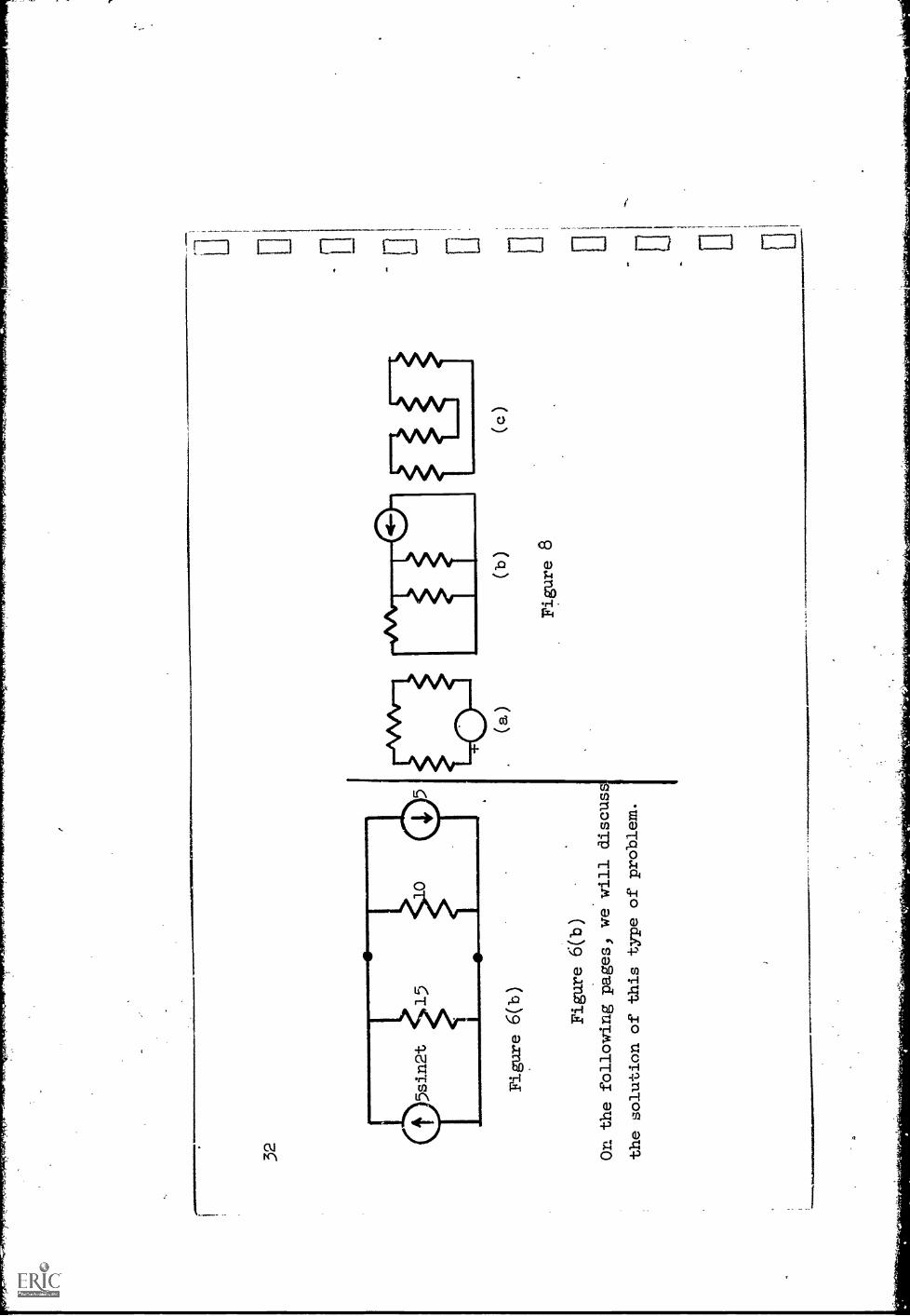
Figure 6(b)
Figure 6(h)
On the following pages, we will discus
the solution of this type of problem.
( b )
Figure
8
( c )
/le
£1

fri"
.fr
r7rf
elfA
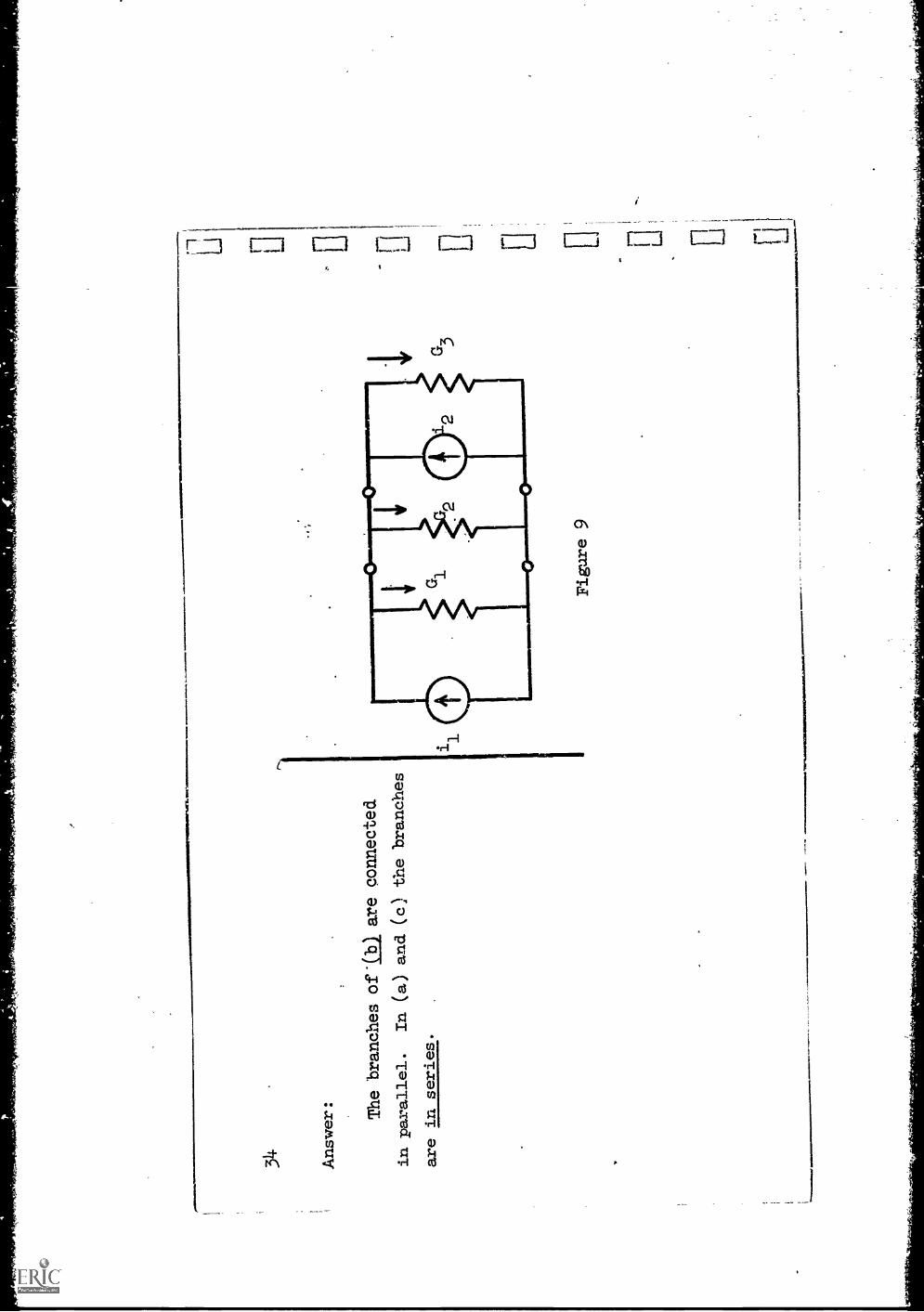
The structure of this
network (Fig. 6(b))is such that
the voltage across
each of the branches is the same.
Branches which are connected so
that their
voltages are
all the same are said to
be in parallel and the resulting
net-
works are said to be parallel
networks.
State which ones, if any,
of the networks in Fig.
8 are in parallel.
State how the remaining ones are
connected.
,.....
nO~
N40
1%
34
Answer: The branches
of*(b) are connected
in parallel.
In (a) and(c) the branches
are in series.
Figure 9
ft 1
L.;
1.1 Li
35
Rather than dealing with a
specific numerical example,
let us turn to a
parallel network having
somewhat more generality yetnot so complicated that
it becomes difficult to
handle.
Such a network is shown in
Fig. 9.
The re-
sistors are labeled in terms
of their conductances
cG
Let iG11iG and iG'3
be the currents in the
three resistors
with the
[1.,
references shown.
Write Kcl at one of the nodes
of this network, starting
with the left hand. branch.
-J
36
Answer: - i1
+ iG1
+ iG
- i2 +
iG3
= 0
2
(If you took "toward" as the junction
reference and used the upper node, or
if
you used the lower nodewith "away from"
as the junctionreference, you got the
opposite signs.)

37
Redraw the diagram
(Fig. 9) choosing areference for the voltage
v.
By appropriate
substitutions and regroupingof terms, put the previous
equation (-i1
+ i
+iG2
- i2
+ i
G3
= 0) into the
form i = Gv and write
Gi
identifying expressions
for i and G.
ii
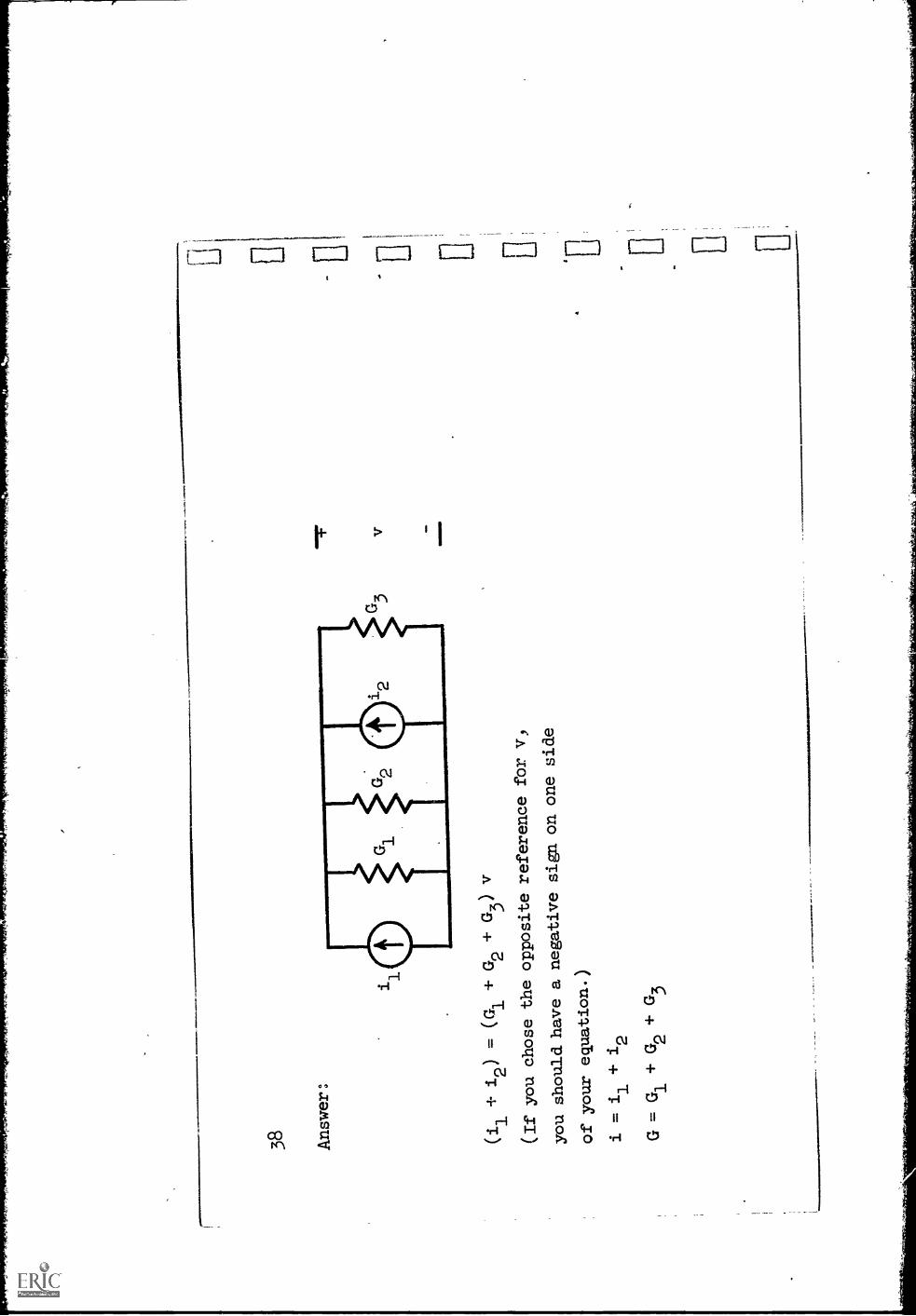
38 Answer:
(i1+ i2) = (G1+ G2+ G3) v
(If you chose the opposite
reference for v,
you
should have a negative
sign on one
side
of your equation.
i = i1
+ i2
G = G1 + G2 + G3
1"*"

It is clear that when two or nore
current sources are conneced in parallel
they can be replaced by a single
equivalent current source equal to the,algebraic
sum of the source currents.
Also, a parallel connection of resistors
1
4-o
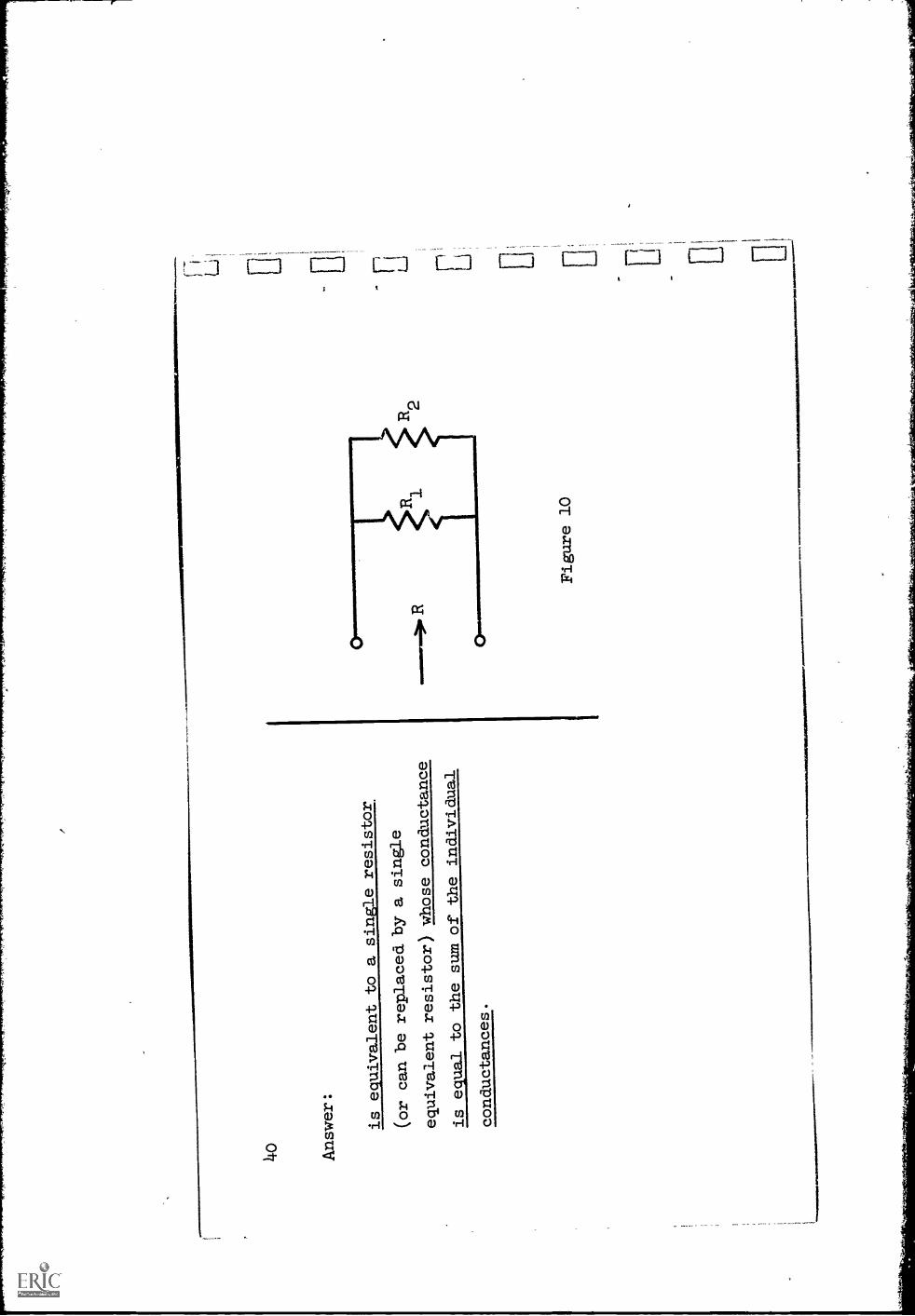
Answer:
is equivalent
to a single resistor
(or can be replaced by a
single
equivalent resistor)
whose conductance
is equal to the sumof the individual
conductances.
Figure 10
*AN
.%
ii 1-7
Li
That is, if Gi, G2, .,.,
are connected in parallel, a single conductance
G = G1+ G +
Gri is equivalent to the parallel combination. Vote that this
result is stated in terms of conductances whereas resistors are usually speci-
fied in terms of their resistances.
Suppose we wish to know the equivalent resistance of two resistors con-
nected in parallel as in Fig. 10.
Using the above result, find an expression
for the equivalent resistance R in terms of RI and R2.

4.2
Answerg
R1R2
RR1
+ R2
This is obtained byfirst writing
G = G + G2
replacing conductances
1by one over
their reciprocals, and
solving for R.
14-3
The combination of two resistors
in parallel occurs very oftenand it
helps in the solution ofproblems if this relationship andits properties
become well known to you.
One property to know; for
example, is the relative value
of two resist-
ances and theirparallel connection.
Let 111 = 10 ohms and R2 = 30
ohms.
Determine the equivalent resistanceR when these two are in parallel
and note
its value relative to
(greater or less than) that of B1 and R2.
Then prove
that for any two resistance R1
and R2 the parallel equivalent
resistance has
this same relative value.
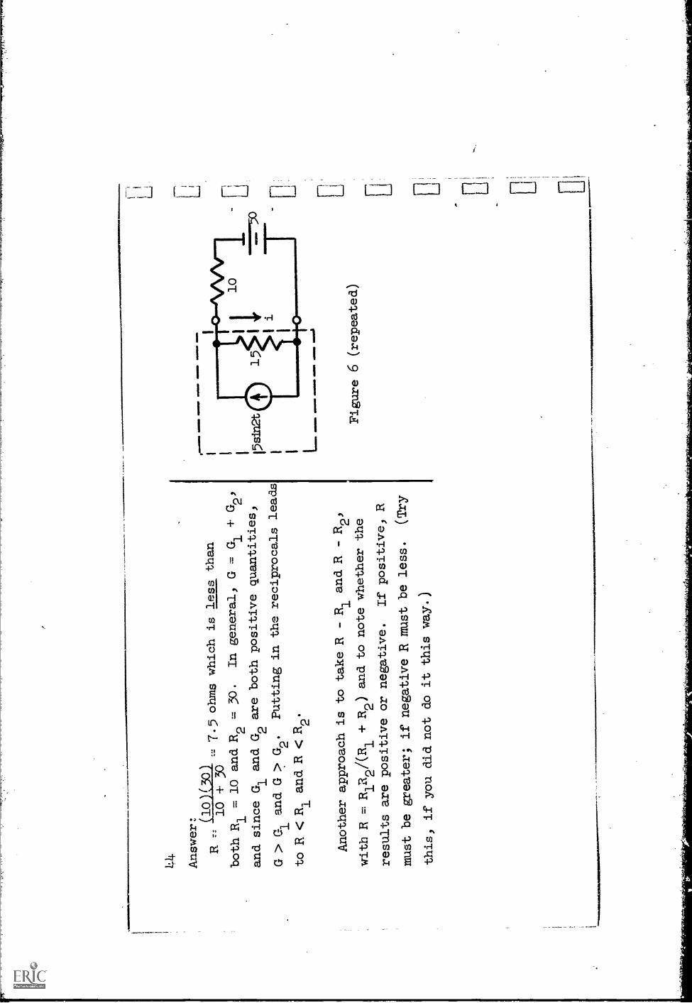
4 Answer: (10)(30)
R -
1.5 ohms which is less than
10 + 30
both Ri . 10 and. R2 = 30.
In general, G = Gi + G2,
and since G1
and G2are both positive
quantities,
G > G1 and G> G2.
Putting in the reciprocals
leads
to R < Ri and R
R2.
Another approach is to take R -Ri and R - R2,
with R = R1R2AR1
+ R2) and to note whether the
results are positive or negative.
If positive, R
must be greater; if negativeR must be less.
(Try
this, if you did not do it
this way.)
psina
.101
1111
.O
NO
%
Figure 6 (repeated)
Li E
45
Having introduced a parallel network and discussed some of its gene-P1
properties, let us return to the example previously under consideratiL
determine the current i in the 15 ohm resistor.
The diagram is repeated 7,A
page 44.
This network is neither a serir4 network nor a parallel network.
It was earlier converted to a series network by replacing the current source
in parallel with the 15 ohm resistor by an equivalent consisting of an ap-
propriate voltage source in series with the resistor.
Alternatively, the
network is converted into a parallel network if the battery in series with
the 10 ohm resistor is replaced by an equivclent consisting of an appropriate
current source in parallel with the resistor.
Rep,at this latter and determine the current i in the 15 ohm resistor.
Verify by comparing with the value determined on page 23.
46
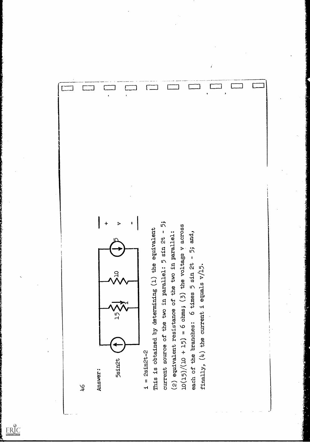
Answer:
5sin2t
i = 2sin2t-2
This is obtained by determining
(1) the equivalent
current source of the two inparallel: 5 sin 2f - 5;
(2) equivalent resistance of the two inparallel:
10(l5)/(10 4. 15) . 6 ohms; (3) the voltage v across
each of the branches:
6 times 5 sin 2t - 5; and,
finally, (4) the current i equals
v/15.
....,.
.

L
To summarize:
1.
In a series network of resistors the equivalent resistance is
2.
In a voltage divider) the voltage across one resistor is
3.
For this network
3e
an equivalent network is
(Draw a diagram and label the
parts.)
4.
Two resistors whose conductances are 10004 mhos and40004 mhos are
connected in parallel.
The resistance of the combination is
1111
1/1.
1101
1114
1=11
b

48
Answer
1.
the equivalent resistance
is equal to
the sum of the series
resistances.
2.
the voltage across one
resistor is to
the total voltage what
that resistance is to
the total resistance.
is equivalent to
4.
R = 200 ohms.
We suggest you
take a break at this point,
before going on.
*mom
..

49
Section 2
Looking back over the work of this unit, it appears
that solving for an
unknown voltage or current either in a series circuit or
in a parallel combina-
tion is relatively simple.
We also saw an example in which it was
possible to
convert a'given network into a series network or a
parallel network.
This was
done by replacing a subnetwork,
consisting of a .current source in parallel with
a resistor, by an appropriate
voltage source in series with the resistor.
(For ease of reference we shall call these two, shown again inFig. 11, equiv-
alent.sources.
Note carefully that the term applies to
the combination of
source andresistance.)
We say that the first is the voltage source
equivalent
of the second and the second is the current source
equivalent of the first.
(Repeat these names out loud.)
ww
.avw
Ino1
wN
aw.b
goN
IO41
ON
AIM
A...
......
""*N
wo
,I10
8.61
110
50
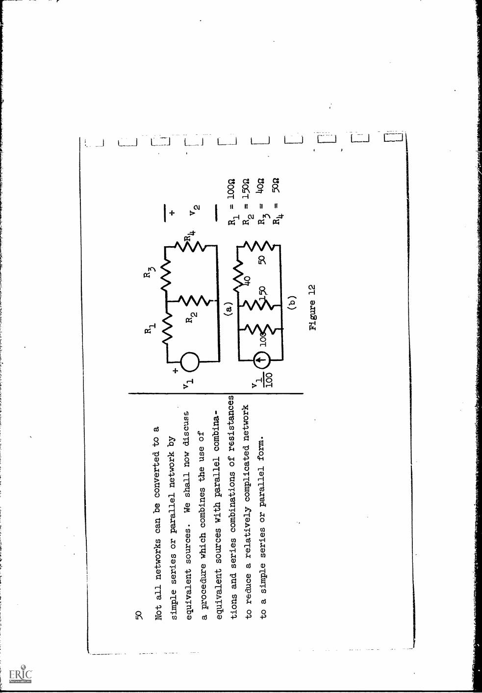
Not all networks can
be converted to a
simple series or parallelnetwork by
equivalent sources.
We shall now discuss
a procedure which
combines the use of
equivalent sources with parallel
combina-
tions and series combinations
of resistances
to reduce a relativelycomplicated network
to a simple series or
parallel form.
vi
100
R1
R3
(b)
Figure 12
2
R= 1002
R2
= 150a
R3
=itoa
R=
5042
1 -, t ;
1,"2

To- start the discussion,
consider the network shown in Fig.
12(a).
It is
desired to determine the
voltage v2 across resistor
R4.
For convenience, let
us initially suppose
the resistors have the numericalvalues shown, but focus
your attention .onthe process being carried out
rather than the numerical
results.
Suppose that the current source
equivalent is used to replace vi
and 111.
The result is shown in Fig.
12(b); it is neither a series nor a parallel
circuit.
Suggest a sequence of stepswhich will convert this networkinto a series net-
work. 'Carry oUt these steps and sketch the
isesulting equivalent circuit,
labeling all components.

52
Answer: Combine R1
in parallel withR2into an equivalent
resistance;
then replace thisresistance and the v1/100
current source withtheir voltage source
equivalent.
100(150)
-60
R -
Q250
vi100
v2
7 [ ii CP.
...4 [ 0 [ [

53
We no101ave a simple series
circuit fi.om which the voltage v2 canbe
easily calculated.
State the value of v2
in terms of v1
.
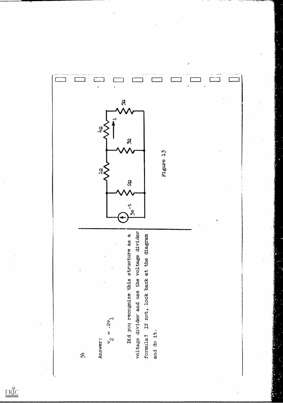
Answer: v2
.2v
Did you recognize this structure as a
voltage divider and use the voltage divider
formula?
If not, look back at the diagram
and do it.
Figure 13
-
EL
4.1.
.1M
MO
NIM
IIIIII
IMM
O e
.."

1111
1116
01%
.....
arsi
ols=
11,
55
Before we attempt to generalize this result,
let's take another example.
It iS desired to find the current i
in the 4-ohm resistor in Fig. 13.
Suggest
a sequence of
steps that converts this network to a
series circuit containing
the 4-ohm resistor.
Carry out these steps and calculate i.

56 Answer: First replace the current source
and 2-ohm resistor
with their voltage source
equivalent.
This leads to
Fig. 13(a).
Next combine the 2- and 1-ohm
resistors;
then replace the resulting
3-ohm resistor and the voltage
source by their
current source equivalent.
This leads to
Fig. 13(b).
Next combine the two 3-ohm
resistors in
parallel; then replace the
resulting 3/2 ohm resistor
and the current sourceby their voltage source
equivalent.
This leads to Fig.
13(c).
Finally, compute i:
2
lonm
anm
aNW
INIM
MO
NIII
ME
MIN
IIIN
1111
1111
1111
101e
NIM
OIM
MI1
111M
INIM
INI
1
3e-t
2-t
i2
eamps.
72 2
+ 4
+ 5
(a (b)
3/2
4
(c)
Figure 13

57
The preceding examples illustrate an important and rather general procedure.
This procedure is most useful when it is desired to determine the voltage or cur-
rent in one branch of a network:
11 a
Min
i* 1
1111
MIn
S M
mII
MM
Ma
1--
- a
S .a
The structure of the rest of the network is replaced by a single equivalent,
consisting of a voltage source and a series resistor, which forms a single
loop with the desired branch.
The eqpivalent is found by successive (one after the other) application
of sone simple steps.
There are four basic steps that.you have used to find
the equivalent.
Write them:
1.
2. 3 14..
, and
58
Answer:
Rather than list these for you, it seems
appropriate to assume that you wrote
them cor-
rectly.
Review the last few frames if you want
to check yourself.
,We will be discussing and using this
procedure on the subsequent pages andat other
times during this course.
1
59
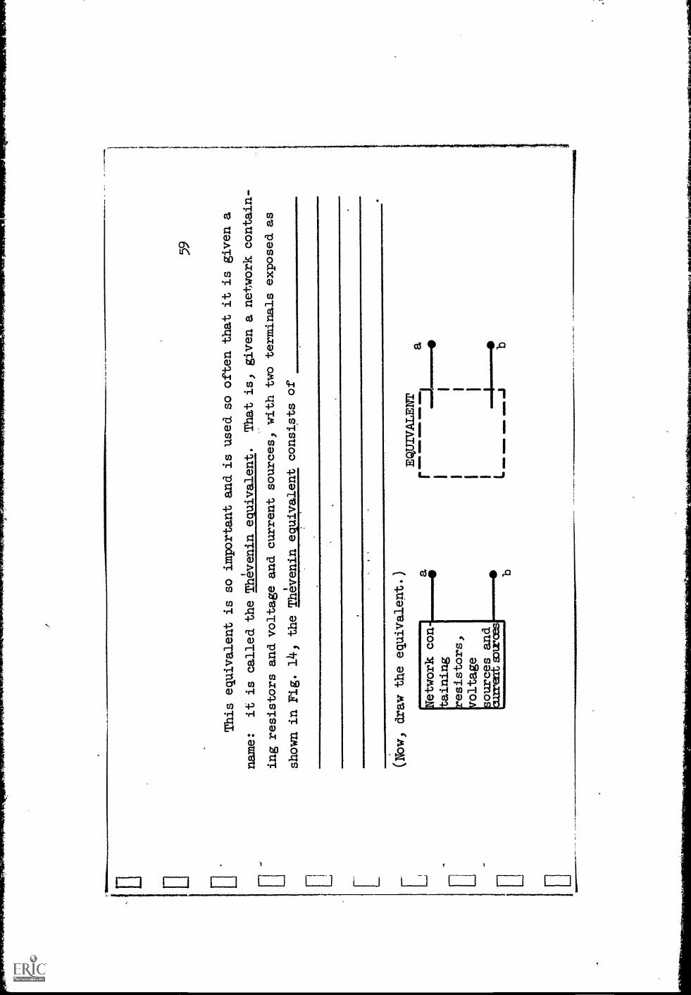
This equivalent is so important and is used so often that it is given a
name:
it is called the Thevenin equivalent.
That is, gtven a network contain-
ing resistors and voltage and current sources, with two terminals exposed as
shown in Fig. 14, theThevenin equivalent consists of
(Now, draw the equivalent.)
Network con
taining
resistors,
voltage
sources and
an:rents:woes
a
...m
met
a le
wsr
m41
0
ID
EWIVALENT

6o Answer: the Thevenin equivalent consists of
(1)a voltage
source in series with(2)a resistor,
wag
..
(3)connectedacross those terminals.
I(Your wordingmay be different but, again7
.your response must contain all three of
the
numbered items.
,If it does not, retUrn and
correct it.)
ME
M IM
MO
AM
MO
111
111.
1101
1NO
61
The equivalent, at a pair of
terminals, of a network containing
resistors,
v- sources and i-sourceswhich consists of a v-source inseries with a resistor
is called the
You will be using it manytimes.)
equivalent.
(Write it. -- Say it out loud.
62
Answer:
1
Thevenin.
(Remark:
This was named after a Ftenchman,
not a Russian, as one might suspect from
the name.)
63
As yoli 'might
suspect, the equivalent
voltage and. rebistance
in the
Thevenin'equivalent of a tWo-terminal
network are called
the
voltage-and the
resistance, zespectively.

64
Answer: Thevenin equivalent
Thevenin equivalent
Remark: Up to this point we have discussed one
1
method of determining the Thevenin
equivalent
of a given network.
This method consists of the
successive use of a v-source equivalent, an
i-
source equivalent, series
combinations of resistors
and parallel combination of resistors.
For our
purposes, the present method
is the only one you
I
will need.
In a later unit, an alternativemethod
will be described.
1111
1111
1141
111ii
4111
!111
1111
4111
.
Figure 13
1111
0
Figure 14'
111
65
Now suppose that it is desired to determine the voltage or current or power
dissipated in more than one branch of a network.
For example, in Fig. 13 (re-
peated) suppose that in addition to i it is desired to find the power dissipated
in the 1-ohm resistor.
(It is sufficient to find the current i, since once it
is found, the desired power will follow.)
In carrying out the suggested procedure for the determination of i, the
structure of the network is destroyed, so that in the resulting equivalent net-
work (repeated as Fig. 14) the 1-ohm resistor does not even show up.
It appears
that we are stymied.
However, once i has been determined from Fig. 14, we can
return to the original network in Fig. 13 in which i is now known.
By applylng
Kcl at the junction of the I-1 3- and 4-ohm resistors, i1 is determined in terms
of i and the current in the 3-ohm resistor which, by Ohm's law is
1/3 the voltage
across it.
It remains to determine this voltage.
By applying Kv11 express the
voltage across the 3-ohm resistor in terms of known quantities.
(Remember, i was
found to be
2 e-t. )
7

66
Answer: By Kvl the voltage across the
3-ohm
resistor is equal to the sum ofthe voltages
across the
4- and 5-ohm resistors.
Since
the current in these resistors
is known,
this voltage can be found.
Thus,
18
-v (across 3-ohmresistor) = 4i + 5i =
et
7

are:
67
Finally, the current
la
and the power dissipated in the I-ohm resistor
i1
=
Wre
n,
68.1
111
Answer: i1
=+
-3voltage across 3-ohm resistor =
e-t
.
7
.2
64
-2t
==
e
pom
mo
LI gIN
IMIO

69
A rather general method of solution, then, involves replacing a sub-
network by its Thevenin equivalent, solving for a voltage or current in a
given branch, then using this solution, together with known sources, in
the original network to find other branch voltages or currents.
I.
The Thevenin equivalent is simply a vdltage source in series with a
resistor.
But we have previously found that equivalent to a v-source of
voltage vo in series with a resistor Ro is another network consisting of
.(Also draw it.)

r
70
Answer:
a current source 10 = v
with the resistor Ro.
in Tara Ilea.
Figure 15
fam
mo.
!am
.,
114
... Maw
s. [ :1 r
Since the v-source and. series resistor
combination
original subnetwork, the i-source and parallel
resistor
equivalent to the subnetwork.
This combination is also
called a Norton equivalent.
In.the solution procedure we have been
discussing,
71
isequivalent to the
combination is also
given a name; it is
it may sometimes be
more convenient to arrive at a
final network which is'a parallel combination
of branches containing the branch in
question, rather than a series circuit.
This was, in fact, done on page
37.
(Read that page and the answer again
before going on.)
Both the Thevenin equivalent and the
equivalent are tools to be used where
each is most appropriate.
.DIWaw the Norton equivalent of the
subnetwork to the left of terminals a-b
in Fig. 13 and show the correct numericalvalues.
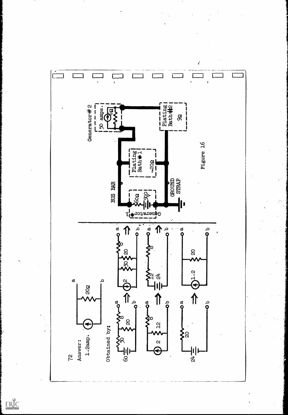
72
Answer:
1.2amp.
Obtained by:
Generator#2
r1
150
amps.'
BUS BAR
20
0a
.1 Lg.
171atingi
1.
IBath* 11
II
,202
L---
' J
GROUND
STRAP
Figure 16
Platkagi
Bath421
92
73
Knowing that you are studying engineering, the foreman of a small electro-
plating shop has asked you for help.
He is blowing fuses and cannot figure out
what his peak currents should be.
Ober some measurements, you were able to make a reasonable guess at his
loads and soUrces and arrived at Fig. 16.
What currents should he expect in
the branches of his system? Assume that each plating bath can be considered
equivalent,to an ideal resistor.
Determine the currents in more than one way
to check yourself.
Focus initially on one branch, replacing the remaining
network by an appropriate equivalent, then retUrning to the original
network.
Then choose another branch on which to focus.


4 Am
mo.
a--
7 5
Let,"s.noW consider another class
of problems, one inwhich the desired
current or voltage or powerin one branch of a
network is specified.
and. it is
,,desired to determine
tha required source
voltage.
Figure 17 shows such a
case,
in which it is
desired to supply 5ao
watts of power to aresistive load. across
_which the voltage is
to be 100 volts.
It is required to
find the source
voltage,Y0.
This problem has
features similar to
the type of problem wehave already
solved.
Instead of first havingsolved for a branchvoltage or current,by
using aThevenin equivalent, and then returningto the originalnetwork, a branch
.voltage or current is
already given.
The remainingprocedure, then, shouldbe
the same; namely,
the alternate use
of KV1, Kb]. and. Ohm's
law.
Ube this procedureto find the requiredvalue of Vo.
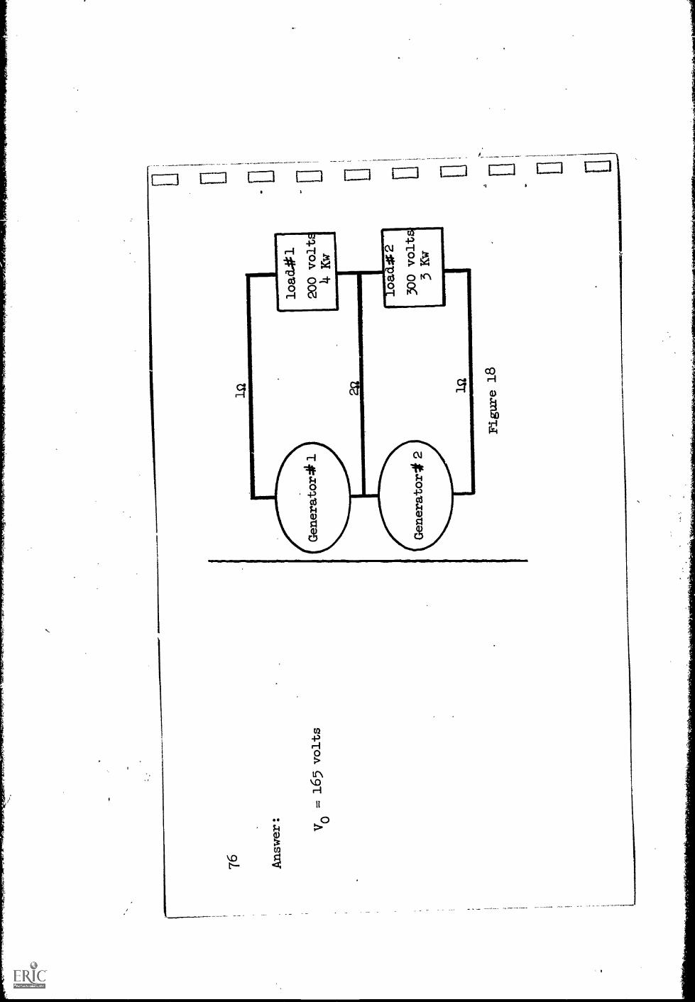
76 Ans
wer
:
Vo
=16
5 vo
lts
la la
Figu
re 1
8
load
.401
200
voltE
li- K
w
4.1.
1.-.
9lo
ad.0
230
0 vo
lts3
Kw
4o o ......
.
101
Figure 18 illustrates a 3-wire power distribution system.
Da power is
to be supplied to two loads as indicated:
The transmission system has losses
which can be represented by the resistances shown.
Two dc generators are
available whose voltages can be set over the following ranges:.
Generator 1:
from 200 to 250 volts
Generator 2:
from 275 to 300 volts
Will these two generators be adequate to supply the required loads?
If so, at what values should their voltages be set? Compute also the power:
that each generator will supply.
You can detect possible numerical errors
by verifying that the power supplied by the generators equals the power lost
plus the power delivered to the loads.

78
Answer: The generator will be adequate.
Set the voltages at:
Generator 1:
240 volts; power supplied =
4.8
KW
Generator 2:
290 volts; power supplied . 2.9 Kw
1611

§aMILIKIY:
1.
A network containing resistors,
v-solirces and i-sources can be
replaced at a pair of
terminals' bY a Thevenin eqUivalent cohsisting
Of
2.
Another structure equivalent to this is
ca1led'a
and it consists of
1
The Thevenin.or Norton equivalent of a givennetwork Can be deter-
mined by successively converting from a
ii4ource equivalent to
while combining resistors in
and
...1.
1ww
ww
ww
ww
wl,
4.
Once a branch current or valtage is determined, orwhen a required
value of branch current or voltage is specified,
it is possible to
work through the rest of the network to findother voltages and currents
by alternate applications of
and
8o Answer: 1.
Thevenin's equivalent consists of a voltage
source in series with a resistance.
2.
Norton equivalent conslsts of a current
source in parallel with a resistance.
from a v-source equivalent to an i-source
equivalent while combining resistors in
series and in parallel.
4.
by alternate applications of KV1, Kcl
and Ohm's law.
Ra
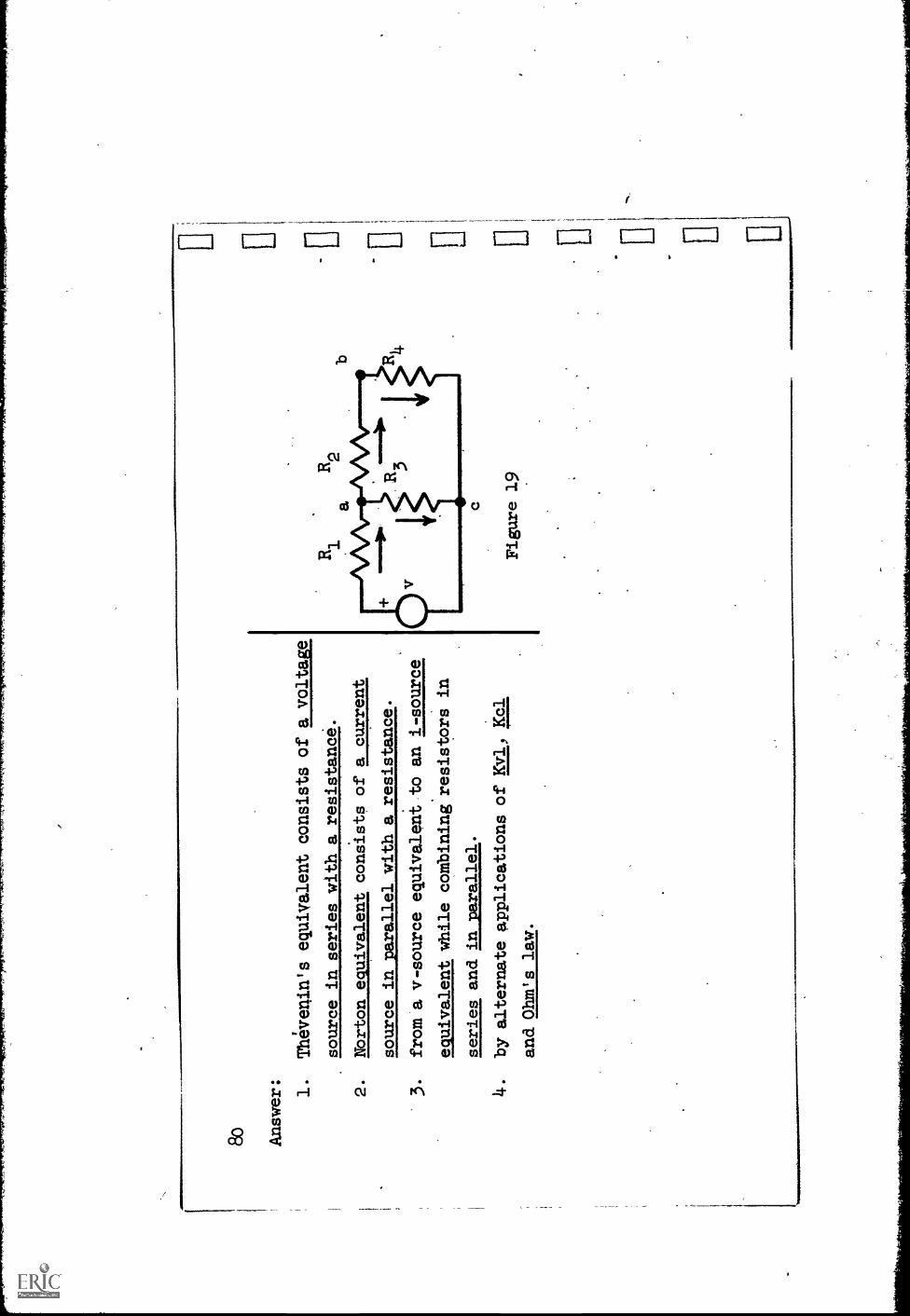
Figure 19
Section 3
The method of solution
of network problems discussed
in the last section
proceeds by replacing, insimple stages, the structure of a
subnetworit by a
simple equivalent, so that asingle equation can bewritten for the only re-
maining variable, and.solved.
The validity of the procedureis established
by applying the basicrelationships --Ohm's law andKirchhoff's two laws.
An alternative procedure
is to apply these basic
laws to a network with-
out replacing any partof it by an equivalent andthereby changing its struc-
ture.
The detailed development
of such a procedure is the
subject of this
section.
The case of a series
circuit(Or a parallel
combination)is simple enough
that no further consideration
will be given to them.
The introductory dis-
cussion will be carried on
in terms of the network
shown in Fig. 19.
Although

82
branch voltage andcurrent references are arbitrary)
let us choose the refer-
ences for eachresistor such that the voltage
plus is at the tailof the cur-
.
rent arrow.
(Aa-mAA* )
Thus, Ohm's
laW will aiways beV
+ Ri.
Then'only one
rof the references
(plus sign or arrow)
is sufficient to designateboth refer-
ences.
In Fig. 19 an arrow
is used.
83
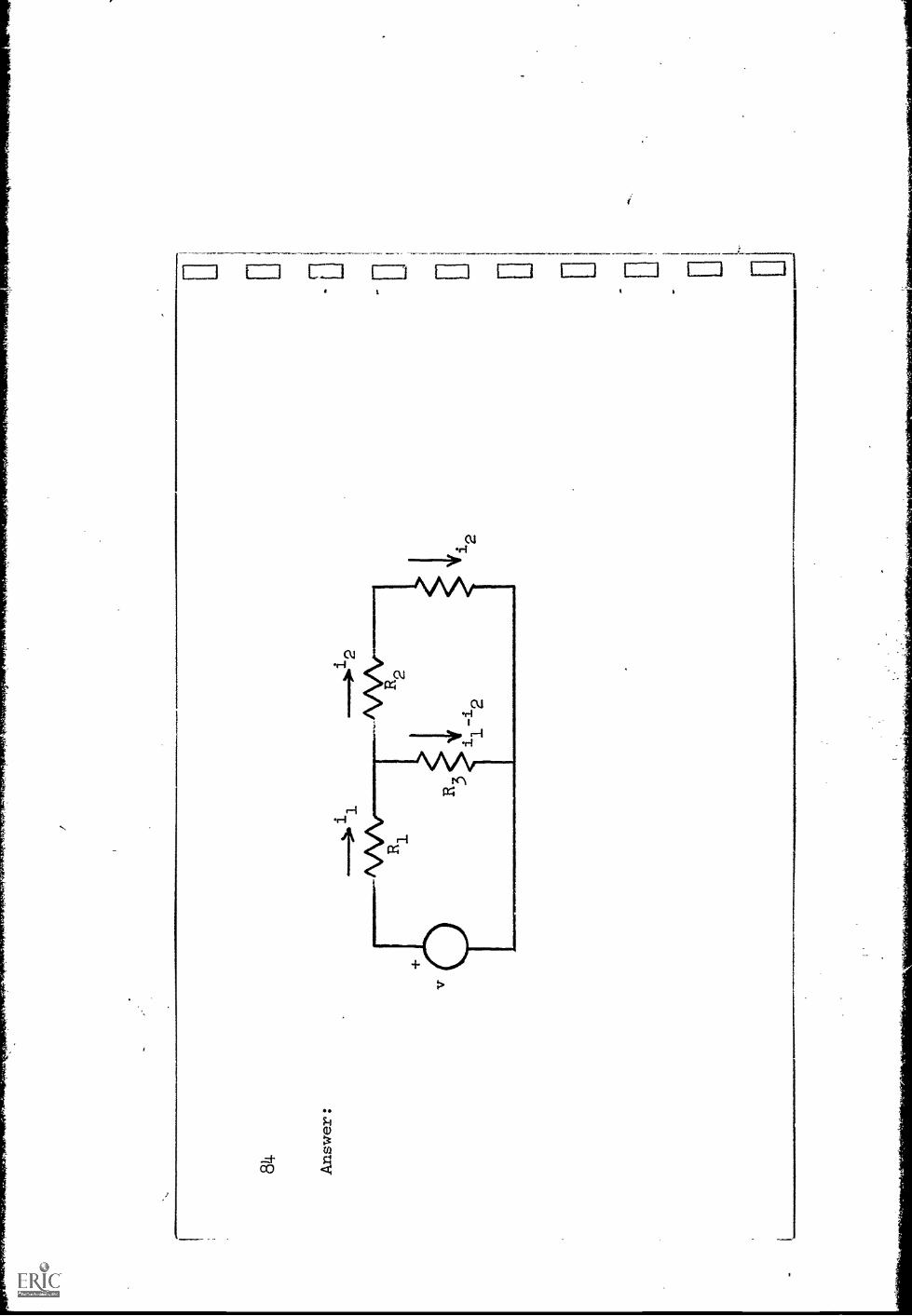
In the three-step procedure to be described, now, wewill apply first Kcl,
then Kvl, and. finally Ohm's
law
.The first step' is to apply Kcl.
Draw your own diagrams of the same circuit
and let i1and i I be the currents in R1 and R2.
Applying Kcl at the nodes,
2write the other two branch currents in terms of i1and i2alongside the reference
arro
ws
in y
our
diag
ram
.
i J L*1 I i 1 i
alI-1)111/1,\A",
i1

85,
The next step-is to apply
Write.Kvl equations around the two
inner "mshes" of the network in
terms
of voltage's
(that is, without applying Ohm's law).
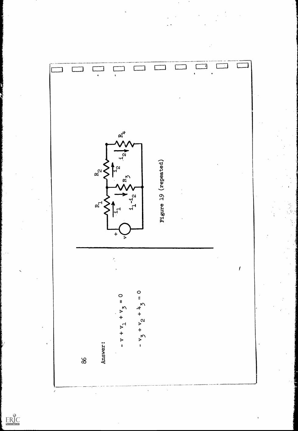
86 Answer: - v + v1
+ v3
= 0
-v3+v2+43
. 0
Figure 19 (repeated)
- -
......
...
.0E
. f r--

87
There is one additional closed path but the equation
obtained by writing
Kvl around this path is the sum of the other two
equations, and hence, not
independent.
(Verify this.)
We have used. Kea. and Kvl.
All that is left of the basic equations is
Ohm's law.
USing Ohm's law, replace all the voltages in the Kvl equations with
appropriate expressions containing the previously
labeled. branch currents.
.Finally, collect terms and transpose appropriately.
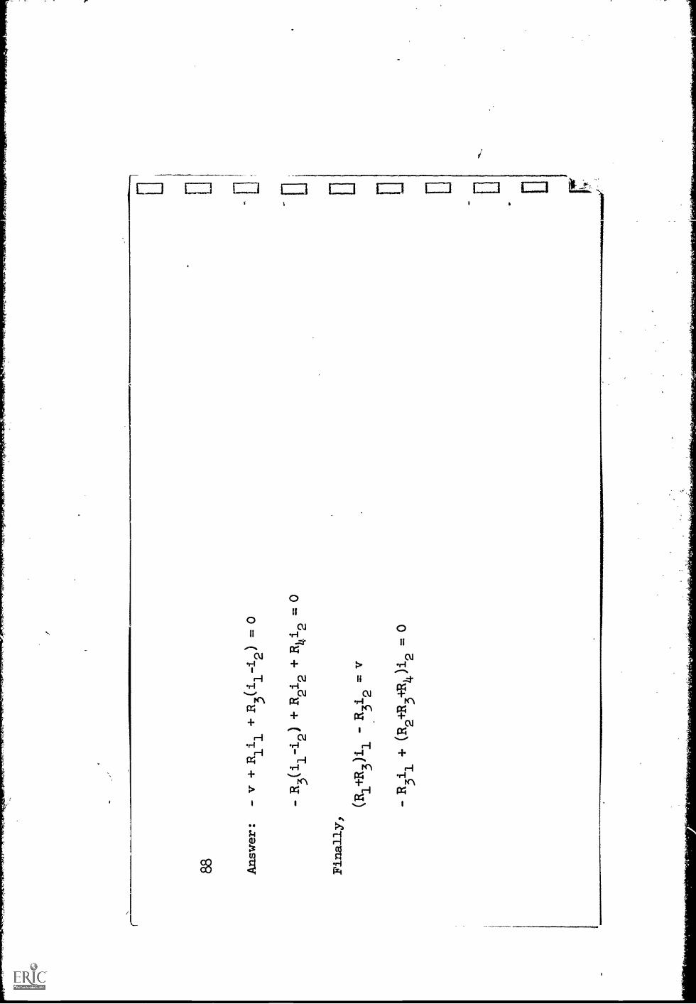
88 Answer :
- v + Rlil +R3(i
1-i
2) = 0
- R3(i1-i2) +R2i2+Rhi2
=0
Finally,
(R1+R
3)i
1=
V
- R3i1
+ (R2+R3+R )i2
= 0

1.10 11
89
Thi
s is
aset of two simultaneous linear equations
tn two unknowns-and can
be s
olve
d, b
y th
e m
etho
dsof algebra.
They are calledthe
looz
esat
aoas
from
the
fact
that
their
basi
c fo
m is
that of Kirchhoff's voltage lawwritten around
clos
ed: p
aths
, or
lOop
s.For convenience, let the following
numerical values be given:
Ri
= 1, R2 = 2, R3 = 3
and
= 4, all in ohms; and. v =
10 sin 3f.
With
these values the equationsbecome
3i
= 10 sin 3t
12
,
-3i1
+ 9i?= 0
$olve,for i
and i2
in any way that you can.
90
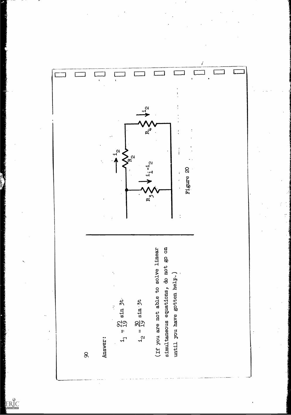
Answer:
sin 3f
12
=sin.3t
(If you are not able to solve
linear
simultaneous equations, do not go on
until you have gotten help.)
Figure 20
11 00

El
11 , El
91
In the example we just completed, after writing Kvl in terms of voltages,
we then ap-olied Ohm's law.
This last is such a simple step that it can be
combined with the previous one.
Thus, when writing Kv1, instead of writing
a voltage, we think a voltage but write it Ri
with the appropriate R and i.
Thus, in Fig. 20, go clockwise around the loop starting
withR2
and. write Kvl
immediately in terns of thd currents.
92
Answer:
R2i2+ RA 4 2
- R3(i1-i2) = 0
1
27
6v
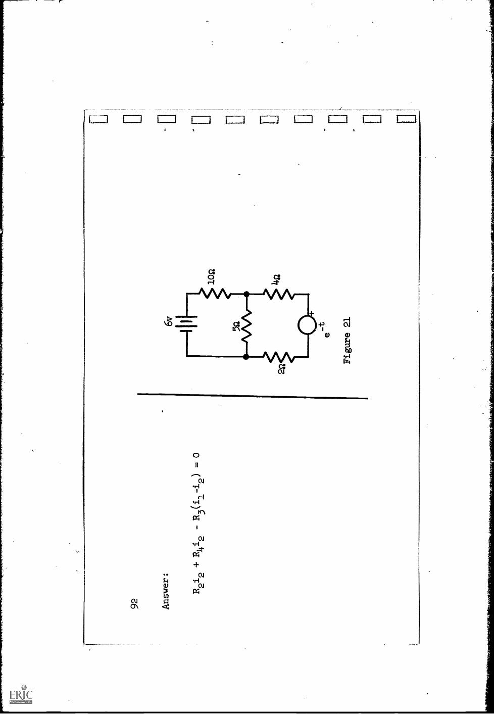
Figure 21
102
..
0 E [ Woo
.
0111
.
4.,
1.0.
1
birm
.1
93
%.
The process of arriving at the loop equations is straightforward.
Given
a network, we first draw references for all the branch currents and express
the branch currents in terms of some of them by applying Kcl.
Then we apply
KV1 to get a set of independent equations, while simultaneously using Ohm's
law, so that the variables in these equations are currents
-- those branch cur-
rents in terms of which all branch currents are expressed.
Test out this approach on Fig. 21 and write a set of loop equations for
the network shown.

9)4-
Answer:
i2t
-6 + 1011
-
5(12-11) + 412 + e-t
+ 212 = 0
This is just one possibility.
Your answer can differ from this in two possible
ways:
(1)
It is possible to choose another set of currents rather than the
ones chosen here.
Thus, the current in the 5-ohm resistor could be called 13
and the ones labeled i2could be expressed as i1
+3'
(2)
It is possible
to write Kvl around one of the "meshes" and the outside loop, rather than the
two meshes as done here.
11..1 ii IJ ci
95
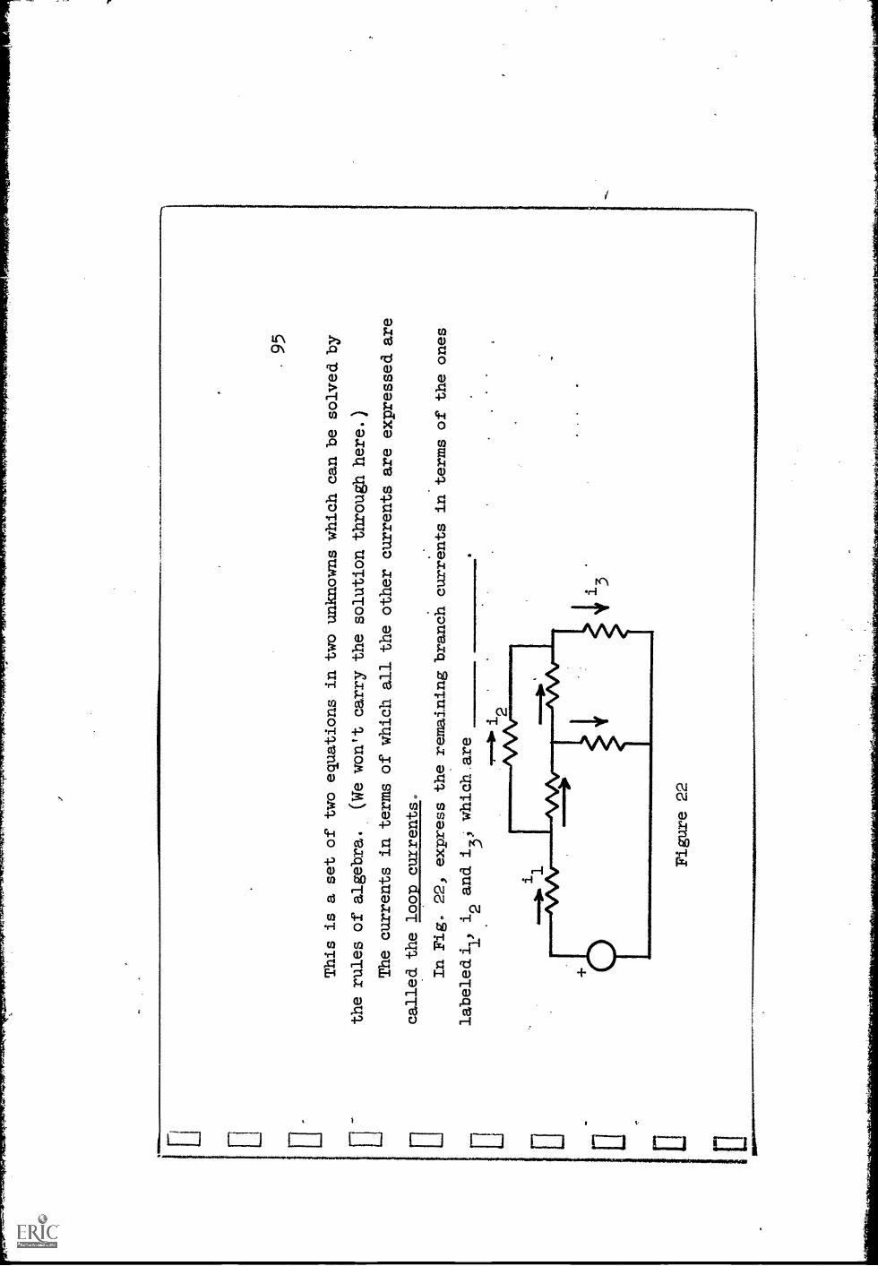
This is a set of two equations in two unknowns which can be solved by
the rules of algebra.
(We won't carry the solution through here.)
The currents in terms of which all the other currents are expressed
are
called the loop currents.
In Fig. 22, express the remaining branch currents in terms of the ones
labelediv i2 and i31 which are
Figure 22

96 Answer
: Z1 ' 1
and
1 are
1.0
2
3
1.
LI / 0/ 0

si11
111. 9 V O
MR
.*
97
Let us consider just one more point.
In,this Aiscussion of loop equations,
there has been no current source.
Figure 23 shows an example of a network
containing a current source.* By-fcllowing the process under discussion, write
a set of loop equations.
Note whether there are any special difficulties with
the current sources.
(If you wish to compare your answer with the one to be
gtven, choose as loop currents those in the
6-and 2-ohm resistors.)

98 Answer:
5(i1-2) + 6ii + 3(i1-i2) = 0
-5(11 -12 ) + 2i2
+ 10 = 0
or
141.1
- 3i2
= 10
+ 5i2
= -10
No difficulty.is introduced by the
presence of the current source.
r [ 11,
11 [
91.1
110,
99
An alternative
procedure for handlingcurrent sources when
carrying on
a loop
analysis is to convert
to a v-source
equivalent.
Thus, in the example
under consideration,
suppose the
current source andparallel 5-ohm resistor
are convertedto a v-source
equivalent.
Draw the resultingnetwork and write
the loop equationsclbosing the same loopcurrents as before.
100
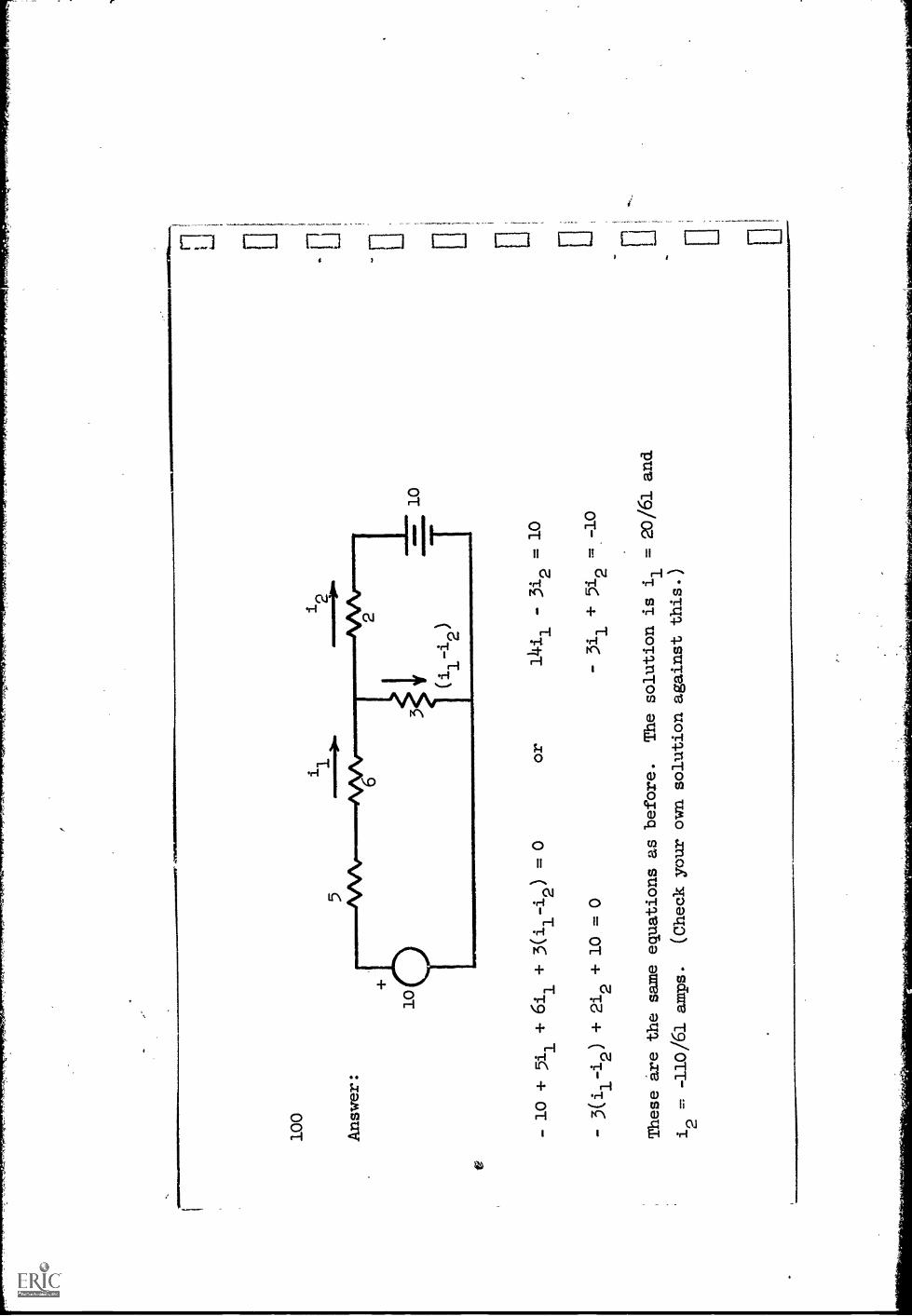
Answer:
VM
AFO
IMI1
1111
01-.
-10 + 5i1 + 6i1 +
3(ii-i2) = 0
-3(i1-i2) + 2i2 + 10 = 0
or
14ii
- 312 =
10
- 3i1
+ 5i2
These are the same equations asbefore.
The solution is i
=20/61 and
i0
=-110/61 amps.
(Check your own solution against this.)
dom
.. Ii
101
Once the loop currents
are determined, all other branch currentswill
become known since theyare expressed in terms of the loop currents.
By Ohm's
law, all the branch voltages
can also be found. .Finally, the
power dissipation
in any branch or delivered byany source
can be calculated.
In the example just completed, determine
the power supplied by each of the
two sources,in the original networkof Fig. 23.

102
Answer:
1100
Power supplied by battery
=-1012 = 71- watts.
Power supplied by current source = 1020 watts.
510
(The voltage across the current source is 5(i1-2) .
-61
volts with the reference at the tail of the current arrow
(2-,10)
1020
Hence, the power supplied is
gy watts.
This completes the discussion of loop equations.
But there is still another way we can approach the
analysis of problems like this.
a.
Figure 24
103
In consid.ering another way of
combining the three basic laws
(Kcl, Kvl
and. Ohm's law) let us use,
for an initial example, the
network of the last
'
example, but
wiihiiiit''the battery andwithou-t*nutherical values, as shown in
Fig. 211-.
(The same convention is used about current
and voltage references,
but this time a
plus
sig
n is
sho
wn.
)We started the
discussion-of loop equations by applyirigKcl and thereby
expressing all the branch currents
in terms of just some of
them.
Why not
do it the other 'way and
apPl
yKvl first? Then
eXpress all the branch voltages
in terms of just some ofthem.
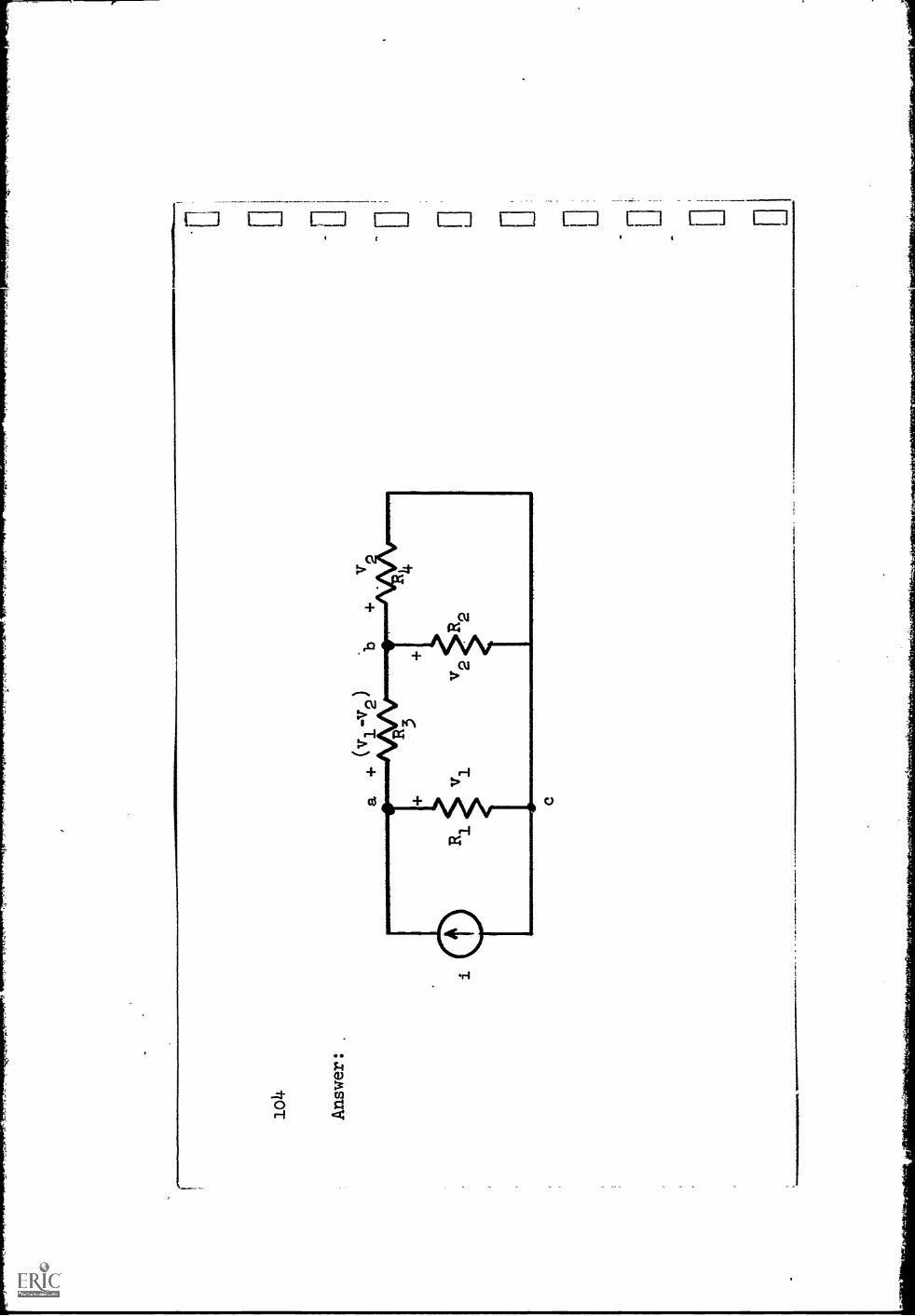
Let v1
and. v2 be the voltages across
R1 and R2.
Apply Kvl as needed and
write the other branch voltages
in terms of v1 and. v2.
1o4
Ans
wer
:
rj gaN
.
limem
e.

105
Next, apply Kel at the nodes.
But now that you have sone practice, you
can simultaneously insert Ohm's law so that the resultingequations are in
terms of voltages':
.-
Write the equations at nodes a and b.
(If you want to check with the
answers to be gtven, use leavinEas the
jundtion'reference.)

NO
1.4
io 6
Ans
wer
: .v 1
v 1-v2
R3
(v,
-v2)
v2v2
++
= 0
R3
R2
R4
v2
Figu
re 2
4 (r
epea
ted)
I.
Ns.
boo.
,
1.1
0-1
;
107
This is a set of two independent equations in two voltage
variables.
(The
source current i is presumed
to be known.)
From this point on, the solution is
a matter of algebra.
Note from Fig. 24 that.the branch voltages vl and v2 arealso the voltages
of,nodes a and b relative to that of node c.
We can look upon c as a datum node
to which the voltages of all other nodes are
referred.
These voltages are then
called the node voltages.
The equations that result when K,c1 is applied at all
the nodes other than the datum node are called the node
equations.
Let us now restate the steps in the procedure for arrivingat the node
equations.
First, choose any one node as a
node.
Then, 1J.bel all
other node voltages (v11 v2 or va, vb,
etc.).
These are the voltages of the
nodes relative to that of the datum node.
Since each branch lies between two
nodes, each branch voltage will equal the difference of two
(The branch voltage of a branch connected to the datum node is just one node
voltage, since the voltage of the datum node is
zero.)
Expressing the branch
voltages in this form amounts to an application of Kvl.
The next .step is to
lo8
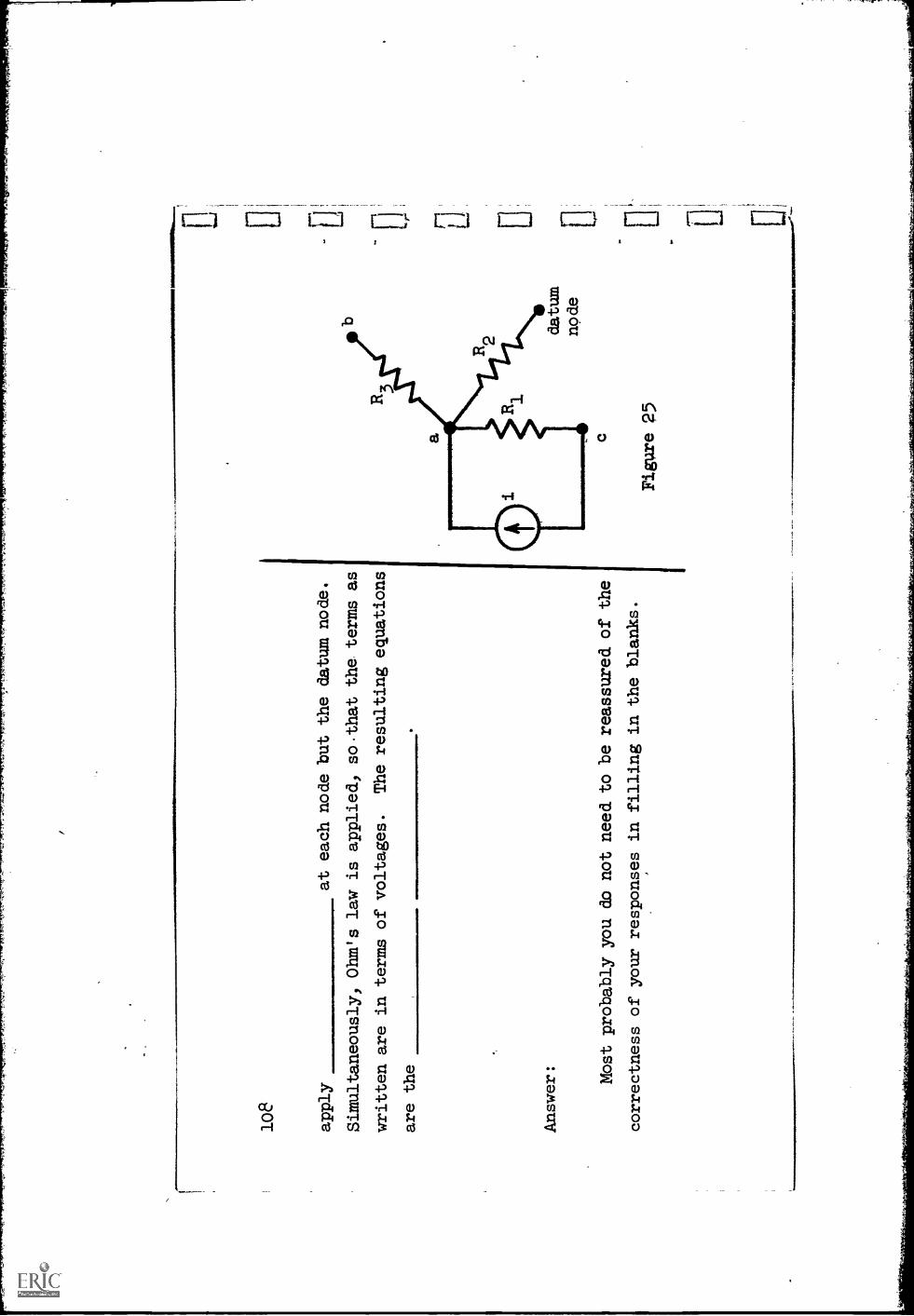
apply
at each node but the datum node.
Simultaneously, Ohm's law is applied, so.that the terms as
written are in terms of voltages.
The resulting equations
are the
Answer: Most probably you do not need to be reassured of the
correctness of your responses in filling in the blanks.
rerls
omM
INIM
I0.!
Figure 25
109
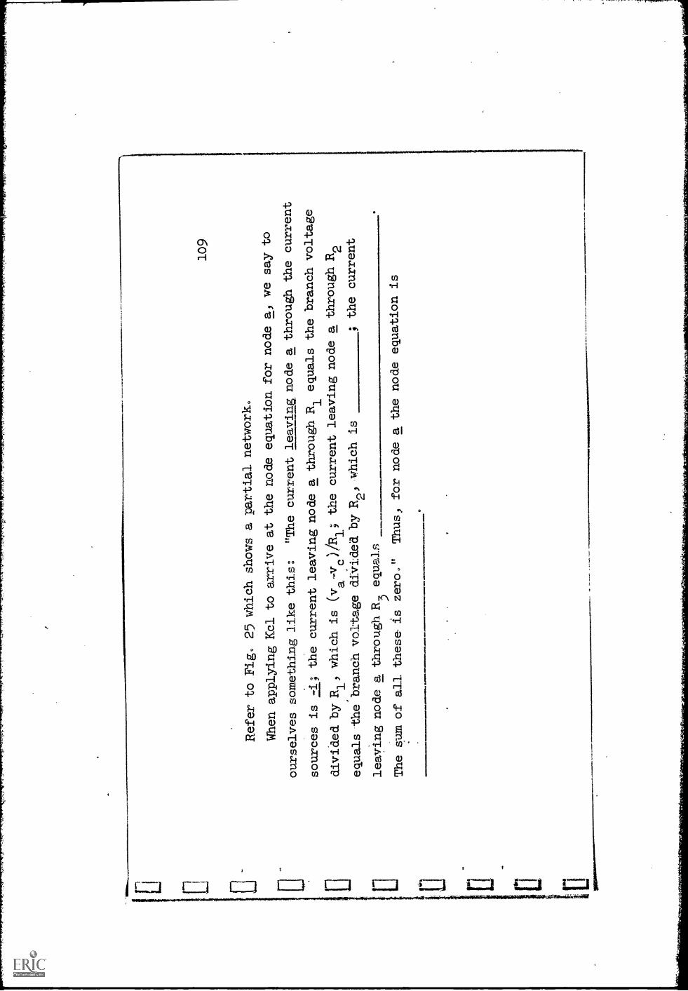
Refer to Fig. 25 which shows a partial
network.
When applying Kcl to arrive at the node
equation for node a) we say to
ourselves something like this:
"The current leaving node a through the current
sources is -i; the currentleaving node a through R1 equals the branchvoltage
divided by R
which is (v -v )/R19
the current leaving node a through R2
equals the branch voltage divided by R2
)wthich is
; the current
leaving node a through R
3equals
The sum of all thesa is zero."
Thus, for node a the node equation is
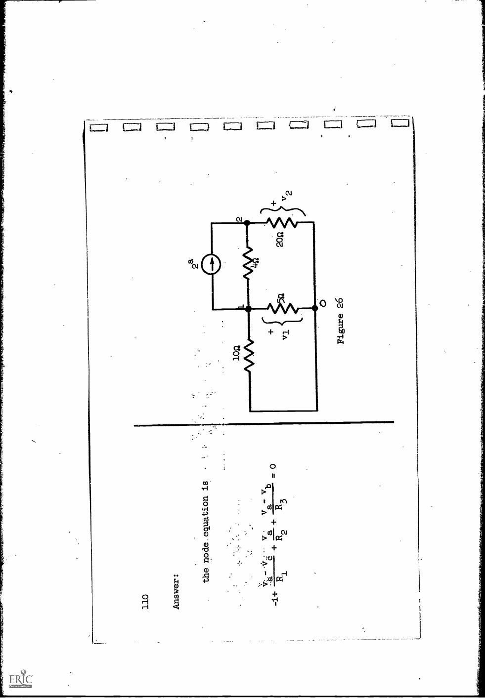
110
Answer: the node equation is
-
v.4
+--
ac
++
ab
0
R3
12
R
Figure 26
9 9 ci
4

Let's now practice writing node equations on the network
in Fig. 26.
Choose node C)as a datum node and let v1and v2be the node voltages of the
other two nodes.
The references of these voltages are implicit; that is,
the plus signs should be at the non-datum nodes.
For clarity, they have
been shown explicitly in Fig. 26.
Write the node equations; then solve for
the node voltages.

112
Answer:
These are the node equations:
vi
vi
vi-v2
10
5+
+ 2 = 0
node a:
node b:
v2-v1
v2
14-
20
40
The solution is:
vl
= -
41volts
240
= ---
v2
41
volts
113
Once the nade voltages havebeen fotnd, all the branch voltages
become
,
known, since they are simply
differences of node voltages.
,From Ohm's law,
then, all the branch
currents can be found.
With currents and voltages known;
any desired power
can be calculated.
.Find the power p supplied bythe current source in.Fig.
26.
iaA
560
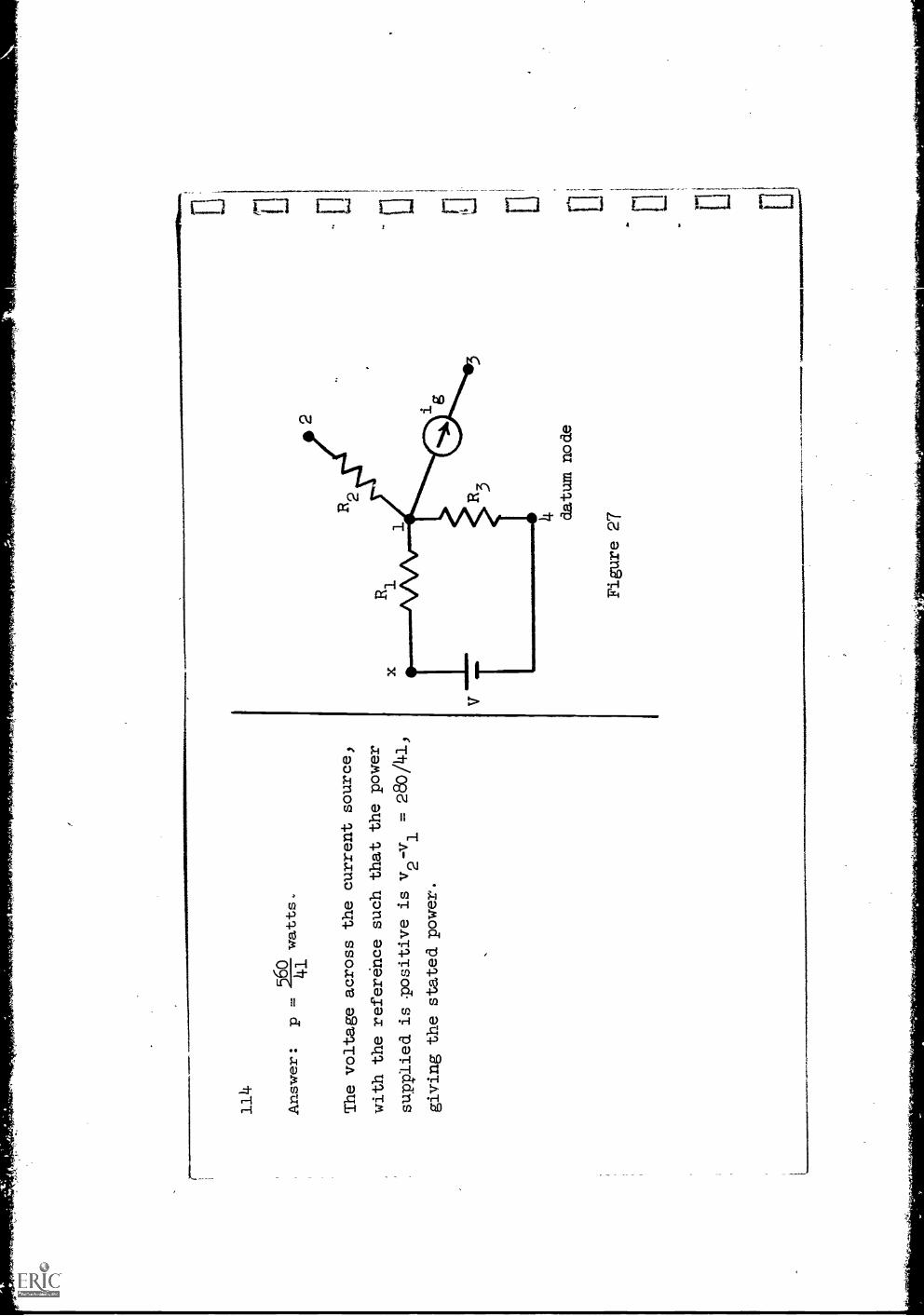
Answer:
p -
41
watts.
The voltage across the current source)
with the reference such that the power
supplied is Tositive is v2-v1 =
280/41,
giving the stated power.

When there is ayoltage source in anetwork, no
insurmountable problem
is
encountered in writingnode equations.
Consider the partial
network shown in
.Fig. 27.
Let one terminal
of the voltage source
(battery) be chosen as
the
datum node.
The voltage ofthe point marked
"x" relative to
the datum *,o;-
known; it is thebattery voltage
V.
To write the
node equationat node 1, weapply Kel and set
the sum of all
currents leaving nodcl
1 equal to zero,
while using Ohm's
law to write each
current in terms
of voltages.
Thus,
current leaving node1 through R2
current leavingnode 1 throughcurrent source
current leavingnode 1 throughR3
current leavingnode 1 throughR1 .....1
116
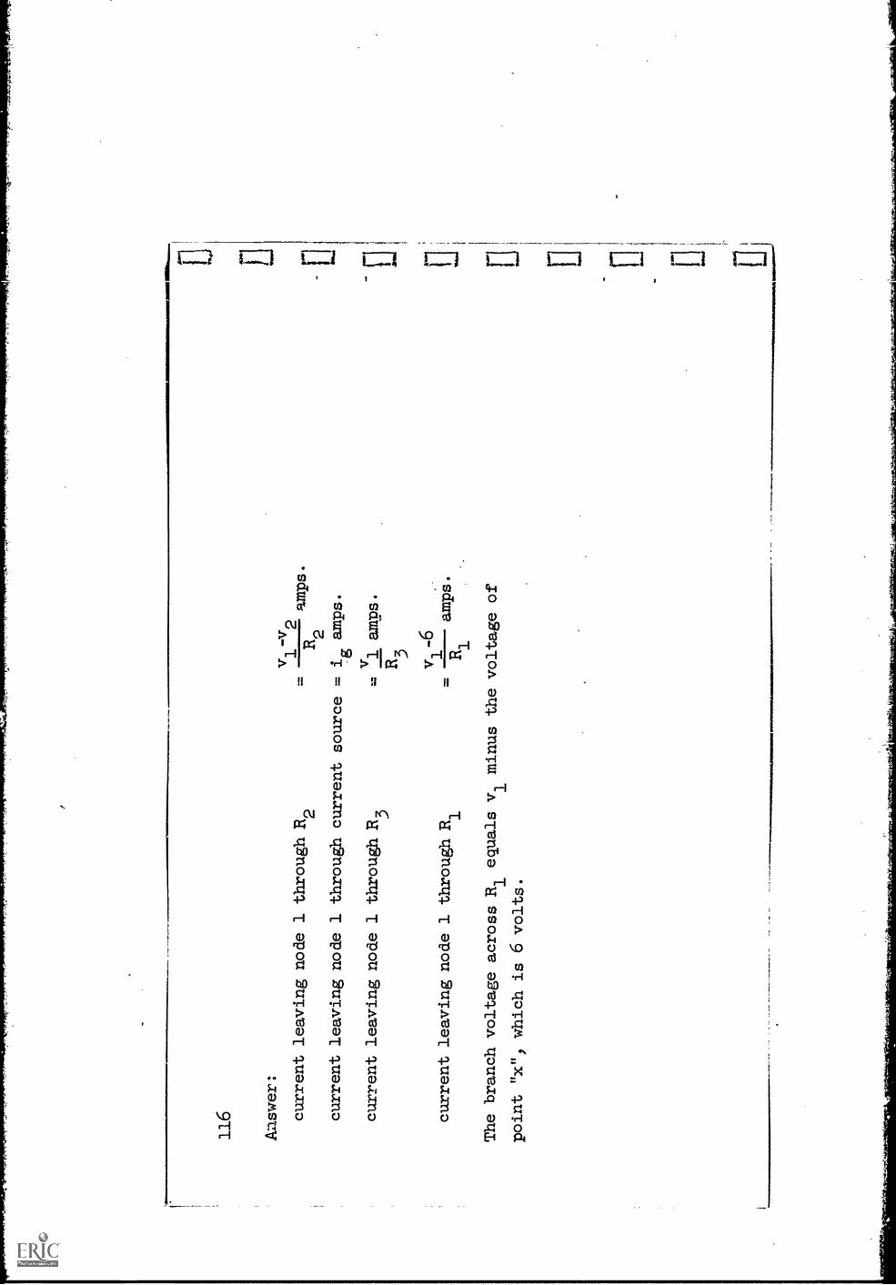
Aaswer:
vl - v2
current leaving node 1 through R2
=R2
amps.
current leaving node 1 through current source
= i
amps.
g
current leaving node 1 through R3
..-:
v1 amps.
R3
v1-6
current leaving node 1 through Ri
=amps.
R1
The branch voltage across R1 equals vl minus the voltage of
point "x") which is 6 volts.
ri:1
1
I. LI
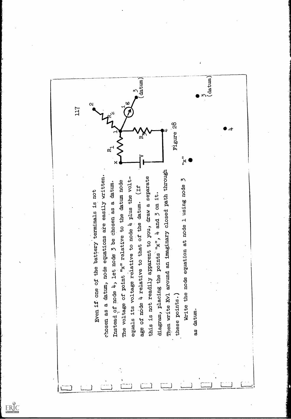
Even it one of thebattery:terminals is not
chosen as a datum, nodeequations are easilywritten.
Instead of node
4) let node 3 be chosen as a
datum.
The voltage of point
"x" relative to the
datum node
equals its voltagerelative to node
4 plus the volt-
age ofnOde 4 relative to that of
the datum.
(If
this is not readilyapparent to you, draw a
separate
diagram, placing the
points'"x", 4 and 3 on it.
Then write.KV1 around an
imaginary closed. paththrough
these points.)
Write the node
equation at node 1using node 3
as datum.
117
Figure 28
33.8
Ans
wer
:
v 1-v2
++
+-
0R
2g
R4
a-
202

7,v-
4:10
,34y
-4,4
K4.
.1.4
.,/,,,
T7p
ff,0
627W
ICIW
*TFT
ent
"s;..
..44
119
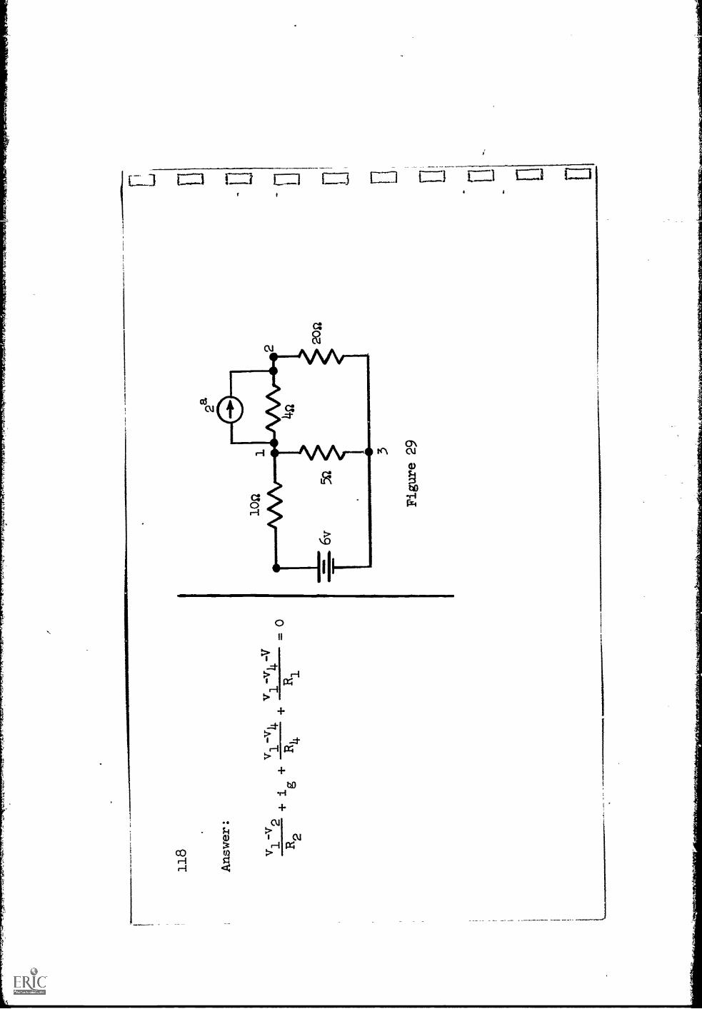
Another Wey to bindle thepresence of a voltage source when carrying
on a
node analysis is to convert it to
an i-source equivalent., In Fig. 29, replace
the battery and series 10-ohmresistor by an i-source equivalent andwrite the
node equation at node 1, choosingnode 3 as datum,
Alsowrite the node equa-
tion at node 1 without this conversion
and compare the two.
1.11
.011
0111
1111
140M
AM

Figure 29 (repeated)
vi+ 2
010
10
Same equation obtained without
converting.
121
Complete writing the node
equations in Fig. 29 and
solve them.
Finally,
compute the power suppliedby the battery in Fig.
29.
ones
mos
ersi
sars
iriaW
rissi
siU
saftr
amor
emw
rom
...
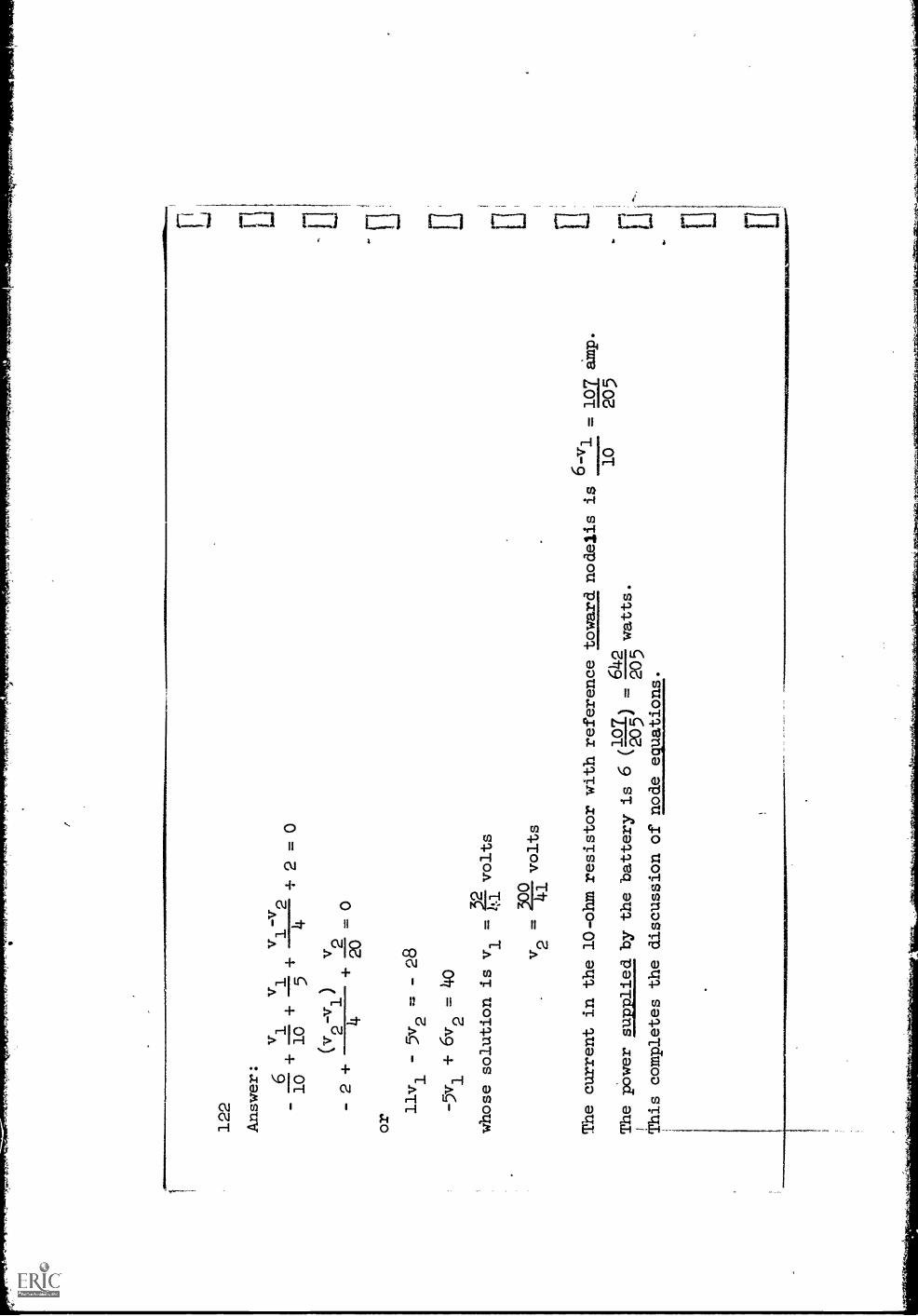
122
Answer: o
vv
v =v
11
12
-10
+10+
++ 2 = 0
54
(v2-v1)
v2
- 2 +
4+
020
or
11v1
- 5v2
=28
- 5v1 +6v2 . 40
whose solution is v1
=2?
-volts
5oo
v2 .
volts
The current in the
The power supplied
1 This completes the
6-v
10-ohm resistor with reference toward nodelis is
. 107 amp.
10
205
/1 7.
642
by the battery is 6
k2g5
j. 5
55 watts.
discussion of node equations.
E., El

123
Superposition
We have been considering a number of procedures whereby electric
networks
consisting of resistors and sources can be analyzed.
In all cases, the funda-
mental expressions relating the voltage and current variables are
Kirchhoff's
laws and
Ohm
'slaw.
Because of the nature of the equations that result from
these relationships, a very important observation follows.
In a network, it is of interest to determine whether the current orvolt-
age in a branch due to all the sources in the
network can be obtained. by finding
the current or voltage resulting from the presence of each source alone,
then
adding these.
A similar question arises in many other areas of science and
engineering; it is answered by the principl
of su er osition which can be
stated in a very general way as follows:

1211
-
Whenever an effect is linearly related to its cause,
then the effect owing
to's. combination of causes is the same as the sumof the effects owing to
each cause acting alone, all other causes being
inoperative, or deactivated.
In the case of an electric network,
the effects are currents and voltages
in the branches of the network and the causes are
the sources.
Ohm's law is a
linear relationship expressing the fact that
the voltage and current of a
branch are proportional:
if the current is doubled, the voltagewill double.
Kirchhoff's laws simply add a number of terms
together, with the result that
the basic linear relationship is retained.
It follows that the principle of
superposition applies in the analysis of
linear electric networks.
125
It remains to interpret whatit means to say that a cause is
inoperative
or deactivated.
In our case, the causes are voltage sources
and current
sources.
Remembering the definit.;on of a voltage source,
rendering a voltage
source inoperative, or
deactivating the source, means making its
voltage go
to zero.
In terms of a circuit diagram, zero
voltage is accomplished by a
126
Answer: zero voltage is accomplished by a
short circuit.
l'l
E1 0 11

127
Similarly, rendering a current source inoparative
or deactivating it
means-making its current
1which is accomplished
in the circuit'diagram by
.
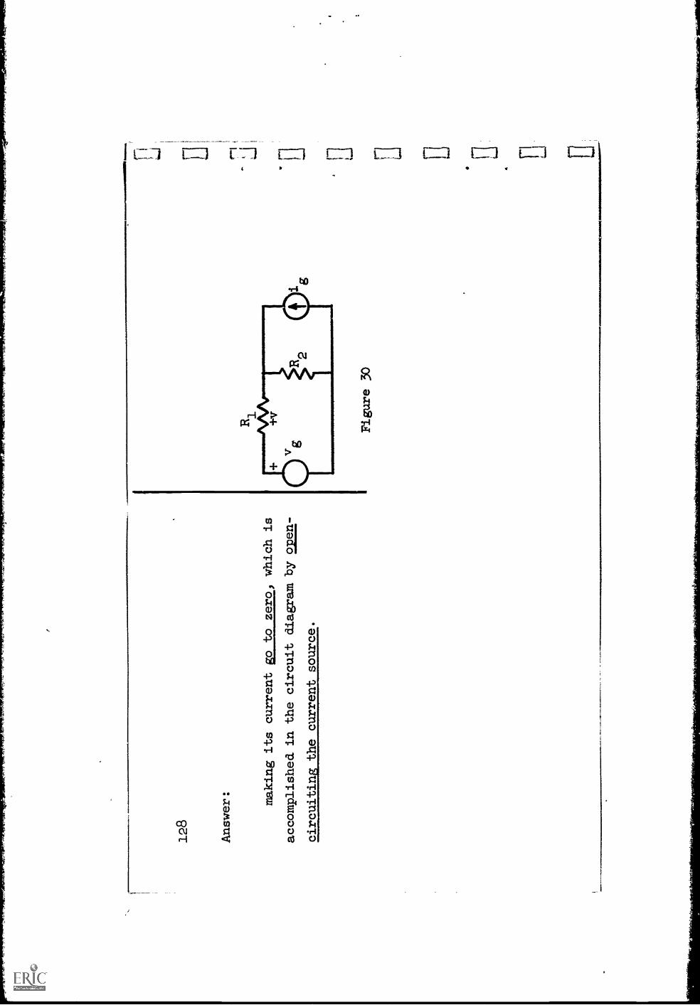
128
Answer: making its current go to zero, which is
accomplished in the circuit diagram by oloen-
circuiting the current source.
Figure 30
129
A procedure for solving network problemswhen more than one source (volt-
age or current) is present, then, is the following:
1.
Deactivate all sources but
one.
This means short-circuit (ideal)
voltage sources and open-circuit (ideal)
current sources.
2.
Use any method to find the desired voltagesand currents due to
this one source.
3.
Repeat this process for each
source in the network.
4.
Add the results due to each
source.
Let us illustrate the procedure in the simple
network of Fig. 30.
It is
desired to find the voltage
v across Ri.
Let vl be the value of v when the
only source is v
the current source being deactivated,
and v2be the value of
v when only i
is present.
gRedraw the di'agram in these two
cases and specify the disposition made of
the sources.

Answer :
Figure
30
+V
0 4.
(b)
,W
...
131
From these two di.agrams computev1
and.v2
and write the desired voltage v.
(Note the structure of Fig. 30(a)).

113
2
Answer:
R1
vl -
R1
+R
vg
2
R1R
2.
v 2=
-R
1+R
21g
1v
vv
12
R R
(vg-R2ig
)+
12
Figure 31
ft

133
That was a relatively simple example and other methods of solution would
be just as convenient to use.
A more complicated network is shrwn in Fig.
It is desired to find, the current i in. resistor R3.
Let i1
be the value
of i when only source vi is operative, the other source being deactivated,
and let i2 be the value of i when only v2 is operative.
Redraw the diagram in these two cases and show what is done with the
sources.
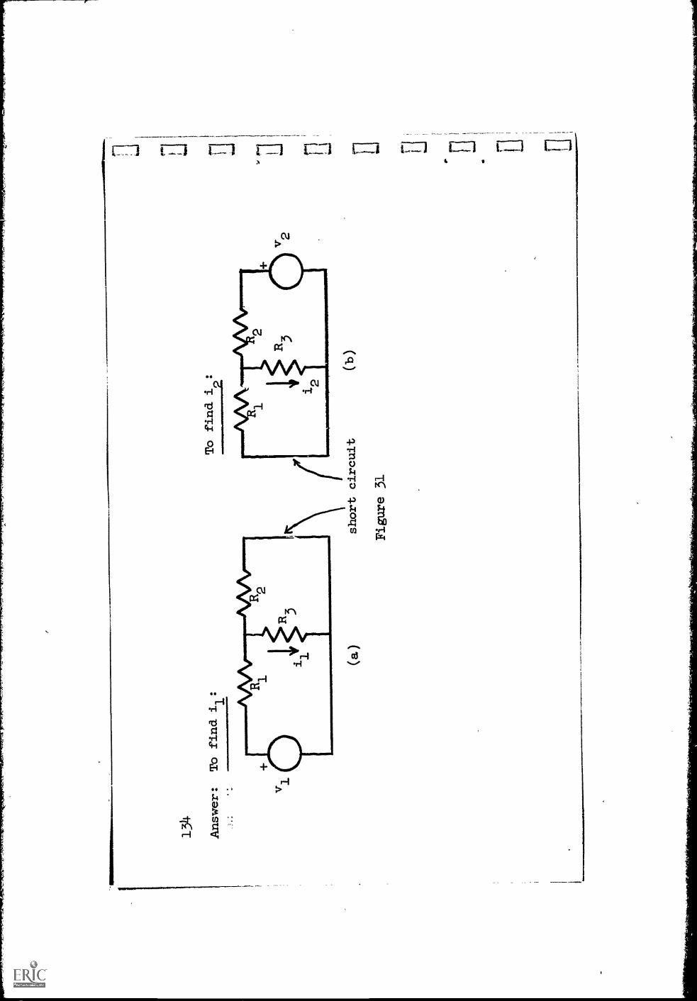
Answer:
To find i
:
1.... v
(a
)
To find i
:
2
short circuit
Figure 31
v 2
i r 0 I I
C1 0 H H E E 0 Pi D Hv
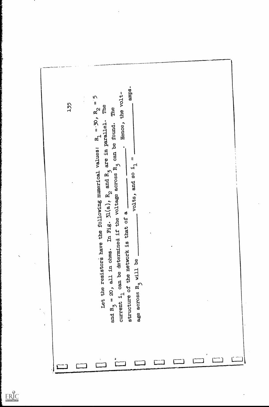
135
Let the
resistors' have thefollowingnumerical values:
Ra.
= 30,R2
and.
R3
. 20,
all in ohms.
In Fig.
31(a) R2 and R3 are
in parallel.
The
current iI
can be
determined if thevoltage acrossR3 can be
found.
The
structure ofthe networkis that of a
.Hence, thevolt-
age acrossR3 will be
volts, and so
il =
amps.

136
Answer: The structure is a voltage divider.
R2Rx
v1
)R2+R3
The Voltage across R3will be
vi
i=
amps.
1170
R R
R2+R3
1
2 17v1
volts

137
The structure of Fig.
31(b) is similar to that of Fig. 31(a)
but now
R and R
3are in parallel.
By a similar procedure, the current i2
is found
1to bet
i=
By the principle of superposition, then, the
total current i in
resistor R
3is
:
i =
138
Ans
wer
:=
v2
52
5v
1i =170
g3a
Tb achieve some insight into the relative ease or
difficulty of using the principle
of superposition, you
should solve the same problem by the use of, say, loop
equations.
Dc
El
139
Summary:
1.
One procedure for solving networkproblems consists of (1) choosing a
number of branch currents in terms of which allbranch currents are
expressed by applying Kb1; thesescurrents are called
the
(2) next, Kvl equations are written around the closed paths, while
simultaneously substituting for the voltages by Ohm's
law.
The result-
ing loop equations are a set of linear equations
in as many unknowns as
there are loop currents.
After these equations are solved all other
branch variables can be computed.
2.
An alternative procedure' is to write a set
of node equations.
The
first step is to select a
node and to label all other node
.
voltages.
This is equivalent to the application of
.The next step is
The resulting node equations are a set of linear
equations in
(how many?) variables.
After these are solved for the node voltages,
all other branch variables can be determined.

Su_l
_mm
einu
ed
3.
Because the loop and node equations are a set of
line'ar equations in
the principle of superposition applies.
According to
this principle, the current or voltage resulting from the
simultaneous
.presence of a number of sources is
(If you need confirmation for any of your responses, look back over the
material of the last section.)
This terminates the booklet on Resistive Networks.