This equipment has been tested in accordance with the...
63
1 This equipment has been tested in accordance with the requirements contained in the appropriate Commission regulations. To the best of our knowledge, these tests were performed using measurement procedures consistent with industry or Commission standards and demonstrate that the equipment complies with the appropriate standards. Each unit manufactured, imported or marketed, as defined in the Commission’s regulations, will comform to the sample(s) tested within the variations that can be expected due to quality production and testing on a statistical basis. We further certify that the necessary measurments were made by Kansai Electronic Industry Development Center, Ikoma Emission Measrement Station, 10830, Takayama- Cho, Ikoma-City, Nara, 630-01 Japan.
Transcript of This equipment has been tested in accordance with the...

1
This equipment has been tested in accordance with the
requirements contained in the appropriate Commission
regulations. To the best of our knowledge, these tests were
performed using measurement procedures consistent with
industry or Commission standards and demonstrate that the
equipment complies with the appropriate standards. Each
unit manufactured, imported or marketed, as defined in
the Commission’s regulations, will comform to the sample(s)
tested within the variations that can be expected due to
quality production and testing on a statistical basis.
We further certify that the necessary measurments were
made by Kansai Electronic Industry Development Center,
Ikoma Emission Measrement Station, 10830, Takayama-
Cho, Ikoma-City, Nara, 630-01 Japan.

2
SECTION I INTRODUCTION
RD6000 Sport Radio Control SystemRD6000 Sport Transmitter/Receiver SpecificationsAcademy of Model AeronauticsInitial PreparationNiCd Battery ChargingRD6000 Sport Transmitter FeaturesAirborne System ConnectionsAirborne ComponentsConnectorsAudio Low Voltage AlarmTransmitter Battery RemovalControl Stick Length AdjustmentThrottle High WarningTransmitter Stick Tension AdjustmentTrainer SystemUsing the RD6000 Sport Micro-ProcessorAero Features DescriptionHeli Features Description
SECTION II COMMON FUNCTIONS
Implementation of Control FunctionServo ReversingControl CenteringData ResetModel SelectionStop WatchIntegral TimerModel NamingExponentialModulationData CopySwitch ReverseClickThrottle Cut
SECTION IIIRD6000 Sport Users Manual- AircraftAircraft Menu StructureProgramming for Aircraft (Model Type)Dual RateEnd Point AdjustmentsLanding Gear End PointsTrim MemoryFlaperonsAlarmsDelta (Elevons)Aileron to Rudder MixV-Tail (Rudder to Elevator Mix)Throttle to Elevator MixCompensation Mixers (C-Mix) AIRCRAFT ONLY
TABLE OF CONTENTS
4455667888999
1011121314
1515161718192021222425272829
3031323435363738404142434458
Page #

3
SECTION IV HELICOPTER
RD6000 Sport User Manual - HelicopterAirborne System ConnectionsHelicopter Menu StructureProgramming for Helicopter (Type)Pitch CurvesThrottle CurvesRevolution MixingGyro AdjustmentTrim MemoryExponentialDual RateDynamic Trim Memory (DTM)Changing Flight Mode 1 and 2 Switch Locations
APPEND I
RD6000 Sport Aircraft and Helicopter Setup pages
457
4647495254555622565760
Page #

4
RD6000 Transmitter Specifications:
Transmitter Type:Dimensions:Weight:Power Output:Frequencies:Modulation:Power Supply:Current Drain:Temperature Range:Pulse Width:Model Memory:
RD6000 Sport Receiver Specifications:
6 Channel, Dual Stick with propriety Microprocessor.W: 7.5” X H: 8.0” X D: 2.5”1 lb. 11 oz600 mWatts72 MHzPPM/FM or PPM/FM Reverce9.6 Volt, 700 mAh NiCd180 MA0 to160 degrees F1.5 ms (nominal)4
Receiver Type:Receiver Sensitivity:Dimensions:Weight:Receiver Power Supply:
92777Z PPM/FM 7 Channel, Super Narrow Band with Universal “Z” Connectors1.5 microvoltsL: 2.25”, W: 0.6”, H: 0.82”1.2 ouncesFour Cell, 4.8 Volt, 700 mAh NiCd
The following additional receivers are compatable if part number 99399Z Adaptor is used.
92745 PPM/FM 4 Channel, Micro Super Narrow Band Receiver92765 PPM/FM 6 Channel, Super Narrow Band Receiver
RD6000 SPORT RADIO CONTROL SYSTEM
Thank you for selecting the Airtronics RD6000 Sport Radio System. In designing the RD6000 Sport wehave made every effort to provide you with a radio that will allow you to extract the maximum performancefrom your powered aircraft, sailplane, or helicopter, while at the same time simplifying the task of setting upand adjusting your model. These instructions are written in great detail to help you understand what all ofyou RD6000 Sport capabilities are. Because of the many features of the RD6000 Sport, this manual is quitelong. Don’t be intimidated! To actually use the system, you may only need to read the INTRODUCTIONsection, the Common Functions section, and study the section that applies to your type of aircraft. Eachtype of aircraft, i.e., fixed wing and helicopter has its own self-contained section describing each applicablefeature and its implementation. However, helicopter flyers may find it advantages to read all sections of themanual to become more acquainted with the operation of the RD6000 Sport unit. Note that the labels forfixed wing switch functions are in red letters and helicopter switch functions are in white letters.
Again, we appreciate your selection of an Airtronics Radio Control System and wish you many hours offlying enjoyment.
SECTION I

5
ACADEMY OF MODEL AERONAUTICS5151 East Memorial Drive
Muncie, Indiana 47302
The Academy of Model Aeronautics (AMA) is a national organization representing modelers in the UnitedStates. We urge you to examine the benefits of membership, including liability protection in the event ofcertain injuries. The Academy has adopted simple and sane rules which are especially pertinent for radiocontrolled flight as the OFFICIAL AMA NATIONAL MODEL AIRCRAFT SAFETY CODE, which we havepartially reprinted below:
I will not fly my model aircraft in sanctioned events, airshows or model flying demonstrations until it hasbeen proven to be airworthy by having been previously, successfully flight tested.I will not fly my model higher than approximately 400 feet within 3 miles of an airport without notifying theairport operator. I will give the right-of-way and avoid flying in the proximity of full-scale aircraft. Wherenecessary, an observer shall be utilized to supervise flying to avoid having models fly in the proximity offull-scale aircraft.Where established, I will abide by the safety rules for the flying site I use, and I will not willfully and deliber-ately fly my models in a careless, reckless and/or dangerous manner.I will have completed a successful radio equipment ground range check before the first flight of a new orrepaired model.I will not fly my model aircraft in the presence of spectators until I become a qualified flyer, unless assistedby and experienced helper.I will perform my initial turn after take off away from the pit or spectator areas, unless beyond my control.I will operate my model using only radio control frequencies currently allowed by the Federal Communica-tions Commission. (See chart below) Only properly licensed amateurs are authorized to operate equipmenton amateur band frequencies.
72 MHz BAND by Channel and Channel Frequency
11 72.01012 72.03013 72.05014 72.07015 72.09016 72.11017 72.13018 72.15019 72.17020 72.190
21 72.21022 72.23023 72.25024 72.27025 72.29026 72.31027 72.33028 72.35029 72.37030 72.390
31 72.41032 72.43033 72.45034 72.47035 72.49036 72.51037 72.53038 72.55039 72.57040 72.590
41 72.61042 72.63043 72.65044 72.67045 72.69046 72.71047 72.73048 72.75049 72.77050 72.790
51 72.81052 72.83053 72.85054 72.87055 72.89056 72.91057 72.93058 72.95059 72.97060 72.990
INITIAL PREPARATION
PACKAGING:
The packaging of your Airtronics RD6000 Sport Radio Control System has been especially designed for thesafe transportation and storage of the radio’s components. After unpacking your radio, DO NOT DISCARDTHE CONTAINERS! You should set the packaging aside for use if you ever need to send your radio in forservice, or to store your radio in case you do not plan to use it for an extended period of time.

6
NiCd BATTERY CHARGING INFORMATION:
In order to protect the charging circuit in your RD6000 Sport transmitter, a diode has been installed toprotect it from some of the high discharge rate “cycler’s” on the market. We recommend that you chargethe transmitter battery (while installed) with the supplied ATX charger, Part # 95033.Should you wish to “cycle” or discharge the transmitter battery, you must first remove it from the transmit-ter. This allows you to bypass the protective diode.The following two Airtronics service items will allow you to “cycle” your RD6000 Sport transmitter battery.See your local dealer for these items.
(1) #99704 Transmitter Charging Plug with Cable for use with your cycling device (black wire w/white traceris positive.
(1) #97051 Transmitter Battery Cycling Adapter Cable.
Above items will also work with Airtronics Quasar, Radiant, and Vanguard transmitter batteries. Airtronicsdoes NOT recommend the use of any fast or quick chargers.
RD6000 SPORT TRANSMITTERS FEATURES
The RD6000 Sport narrow band PPM/FM computer radio control system is designed for the use by powermodel, sailplane, and helicopter pilots who demand a quality product. The RD6000 Sport is packed with allof the capabilities that the beginner as well as the more advanced modelers demand for all three types offlying. It has the features available to get the most out of any type of model.
Program Features for all types of models
4 Model MemoryStop WatchDigital TrimsServo Reversing on all channelsDual Rate on Elevator and Aileron channels(Plus Rudder on Helicopter)Large Screen Liquid Display (LCD)End Point Adjustment on all channels
Model Type selectionCenter Adjustment on EL, AL, TH, RU, and P-FData ResetLCD Transmitter Voltage MeterHigh Capacity Transmitter/Receiver NiCdBatteriesAdjustable Stick Tension and LengthLow Battery, High Throttle and Power Alarms

7
7/B654321
92777/72 FM
BAND
Dual Conversion BYNarrow Band Receiver
24
NiCdBattery
Switch HarnessChargeConnector
92777 Receiver
AERO HELI
Flap
Retract Gear
Rudder
Throttle
Aileron
Elevator
Collective Pitch
Gyro
Rudder(Tail Rotor)
Throttle
Aileron(L/R Cyclic)
Elevator(F/A Cyclic)
The above diagram shows how to connect the components of your RD6000 Sport system together. At thispoint your objective is to get the system operating on your workbench. Once connected you must then referto the corresponding diagram for your system, i.e., either AERO or HELI showing the transmitter controlstick function.
AIRBORNE SYSTEM CONNECTIONS

8
AIRBORNE COMPONENTS
While your systems batteries are charging, you can familiarize yourself with the airborne portion of yourradio. The airborne portion of the radio refers to any components which are mounted in your plane orhelicopter and carried aloft when you fly. The airborne components consist of the receiver, which receivesthe signals from the transmitter, decodes them, and relays the commands to the servos; the servos whichare simply electronically controlled motors used to move the controls of the plane; the NiCd battery packwhich provides power for the receiver and servos to operate; and the switch harness which allows you toturn the airborne package on and off.
CONNECTORS
Your RD6000 Sport unit is equipped the new universal AIRTRONICS “Z” connectors which are color codedblue, and are electrically compatible with the receivers of other radio control system manufacturers. Theconnectors are rugged but should be handled with care. Note that these connectors are not compatiblewith older AIRTRONICS R/C equipment unless Adapter p/n 99399Z is used!
“Z” CONNECTOR
(-)Negative(+)Positive
Signal
AUDIO LOW VOLTAGE ALARM
Your RD6000 Sport transmitter is equipped with an Audio Alarm which will sound whenever the transmitterbatteries drop below 9.5 volts during transmitter operation. If the alarm sounds while you are flying, landimmediately and don’t operate the transmitter until it has been charged for 12 hours. The transmittershould normally operate 120 to 150 minutes before the alarm sounds. If the alarm sounds even after thebatteries have been on charge for the required time it indicates that there is a problem with either thebattery pack or the transmitter, and you should contact AIRTRONICS about service.

9
TRANSMITTER BATTERY REMOVAL
The NiCd battery in your RD6000 Sport transmitter can easily be removed and replaced with a fullycharged pack to extend operating time.Additional packs are sold separately as an accessory item under the Airtronics part number 95010.To remove the pack, push down on the two ears of the battery door located on the rear of the transmitter.The door can then be removed and the NiCd battery pack can now be removed and unplugged. Reversethe procedure to install a new pack.
CAUTION:Observe the correct polarity when plugging in the NiCd battery pack.If incorrect, damage to the transmitter will occur!
CONTROL STICK LENGTH ADJUSTMENT
The sticks in your RD6000 Sport transmitter are adjustable in length and spring tension to allow you totailor their feel to your personal preference. To adjust stick length, hold Part B with your fingers and un-screw Part A counterclockwise to loosen the two pieces. Now screw Part A in or out to the desired positionand lock it in place by screwing Part B against it. It is best to leave at least four threads inside Part A whenscrewed out to its longest length for the best mechanical security. Do not over tighten when you screw thetwo parts together.
THROTTLE HIGH WARNING
The RD6000 Sport has a built in warning feature that will not allow you to use the transmitter if the throttlestick is not in the lowest position when you turn on the transmitter. If the throttle stick is not in the lowposition, when you turn it on, you will hear a continuous beeping sound and the display will read TH-HI!Pull the throttle stick down to the full low position. The normal menu will then be displayed and you canoperate and/or program the transmitter.
Part (A) Loosen End Cap First
Part (B) Adjust Stick Length by turning here

10
TRANSMITTER STICK TENSION ADJUSTMENT
To adjust the spring tension of the transmitter sticks you need to remove the back of the transmitter case.First remove the antenna and the NiCd battery pack from the transmitter. Now remove the eight screwsthat hold the case back in place, four in the main case, two in the LCD back cover and two on the handle.Once the screws are removed swing the back of the case away from the transmitter being careful of thetrainer plug wiring.
There are four locations for the stick tension adjustment screws installed because the stick controlling thethrottle is reattached and has no tension adjustment. The #1 and #3 screws adjust the tension for thevertical motion of each stick. The #2 and #4 screws adjust the tension for the horizontal motion of eachstick. To make the tension adjustment use a small phillips type screwdriver to turn the adjustment screws.Turning the screw clockwise will increase the stick tension, turning it counterclockwise will decrease thetension. Once you have completed your stick adjustments, replace the case back and install the NiCdbattery pack and antenna. Be careful to line the battery charging port pins when replacing the back cover.
WARNING:
Any other modifications made to the transmitter other than adjusting stick tension will void any and allwarranties covered be Airtronics Inc.
Screw Locations
1
2 3
4

11
TRAINER SYSTEM
The Trainer system in the RD6000 Sport transmitter allows you to connect any two Airtronics RD6000Sport together for the purpose of training a new pilot. You can also connect the RD6000 Sport to either anRD6000 Super, RD6000, VG 400, VG 600, Radiant or Vanguard PPM unit. The Trainer cord to use is theATX Part # 97100. The RD6000 Sport is NOT compatible with Infinity 660 or Quasar units.In actual use, one of the two transmitters will serve as the Master and the second transmitter will serve asthe Trainer. The Master transmitter is held by the instructing pilot, AND IS THE TRANSMITTER THATMUST MATCH THE RECEIVER FREQUENCY INSTALLED IN THE MODEL! The trainer transmitter isheld by the learning pilot, and does not need to be on the same frequency as the model. The frequency ofthe Trainer transmitter is unimportant because the switch of the trainer transmitter is NOT turned on duringinstructional flying. Normally during training, the instructor takes the model off and flies it to a reasonablealtitude. While the Master/Trainer switch on the Instructors transmitter is left in its OFF position, theMaster transmitter will have full control of the model. When the instructor is ready to begin training, hepresses and holds the spring loaded switch on his transmitter which transfers control to the student.
(As long as the instructor holds his Trainer switch in the ON position, the model will respond to the com-mands of the Trainer transmitter sticks allowing the pupil to fly the model. It is not necessary for the studentto hold the trainer switch on the Trainer transmitter.)
When the instructor ceases to stop training, or if he feels that the student is in a situation that endangers themodel, the instructor can release the spring loaded switch and control of the model will immediately return tothe Master transmitter. To use the Trainer system, you must plug the appropriate Trainer cable into the backof both the Master and the Trainer transmitters. Turn on the Master transmitter and the Model. The cable willenergize the encoder section of the Trainer transmitter. Once you have verified that both the Master and theTrainer transmitters will control the model when the spring loaded switch in the appropriate position you areready to start training.
NOTE:
Both transmitters must be programmed identically for the trainer system to function properly. All servos mustoperate in the same direction, centering, end points, and other settings such as type of Modulation must beidentical.
Trainer Switch(Spring Loaded)
Master Transmitter Trainer Transmitter

12
USING THE RD6000 SPORT MICROPROCESSOR
Airtronics has invested a large amount of design effort to ensure that the powerful capabilities of theRD6000 Sport are as simple as possible to use. This manual has been written to offer the user completeinstructions for either fixed wing aircraft or helicopter models. The manual is divided into three sections.One for introduction and another for aircraft (both powered and sailplane), and one for helicopters. You onlyneed to read the introduction section and the one that applies to your type of model. In most cases all ofthe programming of a setup is accomplished through the use of the input keys on the RD6000 Sporttransmitter. The function(s) of these are shown below.
Note: Pressing the INC+/YES and DEC-/NO keys simultaneously will clear a setting and return it to thedefault value.
BAR GRAPH VOLTAGE INDICATOR
As a convenience the RD6000 Sport transmitter provides a Bar Graph transmitter battery voltage indicatorat the top of the Liquid Crystal Display screen labeled “E” and “F”. The “F” symbol indicates FULL and the“E” indicates EMPTY. You can consider it similar to a visible gas gauge. The Bar Graph indicator is inaddition to the normal battery voltage that is displayed on the main screen when ever you select either AIRor HELI by pushing the END key twice. When the Bar Graph reads less than half you should not fly untilyou recharge the transmitter.
Press this key to move up in a menuPress this key to increase a value or to indicate YES
Press this key todecrease a value or toindicate NO
Press this key to return tothe previous screen
Select Flight Mode (Helicopter)Press this key to movedown in the menu
Press this key to select achannel and move to the left
Press this key to select achannel and move to the Right

13
RD6000 SPORT AERO FEATURES
FEATURES
STW (Stopwatch)
REV (Reverse)
D/R (Dual Rate)
CNT (Center)
TRM (Trim)
EXP (Exponential)
EPA (End Point Adjustment)
MSL (Model Select)
MOD (Modulation)
TYP (Type of Model)
INT (Integral Timer)
RST (Reset)
CLK (Click)
NAM (Name)
SW-R (Switch Reverse)
CPY (Copy)
FLAPE (Flaperons)
DELTA (Elevons)
V-TAIL (Rudder and Elevator)
D/A-A (Dual Rate Alarm)
T-CUT (Throttle Cut)
C-MIX (Compensation Mixing)
DESCRIPTION
Used as a stopwatch or to countdown to a preset time.
Reverses the servo operating direction.
Adjusts servo throw. Available on Elev and Ail.
Changes servo neutral position.
The LCD provides an indicator of the value, as well as thedirection of the trim.
Changes the linear movement of the servo to the relation of thestick movement. Can be set Positive or Negative.
Limits the total movement of a servo in each direction.
Select models 1, 2, 3, 4.
Transmitting Modulation PPM/FM or PPM/Reverse FM.
Model Type Aircraft or Helicopter.
Used to show how long the transmitter has been in use. Can bereset to zero.
Clears all setup data in any model to factory default settings.
A beep sound can be heard every time you press a transmitterkey. Options Active or Inoperative.
You can use up to 3 characters to name your model.
You can reverse to default direction of all control switches.
Copy one model to another.
Activates 2 channels to be used for Ailerons.
Ailerons operate as ailerons and as well as Elevators. Used forflying wings.
Used for V-Tail models.
Alerts you when a Dual Rate switch is on. Options On or Off.
You can set the point where the throttle can be cut using thethrottle cut-off button.
Ability to mix a master channel to another slave channel.

14
RD6000 SPORT HELI FEATURES
FEATURES
STW (Stopwatch)
REV (Reverse)
D/R (Dual Rate)
CNT (Center)
TRM (Trim)
EXP (Exponential)
EPA (End Point Adjustment)
MSL (Model Select)
MOD (Modulation)
TYP (Type of Model)
INT (Integral Timer)
RST (Reset)
CLK (Click)
NAM (Name)
SW-R (Switch Reverse)
CPY (Copy)
D/A-A (Dual Rate Alarm)
T-CUT (Throttle Cut)
DTM (Dynamic Trim Memory)
GYR (Gyro)
TH-C (Throttle Curve)
PI-C (Pitch Curve)
RV (Revolution Mixing)
DESCRIPTION
Used as a stopwatch or to countdown to a preset time.
Reverses the servo operating direction.
Adjusts servo throw. On Elev, Ail and (Rud in Heli Mode)
Changes servo neutral position.
The LCD provides an indicator of the value, as well as thedirection of the trim.
Changes the linear movement of the servo to the relation of thestick movement. Can be set Positive or Negative.
Limits the total movement of a servo in each direction.
Select models 1, 2, 3, 4.
Transmitting Modulation PPM/FM or PPM/Reverse FM.
Model Type Aircraft or Helicopter.
Used to show how long the transmitter has been in use. Can bereset to zero.
Clears all setup data in any model to factory default settings.
A beep sound can be heard every time you press a transmitterkey. Options Active or Inoperative.
You can use up to 3 characters to name your model.
You can reverse to default direction of all control switches.
Copy one model to another.
Alerts you when a Dual Rate switch is on. Options On or Off.
You can set the point where the throttle can be cut using thethrottle cut off button.
Memorizes trims in each flight mode.
Gyro sensitivity for each flight mode
To setup a curve in all flight modes.
To setup a curve in all flight modes.
Tail rotor offset mixing

15
SECTION II COMMON FUNCTIONS
The following functions are common and are applicable to both Aircraft and Helicopter sections of thismanual. The Liquid Crystal Display shows an Aero model selected; however, a similar screen will bedisplayed when a Helicopter type model is selected.
NOTE: Switches labeled with red lettering are for aircraft and white lettering is used for helicopter.
IMPLEMENTATION OF CONTROL FUNCTIONS
In this section you will learn how to implement the control functions and tailor the servo movement andcentering for each control. Pressing the END key on the front panel several times will bring you to thefollowing screen, i.e., the initial screen that indicates the current model type and number, PPM modulationand the transmitter NiCd battery pack voltage.
Press the (CH +) key to obtain the STW screen. The Elevator channel will appear on the upper part of the screen. Themodel number and aero will be present on the left side and the stop watch will indicate zero since no time has beenprogrammed.
REV (SERVO REVERSING)
The RD6000 Sport allows you to electronically REVERSE the direction of rotation for each of the servos in use. Thisallows you to hook up your control linkages and pushrods in the most mechanically desirable manner without regardto the direction of servo movement. After installing your linkages check to see if any of the controls move in the wrongdirection when you move the controls. If so proceed as follows for reversing the elevator channel. Reverse for all otherchannels are done the same way.
Press the FUNCTION down key to arrive at the following screen:
If the Elevator servo moves in the wrong direction, press the INC +/YES key. To move to the Elevator D/R (Dual Rate)screen, press the FUNCTION down key.

16
CNT (CONTROL CENTERING)
Your RD6000 Sport allows you to fine-tune the CENTER or neutral position of all flight control servos. Afterhooking up your controls and mechanically centering all linkages to the approximate positions, press theFUNCTION down key to arrive at the following screen for the Elevator control.
(Note that the Aileron, Throttle, Rudder and Flap centering operates in the same manner when you selectthat channel on the upper part of the screen. You can move across to the CNT function of each channel aswell as some of the other functions by pressing the (CH+ ) key.
By pressing the INC+/YES or DEC-/NO keys you can vary the value from 0 to + or - 100%. Default is 0%
IMPORTANT NOTE:It is desirable to adjust the control linkages as close as possible to the correct center positions, then use theCNT (CENTER) commands to “Fine-tune” the exact position of the control surface when the transmittercontrol is in neutral.
Using a large amount of electronic centering adjustments will decrease the total throw available for thatchannel. In particular, centering adjustments greater than + or - 50% will tend to make the extreme stickposition on one end less responsive!

17
If you want to “UNDO” all of your programmed parameters at one time, you can use the RST function.However, be certain that is what you want to do, since this function will reset all settings to the factorydefault settings. The RST function will only affect the specific model that you have selected. ALL OTHERModels in memory are unaffected by the RST function.
Press the END key to select the initial AR 1 screen that indicates the Transmitter NiCd pack batteryvoltage. Now, press the CH + to access the STW (Stopwatch) screen. This screen allows you to move upand down as well as left and right on the screen in the RD-6000 program.
RST (DATA RESET)
To RESET ALL DATA for this model to default settings press the (CH +) key and the screen will flash YES.Now, press the INC +/YES key and the screen will indicate OK! All paramameters on this specific modelnumber have now been reset to default values. Press the END key twice to return to the STW screen.
Press the CH + key several times to move across the CH indicator portion of the screen until it reads “etc”.Now, press the FUNCTION down key three times to move down in the menu until you reach the RST (DataReset) screen.
i

18
TYP (MODEL TYPE)To select the type of model you wish to program, press the (CH+) key to scroll to “etc”. Next press the FUNCTION keyto select TYP. Now press the (CH+) key to select the next model type, either HELI or AERO. THe screen will flashYES with the type of model indicated on the LCD display. To confirm your selection, press the INC+/YES key and thescreen will indicate OK!
Press the END key three times to return to the inital screen that will then show your model number/type andtransmitter battery voltage.
HOW TO SELECT MODEL SET-UPS: M-SL (Model Select)
The RD6000 Sport has built in memory to store four model setups in any combination of model types. To use ormodify one of the model setups you first must select M-SL in the etc menu.
Assume that you want to select a second model. To do so, press the END key to bring up the initial screen thatindicates transmitter voltage and model number.
Press the (CH +) key to scroll to “etc”. Use the FUNCTION down key to select MSL. Next press the INC +/YES keyand the screen will flash MSL to indicate you can select a second model. Press the INC +/YES key again to selectthe next or following model such as AR2.
Press the END key three times to return to the initial screen which will show the model number and the transmitterbattery voltage reading.
NOTE: if the model type is incorrect, i.e., HELI rather than AERO, continue with the model selection procedure. Themodel type can then be selected on the TYP screen.

19
STW (STOPWATCH)
The RD6000 Sport offers a built-in timer and allows the pilot to use the stopwatch function in either elapsed timemode or in a countdown mode of operation. To use the stopwatch, press either the (CH -) or the (CH +) key to select“etc” on the Channel indicator display.
Now press the FUNCTION down key to scroll through the various screen’s until you find the STW screen with theflashing >indicator. This is where you can set your stopwatch countdown time. The STW (set) screen is just abovethe INT screen as shown on the Menu Structure, page 31.
Use the INC +/YES key to set a value for the Start of your count down; as an example set it at 10.00 minutes. Thescreen will look like the following illustration. If you want to decrease the time, use the DEC - /NO key. If you want toclear the time, press the INC +/YES and the DEC - /NO keys simultaneously.
You can now start the stop watch when you are on any of the channel indicator screens that displays the STW screenand the time you previously programmed. Press the INC+/YES key to start or stop the countdown. When the timereaches 10 seconds, a tone will be heard and one will also be heard every second as it counts down to zero. Whenthe timer reaches zero, a steady tone will be heard and it will start counting up. Press the INC+/YES key and DEC-/NO key simultaneously to reset the timer to your previously programmed time.
etc
etc
etc

20
INT (INTEGRAL TIMER)
The Integral Timer function of the RD6000 Sport is activated each time the transmitter power switch is turned on, andcontinues to time up to 99 hours and 59 seconds at all times when the transmitter is turned on. This time will give anexcellent indication of how many hours of actual use you RD6000 transmitter has accrued. Or, you may wish to re-set the timer to zero at certain intervals, for instance, each time you charge the transmitter NiCd battery pack.
The INT (Integral Timer) function is located in the “etc” column of the menu, directly below STW (set). Use theFUNCTION down key to access the INT screen. Note that it will have some indication of how long the transmitter hasbeen operating. It may look like the following screen, but with a different time shown. The time will show a change foreach elapsed second and minute. If you want to reset the Integral Timer to Zero, press the INC +/YES and the DEC -/NO keys simultaneously.
If you desire, you can display the Integral Timer function instead of the STW (stop watch) function on all of theChannel screens. To do so while you are in the INT screen, press the (CH +) key to obtain the following screen.
Press the INC +/YES key and the bottom line of the screen will change from INH (inhibit) to read ACT (active). Youcan press either the DEC -/NO key or the INC +/YES key to change it back to INH. Most pilots prefer to have theStop watch function displayed on all of their Channel screens, rather than the Integral Timer, therefore, they leave theIntegral Timer DSP at INH (inhibit). Press the END key twice to get back to the top of the “etc” menu column.

21
NAM (NAMING YOUR MODEL)
The RD6000 Sport provides the capability for you to designate each of the four models you have programmed by useof a 3 digit name. Use the (CH +) key to select the “etc” screen. Press the FUNCTION down key twice to select theNAM screen.
Now press the (CH +) key to select the screen for model number one. The first charater will be flashing to indicateyou can change that letter.
Press the INC +/YES key to scroll through the letters of the alphabet and make a change in the first letter. You manyuse any combination of LETTERS (upper and lower case), NUMBERS, Colon(:), Dash (-), Character, or blank spaceto designate a model. When you have finished the first letter or number, press the (CH +) key to move to the nextletter and set it in a similar manner. The DEC -/NO key can also be used to change a letter or number in the oppositedirection. Press both the INC + /YES and DEC -/NO keys simultaneously to return to the default setting of AR 1.Once you have completed designating your present model, press the END key twice to return to the “etc” columnheading.
i
22
0
25
50
75
100
0 25 50 75 100
0
25
50
75
100
0 25 50 75 100
Serv
o Tr
avel
Serv
o Tr
avel
Stick Deflection Stick Deflection
LINEAR THROW EXPONENTIAL THROW
EXP (EXPONENTIAL)
The RD6000 Sport allows the pilot to choose two settings for Exponential throw for each of the primary flightchannels, Elevator, Aileron (and Rudder in helicopter mode).
Exponential throw is primarily used to “soften” or decrease the control stick sensitivity of a control around the neutralpoint. With Exponential disabled, a control funtion servo will move in an amount proportional to the amount of controlstick deflection, i.e., 50% stick deflection will result in 50% servo travel; 75% stick deflection will cause the servo totravel 75% of it presently set maximun throw.
Exponential settings DO NOT change the amount of travel available at 100% stick deflection, but rather it changesthe amount of the servo travel that will occur with stick deflections less than 100%. The first 25% of stick deflectionmay be set to result in only 10% of total servo throw making the control less sensitive around neutral. See thefollowing illustrations.
If you have used Exponential functions before, you will want to start with a small amount of Exponential (10 to 20%)to determine wheather you like this sort of control response. Exponential is most useful where strong control responseis desired at extreme stick positions but softer response to small stick movement is desired in order to make veryaccurate small corrections to flight path.
The switch positions for Exponential #1 and Exponential #2 correspond to the Dual Rate switch positions of Elevatorand Aileron. Exponential #1 is with the Dual Rate switch in the down i.e., Off position. Exponential #2 is with the DualRate switch UP i.e.,ON position. (Note however that you can leave the Dual Rate adjustments for Elevator and Aileronset at 100% which is no rate, so that switching a Dual Rate switch ON will activate Exponential only.
NOTE: Setting the Exponential with a positive number will make servo movement soft in the neutral area of the stickmovement. Setting the Exponential with a negative number will make servo movement faster in the neutral area andsofter at the end of the stick travel.

23
As an example, to set Exponential for elevator, access “EL” in the Channel area by using the (CH+) key.
Now press the FUNCTION down key to select the EXP display for the Elevator Channel as shown below.
This screen tells you the present Exponential status of the elevator channel and when a Dual Rate Exponential switchis set to ON position, the Exponential setting for that control function. The possibilble range for Exponential settings isfrom -100% to +100%. Note that 0% is linear. A negative value will speed up the response and it will make the stickmovement more sensitive around the neutral position.
To set an EXponential rate in this example, turn the Dual Rate switch for Elevator to the ON upward position. Notethat the display changed to Exponential #2. You can set the value for the Elevator channel Exponential. Press theINC+/Yes key to set a positive value of Exponential function as indicated below.
In the above example we set Exponential #2 to be 20% of the maximum for the Elevator channel. This is a goodstarting point for determining the suitability of Exponential throw for you aircraft and flying style.
You can actually have two different Exponential setting’s if you desired. One for switch position #1 and another forswitch position #2. However when you first start using Exponential throw, it is usually best to leave the switch #1position at 0% which is linear throw.
In general, large amounts of Exponential are useful only in instances where very large control surface deflection isrequired at extreme throw, while very small amounts of control response are necessary for smaller control stickinputs. One example of models for which large Exponential settings may be useful is the highly maneuverable“Competition FUN FLY” style models. For most sport and aerobatic models, an Exponential setting from +10% to+25% will give the desired “softness” around neutral.
CAUTION: Proceed with care when setting Exponential functions to ensure that you will have adequate controldeflection available in any possible switch position. Setting Exponential to a very high or 100% setting will requirevery large stick movements to achieve small control responses. Always make sure that you are aware of the presentstatus of any rate assignments that you have selected! For the most flexibility in setting up an aircraft model to yourliking, study the available options for Dual Rates, End Point Adjustments, and Exponential. The combinationspossible when using these options allows for several possible set-ups. The Exponential for the Aileron Channel is setin the same manner as done for the Elevator. The AI D/R switch located above the right stick assembly is then usedwhen setting the Exponential Throw.

24
MOD (MODULATION)
An extremely versatile feature of the RD6000 Sport transmitter is the capability to select two different types of modula-tion. These are PPM/FM for standard FM receivers and PM/FM-Reverse for “other brand” receivers. To access theModulation screen, press either the (CH –) or (CH +) key to select the “etc” screen.
Next, press the FUNCTION down key to select the MOD (modulation) screen. It will show PP indicating the presentselection is PPM/FM.
If you want to change the Modulation, press the INC +/YES key and the presentation will change to the following screen.Note that the small Modulation Indicator on the right side of the screen will also show the present modulation selectionwhen it is changed, except when you select PPM/FM Reverse.
Press both the INC +/YES and DEC -/NO keys simultaneously to return to the default PP (PPM/FM) modulation.Press the END key to return to the STW screen.
etc

25
CPY (DATA COPY)
A valuable feature of the RD6000 Sport is the Data Copy Function. With this function the entire set of controlparameters for one aircraft can be ‘copied’ from one model set-up into another. (For instance, if you have youraircraft program in Model #1 and nothing in Model #3, you can copy the Model #1 program into Model #3 with thecopy function.
Having copied your control set-up, you can now use MSL (Model Select) to access the Model #3 program and thenmake control changes to that set-up. This allows you to experiment with different control options without changingyour original parameters (in this example Model #1).
To use the CPY (copy) function, select “etc” on the Channel indicator using either the (CH –) or (CH +) key. (notethat you must be on the STW screen to move horizontally across the screen to “etc”).
Press the FUNCTION down key to select the CPY (copy) Function.
For this example, assume you want to copy the set-up of Model #1 (which you selected), to Model #3. The firstnumber on the screen indicates the model number of the model you are copying. The second number indicates thedestination of the model being copied. Press the INC +/YES key to change the destination for the copy to indicateModel #3. Note that one of the small triangles is blinking which indicates there is another screen associated with thisfunction.
etci
i
i

26
On the previous screen, the destination has been set to Model #3. MAKE CERTAIN that this model setup is not oneyou wish to save, because when you copy the Model #1 set-up into Model #3, all data that was in Model #3 isreplaced with the Model #1 data! At this point Model #3 data is still intact, so if you wish to change the destination forthe copied data, do so before proceeding.
Having selected both the data source (Model #1) and the desired destination (in this example Model #3), you can nowproceed to confirm the copy function.
Press the CH + > key to access the next screen as shown below. The “YES” will be blinking.
Press the INC +/YES key to confirm your data copy function. The screen will change to the following screen to informyou that the process has been completed, and that Model #1 and Model #3 now have the same data, (in this exampleModel #1).
Press the END key to return to the CPY select screen.
i
i

27
SW-R (SWITCH REVERSE)
The SW-R Function allows you to reverse the action of the five toggle switches located on your RD6000 Sporttransmitter. The default of the SW-R Function is in the NOR (normal) position. CAUTION! The switch reversalfunction is not selective. If you change it from NOR (normal) to REV (reverse), all switches will be reversed in theiraction!
To access the SW-R Function, select “etc” on the Channel indicator using either the (CH -) or the (CH +) key. ( Notethat you must be on the STW screen to move horizontally across the screen to“etc”)
Press the FUNCTION down key to scroll down to the SW-R (switch reverse) screen.
Now, press either the INC +/YES or the DEC -/NO key to change the indication from NOR to REV. All switches on thetransmitter are now reversed in their function. Press END to return to the STW screen.
etc

28
CLK (CLICK)
The RD6000 Sport transmitter normally is set to emit an audio tone when ever the programming keys are pressed,when values are changed and when the stop watch function is started, stopped or reaches the final ten seconds ofcount-down.
It is possible to disable the “Click” or audio tone, using software settings. When the “Click” tone is disabled, ONLYthe stop watch count-down will still cause an audio tone to be emitted.
To set or disable the “Click” function, select “etc” on the Channel indicator using either the (CH –) or the (CH +) key.
Press the FUNCTION down key to access the CLK (CLICK) screen.
Press the INC +/YES key to change the indication from ACT to INH, to disable the Click function. (pressing either theINC +/YES or the DEC -/NO key will toggle the function between “INH and “ACT” settings
Press the END key to return to the STW screen.
etc

29
T-CUT (THROTTLE-CUT)
Another useful function provided by the RD6000 Sport for engine powered models is T-CUT, Throttle Cut. Normallyyou set your throttle stick in the extreme low position and use EPA and the digital trim to obtain a steady low engineidle speed. However, if you want to stop the engine at the end of the flight you would have to use the throttle digitaltrim and later re-trim for proper idle. The T-CUT function solves this problem by providing a push button that, whenpushed, overrides the throttle sticks low throttle position and drives your throttle servo to a lower position, stoppingthe engine. The throttle stick must be in the low position for the throttle cut to function.
In order to use T-CUT, press either the (CH -) or the (CH +) key to select TH on the Channel indicator.
Next, press the FUNCTION down key several times to obtain the following screen.
Press the DEC -/NO key to set a value of –100%. Place the throttle stick in the extreme low position. Press and holddown the Throttle Cut push button located above the elevator/aileron stick assembly. The throttle servo will then rotatefurther to close the engines carburetor and stop the engine.
etcTH

30
RD6000 Sport USERS MANUAL - AIRCRAFT
Elevator Dual Rate Switch
Trainer Switch
Throttle (U/DRudder (L/R)
Throttle Digital Trim
Rudder Digital Trim
Panel Input Keys
Retract Switch
Liquid Crystal Display
Aileron Dual Rate Switch
Throttle Cut Switch
Elevator (U/D)Aileron (L/R)
Elevator Digital Trim
Aileron Digital Trim
Main Power Switch
Flap Switch
SECTION III
92777 Receiver Channel Assignments
Receiver Plug Number1234567/B
Plug in Servo For:ElevatorAileronThrottleRudderGearFlap or 2nd Aileron ServoBattery

31
AIRCRAFT MENU STRUCTURE
(Rx Channel) CH EL AL TH RU G P/F etcSTW STW STW STW STW STW STWTRM TRM TRM TRM REV TRM M-SLREV REV REV REV EPA REV NAMD/R D/R CNT CNT CNT MAS-1EXP EXP EPA EPA EPA SLVCNT CNT T>E E>EEPA EPA T-CUT MAS-2
A>R SLVE>ESTW setINT setTYPSW-RCPYRSTMODCLKFLAPEDELTAV-TAILD/R-A
Use the four center buttons in the function panel to navagate through the menu’s. (UP / DOWN / LEFT / RIGHT)

32
PROGRAMMING FOR AIRCRAFT
INITiAL SET-UP OF TYP (MODEL TYPE)
When you receive your RD6000 Sport unit the transmitter is preprogrammed for both fixed wing aircraft model’s aswell as for helicopter models as follows:
If you fly only fixed wing model aircraft, you can change both model’s 2 and 3 to aircraft.
Turn the transmitter power ON and press the END key untill you come to the default main screen. The inital screenwill show AR1 which indicates the aircraft type as well as showing the NiCd battery voltage.
Press the (CH+) key to scroll across the CH (channel) indicator on the screen to “etc”.
Press the FUNCTION down Key once to access the MSL (model select) screen.
Model #1 is setup with AERO featuers (AR1)Model #2 is setup with HELI featuers (HL2)Model #3 is setup with AERO featuers (AR3)Model #4 is setup with HELI featuers (HL4)
etc1

33
Next, press the INC+YES key until the screen reads HL2 (heli model 2). Now press the END key and the screen willshow that you have selected model number two which is a helicopter setup. However, since you are a fixed wingaircraft pilot, you want all of the transmitter setups to be fixed wing aircraft. The TYP (type) of aircraft must bechanged from Heli to Aero.
TYP (Type of Model)
To change the type of model, press the FUNCTION down key to select the TYP (model type) screen.
Note that one of the small triangular indicators will be blinking to show that you should press the (CH+) key.Therefore, press the (CH+) key and the screen will change to AERO with a flashing YES.
To confirm the change of aircraft type, press the INC+/YES key. The screen will then change to read OK! As shown onscreen below to indicate the model type has been changed to AERO from model #2. Press the END key twice toreturn to the STW screen. The same procedure as noted above can be used to change model #4 from HELI to AERO.

34
D/R (DUAL RATE)
Dual Rate adjustments allow you to switch from your “standard “ control deflection to a reduced amount of throw bysimply flipping a switch. The Actual speed of signal processing and servo movement are not affected by the DualRate settings, only the amount of total throw available.
The RD6000 Sport allows Dual Rate settings for Aileron and Elevator. To access the Dual Ratesetting for Elevator when you are on the STW or REV screen, press the FUNCTION down key to reach this screen.
The screen tells you the present rate status, and when a Dual Rate is set to the ON position, the alternate rate for thatcontrol function that is presently set in the program. It is important to understand that the term “Dual Rate” is usedbecause it is an old and familiar description. We are showing an example for the Elevator channel, however, all of theother channels are set in the same way.
The Dual Rate setting can be varied from 0 to 150%. Default for Dual Rate 1 is 100%. We recommend you leave itat that setting and only change the setting for Dual Rate 2, i.e., when the Dual Rate Switch on the upper left side ofthe transmitter panel is turned ON. The normal convention for Dual Rate reduced throw is the switch in the UPposition to Turn ON Dual Rate. When you do so, note that the Screen will appear as follows. Press the INC +/YES orDEC -/NO key to increase or decrease the value. An initial setting of 50% is a good starting point and you can tailor itlater following a test flight.
The Dual Rate switch for Aileron is located above the right stick assembly and is labeled AI D/R. Aileron Dual Rate isprogrammed similar to that as done for Elevator. To set it for Aileron, place the AI DR switch in the upper positionand use the DEC -/NO key to reduce the value shown on the screen to something less than 100%.
CAUTION: Prior to taking off your model, check the position of both of your Dual Rate switches to make sure theyare in the position you want!

35
EPA (END POINT ADJUSTMENT)
The RD6000 Sport allows you to adjust the “End Points”, or travel limits, for all flight channels.
In general, it is best to use as close to 100% servo throw as possible. This allows for the best possible resolution andcentering of all control surfaces. However in some cases it is not possible to use full servo movement such as thoseinstances where short control horns must be used because of aircraft design considerations, or with fixed lengthcontrol horns such as a throttle arm.
Assume we want to adjust the EPA of the Elevator channel servo. To electronically do so, we first bring up the STW(stopwatch) screen as previously instructed in INITIAL SETUP. Next press the FUNCTION down key until the EPAscreen appears for the Elevator channel.
The EPA of the Elevator channel can be adjusted from 0% to 150%. By moving the elevator stick up and down, youwill see the LCD arrow change according to the direction you are moving the stick. To set the UP EPA, move the stickback past the neutral position and release the stick. You can increase or decrease the amount by using the (INC+) or(DEC-) function keys.
Note that you can move across the menu using the (CH+) or (CH-) keys to adjust EPA for all other channels.To adjust the EPA on Gear and Flap channels simply move the toggle switch up or down and adjust the EPAaccordingly.

36
G (Landing Gear End Points)
In most cases, (almost all cases in the past) the total servo throw for the landing gear function could not be set by thetransmitter, because most retract servos are SWITCHED (non-proportional) servos. With these servos, mechanicaladjustment is the only method available to ensure proper operation of the retracts.
Airtronics now offers a high Torque PROPORTIONAL retract servo, p/n 94739. With this servo and the RD6000 Sporttransmitters, End Point Adjustments for the retract servo are possible, independently setting the “Down” and “UP”lock positions in mechanical retracts, and precise adjustment of the air valve in pneumatic retracts.
To use this function, select the EPA function as shown on the previous screen.Press the (CH +) key to scroll across the Channel indicator on the screen until you reach G (Landing Gear).
Note that you must set the value for UP and Down landing gear by use of the INC +/YES and DEC -/NO keys.Activate the Landing Gear toggle switch located on the upper left top of the transmitter when setting the values for theLanding Gear. You can vary each one from 0% to 150%. The default values for Landing Gear are –125% and +125%.To restore the landing gear channel to the default values, press the INC and DEC keys simultaneously.
Press the END key to return to the STW screen.
37
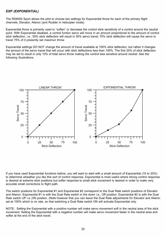
TRM (TRIM MEMORY)
The RD6000 Sport offers the Trim Memory Function on all four of the flight control channels. Trim Memory forElevator, Aileron, Throttle, and Rudder is input by the Digital Trim keys set when you use the INC +/YES or DEC -/NOkeys to input trim.
Any trim that you set while your model is in flight by use of the Digital Trim keys will automatically be stored inmemory for that specific channel and model.
The Trim value in % that you set during flight is shown on the TRM screen for each Channel. In addition, there arebar graph indicators on the screen at all times that visually show how much trim has been set for Elevator, Aileron,Throttle and Rudder channels.
38
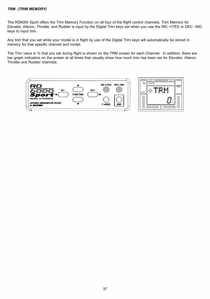
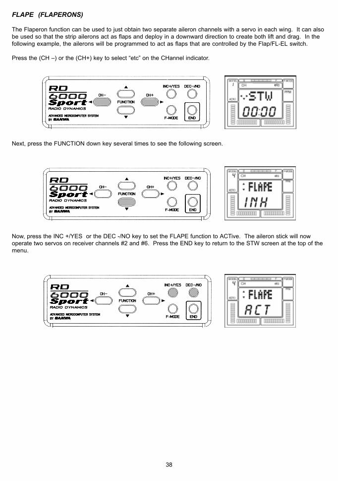
FLAPE (FLAPERONS)
The Flaperon function can be used to just obtain two separate aileron channels with a servo in each wing. It can alsobe used so that the strip ailerons act as flaps and deploy in a downward direction to create both lift and drag. In thefollowing example, the ailerons will be programmed to act as flaps that are controlled by the Flap/FL-EL switch.
Press the (CH –) or the (CH+) key to select “etc” on the CHannel indicator.
Next, press the FUNCTION down key several times to see the following screen.
Now, press the INC +/YES or the DEC -/NO key to set the FLAPE function to ACTive. The aileron stick will nowoperate two servos on receiver channels #2 and #6. Press the END key to return to the STW screen at the top of themenu.
etc1

39
Press the (CH –) key to select p-f on the CHannel indicator.
Use the FUNCTION down key to scroll down to FLAP EPA (endpoint adjust). Note that the default setting is –100%.Range of adjustment is from -150% to +150%. Press either the INC +/YES or the DEC -/NO key to change the valuean/or polarity of the function. The FLAP/FL-EL switch located on the top-right of the transmitter activates theFlaperons. To disable the Flap switch, set the Flap EPA at 0%.
Note that if the ailerons go up when the Flap switch is activated, change the polarity of the programmed value. Usethe FLAP TRM (trim) function to fine tune flap operation.
etc1

40
ALARMSD/R-A(DUAL RATE ALARM)THROTTLE STICK HIGH
The RD6000 Sport offers an “ALARM” function to warn you if you turn your transmitter on while a Dual Rate Switch isactivated, and another to warn you if you turn the transmitter on while the Throttle Stick is in any position other thanFull-Low throttle. TH-Hi! Will be displayed on the LCD screen until you place the Throttle stick in the full-low position.
To activate the D/R-A (Dual Rate alarm), press the (CH –) or the (CH +) key to select “etc” on the CHannel indicator.
Press the FUNCTION down key several times to scroll down the menu items and select the D/R-A screen.
Next, press either the INC +/YES or the DEC -/NO key to set D/R-A to ACTive.
If a Dual Rate switch is in the ON position when you turn ON the transmitter, an audio tone signal of 3 beeps willoccur at approximately every 15 seconds until you turn off a dual rate switch.
If you wish, you can turn off the Dual Rate alarm by pressing either the INC +/YES or the DEC -/NO key to change D/R-A to INHibit.
Note that the High Throttle Stick alarm is always active.
NOTE: The RD6000 Sport transmitter will also sound an alarm if the power switch is left on for a period of time thatexceeds 15 minutes.
etc1

41
DELTA (ELEVONS)
DELTA mix can be used in a flying wing type model to provide ELEVON control, where the elevator and aileronfunctions are combined.
To access the DELTA function, use either the (CH –) or the (CH +) key to select the STW screen.
Press the FUNCTION down key to scroll down to the DELTA screen.
Now press the INC + /YES key to change the display to ACT(Active). Note that you cannot have FLAPE (Flaperon)Active when DELTA is Active and vice versa. When DELTA is Active, you will have two channels assigned forELEVON control. Plug these two servos into channels #1 and #2 of your receiver. The two servos will now respondto movement of the elevator/aileron control stick. End Point Adjustments for elevator and aileron can then be madefor the amount of throw required.
Press the END key to return to the STW screen.
etc14

42
A>R (AILERON-RUDDER MIX)
The RD6000 Sport provides you with the capability to program your aircraft so that Aileron stick deflection will alsocause the rudder servo to respond in the same direction, (right aileron=right rudder). This automatic coordination ofrudder with aileron is useful in many high wing/scale models that suffer from adverse yaw with aileron application.(Note that the rudder servo will still respond to rudder stick movement as well as with aileron stick movement).
To use A>R (aileron-rudder) mixing, first access the AL (aileron) channel on the Channel indicator.
Next, press the FUNCTION down key to select the A>R display.
Press the INC +/YES key to adjust the amount of mixing that will occur.
You can now activate the AL>RU mix switch, located above the throttle/rudder stick assembly, to turn-on or off theAL>RU mix function. Press the INC +/YES and DEC -/NO keys simultaneously if you desire to reset A>RU to 0%.
etc1 CH AL4

43
V-TAIL (RUDDER-ELEVATOR MIX)
The RD6000 Sport transmitter has the ability to control sailplanes or powered models that utilize a V-Tail controlsystem. In these aircraft the two tail controls perform both as elevators and as rudders. Two servos and two chan-nels (receiver channels #1 and #4 are required for V-Tail operation).
To select the V-Tail operation, first press either the < CH - or the CH + > key to access the “etc” channel indicator.
Next, press the FUNCTION down key to scroll down to the V-TAIL display.
Press the INC +/YES key to see the following screen which will activate the V-TAIL function. If you press the DEC -/NO or the INC +/YES key you can toggle from INH (Inhibit) to ACT (Active). You can use the Rudder and ElevatorServo Rev (Reverse) and EPA (End Point Adjustment) functions to fine tune your set-up.
If you desire, you may use the Aileron>Rudder mixing function to allow operation of the V-Tail rudders with the rightaileron control stick. See AL>RU mixing, page 42.
etc1

44
T>E (THROTTLE-ELEVATOR MIX)
The RD6000 Sport allows for automatic adjustment of Elevator trim as you advance or retard the throttle stick. Thisis a valuable option as most sailplanes will need a change in pitch trim when ever flaps are deployed. By making thisadjustment with an electronic mixer, the pilot does not have to alter the elevator digital trims each time flaps are used,and thus does not have to re-trim the elevators for normal flight. This feature can also be used on an engine poweredmodel to make small elevator trim corrections as power is applied or reduced.
To use the T>E (Throttle-Elevator) mix, press either the (CH –) or (CH +) key to select TH on the CH indicator screen.(Note that you must be on the STW screen to move horizontally across the entire CH indicator screen).
Press the FUNCTION down key to see the following T>E screen.
Press the INC +/YES or the DEC -/NO key to set a value for T>E mixing. The range possible is from –100% to+100%. For now in this example, press the INC +/YES key to insert a value of 20% for the T>E mix. Flight testingwill always be required to determine the optimum amount of mix.
Press the INC +/YES and DEC -/NO keys simultaneously to reset T>E mix to the default value of 0%.
etc1 TH4

45
RD6000 Sport USERS MANUAL - HELICOPTER
Trainer Switch
Throttle (U/DRudder (L/R)
Throttle Digital Trim
Rudder Digital Trim
Panel Input Keys
Flight Mode 2
(See Page 60 tochange F.M. switchlocations)
Digital Hover Throttle INC / DEC
Throttle Cut Switch
Elevator (U/D)Aileron (L/R)
Elevator Digital Trim
Aileron Digital Trim
Main Power Switch
Flight Mode 1
(See Page 60 tochange F.M. switch
locations)
SECTION IV
92777 Receiver Channel Assignments
Receiver Plug Number1234567/B
Plug in Servo For:Elevator (F/A) CyclicAileron (L/R) CyclicThrottleRudder (Tail Rotor)GyroCollective PitchBattery
Liquid Crystal Display
Digital Hover Pitch INC / DEC
Flight Mode Selector

46
HELICOPTER MENU STRUCTURE
(Rx Channel) CH EL AL TH RU G P/F etcSTW STW STW STW STW STW STWTRM TRM TRM TRM REV REV M-SLREV REV REV REV GYR CNT NAMD/R D/R CNT D/R EPA STWEXP EXP EPA EXP CV-PH INTCNT CNT CV-PH CNT CV-P2 TYPEPA EPA CV-P2 EPA CV-PL SW-R
CV-PL RV-H CPYT-CUT RV-M RST
RV-L MODCLKDTM
NOTE: Use the (CH-) and (CH+) keys to move horizontally within the same function.Use the FUNCTION UP and FUNCTION DOWN keys to move vertically within the menu.The small trianges to the left of the function that shows on the LCD screen indicates the direction that you can movehorizontally and vertically in the menu.
Use the four center buttons in the function panel to navagate throught the menu’s. (UP / DOWN / LEFT / RIGHT)

47
PROGRAMMING FOR HELICOPTER
INITIAL SET-UP OF TYP (MODEL TYPE)
When you receive your RD6000 Sport unit the transmitter is preprogrammed for both fixed wing aircraft model’s aswell as for helicopter models as follows:
If you fly only helicopter model aircraft, you can change both model’s 1 and 3 to helicopter.
Turn the transmitter power ON and press the END key until you come to the default main screen. The inital screen willshow AR1 which indicates the aircraft type as well as showing the NiCd battery voltage.
Press the (CH+) key to scroll across the CH (channel) indicator on the screen to “etc”.
Press the FUNCTION down Key once to access the TYP (model type) screen.
Model #1 is setup with AERO featuers (AR1)Model #2 is setup with HELI featuers (HL2)Model #3 is setup with AERO featuers (AR3)Model #4 is setup with HELI featuers (HL4)
etc1
i
AERO

48
Note that one of the small triangular indicators will be blinking to show that you should press the (CH+) key.Therefore, press the (CH+) key and the screen will change to read HELI with a flashing YES.
To confirm the change of aircraft type, press the INC+/YES key. The screen will then change to read OK! As shown onscreen below to indicate the model type has been changed to AERO from model #2. Press the END key twice toreturn to the STW screen.
Press the END key twice to return to the STW screen. The same procedure as noted above can be used to changeModel #3 from AERO to HELI.
h e l i
i
AERO
etc1
HELI
N
i

49
PITCH CURVES (FLIGHT MODES)
The RD6000 Sport allows you to customize three distinct flight modes for each helicopter model.
The three pitch curves (flight modes) available for each helicopter model are:
N…………………………..NORMAL1…………………………...Select Curve One – IDLE UP2…………………………...Select Curve Two – THROTTLE HOLD
Selecting a pitch curve is done by activating the two FLIGHT MODE switches located on the top of the transmitter asshown below. The default positions are as indicted.
Note that BOTH F-MODE switches must be positioned towards you to select F-MODE NORMAL.
CAUTION: Flight Modes 1 and 2 are IDLE-UP modes. If either one is activated when you turn on the transmitter, anaudio alarm will sound. You must always be aware of which flight mode you have selected before starting yourengine or attempting flight!
F-Mode 1: Switch positionedaway from you
F-Mode Normal: Switch positionedtowards you
F-Mode 2:Switch positioned
away from you
F-Mode Normal:Switch positioned
towards you

50
The pitch curve for each flight mode has three points that can be adjusted to suit your specific needs. Within eachpitch curve these points are referred to as PH (high pitch), P2, and PL (low pitch). The range of values and defaultsettings for each is shown below.
FLIGHT MODE Curve Point Minimum Default Maximum
Normal PH -25% 100% 125%P2 -25% 55% 125%PL -25% 0% 125%
F. Mode 1 PH -25% 90% 125%P2 -25% 55% 125%PL -25% 0% 125%
F. Mode 2 PH -25% 100% 125%P2 -25% 40% 125%PL -25% -10% 125%
To program your pitch curves, press the (CH –) or (CH +) key to select P-F on the CHannel indicator.
Next, press the FUNCTION down key and scroll down to the CV-PH screen.
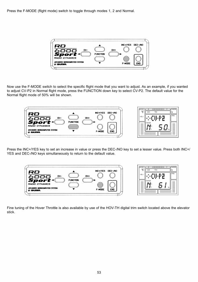
Press the F-MODE (flight mode) switch to toggle through modes 1, 2 and Normal.

51
Now use the F-MODE switch to select the specific flight mode that you want to adjust. As an example, if you wantedto adjust CV-P2 in Normal flight mode, press the FUNCTION down key to select CV-P2. The default value for theNormal flight mode of 55% will be shown.
Press the INC+/YES key to set an increase in value or press the DEC-/NO key to set a lesser value. Press both INC+/YES and DEC-/NO keys simultaneously to return to the default value.
Fine tuning of the Hover Pitch is also available by use of the HOV-PT digital trim switch located above the throttlestick. NOTE: HOV-PI and HOV-TH trims are used only for adjustment in flight mode N (normal). They have no affecton Flight Mode 1 or 2.
In normal operation you will usually set the approximate Hovering Pitch with the software in the Pitch screens thenadjust as needed for various weather and flying conditions with the HOV-PI (hover pitch) digital trim switch.
HOV-TH + -Digital Trim
HOV-PI + -Digital Trim

52
THROTTLE CURVES (FLIGHT MODES)
The throttle curve for each flight mode has three points that can be adjusted to suit your specific needs. Within eachthrottle curve these points are referred to as PH (high pitch) P2, and PL (low pitch). The range of values and defaultsettings for each is shown below.
FLIGHT MODE Curve Point Minimum Default Maximum
Normal PH -25% 100% 125%P2 -25% 50% 125%PL -25% 0% 125%
F. Mode 1 PH -25% 100% 125%P2 -25% 50% 125%PL -25% 0% 125%
F. Mode 2 PH -25% 0% 125%P2 -25% 0% 125%PL -25% 0% 125%
To program your throttle curves, press the (CH –) or (CH +) key to select P-F on the CHannel indicator.
Next, press the FUNCTION down key and scroll down to the CV-PH screen.
TH
TH
53
Now use the F-MODE switch to select the specific flight mode that you want to adjust. As an example, if you wantedto adjust CV-P2 in Normal flight mode, press the FUNCTION down key to select CV-P2. The default value for theNormal flight mode of 50% will be shown.
Press the INC+/YES key to set an increase in value or press the DEC-/NO key to set a lesser value. Press both INC+/YES and DEC-/NO keys simultaneously to return to the default value.
Fine tuning of the Hover Throttle is also available by use of the HOV-TH digital trim switch located above the elevatorstick.
Press the F-MODE (flight mode) switch to toggle through modes 1, 2 and Normal.

54
REVOLUTION MIXING
The RD6000 Sport provides for setting Revolution Mixing for each of the three Flight Modes. Each Flight Mode hasits own curve for adjusting tail rotor position in response to the throttle/collective stick movements. The defaultsettings for RV.H (Revolution Mixing High Point), RV.M (Revolution Mixing Mid Point), and RV.L (Revolution MixingLow Point) are as follows:
FLIGHT MODE RV.H RV.M RV.L
Normal 20% 0% -20%F. Mode #1 0% -2% -5%F.Mode #2 0% 0% 0%
To program Revolution Mixing, press either the (CH –) or (CH +) key to select RU ( rudder) on the CHannel indicator.
Next, press the FUNCTION \/ key to select RV.H which is the revolution mixing high point.
Use the INC +/YES or DEC -/NO key to change the default value if you desire to do so for any of the three flightmodes. In this example we have set RV.H for the Normal flight mode to + 25%.
The same procedure can be used to input values for RV.M and RV.L. Press the Flight Mode switch to select thedifferent Flight Modes.
RU

55
GYRO ADJUSTMENT
The RD6000 Sport allows you to set the Gyro sensitivity of your helicopter’s gyro if it has that capability. The gain ofthe gyro can therefor be adjusted for all of the three Flight Modes. In this manner the pilot can adjust the gyro for asuitable level of sensitivity (gain) for one flight mode (for instance hover), and by changing to a different flight modealter the sensitivity for either more or less stabilization. Note that you must be using a gyro that offers remotesensitivity adjustment.
Press either the (CH –) or the (CH +) key to select G (Gyro) on the CHannel indicator.
Now, press the FUNCTION down key several times to access the GYR (gyro) screen. The display will look like thefollowing screen when the Normal flight mode is selected.
To adjust the gyro sensitivity for a specific flight mode, press either the INC +/YES or DEC- /NO key. Default valuesare : Normal 100%, F.Mode #1 50%, and F.Mode #2 100%. The range of adjustment is from – 150% to + 150%.Press the Flight Mode switch to change from one flight mode to another.
Fine tuning of your gyro sensitivity for the various flight modes can be accomplished by flight tests.
G

56
TRM (TRIM MEMORY)
The RD6000 Sport offers the Trim Memory Function on all four of the flight control channels. Trim Memory forElevator, Aileron, Throttle, and Rudder is input by the Digital Trim keys set when you use the INC +/YES or DEC -/NOkeys to input trim.
Any trim that you set while your model is in flight by use of the Digital Trim keys will automatically be stored inmemory for that specific channel and model.
The Trim value in % that you set during flight is shown on the TRM screen for each Channel. In addition, there arebar graph indicators on the screen at all times that visually show how much trim has been set for Elevator, Aileron,Throttle and Rudder channels.
D/R (DUAL RATE)
Dual Rate adjustments allow you to switch from your “standard” control deflection to a reduced amount of throw byusing your flight mode switches. The actual speed of signal processing and servo movement are not affected by theDual Rate settings, only the amount of total throw available.
The RD6000 Sport allows Dual Rate settings for Aileron, Elevator and Rudder. To access the Dual Rate setting forElevator when you are on the STW or REV screen, press the FUNCTION down key to reach this screen.
The screen tells you the present rate status and the flight mode that you have selected. It is important to understandthat the term “Dual Rate” is used because it is an old familiar description. We are showing an example for theElevator channel. However, all of the other channels are set in the same way.
Dual Rate settings can be varied from 0 to 150% for each flight mode, N, 1 and 2. Default for all flight modes are at100%.
An initial setting of 50% is a good starting point and you can taylor it later following a test flight.
CAUTION: Prior to taking off your model, check the positions of your flight mode switches and make sure they are inthe position you want.

57
DTM (DYNAMIC TRIM MEMORY)
Dynamic Trim Memory (DTM) is an advanced function that can be used in conjunction with the Flight Mode OP-TIONS. When activated Dynamic Trim Memory allows you to make trim changes while in any flight mode WITHOUTaffecting any other flight mode or model.
Flight Modes are used to allow activation of the DTM function. The three flight modes are:
NORMALF.M. #1………….IDLE-UPF.M. #2………….THROTTLE-HOLD
Activating DTM will allow trim changes made in one flight mode to affect ONLY that specific mode. To activateDynamic Trim Memory, press the (CH +) or the (CH –) key to select “etc” on the CHannel indicator.
Now, press the FUNCTION down key to scroll down the menu to the DTM screen.
Press the INC +/YES or the DEC -/NO key to change DTM to ACT (active). Pressing either key will toggle theindication from ACT to INH. Press the END key to return to the STW screen.
Once activated, the Dynamic Trim Memory function is transparent to the pilot. Simply activate a Flight Mode, (forinstance “Normal”) and trim the aircraft for stable hover using the digital trim keys. Then, switch to another flightmode, and do the same as desired. Note that when you change flight modes, the servos affected by the DTMfunction will return to the original neutral position regardless of the value of trim set-in for the previous flight mode.However, the throttle channel is an exception to the rule. The trim that is set for one flight mode will affect all otherflight modes. Also be aware that the throttle trim key only affects the low throttle position of the throttle servo.Throttle trim DOES NOT affect the collective pitch servo.
etc

58
COMPENSATION MIXERS (C-Mix)
The RD6000 Sport has two compensation mixers available to handle advanced mixing needs. These are in addition tothe predefined mixers. Compensation mixers C-Mix 1 and C-Mix 2 are only available in the Aircraft mode of operationand do not have any switch to turn them on or off when activated.
The purpose of a Compensation Mixer is to allow one transmitter control input to affect two flight functions. Acommon mix would be Aileron to Rudder to achieve coordinated turns without moving the rudder stick. However, theRD6000 Sport provides a predefined mixer for this function.
Press the (CH+) key to move across the CH indicator and access the “etc” screen. Next press the FUNCTION downkey and locate the following screen names in order:
MAS 1: EL = (C-Mix #1 Master channel) example EL “Elevator”SLV 1: EL = (C-Mix #1 Slave Channel) example EL “Elevator”E>E 1: 0% = ( C-Mix #1 mixing percentage) Adjust from +150% ~ -150% example “Elevator to Elevator”
MAS 2: EL = (C-Mix #1 Master channel) example EL “Elevator”SLV 2: EL = (C-Mix #1 Slave Channel) example EL “Elevator”E>E 2: 0% = ( C-Mix #1 mixing percentage) Adjust from +150% ~ -150% example “Elevator to Elevator”
NOTE:At this point, both C-Mix 1 and C-Mix 2 are not activated (factory default).
To activate both C-Mix 1 and C-Mix 2 you must first change the (SW-R) from NOR (normal) to REV (reverse). Seepage number 27 on how to change.
REMEMBER:When you activate both C-Mix 1 and C-Mix 2, they both will be on all the time, there is no toggle switch to turn themoff or on. Any number besides “0” in the percentage screen will cause the slave channel to move in either direction.
Changing the SW-R (switch reverse) will also change the switch direction or both your Dual Rate switches and willreverse the direction of your Gear and Flap switches. If you have setup any of the features mentioned, please reviewyour settings before flying.
In the following example, I will use C-Mix 1 to mix Rudder to Elevator as maybe needed for knife edge flight.
Start by pressing the (CH+) key until you reach “etc” .
etc

59
Now use the FUNCTION down key until you reach the (MAS 1:) screen. Next use the INC or DEC keys untill the RU(rudder) is selected. This will be your Master channel.
Next press the FUNCTION down key ones to select (SLV 1:) screen. Now use the INC or DEC keys untill you reachEL (elevator). This will be your Slave channel.
Next press the FUNCTION down key ones to select (R>E 1:) screen.By moving the Rudder stick you will see the arrow indicators on the screen change directions acorrding to thedirection you move the stick, left and right. You can set the C-Mix for both directions independantly. For example,when you are in a knife-edge and you give it right rudder but the plane pulls to the top of the aircraft you can simplymoved the stick to the right and press the INC or DEC keys and abserve the elevator movment. If by incressing thenumber moves the elevator in the wrong direction, you can decress the number into the negative side to change thedirection of the compensation. Only use a small amount of compensation at first. You can sit the left compensation inthe same manor if any compensation is needed.
REMEMBER: When activated, C-Mix 1 and 2 will be on at all times.
When the C-Mix persentages in both directions are at “0”, there will beno compensation mixing.

60
CHANEGING FLIGHT MODE 1 and 2 Switch Locations
From the factory flight mode 1 switch is on the right top toggle and flight mode 2 is on the left top toggle switch. Somefliers perfer on having flight mode 1 switch on the left top and flight mode 2 on the right top switch. The following willbe on how to change flight mode 1 and 2 switch locations.
1 Remove the NiCd battery cover and NiCd battery pack.2 Remove the antena by unscerwing it counter clockwise.3 Remove all 8 scerws located on the back of the transmitter. Refer to page 10 for screw locations.4 Remove both left and right switch retainer nuts located on top of the switches (crome)5 Cut both left and right wire tie’s off holding the wiring to both switches.6 With a black marker pin put a dot on the plastic base of the switch to indecate the rear of the switch. This will
help to not mistakenly flip the switch over.7 Remove both switches by sliding them down into the transmitter case and switch locations.8 Reinstall both switch (crome) nuts and secure in place.9 Arange both switch wires away from any moving parts and secure with new wire tie’s making sure the wires
will not get in the way of the antena as it is being reinstalled.10 Reinstall the transmitter rear case and be careful when placing over ther NiCd battery connector pins.11 Reinstall all 8 case scerws.12 Reinstall Antena by screwing clockwise.13 Reinstall the NiCd battery and battery Cover.
Before After
Wire Tie locations Wire Tie locations
After you have completed the switching over of both flight mode 1 and 2 switches, you can now replace the two frontswitch identifying labels. (new labels are supplied)
Use a small scerw driver to pry up the old label to remove. Be carfull not to damage the plastic transmitter case. Nextpell the backing off the new label and secure in place.
New switch location labels
FLAP/FL-EL MIXFLIGHT - MODE 1
TRAINER EL D/R
lO
RETRACT GEARFLIGHT - MODE 2
THROTTLECUT
AI D/R
lO
WARNING:Any other modifications made to the transmitter other than changing the flight mode switch locations willvoid any and all warranties covered be Airtronics Inc.

61

62
WING TYPE NORMAL DELTA V-TAIL FLAPERON
FLAPERON & V-TAIL
CH (1) EL (2) AL (3) TH (4) RU (5) G (6) F
TRM
REV NOR / REV
% % % % %
NOR / REV NOR / REV NOR / REV NOR / REV NOR / REV
D/R
EXP
CNT
EPA
1
2
1
2
%
%
%
%
%
%
%
%
% % % % %
UP LT HI LT HI
DN RT LO RT LO
%
%
%
%
%
%
%
%
%
%%
MIX A > R T > E
% %
T-CUT STW SW-R D/R-A
% : NOR / REV INH / ACT
RD6000 SPORT / TYPE: AERO MODULATION PPM / PPM-R
MODEL #........................................................................MODEL NAME....................................................

63
CH (1) EL (2) AL (3) TH (4) RU (5) GY (6) PI
TRM
REV NOR / REV
%
NOR / REV NOR / REV NOR / REV NOR / REV NOR / REV
D/R
EXP
CNT
EPA
N
1
2
%
%
%
%
%
%
%
%
% %
UP LT HI LT
DN RT LO RT
%
%
%
%
%
%
%
%
%
%
T-CUT
N
1
2
DTMACT
%
%
%
%
%
N
1
2
% %
%
%
%
%
%
%
% % %% %
HI
LO
N
1
2
%
%
%
%%
TH-CV PL P2 PH
N1
2
% % %
% % %
% % %
PI-CV PL P2 PH
N1
2
% % %
% % %
% % %
REV PL P2 PH
N1
2
% % %
% % %
% % %
%
STW :
SW-R NOR/ REV
DTM INH/ REV
RD6000 SPORT / TYPE: HELI MODULATION PPM / PPM-R
MODEL #........................................................................MODEL NAME....................................................


![RA034 [Telecharger]](https://static.fdocuments.net/doc/165x107/586e0fd61a28ab01648b7aea/ra034-telecharger.jpg)


![RA023 [Telecharger]](https://static.fdocuments.net/doc/165x107/5867b5371a28abd93f8bdcdb/ra023-telecharger.jpg)


